EP2665782B1 - Rutschige oberflächen mit hoher druckstabilität, optischer transparenz, und selbstheilungseigenschaften - Google Patents
Rutschige oberflächen mit hoher druckstabilität, optischer transparenz, und selbstheilungseigenschaften Download PDFInfo
- Publication number
- EP2665782B1 EP2665782B1 EP12703922.0A EP12703922A EP2665782B1 EP 2665782 B1 EP2665782 B1 EP 2665782B1 EP 12703922 A EP12703922 A EP 12703922A EP 2665782 B1 EP2665782 B1 EP 2665782B1
- Authority
- EP
- European Patent Office
- Prior art keywords
- liquid
- slips
- roughened surface
- roughened
- certain embodiments
- Prior art date
- Legal status (The legal status is an assumption and is not a legal conclusion. Google has not performed a legal analysis and makes no representation as to the accuracy of the status listed.)
- Active
Links
- 230000003287 optical effect Effects 0.000 title claims description 56
- 239000007788 liquid Substances 0.000 claims description 688
- XLYOFNOQVPJJNP-UHFFFAOYSA-N water Substances O XLYOFNOQVPJJNP-UHFFFAOYSA-N 0.000 claims description 173
- 239000007787 solid Substances 0.000 claims description 113
- 239000000758 substrate Substances 0.000 claims description 109
- 229910001868 water Inorganic materials 0.000 claims description 106
- 239000000463 material Substances 0.000 claims description 99
- 239000012530 fluid Substances 0.000 claims description 90
- 238000000034 method Methods 0.000 claims description 87
- 230000001050 lubricating effect Effects 0.000 claims description 70
- 239000011148 porous material Substances 0.000 claims description 62
- 239000000126 substance Substances 0.000 claims description 44
- 239000000523 sample Substances 0.000 claims description 31
- 230000001846 repelling effect Effects 0.000 claims description 11
- 239000004744 fabric Substances 0.000 claims description 10
- 229930195733 hydrocarbon Natural products 0.000 claims description 8
- 150000002430 hydrocarbons Chemical class 0.000 claims description 8
- 230000002209 hydrophobic effect Effects 0.000 claims description 7
- 239000004566 building material Substances 0.000 claims description 5
- 150000001875 compounds Chemical class 0.000 claims description 5
- 238000005057 refrigeration Methods 0.000 claims description 5
- 239000004215 Carbon black (E152) Substances 0.000 claims description 3
- 125000005010 perfluoroalkyl group Chemical group 0.000 claims description 2
- 229910052782 aluminium Inorganic materials 0.000 description 85
- XAGFODPZIPBFFR-UHFFFAOYSA-N aluminium Chemical compound [Al] XAGFODPZIPBFFR-UHFFFAOYSA-N 0.000 description 80
- AQZYBQIAUSKCCS-UHFFFAOYSA-N perfluorotripentylamine Chemical compound FC(F)(F)C(F)(F)C(F)(F)C(F)(F)C(F)(F)N(C(F)(F)C(F)(F)C(F)(F)C(F)(F)C(F)(F)F)C(F)(F)C(F)(F)C(F)(F)C(F)(F)C(F)(F)F AQZYBQIAUSKCCS-UHFFFAOYSA-N 0.000 description 57
- 239000010410 layer Substances 0.000 description 56
- -1 sticky notes Substances 0.000 description 53
- 239000004809 Teflon Substances 0.000 description 47
- 229920006362 Teflon® Polymers 0.000 description 47
- 239000003921 oil Substances 0.000 description 42
- 235000019198 oils Nutrition 0.000 description 42
- 239000012528 membrane Substances 0.000 description 40
- 235000019592 roughness Nutrition 0.000 description 40
- 239000010779 crude oil Substances 0.000 description 37
- 239000000243 solution Substances 0.000 description 36
- 238000000576 coating method Methods 0.000 description 35
- 239000000356 contaminant Substances 0.000 description 32
- 238000005259 measurement Methods 0.000 description 31
- 238000009736 wetting Methods 0.000 description 30
- 239000004593 Epoxy Substances 0.000 description 29
- 238000004070 electrodeposition Methods 0.000 description 28
- 229910052751 metal Inorganic materials 0.000 description 28
- 239000002184 metal Substances 0.000 description 28
- 239000000203 mixture Substances 0.000 description 27
- 238000000151 deposition Methods 0.000 description 26
- 239000004205 dimethyl polysiloxane Substances 0.000 description 26
- 229920000435 poly(dimethylsiloxane) Polymers 0.000 description 26
- 238000001704 evaporation Methods 0.000 description 25
- 239000000314 lubricant Substances 0.000 description 25
- 239000003973 paint Substances 0.000 description 25
- 229920000128 polypyrrole Polymers 0.000 description 24
- 241000238631 Hexapoda Species 0.000 description 23
- 230000008021 deposition Effects 0.000 description 23
- 238000013461 design Methods 0.000 description 23
- 229920000642 polymer Polymers 0.000 description 23
- 230000008020 evaporation Effects 0.000 description 22
- 230000008569 process Effects 0.000 description 22
- 238000012360 testing method Methods 0.000 description 22
- LFQSCWFLJHTTHZ-UHFFFAOYSA-N Ethanol Chemical compound CCO LFQSCWFLJHTTHZ-UHFFFAOYSA-N 0.000 description 20
- 238000007710 freezing Methods 0.000 description 19
- 239000011521 glass Substances 0.000 description 19
- 229920001343 polytetrafluoroethylene Polymers 0.000 description 19
- KAESVJOAVNADME-UHFFFAOYSA-N Pyrrole Chemical compound C=1C=CNC=1 KAESVJOAVNADME-UHFFFAOYSA-N 0.000 description 18
- 230000015572 biosynthetic process Effects 0.000 description 18
- DIOQZVSQGTUSAI-UHFFFAOYSA-N decane Chemical compound CCCCCCCCCC DIOQZVSQGTUSAI-UHFFFAOYSA-N 0.000 description 18
- 239000010408 film Substances 0.000 description 18
- 239000004810 polytetrafluoroethylene Substances 0.000 description 18
- 229910000838 Al alloy Inorganic materials 0.000 description 17
- 229910045601 alloy Inorganic materials 0.000 description 17
- 239000000956 alloy Substances 0.000 description 17
- 230000006378 damage Effects 0.000 description 17
- 239000002245 particle Substances 0.000 description 17
- CSCPPACGZOOCGX-UHFFFAOYSA-N Acetone Chemical compound CC(C)=O CSCPPACGZOOCGX-UHFFFAOYSA-N 0.000 description 16
- 238000001816 cooling Methods 0.000 description 16
- 230000008014 freezing Effects 0.000 description 16
- DCAYPVUWAIABOU-UHFFFAOYSA-N hexadecane Chemical compound CCCCCCCCCCCCCCCC DCAYPVUWAIABOU-UHFFFAOYSA-N 0.000 description 16
- 239000010702 perfluoropolyether Substances 0.000 description 16
- 238000001878 scanning electron micrograph Methods 0.000 description 16
- 230000032258 transport Effects 0.000 description 16
- LYCAIKOWRPUZTN-UHFFFAOYSA-N Ethylene glycol Chemical compound OCCO LYCAIKOWRPUZTN-UHFFFAOYSA-N 0.000 description 15
- PEDCQBHIVMGVHV-UHFFFAOYSA-N Glycerine Chemical compound OCC(O)CO PEDCQBHIVMGVHV-UHFFFAOYSA-N 0.000 description 15
- 230000005484 gravity Effects 0.000 description 15
- 238000005507 spraying Methods 0.000 description 15
- 150000002739 metals Chemical class 0.000 description 14
- 238000007711 solidification Methods 0.000 description 14
- 230000008023 solidification Effects 0.000 description 14
- OFBQJSOFQDEBGM-UHFFFAOYSA-N Pentane Chemical compound CCCCC OFBQJSOFQDEBGM-UHFFFAOYSA-N 0.000 description 13
- 239000011324 bead Substances 0.000 description 13
- 230000006399 behavior Effects 0.000 description 13
- 238000009833 condensation Methods 0.000 description 13
- 230000005494 condensation Effects 0.000 description 13
- 238000005530 etching Methods 0.000 description 13
- 239000007921 spray Substances 0.000 description 13
- VYPSYNLAJGMNEJ-UHFFFAOYSA-N Silicium dioxide Chemical compound O=[Si]=O VYPSYNLAJGMNEJ-UHFFFAOYSA-N 0.000 description 12
- 239000000853 adhesive Substances 0.000 description 12
- 230000005540 biological transmission Effects 0.000 description 12
- 238000004140 cleaning Methods 0.000 description 12
- 239000011248 coating agent Substances 0.000 description 12
- 239000003822 epoxy resin Substances 0.000 description 12
- 229920000647 polyepoxide Polymers 0.000 description 12
- 230000002829 reductive effect Effects 0.000 description 12
- 230000003068 static effect Effects 0.000 description 12
- 238000010257 thawing Methods 0.000 description 12
- IJGRMHOSHXDMSA-UHFFFAOYSA-N Atomic nitrogen Chemical compound N#N IJGRMHOSHXDMSA-UHFFFAOYSA-N 0.000 description 11
- XUIMIQQOPSSXEZ-UHFFFAOYSA-N Silicon Chemical compound [Si] XUIMIQQOPSSXEZ-UHFFFAOYSA-N 0.000 description 11
- 239000002086 nanomaterial Substances 0.000 description 11
- BASFCYQUMIYNBI-UHFFFAOYSA-N platinum Substances [Pt] BASFCYQUMIYNBI-UHFFFAOYSA-N 0.000 description 11
- 239000010703 silicon Substances 0.000 description 11
- 229910052710 silicon Inorganic materials 0.000 description 11
- 230000001965 increasing effect Effects 0.000 description 10
- 239000002904 solvent Substances 0.000 description 10
- 230000003746 surface roughness Effects 0.000 description 10
- OKKJLVBELUTLKV-UHFFFAOYSA-N Methanol Chemical compound OC OKKJLVBELUTLKV-UHFFFAOYSA-N 0.000 description 9
- 239000004743 Polypropylene Substances 0.000 description 9
- KWYUFKZDYYNOTN-UHFFFAOYSA-M Potassium hydroxide Chemical compound [OH-].[K+] KWYUFKZDYYNOTN-UHFFFAOYSA-M 0.000 description 9
- HEMHJVSKTPXQMS-UHFFFAOYSA-M Sodium hydroxide Chemical compound [OH-].[Na+] HEMHJVSKTPXQMS-UHFFFAOYSA-M 0.000 description 9
- 230000001070 adhesive effect Effects 0.000 description 9
- 238000005422 blasting Methods 0.000 description 9
- 230000000694 effects Effects 0.000 description 9
- 239000007789 gas Substances 0.000 description 9
- 238000010438 heat treatment Methods 0.000 description 9
- VLKZOEOYAKHREP-UHFFFAOYSA-N n-Hexane Chemical compound CCCCCC VLKZOEOYAKHREP-UHFFFAOYSA-N 0.000 description 9
- 239000002121 nanofiber Substances 0.000 description 9
- 239000005871 repellent Substances 0.000 description 9
- FAPWRFPIFSIZLT-UHFFFAOYSA-M Sodium chloride Chemical compound [Na+].[Cl-] FAPWRFPIFSIZLT-UHFFFAOYSA-M 0.000 description 8
- GVGUFUZHNYFZLC-UHFFFAOYSA-N dodecyl benzenesulfonate;sodium Chemical compound [Na].CCCCCCCCCCCCOS(=O)(=O)C1=CC=CC=C1 GVGUFUZHNYFZLC-UHFFFAOYSA-N 0.000 description 8
- 230000014759 maintenance of location Effects 0.000 description 8
- 238000004519 manufacturing process Methods 0.000 description 8
- 239000003607 modifier Substances 0.000 description 8
- 229940080264 sodium dodecylbenzenesulfonate Drugs 0.000 description 8
- IIYFAKIEWZDVMP-UHFFFAOYSA-N tridecane Chemical compound CCCCCCCCCCCCC IIYFAKIEWZDVMP-UHFFFAOYSA-N 0.000 description 8
- 239000000835 fiber Substances 0.000 description 7
- 239000000178 monomer Substances 0.000 description 7
- 238000003892 spreading Methods 0.000 description 7
- 230000007480 spreading Effects 0.000 description 7
- 230000003075 superhydrophobic effect Effects 0.000 description 7
- 235000019587 texture Nutrition 0.000 description 7
- 238000012546 transfer Methods 0.000 description 7
- OKTJSMMVPCPJKN-UHFFFAOYSA-N Carbon Chemical compound [C] OKTJSMMVPCPJKN-UHFFFAOYSA-N 0.000 description 6
- KRHYYFGTRYWZRS-UHFFFAOYSA-N Fluorane Chemical compound F KRHYYFGTRYWZRS-UHFFFAOYSA-N 0.000 description 6
- VEXZGXHMUGYJMC-UHFFFAOYSA-N Hydrochloric acid Chemical compound Cl VEXZGXHMUGYJMC-UHFFFAOYSA-N 0.000 description 6
- KFZMGEQAYNKOFK-UHFFFAOYSA-N Isopropanol Chemical compound CC(C)O KFZMGEQAYNKOFK-UHFFFAOYSA-N 0.000 description 6
- WCUXLLCKKVVCTQ-UHFFFAOYSA-M Potassium chloride Chemical compound [Cl-].[K+] WCUXLLCKKVVCTQ-UHFFFAOYSA-M 0.000 description 6
- 241000237908 Riftia pachyptila Species 0.000 description 6
- 239000008280 blood Substances 0.000 description 6
- 210000004369 blood Anatomy 0.000 description 6
- 238000009835 boiling Methods 0.000 description 6
- 230000008859 change Effects 0.000 description 6
- 239000003795 chemical substances by application Substances 0.000 description 6
- 239000000428 dust Substances 0.000 description 6
- 210000003608 fece Anatomy 0.000 description 6
- 235000013305 food Nutrition 0.000 description 6
- 230000012010 growth Effects 0.000 description 6
- 230000003993 interaction Effects 0.000 description 6
- 238000002844 melting Methods 0.000 description 6
- 230000008018 melting Effects 0.000 description 6
- 239000011859 microparticle Substances 0.000 description 6
- 230000004048 modification Effects 0.000 description 6
- 238000012986 modification Methods 0.000 description 6
- 229920002379 silicone rubber Polymers 0.000 description 6
- BFKJFAAPBSQJPD-UHFFFAOYSA-N tetrafluoroethene Chemical compound FC(F)=C(F)F BFKJFAAPBSQJPD-UHFFFAOYSA-N 0.000 description 6
- BLRPTPMANUNPDV-UHFFFAOYSA-N Silane Chemical compound [SiH4] BLRPTPMANUNPDV-UHFFFAOYSA-N 0.000 description 5
- 241000607479 Yersinia pestis Species 0.000 description 5
- 238000005270 abrasive blasting Methods 0.000 description 5
- AZDRQVAHHNSJOQ-UHFFFAOYSA-N alumane Chemical class [AlH3] AZDRQVAHHNSJOQ-UHFFFAOYSA-N 0.000 description 5
- 230000008901 benefit Effects 0.000 description 5
- 230000007423 decrease Effects 0.000 description 5
- 230000007547 defect Effects 0.000 description 5
- 239000008367 deionised water Substances 0.000 description 5
- 229910021641 deionized water Inorganic materials 0.000 description 5
- 238000001035 drying Methods 0.000 description 5
- 238000007306 functionalization reaction Methods 0.000 description 5
- 230000000670 limiting effect Effects 0.000 description 5
- 230000007246 mechanism Effects 0.000 description 5
- 239000002105 nanoparticle Substances 0.000 description 5
- 229910052757 nitrogen Inorganic materials 0.000 description 5
- RVZRBWKZFJCCIB-UHFFFAOYSA-N perfluorotributylamine Chemical compound FC(F)(F)C(F)(F)C(F)(F)C(F)(F)N(C(F)(F)C(F)(F)C(F)(F)C(F)(F)F)C(F)(F)C(F)(F)C(F)(F)C(F)(F)F RVZRBWKZFJCCIB-UHFFFAOYSA-N 0.000 description 5
- 229910052697 platinum Inorganic materials 0.000 description 5
- 229920001155 polypropylene Polymers 0.000 description 5
- 229910000077 silane Inorganic materials 0.000 description 5
- 239000000377 silicon dioxide Substances 0.000 description 5
- 239000011343 solid material Substances 0.000 description 5
- 238000004381 surface treatment Methods 0.000 description 5
- 238000012876 topography Methods 0.000 description 5
- 241000894006 Bacteria Species 0.000 description 4
- RYGMFSIKBFXOCR-UHFFFAOYSA-N Copper Chemical compound [Cu] RYGMFSIKBFXOCR-UHFFFAOYSA-N 0.000 description 4
- 241001465754 Metazoa Species 0.000 description 4
- 229910021607 Silver chloride Inorganic materials 0.000 description 4
- GWEVSGVZZGPLCZ-UHFFFAOYSA-N Titan oxide Chemical compound O=[Ti]=O GWEVSGVZZGPLCZ-UHFFFAOYSA-N 0.000 description 4
- 238000009825 accumulation Methods 0.000 description 4
- 150000001298 alcohols Chemical class 0.000 description 4
- PNEYBMLMFCGWSK-UHFFFAOYSA-N aluminium oxide Inorganic materials [O-2].[O-2].[O-2].[Al+3].[Al+3] PNEYBMLMFCGWSK-UHFFFAOYSA-N 0.000 description 4
- 238000013459 approach Methods 0.000 description 4
- 239000000227 bioadhesive Substances 0.000 description 4
- 229910001593 boehmite Inorganic materials 0.000 description 4
- 229910052799 carbon Inorganic materials 0.000 description 4
- 229920001940 conductive polymer Polymers 0.000 description 4
- 239000004035 construction material Substances 0.000 description 4
- 229910052802 copper Inorganic materials 0.000 description 4
- 239000010949 copper Substances 0.000 description 4
- 230000003247 decreasing effect Effects 0.000 description 4
- 230000001419 dependent effect Effects 0.000 description 4
- SZXQTJUDPRGNJN-UHFFFAOYSA-N dipropylene glycol Chemical compound OCCCOCCCO SZXQTJUDPRGNJN-UHFFFAOYSA-N 0.000 description 4
- 230000007613 environmental effect Effects 0.000 description 4
- NBVXSUQYWXRMNV-UHFFFAOYSA-N fluoromethane Chemical group FC NBVXSUQYWXRMNV-UHFFFAOYSA-N 0.000 description 4
- 239000011888 foil Substances 0.000 description 4
- 239000000446 fuel Substances 0.000 description 4
- 239000006262 metallic foam Substances 0.000 description 4
- 238000002156 mixing Methods 0.000 description 4
- 230000006911 nucleation Effects 0.000 description 4
- 238000010899 nucleation Methods 0.000 description 4
- TVMXDCGIABBOFY-UHFFFAOYSA-N octane Chemical compound CCCCCCCC TVMXDCGIABBOFY-UHFFFAOYSA-N 0.000 description 4
- 239000004006 olive oil Substances 0.000 description 4
- 229950011087 perflunafene Drugs 0.000 description 4
- UWEYRJFJVCLAGH-IJWZVTFUSA-N perfluorodecalin Chemical compound FC1(F)C(F)(F)C(F)(F)C(F)(F)[C@@]2(F)C(F)(F)C(F)(F)C(F)(F)C(F)(F)[C@@]21F UWEYRJFJVCLAGH-IJWZVTFUSA-N 0.000 description 4
- 230000009467 reduction Effects 0.000 description 4
- 238000010992 reflux Methods 0.000 description 4
- 230000002940 repellent Effects 0.000 description 4
- HKZLPVFGJNLROG-UHFFFAOYSA-M silver monochloride Chemical compound [Cl-].[Ag+] HKZLPVFGJNLROG-UHFFFAOYSA-M 0.000 description 4
- 239000011780 sodium chloride Substances 0.000 description 4
- 238000009987 spinning Methods 0.000 description 4
- 238000003860 storage Methods 0.000 description 4
- 235000011299 Brassica oleracea var botrytis Nutrition 0.000 description 3
- 240000003259 Brassica oleracea var. botrytis Species 0.000 description 3
- 241000238586 Cirripedia Species 0.000 description 3
- 241000233866 Fungi Species 0.000 description 3
- MHAJPDPJQMAIIY-UHFFFAOYSA-N Hydrogen peroxide Chemical compound OO MHAJPDPJQMAIIY-UHFFFAOYSA-N 0.000 description 3
- 241000237536 Mytilus edulis Species 0.000 description 3
- GRYLNZFGIOXLOG-UHFFFAOYSA-N Nitric acid Chemical compound O[N+]([O-])=O GRYLNZFGIOXLOG-UHFFFAOYSA-N 0.000 description 3
- RTAQQCXQSZGOHL-UHFFFAOYSA-N Titanium Chemical compound [Ti] RTAQQCXQSZGOHL-UHFFFAOYSA-N 0.000 description 3
- YXFVVABEGXRONW-UHFFFAOYSA-N Toluene Chemical compound CC1=CC=CC=C1 YXFVVABEGXRONW-UHFFFAOYSA-N 0.000 description 3
- 241000251555 Tunicata Species 0.000 description 3
- 239000002253 acid Substances 0.000 description 3
- 150000007513 acids Chemical class 0.000 description 3
- 238000013019 agitation Methods 0.000 description 3
- 230000000181 anti-adherent effect Effects 0.000 description 3
- 210000001124 body fluid Anatomy 0.000 description 3
- 125000003178 carboxy group Chemical group [H]OC(*)=O 0.000 description 3
- 238000007385 chemical modification Methods 0.000 description 3
- 230000003111 delayed effect Effects 0.000 description 3
- 239000003599 detergent Substances 0.000 description 3
- 239000000839 emulsion Substances 0.000 description 3
- PCHJSUWPFVWCPO-UHFFFAOYSA-N gold Chemical compound [Au] PCHJSUWPFVWCPO-UHFFFAOYSA-N 0.000 description 3
- 229910052737 gold Inorganic materials 0.000 description 3
- 239000010931 gold Substances 0.000 description 3
- 125000002887 hydroxy group Chemical group [H]O* 0.000 description 3
- 235000008960 ketchup Nutrition 0.000 description 3
- 150000002576 ketones Chemical class 0.000 description 3
- 239000002480 mineral oil Substances 0.000 description 3
- 235000010446 mineral oil Nutrition 0.000 description 3
- 235000020638 mussel Nutrition 0.000 description 3
- 229910017604 nitric acid Inorganic materials 0.000 description 3
- 235000008390 olive oil Nutrition 0.000 description 3
- 239000012071 phase Substances 0.000 description 3
- 150000003009 phosphonic acids Chemical class 0.000 description 3
- 239000004033 plastic Substances 0.000 description 3
- 229920003023 plastic Polymers 0.000 description 3
- 239000001103 potassium chloride Substances 0.000 description 3
- 235000011164 potassium chloride Nutrition 0.000 description 3
- 239000000843 powder Substances 0.000 description 3
- 108090000623 proteins and genes Proteins 0.000 description 3
- 102000004169 proteins and genes Human genes 0.000 description 3
- 230000000717 retained effect Effects 0.000 description 3
- 238000007788 roughening Methods 0.000 description 3
- 229910052594 sapphire Inorganic materials 0.000 description 3
- 239000010980 sapphire Substances 0.000 description 3
- 238000006748 scratching Methods 0.000 description 3
- 230000002393 scratching effect Effects 0.000 description 3
- 150000004756 silanes Chemical class 0.000 description 3
- 239000004094 surface-active agent Substances 0.000 description 3
- 239000000725 suspension Substances 0.000 description 3
- 239000010936 titanium Substances 0.000 description 3
- 238000011282 treatment Methods 0.000 description 3
- PISDRBMXQBSCIP-UHFFFAOYSA-N trichloro(3,3,4,4,5,5,6,6,7,7,8,8,8-tridecafluorooctyl)silane Chemical compound FC(F)(F)C(F)(F)C(F)(F)C(F)(F)C(F)(F)C(F)(F)CC[Si](Cl)(Cl)Cl PISDRBMXQBSCIP-UHFFFAOYSA-N 0.000 description 3
- 239000005052 trichlorosilane Substances 0.000 description 3
- 238000007740 vapor deposition Methods 0.000 description 3
- 239000011701 zinc Substances 0.000 description 3
- BLIQUJLAJXRXSG-UHFFFAOYSA-N 1-benzyl-3-(trifluoromethyl)pyrrolidin-1-ium-3-carboxylate Chemical compound C1C(C(=O)O)(C(F)(F)F)CCN1CC1=CC=CC=C1 BLIQUJLAJXRXSG-UHFFFAOYSA-N 0.000 description 2
- ZTSDOGSKTICNPQ-UHFFFAOYSA-N 2,2,3,3,4,4,5,5,6,6,7,7,8,8,9,9,10,10,11,11,12,12,13,13,14,14,15,15,16,16,17,17,18,18,18-pentatriacontafluorooctadecanoic acid Chemical compound OC(=O)C(F)(F)C(F)(F)C(F)(F)C(F)(F)C(F)(F)C(F)(F)C(F)(F)C(F)(F)C(F)(F)C(F)(F)C(F)(F)C(F)(F)C(F)(F)C(F)(F)C(F)(F)C(F)(F)C(F)(F)F ZTSDOGSKTICNPQ-UHFFFAOYSA-N 0.000 description 2
- DJXNLVJQMJNEMN-UHFFFAOYSA-N 2-[difluoro(methoxy)methyl]-1,1,1,2,3,3,3-heptafluoropropane Chemical compound COC(F)(F)C(F)(C(F)(F)F)C(F)(F)F DJXNLVJQMJNEMN-UHFFFAOYSA-N 0.000 description 2
- 238000009623 Bosch process Methods 0.000 description 2
- 241000426451 Camponotus modoc Species 0.000 description 2
- 229920001651 Cyanoacrylate Polymers 0.000 description 2
- YNQLUTRBYVCPMQ-UHFFFAOYSA-N Ethylbenzene Chemical compound CCC1=CC=CC=C1 YNQLUTRBYVCPMQ-UHFFFAOYSA-N 0.000 description 2
- 241000257303 Hymenoptera Species 0.000 description 2
- XEEYBQQBJWHFJM-UHFFFAOYSA-N Iron Chemical compound [Fe] XEEYBQQBJWHFJM-UHFFFAOYSA-N 0.000 description 2
- MWCLLHOVUTZFKS-UHFFFAOYSA-N Methyl cyanoacrylate Chemical compound COC(=O)C(=C)C#N MWCLLHOVUTZFKS-UHFFFAOYSA-N 0.000 description 2
- IMNFDUFMRHMDMM-UHFFFAOYSA-N N-Heptane Chemical compound CCCCCCC IMNFDUFMRHMDMM-UHFFFAOYSA-N 0.000 description 2
- PXHVJJICTQNCMI-UHFFFAOYSA-N Nickel Chemical compound [Ni] PXHVJJICTQNCMI-UHFFFAOYSA-N 0.000 description 2
- XOJVVFBFDXDTEG-UHFFFAOYSA-N Norphytane Natural products CC(C)CCCC(C)CCCC(C)CCCC(C)C XOJVVFBFDXDTEG-UHFFFAOYSA-N 0.000 description 2
- 239000004677 Nylon Substances 0.000 description 2
- KDLHZDBZIXYQEI-UHFFFAOYSA-N Palladium Chemical compound [Pd] KDLHZDBZIXYQEI-UHFFFAOYSA-N 0.000 description 2
- ATUOYWHBWRKTHZ-UHFFFAOYSA-N Propane Chemical compound CCC ATUOYWHBWRKTHZ-UHFFFAOYSA-N 0.000 description 2
- 229910000831 Steel Inorganic materials 0.000 description 2
- 239000004826 Synthetic adhesive Substances 0.000 description 2
- 241000700605 Viruses Species 0.000 description 2
- HCHKCACWOHOZIP-UHFFFAOYSA-N Zinc Chemical compound [Zn] HCHKCACWOHOZIP-UHFFFAOYSA-N 0.000 description 2
- 230000009471 action Effects 0.000 description 2
- 239000002313 adhesive film Substances 0.000 description 2
- 150000001335 aliphatic alkanes Chemical class 0.000 description 2
- 238000004458 analytical method Methods 0.000 description 2
- 230000003373 anti-fouling effect Effects 0.000 description 2
- 238000000149 argon plasma sintering Methods 0.000 description 2
- 230000009286 beneficial effect Effects 0.000 description 2
- 239000000872 buffer Substances 0.000 description 2
- 150000001735 carboxylic acids Chemical class 0.000 description 2
- 230000015556 catabolic process Effects 0.000 description 2
- 239000000919 ceramic Substances 0.000 description 2
- 239000003153 chemical reaction reagent Substances 0.000 description 2
- 230000009194 climbing Effects 0.000 description 2
- 230000009193 crawling Effects 0.000 description 2
- 239000013078 crystal Substances 0.000 description 2
- 238000002484 cyclic voltammetry Methods 0.000 description 2
- 238000006731 degradation reaction Methods 0.000 description 2
- 238000001514 detection method Methods 0.000 description 2
- 238000011161 development Methods 0.000 description 2
- 239000010432 diamond Substances 0.000 description 2
- 125000001028 difluoromethyl group Chemical group [H]C(F)(F)* 0.000 description 2
- 239000006185 dispersion Substances 0.000 description 2
- SNRUBQQJIBEYMU-UHFFFAOYSA-N dodecane Chemical compound CCCCCCCCCCCC SNRUBQQJIBEYMU-UHFFFAOYSA-N 0.000 description 2
- 238000001312 dry etching Methods 0.000 description 2
- 235000013399 edible fruits Nutrition 0.000 description 2
- 239000003792 electrolyte Substances 0.000 description 2
- 238000001523 electrospinning Methods 0.000 description 2
- 238000005516 engineering process Methods 0.000 description 2
- 238000002474 experimental method Methods 0.000 description 2
- 238000011049 filling Methods 0.000 description 2
- 229920002313 fluoropolymer Polymers 0.000 description 2
- FAHBNUUHRFUEAI-UHFFFAOYSA-M hydroxidooxidoaluminium Chemical compound O[Al]=O FAHBNUUHRFUEAI-UHFFFAOYSA-M 0.000 description 2
- 229910052588 hydroxylapatite Inorganic materials 0.000 description 2
- 229910052500 inorganic mineral Inorganic materials 0.000 description 2
- 230000001788 irregular Effects 0.000 description 2
- 238000001459 lithography Methods 0.000 description 2
- 230000000873 masking effect Effects 0.000 description 2
- 244000005700 microbiome Species 0.000 description 2
- 235000010755 mineral Nutrition 0.000 description 2
- 239000011707 mineral Substances 0.000 description 2
- 230000004297 night vision Effects 0.000 description 2
- BKIMMITUMNQMOS-UHFFFAOYSA-N nonane Chemical compound CCCCCCCCC BKIMMITUMNQMOS-UHFFFAOYSA-N 0.000 description 2
- 229920001778 nylon Polymers 0.000 description 2
- 229920000620 organic polymer Polymers 0.000 description 2
- 239000003960 organic solvent Substances 0.000 description 2
- TWNQGVIAIRXVLR-UHFFFAOYSA-N oxo(oxoalumanyloxy)alumane Chemical compound O=[Al]O[Al]=O TWNQGVIAIRXVLR-UHFFFAOYSA-N 0.000 description 2
- XYJRXVWERLGGKC-UHFFFAOYSA-D pentacalcium;hydroxide;triphosphate Chemical compound [OH-].[Ca+2].[Ca+2].[Ca+2].[Ca+2].[Ca+2].[O-]P([O-])([O-])=O.[O-]P([O-])([O-])=O.[O-]P([O-])([O-])=O XYJRXVWERLGGKC-UHFFFAOYSA-D 0.000 description 2
- 238000000206 photolithography Methods 0.000 description 2
- 238000000053 physical method Methods 0.000 description 2
- 238000001020 plasma etching Methods 0.000 description 2
- 229920000767 polyaniline Polymers 0.000 description 2
- 229920000515 polycarbonate Polymers 0.000 description 2
- 239000004417 polycarbonate Substances 0.000 description 2
- 229920001296 polysiloxane Polymers 0.000 description 2
- 239000011541 reaction mixture Substances 0.000 description 2
- 230000009257 reactivity Effects 0.000 description 2
- 238000009877 rendering Methods 0.000 description 2
- 238000000820 replica moulding Methods 0.000 description 2
- 230000010076 replication Effects 0.000 description 2
- 238000004439 roughness measurement Methods 0.000 description 2
- 239000004576 sand Substances 0.000 description 2
- 230000003678 scratch resistant effect Effects 0.000 description 2
- 235000008113 selfheal Nutrition 0.000 description 2
- 239000002453 shampoo Substances 0.000 description 2
- 235000012239 silicon dioxide Nutrition 0.000 description 2
- 229960001866 silicon dioxide Drugs 0.000 description 2
- 229910052709 silver Inorganic materials 0.000 description 2
- 239000004332 silver Substances 0.000 description 2
- 239000000344 soap Substances 0.000 description 2
- 235000013555 soy sauce Nutrition 0.000 description 2
- 241000894007 species Species 0.000 description 2
- 238000010561 standard procedure Methods 0.000 description 2
- 239000010959 steel Substances 0.000 description 2
- 150000003460 sulfonic acids Chemical class 0.000 description 2
- 239000002344 surface layer Substances 0.000 description 2
- 210000004243 sweat Anatomy 0.000 description 2
- TXEYQDLBPFQVAA-UHFFFAOYSA-N tetrafluoromethane Chemical compound FC(F)(F)F TXEYQDLBPFQVAA-UHFFFAOYSA-N 0.000 description 2
- 238000002411 thermogravimetry Methods 0.000 description 2
- 229910052719 titanium Inorganic materials 0.000 description 2
- 239000004408 titanium dioxide Substances 0.000 description 2
- ZDHXKXAHOVTTAH-UHFFFAOYSA-N trichlorosilane Chemical compound Cl[SiH](Cl)Cl ZDHXKXAHOVTTAH-UHFFFAOYSA-N 0.000 description 2
- WFKWXMTUELFFGS-UHFFFAOYSA-N tungsten Chemical compound [W] WFKWXMTUELFFGS-UHFFFAOYSA-N 0.000 description 2
- 229910052721 tungsten Inorganic materials 0.000 description 2
- 239000010937 tungsten Substances 0.000 description 2
- RSJKGSCJYJTIGS-UHFFFAOYSA-N undecane Chemical compound CCCCCCCCCCC RSJKGSCJYJTIGS-UHFFFAOYSA-N 0.000 description 2
- 239000003981 vehicle Substances 0.000 description 2
- 238000004065 wastewater treatment Methods 0.000 description 2
- 229910052725 zinc Inorganic materials 0.000 description 2
- VCUDBOXVJZSMOK-UHFFFAOYSA-N 1,1,2,2,3,3,4,4,5,5,6,6,7,7,8,8,9,9,10,10,10-henicosafluorodecane-1-thiol Chemical compound FC(F)(F)C(F)(F)C(F)(F)C(F)(F)C(F)(F)C(F)(F)C(F)(F)C(F)(F)C(F)(F)C(F)(F)S VCUDBOXVJZSMOK-UHFFFAOYSA-N 0.000 description 1
- XQUPVDVFXZDTLT-UHFFFAOYSA-N 1-[4-[[4-(2,5-dioxopyrrol-1-yl)phenyl]methyl]phenyl]pyrrole-2,5-dione Chemical compound O=C1C=CC(=O)N1C(C=C1)=CC=C1CC1=CC=C(N2C(C=CC2=O)=O)C=C1 XQUPVDVFXZDTLT-UHFFFAOYSA-N 0.000 description 1
- FNUBKINEQIEODM-UHFFFAOYSA-N 3,3,4,4,5,5,5-heptafluoropentanal Chemical compound FC(F)(F)C(F)(F)C(F)(F)CC=O FNUBKINEQIEODM-UHFFFAOYSA-N 0.000 description 1
- HRPQWSOMACYCRG-UHFFFAOYSA-N 3-dodecylbenzenesulfonic acid Chemical compound CCCCCCCCCCCCC1=CC=CC(S(O)(=O)=O)=C1 HRPQWSOMACYCRG-UHFFFAOYSA-N 0.000 description 1
- 235000001674 Agaricus brunnescens Nutrition 0.000 description 1
- 241000239290 Araneae Species 0.000 description 1
- 241001674044 Blattodea Species 0.000 description 1
- 239000004604 Blowing Agent Substances 0.000 description 1
- 241000254173 Coleoptera Species 0.000 description 1
- 102000008186 Collagen Human genes 0.000 description 1
- 108010035532 Collagen Proteins 0.000 description 1
- 241000196324 Embryophyta Species 0.000 description 1
- 239000004812 Fluorinated ethylene propylene Substances 0.000 description 1
- 229920000544 Gore-Tex Polymers 0.000 description 1
- HTTJABKRGRZYRN-UHFFFAOYSA-N Heparin Chemical compound OC1C(NC(=O)C)C(O)OC(COS(O)(=O)=O)C1OC1C(OS(O)(=O)=O)C(O)C(OC2C(C(OS(O)(=O)=O)C(OC3C(C(O)C(O)C(O3)C(O)=O)OS(O)(=O)=O)C(CO)O2)NS(O)(=O)=O)C(C(O)=O)O1 HTTJABKRGRZYRN-UHFFFAOYSA-N 0.000 description 1
- VPIAKHNXCOTPAY-UHFFFAOYSA-N Heptane-1-thiol Chemical compound CCCCCCCS VPIAKHNXCOTPAY-UHFFFAOYSA-N 0.000 description 1
- NTIZESTWPVYFNL-UHFFFAOYSA-N Methyl isobutyl ketone Chemical compound CC(C)CC(C)=O NTIZESTWPVYFNL-UHFFFAOYSA-N 0.000 description 1
- UIHCLUNTQKBZGK-UHFFFAOYSA-N Methyl isobutyl ketone Natural products CCC(C)C(C)=O UIHCLUNTQKBZGK-UHFFFAOYSA-N 0.000 description 1
- CTQNGGLPUBDAKN-UHFFFAOYSA-N O-Xylene Chemical compound CC1=CC=CC=C1C CTQNGGLPUBDAKN-UHFFFAOYSA-N 0.000 description 1
- 241000238413 Octopus Species 0.000 description 1
- BPQQTUXANYXVAA-UHFFFAOYSA-N Orthosilicate Chemical compound [O-][Si]([O-])([O-])[O-] BPQQTUXANYXVAA-UHFFFAOYSA-N 0.000 description 1
- 208000012868 Overgrowth Diseases 0.000 description 1
- 229910019142 PO4 Inorganic materials 0.000 description 1
- 239000002033 PVDF binder Substances 0.000 description 1
- 239000004952 Polyamide Substances 0.000 description 1
- 239000004698 Polyethylene Substances 0.000 description 1
- 239000004793 Polystyrene Substances 0.000 description 1
- 239000004372 Polyvinyl alcohol Substances 0.000 description 1
- 241000316887 Saissetia oleae Species 0.000 description 1
- 241000190070 Sarracenia purpurea Species 0.000 description 1
- 229910052581 Si3N4 Inorganic materials 0.000 description 1
- BQCADISMDOOEFD-UHFFFAOYSA-N Silver Chemical compound [Ag] BQCADISMDOOEFD-UHFFFAOYSA-N 0.000 description 1
- 229920002472 Starch Polymers 0.000 description 1
- 235000019486 Sunflower oil Nutrition 0.000 description 1
- 230000001133 acceleration Effects 0.000 description 1
- 239000003929 acidic solution Substances 0.000 description 1
- 230000002378 acidificating effect Effects 0.000 description 1
- 230000004913 activation Effects 0.000 description 1
- 230000002411 adverse Effects 0.000 description 1
- 238000002048 anodisation reaction Methods 0.000 description 1
- 230000000844 anti-bacterial effect Effects 0.000 description 1
- 230000003466 anti-cipated effect Effects 0.000 description 1
- 238000003491 array Methods 0.000 description 1
- 239000002473 artificial blood Substances 0.000 description 1
- 230000000712 assembly Effects 0.000 description 1
- 238000000429 assembly Methods 0.000 description 1
- 239000012298 atmosphere Substances 0.000 description 1
- QVGXLLKOCUKJST-UHFFFAOYSA-N atomic oxygen Chemical compound [O] QVGXLLKOCUKJST-UHFFFAOYSA-N 0.000 description 1
- 230000001580 bacterial effect Effects 0.000 description 1
- 239000013060 biological fluid Substances 0.000 description 1
- 230000003592 biomimetic effect Effects 0.000 description 1
- 239000003738 black carbon Substances 0.000 description 1
- 229920001400 block copolymer Polymers 0.000 description 1
- 210000004204 blood vessel Anatomy 0.000 description 1
- 238000007664 blowing Methods 0.000 description 1
- 239000010839 body fluid Substances 0.000 description 1
- 239000013590 bulk material Substances 0.000 description 1
- 239000001273 butane Substances 0.000 description 1
- 239000000828 canola oil Substances 0.000 description 1
- 235000019519 canola oil Nutrition 0.000 description 1
- 239000002041 carbon nanotube Substances 0.000 description 1
- 229910021393 carbon nanotube Inorganic materials 0.000 description 1
- 238000012512 characterization method Methods 0.000 description 1
- 238000006243 chemical reaction Methods 0.000 description 1
- KOPOQZFJUQMUML-UHFFFAOYSA-N chlorosilane Chemical class Cl[SiH3] KOPOQZFJUQMUML-UHFFFAOYSA-N 0.000 description 1
- 238000000970 chrono-amperometry Methods 0.000 description 1
- 238000001553 co-assembly Methods 0.000 description 1
- 239000002817 coal dust Substances 0.000 description 1
- 238000004581 coalescence Methods 0.000 description 1
- 229920001436 collagen Polymers 0.000 description 1
- 239000000084 colloidal system Substances 0.000 description 1
- 238000004891 communication Methods 0.000 description 1
- 238000002508 contact lithography Methods 0.000 description 1
- 238000007334 copolymerization reaction Methods 0.000 description 1
- 238000001723 curing Methods 0.000 description 1
- 238000005520 cutting process Methods 0.000 description 1
- 230000007123 defense Effects 0.000 description 1
- 230000000994 depressogenic effect Effects 0.000 description 1
- 239000000645 desinfectant Substances 0.000 description 1
- 238000000502 dialysis Methods 0.000 description 1
- 229910003460 diamond Inorganic materials 0.000 description 1
- 229910001873 dinitrogen Inorganic materials 0.000 description 1
- 238000007598 dipping method Methods 0.000 description 1
- 201000010099 disease Diseases 0.000 description 1
- 208000037265 diseases, disorders, signs and symptoms Diseases 0.000 description 1
- 239000003814 drug Substances 0.000 description 1
- 238000007876 drug discovery Methods 0.000 description 1
- 238000007877 drug screening Methods 0.000 description 1
- 238000002848 electrochemical method Methods 0.000 description 1
- 238000000635 electron micrograph Methods 0.000 description 1
- 238000006056 electrooxidation reaction Methods 0.000 description 1
- 238000009713 electroplating Methods 0.000 description 1
- 230000003028 elevating effect Effects 0.000 description 1
- 238000004049 embossing Methods 0.000 description 1
- 238000005265 energy consumption Methods 0.000 description 1
- 230000002708 enhancing effect Effects 0.000 description 1
- 229920006335 epoxy glue Polymers 0.000 description 1
- IDGUHHHQCWSQLU-UHFFFAOYSA-N ethanol;hydrate Chemical compound O.CCO IDGUHHHQCWSQLU-UHFFFAOYSA-N 0.000 description 1
- HQQADJVZYDDRJT-UHFFFAOYSA-N ethene;prop-1-ene Chemical group C=C.CC=C HQQADJVZYDDRJT-UHFFFAOYSA-N 0.000 description 1
- 230000029142 excretion Effects 0.000 description 1
- 230000001747 exhibiting effect Effects 0.000 description 1
- 238000000605 extraction Methods 0.000 description 1
- 238000001125 extrusion Methods 0.000 description 1
- 239000002657 fibrous material Substances 0.000 description 1
- 238000001914 filtration Methods 0.000 description 1
- 239000004811 fluoropolymer Substances 0.000 description 1
- 238000011010 flushing procedure Methods 0.000 description 1
- 239000006260 foam Substances 0.000 description 1
- 238000005187 foaming Methods 0.000 description 1
- 238000009472 formulation Methods 0.000 description 1
- 238000010528 free radical solution polymerization reaction Methods 0.000 description 1
- 125000000524 functional group Chemical group 0.000 description 1
- 230000004927 fusion Effects 0.000 description 1
- 239000010439 graphite Substances 0.000 description 1
- 229910002804 graphite Inorganic materials 0.000 description 1
- 239000004519 grease Substances 0.000 description 1
- 230000036541 health Effects 0.000 description 1
- 229960002897 heparin Drugs 0.000 description 1
- 229920000669 heparin Polymers 0.000 description 1
- UQEAIHBTYFGYIE-UHFFFAOYSA-N hexamethyldisiloxane Polymers C[Si](C)(C)O[Si](C)(C)C UQEAIHBTYFGYIE-UHFFFAOYSA-N 0.000 description 1
- 239000012771 household material Substances 0.000 description 1
- 229920001600 hydrophobic polymer Polymers 0.000 description 1
- 230000003116 impacting effect Effects 0.000 description 1
- 238000011065 in-situ storage Methods 0.000 description 1
- 230000008595 infiltration Effects 0.000 description 1
- 238000001764 infiltration Methods 0.000 description 1
- 238000003331 infrared imaging Methods 0.000 description 1
- 230000002401 inhibitory effect Effects 0.000 description 1
- 239000010954 inorganic particle Substances 0.000 description 1
- 239000000077 insect repellent Substances 0.000 description 1
- 230000010354 integration Effects 0.000 description 1
- 229920006273 intrinsic self-healing polymer Polymers 0.000 description 1
- 238000002164 ion-beam lithography Methods 0.000 description 1
- 229910052742 iron Inorganic materials 0.000 description 1
- 238000002032 lab-on-a-chip Methods 0.000 description 1
- 239000002346 layers by function Substances 0.000 description 1
- 238000002386 leaching Methods 0.000 description 1
- 150000002632 lipids Chemical class 0.000 description 1
- 239000007791 liquid phase Substances 0.000 description 1
- 239000010808 liquid waste Substances 0.000 description 1
- MHCFAGZWMAWTNR-UHFFFAOYSA-M lithium perchlorate Chemical compound [Li+].[O-]Cl(=O)(=O)=O MHCFAGZWMAWTNR-UHFFFAOYSA-M 0.000 description 1
- 229910001486 lithium perchlorate Inorganic materials 0.000 description 1
- 230000033001 locomotion Effects 0.000 description 1
- 230000007774 longterm Effects 0.000 description 1
- 229920002521 macromolecule Polymers 0.000 description 1
- 238000013507 mapping Methods 0.000 description 1
- 239000008204 material by function Substances 0.000 description 1
- 238000010297 mechanical methods and process Methods 0.000 description 1
- 239000003595 mist Substances 0.000 description 1
- 230000004001 molecular interaction Effects 0.000 description 1
- 238000012544 monitoring process Methods 0.000 description 1
- IJDNQMDRQITEOD-UHFFFAOYSA-N n-butane Chemical compound CCCC IJDNQMDRQITEOD-UHFFFAOYSA-N 0.000 description 1
- 239000002113 nanodiamond Substances 0.000 description 1
- 239000002070 nanowire Substances 0.000 description 1
- 229920005615 natural polymer Polymers 0.000 description 1
- 229910052759 nickel Inorganic materials 0.000 description 1
- FTMKAMVLFVRZQX-UHFFFAOYSA-N octadecylphosphonic acid Chemical compound CCCCCCCCCCCCCCCCCCP(O)(O)=O FTMKAMVLFVRZQX-UHFFFAOYSA-N 0.000 description 1
- 239000011022 opal Substances 0.000 description 1
- 230000003647 oxidation Effects 0.000 description 1
- 238000007254 oxidation reaction Methods 0.000 description 1
- 230000001590 oxidative effect Effects 0.000 description 1
- 239000001301 oxygen Substances 0.000 description 1
- 229910052760 oxygen Inorganic materials 0.000 description 1
- 238000010422 painting Methods 0.000 description 1
- 229910052763 palladium Inorganic materials 0.000 description 1
- 230000003071 parasitic effect Effects 0.000 description 1
- 238000000059 patterning Methods 0.000 description 1
- 239000011049 pearl Substances 0.000 description 1
- VLTRZXGMWDSKGL-UHFFFAOYSA-M perchlorate Inorganic materials [O-]Cl(=O)(=O)=O VLTRZXGMWDSKGL-UHFFFAOYSA-M 0.000 description 1
- VLTRZXGMWDSKGL-UHFFFAOYSA-N perchloric acid Chemical compound OCl(=O)(=O)=O VLTRZXGMWDSKGL-UHFFFAOYSA-N 0.000 description 1
- 229960004624 perflexane Drugs 0.000 description 1
- 229920009441 perflouroethylene propylene Polymers 0.000 description 1
- 229950008618 perfluamine Drugs 0.000 description 1
- FYJQJMIEZVMYSD-UHFFFAOYSA-N perfluoro-2-butyltetrahydrofuran Chemical compound FC(F)(F)C(F)(F)C(F)(F)C(F)(F)C1(F)OC(F)(F)C(F)(F)C1(F)F FYJQJMIEZVMYSD-UHFFFAOYSA-N 0.000 description 1
- ZJIJAJXFLBMLCK-UHFFFAOYSA-N perfluorohexane Chemical compound FC(F)(F)C(F)(F)C(F)(F)C(F)(F)C(F)(F)C(F)(F)F ZJIJAJXFLBMLCK-UHFFFAOYSA-N 0.000 description 1
- JAJLKEVKNDUJBG-UHFFFAOYSA-N perfluorotripropylamine Chemical compound FC(F)(F)C(F)(F)C(F)(F)N(C(F)(F)C(F)(F)C(F)(F)F)C(F)(F)C(F)(F)C(F)(F)F JAJLKEVKNDUJBG-UHFFFAOYSA-N 0.000 description 1
- 230000000737 periodic effect Effects 0.000 description 1
- 239000000575 pesticide Substances 0.000 description 1
- 239000010452 phosphate Substances 0.000 description 1
- 239000008363 phosphate buffer Substances 0.000 description 1
- 230000000704 physical effect Effects 0.000 description 1
- 238000009832 plasma treatment Methods 0.000 description 1
- 238000000623 plasma-assisted chemical vapour deposition Methods 0.000 description 1
- 229920003192 poly(bis maleimide) Polymers 0.000 description 1
- 229920002239 polyacrylonitrile Polymers 0.000 description 1
- 229920002647 polyamide Polymers 0.000 description 1
- 229920000728 polyester Polymers 0.000 description 1
- 229920000573 polyethylene Polymers 0.000 description 1
- 229920005594 polymer fiber Polymers 0.000 description 1
- 229920006254 polymer film Polymers 0.000 description 1
- 238000006116 polymerization reaction Methods 0.000 description 1
- 229920000193 polymethacrylate Polymers 0.000 description 1
- 229920002223 polystyrene Polymers 0.000 description 1
- 229920002635 polyurethane Polymers 0.000 description 1
- 239000004814 polyurethane Substances 0.000 description 1
- 229920002451 polyvinyl alcohol Polymers 0.000 description 1
- 229920002620 polyvinyl fluoride Polymers 0.000 description 1
- 229920002981 polyvinylidene fluoride Polymers 0.000 description 1
- 230000001376 precipitating effect Effects 0.000 description 1
- 230000002035 prolonged effect Effects 0.000 description 1
- 239000001294 propane Substances 0.000 description 1
- 238000005086 pumping Methods 0.000 description 1
- 238000010926 purge Methods 0.000 description 1
- 239000002994 raw material Substances 0.000 description 1
- 230000003134 recirculating effect Effects 0.000 description 1
- 230000002441 reversible effect Effects 0.000 description 1
- 210000003296 saliva Anatomy 0.000 description 1
- 150000003839 salts Chemical class 0.000 description 1
- 238000005488 sandblasting Methods 0.000 description 1
- 229920006395 saturated elastomer Polymers 0.000 description 1
- 210000002374 sebum Anatomy 0.000 description 1
- 230000028327 secretion Effects 0.000 description 1
- 238000001338 self-assembly Methods 0.000 description 1
- 230000011664 signaling Effects 0.000 description 1
- 238000002444 silanisation Methods 0.000 description 1
- HQVNEWCFYHHQES-UHFFFAOYSA-N silicon nitride Chemical compound N12[Si]34N5[Si]62N3[Si]51N64 HQVNEWCFYHHQES-UHFFFAOYSA-N 0.000 description 1
- 239000002356 single layer Substances 0.000 description 1
- 238000002791 soaking Methods 0.000 description 1
- 159000000000 sodium salts Chemical class 0.000 description 1
- 238000002174 soft lithography Methods 0.000 description 1
- 239000012703 sol-gel precursor Substances 0.000 description 1
- 239000007790 solid phase Substances 0.000 description 1
- 239000002910 solid waste Substances 0.000 description 1
- 230000003381 solubilizing effect Effects 0.000 description 1
- 238000000527 sonication Methods 0.000 description 1
- 238000001179 sorption measurement Methods 0.000 description 1
- 238000001228 spectrum Methods 0.000 description 1
- 230000000087 stabilizing effect Effects 0.000 description 1
- 239000010935 stainless steel Substances 0.000 description 1
- 229910001220 stainless steel Inorganic materials 0.000 description 1
- 235000019698 starch Nutrition 0.000 description 1
- 239000008107 starch Substances 0.000 description 1
- 239000002600 sunflower oil Substances 0.000 description 1
- 239000013526 supercooled liquid Substances 0.000 description 1
- 238000003786 synthesis reaction Methods 0.000 description 1
- 229920001059 synthetic polymer Polymers 0.000 description 1
- 229920006303 teflon fiber Polymers 0.000 description 1
- 238000001029 thermal curing Methods 0.000 description 1
- 239000010409 thin film Substances 0.000 description 1
- 150000003573 thiols Chemical class 0.000 description 1
- 230000001988 toxicity Effects 0.000 description 1
- 231100000419 toxicity Toxicity 0.000 description 1
- 230000009466 transformation Effects 0.000 description 1
- 239000012780 transparent material Substances 0.000 description 1
- 125000005270 trialkylamine group Chemical group 0.000 description 1
- 230000005514 two-phase flow Effects 0.000 description 1
- 210000002700 urine Anatomy 0.000 description 1
- 238000001947 vapour-phase growth Methods 0.000 description 1
- 235000015112 vegetable and seed oil Nutrition 0.000 description 1
- 239000008158 vegetable oil Substances 0.000 description 1
- 238000001075 voltammogram Methods 0.000 description 1
- 239000002351 wastewater Substances 0.000 description 1
- 239000008096 xylene Substances 0.000 description 1
Images


Classifications
-
- C—CHEMISTRY; METALLURGY
- C09—DYES; PAINTS; POLISHES; NATURAL RESINS; ADHESIVES; COMPOSITIONS NOT OTHERWISE PROVIDED FOR; APPLICATIONS OF MATERIALS NOT OTHERWISE PROVIDED FOR
- C09D—COATING COMPOSITIONS, e.g. PAINTS, VARNISHES OR LACQUERS; FILLING PASTES; CHEMICAL PAINT OR INK REMOVERS; INKS; CORRECTING FLUIDS; WOODSTAINS; PASTES OR SOLIDS FOR COLOURING OR PRINTING; USE OF MATERIALS THEREFOR
- C09D5/00—Coating compositions, e.g. paints, varnishes or lacquers, characterised by their physical nature or the effects produced; Filling pastes
-
- A—HUMAN NECESSITIES
- A61—MEDICAL OR VETERINARY SCIENCE; HYGIENE
- A61L—METHODS OR APPARATUS FOR STERILISING MATERIALS OR OBJECTS IN GENERAL; DISINFECTION, STERILISATION OR DEODORISATION OF AIR; CHEMICAL ASPECTS OF BANDAGES, DRESSINGS, ABSORBENT PADS OR SURGICAL ARTICLES; MATERIALS FOR BANDAGES, DRESSINGS, ABSORBENT PADS OR SURGICAL ARTICLES
- A61L15/00—Chemical aspects of, or use of materials for, bandages, dressings or absorbent pads
- A61L15/16—Bandages, dressings or absorbent pads for physiological fluids such as urine or blood, e.g. sanitary towels, tampons
- A61L15/22—Bandages, dressings or absorbent pads for physiological fluids such as urine or blood, e.g. sanitary towels, tampons containing macromolecular materials
- A61L15/24—Macromolecular compounds obtained by reactions only involving carbon-to-carbon unsaturated bonds; Derivatives thereof
-
- A—HUMAN NECESSITIES
- A61—MEDICAL OR VETERINARY SCIENCE; HYGIENE
- A61L—METHODS OR APPARATUS FOR STERILISING MATERIALS OR OBJECTS IN GENERAL; DISINFECTION, STERILISATION OR DEODORISATION OF AIR; CHEMICAL ASPECTS OF BANDAGES, DRESSINGS, ABSORBENT PADS OR SURGICAL ARTICLES; MATERIALS FOR BANDAGES, DRESSINGS, ABSORBENT PADS OR SURGICAL ARTICLES
- A61L15/00—Chemical aspects of, or use of materials for, bandages, dressings or absorbent pads
- A61L15/16—Bandages, dressings or absorbent pads for physiological fluids such as urine or blood, e.g. sanitary towels, tampons
- A61L15/22—Bandages, dressings or absorbent pads for physiological fluids such as urine or blood, e.g. sanitary towels, tampons containing macromolecular materials
- A61L15/34—Oils, fats, waxes or natural resins
-
- A—HUMAN NECESSITIES
- A61—MEDICAL OR VETERINARY SCIENCE; HYGIENE
- A61L—METHODS OR APPARATUS FOR STERILISING MATERIALS OR OBJECTS IN GENERAL; DISINFECTION, STERILISATION OR DEODORISATION OF AIR; CHEMICAL ASPECTS OF BANDAGES, DRESSINGS, ABSORBENT PADS OR SURGICAL ARTICLES; MATERIALS FOR BANDAGES, DRESSINGS, ABSORBENT PADS OR SURGICAL ARTICLES
- A61L15/00—Chemical aspects of, or use of materials for, bandages, dressings or absorbent pads
- A61L15/16—Bandages, dressings or absorbent pads for physiological fluids such as urine or blood, e.g. sanitary towels, tampons
- A61L15/42—Use of materials characterised by their function or physical properties
- A61L15/46—Deodorants or malodour counteractants, e.g. to inhibit the formation of ammonia or bacteria
-
- A—HUMAN NECESSITIES
- A61—MEDICAL OR VETERINARY SCIENCE; HYGIENE
- A61L—METHODS OR APPARATUS FOR STERILISING MATERIALS OR OBJECTS IN GENERAL; DISINFECTION, STERILISATION OR DEODORISATION OF AIR; CHEMICAL ASPECTS OF BANDAGES, DRESSINGS, ABSORBENT PADS OR SURGICAL ARTICLES; MATERIALS FOR BANDAGES, DRESSINGS, ABSORBENT PADS OR SURGICAL ARTICLES
- A61L27/00—Materials for grafts or prostheses or for coating grafts or prostheses
- A61L27/28—Materials for coating prostheses
- A61L27/34—Macromolecular materials
-
- A—HUMAN NECESSITIES
- A61—MEDICAL OR VETERINARY SCIENCE; HYGIENE
- A61L—METHODS OR APPARATUS FOR STERILISING MATERIALS OR OBJECTS IN GENERAL; DISINFECTION, STERILISATION OR DEODORISATION OF AIR; CHEMICAL ASPECTS OF BANDAGES, DRESSINGS, ABSORBENT PADS OR SURGICAL ARTICLES; MATERIALS FOR BANDAGES, DRESSINGS, ABSORBENT PADS OR SURGICAL ARTICLES
- A61L27/00—Materials for grafts or prostheses or for coating grafts or prostheses
- A61L27/50—Materials characterised by their function or physical properties, e.g. injectable or lubricating compositions, shape-memory materials, surface modified materials
-
- A—HUMAN NECESSITIES
- A61—MEDICAL OR VETERINARY SCIENCE; HYGIENE
- A61L—METHODS OR APPARATUS FOR STERILISING MATERIALS OR OBJECTS IN GENERAL; DISINFECTION, STERILISATION OR DEODORISATION OF AIR; CHEMICAL ASPECTS OF BANDAGES, DRESSINGS, ABSORBENT PADS OR SURGICAL ARTICLES; MATERIALS FOR BANDAGES, DRESSINGS, ABSORBENT PADS OR SURGICAL ARTICLES
- A61L33/00—Antithrombogenic treatment of surgical articles, e.g. sutures, catheters, prostheses, or of articles for the manipulation or conditioning of blood; Materials for such treatment
- A61L33/0094—Physical treatment, e.g. plasma treatment
-
- A—HUMAN NECESSITIES
- A61—MEDICAL OR VETERINARY SCIENCE; HYGIENE
- A61L—METHODS OR APPARATUS FOR STERILISING MATERIALS OR OBJECTS IN GENERAL; DISINFECTION, STERILISATION OR DEODORISATION OF AIR; CHEMICAL ASPECTS OF BANDAGES, DRESSINGS, ABSORBENT PADS OR SURGICAL ARTICLES; MATERIALS FOR BANDAGES, DRESSINGS, ABSORBENT PADS OR SURGICAL ARTICLES
- A61L33/00—Antithrombogenic treatment of surgical articles, e.g. sutures, catheters, prostheses, or of articles for the manipulation or conditioning of blood; Materials for such treatment
- A61L33/06—Use of macromolecular materials
- A61L33/064—Use of macromolecular materials obtained by reactions only involving carbon-to-carbon unsaturated bonds
-
- B—PERFORMING OPERATIONS; TRANSPORTING
- B01—PHYSICAL OR CHEMICAL PROCESSES OR APPARATUS IN GENERAL
- B01L—CHEMICAL OR PHYSICAL LABORATORY APPARATUS FOR GENERAL USE
- B01L3/00—Containers or dishes for laboratory use, e.g. laboratory glassware; Droppers
-
- B—PERFORMING OPERATIONS; TRANSPORTING
- B01—PHYSICAL OR CHEMICAL PROCESSES OR APPARATUS IN GENERAL
- B01L—CHEMICAL OR PHYSICAL LABORATORY APPARATUS FOR GENERAL USE
- B01L3/00—Containers or dishes for laboratory use, e.g. laboratory glassware; Droppers
- B01L3/50—Containers for the purpose of retaining a material to be analysed, e.g. test tubes
- B01L3/502—Containers for the purpose of retaining a material to be analysed, e.g. test tubes with fluid transport, e.g. in multi-compartment structures
- B01L3/5027—Containers for the purpose of retaining a material to be analysed, e.g. test tubes with fluid transport, e.g. in multi-compartment structures by integrated microfluidic structures, i.e. dimensions of channels and chambers are such that surface tension forces are important, e.g. lab-on-a-chip
-
- B—PERFORMING OPERATIONS; TRANSPORTING
- B05—SPRAYING OR ATOMISING IN GENERAL; APPLYING FLUENT MATERIALS TO SURFACES, IN GENERAL
- B05D—PROCESSES FOR APPLYING FLUENT MATERIALS TO SURFACES, IN GENERAL
- B05D3/00—Pretreatment of surfaces to which liquids or other fluent materials are to be applied; After-treatment of applied coatings, e.g. intermediate treating of an applied coating preparatory to subsequent applications of liquids or other fluent materials
- B05D3/002—Pretreatement
-
- B—PERFORMING OPERATIONS; TRANSPORTING
- B05—SPRAYING OR ATOMISING IN GENERAL; APPLYING FLUENT MATERIALS TO SURFACES, IN GENERAL
- B05D—PROCESSES FOR APPLYING FLUENT MATERIALS TO SURFACES, IN GENERAL
- B05D5/00—Processes for applying liquids or other fluent materials to surfaces to obtain special surface effects, finishes or structures
- B05D5/08—Processes for applying liquids or other fluent materials to surfaces to obtain special surface effects, finishes or structures to obtain an anti-friction or anti-adhesive surface
-
- B—PERFORMING OPERATIONS; TRANSPORTING
- B65—CONVEYING; PACKING; STORING; HANDLING THIN OR FILAMENTARY MATERIAL
- B65D—CONTAINERS FOR STORAGE OR TRANSPORT OF ARTICLES OR MATERIALS, e.g. BAGS, BARRELS, BOTTLES, BOXES, CANS, CARTONS, CRATES, DRUMS, JARS, TANKS, HOPPERS, FORWARDING CONTAINERS; ACCESSORIES, CLOSURES, OR FITTINGS THEREFOR; PACKAGING ELEMENTS; PACKAGES
- B65D25/00—Details of other kinds or types of rigid or semi-rigid containers
- B65D25/14—Linings or internal coatings
-
- C—CHEMISTRY; METALLURGY
- C09—DYES; PAINTS; POLISHES; NATURAL RESINS; ADHESIVES; COMPOSITIONS NOT OTHERWISE PROVIDED FOR; APPLICATIONS OF MATERIALS NOT OTHERWISE PROVIDED FOR
- C09D—COATING COMPOSITIONS, e.g. PAINTS, VARNISHES OR LACQUERS; FILLING PASTES; CHEMICAL PAINT OR INK REMOVERS; INKS; CORRECTING FLUIDS; WOODSTAINS; PASTES OR SOLIDS FOR COLOURING OR PRINTING; USE OF MATERIALS THEREFOR
- C09D5/00—Coating compositions, e.g. paints, varnishes or lacquers, characterised by their physical nature or the effects produced; Filling pastes
- C09D5/16—Antifouling paints; Underwater paints
- C09D5/1656—Antifouling paints; Underwater paints characterised by the film-forming substance
-
- C—CHEMISTRY; METALLURGY
- C09—DYES; PAINTS; POLISHES; NATURAL RESINS; ADHESIVES; COMPOSITIONS NOT OTHERWISE PROVIDED FOR; APPLICATIONS OF MATERIALS NOT OTHERWISE PROVIDED FOR
- C09D—COATING COMPOSITIONS, e.g. PAINTS, VARNISHES OR LACQUERS; FILLING PASTES; CHEMICAL PAINT OR INK REMOVERS; INKS; CORRECTING FLUIDS; WOODSTAINS; PASTES OR SOLIDS FOR COLOURING OR PRINTING; USE OF MATERIALS THEREFOR
- C09D5/00—Coating compositions, e.g. paints, varnishes or lacquers, characterised by their physical nature or the effects produced; Filling pastes
- C09D5/16—Antifouling paints; Underwater paints
- C09D5/1681—Antifouling coatings characterised by surface structure, e.g. for roughness effect giving superhydrophobic coatings or Lotus effect
-
- C—CHEMISTRY; METALLURGY
- C09—DYES; PAINTS; POLISHES; NATURAL RESINS; ADHESIVES; COMPOSITIONS NOT OTHERWISE PROVIDED FOR; APPLICATIONS OF MATERIALS NOT OTHERWISE PROVIDED FOR
- C09D—COATING COMPOSITIONS, e.g. PAINTS, VARNISHES OR LACQUERS; FILLING PASTES; CHEMICAL PAINT OR INK REMOVERS; INKS; CORRECTING FLUIDS; WOODSTAINS; PASTES OR SOLIDS FOR COLOURING OR PRINTING; USE OF MATERIALS THEREFOR
- C09D5/00—Coating compositions, e.g. paints, varnishes or lacquers, characterised by their physical nature or the effects produced; Filling pastes
- C09D5/16—Antifouling paints; Underwater paints
- C09D5/1693—Antifouling paints; Underwater paints as part of a multilayer system
-
- C—CHEMISTRY; METALLURGY
- C10—PETROLEUM, GAS OR COKE INDUSTRIES; TECHNICAL GASES CONTAINING CARBON MONOXIDE; FUELS; LUBRICANTS; PEAT
- C10M—LUBRICATING COMPOSITIONS; USE OF CHEMICAL SUBSTANCES EITHER ALONE OR AS LUBRICATING INGREDIENTS IN A LUBRICATING COMPOSITION
- C10M105/00—Lubricating compositions characterised by the base-material being a non-macromolecular organic compound
- C10M105/50—Lubricating compositions characterised by the base-material being a non-macromolecular organic compound containing halogen
- C10M105/54—Lubricating compositions characterised by the base-material being a non-macromolecular organic compound containing halogen containing carbon, hydrogen, halogen and oxygen
-
- C—CHEMISTRY; METALLURGY
- C10—PETROLEUM, GAS OR COKE INDUSTRIES; TECHNICAL GASES CONTAINING CARBON MONOXIDE; FUELS; LUBRICANTS; PEAT
- C10M—LUBRICATING COMPOSITIONS; USE OF CHEMICAL SUBSTANCES EITHER ALONE OR AS LUBRICATING INGREDIENTS IN A LUBRICATING COMPOSITION
- C10M105/00—Lubricating compositions characterised by the base-material being a non-macromolecular organic compound
- C10M105/56—Lubricating compositions characterised by the base-material being a non-macromolecular organic compound containing nitrogen
-
- F—MECHANICAL ENGINEERING; LIGHTING; HEATING; WEAPONS; BLASTING
- F01—MACHINES OR ENGINES IN GENERAL; ENGINE PLANTS IN GENERAL; STEAM ENGINES
- F01D—NON-POSITIVE DISPLACEMENT MACHINES OR ENGINES, e.g. STEAM TURBINES
- F01D25/00—Component parts, details, or accessories, not provided for in, or of interest apart from, other groups
- F01D25/18—Lubricating arrangements
-
- F—MECHANICAL ENGINEERING; LIGHTING; HEATING; WEAPONS; BLASTING
- F15—FLUID-PRESSURE ACTUATORS; HYDRAULICS OR PNEUMATICS IN GENERAL
- F15D—FLUID DYNAMICS, i.e. METHODS OR MEANS FOR INFLUENCING THE FLOW OF GASES OR LIQUIDS
- F15D1/00—Influencing flow of fluids
- F15D1/02—Influencing flow of fluids in pipes or conduits
-
- F—MECHANICAL ENGINEERING; LIGHTING; HEATING; WEAPONS; BLASTING
- F15—FLUID-PRESSURE ACTUATORS; HYDRAULICS OR PNEUMATICS IN GENERAL
- F15D—FLUID DYNAMICS, i.e. METHODS OR MEANS FOR INFLUENCING THE FLOW OF GASES OR LIQUIDS
- F15D1/00—Influencing flow of fluids
- F15D1/10—Influencing flow of fluids around bodies of solid material
-
- F—MECHANICAL ENGINEERING; LIGHTING; HEATING; WEAPONS; BLASTING
- F28—HEAT EXCHANGE IN GENERAL
- F28F—DETAILS OF HEAT-EXCHANGE AND HEAT-TRANSFER APPARATUS, OF GENERAL APPLICATION
- F28F13/00—Arrangements for modifying heat-transfer, e.g. increasing, decreasing
- F28F13/18—Arrangements for modifying heat-transfer, e.g. increasing, decreasing by applying coatings, e.g. radiation-absorbing, radiation-reflecting; by surface treatment, e.g. polishing
- F28F13/185—Heat-exchange surfaces provided with microstructures or with porous coatings
-
- F—MECHANICAL ENGINEERING; LIGHTING; HEATING; WEAPONS; BLASTING
- F28—HEAT EXCHANGE IN GENERAL
- F28F—DETAILS OF HEAT-EXCHANGE AND HEAT-TRANSFER APPARATUS, OF GENERAL APPLICATION
- F28F19/00—Preventing the formation of deposits or corrosion, e.g. by using filters or scrapers
- F28F19/02—Preventing the formation of deposits or corrosion, e.g. by using filters or scrapers by using coatings, e.g. vitreous or enamel coatings
-
- G—PHYSICS
- G02—OPTICS
- G02B—OPTICAL ELEMENTS, SYSTEMS OR APPARATUS
- G02B1/00—Optical elements characterised by the material of which they are made; Optical coatings for optical elements
- G02B1/10—Optical coatings produced by application to, or surface treatment of, optical elements
- G02B1/14—Protective coatings, e.g. hard coatings
-
- H—ELECTRICITY
- H01—ELECTRIC ELEMENTS
- H01L—SEMICONDUCTOR DEVICES NOT COVERED BY CLASS H10
- H01L31/00—Semiconductor devices sensitive to infrared radiation, light, electromagnetic radiation of shorter wavelength or corpuscular radiation and specially adapted either for the conversion of the energy of such radiation into electrical energy or for the control of electrical energy by such radiation; Processes or apparatus specially adapted for the manufacture or treatment thereof or of parts thereof; Details thereof
- H01L31/02—Details
- H01L31/0236—Special surface textures
-
- A—HUMAN NECESSITIES
- A61—MEDICAL OR VETERINARY SCIENCE; HYGIENE
- A61L—METHODS OR APPARATUS FOR STERILISING MATERIALS OR OBJECTS IN GENERAL; DISINFECTION, STERILISATION OR DEODORISATION OF AIR; CHEMICAL ASPECTS OF BANDAGES, DRESSINGS, ABSORBENT PADS OR SURGICAL ARTICLES; MATERIALS FOR BANDAGES, DRESSINGS, ABSORBENT PADS OR SURGICAL ARTICLES
- A61L2400/00—Materials characterised by their function or physical properties
- A61L2400/12—Nanosized materials, e.g. nanofibres, nanoparticles, nanowires, nanotubes; Nanostructured surfaces
-
- B—PERFORMING OPERATIONS; TRANSPORTING
- B01—PHYSICAL OR CHEMICAL PROCESSES OR APPARATUS IN GENERAL
- B01D—SEPARATION
- B01D2325/00—Details relating to properties of membranes
- B01D2325/06—Surface irregularities
-
- B—PERFORMING OPERATIONS; TRANSPORTING
- B01—PHYSICAL OR CHEMICAL PROCESSES OR APPARATUS IN GENERAL
- B01D—SEPARATION
- B01D69/00—Semi-permeable membranes for separation processes or apparatus characterised by their form, structure or properties; Manufacturing processes specially adapted therefor
- B01D69/02—Semi-permeable membranes for separation processes or apparatus characterised by their form, structure or properties; Manufacturing processes specially adapted therefor characterised by their properties
-
- B—PERFORMING OPERATIONS; TRANSPORTING
- B01—PHYSICAL OR CHEMICAL PROCESSES OR APPARATUS IN GENERAL
- B01L—CHEMICAL OR PHYSICAL LABORATORY APPARATUS FOR GENERAL USE
- B01L2300/00—Additional constructional details
- B01L2300/16—Surface properties and coatings
-
- B—PERFORMING OPERATIONS; TRANSPORTING
- B05—SPRAYING OR ATOMISING IN GENERAL; APPLYING FLUENT MATERIALS TO SURFACES, IN GENERAL
- B05D—PROCESSES FOR APPLYING FLUENT MATERIALS TO SURFACES, IN GENERAL
- B05D5/00—Processes for applying liquids or other fluent materials to surfaces to obtain special surface effects, finishes or structures
- B05D5/08—Processes for applying liquids or other fluent materials to surfaces to obtain special surface effects, finishes or structures to obtain an anti-friction or anti-adhesive surface
- B05D5/083—Processes for applying liquids or other fluent materials to surfaces to obtain special surface effects, finishes or structures to obtain an anti-friction or anti-adhesive surface involving the use of fluoropolymers
-
- B—PERFORMING OPERATIONS; TRANSPORTING
- B63—SHIPS OR OTHER WATERBORNE VESSELS; RELATED EQUIPMENT
- B63B—SHIPS OR OTHER WATERBORNE VESSELS; EQUIPMENT FOR SHIPPING
- B63B59/00—Hull protection specially adapted for vessels; Cleaning devices specially adapted for vessels
- B63B59/04—Preventing hull fouling
-
- B—PERFORMING OPERATIONS; TRANSPORTING
- B64—AIRCRAFT; AVIATION; COSMONAUTICS
- B64D—EQUIPMENT FOR FITTING IN OR TO AIRCRAFT; FLIGHT SUITS; PARACHUTES; ARRANGEMENT OR MOUNTING OF POWER PLANTS OR PROPULSION TRANSMISSIONS IN AIRCRAFT
- B64D15/00—De-icing or preventing icing on exterior surfaces of aircraft
-
- C—CHEMISTRY; METALLURGY
- C02—TREATMENT OF WATER, WASTE WATER, SEWAGE, OR SLUDGE
- C02F—TREATMENT OF WATER, WASTE WATER, SEWAGE, OR SLUDGE
- C02F1/00—Treatment of water, waste water, or sewage
- C02F1/44—Treatment of water, waste water, or sewage by dialysis, osmosis or reverse osmosis
-
- D—TEXTILES; PAPER
- D06—TREATMENT OF TEXTILES OR THE LIKE; LAUNDERING; FLEXIBLE MATERIALS NOT OTHERWISE PROVIDED FOR
- D06M—TREATMENT, NOT PROVIDED FOR ELSEWHERE IN CLASS D06, OF FIBRES, THREADS, YARNS, FABRICS, FEATHERS OR FIBROUS GOODS MADE FROM SUCH MATERIALS
- D06M13/00—Treating fibres, threads, yarns, fabrics or fibrous goods made from such materials, with non-macromolecular organic compounds; Such treatment combined with mechanical treatment
-
- E—FIXED CONSTRUCTIONS
- E04—BUILDING
- E04B—GENERAL BUILDING CONSTRUCTIONS; WALLS, e.g. PARTITIONS; ROOFS; FLOORS; CEILINGS; INSULATION OR OTHER PROTECTION OF BUILDINGS
- E04B1/00—Constructions in general; Structures which are not restricted either to walls, e.g. partitions, or floors or ceilings or roofs
- E04B1/62—Insulation or other protection; Elements or use of specified material therefor
- E04B1/92—Protection against other undesired influences or dangers
-
- F—MECHANICAL ENGINEERING; LIGHTING; HEATING; WEAPONS; BLASTING
- F01—MACHINES OR ENGINES IN GENERAL; ENGINE PLANTS IN GENERAL; STEAM ENGINES
- F01D—NON-POSITIVE DISPLACEMENT MACHINES OR ENGINES, e.g. STEAM TURBINES
- F01D25/00—Component parts, details, or accessories, not provided for in, or of interest apart from, other groups
- F01D25/02—De-icing means for engines having icing phenomena
-
- F—MECHANICAL ENGINEERING; LIGHTING; HEATING; WEAPONS; BLASTING
- F16—ENGINEERING ELEMENTS AND UNITS; GENERAL MEASURES FOR PRODUCING AND MAINTAINING EFFECTIVE FUNCTIONING OF MACHINES OR INSTALLATIONS; THERMAL INSULATION IN GENERAL
- F16L—PIPES; JOINTS OR FITTINGS FOR PIPES; SUPPORTS FOR PIPES, CABLES OR PROTECTIVE TUBING; MEANS FOR THERMAL INSULATION IN GENERAL
- F16L57/00—Protection of pipes or objects of similar shape against external or internal damage or wear
-
- F—MECHANICAL ENGINEERING; LIGHTING; HEATING; WEAPONS; BLASTING
- F28—HEAT EXCHANGE IN GENERAL
- F28F—DETAILS OF HEAT-EXCHANGE AND HEAT-TRANSFER APPARATUS, OF GENERAL APPLICATION
- F28F2245/00—Coatings; Surface treatments
- F28F2245/04—Coatings; Surface treatments hydrophobic
-
- H—ELECTRICITY
- H01—ELECTRIC ELEMENTS
- H01L—SEMICONDUCTOR DEVICES NOT COVERED BY CLASS H10
- H01L31/00—Semiconductor devices sensitive to infrared radiation, light, electromagnetic radiation of shorter wavelength or corpuscular radiation and specially adapted either for the conversion of the energy of such radiation into electrical energy or for the control of electrical energy by such radiation; Processes or apparatus specially adapted for the manufacture or treatment thereof or of parts thereof; Details thereof
- H01L31/02—Details
- H01L31/0216—Coatings
- H01L31/02161—Coatings for devices characterised by at least one potential jump barrier or surface barrier
- H01L31/02167—Coatings for devices characterised by at least one potential jump barrier or surface barrier for solar cells
-
- Y—GENERAL TAGGING OF NEW TECHNOLOGICAL DEVELOPMENTS; GENERAL TAGGING OF CROSS-SECTIONAL TECHNOLOGIES SPANNING OVER SEVERAL SECTIONS OF THE IPC; TECHNICAL SUBJECTS COVERED BY FORMER USPC CROSS-REFERENCE ART COLLECTIONS [XRACs] AND DIGESTS
- Y02—TECHNOLOGIES OR APPLICATIONS FOR MITIGATION OR ADAPTATION AGAINST CLIMATE CHANGE
- Y02W—CLIMATE CHANGE MITIGATION TECHNOLOGIES RELATED TO WASTEWATER TREATMENT OR WASTE MANAGEMENT
- Y02W10/00—Technologies for wastewater treatment
- Y02W10/30—Wastewater or sewage treatment systems using renewable energies
- Y02W10/37—Wastewater or sewage treatment systems using renewable energies using solar energy
-
- Y—GENERAL TAGGING OF NEW TECHNOLOGICAL DEVELOPMENTS; GENERAL TAGGING OF CROSS-SECTIONAL TECHNOLOGIES SPANNING OVER SEVERAL SECTIONS OF THE IPC; TECHNICAL SUBJECTS COVERED BY FORMER USPC CROSS-REFERENCE ART COLLECTIONS [XRACs] AND DIGESTS
- Y10—TECHNICAL SUBJECTS COVERED BY FORMER USPC
- Y10T—TECHNICAL SUBJECTS COVERED BY FORMER US CLASSIFICATION
- Y10T428/00—Stock material or miscellaneous articles
- Y10T428/24—Structurally defined web or sheet [e.g., overall dimension, etc.]
- Y10T428/24355—Continuous and nonuniform or irregular surface on layer or component [e.g., roofing, etc.]
- Y10T428/24364—Continuous and nonuniform or irregular surface on layer or component [e.g., roofing, etc.] with transparent or protective coating
Definitions
- the present disclosure relates generally to slippery surfaces, methods for forming them, and their uses.
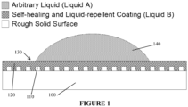
- the invention relates to an article having a surface that is capable of repelling a foreign material, the article comprising:
- the article is capable of repelling a foreign material, or the article is capable of reducing the adhesion of the foreign material to the repellant surface.
- the lubricating liquid is selected to be chemically inert to the foreign material.
- the affinity of the roughened surface for the lubricating liquid is great than the affinity of the roughened surface for the foreign material.
- the foreign material is a fluid or a solid.
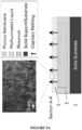
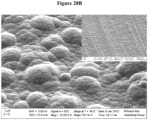
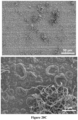
- the roughened surface comprises raised features having at least one dimension of the scale of nanometers to micrometers.
- the substrate comprises a porous material.
- the optical refractive indices of the substrate and the lubricating liquid are substantially similar.
- the substrate comprises a polymer, metal, sapphire, glass, carbon in different form, or ceramic.
- roughened surface comprises fibers, particles, electrochemically deposited polymer a sand blasted surface, or a wet or dry etched surface.
- roughened surface comprises a chemical functionalizing layer
- the chemical functionalizing layer comprises a fluorinated compound such as a perfluorocarbon oil
- the lubricating liquid is a hydrophobic oil.
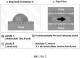
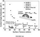
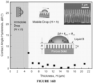
- the article satisfies the following condition ⁇ BX cos ⁇ BX ⁇ ⁇ AX cos ⁇ AX > 0 wherein ⁇ AX is the interfacial energies of the foreign agent with a surrounding medium; wherein ⁇ BX is the interfacial energies of the lubricating liquid with the surrounding medium; wherein ⁇ AX is the equilibrium contact angle of the foreign material on a flat solid surface immersed under the surrounding medium; and wherein ⁇ BX is the equilibrium contact angle of the liquid of the lubricating liquid on a flat solid surface immersed under the surrounding medium.
- the article satisfies the following two conditions when the article is exposed to Medium X, where X is air/gas/water/immiscible fluid: R ⁇ BX cos ⁇ BX ⁇ ⁇ AX cos ⁇ AX ⁇ ⁇ AB > 0 R ⁇ BX cos ⁇ BX ⁇ ⁇ AX cos ⁇ AX + ⁇ AX ⁇ ⁇ BX > 0 wherein ⁇ AX is the interfacial energies of the foreign agent with a surrounding medium; wherein ⁇ BX is the interfacial energies of the lubricating liquid with the surrounding medium; wherein ⁇ AB is the interfacial energies of the foreign material and the lubricating liquid interface; wherein ⁇ AX is the equilibrium contact angle of the foreign material on a flat solid surface immersed under the surrounding medium; wherein ⁇ BX is the equilibrium contact angle of the lubricating liquid on a flat solid surface immersed under the surrounding medium; and R is the rough
- the article maintains its properties when in contact with the foreign material at pressures in excess of 5000 Pa, or the article maintains its properties when in contact with the foreign material at pressures in excess of 10 6 Pa.
- the article is capable of self-cleaning or the article is capable of self-healing.
- the article further comprises a reservoir comprising an amount of lubricating liquid in fluid communication with the lubricating layer.
- the porous material includes a solid substrate that is selected to have one or more of the following properties: electrical conductive, non-conductive, magnetic, non-magnetic, elastic, non-elastic, light-sensitive, non-light-sensitive, temperature-sensitive, or non-temperature sensitive.
- the substrate is a flat substrate, a round substrate, a cylindrical substrate, or a geometrically complex substrate.
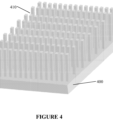
- a flow channel, an optical component, a sign or commercial graphic, a building material, an element of a refrigeration system where preventing or reducing accumulation of ice, frost or condensate is advantageous, like coil, pipe, fin, cartridge of fins or wall, or heat exchanger are provided having a slippery, repellant and/or no-adhesive surface according to any of the preceding embodiments.
- a device having at least one surface exposed to wind or water resistance wherein the device is selected from the group consisting of a wind mill, a container, a solar cell, and avionic device, a marine vessel, roofing material, a fabric, a fingerprint resistant surface, for example contained in a lens, goggle, a touch screen, or a window, and an underwater device are provided having a slippery, repellant and/or no-adhesive surface according to any of the preceding embodiments.
- a fluid transport device having at least a portion of a fluid contacting surface having a slippery, repellant and/or no-adhesive surface according to any of the preceding embodiments.
- a method for producing a slippery surface for repelling a foreign material or reduction adhesion of a foreign material includes providing a roughened surface; and introducing a lubricating liquid to wet and adhere said lubricating liquid to the roughened surface to form an over-coated layer, wherein the roughened surface and the lubricating liquid have an affinity for each other such that the lubricating liquid is substantially immobilized on the substrate to form a repellant surface.
- the substrate comprises a porous material.
- the foreign material is a fluid or a solid.
- said providing and introducing are carried out to satisfy the following condition ⁇ BX cos ⁇ BX ⁇ ⁇ AX cos ⁇ AX > 0 wherein ⁇ AX is the interfacial energies of the foreign agent with a surrounding medium; wherein ⁇ BX is the interfacial energies of the lubricating liquid with the surrounding medium; wherein ⁇ AX is the equilibrium contact angle of the foreign material on a flat solid surface immersed under the surrounding medium; and wherein ⁇ BX is the equilibrium contact angle of the liquid of the lubricating liquid on a flat solid surface immersed under the surrounding medium.
- said providing and introducing are carried out to satisfy the following two conditions when the slippery surface is exposed to Medium X, where X is air/gas/water/immiscible fluid: R ⁇ BX cos ⁇ BX ⁇ ⁇ AX cos ⁇ AX ⁇ ⁇ AB > 0 R ⁇ BX cos ⁇ BX ⁇ ⁇ AX cos ⁇ AX + ⁇ AX ⁇ ⁇ BX > 0 wherein ⁇ AX is the interfacial energies of the foreign agent with a surrounding medium; wherein ⁇ BX is the interfacial energies of the lubricating liquid with the surrounding medium; wherein ⁇ AB is the interfacial energies of the foreign material and the lubricating liquid interface; wherein ⁇ AX is the equilibrium contact angle of the foreign material on a flat solid surface immersed under the surrounding medium; wherein ⁇ BX is the equilibrium contact angle of the lubricating liquid on a flat solid surface immersed under the surrounding medium; and R
- the slippery surface is formed over a flat substrate, a round substrate, a cylindrical substrate, or a geometrically complex substrate.
- the roughened surface is provided on a surface of a flow channel, on a surface of an optical component, on a surface of a sign or a commercial graphic, on a surface of a building material, on a surface of a cooling element, on a surface of a heat exchanger, on a surface of a wind mill, on a surface of a turbine, on a surface of a solar cell on a surface of an avionic device, d on a surface of a marine vessel, or on a surface of an underwater device, on a surface of a fabric.
- the fluid is a non-polar fluid, polar fluid, or combinations thereof, or water, oil, or other complex fluids.
- the article is a building, a billboard, a sign, a fabric, a sink, or a toilet bowl.
- the lubricating liquid is a pure liquid, solution, or a complex fluids consist of a liquid phase and a solid phase.
- the present disclosure describes slippery surfaces referred to herein as S lippery L iquid- I nfused P orous S urfaces (SLIPS).
- SLIPS slippery surfaces
- the slippery surfaces of the present disclosure exhibit anti-adhesive and anti-fouling properties.
- the slippery surfaces of the present disclosure are able to prevent adhesion of a wide range of materials.
- Exemplary materials that do not stick onto the surface include liquids, solids, and gases (or vapors).
- liquids such as water, oil-based paints, hydrocarbons and their mixtures, organic solvents, complex fluids such as crude oil, protein-containing fluids and the like can be repelled.
- the liquids can be both pure liquids and complex fluids.
- SLIPS can be designed to be omniphobic, where SLIPS exhibits both hydrophobic and oleophobic properties.
- solids like bacteria, insects, fungi and the like can be repelled.
- solids like ice, paper, sticky notes, or inorganic particle-containing paints, dust particles can be repelled or cleaned.
- Object A Such materials that can be prevented from sticking to the slippery surfaces disclosed herein are referred to herein as “Object A.”
- Object A that is in liquid form is referred to as “Object A in liquid form,” or “liquefied Object A,” or “Liquid A.”
- Object A that is in solid form is referred to as “Object A in solidified form,” or “solidified Object A” or “Solid A.”
- Object A can contain a mixture of both solids and fluids.
- Object A can include polar and non-polar Liquids A and their solidified forms, such as hydrocarbons and their mixtures (e.g., from pentane up to hexadecane and mineral oil, paraffinic extra light crude oil; paraffinic light crude oil; paraffinic light-medium crude oil; paraffinic-naphthenic medium crude oil; naphthenic medium-heavy crude oil; aromatic-intermediate medium-heavy crude oil; aromatic-naphthenic heavy crude oil, aromatic-asphaltic crude oil, etc.), ketones (e.g., acetone, etc.), alcohols (e.g., methanol, ethanol, isopropanol, dipropylene glycol, ethylene glycol, and glycerol, etc.), water (with a broad range of salinity, e.g., sodium chloride from 0 to 6.1 M; potassium chloride from
- Object A can include biological objects, such as insects, small animals, protozoa, bacteria, viruses, fungi, bodily fluids and tissues, proteins and the like.
- Object A can include solid particles suspended in liquid.
- Object A can include non-biological objects, such as dust, colloidal suspensions, spray paints, food items, common household materials, and the like.
- Object A can include adhesives and adhesive films. The list is intended to be exemplary and the slippery surfaces of the present disclosure are envisioned to successfully repel numerous other types of materials.
- the slippery surface of the present disclosure has a coefficient of friction that is lower than that of polytetrafluoroethylene (PTFE or TEFLON) surface.
- the coefficient of friction may be less than 0.1, less than 0.05, or even less than 0.04.
- the coefficient of friction can be measured by sliding two different surfaces against each other. The value of the coefficient will depend on the load applied onto the surfaces, the sliding velocity, and the materials of the surfaces.
- a reference surface such as a polished steel, could be used to slide against the target surfaces, such as Teflon, or the SLIPS of the present disclosure could be used to slide against itself (e.g., SLIPS/SLIPS) to obtain the coefficients of friction (both static and dynamic).
- FIG. 1 A schematic of the overall design of S lippery L iquid- I nfused P orous S urfaces (SLIPS) is illustrated in FIG. 1 .
- the article includes a solid surface 100 having surface features 110 that provide a certain roughness (i.e., roughened surface) with Liquid B 120 applied thereon.
- Liquid B wets the roughened surface, filling the hills, valleys, and/or pores of the roughened surface, and forming an ultra-smooth surface 130 over the roughened surface. Due to the ultra-smooth surface resulting from wetting the roughened surface with Liquid B, Object A 140 does not adhere to the surface.
- a SLIPS includes at least the following three factors: 1) the lubricating liquid (Liquid B) can infuse into, wet, and stably adhere within the roughened surface, 2) the roughened surface can be preferentially wetted by the lubricating liquid (Liquid B) rather than by the liquid to be repelled (Object A), and 3) the lubricating fluid (Liquid B) and the object or liquid to be repelled (Object A) are immiscible and do not chemically interact with each other.
- the roughened surface can be preferentially wetted by the lubricating fluid (Liquid B) rather than by the immiscible liquid/complex fluids/undesirable solids one wants to repel (Object A). This can ensure that Object A remains on top of a stable lubricating film of Liquid B.
- the enthalpy of mixing between Object A and Liquid B should be sufficiently high (e.g., water/oil; insect/oil; ice/oil, etc.) that they phase separate from each other when mixed together, and/or do not undergo substantial chemical reactions between each other.
- Object A and Liquid B are substantially chemically inert with each other so that they physically remain distinct phases/materials without substantial mixing between the two.
- SLIPS may be incorporated in an environment (1) where Liquid B is exposed substantially only to Object A (e.g., flow pipe, etc.) (see FIG. 2B ) or (2 ) where Liquid B is exposed to both Object A and another fluid environment, such as medium X (e.g., atmosphere, water, etc.) (see FIG. 2A ).
- FIG. 2 shows Object A in the liquid form as Liquid A.
- the working combinations of the substrate surface/lubricant/immiscible test fluid may be chosen by satisfying the condition shown in Equation (e1).
- ⁇ E 0 ⁇ BX cos ⁇ BX ⁇ ⁇ AX cos ⁇ AX > 0
- ⁇ AX , and ⁇ BX represent the interfacial energies of the Object A-medium X interface, and Liquid B-medium X interface, respectively.
- ⁇ AX , and ⁇ BX are the equilibrium contact angles of Object A and Liquid B on a flat solid surface immersed under medium X environment, respectively.
- the density difference between the Object A and Medium X can also play a role for the object repellency.
- the density of Object A, p A may desirably be greater than that of the Medium X, ⁇ X (i.e., ⁇ A > ⁇ X ).
- the size of Object A may be on the order of, or greater than, its capillary length.
- capillary length is a characteristic length scale that quantifies the dominance of gravity over surface force on an object, which can be quantitatively expressed as ( ⁇ / ⁇ g 1/2 ), where ⁇ , ⁇ , and g are surface tension, density of the liquid, and gravity, respectively.
- An equilibrium contact angle is the angle at which a liquid/vapor interface meets a solid surface, which is determined by the interactions across the three interfaces, e.g., solid/liquid/vapor.
- ⁇ is the angle at which a liquid/vapor interface meets a solid surface, which is determined by the interactions across the three interfaces, e.g., solid/liquid/vapor.
- ⁇ A apparent advancing contact angle
- ⁇ R apparent receding contact angle
- contact angle measurement can be performed by a number of different well-established techniques, such as the sessile drop method and the Wilhelmy method.
- the sessile drop method is among the most popular technique for contact angle measurement.
- a liquid droplet is deposited on a targeted solid surface, where the liquid profile is captured by an optical system of a goniometer and geometrically fitted to obtain the contact angle.
- the contact angle measured from a static liquid droplet deposited on the surface is known as the static contact angle, ⁇ static .
- advancing contact angle, ⁇ A can be measured while the volume of the drop is increasing until the wetting line starts to advance.
- Fluid-fluid interfacial tension can be measured by many well-established techniques, such as the Wilhelmy plate method, the Du Noüy ring method, and the pendant drop method (e.g., see Drelich et al., in Encyclopedia of Surface and Colloid Science,, pp. 3152 - 3166, Marcel Dekker Inc, 2002 ).
- the pendant drop method is among the most popular and versatile technique, which can be easily extended to a two-liquid system.
- the pendant drop method measures the shape of a fluid-fluid interface and quantifies the shape distortion due to the competition between the fluid-fluid interfacial tension and gravity.
- a drop of denser fluid e.g., Object A
- immiscible medium X i.e., air/water/Liquid B
- the denser liquid droplet will be deformed as the liquid volume increases.
- the shape profile of the liquid droplet is captured by an optical system and subsequently analyzed by a computer software when the liquid volume is increased to the maximum possible size (i.e., before the liquid drop is detached from the syringe needle).
- ⁇ ⁇ gD 2 / H
- ⁇ the density difference between the two immiscible fluids
- g gravity
- D equatorial diameter of the liquid droplet
- H a drop shape dependent parameter which is a function of the shape profile of the droplet.
- Roughness of a surface can be quantitatively estimated by a number of indirect and direct approaches.
- one of the simplest indirect methods to quantify surface roughness is the use of Wenzel's relationship to estimate the roughness by measuring the apparent contact angle of a surface.
- the roughness of a 3-D porous material can be estimated by measuring the surface morphology of the top-most layer of the porous material. Particularly, the estimation may be particularly well-suited when complete wetting of a surface is predominately induced by the roughness at the surface layer of the material that is in intimate contact with the fluid.
- the roughened surface has a roughness factor, R , greater than 1, where the roughness factor is defined as the ratio between the real surface area and the projected surface area.
- R roughness factor
- the roughness factor of the roughened surface is greater or equal to that defined by the Wenzel relationship (i.e., R ⁇ 1/cos ⁇ , where ⁇ is the contact angle of Liquid B on a flat solid surface). For example, if Liquid B has a contact angle of 50° on a flat surface of a specific material, it is desirable for the corresponding roughened surface to have a roughness factor greater than ⁇ 1.5.
- roughened surface can be made from materials that are functional properties such as conductive/non-conductive, and magnetic/non-magnetic, elastic/non-elastic, light-sensitive/non-light-sensitive materials.
- materials that are functional properties such as conductive/non-conductive, and magnetic/non-magnetic, elastic/non-elastic, light-sensitive/non-light-sensitive materials.
- a broad range of functional materials can make SLIPS.
- the raised structures can be raised posts of a variety of cross-sections, including, but not limited to, circles, ellipses, or polygons (such as triangles, squares, pentagons, hexagons, octagons, and the like), forming cylindrical, pyramidal, conical or prismatic columns.
- Their surface can be smooth or corrugated in a regular or irregular way, e.g., as in the scalloping that is found in a Bosch process.
- the exemplary substrates described above illustrate raised posts having uniform shape and size, the shape, orientation and/or size of raised posts on a given substrate can vary.
- the raised structures can be produced by any known method for fabricating raised structures onto substrates.
- Non-limiting examples include conventional photolithography, projection lithography, e-beam writing or lithography, focused-ion beam lithography, depositing nanowire arrays, growing nanostructures on the surface of a substrate, soft lithography, replica molding, solution deposition, solution polymerization, electropolymerization, electroplating, electroless deposition, vapor deposition, contact printing, etching, transfer patterning, microimprinting, self-assembly, and the like.
- a silicon substrate having a post array can be fabricated by photolithography using the Bosch reactive ion etching method (as described in Plasma Etching: Fundamentals and Applications, M. Sugawara, et. al, Oxford University Press, (1998), ISBN-10: 019856287X ). Further exemplary methods are described in WO2009158631 .
- Patterned surfaces can also be obtained as replicas (e.g., epoxy replicas) by a soft lithographic method (see, e.g., J. Aizenberg and B. Pokroy, WO2009158631 ). Polymer films with patterned surfaces can be fabricated by means known in the art (e.g., roll-to-roll imprinting or embossing).
- the roughened surface can be made, for example, by replica molding procedure described in B. Pokroy, A. K. Epstein, M. C. M. Persson-Gulda, J. Aizenberg, Adv. Mater. 21, 463 (2009 ).
- Negative replicas of pre-generated patterns can be made from polydimethylsiloxane, PDMS (e.g., Dow-Sylgard 184) by pouring mixture of prepolymer and curing agent (e.g., 10: 1 ratio) on the patterns followed by thermal curing in an oven. After cooling, the negative PDMS mold can be peeled off and used for fabricating the final replica by pouring the desired material (e.g. UV-curable epoxy resin) into the negative mold.
- PDMS polydimethylsiloxane
- curing agent e.g. 10: 1 ratio
- the negative mold After solidifying the material, the negative mold can be peeled off, leaving the replica of the original pattern. Then, the surface of the replica can be chemically functionalized with low surface energy coating such as (tridecafluoro-1,1,2,2-tetrahydrooctyl)-trichlorosilane or other reagents having appropriate reactive end groups and straight or branched hydrocarbon or fluorocarbon chains or their combinations.
- low surface energy coating such as (tridecafluoro-1,1,2,2-tetrahydrooctyl)-trichlorosilane or other reagents having appropriate reactive end groups and straight or branched hydrocarbon or fluorocarbon chains or their combinations.
- the roughened surface may be the porous surface layer of a substrate with arbitrary shapes and thickness.
- the porous surface can be any suitable porous network having a sufficient thickness to stabilize Liquid B, such as a thickness from above 100 nm,or the effective range of intermolecular force felt by the liquid from the solid material. Below 100 nm thick, the liquid may start to lose its liquid property.
- the substrates can be considerably thicker, however, such as metal sheets and pipes.
- the porous surface can have any suitable pore sizes to stabilize the Liquid B, such as from about 10 nm to about 2 mm. Such a roughened surface can also be generated by creating surface patterns on a solid support of indefinite thickness.
- the pore size of the porous material can roughly be on the order of the capillary length of Liquid B or smaller. Such size may allow stabilizing Liquid B in the porous material.
- the surface tension of fluorinated liquids is in the range of about 10 - 20 mN/m at a typical density of about 1800 kg/m 3 or above.
- Typical pore sizes can range from about 50 nm to about 100 ⁇ m or up to about 1 mm, such as about 750 ⁇ m - 1 mm.
- the roughened surface can have feature sizes that are nanoscopic in size, such as less than 1 ⁇ m or less than 100 nm. Such feature sizes may be particularly useful in repelling insects that utilize hooks that have sizes on the range of about 5 - 10 ⁇ m to assist in climbing on the SLIPS.
- the presence of the Liquid B may also effectively prevent the attachment of insects or animals that utilize micro/nanostructures to adhere to the surfaces through intermolecular forces (e.g., beetle, fly, spider, and gecko etc.).
- the roughened surface can have pores that are comparable or smaller than the Object A to be repelled.
- pore sizes that are smaller than sizes of insects' hooks may further aid in inhibiting insects from climbing on the SLIPS.
- Exemplary porous materials include solid substrates having holes (e.g., high aspect ratio holes, cylinders, columns, etc.), three-dimensionally interconnected network of holes and one or more materials (e.g., 3-D ordered colloidal assemblies, block copolymers, etc.), random array of fibrous materials (e.g., filter paper, fabrics, electrospun films, etc.), and the like.
- holes e.g., high aspect ratio holes, cylinders, columns, etc.
- materials e.g., 3-D ordered colloidal assemblies, block copolymers, etc.
- random array of fibrous materials e.g., filter paper, fabrics, electrospun films, etc.
- porous materials are commercially available, or can be made by a number of well-established manufacturing techniques.
- PTFE filter materials having a randomly arranged three-dimensionally interconnected network of holes and PTFE fibrils are commercially available.
- FIGS. 5A to 5D illustrate three non-limiting exemplary embodiments of suitable porous materials.
- porous alumina can be manufactured by the process of anodization, where an aluminum substrate is electrochemically oxidized under constant electrical potential.
- the pore size, inter-pore spacing, and the aspect ratio of the pores can be tuned by adjusting the operating parameters of the electrochemical oxidation process.
- Such a process generates porous through-holes into the substrate, where the size of the porous holes are on the order of 50 nm with aspect ratio larger than 10000 (See, Lee et al., Nature Mater. 5, 741-47, 2006 .).
- mechanical or (electro)chemical methods can be used to roughen metal surfaces.
- Roughening and non-wetting materials can be spray coated directly onto metal surfaces.
- Boehmite ( ⁇ -AlO(OH)) formation on aluminum surface by boiling in water can also be used to roughen metallic surfaces such as aluminum.
- Rotary jet spinning of hydrophobic polymer nanofibers and layered deposition of an appropriate primer can also be used to roughen substrates for use in SLIPS.
- long range ordered porous structures of silica can be produced by evaporative co-assembly method of sacrificial polymeric colloidal particles together with a hydrolyzed silicate sol-gel precursor solution.
- Such a method may be able to generate a crack-free porous surface on the order of centimeters or larger, with pore sizes of about 100 nm to about 1000 nm and porosity of about 75%.
- one of the methods can include mixing PTFE powders with lubricants (e.g., naphtha) to form a paste. Then, the paste can be molded into the desired shape by methods such an extrusion molding. The molded PTFE membrane can then be heated up to less than its melting point to drive off the lubricants. Thereafter, a porous PTFE membrane can be formed. ( See , U.S. Patent No. 5,476,589 ).
- the polymeric replica of raised structures can be self-assembled and collapsed into a random network of porous structures (e.g., similar to a mesh of "spaghetti" structures) through an evaporation-induced assembly process initiated by a drying solvent, e.g., ethanol (see FIG. 5D ).
- a drying solvent e.g., ethanol
- the porous roughened surface may be commercially available materials, such as a filter material.
- the porous roughened surface may be formed as part of a pre-existing process for forming a desired device or part of a device.
- the roughened surface to have high chemical affinity to Liquid B, high surface roughness, or both.
- Liquid B its chemical affinity towards the roughened surface can be measured by a contact angle, ⁇ . The lower is the contact angle; the stronger is the chemical affinity of Liquid B towards the roughened surface.
- the roughened, porous material can be generated by a spraying method, where emulsions consisting of micro/nanoparticles are sprayed onto a solid surface (either flat/roughened). These particles assemble into roughened solid layer upon solvent drying.
- a spraying method is described in Poetes et al., Phys Rev. Lett. 105, 166104 (2010 ). Such a solid layer can then be infiltrated by Liquid B (which can also be applied by additional spraying).
- the porous surface can be prepared by using an electrodeposition process.
- the electrodeposition condition can be controlled so that nanofibers of electrically conductive polymer can be formed over an electrically conductive surface.
- the electrodeposition conditions can further be controlled to provide a desired nanofiber diameter and spacing.
- the electrodeposition condition can be controlled to provide any other desirable morphology that can provide additional means to stabilize Liquid B.
- the morphology of the conducting organic polymers can be controlled by varying the deposition conditions such as the concentration of monomer, the types of electrolytes and buffers, the deposition temperature and time, and the electrochemical conditions such as applied potential.
- the deposition conditions such as the concentration of monomer, the types of electrolytes and buffers, the deposition temperature and time, and the electrochemical conditions such as applied potential.
- increasing the concentration of monomer in the electrochemical solution, the applied potential, and/or the temperature generally leads to a faster polymerization rate and many parasitic nucleation sites during growth resulting in a morphology that is similar to a cauliflower (see FIG. 6A ).
- lower concentrations of monomer, lower applied potential, and lower temperatures can lead to nanofibril growth with substantially uniform diameters (see FIG. 6B ). Further decrease in concentration of monomer or applied potential can lead to short rods of polymer nanofibers with low surface coverage (see FIG.
- the applied voltage can be cycled leading to different oxidation states of the deposited polymer layer which is often manifested as a color change (e.g., from dark blue to a green then to a pale yellow color with increasing applied voltage).
- the applied voltage can be pulsed at a constant voltage to form polymers only on the tip of the underlying micropost structures, leading to a mushroom-like morphology (see FIG. 6E ).
- the fibrous surface can be made on an array of raised features, to form a hierarchical roughness (see FIG. 6F ).
- the morphology of conducting organic polymers can be finely controlled from nanometers to over micrometer scales, and surface coatings with precisely controlled morphology can be produced by simple modifications, which promise the customization of various surface properties by design and control of the morphology.
- Many solid surfaces can be made roughened by the process of abrasive blasting. During this process, a stream of abrasive particles propelled by high pressure gas/liquid are hitting onto the targeted solid surfaces, thereby removing the surface materials from the solids through physical bombardment.
- Some examples of abrasive blasting are bead blasting, sand blasting, wet abrasive blasting, and hydro-blasting.
- the solid surfaces that are treated by abrasive blasting can then be post-treated with other methods, such as spray coating (described in U.S. Patent Application No. 61/466,352 , p. 12, [0079]), to enhance their chemical affinity towards a specific lubricant.
- an aluminum substrate was roughened by the process of bead blasting, which was followed by spray-coating a primer (DuPont 459-804) and a Teflon suspension (DuPont 852-200).
- This process creates a highly roughened surface with fluorinated surface chemistry (i.e., Teflon), which would display strong chemical affinity to lubricants such as perfluorinated fluids (e.g., 3M TM Fluorinert TM or Dupont TM Krytox ® oils).
- Dry etching techniques make use of reactive plasma/gaseous species to remove targeted solid materials. Both directional (anisotropic) and non-directional (isotropic) etching can be achieved depending on the operating conditions (e.g., pressure, gas flow, power etc.). For example, isotropic etching of materials is usually carried out under low vacuum environment, as compared to the anisotropic etching in which high vacuum environment is required. Different reactive gaseous species are available to etch a variety of materials, such as silicon, glass, silicon nitride, aluminum, tungsten, and polymers etc. (See, e.g., K.R. Williams et al., J. MEMS, 12, pp. 761 - 778 (2003 )).
- High-aspect-ratio structures i.e., height/width >> 1) with well-defined side-wall profiles (e.g., vertical/slanted side-wall) can be generated by the anisotropic etching methods; whereas isotropic etching techniques can be utilized to generate low-aspect-ratio structures (i.e., height/width ⁇ ⁇ 1) with undercutting or rounded side-wall profiles.
- anisotropic etching methods such as the Bosch process, have been described in the U.S. Provisional Patent Application: 61/466,352 .
- isotropic etching Tuteja et al.
- Metal foams are porous metallic substrates. These porous substrates can be formed typically by the solidification process of a mixture of pre-melted metals with injected gas/gas-releasing blowing agents, or by compressing metal powders into special tooling to form different shapes and forms (e.g., sheet, cylindrical shape, hollow cylinders etc.). Metal foams can be manufactured either in closed-cell or open-cell structures (i.e., interconnected network of metals). Metal foams of different materials, such as aluminum, titanium, nickel, zinc, copper, steel, iron, or other metals and alloys, have been produced by various methods, such as direct foaming and powder compact melting methods, which have been extensively discussed in J. Banhart, Prog. Mater. Sci 46, 559 - 632 (2001 ). These foams have found extensive applications in automotive/aerospace industries, ship building, railway industry, as well as biomedical industry.
- Porous surfaces can be manufactured through the process of electro-spinning or rotary jet spinning.
- electro-spinning uses electric charge to draw micro/nanoscale fibers from a liquid, such as polymer solution. These fibers can be directly drawn onto a targeted solid substrate to form polymeric porous surfaces with controlled fiber density.
- Many polymeric materials can be used during this process such as nylon, polyurethanes, polycarbonate, polyacrylonitrile, polyvinyl alcohol, polymethacrylate, polyaniline, polystyrene, polyamide, collagen, polypropylene, polyethylene napthalate, etc.
- rotary jet spinning highspeed rotating polymer solution jets are extruded to form aligned fibers.
- Fiber morphology, diameter, and web porosity can be controlled by varying nozzle geometry, rotation speed, and polymer solution properties, which have been extensively discussed in Badrossamay et al., Nano Lett. 2010, 10 (6), pp 2257-2261 .
- FIG. 45 provides a schematic illustration summarizing the previous discussion of the various manufacturing methods that can be employed to prepare the roughened porous substrate.
- the roughened porous surface can be generated by a spraying method, where emulsions consisting of micro/nanoparticles are sprayed onto a flat solid surface. These particles assemble into roughened solid layer upon solvent drying. Such a solid layer can then be infiltrated by lubricating fluid (which can also be applied by additional spraying).
- Non-limiting examples of micro/ nanoparticles that can be sprayed onto a flat solid surface to form roughened, porous material include titanium dioxide, silicon dioxide, nanodiamonds, metals such as silver, gold, platinum, copper, gold, palladium, zinc, and titanium, hydroxyapatite (HAp) nanoparticles.
- the roughened, porous substrate is generated using an etchant method.
- the substrate is roughened by etching.
- the etchant is carried by a preformed pipe and deposited onto the substrate to create a roughened surface. Once the surface is roughened, it is functionalized with a liquid (not shown) or vapor silane, and infiltrated with a lubricating liquid.
- the roughened, porous substrate is made by growing a nanostructured material on the surface.
- a nanostructured material is grown on the surface of the substrate to create a roughened surface that is functionalized with a liquid (not shown) or vapor silane and infused with a lubricating liquid.
- these nanostructures include PPy nanofibers, carbon nanotubes.
- the surface can be chemically functionalized by silanization and infiltrated with a lubricating liquid.
- the porous material can be a self-supporting, free-standing membrane which can be attached/glued/adhered to the external or internal surfaces of materials with any kind of geometry (see FIG. 7A ).
- the roughened surface can be formed over or applied to a variety of planar or non-planar surface (see FIGS. 7A and 7B ).
- FIG. 7B shows a SLIPS 700 attached to the outer surface of a cylindrical solid core 710 with a reservoir 720 for Liquid B.
- SLIPS can also be attached to the inner surfaces of the tubes, pipes, and other irregularly shaped substrates.
- FIG. 7C SLIPS 700 can be applied to the inner surface of a cylindrical tube 710 for low drag flow of Liquid A 730.
- FIG. 7C shows SLIPS 700 attached to the inner
- SLIPS can be applied onto both the inner and outer surfaces of a tube/needle with the same/different kind of lubricants (denoted as Liquid B and B' in FIG. 7D ) for low drag flow of Liquid A and remain slippery/non-sticking to the outside environments where the tube/needle is exposed to.
- SLIPS can be applied onto a Liquid-B-soaked porous tubing for low drag flow of Liquid A and remain slippery/non-sticking to the outside environments where the porous tube/needle is exposed to.
- Tubular structures having any arbitrary cross-section, either constant or variable, can also be used in the same context described in the above examples.
- the porous surface can be manufactured over any suitable materials and geometries, such as refrigerator coils, large metal sheets, shingles, siding sheets, spheres, ball-bearing, medical devices, outdoor and road signs, inside of pipes (e.g., metallic or metalized water or oil pipes; plastic pipes), inside and outside of needles, inside and outside of bottles or containers, windows, lens, screens (e.g., on mobile devices, fingerprint reader, computer monitor, or automatic teller machine), tubings, hollow metallic structures, patterned electrodes, meshes, wires, porous conductive surfaces, fabrics, clothes, shoes, and the like.
- suitable materials and geometries such as refrigerator coils, large metal sheets, shingles, siding sheets, spheres, ball-bearing, medical devices, outdoor and road signs, inside of pipes (e.g., metallic or metalized water or oil pipes; plastic pipes), inside and outside of needles, inside and outside of bottles or containers, windows, lens, screens (e.g., on mobile devices, fingerprint reader, computer monitor, or automatic teller
- SLIPS may provide high pressure stabilities without losing any of the beneficial properties of SLIPS described herein. In certain embodiments, SLIPS may provide high resistance to changes in pressure without losing any of the beneficial properties of SLIPS described herein.
- use of a porous material for the roughened surface may provide extremely high pressure stabilities.
- a porous material e.g., Teflon membrane
- use of a porous material may be able to tolerate absolute pressure up to about 6.8 ⁇ 10 7 Pa while maintaining its slippery characteristics.
- the improved pressure tolerance of the 3D porous material can be attributed to the incompressibility of the lubricating layer, as well as the resistance of liquid impalement into the porous structure.
- FIG. 8 shows the applied pressure (left axis) and the sliding angle at which Object A (Test liquids are octane, decane, tridecane, and hexadecane) slides off the SLIPS (right axis) as a function of the surface tension.
- SLIPS retains its slippery function under pressures of more than 1 ⁇ 10 3 or 1 ⁇ 10 4 when in contact with with a test fluid (as shown in FIG. 8 ), or reaching, 1 ⁇ 10 5 , 1 ⁇ 10 6 , 1 ⁇ 10 7 , or even 6.8 ⁇ 10 7 Pa under pressurized environment.
- these pressure stabilities can be achieved when the applied pressure is lower than the solidification pressure of Liquid B (e.g. order of GPa for perfluorotri-n-pentylamine).
- Liquid B may be selected to have characteristics of high pressure stability by selecting fluids that have solidification pressure that is higher than the anticipated applied pressure during application.
- the roughened surface can be selected so that the underlying roughened surface structures do not impose sharp points where stresses are concentrated around those sharp features.
- the presence of sharp points may introduce stress concentration points so that as Object A impinges on the SLIPS at high pressures, Liquid B is locally displaced also due to the sharp points, Object A then encounters the sharp points, breaks apart, and wets the underlying roughened surface before Liquid B has a chance to heal itself.
- use of a porous material for the roughened surface may provide extremely high resistance to pressure changes that may occur.
- a porous material e.g., Teflon membrane, FIG. 5C
- the improved resistance to pressure changes can be attributed to the enhanced capillary interactions between the intricate, large surface area 3D porous network and Liquid B.
- Liquid B and the roughened surface can be selected so that they can sustain rapid pressure changes.
- the slippery surface of the present disclosure may be able to withstand a pressure change of more than 1 ⁇ 10 5 , 5 ⁇ 10 5 , 1 ⁇ 10 6 , 5 ⁇ 10 6 , or even more than 6 ⁇ 10 6 Pa per second
- porous materials may be the presence of the capillary network within the bulk materials, which can further enhance transport of Liquid B through the pores.
- the porous structure can provide a replenishing fluid at the surface and may be useful to address evaporation or other materials loss of Liquid B from the SLIPS surface. For example, in the case where a portion of Liquid B is reduced at the surface of the materials due to evaporation, sudden pressure purging, physical damage or the like, Liquid B can be replenished by the capillary action in these networks. Replenishing Liquid B is drawn through the porous body of the substrate by capillary wicking to refresh the upper surface of SLIPS.
- the porous material itself can be utilized as a fluid reservoir to store Liquid B for subsequent capillary refilling purpose.
- the porous material 905 can be connected to an external fluid reservoir 903 sitting on a solid substrate 901, where the capillary networks within the porous material 905 can help transfer (e.g., via wicking) the Liquid B from the fluid reservoir 903 to the porous material 905.
- FIG. 9B shows an alternate embodiment where SLIPS having a porous material 905 as the roughened surface is formed in an inner surface of a cylindrical tube.
- the cylindrical tube 901 has a first annular region 903 serving as a fluid reservoir for Liquid B, followed by an inner annular region of SLIPS having a porous material 905, which surrounds a hollow region 907 for the flow of Liquid A.
- Liquid B in annular region 903 transfers into (e.g., via wicking) the porous material 905 to form a SLIPS and Liquid A can flow through the hollow region with little to no drag at the interface between 905 and 907.
- FIG. 9C shows yet another embodiment where SLIPS is formed in an inner surface of an arbitrarily shaped flow path.
- the bottom substrate 901 has a channel 903 serving as a fluid replenishment source for Liquid B that is coupled to the porous material 905 of SLIPS.
- Porous material 905 is formed by combining a bottom substrate 901 having a depressed region joined with a top substrate 909 having a substantially flat porous material 911 formed thereon. The combination of the top and bottom substrate portions form a hollow region 907 for the flow of Liquid A.
- FIG. 9D shows some optical photographs on how the bottom substrate 901 and SLIPS 905 of FIG. 9C can be formed.
- a TEFLON filter paper 930 having a three-dimensionally random network of pores can be placed between a male mold 940 and female mold 950 defining an arbitrary flow path and the male mold 940 and female mold 950 can be pressed together to replicate the flow path pattern on the TEFLON filter paper 930.
- the templated TEFLON filter paper 930 can be placed inside the female mold 950, which now serves as bottom substrate 901 of FIG. 9C , and a substantially flat substrate 909 having another substantially flat TEFLON filter paper, serving as SLIPS 911, can be applied thereon (not shown) to form the flow path 907 shown in FIG. 9C .
- the female mold 950 may further contain channel 903 (not shown) that serves to replenish Liquid B as needed.
- FIG. 10 shows several other non-limiting embodiments of SLIPS and how Liquid B can be replenished to the SLIPS in each of those embodiments.
- the left column corresponds to systems where SLIPS is exposed to both Medium X and Liquid A (shown as a droplet).
- the right column corresponds to systems where SLIPS is exposed to substantially only Liquid A (shown as a plug between two SLIPS).
- Liquid B can be replenished to SLIPS as needed.
- the top row shows scenarios where there is a finite amount of Liquid B.
- the middle row shows scenarios where there is a large source (e.g., practically infinite source from the viewpoint of the amount of Liquid B needed to replenish the SLIPS) of Liquid B.
- the bottom row shows scenarios where Liquid B can be replenished by spraying Liquid B as needed, either manually or automatically. As shown, many different configurations and their derivatives are possible.
- the solid surface may be substantially flat. This situation may be applicable when the critical surface energy of the flat surface is higher than the surface tension of the functional Liquid B. For instance, a substantially flat surface may be able to adhere a thin layer of Liquid B due to surface forces.
- Object A may slide off from SLIPS by gravity when the surface is tilted at an angle with respect to the horizontal, given that the size of Object A, either in liquid form or in solidified form, is larger than a characteristic size.
- the effect of gravity on Object A may be more dominant when its size is much larger than the capillary length of Liquid A.
- capillary length is a characteristic length scale that quantifies the dominance of body force over surface force on an object, which can be quantitatively expressed as ( ⁇ / ⁇ g) 1 / 2 , where ⁇ , ⁇ , and g are surface tension and density of the liquid, and gravity, respectively.
- size of Solid A or of Liquid A may be at least 3 times larger than the capillary length of Liquid A.
- Object A can include polar and non-polar Liquids A and their solidified forms, such as hydrocarbons and their mixtures (e.g., from pentane up to hexadecane and mineral oil, paraffinic extra light crude oil; paraffinic light crude oil; paraffinic light-medium crude oil; paraffinic-naphthenic medium crude oil; naphthenic medium-heavy crude oil; aromatic-intermediate medium-heavy crude oil; aromatic-naphthenic heavy crude oil, aromatic-asphaltic crude oil, etc.), ketones (e.g., acetone, etc.), alcohols (e.g., methanol, ethanol, isopropanol, dipropylene glycol, ethylene glycol, and glycerol, etc.), water (with a broad range of salinity, e.g., sodium chloride from 0 to 6.1 M
- Object A can include biological objects, such as insects, blood, small animals, protozoa, bacteria (or bacterial biofilm), viruses, fungi, bodily fluids and tissues, proteins and the like.
- Object A can include solid particles (e.g., dust, smog, dirt, etc.) suspended in liquid (e.g., rain, water, dew, etc.).
- Object A can include non-biological objects, such as dust, colloidal suspensions, spray paints, fingerprints, food items, common household items, and the like.
- Object A can include adhesives and adhesive films. The list is intended to be exemplary and the slippery surfaces of the present disclosure are envisioned to successfully repel numerous other types of materials.
- more than one different Object A can be repelled.
- the combination of two or more Object A may together be more readily repelled as compared to just one Object A.
- Liquid B (alternatively referred to as the "lubricant" through the specification) can be selected from a number of different materials, and is chemically inert with respect to the solid surface and Object A. Liquid B flows readily into the surface recesses of the roughened surface and generally possesses the ability to form an ultra-smooth surface when provided over the roughened surface. In certain embodiments, Liquid B possesses the ability to form a substantially molecularly flat surface when provided over a roughened surface.
- the liquid can be either a pure liquid, a mixture of liquids (solution), or a complex fluid (i.e., a liquid + solid components). For instance, FIG. 11 shows a replication process to reproduce the morphology of the SLIPS surface.
- a porous solid was infiltrated with Liquid B (e.g., perfluorinated fluid). Then polydimethylsiloxane (PDMS) was cured over the Liquid B layer to obtain a negative replica of the SLIPS surface. Then, epoxy resin (e.g., UVO 114) was used to obtain a positive replica using the PDMS negative replica. Then metrology analysis was carried out with an atomic force microscope. As shown, the average roughness of the positive replica surface was less than 1 nm, where the roughness represents an upper bound for the actual roughness of Liquid B as this reaches the physical roughness limits for flat PDMS and UVO 114 epoxy resin (see Xu et al., J. Am. Chem.
- Liquid B overcoats the surface topographies of the porous solid, forming a nearly molecularly smooth surface.
- Liquid B possesses the ability to form a substantially molecularly or even atomically flat surface when provided over a roughened surface.
- Liquid B can be selected from a number of different liquids.
- perfluorinated hydrocarbons or organosilicone compound e.g. silicone elastomer
- organosilicone compound e.g. silicone elastomer
- the tertiary perfluoroalkylamines such as perfluorotri-n-pentylamine, FC-70 by 3M, perfluorotri-n-butylamine FC-40, etc
- perfluoroalkylphosphines and perfluoroalkylphosphineoxides as well as their mixtures can be used for these applications, as well as their mixtures with perfluorocarbons and any and all
- long-chain perfluorinated carboxylic acids e.g., perfluorooctadecanoic acid and other homologues
- fluorinated phosphonic and sulfonic acids fluorinated silanes, and combinations thereof
- fluorinated silanes and combinations thereof
- the perfluoroalkyl group in these compounds could be linear or branched and some or all linear and branched groups can be only partially fluorinated.
- Liquid B has a high density.
- Liquid B has a density that is more than 1.0 g/cm 3 , 1.6 g/cm 3 , or even 1.9 g/cm 3 .
- the density of Liquid B is greater than that of Object A to enhance liquid repellency.
- High density fluids reduce the tendency of any impacting liquid to 'sink' below the surface of Liquid B and to become entrained therein.
- Object A that is smaller than its capillary length (assume Object A is in liquid form), it is possible that the Liquid B has a density lower than that of the Object A, where the SLIPS formed by Liquid B can remain functional.
- Liquid B has a low freezing temperature, such as less than -5°C, -25°C, or even less than -80°C. Having a low freezing temperature will allow Liquid B to maintain its slippery behavior at reduced temperatures and to repel a variety of liquids or solidified fluids, such as ice and the like, for applications such as anti-icing surfaces.
- Liquid B can have a low evaporation rate, such as less than 1 nm/s, less than 0.1 nm/s, or even less than 0.01 nm/s. Taking a typical thickness of Liquid B to be about 10 ⁇ m and an evaporation rate of about 0.01 nm/s, the surface can remain highly liquid-repellant for a long period of time without any refilling mechanisms.
- the lifetime of the surface can be further extended by using a self-refilling mechanism as described above with reference to FIGS. 9A to 9D and FIG. 10 .
- Liquid A can become highly mobile on the surface of Liquid B when the kinematic viscosity of Liquid B is less than 1 cm 2 /s. Since liquid viscosity is a function of temperature (i.e., liquid viscosity reduces with increasing temperature), choosing the appropriate lubricant that operates at the aforementioned viscosity (i.e., ⁇ 1 cm 2 /s) at specific temperature range is desirable.
- Liquid B can be found at the specified viscosity, such as perfluorinated oils (e.g., 3M TM Fluorinert TM and DuPont TM Krytox ® oils), at temperatures ranging from less than - 80 °C to greater than 260 °C.
- perfluorinated oils e.g., 3M TM Fluorinert TM and DuPont TM Krytox ® oils
- temperatures ranging from less than - 80 °C to greater than 260 °C.
- Table A Temperature dependence of liquid viscosity of DuPont Krytox Oils.
- the viscosities of both Liquid A (the one repelled) and B (infusing) both have an effect on the performance of SLIPS. Because the liquid repellency of SLIPS is conferred by the presence of the Liquid B, the viscosity of Liquid B can affect the physical characteristics of liquid repellency of SLIPS, such as the velocity of Liquid A. The more viscous the Liquid B the less mobile the given Liquid A is.
- Liquid A of constant viscosity For a Liquid A of constant viscosity, its velocity on SLIPS reduces with increasing viscosity of Liquid B.
- a Liquid B of viscosities of 13 cP, 140 cP, and 990 cP are ⁇ 17 cm/s, ⁇ 5.8 cm/s, and ⁇ 0.98 cm/s, respectively. Therefore, to enhance the velocity of Liquid A on SLIPS, it is desirable to use a Liquid B having a lower viscosity. This general trend is consistent for Liquid A of viscosities ranging from 1 cP to 1000 cP.
- SLIPS consists of two components-Liquid B and the porous or roughened solid-the temperature stability of SLIPS is highly dependent upon the choice of Liquid B and the substrate.
- Commercially available Liquid Bs have varying liquid viscosities and therefore allow SLIPS to repel material at various temperatures (see Table A).
- Thermogravimetric analysis can be used to assess the temperature stability of SLIPS. As shown in FIG. 21 , Teflon/Krytox-based SLIPS remained stable over a range of 200 °C, depending upon the Liquid B used. Additionally, SLIPS is capable of repelling a broad range of crude oils at a temperature exceeding 200 °C (see FIG.37 ).
- Liquid B can be deposited to any desired thickness. Thickness of Liquid B on the order of the surface roughness peak-to-valley distance of the porous substrate provides good liquid-solid interaction between the substrate and Liquid B.
- liquid layer with thickness below a characteristic length scale can maintain good adherence to the roughened surface, whereas liquid layers above the characteristic length can flow, creating flow lines (surface defects) and disrupting the flatness of the fluid surface.
- non-limiting thicknesses for the fluid layer are on the order of 5-20 ⁇ m when the peak to valley height is ⁇ 5 ⁇ m.
- Liquid B can be applied by pipetting drops of the liquid onto the roughened surface, or by dipping the roughened surface into a reservoir carrying Liquid B. In some embodiments, Liquid B can be flushed over the roughened surface (e.g. in tubes and pipes). In some embodiments, Liquid B can be sprayed or otherwise spread onto the roughened surface. Liquid B and the roughened surface can be both generated by a double-spraying process, where emulsions consisting of nano/microparticles are first sprayed onto a flat solid surface to form a substantially roughened solid layer, and then Liquid B can be sprayed onto this freshly formed layer for further infiltration.
- Liquid B may infiltrate into the pores of the roughened surface by capillary action and form an ultra-smooth film on top of the roughened surface.
- Liquid B may wet the entire roughened surface structure and form an ultra-smooth film over the underlying roughened surface.
- any suitable combination of the roughened surface and Liquid B described above can be employed. Some particular characteristics during selection of the combination of Liquid B and the roughened surface can provide additional features that may be desirable in certain applications.
- the durability of SLIPS may be dependent on the lifetime of the Liquid B within the roughened surface.
- the lifetime of Liquid B may be a function of the vapor pressure of the liquid, which depends on the chemical composition of the fluid (see Table B ). Fluid viscosity can also play a role. In general, the higher is the viscosity of Liquid B, the longer is its lifetime. Table B. Chemical and physical properties of the perfluorinated fluids.
- Liquid B could be continuously replenished through capillary wicking by placing a liquid reservoir underneath or next to the membrane.
- Various reservoir designs can be implemented depending on a specific application, as discussed with respect to FIG. 10 . If an application requires operation within a defined time frame, then a fixed amount of lubricant can be incorporated within the reservoir based on the measured evaporation rates of the lubricants.
- the evaporation rates for the perfluorinated liquids were measured.
- the evaporation data were measured under ambient conditions (i.e., 22 ⁇ 1 °C with 53 ⁇ 5% relative humidity) when Liquid B is incorporated within the porous solid to reflect the actual operating conditions.
- a reservoir with a fixed amount of perfluorinated fluid is connected to SLIPS during the measurement (see FIG. 12 ).
- the measured evaporation rates for FC-70, Krytox ® 100, and Krytox ® 103 are 9.13 %/day, 0.59 %/day, and ⁇ 0.05 %/day, respectively (see FIG.
- Liquid B and the roughened surface can be selected so that they have fast self-healing properties.
- self-healing refers to re-formation of an ultra-smooth (and even substantially molecularly flat) surface after physical impact (e.g., damage).
- the surface may be able to self-heal on a time scale that is faster than 100 s, 10 s, 1s, or even 100 ms.
- the self-healing behavior of the liquid repellant surfaces can be a function of the interaction between Liquid B and the roughened surface, thickness of the film, as well as the viscosity of the Liquid B.
- Typical kinematic viscosities of Liquid B are in the range of 0.10 cm 2 /s to 10 cm 2 /s.
- particle impact or scratching can damage the surface by, for example, breaking or removing the topological features of the surface in a small area.
- the impact can also displace Liquid B, resulting in a scratch or pit and exposing the substrate surface. Due to the wicking capability and good wetting properties of Liquid B, however, the liquid layer can flow back to refill the pit or scratch and to regenerate the smooth fluid surface.
- a reservoir with extra fluid can be available to ⁇ top off the fluid layer thickness to maintain the desired thickness.
- FIGS. 13C and 13D show time-lapse images of SLIPS ( FIG. 13C ) as compared to a typical hydrophobic flat surface ( FIG. 13D ) after physical damage.
- the dotted line depicts the location where a physical damage was made by scratching the respective surfaces with a blade.
- FIG. 13D after damage, oil remains pinned at the damage site for typical hydrophobic flat surface at tilting angles greater than 10° and even after 17 seconds.
- SLIPS heals itself in less than two seconds (i.e., the time it took oil to traverse past the damage site at 5° tilting angle) and oil continues to roll past the damage site for SLIPS as if physical damage was never made.
- the roughened surface and Liquid B can be selected as to promote enhanced transparency at desired wavelengths.
- the roughened surface and Liquid B can be selected to have similar refractive indices so that the combination of roughened surface and Liquid B forms a transparent material in wavelengths, such as visible, infrared, or even UV wavelengths.
- SLIPS similar indices of refraction means to have indices of refraction which can be differed from each other at least by ⁇ 0.3.
- SLIPS can be substantially transparent in desired ranges of wavelengths (e.g., UV, visible, infrared, and the like wavelengths), such as more than 70% , 80%, 90% or even 95% transparent.
- FIG. 14A shows a substantially transparent SLIPS as compared the roughened surface alone that is shown in FIG. 14B .
- the high aspect ratio surface at a solid/air interface e.g., typically having different refractive indices
- FIG. 14A by matching their indices of refraction, light scattering can be reduced and light transmission can be improved.
- a surface having substantially transparent characteristics can be formed.
- the optical transparency of the surface is minimally affected even after physical scratching (i.e., scratch-resistant) due to the aforementioned self-healing property.
- FIG. 14C shows the optical transmission measurement for an epoxy-resin-based SLIPS showing higher transmission across the entire visible light wavelengths (400-800 nm) as compared to the epoxy-resin substrate without the Liquid B.
- FIGS. 15A to 15C show near infrared range wavelength schematics and images (i.e., wavelength > 800 nm) at 50 °C ( FIG. 15B ) and -20 °C ( FIG. 15C ) of a metal block, "H", that was placed on top of a temperature-controlled plate (left), with a dry porous membrane placed over the "H” (center) and, with a porous membrane wetted with perfluorinated liquid as Liquid B (right) placed over the "H” (right).
- SLIPS having a porous membrane and Liquid B infiltrated therein is transparent to near-infrared wavelengths.
- FIG. 15D shows the optical transmission measurement for a Teflon-based SLIPS showing higher transmission across the entire near-infrared wavelengths (800-2300 nm) as compared to the Teflon substrate without the Liquid B.
- the roughened surface may be functionalized so that the critical surface energy of the roughened surface is higher than the surface energy of Liquid B; under these conditions, complete wetting of Liquid B can spontaneously occur throughout the roughened surface.
- Liquid B has a surface energy that is less than the surface energy of the roughened surface.
- S spreading parameter
- the liquid wets a surface completely if S>0 when the drop partially wet a surface if S ⁇ 0.
- the surface energy of the Liquid B is such that the spreading parameter S is positive.
- the critical surface energy of the flat surface may be comparable or lower than the surface tension of Liquid B (i.e., ⁇ LV-B ).
- the critical surface energy of the roughened surface may be at least 1.25 times lower than the surface tension of Liquid B.
- the flat surface when the critical surface energy of the flat surface is lower than the surface energy of Liquid B, the flat surface may be provided with a high degree of roughness to promote wetting of Liquid B within the pores of the roughened surface.
- Liquid B and/or the roughened surface can be modified to obtain the desired surface energy and/or critical surface energy.
- a perfluorinated liquid as Liquid B and a nanostructured surface made out of polymer (for example, epoxy resin, silicone, and Teflon) that is chemically functionalized with end-functional group of -CF 3 or other similar fluorocarbon groups can be utilized as the roughened surface.
- Suitable materials including sapphire, diamonds, silicon, glass, and metals (e.g., aluminum) can be also used with suitable chemical functionalization schemes.
- Surface coating can be achieved by methods well known in the art, including plasma assisted chemical vapor deposition, chemical functionalization, solution deposition, layer deposition, vapor deposition, mechanical, and electro-chemical methods.
- surfaces containing hydroxyl groups i.e., -OH
- fluorosilanes e.g., tridecafluoro-1,1,2,2-tetrahydrooctyl-trichlorosilane, heptadecafluoro-1,1,2,2-tetra-hydrodecyl trichlorosilane, etc.).
- many materials having native oxides such as silicon, glass, and alumina, can be activated to contain -OH functional groups using techniques such as plasma treatment.
- either vapor or solution deposition techniques can be used to attach silanes or other surface modifiers so that surfaces with low surface energy can be produced.
- the deposition can be carried out by exposing the surface with silane vapors.
- the deposition can be carried out by immersing the surface into a solution of a silane or other surface modifier, followed by appropriate rinsing and drying after deposition.
- Examples of other surface modifiers include, but are not limited to, long-chain perfluorinated carboxylic acids (e.g., perfluorooctadecanoic acid and other homologues), fluorinated phosphonic and sulfonic acids, fluorinated silanes, end-functionalized fluorinated polymers, such as DuPont Krytox series of surfactants (like Krytox 157 FSL, FSM, FSH) and combinations thereof.
- the chains of the surface modifier molecules can be linear or branched and they can be only partially fluorinated.
- the solution treatment can be done at a desired temperature depending on the reactivities and other properties of the modifying molecules and surfaces to be modified.
- the solution modification can be done by exposing the surface to refluxing the solution of the modifier, or by continuously spraying it onto the surface, or pumping/recirculating the solution through the pipe whose surface needs to be modified, or any other appropriate way of bringing the surface and the modifier solution in contact.
- layered deposition layered deposition of a primer is followed by application of a mixture of sacrificial beads and Liquid B, which is dried and cured. The beads are removed to produce a contiguous porous Teflon-like surface.
- the surface can be first coated with thin films of metals, such as gold or platinum, and the thin metal films can be functionalized with various commercially available thiols of low surface energy (e.g., heptane thiol, perfluorodecanethiol, etc.).
- thiols of low surface energy e.g., heptane thiol, perfluorodecanethiol, etc.
- vapor or solution deposition techniques can be carried out similar to that describe for silane deposition using, for example, alkane thiol solutions.
- non-polar Liquid B with fluorocarbon functional groups may adhere well with roughened solid surface that is functionalized with fluorocarbon groups (e.g., -CF 3 , -CF 2 ).
- polar Liquid B may adhere well with roughened solid surface that is functionalized with hydroxyl groups (i.e., -OH).
- the roughened surface material can be selected to be chemically inert to Liquid B and to have good wetting properties with respect to Liquid B.
- Liquid B and similarly Object A may be non-reactive with the roughened surface.
- the roughened surface and Liquid B (or Object A) can be chosen so that the roughened surface does not dissolve upon contact with Liquid B (or Object A).
- Liquid B perfluorinated liquids
- polar and non-polar Liquids A and their solidified forms such as hydrocarbons and their mixtures (e.g., from pentane up to hexadecane and mineral oil, paraffinic extra light crude oil; paraffinic light crude oil; paraffinic light-medium crude oil; paraffinic-naphthenic medium crude oil; naphthenic medium-heavy crude oil; aromatic-intermediate medium-heavy crude oil; aromatic-naphthenic heavy crude oil, aromatic-asphaltic crude oil, etc.), ketones (e.g., acetone, etc.), alcohols (e.g., methanol, ethanol, isopropanol, dipropylene glycol, ethylene glycol, and glycerol, etc.), water (with a broad range of salinity, e.g., sodium chloride from 0 to 6.1 M; potassium chloride from
- the roughened surface topographies can be varied over a range of geometries and size scale to provide the desired interaction, e.g., wettability, with Liquid B.
- the micro/nanoscale topographies underneath the Liquid B can enhance the liquid-wicking property and the adherence of Liquid B to the roughened surface. As a result, the Liquid B can uniformly coat the roughened surface and get entrapped inside at any tilting angles.
- Object A i.e., the test liquid
- Liquid B i.e., the functional liquid layer
- the enthalpy of mixing between Object A and Liquid B may be sufficiently high (e.g., water and oil) that they phase separate from each other when mixed together.
- Liquid B can be selected such that Object A has a small or substantially no contact angle hysteresis.
- Liquid B of low viscosity i.e., ⁇ 1 cm 2 /s
- contact angle hysteresis less than about 5°, 2.5°, 2°, or even less than 1° can be obtained.
- Low contact angle hysteresis encourages test Object A sliding at low tilt angles (e.g., ⁇ 5°), further enhancing liquid repellant properties of the surface.
- the density of Object A may be lower than that of the Liquid B.
- density of Object A may be at least ⁇ 1.5 times lower than that of Liquid B.
- the density of Object A may be higher than that of the Liquid B if Object A is smaller than its capillary length in its liquid form.
- the critical surface energy of the Liquid B may be lower than the surface energy of Object A (i.e., ⁇ LV-A ) (i.e., ⁇ LV-A > ⁇ c-B ).
- the critical surface energy of Liquid B may be at least 1.05 times lower than the surface energy of Object A.
- the solidification temperature of Liquid B may be lower than that of Object A.
- Liquid B can maintain its liquid state below the solidification temperature of Object A, thereby retaining its slippery property. Without wishing to be bound by theory, there may be at least two reasons to maintain Liquid B in a liquid state even while Object A solidifies.
- having Liquid B maintained in the liquid state may result in reduced adhesion at the interface between Solid A and Liquid B in the directions normal and tangential to the substrate surface, as compared to that of the interface between Solid A and other solid surfaces (i.e., roughened surfaces).
- Adhesion between surfaces may be proportional to the contact surface area, where the smoothness of Liquid B surface can minimize contact area between Solid A and Liquid B, due to the smaller surface area at the interface compared to a roughened surface.
- the reduced adhesion may facilitate removal of Solid A from Liquid B surface at much reduced force per unit area.
- the ultra-smooth surface of Liquid B may also reduce the condensation of Object A from the air (i.e., assuming the vaporized form of Object A is present in air) when the surface of Liquid B is cooled to the temperature below the solidification temperature of Object A. This may be due to the fact that there are few or even no nucleation sites on the Liquid B surface, which greatly reduce the nucleation probability of Object A. As a result, the formation of fog and frost (i.e., solidified form of Object A at the micro- and nanoscale) on the surface can require more stringent conditions (e.g., lower temperature or a higher vapor pressure of Object A in the air) as compared to the other solid surfaces.
- the solidification temperature of Liquid B may be lower, e.g., 5-150°C lower than that of Object A at atmospheric pressure.
- the boiling temperature of Liquid B may be higher than the solidification temperature of Object A.
- Liquid B may be able to maintain its liquid state above the solidification temperature of Object A. Additionally, maintaining the liquid state may facilitate the removal of Object A from the Liquid B surface due to the aforementioned liquid-slippery function, while the surface is held at a temperature above the solidification temperature of Object A. This may be particularly important for applications in surface defrosting, where Liquid B may be defrosted using minimal energy input (e.g., at a lower temperature) as compared to other solid surfaces.
- the boiling temperature of Liquid B may be higher, e.g., 25-250 °C higher than the solidification temperature of Object A at atmospheric pressure.
- Object A, Liquid B, and the roughened surface may be selected so that the roughened surface has a greater affinity towards Liquid B as compared to that of Object A.
- the roughened surface can be chosen such that the roughened surface is wetted preferentially by Liquid B rather than by Object A.
- PDMS polydimethylsiloxane
- PP polypropylene
- PTFE polytetrafluoroethylene. Notice that the contact angles and interfacial tension values were obtained from the literature for the combinations of PDMS/Water/PDMS, PP/Water/PDMS, PTFE/Water/PDMS (see for example: Israelachvili, J. N. Intermolecular and Surface Forces, Academic Press, 2011 ; Schonhorn, H., J. Phys. Chem. 70, 4086, 1966 ; Gao, L. and McCarthy, T. J., Langmuir 24, 9183 - 9188, 2008 ; Kobayashi, H.
- ⁇ A and ⁇ B are estimated from the measured static contact angles on flat substrates from at least three individual measurements (see Table 2).
- R, ⁇ A , ⁇ B represent the roughness factor of the substrate and the surface tensions of Object A and B, respectively (see Table 3).
- Table 3 Measured Surface Tension for Various Polar and Non-Polar Liquids. Liquid Surface Tension (mN/m) n Water 72.4 ⁇ 0.1 116 Glycerol 60.3 ⁇ 1.1 35 Ethylene Glycol 48.1 ⁇ 0.3 32 Dipropylene Glycol 32.3 ⁇ 0.3 35 Extra-light Crude Oil* 27.0 ⁇ 0.8 15 Light Crude Oil** 25.6 ⁇ 0.9 15 Hexadecane 27.2 ⁇ 0.2 31 Tridecane 25.9 ⁇ 0.1 30 Dodecane 25.3 ⁇ 0.1 32 Undecane 24.6 ⁇ 0.2 32 Decane 23.6 ⁇ 0.1 32 Nonane 22.6 ⁇ 0.2 31 Octane 21.4 ⁇ 0.2 30 Heptane 19.9 ⁇ 0.3 32 Hexane 18.6 ⁇ 0.5 30 Pentane 17.2 ⁇
- ⁇ A and ⁇ B are equivalent to ⁇ AX and ⁇ BX defined in the text, and medium X is air specifically in this context.
- ⁇ AB represents the interfacial tension for Object A-Liquid B interface.
- the surface energies of the roughened surface and Liquid B may be lower than the surface energy of Object A so that Object A will not displace Liquid B from the roughened solid (see Table 1 ) .
- the roughened surface may be functionalized with low surface energy coatings (e.g., less than 30 mJ/m 2 ), such as -CF 3 , -CF 2 H, -CF 3 and -CF 2 -, -CF 2 -CF 3 , -CF2-CFH-, -CF 2 -CH 2 -, -CFH-CH 2 -, and the like.
- low surface energy coatings e.g., less than 30 mJ/m 2
- Liquid B may be selected to also exhibit low surface energy (e.g., less than 20 mJ/m 2 ), such as perfluorotributylamine, perfluorotri-n-pentylamine, perfluorohexane, perfluoro(2-butyl-tetrahydrofuran), perfluorocycloether, perfluoro n-alkyl morpholines, perfluoroalkylethers, perfluorotripropylamine, and the like.
- low surface energy e.g., less than 20 mJ/m 2
- Liquid B when Object A is a high surface tension liquid (e.g., water, fog, condensation) or a solidified fluid (e.g., ice, frost, etc.), Liquid B can be selected from other higher surface energy fluids (i.e., ⁇ 20 mJ/m 2 or higher), such as polydimethylsiloxane, other liquid silicone elastomers or commercial food grade lubricants (e.g., KRYTOX(TM) FG lubricants), oils (e.g, olive oil, canola oil, vegetable oil, sunflower oil, their mixtures, etc.) and the like.
- the roughened surface may be functionalized with low surface energy coatings (e.g., less than 30 mJ/m 2 ), such as -CF 3 , -CF 2 H, -CF 3 and -CF 2 -, -CF 2 -CF 3 , -CF 2 -CFH-, -CF 2 -CH 2 -, -CFH-CH 2 -, and the like.
- low surface energy coatings e.g., less than 30 mJ/m 2
- Selected materials combinations of SLIPS is known in Table 5. Table 5.
- Solid Liquid B Liquid A Polydimethylsiloxane OR Polydimethylsiloxane OR Simple and Complex Aqueous Fluids, such as Water and Blood.
- Polypropylene OR Olive Oil and the Like OR Polytetrafluoroethylene Liquid Hydrocarbons Solidified Fluids, such as Ice Polytetrafluoroethylene OR Perfluorinated Fluids All Liquids Except Perfluorinated Fluids Fluoro-silanized Metals (e.g., Aluminum) OR Fluoro-silanized Natural Polymers OR Fluoro-silanized Synthetic Polymers
- SLIPS can be integrated in miniature channels for microfluidic devices and systems (see FIG. 10 , Designs D1 to D5 and E1 to E5), where laminar flow is the dominant mechanism of fluid transport.
- the fluid flow condition can be characterized by Reynolds number, which is a dimensionless number that quantifies the ratio of inertia forces to viscous forces in a specific flow condition.
- the fluid flow is typically laminar; whereas for large Reynolds number (i.e., Re > 2000), the flow becomes turbulent (see for example Drag-reduction for high flow systems).
- Re ⁇ 100 For small Reynolds number (i.e, Re ⁇ 100), the fluid flow is typically laminar; whereas for large Reynolds number (i.e., Re > 2000), the flow becomes turbulent (see for example Drag-reduction for high flow systems).
- Re > 2000 For microfluidic systems where the channel dimensions is typically on the order of 10 ⁇ m to 1 mm, the Reynolds number is on the order of 100 or less.
- an entire tube or pipe having a roughened surface e.g., TEFLON tubes or pipes having a porous network of TEFLON fibers
- TEFLON tubes or pipes having a porous network of TEFLON fibers can be produced or obtained commercially (see Zeus, Inc.).
- SLIPS can be incorporated into microfluidic systems by attaching Liquid B-soaked porous membranes (such as Teflon) to the interior of the channels (see for example FIGS. 9B-D and 10 ).
- the configuration can be implemented in a finite source of Liquid B configuration, where the amount of Liquid B that can be replenished to the porous membrane is at a fixed amount (see Designs D1 to D5 of FIG. 10 ).
- the configuration can be implemented in a large source of Liquid B configuration by attachment of one or more reservoirs, where Liquid B can be constantly replenished as needed to the porous membrane, as depicted in Design E1 to E5 of FIG. 10 .
- SLIPS can be created by injecting Liquid B and Liquid A simultaneously into the channel to form a two-phase flow (see for example, Wong et al. J. Fluid. Mech. 497, 55 - 65 (2003 )).
- Liquid B can attach to the channel sidewall with Liquid A at the center of the channel (i.e., similar to that of the core-annular flow in a macroscale fluidic system, see for example, Bai et al., Annu. Rev. Fluid. Mech.
- the thickness of Liquid B can be adjusted by the relative flow rates between Liquid B and Liquid A.
- the material requirements of Liquids A and B and the material of the roughened surface may be selected such that they satisfy the condition (e1).
- a roughened surface can be grown on conductive (e.g., metals, conductive polymers, etc.) pipes, cylinders, and any other flow paths using electrodeposition as described in PCT/US11/44553, filed on July 19, 2011 .
- conductive e.g., metals, conductive polymers, etc.
- Liquid B can be chosen to be optimized for extreme temperatures and heat transfer characteristics, bio-compatible, or shear-resistant. Typically, perfluorinated fluids may satisfy part or all of these requirements.
- the high mobility of the Liquid A-Liquid B interface (e.g., where the molecules at the interfacial boundary between Liquid A and Liquid B are not fixed and are free to move) in the flow within the microfluidic channels may allow for Liquid A to slip at the interfacial boundary. Such a slippage may reduce the drag required to transport Liquid A, thereby reducing the energy to push Liquid A through the microfluidic channels.
- Drag-reduced microfluidic devices and systems may find important applications where energy-efficient transport of fluids or non-sticking of biological components are critical.
- Specific application examples include integrated biosensing systems for body fluids such as blood, saliva, DNA solutions, urine, sweat, etc.; sorting devices for biological entities; blood transfusion tubing and storage packages; artificial blood vessels; blood cleansing devices; dialysis; energy-efficient microfluidic cooling system for computer chips; materials synthesis in microfluidic systems, such as polymers, bio-barcode, DNA complexes (see for example: Rothemund, Nature 440, 297 - 302 (2006 )), medicine, etc.; microfluidic computation systems (see for example: Prakash and Gershenfeld, Science 315, 832 - 835 (2007 ); Fuerstman et al., Science 315, 828 - 832 (2007 )); fast drug screening (see for example: Wong et al., Proc. Natl. Acad. Sci. USA 105, 5
- SLIPS can b e integrated in macroscopic channels/pipes and the like for large-scale fluid transport (see FIG. 10 , Design D1 to D5 and E1 to E5) or as drag-reduction skins for airplane foils/body of marine vehicles (e.g., submarine), where laminar and turbulent flows are the dominant mechanisms of fluid transport.
- the Reynolds number is on the order of 1000 or higher.
- Reynolds number is typically above 2000, and sometimes can go as high as orders of 10000, where turbulent flows occur.
- SLIPS can also be incorporated into macroscale flow systems by attaching porous membranes (such as Teflon) to the interior of the channels/pipes and the like.
- porous membranes such as Teflon
- the configuration can be implemented in either finite source of Liquid B (see Design D1 to D5 of FIG. 10 ) or infinite source of Liquid B by attachment reservoir directly to the channels/pipes and the like, as depicted in Design E1 to E5 of FIG. 10 .
- SLIPS can be created by injecting Liquid Band the working Liquid A simultaneously into the channel to form core-annular flow (see for example, Bai et al., Annu. Rev. Fluid. Mech. 29, 65 - 90 (1997 )).
- Liquid B can attach to the channel sidewall with Liquid A at the center of the channel.
- the thickness of Liquid B layer can be adjusted by the relative flow rates between Liquid B and Liquid A.
- the material requirements of Liquids A and B and the material of the roughened surface can be selected such that they satisfy the condition (e1).
- SLIPS can be incorporated onto arbitrary-shape objects (e.g., airplane foils) by attaching lubricant-soaked porous membranes (such as Teflon) onto the surfaces, or by double spray-coating, or by other aforementioned methods.
- the configuration can be implemented in either finite source of Liquid B (see Design A1 to A8 of FIG. 10 ) or infinite source of Liquid B by attachment reservoir directly to the roughened surfaces, as depicted in Design B1 to B8, or replenishing by spraying of Liquid B, as depicted in Design C1 to C8, of FIG. 10 .
- a roughened surface can be grown on conductive (e.g., metals, conductive polymers, etc.) pipes, cylinders, and any other flow paths using electrodeposition as described in PCT/US11/44553, filed on July 19, 2011 .
- conductive e.g., metals, conductive polymers, etc.
- a pipe, cylinder or other desired flow path can be etched with an etchant to create surface roughness in the areas where the etchant contacted the flow path.
- Etchants include chemical liquids, blasting particles, reactive plasma, or any other materials/processes that can induce a desired surface roughness.
- etching can be terminated by stopping the etching process or introducing the flow path with an inert liquid or vapor.
- Liquid B can be provided as the inert liquid to simultaneously stop the etching and form a SLIPS.
- a second liquid or vapor that can provide any desired chemical modification of the roughened surface can be introduced prior to introducing the inert liquid.
- Liquid B can be chosen to be index-matched with the substrate for optical transparency, optimized for extreme temperatures and heat transfer characteristics, bio-compatible, or shear-resistant. Typically, perfluorinated fluids may satisfy part or all of these requirements.
- the mobility of the Liquid A-Liquid B interface in the flow within the macroscale channels/pipes and the like may allow for Liquid A to slip at the interfacial boundary between Liquid A and Liquid B. Such a slippage may reduce the drag required to transport Liquid A, thereby reducing the energy to push Liquid A through the macroscale channels/pipes and the like.
- Drag-reduced macroscale channels/pipes and the like devices and systems may find important applications where energy-efficient transport of fluids, non-sticking of various different components and materials (e.g., ice) are important.
- Specific application examples include district heating and cooling systems; water/oil/fuel transport and storage; anti-icing airplane foils/turbines; heat exchange pipes and jackets in chemical (and other) industries; biofouling-resistant pipes; biofouling-resistant coatings for ships/sub-marines, etc.
- Modern 'frost-free' refrigerators use a built-in electrical heater to remove frost formed on the surface of the heat exchanger up to six times a day with 20-30 minutes of active heating during each defrost cycle, which imposes a significant amount of capital cost and energy consumption. Therefore, reduction of frost formation and decreasing the frequency and the period of defrost cycles can significantly limit energy used and reduce carbon emissions to our environment.
- SLIPS SLIPS
- the refrigerator coils can be provided with a desired porous surface using electrodeposition of conductive polymers as described in PCT/US11/44553, filed on July 19, 2011 .
- Liquid B that can specifically repel water, ice, and frost can be selected.
- the roughened surface can be infiltrated to form an ultra-smooth layer of Liquid B thereon.
- a reservoir that can replenish any loss of Liquid B can be provided (see, e.g., FIGS.
- the refrigerator coil having SLIPS can be connected into a defrost system, which can significantly decrease the amount of frost formation.
- any frost accumulated can be more easily removed (as compared to conventional refrigerator coils) by heating the refrigerator coil to a much lower temperature and for a shorter period to remove the frost.
- mechanical agitation or gentle flow of air such as the reverse cycle of a compressor generating warm stream of air to defrost the coil that is currently used in the art, can further expedite removal of the melted frost (e.g., water droplets) away from the refrigerator coils.
- SLIPS not only inhibit, reduce or delay condensation thereon, but any condensed ice/frost can be efficiently removed by a short heating to transform the condensed frost/ice into water droplets, followed by gentle agitation or air flow that efficiently, almost instantaneously, removes the droplets or entire ice pieces making the surface of a refrigerator coil ready for the next cooling cycle.
- Current industrial practice requires heating refrigerator coils up to room temperature for 4-6 times a day for 15-30 minutes for each defrosting cycle.
- SLIPS can prevent ice formation and ice adhesion with temperatures only slightly above melting temperature ( ⁇ 5°C), and shorten the duration of a defrosting cycle down to less than a minute.
- Liquid B and the roughened surface can be selected to provide all or optimized combination of these characteristics.
- the roughened surface can be selected from roughened aluminum, copper, polypyrrole, polyaniline, and the like and Liquid B can be selected from perfluoropolyether.
- Ice formation and accretion present serious economic and safety issues for many essential infrastructures, such as aircrafts, power lines, turbines, marine vessels, oil transport pipelines, and telecommunications equipment.
- One particular application where SLIPS can be utilized include anti-icing coatings for the aforementioned infrastructures, and the like.
- the surface of the construction materials can be roughened to provide a porous surface (i.e., roughened surface).
- Liquid B that can repel contaminants, such as water condensates, frost, and ice, and the like can be selected.
- the roughened surface can be infiltrated with Liquid B to form an ultra-smooth layer of Liquid B thereon.
- a reservoir that can replenish any loss of Liquid B can be provided (see, e.g., FIGS. 9B and 9C and Designs A1 to A8, B1 to B8, and C1 to C8 of FIG. 10 ).
- Liquid B and the roughened surface can be selected to provide all or optimized combination of these characteristics.
- the roughened surface can be selected from fluorosilanized materials and Liquid B can be selected from perfluoropolyether.
- Other non-fluorinated materials include silicone elastomer as the porous solid, and liquid silicone as the Liquid B.
- SLIPS anti-fingerprinting coatings for windows or optical screens for mobile devices, computers, automatic teller machine, and the like.
- SLIPS can be applied over the optical surface to prevent the build-up of fingerprint and anti-wetting to a broad range of liquid contaminants.
- Fingerprint residues imprinted by the contact of the finger on a surface consist mostly of sebum (e.g., lipids) and sweat (i.e., salty water), which is retained on most smooth solid surfaces.
- sebum e.g., lipids
- sweat i.e., salty water
- the optical surface can be patterned to provide a porous surface (i.e., roughened surface).
- the porous solid can be designed to provide anti-glare property (e.g., random networks of fibers).
- Liquid B that can repel contaminants, such as water, alcohols, and oils the like can be selected.
- Liquid B can be selected so that the refractive index of Liquid B is matched with that of the optical surface to enhance optical transparency.
- the roughened surface can be infiltrated to form an ultra-smooth layer of Liquid B thereon.
- a reservoir that can replenish any loss of Liquid B can be provided (see, e.g., FIGS. 9B and 9C and Designs A1 to A8, B1 to B8 and C1 to C8 of FIG. 10 ).
- Liquid B and the roughened surface can be selected to provide all or optimized combination of these characteristics.
- the roughened surface can be selected from fluorosilanized glass/porous Teflon and Liquid B can be selected from perfluoropolyether.
- SLIPS graffiti coatings for buildings, statues, public infrastructures and the like.
- SLIPS can be used for anti-graffiti purposes as they resist wetting of oil-based/water-based spray paints. Even when the paints solidify onto the SLIPS, the paints have very low adhesion to the surfaces which can be removed easily with adhesion tapes and the like (see, e.g., FIG. 25 ). In addition, the solidified paints can also be removed by regular solvents, such as acetone without leaving traces of residues.
- the surface of the construction materials can be roughened to provide a porous surface (i.e., roughened surface).
- Liquid B that can repel contaminants, such as water-based spray paint, oil-based spray paint, rain, and the like can be selected.
- the roughened surface can be infiltrated with Liquid B to form an ultra-smooth layer of Liquid B thereon.
- a reservoir that can replenish any loss of Liquid B can be provided (see, e.g., FIGS. 9B and 9C and Designs A1 to A8, B1 to B8, and C1 to C8 of FIG. 10 ).
- Liquid B and the roughened surface can be selected to provide all or optimized combination of these characteristics.
- the roughened surface can be selected from fluorosilanized materials and Liquid B can be selected from perfluoropolyether.
- Building and construction materials Self-cleaning surfaces, buildings, billboards, signs, sanitation systems (e.g., toilet bowl), pest control materials etc.
- SLIPS self-cleaning buildings, billboards, signs, pest control, sanitation systems (e.g., toilet bowl), and the like.
- SLIPS can be applied over the sides of the building, windows, billboards, signs, and the like to provide self-cleaning and insect-repellent capabilities.
- large sheets of roughened surface such as a porous substrate, can be applied to buildings, billboards, signs, and the like.
- suitable Liquid B that can repel contaminants, such as smog, dirt, insects, bird feces, and the like can be selected and the roughened surface can be infiltrated therein to form an ultra-smooth layer of Liquid B thereon.
- a reservoir that can replenish any loss of Liquid B, due to evaporation, environmental damage, wear and tear, and the like, can be provided.
- SLIPS can be used for anti-graffiti purposes as they resist wetting of oil-based/water-based spray paints. Even when the paints solidify onto the SLIPS, the paints have very low adhesion to the surfaces which can be removed easily with adhesion tapes and the like (see, e.g., FIG. 25 ). In addition, the solidified paints can also be removed by regular solvents, such as acetone without leaving traces of residues.
- SLIPS can be used for coatings for common sanitation systems, such as toilet flushing systems. More specifically, lubricants (Liquid B) can be easily integrated with the existing infrastructures, and flushed into the toilet bowl to refresh the SLIPS, which can then be used as anti-sticking and anti-wetting surfaces for both liquid and solid wastes. Also, SLIPS can also be used as anti-bacterial surfaces due to the poor adhesion of the bacteria/bio-films with the SLIPS. The integration of SLIPS with the sanitation systems present a sustainable way to minimize usage of water and aggressive disinfectants, which would help reduce diseases spreading in both the rural and metropolitan areas.
- Liquid B and the roughened surface can be selected to provide all or optimized combination of these characteristics.
- the roughened surface can be selected from porous Teflon-coated metals and Liquid B can be selected from perfluoropolyether.
- Liquid B can be infiltrated into the porous materials for fabrics, clothing (e.g., Gore-Tex) and shoes.
- Suitable Liquid B that can repel contaminants, such as dirt, insects, bird feces, soy sauce and the like, wine and the like, olive oil and the like, can be selected and the roughened surface can be infiltrated therein to form an ultra-smooth layer of Liquid B thereon.
- a reservoir that can replenish any loss of Liquid B, due to evaporation, environmental damage, wear and tear, and the like, can be provided.
- a "second Object A” such as a liquid that attracts the contaminants (e.g., solvent, water, rain or even dew)
- a “second Object A” such as a liquid that attracts the contaminants (e.g., solvent, water, rain or even dew)
- Liquid B and the roughened surface can be selected to provide all or optimized combination of these characteristics.
- the roughened surface can be selected from porous Teflon-coated metals and Liquid B can be selected from perfluoropolyether.
- SLIPS can be utilized include anti-marine biofouling coatings on ship/boat/submarine and the like.
- SLIPS can be applied over the sides of the ship/boat/submarine, and the like to provide anti-biofouling capabilities.
- large sheets of roughened surface, such as a porous substrate can be applied to ship/boat/submarine, and the like, by spray-coating.
- suitable Liquid B that can prevent the settlement of marine contaminants, such as mussels, sea squirts, barnacles, tubeworm, tubeworm larva, diatom 'slimes' and the like can be selected and the roughened surface can be infiltrated with Liquid B to form an ultra-smooth layer of Liquid B thereon.
- a reservoir that can replenish any loss of Liquid B, due to evaporation, environmental damage, wear and tear, and the like, can be provided.
- marine contaminants such as mussels, sea squirts, barnacles, tubeworm, tubeworm larva, diatom ⁇ slimes', micro-organisms, and the like
- a "second Object A” such as a liquid (e.g., water) that shear off the contaminants, may further enhance self-cleaning by carrying the contaminants away.
- Liquid B and the roughened surface can be selected to provide all or optimized combination of these characteristics.
- the roughened surface can be selected from porous Teflon-coated metals and Liquid B can be selected from perfluoropolyether.
- SLIPS SLIPS
- coatings for instruments such as cameras, windows, and the like.
- SLIPS can be applied over the optical component to prevent adhesion of contaminants during operation.
- the surface of the window can be patterned to provide a porous surface (i.e., roughened surface).
- Liquid B that can repel contaminants, such as rain, fingerprints, and the like can be selected. If the device is intended for underwater applications, Liquid B that can repel contaminants, such as mussels, sea squirts, barnacles, tubeworm, tubeworm larva, diatom ⁇ slimes', micro-organisms, excretions from marine creatures (e.g., octopus ink), and the like can be selected.
- Liquid B can be selected so that the refractive index of Liquid B is matched with that of the window, camera, and the like instruments.
- the roughened surface can be infiltrated with Liquid B to form an ultra-smooth layer of Liquid B thereon.
- a reservoir that can replenish any loss of Liquid B can be provided (see, e.g., FIGS. 9B and 9C and Designs A1 to A8, B1 to B8, and C1 to C8 of FIG. 10 ).
- Liquid B and the roughened surface can be selected to provide all or optimized combination of these characteristics.
- the roughened surface can be selected from fluorosilanized glass and Liquid B can be selected from perfluoropolyether.
- SLIPS SLIPS can be utilized includes coatings for windows or optical components for night vision/other infrared-related optical instruments.
- SLIPS can be applied over the optical components to prevent fog/frost/ice build-up and anti-wetting to a broad range of liquid contaminants.
- the surface of the window can be patterned to provide a porous surface (i.e., roughened surface).
- Liquid B that can repel contaminants, such as fog, frost, ice, oil, oil-based/water-based ink, smog, dirt, insects, bird feces, and the like can be selected.
- Liquid B can be selected so that the refractive index of Liquid B is matched with that of the window of the optical components.
- the roughened surface can be infiltrated to form an ultra-smooth layer of Liquid B thereon.
- a reservoir that can replenish any loss of Liquid B can be provided (see, e.g., FIGS. 9B and 9C and Designs A1 to A8, B1 to B8 and C1 to C8 of FIG. 10 ).
- Liquid B and the roughened surface can be selected to provide all or optimized combination of these characteristics.
- the roughened surface can be selected from fluorosilanized glass/porous Teflon and Liquid B can be selected from perfluorotri-n-pentylamine.
- SLIPS can be utilized include coatings for solar cell and roof tiling.
- SLIPS can be applied over the optical screen of solar cells/roof tiling to prevent fog/frost/ice build-up and anti-wetting to a broad range of liquid contaminants, as well as solid contaminants.
- the surface of the window can be patterned to provide a porous surface (i.e., roughened surface).
- Liquid B that can repel contaminants, such as fog, frost, ice, oil, smog, dirt, insects, bird feces, and the like can be selected.
- Liquid B can be selected so that the refractive index of Liquid B is matched with that of the window of the optical screen.
- the roughened surface can be infiltrated to form an ultra-smooth layer of Liquid B thereon.
- a reservoir that can replenish any loss of Liquid B can be provided (see, e.g., FIGS. 9B and 9C and Designs A1 to A8, B1 to B8 and C1 to C8 of FIG. 10 ).
- Liquid B and the roughened surface can be selected to provide all or optimized combination of these characteristics.
- the roughened surface can be selected from fluorosilanized glass/porous Teflon and Liquid B can be selected from perfluorotri-n-pentylamine/polyfluoropolyester.
- SLIPS can also be utilized as coatings for anti-fogging lens/goggle.
- SLIPS can be applied over the optical surface of lens/goggle to prevent fog/frost/ice build-up and anti-wetting to a broad range of liquid contaminants, as well as solid contaminants.
- the optical surface can be patterned to provide a porous surface (i.e., roughened surface).
- Liquid B that can repel contaminants, such as fog, frost, ice, oil, smog, dirt, insects, bird feces, and the like can be selected.
- Liquid B can be selected so that the refractive index of Liquid B is matched with that of the window of the optical screen.
- the roughened surface can be infiltrated to form an ultra-smooth layer of Liquid B thereon.
- a reservoir that can replenish any loss of Liquid B can be provided (see, e.g., FIGS. 9B and 9C and Designs A1 to A8, B1 to B8 and C1 to C8 of FIG. 10 ).
- Liquid B and the roughened surface can be selected to provide all or optimized combination of these characteristics.
- the roughened surface can be selected from fluorosilanized glass and Liquid B can be selected from perfluorotri-n-pentylamine/polyfluoropolyester.
- SLIPS can be utilized include robotic endoscope.
- SLIPS can be applied over the optical component to prevent adhesion of complex biological fluids, materials, cells, tissues during operation.
- the tip of the endoscope can be patterned to provide a porous surface (i.e., roughened surface).
- Liquid B that can repel contaminants, such as blood, cells, tissues and the like can be selected.
- Liquid B can be selected so that the refractive index of Liquid B is matched with that of the tip of the endoscope.
- the roughened surface can be infiltrated to form an ultra-smooth layer of Liquid B thereon.
- a reservoir that can replenish any loss of Liquid B can be provided (see, e.g., FIGS. 9B and 9C and Designs A1 to A8, B1 to B8 and C1 to C8 of FIG. 10 ).
- Liquid B and the roughened surface can be selected to provide all or optimized combination of these characteristics.
- the roughened surface can be selected from fluorosilanized glass and Liquid B can be selected from perfluorodecalin.
- the roughened surface/Liquid B combinations such as Teflon/perfluorodecalin can be selected, as well.
- Further example includes roughened silicone elastomer such as polydimethylsiloxane and Liquid B can be selected from liquid polydimethylsiloxane.
- SLIPS SLIPS
- membrane filters for waste water treatment.
- SLIPS can be applied over the surface of membrane filters to prevent adhesion of debris, biofilm, minerals deposit in the waste water.
- the membrane filters can be patterned to provide a porous surface (i.e., roughened surface). Then, Liquid B that can repel contaminants, such as mineral deposits, biofilm and the like can be selected. The roughened surface can be infiltrated to form an ultra-smooth layer of Liquid B thereon. In certain embodiments, a reservoir that can replenish any loss of Liquid B can be provided (see, e.g., FIGS. 9B and 9C and Designs A1 to A8, B1 to B8 and C1 to C8 of FIG. 10 ).
- Liquid B and the roughened surface can be selected to provide all or optimized combination of these characteristics.
- the roughened surface can be selected from fluorosilanized polymers and Liquid B can be selected from perfluoropolyether.
- the roughened surface/Liquid B combinations such as Teflon/perfluoropolyether can be selected, as well.
- Further example includes roughened silicone elastomer such as polydimethylsiloxane and Liquid B can be selected from liquid polydimethylsiloxane; as well as roughened polypropylene and Liquid B can be selected as liquid polydimethylsiloxane or perfluoropolyether.
- SLIPS can be utilized include slippery coatings for cookware, or bottles/containers for food storage such as ketchup or daily consumables such as detergent, shampoos and the like.
- SLIPS can be applied over interior of the bottles/containers to enhance the slipperiness to completely remove the fluids within the bottles/containers.
- the interior of the bottle can be patterned to provide a porous surface (i.e., roughened surface).
- Liquid B that can repel food/daily consumables, such as ketchup, detergent, shampoos and the like can be selected.
- the roughened surface can be infiltrated to form an ultra-smooth layer of Liquid B thereon.
- a reservoir that can replenish any loss of Liquid B can be provided (see, e.g., FIGS. 9B and 9C and Designs A1 to A8, B1 to B8 and C1 to C8 of FIG. 10 ).
- the interior of the bottle can be smooth.
- Liquid B of high chemical affinity can be applied onto the surface to form a uniform coating.
- Liquid B and the roughened/smooth surface can be selected to provide all or optimized combination of these characteristics.
- the roughened surface can be selected from fluorosilanized plastics and Liquid B can be selected from perfluorodecalin/perfluoropolyether.
- the roughened surface/Liquid B combinations such as Teflon/perfluorodecalin can be selected, as well.
- Further example includes roughened silicone elastomer such as polydimethylsiloxane or roughened polypropylene, and Liquid B can be selected as liquid polydimethylsiloxane or perfluoropolyether.
- a high surface tension liquid such as water ( ⁇ 72.8 mN/m)
- pentane ⁇ 17.2 mN/m
- the liquid-repellency of the slippery surface is insensitive to the geometries of the surface textures. As shown in FIG. 16B , the contact angle hysteresis remains less than about 2.5° when the thickness of Liquid B is greater than about 5 ⁇ m, which is about the height of the nanostructured posts.
- the surface showed a very high pressure stability, which can withstand a minimum pressure difference of 5000 Pa of vertical impact for low surface tension liquids. Since the functional liquid layer has a very high solidification pressure (i.e., on the order of GPa), the operating pressure for such a surface is expected to be much higher than our current testing pressure ranges (i.e., a pressure difference on the order of 5000 - 10000 Pa or above). As demonstrated in Example 3, the operating pressure of the slippery surface can be as high as 6.8 x 10 7 Pa using a 3D porous solid material. As shown in FIG. 8 , the surface can maintain its excellent liquid repellency after the liquid impacts. The measured pressure stabilities are at least 2 orders of magnitude higher than that of the current state-of-art technologies.
- the functional liquid layer Liquid B can self-heal within orders of 100 ms to 1 s (see FIG. 13A ), which is approximately four orders of magnitude faster than the current-state-of-art self-healing water-repellent surface (e.g., ⁇ hrs).
- the current-state-of-art self-healing water-repellent surface e.g., ⁇ hrs.
- the surface can restore its slippery performance even after critical damage induced by sharp objects (see FIG. 13B ).
- the presence of the functional liquid layer Liquid B can serve as a scratch-resistant, optical refractive index matching for any roughened solid substrates to enhance their optical transmission property.
- the nanostructured surface is wetted with a liquid whose refractive index, ⁇ liquid , matches that of the solid material, n solid , the optical transparency of the solid will be greatly enhanced (i.e., these two different materials optically appear to be the same).
- FIG. 14B shows such a substrate with "HARVARD” written thereon and a plurality of nanostructures placed thereon. Due to the nanostructured roughened surface, the letters “HARVARD” are obscured when viewed from the top.
- the optical transmission through the liquid-slippery surface at the visible light spectrum i.e., with wavelengths from 400 nm to 700 nm
- the optical transmission of the slippery surface may be made tunable by altering the geometries of the surface textures (e.g., pore size, or pitch of the structures).
- 15A schematically shows a metal block, "H” that was placed on top of a temperature-controlled plate (left), with a dry porous membrane placed over the “H") (center) where the "H” is not visible to infrared wavelengths, and with a porous membrane wetted with perfluorinated liquid (right) placed over the “H” (right) where "H” is now visible to infrared wavelengths.
- FIGS. 15B and 15C indeed confirm that at 50 °C and -20 °C, the dry porous membrane does not allow detection of "H” but the detection of "H” at near infrared wavelengths (greater than 800 nm) indeed becomes possible when the dry porous membrane is wetted with perfluorinated liquid. These results demonstrate the high optical transparency of the slippery surfaces at the near infrared range.
- the amount of optical transmission can be made adjustable by tuning the physical geometries/porosities of the porous solids, as well as the thickness of the solid substrates.
- Such a slippery surface can be used as self-cleaning optical windows for infrared imaging, solar panels, and the like.
- Exceptional pressure stability of the slippery surface is demonstrated with the use of a perfluorinated liquid infiltrated Teflon porous membrane.
- 2 ⁇ L of decane was placed on a 5 mm x 5 mm Teflon porous membrane (Sterlitech, 200 nm pore size, unlaminated) infiltrated with 1.5 ⁇ L DuPont Krytox 103, where the membrane was glued onto a custom-made metal platform for the sample transfer into the high pressure chamber.
- pressurized nitrogen gas was injected into a stainless steel chamber connected to a calibrated pressure gauge for pressure monitoring. The rate of pressure change was monitored during the process. Once the targeted pressure was reached, the sliding angle of the decane droplet was measured by tilting the chamber with respect to the horizontal until the droplet started to slide.
- FIG. 19A to 19B are images demonstrating the superior repellency of the slippery surface of the present disclosure for crude oil (i.e., paraffinic light crude oil) as compared to aluminum and Teflon coated aluminum. As shown, crude oil completely slides off the slippery surface leaving it pristine clean, while the oil adheres to both the bare aluminum surface and Teflon coated aluminum surface leaving black stains.
- crude oil i.e., paraffinic light crude oil
- the surface can be utilized to remove solidified fluids (e.g., ice/frost) at a much reduced energy input.
- Solid A that is larger than a characteristic size can slide off from a tilted surface of Liquid B by gravity.
- the solidified water formed at near its freezing point can slide off from FC-70 at a tilting angle > 70°, when the characteristic size of the ice is about three times the size of the capillary length of water (i.e., ⁇ 2 mm at room conditions) ( FIG. 17 ).
- FIGS. 17A - 17C show comparison of the ice slippery behaviors between the surface of the present disclosure and a flat epoxy surface.
- FIGS. 17D - 17F show comparison of the ice slippery behaviors between the surface of the present disclosure and a nanostructured surface.
- ice was pinned on the flat epoxy and nanostructured surfaces, whereas ice can slide from the surface of the present disclosure by tilting the substrate at >70°.
- the surface of the present disclosure is clear, does not exhibit any fogging while the other flat epoxy and nanostructured surfaces are foggy and optically diffuse.
- the ultra-smooth Liquid B surface reduces its adhesion with Solid A at the plane normal to the substrate surface ( FIG 18 ).
- the estimated adhesion strength of Solid A, such as ice, formed at near its freezing point on the surface of Liquid B, such as FC-70 is on the order of 0.5 kPa.
- Such a low adhesion strength is at least 2 orders of magnitude lower than that reported in the literature regarding ice adhesion on flat surfaces (e.g., Adam J. Meuler, J. David Smith, Kripa K. Varanasi, Joseph M. Mabry, Gareth H. McKinley, and Robert E. Cohen, ACSAppl. Mater.
- the liquid-slippery surface shows resistance to fog and frost formation at a temperature lower than those of the flat and superhydrophobic surfaces under low humidity conditions.
- Solid epoxy resin
- the liquid-slippery surface can be completely defrosted at a temperature lower than those of the flat and superhydrophobic surfaces, and restore its slippery function completely after the frosting-defrosting cycle.
- the super-cooled liquid slippery surface can be completely defrosted by holding the surface at a vertical position while heating up the substrate temperature from -20°C to 5°C, whereas those of the silanized epoxy flat and superhydrophobic surfaces were still covered with frost completely under these conditions.
- the high defrosting efficiency in the liquid slippery surface may be attributed to the fact that the liquid-slippery function is restored after the defrosting cycle, thereby repelling the water condensates on the liquid-slippery surface.
- the superhydrophobic surface after the defrosting cycle loses its water-repellency function, which reduces its defrosting efficiency as compared to the liquid-slippery surface.
- the fully or even partially melted droplets slide instantaneously off the surface completely upon mild agitation or subjected to air flow, thus reducing the required time and energy inputs at the defrosting cycle.
- FIG. 20A shows an SEM image of the Al 1100 alloy surface.
- Electrochemical deposition of polypyrrole was carried out, under conditions that provide both a primary and secondary structure in a single layer (see FIG. 20B ), referred to in this example as a "first layer.”
- an electrodeposition bath was prepared containing 0.1 M pyrrole, 0.1 M dodecylbenzenesulfonic acid, and sodium salt (SDBS) in deionized water.
- Pyrrole was purified by filtering through an alumina column and used immediately.
- the pH of the 0.1 M SDBS was made slightly acidic (pH ⁇ 6.52) as it was realized that if the pH of SDBS is basic, the deposition becomes very slow and non-uniform on the Al 1100 alloy.
- Standard three-electrode configuration was used for the electrodeposition using a potentiostat.
- a silver/silver chloride (saturated with NaCl) reference electrode was used.
- a large surface area platinum electrode (10 cm x 10 cm, 100 mesh) was used as a counter electrode. It is important to have a high surface area counter electrode to achieve a uniform coating. It is also important to have the deposition bath constantly stirred for uniform deposition.
- Other types of counter electrodes e.g. platinized titanium mesh may be used as a counter electrode.
- a salt bridge may be also used if the counter and reference electrodes need to be separated from the main deposition bath.
- the cleaned substrate was immersed in the deposition bath. After soaking the Al substrate for 10 minutes, the electrodeposition was performed by applying a constant potential of 0.9 - 1.0 V vs. Ag/AgCl for 0-600 seconds (i.e. chronoamperometry). After electrodeposition of the first layer, the substrate was rinsed with deionized water and dried by blowing air.
- the counter electrode was placed vertically along the curvature of the container.
- the deposition took place on the surface facing the counter electrode, then the backside.
- the deposition took place on the bottom surface, then the top surface.
- FIG. 20B shows an SEM image of the first layer.
- the deposited first layer includes a plurality of bumps (secondary structure) along with a plurality of fine scale protrusions on each of the bump surfaces (primary structure). Accordingly, both the primary and secondary structures were deposited simultaneously by selecting the appropriate electrodeposition conditions.
- FIG. 6B shows an SEM image of the polypyrrole nanofibrils formed over the first layer.
- the technique illustrates that primary, secondary, and tertiary structures can all be formed in a single process.
- Adhesion between surfaces is a function of interfacial energy, which is the interplay between molecular interactions at the interface. Fundamentally, adhesion energy between a liquid-solid interface ( ⁇ O(10 mJ/m 2 ) is about 1 - 2 orders of magnitude lower than that of the solid-solid interface ( ⁇ O(100 - 1000 mJ/m 2 ).
- liquid surface is inherently mobile (i.e., the surface molecules are free to move), therefore the presence of the Liquid B on our slippery surfaces results in greatly reduced adhesion for a broad variety of natural and synthetic adhesives.
- the slippery surfaces produced in accordance with the present methods have greatly reduced adhesion to synthetic dry adhesives, such as Scotch ® tape, as compared to other existing surfaces ( FIG. 22 ). It is important to note that solid Teflon surface is known to be highly anti-adhesive; however its anti-sticking performance is still inferior to the slippery surfaces produced in accordance with the present methods. In addition, the slippery surfaces produced in accordance with the present methods exhibit highly non-sticking property towards synthetic liquid adhesives, such as Krazy glue (cyanoacrylate-based adhesive) and 2-part epoxy glue, as compared to other existing surfaces.
- synthetic liquid adhesives such as Krazy glue (cyanoacrylate-based adhesive) and 2-part epoxy glue
- the slippery surfaces produced in accordance with the present methods can also operate in underwater environments and feature low adhesion to commercially available underwater adhesives, such as epoxy putty ( FIG. 23 ).
- the present disclosure presents an effective physical means to prevent the intrusion of trapping flying or crawling insects when applied to the surfaces of indoor/outdoor infrastructure.
- the slippery surfaces produced in accordance with the present methods are repellent to insects, such as ants, which use natural oil-based adhesive for attachment on smooth surfaces.
- FIG. 24 is a series of images demonstrating the anti-sticking property of a slippery surface with respect to a carpenter ant.
- the ant typically utilizes secretion of natural adhesives as well as mechanical hooks to climb a surface; however, the ant is unable to hold onto the slippery surface and climb.
- the image further includes a viscous, sticky fluid (i.e., fruit jam) that readily slides off the slippery surface.
- CAH contact angle hysteresis
- the CAH has to be minimized, and ideally approach zero (i.e., ⁇ ⁇ ⁇ 0).
- the origins of CAH are attributed to liquid pinning at sites of physical roughness or chemical heterogeneities of the surface, creating a surface that is free from these artifacts is the key to minimizing CAH, thereby leading to extreme liquid repellency.
- the slippery surfaces produced in accordance with the present methods have very low CAH (i.e., ⁇ ⁇ ⁇ 2.5°) against liquids with a broad range of surface tensions.
- the surfaces are capable of removing liquid droplets (volume ⁇ 2 ⁇ L) at low sliding angle (i.e., ⁇ ⁇ 5°).
- the estimated retention force of the surfaces against low-surface-tension liquids i.e., ⁇ LV ⁇ 25 mN/m
- ⁇ LV ⁇ 25 mN/m is 0.83 ⁇ 0.22 ⁇ N for liquid volume of ⁇ 5 ⁇ L.
- Such a low retention force is nearly an order of magnitude lower than the current state-of-the-art omniphobic surfaces at similar liquid volume.
- the maximum size of liquid droplets that can retain on the surface is ⁇ 500 ⁇ m, which is considerably smaller than any synthetic liquid repellent surfaces for low-surface-tension liquids.
- a commercial oil-based spray paint e.g., Krylon ® Fusion for Plastic ® , which consists of a mixture of propane, butane, naphtha, toluene, ethylbenzene, xylene, actone, methyl isobutyl ketone, and titanium dioxide
- liquid droplets that are larger than order of 500 ⁇ m slid off from the surfaces FIG. 25
- lotus-effect-based surfaces failed to repel the oil paint and were uniformly coated.
- the tiny residual paint droplets (i.e., ⁇ 500 ⁇ m) that were left on the slippery surfaces can be removed easily by commercially available organic solvents/cleaners, rendering a pristine clean surface.
- SLIPS can help to protect the surface from a wide range of particulate contaminants by allowing self-cleaning using a broad assortment of fluids that collect and remove the particles from the surface.
- common dust particles such as carbon-based particles (e.g., coal dust) or silica-based particles (e.g., sand)
- conventional fluids e.g., water or ethanol
- Dust particles that prefer to be wetted by certain types of Liquid B may be difficult to remove. While these micro-particles are wetted and stick to Liquid B, the micro-particles can be completely over-coated by Liquid B, and as a result, the wetting property of the surface remains unaffected as these particles will only contribute to the "roughness” and "porosity" of the substrate and be wicked by Liquid B such that any immiscible foreign liquids (Liquid A) can "float" on top of the over-coated Liquid B layer.
- An aluminum surface can be roughened for use in SLIPS by mechanical or (electro)chemical methods followed by chemical modification using a reactive polyfluorinated long-chain reagent.
- Aluminum alloys 5052, 6061-T6, and 2024 were used to demonstrate surface roughening by mechanical or (electro)chemical methods followed by chemical modification. The typical chemical compositions of these alloys are shown in Table 5. Table 5. Chemical Compositions of the Aluminum Alloys Used.
- SLIPS samples were prepared from the alloys. Sample 1, and a first control ("Control #1") were made of Al 5052. Samples 2, 3, 4 were made of Al 2024. Samples 5, 5-1, and a second control ("Control #5") were made of Al 6061-T6. The samples were subjected to bead blasting as shown in Table 6 . The size of the aluminum samples used in the bead blasting and profile measurements was 2"Wx2"H. For further surface treatments, the aluminum samples were cut in half to produce 1"Wx2"H plates. Table 6. Bead blasting materials Used and Their sources.
- the samples were prepared for surface-roughness measurements by being sonicated in acetone for 5 min and blow dried in nitrogen stream. The roughness of the aluminum alloy samples was then measured using a profilometer Veeco Dektak 6M. The conditions under which the measurements were taken are as follows.
- the modified surfaces were shown to have microstructures ranging in size from 1 to 4 microns.
- the differences in roughness of the samples were not significant.
- the aluminum alloy, of which samples 2-4 were made contained significant amounts of copper, which render this alloy less reactive towards carboxyl functionalities of Krytox 157FSH.
- Sample 2 which was refluxed longer (4 h) than samples 3 and 4 (3 h), exhibited higher contact angles, which suggests that the functionalization of less reactive aluminum alloy such as 2024 does occur, but at a slower rate than for more reactive alloys (e.g., aluminum alloy 5052 and 6061).
- samples 1 and 5 which exhibited the highest contact angles, produced a highly slippery surface when infused with Fluorinert FC-70 Water droplets placed onto these surfaces slid with almost no resistance at very low tilt angles.
- water droplets placed on samples exhibiting low contact angles and defects were pinned and adhered to the roughened surface even at high tilt angles.
- the initial surface cleaning of the samples was performed by subjecting the samples to sonication for 30 min sequentially in 30% H 2 O 2 , water and absolute ethanol. The samples were then oven-dried in at 100 °C for 30 min.
- the mixture used to surface treat the samples were 30% hydrogen peroxide (Aqua Solutions), absolute ethanol (Pharmco), HFE-7100 (mixture of methyl nonafluorobutyl ether, 30-50%, and methyl nonafluoroisobutyl ether, 70-50%, Miller Stephenson), and Krytox 157 FSH (carboxyl terminated poly(hexafluoropropylene oxide), MW 7000-7500, Miller Stephenson). Water of Millipore grade used was for washes.
- the mixture fully covered the plates as shown in FIGS. 27A and 27B .
- the mixture was refluxed under nitrogen at 60 °C for 3 hours, after which time the samples were removed, rinsed sequentially in 40 mL of HFE-7100 and 40 mL of absolute ethanol, and oven dried at 80°C for 55 min.
- the samples were treated two at a time and the solution and rinses were reused in the treatment of the subsequent of samples. A total of four runs with two samples each were performed.
- FC-70 Aldrich, lot #MKBF9431V
- a defect in surface treatment was deliberately introduced in some samples.
- the defect was introduced by placing a 30 ⁇ L drop of water in the center of some samples, placing these samples in an oven set to 100 °C, and allowing the water to dry on the samples, thus disturbing the integrity of Krytox-157 FSH treatment.
- the samples were then again infused with FC-70 and subjected to the sliding tests for comparison against the defect-free samples.
- the treated aluminum samples were placed in a humidity chamber on a cold plate set at -2 °C at 60% relative humidity.
- Samples 1 and 5 infused with FC-70, along with non-treated, flat Control #1 and non-treated, sandblasted Control #5 were subjected to cooling cycles in a humidity chamber.
- the samples were monitored visually, and the condensation and freezing process taking place was captured by video in real time. Still frames of the video showing the anti-icing behavior of sample 1 ( FIG. 29A-F(i) ), untreated flat aluminum coupon ( FIG. 29A-F(ii) ), and untreated sandblasted aluminum coupon ( FIG. 29A-F(iii) ) are presented in FIG. 29 .
- Samples 1 and 5 behaved similarly during the freezing tests. Both water condensation and subsequent freezing were significantly delayed on samples 1 and 5 compared to their respective controls. In particular, the condensation and freezing were delayed by approximately 20 minutes.
- FIG. 29B which is a still frame of a video taken at 1000 seconds, there was significant condensation on the flat and sandblasted controls, and even the cold plate on which the three samples rested. In contrast, no condensation had formed on the SLIPS surface ( FIG. 29B(i).
- FIG. 29 shows example 1 and its controls. The water on the two control surfaces was completely frozen after about 1300 to 1800 seconds ( FIG.
- a scalable and reproducible coating method for creating a slippery surface on an aluminum surface such that the surface not only significantly reduces ice accumulation but allows easy removal of ice that does accumulate was evaluated.
- Industrial pure aluminum alloy 1100
- the aluminum was roughened by electrodeposition to first create nanoporous texture. Electrodeposition of PPy can provide fine control of the morphology at the nanometer scale by varying the concentration of the monomer, applied potential, and the deposition time.
- Aluminum fins from a refrigerator heat exchanger assembly and rolls of extruded aluminum sheet (aluminum alloy 1100) were cut out from the raw material an flattened by a hydraulic press.
- the aluminum sheets were ultrasonically cleaned in acetone for 15 minutes and dried under a stream of nitrogen.
- aluminum (alloy 1100) was used as the working electrode (WE) in a standard three-electrode configuration for oxidative electrochemical deposition of PPy.
- a 0.1-0.2 M pyrrole (Py) solution was made using a 0.1 M sodium dodecylbenzene sulfonate (SDBS) solution as a solvent.
- SDBS sodium dodecylbenzene sulfonate
- the aluminum was used as a working electrode and a platinum gauze was used as a counter electrode.
- a constant voltage of 0.85 V vs. Ag/AgCl reference electrode (RE) was applied for 5-10 minutes, and the surface of the aluminum gradually turned a dark blue-black color as shown in FIG. 30B .
- the PPy electrodeposition on aluminum predominantly occurred on the surface facing the platinum mesh counter electrode (CE) and resulted in uniform PPy films of ca. 3-4 ⁇ m thick.
- the PPY film thickness was measured using a stylus profilometer (Dektak 6M, Veeco). The scalability of the method for roughening aluminum in this manner was confirmed by running electrodeposition of PPy over a large area sample (10 cm x 10 cm).
- SEM images of the PPy coating on aluminum show the rough and globular morphology of the PPy layer with diameters ranging from sub-micrometer up to about 2 micrometers ( FIG. 30C ). Higher magnification SEM images further revealed the hierarchical nature of the surface coating.
- the PPy-coated aluminum samples were hydrophobically modified by placing them under vacuum in a desiccator for 48 hrs with (tridecafluoro-1,1,2,2-tetrahydrooctyl)trichlorosilane.
- Droplets of perfluoroalkylether (Krytox 100, DuPont) were applied to the silanized surface.
- the lubricant was applied to cover the surface then the excess lubricant was removed by tilting the substrate until no macroscopic movement of the lubricant on the surface. From the measurement of the weight change, the area of the substrate, and from the density of the lubricant used, it was determined that the average thickness of the lubricant was about 8-10 ⁇ m.
- the surfaces were then held vertically to remove excess lubricating liquid.
- the thickness of the lubricating film was on the order of 10 ⁇ m, which is comparable to the thickness of the small droplets (i.e., D c ⁇ O(100 ⁇ m)). This allowed the water droplet to float on the lubricating liquid without interacting with the underlying roughened aluminum surface, rendering the contact angle hysteresis at the liquid-liquid interface negligible.
- Contact angles of deionized water were measured using a contact angle goniometer (CAM 101, KSV Instruments) at room temperature. Five independent measurements were used to calculate the average advancing and receding contact angle.
- p is the density of water (997.56 kg/m 2 at 22.9°C)
- V is the volume of the droplet
- g is the standard acceleration due to gravity (9.8 m/s 2 )
- ⁇ is the tilting angle
- ⁇ is the surface tension of water (72.6 mN/m at 22.0°C)
- ⁇ R is the receding contact angle
- ⁇ A is the advancing contact angle.
- FIGs. 32 and 41 show images of a SLIPS-Al surface and an unmodified aluminum surface at room temperature after a cooling cycle (either -2 °C or -10 °C at 2 degree C/min) and a defrost cycle (5 °C at 5 °C/min). Condensation formed on both surfaces in high humidity. Growth of each condensate and the coalescence of droplets resulted in an overall gradual increase of the droplet size over time.
- Ice adhesion measurements were performed within the humidity controlled chamber used for the frost and defrost testing. Glass columns were made by cutting pasteur pipettes. To hydrophobize the glass, it was exposed to oxygen plasma for 180 seconds and placed under vacuum in a desiccator with (tridecafluoro-1,1,2,2-tetrahydrooctyl)trichlorosilane for at least 24 hours. SLIPS-Al and bare Al were attached to a temperature controlled aluminum plate using thermally conductive tape and the glass columns were placed on the substrate and filled with 150 ⁇ L of freshly distilled, deionized water (Millipore Milli-Q A10). The chamber was then closed and the humidity was lowered below 3% RH in order to minimize frost formation.
- Millipore Milli-Q A10 freshly distilled, deionized water
- the temperature of the substrate was lowered at a rate of 2 °C/min until ice formed, generally at a substrate temperature of -20 °C. After ice formation, the temperature was raised to -10 °C at a rate of 2 °C/min and allowed to equilibrate for a minimum of 30 minutes. Force measurements were taken using a Wagner Instruments Force One TM FDIX with a maximum force of 50 N and an accuracy of ⁇ 0.25 N. A custom force gauge attachment was used to apply force by either pulling or pushing the sample columns at a contact point less than 1 mm above the surface of the substrate.
- the force gauge was mounted on a syringe pump (Harvard Apparatus PhD Ultra) that was moved forwards and backwards at a precise rate: 0.5 mm/s for Al and 0.1 mm/s for SLIPS-A1 due to the large difference in the ice adhesion. Ice adhesion data is shown in Table 9. SLIPS-Al showed about two orders of magnitude decrease in the ice adhesion strength than that of conventional aluminum surface, and at least an order of magnitude decrease in the ice adhesion strength than that of state-of-the-art icephobic surfaces (ice adhesion strength -160 kPa).
- FIG. 43 is a plot of % frost coverage with time illustrating the relative surface coverage of frost on Al and SLIPS-A1 in FIG. 42 .
- the morphology of the ice formed on SLIPS-Al was significantly different from that of untreated Al primarily due to the difference in the contact angle as similarly observed on other lotus-leaf inspired superhydrophobic surfaces.
- the ice accretions on bare aluminum tend to have morphology of densely packed sheet that were hardly removed in a defrost cycle. Moreover, even when most of the ice was removed there were still many droplets retained on the surface that must be removed by elevating the temperature of the aluminum for a long time (typically 15-30 minutes) before starting the next cooling cycle.
- a linear scan voltammogram (LSV) using aluminum 1100 as the working electrode was used to record a voltage sweep from 0 V to 1.5 V with a scan rate of 0.01 V/s in a PPy-coating solution (0.1-0.2 M pyrrole (Py) solution with 0.1 M SDBS solution as a solvent).
- a PPy-coating solution 0.1-0.2 M pyrrole (Py) solution with 0.1 M SDBS solution as a solvent.
- FIG. 33B A typical chronoamperogram (current vs. time) was recorded during the PPy coating process ( FIG. 33B ).
- the dimension of the substrate was about 3 cm ⁇ 8 cm (average current density was about 3.8 mA/cm 2 ).
- the current density varied for substrates of different sizes. For example, for a 8 cm ⁇ 8 cm substrate, the current density was kept about 1.9 mA/cm 2 to achieve an optimal PPy coating.
- FIG. 34 shows the cyclic voltammetry of a PPy coating on an aluminum substrate in 0.1 M SDBS solution. The potential of the initial 75 seconds was swept at 0.1 V/s, between -0.85 and +0.5 V.
- Metal surfaces can be functionalized using different surface modifiers (such as, e.g., polyfluorinated chlorosilanes or polyfluorinated phosphonic acids, or even appropriate non-fluorinated long-chain modifiers -see Example 15) or/and different conditions.
- surface modifiers such as, e.g., polyfluorinated chlorosilanes or polyfluorinated phosphonic acids, or even appropriate non-fluorinated long-chain modifiers -see Example 15
- Boehmite ( ⁇ -AlO(OH)) formation on an aluminum alloy (Al 1100) was performed to roughen the metal.
- Several aluminum samples were boiled in hot water for either 3, 5, or 10 minutes and then rinsed with cold water.
- the samples were then placed in a 20 mM solution of octadecylphosphonic acid in a 95:5 (v/v) mixture of ethanol and water, and stirred for 1 hour at 80 °C. After cooling, the samples were rinsed with ethanol.
- Application of lubricating liquid rendered these surfaces ultra-repellant.
- SLIPS Long term stability of SLIPS under flow condition was assessed by extending the above test to seven days SLIPS was manufactured from a Teflon membrane (0.2 ⁇ m pore size) with Krytox 103 as Liquid B. The SLIPS-integrated channel was tested at a flow rate of 10 mL/min. FIG. 40 shows that, under these flow conditions, there was no degradation in performance of the SLIPS during the seven-day period.
Landscapes
- Health & Medical Sciences (AREA)
- Chemical & Material Sciences (AREA)
- Engineering & Computer Science (AREA)
- Life Sciences & Earth Sciences (AREA)
- Materials Engineering (AREA)
- General Health & Medical Sciences (AREA)
- Public Health (AREA)
- Epidemiology (AREA)
- Animal Behavior & Ethology (AREA)
- Veterinary Medicine (AREA)
- Hematology (AREA)
- Physics & Mathematics (AREA)
- Organic Chemistry (AREA)
- Wood Science & Technology (AREA)
- Mechanical Engineering (AREA)
- General Engineering & Computer Science (AREA)
- Chemical Kinetics & Catalysis (AREA)
- Medicinal Chemistry (AREA)
- Transplantation (AREA)
- Oral & Maxillofacial Surgery (AREA)
- Dermatology (AREA)
- Oil, Petroleum & Natural Gas (AREA)
- Fluid Mechanics (AREA)
- Surgery (AREA)
- Crystallography & Structural Chemistry (AREA)
- General Physics & Mathematics (AREA)
- Thermal Sciences (AREA)
- General Chemical & Material Sciences (AREA)
- Plasma & Fusion (AREA)
- Clinical Laboratory Science (AREA)
- Computer Hardware Design (AREA)
- Microelectronics & Electronic Packaging (AREA)
- Power Engineering (AREA)
- Electromagnetism (AREA)
- Condensed Matter Physics & Semiconductors (AREA)
- Dispersion Chemistry (AREA)
- Analytical Chemistry (AREA)
- Optics & Photonics (AREA)
- Emergency Medicine (AREA)
- Laminated Bodies (AREA)
Claims (13)
- Artikel mit einer Oberfläche, die in der Lage ist, ein Fremdmaterial abzuweisen, wobei der Artikel Folgendes umfasst:ein Substrat, das eine aufgeraute Oberfläche umfasst, die eine chemische Funktionalisierungsschicht umfasst, wobei die aufgeraute Oberfläche einen Rauheitsfaktor, R, aufweist, der größer als oder gleich 1/cosθ ist, wobei der Rauheitsfaktor als das Verhältnis zwischen dem realen Flächeninhalt und dem projizierten Flächeninhalt definiert ist, wobei der reale Flächeninhalt mit einem Rasterkraftmikroskop unter Nutzung einer AFM-Sonde mit einem Spitzenkrümmungsradius, der weniger als 10 nm beträgt, und einem Seitenverhältnis von mehr als 10 gemessen wird; undeine Schmierflüssigkeit, mit der die chemisch funktionalisierte aufgeraute Oberfläche benetzt ist und die an dieser haftet, um eine flüssige Überschicht bereitzustellen, wobei die Schmierflüssigkeit die aufgeraute Oberfläche in einer Dicke bedeckt, die ausreicht, um eine flüssige obere Oberfläche über der chemisch funktionalisierten aufgerauten Oberfläche zu bilden;wobei θ ein Gleichgewichtskontaktwinkel der Schmierflüssigkeit auf dem Substrat ist, das eine im Wesentlichen flache Oberfläche umfasst, die die chemische Funktionalisierungsschicht umfasst;wobei der Gleichgewichtskontaktwinkel durch ein Sessile-Drop-Verfahren bestimmt wird;wobei die aufgeraute Oberfläche, die die chemische Funktionalisierungsschicht umfasst, und die Schmierflüssigkeit eine derartige Affinität füreinander aufweisen, dass die Schmierflüssigkeit auf dem Substrat immobilisiert ist, um eine Oberfläche zu bilden, die in der Lage ist, das Fremdmaterial abzuweisen,wobei die Schmierflüssigkeit die aufgeraute Oberfläche durchtränken, benetzen und innerhalb derer stabil haften kann;wobei die funktionalisierte aufgeraute Oberfläche vorzugsweise durch die Schmierflüssigkeit und nicht das Fremdmaterial benetzt ist; undwobei die Schmierflüssigkeit und das Fremdmaterial nicht mischbar sind und nicht chemisch miteinander wechselwirken.
- Artikel nach Anspruch 1, wobei die Affinität der aufgerauten Oberfläche für die Schmierflüssigkeit größer ist als die Affinität der aufgerauten Oberfläche für das abzuweisende Fremdmaterial.
- Artikel nach einem der vorhergehenden Ansprüche, wobei das Fremdmaterial ein Fluid oder ein Feststoff ist.
- Artikel nach einem der vorhergehenden Ansprüche, wobei die aufgeraute Oberfläche erhabene Merkmale mit mindestens einer Dimension in der Größenordnung von Nanometern bis Mikrometern umfasst.
- Artikel nach einem der vorhergehenden Ansprüche, wobei das Substrat ein poröses Material aus einem dreidimensional miteinander verbundenen Netzwerk regelmäßiger und zufälliger Poren umfasst.
- Artikel nach einem der vorhergehenden Ansprüche, wobei die chemische Funktionalisierungsschicht eine fluorierte Verbindung umfasst.
- Artikel nach einem der vorhergehenden Ansprüche, wobei die Schmierflüssigkeit ein perfluorierter Kohlenwasserstoff ist, in dem die Perfluoralkylgruppe linear oder verzweigt ist und einige oder alle linearen und verzweigten Gruppen nur teilweise fluoriert sein können.
- Artikel nach Anspruch 1, wobei die Schmierflüssigkeit eine Organosiliconverbindung oder ein hydrophobes Öl ist.
- Artikel nach einem der vorhergehenden Ansprüche, wobei der Artikel die folgende Bedingung erfüllt, wenn der Artikel einem Medium X ausgesetzt ist, wobei X Luft/Gas/Wasser/nicht mischbares Fluid ist:
 wobei γAX für die Grenzflächenenergien des Fremdmaterials mit einem umgebenden Medium X steht;wobei γBX für die Grenzflächenenergien der Schmierflüssigkeit mit dem umgebenden Medium X steht;wobei θAX für den Gleichgewichtskontaktwinkel des Fremdmaterials auf einer flachen festen Oberfläche steht, die in das umgebende Medium X eingetaucht ist;wobei θBX für den Gleichgewichtskontaktwinkel der Flüssigkeit der Schmierflüssigkeit auf einer flachen festen Oberfläche steht, die in das umgebende Medium X eingetaucht ist,wobei θAX und θBX unter Verwendung eines Sessile-Drop-Verfahrens gemessen werden undwobei γAX und γAX unter Verwendung eines Pendant-Drop-Verfahrens gemessen werden.
 - Artikel nach einem der vorhergehenden Ansprüche, wobei der Artikel die folgenden zwei Bedingungen erfüllt, wenn der Artikel einem Medium X ausgesetzt ist, wobei X Luft/Gas/Wasser/nicht mischbares Fluid ist:

 wobei γAX für die Grenzflächenenergien des Fremdmaterials mit einem umgebenden Medium X steht;wobei γBX für die Grenzflächenenergien der Schmierflüssigkeit mit dem umgebenden Medium X steht;wobei γAB für die Grenzflächenenergien der Grenzfläche des Fremdmaterials und der Schmierflüssigkeit steht;wobei θAX für den Gleichgewichtskontaktwinkel des Fremdmaterials auf einer flachen festen Oberfläche steht, die in das umgebende Medium X eingetaucht ist;wobei θBX für den Gleichgewichtskontaktwinkel der Schmierflüssigkeit auf einer flachen festen Oberfläche steht, die in das umgebende Medium X eingetaucht ist;wobei θAX und θBX unter Verwendung eines Sessile-Drop-Verfahrens gemessen werden, undwobei γAX und γBX unter Verwendung eines Pendant-Drop-Verfahrens gemessen werden.
 - Artikel nach einem der vorhergehenden Ansprüche, wobei die Rauheit der aufgerauten Oberfläche einen Rauheitsfaktor, R, aufweist, der größer als 1,5 ist.
- Artikel nach einem der vorhergehenden Ansprüche, ferner umfassend einen Vorratsbehälter, der eine Menge der Schmierflüssigkeit umfasst, um etwaigen Verlust der Schmierflüssigkeit wieder aufzufüllen.
- Artikel nach einem der vorhergehenden Ansprüche, wobei die aufgeraute Oberfläche auf einer Oberfläche eines Strömungskanals, einer optischen Komponente, eines Schilds oder einer gewerblichen Grafik, eines Baumaterials, eines Elements eines Kühlsystems, eines Wärmetauschers, einer Windmühle oder einer Solarzelle oder einer Avionikvorrichtung oder eines Wasserfahrzeugs oder eines Bedachungsmaterials oder einer Unterwasservorrichtung oder eines Stoffs oder einer Linse, einer Schutzbrille oder eines Touchscreens oder eines Fensters oder einer Fluidtransportvorrichtung oder eines Behälters bereitgestellt ist.
Applications Claiming Priority (8)
| Application Number | Priority Date | Filing Date | Title |
|---|---|---|---|
| US201161434217P | 2011-01-19 | 2011-01-19 | |
| US201161466352P | 2011-03-22 | 2011-03-22 | |
| US201161470973P | 2011-04-01 | 2011-04-01 | |
| US201161496883P | 2011-06-14 | 2011-06-14 | |
| US201161509488P | 2011-07-19 | 2011-07-19 | |
| US201161529734P | 2011-08-31 | 2011-08-31 | |
| US201161538100P | 2011-09-22 | 2011-09-22 | |
| PCT/US2012/021928 WO2012100099A2 (en) | 2011-01-19 | 2012-01-19 | Slippery surfaces with high pressure stability, optical transparency, and self-healing characteristics |
Publications (2)
| Publication Number | Publication Date |
|---|---|
| EP2665782A2 EP2665782A2 (de) | 2013-11-27 |
| EP2665782B1 true EP2665782B1 (de) | 2024-06-19 |
Family
ID=45592809
Family Applications (1)
| Application Number | Title | Priority Date | Filing Date |
|---|---|---|---|
| EP12703922.0A Active EP2665782B1 (de) | 2011-01-19 | 2012-01-19 | Rutschige oberflächen mit hoher druckstabilität, optischer transparenz, und selbstheilungseigenschaften |
Country Status (8)
| Country | Link |
|---|---|
| US (6) | US9353646B2 (de) |
| EP (1) | EP2665782B1 (de) |
| JP (3) | JP6228012B2 (de) |
| KR (1) | KR101966263B1 (de) |
| CN (1) | CN103649240B (de) |
| AU (1) | AU2012207205C1 (de) |
| CA (1) | CA2825008C (de) |
| WO (1) | WO2012100099A2 (de) |
Families Citing this family (226)
| Publication number | Priority date | Publication date | Assignee | Title |
|---|---|---|---|---|
| US10221059B2 (en) * | 2004-03-31 | 2019-03-05 | Ch&I Technologies, Inc. | Refillable material transfer system |
| US9220831B2 (en) | 2005-10-06 | 2015-12-29 | Children's Medical Center Corporation | Device and method for combined microfluidic-micromagnetic separation of material in continuous flow |
| US8741158B2 (en) | 2010-10-08 | 2014-06-03 | Ut-Battelle, Llc | Superhydrophobic transparent glass (STG) thin film articles |
| WO2010123594A2 (en) | 2009-01-15 | 2010-10-28 | Children's Medical Center Corporation | Device for filtration of fluids there through and accompanying method |
| JP5959440B2 (ja) | 2010-01-19 | 2016-08-02 | プレジデント・アンド・フェロウズ・オブ・ハーバード・カレッジ | 病原体の検出および治療のための改変オプソニン |
| US11292919B2 (en) | 2010-10-08 | 2022-04-05 | Ut-Battelle, Llc | Anti-fingerprint coatings |
| KR101966272B1 (ko) | 2011-01-19 | 2019-04-08 | 프레지던트 앤드 펠로우즈 오브 하바드 칼리지 | 미끄러운 액체 주입된 다공성 표면 및 이의 생물학적 용도 |
| KR101966263B1 (ko) | 2011-01-19 | 2019-04-08 | 프레지던트 앤드 펠로우즈 오브 하바드 칼리지 | 고압 안정성, 광학 투과도 및 자가 회복 특징을 갖는 미끄러운 표면 |
| US8763700B2 (en) | 2011-09-02 | 2014-07-01 | Robert Ray McDaniel | Dual function proppants |
| JP2014523914A (ja) | 2011-07-18 | 2014-09-18 | プレジデント・アンド・フェロウズ・オブ・ハーバード・カレッジ | 操作された微生物標的化分子およびその使用 |
| JP2014531326A (ja) | 2011-08-03 | 2014-11-27 | マサチューセッツ インスティテュート オブ テクノロジー | 衝突液体を操作するための物品、およびそれを製造する方法 |
| AU2011374899A1 (en) * | 2011-08-05 | 2014-02-20 | Massachusetts Institute Of Technology | Devices incorporating a liquid - impregnated surface |
| US20130110222A1 (en) * | 2011-08-19 | 2013-05-02 | Joram Slager | Medical devices including superhydrophobic or superoleophobic surfaces |
| US11092977B1 (en) | 2017-10-30 | 2021-08-17 | Zane Coleman | Fluid transfer component comprising a film with fluid channels |
| CN104254579B (zh) * | 2012-01-10 | 2018-05-29 | 哈佛学院院长等 | 用于流体和固体排斥性的表面的改性 |
| SG11201405321XA (en) * | 2012-02-29 | 2014-09-26 | Massachusetts Inst Technology | Articles and methods for modifying condensation on surfaces |
| US9632085B2 (en) | 2012-02-29 | 2017-04-25 | President And Fellows Of Harvard College | Rapid antibiotic susceptibility testing |
| US9309162B2 (en) | 2012-03-23 | 2016-04-12 | Massachusetts Institute Of Technology | Liquid-encapsulated rare-earth based ceramic surfaces |
| CN104349984A (zh) | 2012-03-23 | 2015-02-11 | 麻省理工学院 | 用于食品包装和食品加工设备的自润滑表面 |
| US9492578B2 (en) | 2012-05-11 | 2016-11-15 | President And Fellows Of Harvard College | Reconfigurable surfaces for information security and protection of physical biometrics |
| US20130337027A1 (en) | 2012-05-24 | 2013-12-19 | Massachusetts Institute Of Technology | Medical Devices and Implements with Liquid-Impregnated Surfaces |
| US9625075B2 (en) | 2012-05-24 | 2017-04-18 | Massachusetts Institute Of Technology | Apparatus with a liquid-impregnated surface to facilitate material conveyance |
| US20150153558A1 (en) * | 2012-06-07 | 2015-06-04 | The Regents Of The University Of California | Wide-field microscopy using self-assembled liquid lenses |
| WO2013188702A1 (en) | 2012-06-13 | 2013-12-19 | Massachusetts Institute Of Technology | Articles and methods for levitating liquids on surfaces, and devices incorporating the same |
| AU2013289879B2 (en) | 2012-07-12 | 2017-04-06 | President And Fellows Of Harvard College | Slippery self-lubricating polymer surfaces |
| WO2014012039A1 (en) | 2012-07-13 | 2014-01-16 | President And Fellows Of Harvard College | Slippery liquid-infused porous surfaces having improved stability |
| US20150210951A1 (en) | 2012-07-13 | 2015-07-30 | President And Fellows Of Harvard College | Multifunctional repellent materials |
| KR101660886B1 (ko) * | 2012-07-13 | 2016-09-28 | 도요세이칸 그룹 홀딩스 가부시키가이샤 | 내용물에 대한 미끄러짐성이 뛰어난 포장용기 |
| WO2014011954A1 (en) * | 2012-07-13 | 2014-01-16 | Northwestern University | Multifunctional graphene coated scanning tips |
| US10471468B2 (en) * | 2012-07-18 | 2019-11-12 | Nokia Technologies Oy | Omniphobic surface for use in user interface device |
| EP2711417B1 (de) * | 2012-09-20 | 2016-11-09 | Karlsruher Institut für Technologie | Verwendung poröser hydrophober Polymere, gefüllt und beschichtet mit nicht mit Wasser mischbaren Flüssigkeiten für protein- und zellabstoßende Oberflächen |
| US20140178611A1 (en) | 2012-11-19 | 2014-06-26 | Massachusetts Institute Of Technology | Apparatus and methods employing liquid-impregnated surfaces |
| BR112015011378A8 (pt) * | 2012-11-19 | 2019-10-01 | Massachusetts Inst Technology | artigo compreendendo uma superfície impregnada com líquido e método de uso do referido artigo |
| KR102266608B1 (ko) | 2012-12-10 | 2021-06-18 | 지티에이티 코포레이션 | 다층 사파이어 덮개판을 포함하는 휴대용 전자장치 |
| US9320534B2 (en) | 2012-12-13 | 2016-04-26 | Alcon Research, Ltd. | Fine membrane forceps with integral scraping feature |
| WO2014123217A1 (ja) | 2013-02-08 | 2014-08-14 | 東洋製罐株式会社 | 流動性内容物に対する滑り性に優れた容器 |
| CN104995103B (zh) * | 2013-02-14 | 2017-07-25 | 东洋制罐集团控股株式会社 | 对流动性物质具有优异滑移性的倒出工具 |
| US20140234579A1 (en) * | 2013-02-15 | 2014-08-21 | Liang Wang | Composite Preventing Ice Adhesion |
| BR112015019528A8 (pt) | 2013-02-15 | 2019-11-19 | Massachusetts Inst Technology | artigo compreendendo substrato e película polimérica enxertada sore o mesmo e método para fabricação de superfície para promoção da condensação gota a gota e/ou derramamento de um líquido |
| WO2014134498A2 (en) * | 2013-03-01 | 2014-09-04 | Massachusetts Institute Of Technology | Articles and methods providing liquid-impregnated scale-phobic surfaces |
| EP2969258A4 (de) * | 2013-03-13 | 2016-11-30 | Harvard College | Verdichtbare zusammensetzung zur herstellung glatter oberflächen mit flüssigkeitsinfusion und verfahren zur anwendung |
| JP7019293B2 (ja) * | 2013-03-15 | 2022-02-15 | リキグライド,インコーポレイテッド | 耐久性を向上させた液体含浸表面 |
| WO2014145586A1 (en) * | 2013-03-15 | 2014-09-18 | Jonathan David Smith | Methods and articles for liquid-impregnated surfaces for the inhibition of vapor or gas nucleation |
| WO2014144325A1 (en) | 2013-03-15 | 2014-09-18 | President And Fellows Of Harvard College | Methods and compositions for improving detection and/or capture of a target entity |
| US9427679B2 (en) | 2013-04-16 | 2016-08-30 | Massachusetts Institute Of Technology | Systems and methods for unipolar separation of emulsions and other mixtures |
| US10543516B2 (en) | 2013-04-29 | 2020-01-28 | Gvd Corporation | Liquid-impregnated coatings and devices containing the same |
| US10100247B2 (en) | 2013-05-17 | 2018-10-16 | Preferred Technology, Llc | Proppant with enhanced interparticle bonding |
| EP3848044A1 (de) | 2013-05-21 | 2021-07-14 | President and Fellows of Harvard College | Manipulierte heme-bindende zusammensetzungen und verwendungen davon |
| CN105246688B (zh) * | 2013-05-23 | 2018-04-20 | 东洋制罐集团控股株式会社 | 在表面上具有液体层的多层结构体 |
| US11148309B2 (en) * | 2013-06-05 | 2021-10-19 | The Gillette Company Llc | Razor components with novel coating |
| WO2015005030A1 (ja) * | 2013-07-12 | 2015-01-15 | 日産自動車株式会社 | 防汚フィルム及びこれを用いた自動車部品 |
| JP5673870B1 (ja) | 2013-07-26 | 2015-02-18 | 東洋製罐グループホールディングス株式会社 | 表面に液層を有する樹脂構造体 |
| JP6206391B2 (ja) * | 2013-07-26 | 2017-10-04 | 東洋製罐グループホールディングス株式会社 | 表面に液層を有する構造体 |
| US9970699B2 (en) * | 2013-08-26 | 2018-05-15 | Whirlpool Corporation | Combined refrigerator/freezer appliances with dampers having ice prevention treatments |
| US9585757B2 (en) | 2013-09-03 | 2017-03-07 | Massachusetts Institute Of Technology | Orthopaedic joints providing enhanced lubricity |
| EP3046763A4 (de) * | 2013-09-17 | 2017-07-26 | Liquiglide Inc. | Artikel und verfahren zur herstellung von flüssigkeitsfilmen auf oberflächen von artikeln |
| KR102151247B1 (ko) * | 2013-11-11 | 2020-09-03 | 삼성디스플레이 주식회사 | 플렉서블 표시 패널의 제조 방법 및 플렉서블 표시 장치의 제조 방법 |
| DE102013223440A1 (de) * | 2013-11-18 | 2015-05-21 | Robert Bosch Gmbh | Scheibenwischvorrichtung für ein Fahrzeug |
| WO2015077765A1 (en) * | 2013-11-25 | 2015-05-28 | Hibben Charles W | Destabilization of liquids on liquid impregnated surfaces |
| US10048494B2 (en) | 2013-11-25 | 2018-08-14 | Lsp Technologies, Inc. | Protection of laser bond inspection optical components |
| US9809712B2 (en) * | 2013-11-26 | 2017-11-07 | Baker Hughes, A Ge Company, Llc | Hydrophobic and oleophobic coatings |
| WO2015095604A2 (en) | 2013-12-18 | 2015-06-25 | President And Fellows Of Harvard College | Methods and assays relating to circulating tumor cells |
| US20150179321A1 (en) | 2013-12-20 | 2015-06-25 | Massachusetts Institute Of Technology | Controlled liquid/solid mobility using external fields on lubricant-impregnated surfaces |
| US20150239773A1 (en) * | 2014-02-21 | 2015-08-27 | Ut-Battelle, Llc | Transparent omniphobic thin film articles |
| US10973682B2 (en) | 2014-02-24 | 2021-04-13 | Alcon Inc. | Surgical instrument with adhesion optimized edge condition |
| US10329510B2 (en) | 2014-04-11 | 2019-06-25 | The Penn State Research Foundation | Self-healable coatings and methods of making the same |
| EA032187B1 (ru) * | 2014-04-25 | 2019-04-30 | Тойо Сейкан Груп Холдингз, Лтд. | Тара, имеющая жидкую пленку на поверхности |
| JP6357855B2 (ja) * | 2014-05-09 | 2018-07-18 | 新日鐵住金株式会社 | 高い撥水撥油性を有する複合材料およびその製造方法 |
| CA2948361C (en) * | 2014-05-30 | 2019-02-26 | Toyo Seikan Group Holdings, Ltd. | Structural body having liquid layer on the surface thereof |
| WO2015196052A1 (en) | 2014-06-19 | 2015-12-23 | Massachusetts Institute Of Technology | Lubricant-impregnated surfaces for electrochemical applications, and devices and systems using same |
| WO2015194251A1 (ja) | 2014-06-20 | 2015-12-23 | 東洋製罐株式会社 | 表面に液膜が形成されている構造体及び液膜形成用コーティング液 |
| FR3022757A1 (fr) * | 2014-06-25 | 2016-01-01 | Seb Sa | Article culinaire muni d'un revetement antiadhesif comprenant une surface mobile a chaud |
| JP6444631B2 (ja) * | 2014-06-30 | 2018-12-26 | 大和製罐株式会社 | 滑水・滑油性膜、その製造方法、及びそれにより被覆された表面を有する物品 |
| CN104117833B (zh) * | 2014-07-01 | 2016-09-28 | 北京全四维动力科技有限公司 | 一种多孔亲水不锈钢换热管及其表面处理方法 |
| WO2016014946A2 (en) * | 2014-07-25 | 2016-01-28 | University Of Florida Research Foundation, Inc. | Superoleophobic alumina coatings |
| EP2990742A1 (de) * | 2014-08-28 | 2016-03-02 | ABB Technology AG | Verfahren und Vorrichtung zur Verfestigung einer polaren Substanz |
| TW201610412A (zh) * | 2014-09-02 | 2016-03-16 | 旭硝子股份有限公司 | 評價基材的操作感的方法及基材 |
| JP6506520B2 (ja) * | 2014-09-16 | 2019-04-24 | 株式会社ディスコ | SiCのスライス方法 |
| CN104310302A (zh) * | 2014-09-30 | 2015-01-28 | 中国科学院深圳先进技术研究院 | 一种超滑表面的制作方法 |
| CN104307582B (zh) * | 2014-09-30 | 2017-08-15 | 中国科学院深圳先进技术研究院 | 一种开放式微流控芯片及其制作方法和操控方法 |
| CN106999850B (zh) * | 2014-10-09 | 2020-04-07 | 亿明达股份有限公司 | 用于分离不混溶的液体以有效地隔离至少一种液体的方法和装置 |
| WO2016069239A2 (en) * | 2014-10-28 | 2016-05-06 | 3M Innovative Properties Company | Repellent coatings comprising sintered particles and lubricant, articles & method |
| RU2687436C2 (ru) * | 2014-10-28 | 2019-05-13 | 3М Инновейтив Пропертиз Компани | Компоненты системы нанесения распылением с гидрофобной поверхностью и способы |
| WO2016069785A1 (en) * | 2014-10-28 | 2016-05-06 | President And Fellows Of Harvard College | High energy efficiency phase change device using convex surface features |
| US20160122677A1 (en) * | 2014-10-30 | 2016-05-05 | The Trustees Of Princeton University | Liquid-Infused Surfaces Featuring Reduced Drag Characteristics, and Methods for Fabricating the Same |
| CN104451811A (zh) * | 2014-11-20 | 2015-03-25 | 哈尔滨工程大学 | 一种在金属表面形成超润滑表面的方法 |
| US9373561B1 (en) | 2014-12-18 | 2016-06-21 | International Business Machines Corporation | Integrated circuit barrierless microfluidic channel |
| JP5968491B1 (ja) | 2015-04-20 | 2016-08-10 | 東洋製罐株式会社 | 液膜を有する構造体及びその製造方法 |
| WO2016172561A1 (en) * | 2015-04-24 | 2016-10-27 | The Penn State Research Foundation | Slippery rough surfaces |
| JP6587823B2 (ja) | 2015-04-24 | 2019-10-09 | 東洋製罐株式会社 | 表面に固体粒子が分布している容器 |
| RU2017140844A (ru) | 2015-04-27 | 2019-05-27 | Те Риджентс Оф Те Юниверсити Оф Мичиган | Долговечные антиобледенительные поверхности |
| US9862881B2 (en) | 2015-05-13 | 2018-01-09 | Preferred Technology, Llc | Hydrophobic coating of particulates for enhanced well productivity |
| JP6001726B1 (ja) | 2015-05-21 | 2016-10-05 | 東洋製罐株式会社 | 表面にゲル状被覆を有する構造体 |
| CN104846508B (zh) * | 2015-06-15 | 2017-07-04 | 湖州市菱湖重兆金辉丝织厂 | 一种表面仿猪笼草结构的疏水面料 |
| JP6515696B2 (ja) * | 2015-06-16 | 2019-05-22 | 日産自動車株式会社 | 防汚構造体の製造方法 |
| EP3318137B1 (de) | 2015-07-01 | 2020-04-01 | Toyo Seikan Co., Ltd. | Struktur mit auf der oberfläche ausgebildetem flüssigkeitsfilm |
| WO2017007607A1 (en) | 2015-07-08 | 2017-01-12 | 3M Innovative Properties Company | Photochromic articles containing a polyoxometalate and methods of making and using same |
| JP6069426B2 (ja) | 2015-07-09 | 2017-02-01 | 東洋製罐グループホールディングス株式会社 | 内面がオレフィン系樹脂層により形成されている容器 |
| WO2017013810A1 (ja) * | 2015-07-17 | 2017-01-26 | 日産自動車株式会社 | 防汚構造体及びその製造方法 |
| EP3331549B1 (de) | 2015-08-06 | 2020-12-23 | President and Fellows of Harvard College | Verbesserte mikrobenbindende moleküle und verwendungen davon |
| CN105061804B (zh) * | 2015-08-13 | 2019-07-16 | 东莞市泰和塑胶制品有限公司 | 防粘超滑低密度聚乙烯薄膜及其制备方法 |
| WO2017029624A1 (en) * | 2015-08-18 | 2017-02-23 | Thai Optical Group Public Company Limited | Spectacle lens optic with superhydrophobic superoleophobic surface |
| JP6051278B1 (ja) * | 2015-08-21 | 2016-12-27 | 東洋製罐株式会社 | 液膜を有する構造体及びその製造方法 |
| US11168276B2 (en) * | 2015-08-28 | 2021-11-09 | Battelle Memorial Institute | Reinforced composites with repellent and slippery properties |
| US10221321B2 (en) | 2015-08-28 | 2019-03-05 | Battelle Memorial Institute | Paintable hydrophobic and lubricant-infused surface coatings and processes for making and using same |
| FR3040700B1 (fr) * | 2015-09-07 | 2017-10-06 | Saint Gobain | Vitrage de vehicule de transport a revetement deperlant et anti-poussiere associe a un appareil de detection |
| EP3141522B1 (de) * | 2015-09-08 | 2018-05-02 | Nivarox-FAR S.A. | Mikromechanisches uhrenbauteil, das eine geschmierte oberfläche umfasst, und herstellungsverfahren eines solchen mikromechanischen uhrenbauteils |
| GB201518826D0 (en) * | 2015-10-23 | 2015-12-09 | Ucl Business Plc | Composite particles, coatings and coated articles |
| CN108350290B (zh) | 2015-10-28 | 2021-10-15 | 3M创新有限公司 | 包括拒斥性表面的经历冰形成的制品 |
| CA3003259A1 (en) * | 2015-10-28 | 2017-05-04 | 3M Innovative Properties Company | Spray application system components comprising a repellent surface & methods |
| EP3385194A4 (de) | 2015-12-01 | 2019-08-07 | Toyo Seikan Group Holdings, Ltd. | Verpackung zur lagerung in einer niedrigtemperaturumgebung und verfahren zur verwendung davon |
| WO2017117198A1 (en) * | 2015-12-30 | 2017-07-06 | Maxterial, Inc. | Coatings and coated surfaces with selected surface characteristics and features |
| WO2017127500A1 (en) | 2016-01-20 | 2017-07-27 | Battelle Memorial Institute | Stretchable hydrophobic materials and methods for making the same |
| JP6598138B2 (ja) * | 2016-03-23 | 2019-10-30 | 日産自動車株式会社 | 防汚構造体及び該防汚構造体を備える自動車部品 |
| JP6706420B2 (ja) * | 2016-03-23 | 2020-06-10 | 日産自動車株式会社 | 積層体及び該積層体を備える自動車部品 |
| US10557042B2 (en) * | 2016-03-28 | 2020-02-11 | Wisconsin Alumni Research Foundation | Slippery liquid-infused porous surfaces that prevent microbial surface fouling |
| US10907070B2 (en) | 2016-04-26 | 2021-02-02 | 3M Innovative Properties Company | Articles subject to ice formation comprising a repellent surface comprising a siloxane material |
| US10711393B2 (en) | 2016-05-04 | 2020-07-14 | Arizona Board Of Regents On Behalf Of Arizona State University | Self-sealing and self-decontaminating materials, methods of making, and methods of use |
| CN105733385B (zh) * | 2016-05-08 | 2017-12-01 | 泉州三欣新材料科技有限公司 | 一种仿生保洁水性涂料及其制备方法 |
| AU2017268248A1 (en) | 2016-05-16 | 2018-12-13 | President And Fellows Of Harvard College | Aqueous biomolecule coupling on CO2-plasma-activated surfaces |
| RU2690801C1 (ru) | 2016-05-20 | 2019-06-05 | Ниссан Мотор Ко., Лтд. | Противообрастающая структура и автомобильный компонент, снабженный указанной противообрастающей структурой |
| SG11201809614VA (en) | 2016-05-31 | 2018-11-29 | Univ Northwestern | Method for the fabrication of three-dimensional objects and apparatus for same |
| JP6601647B2 (ja) | 2016-06-13 | 2019-11-13 | 日産自動車株式会社 | 防汚構造体及び該防汚構造体を用いた自動車部品 |
| US10568240B2 (en) | 2016-06-30 | 2020-02-18 | Ford Global Technologies, Llc | Coolant flow distribution using coating materials |
| CN109563292B (zh) | 2016-07-18 | 2021-10-08 | 联合利华知识产权控股有限公司 | 一种改进容器分配特性的方法 |
| EP3491083B1 (de) | 2016-07-27 | 2023-05-10 | Adaptive Surface Technologies, Inc. | Zusammensetzungen und verfahren zur herstellung funktionalisierter, aufgerauter oberflächen und verfahren zur herstellung von abweisenden oberflächen |
| WO2018033921A1 (en) * | 2016-08-18 | 2018-02-22 | Advanced Mem-Tech Ltd. | Improved filtration membrane |
| WO2018035490A1 (en) | 2016-08-18 | 2018-02-22 | Busby Lloyd Kelsey | A dissolvable collection system for turpentine production |
| EP3500662B1 (de) * | 2016-08-20 | 2022-10-05 | The Regents Of The University Of California | Hochdurchsatzsystem und -verfahren zur vorübergehenden permeabilisierung von zellen |
| US10907258B1 (en) | 2016-08-25 | 2021-02-02 | Arrowhead Center, Inc. | Surface modification of metals and alloys to alter wetting properties |
| US10899933B2 (en) | 2016-09-13 | 2021-01-26 | Nissan Motor Co., Ltd. | Antifouling structure |
| US10131570B2 (en) | 2016-10-15 | 2018-11-20 | Behzad Haghighi | Liquid-based masking layer |
| TW201815356A (zh) | 2016-10-18 | 2018-05-01 | 諾華公司 | 具有表面紋理的外科手術器械 |
| CA2948169A1 (en) * | 2016-11-09 | 2018-05-09 | Fccl Partnership | Apparatus for viscous hydrocarbon transportation |
| US11208591B2 (en) | 2016-11-16 | 2021-12-28 | Preferred Technology, Llc | Hydrophobic coating of particulates for enhanced well productivity |
| EP3541619B1 (de) | 2016-11-18 | 2022-03-16 | The Penn State Research Foundation | Flüssige und viskoelastische materialabweisende und anti-biofouling-beschichtungen |
| US10696896B2 (en) | 2016-11-28 | 2020-06-30 | Prefferred Technology, Llc | Durable coatings and uses thereof |
| US11054558B2 (en) | 2016-12-02 | 2021-07-06 | 3M Innovative Properties Company | Photochromic articles containing a porous material with a photochromic dye and fluid, methods of making and using |
| US10319868B2 (en) | 2017-01-06 | 2019-06-11 | Nanoclear Technologies Inc. | Methods and systems to boost efficiency of solar cells |
| US10017384B1 (en) * | 2017-01-06 | 2018-07-10 | Nanoclear Technologies Inc. | Property control of multifunctional surfaces |
| US10121919B2 (en) | 2017-01-06 | 2018-11-06 | Nanoclear Technologies Inc. | Control of surface properties by deposition of particle monolayers |
| WO2018138116A1 (en) * | 2017-01-24 | 2018-08-02 | Sabic Global Technologies B.V. | Textured polymer compositions |
| EP3574043A1 (de) * | 2017-01-24 | 2019-12-04 | SABIC Global Technologies B.V. | Texturierte polymerzusammensetzungen |
| JP6876246B2 (ja) * | 2017-02-14 | 2021-05-26 | 日産自動車株式会社 | 透明被膜、透明被膜の製造方法及び自動車用防汚性部品 |
| CA3053301A1 (en) * | 2017-02-16 | 2018-08-23 | Essenlix Corporation | Assay with textured surface |
| WO2018161004A1 (en) * | 2017-03-02 | 2018-09-07 | Renner C Benjamin | Systems and methods for creating durable lubricious surfaces via interfacial modification |
| JP2018154364A (ja) | 2017-03-17 | 2018-10-04 | 東洋製罐株式会社 | 粘稠物質用小容量容器 |
| WO2018173713A1 (ja) | 2017-03-22 | 2018-09-27 | 東洋製罐株式会社 | 油膜形成能を有する表面を備えた構造体及び油膜形成方法 |
| JP2018177350A (ja) * | 2017-04-20 | 2018-11-15 | 東洋製罐グループホールディングス株式会社 | 包装材料 |
| AU2018256832A1 (en) | 2017-04-26 | 2019-11-07 | The Penn State Research Foundation | Free-standing liquid membranes for substance separation, filtration, extraction, and blockage |
| DE102017211592B4 (de) * | 2017-07-07 | 2022-02-17 | Leibniz-Institut Für Festkörper- Und Werkstoffforschung Dresden E.V. | Verfahren zur Herstellung omniphober Oberflächen, einer omniphoben Oberflächenbeschichtung, Verwendungen der omniphoben Oberflächenbeschichtung und der Einsatz in einem Wärmeübertrager |
| US20200164614A1 (en) * | 2017-08-10 | 2020-05-28 | Nissan Motor Co., Ltd. | Antifouling structure and automobile component provided with said antifouling structure |
| CA3073465A1 (en) | 2017-08-25 | 2019-02-28 | Max-Planck-Innovation Gmbh | Slippery micropropellers penetrate the vitreous humor |
| US10794812B2 (en) * | 2017-09-27 | 2020-10-06 | Saudi Arabian Oil Company | Dynamically determining a rock wettability alteration |
| EP3470475B1 (de) | 2017-10-13 | 2021-01-27 | Evonik Operations GmbH | Härtbare zusammensetzung für beschichtungen mit anti-adhäsiver eigenschaft |
| KR102304660B1 (ko) * | 2017-10-18 | 2021-09-23 | 동우 화인켐 주식회사 | 플렉서블 디스플레이 장치 |
| CN107642136A (zh) * | 2017-10-23 | 2018-01-30 | 吕枫 | 一种多功能直通式马桶 |
| EP3485924A1 (de) * | 2017-11-16 | 2019-05-22 | ETH Zürich | Topologisch strukturierte elastomere membrane, insbesondere zur verwendung in ventrikulärem unterstützungssystem |
| US11945964B2 (en) | 2017-11-30 | 2024-04-02 | Axalta Coating Systems Ip Co., Llc | Coating compositions for application utilizing a high transfer efficiency applicator and methods and systems thereof |
| CN109973833B (zh) * | 2017-12-26 | 2023-03-28 | 嘉兴山蒲照明电器有限公司 | Led灯丝及led球泡灯 |
| EP3741558B1 (de) * | 2018-01-16 | 2024-03-06 | Toyo Seikan Group Holdings, Ltd. | Verpackungsmaterial für tensidhaltiges produkt |
| US10658349B1 (en) * | 2018-01-26 | 2020-05-19 | Facebook Technologies, Llc | Interconnect using embedded carbon nanofibers |
| US10794807B2 (en) * | 2018-02-05 | 2020-10-06 | Saudi Arabian Oil Company | Contact angle measurement with sonication |
| US10718702B2 (en) | 2018-02-05 | 2020-07-21 | Saudi Arabian Oil Company | Dynamic contact angle measurement |
| US20190262829A1 (en) * | 2018-02-28 | 2019-08-29 | Volta Labs, Inc. | Directing Motion of Droplets Using Differential Wetting |
| US11965112B2 (en) | 2018-03-05 | 2024-04-23 | The Regents Of The University Of Michigan | Anti-icing surfaces exhibiting low interfacial toughness with ice |
| ES1209838Y (es) * | 2018-03-14 | 2018-07-04 | Proyectos Valuarte S L | Gafas de sol flotantes |
| US10490682B2 (en) * | 2018-03-14 | 2019-11-26 | National Mechanical Group Corp. | Frame-less encapsulated photo-voltaic solar panel supporting solar cell modules encapsulated within multiple layers of optically-transparent epoxy-resin materials |
| WO2019193514A1 (en) | 2018-04-05 | 2019-10-10 | 3M Innovative Properties Company | Gel adhesive comprising crosslinked blend of polydiorganosiloxane and acrylic polymer |
| US20210039096A1 (en) * | 2018-04-06 | 2021-02-11 | Redbud Labs, Inc. | Magnetic-based actuation mechanisms for and methods of actuating magnetically responsive microposts in a reaction chamber |
| CA3098872A1 (en) | 2018-05-14 | 2019-11-21 | The Penn State Research Foundation | Slippery surfaces on common substrates |
| US10578637B2 (en) | 2018-06-15 | 2020-03-03 | Rosemount Aerospace Inc. | Integration of low ice adhesion surface coatings with air data probes |
| CN108845698B (zh) * | 2018-06-22 | 2020-11-27 | 京东方科技集团股份有限公司 | 触控结构、触控方法和触控装置 |
| US20200000082A1 (en) | 2018-06-28 | 2020-01-02 | Tony Gonzales | Scorpion repel surface treatments and method for same |
| CN108978200B (zh) * | 2018-06-29 | 2021-03-02 | 湖北大学 | 一种用于抗污和抗结冰的超疏水和灌注润滑液光滑型织布的制备方法 |
| JP7234530B2 (ja) * | 2018-08-06 | 2023-03-08 | 栗田工業株式会社 | 燃料ガス吸着カラムの再生方法 |
| US10767941B2 (en) | 2018-09-14 | 2020-09-08 | Ford Global Technologies, Llc | Method of forming a superhydrophobic layer on a motor vehicle heat exchanger housing and a heat exchanger incorporating such a housing |
| JP7492267B2 (ja) * | 2018-10-02 | 2024-05-29 | プレジデント アンド フェローズ オブ ハーバード カレッジ | セラミック間接蒸発冷却システムの疎水性バリア層 |
| WO2020077161A1 (en) | 2018-10-11 | 2020-04-16 | Freeflow Medical Devices Llc | Packaging for medical devices coated with perfluorinated liquids or dispersions thereof |
| CN113226111A (zh) * | 2018-10-15 | 2021-08-06 | 玛丽索尔·西玛德 | 具有排斥性表面的化妆品涂抹器 |
| CN109438606A (zh) * | 2018-11-09 | 2019-03-08 | 北京化工大学 | 一种注液多孔材料光滑表面的构建方法 |
| TWI680288B (zh) * | 2018-11-12 | 2019-12-21 | 國立交通大學 | 由環境空氣中擷取水滴的裝置 |
| US20200163160A1 (en) * | 2018-11-21 | 2020-05-21 | Goodrich Corporation | Passive anti-icing and/or deicing systems |
| KR102255551B1 (ko) * | 2018-12-05 | 2021-05-24 | 한국세라믹기술원 | 자기조립단분자막을 포함하는 slips 오염 방지 구조체 및 그 제조방법 |
| CN109970359A (zh) * | 2019-03-11 | 2019-07-05 | 华南理工大学 | 一种无机氧化物的超润滑表面及其相分离制备方法 |
| WO2020190549A1 (en) * | 2019-03-18 | 2020-09-24 | Purdue Research Foundation | Omniphobic paper-based smart bandage devices |
| CN113677526A (zh) * | 2019-03-27 | 2021-11-19 | 日东电工株式会社 | 膜 |
| EP3718463A1 (de) * | 2019-04-02 | 2020-10-07 | Ambu A/S | Gehäuse für die spitze eines einweg-einführendoskops |
| CN109987578A (zh) * | 2019-04-09 | 2019-07-09 | 电子科技大学 | 一种在微型柱子表面上构造单内凹结构的方法 |
| US11525641B2 (en) * | 2019-04-22 | 2022-12-13 | The Board Of Trustees Of The University Of Illinois | Heat and mass transfer component comprising a lubricant-impregnated surface |
| CN110538785A (zh) * | 2019-07-10 | 2019-12-06 | 中山大学 | 一种液体灌注型涂层的制备方法 |
| US11766822B2 (en) | 2019-08-20 | 2023-09-26 | 3M Innovative Properties Company | Microstructured surface with increased microorganism removal when cleaned, articles and methods |
| BR112022004557A2 (pt) | 2019-09-13 | 2022-07-26 | Spotless Mat Inc | Formulações e processos para gerar superfícies repelentes |
| CN110724397A (zh) * | 2019-09-18 | 2020-01-24 | 山东光韵智能科技有限公司 | 一种降噪耐磨抗老化外墙涂料的制造方法 |
| CN110627376A (zh) * | 2019-09-24 | 2019-12-31 | 上海电机学院 | 一种纳米SiO2超疏水涂层及制备工艺和用途 |
| FR3103492A1 (fr) | 2019-11-26 | 2021-05-28 | Centre National De La Recherche Scientifique | Procédé de fabrication d’un subtrat dont au moins une surface est non-adhérente |
| WO2021105633A1 (fr) | 2019-11-26 | 2021-06-03 | Structurys Biotech | Procédé de fabrication d'un subtrat dont au moins une surface est non-adhérente |
| FR3103397A1 (fr) | 2019-11-26 | 2021-05-28 | Centre National De La Recherche Scientifique | Surface non-adhérente et utilisation dans des applications anti-biofilm |
| JP7358968B2 (ja) * | 2019-12-19 | 2023-10-11 | 凸版印刷株式会社 | 撥液性構造体及びその製造方法並びに包装材及び剥離シート |
| DE102020102029A1 (de) | 2020-01-28 | 2021-08-12 | Schulz Farben- Und Lackfabrik Gmbh | Verfahren und Gebinde zur Verringerung von Anhaftungen innerhalb von gefüllten Gebinden |
| WO2021219886A1 (en) * | 2020-04-30 | 2021-11-04 | Lau Ernest Wai Yin | An article of personal protective equipment with a pump |
| US11825845B2 (en) | 2020-07-30 | 2023-11-28 | Wisconsin Alumni Research Foundation | Slippery liquid-infused porous surfaces that release hydrophilic and hydrophobic agents |
| CN112095098B (zh) * | 2020-09-22 | 2021-12-17 | 湖北大学 | 具有规则凸起阵列、滑移表面的材料应用于水雾收集的方法 |
| CN112552793B (zh) * | 2020-12-11 | 2021-10-29 | 吉林大学 | 一种用于大型旋成体的仿生减阻涂层及其制备方法 |
| CN112472877B (zh) * | 2020-12-18 | 2022-03-08 | 南京鼓楼医院 | 用于医疗导管的润滑油灌注的超滑多孔表面的制备方法 |
| WO2022164971A1 (en) * | 2021-01-29 | 2022-08-04 | Ohio State Innovation Foundation | Liquid crystal-infused porous surfaces and methods of making and use thereof |
| WO2022192480A1 (en) * | 2021-03-10 | 2022-09-15 | Spotless Materials Inc. | Repellent coatings for high temperature surfaces |
| US20240181204A1 (en) * | 2021-03-31 | 2024-06-06 | Freeflow Medical Devices Llc | Implantable medical devices and tubing |
| CN113185578B (zh) * | 2021-04-25 | 2022-05-27 | 中国地质大学(武汉) | 一种模块化多肽-aie探针mp及其合成方法、包含其的试剂盒 |
| FR3123699A1 (fr) * | 2021-06-07 | 2022-12-09 | Safran Transmission Systems | Piece mecanique pour une turbomachine d’aeronef |
| FR3123700A1 (fr) * | 2021-06-07 | 2022-12-09 | Safran Transmission Systems | Piece mecanique pour une turbomachine d’aeronef et turbomachine correspondante. |
| CN113499485A (zh) * | 2021-07-08 | 2021-10-15 | 深圳先进技术研究院 | 一种医疗器械表面用的润滑涂层及其制备方法 |
| FR3125445B1 (fr) * | 2021-07-21 | 2024-03-22 | Commissariat Energie Atomique | Système amélioré de lutte contre l’encrassement biologique |
| TWI775589B (zh) * | 2021-09-03 | 2022-08-21 | 國立臺灣科技大學 | 用於三維列印的樹脂槽底板 |
| FR3127438B1 (fr) * | 2021-09-27 | 2023-10-06 | Alphi | Procede pour reduire l’adherence de corps etrangers sur la surface d’un substrat metallique |
| CN114212184B (zh) * | 2022-01-26 | 2024-05-17 | 西北工业大学 | 一种水下壁面气体束缚系统及制备方法 |
| US20230314060A1 (en) * | 2022-03-31 | 2023-10-05 | Whirlpool Corporation | De-icing coating for evaporator |
| KR102430731B1 (ko) * | 2022-04-05 | 2022-08-09 | 국방과학연구소 | 수중 이동체용 소재 및 이의 제조방법 |
| CN115134477A (zh) * | 2022-04-29 | 2022-09-30 | 西安应用光学研究所 | 一种光电系统同步定位方法 |
| WO2024006964A1 (en) * | 2022-06-30 | 2024-01-04 | University Of Virginia Patent Foundation | Superhydrophobic substrates and methods for producing the same |
| KR102565958B1 (ko) * | 2022-07-19 | 2023-08-11 | 주식회사 코나솔 | 윤활유 조성물 |
| CN115651435B (zh) * | 2022-09-07 | 2023-09-29 | 上海兴赛尔表面材料有限公司 | 一种镀铝锌镁板用耐指纹液及其制备方法 |
| WO2024083812A1 (en) | 2022-10-18 | 2024-04-25 | Omya International Ag | Liquid infused surface-modified material |
| WO2024085157A1 (ja) * | 2022-10-19 | 2024-04-25 | 東洋アルミニウム株式会社 | 積層体 |
| CN116162285A (zh) * | 2023-03-01 | 2023-05-26 | 西南科技大学 | 一种多孔pdms浸润有机油防冰润滑表面的制备及应用 |
| CN116543384B (zh) * | 2023-04-07 | 2024-05-31 | 中国人民解放军陆军装甲兵学院 | 预测材料表面滚动角的方法和装置及存储介质和检测系统 |
Citations (1)
| Publication number | Priority date | Publication date | Assignee | Title |
|---|---|---|---|---|
| WO1993017077A1 (en) * | 1992-02-21 | 1993-09-02 | Dunton Ronald K | Poly(fluorinated ethylene) coatings |
Family Cites Families (135)
| Publication number | Priority date | Publication date | Assignee | Title |
|---|---|---|---|---|
| NL124492C (de) | 1959-08-10 | |||
| US3274007A (en) | 1963-08-01 | 1966-09-20 | Lockheed Aircraft Corp | High-temperature resistant self-healing coating and method of application |
| US4386170A (en) | 1980-10-31 | 1983-05-31 | Dow Corning Corporation | Curable fluorinated silicone elastomer |
| JPS60259269A (ja) | 1984-06-04 | 1985-12-21 | テルモ株式会社 | 医療用具およびその製造方法 |
| DE3582754D1 (de) | 1984-06-04 | 1991-06-13 | Terumo Corp | Medizinisches werkzeug und verfahren zur herstellung. |
| FR2573079B1 (fr) | 1984-11-13 | 1987-08-14 | Atochem | Fluorosilanes et leur procede de preparation |
| JPS6263219A (ja) | 1985-09-13 | 1987-03-19 | Ibiden Co Ltd | セラミツクス質複合体からなる摺動部材 |
| JPS6291560A (ja) | 1985-10-18 | 1987-04-27 | Asahi Glass Co Ltd | 潤滑性樹脂組成物 |
| DE3768691D1 (de) | 1986-04-22 | 1991-04-25 | Hoffmann La Roche | Fluessigkristalline pyridinderivate. |
| JPS62252477A (ja) | 1986-04-24 | 1987-11-04 | Chugoku Toryo Kk | 着氷雪防止塗料組成物 |
| US4861511A (en) | 1987-06-26 | 1989-08-29 | Nalco Chemical Company | Toilet bowl cleaner and stain-inhibiting composition |
| JPH01170932A (ja) * | 1987-12-25 | 1989-07-06 | Nippon Sheet Glass Co Ltd | 低摩擦薄膜付き製品 |
| US5013717A (en) | 1988-04-18 | 1991-05-07 | Becton, Dickinson And Company | Blood compatible, lubricious article and composition and method therefor |
| EP0361034A3 (de) | 1988-09-28 | 1990-07-11 | Siemens Aktiengesellschaft | Tintenschreibkopf |
| US5091205A (en) | 1989-01-17 | 1992-02-25 | Union Carbide Chemicals & Plastics Technology Corporation | Hydrophilic lubricious coatings |
| GB9026687D0 (en) | 1990-12-07 | 1991-01-23 | Vascutek Ltd | Process for providing a low-energy surface on a polymer |
| EP0497204B1 (de) * | 1991-01-28 | 2001-04-18 | Matsushita Electric Industrial Co., Ltd. | Medizinischer Artikel und Verfahren zu seiner Herstellung |
| CA2060294C (en) | 1991-02-06 | 2000-01-18 | Kazufumi Ogawa | Chemically absorbed film and method of manufacturing the same |
| JPH04270649A (ja) | 1991-02-26 | 1992-09-28 | Toray Ind Inc | 離型フイルム |
| EP0501298B1 (de) | 1991-02-27 | 1996-06-05 | Matsushita Electric Industrial Co., Ltd. | Selbstschmierende Vorrichtung |
| FR2675377B1 (fr) | 1991-04-22 | 1995-02-03 | Oreal | Microspheres poreuses enrobees a l'aide d'une huile perfluoree, d'une huile de silicone fluoree ou d'une gomme de silicone et leur utilisation en cosmetique. |
| DE69332402T2 (de) | 1992-01-27 | 2003-06-26 | Daikin Industries, Ltd. | Verwendung eines behandlungsmittels für faserprodukte, verfahren zum behandeln von faserprodukten und die dadurch behandelten faserprodukte |
| JPH05229402A (ja) * | 1992-02-19 | 1993-09-07 | Railway Technical Res Inst | 着雪氷防止体 |
| JPH05240251A (ja) * | 1992-02-28 | 1993-09-17 | Ntn Corp | 焼結含油軸受 |
| JP3387139B2 (ja) | 1992-03-31 | 2003-03-17 | ソニー株式会社 | 光磁気ディスク |
| JP2593080Y2 (ja) | 1992-12-21 | 1999-03-31 | 住友ベークライト株式会社 | 医療用チューブ導入用具 |
| CA2119286A1 (en) | 1993-04-15 | 1994-10-16 | Hubert S. Smith, Iii | Internally lubricated elastomers for use in biomedical applications |
| DE4414982A1 (de) | 1993-05-13 | 1994-11-17 | Gen Electric | Silicon-Haftkleber-Zusammensetzungen |
| CA2132783C (en) | 1993-10-18 | 2001-12-25 | Leonard Pinchuk | Lubricious silicone surface modification |
| JPH07242769A (ja) * | 1994-01-12 | 1995-09-19 | Daikin Ind Ltd | 含油多孔体 |
| BE1009209A3 (nl) | 1995-03-14 | 1996-12-03 | Pharo Ltd | Vloeistofwerende afdeklaag. |
| ATE239068T1 (de) | 1995-06-07 | 2003-05-15 | Lee County Mosquito Control Di | Schmiermittelzusammensetzungen und verfahren |
| US5798409A (en) | 1995-10-03 | 1998-08-25 | Minnesota Mining & Manufacturing Company | Reactive two-part polyurethane compositions and optionally self-healable and scratch-resistant coatings prepared therefrom |
| US5804318A (en) | 1995-10-26 | 1998-09-08 | Corvita Corporation | Lubricious hydrogel surface modification |
| US5624713A (en) | 1996-01-25 | 1997-04-29 | Zardoz Llc | Method of increasing lubricity of snow ski bases |
| US6060546A (en) | 1996-09-05 | 2000-05-09 | General Electric Company | Non-aqueous silicone emulsions |
| JPH10183049A (ja) | 1996-11-08 | 1998-07-07 | Daikin Ind Ltd | 被膜形成組成物 |
| US6156389A (en) | 1997-02-03 | 2000-12-05 | Cytonix Corporation | Hydrophobic coating compositions, articles coated with said compositions, and processes for manufacturing same |
| DE19818956A1 (de) * | 1997-05-23 | 1998-11-26 | Huels Chemische Werke Ag | Materialien mit mikrorauhen, bakterienabweisenden Oberflächen |
| EP0893164A2 (de) | 1997-06-28 | 1999-01-27 | Hüls Aktiengesellschaft | Bioaktive Beschichtung von Oberflächen unter Mitverwendung von Vernetzern |
| JPH1164772A (ja) | 1997-08-25 | 1999-03-05 | Koyo Seiko Co Ltd | ポリゴンミラ−のスキャナモ−タ用軸受 |
| US6071981A (en) | 1997-09-30 | 2000-06-06 | Aveka, Inc. | Anti-immunoresponsive polymeric material and its use in biological applications |
| US6127320A (en) | 1998-01-19 | 2000-10-03 | University Of Cincinnati | Methods and compositions for increasing lubricity of rubber surfaces |
| JPH11345441A (ja) | 1998-06-01 | 1999-12-14 | Sony Chem Corp | 保護膜用組成物及び光学的記録媒体 |
| WO1999063022A1 (fr) | 1998-06-04 | 1999-12-09 | Nippon Sheet Glass Co., Ltd. | Procede pour produire un article recouvert d'un film hydrofuge, article recouvert d'un film hydrofuge, et composition liquide pour revetement a base d'un film hydrofuge |
| JP3500973B2 (ja) | 1998-07-15 | 2004-02-23 | 信越化学工業株式会社 | オイルブリード性シリコーンゴム組成物 |
| US6485794B1 (en) | 1999-07-09 | 2002-11-26 | Ecolab Inc. | Beverage container and beverage conveyor lubricated with a coating that is thermally or radiation cured |
| US6247603B1 (en) | 1999-08-20 | 2001-06-19 | Continental Plastic Containers, Inc. | Container coating for increasing product outage |
| JP3527866B2 (ja) | 1999-11-04 | 2004-05-17 | 株式会社久留米リサーチ・パーク | 海洋生物の付着を防止した加硫ゴム組成物及び海洋生物付着防止方法 |
| US6936298B2 (en) | 2000-04-13 | 2005-08-30 | Emory University | Antithrombogenic membrane mimetic compositions and methods |
| EP1317253A4 (de) | 2000-07-28 | 2006-04-26 | Univ Emory | Biologische komponente eine künstliche membran enthaltend |
| US7232932B2 (en) | 2001-07-10 | 2007-06-19 | E. I. Du Pont De Nemours And Company | Thermally stable perfluoropolyethers and processes therefor and therewith |
| DE10138036A1 (de) | 2001-08-03 | 2003-02-20 | Creavis Tech & Innovation Gmbh | Strukturierte Oberflächen mit Lotus-Effekt |
| JP2004136630A (ja) | 2001-11-08 | 2004-05-13 | Nippon Sheet Glass Co Ltd | 機能性皮膜被覆物品、およびその製造方法 |
| JP3944633B2 (ja) * | 2001-12-06 | 2007-07-11 | 株式会社ブリヂストン | ハードコート用フィルム及びハードコートフィルム被着体 |
| GB0206930D0 (en) | 2002-03-23 | 2002-05-08 | Univ Durham | Method and apparatus for the formation of hydrophobic surfaces |
| US6887836B2 (en) | 2002-05-09 | 2005-05-03 | The Procter & Gamble Company | Home care compositions comprising a dicarboxy functionalized polyorganosiloxane |
| JP2004037764A (ja) * | 2002-07-02 | 2004-02-05 | Fuji Xerox Co Ltd | 画像定着装置、およびそれを用いた電子写真装置 |
| US8541060B2 (en) | 2006-10-19 | 2013-09-24 | Northwestern University | Surface-independent, surface-modifying, multifunctional coatings and application thereof |
| JP2004076231A (ja) | 2002-08-21 | 2004-03-11 | Du Pont Kk | 撥水撥油防汚性に優れた高強力耐熱有機繊維と繊維製品及びそれらの製造方法 |
| US20100210745A1 (en) | 2002-09-09 | 2010-08-19 | Reactive Surfaces, Ltd. | Molecular Healing of Polymeric Materials, Coatings, Plastics, Elastomers, Composites, Laminates, Adhesives, and Sealants by Active Enzymes |
| US7192993B1 (en) | 2003-03-04 | 2007-03-20 | The United States Of America As Represented By The Secretary Of The Army | Self-healing coating and microcapsules to make same |
| US7431989B2 (en) | 2003-05-06 | 2008-10-07 | Tribofilm Research, Inc. | Article with lubricated surface and method |
| AU2003254564A1 (en) | 2003-07-22 | 2005-02-25 | Canon Kabushiki Kaisha | Liquid-repellent coating composition and coating having high alkali resistance |
| JP2005082848A (ja) | 2003-09-08 | 2005-03-31 | Mitsubishi Alum Co Ltd | 耐食性、親水持続性、成形性に優れた表面処理アルミニウム材 |
| US7666514B2 (en) | 2003-09-16 | 2010-02-23 | Shin-Etsu Chemical Co., Ltd. | Antifouling condensation curing organopolysiloxane composition and underwater structure |
| US7189934B2 (en) | 2003-11-13 | 2007-03-13 | Honeywell International Inc. | Self-healing liquid contact switch |
| US7560492B1 (en) | 2003-11-25 | 2009-07-14 | Advanced Cardiovascular Systems, Inc. | Polysulfone block copolymers as drug-eluting coating material |
| JP4467300B2 (ja) | 2003-12-26 | 2010-05-26 | 株式会社日立製作所 | 配線基板 |
| US7732555B2 (en) | 2004-01-27 | 2010-06-08 | Ppg Industries Ohio, Inc. | Urethane polyol precursors for coating compositions |
| JP4620363B2 (ja) * | 2004-02-17 | 2011-01-26 | 三菱鉛筆株式会社 | 内容物可視型筆記具用部材及び筆記具 |
| EP1728256B1 (de) | 2004-03-24 | 2015-05-13 | Showa Denko K.K. | Elektrisch leitender polymer des vernetzten selbstdotierungstyps, herstellungsprozess dafür, mit dem polymer beschichtetes produkt und elektronische einrichtung |
| US7703983B2 (en) * | 2004-06-10 | 2010-04-27 | Ntn Corporation | Sliding material and sliding bearing |
| US7258731B2 (en) * | 2004-07-27 | 2007-08-21 | Ut Battelle, Llc | Composite, nanostructured, super-hydrophobic material |
| US7655275B2 (en) | 2004-08-02 | 2010-02-02 | Hewlett-Packard Delopment Company, L.P. | Methods of controlling flow |
| DE102004046385A1 (de) | 2004-09-24 | 2006-04-06 | Construction Research & Technology Gmbh | Flüssige fluorhaltige Zusammensetzungen für die Oberflächenbehandlung mineralischer und nichtmineralischer Untergründe |
| US20060159645A1 (en) | 2004-10-04 | 2006-07-20 | Jonathan Miller | Method of providing lubricious surfaces |
| EP1858820A2 (de) | 2005-03-18 | 2007-11-28 | Cinvention Ag | Verfahren zur herstellung von porösen gesinterten metallmaterialien |
| JP4649567B2 (ja) | 2005-04-05 | 2011-03-09 | アルケア株式会社 | 排泄物収容装具用パウチのための潤滑性組成物及び排泄物収容装具用パウチ |
| JP2008538531A (ja) | 2005-04-22 | 2008-10-30 | セルドン テクノロジーズ,エルエルシー | カーボンナノチューブを含む物品および流体の浄化にこれを使用するための方法 |
| ATE512200T1 (de) | 2005-05-04 | 2011-06-15 | Suprapolix Bv | Hydrogele mit wasserstoffbrückenbindungen |
| CN100457834C (zh) | 2005-06-21 | 2009-02-04 | 中国科学院合肥物质科学研究院 | 氧化铝绝缘涂层及其制备方法 |
| CA2615699A1 (en) | 2005-07-01 | 2007-01-11 | Carolyn M. Dry | Multiple function, self-repairing composites with special adhesives |
| US8308927B2 (en) | 2005-08-17 | 2012-11-13 | University Of Cincinnati | Electrofluidic textiles and cleaning implements using such electrofluidic textiles |
| US8017687B2 (en) | 2005-11-15 | 2011-09-13 | Momentive Performance Materials Inc. | Swollen silicone composition and process of producing same |
| US20070141306A1 (en) | 2005-12-21 | 2007-06-21 | Toshihiro Kasai | Process for preparing a superhydrophobic coating |
| WO2007082153A2 (en) | 2006-01-05 | 2007-07-19 | The Board Of Trustees Of The University Of Illinois | Self-healing coating system |
| US20070166344A1 (en) | 2006-01-18 | 2007-07-19 | Xin Qu | Non-leaching surface-active film compositions for microbial adhesion prevention |
| US7581568B2 (en) | 2006-02-07 | 2009-09-01 | International Textile Group, Inc. | Water jet woven air bag fabric made from sized yarns |
| AU2007248387A1 (en) | 2006-03-03 | 2007-11-15 | C. R. Bard, Inc. | Antimicrobial coating |
| EP1832629B1 (de) | 2006-03-10 | 2016-03-02 | Max-Planck-Gesellschaft zur Förderung der Wissenschaften e.V. | Korrosionshemmendes Pigment enthaltend Nanoreservoirs eines Korrosionsinhibitors |
| US7998559B2 (en) | 2006-03-23 | 2011-08-16 | Alcatel Lucent | Super-phobic surface structures |
| US20070254000A1 (en) | 2006-04-28 | 2007-11-01 | Xiaoping Guo | Biocompatible self-lubricating polymer compositions and their use in medical and surgical devices |
| US20080004394A1 (en) * | 2006-06-30 | 2008-01-03 | Stefan Reinartz | Method of providing repellency |
| AR063209A1 (es) | 2006-07-25 | 2009-01-14 | Fujifilm Hunt Smart Surfaces L | Mezclas-composiciones polimericas con base de polisiloxano in-situ, articulos y metodos de preparacion de las mismas |
| DE102006037067B4 (de) | 2006-08-08 | 2011-06-16 | Metoxit Ag | Verfahren zum Herstellen eines Implantats mit einer porösen, keramischen Oberflächenschicht |
| US7622197B2 (en) * | 2006-11-20 | 2009-11-24 | Ferroxy-Aled, Llc | Seasoned ferrous cookware |
| JP2008223003A (ja) | 2006-12-28 | 2008-09-25 | Toto Ltd | 自己浄化性部材およびコーティング組成物 |
| WO2008098924A2 (en) | 2007-02-13 | 2008-08-21 | Cinvention Ag | Medical devices with extended or multiple reservoirs |
| CA2682192A1 (en) | 2007-03-29 | 2008-10-09 | University Of Utah Research Foundation | Materials for removing contaminants from fluids using supports with biologically-derived functionalized groups and methods of forming and using the same |
| JPWO2008120505A1 (ja) * | 2007-03-29 | 2010-07-15 | コニカミノルタホールディングス株式会社 | 撥水性物品と建築用窓ガラス及び車両用窓ガラス |
| US7877968B2 (en) | 2007-05-15 | 2011-02-01 | Kraft Foods Global Brands Llc | Method for forming a container with improved release properties |
| US20100009583A1 (en) | 2007-09-21 | 2010-01-14 | Bigsky Technologies Llc | Flame retardant, stain and soil resistant textile article |
| EP2198076B1 (de) | 2007-10-03 | 2016-03-16 | Accentus Medical Limited | Verfahren zur herstellung von metallen mit bioziden eigenschaften |
| US7998529B2 (en) | 2007-10-10 | 2011-08-16 | Ppg Industries Ohio, Inc. | Methods for making polymeric substrates comprising a haze-free, self-healing coating and coated substrates made thereby |
| US8512731B2 (en) | 2007-11-13 | 2013-08-20 | Medtronic Minimed, Inc. | Antimicrobial coatings for medical devices and methods for making and using them |
| US20090209922A1 (en) | 2008-02-15 | 2009-08-20 | Nypro Inc. | Self-Lubricating Elastomeric Components for Use in Medical Devices |
| JP5642064B2 (ja) | 2008-04-16 | 2014-12-17 | ダウ・コーニング・コーポレイション | シリコーンマイクロエマルションの調製 |
| US7841022B2 (en) * | 2008-07-15 | 2010-11-30 | Luthai Textile Co., Ltd. | Garment having various functional finishes |
| WO2011009096A1 (en) | 2009-07-16 | 2011-01-20 | Micell Technologies, Inc. | Drug delivery medical device |
| US7976692B2 (en) | 2008-07-25 | 2011-07-12 | Xerox Corporation | Metallization process for making fuser members |
| EP2163295A1 (de) | 2008-09-15 | 2010-03-17 | Services Pétroliers Schlumberger | Mikrostrukturierte Fläche mit zugeschnittenen Nässeeigenschaften |
| WO2010042804A2 (en) | 2008-10-10 | 2010-04-15 | Ndsu Research Foundation | Zwitterionic/amphiphilic pentablock copolymers and coatings therefrom |
| JP6150267B2 (ja) | 2008-12-05 | 2017-06-21 | アロー インターナショナル インコーポレイテッド | 非ファウリングで抗菌の抗血栓形成性グラフト−フロム組成物 |
| CN101444777B (zh) * | 2008-12-29 | 2011-07-20 | 大连海事大学 | 一种提高船体表面材料防污性能的方法 |
| JP5258595B2 (ja) | 2009-01-23 | 2013-08-07 | 株式会社豊田中央研究所 | 流動抵抗低減構造 |
| KR20110139228A (ko) | 2009-02-17 | 2011-12-28 | 더 보드 오브 트러스티즈 오브 더 유니버시티 오브 일리노이 | 플렉서블 마이크로구조화 초소수성 재료 |
| FR2943066B1 (fr) | 2009-03-13 | 2011-04-22 | Veronique Roulleaux | Formulation aqueuse d'un systeme de revetement antisalissure de supports immerges,son procede de traitement et son utilisation |
| FI20095392A0 (fi) | 2009-04-09 | 2009-04-09 | Upm Kymmene Corp | Menetelmä substraatin pinnan käsittelemiseksi |
| CN101538395B (zh) | 2009-04-23 | 2010-12-08 | 宁波登天氟材有限公司 | 一种防油污的聚四氟乙烯微孔薄膜及其加工方法 |
| CN101580753B (zh) * | 2009-06-19 | 2012-09-26 | 大庆石油学院 | 新型聚醚醚酮自润滑耐磨复合材料及其制备方法 |
| RU2590861C9 (ru) | 2009-07-10 | 2016-10-10 | Милакс Холдинг С.А. | Имплантируемое смазочное устройство |
| WO2011049896A2 (en) | 2009-10-23 | 2011-04-28 | Dow Corning Corporation | Silicone compositions comprising a swollen silicone gel |
| EP2363438A1 (de) | 2010-02-26 | 2011-09-07 | Severn Marine Technologies, LLC | Optisch klare biofoulingbeständige Beschichtungszusammensetzungen für Unterwasserinstrumente und Anwendungsverfahren |
| US8563485B2 (en) | 2010-05-20 | 2013-10-22 | GM Global Technology Operations LLC | Tribo-system and method for reducing particle conglomeration therein |
| EP2579907A4 (de) | 2010-06-09 | 2016-03-23 | Arrow Int Inc | Artikel mit bewuchsfreien oberflächen und verfahren zu ihrer herstellung einschliesslich aufbringung einer primer-beschichtung |
| JP5240251B2 (ja) | 2010-08-06 | 2013-07-17 | ダイキン工業株式会社 | 梱包材 |
| EP2633015A1 (de) | 2010-10-25 | 2013-09-04 | Aktiebolaget SKF | Verdicktes schmiermittel mit ölaufnehmenden fasern |
| US20120141052A1 (en) | 2010-12-05 | 2012-06-07 | New Hampshire Ball Bearings, Inc. | Self lubricated bearing compositions and methods of making the same |
| KR101966272B1 (ko) | 2011-01-19 | 2019-04-08 | 프레지던트 앤드 펠로우즈 오브 하바드 칼리지 | 미끄러운 액체 주입된 다공성 표면 및 이의 생물학적 용도 |
| KR101966263B1 (ko) | 2011-01-19 | 2019-04-08 | 프레지던트 앤드 펠로우즈 오브 하바드 칼리지 | 고압 안정성, 광학 투과도 및 자가 회복 특징을 갖는 미끄러운 표면 |
| AU2011374899A1 (en) | 2011-08-05 | 2014-02-20 | Massachusetts Institute Of Technology | Devices incorporating a liquid - impregnated surface |
| US20130110222A1 (en) | 2011-08-19 | 2013-05-02 | Joram Slager | Medical devices including superhydrophobic or superoleophobic surfaces |
| WO2013115868A2 (en) | 2011-11-04 | 2013-08-08 | President And Fellows Of Harvard College | Dynamic and switchable slippery surfaces |
| CN104254579B (zh) | 2012-01-10 | 2018-05-29 | 哈佛学院院长等 | 用于流体和固体排斥性的表面的改性 |
-
2012
- 2012-01-19 KR KR1020137021611A patent/KR101966263B1/ko active IP Right Grant
- 2012-01-19 CA CA2825008A patent/CA2825008C/en active Active
- 2012-01-19 CN CN201280012205.0A patent/CN103649240B/zh active Active
- 2012-01-19 AU AU2012207205A patent/AU2012207205C1/en active Active
- 2012-01-19 JP JP2013550591A patent/JP6228012B2/ja active Active
- 2012-01-19 EP EP12703922.0A patent/EP2665782B1/de active Active
- 2012-01-19 WO PCT/US2012/021928 patent/WO2012100099A2/en active Application Filing
- 2012-01-19 US US13/980,856 patent/US9353646B2/en active Active
-
2013
- 2013-12-24 US US14/140,391 patent/US9121307B2/en active Active
- 2013-12-24 US US14/140,374 patent/US9121306B2/en active Active
-
2016
- 2016-04-20 US US15/134,070 patent/US9932482B2/en active Active
-
2017
- 2017-03-08 JP JP2017043866A patent/JP2017140405A/ja active Pending
- 2017-10-12 JP JP2017198510A patent/JP6619403B2/ja active Active
- 2017-11-06 US US15/804,809 patent/US10233334B2/en active Active
-
2018
- 2018-01-25 US US15/879,526 patent/US11118067B2/en active Active
Patent Citations (1)
| Publication number | Priority date | Publication date | Assignee | Title |
|---|---|---|---|---|
| WO1993017077A1 (en) * | 1992-02-21 | 1993-09-02 | Dunton Ronald K | Poly(fluorinated ethylene) coatings |
Non-Patent Citations (1)
| Title |
|---|
| BOAZ POKROY ET AL: "Fabrication of Bioinspired Actuated Nanostructures with Arbitrary Geometry and Stiffness", ADVANCED MATERIALS, vol. 21, no. 4, 26 January 2009 (2009-01-26), DE, pages 463 - 469, XP055342687, ISSN: 0935-9648, DOI: 10.1002/adma.200801432 * |
Also Published As
| Publication number | Publication date |
|---|---|
| CN103649240A (zh) | 2014-03-19 |
| WO2012100099A2 (en) | 2012-07-26 |
| US9353646B2 (en) | 2016-05-31 |
| US20140290732A1 (en) | 2014-10-02 |
| JP6619403B2 (ja) | 2019-12-11 |
| JP2018039266A (ja) | 2018-03-15 |
| US9121306B2 (en) | 2015-09-01 |
| US10233334B2 (en) | 2019-03-19 |
| US20140147627A1 (en) | 2014-05-29 |
| JP6228012B2 (ja) | 2017-11-08 |
| AU2012207205C1 (en) | 2016-09-08 |
| US11118067B2 (en) | 2021-09-14 |
| KR20140019322A (ko) | 2014-02-14 |
| US20170015835A1 (en) | 2017-01-19 |
| CN103649240B (zh) | 2016-09-14 |
| EP2665782A2 (de) | 2013-11-27 |
| US9121307B2 (en) | 2015-09-01 |
| WO2012100099A3 (en) | 2012-10-18 |
| CA2825008C (en) | 2020-10-13 |
| US20180187022A1 (en) | 2018-07-05 |
| US9932482B2 (en) | 2018-04-03 |
| US20180127594A1 (en) | 2018-05-10 |
| JP2017140405A (ja) | 2017-08-17 |
| CA2825008A1 (en) | 2012-07-26 |
| KR101966263B1 (ko) | 2019-04-08 |
| AU2012207205B2 (en) | 2016-03-17 |
| JP2014509959A (ja) | 2014-04-24 |
| US20140290731A1 (en) | 2014-10-02 |
Similar Documents
| Publication | Publication Date | Title |
|---|---|---|
| US11118067B2 (en) | Sanitation systems and components thereof having a slippery surface | |
| AU2012207205A1 (en) | Slippery surfaces with high pressure stability, optical transparency, and self-healing characteristics | |
| Chen et al. | Robust and durable liquid-repellent surfaces | |
| US10550272B2 (en) | Slippery liquid-infused porous surfaces and biological applications thereof | |
| Wang et al. | Bioinspired omniphobic coatings with a thermal self-repair function on industrial materials | |
| US11248129B2 (en) | Liquid impregnated surfaces for liquid repellancy | |
| US20150209198A1 (en) | Selective Wetting and Transport Surfaces | |
| US20150210951A1 (en) | Multifunctional repellent materials | |
| Wang et al. | Adhesion behaviors on four special wettable surfaces: natural sources, mechanisms, fabrications and applications | |
| Li et al. | Bioinspired Lubricant-infused Porous Surfaces: A Review on Principle, Fabrication, and Applications | |
| Bhushan et al. | Modeling, Fabrication, and Characterization of Superoleophobic/Philic Surfaces |
Legal Events
| Date | Code | Title | Description |
|---|---|---|---|
| PUAI | Public reference made under article 153(3) epc to a published international application that has entered the european phase |
Free format text: ORIGINAL CODE: 0009012 |
|
| 17P | Request for examination filed |
Effective date: 20130819 |
|
| AK | Designated contracting states |
Kind code of ref document: A2 Designated state(s): AL AT BE BG CH CY CZ DE DK EE ES FI FR GB GR HR HU IE IS IT LI LT LU LV MC MK MT NL NO PL PT RO RS SE SI SK SM TR |
|
| RIN1 | Information on inventor provided before grant (corrected) |
Inventor name: AIZENBERG, JOANNA Inventor name: WONG, TAK, SING Inventor name: KANG, SUNG, HOON Inventor name: KIM, PHILSEOK Inventor name: AIZENBERG, MICHAEL Inventor name: TANG, KAM, YAN |
|
| RIN1 | Information on inventor provided before grant (corrected) |
Inventor name: TANG, KAM, YAN Inventor name: AIZENBERG, MICHAEL Inventor name: AIZENBERG, JOANNA Inventor name: KIM, PHILSEOK Inventor name: KANG, SUNG, HOON Inventor name: WONG, TAK, SING |
|
| DAX | Request for extension of the european patent (deleted) | ||
| STAA | Information on the status of an ep patent application or granted ep patent |
Free format text: STATUS: EXAMINATION IS IN PROGRESS |
|
| 17Q | First examination report despatched |
Effective date: 20170609 |
|
| STAA | Information on the status of an ep patent application or granted ep patent |
Free format text: STATUS: EXAMINATION IS IN PROGRESS |
|
| STAA | Information on the status of an ep patent application or granted ep patent |
Free format text: STATUS: EXAMINATION IS IN PROGRESS |
|
| GRAP | Despatch of communication of intention to grant a patent |
Free format text: ORIGINAL CODE: EPIDOSNIGR1 |
|
| STAA | Information on the status of an ep patent application or granted ep patent |
Free format text: STATUS: GRANT OF PATENT IS INTENDED |
|
| RIC1 | Information provided on ipc code assigned before grant |
Ipc: F15D 1/10 20060101ALI20230301BHEP Ipc: F15D 1/02 20060101ALI20230301BHEP Ipc: A61L 33/06 20060101ALI20230301BHEP Ipc: A61L 33/00 20060101ALI20230301BHEP Ipc: A61L 27/50 20060101ALI20230301BHEP Ipc: A61L 27/28 20060101ALI20230301BHEP Ipc: A61L 27/34 20060101ALI20230301BHEP Ipc: A61L 15/46 20060101ALI20230301BHEP Ipc: A61L 15/42 20060101ALI20230301BHEP Ipc: A61L 15/34 20060101ALI20230301BHEP Ipc: A61L 15/24 20060101ALI20230301BHEP Ipc: B05D 5/08 20060101ALI20230301BHEP Ipc: B01L 3/00 20060101ALI20230301BHEP Ipc: C09D 5/16 20060101AFI20230301BHEP |
|
| INTG | Intention to grant announced |
Effective date: 20230320 |
|
| RIN1 | Information on inventor provided before grant (corrected) |
Inventor name: WONG, TAK, SING Inventor name: KIM, PHILSEOK Inventor name: KANG, SUNG, HOON Inventor name: AIZENBERG, MICHAEL Inventor name: AIZENBERG, JOANNA Inventor name: TANG, KAM, YAN |
|
| GRAJ | Information related to disapproval of communication of intention to grant by the applicant or resumption of examination proceedings by the epo deleted |
Free format text: ORIGINAL CODE: EPIDOSDIGR1 |
|
| STAA | Information on the status of an ep patent application or granted ep patent |
Free format text: STATUS: EXAMINATION IS IN PROGRESS |
|
| INTC | Intention to grant announced (deleted) | ||
| GRAP | Despatch of communication of intention to grant a patent |
Free format text: ORIGINAL CODE: EPIDOSNIGR1 |
|
| STAA | Information on the status of an ep patent application or granted ep patent |
Free format text: STATUS: GRANT OF PATENT IS INTENDED |
|
| INTG | Intention to grant announced |
Effective date: 20240110 |
|
| GRAS | Grant fee paid |
Free format text: ORIGINAL CODE: EPIDOSNIGR3 |
|
| GRAA | (expected) grant |
Free format text: ORIGINAL CODE: 0009210 |
|
| STAA | Information on the status of an ep patent application or granted ep patent |
Free format text: STATUS: THE PATENT HAS BEEN GRANTED |
|
| AK | Designated contracting states |
Kind code of ref document: B1 Designated state(s): AL AT BE BG CH CY CZ DE DK EE ES FI FR GB GR HR HU IE IS IT LI LT LU LV MC MK MT NL NO PL PT RO RS SE SI SK SM TR |
|
| REG | Reference to a national code |
Ref country code: GB Ref legal event code: FG4D |
|
| REG | Reference to a national code |
Ref country code: CH Ref legal event code: EP |
|
| REG | Reference to a national code |
Ref country code: DE Ref legal event code: R096 Ref document number: 602012080875 Country of ref document: DE |