EP1055505A2 - Procédé d'assemblage de produits synthétiques moulés, récipient de développateur et son procédé d'assemblage - Google Patents
Procédé d'assemblage de produits synthétiques moulés, récipient de développateur et son procédé d'assemblage Download PDFInfo
- Publication number
- EP1055505A2 EP1055505A2 EP20000304295 EP00304295A EP1055505A2 EP 1055505 A2 EP1055505 A2 EP 1055505A2 EP 20000304295 EP20000304295 EP 20000304295 EP 00304295 A EP00304295 A EP 00304295A EP 1055505 A2 EP1055505 A2 EP 1055505A2
- Authority
- EP
- European Patent Office
- Prior art keywords
- resin material
- molded product
- injection path
- material molded
- frame
- Prior art date
- Legal status (The legal status is an assumption and is not a legal conclusion. Google has not performed a legal analysis and makes no representation as to the accuracy of the status listed.)
- Granted
Links
- 239000011347 resin Substances 0.000 title claims abstract description 527
- 229920005989 resin Polymers 0.000 title claims abstract description 527
- 239000000463 material Substances 0.000 title claims abstract description 516
- 238000000034 method Methods 0.000 title claims abstract description 239
- 230000008569 process Effects 0.000 title claims description 154
- 238000002347 injection Methods 0.000 claims abstract description 193
- 239000007924 injection Substances 0.000 claims abstract description 193
- 230000006872 improvement Effects 0.000 claims abstract description 6
- 229910052751 metal Inorganic materials 0.000 claims description 93
- 239000002184 metal Substances 0.000 claims description 93
- 238000004140 cleaning Methods 0.000 claims description 90
- 239000004793 Polystyrene Substances 0.000 claims description 43
- 230000008878 coupling Effects 0.000 claims description 37
- 238000010168 coupling process Methods 0.000 claims description 37
- 238000005859 coupling reaction Methods 0.000 claims description 37
- 229920002223 polystyrene Polymers 0.000 claims description 29
- 238000000465 moulding Methods 0.000 claims description 26
- 229920006864 PPE/PS Polymers 0.000 claims description 14
- 239000004721 Polyphenylene oxide Substances 0.000 claims description 14
- 229920001955 polyphenylene ether Polymers 0.000 claims description 14
- 229920006380 polyphenylene oxide Polymers 0.000 claims description 14
- 238000005304 joining Methods 0.000 claims description 11
- 230000015572 biosynthetic process Effects 0.000 claims description 8
- 238000011144 upstream manufacturing Methods 0.000 claims description 8
- 230000007423 decrease Effects 0.000 claims description 7
- 239000012530 fluid Substances 0.000 claims description 5
- 238000005520 cutting process Methods 0.000 claims description 3
- 238000004891 communication Methods 0.000 claims 1
- 238000011161 development Methods 0.000 description 111
- 238000003860 storage Methods 0.000 description 72
- 238000007789 sealing Methods 0.000 description 42
- 230000002093 peripheral effect Effects 0.000 description 8
- 125000006850 spacer group Chemical group 0.000 description 8
- 229920001971 elastomer Polymers 0.000 description 7
- 238000013461 design Methods 0.000 description 6
- 238000006073 displacement reaction Methods 0.000 description 6
- 230000004308 accommodation Effects 0.000 description 5
- 238000001816 cooling Methods 0.000 description 5
- JOYRKODLDBILNP-UHFFFAOYSA-N Ethyl urethane Chemical compound CCOC(N)=O JOYRKODLDBILNP-UHFFFAOYSA-N 0.000 description 4
- PPBRXRYQALVLMV-UHFFFAOYSA-N Styrene Chemical compound C=CC1=CC=CC=C1 PPBRXRYQALVLMV-UHFFFAOYSA-N 0.000 description 4
- 230000006835 compression Effects 0.000 description 4
- 238000007906 compression Methods 0.000 description 4
- 239000000806 elastomer Substances 0.000 description 4
- 238000001746 injection moulding Methods 0.000 description 4
- 238000004519 manufacturing process Methods 0.000 description 4
- 238000003825 pressing Methods 0.000 description 4
- 238000003756 stirring Methods 0.000 description 4
- 239000000057 synthetic resin Substances 0.000 description 4
- 229920003002 synthetic resin Polymers 0.000 description 4
- 238000004873 anchoring Methods 0.000 description 3
- 230000005540 biological transmission Effects 0.000 description 3
- 238000009434 installation Methods 0.000 description 3
- 229920002379 silicone rubber Polymers 0.000 description 3
- 230000009471 action Effects 0.000 description 2
- 230000008901 benefit Effects 0.000 description 2
- 239000013013 elastic material Substances 0.000 description 2
- 238000012986 modification Methods 0.000 description 2
- 230000004048 modification Effects 0.000 description 2
- 239000000088 plastic resin Substances 0.000 description 2
- 238000012545 processing Methods 0.000 description 2
- 230000001105 regulatory effect Effects 0.000 description 2
- 238000007493 shaping process Methods 0.000 description 2
- 238000012546 transfer Methods 0.000 description 2
- 239000000853 adhesive Substances 0.000 description 1
- 238000004026 adhesive bonding Methods 0.000 description 1
- 230000001070 adhesive effect Effects 0.000 description 1
- 239000002390 adhesive tape Substances 0.000 description 1
- 229910052782 aluminium Inorganic materials 0.000 description 1
- XAGFODPZIPBFFR-UHFFFAOYSA-N aluminium Chemical compound [Al] XAGFODPZIPBFFR-UHFFFAOYSA-N 0.000 description 1
- 230000008859 change Effects 0.000 description 1
- 238000000748 compression moulding Methods 0.000 description 1
- 238000007796 conventional method Methods 0.000 description 1
- 238000010586 diagram Methods 0.000 description 1
- 230000000694 effects Effects 0.000 description 1
- 150000002148 esters Chemical class 0.000 description 1
- 230000005484 gravity Effects 0.000 description 1
- 238000007689 inspection Methods 0.000 description 1
- 230000002452 interceptive effect Effects 0.000 description 1
- 239000007769 metal material Substances 0.000 description 1
- 238000005192 partition Methods 0.000 description 1
- 230000000149 penetrating effect Effects 0.000 description 1
- 229920005749 polyurethane resin Polymers 0.000 description 1
- 230000009467 reduction Effects 0.000 description 1
- 239000012260 resinous material Substances 0.000 description 1
- 238000005070 sampling Methods 0.000 description 1
- -1 sheet Substances 0.000 description 1
- 230000035939 shock Effects 0.000 description 1
- 239000004945 silicone rubber Substances 0.000 description 1
- 229910001220 stainless steel Inorganic materials 0.000 description 1
- 239000010935 stainless steel Substances 0.000 description 1
- 230000003068 static effect Effects 0.000 description 1
- 238000009423 ventilation Methods 0.000 description 1
- 238000003466 welding Methods 0.000 description 1
Images


Classifications
-
- B—PERFORMING OPERATIONS; TRANSPORTING
- B29—WORKING OF PLASTICS; WORKING OF SUBSTANCES IN A PLASTIC STATE IN GENERAL
- B29C—SHAPING OR JOINING OF PLASTICS; SHAPING OF MATERIAL IN A PLASTIC STATE, NOT OTHERWISE PROVIDED FOR; AFTER-TREATMENT OF THE SHAPED PRODUCTS, e.g. REPAIRING
- B29C45/00—Injection moulding, i.e. forcing the required volume of moulding material through a nozzle into a closed mould; Apparatus therefor
- B29C45/0053—Injection moulding, i.e. forcing the required volume of moulding material through a nozzle into a closed mould; Apparatus therefor combined with a final operation, e.g. shaping
- B29C45/006—Joining parts moulded in separate cavities
- B29C45/0062—Joined by injection moulding
-
- B—PERFORMING OPERATIONS; TRANSPORTING
- B29—WORKING OF PLASTICS; WORKING OF SUBSTANCES IN A PLASTIC STATE IN GENERAL
- B29C—SHAPING OR JOINING OF PLASTICS; SHAPING OF MATERIAL IN A PLASTIC STATE, NOT OTHERWISE PROVIDED FOR; AFTER-TREATMENT OF THE SHAPED PRODUCTS, e.g. REPAIRING
- B29C65/00—Joining or sealing of preformed parts, e.g. welding of plastics materials; Apparatus therefor
-
- B—PERFORMING OPERATIONS; TRANSPORTING
- B29—WORKING OF PLASTICS; WORKING OF SUBSTANCES IN A PLASTIC STATE IN GENERAL
- B29C—SHAPING OR JOINING OF PLASTICS; SHAPING OF MATERIAL IN A PLASTIC STATE, NOT OTHERWISE PROVIDED FOR; AFTER-TREATMENT OF THE SHAPED PRODUCTS, e.g. REPAIRING
- B29C45/00—Injection moulding, i.e. forcing the required volume of moulding material through a nozzle into a closed mould; Apparatus therefor
- B29C45/14—Injection moulding, i.e. forcing the required volume of moulding material through a nozzle into a closed mould; Apparatus therefor incorporating preformed parts or layers, e.g. injection moulding around inserts or for coating articles
- B29C45/14467—Joining articles or parts of a single article
-
- B—PERFORMING OPERATIONS; TRANSPORTING
- B29—WORKING OF PLASTICS; WORKING OF SUBSTANCES IN A PLASTIC STATE IN GENERAL
- B29C—SHAPING OR JOINING OF PLASTICS; SHAPING OF MATERIAL IN A PLASTIC STATE, NOT OTHERWISE PROVIDED FOR; AFTER-TREATMENT OF THE SHAPED PRODUCTS, e.g. REPAIRING
- B29C65/00—Joining or sealing of preformed parts, e.g. welding of plastics materials; Apparatus therefor
- B29C65/02—Joining or sealing of preformed parts, e.g. welding of plastics materials; Apparatus therefor by heating, with or without pressure
- B29C65/40—Applying molten plastics, e.g. hot melt
- B29C65/42—Applying molten plastics, e.g. hot melt between pre-assembled parts
-
- B—PERFORMING OPERATIONS; TRANSPORTING
- B29—WORKING OF PLASTICS; WORKING OF SUBSTANCES IN A PLASTIC STATE IN GENERAL
- B29C—SHAPING OR JOINING OF PLASTICS; SHAPING OF MATERIAL IN A PLASTIC STATE, NOT OTHERWISE PROVIDED FOR; AFTER-TREATMENT OF THE SHAPED PRODUCTS, e.g. REPAIRING
- B29C65/00—Joining or sealing of preformed parts, e.g. welding of plastics materials; Apparatus therefor
- B29C65/48—Joining or sealing of preformed parts, e.g. welding of plastics materials; Apparatus therefor using adhesives, i.e. using supplementary joining material; solvent bonding
- B29C65/4805—Joining or sealing of preformed parts, e.g. welding of plastics materials; Apparatus therefor using adhesives, i.e. using supplementary joining material; solvent bonding characterised by the type of adhesives
- B29C65/481—Non-reactive adhesives, e.g. physically hardening adhesives
- B29C65/4815—Hot melt adhesives, e.g. thermoplastic adhesives
-
- B—PERFORMING OPERATIONS; TRANSPORTING
- B29—WORKING OF PLASTICS; WORKING OF SUBSTANCES IN A PLASTIC STATE IN GENERAL
- B29C—SHAPING OR JOINING OF PLASTICS; SHAPING OF MATERIAL IN A PLASTIC STATE, NOT OTHERWISE PROVIDED FOR; AFTER-TREATMENT OF THE SHAPED PRODUCTS, e.g. REPAIRING
- B29C65/00—Joining or sealing of preformed parts, e.g. welding of plastics materials; Apparatus therefor
- B29C65/48—Joining or sealing of preformed parts, e.g. welding of plastics materials; Apparatus therefor using adhesives, i.e. using supplementary joining material; solvent bonding
- B29C65/52—Joining or sealing of preformed parts, e.g. welding of plastics materials; Apparatus therefor using adhesives, i.e. using supplementary joining material; solvent bonding characterised by the way of applying the adhesive
- B29C65/54—Joining or sealing of preformed parts, e.g. welding of plastics materials; Apparatus therefor using adhesives, i.e. using supplementary joining material; solvent bonding characterised by the way of applying the adhesive between pre-assembled parts
- B29C65/542—Joining or sealing of preformed parts, e.g. welding of plastics materials; Apparatus therefor using adhesives, i.e. using supplementary joining material; solvent bonding characterised by the way of applying the adhesive between pre-assembled parts by injection
-
- B—PERFORMING OPERATIONS; TRANSPORTING
- B29—WORKING OF PLASTICS; WORKING OF SUBSTANCES IN A PLASTIC STATE IN GENERAL
- B29C—SHAPING OR JOINING OF PLASTICS; SHAPING OF MATERIAL IN A PLASTIC STATE, NOT OTHERWISE PROVIDED FOR; AFTER-TREATMENT OF THE SHAPED PRODUCTS, e.g. REPAIRING
- B29C66/00—General aspects of processes or apparatus for joining preformed parts
- B29C66/01—General aspects dealing with the joint area or with the area to be joined
- B29C66/05—Particular design of joint configurations
- B29C66/10—Particular design of joint configurations particular design of the joint cross-sections
- B29C66/12—Joint cross-sections combining only two joint-segments; Tongue and groove joints; Tenon and mortise joints; Stepped joint cross-sections
- B29C66/124—Tongue and groove joints
- B29C66/1244—Tongue and groove joints characterised by the male part, i.e. the part comprising the tongue
- B29C66/12445—Tongue and groove joints characterised by the male part, i.e. the part comprising the tongue having the tongue on the side
-
- B—PERFORMING OPERATIONS; TRANSPORTING
- B29—WORKING OF PLASTICS; WORKING OF SUBSTANCES IN A PLASTIC STATE IN GENERAL
- B29C—SHAPING OR JOINING OF PLASTICS; SHAPING OF MATERIAL IN A PLASTIC STATE, NOT OTHERWISE PROVIDED FOR; AFTER-TREATMENT OF THE SHAPED PRODUCTS, e.g. REPAIRING
- B29C66/00—General aspects of processes or apparatus for joining preformed parts
- B29C66/01—General aspects dealing with the joint area or with the area to be joined
- B29C66/05—Particular design of joint configurations
- B29C66/10—Particular design of joint configurations particular design of the joint cross-sections
- B29C66/12—Joint cross-sections combining only two joint-segments; Tongue and groove joints; Tenon and mortise joints; Stepped joint cross-sections
- B29C66/124—Tongue and groove joints
- B29C66/1246—Tongue and groove joints characterised by the female part, i.e. the part comprising the groove
- B29C66/12469—Tongue and groove joints characterised by the female part, i.e. the part comprising the groove being asymmetric
-
- B—PERFORMING OPERATIONS; TRANSPORTING
- B29—WORKING OF PLASTICS; WORKING OF SUBSTANCES IN A PLASTIC STATE IN GENERAL
- B29C—SHAPING OR JOINING OF PLASTICS; SHAPING OF MATERIAL IN A PLASTIC STATE, NOT OTHERWISE PROVIDED FOR; AFTER-TREATMENT OF THE SHAPED PRODUCTS, e.g. REPAIRING
- B29C66/00—General aspects of processes or apparatus for joining preformed parts
- B29C66/01—General aspects dealing with the joint area or with the area to be joined
- B29C66/05—Particular design of joint configurations
- B29C66/10—Particular design of joint configurations particular design of the joint cross-sections
- B29C66/13—Single flanged joints; Fin-type joints; Single hem joints; Edge joints; Interpenetrating fingered joints; Other specific particular designs of joint cross-sections not provided for in groups B29C66/11 - B29C66/12
- B29C66/131—Single flanged joints, i.e. one of the parts to be joined being rigid and flanged in the joint area
-
- B—PERFORMING OPERATIONS; TRANSPORTING
- B29—WORKING OF PLASTICS; WORKING OF SUBSTANCES IN A PLASTIC STATE IN GENERAL
- B29C—SHAPING OR JOINING OF PLASTICS; SHAPING OF MATERIAL IN A PLASTIC STATE, NOT OTHERWISE PROVIDED FOR; AFTER-TREATMENT OF THE SHAPED PRODUCTS, e.g. REPAIRING
- B29C66/00—General aspects of processes or apparatus for joining preformed parts
- B29C66/50—General aspects of joining tubular articles; General aspects of joining long products, i.e. bars or profiled elements; General aspects of joining single elements to tubular articles, hollow articles or bars; General aspects of joining several hollow-preforms to form hollow or tubular articles
- B29C66/51—Joining tubular articles, profiled elements or bars; Joining single elements to tubular articles, hollow articles or bars; Joining several hollow-preforms to form hollow or tubular articles
- B29C66/54—Joining several hollow-preforms, e.g. half-shells, to form hollow articles, e.g. for making balls, containers; Joining several hollow-preforms, e.g. half-cylinders, to form tubular articles
- B29C66/543—Joining several hollow-preforms, e.g. half-shells, to form hollow articles, e.g. for making balls, containers; Joining several hollow-preforms, e.g. half-cylinders, to form tubular articles joining more than two hollow-preforms to form said hollow articles
-
- B—PERFORMING OPERATIONS; TRANSPORTING
- B29—WORKING OF PLASTICS; WORKING OF SUBSTANCES IN A PLASTIC STATE IN GENERAL
- B29C—SHAPING OR JOINING OF PLASTICS; SHAPING OF MATERIAL IN A PLASTIC STATE, NOT OTHERWISE PROVIDED FOR; AFTER-TREATMENT OF THE SHAPED PRODUCTS, e.g. REPAIRING
- B29C66/00—General aspects of processes or apparatus for joining preformed parts
- B29C66/80—General aspects of machine operations or constructions and parts thereof
- B29C66/83—General aspects of machine operations or constructions and parts thereof characterised by the movement of the joining or pressing tools
- B29C66/832—Reciprocating joining or pressing tools
- B29C66/8322—Joining or pressing tools reciprocating along one axis
-
- B—PERFORMING OPERATIONS; TRANSPORTING
- B29—WORKING OF PLASTICS; WORKING OF SUBSTANCES IN A PLASTIC STATE IN GENERAL
- B29C—SHAPING OR JOINING OF PLASTICS; SHAPING OF MATERIAL IN A PLASTIC STATE, NOT OTHERWISE PROVIDED FOR; AFTER-TREATMENT OF THE SHAPED PRODUCTS, e.g. REPAIRING
- B29C66/00—General aspects of processes or apparatus for joining preformed parts
- B29C66/90—Measuring or controlling the joining process
- B29C66/97—Checking completion of joining or correct joining by using indications on at least one of the joined parts
-
- B—PERFORMING OPERATIONS; TRANSPORTING
- B29—WORKING OF PLASTICS; WORKING OF SUBSTANCES IN A PLASTIC STATE IN GENERAL
- B29C—SHAPING OR JOINING OF PLASTICS; SHAPING OF MATERIAL IN A PLASTIC STATE, NOT OTHERWISE PROVIDED FOR; AFTER-TREATMENT OF THE SHAPED PRODUCTS, e.g. REPAIRING
- B29C65/00—Joining or sealing of preformed parts, e.g. welding of plastics materials; Apparatus therefor
- B29C65/02—Joining or sealing of preformed parts, e.g. welding of plastics materials; Apparatus therefor by heating, with or without pressure
- B29C65/40—Applying molten plastics, e.g. hot melt
- B29C65/42—Applying molten plastics, e.g. hot melt between pre-assembled parts
- B29C65/425—Applying molten plastics, e.g. hot melt between pre-assembled parts characterised by the composition of the molten plastics applied between pre-assembled parts
-
- B—PERFORMING OPERATIONS; TRANSPORTING
- B29—WORKING OF PLASTICS; WORKING OF SUBSTANCES IN A PLASTIC STATE IN GENERAL
- B29C—SHAPING OR JOINING OF PLASTICS; SHAPING OF MATERIAL IN A PLASTIC STATE, NOT OTHERWISE PROVIDED FOR; AFTER-TREATMENT OF THE SHAPED PRODUCTS, e.g. REPAIRING
- B29C66/00—General aspects of processes or apparatus for joining preformed parts
- B29C66/01—General aspects dealing with the joint area or with the area to be joined
- B29C66/05—Particular design of joint configurations
- B29C66/10—Particular design of joint configurations particular design of the joint cross-sections
- B29C66/13—Single flanged joints; Fin-type joints; Single hem joints; Edge joints; Interpenetrating fingered joints; Other specific particular designs of joint cross-sections not provided for in groups B29C66/11 - B29C66/12
- B29C66/131—Single flanged joints, i.e. one of the parts to be joined being rigid and flanged in the joint area
- B29C66/1312—Single flange to flange joints, the parts to be joined being rigid
-
- B—PERFORMING OPERATIONS; TRANSPORTING
- B29—WORKING OF PLASTICS; WORKING OF SUBSTANCES IN A PLASTIC STATE IN GENERAL
- B29C—SHAPING OR JOINING OF PLASTICS; SHAPING OF MATERIAL IN A PLASTIC STATE, NOT OTHERWISE PROVIDED FOR; AFTER-TREATMENT OF THE SHAPED PRODUCTS, e.g. REPAIRING
- B29C66/00—General aspects of processes or apparatus for joining preformed parts
- B29C66/50—General aspects of joining tubular articles; General aspects of joining long products, i.e. bars or profiled elements; General aspects of joining single elements to tubular articles, hollow articles or bars; General aspects of joining several hollow-preforms to form hollow or tubular articles
- B29C66/51—Joining tubular articles, profiled elements or bars; Joining single elements to tubular articles, hollow articles or bars; Joining several hollow-preforms to form hollow or tubular articles
- B29C66/54—Joining several hollow-preforms, e.g. half-shells, to form hollow articles, e.g. for making balls, containers; Joining several hollow-preforms, e.g. half-cylinders, to form tubular articles
- B29C66/543—Joining several hollow-preforms, e.g. half-shells, to form hollow articles, e.g. for making balls, containers; Joining several hollow-preforms, e.g. half-cylinders, to form tubular articles joining more than two hollow-preforms to form said hollow articles
- B29C66/5432—Joining several hollow-preforms, e.g. half-shells, to form hollow articles, e.g. for making balls, containers; Joining several hollow-preforms, e.g. half-cylinders, to form tubular articles joining more than two hollow-preforms to form said hollow articles joining hollow covers and hollow bottoms to open ends of container bodies
-
- B—PERFORMING OPERATIONS; TRANSPORTING
- B29—WORKING OF PLASTICS; WORKING OF SUBSTANCES IN A PLASTIC STATE IN GENERAL
- B29C—SHAPING OR JOINING OF PLASTICS; SHAPING OF MATERIAL IN A PLASTIC STATE, NOT OTHERWISE PROVIDED FOR; AFTER-TREATMENT OF THE SHAPED PRODUCTS, e.g. REPAIRING
- B29C66/00—General aspects of processes or apparatus for joining preformed parts
- B29C66/70—General aspects of processes or apparatus for joining preformed parts characterised by the composition, physical properties or the structure of the material of the parts to be joined; Joining with non-plastics material
- B29C66/71—General aspects of processes or apparatus for joining preformed parts characterised by the composition, physical properties or the structure of the material of the parts to be joined; Joining with non-plastics material characterised by the composition of the plastics material of the parts to be joined
-
- B—PERFORMING OPERATIONS; TRANSPORTING
- B29—WORKING OF PLASTICS; WORKING OF SUBSTANCES IN A PLASTIC STATE IN GENERAL
- B29L—INDEXING SCHEME ASSOCIATED WITH SUBCLASS B29C, RELATING TO PARTICULAR ARTICLES
- B29L2031/00—Other particular articles
- B29L2031/767—Printing equipment or accessories therefor
- B29L2031/7678—Ink or toner cartridges
Definitions
- the present invention relates to a connecting method of molded resin products. Also, the present invention relates to a process cartridge detachably mounted to a main assembly of the electrophotographic image forming apparatus, and an assembling method of the process cartridge.
- the electrophotographic image forming apparatus forms an image on a recording material through an electrophotographic image formation type.
- electrophotographic image forming apparatus examples include an electrophotographic copying machine, an electrophotographic printer (laser beam printer, LED printer or the like), a facsimile machine and a word processor.
- the above-described process cartridge contains as a unit an electrophotographic photosensitive member and a charging means, a developing means or a cleaning means in the form of may cartridge which is detachably mountable to a main assembly of an image forming apparatus.
- the process cartridge may contain an electrophotographic photosensitive member and at least one of a charging means, a developing means and a cleaning means in the form of a cartridge which is detachably mountably to a main assembly of an,image forming apparatus.
- the process cartridge may contain an electrophotographic photosensitive member and at least developing means in the form of a cartridge which is detachably mountably to a main assembly of an image forming apparatus.
- the molded resin product is a molded material of resin material, and may be a frame of the above-described process cartridge, a cap of a toner container and a main body of the container.
- the toner container is used with an electrophotographic image forming apparatus, and accommodates a developer (toner) for developing an electrostatic latent image.
- FIG. 1 schematically shows a conventional toner container 40. More particularly, it shows a molding method wherein the toner container 42 and the toner container cap 41 are molded using a die slide injection molding method (the primary molding and the secondary molding are carried out using the same metal mold, as disclosed in Japanese Patent Application Publication No. HEI 2-38377, for example.
- a molten resin material which is the same material as the toner container 42 and the cap 41 to the abutment portions 142a, 142b, by which the container 42 and the cap 41 are bonded.
- the toner container 42 and the cap 41 have the abutment portions 142a, 142b and flanges 143a, 143b, 143c, 143d.
- In the surface of the flange there is provided continuous or intermittent recesses or projections 144a, 144b, 144c, 144d extended along the longitudinal direction, which are projected or recessed in a direction not interfering the removal of the mold. The recess or the projection are engaged in the mold at a predetermined position.
- a gate 72 which means in the molding technique an inlet for the bonding material to the abutment portion is provided on a horizontal extension line of the abutment portion 142a, more particularly, the gap formed between the frames.
- the molten resin material flows perpendicularly into the abutment portion 142a through the gate 72 in the horizontal direction.
- t projected area of the unit after the connection has to be significantly larger than the inside volume thereof (by approx. 3 - 4 mm at the connecting portions at each sides.
- the position of the gate is as described in the foregoing. Therefore, the portion of the container not engaged with the metal mold due to the pressure of the resin material upon the resin material injection, is liable to deform inwardly of the container, that is, the direction of the resin material injection through the gate. Furthermore, a high fluid material has to be selected with increased number of gates.
- the resin material injecting direction is necessarily determined with the result of less latitude of design of the metal molds.
- DSI molding method as disclosed in Japanese Patent Application Publication No. HEI 2-38377, carries out the primary molding and the secondary molding in the same metal molds. Therefore, the number of the containers which can be bonded is normally two, and if the number is larger, the configurations of the metal molds are very complicated. However, when parts are connected using connecting metal molds other than the molding molds, the container side for one connecting molds has a plurality of cavities (determined by the number of the metal molds and the number of the containers). Therefore, the matching is not good, and there is a liability that gap results in the molded product and the metal mold and therefore the leakage of the resin material.
- the present invention is intended to provide a further development of the above-described conventional technique.
- a bonding method for bonding molded resin products the improvement residing in that a first one of the molded resin products and a second one of the molded resin products are bonded by injecting resin material through a resin material injection path to a bonding portion therebetween, wherein the resin material injection path is formed in one of or both of the first resin material molded product and the second resin material molded product.
- a bonding method for bonding molded resin products comprising:
- a process cartridge which is detachably mountable to a main assembly of an electrophotographic image forming apparatus, comprising:
- a process cartridge which is detachably mountable to a main assembly of an electrophotographic image forming apparatus, comprising:
- an assembling method of a process cartridge which is detachably mountable to a main assembly of an electrophotographic image forming apparatus comprising:
- an assembling method of a process cartridge which is detachably mountable to a main assembly of an electrophotographic image forming apparatus comprising:
- Figure 1 is a longitudinal sectional view of a hollow member of resin material according to Embodiment 1 of the present invention (a), and a longitudinal sectional view of a hollow member of resin material according to prior art.
- Figure 2 is a perspective view of a hollow member of resin material according to Embodiment 2 of the present invention.
- Figure 3 is a view taken along a line V-V of Figure 2.
- Figure 4 is a sectional view taken along a line M-M of Figure 3.
- Figure 5 is a sectional view taken along a line N-N of Figure 3.
- Figure 6 is a partly enlarged view of the view shown in Figure 4.
- Figure 7 is a longitudinal sectional view illustrating a runner and a gate in a conventional example.
- Figure 8 is a sectional view taken along a line M-M of Figure 3 illustrating a relation between a gate of a metal mold and a resin material flow path.
- Figure 9 is a sectional view taken along a line M-M of Figure 3 illustrating a relation between a metal mold gate and a resin material flow path.
- Figure 10 is a longitudinal sectional view illustrating a structure around the inlet port of a resin material flow path according to, another embodiment of the present invention.
- Figure 11 is a top plan view of a container part with metal mold omitted in Figure 10.
- Figure 12 is a longitudinal sectional view illustrating a connection metal mold and a container part to be conducted therewith.
- Figure 13 is a longitudinal sectional view in which molten resin material has to flown to an abutment portion in which a container part has been set in a metal mold for collection.
- Figure 14 is a perspective view of a toner container.
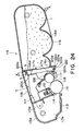
- Figure 15 is a sectional view of a process cartridge according to an embodiment of the present invention.
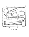
- Figure 16 is a schematic sectional view of the main assembly of an apparatus according to an embodiment of the present invention.
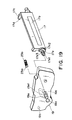
- Figure 17 is a schematic exploded perspective view of a frame for a process cartridge according to an embodiment of the present invention.
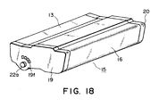
- Figure 18 is a schematic perspective view of a frame only process cartridge according to an embodiment of the present invention.
- Figure 19 is a parcel perspective view of a process cartridge according to an embodiment of the present invention.
- Figure 20 is a skeleton side view of a part of a process cartridge according to an embodiment of the present invention.
- Figure 21 is a schematic side view of a part of a process cartridge according to an embodiment of the present invention.
- Figure 22 is a schematic side view of a process cartridge according to an embodiment of the present invention.
- Figure 23 is an illustration of a driving system for the process cartridge according to an embodiment of the present invention.
- Figure 24 is a longitudinal sectional view of a process cartridge according to a further embodiment of the present invention.
- Figure 25 is a disassembling top plan view of a process cartridge according to an embodiment of the present invention.
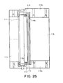
- Figure 26 is a top plan view of a process cartridge according to a further embodiment of the present invention.
- Figure 27 is a side view of a process cartridge according to a further embodiment of the present invention.
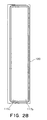
- Figure 28 is a front view of a sealing member according to an embodiment of the present invention.
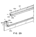
- Figure 29 is a perspective view of a sealing member according to another embodiment of the present invention.
- Figure 30 is a longitudinal sectional view of a process cartridge according to a further embodiment of the present invention.
- Figure 31 is a longitudinal sectional view of a process cartridge according to a further embodiment of the present invention.
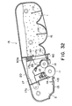
- Figure 32 is a longitudinal sectional view of a process cartridge according to a further embodiment of the present invention.
- Figure 33 is a perspective view illustrating mounting and demounting of the process cartridge relative to the main assembly of the image forming apparatus.
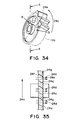
- Figure 34 is a perspective view of a gear having an impeller in a process cartridge.
- Figure 35 is a sectional view taken along a line B-B of Figure 34.
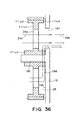
- Figure 36 is a sectional view taken along a line A-A of Figure 34.
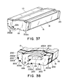
- Figure 37 is a perspective view of a process cartridge.
- Figure 38 is a perspective view of a side cover of a process cartridge.
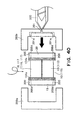
- Figure 39 is a perspective view for industries of a bonding process of a side cover.
- Figure 40 is a perspective view for the illustration of a bonding process of a side cover.
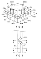
- Figure 14 is a perspective view of a toner container 50.
- the container 50 is used for a color developing device for a color laser beam printer.
- the container 50 accommodates a developer (toner) for developing an electrostatic latent image formed on an electrophotographic photosensitive member.
- the container 50 comprises a main body 51 of a toner container of a molded resin product and a cap 52, which are bonded by resin material.
- the container 50 is produced through an integral molding process.
- two half bodies are abutted to each other and are bonded by molten resin material.
- the connecting portion is indicated by D part of chain line.
- the inside 60 of the container 50 is filled with toner, and is sealed until the start of use.
- Figure 1 is a cross-sectional view of the toner container.
- Figure 1 is a sectional view only toner container 50 according to an embodiment of the present invention.
- Figure 1 is a sectional view of a conventional toner container 40.
- a main body of the toner container (molded resin product or container part) 51 and a toner container cap (molded resin product or container part) 52 are bonded in the following manner.
- Embodiments 1 to 4. The description will be made as to Embodiments 1 to 4.
- the Embodiments 1 - 4 will be described in more detail after Embodiment 5.
- FIGS 1, (a), 4, 12, 13 show Embodiment 1.
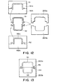
- the main body 51 of the container is injection-molded using an upper metal mold 191a and a lower metal mold 191b.
- the main body 51 of the container is formed as a molded resin product.
- a cap 52 is injection-molded using an upper metal mold 192a and a lower metal mold 192b. By this, a cap 52 is formed as a molded resin product.
- the main body 51 and the cap 52 of the container are accommodated in the cavity formed by an upper metal mold 200a and a lower metal mold 200b which are different from the metal molds 191a, 191b, 192a, 192b.
- the flanges 152a, 152c and the flanges 152b, 152d are abutted to each other.
- abutment portions 154a, 154b for receiving the resin material injected is formed between the flanges 152a and the 152c and the flanges 152b and 152d.
- the abutment portions 154a, 154b are constituted by the main body 51 and the cap 52 of the container.
- a groove (resin material injection path) for injecting the resin material along the connecting portion between the main body 51 cap 52 of the container, is formed in one of the main body 51 and the cap 52. The groove functions to guide the injected resin material.
- the main body 51 and the cap 52 are abutted to each other using metal molds 200a, 200b which are different from the metal molds 191a, b, 192a, b used for the injection molding of the plastic resin material (resin material) to form the main body 51 and the cap 52 of the container.
- the container resin material is injected to the abutment portion 154 through the injection path 200 ( Figure 4).
- the main body 51 and the cap 52 are bonded to each other.
- the plurality of the parts (molded resin products) can be bonded with higher latitude of the design. The assembling is simplified.
- the resin material injection path 200 is provided in the main body 200a of the container.
- One of container part 52 is provided, in addition to the ribs 160b, 160d, with ribs 161a, 161b for preventing inward deformation of the ribs 160b, 160d when the molten resin material is injected.
- the ribs 161a, 161b are projected in the mold removing direction, similarly to the ribs 160a, b, c, d. Therefore, as compared with the conventional structure, the flange portion 152b is shorter, so that container 50 can provide larger inside volume F.
- the projected area S as the unit can be reduced. Additionally, the mold removing structure can be more freely selected when the container 50 is produced or molded. Thus, the limitations in the product design can be reduced.
- the thickness of the rib 160a, 160b is 0.3 mm - -2.5 mm.
- the ribs are deformed radially in the perpendicular direction to the resin flow direction by the pressure applied further center of the abutment portion.
- the ribs are closely contacted to the back-up ribs 161a of the metal mold 200a and the container part 52. Therefore, the injected material does not leak into the container.
- the cross-sectional area 55 in the direction perpendicular to the direction of the resin material flow at the molten resin material injecting portion is 1 mm to -9 mm.
- Figure 1 is a longitudinal sectional view of a hollow member of synthetic resin material, which illustrates an Embodiment 5.
- the longitudinal section in the direction perpendicular to the direction of Figure 1, is similar, too, except for the different size in the horizontal direction. Therefore, Figure 1 is commonly used for explanation.
- Figure 1 shows also Embodiment 5.
- Figure 1 shows a prior art structure for comparison with the embodiment of the present invention.
- Said container parts 51, 52 are abutted to each other in the mold (unshown). Then the molten resin material for the bonding is injected into the abutment portions 154a, 154b. By doing so, the container parts 51, 52 are bonded to each other.
- flange portions 152a, 152b and 152c, 152d are provided at the position where the container parts 51, 52 are abutted to each other.
- the flange portions 152b, 152d are provided on the container part 51.
- the flange portions 152a, 152c are provided on the container part 52.
- the flange portions 152b, 152d are provided with ribs 160b, 160d which are projected in the mold removing direction along the edge of the container part 51 and which are contactable to the flange portions 152a, 152c.
- the container part 51 takes a top position, and the container part 52 takes the bottom position during the bonding.
- the rib 160b, 160d are directed in the vertical direction (mold removing direction)
- the inner walls 51b, 51b of the container part 51 are flush with a side surface of the ribs 160b, 160d.
- the flange portions 152b, 152d are outer flanges extended on the outer periphery of the side and has horizontal flange surfaces 152b1, 152d1.
- the thicknesses of the ribs 160b, 160d measured in the direction perpendicular to the mold removing direction are 0.3 mm - -2.5 mm.
- the top surfaces of the ribs 160b, 160d are horizontal, and inner corners of the ribs 160b, 160d are beveled as indicated by C.
- the flange portions 152a, 152c are provided with ribs 160a, 160c which are projected in the mold removing direction along the edge of the container part 52 and which are contacted to the flange portions 152b, 152d.
- the ribs 160a, 160c are provided on the outside of the rib 160b, 160d as with the abutment portions 154a, 154b therebetween.
- the horizontal surfaces 152a1, 152c1 of the flange portions 152a, 152c are contacted by the ribs 160b, 160d.
- the ribs 160a, 160c are projected in the mold removing direction (perpendicular direction).
- the container part 52 is provided with ribs 160a, 160c which are parallel with the ribs 161a, 161b which will be described hereinafter, respectively.
- the ribs 160a, 160c have outer surfaces which are flush with the ends of the flange portions 152a, 152c.
- the flange portions 152a, 152c are on the outside of the container part 52.
- the ribs 160b, 160d are contacted to the flange surfaces 152a1, 152c1 of the flange portions 152a, 152c.
- the thicknesses of the ribs 160a, 160c measured in the mold removing direction are 0.3 mm - -2.5 mm.
- the heights of the ribs 160a, 160b, 160c, 160d from the flange surfaces 152a1, 152b1, 152c1, 1521d are the same.
- the abutment portion 154a, 154b sides of the ribs 160a, 160b, 160c, 160d are circular column shape having a radius r.
- the heights of the ribs 160b, 160d are the same as the heights of the ribs 160a, 160c. Therefore, before the state is injected into the abutment portion 154a, 154b, the abutment portion 154a, 154b is a cavity having a rectangular cross-section. It is provided at one diagonal corners.
- the ribs 160a, 160b, 160c, 160d enclose the edges of the container part 51, 52.
- the shape provided by legitimate cutting of the edges of the container parts 51, 52 is the same as in Figure 1, (a).
- the cross-sectional area of the abutment portions 154a, 154b is 1 - 9 mm 2 .
- cross-sections of the abutment portions 154a, 154b are square. Therefore, the heights of the ribs 160a, 160b, 160c, 160d are approx. 1 - 3 mm.
- the container part 52 is provided with back-up ribs 161a, 161b for preventing deformation of the ribs 160b, 160d toward inside of the container when the molten resin material is injected.
- the ribs 161a, 161b are projected in the mold removing direction.
- the rib 161a, 161b have side surfaces which are flush with the inner walls 52a, 52b.
- the container part 52 has inner walls 52a, 52b having flat surfaces.
- the inner walls 52a, 52b extend beyond the flange portion 152a, 152c as back-up ribs 161a, 161b.
- the heights of the back-up ribs 161a, 161b are substantially equal to the height of the abutment portions 154a, 154b from the flange surfaces 152a1, 152c1 plus the thickness of the flange portions 152b, 152d.
- the thickness of the back-up ribs 161a, 161b is substantially equal to the thickness of the container part 52.
- Figure 1 shows both of the embodiment in (a) and the conventional example in (b).
- widths of the hollow members of synthetic resin material of the containers of the prior art and of the present invention are the same (in Figure 1, the parallel broken lines are on the flange end surfaces which define the widths.
- the inner distances of the cap 41 and the container 42 in the widthwise direction are the same (W).
- the inner distance of the container part 51 that is, the dimension W1 between the inner walls 51b, 51b is larger than the distance W between the inner walls of the toner container of the conventional example.
- the distance W2 between the inner walls of the container part 52 is equal to the distance W between the inner walls of the conventional example.
- the hollow members of synthetic resin material of the conventional example and the embodiment have the same heights.
- the inside volume F on the embodiment is larger than the inside volume E of the conventional toner container.
- the molten resin material flows to the abutment portions 154a, 154b through a molten resin material injecting portion extending from the outside to abutment portions 154a, 154b.
- the ribs 160b, 160d receive inward forces by the pressure applied in the direction for the center of the abutment portion perpendicularly to the direction of the flow of the molten resin material.
- the ribs 160b, 160d are abutted to the ribs 161a, 161b so that deformation thereof is prevented.
- the ribs 160b, 160d process against the rib 161a, 161b to enhance the rigidity and the strength of the container.
- the ribs 160a, 160c tend to deform outwardly of the container by the pressure.
- the outer surfaces of the ribs 160a, 160c are abutted to the metal mold (unshown) so that deformation is limited. It is preferable that heights of the back-up ribs 161a, 161b from the flange surfaces 152a1, 152c1 are larger than the heights of the ribs 160b, 160d. From the standpoint of increasing the inside volume F of the container, the heights of the back-up ribs 161a, 161b are small.
- the ribs 160a, 160c receive pressure from the molten resin material in the abutment portions 154a, 154b. However, the deformation is limited by the contact to the metal mold. Therefore, the ribs 160a, 160c may have a smaller thickness within the range described above.
- the material of the container part is, for example, shock-resistant polystyrene.
- an injection path leading to the abutment portion is provided in one of the container parts.
- the structure of the ribs is the same as with Embodiment 5, the detailed description thereof are omitted for simplicity.
- Figure 2 is a perspective view
- Figure 3 is a view as seen in a direction V
- Figure 4 is a sectional view taken along a line M-M
- Figure 5 is a sectional view taken along a line N-N of Figure 3.
- the injection path down to the abutment portion is formed in one of the container parts.
- the flow path is penetrated between the abutment portion and an outside of the container part.
- the container part 51 is provided with injection ports 200d for the molten resin material at the position of the gate of the metal mold.
- each of the injection ports 200d is disposed substantially at the center of the edge of the flange portion 152 (152a, 152b, 152c, 152d) of the container part 51.
- the injection path 200 extended toward the abutment portion in the flange 152 is the same as the one described in the foregoing. The description will be made as to the abutment portion 154a.
- the injection path 200 is extended perpendicularly to the direction of the flow of the resin material at abutment portion 154a.
- the injection path 200 is vertical.
- the injection path 200 is extended between the outer surface 51a and the abutment portion 154a of the container part 51.
- the container part 51 is provided with a column-like portion 51c extended from the flange portion 152b to the outer surface 51a (( Figure 2). As shown in Figure 3, is accurate having a center which is the center line x of the injection path 200. The corners between the outer surface of the container part 51 is rounded as indicated by R.
- the injection path 200 is tapered with a large diameter portion at the injection port 200d side and a small diameter portion 200c at the abutment portion 154a side.
- the relationship among the ribs 160a, 160b, 161a is the same as with Embodiment 1.
- the corner of the base portion of the back-up rib 161a is not rounded.
- the rib 161a is provided with an inclined surface SL with a beveled portion R1. Therefore, the rib 160b is easily not to the side surface of the back-up rib 161a when the container parts 51, 52 are assembled.
- a side surface of a free end of the rib 160b is closely contacted to a side surface of the back-up rib 161a at the base portion, by pressure of the resin material flowing into the abutment portion 154a. Therefore, the back-up rib and the rib of the upper container part are closely contacted all over the connecting portion of the container parts 51, 52.
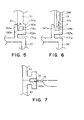
- the gate portion of the metal mold is connected to the injection path 200 at the outer side of the container part 51. Therefore, as shown in Figure 7, there is no need of providing a side gate 72 adjacent to the abutment portion. Moreover, the metal mold for bonding the container parts 51, 52 can be downsized in terms of the product projected area.
- the side gate 72 is provided at the side of the abutment portion 142a. Therefore, a runner has to be provided in a radio direction from an outside of the main body 42 of the container and the container cap 41 with the result of larger metal mold.
- the gate of the metal mold is connected to the injection port 200d of the injection path 200. Since the injection path 200 is convergingly tapered, the molten resin material, when it is supplied into the injection path 200, is not solidified in the injection path 200 and is gate-sealed in the neighborhood of the small diameter portion 200c whether the abutment portion 154a and the injection path 200 are crossed with each other. Therefore, the resin material pressed and injected into the abutment portion 154a does not flow back to the injection path 200. The resin material is solidified at the abutment portion 154a with the ribs 160a, 160b pressed against the metal mold 200a ( Figure 9) and back-up rib 161a.
- the resin material flowing in the injection path 200 is as indicated by an arrow 71b in Figure 6 at the abutment portion 154a. It then abuts the flange portion 152a. By this, the flange 152a receives molten resin material by the change of the kinetic momentum of the molten resin material.
- the force P is large because the flow speed and the mass of the flowing resin material through the injection path 200 are large.
- a lower surface 171a of the flange 152a is supported by a support surface 202b provided in the metal mold 200b to support the container part 52.
- a surface 202b for supporting the metal mold 200b is provided to cross with an extension of a center portion line x extending through the gate of the metal mold and the injection path 200. Therefore, the pressure imparted to the flange by the indebted resin material is received by the flange which is backed up by the metal mold, so that flange is not deformed. Additionally, the limitation on the selection of the high fluid material, the requirement for the increase of the number of the gates, or other limitations on the manufacturing process, can be avoided. Even if the ejection pressure is set slightly higher, the problem such as deformation in the unit after the bonding, does not arise.
- the thickness of the ribs 160a, 160b, 160c, 160d is 0.3 mm - -2.5 mm.
- the bonding material is injected to the abutment portions 154a, 154b, the rib is closely contacted to the back-up ribs 161a, 161b. Therefore, the bonding material injected to the abutment portions 154a, 154b do not leak outside or into the inside of the container.
- the back-up ribs 161a, 161b receive a pressure from the molten resin material in the abutment portions 154a, 154b through the ribs 160b, 160d. The pressure is eased by the deformation of the rib s160a, 160d.
- the ribs 160a, 160d are contacted to the back-up ribs 161a, 161b, the ribs 160a, 160b and back-up ribs 161a, 161b cooperate with each other to bear against the pressure applied by the molten resin material to the abutment portions 154a, 154b.
- the thickness of the back-up ribs 161a, 161b are substantially the same as the base material of the container part 52.
- FIG. 8 and Figure 9 illustrate Embodiment 8.
- the free end portion of the metal mold constituting the gate which is an injection port of molten resin material is flush with, or retracted inwardly of the injection path from, an outer surface of the inlet of the resin material flow path of the container part.
- the gate 201 in the metal mold 200a and the injection path 200 of the container part 51 having are concentric, that is, having a common center line x.
- the diameter of the inlet port 200d of the injection path 200 is g.
- the metal mold 200a is provided with an inclined portion 303 (conical portion) which has the common center center line x and extended downwardly from the lower surface 200a1 of the metal mold.
- the metal mold 200a is provided with a gate 201 the injection port 201a is petitioned at the top surface of the inclined portion 303.
- the lower surface 200a1 of the metal mold is parallel with the outer surface 51a of the container part 51.
- the diameter f1 is very close to the diameter g.
- the metal mold 200a is moved downwardly. Then, the top portion of the inclined portion 303 is press-contacted to the edge corner of the injection port 200d. Thus, the neighborhood of the inlet is deformed. By doing so, the connection point between the gate 201 and the injection path 200 is sealed.
- the molten resin material is prevented from leaking to the outside through between the injection port 201a and the injection port 200d.
- the container part 51 is provided with a beveling 300 which is closely contacted to the inclined portion 303, around the injection port 200d.
- This structure is also effective to prevent the leakage of the molten resin material at the connecting portion between the injection port 200d parts and the gate 201 of the metal mold 200a.
- the inclined portion 303 is closely contacted to the beveled portion 300. In the state in which the inclined portion 303 of the metal mold 200a is press-contacted to the beveled 300, there are gaps 301a, 301b between the resin material part 51 and that lower surface 200a1 of the metal mold.
- the inclined portion 303 enters the injection port, and the amount h of the entering is not more than 10mm.
- the metal mold for forming the gate is press-contacted closely to the inlet of the injection path of the container part.
- the metal mold 200a extends to devour the contact surface between the surface 152b1 of the flange and the rib 160a to be close to the side surface of the container part 51, 52.
- the inclined portion 303 is a part of the conical shape, but it is not inevitable that shape is conical.
- the structure around the gate may be of another pyramid shape.
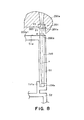
- FIG. 10 illustrates Embodiment 9.
- the embodiment is different from the embodiment of Figure 2 in the structure around the inlet port of the injection path 200.
- the general shape of the connecting portion is substantially the same as Figure 2.
- the metal mold 300a for confining the container part 51 is provided with a downward cylindrical projected portion 306b.
- the center of the projected portion 306b is provided with a cylindrical recess 306a.
- An injection port 201a of the gate 201 is provided at the center of the inclined portion 303 formed at center of a bottom surface of the recess 306a.
- the inlet port of the injection path 200 there is provided a cylindrical boss 305 engaged with the cylindrical recess 306a of the metal mold 300a with a gap therebetween.
- the free_end of the projected portion 306b of the metal mold is away from the container part 51.
- the metal mold 300a is sufficiently spaced from the container part 51 in the portion other than the portion where the periphery of the inlet of the injection path 200 is contacted to the inclined portion 303, except for the portion corresponding to the rib 160a and the flange 152b.
- a cylindrical recess having a larger diameter than the injection port of the gate is provided continuing from the gate outside the injection port of the gate of the metal mold.
- a cylindrical boss is provided around the inlet of the injection path of the container part and is engaged with the cylindrical boss with a gap therebetween and contacted to the bottom of the recess.
- the gap between the recess 306a and the cylindrical portion 305 is preferably not more than 0.3mm.
- the gap may be omitted.
- the abutment portion 154a, 154b constituting the injection path is provided in the outer periphery part toner container 50 in above-described Embodiments 1 - 9.
- the injection path may have a cross-shaped partition as seen in a top plan view of a connecting plane of the two container parts.
- the ribs 160a, 160c shown in Figure 1, (a) may be provided with cut-away portions 160e, 160f ( Figure 2).
- the cut-away portions 160e, 160f are filled with the resin material. Since the side surface of the rib 160 is covered with the metal mold 200a, the resin material does not leak. If the flow of the molten resin material is not enough with the result of short shot, the operator can find during the manufacturing the event because there is provided a recess in the cut-away portions portion 160e, 160f.
- the products are checked by sampling inspection. By this, the ejection balance can be checked.
- longitudinal direction means the direction which is perpendicular to the recording medium conveyance direction, and is parallel to the plane of the recording medium.
- FIG 15 is a sectional view of the essential portion of the process cartridge in accordance with the present invention.
- Figure 16 is a sectional view of the essential portion of an image forming apparatus in accordance with the present invention.
- This process cartridge is provided with an electrophoto-graphic photosensitive member, and a processing means which acts on the electrophotographic photosensitive member.
- the processing means there are, for example, a charging means for charging the peripheral surface of the electrophotographic photosensitive member, a developing means for developing an electrostatic latent image formed on the electrophotographic photosensitive member, a cleaning means for removing the toner remaining on the peripheral surface of the electrophotographic photosensitive member.
- the process cartridge 15 in this embodiment comprises: an electrophoto-graphic photosensitive member 11 (hereinafter, “electrophotographic photosensitive drum”) in the form of a drum; a charge roller 12 as a charging member; a developing apparatus comprising a development roller 18 as a developing member, and a development blade 26; a cleaning blade 14 as a cleaning member; and a housing in which the preceding components are integrally disposed.
- the process cartridge 15 is removably installable in the main assembly 27 of an electrophotographic image forming apparatus (hereinafter, "apparatus main assembly”).
- the development roller 18 is a cylindrical member formed of metallic material such as aluminum, stainless steel, or the like, and contains a nonconducting magnetic roller (unillustrated).
- this process cartridge 15 is installed in an electrophotographic image forming apparatus C, for image formation.
- a sheet S is fed out of a sheet cassette 6 in the bottom portion of the apparatus, by a conveyer roller 7.
- the photosensitive drum 11 is exposed by an exposing apparatus 8 according to the image data.
- an electrostatic latent image is formed on the photosensitive drum 11.
- the developer hereinafter, "toner” stored in a toner storage container 16 is triboelectrically charged by a development blade 26, and this developer is borne on the peripheral surface of the development roller 18.
- development bias is applied to the development roller 18 as a developing member, the toner is supplied to the photosensitive drum 11.
- toner image an image formed of toner (hereinafter, "toner image”) is formed on the photosensitive drum 11, correspondent to the electrostatic latent image.
- this toner image is transferred onto the sheet S, as recording medium, by applying bias (voltage) to a transfer roller 9.
- the sheet S is conveyed to a fixing apparatus 10, in which the toner image is fixed.
- the sheet S is discharged by a discharge roller 1 into a delivery portion 2 provided on the top side of the apparatus.
- the toner which remained on the photosensitive drum 11 after the image transfer is removed by a cleaning blade 14 as a cleaning member.
- the removed toner is moved rearward of a removed toner storage bin 5 by a removed toner conveying member 115.
- the photosensitive drum 111 is charged by a charge roller as a charging member.
- Figures 17 and 18 are perspective views which show the structure of the process cartridge frame.
- Figure 17 shows the process cartridge frame prior to its assembly
- Figure 18 shows the process cartridge after its assembly.
- the process cartridge 15 comprises three pieces of frames: a cleaning means frame 13 as a drum frame which integrally supports the photosensitive drum 11, charge roller 12, and cleaning blade 14; a developing means frame 17 which integrally supports the development roller 18, and development blade (unillustrated in Figure 17, and designated by a referential code 26 in Figure 18); and a toner storage frame 16 provided with a toner storage portion 16d in which toner is stored. Further, the process cartridge 15 in this embodiment comprises a pair of side covers 19 and 20 which are fixed to the longitudinal ends of the cleaning means frame 13 and toner storage frame 16 to hold the frames 13 and 16 together.
- the development means frame 17 is supported by the cleaning means frame 13.
- the cleaning blade 14 is fixed with the use of small screws.
- the charge roller 12 is rotatably supported by the longitudinal ends, by bearings (unillustrated).
- the removed toner conveying member 115 for conveying the toner removed by the cleaning blade 14, into the removed toner bin 5 is rotatably disposed.
- the photosensitive drum 11 is rotatably supported, with the flange portions, that is, the longitudinal end portions, of the photosensitive drum 11, supported by a pair of bearings 22a and 22b.
- the toner storage frame 16 stores toner therein, and comprises a pair of toner conveying members 113 and 114 ( Figure 15) for conveying the stored toner toward the development roller 18. These toner conveying members may be provided with a toner stirring function.
- the aforementioned side covers 19 and 20 are large enough to match in size the primary cross section (cross section at a plane perpendicular to the longitudinal direction of the photosensitive drum 11) of the process cartridge 15. They are positioned at the longitudinal ends of the process cartridge 15 (end portion in terms of the longitudinal direction of the photosensitive drum 11), one for one, covering, and being fixed to, both the cleaning means frame 13 and toner storage frame 16. With this arrangement, the side covers 19 and 20 integrally hold together the cleaning means frame 13 and toner storage frame 16.
- the holes 19a and 20a with which the side covers 19 and 20 are provided, respectively, are aligned with the rotational axis of the photosensitive drum 11 in the cleaning means frame 13.
- the bearing 22a is press fitted in the hole 13a of the side cover 19, that is, the side cover illustrated on the front side of the drawing, with which cleaning means frame 13 is provided. Also, a shaft 25 is put through the hole 19a of the side cover 19, bearing 22a, and the center hole 11a1 of the flange 11a, to rotatably support one of the longitudinal ends of the photosensitive drum 11 by the cleaning means frame 13. With this arrangement, the side cover 19 is precisely positioned by the bearing 22a, improving the accuracy in terms of the positional relationship of the side cover 19 with respect to the photosensitive drum 11.
- a positioning member 19b with which the side cover 19 is provided, and which is located so that its position becomes as far away as possible from the photosensitive drum 11 after the attachment of the side cover 19, is engaged with a positioning portion 13b with which the side wall 13c of the cleaning means frame 13 is provided.
- the position of the side cover 19, in terms of the rotational direction of the side cover 19 with respect to the center, or the axial line, of the photosensitive drum 11, is fixed.
- the side cover 19 is fixed to the side wall 13c, that is, the wall at the longitudinal end, of the cleaning means frame 13.
- the toner storage frame 16 is provided with a pair of cylindrical positioning portions 16a and 16b, which project from one of the side walls 16d, that is, the wall at the longitudinal end, of the toner storage frame 16, in the longitudinal direction of the toner storage frame 16. These positioning portions 16a and 16b are fitted in the positioning portion 19c and 19d, that is, holes, respectively, with which the side cover 19 is provided, accurately positioning the toner storage frame 16 relative to the side cover 19. Then, the toner storage frame 16 and side cover 19 are fixed to each other.
- the other wide cover 20 is similarly fixed to the toner storage frame 16 and cleaning means frame 13, being accurately positioned relative to each other.
- the developing means frame 17 is positioned using a method which will be described later.
- the bearings 22 (22a and 22b) double as members for positioning the process cartridge 15 relative to the apparatus main assembly 27.
- the toner storage frame 16 and development means frame 17 are provided with opening 16c ( Figure 15) and 17a. Further, the development means frame 17 and toner storage frame 16 are joined with each other in such a manner that their internal spaces become connected to each other through the openings 17a and 16c, with a sealing means 21 as a flexible sealing means disposed between the two frames.
- a sealing means 21 as a flexible sealing means disposed between the two frames.
- the position of the process cartridge 15 is fixed relative to the cartridge installation space of the apparatus main assembly 27, by the cleaning means frame 13 which supports the photosensitive drum 11.
- the toner storage frame 16 is substantially different in weight between the beginning of its usage when it contains toner, and the end of its usage when it is empty. Therefore, flexible material is used as the material for the sealing member 21. With this setup, even if a deformation occurs to the toner storage frame 16, or one or both of the side covers 19 and 20, the deformation can be absorbed.
- Figure 32 is a vertical sectional view of a process cartridge equipped with a flexible sealing member different from the above described sealing member 21.
- a sealing member 60 as a flexible sealing means is formed of elastic material such as foamed synthetic resin (for example, foamed urethane), rubber with a low degree of hardness, silicon rubber, or the like.
- This sealing member 60 is in the form of a piece of plate with a large opening 60a. After the installation of the sealing member 60, the opening 60a aligns with both the openings 17a and 16c. The size of the opening 60a is approximately the same as those of the openings 17a and 16c.
- the sealing member 60 is pasted to either to the surface of the development means frame 17 or the surface of the toner storage frame 16, which face each other, or both of the surfaces.
- the sealing member 60 is not pasted to the portion of the toner storage frame 16, correspondent to the area through which the toner seal 24 is passed when the toner seal 24 is pulled out.
- the thickness of the sealing member 60 is greater than the distance, after the completion of the assembly of the process cartridge 15, between the surface 17g of the developing means frame 17 and the surface 16f of the toner storage frame 16.
- the sealing member 60 is compressed by the mutually facing surfaces 17g and 16f as shown in Figure 32.
- the reactive force generated by the compression of the sealing member 60 acts as the pressure which keeps the spacer rollers 18b of the development roller 18 pressed upon the photosensitive drum 11. Therefore, the reactive force which the sealing member 60 generates is desired to be as small as possible.
- the load generated by the weight of the toner applies to the side covers 19 and 20, instead of applying to the development roller supported by the development means frame 17.
- the photosensitive drum 11 is not subjected to the load generated by the weight of the toner, and therefore, a stable image can be formed, even if the amount of the toner in the toner storage frame 16 increases.
- Figure 17 represents the state of the developing means frame prior to assembly.
- Figures 19, 20 and 21 are drawings for describing the structure of the developing means frame involved in the pressure application to the developing means frame.
- the development roller 18 which contains the magnetic roller 18a, the development blade 26 ( Figure 15), and a magnetic seal (unillustrated) is attached.
- a magnetic roller 18a is put through the longitudinal center hole of the development roller 18, and is nonrotationally supported by a developing means frame 17, at each of the longitudinal ends. There is maintained a gap between the development roller 18 and magnetic roller 18a.
- the development roller 18 is rotationally supported by the developing means frame 17, at each of the longitudinal ends.
- electrical contacts are provided within the development roller 18.
- both of the longitudinal end portions of the development roller 18 are fitted with a ring 18b (spacer rig) ( Figure 17) for maintaining a predetermined distance between the peripheral surfaces of the photosensitive drum 11 and development roller 18.
- the developing means frame 17 is provided with an arm portion 17c, which is on the driven side, that is, one of the longitudinal ends of the development roller 18, from which the development roller 18 is driven.
- the end portion of this arm portion 17c is provided with a hole 17d, the center of which functions as the pivotal center.
- the developing means frame 17 is pivotally supported by a cleaning means frame 13, in such a manner that the central axes of the photosensitive drum 11 and development roller 18 remain parallel to each other. More specifically, a pin 17d1 is fitted in the hole 17d of the development means frame 17 and the hole (unillustrated) of the cleaning means frame 13, so that the development means frame 17 becomes pivotable about the center of the hole 17d.
- the cleaning means frame 13 and toner storage frame 16 are immovably fixed to each other.
- the development means frame 17 is movable relative to the toner storage frame 16.
- the hooks of a tensional coil spring 36 are fitted around the spring anchoring projections 13d and 17f of the cleaning means frame 13 and development means frame 17, respectively, to provide such force that keeps the development roller 18 pressed toward the photosensitive drum 11, by their longitudinal ends.
- the hole 17d is located on the driven side of the photosensitive drum 11.
- the drive side means the side by which the driving force is received when the process cartridge 15 is in the apparatus main assembly 27.
- the non-driven side means the side opposite to the driven side in terms of the longitudinal direction of the electrophotographic photosensitive drum 11.
- the non-driven side of the developing means frame 17 is provided with a projecting member 17e, which is fixed to the development means frame 17 with the use of screws 17e2 and projects in the direction of the rotational axis of the development roller 18.
- This projecting member 17e is under the pressure which keeps it pressed toward the photosensitive drum 11 while keeping the rotational axes of the photosensitive drum 11 and development roller 18 parallel to each other.
- the longitudinal ends of the cleaning means frame 13 and toner storage frame 16, on the non-driven side are covered with a side cover 19 which is attached thereto with the use of screws 100.
- the cleaning means frame 13 and toner storage frame 16 are fixed to the side covers 19 and 20.
- the development means frame 17 is movable relative to the cleaning means frame 13 and toner storage frame 16, with one of the longitudinal ends of the development means frame 17 being supported by the cleaning means frame 13 and the other being supported by the side cover 19.
- the end 17e1 of the projecting member 17e is inserted in a groove 19e, as a guiding portion, with which the side cover 19 is provided.
- the groove 19e extends toward the rotational axis of the photosensitive drum 11, allowing the projecting member 17e to move toward the rotational axis of the photosensitive drum 11.
- a compression coil spring 23b as an elastic member, and a slide piece 23a as a pressing member, slidable in the longitudinal direction of the groove 19e are disposed so that pressure is applied to the projecting member 17e through the slide piece 23a.
- this groove 19e functions as a positioning member for regulating the direction in which the development roller 18 (developing means frame 17) is allowed to move.
- the development roller 18 is allowed to displace only in the direction parallel to the longitudinal direction of this groove 19e, since the moving direction of the projecting member 17e is regulated by the internal surface of the groove 19e.
- the force applies to the gears 105b and 107b ( Figure 23), which are attached to the longitudinal ends of the photosensitive drum 11 and development roller 18, respectively, in the direction parallel to the central axis of the hole 17e to move the gears 105b and 107b so that they engage with each other (it does not occur that the force applies in the direction to separate the gears 105b and 107b from each other).
- the gears 105b and 107b are disposed so that the extension of the transverse line of action between the gears 105b and 107b runs adjacent to the hole 17d.
- the center line of the hole 17d and the rotational axis of the photosensitive drum 11 are disposed on the same side with respect to the transverse line of action. Furthermore, the development roller 18 is under the force from the aforementioned compression coil spring 23b, being kept pressed toward the photosensitive drum 11.
- the process cartridge 15 removably installable in the main assembly 27 of an image forming apparatus comprises: the electrophotographic photosensitive drum 11; the development roller 18 as a developing member for developing the electrostatic latent image formed on the electrophotographic photosensitive drum 11; the cleaning means frame 13 as a frame for supporting the electrophotographic photosensitive drum 11; and the developing means frames 17 for supporting the development roller 18.
- the developing means frame 17 is provided with the projecting member 17e, which is attached to one of the longitudinal ends of the development roller 18, and projects in the longitudinal direction of the development roller 18.
- the projecting member 17e is fitted in the groove 19e as a guiding portion, being enabled to move in the groove 19e toward, or away from, the cleaning means frame 13.
- the developing mean frame 17 is pivotally joined with the cleaning means frame 13, at the other longitudinal end of the development roller 18.
- the development roller 18 is supported by the development means frame 17, being enabled to move in the direction perpendicular to its rotational axis.
- the process cartridge 15 further comprises the compression coil spring 23b as an elastic member for generating such pressure that keeps the projecting member 17e pressed toward the cleaning means frame 13 while allowing the projecting member 17e to move in the groove 19e in the direction perpendicular to the central axis of the projecting member 17e.
- the groove 19e as a guiding member is provided with a recess 19e1, in which the end 17e1 of the projecting member 17e is fitted.
- the coil spring 23b as an elastic member, is fitted in such a manner that the projecting member 17e is kept pressed toward the cleaning means frame 13 by the elastic force of the coil spring 23b.
- the slide piece 23a As a pressing member is attached.
- the slide piece 23a makes contact with the flat portion 17e3 of the projecting member 17e, pressing the projecting member 17e due to the elastic force of the coil spring 23b.
- the coil spring 23b is fitted in the groove 19e, being allowed to slide within the groove 19e.
- the projecting member 17e is disposed so that its axial line approximately aligns with the rotational axis of the development roller 18.
- the development means frame 17 is rotationally supported by the cleaning means frame 13, by the other longitudinal end of the development roller 18, at a position away from the rotational axis of the development roller 18 rotationally supported also by he developing means frame 17, with the pin 17d1 fitted through the developing means frame 17 and cleaning means frame 18.
- the tension spring 36 is stretched between the development means frame 17 and cleaning means frame 13, with one end of the tension spring 36 attached to the development means frame 17 and the other end attached to the cleaning means frame 13.
- the groove 19e is provided in the inwardly facing surface of the side cover 19, as a first side cover, attached to the longitudinal ends of the cleaning means frame 13 and development means frame 17, at each of their longitudinal ends.
- the toner storage frame 16 and development means frame 17 are joined so that toner does not leak from the joint between the opening 16c of the toner storage frame 16 and the opening 17a of the development means frame 17.
- the development means frame 17 and toner storage frame 16 need to be pivotable relative to each other. Therefore, in this embodiment, a sealing member 21, the size of which matches the size of the moving ranges of both opening portions, is placed between the opening portion of the toner storage frame 16 and the opening portion of the development means frame 17, to prevent the toner leakage. This sealing member 21 is pinched between the two opening portions, with the opening of the sealing member 21 aligning with the openings 16c and 17a.
- the sealing member 21 is desired to be shaped not to generate such force that impedes the movement of the development means frame 17; more specifically, it is provided with at least one fold, or it is in the form of a bellows. It is possible that the surface surrounding the opening 16c or 17a is provided with a groove which surrounds the opening, and in which an O-ring is fitted to seal the joint between the tone storage frame 16 and development means frame 17 while allowing the gap between the two frames to be variable.
- the sealing member 21 is formed of elastomer, and is provided with two folds (unillustrated), to reduce the overall resiliency of the sealing member 21.
- the material for the sealing member 21 does not need to be limited to the elastomer. It may be any material superior in flexibility, for example, foamed urethane, rubber with a low degree of hardness, silicone rubber, or the like. If the material used for the sealing member 21 is small in reactive force, the same effects at those obtained with the provision of the folds, that is,the shaping of the sealing member 21 in the form of a bellows, can be obtained without such provision or shaping.
- Figure 23 is a diagram which depicts the drive train in this embodiment.
- An arrow mark X indicates the direction in which the process cartridge 15 is installed into the apparatus main assembly 27.
- the driving force sources 101 and 102 (for example, an electric motor) provided in the apparatus main assembly 27 are connected to couplings 103 and 104. As the process cartridge 15 is installed into the apparatus main assembly 27, the couplings 103 and 104 are engaged with couplings 105a and 16a,
- the couplings 105a and 106a rotate with the input gears 105b and 106b, respectively.
- the coupling 106a is supported by a bearing 116c.
- the coupling 105a is integral with the gear 105b, or is an integral part of a gear flange 105.
- the gear flange 105 is supported by a bearing 116b.
- the gear flange 105 is fixed.
- a gear flange 107 is fixed.
- the gear flanges 105 is integrally formed with the gear 105b.
- the gear flange 107 is integrally formed with the gear 107b.
- a bearing flange 119 is fixed, and to the other longitudinal end of the development roller 18, a bearing flange 120 is fixed.
- the photosensitive drum 11 are development roller 18 being to their own units.
- the gear 105b is in mesh with the sleeve gear 107b.
- the photosensitive drum 11 and development roller 18 are rotated.
- the photosensitive drum unit is rotationally supported by the bearings 116b and 117b.
- the development roller 18 s rotationally supported by the development means frame 17. Further, the development roller 18 is rotated while maintaining an optimal gap, which is provided by the aforementioned spacer rollers 18b, from the peripheral surface of the photosensitive drum 11.
- the bearings 116b and 117b are the surfaces themselves of the holes with which the cleaning means frame 13 is provided, or the bearings 22 ( Figure 19) fixed to the cleaning means frame 13. In the bearings 116b and 117b, the journal portions 105c and 119b of the flanges 105 and 109, respectively, are fitted.
- the toner conveying member 114 To the toner conveying member 114, driving force is transmitted from the input gear 106b.
- the toner conveying member 114 is directly connected to the shaft of the gear 106b.
- the driving force is transmitted to the toner conveying member 113 through an idler gear 108 meshed with the input gear 106b, and a toner conveyance gear 109 meshed with the idler gear 108.
- the idler gear 108 is rotationally supported by the shaft 108a.
- the toner conveyance gear members 114 and 113 follow the rotation of the input gear 106b because their journal portions are rotationally supported by the bearings 116b and 116e, and the bearings 117c and 117d, respectively.
- a feather-shaped toner conveying member 115 for conveying the toner removed from the photosensitive drum 11 is disposed.
- This removed toner conveying member 115 is rotationally supported by the cleaning means frame 13, with the use of bearings 116a and 117a.
- an input gear 112 fixed to one of the longitudinal ends of the toner conveying member 115.
- This gear 112 is indirectly meshed with an output gear 110, through idler gears 111c, 111b and 111a.
- the output gear 110 is fixed to the other longitudinal end (non-driven side) of the toner conveying member 114.
- the idler gears 11a, 11b and 11c are rotationally supported by the bearing portions 117e, 117f, 117g, by their shaft portions.
- the removed toner conveying member 115 follows the rotation of the toner conveying member 114.
- the driving force received by the gear 106b is transmitted to the other longitudinal end of the toner conveying member through the toner conveying member 114.
- it is transmitted to the conveying member 115 through the gears 111a, 111b, 111c and 112, at the other longitudinal end (on the non-driven side).
- the above positional arrangement of the components of the driving system assures that the driving force is efficiently delivered to both the driven and non-driven sides through the driving system.
- the transmission of the driving force throughout the process cartridge 15 is separately shared by a driving system for transmitting the driving force to the photosensitive drum 11 and development roller 18, and another driving system for transmitting the driving force to the toner conveying members and removed toner conveying members, to which the driving force is delivered from the driving force source 101 and 102, respectively.
- the removed toner conveying member 115 is driven by transmitting the driving force by way of the toner conveying member 113 with the provision of the similar structure; (2) the removed toner conveying member 115 is driven by transmitting the driving force by way of any of the input gears 106b and 109, and the idler gear 108, through the gear trains; or (3) the removed toner conveying member 115 is driven by an idler gear attached to the end of the shaft of the idler gear 108 extended to the non-driven side.
- the process cartridge 15 removably installable in the main assembly 27 of an electrophotographic image forming apparatus comprises: the electrophotographic photosensitive drum 11; the development roller 18 as a developing member for developing the electrostatic latent image formed on the electrophoto-graphic photosensitive drum 11; the toner storage portion 16d as a developer storage portion for storing the developer t used for developing the electrostatic latent image; the toner conveying members 113 and 114 as a developer conveying member for conveying the toner t stored in the toner storage portion 16d, toward where the development roller 18 is disposed; a combination of the coupling 105a and input gear 105b as the first driving force transmitting means for receiving the driving force for rotating the electrophotographic photosensitive drum 11 from the apparatus main assembly 27 and transmitting the received driving force to the electrophotographic photosensitive drum 11, as the process cartridge 15 is installed into the electrophotographic photosensitive member main assembly 27; and a combination of the coupling 106a and input gear 106b as the second driving force transmitting means for receiving the driving force for driving the to
- the position at which the coupling 105a and coupling 106a receive the driving force from the apparatus main assembly 27 is the leading end of the process cartridge in terms of the direction in which the process cartridge 15 is installed into the apparatus main assembly 27, provided that the process cartridge 15 is installed into the apparatus main assembly 27 in the direction parallel to the longitudinal direction of the electrophotographic photosensitive drum 11.
- the process cartridge 15 comprises the cleaning blade 114 as a cleaning member for removing the developer remaining on the electrophotographic photosensitive drum 11, and the removed toner conveying member 115 as a removed developer conveying member for conveying the developer removed from the electrophotographic photosensitive drum 11 by the cleaning blade 114.
- the removed toner conveying member 115 is rotated by the driving force which the coupling 106a received from the apparatus main assembly 27.
- the driving force which the coupling 106a received from the apparatus main assembly 27 is transmitted to the other longitudinal end of the toner conveying member 114 through the toner conveying member 114, and then, is transmitted to the removed toner conveying member 115, at the other longitudinal end of the toner conveying member 114.
- the plurality of gears 111a, 111b, 111c and 112 are disposed, and the driving force which was transmitted to this side through the toner conveying member 114 is transmitted to the removed toner conveying member 115 through the plurality of gears 111a, 111b, 111c and 112.
- the driving force which the coupling 105a received from the apparatus main assembly 27 is transmitted to the development roller 18 through the gear 107b. By this driving force, the development roller 18 is rotationally driven. Further, as the process cartridge 15 is installed into the apparatus main assembly 27, the coupling 106a as the aforementioned cartridge coupling engages with the coupling 104 as the main assembly coupling of the apparatus main assembly 27 to receive the driving force, whereas the coupling 105a as the aforementioned cartridge coupling engages the coupling 103 as the main assembly coupling of the apparatus main assembly 27 to receive the driving force.
- the apparatus main assembly 27 is provided with the coupling 103 as the first driving force transmitting member of the main assembly, and the coupling 104 as the second driving force transmitting member of the main assembly.
- the amount of load which applies to the system for driving the toner conveying member increases.
- the number of the toner conveying members is increased to three, four, and so on, it becomes easier for the irregularities traceable to driving force transmission to occur.
- a driving system structure such as the above described one in which the driving system is divided into a plurality of sub-systems is advantageous.
- the load which applies to the removed toner conveying member also increases.
- the driving system in which the driving system is divided into a plurality of sub-systems becomes advantageous as the cleaning means frame becomes virtually filled up with the removed toner.
- the driving force input system for driving the removed toner conveying member and the driving force input system for driving the developmental toner are integrated into a single unit, simplifying the structure of the coupling for connecting the apparatus main assembly and the process cartridge, which in turn makes it easier to arrange the gears and the like, providing an advantage from the viewpoint of space saving.
- the toner conveying system and toner stirring system are driven by directly meshing the gear of the development roller with the gears of the toner conveying system and toner stirring system.
- such direct engagement between the gears of the former and latter does not occur. Therefore, even if the load which applies to the toner conveying system and toner stirring system increases due to he increase in the toner storage container capacity, it is unnecessary to increase the strength of the gears 105b and 107b for driving the development roller 18. Therefore, it is possible to use low module gears for driving force transmission. With this arrangement, it does not occur that an image suffering from the aforementioned irregularities is produced due to the irregularity in the pitch which occurs as the drum gear 105b and sleeve gear 107b mesh with each other.
- the cleaning means frame and toner storage frame are integrally fixed to each other by the side covers. Therefore, the removed toner conveying member and developmental toner conveying member can be precisely connected and driven.
- the developing means frame which supports the developing member such as the development roller is pivotally supported so that it is enabled to pivot following the photosensitive drum. Therefore, it is easy to connect the drum gear 105b and sleeve gear 107b to each other by driving them.
- the force for rotationally driving the removed toner conveying member 115 is transmitted from the driving system for driving the toner conveying member. Therefore, even when the photosensitive drum is rotated at a high velocity, it is easy to continue to convey the removed toner at the conventional rotational velocity.
- Figure 22 is a schematic drawing of the gear train positioned along the photosensitive drum.
- Figure 22 (a) is a side view of the process cartridge, with the side cover removed, and Figure 22, (b) is a side view of the process cartridge, in which the contour of the side cover is indicated by an imaginary line.
- the conveying member 115 for conveying the recovered removed toner toward the rear of the removed toner bin 5 is disposed.
- the structural arrangement of the process cartridge 15 is such that the conveying member 115 receives the driving force from photosensitive drum 11, the rotational velocity must be reduced by a large ratio. However, if the arrangement is such that the driving force is transmitted from the toner conveying member 114, the velocity reduction by a large ratio is unnecessary.
- the gears 111b and 111c are disposed in the adjacencies of the photosensitive drum 11, penetrating the toner storage frame 16 and developing means frame 17 ( Figure 22, (a)).
- the gear 111b and 111c are provided with a plurality of slits 24a and 24b, respectively, the interval portions of which form a plurality of axial flow vanes, to forcefully exhaust, or take in, the air through an air passage 19b. With this arrangement, it does not occur that the air passage 19 for cooing the interior is blocked by the gears 111b and 111c.
- Figure 34 is a perspective view of the gear llc.
- the structure of the gear 111b is the same as that of the gear 111c, except that the former is opposite to the latter in the direction of the helical teeth, and the direction of the helical air passages. Therefore, the air passage structure is described referring to the gear 111c as an example.
- Figure 35 is a development of the section of the B-B portion of the gear 111c illustrated in Figure 34, at a cylindrical plane perpendicular to the rotational axis of the gear 111c
- Figure 36 is a sectional view of the gear 111c illustrated in Figure 34, at a plane A-A.
- the gear 111c is a helical gear.
- a disk portion 111c3 which connects the rim portion llc2 comprising the helical teeth, and the hub portion 111c1
- a plurality of through slits 24a which extend in the radial direction of the gear 111c, at equal intervals.
- the air passage 19f of the side cover 19 and the slits 24a are rendered continuous through the space 29.
- the gear 111c is rotationally supported by a shaft 19G which extends inward from the inwardly facing surface of the side cover 19, perpendicular to the longitudinal direction of the photosensitive drum 15; the shaft 19G is put through the center hole of the hub 111c1.
- the end portion of the shaft 19G is fitted with a retainer ring (unillustrated) to prevent the gear 111c from moving in the shaft direction.
- the outwardly facing surface 111c4 of the rim portion 111c2 is very close to the inwardly facing surface 19h of the side cover 19.
- the inwardly facing surface 19h of the side cover 19, and the outwardly facing surface 111c4 of the rim portion are required to make the amount of the air flow between them as small as possible. Thus, they may be intricately formed in such a manner that the gap between them forms a labyrinth.
- each slit 24a in terms of the radial direction of the gear 111c matches those of the air passage 19f.
- the interval between the adjacent two slits 24a is occupied by a helical vane 24g; the adjacent two slits 24a are separated by a helical vane.
- the slit 24a is desired to be shaped like an interval space between adjacent two vanes of an axial flow fan so that the gear 111c is rendered aerodynamically effective in moving air.
- the gear 111c is relatively slow in rotational velocity, and therefore, the vanes of the gear 111c may be simply angled.
- the disk portion 111c3 of the gear 111c that is, the portion of the gear 111c on the inward side of the rim 111c2 in terms of the radial direction of the gear 111c, constitutes an impeller.
- the cooling air passage is structured so that the air currents from all the slits 24a are allowed to simultaneously flow through the space 29. Therefore, all the vanes 24d contribute to the generation of the air flow.
- the direction of the surface 24f of the vane 24g should be determined to be advantageous in terms of cooling efficiency, in consideration of the positional arrangement of the components, and the general configuration of the cooling air passage.
- the twist angle of teeth 24e of the helical gear 111c is rendered parallel to the twist angle of the surfaces 24f of the vanes 24g.
- the teeth 24e and vanes 24g become the same in terms of the air flow in the axial direction of the gear 111c.
- the gear 111c is molded of resin.
- a gap for allowing the air to pass is provided between the outwardly facing surface of the rim 111c2 and the inwardly facing surface of the side cover 119.
- a cover which follows the peripheral surface of the gear 111c, except for the portion where the gear 111c meshes with its counterpart, is provided as a member which functions like the casing of an air blower.
- the gears 111b and 111c rotates, and therefore, the internal space of the process cartridge 15 is ventilated. Also, the heat generated by the fixing apparatus and the like is removed. Further, the apparatus main assembly 27 is provided with ventilation holes through which the apparatus main assembly 27 is naturally ventilated, or ventilating means such as a fan (unillustrated), or the like.
- Figures 25 and 26 are schematic drawings of one of the embodiments of a process cartridge in accordance with the present invention, and show the structure of the cartridge as seen from above.
- a toner storage frame 116 provided with a toner storage portion is accurately positioned relative to side covers 119a and 119b, and fixed thereto, by fitting the pins 119c of the side covers 119 (119a and 119b) into the holes or correspondent positioning bosses 116a of the toner storage frame 116.
- the cleaning means frame 113 is accurately positioned relative to the side covers 119a and 119b, and fixed thereto, by engaging the positioning bosses 113b with the positioning pins 119d of the side covers 119a and 119b. Consequently, the cleaning means frame 113 and toner storage frame 116 are integrally fixed to each other.
- the developing means frame 117 of a developing apparatus D is supported by the pins inserted in the holes 113a of the cleaning means frame 113, being enabled to pivot about the center of the holes 113a while holding a development roller 118 and a development blade 112.
- a tensional coil spring 112 is stretched as shown in Figure 27.
- the spacer rings 118b are kept pressed upon the photosensitive drum 11, outside the image formation region.
- the spacer rings 18b are provided at the longitudinal ends of the development roller 118, one for one, and are greater in radius by a value equivalent to a development gap (approximately 300 pm) than the development roller 118.
- the developing means frame 117 is structured so that its bottom well is approximately horizontal when the process cartridge is in the apparatus main assembly.
- the gap between the developing apparatus D and toner storage frame 116 is sealed. More specifically, the openings 117b and 116c of the developing apparatus D and frame 116, respectively, for allowing toner to pass, are connected by a flexible member 120, as a sealing member, shaped like a bellows.
- the flexible member 120 as a flexible seal is welded or glued to the frames 116 and 117, by the connective portions 120a and 120b, respectively.
- the flexible member 120 has to be connected only to prevent toner from leaking while toner is passing between the openings 116c of the frame 116, and the opening 117b of the frame 117. Therefore, the frames 116 and 117 may be provided with a male and a female coupler, which surround the openings 116c and 117b, respectively, and the joint between them is sealed with a sealing member, provided that the couplers can absorb the displacement of the frames 116 and 117 relative to each other.
- the flexible member 120 is shaped like a belt which surrounds the openings 117b and 116c.
- the surfaces 116d and 117c of the frames 116 and 117, respectively, which face each other, are flat surfaces approximately parallel to each other. They surround the openings 116c and 117b, respectively.
- a connective portion 120a of the flexible member 120 is fixed, and to the surface 117c, the connective portion 120b of the flexible member 120 is fixed.
- the method used to fix these connective portions 120a and 120b to the surfaces 116d and 117c is thermal welding, or gluing. It is also possible to clasp the connective portions 120a and 120b with the use of clasping members (unillustrated), for example, a wear plate, and screw the clasping members to the surfaces 116d and 117c.
- the flexible member 120 is uniform in terms of the shape of the cross section perpendicular to the surfaces 120a and 120b. More specifically, referring to Figures 24 and 29, in terms of cross section, the L-shaped outward sheath portion 120c and L-shaped inward sheath portion 120d of the flexible member 120 are connected by a zigzag portion. Further, the inward sheath portion 120d and outward sheath portion 120c overlap each other in terms of the direction parallel to the planes of the openings 116d and 117c. In other words, the flexible member 120 has two folds k.
- the flexible member 120 bends like a bellows, absorbing the displacements to keep sealed the passage between the openings 116c and 117d. Further, since the flexible member 120 is in the form of a bellows, it is very small in the resistance it generates as one or a plurality of the aforementioned displacements occur. Therefore, the flexible member 120 does not affect the contact pressure generated between the spacer rings 118b and photosensitive drum 111 by the tensional coil spring 122.
- the flexible member 120 is capable of dealing with this type of a situation. This type of deformation changes as the amount of the toner within the frame 116 reduces. As a result, the positional relationship between the opposing surfaces 116d and 117c also changes. However, this displacement can also be dealt with by the flexible member 120.
- the front and rear walls of the apparatus main assembly 27 are provided with a guide (unillustrated).
- the process cartridge 115 is provided with a pair of shaft-like, cylindrical projections (unillustrated), which project outward from the cleaning means frame 113 through the holes 119e and 119f of the side covers 119, one for one, and the axial lines of which are in alignment with the rotational axis of the photosensitive drum 111.
- the process cartridge 115 is installed into the apparatus main assembly 27, the position of the process cartridge 15 relative to the apparatus main assembly 27 is fixed as these cylindrical projections engage with the positioning portions (unillustrated) of the apparatus main assembly 27.
- the material for the flexible member 120 is desired to be such elastomer that is similar in properties to the material used for the frames 113 and 116.
- styrene resin was used as the frame material
- styrene elastomer was used as the material for the flexible member 120.
- Other material such as rubber, urethane, silicon rubber, and the like may be also used as the material for the flexible member 120.
- adhesive or double-shaped adhesive tape may be used as a mechanically attaching means may be used.
- the flexible member 120 may be clasped by a clasping member. Obviously, both connective means may be used in combination.
- injection molding or compression molding may be used. Further, material in the form of a sheet may be heat-pressed.
- the flexible member 120 In order to minimize the reactive force of the flexible member 120, the direction of which is approximately parallel to the conveyance direction of the sheet S, the flexible member 120 is structured so that the portion between the folds k and k, the portion between the fold k and the connective portion 120a, and the portion between the fold k and the connective portion 120b, become parallel to the sheet conveyance direction, as shown in Figure 24. However, the flexible member 120 may be folded so that the above described portions become perpendicular to the sheet conveyance direction.
- a fold width W, or the distance between the opposing two folds, of the flexible member 120 is determined so that the flexibility of the flexible member is not lost within a range in which the frames 117 and 116 are allowed to move relative to each other.
- the opening of the flexible member 120, which faces the opening 116c, is greater in both the horizontal and vertical directions than the opening 116c, and the opening of the flexible member 120, which faces the opening 117b, is smaller in both the horizontal and vertical direction than the opening 117b.
- Figure 31 shows an example of the flexible member 120, which has only a single fold k. Even if the flexible member 120 is provided with only one fold k, it can deal with the displacement of the frames 116 and 117 relative to each other, as long as the width W from the connective portion 120b to the fold k is rendered generous.
- the bellows portion of the flexible member 120 was described with reference to its vertical sectional view. However, when shown in horizontal sectional view, the direction in which the fold k projects is opposite to the direction in which it projects in the vertical sectional view. For example, the fold projecting inward in Figure 30 projects outward when seen in horizontal sectional view.
- the process cartridge 15 (115) removably installable in the main assembly 27 of an electrophotographic image forming apparatus comprises:
- the developing means frame 17 (117) and toner storage frame 16 (116) are connected to each other, with the interposition of the sealing member 21 to 60, or the flexible member 120, and the flexible sealing member is pasted to the developing means frame 17 (117) and toner storage frame 16 (116).
- the sealing member 60 is a hollow member and has a through hole 60a.
- One end of the through hole 60a faces the opening 16c, as a supply outlet, with which the toner storage frame 16 is provided, and the other end of the through hole 60a faces the opening 17a, as a supply inlet, with which the developing means frame 17 is provided.
- the opening 16c is an opening through which the developer t stored in the toner storage portion 16a is conveyed toward the development roller 18.
- the opening 17a is an opening through which the developer t is received into the developing means frame 17 after passing through the opening 16c.
- one end of its through hole 60a is pasted to the toner storage frame 16, by the surface which surrounds the opening of the hole 60a, and the other end of the through hole 60a is pasted to the developing means frame 17 by the surface which surrounds the opening of the hole 60a.
- the sealing member 21 and flexible member 120 have at least one fold k between the surface b which they are pasted to the developing means frames 17 and 117, respectively, and the surface by which they are pasted to the toner storage frame 16 and 116, respectively.
- the sealing member 21 and flexible member 120 are in the form of a bellows, one end of which is pasted to the toner storage frame 16 and 116, respectively, and the other end of which is pasted to the developing means frame 17 and 117, respectively.
- the flexible sealing members 21 and 60 are formed of elastic material, sheet, or film.
- the material for the sealing members 21 and 60, and the material for the flexible member 120 are foamed urethane, ester resin, or polyurethane resin.
- the side cover 19 is provided with a handle 29, which is grasped by an operator when the process cartridge 15 (115) is installed into, or removed from, the apparatus main assembly.
- the process cartridge 15 (115) is installed into, or removed from, the apparatus main assembly 27 in the direction parallel to the longitudinal direction of the electrophoto-graphic photosensitive drum 11 (111).
- the side cover 19 (119) is provided with the hole 19a (119f), through which the shaft 25 (125) of the electrophotographic photosensitive member 11 (111) projects.
- One of the longitudinal ends of the electrophotographic photosensitive member 11 (111) is supported by the cleaning means frame 13 (113), by the shaft 25 (125).
- the position of the process cartridge 15 (115) relative to the apparatus main assembly 27 is fixed as the process cartridge 15 (115) is installed into the apparatus main assembly 27.
- the top surface of the toner storage frame 16 (116) is provided with a handle 30.
- the top surface means the surface which faces upward when the process cartridge 15 (115) is in the apparatus main assembly 27.
- the handle 30 is a portion which is grasped by an operator when the process cartridge 15 (115) is moved.
- the cleaning means frame 13 (113) has an exposure opening 131 (113 l ), which is an opening through which a beam of light modulated with image formation data is projected onto the electrophoto-graphic photosensitive drum 11 (111) from the apparatus main assembly 27 after the installation of the process cartridge 15 (115) into the apparatus main assembly 27.
- the charge roller 12 (112), as a charging member for charging the electrophotographic photosensitive drum 11 (111), and the cleaning blade 14 (114) as a cleaning member for removing the developer remaining on the electrophotographic photosensitive drum 11 (111), are disposed.
- the side covers 19 and 20 (119a and 119b) are fixed to the cleaning means frame 13 (113) and toner storage frame 16 (116) with the use of screws 100.
- the side covers 19 and 20 (119a and 119b) are fixed to the cleaning means frame 13 (113) and toner storage frame 16 (116) with the use of resin.
- the side cover 19 is provided with the groove 19e in which the projecting member 17e provided at one of the longitudinal ends of the developing means frame 17 is movably supported.
- the projecting member 17e formed of resinous material is an integral portion of the developing means frame 17.
- the toner storage portion 16 (116) contains the developer t.
- the assembly method for the process cartridge 15 (115) is as follows.
- the assembly method for the process cartridge 15 (115) removably installable in the main assembly 27 of an electrophotographic image forming apparatus comprises:
- the development means frame 17 (117) and toner storage frame 16 (116) are joined with each other in a manner to allow them to pivot relative to each other, with the interposition of the sealing member 21 (60) or the flexible sealing member 120, as a flexible member, between the two frames, so that one end of the flexible member is attached to the development means frame 17 (117) and the other end of the flexible member is attached to the toner storage frame 16 (116).
- the side covers 19 (119a) and side cover 20 (119b) are attached to the cleaning means frame 13 (113) and development means frame 17 (117) with the use of screws.
- the side covers 19 (119a) and side cover 20 (119b) are attached to the cleaning means frame 13 (113) and development means frame 17 (117) with the use of resin.
- the developer t is filled into the developer storage portion of the toner storage frame 16 (116) through the developer filling opening (unillustrated) provided at one of the longitudinal ends of the toner storage frame 16 (116).
- Figure 33 is a perspective view of the cartridge installing space provided in the apparatus main assembly 17. As the front door (unillustrated) of the apparatus main assembly 17 is opened, the entrance to the cartridge installing space 71 becomes visible.
- a pair of guide rails 72 and 73 are provided one for one, which extend in the direction perpendicular to the direction in which the sheet S is conveyed, and parallel to the surface of the sheet S.
- the guide rails 72 and 73 are disposed virtually parallel to each other, and also at virtually the same levels, that is, in a virtually horizontal plane.
- the process cartridge 15 (115) is advanced into, or retracted out of, the above described cartridge installing space 71, in the longitudinal direction of the process cartridge 15 (115); the process cartridge 15 (115) is removably installed into the apparatus main assembly 17, with the guide portions 15a (115a) and 15b (115b) engaged in the correspondent guide rails 72 and 73 of the cartridge installing space 71.
- the side covers 19, 20 (119a, b), the cleaning frame 13 (113) and the toner accommodation frame 16 (116) are molded resin products.
- a resin material injection paths 200 are provided in side covers 19, 20 (the path is not seen in the Figure)
- Designated by 200d is an injection port.
- the molten resin material is injected into the injection path 200 through the injection port 200d.
- the injection path 200 (injection port 200d) are integrally molded when the side covers 19, 20 are molded.
- Figure 39 and Figure 40 illustrate a resin material connecting between the side covers 19, 20 and the cleaning frame 13 and the toner accommodation frame 16.
- Figure 39 is a perspective view
- Figure 40 is a top plan view.
- the process cartridge 15 (115) shown in Figure 39 and Figure 40 are preassembled (temporarily coupled).
- the side cover 19, 20 (119a, b), the cleaning frame 13 (113), the development frame 17 (117) and the toner accommodation frame 16 (116) are integrally molded, individually.
- Various parts are mounted to the side covers 19, 20 (119a, b) and the frames 13, 16, 17 (113, 116, 117), as described in the foregoing.
- the cleaning frame 13 (113) and the development frame 17 (117) are rotatably coupled.
- the side cover 19 (119a) is temporarily mounted to one side longitudinal ends of the frames 13, 16, 17 (113, 116, 117).
- the side cover 20 (119b) is temporarily mounted to the other longitudinal ends.
- the positioning portions described above are engaged.
- the temporary mounting of the side cover 19, for example, is carried out in the following manner.
- the shaft member 25 is inserted into the hole portion 19a of t side cover and into the hole portion 13a of the cleaning frame 13.
- the positioning portion 19b of t side cover 19 is engaged with the positioning portion 13b of the cleaning frame 13.
- the positioning portion (hole) 19c, d of the side cover 19 is engaged with a positioning portion (projection) 16a, b of the toner accommodation frame 16.
- the side covers 19, 20 119a, b are temporarily mounted to the frames 13, 16 (113, 116).
- the method of mounting the side covers 19, 20 (119a, b) to the frames 13, 16 (113, 116) has been described in detail.
- the metal mold 200a, b is mounted to the process cartridge 15 (115) which has been preassembled ( Figures 39, 40).
- the outlets 201a, b of the gate 201 provided in t metal mold 200b are aligned with an injection port 200d of the side cover 20.
- the resin material injected into t gate 201 from an injector 500 flows to the abutment portions 154a, b.
- the molten resin material is cooled and solidified so that side covers 19, 20 (119a, b) are fixed to the frames 13, 16 (113, 116).
- the metal molds 200a, b are the ones different from the metal molds used when the side covers and the metal molds 200a, b are molded.
- a bonding method for bonding molded resin products (a main body of the container 51, a cover 52, a side cover 19, 29, 119a, 119b, cleaning frame 13, 113, toner accommodating frame 16, 116), the improvement residing in that a first one of the molded resin products (51, 19, 20, 119a, 119b) and a second one of the molded resin products (52, 13, 113, 16, 116) are bonded by injecting resin material through a resin material injection path (200) to a bonding portion therebetween, wherein the resin material injection path is formed in one of or both of the first resin material molded product and the second resin material molded product.
- the resin material injection path (200) is constituted by a corporation between a first resin material injection path (200) formed in the first resin material molded product (51, 19, 20, 119a, 119b) and a second resin material injection path (200) portion formed in the second resin material molded product (52, 13, 113, 16, 116).
- the resin material injection path (200) is independently formed in the first resin material molded product (51, 19, 20, 119a, 119b) and/or the second resin material molded product (52, 13, 113, 16, 116).
- the resin material injection path (200) has a larger cross-sectional area in an upstream side than in downstream side with respect to a direction of injection of the resin material.
- the resin material injection path (200) is cylindrical, and has an inner diameter which decreases toward downstream with respect to the direction.
- the resin material injection path (200) is extended in a direction crossing with a direction in which the bonding portion (154a, 154b) is extended.
- the resin material injection path (200) is provided by integral bonding of the first resin material molded product (51, 19, 20, 119a, 119b) and/or the second resin material molded product (52, 13, 113, 16, 116).
- the resin material injection path (200) is provided in an outer wall of the first resin material molded product (51, 19, 20, 119a, 119b) and/or the second resin material molded product (52, 13, 113, 16, 116) by integral molding.
- a resin material injected through the resin material injection path (200) is a different resin material which is different from a resin material constituting the first resin material molded product (51, 19, 20, 119a, 119b) and the second resin material molded product (52, 13, 113, 16, 116).
- a resin material injected through the resin material injection path (200) is polystyrene (PS), polyphenyleneoxide/polystyrene (PPO/PS), or polyphenylene ether/polystyrene (PPE/PS), and a resin material of the first resin material molded product (51, 19, 20, 119a, 119b) and the second resin material molded product (52, 13, 113, 16, 116) is polystyrene (PS), or polyphenylene ether/polystyrene (PPE/PS).
- PS polystyrene
- PPO/PS polyphenyleneoxide/polystyrene
- PPE/PS polyphenylene ether/polystyrene
- a metal mold (200a, 200b) for bonding the first resin material molded product (52, 13, 113, 16, 116) and the second resin material molded product (52, 13, 113, 16, 116), used when the resin material is injected through the resin material injection path (200), is different from a metal mold (191a, 191b, 192a, 192b) used when the first resin material molded product (51, 19, 20, 119a, 119b) and the second resin material molded product (52, 13, 113, 16, 116) are formed.
- a method comprises a temporary coupling step for temporarily coupling the first resin material molded product (52, 13, 113, 16, 116) and the second resin material molded product (52, 13, 113, 16, 116) prior to inserting the first resin material molded product (51, 19, 20, 119a, 119b) and the second resin material molded product (52, 13, 113, 16, 116) into the metal mold (200a, 200b), wherein the first resin material molded product (51, 19, 20, 119a, 119b) and the second resin material molded product (52, 13, 113, 16, 116) which are temporarily coupled are inserted into the metal mold (200a, 200b) ( Figures 39 and 40).
- a method for bonding molded resin products (a main body of the container 51, a cover 52, a side cover 19, 29, 119a, 119b, cleaning frame 13, 113, toner accommodating frame 16, 116), comprising:
- the method further comprises temporary coupling step for temporarily cutting the first resin material molded product (51, 19, 20, 119a, 119b) and the second resin material molded product (52, 13, 113, 16, 116), wherein the first resin material molded product (51, 19, 20, 119a, 119b) and second resin material molded product (52, 13, 113, 16, 116) which are temporarily coupled by the temporary coupling step is inserted into the third metal mold (200a, 200b) ( Figures 39 and 40).
- An assembling method of a process cartridge (15, 115) which is detachably mountable to a main assembly (27) of an electrophotographic image forming apparatus comprising:
- An assembling method of a process cartridge (15, 115) which is detachably mountable to a main assembly (27) of an electrophotographic image forming apparatus comprising:
- the latitude of the design is improved, and the assembling process is simplified.
- the rigidity is improved, too.
- the resin material injection path is independently formed in the first resin material molded product and/or the second resin material molded product. Therefore, the resin material inlet can be provided within a projection area of the product.
- the resin material injection path has a larger cross-sectional area in an upstream side than in downstream side with respect to a direction of injection of the resin material. Therefore, the position in the resin injection path where the resin material is desired to be solidified first can be set at a downstream position, and the gate seal is effected at the position, so that the resin material is prevented from flowing back. Additionally, the resin material is solidified in a pressurized state.
- the injection path is cylindrical and converging in the injecting direction, so that the resin material is evenly solidified at the gate sealing position.
- the injection passage is formed integrally with the first molded resin product and/or the second molded resin product, so that the area usable for the passage is wide, and therefore, the design latitude is high.
- the metal mold (200a, 200b) for bonding the second resin material molded product (52, 13, 113, 16, 116) and the second resin material molded product (52, 13, 113, 16, 116), used when the resin material is injected through the resin material injection path (200), is different from a metal mold (191a, 191b, 192a, 192b) used when the first resin material molded product (51, 19, 20, 119a, 119b) and the second resin material molded product (52, 13, 113, 16, 116) are formed. Therefore, the metal mold for the connection is simplified.
- the bonding method comprises a temporary coupling step for temporarily coupling the first resin material molded product (51, 19, 20, 119a, 119b) and the second resin material molded product (52, 13, 113, 16, 116) prior to inserting the first resin material molded product (51, 19, 20, 119a, 119b) and the second resin material molded product (52, 13, 113, 16, 116) into the metal mold (200a, 200b), wherein the first resin material molded product (51, 19, 20, 119a, 119b) and the second resin material molded product (52, 13, 113, 16, 116) which are temporarily coupled are inserted into the metal mold (200a, 200b) ( Figures 39 and 40). Therefore, the first resin material molded product (51, 19, 20, 119a, 119b) and the second resin material molded product (52, 13, 113, 16, 116) can be easily set in the metal mold for the bonding.
- the necessity for using screws for fastening the frames is eliminated. Furthermore, the rigidity of frame is enhanced so that mechanical strength against impact is enhanced, and the twisting deformation is suppressed.
- the quality of the process cartridge having a large capacity, and therefore, a long service life can be improved.
- the molded resin products can be assuredly bonded.
Landscapes
- Engineering & Computer Science (AREA)
- Mechanical Engineering (AREA)
- Manufacturing & Machinery (AREA)
- Injection Moulding Of Plastics Or The Like (AREA)
- Electrophotography Configuration And Component (AREA)
- Moulds For Moulding Plastics Or The Like (AREA)
- Lining Or Joining Of Plastics Or The Like (AREA)
Applications Claiming Priority (4)
| Application Number | Priority Date | Filing Date | Title |
|---|---|---|---|
| JP13991499 | 1999-05-20 | ||
| JP13991499 | 1999-05-20 | ||
| JP2000143047 | 2000-05-16 | ||
| JP2000143047A JP3748506B2 (ja) | 1999-05-20 | 2000-05-16 | プロセスカートリッジ及びプロセスカートリッジの組立方法 |
Publications (3)
| Publication Number | Publication Date |
|---|---|
| EP1055505A2 true EP1055505A2 (fr) | 2000-11-29 |
| EP1055505A3 EP1055505A3 (fr) | 2003-03-05 |
| EP1055505B1 EP1055505B1 (fr) | 2006-08-02 |
Family
ID=26472582
Family Applications (1)
| Application Number | Title | Priority Date | Filing Date |
|---|---|---|---|
| EP20000304295 Expired - Lifetime EP1055505B1 (fr) | 1999-05-20 | 2000-05-22 | Procédé d'assemblage de produits synthétiques moulés, récipient de développateur et son procédé d'assemblage |
Country Status (6)
| Country | Link |
|---|---|
| US (1) | US6415121B1 (fr) |
| EP (1) | EP1055505B1 (fr) |
| JP (1) | JP3748506B2 (fr) |
| KR (1) | KR100532182B1 (fr) |
| CN (1) | CN1166504C (fr) |
| DE (1) | DE60029679T2 (fr) |
Cited By (5)
| Publication number | Priority date | Publication date | Assignee | Title |
|---|---|---|---|---|
| EP1253485A2 (fr) | 2001-04-27 | 2002-10-30 | Canon Kabushiki Kaisha | Unité de traitement, appareil électrophotographique de formation d'images et procédé de fixation d'un élément de contact électrique |
| EP1489467A1 (fr) | 2003-06-18 | 2004-12-22 | Canon Kabushiki Kaisha | Cartouche de traitement et récipient de toner |
| FR2977524A1 (fr) * | 2011-07-06 | 2013-01-11 | Mecaplast Sa | Piece assemblee par injection |
| EP3321073A1 (fr) * | 2016-11-09 | 2018-05-16 | Mann+Hummel GmbH | Procédé de fabrication d'un récipient sous pression pour des applications automobiles et récipient sous pression |
| US10401762B2 (en) | 2011-11-09 | 2019-09-03 | Canon Kabushiki Kaisha | Cartridge and unit |
Families Citing this family (50)
| Publication number | Priority date | Publication date | Assignee | Title |
|---|---|---|---|---|
| JP4136299B2 (ja) * | 2000-09-12 | 2008-08-20 | キヤノン株式会社 | 合成樹脂製の部品結合体 |
| US6489777B2 (en) * | 2001-01-29 | 2002-12-03 | Xerox Corporation | System for purging electrostatic voltmeter modulator assembly |
| JP3774632B2 (ja) * | 2001-02-22 | 2006-05-17 | キヤノン株式会社 | 樹脂部品固定治具 |
| JP2002361679A (ja) * | 2001-06-12 | 2002-12-18 | Polyplastics Co | 管状成形品の成形方法、成形品及び金型 |
| JP2003154577A (ja) * | 2001-11-22 | 2003-05-27 | Toyoda Spinning & Weaving Co Ltd | 合成樹脂製中空成形体 |
| JP3548558B2 (ja) * | 2001-12-13 | 2004-07-28 | キヤノン株式会社 | プロセスカートリッジおよび電子写真画像形成装置 |
| JP3754926B2 (ja) * | 2002-02-18 | 2006-03-15 | キヤノン株式会社 | カートリッジ |
| DE60306836T2 (de) * | 2002-04-19 | 2007-08-09 | Canon K.K. | Toner, Bilderzeugungsmethode unter Anwendung des Toners und Prozesskartusche |
| JP4239138B2 (ja) * | 2002-05-21 | 2009-03-18 | 富士ゼロックス株式会社 | 画像形成装置及びこれに用いる現像剤回収容器 |
| JP3972843B2 (ja) * | 2003-03-18 | 2007-09-05 | 株式会社デンソー | 中空成形品の成形方法およびそれに用いられる成形用金型 |
| US6801734B1 (en) * | 2003-05-16 | 2004-10-05 | Static Control Components, Inc. | Method and apparatus for reassembling a toner cartridge |
| US7366439B2 (en) * | 2004-06-14 | 2008-04-29 | Canon Kabushiki Kaisha | Method of remanufacturing cartridge and remanufactured cartridge |
| JP4617122B2 (ja) * | 2004-09-08 | 2011-01-19 | キヤノン株式会社 | 現像剤搬送部材、現像装置、および、プロセスカートリッジ |
| JP3950883B2 (ja) * | 2004-10-06 | 2007-08-01 | キヤノン株式会社 | 電子写真画像形成装置 |
| US20070092291A1 (en) * | 2005-10-07 | 2007-04-26 | Canon Kabushiki Kaisha | Cartridge and a process for manufacturing a cartridge |
| US7472486B2 (en) * | 2006-05-19 | 2009-01-06 | The Stanley Works | Level with vial and manufacturing method therefor |
| JP4498407B2 (ja) | 2006-12-22 | 2010-07-07 | キヤノン株式会社 | プロセスカートリッジ、電子写真画像形成装置、及び、電子写真感光体ドラムユニット |
| JP4948382B2 (ja) | 2006-12-22 | 2012-06-06 | キヤノン株式会社 | 感光ドラム取り付け用カップリング部材 |
| JP5311854B2 (ja) | 2007-03-23 | 2013-10-09 | キヤノン株式会社 | 電子写真画像形成装置、現像装置、及び、カップリング部材 |
| US7711287B2 (en) | 2007-05-15 | 2010-05-04 | Canon Kabushiki Kaisha | Cartridge and electrophotographic image forming apparatus |
| US8439494B2 (en) | 2007-11-02 | 2013-05-14 | Seiko Epson Corporation | Liquid ejecting head, method for making the same, and liquid ejecting apparatus |
| US8240833B2 (en) | 2008-02-21 | 2012-08-14 | Seiko Epson Corporation | Liquid ejecting head, method of manufacturing the same, and liquid ejecting apparatus |
| JP2009196224A (ja) | 2008-02-21 | 2009-09-03 | Seiko Epson Corp | 液体噴射ヘッドの製造方法 |
| JP5019061B2 (ja) * | 2008-03-06 | 2012-09-05 | セイコーエプソン株式会社 | 液体噴射ヘッド及びその製造方法並びに液体噴射装置 |
| JP4968957B2 (ja) * | 2008-03-31 | 2012-07-04 | キヤノン株式会社 | 枠体ユニット、現像装置及びプロセスカートリッジ、並びに、枠体ユニット、現像装置及びプロセスカートリッジの製造方法 |
| JP5127584B2 (ja) | 2008-06-20 | 2013-01-23 | キヤノン株式会社 | ドラムユニット、及び、電子写真画像形成装置 |
| JP4558083B2 (ja) | 2008-06-20 | 2010-10-06 | キヤノン株式会社 | カートリッジ、前記カートリッジの組立て方法、及び、前記カートリッジの分解方法 |
| CN102138108B (zh) | 2008-09-01 | 2014-01-08 | 佳能株式会社 | 显影盒、处理盒以及电子照相成像设备 |
| JP4663801B2 (ja) * | 2008-09-01 | 2011-04-06 | キヤノン株式会社 | プロセスカートリッジ及び画像形成装置 |
| JP2010094973A (ja) | 2008-09-22 | 2010-04-30 | Seiko Epson Corp | 液体噴射ヘッドの製造方法 |
| US8029284B2 (en) * | 2008-09-29 | 2011-10-04 | Maxillent Ltd. | Implants, tools, and methods for sinus lift and lateral ridge augmentation |
| JP5751779B2 (ja) * | 2009-10-30 | 2015-07-22 | キヤノン株式会社 | 現像装置、現像カートリッジ、プロセスカートリッジ、及び、画像形成装置 |
| JP4846062B1 (ja) | 2010-08-20 | 2011-12-28 | キヤノン株式会社 | カートリッジ及び画像形成装置 |
| JP5456142B2 (ja) | 2011-11-09 | 2014-03-26 | キヤノン株式会社 | 現像剤収容器、及び、プロセスカートリッジ |
| US8918011B2 (en) | 2011-11-09 | 2014-12-23 | Canon Kabushiki Kaisha | Unit and image forming apparatus |
| CN103930835B (zh) | 2011-11-09 | 2018-05-18 | 佳能株式会社 | 包括电极的盒 |
| JP6000543B2 (ja) | 2011-12-19 | 2016-09-28 | キヤノン株式会社 | カートリッジおよびカートリッジの製造方法 |
| JP6207137B2 (ja) | 2012-09-05 | 2017-10-04 | キヤノン株式会社 | カートリッジ及び画像形成装置 |
| JP6138181B2 (ja) | 2014-04-15 | 2017-05-31 | キヤノン株式会社 | 画像形成装置に用いられる樹脂成形品及びカートリッジ、並びに画像形成装置に用いられる可動部材の製造方法及びカートリッジの製造方法 |
| EP3051360B1 (fr) | 2015-01-30 | 2022-05-25 | Canon Kabushiki Kaisha | Appareil de développement, cartouche de traitement et appareil de formation d'image |
| JP2017132219A (ja) | 2016-01-29 | 2017-08-03 | 日本サーモスタット株式会社 | 樹脂成形品及びその製造方法 |
| JP6701008B2 (ja) * | 2016-06-28 | 2020-05-27 | キヤノン株式会社 | 樹脂モールド成形方法 |
| KR102250501B1 (ko) | 2016-08-26 | 2021-05-10 | 캐논 가부시끼가이샤 | 드럼 유닛, 카트리지, 전자 사진 화상 형성 장치 및 커플링 부재 |
| KR101831185B1 (ko) * | 2017-08-14 | 2018-02-22 | (주)중앙테크 | 중공형 부구 성형체의 제조방법과, 이를 이용하여 제조된 중공형 부구 성형체 |
| JP7262983B2 (ja) | 2018-11-30 | 2023-04-24 | キヤノン株式会社 | プロセスカートリッジ及び画像形成装置 |
| JP7305417B2 (ja) | 2019-04-25 | 2023-07-10 | キヤノン株式会社 | プロセスカートリッジ及び画像形成装置 |
| JP2021189333A (ja) | 2020-06-01 | 2021-12-13 | キヤノン株式会社 | 現像装置、カートリッジ及び画像形成装置 |
| CN112659460B (zh) * | 2020-12-10 | 2023-02-28 | 深圳美工源塑胶模具有限公司 | 一种具有内部空腔的产品的成型方法及其产品 |
| CN114834061A (zh) * | 2022-05-18 | 2022-08-02 | 深圳市科曼医疗设备有限公司 | 一种显示壳制造工艺、显示壳及输注泵显示屏 |
| JP2024007835A (ja) * | 2022-07-06 | 2024-01-19 | キヤノン株式会社 | 容器およびその製造方法 |
Citations (2)
| Publication number | Priority date | Publication date | Assignee | Title |
|---|---|---|---|---|
| EP0158046A1 (fr) * | 1984-02-16 | 1985-10-16 | Bayerische Motoren Werke Aktiengesellschaft, Patentabteilung AJ-3 | Connextion de deux éléments, notamment de deux demi-coquilles en matière plastique |
| US5208634A (en) * | 1990-04-27 | 1993-05-04 | Canon Kabushiki Kaisha | Process cartridge detachably mountable to image forming apparatus featuring an injectable sealing member |
Family Cites Families (68)
| Publication number | Priority date | Publication date | Assignee | Title |
|---|---|---|---|---|
| JPS6357222A (ja) * | 1986-08-29 | 1988-03-11 | Toyoda Gosei Co Ltd | 中空体の製造方法 |
| DE3820459C1 (fr) | 1988-06-16 | 1989-11-09 | Kernforschungsanlage Juelich Gmbh, 5170 Juelich, De | |
| US5134441A (en) | 1989-05-30 | 1992-07-28 | Canon Kabushiki Kaisha | Developing device and process cartridge including the device |
| JPH03101751A (ja) | 1989-09-16 | 1991-04-26 | Canon Inc | プロセスカートリッジ |
| US5404198A (en) | 1989-12-15 | 1995-04-04 | Canon Kabushiki Kaisha | Process cartridge and image forming apparatus |
| US5223893A (en) | 1989-12-15 | 1993-06-29 | Canon Kabushiki Kaisha | Process cartridge detachably mountable to image forming apparatus |
| DE69103545T2 (de) | 1990-02-17 | 1995-01-12 | Canon Kk | Arbeitseinheit und Bilderzeugungsgerät mit einer solchen Einheit. |
| US5623328A (en) | 1990-04-27 | 1997-04-22 | Canon Kabushiki Kaisha | Process cartridge and image forming system on which process cartridge is mountable |
| US5828928A (en) | 1990-04-27 | 1998-10-27 | Canon Kabushiki Kaisha | Process cartridge mountable in an image forming system and a method for assembling a cleaning device |
| FR2664713B1 (fr) | 1990-07-13 | 1994-07-29 | Canon Kk | Cartouche de traitement et appareil de formation d'images l'utilisant. |
| JPH0673874B2 (ja) * | 1991-01-09 | 1994-09-21 | 株式会社日本製鋼所 | 合成樹脂中空体の接合構造 |
| JPH0739143B2 (ja) * | 1991-01-09 | 1995-05-01 | 株式会社日本製鋼所 | 合成樹脂中空体の接合構造 |
| JPH0763988B2 (ja) * | 1991-01-09 | 1995-07-12 | 株式会社日本製鋼所 | 合成樹脂中空体の接合構造 |
| JPH05134488A (ja) | 1991-06-05 | 1993-05-28 | Canon Inc | プロセスカートリツジ及び前記プロセスカートリツジの組立て方法及び前記プロセスカートリツジを装着可能な画像形成装置 |
| JPH05224476A (ja) | 1991-12-20 | 1993-09-03 | Canon Inc | プロセスカートリッジ及び前記プロセスカートリッジを装着可能な画像形成装置 |
| US5331373A (en) | 1992-03-13 | 1994-07-19 | Canon Kabushiki Kaisha | Image forming apparatus, process cartridge mountable within it and method for attaching photosensitive drum to process cartridge |
| JP2522742B2 (ja) * | 1992-04-13 | 1996-08-07 | 三菱レイヨン株式会社 | 中空成形品の製造方法及びこれに用いる金型 |
| JPH06282122A (ja) | 1992-04-16 | 1994-10-07 | Canon Inc | ブレード部材、ブレード部材取り付け方法、プロセスカートリッジ、プロセスカートリッジの組立て方法及び画像形成装置 |
| JPH0675439A (ja) | 1992-06-30 | 1994-03-18 | Canon Inc | プロセスカートリッジ及び画像形成装置 |
| JP3270121B2 (ja) | 1992-06-30 | 2002-04-02 | キヤノン株式会社 | 画像形成装置 |
| DE69317607T2 (de) | 1992-06-30 | 1998-08-20 | Canon Kk | Photoempfindliche Trommel, Prozesskassette und Bilderzeugungsgerät |
| JP3270120B2 (ja) | 1992-06-30 | 2002-04-02 | キヤノン株式会社 | プロセスカートリッジ及び画像形成装置 |
| EP0577893B1 (fr) | 1992-06-30 | 1997-04-16 | Canon Kabushiki Kaisha | Cartouche de traitement et système de formation d'image pouvant recevoir ladite cartouche |
| JP3352155B2 (ja) | 1992-06-30 | 2002-12-03 | キヤノン株式会社 | プロセスカートリッジ及び画像形成装置 |
| JP3157610B2 (ja) | 1992-06-30 | 2001-04-16 | キヤノン株式会社 | プロセスカートリッジ及び画像形成装置 |
| JPH0619230A (ja) | 1992-06-30 | 1994-01-28 | Canon Inc | プロセスカートリッジ及び画像形成装置 |
| JP2985032B2 (ja) * | 1992-07-06 | 1999-11-29 | 株式会社日本製鋼所 | 合成樹脂中空成形品の成形方法およびその成形用金型 |
| EP0586044B1 (fr) | 1992-09-04 | 1997-03-26 | Canon Kabushiki Kaisha | Unité de traitement, procédé d'assemblage de cette unité et appareil de formation d'images |
| JP3259985B2 (ja) | 1992-09-04 | 2002-02-25 | キヤノン株式会社 | プロセスカートリッジ及び画像形成装置 |
| MX9303563A (es) | 1992-09-04 | 1994-03-31 | Canon Kk | Cartucho de proceso, metodo para ensamblar un cartucho de proceso y aparato formador de imagen. |
| US5296960A (en) | 1993-02-26 | 1994-03-22 | Cornell Research Foundation, Inc. | Intracavity-doubled tunable optical parametric oscillator |
| JP3263167B2 (ja) * | 1993-02-26 | 2002-03-04 | 株式会社日本製鋼所 | 中空体製品の成形方法およびその成形装置 |
| DE69321944T2 (de) | 1993-05-20 | 1999-04-29 | Canon Kk | Eine Prozesskassette |
| JP3313900B2 (ja) | 1993-08-31 | 2002-08-12 | キヤノン株式会社 | プロセスカートリッジのフレーム及びプロセスカートリッジ及び電子写真画像形成装置 |
| US5581325A (en) | 1993-10-01 | 1996-12-03 | Canon Kabushiki Kaisha | Process cartridge having an electroconductive grounding member and an image forming apparatus using such a process cartridge |
| JP2656723B2 (ja) * | 1994-01-11 | 1997-09-24 | 株式会社日本製鋼所 | 樹脂製屈曲管状体 |
| JPH07219407A (ja) | 1994-01-31 | 1995-08-18 | Canon Inc | プロセスカートリッジ及び画像形成装置 |
| JPH07302034A (ja) | 1994-03-08 | 1995-11-14 | Canon Inc | トナーカートリッジ及びプロセスカートリッジ及び電子写真画像形成装置 |
| JPH07319368A (ja) * | 1994-03-30 | 1995-12-08 | Canon Inc | トナーカートリッジ及びプロセスカートリッジ及び電子写真画像形成装置 |
| JP3869868B2 (ja) | 1994-04-27 | 2007-01-17 | キヤノン株式会社 | プロセスカートリッジ及び画像形成装置 |
| JP3337859B2 (ja) | 1994-04-26 | 2002-10-28 | キヤノン株式会社 | プロセスカートリッジ及び画像形成装置 |
| JPH07319362A (ja) | 1994-05-19 | 1995-12-08 | Canon Inc | プロセスカートリッジの再生産方法及びプロセスカートリッジ |
| CA2160649C (fr) | 1994-10-17 | 1999-11-23 | Yoshiya Nomura | Contenant pour toner, methode d'assemblage de ce contenant, cartouche de traitement et appareil d'imagerie electrophotographique |
| JP3471950B2 (ja) | 1995-02-02 | 2003-12-02 | キヤノン株式会社 | プロセスカートリッジ及び画像形成装置 |
| JP3154642B2 (ja) * | 1995-04-28 | 2001-04-09 | キヤノン株式会社 | プロセスカートリッジ、トナー現像枠体とクリーニング枠体の結合方法、及び、画像形成装置 |
| JPH08314247A (ja) | 1995-05-16 | 1996-11-29 | Canon Inc | 現像装置、プロセスカートリッジおよび画像形成装置 |
| JP3315560B2 (ja) | 1995-06-13 | 2002-08-19 | キヤノン株式会社 | プロセスカートリッジ及び電子写真画像形成装置及び電子写真感光体ドラムの取り付け方法 |
| JP3372719B2 (ja) | 1995-07-11 | 2003-02-04 | キヤノン株式会社 | プロセスカートリッジ及び画像形成装置 |
| US5768660A (en) | 1995-08-02 | 1998-06-16 | Canon Kabushiki Kaisha | Charging device and process cartridge |
| JPH0962079A (ja) | 1995-08-25 | 1997-03-07 | Canon Inc | プロセスカートリッジのトナー再充填方法及びプロセスカートリッジ |
| JP3402872B2 (ja) | 1995-08-25 | 2003-05-06 | キヤノン株式会社 | プロセスカートリッジの再生方法及びプロセスカートリッジ |
| JP3492129B2 (ja) | 1996-01-09 | 2004-02-03 | キヤノン株式会社 | プロセスカートリッジ、現像装置、及び、電子写真画像形成装置 |
| JPH09288413A (ja) * | 1996-04-19 | 1997-11-04 | Canon Inc | 現像装置及びプロセスカートリッジ |
| JP3205508B2 (ja) * | 1996-07-03 | 2001-09-04 | 株式会社日本製鋼所 | 合成樹脂製インテーク・マニホールド |
| JP3445069B2 (ja) | 1996-07-24 | 2003-09-08 | キヤノン株式会社 | 現像ユニット及びプロセスカートリッジ及び画像形成装置 |
| JP3323749B2 (ja) | 1996-08-01 | 2002-09-09 | キヤノン株式会社 | 磁気シール装置及び現像装置並びに画像形成装置 |
| JP3332818B2 (ja) | 1996-08-29 | 2002-10-07 | キヤノン株式会社 | プロセスカートリッジ及び電子写真画像形成装置及び接続端子の接続方法 |
| JP3363751B2 (ja) | 1996-08-29 | 2003-01-08 | キヤノン株式会社 | プロセスカートリッジ及び電子写真画像形成装置 |
| JPH10143050A (ja) | 1996-09-12 | 1998-05-29 | Canon Inc | プロセスカートリッジ、現像剤容器、残余現像剤容器、プロセスカートリッジの組立方法、プロセスカートリッジの現像剤再充填方法、プロセスカートリッジに用いられる支持枠体及び支持枠体の組立て方法 |
| JPH10153938A (ja) | 1996-09-26 | 1998-06-09 | Canon Inc | 電子写真画像形成装置及びプロセスカートリッジ |
| JP3492109B2 (ja) | 1996-09-26 | 2004-02-03 | キヤノン株式会社 | プロセスカートリッジ及び電子写真画像形成装置 |
| JPH10186826A (ja) | 1996-11-09 | 1998-07-14 | Canon Inc | 現像剤残量報知装置、プロセスカートリッジ、及び電子写真画像形成装置 |
| JPH10222041A (ja) | 1996-12-03 | 1998-08-21 | Canon Inc | プロセスカートリッジ及び電子写真画像形成装置 |
| JP3363727B2 (ja) | 1996-12-12 | 2003-01-08 | キヤノン株式会社 | プロセスカートリッジ及び電子写真画像形成装置及びプロセスカートリッジの組立方法及び廃トナー容器の組立方法 |
| JPH10228224A (ja) | 1997-02-14 | 1998-08-25 | Canon Inc | プロセスカートリッジ及び電子写真画像形成装置 |
| JPH1113980A (ja) * | 1997-06-20 | 1999-01-22 | Nkk Corp | 合成樹脂管用継手 |
| JP3332813B2 (ja) | 1997-08-01 | 2002-10-07 | キヤノン株式会社 | プロセスカートリッジ及び電子写真画像形成装置 |
| US6041196A (en) | 1997-10-27 | 2000-03-21 | Canon Kabushiki Kaisha | Developer detecting apparatus for detecting the position of an upper surface of developer contained in a container and process cartridge comprising such apparatus |
-
2000
- 2000-05-16 JP JP2000143047A patent/JP3748506B2/ja not_active Expired - Fee Related
- 2000-05-19 CN CNB001203282A patent/CN1166504C/zh not_active Expired - Fee Related
- 2000-05-20 KR KR10-2000-0027207A patent/KR100532182B1/ko active IP Right Grant
- 2000-05-22 EP EP20000304295 patent/EP1055505B1/fr not_active Expired - Lifetime
- 2000-05-22 US US09/575,443 patent/US6415121B1/en not_active Expired - Lifetime
- 2000-05-22 DE DE2000629679 patent/DE60029679T2/de not_active Expired - Lifetime
Patent Citations (2)
| Publication number | Priority date | Publication date | Assignee | Title |
|---|---|---|---|---|
| EP0158046A1 (fr) * | 1984-02-16 | 1985-10-16 | Bayerische Motoren Werke Aktiengesellschaft, Patentabteilung AJ-3 | Connextion de deux éléments, notamment de deux demi-coquilles en matière plastique |
| US5208634A (en) * | 1990-04-27 | 1993-05-04 | Canon Kabushiki Kaisha | Process cartridge detachably mountable to image forming apparatus featuring an injectable sealing member |
Cited By (9)
| Publication number | Priority date | Publication date | Assignee | Title |
|---|---|---|---|---|
| EP1253485A2 (fr) | 2001-04-27 | 2002-10-30 | Canon Kabushiki Kaisha | Unité de traitement, appareil électrophotographique de formation d'images et procédé de fixation d'un élément de contact électrique |
| EP1253485A3 (fr) * | 2001-04-27 | 2007-05-30 | Canon Kabushiki Kaisha | Unité de traitement, appareil de formation d'images et procédé de fixation d'un élément de contact électrique |
| EP2388661A1 (fr) * | 2001-04-27 | 2011-11-23 | Canon Kabushiki Kaisha | Unité de traitement et procédé de fixation d'un élément de contact électrique |
| EP1489467A1 (fr) | 2003-06-18 | 2004-12-22 | Canon Kabushiki Kaisha | Cartouche de traitement et récipient de toner |
| EP1489467B1 (fr) * | 2003-06-18 | 2016-12-07 | Canon Kabushiki Kaisha | Cartouche de traitement et récipient de toner |
| FR2977524A1 (fr) * | 2011-07-06 | 2013-01-11 | Mecaplast Sa | Piece assemblee par injection |
| US10401762B2 (en) | 2011-11-09 | 2019-09-03 | Canon Kabushiki Kaisha | Cartridge and unit |
| EP2776891B1 (fr) * | 2011-11-09 | 2020-04-01 | Canon Kabushiki Kaisha | Cartuche et unité pour un appareil de formation d'images électrophotographique |
| EP3321073A1 (fr) * | 2016-11-09 | 2018-05-16 | Mann+Hummel GmbH | Procédé de fabrication d'un récipient sous pression pour des applications automobiles et récipient sous pression |
Also Published As
| Publication number | Publication date |
|---|---|
| CN1166504C (zh) | 2004-09-15 |
| KR20010039616A (ko) | 2001-05-15 |
| JP3748506B2 (ja) | 2006-02-22 |
| DE60029679T2 (de) | 2007-08-09 |
| KR100532182B1 (ko) | 2005-11-30 |
| EP1055505A3 (fr) | 2003-03-05 |
| JP2001030297A (ja) | 2001-02-06 |
| EP1055505B1 (fr) | 2006-08-02 |
| DE60029679D1 (de) | 2006-09-14 |
| CN1277913A (zh) | 2000-12-27 |
| US6415121B1 (en) | 2002-07-02 |
Similar Documents
| Publication | Publication Date | Title |
|---|---|---|
| EP1055505B1 (fr) | Procédé d'assemblage de produits synthétiques moulés, récipient de développateur et son procédé d'assemblage | |
| EP1054307B1 (fr) | Unité de traitement, sa méthode d'assemblage et appareil électrophotographique de formation d'images | |
| EP1054305B1 (fr) | Unité de traitement et appareil électrophotographique de formation d'images | |
| EP1054306B1 (fr) | Unité de traitement et appareil électrophotographique de formation d'images | |
| US10401762B2 (en) | Cartridge and unit | |
| US6792229B2 (en) | Process cartridge, electrophotographic image forming apparatus and cartridge mounting method | |
| US6603939B1 (en) | Developing apparatus, process cartridge, connecting method between developing frame and developer frame, and flexible seal | |
| EP1096330B1 (fr) | Elément d'agitation pour développateur et sa méthode de recyclage | |
| US6643481B2 (en) | Remanufacturing method for process cartridge | |
| US6788908B2 (en) | Process cartridge remanufacturing method, disassembling method and assembling method, positioning and connecting apparatus and process cartridge | |
| US7116929B2 (en) | Developer supply container including plate-like member which can be easily and solidly fixed to interior of the container | |
| JP3535856B2 (ja) | プロセスカートリッジ及び電子写真画像形成装置 | |
| JP5804934B2 (ja) | カートリッジ | |
| JP5709729B2 (ja) | カートリッジ、及び画像形成装置 | |
| JP5976151B2 (ja) | カートリッジ、及び画像形成装置 | |
| JP2016184176A (ja) | カートリッジ及びユニットの製造方法 |
Legal Events
| Date | Code | Title | Description |
|---|---|---|---|
| PUAI | Public reference made under article 153(3) epc to a published international application that has entered the european phase |
Free format text: ORIGINAL CODE: 0009012 |
|
| AK | Designated contracting states |
Kind code of ref document: A2 Designated state(s): AT BE CH CY DE DK ES FI FR GB GR IE IT LI LU MC NL PT SE |
|
| AX | Request for extension of the european patent |
Free format text: AL;LT;LV;MK;RO;SI |
|
| PUAL | Search report despatched |
Free format text: ORIGINAL CODE: 0009013 |
|
| AK | Designated contracting states |
Kind code of ref document: A3 Designated state(s): AT BE CH CY DE DK ES FI FR GB GR IE IT LI LU MC NL PT SE |
|
| AX | Request for extension of the european patent |
Extension state: AL LT LV MK RO SI |
|
| RIC1 | Information provided on ipc code assigned before grant |
Ipc: 7G 03G 15/08 B Ipc: 7B 29C 65/42 B Ipc: 7B 29C 65/70 A Ipc: 7B 29C 45/14 B Ipc: 7B 29L 22:00 Z |
|
| 17P | Request for examination filed |
Effective date: 20030723 |
|
| AKX | Designation fees paid |
Designated state(s): DE FR GB IT |
|
| 17Q | First examination report despatched |
Effective date: 20031120 |
|
| GRAP | Despatch of communication of intention to grant a patent |
Free format text: ORIGINAL CODE: EPIDOSNIGR1 |
|
| GRAS | Grant fee paid |
Free format text: ORIGINAL CODE: EPIDOSNIGR3 |
|
| GRAA | (expected) grant |
Free format text: ORIGINAL CODE: 0009210 |
|
| AK | Designated contracting states |
Kind code of ref document: B1 Designated state(s): DE FR GB IT |
|
| PG25 | Lapsed in a contracting state [announced via postgrant information from national office to epo] |
Ref country code: IT Free format text: LAPSE BECAUSE OF FAILURE TO SUBMIT A TRANSLATION OF THE DESCRIPTION OR TO PAY THE FEE WITHIN THE PRESCRIBED TIME-LIMIT;WARNING: LAPSES OF ITALIAN PATENTS WITH EFFECTIVE DATE BEFORE 2007 MAY HAVE OCCURRED AT ANY TIME BEFORE 2007. THE CORRECT EFFECTIVE DATE MAY BE DIFFERENT FROM THE ONE RECORDED. Effective date: 20060802 |
|
| REG | Reference to a national code |
Ref country code: GB Ref legal event code: FG4D |
|
| REF | Corresponds to: |
Ref document number: 60029679 Country of ref document: DE Date of ref document: 20060914 Kind code of ref document: P |
|
| ET | Fr: translation filed | ||
| PLBE | No opposition filed within time limit |
Free format text: ORIGINAL CODE: 0009261 |
|
| STAA | Information on the status of an ep patent application or granted ep patent |
Free format text: STATUS: NO OPPOSITION FILED WITHIN TIME LIMIT |
|
| 26N | No opposition filed |
Effective date: 20070503 |
|
| REG | Reference to a national code |
Ref country code: FR Ref legal event code: PLFP Year of fee payment: 17 |
|
| PGFP | Annual fee paid to national office [announced via postgrant information from national office to epo] |
Ref country code: IT Payment date: 20160503 Year of fee payment: 17 Ref country code: FR Payment date: 20160526 Year of fee payment: 17 |
|
| REG | Reference to a national code |
Ref country code: FR Ref legal event code: ST Effective date: 20180131 |
|
| PG25 | Lapsed in a contracting state [announced via postgrant information from national office to epo] |
Ref country code: IT Free format text: LAPSE BECAUSE OF NON-PAYMENT OF DUE FEES Effective date: 20170522 Ref country code: FR Free format text: LAPSE BECAUSE OF NON-PAYMENT OF DUE FEES Effective date: 20170531 |
|
| PGFP | Annual fee paid to national office [announced via postgrant information from national office to epo] |
Ref country code: GB Payment date: 20190529 Year of fee payment: 20 Ref country code: DE Payment date: 20190731 Year of fee payment: 20 |
|
| REG | Reference to a national code |
Ref country code: DE Ref legal event code: R071 Ref document number: 60029679 Country of ref document: DE |
|
| REG | Reference to a national code |
Ref country code: GB Ref legal event code: PE20 Expiry date: 20200521 |
|
| PG25 | Lapsed in a contracting state [announced via postgrant information from national office to epo] |
Ref country code: GB Free format text: LAPSE BECAUSE OF EXPIRATION OF PROTECTION Effective date: 20200521 |