EP0770932B1 - Prozesskartusche und Bilderzeugungsgerät - Google Patents
Prozesskartusche und Bilderzeugungsgerät Download PDFInfo
- Publication number
- EP0770932B1 EP0770932B1 EP97200004A EP97200004A EP0770932B1 EP 0770932 B1 EP0770932 B1 EP 0770932B1 EP 97200004 A EP97200004 A EP 97200004A EP 97200004 A EP97200004 A EP 97200004A EP 0770932 B1 EP0770932 B1 EP 0770932B1
- Authority
- EP
- European Patent Office
- Prior art keywords
- toner
- developing
- cartridge
- frame
- drum
- Prior art date
- Legal status (The legal status is an assumption and is not a legal conclusion. Google has not performed a legal analysis and makes no representation as to the accuracy of the status listed.)
- Expired - Lifetime
Links
Images


Classifications
-
- G—PHYSICS
- G03—PHOTOGRAPHY; CINEMATOGRAPHY; ANALOGOUS TECHNIQUES USING WAVES OTHER THAN OPTICAL WAVES; ELECTROGRAPHY; HOLOGRAPHY
- G03G—ELECTROGRAPHY; ELECTROPHOTOGRAPHY; MAGNETOGRAPHY
- G03G21/00—Arrangements not provided for by groups G03G13/00 - G03G19/00, e.g. cleaning, elimination of residual charge
- G03G21/16—Mechanical means for facilitating the maintenance of the apparatus, e.g. modular arrangements
- G03G21/18—Mechanical means for facilitating the maintenance of the apparatus, e.g. modular arrangements using a processing cartridge, whereby the process cartridge comprises at least two image processing means in a single unit
- G03G21/1803—Arrangements or disposition of the complete process cartridge or parts thereof
- G03G21/181—Manufacturing or assembling, recycling, reuse, transportation, packaging or storage
-
- G—PHYSICS
- G03—PHOTOGRAPHY; CINEMATOGRAPHY; ANALOGOUS TECHNIQUES USING WAVES OTHER THAN OPTICAL WAVES; ELECTROGRAPHY; HOLOGRAPHY
- G03G—ELECTROGRAPHY; ELECTROPHOTOGRAPHY; MAGNETOGRAPHY
- G03G15/00—Apparatus for electrographic processes using a charge pattern
- G03G15/06—Apparatus for electrographic processes using a charge pattern for developing
- G03G15/08—Apparatus for electrographic processes using a charge pattern for developing using a solid developer, e.g. powder developer
- G03G15/0822—Arrangements for preparing, mixing, supplying or dispensing developer
- G03G15/0848—Arrangements for testing or measuring developer properties or quality, e.g. charge, size, flowability
- G03G15/0856—Detection or control means for the developer level
- G03G15/086—Detection or control means for the developer level the level being measured by electro-magnetic means
-
- G—PHYSICS
- G03—PHOTOGRAPHY; CINEMATOGRAPHY; ANALOGOUS TECHNIQUES USING WAVES OTHER THAN OPTICAL WAVES; ELECTROGRAPHY; HOLOGRAPHY
- G03G—ELECTROGRAPHY; ELECTROPHOTOGRAPHY; MAGNETOGRAPHY
- G03G15/00—Apparatus for electrographic processes using a charge pattern
- G03G15/06—Apparatus for electrographic processes using a charge pattern for developing
- G03G15/08—Apparatus for electrographic processes using a charge pattern for developing using a solid developer, e.g. powder developer
- G03G15/0822—Arrangements for preparing, mixing, supplying or dispensing developer
- G03G15/0877—Arrangements for metering and dispensing developer from a developer cartridge into the development unit
- G03G15/0881—Sealing of developer cartridges
-
- G—PHYSICS
- G03—PHOTOGRAPHY; CINEMATOGRAPHY; ANALOGOUS TECHNIQUES USING WAVES OTHER THAN OPTICAL WAVES; ELECTROGRAPHY; HOLOGRAPHY
- G03G—ELECTROGRAPHY; ELECTROPHOTOGRAPHY; MAGNETOGRAPHY
- G03G21/00—Arrangements not provided for by groups G03G13/00 - G03G19/00, e.g. cleaning, elimination of residual charge
- G03G21/16—Mechanical means for facilitating the maintenance of the apparatus, e.g. modular arrangements
- G03G21/18—Mechanical means for facilitating the maintenance of the apparatus, e.g. modular arrangements using a processing cartridge, whereby the process cartridge comprises at least two image processing means in a single unit
- G03G21/1803—Arrangements or disposition of the complete process cartridge or parts thereof
- G03G21/1814—Details of parts of process cartridge, e.g. for charging, transfer, cleaning, developing
-
- G—PHYSICS
- G03—PHOTOGRAPHY; CINEMATOGRAPHY; ANALOGOUS TECHNIQUES USING WAVES OTHER THAN OPTICAL WAVES; ELECTROGRAPHY; HOLOGRAPHY
- G03G—ELECTROGRAPHY; ELECTROPHOTOGRAPHY; MAGNETOGRAPHY
- G03G2215/00—Apparatus for electrophotographic processes
- G03G2215/00987—Remanufacturing, i.e. reusing or recycling parts of the image forming apparatus
-
- G—PHYSICS
- G03—PHOTOGRAPHY; CINEMATOGRAPHY; ANALOGOUS TECHNIQUES USING WAVES OTHER THAN OPTICAL WAVES; ELECTROGRAPHY; HOLOGRAPHY
- G03G—ELECTROGRAPHY; ELECTROPHOTOGRAPHY; MAGNETOGRAPHY
- G03G2215/00—Apparatus for electrophotographic processes
- G03G2215/02—Arrangements for laying down a uniform charge
- G03G2215/021—Arrangements for laying down a uniform charge by contact, friction or induction
-
- G—PHYSICS
- G03—PHOTOGRAPHY; CINEMATOGRAPHY; ANALOGOUS TECHNIQUES USING WAVES OTHER THAN OPTICAL WAVES; ELECTROGRAPHY; HOLOGRAPHY
- G03G—ELECTROGRAPHY; ELECTROPHOTOGRAPHY; MAGNETOGRAPHY
- G03G2221/00—Processes not provided for by group G03G2215/00, e.g. cleaning or residual charge elimination
- G03G2221/16—Mechanical means for facilitating the maintenance of the apparatus, e.g. modular arrangements and complete machine concepts
- G03G2221/163—Mechanical means for facilitating the maintenance of the apparatus, e.g. modular arrangements and complete machine concepts for the developer unit
-
- G—PHYSICS
- G03—PHOTOGRAPHY; CINEMATOGRAPHY; ANALOGOUS TECHNIQUES USING WAVES OTHER THAN OPTICAL WAVES; ELECTROGRAPHY; HOLOGRAPHY
- G03G—ELECTROGRAPHY; ELECTROPHOTOGRAPHY; MAGNETOGRAPHY
- G03G2221/00—Processes not provided for by group G03G2215/00, e.g. cleaning or residual charge elimination
- G03G2221/16—Mechanical means for facilitating the maintenance of the apparatus, e.g. modular arrangements and complete machine concepts
- G03G2221/1651—Mechanical means for facilitating the maintenance of the apparatus, e.g. modular arrangements and complete machine concepts for connecting the different parts
- G03G2221/166—Electrical connectors
-
- G—PHYSICS
- G03—PHOTOGRAPHY; CINEMATOGRAPHY; ANALOGOUS TECHNIQUES USING WAVES OTHER THAN OPTICAL WAVES; ELECTROGRAPHY; HOLOGRAPHY
- G03G—ELECTROGRAPHY; ELECTROPHOTOGRAPHY; MAGNETOGRAPHY
- G03G2221/00—Processes not provided for by group G03G2215/00, e.g. cleaning or residual charge elimination
- G03G2221/16—Mechanical means for facilitating the maintenance of the apparatus, e.g. modular arrangements and complete machine concepts
- G03G2221/1669—Details about used materials
-
- G—PHYSICS
- G03—PHOTOGRAPHY; CINEMATOGRAPHY; ANALOGOUS TECHNIQUES USING WAVES OTHER THAN OPTICAL WAVES; ELECTROGRAPHY; HOLOGRAPHY
- G03G—ELECTROGRAPHY; ELECTROPHOTOGRAPHY; MAGNETOGRAPHY
- G03G2221/00—Processes not provided for by group G03G2215/00, e.g. cleaning or residual charge elimination
- G03G2221/16—Mechanical means for facilitating the maintenance of the apparatus, e.g. modular arrangements and complete machine concepts
- G03G2221/18—Cartridge systems
- G03G2221/183—Process cartridge
- G03G2221/1846—Process cartridge using a handle for carrying or pulling out of the main machine
-
- G—PHYSICS
- G03—PHOTOGRAPHY; CINEMATOGRAPHY; ANALOGOUS TECHNIQUES USING WAVES OTHER THAN OPTICAL WAVES; ELECTROGRAPHY; HOLOGRAPHY
- G03G—ELECTROGRAPHY; ELECTROPHOTOGRAPHY; MAGNETOGRAPHY
- G03G2221/00—Processes not provided for by group G03G2215/00, e.g. cleaning or residual charge elimination
- G03G2221/16—Mechanical means for facilitating the maintenance of the apparatus, e.g. modular arrangements and complete machine concepts
- G03G2221/18—Cartridge systems
- G03G2221/183—Process cartridge
- G03G2221/1853—Process cartridge having a submodular arrangement
-
- G—PHYSICS
- G03—PHOTOGRAPHY; CINEMATOGRAPHY; ANALOGOUS TECHNIQUES USING WAVES OTHER THAN OPTICAL WAVES; ELECTROGRAPHY; HOLOGRAPHY
- G03G—ELECTROGRAPHY; ELECTROPHOTOGRAPHY; MAGNETOGRAPHY
- G03G2221/00—Processes not provided for by group G03G2215/00, e.g. cleaning or residual charge elimination
- G03G2221/16—Mechanical means for facilitating the maintenance of the apparatus, e.g. modular arrangements and complete machine concepts
- G03G2221/18—Cartridge systems
- G03G2221/183—Process cartridge
- G03G2221/1884—Projections on process cartridge for guiding mounting thereof in main machine
-
- G—PHYSICS
- G03—PHOTOGRAPHY; CINEMATOGRAPHY; ANALOGOUS TECHNIQUES USING WAVES OTHER THAN OPTICAL WAVES; ELECTROGRAPHY; HOLOGRAPHY
- G03G—ELECTROGRAPHY; ELECTROPHOTOGRAPHY; MAGNETOGRAPHY
- G03G2221/00—Processes not provided for by group G03G2215/00, e.g. cleaning or residual charge elimination
- G03G2221/16—Mechanical means for facilitating the maintenance of the apparatus, e.g. modular arrangements and complete machine concepts
- G03G2221/18—Cartridge systems
- G03G2221/183—Process cartridge
- G03G2221/1892—Presence detection
Definitions
- the present invention relates to electrophotographic image forming apparatus, to process cartridges for use with such apparatus, and to combinations of such apparatus and cartridges.
- Examples of such apparatus are laser beam printers, LED beam printers, facsimile receivers and copying machines.
- Such cartridges typically contain a photosensitive drum on which a latent image can be formed by the apparatus, a supply of toner and a developing means for developing the latent image so that it can be transferred to a recording medium, means for cleaning any unused toner from the drum, and means for charging the drum ready for the formation of another latent image.
- a photosensitive drum on which a latent image can be formed by the apparatus typically contains a photosensitive drum on which a latent image can be formed by the apparatus, a supply of toner and a developing means for developing the latent image so that it can be transferred to a recording medium, means for cleaning any unused toner from the drum, and means for charging the drum ready for the formation of another latent image.
- toner runs out, or if any of the other components of the cartridge fail to operate properly, the cartridge can simply be removed and replaced by a fresh cartridge.
- Such process cartridges therefore greatly facilitate maintenance of the image forming apparatus.
- the apparatus is divided into upper and lower substantial parts which are hinged together and each of which contains operating elements of the apparatus.
- the upper part is hinged open, the cartridge is replaced with a fresh one, and the upper part is then closed to place the cartridge in an operative position in the apparatus and to place the apparatus in an operative condition.
- a disadvantage of the clam-shell type of apparatus is that the upper part is heavy, because it contains operating elements of the apparatus, and accordingly heavy-duty hinges and counter-balancing springs are required.
- This invention relates more particularly to a process cartridge, as shown in patent application JP-A-04-070767, which is adapted to be removably mounted in an image forming apparatus, the cartridge comprising casing means containing a rotatable photosensitive drum, a driven gear co-axial with the drum, charging means operable for charging the drum utilising a charging bias voltage obtained from the apparatus, developing means including a supply of toner operable for developing latent images on said drum utilising a developing bias voltage obtained from the apparatus, and cleaning means operable for cleaning the drum, the casing means having a first opening for passing light to the drum for forming a latent image thereon and a second opening for transferring the developed images from the drum to transfer material; the cartridge being adapted to be inserted into the image forming apparatus by movement in a direction generally transverse to the axis of the drum and thereafter rotated about an axis extending transversely of the cartridge to an operative position in the apparatus; the drum being mounted in the casing means in a front portion thereof relative to
- the invention also relates to a complementary image forming apparatus, as also shown in JP-A-04-070767.
- the apparatus shown in JP-A-04-070767 will herein be called a "monocoque" type of apparatus, ie. it is not necessary to hinge open two substantial parts of the apparatus in order to replace a process cartridge. Instead, cartridges are pushed into a cavity in the apparatus.
- the cartridge of the present invention is characterised by: a toner detection member for providing to the apparatus, on the basis of an electrostatic capacity which varies depending upon the presence or absence of toner for supply to the image bearing member, a signal indicating the presence or absence of toner, the toner detection member having a contact positioned rearwardly of the drum relative to the insertion direction.
- the apparatus of the present invention is characterised by: a toner detection contact which is disposed to said one side of the cavity and which engages the toner detection contact of the cartridge when in the operative position, and means connected to the toner detection contact of the apparatus for determining whether or not a cartridge is disposed in the apparatus in the operative position and for determining an amount of toner remaining in the cartridge.
- the toner detection contact of the cartridge is suitable for use also as a "cartridge-present" contact, because the contact engages only as the cartridge reaches its operative position, and the complementary image forming apparatus has means for determining from its toner detector contact whether or not a cartridge is present.
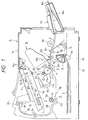
- Fig. 1 is an elevational sectional view of a laser beam printer having a process cartridge mounted thereto, according to one aspect of the present invention
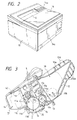
- Fig. 2 is a perspective view of the laser beam printer
- Fig. 3 is a cross-sectional view of the process cartridge
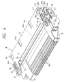
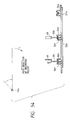
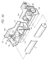
- Fig. 4 is a perspective view of the process cartridge.
- the image forming apparatus A is so designed that a latent image is formed on a photosensitive drum (as an example of an image bearing member) by illuminating light image from an optical system 1 onto the drum in response to image information, and the latent image is developed with developer (referred to as "toner” hereinafter) to form a toner image.
- a recording medium 2 is fed by a convey means 3 to an image forming station of a process cartridge B, and, in the image forming station, the toner image formed on the photosensitive drum is transferred onto the recording medium 2 by a transfer means 4. Then, the recording medium 2 is sent to a fixing means 5, where the transferred toner image is fixed to the recording medium. Thereafter, the recording medium is discharged to a discharge portion 6.
- the rotating photosensitive drum (an example of an image bearing member) 7 is uniformly charged by a charger means 8.
- the latent image is formed on the photosensitive drum 7 by illuminating the light image from the optical system 1 through an exposure portion 9, and then the latent image is developed by a developing means 10 to visualize the image as a toner image.
- the toner image is then transferred onto the recording medium 2.
- the residual toner remaining on the photosensitive drum 7 is removed by a cleaning means 11.
- the process cartridge B comprises a toner frame 12 as a first frame having a toner reservoir, a developing frame 13 as a second frame having a developing sleeve, and a cleaning frame 14 as a third frame having the photosensitive drum 7 and the cleaning means 11 and the like.
- the reference numeral 15a denotes an operation portion on which a recording copy number setting button, a density setting button, a test print button, a lamp for informing of the exchange of the cartridge which will be described later, and the like are provided.
- the optical system 1 serves to illuminate the light image onto the photosensitive drum 7 in response to the image information sent from an external device and the like.
- the optical system comprises an optical unit 1a in which a polygon mirror 1b, a scanner motor 1c, a focusing lens 1d, a reflection mirror 1e and a laser diode 1f are accommodated and which is disposed within a frame 15 of the apparatus A.
- the laser diode 1f emits the light in response to the image signal, which light is sent to the polygon mirror 1b as image light.
- the polygon mirror 1b is rotated at a high speed by the scanner motor 1c, and the image light reflected by the polygon mirror 1b is illuminated onto the photosensitive drum 7 via the focusing lens 1d and the reflection mirror 1e, thereby selectively exposing the surface of the photosensitive drum 7 to form a latent image corresponding to the image information on the photosensitive drum 7.
- the convey means 3 for conveying or feeding the recording medium (for example, an OHP sheet, thin film or the like) 2 will be explained.
- the convey means 3 permits both the manual sheet supply and the cassette sheet supply.
- the manual sheet supply one or more recording medium 2 is set on a sheet supply tray 3a and then the image forming operation is started.
- the recording medium 2 on the sheet supply tray 3a is sent into the image forming apparatus by the rotation of a pick-up roller 3b.
- a plurality of recording media 2 are set on the sheet supply tray, the recording media are separated one by one by a pair of separation rollers 3c1, 3c2, and the separated recording medium is conveyed until a leading end of the recording medium is abutted against a nip between a pair of regist rollers 3d1, 3d2.
- the paired regist rollers 3d1, 3d2 are rotated in response to the image forming operation to feed the recording medium 2 to an image forming station.
- the recording medium 2 is conveyed to the fixing means 5, and then is discharged onto the discharge portion 6 by a pair of intermediate discharge rollers 3e and a pair of discharge rollers 3f1, 3f2.
- guide members 3g for guiding the recording medium 2 are arranged between the fixing means and the intermediate discharge rollers and between the intermediate discharge rollers and the paired discharge rollers.
- the sheet supply tray 3a comprises an inner member 3a1 and an outer member 3a2.
- the inner member 3a1 is contained in the outer member 3a2, and, as shown in Fig. 2, the outer member 3a2 constitutes a portion of the frame 15 of the apparatus.
- a mounting portion for a cassette 3h is provided at a lower portion within the frame 15.
- the recording media 2 in the cassette 3h mounted in the mounting portion are sent to the paired regist rollers 3d1, 3d2 one by one from the uppermost one by the rotation of a pick-up roller 3i and a feed roller 3j.
- the recording medium is conveyed in the same manner as the manual sheet supply.
- a sensor 3k serves to detect the presence/absence of the recording medium 2 in the cassette 3h.
- the transfer means 4 serves to transfer the toner image formed on the photosensitive drum 7 onto the recording medium 2, and, as shown in Fig. 1, comprises a transfer roller 4. More particularly, the recording medium 2 is urged against the photosensitive drum 7 of the process cartridge B mounted on a mounting means (described later) by the transfer roller 4, and, by applying a voltage having the polarity opposite to that of the toner image formed on the photosensitive drum 7 to the transfer roller 4 (in the illustrated embodiment, by effecting the constant current control with DC voltage of about 1000 V), the toner image on the photosensitive drum 7 is transferred onto the recording medium 2.
- the fixing means 5 serves to fix the toner image transferred to the recording medium 2 by the application of the voltage to the transfer roller 4 onto the recording medium 2.
- the fixing means comprises a rotating drive roller 5a, and a driven fixing roller 5b having a heater 5c therein and urged against the drive roller 5a. More particularly, while the recording medium 2 to which the toner image was transferred at the image forming station is being passed between the drive roller 5a and the fixing roller 5b, the recording medium is subjected to pressure due to the abutment between the rollers 5a, 5b and heat due to the heating of the fixing roller 5b, thereby fixing the transferred toner image to the recording medium 2.
- the cartridge mounting means for mounting the process cartridge B is provided in the image forming apparatus A. After an opening/closing cover 16 is opened, the mounting or dismounting of the process cartridge B is effected. More particularly, the opening/closing cover 16 is pivotally mounted on an upper part of the frame 15 via hinges 16a.
- a left guide member 17 and a right guide member 18 are attached to inner side walls.
- the guide members 17, 18 have first guide portions 17a, 18a which are inclined forwardly and downwardly, and second guide portions 17b, 18b which are disposed above the first guide portions.
- the guide portions 17a, 17b and 18a, 18b are arranged with left/right symmetry.
- Bearing portions 17c, 18c (described later) for supporting drum bearings of the process cartridge B are formed on ends of the first guide portions 17a, 18a, respectively, and intermediate stepped portions 17b1, 18b1 are formed on the second guide portions 17b, 18b, respectively.
- the left guide member 17 has a cartridge rocking movement regulating guide portion 17d which is disposed above the second guide portion 17b.
- the right guide member 18 has a shutter cam portion 18d for opening and closing a drum shutter 35 of the process cartridge B, which cam portion is disposed above the second guide portion 18b.
- pressure members 19 are disposed above the rocking movement regulating guide portion 17d and the shutter cam portion 18d, which pressure members serve to bias the mounted process cartridge B downwardly via torsion coil springs 19a.
- abutment members 20 for positioning the process cartridge B are arranged at front sides of the left and right guide members 17, 18 (front sides in a cartridge inserting direction).
- the process cartridge B can be mounted within the image forming apparatus while being guided by the first and second guide portions 17a, 18a and 17b, 18b of the left and right guide members 17, 18.
- the mounting operation for the process cartridge will be explained after the construction of the process cartridge is described.
- the process cartridge B includes an image bearing member, and at least one process means.
- the process means may be, for example, a charger means for charging a surface of the image bearing member, a developing means for developing a latent image formed on the image bearing member to form a toner image, a cleaning means for removing residual toner remaining on the image bearing member, and the like. As shown in Fig.
- the process cartridge B comprises a charger means 8, exposure portion 9, developing means 10 for performing a developing operation with toner and cleaning means 11 which are arranged around an electrophotographic photosensitive drum 7 as an image bearing member and which are enclosed by a housing comprising a toner frame 12, developing frame 13 and cleaning frame 14 to form a unit which can removably be mounted to the frame 15 of the image forming apparatus as a process cartridge B.
- the photosensitive drum 7 comprises a cylindrical drum base 17a made of aluminium, and an organic photosensitive layer 7b coated on an outer peripheral surface of the drum base.
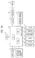
- a drive motor 71 (refer to Fig. 59) of the image forming apparatus is transmitted to a helical gear 7c (refer to Fig. 8A) secured to one longitudinal end of the photosensitive drum 7, the drum 7 is rotated in a direction shown by the arrow in Fig. 1 in response to the image forming operation.
- the photosensitive drum 7 is rotatably attached to the cleaning frame 14 by fitting a boss 7d1 of a gear flange 7d attached to one longitudinal end of the photosensitive drum into a bearing portion 14a of the frame 14 and by inserting a metal (iron in the illustrated embodiment) shaft 21 into a hole formed in a resin helical gear 7c attached to the other end of the drum and by securing the shaft 21 to the frame 14.
- the shaft 21 has an integral shaft portion 21a and flange 21b and is secured to the frame 14 by securing the flange 21b to the frame 14 by screws.
- the gear flange 7d comprises a spur wheel and serves to transmit the rotational force of the photosensitive drum 7 rotated via the helical gear 7c receiving the driving force from the image forming apparatus to the transfer roller 4, thereby rotating the latter.
- the metal shaft 21 is a conductive member
- another conductive member 22 (made of bronze phosphide in the illustrated embodiment) is arranged to contact with an inner surface of the aluminium drum base 7a of the photosensitive drum at the end thereof into which the metal shaft 21 is inserted, so that, when the metal shaft 21 is inserted, it is contacted with the conductive member 22. Consequently, the photosensitive drum 7 is earthed to the image forming apparatus through the conductive member 22 and the metal shaft 21 as will be described later. That is to say, as shown in Fig.
- the conductive member 22 is fitted on and secured by bosses 7c2 formed on a side surface of the flange portion 7c1 of the helical gear 7c, and has a hole or opening 22a into which the metal shaft 21 is to be inserted. Further, a contact portion 22b having a spring feature is also provided to extend into the opening 22a. When the metal shaft 21 is inserted into the opening, it is contacted with the contact member 22b while urging the latter. Further, the conductive member 22 is provided with bifurcated pawl portions 22c protruding in the left and right direction, so that, when the flange portion 7c1 is inserted into the photosensitive drum 7, the pawl portions 22c are contacted with the inner surface of the photosensitive drum 7.
- the photosensitive drum 7 is rotated, and the surface of the photosensitive drum 7 is uniformly charged by applying the DC voltage and AC voltage in an overlapped fashion to the charger roller 8.
- the DC voltage and AC voltage are applied to the charger roller 8 in the overlapped fashion and the frequency of the AC voltage is increased.
- the frequency of the AC voltage exceeds about 200 Hz, it is feared that a so-called "charging noise" due to the vibration of the photosensitive drum 7 and the charger roller 8 is increased.
- the charger roller 8 when the AC voltage is applied to the charger roller 8, an electrostatic attraction force is generated between the photosensitive drum 7 and the charger roller 8, and the attraction force is strong at the maximum and minimum values of the AC voltage, whereby the charger roller 8 is attracted toward the photosensitive drum 7 while deforming elastically.
- the attraction force is relatively weak at the intermediate value of the AC voltage, with the result that the charger roller 8 tends to separate from the photosensitive drum 7 by the restoring force due to the elastic deformation. Consequently, the photosensitive drum 7 and the charger roller 8 are vibrated at the frequency greater than the frequency of the applied AC voltage by twice.
- the charger roller 8 when the charger roller 8 is attracted to the photosensitive drum 7, the rotations of the roller and the drum are braked, thereby generating the vibration due to the stick slip (generated as if a wet glass is rubbed by a finger); this vibration causes the charging noise.
- a filler 7e formed from a rigid body or elastic body is arranged in the photosensitive drum 7 at a central portion in the longitudinal direction thereof.
- the material of the filler 7e may be metal such as aluminium or brass, or ceramics such as cement or gypsum, or rubber such as natural rubber or the like. In consideration of the productivity, workability, and effect of weight and cost, the material of the filler may be appropriately selected among them.
- the filler 7e is made of aluminium having a weight of about 120 grams.
- the shape or configuration of the filler 7e may be solid cylindrical or hollow cylindrical (in the illustrated embodiment, as shown in Fig. 8B, the filler is formed as the solid cylinder).
- the filler 7e having an outer diameter smaller than an inner diameter of the photosensitive drum 7 by about 100 ⁇ m is inserted into the hollow drum base 7a, thus attaching the filler to the photosensitive drum. That is to say, the gap between the drum base 7a and the filler 7e is kept to 100 ⁇ m at the maximum, and an adhesive (for example, cyanoacrylate group, epoxy resin group or the like) is applied to an outer surface of the filler or the inner surface of the drum base 7a, thereby adhering the filler 7e to the inner surface of the drum base 7a.
- an adhesive for example, cyanoacrylate group, epoxy resin group or the like
- the photosensitive drum 7 is rotated stably, thereby suppressing the vibration due to the rotation of the photosensitive drum 7 during the image forming operation. As a result, even when the frequency of the AC voltage applied to the charger roller 8 is increased, it is possible to suppress the charging noise.
- the charger means serves to charge the surface of the photosensitive drum 7.
- a charging method of a so-called contact type as disclosed in the Japanese Patent Laid-open No. 63-149669 is used. More particularly, as shown in Fig. 10, the charger roller 8 is rotatably mounted on the cleaning frame 14.
- the charger roller 8 comprises a metal roller shaft 8a, an elastic conductive layer around the roller shaft, a high resistive elastic layer around the conductive layer, and a protection film around the high resistive layer.
- the elastic conductive layer is formed from an elastic rubber layer made of EPDM or NBR dispersing carbon powder therein, and acts to direct the bias voltage to the roller shaft 8a.
- the high resistive elastic layer is made of urethane rubber dispersing a small amount of conductive fine powder (for example, carbon powder), and acts to prevent the abrupt reduction of the bias voltage by limiting the leak current to the photosensitive drum 7 even when the charger roller having high conductivity such as a pin hole is opposed to the photosensitive drum 7.
- the protection film is made of N-methyl methoxyl nylon and acts to prevent the deterioration of the surface of the photosensitive drum 7 if the plastic material of the conductive elastic layer and/or the high resistive elastic layer is contacted with the photosensitive layer.
- roller shaft 8a is attached to the frame 14 via bearings 23, 24 slidable slightly toward the photosensitive drum 7, which bearings are biased toward the photosensitive drum 7 by springs 25, thereby contacting the charger roller 8 with the photosensitive drum 7.
- the charger roller 8 is rotatingly driven by the rotation of the photosensitive drum 7 while applying the DC voltage and AC voltage in the overlapped fashion to the charger roller 8 as mentioned above, thereby uniformly charging the surface of the photosensitive drum 7.
- a metal contact member 26 having a spring feature is contacted with one end of the metal roller shaft 8a, thereby permitting the application of the voltage from the image forming apparatus to the charger roller 8.
- a regulating member 14b for suppressing the deformation of the contact member 26 is formed on the cleaning frame 14 so that, even if any force directing toward the left in Fig. 10 is applied to the roller shaft 8a resulting from the dropping of the process cartridge B or the like, the contact member 26 is prevented from being deformed plastically by contacting the contact member 26 against the regulating member 14b. Further, since the regulating member 14b limits the axial movement (toward the left in Fig. 10) of the charger roller 8, the charger roller 8 is always maintained on the photosensitive drum 7.
- the bearing 24 has a hooked abutment portion 24a integrally formed therewith.
- the bearing 24 is made of polyacetal (POM) which has the good anti-wear feature and provides the good slidability with respect to the metal roller shaft 8a.
- the both ends of the roller shaft 8a are abutted against the anti-wear bearing 24 and the contact member 26 to limit the axial movement of the charger roller 8, thereby preventing the roller shaft 8a from contacting with the frame 14.
- the frame 14 must be made from material such as polyphenylene oxide resin (PPO) having the good anti-wear feature with respect to the metal roller shaft 8a.
- PPO polyphenylene oxide resin
- the frame 14 can be made of polystyrene resin (PS) which is more cheap, rather than PPO, thereby reducing the manufacturing cost of the process cartridge B.
- the material of the bearing 24 is not limited to polyacetal, but may be other material such as nylon, so long as the material has the high anti-wear ability with respect to the metal roller shaft 8a.
- the voltage applied to the charger roller 8 to charge the photosensitive drum 7 has an AC component Vpp of about 1800 V and DC component VDC1 of about -670 V, and the constant current control is effected.
- the exposure portion 9 serves to form an electrostatic latent image on the photosensitive drum 7 uniformly charged by the charger roller 8, by exposing the light image from the optical system 1 onto the photosensitive drum.
- the exposure portion is constituted by an opening portion 9 which is formed in an upper surface between the developing frame 13 and the cleaning frame 14 and through which the image light passes. That is to say, by providing a rectangular notch 9a in an upper surface 13r of the developing frame 13 and by arranging an upper wall portion 14n of the cleaning frame 14 to cover a portion of the notch 9a, the exposure portion 9 is formed.
- the developing means serves to visualize the electrostatic latent image formed on the photosensitive drum 7 by the aforementioned exposure with toner to form a toner image.
- the image forming apparatus A can utilize both magnetic toner and non-magnetic toner, in the illustrated embodiment, an example that a process cartridge B containing magnetic toner as one-component magnetic developer is mounted to the image forming apparatus is shown.
- the magnetic toner used in the developing operation utilizes polystyrene resin as the binding resin, and preferably utilizes styrene acrylic resin.
- Coloring material which can be added to the magnetic toner may be conventional carbon black, copper phthalocyanine, iron black or the like.
- magnetic fine particles included in the magnetic toner are made from material which can be magnetized in the magnetic field and which may be ferromagnetic metal powder such as iron, cobalt, nickel, or alloy or compound such as magnetite or ferrite.
- the developing means 10 for forming the toner image with the magnetic toner has a toner reservoir 10a for containing toner, and a toner feed member 10b for feeding out the toner is disposed in the toner reservoir 10a, which feed member is rotated in a direction shown by the arrow. Further, by using the fed out toner and by rotating a developing sleeve 10d having a magnet 10c therein, a thin toner layer is formed on the developing sleeve. When the toner layer is formed on the developing sleeve 10d, the friction charging charge sufficient to develop the electrostatic latent image on the photosensitive drum 7 can be obtained due to the friction between the toner and the developing sleeve 10d. Further, a developing blade 10e for regulating a thickness of the toner layer is provided to abut against the surface of the developing sleeve 10d.
- the AC component Vpp of about 1600 V and the DC component VDC2 of about -500 V are applied as the developing bias.
- the DC component VDC2 of this developing bias if a value (VDC1 - VDC2) becomes greater than -50 V (becomes greater toward the plus side), it is feared that the fog occurs.
- the toner reservoir 10a and the toner feed member 10b are formed in the toner frame 12; whereas, the developing sleeve 10d and the developing blade 10e are attached to the developing frame 13. Longitudinal abutment portions of the frames 12, 13 are bonded to each other by ultrasonic welding, thereby integrally connecting these frames.
- abutment rings 10f each having an outer diameter greater than an outer diameter of the developing sleeve 10d by a value corresponding to the above-mentioned gap are arranged in the vicinity of both axial ends of the developing sleeve 10d and out of a toner forming area on the developing sleeve, which abutment rings are abutted against the photosensitive drum 7 out of a latent image forming area thereon.
- a gear (helical gear) 10g is attached to one axial end of the developing sleeve 10d so that the gear 10g can be rotated together with the developing sleeve 10d.
- the gear 10g is meshed with the helical gear 7c of the photosensitive drum 7 so that the developing sleeve 10d can be rotated by the rotation of the photosensitive drum 7.
- the gear 10g is meshed with a gear (not shown) connected to the toner feed member 10b, thereby transmitting the rotational force of the photosensitive drum 7 to the toner feed member 10b.
- the toner in the toner reservoir 10a is sent to the developing sleeve 10d, where the toner layer having a constant thickness is formed on the developing sleeve 10d by the developing blade 10e, and then the toner on the developing sleeve is transferred onto the electrostatic latent image formed on the photosensitive drum 7.
- the formation of the toner layer on the developing sleeve 10d is effected by supplying the toner to only a carbon coating area of the developing sleeve 10d, and a relation between (a) the photosensitive layer area on the photosensitive drum 7 along its longitudinal (axial) direction and (b) the charging area affected by the charger roller 8 and (c) the toner layer forming area (developing area) on the developing sleeve 10d is so selected to become (a) > (b) > (c).
- toner in the toner reservoir 10a must be prevented from leaking between the developing sleeve 10d and the developing frame 13.
- toner leak preventing elastic seals 10h are arranged on both longitudinal end portions of an opening 13a which is formed in the developing frame 13 and through which the toner is fed toward the developing sleeve 10d, and an elastic blow sheet 10i is arranged along a lower edge of the opening 13a to contact with the whole length of the developing sleeve 10d.
- a thickness of each toner leak preventing seal 10h is equal to a thickness of a stepped portion formed on a lower edge 13o of the developing frame 13 so that, when the toner leak preventing seals 10h are adhered to the developing frame 13, upper surfaces of the seals 10h become flush with the lower edge 13o.
- the blow sheet 10i is adhered to an upper surface of the lower edge portion 13o by a both-sided adhesive tape (not shown).
- a (longitudinal) length of the blow sheet 10i is longer than a (longitudinal) length of the opening 13a, and both longitudinal end portions of the blow sheet are overlapped with the toner leak preventing seals 10h, and a (widthwise) free edge of the blow sheet is urged against the peripheral surface of the developing sleeve 10d along its length with an appropriate urging force.
- the toner tm passing through the gaps 10k is adhered to the developing sleeve 10d in a swelled condition.
- the toner tm is collected to the toner reservoir 10a through the blow sheet 10i, thereby preventing the toner from leaking out of the cartridge.
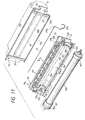
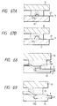
- Fig. 13A shows a section taken along the line A - A in Fig. 11
- Fig. 13B shows a section taken along the line B - B in Fig. 11.
- the toner leak preventing seals 10h and the blow sheet 10i are closely contacted with each other without bending at the overlapped areas, and they become in parallel with each other. If the blow sheet 10i is bent and not too closely contacted with the toner leak preventing seals 10h as shown in Figs. 14A and 14B, it is feared that the toner leaks between a gap between the seals and the sheet. However, in the illustrated embodiment, since the blow sheet 10i is not bent and is closely contacted with the toner leak preventing seals 10h, the risk of the leakage of toner can be avoided.
- an abutment angle between the free edge portion of the blow sheet 10i and the peripheral surface of the developing sleeve 10d is defined by the upper surfaces of the toner leak preventing seals 10h, and there is no dispersion in the accuracy of the upper surfaces of the toner leak preventing seals.
- the blow sheet 10i is used in the straight condition, the abutment angle of the blow sheet 10i is difficult to change for a long time.
- the toner contained in the toner reservoir 10a is hard to leak between the blow sheet 10i and the developing sleeve 10d.
- three longitudinal ribs 13b, 13c, 13d are formed on a portion of the developing frame 13 against which the developing blade 10e is abutted, so that the first and second ribs 13b, 13c are abutted against the developing blade 10e and the third rib 13d is abutted against a blade attachment member 10j such as a metal plate for attaching the developing blade 10e.
- a free edge of the second rib 13c abutted against the developing blade 10e is sharpened so that, when the first rib 13b is abutted against the deve-loping blade 10e and the third rib 13d is abutted against the blade attachment member 10j, the sharpened edge of the second rib 13c is penetrated into the developing blade made of rubber having a thickness of about 1.3 mm.
- the sharpened edge of the second rib 13c is curved so that a central portion of the edge in the longitudinal direction is convexly protruded slightly more than both end portions of the edge.
- the rib 13c can be surely penetrated into the developing blade 10e along its whole longitudinal edge. Accordingly, there is no gap between the developing frame 13 and the blade 10e, thus preventing the toner from leaking between the blade and the developing frame.
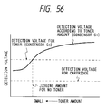
- a toner remaining amount detection mechanism for detecting the toner remaining in the toner reservoir 10a.
- this mechanism comprises a metallic antenna wire 27 arranged at a jointed zone between the toner frame 12 and the developing frame 13 and in a toner passage from the toner reservoir 10a to the developing sleeve 10d.
- the antenna wire 27 By acting the antenna wire 27 as a first electrode and the developing sleeve 10d as a second electrode, the voltage is applied between the first and second electrodes. In this case, if there is any toner between the electrodes, the electrostatic capacity therebetween will be increased; whereas, if there is no toner between the electrodes, the electrostatic capacity will be decreased.
- a control portion 60 by detecting the change in the electrostatic capacity by a control portion 60 (refer to Fig. 59), it is possible to detect the toner remaining amount.
- a control portion 60 By comparing an electric signal representative of the electrostatic capacity with a predetermined reference value, it is possible to detect a "no toner" condition.
- a lamp alarm for process cartridge exchange
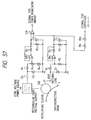
- a concrete circuit for detecting the toner remaining amount will be described later.
- the widthwise jointed areas cannot be welded, because, as shown in Fig. 11, an opening 12e formed in the toner frame 12 is sealingly covered by a cover film 28 to prevent the leakage of the toner in the toner reservoir 10a of the process cartridge B and a free end of the cover film 28 is exposed outwardly through the widthwise jointed area (between the frames 12, 13) so that in use the operator can pull the free end of the cover film 28 to open the opening 12e. Therefore, in order to prevent the toner from leaking through the widthwise jointed areas between the toner frame 12 and the developing frame 13, toner leak preventing seals 29 are disposed at the widthwise jointed areas.
- the antenna line 27 since the voltage is applied to the antenna wire or line 27, one end of the antenna line 27 must be protruded outwardly through the jointed zone between the frames 12, 13 and a contact portion 27a is formed on the end of the antenna line. To this end, the antenna line 27 must be protruded outwardly through the widthwise jointed area (between the toner frame 12 and the developing frame 13) where the toner leak preventing seal 29 is adhered. In order to attach the antenna line 27 in this way, as shown in Fig.
- a recess 13e is formed in the developing frame 13 at its jointed zone, and an adhesive 30 such as silicone is coated on the surface of the recess 13e, and then the antenna line 27 is adhered to the developing frame 13 by inserting the antenna line into the recess.
- the adhesive 30 coated on the surface of the recess 13e is projected from the recess and swollen. If the adhesive 30 is cured in the swelled condition, even when the toner leak preventing seal 29 is adhered to the frame 13, the seal 29 cannot be closely contacted with the developing frame 13 completely, thereby often creating a clearance 31. Although such clearance 31 is small, since the toner comprises fine particles, it is feared that the toner is leaked through the clearance 31.
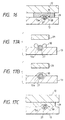
- Fig. 17A after the antenna line 27 is inserted into the recess 13e having the adhesive 30 therein, the adhesive swollen from the recess 13e is flattened or averaged along and on the antenna line 27 (as completely covering the antenna line 27) by a rod member or the like as shown in Fig. 17B.
- Fig. 17C when the toner leak preventing seal 29 is adhered to the frame 13, the seal 29 can be closely contacted with the surface (to be jointed) of the developing frame 13 without any clearance, thereby preventing the leakage of toner completely.
- new adhesive may be added to average the adhesive and completely cover the antenna line 27.
- the contact portion 27a of the antenna line 27 is exposed outwardly. Therefore, it is feared that the exposed portion of the antenna line 27 is erroneously struck against any body by the operator during the handling of the process cartridge B. Since the toner leak preventing seal 29 is made of foam urethane having a thickness of about 4 mm and is elastic, if the exposed portion of the antenna line 27 is struck against any body, as shown in Fig. 18A, it is feared that the antenna line 27 is floated from the developing frame 13. Also in this case, a small clearance 32 is created between the frame 13 and the antenna line 27, resulting in the leakage of toner. To avoid this, in the illustrated embodiment, as shown in Fig.
- a bent portion 27b bent in an L-shape directing from the developing frame 13 to the toner frame 12 is formed on the antenna line 27 disposed in the jointed zone between the toner frame 12 and the developing frame 13.
- the seal 29 having the thickness of about 4 mm is compressed up to about 1 mm, the elastic deformation does not occur. Accordingly, if the shock acts on the exposed portion of the antenna line 27 as mentioned above, the antenna line 27 does not float from the recess 13e of the developing frame 13. Thus, since the clearance as shown in Fig. 18A is not created, the risk of the leakage of the toner can be avoided.
- the toner leak preventing seal 29 will be explained.
- the toner leak preventing seals 29 are adhered to both longitudinal end portions of the opening 12e of the toner frame 12 by both-sided tapes.
- a tear preventing sheet 29a having a width narrower than a width of the seal 29 and a thickness of about 0.01 - 1 mm is adhered.
- the reason why the tear preventing sheet 29a is provided is as follows. That is to say, in use, the operator must draw out the cover film 28 by hand to open the opening 12e of the process cartridge B. In this case, there is no problem when the operator pulls the cover film 28 in a film draw-out direction (corresponding to the longitudinal direction of the opening 12e). However, as shown in Fig. 19, when the cover film is pulled in a direction inclined with respect to the film draw-out direction by an angle ⁇ , as shown in Fig. 20, the width of the cover film 28 is shortened or wrinkled by gathering the sheet in one direction (upward direction in Fig.
- the tear preventing sheet 29a when the tear preventing sheet 29a is adhered to the toner leak preventing seal 29 through which the cover film 28 is drawn out, if the creases are created during the pulling of the cover film 28, since the tear preventing sheet 29a protects the seal 29, the seal 29 is prevented from tearing. Accordingly, regardless of the direction along which the operator draws out the cover film 28, the leakage of the toner can be prevented.
- the tear preventing sheet 29a along the width of the seal 29 at a side of the opening 12e, while the cover film 28 is being drawn out, the toner adhered to the film 28 is scraped by the tear preventing sheet 29a, thereby eliminating the possibility that the operator's hand is smudged by the drawn-out film 28.
- the toner leak preventing seal 29 and the tear preventing sheet 29a are firmly pinched between and secured by the frames 12, 13 at both longitudinal ends thereof (upper and lower ends in Fig. 11), the sheet 29a is not deviated from the seal 29.
- the tear preventing sheet 29a is preferably made from material which is strong against the rubbing to the cover film 28, for example, such as polyethylene terephthalate or high dense polyethylene.
- the adhering position of the sheet 29a is spaced apart from an edge 29b of the toner leak preventing seal 29 in the film draw-out direction by a distance U.
- the distance is selected to be about 5 mm or less, the tear preventing effect regarding the toner leak preventing seal 29 is not worsened during the draw-out of the cover film 28.
- the tear preventing sheet 29a may have a width not small than the width of the toner preventing seal 29 so that the sheet are adhered to the whole surface of the seal 29.
- the helical gear 7c and the developing gear 10g are so-called helical gears, so that, when the gear 7c is subjected to the driving force from the image forming apparatus, the photosensitive drum 7 mounted with play is subjected to the thrust force directing to the gear 7c.
- the photosensitive drum 7 is shifted in the thrust direction by the thrust force, with the result that the photosensitive drum is abutted against the cleaning frame 14, thus positioning the photosensitive drum in the thrust direction.
- the cleaning means 11 serves to remove the toner remaining on the photosensitive drum 7 after the toner image on the photosensitive drum 7 is transferred onto the recording medium 2 by the transfer means 4.
- the cleaning means 11 comprises a cleaning blade 11a contacted with the surface of the photosensitive drum 7 and adapted to scrape off the toner remaining on the drum 7, a dip sheet 11b disposed below the blade 11a to receive and scraped toner and contacted with the surface of the photosensitive drum 7, and a waste toner reservoir 11c for collecting the received waste toner.
- the dip sheet 11b is lightly contacted with the surface of the photosensitive drum 7 so that it permits the passage of the waste toner on the photosensitive drum 7 and directs the toner removed from the photosensitive drum 7 by the blade 11a toward a direction away from the surface of the photosensitive drum 7 (i.e., toward the waste toner reservoir 11c).
- the cleaning blade 11a is made of rubber and the like and is adhered to a blade attachment member 11d by a both-sided adhesive tape, which blade attachment member is attached to the cleaning frame 14 by screws. Further, the dip sheet 11b is adhered to a dip sheet adhesion surface (edge portion) 11c1 of the waste toner reservoir 11c by a both-sided adhesive tape.
- toner leak preventing seals 11e are provided on both longitudinal ends of the cleaning blade 11a.
- the portions where the seals 11e are provided will be further fully described.
- the seals 11e are adhered to both end portions of the waste toner reservoir 11c, and the both longitudinal end portions of the cleaning blade 11a are adhered to the seals 11e.
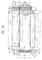
- screen members 11c3 are formed on an upper surface 11c2 of the waste toner reservoir 11c to contact with inner surfaces of the corresponding seals 11e.
- the cleaning blade 11a is attached to the cleaning frame 14, and then the seals 11e are attached in such a manner that edges S2 of the seals are closely contacted with both longitudinal edges S1 of the cleaning blade 11a shown in Fig. 26.
- the width W1 of the seal 11e is longer than a distance L0 between the dip sheet adhesion surface 11c1 and the cleaning blade 11a, a clearance is created between a lower edge T1 of the seal 11e and the dip sheet adhesion surface 11c1, thus causing the leakage of toner.
- the distance L0 is selected to be greater than the width L1 (L0 > L1) in tolerance and an compression amount X is given to the seal 11e.
- the seal 11e must be adhered to the dip sheet adhesion surface 11c1 while urging the lower edge T1 of the seal against a hatched portion T2 of the adhesion surface; however, in the illustrated embodiment, since the screen members 11c3 are provided, the waste toner is prevented from leaking while sliding laterally along the dip sheet adhesion surface.
- the compression amount X of the seal 11e substantially zero in tolerance.
- the housing of the process cartridge B is constituted by the toner frame 12, developing frame 13 and cleaning frame 14.
- the toner frame 12 and the developing frame 13 are integrally welded to each other to form a toner developing frame C.
- the toner developing frame C is connected to the cleaning frame 14 in a manner as described later to form the housing of the process cartridge B.
- the frames 12, 13, 14 according to the illustrated embodiment are formed from polystyrene resin by injection molding.
- the frames 12, 13, 14 are made of material having the charging feature near that of the toner component, even if the toner is rubbed against the frames during the image forming operation, the abnormal charge is not generated due to the frictional charging, thereby preventing the deterioration of the image quality.
- the toner reservoir 12a and the toner feed member 10b is provided in the toner frame 12.
- a plurality of longitudinal ribs 12d are formed on an outer surface of the toner frame 12, which ribs constitute a gripper portion.
- the widths of the ribs 12d formed on the outer surface of the toner frame 12 are gradually changed to form the R configuration wholly.
- the developing sleeve 10d and the developing blade 10e are provided on the developing frame 13.
- the developing blade 10e is mounted by attaching both longitudinal end portions of the blade attachment member 10j to which the blade is adhered to the frame 13 by screws, in the illustrated embodiment, prior to the attachment by the screws, the blade attachment member 10j is positioned with respect to the developing frame 13.
- positioning bosses 13g are uprightly formed on a blade attachment surface 13f of the developing frame 13, and holes formed in the blade attachment member 10j are fitted onto the positioning bosses 13g, thereby positioning the attachment member with respect to the frame 13.
- positioning bosses 13i are uprightly formed on an interface 13h of the developing frame 13 which is to be joined to the toner frame 12 (these positioning bosses are disposed on both longitudinal end portions of the developing frame 13, as shown in Fig. 11), and these bosses 13i are fitted into fitting holes 12c formed in the toner frame 12, thereby positioning the joint position between the developing frame 13 and the toner frame 12.
- the blade attachment surface 13f and the joint interface 13h of the developing frame 13 are in parallel with each other.
- the bosses 13g for positioning the blade and the bosses 13i for positioning the toner frame are in parallel with each other, after the molding operation, only by separating molds 33 from each other in the left and right direction, the molded frame can easily be separated from the molds.
- the photosensitive drum 7, the charger roller 8, and the cleaning blade lla, dip sheet llb and waste toner reservoir llc of the cleaning means 11 are provided on the cleaning frame 14.
- both longitudinal end portions of a blade attachment member 11d to which the cleaning blade is adhered are attached to the frame 14 by screws.
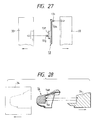
- the blade attachment member 11d is positioned with respect to the frame 14. To this end, as shown in Fig.
- positioning bosses 14d are uprightly formed on a blade attachment surface 14c of the frame 14, and holes (not shown) formed in the blade attachment member 11d are fitted onto the bosses 14d, thereby positioning the attachment member with respect to the cleaning frame.
- the blade attachment surface 14c becomes perpendicular to a mold releasing direction (as shown by the arrow in Fig. 28) for molds 34.
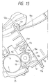
- the drum shutter 35 shown in Fig. 3 is pivotably mounted on the cleaning frame 14.
- the drum shutter 35 serves to open and close an opening through which the photosensitive drum 7 faces the transfer roller 4.
- the drum shutter is automatically opened when the process cartridge B is mounted to the image forming apparatus A and is automatically closed when the process cartridge is dismounted from the image forming apparatus A.
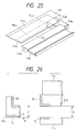
- the frames 12, 13 are joined to each other by ultrasonic welding. That is to say, after the opening 12e of the toner frame 12 is closed by the cover film 28, as shown in Fig. 29, the toner frame 12 is set in a recessed portion 75a of a receiving tool 75, and then a separable cover film draw-out grip 12f formed integrally with the frame 12 is bent downwardly. Then, the developing frame 13 is overlapped with the toner frame 12, and the developing frame 13 is pressed from above by a press (hold-down) tool 76. In this condition, when the ultrasonic waves are applied to the toner frame 12 and the developing frame 13, ribs 13s (Fig. 7) formed on the joint interface of the toner frame 12 are welded, thereby interconnecting the frames 12, 13.
- the frames 12, 13 are apt to deform in their widthwise directions (shown by the arrows J in Fig. 29).
- the developing frame since longitudinal ribs 13t are formed on the developing frame 13 as shown in Fig. 11 and the blade attachment member 10j made of a metal plate is attached to the developing frame, the developing frame has the sufficient strength to resist the deformation thereof.
- the toner frame 12 since the toner frame 12 has no reinforcement rib, the toner frame has poor strength and is generally apt to deform.
- flanges 12g are formed on the toner frame 12 at both lengthwise edges (upper and lower ends along lengthwise direction of opening 12e) thereof. A distance between the flanges 12g is substantially equal to the widthwise length L13 of the interface 13h of the developing frame 13, so that the interface 13h of the developing frame 13 can be fitted between the flanges 12g.
- the interface 13h of the developing frame 13 is fitted between the flanges 12g of the toner frame 12 and the positioning bosses 13i of the developing frame 13 are fitted into the fitting holes 12c of the toner frame 12. Therefore, the toner frame 12 is hard to deform by the vibration generated during the ultrasonic welding operation, thereby preventing the deviation between the frames 12, 13.
- the interface 13h of the developing frame is fitted between the flanges 12g formed on the toner frame 12 along their upper and lower edges, even if the up-and-down vibration is applied to the widthwise direction of the toner frame 12, the movement of the toner frame 12 is regulated by the developing frame 13, thus preventing the deformation of the toner frame and the deviation between the frames 12, 13.
- the frames 12, 13 are welded together, in the illustrated embodiment, since all of the frames are formed from the same material (polystyrene resin), the welding and bonding strength between the frames 12, 13 is increased extremely.
- the developing frame 13 is not welded to the cleaning frame 14, from the view point of the improvement of the welding and bonding strength, it is not necessary to make the cleaning frame 14 by the material same as the material of the toner frame 12 and the developing frame 13.
- positioning bosses 13i of the developing frame 13 are disposed only at one lengthwise edge of the developing frame.
- positioning bosses 13i may be formed on both lengthwise edges of the developing frame 13. If do so, it is possible to prevent the deformation of the toner frame 12 and the developing frame 13 more positively during the welding operation and to prevent the deviation between the frames 12, 13 more positively.
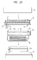
- the toner feed member 10b is mounted on the toner frame 12, and the opening 12e of the toner reservoir 10a containing the toner is closed by the cover film 28, and the antenna line 27 is attached. Thereafter, the developing frame 13 is welded to the toner frame. Then, the developing sleeve 10d and the like are assembled to the developing frame 13. In this case, the toner developing frame C comprising the integral developing frame 13 and toner frame 12 is securely rested on the assembling tray, and the various parts are assembled to the frame C (refer to Fig. 33). In the illustrated embodiment, as shown in Fig.
- a fitting hole 12a is formed in the toner frame 12 at a predetermined position, and a bottom 12b of the toner frame 12 is made flat.
- the toner frame 12 can easily be fixed, thereby facilitating the assembling of the parts such as the developing sleeve 10d, developing blade 10e and the like, which results in the improvement of the assembling operability.
- the parts such as the cleaning blade 11a and the like are assembled to the cleaning frame 14.
- a bottom of the cleaning frame 14 is made flat, and a fitting hole 14e is formed in the bottom of the cleaning frame. Accordingly, when the parts such as the blade 11a and the like are assembled to the cleaning frame 14, by inserting a fitting projection 37a formed on the assembling tray 37 into the fitting hole 14e, the cleaning frame 14 can easily be fixed, thereby facilitating the assembling of the parts such as the cleaning blade 11a and the like, which results in the improvement of the assembling operability.
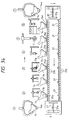
- the developing sleeve 10d is assembled, at a step 5 ⁇ the developing sleeve is fixed, and at a step 6 ⁇ the toner developing frame C is picked up to bring it to a next step. Further, after the toner developing frame C is picked up, the assembling tray 36 is returned through a lower auxiliary line, and the step 1 ⁇ is repeated again.
- the cleaing frame 14 is provided with locking recessed portions 14o which are gripped by the assembling machine to shift the cleaning frame between the stations during the automatic assembling operation.
- the assembling of the toner frame 12 and the cleaning frame 14 can be effected by any means other than the automatic assembling machines.
- the working efficiency can be improved.
- the toner developing frame C comprising the integral toner frame 12 and developing frame 13 and to the cleaning frame 14
- the toner developing frame C is joined to the cleaning frame 14.
- the frames are often rested on a table.
- the photosensitive drum 7 assembled to the cleaning frame 14 and the developing sleeve 10d assembled to the developing frame 13 are exposed outwardly.
- the photosensitive drum 7 is a most important element for performing the image forming operation, and, even if the surface of the drum is damaged more or less, the image will be distorted or deteriorated, thereby worsening the image quality.
- protruded portions 14f are formed on edges of an open end of the cleaning frame 14 to which the photosensitive drum 7 is assembled.
- the photosensitive drum 7 is arranged so that the photosensitive drum is positioned inwardly (toward the cleaning frame 14) from a line connecting between tip ends of the protruded portions 14f.
- protruded portions 13j are formed on edges of an open end of the toner developing frame C to which the developing sleeve 10d is assembled. And, the developing sleeve 10d is arranged so that the developing sleeve is positioned inwardly (toward the developing frame 13) from a line connecting between tip ends of the protruded portions 13j. With this arrangement, when the developing frame 13 integrally joined to the toner frame 12 is rested on the table, the protruded portions 13j are contacted with the table and the developing sleeve 10d is not contacted with the table.
- connection member 38 comprises a base member 38a having a threaded hole 38b through which a screw 39 is threaded, a vertical portion 38c, and a spring attachment portion 38d, which portions 38c, 38d are disposed on both sides of the threaded hole 38b.
- the vertical portion 38c protrudes downwardly from the base member 38a to prevent a connection projection (described later) of the developing frame 13 from falling out.
- the spring attachment portion 38d is disposed in parallel with the vertical portion 38c and is provided at its free end portion with a spring 38e which is protruded downwardly more than the vertical portion 38c.
- Arm portions 13k are provided on both longitudinal ends of the developing frame 13, and a connection projection 13m is protruded laterally from each arm portion 13k. Further, a spring receiving recessed portion 13n is formed on an upper surface of each arm portion 13k.
- connection recessed portions 14g into which the connection projections 13m are fitted are provided in the cleaning frame 14.
- a fastening portion 14h is formed on each recessed portion 14g.
- the fastening portion 14h has a fitting hole 14i into which the vertical portion 38c of the connection member 38 is fitted, a female threaded portion 14j into which the screw 39 is threaded, and a through hole 14k through which the spring 38e extends.
- connection projections 13m of the developing frame 13 are deeply fitted into the corresponding connection recessed portions 14g of the cleaning frame 14, and then the connection members 38 are fastened to the fastening portions 14h. That is to say, each vertical portion 38c of the connection member 38 is fitted into the hole 14i, and the spring 38e is passed through the through hole 14k and is compressed against the spring receiving recessed portion 13n of the developing frame 13. In this condition, the screw 39 is threaded into the threaded hole 38b and is fastened to the female threaded portion 14j.
- the toner developing frame C and the cleaning frame 14 are connected to each other for relative pivotal movement around the connection projections 13m, thereby completing the assembling of the process cartridge B.
- the ring members 10f are abutted against the peripheral surface of the photosensitive drum 7, thereby determining the positions of the photosensitive drum 7 and the developing sleeve 10d.
- the developing sleeve 10d is biased toward the photosensitive drum 7 (Incidentally, in the illustrated embodiment, the spring force of the spring 38e is selected to about 2 kg to urge the developing sleeve 10d with a force of about 1 kg).
- the helical gear 7c provided at the end of the photosensitive drum 7 is meshed with the gear 10g provided at the end of the developing sleeve 10d.
- connection projections 13m can be extended outwardly (these may be extended inwardly).
- the frames 13, 14 can be positioned with respect to the longitudinal direction (thrust direction), thereby eliminating the need for providing thrust stoppers.
- connection members 38 are inserted from the above and are fastened, the toner developing frame C can be pressurized at the same time when the connection members 38 are fastened.
- the toner developing frame was joined to the cleaning frame, it was requried for hooking a tension spring to the frames to urge the frames against each other, with the result that a space for arranging the tension spring was required and the spring hooking operation was troublesome.
- the compression forces of the compressed springs 38e are released, thereby permitting the very easy disassembling of the frames because of no thrust stopper.
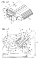
- the left guide member 17 having the first and second guide portions 17a, 17b and the right guide member 18 having the first and second guide portions 18a, 18b are formed on the frame 15 of the image forming apparatus.
- the bearing portion 14a and the shaft 21 are protruded from the left and right side surfaces of the cleaning frame 14 of the process cartridge B substantially in left/right symmetry.
- protruded ribs 40 which are to be guided along the second guide portions 17b, 18b are arranged above the bearing portion 14a and the shaft 21 in left/right symmetry.
- pressure surfaces 41 are formed on the upper surface of the cleaning frame 14 at both longitudinal ends thereof, which pressure surfaces are pressurized by pressure members 19 attached to the frame 15 of the image forming apparatus. Furthermore, there are provided positioning recesses 42 for receiving the abutment members 20 and for positioning the abutment members. In addition, an auxiliary rib 43 is protruded from the right side surface of the cleaning frame 14 above the protruded rib 40, as shown in Fig. 4. Further, there is provided a link portion 35a for opening and closing the drum shutter 35. The link portion 35a is pivoted in response to the mounting and dismounting movement of the process cartridge B, thereby opening and closing the drum shutter 35 connected to the link portion. Incidentally, the opening and closing of the drum shutter 35 will be described later fully.
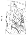
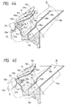
- the abutment members 20 are completely engaged by the positioning recesses 42, with the result that the process cartridge B is mounted to the frame 15 of the image forming apparatus while being pressurized by the pressure members 19. Further, in this case, the helical gear 7c of the photosensitive drum 7 is meshed with the drive gear (refer to Fig. 6) in the frame 15, thereby permitting the transmission of the driving force. Further, when the process cartridge B is mounted, the urging forces of the pressure members 19 against the process cartridge B are relieved by the lowering movement of the process cartridge B. Thus, the operator who has mounted the process cartridge B feels the "click" feeling to easily recognize the fact that the process cartridge B was positioned at the mounting position.
- the abutment members 20 of the apparatus frame 15 and the positioning recesses 42 of the process cartridge B are so arranged that abutment surfaces 20a, 42a thereof are substantially in parallel with each other.
- the abutment members 20 may be assembled to the frame 15 in such a manner that the abutment surfaces 20a are disposed substantially horizontally. Therefore, the design of the abutment members 20 and the assembling of the abutment members to the frame 15 can be simplified or facilitated, with the result that the dimensional error is hard to occur. Accordingly, it is easy to mount the process cartridge B to the frame 15 of the image forming apparatus correctly.
- a roller 19b is mounted on each pressure member 19, so that the sliding resistance is minimized by pressurizing the process cartridge by the rollers 19b when the process cartridge B is being shifted while pressurizing the pressure surfaces 41 by the pressure members 19.
- the pressure surfaces 41 of the process cartridge B pressurized by the rollers 19b were formed as surface configuration, such process surfaces may be ribbed-shape to reduce the contacting area, thereby further reducing the sliding resistance.
- the upper portion of the process cartridge B is made substantially flat, and the flat upper surface of the process cartridge is substantially in parallel with the cartridge mounting direction.
- the cartridge mounting space in the frame 15 of the image forming apparatus can be minimized, and the space in the process cartridge B (for example, spaces for the toner reservoir and the waste toner reservoir) can be used efficiently.
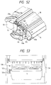
- the drum shutter 35 is opened and closed in response to the mounting and dismounting movement of the process cartridge. Now, the opening/closing operation of the drum shutter will be explained.
- the drum shutter 35 has the arm portion 35b pivotally mounted around a shaft 35c, and the link portion 35a is pivotally mounted on the shaft 35c for movement together with the arm portion 35b.
- the link portion 35a is pivoted, the arm portion 35b is also pivoted, thereby opening and closing the drum shutter 35.
- a link boss 35d is protruded from the arm portion 35b.
- the shutter cam portion 18d provided on the right guide member 18 has a first cam portion 18d1 engaged by the link portion 35a, and a second cam portion 18d2 engaged by the link boss 35d.
- An inclined angle of the first cam portion 18d1 is substantially the same as that of the second guide portion 18b for guiding the protruded portion 40 of the process cartridge B, and an inclined angle of the second cam portion 18d2 is greater than that of the first cam portion 18d1.
- the above-mentioned drum shutter 35 serves to protect the photosensitive drum 7.
- the laser shutter is provided in the image forming apparatus A.
- the laser shutter constitutes a laser light path blocking means to prevent the laser light emitted from the optical system 1 to the photosensitive drum 7 from leaking from the optical unit 1a (of the image forming apparatus) in an inoperative condition of the apparatus.
- the optical unit 1a is provided with an opening 1a1 through which the laser light is illuminated onto the photosensitive drum 7, and the laser shutter 46 is formed from a metal plate bent to cover the opening 1a1. That is to say, the laser shutter 46 has a shutter portion 46a comprising the bent metal plate, and a link portion 46b disposed at the left of the shutter portion and integrally formed therewith.
- the laser shutter 46 is pivotally mounted on the frame 15 of the image forming apparatus via shafts 46c.
- an arm member 47 is pivotally mounted around a shaft 47a.
- the arm member 47 has a free end engageable by the link portion 46b of the laser shutter 46 and is positioned to abut against the end of the process cartridge B when the cartridge B is mounted to the frame 15 of the apparatus.
- the laser shutter 46 is always biased toward a direction to close the opening 1a1.
- the laser shutter 46 automatically closes the opening 1a1 by the spring force of the spring 47b.
- the laser light is prevented from illuminating onto the photosensitive drum 7 and the like from the optical unit 1a.
- the link portion 46b and the arm member 47 for opening and closing the laser shutter 46 are positioned in the vicinity of the left guide member 17 and opposite to the right guide member 18, the space for installing these elements can be used effectively. Accordingly, the effective use of the space can be achieved, and, thus, the apparatus can be made small-sized.
- the position where the projection 14m is abutted against the arm member 47 is spaced apart from the longitudinal end of the cartridge by a distance Y1 of about 5 - 6 mm.
- the projection 14m (acting as an opening member) provided at the left (in longitudinal or thrust direction) shoulder portion of the process cartridge B urges the arm member 47 (for opening and closing the laser shutter 46) provided on the frame of the apparatus.
- the metal shaft 21 (having a diameter X1 of about 10 mm and a protruding amount X2 of about 5 mm) protruded from the right side of the process cartridge B and acting as a drum earth is contacted with an earthing contact member (electric contact) 51 having a spring feature and provided on the frame of the apparatus.
- the link portion provided on the right side of the cartridge B is abutted against the shutter cam portion 18d of the frame to open the drum shutter 35.
- the left side of the cartridge B in the longitudinal direction is subjected to a load for resisting to the biasing force of the spring 47b, in order to open the laser shutter 46.
- the right side of the process cartridge B is subjected to a load for deforming the contact member 51 having the spring feature due to the contact between the metal shaft 21 and the earthing contact member 51, and a load for resisting to the biasing force of the torsion coil spring 35e in order to open the drum shutter 35.
- the load for opening the drum shutter 35 is greatest.
- the ribs 12d are arranged so that the longitudinal center C1 of the ribs (constituting the gripper portion of the cartridge B) is offset from the longitudinal center C2 of the process cartridge B toward a side where the link portion 35a of the drum shutter 35 and the metal shaft (conductive member) 21 are provided.
- the longitudinal center C1 of the ribs 12d is offset from the center C2 of the longitudinal length L11 (about 300 mm) of the process cartridge B by about 10 mm (The longitudinal center C1 of the ribs 12d is offset from a center of a recording medium convey path when the process cartridge B is mounted to the image forming apparatus A by about 10 mm or is offset from a longitudinal center of the photosensitive drum 7 of the process cartridge B by about 10 mm).
- the operator grips the right side from the longitudinal center C2 of the cartridge B, i.e., a side where the link portion 35a of the drum shutter 35 is provided to insert the cartridge into the frame of the apparatus.
- the side where the link portion 35a is provided is subjected to a force slightly greater than the other side. Due to the offset of force, the load for opening and closing the drum shutter 35 is cancelled, whereby the cartridge B can be smoothly inserted into the image forming apparatus A without any play, as a whole.
- the ribs 12d are disposed in parallel with the photosensitive drum 7 arranged in the longitudinal direction of the cartridge B, when the cartridge is inserted while gripping the ribs 12d, the longitudinal direction of the cartridge can easily be maintained in perpendicular to the cartridge inserting direction, thereby easily eliminating any plays at both longitudinal ends of the cartridge during the insertion of the cartridge.
- the gripper portion can be constituted by the ribs 12d as shown in Fig. 48, it may be constituted by a recess 73 formed in the frame as shown in Fig. 50 or may be constituted by a projection or ridge 74 formed on the frame as shown in Fig. 51. That is to say, the gripper portion may have any configuration so long as the operator can easily grip it.
- the gripper portion is arranged offset toward the side where the link portion 35a of the drum shutter 35 and the metal shaft 21 are provided.
- the gripper portion is arranged offset toward a side where the projection 14m is provided. In this way, the gripper portion is arranged offset toward a side where the frame is subjected to the greater mounting resistance generated due to the abutment between the parts of the image forming apparatus and the frame when the process cartridge is mounted to the image forming apparatus.
- the charging bias contact portion 49 (made of stainless steel in the illustrated embodiment) as the conductive member for applying the charging bias to the charger roller 8 is exposed from the lower portion of the cleaning frame 14. More particularly, with respect to the photosensitive drum 7, the contact portion 27a of the antenna line 27 and the developing bias contact portion 48 are arranged at one side, and the charging bias contact portion 49 is arranged at the other side. Incidentally, the charging bias contact portion 49 is integrally formed with the contact member 26 (Fig. 10).
- an antenna line contact member 50 to which the contact portion 27a of the antenna line 27 is contacted when the process cartridge B is mounted and a developing bias contact pin 50b to which the developing bias contact portion 48 is contacted are arranged at one side in the recording medium feeding direction, and a charging bias contact pin 50c to which the charging bias contact portion 49 is contacted is arranged at the other side.
- the contact pins 50b, 50c are attached to respective holder covers 50d not to slip out of the holder covers and can be protruded from the holder covers.
- the contact pins are biased upwardly by springs 50f and are electrically connected to the wiring pattern on an electric substrate 50e to which the holder covers 50d are attached via the springs 50f. Further, among the contact portions 48, 49 to which the contact pins 50b, 50c are abutted, the charging bias contact portion 49 is configured as an arcuated shape having straight portions and a curved portion connecting between the straight portions so that the curvature is formed at a side of the pivot hinge 16a of the opening/closing cover 16.
- the charging bias contact portion 49 nearest the hinge 16a and having the minimum radius of rotation can be smoothly and effectively contacted with the contact pin 50c.
- the shaft 21 for supporting one end of the photosensitive drum 7 is made of metal, and the photosensitive drum 7 is earthed via the metal shaft 21.
- an earthing contact member 51 comprising a leaf spring earthed via a chassis of the frame 15 and the like is provided at the bearing portion 18a of the right guide member 17 on which the shaft 21 is disposed when the process cartridge B is mounted, and, in the condition that the cartridge is mounted, the shaft 21 is contacted with the earthing contact member 51.
- the contacts 48, 49 are arranged at the side of the photosensitive drum 7 opposite to the side where the helical gear 7c is provided, and at the other side (where the helical gear 7c is provided) of the photosensitive drum 7, the metal shaft 21 as the drum earthing contact is arranged.
- the developing bias contct member 48 is arranged at one side of the drum (side toward the developing means 10), and the charging bias contact member 49 is arranged at the other side (side toward the cleaning means 11).
- the metal shaft 21 as the drum earthing contact is protruded outwardly of the frame 14 and is positioned on a rotational centerline of the photosensitive drum 7.
- the developing bias contact member 48 and the charging bias contact member 49 are arranged along a line with respect to the longitudinal direction of the photosensitive drum 7 and are disposed on both sides of the gear flange (spur gear) 7d and the photosensitive drum 7.
- the contact members 48, 49 are positioned inwardly of the outer end surface of the gear flange 7d of the longitudinal direction of the photosensitive drum 7.
- the charging bias contact member 49 is arcuated outwardly. That is to say, the contact member 49 has the straight portion which becomes a leading end when the process cartridge is mounted, and is arcuated from the straight portion.
- the contact portion 27a of the antenna line 27 for detecting the toner remaining amount of the toner in the toner reservoir 10a of the developing means 10 at the side of the image forming apparatus is disposed at the same side as the developing bias contact member 48 with respect to the longitudinal direction of the photosensitive drum 7, and is spaced apart from the photosensitive drum 7 more than the developing bias contact member 48 at one lateral side (toward the developing means 10) of the photosensitive drum 7.
- the charging bias contact member 49 is spaced apart from the metal shaft 21 as the earthing contact, there is no risk of generating the floating capacity between the contacts, thereby stabilizing the charging voltage to avoid the charging discrepancy. That is to say, if the drum earthing contact is arranged near other contacts, the floating capacity will be generated between the wiring and contacts arranged around the drum earthing contact and such other contacts, with the result that the AC voltages used to the developing, charging and toner remaining amount detection tend to go wrong. Particularly, in the case of the charger roller that is contacted with the photosensitive drum 7 to charge the latter, since the constant current control is effected, if the AC voltage is fluctuated due to the floating capacity, it is feared that the image is deteriorated. To the contrary, by arranging the contacts as in the illustrated embodiment, the floating capacity can be eliminated, thus maintaining the AC voltage stably or normally, thereby eliminating the charging discrepancy.
- the developing bias contact member 48 and the charging bias contact member 49 are arranged on both sides with respect to the photosensitive drum 7, the electric interference between these contacts can be avoided.
- the metal shaft 21 is attached to the cleaning frame 14 which supports the photosensitive member 7 in the direction protruding outwardly from the drum 7 with respect to the axial direction of the drum 7, and the contact member for charge bias 49 is attached at opposite side of the metal shaft 21 with respect to the axial direction of the drum.
- the contact member for developing bias 48 is attached to the toner developing frame member C which supports developing means 10 . This contact member 48 is located in the axial direction of the photosensitive drum 7 when the cleaning frame member 14 and the toner developing frame member C are connected to each other. Afterthen, the frame members 14 and C are connected to assemble the process cartridge B.
- the toner remaining amount detection and the process cartridge mount detection in this apparatus will be explained.
- the remaining amount of toner in the process cartridge B is detected on the basis of the change in the electrostatic capacity between the antenna line 27 provided on the cartridge and the developing sleeve 10d.
- a circuit shown in Fig. 55 is provided.
- the high voltage from the high voltage power source HV has the rectangular building-up and the rectangular building-down, and is detected as the derivative wave form ANT by the electrostatic capacity between the developing sleeve 10d and the antenna line 27 and resistors R1, R2.
- a diode D1 is a clamp diode having the minus output.
- the derivative wave form ANT is voltage-divided by the resistors R1, R2 and is peak-detected by a first peak hold circuit comprising an operation amplifier OA1, a diode D2 and a capacitor C1, and is converted into a DC signal.
- a resistor R3 serves to discharge the capacitor C1.
- the electrostatic capacity between the developing sleeve 10d and the antenna line 27 depends upon an amount of toner exsisting between the developing sleeve 10d and the antenna line 27. That is to say, when the toner exists between both conductors, since the dielectric constant between the conductors increases, the electrostatic capacity between the conductors is increased. Accordingly, as the amount of the toner is decreased, since the dielectric constant between the conductors is decreased and the electrostatic capacity is also decreased, the voltage detected by the first peak hold circuit is decreased as the amount of the toner is reduced.
- the output from the high voltage power source HV is supplied to the developing sleeve 10d and is also supplied to a derivative circuit comprised of a reference capacitor C2, a resistor R4, a resistor R5 (volume resistor) and a resistor R6.
- a diode D3 is a clamp diode having the minus output.
- the derivative wave form detected through the volume resistor R5 is converted into a DC signal by a second peak hold circuit comprising an operation amplifier OA2, a diode D4, a capacitor C3 and a discharging resistor R7.
- the volume resistor R5 is adjusted so that the output from the second peak hold circuit becomes a desired reference value (about 2.7 V in the illustrated embodiment).
- the output (potential of the capacitor C1 ⁇ value corresponding to the toner remaining amount) of the first peak hold circuit and the output (potential of the capacitor C3 ⁇ reference value) of the second peak hold circuit are compared by a comparator CO1, and is outputted as a signal representative of the toner remaining amount. Accordingly, when the adequate amount of toner remains between the developing sleeve 10d and the antenna line 27, the potential of the capacitor C1 is higher than the potential of the capacitor C3, and the output of the comparator CO1 becomes a high level. As the amount of toner between the developing sleeve 10d and the antenna line 27 is reduced, the potential of the capacitor C1 is decreased. When the potential of the capacitor C1 is lowered below the potential of the capacitor C3, the output of the comparator becomes a low level. Therefore, it is possible to detect the toner remaining amount on the basis of the output of the comparator CO1.
- the controller for controlling the apparatus when the power source is turned ON, the controller for controlling the apparatus outputs the rectangular wave form alternate current from the high voltage power source HV to the developing sleeve 10d.
- the process cartridge B is not mounted to the image forming apparatus, since the photosensitive drum 7, developing sleeve 10d and antenna line 27 do not exist in the circuit of Fig. 55, the signal is not inputted to the operation amplifier OA1. Accordingly, in this case, the potential of the capacitor C1 becomes zero.
- the reference potential E to the plus voltage having some margin regarding the zero level and to the potential lower than the potential of the capacitor C1 when the toner in the cartridge is empty, it is possible to detect the presence/absence of the process cartridge B.
- a detection reference voltage (potential of the capacitor C3) for the presence/absence of the toner remaining amount may be set to an alarm level for informing of the toner amount insufficient to perform the recording.
- the reference voltage is adjusted by adjusting the volume resistor R5 (at the manufacture thereof) to the electrostatic capacity (about 7.5 pF) corresponding to the case where the toner of about 20 grams exists between the develoing sleeve 10d and the antenna line 27.
- the detection reference voltage for the presence/absence of the cartridge mount may be obtained by voltage-dividing the voltage of the power source by resistor(s).
- inverters IN1, IN2 having the appropriate slice level may be used. Also in this case, it is necessary to adjust the detection voltage level from the antenna line 27 by the resistors R1, R2, R4, R5, R6 so that the outputs of the inverters IN1, IN2 do not become the low levels when there is no toner in the cartridge.
- a control portion 60 for controlling the whole image forming apparatus comprises a CPU such as a microcomputer, a ROM for storing a control program for the CPU and various data, and a RAM used as a work area for the CPU and adapted to temporarily store various data.
- the control portion 60 receives signals from a sensor group 61 including a sheet jam sensor and the like. Further, the control portion receives a signal from a toner remaining amount detection mechanism 61a for detecting the remaining amount of the toner in the cartridge on the basis of the change in the electrostatic capacity between the developing sleeve 10d and the antenna line 27. Further, the control portion receives an image signal from a host 62 such as a computer, a word processor or the like.
- control portion 60 controls various processes such as exposure 63, charge 64 (charger roller 8 and the like), development 65 (developing sleeve 10d and the like), transfer 66 (transfer roller 4 and the like) and fixing 67 (fixing roller 5b and the like), and the feeding 68 of the recording medium (regist rollers 3d1, 3d2, discharge rollers 3f1, 3f2 and the like). Further, the control portion controls the drive of a main drive motor 71 via a counter 70 for counting the number of pulses to be applied from the control portion to a driver 69.
- control portion 60 receives a signal representative of no toner generated as a result of the toner remaining amount detection, and performs the alarm 72 for the process cartridge exchange (for example, turning lamp or buzzer ON).
- the pick-up roller 3b or 3i starts to rotate, and the paired separation rollers 3c1, 3c2 and the paired regist rollers 3d1, 3d2 are rotated to feed the recording medium 2 to the image forming station.
- the photosensitive drum 7 is rotated in the direction shown by the arrow in Fig. 1, and, by applying the charging bias to the charger roller 8, the surface of the photosensitive drum 7 is uniformly charged. Then, the laser light corresponding to the image signal is illuminated from the optical system 1 through the exposure portion 9 onto the photosensitive drum 7, thereby forming a latent image on the drum in response to the light illumination.
- the developing means 10 of the process cartridge B is driven to rotate the toner feed member 10b, thereby feeding out the toner in the toner reservoir 10a to the developing sleeve 10d where the toner layer is formed on the sleeve 10d.
- the latent image on the photosensitive drum 7 is visualized as the toner image.
- the recording medium 2 is fed between the photosensitive drum 7 and the transfer roller 4, and, by applying the voltage having the polarity opposite to that of the toner to the transfer roller 4, the toner image on the photosensitive drum 7 is transferred onto the recording medium 2.
- the photosensitive drum 7 After the transferring operation, the photosensitive drum 7 is further rotated in the direction shown by the arrow in Fig. 1; meanwhile, the residual toner remaining on the photosensitive drum 7 is scraped off by the cleaning blade 11a, and the scraped toner is collected into the waste toner reservoir 10c.
- the recording medium 2 to which the toner image was transferred is sent to the fixing means 5, where the toner image is fixed to the recording medium 2 with heat and pressure. Thereafter, the recording medium 2 is discharged onto the discharge portion 6 by the discharge rollers 3e, 3f1, 3f2.
- the fixing means in the illustrated embodiment, while the so-called heat fixing type was used, other fixing means such as pressure fixing type may be used.
- the procedure of the recycle of the process cartridge includes the following steps; that is, (1) collection, (2) sorting, (3) decomposition, (4) selection, (5) cleaning, (6) check and (7) re-assembling. These steps will be fully explained hereinbelow.
- the used process cartridges are collected to a collection center with the aid of users and service men.
- the used process cartridges collected to the various collection centers are transported to a cartridge recycle factory. And, the collected process cartridges are sorted on the basis of the types.
- the sorted process cartridges are decomposed to pick up parts.
- the picked-up parts are checked to select or divide them into reusable parts and non-reusable parts which were damaged or service lives of which were expired.
- the parts are checked whether they restore their functions sufficiently and can be reused.
- a new process cartridge is assembled by using the parts which pass the check.
- the charger roller 8 and the developing sleeve 10d and the like are reused by re-assembling them, and the frames 12, 13, 14 are crushed to reuse as material.
- the frames 12, 13, 14 are formed from different materials, when these frames are crushed together, the different materials are mixed, thus deteriorating the mechanical feature of the material which is reused.
- each frame 12, 13, 14 must be crushed separately or independently.
- the toner frame is welded to the developing frame, these frames must be separated from each other by cutting, thereby making the recycle process troublesome.
- the toner frame 12, developing frame 13 and cleaning frame 14 are formed from the same material (polystyrene resin), even when these frames 12, 13, 14 are crushed together to obtain pellets, the mechanical feature of the material is not worsened, thereby improving the recycle process.
- the polystyrene resin which is material for the frames is the similar material to the component of the toner (both styrene group), even when the frames are crushed in a condition that the cleaning of the used cartridge is incomplete and the toner is adhered to the frames, the mechanical feature of the material is not deteriorated, unlike to the case where the different materials are mixed.
- the cleaning frame 14 can be separated from the toner developing frame C, it is not necessary to form the cleaning frame from the same material as that of the toner developing frame so long as these frames are crushed independently; however, the cleaning frame is preferably formed from the same material as that of the toner developing frame C when these frames are formed from the material similar to the material of the toner component.
- the cleaning frame 14 must have the mechanical strength sufficient to support the photosensitive drum 7 and the like. But, as in the illustrated embodiment, when the cleaning frame 14 is formed from polystyrene resin which is material same as that of the toner developing frame C, the mechanical strength of the cleaning frame is weaker than that of a cleaning frame which is formed from polyphenylene oxide (PPO) or polyphenylene ether (PPE).
- the cleaning frame 14 is provided with an upper wall portion 14n (Figs. 4, 7 and 47 - 51) for covering an upper portion of the photosensitive drum 7 between both side walls 14p (of the frame 14) for supporting the rotary shaft of the photosensitive drum 7, thereby reinforcing the side walls 14p.
- partition walls 14q are provided in the waste toner reservoir 11c to divide the interior of the waste toner reservoir into a plurality of chambers, and reinforcing ribs 14r are formed on the walls of each chamber at that side, thereby reinforcing the cleaning frame.
- the partition walls 14q limits the inadvertent longitudinal movement of the toner contained in the waste toner reservoir 11c, thereby preventing the waste toner from leaking from the waste toner reservoir 11c.
- one end of the roller shaft 8a may be supported by a bearing 52 having a cylindrical bore 52a.
- the bearing 52 is preferably formed from material such as polyacetal having the good sliding feature to the metal, silimar to the bearing 24 in the previous embodiment.
- a side notch 52c may be formed in the bearing 52, and the roller shaft 8a may be forcibly inserted into the bearing while deforming the notch 52c elastically.
- the assembling ability of the charger roller 8 is improved.
- the notch 52c is oriented to direct downwardly as the process cartridge B is mounted, even if a small amount of cutting debris remains in the cylindrical bore 52a, since such cutting debris drops through the notch 52c and is removed from the bore 52a, it is possible to stably rotate the roller shaft 8a in the bore 52a.
- a rib 53 as a regulating member may be provided on the cleaning frame 14 and the contact member 26 may be secured to the rib 53 by heat caulking and the like.
- a buffer 54 made of rubber or the like may be adhered to a side surface of the rib 53 by a both-sided adhesive tape so that the buffer is interposed between the rib 53 and the contact member 26.
- the end of the second rib may not necessarily be wedged, and, as for example, shown in Fig. 66, the edge of the second rib 13c may be sharpened as an arrow shape, and the tip end of the rib 13c may be strongly urged against the developing blade 10e.
- the bent portion 27b was formed in the antenna line 27 so that the antenna line 27 did not float from the recessed portion 13e of the developing frame 13 when the shock is applied to the exposed portion of the antenna line 27.
- the configuration of the bent portion 27b is not limited to that shown in Fig. 18, but may be semi-circular as shown in Fig. 67A or trapezoidal as shown in Fig. 67B.
- a cut-out 13p may be formed in the developing frame 13 and the antenna line 27 may be passed through the cut-out 13p.
- a round bore 13q having a diameter which permits the passage of the antenna line 27 may be formed in the developing frame 13 and the antenna line 27 may be passed through the cylindrical bore 13q. Also with this arrangement, similar to the cut-out 13p, even when the antenna line 27 is subjected to an external force shown by the arrow in Fig. 69, the antenna line 27 does not float from the developing frame 13.
- the toner layer is formed on the developing sleeve 10d by a coating roller.
- the coating roller may be positioned by abutting one end of a roller shaft of the coating roller against a bearing member having the same construction as mentioned above.
- the arrangement shown in Figs. 12, 13A and 13B may be taken into consideration on the basis of the relation between the cleaning means (cleaning blade 11a, dip sheet 11b, toner leak preventing seals 11e) and the photosensitive drum 7. That is to say, the dip sheet 11b may be overlapped with the toner leak preventing seals 11e outwardly of both longitudinal ends of the cleaning blade 11a.
- the process cartridge according to the present invention can be suitably applied to form not only a mono-color image as mentioned above, but also a plural color image (for example, two-color image, three-color image or full-color image) by providing a plurality of developing means 10.
- a developing method a conventional two-component magnetic brush developing method, cascade developing method, touch-down developing method or cloud developing method may be used.
- the charger means in the first embodiment, while a so-called contact charging type was used, a conventional charging arrangement wherein three walls formed from tungsten wires are enclosed by a metal shield such as aluminium and positive or negative ions generated by applying high voltage to the tungsten wires are transferred onto the photosensitive drum 7 thereby to uniformly charge the surface of the photosensitive drum 7 may be used.
- the charger means may be of blade (charger blade) type, pad type, block type, rod type or wire type, other than the aforementioned roller type.
- the cleaning means for cleaning the residual toner remaining on an image bearing member such as the photosensitive drum 7 may be constituted by a blade, a fur brush and/or a magnet brush.
- the image bearing member as a photosensitive body, for example, organic semi-conductor (OPC), amorphous silicone (A-Si), selenium (Se), zinc oxide (ZnO), or cadmium sulfide (CdS) can be used, and the shape of the image bearing member is not limited to the drum, but may be a belt.
- OPC organic semi-conductor
- A-Si amorphous silicone
- Se selenium
- ZnO zinc oxide
- CdS cadmium sulfide
- the process cartridge B includes an electrophotographic photosensitive body as an image bearing member, and at least one process means. Accordingly, the process cartridge may integrally incorporate therein an image bearing member and a charger means as a unit which can be removably mounted to an image forming apparatus, or may integrally incorporated therein an image bearing member and a developing means as a unit which can be removably mounted to an image forming apparatus, or may integrally incorporate therein an image bearing member and a cleaning means as a unit which can be removably mounted to an image forming apparatus, or may integrally incorporate therein an image bearing member and two or more process means as a unit which can be removably mounted to an image forming apparatus, as well as the above-mentioned one.
- the process cartridge integrally incorporates therein an electrophotographic photosensitive body, and a charger means, a developing means or a cleaning means as a unit which can be removably mounted to an image forming apparatus, or integrally incorporates therein an electrophotographic photosensitive body, and at least one of a charger means, a developing means and a cleaning means as a unit which can be removably mounted to an image forming apparatus, or integrally incorporates therein an electrophotographic photosensitive body, and at least a developing means as a unit which can be removably mounted to an image forming apparatus.
- the present invention is not limited to the laser beam printer, but may be applied to other image forming apparatuses such as an LED printer, an electrophotographic copying machine, a facsimile system or a word processor.
- the frames constituting the housing of the process cartridge are formed from the same material, the welding between the frames can be effected positively and strongly.
- the frames are formed from material similar to that of the toner, in the recycle, even when the frames having the toner adhered thereto are crushed, the mechanical feature of the material is not deteriorated, unlike to the case where different materials are mixed. Accordingly, in the recycle, it is not required for separating the frames independently, and the cleaning operation can be facilitated.
- the frames are formed from material having the charging feature similar to that of the developer, even when the developer is rubbed against the frames during the image forming operation, the abnormal charging does not occur, thus obtaining an image with high quality.
- the present invention since the presence/absence of the mounting of the process cartridge is detected by the mechanism for detecting the remaining amount of the developer by utilizing the change in the electrostatic capacity, it is no need to use mechanical parts such as a contact switch and an actuator, unlike to the conventional detection of the presence/absence of the process cartridge. Thus, it is possible to achieve the cost-down and to provide a process cartridge and an image forming apparatus which are made small-sized.
Claims (8)
- Elektrophotographische Prozeßkartusche, die angepaßt ist, in einem elektrophotographischen Bilderzeugungsgerät herausnehmbar angeordnet zu werden, wobei die Prozeßkartusche (B) aufweist:wobei die Gehäuseeinrichtung eine erste Öffnung (9) zum Durchtritt von Licht zu der Trommel aufweist, um auf dieser ein latentes Bild zu erzeugen, und eine zweite Öffnung zum Übertragen der entwickelten Bilder von der Trommel auf das Transfermaterial,eine Gehäuseeinrichtung, die eine drehbare, lichtempfindliche Trommel (7) enthält,eine Ladeeinrichtung (8), welche zum Aufladen der Trommel unter Verwendung einer von dem Gerät erzeugten Ladevorspannung betreibbar ist,eine Entwicklungseinrichtung (10) mit einem Entwicklungselement zum Entwickeln latenter Bilder auf der Trommel unter Verwendung einer von dem Gerät erzeugten Entwicklungsvorspannung und einem Entwickler enthaltenden Abschnitt zum Vorhalten eines Entwicklers, der zum Entwickeln der latenten Bilder auf der Trommel verwendet wird,eine Reinigungseinrichtung (11), die zum Reinigen der Trommel betreibbar ist, undein Entwicklererfassungselement (27) mit einem Kontakt (27a), der auf der Gehäuseeinrichtung freiliegt,
wobei die Prozeßkartusche angepaßt ist, durch Bewegung in eine Richtung im allgemeinen quer zur Trommelachse in das Bilderzeugungsgerät eingefügt zu werden, und
wobei die Trommel in der Gehäuseeinrichtung in bezug auf die Einfügerichtung in einem Vorderabschnitt angeordnet wird,
dadurch gekennzeichnet, daß das Entwicklererfassungselement (27) angeordnet ist, um in dem Gerät auf der Grundlage einer elektrostatischen Kapazität, welche sich abhängig von der Entwicklerrestmenge in der Entwicklungseinrichtung verändert, ein Signal zu erzeugen, welches nicht nur das Vorliegen oder das Fehlen von Entwickler anzeigt, sondern auch, ob die Prozeßkartusche in dem Bilderzeugungsgerät in der Betriebsposition angeordnet ist oder nicht. - Prozeßkartusche gemäß Anspruch 1, die ferner aufweist: einen Massekontakt (21) auf einer Seite der Gehäuseeinrichtung, angrenzend an ein Ende der lichtempfindlichen Trommel, und einen Ladevorspannungskontakt (49) sowie einen Entwicklungsvorspannungskontakt (48), die auf der Seite in Gegenüberlage der Gehäuseeinrichtung angeordnet sind, wobei der Entwicklererfassungselementkontakt (27a) auf der Seite in Gegenüberlage der Gehäuseeinrichtung angeordnet ist, der Ladevorspannungskontakt (49) und der Entwicklungsvorspannungskontakt (48), angrenzend an die lichtempfindliche Trommel, in bezug auf die allgemeine Einfügerichtung jeweils vor und hinter der lichtempfindlichen Trommel angeordnet sind und der Entwicklererfassungselementkontakt (27a) in bezug auf die allgemeine Einfügerichtung hinter dem Entwicklungsvorspannungskontakt angeordnet ist.
- Prozeßkartusche gemäß Anspruch 2, wobei die Gehäuseeinrichtung einen vorderen Gehäuseeinrichtungsabschnitt mit der Ladeeinrichtung, der Reinigungseinrichtung und der lichtempfindlichen Trommel aufweist und einen hinteren Gehäuseeinrichtungsabschnitt mit der Entwicklungseinrichtung, wobei der vordere und der hintere Gehäuseeinrichtungsabschnitt zur relativen Verschwenkbewegung um eine Achse quer zu der Prozeßkartusche miteinander verbunden sind, wobei der Massekontakt und der Ladevorspannungskontakt auf dem vorderen Gehäuseeinrichtungsabschnitt angeordnet sind und der Entwicklungsvorspannungskontakt sowie der Entwicklererfassungselementkontakt auf dem hinteren Gehäuseeinrichtungsabschnitt angeordnet sind.
- Elektrophotographisches Bilderzeugungsgerät mit einem Hohlraum, in welchem eine Prozeßkartusche (B) aufgenommen werden kann, wobei die Prozeßkartusche (B) eine Gehäuseeinrichtung aufweist, die enthält: eine drehbare, lichtempfindliche Trommel (7), eine Ladeeinrichtung (8), welche zum Laden der Trommel unter Verwendung einer Ladevorspannung, die von dem Bilderzeugungsgerät erzeugt wird, betreibbar ist, eine Entwicklungseinrichtung (10) mit einem Entwicklungselement zum Entwickeln eines latenten Bilds auf der Trommel (7) unter Verwendung einer Entwicklungsvorspannung, die von dem Gerät erzeugt wird, und einen Entwickler vorhaltenden Abschnitt, welcher einen zur Entwicklung des latenten Bilds auf der Trommel verwendeten Entwickler enthält, eine Reinigungseinrichtung (11), die zum Reinigen der Trommel (7) betreibbar ist, und ein Entwicklererfassungselement (27) mit einem Kontakt (27a), der auf der Gehäuseeinrichtung freiliegt, wobei die Gehäuseeinrichtung eine erste Öffnung (9) zum Durchtritt von Licht zu der Trommel (7) zum Erzeugen des latenten Bilds auf dieser und eine zweite Öffnung zum Übertragen des entwickelten Bilds von der Trommel auf das Transfermaterial aufweist, wobei die Prozeßkassette durch Bewegen der Prozeßkassette in eine Richtung im allgemeinen quer zu der Trommelachse in den Hohlraum aufgenommen wird,
dadurch gekennzeichnet, daß das Bilderzeugungsgerät eine Prozeßkartuschen-Erfassungseinrichtung (CO2, IN1, IN2, BA) und eine Entwicklererfassungseinrichtung (CO1) aufweist, die mit einem Kontakt verbunden ist, der in dem Hohlraum angeordnet ist, um den Kontakt (27a) des Entwicklererfassungselements (27) zu betätigen, um von diesem ein Kapazitätssignal aufzunehmen, wobei die Entwicklererfassungseinrichtung (CO1) das Vorliegen oder das Fehlen von Entwickler auf der Grundlage des aufgenommenen Signals bestimmt und die Prozeßkartuschen-Erfassungseinrichtung (CO2, IN1, IN2, BA) auf der Grundlage des aufgenommenen Signals bestimmt, ob eine Prozeßkartusche in dem Hohlraum angeordnet ist. - Elektrophotographisches Bilderzeugungsgerät gemäß Anspruch 4, wobei das Entwicklererfassungselement (27) der Prozeßkassette ein Kapazitätssignal über einem ersten Schwellenpegel erzeugt, um das Vorliegen von Entwickler anzuzeigen, und ein Kapazitätssignal zwischen dem ersten Schwellenpegel und einem zweiten, niedrigeren Schwellenpegel, um das Fehlen von Entwickler anzuzeigen, und wobei die Entwicklererfassungseinrichtung (CO1) anzeigt, daß Entwickler vorliegt, wenn das Kapazitätssignal über dem ersten Schwellenpegel ist, und anzeigt, daß Entwickler fehlt, wenn das Kapazitätssignal unterhalb des ersten Schwellenpegels, aber über dem zweiten Schwellenpegel ist, und wobei die Prozeßkartuschen-Erfassungseinrichtung (CO2, IN1, IN2, BA) anzeigt, daß die Prozeßkartusche (B) vorliegt, wenn das Kapazitätssignal den zweiten Schwellenpegel übersteigt.
- Gerät gemäß Anspruch 4 oder Anspruch 5, welches ferner aufweist: einen Massekontakt (51), der auf einer Seite des Hohlraums zum Betätigen und Erden des Massekontakts (21) der Prozeßkartusche angeordnet ist, wenn sie in der Betriebsposition ist, eine Einrichtung zum Erzeugen einer Ladevorspannung und zum Zuführen der Ladevorspannung zu einem Ladevorspannungskontakt (50c), welcher auf der anderen Seite des Hohlraums angeordnet ist und welcher den Ladevorspannungskontakt (49) der Prozeßkartusche betätigt, wenn diese in der Betriebsposition ist, eine Einrichtung zum Erzeugen einer Entwicklungsvorspannung und zum Zuführen der Entwicklungsvorspannung zu einem Entwicklungsvorspannungskontakt (50b), welcher auf der anderen Seite des Hohlraums angeordnet ist und welcher den Entwicklungsvorspannungskontakt (48) der Prozeßkartusche betätigt, wenn diese in der Betriebsposition ist.
- Gerät gemäß einem der Ansprüche 4 bis 6 in der Form oder als ein Teil einer elektrophotographischen Kopiermaschine, einer Laserstrahldruckvorrichtung, einer LED-Strahldruckvorrichtung oder einer Faksimilemaschine.
- Kombination einer Prozeßkartusche gemäß einem der Ansprüche 1 bis 3 und eines Geräts gemäß einem der Ansprüche 4 bis 7 zur gemeinsamen Verwendung.
Applications Claiming Priority (7)
| Application Number | Priority Date | Filing Date | Title |
|---|---|---|---|
| JP26061392A JP3259985B2 (ja) | 1992-09-04 | 1992-09-04 | プロセスカートリッジ及び画像形成装置 |
| JP26061392 | 1992-09-04 | ||
| JP260613/92 | 1992-09-04 | ||
| JP301590/92 | 1992-10-15 | ||
| JP30159092 | 1992-10-15 | ||
| JP4301588A JPH06130739A (ja) | 1992-10-15 | 1992-10-15 | プロセスカートリッジ及び画像形成装置 |
| EP93304623A EP0586042B1 (de) | 1992-09-04 | 1993-06-15 | Arbeitseinheit und Bilderzeugungsgerät |
Related Parent Applications (2)
| Application Number | Title | Priority Date | Filing Date |
|---|---|---|---|
| EP93304623A Division EP0586042B1 (de) | 1992-09-04 | 1993-06-15 | Arbeitseinheit und Bilderzeugungsgerät |
| EP93304623.7 Division | 1993-06-15 |
Publications (2)
| Publication Number | Publication Date |
|---|---|
| EP0770932A1 EP0770932A1 (de) | 1997-05-02 |
| EP0770932B1 true EP0770932B1 (de) | 1999-08-25 |
Family
ID=26544681
Family Applications (2)
| Application Number | Title | Priority Date | Filing Date |
|---|---|---|---|
| EP97200004A Expired - Lifetime EP0770932B1 (de) | 1992-09-04 | 1993-06-15 | Prozesskartusche und Bilderzeugungsgerät |
| EP93304632A Expired - Lifetime EP0586044B1 (de) | 1992-09-04 | 1993-06-15 | Arbeitseinheit, Verfahren zum Zusammenbau dieser Einheit und Bilderzeugungsgerät |
Family Applications After (1)
| Application Number | Title | Priority Date | Filing Date |
|---|---|---|---|
| EP93304632A Expired - Lifetime EP0586044B1 (de) | 1992-09-04 | 1993-06-15 | Arbeitseinheit, Verfahren zum Zusammenbau dieser Einheit und Bilderzeugungsgerät |
Country Status (2)
| Country | Link |
|---|---|
| US (2) | US5543898A (de) |
| EP (2) | EP0770932B1 (de) |
Families Citing this family (111)
| Publication number | Priority date | Publication date | Assignee | Title |
|---|---|---|---|---|
| JP3259985B2 (ja) | 1992-09-04 | 2002-02-25 | キヤノン株式会社 | プロセスカートリッジ及び画像形成装置 |
| US6408142B1 (en) | 1992-09-04 | 2002-06-18 | Canon Kabushiki Kaisha | Process cartridge and image forming apparatus |
| JP3285392B2 (ja) * | 1992-09-04 | 2002-05-27 | キヤノン株式会社 | プロセスカートリッジ及び画像形成装置 |
| JP3281483B2 (ja) * | 1994-07-15 | 2002-05-13 | キヤノン株式会社 | 現像装置及びプロセスカートリッジ及び画像形成装置 |
| CA2160649C (en) * | 1994-10-17 | 1999-11-23 | Yoshiya Nomura | Toner container, toner container assembling method, process cartridge, and electrophotographic image forming apparatus |
| JP3839932B2 (ja) * | 1996-09-26 | 2006-11-01 | キヤノン株式会社 | プロセスカートリッジ及び電子写真画像形成装置及び電子写真感光体ドラム及びカップリング |
| US5832343A (en) * | 1995-04-03 | 1998-11-03 | Canon Kabushiki Kaisha | Toner supply method, toner accommodation container, process cartridge and electrophotographic image forming apparatus |
| JPH08272282A (ja) * | 1995-04-03 | 1996-10-18 | Canon Inc | 画像形成装置、プロセスカートリッジ及びトナーホッパー |
| EP0736817B1 (de) * | 1995-04-03 | 2002-11-06 | Canon Kabushiki Kaisha | Tonerbehälter und Prozesskassette |
| JP3154642B2 (ja) * | 1995-04-28 | 2001-04-09 | キヤノン株式会社 | プロセスカートリッジ、トナー現像枠体とクリーニング枠体の結合方法、及び、画像形成装置 |
| JP3774488B2 (ja) * | 1995-04-28 | 2006-05-17 | キヤノン株式会社 | プロセスカートリッジ及び画像形成装置 |
| US5943528A (en) * | 1995-04-28 | 1999-08-24 | Canon Kabushiki Kaisha | Toner accommodating container with a gripping cover feature usable with a process cartridge, a process cartridge using the same, and an apparatus using the process cartridge |
| JP3294465B2 (ja) * | 1995-04-28 | 2002-06-24 | キヤノン株式会社 | プロセスカートリッジ及び画像形成装置 |
| JP3323696B2 (ja) * | 1995-06-13 | 2002-09-09 | キヤノン株式会社 | アース部材及び電子写真感光体ドラム及びプロセスカートリッジ及び電子写真画像形成装置 |
| JPH0916056A (ja) * | 1995-06-30 | 1997-01-17 | Canon Inc | プロセスカートリッジ及び画像形成装置 |
| JP3372719B2 (ja) * | 1995-07-11 | 2003-02-04 | キヤノン株式会社 | プロセスカートリッジ及び画像形成装置 |
| US5768658A (en) * | 1995-07-21 | 1998-06-16 | Canon Kabushiki Kaisha | Electrode member, developing apparatus, process cartridge and image forming apparatus |
| JP3402860B2 (ja) * | 1995-07-31 | 2003-05-06 | キヤノン株式会社 | プロセスカートリッジ及び電子写真画像形成装置 |
| JP3359194B2 (ja) | 1995-07-31 | 2002-12-24 | キヤノン株式会社 | 現像ホルダ及びプロセスカートリッジ及び電子写真画像形成装置 |
| US6070029A (en) * | 1995-07-31 | 2000-05-30 | Canon Kabushiki Kaisha | Coupling member, process cartridge, electrophotographic image forming apparatus and assembling method |
| US5768660A (en) * | 1995-08-02 | 1998-06-16 | Canon Kabushiki Kaisha | Charging device and process cartridge |
| US6006053A (en) * | 1995-11-21 | 1999-12-21 | Mita Industrial Co., Ltd. | Photosensitive drum unit and a ground plant used therewith |
| JP3492129B2 (ja) * | 1996-01-09 | 2004-02-03 | キヤノン株式会社 | プロセスカートリッジ、現像装置、及び、電子写真画像形成装置 |
| JPH09213407A (ja) * | 1996-01-31 | 1997-08-15 | Canon Inc | コネクタ及びユニット及びプロセスカートリッジ及び電子写真画像形成装置 |
| JP3337915B2 (ja) * | 1996-07-04 | 2002-10-28 | キヤノン株式会社 | プロセスカートリッジ及びプロセスカートリッジの組立方法及び画像形成装置 |
| JP3382465B2 (ja) | 1996-07-04 | 2003-03-04 | キヤノン株式会社 | プロセスカートリッジ及び電子写真画像形成装置 |
| JP3337916B2 (ja) * | 1996-07-04 | 2002-10-28 | キヤノン株式会社 | プロセスカートリッジ及び電子写真画像形成装置及び軸受ガイド部品 |
| JP3372772B2 (ja) * | 1996-07-22 | 2003-02-04 | キヤノン株式会社 | プロセスカートリッジ及び電子写真画像形成装置 |
| JP3352329B2 (ja) * | 1996-07-26 | 2002-12-03 | キヤノン株式会社 | 現像装置およびこれを備えたプロセスカートリッジ |
| JPH10143050A (ja) * | 1996-09-12 | 1998-05-29 | Canon Inc | プロセスカートリッジ、現像剤容器、残余現像剤容器、プロセスカートリッジの組立方法、プロセスカートリッジの現像剤再充填方法、プロセスカートリッジに用いられる支持枠体及び支持枠体の組立て方法 |
| JP3492109B2 (ja) * | 1996-09-26 | 2004-02-03 | キヤノン株式会社 | プロセスカートリッジ及び電子写真画像形成装置 |
| JP3969805B2 (ja) | 1996-09-26 | 2007-09-05 | キヤノン株式会社 | 電子写真画像形成装置 |
| JP3382474B2 (ja) * | 1996-09-30 | 2003-03-04 | キヤノン株式会社 | プロセスカートリッジ及び電子写真画像形成装置及びクリーニングローラの組み込み方法 |
| JPH10171233A (ja) * | 1996-10-07 | 1998-06-26 | Canon Inc | 現像カートリッジ及び電子写真画像形成装置 |
| JP3352370B2 (ja) * | 1996-11-14 | 2002-12-03 | キヤノン株式会社 | プロセスカートリッジ及び電子写真画像形成装置 |
| US5794102A (en) * | 1996-12-20 | 1998-08-11 | Lexmark International, Inc. | Toner cartridge with heat shield shutter |
| US5768661A (en) * | 1996-12-20 | 1998-06-16 | Lexmark International, Inc. | Toner cartridge with external planar installation guides |
| US5802432A (en) * | 1996-12-20 | 1998-09-01 | Lexmark International, Inc. | Toner cartridge with housing and pin construction |
| JP3327801B2 (ja) * | 1996-12-25 | 2002-09-24 | キヤノン株式会社 | プロセスカートリッジ及びプロセスカートリッジの組み立て方法及びトナー容器の組み立て方法及び電子写真画像形成装置 |
| AU746772B2 (en) * | 1997-03-18 | 2002-05-02 | Canon Kabushiki Kaisha | Coupling member, process cartridge and assembling method of process cartridge |
| JP3745111B2 (ja) | 1997-03-18 | 2006-02-15 | キヤノン株式会社 | 結合部材、プロセスカートリッジ、及び、プロセスカートリッジの組立方法 |
| JP3332813B2 (ja) * | 1997-08-01 | 2002-10-07 | キヤノン株式会社 | プロセスカートリッジ及び電子写真画像形成装置 |
| JP3472108B2 (ja) * | 1997-10-01 | 2003-12-02 | キヤノン株式会社 | プロセスカートリッジ及び電子写真画像形成装置 |
| JP3466888B2 (ja) * | 1997-10-01 | 2003-11-17 | キヤノン株式会社 | プロセスカートリッジ及び電子写真画像形成装置 |
| JP3437424B2 (ja) * | 1997-10-27 | 2003-08-18 | キヤノン株式会社 | 現像装置及びプロセスカートリッジ及び電子写真画像形成装置 |
| JPH11143226A (ja) | 1997-11-11 | 1999-05-28 | Canon Inc | プロセスカートリッジ及び現像装置 |
| US5826132A (en) * | 1997-11-14 | 1998-10-20 | Xerox Corporation | Variable size, replaceable toner sump pans for print cartridges |
| JP3817369B2 (ja) * | 1998-05-22 | 2006-09-06 | キヤノン株式会社 | 現像器及びこの現像器を備えるプロセスカートリッジ並びに画像形成装置 |
| JP2000066498A (ja) | 1998-08-21 | 2000-03-03 | Canon Inc | 電子写真画像形成装置及びプロセスカートリッジ |
| JP3437460B2 (ja) | 1998-08-31 | 2003-08-18 | キヤノン株式会社 | トナー容器 |
| US6115570A (en) | 1998-09-21 | 2000-09-05 | Xerox Corporation | Ultrasonic weld rivet for process cartridge |
| JP3530752B2 (ja) | 1998-10-09 | 2004-05-24 | キヤノン株式会社 | 電子写真画像形成装置、プロセスカートリッジ、現像装置、現像剤供給容器及び測定部品 |
| JP3530751B2 (ja) | 1998-10-09 | 2004-05-24 | キヤノン株式会社 | プロセスカートリッジ及び電子写真画像形成装置 |
| US6859627B2 (en) | 1998-12-28 | 2005-02-22 | Canon Kabushiki Kaisha | Image developing apparatus, process cartridge, electrophotographic image forming apparatus, and developing unit frame |
| JP2000194248A (ja) | 1998-12-28 | 2000-07-14 | Canon Inc | プロセスカ―トリッジ及び帯電ユニット及び現像ユニット |
| JP3768706B2 (ja) | 1998-12-28 | 2006-04-19 | キヤノン株式会社 | 電子写真画像形成装置 |
| JP3679645B2 (ja) | 1999-03-29 | 2005-08-03 | キヤノン株式会社 | プロセスカートリッジ |
| JP3320398B2 (ja) | 1999-05-20 | 2002-09-03 | キヤノン株式会社 | プロセスカートリッジおよび電子写真画像形成装置 |
| JP3748506B2 (ja) | 1999-05-20 | 2006-02-22 | キヤノン株式会社 | プロセスカートリッジ及びプロセスカートリッジの組立方法 |
| JP3363873B2 (ja) | 1999-07-13 | 2003-01-08 | キヤノン株式会社 | 現像剤量逐次表示方法及び電子写真画像形成装置 |
| JP3943772B2 (ja) | 1999-08-06 | 2007-07-11 | キヤノン株式会社 | 現像装置、プロセスカートリッジ及び電子写真画像形成装置 |
| JP2001051490A (ja) | 1999-08-06 | 2001-02-23 | Canon Inc | 現像装置、プロセスカートリッジ及び電子写真画像形成装置 |
| JP3188435B2 (ja) * | 1999-10-29 | 2001-07-16 | キヤノン株式会社 | プロセスカートリッジの再生産方法 |
| JP3679665B2 (ja) | 1999-11-19 | 2005-08-03 | キヤノン株式会社 | 間隙保証部材および現像装置および帯電装置およびプロセスカートリッジ |
| JP3478797B2 (ja) | 1999-12-28 | 2003-12-15 | キヤノン株式会社 | プロセスカートリッジ及び電子写真画像形成装置 |
| JP2001255786A (ja) | 2000-01-07 | 2001-09-21 | Canon Inc | 電子写真画像形成装置 |
| JP4250294B2 (ja) | 2000-02-16 | 2009-04-08 | キヤノン株式会社 | カラー電子写真画像形成装置及びプロセスカートリッジ |
| US6208821B1 (en) * | 2000-03-31 | 2001-03-27 | Mitsubishi Chemical America, Inc. | Photosensitive drum having injection molded insert and method of forming same |
| JP2001290355A (ja) | 2000-04-06 | 2001-10-19 | Canon Inc | 現像装置、プロセスカートリッジ及び電子写真画像形成装置 |
| EP1162515B1 (de) | 2000-06-09 | 2011-04-27 | Canon Kabushiki Kaisha | Entwicklungsgerät, Arbeitseinheit und flexibele Dichtung |
| US6697578B2 (en) | 2000-08-25 | 2004-02-24 | Canon Kabushiki Kaisha | Memory member, unit, process cartridge and electrophotographic image forming apparatus |
| JP3432218B2 (ja) | 2000-10-31 | 2003-08-04 | キヤノン株式会社 | プロセスカートリッジ、負荷発生部材及び電子写真画像形成装置 |
| JP2002139904A (ja) | 2000-10-31 | 2002-05-17 | Canon Inc | 現像装置及びプロセスカートリッジ及び電子写真画像形成装置 |
| JP3423684B2 (ja) | 2000-11-28 | 2003-07-07 | キヤノン株式会社 | 現像装置およびプロセスカートリッジおよび電子写真画像形成装置および電気接点部材 |
| JP2002244382A (ja) | 2000-12-13 | 2002-08-30 | Canon Inc | プロセスカートリッジ及び電気接点部材及び電子写真画像形成装置 |
| JP2002196647A (ja) | 2000-12-22 | 2002-07-12 | Canon Inc | プロセスカートリッジ及び画像形成装置 |
| JP2002258720A (ja) | 2001-03-05 | 2002-09-11 | Canon Inc | 電子写真画像形成装置及びプロセスカートリッジ |
| JP3697168B2 (ja) | 2001-03-09 | 2005-09-21 | キヤノン株式会社 | プロセスカートリッジおよび電子写真画像形成装置 |
| JP3595798B2 (ja) * | 2002-01-31 | 2004-12-02 | キヤノン株式会社 | プロセスカートリッジおよび電子写真画像形成装置 |
| JP2003241606A (ja) | 2002-02-20 | 2003-08-29 | Canon Inc | プロセスカートリッジ及びクリーニング装置 |
| JP4072362B2 (ja) | 2002-03-14 | 2008-04-09 | キヤノン株式会社 | 現像装置及びプロセスカートリッジ及び画像形成装置 |
| US6785489B2 (en) * | 2002-04-11 | 2004-08-31 | Pentax Technologies Corporation | Ground plate for a photosensitive drum assembly |
| JP3809402B2 (ja) | 2002-05-17 | 2006-08-16 | キヤノン株式会社 | プロセスカートリッジ、及び、電子写真画像形成装置 |
| JP2004101690A (ja) * | 2002-09-06 | 2004-04-02 | Canon Inc | 現像装置及びプロセスカートリッジ及び電子写真画像形成装置 |
| JP2004101668A (ja) * | 2002-09-06 | 2004-04-02 | Canon Inc | 分解工具 |
| JP3913153B2 (ja) * | 2002-09-30 | 2007-05-09 | キヤノン株式会社 | 給電接点部材及びプロセスカートリッジ及び画像形成装置 |
| JP4314006B2 (ja) * | 2002-09-30 | 2009-08-12 | キヤノン株式会社 | 画像形成装置 |
| JP2004151563A (ja) * | 2002-10-31 | 2004-05-27 | Canon Inc | プロセスカートリッジの再生産方法 |
| JP3970161B2 (ja) * | 2002-11-08 | 2007-09-05 | キヤノン株式会社 | プロセスカートリッジの再生産方法 |
| US7099607B2 (en) * | 2003-06-18 | 2006-08-29 | Canon Kabushiki Kaisha | Cartridge, and toner container |
| JP2005258344A (ja) * | 2004-03-15 | 2005-09-22 | Brother Ind Ltd | 現像カートリッジ、像担持体カートリッジ、プロセスカートリッジ及び画像形成装置 |
| US7162182B2 (en) * | 2004-03-19 | 2007-01-09 | Lexmark International, Inc. | Image forming device having a door assembly and method of use |
| US7136609B2 (en) * | 2004-03-19 | 2006-11-14 | Lexmark International, Inc. | Movable subunit and two piece cartridge for use in an image forming device |
| JP4101248B2 (ja) * | 2004-04-16 | 2008-06-18 | キヤノン株式会社 | プロセスカートリッジの再生産方法 |
| JP4110128B2 (ja) * | 2004-04-26 | 2008-07-02 | キヤノン株式会社 | プロセスカートリッジ、電子写真画像形成装置及び軸受部材 |
| US7158749B2 (en) * | 2004-04-26 | 2007-01-02 | Canon Kabushiki Kaisha | Cleaning device, process cartridge, cleaning member and electrophotographic image forming apparatus |
| JP3950883B2 (ja) * | 2004-10-06 | 2007-08-01 | キヤノン株式会社 | 電子写真画像形成装置 |
| JP3950882B2 (ja) * | 2004-10-06 | 2007-08-01 | キヤノン株式会社 | 電子写真画像形成装置 |
| JP4738875B2 (ja) * | 2005-04-19 | 2011-08-03 | 京セラミタ株式会社 | 画像形成装置 |
| US20070098439A1 (en) * | 2005-10-27 | 2007-05-03 | Toshiyuki Nakada | Image forming device |
| JP4280770B2 (ja) | 2006-01-11 | 2009-06-17 | キヤノン株式会社 | プロセスカートリッジ及び電子写真画像形成装置 |
| JP4444999B2 (ja) | 2006-12-11 | 2010-03-31 | キヤノン株式会社 | 現像装置、プロセスカートリッジ及び電子写真画像形成装置 |
| JP4667444B2 (ja) * | 2006-12-13 | 2011-04-13 | キヤノン株式会社 | 電子写真画像形成装置 |
| JP5115015B2 (ja) * | 2007-04-20 | 2013-01-09 | 富士ゼロックス株式会社 | トナーカートリッジ |
| JP4458378B2 (ja) * | 2007-06-29 | 2010-04-28 | キヤノン株式会社 | プロセスカートリッジ及び電子写真画像形成装置 |
| JP4458377B2 (ja) | 2007-06-29 | 2010-04-28 | キヤノン株式会社 | プロセスカートリッジ及び電子写真画像形成装置 |
| JP5489883B2 (ja) * | 2009-09-08 | 2014-05-14 | キヤノン株式会社 | カートリッジ |
| US20130084098A1 (en) * | 2011-10-03 | 2013-04-04 | Canon Kabushiki Kaisha | Developing device and cleaning device |
| KR101703103B1 (ko) | 2011-11-09 | 2017-02-06 | 캐논 가부시끼가이샤 | 카트리지 및 유닛 |
| JP5622782B2 (ja) * | 2012-04-16 | 2014-11-12 | 京セラドキュメントソリューションズ株式会社 | トナー搬送装置及びそれを備えた画像形成装置 |
| JP6855284B2 (ja) | 2017-03-03 | 2021-04-07 | キヤノン株式会社 | カートリッジ及び画像形成装置 |
Family Cites Families (27)
| Publication number | Priority date | Publication date | Assignee | Title |
|---|---|---|---|---|
| US3985436A (en) * | 1974-06-25 | 1976-10-12 | Minolta Camera Kabushiki Kaisha | Electrophotographic copying apparatus |
| JPS55153970A (en) | 1979-05-18 | 1980-12-01 | Canon Inc | Developer replenishing time detector |
| JPS5788461A (en) | 1980-11-22 | 1982-06-02 | Canon Inc | Picture formation device |
| US4575221A (en) | 1982-05-20 | 1986-03-11 | Canon Kabushiki Kaisha | Process kit and an image forming apparatus using the same |
| US4540268A (en) * | 1983-04-25 | 1985-09-10 | Canon Kabushiki Kaisha | Process kit and image forming apparatus using such kit |
| JPS63149669A (ja) | 1986-12-15 | 1988-06-22 | Canon Inc | 接触帯電方法 |
| JPS63163879A (ja) * | 1986-12-26 | 1988-07-07 | Mita Ind Co Ltd | 現像剤カ−トリツジ |
| JPH01209465A (ja) * | 1988-02-16 | 1989-08-23 | Nec Corp | トナー簡易封止型epカートリッジ |
| JP2629945B2 (ja) * | 1988-02-24 | 1997-07-16 | キヤノン株式会社 | 現像装置 |
| JP2612197B2 (ja) * | 1988-12-22 | 1997-05-21 | 新電元工業株式会社 | 電子写真装置 |
| JPH02210482A (ja) * | 1989-02-10 | 1990-08-21 | Minolta Camera Co Ltd | 画像形成装置 |
| JPH02210479A (ja) * | 1989-02-10 | 1990-08-21 | Minolta Camera Co Ltd | 画像形成装置 |
| JPH02304470A (ja) * | 1989-05-18 | 1990-12-18 | Canon Inc | 現像装置 |
| US5134441A (en) * | 1989-05-30 | 1992-07-28 | Canon Kabushiki Kaisha | Developing device and process cartridge including the device |
| JP2887256B2 (ja) * | 1989-08-21 | 1999-04-26 | 富士ゼロックス株式会社 | トナー有無検知装置 |
| JPH03101751A (ja) * | 1989-09-16 | 1991-04-26 | Canon Inc | プロセスカートリッジ |
| US5223893A (en) * | 1989-12-15 | 1993-06-29 | Canon Kabushiki Kaisha | Process cartridge detachably mountable to image forming apparatus |
| EP0443461B1 (de) * | 1990-02-17 | 1994-08-24 | Canon Kabushiki Kaisha | Arbeitseinheit und Bilderzeugungsgerät mit einer solchen Einheit |
| JPH03248176A (ja) * | 1990-02-27 | 1991-11-06 | Canon Inc | 画像形成装置 |
| DE69127392T2 (de) * | 1990-04-27 | 1997-12-18 | Canon Kk | Von einem Bilderzeugungsgerät abnehmbare Arbeitseinheit |
| JPH0690554B2 (ja) * | 1990-07-11 | 1994-11-14 | キヤノン株式会社 | 画像形成装置 |
| JP3082936B2 (ja) * | 1990-10-25 | 2000-09-04 | キヤノン株式会社 | 画像形成装置 |
| DE69132410T2 (de) * | 1990-11-06 | 2001-02-15 | Canon Kk | Arbeitseinheit und Bilderzeugungsgerät mit einer solchen Einheit |
| JPH04220658A (ja) * | 1990-12-21 | 1992-08-11 | Brother Ind Ltd | 画像記録装置用プロセスユニット |
| JPH04242771A (ja) * | 1990-12-28 | 1992-08-31 | Canon Inc | 画像形成装置 |
| DE4201899C2 (de) * | 1991-01-31 | 1996-04-11 | Minolta Camera Kk | Elektrophotographische Prozeßeinheit |
| EP0538479B1 (de) * | 1991-04-10 | 1996-05-08 | Canon Kabushiki Kaisha | Prozesskartusche und verfahren zur montage der prozesskartusche |
-
1993
- 1993-06-15 EP EP97200004A patent/EP0770932B1/de not_active Expired - Lifetime
- 1993-06-15 EP EP93304632A patent/EP0586044B1/de not_active Expired - Lifetime
-
1994
- 1994-09-15 US US08/306,518 patent/US5543898A/en not_active Expired - Lifetime
-
1996
- 1996-07-11 US US08/678,783 patent/US5619309A/en not_active Expired - Lifetime
Also Published As
| Publication number | Publication date |
|---|---|
| EP0586044B1 (de) | 1997-03-26 |
| EP0586044A2 (de) | 1994-03-09 |
| US5543898A (en) | 1996-08-06 |
| EP0770932A1 (de) | 1997-05-02 |
| EP0586044A3 (en) | 1995-08-16 |
| US5619309A (en) | 1997-04-08 |
Similar Documents
| Publication | Publication Date | Title |
|---|---|---|
| EP0770932B1 (de) | Prozesskartusche und Bilderzeugungsgerät | |
| EP0586046B1 (de) | Elektrophotographische Arbeitseinheit und Bilderzeugungsgerät zur Benutzung der Arbeitseinheit | |
| EP0586041B1 (de) | Elektrophotographische Arbeitseinheit und Bilderzeugungsgerät mit einer solchen Arbeitseinheit | |
| EP0586043B1 (de) | Elektrophotographische Arbeitseinheit und Bilderzeugungsgerät mit einer solchen Arbeitseinheit | |
| US5966566A (en) | Recycle method for process cartridge and image forming apparatus | |
| US6408142B1 (en) | Process cartridge and image forming apparatus | |
| US6064842A (en) | Process cartridge having a conductive member for use in detecting presence of the process cartridge, and image forming apparatus for using such a process cartridge | |
| EP1168107A2 (de) | Wiederherstellungsverfahren für eine Arbeitseinheit | |
| EP0609632A2 (de) | Verfahren, um ein zylindrisches Bauteil und ein Verbindungsglied miteinander zu verbinden, ein zylindrisches Bauteil, eine Prozesskassette und ein Bilderzeugungsgerät | |
| EP0586042B1 (de) | Arbeitseinheit und Bilderzeugungsgerät | |
| JP3287636B2 (ja) | プロセスカートリッジおよび画像形成装置 | |
| JP3110581B2 (ja) | ブレード部材及びブレード部材の取り付け方法及びプロセスカートリッジ及びクリーニング装置 | |
| KR0139115B1 (ko) | 전자사진용 프로세스카트리지 및 전자사진용 화상형성장치 | |
| JP2002082579A (ja) | プロセスカートリッジ | |
| JP3241859B2 (ja) | プロセスカートリッジの再生産方法 | |
| JP3285406B2 (ja) | 感光体ドラム及びプロセスカートリッジ及び画像形成装置 | |
| JP3352141B2 (ja) | プロセスカートリッジ、及び、電子写真画像形成装置 | |
| JP3241826B2 (ja) | プロセスカートリッジ及び画像形成装置 | |
| JP3382270B2 (ja) | プロセスカートリッジ及び画像形成装置 | |
| JP3320116B2 (ja) | プロセスカートリッジ及び画像形成装置 | |
| JPH06130739A (ja) | プロセスカートリッジ及び画像形成装置 |
Legal Events
| Date | Code | Title | Description |
|---|---|---|---|
| PUAI | Public reference made under article 153(3) epc to a published international application that has entered the european phase |
Free format text: ORIGINAL CODE: 0009012 |
|
| AC | Divisional application: reference to earlier application |
Ref document number: 586042 Country of ref document: EP |
|
| AK | Designated contracting states |
Kind code of ref document: A1 Designated state(s): CH DE ES FR GB IT LI NL |
|
| 17P | Request for examination filed |
Effective date: 19970604 |
|
| 17Q | First examination report despatched |
Effective date: 19970819 |
|
| GRAG | Despatch of communication of intention to grant |
Free format text: ORIGINAL CODE: EPIDOS AGRA |
|
| GRAG | Despatch of communication of intention to grant |
Free format text: ORIGINAL CODE: EPIDOS AGRA |
|
| GRAG | Despatch of communication of intention to grant |
Free format text: ORIGINAL CODE: EPIDOS AGRA |
|
| GRAH | Despatch of communication of intention to grant a patent |
Free format text: ORIGINAL CODE: EPIDOS IGRA |
|
| GRAH | Despatch of communication of intention to grant a patent |
Free format text: ORIGINAL CODE: EPIDOS IGRA |
|
| GRAA | (expected) grant |
Free format text: ORIGINAL CODE: 0009210 |
|
| AC | Divisional application: reference to earlier application |
Ref document number: 586042 Country of ref document: EP |
|
| AK | Designated contracting states |
Kind code of ref document: B1 Designated state(s): CH DE ES FR GB IT LI NL |
|
| PG25 | Lapsed in a contracting state [announced via postgrant information from national office to epo] |
Ref country code: NL Free format text: LAPSE BECAUSE OF FAILURE TO SUBMIT A TRANSLATION OF THE DESCRIPTION OR TO PAY THE FEE WITHIN THE PRESCRIBED TIME-LIMIT Effective date: 19990825 Ref country code: ES Free format text: THE PATENT HAS BEEN ANNULLED BY A DECISION OF A NATIONAL AUTHORITY Effective date: 19990825 |
|
| REG | Reference to a national code |
Ref country code: CH Ref legal event code: EP |
|
| REF | Corresponds to: |
Ref document number: 69326169 Country of ref document: DE Date of ref document: 19990930 |
|
| REG | Reference to a national code |
Ref country code: CH Ref legal event code: NV Representative=s name: BOVARD AG PATENTANWAELTE |
|
| ET | Fr: translation filed | ||
| ITF | It: translation for a ep patent filed |
Owner name: SOCIETA' ITALIANA BREVETTI S.P.A. |
|
| NLV1 | Nl: lapsed or annulled due to failure to fulfill the requirements of art. 29p and 29m of the patents act | ||
| PLBE | No opposition filed within time limit |
Free format text: ORIGINAL CODE: 0009261 |
|
| STAA | Information on the status of an ep patent application or granted ep patent |
Free format text: STATUS: NO OPPOSITION FILED WITHIN TIME LIMIT |
|
| 26N | No opposition filed | ||
| REG | Reference to a national code |
Ref country code: GB Ref legal event code: IF02 |
|
| PGFP | Annual fee paid to national office [announced via postgrant information from national office to epo] |
Ref country code: IT Payment date: 20090620 Year of fee payment: 17 |
|
| PGFP | Annual fee paid to national office [announced via postgrant information from national office to epo] |
Ref country code: CH Payment date: 20090611 Year of fee payment: 17 |
|
| REG | Reference to a national code |
Ref country code: CH Ref legal event code: PL |
|
| PG25 | Lapsed in a contracting state [announced via postgrant information from national office to epo] |
Ref country code: IT Free format text: LAPSE BECAUSE OF NON-PAYMENT OF DUE FEES Effective date: 20100615 |
|
| PG25 | Lapsed in a contracting state [announced via postgrant information from national office to epo] |
Ref country code: CH Free format text: LAPSE BECAUSE OF NON-PAYMENT OF DUE FEES Effective date: 20100630 Ref country code: LI Free format text: LAPSE BECAUSE OF NON-PAYMENT OF DUE FEES Effective date: 20100630 |
|
| PGFP | Annual fee paid to national office [announced via postgrant information from national office to epo] |
Ref country code: GB Payment date: 20110621 Year of fee payment: 19 |
|
| PGFP | Annual fee paid to national office [announced via postgrant information from national office to epo] |
Ref country code: FR Payment date: 20110713 Year of fee payment: 19 |
|
| PGFP | Annual fee paid to national office [announced via postgrant information from national office to epo] |
Ref country code: DE Payment date: 20110630 Year of fee payment: 19 |
|
| GBPC | Gb: european patent ceased through non-payment of renewal fee |
Effective date: 20120615 |
|
| REG | Reference to a national code |
Ref country code: FR Ref legal event code: ST Effective date: 20130228 |
|
| REG | Reference to a national code |
Ref country code: DE Ref legal event code: R119 Ref document number: 69326169 Country of ref document: DE Effective date: 20130101 |
|
| PG25 | Lapsed in a contracting state [announced via postgrant information from national office to epo] |
Ref country code: DE Free format text: LAPSE BECAUSE OF NON-PAYMENT OF DUE FEES Effective date: 20130101 Ref country code: FR Free format text: LAPSE BECAUSE OF NON-PAYMENT OF DUE FEES Effective date: 20120702 Ref country code: GB Free format text: LAPSE BECAUSE OF NON-PAYMENT OF DUE FEES Effective date: 20120615 |