WO2015111189A1 - 電気デバイス - Google Patents
電気デバイス Download PDFInfo
- Publication number
- WO2015111189A1 WO2015111189A1 PCT/JP2014/051529 JP2014051529W WO2015111189A1 WO 2015111189 A1 WO2015111189 A1 WO 2015111189A1 JP 2014051529 W JP2014051529 W JP 2014051529W WO 2015111189 A1 WO2015111189 A1 WO 2015111189A1
- Authority
- WO
- WIPO (PCT)
- Prior art keywords
- active material
- electrode active
- positive electrode
- negative electrode
- solid solution
- Prior art date
Links
Images

Classifications
-
- H—ELECTRICITY
- H01—ELECTRIC ELEMENTS
- H01M—PROCESSES OR MEANS, e.g. BATTERIES, FOR THE DIRECT CONVERSION OF CHEMICAL ENERGY INTO ELECTRICAL ENERGY
- H01M4/00—Electrodes
- H01M4/02—Electrodes composed of, or comprising, active material
- H01M4/36—Selection of substances as active materials, active masses, active liquids
- H01M4/362—Composites
- H01M4/366—Composites as layered products
-
- H—ELECTRICITY
- H01—ELECTRIC ELEMENTS
- H01M—PROCESSES OR MEANS, e.g. BATTERIES, FOR THE DIRECT CONVERSION OF CHEMICAL ENERGY INTO ELECTRICAL ENERGY
- H01M4/00—Electrodes
- H01M4/02—Electrodes composed of, or comprising, active material
- H01M4/36—Selection of substances as active materials, active masses, active liquids
- H01M4/362—Composites
- H01M4/364—Composites as mixtures
-
- H—ELECTRICITY
- H01—ELECTRIC ELEMENTS
- H01M—PROCESSES OR MEANS, e.g. BATTERIES, FOR THE DIRECT CONVERSION OF CHEMICAL ENERGY INTO ELECTRICAL ENERGY
- H01M10/00—Secondary cells; Manufacture thereof
- H01M10/05—Accumulators with non-aqueous electrolyte
- H01M10/052—Li-accumulators
- H01M10/0525—Rocking-chair batteries, i.e. batteries with lithium insertion or intercalation in both electrodes; Lithium-ion batteries
-
- H—ELECTRICITY
- H01—ELECTRIC ELEMENTS
- H01M—PROCESSES OR MEANS, e.g. BATTERIES, FOR THE DIRECT CONVERSION OF CHEMICAL ENERGY INTO ELECTRICAL ENERGY
- H01M10/00—Secondary cells; Manufacture thereof
- H01M10/05—Accumulators with non-aqueous electrolyte
- H01M10/058—Construction or manufacture
- H01M10/0585—Construction or manufacture of accumulators having only flat construction elements, i.e. flat positive electrodes, flat negative electrodes and flat separators
-
- H—ELECTRICITY
- H01—ELECTRIC ELEMENTS
- H01M—PROCESSES OR MEANS, e.g. BATTERIES, FOR THE DIRECT CONVERSION OF CHEMICAL ENERGY INTO ELECTRICAL ENERGY
- H01M4/00—Electrodes
- H01M4/02—Electrodes composed of, or comprising, active material
- H01M4/13—Electrodes for accumulators with non-aqueous electrolyte, e.g. for lithium-accumulators; Processes of manufacture thereof
- H01M4/131—Electrodes based on mixed oxides or hydroxides, or on mixtures of oxides or hydroxides, e.g. LiCoOx
-
- H—ELECTRICITY
- H01—ELECTRIC ELEMENTS
- H01M—PROCESSES OR MEANS, e.g. BATTERIES, FOR THE DIRECT CONVERSION OF CHEMICAL ENERGY INTO ELECTRICAL ENERGY
- H01M4/00—Electrodes
- H01M4/02—Electrodes composed of, or comprising, active material
- H01M4/13—Electrodes for accumulators with non-aqueous electrolyte, e.g. for lithium-accumulators; Processes of manufacture thereof
- H01M4/134—Electrodes based on metals, Si or alloys
-
- H—ELECTRICITY
- H01—ELECTRIC ELEMENTS
- H01M—PROCESSES OR MEANS, e.g. BATTERIES, FOR THE DIRECT CONVERSION OF CHEMICAL ENERGY INTO ELECTRICAL ENERGY
- H01M4/00—Electrodes
- H01M4/02—Electrodes composed of, or comprising, active material
- H01M4/36—Selection of substances as active materials, active masses, active liquids
- H01M4/38—Selection of substances as active materials, active masses, active liquids of elements or alloys
- H01M4/386—Silicon or alloys based on silicon
-
- H—ELECTRICITY
- H01—ELECTRIC ELEMENTS
- H01M—PROCESSES OR MEANS, e.g. BATTERIES, FOR THE DIRECT CONVERSION OF CHEMICAL ENERGY INTO ELECTRICAL ENERGY
- H01M4/00—Electrodes
- H01M4/02—Electrodes composed of, or comprising, active material
- H01M4/36—Selection of substances as active materials, active masses, active liquids
- H01M4/48—Selection of substances as active materials, active masses, active liquids of inorganic oxides or hydroxides
- H01M4/483—Selection of substances as active materials, active masses, active liquids of inorganic oxides or hydroxides for non-aqueous cells
-
- H—ELECTRICITY
- H01—ELECTRIC ELEMENTS
- H01M—PROCESSES OR MEANS, e.g. BATTERIES, FOR THE DIRECT CONVERSION OF CHEMICAL ENERGY INTO ELECTRICAL ENERGY
- H01M4/00—Electrodes
- H01M4/02—Electrodes composed of, or comprising, active material
- H01M4/36—Selection of substances as active materials, active masses, active liquids
- H01M4/48—Selection of substances as active materials, active masses, active liquids of inorganic oxides or hydroxides
- H01M4/50—Selection of substances as active materials, active masses, active liquids of inorganic oxides or hydroxides of manganese
- H01M4/502—Selection of substances as active materials, active masses, active liquids of inorganic oxides or hydroxides of manganese for non-aqueous cells
-
- H—ELECTRICITY
- H01—ELECTRIC ELEMENTS
- H01M—PROCESSES OR MEANS, e.g. BATTERIES, FOR THE DIRECT CONVERSION OF CHEMICAL ENERGY INTO ELECTRICAL ENERGY
- H01M4/00—Electrodes
- H01M4/02—Electrodes composed of, or comprising, active material
- H01M4/36—Selection of substances as active materials, active masses, active liquids
- H01M4/48—Selection of substances as active materials, active masses, active liquids of inorganic oxides or hydroxides
- H01M4/50—Selection of substances as active materials, active masses, active liquids of inorganic oxides or hydroxides of manganese
- H01M4/505—Selection of substances as active materials, active masses, active liquids of inorganic oxides or hydroxides of manganese of mixed oxides or hydroxides containing manganese for inserting or intercalating light metals, e.g. LiMn2O4 or LiMn2OxFy
-
- H—ELECTRICITY
- H01—ELECTRIC ELEMENTS
- H01M—PROCESSES OR MEANS, e.g. BATTERIES, FOR THE DIRECT CONVERSION OF CHEMICAL ENERGY INTO ELECTRICAL ENERGY
- H01M4/00—Electrodes
- H01M4/02—Electrodes composed of, or comprising, active material
- H01M4/36—Selection of substances as active materials, active masses, active liquids
- H01M4/48—Selection of substances as active materials, active masses, active liquids of inorganic oxides or hydroxides
- H01M4/52—Selection of substances as active materials, active masses, active liquids of inorganic oxides or hydroxides of nickel, cobalt or iron
- H01M4/525—Selection of substances as active materials, active masses, active liquids of inorganic oxides or hydroxides of nickel, cobalt or iron of mixed oxides or hydroxides containing iron, cobalt or nickel for inserting or intercalating light metals, e.g. LiNiO2, LiCoO2 or LiCoOxFy
-
- H—ELECTRICITY
- H01—ELECTRIC ELEMENTS
- H01M—PROCESSES OR MEANS, e.g. BATTERIES, FOR THE DIRECT CONVERSION OF CHEMICAL ENERGY INTO ELECTRICAL ENERGY
- H01M4/00—Electrodes
- H01M4/02—Electrodes composed of, or comprising, active material
- H01M4/36—Selection of substances as active materials, active masses, active liquids
- H01M4/58—Selection of substances as active materials, active masses, active liquids of inorganic compounds other than oxides or hydroxides, e.g. sulfides, selenides, tellurides, halogenides or LiCoFy; of polyanionic structures, e.g. phosphates, silicates or borates
- H01M4/583—Carbonaceous material, e.g. graphite-intercalation compounds or CFx
- H01M4/587—Carbonaceous material, e.g. graphite-intercalation compounds or CFx for inserting or intercalating light metals
-
- H—ELECTRICITY
- H01—ELECTRIC ELEMENTS
- H01M—PROCESSES OR MEANS, e.g. BATTERIES, FOR THE DIRECT CONVERSION OF CHEMICAL ENERGY INTO ELECTRICAL ENERGY
- H01M4/00—Electrodes
- H01M4/02—Electrodes composed of, or comprising, active material
- H01M2004/026—Electrodes composed of, or comprising, active material characterised by the polarity
- H01M2004/027—Negative electrodes
-
- H—ELECTRICITY
- H01—ELECTRIC ELEMENTS
- H01M—PROCESSES OR MEANS, e.g. BATTERIES, FOR THE DIRECT CONVERSION OF CHEMICAL ENERGY INTO ELECTRICAL ENERGY
- H01M4/00—Electrodes
- H01M4/02—Electrodes composed of, or comprising, active material
- H01M2004/026—Electrodes composed of, or comprising, active material characterised by the polarity
- H01M2004/028—Positive electrodes
-
- H—ELECTRICITY
- H01—ELECTRIC ELEMENTS
- H01M—PROCESSES OR MEANS, e.g. BATTERIES, FOR THE DIRECT CONVERSION OF CHEMICAL ENERGY INTO ELECTRICAL ENERGY
- H01M2220/00—Batteries for particular applications
- H01M2220/20—Batteries in motive systems, e.g. vehicle, ship, plane
-
- Y—GENERAL TAGGING OF NEW TECHNOLOGICAL DEVELOPMENTS; GENERAL TAGGING OF CROSS-SECTIONAL TECHNOLOGIES SPANNING OVER SEVERAL SECTIONS OF THE IPC; TECHNICAL SUBJECTS COVERED BY FORMER USPC CROSS-REFERENCE ART COLLECTIONS [XRACs] AND DIGESTS
- Y02—TECHNOLOGIES OR APPLICATIONS FOR MITIGATION OR ADAPTATION AGAINST CLIMATE CHANGE
- Y02E—REDUCTION OF GREENHOUSE GAS [GHG] EMISSIONS, RELATED TO ENERGY GENERATION, TRANSMISSION OR DISTRIBUTION
- Y02E60/00—Enabling technologies; Technologies with a potential or indirect contribution to GHG emissions mitigation
- Y02E60/10—Energy storage using batteries
-
- Y—GENERAL TAGGING OF NEW TECHNOLOGICAL DEVELOPMENTS; GENERAL TAGGING OF CROSS-SECTIONAL TECHNOLOGIES SPANNING OVER SEVERAL SECTIONS OF THE IPC; TECHNICAL SUBJECTS COVERED BY FORMER USPC CROSS-REFERENCE ART COLLECTIONS [XRACs] AND DIGESTS
- Y02—TECHNOLOGIES OR APPLICATIONS FOR MITIGATION OR ADAPTATION AGAINST CLIMATE CHANGE
- Y02P—CLIMATE CHANGE MITIGATION TECHNOLOGIES IN THE PRODUCTION OR PROCESSING OF GOODS
- Y02P70/00—Climate change mitigation technologies in the production process for final industrial or consumer products
- Y02P70/50—Manufacturing or production processes characterised by the final manufactured product
-
- Y—GENERAL TAGGING OF NEW TECHNOLOGICAL DEVELOPMENTS; GENERAL TAGGING OF CROSS-SECTIONAL TECHNOLOGIES SPANNING OVER SEVERAL SECTIONS OF THE IPC; TECHNICAL SUBJECTS COVERED BY FORMER USPC CROSS-REFERENCE ART COLLECTIONS [XRACs] AND DIGESTS
- Y02—TECHNOLOGIES OR APPLICATIONS FOR MITIGATION OR ADAPTATION AGAINST CLIMATE CHANGE
- Y02T—CLIMATE CHANGE MITIGATION TECHNOLOGIES RELATED TO TRANSPORTATION
- Y02T10/00—Road transport of goods or passengers
- Y02T10/60—Other road transportation technologies with climate change mitigation effect
- Y02T10/70—Energy storage systems for electromobility, e.g. batteries
Definitions
- the present invention relates to an electrical device.
- the electric device according to the present invention is used, for example, as a secondary battery, a capacitor or the like as a driving power source or auxiliary power source for motors of vehicles such as electric vehicles, fuel cell vehicles, and hybrid electric vehicles.
- Motor drive secondary batteries are required to have extremely high output characteristics and high energy compared to consumer lithium ion secondary batteries used in mobile phones and notebook computers. Therefore, lithium ion secondary batteries having the highest theoretical energy among all the batteries are attracting attention, and are currently being developed rapidly.
- a lithium ion secondary battery includes a positive electrode in which a positive electrode active material or the like is applied to both surfaces of a positive electrode current collector using a binder, and a negative electrode in which a negative electrode active material or the like is applied to both surfaces of a negative electrode current collector using a binder.
- a positive electrode in which a positive electrode active material or the like is applied to both surfaces of a positive electrode current collector using a binder
- a negative electrode in which a negative electrode active material or the like is applied to both surfaces of a negative electrode current collector using a binder.
- it has the structure connected through an electrolyte layer and accommodated in a battery case.
- a battery using a SiO x (0 ⁇ x ⁇ 2) material that forms a compound with Li in the negative electrode has an improved energy density as compared with a conventional carbon / graphite negative electrode material.
- a SiO x (0 ⁇ x ⁇ 2) material that forms a compound with Li in the negative electrode
- SiO x a material that forms a compound with Li in the negative electrode
- a conventional carbon / graphite negative electrode material expected to bed as a material.
- SiO x single crystal nanoparticles
- amorphous SiO 2 exist in phase separation.
- Silicon oxide has a tetrahedral structure as a unit structure, and silicon oxides (intermediate oxides) other than SiO 2 correspond to the number of oxygen at the apex of the tetrahedron, 1, 2 and 3, respectively. Although they can be expressed as 2 O, SiO and Si 2 O 3 , these intermediate oxides are thermodynamically unstable and are extremely difficult to exist as single crystals. Therefore, SiO x is composed of an amorphous structure in which unit structures are irregularly arranged, and this amorphous structure is an amorphous structure in which a plurality of amorphous compounds are formed without forming an interface. The structure is mainly composed of a homogeneous amorphous structure portion. Therefore, SiO x has a structure in which Si nanoparticles are dispersed in amorphous SiO 2 .
- Li y SiO x such as Li 4 SiO 4 , Li 2 SiO 3 , Li 2 Si 2 O 5 , Li 2 Si 3 O 8 , Li 6 Si 4 O 11, etc. (0 ⁇ y, 0 ⁇ x ⁇ 2)
- Li y SiO x has extremely low electron conductivity, and furthermore, since SiO 2 does not have electron conductivity, the resistance of the negative electrode increases. There is. As a result, it is extremely difficult to desorb and insert lithium ions into the negative electrode active material.
- a lithium ion secondary battery using a material that is alloyed with Li for the negative electrode has a large expansion and contraction in the negative electrode during charge and discharge.
- the volume expansion when lithium ions are occluded is about 1.2 times in graphite materials, whereas in Si materials, when Si and Li are alloyed, the amorphous state transitions to the crystalline state, resulting in a large volume change. (Approximately 4 times), there was a problem of reducing the cycle life of the electrode.
- the Si negative electrode active material the battery capacity and the cycle durability are in a trade-off relationship, and there is a problem that it is difficult to improve the high cycle durability while exhibiting a high capacity.
- Patent Document 1 a negative electrode for a lithium ion secondary battery containing SiO x and a graphite material has been proposed (see, for example, Patent Document 1).
- paragraph “0018” describes that, by minimizing the content of SiO x , good cycle life is exhibited in addition to high capacity.
- the present invention is satisfactory in rate characteristics while fully utilizing the high capacity characteristics that are characteristic of solid solution positive electrode active materials in electrical devices such as lithium ion secondary batteries having positive electrodes using solid solution positive electrode active materials.
- the object is to provide a means to achieve the desired performance.
- the present inventors have conducted intensive research to solve the above problems. As a result, a negative electrode containing a negative electrode active material obtained by mixing an Si-containing alloy and a carbon material and a positive electrode containing a solid solution positive electrode active material coated with a predetermined metal oxide are used. The inventors have found that the above problem can be solved by controlling the coating amount (weight per unit area) of the layer to a predetermined value, and have completed the present invention.
- the present invention includes a positive electrode in which a positive electrode active material layer including a positive electrode active material is formed on the surface of a positive electrode current collector, and a negative electrode active material layer including a negative electrode active material on the surface of the negative electrode current collector.
- the present invention relates to an electric device having a power generation element including a negative electrode and a separator.
- the coating amount of the negative electrode active material layer is 4 to 11 mg / cm 2 .
- the said negative electrode active material layer contains the negative electrode active material represented by following formula (1).
- ⁇ and ⁇ represent the weight percent of each component in the negative electrode active material layer, and 80 ⁇ ⁇ + ⁇ ⁇ 98, 3 ⁇ ⁇ ⁇ 40, and 40 ⁇ ⁇ ⁇ 95.
- the positive electrode active material layer contains a positive electrode active material represented by the following formula (2).
- e represents weight% of each component in the positive electrode active material layer, and 80 ⁇ e ⁇ 98.
- the solid solution positive electrode active material is represented by the following formula (3).
- z represents the number of oxygen satisfying the valence
- a + b + c + d 1.5, 0.1 ⁇ d ⁇ 0.4, 1.1 ⁇ [a + b + c] ⁇ 1.4.
- a coating layer made of a metal oxide or composite oxide selected from the group consisting of Al, Zr and Ti is formed on the particle surface of the solid solution positive electrode active material, and the solid solution positive electrode active material in the solid solution positive electrode active material
- the content of the oxide or composite oxide is characterized by 0.1 to 3.0% by weight in terms of oxide.
- the positive electrode active material by making the positive electrode active material a solid solution material coated with a predetermined metal oxide, there is an effect that the reduction of the initial discharge capacity due to the initial irreversible capacity of the negative electrode active material can be greatly reduced. can get.
- the electrical device according to the present invention can achieve satisfactory performance in terms of rate characteristics while fully utilizing the high capacity characteristics that are characteristic of the solid solution positive electrode active material.
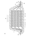
- FIG. 1 is a schematic cross-sectional view showing the basic configuration of a non-aqueous electrolyte lithium ion secondary battery that is not a flat type (stacked type) bipolar type, which is an embodiment of the electrical device according to the present invention. It is a perspective view showing the appearance of a flat lithium ion secondary battery which is a typical embodiment of an electric device according to the present invention.
- a positive electrode in which a positive electrode active material layer containing a positive electrode active material is formed on the surface of a positive electrode current collector, and a negative electrode active material layer containing a negative electrode active material on the surface of the negative electrode current collector are provided.
- the negative electrode active material layer has the following formula (1):
- ⁇ and ⁇ represent the weight percentage of each component in the negative electrode active material layer, and 80 ⁇ ⁇ + ⁇ ⁇ 98, 3 ⁇ ⁇ ⁇ 40, and 40 ⁇ ⁇ ⁇ 95.
- Containing a negative electrode active material represented by The positive electrode active material layer has the following formula (2):
- e represents the weight% of each component in the positive electrode active material layer, and 80 ⁇ e ⁇ 98.
- the solid solution positive electrode active material is represented by the following formula (3):
- z represents the number of oxygen satisfying the valence
- a + b + c + d 1.5, 0.1 ⁇ d ⁇ 0.4, 1.1 ⁇ [a + b + c] ⁇ 1.4.
- a coating layer made of a metal oxide or composite oxide selected from the group consisting of Al, Zr and Ti is formed on the particle surface of the solid solution positive electrode active material, and the solid solution positive electrode An electric device is provided in which the content of the oxide or composite oxide in the active material is 0.1 to 3.0% by weight in terms of oxide.
- a lithium ion secondary battery will be described as an example of an electric device.
- the lithium ion secondary battery using the electric device according to the present invention the voltage of the cell (single cell layer) is large, and high energy density and high output density can be achieved. Therefore, the lithium ion secondary battery of the present embodiment is excellent as a vehicle driving power source or an auxiliary power source. As a result, it can be suitably used as a lithium ion secondary battery for a vehicle driving power source or the like. In addition to this, the present invention can be sufficiently applied to lithium ion secondary batteries for portable devices such as mobile phones.
- the lithium ion secondary battery When the lithium ion secondary battery is distinguished by its form / structure, it can be applied to any conventionally known form / structure such as a stacked (flat) battery or a wound (cylindrical) battery. Is. By adopting a stacked (flat) battery structure, long-term reliability can be secured by a sealing technique such as simple thermocompression bonding, which is advantageous in terms of cost and workability.
- a solution electrolyte type battery using a solution electrolyte such as a nonaqueous electrolyte solution for the electrolyte layer, a polymer battery using a polymer electrolyte for the electrolyte layer, etc. It can be applied to any conventionally known electrolyte layer type.
- the polymer battery is further divided into a gel electrolyte type battery using a polymer gel electrolyte (also simply referred to as gel electrolyte) and a solid polymer (all solid) type battery using a polymer solid electrolyte (also simply referred to as polymer electrolyte). It is done.
- FIG. 1 schematically shows the overall structure of a flat (stacked) lithium ion secondary battery (hereinafter also simply referred to as “stacked battery”), which is a typical embodiment of the electrical device of the present invention.
- stacked battery a flat (stacked) lithium ion secondary battery
- the stacked battery 10 of the present embodiment has a structure in which a substantially rectangular power generation element 21 in which a charge / discharge reaction actually proceeds is sealed inside a laminate sheet 29 that is an exterior body.
- the positive electrode in which the positive electrode active material layer 13 is disposed on both surfaces of the positive electrode current collector 11, the electrolyte layer 17, and the negative electrode active material layer 15 is disposed on both surfaces of the negative electrode current collector 12. It has a configuration in which a negative electrode is laminated. Specifically, the negative electrode, the electrolyte layer, and the positive electrode are laminated in this order so that one positive electrode active material layer 13 and the negative electrode active material layer 15 adjacent thereto face each other with the electrolyte layer 17 therebetween. .
- the adjacent positive electrode, electrolyte layer, and negative electrode constitute one unit cell layer 19. Therefore, it can be said that the stacked battery 10 shown in FIG. 1 has a configuration in which a plurality of single battery layers 19 are stacked and electrically connected in parallel.
- the positive electrode current collector 13 on the outermost layer located on both outermost layers of the power generating element 21 is provided with the positive electrode active material layer 13 only on one side, but the active material layer may be provided on both sides. . That is, instead of using a current collector dedicated to the outermost layer provided with an active material layer only on one side, a current collector having an active material layer on both sides may be used as it is as an outermost current collector.
- the outermost negative electrode current collector is positioned on both outermost layers of the power generation element 21, and one side of the outermost negative electrode current collector or A negative electrode active material layer may be disposed on both sides.
- the positive electrode current collector 11 and the negative electrode current collector 12 are attached to a positive electrode current collector plate 25 and a negative electrode current collector plate 27 that are electrically connected to the respective electrodes (positive electrode and negative electrode), and are sandwiched between end portions of the laminate sheet 29. Thus, it has a structure led out of the laminate sheet 29.
- the positive electrode current collector plate 25 and the negative electrode current collector plate 27 are ultrasonically welded to the positive electrode current collector 11 and the negative electrode current collector 12 of each electrode via a positive electrode lead and a negative electrode lead (not shown), respectively, as necessary. Or resistance welding or the like.
- the lithium ion secondary battery according to this embodiment is characterized by the configuration of the positive electrode and the negative electrode.
- main components of the battery including the positive electrode and the negative electrode will be described.
- the active material layers (13, 15) contain an active material, and further contain other additives as necessary.
- the positive electrode active material layer 13 includes at least a positive electrode active material (also referred to as “solid solution positive electrode active material” in the present specification) made of a solid solution material.
- Solid solution positive electrode active material The solid solution positive electrode active material is represented by the following formula (3).
- a coating layer made of an oxide or composite oxide of a metal selected from the group consisting of Al, Zr and Ti is formed on the particle surface of the solid solution cathode active material, and the solid solution cathode active material in the solid solution cathode active material
- the content of the oxide or composite oxide is 0.1 to 3.0% by weight in terms of oxide.
- the specific configuration of the metal oxide present on the particle surface of the solid solution positive electrode active material is not particularly limited, and any of the theoretically possible oxides or composite oxides containing the metal elements described above can be used.
- Al 2 O 3 , ZrO 2 or TiO 2 is used.
- a (composite) oxide containing one or more elements selected from the group consisting of Nb, Sn, W, Mo, and V may be further included in the coating layer.
- a solid solution positive electrode active material has been studied as a positive electrode active material.
- electrochemically inactive layered Li 2 MnO 3 and electrochemically active layered LiMO 2 (where [M] is a transition of Co, Ni, Mn, Fe, etc.) Layered lithium-containing transition metal oxides consisting of solid solutions with metals have been studied.
- a solid solution positive electrode active material (Li 2 MnO 3 composition) is activated (a part of the crystal structure is changed into a spinel phase: phase transition). It is necessary to charge up to 4.4 to 4.8V).
- the phase transition to this spinel phase (the LiMnO 2 system generated by the movement of Mn gradually changes into a spinel phase) is caused by the transition metal element (in the crystal structure of the positive electrode active material) constituting the transition metal layer ( It is considered that this is caused by oxidation (for example, Mn 3+ ⁇ Mn 4+ ) (irreversible phase transition by charging).
- the transition metal element involved in the phase transition does not form a spinel phase (is not fixed) and is eluted out of the crystal structure. Further, along with the oxidation of the transition metal, part of the lattice oxygen is released and oxygen gas is also generated. However, the transition metal element is also eluted by the occurrence of oxygen defects in the crystal structure. Furthermore, the transition metal (Mn, etc.) constituting the solid solution active material can be obtained by repeating the charge / discharge cycle near the plateau potential (4.3 to 4.5 V) or by exposing it to a potential near the plateau potential for a long time. ) Elution accompanied by oxidation. Therefore, while the Li 2 MnO 3 composition electrochemically active state, must be suppressed transition metal elution stabilization and Mn or the like of rock salt type layered structure.
- the overvoltage (resistance) at the end of charge and end of discharge of the layered Li 2 MnO 3 is higher than that of the layered LiMO 2 (for example, LiNi 1/2 Mn 1/2 O 2 ). It is known that charge / discharge capacity and rate characteristics are degraded. In addition, since the upper limit potential for use is high (4.3 V or higher), there is a problem that Ni and Mn are easily eluted.
- a conventional solid solution active material needs to be charged at a plateau potential or higher (for example, 4.4 to 4.8 V) in order to be activated (a part of the crystal structure is changed to a spinel phase structure (phase transition)).
- a plateau potential or higher for example, 4.4 to 4.8 V
- transition metal elements (Mn, Ni, etc.) constituting the transition metal layer are oxidized in the crystal structure of the positive electrode active material (for example, Mn 3+ ⁇ Mn 4+ ; irreversible phase transition due to charging) and the process in which lattice oxygen is desorbed along with the above.
- phase transition and oxygen desorption progress gradually.
- the average voltage, capacity, and rate characteristics decrease with changes in crystal structure (phase transition and oxygen desorption).
- a part of the transition metal element involved in the phase transition does not form a spinel phase (is not fixed), and is eluted outside the crystal structure.
- some of the lattice oxygen is released and oxygen gas is generated with the oxidation of the transition metal.
- the transition metal element is also eluted by the occurrence of oxygen defects in the crystal structure.
- the particle surface of the solid solution positive electrode active material is configured to have a coating layer made of a (composite) metal oxide such as Al 2 O 3 .
- a high potential for example, 4.4 to 4.8 V
- the charge / discharge cycle for example, 4.3 to 4.5 V
- Transition metal (Mn) eluted out of the crystal structure without forming a spinel phase is reduced, and performance and durability can be improved.
- a part of the metal element of the coating layer penetrates into the surface layer of particles of the solid solution positive electrode active material (has an existing region).
- the covalent bond with oxygen is strengthened.
- the release of lattice oxygen accompanying the oxidation of other transition metals is reduced, so that the generation of oxygen gas is reduced and the generation of oxygen defects in the crystal structure is also reduced.
- the charge / discharge cycle is repeated near the plateau potential (4.3 to 4.5 V), or even when exposed to a potential near the plateau potential for a long time, the crystal structure is stabilized and oxygen desorption is reduced.
- the presence of the coating layer can suppress the elution of transition metals (Mn 4+ , Ni 2+ ) from the crystal structure of the surface layer and the suppression of the detachment of oxygen.
- transition metals Mn 4+ , Ni 2+
- the Li diffusibility Li conductivity
- Battery performance can be improved by reducing the resistance and improving the Li diffusibility.
- a high-resolution measuring device is used to confirm that there is a region where the metal element constituting the coating layer exists on the solid solution positive electrode active material side of the interface between the solid solution positive electrode active material particles and the coating layer. For example, it can be qualitatively confirmed that a metal element is present on the surface layer of the active material particles.
- the analyzer includes XPS (X-ray photoelectron spectroscopy), TEM-EDX (transmission electron microscope-energy dispersive X-ray spectroscopy), STEM-EDX / EELS (scanning transmission electron microscope-energy dispersion). Type X-ray spectroscopy / electron energy loss spectrometer), HAADF-STEM (high angle scattering dark field-scanning transmission electron microscope image), and the like can be used.
- the thickness (average thickness) of the coating layer is not particularly limited, but is preferably 2 to 20 nm from the viewpoint of improving the characteristics of the solid solution positive electrode active material as described above.
- the measurement method of the average thickness of a coating layer can be performed with the observation image of SEM or TEM, for example.
- the average particle size of the solid solution active material described above, the average particle size of the positive electrode active material provided with the alumina layer, and the particle size distribution measuring device of the laser diffraction / scattering method are measured, and the difference between them is the average of the alumina layer It is good also as thickness.
- the ratio of the coating layer existing on the particle surface of the solid solution positive electrode active material is not particularly limited, and is most preferably 100 area%. However, from the viewpoint of expressing the effect of the present embodiment, it is 20 area% or more. What is necessary is just 50 area% or more.
- the step of coating the surface of the solid solution active material with the metal oxide includes the solid solution active material, a salt of a metal element constituting the coating layer (nitrate (aluminum nitrate, which is an aluminum salt)), carbonate (zirconium A step of mixing a solution of carbonate ammonium carbonate (a carbonate), a metal alkoxide (such as tetraisopropoxy titanium which is a metal alkoxide of titanium) at a pH of 7 to 8, and a step of drying the obtained solid solution active material precursor And a step of calcining the obtained solid solution active material precursor after drying at a temperature of 450 ° C. ⁇ 50 ° C.
- a salt of a metal element constituting the coating layer nitrate (aluminum nitrate, which is an aluminum salt)
- carbonate zirconium
- the coating layer formed on part or all of the particle surface of the solid solution active material through these steps is desired to have a high Li ion mobility and a high effect of suppressing the elution of transition metals. Further, by performing a precipitation reaction of metal hydroxide in the range of pH 7 to 8, and setting the firing temperature to 450 ° C. ⁇ 50 ° C., preferably 420 ° C. to 480 ° C., a part of the surface of the solid solution active material particles. Alternatively, the coating layer can be present entirely (20 to 100%). Moreover, a solid solution active material in which a metal element has penetrated into the surface layer of the solid solution active material particles can be produced. As a result, a battery excellent in performance and durability can be provided.
- each step will be described by taking the case where the coating layer is formed of alumina as an example.
- a solid solution active material and an aluminum nitrate solution are mixed at pH 7-8. Thereby, a solid solution active material precursor can be obtained.
- Aluminum nitrate is suitable as the aluminum raw material. This is because the nitrate radical can be decomposed and removed in the firing step, and the performance of the battery using this positive electrode active material is good. In aluminum sulfate and aluminum chloride, sulfate radicals and hydrochloric acid radicals remain, and the performance of a battery using this positive electrode active material is lowered. Aluminum acetate is not suitable for this method (precipitation reaction).
- the amount of aluminum nitrate as the raw material of aluminum (Al 2 O 3 layer), such that the content of Al 2 O 3 of the positive electrode active material described above may be appropriately adjusted.
- a precipitant is further used.
- ammonium water is suitable. This is because the ammonium root can be decomposed and removed in the firing step, so that the performance of the battery using this positive electrode active material is good.
- Na remains as an impurity of the positive electrode active material, and the performance of a battery using the positive electrode active material is deteriorated.
- the pH of the solid solution active material, the aluminum nitrate solution and the ammonium water of the precipitant is less than pH 7, the reaction between the aluminum nitrate and the ammonium water is insufficient, the precipitation of aluminum hydroxide is poor, The desired coating amount cannot be obtained.
- the pH exceeds 8 aluminum hydroxide is re-dissolved, and a desired coating amount cannot be obtained with respect to the charged amount.
- the reaction between the aluminum nitrate and the aqueous ammonium is sufficiently performed by the mixing operation, and the desired solid solution active material precursor (the aluminum hydroxide is precipitated on the surface of the solid solution active material).
- the mixing temperature reaction system solution temperature
- the mixing time is in the range of 30 minutes to 3 hours.
- the obtained solid solution active material precursor may be immersed in the solution for up to about 3 hours after mixing. Thereby, the coating of a suitable alumina layer can be performed and the improvement effect of charging / discharging characteristics and cycle durability can be obtained.
- the mixing means is not particularly limited, and conventionally known mixing / stirring means (apparatus) can be used.
- the filtering means is not particularly limited, and conventionally known filtering means (apparatus) can be used.
- the filtered solid solution active material precursor is dried. Drying conditions are not particularly limited as long as the solid solution active material precursor can be sufficiently dried. That is, when the process from drying to baking is performed continuously, it is not necessary to strictly distinguish the drying process from the baking process, and the process may be performed from drying to baking at a predetermined baking temperature. From the above, the drying conditions may be a drying temperature in the range of 80 to 200 ° C. and a drying time in the range of 30 minutes to 12 hours, preferably 1 to 6 hours. Further, the atmosphere during drying is not particularly limited, and can be performed in an air atmosphere or the like.
- the drying means (apparatus) is not particularly limited, and a conventionally known drying means (apparatus) can be used. Specifically, for example, vacuum drying, hot air drying, infrared (IR) drying, natural drying, and the like can be used in appropriate combination.
- the solid solution active material precursor dried as described above is fired at a temperature of 450 ° C. ⁇ 50 ° C.
- the firing temperature is in the range of 450 ° C. ⁇ 50 ° C., preferably in the range of 420 to 480 ° C. for 1 to 12 hours, preferably in the range of 2 to 6 hours.
- An Al 2 O 3 layer is present on part or all of the surface of the solid solution active material particles.
- the solid solution active material quality in which Al element penetrates into the surface layer of the solid solution active material particles can be produced.
- the firing temperature is less than 400 ° C., the decomposition of aluminum hydroxide is insufficient and a desired Al 2 O 3 coat layer cannot be formed, and the battery using this positive electrode active material has poor durability.
- the firing temperature exceeds 500 ° C., the Al 2 O 3 layer becomes dense and the mobility of Li ions decreases, and the battery using this positive electrode active material has poor performance.
- the atmosphere during firing is not particularly limited, and can be performed in an air atmosphere or the like.
- the baking means (apparatus) is not particularly limited, and conventionally known baking means (apparatus) can be used.
- a positive electrode active material other than the solid solution positive electrode active material described above may be used in combination.
- a lithium-transition metal composite oxide is used in combination as the positive electrode active material from the viewpoint of capacity and output characteristics.
- other positive electrode active materials may be used.
- the optimum particle size is different for expressing the unique effect of each active material, the optimum particle size may be blended and used for expressing each unique effect. It is not always necessary to make the particle diameter uniform.
- the average particle diameter of the positive electrode active material contained in the positive electrode active material layer 13 is not particularly limited, but is preferably 1 to 30 ⁇ m and more preferably 5 to 20 ⁇ m from the viewpoint of increasing the output.
- the “particle diameter” refers to the outline of the active material particles (observation surface) observed using an observation means such as a scanning electron microscope (SEM) or a transmission electron microscope (TEM). It means the maximum distance among any two points.
- the value of “average particle diameter” is the value of particles observed in several to several tens of fields using observation means such as a scanning electron microscope (SEM) or a transmission electron microscope (TEM). The value calculated as the average value of the particle diameter shall be adopted.
- the particle diameters and average particle diameters of other components can be defined in the same manner.
- the positive electrode active material layer contains a positive electrode active material (solid solution positive electrode active material) represented by the following formula (2).
- e represents the weight% of each component in the positive electrode active material layer, and 80 ⁇ e ⁇ 98.
- the content of the solid solution positive electrode active material in the positive electrode active material layer is indispensable to be 80 to 98% by weight, preferably 84 to 98% by weight.
- the positive electrode active material layer preferably contains a binder and a conductive aid in addition to the solid solution positive electrode active material described above. Further, if necessary, it further contains other additives such as an electrolyte (polymer matrix, ion-conductive polymer, electrolyte solution, etc.) and a lithium salt for increasing the ion conductivity.
- a binder and a conductive aid in addition to the solid solution positive electrode active material described above. Further, if necessary, it further contains other additives such as an electrolyte (polymer matrix, ion-conductive polymer, electrolyte solution, etc.) and a lithium salt for increasing the ion conductivity.
- Binder Although it does not specifically limit as a binder used for a positive electrode active material layer, for example, the following materials are mentioned. Polyethylene, polypropylene, polyethylene terephthalate (PET), polyether nitrile, polyacrylonitrile, polyimide, polyamide, cellulose, carboxymethyl cellulose (CMC) and its salts, ethylene-vinyl acetate copolymer, polyvinyl chloride, styrene-butadiene rubber (SBR) ), Isoprene rubber, butadiene rubber, ethylene / propylene rubber, ethylene / propylene / diene copolymer, styrene / butadiene / styrene block copolymer and hydrogenated product thereof, styrene / isoprene / styrene block copolymer and hydrogenated product thereof.
- Thermoplastic polymers such as products, polyvinylidene fluoride (P
- the binder content in the positive electrode active material layer is preferably 1 to 10% by weight, more preferably 1 to 8% by weight.
- the conductive assistant refers to an additive that is blended in order to improve the conductivity of the positive electrode active material layer or the negative electrode active material layer.
- Examples of the conductive assistant include carbon black such as ketjen black and acetylene black.
- the content of the conductive auxiliary in the positive electrode active material layer is preferably 1 to 10% by weight, more preferably 1 to 8% by weight.
- electrolyte salt examples include Li (C 2 F 5 SO 2 ) 2 N, LiPF 6 , LiBF 4 , LiClO 4 , LiAsF 6 , LiCF 3 SO 3 and the like.
- Examples of the ion conductive polymer include polyethylene oxide (PEO) and polypropylene oxide (PPO) polymers.
- the positive electrode (positive electrode active material layer) can be applied by any one of a kneading method, a sputtering method, a vapor deposition method, a CVD method, a PVD method, an ion plating method, and a thermal spraying method in addition to a method of applying (coating) a normal slurry. Can be formed.
- the negative electrode active material layer 15 essentially contains a Si-containing alloy and a carbon material as a negative electrode active material.
- Si-containing alloy is not particularly limited as long as it is an alloy with another metal containing Si, and conventionally known knowledge can be appropriately referred to.
- Si-containing alloy Si x Ti y Ge z A a , Si x Ti y Zn z A a , Si x Ti y Sn z A a , Si x Sn y Al z A a , and Si x Sn y V z A a , Si x Sn y C z A a , Si x Zn y V z A a , Si x Zn y Sn z A a , Si x Zn y Al z A a , Si x Zn y C zA a, Si x Al y C z a a and Si x Al y Nb z a a ( wherein, a is unavoidable impurities.
- the average particle size of the Si-containing alloy is not particularly limited as long as it is approximately the same as the average particle size of the negative electrode active material included in the existing negative electrode active material layer 15. From the viewpoint of higher output, it is preferably in the range of 1 to 20 ⁇ m. However, it is not limited at all to the above range, and it goes without saying that it may be outside the above range as long as the effects of the present embodiment can be effectively expressed.
- the shape of the Si-containing alloy is not particularly limited, and may be spherical, elliptical, cylindrical, polygonal, flaky, indefinite, or the like.
- the carbon material that can be used in the present invention is not particularly limited, but graphite (graphite), which is a highly crystalline carbon such as natural graphite or artificial graphite; low crystalline carbon such as soft carbon or hard carbon; ketjen black, acetylene Carbon black such as black, channel black, lamp black, oil furnace black, and thermal black; and carbon materials such as fullerene, carbon nanotube, carbon nanofiber, carbon nanohorn, and carbon fibril. Of these, graphite is preferably used.
- the average particle diameter of the carbon material is not particularly limited, but is preferably 5 to 25 ⁇ m, and more preferably 5 to 10 ⁇ m.
- the average particle size of the carbon material may be the same as or different from the average particle size of the Si-containing alloy. Is preferred.
- the average particle size of the Si-containing alloy is more preferably smaller than the average particle size of the carbon material.
- negative electrode active materials other than the two types of negative electrode active materials described above may be used in combination.
- the negative electrode active material that can be used in combination include SiO x , a lithium-transition metal composite oxide (eg, Li 4 Ti 5 O 12 ), a metal material, and a lithium alloy negative electrode material.
- SiO x SiO x
- Li 4 Ti 5 O 12 lithium-transition metal composite oxide
- metal material e.g., Li 4 Ti 5 O 12
- lithium alloy negative electrode material e.g, Li 4 Ti 5 O 12
- other negative electrode active materials may be used.
- the negative electrode active material layer contains a negative electrode active material represented by the following formula (1).
- ⁇ and ⁇ represent the weight percentage of each component in the negative electrode active material layer, and 80 ⁇ ⁇ + ⁇ ⁇ 98, 3 ⁇ ⁇ ⁇ 40, and 40 ⁇ ⁇ ⁇ 95.
- the content of the negative electrode active material made of the Si-containing alloy in the negative electrode active material layer is 3 to 40% by weight.
- the content of the carbon material negative electrode active material is 40 to 95% by weight. Furthermore, the total content thereof is 80 to 98% by weight.
- the mixing ratio of the Si-containing alloy and the carbon material of the negative electrode active material is not particularly limited as long as the above-described content specification is satisfied, and can be appropriately selected according to a desired application.
- the content of the Si-containing alloy in the negative electrode active material is preferably 3 to 40% by weight.
- the content of the Si-containing alloy in the negative electrode active material is more preferably 4 to 30% by weight.
- the content of the Si-containing alloy in the negative electrode active material is more preferably 5 to 20% by weight.
- the content of the Si-containing alloy is 3% by weight or more because a high initial capacity can be obtained.
- the content of the Si-containing alloy is 40% by weight or less, it is preferable because high cycle characteristics can be obtained.
- the negative electrode active material layer preferably contains a binder and a conductive additive in addition to the negative electrode active material described above. Further, if necessary, it further contains other additives such as an electrolyte (polymer matrix, ion conductive polymer, electrolytic solution, etc.) and a lithium salt for increasing the ion conductivity.
- an electrolyte polymer matrix, ion conductive polymer, electrolytic solution, etc.
- a lithium salt for increasing the ion conductivity.
- the present embodiment is characterized in that the coating amount (weight per unit area) of the negative electrode active material layer is 4 to 11 mg / cm 2 .
- the coating amount (weight per unit area) of the negative electrode active material layer exceeds 11 mg / cm 2 , there is a problem that the rate characteristics of the battery are remarkably deteriorated.
- the coating amount (weight per unit area) of the negative electrode active material layer is less than 4 mg / cm 2 , the content of the active material in the negative electrode active material layer is reduced in the first place. A load will be applied, and cycle durability will deteriorate.
- the coating amount (weight per unit area) of the negative electrode active material layer is a value within the above-described range, both rate characteristics and cycle characteristics can be achieved.
- a predetermined negative electrode active material is used in combination, and the content thereof is adjusted to achieve the coating amount (weight per unit area) within the above range.
- each active material layer (active material layer on one side of the current collector) is not particularly limited, and conventionally known knowledge about the battery can be appropriately referred to.
- the thickness of each active material layer is usually about 1 to 500 ⁇ m, preferably 2 to 100 ⁇ m, taking into consideration the intended use of the battery (emphasis on output, energy, etc.) and ion conductivity.
- the current collectors (11, 12) are made of a conductive material.
- the size of the current collector is determined according to the intended use of the battery. For example, if it is used for a large battery that requires a high energy density, a current collector having a large area is used.
- the thickness of the current collector is usually about 1 to 100 ⁇ m.
- the shape of the current collector is not particularly limited.
- a mesh shape (such as an expanded grid) can be used.
- the negative electrode active material is formed directly on the negative electrode current collector 12 by sputtering or the like, it is preferable to use a current collector foil.
- a metal or a resin in which a conductive filler is added to a conductive polymer material or a non-conductive polymer material can be employed.
- examples of the metal include aluminum, nickel, iron, stainless steel, titanium, and copper.
- a clad material of nickel and aluminum, a clad material of copper and aluminum, or a plating material of a combination of these metals can be preferably used.
- covered on the metal surface may be sufficient.
- aluminum, stainless steel, copper, and nickel are preferable from the viewpoints of electronic conductivity, battery operating potential, and adhesion of the negative electrode active material by sputtering to the current collector.
- examples of the conductive polymer material include polyaniline, polypyrrole, polythiophene, polyacetylene, polyparaphenylene, polyphenylene vinylene, polyacrylonitrile, and polyoxadiazole. Since such a conductive polymer material has sufficient conductivity without adding a conductive filler, it is advantageous in terms of facilitating the manufacturing process or reducing the weight of the current collector.
- Non-conductive polymer materials include, for example, polyethylene (PE; high density polyethylene (HDPE), low density polyethylene (LDPE), etc.), polypropylene (PP), polyethylene terephthalate (PET), polyether nitrile (PEN), polyimide (PI), polyamideimide (PAI), polyamide (PA), polytetrafluoroethylene (PTFE), styrene-butadiene rubber (SBR), polyacrylonitrile (PAN), polymethyl acrylate (PMA), polymethyl methacrylate (PMMA) , Polyvinyl chloride (PVC), polyvinylidene fluoride (PVdF), or polystyrene (PS).
- PE polyethylene
- HDPE high density polyethylene
- LDPE low density polyethylene
- PP polypropylene
- PET polyethylene terephthalate
- PEN polyether nitrile
- PI polyimide
- PAI polyamideimide
- PA polyamide
- PTFE polytetraflu
- a conductive filler may be added to the conductive polymer material or the non-conductive polymer material as necessary.
- a conductive filler is inevitably necessary to impart conductivity to the resin.
- the conductive filler can be used without particular limitation as long as it has a conductivity.
- metals, conductive carbon, etc. are mentioned as a material excellent in electroconductivity, electric potential resistance, or lithium ion barrier
- the metal is not particularly limited, but at least one metal selected from the group consisting of Ni, Ti, Al, Cu, Pt, Fe, Cr, Sn, Zn, In, Sb, and K, or these metals It is preferable to contain an alloy or metal oxide containing.
- it includes at least one selected from the group consisting of acetylene black, vulcan, black pearl, carbon nanofiber, ketjen black, carbon nanotube, carbon nanohorn, carbon nanoballoon, and fullerene.
- the amount of the conductive filler added is not particularly limited as long as it is an amount capable of imparting sufficient conductivity to the current collector, and is generally about 5 to 35% by weight.
- the separator has a function of holding an electrolyte and ensuring lithium ion conductivity between the positive electrode and the negative electrode, and a function as a partition wall between the positive electrode and the negative electrode.
- separator examples include a separator made of a porous sheet made of a polymer or fiber that absorbs and holds the electrolyte and a nonwoven fabric separator.
- a microporous (microporous film) can be used as the separator of the porous sheet made of polymer or fiber.
- the porous sheet made of the polymer or fiber include polyolefins such as polyethylene (PE) and polypropylene (PP); a laminate in which a plurality of these are laminated (for example, three layers of PP / PE / PP) And a microporous (microporous membrane) separator made of a hydrocarbon resin such as polyimide, aramid, polyvinylidene fluoride-hexafluoropropylene (PVdF-HFP), glass fiber, and the like.
- PE polyethylene
- PP polypropylene
- a microporous (microporous membrane) separator made of a hydrocarbon resin such as polyimide, aramid, polyvinylidene fluoride-hexafluoropropylene (PVdF-HFP), glass fiber, and the like.
- the thickness of the microporous (microporous membrane) separator cannot be uniquely defined because it varies depending on the intended use. For example, in applications such as secondary batteries for driving motors such as electric vehicles (EV), hybrid electric vehicles (HEV), and fuel cell vehicles (FCV), it is 4 to 60 ⁇ m in a single layer or multiple layers. Is desirable.
- the fine pore diameter of the microporous (microporous membrane) separator is desirably 1 ⁇ m or less (usually a pore diameter of about several tens of nm).
- nonwoven fabric separator cotton, rayon, acetate, nylon, polyester; polyolefins such as PP and PE; conventionally known ones such as polyimide and aramid are used alone or in combination.
- the bulk density of the nonwoven fabric is not particularly limited as long as sufficient battery characteristics can be obtained by the impregnated polymer gel electrolyte.
- the thickness of the nonwoven fabric separator may be the same as that of the electrolyte layer, and is preferably 5 to 200 ⁇ m, particularly preferably 10 to 100 ⁇ m.
- the separator includes an electrolyte.
- the electrolyte is not particularly limited as long as it can exhibit such a function, but a liquid electrolyte or a gel polymer electrolyte is used.
- a gel polymer electrolyte By using the gel polymer electrolyte, the distance between the electrodes is stabilized, the occurrence of polarization is suppressed, and the durability (cycle characteristics) is improved.
- the liquid electrolyte functions as a lithium ion carrier.
- the liquid electrolyte constituting the electrolytic solution layer has a form in which a lithium salt as a supporting salt is dissolved in an organic solvent as a plasticizer.
- organic solvent include carbonates such as ethylene carbonate (EC), propylene carbonate (PC), dimethyl carbonate (DMC), diethyl carbonate (DEC), and ethyl methyl carbonate.
- EC ethylene carbonate
- PC propylene carbonate
- DMC dimethyl carbonate
- DEC diethyl carbonate
- ethyl methyl carbonate ethyl methyl carbonate.
- Li (CF 3 SO 2) 2 N Li (C 2 F 5 SO 2) 2 N, LiPF 6, LiBF 4, LiClO 4, LiAsF 6, LiTaF such 6, LiCF 3 SO 3
- a compound that can be added to the active material layer of the electrode can be similarly employed.
- the liquid electrolyte may further contain additives other than the components described above.
- additives include, for example, vinylene carbonate, methyl vinylene carbonate, dimethyl vinylene carbonate, phenyl vinylene carbonate, diphenyl vinylene carbonate, ethyl vinylene carbonate, diethyl vinylene carbonate, vinyl ethylene carbonate, 1,2-divinyl ethylene carbonate.
- vinylene carbonate, methyl vinylene carbonate, and vinyl ethylene carbonate are preferable, and vinylene carbonate and vinyl ethylene carbonate are more preferable.
- These cyclic carbonates may be used alone or in combination of two or more.
- the gel polymer electrolyte has a configuration in which the above liquid electrolyte is injected into a matrix polymer (host polymer) made of an ion conductive polymer.
- a gel polymer electrolyte as the electrolyte is superior in that the fluidity of the electrolyte is lost and the ion conductivity between the layers is easily cut off.
- ion conductive polymer used as the matrix polymer (host polymer) examples include polyethylene oxide (PEO), polypropylene oxide (PPO), polyethylene glycol (PEG), polyacrylonitrile (PAN), polyvinylidene fluoride-hexafluoropropylene ( PVdF-HEP), poly (methyl methacrylate (PMMA), and copolymers thereof.
- PEO polyethylene oxide
- PPO polypropylene oxide
- PEG polyethylene glycol
- PAN polyacrylonitrile
- PVdF-HEP polyvinylidene fluoride-hexafluoropropylene
- PMMA methyl methacrylate
- the matrix polymer of gel electrolyte can express excellent mechanical strength by forming a crosslinked structure.
- thermal polymerization, ultraviolet polymerization, radiation polymerization, electron beam polymerization, etc. are performed on a polymerizable polymer (for example, PEO or PPO) for forming a polymer electrolyte using an appropriate polymerization initiator.
- a polymerization treatment may be performed.
- the separator is preferably a separator in which a heat-resistant insulating layer is laminated on a porous substrate (a separator with a heat-resistant insulating layer).
- the heat resistant insulating layer is a ceramic layer containing inorganic particles and a binder.
- a highly heat-resistant separator having a melting point or a heat softening point of 150 ° C. or higher, preferably 200 ° C. or higher is used.
- the separator is less likely to curl in the battery manufacturing process due to the effect of suppressing thermal shrinkage and high mechanical strength.
- the inorganic particles in the heat resistant insulating layer contribute to the mechanical strength and heat shrinkage suppressing effect of the heat resistant insulating layer.
- the material used as the inorganic particles is not particularly limited. Examples thereof include silicon, aluminum, zirconium, titanium oxides (SiO 2 , Al 2 O 3 , ZrO 2 , TiO 2 ), hydroxides and nitrides, and composites thereof. These inorganic particles may be derived from mineral resources such as boehmite, zeolite, apatite, kaolin, mullite, spinel, olivine and mica, or may be artificially produced. Moreover, only 1 type may be used individually for these inorganic particles, and 2 or more types may be used together. Of these, silica (SiO 2 ) or alumina (Al 2 O 3 ) is preferably used, and alumina (Al 2 O 3 ) is more preferably used from the viewpoint of cost.
- the basis weight of the heat-resistant particles is not particularly limited, but is preferably 5 to 15 g / m 2 . If it is this range, sufficient ion conductivity will be acquired and it is preferable at the point which maintains heat resistant strength.
- the binder in the heat-resistant insulating layer has a role of adhering the inorganic particles and the inorganic particles to the resin porous substrate layer.
- the heat resistant insulating layer is stably formed, and peeling between the porous substrate layer and the heat resistant insulating layer is prevented.
- the binder used for the heat-resistant insulating layer is not particularly limited.
- a compound such as butadiene rubber, polyvinylidene fluoride (PVDF), polytetrafluoroethylene (PTFE), polyvinyl fluoride (PVF), or methyl acrylate can be used as the binder.
- PVDF polyvinylidene fluoride
- PTFE polytetrafluoroethylene
- PVF polyvinyl fluoride
- methyl acrylate methyl acrylate
- PVDF polyvinylidene fluoride
- these compounds only 1 type may be used independently and 2 or more types may be used together.
- the binder content in the heat-resistant insulating layer is preferably 2 to 20% by weight with respect to 100% by weight of the heat-resistant insulating layer.
- the binder content is 2% by weight or more, the peel strength between the heat-resistant insulating layer and the porous substrate layer can be increased, and the vibration resistance of the separator can be improved.
- the binder content is 20% by weight or less, the gap between the inorganic particles is appropriately maintained, so that sufficient lithium ion conductivity can be ensured.
- the thermal contraction rate of the separator with a heat-resistant insulating layer is preferably 10% or less for both MD and TD after holding for 1 hour at 150 ° C. and 2 gf / cm 2 .
- a current collector plate (tab) electrically connected to a current collector is taken out of a laminate film as an exterior material for the purpose of taking out current outside the battery.
- the material constituting the current collector plate is not particularly limited, and a known highly conductive material conventionally used as a current collector plate for a lithium ion secondary battery can be used.
- a constituent material of the current collector plate for example, metal materials such as aluminum, copper, titanium, nickel, stainless steel (SUS), and alloys thereof are preferable. From the viewpoint of light weight, corrosion resistance, and high conductivity, aluminum and copper are more preferable, and aluminum is particularly preferable. Note that the same material may be used for the positive electrode current collector plate (positive electrode tab) and the negative electrode current collector plate (negative electrode tab), or different materials may be used.
- the tabs 58 and 59 shown in FIG. 2 are not particularly limited.
- the positive electrode tab 58 and the negative electrode tab 59 may be drawn out from the same side, or the positive electrode tab 58 and the negative electrode tab 59 may be divided into a plurality of parts and taken out from each side, as shown in FIG. It is not limited to.
- a terminal may be formed using a cylindrical can (metal can).
- the seal portion is a member unique to the serially stacked battery and has a function of preventing leakage of the electrolyte layer. In addition to this, it is possible to prevent current collectors adjacent in the battery from coming into contact with each other and a short circuit due to a slight unevenness at the end of the laminated electrode.
- the constituent material of the seal part is not particularly limited, but polyolefin resin such as polyethylene and polypropylene, epoxy resin, rubber, polyimide and the like can be used. Among these, it is preferable to use a polyolefin resin from the viewpoints of corrosion resistance, chemical resistance, film-forming property, economy, and the like.
- ⁇ Positive terminal lead and negative terminal lead> As a material for the negative electrode and the positive electrode terminal lead, a lead used in a known laminated secondary battery can be used.
- the parts removed from the battery exterior material should be heat-insulating so that they do not affect products (for example, automobile parts, especially electronic devices) by touching peripheral devices or wiring and causing leakage. It is preferable to coat with a heat shrinkable tube or the like.
- Laminate film A conventionally known metal can case can be used as the exterior material.
- the power generation element 17 may be packed using a laminate film 22 as shown in FIG.
- the laminate film can be configured as a three-layer structure in which, for example, polypropylene, aluminum, and nylon are laminated in this order.
- the manufacturing method in particular of a lithium ion secondary battery is not restrict
- a lithium ion secondary battery is not limited to this.
- the electrode (positive electrode and negative electrode) is prepared, for example, by preparing an active material slurry (positive electrode active material slurry or negative electrode active material slurry) and applying the active material slurry onto a current collector. It can be made by drying, then pressing.
- the active material slurry includes the above-described active material (positive electrode active material or negative electrode active material), a binder, a conductive additive, and a solvent.
- the solvent is not particularly limited, and N-methyl-2-pyrrolidone (NMP), dimethylformamide, dimethylacetamide, methylformamide, cyclohexane, hexane, water and the like can be used.
- NMP N-methyl-2-pyrrolidone
- the method for applying the active material slurry to the current collector is not particularly limited, and examples thereof include a screen printing method, a spray coating method, an electrostatic spray coating method, an ink jet method, and a doctor blade method.
- the method for drying the coating film formed on the surface of the current collector is not particularly limited as long as at least a part of the solvent in the coating film is removed.
- An example of the drying method is heating. Drying conditions (drying time, drying temperature, etc.) can be appropriately set according to the volatilization rate of the solvent contained in the applied active material slurry, the coating amount of the active material slurry, and the like. A part of the solvent may remain. The remaining solvent can be removed by a press process described later.
- the pressing means is not particularly limited, and for example, a calendar roll, a flat plate press, or the like can be used.
- the single cell layer can be produced by laminating the electrodes (positive electrode and negative electrode) produced in (1) via an electrolyte layer.
- the power generation element can be produced by laminating the single cell layers in consideration of the output and capacity of the single cell layer, the output and capacity required for the battery, and the like.
- the structure of the battery various shapes such as a square, a paper, a laminated, a cylindrical, and a coin can be adopted.
- the current collector and insulating plate of the component parts are not particularly limited, and may be selected according to the above shape.
- a stacked battery is preferable.
- a lead is joined to the current collector of the power generation element obtained above, and the positive electrode lead or the negative electrode lead is joined to the positive electrode tab or the negative electrode tab.
- a power generation element is placed in a laminate sheet so that the positive electrode tab and the negative electrode tab are exposed to the outside of the battery, and an electrolytic solution is injected with a liquid injector and then sealed in a vacuum to produce a stacked battery. sell.
- the initial charge treatment, gas removal treatment and activation treatment are further performed under the following conditions.
- it is done (see Example 1).
- the three sides of the laminate sheet (exterior material) are completely sealed in a rectangular shape by thermocompression when sealing in the production of the laminated battery of (4) so that the gas removal treatment can be performed. Stop (main sealing), and the remaining one side is temporarily sealed by thermocompression bonding.
- the remaining one side may be freely opened and closed by, for example, clip fastening, but from the viewpoint of mass production (production efficiency), it is preferable to temporarily seal the side by thermocompression bonding.
- thermocompression it is only necessary to adjust the temperature and pressure for pressure bonding.
- it can be opened by lightly applying force, and after degassing, it may be sealed again by thermocompression, or finally completely sealed by thermocompression ( Main sealing).
- the battery aging treatment is preferably performed as follows. At 25 ° C., a constant current charging method is used for 0.05 C for 4 hours (SOC approximately 20%). Next, after charging to 4.45 V at a 0.1 C rate at 25 ° C., the charging is stopped, and the state (SOC is about 70%) is maintained for about 2 days (48 hours).
- thermocompression bonding Next, the following process is performed as the first (first) gas removal process. First, one side temporarily sealed by thermocompression bonding is opened, gas is removed at 10 ⁇ 3 hPa for 5 minutes, and then thermocompression bonding is performed again to perform temporary sealing. Further, pressurization with a roller (surface pressure 0.5 ⁇ 0.1 MPa) is performed, and the electrode and the separator are sufficiently adhered.
- the battery is charged at 25 ° C. by a constant current charging method until the voltage reaches 4.45 V at 0.1 C, and then discharged twice to 2.0 V at 0.1 C.
- a cycle of discharging to 2.0 V at 0.1 C once is 4.65 V at 0.1 C.
- the battery is charged until it reaches 0, and then discharged once at 0.1 C to 2.0 V.
- a cycle of charging at 0.1 C to 4.75 V by a constant current charging method at 25 ° C. and then discharging to 0.1 V at 0.1 C may be performed once.
- the constant current charging method is used as the activation processing method, and the electrochemical pretreatment method when the voltage is set as the termination condition is described as an example, but the charging method is a constant current constant voltage charging method. You may use. Further, as the termination condition, a charge amount or time may be used in addition to the voltage.
- thermocompression bonding Next, the following process is performed as the first (first) gas removal process. First, one side temporarily sealed by thermocompression bonding is opened, gas is removed at 10 ⁇ 3 hPa for 5 minutes, and then thermocompression bonding is performed again to perform main sealing. Further, pressurization with a roller (surface pressure 0.5 ⁇ 0.1 MPa) is performed, and the electrode and the separator are sufficiently adhered.
- the performance and durability of the obtained battery can be improved by performing the initial charging process, the gas removal process, and the activation process described above.
- the assembled battery is configured by connecting a plurality of batteries. Specifically, at least two or more are used, and are configured by serialization, parallelization, or both. Capacitance and voltage can be freely adjusted by paralleling in series.
- a small assembled battery that can be attached and detached by connecting a plurality of batteries in series or in parallel. Then, a plurality of small assembled batteries that can be attached and detached are connected in series or in parallel to provide a large capacity and large capacity suitable for vehicle drive power supplies and auxiliary power supplies that require high volume energy density and high volume output density.
- An assembled battery having an output can also be formed. How many batteries are connected to make an assembled battery, and how many small assembled batteries are stacked to make a large-capacity assembled battery depends on the battery capacity of the mounted vehicle (electric vehicle) It may be determined according to the output.
- the electric device of the present invention including the lithium ion secondary battery according to the present embodiment maintains a discharge capacity even when used for a long time, and has good cycle characteristics. Furthermore, the volume energy density is high. Vehicle applications such as electric vehicles, hybrid electric vehicles, fuel cell vehicles, and hybrid fuel cell vehicles require higher capacity, larger size, and longer life than electric and portable electronic devices. . Therefore, the lithium ion secondary battery (electric device) can be suitably used as a vehicle power source, for example, as a vehicle driving power source or an auxiliary power source.
- a battery or an assembled battery formed by combining a plurality of these batteries can be mounted on the vehicle.
- a plug-in hybrid electric vehicle having a long EV mileage or an electric vehicle having a long charge mileage can be formed by mounting such a battery.
- a car a hybrid car, a fuel cell car, an electric car (four-wheeled vehicles (passenger cars, trucks, buses, commercial vehicles, light cars, etc.) This is because it can be used for motorcycles (including motorcycles) and tricycles) to provide a long-life and highly reliable automobile.
- the application is not limited to automobiles.
- it can be applied to various power sources for moving vehicles such as other vehicles, for example, trains, and power sources for mounting such as uninterruptible power supplies. It is also possible to use as.
- Example 1 (Preparation of solid solution positive electrode active material C1) 1.
- Manganese sulfate monohydrate (molecular weight 223.06 g / mol) 28.61 g, Nickel sulfate hexahydrate (molecular weight 262.85 g / mol) 17.74 g, was added to 200 g of pure water and dissolved by stirring to prepare a mixed solution.
- the dried powder was pulverized in a mortar and then calcined at 500 ° C. for 5 hours.
- Lithium hydroxide monohydrate (molecular weight 41.96 g / mol) 10.67 g was mixed with the calcined powder and pulverized and mixed for 30 minutes.
- This powder was calcined at 500 ° C. for 2 hours and then calcined at 900 ° C. for 12 hours to obtain a solid solution positive electrode active material C1.
- composition of the solid solution positive electrode active material C1 thus obtained was as follows.
- composition C1 Li 1.5 [Ni 0.45 Mn 0.85 [Li] 0.20 ] O 3
- the dried powder was pulverized in a mortar and then baked at 450 ° C. for 5 hours to obtain a solid solution positive electrode active material C1.
- the solid solution positive electrode active material C1 thus obtained was 0 on the particle surface of the solid solution positive electrode active material C1 obtained in “Preparation of the solid solution positive electrode active material C1” with respect to the total amount (100 wt%) of the solid solution positive electrode active material C1. It was a powder formed with a coating layer made of 5 wt% Al 2 O 3 .
- the average particle size of the obtained solid solution positive electrode active material C1 was 8 ⁇ m.
- the average particle diameters of the solid solution positive electrode active materials obtained in other examples and comparative examples were also the same average particle diameter.
- composition of slurry for positive electrode had the following composition.
- Cathode active material Al 2 O 3 coated solid solution cathode active material C1 obtained above 9.4 parts by weight
- Conductive aid flake graphite 0.15 parts by weight
- Acetylene black 0.15 parts by weight
- Binder Polyvinylidene fluoride ( PVDF) 0.3 part by weight
- Solvent 8.2 parts by weight of N-methyl-2-pyrrolidone (NMP).
- a positive electrode slurry having the above composition was prepared as follows. First, 4.0 parts by weight of a solvent (NMP) is added to 2.0 parts by weight of a 20% binder solution obtained by dissolving a binder in a solvent (NMP) into a 50 ml disposable cup, and a stirring defoaming machine (spinning revolving mixer: Awatori) A binder diluted solution was prepared by stirring for 1 minute with Rentaro AR-100).
- NMP solvent
- NMP spinning revolving mixer
- the positive electrode slurry was applied to one side of an aluminum current collector with a thickness of 20 ⁇ m using an automatic coating apparatus (Doctor blade manufactured by Tester Sangyo: PI-1210 automatic coating apparatus). Subsequently, the current collector coated with the positive electrode slurry was dried on a hot plate (100 ° C. to 110 ° C., drying time 30 minutes), and the amount of NMP remaining in the positive electrode active material layer was 0.02 wt%.
- a sheet-like positive electrode was formed as follows.
- the sheet-like positive electrode was compression-molded by applying a roller press and cut to prepare a positive electrode having a weight of about 17.1 mg / cm 2 and a density of 2.65 g / cm 3 of the positive electrode active material layer on one side.
- Si 29 Ti 62 Ge 9 was used as the Si-containing alloy as the negative electrode active material.
- the Si-containing alloy was produced by a mechanical alloy method. Specifically, using a planetary ball mill device P-6 manufactured by Fricht, Germany, zirconia pulverized balls and alloy raw material powders were charged into a zirconia pulverized pot and alloyed at 600 rpm for 48 hours.
- Si-containing alloy Si 29 Ti 62 Ge 9
- other alloys that can be used in the present invention Si x Ti y Ge z A a , Si x Ti y Zn z A a , and Si this of x Ti y Sn z a, Si 29 Ti 62 Ge 9 except one
- Si x Ti y Ge z A a Si x Ti y Zn z A a
- Si this of x Ti y Sn z a, Si 29 Ti 62 Ge 9 except one also, since those having the same characteristics as Si 29 Ti 62 Ge 9, using Si 29 Ti 62 Ge 9 The same or similar results as in the examples are obtained.
- composition of slurry for negative electrode The negative electrode slurry had the following composition.
- Negative electrode active material Si-containing alloy (Si 29 Ti 62 Ge 9 ) 1.38 parts by weight Carbon material (manufactured by Hitachi Chemical, graphite) 7.82 parts by weight Conductive aid: SuperP 0.40 part by weight Binder: Polyimide 0.40 Part by weight Solvent: 10.0 parts by weight of N-methyl-2-pyrrolidone (NMP).
- NMP N-methyl-2-pyrrolidone
- a negative electrode slurry having the above composition was prepared as follows. First, 5.0 parts by weight of a solvent (NMP) was added to 2.0 parts by weight of a 20% binder solution obtained by dissolving a binder in a solvent (NMP), and the mixture was stirred for 1 minute with a stirring deaerator to prepare a diluted binder solution. To this binder diluted solution, 0.4 parts by weight of conductive additive, 9.2 parts by weight of negative electrode active material powder, and 3.4 parts by weight of solvent (NMP) are added, and stirred for 3 minutes with a stirring defoamer for the negative electrode. A slurry (solid content concentration 50 wt%) was obtained.
- NMP solvent
- the negative electrode slurry was applied to one side of a 10 ⁇ m thick electrolytic copper current collector using an automatic coating apparatus. Subsequently, the current collector coated with the negative electrode slurry was dried on a hot plate (100 ° C. to 110 ° C., drying time 30 minutes), and the amount of NMP remaining in the negative electrode active material layer was 0.02 wt% or less. A sheet-like negative electrode was formed.
- the obtained sheet-like negative electrode was compression-molded using a roller press and cut to prepare a negative electrode having a weight of about 8.48 mg / cm 2 and a density of 1.60 g / cm 3 of the negative electrode active material layer on one side. When the surface of this negative electrode was observed, no cracks were observed.
- ethylene carbonate (EC) and diethyl carbonate (DEC) 1 in a mixed nonaqueous solvent were mixed at a volume ratio, the concentration of LiPF 6 a (lithium hexafluorophosphate) 1M What was dissolved so that it might become was used.
- LiPF 6 a lithium hexafluorophosphate
- the battery is evaluated by the constant current constant voltage charging method in which the battery is charged at a 0.1 C rate until the maximum voltage reaches 4.5 V and then held for about 1 to 1.5 hours.
- the constant current discharge method was used in which discharge was performed at a 0.1 C rate until the minimum voltage reached 2.0V.
- the discharge capacity at the 0.1 C rate at this time was defined as “0.1 C discharge capacity (mAh / g)”.
- the discharge capacity per active material of the positive electrode C1 was 226 mAh / g, and the discharge capacity per electrode unit area was 3.61 mAh / cm 2 .
- ethylene carbonate (EC) and diethyl carbonate (DEC) 1 in a mixed nonaqueous solvent were mixed at a volume ratio, the concentration of LiPF 6 a (lithium hexafluorophosphate) 1M What was dissolved so that it might become was used.
- LiPF 6 a lithium hexafluorophosphate
- the battery is evaluated by a constant current / constant voltage charging method in which charging (the Li insertion process into the negative electrode to be evaluated) is charged from 2 V to 10 mV at a 0.1 C rate and then held for about 1 to 1.5 hours.
- the constant current mode was used, and a constant current discharge method was performed in which discharge was performed from 10 mV to 2 V at a 0.1 C rate.
- the discharge capacity at the 0.1 C rate at this time was defined as “0.1 C discharge capacity (mAh / g)”.
- the discharge capacity per active material of the negative electrode A1 was 481 mAh / g, and the discharge capacity per electrode unit area was 4.08 mAh / cm 2 .
- the positive electrode C1 obtained above was cut out so as to have an active material layer area of 2.5 cm in length and 2.0 cm in width, and the two current collectors faced each other, so that the uncoated surface (aluminum current collector)
- the current collector portion was spot welded together with the surface not coated with the foil slurry.
- an aluminum positive electrode tab positive electrode current collector plate
- the negative electrode A1 obtained above was cut out so as to have an active material layer area of 2.7 cm in length and 2.2 cm in width, and then a negative electrode tab of electrolytic copper was further welded to the current collector portion to form a negative electrode A11.
- the negative electrode A11 has a structure in which a negative electrode active material layer is formed on one surface of a current collector.
- a porous polypropylene separator (S) (length 3.0 cm ⁇ width 2.5 cm, thickness 25 ⁇ m, porosity 55%) is sandwiched between the negative electrode A11 to which these tabs are welded and the positive electrode C11.
- a laminated power generation element was produced.
- the structure of the stacked type power generation element is the structure of negative electrode (single side) / separator / positive electrode (both sides) / separator / negative electrode (single side), that is, A11- (S) -C11- (S) -A11. The configuration.
- both sides of the power generation element were sandwiched with an aluminum laminate film exterior material (length 3.5 cm ⁇ width 3.5 cm), and the above power generation element was accommodated by thermocompression sealing at three sides.
- LiPF 6 electrolyzed ethylene carbonate
- DEC diethyl carbonate
- lithium lithium fluorophosphate LiPO 2 F 2
- MMDS methylenemethane disulfonic acid
- active materials were prepared according to Example 1. That is, an active material was prepared in the same manner as in Example 1 described above, except as otherwise noted below.
- Solid solution positive electrode active material C2 Li 1.5 [Ni 0.525 Mn 0.825 [Li] 0.15] O 3 was produced.
- the coating amount of the coating layer made of Al 2 O 3 was 0.5% by weight with respect to the total amount (100% by weight) of the solid solution positive electrode active material C2 coated with the coating layer.
- Solid solution positive electrode active material C3 Li 1.5 [Ni 0.375 Mn 0.875 [Li] 0.25] O 3 was produced.
- the coating amount of the coating layer made of Al 2 O 3 was 0.5% by weight with respect to the total amount (100% by weight) of the solid solution positive electrode active material C3 coated with the coating layer.
- Solid solution positive electrode active material C4 Li 1.5 [Ni 0.600 Mn 0.800 [Li] 0.10] O 3 was produced.
- the coating amount of the coating layer made of Al 2 O 3 was set to 0.5% by weight with respect to the total amount (100% by weight) of the solid solution positive electrode active material C4 coated with the coating layer.
- Solid solution positive electrode active material C5 Li 1.5 [Ni 0.300 Mn 0.900 [Li] 0.30] O 3 was produced.
- the coating amount of the coating layer made of Al 2 O 3 was 0.5% by weight with respect to the total amount (100% by weight) of the solid solution positive electrode active material C5 coated with the coating layer.
- Solid solution positive electrode active material C6 Li 1.5 [Ni 0.225 Mn 0.925 [Li] 0.35] O 3 was produced.
- the coating amount of the coating layer made of Al 2 O 3 was 0.5% by weight with respect to the total amount (100% by weight) of the solid solution positive electrode active material C6 coated with the coating layer.
- Solid solution positive electrode active material C7 According to Example 1, a solid solution positive electrode active material C1 before metal oxide coating was produced. Subsequently, Al 2 O 3 coating was performed in the same manner as in Example 1. At this time, the coating amount of the coating layer made of Al 2 O 3 was set to 2.0% by weight with respect to the total amount (100% by weight) of the solid solution positive electrode active material C7 coated with the coating layer.
- Solid solution positive electrode active material C8 According to Example 1, a solid solution positive electrode active material C1 before metal oxide coating was produced. Next, using zirconium ammonium carbonate (Zr (OH) 2 (CO 3 ) 2 ⁇ 2NH 4 molecular weight 281.33 g / mol) instead of aluminum nitrate, a coating layer made of zirconium oxide on the particle surface of the solid solution positive electrode active material C1 To obtain a solid solution positive electrode active material C8. At this time, according to Example 1, the coating amount of the coating layer made of Al 2 O 3 was 0.5% by weight with respect to the total amount (100% by weight) of the solid solution positive electrode active material C6 coated with the coating layer. did.
- zirconium ammonium carbonate Zr (OH) 2 (CO 3 ) 2 ⁇ 2NH 4 molecular weight 281.33 g / mol
- Solid solution positive electrode active material C9 According to Example 1, a solid solution positive electrode active material C1 before metal oxide coating was produced. Next, a coating layer made of titanium oxide is formed on the particle surface of the solid solution positive electrode active material C1 using tetraisopropoxy titanium (C 14 H 28 O 4 Ti molecular weight 284.22 g / mol), and the solid solution positive electrode active material C9 is formed. Got. At this time, the coating layer was formed as follows.
- Solid solution positive electrode active material C10 A solid solution positive electrode active material C1 Li 1.5 [Ni 0.45 Mn 0.85 [Li] 0.20 ] O 3 in which a coating layer made of a metal oxide was not formed was used as the solid solution positive electrode active material C10.
- positive electrodes C2 to C10 were produced according to Example 1. At this time, the coating amount was adjusted in consideration of the discharge capacity of the solid solution positive electrode active material and the positive electrode slurry composition so that the discharge capacities of the positive electrodes C2 to C10 were 3.61 mAh / cm 2 .
- the compositions of the positive electrodes C1 to C10 obtained and the measured values of the charge capacity and discharge capacity are summarized in Table 1 below.
- Negative electrode A2 A negative electrode A2 was produced in the same manner as in Example 1 except that the composition of the negative electrode slurry was as follows.
- Negative electrode active material Si-containing alloy (Si 49 Ti 32 Sn 19 ) 1.38 parts by weight Carbon material (made by Hitachi Chemical, graphite) 7.82 parts by weight Conductive aid: SuperP 0.40 part by weight Binder: Polyimide 0.40 Part by weight Solvent: 10.0 parts by weight of N-methyl-2-pyrrolidone (NMP).
- NMP N-methyl-2-pyrrolidone
- Negative electrode A3 A negative electrode A3 was produced in the same manner as in Example 1 except that the composition of the negative electrode slurry was as follows.
- Negative electrode active material Si-containing alloy (Si 53 Ti 21 Sn 26 ) 1.38 parts by weight Carbon material (manufactured by Hitachi Chemical, graphite) 7.82 parts by weight Conductive aid: SuperP 0.40 part by weight Binder: Polyimide 0.40 Part by weight Solvent: 10.0 parts by weight of N-methyl-2-pyrrolidone (NMP).
- NMP N-methyl-2-pyrrolidone
- Negative electrode A4 A negative electrode A4 was produced in the same manner as in Example 1 except that the composition of the negative electrode slurry was as follows.
- Negative electrode active material Si-containing alloy (Si 41 Ti 15 Al 43 ) 1.38 parts by weight Carbon material (made by Hitachi Chemical, graphite) 7.82 parts by weight Conductive aid: SuperP 0.40 part by weight Binder: Polyimide 0.40 Part by weight Solvent: 10.0 parts by weight of N-methyl-2-pyrrolidone (NMP).
- NMP N-methyl-2-pyrrolidone
- Negative electrode A5 A negative electrode A5 was produced in the same manner as in Example 1 except that the composition of the negative electrode slurry was as follows.
- Negative electrode active material Si-containing alloy (Si 34 Sn 13 V 53 ) 1.38 parts by weight Carbon material (manufactured by Hitachi Chemical, graphite) 7.82 parts by weight Conductive aid: SuperP 0.40 parts by weight Binder: Polyimide 0.40 Part by weight Solvent: 10.0 parts by weight of N-methyl-2-pyrrolidone (NMP).
- NMP N-methyl-2-pyrrolidone
- Negative electrode A6 A negative electrode A6 was produced in the same manner as in Example 1 except that the composition of the negative electrode slurry was as follows.
- Negative electrode active material Si-containing alloy (Si 34 Sn 41 C 25 ) 1.38 parts by weight Carbon material (made by Hitachi Chemical, graphite) 7.82 parts by weight Conductive aid: SuperP 0.40 part by weight Binder: Polyimide 0.40 Part by weight Solvent: 10.0 parts by weight of N-methyl-2-pyrrolidone (NMP).
- NMP N-methyl-2-pyrrolidone
- Negative electrode A7 A negative electrode A7 was produced in the same manner as in Example 1 except that the composition of the negative electrode slurry was as follows.
- Negative electrode active material Si-containing alloy (Si 34 Zn 23 V 43 ) 1.38 parts by weight Carbon material (made by Hitachi Chemical, graphite) 7.82 parts by weight Conductive aid: SuperP 0.40 part by weight Binder: Polyimide 0.40 Part by weight Solvent: 10.0 parts by weight of N-methyl-2-pyrrolidone (NMP).
- NMP N-methyl-2-pyrrolidone
- Negative electrode A8 was produced in the same manner as in Example 1 except that the composition of the negative electrode slurry was as follows.
- Negative electrode active material Si-containing alloy (Si 42 Zn 53 Sn 5 ) 1.38 parts by weight Carbon material (manufactured by Hitachi Chemical, graphite) 7.82 parts by weight Conductive aid: SuperP 0.40 part by weight Binder: Polyimide 0.40 Part by weight Solvent: 10.0 parts by weight of N-methyl-2-pyrrolidone (NMP).
- NMP N-methyl-2-pyrrolidone
- Negative electrode A9 was produced according to Example 1 except that the composition of the negative electrode slurry was as follows.
- Negative electrode active material Si-containing alloy (Si 31 Zn 40 Al 29 ) 1.38 parts by weight Carbon material (made by Hitachi Chemical, graphite) 7.82 parts by weight Conductive aid: SuperP 0.40 part by weight Binder: Polyimide 0.40 Part by weight Solvent: 10.0 parts by weight of N-methyl-2-pyrrolidone (NMP).
- NMP N-methyl-2-pyrrolidone
- Negative electrode A10 A negative electrode A10 was produced in the same manner as in Example 1 except that the composition of the negative electrode slurry was as follows.
- Negative electrode active material Si-containing alloy (Si 53 Zn 44 C 3 ) 1.38 parts by weight Carbon material (manufactured by Hitachi Chemical, graphite) 7.82 parts by weight Conductive aid: SuperP 0.40 part by weight Binder: Polyimide 0.40 Part by weight Solvent: 10.0 parts by weight of N-methyl-2-pyrrolidone (NMP).
- NMP N-methyl-2-pyrrolidone
- a negative electrode A11 was produced according to Example 1 except that the composition of the negative electrode slurry was as follows.
- Negative electrode active material Si-containing alloy (Si 50 Al 47 C 3 ) 1.38 parts by weight Carbon material (made by Hitachi Chemical, graphite) 7.82 parts by weight Conductive aid: SuperP 0.40 part by weight Binder: Polyimide 0.40 Part by weight Solvent: 10.0 parts by weight of N-methyl-2-pyrrolidone (NMP).
- NMP N-methyl-2-pyrrolidone
- Negative electrode A12 A negative electrode A12 was produced according to Example 1 except that the composition of the negative electrode slurry was as follows.
- Negative electrode active material Si-containing alloy (Si 67 Al 22 Nb 11 ) 1.38 parts by weight Carbon material (manufactured by Hitachi Chemical, graphite) 7.82 parts by weight Conductive aid: SuperP 0.40 part by weight Binder: Polyimide 0.40 Part by weight Solvent: 10.0 parts by weight of N-methyl-2-pyrrolidone (NMP).
- NMP N-methyl-2-pyrrolidone
- a negative electrode A13 was produced in the same manner as in Example 1 except that the composition of the negative electrode slurry was as follows.
- Negative electrode active material carbon material (manufactured by Hitachi Chemical, graphite) 9.2 parts by weight
- Conductive aid SuperP 0.40 part by weight
- Binder polyimide 0.40 part by weight
- Solvent N-methyl-2-pyrrolidone (NMP) 10. 0 parts by weight.
- a negative electrode A4 was produced in the same manner as in Example 1 except that the composition of the negative electrode slurry was as follows.
- Negative electrode active material Si-containing alloy (Si 29 Ti 62 Ge 9 ) 9.2 parts by weight
- Conductive aid SuperP 0.40 parts by weight
- Binder Polyimide 0.40 parts by weight
- Solvent N-methyl-2-pyrrolidone (NMP) 10.0 parts by weight.
- the coating amount was set so that the discharge capacities of the negative electrodes A2 to A12 were 4.08 mAh / cm 2. It was adjusted.
- Table 2 The compositions of the obtained negative electrodes A1 to A14 and the measured values of the charge capacity and discharge capacity are summarized in Table 2 below.
- “ ⁇ ” and “ ⁇ ” mean the respective weight percentages of the binder and the conductive additive in the negative electrode active material layer.
- the power generation element of each battery obtained above was set on an evaluation cell mounting jig, and a positive electrode lead and a negative electrode lead were attached to each tab end of the power generation element, and a test was performed.
- the battery aging treatment was performed as follows. At 25 ° C., the battery was charged at a constant current charging method of 0.05 C for 4 hours (SOC approximately 20%). Next, after charging to 4.45 V at a 0.1 C rate at 25 ° C., the charging was stopped and the state (SOC about 70%) was maintained for about 2 days (48 hours).
- thermocompression bonding One side temporarily sealed by thermocompression bonding was opened, gas was removed at 10 ⁇ 3 hPa for 5 minutes, and then thermocompression bonding was performed again to perform temporary sealing. Further, pressurization with a roller (surface pressure 0.5 ⁇ 0.1 MPa) was performed, and the electrode and the separator were sufficiently adhered.
- thermocompression bonding One side temporarily sealed by thermocompression bonding was opened, gas was removed at 10 ⁇ 3 hPa for 5 minutes, and then thermocompression bonding was performed again to perform main sealing. Further, pressurization with a roller (surface pressure 0.5 ⁇ 0.1 MPa) was performed, and the electrode and the separator were sufficiently adhered.
- Rate performance evaluation The rate performance of the battery is evaluated by a constant current / constant voltage charging method in which the battery is charged at a 0.1 C rate until the maximum voltage reaches 4.5 V and then held for about 1 hour to 1.5 hours. This was carried out by a constant current discharge method in which discharge was performed at a 0.1 C rate or a 2.5 C rate until the minimum voltage of 2.0 V became 2.0 V. All were performed at room temperature. The rate characteristics were evaluated as the ratio of the capacity at 2.5 C discharge to the capacity at 0.1 C discharge. The results are shown in Table 3 below.
- the ratio of the discharge capacity at the 100th cycle to the discharge capacity at the 1st cycle was evaluated as “capacity maintenance rate (%)”. The results are shown in Table 3 below.
- Capacity retention rate (%) 100th cycle discharge capacity / 1st cycle discharge capacity ⁇ 100
Priority Applications (6)
| Application Number | Priority Date | Filing Date | Title |
|---|---|---|---|
| CN201480073880.3A CN105934846B (zh) | 2014-01-24 | 2014-01-24 | 电器件 |
| EP14879656.8A EP3098891A1 (en) | 2014-01-24 | 2014-01-24 | Electrical device |
| PCT/JP2014/051529 WO2015111189A1 (ja) | 2014-01-24 | 2014-01-24 | 電気デバイス |
| JP2015558666A JP6202106B2 (ja) | 2014-01-24 | 2014-01-24 | 電気デバイス |
| US15/112,725 US10535870B2 (en) | 2014-01-24 | 2014-01-24 | Electrical device |
| KR1020167019739A KR20160102026A (ko) | 2014-01-24 | 2014-01-24 | 전기 디바이스 |
Applications Claiming Priority (1)
| Application Number | Priority Date | Filing Date | Title |
|---|---|---|---|
| PCT/JP2014/051529 WO2015111189A1 (ja) | 2014-01-24 | 2014-01-24 | 電気デバイス |
Publications (1)
| Publication Number | Publication Date |
|---|---|
| WO2015111189A1 true WO2015111189A1 (ja) | 2015-07-30 |
Family
ID=53681018
Family Applications (1)
| Application Number | Title | Priority Date | Filing Date |
|---|---|---|---|
| PCT/JP2014/051529 WO2015111189A1 (ja) | 2014-01-24 | 2014-01-24 | 電気デバイス |
Country Status (6)
| Country | Link |
|---|---|
| US (1) | US10535870B2 (ko) |
| EP (1) | EP3098891A1 (ko) |
| JP (1) | JP6202106B2 (ko) |
| KR (1) | KR20160102026A (ko) |
| CN (1) | CN105934846B (ko) |
| WO (1) | WO2015111189A1 (ko) |
Cited By (4)
| Publication number | Priority date | Publication date | Assignee | Title |
|---|---|---|---|---|
| JP2016018654A (ja) * | 2014-07-08 | 2016-02-01 | 株式会社日立製作所 | リチウムイオン二次電池 |
| US10276866B2 (en) * | 2014-12-17 | 2019-04-30 | Nissan Motor Co., Ltd. | Electric device |
| US10748715B2 (en) | 2016-04-26 | 2020-08-18 | Gs Yuasa International Ltd. | Energy storage device and method for manufacturing same |
| US11682766B2 (en) * | 2017-01-27 | 2023-06-20 | Nec Corporation | Silicone ball containing electrode and lithium ion battery including the same |
Families Citing this family (9)
| Publication number | Priority date | Publication date | Assignee | Title |
|---|---|---|---|---|
| CN104813513B (zh) | 2012-11-22 | 2017-06-16 | 日产自动车株式会社 | 电气设备用负极和使用了其的电气设备 |
| US10535870B2 (en) | 2014-01-24 | 2020-01-14 | Nissan Motor Co., Ltd. | Electrical device |
| WO2015111187A1 (ja) * | 2014-01-24 | 2015-07-30 | 日産自動車株式会社 | 電気デバイス |
| JP6361599B2 (ja) * | 2015-07-07 | 2018-07-25 | 株式会社豊田中央研究所 | 蓄電デバイス |
| US20190020000A1 (en) | 2017-07-11 | 2019-01-17 | Apple Inc. | Battery cell tabs with a unitary seal |
| WO2019021806A1 (ja) * | 2017-07-27 | 2019-01-31 | パナソニックIpマネジメント株式会社 | 非水電解質二次電池用正極活物質、非水電解質二次電池用正極活物質の製造方法、及び非水電解質二次電池 |
| US10698456B1 (en) * | 2019-03-14 | 2020-06-30 | Dell Products, L.P. | Information handling system having a pressure plate for a solid state battery |
| KR20210032219A (ko) | 2019-09-16 | 2021-03-24 | 주식회사 엘지화학 | 이차전지 제조방법 및 이차전지 |
| CN112820952A (zh) * | 2019-11-15 | 2021-05-18 | 通用汽车环球科技运作有限责任公司 | 电容器辅助的电池模块和系统 |
Citations (6)
| Publication number | Priority date | Publication date | Assignee | Title |
|---|---|---|---|---|
| JP2009517850A (ja) | 2005-12-01 | 2009-04-30 | スリーエム イノベイティブ プロパティズ カンパニー | ケイ素含有量が高いアモルファス合金に基づく電極組成物 |
| JP2009158099A (ja) * | 2007-12-25 | 2009-07-16 | Hitachi Vehicle Energy Ltd | リチウムイオン二次電池 |
| WO2012161190A1 (ja) * | 2011-05-25 | 2012-11-29 | 日産自動車株式会社 | 電気デバイス用負極活物質、電気デバイス用負極及び電気デバイス |
| WO2012160866A1 (ja) * | 2011-05-25 | 2012-11-29 | 日産自動車株式会社 | 電気デバイス用負極活物質 |
| WO2013115390A1 (ja) * | 2012-02-01 | 2013-08-08 | 日産自動車株式会社 | 固溶体リチウム含有遷移金属酸化物、非水電解質二次電池用正極及び非水電解質二次電池 |
| JP2013229163A (ja) * | 2012-04-25 | 2013-11-07 | Shin Etsu Chem Co Ltd | 非水電解質二次電池用負極及び非水電解質二次電池 |
Family Cites Families (137)
| Publication number | Priority date | Publication date | Assignee | Title |
|---|---|---|---|---|
| US4560524A (en) | 1983-04-15 | 1985-12-24 | Smuckler Jack H | Method of manufacturing a positive temperature coefficient resistive heating element |
| JPH08250117A (ja) | 1995-03-09 | 1996-09-27 | Shin Kobe Electric Mach Co Ltd | リチウム二次電池負極用炭素材料及びその製造方法 |
| JP4029235B2 (ja) | 1998-10-02 | 2008-01-09 | 大阪瓦斯株式会社 | リチウム二次電池用負極 |
| CA2305837C (en) | 1999-04-14 | 2011-05-31 | Sony Corporation | Material for negative electrode and nonaqueous-electrolyte battery incorporating the same |
| JP2000299108A (ja) | 1999-04-14 | 2000-10-24 | Sony Corp | 非水電解質電池 |
| EP1244163A4 (en) | 1999-10-22 | 2007-10-31 | Sanyo Electric Co | ELECTRODE FOR LITHIUM ACCUMULATOR AND LITHIUM ACCUMULATOR |
| JP2002083594A (ja) | 1999-10-22 | 2002-03-22 | Sanyo Electric Co Ltd | リチウム電池用電極並びにこれを用いたリチウム電池及びリチウム二次電池 |
| AU7951000A (en) | 1999-10-22 | 2001-05-08 | Sanyo Electric Co., Ltd. | Electrode for lithium cell and lithium secondary cell |
| AU7951100A (en) | 1999-10-22 | 2001-04-30 | Sanyo Electric Co., Ltd. | Electrode for lithium secondary cell and lithium secondary cell |
| KR100500344B1 (ko) | 1999-10-22 | 2005-07-12 | 산요덴키가부시키가이샤 | 리튬 전지용 전극 및 리튬 2차전지 |
| KR100487458B1 (ko) | 1999-10-22 | 2005-05-06 | 산요덴키가부시키가이샤 | 리튬 2차 전지용 전극의 제조 방법 |
| JP2001196052A (ja) | 2000-01-12 | 2001-07-19 | Sony Corp | 負極及び非水電解質電池 |
| US6699336B2 (en) | 2000-01-13 | 2004-03-02 | 3M Innovative Properties Company | Amorphous electrode compositions |
| US6680143B2 (en) * | 2000-06-22 | 2004-01-20 | The University Of Chicago | Lithium metal oxide electrodes for lithium cells and batteries |
| JP3848065B2 (ja) | 2000-08-08 | 2006-11-22 | キヤノン株式会社 | 画像形成装置 |
| US6984469B2 (en) * | 2000-09-25 | 2006-01-10 | Samsung Sdi Co., Ltd. | Positive active material for rechargeable lithium batteries and method of preparing same |
| EP1313158A3 (en) | 2001-11-20 | 2004-09-08 | Canon Kabushiki Kaisha | Electrode material for rechargeable lithium battery, electrode comprising said electrode material, rechargeable lithium battery having said electrode , and process for the production thereof |
| JP4225727B2 (ja) | 2001-12-28 | 2009-02-18 | 三洋電機株式会社 | リチウム二次電池用負極及びリチウム二次電池 |
| JP3744462B2 (ja) | 2002-05-08 | 2006-02-08 | ソニー株式会社 | 非水電解質電池 |
| JP4471836B2 (ja) | 2002-06-26 | 2010-06-02 | 三洋電機株式会社 | リチウム二次電池用負極及びリチウム二次電池 |
| JP2004119199A (ja) | 2002-09-26 | 2004-04-15 | Japan Storage Battery Co Ltd | 非水電解質二次電池 |
| AU2003302282A1 (en) | 2002-11-26 | 2004-06-18 | Showa Denko K.K. | Electrode material comprising silicon and/or tin particles and production method and use thereof |
| JP4385589B2 (ja) | 2002-11-26 | 2009-12-16 | 昭和電工株式会社 | 負極材料及びそれを用いた二次電池 |
| AU2003302519A1 (en) | 2002-11-29 | 2004-06-23 | Mitsui Mining And Smelting Co., Ltd. | Negative electrode for non-aqueous electrolyte secondary cell and method for manufacture thereof, and non-aqueous electrolyte secondary cell |
| JP3643108B2 (ja) | 2003-07-23 | 2005-04-27 | 三井金属鉱業株式会社 | 非水電解液二次電池用負極及び非水電解液二次電池 |
| JP3750117B2 (ja) | 2002-11-29 | 2006-03-01 | 三井金属鉱業株式会社 | 非水電解液二次電池用負極及びその製造方法並びに非水電解液二次電池 |
| CN100365849C (zh) | 2002-11-29 | 2008-01-30 | 三井金属矿业株式会社 | 非水电解液二次电池用负极及其制造方法以及非水电解液二次电池 |
| JP4046601B2 (ja) | 2002-12-03 | 2008-02-13 | 大阪瓦斯株式会社 | リチウム二次電池用負極材及びそれを用いたリチウム二次電池 |
| US20040137327A1 (en) * | 2003-01-13 | 2004-07-15 | Gross Karl J. | Synthesis of carbon/silicon composites |
| JP2004296412A (ja) | 2003-02-07 | 2004-10-21 | Mitsui Mining & Smelting Co Ltd | 非水電解液二次電池用負極活物質の製造方法 |
| JP4464173B2 (ja) | 2003-03-26 | 2010-05-19 | キヤノン株式会社 | リチウム二次電池用の電極材料、該電極材料を有する電極構造体、及び該電極構造体を有する二次電池 |
| JP4366222B2 (ja) | 2003-03-26 | 2009-11-18 | キヤノン株式会社 | リチウム二次電池用の電極材料、該電極材料を有する電極構造体、該電極構造体を有する二次電池 |
| EP2302720B1 (en) | 2003-03-26 | 2012-06-27 | Canon Kabushiki Kaisha | Electrode material for lithium secondary battery and electrode structure including the same |
| US7378041B2 (en) | 2003-03-26 | 2008-05-27 | Canon Kabushiki Kaisha | Electrode material for lithium secondary battery, electrode structure comprising the electrode material and secondary battery comprising the electrode structure |
| JP4366101B2 (ja) | 2003-03-31 | 2009-11-18 | キヤノン株式会社 | リチウム二次電池 |
| AU2003289402A1 (en) | 2003-04-23 | 2004-11-19 | Mitsui Mining And Smelting Co., Ltd. | Negative electrode for nonaqueous electrolyte secondary battery, method for manufacturing same and nonaqueous electrolyte secondary battery |
| JP2005011650A (ja) | 2003-06-18 | 2005-01-13 | Sony Corp | 負極材料およびそれを用いた電池 |
| JP2005011699A (ja) | 2003-06-19 | 2005-01-13 | Canon Inc | リチウム二次電池 |
| JP4029291B2 (ja) | 2003-09-02 | 2008-01-09 | 福田金属箔粉工業株式会社 | リチウム二次電池用負極材料及びその製造方法 |
| JP3746501B2 (ja) | 2003-10-09 | 2006-02-15 | 三星エスディアイ株式会社 | リチウム二次電池用電極材料及びリチウム二次電池及びリチウム二次電池用電極材料の製造方法 |
| US7479351B2 (en) | 2003-10-09 | 2009-01-20 | Samsung Sdi Co., Ltd. | Electrode material for a lithium secondary battery, lithium secondary battery, and preparation method for the electrode material for a lithium secondary battery |
| JP4625672B2 (ja) | 2003-10-30 | 2011-02-02 | 株式会社東芝 | 非水電解質二次電池 |
| CN100413122C (zh) | 2004-11-03 | 2008-08-20 | 深圳市比克电池有限公司 | 含锰的多元金属氧化物、锂离子二次电池的正极材料及其制备方法 |
| US7635540B2 (en) * | 2004-11-15 | 2009-12-22 | Panasonic Corporation | Negative electrode for non-aqueous electrolyte secondary battery and non-aqueous electrolyte secondary battery comprising the same |
| WO2006075446A1 (ja) | 2005-01-14 | 2006-07-20 | Matsushita Electric Industrial Co., Ltd. | リチウムイオン二次電池用負極およびその製造方法ならびにリチウムイオン二次電池およびその製造方法 |
| JP4877898B2 (ja) * | 2005-01-21 | 2012-02-15 | 日立マクセルエナジー株式会社 | 非水電解質二次電池 |
| JP2006216277A (ja) | 2005-02-01 | 2006-08-17 | Canon Inc | リチウム二次電池用電極材料の製造方法、電極構造体および二次電池 |
| JP4794893B2 (ja) | 2005-04-12 | 2011-10-19 | パナソニック株式会社 | 非水電解液二次電池 |
| JP5076288B2 (ja) | 2005-07-14 | 2012-11-21 | 日本電気株式会社 | 二次電池用負極およびそれを用いた二次電池 |
| JP2007026926A (ja) | 2005-07-19 | 2007-02-01 | Nec Corp | 二次電池用負極およびこれを用いた二次電池 |
| TWI371885B (en) | 2005-08-02 | 2012-09-01 | Showa Denko Kk | Alloy for negative electrode of lithium secondary battery |
| WO2007015508A1 (ja) | 2005-08-02 | 2007-02-08 | Showa Denko K.K. | リチウム二次電池負極用合金 |
| JP2007149604A (ja) | 2005-11-30 | 2007-06-14 | Sanyo Electric Co Ltd | リチウム二次電池用負極及びリチウム二次電池 |
| US7906238B2 (en) | 2005-12-23 | 2011-03-15 | 3M Innovative Properties Company | Silicon-containing alloys useful as electrodes for lithium-ion batteries |
| JP4599314B2 (ja) | 2006-02-22 | 2010-12-15 | 株式会社東芝 | 非水電解質電池、電池パック及び自動車 |
| JP2007305424A (ja) | 2006-05-11 | 2007-11-22 | Sony Corp | 負極活物質およびそれを用いた電池 |
| JP4573053B2 (ja) | 2006-05-23 | 2010-11-04 | ソニー株式会社 | 負極および電池 |
| CN101331630B (zh) | 2006-05-23 | 2011-01-26 | 索尼株式会社 | 负极及其制造方法、以及电池及其制造方法 |
| US8080335B2 (en) | 2006-06-09 | 2011-12-20 | Canon Kabushiki Kaisha | Powder material, electrode structure using the powder material, and energy storage device having the electrode structure |
| JP2008016446A (ja) | 2006-06-09 | 2008-01-24 | Canon Inc | 粉末材料、粉末材料を用いた電極構造体及び該電極構造体を有する蓄電デバイス、並びに粉末材料の製造方法 |
| KR101375455B1 (ko) | 2006-08-29 | 2014-03-26 | 강원대학교산학협력단 | 이차 전지용 전극 활물질 |
| US20100233543A1 (en) | 2006-09-29 | 2010-09-16 | Koichi Numata | Nonaqueous secondary battery |
| WO2008086041A1 (en) | 2007-01-10 | 2008-07-17 | Nanoexa, Inc. | Lithium batteries with nano-composite positive electrode material |
| KR20090109570A (ko) | 2007-02-06 | 2009-10-20 | 쓰리엠 이노베이티브 프로퍼티즈 컴파니 | 신규한 결합제를 포함하는 전극과, 그의 제조 방법 및 사용 방법 |
| US7875388B2 (en) | 2007-02-06 | 2011-01-25 | 3M Innovative Properties Company | Electrodes including polyacrylate binders and methods of making and using the same |
| JP5256816B2 (ja) | 2007-03-27 | 2013-08-07 | 学校法人神奈川大学 | リチウムイオン電池用正極材料 |
| CN101687404B (zh) | 2007-06-06 | 2013-06-05 | 旭化成电子材料株式会社 | 多层多孔膜 |
| JP5343342B2 (ja) | 2007-06-26 | 2013-11-13 | 大同特殊鋼株式会社 | リチウム二次電池用負極活物質およびリチウム二次電池 |
| US8753432B2 (en) | 2007-08-31 | 2014-06-17 | Stephen B. Maguire | Tiltable vacuum loader and receiver with blow-back |
| JP5374851B2 (ja) | 2007-10-15 | 2013-12-25 | ソニー株式会社 | リチウムイオン二次電池用負極およびリチウムイオン二次電池 |
| KR101406013B1 (ko) | 2008-03-17 | 2014-06-11 | 신에쓰 가가꾸 고교 가부시끼가이샤 | 비수 전해질 2차 전지용 부극재 및 그것의 제조 방법, 및 비수 전해질 2차 전지용 부극 및 비수 전해질 2차 전지 |
| JP2009224239A (ja) | 2008-03-18 | 2009-10-01 | Nissan Motor Co Ltd | 電池用電極 |
| JP5046302B2 (ja) | 2008-03-28 | 2012-10-10 | 日立マクセルエナジー株式会社 | 非水二次電池 |
| JP5357565B2 (ja) | 2008-05-27 | 2013-12-04 | 株式会社神戸製鋼所 | リチウムイオン二次電池用負極材、および、その製造方法、ならびに、リチウムイオン二次電池 |
| WO2010052950A1 (ja) | 2008-11-04 | 2010-05-14 | 国立大学法人岩手大学 | 不定比チタン化合物、その炭素複合体、それら化合物の製造方法、及びそれら化合物を含むリチウムイオン二次電池用負極活物質、並びにそれを用いたリチウムイオン二次電池 |
| US9012073B2 (en) | 2008-11-11 | 2015-04-21 | Envia Systems, Inc. | Composite compositions, negative electrodes with composite compositions and corresponding batteries |
| JP2010205609A (ja) | 2009-03-04 | 2010-09-16 | Nissan Motor Co Ltd | 電極およびこれを用いた電池 |
| WO2010110205A1 (ja) | 2009-03-24 | 2010-09-30 | 古河電気工業株式会社 | リチウムイオン二次電池、該電池用電極、該電池電極用電解銅箔 |
| EP2239803A1 (fr) | 2009-04-10 | 2010-10-13 | Saft Groupe Sa | Composition de matiere active pour electrode negative d'accumulateur lithium-ion. |
| US20100288077A1 (en) | 2009-05-14 | 2010-11-18 | 3M Innovative Properties Company | Method of making an alloy |
| WO2010150513A1 (ja) | 2009-06-23 | 2010-12-29 | キヤノン株式会社 | 電極構造体及び蓄電デバイス |
| EP2458671A1 (en) | 2009-07-21 | 2012-05-30 | Panasonic Corporation | Rectangular nonaqueous electrolyte secondary battery and method for manufacturing same |
| JP2011048969A (ja) | 2009-08-26 | 2011-03-10 | Toyobo Co Ltd | リチウムイオン二次電池用負極及びこれを用いた二次電池 |
| US8394534B2 (en) | 2009-08-27 | 2013-03-12 | Envia Systems, Inc. | Layer-layer lithium rich complex metal oxides with high specific capacity and excellent cycling |
| US9263733B2 (en) | 2009-09-25 | 2016-02-16 | Zeon Corporation | Anode for use in a lithium-ion secondary battery, and lithium-ion secondary battery |
| WO2011059251A2 (ko) * | 2009-11-12 | 2011-05-19 | 주식회사 엘지화학 | 리튬 이차전지용 음극 활물질 및 이를 구비하는 리튬 이차전지 |
| US8835052B2 (en) | 2009-11-27 | 2014-09-16 | Nissan Motor Co., Ltd. | Si alloy negative electrode active material for electric device |
| JP5387690B2 (ja) | 2009-11-27 | 2014-01-15 | 日産自動車株式会社 | 電気デバイス用Si合金負極活物質 |
| US20110183209A1 (en) | 2010-01-27 | 2011-07-28 | 3M Innovative Properties Company | High capacity lithium-ion electrochemical cells |
| US9876221B2 (en) | 2010-05-14 | 2018-01-23 | Samsung Sdi Co., Ltd. | Negative active material for rechargeable lithium battery and rechargeable lithium battery including same |
| JPWO2011145301A1 (ja) | 2010-05-18 | 2013-07-22 | パナソニック株式会社 | リチウム二次電池 |
| JP5128695B2 (ja) | 2010-06-28 | 2013-01-23 | 古河電気工業株式会社 | 電解銅箔、リチウムイオン二次電池用電解銅箔、該電解銅箔を用いたリチウムイオン二次電池用電極、該電極を使用したリチウムイオン二次電池 |
| WO2012000854A1 (en) | 2010-06-29 | 2012-01-05 | Umicore | Negative electrode material for lithium-ion batteries |
| US10181600B2 (en) | 2010-06-29 | 2019-01-15 | Umicore | Submicron sized silicon powder with low oxygen content |
| JP5472041B2 (ja) | 2010-10-28 | 2014-04-16 | 三菱化学株式会社 | 非水系電解液およびそれを用いた非水系電解液二次電池 |
| JP5850611B2 (ja) | 2010-11-17 | 2016-02-03 | 三井金属鉱業株式会社 | リチウムイオン二次電池負極集電体用の銅箔、リチウムイオン二次電池負極材及びリチウムイオン二次電池負極集電体選定方法。 |
| JP5652161B2 (ja) | 2010-11-26 | 2015-01-14 | 日産自動車株式会社 | 電気デバイス用Si合金負極活物質 |
| US9603245B2 (en) | 2010-12-27 | 2017-03-21 | Furukawa Electric Co., Ltd. | Lithium-ion secondary battery, electrode for the secondary battery, and electrolytic copper foil for electrode for the secondary battery |
| JP2012142154A (ja) | 2010-12-28 | 2012-07-26 | Sony Corp | リチウムイオン二次電池、電動工具、電動車両および電力貯蔵システム |
| KR20120090594A (ko) | 2011-02-08 | 2012-08-17 | 삼성전자주식회사 | 고분자 전극의 제조방법 및 고분자 전극을 채용한 고분자 구동기 |
| JP5614729B2 (ja) | 2011-03-03 | 2014-10-29 | 日産自動車株式会社 | リチウムイオン二次電池用正極活物質、リチウムイオン二次電池用正極及びリチウムイオン二次電池 |
| JP5768968B2 (ja) | 2011-03-08 | 2015-08-26 | 日産自動車株式会社 | リチウムイオン二次電池用負極活物質 |
| JP5741908B2 (ja) | 2011-03-09 | 2015-07-01 | 日産自動車株式会社 | リチウムイオン二次電池用正極活物質 |
| JP2012238581A (ja) | 2011-04-28 | 2012-12-06 | Nichia Chem Ind Ltd | 非水電解液二次電池用正極活物質 |
| JP5751449B2 (ja) | 2011-05-25 | 2015-07-22 | 日産自動車株式会社 | リチウムイオン二次電池用負極活物質 |
| JP5751448B2 (ja) | 2011-05-25 | 2015-07-22 | 日産自動車株式会社 | リチウムイオン二次電池用負極活物質 |
| JP5970978B2 (ja) * | 2011-07-04 | 2016-08-17 | 日産自動車株式会社 | 電気デバイス用正極活物質、電気デバイス用正極及び電気デバイス |
| US9905838B2 (en) | 2011-08-30 | 2018-02-27 | Gs Yuasa International Ltd. | Electrode and method of manufacturing the same |
| KR20130037091A (ko) | 2011-10-05 | 2013-04-15 | 삼성에스디아이 주식회사 | 음극 활물질 및 이를 채용한 리튬 전지 |
| EP2766944A4 (en) | 2011-10-10 | 2015-06-10 | 3M Innovative Properties Co | AMORPHOUS ALLOY NEGATIVE ELECTRODE COMPOSITIONS FOR LITHIUM ION ELECTROCHEMICAL CELLS |
| JP5945903B2 (ja) | 2011-12-16 | 2016-07-05 | 日産自動車株式会社 | 電気デバイス用負極活物質 |
| WO2013094465A1 (ja) | 2011-12-19 | 2013-06-27 | 日立マクセル株式会社 | リチウム二次電池 |
| JP5903556B2 (ja) | 2011-12-22 | 2016-04-13 | パナソニックIpマネジメント株式会社 | 非水電解液二次電池 |
| JP5904364B2 (ja) | 2011-12-27 | 2016-04-13 | 日産自動車株式会社 | 電気デバイス用負極活物質 |
| JP5904363B2 (ja) | 2011-12-27 | 2016-04-13 | 日産自動車株式会社 | 電気デバイス用負極活物質 |
| US20130202967A1 (en) | 2012-02-07 | 2013-08-08 | Jae-Hyuk Kim | Negative active material for rechargeable lithium battery and rechargeable lithium battery including same |
| JP6268729B2 (ja) * | 2012-03-23 | 2018-01-31 | 三菱ケミカル株式会社 | 非水系二次電池用負極材、非水系二次電池用負極及び非水系二次電池 |
| US20150044513A1 (en) * | 2012-03-26 | 2015-02-12 | Sony Corporation | Cathode active material, cathode, secondary battery, battery pack, electric vehicle, electric power storage system, electric power tool, and electronic apparatus |
| JP6085994B2 (ja) * | 2012-04-27 | 2017-03-01 | 日産自動車株式会社 | 非水電解質二次電池の製造方法 |
| JP5999968B2 (ja) | 2012-05-02 | 2016-09-28 | セイコーインスツル株式会社 | 扁平形一次電池、扁平形一次電池用負極合剤及びその製造方法 |
| CN104781955B (zh) | 2012-11-22 | 2017-05-10 | 日产自动车株式会社 | 电气设备用负极、及使用其的电气设备 |
| JP6040997B2 (ja) | 2012-11-22 | 2016-12-07 | 日産自動車株式会社 | リチウムイオン二次電池用負極、及びこれを用いたリチウムイオン二次電池 |
| CN104813516B (zh) | 2012-11-22 | 2017-12-01 | 日产自动车株式会社 | 电气设备用负极、及使用其的电气设备 |
| WO2014080883A1 (ja) | 2012-11-22 | 2014-05-30 | 日産自動車株式会社 | 電気デバイス用負極、及びこれを用いた電気デバイス |
| JP6052299B2 (ja) | 2012-11-22 | 2016-12-27 | 日産自動車株式会社 | 電気デバイス用負極、及びこれを用いた電気デバイス |
| CN104813511B (zh) | 2012-11-22 | 2017-03-22 | 日产自动车株式会社 | 电气设备用负极、及使用其的电气设备 |
| WO2014080893A1 (ja) | 2012-11-22 | 2014-05-30 | 日産自動車株式会社 | 電気デバイス用負極、及びこれを用いた電気デバイス |
| EP2924772B1 (en) | 2012-11-22 | 2021-03-17 | Nissan Motor Co., Ltd | Negative electrode for electric device, and electric device using the same |
| WO2014080890A1 (ja) | 2012-11-22 | 2014-05-30 | 日産自動車株式会社 | 電気デバイス用負極、及びこれを用いた電気デバイス |
| CN104813513B (zh) | 2012-11-22 | 2017-06-16 | 日产自动车株式会社 | 电气设备用负极和使用了其的电气设备 |
| JP6052298B2 (ja) | 2012-11-22 | 2016-12-27 | 日産自動車株式会社 | 電気デバイス用負極、及びこれを用いた電気デバイス |
| US20150303464A1 (en) | 2012-11-22 | 2015-10-22 | Nissan Motor Co., Ltd, | Negative electrode for electrical device, and electrical device using the same |
| WO2015111187A1 (ja) | 2014-01-24 | 2015-07-30 | 日産自動車株式会社 | 電気デバイス |
| EP3098882B1 (en) | 2014-01-24 | 2019-09-18 | Nissan Motor Co., Ltd | Electrical device |
| KR101910721B1 (ko) | 2014-01-24 | 2018-10-22 | 닛산 지도우샤 가부시키가이샤 | 전기 디바이스 |
| US10535870B2 (en) | 2014-01-24 | 2020-01-14 | Nissan Motor Co., Ltd. | Electrical device |
| CN105934845B (zh) | 2014-01-24 | 2019-07-05 | 日产自动车株式会社 | 电器件 |
-
2014
- 2014-01-24 US US15/112,725 patent/US10535870B2/en not_active Expired - Fee Related
- 2014-01-24 WO PCT/JP2014/051529 patent/WO2015111189A1/ja active Application Filing
- 2014-01-24 JP JP2015558666A patent/JP6202106B2/ja not_active Expired - Fee Related
- 2014-01-24 EP EP14879656.8A patent/EP3098891A1/en not_active Withdrawn
- 2014-01-24 CN CN201480073880.3A patent/CN105934846B/zh not_active Expired - Fee Related
- 2014-01-24 KR KR1020167019739A patent/KR20160102026A/ko active Search and Examination
Patent Citations (6)
| Publication number | Priority date | Publication date | Assignee | Title |
|---|---|---|---|---|
| JP2009517850A (ja) | 2005-12-01 | 2009-04-30 | スリーエム イノベイティブ プロパティズ カンパニー | ケイ素含有量が高いアモルファス合金に基づく電極組成物 |
| JP2009158099A (ja) * | 2007-12-25 | 2009-07-16 | Hitachi Vehicle Energy Ltd | リチウムイオン二次電池 |
| WO2012161190A1 (ja) * | 2011-05-25 | 2012-11-29 | 日産自動車株式会社 | 電気デバイス用負極活物質、電気デバイス用負極及び電気デバイス |
| WO2012160866A1 (ja) * | 2011-05-25 | 2012-11-29 | 日産自動車株式会社 | 電気デバイス用負極活物質 |
| WO2013115390A1 (ja) * | 2012-02-01 | 2013-08-08 | 日産自動車株式会社 | 固溶体リチウム含有遷移金属酸化物、非水電解質二次電池用正極及び非水電解質二次電池 |
| JP2013229163A (ja) * | 2012-04-25 | 2013-11-07 | Shin Etsu Chem Co Ltd | 非水電解質二次電池用負極及び非水電解質二次電池 |
Non-Patent Citations (1)
| Title |
|---|
| See also references of EP3098891A4 |
Cited By (4)
| Publication number | Priority date | Publication date | Assignee | Title |
|---|---|---|---|---|
| JP2016018654A (ja) * | 2014-07-08 | 2016-02-01 | 株式会社日立製作所 | リチウムイオン二次電池 |
| US10276866B2 (en) * | 2014-12-17 | 2019-04-30 | Nissan Motor Co., Ltd. | Electric device |
| US10748715B2 (en) | 2016-04-26 | 2020-08-18 | Gs Yuasa International Ltd. | Energy storage device and method for manufacturing same |
| US11682766B2 (en) * | 2017-01-27 | 2023-06-20 | Nec Corporation | Silicone ball containing electrode and lithium ion battery including the same |
Also Published As
| Publication number | Publication date |
|---|---|
| JPWO2015111189A1 (ja) | 2017-03-23 |
| JP6202106B2 (ja) | 2017-09-27 |
| CN105934846B (zh) | 2019-06-28 |
| EP3098891A4 (en) | 2016-11-30 |
| EP3098891A1 (en) | 2016-11-30 |
| KR20160102026A (ko) | 2016-08-26 |
| US10535870B2 (en) | 2020-01-14 |
| US20160336593A1 (en) | 2016-11-17 |
| CN105934846A (zh) | 2016-09-07 |
Similar Documents
| Publication | Publication Date | Title |
|---|---|---|
| JP6202106B2 (ja) | 電気デバイス | |
| JP6252602B2 (ja) | 電気デバイス | |
| JP6187602B2 (ja) | 電気デバイス | |
| WO2017187637A1 (ja) | 非水電解質二次電池 | |
| JP2018055952A (ja) | 非水電解質二次電池、および負極ユニット | |
| JP6252600B2 (ja) | 電気デバイス | |
| JP6327361B2 (ja) | 電気デバイス | |
| JP6202107B2 (ja) | 電気デバイス | |
| JP2018063920A (ja) | 非水電解質二次電池用負極及びこれを用いた非水電解質二次電池 | |
| JP6252604B2 (ja) | 電気デバイス | |
| JP6380553B2 (ja) | 電気デバイス | |
| JP6380554B2 (ja) | 電気デバイス | |
| JP6737091B2 (ja) | 非水電解質二次電池用負極及びこれを用いた非水電解質二次電池 | |
| JP6252603B2 (ja) | 電気デバイス | |
| WO2015111195A1 (ja) | 電気デバイス用負極およびこれを用いた電気デバイス | |
| JP2018078052A (ja) | 非水電解質二次電池 | |
| JP6252601B2 (ja) | 電気デバイス |
Legal Events
| Date | Code | Title | Description |
|---|---|---|---|
| 121 | Ep: the epo has been informed by wipo that ep was designated in this application |
Ref document number: 14879656 Country of ref document: EP Kind code of ref document: A1 |
|
| ENP | Entry into the national phase |
Ref document number: 20167019739 Country of ref document: KR Kind code of ref document: A |
|
| WWE | Wipo information: entry into national phase |
Ref document number: 15112725 Country of ref document: US |
|
| ENP | Entry into the national phase |
Ref document number: 2015558666 Country of ref document: JP Kind code of ref document: A |
|
| REEP | Request for entry into the european phase |
Ref document number: 2014879656 Country of ref document: EP |
|
| WWE | Wipo information: entry into national phase |
Ref document number: 2014879656 Country of ref document: EP |
|
| NENP | Non-entry into the national phase |
Ref country code: DE |