WO2012086243A1 - 管内で対象成分を操作するためのデバイス及び方法 - Google Patents
管内で対象成分を操作するためのデバイス及び方法 Download PDFInfo
- Publication number
- WO2012086243A1 WO2012086243A1 PCT/JP2011/065995 JP2011065995W WO2012086243A1 WO 2012086243 A1 WO2012086243 A1 WO 2012086243A1 JP 2011065995 W JP2011065995 W JP 2011065995W WO 2012086243 A1 WO2012086243 A1 WO 2012086243A1
- Authority
- WO
- WIPO (PCT)
- Prior art keywords
- tube
- aqueous liquid
- magnetic field
- magnetic particles
- nucleic acid
- Prior art date
- Legal status (The legal status is an assumption and is not a legal conclusion. Google has not performed a legal analysis and makes no representation as to the accuracy of the status listed.)
- Ceased
Links
Images


Classifications
-
- G—PHYSICS
- G01—MEASURING; TESTING
- G01N—INVESTIGATING OR ANALYSING MATERIALS BY DETERMINING THEIR CHEMICAL OR PHYSICAL PROPERTIES
- G01N35/00—Automatic analysis not limited to methods or materials provided for in any single one of groups G01N1/00 - G01N33/00; Handling materials therefor
- G01N35/0098—Automatic analysis not limited to methods or materials provided for in any single one of groups G01N1/00 - G01N33/00; Handling materials therefor involving analyte bound to insoluble magnetic carrier, e.g. using magnetic separation
-
- B—PERFORMING OPERATIONS; TRANSPORTING
- B01—PHYSICAL OR CHEMICAL PROCESSES OR APPARATUS IN GENERAL
- B01L—CHEMICAL OR PHYSICAL LABORATORY APPARATUS FOR GENERAL USE
- B01L3/00—Containers or dishes for laboratory use, e.g. laboratory glassware; Droppers
- B01L3/50—Containers for the purpose of retaining a material to be analysed, e.g. test tubes
- B01L3/502—Containers for the purpose of retaining a material to be analysed, e.g. test tubes with fluid transport, e.g. in multi-compartment structures
- B01L3/5025—Containers for the purpose of retaining a material to be analysed, e.g. test tubes with fluid transport, e.g. in multi-compartment structures for parallel transport of multiple samples
-
- B—PERFORMING OPERATIONS; TRANSPORTING
- B01—PHYSICAL OR CHEMICAL PROCESSES OR APPARATUS IN GENERAL
- B01L—CHEMICAL OR PHYSICAL LABORATORY APPARATUS FOR GENERAL USE
- B01L3/00—Containers or dishes for laboratory use, e.g. laboratory glassware; Droppers
- B01L3/50—Containers for the purpose of retaining a material to be analysed, e.g. test tubes
- B01L3/508—Containers for the purpose of retaining a material to be analysed, e.g. test tubes rigid containers not provided for above
- B01L3/5082—Test tubes per se
-
- B—PERFORMING OPERATIONS; TRANSPORTING
- B03—SEPARATION OF SOLID MATERIALS USING LIQUIDS OR USING PNEUMATIC TABLES OR JIGS; MAGNETIC OR ELECTROSTATIC SEPARATION OF SOLID MATERIALS FROM SOLID MATERIALS OR FLUIDS; SEPARATION BY HIGH-VOLTAGE ELECTRIC FIELDS
- B03C—MAGNETIC OR ELECTROSTATIC SEPARATION OF SOLID MATERIALS FROM SOLID MATERIALS OR FLUIDS; SEPARATION BY HIGH-VOLTAGE ELECTRIC FIELDS
- B03C1/00—Magnetic separation
- B03C1/005—Pretreatment specially adapted for magnetic separation
- B03C1/01—Pretreatment specially adapted for magnetic separation by addition of magnetic adjuvants
-
- B—PERFORMING OPERATIONS; TRANSPORTING
- B03—SEPARATION OF SOLID MATERIALS USING LIQUIDS OR USING PNEUMATIC TABLES OR JIGS; MAGNETIC OR ELECTROSTATIC SEPARATION OF SOLID MATERIALS FROM SOLID MATERIALS OR FLUIDS; SEPARATION BY HIGH-VOLTAGE ELECTRIC FIELDS
- B03C—MAGNETIC OR ELECTROSTATIC SEPARATION OF SOLID MATERIALS FROM SOLID MATERIALS OR FLUIDS; SEPARATION BY HIGH-VOLTAGE ELECTRIC FIELDS
- B03C1/00—Magnetic separation
- B03C1/02—Magnetic separation acting directly on the substance being separated
- B03C1/025—High gradient magnetic separators
- B03C1/031—Component parts; Auxiliary operations
- B03C1/033—Component parts; Auxiliary operations characterised by the magnetic circuit
- B03C1/0332—Component parts; Auxiliary operations characterised by the magnetic circuit using permanent magnets
-
- B—PERFORMING OPERATIONS; TRANSPORTING
- B03—SEPARATION OF SOLID MATERIALS USING LIQUIDS OR USING PNEUMATIC TABLES OR JIGS; MAGNETIC OR ELECTROSTATIC SEPARATION OF SOLID MATERIALS FROM SOLID MATERIALS OR FLUIDS; SEPARATION BY HIGH-VOLTAGE ELECTRIC FIELDS
- B03C—MAGNETIC OR ELECTROSTATIC SEPARATION OF SOLID MATERIALS FROM SOLID MATERIALS OR FLUIDS; SEPARATION BY HIGH-VOLTAGE ELECTRIC FIELDS
- B03C1/00—Magnetic separation
- B03C1/02—Magnetic separation acting directly on the substance being separated
- B03C1/10—Magnetic separation acting directly on the substance being separated with cylindrical material carriers
- B03C1/12—Magnetic separation acting directly on the substance being separated with cylindrical material carriers with magnets moving during operation; with movable pole pieces
-
- B—PERFORMING OPERATIONS; TRANSPORTING
- B03—SEPARATION OF SOLID MATERIALS USING LIQUIDS OR USING PNEUMATIC TABLES OR JIGS; MAGNETIC OR ELECTROSTATIC SEPARATION OF SOLID MATERIALS FROM SOLID MATERIALS OR FLUIDS; SEPARATION BY HIGH-VOLTAGE ELECTRIC FIELDS
- B03C—MAGNETIC OR ELECTROSTATIC SEPARATION OF SOLID MATERIALS FROM SOLID MATERIALS OR FLUIDS; SEPARATION BY HIGH-VOLTAGE ELECTRIC FIELDS
- B03C1/00—Magnetic separation
- B03C1/02—Magnetic separation acting directly on the substance being separated
- B03C1/28—Magnetic plugs and dipsticks
- B03C1/288—Magnetic plugs and dipsticks disposed at the outer circumference of a recipient
-
- B—PERFORMING OPERATIONS; TRANSPORTING
- B03—SEPARATION OF SOLID MATERIALS USING LIQUIDS OR USING PNEUMATIC TABLES OR JIGS; MAGNETIC OR ELECTROSTATIC SEPARATION OF SOLID MATERIALS FROM SOLID MATERIALS OR FLUIDS; SEPARATION BY HIGH-VOLTAGE ELECTRIC FIELDS
- B03C—MAGNETIC OR ELECTROSTATIC SEPARATION OF SOLID MATERIALS FROM SOLID MATERIALS OR FLUIDS; SEPARATION BY HIGH-VOLTAGE ELECTRIC FIELDS
- B03C1/00—Magnetic separation
- B03C1/02—Magnetic separation acting directly on the substance being separated
- B03C1/30—Combinations with other devices, not otherwise provided for
-
- B—PERFORMING OPERATIONS; TRANSPORTING
- B01—PHYSICAL OR CHEMICAL PROCESSES OR APPARATUS IN GENERAL
- B01J—CHEMICAL OR PHYSICAL PROCESSES, e.g. CATALYSIS OR COLLOID CHEMISTRY; THEIR RELEVANT APPARATUS
- B01J2219/00—Chemical, physical or physico-chemical processes in general; Their relevant apparatus
- B01J2219/00274—Sequential or parallel reactions; Apparatus and devices for combinatorial chemistry or for making arrays; Chemical library technology
- B01J2219/00277—Apparatus
- B01J2219/00351—Means for dispensing and evacuation of reagents
- B01J2219/00364—Pipettes
-
- B—PERFORMING OPERATIONS; TRANSPORTING
- B01—PHYSICAL OR CHEMICAL PROCESSES OR APPARATUS IN GENERAL
- B01J—CHEMICAL OR PHYSICAL PROCESSES, e.g. CATALYSIS OR COLLOID CHEMISTRY; THEIR RELEVANT APPARATUS
- B01J2219/00—Chemical, physical or physico-chemical processes in general; Their relevant apparatus
- B01J2219/00274—Sequential or parallel reactions; Apparatus and devices for combinatorial chemistry or for making arrays; Chemical library technology
- B01J2219/00277—Apparatus
- B01J2219/00457—Dispensing or evacuation of the solid phase support
- B01J2219/00459—Beads
- B01J2219/00466—Beads in a slurry
-
- B—PERFORMING OPERATIONS; TRANSPORTING
- B01—PHYSICAL OR CHEMICAL PROCESSES OR APPARATUS IN GENERAL
- B01J—CHEMICAL OR PHYSICAL PROCESSES, e.g. CATALYSIS OR COLLOID CHEMISTRY; THEIR RELEVANT APPARATUS
- B01J2219/00—Chemical, physical or physico-chemical processes in general; Their relevant apparatus
- B01J2219/00274—Sequential or parallel reactions; Apparatus and devices for combinatorial chemistry or for making arrays; Chemical library technology
- B01J2219/00277—Apparatus
- B01J2219/00457—Dispensing or evacuation of the solid phase support
- B01J2219/00459—Beads
- B01J2219/00468—Beads by manipulation of individual beads
-
- B—PERFORMING OPERATIONS; TRANSPORTING
- B01—PHYSICAL OR CHEMICAL PROCESSES OR APPARATUS IN GENERAL
- B01L—CHEMICAL OR PHYSICAL LABORATORY APPARATUS FOR GENERAL USE
- B01L2200/00—Solutions for specific problems relating to chemical or physical laboratory apparatus
- B01L2200/06—Fluid handling related problems
- B01L2200/0647—Handling flowable solids, e.g. microscopic beads, cells, particles
-
- B—PERFORMING OPERATIONS; TRANSPORTING
- B01—PHYSICAL OR CHEMICAL PROCESSES OR APPARATUS IN GENERAL
- B01L—CHEMICAL OR PHYSICAL LABORATORY APPARATUS FOR GENERAL USE
- B01L2200/00—Solutions for specific problems relating to chemical or physical laboratory apparatus
- B01L2200/06—Fluid handling related problems
- B01L2200/0673—Handling of plugs of fluid surrounded by immiscible fluid
-
- B—PERFORMING OPERATIONS; TRANSPORTING
- B01—PHYSICAL OR CHEMICAL PROCESSES OR APPARATUS IN GENERAL
- B01L—CHEMICAL OR PHYSICAL LABORATORY APPARATUS FOR GENERAL USE
- B01L2300/00—Additional constructional details
- B01L2300/08—Geometry, shape and general structure
- B01L2300/0832—Geometry, shape and general structure cylindrical, tube shaped
-
- B—PERFORMING OPERATIONS; TRANSPORTING
- B01—PHYSICAL OR CHEMICAL PROCESSES OR APPARATUS IN GENERAL
- B01L—CHEMICAL OR PHYSICAL LABORATORY APPARATUS FOR GENERAL USE
- B01L2300/00—Additional constructional details
- B01L2300/08—Geometry, shape and general structure
- B01L2300/0861—Configuration of multiple channels and/or chambers in a single devices
- B01L2300/087—Multiple sequential chambers
-
- B—PERFORMING OPERATIONS; TRANSPORTING
- B01—PHYSICAL OR CHEMICAL PROCESSES OR APPARATUS IN GENERAL
- B01L—CHEMICAL OR PHYSICAL LABORATORY APPARATUS FOR GENERAL USE
- B01L2400/00—Moving or stopping fluids
- B01L2400/04—Moving fluids with specific forces or mechanical means
- B01L2400/0403—Moving fluids with specific forces or mechanical means specific forces
- B01L2400/043—Moving fluids with specific forces or mechanical means specific forces magnetic forces
-
- B—PERFORMING OPERATIONS; TRANSPORTING
- B03—SEPARATION OF SOLID MATERIALS USING LIQUIDS OR USING PNEUMATIC TABLES OR JIGS; MAGNETIC OR ELECTROSTATIC SEPARATION OF SOLID MATERIALS FROM SOLID MATERIALS OR FLUIDS; SEPARATION BY HIGH-VOLTAGE ELECTRIC FIELDS
- B03C—MAGNETIC OR ELECTROSTATIC SEPARATION OF SOLID MATERIALS FROM SOLID MATERIALS OR FLUIDS; SEPARATION BY HIGH-VOLTAGE ELECTRIC FIELDS
- B03C2201/00—Details of magnetic or electrostatic separation
- B03C2201/18—Magnetic separation whereby the particles are suspended in a liquid
-
- B—PERFORMING OPERATIONS; TRANSPORTING
- B03—SEPARATION OF SOLID MATERIALS USING LIQUIDS OR USING PNEUMATIC TABLES OR JIGS; MAGNETIC OR ELECTROSTATIC SEPARATION OF SOLID MATERIALS FROM SOLID MATERIALS OR FLUIDS; SEPARATION BY HIGH-VOLTAGE ELECTRIC FIELDS
- B03C—MAGNETIC OR ELECTROSTATIC SEPARATION OF SOLID MATERIALS FROM SOLID MATERIALS OR FLUIDS; SEPARATION BY HIGH-VOLTAGE ELECTRIC FIELDS
- B03C2201/00—Details of magnetic or electrostatic separation
- B03C2201/26—Details of magnetic or electrostatic separation for use in medical or biological applications
-
- Y—GENERAL TAGGING OF NEW TECHNOLOGICAL DEVELOPMENTS; GENERAL TAGGING OF CROSS-SECTIONAL TECHNOLOGIES SPANNING OVER SEVERAL SECTIONS OF THE IPC; TECHNICAL SUBJECTS COVERED BY FORMER USPC CROSS-REFERENCE ART COLLECTIONS [XRACs] AND DIGESTS
- Y10—TECHNICAL SUBJECTS COVERED BY FORMER USPC
- Y10T—TECHNICAL SUBJECTS COVERED BY FORMER US CLASSIFICATION
- Y10T29/00—Metal working
- Y10T29/49—Method of mechanical manufacture
- Y10T29/49826—Assembling or joining
Definitions
- the present invention relates to a device and method for manipulating a target component using a gel. More specifically, the present invention relates to a device and method capable of subjecting a target component to various operations within the tube by manipulating magnetic particles with a magnetic field from outside the tube in a sealable tube. More specifically, the present invention performs extraction, purification, synthesis, elution, separation, recovery, analysis, and the like of the target component by manipulating magnetic particles in a thin tube containing a reagent solution using an oil gel. It relates to a method and apparatus that can be performed.
- the extraction / purification, separation, recovery, etc. of the target component can be performed by giving various chemical affinity to the surface of fine particles insoluble in water having a diameter of several tens to 0.5 ⁇ m.
- target cells can be collected by recognizing specific cell surface molecules. For this reason, fine particles in which a functional molecule is introduced on the particle surface according to the object are commercially available.
- fine particles in which a functional molecule is introduced on the particle surface according to the object are commercially available.
- those with a ferromagnetic material such as iron oxide can recover the target component with a magnet and eliminate the need for centrifugation, which is advantageous for automated chemical extraction and purification. .
- a system for continuously performing nucleic acid extraction from cells and analysis by gene amplification reaction with one device is commercially available.
- the process from nucleic acid extraction to analysis by gene amplification reaction can be performed with one cartridge type device, and the maximum number of simultaneously processed samples is 16.
- Disposal content of GeneXpert® System is described in Non-Patent Document 1.
- Simplexa (Non-Patent Document 2) of 3M Company performs a single disk-shaped device from nucleic acid extraction to PCR. Twelve specimens can be immobilized on the same.
- magnetic particles are commercially available as part of reagents as extraction / purification kits.
- the kit contains multiple reagents in separate containers, and the user dispenses and dispenses the reagent with a pipette when using it. Even in the case of an automated apparatus, in the apparatus currently on the market, the liquid is separated by a pipetting operation mechanically.
- Precision System Science Co., Ltd. markets a system (Non-patent Document 3) that performs nucleic acid extraction using magnetic particles.
- Pipetting which is essential when using an extraction / purification kit containing magnetic particles as a part of a reagent, involves generation of aerosol. This increases the risk of contamination that hinders analysis.
- the contamination source is accumulated in the apparatus due to the generation of the aerosol, it is necessary to periodically clean the apparatus.
- the apparatus automated by the pipette type dispensing mechanism has a complicated structure and it is difficult to completely remove the contamination source.
- the system for nucleic acid extraction using magnetic particles marketed by Precision System Science, it is possible to recover purified nucleic acid, but the analysis by gene amplification reaction etc. Must be done on another system.
- this system uses an open system for pipetting, there is always a risk of contamination.
- An object of the present invention is to provide a small and low running cost device capable of performing a desired series of operations in a completely sealed state while suppressing generation of a contamination source as much as possible.
- the object of the present invention is, for example, to extract and purify target components in a completely sealed container, or to perform analysis in the same container while maintaining a sealed state. To provide a device.
- the inventor has divided and accommodated one or more liquid reagents with a water-insoluble gel substance in a sealed capillary (capillary) without using a dispenser accompanied by generation of aerosol, and It is found that the object of the present invention is achieved by the presence of magnetic particles in the liquid reagent accommodated in the narrow tube and the magnetic field applying means operable from the outside of the narrow tube, thereby completing the present invention. It came to.
- the present invention includes the following inventions.
- a device for operating a target component in an operation tube A tube having an open end that may be closable for supplying a sample containing the target component on one side and a closed end on the other side, and a gel layer and an aqueous liquid layer that are contained in the tube and alternate in the longitudinal direction of the tube
- An operation tube including an operation medium layered thereon, Magnetic particles to capture and transport the target component;
- a magnetic field applying means capable of moving the magnetic particles in the longitudinal direction of the operation tube by applying a magnetic field to the operation tube.
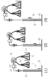
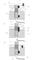
- the open end is preferably closed so that all or a part thereof can be opened and closed. Examples of preferred open ends are shown in FIGS. 1 (2) and (3).
- the tube has a substantially inner diameter of 0.1 mm to 5 mm.
- the magnetic field applying unit is capable of moving the magnetic particles in the longitudinal direction of the operation tube outside the operation tube.
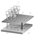
- the holding means is a holding substrate in which a plurality of holding holes capable of holding the closed end portion of the operation tube are formed.
- An example of the holding means which is the holding substrate of the above (5) is shown as 51 in FIGS. (6)
- An example of the holding means having the recess (7) is shown as 51 in FIG.
- the magnetic field applying unit has a mechanism for controlling the movement of the magnetic field in the longitudinal direction of the operation tube and the strength of the magnetic field.
- the magnetic field applying unit has a temperature control function.
- the magnetic field application unit includes any one of (5) to (10), including a movable substrate capable of moving in a longitudinal direction of the operation tube, and a plurality of magnetic force sources held in the movable substrate. Devices. An example of the magnetic field applying means (11) is shown as the movable magnet plate 53 in FIG.
- the magnetic particles have binding force or adsorption power to nucleic acid as a target component, and the operation medium liberates nucleic acid, and an aqueous liquid layer made of a liquid that binds or adsorbs to the magnetic particles, and
- the device according to any one of (1) to (12), comprising an aqueous liquid layer comprising a cleaning liquid for the magnetic particles.
- the operation medium further includes an aqueous liquid layer made of a nucleic acid amplification reaction solution, or an aqueous liquid layer made of a reverse transcription reaction solution and an aqueous liquid layer made of a nucleic acid amplification reaction solution. device.
- the device according to any one of (1) to (14), wherein the tube is integrally formed.
- the operation tube has an operation part A and a recovery part B,
- the tube constituting the operation tube has an operation tube portion a and a recovery tube portion b corresponding to the operation portion A and the recovery portion B, respectively.
- the operation part A includes the pipe part a and the operation medium accommodated in the pipe part a
- the recovery part B includes the pipe part b and a recovery medium that is accommodated in the pipe part b and includes at least one of an aqueous liquid layer and a gel layer.
- FIG. An example of the operation tube (16) is shown in FIG.
- the tube material is polyethylene, polypropylene, fluororesin, polyvinyl chloride, polystyrene, polycarbonate, acrylonitrile butadiene styrene copolymer (ABS resin), acrylonitrile styrene copolymer (AS resin), acrylic resin, polyvinyl acetate, polyethylene terephthalate, cyclic polyolefin
- a method for producing an operation tube included in the device according to (1) comprising a step of alternately laminating an aqueous liquid layer and a gel layer in a tube having an open end on one side and a closed end on the other side.
- a manufacturing method including the step of connecting the one end of the operation tube a of the operation unit A and the open end of the recovery tube b of the recovery unit B. The outline of the step (i) in the method (20) is shown in FIG.
- a method for manipulating a target component using the device according to (1) comprising the following steps: (I) obtaining an aqueous liquid mixture containing a sample containing the target component, magnetic particles and an aqueous liquid in the uppermost layer of the operation tube; (Ii) A magnetic field is generated by a magnetic field applying means, and the magnetic particles are transported together with the target component from the uppermost aqueous liquid mixture layer to the adjacent aqueous liquid layer through the gel layer.
- the target component is a nucleic acid
- the aqueous liquid contained in the uppermost aqueous liquid mixture is a liquid that liberates the nuclei and binds or adsorbs to the magnetic particles, and nucleic acid extraction is performed in the aqueous liquid.
- at least one of the aqueous liquid layers is composed of a cleaning solution for the magnetic particles, and nucleic acid purification is performed in the cleaning solution by removing contaminants associated with free nucleic acids. Or the method as described in (22).
- the lowermost layer comprises a nucleic acid amplification reaction solution, and the target nucleic acid in the purified nucleic acid is amplified in the nucleic acid amplification reaction solution.
- the layer immediately above the lowermost layer made of the nucleic acid amplification reaction solution is made of a reverse transcription reaction solution.
- the product of the nucleic acid amplification reaction is optically detected in real time.
- the small and low running cost device which can perform all of a desired series of operations, suppressing generation
- a small and low running cost device capable of performing extraction / purification of a target component in a completely sealed container, or further performing analysis in the same container while maintaining a sealed state. Can be provided.
- FIG. 1 It is a longitudinal cross-sectional view of the example of the operation pipe
- An example of the manufacturing method of the operating tube of this invention is shown.
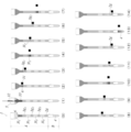
- the process of extracting and purifying a nucleic acid from a nucleic acid containing sample using the operation tube of the present invention shown in FIG. 1 (3) is shown.
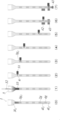
- purifies a nucleic acid from a nucleic acid containing sample using another example of the operating tube of this invention, and also performs the analysis by reverse transcription reaction and PCR reaction is shown.
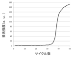
- FIG. 6 is a longitudinal sectional view of a portion including a modified example of the magnetic field applying unit (movable magnet plate), a modified example of the holding unit (holding substrate), and an operation tube held by the holding unit shown in FIG. 5. It is the result obtained in Example 1 which performed the process shown in FIG. It is the result obtained in Example 2 which performed the process shown in FIG.
- target component to be operated in the present invention is not particularly limited as long as it is a component that can be normally operated in an aqueous liquid, an emulsion, or a hydrogel, and may be an in vivo component or a non-in vivo component.
- In vivo components include biomolecules such as nucleic acids (including DNA and RNA), proteins, lipids, and sugars.
- Non-in vivo components include non-biomolecules such as artificially modified (both chemical and biochemical) biomolecules, labeled and mutants, non-biomolecules derived from natural products, and other aqueous systems. Any component that can be manipulated in a liquid is included.
- the target component can usually be provided in the form of a sample containing the target component.
- a sample include biological-derived samples such as animal and plant tissues, body fluids, and excreta, and biomolecule-containing bodies such as cells, protozoa, fungi, bacteria, and viruses.
- Body fluids include blood, sputum, cerebrospinal fluid, saliva, and milk, and excreta includes feces, urine, and sweat, and combinations thereof may be used.
- the cells include leukocytes in blood, platelets, exfoliated cells of oral cells and other mucosal cells, and a combination thereof may be used. These samples may be obtained as clinical swabs.
- said sample may be prepared in aspects, such as a cell suspension, a homogenate, a liquid mixture with a cell lysis solution, for example.
- the sample containing the target component may be obtained by performing treatments such as modification, labeling, fragmentation, and mutation on the above sample.
- the sample containing the target component may be prepared by appropriately pretreating the above sample in advance.
- the pretreatment include a process of extracting, separating, and purifying the target component or the target component-containing body from a sample containing the target component.
- pre-processing can be performed in the device of the present invention, it is not always required to be performed in advance before being supplied into the device. By performing the pretreatment in the device of the present invention, it is possible to avoid the contamination problem that is usually a concern in the pretreatment of the sample.
- the sample containing the target component is supplied into the operation tube exemplified as 1 in FIG. 1, and the target component is operated in the operation tube.
- Manipulation of the target component in the present invention includes subjecting the target component to various processes and transporting the target component among a plurality of environments in which various processes are performed.
- the operation tube contains a gel layer and an aqueous liquid layer.
- the layers indicated by 2g and 3g are made of gel (gel plug), and the layer shown by 3l is made of an aqueous liquid.
- the layer indicated by 4 may be made of an aqueous liquid or a hydrogel as long as the aqueous liquid can maintain a gel state.
- An aqueous liquid or hydrogel constructs an environment for processing the target component. Therefore, more specifically, the operation of the target component in the present invention includes subjecting the target component to processing in an aqueous liquid or hydrogel, and transporting the target component between a plurality of processing environments through the gel plug. Including doing.
- the process in which the target component is provided includes a process involving a substance change of the target component and a process involving a physical change.
- the process accompanied by the substance change of the target component includes any process as long as it is a process that newly generates a different substance by generating or breaking a bond between substrates. More specifically, chemical reactions and biochemical reactions are included.
- a chemical reaction includes any reaction involving compounding, decomposition, oxidation and reduction. In the present invention, those usually performed in an aqueous liquid are included.
- a biochemical reaction includes any reaction accompanied by a change in a biological material, and usually refers to an in vitro reaction. For example, reactions based on the synthesis system, metabolic system and immune system of biological substances such as nucleic acids, proteins, lipids and sugars can be mentioned.
- Processes that involve physical changes in target components include any process that does not involve material changes. More specifically, denaturation of the target component (for example, when the target component is a biopolymer or other polymer containing nucleic acid or protein), dissolution, mixing, emulsification, dilution, and the like are included.
- the process of the present invention makes it possible to perform steps such as extraction, purification, synthesis, elution, separation, recovery and analysis of the target component. Through these steps, the target component can be finally isolated, detected, identified, and the like.
- the process in the present invention includes not only the target process (process in a process in which an effect such as isolation, detection and identification of the target component is directly obtained), but also a pre-process and / or a post-process associated therewith. Included as appropriate.
- steps such as nucleic acid amplification reaction, or nucleic acid amplification reaction and analysis of amplification product can be performed.
- pretreatment thereof extraction of nucleic acid from a nucleic acid-containing sample ( Cell lysis) and / or purification (washing) are essential, and amplification products may be recovered as a post-treatment.
- the target component is transported by magnetic particles and magnetic field application means.
- the magnetic particles are present in the operation tube at the time of operation, and the target component is transported by moving in the operation tube in a state of being captured by binding or adsorbing the target component to the surface thereof. It is something that can be done.
- the magnetic particles can be dispersed in the aqueous liquid layer in the operation tube, and are usually aggregated in the aqueous liquid layer by generating a magnetic field from the outside of the operation tube by a magnetic field applying means.
- the agglomerated magnetic particles can be moved from the outside of the operation tube as the magnetic field is generated by the magnetic field applying means. Aggregated magnetic particles can move into the gel layer.
- the aggregated magnetic particles can pass through without destroying the gel layer.
- the aggregated magnetic particles are accompanied by binding or adsorption of the target component.
- the aggregated magnetic particles are coated with a very small amount of aqueous liquid. That is, components other than the target component can be accompanied.
- the amount of the coated aqueous liquid is very small, it can be said that the aqueous liquid hardly accompanies. For this reason, the target component can be transported very efficiently.
- the device of the present invention has an operation tube.
- the structure of the operation tube will be described with reference to FIG. 1 (in the following description, the upper and lower sides are referred to based on FIG. 1). It is preferable that the upper end of the tube constituting the operation tube is opened for sample introduction, and the open end can be closed from the viewpoint of contamination. The lower end is closed.
- the tubes constituting the operation tube have a substantially circular cross section, but do not exclude tubes having other shapes of cross sections.
- An operation medium in which the aqueous liquid layer 1 and the gel layer g are alternately stacked in the longitudinal direction of the tube is accommodated in the tube.
- FIG. 1 exemplifies three modes (1) to (3) in which the upper and lower modes of the operation tube are different.
- the upper part and the lower part can be arbitrarily combined, and are not limited to the combinations shown in (1) to (3).
- the upper open end of the tube is a sample supply unit 5 for supplying a sample containing the target component, and the sample supply unit 5 that is the open end may be temporarily opened (FIG. 1 (1)), The whole (FIG. 1 (2)) or part may be closed so that opening is possible.
- a part is closed in a releasable manner, by using a septum having a check valve function, it is possible to supply a sample by puncture close to a sealed state by an injection needle. (FIG. 1 (3)).
- the sample supply unit 5 that is the open end is closed in that a completely sealed system can be constructed. The possibility of constructing a completely closed system is very effective because it can prevent external contamination during operation.
- the inner diameter of the sample supply part 5 may be the same as the inner diameter of the tube part a in which the gel layer and the aqueous liquid layer as the operation medium are accommodated (FIG. 1 (1)), and at the time of supplying the sample It may be appropriately formed so as to have a wider inner diameter from the viewpoint of operability (FIGS. 1 (2) and (3)).
- the tube is integrally formed.
- the pipe is composed of an operation pipe part a and a recovery pipe part b.
- the upper and lower ends of the operation tube portion a are open.
- the recovery pipe part b has an upper end opened and a lower end closed.
- the operation tube portion a and the collection tube portion b are connected to one end of the tube portion a and the open end of the tube portion b.
- the operation tube portion a and the recovery tube portion b may have a separable shape, or may have a shape that does not consider separation (a shape that cannot be separated).
- a gel layer 2g that closes one end and a multilayer layer, that is, an operation medium 3 that overlaps the gel layer 2 are accommodated.
- the operation medium 3 is configured by alternately layering an aqueous liquid layer 3l and a gel layer 3g.
- a portion composed of the operation tube portion a and the operation medium that is the container is referred to as an operation portion A.
- a recovery medium 4 containing at least one of the aqueous liquid and the gel is accommodated in the recovery tube portion b.
- a portion constituted by the collection pipe portion b and the collection medium 4 that is the contained material is referred to as a collection portion B.
- the operation unit A and the recovery unit B may be provided in a connected state or may be provided in an independent state.
- the substantially inner diameter of the tube constituting the operation tube is, for example, 0.1 mm to 5 mm, preferably 1 to 2 mm. Within this range, the operating tube can have good operability. Below this range, the tube wall must be thickened to maintain strength, the distance between the magnetic particles and the magnet increases, and the magnetic force on the magnetic particles becomes difficult to reach, which may cause operational problems. There is sex. On the other hand, when the inner diameter of the tube exceeds the above range, the multilayer of the gel layer and the aqueous liquid layer constituting the operation medium tends to be disturbed due to an impact from the outside or the influence of gravity.
- a tube having an inner diameter of 0.1 mm or less is not excluded as long as the capillary material can withstand high-precision processing.
- the length of the operation tube in the longitudinal direction is, for example, 1 to 30 cm, preferably 5 to 15 cm.
- the substantially internal diameter of the sample supply part 5 is larger than the above-mentioned range, and is 10 mm.
- it may be preferably 5 mm or less.
- the reagent supply unit has a wider inner diameter from the viewpoint of workability at the time of reagent supply. When the wider inner diameter exceeds the above range, for example, when processing a plurality of operation tubes at the same time, the operation tubes interfere with each other and the device integration tends to deteriorate.
- the material of the pipe constituting the operation pipe is not particularly limited.
- the inner wall which is the conveying surface is smooth and water-repellent.
- Examples of materials that give such properties include polyethylene, polypropylene, fluororesin (Teflon (registered trademark)), polyvinyl chloride, polystyrene, polycarbonate, acrylonitrile butadiene styrene copolymer (ABS resin), acrylonitrile styrene copolymer (AS resin),
- Examples of the resin material include acrylic resin, polyvinyl acetate, polyethylene terephthalate, and cyclic polyolefin.
- a resin material is preferable in that the layer in the operation tube is less likely to be disturbed even if the operation tube is dropped or bent, and is highly robust.
- the material of the tube may be glass if necessary in terms of transparency, heat resistance and / or workability.
- the materials of the reagent supply unit 5, the operation tube unit a, and the recovery tube unit b may be the same or different.
- the tube material is selected from the viewpoint of visibility during operation and from the viewpoint of optical detection when measuring absorbance, fluorescence, chemiluminescence, bioluminescence, refractive index change, etc. from the outside of the tube. It is preferable that it has permeability.
- FIG. 1 (1) a gel layer
- FIG. 1 (2) an aqueous liquid layer
- FIG. 1 (2) a gel layer
- the magnetic particles 6 may be included in the layer (FIG. 1 (3)) or may not be included (FIG. 1 (1)).
- the lowermost layer may be an aqueous liquid layer (FIGS. 1 (1) to (3)) or a gel layer.
- the tubes constituting the operation tube when the tubes constituting the operation tube are integrally formed, all the layers accommodated in the tube may be in contact with each other.
- the recovery tube portion b when the tube constituting the operation tube is composed of the operation tube portion a and the recovery tube portion b, the recovery tube portion b contains only an aqueous liquid as a recovery medium.
- the gel may be accommodated, or a multilayer in which the aqueous liquid layer and the gel layer are alternately stacked may be accommodated.
- the gel layer 2g accommodated at the lowermost end of the operation tube portion a and the aqueous liquid, gel contained in the collection tube portion b, or the multilayer uppermost layer contained in the collection tube portion b are: They may be in contact with each other or may not be in contact by sandwiching a gas layer between them (FIG. 1 (3)).
- the number and order of the layers accommodated in the tube are not particularly limited, and can be appropriately determined by those skilled in the art based on the number and order of the operation steps for providing the target component.
- Each of the aqueous liquid layers accommodated in one operation tube is preferably composed of two or more different types of aqueous liquids.
- a liquid that builds an environment necessary for each of the processing step and the reaction step for supplying the target component can be used in order from the upper end side of the operation tube.
- Each of the gel layers accommodated in one operation tube may be made of a different kind of gel or may be made of the same kind of gel.
- the gel when a treatment or reaction by heating is performed in a part of the plurality of aqueous liquid layers, the gel is only in the gel layer adjacent to the aqueous liquid layer even at the temperature required for the heating.
- a gel having a high sol-gel transition point capable of maintaining a state or a gel-sol intermediate state can be used, and a gel having a relatively low sol-gel transition point can be used for the other gel layers.
- those skilled in the art can appropriately select a gel having appropriate characteristics depending on the characteristics and volume of the aqueous liquid constituting the adjacent aqueous liquid layer.
- the gel layer serves as a plug (gel plug) that partitions the aqueous liquid layer on both sides in the longitudinal direction of the tube in the operation tube.
- a plug gel plug
- the thickness that functions as a plug in consideration of the inner diameter and length of the tube, the amount of magnetic particles conveyed by the magnetic field applying means, and the like.
- it can be 1 to 20 mm, preferably 3 to 10 mm.
- the strength as a plug tends to be lacking.
- the operation tube becomes long, and the operability, the durability of the device, and the accommodating property tend to deteriorate.
- the aqueous liquid layer provides an environment such as treatment or reaction in which a sample containing the target component is provided.
- the thickness is determined based on the inner diameter and length of the tube, the amount of the target component, the type of treatment and reaction to which the target component is provided, and the aqueous liquid that achieves the desired treatment or reaction for the target component. Those skilled in the art can appropriately determine the thickness to give the amount. For example, it can be 0.5 to 30 mm, preferably 3 to 10 mm. Below the above range, the treatment and reaction for the target component may not be sufficiently achieved, and there is a possibility that the plug becomes droplets and the magnetic particles cannot be combined with the reagent. When the above range is exceeded, the aqueous liquid layer is often too thick compared to the gel layer, which may cause the same problem as the gel plug, and when the specific gravity of the aqueous liquid is larger than the gel, Tend to collapse.
- the hydrogel layer when the gel layer is composed of a hydrogel, the hydrogel layer not only serves as a reagent partition, but can provide an environment such as a treatment or reaction in which a sample containing the target component is provided, similar to the aqueous liquid layer. it can.
- the hydrogel layer may be thicker than the aqueous liquid layer.
- the gel layer is made of a chemically inert substance that is insoluble or hardly soluble in the liquid constituting the aqueous liquid layer when it is overlaid with the aqueous liquid in the tube.
- Insoluble or hardly soluble in a liquid means that the solubility in the liquid at 25 ° C. is approximately 100 ppm or less.
- a chemically inert substance refers to a target component and an aqueous liquid or hydrogel in the operation of the target component (that is, treatment of the target component in an aqueous liquid or hydrogel and transport of the target component through a gel plug).
- the gel in the present invention includes both organogel and hydrogel.
- Organogel can be gelled by adding a gelling agent to a liquid substance that is usually insoluble or sparingly soluble in water.
- a gelling agent e.g., a gelling agent for a gelling agent for a gelling agent for a gelling agent for a gelling agent for a liquid substance that is usually insoluble or sparingly soluble in water.
- Liquid substances that are insoluble or sparingly soluble in water As the water-insoluble or hardly water-soluble liquid substance, oil having a solubility in water at 25 ° C. of approximately 100 ppm or less and liquid at room temperature (20 ° C. ⁇ 15 ° C.) can be used.
- 1 type, or 2 or more types from the group which consists of liquid fats and oils, ester oil, hydrocarbon oil, and silicone oil may be used.
- Liquid oils include linseed oil, camellia oil, macadamia nut oil, corn oil, mink oil, olive oil, avocado oil, sasanqua oil, castor oil, safflower oil, kyounin oil, cinnamon oil, jojoba oil, grape oil, sunflower oil, Almond oil, rapeseed oil, sesame oil, wheat germ oil, rice germ oil, rice bran oil, cottonseed oil, soybean oil, peanut oil, teaseed oil, evening primrose oil, egg yolk oil, liver oil, palm oil, palm oil, palm kernel oil, etc. Is mentioned.
- Ester oils include octanoic esters such as cetyl octanoate, lauric esters such as hexyl laurate, myristate esters such as isopropyl myristate and octyldodecyl myristate, palmitate esters such as octyl palmitate, isocetyl stearate, etc.
- octanoic esters such as cetyl octanoate
- lauric esters such as hexyl laurate
- myristate esters such as isopropyl myristate and octyldodecyl myristate
- palmitate esters such as octyl palmitate, isocetyl stearate, etc.
- Stearic acid ester isostearic acid ester such as isopropyl isostearate, isopalmitic acid ester such as octyl isopalmitate, oleic acid ester such as isodecyl oleate, adipic acid ester such as isopropyl adipate, sebacic acid such as ethyl sebacate
- esters malate esters such as isostearyl malate, glycerin trioctanoate, glycerin triisopalmitate, and the like.
- hydrocarbon oil examples include pentadecane, hexadecane, octadecane, mineral oil, liquid paraffin, and the like.
- silicone oil examples include dimethylpolysiloxane, methylphenylpolysiloxane and other phenyl group-containing silicone oils, and methylhydrogenpolysiloxane.
- gelling agent an oil gelling agent selected from the group consisting of hydroxy fatty acid, dextrin fatty acid ester, and glycerin fatty acid ester may be used alone or in combination.
- the hydroxy fatty acid is not particularly limited as long as it is a fatty acid having a hydroxyl group. Specific examples include hydroxymyristic acid, hydroxypalmitic acid, dihydroxypalmitic acid, hydroxystearic acid, dihydroxystearic acid, hydroxymargaric acid, ricinoleic acid, ricinaleic acid, and linolenic acid. Of these, hydroxystearic acid, dihydroxystearic acid, and ricinoleic acid are particularly preferable. These hydroxy fatty acids may be used alone or in combination of two or more. Moreover, animal and vegetable oil fatty acids (for example, castor oil fatty acid, hydrogenated castor oil fatty acid, etc.) that are a mixture of these can also be used as the hydroxy fatty acid.
- animal and vegetable oil fatty acids for example, castor oil fatty acid, hydrogenated castor oil fatty acid, etc.
- dextrin fatty acid esters examples include dextrin myristate [trade name “Leopard MKL”, manufactured by Chiba Flour Mills Co., Ltd.], dextrin palmitate [trade names “Leopard KL”, “Leopard TL”, both manufactured by Chiba Flour Mills Co., Ltd.] , (Palmitic acid / 2-ethylhexanoic acid) dextrin [trade name “Leopard TT”, manufactured by Chiba Flour Milling Co., Ltd.] and the like.
- glycerin fatty acid ester examples include glyceryl behenate, glyceryl octastearate, and glyceryl eicoate. These may be used in combination of one or more.
- the trade name “TAISET 26” (manufactured by Taiyo Chemical Co., Ltd.), 20% glyceryl behenate and 50% octastearic acid containing 20% glyceryl behenate, 20% glyceryl octastearate and 60% hydrogenated palm oil.
- a trade name “TAISET 50” (manufactured by Taiyo Kagaku Co., Ltd.) including glyceryl can be used.
- the content of the gelling agent added to the liquid substance that is not water-soluble or poorly water-soluble is, for example, 0.1 to 0.5% by weight, 0.5 to 2% by weight of the total weight of the liquid substance, Alternatively, an amount of gelling agent corresponding to 1 to 5% by weight can be used. However, without being limited thereto, those skilled in the art can appropriately determine the amount that can achieve the desired gel and sol state.
- the gelation method can be appropriately determined by those skilled in the art. Specifically, a liquid substance that is water-insoluble or poorly water-soluble is heated, a gelling agent is added to the heated liquid substance, the gelling agent is completely dissolved, and then cooled to Liquid substances can be gelled.
- the heating temperature may be appropriately determined in consideration of the liquid substance to be used and the physical properties of the gelling agent. For example, it may be preferable to set the temperature to about 60 to 70 ° C.
- the gelling agent is dissolved in the heated liquid substance, and at this time, it is preferable that the gelling agent is gently mixed. Cooling is preferably performed slowly. For example, it can be cooled for about 1 to 2 hours. For example, cooling can be completed when the temperature falls to room temperature (20 ° C.
- hydrogel for example, gelatin, collagen, starch, pectin, hyaluronic acid, chitin, chitosan or alginic acid and derivatives thereof are used as hydrogel materials, and those prepared by equilibrium swelling of the hydrogel material in water or an aqueous liquid are used. Can be.
- a hydrogel prepared from gelatin it is preferable to use a hydrogel prepared from gelatin.
- the hydrogel is obtained by chemically crosslinking the above hydrogel material, or by a gelling agent (for example, a salt of an alkali metal or alkaline earth metal such as lithium, potassium or magnesium, or a transition metal such as titanium, gold, silver or platinum). Or a silica, carbon, alumina compound, etc.).
- a gelling agent for example, a salt of an alkali metal or alkaline earth metal such as lithium, potassium or magnesium, or a transition metal such as titanium, gold, silver or platinum.
- a silica, carbon, alumina compound, etc.
- the hydrogel provides an environment such as a treatment or reaction in which a sample containing the target component is provided in the same manner as an aqueous liquid
- a person skilled in the art will have a composition suitable for such treatment and reaction.
- a DNA hydrogel (P-gel) based on polydimethylsiloxane capable of synthesizing proteins can be mentioned.
- This hydrogel is composed of DNA as part of the gel scaffold.
- Such a hydrogel can be subjected to a reaction for obtaining a protein from the target component when the target component is a substrate for protein synthesis (more specifically, Nature Materials 8, 432-437 (2009), And Nature Protocols 4: 1759-1770 (2009), which can be appropriately determined by those skilled in the art.
- the produced protein can be recovered, for example, by using magnetic particles having an antibody specific for the protein.
- the gel contained in the tube has a property of causing a sol-gel transition at a certain temperature.
- the sol-gel transition point may be in the range of 25-70 ° C. A sol-gel transition point in this range is desirable in a reaction system that requires fluidity by solification for recovery or the like.
- the sol-gel transition point may vary depending on conditions such as the type of organogel material (oil) or hydrogel material, the type of gelling agent, and the amount of gelling agent added. Accordingly, each condition is appropriately selected by those skilled in the art so as to have a desired sol-gel transition point.
- the gel plug allows the aqueous liquid in the tube to be fixed at a predetermined position in the tube by sandwiching it from both sides in the longitudinal direction of the tube.
- magnetic particles can be moved by an external magnetic field operation, and can pass through the gel. This is due to the thixotropic nature of the gel (thixotropic properties).
- the magnetic particles in the tube give a shearing force to the gel along the conveying surface by moving the magnet from the outside, and the gel in the forward direction of the magnetic particles is solated and fluidized, so that the magnetic particles proceed as they are. Can do.
- the sol released from the shearing force after the magnetic particles have passed through returns quickly to the gel state, so that the gel does not form through holes due to the passage of the magnetic particles.
- the object can easily move using the magnetic particles as a carrier, and therefore, various chemical environments provided with the object can be switched in a very short time.
- the processing time of the object can be greatly shortened. If the property of gelation at a temperature below room temperature is used, even a reagent that exhibits a liquid state at that temperature can be immobilized by being sandwiched by gel plugs in the tube.
- the state in which the capillary is preliminarily loaded with the liquid reagent can be maintained from the time of manufacturing the device to the hand of the user, and the liquid reagent can be stably supplied. Furthermore, reagent collection and dispensing operations for each process are unnecessary, and labor and time can be reduced, and deterioration of analysis accuracy due to contamination can be prevented.
- the storage viscoelasticity E ′ of the dynamic viscoelasticity can be preferably 10 to 100 kPa, more preferably 20 to 50 kPa at room temperature (20 ° C. ⁇ 15 ° C.).
- the strength as a gel plug tends to be lacking.
- even magnetic particles having a particle size of about several ⁇ m tend to be hindered in movement.
- it may have a kinematic viscosity of 5 mm 2 / s to 100 mm 2 / s, preferably 5 mm 2 / s to 50 mm 2 / s, for example about 20 mm 2 / s (50 ° C.).
- the aqueous liquid in the present invention may be an aqueous liquid that is insoluble or hardly soluble in the gel, and can be provided in the form of an emulsion called water, an aqueous solution or an emulsion, or a suspension in which fine particles are dispersed.
- the constituent component of the aqueous liquid includes any component that provides a reaction or treatment environment in which the target component in the present invention is provided.
- a liquid for releasing the component to be operated in the present invention in the aqueous liquid layer and binding or adsorbing it to the surface of the magnetic particles that is, separating the target component from the contaminants, the surface of the magnetic beads
- a liquid having an action of promoting binding to or adsorption to a target component a cleaning solution for removing foreign substances coexisting with the target component, an eluent for separating the target component adsorbed on the magnetic particle from the magnetic particle, and the target component
- a reaction solution for constructing a reaction system for a reaction system.
- the reagent solution (cell lysate) is used to destroy the cell, release the nucleic acid, and adsorb it onto the surface of the silica-coated magnetic particle, and the magnetic particle to remove components other than the nucleic acid Washing solution for washing the nucleic acid, elution solution for separating nucleic acid from magnetic particles (nucleic acid elution solution), nucleic acid amplification reaction solution for performing nucleic acid amplification reaction, and the like.
- the target component is a nucleic acid
- the treatment liquid and reaction liquid for the nucleic acid and the treatment and reaction in which they are provided will be further described.
- cell lysate An example of the cell lysate is a buffer containing a chaotropic substance.
- the buffer may further include EDTA or any other chelating agent, Triton X-100 or any other surfactant.
- the buffer is based on, for example, Tris-HCl or any other buffer.
- chaotropic substances include guanidine hydrochloride, guanidine isothiocyanate, potassium iodide, urea and the like.
- the chaotropic substance is a powerful protein denaturing agent, and has an action of pulling away proteins such as histones clinging to nucleic acids from the nucleic acids and promoting adsorption of the magnetic particles on the silica coating surface.
- the buffer can be used as an auxiliary agent for preparing a pH environment in which nucleic acids are easily adsorbed on the surface of magnetic particles.
- the chaotropic substance also has a cell lysis (ie, destroying cell membrane) action. However, a surfactant contributes more to the cell lysis (i.e., disrupts the cell membrane) than the chaotropic substance. Chelating agents can be used as adjuvants that promote cell lysis.
- a specific protocol for nucleic acid extraction from a sample containing nucleic acid can be appropriately determined by those skilled in the art.
- the magnetic particles are used for transporting the nucleic acid in the droplet encapsulating medium, it is preferable to adopt a method using the magnetic particles as the nucleic acid extraction method.
- a method for extracting and purifying nucleic acid using magnetic particles from a sample containing nucleic acid can be carried out.
- the nucleic acid is adsorbed on the surface of the magnetic particles, and the reagent used for other components other than the nucleic acid contained in the nucleic acid-containing sample (for example, protein, sugar, etc.)
- a solution capable of dissolving other components is preferred.
- Specific examples include high salt concentration aqueous solutions such as sodium chloride, potassium chloride, and ammonium sulfate, and aqueous alcohol solutions such as ethanol and isopropanol.
- the washing of the nucleic acid is a washing of the magnetic particles to which the nucleic acid has been adsorbed. A specific protocol for this washing can also be appropriately determined by those skilled in the art.
- the number of washings of the magnetic particles to which the nucleic acid has been adsorbed can be appropriately selected by those skilled in the art to such an extent that undesired inhibition does not occur during the nucleic acid amplification reaction. Further, when the influence of the inhibitory component can be ignored from the same viewpoint, the washing step can be omitted.
- the aqueous liquid layer made of the cleaning liquid is prepared at least as many times as the number of times of cleaning.
- nucleic acid eluate As the nucleic acid eluate, a buffer solution containing water or salt can be used. Specifically, a Tris buffer solution, a phosphate buffer solution, distilled water, or the like can be used. A person skilled in the art can also determine a specific method for separating the nucleic acid from the magnetic particles adsorbed with the nucleic acid and eluting it into the eluate.
- nucleic acid amplification reaction solution In the nucleic acid amplification reaction solution of the present invention, various elements usually used in the nucleic acid amplification reaction include at least a nucleic acid containing a base sequence to be amplified and magnetic particles adsorbed on the surface thereof.
- the nucleic acid amplification reaction is not particularly limited, and therefore various elements used in the nucleic acid amplification reaction can be appropriately determined by those skilled in the art based on known nucleic acid amplification methods exemplified below. it can.
- salts such as MgCl 2 and KCl, primers, deoxyribonucleotides, nucleic acid synthetase and pH buffer are included.
- the above salts can be used by appropriately changing to other salts.
- a substance for reducing non-specific priming such as dimethyl sulfoxide, betaine, or glycerol may be further added.
- the nucleic acid amplification reaction solution in the present invention can contain a blocking agent.
- the blocking agent can be used for the purpose of preventing the deactivation of the nucleic acid polymerizing enzyme due to adsorption to the inner wall of the reaction vessel or the surface of the magnetic particles.
- Specific examples of the blocking agent include bovine serum albumin (ie, BSA) and other albumins, gelatin (ie, denatured collagen), proteins such as casein and polylysine, peptides (both natural and synthetic), ficoll, and polyvinylpyrrolidone. And polyethylene glycol.
- the nucleic acid amplification reaction according to the present invention is not particularly limited.
- the PCR method (US Pat. Nos. 4,683,195, 4,683,202, 4,800,159, and 4,965,188), the LCR method (US Pat. No. 5,494,810). No. 4), Q ⁇ method (US Pat. No. 4,786,600), NASBA method (US Pat. No. 5,409,818), LAMP method (US Pat. No. 3,313,358), SDA method (US Pat. No. 5,455,166), RCA method ( U.S. Pat. No. 5,354,688), ICAN method (Japanese Patent No. 3433929), TAS method (Japanese Patent No. 2443586), and the like can be used.
- RT reaction can also be performed prior to the above reaction.
- the composition of the reaction solution necessary for these nucleic acid amplification reactions and the reaction temperature can be appropriately selected by those skilled in the art.
- a nucleic acid amplification reaction is further performed after the reverse transcriptase (RT) reaction
- the RT reaction is performed on the PCR reaction solution layer via a gel layer.
- the layers of the reaction solution can be overlaid (for example, illustrated in FIG. 4).
- the amplification product can be detected with a fluorescent dye capable of binding to double-stranded DNA or a probe labeled with the fluorescent dye.
- detection methods in the real-time nucleic acid amplification method include the following methods.
- an intercalator method using SYBR (registered trademark) GREEN I or the like is used.
- An intercalator that emits fluorescence by binding to double-stranded DNA binds to double-stranded DNA synthesized by a nucleic acid amplification reaction, and emits fluorescence of a specific wavelength when irradiated with excitation light. By detecting this fluorescence, the amount of amplification product generated can be monitored.
- This method does not require designing and synthesizing a target-specific fluorescently labeled probe, and can be easily used for measuring various targets.
- the fluorescent labeling probe method when it is necessary to distinguish and detect similar sequences, or when typing SNPs, the fluorescent labeling probe method is used.
- a TaqMan (registered trademark) probe method using an oligonucleotide whose 5 ′ end is modified with a fluorescent substance and whose 3 ′ end is modified with a quencher substance as a probe.
- the TaqMan probe specifically hybridizes to the template DNA in the annealing step.
- a quencher is present on the probe, fluorescence emission is suppressed even when irradiated with excitation light.
- the fluorescent dye is released from the probe, the suppression by the quencher is released, and the fluorescence is released. Emits light. By measuring the fluorescence intensity, the amount of amplification product generated can be monitored.
- PCR is performed using serially diluted standard samples with known concentrations as templates. Then, the number of cycles (threshold cycle; Ct value) reaching a certain amount of amplification product is obtained.
- Ct value the number of cycles reaching a certain amount of amplification product is obtained.
- a calibration curve is created by plotting the Ct value on the horizontal axis and the initial DNA amount on the vertical axis. For a sample of unknown concentration, a Ct value is obtained by performing a PCR reaction under the same conditions. From this value and the calibration curve described above, the target DNA amount in the sample can be measured.
- the temperature after the PCR reaction solution containing the fluorescent dye is gradually raised from 40 ° C. to about 95 ° C., and the fluorescence intensity is continuously monitored, a melting curve of the amplification product can be obtained.
- Double-stranded DNA generated by the nucleic acid amplification reaction has a unique Tm value depending on the length of the DNA and its base sequence. That is, when the temperature of the droplet containing DNA to which the fluorescent dye is bound is gradually increased, a temperature at which the fluorescence intensity rapidly decreases is observed. When the amount of change in the fluorescence intensity is examined, the temperature peak almost coincides with the Tm value defined by the base sequence and the length.
- composition of the respective aqueous liquid can be easily determined by those skilled in the art. Even if the target component is other than the above nucleic acid, the composition of each aqueous liquid can be easily determined by those skilled in the art.
- Operation tube manufacturing method As a method for producing the operation tube, there are the following two methods depending on an aspect in which a tube in which a multilayer as an operation medium is to be accommodated is prepared.
- the operation medium can be formed by filling the required aqueous liquid and gel alternately in the required order from the lower closed end, thereby forming the operation tube.
- the tube is composed of the operation tube portion a and the recovery tube portion b
- storage of the recovery medium necessary for configuring the recovery portion B that is, storage of the aqueous liquid, storage of the gel
- the recovery unit B is completed.
- the operation unit A is completed by accommodating the operation medium necessary for configuring the operation unit A, that is, forming a multilayer of an aqueous liquid layer and a gel layer.
- a more specific method for forming a multilayer by alternately layering an aqueous liquid and a gel can be appropriately performed by those skilled in the art according to the layering method in the case of 4-2 described later.
- the sample supply part which is an upper opening end may be closed suitably.
- the pipe may be composed of the operation pipe part a and the recovery pipe part b, and the pipe part a and the pipe part b may be prepared independently.
- the operation part A and the recovery part B are separately prepared by accommodating the necessary aqueous liquid and / or gel in the pipe part a and the pipe part b, and the prepared operation part A and recovery part are produced.
- An operation tube can be produced by connecting B to each other.
- FIG. 2 An outline of the method for manufacturing the operation unit A is schematically shown in FIG.
- the aqueous liquid L for example, cleaning liquid
- the gel G constituting the gel layer is accommodated in another container in a sol state.
- the sol state is maintained by heating with a constant temperature bath 21 at 70 ° C.
- the lower opening end of the pipe part a is prepared in a closed state by being pressed against the pressing mat 22.
- the liquid feeding system into the pipe part a includes tubes 23 and 23 ′ for feeding the aqueous liquid L or the sol-gel G, respectively, extending from the container in which the aqueous liquid L and the sol-gel G are accommodated.
- a liquid feeding means 24 (peristaltic pump in FIG. 2) to which a tube 23 ′ is connected, and a needle 25 for filling the tube portion a with a liquid substance in the tube sent by the liquid feeding means. It is preferable that the needle 25 has a length enough to reach the bottom of the tube part a by being inserted into the tube part a.
- a tube 23 extending from the container containing the aqueous liquid L and a tube 23 extending from the container containing the sol-gel G are connected to the switching valve 26.
- different liquid substances aqueous liquid L and sol-gel G
- This embodiment can be preferably used when the inner diameter of the tube portion a is relatively small because only one needle is inserted into the tube portion a.
- the liquid supply path from the container to the needle may be made independent without using the switching valve 26.
- the tube extended from the container in which the aqueous liquid was accommodated, the needle connected to the tube, the tube extended from the container in which the sol-gel was accommodated, and Two liquid feeding paths with the needle connected to the tube can be formed.
- two needles can be inserted into the tube portion a, it can be preferably used when the inner diameter of the tube portion a is relatively large.
- the sol gel G and the aqueous liquid L are alternately sent and filled into the tube portion a in order from the sol gel G.
- the tip of the needle 25 is raised as the liquid level in the pipe part a rises.
- the aqueous liquid L is layered as shown in FIG. 2 (2) after filling the sol-gel, the previously filled sol-gel may or may not be completely gelled. Good.
- a heat source (a constant temperature bath 21 in FIG. 2). In general, it can be in an intermediate state of gel-sol with increased viscoelasticity.
- the recovery unit B can be obtained by storing a necessary aqueous liquid or gel. Or the collection
- recovery part B can be obtained by forming the multilayer of an aqueous liquid layer and a gel layer in the order required suitably by the method similar to the above except not using the mat for suppression.
- the operation unit A and the recovery unit B obtained as described above are connected to each other.
- the operation unit A may be configured such that the pipe part a is tilted so that the contents do not slide down, the restraining mat is removed, and the collection unit B is connected in a tilted state or a sideways state.
- the pipe part a and the pipe part b may be wound with a tape or the like, or the pipe part a and the pipe part b each having a connection part that can be connected to each other are used. , You may connect both connection parts.
- the sample supply portion that is the upper open end of the operation tube portion a may be appropriately closed.
- the closing timing may be after the operation unit A is manufactured and before the operation unit A and the recovery unit B are connected, or the operation unit A and the recovery unit B are connected. It may be later.
- the magnetic particles are used to move the target component in the operation tube by being accompanied by a small amount of liquid mass accompanying the fluctuation of the magnetic field from the outside of the operation tube. Magnetic particles intended to enable separation, recovery and purification of specific components by such movement usually have a chemical functional group on the surface.
- the magnetic particles may not be accommodated in the operation tube in advance (FIGS. 1 (1) and 1 (2)) or may be accommodated (FIGS. 1 (3), 3 and 4). When it is accommodated in the operation tube in advance, it can be contained in the aqueous liquid constituting the uppermost layer.
- the magnetic particles are not previously stored in the operation tube, the magnetic particles are also supplied into the operation tube when the sample having the target component is supplied into the operation tube.
- the magnetic particle is not particularly limited as long as it is a particle that responds to magnetism, and examples thereof include particles having a magnetic material such as magnetite, ⁇ -iron oxide, and manganese zinc ferrite.
- the magnetic particle has a chemical structure that specifically binds to the target component subjected to the above treatment or reaction, such as amino group, carboxyl group, epoxy group, avidin, biotin, digoxigenin, protein A, protein G, complex
- the surface may be provided with a metal ion or an antibody, and may have a surface that specifically binds to the target component by electrostatic force or van der Waals force. Thereby, the target component to be subjected to the reaction or treatment can be selectively adsorbed to the magnetic particles.
- the hydrophilic group on the surface of the magnetic particles include a hydroxyl group, an amino group, a carboxyl group, a phosphoric acid group, and a sulfonic acid group.
- the magnetic particles can further include various elements appropriately selected by those skilled in the art.
- the surface is covered with particles made of a mixture of a magnetic material and silica and / or anion exchange resin, silica and / or anion exchange resin.
- Preferred examples include magnetic particles, magnetic particles whose surface is covered with gold having a hydrophilic group via a mercapto group, and gold particles containing a magnetic substance and having a hydrophilic group via a mercapto group on the surface. .
- the magnetic particles having hydrophilic groups on the surface may have an average particle size of about 0.1 ⁇ m to 500 ⁇ m. When the average particle size is small, the magnetic particles tend to exist in a dispersed state when released from the magnetic field in the aqueous liquid layer.
- Examples of commercially available magnetic particles include Magnetic Beads coated with silica for nucleic acid extraction, which is a constituent reagent of Plasmid DNA Purification Kit MagExtractor-Plasmid- sold by Toyobo. In this way, when sold as a component reagent of a kit, since the stock solution of the product containing magnetic particles contains a storage solution or the like, it can be washed by suspending it with pure water (for example, about 10 times the amount). preferable.
- This washing can be carried out by removing the supernatant by centrifuging or agglomerating with a magnet after suspending purely, and suspension and removal of the supernatant can be repeated.
- the magnetic field application means for applying a magnetic field fluctuation to move the magnetic particles will be described in detail in Item 8 below.
- FIGS. 3 (0) to (14) and FIGS. 4 (0) to (7) The operation of the target component in the operation tube is shown in FIGS. 3 (0) to (14) and FIGS. 4 (0) to (7). Hereinafter, a description will be given based on FIGS. 3 and 4.
- the sample 32 containing the target component is supplied from the reagent supply port 5 (FIG. 3 (1) and FIG. 4 (1)).
- the sample is supplied in a liquid form.
- the sample supply may be performed manually with a syringe or the like, or may be automatically controlled with a dispenser using a pipetter or the like.
- the sample supply can be performed in a state where the operation tube is set up by appropriate holding means (not shown; the holding means for holding the operation tube will be described in detail in item 7 described later).
- obtaining a sample 32, the magnetic particles 6 and an aqueous liquid 3l 1 aqueous liquid mixture 33 comprising including a target component can be obtained as follows.
- the sample may be supplied into the operation tube together with the magnetic particles, or the sample may be supplied into the operation tube together with the aqueous liquid and suspended magnetic particles. May be.
- an aqueous liquid mixture can be obtained from the aqueous liquid in the uppermost layer.
- the uppermost layer accommodated in the operation tube is made of an aqueous liquid containing magnetic particles (the case illustrated in FIGS.
- only the sample may be supplied into the operation tube.
- the sample may be supplied into the operation tube together with the aqueous liquid.
- an aqueous liquid mixture can be obtained from the aqueous liquid containing the magnetic particles in the uppermost layer.
- the sample may be supplied into the operation tube together with the aqueous liquid and the magnetic particles. Thereby, an aqueous liquid mixture can be newly formed as the uppermost layer on the gel layer.
- the operation tube that is supplied with the sample and the aqueous liquid mixture containing the sample and magnetic particles in the uppermost layer is prepared in the state where it is placed on the holding means or transferred to the holding means dedicated to the device. Can be set.
- a magnetic field is applied from the outside by bringing a magnetic field applying means (for example, a cylindrical neodymium magnet having a diameter of 1 mm to 5 mm and a length of 5 mm to 30 mm) 31 close to the operation tube 1 and dispersed in the aqueous liquid mixture layer 311.
- the formed magnetic particles 6 are aggregated together with the target component (FIGS. 3 (2) and 4 (2)).
- unnecessary components contained in the aqueous liquid mixture layer 3l 1 may also be aggregated together.
- the magnetic field applying means 31 By moving the magnetic field applying means 31 downward at a speed of 0.5 mm to 10 mm per second, the magnetic particles attracting the target component are passed from the aqueous liquid mixture layer 3l 1 through the gel layer 3g 1 directly below it (see FIG. 3 (3) and FIG. 4 (3)) and transport to the aqueous liquid layer 3 l 2 immediately below the gel layer 3 g 1 (FIGS. 3 (4) and 4 (4)).
- magnetic particles passing through the gel layer 3 g because they are thin-coated in an aqueous liquid mixture of the aqueous liquid mixture layer 3l 1 which has been subjected to prior pass, in addition to the target component, the concentration is low It is accompanied by the contaminated components.
- Such magnetic particles are further transported to the aqueous liquid layer 3l 2.
- the size and moving speed of the magnet are appropriately determined by those skilled in the art according to the amount of magnetic particles, the inner and outer diameters of the operation tube, the state of the gel plug, and the like.
- the magnetic field applying unit 31 repeated as necessary to transport the aqueous liquid layer 3l 2 through the gel layer to the other aqueous liquid layer.
- “Repeat as necessary” means that, as a general rule, by carrying the magnetic particles only in one direction from the top to the bottom, the number of layers corresponding to the number of layers may be transported (FIG. 3 (4)). ⁇ (13) and Fig. 4 (4) ⁇ (7)), and by returning from not only one direction from the top to the bottom but also from the bottom to the top as appropriate, carry more than the number of transport operations according to the number of layers. It means you may. That is, the other aqueous liquid layer of the transportation destination may be present above the transportation-source aqueous liquid layer or may be present below.
- the amount of contaminating components transported by the magnetic particles together with the target component is infinitely close to zero.
- the magnetic particles with the target component are accompanied by a very small amount of cleaning liquid, the target component on the particle surface is purified to a level that does not hinder the subsequent analysis process and the like.
- the purification of the target component can be performed very efficiently only by the magnetic field operation.
- target components specifically, including target components accompanied by unnecessary components and target components from which unnecessary components have been removed
- target components specifically, including target components accompanied by unnecessary components and target components from which unnecessary components have been removed
- the magnetic particles that follow can be sufficiently brought into contact with the aqueous liquid.
- the magnetic field applying means is moved up and down while the magnetic particles are aggregated by applying the magnetic field in the aqueous liquid layer.
- the magnetic particles that have been aggregated by the application of the magnetic field are naturally diffused by releasing the magnetic field from the magnetic particles that have been subjected to the application of the magnetic field by the magnetic particles. Is mentioned.
- the magnetic field applying means 31 is once moved away from the operation tube 1 to block or attenuate the magnetic field, and the magnetic particles are dispersed in the cleaning liquid layer 3 12 .
- the magnetic field application means 31 is brought closer to the operation tube 1 again, thereby aggregating the magnetic particles together with the target component to be in a transportable state.
- the magnetic field applying unit 31 is transported into the gel layer 3 g 2 just below similarly as shown in FIG. 3 (6).
- the magnetic particles and target components in the gel layer 3g 2 in FIG. 3 (6) the magnetic particles and target components in the gel layer 3g 1 in FIG. Also, some or most of the attendant components have been removed.
- the magnetic substance particles separated from the target substance are moved from the layer where the target substance is separated to another layer.
- nucleic acid extraction For example, when the magnetic particle surfaces is silica coating, as shown in FIG. 3, the biological sample, by being subjected to the cell lysate 3l 1 containing a chaotropic salt such as a surfactant and guanidine thiocyanate, a nucleic acid They are released from the cells (FIG. 3 (1)). The liberated nucleic acid can be specifically adsorbed on the silica surface of the particles. The adsorbed nucleic acid cannot be used as a template for gene amplification reaction because it is accompanied by a reaction inhibiting component. Therefore, the magnetic particles remain adsorbed the nucleic acid to the surface is washed with a washing solution 3l 2.
- a chaotropic salt such as a surfactant and guanidine thiocyanate
- the magnetic particles 6 are collected by the magnet 31 (FIG. 3 (2)), and the gel plug separating the cell lysate 3l 1 and the washing solution 3l 2 is used. It passes through 3g 1 (FIG. 3 (3)).
- the cleaning liquid 3l 2 can be reached with little liquid fraction (FIG. 3 (4)). For this reason, magnetic particles can be washed with high efficiency.
- nucleic acids purified while adsorbed on the surface of the magnetic particles are collected again by a magnet (FIG. 2 (11)), passed through the gel plug 2g (FIG. 3 (12)), and transported into the eluate 4 (FIG. 3). 3) (13).
- the nucleic acid is separated from the magnetic particles and eluted in the eluate.
- the magnetic particles from which the nucleic acid has been eluted are retained in the gel plug 2g again, and the purified purified nucleic acid remains in the recovery part B (FIG. 3 (14)).
- the nucleic acid thus obtained is useful as a template nucleic acid that can be analyzed by a nucleic acid amplification reaction.
- the obtained nucleic acid can be subjected to the next operation (step of performing analysis by nucleic acid amplification reaction) by removing the recovery part B of the operation tube from the operation part A.
- the tube portion a of the operation portion A of the operation tube and the tube portion b of the recovery portion B are integrally formed and partitioned by the operation portion A similar to that in FIG. 3 and the gel plug 4g.
- FIGS. 3 (1) to (12) FIGS. 4 (1) to (5)
- magnetic particles 6 are brought to leave RT reaction 4l 1 has adsorbed the nucleic acid (RNA) purified, RT reaction is carried out (FIG. 4 (7)).
- PCR reaction After RT reaction was completed, magnetic particles, DNA obtained by RT reaction (a template for PCR reactions) also carried in a PCR reaction solution 4l 2 to pass through the gel plugs 4g adsorbed, PCR reactions are performed (FIG. 4 (7)).
- the PCR product can be analyzed by a real-time detection method using a fluorescent dye or a fluorescence detection method using an endpoint detection method.
- 42 and 43 schematically show the temperature control function.
- a more specific example of the temperature control function 42 will be described in item 8-2-6 described later, and a more specific example of the temperature control function 43 will be described in item 7-3 described later.
- the device illustrated in FIG. 5 has a simple configuration in which a magnetic field applying unit (movable magnet plate 53) having a magnet moving mechanism and a holding substrate with temperature control function (temperature control block 51) are main units. Each configuration will be described in items 7 and 8 below.
- the operating tube is usually installed in a substantially vertical state (that is, in an upright state) so that the sample supply unit, which is an opening, is at the top during use.
- An appropriate holding means can be used for installation. Further, the same holding means may be used during sample supply and during operation of the target component, or different ones may be used. When different holding means are used during sample supply and target component operation, the transfer of the operation tube between the holding means may be manual or automated.
- the holding means is not particularly limited as long as it can be held in a substantially vertical state (that is, in a standing state) so that a sample supply unit which is an opening of the operation tube is generally on the upper side.
- a substantially vertical state that is, in a standing state
- a sample supply unit which is an opening of the operation tube is generally on the upper side.
- one or two or more holding members formed with holding holes that can be held by piercing the closed end of the operation tube are combined, or a linear member is latticed so as to form a lattice hole as a holding hole.
- a rack configured by assembling in a shape is included, but the invention is not limited thereto. In the former case, the holding hole formed in the holding member may penetrate or may not penetrate.
- the inner diameter of the holding hole is determined based on the outer diameter of the operation tube to be held.
- the holding hole can be formed so that the closed end of the holding portion B does not penetrate the holding substrate (that is, the holding hole itself does not penetrate the holding substrate).
- the depth of the holding hole is appropriately determined based on the range to be held in the operation tube.
- the operation tube of the present invention is elongated and has an extremely small installation area when standing, a plurality of operation tubes can be installed in a dense state even with a small installation area. As a result, a plurality of operation tubes can be operated simultaneously. That is, it is possible to achieve multi-channel operation.
- FIG. 5 An example of this aspect is shown in FIG. In the device of FIG. 5, a maximum of 20 operation tubes can be processed simultaneously. Of course, more operation tubes can be processed depending on the specifications of the device. For example, if there is an installation area of a standard 96-well plate size, a maximum of 96 operation tubes can be set up, thereby enabling simultaneous processing of a maximum of 96 samples. Moreover, since each operation tube is independent, in the above example, the number of operation tubes can be arbitrarily adjusted according to the number of samples. Such an embodiment is particularly useful for POCT (Point Of Care Testing) applications where the number of specimens is small and the number is not constant.
- POCT Point Of Care Testing
- the holding substrate may have a plurality of holding holes 52 as shown in 51 of FIG. 5, for example.
- the holding holes differ depending on the manner in which the operation tubes are densely packed, and can be formed, for example, in an array (that is, one-dimensionally, in a row) or in a matrix (ie, two-dimensionally) as shown in FIG.
- the interval between the holding holes 52 can be determined as appropriate based on the density of the operation tubes.
- the interval between the holding holes 52 can be appropriately determined based on the outer diameter of the sample supply unit.
- the holding means may have a temperature control function. More specifically, the holding means may have a temperature control function in a portion that holds at least a part of the collection unit B. For example, in FIG. 4, the temperature control function is schematically shown as 43. More specifically, when the holding substrate holds the closed end of the collection unit B in the holding hole, the holding substrate can have a temperature control function. For example, the holding substrate 51 shown in FIG. 5 holds the closed end of the collection part B in the holding hole 52, but the holding substrate 51 itself may be formed of a temperature control block.
- the temperature control function makes it possible to perform a treatment or reaction that requires temperature control in the aqueous liquid stored at least at the lower end of the recovery unit B. In the present invention, this embodiment is preferably used, for example, when the nucleic acid amplification reaction is performed in the recovery unit B.
- the holding substrate may have an optical detection port.
- the optical detection port can irradiate excitation light into the recovery unit B, and is provided to detect a signal derived from a target component or a component related thereto, which is emitted in a process or reaction in the recovery unit B.
- the optical detection port is formed so as to penetrate the holding substrate from the lower end of the holding hole 52 and to have a smaller diameter than the outer diameter of the tube portion b held by the holding hole 52.
- a detection port 71 can be formed.
- the optical detection port 71 may be provided with optical detection means (configured to include the fluorescence detection lens 44 and the optical fiber cable 45 in FIG. 7). The position of the optical detection port is not limited to that in FIG. 7, and for example, photometry from the side surface of the recovery unit may be considered.
- Magnetic field application means There are no particular limitations on the magnetic field applying means and the magnetic field moving mechanism that the magnetic field applying means causes to change the magnetic field for moving the magnetic particles in the operation tube together with the target component.
- a magnetic source such as a permanent magnet (for example, a ferrite magnet or a neodymium magnet) or an electromagnet can be used.
- the magnetic field applying means can aggregate the magnetic particles dispersed in the aqueous liquid layer in the operation tube on the transport surface side of the tube outside the operation tube, and aggregate in the gel layer in the operation tube.
- the magnetic particles can be arranged close to the operation tube to such an extent that the magnetic particles can be transported. Thereby, the magnetic field applying means can effectively generate a magnetic field for the magnetic particles through the transport surface of the tube, and the target component can be captured and transported together with the magnetic particle lump.
- the shape of the magnetic field applying means is not particularly limited.
- it may be a block (for example, illustrated as the magnet 31 in FIGS. 3 and 4) that can generate a magnetic field at one point or a part of the operation tube.
- it may have a cylindrical shape (for example, a diameter of 1 mm to 5 mm, a thickness of 5 mm to 30 mm).
- the magnetic field applying means can generate a magnetic field inside the operation tube by being attached to one point or a part of the outer periphery of the operation tube.
- the magnetic field applying means may be a ring-shaped magnet having a central circular hole capable of generating a magnetic field around the operation tube having a substantially circular cross section.
- the magnetic field applying means can generate a magnetic field inside the operation tube by passing the operation tube through the substantially circular hole in the center of the ring.
- the magnetic field application means having a ring shape surrounds the operation tube, when the magnetic particles are aggregated, the magnetic particles also become a ring shape according to the shape of the magnetic field application means.
- the shape of the magnetic field applying means is a lump, the aggregated shape of the magnetic particles is also a lump.
- the contact area between the magnetic particles and the aqueous liquid is larger, so that the target component adsorbed on the magnetic particles is removed from the liquid constituting the aqueous liquid layer. It is preferable in that it can be exposed more efficiently.
- the magnetic field moving mechanism of the magnetic field applying means for example, the magnetic field can be moved in the longitudinal direction (axial direction, at least downward) of the operation tube in a state where the aggregation form of the magnetic particles can be maintained. It is possible. When described as a magnetic field moving mechanism below, the mechanism can determine the stop position and control the moving speed, and the control may be performed manually, a computer, etc. It may be done automatically by The moving speed may be, for example, 0.5 mm to 10 mm per second.
- the magnetic field moving mechanism is preferably one that can physically move the magnetic field applying means itself in the longitudinal direction of the operation tube.
- the magnetic field moving mechanism can move the magnetic field applying means (permanent magnet 31 in FIGS. 3 and 4) itself as shown in FIGS. 3 and 4 in the vertical direction.
- the magnetic field applying means (movable magnet plate 53 in FIG. 5) can be moved in the vertical direction (both are magnetic fields).
- the moving mechanism itself is not shown).
- the magnetic field moving mechanism possessed by the magnetic field applying means may be capable of variably controlling the strength of the magnetic field applied to the magnetic particles.
- the magnetic field can be blocked or attenuated.
- the degree of blocking or attenuation of the magnetic field is preferably such that the aggregated magnetic particles can be dispersed in the droplet (the above item 6-2).
- the magnetic field can be interrupted using an energization control means.
- a mechanism that can move a magnet disposed outside the operation tube away from the operation tube can be used. This mechanism may be controlled manually or automatically.
- the magnetic particles can be naturally dispersed in the aqueous liquid layer by reducing the magnetic field applied to the magnetic particles, preferably by releasing the magnetic particles from the magnetic field. As a result, the target component and accompanying components adsorbed on the magnetic particles can be sufficiently exposed to the liquid constituting the aqueous liquid layer.
- a plurality of magnetic sources corresponding to the plurality of operation tubes are unitized into one member movable in the longitudinal direction of the operation tube.
- a unitized member can be embodied as a movable magnet plate 53 which is a magnetic field applying means that can move in the longitudinal direction of the operation tube 1 as illustrated in FIG.
- the movable magnet plate 53 in FIG. 5 includes a movable substrate that can move in the longitudinal direction of the operation tube, and a magnetic source (magnet 31) held in the movable substrate.
- the member may or may not have a function of holding the operation tube such as the holding means described above.
- the holding function 54 can be provided by forming the holding hole 54 corresponding to the operation tube 1 in the movable magnet plate 53.
- the magnetic field applying means is shown as a lump, but the magnetic field applying means may be a ring having a hollow corresponding to the holding hole 54.
- the magnetic field moving mechanism of the magnetic field application unit simultaneously controls the strength of the magnetic field by the magnetic field application unit in each of the plurality of operation tubes. It may be possible. For example, when using a plurality of different magnetic field application units for each of the plurality of operation tubes, the magnetic field moving mechanism may be capable of simultaneously controlling the magnetic fields generated by the plurality of magnetic field application units.
- the magnetic field can be controlled by current control.
- a permanent magnet used as the magnetic field application means
- the member itself is moved closer to or away from the operation tube (for example, moved substantially perpendicular to the longitudinal direction of the operation tube)
- the movable magnet plate 53 of FIG. 5 can be accommodated in the magnet holding portion 61 in a state where the magnets 31 corresponding to the respective operation tubes held in the holding holes 54 are arranged as illustrated in FIG.
- the magnet holding part 61 is formed to have a size that allows movement of the magnet 31 in the movable magnet plate 53 (that is, movement that moves the magnet 31 closer to or away from the operation tube).
- a plurality of magnets 31 can be connected to each other with a connecting rod 62, and all the connecting rods 62 can be coupled to the handle member 63. By moving the handle member 63, as shown in FIG. 6, it is possible to bring all the magnets closer to the operation tube (magnetic field application state) and away from the operation tube (magnetic field open state).
- the ring-shaped magnet is constituted by two or more arc-shaped magnet parts. Can be used. Such a ring-shaped magnet can be opened from the magnetic field by being divided substantially perpendicular to the diameter direction.
- the holding means may have a recess in which the magnetic field applying means can move in the longitudinal direction of the tube portion b. More specifically, the holding means can have a recess where the magnetic field applying means can move in the longitudinal direction of the tube part b at the part holding the recovery part B.
- the magnetic field application means that moves in the recess may be the same as or different from the magnetic field application means that contributes to the operation in the operation unit A.
- a recess 72 is formed in a holding substrate 51 provided with a holding hole 52 (in FIG. 7, the holding substrate 51 is constituted by a temperature control block).
- a magnet 31 ' is accommodated in the recess in advance.
- the movable magnet plate 53 on which the magnet 31 is arranged descends, and the movable magnet plate 53 is in contact with the holding substrate 51 and cannot move further as shown in FIG. That is, depending on the magnet 31, the magnetic particles 6 can no longer be transported downward.
- the magnet 31 ′ accommodated in the recess 72 of the holding substrate 51 is attracted to the magnet 31 by the magnetic field exerted by the magnet 31 on the movable magnet plate 53.
- the magnetic particles 6 in the operation tube 1 are attracted to both the magnet 31 and the magnet 31 ′.
- the magnetic field moving mechanism may include a mechanism that enables swinging movement such as amplitude movement and rotation of the magnetic field.
- a stirrer by providing a function capable of causing the magnetic force source to perform an amplitude motion (vertical motion) in the longitudinal direction of the operation tube. This facilitates mixing and stirring in the aqueous liquid.
- the magnetic field applying means is kept close to the operation tube (magnetic particles are aggregated) several times within the width of the aqueous liquid layer. By reciprocating in the vertical direction, the target component adsorbed on the magnetic particles in the aqueous liquid can be sufficiently exposed to the liquid constituting the aqueous liquid layer.
- the magnetic field applying means may further have a temperature control function.
- a temperature control function is schematically shown as 42.
- a heater can be incorporated in the magnetic field applying means.
- the reagent temperature in the aqueous liquid layer at the position where the magnetic particles are present can be arbitrarily adjusted.
- the operation tube shown in FIG. 4 is held by a holding means (holding substrate) as shown in FIG. 7 and having a temperature control function as described in 7-3 above will be described.
- the recovery unit B is accommodated as recovery medium multilayer including RT reaction layer 4l 1 and PCR reaction layer 4l 2 through the gel layer 4g.
- the portion directly held in the holding hole 52 of the holding substrate 51 is roughly the lower layer of the operation tube (PCR reaction solution layer 4l 2 ) In some cases. In this case, part RT reaction layer 4l 1 reverse transcription reaction is carried out is accommodated, since apart a PCR reaction layer 4l 2 which is directly held by the holding substrate 51, the temperature control by the holding board 51 It is difficult to exert.
- the device of the present invention can be provided with a temperature control function different from the temperature control function of the holding means.
- a temperature control function different from the temperature control function of the holding means.
- the heater 64 has an annular shape surrounding the holding hole 54.
- the optical detection means is not particularly limited, and can be easily selected by those skilled in the art according to the analysis method to which the target component is provided.
- the detection means attached to the detection lens 44 from the light generation part (not shown).
- the light can be incident on the optical transmission means (optical fiber cable 45), and the reaction solution 4 in the operation tube 1 can be irradiated with light through the detection lens 44.
- the optical signal detected by the detection lens 44 is converted into an optical fiber.
- An LED, a laser, a lamp, or the like can be used as the light generation unit.
- various light receiving elements can be used without particular limitation, from inexpensive photodiodes to photomultiplier tubes aiming at higher sensitivity.
- a nucleic acid-related reaction such as a real-time nucleic acid amplification reaction or a nucleic acid-related process is performed, for example, when SYBR (registered trademark) GREEN I is used
- the dye specifically binds to double-stranded DNA and is 525 nm. Since fluorescence is generated in the vicinity, the detection means can detect light of the target wavelength by cutting light other than the target wavelength with an optical filter.
- the fluorescence observation of the droplet subjected to the nucleic acid amplification reaction is performed by an extension reaction (usually about 68 to 74 ° C.) using a DNA polymerase. It can be carried out in a dark room in a state in which excitation light is irradiated to a temperature point to be performed and a droplet is stopped at the point. Furthermore, when the irradiation range of the excitation light is expanded from the temperature point where heat denaturation is performed to the temperature point where annealing is performed, the droplet can be moved and a melting curve of the amplification product can be obtained.
- Example 1 Extraction and purification of nucleic acid from blood
- a gelling agent Tiyo Chemical Co., Ltd .; TAISET 26
- silicon oil Sihin-Etsu Silicone KF-56
- the operation tube capillary (operation unit A) and sample tube (recovery unit) shown in FIG. 3 (0) are alternately arranged so that bubbles do not enter the required amount of oil mixed into the sol state and the necessary reagent.
- B) was injected from the tip of the injection needle into layers) and layered.
- the top layer in the capillary is 100 ⁇ L of cell lysate (4M guanidine thiocyanate, 2% (w / v) Triton X-100, and 100 mM Tris-HCl pH 6.3), and silica-coated magnetic particles (nucleic acid extraction) Kit: Toyobo MagExtractor-Plasmid-attached magnetic particles) 500 ⁇ g.
- the nucleic acid isolation method using silica particles and chaotropic salt JP-A-2-289596) used the method disclosed by Boom et al.
- FIGS. 3 (1) to 3 (14) are diagrams showing a nucleic acid extraction process from blood for each operation of a magnet. Ultimately, the nucleic acid is recovered in the eluate in the sample tube attached to the lower end of the capillary.
- 200 ⁇ L of human whole blood was injected with an injection needle and lightly mixed with magnetic particles by pipetting. After 5 minutes, as shown in FIGS. 3 (2) and (3), the magnetic particles were collected by bringing the magnet close to the side of the capillary, and the magnet was lowered at a speed of 0.5 mm per second. After the magnetic particles passed through the gel plug, the magnet was separated from the capillary as shown in FIG. As shown in FIGS. 3 (5) to (12), washing was performed three times in the same manner.
- the magnet was released as shown in FIG. 3 (13), and the magnetic particles were dropped into the tube containing the eluate. After 1 minute, the magnet was brought close again to collect the magnetic particles, and as shown in FIG. 3 (14), the particles were retracted into the gel plug to complete the nucleic acid extraction / purification operation. In this example, 200 ng of DNA per 1 ⁇ L of eluate was obtained.
- Example 2 Detection of influenza virus from nasal swab
- Loading of the reagent and gel into the operation tube (capillary device) shown in FIG. 4 (0) is the same as in Example 1 except that the reaction solution for reverse transcription (RT reaction solution) and the PCR reaction solution are further used. Went to.
- the capillary device in this example is not the one in which the collection sample tube is attached to the lower end of the capillary as in Example 1, but the whole capillary device in which the lower end of the capillary is a blind tube is integrally formed. Was used.
- a completely sealed PCR device with a nucleic acid extraction function is obtained. Detection was performed by a real-time detection method using a fluorescent dye such as SYBR Green I or a fluorescence detection method using an endpoint detection method.
- FIGS. 3 (1) to (12) sample addition and magnet operation were performed in the same manner as in FIGS. 3 (1) to (12) (FIG. 4 (1) to (5)).
- One hundred influenza virus particles were added to a 200 ⁇ L nasal swab used as a sample, and an attempt was made to detect whether the viral gene could be detected by RT-PCR. Since the influenza virus genome is RNA, it needs to be converted to DNA in order to be detected by PCR, so a reaction using reverse transcriptase was performed prior to PCR.
- nucleic acid containing viral RNA is adsorbed on the surface of the magnetic particles. Viral RNA was converted to DNA using reverse transcriptase and reverse transcription reaction primers.
- the composition of the reverse transcription reaction solution used in this example was as described in the instruction manual for SuperScript III- reverse transcriptase manufactured by Invitrogen.
- the primer used was 50 ng of random hexamer (Roche).
- the reaction volume was 10 ⁇ L.
- the reaction was performed by separating the magnet from the capillary to disperse the magnetic particles in the reaction solution, and then incubating at 25 ° C. for 5 minutes and subsequently at 50 ° C. for 5 minutes. After the reverse transcription reaction, the magnetic particles were collected again with a magnet and transferred to the PCR reaction solution at the bottom end. Thereafter, a PCR temperature cycle was performed.
- composition of the PCR reaction solution used in this example is as follows; 25 mM Tris-HCl pH 8.3, 10 mM MgCl 2, 0.2% (w / v) BSA, 1 mM dNTP, each 0.5 ⁇ M influenza virus Type A detection primers (5′-GACCRATCCTGTCACCTCTGAC-3 ′ (SEQ ID NO: 3)) and (5′-AGGGCATTYTGGACAAAKCGTCTA-3 ′ (SEQ ID NO: 4)), 0.1 U / ⁇ L Ex Taq DNA polymerase (Takara Bio).
- the PCR reaction volume was 5 ⁇ L.
- PCR temperature cycles were 95 ° C., 1 second, 68 ° C., 10 seconds, with 50 cycles.
- Fluorescence photometry was performed using a cooled CCD camera and exposed for 3 seconds during an extension reaction at 68 ° C.
- the image data was digitized using analysis software “Image J”. The result is shown in FIG.
- FIG. 9 an increase in fluorescence specific to SYBR Green I was observed from around 35 cycles, indicating that the influenza virus gene was amplified and detected.
- SEQ ID Nos: 1 to 4 are synthetic primers.
Landscapes
- Health & Medical Sciences (AREA)
- Chemical & Material Sciences (AREA)
- Analytical Chemistry (AREA)
- General Health & Medical Sciences (AREA)
- Hematology (AREA)
- Clinical Laboratory Science (AREA)
- Chemical Kinetics & Catalysis (AREA)
- Immunology (AREA)
- Physics & Mathematics (AREA)
- Life Sciences & Earth Sciences (AREA)
- Biochemistry (AREA)
- General Physics & Mathematics (AREA)
- Pathology (AREA)
- Apparatus Associated With Microorganisms And Enzymes (AREA)
- Measuring Or Testing Involving Enzymes Or Micro-Organisms (AREA)
Priority Applications (4)
| Application Number | Priority Date | Filing Date | Title |
|---|---|---|---|
| US13/995,270 US9517472B2 (en) | 2010-12-21 | 2011-07-13 | Device and method for processing target component in tube |
| JP2012549655A JP5578241B2 (ja) | 2010-12-21 | 2011-07-13 | 管内で対象成分を操作するためのデバイス及び方法 |
| CN201180062156.7A CN103269787B9 (zh) | 2010-12-21 | 2011-07-13 | 用于在管内操作对象成分的器件和方法 |
| US15/349,807 US10073108B2 (en) | 2010-12-21 | 2016-11-11 | Device and method for processing target component in tube |
Applications Claiming Priority (2)
| Application Number | Priority Date | Filing Date | Title |
|---|---|---|---|
| JP2010-285210 | 2010-12-21 | ||
| JP2010285210 | 2010-12-21 |
Related Child Applications (2)
| Application Number | Title | Priority Date | Filing Date |
|---|---|---|---|
| US13/995,270 A-371-Of-International US9517472B2 (en) | 2010-12-21 | 2011-07-13 | Device and method for processing target component in tube |
| US15/349,807 Continuation US10073108B2 (en) | 2010-12-21 | 2016-11-11 | Device and method for processing target component in tube |
Publications (1)
| Publication Number | Publication Date |
|---|---|
| WO2012086243A1 true WO2012086243A1 (ja) | 2012-06-28 |
Family
ID=46313530
Family Applications (1)
| Application Number | Title | Priority Date | Filing Date |
|---|---|---|---|
| PCT/JP2011/065995 Ceased WO2012086243A1 (ja) | 2010-12-21 | 2011-07-13 | 管内で対象成分を操作するためのデバイス及び方法 |
Country Status (4)
| Country | Link |
|---|---|
| US (2) | US9517472B2 (enExample) |
| JP (2) | JP5578241B2 (enExample) |
| CN (2) | CN103269787B9 (enExample) |
| WO (1) | WO2012086243A1 (enExample) |
Cited By (35)
| Publication number | Priority date | Publication date | Assignee | Title |
|---|---|---|---|---|
| JP2013217699A (ja) * | 2012-04-05 | 2013-10-24 | Seiko Epson Corp | 核酸抽出用デバイス、核酸抽出用キット、核酸抽出用装置及び核酸抽出方法 |
| JP2014033663A (ja) * | 2012-08-10 | 2014-02-24 | Seiko Epson Corp | 核酸抽出装置及び核酸抽出方法 |
| WO2014057907A1 (ja) * | 2012-10-10 | 2014-04-17 | 公益財団法人かずさDna研究所 | 簡易測定器具 |
| JP2014083041A (ja) * | 2012-10-26 | 2014-05-12 | Seiko Epson Corp | 核酸抽出用装置 |
| JP2014083040A (ja) * | 2012-10-26 | 2014-05-12 | Seiko Epson Corp | 核酸抽出用器具及びそれを用いた核酸抽出方法 |
| WO2014073218A1 (en) * | 2012-11-12 | 2014-05-15 | Seiko Epson Corporation | A method of manipulating solid carriers and an apparatus of manipulating solid carriers |
| CN104046558A (zh) * | 2013-03-13 | 2014-09-17 | 精工爱普生株式会社 | 核酸扩增反应用筒 |
| EP2778687A1 (en) * | 2013-03-13 | 2014-09-17 | Seiko Epson Corporation | Cartridge for nucleic acid amplification reaction |
| EP2777811A1 (en) * | 2013-03-13 | 2014-09-17 | Seiko Epson Corporation | Nucleic acid amplification reaction device and nucleic acid amplification method |
| CN104046555A (zh) * | 2013-03-13 | 2014-09-17 | 精工爱普生株式会社 | 核酸扩增反应用筒 |
| WO2015001629A1 (ja) * | 2013-07-03 | 2015-01-08 | 株式会社島津製作所 | 粒子操作方法および粒子操作用デバイス |
| JP2015104363A (ja) * | 2013-11-29 | 2015-06-08 | セイコーエプソン株式会社 | 核酸増幅反応用カートリッジ、及び核酸増幅反応用カートリッジキット |
| JP2015159786A (ja) * | 2014-02-28 | 2015-09-07 | セイコーエプソン株式会社 | 標的物質の精製装置及び精製方法 |
| WO2015136689A1 (ja) * | 2014-03-14 | 2015-09-17 | 株式会社島津製作所 | 磁性体粒子の操作方法および磁性体粒子操作用デバイス |
| JP2015188378A (ja) * | 2014-03-28 | 2015-11-02 | セイコーエプソン株式会社 | 核酸分析装置、及び核酸分析方法 |
| WO2015177934A1 (ja) * | 2014-05-23 | 2015-11-26 | 株式会社島津製作所 | 磁性体粒子の操作方法および磁性体粒子操作用デバイス |
| WO2015177933A1 (ja) * | 2014-05-23 | 2015-11-26 | 株式会社島津製作所 | 磁性体粒子の操作方法および磁性体粒子操作用デバイス |
| WO2016051795A1 (en) | 2014-09-30 | 2016-04-07 | Seiko Epson Corporation | Biological substance extraction device and biological substance extraction apparatus |
| JP2016514453A (ja) * | 2013-03-15 | 2016-05-23 | アボツト・モレキユラー・インコーポレイテツド | 核酸の精製のための1工程法 |
| WO2016079779A1 (ja) * | 2014-11-17 | 2016-05-26 | 株式会社島津製作所 | 粒子操作方法および粒子操作用装置 |
| US20160152969A1 (en) * | 2014-11-27 | 2016-06-02 | Seiko Epson Corporation | Nucleic acid extraction device |
| JP2016117032A (ja) * | 2014-12-22 | 2016-06-30 | 株式会社島津製作所 | 磁性体粒子操作用装置 |
| WO2016113883A1 (ja) * | 2015-01-15 | 2016-07-21 | 株式会社島津製作所 | 磁性体粒子操作用デバイスおよび磁性体粒子の操作方法 |
| CN106662573A (zh) * | 2014-06-12 | 2017-05-10 | 赛克利普有限公司 | 确定尿液中分析物和/或化学‑物理参数及确定尿沉淀的容器和用该容器分析全尿的方法 |
| WO2017126521A1 (ja) * | 2016-01-19 | 2017-07-27 | 株式会社島津製作所 | 核酸前処理キット、および塩基配列解析方法 |
| JP2017523907A (ja) * | 2014-12-02 | 2017-08-24 | コーニンクレッカ フィリップス エヌ ヴェKoninklijke Philips N.V. | 微小流体工学システムにおける磁性粒子の分散および蓄積 |
| JP2018126693A (ja) * | 2017-02-09 | 2018-08-16 | 株式会社島津製作所 | 磁性体粒子操作用デバイス |
| JP2018161649A (ja) * | 2018-04-10 | 2018-10-18 | 株式会社島津製作所 | 磁性体粒子の操作方法および磁性体粒子操作用デバイス |
| JP2020006309A (ja) * | 2018-07-06 | 2020-01-16 | 株式会社島津製作所 | 磁性体粒子操作用容器 |
| WO2020129365A1 (ja) * | 2018-12-19 | 2020-06-25 | 株式会社島津製作所 | 磁性体粒子操作デバイス |
| JP2020141646A (ja) * | 2019-03-09 | 2020-09-10 | 株式会社島津製作所 | 粒子操作用デバイス |
| JP2020168027A (ja) * | 2020-07-14 | 2020-10-15 | 株式会社島津製作所 | 核酸前処理キット、および塩基配列解析方法 |
| JPWO2020105159A1 (ja) * | 2018-11-22 | 2021-10-07 | 株式会社島津製作所 | 磁性体粒子の操作方法及び装置 |
| US11766672B2 (en) | 2018-11-14 | 2023-09-26 | Shimadzu Corporation | Apparatus for manipulating magnetic particles |
| US11883831B2 (en) | 2017-04-06 | 2024-01-30 | Shimadzu Corporation | Magnetic particle operation device |
Families Citing this family (35)
| Publication number | Priority date | Publication date | Assignee | Title |
|---|---|---|---|---|
| US8207497B2 (en) | 2009-05-08 | 2012-06-26 | Ionsense, Inc. | Sampling of confined spaces |
| US8276762B2 (en) | 2009-05-15 | 2012-10-02 | Gen-Probe Incorporated | Method and system for performing a magnetic separation procedure |
| US9517472B2 (en) * | 2010-12-21 | 2016-12-13 | Shimadzu Corporation | Device and method for processing target component in tube |
| US8822949B2 (en) | 2011-02-05 | 2014-09-02 | Ionsense Inc. | Apparatus and method for thermal assisted desorption ionization systems |
| US8901488B1 (en) * | 2011-04-18 | 2014-12-02 | Ionsense, Inc. | Robust, rapid, secure sample manipulation before during and after ionization for a spectroscopy system |
| JP2015073485A (ja) * | 2013-10-09 | 2015-04-20 | セイコーエプソン株式会社 | 核酸増幅方法、核酸抽出用デバイス、核酸増幅反応用カートリッジ、及び核酸増幅反応用キット |
| JP2015073513A (ja) * | 2013-10-11 | 2015-04-20 | セイコーエプソン株式会社 | 核酸抽出用デバイス、核酸抽出用キット、及び核酸抽出用装置 |
| JP2015084657A (ja) * | 2013-10-28 | 2015-05-07 | セイコーエプソン株式会社 | 核酸抽出用デバイス |
| EP3074132A2 (en) * | 2013-11-25 | 2016-10-05 | Gencell Biosystems Limited | Magnetic separation |
| JP2015104364A (ja) * | 2013-11-29 | 2015-06-08 | セイコーエプソン株式会社 | 核酸増幅反応用容器、核酸増幅反応用カートリッジ、及び核酸増幅反応用カートリッジキット |
| JP2015159754A (ja) * | 2014-02-27 | 2015-09-07 | セイコーエプソン株式会社 | 核酸増幅方法、核酸抽出用デバイス、核酸増幅反応用カートリッジ、及び核酸増幅反応用キット |
| WO2015141828A1 (ja) * | 2014-03-20 | 2015-09-24 | ユニバーサル・バイオ・リサーチ株式会社 | 導光集積検査装置およびその検査方法 |
| US9337007B2 (en) | 2014-06-15 | 2016-05-10 | Ionsense, Inc. | Apparatus and method for generating chemical signatures using differential desorption |
| KR102323205B1 (ko) * | 2014-08-22 | 2021-11-08 | 삼성전자주식회사 | 표적물질 분리장치 및 표적물질 분리방법 |
| CN104297039B (zh) | 2014-09-25 | 2017-01-11 | 深圳市奥特库贝科技有限公司 | 一种新型磁分离机构 |
| JP2016067273A (ja) * | 2014-09-30 | 2016-05-09 | セイコーエプソン株式会社 | 容器組立体及び容器組立体キット |
| JP2016067274A (ja) * | 2014-09-30 | 2016-05-09 | セイコーエプソン株式会社 | 物質精製デバイス及びカートリッジ |
| CN105754988B (zh) * | 2014-12-15 | 2019-05-03 | 深圳华大智造科技有限公司 | 用于磁珠捕获dna的纯化方法、装置及自动化移液站 |
| WO2016121102A1 (ja) * | 2015-01-30 | 2016-08-04 | 株式会社島津製作所 | 磁性体粒子操作用デバイスおよび磁性体粒子の操作方法 |
| JP2016158557A (ja) * | 2015-03-02 | 2016-09-05 | セイコーエプソン株式会社 | 容器、生体関連物質精製カートリッジ及び生体関連物質精製カートリッジ組立体キット |
| CN105176972B (zh) * | 2015-08-26 | 2019-05-21 | 复旦大学附属华山医院 | 一种快速提取全血基因组dna的装置及其方法 |
| US9656267B2 (en) * | 2015-09-17 | 2017-05-23 | Nvigen, Inc. | Magnetic rack |
| US9899196B1 (en) | 2016-01-12 | 2018-02-20 | Jeol Usa, Inc. | Dopant-assisted direct analysis in real time mass spectrometry |
| CN119056579A (zh) * | 2016-03-18 | 2024-12-03 | 安德鲁联合有限公司 | 液体处理器的尖端中的珠子操作方法及装置 |
| KR101895597B1 (ko) * | 2017-02-20 | 2018-09-07 | 강릉원주대학교산학협력단 | 정지 액체상 랩온어튜빙 |
| US10636640B2 (en) | 2017-07-06 | 2020-04-28 | Ionsense, Inc. | Apparatus and method for chemical phase sampling analysis |
| US20190015833A1 (en) * | 2017-07-14 | 2019-01-17 | Dexter Magnetic Technologies, Inc. | Illumination device for microtiter well trays, tubes and tube strips |
| US10825673B2 (en) | 2018-06-01 | 2020-11-03 | Ionsense Inc. | Apparatus and method for reducing matrix effects |
| CN108796038B (zh) * | 2018-06-26 | 2019-10-18 | 杭州优思达生物技术有限公司 | 一种核酸一体化检测方法及检测试剂管 |
| JP7705845B2 (ja) | 2019-10-28 | 2025-07-10 | イオンセンス インコーポレイテッド | 大気リアルタイムイオン化 |
| CN115362372A (zh) | 2020-04-03 | 2022-11-18 | 安德鲁联合有限公司 | 耗材中的微珠操控 |
| US11913861B2 (en) | 2020-05-26 | 2024-02-27 | Bruker Scientific Llc | Electrostatic loading of powder samples for ionization |
| EP4334469A4 (en) * | 2021-05-06 | 2025-01-29 | Abbott Molecular Inc. | COMPOSITIONS AND METHODS OF COLLECTION OF SINGLE SAMPLES |
| CN113528333B (zh) * | 2021-07-20 | 2022-03-08 | 北京擎科生物科技有限公司 | 核酸合成反应装置及核酸合成方法 |
| CN116727104A (zh) * | 2022-03-04 | 2023-09-12 | 宁德时代新能源科技股份有限公司 | 分离方法及分离装置 |
Citations (3)
| Publication number | Priority date | Publication date | Assignee | Title |
|---|---|---|---|---|
| JPS59154362A (ja) * | 1983-02-18 | 1984-09-03 | テクニコン,インストルメンツ,コーポレーシヨン | 凝固防止血液からリンパ球を分離する方法および装置 |
| JPH02502405A (ja) * | 1987-12-01 | 1990-08-02 | ベーリンガー マンヘイム コーポレイション | アッセイを実施するための方法及び装置 |
| US20080160630A1 (en) * | 2006-12-29 | 2008-07-03 | Intel Corporation | Enzymatic signal generation and detection of binding complexes in stationary fluidic chip |
Family Cites Families (24)
| Publication number | Priority date | Publication date | Assignee | Title |
|---|---|---|---|---|
| US3313358A (en) | 1964-04-01 | 1967-04-11 | Chevron Res | Conductor casing for offshore drilling and well completion |
| US4786600A (en) | 1984-05-25 | 1988-11-22 | The Trustees Of Columbia University In The City Of New York | Autocatalytic replication of recombinant RNA |
| FI850481A0 (fi) * | 1985-02-06 | 1985-02-06 | Labsystems Oy | Foerfarande foer bestaemning av motmedel eller antigener. |
| US4683202A (en) | 1985-03-28 | 1987-07-28 | Cetus Corporation | Process for amplifying nucleic acid sequences |
| US4965188A (en) | 1986-08-22 | 1990-10-23 | Cetus Corporation | Process for amplifying, detecting, and/or cloning nucleic acid sequences using a thermostable enzyme |
| US4683195A (en) | 1986-01-30 | 1987-07-28 | Cetus Corporation | Process for amplifying, detecting, and/or-cloning nucleic acid sequences |
| US4800159A (en) | 1986-02-07 | 1989-01-24 | Cetus Corporation | Process for amplifying, detecting, and/or cloning nucleic acid sequences |
| IL86724A (en) | 1987-06-19 | 1995-01-24 | Siska Diagnostics Inc | Methods and kits for amplification and testing of nucleic acid sequences |
| CA1340807C (en) | 1988-02-24 | 1999-11-02 | Lawrence T. Malek | Nucleic acid amplification process |
| NL8900725A (nl) | 1989-03-23 | 1990-10-16 | Az Univ Amsterdam | Werkwijze en combinatie van middelen voor het isoleren van nucleinezuur. |
| US5494810A (en) | 1990-05-03 | 1996-02-27 | Cornell Research Foundation, Inc. | Thermostable ligase-mediated DNA amplifications system for the detection of genetic disease |
| US5354688A (en) | 1990-05-11 | 1994-10-11 | Associated Universities, Inc. | Anaerobic microbial remobilization of coprecipitated metals |
| JP2643586B2 (ja) | 1990-11-09 | 1997-08-20 | 日本電気株式会社 | 光学式情報記録再生装置 |
| US5455166A (en) | 1991-01-31 | 1995-10-03 | Becton, Dickinson And Company | Strand displacement amplification |
| US6951722B2 (en) | 1999-03-19 | 2005-10-04 | Takara Bio Inc. | Method for amplifying nucleic acid sequence |
| EA004327B1 (ru) | 1999-03-19 | 2004-04-29 | Такара Био. Инк. | Способ амплификации последовательности нуклеиновой кислоты |
| WO2000058877A2 (en) | 1999-03-26 | 2000-10-05 | Basil Products A/S | Electronic resource system |
| CA2592204C (en) * | 2004-12-23 | 2013-03-12 | I-Stat Corporation | Nucleic acid diagnostics system and methods |
| US7998708B2 (en) * | 2006-03-24 | 2011-08-16 | Handylab, Inc. | Microfluidic system for amplifying and detecting polynucleotides in parallel |
| WO2008063135A1 (en) * | 2006-11-24 | 2008-05-29 | Agency For Science, Technology And Research | Apparatus for processing a sample in a liquid droplet and method of using the same |
| EP2060637A1 (en) * | 2007-11-14 | 2009-05-20 | Koninklijke Philips Electronics N.V. | Means and methods for detection of nucleic acids |
| CN101430334A (zh) * | 2008-11-05 | 2009-05-13 | 中国科学院上海应用物理研究所 | 基于核酸适体的靶物质的检测方法及其固相生物感应器 |
| CN101838702A (zh) * | 2010-06-02 | 2010-09-22 | 何农跃 | 高通量单核苷酸多态性检测方法 |
| US9517472B2 (en) * | 2010-12-21 | 2016-12-13 | Shimadzu Corporation | Device and method for processing target component in tube |
-
2011
- 2011-07-13 US US13/995,270 patent/US9517472B2/en active Active
- 2011-07-13 CN CN201180062156.7A patent/CN103269787B9/zh active Active
- 2011-07-13 JP JP2012549655A patent/JP5578241B2/ja active Active
- 2011-07-13 CN CN201610224316.8A patent/CN105772122B/zh active Active
- 2011-07-13 WO PCT/JP2011/065995 patent/WO2012086243A1/ja not_active Ceased
-
2014
- 2014-07-02 JP JP2014136442A patent/JP5804148B2/ja active Active
-
2016
- 2016-11-11 US US15/349,807 patent/US10073108B2/en active Active
Patent Citations (3)
| Publication number | Priority date | Publication date | Assignee | Title |
|---|---|---|---|---|
| JPS59154362A (ja) * | 1983-02-18 | 1984-09-03 | テクニコン,インストルメンツ,コーポレーシヨン | 凝固防止血液からリンパ球を分離する方法および装置 |
| JPH02502405A (ja) * | 1987-12-01 | 1990-08-02 | ベーリンガー マンヘイム コーポレイション | アッセイを実施するための方法及び装置 |
| US20080160630A1 (en) * | 2006-12-29 | 2008-07-03 | Intel Corporation | Enzymatic signal generation and detection of binding complexes in stationary fluidic chip |
Cited By (75)
| Publication number | Priority date | Publication date | Assignee | Title |
|---|---|---|---|---|
| JP2013217699A (ja) * | 2012-04-05 | 2013-10-24 | Seiko Epson Corp | 核酸抽出用デバイス、核酸抽出用キット、核酸抽出用装置及び核酸抽出方法 |
| JP2014033663A (ja) * | 2012-08-10 | 2014-02-24 | Seiko Epson Corp | 核酸抽出装置及び核酸抽出方法 |
| WO2014057907A1 (ja) * | 2012-10-10 | 2014-04-17 | 公益財団法人かずさDna研究所 | 簡易測定器具 |
| JP2014077704A (ja) * | 2012-10-10 | 2014-05-01 | Kazusa Dna Research Institute | 簡易測定器具 |
| US10809256B2 (en) | 2012-10-10 | 2020-10-20 | Kazusa Dna Research Institute Foundation | Simple measurement tool having reaction regions separated by gel boundary regions |
| CN104737019A (zh) * | 2012-10-10 | 2015-06-24 | 财团法人上总Dna研究所 | 简易测定器具 |
| JP2014083041A (ja) * | 2012-10-26 | 2014-05-12 | Seiko Epson Corp | 核酸抽出用装置 |
| JP2014083040A (ja) * | 2012-10-26 | 2014-05-12 | Seiko Epson Corp | 核酸抽出用器具及びそれを用いた核酸抽出方法 |
| WO2014073218A1 (en) * | 2012-11-12 | 2014-05-15 | Seiko Epson Corporation | A method of manipulating solid carriers and an apparatus of manipulating solid carriers |
| CN104755169A (zh) * | 2012-11-12 | 2015-07-01 | 精工爱普生株式会社 | 操纵固体载体的方法及操纵固体载体的设备 |
| US20140273198A1 (en) * | 2013-03-13 | 2014-09-18 | Seiko Epson Corporation | Cartridge for nucleic acid amplification reacion |
| CN104046558A (zh) * | 2013-03-13 | 2014-09-17 | 精工爱普生株式会社 | 核酸扩增反应用筒 |
| US20140273202A1 (en) * | 2013-03-13 | 2014-09-18 | Seiko Epson Corporation | Cartridge for nucleic acid amplification reaction |
| EP2777811A1 (en) * | 2013-03-13 | 2014-09-17 | Seiko Epson Corporation | Nucleic acid amplification reaction device and nucleic acid amplification method |
| JP2014176302A (ja) * | 2013-03-13 | 2014-09-25 | Seiko Epson Corp | 核酸増幅反応装置及び核酸増幅方法 |
| JP2014176306A (ja) * | 2013-03-13 | 2014-09-25 | Seiko Epson Corp | 核酸増幅反応用カートリッジ |
| CN104046557A (zh) * | 2013-03-13 | 2014-09-17 | 精工爱普生株式会社 | 核酸扩增反应用筒 |
| CN104046555A (zh) * | 2013-03-13 | 2014-09-17 | 精工爱普生株式会社 | 核酸扩增反应用筒 |
| EP2778687A1 (en) * | 2013-03-13 | 2014-09-17 | Seiko Epson Corporation | Cartridge for nucleic acid amplification reaction |
| JP2014176305A (ja) * | 2013-03-13 | 2014-09-25 | Seiko Epson Corp | 核酸増幅反応用カートリッジ |
| JP2014176304A (ja) * | 2013-03-13 | 2014-09-25 | Seiko Epson Corp | 核酸増幅反応用カートリッジ |
| EP2969140A4 (en) * | 2013-03-15 | 2017-05-03 | Abbott Molecular Inc. | One-step procedure for the purification of nucleic acids |
| US9803230B2 (en) | 2013-03-15 | 2017-10-31 | Abbott Molecular Inc. | One-step procedure for the purification of nucleic acids |
| JP2018198599A (ja) * | 2013-03-15 | 2018-12-20 | アボツト・モレキユラー・インコーポレイテツド | 核酸の精製のための1工程法 |
| JP2016514453A (ja) * | 2013-03-15 | 2016-05-23 | アボツト・モレキユラー・インコーポレイテツド | 核酸の精製のための1工程法 |
| EP3828284A1 (en) * | 2013-03-15 | 2021-06-02 | Abbott Molecular Inc. | One-step procedure for the purification of nucleic acids |
| WO2015001629A1 (ja) * | 2013-07-03 | 2015-01-08 | 株式会社島津製作所 | 粒子操作方法および粒子操作用デバイス |
| CN105358688A (zh) * | 2013-07-03 | 2016-02-24 | 株式会社岛津制作所 | 粒子操作方法以及粒子操作用器件 |
| CN105358688B (zh) * | 2013-07-03 | 2019-01-18 | 株式会社岛津制作所 | 粒子操作方法以及粒子操作器件 |
| US10159909B2 (en) | 2013-07-03 | 2018-12-25 | Shimadzu Corporation | Particle manipulation method and particle manipulation device |
| JPWO2015001629A1 (ja) * | 2013-07-03 | 2017-02-23 | 株式会社島津製作所 | 粒子操作方法および粒子操作デバイス |
| JP2015104363A (ja) * | 2013-11-29 | 2015-06-08 | セイコーエプソン株式会社 | 核酸増幅反応用カートリッジ、及び核酸増幅反応用カートリッジキット |
| JP2015159786A (ja) * | 2014-02-28 | 2015-09-07 | セイコーエプソン株式会社 | 標的物質の精製装置及び精製方法 |
| US10533170B2 (en) | 2014-03-14 | 2020-01-14 | Shimadzu Corporation | Method for manipulating magnetic particles and device for manipulating magnetic particles |
| WO2015136689A1 (ja) * | 2014-03-14 | 2015-09-17 | 株式会社島津製作所 | 磁性体粒子の操作方法および磁性体粒子操作用デバイス |
| JPWO2015136689A1 (ja) * | 2014-03-14 | 2017-04-06 | 株式会社島津製作所 | 磁性体粒子の操作方法および磁性体粒子操作用デバイス |
| JP2015188378A (ja) * | 2014-03-28 | 2015-11-02 | セイコーエプソン株式会社 | 核酸分析装置、及び核酸分析方法 |
| JPWO2015177934A1 (ja) * | 2014-05-23 | 2017-04-20 | 株式会社島津製作所 | 磁性体粒子の操作方法および磁性体粒子操作用デバイス |
| WO2015177934A1 (ja) * | 2014-05-23 | 2015-11-26 | 株式会社島津製作所 | 磁性体粒子の操作方法および磁性体粒子操作用デバイス |
| WO2015177933A1 (ja) * | 2014-05-23 | 2015-11-26 | 株式会社島津製作所 | 磁性体粒子の操作方法および磁性体粒子操作用デバイス |
| JPWO2015177933A1 (ja) * | 2014-05-23 | 2017-04-20 | 株式会社島津製作所 | 磁性体粒子の操作方法および磁性体粒子操作用デバイス |
| CN106662573A (zh) * | 2014-06-12 | 2017-05-10 | 赛克利普有限公司 | 确定尿液中分析物和/或化学‑物理参数及确定尿沉淀的容器和用该容器分析全尿的方法 |
| CN106662573B (zh) * | 2014-06-12 | 2019-10-11 | 赛克利普有限公司 | 用于确定尿液中的分析物和/或化学-物理参数、以及确定尿液中尿沉淀的容器;以及使用该容器进行全尿分析的方法 |
| CN106574220A (zh) * | 2014-09-30 | 2017-04-19 | 精工爱普生株式会社 | 生物物质提取装置和生物物质提取设备 |
| WO2016051795A1 (en) | 2014-09-30 | 2016-04-07 | Seiko Epson Corporation | Biological substance extraction device and biological substance extraction apparatus |
| CN106999890A (zh) * | 2014-11-17 | 2017-08-01 | 株式会社岛津制作所 | 颗粒操作方法和颗粒操作用装置 |
| JPWO2016079779A1 (ja) * | 2014-11-17 | 2017-08-03 | 株式会社島津製作所 | 粒子操作方法および粒子操作用装置 |
| CN106999890B (zh) * | 2014-11-17 | 2019-09-24 | 株式会社岛津制作所 | 颗粒操作方法和颗粒操作用装置 |
| WO2016079779A1 (ja) * | 2014-11-17 | 2016-05-26 | 株式会社島津製作所 | 粒子操作方法および粒子操作用装置 |
| US20160152969A1 (en) * | 2014-11-27 | 2016-06-02 | Seiko Epson Corporation | Nucleic acid extraction device |
| JP2017523907A (ja) * | 2014-12-02 | 2017-08-24 | コーニンクレッカ フィリップス エヌ ヴェKoninklijke Philips N.V. | 微小流体工学システムにおける磁性粒子の分散および蓄積 |
| JP2016117032A (ja) * | 2014-12-22 | 2016-06-30 | 株式会社島津製作所 | 磁性体粒子操作用装置 |
| US9662663B2 (en) | 2014-12-22 | 2017-05-30 | Shimadzu Corporation | Magnetic particle manipulation apparatus |
| JPWO2016113883A1 (ja) * | 2015-01-15 | 2017-07-20 | 株式会社島津製作所 | 磁性体粒子操作用デバイスおよび磁性体粒子の操作方法 |
| WO2016113883A1 (ja) * | 2015-01-15 | 2016-07-21 | 株式会社島津製作所 | 磁性体粒子操作用デバイスおよび磁性体粒子の操作方法 |
| JP2017127224A (ja) * | 2016-01-19 | 2017-07-27 | 株式会社島津製作所 | 核酸前処理キット、および塩基配列解析方法 |
| WO2017126521A1 (ja) * | 2016-01-19 | 2017-07-27 | 株式会社島津製作所 | 核酸前処理キット、および塩基配列解析方法 |
| JP2018126693A (ja) * | 2017-02-09 | 2018-08-16 | 株式会社島津製作所 | 磁性体粒子操作用デバイス |
| US10684279B2 (en) | 2017-02-09 | 2020-06-16 | Shimadzu Corporation | Device for operating magnetic particles |
| JP7035316B2 (ja) | 2017-02-09 | 2022-03-15 | 株式会社島津製作所 | 磁性体粒子操作用デバイス |
| US11883831B2 (en) | 2017-04-06 | 2024-01-30 | Shimadzu Corporation | Magnetic particle operation device |
| JP2018161649A (ja) * | 2018-04-10 | 2018-10-18 | 株式会社島津製作所 | 磁性体粒子の操作方法および磁性体粒子操作用デバイス |
| JP2020006309A (ja) * | 2018-07-06 | 2020-01-16 | 株式会社島津製作所 | 磁性体粒子操作用容器 |
| JP7091891B2 (ja) | 2018-07-06 | 2022-06-28 | 株式会社島津製作所 | 磁性体粒子操作用容器 |
| US11766672B2 (en) | 2018-11-14 | 2023-09-26 | Shimadzu Corporation | Apparatus for manipulating magnetic particles |
| JPWO2020105159A1 (ja) * | 2018-11-22 | 2021-10-07 | 株式会社島津製作所 | 磁性体粒子の操作方法及び装置 |
| JP7334745B2 (ja) | 2018-11-22 | 2023-08-29 | 株式会社島津製作所 | 磁性体粒子の操作方法及び装置 |
| JPWO2020129365A1 (ja) * | 2018-12-19 | 2021-11-04 | 株式会社島津製作所 | 磁性体粒子操作デバイス |
| JP7014309B2 (ja) | 2018-12-19 | 2022-02-01 | 株式会社島津製作所 | 磁性体粒子操作デバイス |
| WO2020129365A1 (ja) * | 2018-12-19 | 2020-06-25 | 株式会社島津製作所 | 磁性体粒子操作デバイス |
| JP2020141646A (ja) * | 2019-03-09 | 2020-09-10 | 株式会社島津製作所 | 粒子操作用デバイス |
| JP7305988B2 (ja) | 2019-03-09 | 2023-07-11 | 株式会社島津製作所 | 粒子操作用デバイス |
| US12263489B2 (en) | 2019-03-09 | 2025-04-01 | Shimadzu Corporation | Manufacturing method of the operation pipe |
| JP2020168027A (ja) * | 2020-07-14 | 2020-10-15 | 株式会社島津製作所 | 核酸前処理キット、および塩基配列解析方法 |
| JP7138677B2 (ja) | 2020-07-14 | 2022-09-16 | 株式会社島津製作所 | 核酸前処理キット、および塩基配列解析方法 |
Also Published As
| Publication number | Publication date |
|---|---|
| JPWO2012086243A1 (ja) | 2014-05-22 |
| CN105772122A (zh) | 2016-07-20 |
| CN105772122B (zh) | 2017-11-03 |
| CN103269787B9 (zh) | 2016-07-20 |
| US20170067923A1 (en) | 2017-03-09 |
| CN103269787A (zh) | 2013-08-28 |
| JP2014221061A (ja) | 2014-11-27 |
| CN103269787B (zh) | 2016-03-16 |
| US20130273552A1 (en) | 2013-10-17 |
| JP5804148B2 (ja) | 2015-11-04 |
| US10073108B2 (en) | 2018-09-11 |
| JP5578241B2 (ja) | 2014-08-27 |
| US9517472B2 (en) | 2016-12-13 |
Similar Documents
| Publication | Publication Date | Title |
|---|---|---|
| JP5578241B2 (ja) | 管内で対象成分を操作するためのデバイス及び方法 | |
| JP5573335B2 (ja) | 磁性体粒子操作デバイス及び磁性体粒子操作方法 | |
| JP5807542B2 (ja) | 対象成分を操作するためのチップデバイス及びそれを用いた方法 | |
| US12263489B2 (en) | Manufacturing method of the operation pipe | |
| US20160298107A1 (en) | A sample preparation method and apparatus | |
| US20110263044A1 (en) | Device and method for the automatic detection of biological particles | |
| JP5454338B2 (ja) | 液滴操作によるリアルタイム核酸増幅法 | |
| JP2008530563A (ja) | パンチを取扱うためのおよび処理するための装置ならびに方法 | |
| EP4630582A1 (en) | Fully automated dpcr systems and methods of use thereof | |
| CN120866034A (zh) | 一种用于提取核酸的装置、试剂盒和方法 | |
| CA2773059A1 (en) | Bead emulsion nucleic acid amplification |
Legal Events
| Date | Code | Title | Description |
|---|---|---|---|
| WWE | Wipo information: entry into national phase |
Ref document number: 201180062156.7 Country of ref document: CN |
|
| 121 | Ep: the epo has been informed by wipo that ep was designated in this application |
Ref document number: 11851276 Country of ref document: EP Kind code of ref document: A1 |
|
| ENP | Entry into the national phase |
Ref document number: 2012549655 Country of ref document: JP Kind code of ref document: A |
|
| WWE | Wipo information: entry into national phase |
Ref document number: 13995270 Country of ref document: US |
|
| NENP | Non-entry into the national phase |
Ref country code: DE |
|
| 122 | Ep: pct application non-entry in european phase |
Ref document number: 11851276 Country of ref document: EP Kind code of ref document: A1 |