WO2012086243A1 - Device and method for processing target component in tube - Google Patents
Device and method for processing target component in tube Download PDFInfo
- Publication number
- WO2012086243A1 WO2012086243A1 PCT/JP2011/065995 JP2011065995W WO2012086243A1 WO 2012086243 A1 WO2012086243 A1 WO 2012086243A1 JP 2011065995 W JP2011065995 W JP 2011065995W WO 2012086243 A1 WO2012086243 A1 WO 2012086243A1
- Authority
- WO
- WIPO (PCT)
- Prior art keywords
- tube
- aqueous liquid
- magnetic field
- magnetic particles
- nucleic acid
- Prior art date
Links
Images


Classifications
-
- G—PHYSICS
- G01—MEASURING; TESTING
- G01N—INVESTIGATING OR ANALYSING MATERIALS BY DETERMINING THEIR CHEMICAL OR PHYSICAL PROPERTIES
- G01N35/00—Automatic analysis not limited to methods or materials provided for in any single one of groups G01N1/00 - G01N33/00; Handling materials therefor
- G01N35/0098—Automatic analysis not limited to methods or materials provided for in any single one of groups G01N1/00 - G01N33/00; Handling materials therefor involving analyte bound to insoluble magnetic carrier, e.g. using magnetic separation
-
- B—PERFORMING OPERATIONS; TRANSPORTING
- B01—PHYSICAL OR CHEMICAL PROCESSES OR APPARATUS IN GENERAL
- B01L—CHEMICAL OR PHYSICAL LABORATORY APPARATUS FOR GENERAL USE
- B01L3/00—Containers or dishes for laboratory use, e.g. laboratory glassware; Droppers
- B01L3/50—Containers for the purpose of retaining a material to be analysed, e.g. test tubes
- B01L3/502—Containers for the purpose of retaining a material to be analysed, e.g. test tubes with fluid transport, e.g. in multi-compartment structures
- B01L3/5025—Containers for the purpose of retaining a material to be analysed, e.g. test tubes with fluid transport, e.g. in multi-compartment structures for parallel transport of multiple samples
-
- B—PERFORMING OPERATIONS; TRANSPORTING
- B01—PHYSICAL OR CHEMICAL PROCESSES OR APPARATUS IN GENERAL
- B01L—CHEMICAL OR PHYSICAL LABORATORY APPARATUS FOR GENERAL USE
- B01L3/00—Containers or dishes for laboratory use, e.g. laboratory glassware; Droppers
- B01L3/50—Containers for the purpose of retaining a material to be analysed, e.g. test tubes
- B01L3/508—Containers for the purpose of retaining a material to be analysed, e.g. test tubes rigid containers not provided for above
- B01L3/5082—Test tubes per se
-
- B—PERFORMING OPERATIONS; TRANSPORTING
- B03—SEPARATION OF SOLID MATERIALS USING LIQUIDS OR USING PNEUMATIC TABLES OR JIGS; MAGNETIC OR ELECTROSTATIC SEPARATION OF SOLID MATERIALS FROM SOLID MATERIALS OR FLUIDS; SEPARATION BY HIGH-VOLTAGE ELECTRIC FIELDS
- B03C—MAGNETIC OR ELECTROSTATIC SEPARATION OF SOLID MATERIALS FROM SOLID MATERIALS OR FLUIDS; SEPARATION BY HIGH-VOLTAGE ELECTRIC FIELDS
- B03C1/00—Magnetic separation
- B03C1/005—Pretreatment specially adapted for magnetic separation
- B03C1/01—Pretreatment specially adapted for magnetic separation by addition of magnetic adjuvants
-
- B—PERFORMING OPERATIONS; TRANSPORTING
- B03—SEPARATION OF SOLID MATERIALS USING LIQUIDS OR USING PNEUMATIC TABLES OR JIGS; MAGNETIC OR ELECTROSTATIC SEPARATION OF SOLID MATERIALS FROM SOLID MATERIALS OR FLUIDS; SEPARATION BY HIGH-VOLTAGE ELECTRIC FIELDS
- B03C—MAGNETIC OR ELECTROSTATIC SEPARATION OF SOLID MATERIALS FROM SOLID MATERIALS OR FLUIDS; SEPARATION BY HIGH-VOLTAGE ELECTRIC FIELDS
- B03C1/00—Magnetic separation
- B03C1/02—Magnetic separation acting directly on the substance being separated
- B03C1/025—High gradient magnetic separators
- B03C1/031—Component parts; Auxiliary operations
- B03C1/033—Component parts; Auxiliary operations characterised by the magnetic circuit
- B03C1/0332—Component parts; Auxiliary operations characterised by the magnetic circuit using permanent magnets
-
- B—PERFORMING OPERATIONS; TRANSPORTING
- B03—SEPARATION OF SOLID MATERIALS USING LIQUIDS OR USING PNEUMATIC TABLES OR JIGS; MAGNETIC OR ELECTROSTATIC SEPARATION OF SOLID MATERIALS FROM SOLID MATERIALS OR FLUIDS; SEPARATION BY HIGH-VOLTAGE ELECTRIC FIELDS
- B03C—MAGNETIC OR ELECTROSTATIC SEPARATION OF SOLID MATERIALS FROM SOLID MATERIALS OR FLUIDS; SEPARATION BY HIGH-VOLTAGE ELECTRIC FIELDS
- B03C1/00—Magnetic separation
- B03C1/02—Magnetic separation acting directly on the substance being separated
- B03C1/10—Magnetic separation acting directly on the substance being separated with cylindrical material carriers
- B03C1/12—Magnetic separation acting directly on the substance being separated with cylindrical material carriers with magnets moving during operation; with movable pole pieces
-
- B—PERFORMING OPERATIONS; TRANSPORTING
- B03—SEPARATION OF SOLID MATERIALS USING LIQUIDS OR USING PNEUMATIC TABLES OR JIGS; MAGNETIC OR ELECTROSTATIC SEPARATION OF SOLID MATERIALS FROM SOLID MATERIALS OR FLUIDS; SEPARATION BY HIGH-VOLTAGE ELECTRIC FIELDS
- B03C—MAGNETIC OR ELECTROSTATIC SEPARATION OF SOLID MATERIALS FROM SOLID MATERIALS OR FLUIDS; SEPARATION BY HIGH-VOLTAGE ELECTRIC FIELDS
- B03C1/00—Magnetic separation
- B03C1/02—Magnetic separation acting directly on the substance being separated
- B03C1/28—Magnetic plugs and dipsticks
- B03C1/288—Magnetic plugs and dipsticks disposed at the outer circumference of a recipient
-
- B—PERFORMING OPERATIONS; TRANSPORTING
- B03—SEPARATION OF SOLID MATERIALS USING LIQUIDS OR USING PNEUMATIC TABLES OR JIGS; MAGNETIC OR ELECTROSTATIC SEPARATION OF SOLID MATERIALS FROM SOLID MATERIALS OR FLUIDS; SEPARATION BY HIGH-VOLTAGE ELECTRIC FIELDS
- B03C—MAGNETIC OR ELECTROSTATIC SEPARATION OF SOLID MATERIALS FROM SOLID MATERIALS OR FLUIDS; SEPARATION BY HIGH-VOLTAGE ELECTRIC FIELDS
- B03C1/00—Magnetic separation
- B03C1/02—Magnetic separation acting directly on the substance being separated
- B03C1/30—Combinations with other devices, not otherwise provided for
-
- B—PERFORMING OPERATIONS; TRANSPORTING
- B01—PHYSICAL OR CHEMICAL PROCESSES OR APPARATUS IN GENERAL
- B01J—CHEMICAL OR PHYSICAL PROCESSES, e.g. CATALYSIS OR COLLOID CHEMISTRY; THEIR RELEVANT APPARATUS
- B01J2219/00—Chemical, physical or physico-chemical processes in general; Their relevant apparatus
- B01J2219/00274—Sequential or parallel reactions; Apparatus and devices for combinatorial chemistry or for making arrays; Chemical library technology
- B01J2219/00277—Apparatus
- B01J2219/00351—Means for dispensing and evacuation of reagents
- B01J2219/00364—Pipettes
-
- B—PERFORMING OPERATIONS; TRANSPORTING
- B01—PHYSICAL OR CHEMICAL PROCESSES OR APPARATUS IN GENERAL
- B01J—CHEMICAL OR PHYSICAL PROCESSES, e.g. CATALYSIS OR COLLOID CHEMISTRY; THEIR RELEVANT APPARATUS
- B01J2219/00—Chemical, physical or physico-chemical processes in general; Their relevant apparatus
- B01J2219/00274—Sequential or parallel reactions; Apparatus and devices for combinatorial chemistry or for making arrays; Chemical library technology
- B01J2219/00277—Apparatus
- B01J2219/00457—Dispensing or evacuation of the solid phase support
- B01J2219/00459—Beads
- B01J2219/00466—Beads in a slurry
-
- B—PERFORMING OPERATIONS; TRANSPORTING
- B01—PHYSICAL OR CHEMICAL PROCESSES OR APPARATUS IN GENERAL
- B01J—CHEMICAL OR PHYSICAL PROCESSES, e.g. CATALYSIS OR COLLOID CHEMISTRY; THEIR RELEVANT APPARATUS
- B01J2219/00—Chemical, physical or physico-chemical processes in general; Their relevant apparatus
- B01J2219/00274—Sequential or parallel reactions; Apparatus and devices for combinatorial chemistry or for making arrays; Chemical library technology
- B01J2219/00277—Apparatus
- B01J2219/00457—Dispensing or evacuation of the solid phase support
- B01J2219/00459—Beads
- B01J2219/00468—Beads by manipulation of individual beads
-
- B—PERFORMING OPERATIONS; TRANSPORTING
- B01—PHYSICAL OR CHEMICAL PROCESSES OR APPARATUS IN GENERAL
- B01L—CHEMICAL OR PHYSICAL LABORATORY APPARATUS FOR GENERAL USE
- B01L2200/00—Solutions for specific problems relating to chemical or physical laboratory apparatus
- B01L2200/06—Fluid handling related problems
- B01L2200/0647—Handling flowable solids, e.g. microscopic beads, cells, particles
-
- B—PERFORMING OPERATIONS; TRANSPORTING
- B01—PHYSICAL OR CHEMICAL PROCESSES OR APPARATUS IN GENERAL
- B01L—CHEMICAL OR PHYSICAL LABORATORY APPARATUS FOR GENERAL USE
- B01L2200/00—Solutions for specific problems relating to chemical or physical laboratory apparatus
- B01L2200/06—Fluid handling related problems
- B01L2200/0673—Handling of plugs of fluid surrounded by immiscible fluid
-
- B—PERFORMING OPERATIONS; TRANSPORTING
- B01—PHYSICAL OR CHEMICAL PROCESSES OR APPARATUS IN GENERAL
- B01L—CHEMICAL OR PHYSICAL LABORATORY APPARATUS FOR GENERAL USE
- B01L2300/00—Additional constructional details
- B01L2300/08—Geometry, shape and general structure
- B01L2300/0832—Geometry, shape and general structure cylindrical, tube shaped
-
- B—PERFORMING OPERATIONS; TRANSPORTING
- B01—PHYSICAL OR CHEMICAL PROCESSES OR APPARATUS IN GENERAL
- B01L—CHEMICAL OR PHYSICAL LABORATORY APPARATUS FOR GENERAL USE
- B01L2300/00—Additional constructional details
- B01L2300/08—Geometry, shape and general structure
- B01L2300/0861—Configuration of multiple channels and/or chambers in a single devices
- B01L2300/087—Multiple sequential chambers
-
- B—PERFORMING OPERATIONS; TRANSPORTING
- B01—PHYSICAL OR CHEMICAL PROCESSES OR APPARATUS IN GENERAL
- B01L—CHEMICAL OR PHYSICAL LABORATORY APPARATUS FOR GENERAL USE
- B01L2400/00—Moving or stopping fluids
- B01L2400/04—Moving fluids with specific forces or mechanical means
- B01L2400/0403—Moving fluids with specific forces or mechanical means specific forces
- B01L2400/043—Moving fluids with specific forces or mechanical means specific forces magnetic forces
-
- B—PERFORMING OPERATIONS; TRANSPORTING
- B03—SEPARATION OF SOLID MATERIALS USING LIQUIDS OR USING PNEUMATIC TABLES OR JIGS; MAGNETIC OR ELECTROSTATIC SEPARATION OF SOLID MATERIALS FROM SOLID MATERIALS OR FLUIDS; SEPARATION BY HIGH-VOLTAGE ELECTRIC FIELDS
- B03C—MAGNETIC OR ELECTROSTATIC SEPARATION OF SOLID MATERIALS FROM SOLID MATERIALS OR FLUIDS; SEPARATION BY HIGH-VOLTAGE ELECTRIC FIELDS
- B03C2201/00—Details of magnetic or electrostatic separation
- B03C2201/18—Magnetic separation whereby the particles are suspended in a liquid
-
- B—PERFORMING OPERATIONS; TRANSPORTING
- B03—SEPARATION OF SOLID MATERIALS USING LIQUIDS OR USING PNEUMATIC TABLES OR JIGS; MAGNETIC OR ELECTROSTATIC SEPARATION OF SOLID MATERIALS FROM SOLID MATERIALS OR FLUIDS; SEPARATION BY HIGH-VOLTAGE ELECTRIC FIELDS
- B03C—MAGNETIC OR ELECTROSTATIC SEPARATION OF SOLID MATERIALS FROM SOLID MATERIALS OR FLUIDS; SEPARATION BY HIGH-VOLTAGE ELECTRIC FIELDS
- B03C2201/00—Details of magnetic or electrostatic separation
- B03C2201/26—Details of magnetic or electrostatic separation for use in medical applications
-
- Y—GENERAL TAGGING OF NEW TECHNOLOGICAL DEVELOPMENTS; GENERAL TAGGING OF CROSS-SECTIONAL TECHNOLOGIES SPANNING OVER SEVERAL SECTIONS OF THE IPC; TECHNICAL SUBJECTS COVERED BY FORMER USPC CROSS-REFERENCE ART COLLECTIONS [XRACs] AND DIGESTS
- Y10—TECHNICAL SUBJECTS COVERED BY FORMER USPC
- Y10T—TECHNICAL SUBJECTS COVERED BY FORMER US CLASSIFICATION
- Y10T29/00—Metal working
- Y10T29/49—Method of mechanical manufacture
- Y10T29/49826—Assembling or joining
Definitions
- the present invention relates to a device and method for manipulating a target component using a gel. More specifically, the present invention relates to a device and method capable of subjecting a target component to various operations within the tube by manipulating magnetic particles with a magnetic field from outside the tube in a sealable tube. More specifically, the present invention performs extraction, purification, synthesis, elution, separation, recovery, analysis, and the like of the target component by manipulating magnetic particles in a thin tube containing a reagent solution using an oil gel. It relates to a method and apparatus that can be performed.
- the extraction / purification, separation, recovery, etc. of the target component can be performed by giving various chemical affinity to the surface of fine particles insoluble in water having a diameter of several tens to 0.5 ⁇ m.
- target cells can be collected by recognizing specific cell surface molecules. For this reason, fine particles in which a functional molecule is introduced on the particle surface according to the object are commercially available.
- fine particles in which a functional molecule is introduced on the particle surface according to the object are commercially available.
- those with a ferromagnetic material such as iron oxide can recover the target component with a magnet and eliminate the need for centrifugation, which is advantageous for automated chemical extraction and purification. .
- a system for continuously performing nucleic acid extraction from cells and analysis by gene amplification reaction with one device is commercially available.
- the process from nucleic acid extraction to analysis by gene amplification reaction can be performed with one cartridge type device, and the maximum number of simultaneously processed samples is 16.
- Disposal content of GeneXpert® System is described in Non-Patent Document 1.
- Simplexa (Non-Patent Document 2) of 3M Company performs a single disk-shaped device from nucleic acid extraction to PCR. Twelve specimens can be immobilized on the same.
- magnetic particles are commercially available as part of reagents as extraction / purification kits.
- the kit contains multiple reagents in separate containers, and the user dispenses and dispenses the reagent with a pipette when using it. Even in the case of an automated apparatus, in the apparatus currently on the market, the liquid is separated by a pipetting operation mechanically.
- Precision System Science Co., Ltd. markets a system (Non-patent Document 3) that performs nucleic acid extraction using magnetic particles.
- Pipetting which is essential when using an extraction / purification kit containing magnetic particles as a part of a reagent, involves generation of aerosol. This increases the risk of contamination that hinders analysis.
- the contamination source is accumulated in the apparatus due to the generation of the aerosol, it is necessary to periodically clean the apparatus.
- the apparatus automated by the pipette type dispensing mechanism has a complicated structure and it is difficult to completely remove the contamination source.
- the system for nucleic acid extraction using magnetic particles marketed by Precision System Science, it is possible to recover purified nucleic acid, but the analysis by gene amplification reaction etc. Must be done on another system.
- this system uses an open system for pipetting, there is always a risk of contamination.
- An object of the present invention is to provide a small and low running cost device capable of performing a desired series of operations in a completely sealed state while suppressing generation of a contamination source as much as possible.
- the object of the present invention is, for example, to extract and purify target components in a completely sealed container, or to perform analysis in the same container while maintaining a sealed state. To provide a device.
- the inventor has divided and accommodated one or more liquid reagents with a water-insoluble gel substance in a sealed capillary (capillary) without using a dispenser accompanied by generation of aerosol, and It is found that the object of the present invention is achieved by the presence of magnetic particles in the liquid reagent accommodated in the narrow tube and the magnetic field applying means operable from the outside of the narrow tube, thereby completing the present invention. It came to.
- the present invention includes the following inventions.
- a device for operating a target component in an operation tube A tube having an open end that may be closable for supplying a sample containing the target component on one side and a closed end on the other side, and a gel layer and an aqueous liquid layer that are contained in the tube and alternate in the longitudinal direction of the tube
- An operation tube including an operation medium layered thereon, Magnetic particles to capture and transport the target component;
- a magnetic field applying means capable of moving the magnetic particles in the longitudinal direction of the operation tube by applying a magnetic field to the operation tube.
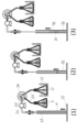
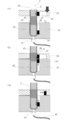
- the open end is preferably closed so that all or a part thereof can be opened and closed. Examples of preferred open ends are shown in FIGS. 1 (2) and (3).
- the tube has a substantially inner diameter of 0.1 mm to 5 mm.
- the magnetic field applying unit is capable of moving the magnetic particles in the longitudinal direction of the operation tube outside the operation tube.
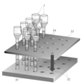
- the holding means is a holding substrate in which a plurality of holding holes capable of holding the closed end portion of the operation tube are formed.
- An example of the holding means which is the holding substrate of the above (5) is shown as 51 in FIGS. (6)
- An example of the holding means having the recess (7) is shown as 51 in FIG.
- the magnetic field applying unit has a mechanism for controlling the movement of the magnetic field in the longitudinal direction of the operation tube and the strength of the magnetic field.
- the magnetic field applying unit has a temperature control function.
- the magnetic field application unit includes any one of (5) to (10), including a movable substrate capable of moving in a longitudinal direction of the operation tube, and a plurality of magnetic force sources held in the movable substrate. Devices. An example of the magnetic field applying means (11) is shown as the movable magnet plate 53 in FIG.
- the magnetic particles have binding force or adsorption power to nucleic acid as a target component, and the operation medium liberates nucleic acid, and an aqueous liquid layer made of a liquid that binds or adsorbs to the magnetic particles, and
- the device according to any one of (1) to (12), comprising an aqueous liquid layer comprising a cleaning liquid for the magnetic particles.
- the operation medium further includes an aqueous liquid layer made of a nucleic acid amplification reaction solution, or an aqueous liquid layer made of a reverse transcription reaction solution and an aqueous liquid layer made of a nucleic acid amplification reaction solution. device.
- the device according to any one of (1) to (14), wherein the tube is integrally formed.
- the operation tube has an operation part A and a recovery part B,
- the tube constituting the operation tube has an operation tube portion a and a recovery tube portion b corresponding to the operation portion A and the recovery portion B, respectively.
- the operation part A includes the pipe part a and the operation medium accommodated in the pipe part a
- the recovery part B includes the pipe part b and a recovery medium that is accommodated in the pipe part b and includes at least one of an aqueous liquid layer and a gel layer.
- FIG. An example of the operation tube (16) is shown in FIG.
- the tube material is polyethylene, polypropylene, fluororesin, polyvinyl chloride, polystyrene, polycarbonate, acrylonitrile butadiene styrene copolymer (ABS resin), acrylonitrile styrene copolymer (AS resin), acrylic resin, polyvinyl acetate, polyethylene terephthalate, cyclic polyolefin
- a method for producing an operation tube included in the device according to (1) comprising a step of alternately laminating an aqueous liquid layer and a gel layer in a tube having an open end on one side and a closed end on the other side.
- a manufacturing method including the step of connecting the one end of the operation tube a of the operation unit A and the open end of the recovery tube b of the recovery unit B. The outline of the step (i) in the method (20) is shown in FIG.
- a method for manipulating a target component using the device according to (1) comprising the following steps: (I) obtaining an aqueous liquid mixture containing a sample containing the target component, magnetic particles and an aqueous liquid in the uppermost layer of the operation tube; (Ii) A magnetic field is generated by a magnetic field applying means, and the magnetic particles are transported together with the target component from the uppermost aqueous liquid mixture layer to the adjacent aqueous liquid layer through the gel layer.
- the target component is a nucleic acid
- the aqueous liquid contained in the uppermost aqueous liquid mixture is a liquid that liberates the nuclei and binds or adsorbs to the magnetic particles, and nucleic acid extraction is performed in the aqueous liquid.
- at least one of the aqueous liquid layers is composed of a cleaning solution for the magnetic particles, and nucleic acid purification is performed in the cleaning solution by removing contaminants associated with free nucleic acids. Or the method as described in (22).
- the lowermost layer comprises a nucleic acid amplification reaction solution, and the target nucleic acid in the purified nucleic acid is amplified in the nucleic acid amplification reaction solution.
- the layer immediately above the lowermost layer made of the nucleic acid amplification reaction solution is made of a reverse transcription reaction solution.
- the product of the nucleic acid amplification reaction is optically detected in real time.
- the small and low running cost device which can perform all of a desired series of operations, suppressing generation
- a small and low running cost device capable of performing extraction / purification of a target component in a completely sealed container, or further performing analysis in the same container while maintaining a sealed state. Can be provided.
- FIG. 1 It is a longitudinal cross-sectional view of the example of the operation pipe
- An example of the manufacturing method of the operating tube of this invention is shown.
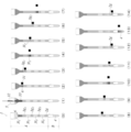
- the process of extracting and purifying a nucleic acid from a nucleic acid containing sample using the operation tube of the present invention shown in FIG. 1 (3) is shown.
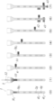
- purifies a nucleic acid from a nucleic acid containing sample using another example of the operating tube of this invention, and also performs the analysis by reverse transcription reaction and PCR reaction is shown.
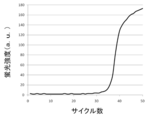
- FIG. 6 is a longitudinal sectional view of a portion including a modified example of the magnetic field applying unit (movable magnet plate), a modified example of the holding unit (holding substrate), and an operation tube held by the holding unit shown in FIG. 5. It is the result obtained in Example 1 which performed the process shown in FIG. It is the result obtained in Example 2 which performed the process shown in FIG.
- target component to be operated in the present invention is not particularly limited as long as it is a component that can be normally operated in an aqueous liquid, an emulsion, or a hydrogel, and may be an in vivo component or a non-in vivo component.
- In vivo components include biomolecules such as nucleic acids (including DNA and RNA), proteins, lipids, and sugars.
- Non-in vivo components include non-biomolecules such as artificially modified (both chemical and biochemical) biomolecules, labeled and mutants, non-biomolecules derived from natural products, and other aqueous systems. Any component that can be manipulated in a liquid is included.
- the target component can usually be provided in the form of a sample containing the target component.
- a sample include biological-derived samples such as animal and plant tissues, body fluids, and excreta, and biomolecule-containing bodies such as cells, protozoa, fungi, bacteria, and viruses.
- Body fluids include blood, sputum, cerebrospinal fluid, saliva, and milk, and excreta includes feces, urine, and sweat, and combinations thereof may be used.
- the cells include leukocytes in blood, platelets, exfoliated cells of oral cells and other mucosal cells, and a combination thereof may be used. These samples may be obtained as clinical swabs.
- said sample may be prepared in aspects, such as a cell suspension, a homogenate, a liquid mixture with a cell lysis solution, for example.
- the sample containing the target component may be obtained by performing treatments such as modification, labeling, fragmentation, and mutation on the above sample.
- the sample containing the target component may be prepared by appropriately pretreating the above sample in advance.
- the pretreatment include a process of extracting, separating, and purifying the target component or the target component-containing body from a sample containing the target component.
- pre-processing can be performed in the device of the present invention, it is not always required to be performed in advance before being supplied into the device. By performing the pretreatment in the device of the present invention, it is possible to avoid the contamination problem that is usually a concern in the pretreatment of the sample.
- the sample containing the target component is supplied into the operation tube exemplified as 1 in FIG. 1, and the target component is operated in the operation tube.
- Manipulation of the target component in the present invention includes subjecting the target component to various processes and transporting the target component among a plurality of environments in which various processes are performed.
- the operation tube contains a gel layer and an aqueous liquid layer.
- the layers indicated by 2g and 3g are made of gel (gel plug), and the layer shown by 3l is made of an aqueous liquid.
- the layer indicated by 4 may be made of an aqueous liquid or a hydrogel as long as the aqueous liquid can maintain a gel state.
- An aqueous liquid or hydrogel constructs an environment for processing the target component. Therefore, more specifically, the operation of the target component in the present invention includes subjecting the target component to processing in an aqueous liquid or hydrogel, and transporting the target component between a plurality of processing environments through the gel plug. Including doing.
- the process in which the target component is provided includes a process involving a substance change of the target component and a process involving a physical change.
- the process accompanied by the substance change of the target component includes any process as long as it is a process that newly generates a different substance by generating or breaking a bond between substrates. More specifically, chemical reactions and biochemical reactions are included.
- a chemical reaction includes any reaction involving compounding, decomposition, oxidation and reduction. In the present invention, those usually performed in an aqueous liquid are included.
- a biochemical reaction includes any reaction accompanied by a change in a biological material, and usually refers to an in vitro reaction. For example, reactions based on the synthesis system, metabolic system and immune system of biological substances such as nucleic acids, proteins, lipids and sugars can be mentioned.
- Processes that involve physical changes in target components include any process that does not involve material changes. More specifically, denaturation of the target component (for example, when the target component is a biopolymer or other polymer containing nucleic acid or protein), dissolution, mixing, emulsification, dilution, and the like are included.
- the process of the present invention makes it possible to perform steps such as extraction, purification, synthesis, elution, separation, recovery and analysis of the target component. Through these steps, the target component can be finally isolated, detected, identified, and the like.
- the process in the present invention includes not only the target process (process in a process in which an effect such as isolation, detection and identification of the target component is directly obtained), but also a pre-process and / or a post-process associated therewith. Included as appropriate.
- steps such as nucleic acid amplification reaction, or nucleic acid amplification reaction and analysis of amplification product can be performed.
- pretreatment thereof extraction of nucleic acid from a nucleic acid-containing sample ( Cell lysis) and / or purification (washing) are essential, and amplification products may be recovered as a post-treatment.
- the target component is transported by magnetic particles and magnetic field application means.
- the magnetic particles are present in the operation tube at the time of operation, and the target component is transported by moving in the operation tube in a state of being captured by binding or adsorbing the target component to the surface thereof. It is something that can be done.
- the magnetic particles can be dispersed in the aqueous liquid layer in the operation tube, and are usually aggregated in the aqueous liquid layer by generating a magnetic field from the outside of the operation tube by a magnetic field applying means.
- the agglomerated magnetic particles can be moved from the outside of the operation tube as the magnetic field is generated by the magnetic field applying means. Aggregated magnetic particles can move into the gel layer.
- the aggregated magnetic particles can pass through without destroying the gel layer.
- the aggregated magnetic particles are accompanied by binding or adsorption of the target component.
- the aggregated magnetic particles are coated with a very small amount of aqueous liquid. That is, components other than the target component can be accompanied.
- the amount of the coated aqueous liquid is very small, it can be said that the aqueous liquid hardly accompanies. For this reason, the target component can be transported very efficiently.
- the device of the present invention has an operation tube.
- the structure of the operation tube will be described with reference to FIG. 1 (in the following description, the upper and lower sides are referred to based on FIG. 1). It is preferable that the upper end of the tube constituting the operation tube is opened for sample introduction, and the open end can be closed from the viewpoint of contamination. The lower end is closed.
- the tubes constituting the operation tube have a substantially circular cross section, but do not exclude tubes having other shapes of cross sections.
- An operation medium in which the aqueous liquid layer 1 and the gel layer g are alternately stacked in the longitudinal direction of the tube is accommodated in the tube.
- FIG. 1 exemplifies three modes (1) to (3) in which the upper and lower modes of the operation tube are different.
- the upper part and the lower part can be arbitrarily combined, and are not limited to the combinations shown in (1) to (3).
- the upper open end of the tube is a sample supply unit 5 for supplying a sample containing the target component, and the sample supply unit 5 that is the open end may be temporarily opened (FIG. 1 (1)), The whole (FIG. 1 (2)) or part may be closed so that opening is possible.
- a part is closed in a releasable manner, by using a septum having a check valve function, it is possible to supply a sample by puncture close to a sealed state by an injection needle. (FIG. 1 (3)).
- the sample supply unit 5 that is the open end is closed in that a completely sealed system can be constructed. The possibility of constructing a completely closed system is very effective because it can prevent external contamination during operation.
- the inner diameter of the sample supply part 5 may be the same as the inner diameter of the tube part a in which the gel layer and the aqueous liquid layer as the operation medium are accommodated (FIG. 1 (1)), and at the time of supplying the sample It may be appropriately formed so as to have a wider inner diameter from the viewpoint of operability (FIGS. 1 (2) and (3)).
- the tube is integrally formed.
- the pipe is composed of an operation pipe part a and a recovery pipe part b.
- the upper and lower ends of the operation tube portion a are open.
- the recovery pipe part b has an upper end opened and a lower end closed.
- the operation tube portion a and the collection tube portion b are connected to one end of the tube portion a and the open end of the tube portion b.
- the operation tube portion a and the recovery tube portion b may have a separable shape, or may have a shape that does not consider separation (a shape that cannot be separated).
- a gel layer 2g that closes one end and a multilayer layer, that is, an operation medium 3 that overlaps the gel layer 2 are accommodated.
- the operation medium 3 is configured by alternately layering an aqueous liquid layer 3l and a gel layer 3g.
- a portion composed of the operation tube portion a and the operation medium that is the container is referred to as an operation portion A.
- a recovery medium 4 containing at least one of the aqueous liquid and the gel is accommodated in the recovery tube portion b.
- a portion constituted by the collection pipe portion b and the collection medium 4 that is the contained material is referred to as a collection portion B.
- the operation unit A and the recovery unit B may be provided in a connected state or may be provided in an independent state.
- the substantially inner diameter of the tube constituting the operation tube is, for example, 0.1 mm to 5 mm, preferably 1 to 2 mm. Within this range, the operating tube can have good operability. Below this range, the tube wall must be thickened to maintain strength, the distance between the magnetic particles and the magnet increases, and the magnetic force on the magnetic particles becomes difficult to reach, which may cause operational problems. There is sex. On the other hand, when the inner diameter of the tube exceeds the above range, the multilayer of the gel layer and the aqueous liquid layer constituting the operation medium tends to be disturbed due to an impact from the outside or the influence of gravity.
- a tube having an inner diameter of 0.1 mm or less is not excluded as long as the capillary material can withstand high-precision processing.
- the length of the operation tube in the longitudinal direction is, for example, 1 to 30 cm, preferably 5 to 15 cm.
- the substantially internal diameter of the sample supply part 5 is larger than the above-mentioned range, and is 10 mm.
- it may be preferably 5 mm or less.
- the reagent supply unit has a wider inner diameter from the viewpoint of workability at the time of reagent supply. When the wider inner diameter exceeds the above range, for example, when processing a plurality of operation tubes at the same time, the operation tubes interfere with each other and the device integration tends to deteriorate.
- the material of the pipe constituting the operation pipe is not particularly limited.
- the inner wall which is the conveying surface is smooth and water-repellent.
- Examples of materials that give such properties include polyethylene, polypropylene, fluororesin (Teflon (registered trademark)), polyvinyl chloride, polystyrene, polycarbonate, acrylonitrile butadiene styrene copolymer (ABS resin), acrylonitrile styrene copolymer (AS resin),
- Examples of the resin material include acrylic resin, polyvinyl acetate, polyethylene terephthalate, and cyclic polyolefin.
- a resin material is preferable in that the layer in the operation tube is less likely to be disturbed even if the operation tube is dropped or bent, and is highly robust.
- the material of the tube may be glass if necessary in terms of transparency, heat resistance and / or workability.
- the materials of the reagent supply unit 5, the operation tube unit a, and the recovery tube unit b may be the same or different.
- the tube material is selected from the viewpoint of visibility during operation and from the viewpoint of optical detection when measuring absorbance, fluorescence, chemiluminescence, bioluminescence, refractive index change, etc. from the outside of the tube. It is preferable that it has permeability.
- FIG. 1 (1) a gel layer
- FIG. 1 (2) an aqueous liquid layer
- FIG. 1 (2) a gel layer
- the magnetic particles 6 may be included in the layer (FIG. 1 (3)) or may not be included (FIG. 1 (1)).
- the lowermost layer may be an aqueous liquid layer (FIGS. 1 (1) to (3)) or a gel layer.
- the tubes constituting the operation tube when the tubes constituting the operation tube are integrally formed, all the layers accommodated in the tube may be in contact with each other.
- the recovery tube portion b when the tube constituting the operation tube is composed of the operation tube portion a and the recovery tube portion b, the recovery tube portion b contains only an aqueous liquid as a recovery medium.
- the gel may be accommodated, or a multilayer in which the aqueous liquid layer and the gel layer are alternately stacked may be accommodated.
- the gel layer 2g accommodated at the lowermost end of the operation tube portion a and the aqueous liquid, gel contained in the collection tube portion b, or the multilayer uppermost layer contained in the collection tube portion b are: They may be in contact with each other or may not be in contact by sandwiching a gas layer between them (FIG. 1 (3)).
- the number and order of the layers accommodated in the tube are not particularly limited, and can be appropriately determined by those skilled in the art based on the number and order of the operation steps for providing the target component.
- Each of the aqueous liquid layers accommodated in one operation tube is preferably composed of two or more different types of aqueous liquids.
- a liquid that builds an environment necessary for each of the processing step and the reaction step for supplying the target component can be used in order from the upper end side of the operation tube.
- Each of the gel layers accommodated in one operation tube may be made of a different kind of gel or may be made of the same kind of gel.
- the gel when a treatment or reaction by heating is performed in a part of the plurality of aqueous liquid layers, the gel is only in the gel layer adjacent to the aqueous liquid layer even at the temperature required for the heating.
- a gel having a high sol-gel transition point capable of maintaining a state or a gel-sol intermediate state can be used, and a gel having a relatively low sol-gel transition point can be used for the other gel layers.
- those skilled in the art can appropriately select a gel having appropriate characteristics depending on the characteristics and volume of the aqueous liquid constituting the adjacent aqueous liquid layer.
- the gel layer serves as a plug (gel plug) that partitions the aqueous liquid layer on both sides in the longitudinal direction of the tube in the operation tube.
- a plug gel plug
- the thickness that functions as a plug in consideration of the inner diameter and length of the tube, the amount of magnetic particles conveyed by the magnetic field applying means, and the like.
- it can be 1 to 20 mm, preferably 3 to 10 mm.
- the strength as a plug tends to be lacking.
- the operation tube becomes long, and the operability, the durability of the device, and the accommodating property tend to deteriorate.
- the aqueous liquid layer provides an environment such as treatment or reaction in which a sample containing the target component is provided.
- the thickness is determined based on the inner diameter and length of the tube, the amount of the target component, the type of treatment and reaction to which the target component is provided, and the aqueous liquid that achieves the desired treatment or reaction for the target component. Those skilled in the art can appropriately determine the thickness to give the amount. For example, it can be 0.5 to 30 mm, preferably 3 to 10 mm. Below the above range, the treatment and reaction for the target component may not be sufficiently achieved, and there is a possibility that the plug becomes droplets and the magnetic particles cannot be combined with the reagent. When the above range is exceeded, the aqueous liquid layer is often too thick compared to the gel layer, which may cause the same problem as the gel plug, and when the specific gravity of the aqueous liquid is larger than the gel, Tend to collapse.
- the hydrogel layer when the gel layer is composed of a hydrogel, the hydrogel layer not only serves as a reagent partition, but can provide an environment such as a treatment or reaction in which a sample containing the target component is provided, similar to the aqueous liquid layer. it can.
- the hydrogel layer may be thicker than the aqueous liquid layer.
- the gel layer is made of a chemically inert substance that is insoluble or hardly soluble in the liquid constituting the aqueous liquid layer when it is overlaid with the aqueous liquid in the tube.
- Insoluble or hardly soluble in a liquid means that the solubility in the liquid at 25 ° C. is approximately 100 ppm or less.
- a chemically inert substance refers to a target component and an aqueous liquid or hydrogel in the operation of the target component (that is, treatment of the target component in an aqueous liquid or hydrogel and transport of the target component through a gel plug).
- the gel in the present invention includes both organogel and hydrogel.
- Organogel can be gelled by adding a gelling agent to a liquid substance that is usually insoluble or sparingly soluble in water.
- a gelling agent e.g., a gelling agent for a gelling agent for a gelling agent for a gelling agent for a gelling agent for a liquid substance that is usually insoluble or sparingly soluble in water.
- Liquid substances that are insoluble or sparingly soluble in water As the water-insoluble or hardly water-soluble liquid substance, oil having a solubility in water at 25 ° C. of approximately 100 ppm or less and liquid at room temperature (20 ° C. ⁇ 15 ° C.) can be used.
- 1 type, or 2 or more types from the group which consists of liquid fats and oils, ester oil, hydrocarbon oil, and silicone oil may be used.
- Liquid oils include linseed oil, camellia oil, macadamia nut oil, corn oil, mink oil, olive oil, avocado oil, sasanqua oil, castor oil, safflower oil, kyounin oil, cinnamon oil, jojoba oil, grape oil, sunflower oil, Almond oil, rapeseed oil, sesame oil, wheat germ oil, rice germ oil, rice bran oil, cottonseed oil, soybean oil, peanut oil, teaseed oil, evening primrose oil, egg yolk oil, liver oil, palm oil, palm oil, palm kernel oil, etc. Is mentioned.
- Ester oils include octanoic esters such as cetyl octanoate, lauric esters such as hexyl laurate, myristate esters such as isopropyl myristate and octyldodecyl myristate, palmitate esters such as octyl palmitate, isocetyl stearate, etc.
- octanoic esters such as cetyl octanoate
- lauric esters such as hexyl laurate
- myristate esters such as isopropyl myristate and octyldodecyl myristate
- palmitate esters such as octyl palmitate, isocetyl stearate, etc.
- Stearic acid ester isostearic acid ester such as isopropyl isostearate, isopalmitic acid ester such as octyl isopalmitate, oleic acid ester such as isodecyl oleate, adipic acid ester such as isopropyl adipate, sebacic acid such as ethyl sebacate
- esters malate esters such as isostearyl malate, glycerin trioctanoate, glycerin triisopalmitate, and the like.
- hydrocarbon oil examples include pentadecane, hexadecane, octadecane, mineral oil, liquid paraffin, and the like.
- silicone oil examples include dimethylpolysiloxane, methylphenylpolysiloxane and other phenyl group-containing silicone oils, and methylhydrogenpolysiloxane.
- gelling agent an oil gelling agent selected from the group consisting of hydroxy fatty acid, dextrin fatty acid ester, and glycerin fatty acid ester may be used alone or in combination.
- the hydroxy fatty acid is not particularly limited as long as it is a fatty acid having a hydroxyl group. Specific examples include hydroxymyristic acid, hydroxypalmitic acid, dihydroxypalmitic acid, hydroxystearic acid, dihydroxystearic acid, hydroxymargaric acid, ricinoleic acid, ricinaleic acid, and linolenic acid. Of these, hydroxystearic acid, dihydroxystearic acid, and ricinoleic acid are particularly preferable. These hydroxy fatty acids may be used alone or in combination of two or more. Moreover, animal and vegetable oil fatty acids (for example, castor oil fatty acid, hydrogenated castor oil fatty acid, etc.) that are a mixture of these can also be used as the hydroxy fatty acid.
- animal and vegetable oil fatty acids for example, castor oil fatty acid, hydrogenated castor oil fatty acid, etc.
- dextrin fatty acid esters examples include dextrin myristate [trade name “Leopard MKL”, manufactured by Chiba Flour Mills Co., Ltd.], dextrin palmitate [trade names “Leopard KL”, “Leopard TL”, both manufactured by Chiba Flour Mills Co., Ltd.] , (Palmitic acid / 2-ethylhexanoic acid) dextrin [trade name “Leopard TT”, manufactured by Chiba Flour Milling Co., Ltd.] and the like.
- glycerin fatty acid ester examples include glyceryl behenate, glyceryl octastearate, and glyceryl eicoate. These may be used in combination of one or more.
- the trade name “TAISET 26” (manufactured by Taiyo Chemical Co., Ltd.), 20% glyceryl behenate and 50% octastearic acid containing 20% glyceryl behenate, 20% glyceryl octastearate and 60% hydrogenated palm oil.
- a trade name “TAISET 50” (manufactured by Taiyo Kagaku Co., Ltd.) including glyceryl can be used.
- the content of the gelling agent added to the liquid substance that is not water-soluble or poorly water-soluble is, for example, 0.1 to 0.5% by weight, 0.5 to 2% by weight of the total weight of the liquid substance, Alternatively, an amount of gelling agent corresponding to 1 to 5% by weight can be used. However, without being limited thereto, those skilled in the art can appropriately determine the amount that can achieve the desired gel and sol state.
- the gelation method can be appropriately determined by those skilled in the art. Specifically, a liquid substance that is water-insoluble or poorly water-soluble is heated, a gelling agent is added to the heated liquid substance, the gelling agent is completely dissolved, and then cooled to Liquid substances can be gelled.
- the heating temperature may be appropriately determined in consideration of the liquid substance to be used and the physical properties of the gelling agent. For example, it may be preferable to set the temperature to about 60 to 70 ° C.
- the gelling agent is dissolved in the heated liquid substance, and at this time, it is preferable that the gelling agent is gently mixed. Cooling is preferably performed slowly. For example, it can be cooled for about 1 to 2 hours. For example, cooling can be completed when the temperature falls to room temperature (20 ° C.
- hydrogel for example, gelatin, collagen, starch, pectin, hyaluronic acid, chitin, chitosan or alginic acid and derivatives thereof are used as hydrogel materials, and those prepared by equilibrium swelling of the hydrogel material in water or an aqueous liquid are used. Can be.
- a hydrogel prepared from gelatin it is preferable to use a hydrogel prepared from gelatin.
- the hydrogel is obtained by chemically crosslinking the above hydrogel material, or by a gelling agent (for example, a salt of an alkali metal or alkaline earth metal such as lithium, potassium or magnesium, or a transition metal such as titanium, gold, silver or platinum). Or a silica, carbon, alumina compound, etc.).
- a gelling agent for example, a salt of an alkali metal or alkaline earth metal such as lithium, potassium or magnesium, or a transition metal such as titanium, gold, silver or platinum.
- a silica, carbon, alumina compound, etc.
- the hydrogel provides an environment such as a treatment or reaction in which a sample containing the target component is provided in the same manner as an aqueous liquid
- a person skilled in the art will have a composition suitable for such treatment and reaction.
- a DNA hydrogel (P-gel) based on polydimethylsiloxane capable of synthesizing proteins can be mentioned.
- This hydrogel is composed of DNA as part of the gel scaffold.
- Such a hydrogel can be subjected to a reaction for obtaining a protein from the target component when the target component is a substrate for protein synthesis (more specifically, Nature Materials 8, 432-437 (2009), And Nature Protocols 4: 1759-1770 (2009), which can be appropriately determined by those skilled in the art.
- the produced protein can be recovered, for example, by using magnetic particles having an antibody specific for the protein.
- the gel contained in the tube has a property of causing a sol-gel transition at a certain temperature.
- the sol-gel transition point may be in the range of 25-70 ° C. A sol-gel transition point in this range is desirable in a reaction system that requires fluidity by solification for recovery or the like.
- the sol-gel transition point may vary depending on conditions such as the type of organogel material (oil) or hydrogel material, the type of gelling agent, and the amount of gelling agent added. Accordingly, each condition is appropriately selected by those skilled in the art so as to have a desired sol-gel transition point.
- the gel plug allows the aqueous liquid in the tube to be fixed at a predetermined position in the tube by sandwiching it from both sides in the longitudinal direction of the tube.
- magnetic particles can be moved by an external magnetic field operation, and can pass through the gel. This is due to the thixotropic nature of the gel (thixotropic properties).
- the magnetic particles in the tube give a shearing force to the gel along the conveying surface by moving the magnet from the outside, and the gel in the forward direction of the magnetic particles is solated and fluidized, so that the magnetic particles proceed as they are. Can do.
- the sol released from the shearing force after the magnetic particles have passed through returns quickly to the gel state, so that the gel does not form through holes due to the passage of the magnetic particles.
- the object can easily move using the magnetic particles as a carrier, and therefore, various chemical environments provided with the object can be switched in a very short time.
- the processing time of the object can be greatly shortened. If the property of gelation at a temperature below room temperature is used, even a reagent that exhibits a liquid state at that temperature can be immobilized by being sandwiched by gel plugs in the tube.
- the state in which the capillary is preliminarily loaded with the liquid reagent can be maintained from the time of manufacturing the device to the hand of the user, and the liquid reagent can be stably supplied. Furthermore, reagent collection and dispensing operations for each process are unnecessary, and labor and time can be reduced, and deterioration of analysis accuracy due to contamination can be prevented.
- the storage viscoelasticity E ′ of the dynamic viscoelasticity can be preferably 10 to 100 kPa, more preferably 20 to 50 kPa at room temperature (20 ° C. ⁇ 15 ° C.).
- the strength as a gel plug tends to be lacking.
- even magnetic particles having a particle size of about several ⁇ m tend to be hindered in movement.
- it may have a kinematic viscosity of 5 mm 2 / s to 100 mm 2 / s, preferably 5 mm 2 / s to 50 mm 2 / s, for example about 20 mm 2 / s (50 ° C.).
- the aqueous liquid in the present invention may be an aqueous liquid that is insoluble or hardly soluble in the gel, and can be provided in the form of an emulsion called water, an aqueous solution or an emulsion, or a suspension in which fine particles are dispersed.
- the constituent component of the aqueous liquid includes any component that provides a reaction or treatment environment in which the target component in the present invention is provided.
- a liquid for releasing the component to be operated in the present invention in the aqueous liquid layer and binding or adsorbing it to the surface of the magnetic particles that is, separating the target component from the contaminants, the surface of the magnetic beads
- a liquid having an action of promoting binding to or adsorption to a target component a cleaning solution for removing foreign substances coexisting with the target component, an eluent for separating the target component adsorbed on the magnetic particle from the magnetic particle, and the target component
- a reaction solution for constructing a reaction system for a reaction system.
- the reagent solution (cell lysate) is used to destroy the cell, release the nucleic acid, and adsorb it onto the surface of the silica-coated magnetic particle, and the magnetic particle to remove components other than the nucleic acid Washing solution for washing the nucleic acid, elution solution for separating nucleic acid from magnetic particles (nucleic acid elution solution), nucleic acid amplification reaction solution for performing nucleic acid amplification reaction, and the like.
- the target component is a nucleic acid
- the treatment liquid and reaction liquid for the nucleic acid and the treatment and reaction in which they are provided will be further described.
- cell lysate An example of the cell lysate is a buffer containing a chaotropic substance.
- the buffer may further include EDTA or any other chelating agent, Triton X-100 or any other surfactant.
- the buffer is based on, for example, Tris-HCl or any other buffer.
- chaotropic substances include guanidine hydrochloride, guanidine isothiocyanate, potassium iodide, urea and the like.
- the chaotropic substance is a powerful protein denaturing agent, and has an action of pulling away proteins such as histones clinging to nucleic acids from the nucleic acids and promoting adsorption of the magnetic particles on the silica coating surface.
- the buffer can be used as an auxiliary agent for preparing a pH environment in which nucleic acids are easily adsorbed on the surface of magnetic particles.
- the chaotropic substance also has a cell lysis (ie, destroying cell membrane) action. However, a surfactant contributes more to the cell lysis (i.e., disrupts the cell membrane) than the chaotropic substance. Chelating agents can be used as adjuvants that promote cell lysis.
- a specific protocol for nucleic acid extraction from a sample containing nucleic acid can be appropriately determined by those skilled in the art.
- the magnetic particles are used for transporting the nucleic acid in the droplet encapsulating medium, it is preferable to adopt a method using the magnetic particles as the nucleic acid extraction method.
- a method for extracting and purifying nucleic acid using magnetic particles from a sample containing nucleic acid can be carried out.
- the nucleic acid is adsorbed on the surface of the magnetic particles, and the reagent used for other components other than the nucleic acid contained in the nucleic acid-containing sample (for example, protein, sugar, etc.)
- a solution capable of dissolving other components is preferred.
- Specific examples include high salt concentration aqueous solutions such as sodium chloride, potassium chloride, and ammonium sulfate, and aqueous alcohol solutions such as ethanol and isopropanol.
- the washing of the nucleic acid is a washing of the magnetic particles to which the nucleic acid has been adsorbed. A specific protocol for this washing can also be appropriately determined by those skilled in the art.
- the number of washings of the magnetic particles to which the nucleic acid has been adsorbed can be appropriately selected by those skilled in the art to such an extent that undesired inhibition does not occur during the nucleic acid amplification reaction. Further, when the influence of the inhibitory component can be ignored from the same viewpoint, the washing step can be omitted.
- the aqueous liquid layer made of the cleaning liquid is prepared at least as many times as the number of times of cleaning.
- nucleic acid eluate As the nucleic acid eluate, a buffer solution containing water or salt can be used. Specifically, a Tris buffer solution, a phosphate buffer solution, distilled water, or the like can be used. A person skilled in the art can also determine a specific method for separating the nucleic acid from the magnetic particles adsorbed with the nucleic acid and eluting it into the eluate.
- nucleic acid amplification reaction solution In the nucleic acid amplification reaction solution of the present invention, various elements usually used in the nucleic acid amplification reaction include at least a nucleic acid containing a base sequence to be amplified and magnetic particles adsorbed on the surface thereof.
- the nucleic acid amplification reaction is not particularly limited, and therefore various elements used in the nucleic acid amplification reaction can be appropriately determined by those skilled in the art based on known nucleic acid amplification methods exemplified below. it can.
- salts such as MgCl 2 and KCl, primers, deoxyribonucleotides, nucleic acid synthetase and pH buffer are included.
- the above salts can be used by appropriately changing to other salts.
- a substance for reducing non-specific priming such as dimethyl sulfoxide, betaine, or glycerol may be further added.
- the nucleic acid amplification reaction solution in the present invention can contain a blocking agent.
- the blocking agent can be used for the purpose of preventing the deactivation of the nucleic acid polymerizing enzyme due to adsorption to the inner wall of the reaction vessel or the surface of the magnetic particles.
- Specific examples of the blocking agent include bovine serum albumin (ie, BSA) and other albumins, gelatin (ie, denatured collagen), proteins such as casein and polylysine, peptides (both natural and synthetic), ficoll, and polyvinylpyrrolidone. And polyethylene glycol.
- the nucleic acid amplification reaction according to the present invention is not particularly limited.
- the PCR method (US Pat. Nos. 4,683,195, 4,683,202, 4,800,159, and 4,965,188), the LCR method (US Pat. No. 5,494,810). No. 4), Q ⁇ method (US Pat. No. 4,786,600), NASBA method (US Pat. No. 5,409,818), LAMP method (US Pat. No. 3,313,358), SDA method (US Pat. No. 5,455,166), RCA method ( U.S. Pat. No. 5,354,688), ICAN method (Japanese Patent No. 3433929), TAS method (Japanese Patent No. 2443586), and the like can be used.
- RT reaction can also be performed prior to the above reaction.
- the composition of the reaction solution necessary for these nucleic acid amplification reactions and the reaction temperature can be appropriately selected by those skilled in the art.
- a nucleic acid amplification reaction is further performed after the reverse transcriptase (RT) reaction
- the RT reaction is performed on the PCR reaction solution layer via a gel layer.
- the layers of the reaction solution can be overlaid (for example, illustrated in FIG. 4).
- the amplification product can be detected with a fluorescent dye capable of binding to double-stranded DNA or a probe labeled with the fluorescent dye.
- detection methods in the real-time nucleic acid amplification method include the following methods.
- an intercalator method using SYBR (registered trademark) GREEN I or the like is used.
- An intercalator that emits fluorescence by binding to double-stranded DNA binds to double-stranded DNA synthesized by a nucleic acid amplification reaction, and emits fluorescence of a specific wavelength when irradiated with excitation light. By detecting this fluorescence, the amount of amplification product generated can be monitored.
- This method does not require designing and synthesizing a target-specific fluorescently labeled probe, and can be easily used for measuring various targets.
- the fluorescent labeling probe method when it is necessary to distinguish and detect similar sequences, or when typing SNPs, the fluorescent labeling probe method is used.
- a TaqMan (registered trademark) probe method using an oligonucleotide whose 5 ′ end is modified with a fluorescent substance and whose 3 ′ end is modified with a quencher substance as a probe.
- the TaqMan probe specifically hybridizes to the template DNA in the annealing step.
- a quencher is present on the probe, fluorescence emission is suppressed even when irradiated with excitation light.
- the fluorescent dye is released from the probe, the suppression by the quencher is released, and the fluorescence is released. Emits light. By measuring the fluorescence intensity, the amount of amplification product generated can be monitored.
- PCR is performed using serially diluted standard samples with known concentrations as templates. Then, the number of cycles (threshold cycle; Ct value) reaching a certain amount of amplification product is obtained.
- Ct value the number of cycles reaching a certain amount of amplification product is obtained.
- a calibration curve is created by plotting the Ct value on the horizontal axis and the initial DNA amount on the vertical axis. For a sample of unknown concentration, a Ct value is obtained by performing a PCR reaction under the same conditions. From this value and the calibration curve described above, the target DNA amount in the sample can be measured.
- the temperature after the PCR reaction solution containing the fluorescent dye is gradually raised from 40 ° C. to about 95 ° C., and the fluorescence intensity is continuously monitored, a melting curve of the amplification product can be obtained.
- Double-stranded DNA generated by the nucleic acid amplification reaction has a unique Tm value depending on the length of the DNA and its base sequence. That is, when the temperature of the droplet containing DNA to which the fluorescent dye is bound is gradually increased, a temperature at which the fluorescence intensity rapidly decreases is observed. When the amount of change in the fluorescence intensity is examined, the temperature peak almost coincides with the Tm value defined by the base sequence and the length.
- composition of the respective aqueous liquid can be easily determined by those skilled in the art. Even if the target component is other than the above nucleic acid, the composition of each aqueous liquid can be easily determined by those skilled in the art.
- Operation tube manufacturing method As a method for producing the operation tube, there are the following two methods depending on an aspect in which a tube in which a multilayer as an operation medium is to be accommodated is prepared.
- the operation medium can be formed by filling the required aqueous liquid and gel alternately in the required order from the lower closed end, thereby forming the operation tube.
- the tube is composed of the operation tube portion a and the recovery tube portion b
- storage of the recovery medium necessary for configuring the recovery portion B that is, storage of the aqueous liquid, storage of the gel
- the recovery unit B is completed.
- the operation unit A is completed by accommodating the operation medium necessary for configuring the operation unit A, that is, forming a multilayer of an aqueous liquid layer and a gel layer.
- a more specific method for forming a multilayer by alternately layering an aqueous liquid and a gel can be appropriately performed by those skilled in the art according to the layering method in the case of 4-2 described later.
- the sample supply part which is an upper opening end may be closed suitably.
- the pipe may be composed of the operation pipe part a and the recovery pipe part b, and the pipe part a and the pipe part b may be prepared independently.
- the operation part A and the recovery part B are separately prepared by accommodating the necessary aqueous liquid and / or gel in the pipe part a and the pipe part b, and the prepared operation part A and recovery part are produced.
- An operation tube can be produced by connecting B to each other.
- FIG. 2 An outline of the method for manufacturing the operation unit A is schematically shown in FIG.
- the aqueous liquid L for example, cleaning liquid
- the gel G constituting the gel layer is accommodated in another container in a sol state.
- the sol state is maintained by heating with a constant temperature bath 21 at 70 ° C.
- the lower opening end of the pipe part a is prepared in a closed state by being pressed against the pressing mat 22.
- the liquid feeding system into the pipe part a includes tubes 23 and 23 ′ for feeding the aqueous liquid L or the sol-gel G, respectively, extending from the container in which the aqueous liquid L and the sol-gel G are accommodated.
- a liquid feeding means 24 (peristaltic pump in FIG. 2) to which a tube 23 ′ is connected, and a needle 25 for filling the tube portion a with a liquid substance in the tube sent by the liquid feeding means. It is preferable that the needle 25 has a length enough to reach the bottom of the tube part a by being inserted into the tube part a.
- a tube 23 extending from the container containing the aqueous liquid L and a tube 23 extending from the container containing the sol-gel G are connected to the switching valve 26.
- different liquid substances aqueous liquid L and sol-gel G
- This embodiment can be preferably used when the inner diameter of the tube portion a is relatively small because only one needle is inserted into the tube portion a.
- the liquid supply path from the container to the needle may be made independent without using the switching valve 26.
- the tube extended from the container in which the aqueous liquid was accommodated, the needle connected to the tube, the tube extended from the container in which the sol-gel was accommodated, and Two liquid feeding paths with the needle connected to the tube can be formed.
- two needles can be inserted into the tube portion a, it can be preferably used when the inner diameter of the tube portion a is relatively large.
- the sol gel G and the aqueous liquid L are alternately sent and filled into the tube portion a in order from the sol gel G.
- the tip of the needle 25 is raised as the liquid level in the pipe part a rises.
- the aqueous liquid L is layered as shown in FIG. 2 (2) after filling the sol-gel, the previously filled sol-gel may or may not be completely gelled. Good.
- a heat source (a constant temperature bath 21 in FIG. 2). In general, it can be in an intermediate state of gel-sol with increased viscoelasticity.
- the recovery unit B can be obtained by storing a necessary aqueous liquid or gel. Or the collection
- recovery part B can be obtained by forming the multilayer of an aqueous liquid layer and a gel layer in the order required suitably by the method similar to the above except not using the mat for suppression.
- the operation unit A and the recovery unit B obtained as described above are connected to each other.
- the operation unit A may be configured such that the pipe part a is tilted so that the contents do not slide down, the restraining mat is removed, and the collection unit B is connected in a tilted state or a sideways state.
- the pipe part a and the pipe part b may be wound with a tape or the like, or the pipe part a and the pipe part b each having a connection part that can be connected to each other are used. , You may connect both connection parts.
- the sample supply portion that is the upper open end of the operation tube portion a may be appropriately closed.
- the closing timing may be after the operation unit A is manufactured and before the operation unit A and the recovery unit B are connected, or the operation unit A and the recovery unit B are connected. It may be later.
- the magnetic particles are used to move the target component in the operation tube by being accompanied by a small amount of liquid mass accompanying the fluctuation of the magnetic field from the outside of the operation tube. Magnetic particles intended to enable separation, recovery and purification of specific components by such movement usually have a chemical functional group on the surface.
- the magnetic particles may not be accommodated in the operation tube in advance (FIGS. 1 (1) and 1 (2)) or may be accommodated (FIGS. 1 (3), 3 and 4). When it is accommodated in the operation tube in advance, it can be contained in the aqueous liquid constituting the uppermost layer.
- the magnetic particles are not previously stored in the operation tube, the magnetic particles are also supplied into the operation tube when the sample having the target component is supplied into the operation tube.
- the magnetic particle is not particularly limited as long as it is a particle that responds to magnetism, and examples thereof include particles having a magnetic material such as magnetite, ⁇ -iron oxide, and manganese zinc ferrite.
- the magnetic particle has a chemical structure that specifically binds to the target component subjected to the above treatment or reaction, such as amino group, carboxyl group, epoxy group, avidin, biotin, digoxigenin, protein A, protein G, complex
- the surface may be provided with a metal ion or an antibody, and may have a surface that specifically binds to the target component by electrostatic force or van der Waals force. Thereby, the target component to be subjected to the reaction or treatment can be selectively adsorbed to the magnetic particles.
- the hydrophilic group on the surface of the magnetic particles include a hydroxyl group, an amino group, a carboxyl group, a phosphoric acid group, and a sulfonic acid group.
- the magnetic particles can further include various elements appropriately selected by those skilled in the art.
- the surface is covered with particles made of a mixture of a magnetic material and silica and / or anion exchange resin, silica and / or anion exchange resin.
- Preferred examples include magnetic particles, magnetic particles whose surface is covered with gold having a hydrophilic group via a mercapto group, and gold particles containing a magnetic substance and having a hydrophilic group via a mercapto group on the surface. .
- the magnetic particles having hydrophilic groups on the surface may have an average particle size of about 0.1 ⁇ m to 500 ⁇ m. When the average particle size is small, the magnetic particles tend to exist in a dispersed state when released from the magnetic field in the aqueous liquid layer.
- Examples of commercially available magnetic particles include Magnetic Beads coated with silica for nucleic acid extraction, which is a constituent reagent of Plasmid DNA Purification Kit MagExtractor-Plasmid- sold by Toyobo. In this way, when sold as a component reagent of a kit, since the stock solution of the product containing magnetic particles contains a storage solution or the like, it can be washed by suspending it with pure water (for example, about 10 times the amount). preferable.
- This washing can be carried out by removing the supernatant by centrifuging or agglomerating with a magnet after suspending purely, and suspension and removal of the supernatant can be repeated.
- the magnetic field application means for applying a magnetic field fluctuation to move the magnetic particles will be described in detail in Item 8 below.
- FIGS. 3 (0) to (14) and FIGS. 4 (0) to (7) The operation of the target component in the operation tube is shown in FIGS. 3 (0) to (14) and FIGS. 4 (0) to (7). Hereinafter, a description will be given based on FIGS. 3 and 4.
- the sample 32 containing the target component is supplied from the reagent supply port 5 (FIG. 3 (1) and FIG. 4 (1)).
- the sample is supplied in a liquid form.
- the sample supply may be performed manually with a syringe or the like, or may be automatically controlled with a dispenser using a pipetter or the like.
- the sample supply can be performed in a state where the operation tube is set up by appropriate holding means (not shown; the holding means for holding the operation tube will be described in detail in item 7 described later).
- obtaining a sample 32, the magnetic particles 6 and an aqueous liquid 3l 1 aqueous liquid mixture 33 comprising including a target component can be obtained as follows.
- the sample may be supplied into the operation tube together with the magnetic particles, or the sample may be supplied into the operation tube together with the aqueous liquid and suspended magnetic particles. May be.
- an aqueous liquid mixture can be obtained from the aqueous liquid in the uppermost layer.
- the uppermost layer accommodated in the operation tube is made of an aqueous liquid containing magnetic particles (the case illustrated in FIGS.
- only the sample may be supplied into the operation tube.
- the sample may be supplied into the operation tube together with the aqueous liquid.
- an aqueous liquid mixture can be obtained from the aqueous liquid containing the magnetic particles in the uppermost layer.
- the sample may be supplied into the operation tube together with the aqueous liquid and the magnetic particles. Thereby, an aqueous liquid mixture can be newly formed as the uppermost layer on the gel layer.
- the operation tube that is supplied with the sample and the aqueous liquid mixture containing the sample and magnetic particles in the uppermost layer is prepared in the state where it is placed on the holding means or transferred to the holding means dedicated to the device. Can be set.
- a magnetic field is applied from the outside by bringing a magnetic field applying means (for example, a cylindrical neodymium magnet having a diameter of 1 mm to 5 mm and a length of 5 mm to 30 mm) 31 close to the operation tube 1 and dispersed in the aqueous liquid mixture layer 311.
- the formed magnetic particles 6 are aggregated together with the target component (FIGS. 3 (2) and 4 (2)).
- unnecessary components contained in the aqueous liquid mixture layer 3l 1 may also be aggregated together.
- the magnetic field applying means 31 By moving the magnetic field applying means 31 downward at a speed of 0.5 mm to 10 mm per second, the magnetic particles attracting the target component are passed from the aqueous liquid mixture layer 3l 1 through the gel layer 3g 1 directly below it (see FIG. 3 (3) and FIG. 4 (3)) and transport to the aqueous liquid layer 3 l 2 immediately below the gel layer 3 g 1 (FIGS. 3 (4) and 4 (4)).
- magnetic particles passing through the gel layer 3 g because they are thin-coated in an aqueous liquid mixture of the aqueous liquid mixture layer 3l 1 which has been subjected to prior pass, in addition to the target component, the concentration is low It is accompanied by the contaminated components.
- Such magnetic particles are further transported to the aqueous liquid layer 3l 2.
- the size and moving speed of the magnet are appropriately determined by those skilled in the art according to the amount of magnetic particles, the inner and outer diameters of the operation tube, the state of the gel plug, and the like.
- the magnetic field applying unit 31 repeated as necessary to transport the aqueous liquid layer 3l 2 through the gel layer to the other aqueous liquid layer.
- “Repeat as necessary” means that, as a general rule, by carrying the magnetic particles only in one direction from the top to the bottom, the number of layers corresponding to the number of layers may be transported (FIG. 3 (4)). ⁇ (13) and Fig. 4 (4) ⁇ (7)), and by returning from not only one direction from the top to the bottom but also from the bottom to the top as appropriate, carry more than the number of transport operations according to the number of layers. It means you may. That is, the other aqueous liquid layer of the transportation destination may be present above the transportation-source aqueous liquid layer or may be present below.
- the amount of contaminating components transported by the magnetic particles together with the target component is infinitely close to zero.
- the magnetic particles with the target component are accompanied by a very small amount of cleaning liquid, the target component on the particle surface is purified to a level that does not hinder the subsequent analysis process and the like.
- the purification of the target component can be performed very efficiently only by the magnetic field operation.
- target components specifically, including target components accompanied by unnecessary components and target components from which unnecessary components have been removed
- target components specifically, including target components accompanied by unnecessary components and target components from which unnecessary components have been removed
- the magnetic particles that follow can be sufficiently brought into contact with the aqueous liquid.
- the magnetic field applying means is moved up and down while the magnetic particles are aggregated by applying the magnetic field in the aqueous liquid layer.
- the magnetic particles that have been aggregated by the application of the magnetic field are naturally diffused by releasing the magnetic field from the magnetic particles that have been subjected to the application of the magnetic field by the magnetic particles. Is mentioned.
- the magnetic field applying means 31 is once moved away from the operation tube 1 to block or attenuate the magnetic field, and the magnetic particles are dispersed in the cleaning liquid layer 3 12 .
- the magnetic field application means 31 is brought closer to the operation tube 1 again, thereby aggregating the magnetic particles together with the target component to be in a transportable state.
- the magnetic field applying unit 31 is transported into the gel layer 3 g 2 just below similarly as shown in FIG. 3 (6).
- the magnetic particles and target components in the gel layer 3g 2 in FIG. 3 (6) the magnetic particles and target components in the gel layer 3g 1 in FIG. Also, some or most of the attendant components have been removed.
- the magnetic substance particles separated from the target substance are moved from the layer where the target substance is separated to another layer.
- nucleic acid extraction For example, when the magnetic particle surfaces is silica coating, as shown in FIG. 3, the biological sample, by being subjected to the cell lysate 3l 1 containing a chaotropic salt such as a surfactant and guanidine thiocyanate, a nucleic acid They are released from the cells (FIG. 3 (1)). The liberated nucleic acid can be specifically adsorbed on the silica surface of the particles. The adsorbed nucleic acid cannot be used as a template for gene amplification reaction because it is accompanied by a reaction inhibiting component. Therefore, the magnetic particles remain adsorbed the nucleic acid to the surface is washed with a washing solution 3l 2.
- a chaotropic salt such as a surfactant and guanidine thiocyanate
- the magnetic particles 6 are collected by the magnet 31 (FIG. 3 (2)), and the gel plug separating the cell lysate 3l 1 and the washing solution 3l 2 is used. It passes through 3g 1 (FIG. 3 (3)).
- the cleaning liquid 3l 2 can be reached with little liquid fraction (FIG. 3 (4)). For this reason, magnetic particles can be washed with high efficiency.
- nucleic acids purified while adsorbed on the surface of the magnetic particles are collected again by a magnet (FIG. 2 (11)), passed through the gel plug 2g (FIG. 3 (12)), and transported into the eluate 4 (FIG. 3). 3) (13).
- the nucleic acid is separated from the magnetic particles and eluted in the eluate.
- the magnetic particles from which the nucleic acid has been eluted are retained in the gel plug 2g again, and the purified purified nucleic acid remains in the recovery part B (FIG. 3 (14)).
- the nucleic acid thus obtained is useful as a template nucleic acid that can be analyzed by a nucleic acid amplification reaction.
- the obtained nucleic acid can be subjected to the next operation (step of performing analysis by nucleic acid amplification reaction) by removing the recovery part B of the operation tube from the operation part A.
- the tube portion a of the operation portion A of the operation tube and the tube portion b of the recovery portion B are integrally formed and partitioned by the operation portion A similar to that in FIG. 3 and the gel plug 4g.
- FIGS. 3 (1) to (12) FIGS. 4 (1) to (5)
- magnetic particles 6 are brought to leave RT reaction 4l 1 has adsorbed the nucleic acid (RNA) purified, RT reaction is carried out (FIG. 4 (7)).
- PCR reaction After RT reaction was completed, magnetic particles, DNA obtained by RT reaction (a template for PCR reactions) also carried in a PCR reaction solution 4l 2 to pass through the gel plugs 4g adsorbed, PCR reactions are performed (FIG. 4 (7)).
- the PCR product can be analyzed by a real-time detection method using a fluorescent dye or a fluorescence detection method using an endpoint detection method.
- 42 and 43 schematically show the temperature control function.
- a more specific example of the temperature control function 42 will be described in item 8-2-6 described later, and a more specific example of the temperature control function 43 will be described in item 7-3 described later.
- the device illustrated in FIG. 5 has a simple configuration in which a magnetic field applying unit (movable magnet plate 53) having a magnet moving mechanism and a holding substrate with temperature control function (temperature control block 51) are main units. Each configuration will be described in items 7 and 8 below.
- the operating tube is usually installed in a substantially vertical state (that is, in an upright state) so that the sample supply unit, which is an opening, is at the top during use.
- An appropriate holding means can be used for installation. Further, the same holding means may be used during sample supply and during operation of the target component, or different ones may be used. When different holding means are used during sample supply and target component operation, the transfer of the operation tube between the holding means may be manual or automated.
- the holding means is not particularly limited as long as it can be held in a substantially vertical state (that is, in a standing state) so that a sample supply unit which is an opening of the operation tube is generally on the upper side.
- a substantially vertical state that is, in a standing state
- a sample supply unit which is an opening of the operation tube is generally on the upper side.
- one or two or more holding members formed with holding holes that can be held by piercing the closed end of the operation tube are combined, or a linear member is latticed so as to form a lattice hole as a holding hole.
- a rack configured by assembling in a shape is included, but the invention is not limited thereto. In the former case, the holding hole formed in the holding member may penetrate or may not penetrate.
- the inner diameter of the holding hole is determined based on the outer diameter of the operation tube to be held.
- the holding hole can be formed so that the closed end of the holding portion B does not penetrate the holding substrate (that is, the holding hole itself does not penetrate the holding substrate).
- the depth of the holding hole is appropriately determined based on the range to be held in the operation tube.
- the operation tube of the present invention is elongated and has an extremely small installation area when standing, a plurality of operation tubes can be installed in a dense state even with a small installation area. As a result, a plurality of operation tubes can be operated simultaneously. That is, it is possible to achieve multi-channel operation.
- FIG. 5 An example of this aspect is shown in FIG. In the device of FIG. 5, a maximum of 20 operation tubes can be processed simultaneously. Of course, more operation tubes can be processed depending on the specifications of the device. For example, if there is an installation area of a standard 96-well plate size, a maximum of 96 operation tubes can be set up, thereby enabling simultaneous processing of a maximum of 96 samples. Moreover, since each operation tube is independent, in the above example, the number of operation tubes can be arbitrarily adjusted according to the number of samples. Such an embodiment is particularly useful for POCT (Point Of Care Testing) applications where the number of specimens is small and the number is not constant.
- POCT Point Of Care Testing
- the holding substrate may have a plurality of holding holes 52 as shown in 51 of FIG. 5, for example.
- the holding holes differ depending on the manner in which the operation tubes are densely packed, and can be formed, for example, in an array (that is, one-dimensionally, in a row) or in a matrix (ie, two-dimensionally) as shown in FIG.
- the interval between the holding holes 52 can be determined as appropriate based on the density of the operation tubes.
- the interval between the holding holes 52 can be appropriately determined based on the outer diameter of the sample supply unit.
- the holding means may have a temperature control function. More specifically, the holding means may have a temperature control function in a portion that holds at least a part of the collection unit B. For example, in FIG. 4, the temperature control function is schematically shown as 43. More specifically, when the holding substrate holds the closed end of the collection unit B in the holding hole, the holding substrate can have a temperature control function. For example, the holding substrate 51 shown in FIG. 5 holds the closed end of the collection part B in the holding hole 52, but the holding substrate 51 itself may be formed of a temperature control block.
- the temperature control function makes it possible to perform a treatment or reaction that requires temperature control in the aqueous liquid stored at least at the lower end of the recovery unit B. In the present invention, this embodiment is preferably used, for example, when the nucleic acid amplification reaction is performed in the recovery unit B.
- the holding substrate may have an optical detection port.
- the optical detection port can irradiate excitation light into the recovery unit B, and is provided to detect a signal derived from a target component or a component related thereto, which is emitted in a process or reaction in the recovery unit B.
- the optical detection port is formed so as to penetrate the holding substrate from the lower end of the holding hole 52 and to have a smaller diameter than the outer diameter of the tube portion b held by the holding hole 52.
- a detection port 71 can be formed.
- the optical detection port 71 may be provided with optical detection means (configured to include the fluorescence detection lens 44 and the optical fiber cable 45 in FIG. 7). The position of the optical detection port is not limited to that in FIG. 7, and for example, photometry from the side surface of the recovery unit may be considered.
- Magnetic field application means There are no particular limitations on the magnetic field applying means and the magnetic field moving mechanism that the magnetic field applying means causes to change the magnetic field for moving the magnetic particles in the operation tube together with the target component.
- a magnetic source such as a permanent magnet (for example, a ferrite magnet or a neodymium magnet) or an electromagnet can be used.
- the magnetic field applying means can aggregate the magnetic particles dispersed in the aqueous liquid layer in the operation tube on the transport surface side of the tube outside the operation tube, and aggregate in the gel layer in the operation tube.
- the magnetic particles can be arranged close to the operation tube to such an extent that the magnetic particles can be transported. Thereby, the magnetic field applying means can effectively generate a magnetic field for the magnetic particles through the transport surface of the tube, and the target component can be captured and transported together with the magnetic particle lump.
- the shape of the magnetic field applying means is not particularly limited.
- it may be a block (for example, illustrated as the magnet 31 in FIGS. 3 and 4) that can generate a magnetic field at one point or a part of the operation tube.
- it may have a cylindrical shape (for example, a diameter of 1 mm to 5 mm, a thickness of 5 mm to 30 mm).
- the magnetic field applying means can generate a magnetic field inside the operation tube by being attached to one point or a part of the outer periphery of the operation tube.
- the magnetic field applying means may be a ring-shaped magnet having a central circular hole capable of generating a magnetic field around the operation tube having a substantially circular cross section.
- the magnetic field applying means can generate a magnetic field inside the operation tube by passing the operation tube through the substantially circular hole in the center of the ring.
- the magnetic field application means having a ring shape surrounds the operation tube, when the magnetic particles are aggregated, the magnetic particles also become a ring shape according to the shape of the magnetic field application means.
- the shape of the magnetic field applying means is a lump, the aggregated shape of the magnetic particles is also a lump.
- the contact area between the magnetic particles and the aqueous liquid is larger, so that the target component adsorbed on the magnetic particles is removed from the liquid constituting the aqueous liquid layer. It is preferable in that it can be exposed more efficiently.
- the magnetic field moving mechanism of the magnetic field applying means for example, the magnetic field can be moved in the longitudinal direction (axial direction, at least downward) of the operation tube in a state where the aggregation form of the magnetic particles can be maintained. It is possible. When described as a magnetic field moving mechanism below, the mechanism can determine the stop position and control the moving speed, and the control may be performed manually, a computer, etc. It may be done automatically by The moving speed may be, for example, 0.5 mm to 10 mm per second.
- the magnetic field moving mechanism is preferably one that can physically move the magnetic field applying means itself in the longitudinal direction of the operation tube.
- the magnetic field moving mechanism can move the magnetic field applying means (permanent magnet 31 in FIGS. 3 and 4) itself as shown in FIGS. 3 and 4 in the vertical direction.
- the magnetic field applying means (movable magnet plate 53 in FIG. 5) can be moved in the vertical direction (both are magnetic fields).
- the moving mechanism itself is not shown).
- the magnetic field moving mechanism possessed by the magnetic field applying means may be capable of variably controlling the strength of the magnetic field applied to the magnetic particles.
- the magnetic field can be blocked or attenuated.
- the degree of blocking or attenuation of the magnetic field is preferably such that the aggregated magnetic particles can be dispersed in the droplet (the above item 6-2).
- the magnetic field can be interrupted using an energization control means.
- a mechanism that can move a magnet disposed outside the operation tube away from the operation tube can be used. This mechanism may be controlled manually or automatically.
- the magnetic particles can be naturally dispersed in the aqueous liquid layer by reducing the magnetic field applied to the magnetic particles, preferably by releasing the magnetic particles from the magnetic field. As a result, the target component and accompanying components adsorbed on the magnetic particles can be sufficiently exposed to the liquid constituting the aqueous liquid layer.
- a plurality of magnetic sources corresponding to the plurality of operation tubes are unitized into one member movable in the longitudinal direction of the operation tube.
- a unitized member can be embodied as a movable magnet plate 53 which is a magnetic field applying means that can move in the longitudinal direction of the operation tube 1 as illustrated in FIG.
- the movable magnet plate 53 in FIG. 5 includes a movable substrate that can move in the longitudinal direction of the operation tube, and a magnetic source (magnet 31) held in the movable substrate.
- the member may or may not have a function of holding the operation tube such as the holding means described above.
- the holding function 54 can be provided by forming the holding hole 54 corresponding to the operation tube 1 in the movable magnet plate 53.
- the magnetic field applying means is shown as a lump, but the magnetic field applying means may be a ring having a hollow corresponding to the holding hole 54.
- the magnetic field moving mechanism of the magnetic field application unit simultaneously controls the strength of the magnetic field by the magnetic field application unit in each of the plurality of operation tubes. It may be possible. For example, when using a plurality of different magnetic field application units for each of the plurality of operation tubes, the magnetic field moving mechanism may be capable of simultaneously controlling the magnetic fields generated by the plurality of magnetic field application units.
- the magnetic field can be controlled by current control.
- a permanent magnet used as the magnetic field application means
- the member itself is moved closer to or away from the operation tube (for example, moved substantially perpendicular to the longitudinal direction of the operation tube)
- the movable magnet plate 53 of FIG. 5 can be accommodated in the magnet holding portion 61 in a state where the magnets 31 corresponding to the respective operation tubes held in the holding holes 54 are arranged as illustrated in FIG.
- the magnet holding part 61 is formed to have a size that allows movement of the magnet 31 in the movable magnet plate 53 (that is, movement that moves the magnet 31 closer to or away from the operation tube).
- a plurality of magnets 31 can be connected to each other with a connecting rod 62, and all the connecting rods 62 can be coupled to the handle member 63. By moving the handle member 63, as shown in FIG. 6, it is possible to bring all the magnets closer to the operation tube (magnetic field application state) and away from the operation tube (magnetic field open state).
- the ring-shaped magnet is constituted by two or more arc-shaped magnet parts. Can be used. Such a ring-shaped magnet can be opened from the magnetic field by being divided substantially perpendicular to the diameter direction.
- the holding means may have a recess in which the magnetic field applying means can move in the longitudinal direction of the tube portion b. More specifically, the holding means can have a recess where the magnetic field applying means can move in the longitudinal direction of the tube part b at the part holding the recovery part B.
- the magnetic field application means that moves in the recess may be the same as or different from the magnetic field application means that contributes to the operation in the operation unit A.
- a recess 72 is formed in a holding substrate 51 provided with a holding hole 52 (in FIG. 7, the holding substrate 51 is constituted by a temperature control block).
- a magnet 31 ' is accommodated in the recess in advance.
- the movable magnet plate 53 on which the magnet 31 is arranged descends, and the movable magnet plate 53 is in contact with the holding substrate 51 and cannot move further as shown in FIG. That is, depending on the magnet 31, the magnetic particles 6 can no longer be transported downward.
- the magnet 31 ′ accommodated in the recess 72 of the holding substrate 51 is attracted to the magnet 31 by the magnetic field exerted by the magnet 31 on the movable magnet plate 53.
- the magnetic particles 6 in the operation tube 1 are attracted to both the magnet 31 and the magnet 31 ′.
- the magnetic field moving mechanism may include a mechanism that enables swinging movement such as amplitude movement and rotation of the magnetic field.
- a stirrer by providing a function capable of causing the magnetic force source to perform an amplitude motion (vertical motion) in the longitudinal direction of the operation tube. This facilitates mixing and stirring in the aqueous liquid.
- the magnetic field applying means is kept close to the operation tube (magnetic particles are aggregated) several times within the width of the aqueous liquid layer. By reciprocating in the vertical direction, the target component adsorbed on the magnetic particles in the aqueous liquid can be sufficiently exposed to the liquid constituting the aqueous liquid layer.
- the magnetic field applying means may further have a temperature control function.
- a temperature control function is schematically shown as 42.
- a heater can be incorporated in the magnetic field applying means.
- the reagent temperature in the aqueous liquid layer at the position where the magnetic particles are present can be arbitrarily adjusted.
- the operation tube shown in FIG. 4 is held by a holding means (holding substrate) as shown in FIG. 7 and having a temperature control function as described in 7-3 above will be described.
- the recovery unit B is accommodated as recovery medium multilayer including RT reaction layer 4l 1 and PCR reaction layer 4l 2 through the gel layer 4g.
- the portion directly held in the holding hole 52 of the holding substrate 51 is roughly the lower layer of the operation tube (PCR reaction solution layer 4l 2 ) In some cases. In this case, part RT reaction layer 4l 1 reverse transcription reaction is carried out is accommodated, since apart a PCR reaction layer 4l 2 which is directly held by the holding substrate 51, the temperature control by the holding board 51 It is difficult to exert.
- the device of the present invention can be provided with a temperature control function different from the temperature control function of the holding means.
- a temperature control function different from the temperature control function of the holding means.
- the heater 64 has an annular shape surrounding the holding hole 54.
- the optical detection means is not particularly limited, and can be easily selected by those skilled in the art according to the analysis method to which the target component is provided.
- the detection means attached to the detection lens 44 from the light generation part (not shown).
- the light can be incident on the optical transmission means (optical fiber cable 45), and the reaction solution 4 in the operation tube 1 can be irradiated with light through the detection lens 44.
- the optical signal detected by the detection lens 44 is converted into an optical fiber.
- An LED, a laser, a lamp, or the like can be used as the light generation unit.
- various light receiving elements can be used without particular limitation, from inexpensive photodiodes to photomultiplier tubes aiming at higher sensitivity.
- a nucleic acid-related reaction such as a real-time nucleic acid amplification reaction or a nucleic acid-related process is performed, for example, when SYBR (registered trademark) GREEN I is used
- the dye specifically binds to double-stranded DNA and is 525 nm. Since fluorescence is generated in the vicinity, the detection means can detect light of the target wavelength by cutting light other than the target wavelength with an optical filter.
- the fluorescence observation of the droplet subjected to the nucleic acid amplification reaction is performed by an extension reaction (usually about 68 to 74 ° C.) using a DNA polymerase. It can be carried out in a dark room in a state in which excitation light is irradiated to a temperature point to be performed and a droplet is stopped at the point. Furthermore, when the irradiation range of the excitation light is expanded from the temperature point where heat denaturation is performed to the temperature point where annealing is performed, the droplet can be moved and a melting curve of the amplification product can be obtained.
- Example 1 Extraction and purification of nucleic acid from blood
- a gelling agent Tiyo Chemical Co., Ltd .; TAISET 26
- silicon oil Sihin-Etsu Silicone KF-56
- the operation tube capillary (operation unit A) and sample tube (recovery unit) shown in FIG. 3 (0) are alternately arranged so that bubbles do not enter the required amount of oil mixed into the sol state and the necessary reagent.
- B) was injected from the tip of the injection needle into layers) and layered.
- the top layer in the capillary is 100 ⁇ L of cell lysate (4M guanidine thiocyanate, 2% (w / v) Triton X-100, and 100 mM Tris-HCl pH 6.3), and silica-coated magnetic particles (nucleic acid extraction) Kit: Toyobo MagExtractor-Plasmid-attached magnetic particles) 500 ⁇ g.
- the nucleic acid isolation method using silica particles and chaotropic salt JP-A-2-289596) used the method disclosed by Boom et al.
- FIGS. 3 (1) to 3 (14) are diagrams showing a nucleic acid extraction process from blood for each operation of a magnet. Ultimately, the nucleic acid is recovered in the eluate in the sample tube attached to the lower end of the capillary.
- 200 ⁇ L of human whole blood was injected with an injection needle and lightly mixed with magnetic particles by pipetting. After 5 minutes, as shown in FIGS. 3 (2) and (3), the magnetic particles were collected by bringing the magnet close to the side of the capillary, and the magnet was lowered at a speed of 0.5 mm per second. After the magnetic particles passed through the gel plug, the magnet was separated from the capillary as shown in FIG. As shown in FIGS. 3 (5) to (12), washing was performed three times in the same manner.
- the magnet was released as shown in FIG. 3 (13), and the magnetic particles were dropped into the tube containing the eluate. After 1 minute, the magnet was brought close again to collect the magnetic particles, and as shown in FIG. 3 (14), the particles were retracted into the gel plug to complete the nucleic acid extraction / purification operation. In this example, 200 ng of DNA per 1 ⁇ L of eluate was obtained.
- Example 2 Detection of influenza virus from nasal swab
- Loading of the reagent and gel into the operation tube (capillary device) shown in FIG. 4 (0) is the same as in Example 1 except that the reaction solution for reverse transcription (RT reaction solution) and the PCR reaction solution are further used. Went to.
- the capillary device in this example is not the one in which the collection sample tube is attached to the lower end of the capillary as in Example 1, but the whole capillary device in which the lower end of the capillary is a blind tube is integrally formed. Was used.
- a completely sealed PCR device with a nucleic acid extraction function is obtained. Detection was performed by a real-time detection method using a fluorescent dye such as SYBR Green I or a fluorescence detection method using an endpoint detection method.
- FIGS. 3 (1) to (12) sample addition and magnet operation were performed in the same manner as in FIGS. 3 (1) to (12) (FIG. 4 (1) to (5)).
- One hundred influenza virus particles were added to a 200 ⁇ L nasal swab used as a sample, and an attempt was made to detect whether the viral gene could be detected by RT-PCR. Since the influenza virus genome is RNA, it needs to be converted to DNA in order to be detected by PCR, so a reaction using reverse transcriptase was performed prior to PCR.
- nucleic acid containing viral RNA is adsorbed on the surface of the magnetic particles. Viral RNA was converted to DNA using reverse transcriptase and reverse transcription reaction primers.
- the composition of the reverse transcription reaction solution used in this example was as described in the instruction manual for SuperScript III- reverse transcriptase manufactured by Invitrogen.
- the primer used was 50 ng of random hexamer (Roche).
- the reaction volume was 10 ⁇ L.
- the reaction was performed by separating the magnet from the capillary to disperse the magnetic particles in the reaction solution, and then incubating at 25 ° C. for 5 minutes and subsequently at 50 ° C. for 5 minutes. After the reverse transcription reaction, the magnetic particles were collected again with a magnet and transferred to the PCR reaction solution at the bottom end. Thereafter, a PCR temperature cycle was performed.
- composition of the PCR reaction solution used in this example is as follows; 25 mM Tris-HCl pH 8.3, 10 mM MgCl 2, 0.2% (w / v) BSA, 1 mM dNTP, each 0.5 ⁇ M influenza virus Type A detection primers (5′-GACCRATCCTGTCACCTCTGAC-3 ′ (SEQ ID NO: 3)) and (5′-AGGGCATTYTGGACAAAKCGTCTA-3 ′ (SEQ ID NO: 4)), 0.1 U / ⁇ L Ex Taq DNA polymerase (Takara Bio).
- the PCR reaction volume was 5 ⁇ L.
- PCR temperature cycles were 95 ° C., 1 second, 68 ° C., 10 seconds, with 50 cycles.
- Fluorescence photometry was performed using a cooled CCD camera and exposed for 3 seconds during an extension reaction at 68 ° C.
- the image data was digitized using analysis software “Image J”. The result is shown in FIG.
- FIG. 9 an increase in fluorescence specific to SYBR Green I was observed from around 35 cycles, indicating that the influenza virus gene was amplified and detected.
- SEQ ID Nos: 1 to 4 are synthetic primers.
Abstract
Description
例えば、米国Cepheid 社GeneXpert Systemでは、特にデバイスが複雑かつ高コスト(1検体42米ドル)である。また、デバイスサイズも大型であるためシステム全体も大型となり、気軽に移動して利用できる製品ではない。特に、比較的検体数が少ない用途のPOCT(Point of Care Testing)になじむ製品でない。
また例えば、3M社のSimplexaは、一つのディスクにおける検体数が12検体に固定されてしまうため、任意の検体数を自由に設定できる仕様にはなっていない。 In a commercially available system that performs nucleic acid extraction from cells and analysis by gene amplification reaction continuously with one device, the number of simultaneously processed samples is small, and the device itself is complicated and expensive to manufacture. Absent.
For example, in the US Cepheid GeneXpert System, the device is particularly complex and expensive (one
In addition, for example, Simplexa of 3M Company does not have a specification that allows an arbitrary number of samples to be freely set because the number of samples on one disk is fixed to 12.
プレシジョン・システム・サイエンス社によって市販されている、磁気粒子を用いて核酸抽出を行うシステムにおいては、精製した核酸の回収までを行うことができるが、遺伝子増幅反応などによる分析はリアルタイムPCR装置などの別のシステムで行わなければならない。さらに、このシステムはピペット型分注機による分注が開放系で行われるため、コンタミネーションの危険性が常につきまとう。 Pipetting, which is essential when using an extraction / purification kit containing magnetic particles as a part of a reagent, involves generation of aerosol. This increases the risk of contamination that hinders analysis. The same applies to the case where the liquid is separated mechanically by pipetting in an automated apparatus. In this case, since the contamination source is accumulated in the apparatus due to the generation of the aerosol, it is necessary to periodically clean the apparatus. However, the apparatus automated by the pipette type dispensing mechanism has a complicated structure and it is difficult to completely remove the contamination source.
In the system for nucleic acid extraction using magnetic particles marketed by Precision System Science, it is possible to recover purified nucleic acid, but the analysis by gene amplification reaction etc. Must be done on another system. In addition, since this system uses an open system for pipetting, there is always a risk of contamination.
本発明の目的は、例えば、完全密閉容器内で対象成分の抽出・精製を行い、或いは、さらに引き続いて、密閉状態を保ちながら同一容器内で分析を行うことができる、小型且つ低ランニングコストのデバイスを提供することにある。 An object of the present invention is to provide a small and low running cost device capable of performing a desired series of operations in a completely sealed state while suppressing generation of a contamination source as much as possible.
The object of the present invention is, for example, to extract and purify target components in a completely sealed container, or to perform analysis in the same container while maintaining a sealed state. To provide a device.
本発明は、以下の発明を含む。 As a result of intensive studies, the inventor has divided and accommodated one or more liquid reagents with a water-insoluble gel substance in a sealed capillary (capillary) without using a dispenser accompanied by generation of aerosol, and It is found that the object of the present invention is achieved by the presence of magnetic particles in the liquid reagent accommodated in the narrow tube and the magnetic field applying means operable from the outside of the narrow tube, thereby completing the present invention. It came to.
The present invention includes the following inventions.
操作管内で対象成分を操作するためのデバイスであって、
一方に対象成分を含む試料を供給するための閉鎖可能であってよい開口端及び他方に閉口端を有する管と、前記管内に収容され且つゲル層及び水系液体層が前記管の長手方向に交互に重層されている操作媒体とを含む操作管と、
対象成分を捕捉し運搬すべき磁性体粒子と、
前記操作管に磁場を印加することによって前記磁性体粒子を前記操作管の長手方向に移動させることができる磁場印加手段とを含むデバイス。
上記開口端は、好ましくは、その全部又は一部が開閉可能に閉鎖される。好ましい開口端の例は図1の(2)及び(3)に示されている。 (1)
A device for operating a target component in an operation tube,
A tube having an open end that may be closable for supplying a sample containing the target component on one side and a closed end on the other side, and a gel layer and an aqueous liquid layer that are contained in the tube and alternate in the longitudinal direction of the tube An operation tube including an operation medium layered thereon,
Magnetic particles to capture and transport the target component;
A magnetic field applying means capable of moving the magnetic particles in the longitudinal direction of the operation tube by applying a magnetic field to the operation tube.
The open end is preferably closed so that all or a part thereof can be opened and closed. Examples of preferred open ends are shown in FIGS. 1 (2) and (3).
前記管の略内径が0.1mm~5mmである、(1)に記載のデバイス。
(3)
前記磁場印加手段が、前記操作管の外部において、前記操作管の長手方向に前記磁性体粒子を移動させることができるものである、(1)又は(2)に記載のデバイス。 (2)
The device according to (1), wherein the tube has a substantially inner diameter of 0.1 mm to 5 mm.
(3)
The device according to (1) or (2), wherein the magnetic field applying unit is capable of moving the magnetic particles in the longitudinal direction of the operation tube outside the operation tube.
前記操作管を、開口端が上となるように略垂直状に保持することができる保持手段をさらに含む、(1)~(3)のいずれかに記載のデバイス。
(5)
前記保持手段が、前記操作管の閉口端部を保持することができる保持穴が複数形成された保持基板である、(4)に記載のデバイス。
上記(5)の保持基板である保持手段の例は、図5及び図7の51として示されている。
(6)
前記保持手段が温度制御機能を有する、(4)又は(5)に記載のデバイス。
(7)
前記保持手段が前記磁場印加手段の前記操作管の長手方向への移動を許す凹所を有するものである、(4)~(6)のいずれかに記載のデバイス。
上記(7)の凹所を有する保持手段の一例は、図7の51として示されている。
(8)
前記保持手段が光学的検出口を有するものである、(4)~(7)のいずれかに記載のデバイス。 (4)
The device according to any one of (1) to (3), further including holding means capable of holding the operation tube in a substantially vertical shape with an open end on top.
(5)
The device according to (4), wherein the holding means is a holding substrate in which a plurality of holding holes capable of holding the closed end portion of the operation tube are formed.
An example of the holding means which is the holding substrate of the above (5) is shown as 51 in FIGS.
(6)
The device according to (4) or (5), wherein the holding means has a temperature control function.
(7)
The device according to any one of (4) to (6), wherein the holding means has a recess allowing the magnetic field applying means to move in the longitudinal direction of the operation tube.
An example of the holding means having the recess (7) is shown as 51 in FIG.
(8)
The device according to any one of (4) to (7), wherein the holding means has an optical detection port.
前記磁場印加手段が、操作管の長手方向への磁場の移動と磁場の強度との制御を行う機構を有する、(1)~(8)のいずれかに記載のデバイス。
(10)
前記磁場印加手段が温度制御機能を有する、(1)~(9)のいずれかに記載のデバイス。
(11)
前記磁場印加手段が、前記操作管の長手方向に移動することができる可動基板と、前記可動基板中に保持された複数の磁力源とを含む、(5)~(10)のいずれかに記載のデバイス。
上記(11)の磁場印加手段の一例は、図5の可動磁石板53として示されている。
(12)
前記操作管の長手方向への磁場の移動と磁場の強度との制御を行う機構が、前記可動基板中において前記複数の磁力源を同時に移動させるものである、(11)に記載のデバイス。
上記(12)の機構を有する可動基板の一例は、図6に示されている。 (9)
The device according to any one of (1) to (8), wherein the magnetic field applying unit has a mechanism for controlling the movement of the magnetic field in the longitudinal direction of the operation tube and the strength of the magnetic field.
(10)
The device according to any one of (1) to (9), wherein the magnetic field applying unit has a temperature control function.
(11)
The magnetic field application unit includes any one of (5) to (10), including a movable substrate capable of moving in a longitudinal direction of the operation tube, and a plurality of magnetic force sources held in the movable substrate. Devices.
An example of the magnetic field applying means (11) is shown as the
(12)
The device according to (11), wherein the mechanism that controls the movement of the magnetic field in the longitudinal direction of the operation tube and the intensity of the magnetic field moves the plurality of magnetic force sources simultaneously in the movable substrate.
An example of the movable substrate having the mechanism (12) is shown in FIG.
前記磁性体粒子が、対象成分としての核酸への結合力又は吸着力を有するものであり、前記操作用媒体が核酸を遊離させ、前記磁性体粒子へ結合又は吸着させる液体からなる水系液体層及び/又は前記磁性体粒子の洗浄液からなる水系液体層を含む、(1)~(12)のいずれかに記載のデバイス。
(14)
前記操作用媒体が、核酸増幅反応液からなる水系液体層、又は、逆転写反応液からなる水系液体層及び核酸増幅反応液からなる水系液体層をさらに含む、(13)のいずれかに記載のデバイス。 (13)
The magnetic particles have binding force or adsorption power to nucleic acid as a target component, and the operation medium liberates nucleic acid, and an aqueous liquid layer made of a liquid that binds or adsorbs to the magnetic particles, and The device according to any one of (1) to (12), comprising an aqueous liquid layer comprising a cleaning liquid for the magnetic particles.
(14)
The operation medium further includes an aqueous liquid layer made of a nucleic acid amplification reaction solution, or an aqueous liquid layer made of a reverse transcription reaction solution and an aqueous liquid layer made of a nucleic acid amplification reaction solution. device.
前記管が一体成形されている、(1)~(14)のいずれかに記載のデバイス。
(16)
前記操作管が、操作部A及び回収部Bを有し、
前記操作管を構成する前記管が、前記操作部A及び前記回収部Bにそれぞれ対応する操作用管部a及び回収用管部bを有し、
前記操作部Aが、前記管部aと、前記管部a内に収容された前記操作媒体とを含み、
前記回収部Bが、前記管部bと、前記管部b内に収容され且つ水系液体層及びゲル層のいずれか一方を少なくとも含む回収用媒体とを含む、(1)~(15)のいずれかに記載のデバイス。
上記(16)の操作管の一例は、図1(3)に示されている。
(17)
前記操作用管部aと前記回収用管部bとが分離可能である、(16)に記載のデバイス。
(18)
前記管の材質が、ポリエチレン、ポリプロピレン、フッ素樹脂、ポリ塩化ビニル、ポリスチレン、ポリカーボネート、アクリロニトリルブタジエンスチレンコポリマー(ABS樹脂)、アクリロニトリルスチレンコポリマー(AS樹脂)、アクリル樹脂、ポリ酢酸ビニル、ポリエチレンテレフタレート、環状ポリオレフィン及びガラスからなる群から選ばれる、(1)~(17)のいずれかに記載のデバイス。 (15)
The device according to any one of (1) to (14), wherein the tube is integrally formed.
(16)
The operation tube has an operation part A and a recovery part B,
The tube constituting the operation tube has an operation tube portion a and a recovery tube portion b corresponding to the operation portion A and the recovery portion B, respectively.
The operation part A includes the pipe part a and the operation medium accommodated in the pipe part a,
Any of (1) to (15), wherein the recovery part B includes the pipe part b and a recovery medium that is accommodated in the pipe part b and includes at least one of an aqueous liquid layer and a gel layer. Device according to.
An example of the operation tube (16) is shown in FIG.
(17)
The device according to (16), wherein the operation pipe part a and the recovery pipe part b are separable.
(18)
The tube material is polyethylene, polypropylene, fluororesin, polyvinyl chloride, polystyrene, polycarbonate, acrylonitrile butadiene styrene copolymer (ABS resin), acrylonitrile styrene copolymer (AS resin), acrylic resin, polyvinyl acetate, polyethylene terephthalate, cyclic polyolefin And the device according to any one of (1) to (17), which is selected from the group consisting of glass.
(1)に記載のデバイスに含まれる操作管の作製方法であって、一方に開口端及び他方に閉口端を有する管内に、水系液体層とゲル層とを交互に重層させる工程を含む作製方法。 (19)
A method for producing an operation tube included in the device according to (1), the method comprising a step of alternately laminating an aqueous liquid layer and a gel layer in a tube having an open end on one side and a closed end on the other side. .
(16)に記載のデバイスに含まれる操作管の作製方法であって、
(i)両方に開口端を有する操作用管a内に、一方の端からゲル層と水系液体層とを交互に重層させることによって、操作部Aを作製する工程と、
(ii)一方に開口端及び他方に閉口端を有する回収用管b内に、水系液体又はゲルを収容し、又は、水系液体層とゲル層と交互に重層し、回収部Bを作製する工程と、
(iii)前記操作部Aの操作用管aの前記一方の端と前記回収部Bの回収用管bの開口端とを連結させる工程とを含む作製方法。
上記(20)の方法における工程(i)の概略は、図2に示されている。 (20)
A method for producing an operation tube included in the device according to (16),
(I) In the operation tube a having both open ends, the step of producing the operation portion A by alternately stacking the gel layer and the aqueous liquid layer from one end;
(Ii) A step of housing the aqueous liquid or gel in the collection tube b having an open end on one side and a closed end on the other, or alternately stacking the aqueous liquid layer and the gel layer to produce the recovery unit B When,
(Iii) A manufacturing method including the step of connecting the one end of the operation tube a of the operation unit A and the open end of the recovery tube b of the recovery unit B.
The outline of the step (i) in the method (20) is shown in FIG.
(1)に記載のデバイスを用いて対象成分を操作するための方法であって、以下の工程を含む方法:
(i)前記操作管の最上層において、対象成分を含む試料と磁性体粒子と水系液体とを含
む水系液体混合物を得る工程と、
(ii)磁場印加手段によって磁場を生じさせ、前記磁性体粒子を前記対象成分と共に、前記最上層の水系液体混合物の層から前記ゲル層を介して、隣接している水系液体層中へ運搬する工程と、
(iii)前記水系液体層中で所望の処理を行う工程と、
(iv)磁場印加手段によって磁場を生じさせ、前記磁性体粒子を前記対象成分と共に、前記水系液体層から他の水系液体層へ運搬する工程と、
(v)前記他の水系液体層中で所望の処理を行う工程と、
(vi)前記の工程(iv)及び(v)を必要に応じて繰り返す工程と、
(vii)前記磁性体粒子を対象成分と共に操作管内の最下層へ運搬する工程。 (21)
A method for manipulating a target component using the device according to (1), comprising the following steps:
(I) obtaining an aqueous liquid mixture containing a sample containing the target component, magnetic particles and an aqueous liquid in the uppermost layer of the operation tube;
(Ii) A magnetic field is generated by a magnetic field applying means, and the magnetic particles are transported together with the target component from the uppermost aqueous liquid mixture layer to the adjacent aqueous liquid layer through the gel layer. Process,
(Iii) performing a desired treatment in the aqueous liquid layer;
(Iv) generating a magnetic field by a magnetic field applying means, and transporting the magnetic particles together with the target component from the aqueous liquid layer to another aqueous liquid layer;
(V) performing a desired treatment in the other aqueous liquid layer;
(Vi) repeating the steps (iv) and (v) as necessary;
(Vii) A step of transporting the magnetic particles together with the target component to the lowermost layer in the operation tube.
前記操作管が複数本存在し、前記複数本の操作管について、前記磁性体粒子による搬送同時に行う、(21)に記載の方法。 (22)
The method according to (21), wherein a plurality of the operation tubes are present, and the plurality of operation tubes are simultaneously conveyed by the magnetic particles.
前記対象成分が核酸であり、
前記工程(i)において、前記最上層の水系液体混合物に含まれる水系液体が前記核
を遊離させ、前記磁性体粒子へ結合又は吸着させる液体であり、前記水系液体中で核酸抽出が行われ、
前記工程(ii)~(vi)において、前記水系液体層の少なくとも1つが前記磁性体粒子の洗浄液からなり、前記洗浄液中で遊離核酸に伴う夾雑物の除去による核酸精製が行われる、(21)又は(22)に記載の方法。
(24)
前記工程(vii)において、前記最下層が核酸増幅反応液からなり、前記核酸増幅反
液中で精製核酸中の標的核酸の増幅が行われる、(23)に記載の方法。
上記(24)において、前記核酸がRNAである場合、核酸増幅反応液からなる最下層の直上の層は、逆転写反応液からなる。
(25)
前記核酸増幅反応による生成物をリアルタイムで光学的に検出する、(24)に記載の方法。 (23)
The target component is a nucleic acid;
In the step (i), the aqueous liquid contained in the uppermost aqueous liquid mixture is a liquid that liberates the nuclei and binds or adsorbs to the magnetic particles, and nucleic acid extraction is performed in the aqueous liquid.
In the steps (ii) to (vi), at least one of the aqueous liquid layers is composed of a cleaning solution for the magnetic particles, and nucleic acid purification is performed in the cleaning solution by removing contaminants associated with free nucleic acids. Or the method as described in (22).
(24)
The method according to (23), wherein, in the step (vii), the lowermost layer comprises a nucleic acid amplification reaction solution, and the target nucleic acid in the purified nucleic acid is amplified in the nucleic acid amplification reaction solution.
In (24) above, when the nucleic acid is RNA, the layer immediately above the lowermost layer made of the nucleic acid amplification reaction solution is made of a reverse transcription reaction solution.
(25)
The method according to (24), wherein the product of the nucleic acid amplification reaction is optically detected in real time.
本発明によると、例えば、完全密閉容器内で対象成分の抽出・精製を行い、或いは、さらに引き続いて、密閉状態を保ちながら同一容器内で分析を行うことができる、小型且つ低ランニングコストのデバイスを提供することができる。 ADVANTAGE OF THE INVENTION According to this invention, the small and low running cost device which can perform all of a desired series of operations, suppressing generation | occurrence | production of a contamination source as much as possible can be provided.
According to the present invention, for example, a small and low running cost device capable of performing extraction / purification of a target component in a completely sealed container, or further performing analysis in the same container while maintaining a sealed state. Can be provided.
[1-1.対象成分]
本発明において操作される対象成分は、通常水系液体中、エマルジョン中、或いはヒドロゲル中で操作されうる成分であれば特に限定されず、生体内成分及び非生体内成分を問わない。生体内成分には、核酸(DNA及びRNAを含む)、タンパク質、脂質、糖などの生体分子が含まれる。非生体内成分には、前記の生体分子の人為的(化学的及び生化学的を問わない)修飾体、ラベル化体、変異体などの非生体分子、天然物由来の非生体分子、その他水系液体中で操作されうるいかなる成分も含まれる。 [1. Operation of target component]
[1-1. Target ingredient]
The target component to be operated in the present invention is not particularly limited as long as it is a component that can be normally operated in an aqueous liquid, an emulsion, or a hydrogel, and may be an in vivo component or a non-in vivo component. In vivo components include biomolecules such as nucleic acids (including DNA and RNA), proteins, lipids, and sugars. Non-in vivo components include non-biomolecules such as artificially modified (both chemical and biochemical) biomolecules, labeled and mutants, non-biomolecules derived from natural products, and other aqueous systems. Any component that can be manipulated in a liquid is included.
また、対象成分を含む試料は、上記の試料に対して、修飾、ラベル化、断片化、変異等の処置が行われて得られたものであってもよい。 The target component can usually be provided in the form of a sample containing the target component. Examples of such a sample include biological-derived samples such as animal and plant tissues, body fluids, and excreta, and biomolecule-containing bodies such as cells, protozoa, fungi, bacteria, and viruses. Body fluids include blood, sputum, cerebrospinal fluid, saliva, and milk, and excreta includes feces, urine, and sweat, and combinations thereof may be used. The cells include leukocytes in blood, platelets, exfoliated cells of oral cells and other mucosal cells, and a combination thereof may be used. These samples may be obtained as clinical swabs. Moreover, said sample may be prepared in aspects, such as a cell suspension, a homogenate, a liquid mixture with a cell lysis solution, for example.
In addition, the sample containing the target component may be obtained by performing treatments such as modification, labeling, fragmentation, and mutation on the above sample.
[1-2-1.操作の態様]
本発明においては、上記対象成分を含む試料は図1中の1として例示される操作管の中に供給され、操作管の中で対象成分が操作される。本発明における対象成分の操作は、上記の対象成分を種々の処理に供すること、及び、種々の処理行う複数の環境の間で上記対象成分を運搬することを含む。
後に詳述するが、操作管にはゲル層と水系液体層とを収容している。例えば、図1に例示する態様においては、2g及び3gで示される層がゲルからなるもの(ゲルプラグ)であり、3lで示される層が水系液体からなるものである。4で示される層は、水系液体からなってもよいし、水系液体がゲル状態を維持できればヒドロゲルからなってもよい。水系液体やヒドロゲルは、対象成分の処理を行う環境を構築するものである。
従ってより具体的には、本発明における対象成分の操作は、対象成分を水系液体やヒドロゲル内で処理に供すること、及び、ゲルプラグを介して、処理を行う複数の環境の間で対象成分を運搬することを含む。 [1-2. operation]
[1-2-1. Mode of operation]
In the present invention, the sample containing the target component is supplied into the operation tube exemplified as 1 in FIG. 1, and the target component is operated in the operation tube. Manipulation of the target component in the present invention includes subjecting the target component to various processes and transporting the target component among a plurality of environments in which various processes are performed.
As will be described later in detail, the operation tube contains a gel layer and an aqueous liquid layer. For example, in the embodiment illustrated in FIG. 1, the layers indicated by 2g and 3g are made of gel (gel plug), and the layer shown by 3l is made of an aqueous liquid. The layer indicated by 4 may be made of an aqueous liquid or a hydrogel as long as the aqueous liquid can maintain a gel state. An aqueous liquid or hydrogel constructs an environment for processing the target component.
Therefore, more specifically, the operation of the target component in the present invention includes subjecting the target component to processing in an aqueous liquid or hydrogel, and transporting the target component between a plurality of processing environments through the gel plug. Including doing.
対象成分が供される処理には、対象成分の物質変化を伴うもの、及び物理変化を伴うものが含まれる。 [1-2-2. Processing target components]
The process in which the target component is provided includes a process involving a substance change of the target component and a process involving a physical change.
化学反応としては、化合、分解、酸化及び還元を伴ういかなる反応も含まれる。本発明においては、通常、水系液体中で行われるものが含まれる。生化学反応としても、生体物質の物質変化を伴ういかなる反応も含まれ、通常、in vitro反応をいう。例えば、核酸、タンパク質、脂質、糖などの生体物質の合成系、代謝系及び免疫系に基づく反応が挙げられる。 The process accompanied by the substance change of the target component includes any process as long as it is a process that newly generates a different substance by generating or breaking a bond between substrates. More specifically, chemical reactions and biochemical reactions are included.
A chemical reaction includes any reaction involving compounding, decomposition, oxidation and reduction. In the present invention, those usually performed in an aqueous liquid are included. A biochemical reaction includes any reaction accompanied by a change in a biological material, and usually refers to an in vitro reaction. For example, reactions based on the synthesis system, metabolic system and immune system of biological substances such as nucleic acids, proteins, lipids and sugars can be mentioned.
対象成分の運搬は、磁性体粒子及び磁場印加手段によって行われる。磁性体粒子は、操作の際には操作管の中に存在するものであり、対象成分をその表面に結合又は吸着させることによって捕捉した状態で操作管内を移動することにより、対象成分を運搬することができるものである。磁性体粒子は、操作管内の水系液体層中において分散することができ、通常操作管外部から磁場印加手段で磁場を生じさせることによって水系液体層中で凝集する。凝集した磁性体粒子は、操作管外部から磁場印加手段によって生じさせられた磁場の変動に伴って移動することができる。凝集した磁性体粒子は、ゲル層中に移動することができる。3-2-3で後述するゲルのチキソトロピックな性質(揺変性)を利用することにより、凝集した磁性体粒子はゲル層を破壊することなく通過することができる。ゲル中において、凝集した磁性体粒子は対象成分を結合又は吸着により伴っている。凝集した磁性体粒子群は、厳密には極僅かな水系液体にコートされている。すなわち、対象成分以外の成分を伴いうる。しかしコートされている水系液体の量が極僅かであるため、水系液体はほとんど引き連れないといえる。このため、対象成分の運搬を非常に効率よく行うことができる。 [1-2-3. Transport of target components]
The target component is transported by magnetic particles and magnetic field application means. The magnetic particles are present in the operation tube at the time of operation, and the target component is transported by moving in the operation tube in a state of being captured by binding or adsorbing the target component to the surface thereof. It is something that can be done. The magnetic particles can be dispersed in the aqueous liquid layer in the operation tube, and are usually aggregated in the aqueous liquid layer by generating a magnetic field from the outside of the operation tube by a magnetic field applying means. The agglomerated magnetic particles can be moved from the outside of the operation tube as the magnetic field is generated by the magnetic field applying means. Aggregated magnetic particles can move into the gel layer. By utilizing the thixotropic property (thixotropic property) of the gel described later in 3-2-3, the aggregated magnetic particles can pass through without destroying the gel layer. In the gel, the aggregated magnetic particles are accompanied by binding or adsorption of the target component. Strictly speaking, the aggregated magnetic particles are coated with a very small amount of aqueous liquid. That is, components other than the target component can be accompanied. However, since the amount of the coated aqueous liquid is very small, it can be said that the aqueous liquid hardly accompanies. For this reason, the target component can be transported very efficiently.
[2-1.操作管の構造]
本発明のデバイスは、操作管を有する。図1を参照して操作管の構造を説明する(以下の説明において、上下は、図1を基準としていうものとする)。操作管を構成する管は、上端が試料投入のため開口しており、コンタミネーションの観点から、開口端は閉鎖可能であることが好ましい。下端は閉鎖されている。通常、操作管を構成する管は横断面略円形であるが、その他の形の横断面を有する管を除外するものではない。管内には、水系液体層l及びゲル層gが管の長手方向に交互に重層した操作媒体が収容されている。なお、図1においては、操作管の上部及び下部の態様が異なる(1)~(3)の3つの態様を例示している。しかしながら、上部と下部とは任意に組み合わせられるものであって、これら(1)~(3)で示す組み合わせに限られるものではない。 [2. Operation tube]
[2-1. Operation tube structure]
The device of the present invention has an operation tube. The structure of the operation tube will be described with reference to FIG. 1 (in the following description, the upper and lower sides are referred to based on FIG. 1). It is preferable that the upper end of the tube constituting the operation tube is opened for sample introduction, and the open end can be closed from the viewpoint of contamination. The lower end is closed. Normally, the tubes constituting the operation tube have a substantially circular cross section, but do not exclude tubes having other shapes of cross sections. An operation medium in which the
回収用管部b内には、水系液体及びゲルのいずれが一方を少なくとも含む回収用媒体4が収容される。回収用管部bとその収容物である回収用媒体4とから構成される部分を回収部Bと表記する。
操作部Aと回収部Bとは、連結された状態で提供されてもよいし、それぞれ独立した状態で提供されてもよい。 In the operation tube portion a, a
A
The operation unit A and the recovery unit B may be provided in a connected state or may be provided in an independent state.
操作管を構成する管の略内径は、例えば0.1mm~5mm、好ましくは1~2mmである。この程度の範囲であれば、操作管が良好な操作性を有することができる。上記範囲を下回ると、強度維持のため、管壁を厚くせざるを得ず、磁性粒子と磁石との距離が広がり、磁性体粒子への磁力が届きにくくなることで、操作上問題を生じる可能性はある。一方、管の内径が上記範囲を上回ると、操作用媒体を構成するゲル層と水系液体層との複層が外部からの衝撃や重力の影響等で乱れやすくなる傾向にある。なお、本発明においては、キャピラリー材質が高精度加工に耐えうるならば、内径0.1mm以下の管であることを除外するものではない。
操作管の長手方向の長さは、例えば1~30cm、好ましくは5~15cmである。 [2-2. Operation tube size]
The substantially inner diameter of the tube constituting the operation tube is, for example, 0.1 mm to 5 mm, preferably 1 to 2 mm. Within this range, the operating tube can have good operability. Below this range, the tube wall must be thickened to maintain strength, the distance between the magnetic particles and the magnet increases, and the magnetic force on the magnetic particles becomes difficult to reach, which may cause operational problems. There is sex. On the other hand, when the inner diameter of the tube exceeds the above range, the multilayer of the gel layer and the aqueous liquid layer constituting the operation medium tends to be disturbed due to an impact from the outside or the influence of gravity. In the present invention, a tube having an inner diameter of 0.1 mm or less is not excluded as long as the capillary material can withstand high-precision processing.
The length of the operation tube in the longitudinal direction is, for example, 1 to 30 cm, preferably 5 to 15 cm.
操作管を構成する管の材質としては特に限定されない。例えば、ゲル層内において対象成分と微量の液体が磁性体粒子とともに移動する際の移動抵抗を下げるために、搬送面である内壁が滑らかでかつ撥水性であるものが挙げられる。そのような性質を与える材質として、例えば、ポリエチレン、ポリプロピレン、フッ素樹脂(テフロン(登録商標))、ポリ塩化ビニル、ポリスチレン、ポリカーボネート、アクリロニトリルブタジエンスチレンコポリマー(ABS樹脂)、アクリロニトリルスチレンコポリマー(AS樹脂)、アクリル樹脂、ポリ酢酸ビニル、ポリエチレンテレフタレート、環状ポリオレフィンなどの樹脂素材が挙げられる。樹脂素材であることは、操作管を落としたり曲げたりしても操作管内の層が乱れにくく堅牢性が高い点で好ましい。また、管の材質は、透明度、耐熱性及び/又は加工性の上で必要であればガラスであってもよい。
また、試薬供給部5、操作用管部a、及び回収用管部bの材質は、同じであってもよいし、異なっていてもよい。 [2-3. Tube material]
The material of the pipe constituting the operation pipe is not particularly limited. For example, in order to reduce the movement resistance when the target component and a small amount of liquid move together with the magnetic particles in the gel layer, the inner wall which is the conveying surface is smooth and water-repellent. Examples of materials that give such properties include polyethylene, polypropylene, fluororesin (Teflon (registered trademark)), polyvinyl chloride, polystyrene, polycarbonate, acrylonitrile butadiene styrene copolymer (ABS resin), acrylonitrile styrene copolymer (AS resin), Examples of the resin material include acrylic resin, polyvinyl acetate, polyethylene terephthalate, and cyclic polyolefin. A resin material is preferable in that the layer in the operation tube is less likely to be disturbed even if the operation tube is dropped or bent, and is highly robust. The material of the tube may be glass if necessary in terms of transparency, heat resistance and / or workability.
Further, the materials of the
管の材質は、操作時における視認性の観点や、管外部から吸光度、蛍光、化学発光、生物発光、屈折率の変化等の測定を行う場合に、光学的な検出を行う観点などから、光透過性を有するものであることが好ましい。 [2-4. Physical properties of the tube]
The tube material is selected from the viewpoint of visibility during operation and from the viewpoint of optical detection when measuring absorbance, fluorescence, chemiluminescence, bioluminescence, refractive index change, etc. from the outside of the tube. It is preferable that it has permeability.
[3-1.操作用媒体]
操作管内には、少なくとも、水系液体の層とゲルの層とが交互に重層した複層が操作用媒体として収容される。最上層は、ゲル層であってもよい(図1(1))し、水系液体層であってもよい(図1(2)及び(3))。また、最上の層が水系液体層である場合、その層中に磁性体粒子6が含まれていてもよいし(図1(3))、含まれていなくてもよい(図1(1)及び(2))。最下層は、水系液体層であってもよい(図1(1)~(3))し、ゲル層であってもよい。 [3. Containment in operation tube]
[3-1. Operation medium]
In the operation tube, at least a multilayer in which an aqueous liquid layer and a gel layer are alternately stacked is accommodated as an operation medium. The uppermost layer may be a gel layer (FIG. 1 (1)) or an aqueous liquid layer (FIGS. 1 (2) and (3)). When the uppermost layer is an aqueous liquid layer, the
図1(3)に示すように操作管を構成する管が操作用管部aと回収用管部bとからなる場合、回収用管部bには、回収用媒体として水系液体のみが収容されていてもよいし、ゲルのみが収容されていてもよいし、水系液体層とゲル層とが交互に重層した複層が収容されていてもよい。操作用管部aの最下端に収容されるゲル層2gと、回収用管部bに収容された水系液体、ゲル、又は、回収用管部bに収容された複層の最上層とは、互いに接していても良いし、間に気体の層を挟むことによって接していなくてもよい(図1(3))。 As shown in FIGS. 1 (1) and (2), when the tubes constituting the operation tube are integrally formed, all the layers accommodated in the tube may be in contact with each other.
As shown in FIG. 1 (3), when the tube constituting the operation tube is composed of the operation tube portion a and the recovery tube portion b, the recovery tube portion b contains only an aqueous liquid as a recovery medium. Alternatively, only the gel may be accommodated, or a multilayer in which the aqueous liquid layer and the gel layer are alternately stacked may be accommodated. The
一本の操作管内に収容される水系液体層のそれぞれは、2以上の異なる種類の水系液体からなるものであることが好ましい。それぞれの層を構成する水系液体は、操作管の上端側から順に、対象成分を供する処理工程や反応工程のそれぞれに必要な環境を構築する液体を用いることができる。
一本の操作管内に収容されるゲル層のそれぞれは、異なる種類のゲルからなるものであってもよいし、同じ種類のゲルからなるものであってもよい。例えば、複数の水系液体層のうちの一部の水系液体層において、加熱による処理又は反応が行われる場合に、その水系液体層に隣接するゲル層においてのみ、上記加熱に必要な温度においてもゲル状態又はゲル-ゾル中間状態を保持することができる高いゾル-ゲル転移点を有するゲルを用い、その他のゲル層には、比較的低いゾル-ゲル転移点を有するゲルを用いることができる。その他にも、隣接する水系液体層を構成する水系液体の特性や体積などに応じて、適切な特性を有するゲルを当業者が適宜選択することができる。 The number and order of the layers accommodated in the tube are not particularly limited, and can be appropriately determined by those skilled in the art based on the number and order of the operation steps for providing the target component.
Each of the aqueous liquid layers accommodated in one operation tube is preferably composed of two or more different types of aqueous liquids. As the aqueous liquid constituting each layer, a liquid that builds an environment necessary for each of the processing step and the reaction step for supplying the target component can be used in order from the upper end side of the operation tube.
Each of the gel layers accommodated in one operation tube may be made of a different kind of gel or may be made of the same kind of gel. For example, when a treatment or reaction by heating is performed in a part of the plurality of aqueous liquid layers, the gel is only in the gel layer adjacent to the aqueous liquid layer even at the temperature required for the heating. A gel having a high sol-gel transition point capable of maintaining a state or a gel-sol intermediate state can be used, and a gel having a relatively low sol-gel transition point can be used for the other gel layers. In addition, those skilled in the art can appropriately select a gel having appropriate characteristics depending on the characteristics and volume of the aqueous liquid constituting the adjacent aqueous liquid layer.
ゲル層は、管内で水系液体とともに重層された場合に、水系液体層を構成する液体に不溶性又は難溶性である化学的に不活性な物質からなる。液体に不溶性又は難溶性であるとは、25℃における液体に対する溶解度が概ね100ppm以下であることを意味する。化学的に不活性な物質とは、対象成分の操作(すなわち、水系液体中又はヒドロゲル中における対象成分の処理、及び、ゲルプラグを介した対象成分の運搬)において、対象成分及び水系液体又はヒドロゲルに化学的な影響を及ぼさない物質を指す。本発明におけるゲルには、オルガノゲルとヒドロゲルとの両方が含まれる。 [3-2. Gel type]
The gel layer is made of a chemically inert substance that is insoluble or hardly soluble in the liquid constituting the aqueous liquid layer when it is overlaid with the aqueous liquid in the tube. Insoluble or hardly soluble in a liquid means that the solubility in the liquid at 25 ° C. is approximately 100 ppm or less. A chemically inert substance refers to a target component and an aqueous liquid or hydrogel in the operation of the target component (that is, treatment of the target component in an aqueous liquid or hydrogel and transport of the target component through a gel plug). A substance that has no chemical effect. The gel in the present invention includes both organogel and hydrogel.
オルガノゲルは、通常、非水溶性又は水難溶性である液体物質にゲル化剤を添加してゲル化され得るものである。
[3-2-1-1.非水溶性又は水難溶性である液体物質]
非水溶性又は水難溶性である液体物質としては、25℃における水に対する溶解度が概ね100ppm以下であり、常温(20℃±15℃)において液体状であるオイルが用いられうる。例えば、液体油脂、エステル油、炭化水素油、及びシリコーン油からなる群から1種又は2種以上が組み合わされて用いられうる。 [3-2-1. Organogel]
Organogel can be gelled by adding a gelling agent to a liquid substance that is usually insoluble or sparingly soluble in water.
[3-2-1-1. Liquid substances that are insoluble or sparingly soluble in water]
As the water-insoluble or hardly water-soluble liquid substance, oil having a solubility in water at 25 ° C. of approximately 100 ppm or less and liquid at room temperature (20 ° C. ± 15 ° C.) can be used. For example, 1 type, or 2 or more types from the group which consists of liquid fats and oils, ester oil, hydrocarbon oil, and silicone oil may be used.
シリコーン油としては、ジメチルポリシロキサン、メチルフェニルポリシロキサンその他のフェニル基含有シリコーン油、メチルハイドロジェンポリシロキサン等が挙げられる。 Examples of the hydrocarbon oil include pentadecane, hexadecane, octadecane, mineral oil, liquid paraffin, and the like.
Examples of the silicone oil include dimethylpolysiloxane, methylphenylpolysiloxane and other phenyl group-containing silicone oils, and methylhydrogenpolysiloxane.
ゲル化剤としては、ヒドロキシ脂肪酸、デキストリン脂肪酸エステル、及びグリセリン脂肪酸エステルからなる群から選ばれる油ゲル化剤が1種又は2種以上組み合わされて用いられうる。 [3-2-1-2. Gelling agent]
As the gelling agent, an oil gelling agent selected from the group consisting of hydroxy fatty acid, dextrin fatty acid ester, and glycerin fatty acid ester may be used alone or in combination.
ヒドロゲルとしては、例えば、ゼラチン、コラーゲン、デンプン、ペクチン、ヒアルロン酸、キチン、キトサンまたはアルギン酸及びこれらの誘導体をヒドロゲル材料として、ヒドロゲル材料を水又は水系液体に平衡膨潤させることによって調製されたものが用いられうる。上述のヒドロゲルの中でも、ゼラチンから調製されるヒドロゲルを用いることが好ましい。また、ヒドロゲルは、上記のヒドロゲル材料を化学架橋し、又は、ゲル化剤(例えばリチウム、カリウム、マグネシウムなどのアルカリ金属・アルカリ土類金属の塩、或いはチタン、金、銀、白金等の遷移金属の塩、さらには、シリカ、カーボン、アルミナ化合物等)で処理して得てもよい。これら化学架橋やゲル化剤は、当業者であれば容易に選択することができる。 [3-2-2. Hydrogel]
As the hydrogel, for example, gelatin, collagen, starch, pectin, hyaluronic acid, chitin, chitosan or alginic acid and derivatives thereof are used as hydrogel materials, and those prepared by equilibrium swelling of the hydrogel material in water or an aqueous liquid are used. Can be. Among the hydrogels described above, it is preferable to use a hydrogel prepared from gelatin. The hydrogel is obtained by chemically crosslinking the above hydrogel material, or by a gelling agent (for example, a salt of an alkali metal or alkaline earth metal such as lithium, potassium or magnesium, or a transition metal such as titanium, gold, silver or platinum). Or a silica, carbon, alumina compound, etc.). Those skilled in the art can easily select these chemical crosslinking and gelling agents.
例えば、タンパク質を合成することができるポリジメチルシロキサンを基剤としたDNAヒドロゲル(P-ゲル)が挙げられる。このヒドロゲルは、ゲルスキャフォールドの一部としてのDNAから構成される。このようなヒドロゲルは、対象成分がタンパク質合成用基質である場合に、その対象成分からタンパク質を得る反応に供することができる(より具体的な態様は、Nature Materials 8, 432-437 (2009)、及びNature Protocols 4: 1759-1770 (2009)を参照して当業者が適宜決定することができる)。生成したタンパク質は、例えばそのタンパク質に特異的な抗体を有する磁性体粒子を用いることによって回収することができる。 In particular, in the case where the hydrogel provides an environment such as a treatment or reaction in which a sample containing the target component is provided in the same manner as an aqueous liquid, a person skilled in the art will have a composition suitable for such treatment and reaction. Is appropriately prepared.
For example, a DNA hydrogel (P-gel) based on polydimethylsiloxane capable of synthesizing proteins can be mentioned. This hydrogel is composed of DNA as part of the gel scaffold. Such a hydrogel can be subjected to a reaction for obtaining a protein from the target component when the target component is a substrate for protein synthesis (more specifically,
管に収容したゲルは、ある温度を境にゾル-ゲル転移を起こす特性を有する。ゾル-ゲル転移点は、25~70℃の範囲でありうる。ゾル-ゲル転移点がこの範囲であることは、回収等でゾル化による流動性を必要とする反応システムにおいて望ましい。ゾル-ゲル転移点は、オルガノゲル材料(オイル)やヒドロゲル材料の種類、ゲル化剤の種類、及びゲル化剤の添加量などの条件によって変動しうる。従って、当該各条件は、所望のゾル-ゲル転移点を有するよう、当業者によって適宜選択される。 [3-2-3. Gel properties]
The gel contained in the tube has a property of causing a sol-gel transition at a certain temperature. The sol-gel transition point may be in the range of 25-70 ° C. A sol-gel transition point in this range is desirable in a reaction system that requires fluidity by solification for recovery or the like. The sol-gel transition point may vary depending on conditions such as the type of organogel material (oil) or hydrogel material, the type of gelling agent, and the amount of gelling agent added. Accordingly, each condition is appropriately selected by those skilled in the art so as to have a desired sol-gel transition point.
常温以下の温度でゲル化する性質を利用すれば、その温度で液体状態を呈する試薬であっても、その液体試薬は管内でゲルプラグによって挟まれることにより固定化されることができる。このため、予めキャピラリーに液状試薬を装填した状態を、デバイス製造時から利用者の手に渡るまで保つことができ、液体試薬の安定供給が可能となる。さらに、工程ごとの試薬分取及び分注操作が不要で、手間や時間が低減でき、さらにコンタミネーションによる分析精度の劣化を防ぐことができる。 The gel plug allows the aqueous liquid in the tube to be fixed at a predetermined position in the tube by sandwiching it from both sides in the longitudinal direction of the tube. On the other hand, magnetic particles can be moved by an external magnetic field operation, and can pass through the gel. This is due to the thixotropic nature of the gel (thixotropic properties). In other words, the magnetic particles in the tube give a shearing force to the gel along the conveying surface by moving the magnet from the outside, and the gel in the forward direction of the magnetic particles is solated and fluidized, so that the magnetic particles proceed as they are. Can do. In addition, the sol released from the shearing force after the magnetic particles have passed through returns quickly to the gel state, so that the gel does not form through holes due to the passage of the magnetic particles. By utilizing this phenomenon, the object can easily move using the magnetic particles as a carrier, and therefore, various chemical environments provided with the object can be switched in a very short time. For example, if the present invention is used in a system composed of a plurality of chemical reactions with a plurality of reagents, the processing time of the object can be greatly shortened.
If the property of gelation at a temperature below room temperature is used, even a reagent that exhibits a liquid state at that temperature can be immobilized by being sandwiched by gel plugs in the tube. For this reason, the state in which the capillary is preliminarily loaded with the liquid reagent can be maintained from the time of manufacturing the device to the hand of the user, and the liquid reagent can be stably supplied. Furthermore, reagent collection and dispensing operations for each process are unnecessary, and labor and time can be reduced, and deterioration of analysis accuracy due to contamination can be prevented.
ゾル状態においては、5mm2/s~100mm2/s、好ましくは5mm2/s~50mm2/s、例えば20mm2/s程度(50℃)の動粘度を有しうる。 Regarding the physical properties of the gel, the storage viscoelasticity E ′ of the dynamic viscoelasticity can be preferably 10 to 100 kPa, more preferably 20 to 50 kPa at room temperature (20 ° C. ± 15 ° C.). Below the above range, the strength as a gel plug tends to be lacking. When the above range is exceeded, even magnetic particles having a particle size of about several μm tend to be hindered in movement.
In the sol state, it may have a kinematic viscosity of 5 mm 2 / s to 100 mm 2 / s, preferably 5 mm 2 / s to 50 mm 2 / s, for example about 20 mm 2 / s (50 ° C.).
本発明における水系液体は、ゲルに不溶性又は難溶性である水系液体であれば良く、水、水溶液又はエマルジョンと呼ばれる乳濁液、若しくは、微粒子が分散した懸濁液の態様で提供されうる。水系液体の構成成分としては、本発明における対象成分が供される反応や処理の環境を提供するいかなるものも含まれる。 [3-3. Type of aqueous liquid]
The aqueous liquid in the present invention may be an aqueous liquid that is insoluble or hardly soluble in the gel, and can be provided in the form of an emulsion called water, an aqueous solution or an emulsion, or a suspension in which fine particles are dispersed. The constituent component of the aqueous liquid includes any component that provides a reaction or treatment environment in which the target component in the present invention is provided.
例えば、対象成分が核酸である場合は、細胞を破壊し核酸を遊離させ、シリカコーティングされた磁性粒子表面に吸着させるための試薬液(細胞溶解液)、核酸以外の成分を除去するため磁性粒子を洗浄するための洗浄液、核酸を磁性粒子から分離させるための溶出液(核酸溶出液)、核酸増幅反応を行うための核酸増幅反応液などが挙げられる。以下に、対象成分が核酸である場合を例示して、上記の核酸についての処理液及び反応液と、それらが供される処理及び反応についてさらに説明する。 As a more specific example, a liquid for releasing the component to be operated in the present invention in the aqueous liquid layer and binding or adsorbing it to the surface of the magnetic particles (that is, separating the target component from the contaminants, the surface of the magnetic beads A liquid having an action of promoting binding to or adsorption to a target component), a cleaning solution for removing foreign substances coexisting with the target component, an eluent for separating the target component adsorbed on the magnetic particle from the magnetic particle, and the target component And a reaction solution for constructing a reaction system.
For example, when the target component is a nucleic acid, the reagent solution (cell lysate) is used to destroy the cell, release the nucleic acid, and adsorb it onto the surface of the silica-coated magnetic particle, and the magnetic particle to remove components other than the nucleic acid Washing solution for washing the nucleic acid, elution solution for separating nucleic acid from magnetic particles (nucleic acid elution solution), nucleic acid amplification reaction solution for performing nucleic acid amplification reaction, and the like. Hereinafter, the case where the target component is a nucleic acid will be exemplified, and the treatment liquid and reaction liquid for the nucleic acid and the treatment and reaction in which they are provided will be further described.
細胞溶解液としては、カオトロピック物質を含有する緩衝液が挙げられる。この緩衝液は、EDTAその他の任意のキレート剤やTritonX-100その他の任意の界面活性剤をさらに含むことができる。緩衝液は、例えばトリス塩酸、その他の任意の緩衝剤に基づく。カオトロピック物質としては、グアニジン塩酸塩、グアニジンイソチアン酸塩、ヨウ化カリウム、尿素などが挙げられる。 [3-3-1. Cell lysate]
An example of the cell lysate is a buffer containing a chaotropic substance. The buffer may further include EDTA or any other chelating agent, Triton X-100 or any other surfactant. The buffer is based on, for example, Tris-HCl or any other buffer. Examples of chaotropic substances include guanidine hydrochloride, guanidine isothiocyanate, potassium iodide, urea and the like.
カオトロピック物質は、細胞溶解(すなわち細胞膜を破壊する)作用も併せ持つ。しかしながら、細胞溶解(すなわち細胞膜を破壊する)作用には、カオトロピック物質よりも、界面活性剤の寄与が大きい。
キレート剤は、細胞溶解を促進させる補助剤として用いられることができる。 The chaotropic substance is a powerful protein denaturing agent, and has an action of pulling away proteins such as histones clinging to nucleic acids from the nucleic acids and promoting adsorption of the magnetic particles on the silica coating surface. The buffer can be used as an auxiliary agent for preparing a pH environment in which nucleic acids are easily adsorbed on the surface of magnetic particles.
The chaotropic substance also has a cell lysis (ie, destroying cell membrane) action. However, a surfactant contributes more to the cell lysis (i.e., disrupts the cell membrane) than the chaotropic substance.
Chelating agents can be used as adjuvants that promote cell lysis.
洗浄液としては、核酸が磁性体粒子表面に吸着したまま、核酸含有試料に含まれる核酸以外の成分(例えば蛋白質、糖質など)や、核酸抽出など予め行われた他の処理に用いられた試薬その他の成分を溶解できる溶液であることが好ましい。具体的には、塩化ナトリウム、塩化カリウム、硫酸アンモニウム等の高塩濃度水溶液、エタノール、イソプロパノール等のアルコール水溶液などが挙げられる。
核酸の洗浄は、すなわち、核酸が吸着した磁性体粒子の洗浄である。この洗浄の具体的プロトコールも、当業者が適宜決定することができる。また、核酸が吸着した磁性体粒子の洗浄の回数は、核酸増幅反応の際に不所望の阻害が生じない程度に当業者が適宜選択することができる。また、同様の観点で阻害成分の影響が無視できる場合、洗浄工程を省略することも可能である。
洗浄液からなる水系液体層は、少なくとも洗浄する回数と同じ数だけ調製される。 [3-3-2. Cleaning fluid]
As the washing liquid, the nucleic acid is adsorbed on the surface of the magnetic particles, and the reagent used for other components other than the nucleic acid contained in the nucleic acid-containing sample (for example, protein, sugar, etc.) A solution capable of dissolving other components is preferred. Specific examples include high salt concentration aqueous solutions such as sodium chloride, potassium chloride, and ammonium sulfate, and aqueous alcohol solutions such as ethanol and isopropanol.
The washing of the nucleic acid is a washing of the magnetic particles to which the nucleic acid has been adsorbed. A specific protocol for this washing can also be appropriately determined by those skilled in the art. Further, the number of washings of the magnetic particles to which the nucleic acid has been adsorbed can be appropriately selected by those skilled in the art to such an extent that undesired inhibition does not occur during the nucleic acid amplification reaction. Further, when the influence of the inhibitory component can be ignored from the same viewpoint, the washing step can be omitted.
The aqueous liquid layer made of the cleaning liquid is prepared at least as many times as the number of times of cleaning.
核酸溶出液としては、水又は塩などを含む緩衝液を用いることができる。具体的には、トリス緩衝液、リン酸緩衝液、蒸留水などを用いることができる。
核酸が吸着した磁性体粒子から核酸を分離し溶出液中へ溶出させる具体的方法も、当業者が適宜決定することができる。 [3-3-3. Nucleic acid eluate]
As the nucleic acid eluate, a buffer solution containing water or salt can be used. Specifically, a Tris buffer solution, a phosphate buffer solution, distilled water, or the like can be used.
A person skilled in the art can also determine a specific method for separating the nucleic acid from the magnetic particles adsorbed with the nucleic acid and eluting it into the eluate.
本発明における核酸増幅反応液には、通常核酸増幅反応に用いられる種々の要素に、少なくとも増幅すべき塩基配列を含む核酸及びそれを表面に吸着した磁性体粒子が含まれる。 [3-3-4. Nucleic acid amplification reaction solution]
In the nucleic acid amplification reaction solution of the present invention, various elements usually used in the nucleic acid amplification reaction include at least a nucleic acid containing a base sequence to be amplified and magnetic particles adsorbed on the surface thereof.
ブロッキング剤の具体例としては、牛血清アルブミン(すなわちBSA)その他のアルブミン、ゼラチン(すなわち変性コラーゲン)、カゼイン及びポリリジンなどのタンパク質や、ペプチド(いずれも天然及び合成を問わない)、フィコール、ポリビニルピロリドン、ポリエチレングリコール等が挙げられる。 In addition to the above components, the nucleic acid amplification reaction solution in the present invention can contain a blocking agent. The blocking agent can be used for the purpose of preventing the deactivation of the nucleic acid polymerizing enzyme due to adsorption to the inner wall of the reaction vessel or the surface of the magnetic particles.
Specific examples of the blocking agent include bovine serum albumin (ie, BSA) and other albumins, gelatin (ie, denatured collagen), proteins such as casein and polylysine, peptides (both natural and synthetic), ficoll, and polyvinylpyrrolidone. And polyethylene glycol.
また、上記反応に先立ってRT反応を行うこともできる。
これらの核酸増幅反応に必要な反応液の組成、並びに反応温度は、当業者が適宜選択することができる。 The nucleic acid amplification reaction according to the present invention is not particularly limited. For example, the PCR method (US Pat. Nos. 4,683,195, 4,683,202, 4,800,159, and 4,965,188), the LCR method (US Pat. No. 5,494,810). No. 4), Qβ method (US Pat. No. 4,786,600), NASBA method (US Pat. No. 5,409,818), LAMP method (US Pat. No. 3,313,358), SDA method (US Pat. No. 5,455,166), RCA method ( U.S. Pat. No. 5,354,688), ICAN method (Japanese Patent No. 3433929), TAS method (Japanese Patent No. 2443586), and the like can be used.
Moreover, RT reaction can also be performed prior to the above reaction.
The composition of the reaction solution necessary for these nucleic acid amplification reactions and the reaction temperature can be appropriately selected by those skilled in the art.
リアルタイム核酸増幅法における検出法としては、下記の方法が挙げられる。 In the real-time nucleic acid amplification method, the amplification product can be detected with a fluorescent dye capable of binding to double-stranded DNA or a probe labeled with the fluorescent dye.
Examples of detection methods in the real-time nucleic acid amplification method include the following methods.
二本鎖DNAに結合することで蛍光を発するインターカレーターは、核酸増幅反応によって合成された二本鎖DNAに結合し、励起光の照射により特定波長の蛍光を発する。この蛍光を検出することにより、増幅産物の生成量をモニターすることができる。この方法は、ターゲットに特異的な蛍光標識プローブを設計・合成する必要がなく、簡便にさまざまなターゲットの測定に利用できる。 For example, when only a target of interest can be amplified with a highly specific primer, an intercalator method using SYBR (registered trademark) GREEN I or the like is used.
An intercalator that emits fluorescence by binding to double-stranded DNA binds to double-stranded DNA synthesized by a nucleic acid amplification reaction, and emits fluorescence of a specific wavelength when irradiated with excitation light. By detecting this fluorescence, the amount of amplification product generated can be monitored. This method does not require designing and synthesizing a target-specific fluorescently labeled probe, and can be easily used for measuring various targets.
TaqManプローブは、アニーリングステップで鋳型DNAに特異的にハイブリダイズするが、プローブ上にクエンチャーが存在するため、励起光を照射しても蛍光発光は抑制される。伸長反応ステップでは、TaqDNAポリメラーゼのもつ5´→3´エキソヌクレアーゼ活性により、鋳型にハイブリダイズしたTaqManプローブが分解されると、蛍光色素がプローブから遊離し、クエンチャーによる抑制が解除されて蛍光が発光される。この蛍光強度を測定することで、増幅産物の生成量をモニターすることができる。 Further, when it is necessary to distinguish and detect similar sequences, or when typing SNPs, the fluorescent labeling probe method is used. As an example, there is a TaqMan (registered trademark) probe method using an oligonucleotide whose 5 ′ end is modified with a fluorescent substance and whose 3 ′ end is modified with a quencher substance as a probe.
The TaqMan probe specifically hybridizes to the template DNA in the annealing step. However, since a quencher is present on the probe, fluorescence emission is suppressed even when irradiated with excitation light. In the extension reaction step, when the TaqMan probe hybridized to the template is decomposed by the 5 ′ → 3 ′ exonuclease activity of Taq DNA polymerase, the fluorescent dye is released from the probe, the suppression by the quencher is released, and the fluorescence is released. Emits light. By measuring the fluorescence intensity, the amount of amplification product generated can be monitored.
未知濃度のサンプルについても、同じ条件下でPCR反応を行ってCt値を求める。この値と前述した検量線とから、サンプル中の目的のDNA量が測定できることになる。 The principle of quantifying DNA by real-time PCR by such a method will be described below. First, PCR is performed using serially diluted standard samples with known concentrations as templates. Then, the number of cycles (threshold cycle; Ct value) reaching a certain amount of amplification product is obtained. A calibration curve is created by plotting the Ct value on the horizontal axis and the initial DNA amount on the vertical axis.
For a sample of unknown concentration, a Ct value is obtained by performing a PCR reaction under the same conditions. From this value and the calibration curve described above, the target DNA amount in the sample can be measured.
核酸増幅反応で生じた二本鎖DNAは、DNAの長さ及びその塩基配列により固有のTm値を持つ。つまり、蛍光色素が結合したDNAを含む液滴の温度を徐々に上昇させると、急激に蛍光強度が減少する温度が観測される。蛍光強度の変化量を調べると、その温度ピークは塩基配列と長さによって規定されるTm値とほぼ一致している。このことによって、目的遺伝子ではなく例えばプライマーダイマーが生じて観測されたデータなど(すなわち偽陽性データ)を陽性とみなしたデータから除外することができる。遺伝子検査では、試料中の夾雑物により非特異反応が起こることも多いため、このような偽陽性を排除することは重要である。これにより、生成した増幅産物が、標的遺伝子固有のものであるかどうかの判定を行うこともできる。 Furthermore, in the intercalator method, the temperature after the PCR reaction solution containing the fluorescent dye is gradually raised from 40 ° C. to about 95 ° C., and the fluorescence intensity is continuously monitored, a melting curve of the amplification product can be obtained.
Double-stranded DNA generated by the nucleic acid amplification reaction has a unique Tm value depending on the length of the DNA and its base sequence. That is, when the temperature of the droplet containing DNA to which the fluorescent dye is bound is gradually increased, a temperature at which the fluorescence intensity rapidly decreases is observed. When the amount of change in the fluorescence intensity is examined, the temperature peak almost coincides with the Tm value defined by the base sequence and the length. As a result, not the target gene but, for example, data observed when a primer dimer is generated (ie, false positive data) can be excluded from data regarded as positive. In genetic testing, non-specific reactions often occur due to contaminants in the sample, so it is important to eliminate such false positives. This makes it possible to determine whether the generated amplification product is unique to the target gene.
上記以外のいかなる反応及び処理についても、それぞれの水系液体の組成は、当業者が容易に決定することができる。また、対象成分が上記の核酸以外の場合であっても、それぞれの水系液体の組成は当業者が容易に決定する事ができる。 [3-3-5. Other aqueous liquids]
For any other reactions and treatments, the composition of the respective aqueous liquid can be easily determined by those skilled in the art. Even if the target component is other than the above nucleic acid, the composition of each aqueous liquid can be easily determined by those skilled in the art.
操作管の作製方法としては、操作用媒体である複層が収容されるべき管が用意される態様によって、以下の2つの方法が挙げられる。 [4. Operation tube manufacturing method]
As a method for producing the operation tube, there are the following two methods depending on an aspect in which a tube in which a multilayer as an operation medium is to be accommodated is prepared.
この作成方法を行う場合としては、管が一体形成された状態で用意される場合や、管が操作用管部aと回収用管部bとから構成される場合であって、管部aと管部bとが連結された状態で用意される場合が当てはまる。
一本の管内において、下部閉口端から必要な順番で、必要な水系液体及びゲルを交互に重層させるように充填することによって操作用媒体を形成し、操作管を作製することができる。
管が操作用管部aと回収用管部bとから構成される場合は、まず、回収部Bを構成するために必要な回収用媒体の収容、すなわち、水系液体の収容、ゲルの収容、又は水系液体層とゲル層との複層形成が完了した時点で、回収部Bが完成する。さらに、操作部Aを構成するために必要な操作用媒体の収容、すなわち水系液体層及びゲル層の複層を形成することによって、操作部Aが完成する。
水系液体及びゲルを交互に重層させて複層を形成するより具体的な方法は、後述4-2の場合における重層方法に準じて、当業者が適宜行うことができる。
なお、必要な水系液体及び/又はゲルを収容した後は、上部開口端である試料供給部が適宜閉鎖されてよい。 [4-1. When one tube is prepared for the production of one operation tube]
When performing this creation method, it is a case where the tube is prepared in a state of being integrally formed, or a case where the tube is composed of an operation tube portion a and a recovery tube portion b, and the tube portion a The case where it prepares in the state where the pipe part b was connected is applicable.
In one tube, the operation medium can be formed by filling the required aqueous liquid and gel alternately in the required order from the lower closed end, thereby forming the operation tube.
When the tube is composed of the operation tube portion a and the recovery tube portion b, first, storage of the recovery medium necessary for configuring the recovery portion B, that is, storage of the aqueous liquid, storage of the gel, Alternatively, when the multilayer formation of the aqueous liquid layer and the gel layer is completed, the recovery unit B is completed. Furthermore, the operation unit A is completed by accommodating the operation medium necessary for configuring the operation unit A, that is, forming a multilayer of an aqueous liquid layer and a gel layer.
A more specific method for forming a multilayer by alternately layering an aqueous liquid and a gel can be appropriately performed by those skilled in the art according to the layering method in the case of 4-2 described later.
In addition, after accommodating a required aqueous liquid and / or gel, the sample supply part which is an upper opening end may be closed suitably.
この作成方法を行う場合としては、管が操作用管部aと回収用管部bとから構成される場合であって、管部aと管部bとが独立し状態で用意される場合が当てはまる。この場合、管部a内及び管部b内のそれぞれにおいて必要な水系液体及び/又はゲルを収容することによって操作部A及び回収部Bを別々に作製し、作製された操作部Aと回収部Bとを互いに連結することによって、操作管を作製することができる。 [4-2. When multiple tubes are prepared for the production of a single operation tube]
In the case of performing this creation method, the pipe may be composed of the operation pipe part a and the recovery pipe part b, and the pipe part a and the pipe part b may be prepared independently. apply. In this case, the operation part A and the recovery part B are separately prepared by accommodating the necessary aqueous liquid and / or gel in the pipe part a and the pipe part b, and the prepared operation part A and recovery part are produced. An operation tube can be produced by connecting B to each other.
このように、ゾル化ゲルGと水系液体Lとを交互に管部a内に送ることによって、必要数の層を形成させ、操作部Aを得ることができる。 As shown in order in (1) to (3) of FIG. 2, the sol gel G and the aqueous liquid L are alternately sent and filled into the tube portion a in order from the sol gel G. The tip of the
Thus, by sending the sol-gel G and the aqueous liquid L alternately into the pipe part a, the required number of layers can be formed and the operation part A can be obtained.
磁性体粒子は、操作管外からの磁場の変動によって、操作管内における対象成分を、付随する少量の液体塊と共に引き連れることにより移動させるために使用される。そのような移動によって特定成分の分離、回収、精製を可能にする目的とした磁性体粒子は、通常その表面に化学官能基を有する。磁性体粒子は予め操作管内に収容されていなくともよい(図1(1)及び図1(2))し、収容されていてもよい(図1(3)、図3及び図4)。予め操作管内に収容されている場合は、最上層を構成する水系液体の中に含ませることができる。磁性体粒子が予め操作管内に収容されていない場合は、対象成分を有する試料を操作管内に供給する際に、磁性体粒子も操作管内に供給される。 [5. Magnetic particles]
The magnetic particles are used to move the target component in the operation tube by being accompanied by a small amount of liquid mass accompanying the fluctuation of the magnetic field from the outside of the operation tube. Magnetic particles intended to enable separation, recovery and purification of specific components by such movement usually have a chemical functional group on the surface. The magnetic particles may not be accommodated in the operation tube in advance (FIGS. 1 (1) and 1 (2)) or may be accommodated (FIGS. 1 (3), 3 and 4). When it is accommodated in the operation tube in advance, it can be contained in the aqueous liquid constituting the uppermost layer. When the magnetic particles are not previously stored in the operation tube, the magnetic particles are also supplied into the operation tube when the sample having the target component is supplied into the operation tube.
磁性体粒子が表面に有する親水性基としては、水酸基、アミノ基、カルボキシル基、リン酸基、スルホン酸基等が挙げられる。 The magnetic particle is not particularly limited as long as it is a particle that responds to magnetism, and examples thereof include particles having a magnetic material such as magnetite, γ-iron oxide, and manganese zinc ferrite. In addition, the magnetic particle has a chemical structure that specifically binds to the target component subjected to the above treatment or reaction, such as amino group, carboxyl group, epoxy group, avidin, biotin, digoxigenin, protein A, protein G, complex The surface may be provided with a metal ion or an antibody, and may have a surface that specifically binds to the target component by electrostatic force or van der Waals force. Thereby, the target component to be subjected to the reaction or treatment can be selectively adsorbed to the magnetic particles.
Examples of the hydrophilic group on the surface of the magnetic particles include a hydroxyl group, an amino group, a carboxyl group, a phosphoric acid group, and a sulfonic acid group.
磁性体粒子として市販されているものの例としては、東洋紡から販売されているPlasmid DNA Purification Kit MagExtractor-Plasmid-の構成試薬である核酸抽出用にシリカコーティングされたMagnetic Beadsが挙げられる。このようにキットの構成試薬として販売されている場合、磁性体粒子を含む製品原液は保存液等を含んでいるため、純水(例えば10倍量程度)で懸濁させることによって洗浄することが好ましい。この洗浄においては、純粋で懸濁した後、遠心操作、又は磁石による凝集によって上清を除去することによって行うことができ、また懸濁及び上清除去を繰り返し行うことができる。
なお、磁性体粒子を動かすために磁場の変動を与える磁場印加手段については、後述の項目8で詳述する。 The magnetic particles having hydrophilic groups on the surface may have an average particle size of about 0.1 μm to 500 μm. When the average particle size is small, the magnetic particles tend to exist in a dispersed state when released from the magnetic field in the aqueous liquid layer.
Examples of commercially available magnetic particles include Magnetic Beads coated with silica for nucleic acid extraction, which is a constituent reagent of Plasmid DNA Purification Kit MagExtractor-Plasmid- sold by Toyobo. In this way, when sold as a component reagent of a kit, since the stock solution of the product containing magnetic particles contains a storage solution or the like, it can be washed by suspending it with pure water (for example, about 10 times the amount). preferable. This washing can be carried out by removing the supernatant by centrifuging or agglomerating with a magnet after suspending purely, and suspension and removal of the supernatant can be repeated.
The magnetic field application means for applying a magnetic field fluctuation to move the magnetic particles will be described in detail in
操作管内での対象成分の操作を、図3(0)~(14)及び図4(0)~(7)に示されている。以下、図3及び図4に基づいて説明する。 [6. Method of manipulating target components in the tube]
The operation of the target component in the operation tube is shown in FIGS. 3 (0) to (14) and FIGS. 4 (0) to (7). Hereinafter, a description will be given based on FIGS. 3 and 4.
操作管の使用の際には、試薬供給口5から対象成分を含む試料32を供給する(図3(1)及び図4(1))。通常、試料は液状の態様で供給される。試料供給は、注射器などによって手動で行ってもよいし、ピペッターなどを用いる分注機で自動制御して行ってもよい。試料供給は、操作管を適当な保持手段(図示せず;なお操作管を保持するための保持手段については後述の項目7に詳述する)によって立てた状態で行われうる。 [6-1. Supply of sample to the operation tube]
When the operation tube is used, the
例えば、操作管内に収容された最上層が水系液体からなる場合は、試料を磁性体粒子とともに操作管内へ供給してもよいし、試料を水系液体及び懸濁した磁性体粒子とともに操作管内へ供給してもよい。これによって、最上層における水系液体から水系液体混合物を得ることができる。
また例えば、操作管内に収容された最上の層が磁性体粒子を含んだ水系液体からなる場合(図3及び図4に例示の場合が該当)は、試料のみを操作管内へ供給してもよいし、試料を水系液体とともに操作管内へ供給してもよい。これによって、最上の層における磁性体粒子を含んだ水系液体から水系液体混合物を得ることができる。
さらに例えば、操作管内に収容された最上の層がゲルからなる場合は、試料を水系液体及び磁性体粒子とともに操作管内へ供給してよい。これによって、前記のゲル層の上に、水系液体混合物を新たに最上層として形成することができる。 In the top layer of the operating tube, obtaining a
For example, when the uppermost layer contained in the operation tube is made of an aqueous liquid, the sample may be supplied into the operation tube together with the magnetic particles, or the sample may be supplied into the operation tube together with the aqueous liquid and suspended magnetic particles. May be. Thereby, an aqueous liquid mixture can be obtained from the aqueous liquid in the uppermost layer.
Further, for example, when the uppermost layer accommodated in the operation tube is made of an aqueous liquid containing magnetic particles (the case illustrated in FIGS. 3 and 4 is applicable), only the sample may be supplied into the operation tube. The sample may be supplied into the operation tube together with the aqueous liquid. Thereby, an aqueous liquid mixture can be obtained from the aqueous liquid containing the magnetic particles in the uppermost layer.
Further, for example, when the uppermost layer accommodated in the operation tube is made of gel, the sample may be supplied into the operation tube together with the aqueous liquid and the magnetic particles. Thereby, an aqueous liquid mixture can be newly formed as the uppermost layer on the gel layer.
試料を供給し、最上層で試料と磁性粒子とを含む水系液体混合物が調製された操作管は、保持手段に立てた状態でそのまま、又はデバイス内専用の保持手段に移しかえる要領で、デバイスにセットすることができる。デバイス内においては、外部から磁場印加手段(例えば直径1mm~5mm、長さ5mm~30mmの円筒形ネオジム磁石)31を操作管1に近づけることによって磁場を生じさせ、水系液体混合物層3l1に分散していた磁性体粒子6を対象成分と共に凝集させる(図3(2)及び図4(2))。このとき、水系液体混合物層3l1に含まれていた不要成分も共に凝集しうる。磁場印加手段31を下へ毎秒0.5mm~10mmの速度で移動させることによって、対象成分を引き連れる磁性体粒子を、水系液体混合物層3l1からそれに接する直下のゲル層3g1を介し(図3(3)及び図4(3))、ゲル層3g1に接する直下の水系液体層3l2へ運搬する(図3(4)及び図4(4))。なお、ゲル層3g1を通過している磁性体粒子は、通過前に供された水系液体混合物層3l1の水系液体混合物に薄くコートされているため、対象成分の他にも、濃度は低くなったものの夾雑成分を伴っている。そのような磁性体粒子がさらに水系液体層3l2へ運搬される。
磁石の大きさ及び移動速度は、磁性粒子の量、操作管の内径・外径、ゲルプラグの状態等に応じて、当業者によって適宜決定される。 [6-2. Operation in the operation tube]
The operation tube that is supplied with the sample and the aqueous liquid mixture containing the sample and magnetic particles in the uppermost layer is prepared in the state where it is placed on the holding means or transferred to the holding means dedicated to the device. Can be set. In the device, a magnetic field is applied from the outside by bringing a magnetic field applying means (for example, a cylindrical neodymium magnet having a diameter of 1 mm to 5 mm and a length of 5 mm to 30 mm) 31 close to the operation tube 1 and dispersed in the aqueous
The size and moving speed of the magnet are appropriately determined by those skilled in the art according to the amount of magnetic particles, the inner and outer diameters of the operation tube, the state of the gel plug, and the like.
このような運搬操作を繰り返すことで、対象成分と共に磁性体粒子によって運搬される夾雑成分の量は限りなくゼロに近くなる。対象成分を伴う磁性体粒子は極僅かな洗浄液を伴うものの、粒子表面の対象成分は、後の分析工程等に支障を来さないレベルにまで精製される。このように、対象成分の精製を磁場操作のみで非常に効率よく行うことができる。 Further the magnetic
By repeating such a transporting operation, the amount of contaminating components transported by the magnetic particles together with the target component is infinitely close to zero. Although the magnetic particles with the target component are accompanied by a very small amount of cleaning liquid, the target component on the particle surface is purified to a level that does not hinder the subsequent analysis process and the like. Thus, the purification of the target component can be performed very efficiently only by the magnetic field operation.
例えば磁性粒子表面がシリカ被膜されている場合、図3に示すように、生体試料は、界面活性剤とグアニジンチオシアネート等のカオトロピック塩とを含む細胞溶解液3l1に供されることによって、核酸を細胞から遊離させる(図3(1))。遊離した核酸は粒子のシリカ表面に特異的に吸着させることができる。吸着した核酸はそのままでは反応阻害成分を伴っているため遺伝子増幅反応の鋳型として利用できない。このため、表面に核酸を吸着させたまま磁性粒子を洗浄液3l2で洗浄する。この際に反応阻害成分を洗浄液中に大量に持ち込まないようにするため、磁性体粒子6を磁石31によって集めて(図3(2))、細胞溶解液3l1と洗浄液3l2とを隔てるゲルプラグ3g1の中を通過させる(図3(3))。磁性体粒子がゲルプラグ3g1内を通過する際、液画分をほとんど引き連れずに洗浄液3l2に到達することができる(図3(4))。このため、高効率で磁性粒子の洗浄を実施することができる。磁性体粒子のさらなるゲルプラグ(3g2、3g3)内の通過及び洗浄液(3l3、3l4)への運搬を繰り返す(図3(5)~(10))ことによって、核酸の精製度を上げることができる。磁性体粒子表面に吸着した状態で精製された核酸は磁石によって再び集められ(図2(11))ゲルプラグ2g内を通過させ(図3(12))、溶出液4中へ運搬される(図3)(13)。溶出液4中では磁性体粒子から核酸が分離し溶出液中に溶出する。磁性体粒子の混入を望まない場合、核酸を溶出させた磁性体粒子は再びゲルプラグ2gにとどめおかれ、回収部Bには溶出された精製核酸が残る(図3(14))。このようにして得られた核酸は、核酸増幅反応による分析が可能な鋳型核酸として有用である。得られた核酸は、操作管の回収部Bを操作部Aから取り外すことによって、次の操作(核酸増幅反応による分析を行う工程)に供することができる。 [6-3. Nucleic acid extraction]
For example, when the magnetic particle surfaces is silica coating, as shown in FIG. 3, the biological sample, by being subjected to the cell lysate 3l 1 containing a chaotropic salt such as a surfactant and guanidine thiocyanate, a nucleic acid They are released from the cells (FIG. 3 (1)). The liberated nucleic acid can be specifically adsorbed on the silica surface of the particles. The adsorbed nucleic acid cannot be used as a template for gene amplification reaction because it is accompanied by a reaction inhibiting component. Therefore, the magnetic particles remain adsorbed the nucleic acid to the surface is washed with a washing solution 3l 2. At this time, in order to prevent a large amount of reaction-inhibiting components from being brought into the washing solution, the
また、図4に示すように、操作管の操作部Aの管部a及び回収部Bの管部bが一体成形され、図3におけるものと同様の操作部Aと、ゲルプラグ4gで仕切られたRT反応液4l1及びPCR反応液4l2が収容された回収部Bとを有する操作管を使用する場合は、図3(1)~(12)と同じ操作(図4(1)~(5))を行った後、磁性体粒子6は精製された核酸(RNA)を吸着したままRT反応液4l1に運ばれ、RT反応が行われる(図4(7))。RT反応終了後、磁性体粒子は、RT反応によって得られたDNA(PCR反応の鋳型となる)も吸着してゲルプラグ4g中を通過してPCR反応液4l2に運ばれ、PCR反応が行われる(図4(7))。PCR生成物は、蛍光色素によるリアルタイム検出法又はエンドポイント検出法による蛍光検出法によって分析することができる。
なお、図4において、42及び43は温度制御機能を模式的に示したものである。42の温度制御機能のより具体的な例は、後述の項目8-2-6で述べ、43の温度制御機能のより具体的な例は、後述の項目7-3で述べる。 [6-4. Nucleic acid synthesis / analysis]
Further, as shown in FIG. 4, the tube portion a of the operation portion A of the operation tube and the tube portion b of the recovery portion B are integrally formed and partitioned by the operation portion A similar to that in FIG. 3 and the
In FIG. 4, 42 and 43 schematically show the temperature control function. A more specific example of the
[6-5-1.ヒドロゲル(P-ゲル)を用いたタンパク質合成]
ポリジメチルシロキサンを基剤とした無細胞タンパク合成システムが、前述の参考文献(Nature materials 8,432-437,2009)に発表さている。この無細胞タンパク質合成システムは、汎用の試料チューブで行われるものであるが、本発明の操作管内においても、そのような無細胞タンパク質合成システムを構築することができる。 [6-5. Protein synthesis, separation and analysis]
[6-5-1. Protein synthesis using hydrogel (P-gel)]
A cell-free protein synthesis system based on polydimethylsiloxane has been published in the aforementioned reference (
タンパク質とそれを標的として製造された抗体(これもタンパク質である)による抗原抗体反応を利用した、タンパク質の分離、回収手段が市販精製キットですでに存在している。それらは汎用のチューブと遠心機とを用いたプロトコールで実施されている。上述の無細胞タンパク質システムにおいても、合成されたタンパクの分離には、試料チューブとは別にスピンカラムが使用される。
本発明においては、表面に目的タンパク質の抗体を固定した磁性体粒子を採用することにより、目的タンパク質を異なるデバイス間で移動させることなく、1つの操作管内で目的タンパク質の分離及び取得を行うことができる。 [6-5-2. Analysis using interaction between target protein and other proteins]
Commercially available purification kits already have means for separating and recovering proteins using an antigen-antibody reaction between a protein and an antibody (also a protein) produced with the protein as a target. They are implemented by a protocol using a general-purpose tube and a centrifuge. In the cell-free protein system described above, a spin column is used separately from the sample tube to separate the synthesized protein.
In the present invention, by adopting magnetic particles having the target protein antibody immobilized on the surface, the target protein can be separated and obtained in one operation tube without moving the target protein between different devices. it can.
表面に酸化チタンをコーティングした磁性体粒子に、別途調製された質量分析すべきタンパク質を吸着させ、そのままマトリックスと混合させて質量分析機で解析する手法が、参考文献(Analytical Chemistry,77,5912-5919,2005)等に記載されている。本発明においては、質量分析すべきタンパク質の調製及び磁性体粒子への吸着を、1つの操作管内で行うことができる。 [6-5-3. Mass spectrometry with protein adsorbed on magnetic particles]
A method of adsorbing a separately prepared protein to be subjected to mass spectrometry to magnetic particles coated with titanium oxide on the surface, mixing it with a matrix as it is, and analyzing it with a mass spectrometer is described in Reference Literature (Analytical Chemistry, 77, 5912- 5919, 2005). In the present invention, the preparation of the protein to be subjected to mass spectrometry and the adsorption to the magnetic particles can be performed in one operation tube.
操作管は、通常、使用の際には開口部である試料供給部が上となるように略垂直状に(すなわち立てた状態で)設置される。設置には、適当な保持手段を用いることができる。また保持手段は、試料供給時と対象成分操作時において同じものが用いられてもよいし、異なるものが用いられてもよい。試料供給時と対象成分操作時において異なる保持手段が用いられる場合は、保持手段間の操作管の移し変えは、手動でもよいし、自動化されていてもよい。 [7. Holding means]
The operating tube is usually installed in a substantially vertical state (that is, in an upright state) so that the sample supply unit, which is an opening, is at the top during use. An appropriate holding means can be used for installation. Further, the same holding means may be used during sample supply and during operation of the target component, or different ones may be used. When different holding means are used during sample supply and target component operation, the transfer of the operation tube between the holding means may be manual or automated.
保持手段としては、一般的に操作管の開口部である試料供給部が上となるように略垂直状に(すなわち立てた状態で)保持することができるものであれば特に限定されない。例えば、操作管の閉口端部を突き刺すことによって保持することができる保持穴が形成された保持部材を1又は2以上組み合わせたり、線状部材を、保持穴としての格子穴を形成するように格子状に組んだりすることによって構成されるラックなどが挙げられるが、これらに限定されるものではない。上記の前者のケースにおいては、保持部材に形成される保持穴は、貫通していてもよいし、貫通していなくてもよい。保持穴の内径は、保持する操作管の外径に基づいて決定される。保持部材のうち、操作管の閉口端部を保持するものは、保持基板と記載する。保持基板においては、保持穴は、保持部Bの閉口端が保持基板を突き抜けないように(すなわち保持穴自体が保持基板を貫通しないように)形成されることができる。保持穴の深さは、操作管における保持したい範囲に基づいて適宜決定される。 [7-1. Retention mode]
The holding means is not particularly limited as long as it can be held in a substantially vertical state (that is, in a standing state) so that a sample supply unit which is an opening of the operation tube is generally on the upper side. For example, one or two or more holding members formed with holding holes that can be held by piercing the closed end of the operation tube are combined, or a linear member is latticed so as to form a lattice hole as a holding hole. A rack configured by assembling in a shape is included, but the invention is not limited thereto. In the former case, the holding hole formed in the holding member may penetrate or may not penetrate. The inner diameter of the holding hole is determined based on the outer diameter of the operation tube to be held. Of the holding members, one that holds the closed end of the operation tube is referred to as a holding substrate. In the holding substrate, the holding hole can be formed so that the closed end of the holding portion B does not penetrate the holding substrate (that is, the holding hole itself does not penetrate the holding substrate). The depth of the holding hole is appropriately determined based on the range to be held in the operation tube.
本発明の操作管は細長く、立てた場合の一本当たりの設置面積が極めて小さいため、小さな設置面積であっても、複数の操作管を密集状態で立てて設置することができる。このことにより、複数の操作管を同時に操作することが可能になる。すなわち、操作のマルチチャンネル化を図ることができる。 [7-2. Holding multiple control tubes]
Since the operation tube of the present invention is elongated and has an extremely small installation area when standing, a plurality of operation tubes can be installed in a dense state even with a small installation area. As a result, a plurality of operation tubes can be operated simultaneously. That is, it is possible to achieve multi-channel operation.
また、保持手段は、温度制御機能を有してよい。より具体的には、保持手段は、回収部Bの少なくとも一部を保持する部位において、温度制御機能を有してよい。例えば図4において、温度制御機能を43として模式的に示している。より具体的には、保持基板が、保持穴において、回収部Bの閉口端部を保持するものである場合、その保持する部位において、温度制御機能を有することができる。例えば図5に示す保持基板51は、保持穴52において、回収部Bの閉口端部を保持するものであるが、保持基板51自体が温調ブロックから形成されていてもよい。温度制御機能により、回収部Bの少なくとも下端に収容された水系液体内で、温度制御を必要とする処理又は反応を行うことが可能となる。本発明では、例えば回収部Bで核酸増幅反応が行われる場合にこの態様が好ましく用いられる。 [7-3. Temperature control function]
Further, the holding means may have a temperature control function. More specifically, the holding means may have a temperature control function in a portion that holds at least a part of the collection unit B. For example, in FIG. 4, the temperature control function is schematically shown as 43. More specifically, when the holding substrate holds the closed end of the collection unit B in the holding hole, the holding substrate can have a temperature control function. For example, the holding
さらに、保持基板は光学検出口を有してよい。光学検出口は、回収部B内へ励起光を照射することができ、回収部Bにおける処理又は反応において発せられる、対象成分又はそれに関連する成分に由来するシグナルを検出するために設けられる。光学検出口は、例えば図7に示されるように、保持穴52の下端から保持基板を貫通するように、且つ保持穴52が保持する管部bの外径より小さい口径を有するように、光学検出口71が形成されうる。光学検出口71には、光学的検出用手段(図7においては蛍光検出用レンズ44及び光ファイバーケーブル45を含んで構成される)が設けられうる。光学検出口の位置は図7に限定されず、例えば回収部側面からの測光を考慮してもよい。 [7-4. Optical detection port]
Furthermore, the holding substrate may have an optical detection port. The optical detection port can irradiate excitation light into the recovery unit B, and is provided to detect a signal derived from a target component or a component related thereto, which is emitted in a process or reaction in the recovery unit B. For example, as shown in FIG. 7, the optical detection port is formed so as to penetrate the holding substrate from the lower end of the holding
操作管内の磁性体粒子を対象成分と共に移動させるための磁場の変動をもたらす、磁場印加手段及びそれが有する磁場移動機構については特に限定されない。磁場印加手段としては、永久磁石(例えばフェライト磁石やネオジム磁石)や電磁石などの磁力源を用いることができる。磁場印加手段は、操作管の外側において、操作管内の水系液体層中に分散している磁性体粒子を管の搬送面側に凝集させることができ、且つ操作管内のゲル層中において凝集している磁性体粒子を運搬することができる程度に操作管に近接させて配置することができる。これによって、磁場印加手段が管の搬送面を介して磁性体粒子に対して効果的に磁場を生じさせ、磁性体粒子塊とともに対象成分を捕捉及び運搬することができる。 [8. Magnetic field application means]
There are no particular limitations on the magnetic field applying means and the magnetic field moving mechanism that the magnetic field applying means causes to change the magnetic field for moving the magnetic particles in the operation tube together with the target component. As the magnetic field applying means, a magnetic source such as a permanent magnet (for example, a ferrite magnet or a neodymium magnet) or an electromagnet can be used. The magnetic field applying means can aggregate the magnetic particles dispersed in the aqueous liquid layer in the operation tube on the transport surface side of the tube outside the operation tube, and aggregate in the gel layer in the operation tube. The magnetic particles can be arranged close to the operation tube to such an extent that the magnetic particles can be transported. Thereby, the magnetic field applying means can effectively generate a magnetic field for the magnetic particles through the transport surface of the tube, and the target component can be captured and transported together with the magnetic particle lump.
磁場印加手段の形状は特に限定されない。例えば、操作管の一点又は一部に磁場を生じさせることができる塊状のもの(例えば図3や図4の磁石31として例示)であってよい。より具体的には、円筒形(例えば直径1mm~5mm、厚さ5mm~30mm)でありうる。このような形状の場合、磁場印加手段は操作管の外周の一点又は一部に添えられることによって操作管内部に磁場を生じさせることができる。一方、磁場印加手段は、横断面略円形である操作管の周囲に磁場を生じさせることができる中心略円形穴を有するリング状の磁石であってもよい。このような形状の場合、磁場印加手段はそのリングの中心略円形穴に操作管を通すことによって、操作管内部に磁場を生じさせることができる。この場合、リング状の形状を有する磁場印加手段は操作管を取り囲むため、磁性体粒子が凝集すると、磁性体粒子も磁場印加手段の形状に従ってリング状となる。一方、磁場印加手段の形状が塊状であれば磁性体粒子の凝集形状も塊状となる。つまり、リング状の形状を有する磁場印加手段を用いた場合は、磁性体粒子と水系液体との接触面積がより大きいため、磁性体粒子に吸着した対象成分などを、水系液体層を構成する液体中により効率よく晒すことができるという点において好ましい。 [8-1. shape]
The shape of the magnetic field applying means is not particularly limited. For example, it may be a block (for example, illustrated as the
[8-2-1.操作管の長手方向への移動]
磁場印加手段が有する磁場移動機構としては、例えば、磁性体粒子の凝集形態を保つことができる状態で、磁場を操作管の長手方向(軸方向、少なくとも下方向)に移動させることができるものでありうる。以下において磁場移動機構と記載する場合、その機構は、停止位置の決定及び移動速度の制御を行うことができるものであり、その制御は、手動によってなされるものであってもよいし、コンピュータなどによって自動的になされるものであってもよい。移動速度は、例えば毎秒0.5mm~10mmであってよい。
磁場移動機構は、磁場印加手段自体を物理的に操作管の長手方向に移動させることができるものであることが好ましい。磁場移動機構は、図3や図4に示すような磁場印加手段(図3及び図4中においては永久磁石31)自体を上下方向に移動させることができる。また、図5に示すような複数の操作管を密集させることができるデバイスにおいても、磁場印加手段(図5中においては可動磁石板53)を上下方向に移動させることができる(いずれも、磁場移動機構自体は図示せず)。 [8-2. Magnetic field transfer mechanism]
[8-2-1. Movement of control tube in the longitudinal direction]
As the magnetic field moving mechanism of the magnetic field applying means, for example, the magnetic field can be moved in the longitudinal direction (axial direction, at least downward) of the operation tube in a state where the aggregation form of the magnetic particles can be maintained. It is possible. When described as a magnetic field moving mechanism below, the mechanism can determine the stop position and control the moving speed, and the control may be performed manually, a computer, etc. It may be done automatically by The moving speed may be, for example, 0.5 mm to 10 mm per second.
The magnetic field moving mechanism is preferably one that can physically move the magnetic field applying means itself in the longitudinal direction of the operation tube. The magnetic field moving mechanism can move the magnetic field applying means (
磁場印加手段が有する磁場移動機構は、磁性体粒子へ印加する磁場の強度を可変制御することができるものであってよい。具体的には、磁場が遮断又は減弱されうる。磁場の遮断又は減弱の程度は、凝集していた磁性体粒子群が液滴中で分散する(前述項目6-2)ことができる程度であることが好ましい。
例えば、電磁石の場合であれば通電制御手段を用いて磁場を遮断することができる。
また例えば、永久磁石の場合であれば、操作管外側に配置した磁石を、操作管から遠ざけることができる機構を用いることができる。この機構は、手動で制御されてもよいし、自動制御されてもよい。磁性体粒子への磁場が減弱されること、好ましくは磁性体粒子が磁場から開放されることによって、水系液体層中において磁性体粒子群を自然分散させることができる。これによって、磁性体粒子に吸着した対象成分や付随成分を、水系液体層を構成する液体中に十分に晒すことが可能になる。 [8-2-2. Control of magnetic field strength]
The magnetic field moving mechanism possessed by the magnetic field applying means may be capable of variably controlling the strength of the magnetic field applied to the magnetic particles. Specifically, the magnetic field can be blocked or attenuated. The degree of blocking or attenuation of the magnetic field is preferably such that the aggregated magnetic particles can be dispersed in the droplet (the above item 6-2).
For example, in the case of an electromagnet, the magnetic field can be interrupted using an energization control means.
Further, for example, in the case of a permanent magnet, a mechanism that can move a magnet disposed outside the operation tube away from the operation tube can be used. This mechanism may be controlled manually or automatically. The magnetic particles can be naturally dispersed in the aqueous liquid layer by reducing the magnetic field applied to the magnetic particles, preferably by releasing the magnetic particles from the magnetic field. As a result, the target component and accompanying components adsorbed on the magnetic particles can be sufficiently exposed to the liquid constituting the aqueous liquid layer.
図5に例示するように操作管1を複数本密集させたデバイスにおいては、複数の操作管に対応する複数の磁力源が、操作管の長手方向に移動可能な一の部材にユニット化されることにより保持されることができる。このようなユニット化された部材は、図5に例示するように、操作管1の長手方向に移動可能な磁場印加手段である可動磁石板53として体現されうる。図5の可動磁石板53は、図6に例示すように、操作管の長手方向に移動することができる可動基板と、その可動基板中に保持された磁力源(磁石31)とを含んで構成されるものであり、操作管のそれぞれに対応する複数の磁石31が配置された状態で保持されうる。
また、前記部材は、前述の保持手段のような操作管を保持する機能を有していてもよいし、有していなくてもよい。図5に例示する場合においては、可動磁石板53に、操作管1に対応する保持穴54が形成されることによって、保持機能も持たせることができる。
なお、図6の例示においては、磁場印加手段が塊状のものとして示されているが、磁場印加手段は、保持穴54に応じた中空を有するリング状のものであってもよい。 [8-2-3. For devices with multiple control tubes
As illustrated in FIG. 5, in a device in which a plurality of
Further, the member may or may not have a function of holding the operation tube such as the holding means described above. In the case illustrated in FIG. 5, the holding
In the illustration of FIG. 6, the magnetic field applying means is shown as a lump, but the magnetic field applying means may be a ring having a hollow corresponding to the holding
一方、磁場印加手段として永久磁石が用いられる場合には、上記部材において、例えば、部材自体を操作管に近づけたり操作管から遠ざけたり(例えば操作管の長手方向に略垂直に移動させたり)、磁気シールド材を間に挿入したり、部材自体は動かすことなく部材に保持された複数の磁場印加手段を一度に操作管に近づけたり操作管から遠ざけたりする機構を持たせることができる。 In such a member, when an electromagnet is used as the magnetic field application means, the magnetic field can be controlled by current control.
On the other hand, when a permanent magnet is used as the magnetic field application means, in the above member, for example, the member itself is moved closer to or away from the operation tube (for example, moved substantially perpendicular to the longitudinal direction of the operation tube), It is possible to provide a mechanism that allows a plurality of magnetic field applying means held by the member to be brought close to or away from the operation tube at once without inserting a magnetic shield material between them or moving the member itself.
保持手段は、磁場印加手段が管部bの長手方向へ移動することができる凹所を有することができる。より具体的には、保持手段は、回収部Bを保持する部位において、磁場印加手段が管部bの長手方向へ移動することができる凹所を有することができる。この凹所の中を移動する磁場印加手段は、操作部Aにおける操作に貢献した磁場印加手段と同じであってもよいし、異なるものであってもよい。例えば、図7(1)に示すように、保持穴52を設けた保持基板51(図7において、保持基板51は温調ブロックから構成されている)において凹所72が形成されており、この凹所には予め磁石31’が収容されている。磁石31を配置した可動磁石板53が下りていき、図7(2)に示すように、可動磁石板53が保持基板51と接してそれ以上下に移動することができない状態になる。すなわち、磁石31によってはこれ以上磁性体粒子6を下へ運搬することができない様態となる。このとき、可動磁石板53における磁石31が及ぼす磁場によって、保持基板51の凹所72に収容されていた磁石31’が磁石31に引き寄せられる。そして、操作管1内の磁性体粒子6は、磁石31と磁石31’との両方にひきつけられる。次に、図7(3)に示すように、可動磁石板53における磁石31を操作管1から遠ざけると、磁石31’は磁石31による磁場から開放されるため、重力によって凹所72内を落ちる。この際、操作管1内の磁性体粒子は磁石31’の磁場の影響を受けることにより、共に回収部B内の水系液体4l2中へ運搬され、回収部B内の底近くまで降下することができる。このように、磁石31及び磁石31’によって、磁性体粒子の受け渡しを行い、対象成分を伴った磁性体粒子を操作管内の最下層内に十分に晒すことができる。 [8-2-4. Movement of magnetic field applying means in holding means capable of holding recovery unit B]
The holding means may have a recess in which the magnetic field applying means can move in the longitudinal direction of the tube portion b. More specifically, the holding means can have a recess where the magnetic field applying means can move in the longitudinal direction of the tube part b at the part holding the recovery part B. The magnetic field application means that moves in the recess may be the same as or different from the magnetic field application means that contributes to the operation in the operation unit A. For example, as shown in FIG. 7A, a recess 72 is formed in a holding
磁場移動機構は、磁場の振幅移動、回転等の揺動運動を可能にする機構を備えてよい。例えば磁力源を操作管の長手方向に振幅運動(上下運動)させることができる機能を備えることによって、スターラーの代用とすることができる。これによって、水系液体中における混合や撹拌が容易になる。
例えば磁場の遮断又は減弱の機能を有さない場合であっても、磁場印加手段を操作管に近接させたまま(磁性体粒子を凝集させたまま)水系液体層の厚みの幅内で数回、上下方向に往復運動させることによって、水系液体中で磁性体粒子に吸着した対象成分などを、水系液体層を構成する液体中に十分に晒すことができる。 [8-2-5. Magnetic field fluctuation]
The magnetic field moving mechanism may include a mechanism that enables swinging movement such as amplitude movement and rotation of the magnetic field. For example, it is possible to substitute a stirrer by providing a function capable of causing the magnetic force source to perform an amplitude motion (vertical motion) in the longitudinal direction of the operation tube. This facilitates mixing and stirring in the aqueous liquid.
For example, even when it does not have a function of blocking or attenuating the magnetic field, the magnetic field applying means is kept close to the operation tube (magnetic particles are aggregated) several times within the width of the aqueous liquid layer. By reciprocating in the vertical direction, the target component adsorbed on the magnetic particles in the aqueous liquid can be sufficiently exposed to the liquid constituting the aqueous liquid layer.
磁場印加手段は、温度制御機能をさらに有するものであってもよい。例えば図4において、42として温度制御機能が模式的に示されている。或いは、磁場印加手段にヒーターを内蔵させることもできる。後者の温度制御機能により、磁性体粒子が存在する位置における水系液体層中の試薬温度などを任意に調節することができる。
例えば、図4に示す操作管が、図7に示すような保持手段(保持基板)であって上述の7-3に記載のような温度制御機能を有するものによって保持される場合を挙げて説明する。図4に示す操作管においては、回収部Bがゲル層4gを介したRT反応液層4l1及びPCR反応液層4l2を含む複層を回収用媒体として収容する。図4の操作管が図7に示すような保持基板51によって保持されると、保持基板51の保持穴52に直接保持される部分が、おおよそ、操作管の再下層(PCR反応液層4l2)に相当する部分のみとなる場合がある。この場合、逆転写反応が行われるRT反応液層4l1が収容された部分は、保持基板51に直接保持されているPCR反応液層4l2と離れているため、保持基板51による温度制御を及ぼすことが困難である。 [8-2-6. Temperature control function]
The magnetic field applying means may further have a temperature control function. For example, in FIG. 4, a temperature control function is schematically shown as 42. Alternatively, a heater can be incorporated in the magnetic field applying means. By the latter temperature control function, the reagent temperature in the aqueous liquid layer at the position where the magnetic particles are present can be arbitrarily adjusted.
For example, the case where the operation tube shown in FIG. 4 is held by a holding means (holding substrate) as shown in FIG. 7 and having a temperature control function as described in 7-3 above will be described. To do. In operation tube shown in FIG. 4, the recovery unit B is accommodated as recovery medium multilayer including RT reaction layer 4l 1 and PCR reaction layer 4l 2 through the
光学的検出手段は特に限定されるものではなく、当業者であれば、対象成分が供された分析方法に応じて容易に選択可能である。例えば、光発生部、検出用手段、光送信手段及びパーソナルコンピュータなどを適宜含んで構成された手段を用いることができる。
一例を挙げると、図4(7)に示す蛍光検出手段41の場合、図7により具体的に示すように、光発生部(図示せず)から、検出用手段(検出用レンズ44に取り付けた光送信手段(光ファイバーケーブル45)への入射を行い、検出用レンズ44を通して操作管1内の反応液4への光照射を行うことができる。検出用レンズ44によって検出された光学的シグナルを光ファイバーケーブル45によって受光素子に送られ、電気的シグナルに変換後、パーソナルコンピュータ(図示せず)にリアルタイムで送信し、反応液4の蛍光強度の変化をモニターすることができる。これは、本発明がリアルタイム核酸増幅反応などの変化しうる蛍光強度の検出が行われる反応又は処理が行われる場合に好適である。 [9. Optical detection means]
The optical detection means is not particularly limited, and can be easily selected by those skilled in the art according to the analysis method to which the target component is provided. For example, it is possible to use means constituted by appropriately including a light generation unit, detection means, light transmission means, personal computer, and the like.
For example, in the case of the fluorescence detection means 41 shown in FIG. 4 (7), as shown more specifically in FIG. 7, the detection means (attached to the detection lens 44) from the light generation part (not shown). The light can be incident on the optical transmission means (optical fiber cable 45), and the
リアルタイム核酸増幅反応などの核酸関連反応や核酸関連処理が行われる場合を例に挙げると、例えばSYBR(登録商標) GREEN Iを用いた場合、この色素は二本鎖DNAに特異的に結合し525nm付近に蛍光を生じるため、検出用手段は目的波長以外の光を光学フィルターでカットして目的波長の光を検出することができる。
また、操作管内で液滴移動による核酸増幅反応が行われる場合を例に挙げると、核酸増幅反応に供される液滴の蛍光観測は、DNAポリメラーゼによる伸長反応(通常68~74℃程度)を行う温度地点に励起光を照射し、当該地点に液滴を停止させた状態で暗室内にて行うことができる。さらに、励起光の照射範囲を、熱変性を行う温度地点からアニーリングを行う温度地点まで拡大すると、液滴を移動させると共に増幅産物の融解曲線を得ることもできる。 An LED, a laser, a lamp, or the like can be used as the light generation unit. In detection, various light receiving elements can be used without particular limitation, from inexpensive photodiodes to photomultiplier tubes aiming at higher sensitivity.
For example, when a nucleic acid-related reaction such as a real-time nucleic acid amplification reaction or a nucleic acid-related process is performed, for example, when SYBR (registered trademark) GREEN I is used, the dye specifically binds to double-stranded DNA and is 525 nm. Since fluorescence is generated in the vicinity, the detection means can detect light of the target wavelength by cutting light other than the target wavelength with an optical filter.
For example, in the case where a nucleic acid amplification reaction is performed by moving a droplet in an operation tube, the fluorescence observation of the droplet subjected to the nucleic acid amplification reaction is performed by an extension reaction (usually about 68 to 74 ° C.) using a DNA polymerase. It can be carried out in a dark room in a state in which excitation light is irradiated to a temperature point to be performed and a droplet is stopped at the point. Furthermore, when the irradiation range of the excitation light is expanded from the temperature point where heat denaturation is performed to the temperature point where annealing is performed, the droplet can be moved and a melting curve of the amplification product can be obtained.
[実施例1:血液からの核酸抽出・精製]
シリコンオイル(信越シリコーンKF-56)にゲル化剤(太陽化学株式会社;TAISET 26)を1.2%(重量比)となるように添加し70℃に加熱して完全にシリコンオイルと混和させた。混和してゾル状態となったオイルと、必要な試薬との所要量を気泡が入らないように交互に、図3(0)に示す操作管(キャピラリー(操作部A)とサンプルチューブ(回収部B)とからなる)内に注射針の先から注入し、重層した。内径1.5mmのキャピラリーを用いた場合、ゲルプラグの形成に各10μL、洗浄液(200mM KCl)は各15μL、溶出液(10mM Tris HCl, 1 mM EDTA pH8.0)20μLを図3(0)に示す通りに装填した。充填済みキャピラリーを室温で30分放置し、ゲルプラグを完全にゲル化させた。キャピラリー上端はフィルム材で封印したロート状の試料供給口を形成しており、セプタムで密封した。 EXAMPLES Next, although an Example is given and this invention is demonstrated in detail, this invention is not limited by these.
[Example 1: Extraction and purification of nucleic acid from blood]
Add a gelling agent (Taiyo Chemical Co., Ltd .; TAISET 26) to silicon oil (Shin-Etsu Silicone KF-56) to 1.2% (weight ratio) and heat to 70 ° C to completely mix with silicone oil. It was. The operation tube (capillary (operation unit A) and sample tube (recovery unit) shown in FIG. 3 (0) are alternately arranged so that bubbles do not enter the required amount of oil mixed into the sol state and the necessary reagent. B) was injected from the tip of the injection needle into layers) and layered. When a capillary with an inner diameter of 1.5 mm is used, 10 μL each for gel plug formation, 15 μL each for the washing solution (200 mM KCl), and 20 μL elution solution (10 mM Tris HCl, 1 mM EDTA pH 8.0) are shown in FIG. Loaded on the street. The filled capillary was allowed to stand at room temperature for 30 minutes to completely gel the gel plug. The upper end of the capillary formed a funnel-shaped sample supply port sealed with a film material and sealed with a septum.
れた磁性粒子(核酸抽出キット;東洋紡MagExtractor-Plasmid-添付の磁性粒子)500μgを含ませた。なお、シリカ粒子とカオトロピック塩を用いた核酸の単離方法(特開平2-289596)はBoomらにより開示された方法を用いた。 The top layer in the capillary is 100 μL of cell lysate (4M guanidine thiocyanate, 2% (w / v) Triton X-100, and 100 mM Tris-HCl pH 6.3), and silica-coated magnetic particles (nucleic acid extraction) Kit: Toyobo MagExtractor-Plasmid-attached magnetic particles) 500 μg. The nucleic acid isolation method using silica particles and chaotropic salt (JP-A-2-289596) used the method disclosed by Boom et al.
図3(1)では注射針でヒト全血200μLを注入し、ピペティングで軽く磁性粒子と共に混和した。5分後、図3(2)及び(3)に示すように、キャピラリー側面から磁石を近づけることによって磁性粒子を集め、磁石を毎秒0.5mmの速度で降下させた。磁性体粒子がゲルプラグを通過後、図3(4)に示すように、磁石をキャピラリーから離した。図3(5)から(12)に示すように、同様に3回の洗浄を行った。その後、図3(13)に示すように磁石を離し、磁性粒子を溶出液の入ったチューブへ落とした。1分後、磁石を再び近づけて磁気粒子を集め、図3(14)に示すように、ゲルプラグの中まで後退させ、核酸抽出・精製の操作を完了した。この実施例では溶出液1μL当たり200ngのDNAが得られた。 FIGS. 3 (1) to 3 (14) are diagrams showing a nucleic acid extraction process from blood for each operation of a magnet. Ultimately, the nucleic acid is recovered in the eluate in the sample tube attached to the lower end of the capillary.
In FIG. 3 (1), 200 μL of human whole blood was injected with an injection needle and lightly mixed with magnetic particles by pipetting. After 5 minutes, as shown in FIGS. 3 (2) and (3), the magnetic particles were collected by bringing the magnet close to the side of the capillary, and the magnet was lowered at a speed of 0.5 mm per second. After the magnetic particles passed through the gel plug, the magnet was separated from the capillary as shown in FIG. As shown in FIGS. 3 (5) to (12), washing was performed three times in the same manner. Thereafter, the magnet was released as shown in FIG. 3 (13), and the magnetic particles were dropped into the tube containing the eluate. After 1 minute, the magnet was brought close again to collect the magnetic particles, and as shown in FIG. 3 (14), the particles were retracted into the gel plug to complete the nucleic acid extraction / purification operation. In this example, 200 ng of DNA per 1 μL of eluate was obtained.
図4(0)に示す操作管(キャピラリーデバイス)への試薬およびゲルの装填は、逆転写用反応液(RT反応液)及びPCR反応液がさらに用いられたことを除いて実施例1と同様に行った。本実施例におけるキャピラリ-デバイスは、実施例1のようにキャピラリー下端に回収用サンプルチューブが取り付けられたものではなく、キャピラリ-下端が盲管状となった、キャピラリーデバイス全体が一体成形されているものが用いられた。このキャピラリ-デバイスの試料供給口をセプタムで塞ぐと、核酸抽出機能付き完全密封型のPCRデバイスとなる。検出はSYBR Green I等の蛍光色素によるリアルタイム検出法又はエンドポイント検出法による蛍光検出法によって行った。 [Example 2: Detection of influenza virus from nasal swab]
Loading of the reagent and gel into the operation tube (capillary device) shown in FIG. 4 (0) is the same as in Example 1 except that the reaction solution for reverse transcription (RT reaction solution) and the PCR reaction solution are further used. Went to. The capillary device in this example is not the one in which the collection sample tube is attached to the lower end of the capillary as in Example 1, but the whole capillary device in which the lower end of the capillary is a blind tube is integrally formed. Was used. When the sample supply port of this capillary device is closed with a septum, a completely sealed PCR device with a nucleic acid extraction function is obtained. Detection was performed by a real-time detection method using a fluorescent dye such as SYBR Green I or a fluorescence detection method using an endpoint detection method.
2g:ゲル層(ゲルプラグ)
3:操作用媒体(複層)
3l:水系液体層
3g:ゲル層(ゲルプラグ)
4:回収用媒体(例えば溶出液、反応液)
4l:水系液体層
4g:ゲル層(ゲルプラグ)
5:試料供給部(開口端)
6:磁性体粒子
31:磁場印加手段(磁石)
32:試料
33:水系液体混合物
41:光学的検出手段
42、43:温度制御機能(ヒーター)
51:保持手段(温調ブロック)
52:保持穴
53:磁場印加手段(可動磁石板)
54:保持穴
61:磁石保持部
64:温度制御機能(ヒーター)
71:光学検出口
72:凹所 1:
3: Operation medium (multi-layer)
3l:
4: Recovery medium (eg, eluate, reaction solution)
4l:
5: Sample supply part (open end)
6: Magnetic particles 31: Magnetic field applying means (magnet)
32: Sample 33: Aqueous liquid mixture 41: Optical detection means 42, 43: Temperature control function (heater)
51: Holding means (temperature control block)
52: Holding hole 53: Magnetic field applying means (movable magnet plate)
54: Holding hole 61: Magnet holding part 64: Temperature control function (heater)
71: Optical detection port 72: Recess
Claims (25)
- 操作管内で対象成分を操作するためのデバイスであって、
一方に対象成分を含む試料を供給するための閉鎖可能であってよい開口端及び他方に閉口端を有する管と、前記管内に収容され且つゲル層及び水系液体層が前記管の長手方向に交互に重層されている操作媒体とを含む操作管と、
対象成分を捕捉し運搬すべき磁性体粒子と、
前記操作管に磁場を印加することによって前記磁性体粒子を前記操作管の長手方向に移動させることができる磁場印加手段とを含むデバイス。 A device for operating a target component in an operation tube,
A tube having an open end that may be closable for supplying a sample containing the target component on one side and a closed end on the other side, and a gel layer and an aqueous liquid layer that are contained in the tube and alternate in the longitudinal direction of the tube An operation tube including an operation medium layered thereon,
Magnetic particles to capture and transport the target component;
A magnetic field applying means capable of moving the magnetic particles in the longitudinal direction of the operation tube by applying a magnetic field to the operation tube. - 前記管の略内径が0.1mm~5mmである、請求項1に記載のデバイス。 The device according to claim 1, wherein the tube has a substantially inner diameter of 0.1 mm to 5 mm.
- 前記磁場印加手段が、前記操作管の外部において、前記操作管の長手方向に前記磁性体粒子を移動させることができるものである、請求項1又は2に記載のデバイス。 3. The device according to claim 1 or 2, wherein the magnetic field applying means is capable of moving the magnetic particles in the longitudinal direction of the operation tube outside the operation tube.
- 前記操作管を、開口端が上となるように略垂直状に保持することができる保持手段をさらに含む、請求項1~3のいずれか1項に記載のデバイス。 The device according to any one of claims 1 to 3, further comprising holding means capable of holding the operation tube in a substantially vertical shape with an open end on top.
- 前記保持手段が、前記操作管の閉口端部を保持することができる保持穴が複数形成された保持基板である、請求項4に記載のデバイス。 The device according to claim 4, wherein the holding means is a holding substrate in which a plurality of holding holes capable of holding the closed end of the operation tube are formed.
- 前記保持手段が温度制御機能を有する、請求項4又は5に記載のデバイス。 The device according to claim 4 or 5, wherein the holding means has a temperature control function.
- 前記保持手段が前記磁場印加手段の前記操作管の長手方向への移動を許す凹所を有するものである、請求項4~6のいずれか1項に記載のデバイス。 The device according to any one of claims 4 to 6, wherein the holding means has a recess allowing the magnetic field applying means to move in the longitudinal direction of the operation tube.
- 前記保持手段が光学的検出口を有するものである、請求項4~7のいずれか1項に記載のデバイス。 The device according to any one of claims 4 to 7, wherein the holding means has an optical detection port.
- 前記磁場印加手段が、操作管の長手方向への磁場の移動と磁場の強度との制御を行う機構を有する、請求項1~8のいずれか1項に記載のデバイス。 The device according to any one of claims 1 to 8, wherein the magnetic field applying means has a mechanism for controlling the movement of the magnetic field in the longitudinal direction of the operation tube and the strength of the magnetic field.
- 前記磁場印加手段が温度制御機能を有する、請求項1~9のいずれか1項に記載のデバイス。 The device according to any one of claims 1 to 9, wherein the magnetic field applying means has a temperature control function.
- 前記磁場印加手段が、前記操作管の長手方向に移動することができる可動基板と、前記可動基板中に保持された複数の磁力源とを含む、請求項5~10のいずれか1項に記載のデバイス。 The magnetic field applying unit includes a movable substrate capable of moving in a longitudinal direction of the operation tube, and a plurality of magnetic force sources held in the movable substrate. Devices.
- 前記操作管の長手方向への磁場の移動と磁場の強度との制御を行う機構が、前記可動基板中において前記複数の磁力源を同時に移動させるものである、請求項11に記載のデバイス。 12. The device according to claim 11, wherein the mechanism for controlling the movement of the magnetic field in the longitudinal direction of the operation tube and the intensity of the magnetic field simultaneously moves the plurality of magnetic sources in the movable substrate.
- 前記磁性体粒子が、対象成分としての核酸への結合力又は吸着力を有するものであり、前記操作用媒体が核酸を遊離させ、前記磁性体粒子へ結合又は吸着させる液体からなる水系液体層及び/又は前記磁性体粒子の洗浄液からなる水系液体層を含む、請求項1~12のいずれか1項に記載のデバイス。 The magnetic particles have binding force or adsorption power to nucleic acid as a target component, and the operation medium liberates nucleic acid, and an aqueous liquid layer made of a liquid that binds or adsorbs to the magnetic particles, and The device according to any one of claims 1 to 12, further comprising an aqueous liquid layer comprising a cleaning liquid for the magnetic particles.
- 前記操作用媒体が、核酸増幅反応液からなる水系液体層、又は、逆転写反応液からなる水系液体層及び核酸増幅反応液からなる水系液体層をさらに含む、請求項13のいずれか1項に記載のデバイス。 14. The method according to claim 13, wherein the operation medium further includes an aqueous liquid layer made of a nucleic acid amplification reaction solution, or an aqueous liquid layer made of a reverse transcription reaction solution and an aqueous liquid layer made of a nucleic acid amplification reaction solution. The device described.
- 前記管が一体成形されている、請求項1~14のいずれか1項に記載のデバイス。 The device according to any one of claims 1 to 14, wherein the tube is integrally formed.
- 前記操作管が、操作部A及び回収部Bを有し、
前記操作管を構成する前記管が、前記操作部A及び前記回収部Bにそれぞれ対応する操作用管部a及び回収用管部bを有し、
前記操作部Aが、前記管部aと、前記管部a内に収容された前記操作媒体とを含み、
前記回収部Bが、前記管部bと、前記管部b内に収容され且つ水系液体層及びゲル層のいずれか一方を少なくとも含む回収用媒体とを含む、請求項1~15のいずれか1項に記載のデバイス。 The operation tube has an operation part A and a recovery part B,
The tube constituting the operation tube has an operation tube portion a and a recovery tube portion b corresponding to the operation portion A and the recovery portion B, respectively.
The operation part A includes the pipe part a and the operation medium accommodated in the pipe part a,
The recovery part B includes the pipe part b, and a recovery medium accommodated in the pipe part b and including at least one of an aqueous liquid layer and a gel layer. The device according to item. - 前記操作用管部aと前記回収用管部bとが分離可能である、請求項16に記載のデバイス。 The device according to claim 16, wherein the operation pipe part a and the recovery pipe part b are separable.
- 前記管の材質が、ポリエチレン、ポリプロピレン、フッ素樹脂、ポリ塩化ビニル、ポリスチレン、ポリカーボネート、アクリロニトリルブタジエンスチレンコポリマー、アクリロニトリルスチレンコポリマー、アクリル樹脂、ポリ酢酸ビニル、ポリエチレンテレフタレート、環状ポリオレフィン及びガラスからなる群から選ばれる、請求項1~17のいずれか1項に記載のデバイス。 The material of the tube is selected from the group consisting of polyethylene, polypropylene, fluororesin, polyvinyl chloride, polystyrene, polycarbonate, acrylonitrile butadiene styrene copolymer, acrylonitrile styrene copolymer, acrylic resin, polyvinyl acetate, polyethylene terephthalate, cyclic polyolefin, and glass. The device according to any one of claims 1 to 17.
- 請求項1に記載のデバイスに含まれる操作管の作製方法であって、一方に開口端及び他方に閉口端を有する管内に、水系液体層とゲル層とを交互に重層させる工程を含む作製方法。 A method for producing an operation tube included in a device according to claim 1, comprising a step of alternately superposing an aqueous liquid layer and a gel layer in a tube having an open end on one side and a closed end on the other side. .
- 請求項16に記載のデバイスに含まれる操作管の作製方法であって、
(i)両方に開口端を有する操作用管a内に、一方の端からゲル層と水系液体層とを交互に重層させることによって、操作部Aを作製する工程と、
(ii)一方に開口端及び他方に閉口端を有する回収用管b内に、水系液体又はゲルを収容し、又は、水系液体層とゲル層と交互に重層し、回収部Bを作製する工程と、
(iii)前記操作部Aの操作用管aの前記一方の端と前記回収部Bの回収用管bの開口端とを連結させる工程とを含む作製方法。 A method for producing an operation tube included in the device according to claim 16,
(I) In the operation tube a having both open ends, the step of producing the operation portion A by alternately stacking the gel layer and the aqueous liquid layer from one end;
(Ii) A step of housing the aqueous liquid or gel in the collection tube b having an open end on one side and a closed end on the other, or alternately stacking the aqueous liquid layer and the gel layer to produce the recovery unit B When,
(Iii) A manufacturing method including the step of connecting the one end of the operation tube a of the operation unit A and the open end of the recovery tube b of the recovery unit B. - 請求項1に記載のデバイスを用いて対象成分を操作するための方法であって、以下の工程を含む方法:
(i)前記操作管の最上層において、対象成分を含む試料と磁性体粒子と水系液体とを含む水系液体混合物を得る工程と、
(ii)磁場印加手段によって磁場を生じさせ、前記磁性体粒子を前記対象成分と共に、前記最上層の水系液体混合物の層から前記ゲル層を介して、隣接している水系液体層中へ運搬する工程と、
(iii)前記水系液体層中で所望の処理を行う工程と、
(iv)磁場印加手段によって磁場を生じさせ、前記磁性体粒子を前記対象成分と共に、前記水系液体層から他の水系液体層へ運搬する工程と、
(v)前記他の水系液体層中で所望の処理を行う工程と、
(vi)前記の工程(iv)及び(v)を必要に応じて繰り返す工程と、
(vii)前記磁性体粒子を対象成分と共に操作管内の最下層へ運搬する工程。 A method for manipulating a target component using the device of claim 1, comprising the following steps:
(I) obtaining an aqueous liquid mixture containing a sample containing the target component, magnetic particles and an aqueous liquid in the uppermost layer of the operation tube;
(Ii) A magnetic field is generated by a magnetic field applying means, and the magnetic particles are transported together with the target component from the uppermost aqueous liquid mixture layer to the adjacent aqueous liquid layer through the gel layer. Process,
(Iii) performing a desired treatment in the aqueous liquid layer;
(Iv) generating a magnetic field by a magnetic field applying means, and transporting the magnetic particles together with the target component from the aqueous liquid layer to another aqueous liquid layer;
(V) performing a desired treatment in the other aqueous liquid layer;
(Vi) repeating the steps (iv) and (v) as necessary;
(Vii) A step of transporting the magnetic particles together with the target component to the lowermost layer in the operation tube. - 前記操作管が複数本存在し、前記複数本の操作管について、前記磁性体粒子による運搬を同時に行う、請求項21に記載の方法。 The method according to claim 21, wherein there are a plurality of the operation tubes, and the plurality of operation tubes are simultaneously transported by the magnetic particles.
- 前記対象成分が核酸であり、
前記工程(i)において、前記最上層の水系液体混合物に含まれる水系液体が前記核酸を遊離させ、前記磁性体粒子へ結合又は吸着させる液体であり、前記水系液体中で核酸抽出が行われ、
前記工程(ii)~(vi)において、前記水系液体層の少なくとも1つが前記磁性体粒子の洗浄液からなり、前記洗浄液中で遊離核酸に伴う夾雑物の除去による核酸精製が行われる、請求項21又は22に記載の方法。 The target component is a nucleic acid;
In the step (i), the aqueous liquid contained in the uppermost aqueous liquid mixture is a liquid that liberates the nucleic acid and binds or adsorbs to the magnetic particles, and nucleic acid extraction is performed in the aqueous liquid,
In the steps (ii) to (vi), at least one of the aqueous liquid layers is composed of a cleaning solution for the magnetic particles, and nucleic acid purification is performed in the cleaning solution by removing contaminants associated with free nucleic acids. Or the method according to 22. - 前記工程(vii)において、前記最下層が核酸増幅反応液からなり、前記核酸増幅反応液中で精製核酸中の標的核酸の増幅が行われる、請求項23に記載の方法。 The method according to claim 23, wherein, in the step (vii), the lowermost layer comprises a nucleic acid amplification reaction solution, and amplification of a target nucleic acid in the purified nucleic acid is performed in the nucleic acid amplification reaction solution.
- 前記核酸増幅反応による生成物をリアルタイムで光学的に検出する、請求項24に記載の方法。 The method according to claim 24, wherein the product of the nucleic acid amplification reaction is optically detected in real time.
Priority Applications (4)
| Application Number | Priority Date | Filing Date | Title |
|---|---|---|---|
| CN201180062156.7A CN103269787B9 (en) | 2010-12-21 | 2011-07-13 | Device and method for manipulating a component of an object within a tube |
| US13/995,270 US9517472B2 (en) | 2010-12-21 | 2011-07-13 | Device and method for processing target component in tube |
| JP2012549655A JP5578241B2 (en) | 2010-12-21 | 2011-07-13 | Device and method for manipulating a target component in a tube |
| US15/349,807 US10073108B2 (en) | 2010-12-21 | 2016-11-11 | Device and method for processing target component in tube |
Applications Claiming Priority (2)
| Application Number | Priority Date | Filing Date | Title |
|---|---|---|---|
| JP2010-285210 | 2010-12-21 | ||
| JP2010285210 | 2010-12-21 |
Related Child Applications (2)
| Application Number | Title | Priority Date | Filing Date |
|---|---|---|---|
| US13/995,270 A-371-Of-International US9517472B2 (en) | 2010-12-21 | 2011-07-13 | Device and method for processing target component in tube |
| US15/349,807 Continuation US10073108B2 (en) | 2010-12-21 | 2016-11-11 | Device and method for processing target component in tube |
Publications (1)
| Publication Number | Publication Date |
|---|---|
| WO2012086243A1 true WO2012086243A1 (en) | 2012-06-28 |
Family
ID=46313530
Family Applications (1)
| Application Number | Title | Priority Date | Filing Date |
|---|---|---|---|
| PCT/JP2011/065995 WO2012086243A1 (en) | 2010-12-21 | 2011-07-13 | Device and method for processing target component in tube |
Country Status (4)
| Country | Link |
|---|---|
| US (2) | US9517472B2 (en) |
| JP (2) | JP5578241B2 (en) |
| CN (2) | CN103269787B9 (en) |
| WO (1) | WO2012086243A1 (en) |
Cited By (35)
| Publication number | Priority date | Publication date | Assignee | Title |
|---|---|---|---|---|
| JP2013217699A (en) * | 2012-04-05 | 2013-10-24 | Seiko Epson Corp | Nucleic acid extraction device, nucleic acid extraction kit, nucleic acid extraction apparatus, and nucleic acid extraction method |
| JP2014033663A (en) * | 2012-08-10 | 2014-02-24 | Seiko Epson Corp | Nucleic acid extraction apparatus and nucleic acid extraction method |
| WO2014057907A1 (en) * | 2012-10-10 | 2014-04-17 | 公益財団法人かずさDna研究所 | Simple measurement tool |
| JP2014083041A (en) * | 2012-10-26 | 2014-05-12 | Seiko Epson Corp | Nucleic acid extraction apparatus |
| JP2014083040A (en) * | 2012-10-26 | 2014-05-12 | Seiko Epson Corp | Nucleic acid extraction apparatus and nucleic acid extraction method using the same |
| WO2014073218A1 (en) * | 2012-11-12 | 2014-05-15 | Seiko Epson Corporation | A method of manipulating solid carriers and an apparatus of manipulating solid carriers |
| CN104046555A (en) * | 2013-03-13 | 2014-09-17 | 精工爱普生株式会社 | Cartridge For Nucleic Acid Amplification Reaction |
| EP2778687A1 (en) * | 2013-03-13 | 2014-09-17 | Seiko Epson Corporation | Cartridge for nucleic acid amplification reaction |
| CN104046558A (en) * | 2013-03-13 | 2014-09-17 | 精工爱普生株式会社 | Cartridge For Nucleic Acid Amplification Reacion |
| JP2014176302A (en) * | 2013-03-13 | 2014-09-25 | Seiko Epson Corp | Nucleic acid amplification reaction device and nucleic acid amplification method |
| WO2015001629A1 (en) * | 2013-07-03 | 2015-01-08 | 株式会社島津製作所 | Particle manipulation method and particle manipulation device |
| JP2015104363A (en) * | 2013-11-29 | 2015-06-08 | セイコーエプソン株式会社 | Cartridge for nucleic acid amplification reaction and cartridge kit for nucleic acid amplification reaction |
| JP2015159786A (en) * | 2014-02-28 | 2015-09-07 | セイコーエプソン株式会社 | Purification apparatus and purification method of target substance |
| WO2015136689A1 (en) * | 2014-03-14 | 2015-09-17 | 株式会社島津製作所 | Method for manipulating magnetic particles and device for manipulating magnetic particles |
| JP2015188378A (en) * | 2014-03-28 | 2015-11-02 | セイコーエプソン株式会社 | Nucleic acid analysis apparatus and nucleic acid analysis method |
| WO2015177934A1 (en) * | 2014-05-23 | 2015-11-26 | 株式会社島津製作所 | Method for operating magnetic body particles and device for operating magnetic body particles |
| WO2015177933A1 (en) * | 2014-05-23 | 2015-11-26 | 株式会社島津製作所 | Method for operating magnetic body particles and device for operating magnetic body particles |
| EP2969140A1 (en) * | 2013-03-15 | 2016-01-20 | Abbott Molecular Inc. | One-step procedure for the purification of nucleic acids |
| WO2016051795A1 (en) | 2014-09-30 | 2016-04-07 | Seiko Epson Corporation | Biological substance extraction device and biological substance extraction apparatus |
| WO2016079779A1 (en) * | 2014-11-17 | 2016-05-26 | 株式会社島津製作所 | Particle operation method and particle operation device |
| US20160152969A1 (en) * | 2014-11-27 | 2016-06-02 | Seiko Epson Corporation | Nucleic acid extraction device |
| JP2016117032A (en) * | 2014-12-22 | 2016-06-30 | 株式会社島津製作所 | Device for operating magnetic material grains |
| WO2016113883A1 (en) * | 2015-01-15 | 2016-07-21 | 株式会社島津製作所 | Device for manipulating magnetic particles and method for manipulating magnetic particles |
| CN106662573A (en) * | 2014-06-12 | 2017-05-10 | 赛克利普有限公司 | Container for determining of analytes and/or chemico-physical parameters, as well as determining of urinary sediment, in urine; and method of full urine analysis using this container |
| JP2017127224A (en) * | 2016-01-19 | 2017-07-27 | 株式会社島津製作所 | Nucleic acid pretreatment kit and nucleic acid sequence analysis method |
| JP2017523907A (en) * | 2014-12-02 | 2017-08-24 | コーニンクレッカ フィリップス エヌ ヴェKoninklijke Philips N.V. | Dispersion and accumulation of magnetic particles in microfluidics systems |
| JP2018126693A (en) * | 2017-02-09 | 2018-08-16 | 株式会社島津製作所 | Device for operating magnetic substance particle |
| JP2018161649A (en) * | 2018-04-10 | 2018-10-18 | 株式会社島津製作所 | Method and device for operating magnetic material particle |
| JP2020006309A (en) * | 2018-07-06 | 2020-01-16 | 株式会社島津製作所 | Vessel for magnetic substance particle operation |
| WO2020129365A1 (en) * | 2018-12-19 | 2020-06-25 | 株式会社島津製作所 | Magnetic particle operation device |
| JP2020141646A (en) * | 2019-03-09 | 2020-09-10 | 株式会社島津製作所 | Particle manipulation device |
| JP2020168027A (en) * | 2020-07-14 | 2020-10-15 | 株式会社島津製作所 | Nucleic acid pretreatment kit and nucleic acid sequence analysis method |
| JPWO2020105159A1 (en) * | 2018-11-22 | 2021-10-07 | 株式会社島津製作所 | Operation method and equipment for magnetic particles |
| US11766672B2 (en) | 2018-11-14 | 2023-09-26 | Shimadzu Corporation | Apparatus for manipulating magnetic particles |
| US11883831B2 (en) | 2017-04-06 | 2024-01-30 | Shimadzu Corporation | Magnetic particle operation device |
Families Citing this family (32)
| Publication number | Priority date | Publication date | Assignee | Title |
|---|---|---|---|---|
| US8207497B2 (en) | 2009-05-08 | 2012-06-26 | Ionsense, Inc. | Sampling of confined spaces |
| CN113145296B (en) | 2009-05-15 | 2024-03-29 | 简·探针公司 | Method and apparatus for automatic movement of magnet in instrument for performing magnetic separation process |
| CN103269787B9 (en) * | 2010-12-21 | 2016-07-20 | 株式会社岛津制作所 | Device and method for manipulating a component of an object within a tube |
| US8822949B2 (en) | 2011-02-05 | 2014-09-02 | Ionsense Inc. | Apparatus and method for thermal assisted desorption ionization systems |
| US8901488B1 (en) * | 2011-04-18 | 2014-12-02 | Ionsense, Inc. | Robust, rapid, secure sample manipulation before during and after ionization for a spectroscopy system |
| JP2015073485A (en) * | 2013-10-09 | 2015-04-20 | セイコーエプソン株式会社 | Nucleic acid amplification method, device for nucleic acid extraction, cartridge for nucleic acid amplification reaction, and kit for nucleic acid amplification reaction |
| JP2015073513A (en) * | 2013-10-11 | 2015-04-20 | セイコーエプソン株式会社 | Nucleic acid extraction device, nucleic acid extraction kit, and nucleic acid extraction apparatus |
| JP2015084657A (en) * | 2013-10-28 | 2015-05-07 | セイコーエプソン株式会社 | Device for nucleic acid extraction |
| EP3074132A2 (en) | 2013-11-25 | 2016-10-05 | Gencell Biosystems Limited | Magnetic separation |
| JP2015104364A (en) * | 2013-11-29 | 2015-06-08 | セイコーエプソン株式会社 | Container for nucleic acid amplification reaction, cartridge for nucleic acid amplification reaction, and cartridge kit for nucleic acid amplification reaction |
| JP2015159754A (en) * | 2014-02-27 | 2015-09-07 | セイコーエプソン株式会社 | nucleic acid amplification method, nucleic acid extraction device, nucleic acid amplification reaction cartridge, and nucleic acid amplification reaction kit |
| EP3121590B1 (en) * | 2014-03-20 | 2023-08-02 | Universal Bio Research Co., Ltd. | Lightguide aggregate inspection device and inspection method |
| US9337007B2 (en) | 2014-06-15 | 2016-05-10 | Ionsense, Inc. | Apparatus and method for generating chemical signatures using differential desorption |
| KR102323205B1 (en) * | 2014-08-22 | 2021-11-08 | 삼성전자주식회사 | Apparatus for separating target matter and Method for separating target matter |
| CN104297039B (en) * | 2014-09-25 | 2017-01-11 | 深圳市奥特库贝科技有限公司 | Novel magnetic separation mechanism |
| JP2016067273A (en) * | 2014-09-30 | 2016-05-09 | セイコーエプソン株式会社 | Container assembly and container assembly kit |
| JP2016067274A (en) * | 2014-09-30 | 2016-05-09 | セイコーエプソン株式会社 | Device for purifying substance, and cartridge |
| CN105754988B (en) * | 2014-12-15 | 2019-05-03 | 深圳华大智造科技有限公司 | For the purification process of magnetic capture DNA, device and automation liquid relief station |
| JP6509913B2 (en) * | 2015-01-30 | 2019-05-08 | 株式会社島津製作所 | Device for manipulating magnetic particles and method for manipulating magnetic particles |
| JP2016158557A (en) * | 2015-03-02 | 2016-09-05 | セイコーエプソン株式会社 | Container, biological substance purification cartridge, and assembly kit for biological substance purification cartridge |
| CN105176972B (en) * | 2015-08-26 | 2019-05-21 | 复旦大学附属华山医院 | A kind of devices and methods therefor of rapidly extracting Whole Blood Genomic DNA |
| US9656267B2 (en) * | 2015-09-17 | 2017-05-23 | Nvigen, Inc. | Magnetic rack |
| US9899196B1 (en) | 2016-01-12 | 2018-02-20 | Jeol Usa, Inc. | Dopant-assisted direct analysis in real time mass spectrometry |
| US10788503B2 (en) | 2016-03-18 | 2020-09-29 | Andrew Alliance S.A. | Methods and apparatus for bead manipulation in a tip of a liquid handler |
| KR101895597B1 (en) * | 2017-02-20 | 2018-09-07 | 강릉원주대학교산학협력단 | Stationary liquid phase lab-on-a-tubing |
| US10636640B2 (en) | 2017-07-06 | 2020-04-28 | Ionsense, Inc. | Apparatus and method for chemical phase sampling analysis |
| US20190015833A1 (en) * | 2017-07-14 | 2019-01-17 | Dexter Magnetic Technologies, Inc. | Illumination device for microtiter well trays, tubes and tube strips |
| WO2019231859A1 (en) | 2018-06-01 | 2019-12-05 | Ionsense Inc. | Apparatus and method for reducing matrix effects when ionizing a sample |
| CN108796038B (en) * | 2018-06-26 | 2019-10-18 | 杭州优思达生物技术有限公司 | A kind of nucleic acid integrated detection method and detection reagent pipe |
| US11424116B2 (en) | 2019-10-28 | 2022-08-23 | Ionsense, Inc. | Pulsatile flow atmospheric real time ionization |
| US11913861B2 (en) | 2020-05-26 | 2024-02-27 | Bruker Scientific Llc | Electrostatic loading of powder samples for ionization |
| CN113528333B (en) * | 2021-07-20 | 2022-03-08 | 北京擎科生物科技有限公司 | Nucleic acid synthesis reaction apparatus and nucleic acid synthesis method |
Citations (3)
| Publication number | Priority date | Publication date | Assignee | Title |
|---|---|---|---|---|
| JPS59154362A (en) * | 1983-02-18 | 1984-09-03 | テクニコン,インストルメンツ,コーポレーシヨン | Method and device for separating lymphocyte from coagulationpreventive blood |
| JPH02502405A (en) * | 1987-12-01 | 1990-08-02 | ベーリンガー マンヘイム コーポレイション | Methods and apparatus for performing assays |
| US20080160630A1 (en) * | 2006-12-29 | 2008-07-03 | Intel Corporation | Enzymatic signal generation and detection of binding complexes in stationary fluidic chip |
Family Cites Families (24)
| Publication number | Priority date | Publication date | Assignee | Title |
|---|---|---|---|---|
| US3313358A (en) | 1964-04-01 | 1967-04-11 | Chevron Res | Conductor casing for offshore drilling and well completion |
| US4786600A (en) | 1984-05-25 | 1988-11-22 | The Trustees Of Columbia University In The City Of New York | Autocatalytic replication of recombinant RNA |
| FI850481A0 (en) * | 1985-02-06 | 1985-02-06 | Labsystems Oy | FOERFARANDE FOER BESTAEMNING AV MOTMEDEL ELLER ANTIGENER. |
| US4683195A (en) | 1986-01-30 | 1987-07-28 | Cetus Corporation | Process for amplifying, detecting, and/or-cloning nucleic acid sequences |
| US4683202A (en) | 1985-03-28 | 1987-07-28 | Cetus Corporation | Process for amplifying nucleic acid sequences |
| US4965188A (en) | 1986-08-22 | 1990-10-23 | Cetus Corporation | Process for amplifying, detecting, and/or cloning nucleic acid sequences using a thermostable enzyme |
| US4800159A (en) | 1986-02-07 | 1989-01-24 | Cetus Corporation | Process for amplifying, detecting, and/or cloning nucleic acid sequences |
| IL86724A (en) | 1987-06-19 | 1995-01-24 | Siska Diagnostics Inc | Method and kits for the amplification and detection of nucleic acid sequences |
| CA1340807C (en) | 1988-02-24 | 1999-11-02 | Lawrence T. Malek | Nucleic acid amplification process |
| NL8900725A (en) | 1989-03-23 | 1990-10-16 | Az Univ Amsterdam | METHOD AND COMBINATION OF AGENTS FOR INSULATING NUCLEIC ACID. |
| US5494810A (en) | 1990-05-03 | 1996-02-27 | Cornell Research Foundation, Inc. | Thermostable ligase-mediated DNA amplifications system for the detection of genetic disease |
| US5354688A (en) | 1990-05-11 | 1994-10-11 | Associated Universities, Inc. | Anaerobic microbial remobilization of coprecipitated metals |
| JP2643586B2 (en) | 1990-11-09 | 1997-08-20 | 日本電気株式会社 | Optical information recording / reproducing device |
| US5455166A (en) | 1991-01-31 | 1995-10-03 | Becton, Dickinson And Company | Strand displacement amplification |
| US6951722B2 (en) | 1999-03-19 | 2005-10-04 | Takara Bio Inc. | Method for amplifying nucleic acid sequence |
| JP3433929B2 (en) | 1999-03-19 | 2003-08-04 | タカラバイオ株式会社 | Method for amplifying nucleic acid sequence |
| AU3419000A (en) | 1999-03-26 | 2000-10-16 | Basil Products A/S | Electronic resource system |
| JP5165383B2 (en) * | 2004-12-23 | 2013-03-21 | アイ−スタツト・コーポレイシヨン | Molecular diagnostic system and method |
| US7998708B2 (en) * | 2006-03-24 | 2011-08-16 | Handylab, Inc. | Microfluidic system for amplifying and detecting polynucleotides in parallel |
| WO2008063135A1 (en) * | 2006-11-24 | 2008-05-29 | Agency For Science, Technology And Research | Apparatus for processing a sample in a liquid droplet and method of using the same |
| EP2060637A1 (en) * | 2007-11-14 | 2009-05-20 | Koninklijke Philips Electronics N.V. | Means and methods for detection of nucleic acids |
| CN101430334A (en) * | 2008-11-05 | 2009-05-13 | 中国科学院上海应用物理研究所 | Detection method for target substance based on aptamer and its solid phase biological inductor |
| CN101838702A (en) * | 2010-06-02 | 2010-09-22 | 何农跃 | Detection method of single nucleotide polymorphism with high throughout |
| CN103269787B9 (en) * | 2010-12-21 | 2016-07-20 | 株式会社岛津制作所 | Device and method for manipulating a component of an object within a tube |
-
2011
- 2011-07-13 CN CN201180062156.7A patent/CN103269787B9/en active Active
- 2011-07-13 WO PCT/JP2011/065995 patent/WO2012086243A1/en active Application Filing
- 2011-07-13 JP JP2012549655A patent/JP5578241B2/en active Active
- 2011-07-13 US US13/995,270 patent/US9517472B2/en active Active
- 2011-07-13 CN CN201610224316.8A patent/CN105772122B/en active Active
-
2014
- 2014-07-02 JP JP2014136442A patent/JP5804148B2/en active Active
-
2016
- 2016-11-11 US US15/349,807 patent/US10073108B2/en active Active
Patent Citations (3)
| Publication number | Priority date | Publication date | Assignee | Title |
|---|---|---|---|---|
| JPS59154362A (en) * | 1983-02-18 | 1984-09-03 | テクニコン,インストルメンツ,コーポレーシヨン | Method and device for separating lymphocyte from coagulationpreventive blood |
| JPH02502405A (en) * | 1987-12-01 | 1990-08-02 | ベーリンガー マンヘイム コーポレイション | Methods and apparatus for performing assays |
| US20080160630A1 (en) * | 2006-12-29 | 2008-07-03 | Intel Corporation | Enzymatic signal generation and detection of binding complexes in stationary fluidic chip |
Cited By (75)
| Publication number | Priority date | Publication date | Assignee | Title |
|---|---|---|---|---|
| JP2013217699A (en) * | 2012-04-05 | 2013-10-24 | Seiko Epson Corp | Nucleic acid extraction device, nucleic acid extraction kit, nucleic acid extraction apparatus, and nucleic acid extraction method |
| JP2014033663A (en) * | 2012-08-10 | 2014-02-24 | Seiko Epson Corp | Nucleic acid extraction apparatus and nucleic acid extraction method |
| US10809256B2 (en) | 2012-10-10 | 2020-10-20 | Kazusa Dna Research Institute Foundation | Simple measurement tool having reaction regions separated by gel boundary regions |
| WO2014057907A1 (en) * | 2012-10-10 | 2014-04-17 | 公益財団法人かずさDna研究所 | Simple measurement tool |
| JP2014077704A (en) * | 2012-10-10 | 2014-05-01 | Kazusa Dna Research Institute | Simple measuring device |
| CN104737019A (en) * | 2012-10-10 | 2015-06-24 | 财团法人上总Dna研究所 | Simple measurement tool |
| JP2014083041A (en) * | 2012-10-26 | 2014-05-12 | Seiko Epson Corp | Nucleic acid extraction apparatus |
| JP2014083040A (en) * | 2012-10-26 | 2014-05-12 | Seiko Epson Corp | Nucleic acid extraction apparatus and nucleic acid extraction method using the same |
| WO2014073218A1 (en) * | 2012-11-12 | 2014-05-15 | Seiko Epson Corporation | A method of manipulating solid carriers and an apparatus of manipulating solid carriers |
| CN104755169A (en) * | 2012-11-12 | 2015-07-01 | 精工爱普生株式会社 | A method of manipulating solid carriers and an apparatus of manipulating solid carriers |
| CN104046557A (en) * | 2013-03-13 | 2014-09-17 | 精工爱普生株式会社 | Cartridge For Nucleic Acid Amplification Reaction |
| US20140273198A1 (en) * | 2013-03-13 | 2014-09-18 | Seiko Epson Corporation | Cartridge for nucleic acid amplification reacion |
| US20140273202A1 (en) * | 2013-03-13 | 2014-09-18 | Seiko Epson Corporation | Cartridge for nucleic acid amplification reaction |
| JP2014176305A (en) * | 2013-03-13 | 2014-09-25 | Seiko Epson Corp | Cartridge for nucleic acid amplification reaction |
| JP2014176304A (en) * | 2013-03-13 | 2014-09-25 | Seiko Epson Corp | Cartridge for nucleic acid amplification reaction |
| JP2014176306A (en) * | 2013-03-13 | 2014-09-25 | Seiko Epson Corp | Cartridge for nucleic acid amplification reaction |
| JP2014176302A (en) * | 2013-03-13 | 2014-09-25 | Seiko Epson Corp | Nucleic acid amplification reaction device and nucleic acid amplification method |
| CN104046558A (en) * | 2013-03-13 | 2014-09-17 | 精工爱普生株式会社 | Cartridge For Nucleic Acid Amplification Reacion |
| EP2778687A1 (en) * | 2013-03-13 | 2014-09-17 | Seiko Epson Corporation | Cartridge for nucleic acid amplification reaction |
| CN104046555A (en) * | 2013-03-13 | 2014-09-17 | 精工爱普生株式会社 | Cartridge For Nucleic Acid Amplification Reaction |
| EP3828284A1 (en) * | 2013-03-15 | 2021-06-02 | Abbott Molecular Inc. | One-step procedure for the purification of nucleic acids |
| EP2969140A1 (en) * | 2013-03-15 | 2016-01-20 | Abbott Molecular Inc. | One-step procedure for the purification of nucleic acids |
| JP2018198599A (en) * | 2013-03-15 | 2018-12-20 | アボツト・モレキユラー・インコーポレイテツド | One step method for purifying nucleic acid |
| US9803230B2 (en) | 2013-03-15 | 2017-10-31 | Abbott Molecular Inc. | One-step procedure for the purification of nucleic acids |
| EP2969140A4 (en) * | 2013-03-15 | 2017-05-03 | Abbott Molecular Inc. | One-step procedure for the purification of nucleic acids |
| JP2016514453A (en) * | 2013-03-15 | 2016-05-23 | アボツト・モレキユラー・インコーポレイテツド | One-step method for purification of nucleic acids |
| CN105358688B (en) * | 2013-07-03 | 2019-01-18 | 株式会社岛津制作所 | Particle manipulation method and particle manipulation device |
| CN105358688A (en) * | 2013-07-03 | 2016-02-24 | 株式会社岛津制作所 | Particle manipulation method and particle manipulation device |
| WO2015001629A1 (en) * | 2013-07-03 | 2015-01-08 | 株式会社島津製作所 | Particle manipulation method and particle manipulation device |
| US10159909B2 (en) | 2013-07-03 | 2018-12-25 | Shimadzu Corporation | Particle manipulation method and particle manipulation device |
| JPWO2015001629A1 (en) * | 2013-07-03 | 2017-02-23 | 株式会社島津製作所 | Particle manipulation method and particle manipulation device |
| JP6088651B2 (en) * | 2013-07-03 | 2017-03-01 | 株式会社島津製作所 | Particle manipulation method and particle manipulation device |
| JP2015104363A (en) * | 2013-11-29 | 2015-06-08 | セイコーエプソン株式会社 | Cartridge for nucleic acid amplification reaction and cartridge kit for nucleic acid amplification reaction |
| JP2015159786A (en) * | 2014-02-28 | 2015-09-07 | セイコーエプソン株式会社 | Purification apparatus and purification method of target substance |
| US10533170B2 (en) | 2014-03-14 | 2020-01-14 | Shimadzu Corporation | Method for manipulating magnetic particles and device for manipulating magnetic particles |
| WO2015136689A1 (en) * | 2014-03-14 | 2015-09-17 | 株式会社島津製作所 | Method for manipulating magnetic particles and device for manipulating magnetic particles |
| JPWO2015136689A1 (en) * | 2014-03-14 | 2017-04-06 | 株式会社島津製作所 | Magnetic particle operation method and magnetic particle operation device |
| JP2015188378A (en) * | 2014-03-28 | 2015-11-02 | セイコーエプソン株式会社 | Nucleic acid analysis apparatus and nucleic acid analysis method |
| JPWO2015177933A1 (en) * | 2014-05-23 | 2017-04-20 | 株式会社島津製作所 | Magnetic particle operation method and magnetic particle operation device |
| WO2015177934A1 (en) * | 2014-05-23 | 2015-11-26 | 株式会社島津製作所 | Method for operating magnetic body particles and device for operating magnetic body particles |
| WO2015177933A1 (en) * | 2014-05-23 | 2015-11-26 | 株式会社島津製作所 | Method for operating magnetic body particles and device for operating magnetic body particles |
| JPWO2015177934A1 (en) * | 2014-05-23 | 2017-04-20 | 株式会社島津製作所 | Magnetic particle operation method and magnetic particle operation device |
| CN106662573A (en) * | 2014-06-12 | 2017-05-10 | 赛克利普有限公司 | Container for determining of analytes and/or chemico-physical parameters, as well as determining of urinary sediment, in urine; and method of full urine analysis using this container |
| CN106662573B (en) * | 2014-06-12 | 2019-10-11 | 赛克利普有限公司 | For determining the container of urinary precipitation in analyte and/or chemico-physical parameter and determining urine in urine;And the method for using the container carrying out full urinalysis |
| WO2016051795A1 (en) | 2014-09-30 | 2016-04-07 | Seiko Epson Corporation | Biological substance extraction device and biological substance extraction apparatus |
| CN106574220A (en) * | 2014-09-30 | 2017-04-19 | 精工爱普生株式会社 | Biological substance extraction device and biological substance extraction apparatus |
| WO2016079779A1 (en) * | 2014-11-17 | 2016-05-26 | 株式会社島津製作所 | Particle operation method and particle operation device |
| CN106999890A (en) * | 2014-11-17 | 2017-08-01 | 株式会社岛津制作所 | Particle manipulation method and particle manipulation device |
| JPWO2016079779A1 (en) * | 2014-11-17 | 2017-08-03 | 株式会社島津製作所 | Particle manipulation method and particle manipulation apparatus |
| CN106999890B (en) * | 2014-11-17 | 2019-09-24 | 株式会社岛津制作所 | Particle manipulation method and particle manipulation device |
| US20160152969A1 (en) * | 2014-11-27 | 2016-06-02 | Seiko Epson Corporation | Nucleic acid extraction device |
| JP2017523907A (en) * | 2014-12-02 | 2017-08-24 | コーニンクレッカ フィリップス エヌ ヴェKoninklijke Philips N.V. | Dispersion and accumulation of magnetic particles in microfluidics systems |
| JP2016117032A (en) * | 2014-12-22 | 2016-06-30 | 株式会社島津製作所 | Device for operating magnetic material grains |
| US9662663B2 (en) | 2014-12-22 | 2017-05-30 | Shimadzu Corporation | Magnetic particle manipulation apparatus |
| JPWO2016113883A1 (en) * | 2015-01-15 | 2017-07-20 | 株式会社島津製作所 | Device for manipulating magnetic particles and method for manipulating magnetic particles |
| WO2016113883A1 (en) * | 2015-01-15 | 2016-07-21 | 株式会社島津製作所 | Device for manipulating magnetic particles and method for manipulating magnetic particles |
| WO2017126521A1 (en) * | 2016-01-19 | 2017-07-27 | 株式会社島津製作所 | Nucleic acid pretreatment kit, and base sequence analysis method |
| JP2017127224A (en) * | 2016-01-19 | 2017-07-27 | 株式会社島津製作所 | Nucleic acid pretreatment kit and nucleic acid sequence analysis method |
| US10684279B2 (en) | 2017-02-09 | 2020-06-16 | Shimadzu Corporation | Device for operating magnetic particles |
| JP7035316B2 (en) | 2017-02-09 | 2022-03-15 | 株式会社島津製作所 | Device for manipulating magnetic particles |
| JP2018126693A (en) * | 2017-02-09 | 2018-08-16 | 株式会社島津製作所 | Device for operating magnetic substance particle |
| US11883831B2 (en) | 2017-04-06 | 2024-01-30 | Shimadzu Corporation | Magnetic particle operation device |
| JP2018161649A (en) * | 2018-04-10 | 2018-10-18 | 株式会社島津製作所 | Method and device for operating magnetic material particle |
| JP2020006309A (en) * | 2018-07-06 | 2020-01-16 | 株式会社島津製作所 | Vessel for magnetic substance particle operation |
| JP7091891B2 (en) | 2018-07-06 | 2022-06-28 | 株式会社島津製作所 | Magnetic particle manipulation container |
| US11766672B2 (en) | 2018-11-14 | 2023-09-26 | Shimadzu Corporation | Apparatus for manipulating magnetic particles |
| JP7334745B2 (en) | 2018-11-22 | 2023-08-29 | 株式会社島津製作所 | Method and apparatus for manipulating magnetic particles |
| JPWO2020105159A1 (en) * | 2018-11-22 | 2021-10-07 | 株式会社島津製作所 | Operation method and equipment for magnetic particles |
| JP7014309B2 (en) | 2018-12-19 | 2022-02-01 | 株式会社島津製作所 | Magnetic particle manipulation device |
| JPWO2020129365A1 (en) * | 2018-12-19 | 2021-11-04 | 株式会社島津製作所 | Magnetic particle manipulation device |
| WO2020129365A1 (en) * | 2018-12-19 | 2020-06-25 | 株式会社島津製作所 | Magnetic particle operation device |
| JP7305988B2 (en) | 2019-03-09 | 2023-07-11 | 株式会社島津製作所 | Device for particle manipulation |
| JP2020141646A (en) * | 2019-03-09 | 2020-09-10 | 株式会社島津製作所 | Particle manipulation device |
| JP7138677B2 (en) | 2020-07-14 | 2022-09-16 | 株式会社島津製作所 | Nucleic acid pretreatment kit and nucleotide sequence analysis method |
| JP2020168027A (en) * | 2020-07-14 | 2020-10-15 | 株式会社島津製作所 | Nucleic acid pretreatment kit and nucleic acid sequence analysis method |
Also Published As
| Publication number | Publication date |
|---|---|
| US10073108B2 (en) | 2018-09-11 |
| US20170067923A1 (en) | 2017-03-09 |
| CN105772122B (en) | 2017-11-03 |
| CN103269787B9 (en) | 2016-07-20 |
| CN105772122A (en) | 2016-07-20 |
| JP5804148B2 (en) | 2015-11-04 |
| US9517472B2 (en) | 2016-12-13 |
| CN103269787B (en) | 2016-03-16 |
| JP2014221061A (en) | 2014-11-27 |
| JP5578241B2 (en) | 2014-08-27 |
| US20130273552A1 (en) | 2013-10-17 |
| CN103269787A (en) | 2013-08-28 |
| JPWO2012086243A1 (en) | 2014-05-22 |
Similar Documents
| Publication | Publication Date | Title |
|---|---|---|
| JP5804148B2 (en) | Operation tube for manipulating target components in the tube | |
| JP5573335B2 (en) | Magnetic particle manipulation device and magnetic particle manipulation method | |
| JP5807542B2 (en) | Chip device for manipulating target components and method using the same | |
| US10995331B2 (en) | Sample preparation method and apparatus | |
| JP2017072603A (en) | Biological substance measuring device | |
| US20100047808A1 (en) | Device and method for extraction and analysis of nucleic acids from biological samples | |
| AU2004209001A1 (en) | Bead emulsion nucleic acid amplification | |
| US20110263044A1 (en) | Device and method for the automatic detection of biological particles | |
| AU2014265791A1 (en) | Analyte enrichment methods and compositions | |
| JP5454338B2 (en) | Real-time nucleic acid amplification by droplet manipulation | |
| US20220355310A1 (en) | Manufacturing method of the operation pipe | |
| JP2008530563A (en) | Apparatus and method for handling and processing punches | |
| JP2018537676A (en) | Integrated sample processing system | |
| CA2773059C (en) | Bead emulsion nucleic acid amplification |
Legal Events
| Date | Code | Title | Description |
|---|---|---|---|
| WWE | Wipo information: entry into national phase |
Ref document number: 201180062156.7 Country of ref document: CN |
|
| 121 | Ep: the epo has been informed by wipo that ep was designated in this application |
Ref document number: 11851276 Country of ref document: EP Kind code of ref document: A1 |
|
| ENP | Entry into the national phase |
Ref document number: 2012549655 Country of ref document: JP Kind code of ref document: A |
|
| WWE | Wipo information: entry into national phase |
Ref document number: 13995270 Country of ref document: US |
|
| NENP | Non-entry into the national phase |
Ref country code: DE |
|
| 122 | Ep: pct application non-entry in european phase |
Ref document number: 11851276 Country of ref document: EP Kind code of ref document: A1 |