WO2004108408A1 - 積層フィルムおよび二軸配向ポリエステルフィルム - Google Patents
積層フィルムおよび二軸配向ポリエステルフィルム Download PDFInfo
- Publication number
- WO2004108408A1 WO2004108408A1 PCT/JP2004/007599 JP2004007599W WO2004108408A1 WO 2004108408 A1 WO2004108408 A1 WO 2004108408A1 JP 2004007599 W JP2004007599 W JP 2004007599W WO 2004108408 A1 WO2004108408 A1 WO 2004108408A1
- Authority
- WO
- WIPO (PCT)
- Prior art keywords
- film
- laminated film
- thermoplastic resin
- layers
- film according
- Prior art date
- Legal status (The legal status is an assumption and is not a legal conclusion. Google has not performed a legal analysis and makes no representation as to the accuracy of the status listed.)
- Ceased
Links
Classifications
-
- B—PERFORMING OPERATIONS; TRANSPORTING
- B32—LAYERED PRODUCTS
- B32B—LAYERED PRODUCTS, i.e. PRODUCTS BUILT-UP OF STRATA OF FLAT OR NON-FLAT, e.g. CELLULAR OR HONEYCOMB, FORM
- B32B27/00—Layered products comprising a layer of synthetic resin
- B32B27/36—Layered products comprising a layer of synthetic resin comprising polyesters
-
- B—PERFORMING OPERATIONS; TRANSPORTING
- B32—LAYERED PRODUCTS
- B32B—LAYERED PRODUCTS, i.e. PRODUCTS BUILT-UP OF STRATA OF FLAT OR NON-FLAT, e.g. CELLULAR OR HONEYCOMB, FORM
- B32B27/00—Layered products comprising a layer of synthetic resin
-
- B—PERFORMING OPERATIONS; TRANSPORTING
- B32—LAYERED PRODUCTS
- B32B—LAYERED PRODUCTS, i.e. PRODUCTS BUILT-UP OF STRATA OF FLAT OR NON-FLAT, e.g. CELLULAR OR HONEYCOMB, FORM
- B32B27/00—Layered products comprising a layer of synthetic resin
- B32B27/06—Layered products comprising a layer of synthetic resin as the main or only constituent of a layer, which is next to another layer of the same or of a different material
- B32B27/08—Layered products comprising a layer of synthetic resin as the main or only constituent of a layer, which is next to another layer of the same or of a different material of synthetic resin
-
- H—ELECTRICITY
- H01—ELECTRIC ELEMENTS
- H01M—PROCESSES OR MEANS, e.g. BATTERIES, FOR THE DIRECT CONVERSION OF CHEMICAL ENERGY INTO ELECTRICAL ENERGY
- H01M50/00—Constructional details or processes of manufacture of the non-active parts of electrochemical cells other than fuel cells, e.g. hybrid cells
- H01M50/10—Primary casings; Jackets or wrappings
- H01M50/116—Primary casings; Jackets or wrappings characterised by the material
- H01M50/124—Primary casings; Jackets or wrappings characterised by the material having a layered structure
- H01M50/126—Primary casings; Jackets or wrappings characterised by the material having a layered structure comprising three or more layers
- H01M50/129—Primary casings; Jackets or wrappings characterised by the material having a layered structure comprising three or more layers with two or more layers of only organic material
-
- H—ELECTRICITY
- H01—ELECTRIC ELEMENTS
- H01M—PROCESSES OR MEANS, e.g. BATTERIES, FOR THE DIRECT CONVERSION OF CHEMICAL ENERGY INTO ELECTRICAL ENERGY
- H01M50/00—Constructional details or processes of manufacture of the non-active parts of electrochemical cells other than fuel cells, e.g. hybrid cells
- H01M50/10—Primary casings; Jackets or wrappings
- H01M50/131—Primary casings; Jackets or wrappings characterised by physical properties, e.g. gas permeability, size or heat resistance
-
- H—ELECTRICITY
- H01—ELECTRIC ELEMENTS
- H01M—PROCESSES OR MEANS, e.g. BATTERIES, FOR THE DIRECT CONVERSION OF CHEMICAL ENERGY INTO ELECTRICAL ENERGY
- H01M50/00—Constructional details or processes of manufacture of the non-active parts of electrochemical cells other than fuel cells, e.g. hybrid cells
- H01M50/10—Primary casings; Jackets or wrappings
- H01M50/131—Primary casings; Jackets or wrappings characterised by physical properties, e.g. gas permeability, size or heat resistance
- H01M50/133—Thickness
-
- B—PERFORMING OPERATIONS; TRANSPORTING
- B32—LAYERED PRODUCTS
- B32B—LAYERED PRODUCTS, i.e. PRODUCTS BUILT-UP OF STRATA OF FLAT OR NON-FLAT, e.g. CELLULAR OR HONEYCOMB, FORM
- B32B2250/00—Layers arrangement
- B32B2250/05—5 or more layers
-
- B—PERFORMING OPERATIONS; TRANSPORTING
- B32—LAYERED PRODUCTS
- B32B—LAYERED PRODUCTS, i.e. PRODUCTS BUILT-UP OF STRATA OF FLAT OR NON-FLAT, e.g. CELLULAR OR HONEYCOMB, FORM
- B32B2250/00—Layers arrangement
- B32B2250/24—All layers being polymeric
- B32B2250/244—All polymers belonging to those covered by group B32B27/36
-
- B—PERFORMING OPERATIONS; TRANSPORTING
- B32—LAYERED PRODUCTS
- B32B—LAYERED PRODUCTS, i.e. PRODUCTS BUILT-UP OF STRATA OF FLAT OR NON-FLAT, e.g. CELLULAR OR HONEYCOMB, FORM
- B32B2274/00—Thermoplastic elastomer material
-
- B—PERFORMING OPERATIONS; TRANSPORTING
- B32—LAYERED PRODUCTS
- B32B—LAYERED PRODUCTS, i.e. PRODUCTS BUILT-UP OF STRATA OF FLAT OR NON-FLAT, e.g. CELLULAR OR HONEYCOMB, FORM
- B32B2307/00—Properties of the layers or laminate
- B32B2307/40—Properties of the layers or laminate having particular optical properties
- B32B2307/406—Bright, glossy, shiny surface
-
- B—PERFORMING OPERATIONS; TRANSPORTING
- B32—LAYERED PRODUCTS
- B32B—LAYERED PRODUCTS, i.e. PRODUCTS BUILT-UP OF STRATA OF FLAT OR NON-FLAT, e.g. CELLULAR OR HONEYCOMB, FORM
- B32B2307/00—Properties of the layers or laminate
- B32B2307/40—Properties of the layers or laminate having particular optical properties
- B32B2307/412—Transparent
-
- B—PERFORMING OPERATIONS; TRANSPORTING
- B32—LAYERED PRODUCTS
- B32B—LAYERED PRODUCTS, i.e. PRODUCTS BUILT-UP OF STRATA OF FLAT OR NON-FLAT, e.g. CELLULAR OR HONEYCOMB, FORM
- B32B2307/00—Properties of the layers or laminate
- B32B2307/50—Properties of the layers or laminate having particular mechanical properties
- B32B2307/514—Oriented
- B32B2307/518—Oriented bi-axially
-
- B—PERFORMING OPERATIONS; TRANSPORTING
- B32—LAYERED PRODUCTS
- B32B—LAYERED PRODUCTS, i.e. PRODUCTS BUILT-UP OF STRATA OF FLAT OR NON-FLAT, e.g. CELLULAR OR HONEYCOMB, FORM
- B32B2307/00—Properties of the layers or laminate
- B32B2307/50—Properties of the layers or laminate having particular mechanical properties
- B32B2307/536—Hardness
-
- B—PERFORMING OPERATIONS; TRANSPORTING
- B32—LAYERED PRODUCTS
- B32B—LAYERED PRODUCTS, i.e. PRODUCTS BUILT-UP OF STRATA OF FLAT OR NON-FLAT, e.g. CELLULAR OR HONEYCOMB, FORM
- B32B2307/00—Properties of the layers or laminate
- B32B2307/70—Other properties
- B32B2307/704—Crystalline
-
- B—PERFORMING OPERATIONS; TRANSPORTING
- B32—LAYERED PRODUCTS
- B32B—LAYERED PRODUCTS, i.e. PRODUCTS BUILT-UP OF STRATA OF FLAT OR NON-FLAT, e.g. CELLULAR OR HONEYCOMB, FORM
- B32B2307/00—Properties of the layers or laminate
- B32B2307/70—Other properties
- B32B2307/732—Dimensional properties
- B32B2307/734—Dimensional stability
-
- B—PERFORMING OPERATIONS; TRANSPORTING
- B32—LAYERED PRODUCTS
- B32B—LAYERED PRODUCTS, i.e. PRODUCTS BUILT-UP OF STRATA OF FLAT OR NON-FLAT, e.g. CELLULAR OR HONEYCOMB, FORM
- B32B2307/00—Properties of the layers or laminate
- B32B2307/70—Other properties
- B32B2307/738—Thermoformability
-
- B—PERFORMING OPERATIONS; TRANSPORTING
- B32—LAYERED PRODUCTS
- B32B—LAYERED PRODUCTS, i.e. PRODUCTS BUILT-UP OF STRATA OF FLAT OR NON-FLAT, e.g. CELLULAR OR HONEYCOMB, FORM
- B32B2429/00—Carriers for sound or information
-
- B—PERFORMING OPERATIONS; TRANSPORTING
- B32—LAYERED PRODUCTS
- B32B—LAYERED PRODUCTS, i.e. PRODUCTS BUILT-UP OF STRATA OF FLAT OR NON-FLAT, e.g. CELLULAR OR HONEYCOMB, FORM
- B32B2439/00—Containers; Receptacles
-
- B—PERFORMING OPERATIONS; TRANSPORTING
- B32—LAYERED PRODUCTS
- B32B—LAYERED PRODUCTS, i.e. PRODUCTS BUILT-UP OF STRATA OF FLAT OR NON-FLAT, e.g. CELLULAR OR HONEYCOMB, FORM
- B32B2457/00—Electrical equipment
- B32B2457/10—Batteries
-
- B—PERFORMING OPERATIONS; TRANSPORTING
- B32—LAYERED PRODUCTS
- B32B—LAYERED PRODUCTS, i.e. PRODUCTS BUILT-UP OF STRATA OF FLAT OR NON-FLAT, e.g. CELLULAR OR HONEYCOMB, FORM
- B32B2479/00—Furniture
-
- B—PERFORMING OPERATIONS; TRANSPORTING
- B32—LAYERED PRODUCTS
- B32B—LAYERED PRODUCTS, i.e. PRODUCTS BUILT-UP OF STRATA OF FLAT OR NON-FLAT, e.g. CELLULAR OR HONEYCOMB, FORM
- B32B2553/00—Packaging equipment or accessories not otherwise provided for
-
- B—PERFORMING OPERATIONS; TRANSPORTING
- B32—LAYERED PRODUCTS
- B32B—LAYERED PRODUCTS, i.e. PRODUCTS BUILT-UP OF STRATA OF FLAT OR NON-FLAT, e.g. CELLULAR OR HONEYCOMB, FORM
- B32B2581/00—Seals; Sealing equipment; Gaskets
-
- H—ELECTRICITY
- H01—ELECTRIC ELEMENTS
- H01M—PROCESSES OR MEANS, e.g. BATTERIES, FOR THE DIRECT CONVERSION OF CHEMICAL ENERGY INTO ELECTRICAL ENERGY
- H01M10/00—Secondary cells; Manufacture thereof
- H01M10/05—Accumulators with non-aqueous electrolyte
- H01M10/052—Li-accumulators
-
- H—ELECTRICITY
- H01—ELECTRIC ELEMENTS
- H01M—PROCESSES OR MEANS, e.g. BATTERIES, FOR THE DIRECT CONVERSION OF CHEMICAL ENERGY INTO ELECTRICAL ENERGY
- H01M10/00—Secondary cells; Manufacture thereof
- H01M10/05—Accumulators with non-aqueous electrolyte
- H01M10/052—Li-accumulators
- H01M10/0525—Rocking-chair batteries, i.e. batteries with lithium insertion or intercalation in both electrodes; Lithium-ion batteries
-
- H—ELECTRICITY
- H01—ELECTRIC ELEMENTS
- H01M—PROCESSES OR MEANS, e.g. BATTERIES, FOR THE DIRECT CONVERSION OF CHEMICAL ENERGY INTO ELECTRICAL ENERGY
- H01M50/00—Constructional details or processes of manufacture of the non-active parts of electrochemical cells other than fuel cells, e.g. hybrid cells
- H01M50/10—Primary casings; Jackets or wrappings
- H01M50/116—Primary casings; Jackets or wrappings characterised by the material
- H01M50/124—Primary casings; Jackets or wrappings characterised by the material having a layered structure
-
- Y—GENERAL TAGGING OF NEW TECHNOLOGICAL DEVELOPMENTS; GENERAL TAGGING OF CROSS-SECTIONAL TECHNOLOGIES SPANNING OVER SEVERAL SECTIONS OF THE IPC; TECHNICAL SUBJECTS COVERED BY FORMER USPC CROSS-REFERENCE ART COLLECTIONS [XRACs] AND DIGESTS
- Y02—TECHNOLOGIES OR APPLICATIONS FOR MITIGATION OR ADAPTATION AGAINST CLIMATE CHANGE
- Y02E—REDUCTION OF GREENHOUSE GAS [GHG] EMISSIONS, RELATED TO ENERGY GENERATION, TRANSMISSION OR DISTRIBUTION
- Y02E60/00—Enabling technologies; Technologies with a potential or indirect contribution to GHG emissions mitigation
- Y02E60/10—Energy storage using batteries
-
- Y—GENERAL TAGGING OF NEW TECHNOLOGICAL DEVELOPMENTS; GENERAL TAGGING OF CROSS-SECTIONAL TECHNOLOGIES SPANNING OVER SEVERAL SECTIONS OF THE IPC; TECHNICAL SUBJECTS COVERED BY FORMER USPC CROSS-REFERENCE ART COLLECTIONS [XRACs] AND DIGESTS
- Y10—TECHNICAL SUBJECTS COVERED BY FORMER USPC
- Y10S—TECHNICAL SUBJECTS COVERED BY FORMER USPC CROSS-REFERENCE ART COLLECTIONS [XRACs] AND DIGESTS
- Y10S428/00—Stock material or miscellaneous articles
- Y10S428/91—Product with molecular orientation
-
- Y—GENERAL TAGGING OF NEW TECHNOLOGICAL DEVELOPMENTS; GENERAL TAGGING OF CROSS-SECTIONAL TECHNOLOGIES SPANNING OVER SEVERAL SECTIONS OF THE IPC; TECHNICAL SUBJECTS COVERED BY FORMER USPC CROSS-REFERENCE ART COLLECTIONS [XRACs] AND DIGESTS
- Y10—TECHNICAL SUBJECTS COVERED BY FORMER USPC
- Y10T—TECHNICAL SUBJECTS COVERED BY FORMER US CLASSIFICATION
- Y10T428/00—Stock material or miscellaneous articles
- Y10T428/24—Structurally defined web or sheet [e.g., overall dimension, etc.]
- Y10T428/24942—Structurally defined web or sheet [e.g., overall dimension, etc.] including components having same physical characteristic in differing degree
-
- Y—GENERAL TAGGING OF NEW TECHNOLOGICAL DEVELOPMENTS; GENERAL TAGGING OF CROSS-SECTIONAL TECHNOLOGIES SPANNING OVER SEVERAL SECTIONS OF THE IPC; TECHNICAL SUBJECTS COVERED BY FORMER USPC CROSS-REFERENCE ART COLLECTIONS [XRACs] AND DIGESTS
- Y10—TECHNICAL SUBJECTS COVERED BY FORMER USPC
- Y10T—TECHNICAL SUBJECTS COVERED BY FORMER US CLASSIFICATION
- Y10T428/00—Stock material or miscellaneous articles
- Y10T428/24—Structurally defined web or sheet [e.g., overall dimension, etc.]
- Y10T428/24942—Structurally defined web or sheet [e.g., overall dimension, etc.] including components having same physical characteristic in differing degree
- Y10T428/2495—Thickness [relative or absolute]
-
- Y—GENERAL TAGGING OF NEW TECHNOLOGICAL DEVELOPMENTS; GENERAL TAGGING OF CROSS-SECTIONAL TECHNOLOGIES SPANNING OVER SEVERAL SECTIONS OF THE IPC; TECHNICAL SUBJECTS COVERED BY FORMER USPC CROSS-REFERENCE ART COLLECTIONS [XRACs] AND DIGESTS
- Y10—TECHNICAL SUBJECTS COVERED BY FORMER USPC
- Y10T—TECHNICAL SUBJECTS COVERED BY FORMER US CLASSIFICATION
- Y10T428/00—Stock material or miscellaneous articles
- Y10T428/26—Web or sheet containing structurally defined element or component, the element or component having a specified physical dimension
-
- Y—GENERAL TAGGING OF NEW TECHNOLOGICAL DEVELOPMENTS; GENERAL TAGGING OF CROSS-SECTIONAL TECHNOLOGIES SPANNING OVER SEVERAL SECTIONS OF THE IPC; TECHNICAL SUBJECTS COVERED BY FORMER USPC CROSS-REFERENCE ART COLLECTIONS [XRACs] AND DIGESTS
- Y10—TECHNICAL SUBJECTS COVERED BY FORMER USPC
- Y10T—TECHNICAL SUBJECTS COVERED BY FORMER US CLASSIFICATION
- Y10T428/00—Stock material or miscellaneous articles
- Y10T428/31504—Composite [nonstructural laminate]
- Y10T428/31786—Of polyester [e.g., alkyd, etc.]
Definitions
- the present invention relates to a laminated film and a biaxially oriented polyester film.
- Thermoplastic resin films include various industrial materials such as packaging materials, labels, graphics, mold release, ink ribbons, electrical insulation, heat-sensitive stencils, and stamping, as well as audio, video, and data storage. It is widely used as a magnetic material. In these applications, the film is generally used as a support, and is subjected to various surface treatments such as printing, vapor deposition, sputtering, plating, laminating, and coating. For this reason, from the viewpoint of handling, it is important that the film serving as the support has appropriate rigidity. In addition, in order to perform processing with high accuracy under heating, it is important to have excellent dimensional stability at high temperatures.
- films are often formed and used by various methods such as vacuum forming, vacuum press forming, plug assist vacuum press forming, press forming, and in-mold forming.
- high moldability which is considered to be difficult to achieve at the same time as rigidity and dimensional stability, is also required.
- molding having a more complicated shape and a deeper shape while having higher definition printing and a glossy appearance has been demanded in a wide variety of applications.
- Patent Document 1 discloses a film having excellent dimensional stability at high temperatures, and also having excellent moldability and surface processing characteristics. However, in recent years, it has been used at a higher temperature in a printing process or the like, and there has been a problem that these conventional films cannot be used. Further, although the heat shrinkage in the width direction can be relatively easily reduced in the film manufacturing process, there is a problem that it is difficult to reduce the heat shrinkage in the longitudinal direction.
- Patent Document 1 JP 2003-11217 A
- Patent Document 2 US Patent No. 5604019
- Patent Document 3 JP-A-10-76620
- Patent Document 4 JP-A-3-41401
- Patent Document 5 Japanese Patent Application Laid-Open No. 4-295804
- Patent Document 6 W ⁇ 95Zl7303
- Patent Document 7 JP-A-111-188810
- Patent Document 8 JP-A-2000-141567
- Patent Document 9 JP-A-2000-329935
- the present invention has been made in view of the above-mentioned problems of the background art, and has as its object to provide a film having high rigidity, excellent dimensional stability at high temperatures, excellent wideness, and excellent moldability in a temperature range. This is an issue.
- the laminated film of the present invention has the following constitution.
- a laminated film comprising the biaxially oriented polyester film of (4).
- the laminated film of the present invention is a laminated film characterized by including at least 50 layers of a thermoplastic resin having a thickness of less than 30 nm and having a high rigidity and dimensional stability at high temperatures. And also excellent in moldability.
- the biaxially oriented polyester film of the present invention has a density of 11 to 1.4 g / cm 3 , a heat shrinkage in the longitudinal direction at 180 ° C of 2-2%, and at least one direction. It is characterized by a rupture elongation of 100-1000%, so it has high rigidity, excellent dimensional stability at high temperatures, and excellent moldability.
- the ⁇ -relaxation temperature of the laminated film in the dynamic viscoelasticity measurement is (A relaxation temperature of thermoplastic resin + + 10) ° C-(a relaxation temperature of thermoplastic resin A minus 10) at least between 10 ° C and two or more melting points It also has excellent transparency after heating.
- the laminated film of the present invention is composed of a thermoplastic resin and includes 50 or more layers having a thickness of less than 30 nm. Preferably, 500 or more layers having a thickness of less than 30 nm are included, and more preferably, 1000 layers or more are included.
- the thickness is less than 30 nm, the size effect exerts effects such as a dramatic increase in interfacial volume in the fill, position control in the order of tens of molecules to several microcrystals, and an increase in intermolecular interactions. Will work. For this reason, it is necessary to control the microstructure of crystalline and amorphous parts that could not be achieved by the conventional method.
- the polyester as a thermoplastic resin in the present invention refers to a polycondensate of a dicarboxylic acid component and a diol component.
- the dicarboxylic acid component includes terephthalic acid, isophthalic acid, phthalic acid, 1,4-naphthalenedicarboxylic acid, 1,5_naphthalenedicarboxylic acid, 2,6-naphthalenedicarboxylic acid, and 4,4'-diphenyldicarboxylic acid , 4,4'-diphenylsulfonedicarboxylic acid, adipic acid, sebacic acid, dimer acid, cyclohexanedicarboxylic acid and the like, and also ester derivatives thereof.
- the glycol components include ethylene glycol, 1,3-propanediol, 1,2-propanediol, 1,3-butanediol, 1,4-butanediol, 1,5-pentadiol, diethylene glycol, polyalkylene glycol And 2,2_bis (4'_j3-hydroxyethoxyphenyl) pulp bread, and 1,4-cyclohexanedimethanol.
- polyester resins polyethylene 1,6_ naphthalate and polyethylene terephthalate are preferred. Ethylene terephthalate is more preferred.
- These thermoplastic resins may be homo resins, copolymers or blends of two or more.
- the laminated film of the present invention preferably comprises at least two kinds of thermoplastic resins.
- thermoplastic resins when at least two kinds of thermoplastic resins are used, when 50 or more layers each having a thickness of less than 30 nm are included as in the present invention, a region in which interaction between different thermoplastic resins interacts is increased. This is because the dimensional stability and molding workability underneath are further improved.
- the laminated film of the present invention is preferably biaxially stretched. This is because the biaxially stretched finolem has high rigidity and excellent dimensional stability at high temperatures.
- a more preferable range of the density is 1.2 to 1.39 g / cm 3 , and a most preferable range is 1.3 to 1.39 gz cm.
- the elongation at break in at least one direction is 100 to 1000%. If the elongation at break is less than 100%, the film may be broken at the time of molding to lower the yield, and it is extremely difficult to obtain a desired molding material. Further, it is substantially difficult to make the breaking elongation larger than 1000% due to the properties of polyester. Elongation at break ⁇ ⁇ ⁇ ⁇ ⁇
- the laminated structure of the laminated film of the present invention has a structure in which a layer mainly composed of thermoplastic resin ⁇ and a layer mainly composed of thermoplastic resin B are regularly laminated in the thickness direction.
- a layer mainly composed of thermoplastic resin ⁇ and a layer mainly composed of thermoplastic resin B are regularly laminated in the thickness direction.
- the layer mainly composed of the thermoplastic resin A and the layer mainly composed of the thermoplastic resin B in the laminated film are regularly laminated in the thickness direction, particularly alternately. It is preferable to have a laminated structure.
- the order of lamination of the layers other than the layer mainly containing the thermoplastic resin A and the layer mainly containing the thermoplastic resin B is not particularly limited.
- the film of the present invention is preferably composed of at least two types of crystalline resins having different crystal structures.
- the crystalline resin refers to a resin having a crystalline structure when evaluated by using an X-structure analysis method such as a wide-angle X-ray diffractometer in a used state.
- the term “different crystal structure” means a state in which the crystal lattice constant is different when evaluated using an X-ray structure analysis method such as a wide-angle X-ray diffractometer in a used state.
- a unique crystal is formed within the layer and between the layers.
- thermoplastic resins A and B when a crystalline thermoplastic resin is selected as the thermoplastic resins A and B, the effect of the present invention is easily obtained when the difference in melting point between the two is 20 ° C. or more. Preferred for. More preferably, it is at least 15 ° C, most preferably at least 20 ° C. On the other hand, the difference in melting points is preferably 100 (more preferably 60, more preferably 50) ° C or less.
- the average thickness of the constituent layers is preferably 0.1 to 8 times the crystal size of the resin forming each layer. More preferably, it is in the range of 115 times.
- the film when the film is measured by DSC, the film preferably has two or more peaks having a heat of crystal fusion of 8 j / g or more. More preferably, it is 12 j / g or more. More preferably, it is 15 j / g or more.
- the upper limit is not particularly limited, but is preferably 100 j / g or less.
- the ratio of the crystalline resin in the film In order to have two or more peaks having a heat of crystal fusion of 8 j / g or more, the ratio of the crystalline resin in the film must be at least 20 wt%. It is preferable to make it 80 wt% or less.
- the laminated film of the present invention preferably has a laminated number of 1000 layers or more and a lamination accuracy of 50% or less.
- the lamination accuracy refers to a value obtained by subtracting the thickness of the thinnest layer from the thickness of the thickest layer in the layers constituting the laminated film, dividing the result by the average layer thickness, and multiplying by 100.
- the lamination accuracy is 40% or less, and further preferably 20% or less. If the lamination accuracy is greater than 50%, the effect of improving the dimensional stability at high temperatures may not be obtained due to uneven lamination, and the molding force may also be poor. is there.
- the film of the present invention preferably has at least one-way elongation-stress characteristics at room temperature (25 ° C.) satisfying the following formulas (1) and / or (2)-(4).
- the film of the present invention may have an average Young's modulus in the longitudinal direction and the width direction of 35 GPa. I like it. Since such a film has appropriate rigidity, it is excellent in handling property in a processing step and also excellent in moldability.
- the more preferable range of the average Young's modulus is 3.2-4.8 GPa, and the more preferable range is 3.4-4.2 GPa.
- the film of the present invention includes a slippery layer, an adhesive layer, an adhesive layer, an antireflection film, a hard coat layer, a near-infrared shielding layer, an electromagnetic wave shielding layer, an antistatic layer, a conductive layer, an antifouling layer, and condensation.
- a prevention layer, a printing layer, and the like may be formed inside or on a surface layer. These layers are not particularly limited, and various conventionally known techniques and the like can be used.
- the film of the present invention has a deformation rate of at least 11% at 180 ° C. in the longitudinal direction when measured using a thermomechanical tester according to the method described in Method (2) for evaluating physical properties.
- such a film can be said to be a film with excellent dimensional stability at high temperatures, and has improved the dimensional stability in the longitudinal direction, which was difficult to control conventionally, by increasing the interaction between layers.
- the crystal part that interacts between the layers acts as a nodal point, and the amorphous part is extremely relaxed, thereby greatly improving the structure.
- the deformation rate is less than 1.0%, it is difficult to achieve a high degree of dimensional stability during the molding process in which the contraction is large.
- the deformation ratio is larger than 3%, the same state is obtained because the expansion amount is large. More preferably, the deformation rate at 180 ° C. in both the longitudinal direction and the width direction is ⁇ 1% or more and 3% or less.
- the film of the present invention further preferably has a yield point stress in at least one direction of 100 MPa or less and a breaking elongation of 180% or more. Since such a film can be deformed with low stress and follow a large deformation, it can be said that the film has excellent molding properties. More preferably, the elongation at break in at least one direction is 200% or more. If the elongation at break is less than 180%, it is not preferable because a molded piece that requires large deformation will break the film. Preferably, the yield point stress in the longitudinal or width direction of the film is not more than 100 MPa and the breaking elongation is not less than 180%.
- the relaxation temperature of the laminated film in the dynamic viscoelasticity measurement is (the relaxation temperature of the thermoplastic resin B + 10) ° C-(the relaxation temperature of the thermoplastic resin A-10). It is preferable that two or more melting points are observed during the reaction.
- the relaxation temperature is like this In order to achieve such a range, it is preferable that 50 or more layers of thermoplastic resin A and thermoplastic resin B having a thickness of less than 30 nm are laminated.
- the higher ⁇ -relaxation temperature is defined as thermoplastic resin ⁇ .
- the laminated film of the present invention originally laminates thermoplastic resin A and thermoplastic resin B having different relaxation temperatures in the dynamic viscoelasticity measurement, the laminated film is sufficiently macroscopic in the longitudinal direction and the width direction.
- the relaxation temperature of the laminated film itself is (the relaxation temperature of the thermoplastic resin B + 10) ° C
- One is observed as a single resin between the relaxation temperature of thermoplastic resin A and -10) ° C.
- the melting point by DSC it is important that the peaks of the melting points of the thermoplastic resin A and the thermoplastic resin B exist, and the thermal properties of the respective resins are not impaired.
- the control of the microstructure of the crystalline and amorphous parts is achieved, high rigidity and excellent dimensional stability at high temperatures without impairing the characteristics of each thermoplastic resin, and transparency after heating.
- a film having excellent properties and moldability in a wide temperature range can be obtained.
- the ⁇ -relaxation in the present invention is caused by the movement of a relatively long molecular chain in the amorphous portion of the film in the dynamic viscoelasticity measurement, and corresponds to the glass transition temperature of the stretched film.
- the weight ratio of the thermoplastic resin A in the film is set to 35 wt% and 65 wt%.
- the weight ratio of the thermoplastic resin A is less than 20% by weight, the effect of dimensional stability at high temperatures at which one crystal control is not sufficient may be reduced. The same applies to the case where it is larger than 80 wt%.
- the thermoplastic resin used in the present invention is not particularly limited, the thermoplastic resin A Is preferably 5 ° C. or more higher than the melting point of the thermoplastic resin B.
- thermoplastic resin B has the following properties. Resins are preferably used.
- polyester resins such as polybutylene terephthalate and polypropylene terephthalate, polyolefin resins such as polyethylene, polypropylene and polymethylpentene, polyamide resins such as nylon 6 and nylon 66, and polyethylene terephthalate to isophthalic acid, adipic acid, sebacic acid And those obtained by copolymerizing dimer acid, cyclohexanedicarboxylic acid, and the like.
- the present invention is not limited to these.
- thermoplastic resin A and the thermoplastic resin B In addition to the a relaxation caused by the thermoplastic resin A and the thermoplastic resin B, an ⁇ relaxation and / or a peak of the melting point caused by the third thermoplastic resin or various additives may be observed. .
- the film of the present invention preferably has a coefficient of thermal expansion in the longitudinal direction and / or width direction of less than 10 ppm when the ambient temperature is changed from 50 ° C to 65 ° C. More preferably, it is less than 100 ppm. l If the expansion is less than lOppm, it can be used without any problem during processing. Further, the draw ratio can be reduced to 100 ppm or less by increasing the stretching ratio and the orientation of the film. In this case, the influence of expansion is further reduced and the dimensional stability is improved, which is preferable.
- the lower limit of the coefficient of thermal expansion is not particularly specified, and is preferably as low as possible. Although not particularly limited, it is generally about 90 ppm. On the other hand, if the coefficient of thermal expansion is higher than 10 ppm, dimensional stability at high temperatures is reduced, and slack is easily generated and wrinkles are easily formed.
- the film of the present invention preferably has a haze rise value of 15% or less after a 30 minute heating test in an atmosphere of 210 ° C.
- the haze increase value here is the difference between the haze (%) after heating and the haze (%) before heating. It is more preferably at most 10%, further preferably at most 5%, most preferably at most 2%.
- lamination in dynamic viscoelasticity measurement The ⁇ relaxation temperature of the film is observed between ( ⁇ relaxation temperature of thermoplastic resin + 10) ° C-( ⁇ relaxation temperature of thermoplastic resin A minus 10) ° C, and there are two or more melting points.
- the haze increase value can be reduced to 15% or less. In this case, it is suitable for use in molded articles and the like from the viewpoint of light transmittance. Further, by setting the heat treatment temperature at the time of film formation to Tm (melting point) of thermoplastic resin B or less (where the melting point is thermoplastic resin A> thermoplastic resin B), the haze increase value is reduced to 10% or less. In this case, scattering of transmitted light is further reduced, and the appearance of the molded body is not white and cloudy, which is preferable.
- Tm is the temperature at which the endotherm due to melting is greatest when the sample is heated at a constant rate by DSC.
- the haze rise value can be set to 2% or less. It is preferable to obtain a film having extremely low transparency with very little scattering of transmitted light and excellent gloss when formed into a molded product.
- the lower limit of the haze rise value is not particularly defined, and a lower rise value is preferable because scattering is reduced.
- thermoplastic resin A or thermoplastic resin B is 60 ° C or less and 50 or more layers of less than 30 nm are included, the periodic structure of the lamella composed of crystals of both resins in the layer It is more preferable because the crystallization speed is appropriate for forming the film, and the dimensional stability and moldability at high temperatures are improved.
- the film of the present invention preferably has a thickness of lxm or more and 600xm or less.
- the thickness is smaller than l x m, the handleability is deteriorated such as easy formation of wrinkles.
- the number of layers is 1000 or more, the thickness per one layer becomes too small, which is not preferable. If it is larger than 600 ⁇ , it may be difficult to form a film, or the number of layers may be too large, resulting in poor production efficiency, or the thickness may be too large, resulting in poor working life during processing.
- the film of the present invention is preferably balanced in the vertical and horizontal directions where the difference in physical properties between the longitudinal direction and the width direction is small. Specifically, the difference between the elongation at break (%) in the longitudinal direction and the elongation at break (%) in the width direction is within 50%. This is preferable because a film having not only improved dimensional stability at high temperatures and moldability in a wide temperature range but also excellent transparency after heating can be obtained. Balancing physical properties is a common sense preference. In the case of the laminated film of the present invention, a unique layer structure of the order of nanometers close to the molecular order is formed. On the other hand, there was a problem that it became very difficult to control the balance of physical properties immediately after stretching.
- the thickness of the unstretched film in the width direction is not more than 2.5 times the thickness of the central portion of the film. is there.
- the time of the preheating step performed before stretching is preferably within 20 seconds. If the preheating time is longer than 20 seconds, the crystallization of the film proceeds and the stretchability deteriorates, which is not preferable.
- the preheating temperature and the stretching temperature are preferably set to a temperature between the glass transition temperature of the thermoplastic resin A and the glass transition temperature of the thermoplastic resin B. , Preferably between 2.8 times and 3.5 times.
- the crystallization of both the thermoplastic resin A and the thermoplastic resin B is controlled, so that a film having excellent transparency after heating and a film in the longitudinal direction are obtained. Since the orientation in the width direction is substantially the same and balanced vertically and horizontally, dimensional stability at high temperatures and moldability in a wide temperature range are improved.
- thermoplastic resin A and the thermoplastic resin B are prepared in the form of pellets or the like.
- the pellets are pre-dried, if necessary, in hot air or under vacuum and fed to an extruder.
- the resin heated and melted at a temperature equal to or higher than the melting point is made uniform with a gear pump or the like, and foreign matter or denatured resin is filtered through a filter or the like. Further, after the resin is formed into a desired shape by a die, the resin is discharged.
- the stretching in the longitudinal direction refers to stretching for imparting molecular orientation in the longitudinal direction to the film, and is usually performed by a difference in peripheral speed of the roll. This stretching may be performed in one stage, or may be performed in multiple stages using a plurality of roll pairs.
- the stretching ratio varies depending on the type of resin, but usually 2 to 15 times is preferable. When polyethylene terephthalate is used in the majority of the resin constituting the laminated film, 2 to 7 times is particularly preferable. Let's do it. Further, when it is desired to improve the dimensional stability and the formability by reducing the difference in physical properties between the longitudinal direction and the width direction, a ratio of 2.8 to 3.5 is preferably used.
- the stretching temperature is preferably (the glass transition temperature of the resin constituting the laminated film / the glass transition temperature + 100 ° C).
- the difference between the glass transition temperature of the thermoplastic resin A and the glass transition temperature of the thermoplastic resin B is required. It is preferable to preheat and stretch at a temperature.
- the uniaxially stretched film thus obtained may be subjected to corona treatment After surface treatment such as heat treatment and plasma treatment, functions such as easy sliding, easy adhesion and antistatic property may be imparted by in-line coating.
- the film thus biaxially stretched is preferably subjected to a heat treatment at a stretching temperature or higher and a melting point or lower within a tenter in order to impart flatness and dimensional stability. More preferably, it is lower than the melting point of the thermoplastic resin A and higher than the melting point of the thermoplastic resin B (here, the melting point of the thermoplastic resin A> the melting point of the thermoplastic resin B).
- a heat treatment is performed at a temperature lower than the melting point of thermoplastic resin A and higher than the melting point of thermoplastic resin B, a periodic structure is formed in the above-described layer, and higher dimensional stability and moldability are obtained. It is something that can be done.
- the heat treatment after performing a heat treatment at a temperature lower than the melting point of the crystalline resin A and higher than the melting point of the crystalline resin B (here, the melting point of the crystalline resin A> the melting point of the crystalline resin B), It is preferable to perform the heat treatment at two stages so that the heat treatment is performed at the following temperature. It is preferable that the second heat treatment temperature is lower than the first heat treatment temperature by 20 ° C or more, preferably 30 ° C or more. By performing the heat treatment at the two heat treatment temperatures in this way, higher-temperature thermal dimensional stability and moldability can be obtained.
- the biaxially stretched film is preferably subjected to a heat treatment at a stretching temperature or higher and a melting point or lower in a tenter in order to impart flatness and dimensional stability. After being heat-treated in this way, it is gradually cooled, cooled to room temperature, and wound up. Also, if necessary, the heat treatment can also be used together with relaxation treatment during slow cooling. You may.
- the thus obtained laminated film or biaxially oriented polyester film of the present invention is suitably used as a molded product in various molding processes and the like.
- the processing method is not particularly limited, but for example, easy forming such as surface processing, embossing, sand matting, drawing, vacuum forming, vacuum pressure forming, in-mold lamination, cold stretching, in-mold stamping, and insert forming.
- easy forming such as surface processing, embossing, sand matting, drawing, vacuum forming, vacuum pressure forming, in-mold lamination, cold stretching, in-mold stamping, and insert forming.
- the film of the present invention is suitable as an exterior material for a lithium ion battery or the like.
- the structure consists of laminating a polypropylene film, aluminum foil, nylon film, PET film, etc. .
- the laminated film of the present invention can be processed into deep squeezed and complex shapes as compared with the conventional one, and has characteristics of high rigidity, high transparency, excellent appearance, and excellent chemical resistance. . Therefore, the laminated film of the present invention can be suitably used as an exterior material of a lithium ion battery by laminating the unstretched polypropylene film or aluminum foil.
- the film of the present invention can be used in close contact with a metal, wood, paper, resin, or the like, and fortune-telling of shellfish. More specifically, after providing a pattern layer or a colored layer on the surface of these materials by printing or the like, the pattern layer or the colored layer is attached by heat bonding or an adhesive, or the pattern layer or the colored layer is printed on the film of the present invention by printing or the like. It can be used by attaching the picture layer or the colored layer side to various plate materials.
- the adhesive for example, a urea resin-based adhesive, a melamine resin-based adhesive, a phenol resin-based adhesive, a Hi-Iseki refin resin adhesive, or an adhesive with a mixture of an aqueous polymer and an isocyanate Agent, epoxy adhesive, solution type vinyl acetate resin adhesive, Adhesives such as vinyl acetate resin adhesives, acrylic emulsion adhesives, hot melt adhesives, cyanoacrylate adhesives, polyurethane adhesives, chloroprene rubber adhesives, nitrile rubber adhesives, and SBR adhesives Agents, modified rubber emulsion adhesives, ethylene copolymer resin adhesives, resorcinol adhesives, natural rubber adhesives, cellulose adhesives, starch pastes, dextrins and the like.
- Adhesives such as vinyl acetate resin adhesives, acrylic emulsion adhesives, hot melt adhesives, cyanoacrylate adhesives, polyurethane adhesives, chloroprene rubber adhesives,
- the film of the present invention can be suitably used for transfer in-mold and the like.
- resin is poured onto a sheet processed into a film / release layer / top layer (hard coat layer) Z print layer Z adhesive layer, etc., and the film / release layer is peeled off. It can be suitably used for applications where printing and molding of members are performed simultaneously.
- ABS acrylic, polycarbonate, and the like can be preferably used because they have good adhesiveness and adhesion to the film.
- the film of the present invention can be subjected to various surface treatments such as embossing and printing, and used for forming.
- various surface treatments such as embossing and printing, and used for forming.
- the film is bonded to a steel plate, bent and bent, and compressed. It can be suitably used as a surface material for furniture, building materials (such as wall materials), housing equipment, and electronic equipment (such as switches) and as a base material for inner layers.
- the layer structure of the film was determined by electron microscopic observation of a sample obtained by cutting a cross section using a microtome. That is, using a transmission electron microscope HU-12 (Hitachi, Ltd.), the cross section of the film was observed at a magnification of 3000 to 200,000 times, a cross-sectional photograph was taken, and the layer configuration and thickness of each layer were measured. .
- the lamination accuracy was obtained by dividing the difference between the thickness of the thickest layer and the thickness of the thinnest layer in the layers constituting the laminated film by the average layer thickness and multiplying by 100. Average layer thickness is random from layers of the same composition The average value of the thicknesses of the 30 layers extracted was adopted.
- staining was performed by a RuO staining method.
- the dimensional stability was evaluated by using a thermomechanical testing machine manufactured by Seiko Instruments Inc. (EXTRA6000 & TMA / SS6000) in a constant load mode. The evaluation was performed under the following conditions, and the amount of deformation at 180 ° C was defined as dimensional stability. If the amount of deformation is negative, it indicates contraction, and if the amount of deformation is positive, it indicates elongation. The number of n was set to 3 times, and the average value was adopted.
- Sample shape length 20mm width 4mm (distance between chucks 15mm)
- Yield point stress and elongation at break were measured at 25 ° C and 65% RH using an Instron type tensile tester (Tensilon AMF / RTA-100, an automatic film strength and elongation measuring device manufactured by Orientec Co., Ltd.). It was measured in accordance with JIS-K7127 (established in 1989) under the following environment. In each of the film longitudinal direction and the film width direction, a sample film having a width of 10 mm was pulled under the conditions of a test length of 100 mm and a pulling speed of 200 mm / min, and the elongation at break, yield stress, and stress' Young's modulus were determined. The number n was set to 5 times, and the average value was adopted.
- the crystal size was measured using a wide-angle X-ray diffractometer (manufactured by Rigaku Denki Co., Ltd.) under the following conditions. It is calculated using the formula. In this case, when the peaks of the crystalline resin A and the crystalline resin B overlap with each other, the crystal size of each was determined using a peak separation technique.
- Grade A The printed surface is clear and good with no spots.
- Grade B Power with some spots in print.
- the dynamic viscoelasticity was evaluated using EXSTRA6000 & DMS6100 manufactured by Seiko Instruments Inc.
- the temperature was raised at a heating rate of 2 ° C / min to -150 ° C force to 220 ° C, and the peak temperature of ⁇ relaxation was read from the tan ⁇ , which was taken as the ⁇ relaxation temperature.
- the frequency was 1 mm, and the sample shape was 20 mm in length and 10 mm in width.
- the coefficient of thermal expansion was evaluated using a thermomechanical tester EXTAR6000 & TMA / SS6000 manufactured by Seiko Instruments Inc.
- the temperature was raised from 30 ° C to 150 ° C at a rate of 10 ° C / min, and the temperature was also reduced to 30 ° C at a rate of 10 ° C / min.
- the amount of deformation up to 65 ° C and 50 ° C during this cooling process was determined from the average slope.
- the load during the measurement was kept constant at 0.0294N.
- the haze was measured using a fully automatic direct reading haze computer “HGM_2DP” manufactured by Suga Test Instruments Co., Ltd. The average of three measurements was taken as the haze of the sample.
- HGM_2DP fully automatic direct reading haze computer
- the rise in haze after the heating test As a method for measuring, the sample was attached to a metal frame so as not to be shrunk and deformed, and heated and removed in a TABAI gear oven GHPS-222 set at 210 ° C for 30 minutes. The haze of the sample after this heating was measured by the method described above, and the haze increase value after the heating test was determined.
- Haze increase after heating Haze after heating (%)-Haze before heating (%)
- the test was performed using an X-ray generator RU-200 manufactured by Rigaku Corporation.
- the X-ray source was CuK ⁇ -ray (using i-fino letter), output 50kV 200mA, slit system 0.5mm ⁇ , camera radius 405mm, exposure time 60min. Table 2 shows the obtained results.
- the test was performed using a vacuum forming equipment SANWA KOGYO PLAVAC TYPE FB-7.
- a cylindrical cup having a depth of 15 mm and a diameter of 50 mm was pressed against the sample heated to 193 ° C, and the air in the cup was instantaneously extracted to make a vacuum.
- the moldability was judged to be high, and it was set to A.
- Sample B was deformed following the cup, but corners were not sufficiently formed. Samples that did not follow the cup and hardly deformed were judged to have poor moldability and were rated C.
- a cylindrical mold having a diameter of 6.3 cm was heated to 180 ° C., pressed into the film, molded at a drawing ratio of 0.6, and judged as follows. Class B or higher is passed.
- A It is molded uniformly, and there is no slack in the molded product.
- thermoplastic resin A polyethylene terephthalate (PET) having an intrinsic viscosity of 0.65 was used.
- polyester B Toraycon 1200S, a polybutylene terephthalate (PBT) having an intrinsic viscosity of 1.2, manufactured by Toray Industries, Inc. was used.
- PBT polybutylene terephthalate
- Each of these thermoplastic resins A and B was dried and then supplied to an extruder.
- Thermoplastic resins A and B were each brought into a molten state at 280 ° C by an extruder, and after passing through a gear pump and a filter, were joined by a 601-layer feed block (pressure loss 6 MPa). .
- thermoplastic resins A and B are supplied to a static mixer with a square flow path, and have a structure in which 601 layers of polyester A and 600 layers of polyester B are alternately laminated in the thickness direction.
- the part became polyester A.
- the thus obtained laminate having a total of 1201 layers was supplied to a T-die, formed into a sheet, and then rapidly cooled and solidified on a casting drum maintained at a surface temperature of 20 ° C while applying static electricity. .
- the obtained cast film was heated by a group of rolls set at 80 ° C and stretched 3.3 times in the machine direction. This uniaxially stretched film was guided to a tenter, preheated with hot air at 80 ° C., and then stretched 4.0 times in the transverse direction. The stretched film was directly subjected to a heat treatment in a tenter with hot air at 235 ° C, followed by a 5% relaxation treatment, slowly cooled to room temperature, and wound up. The thickness of the obtained film was 15 / im.
- the average layer thickness of the obtained laminated film is 12 nm, and there are 1000 or more layers with a layer thickness of less than 30 nm, and it has high rigidity and excellent dimensional stability at high temperatures.
- the film was excellent in processability. Table 1 shows the obtained results.
- Example 2 Under the same apparatus conditions as in Example 1, a laminated film consisting of a total of 301 layers was obtained. However, only a 301-layer feed block with a pressure loss force MPa was used in the laminating apparatus, and the thickness of the laminated film was 6 ⁇ .
- the average layer thickness of the obtained laminated film is 20 nm, and there are 250 or more layers with a layer thickness of less than 30 nm, high rigidity, excellent dimensional stability at high temperatures, and moldability. It was an excellent film.
- Table 1 The results obtained are shown in Table 1.
- Example 2 Under the same apparatus conditions as in Example 2, a laminated film consisting of a total of 301 layers was obtained. However, a 76-layer feed block with a pressure loss of IMPa and a static mixer with a square flow path were used for the laminator. The thickness of the laminated film was 6 zm. The average layer thickness of the obtained laminated film is 20 nm, and there are 62 layers having a layer thickness of less than 30 nm, The film was rigid, excellent in dimensional stability at high temperatures, and excellent in moldability. The results obtained are shown in Table 1.
- Example 2 Under the same apparatus conditions as in Example 1, a laminated film composed of a total of 1201 layers was obtained. However, polyethylene isophthalate (PEI) having an intrinsic viscosity of 0.68 was used as the thermoplastic resin B. The average layer thickness of the obtained laminated film is 12 nm, the layer thickness of less than 30 nm is S1000 or more, and it has high rigidity and excellent dimensional stability at high temperature. The film had excellent properties. The results obtained are shown in Table 1.
- PEI polyethylene isophthalate
- Example 2 Under the same apparatus conditions as in Example 1, a laminated film composed of a total of 1201 layers was obtained.
- S ⁇ R ⁇ NA P90D manufactured by DuPont which is polypropylene terephthalate (PPT) having an intrinsic viscosity of 1.4, was used as the thermoplastic resin B.
- the average layer thickness of the obtained laminated film is 12 nm, and there are 1000 or more layers with a layer thickness of less than 30 nm, which have high rigidity, excellent dimensional stability at high temperatures, and The film had excellent quenching properties. Table 2 shows the results.
- Example 2 Under the same apparatus conditions as in Example 1, a laminated film composed of a total of 1201 layers was obtained. However, set to 90 ° C using PETG6 763 manufactured by Eastman Chemical Co., which is cyclohexanedimethanol 30mol copolymerized polyethylene terephthalate (PECHDM / T) with an intrinsic viscosity of 0.8 as thermoplastic resin B. The rolls were heated and stretched 3.3 times in the machine direction. This uniaxially stretched film was guided to a tenter, preheated with hot air at 100 ° C, and then stretched 4.0 times in the transverse direction. The stretched film was directly subjected to a heat treatment in a tenter with 235 ° C.
- PETG6 763 manufactured by Eastman Chemical Co., which is cyclohexanedimethanol 30mol copolymerized polyethylene terephthalate (PECHDM / T) with an intrinsic viscosity of 0.8 as thermoplastic resin B.
- PECHDM / T polyethylene
- the average layer thickness of the obtained laminated film is 12 nm, and there are 1000 or more layers with a layer thickness of less than 30 nm, high rigidity, excellent dimensional stability at high temperatures, and moldability. It was an excellent film.
- Table 2 The results obtained are shown in Table 2.
- Example 2 Under the same apparatus' conditions as in Example 1, a laminated film having a total of 1201 layers strength was obtained. However, made The film thickness was adjusted to 32 ⁇ m by adjusting the film speed. The average layer thickness of the obtained laminated film is 27 nm, and there are 1000 or more layers with a layer thickness of less than 30 nm, and it has high rigidity, excellent dimensional stability at high temperatures, and excellent moldability. Was also an excellent film. The results obtained are shown in Table 2.
- Example 2 Under the same apparatus conditions as in Example 1, a laminated film composed of a total of 1201 layers was obtained. However, a feed block and static mixer of 301 layers with pressure loss of IMPa were used for the layering device. The average layer thickness of the obtained laminated film is 12 nm, and there are 810 layers with a layer thickness of less than 30 nm, which have high rigidity, excellent dimensional stability at high temperatures, and excellent moldability. Was also an excellent film. Table 3 shows the obtained results.
- Example 2 Under the same apparatus conditions as in Example 1, a laminated film composed of a total of 1201 layers was obtained. However, heat The treatment temperature was 190 ° C. The thickness of the obtained film was 15 / im. The average layer thickness of the obtained laminated film is 12 nm, and there are 1000 or more layers with a layer thickness of less than 30 nm, and it has high rigidity, excellent dimensional stability at high temperatures, and excellent moldability. Was also an excellent film. Table 3 shows the obtained results.
- Example 2 Under the same apparatus conditions as in Example 1, a laminated film composed of a total of 4001 layers was obtained. However, a 1001 layer feed block with a pressure loss of 8 MPa and a static mixer with a square flow path were used for the stacking apparatus. The thickness of the obtained film was 12 zm. The average layer thickness of the obtained laminated film is 3 nm, and there are more than 3000 layers with a layer thickness of less than 30 nm, high rigidity, excellent dimensional stability at high temperatures, and moldability. It was an excellent film. Table 4 shows the obtained results.
- thermoplastic resin A polyethylene terephthalate (PET) having an intrinsic viscosity of 0.65 was used. After drying the thermoplastic resin A, it was supplied to an extruder.
- PET polyethylene terephthalate
- thermoplastic resin A is melted at 280 ° C with an extruder, passed through a gear pump and a filter, fed to a T-die, formed into a sheet, and then heated to a surface temperature of 20 ° C while applying static electricity. Quenched and solidified on the kept casting drum.
- the obtained cast film was heated by a group of rolls set at 90 ° C. and stretched 3.5 times in the machine direction.
- This uniaxially stretched film was guided to a tenter, preheated with hot air at 100 ° C., and then stretched 4.8 times in the transverse direction.
- the stretched film was directly subjected to a heat treatment in a tenter with hot air at 235 ° C, followed by a 5% relaxation treatment, slowly cooled to room temperature, and wound up.
- the thickness of the obtained film was 15 zm. This film was unsuitable for dimensional stability at high temperatures and moldability. Table 4 shows the obtained results.
- Example 3 Under the same apparatus conditions as in Example 3, a laminated film consisting of a total of 301 layers was obtained. However, the thickness of the laminated film was 10 ⁇ m. The average layer thickness of the obtained laminated film was 33 nm, and there were 41 layers having a layer thickness of less than 30 nm. This film had insufficient dimensional stability at high temperatures and poor moldability. Table 4 shows the obtained results. (Comparative Example 3)
- thermoplastic resin A polyethylene terephthalate (PET) having an intrinsic viscosity of 0.65 and a melting point of 260 ° C was used.
- polyester B Toraycon 1200S, a polybutylene terephthalate (PBT) having an intrinsic viscosity of 1.2 and a melting point of 240 ° C, manufactured by Toray Industries, Inc. was used. After drying these thermoplastic resins A and B, respectively, they were supplied to an extruder.
- PET polyethylene terephthalate
- polyester B Toraycon 1200S, a polybutylene terephthalate (PBT) having an intrinsic viscosity of 1.2 and a melting point of 240 ° C, manufactured by Toray Industries, Inc. was used. After drying these thermoplastic resins A and B, respectively, they were supplied to an extruder.
- PBT polybutylene terephthalate
- Thermoplastic resins A and B were each brought into a molten state at 280 ° C by an extruder, and after passing through a gear pump and a filter, were joined by a 251-layer feed block (pressure loss 6 MPa). .
- the combined thermoplastic resins A and B are supplied to a static mixer with a square flow path, and a structure in which the polyester A is laminated alternately in the thickness direction of 501 layers and 500 layers of polyester B.
- the part became polyester A.
- the thus obtained laminate comprising a total of 1001 layers was supplied to a T-die, formed into a sheet, and then rapidly cooled and solidified on a casting drum maintained at a surface temperature of 20 ° C while applying static electricity. .
- a biaxially oriented polyester film was Obtained.
- the number of stages of the square mixer was adjusted to obtain a 2001-layer laminated film.
- the average layer thickness of the obtained laminated film was 6 nm, and the film was excellent in high-temperature dimensional stability and also excellent in moldability. Table 5 shows the obtained results.
- the film was formed using the same equipment and conditions as in Example 13 except that a feed block (pressure loss of 3 MPa) with 305 layers was not used, and the square static mixer was not used. Was obtained. However, the thickness of the laminated film was 12 x m. The average layer thickness of the obtained laminated film was 40 nm, and it was a film with excellent high-temperature dimensional stability and excellent moldability. Table 5 shows the obtained results.
- Example 13 Except that a feed block (pressure loss of 3 MPa) with 39 layers and a square mixer were used as the laminating apparatus, a film was formed using the same apparatus and conditions as in Example 13, and a total of 305 layers of laminated film was obtained. Got. However, the thickness of the laminated film was 12 / im. The average layer thickness of the obtained laminated film was 40 nm, and the film was excellent in high-temperature thermal dimensional stability and also excellent in moldability. Table 6 shows the obtained results.
- a laminated film consisting of a total of 1001 layers was obtained under the same conditions as in Example 13 except that polyethylene isophthalate (PEI) having an intrinsic viscosity of 0.68 and a melting point of 220 ° C was used as the thermoplastic resin B.
- PEI polyethylene isophthalate
- the average layer thickness of the obtained laminated film was 12 nm, which was excellent in high-temperature thermal dimensional stability and also excellent in moldability. Table 6 shows the results.
- thermoplastic resin B a polybutylene (terephthalate Z isophthalate) copolymer (PBTZI) having an intrinsic viscosity of 1.4 and a melting point of 240 ° C (PBTZI) was used as the thermoplastic resin B, a total of 1001 A laminated film composed of layers was obtained.
- the average layer thickness of the obtained laminated film was 12 nm, and the film was excellent in high-temperature dimensional stability and also excellent in moldability. The results obtained are shown in Table 6.
- Example 17 A film was obtained in the same manner as in Example 13, except that the lamination ratio was changed as shown in Table 6.
- the average layer thickness of the obtained laminated film was 10 nm for the A layer / 14 nm for the B layer.
- the film was excellent in high-temperature thermal dimensional stability and also excellent in moldability.
- thermoplastic resin A polyethylene terephthalate (PET) having an intrinsic viscosity of 0.65 was used. After drying the thermoplastic resin A, it was supplied to an extruder.
- PET polyethylene terephthalate
- thermoplastic resin A is melted at 280 ° C with an extruder, passed through a gear pump and a filter, fed to a T-die, formed into a sheet, and then heated to a surface temperature of 20 ° C while applying static electricity. Quenched and solidified on the kept casting drum.
- the obtained cast film was heated by a set of rolls set at 90 ° C. and stretched three times in the machine direction.
- This uniaxially stretched film was guided to a tenter, preheated with hot air at 95 ° C, and then stretched 4.2 times in the transverse direction.
- the stretched film was directly subjected to heat treatment 1 in a tenter with 235 ° C. hot air, followed by heat treatment 2 in 200 ° C. hot air, gradually cooled to room temperature, and wound up.
- the thickness of the obtained film was 12 ⁇ .
- the density and heat shrinkage of this film were out of the range of the present invention, and only those having inadequate high-temperature dimensional stability and moldability were obtained. Table 7 shows the results.
- a film was formed under the conditions shown in Table 7 in the same manner as in Comparative Example 4, except that poly-1,6-naphthalene terephthalate (PEN) having an intrinsic viscosity of 0.62 was used as the thermoplastic resin A.
- PEN poly-1,6-naphthalene terephthalate
- the obtained film had an elongation at break outside the range of the present invention, and was inferior in moldability.
- a film was formed in the same manner as in Reference Example 2, except that the temperature of the heat treatment step was changed to the conditions shown in Table 7.
- the obtained film had a heat shrinkage outside the range of the present invention, and only a film having poor printability and moldability was obtained.
- thermoplastic resin A F20S manufactured by Toray Industries, Inc., which is polyethylene terephthalate (PET) having a melting point Tm of 255 ° C., a crystallization temperature of Tmcl of 92 ° C., and an intrinsic viscosity of 0.65, was used.
- PET polyethylene terephthalate
- thermoplastic resin B a polybutylene terephthalate (PBT) having a melting point Tm of 223 ° C, a crystallization temperature of Tmcl of 68 ° C, and an intrinsic viscosity of 1.2, was used as the thermoplastic resin B.
- PBT polybutylene terephthalate
- thermoplastic resins A and B were each brought to a molten state at 280 ° C. by an extruder, passed through a gear pump and a filter, and then joined by a 177-layer feed block (pressure loss 3 MPa).
- the combined thermoplastic resins A and B are supplied to a static mixer and split three times in a square-shaped flow path; they are combined, and 705 layers of PET and 704 layers of PBT are alternately stacked in the thickness direction. And both surfaces were PET.
- the thus obtained laminated body composed of a total of 1409 layers was supplied to a T-die and formed into a sheet, and then rapidly cooled and solidified on a casting drum maintained at a surface temperature of 20 ° C while applying static electricity. At this time, the thickness of the casting film was different from the thickness in the width direction, so that the thickness at the film edge portion was 2.3 times the thickness at the center portion of the film.
- the resulting cast film was preheated for 10 seconds with a set of rolls set at 60 ° C, further heated with a set of rolls set at 70 ° C, and stretched three times in the machine direction.
- the uniaxially stretched film was guided to a tenter, preheated with hot air at 70 ° C, and then stretched 3.2 times in the transverse direction.
- the stretched film is heat-treated in a tenter with hot air at 235 ° C, and then 5.
- the film was subjected to a relaxation treatment of / 0 , gradually cooled to room temperature, and wound up.
- the thickness of the resulting film was as follows, and there were S1200 layers or more with a layer thickness of less than 30 nm.
- the resulting film had high rigidity and excellent dimensional stability at high temperatures, and was excellent in transparency after heating and moldability in a wide temperature range. Table 8 shows the obtained results.
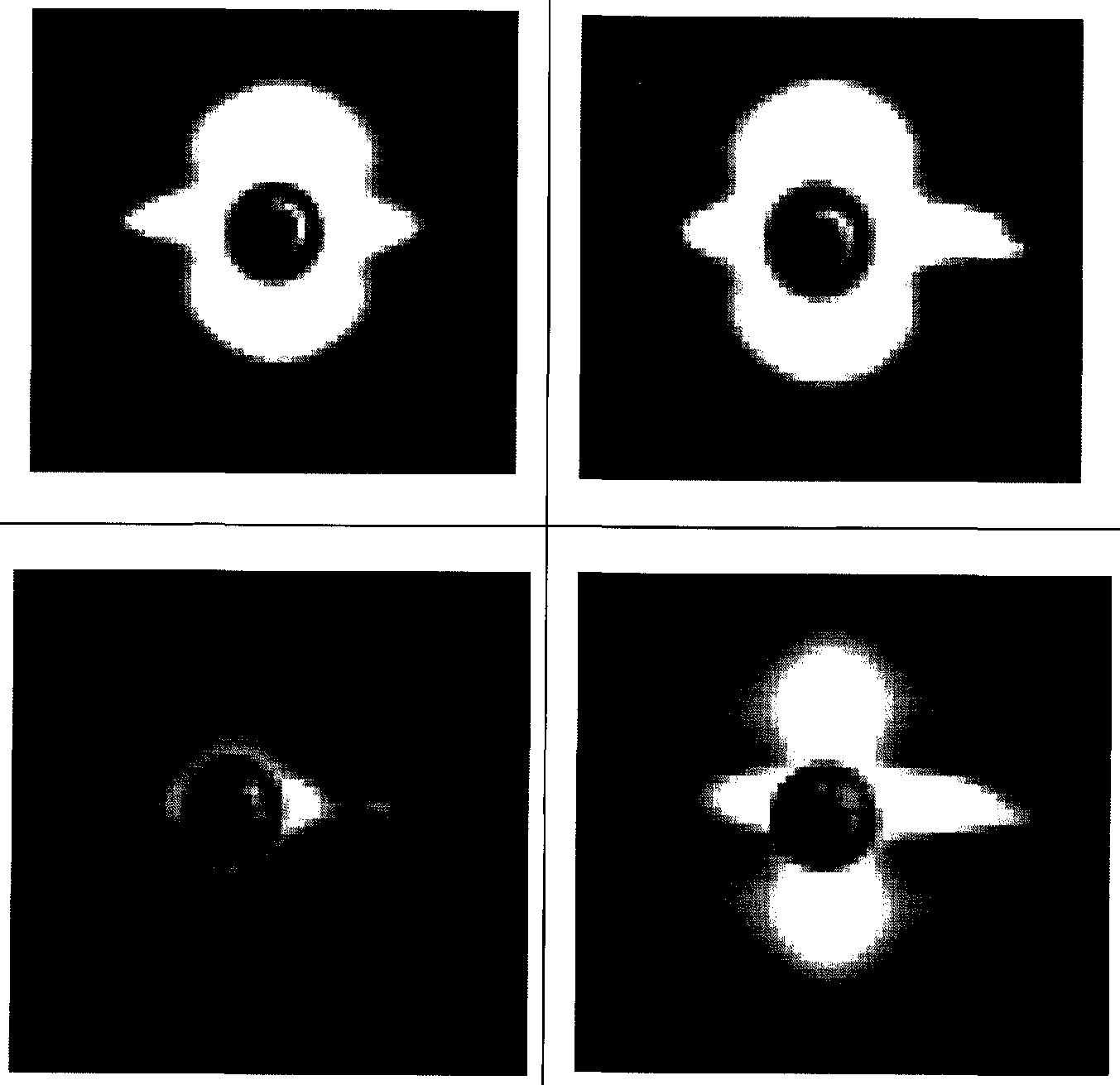
- small angle X-ray The scattering was spot-shaped as shown in Table 12.
- a laminated film consisting of a total of 705 layers was obtained using the same apparatus and conditions as in Example 18, except that the number of times of splitting and combining by the static mixer in the square flow path was two.
- the thickness of the laminated film was 12 ⁇ m, and there were 600 or more layers having a thickness of less than 30 nm.
- the resulting film had high rigidity, excellent dimensional stability at high temperatures, and was excellent in transparency after heating and in moldability over a wide temperature range. Table 8 shows the obtained results.
- a laminated film consisting of a total of 353 layers was obtained using the same apparatus and conditions as in Example 18, except that the number of times of splitting and combining by the static mixer of the square flow path was one.
- the thickness of the laminated film was, and 93 layers had a thickness of less than 30 nm.
- the resulting film had high rigidity, excellent dimensional stability at high temperatures, and was excellent in transparency after heating and moldability in a wide temperature range. Table 8 shows the obtained results.
- Example 18 Under the same apparatus and conditions as in Example 18, a laminated film consisting of a total of 1409 layers was obtained. However, the film thickness was adjusted to 25 / im by adjusting the film forming speed. There were 1200 or more layers with a layer thickness of less than 30 nm. The obtained film was high in rigidity, excellent in dimensional stability at high temperatures, and excellent in transparency after heating and moldability in a wide temperature range. Table 9 shows the obtained results.
- Example 18 Under the same apparatus and conditions as in Example 18, a laminated film consisting of a total of 1409 layers was obtained. However, the film thickness was adjusted to 40 zm by adjusting the film forming speed. There were 1000 or more layers having a thickness of less than 30 nm. The obtained film was high in rigidity, excellent in dimensional stability at high temperatures, and excellent in transparency after heating and moldability in a wide temperature range. Table 9 shows the obtained results.
- the obtained film was a film with high rigidity, excellent dimensional stability at high temperatures, excellent transparency after heating, and excellent moldability in a wide temperature range. Table 10 shows the obtained results.
- Example 18 Under the same apparatus and conditions as in Example 18, a laminated film consisting of a total of 1409 layers was obtained. However, the heat treatment temperature performed after elongation was 210 ° C. The film thickness was 12 ⁇ , and there were 1200 or more layers having a layer thickness of less than 30 nm. The resulting film was high in rigidity, excellent in dimensional stability at high temperatures, and excellent in transparency after heating and moldability in a wide temperature range. Table 10 shows the obtained results.
- a film having a total of 1,409 layers was obtained by using the same apparatus and conditions as in Example 18 except that the number of times was one.
- the film thickness was 12 ⁇ m, and there were 1200 or more layers having a layer thickness of less than 30 nm.
- the resulting film was highly rigid, excellent in dimensional stability at high temperatures, excellent in moldability in a wide temperature range, and further excellent in transparency after heating. Table 10 shows the obtained results. (Example 27)
- a laminated film consisting of a total of 1409 layers was obtained under the same apparatus and conditions as in Example 26. However, the heat treatment temperature performed after stretching was 210 ° C. The film thickness was 12 ⁇ , and there were 1200 or more layers with a layer thickness of less than 30 nm. The resulting film had high rigidity, excellent dimensional stability at high temperatures, excellent moldability in a wide temperature range, and very excellent transparency after heating. Table 11 shows the obtained results.
- Thermoplastic resin A has a melting point Tm of 255 ° C, a crystallization temperature of Tmcl of 92 ° C and an intrinsic viscosity of 0.65 PET, Toray F20S.
- Thermoplastic resin B has a melting point Tm of 229.
- a laminated film consisting of a total of 1409 layers was obtained under the same apparatus' conditions as in Example 1 except that polypropylene terephthalate (PPT) manufactured by DuPont C was used.
- PPT polypropylene terephthalate
- the melting point of PPT used in the present invention is 192 ° C
- a PET layer was laminated on both surfaces of the PPT, formed into a three-layer structure of PET / PPT / PET, and the ⁇ relaxation temperature was measured.
- the film thickness was 12 ⁇ , and there were 1200 or more layers with a layer thickness of less than 30 nm.
- the resulting film was highly rigid, excellent in dimensional stability at high temperatures, and excellent in transparency after heating and moldability in a wide temperature range. Table 11 shows the obtained results.
- thermoplastic resin A F20S made of Toray-Ene clay, which is a PET having a melting point Tm of 255 ° C, a crystallization temperature of Tmcl of 92 ° C, and an intrinsic viscosity of 0.65, was used. After drying the thermoplastic resin A, it was supplied to an extruder.
- thermoplastic resin A is melted at 280 ° C with an extruder, passed through a gear pump and a filter, fed to a T-die, formed into a sheet, and then heated to a surface temperature of 20 ° C while applying static electricity. Quenched and solidified on the kept casting drum.
- the resulting cast film is preheated with a set of rolls set at 85 ° C and set at 90 ° C
- the sheet was heated by the roll group and stretched 3.3 times in the machine direction.
- This uniaxially stretched film was guided to a tenter, preheated with hot air at 100 ° C, and then stretched 4.0 times in the transverse direction.
- the stretched film was subjected to a heat treatment in a tenter with hot air at 235 ° C., followed by a 5% relaxation treatment, gradually cooled to room temperature, and wound up.
- the thickness of the obtained film was 15 ⁇ . This finolem was unsuitable for dimensional stability at high temperatures and moldability. Table 11 shows the results.
- a laminated film consisting of a total of 41 layers was obtained under the same conditions as in Example 18 except that the feed block (pressure loss IMPa) was 41 layers and a static mixer was not used.
- the film thickness was 12 / m and no layers with a layer thickness of less than 30 nm were present.
- the obtained laminated film had insufficient dimensional stability at high temperature, transparency after heating, and moldability.
- Table 11 shows the obtained results. As shown in Table 12, small-angle X-ray scattering was observed in the form of layered scattering.
- Example 8 Example 9 Example 10
- Example 1 Thermoplastic resin A PET PET PET PET Thermoplastic resin B PBT PBT PBT PBT PBT Lamination number 1201 1201 1201 1201 Lamination ratio (A / B) 8/2 4/6 1 1 Average layer thickness 20 nm / 5 nm 10 nm / 15 nm 12 nm 12 nm Product 25% 25% 69% 20% Thermoplastic resin A 4.6 nm 4.5 nm 5 nm 3.6 nm
- Thermoplastic resin B 4nm 5nm 5nm 4nm In-layer periodic structure No Yes No No No Thermoplastic resin A 37J / g 20J / g 24J / g 24J / g
- Example 15 Example 16
- Example 17 Thermoplastic resin A PET PET PET PET Thermoplastic resin B PBT PEI PBT / I PBT Lamination number 305 1001 1001 1001 Lamination ratio ( ⁇ / ⁇ ) 1/1 1/1 1 / 1 2/3 Magnification 3x 3x 3x Longitudinal stretching
- a laminated film or a biaxially oriented polyester film having excellent high-temperature thermal dimensional stability and excellent moldability can be obtained. It can be used favorably for exterior materials.
Landscapes
- Chemical & Material Sciences (AREA)
- Chemical Kinetics & Catalysis (AREA)
- Electrochemistry (AREA)
- General Chemical & Material Sciences (AREA)
- Laminated Bodies (AREA)
- Sealing Battery Cases Or Jackets (AREA)
Abstract
Description


Claims
Priority Applications (4)
| Application Number | Priority Date | Filing Date | Title |
|---|---|---|---|
| US10/559,126 US7790272B2 (en) | 2003-06-04 | 2004-06-02 | Multilayer film and biaxially oriented polyester film |
| KR1020057023106A KR101110140B1 (ko) | 2003-06-04 | 2004-06-02 | 적층필름 및 이축배향 폴리에스테르 필름 |
| EP04745498.8A EP1640152B1 (en) | 2003-06-04 | 2004-06-02 | Multilayer film and biaxially oriented polyester film |
| JP2005506758A JP5105459B2 (ja) | 2003-06-04 | 2004-06-02 | 積層フィルムおよび二軸配向ポリエステルフィルム |
Applications Claiming Priority (4)
| Application Number | Priority Date | Filing Date | Title |
|---|---|---|---|
| JP2003-159030 | 2003-06-04 | ||
| JP2003159030 | 2003-06-04 | ||
| JP2003-313569 | 2003-09-05 | ||
| JP2003313569 | 2003-09-05 |
Publications (1)
| Publication Number | Publication Date |
|---|---|
| WO2004108408A1 true WO2004108408A1 (ja) | 2004-12-16 |
Family
ID=33513377
Family Applications (1)
| Application Number | Title | Priority Date | Filing Date |
|---|---|---|---|
| PCT/JP2004/007599 Ceased WO2004108408A1 (ja) | 2003-06-04 | 2004-06-02 | 積層フィルムおよび二軸配向ポリエステルフィルム |
Country Status (5)
| Country | Link |
|---|---|
| US (1) | US7790272B2 (ja) |
| EP (1) | EP1640152B1 (ja) |
| JP (1) | JP5105459B2 (ja) |
| KR (1) | KR101110140B1 (ja) |
| WO (1) | WO2004108408A1 (ja) |
Cited By (23)
| Publication number | Priority date | Publication date | Assignee | Title |
|---|---|---|---|---|
| JP2006240112A (ja) * | 2005-03-04 | 2006-09-14 | Mitsubishi Plastics Ind Ltd | ポリ乳酸系印刷用フィルムおよび印刷体並びに自動販売機内模擬缶用ラベル |
| JP2006303478A (ja) * | 2005-03-24 | 2006-11-02 | Toray Ind Inc | Led用反射体 |
| JP2007203687A (ja) * | 2006-02-06 | 2007-08-16 | Toray Ind Inc | 積層フィルム |
| JP2009096116A (ja) * | 2007-10-18 | 2009-05-07 | Teijin Dupont Films Japan Ltd | 音響振動板用二軸配向多層積層フィルム及びその製造方法 |
| JP2009208324A (ja) * | 2008-03-04 | 2009-09-17 | Toray Ind Inc | 成形体 |
| CN100547826C (zh) * | 2005-05-27 | 2009-10-07 | 昭和电工包装株式会社 | 电池外壳用包装材料及电池用外壳 |
| WO2012033133A1 (ja) * | 2010-09-08 | 2012-03-15 | 凸版印刷株式会社 | リチウムイオン電池用外装材 |
| JP2013012469A (ja) * | 2011-05-31 | 2013-01-17 | Fujimori Kogyo Co Ltd | 電池外装用積層体 |
| JP2014049307A (ja) * | 2012-08-31 | 2014-03-17 | Dainippon Printing Co Ltd | 電池用包装材料 |
| JP2014049308A (ja) * | 2012-08-31 | 2014-03-17 | Dainippon Printing Co Ltd | 電池用包装材料 |
| JP2014184562A (ja) * | 2013-03-21 | 2014-10-02 | Sumitomo Bakelite Co Ltd | 多層フィルムおよび包装体 |
| KR20150087193A (ko) | 2012-11-16 | 2015-07-29 | 도요보 가부시키가이샤 | 2축 연신 폴리에스테르 필름 및 그의 제조 방법 |
| JP2015147309A (ja) * | 2014-02-05 | 2015-08-20 | 東レ株式会社 | 二軸配向ポリエステルフィルム |
| JP2016168820A (ja) * | 2015-03-16 | 2016-09-23 | 東洋紡株式会社 | 熱可塑性樹脂シートの製造方法、熱可塑性樹脂シート、およびそれを加熱成型して得られた成形品 |
| JP2016168821A (ja) * | 2015-03-16 | 2016-09-23 | 東洋紡株式会社 | 熱可塑性樹脂シートの製造方法、熱可塑性樹脂シート、およびそれを加熱成型して得られた成形品 |
| JP2016169045A (ja) * | 2015-03-16 | 2016-09-23 | 東洋紡株式会社 | 熱可塑性樹脂容器 |
| WO2017170332A1 (ja) | 2016-03-30 | 2017-10-05 | 東洋紡株式会社 | 真空断熱材用積層体 |
| JP2019081377A (ja) * | 2019-02-12 | 2019-05-30 | 東洋紡株式会社 | 熱可塑性樹脂シート、およびそれを加熱成型して得られた成形品 |
| JP2020077646A (ja) * | 2014-04-24 | 2020-05-21 | 凸版印刷株式会社 | 蓄電装置用外装材、及びそれを用いた蓄電装置 |
| JP2020128085A (ja) * | 2020-03-30 | 2020-08-27 | 東洋紡株式会社 | 熱可塑性樹脂シート、およびそれを加熱成型して得る、成形品の製造方法。 |
| JPWO2022131360A1 (ja) * | 2020-12-18 | 2022-06-23 | ||
| WO2023042884A1 (ja) * | 2021-09-15 | 2023-03-23 | 大日本印刷株式会社 | 蓄電デバイス用外装材、その製造方法、フィルム、及び蓄電デバイス |
| WO2025205680A1 (ja) * | 2024-03-25 | 2025-10-02 | 三菱ケミカル株式会社 | 蓄電デバイス用外装材、その製造方法、及び蓄電デバイス |
Families Citing this family (27)
| Publication number | Priority date | Publication date | Assignee | Title |
|---|---|---|---|---|
| US7241485B2 (en) * | 2001-11-09 | 2007-07-10 | Toray Industries, Inc. | Protective film for glass |
| EP1712592B1 (en) | 2004-01-29 | 2009-10-07 | Teijin Dupont Films Japan Limited | Biaxially oriented film |
| KR100898670B1 (ko) * | 2006-11-30 | 2009-05-22 | 삼성에스디아이 주식회사 | 리튬 이차 전지용 세퍼레이터 및 이를 채용한 리튬 이차전지 |
| KR100904144B1 (ko) * | 2007-08-16 | 2009-06-24 | 에스케이씨 주식회사 | 생분해성 이축연신 적층 필름 |
| KR101468937B1 (ko) * | 2008-09-05 | 2014-12-11 | 코오롱인더스트리 주식회사 | 폴리에스테르 필름 및 이의 제조방법 |
| WO2010140575A1 (ja) * | 2009-06-05 | 2010-12-09 | 東洋紡績株式会社 | 容器の胴巻ラベル用二軸配向ポリエステルフィルム及び容器の胴巻用ラベル |
| JP6032786B2 (ja) * | 2010-12-24 | 2016-11-30 | 興人フィルム&ケミカルズ株式会社 | 二軸延伸ポリブチレンテレフタレートフィルムを含む冷間成形用電池ケース包材 |
| WO2013080143A1 (en) * | 2011-11-28 | 2013-06-06 | Cryovac, Inc. | Polyester based multilayered films |
| US10033021B2 (en) * | 2013-09-20 | 2018-07-24 | Dai Nippon Printing Co., Ltd. | Packaging material for cell |
| KR102090124B1 (ko) * | 2013-11-13 | 2020-03-17 | 도요보 가부시키가이샤 | 2축 연신 폴리부틸렌테레프탈레이트 필름 |
| CN106459444B (zh) * | 2014-04-11 | 2019-07-30 | 可隆工业株式会社 | 聚酯薄膜及其制造方法,以及使用该聚酯薄膜的聚酯模制品及其制造方法 |
| WO2015178390A1 (ja) * | 2014-05-21 | 2015-11-26 | 東洋紡株式会社 | 二軸延伸ポリブチレンテレフタレートフィルムおよびその製造方法、並びにガスバリア性積層フィルム |
| CN106470839A (zh) * | 2014-07-09 | 2017-03-01 | 东丽株式会社 | 聚丙烯膜及脱模用膜 |
| EP3689599B1 (en) | 2014-08-28 | 2021-03-31 | Dai Nippon Printing Co., Ltd. | Packaging material for battery |
| KR20170047375A (ko) * | 2014-09-02 | 2017-05-04 | 고쿠리츠다이가쿠호진 히로시마다이가쿠 | 고내열성 폴리에스테르 시트 |
| US9987907B1 (en) * | 2015-06-23 | 2018-06-05 | Madico, Inc. | Heat shapeable film composite |
| JP6724913B2 (ja) * | 2016-03-01 | 2020-07-15 | 東レ株式会社 | 積層フィルム |
| CN108886115B (zh) * | 2016-04-06 | 2022-02-18 | 大日本印刷株式会社 | 电池用包装材料、其制造方法和电池 |
| JP6932523B2 (ja) * | 2017-03-09 | 2021-09-08 | 昭和電工パッケージング株式会社 | 蓄電デバイス用外装材及び蓄電デバイス |
| CN110832662B (zh) * | 2017-07-10 | 2023-03-31 | 凸版印刷株式会社 | 蓄电装置用封装材料以及使用了该封装材料的蓄电装置 |
| KR102036418B1 (ko) * | 2017-12-26 | 2019-10-24 | 도레이첨단소재 주식회사 | 성형용 폴리에스테르 필름 및 그 제조방법 |
| KR102644424B1 (ko) * | 2018-12-07 | 2024-03-06 | 현대자동차 주식회사 | 스탬핑 필름, 및 이를 이용한 자동차용 기호 버튼 제조 방법 |
| WO2021026204A1 (en) * | 2019-08-05 | 2021-02-11 | Flex Films (Usa) Inc. | Controlled density thermoplastic multilayer films |
| EP4120415A4 (en) * | 2020-03-12 | 2025-02-19 | Dai Nippon Printing Co., Ltd. | Outer package material for all-solid-state batteries, method for producing same and all-solid-state battery |
| GB202106834D0 (en) * | 2021-05-13 | 2021-06-30 | Dupont Teijin Films Us Lp | Metallised films |
| WO2023013650A1 (ja) * | 2021-08-05 | 2023-02-09 | 旭化成株式会社 | アンテナ部材 |
| KR20240069711A (ko) * | 2021-09-17 | 2024-05-20 | 도레이 카부시키가이샤 | 적층 필름 |
Citations (1)
| Publication number | Priority date | Publication date | Assignee | Title |
|---|---|---|---|---|
| JP2003112355A (ja) * | 2001-10-04 | 2003-04-15 | Teijin Dupont Films Japan Ltd | 多層フィルムの製造方法及び装置 |
Family Cites Families (25)
| Publication number | Priority date | Publication date | Assignee | Title |
|---|---|---|---|---|
| JPS5854035B2 (ja) * | 1975-02-13 | 1983-12-02 | 東レ株式会社 | 積層フイルム |
| US4162343A (en) * | 1977-12-23 | 1979-07-24 | The Mearl Corporation | Multilayer light-reflecting film |
| US4310584A (en) * | 1979-12-26 | 1982-01-12 | The Mearl Corporation | Multilayer light-reflecting film |
| US4797308A (en) * | 1987-07-06 | 1989-01-10 | The Mearl Corporation | Simulated mother-of-pearl |
| JP2657266B2 (ja) * | 1989-04-28 | 1997-09-24 | 直哉 緒方 | 有機非線形光学材料 |
| US5262894A (en) * | 1989-06-20 | 1993-11-16 | The Dow Chemical Company | Multicomponent, multilayer polymeric reflective bodies |
| US5122905A (en) * | 1989-06-20 | 1992-06-16 | The Dow Chemical Company | Relective polymeric body |
| US5089318A (en) * | 1989-10-31 | 1992-02-18 | The Mearl Corporation | Iridescent film with thermoplastic elastomeric components |
| US5278694A (en) * | 1990-01-11 | 1994-01-11 | The Dow Chemical Company | Optically dissimilar composition for polymeric reflective bodies |
| US5126880A (en) * | 1990-12-18 | 1992-06-30 | The Dow Chemical Company | Polymeric reflective bodies with multiple layer types |
| US5234729A (en) * | 1992-02-27 | 1993-08-10 | The Dow Chemical Company | Multilayer polymeric reflective bodies for decorative and security applications |
| US5731071A (en) * | 1992-04-16 | 1998-03-24 | Teijin Limited | Biaxially oriented polyester film |
| US5451449A (en) * | 1994-05-11 | 1995-09-19 | The Mearl Corporation | Colored iridescent film |
| BR9912618A (pt) * | 1998-07-31 | 2001-05-02 | Minnesota Mining & Mfg | Artigo compreendendo uma pelìcula óptica de múltiplas camadas e processo de fabricar o mesmo |
| DE19839848A1 (de) * | 1998-09-02 | 2000-04-13 | Hoechst Diafoil Gmbh | Mehrschichtige, biaxial orientierte Polyesterfolie, Verfahren zu ihrer Herstellung und ihre Verwendung als Magnetbandfolie mit optimierten elektromagnetischen Eigenschaften |
| US6475608B2 (en) * | 1998-11-16 | 2002-11-05 | Engelhard Corporation | Multi-layer iridescent films |
| JP4736146B2 (ja) * | 1999-05-26 | 2011-07-27 | 大日本印刷株式会社 | ポリマー電池用包装材料 |
| JP4390922B2 (ja) * | 1999-08-19 | 2009-12-24 | 大日本印刷株式会社 | 包装用袋 |
| WO2001022129A1 (en) * | 1999-09-20 | 2001-03-29 | 3M Innovative Properties Company | Optical films having at least one particle-containing layer |
| JP2002146056A (ja) * | 2000-11-15 | 2002-05-22 | Toray Ind Inc | 二軸配向ポリエチレンナフタレートフィルム |
| JP2002337225A (ja) * | 2001-05-17 | 2002-11-27 | Toray Ind Inc | 成形用二軸延伸ポリエステルフィルム |
| US6602585B2 (en) * | 2001-09-26 | 2003-08-05 | Engelhard Corporation | Shrinkable iridescent film |
| US7572865B2 (en) * | 2002-01-11 | 2009-08-11 | Toyo Boseki Kabushiki Kaisha | Polyester films |
| US7065990B2 (en) * | 2004-05-26 | 2006-06-27 | Armament Systems & Procedures, Inc. | High contact conical bow |
| US7606288B2 (en) * | 2005-05-27 | 2009-10-20 | S5 Wireless, Inc. | Burst spread spectrum radio system and method for asset tracking and data telemetry |
-
2004
- 2004-06-02 US US10/559,126 patent/US7790272B2/en not_active Expired - Lifetime
- 2004-06-02 JP JP2005506758A patent/JP5105459B2/ja not_active Expired - Fee Related
- 2004-06-02 WO PCT/JP2004/007599 patent/WO2004108408A1/ja not_active Ceased
- 2004-06-02 EP EP04745498.8A patent/EP1640152B1/en not_active Expired - Lifetime
- 2004-06-02 KR KR1020057023106A patent/KR101110140B1/ko not_active Expired - Lifetime
Patent Citations (1)
| Publication number | Priority date | Publication date | Assignee | Title |
|---|---|---|---|---|
| JP2003112355A (ja) * | 2001-10-04 | 2003-04-15 | Teijin Dupont Films Japan Ltd | 多層フィルムの製造方法及び装置 |
Cited By (30)
| Publication number | Priority date | Publication date | Assignee | Title |
|---|---|---|---|---|
| JP2006240112A (ja) * | 2005-03-04 | 2006-09-14 | Mitsubishi Plastics Ind Ltd | ポリ乳酸系印刷用フィルムおよび印刷体並びに自動販売機内模擬缶用ラベル |
| JP2006303478A (ja) * | 2005-03-24 | 2006-11-02 | Toray Ind Inc | Led用反射体 |
| US8541080B2 (en) | 2005-05-27 | 2013-09-24 | Showa Denko Packaging Co. | Packaging material for battery case and battery case |
| CN100547826C (zh) * | 2005-05-27 | 2009-10-07 | 昭和电工包装株式会社 | 电池外壳用包装材料及电池用外壳 |
| US8129008B2 (en) | 2005-05-27 | 2012-03-06 | Showa Denko Packaging Co. | Packaging material for battery case and battery case |
| JP2007203687A (ja) * | 2006-02-06 | 2007-08-16 | Toray Ind Inc | 積層フィルム |
| JP2009096116A (ja) * | 2007-10-18 | 2009-05-07 | Teijin Dupont Films Japan Ltd | 音響振動板用二軸配向多層積層フィルム及びその製造方法 |
| JP2009208324A (ja) * | 2008-03-04 | 2009-09-17 | Toray Ind Inc | 成形体 |
| WO2012033133A1 (ja) * | 2010-09-08 | 2012-03-15 | 凸版印刷株式会社 | リチウムイオン電池用外装材 |
| US8920959B2 (en) | 2010-09-08 | 2014-12-30 | Toppan Printing Co., Ltd. | Lithium ion battery outer cover material |
| JP2013012469A (ja) * | 2011-05-31 | 2013-01-17 | Fujimori Kogyo Co Ltd | 電池外装用積層体 |
| JP2014049307A (ja) * | 2012-08-31 | 2014-03-17 | Dainippon Printing Co Ltd | 電池用包装材料 |
| JP2014049308A (ja) * | 2012-08-31 | 2014-03-17 | Dainippon Printing Co Ltd | 電池用包装材料 |
| KR20150087193A (ko) | 2012-11-16 | 2015-07-29 | 도요보 가부시키가이샤 | 2축 연신 폴리에스테르 필름 및 그의 제조 방법 |
| US9688826B2 (en) | 2012-11-16 | 2017-06-27 | Toyobo Co., Ltd. | Biaxially stretched polyester film and method for producing same |
| JP2014184562A (ja) * | 2013-03-21 | 2014-10-02 | Sumitomo Bakelite Co Ltd | 多層フィルムおよび包装体 |
| JP2015147309A (ja) * | 2014-02-05 | 2015-08-20 | 東レ株式会社 | 二軸配向ポリエステルフィルム |
| JP2020077646A (ja) * | 2014-04-24 | 2020-05-21 | 凸版印刷株式会社 | 蓄電装置用外装材、及びそれを用いた蓄電装置 |
| JP2016169045A (ja) * | 2015-03-16 | 2016-09-23 | 東洋紡株式会社 | 熱可塑性樹脂容器 |
| JP2016168821A (ja) * | 2015-03-16 | 2016-09-23 | 東洋紡株式会社 | 熱可塑性樹脂シートの製造方法、熱可塑性樹脂シート、およびそれを加熱成型して得られた成形品 |
| JP2016168820A (ja) * | 2015-03-16 | 2016-09-23 | 東洋紡株式会社 | 熱可塑性樹脂シートの製造方法、熱可塑性樹脂シート、およびそれを加熱成型して得られた成形品 |
| WO2017170332A1 (ja) | 2016-03-30 | 2017-10-05 | 東洋紡株式会社 | 真空断熱材用積層体 |
| JP2019081377A (ja) * | 2019-02-12 | 2019-05-30 | 東洋紡株式会社 | 熱可塑性樹脂シート、およびそれを加熱成型して得られた成形品 |
| JP2020128085A (ja) * | 2020-03-30 | 2020-08-27 | 東洋紡株式会社 | 熱可塑性樹脂シート、およびそれを加熱成型して得る、成形品の製造方法。 |
| JPWO2022131360A1 (ja) * | 2020-12-18 | 2022-06-23 | ||
| WO2022131360A1 (ja) * | 2020-12-18 | 2022-06-23 | 東洋紡株式会社 | 二軸延伸ポリエステルフィルム |
| TWI828020B (zh) * | 2020-12-18 | 2024-01-01 | 日商東洋紡股份有限公司 | 聚酯膜、標籤膜、顯示器用擴散膜及顯示器用透鏡膜 |
| US12612536B2 (en) | 2020-12-18 | 2026-04-28 | Toyobo Co., Ltd. | Biaxially stretched polyester film |
| WO2023042884A1 (ja) * | 2021-09-15 | 2023-03-23 | 大日本印刷株式会社 | 蓄電デバイス用外装材、その製造方法、フィルム、及び蓄電デバイス |
| WO2025205680A1 (ja) * | 2024-03-25 | 2025-10-02 | 三菱ケミカル株式会社 | 蓄電デバイス用外装材、その製造方法、及び蓄電デバイス |
Also Published As
| Publication number | Publication date |
|---|---|
| KR20060015330A (ko) | 2006-02-16 |
| EP1640152A1 (en) | 2006-03-29 |
| EP1640152A4 (en) | 2008-04-23 |
| JP5105459B2 (ja) | 2012-12-26 |
| EP1640152B1 (en) | 2018-12-05 |
| US20070026223A1 (en) | 2007-02-01 |
| JPWO2004108408A1 (ja) | 2006-07-20 |
| KR101110140B1 (ko) | 2012-01-31 |
| US7790272B2 (en) | 2010-09-07 |
Similar Documents
| Publication | Publication Date | Title |
|---|---|---|
| WO2004108408A1 (ja) | 積層フィルムおよび二軸配向ポリエステルフィルム | |
| CN100537230C (zh) | 多层聚酯薄膜及其制备方法 | |
| JP4661073B2 (ja) | 積層フィルム | |
| CN101484317B (zh) | 成型用层叠聚酯薄膜及其制造方法 | |
| WO1999062710A1 (fr) | Carte biodegradable | |
| WO2017170333A1 (ja) | 電池包装用積層体 | |
| JP6205868B2 (ja) | 二軸配向ポリエステルフィルム | |
| JP5418235B2 (ja) | 積層フィルム | |
| JP2008030475A (ja) | 成型用積層ポリエステルフィルムおよびその製造方法 | |
| KR102879509B1 (ko) | 공동 함유 폴리에스테르계 필름 | |
| JP4998153B2 (ja) | 積層ポリエステルフィルム | |
| EP3854837B1 (en) | Film for coating metal sheet and resin-coated metal sheet | |
| JP5696478B2 (ja) | 成形用フィルム | |
| JP5154959B2 (ja) | 成形加工用多層積層二軸配向ポリエステルフィルム | |
| CN100532088C (zh) | 层压薄膜和双轴取向聚酯薄膜 | |
| WO2023199792A1 (ja) | 空洞含有ポリエステル系フィルム、樹脂組成物、樹脂組成物の製造方法 | |
| JP2003191419A (ja) | Icカード用ポリエステルフィルム | |
| JP6786901B2 (ja) | ポリエステルフィルム | |
| JP2005335276A (ja) | 多層フィルム | |
| JP2024059373A (ja) | 離型フィルム | |
| CN118804836A (zh) | 包含双轴取向聚酯薄膜和双轴取向聚酰胺薄膜的层叠体 | |
| WO2025074878A1 (ja) | 成型用ポリエステルフィルム | |
| CN117480050A (zh) | 具有特定性质的超薄分层结构 | |
| JP4229682B2 (ja) | ポリエステルフィルム及びその製造方法 | |
| JP2004255590A (ja) | 包装用フィルム |
Legal Events
| Date | Code | Title | Description |
|---|---|---|---|
| WWE | Wipo information: entry into national phase |
Ref document number: 200480022279.8 Country of ref document: CN |
|
| AK | Designated states |
Kind code of ref document: A1 Designated state(s): AE AG AL AM AT AU AZ BA BB BG BR BW BY BZ CA CH CN CO CR CU CZ DE DK DM DZ EC EE EG ES FI GB GD GE GH GM HR HU ID IL IN IS JP KE KG KP KR KZ LC LK LR LS LT LU LV MA MD MG MK MN MW MX MZ NA NI NO NZ OM PG PH PL PT RO RU SC SD SE SG SK SL SY TJ TM TN TR TT TZ UA UG US UZ VC VN YU ZA ZM ZW |
|
| AL | Designated countries for regional patents |
Kind code of ref document: A1 Designated state(s): GM KE LS MW MZ NA SD SL SZ TZ UG ZM ZW AM AZ BY KG KZ MD RU TJ TM AT BE BG CH CY CZ DE DK EE ES FI FR GB GR HU IE IT LU MC NL PL PT RO SE SI SK TR BF BJ CF CG CI CM GA GN GQ GW ML MR NE SN TD TG |
|
| 121 | Ep: the epo has been informed by wipo that ep was designated in this application | ||
| WWE | Wipo information: entry into national phase |
Ref document number: 2005506758 Country of ref document: JP |
|
| WWE | Wipo information: entry into national phase |
Ref document number: 1020057023106 Country of ref document: KR |
|
| WWE | Wipo information: entry into national phase |
Ref document number: 2004745498 Country of ref document: EP |
|
| WWP | Wipo information: published in national office |
Ref document number: 1020057023106 Country of ref document: KR |
|
| WWP | Wipo information: published in national office |
Ref document number: 2004745498 Country of ref document: EP |
|
| WWE | Wipo information: entry into national phase |
Ref document number: 2007026223 Country of ref document: US Ref document number: 10559126 Country of ref document: US |
|
| WWP | Wipo information: published in national office |
Ref document number: 10559126 Country of ref document: US |