US8823852B2 - Information communication method of obtaining information from a subject by demodulating data specified by a pattern of a bright line included in an obtained image - Google Patents
Information communication method of obtaining information from a subject by demodulating data specified by a pattern of a bright line included in an obtained image Download PDFInfo
- Publication number
- US8823852B2 US8823852B2 US13/902,436 US201313902436A US8823852B2 US 8823852 B2 US8823852 B2 US 8823852B2 US 201313902436 A US201313902436 A US 201313902436A US 8823852 B2 US8823852 B2 US 8823852B2
- Authority
- US
- United States
- Prior art keywords
- information
- user
- diagram illustrating
- sound
- unit
- Prior art date
- Legal status (The legal status is an assumption and is not a legal conclusion. Google has not performed a legal analysis and makes no representation as to the accuracy of the status listed.)
- Active
Links
- 238000004891 communication Methods 0.000 title claims abstract description 470
- 230000006854 communication Effects 0.000 title claims abstract description 467
- 238000000034 method Methods 0.000 title claims abstract description 258
- 238000003384 imaging method Methods 0.000 claims description 376
- 230000008859 change Effects 0.000 abstract description 127
- 230000005540 biological transmission Effects 0.000 description 476
- 238000010586 diagram Methods 0.000 description 474
- 238000012545 processing Methods 0.000 description 295
- 238000011112 process operation Methods 0.000 description 128
- 230000008569 process Effects 0.000 description 65
- 238000003860 storage Methods 0.000 description 60
- 230000006870 function Effects 0.000 description 53
- 238000001514 detection method Methods 0.000 description 41
- 230000008054 signal transmission Effects 0.000 description 41
- 230000004397 blinking Effects 0.000 description 40
- 230000000694 effects Effects 0.000 description 38
- 230000033001 locomotion Effects 0.000 description 38
- 239000000047 product Substances 0.000 description 38
- 238000007726 management method Methods 0.000 description 30
- 238000010411 cooking Methods 0.000 description 25
- 230000003287 optical effect Effects 0.000 description 25
- 241000282412 Homo Species 0.000 description 21
- 230000001960 triggered effect Effects 0.000 description 15
- 238000012935 Averaging Methods 0.000 description 13
- 238000004458 analytical method Methods 0.000 description 13
- 230000008901 benefit Effects 0.000 description 13
- 230000004044 response Effects 0.000 description 13
- 230000007613 environmental effect Effects 0.000 description 11
- 230000001965 increasing effect Effects 0.000 description 11
- 238000004140 cleaning Methods 0.000 description 10
- 238000004590 computer program Methods 0.000 description 10
- 230000002123 temporal effect Effects 0.000 description 9
- 230000035945 sensitivity Effects 0.000 description 8
- 230000004913 activation Effects 0.000 description 7
- 238000013459 approach Methods 0.000 description 7
- 230000003190 augmentative effect Effects 0.000 description 7
- 235000013305 food Nutrition 0.000 description 7
- 238000012937 correction Methods 0.000 description 6
- 230000007423 decrease Effects 0.000 description 6
- 238000005096 rolling process Methods 0.000 description 6
- 230000003247 decreasing effect Effects 0.000 description 5
- 230000002829 reductive effect Effects 0.000 description 5
- 230000006641 stabilisation Effects 0.000 description 5
- 238000011105 stabilization Methods 0.000 description 5
- 241000209094 Oryza Species 0.000 description 4
- 235000007164 Oryza sativa Nutrition 0.000 description 4
- 230000007175 bidirectional communication Effects 0.000 description 4
- 238000012790 confirmation Methods 0.000 description 4
- 239000000470 constituent Substances 0.000 description 4
- 238000009826 distribution Methods 0.000 description 4
- 230000001771 impaired effect Effects 0.000 description 4
- 230000000670 limiting effect Effects 0.000 description 4
- 238000012986 modification Methods 0.000 description 4
- 230000004048 modification Effects 0.000 description 4
- 238000003825 pressing Methods 0.000 description 4
- 230000009467 reduction Effects 0.000 description 4
- 230000033764 rhythmic process Effects 0.000 description 4
- 235000009566 rice Nutrition 0.000 description 4
- 230000006399 behavior Effects 0.000 description 3
- 230000000903 blocking effect Effects 0.000 description 3
- 230000000052 comparative effect Effects 0.000 description 3
- 238000007796 conventional method Methods 0.000 description 3
- 239000000463 material Substances 0.000 description 3
- 238000012544 monitoring process Methods 0.000 description 3
- 238000010079 rubber tapping Methods 0.000 description 3
- 238000005070 sampling Methods 0.000 description 3
- 238000012546 transfer Methods 0.000 description 3
- 230000001131 transforming effect Effects 0.000 description 3
- 108010076504 Protein Sorting Signals Proteins 0.000 description 2
- 101100202463 Schizophyllum commune SC14 gene Proteins 0.000 description 2
- 206010047571 Visual impairment Diseases 0.000 description 2
- 230000002411 adverse Effects 0.000 description 2
- 238000009435 building construction Methods 0.000 description 2
- 238000009792 diffusion process Methods 0.000 description 2
- 239000003814 drug Substances 0.000 description 2
- 229940079593 drug Drugs 0.000 description 2
- 230000002708 enhancing effect Effects 0.000 description 2
- 239000000284 extract Substances 0.000 description 2
- 238000001914 filtration Methods 0.000 description 2
- 230000007274 generation of a signal involved in cell-cell signaling Effects 0.000 description 2
- 238000005286 illumination Methods 0.000 description 2
- 230000006872 improvement Effects 0.000 description 2
- 230000002452 interceptive effect Effects 0.000 description 2
- 239000004973 liquid crystal related substance Substances 0.000 description 2
- 238000005259 measurement Methods 0.000 description 2
- 230000036961 partial effect Effects 0.000 description 2
- 230000008447 perception Effects 0.000 description 2
- 238000002360 preparation method Methods 0.000 description 2
- 238000001454 recorded image Methods 0.000 description 2
- 230000008439 repair process Effects 0.000 description 2
- 230000003252 repetitive effect Effects 0.000 description 2
- 239000004065 semiconductor Substances 0.000 description 2
- 238000000926 separation method Methods 0.000 description 2
- 230000003595 spectral effect Effects 0.000 description 2
- 230000001360 synchronised effect Effects 0.000 description 2
- 208000029257 vision disease Diseases 0.000 description 2
- 230000004393 visual impairment Effects 0.000 description 2
- XLYOFNOQVPJJNP-UHFFFAOYSA-N water Substances O XLYOFNOQVPJJNP-UHFFFAOYSA-N 0.000 description 2
- 208000032041 Hearing impaired Diseases 0.000 description 1
- 101100172132 Mus musculus Eif3a gene Proteins 0.000 description 1
- 230000002159 abnormal effect Effects 0.000 description 1
- 230000001133 acceleration Effects 0.000 description 1
- 238000009825 accumulation Methods 0.000 description 1
- 230000009286 beneficial effect Effects 0.000 description 1
- 230000002457 bidirectional effect Effects 0.000 description 1
- 230000015572 biosynthetic process Effects 0.000 description 1
- 238000005282 brightening Methods 0.000 description 1
- 238000004364 calculation method Methods 0.000 description 1
- 230000006835 compression Effects 0.000 description 1
- 238000007906 compression Methods 0.000 description 1
- 238000010276 construction Methods 0.000 description 1
- 238000013461 design Methods 0.000 description 1
- 230000005611 electricity Effects 0.000 description 1
- 239000011521 glass Substances 0.000 description 1
- 230000005484 gravity Effects 0.000 description 1
- 208000016354 hearing loss disease Diseases 0.000 description 1
- 238000009434 installation Methods 0.000 description 1
- 239000007788 liquid Substances 0.000 description 1
- 230000007774 longterm Effects 0.000 description 1
- 238000012423 maintenance Methods 0.000 description 1
- 230000014759 maintenance of location Effects 0.000 description 1
- 239000003550 marker Substances 0.000 description 1
- 230000007246 mechanism Effects 0.000 description 1
- QSHDDOUJBYECFT-UHFFFAOYSA-N mercury Chemical compound [Hg] QSHDDOUJBYECFT-UHFFFAOYSA-N 0.000 description 1
- 230000000474 nursing effect Effects 0.000 description 1
- 230000010355 oscillation Effects 0.000 description 1
- 230000010363 phase shift Effects 0.000 description 1
- 230000002265 prevention Effects 0.000 description 1
- 230000002441 reversible effect Effects 0.000 description 1
- 238000000060 site-specific infrared dichroism spectroscopy Methods 0.000 description 1
- 239000013589 supplement Substances 0.000 description 1
- 238000003786 synthesis reaction Methods 0.000 description 1
- 230000000007 visual effect Effects 0.000 description 1
- 238000005406 washing Methods 0.000 description 1
Images


Classifications
-
- H—ELECTRICITY
- H04—ELECTRIC COMMUNICATION TECHNIQUE
- H04N—PICTORIAL COMMUNICATION, e.g. TELEVISION
- H04N3/00—Scanning details of television systems; Combination thereof with generation of supply voltages
- H04N3/10—Scanning details of television systems; Combination thereof with generation of supply voltages by means not exclusively optical-mechanical
- H04N3/14—Scanning details of television systems; Combination thereof with generation of supply voltages by means not exclusively optical-mechanical by means of electrically scanned solid-state devices
- H04N3/15—Scanning details of television systems; Combination thereof with generation of supply voltages by means not exclusively optical-mechanical by means of electrically scanned solid-state devices for picture signal generation
- H04N3/1506—Scanning details of television systems; Combination thereof with generation of supply voltages by means not exclusively optical-mechanical by means of electrically scanned solid-state devices for picture signal generation with addressing of the image-sensor elements
-
- H—ELECTRICITY
- H04—ELECTRIC COMMUNICATION TECHNIQUE
- H04N—PICTORIAL COMMUNICATION, e.g. TELEVISION
- H04N25/00—Circuitry of solid-state image sensors [SSIS]; Control thereof
- H04N25/50—Control of the SSIS exposure
- H04N25/53—Control of the integration time
- H04N25/531—Control of the integration time by controlling rolling shutters in CMOS SSIS
-
- H—ELECTRICITY
- H04—ELECTRIC COMMUNICATION TECHNIQUE
- H04B—TRANSMISSION
- H04B10/00—Transmission systems employing electromagnetic waves other than radio-waves, e.g. infrared, visible or ultraviolet light, or employing corpuscular radiation, e.g. quantum communication
- H04B10/11—Arrangements specific to free-space transmission, i.e. transmission through air or vacuum
- H04B10/114—Indoor or close-range type systems
- H04B10/1143—Bidirectional transmission
-
- H—ELECTRICITY
- H04—ELECTRIC COMMUNICATION TECHNIQUE
- H04B—TRANSMISSION
- H04B10/00—Transmission systems employing electromagnetic waves other than radio-waves, e.g. infrared, visible or ultraviolet light, or employing corpuscular radiation, e.g. quantum communication
- H04B10/11—Arrangements specific to free-space transmission, i.e. transmission through air or vacuum
- H04B10/114—Indoor or close-range type systems
- H04B10/116—Visible light communication
-
- H—ELECTRICITY
- H04—ELECTRIC COMMUNICATION TECHNIQUE
- H04B—TRANSMISSION
- H04B10/00—Transmission systems employing electromagnetic waves other than radio-waves, e.g. infrared, visible or ultraviolet light, or employing corpuscular radiation, e.g. quantum communication
- H04B10/50—Transmitters
- H04B10/516—Details of coding or modulation
- H04B10/54—Intensity modulation
- H04B10/541—Digital intensity or amplitude modulation
-
- H—ELECTRICITY
- H04—ELECTRIC COMMUNICATION TECHNIQUE
- H04L—TRANSMISSION OF DIGITAL INFORMATION, e.g. TELEGRAPHIC COMMUNICATION
- H04L12/00—Data switching networks
- H04L12/28—Data switching networks characterised by path configuration, e.g. LAN [Local Area Networks] or WAN [Wide Area Networks]
- H04L12/2803—Home automation networks
-
- H—ELECTRICITY
- H04—ELECTRIC COMMUNICATION TECHNIQUE
- H04N—PICTORIAL COMMUNICATION, e.g. TELEVISION
- H04N23/00—Cameras or camera modules comprising electronic image sensors; Control thereof
- H04N23/60—Control of cameras or camera modules
- H04N23/63—Control of cameras or camera modules by using electronic viewfinders
- H04N23/631—Graphical user interfaces [GUI] specially adapted for controlling image capture or setting capture parameters
-
- H—ELECTRICITY
- H04—ELECTRIC COMMUNICATION TECHNIQUE
- H04N—PICTORIAL COMMUNICATION, e.g. TELEVISION
- H04N23/00—Cameras or camera modules comprising electronic image sensors; Control thereof
- H04N23/60—Control of cameras or camera modules
- H04N23/66—Remote control of cameras or camera parts, e.g. by remote control devices
- H04N23/661—Transmitting camera control signals through networks, e.g. control via the Internet
-
- H—ELECTRICITY
- H04—ELECTRIC COMMUNICATION TECHNIQUE
- H04N—PICTORIAL COMMUNICATION, e.g. TELEVISION
- H04N23/00—Cameras or camera modules comprising electronic image sensors; Control thereof
- H04N23/70—Circuitry for compensating brightness variation in the scene
- H04N23/72—Combination of two or more compensation controls
-
- H—ELECTRICITY
- H04—ELECTRIC COMMUNICATION TECHNIQUE
- H04N—PICTORIAL COMMUNICATION, e.g. TELEVISION
- H04N23/00—Cameras or camera modules comprising electronic image sensors; Control thereof
- H04N23/70—Circuitry for compensating brightness variation in the scene
- H04N23/73—Circuitry for compensating brightness variation in the scene by influencing the exposure time
-
- H—ELECTRICITY
- H04—ELECTRIC COMMUNICATION TECHNIQUE
- H04N—PICTORIAL COMMUNICATION, e.g. TELEVISION
- H04N23/00—Cameras or camera modules comprising electronic image sensors; Control thereof
- H04N23/70—Circuitry for compensating brightness variation in the scene
- H04N23/76—Circuitry for compensating brightness variation in the scene by influencing the image signals
-
- H—ELECTRICITY
- H04—ELECTRIC COMMUNICATION TECHNIQUE
- H04W—WIRELESS COMMUNICATION NETWORKS
- H04W4/00—Services specially adapted for wireless communication networks; Facilities therefor
- H04W4/50—Service provisioning or reconfiguring
-
- H—ELECTRICITY
- H04—ELECTRIC COMMUNICATION TECHNIQUE
- H04L—TRANSMISSION OF DIGITAL INFORMATION, e.g. TELEGRAPHIC COMMUNICATION
- H04L12/00—Data switching networks
- H04L12/28—Data switching networks characterised by path configuration, e.g. LAN [Local Area Networks] or WAN [Wide Area Networks]
- H04L12/2803—Home automation networks
- H04L2012/284—Home automation networks characterised by the type of medium used
- H04L2012/2841—Wireless
-
- H—ELECTRICITY
- H04—ELECTRIC COMMUNICATION TECHNIQUE
- H04W—WIRELESS COMMUNICATION NETWORKS
- H04W4/00—Services specially adapted for wireless communication networks; Facilities therefor
- H04W4/20—Services signaling; Auxiliary data signalling, i.e. transmitting data via a non-traffic channel
Definitions
- the present disclosure relates to a method of communication between a mobile terminal such as a smartphone, a tablet terminal, or a mobile phone and a home electric appliance such as an air conditioner, a lighting device, or a rice cooker.
- a mobile terminal such as a smartphone, a tablet terminal, or a mobile phone
- a home electric appliance such as an air conditioner, a lighting device, or a rice cooker.
- HEMS home energy management system
- IP internet protocol
- Ethernet registered trademark
- LAN wireless local area network
- Patent Literature (PTL) 1 discloses a technique of efficiently establishing communication between devices among limited optical spatial transmission devices which transmit information to free space using light, by performing communication using plural single color light sources of illumination light.
- the conventional method is limited to a case in which a device to which the method is applied has three color light sources such as an illuminator.
- One non-limiting and exemplary embodiment solves this problem, and provides an information communication method that enables communication between various devices including a device with low computational performance.
- An information communication method is an information communication method of obtaining information from a subject, the information communication method including: a first imaging step of obtaining a first image by capturing the subject using an image sensor that includes a plurality of exposure lines; a detection step of detecting a range in which the subject is captured, from the first image; a determination step of determining, from among the plurality of exposure lines, predetermined exposure lines for capturing the range in which the subject is captured; an exposure time setting step of setting an exposure time of the image sensor so that, in a second image obtained using the predetermined exposure lines, a bright line corresponding to the predetermined exposure lines appears according to a change in luminance of the subject; a second imaging step of obtaining the second image including the bright line, by capturing the subject that changes in luminance using the predetermined exposure lines with the set exposure time; and an information obtainment step of obtaining the information by demodulating data specified by a pattern of the bright line included in the obtained second image.
- An information communication method disclosed herein enables communication between various devices including a device with low computational performance.
- FIG. 1 is a diagram illustrating an example of an environment in a house in Embodiment 1.
- FIG. 2 is a diagram illustrating an example of communication between a smartphone and home electric appliances according to Embodiment 1.
- FIG. 3 is a diagram illustrating an example of a configuration of a transmitter device according to Embodiment 1.
- FIG. 4 is a diagram illustrating an example of a configuration of a receiver device according to Embodiment 1.
- FIG. 5 is a diagram illustrating a flow of processing of transmitting information to the receiver device by blinking an LED of the transmitter device according to Embodiment 1.
- FIG. 6 is a diagram illustrating a flow of processing of transmitting information to the receiver device by blinking an LED of the transmitter device according to Embodiment 1.
- FIG. 7 is a diagram illustrating a flow of processing of transmitting information to the receiver device by blinking an LED of the transmitter device according to Embodiment 1.
- FIG. 8 is a diagram illustrating a flow of processing of transmitting information to the receiver device by blinking an LED of the transmitter device according to Embodiment 1.
- FIG. 9 is a diagram illustrating a flow of processing of transmitting information to the receiver device by blinking an LED of the transmitter device according to Embodiment 1.
- FIG. 10 is a diagram for describing a procedure of performing communication between a user and a device using visible light according to Embodiment 2.
- FIG. 11 is a diagram for describing a procedure of performing communication between the user and the device using visible light according to Embodiment 2.
- FIG. 12 is a diagram for describing a procedure from when a user purchases a device until when the user makes initial settings of the device according to Embodiment 2.
- FIG. 13 is a diagram for describing service exclusively performed by a serviceman when a device fails according to Embodiment 2.
- FIG. 14 is a diagram for describing service for checking a cleaning state using a cleaner and visible light communication according to Embodiment 2.
- FIG. 15 is a schematic diagram of home delivery service support using optical communication according to Embodiment 3.
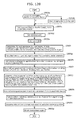
- FIG. 16 is a flowchart for describing home delivery service support using optical communication according to Embodiment 3.
- FIG. 17 is a flowchart for describing home delivery service support using optical communication according to Embodiment 3.
- FIG. 18 is a flowchart for describing home delivery service support using optical communication according to Embodiment 3.
- FIG. 19 is a flowchart for describing home delivery service support using optical communication according to Embodiment 3.
- FIG. 20 is a flowchart for describing home delivery service support using optical communication according to Embodiment 3.
- FIG. 21 is a flowchart for describing home delivery service support using optical communication according to Embodiment 3.
- FIG. 22 is a diagram for describing processing of registering a user and a mobile phone in use to a server according to Embodiment 4.
- FIG. 23 is a diagram for describing processing of analyzing user voice characteristics according to Embodiment 4.
- FIG. 24 is a diagram for describing processing of preparing sound recognition processing according to Embodiment 4.
- FIG. 25 is a diagram for describing processing of collecting sound by a sound collecting device in the vicinity according to Embodiment 4.
- FIG. 26 is a diagram for describing processing of analyzing environmental sound characteristics according to Embodiment 4.
- FIG. 27 is a diagram for describing processing of canceling sound from a sound output device which is present in the vicinity according to Embodiment 4.
- FIG. 28 is a diagram for describing processing of selecting what to cook and setting detailed operation of a microwave according to Embodiment 4.
- FIG. 29 is a diagram for describing processing of obtaining notification sound for the microwave from a DB of a server, for instance, and setting the sound in the microwave according to Embodiment 4.
- FIG. 30 is a diagram for describing processing of adjusting notification sound of the microwave according to Embodiment 4.
- FIG. 31 is a diagram illustrating examples of waveforms of notification sounds set in the microwave according to Embodiment 4.
- FIG. 32 is a diagram for describing processing of displaying details of cooking according to Embodiment 4.
- FIG. 33 is a diagram for describing processing of recognizing notification sound of the microwave according to Embodiment 4.
- FIG. 34 is a diagram for describing processing of collecting sound by a sound collecting device in the vicinity and recognizing notification sound of the microwave according to Embodiment 4.
- FIG. 35 is a diagram for describing processing of notifying a user of the end of operation of the microwave according to Embodiment 4.
- FIG. 36 is a diagram for describing processing of checking an operation state of a mobile phone according to Embodiment 4.
- FIG. 37 is a diagram for describing processing of tracking a user position according to Embodiment 4.
- FIG. 38 is a diagram illustrating that while canceling sound from a sound output device, notification sound of a home electric appliance is recognized, an electronic device which can communicate is caused to recognize a current position of a user (operator), and based on the recognition result of the user position, a device located near the user position is caused to give a notification to the user.
- FIG. 39 is a diagram illustrating content of a database held in the server, the mobile phone, or the microwave according to Embodiment 4.
- FIG. 40 is a diagram illustrating that a user cooks based on cooking processes displayed on a mobile phone, and further operates the display content of the mobile phone by saying “next”, “return”, and others, according to Embodiment 4.
- FIG. 41 is a diagram illustrating that the user has moved to another place while he/she is waiting until the operation of the microwave ends after starting the operation or while he/she is stewing food according to Embodiment 4.
- FIG. 42 is a diagram illustrating that a mobile phone transmits an instruction to detect a user to a device which is connected to the mobile phone via a network, and can recognize a position of the user and the presence of the user, such as a camera, a microphone, or a human sensing sensor.
- FIG. 43 is a diagram illustrating that a user face is recognized using a camera included in a television, and further the movement and presence of the user are recognized using a human sensing sensor of an air-conditioner, as an example of user detection according to Embodiment 4.
- FIG. 45 is a diagram illustrating that the mobile phone recognizes microwave operation end sound according to Embodiment 4.
- FIG. 46 is a diagram illustrating that the mobile phone which has recognized the end of the operation of the microwave transmits an instruction to, among the devices which have detected the user, a device having a screen-display function and a sound output function to notify the user of the end of the microwave operation.
- FIG. 47 is a diagram illustrating that the device which has received an instruction notifies the user of the details of the notification.
- FIG. 48 is a diagram illustrating that a device which is present near the microwave, is connected to the mobile phone via a network, and includes a microphone recognizes the microwave operation end sound.
- FIG. 50 is a diagram illustrating that if the mobile phone is near the user when the mobile phone receives the notification indicating the end of the operation of the microwave, the user is notified of the end of the operation of the microwave, using screen display, sound output, and the like by the mobile phone.
- FIG. 52 is a diagram illustrating that the user who has received the notification indicating the end of the operation of the microwave moves to a kitchen.
- FIG. 53 is a diagram illustrating that the microwave transmits information such as the end of operation to the mobile phone by wireless communication, the mobile phone gives a notification instruction to the television which the user is watching, and the user is notified by a screen display and sound of the television.
- FIG. 54 is a diagram illustrating that the microwave transmits information such as the end of operation to the television which the user is watching by wireless communication, and the user is notified thereof using the screen display and sound of the television.
- FIG. 55 is a diagram illustrating that the user is notified by the screen display and sound of the television.
- FIG. 56 is a diagram illustrating that a user who is at a remote place is notified of information.
- FIG. 57 is a diagram illustrating that if the microwave cannot directly communicate with the mobile phone serving as a hub, the microwave transmits information to the mobile phone via a personal computer, for instance.
- FIG. 58 is a diagram illustrating that the mobile phone which has received communication in FIG. 57 transmits information such as an operation instruction to the microwave, following the information-and-communication path in an opposite direction.
- FIG. 59 is a diagram illustrating that in the case where the air-conditioner which is an information source device cannot directly communicate with the mobile phone serving as a hub, the air-conditioner notifies the user of information.
- FIG. 60 is a diagram for describing a system utilizing a communication device which uses a 700 to 900 MHz radio wave.
- FIG. 61 is a diagram illustrating that a mobile phone at a remote place notifies a user of information.
- FIG. 62 is a diagram illustrating that the mobile phone at a remote place notifies the user of information.
- FIG. 64 is a diagram illustrating an example of an environment in a house in Embodiment 5.
- FIG. 65 is a diagram illustrating an example of communication between a smartphone and home electric appliances according to Embodiment 5.
- FIG. 66 is a diagram illustrating a configuration of a transmitter device according to Embodiment 5.
- FIG. 67 is a diagram illustrating a configuration of a receiver device according to Embodiment 5.
- FIG. 70 is a flowchart illustrating operation of the transmitter terminal according to Embodiment 5.
- FIG. 71 is a flowchart illustrating operation of the receiver terminal according to Embodiment 5.
- FIG. 73 is a diagram illustrating a screen changed when the mobile AV terminal 1 transmits data to the mobile AV terminal 2 according to Embodiment 6.
- FIG. 74 is a diagram illustrating a screen changed when the mobile AV terminal 1 transmits data to the mobile AV terminal 2 according to Embodiment 6.
- FIG. 75 is a system outline diagram for when the mobile AV terminal 1 is a digital camera according to Embodiment 6.
- FIG. 76 is a system outline diagram for when the mobile AV terminal 1 is a digital camera according to Embodiment 6.
- FIG. 77 is a system outline diagram for when the mobile AV terminal 1 is a digital camera according to Embodiment 6.
- FIG. 78 is a diagram illustrating an example of an observation method of luminance of a light emitting unit in Embodiment 7.
- FIG. 79 is a diagram illustrating an example of an observation method of luminance of a light emitting unit in Embodiment 7.
- FIG. 80 is a diagram illustrating an example of an observation method of luminance of a light emitting unit in Embodiment 7.
- FIG. 81 is a diagram illustrating an example of an observation method of luminance of a light emitting unit in Embodiment 7.
- FIG. 82 is a diagram illustrating an example of an observation method of luminance of a light emitting unit in Embodiment 7.
- FIG. 83 is a diagram illustrating an example of a signal modulation scheme in Embodiment 7.
- FIG. 84 is a diagram illustrating an example of a signal modulation scheme in Embodiment 7.
- FIG. 85 is a diagram illustrating an example of a signal modulation scheme in Embodiment 7.
- FIG. 86 is a diagram illustrating an example of a signal modulation scheme in Embodiment 7.
- FIG. 87 is a diagram illustrating an example of a signal modulation scheme in Embodiment 7.
- FIG. 88 is a diagram illustrating an example of a signal modulation scheme in Embodiment 7.
- FIG. 89 is a diagram illustrating an example of a signal modulation scheme in Embodiment 7.
- FIG. 90 is a diagram illustrating an example of a signal modulation scheme in Embodiment 7.
- FIG. 91 is a diagram illustrating an example of a signal modulation scheme in Embodiment 7.
- FIG. 92 is a diagram illustrating an example of a signal modulation scheme in Embodiment 7.
- FIG. 93 is a diagram illustrating an example of a signal modulation scheme in Embodiment 7.
- FIG. 94 is a diagram illustrating an example of a signal modulation scheme in Embodiment 7.
- FIG. 95 is a diagram illustrating an example of a signal modulation scheme in Embodiment 7.
- FIG. 96 is a diagram illustrating an example of a signal modulation scheme in Embodiment 7.
- FIG. 97 is a diagram illustrating an example of a signal modulation scheme in Embodiment 7.
- FIG. 98 is a diagram illustrating an example of a signal modulation scheme in Embodiment 7.
- FIG. 99 is a diagram illustrating an example of a light emitting unit detection method in Embodiment 7.
- FIG. 100 is a diagram illustrating an example of a light emitting unit detection method in Embodiment 7.
- FIG. 101 is a diagram illustrating an example of a light emitting unit detection method in Embodiment 7.
- FIG. 102 is a diagram illustrating an example of a light emitting unit detection method in Embodiment 7.
- FIG. 103 is a diagram illustrating an example of a light emitting unit detection method in Embodiment 7.
- FIG. 104 is a diagram illustrating transmission signal timelines and an image obtained by capturing light emitting units in Embodiment 7.
- FIG. 105 is a diagram illustrating an example of signal transmission using a position pattern in Embodiment 7.
- FIG. 106 is a diagram illustrating an example of a reception device in Embodiment 7.
- FIG. 107 is a diagram illustrating an example of a transmission device in Embodiment 7.
- FIG. 108 is a diagram illustrating an example of a transmission device in Embodiment 7.
- FIG. 109 is a diagram illustrating an example of a transmission device in Embodiment 7.
- FIG. 110 is a diagram illustrating an example of a transmission device in Embodiment 7.
- FIG. 111 is a diagram illustrating an example of a transmission device in Embodiment 7.
- FIG. 112 is a diagram illustrating an example of a transmission device in Embodiment 7.
- FIG. 113 is a diagram illustrating an example of a transmission device in Embodiment 7.
- FIG. 114 is a diagram illustrating an example of a transmission device in Embodiment 7.
- FIG. 115 is a diagram illustrating an example of a structure of a light emitting unit in Embodiment 7.
- FIG. 116 is a diagram illustrating an example of a signal carrier in Embodiment 7.
- FIG. 117 is a diagram illustrating an example of an imaging unit in Embodiment 7.
- FIG. 118 is a diagram illustrating an example of position estimation of a reception device in Embodiment 7.
- FIG. 119 is a diagram illustrating an example of position estimation of a reception device in Embodiment 7.
- FIG. 120 is a diagram illustrating an example of position estimation of a reception device in Embodiment 7.
- FIG. 121 is a diagram illustrating an example of position estimation of a reception device in Embodiment 7.
- FIG. 122 is a diagram illustrating an example of position estimation of a reception device in Embodiment 7.
- FIG. 123 is a diagram illustrating an example of transmission information setting in Embodiment 7.
- FIG. 124 is a diagram illustrating an example of transmission information setting in Embodiment 7.
- FIG. 125 is a diagram illustrating an example of transmission information setting in Embodiment 7.
- FIG. 126 is a block diagram illustrating an example of structural elements of a reception device in Embodiment 7.
- FIG. 127 is a block diagram illustrating an example of structural elements of a transmission device in Embodiment 7.
- FIG. 128 is a diagram illustrating an example of a reception procedure in Embodiment 7.
- FIG. 129 is a diagram illustrating an example of a self-position estimation procedure in Embodiment 7.
- FIG. 130 is a diagram illustrating an example of a transmission control procedure in Embodiment 7.
- FIG. 131 is a diagram illustrating an example of a transmission control procedure in Embodiment 7.
- FIG. 132 is a diagram illustrating an example of a transmission control procedure in Embodiment 7.
- FIG. 133 is a diagram illustrating an example of information provision inside a station in Embodiment 7.
- FIG. 134 is a diagram illustrating an example of a passenger service in Embodiment 7.
- FIG. 135 is a diagram illustrating an example of an in-store service in Embodiment 7.
- FIG. 136 is a diagram illustrating an example of wireless connection establishment in Embodiment 7.
- FIG. 137 is a diagram illustrating an example of communication range adjustment in Embodiment 7.
- FIG. 138 is a diagram illustrating an example of indoor use in Embodiment 7.
- FIG. 139 is a diagram illustrating an example of outdoor use in Embodiment 7.
- FIG. 140 is a diagram illustrating an example of route indication in Embodiment 7.
- FIG. 141 is a diagram illustrating an example of use of a plurality of imaging devices in Embodiment 7.
- FIG. 142 is a diagram illustrating an example of transmission device autonomous control in Embodiment 7.
- FIG. 143 is a diagram illustrating an example of transmission information setting in Embodiment 7.
- FIG. 144 is a diagram illustrating an example of transmission information setting in Embodiment 7.
- FIG. 145 is a diagram illustrating an example of transmission information setting in Embodiment 7.
- FIG. 146 is a diagram illustrating an example of combination with 2D barcode in Embodiment 7.
- FIG. 147 is a diagram illustrating an example of map generation and use in Embodiment 7.
- FIG. 148 is a diagram illustrating an example of electronic device state obtainment and operation in Embodiment 7.
- FIG. 149 is a diagram illustrating an example of electronic device recognition in Embodiment 7.
- FIG. 150 is a diagram illustrating an example of augmented reality object display in Embodiment 7.
- FIG. 151 is a diagram illustrating an example of a user interface in Embodiment 7.
- FIG. 152 is a diagram illustrating an example of a user interface in Embodiment 7.
- FIG. 153 is a diagram illustrating an example of a user interface in Embodiment 7.
- FIG. 154 is a diagram illustrating an example of a user interface in Embodiment 7.
- FIG. 155 is a diagram illustrating an example of a user interface in Embodiment 7.
- FIG. 156 is a diagram illustrating an example of a user interface in Embodiment 7.
- FIG. 157 is a diagram illustrating an example of a user interface in Embodiment 7.
- FIG. 158 is a diagram illustrating an example of a user interface in Embodiment 7.
- FIG. 159 is a diagram illustrating an example of a user interface in Embodiment 7.
- FIG. 160 is a diagram illustrating an example of a user interface in Embodiment 7.
- FIG. 161 is a diagram illustrating an example of a user interface in Embodiment 7.
- FIG. 162 is a diagram illustrating an example of a user interface in Embodiment 7.
- FIG. 163 is a diagram illustrating an example of a user interface in Embodiment 7.
- FIG. 164 is a diagram illustrating an example of a user interface in Embodiment 7.
- FIG. 165 is a diagram illustrating an example of a user interface in Embodiment 7.
- FIG. 166 is a diagram illustrating an example of a user interface in Embodiment 7.
- FIG. 167 is a diagram illustrating an example of a user interface in Embodiment 7.
- FIG. 168 is a diagram illustrating an example of application to ITS in Embodiment 8.
- FIG. 169 is a diagram illustrating an example of application to ITS in Embodiment 8.
- FIG. 170 is a diagram illustrating an example of application to a position information reporting system and a facility system in Embodiment 8.
- FIG. 171 is a diagram illustrating an example of application to a supermarket system in Embodiment 8.
- FIG. 172 is a diagram illustrating an example of application to communication between a mobile phone terminal and a camera in Embodiment 8.
- FIG. 173 is a diagram illustrating an example of application to underwater communication in Embodiment 8.
- FIG. 174 is a diagram for describing an example of service provision to a user in Embodiment 9.
- FIG. 175 is a diagram for describing an example of service provision to a user in Embodiment 9.
- FIG. 176 is a flowchart illustrating the case where a receiver simultaneously processes a plurality of signals received from transmitters in Embodiment 9.
- FIG. 177 is a diagram illustrating an example of the case of realizing inter-device communication by two-way communication in Embodiment 9.
- FIG. 178 is a diagram for describing a service using directivity characteristics in Embodiment 9.
- FIG. 179 is a diagram for describing another example of service provision to a user in Embodiment 9.
- FIG. 180 is a diagram illustrating a format example of a signal included in a light source emitted from a transmitter in Embodiment 9.
- FIG. 181 is a diagram illustrating a principle in Embodiment 10.
- FIG. 182 is a diagram illustrating an example of operation in Embodiment 10.
- FIG. 183 is a diagram illustrating an example of operation in Embodiment 10.
- FIG. 184 is a diagram illustrating an example of operation in Embodiment 10.
- FIG. 185 is a diagram illustrating an example of operation in Embodiment 10.
- FIG. 186 is a diagram illustrating an example of operation in Embodiment 10.
- FIG. 187 is a diagram illustrating an example of operation in Embodiment 10.
- FIG. 188 is a diagram illustrating an example of operation in Embodiment 10.
- FIG. 189 is a diagram illustrating an example of operation in Embodiment 10.
- FIG. 190 is a diagram illustrating an example of operation in Embodiment 10.
- FIG. 191 is a diagram illustrating an example of operation in Embodiment 10.
- FIG. 192 is a diagram illustrating an example of operation in Embodiment 10.
- FIG. 193 is a diagram illustrating an example of operation in Embodiment 10.
- FIG. 194 is a diagram illustrating an example of operation in Embodiment 10.
- FIG. 195 is a timing diagram of a transmission signal in an information communication device in Embodiment 11.
- FIG. 196 is a diagram illustrating relations between a transmission signal and a reception signal in Embodiment 11.
- FIG. 197 is a diagram illustrating relations between a transmission signal and a reception signal in Embodiment 11.
- FIG. 198 is a diagram illustrating relations between a transmission signal and a reception signal in Embodiment 11.
- FIG. 199 is a diagram illustrating relations between a transmission signal and a reception signal in Embodiment 11.
- FIG. 200 is a diagram illustrating relations between a transmission signal and a reception signal in Embodiment 11.
- FIG. 201 is a diagram illustrating an example of application of a receiver and a transmitter in Embodiment 12.
- FIG. 202 is a diagram illustrating an example of application of a receiver and a transmitter in Embodiment 12.
- FIG. 203 is a diagram illustrating an example of application of a receiver and a transmitter in Embodiment 12.
- FIG. 204 is a diagram illustrating an example of application of a receiver and a transmitter in Embodiment 12.
- FIG. 205 is a flowchart illustrating an example of process operations of a receiver and a transmitter in Embodiment 12.
- FIG. 206 is a diagram illustrating an example of application of a receiver and a transmitter in Embodiment 12.
- FIG. 207 is a flowchart illustrating an example of process operations of a receiver and a transmitter in Embodiment 12.
- FIG. 208 is a diagram illustrating an example of application of a receiver and a transmitter in Embodiment 12.
- FIG. 209 is a flowchart illustrating an example of process operations of a receiver and a transmitter in Embodiment 12.
- FIG. 210 is a diagram illustrating an example of application of a receiver and a transmitter in Embodiment 12.
- FIG. 211 is a flowchart illustrating an example of process operations of a receiver and a transmitter in Embodiment 12.
- FIG. 212 is a diagram illustrating an example of application of a receiver and a transmitter in Embodiment 12.
- FIG. 213 is a flowchart illustrating an example of process operations of a receiver and a transmitter in Embodiment 12.
- FIG. 214 is a diagram illustrating an example of application of a receiver and a transmitter in Embodiment 12.
- FIG. 215 is a flowchart illustrating an example of process operations of a receiver and a transmitter in Embodiment 12.
- FIG. 216 is a diagram illustrating an example of application of a receiver and a transmitter in Embodiment 12.
- FIG. 217 is a flowchart illustrating an example of process operations of a receiver and a transmitter in Embodiment 12.
- FIG. 218 is a diagram illustrating an example of application of a receiver and a transmitter in Embodiment 12.
- FIG. 219 is a flowchart illustrating an example of process operations of a receiver and a transmitter in Embodiment 12.
- FIG. 220 is a diagram illustrating an example of application of a receiver and a transmitter in Embodiment 12.
- FIG. 221 is a diagram illustrating an example of application of a receiver and a transmitter in Embodiment 12.
- FIG. 222 is a flowchart illustrating an example of process operations of a receiver and a transmitter in Embodiment 12.
- FIG. 223 is a diagram illustrating an example of application of a receiver and a transmitter in Embodiment 12.
- FIG. 224 is a flowchart illustrating an example of process operations of a receiver and a transmitter in Embodiment 12.
- FIG. 225 is a diagram illustrating an example of application of a receiver and a transmitter in Embodiment 12.
- FIG. 226 is a flowchart illustrating an example of process operations of a receiver and a transmitter in Embodiment 12.
- FIG. 227 is a diagram illustrating an example of application of a receiver and a transmitter in Embodiment 12.
- FIG. 228 is a flowchart illustrating an example of process operations of a receiver and a transmitter in Embodiment 12.
- FIG. 229 is a diagram illustrating a state of a receiver in Embodiment 12.
- FIG. 230 is a flowchart illustrating an example of process operations of a receiver in Embodiment 12.
- FIG. 231 is a diagram illustrating a state of a receiver in Embodiment 12.
- FIG. 232 is a flowchart illustrating an example of process operations of a receiver in Embodiment 12.
- FIG. 233 is a diagram illustrating a state of a receiver in Embodiment 12.
- FIG. 234 is a flowchart illustrating an example of process operations of a receiver in Embodiment 12.
- FIG. 235 is a diagram illustrating a state of a receiver in Embodiment 12.
- FIG. 236 is a flowchart illustrating an example of process operations of a receiver in Embodiment 12.
- FIG. 237 is a diagram illustrating a state of a receiver in Embodiment 12.
- FIG. 238 is a flowchart illustrating an example of process operations of a receiver in Embodiment 12.
- FIG. 239 is a diagram illustrating an example of application of a receiver and a transmitter in Embodiment 12.
- FIG. 240 is a diagram illustrating an example of application of a receiver and a transmitter in Embodiment 12.
- FIG. 241 is a diagram illustrating an example of application of a receiver and a transmitter in Embodiment 12.
- FIG. 242 is a diagram illustrating an example of application of a receiver and a transmitter in Embodiment 12.
- FIG. 243 is a diagram illustrating an example of application of a receiver and a transmitter in Embodiment 12.
- FIG. 244 is a diagram illustrating an example of application of a receiver and a transmitter in Embodiment 12.
- FIG. 245 is a flowchart illustrating an example of process operations of a receiver and a transmitter in Embodiment 12.
- FIG. 246 is a flowchart illustrating an example of process operations of a receiver and a transmitter in Embodiment 12.
- FIG. 247 is a flowchart illustrating an example of process operations of a receiver and a transmitter in Embodiment 12.
- FIG. 248 is a diagram illustrating a luminance change of a transmitter in Embodiment 12.
- FIG. 249 is a flowchart illustrating an example of process operations of a receiver in Embodiment 12.
- FIG. 250 is a diagram illustrating a luminance change of a transmitter in Embodiment 12.
- FIG. 251 is a flowchart illustrating an example of process operations of a receiver in Embodiment 12.
- FIG. 252 is a diagram illustrating a luminance change of a transmitter in Embodiment 12.
- FIG. 253 is a flowchart illustrating an example of process operations of a transmitter in Embodiment 12.
- FIG. 254 is a diagram illustrating a luminance change of a transmitter in Embodiment 12.
- FIG. 255 is a flowchart illustrating an example of process operations of a receiver in Embodiment 12.
- FIG. 256 is a flowchart illustrating an example of process operations of a receiver in Embodiment 12.
- FIG. 257 is a flowchart illustrating an example of process operations of a transmitter in Embodiment 12.
- FIG. 258 is a diagram illustrating an example of a structure of a transmitter in Embodiment 12.
- FIG. 259 is a diagram illustrating an example of a structure of a transmitter in Embodiment 12.
- FIG. 260 is a diagram illustrating an example of a structure of a transmitter in Embodiment 12.
- FIG. 261 is a flowchart illustrating an example of process operations of a receiver in Embodiment 12.
- FIG. 262 is a diagram illustrating an example of display and imaging by a receiver and a transmitter in Embodiment 12.
- FIG. 263 is a flowchart illustrating an example of process operations of a transmitter in Embodiment 12.
- FIG. 264 is a flowchart illustrating an example of process operations of a receiver in Embodiment 12.
- FIG. 265 is a diagram illustrating an example of application of a receiver and a transmitter in Embodiment 12.
- FIG. 266 is a flowchart illustrating an example of process operations of a receiver and a transmitter in Embodiment 12.
- FIG. 267 is a diagram illustrating a state of a receiver in Embodiment 12.
- FIG. 268 is a flowchart illustrating an example of process operations of a receiver in Embodiment 12.
- FIG. 269 is a diagram illustrating a state of a receiver in Embodiment 12.
- FIG. 270 is a flowchart illustrating an example of process operations of a receiver in Embodiment 12.
- FIG. 271 is a flowchart illustrating an example of process operations of a receiver in Embodiment 12.
- FIG. 272 is a diagram illustrating an example of a wavelength of a transmitter in Embodiment 12.
- FIG. 273 is a flowchart illustrating an example of process operations of a receiver and a transmitter in Embodiment 12.
- FIG. 274 is a diagram illustrating an example of a structure of a system including a receiver and a transmitter in Embodiment 12.
- FIG. 275 is a flowchart illustrating an example of process operations of a system in Embodiment 12.
- FIG. 276 is a diagram illustrating an example of a structure of a system including a receiver and a transmitter in Embodiment 12.
- FIG. 277 is a flowchart illustrating an example of process operations of a system in Embodiment 12.
- FIG. 278 is a flowchart illustrating an example of process operations of a receiver in Embodiment 12.
- FIG. 279 is a flowchart illustrating an example of process operations of a receiver in Embodiment 12.
- FIG. 280 is a diagram illustrating an example of a structure of a system including a receiver and a transmitter in Embodiment 12.
- FIG. 281 is a flowchart illustrating an example of process operations of a receiver in Embodiment 12.
- FIG. 282 is a diagram illustrating an example of application of a receiver and a transmitter in Embodiment 12.
- FIG. 283 is a flowchart illustrating an example of process operations of a receiver in Embodiment 12.
- FIG. 284 is a diagram illustrating an example of a structure of a system including a receiver and a transmitter in Embodiment 12.
- FIG. 285 is a flowchart illustrating an example of process operations of a system in Embodiment 12.
- FIG. 286 is a flowchart illustrating an example of process operations of a receiver in Embodiment 12.
- FIG. 287A is a diagram illustrating an example of a structure of a transmitter in Embodiment 12.
- FIG. 287B is a diagram illustrating another example of a structure of a transmitter in Embodiment 12.
- FIG. 288 is a flowchart illustrating an example of process operations of a receiver and a transmitter in Embodiment 12.
- FIG. 289 is a flowchart illustrating an example of process operations relating to a receiver and a transmitter in Embodiment 13.
- FIG. 290 is a flowchart illustrating an example of process operations relating to a receiver and a transmitter in Embodiment 13.
- FIG. 291 is a flowchart illustrating an example of process operations relating to a receiver and a transmitter in Embodiment 13.
- FIG. 292 is a flowchart illustrating an example of process operations relating to a receiver and a transmitter in Embodiment 13.
- FIG. 293 is a flowchart illustrating an example of process operations relating to a receiver and a transmitter in Embodiment 13.
- FIG. 294 is a diagram illustrating an example of application of a transmitter in Embodiment 13.
- FIG. 295 is a diagram illustrating an example of application of a transmitter in Embodiment 13.
- FIG. 296 is a diagram illustrating an example of application of a transmitter in Embodiment 13.
- FIG. 297 is a diagram illustrating an example of application of a transmitter and a receiver in Embodiment 13.
- FIG. 298 is a diagram illustrating an example of application of a transmitter and a receiver in Embodiment 13.
- FIG. 299 is a diagram illustrating an example of application of a transmitter and a receiver in Embodiment 13.
- FIG. 300 is a diagram illustrating an example of application of a transmitter and a receiver in Embodiment 13.
- FIG. 301A is a diagram illustrating an example of a transmission signal in Embodiment 13.
- FIG. 301B is a diagram illustrating another example of a transmission signal in Embodiment 13.
- FIG. 302 is a diagram illustrating an example of a transmission signal in Embodiment 13.
- FIG. 303A is a diagram illustrating an example of a transmission signal in Embodiment 13.
- FIG. 303B is a diagram illustrating another example of a transmission signal in Embodiment 13.
- FIG. 304 is a diagram illustrating an example of a transmission signal in Embodiment 13.
- FIG. 305A is a diagram illustrating an example of a transmission signal in Embodiment 13.
- FIG. 305B is a diagram illustrating an example of a transmission signal in Embodiment 13.
- FIG. 306 is a diagram illustrating an example of application of a transmitter in Embodiment 13.
- FIG. 307 is a diagram illustrating an example of application of a transmitter in Embodiment 13.
- FIG. 308 is a diagram for describing an imaging element in Embodiment 13.
- FIG. 309 is a diagram for describing an imaging element in Embodiment 13.
- FIG. 310 is a diagram for describing an imaging element in Embodiment 13.
- FIG. 311A is a flowchart illustrating process operations of a reception device (imaging device) in a variation of each embodiment.
- FIG. 311B is a diagram illustrating a normal imaging mode and a macro imaging mode in a variation of each embodiment in comparison.
- FIG. 312 is a diagram illustrating a display device for displaying video and the like in a variation of each embodiment.
- FIG. 313 is a diagram illustrating an example of process operations of a display device in a variation of each embodiment.
- FIG. 314 is a diagram illustrating an example of a part transmitting a signal in a display device in a variation of each embodiment.
- FIG. 315 is a diagram illustrating another example of process operations of a display device in a variation of each embodiment.
- FIG. 316 is a diagram illustrating another example of a part transmitting a signal in a display device in a variation of each embodiment.
- FIG. 317 is a diagram illustrating yet another example of process operations of a display device in a variation of each embodiment.
- FIG. 318 is a diagram illustrating a structure of a communication system including a transmitter and a receiver in a variation of each embodiment.
- FIG. 319 is a flowchart illustrating process operations of a communication system in a variation of each embodiment.
- FIG. 320 is a diagram illustrating an example of signal transmission in a variation of each embodiment.
- FIG. 321 is a diagram illustrating an example of signal transmission in a variation of each embodiment.
- FIG. 322 is a diagram illustrating an example of signal transmission in a variation of each embodiment.
- FIG. 323A is a diagram illustrating an example of signal transmission in a variation of each embodiment.
- FIG. 323B is a diagram illustrating an example of signal transmission in a variation of each embodiment.
- FIG. 323C is a diagram illustrating an example of signal transmission in a variation of each embodiment.
- FIG. 323D is a flowchart illustrating process operations of a communication system including a receiver and a display or a projector in a variation of each embodiment.
- FIG. 324 is a diagram illustrating an example of a transmission signal in a variation of each embodiment.
- FIG. 325 is a diagram illustrating an example of a transmission signal in a variation of each embodiment.
- FIG. 326 is a diagram illustrating an example of a transmission signal in a variation of each embodiment.
- FIG. 327A is a diagram illustrating an example of an imaging element of a receiver in a variation of each embodiment.
- FIG. 327B is a diagram illustrating an example of a structure of an internal circuit of an imaging device of a receiver in a variation of each embodiment.
- FIG. 327C is a diagram illustrating an example of a transmission signal in a variation of each embodiment.
- FIG. 327D is a diagram illustrating an example of a transmission signal in a variation of each embodiment.
- FIG. 328A is a diagram for describing an imaging mode of a receiver in a variation of each embodiment.
- FIG. 328B is a flowchart illustrating process operations of a receiver using a special imaging mode A in a variation of each embodiment.
- FIG. 329A is a diagram for describing another imaging mode of a receiver in a variation of each embodiment.
- FIG. 329B is a flowchart illustrating process operations of a receiver using a special imaging mode B in a variation of each embodiment.
- FIG. 330A is a diagram for describing yet another imaging mode of a receiver in a variation of each embodiment.
- FIG. 330B is a flowchart illustrating process operations of a receiver using a special imaging mode C in a variation of each embodiment.
- FIG. 331A is a flowchart of an information communication method according to an aspect of the present disclosure.
- FIG. 331B is a block diagram of an information communication device according to an aspect of the present disclosure.
- FIG. 331C is a flowchart of an information communication method according to an aspect of the present disclosure.
- FIG. 331D is a block diagram of an information communication device according to an aspect of the present disclosure.
- FIG. 332 is a diagram illustrating an example of an image obtained by an information communication method according to an aspect of the present disclosure.
- FIG. 333A is a flowchart of an information communication method according to another aspect of the present disclosure.
- FIG. 333B is a block diagram of an information communication device according to another aspect of the present disclosure.
- FIG. 334A is a flowchart of an information communication method according to yet another aspect of the present disclosure.
- FIG. 334B is a block diagram of an information communication device according to yet another aspect of the present disclosure.
- An information communication method is an information communication method of obtaining information from a subject, the information communication method including: a first imaging step of obtaining a first image by capturing the subject using an image sensor that includes a plurality of exposure lines; a detection step of detecting a range in which the subject is captured, from the first image; a determination step of determining, from among the plurality of exposure lines, predetermined exposure lines for capturing the range in which the subject is captured; an exposure time setting step of setting an exposure time of the image sensor so that, in a second image obtained using the predetermined exposure lines, a bright line corresponding to the predetermined exposure lines appears according to a change in luminance of the subject; a second imaging step of obtaining the second image including the bright line, by capturing the subject that changes in luminance using the predetermined exposure lines with the set exposure time; and an information obtainment step of obtaining the information by demodulating data specified by a pattern of the bright line included in the obtained second image.
- the information transmitted using the change in luminance of the subject is obtained by the exposure of the exposure line in the image sensor.
- This enables communication between various devices, with no need for, for example, a special communication device for wireless communication.
- only the exposure lines in which the subject is captured are used for obtaining the second image including the bright line, so that the process for the exposure lines in which the subject is not captured can be omitted. This enhances the efficiency of information obtainment, and prevents missing the reception of the information from the subject.
- the exposure line is a column or a row of a plurality of pixels that are simultaneously exposed in the image sensor
- the bright line is a line included in a captured image illustrated, for instance, in FIG. 79 described later.
- the predetermined exposure lines may include only exposure lines for capturing the range in which the subject is captured and not include exposure lines for capturing a range in which the subject is not captured, from among the plurality of exposure lines.
- a first imaging time when obtaining the first image may be equally divided by the number of exposure lines included in the predetermined exposure lines to obtain a second imaging time, wherein the second imaging time is set as an imaging time of each exposure line included in the predetermine exposure lines.
- the information can be appropriately obtained from the subject which is a transmitter, for instance as illustrated in FIGS. 328A and 328B described later.
- an imaging time of each exposure line in the image sensor in the first imaging step may be set as an imaging time of each exposure line included in the predetermined exposure lines.
- the information can be appropriately obtained from the subject which is a transmitter, for instance as illustrated in FIGS. 329A and 329B described later.
- a plurality of second images obtained using the predetermined exposure lines may be combined to form a third image equal in image size to the first image, wherein in the information obtainment step, the information is obtained by demodulating the data specified by the pattern of the bright line included in the third image.
- the information can be appropriately obtained from the subject which is a transmitter, for instance as illustrated in FIGS. 330A and 330B described later.
- exposure lines for capturing a narrower range than the range in which the subject is captured may be determined as the predetermined exposure lines, from among the plurality of exposure lines.
- the information can be appropriately obtained from the subject which is a transmitter without being affected by hand movement and the like, for instance as illustrated in FIGS. 328B , 329 B, and 330 B described later.
- an imaging mode may be switchable between a first mode in which the subject is captured using all of the plurality of exposure lines in the image sensor and a second mode in which the subject is captured using the predetermined exposure lines from among the plurality of exposure lines in the image sensor.
- the information can be appropriately obtained from the subject which is a transmitter, by switching the imaging mode.
- An information communication method is an information communication method of obtaining information from a subject, the information communication method including: an exposure time setting step of setting an exposure time of an image sensor so that, in an image obtained by capturing the subject by the image sensor, a bright line corresponding to an exposure line included in the image sensor appears according to a change in luminance of the subject; an imaging step of capturing the subject that changes in luminance by the image sensor with the set exposure time, to obtain the image including the bright line; and an information obtainment step of obtaining the information by demodulating data specified by a pattern of the bright line included in the obtained image.
- the information transmitted using the change in luminance of the subject is obtained by the exposure of the exposure line in the image sensor.
- the exposure line is a column or a row of a plurality of pixels that are simultaneously exposed in the image sensor
- the bright line is a line included in a captured image illustrated, for instance, in FIG. 79 described later.
- a plurality of exposure lines included in the image sensor may be exposed sequentially, each at a different time.
- the bright line generated by capturing the subject in a rolling shutter mode is included in the position corresponding to each exposure line in the image, and therefore a lot of information can be obtained from the subject.
- the data specified by a pattern in a direction perpendicular to the exposure line in the pattern of the bright line may be demodulated.
- the exposure time may be set to less than 10 milliseconds.
- the bright line can be generated in the image more reliably.
- the subject that changes in luminance at a frequency greater than or equal to 200 Hz may be captured.
- the image including the bright line parallel to the exposure line may be obtained.
- the data indicating 0 or 1 specified according to whether or not the bright line is present in the area may be demodulated.
- whether or not the bright line is present in the area may be determined according to whether or not a luminance value of the area is greater than or equal to a threshold.
- the subject that changes in luminance at a constant frequency corresponding to the predetermined period may be captured, wherein in the information obtainment step, the data specified by the pattern of the bright line generated, for each predetermined period, according to the change in luminance at the constant frequency corresponding to the predetermined period is demodulated.
- the brightness of the subject e.g. lighting device
- PWM control without changing the information transmitted from the subject, for instance as illustrated in FIG. 248 described later.
- the subject that changes in luminance so that each average obtained by moving-averaging the changing luminance with a width greater than or equal to 5 milliseconds is within a predetermined range may be captured.
- each luminance average obtained by moving averaging is about 75% of the luminance at the time of light emission. This can prevent humans from perceiving flicker.
- the pattern of the bright line may differ according to the exposure time of the image sensor, wherein in the information obtainment step, the data specified by the pattern corresponding to the set exposure time is demodulated.
- the information communication method may further include detecting a state of an imaging device including the image sensor, wherein in the information obtainment step, the information indicating a position of the subject is obtained, and a position of the imaging device is calculated based on the obtained information and the detected state.
- the position of the imaging device can be accurately specified even in the case where GPS or the like is unavailable or more accurately specified than in the case where GPS or the like is used, for instance as illustrated in FIG. 185 described later.
- the subject that includes a plurality of areas arranged along the exposure line and changes in luminance for each area may be captured.
- the subject that emits a plurality of types of metameric light each at a different time may be captured.
- the information communication method may further include estimating a location where an imaging device including the image sensor is present, wherein in the information obtainment step, identification information of the subject is obtained as the information, and related information associated with the location and the identification information is obtained from a server.
- An information communication method is an information communication method of transmitting a signal using a change in luminance, the information communication method including: a determination step of determining a pattern of the change in luminance by modulating the signal to be transmitted; a first transmission step of transmitting the signal by a light emitter changing in luminance according to the determined pattern; and a second transmission step of transmitting the same signal as the signal by the light emitter changing in luminance according to the same pattern as the determined pattern within 33 milliseconds from the transmission of the signal, wherein in the determination step, the pattern is determined so that each average obtained by moving-averaging the changing luminance with a width greater than or equal to 5 milliseconds is within a predetermined range.
- the pattern of the change in luminance is determined so that each average obtained by moving-averaging the changing luminance with a width greater than or equal to 5 milliseconds is within a predetermined range.
- the signal can be transmitted using the change in luminance without humans perceiving flicker.
- the same signal is transmitted within 33 milliseconds, ensuring that, even when the receiver receiving the signal has blanking, the signal is transmitted to the receiver.
- the signal may be modulated by a scheme of modulating a signal expressed by 2 bits to a signal expressed by 4 bits made up of 3 bits each indicating a same value and 1 bit indicating a value other than the same value.
- each luminance average obtained by moving averaging is about 75% of the luminance at the time of light emission. This can more reliably prevent humans from perceiving flicker.
- the pattern of the change in luminance may be determined by adjusting a time from one change to a next change in luminance according to the signal, the one change and the next change being the same one of a rise and a fall in luminance.
- the brightness of the light emitter e.g. lighting device
- PWM control without changing the transmission signal, for instance as illustrated in FIG. 248 described later.
- the light emitter may change in luminance so that a signal different according to an exposure time of an image sensor that captures the light emitter changing in luminance is obtained by an imaging device including the image sensor.
- a plurality of light emitters may change in luminance synchronously to transmit common information, wherein after the transmission of the common information, each light emitter changes in luminance individually to transmit information different depending on the light emitter.
- the plurality of light emitters when the plurality of light emitters simultaneously transmit the common information, the plurality of light emitters can be regarded as one large light emitter. Such a light emitter is captured in a large size by the imaging device receiving the common information, so that information can be transmitted faster from a longer distance. Moreover, for instance as illustrated in FIG. 186 described later, by the plurality of light emitters transmitting the common information, it is possible to reduce the amount of individual information transmitted from each light emitter.
- the information communication method may further include an instruction reception step of receiving an instruction of whether or not to modulate the signal, wherein the determination step, the first transmission step, and the second transmission step are performed in the case where an instruction to modulate the signal is received, and the light emitter emits light or stops emitting light without the determination step, the first transmission step, and the second transmission step being performed in the case where an instruction not to modulate the signal is received.
- the light emitter may include a plurality of areas arranged along an exposure line of an image sensor that captures the light emitter, wherein in the first transmission step and the second transmission step, the light emitter changes in luminance for each area.
- the light emitter may change in luminance by emitting a plurality of types of metameric light each at a different time.
- identification information of the light emitter may be transmitted as the signal or the same signal.
- the identification information of the light emitter is transmitted, for instance as illustrated in FIG. 282 described later.
- the imaging device receiving the identification information can obtain more information associated with the identification information from a server or the like via a communication line such as the Internet.
- An information communication method is an information communication method of transmitting a signal using a change in luminance, the information communication method including: a determination step of determining a plurality of frequencies by modulating the signal to be transmitted; a transmission step of transmitting the signal by a light emitter changing in luminance according to a constant frequency out of the determined plurality of frequencies; and a change step of changing the frequency used for the change in luminance to an other one of the determined plurality of frequencies in sequence, in a period greater than or equal to 33 milliseconds, wherein in the transmission step, the light emitter changes in luminance so that each average obtained by moving-averaging the changing luminance with a width greater than or equal to 5 milliseconds is within a predetermined range.
- the pattern of the change in luminance is determined so that each average obtained by moving-averaging the changing luminance with a width greater than or equal to 5 milliseconds is within a predetermined range.
- the signal can be transmitted using the change in luminance without humans perceiving flicker.
- a lot of FM modulated signals can be transmitted. For instance as illustrated in FIG. 188 described later, appropriate information can be transmitted by changing the luminance change frequency (f 1 , f 2 , etc.) in a period greater than or equal to 33 milliseconds.
- the following is a description of the flow of processing of communication performed using a camera of a smartphone by transmitting information using a blink pattern of an LED included in a device.
- FIG. 1 is a diagram illustrating an example of the environment in a house in the present embodiment.
- a television 1101 there are a television 1101 , a microwave 1106 , and an air cleaner 1107 , in addition to a smartphone 1105 , for instance, around a user.
- a smartphone 1105 for instance, around a user.
- FIG. 2 is a diagram illustrating an example of communication between the smartphone and the home electric appliances according to the present embodiment.
- FIG. 2 illustrates an example of information communication, and is a diagram illustrating a configuration in which information output by devices such as the television 1101 and the microwave 1106 in FIG. 1 is obtained by a smartphone 1201 owned by a user, thereby obtaining information.
- the devices transmit information using LED blink patterns, and the smartphone 1201 receives the information using an image pickup function of a camera, for instance.
- FIG. 3 is a diagram illustrating an example of a configuration of a transmitter device 1301 according to the present embodiment.
- the transmitter device 1301 transmits information using light blink patterns by pressing a button by a user, transmitting a transmission instruction using, for instance, near field communication (NFC), and detecting a change in a state such as failure inside the device. At this time, transmission is repeated for a certain period of time.
- NFC near field communication
- a simplified identification (ID) may be used for transmitting information to a device which is registered previously.
- a device has a wireless communication unit which uses a wireless LAN and specific power-saving wireless communication, authentication information necessary for connection thereof can also be transmitted using blink patterns.
- a transmission speed determination unit 1309 ascertains the performance of a clock generation device inside a device, thereby performing processing of decreasing the transmission speed if the clock generation device is inexpensive and does not operate accurately and increasing the transmission speed if the clock generation device operates accurately.
- a clock generation device exhibits poor performance, it is also possible to reduce an error due to the accumulation of differences of blink intervals because of a long-term communication, by dividing information to be transmitted itself into short pieces.
- FIG. 4 illustrates an example of a configuration of a receiver device 1401 according to the present embodiment.
- the receiver device 1401 determines an area where light blink is observed, from a frame image obtained by an image obtaining unit 1404 . At this time, for the blink, it is also possible to take a method of tracking an area where an increase or a decrease in brightness by a certain amount is observed.
- a blink information obtaining unit 1406 obtains transmitted information from a blink pattern, and if the information includes information related to a device such as a device ID, an inquiry is made as to information on a related server on a cloud computing system using the information, or interpolation is performed using information stored previously in a device in a wireless-communication area or information stored in the receiver apparatus. This achieves advantageous effect of reducing a time for correcting error due to noise when capturing a light emission pattern or for a user to hold up a smartphone to the light-emitting part of the transmitter device to obtain information already acquired.
- FIG. 5 is a diagram illustrating a flow of processing of transmitting information to a receiver device such as a smartphone by blinking an LED of a transmitter device according to the present embodiment.
- a state is assumed in which a transmitter device has a function of communicating with a smartphone by NFC, and information is transmitted with a light emission pattern of the LED embedded in part of a communication mark for NFC which the transmitter device has.
- step 1001 a a user purchases a home electric appliance, and connects the appliance to power supply for the first time, thereby causing the appliance to be in an energized state.
- step 1001 b it is checked whether initial setting information has been written. In the case of Yes, the processing proceeds to C in FIG. 5 . In the case of No, the processing proceeds to step 1001 c , where the mark blinks at a blink speed (for example: 1 to 2 ⁇ 5) which the user can easily recognize.
- a blink speed for example: 1 to 2 ⁇ 5
- step 1001 d the user checks whether device information of the home electric appliance is obtained by bringing the smartphone to touch the mark via NFC communication.
- the processing proceeds to step 1001 e , where the smartphone receives device information to a server of the cloud computing system, and registers the device information at the cloud computing system.
- step 1001 f a simplified ID associated with an account of the user of the smartphone is received from the cloud computing system and transmitted to the home electric appliance, and the processing proceeds to step 1001 g . It should be noted that in the case of No in step 1001 d , the processing proceeds to step 1001 g.
- step 1001 g it is checked whether there is registration via NFC. In the case of Yes, the processing proceeds to step 1001 j , where two blue blinks are made, and thereafter the blinking stops in step 1001 k.
- step 1001 g the processing proceeds to step 1001 h .
- step 1001 h it is checked in step 1001 h whether 30 seconds have elapsed.
- the processing proceeds to step 1001 i , where an LED portion outputs device information (a model number of the device, whether registration processing has been performed via NFC, an ID unique to the device) by blinking light, and the processing proceeds B in FIG. 6 .
- step 1001 h the processing returns to step 1001 d.
- FIGS. 6 to 9 are diagrams illustrating a flow of processing of transmitting information to a receiver device by blinking an LED of a transmitter apparatus.
- the user activates an application for obtaining light blink information of the smartphone in step 1002 a.
- the image obtaining portion obtains blinks of light in step 1002 b .
- a blinking area determination unit determines a blinking area from a time series change of an image.
- a blink information obtaining unit determines a blink pattern of the blinking area, and waits for detection of a preamble.
- step 1002 d if a preamble is successfully detected, information on the blinking area is obtained.
- step 1002 e if information on a device ID is successfully obtained, also in a reception continuing state, information is transmitted to a server of the cloud computing system, an information interpolation unit performs interpolation while comparing information acquired from the cloud computing system to information obtained by the blink information obtaining unit.
- step 1002 f when all the information including information as a result of the interpolation is obtained, the smartphone or the user is notified thereof. At this time, a GUI and a related site acquired from the cloud computing system are displayed, thereby allowing the notification to include more information and be readily understood, and the processing proceeds to D in FIG. 7
- step 1003 a an information transmission mode is started when a home electric appliance creates a message indicating failure, a usage count to be notified to the user, and a room temperature, for instance.
- the mark is caused to blink per 1 to 2 seconds in step 1003 b .
- the LED also starts transmitting information.
- step 1003 c it is checked whether communication via NFC has been started. It should be noted that in the case of No, the processing proceeds to G in FIG. 9 . In the case of Yes, the processing proceeds to step 1003 d , where blinking the LED is stopped.
- the smartphone accesses the server of the cloud computing system and displays related information in step 1003 e.
- step 1003 f in the case of failure which needs to be handled at the actual location, a serviceman who gives support is looked for by the server. Information on the home electric appliance, a setting position, and the location are utilized.
- step 1003 g the serviceman sets the mode of the device to a support mode by pressing buttons of the home electric appliance in the predetermined order.
- step 1003 h if blinks of a marker for an LED of a home electric appliance other than the home electric appliance of interest can be seen from the smartphone, some of or all such LEDs observed simultaneously blink so as to interpolate information, and the processing proceeds to E in FIG. 8 .
- step 1004 a the serviceman presses a setting button of his/her receiving terminal if the performance of the terminal allows detection of blinking at a high speed (for example, 1000 times/second).
- step 1004 b the LED of the home electric appliance blinks in a high speed mode, and the processing proceeds to F.
- the blinking is continued in step 1005 a.
- step 1005 b the user obtains, using the smartphone, blink information of the LED.
- the user activates an application for obtaining light blinking information of the smartphone in step 1005 c.
- the image obtaining portion obtains the blinking of light in step 1005 d .
- the blinking area determination unit determines a blinking area, from a time series change in an image.
- step 1005 e the blink information obtaining unit determines a blink pattern of the blinking area, and waits for detection of a preamble.
- step 1005 f if a preamble is successfully detected, information on the blinking area is obtained.
- step 1005 g if information on a device ID is successfully obtained, also in a reception continuing state, information is transmitted to the server of the cloud computing system, and the information interpolation unit performs interpolation while comparing information acquired from the cloud computing system with information obtained by the blink information obtaining unit.
- step 1005 h if all the information pieces including information as a result of the interpolation are obtained, the smartphone or the user is notified thereof. At this time, a GUI and a related site acquired from the cloud computing system are displayed, thereby allowing the notification to be include more information and easier to understand.
- step 1003 f in FIG. 7 the processing proceeds to step 1003 f in FIG. 7 .
- a transmission device such as a home electric appliance can transmit information to a smartphone by blinking an LED.
- a device which does not have means of communication such as wireless communication function or NFC can transmit information, and provide a user with information having a lot of details which is in the server of the cloud computing system via a smartphone.
- bidirectional communication e.g. communication by NFC
- unidirectional communication e.g. communication by LED luminance change
- an information communication device can be achieved which allows communication between various devices including a device which exhibits low computational performance.
- an information communication device includes: an information management unit configured to manage device information which includes an ID unique to the information communication device and state information of a device; a light emitting element; and a light transmission unit configured to transmit information using a blink pattern of the light emitting element, wherein when an internal state of the device has changed, the light transmission unit is configured to convert the device information into the blink pattern of the light emitting element, and transmit the converted device information.
- the device may further include an activation history management unit configured to store information sensed in the device including an activation state of the device and a user usage history, wherein the light transmission unit is configured to obtain previously registered performance information of a clock generation device to be utilized, and change a transmission speed.
- an activation history management unit configured to store information sensed in the device including an activation state of the device and a user usage history, wherein the light transmission unit is configured to obtain previously registered performance information of a clock generation device to be utilized, and change a transmission speed.
- the light transmission unit may include a second light emitting element disposed in vicinity of a first light emitting element for transmitting information by blinking, and when information transmission is repeatedly performed a certain number of times by the first light emitting element blinking, the second light emitting element may emit light during an interval between an end of the information transmission and a start of the information transmission.
- a description is given, using a cleaner as an example, of the procedure of communication between a device and a user using visible light communication, initial settings to a repair service at the time of failure using visible light communication, and service cooperation using the cleaner.
- FIGS. 10 and 11 are diagrams for describing the procedure of performing communication between a user and a device using visible light according to the present embodiment.
- step 2001 a the user turns on a device in step 2001 a.
- step 2001 b as start processing, it is checked whether initial settings such as installation setting and network (NW) setting have been made.
- step 2001 f where normal operation starts, and the processing ends as illustrated by C.
- step 2001 c If initial settings have not been made, the processing proceeds to step 2001 c , where “LED normal light emission” and an “audible tone” notify the user that initial settings need to be made.
- step 2001 d device information (product number and serial number) is collected, and visible light communication is prepared.
- step 2001 e “LED communication light emission”, “icon display on the display”, “audible tone”, and “light emission by plural LEDs” notify the user that device information (product number and serial number) can be transmitted by visible light communication.
- step 2002 a the approach of a visible light receiving terminal is perceived by a “proximity sensor”, an “illuminance sensor”, and a “human sensing sensor”.
- step 2002 b visible light communication is started by the perception thereof which is a trigger.
- step 2002 c the user obtains device information using the visible light receiving terminal.
- step 2002 f it is perceived, by a “sensitivity sensor” and “cooperation with a light control device,” that the light of a room is switched off, and light emission for device information is stopped.
- the processing ends as illustrated by E.
- step 2002 g the visible light receiving terminal notifies, by “NFC communication” and “NW communication”, that device information has been perceived and obtained, and the processing ends.
- step 2002 h it is perceived that the visible light receiving terminal has moved away, light emission for device information is stopped, and the processing ends.
- step 2002 i after a certain time period elapses, light emission for device information is stopped, and the processing ends.
- step 2002 d the processing proceeds to step 2002 d , where after a certain period of time elapses, the level of notification indicating that visible light communication is possible is increased by “brightening”, “increasing sound volume”, and “moving an icon”, for instance.
- the processing returns to step 2002 d .
- the processing proceeds to step 2002 e , and proceeds to step 2002 i after another certain period of time elapses.
- FIG. 12 is a diagram for describing a procedure from when the user purchases a device until when the user makes initial settings of the device according to the present embodiment.
- step 2003 a position information of a smartphone which has received device information is obtained using the global positioning system (GPS).
- GPS global positioning system
- step 2003 b if the smartphone has user information such as a user name, a telephone number, and an e-mail address, such user information is collected in the terminal.
- step 2003 c if the smartphone does not have user information, user information is collected from a device in the vicinity via NW.
- step 2003 d device information, user information, and position information are transmitted to the cloud server.
- step 2003 e using the device information and the position information, information necessary for initial settings and activation information are collected.
- step 2003 f cooperation information such as an Internet protocol (IP), an authentication method, and available service necessary for setting cooperation with a device whose user has been registered is collected.
- step 2003 g device information and setting information are transmitted to a device whose user has been registered via NW to make cooperation setting with devices in the vicinity thereof.
- IP Internet protocol
- step 2003 h user setting is made in step 2003 h using device information and user information.
- initial setting information, activity information, and cooperation setting information are transmitted to the smartphone in step 2003 i.
- the initial setting information, the activation information, and the cooperation setting information are transmitted to home electric appliance by NFC in step 2003 j.
- device setting is made using the initial setting information, the activation information, and the cooperation setting information in step 2003 k.
- FIG. 13 is a diagram for describing service exclusively performed by a serviceman when a device fails according to the present embodiment.
- step 2004 a history information such as operation log and user operation log generated during a normal operation of the device is stored into a local storage medium.
- step 2004 b at the same time with the occurrence of a failure, error information such as an error code and details of the error is recorded, and LED abnormal light emission notifies that visible light communication is possible.
- step 2004 c the mode is changed to a high-speed LED light emission mode by the serviceman executing a special command, thereby starting high-speed visible light communication.
- step 2004 d it is identified whether a terminal which has approached is an ordinary smartphone or a receiving terminal exclusively used by the serviceman.
- step 2004 e error information is obtained in the case of a smartphone, and the processing ends.
- the receiving terminal for exclusive use obtains error information and history information in the case of a serviceman.
- step 2004 g device information, error information, and history information are transmitted to the cloud computing system, and a repair method is obtained.
- the processing proceeds to step 2004 h , the high-speed LED light emission mode is canceled by the serviceman executing a special command, and the processing ends.
- step 2004 i product information on products related and similar to the product in the device information, selling prices at nearby stores, and new product information are obtained from the cloud server.
- step 2004 j user information is obtained via visible light communication between the user's smartphone and the terminal exclusively used by the serviceman, and an order for a product is made to a nearby store via the cloud server.
- FIG. 14 is a diagram for describing service for checking a cleaning state using a cleaner and visible light communication according to the present embodiment.
- step 2005 a cleaning information of a device performing normal operation is recorded in step 2005 a.
- step 2005 b dirt information is created in combination with room arrangement information, and encrypted and compressed.
- step 2005 c the dirt information is stored in a local storage medium, which is triggered by compression of the dirt information.
- step 2005 d dirt information is transmitted to a lighting device by visible light communication, which is triggered by a temporary stop of cleaning (stoppage of suction processing).
- step 2005 e the dirt information is transmitted to a domestic local server and the cloud server via NW, which is triggered by recording dirt information.
- step 2005 f device information, a storage location, and a decryption key are transmitted to the smartphone by visible light communication, which is triggered by the transmission and storage of the dirt information.
- step 2005 g the dirt information is obtained via NW and NFC, and decoded.
- a visible light communication system can be achieved which includes an information communication device allowing communication between various devices including a device which exhibits low computational performance.
- the visible light communication system including the information communication device according to the present embodiment includes a visible light transmission permissibility determination unit for determining whether preparation for visible light transmission is completed, and a visible light transmission notification unit which notifies a user that visible light transmission is being performed, wherein when visible light communication is possible, the user is notified visually and auditorily. Accordingly, the user is notified of a state where visible light reception is possible by an LED light emission mode, such as “emitted light color”, “sound”, “icon display”, or “light emission by a plurality of LEDs”, thereby improving user's convenience.
- an LED light emission mode such as “emitted light color”, “sound”, “icon display”, or “light emission by a plurality of LEDs”, thereby improving user's convenience.
- the visible light communication system may include, as described using FIG. 11 , a terminal approach sensing unit which senses the approach of a visible light receiving terminal, and a visible light transmission determination unit which determines whether visible light transmission is started or stopped, based on the position of a visible light receiving terminal, and may start visible light transmission, which is triggered by the terminal approaching sensing unit sensing the approach of the visible light receiving terminal.
- the visible light communication system may stop visible light transmission, which is triggered by the terminal approaching sensing unit sensing that the visible light receiving terminal has moved away.
- the visible light communication system may include a surrounding illuminance sensing unit which senses that a light of a room is turned off, and may stop visible light transmission, which is triggered by the surrounding illuminance sensing unit sensing that the light of the room is turned off.
- the visible light communication system may include: a visible light communication time monitoring unit which measures a time period during which visible light transmission is performed; and a visible light transmission notification unit which notifies a user that visible light transmission is being performed, and may further increase the level of visual and auditory notification to a user, which is triggered by no visible light receiving terminal approaching even though visible light communication is performed more than a certain time period.
- the visible light communication system may stop visible light transmission, which is triggered by no visible light receiving terminal approaching even though visible light communication is performed more than a certain time period after the visible light transmission notification unit increases the level of notification.
- a request to a user to perform visible light reception and to stop visible light transmission is made to avoid not performing visible light reception and not stopping visible light transmission, thereby improving a user's convenience.
- the visible light communication system including the information communication device according to the present embodiment may include: a visible light reception determination unit which determines that visible light communication has been received; a receiving terminal position obtaining unit for obtaining a position of a terminal; and a device-setting-information collecting unit which obtains device information and position information to collect device setting information, and may obtain a position of a receiving terminal, which is triggered by the reception of visible light, and collect information necessary for device setting. Accordingly, position information and user information necessary for device setting and user registration are automatically collected and set, which is triggered by device information being obtained via visible light communication, thereby improving convenience by skipping the input and registration procedure by a user.
- the visible light communication system may further include: a device information management unit which manages device information; a device relationship management unit which manages the similarity between devices; a store information management unit which manages information on a store which sells a device; and a nearby store search unit which searches for a nearby store, based on position information, and may search for a nearby store which sells a similar device and obtain a price thereof, which is triggered by receiving device information and position information.
- a device information management unit which manages device information
- a device relationship management unit which manages the similarity between devices
- a store information management unit which manages information on a store which sells a device
- a nearby store search unit which searches for a nearby store, based on position information, and may search for a nearby store which sells a similar device and obtain a price thereof, which is triggered by receiving device information and position information.
- the visible light communication system which includes the information communication device according to the present embodiment may include: a user information monitoring unit which monitors user information being stored in a terminal; a user information collecting unit which collects user information from devices in the vicinity through NW; and a user registration processing unit which obtains user information and device information to register a user, and may collect user information from accessible devices in the vicinity, which is triggered by no user information being obtained, and register a user together with device information. Accordingly, position information and user information necessary for device setting and user registration are automatically collected and set, which is triggered by device information being obtained by visible light communication, thereby improving convenience by skipping the input and a registration procedure by a user.
- the visible light communication system including the information communication device according to the present embodiment may include: a command determination unit which accepts a special command; and a visible light communication speed adjustment unit which controls the frequency of visible light communication and cooperation of a plurality of LEDs, and may adjust the frequency of visible light communication and the number of transmission LEDs by accepting a special command, thereby accelerating visible light communication.
- the visible light communication system may include: a terminal type determination unit which identifies the type of an approaching terminal by NFC communication; and a transmission information type determination unit which distinguishes information to be transmitted according to a terminal type, and may change the amount of information to be transmitted and the visible light communication speed according to the terminal which approaches.
- the frequency of visible light communication and the number of transmission LEDs are adjusted to change the speed of the visible light communication and information to be transmitted, thereby allowing high speed communication and improving user's convenience.
- the visible light communication system which includes the information communication device according to the present embodiment may include: a cleaning information recording unit which records cleaning information; a room arrangement information recording unit which records room arrangement information; an information combining unit which creates dirty portion information by superimposing the room arrangement information and the cleaning information; and an operation monitoring unit which monitors the stop of normal operation, and may transmit the dirty portion information, using visible light, which is triggered by the perception of the stop of a device.
- FIG. 15 is a schematic diagram of home delivery service support using optical communication according to the present embodiment.
- an orderer orders a product from a product purchase site using a mobile terminal 3001 a .
- an order number is issued from the product purchase site.
- the mobile terminal 3001 a which has received the order number transmits the order number to an intercom indoor unit 3001 b , using NFC communication.
- the intercom indoor unit 3001 b displays the order number received from the mobile terminal 3001 a on the monitor of the unit itself, thereby showing to the user that the transmission has been completed.
- the intercom indoor unit 3001 b transmits, to an intercom outdoor unit 3001 c , blink instructions and blink patterns for an LED included in the intercom outdoor unit 3001 c .
- the blink patterns are created by the intercom indoor unit 3001 b according to the order number received from the mobile terminal 3001 a.
- the intercom outdoor unit 3001 c blinks the LED according to the blink patterns designated by the intercom indoor unit 3001 b.
- an environment may be used which is accessible to a product purchase site in WWW 3001 d , such as a personal computer (PC).
- PC personal computer
- a home network may be used as means for transmission from the mobile terminal 3001 a to the intercom indoor unit 3001 b , in addition to NFC communication.
- the mobile terminal 3001 a may transmit the order number to the intercom outdoor unit 3001 c directly, not via the intercom indoor unit 3001 b.
- an order number is transmitted from a delivery order receiving server 3001 e to a deliverer mobile terminal 3001 f .
- the deliverer mobile terminal 3001 f and the intercom outdoor unit 3001 c bidirectionally perform optical communication using the LED blink patterns created based on the order number.
- FIGS. 16 to 21 are flowcharts for describing home delivery service support using optical communication according to Embodiment 3 of the present disclosure.
- FIG. 16 illustrates a flow from when an orderer places an order until when an order number is issued. The following is a description of FIG. 16 .
- step 3002 a the orderer mobile terminal 3001 a reserves delivery using the web browser or an application of the smartphone. Then, the processing proceeds to A in FIG. 17 .
- step 3002 b subsequent to B in FIG. 17 , the orderer mobile terminal 3001 a waits for the order number to be transmitted.
- step 3002 c the orderer mobile terminal 3001 a checks whether the terminal has been brought to touch an order number transmission destination device. In the case of Yes, the processing proceeds to step 3002 d , where the order number is transmitted by touching the intercom indoor unit via NFC (if the intercom and the smartphone are in the same network, a method for transmitting the number via the network may also be used). On the other hand, in the case of No, the processing returns to step 3002 b.
- the intercom indoor unit 3001 b waits for an LED blink request from another terminal in step 3002 e .
- the order number is received from the smartphone in step 3002 f .
- the intercom indoor unit 3001 b gives an instruction to blink an LED of the intercom outdoor unit according to the received order number, in step 3002 g .
- the processing proceeds to C in FIG. 19 .
- the intercom outdoor unit 3001 c waits for the LED blink instruction from the intercom indoor unit in step 3002 h . Then, the processing proceeds to G in FIG. 19 .
- step 3002 i the deliverer mobile terminal 3001 f waits for an order notification.
- the deliverer mobile terminal 3001 f checks whether the order notification has been given from the delivery order server.
- the processing returns to step 3002 i .
- the processing proceeds to step 3002 k , where the deliverer mobile terminal 3001 f receives information on an order number, a delivery address, and the like.
- step 3002 n the deliverer mobile terminal 3001 f waits until its camera is activated to recognize an LED light emission instruction for the order number received by the user and LED light emission from another device. Then, the processing proceeds to E in FIG. 18 .
- FIG. 17 illustrates the flow until an orderer makes a delivery order using the orderer mobile terminal 3001 a .
- the following is a description of FIG. 17 .
- a delivery order server 3001 e waits for an order number in step 3003 a .
- the delivery order server 3001 e checks whether a delivery order has been received.
- the processing returns to step 3003 a .
- the processing proceeds to step 3003 c , where an order number is issued to the received delivery order.
- the delivery order server 3001 e notifies a deliverer that the delivery order has been received, and the processing ends.
- step 3003 e subsequent to A in FIG. 16 , the orderer mobile terminal 3001 a selects what to order from the menu presented by the delivery order server.
- step 3003 f the orderer mobile terminal 3001 a sets the order, and transmits the order to the delivery server.
- the orderer mobile terminal 3001 a checks in step 3003 g whether the order number has been received.
- the processing returns to step 3003 f .
- step 3003 h where the orderer mobile terminal 3001 a displays the received order number, and prompts the user to touch the intercom indoor unit.
- the processing proceeds to B in FIG. 16 .
- FIG. 18 illustrates the flow of the deliverer performing optical communication with the intercom outdoor unit 3001 c at a delivery destination, using the deliverer mobile terminal 3001 f .
- the following is a description of FIG. 18 .
- step 3004 a subsequent to E in FIG. 16 the deliverer mobile terminal 3001 f checks whether to activate a camera in order to recognize an LED of the intercom outdoor unit 3001 c at the delivery destination.
- the processing returns E in FIG. 16 .
- step 3004 b the blinks of the LED of the intercom outdoor unit at the delivery destination are identified using the camera of the deliverer mobile terminal.
- step 3004 c the deliverer mobile terminal 3001 f recognizes light emission of the LED of the intercom outdoor unit, and checks it against the order number.
- step 3004 d the deliverer mobile terminal 3001 f checks whether the blinks of the LED of the intercom outdoor unit correspond to the order number.
- the processing proceeds to F in FIG. 20 .
- the deliverer mobile terminal 3001 f checks whether the blinks of another LED can be identified using the camera. In the case of Yes, the processing returns to step 3004 c , whereas the processing ends in the case of No.
- FIG. 19 illustrates the flow of order number checking between the intercom indoor unit 3001 b and the intercom outdoor unit 3001 c . The following is a description of FIG. 19 .
- step 3005 a subsequent to G in FIG. 16 the intercom outdoor unit 3001 c checks whether the intercom indoor unit has given an LED blink instruction. In the case of No, the processing returns to G in FIG. 16 . In the case of Yes, the processing proceeds to step 3005 b , where the intercom outdoor unit 3001 blinks the LED in accordance with the LED blink instruction from the intercom indoor unit. Then, the processing proceeds to H in FIG. 20 .
- step 3005 c subsequent to I in FIG. 20 the intercom outdoor unit 3001 c notifies the intercom indoor unit of the blinks of the LED recognized using the camera of the intercom outdoor unit. Then, the processing proceeds to J in FIG. 21 .
- step 3005 d subsequent to C in FIG. 16 , the intercom indoor unit 3001 c gives an instruction to the intercom outdoor unit to blink the LED according to the order number.
- step 3005 e the intercom indoor unit 3001 b waits until the camera of the intercom outdoor unit recognizes the blinks of the LED of the deliverer mobile terminal.
- step 3005 f the intercom indoor unit 3001 b checks whether the intercom outdoor unit has notified that the blinks of the LED are recognized. Here, in the case of No, the processing returns to step 3005 e . In the case of Yes, the intercom indoor unit 3001 b checks the blinks of the LED of the intercom outdoor unit against the order number in step 3005 g .
- step 3005 h the intercom indoor unit 3001 b checks whether the blinks of the LED of the intercom outdoor unit correspond to the order number. In the case of Yes, the processing proceeds to K in FIG. 21 . On the other hand, in the case of No, the intercom indoor unit 3001 b gives an instruction to the intercom outdoor unit to stop blinking the LED in step 3005 i , and the processing ends.
- FIG. 20 illustrates the flow between the intercom outdoor unit 3001 c and the deliverer mobile terminal 3001 f after checking against the order number. The following is a description of FIG. 20 .
- step 3006 a subsequent to F in FIG. 18 the deliverer mobile terminal 3001 f starts blinking the LED according to the order number held by the deliverer mobile terminal.
- step 3006 b an LED blinking portion is put in the range from the intercom outdoor unit where the camera can capture an image.
- step 3006 c the deliverer mobile terminal 3001 f checks whether the blinks of the LED of the intercom outdoor unit indicate that the blinks of the LED of the deliverer mobile terminal shot by the camera of the intercom outdoor unit correspond to the order number held by the intercom indoor unit.
- step 3006 e the deliverer mobile terminal displays whether the blinks correspond to the order number, and the processing ends.
- the intercom outdoor unit 3001 c checks whether the blinks of the LED of the deliverer mobile terminal have been recognized using the camera of the intercom outdoor unit, in step 3006 f subsequent to H in FIG. 19 .
- the processing proceeds to I in FIG. 19 .
- the processing returns to H in FIG. 19 .
- FIG. 21 illustrates the flow between the intercom outdoor unit 3001 c and the deliverer mobile terminals 3001 f after checking against the order number. The following is a description of FIG. 21 .
- step 3007 a subsequent to K in FIG. 19 the intercom outdoor unit 3001 c checks whether a notification has been given regarding whether the blinks of the LED notified from the intercom indoor unit correspond to the order number.
- the processing returns to K in FIG. 19 .
- the processing proceeds to step 3007 b , where the intercom outdoor unit blinks the LED to show whether the blinks correspond to the order number, and the processing ends.
- step 3007 c subsequent to J in FIG. 19 the intercom indoor unit 3001 b notifies the orderer by the display of the intercom indoor unit showing that the deliverer has arrived, with ring tone output.
- step 3007 d the intercom indoor unit gives, to the intercom outdoor unit, an instruction to stop blinking the LED and an instruction to blink the LED to show that the blinks correspond to the order number. Then, the processing ends.
- a delivery box for keeping a delivered product is often placed at the entrance, for instance, in the case where an orderer is not at home in an apartment, which is the delivery destination.
- a deliverer puts a delivery product in the delivery box if the orderer is not at home when the deliverer delivers the product.
- optical communication is performed with the camera of the intercom outdoor unit 3001 c to transmit the size of the delivery product, whereby the intercom outdoor unit 3001 c automatically allows only a delivery box to be used which has a size corresponding to the delivery product.
- Embodiment 4 The following is a description of Embodiment 4.
- FIG. 22 is a diagram for describing processing of registering a user and a mobile phone in use to a server according to the present embodiment. The following is a description of FIG. 22 .
- a user activates an application in step 4001 b.
- step 4001 c an inquiry as to information on this user and his/her mobile phone is made to a server.
- step 4001 d it is checked in step 4001 d whether user information and information on a mobile phone in use are registered in a database (DB) of the server.
- DB database
- step 4001 f the analysis of a user voice characteristic (processing a) is started as parallel processing, and the processing proceeds to B in FIG. 24 .
- step 4001 e a mobile phone ID and a user ID are registered into a mobile phone table of the DB, and the processing proceeds to B in FIG. 24 .
- FIG. 23 is a diagram for describing processing of analyzing user voice characteristics according to the present embodiment. The following is a description of FIG. 23 .
- step 4002 a sound is collected from a microphone.
- step 4002 b it is checked whether the collected sound is estimated to be the user voice, as a result of sound recognition.
- the processing returns to step 4002 a.
- step 4002 c the processing proceeds to step 4002 c , where it is checked whether what is said is a keyword (such as “next” and “return”) used for this application.
- step 4002 f voice data is registered into a user keyword voice table of the server, and the processing proceeds to step 4002 d .
- step 4002 d the processing proceeds to step 4002 d.
- step 4002 d voice characteristics (frequency, sound pressure, rate of speech) are analyzed.
- step 4002 e the analysis result is registered into the mobile phone and a user voice characteristic table of the server.
- FIG. 24 is a diagram for describing processing of preparing sound recognition processing according to the present embodiment. The following is a description of FIG. 24 .
- step 4003 a subsequent to B in the diagram operation for displaying a cooking menu list is performed (user operation).
- step 4003 b the cooking menu list is obtained from the server.
- step 4003 c the cooking menu list is displayed on a screen of the mobile phone.
- step 4004 d collecting sound is started using the microphone connected to the mobile phone.
- step 4003 e collecting sound by a sound collecting device in the vicinity thereof is started (processing b) as parallel processing.
- step 4003 f the analysis of environmental sound characteristics is started as parallel processing (processing c).
- step 4003 g cancellation of the sound output from a sound output device which is present in the vicinity is started (processing d) as parallel processing.
- step 4003 h user voice characteristics are obtained from the DB of the server.
- step 4003 i recognition of user voice is started, and the processing proceeds to C in FIG. 28 .
- FIG. 25 is a diagram for describing processing of collecting sound by a sound collecting device in the vicinity according to the present embodiment. The following is a description of FIG. 25 .
- step 4004 a a device which can communicate with a mobile phone and collect sound (a sound collecting device) is searched for.
- step 4004 b it is checked whether a sound collecting device has been detected.
- step 4004 c position information and microphone characteristic information of the sound collecting device are obtained from the server.
- step 4004 d it is checked whether the server has such information.
- step 4004 e the processing proceeds to step 4004 e , where it is checked whether the location of the sound collecting device is sufficiently close to the position of the mobile phone, so that the user voice can be collected. It should be noted that in the case of No in step 4004 e , the processing returns to step 4004 a . On the other hand, in the case of Yes in step 4004 e , the processing proceeds to step 4004 f , where the sound collecting device is caused to start collecting sound. Next, in step 4004 g , the sound collected by the sound collecting device is transmitted to the mobile phone until an instruction to terminate sound collecting processing is given. It should be noted that rather than transmitting the collected sound to the mobile phone as it is, the result obtained by sound recognition may be transmitted to the mobile phone. Further, the sound transmitted to the mobile phone is processed similarly to the sound collected from the microphone connected to the mobile phone, and the processing returns to step 4004 a.
- step 4004 d the processing proceeds to step 4004 h , where the sound collecting device is caused to start collecting sound.
- step 4004 i a tone is output from the mobile phone.
- step 4004 j the voice collected by the sound collecting device is transmitted to the mobile phone.
- step 4004 k it is checked whether a tone has been recognized based on the sound transmitted from the sound collecting device.
- the processing proceeds to step 4004 g , whereas the processing returns to step 4004 a in the case of No.
- FIG. 26 is a diagram for describing processing of analyzing environmental sound characteristics according to the present embodiment. The following is a description of FIG. 26 .
- step 4005 f the list of devices is obtained which excludes any device whose position is sufficiently far from the position of a microwave, among the devices which this user owns. Data of sounds output by these devices is obtained from the DB.
- step 4005 g the characteristics (frequency, sound pressure, and the like) of the obtained sound data are analyzed, and stored as environmental sound characteristics. It should be noted that particularly the sound output by, for instance, a rice cooker near the microwave tends to be incorrectly recognized, and thus characteristics thereof are stored with high importance being set
- step 4005 a Sound is collected by a microphone in step 4005 a.
- step 4005 b it is checked in step 4005 b whether the collected sound is user voice, and in the case of Yes, the processing returns to step 4005 a . In the case of No, the processing proceeds to step 4005 c , where characteristics (frequency, sound pressure) of the collected sound are analyzed.
- step 4005 d environmental sound characteristics are updated based on the analysis result.
- step 4005 e it is checked whether an ending flag is on, and the processing ends in the case of Yes, whereas the processing returns to step 4005 a in the case of No.
- FIG. 27 is a diagram for describing processing of canceling sound from a sound output device which is present in the vicinity according to the present embodiment. The following is a description of FIG. 27 .
- step 4006 a a device which can communicate and output sound (sound output device) is searched for.
- step 4006 b it is checked whether a sound output device has been detected, and the processing ends in the case of No. In the case of Yes, the processing proceeds to step 4006 c , where the sound output device is caused to output tones including various frequencies.
- step 4006 d the mobile phone and the sound collecting device in FIG. 25 (sound collecting devices) collect the sound, thereby collecting the tones output from the sound output device.
- step 4006 e it is checked in step 4006 e whether a tone has been collected and recognized.
- the processing ends in the case of No.
- the processing proceeds to step 4006 f , where transmission characteristics from the sound output device to each sound collecting device are analyzed (a relationship for each frequency between the output sound volume and the volume of collected sound and the delay time between the output of a tone and collection of the sound).
- step 4006 g it is checked in step 4006 g whether sound data output from the sound output device is accessible from the mobile phone.
- step 4006 h where until an instruction is given to terminate cancellation processing, an output sound source, an output portion, and the volume are obtained from the sound output device, and the sound output by the sound output device is canceled from the sound collected by the sound collecting devices in consideration of the transmission characteristics.
- the processing returns to step 4006 a .
- step 4006 i where until an instruction is given to terminate cancellation processing, the output sound from the sound output device is obtained, and the sound output by the sound output device is canceled from the sound collected by the sound collecting devices in consideration of the transmission characteristics.
- the processing returns to step 4006 a.
- FIG. 28 is a diagram for describing processing of selecting what to cook and setting detailed operation of a microwave according to the present embodiment. The following is a description of FIG. 28 .
- step 4007 a subsequent to C in the diagram, what to cook is selected (user operation).
- step 4007 b recipe parameters (the quantity to cook, how strong the taste is to be, a baking degree, and the like) are set (user operation).
- step 4007 c recipe data and a detailed microwave operation setting command are obtained from the server in accordance with the recipe parameters.
- step 4007 d the user is prompted to bring the mobile phone to touch a noncontact integrated circuit (IC) tag embedded in the microwave.
- IC integrated circuit
- step 4007 e it is checked whether the microwave being touched is detected.
- step 4007 f the microwave setting command obtained from the server is transmitted to the microwave. Accordingly, all the settings for the microwave necessary for this recipe are made, and the user can cook by only pressing an operation start button of the microwave.
- step 4007 g notification sound for the microwave is obtained from the DB of the server, for instance, and set in the microwave (processing e).
- step 4007 h the notification sound of the microwave is adjusted (processing f), and the processing proceeds to D in FIG. 32 .
- FIG. 29 is a diagram for describing processing of obtaining notification sound for a microwave from a DB of a server, for instance, and setting the sound in the microwave according to the present embodiment. The following is a description of FIG. 29 .
- step 4008 b an inquiry is made as to whether notification sound data for the mobile phone (data of sound output when the microwave is operating and ends operation) is registered in the microwave.
- step 4008 c it is checked in step 4008 c whether the notification sound data for the mobile phone is registered in the microwave.
- step 4008 d it is checked whether the notification sound data for the mobile phone is registered in the mobile phone.
- step 4008 h the notification sound data registered in the mobile phone is registered in the microwave, and the processing ends.
- step 4008 e the DB of the server, the mobile phone, or the microwave is referred to.
- step 4008 f if notification sound data for the mobile phone (data of notification sound which this mobile phone can easily recognize) is in the DB, that data is obtained from the DB, whereas if such data is not in the DB, notification sound data for typical mobile phones (data of typical notification sound which mobile phones can easily recognize) is obtained from the DB.
- step 4008 g the obtained notification sound data is registered in the mobile phone.
- step 4008 h the notification sound data registered in the mobile phone is registered in the microwave, and the processing ends.
- FIG. 30 is a diagram for describing processing of adjusting notification sound of a microwave according to the present embodiment. The following is a description of FIG. 30 .
- step 4009 a notification sound data of the microwave registered in the mobile phone is obtained.
- step 4009 b it is checked whether a frequency of the notification sound for the terminal and a frequency of environmental sound overlap a certain amount or more.
- step 4009 c the volume of notification sound is set so as to be sufficiently larger than the environmental sound.
- the frequency of the notification sound is changed.
- notification sound is generated in the pattern in (c), and the processing ends. If the microwave cannot output sound in (c), but can output the sound in (b), notification sound is generated in the pattern in (b), and the processing ends. If the microwave can output only the sound in (a), notification sound is generated in the pattern in (a), and the processing ends.
- FIG. 31 is a diagram illustrating examples of waveforms of notification sounds set in a microwave according to the present embodiment.
- the waveform illustrated in (a) of FIG. 31 includes simple square waves, and almost all sound output devices can output sound in the waveform. Since the sound in the waveform is easily mixed up with sound other than notification sound, the sound is output several times, and if the sound can be recognized some of the several times, it is to be determined that the output of the notification sound is recognized, which is an example of handling such case.
- the waveform illustrated in (c) of FIG. 31 is obtained by changing the temporal lengths of sound output portions, and is referred to as a pulse-width modulation (PWM) waveform.
- PWM pulse-width modulation
- the recognition rate of the sounds can be further improved by repeating the sounds in the same waveform several times, as with the sound in (a) of FIG. 31 .
- FIG. 32 is a diagram illustrating examples of waveforms of notification sounds set in a microwave according to the present embodiment. The following is a description of FIG. 32 .
- step 4011 a subsequent to D in the diagram the details of cooking are displayed in step 4011 a subsequent to D in the diagram.
- step 4011 b it is checked in step 4011 b whether the cooking in detail is to be done by the operation of the microwave.
- step 4011 c the processing proceeds to step 4011 c , where the user is notified that food is to be put in the microwave, and the operation start button is to be pressed.
- the processing proceeds to E in FIG. 33 .
- step 4011 d where the details of cooking are displayed, and the processing proceeds to F in the diagram or proceeds to step 4011 e.
- step 4011 e it is checked whether the operation is performed by the user. If the application has ended, the processing ends.
- step 4011 f it is checked whether cooking ends as a result of changing the display content.
- step 4011 g the user is notified of the end of cooking, and the processing ends.
- step 4011 a the processing proceeds to step 4011 a.
- FIG. 33 is a diagram for describing processing of recognizing notification sound of a microwave according to the present embodiment. The following is a description of FIG. 33 .
- step 4012 a subsequent to E in the diagram collecting sound by a sound collecting device in the vicinity and recognition of notification sound of the microwave are started (processing g) as parallel processing.
- step 4012 f checking of the operation state of the mobile phone is started (processing i) as parallel processing.
- step 4012 g tracking a user position is started (processing j) as parallel processing.
- step 4012 b the details of recognition are checked in step 4012 b.
- step 4012 c where the change of the setting is registered, and the processing returns to step 4012 b .
- the processing proceeds to F in FIG. 32 . If notification sound indicating the end of operation or the sound of opening the door of the microwave is recognized after an operation time elapses since the display is presented to prompt the user to put food into the microwave and press the operation start button, the user is notified of the end of operation of the microwave (processing h) in step 4012 e , and the processing proceeds to G in FIG. 32 .
- step 4012 d the elapse of the operation time is waited for
- step 4012 e the user is notified of the end of operation of the microwave (processing h). Then, the processing proceeds to G in FIG. 32 .
- FIG. 34 is a diagram for describing processing of collecting sound by a sound collecting device in the vicinity and recognizing notification sound of a microwave according to the present embodiment. The following is a description of FIG. 34 .
- a device (sound collecting device) is searched for which can communicate with a mobile phone and collect sound.
- step 4013 b it is checked in step 4013 b whether a sound collecting device has been detected.
- step 4013 d it is checked whether the server has that information.
- step 4013 r it is checked whether the location of the sound collecting device is close enough to the microwave so that notification sound can be collected.
- step 4013 r the processing returns to step 4013 a .
- step 4013 s it is checked whether an arithmetic unit of the sound collecting device can perform sound recognition.
- information for recognizing notification sound of the microwave is transmitted to the sound collecting device in step 4013 u .
- step 4013 v the sound collecting device is caused to start collecting and recognizing sound, and transmit the recognition results to the mobile phone.
- step 4013 q processing of recognizing notification sound of the microwave is performed until the cooking procedure proceeds to the next cooking step, and the recognition results are transmitted to the mobile phone.
- step 4013 d the processing proceeds to step 4013 e , where it is checked whether the arithmetic unit of the sound collecting device can perform sound recognition.
- step 4013 k information for recognizing notification sound of the microwave is transmitted to the sound collecting device.
- step 4013 m the sound collecting device is caused to start collecting sound and recognizing sound, and transmit the recognition results to the mobile phone.
- step 4013 n notification sound of the microwave is output.
- step 4013 p it is checked whether the sound collecting device has successfully recognized the notification sound.
- the processing proceeds to 4013 q , where the sound collecting device is caused to perform processing of recognizing the notification sound of the microwave until the cooking procedure proceeds to the next cooking step, and transmit the recognition results to the mobile phone, and then the processing returns to step 4013 a .
- step 4013 p the processing returns to step 4013 a.
- step 4013 e the processing proceeds to step 4013 f , where the sound collecting device is caused to start collecting sound, and transmit the collected sound to the mobile phone.
- step 4013 g the notification sound of the microwave is output.
- step 4013 h recognition processing is performed on the sound transmitted from the sound collecting device.
- step 4013 i it is checked whether the notification sound has been successfully recognized.
- the processing proceeds to 4013 j , where the sound collecting device is caused to transmit the collected sound to the mobile phone until the cooking procedure proceeds to the next cooking step, and the mobile phone recognizes the notification sound of the microwave, and then the processing returns to step 4013 a .
- the processing returns to step 4013 a.
- FIG. 35 is a diagram for describing processing of notifying a user of the end of operation of the microwave according to the present embodiment. The following is a description of FIG. 35 .
- step 4013 a it is checked whether it can be determined that the mobile phone is currently being used or carried using sensor data. It should be noted that in the case of Yes, the processing proceeds to step 4014 m , where the user is notified of the end of operation of the microwave using screen display, sound, and vibration of the mobile phone, for instance, and the processing ends.
- step 4014 b a device which is being operated (a device under user operation) is searched for from among devices such as a personal computer (PC) which the user has logged in.
- PC personal computer
- step 4014 c it is checked in step 4014 c whether the device under user operation has been detected. It should be noted that in the case of Yes, the user is notified of the end of operation of the microwave using, for instance, the screen display of the device under user operation, and the processing ends.
- step 4014 e a device (imaging device) is searched for which can communicate with the mobile phone and obtain images.
- step 4014 f it is checked in step 4014 f whether an imaging device has been detected.
- step 4014 p the imaging device is caused to capture an image, transmit data of a user face to the imaging device itself, and then recognize the user face.
- the imaging device is caused to transmit the captured image to the mobile phone or the server, and the user face is recognized at the destination to which the image is transmitted.
- step 4014 q it is checked in step 4014 q whether the user face has been recognized. In the case of No, the processing returns to step 4014 e . In the case of Yes, the processing proceeds to step 4014 r , where it is checked whether a device (detection device) which has detected the user includes a display unit and a sound output unit. In the case of Yes in step 4014 r , the processing proceeds to step 4014 s , where the user is notified of the end of operation of the microwave using the unit included in the device, and the processing ends.
- a device detection device
- step 4014 f the processing proceeds to step 4014 g , where a device (sound collecting device) is searched for which can communicate with the mobile phone and collect sound.
- a device sound collecting device
- step 4014 r it is checked whether a device (detection device) which has detected the user includes a display unit and a sound output unit.
- a device detection device
- the position information of a detection device is obtained from the server.
- step 4014 u a device (notification device) which is near the detection device, and includes a display unit and a sound output unit is searched for.
- step 4014 v the user is notified of the end of operation of the microwave by a screen display or sound of sufficient volume in consideration of the distance from the notification device to the user, and the processing ends.
- FIG. 36 is a diagram for describing processing of checking an operation state of a mobile phone according to the present embodiment. The following is a description of FIG. 36 .
- step 4015 a it is checked in step 4015 a whether the mobile phone is being operated, the mobile phone is being carried, an input/output device connected to the mobile phone has received input and output, video and music are being played back, a device located near the mobile phone is being operated, or the user is recognized by a camera or various sensors of a device located near the mobile phone.
- step 4015 b the processing proceeds to step 4015 b , where it is acknowledged that there is a high probability that the position of the user is close to this mobile phone. Then, the processing returns to step 4015 a.
- step 4015 c it is checked whether a device located far from the mobile phone is being operated, the user is recognized by a camera or various sensors of the device located far from the mobile phone, or the mobile phone is being charged.
- step 4015 c the processing proceeds to step 4015 d , where it is acknowledged that there is a high probability that the position of the user is far from this mobile phone, and the processing returns to step 4015 a .
- step 4015 c the processing returns to step 4015 a.
- FIG. 37 is a diagram for describing processing of tracking a user position according to the present embodiment. The following is a description of FIG. 37 .
- step 4016 a it is checked whether the mobile phone is determined to be being carried, using a bearing sensor, a position sensor, or an acceleration sensor.
- step 4016 a the processing proceeds to step 4016 b , where the positions of the mobile phone and the user are registered into the DB, and the processing returns to step 4016 a.
- step 4016 a the processing proceeds to step 4016 c , where a device (user detection device) is searched for which can communicate with the mobile phone, and detect a user position and the presence of the user, such as a camera, a microphone, or a human sensing sensor.
- a device user detection device
- step 4016 d it is checked in step 4016 d whether a sound collecting device is detected. In the case of No in step 4016 d , the processing returns to step 4016 a.
- step 4016 d the processing proceeds to step 4016 e , where it is checked whether the user detection device detects the user. In the case of No in step 4016 e , the processing returns to step 4016 a.
- step 4016 e the processing proceeds to step 4016 f , where the detection of the user is transmitted to the mobile phone.
- step 4016 g the user being present near the user detection device is registered into the DB.
- step 4016 h if the DB has position information of the user detection device, the information is obtained, thereby determining the position of the user, and the processing returns to step 4016 a.
- FIG. 38 is a diagram illustrating that while canceling sound from a sound output device, notification sound of a home electric appliance is recognized, an electronic device which can communicate is caused to recognize a current position of a user (operator), and based on the recognition result of the user position, a device located near the user position is caused to give a notification to the user.
- FIG. 39 is a diagram illustrating content of a database held in a server, a mobile phone, or a microwave according to the present embodiment.
- the model of a microwave As illustrated in FIG. 39 , on a microwave table 4040 a , the model of a microwave, data for identifying sound which can be output (speaker characteristics, a modulation method, and the like), for each of various mobile phone models, data of notification sound having characteristics easily recognized by the mobile phone, and data of notification sound easily recognized by a typical mobile phone on the average are held in association with one another.
- a mobile phone table 4040 b holds mobile phones, and for each of the mobile phones, the model of the mobile phone, a user who uses the mobile phone, and data indicating the position of the mobile phone in association with one another.
- a mobile phone model table 4040 c holds the model of a mobile phone, sound-collecting characteristics of a microphone which is an accessory of the mobile phone of the model in association with each other
- a user voice characteristic table 4040 d holds a user and an acoustic feature of the user voice in association with each other.
- a user keyword voice table 4040 e holds a user and voice waveform data obtained when the user says keywords such as “next” and “return” to be recognized by a mobile phone in association with each other. It should be noted that this data may be obtained by analyzing and changing in the form with which the data is easily handled, rather than the voice waveform data as is.
- a user owned device position table 4040 f holds a user, a device that the user owns, and position data of the device in association with one another.
- a user owned device position table 4040 g holds a user, a device that the user owns, and data of sound such as notification sound and operation sound output by the device in association with one another.
- a user position table 4040 h holds a user and data of a position of the user in association with each other.
- FIG. 40 is a diagram illustrating that a user cooks based on cooking processes displayed on a mobile phone, and further operates the display content of the mobile phone by saying “next”, “return”, and others according to the present embodiment.
- FIG. 41 is a diagram illustrating that the user has moved to another place while he/she is waiting until the operation of a microwave ends after starting the operation or while he/she is stewing food according to the present embodiment.
- FIG. 42 is a diagram illustrating that a mobile phone transmits an instruction to detect the user to a device which is connected to the mobile phone via a network, and can recognize a position of the user and the presence of the user, such as a camera, a microphone, or a human sensing sensor.
- FIG. 40 is a diagram illustrating that a user cooks based on cooking processes displayed on a mobile phone, and further operates the display content of the mobile phone by saying “next”, “return”, and others according to the present embodiment.
- FIG. 41 is a diagram illustrating that
- a user face is recognized using a camera included in a television, and further the movement and presence of the user are recognized using a human sensing sensor of an air-conditioner.
- a television and an air-conditioner may perform this recognition processing, or image data or the like may be transmitted to a mobile phone or a server, and recognition processing may be performed at the transmission destination. From a viewpoint of privacy protection, it is better not to transmit data of the user to an external server.
- FIG. 44 illustrates that devices which have detected the user transmit to the mobile phone the detection of the user and a relative position of the user to the devices which have detected the user.
- FIG. 45 is a diagram illustrating that the mobile phone recognizes microwave operation end sound according to the present embodiment.
- FIG. 46 illustrates that the mobile phone which has recognized the end of the operation of the microwave transmits an instruction to, among the devices which have detected the user, a device having a screen-display function or a sound output function (the television in front of the user in this drawing) to notify the user of the end of the microwave operation.
- FIG. 47 illustrates that the device which has received the instruction notifies the user of the details of the notification (in the drawing, the television displays the end of operation of the microwave on the screen thereof).
- FIG. 48 is a diagram illustrating that a device which is present near the microwave is connected to the mobile phone via a network, and includes a microphone recognizes the microwave operation end sound.
- FIG. 49 is a diagram illustrating that the device which has recognized the end of operation of the microwave notifies the mobile phone thereof.
- FIG. 50 illustrates that if the mobile phone is near the user when the mobile phone receives the notification indicating the end of the operation of the microwave, the user is notified of the end of the operation of the microwave, using screen display, sound output, and the like by the mobile phone.
- FIG. 51 is a diagram illustrating that the user is notified of the end of the operation of the microwave. Specifically, FIG. 51 illustrates that if the mobile phone is not near the user when the mobile phone receives the notification indicating the end of the operation of the microwave, an instruction is transmitted to, among the devices which have detected the user, a device having a screen display function or a sound output function (the television in front of the user in this drawing) to notify the user of the end of the operation of the microwave, and the device which has received the instruction notifies the user of the end of the operation of the microwave.
- This drawing illustrates that there are often cases where the mobile phone is not present near the microwave nor the user when the mobile phone is connected to a charger, and thus the illustrated situation tends to occur.
- FIG. 52 is a diagram illustrating that the user who has received the notification indicating the end of the operation of the microwave moves to a kitchen. It should be noted that the mobile phone shows what to do next for the cooking at this time. Further, the mobile phone may recognize that the user has moved to the kitchen by sound, for instance, and start giving explanation of the next process of the cooking in a timely manner.
- FIG. 53 illustrates that the microwave transmits information such as the end of operation to the mobile phone by wireless communication, the mobile phone gives a notification instruction to the television which the user is watching, and the user is notified by a screen display or sound of the television.
- a home LAN direct wireless communication, especially the wireless communication of 700 MHz to 900 MHz, for instance, can be utilized for communication between an information source device (the microwave in this drawing) and the mobile phone and communication between the mobile phone and a device which gives a notification to the user (the television in this drawing).
- an information source device the microwave in this drawing
- the mobile phone is utilized as a hub here, another device having communication capability may be utilized instead of the mobile phone.
- FIG. 54 illustrates that the microwave transmits information such as the end of operation to the television which the user is watching by wireless communication, and the user is notified thereof using the screen display or sound of the television. This illustrates the operation performed when communication is performed not via the mobile phone serving as a hub in FIG. 53 .
- FIG. 55 illustrates that if an air-conditioner on the first floor notifies the user of certain information, the air-conditioner on the first floor transmits information to an air-conditioner on the second floor, the air-conditioner on the second floor transmits the information to the mobile phone, the mobile phone gives a notification instruction to the television which the user is watching, and the user is notified thereof by the screen display or sound of the television.
- an information source device the air-conditioner on the first floor in this drawing
- the information source device transmits information to another device which can communicate therewith, and establishes communication with the mobile phone.
- FIG. 56 is a diagram illustrating that a user who is at a remote place is notified of information.
- FIG. 56 illustrates that the mobile phone which has received a notification from the microwave by sound, optically, or via wireless communication, for instance, notifies the user at a remote place of information via the Internet or carrier communication.
- FIG. 57 illustrates that if the microwave cannot directly communicate with the mobile phone serving as a hub, the microwave transmits information to the mobile phone via a personal computer, for instance.
- FIG. 58 illustrates that the mobile phone which has received communication in FIG. 57 transmits information such as an operation instruction to the microwave, following the information-and-communication path in an opposite direction.
- the mobile phone may automatically transmit information in response to the information in FIG. 57 , notify the user of the information, and transmit information on the operation performed by the user in response to the notification.
- FIG. 59 illustrates that in the case where the air-conditioner which is an information source device cannot directly communicate with the mobile phone serving as a hub, the air-conditioner notifies the user of information.
- FIG. 59 illustrates that in the case where the air-conditioner which is an information source device cannot directly communicate with the mobile phone serving as a hub, first, information is transmitted to a device such as a personal computer which establishes one step of communication with the mobile phone as shown by A, the information is transmitted to the mobile phone from the personal computer via the Internet or a carrier communication network as shown by B and C, and the mobile phone processes the information automatically, or the user operates the mobile phone, thereby transmitting the information to the personal computer via the Internet or the carrier communication network as shown by D and E, the personal computer transmits a notification instruction to a device (the television in this drawing) which can notify the user who the computer wants to notify the information as shown by F, and the user is notified of the information using the screen display or sound of the television as shown by G.
- a device such as
- communication between the personal computer and the mobile phone is established via the Internet or the carrier communication network in this drawing, communication may be established via a home LAN, direct communication, or the like.
- FIG. 60 is a diagram for describing a system utilizing a communication device which uses a 700 to 900 MHz radio wave. Specifically, with the configuration in FIG. 60 , a system is described which utilizes a communication unit (referred to as a G unit in the following) which uses a 700 to 900 MHz radio wave (referred to as a G radio wave in the following).
- FIG. 60 illustrates that the microwave having a G unit transmits information, using a G radio wave, to a mobile phone on the third floor having a G unit, the mobile phone on the third floor having the G unit transmits, utilizing a home network, the information to a mobile phone on the second floor which does not have a G unit, and the user is notified of the information from the mobile phone on the second floor.
- an information source device (the microwave in this drawing) may be a device other than a microwave, as long as the device has a G unit.
- a device which relays communication between the information source device and the information notification device (the mobile phone on the second floor in this drawing) may be a device such as a personal computer, an air-conditioner, or a smart meter rather than a mobile phone, as long as the device can access a G radio wave and a home network.
- an information notification device may be a device such as a personal computer or a television rather than a mobile phone, as long as the device can access a home network, and give a notification to a user by using screen display, audio output, or the like.
- FIG. 61 is a diagram illustrating that a mobile phone at a remote place notifies a user of information. Specifically, FIG. 61 illustrates that an air-conditioner having a G unit transmits information to a mobile phone having a G unit in a house, the mobile phone in the house transmits the information to the mobile phone at the remote place via the Internet or a carrier communication network, and the mobile phone at the remote place notifies the user of the information.
- the information source device (the air-conditioner in this drawing) may be a device other than a microwave, as long as the device has a G unit.
- a device (the mobile phone in the house in this drawing) which relays communication between the information source device and the information notification device (the mobile phone at a remote place in this drawing) may be a device such as a personal computer, an air-conditioner, or a smart meter rather than a mobile phone, as long as the device can access a G radio wave, the Internet, or a carrier communication network.
- the information notification device may be a device such as a personal computer or a television rather than a mobile phone, as long as the device can access the Internet or a carrier communication network, and give a notification to a user by using screen display, audio output, or the like.
- FIG. 62 is a diagram illustrating that the mobile phone at a remote place notifies the user of information.
- FIG. 62 illustrates that a television having a G unit recognizes notification sound of the microwave which does not have a G unit and transmits information to the mobile phone having a G unit in the house via a G radio wave, the mobile phone in the house transmits the information to the mobile phone at a remote place via the Internet or a carrier communication network, and the mobile phone at the remote place notifies the user of the information.
- another device may perform a similar operation to that of an information source device (the microwave in this drawing), and a method for a notification recognition device (the television in this drawing) to recognize notification from the information source device may be performed using, for instance, a light emission state rather than sound, which also achieves similar effects.
- a device which relays communication between the notification recognition device and the information notification device (the mobile phone at a remote place in this drawing) may be a device such as a personal computer, an air-conditioner, or a smart meter rather than a mobile phone, as long as the device can access a G radio wave, the Internet, or a carrier communication network.
- the information notification device may be a device such as a personal computer or a television rather than a mobile phone, as long as the device can access the Internet or a carrier communication network and give a notification to a user using screen display and audio output, for instance.
- FIG. 63 is a diagram illustrating that in a similar case to that of FIG. 62 , a television on the second floor serves as a relay device instead of a device (a mobile phone in the house in FIG. 62 ) which relays communication between a notification recognition device (the television on the second floor in this drawing) and an information notification device (the mobile phone at a remote place in this drawing).
- a notification recognition device the television on the second floor in this drawing
- an information notification device the mobile phone at a remote place in this drawing.
- the device according to the present embodiment achieves the following functions.
- an electronic device which outputs notification sound to be recognized may not be a microwave, but changed to a washing machine, a rice cooker, a cleaner, a refrigerator, an air cleaner, an electric water boiler, an automatic dishwasher, an air-conditioner, a personal computer, a mobile phone, a television, a car, a telephone, a mail receiving device, or the like, which also achieves similar effects.
- the devices may communicate with one another indirectly via another device if there is a problem with direct communication.
- the present embodiment achieves effects of preventing leakage of personal information since a mobile phone makes simultaneous inquiry about the position of a user, to cause a camera of a TV, for instance, to perform person identification, and a coded result is transmitted to the mobile phone of that user. Even if there are two or more people in a house, data obtained by a human sensing sensor of an air-conditioner, an air cleaner, and a refrigerator is transmitted to a position control database of a mobile phone or the like, whereby the movement of an operator recognized once is tracked by the sensor. This allows the position of the operator to be estimated.
- data of identified position may be registered into a user position database.
- the operation of a physical sensor firstly stops for a certain period of time, and thus this can be detected.
- button operation and human sensing sensors of a home electric appliance and a light, a camera of a TV or the like, a microphone of the mobile phone, and the like are used to detect that the operator has left there. Then, the position of the operator is registered into a mobile phone or the user position database of a server in the house.
- an information communication device (recognition device) which enables communication between devices can be achieved.
- the information communication device may include a recognition device which searches for an electronic device (sound collecting device) having sound-collecting functionality from among electronic devices which can communicate with an operation terminal, and recognizes, utilizing the sound-collecting functionality of the sound collecting device, notification sound of another electronic device.
- a recognition device searches for an electronic device (sound collecting device) having sound-collecting functionality from among electronic devices which can communicate with an operation terminal, and recognizes, utilizing the sound-collecting functionality of the sound collecting device, notification sound of another electronic device.
- this recognition device may be a recognition device utilizing the sound-collecting functionality of only a sound collecting device which can collect tones output from the operation terminal.
- the information communication device may include a sound collecting device which searches for an electronic device (sound output device) having sound output functionality from among electronic devices which can communicate with the operation terminal, analyzes sound transmission characteristics between the sound output device and the sound collecting device, obtains output sound data from the sound output device, and cancels, from the collected sound, sound output from the sound output device, based on the sound transmission characteristics and the output sound data.
- a sound collecting device searches for an electronic device (sound output device) having sound output functionality from among electronic devices which can communicate with the operation terminal, analyzes sound transmission characteristics between the sound output device and the sound collecting device, obtains output sound data from the sound output device, and cancels, from the collected sound, sound output from the sound output device, based on the sound transmission characteristics and the output sound data.
- the information communication device may include a recognition device which adjusts notification sound of electronic device whose notification sound is to be recognized so that the sound is prevented from being lost in environmental sound.
- the information communication device may include a recognition device which stores, in a database, an electronic device owned by a user (owned electronic device), data of sound output by the owned electronic device, and position data of the owned electronic device, and adjusts notification sound of the electronic device to be recognized so that the sound output by the owned electronic device and the notification sound of the electronic device to be recognized are easily distinguished.
- a recognition device stores, in a database, an electronic device owned by a user (owned electronic device), data of sound output by the owned electronic device, and position data of the owned electronic device, and adjusts notification sound of the electronic device to be recognized so that the sound output by the owned electronic device and the notification sound of the electronic device to be recognized are easily distinguished.
- this recognition device may further adjust sound recognition processing so that it is easy to distinguish between the sound output by an owned electronic device and the notification sound of the electronic device to be recognized.
- the information communication device may include a recognition device which recognizes whether the positions of the operation terminal and an operator are close to each other, utilizing an operating condition of an operation terminal, a sensor value of a physical sensor, a data link state, and a charging state.
- this recognition device may further recognize a position of the user, utilizing an operating state of an electronic device which can communicate with an operation terminal, a camera, a microphone, a human sensing sensor, and position data of the electronic device stored in the database.
- this recognition device may further be included in an information notifying device which notifies a user of information using the notification device which can give notification to the user, utilizing a recognition result of the user position, and position data, stored in the database, of an electronic device (notification device) which has a function of giving notification to the user by means of screen display, voice output, and the like.
- Wi-Fi protected setup (WPS) of wireless LAN, which is set by the Wi-Fi alliance.
- Wi-Fi protected setup (WPS) of wireless LAN, which is set by the Wi-Fi alliance.
- a method of determining that a user-who is to be authenticated is certainly in a room, and performing wireless authentication of a home electric appliance with ease and in a secured manner, by using communication using visible light for wireless authentication.
- FIG. 64 is a diagram illustrating an example of an environment in a house in the present embodiment.
- FIG. 65 is a diagram illustrating an example of communication between a smartphone and home electric appliances according to the present embodiment.
- FIG. 66 is a diagram illustrating a configuration of a transmitter device according to the present embodiment.
- FIG. 67 is a diagram illustrating a configuration of a receiver device according to the present embodiment.
- FIGS. 64 to 67 are similar to FIGS. 1 to 4 , and thus a detailed description thereof is omitted.
- Home environment is assumed to be an environment where a tablet terminal which the user has in the kitchen and a TV placed in a living room are authenticated as illustrated in FIG. 64 .
- both the devices are terminals which can be connected to a wireless LAN, and each includes a WPS module.
- FIG. 68 is a sequence diagram for when a transmitter terminal (TV) performs wireless LAN authentication with a receiver terminal (tablet terminal), using optical communication in FIG. 64 .
- the following is a description of FIG. 68 .
- a transmitter terminal as illustrated in FIG. 66 creates a random number (step 5001 a ).
- the random number is registered in a registrar of WPS (step 5001 b ).
- a light emitting element is caused to emit light as indicated by a pattern of the random number registered in the registrar (step 5001 c ).
- the optical authentication mode is a mode in which it can be recognized that the light emitting element is emitting light for authentication, and is a video shooting mode which allows shooting in accordance with a cycle of light emissions.
- a user shoots a light emitting element of the transmitter terminal, first (step 5001 d ).
- the receiver terminal receives the random number by shooting (step 5001 e ).
- the receiver terminal which has received the random number inputs the random number as a PIN of WPS (step 5001 f ).
- the transmitter and receiver terminals which share the PIN perform authentication processing according to the standard by WPS (step 5001 g ).
- the transmitter terminal deletes the random number from the registrar, and avoids accepting authentication from a plurality of terminals ( 5001 h ).
- this method is applicable not only to wireless LAN authentication, but also to all the wireless authentication methods which use a common key.
- this method is not limited to a wireless authentication method.
- this method is also applicable for authentication of an application loaded on both the TV and the tablet terminal.
- FIG. 69 is a sequence diagram for when authentication is performed using an application according to the present embodiment. The following is a description of FIG. 69 .
- a transmitter terminal creates a transmitter ID according to the state of the terminal (step 5002 a ).
- the transmitter ID may be a random number or a key for coding.
- a terminal ID (a MAC address, an IP address) of the transmitter terminal may be included.
- the transmitter terminal emits light as indicated by the pattern of the transmitter ID (step 5002 b ).
- a receiver device receives the transmitter ID in the same process as in the case of wireless authentication (step 5002 f ).
- the receiver device creates a receiver ID which can show that the transmitter ID has been received (step 5002 g ).
- the receiver ID may be a terminal ID of the receiver terminal coded in the transmitter ID.
- the receiver ID may also include a process ID and a password of an application which has been activated in the receiver terminal.
- the receiver terminal broadcasts the receiver ID wirelessly (step 5002 h ). It should be noted that if a terminal ID of the transmitter terminal is included in the transmitter ID, the receiver terminal may unicast the receiver ID
- the transmitter terminal which has received the receiver ID wirelessly ( 5002 c ) performs authentication with a terminal which has transmitted the received receiver ID, using the transmitter ID shared in both the terminals (step 5002 d ).
- FIG. 70 is a flowchart illustrating operation of the transmitter terminal according to the present embodiment. The following is a description of FIG. 70 .
- the transmitter terminal emits light indicating an ID, according to the state of the terminal (step 5003 a ).
- step 5003 c it is checked whether there is a wireless response corresponding to the ID indicated by emitted light. If there is a response (Yes in step 5003 c ), processing of authenticating the terminal which has transmitted the response is performed (step 5003 d ). It should be noted that if there is no response in step 5003 c , the transmitter terminal waits until a timeout time elapses (step 5003 i ), and ends the processing after displaying there being no response (step 5003 j ).
- step 5003 e it is checked whether authentication processing has succeeded in step 5003 e , and when authentication processing has succeeded (Yes in step 5003 e ), if a command other than authentication is included in the ID indicated by light emission (Yes in step 5003 f ), processing in accordance with the command is performed (step 5003 g ).
- step 5003 e If authentication fails in step 5003 e , an authentication error is displayed (step 5003 h ), and the processing ends.
- FIG. 71 is a flowchart illustrating operation of the receiver terminal according to the present embodiment. The following is a description of FIG. 71 .
- a receiver terminal activates a camera in an optical authentication mode (step 5004 a ).
- step 5004 b it is checked whether light has been received in a specific pattern (step 5004 b ), and if it is determined that such light has been received (Yes in step 5004 b ), a receiver ID is created which can show that a transmitter ID has been received (step 5004 c ). It should be noted that if it is not determined that such light has been received (No in step 5004 b ), the receiver terminal waits until a timeout time elapses (Yes in step 5004 i ), and displays timeout (step 5004 j ), and the processing ends.
- step 5004 k it is checked whether the transmitter terminal holds an ID of the transmitter terminal (step 5004 k ), and if the transmitter terminal holds the ID of the terminal (Yes in step 5004 k ), the transmitter terminal unicasts the receiver ID to the terminal (step 5004 d ). On the other hand, if the transmitter terminal does not hold the ID of the terminal (No in step 5004 k ), the transmitter terminal broadcasts the receiver ID (step 50041 ).
- step 5004 e authentication processing is started by the transmission terminal (step 5004 e ), and if the authentication processing has succeeded (Yes in step 5004 e ), it is determined whether a command is included in the ID obtained by receiving light (step 5004 f ). If it is determined in step 5004 f that a command is included (YES in step 5004 f ), processing according to the ID is performed (step 5004 g ).
- step 5004 e If authentication fails in step 5004 e (No in step 5004 e ), an authentication error is displayed (step 5004 h ), and the processing ends.
- the communication using visible light is used for wireless authentication, whereby it can be determined that a user to be authenticated is certainly in a room, and wireless authentication of a home electric appliance can be performed with ease and in a secured manner.
- FIG. 72 is a sequence diagram in which a mobile AV terminal 1 transmits data to a mobile AV terminal 2 according to the present embodiment. Specifically, FIG. 72 is a sequence diagram of data transmission and reception performed using NFC and wireless LAN communication. The following is a description of FIG. 72 .
- the mobile AV terminal 1 displays, on a screen, data to be transmitted to the mobile AV terminal 2 .
- the mobile AV terminal 1 displays, on the screen, a confirmation screen for checking whether data transmission is to be performed.
- This confirmation screen may be a screen for requesting a user to select “Yes/No” together with the words “Transmit data?” or may be an interface for starting data transmission by the screen of the mobile AV terminal 1 being touched again.
- the mobile AV terminal 1 and the mobile AV terminal 2 exchange, by NFC communication, information on data to be transmitted and information for establishing high-speed wireless communication.
- the information on the data to be transmitted may be exchanged by wireless LAN communication.
- Information on establishment of wireless LAN communication may indicate a communication channel, or a service set identifier (SSID), and cryptographic key information, or may indicate a method of exchanging ID information created randomly and establishing a secure channel using this information
- the mobile AV terminals 1 and 2 perform data communication by wireless LAN communication, and the mobile AV terminal 1 transmits the transmission target data thereof to the mobile AV terminal 2 .
- FIG. 73 is a diagram illustrating a screen changed when the mobile AV terminal 1 transmits data to the mobile AV terminal 2 according to the present embodiment.
- FIG. 74 is a diagram illustrating a screen changed when the mobile AV terminal 1 transmits data to the mobile AV terminal 2 according to the present embodiment.
- a user activates an application for reproducing video and a still image in the mobile AV terminal 1 , first.
- This application displays a still image and video data stored in the mobile AV terminal 1 .
- NFC communication is performed by bringing the mobile AV terminals 1 and 2 to be almost in contact with each other.
- This NFC communication is processing for starting exchange of a still image and video data in the mobile AV terminal 1 .
- a confirmation screen for checking whether data is to be transmitted is displayed on the screen of the mobile AV terminal 1 .
- this confirmation screen may be an interface for facilitating a user to touch the screen to start data transmission or an interface for facilitating a user to select whether to allow data transmission by Yes/No, as in FIG. 73 .
- Yes in determination as to whether data transmission is to be started or specifically, when the mobile AV terminal 1 is to transmit data to the mobile AV terminal 2 , the mobile AV terminal 1 transmits, to the mobile AV terminal 2 , information on data to be exchanged and information on the start of high-speed wireless communication via a wireless LAN. It should be noted that information on this data to be exchanged may be transmitted using high-speed wireless communication.
- the mobile AV terminals 1 and 2 perform processing for establishing connection by wireless LAN communication.
- This processing includes determining which channel is to be used for communication, and which of the terminals is a parent terminal and which is a child terminal on communication topology, and exchanging password information, SSIDs of the terminals, and terminal information, for instance.
- the mobile AV terminals 1 and 2 transmit data by wireless LAN communication.
- the mobile AV terminal 1 displays, on the screen, video being reproduced normally, whereas the mobile AV terminal 2 which receives data displays, on the screen, data being received.
- the mobile AV terminal 1 displays data being transmitted on the screen, the mobile AV terminal 1 cannot perform other processing, and thus data is transmitted in the background, thereby achieving an advantage of the improvement of a user's convenience.
- the mobile AV terminal 2 which is receiving data displays data being received on the screen so that the received data can be immediately displayed, thereby achieving an advantage of displaying data immediately after reception of the data is completed.
- the mobile AV terminal 2 displays the received data after the data reception is completed.
- FIGS. 75 to 77 are system outline diagrams when the mobile AV terminal 1 is a digital camera according to the present embodiment.
- the mobile phone according to the present embodiment is even applicable to the case where the mobile AV terminal 1 is a digital camera.
- the mobile AV terminal 1 is a digital camera
- the digital camera does not have a means of the Internet access by mobile-phone communication in many cases, although typical digital cameras have a means of the Internet access by wireless LAN.
- the digital camera (the mobile AV terminal 1 ) transmits captured image data by a wireless LAN to picture sharing service in an environment where wireless LAN communication can be performed, whereas in an environment where wireless LAN communication cannot be performed, the digital camera transmits data to the mobile AV terminal 2 using a wireless LAN first, and the mobile AV terminal 2 transmits the as-is received data to picture sharing service by mobile phone communication.
- the service area of a mobile phone communication network is generally larger than a wireless LAN communication network, and thus if wireless LAN environment is not available, a function of transmitting data to picture sharing service by mobile phone communication via the mobile AV terminal 2 is provided, thereby allowing a picture to be immediately transmitted to picture sharing service at various places.
- data can be exchanged using NFC communication and high-speed wireless communication.
- each of the constituent elements may be constituted by dedicated hardware, or may be obtained by executing a software program suitable for the constituent element.
- Each constituent element may be achieved by a program execution unit such as a CPU or a processor reading and executing a software program stored in a recording medium such as a hard disk or semiconductor memory.
- one captured image is completed not by exposing all pixels at once but by exposing each line (exposure line) with a time difference as illustrated in FIG. 78 .
- the blink state of the light emitting unit that blinks at a speed higher than an imaging frame rate can be recognized based on whether or not the light of the light emitting unit is shown on each exposure line, as illustrated in FIG. 79 .
- the exposure time is set to less than 10 milliseconds, for example.
- FIG. 79 illustrates a situation where, after the exposure of one exposure line ends, the exposure of the next exposure line starts.
- the transmission speed is flm bits per second at the maximum, where m is the number of pixels per exposure line.
- each exposure line caused by the light emission of the light emitting unit is recognizable in a plurality of levels as illustrated in FIG. 80 , more information can be transmitted by controlling the light emission time of the light emitting unit in a shorter unit of time than the exposure time of each exposure line.
- information can be transmitted at a speed of flElv bits per second at the maximum.
- a fundamental period of transmission can be recognized by causing the light emitting unit to emit light with a timing slightly different from the timing of exposure of each exposure line.
- FIG. 81 illustrates a situation where, before the exposure of one exposure line ends, the exposure of the next exposure line starts.
- the exposure time is calculated from the brightness of each exposure line, to recognize the light emission state of the light emitting unit.
- the light emitting unit in the case of determining the brightness of each exposure line in a binary fashion of whether or not the luminance is greater than or equal to a threshold, it is necessary for the light emitting unit to continue the state of emitting no light for at least the exposure time of each line, to enable the no light emission state to be recognized.
- a transmission loss caused by blanking can be prevented by the light emitting unit repeatedly transmitting the same signal two or more times or adding error correcting code.
- the light emitting unit transmits the signal in a period that is relatively prime to the period of image capture or a period that is shorter than the period of image capture.
- the light emitting unit of the transmission device appears to be emitting light with uniform luminance to the person (human) while the luminance change of the light emitting unit is observable by the reception device, as illustrated in FIG. 83 .
- a modulation method illustrated in FIG. 84 is available as a modulation scheme for causing the light emitting unit to emit light so as to keep the constant moving average of the luminance of the light emitting unit when the temporal resolution of human vision is set as the window width.
- a modulated signal “0” indicates no light emission and a modulated signal “1” indicates light emission, and there is no bias in a transmission signal.
- the average of the luminance of the light emitting unit is about 50% of the luminance at the time of light emission.
- a modulation method illustrated in FIG. 85 is available as a modulation scheme for causing the light emitting unit to emit light so as to keep the constant moving average of the luminance of the light emitting unit when the temporal resolution of human vision is set as the window width.
- a modulated signal “0” indicates no light emission and a modulated signal “1” indicates light emission, and there is no bias in a transmission signal.
- the average of the luminance of the light emitting unit is about 75% of the luminance at the time of light emission.
- the coding efficiency is equal at 0.5, but the average luminance can be increased.
- a modulation method illustrated in FIG. 86 is available as a modulation scheme for causing the light emitting unit to emit light so as to keep the constant moving average of the luminance of the light emitting unit when the temporal resolution of human vision is set as the window width.
- a modulated signal “0” indicates no light emission and a modulated signal “1” indicates light emission, and there is no bias in a transmission signal.
- the average of the luminance of the light emitting unit is about 87.5% of the luminance at the time of light emission.
- the coding efficiency is lower at 0.375, but high average luminance can be maintained.
- a modulation method illustrated in FIG. 87 is available as a modulation scheme for causing the light emitting unit to emit light so as to keep the constant moving average of the luminance of the light emitting unit when the temporal resolution of human vision is set as the window width.
- the average of the luminance of the light emitting unit is about 25% of the luminance at the time of light emission.
- the light emitting unit by changing the modulation method, it is possible to cause the light emitting unit to appear to be emitting light with an arbitrary luminance change to the person or the imaging device whose exposure time is long.
- the light emitting unit of the transmission device appears to be blinking or changing with an arbitrary rhythm to the person while the light emission signal is observable by the reception device, as illustrated in FIG. 88 .
- signal propagation can be carried out at two different speeds in such a manner that observes the light emission state of the transmission device per exposure line in the case of image capture at a short distance and observes the light emission state of the transmission device per frame in the case of image capture at a long distance, as illustrated in FIG. 90 .
- FIG. 91 is a diagram illustrating how light emission is observed for each exposure time.
- each capture pixel is proportional to the average luminance of the imaging object in the time during which the imaging element is exposed. Accordingly, if the exposure time is short, a light emission pattern 2217 a itself is observed as illustrated in 2217 b . If the exposure time is longer, the light emission pattern 2217 a is observed as illustrated in 2217 c , 2217 d , or 2217 e.
- 2217 a corresponds to a modulation scheme that repeatedly uses the modulation scheme in FIG. 85 in a fractal manner.
- Such a light emission pattern enables simultaneous transmission of more information to a reception device that includes an imaging device of a shorter exposure time and less information to a reception device that includes an imaging device of a longer exposure time.
- the reception device recognizes that “1” is received if the luminance of pixels at the estimated position of the light emitting unit is greater than or equal to predetermined luminance and that “0” is received if the luminance of pixels at the estimated position of the light emitting unit is less than or equal to the predetermined luminance, for one exposure line or for a predetermined number of exposure lines.
- the transmission device may transmit a different numeric when the same numeric continues for a predetermined number of times.
- transmission may be performed separately for a header unit that always includes “1” and “0” and a body unit for transmitting a signal, as illustrated in FIG. 92 .
- the same numeric never appears more than five successive times.
- the light emitting unit is situated at a position not shown on part of exposure lines or there is blanking, it is impossible to capture the whole state of the light emitting unit by the imaging device of the reception device.
- the length of the light emission pattern combining the data unit and the address unit is sufficiently short so that the light emission pattern is captured within one image in the reception device.
- the transmission device transmits a reference unit, an address pattern unit, and a data unit and the reception device obtains each set of data of the data unit and the pattern of the position of each set of data from the address pattern unit following the reference unit, and recognizes the position of each set of data based on the obtained pattern and the difference between the time of receiving the reference unit and the time of receiving the data, as illustrated in FIG. 95 .
- Adding a header unit allows a signal separation to be detected and an address unit and a data unit to be detected, as illustrated in FIG. 96 .
- a pattern not appearing in the address unit or the data unit is used as the light emission pattern of the header unit.
- the light emission pattern of the header unit may be “0011” in the case of using the modulation scheme of table 2200 . 2 a.
- the header unit pattern is “11110011”, the average luminance is equal to the other parts, with it being possible to suppress flicker when seen with the human eye. Since the header unit has a high redundancy, information can be superimposed on the header unit. As an example, it is possible to indicate, with the header unit pattern “11100111”, that data for communication between transmission devices is transmitted.
- the length of the light emission pattern combining the data unit, the address unit, and the header unit is sufficiently short so that the light emission pattern is captured within one image in the reception device.
- the transmission device determines the information transmission order according to priority.
- the number of transmissions is set in proportion to the priority.
- the reception device cannot receive signals continuously. Accordingly, information with higher transmission frequency is likely to be received earlier.
- FIG. 98 illustrates a pattern in which a plurality of transmission devices located near each other transmit information synchronously.
- the plurality of transmission devices When the plurality of transmission devices simultaneously transmit common information, the plurality of transmission devices can be regarded as one large transmission device. Such a transmission device can be captured in a large size by the imaging unit of the reception device, so that information can be received faster from a longer distance.
- Each transmission device transmits individual information during a time slot when the light emitting unit of the nearby transmission device emits light uniformly (transmits no signal), to avoid confusion with the light emission pattern of the nearby transmission device.
- Each transmission device may receive, at its light receiving unit, the light emission pattern of the nearby transmission signal to learn the light emission pattern of the nearby transmission device, and determine the light emission pattern of the transmission device itself. Moreover, each transmission device may receive, at its light receiving unit, the light emission pattern of the nearby transmission signal, and determine the light emission pattern of the transmission device itself according to an instruction from the other transmission device. Alternatively, each transmission device may determine the light emission pattern according to an instruction from a centralized control device.
- the decree of light reception fluctuates in the parts near the edges of the light emitting unit, which tends to cause wrong determination of whether or not the light emitting unit is captured. Therefore, signals are extracted from the imaging results of the pixels in the center column of all columns in each of which the light emitting unit is captured most.
- the estimated position of the light emitting unit may be updated from the information of the current frame, by using the estimated position of the light emitting unit in the previous frame as a prior probability.
- the current estimated position of the light emitting unit may be updated based on values of an accelerometer and a gyroscope during the time.
- FIG. 102 when capturing a light emitting unit 2212 b in an imaging range 2212 a , images such as captured images 2212 c , 2212 d , and 2212 e are obtained.
- the reception device detects ON/OFF of light emission of the light emitting unit, from the specified position of the light emitting unit.
- the orientation of the imaging unit is estimated from sensor values of a gyroscope, an accelerometer, and a magnetic sensor and the imaging direction is compensated for before the image synthesis.
- the imaging time is short, and so there is little adverse effect even when the imaging direction is not compensated for.
- FIG. 103 is a diagram illustrating a situation where the reception device captures a plurality of light emitting units.
- the reception device obtains one transmission signal from both light emission patterns. In the case where the plurality of light emitting units transmit different signals, the reception device obtains different transmission signals from different light emission patterns.
- the difference in data value at the same address between the transmission signals means different signals are transmitted. Whether the signal same as or different from the nearby transmission device is transmitted may be determined based on the pattern of the header unit of the transmission signal.
- FIG. 104 illustrates transmission signal timelines and an image obtained by capturing the light emitting units in this case.
- light emitting units 2216 a , 2216 c , and 2216 e are emitting light uniformly, while light emitting units 2216 b , 2216 d , and 2216 f are transmitting signals using light emission patterns.
- the light emitting units 2216 b , 2216 d , and 2216 f may be simply emitting light so as to appear as stripes when captured by the reception device on an exposure line basis.
- the light emitting units 2216 a to 2216 f may be light emitting units of the same transmission device or separate transmission devices.
- the transmission device expresses the transmission signal by the pattern (position pattern) of the positions of the light emitting units engaged in signal transmission and the positions of the light emitting units not engaged in signal transmission.
- the transmission device may perform signal transmission using the position pattern during one time slot and perform signal transmission using the light emission pattern during another time slot. For instance, all light emitting units may be synchronized during a time slot to transmit the ID or position information of the transmission device using the light emission pattern.
- the reception device obtains a list of nearby position patterns from a server and analyzes the position pattern based on the list, using the ID or position information of the transmission device transmitted from the transmission device using the light emission pattern, the position of the reception device estimated by a wireless base station, and the position information of the reception device estimated by a GPS, a gyroscope, an accelerometer, or a magnetic sensor as a key.
- the signal expressed by the position pattern does not need to be unique in the whole world, as long as the same position pattern is not situated nearby (radius of about several meters to 300 meters). This solves the problem that a transmission device with a small number of light emitting units can express only a small number of position patterns.
- the position of the reception device can be estimated from the size, shape, and position information of the light emitting units obtained from the server, the size and shape of the captured position pattern, and the lens characteristics of the imaging unit.
- Examples of a communication device that mainly performs reception include a mobile phone, a digital still camera, a digital video camera, a head-mounted display, a robot (cleaning, nursing care, industrial, etc.), and a surveillance camera as illustrated in FIG. 106 , though the reception device is not limited to such.
- the reception device is a communication device that mainly receives signals, and may also transmit signals according to the method in this embodiment or other methods.
- Examples of a communication device that mainly performs transmission include a lighting (household, store, office, underground city, street, etc.), a flashlight, a home appliance, a robot, and other electronic devices as illustrated in FIG. 107 , though the transmission device is not limited to such.
- the transmission device is a communication device that mainly transmits signals, and may also receive signals according to the method in this embodiment or other methods.
- the light emitting unit is desirably a device that switches between light emission and no light emission at high speed such as an LED lighting or a liquid crystal display using an LED backlight as illustrated in FIG. 108 , though the light emitting unit is not limited to such
- the light emitting unit include lightings such as a fluorescent lamp, an incandescent lamp, a mercury vapor lamp, and an organic EL display.
- the transmission device may include a plurality of light emitting units that emit light synchronously as illustrated in FIG. 109 .
- the light emitting units may be arranged in a line.
- the light emitting units may also be arranged so as to be perpendicular to the exposure lines when the reception device is held normally.
- the light emitting units may be arranged in the shape of a cross as illustrated in FIG. 110 .
- the transmission device may cover the light emitting unit(s) with a diffusion plate as illustrated in FIG. 112 .
- Light emitting units that transmit different signals are positioned away from each other so as not to be captured at the same time, as illustrated in FIG. 113 .
- light emitting units that transmit different signals have a light emitting unit, which transmits no signal, placed therebetween so as not to be captured at the same time, as illustrated in FIG. 114 .
- FIG. 115 is a diagram illustrating a desirable structure of the light emitting unit.
- the light emitting unit and its surrounding material have low reflectance. This eases the recognition of the light emission state by the reception device even when light impinges on or around the light emitting unit.
- a shade for blocking external light is provided. This eases the recognition of the light emission state by the reception device because light is kept from impinging on or around the light emitting unit.
- the light emitting unit is provided in a more recessed part. This eases the recognition of the light emission state by the reception device because light is kept from impinging on or around the light emitting unit.
- an imaging unit in the reception device detects a light emitting unit 2310 b emitting light in a pattern, in an imaging range 2310 a.
- An imaging control unit obtains a captured image 2310 d by repeatedly using an exposure line 2310 c at the center position of the light emitting unit, instead of using the other exposure lines.
- the captured image 2310 d is an image of the same area at different exposure times.
- the light emission pattern of the light emitting unit can be observed by scanning, in the direction perpendicular to the exposure lines, the pixels where the light emitting unit is shown in the captured image 2310 d.
- the luminance change of the light emitting unit can be observed for a longer time.
- the signal can be read even when the light emitting unit is small or the light emitting unit is captured from a long distance.
- the method allows every luminance change of the light emitting unit to be observed so long as the light emitting unit is shown in at least one part of the imaging device.
- the same advantageous effect can be achieved by capturing the image using a plurality of exposure lines at the center of the light emitting unit.
- the image is captured using only a point closest to the center of the light emitting unit or only a plurality of points closest to the center of the light emitting unit.
- the exposure start time of each pixel can be made different.
- the synthetic image (video) that is similar to the normally captured image though lower in resolution or frame rate can be obtained.
- the synthetic image is then displayed to the user, so that the user can operate the reception device or perform image stabilization using the synthetic image.
- the image stabilization may be performed using sensor values of a gyroscope, an accelerometer, a magnetic sensor, and the like, or using an image captured by an imaging device other than the imaging device capturing the light emitting unit.
- the periphery of the light emitting unit is low in luminance, it is desirable to use exposure lines or exposure pixels in a part that is as far from the periphery of the light emitting unit as possible and is high in luminance.
- the transmission device transmits the position information of the transmission device, the size of the light emitting device, the shape of the light emitting device, and the ID of the transmission device.
- the position information includes the latitude, longitude, altitude, height from the floor surface, and the like of the center part of the light emitting device.
- the reception device estimates the imaging direction based on information obtained from the magnetic sensor, the gyroscope, and the accelerometer.
- the reception device estimates the distance from the reception device to the light emitting device, from the size and shape of the light emitting device transmitted from the transmission device, the size and shape of the light emitting device in the captured image, and information about the imaging device.
- the information about the imaging device includes the focal length of a lens, the distortion of the lens, the size of the imaging element, the distance between the lens and the imaging element, a comparative table of the size of an object of a reference size in the captured image and the distance from the imaging device to the imaging object, and so on.
- the reception device also estimates the position information of the reception device, from the information transmitted from the transmission device, the imaging direction, and the distance from the reception device to the light emitting device.
- the transmission device transmits the position information of the transmission device, the size of the light emitting unit, the shape of the light emitting unit, and the ID of the transmission device.
- the position information includes the latitude, longitude, altitude, height from the floor surface, and the like of the center part of the light emitting unit.
- the reception device estimates the imaging direction based on information obtained from the magnetic sensor, the gyroscope, and the accelerometer.
- the reception device estimates the distance from the reception device to the light emitting unit, from the size and shape of the light emitting unit transmitted from the transmission device, the size and shape of the light emitting unit in the captured image, and information about the imaging device.
- the information about the imaging device includes the focal length of a lens, the distortion of the lens, the size of the imaging element, the distance between the lens and the imaging element, a comparative table of the size of an object of a reference size in the captured image and the distance from the imaging device to the imaging object, and so on.
- the reception device also estimates the position information of the reception device, from the information transmitted from the transmission device, the imaging direction, and the distance from the reception device to the light emitting unit.
- the reception device estimates the moving direction and the moving distance, from the information obtained from the magnetic sensor, the gyroscope, and the accelerometer.
- the reception device estimates the position information of the reception device, using position information estimated at a plurality of points and the position relation between the points estimated from the moving direction and the moving distance.
- the random field of the position information of the reception device estimated at point [Math. 1] x 1 is [Math. 2] P x1
- the random field of the moving direction and the moving distance estimated when moving from point [Math. 3] x 1 to point [Math. 4] x 2 is [Math. 5] M x1x2 .
- the random field of the eventually estimated position information can be calculated at [Math. 6] ⁇ k n-1 ( P x k ⁇ M x k x k+1 ) ⁇ P x n .
- the transmission device may transmit the position information of the transmission device and the ID of the transmission device.
- the position information includes the latitude, longitude, altitude, height from the floor surface, and the like of the center part of the light emitting device.
- the reception device estimates the imaging direction based on information obtained from the magnetic sensor, the gyroscope, and the accelerometer.
- the reception device estimates the position information of the reception device by trilateration.
- the transmission device transmits the ID of the transmission device.
- the reception device receives the ID of the transmission device, and obtains the position information of the transmission device, the size of the light emitting device, the shape of the light emitting device, and the like from the Internet.
- the position information includes the latitude, longitude, altitude, height from the floor surface, and the like of the center part of the light emitting device.
- the reception device estimates the imaging direction based on information obtained from the magnetic sensor, the gyroscope, and the accelerometer.
- the reception device estimates the distance from the reception device to the light emitting device, from the size and shape of the light emitting device transmitted from the transmission device, the size and shape of the light emitting device in the captured image, and information about the imaging device.
- the information about the imaging device includes the focal length of a lens, the distortion of the lens, the size of the imaging element, the distance between the lens and the imaging element, a comparative table of the size of an object of a reference size in the captured image and the distance from the imaging device to the imaging object, and so on.
- the reception device also estimates the position information of the reception device, from the information obtained from the Internet, the imaging direction, and the distance from the reception device to the light emitting device.
- the transmission device transmits the position information of the transmission device and the ID of the transmission device.
- the position information includes the latitude, longitude, altitude, height from the floor surface, and the like of the center part of the light emitting device.
- the reception device estimates the imaging direction based on information obtained from the magnetic sensor, the gyroscope, and the accelerometer.
- the reception device estimates the position information of the reception device by triangulation.
- the reception device also estimates the orientation change and movement of the reception device, from the gyroscope, the accelerometer, and the magnetic sensor.
- the reception device may perform zero point adjustment or calibration of the magnetic sensor simultaneously.
- a reception device 2606 c obtains a transmitted signal by capturing a light emission pattern of a transmission device 2606 b , and estimates the position of the reception device.
- the reception device 2606 c estimates the moving distance and direction from the change in captured image and the sensor values of the magnetic sensor, accelerometer, and gyroscope, during movement.
- the reception device captures a light receiving unit of a transmission device 2606 a , estimates the center position of the light emitting unit, and transmits the position to the transmission device.
- the transmission device desirably transmits the size information of the light emitting unit even in the case where part of the transmission information is missing.
- the reception device estimates the height of the ceiling from the distance between the transmission device 2606 b and the reception device 2606 c used in the position estimation and, through the use of this estimation result, estimates the distance between the transmission device 2606 a and the reception device 2606 c.
- transmission methods such as transmission using a light emission pattern, transmission using a sound pattern, and transmission using a radio wave.
- the light emission pattern of the transmission device and the corresponding time may be stored and later transmitted to the transmission device or the centralized control device.
- the transmission device or the centralized control device specifies, based on the light emission pattern and the time, the transmission device captured by the reception device, and stores the position information in the transmission device.
- a position setting point is designated by designating one point of the transmission device as a point in the image captured by the reception device.
- the reception device calculates the position relation to the center of the light emitting unit of the transmission device from the position setting point, and transmits, to the transmission device, the position obtained by adding the position relation to the setting point.
- the reception device receives the transmitted signal by capturing the image of the transmission device.
- the reception device communicates with a server or an electronic device based on the received signal.
- the reception device obtains the information of the transmission device, the position and size of the transmission device, service information relating to the position, and the like from the server, using the ID of the transmission device included in the signal as a key.
- the reception device estimates the position of the reception device from the position of the transmission device included in the signal, and obtains map information, service information relating to the position, and the like from the server.
- the reception device obtains a modulation scheme of a nearby transmission device from the server, using the rough current position as a key.
- the reception device registers, in the server, the position information of the reception device or the transmission device, neighborhood information, and information of any process performed by the reception device in the neighborhood, using the ID of the transmission device included in the signal as a key.
- the reception device operates the electronic device, using the ID of the transmission device included in the signal as a key.
- FIG. 126 is a block diagram illustrating the reception device.
- the reception device includes all of the structure or part of the structure including an imaging unit and a signal analysis unit.
- blocks having the same name may be realized by the same structural element or different structural elements.
- a reception device 2400 af in a narrow sense is included in a smartphone, a digital camera, or the like.
- An input unit 2400 h includes all or part of: a user operation input unit 2400 i ; a light meter 24001 ; a microphone 2400 k ; a timer unit 2400 n ; a position estimation unit 2400 m ; and a communication unit 2400 p.
- An imaging unit 2400 a includes all or part of: a lens 2400 b ; an imaging element 2400 c ; a focus control unit 2400 d ; an imaging control unit 2400 e ; a signal detection unit 2400 f ; and an imaging information storage unit 2400 g .
- the imaging unit 2400 a starts imaging according to a user operation, an illuminance change, or a sound or voice pattern, when a specific time is reached, when the reception device moves to a specific position, or when instructed by another device via a communication unit.
- the focus control unit 2400 d performs control such as adjusting the focus to a light emitting unit 2400 ae of the transmission device or adjusting the focus so that the light emitting unit 2400 ae of the transmission device is shown in a large size in a blurred state.
- An exposure control unit 2400 ak sets an exposure time and an exposure gain.
- the imaging control unit 2400 e limits the position to be captured, to specific pixels.
- the signal detection unit 2400 f detects pixels including the light emitting unit 2400 ae of the transmission device or pixels including the signal transmitted using light emission, from the captured image.
- the imaging information storage unit 2400 g stores control information of the focus control unit 2400 d , control information of the imaging control unit 2400 e , and information detected by the signal detection unit 2400 f .
- imaging may be simultaneously performed by the plurality of imaging devices so that one of the captured images is put to use in estimating the position or orientation of the reception device.
- a light emission control unit 2400 ad transmits a signal by controlling the light emission pattern of the light emitting unit 2400 ae according to the input from the input unit 2400 h .
- the light emission control unit 2400 ad obtains, from a timer unit 2400 ac , the time at which the light emitting unit 2400 ae emits light, and records the obtained time.
- a captured image storage unit 2400 w stores the image captured by the imaging unit 2400 a.
- a signal analysis unit 2400 y obtains the transmitted signal from the captured light emission pattern of the light emitting unit 2400 ae of the transmission device through the use of the difference between exposure times of lines in the imaging element, based on a modulation scheme stored in the modulation scheme storage unit 2400 af.
- a received signal storage unit 2400 z stores the signal analyzed by the signal analysis unit 2400 y.
- a sensor unit 2400 q includes all or part of: a GPS 2400 r ; a magnetic sensor 2400 t ; an accelerometer 2400 s ; and a gyroscope 2400 u.
- a position estimation unit estimates the position or orientation of the reception device, from the information from the sensor unit, the captured image, and the received signal.
- a computation unit 2400 aa causes a display unit 2400 ab to display the received signal, the estimated position of the reception device, and information (e.g. information relating to a map or locations, information relating to the transmission device) obtained from a network 2400 ah based on the received signal or the estimated position of the reception device.
- information e.g. information relating to a map or locations, information relating to the transmission device
- the computation unit 2400 aa controls the transmission device based on the information input to the input unit 2400 h from the received signal or the estimated position of the reception device.
- a communication unit 2400 ag performs communication between terminals without via the network 2400 ah , in the case of using a peer-to-peer connection scheme (e.g. Bluetooth).
- a peer-to-peer connection scheme e.g. Bluetooth
- An electronic device 2400 aj is controlled by the reception device.
- a server 2400 ai stores the information of the transmission device, the position of the transmission device, and information relating to the position of the transmission device, in association with the ID of the transmission device.
- the server 2400 ai stores the modulation scheme of the transmission device in association with the position.
- FIG. 127 is a block diagram illustrating the transmission device.
- the transmission device includes all of the structure or part of the structure including a light emitting unit, a transmission signal storage unit, a modulation scheme storage unit, and a computation unit.
- a transmission device 2401 ab in a narrow sense is included in an electric light, an electronic device, or a robot.
- a lighting control switch 2401 n is a switch for switching the lighting ON and OFF.
- a diffusion plate 2401 p is a member attached near a light emitting unit 2401 q in order to diffuse light of the light emitting unit 2401 q.
- the light emitting unit 2401 q is composed of a light source, such as an LED or a fluorescent lamp, capable of turning ON and OFF at high speed.
- a light emission control unit 2401 r controls ON and OFF of the light emitting unit 2401 q.
- a light receiving unit 2401 s is composed of a light receiving element or an imaging element.
- the light receiving unit 2401 s converts the intensity of received light to an electric signal.
- An imaging unit may be used instead of the light receiving unit 2401 s.
- a signal analysis unit 2401 t obtains the signal from the pattern of the light received by the light receiving unit 2401 s.
Landscapes
- Engineering & Computer Science (AREA)
- Signal Processing (AREA)
- Multimedia (AREA)
- Computer Networks & Wireless Communication (AREA)
- Physics & Mathematics (AREA)
- Electromagnetism (AREA)
- Human Computer Interaction (AREA)
- Automation & Control Theory (AREA)
- Optical Communication System (AREA)
- Studio Devices (AREA)
- Transforming Light Signals Into Electric Signals (AREA)
- Exposure Control For Cameras (AREA)
- Telephone Function (AREA)
- Telephonic Communication Services (AREA)
- Cameras In General (AREA)
Priority Applications (99)
| Application Number | Priority Date | Filing Date | Title |
|---|---|---|---|
| US13/902,436 US8823852B2 (en) | 2012-05-24 | 2013-05-24 | Information communication method of obtaining information from a subject by demodulating data specified by a pattern of a bright line included in an obtained image |
| CN201380066360.5A CN104956608B (zh) | 2012-12-27 | 2013-11-22 | 信息通信方法 |
| EP13868118.4A EP2940896B1 (en) | 2012-12-27 | 2013-11-22 | Information communication method |
| US14/087,665 US9087349B2 (en) | 2012-12-27 | 2013-11-22 | Information communication method |
| SG10201609857SA SG10201609857SA (en) | 2012-12-27 | 2013-11-22 | Information communication method |
| SG11201504987SA SG11201504987SA (en) | 2012-12-27 | 2013-11-22 | Information communication method |
| CN201380067611.1A CN104919727B (zh) | 2012-12-27 | 2013-11-22 | 信息通信方法、信息通信装置、以及记录介质 |
| CN201710695427.1A CN107360379B (zh) | 2012-12-27 | 2013-11-22 | 信息通信方法 |
| PCT/JP2013/006861 WO2014103155A1 (ja) | 2012-12-27 | 2013-11-22 | 情報通信方法 |
| US14/087,641 US8913144B2 (en) | 2012-12-27 | 2013-11-22 | Information communication method |
| PCT/JP2013/006859 WO2014103153A1 (ja) | 2012-12-27 | 2013-11-22 | 情報通信方法 |
| CN201380066377.0A CN104919726B (zh) | 2012-12-27 | 2013-11-22 | 信息通信方法 |
| SG11201504978WA SG11201504978WA (en) | 2012-12-27 | 2013-11-22 | Information communication method |
| CN201710690983.XA CN107395977B (zh) | 2012-12-27 | 2013-11-22 | 信息通信方法 |
| JP2014509401A JP5564636B1 (ja) | 2012-12-27 | 2013-11-22 | 情報通信方法 |
| JP2014509963A JP5606653B1 (ja) | 2012-12-27 | 2013-11-22 | 情報通信方法 |
| CN201380067468.6A CN104871455B (zh) | 2012-12-27 | 2013-11-22 | 信息通信方法 |
| PCT/JP2013/006858 WO2014103152A1 (ja) | 2012-12-27 | 2013-11-22 | 情報通信方法 |
| SG11201400469SA SG11201400469SA (en) | 2012-12-27 | 2013-11-22 | Information communication method |
| EP13867015.3A EP2940891A4 (en) | 2012-12-27 | 2013-11-22 | INFORMATION COMMUNICATION METHOD |
| PCT/JP2013/006857 WO2014103151A1 (ja) | 2012-12-27 | 2013-11-22 | 情報通信方法 |
| SG11201400255RA SG11201400255RA (en) | 2012-12-27 | 2013-11-22 | Information communication method |
| CN201380067423.9A CN104871454B (zh) | 2012-12-27 | 2013-11-22 | 信息通信方法和信息通信装置 |
| JP2014512214A JP5607277B1 (ja) | 2012-12-27 | 2013-11-22 | 情報通信方法 |
| EP13868814.8A EP2940899B1 (en) | 2012-12-27 | 2013-11-22 | Information communication method |
| CN201380067578.2A CN104995853B (zh) | 2012-12-27 | 2013-11-22 | 信息通信方法 |
| MX2016013242A MX359612B (es) | 2012-12-27 | 2013-11-22 | Metodo de comunicacion de informacion. |
| CN201710695761.7A CN107547806B (zh) | 2012-12-27 | 2013-11-22 | 信息通信方法、装置及记录介质 |
| US14/087,620 US9252878B2 (en) | 2012-12-27 | 2013-11-22 | Information communication method |
| US14/087,639 US8988574B2 (en) | 2012-12-27 | 2013-11-22 | Information communication method for obtaining information using bright line image |
| AU2013368082A AU2013368082B9 (en) | 2012-12-27 | 2013-11-22 | Information communication method |
| SG10201502498PA SG10201502498PA (en) | 2012-12-27 | 2013-11-22 | Information communication method |
| BR112015014762-3A BR112015014762B1 (pt) | 2013-04-10 | 2013-11-22 | Método, dispositivo e meio de gravação não transitório de comunicação de informações para obter informações de um sujeito |
| US14/087,619 US8994841B2 (en) | 2012-05-24 | 2013-11-22 | Information communication method for obtaining information specified by stripe pattern of bright lines |
| PCT/JP2013/006871 WO2014103159A1 (ja) | 2012-12-27 | 2013-11-22 | 情報通信方法 |
| JP2014510572A JP5603523B1 (ja) | 2012-12-27 | 2013-11-22 | 制御方法、情報通信装置およびプログラム |
| EP13867192.0A EP2940892B1 (en) | 2012-12-27 | 2013-11-22 | Information communication method |
| JP2014512981A JP5608307B1 (ja) | 2012-12-27 | 2013-11-22 | 情報通信方法 |
| JP2014554089A JPWO2014103156A1 (ja) | 2012-12-27 | 2013-11-22 | 情報通信方法 |
| PCT/JP2013/006863 WO2014103156A1 (ja) | 2012-12-27 | 2013-11-22 | 情報通信方法 |
| CN201380066941.9A CN104871451B (zh) | 2012-12-27 | 2013-11-22 | 信息通信方法 |
| CN201710695602.7A CN107528633A (zh) | 2012-12-27 | 2013-11-22 | 信息通信方法 |
| US14/087,605 US9560284B2 (en) | 2012-12-27 | 2013-11-22 | Information communication method for obtaining information specified by striped pattern of bright lines |
| JP2014509404A JP5530578B1 (ja) | 2012-12-27 | 2013-11-22 | 情報通信方法 |
| EP13868307.3A EP2940897B1 (en) | 2012-12-27 | 2013-11-22 | Information communication method |
| PCT/JP2013/006860 WO2014103154A1 (ja) | 2012-12-27 | 2013-11-22 | 情報通信方法 |
| EP13869757.8A EP2940903B1 (en) | 2012-12-27 | 2013-11-22 | Information communication method |
| US14/087,630 US8922666B2 (en) | 2012-12-27 | 2013-11-22 | Information communication method |
| EP13867905.5A EP2940894B1 (en) | 2012-12-27 | 2013-11-22 | Information communication method |
| MX2016009594A MX351882B (es) | 2012-12-27 | 2013-11-22 | Método de comunicación de información. |
| MX2015008254A MX342734B (es) | 2012-12-27 | 2013-11-22 | Método de comunicación de información. |
| JP2014049554A JP6392525B2 (ja) | 2012-12-27 | 2014-03-12 | プログラム、制御方法、情報通信装置 |
| JP2014049553A JP5525664B1 (ja) | 2012-12-27 | 2014-03-12 | 情報通信方法 |
| JP2014049552A JP5525663B1 (ja) | 2012-12-27 | 2014-03-12 | 情報通信方法 |
| JP2014057292A JP5603513B1 (ja) | 2012-12-27 | 2014-03-19 | 制御方法、情報通信装置およびプログラム |
| JP2014056210A JP5564630B1 (ja) | 2012-12-27 | 2014-03-19 | 情報通信方法 |
| JP2014057297A JP5564632B1 (ja) | 2012-12-27 | 2014-03-19 | 情報通信方法 |
| JP2014057293A JP2015119460A (ja) | 2012-12-27 | 2014-03-19 | 情報通信方法 |
| JP2014057296A JP5564631B1 (ja) | 2012-12-27 | 2014-03-19 | 情報通信方法 |
| JP2014057291A JP5603512B1 (ja) | 2012-12-27 | 2014-03-19 | 制御方法、情報通信装置およびプログラム |
| JP2014057298A JP2015046864A (ja) | 2012-12-27 | 2014-03-19 | 情報通信方法 |
| JP2014056211A JP6382542B2 (ja) | 2012-12-27 | 2014-03-19 | 情報通信方法 |
| JP2014064108A JP5589200B1 (ja) | 2012-12-27 | 2014-03-26 | 情報通信方法 |
| US14/226,982 US9088362B2 (en) | 2012-12-27 | 2014-03-27 | Information communication method for obtaining information by demodulating bright line pattern included in an image |
| US14/227,010 US8965216B2 (en) | 2012-12-27 | 2014-03-27 | Information communication method |
| US14/261,572 US9456109B2 (en) | 2012-05-24 | 2014-04-25 | Information communication method of obtaining information from a subject by demodulating data specified by a pattern of a bright line included in an obtained image |
| US14/315,792 US9030585B2 (en) | 2012-12-27 | 2014-06-26 | Information communication method for obtaining information by demodulating bright line pattern included in image |
| US14/315,509 US9019412B2 (en) | 2012-12-27 | 2014-06-26 | Information communication method for selecting between visible light communication mode and normal imaging mode |
| US14/315,867 US8908074B2 (en) | 2012-12-27 | 2014-06-26 | Information communication method |
| US14/315,732 US8994865B2 (en) | 2012-12-27 | 2014-06-26 | Information communication method |
| JP2014176528A JP2015111813A (ja) | 2012-12-27 | 2014-08-29 | 情報通信方法 |
| JP2014181789A JP5683737B1 (ja) | 2012-12-27 | 2014-09-05 | 制御方法、情報通信装置、およびプログラム |
| US14/526,822 US9450672B2 (en) | 2012-12-27 | 2014-10-29 | Information communication method of transmitting a signal using change in luminance |
| US14/539,208 US9184838B2 (en) | 2012-12-27 | 2014-11-12 | Information communication method for obtaining information using ID list and bright line image |
| US14/616,091 US9258058B2 (en) | 2012-12-27 | 2015-02-06 | Signal transmitting apparatus for transmitting information by bright line pattern in image |
| US14/699,200 US9462173B2 (en) | 2012-12-27 | 2015-04-29 | Information communication method |
| CL2015001828A CL2015001828A1 (es) | 2012-12-27 | 2015-06-24 | Método de comunicación de información de obtención de información a partir de un sujeto, que comprende obtener una imagen, en que en la obtención de una imagen de líneas brillantes, una exposición comienza de forma secuencial para la pluralidad de líneas de exposición cada una en un instante diferente, y una exposición de cada una de la pluralidad de líneas de exposición comienza después de que haya transcurrido un tiempo en blanco; dispositivo. |
| JP2015129247A JP5848846B2 (ja) | 2012-12-27 | 2015-06-26 | 制御方法、情報通信装置、およびプログラム |
| US14/818,949 US9331779B2 (en) | 2012-12-27 | 2015-08-05 | Information communication method for obtaining information using ID list and bright line image |
| US14/959,264 US9380227B2 (en) | 2012-12-27 | 2015-12-04 | Information communication method for obtaining information using bright line image |
| US14/979,655 US9407368B2 (en) | 2012-12-27 | 2015-12-28 | Information communication method |
| US15/086,944 US9564970B2 (en) | 2012-12-27 | 2016-03-31 | Information communication method for obtaining information using ID list and bright line image |
| US15/161,657 US9918016B2 (en) | 2012-12-27 | 2016-05-23 | Information communication apparatus, method, and recording medium using switchable normal mode and visible light communication mode |
| US15/227,362 US9641766B2 (en) | 2012-12-27 | 2016-08-03 | Information communication method |
| US15/345,804 US9635278B2 (en) | 2012-12-27 | 2016-11-08 | Information communication method for obtaining information specified by striped pattern of bright lines |
| US15/386,814 US10225014B2 (en) | 2012-12-27 | 2016-12-21 | Information communication method for obtaining information using ID list and bright line image |
| US15/464,424 US9794489B2 (en) | 2012-12-27 | 2017-03-21 | Information communication method |
| US15/652,831 US10165192B2 (en) | 2012-12-27 | 2017-07-18 | Information communication method |
| US15/860,060 US10218914B2 (en) | 2012-12-20 | 2018-01-02 | Information communication apparatus, method and recording medium using switchable normal mode and visible light communication mode |
| HK18106388.7A HK1247448A1 (zh) | 2012-12-27 | 2018-05-17 | 信息通信方法 |
| HK18106387.8A HK1247482A1 (zh) | 2012-12-27 | 2018-05-17 | 信息通信方法 |
| HK18106383.2A HK1247481A1 (zh) | 2012-12-27 | 2018-05-17 | 信息通信方法 |
| HK18106389.6A HK1247483A1 (zh) | 2012-12-27 | 2018-05-17 | 信息通信方法 |
| JP2018145644A JP6730380B2 (ja) | 2012-12-27 | 2018-08-02 | プログラム、情報通信装置および情報通信方法 |
| JP2018156280A JP6568276B2 (ja) | 2012-12-27 | 2018-08-23 | プログラム、制御方法、および情報通信装置 |
| US16/163,874 US10638051B2 (en) | 2012-12-27 | 2018-10-18 | Information communication method |
| US16/239,133 US10334177B2 (en) | 2012-12-27 | 2019-01-03 | Information communication apparatus, method, and recording medium using switchable normal mode and visible light communication mode |
| JP2019142553A JP6970146B2 (ja) | 2012-12-27 | 2019-08-01 | プログラム、制御方法、および情報通信装置 |
| JP2020115028A JP6944571B2 (ja) | 2012-12-27 | 2020-07-02 | プログラム、装置および制御方法 |
Applications Claiming Priority (12)
| Application Number | Priority Date | Filing Date | Title |
|---|---|---|---|
| JP2012119082 | 2012-05-24 | ||
| JP2012-119082 | 2012-05-24 | ||
| US201261746315P | 2012-12-27 | 2012-12-27 | |
| JP2012286339 | 2012-12-27 | ||
| JP2012-286339 | 2012-12-27 | ||
| US201361805978P | 2013-03-28 | 2013-03-28 | |
| JP2013-070740 | 2013-03-28 | ||
| JP2013070740 | 2013-03-28 | ||
| US201361810291P | 2013-04-10 | 2013-04-10 | |
| JP2013082546 | 2013-04-10 | ||
| JP2013-082546 | 2013-04-10 | ||
| US13/902,436 US8823852B2 (en) | 2012-05-24 | 2013-05-24 | Information communication method of obtaining information from a subject by demodulating data specified by a pattern of a bright line included in an obtained image |
Related Parent Applications (2)
| Application Number | Title | Priority Date | Filing Date |
|---|---|---|---|
| US13/902,215 Continuation-In-Part US9166810B2 (en) | 2012-05-24 | 2013-05-24 | Information communication device of obtaining information by demodulating a bright line pattern included in an image |
| US13/902,393 Continuation-In-Part US9083543B2 (en) | 2012-05-24 | 2013-05-24 | Information communication method of obtaining information from a subject by demodulating data specified by a pattern of a bright line included in an obtained image |
Related Child Applications (12)
| Application Number | Title | Priority Date | Filing Date |
|---|---|---|---|
| US13/902,215 Continuation-In-Part US9166810B2 (en) | 2012-05-24 | 2013-05-24 | Information communication device of obtaining information by demodulating a bright line pattern included in an image |
| US13/902,215 Continuation US9166810B2 (en) | 2012-05-24 | 2013-05-24 | Information communication device of obtaining information by demodulating a bright line pattern included in an image |
| US13/902,393 Continuation-In-Part US9083543B2 (en) | 2012-05-24 | 2013-05-24 | Information communication method of obtaining information from a subject by demodulating data specified by a pattern of a bright line included in an obtained image |
| US14/087,641 Continuation-In-Part US8913144B2 (en) | 2012-12-27 | 2013-11-22 | Information communication method |
| US14/087,641 Continuation US8913144B2 (en) | 2012-12-27 | 2013-11-22 | Information communication method |
| US14/087,619 Continuation-In-Part US8994841B2 (en) | 2012-05-24 | 2013-11-22 | Information communication method for obtaining information specified by stripe pattern of bright lines |
| US14/087,619 Continuation US8994841B2 (en) | 2012-05-24 | 2013-11-22 | Information communication method for obtaining information specified by stripe pattern of bright lines |
| US14/087,665 Continuation-In-Part US9087349B2 (en) | 2012-12-27 | 2013-11-22 | Information communication method |
| US14/087,605 Continuation-In-Part US9560284B2 (en) | 2012-12-27 | 2013-11-22 | Information communication method for obtaining information specified by striped pattern of bright lines |
| US14/087,630 Continuation-In-Part US8922666B2 (en) | 2012-12-27 | 2013-11-22 | Information communication method |
| US14/087,639 Continuation-In-Part US8988574B2 (en) | 2012-12-20 | 2013-11-22 | Information communication method for obtaining information using bright line image |
| US14/261,572 Continuation US9456109B2 (en) | 2012-05-24 | 2014-04-25 | Information communication method of obtaining information from a subject by demodulating data specified by a pattern of a bright line included in an obtained image |
Publications (2)
| Publication Number | Publication Date |
|---|---|
| US20130335592A1 US20130335592A1 (en) | 2013-12-19 |
| US8823852B2 true US8823852B2 (en) | 2014-09-02 |
Family
ID=49623509
Family Applications (8)
| Application Number | Title | Priority Date | Filing Date |
|---|---|---|---|
| US13/902,436 Active US8823852B2 (en) | 2012-05-24 | 2013-05-24 | Information communication method of obtaining information from a subject by demodulating data specified by a pattern of a bright line included in an obtained image |
| US13/902,215 Active US9166810B2 (en) | 2012-05-24 | 2013-05-24 | Information communication device of obtaining information by demodulating a bright line pattern included in an image |
| US13/902,393 Active US9083543B2 (en) | 2012-05-24 | 2013-05-24 | Information communication method of obtaining information from a subject by demodulating data specified by a pattern of a bright line included in an obtained image |
| US13/911,530 Active US9083544B2 (en) | 2012-05-24 | 2013-06-06 | Information communication method of obtaining information from a subject by demodulating data specified by a pattern of a bright line included in an obtained image |
| US14/087,619 Active US8994841B2 (en) | 2012-05-24 | 2013-11-22 | Information communication method for obtaining information specified by stripe pattern of bright lines |
| US14/210,768 Active US9300845B2 (en) | 2012-05-24 | 2014-03-14 | Information communication device for obtaining information from a subject by demodulating a bright line pattern included in an obtained image |
| US14/210,688 Active US9143339B2 (en) | 2012-05-24 | 2014-03-14 | Information communication device for obtaining information from image data by demodulating a bright line pattern appearing in the image data |
| US14/261,572 Active US9456109B2 (en) | 2012-05-24 | 2014-04-25 | Information communication method of obtaining information from a subject by demodulating data specified by a pattern of a bright line included in an obtained image |
Family Applications After (7)
| Application Number | Title | Priority Date | Filing Date |
|---|---|---|---|
| US13/902,215 Active US9166810B2 (en) | 2012-05-24 | 2013-05-24 | Information communication device of obtaining information by demodulating a bright line pattern included in an image |
| US13/902,393 Active US9083543B2 (en) | 2012-05-24 | 2013-05-24 | Information communication method of obtaining information from a subject by demodulating data specified by a pattern of a bright line included in an obtained image |
| US13/911,530 Active US9083544B2 (en) | 2012-05-24 | 2013-06-06 | Information communication method of obtaining information from a subject by demodulating data specified by a pattern of a bright line included in an obtained image |
| US14/087,619 Active US8994841B2 (en) | 2012-05-24 | 2013-11-22 | Information communication method for obtaining information specified by stripe pattern of bright lines |
| US14/210,768 Active US9300845B2 (en) | 2012-05-24 | 2014-03-14 | Information communication device for obtaining information from a subject by demodulating a bright line pattern included in an obtained image |
| US14/210,688 Active US9143339B2 (en) | 2012-05-24 | 2014-03-14 | Information communication device for obtaining information from image data by demodulating a bright line pattern appearing in the image data |
| US14/261,572 Active US9456109B2 (en) | 2012-05-24 | 2014-04-25 | Information communication method of obtaining information from a subject by demodulating data specified by a pattern of a bright line included in an obtained image |
Country Status (9)
| Country | Link |
|---|---|
| US (8) | US8823852B2 (ja) |
| EP (2) | EP2858269B1 (ja) |
| JP (10) | JP5393917B1 (ja) |
| CN (9) | CN106877926B (ja) |
| ES (1) | ES2668904T3 (ja) |
| LT (1) | LT2858269T (ja) |
| PT (1) | PT2858269T (ja) |
| SI (1) | SI2858269T1 (ja) |
| WO (2) | WO2013175803A1 (ja) |
Cited By (24)
| Publication number | Priority date | Publication date | Assignee | Title |
|---|---|---|---|---|
| US20140211018A1 (en) * | 2013-01-29 | 2014-07-31 | Hewlett-Packard Development Company, L.P. | Device configuration with machine-readable identifiers |
| US20140232896A1 (en) * | 2012-05-24 | 2014-08-21 | Panasonic Corporation | Information communication method of obtaining information from a subject by demodulating data specified by a pattern of a bright line included in an obtained image |
| US9030585B2 (en) | 2012-12-27 | 2015-05-12 | Panasonic Intellectual Property Corporation Of America | Information communication method for obtaining information by demodulating bright line pattern included in image |
| US9088360B2 (en) | 2012-12-27 | 2015-07-21 | Panasonic Intellectual Property Corporation Of America | Information communication method |
| US9087349B2 (en) | 2012-12-27 | 2015-07-21 | Panasonic Intellectual Property Corporation Of America | Information communication method |
| US9094120B2 (en) | 2012-12-27 | 2015-07-28 | Panasonic Intellectual Property Corporaton Of America | Information communication method |
| US9247180B2 (en) | 2012-12-27 | 2016-01-26 | Panasonic Intellectual Property Corporation Of America | Video display method using visible light communication image including stripe patterns having different pitches |
| US9252878B2 (en) | 2012-12-27 | 2016-02-02 | Panasonic Intellectual Property Corporation Of America | Information communication method |
| US9262954B2 (en) | 2012-12-27 | 2016-02-16 | Panasonic Intellectual Property Corporation Of America | Visible light communication signal display method and apparatus |
| US9341014B2 (en) | 2012-12-27 | 2016-05-17 | Panasonic Intellectual Property Corporation Of America | Information communication method using change in luminance |
| US9608725B2 (en) | 2012-12-27 | 2017-03-28 | Panasonic Intellectual Property Corporation Of America | Information processing program, reception program, and information processing apparatus |
| US9608727B2 (en) | 2012-12-27 | 2017-03-28 | Panasonic Intellectual Property Corporation Of America | Switched pixel visible light transmitting method, apparatus and program |
| US9646568B2 (en) | 2012-12-27 | 2017-05-09 | Panasonic Intellectual Property Corporation Of America | Display method |
| US9847835B2 (en) | 2015-03-06 | 2017-12-19 | Panasonic Intellectual Property Management Co., Ltd. | Lighting device and lighting system |
| USD838288S1 (en) * | 2009-02-24 | 2019-01-15 | Tixtrack, Inc. | Display screen or portion of a display screen with a computer generated venue map and a pop-up window appearing in response to an electronic pointer |
| US10303945B2 (en) | 2012-12-27 | 2019-05-28 | Panasonic Intellectual Property Corporation Of America | Display method and display apparatus |
| US10412173B2 (en) | 2015-04-22 | 2019-09-10 | Panasonic Avionics Corporation | Passenger seat pairing system |
| US10462073B2 (en) | 2015-01-06 | 2019-10-29 | The Boeing Company | Aircraft control domain communication framework |
| US10523876B2 (en) | 2012-12-27 | 2019-12-31 | Panasonic Intellectual Property Corporation Of America | Information communication method |
| US10530486B2 (en) | 2012-12-27 | 2020-01-07 | Panasonic Intellectual Property Corporation Of America | Transmitting method, transmitting apparatus, and program |
| US10951310B2 (en) | 2012-12-27 | 2021-03-16 | Panasonic Intellectual Property Corporation Of America | Communication method, communication device, and transmitter |
| US10951309B2 (en) * | 2015-11-12 | 2021-03-16 | Panasonic Intellectual Property Corporation Of America | Display method, non-transitory recording medium, and display device |
| US11418956B2 (en) | 2019-11-15 | 2022-08-16 | Panasonic Avionics Corporation | Passenger vehicle wireless access point security system |
| US11496216B2 (en) | 2019-01-11 | 2022-11-08 | Joled Inc. | Optical communication system |
Families Citing this family (135)
| Publication number | Priority date | Publication date | Assignee | Title |
|---|---|---|---|---|
| US10105844B2 (en) | 2016-06-16 | 2018-10-23 | General Electric Company | System and method for controlling robotic machine assemblies to perform tasks on vehicles |
| US9497172B2 (en) * | 2005-05-23 | 2016-11-15 | Litera Corp. | Method of encrypting and transferring data between a sender and a receiver using a network |
| EP2538584B1 (en) * | 2011-06-23 | 2018-12-05 | Casio Computer Co., Ltd. | Information Transmission System, and Information Transmission Method |
| US9479251B2 (en) * | 2012-09-10 | 2016-10-25 | Koninklijke Philips N.V. | Light detection system and method |
| JP5954106B2 (ja) * | 2012-10-22 | 2016-07-20 | ソニー株式会社 | 情報処理装置、情報処理方法、プログラム、及び情報処理システム |
| JP6075756B2 (ja) | 2012-12-07 | 2017-02-08 | 株式会社Pfu | 照明装置及び撮像システム |
| JP5997601B2 (ja) | 2012-12-17 | 2016-09-28 | 株式会社Pfu | 撮像システム |
| US8988574B2 (en) | 2012-12-27 | 2015-03-24 | Panasonic Intellectual Property Corporation Of America | Information communication method for obtaining information using bright line image |
| US8922666B2 (en) | 2012-12-27 | 2014-12-30 | Panasonic Intellectual Property Corporation Of America | Information communication method |
| CN104137521A (zh) * | 2012-12-27 | 2014-11-05 | 松下电器产业株式会社 | 电子设备 |
| US9413950B2 (en) * | 2013-01-25 | 2016-08-09 | Hewlett-Packard Development Company, L.P. | Determining a device identifier from a light signal emitted by a device |
| KR20140104610A (ko) * | 2013-02-20 | 2014-08-29 | 한국전자통신연구원 | 조명 통신을 이용한 실시간 이동 경로 추정 장치 및 방법 |
| US9391966B2 (en) * | 2013-03-08 | 2016-07-12 | Control4 Corporation | Devices for providing secure remote access |
| KR20140118667A (ko) * | 2013-03-29 | 2014-10-08 | 삼성전자주식회사 | 디스플레이장치 및 그 제어방법 |
| CN203574655U (zh) * | 2013-04-09 | 2014-04-30 | 北京半导体照明科技促进中心 | 利用可见光传输信息的装置和系统以及光源 |
| US9407367B2 (en) * | 2013-04-25 | 2016-08-02 | Beijing Guo Cheng Wan Tong Information Co. Ltd | Methods and devices for transmitting/obtaining information by visible light signals |
| JP2017123696A (ja) * | 2013-06-04 | 2017-07-13 | ユニバーリンク株式会社 | 可視光受信方法 |
| JP6183802B2 (ja) * | 2013-06-04 | 2017-08-23 | ユニバーリンク株式会社 | 可視光受信方法及びその装置 |
| US20150036016A1 (en) * | 2013-07-30 | 2015-02-05 | Qualcomm Incorporated | Methods and apparatus for determining the orientation of a mobile phone in an indoor environment |
| US9288652B2 (en) * | 2013-08-16 | 2016-03-15 | AZAPA R&D Americas, Inc. | Method for establishing high-speed communication protocol and device thereof |
| JP5847781B2 (ja) * | 2013-09-25 | 2016-01-27 | シャープ株式会社 | 機器操作管理装置、遠隔操作システム、機器操作管理装置の制御方法、制御プログラム、端末装置 |
| US20150113364A1 (en) * | 2013-10-21 | 2015-04-23 | Tata Consultancy Services Limited | System and method for generating an audio-animated document |
| JP5698823B1 (ja) * | 2013-10-31 | 2015-04-08 | 株式会社Pfu | 照明装置、撮像システム及び照明制御方法 |
| JP6371158B2 (ja) * | 2013-11-14 | 2018-08-08 | ルネサスエレクトロニクス株式会社 | Ledランプ、プロジェクタ、データ処理方法、及び衝突防止装置 |
| JP6285954B2 (ja) * | 2013-11-21 | 2018-02-28 | パナソニック インテレクチュアル プロパティ コーポレーション オブ アメリカPanasonic Intellectual Property Corporation of America | 情報通信方法 |
| WO2015075937A1 (ja) | 2013-11-22 | 2015-05-28 | パナソニック インテレクチュアル プロパティ コーポレーション オブ アメリカ | 情報処理プログラム、受信プログラムおよび情報処理装置 |
| US20150311977A1 (en) * | 2013-12-16 | 2015-10-29 | Qualcomm Incorporated | Methods and apparatus for configuring an image sensor for decoding high frequency visible light communication signals |
| JP2015126317A (ja) * | 2013-12-26 | 2015-07-06 | アイホン株式会社 | インターホンシステム |
| AU2014371943B2 (en) * | 2013-12-27 | 2018-05-24 | Panasonic Intellectual Property Corporation Of America | Information processing program, receiving program and information processing device |
| US9294666B2 (en) | 2013-12-27 | 2016-03-22 | Panasonic Intellectual Property Corporation Of America | Communication method |
| JP6377077B2 (ja) * | 2013-12-27 | 2018-08-22 | パナソニック インテレクチュアル プロパティ コーポレーション オブ アメリカPanasonic Intellectual Property Corporation of America | 可視光通信方法及び受信装置 |
| JPWO2015107928A1 (ja) * | 2014-01-17 | 2017-03-23 | ソニー株式会社 | 撮影システム、警告発生装置および方法、撮像装置および方法、並びにプログラム |
| KR102135764B1 (ko) * | 2014-02-11 | 2020-07-20 | 한국전자통신연구원 | 가시광 통신을 이용한 데이터 제공 방법 및 상기 방법을 수행하는 가시광 통신 시스템 |
| JP2017511034A (ja) * | 2014-02-14 | 2017-04-13 | フィリップス ライティング ホールディング ビー ヴィ | 符号化光の休止期間を用いたシグナリング |
| JP6198965B2 (ja) | 2014-02-14 | 2017-09-20 | フィリップス ライティング ホールディング ビー ヴィ | 符号化光 |
| MX2016010393A (es) * | 2014-02-14 | 2017-05-12 | Philips Lighting Holding Bv | Luz codificada. |
| JP6140359B2 (ja) * | 2014-03-05 | 2017-05-31 | 日立アプライアンス株式会社 | 機器診断装置及び機器診断方法 |
| US9929807B2 (en) | 2014-03-14 | 2018-03-27 | Univerlink Inc. | Visible light receiving method |
| US10869805B2 (en) * | 2014-03-21 | 2020-12-22 | Fruit Innovations Limited | System and method for providing navigation information |
| US9680571B2 (en) | 2014-03-25 | 2017-06-13 | Osram Sylvania Inc. | Techniques for selective use of light-sensing devices in light-based communication |
| US9948391B2 (en) * | 2014-03-25 | 2018-04-17 | Osram Sylvania Inc. | Techniques for determining a light-based communication receiver position |
| US10178506B2 (en) * | 2014-03-25 | 2019-01-08 | Osram Sylvania Inc. | Augmenting light-based communication receiver positioning |
| US10097265B2 (en) | 2014-03-25 | 2018-10-09 | Osram Sylvania Inc. | Techniques for position-based actions using light-based communication |
| JP6331571B2 (ja) * | 2014-03-28 | 2018-05-30 | 日本電気株式会社 | 情報通知装置及び情報通知方法、情報通知システム、並びにコンピュータ・プログラム |
| US10062178B2 (en) * | 2014-03-28 | 2018-08-28 | Philips Lighting Holding B.V. | Locating a portable device based on coded light |
| US9489832B2 (en) * | 2014-04-04 | 2016-11-08 | Rockwell Automation Technologies, Inc. | Industrial-enabled mobile device |
| EP3930385A1 (en) * | 2014-05-08 | 2021-12-29 | Sony Group Corporation | Communication apparatus, communication method, and program |
| JP2017525172A (ja) * | 2014-05-12 | 2017-08-31 | フィリップス ライティング ホールディング ビー ヴィ | 符号化光の検出 |
| JP6653128B2 (ja) * | 2014-05-16 | 2020-02-26 | 株式会社Gocco. | 可視光通信システム |
| US10592924B1 (en) | 2014-06-05 | 2020-03-17 | ProSports Technologies, LLC | Managing third party interactions with venue communications |
| US9648452B1 (en) | 2014-06-05 | 2017-05-09 | ProSports Technologies, LLC | Wireless communication driven by object tracking |
| US9635506B1 (en) | 2014-06-05 | 2017-04-25 | ProSports Technologies, LLC | Zone based wireless player communications |
| CN104135753B (zh) * | 2014-06-11 | 2016-01-20 | 腾讯科技(深圳)有限公司 | 一种无线网络接入方法、装置、终端及服务器 |
| WO2015191998A1 (en) * | 2014-06-12 | 2015-12-17 | Duke University | Systyem and method for improved computational imaging |
| JP6388030B2 (ja) | 2014-06-30 | 2018-09-12 | 富士通株式会社 | 送信装置、受信装置、通信システム、及び送信方法ならびに受信方法 |
| WO2016001339A1 (en) * | 2014-07-03 | 2016-01-07 | Koninklijke Philips N.V. | Communicating barcode data |
| KR102301231B1 (ko) * | 2014-07-31 | 2021-09-13 | 삼성전자주식회사 | 영상 제공 방법 및 이를 위한 장치 |
| WO2016017987A1 (en) | 2014-07-31 | 2016-02-04 | Samsung Electronics Co., Ltd. | Method and device for providing image |
| CN104197299A (zh) * | 2014-08-21 | 2014-12-10 | 浙江生辉照明有限公司 | 照明装置及基于该装置的语音播报系统及方法 |
| US9742894B2 (en) | 2014-08-25 | 2017-08-22 | ProSports Technologies, LLC | Disposable connectable wireless communication receiver |
| JP6670996B2 (ja) * | 2014-09-26 | 2020-03-25 | パナソニックIpマネジメント株式会社 | 表示装置及び表示方法 |
| US10409968B2 (en) | 2014-10-15 | 2019-09-10 | Sony Corporation | Information processing system, information processing device, and information processing terminal |
| JP6591262B2 (ja) | 2014-11-14 | 2019-10-16 | パナソニック インテレクチュアル プロパティ コーポレーション オブ アメリカPanasonic Intellectual Property Corporation of America | 再生方法、再生装置およびプログラム |
| JP6485767B2 (ja) * | 2014-12-26 | 2019-03-20 | パナソニックIpマネジメント株式会社 | 照明器具及び可視光通信システム |
| JP6337785B2 (ja) | 2015-01-23 | 2018-06-06 | ソニー株式会社 | 情報処理装置、情報処理方法、並びにプログラム |
| US9806810B2 (en) * | 2015-01-28 | 2017-10-31 | Abl Ip Holding Llc | Auto-discovery of neighbor relationships and lighting installation self-mapping via visual light communication |
| WO2016133285A1 (ko) * | 2015-02-17 | 2016-08-25 | 국민대학교산학협력단 | 롤링 셔터 변조를 이용한 이미지 센서 통신 시스템 및 통신 방법 |
| KR101625534B1 (ko) | 2015-02-17 | 2016-05-30 | 국민대학교산학협력단 | 롤링 셔터 카메라를 이용한 광학 카메라 통신시스템 |
| US10560188B2 (en) | 2015-02-17 | 2020-02-11 | Kookmin University Industry Academy Cooperation Foundation | Image sensor communication system and communication method using rolling shutter modulation |
| JP6565378B2 (ja) * | 2015-03-20 | 2019-08-28 | 株式会社リコー | 電子情報処理システム及び電子情報処理方法 |
| JP6582478B2 (ja) * | 2015-03-23 | 2019-10-02 | 日本電気株式会社 | 会計装置、会計方法、及び、プログラム |
| JP6501183B2 (ja) * | 2015-04-03 | 2019-04-17 | パナソニックIpマネジメント株式会社 | 看板装置および看板システム |
| US9660727B2 (en) * | 2015-04-28 | 2017-05-23 | Qualcomm Incorporated | Coherent decoding of visible light communication (VLC) signals |
| TWI558148B (zh) * | 2015-05-07 | 2016-11-11 | 緯創資通股份有限公司 | 位址資訊檢視方法及應用其之電子裝置 |
| US10594680B2 (en) | 2015-05-19 | 2020-03-17 | Telefonaktiebolaget Lm Ericsson (Publ) | Communications system, a station, a controller of a light source, and methods therein for authenticating the station to access a network |
| CN105357368B (zh) * | 2015-09-30 | 2019-02-19 | 小米科技有限责任公司 | 提醒方法及装置 |
| US9698908B2 (en) * | 2015-09-30 | 2017-07-04 | Osram Sylvania Inc. | Sub-sampling raster lines in rolling shutter mode for light-based communication |
| WO2017072842A1 (ja) | 2015-10-27 | 2017-05-04 | 日立マクセル株式会社 | プロジェクタ、映像表示装置、及び映像表示方法 |
| JP6122233B1 (ja) | 2015-11-06 | 2017-04-26 | パナソニック インテレクチュアル プロパティ コーポレーション オブ アメリカPanasonic Intellectual Property Corporation of America | 可視光信号の生成方法、信号生成装置およびプログラム |
| WO2017096360A1 (en) * | 2015-12-03 | 2017-06-08 | Osram Sylvania Inc. | Light-based vehicle positioning for mobile transport systems |
| WO2017104666A1 (ja) | 2015-12-17 | 2017-06-22 | パナソニック インテレクチュアル プロパティ コーポレーション オブ アメリカ | 表示方法および表示装置 |
| US9742492B2 (en) | 2015-12-30 | 2017-08-22 | Surefire Llc | Systems and methods for ad-hoc networking in an optical narrowcasting system |
| US20170244482A1 (en) * | 2016-02-24 | 2017-08-24 | Qualcomm Incorporated | Light-based communication processing |
| CN105897968A (zh) * | 2016-05-31 | 2016-08-24 | 京东方科技集团股份有限公司 | 移动终端 |
| US20180012318A1 (en) * | 2016-07-06 | 2018-01-11 | Panasonic Intellectual Property Management Co., Ltd. | Method and system for remote order submission via a light identifier |
| US10411898B2 (en) * | 2016-08-19 | 2019-09-10 | Futurewei Technologies, Inc. | Method and device for providing a key for internet of things (IoT) communication |
| JP2018031607A (ja) | 2016-08-23 | 2018-03-01 | ソニーセミコンダクタソリューションズ株式会社 | 測距装置、電子装置、および、測距装置の制御方法 |
| CN115378503A (zh) * | 2016-10-12 | 2022-11-22 | 松下电器(美国)知识产权公司 | 接收方法及接收装置 |
| CN108476286B (zh) * | 2016-10-17 | 2020-09-08 | 华为技术有限公司 | 一种图像输出方法以及电子设备 |
| US11057566B2 (en) | 2016-10-20 | 2021-07-06 | Spookfish Innovations Pty Ltd | Image synthesis system |
| KR102576159B1 (ko) * | 2016-10-25 | 2023-09-08 | 삼성디스플레이 주식회사 | 표시 장치 및 이의 구동 방법 |
| US10545092B2 (en) | 2016-11-07 | 2020-01-28 | Alarm.Com Incorporated | Automated optical device monitoring |
| CN110114988B (zh) | 2016-11-10 | 2021-09-07 | 松下电器(美国)知识产权公司 | 发送方法、发送装置及记录介质 |
| CN109740718B (zh) * | 2016-11-19 | 2022-01-28 | 哈尔滨理工大学 | 一种基于条纹灰度信息隐藏功能的包装系统 |
| WO2018161163A1 (en) * | 2017-03-07 | 2018-09-13 | Jason Carl Radel | Method to control a virtual image in a display |
| DE102018105113A1 (de) * | 2017-03-13 | 2018-09-13 | Panasonic Avionics Corporation | Passagiersitzpaarbildungssysteme und -verfahren |
| JP6705411B2 (ja) * | 2017-03-28 | 2020-06-03 | カシオ計算機株式会社 | 情報処理装置、情報処理方法及びプログラム |
| KR102032421B1 (ko) * | 2017-05-12 | 2019-10-15 | 주식회사 팬라이트 | 복수의 사용자 단말들을 제어하는 군중 제어 시스템 |
| US9853740B1 (en) | 2017-06-06 | 2017-12-26 | Surefire Llc | Adaptive communications focal plane array |
| CN107274438B (zh) * | 2017-06-28 | 2020-01-17 | 山东大学 | 支持移动虚拟现实应用的单Kinect多人跟踪系统及方法 |
| JP7213494B2 (ja) * | 2017-07-11 | 2023-01-27 | 大学共同利用機関法人情報・システム研究機構 | 情報伝送システム |
| CN110892389A (zh) | 2017-07-20 | 2020-03-17 | 松下电器(美国)知识产权公司 | 通信系统、终端、控制方法及程序 |
| US11240854B2 (en) * | 2017-08-22 | 2022-02-01 | AI Incorporated | Methods and systems for pairing mobile robotic device docking stations with a wireless router and cloud service |
| WO2019041167A1 (zh) * | 2017-08-30 | 2019-03-07 | 陕西外号信息技术有限公司 | 光通信装置和系统以及相应的信息传输和接收方法 |
| CN107919909B (zh) * | 2017-10-10 | 2020-02-14 | 深圳大学 | 一种多通道同色异谱可见光通信方法及系统 |
| CN110121882B (zh) * | 2017-10-13 | 2020-09-08 | 华为技术有限公司 | 一种图像处理方法及装置 |
| JP6970376B2 (ja) * | 2017-12-01 | 2021-11-24 | オムロン株式会社 | 画像処理システム、及び画像処理方法 |
| US11700059B2 (en) | 2017-12-04 | 2023-07-11 | Panasonic Intellectual Property Management Co., Ltd. | Display device and reception terminal |
| US10250948B1 (en) | 2018-01-05 | 2019-04-02 | Aron Surefire, Llc | Social media with optical narrowcasting |
| US10236986B1 (en) | 2018-01-05 | 2019-03-19 | Aron Surefire, Llc | Systems and methods for tiling free space optical transmissions |
| US10473439B2 (en) | 2018-01-05 | 2019-11-12 | Aron Surefire, Llc | Gaming systems and methods using optical narrowcasting |
| KR102351498B1 (ko) * | 2018-01-09 | 2022-01-14 | 삼성전자주식회사 | 데이터 처리 방법 및 그에 따른 전자 장치 |
| WO2019169613A1 (en) | 2018-03-08 | 2019-09-12 | Midea Group Co., Ltd. | Smart rice cookers capable of mixed grain cooking and abnormal conditions detection |
| JP7054362B2 (ja) * | 2018-05-07 | 2022-04-13 | キヤノン株式会社 | 撮像装置、発光装置およびそれらの制御方法、プログラム |
| CN108766277A (zh) * | 2018-06-07 | 2018-11-06 | 南京云睿航天科技有限公司 | 一种基于光携能通信的电子价签 |
| DE112018007587T5 (de) * | 2018-06-19 | 2021-05-12 | Mitsubishi Electric Corporation | Programmausführungs-unterstützungsvorrichtung, programmausführungs-unterstützungsverfahren und programmausführungs-unterstützungsprogramm |
| CN110943778B (zh) | 2018-09-25 | 2021-12-07 | 北京外号信息技术有限公司 | 光通信装置以及用于传输和接收信息的方法 |
| JP7212500B2 (ja) | 2018-10-31 | 2023-01-25 | ダイキン工業株式会社 | 遠隔管理装置及び遠隔管理システム |
| EP3884659A4 (en) | 2018-11-26 | 2021-12-15 | Guangdong Oppo Mobile Telecommunications Corp., Ltd. | METHOD, SYSTEM AND COMPUTER READABLE MEDIA FOR COMMUNICATING AN IMAGE SENSOR USING A DIFFERENT SEND DATA SEQUENCE FREQUENCY AND A DIFFERENT RECEIVE IMAGE FREQUENCY |
| US10755065B2 (en) * | 2018-12-03 | 2020-08-25 | Novatek Microelectronics Corp. | Sensor device and flicker noise mitigating method |
| US10970902B2 (en) * | 2019-03-26 | 2021-04-06 | At&T Intellectual Property I, L.P. | Allocating and extrapolating data for augmented reality for 6G or other next generation network |
| EP3716502A1 (en) | 2019-03-28 | 2020-09-30 | Panasonic Intellectual Property Management Co., Ltd. | Device, system and method for visible light communication using a display device |
| US10855371B2 (en) | 2019-03-28 | 2020-12-01 | Panasonic Intellectual Property Management Co., Ltd. | Device, system and method for visible light communication, and display device |
| CN112152715B (zh) * | 2019-06-28 | 2022-08-02 | Oppo广东移动通信有限公司 | 通信控制方法、装置、存储介质及电子设备 |
| WO2021001938A1 (ja) * | 2019-07-02 | 2021-01-07 | 日本電信電話株式会社 | 通信システム、基地局、及び通信方法 |
| WO2021002023A1 (ja) * | 2019-07-04 | 2021-01-07 | 日本電信電話株式会社 | 通信システム、端末、通信方法、及びプログラム |
| WO2021002024A1 (ja) * | 2019-07-04 | 2021-01-07 | 日本電信電話株式会社 | 無線通信システム、無線通信方法及び無線端末装置 |
| US20220303004A1 (en) * | 2019-08-07 | 2022-09-22 | Nippon Telegraph And Telephone Corporation | Wireless communication system, wireless terminal equipment, wireless base station equipment and wireless communication methods |
| JP7198406B2 (ja) | 2019-10-03 | 2023-01-04 | 正佳 近藤 | 真空圧密工法及び真空圧密浚渫工法と鉛直ドレーン |
| WO2021150206A1 (en) * | 2020-01-21 | 2021-07-29 | Hewlett-Packard Development Company, L.P. | Data packets for controlling light sources |
| CN111835419B (zh) * | 2020-07-14 | 2021-08-27 | 长安大学 | 一种cmos摄像头可见光通信的数据保密传输方法 |
| TWI769497B (zh) * | 2020-08-17 | 2022-07-01 | 美商美國未來科技公司 | 隨著音樂節奏產生動作之方法 |
| TWI769498B (zh) * | 2020-08-17 | 2022-07-01 | 美商美國未來科技公司 | 隨著音樂轉場而改變動作之方法 |
| CN113592754A (zh) * | 2021-07-28 | 2021-11-02 | 维沃移动通信有限公司 | 图像生成的方法和电子设备 |
| US12081264B1 (en) * | 2021-08-12 | 2024-09-03 | SA Photonics, Inc. | Beacons for optical location and tracking |
Citations (69)
| Publication number | Priority date | Publication date | Assignee | Title |
|---|---|---|---|---|
| JPH07200428A (ja) | 1993-12-28 | 1995-08-04 | Canon Inc | 通信装置 |
| JP2002144984A (ja) | 2000-11-17 | 2002-05-22 | Matsushita Electric Ind Co Ltd | 車載用電子機器 |
| JP2002290335A (ja) | 2001-03-28 | 2002-10-04 | Sony Corp | 光空間伝送装置 |
| US20030058262A1 (en) | 2001-09-21 | 2003-03-27 | Casio Computer Co., Ltd. | Information transmission system using light as communication medium, information transmission method, image pickup device, and computer programmed product |
| US20030076338A1 (en) | 2001-08-30 | 2003-04-24 | Fujitsu Limited | Method and device for displaying image |
| WO2003036829A1 (fr) | 2001-10-23 | 2003-05-01 | Sony Corporation | Systeme de communication de donnees, emetteur et recepteur de donnees |
| US20030171096A1 (en) | 2000-05-31 | 2003-09-11 | Gabriel Ilan | Systems and methods for distributing information through broadcast media |
| JP2003281482A (ja) | 2002-03-22 | 2003-10-03 | Denso Wave Inc | 光学的情報記録媒体及び光学的情報読取装置 |
| JP2004072365A (ja) | 2002-08-06 | 2004-03-04 | Sony Corp | 光通信装置、光通信データ出力方法、および光通信データ解析方法、並びにコンピュータ・プログラム |
| US20040101309A1 (en) * | 2002-11-27 | 2004-05-27 | Beyette Fred R. | Optical communication imager |
| US20040125053A1 (en) | 2002-09-10 | 2004-07-01 | Sony Corporation | Information processing apparatus and method, recording medium and program |
| JP2004306902A (ja) | 2003-04-10 | 2004-11-04 | Kyosan Electric Mfg Co Ltd | 踏切障害物検知装置 |
| WO2005001593A2 (ja) | 2003-06-27 | 2005-01-06 | Nippon Kogaku Kk | 基準パターン抽出方法とその装置、パターンマッチング方法とその装置、位置検出方法とその装置及び露光方法とその装置 |
| JP2005160119A (ja) | 2005-02-03 | 2005-06-16 | Mitsubishi Electric Corp | データ送信及び受信方法、データ送信及び受信装置 |
| JP2006020294A (ja) | 2004-05-31 | 2006-01-19 | Casio Comput Co Ltd | 情報受信装置、情報伝送システム及び情報受信方法 |
| WO2006013755A1 (ja) | 2004-08-05 | 2006-02-09 | Japan Science And Technology Agency | 空間光通信を用いた情報処理システム及び空間光通信システム |
| US20060056855A1 (en) | 2002-10-24 | 2006-03-16 | Masao Nakagawa | Illuminative light communication device |
| JP2006092486A (ja) | 2004-09-27 | 2006-04-06 | Nippon Signal Co Ltd:The | Led信号灯器 |
| JP2006121466A (ja) | 2004-10-22 | 2006-05-11 | Nec Corp | 撮像素子、撮像モジュール及び携帯端末 |
| US20060171360A1 (en) | 2005-01-31 | 2006-08-03 | Samsung Electronics Co., Ltd. | Apparatus and method for displaying data using afterimage effect in mobile communication terminal |
| JP2006227204A (ja) | 2005-02-16 | 2006-08-31 | Sharp Corp | 画像表示装置及びデータ伝達システム |
| JP2006319545A (ja) | 2005-05-11 | 2006-11-24 | Fuji Photo Film Co Ltd | ディスプレイ装置および可視光送受信システム |
| JP2006340138A (ja) | 2005-06-03 | 2006-12-14 | Shimizu Corp | 光通信範囲識別方法 |
| JP2007019936A (ja) | 2005-07-08 | 2007-01-25 | Fujifilm Holdings Corp | 可視光通信システム、撮像装置、可視光通信準備方法及び可視光通信準備プログラム |
| JP2007036833A (ja) | 2005-07-28 | 2007-02-08 | Sharp Corp | 電子透かし埋め込み方法及び埋め込み装置、電子透かし検出方法及び検出装置 |
| JP2007049584A (ja) | 2005-08-12 | 2007-02-22 | Casio Comput Co Ltd | 宣伝支援システム及びプログラム |
| JP2007060093A (ja) | 2005-07-29 | 2007-03-08 | Japan Science & Technology Agency | 情報処理装置及び情報処理システム |
| JP2007082098A (ja) | 2005-09-16 | 2007-03-29 | Nakagawa Kenkyusho:Kk | 送信データ割り当て方法および光通信システム |
| JP2007096548A (ja) | 2005-09-27 | 2007-04-12 | Kyocera Corp | 光通信装置、光通信方法及び光通信システム |
| JP2007124404A (ja) | 2005-10-28 | 2007-05-17 | Kyocera Corp | 通信装置、通信システム及び通信方法 |
| JP2007201681A (ja) | 2006-01-25 | 2007-08-09 | Sony Corp | 撮像装置および方法、記録媒体、並びにプログラム |
| JP2007228512A (ja) | 2006-02-27 | 2007-09-06 | Kyocera Corp | 可視光通信システムおよび情報処理装置 |
| US20080180547A1 (en) | 2007-01-31 | 2008-07-31 | Canon Kabushiki Kaisha | Image pickup device, image pickup apparatus, control method, and program |
| US20080205848A1 (en) | 2007-02-28 | 2008-08-28 | Victor Company Of Japan, Ltd. | Imaging apparatus and reproducing apparatus |
| JP2008252466A (ja) | 2007-03-30 | 2008-10-16 | Nakagawa Kenkyusho:Kk | 光通信システム、送信装置および受信装置 |
| JP2008282253A (ja) | 2007-05-11 | 2008-11-20 | Toyota Central R&D Labs Inc | 光送信装置、光受信装置、及び光通信装置 |
| US20080297615A1 (en) * | 2004-11-02 | 2008-12-04 | Japan Science And Technology | Imaging Device and Method for Reading Signals From Such Device |
| JP2008292397A (ja) | 2007-05-28 | 2008-12-04 | Shimizu Corp | 可視光通信を用いた位置情報提供システム |
| US20090135271A1 (en) | 2007-11-27 | 2009-05-28 | Seiko Epson Corporation | Image taking apparatus and image recorder |
| JP2009206620A (ja) | 2008-02-26 | 2009-09-10 | Panasonic Electric Works Co Ltd | 光伝送システム |
| JP2009232083A (ja) | 2008-03-21 | 2009-10-08 | Mitsubishi Electric Engineering Co Ltd | 可視光通信システム |
| US20100116888A1 (en) | 2008-11-13 | 2010-05-13 | Satoshi Asami | Method of reading pattern image, apparatus for reading pattern image, information processing method, and program for reading pattern image |
| JP2010152285A (ja) | 2008-12-26 | 2010-07-08 | Fujifilm Corp | 撮像装置 |
| JP2010232912A (ja) | 2009-03-26 | 2010-10-14 | Panasonic Electric Works Co Ltd | 照明光伝送システム |
| JP2010268264A (ja) | 2009-05-15 | 2010-11-25 | Panasonic Corp | 撮像素子及び撮像装置 |
| US20100315395A1 (en) | 2009-06-12 | 2010-12-16 | Samsung Electronics Co., Ltd. | Image display method and apparatus |
| US20110007160A1 (en) | 2008-03-10 | 2011-01-13 | Nec Corporation | Communication system, control device, and reception device |
| US20110063510A1 (en) | 2009-09-16 | 2011-03-17 | Samsung Electronics Co., Ltd. | Method and apparatus for providing additional information through display |
| US20110064416A1 (en) | 2009-09-16 | 2011-03-17 | Samsung Electronics Co., Ltd. | Apparatus and method for generating high resolution frames for dimming and visibility support in visible light communication |
| US20110229147A1 (en) | 2008-11-25 | 2011-09-22 | Atsuya Yokoi | Visible ray communication system and method for transmitting signal |
| US20110299857A1 (en) | 2010-06-02 | 2011-12-08 | Sony Corporaton | Transmission device, transmission method, reception device, reception method, communication system, and communication method |
| JP2011250231A (ja) | 2010-05-28 | 2011-12-08 | Casio Comput Co Ltd | 情報伝送システムおよび情報伝送方法 |
| JP2012095214A (ja) | 2010-10-28 | 2012-05-17 | Canon Inc | 撮像装置 |
| JP2012205168A (ja) | 2011-03-28 | 2012-10-22 | Toppan Printing Co Ltd | 映像処理装置、映像処理方法及び映像処理プログラム |
| JP2012244549A (ja) | 2011-05-23 | 2012-12-10 | Nec Commun Syst Ltd | イメージセンサ通信装置と方法 |
| JP2013042221A (ja) | 2011-08-11 | 2013-02-28 | Panasonic Corp | 通信端末、通信方法、マーカ装置及び通信システム |
| JP2013197849A (ja) | 2012-03-19 | 2013-09-30 | Toshiba Corp | 可視光通信送信装置、可視光通信受信装置および可視光通信システム |
| US20130272717A1 (en) | 2012-04-13 | 2013-10-17 | Kabushiki Kaisha Toshiba | Transmission system, transmitter and receiver |
| US20130271631A1 (en) | 2012-04-13 | 2013-10-17 | Kabushiki Kaisha Toshiba | Light receiver, light reception method and transmission system |
| JP2013235505A (ja) | 2012-05-10 | 2013-11-21 | Fujikura Ltd | Ledチューブを用いた移動システム、移動方法及びledチューブ |
| US20130330088A1 (en) | 2012-05-24 | 2013-12-12 | Panasonic Corporation | Information communication device |
| US8749470B2 (en) | 2006-12-13 | 2014-06-10 | Renesas Electronics Corporation | Backlight brightness control for liquid crystal display panel using a frequency-divided clock signal |
| US20140186026A1 (en) | 2012-12-27 | 2014-07-03 | Panasonic Corporation | Information communication method |
| US20140185860A1 (en) | 2012-12-27 | 2014-07-03 | Panasonic Corporation | Video display method |
| US20140186050A1 (en) | 2012-12-27 | 2014-07-03 | Panasonic Corporation | Information communication method |
| US20140186052A1 (en) | 2012-12-27 | 2014-07-03 | Panasonic Corporation | Information communication method |
| US20140186049A1 (en) | 2012-12-27 | 2014-07-03 | Panasonic Corporation | Information communication method |
| US20140184883A1 (en) | 2012-05-17 | 2014-07-03 | Panasonic Corporation | Imaging device, semiconductor integrated circuit and imaging method |
| US20140186048A1 (en) | 2012-12-27 | 2014-07-03 | Panasonic Corporation | Information communication method |
Family Cites Families (103)
| Publication number | Priority date | Publication date | Assignee | Title |
|---|---|---|---|---|
| JPH087567B2 (ja) | 1986-08-12 | 1996-01-29 | 株式会社日立製作所 | 画像表示装置 |
| WO1994026063A1 (en) | 1993-05-03 | 1994-11-10 | Pinjaroo Pty Limited | Subliminal message display system |
| CA2218957C (en) | 1995-05-08 | 2005-01-25 | Digimarc Corporation | Steganography systems |
| JP3949679B2 (ja) | 1995-05-08 | 2007-07-25 | ディジマーク コーポレイション | ステガノグラフィシステム |
| US5765176A (en) | 1996-09-06 | 1998-06-09 | Xerox Corporation | Performing document image management tasks using an iconic image having embedded encoded information |
| US5974348A (en) | 1996-12-13 | 1999-10-26 | Rocks; James K. | System and method for performing mobile robotic work operations |
| US6831643B2 (en) | 2001-04-16 | 2004-12-14 | Lucent Technologies Inc. | Method and system for reconstructing 3D interactive walkthroughs of real-world environments |
| US20030026422A1 (en) | 2001-06-19 | 2003-02-06 | Usa Video Interactive Corporation | Method and apparatus for digitally fingerprinting videos |
| US8054357B2 (en) * | 2001-11-06 | 2011-11-08 | Candela Microsystems, Inc. | Image sensor with time overlapping image output |
| US7465298B2 (en) * | 2002-06-28 | 2008-12-16 | Mercator Medsystems, Inc. | Methods and systems for delivering liquid substances to tissues surrounding body lumens |
| JP4082689B2 (ja) | 2004-01-23 | 2008-04-30 | 株式会社 日立ディスプレイズ | 液晶表示装置 |
| KR101110009B1 (ko) | 2004-02-27 | 2012-02-06 | 교세라 가부시키가이샤 | 촬상 장치 및 화상 생성 방법 |
| US7706917B1 (en) | 2004-07-07 | 2010-04-27 | Irobot Corporation | Celestial navigation system for an autonomous robot |
| WO2006011515A1 (ja) * | 2004-07-28 | 2006-02-02 | Matsushita Electric Industrial Co., Ltd. | 映像表示装置及び映像表示システム |
| US8254791B2 (en) | 2004-09-22 | 2012-08-28 | Kyocera Corporation | Optical transmitting apparatus and optical communication system |
| JP2006148549A (ja) * | 2004-11-19 | 2006-06-08 | Konica Minolta Opto Inc | 撮像素子及び撮像装置 |
| CA2609877C (en) | 2005-01-25 | 2015-05-26 | Tir Technology Lp | Method and apparatus for illumination and communication |
| JP4627084B2 (ja) | 2005-04-12 | 2011-02-09 | パイオニア株式会社 | 通信システム、通信装置及び方法、並びにコンピュータプログラム |
| JP4692991B2 (ja) | 2005-05-20 | 2011-06-01 | 株式会社中川研究所 | データ送信装置及びデータ受信装置 |
| US20080290988A1 (en) | 2005-06-18 | 2008-11-27 | Crawford C S Lee | Systems and methods for controlling access within a system of networked and non-networked processor-based systems |
| WO2007004530A1 (ja) * | 2005-06-30 | 2007-01-11 | Pioneer Corporation | 照明光通信装置および照明光通信方法 |
| US7570246B2 (en) | 2005-08-01 | 2009-08-04 | Avago Technologies Ecbu Ip (Singapore) Pte. Ltd. | Method and apparatus for communication using pulse-width-modulated visible light |
| JP4643403B2 (ja) | 2005-09-13 | 2011-03-02 | 株式会社東芝 | 可視光通信システム及びその方法 |
| JP4325604B2 (ja) | 2005-09-30 | 2009-09-02 | 日本電気株式会社 | 可視光制御装置、可視光通信装置、可視光制御方法及びプログラム |
| JP4371108B2 (ja) * | 2005-12-27 | 2009-11-25 | ソニー株式会社 | 撮像装置および方法、記録媒体、並びにプログラム |
| JP4600297B2 (ja) | 2006-01-11 | 2010-12-15 | ソニー株式会社 | オブジェクトの関連情報の記録システム,オブジェクトの関連情報の記録方法,テレビジョン受像機及び表示制御方法 |
| US20060242908A1 (en) | 2006-02-15 | 2006-11-02 | Mckinney David R | Electromagnetic door actuator system and method |
| JP2007221570A (ja) | 2006-02-17 | 2007-08-30 | Casio Comput Co Ltd | 撮像装置及びそのプログラム |
| JP4980633B2 (ja) | 2006-03-16 | 2012-07-18 | エヌ・ティ・ティ・コミュニケーションズ株式会社 | 画像表示装置、受信装置、画像表示制御方法およびデータ受信方法 |
| JP2007256496A (ja) | 2006-03-22 | 2007-10-04 | Fujifilm Corp | 液晶表示装置 |
| JP4767747B2 (ja) | 2006-04-27 | 2011-09-07 | 京セラ株式会社 | 可視光通信のための発光装置およびその制御方法 |
| DE102006024421B3 (de) | 2006-05-24 | 2007-10-25 | Siemens Ag | Verfahren und Anordnung zur Übertragung von Daten mit wenigstens zwei Strahlungsquellen |
| JP5162850B2 (ja) | 2006-07-10 | 2013-03-13 | セイコーエプソン株式会社 | プロジェクタ及び画像表示システム |
| JP4873623B2 (ja) | 2006-07-28 | 2012-02-08 | Kddi株式会社 | カラー画像へのバーコード埋め込み方法および装置、およびコンピュータプログラム |
| JP4996175B2 (ja) | 2006-08-29 | 2012-08-08 | 株式会社東芝 | 入室管理システムおよび入室管理方法 |
| US20100020970A1 (en) | 2006-11-13 | 2010-01-28 | Xu Liu | System And Method For Camera Imaging Data Channel |
| JP2008124922A (ja) * | 2006-11-14 | 2008-05-29 | Matsushita Electric Works Ltd | 照明装置、および照明システム |
| US20080122994A1 (en) | 2006-11-28 | 2008-05-29 | Honeywell International Inc. | LCD based communicator system |
| JP5031427B2 (ja) | 2007-03-30 | 2012-09-19 | 三星電子株式会社 | 可視光送信装置、可視光受信装置、可視光通信システム、及び可視光通信方法 |
| JP2008269486A (ja) | 2007-04-24 | 2008-11-06 | Olympus Corp | 撮像機器及びその認証方法 |
| JP2009033338A (ja) * | 2007-07-25 | 2009-02-12 | Olympus Imaging Corp | 撮像装置 |
| JP4867874B2 (ja) * | 2007-09-12 | 2012-02-01 | 富士通株式会社 | 画像処理プログラム、画像処理装置、および画像処理方法 |
| JP5048440B2 (ja) | 2007-09-27 | 2012-10-17 | 株式会社豊田中央研究所 | 光通信システム |
| JP2009212768A (ja) | 2008-03-04 | 2009-09-17 | Victor Co Of Japan Ltd | 可視光通信光送信装置、情報提供装置、及び情報提供システム |
| JP5541153B2 (ja) | 2008-03-10 | 2014-07-09 | 日本電気株式会社 | 通信システム、送信装置及び受信装置 |
| JP5171393B2 (ja) | 2008-05-27 | 2013-03-27 | パナソニック株式会社 | 可視光通信システム |
| EP2258976A4 (en) | 2008-05-30 | 2014-01-15 | Sharp Kk | LIGHTING DEVICE, DISPLAY DEVICE AND LIGHTING PLATE |
| US20100107189A1 (en) | 2008-06-12 | 2010-04-29 | Ryan Steelberg | Barcode advertising |
| JP2010103746A (ja) | 2008-10-23 | 2010-05-06 | Hoya Corp | 撮像装置 |
| KR20100059502A (ko) | 2008-11-26 | 2010-06-04 | 삼성전자주식회사 | 가시광 통신 시스템에서 브로드캐스팅 서비스 방법 및 시스템 |
| GB2465793A (en) | 2008-11-28 | 2010-06-02 | Sony Corp | Estimating camera angle using extrapolated corner locations from a calibration pattern |
| JP5307527B2 (ja) | 2008-12-16 | 2013-10-02 | ルネサスエレクトロニクス株式会社 | 表示装置、表示パネルドライバ、及びバックライト駆動方法 |
| WO2010071193A1 (ja) | 2008-12-18 | 2010-06-24 | 日本電気株式会社 | ディスプレイシステム、制御装置、表示方法およびプログラム |
| JP5282899B2 (ja) | 2009-03-19 | 2013-09-04 | カシオ計算機株式会社 | 情報復元装置及び情報復元方法 |
| JP5193124B2 (ja) | 2009-04-23 | 2013-05-08 | 株式会社日立情報制御ソリューションズ | 電子透かし埋め込み方法及び装置 |
| JP2010278573A (ja) | 2009-05-26 | 2010-12-09 | Panasonic Electric Works Co Ltd | 点灯制御装置、盗撮防止システム、映写機 |
| JP5537841B2 (ja) | 2009-06-15 | 2014-07-02 | ビーコア株式会社 | 発光体及び受光体及び関連する方法 |
| JP5515472B2 (ja) | 2009-07-13 | 2014-06-11 | カシオ計算機株式会社 | 撮像装置、撮像方法及びプログラム |
| CN101959016B (zh) * | 2009-07-14 | 2012-08-22 | 华晶科技股份有限公司 | 图像撷取装置的省电方法 |
| JP5394843B2 (ja) | 2009-07-24 | 2014-01-22 | 三星電子株式会社 | 送信装置、受信装置、可視光通信システム、及び可視光通信方法 |
| KR101615762B1 (ko) | 2009-09-19 | 2016-04-27 | 삼성전자주식회사 | 다중 통신 모드를 제공하는 가시광 통신 시스템에서 가시 프레임을 출력하기 위한 방법 및 장치 |
| TWI441512B (zh) | 2009-10-01 | 2014-06-11 | Sony Corp | 影像取得裝置及照相機系統 |
| JP2011097141A (ja) * | 2009-10-27 | 2011-05-12 | Renesas Electronics Corp | 撮像装置、撮像装置の制御方法、及びプログラム |
| US8175617B2 (en) | 2009-10-28 | 2012-05-08 | Digimarc Corporation | Sensor-based mobile search, related methods and systems |
| US8831279B2 (en) | 2011-03-04 | 2014-09-09 | Digimarc Corporation | Smartphone-based methods and systems |
| KR101654934B1 (ko) | 2009-10-31 | 2016-09-23 | 삼성전자주식회사 | 가시광 통신 방법 및 장치 |
| US8855496B2 (en) | 2010-01-05 | 2014-10-07 | Samsung Electronics Co., Ltd. | Optical clock rate negotiation for supporting asymmetric clock rates for visible light communication |
| JP5698764B2 (ja) * | 2010-01-15 | 2015-04-08 | コーニンクレッカ フィリップス エヌ ヴェ | 従来のカメラセンサを使用した可視光通信のためのデータ検出 |
| US8217997B2 (en) | 2010-03-16 | 2012-07-10 | Interphase Corporation | Interactive display system |
| JP5802997B2 (ja) | 2010-05-05 | 2015-11-04 | ディジマーク コーポレイション | 隠された画像のシグナリング |
| US8941686B2 (en) | 2010-06-08 | 2015-01-27 | Panasonic Intellectual Property Corporation Of America | Information display apparatus, display control integrated circuit, and display control method for superimposing, for display, information onto images captured in a time sequence |
| JP5635312B2 (ja) | 2010-06-28 | 2014-12-03 | 株式会社アウトスタンディングテクノロジー | 可視光通信送信機 |
| JP5561860B2 (ja) | 2010-08-19 | 2014-07-30 | 西日本電信電話株式会社 | 広告配信装置及び方法、ならびに、プログラム |
| WO2012023253A1 (ja) * | 2010-08-20 | 2012-02-23 | パナソニック株式会社 | 受信表示装置、情報発信装置、光無線通信システム、受信表示用集積回路、情報発信用集積回路、受信表示プログラム、情報発信プログラム、及び光無線通信方法 |
| WO2012026039A1 (ja) | 2010-08-27 | 2012-03-01 | 富士通株式会社 | 電子透かし埋め込み装置、電子透かし埋め込み方法及び電子透かし埋め込み用コンピュータプログラムならびに電子透かし検出装置 |
| US8891977B2 (en) | 2010-09-29 | 2014-11-18 | Supreme Architecture Ltd. | Receiver chip and method for on-chip multi-node visible light communication |
| US8523075B2 (en) | 2010-09-30 | 2013-09-03 | Apple Inc. | Barcode recognition using data-driven classifier |
| US8634725B2 (en) | 2010-10-07 | 2014-01-21 | Electronics And Telecommunications Research Institute | Method and apparatus for transmitting data using visible light communication |
| US8553146B2 (en) | 2011-01-26 | 2013-10-08 | Echostar Technologies L.L.C. | Visually imperceptible matrix codes utilizing interlacing |
| US9571888B2 (en) | 2011-02-15 | 2017-02-14 | Echostar Technologies L.L.C. | Selection graphics overlay of matrix code |
| JP2012169189A (ja) | 2011-02-15 | 2012-09-06 | Koito Mfg Co Ltd | 発光モジュールおよび車両用灯具 |
| CN103415881B (zh) | 2011-03-04 | 2015-08-26 | 国立大学法人德岛大学 | 信息提供方法及信息提供装置 |
| CN103503338A (zh) | 2011-03-16 | 2014-01-08 | 西门子公司 | 用于可见光通信的系统中的通知的方法和设备 |
| EP2503852A1 (en) | 2011-03-22 | 2012-09-26 | Koninklijke Philips Electronics N.V. | Light detection system and method |
| US9667823B2 (en) | 2011-05-12 | 2017-05-30 | Moon J. Kim | Time-varying barcode in an active display |
| US8256673B1 (en) | 2011-05-12 | 2012-09-04 | Kim Moon J | Time-varying barcode in an active display |
| JP2013029816A (ja) | 2011-06-20 | 2013-02-07 | Canon Inc | 表示装置 |
| EP2538584B1 (en) | 2011-06-23 | 2018-12-05 | Casio Computer Co., Ltd. | Information Transmission System, and Information Transmission Method |
| US8334901B1 (en) | 2011-07-26 | 2012-12-18 | ByteLight, Inc. | Method and system for modulating a light source in a light based positioning system using a DC bias |
| US9287976B2 (en) | 2011-07-26 | 2016-03-15 | Abl Ip Holding Llc | Independent beacon based light position system |
| KR101961887B1 (ko) | 2011-11-30 | 2019-03-25 | 삼성전자주식회사 | 무선 광통신 시스템 및 이를 이용한 무선 광통신 방법 |
| KR20130093699A (ko) | 2011-12-23 | 2013-08-23 | 삼성전자주식회사 | 광정보 전송장치 및 광정보 수신장치 |
| US20130169663A1 (en) | 2011-12-30 | 2013-07-04 | Samsung Electronics Co., Ltd. | Apparatus and method for displaying images and apparatus and method for processing images |
| US9450671B2 (en) | 2012-03-20 | 2016-09-20 | Industrial Technology Research Institute | Transmitting and receiving apparatus and method for light communication, and the light communication system thereof |
| JP2013201541A (ja) | 2012-03-23 | 2013-10-03 | Toshiba Corp | 受信装置、送信装置、及び通信システム |
| JP2013223209A (ja) | 2012-04-19 | 2013-10-28 | Panasonic Corp | 撮像処理装置 |
| DE112013004582T5 (de) | 2012-10-09 | 2015-06-25 | Panasonic intellectual property Management co., Ltd | Leuchte und System zur Kommunikation durch sichtbares Licht, das diese verwendet |
| US9667865B2 (en) | 2012-11-03 | 2017-05-30 | Apple Inc. | Optical demodulation using an image sensor |
| EP2940889B1 (en) | 2012-12-27 | 2019-07-31 | Panasonic Intellectual Property Corporation of America | Visible-light-communication-signal display method and display device |
| EP2940901B1 (en) | 2012-12-27 | 2019-08-07 | Panasonic Intellectual Property Corporation of America | Display method |
| MX343578B (es) | 2012-12-27 | 2016-11-10 | Panasonic Ip Corp America | Metodo de comunicacion de informacion. |
| US9560284B2 (en) | 2012-12-27 | 2017-01-31 | Panasonic Intellectual Property Corporation Of America | Information communication method for obtaining information specified by striped pattern of bright lines |
| US9087349B2 (en) | 2012-12-27 | 2015-07-21 | Panasonic Intellectual Property Corporation Of America | Information communication method |
-
2013
- 2013-05-24 PT PT137937777T patent/PT2858269T/pt unknown
- 2013-05-24 CN CN201710164060.0A patent/CN106877926B/zh active Active
- 2013-05-24 JP JP2013110446A patent/JP5393917B1/ja active Active
- 2013-05-24 SI SI201331025T patent/SI2858269T1/en unknown
- 2013-05-24 CN CN201710567895.0A patent/CN107317625B/zh active Active
- 2013-05-24 US US13/902,436 patent/US8823852B2/en active Active
- 2013-05-24 CN CN201710160362.0A patent/CN107104731B/zh active Active
- 2013-05-24 WO PCT/JP2013/003318 patent/WO2013175803A1/ja active Application Filing
- 2013-05-24 CN CN201710165008.7A patent/CN106972887B/zh active Active
- 2013-05-24 EP EP13793777.7A patent/EP2858269B1/en active Active
- 2013-05-24 WO PCT/JP2013/003319 patent/WO2013175804A1/ja unknown
- 2013-05-24 CN CN201380002141.0A patent/CN103650384B/zh active Active
- 2013-05-24 EP EP13793716.5A patent/EP2858268B1/en active Active
- 2013-05-24 CN CN201710167396.2A patent/CN106877927B/zh active Active
- 2013-05-24 ES ES13793777.7T patent/ES2668904T3/es active Active
- 2013-05-24 US US13/902,215 patent/US9166810B2/en active Active
- 2013-05-24 CN CN201710164429.8A patent/CN106888357B/zh active Active
- 2013-05-24 CN CN201380002096.9A patent/CN103650383B/zh active Active
- 2013-05-24 CN CN201710560764.XA patent/CN107196703B/zh active Active
- 2013-05-24 JP JP2013548699A patent/JP5521125B2/ja active Active
- 2013-05-24 JP JP2013536359A patent/JP5405695B1/ja active Active
- 2013-05-24 US US13/902,393 patent/US9083543B2/en active Active
- 2013-05-24 LT LTEP13793777.7T patent/LT2858269T/lt unknown
- 2013-05-24 JP JP2013110447A patent/JP5395293B1/ja active Active
- 2013-06-06 US US13/911,530 patent/US9083544B2/en active Active
- 2013-08-30 JP JP2013180624A patent/JP2014220783A/ja active Pending
- 2013-11-22 US US14/087,619 patent/US8994841B2/en active Active
-
2014
- 2014-02-24 JP JP2014033157A patent/JP5602966B1/ja active Active
- 2014-02-24 JP JP2014033206A patent/JP5521128B1/ja active Active
- 2014-03-12 JP JP2014049484A patent/JP5525662B1/ja active Active
- 2014-03-12 JP JP2014049448A patent/JP5525661B1/ja active Active
- 2014-03-12 JP JP2014049080A patent/JP2014220789A/ja active Pending
- 2014-03-14 US US14/210,768 patent/US9300845B2/en active Active
- 2014-03-14 US US14/210,688 patent/US9143339B2/en active Active
- 2014-04-25 US US14/261,572 patent/US9456109B2/en active Active
Patent Citations (101)
| Publication number | Priority date | Publication date | Assignee | Title |
|---|---|---|---|---|
| US5734328A (en) | 1993-12-28 | 1998-03-31 | Canon Kabushiki Kaisha | Apparatus for switching communication method based on detected communication distance |
| JPH07200428A (ja) | 1993-12-28 | 1995-08-04 | Canon Inc | 通信装置 |
| US20030171096A1 (en) | 2000-05-31 | 2003-09-11 | Gabriel Ilan | Systems and methods for distributing information through broadcast media |
| JP2002144984A (ja) | 2000-11-17 | 2002-05-22 | Matsushita Electric Ind Co Ltd | 車載用電子機器 |
| JP2002290335A (ja) | 2001-03-28 | 2002-10-04 | Sony Corp | 光空間伝送装置 |
| US20020167701A1 (en) | 2001-03-28 | 2002-11-14 | Shoji Hirata | Optical transmission apparatus employing an illumination light |
| US20030076338A1 (en) | 2001-08-30 | 2003-04-24 | Fujitsu Limited | Method and device for displaying image |
| US6933956B2 (en) | 2001-09-21 | 2005-08-23 | Casio Computer Co., Ltd. | Information transmission system using light as communication medium, information transmission method, image pickup device, and computer programmed product |
| JP2003179556A (ja) | 2001-09-21 | 2003-06-27 | Casio Comput Co Ltd | 情報伝送方式、情報伝送システム、撮像装置、および、情報伝送方法 |
| USRE44004E1 (en) | 2001-09-21 | 2013-02-19 | Casio Computer Co., Ltd. | Information transmission system using light as communication medium, information transmission method, image pickup device, and computer programmed product |
| USRE42848E1 (en) | 2001-09-21 | 2011-10-18 | Casio Computer Co., Ltd. | Information transmission system using light as communication medium, information transmission method, image pickup device, and computer programmed product |
| US20030058262A1 (en) | 2001-09-21 | 2003-03-27 | Casio Computer Co., Ltd. | Information transmission system using light as communication medium, information transmission method, image pickup device, and computer programmed product |
| US7415212B2 (en) | 2001-10-23 | 2008-08-19 | Sony Corporation | Data communication system, data transmitter and data receiver |
| WO2003036829A1 (fr) | 2001-10-23 | 2003-05-01 | Sony Corporation | Systeme de communication de donnees, emetteur et recepteur de donnees |
| US20040161246A1 (en) | 2001-10-23 | 2004-08-19 | Nobuyuki Matsushita | Data communication system, data transmitter and data receiver |
| JP2003281482A (ja) | 2002-03-22 | 2003-10-03 | Denso Wave Inc | 光学的情報記録媒体及び光学的情報読取装置 |
| JP2004072365A (ja) | 2002-08-06 | 2004-03-04 | Sony Corp | 光通信装置、光通信データ出力方法、および光通信データ解析方法、並びにコンピュータ・プログラム |
| US20040125053A1 (en) | 2002-09-10 | 2004-07-01 | Sony Corporation | Information processing apparatus and method, recording medium and program |
| US20060056855A1 (en) | 2002-10-24 | 2006-03-16 | Masao Nakagawa | Illuminative light communication device |
| US20040101309A1 (en) * | 2002-11-27 | 2004-05-27 | Beyette Fred R. | Optical communication imager |
| JP2004306902A (ja) | 2003-04-10 | 2004-11-04 | Kyosan Electric Mfg Co Ltd | 踏切障害物検知装置 |
| WO2005001593A2 (ja) | 2003-06-27 | 2005-01-06 | Nippon Kogaku Kk | 基準パターン抽出方法とその装置、パターンマッチング方法とその装置、位置検出方法とその装置及び露光方法とその装置 |
| JP2006020294A (ja) | 2004-05-31 | 2006-01-19 | Casio Comput Co Ltd | 情報受信装置、情報伝送システム及び情報受信方法 |
| US20060239675A1 (en) | 2004-05-31 | 2006-10-26 | Casio Computer Co., Ltd. | Information reception device, information transmission system, and information reception method |
| US7308194B2 (en) | 2004-05-31 | 2007-12-11 | Casio Computer Co., Ltd. | Information reception device, information transmission system, and information reception method |
| WO2006013755A1 (ja) | 2004-08-05 | 2006-02-09 | Japan Science And Technology Agency | 空間光通信を用いた情報処理システム及び空間光通信システム |
| US7715723B2 (en) | 2004-08-05 | 2010-05-11 | Japan Science And Technology Agency | Information-processing system using free-space optical communication and free-space optical communication system |
| US20080044188A1 (en) | 2004-08-05 | 2008-02-21 | Japan Science And Technology Agency | Information-Processing System Using Free-Space Optical Communication and Free-Space Optical Communication System |
| JP2006092486A (ja) | 2004-09-27 | 2006-04-06 | Nippon Signal Co Ltd:The | Led信号灯器 |
| JP2006121466A (ja) | 2004-10-22 | 2006-05-11 | Nec Corp | 撮像素子、撮像モジュール及び携帯端末 |
| US20080297615A1 (en) * | 2004-11-02 | 2008-12-04 | Japan Science And Technology | Imaging Device and Method for Reading Signals From Such Device |
| US20060171360A1 (en) | 2005-01-31 | 2006-08-03 | Samsung Electronics Co., Ltd. | Apparatus and method for displaying data using afterimage effect in mobile communication terminal |
| JP2005160119A (ja) | 2005-02-03 | 2005-06-16 | Mitsubishi Electric Corp | データ送信及び受信方法、データ送信及び受信装置 |
| JP2006227204A (ja) | 2005-02-16 | 2006-08-31 | Sharp Corp | 画像表示装置及びデータ伝達システム |
| JP2006319545A (ja) | 2005-05-11 | 2006-11-24 | Fuji Photo Film Co Ltd | ディスプレイ装置および可視光送受信システム |
| JP2006340138A (ja) | 2005-06-03 | 2006-12-14 | Shimizu Corp | 光通信範囲識別方法 |
| JP2007019936A (ja) | 2005-07-08 | 2007-01-25 | Fujifilm Holdings Corp | 可視光通信システム、撮像装置、可視光通信準備方法及び可視光通信準備プログラム |
| JP2007036833A (ja) | 2005-07-28 | 2007-02-08 | Sharp Corp | 電子透かし埋め込み方法及び埋め込み装置、電子透かし検出方法及び検出装置 |
| US20070070060A1 (en) | 2005-07-29 | 2007-03-29 | Japan Science And Technology Agency | Information-processing device and information-processing system |
| JP2007060093A (ja) | 2005-07-29 | 2007-03-08 | Japan Science & Technology Agency | 情報処理装置及び情報処理システム |
| US7502053B2 (en) | 2005-07-29 | 2009-03-10 | Japan Science And Technology Agency | Information-processing device and information-processing system |
| JP2007049584A (ja) | 2005-08-12 | 2007-02-22 | Casio Comput Co Ltd | 宣伝支援システム及びプログラム |
| JP2007082098A (ja) | 2005-09-16 | 2007-03-29 | Nakagawa Kenkyusho:Kk | 送信データ割り当て方法および光通信システム |
| US20090129781A1 (en) | 2005-09-27 | 2009-05-21 | Kyocera Corporation | Optical communication apparatus, optical communication method, and optical communication system |
| JP2007096548A (ja) | 2005-09-27 | 2007-04-12 | Kyocera Corp | 光通信装置、光通信方法及び光通信システム |
| JP2007124404A (ja) | 2005-10-28 | 2007-05-17 | Kyocera Corp | 通信装置、通信システム及び通信方法 |
| JP2007201681A (ja) | 2006-01-25 | 2007-08-09 | Sony Corp | 撮像装置および方法、記録媒体、並びにプログラム |
| JP2007228512A (ja) | 2006-02-27 | 2007-09-06 | Kyocera Corp | 可視光通信システムおよび情報処理装置 |
| US8749470B2 (en) | 2006-12-13 | 2014-06-10 | Renesas Electronics Corporation | Backlight brightness control for liquid crystal display panel using a frequency-divided clock signal |
| JP2008187615A (ja) | 2007-01-31 | 2008-08-14 | Canon Inc | 撮像素子、撮像装置、制御方法、及びプログラム |
| US20130201369A1 (en) | 2007-01-31 | 2013-08-08 | Canon Kabushiki Kaisha | Image pickup device, image pickup apparatus, control method, and program |
| US20080180547A1 (en) | 2007-01-31 | 2008-07-31 | Canon Kabushiki Kaisha | Image pickup device, image pickup apparatus, control method, and program |
| US8493485B2 (en) | 2007-01-31 | 2013-07-23 | Canon Kabushiki Kaisha | Image pickup device, image pickup apparatus, control method, and program |
| US20080205848A1 (en) | 2007-02-28 | 2008-08-28 | Victor Company Of Japan, Ltd. | Imaging apparatus and reproducing apparatus |
| JP2008252466A (ja) | 2007-03-30 | 2008-10-16 | Nakagawa Kenkyusho:Kk | 光通信システム、送信装置および受信装置 |
| JP2008282253A (ja) | 2007-05-11 | 2008-11-20 | Toyota Central R&D Labs Inc | 光送信装置、光受信装置、及び光通信装置 |
| JP2008292397A (ja) | 2007-05-28 | 2008-12-04 | Shimizu Corp | 可視光通信を用いた位置情報提供システム |
| JP2009130771A (ja) | 2007-11-27 | 2009-06-11 | Seiko Epson Corp | 撮像装置及び映像記録装置 |
| US20090135271A1 (en) | 2007-11-27 | 2009-05-28 | Seiko Epson Corporation | Image taking apparatus and image recorder |
| JP2009206620A (ja) | 2008-02-26 | 2009-09-10 | Panasonic Electric Works Co Ltd | 光伝送システム |
| US20110007160A1 (en) | 2008-03-10 | 2011-01-13 | Nec Corporation | Communication system, control device, and reception device |
| US8648911B2 (en) | 2008-03-10 | 2014-02-11 | Nec Corporation | Communication system, control device, and reception device |
| JP2009232083A (ja) | 2008-03-21 | 2009-10-08 | Mitsubishi Electric Engineering Co Ltd | 可視光通信システム |
| US8720779B2 (en) | 2008-11-13 | 2014-05-13 | Sony Corporation | Method of reading pattern image, apparatus for reading pattern image, information processing method, and program for reading pattern image |
| JP2010117871A (ja) | 2008-11-13 | 2010-05-27 | Sony Ericsson Mobile Communications Ab | パターン画像の読み取り方法、パターン画像の読み取り装置、情報処理方法およびパターン画像の読み取りプログラム |
| US20100116888A1 (en) | 2008-11-13 | 2010-05-13 | Satoshi Asami | Method of reading pattern image, apparatus for reading pattern image, information processing method, and program for reading pattern image |
| US20110229147A1 (en) | 2008-11-25 | 2011-09-22 | Atsuya Yokoi | Visible ray communication system and method for transmitting signal |
| JP2010152285A (ja) | 2008-12-26 | 2010-07-08 | Fujifilm Corp | 撮像装置 |
| JP2010232912A (ja) | 2009-03-26 | 2010-10-14 | Panasonic Electric Works Co Ltd | 照明光伝送システム |
| JP2010268264A (ja) | 2009-05-15 | 2010-11-25 | Panasonic Corp | 撮像素子及び撮像装置 |
| US20100315395A1 (en) | 2009-06-12 | 2010-12-16 | Samsung Electronics Co., Ltd. | Image display method and apparatus |
| US20110064416A1 (en) | 2009-09-16 | 2011-03-17 | Samsung Electronics Co., Ltd. | Apparatus and method for generating high resolution frames for dimming and visibility support in visible light communication |
| US20110063510A1 (en) | 2009-09-16 | 2011-03-17 | Samsung Electronics Co., Ltd. | Method and apparatus for providing additional information through display |
| JP2011250231A (ja) | 2010-05-28 | 2011-12-08 | Casio Comput Co Ltd | 情報伝送システムおよび情報伝送方法 |
| JP2011254317A (ja) | 2010-06-02 | 2011-12-15 | Sony Corp | 送信装置、送信方法、受信装置、受信方法、通信システムおよび通信方法 |
| US20110299857A1 (en) | 2010-06-02 | 2011-12-08 | Sony Corporaton | Transmission device, transmission method, reception device, reception method, communication system, and communication method |
| JP2012095214A (ja) | 2010-10-28 | 2012-05-17 | Canon Inc | 撮像装置 |
| JP2012205168A (ja) | 2011-03-28 | 2012-10-22 | Toppan Printing Co Ltd | 映像処理装置、映像処理方法及び映像処理プログラム |
| JP2012244549A (ja) | 2011-05-23 | 2012-12-10 | Nec Commun Syst Ltd | イメージセンサ通信装置と方法 |
| JP2013042221A (ja) | 2011-08-11 | 2013-02-28 | Panasonic Corp | 通信端末、通信方法、マーカ装置及び通信システム |
| JP2013197849A (ja) | 2012-03-19 | 2013-09-30 | Toshiba Corp | 可視光通信送信装置、可視光通信受信装置および可視光通信システム |
| US20130271631A1 (en) | 2012-04-13 | 2013-10-17 | Kabushiki Kaisha Toshiba | Light receiver, light reception method and transmission system |
| JP2013223043A (ja) | 2012-04-13 | 2013-10-28 | Toshiba Corp | 受光装置および伝送システム |
| JP2013223047A (ja) | 2012-04-13 | 2013-10-28 | Toshiba Corp | 伝送システム、送信装置および受信装置 |
| US20130272717A1 (en) | 2012-04-13 | 2013-10-17 | Kabushiki Kaisha Toshiba | Transmission system, transmitter and receiver |
| JP2013235505A (ja) | 2012-05-10 | 2013-11-21 | Fujikura Ltd | Ledチューブを用いた移動システム、移動方法及びledチューブ |
| US20140184883A1 (en) | 2012-05-17 | 2014-07-03 | Panasonic Corporation | Imaging device, semiconductor integrated circuit and imaging method |
| US20130330088A1 (en) | 2012-05-24 | 2013-12-12 | Panasonic Corporation | Information communication device |
| US20140186047A1 (en) | 2012-05-24 | 2014-07-03 | Panasonic Corporation | Information communication method |
| JP5405695B1 (ja) | 2012-05-24 | 2014-02-05 | パナソニック株式会社 | 情報通信方法および情報通信装置 |
| US20130337787A1 (en) | 2012-05-24 | 2013-12-19 | Panasonic Corporation | Information communication device |
| US20140037296A1 (en) | 2012-05-24 | 2014-02-06 | Panasonic Corporation | Information communication device |
| US20130335592A1 (en) | 2012-05-24 | 2013-12-19 | Panasonic Corporation | Information communication device |
| US20140186026A1 (en) | 2012-12-27 | 2014-07-03 | Panasonic Corporation | Information communication method |
| US20140186050A1 (en) | 2012-12-27 | 2014-07-03 | Panasonic Corporation | Information communication method |
| US20140186052A1 (en) | 2012-12-27 | 2014-07-03 | Panasonic Corporation | Information communication method |
| US20140186049A1 (en) | 2012-12-27 | 2014-07-03 | Panasonic Corporation | Information communication method |
| US20140184914A1 (en) | 2012-12-27 | 2014-07-03 | Panasonic Corporation | Video display method |
| US20140185860A1 (en) | 2012-12-27 | 2014-07-03 | Panasonic Corporation | Video display method |
| US20140186048A1 (en) | 2012-12-27 | 2014-07-03 | Panasonic Corporation | Information communication method |
| US20140186055A1 (en) | 2012-12-27 | 2014-07-03 | Panasonic Corporation | Information communication method |
Non-Patent Citations (12)
| Title |
|---|
| International Search Report issued Feb. 10, 2014 in International (PCT) Application No. PCT/JP2013/006859. |
| International Search Report issued Feb. 10, 2014 in International (PCT) Application No. PCT/JP2013/006860. |
| International Search Report issued Feb. 18, 2014 in International (PCT) Application No. PCT/JP2013/006871. |
| International Search Report issued Feb. 4, 2014 in International (PCT) Application No. PCT/JP2013/006857. |
| International Search Report issued Feb. 4, 2014 in International (PCT) Application No. PCT/JP2013/006858. |
| International Search Report issued Feb. 4, 2014 in International (PCT) Application No. PCT/JP2013/006861. |
| International Search Report issued Feb. 4, 2014 in International (PCT) Application No. PCT/JP2013/006863. |
| International Search Report issued Jun. 18, 2013 in International (PCT) Application No. PCT/JP2013/003319. |
| Office Action issued Jul. 3, 2014 in U.S. Appl. No. 14/141,833. |
| Office Action issued Jun. 20, 2014 in U.S. Appl. No. 14/087,635. |
| Office Action issued May 22, 2014 in U.S. Appl. No. 14/087,645. |
| Written Opinion of the International Searching Authority issued Jun. 18, 2013 in International (PCT) Application No. PCT/JP2013/003319 (with English translation). |
Cited By (64)
| Publication number | Priority date | Publication date | Assignee | Title |
|---|---|---|---|---|
| USD838288S1 (en) * | 2009-02-24 | 2019-01-15 | Tixtrack, Inc. | Display screen or portion of a display screen with a computer generated venue map and a pop-up window appearing in response to an electronic pointer |
| US9456109B2 (en) * | 2012-05-24 | 2016-09-27 | Panasonic Intellectual Property Corporation Of America | Information communication method of obtaining information from a subject by demodulating data specified by a pattern of a bright line included in an obtained image |
| US20140232896A1 (en) * | 2012-05-24 | 2014-08-21 | Panasonic Corporation | Information communication method of obtaining information from a subject by demodulating data specified by a pattern of a bright line included in an obtained image |
| US10165192B2 (en) | 2012-12-27 | 2018-12-25 | Panasonic Intellectual Property Corporation Of America | Information communication method |
| US9341014B2 (en) | 2012-12-27 | 2016-05-17 | Panasonic Intellectual Property Corporation Of America | Information communication method using change in luminance |
| US9094120B2 (en) | 2012-12-27 | 2015-07-28 | Panasonic Intellectual Property Corporaton Of America | Information communication method |
| US9203515B2 (en) | 2012-12-27 | 2015-12-01 | Panasonic Intellectual Property Corporation Of America | Information communication method |
| US9247180B2 (en) | 2012-12-27 | 2016-01-26 | Panasonic Intellectual Property Corporation Of America | Video display method using visible light communication image including stripe patterns having different pitches |
| US9252878B2 (en) | 2012-12-27 | 2016-02-02 | Panasonic Intellectual Property Corporation Of America | Information communication method |
| US9262954B2 (en) | 2012-12-27 | 2016-02-16 | Panasonic Intellectual Property Corporation Of America | Visible light communication signal display method and apparatus |
| US10205887B2 (en) | 2012-12-27 | 2019-02-12 | Panasonic Intellectual Property Corporation Of America | Information communication method |
| US9407368B2 (en) | 2012-12-27 | 2016-08-02 | Panasonic Intellectual Property Corporation Of America | Information communication method |
| US9088360B2 (en) | 2012-12-27 | 2015-07-21 | Panasonic Intellectual Property Corporation Of America | Information communication method |
| US9462173B2 (en) | 2012-12-27 | 2016-10-04 | Panasonic Intellectual Property Corporation Of America | Information communication method |
| US9467225B2 (en) | 2012-12-27 | 2016-10-11 | Panasonic Intellectual Property Corporation Of America | Information communication method |
| US9560284B2 (en) | 2012-12-27 | 2017-01-31 | Panasonic Intellectual Property Corporation Of America | Information communication method for obtaining information specified by striped pattern of bright lines |
| US9571191B2 (en) | 2012-12-27 | 2017-02-14 | Panasonic Intellectual Property Corporation Of America | Information communication method |
| US9591232B2 (en) | 2012-12-27 | 2017-03-07 | Panasonic Intellectual Property Corporation Of America | Information communication method |
| US9608725B2 (en) | 2012-12-27 | 2017-03-28 | Panasonic Intellectual Property Corporation Of America | Information processing program, reception program, and information processing apparatus |
| US9608727B2 (en) | 2012-12-27 | 2017-03-28 | Panasonic Intellectual Property Corporation Of America | Switched pixel visible light transmitting method, apparatus and program |
| US9613596B2 (en) | 2012-12-27 | 2017-04-04 | Panasonic Intellectual Property Corporation Of America | Video display method using visible light communication image including stripe patterns having different pitches |
| US9635278B2 (en) | 2012-12-27 | 2017-04-25 | Panasonic Intellectual Property Corporation Of America | Information communication method for obtaining information specified by striped pattern of bright lines |
| US9641766B2 (en) | 2012-12-27 | 2017-05-02 | Panasonic Intellectual Property Corporation Of America | Information communication method |
| US9646568B2 (en) | 2012-12-27 | 2017-05-09 | Panasonic Intellectual Property Corporation Of America | Display method |
| US9756255B2 (en) | 2012-12-27 | 2017-09-05 | Panasonic Intellectual Property Corporation Of America | Information communication method |
| US9794489B2 (en) | 2012-12-27 | 2017-10-17 | Panasonic Intellectual Property Corporation Of America | Information communication method |
| US12088923B2 (en) | 2012-12-27 | 2024-09-10 | Panasonic Intellectual Property Corporation Of America | Information communication method |
| US9859980B2 (en) | 2012-12-27 | 2018-01-02 | Panasonic Intellectual Property Corporation Of America | Information processing program, reception program, and information processing apparatus |
| US9998220B2 (en) | 2012-12-27 | 2018-06-12 | Panasonic Intellectual Property Corporation Of America | Transmitting method, transmitting apparatus, and program |
| US10051194B2 (en) | 2012-12-27 | 2018-08-14 | Panasonic Intellectual Property Corporation Of America | Information communication method |
| US10148354B2 (en) | 2012-12-27 | 2018-12-04 | Panasonic Intellectual Property Corporation Of America | Luminance change information communication method |
| US11659284B2 (en) | 2012-12-27 | 2023-05-23 | Panasonic Intellectual Property Corporation Of America | Information communication method |
| US9030585B2 (en) | 2012-12-27 | 2015-05-12 | Panasonic Intellectual Property Corporation Of America | Information communication method for obtaining information by demodulating bright line pattern included in image |
| US10354599B2 (en) | 2012-12-27 | 2019-07-16 | Panasonic Intellectual Property Corporation Of America | Display method |
| US10303945B2 (en) | 2012-12-27 | 2019-05-28 | Panasonic Intellectual Property Corporation Of America | Display method and display apparatus |
| US9087349B2 (en) | 2012-12-27 | 2015-07-21 | Panasonic Intellectual Property Corporation Of America | Information communication method |
| US10361780B2 (en) | 2012-12-27 | 2019-07-23 | Panasonic Intellectual Property Corporation Of America | Information processing program, reception program, and information processing apparatus |
| US10368006B2 (en) | 2012-12-27 | 2019-07-30 | Panasonic Intellectual Property Corporation Of America | Information communication method |
| US10368005B2 (en) | 2012-12-27 | 2019-07-30 | Panasonic Intellectual Property Corporation Of America | Information communication method |
| US11490025B2 (en) | 2012-12-27 | 2022-11-01 | Panasonic Intellectual Property Corporation Of America | Information communication method |
| US10447390B2 (en) | 2012-12-27 | 2019-10-15 | Panasonic Intellectual Property Corporation Of America | Luminance change information communication method |
| US10455161B2 (en) | 2012-12-27 | 2019-10-22 | Panasonic Intellectual Property Corporation Of America | Information communication method |
| US11165967B2 (en) | 2012-12-27 | 2021-11-02 | Panasonic Intellectual Property Corporation Of America | Information communication method |
| US10516832B2 (en) | 2012-12-27 | 2019-12-24 | Panasonic Intellectual Property Corporation Of America | Information communication method |
| US10523876B2 (en) | 2012-12-27 | 2019-12-31 | Panasonic Intellectual Property Corporation Of America | Information communication method |
| US10521668B2 (en) | 2012-12-27 | 2019-12-31 | Panasonic Intellectual Property Corporation Of America | Display method and display apparatus |
| US10531009B2 (en) | 2012-12-27 | 2020-01-07 | Panasonic Intellectual Property Corporation Of America | Information communication method |
| US10530486B2 (en) | 2012-12-27 | 2020-01-07 | Panasonic Intellectual Property Corporation Of America | Transmitting method, transmitting apparatus, and program |
| US10531010B2 (en) | 2012-12-27 | 2020-01-07 | Panasonic Intellectual Property Corporation Of America | Information communication method |
| US10616496B2 (en) | 2012-12-27 | 2020-04-07 | Panasonic Intellectual Property Corporation Of America | Information communication method |
| US10638051B2 (en) | 2012-12-27 | 2020-04-28 | Panasonic Intellectual Property Corporation Of America | Information communication method |
| US10666871B2 (en) | 2012-12-27 | 2020-05-26 | Panasonic Intellectual Property Corporation Of America | Information communication method |
| US10742891B2 (en) | 2012-12-27 | 2020-08-11 | Panasonic Intellectual Property Corporation Of America | Information communication method |
| US10887528B2 (en) | 2012-12-27 | 2021-01-05 | Panasonic Intellectual Property Corporation Of America | Information communication method |
| US10951310B2 (en) | 2012-12-27 | 2021-03-16 | Panasonic Intellectual Property Corporation Of America | Communication method, communication device, and transmitter |
| US20140211018A1 (en) * | 2013-01-29 | 2014-07-31 | Hewlett-Packard Development Company, L.P. | Device configuration with machine-readable identifiers |
| US10462073B2 (en) | 2015-01-06 | 2019-10-29 | The Boeing Company | Aircraft control domain communication framework |
| US9847835B2 (en) | 2015-03-06 | 2017-12-19 | Panasonic Intellectual Property Management Co., Ltd. | Lighting device and lighting system |
| US11167678B2 (en) | 2015-04-22 | 2021-11-09 | Panasonic Avionics Corporation | Passenger seat pairing systems and methods |
| US10412173B2 (en) | 2015-04-22 | 2019-09-10 | Panasonic Avionics Corporation | Passenger seat pairing system |
| US10951309B2 (en) * | 2015-11-12 | 2021-03-16 | Panasonic Intellectual Property Corporation Of America | Display method, non-transitory recording medium, and display device |
| EP3376772B1 (en) * | 2015-11-12 | 2023-01-25 | Panasonic Intellectual Property Corporation of America | Display method, program and display device |
| US11496216B2 (en) | 2019-01-11 | 2022-11-08 | Joled Inc. | Optical communication system |
| US11418956B2 (en) | 2019-11-15 | 2022-08-16 | Panasonic Avionics Corporation | Passenger vehicle wireless access point security system |
Also Published As
Similar Documents
| Publication | Publication Date | Title |
|---|---|---|
| US11659284B2 (en) | Information communication method | |
| US9635278B2 (en) | Information communication method for obtaining information specified by striped pattern of bright lines | |
| US9456109B2 (en) | Information communication method of obtaining information from a subject by demodulating data specified by a pattern of a bright line included in an obtained image | |
| US10165192B2 (en) | Information communication method | |
| US10225014B2 (en) | Information communication method for obtaining information using ID list and bright line image | |
| US9407368B2 (en) | Information communication method |
Legal Events
| Date | Code | Title | Description |
|---|---|---|---|
| AS | Assignment |
Owner name: PANASONIC CORPORATION, JAPAN Free format text: ASSIGNMENT OF ASSIGNORS INTEREST;ASSIGNORS:YAMADA, KAZUNORI;IIDA, SHIGEHIRO;NAKANISHI, KOJI;AND OTHERS;SIGNING DATES FROM 20130722 TO 20130724;REEL/FRAME:032068/0736 |
|
| AS | Assignment |
Owner name: PANASONIC INTELLECTUAL PROPERTY CORPORATION OF AME Free format text: ASSIGNMENT OF ASSIGNORS INTEREST;ASSIGNOR:PANASONIC CORPORATION;REEL/FRAME:033182/0895 Effective date: 20140617 |
|
| STCF | Information on status: patent grant |
Free format text: PATENTED CASE |
|
| FEPP | Fee payment procedure |
Free format text: PAYOR NUMBER ASSIGNED (ORIGINAL EVENT CODE: ASPN); ENTITY STATUS OF PATENT OWNER: LARGE ENTITY |
|
| MAFP | Maintenance fee payment |
Free format text: PAYMENT OF MAINTENANCE FEE, 4TH YEAR, LARGE ENTITY (ORIGINAL EVENT CODE: M1551) Year of fee payment: 4 |
|
| MAFP | Maintenance fee payment |
Free format text: PAYMENT OF MAINTENANCE FEE, 8TH YEAR, LARGE ENTITY (ORIGINAL EVENT CODE: M1552); ENTITY STATUS OF PATENT OWNER: LARGE ENTITY Year of fee payment: 8 |