US12296694B2 - Lawnmowers - Google Patents
Lawnmowers Download PDFInfo
- Publication number
- US12296694B2 US12296694B2 US17/670,749 US202217670749A US12296694B2 US 12296694 B2 US12296694 B2 US 12296694B2 US 202217670749 A US202217670749 A US 202217670749A US 12296694 B2 US12296694 B2 US 12296694B2
- Authority
- US
- United States
- Prior art keywords
- lawnmower
- battery
- batteries
- voltage
- coupled
- Prior art date
- Legal status (The legal status is an assumption and is not a legal conclusion. Google has not performed a legal analysis and makes no representation as to the accuracy of the status listed.)
- Active, expires
Links
Images


Classifications
-
- A—HUMAN NECESSITIES
- A01—AGRICULTURE; FORESTRY; ANIMAL HUSBANDRY; HUNTING; TRAPPING; FISHING
- A01D—HARVESTING; MOWING
- A01D34/00—Mowers; Mowing apparatus of harvesters
- A01D34/01—Mowers; Mowing apparatus of harvesters characterised by features relating to the type of cutting apparatus
- A01D34/412—Mowers; Mowing apparatus of harvesters characterised by features relating to the type of cutting apparatus having rotating cutters
- A01D34/63—Mowers; Mowing apparatus of harvesters characterised by features relating to the type of cutting apparatus having rotating cutters having cutters rotating about a vertical axis
- A01D34/64—Mowers; Mowing apparatus of harvesters characterised by features relating to the type of cutting apparatus having rotating cutters having cutters rotating about a vertical axis mounted on a vehicle, e.g. a tractor, or drawn by an animal or a vehicle
- A01D34/66—Mowers; Mowing apparatus of harvesters characterised by features relating to the type of cutting apparatus having rotating cutters having cutters rotating about a vertical axis mounted on a vehicle, e.g. a tractor, or drawn by an animal or a vehicle with two or more cutters
-
- H—ELECTRICITY
- H02—GENERATION; CONVERSION OR DISTRIBUTION OF ELECTRIC POWER
- H02J—ELECTRIC POWER NETWORKS; CIRCUIT ARRANGEMENTS OR SYSTEMS FOR SUPPLYING OR DISTRIBUTING ELECTRIC POWER; SYSTEMS FOR STORING ELECTRIC ENERGY
- H02J7/00—Circuit arrangements for charging or discharging batteries or for supplying loads from batteries
- H02J7/50—Circuit arrangements for charging or discharging batteries or for supplying loads from batteries acting upon multiple batteries simultaneously or sequentially
-
- B—PERFORMING OPERATIONS; TRANSPORTING
- B60—VEHICLES IN GENERAL
- B60L—PROPULSION OF ELECTRICALLY-PROPELLED VEHICLES; SUPPLYING ELECTRIC POWER FOR AUXILIARY EQUIPMENT OF ELECTRICALLY-PROPELLED VEHICLES; ELECTRODYNAMIC BRAKE SYSTEMS FOR VEHICLES IN GENERAL; MAGNETIC SUSPENSION OR LEVITATION FOR VEHICLES; MONITORING OPERATING VARIABLES OF ELECTRICALLY-PROPELLED VEHICLES; ELECTRIC SAFETY DEVICES FOR ELECTRICALLY-PROPELLED VEHICLES
- B60L50/00—Electric propulsion with power supplied within the vehicle
- B60L50/50—Electric propulsion with power supplied within the vehicle using propulsion power supplied by batteries or fuel cells
- B60L50/60—Electric propulsion with power supplied within the vehicle using propulsion power supplied by batteries or fuel cells using power supplied by batteries
- B60L50/64—Constructional details of batteries specially adapted for electric vehicles
-
- A—HUMAN NECESSITIES
- A01—AGRICULTURE; FORESTRY; ANIMAL HUSBANDRY; HUNTING; TRAPPING; FISHING
- A01D—HARVESTING; MOWING
- A01D34/00—Mowers; Mowing apparatus of harvesters
- A01D34/006—Control or measuring arrangements
-
- A—HUMAN NECESSITIES
- A01—AGRICULTURE; FORESTRY; ANIMAL HUSBANDRY; HUNTING; TRAPPING; FISHING
- A01D—HARVESTING; MOWING
- A01D34/00—Mowers; Mowing apparatus of harvesters
- A01D34/01—Mowers; Mowing apparatus of harvesters characterised by features relating to the type of cutting apparatus
- A01D34/412—Mowers; Mowing apparatus of harvesters characterised by features relating to the type of cutting apparatus having rotating cutters
- A01D34/63—Mowers; Mowing apparatus of harvesters characterised by features relating to the type of cutting apparatus having rotating cutters having cutters rotating about a vertical axis
- A01D34/71—Mowers; Mowing apparatus of harvesters characterised by features relating to the type of cutting apparatus having rotating cutters having cutters rotating about a vertical axis with means for discharging mown material
-
- A—HUMAN NECESSITIES
- A01—AGRICULTURE; FORESTRY; ANIMAL HUSBANDRY; HUNTING; TRAPPING; FISHING
- A01D—HARVESTING; MOWING
- A01D34/00—Mowers; Mowing apparatus of harvesters
- A01D34/01—Mowers; Mowing apparatus of harvesters characterised by features relating to the type of cutting apparatus
- A01D34/412—Mowers; Mowing apparatus of harvesters characterised by features relating to the type of cutting apparatus having rotating cutters
- A01D34/63—Mowers; Mowing apparatus of harvesters characterised by features relating to the type of cutting apparatus having rotating cutters having cutters rotating about a vertical axis
- A01D34/73—Cutting apparatus
-
- A—HUMAN NECESSITIES
- A01—AGRICULTURE; FORESTRY; ANIMAL HUSBANDRY; HUNTING; TRAPPING; FISHING
- A01D—HARVESTING; MOWING
- A01D34/00—Mowers; Mowing apparatus of harvesters
- A01D34/01—Mowers; Mowing apparatus of harvesters characterised by features relating to the type of cutting apparatus
- A01D34/412—Mowers; Mowing apparatus of harvesters characterised by features relating to the type of cutting apparatus having rotating cutters
- A01D34/63—Mowers; Mowing apparatus of harvesters characterised by features relating to the type of cutting apparatus having rotating cutters having cutters rotating about a vertical axis
- A01D34/76—Driving mechanisms for the cutters
- A01D34/78—Driving mechanisms for the cutters electric
-
- A—HUMAN NECESSITIES
- A01—AGRICULTURE; FORESTRY; ANIMAL HUSBANDRY; HUNTING; TRAPPING; FISHING
- A01D—HARVESTING; MOWING
- A01D34/00—Mowers; Mowing apparatus of harvesters
- A01D34/01—Mowers; Mowing apparatus of harvesters characterised by features relating to the type of cutting apparatus
- A01D34/412—Mowers; Mowing apparatus of harvesters characterised by features relating to the type of cutting apparatus having rotating cutters
- A01D34/63—Mowers; Mowing apparatus of harvesters characterised by features relating to the type of cutting apparatus having rotating cutters having cutters rotating about a vertical axis
- A01D34/82—Other details
-
- A—HUMAN NECESSITIES
- A01—AGRICULTURE; FORESTRY; ANIMAL HUSBANDRY; HUNTING; TRAPPING; FISHING
- A01D—HARVESTING; MOWING
- A01D43/00—Mowers combined with apparatus performing additional operations while mowing
- A01D43/06—Mowers combined with apparatus performing additional operations while mowing with means for collecting, gathering or loading mown material
- A01D43/063—Mowers combined with apparatus performing additional operations while mowing with means for collecting, gathering or loading mown material in or into a container carried by the mower; Containers therefor
- A01D43/0636—Flexible containers
-
- A—HUMAN NECESSITIES
- A01—AGRICULTURE; FORESTRY; ANIMAL HUSBANDRY; HUNTING; TRAPPING; FISHING
- A01D—HARVESTING; MOWING
- A01D69/00—Driving mechanisms or parts thereof for harvesters or mowers
- A01D69/02—Driving mechanisms or parts thereof for harvesters or mowers electric
-
- B—PERFORMING OPERATIONS; TRANSPORTING
- B60—VEHICLES IN GENERAL
- B60L—PROPULSION OF ELECTRICALLY-PROPELLED VEHICLES; SUPPLYING ELECTRIC POWER FOR AUXILIARY EQUIPMENT OF ELECTRICALLY-PROPELLED VEHICLES; ELECTRODYNAMIC BRAKE SYSTEMS FOR VEHICLES IN GENERAL; MAGNETIC SUSPENSION OR LEVITATION FOR VEHICLES; MONITORING OPERATING VARIABLES OF ELECTRICALLY-PROPELLED VEHICLES; ELECTRIC SAFETY DEVICES FOR ELECTRICALLY-PROPELLED VEHICLES
- B60L1/00—Supplying electric power to auxiliary equipment of vehicles
-
- H—ELECTRICITY
- H01—ELECTRIC ELEMENTS
- H01M—PROCESSES OR MEANS, e.g. BATTERIES, FOR THE DIRECT CONVERSION OF CHEMICAL ENERGY INTO ELECTRICAL ENERGY
- H01M10/00—Secondary cells; Manufacture thereof
- H01M10/42—Methods or arrangements for servicing or maintenance of secondary cells or secondary half-cells
- H01M10/4207—Methods or arrangements for servicing or maintenance of secondary cells or secondary half-cells for several batteries or cells simultaneously or sequentially
-
- H—ELECTRICITY
- H02—GENERATION; CONVERSION OR DISTRIBUTION OF ELECTRIC POWER
- H02J—ELECTRIC POWER NETWORKS; CIRCUIT ARRANGEMENTS OR SYSTEMS FOR SUPPLYING OR DISTRIBUTING ELECTRIC POWER; SYSTEMS FOR STORING ELECTRIC ENERGY
- H02J7/00—Circuit arrangements for charging or discharging batteries or for supplying loads from batteries
- H02J7/34—Parallel operation in networks using both storage and other DC sources, e.g. providing buffering
-
- H—ELECTRICITY
- H02—GENERATION; CONVERSION OR DISTRIBUTION OF ELECTRIC POWER
- H02J—ELECTRIC POWER NETWORKS; CIRCUIT ARRANGEMENTS OR SYSTEMS FOR SUPPLYING OR DISTRIBUTING ELECTRIC POWER; SYSTEMS FOR STORING ELECTRIC ENERGY
- H02J7/00—Circuit arrangements for charging or discharging batteries or for supplying loads from batteries
- H02J7/70—Circuit arrangements for charging or discharging batteries or for supplying loads from batteries characterised by the mechanical construction
- H02J7/751—Circuit arrangements for charging or discharging batteries or for supplying loads from batteries characterised by the mechanical construction concerning the insertion or the connection of the batteries
-
- H—ELECTRICITY
- H02—GENERATION; CONVERSION OR DISTRIBUTION OF ELECTRIC POWER
- H02J—ELECTRIC POWER NETWORKS; CIRCUIT ARRANGEMENTS OR SYSTEMS FOR SUPPLYING OR DISTRIBUTING ELECTRIC POWER; SYSTEMS FOR STORING ELECTRIC ENERGY
- H02J7/00—Circuit arrangements for charging or discharging batteries or for supplying loads from batteries
- H02J7/80—Circuit arrangements for charging or discharging batteries or for supplying loads from batteries including monitoring or indicating arrangements
-
- A—HUMAN NECESSITIES
- A01—AGRICULTURE; FORESTRY; ANIMAL HUSBANDRY; HUNTING; TRAPPING; FISHING
- A01D—HARVESTING; MOWING
- A01D2101/00—Lawn-mowers
-
- A—HUMAN NECESSITIES
- A01—AGRICULTURE; FORESTRY; ANIMAL HUSBANDRY; HUNTING; TRAPPING; FISHING
- A01D—HARVESTING; MOWING
- A01D43/00—Mowers combined with apparatus performing additional operations while mowing
- A01D43/06—Mowers combined with apparatus performing additional operations while mowing with means for collecting, gathering or loading mown material
- A01D43/063—Mowers combined with apparatus performing additional operations while mowing with means for collecting, gathering or loading mown material in or into a container carried by the mower; Containers therefor
- A01D43/0631—Control devices specially adapted therefor
-
- A—HUMAN NECESSITIES
- A01—AGRICULTURE; FORESTRY; ANIMAL HUSBANDRY; HUNTING; TRAPPING; FISHING
- A01D—HARVESTING; MOWING
- A01D43/00—Mowers combined with apparatus performing additional operations while mowing
- A01D43/06—Mowers combined with apparatus performing additional operations while mowing with means for collecting, gathering or loading mown material
- A01D43/063—Mowers combined with apparatus performing additional operations while mowing with means for collecting, gathering or loading mown material in or into a container carried by the mower; Containers therefor
- A01D43/0635—Mowers combined with apparatus performing additional operations while mowing with means for collecting, gathering or loading mown material in or into a container carried by the mower; Containers therefor with emptying means
-
- A—HUMAN NECESSITIES
- A01—AGRICULTURE; FORESTRY; ANIMAL HUSBANDRY; HUNTING; TRAPPING; FISHING
- A01D—HARVESTING; MOWING
- A01D43/00—Mowers combined with apparatus performing additional operations while mowing
- A01D43/06—Mowers combined with apparatus performing additional operations while mowing with means for collecting, gathering or loading mown material
- A01D43/063—Mowers combined with apparatus performing additional operations while mowing with means for collecting, gathering or loading mown material in or into a container carried by the mower; Containers therefor
- A01D43/0638—Rigid containers
-
- A—HUMAN NECESSITIES
- A01—AGRICULTURE; FORESTRY; ANIMAL HUSBANDRY; HUNTING; TRAPPING; FISHING
- A01D—HARVESTING; MOWING
- A01D43/00—Mowers combined with apparatus performing additional operations while mowing
- A01D43/06—Mowers combined with apparatus performing additional operations while mowing with means for collecting, gathering or loading mown material
- A01D43/077—Mowers combined with apparatus performing additional operations while mowing with means for collecting, gathering or loading mown material with auxiliary means, e.g. fans, for transporting the mown crop
-
- B—PERFORMING OPERATIONS; TRANSPORTING
- B60—VEHICLES IN GENERAL
- B60L—PROPULSION OF ELECTRICALLY-PROPELLED VEHICLES; SUPPLYING ELECTRIC POWER FOR AUXILIARY EQUIPMENT OF ELECTRICALLY-PROPELLED VEHICLES; ELECTRODYNAMIC BRAKE SYSTEMS FOR VEHICLES IN GENERAL; MAGNETIC SUSPENSION OR LEVITATION FOR VEHICLES; MONITORING OPERATING VARIABLES OF ELECTRICALLY-PROPELLED VEHICLES; ELECTRIC SAFETY DEVICES FOR ELECTRICALLY-PROPELLED VEHICLES
- B60L2210/00—Converter types
- B60L2210/10—DC to DC converters
-
- B—PERFORMING OPERATIONS; TRANSPORTING
- B60—VEHICLES IN GENERAL
- B60L—PROPULSION OF ELECTRICALLY-PROPELLED VEHICLES; SUPPLYING ELECTRIC POWER FOR AUXILIARY EQUIPMENT OF ELECTRICALLY-PROPELLED VEHICLES; ELECTRODYNAMIC BRAKE SYSTEMS FOR VEHICLES IN GENERAL; MAGNETIC SUSPENSION OR LEVITATION FOR VEHICLES; MONITORING OPERATING VARIABLES OF ELECTRICALLY-PROPELLED VEHICLES; ELECTRIC SAFETY DEVICES FOR ELECTRICALLY-PROPELLED VEHICLES
- B60L2270/00—Problem solutions or means not otherwise provided for
- B60L2270/20—Inrush current reduction, i.e. avoiding high currents when connecting the battery
-
- H—ELECTRICITY
- H01—ELECTRIC ELEMENTS
- H01M—PROCESSES OR MEANS, e.g. BATTERIES, FOR THE DIRECT CONVERSION OF CHEMICAL ENERGY INTO ELECTRICAL ENERGY
- H01M2220/00—Batteries for particular applications
- H01M2220/20—Batteries in motive systems, e.g. vehicle, ship, plane
-
- Y—GENERAL TAGGING OF NEW TECHNOLOGICAL DEVELOPMENTS; GENERAL TAGGING OF CROSS-SECTIONAL TECHNOLOGIES SPANNING OVER SEVERAL SECTIONS OF THE IPC; TECHNICAL SUBJECTS COVERED BY FORMER USPC CROSS-REFERENCE ART COLLECTIONS [XRACs] AND DIGESTS
- Y02—TECHNOLOGIES OR APPLICATIONS FOR MITIGATION OR ADAPTATION AGAINST CLIMATE CHANGE
- Y02E—REDUCTION OF GREENHOUSE GAS [GHG] EMISSIONS, RELATED TO ENERGY GENERATION, TRANSMISSION OR DISTRIBUTION
- Y02E60/00—Enabling technologies; Technologies with a potential or indirect contribution to GHG emissions mitigation
- Y02E60/10—Energy storage using batteries
Definitions
- the present disclosure relates generally to lawnmowers, and more particularly to electrically powered lawnmowers.
- Lawnmowers are typically used to trim grass and maintain lawns. Traditionally, lawnmowing operations were performed manually or using gas powered lawnmowers. However, manual grass trimming operations are laborious and inefficient while gas powered lawnmowers are loud and require gas and other fluids to operate.
- lawnmowers which provide quiet, clean, and efficient mowing would be advantageous.
- a lawnmower a lawnmower.
- the lawnmower a first battery having a first voltage, the first battery mounted on the lawnmower; a second battery having a second voltage different than the first voltage, the second battery mounted on the lawnmower; and a booster configured to boost the second voltage to the first voltage, wherein the booster is connected to a common rail operating at the first voltage.
- a battery for power equipment includes a core, wherein the core comprises: a first segment having a plurality of battery cells; and a second segment having a plurality of battery cells; and a quick connect interface configured to electrically and structurally connect together the first and second segments.
- a lawnmower in accordance with another embodiment, includes a power system comprising one or more batteries; an accessory electrically coupled to the power system; and a pre-discharge bypass circuit coupling the accessory to the power system, wherein the pre-discharge bypass circuit is configured to limit inrush of current to the accessory until one or more capacitors of the accessory are fully charged upon starting the lawnmower.
- FIG. 1 is a perspective view of a lawnmower in accordance with embodiments of the present disclosure
- FIG. 2 is an enlarged perspective view of a portion of a bagging system of the lawnmower in accordance with embodiments of the present disclosure
- FIG. 3 is a rear view of another portion of the bagging system of the lawnmower in accordance with embodiments of the present disclosure
- FIG. 4 is a perspective view of a frame of a bagger of the bagging system of the lawnmower in accordance with embodiments of the present disclosure
- FIG. 5 is a rear perspective view of the lawnmower in accordance with embodiments of the present disclosure.
- FIG. 6 is a perspective view of a frame of the bagger of the bagging system of the lawnmower in accordance with embodiments of the present disclosure
- FIG. 7 is an enlarged view of a portion of the frame of the bagger as seen in Circle A in FIG. 6 in accordance with embodiments of the present disclosure
- FIG. 8 is a cross-sectional perspective view of the portion of the frame as seen along Line B-B in FIG. 7 in accordance with embodiments of the present disclosure
- FIG. 9 is a top view of the bagger in accordance with embodiments of the present disclosure.
- FIG. 10 is a perspective view of a user interface coupled with a frame of the lawnmower in accordance with embodiments of the present disclosure
- FIG. 11 is a perspective view of the user interface in accordance with embodiments of the present disclosure.
- FIG. 12 is a perspective view of a human machine interface of the lawnmower in accordance with embodiments of the present disclosure.
- FIG. 13 is a top view of the human machine interface in accordance with embodiments of the present disclosure.
- FIG. 14 is a screenshot of a window displayed by the human machine interface in accordance with embodiments of the present disclosure.
- FIG. 15 is a screenshot of a window displayed by the human machine interface in accordance with embodiments of the present disclosure.
- FIG. 16 is a perspective side view of a portion of the lawnmower in accordance with embodiments of the present disclosure.
- FIG. 17 is a front perspective view of a portion of the lawnmower in accordance with embodiments of the present disclosure.
- FIG. 18 is a rear perspective view of the lawnmower in accordance with embodiments of the present disclosure.
- FIG. 19 is a rear perspective view of a storage area portion of the lawnmower with dividers in accordance with embodiments of the present disclosure
- FIG. 20 is a top view of a rear portion of the lawnmower in accordance with embodiments of the present disclosure.
- FIG. 21 is a rear perspective view of a rear portion of the lawnmower in accordance with embodiments of the present disclosure.
- FIG. 22 A is an enlarged perspective view of a terminal of a battery of the lawnmower in accordance with embodiments of the present disclosure
- FIG. 22 B is an enlarged perspective view of a terminal of a battery of the lawnmower in accordance with other embodiments of the present disclosure.
- FIG. 22 C is a normal view of a connector for interfacing with the lawnmower in accordance with embodiments of the present disclosure
- FIG. 22 D is a perspective view of a connector for a charger for interfacing with a battery of the lawnmower in accordance with embodiments of the present disclosure
- FIG. 23 is a perspective view of the battery in accordance with embodiments of the present disclosure.
- FIG. 24 is an exploded view of the battery in accordance with embodiments of the present disclosure.
- FIG. 25 is a partially exploded view of a portion of the battery in accordance with embodiments of the present disclosure.
- FIG. 26 is a perspective view of strap links used to electrically couple individual battery cells of the battery together in accordance with embodiments of the present disclosure
- FIG. 27 is a perspective view of a quick connect portion between segments of a core of the battery in accordance with embodiments of the present disclosure
- FIG. 28 is a schematic of components of the lawnmower in accordance with embodiments of the present disclosure.
- FIG. 29 is a schematic of components of the lawnmower in accordance with embodiments of the present disclosure.
- FIG. 30 is a bottom view of the lawnmower in accordance with embodiments of the present disclosure.
- FIG. 31 is a schematic view of a cooling circuit of the lawnmower in accordance with embodiments of the present disclosure.
- FIG. 32 is a flow chart of a method of flow of current path control in accordance with embodiments of the present disclosure.
- FIG. 33 is a flow chart of a method of operating a lawnmower in accordance with embodiments of the present disclosure.
- the terms “first”, “second”, and “third” may be used interchangeably to distinguish one component from another and are not intended to signify location or importance of the individual components.
- the singular forms “a,” “an,” and “the” include plural references unless the context clearly dictates otherwise.
- the terms “coupled,” “fixed,” “attached to,” and the like refer to both direct coupling, fixing, or attaching, as well as indirect coupling, fixing, or attaching through one or more intermediate components or features, unless otherwise specified herein.
- the terms “comprises,” “comprising,” “includes,” “including,” “has,” “having” or any other variation thereof, are intended to cover a non-exclusive inclusion.
- a process, method, article, or apparatus that comprises a list of features is not necessarily limited only to those features but may include other features not expressly listed or inherent to such process, method, article, or apparatus.
- “or” refers to an inclusive- or and not to an exclusive- or. For example, a condition A or B is satisfied by any one of the following: A is true (or present) and B is false (or not present), A is false (or not present) and B is true (or present), and both A and B are true (or present).
- Terms of approximation such as “about,” “generally,” “approximately,” or “substantially,” include values within ten percent greater or less than the stated value. When used in the context of an angle or direction, such terms include within ten degrees greater or less than the stated angle or direction.
- “generally vertical” includes directions within ten degrees of vertical in any direction, e.g., clockwise or counter-clockwise.
- a lawnmower described herein may operate using power provided by one or more batteries.
- the lawnmower can include a plurality of first batteries and a plurality of second batteries.
- the first and second batteries can be different from one another, e.g., operate at different voltages.
- the first batteries can be 80V batteries and the second batteries can be 40V batteries.
- the 40V batteries can be boosted to 80V by a booster, e.g., a voltage converter, a boost converter, a buck-boost converter, or the like, to allow the 40V and 80V batteries to operate in parallel across a common rail.
- a booster e.g., a voltage converter, a boost converter, a buck-boost converter, or the like, to allow the 40V and 80V batteries to operate in parallel across a common rail.
- Other voltages and operating parameters are contemplated herein.
- the first batteries are between 50V and 80V, such as approximately 72V.
- the batteries can operate alone, together, or in various sub-combinations to provide power to the lawnmower.
- the batteries e.g., the first and second batteries, can be charged through a charging port on the lawnmower.
- at least one of the batteries can be directly charged without use of a charging port of the lawnmower.
- the battery can be removed from the lawnmower and directly connected to a power source or indirectly coupled to the power source through an intermediary component, e.g., a converter.
- the lawnmower can include features which enable advantageous aspects of operation.
- the lawnmower can include a battery storage area having a design which enables efficient space utilization and customization.
- the lawnmower can have an ergonomic design which enables more efficient operation, e.g., easier release of debris from a bagger system, better control of movement using a joystick, storage areas for personal items during use, bagger boost systems which enhance debris removal, and the like.
- FIG. 1 illustrates a perspective view of a lawnmower 100 in accordance with an exemplary embodiment of the present disclosure.
- the lawnmower 100 depicted in FIG. 1 is a riding lawn mower which includes a seat 102 configured to support a lawnmower operator (hereinafter referred to as the “operator”).
- the seat 102 is coupled to a frame 104 which provides rigidity and structural support to the lawnmower 100 .
- the frame 104 can extend between a front end 106 of the lawnmower 100 and a rear end 108 of the lawnmower 100 .
- the frame 104 can extend between a left side 110 of the lawnmower 100 and a right side 112 of the lawnmower 100 .
- the frame 104 may extend continuously, i.e., be formed from one or more components connected together. In other instances, the frame 104 can be formed from separate, spaced apart components which are joined through dynamic interfaces.
- a mower deck 114 can be disposed at a vertical elevation below the seat 102 .
- the mower deck 114 may also be disposed at least partially in front of the seat 102 .
- At least a portion of the mower deck 114 may also be disposed below at least a portion of the frame 104 .
- the mower deck 114 may be adjustable between a plurality of different heights, as measured relative to an underlying ground surface.
- the mower deck 114 can be adjustable between at least two different heights, such as at least three different heights, such as at least four different heights, such as at least five different heights, such as at least six different heights, such as at least seven different heights, and so on. The operator can select a desired length of the grass by selecting between the different heights of the mower deck 114 .
- the mower deck 114 can include one or more walking elements, such as one or more wheels 116 .
- the wheel(s) 116 can be configured to support the mower deck 114 relative to the underlying ground surface at least when the mower deck 114 is at the lowest height, i.e., closest to the underlying ground surface.
- the wheel(s) 116 may also contact the ground, for example, when the mower deck 114 passes over uneven ground (independent of which height position the mower deck 114 is at). In such instances, the wheels 116 may contact one or more elevated portions of the ground and lift the mower deck 114 relative to the frame 104 . This can allow the mower deck 114 to conform to the shape of the underlying ground surface to provide a more even mowing height.
- the mower deck 114 can include a body 118 defining an upper surface 120 and a lower surface 122 ( FIG. 30 ).
- a sound dampening element such as a sound dampening material, may be used on the mower deck 114 to reduce the sound created by rotation of the cutting implement.
- the sound dampening material can be disposed on the upper surface 120 of the mower deck 114 .
- the sound dampening material can be disposed on the lower surface 122 of the mower deck 114 .
- the sound dampening material can be disposed between the upper surface 120 and the lower surface 122 of the mower deck 114 , e.g., within a cavity (not illustrated) between the upper and lower surfaces 120 and 122 .
- the sound dampening material can include a mass-loaded vinyl sound barrier, acoustic mineral wool insulation, glue compound, one or more resilient sound channels, acoustic caulk, soundproof foam, soundproof blankets or sheets, or the like.
- the sound dampening material can be coupled to the mower deck 114 through adhesive.
- the sound dampening material can be coupled to the mower deck 114 through one or more fasteners, e.g., threaded fasteners.
- a floor 123 can be disposed above the mower deck 114 .
- the floor 123 can be coupled with the frame 104 .
- the floor 123 can define a textured surface 136 to enhance grip and increase traction for the operator.
- the textured surface 136 may be integral with the floor 123 .
- the textured surface 136 can include stamped ridges or frustoconical cutouts in the floor 123 .
- the textured surface 136 may include a removable or discrete textured component which is coupled with the floor 123 .
- the floor 123 can include a cutout 125 .
- the cutout 125 can be defined entirely by the floor 123 , i.e., the cutout 125 can be a closed cutout.
- the cutout 125 can be a slot which extends into the floor 123 from a side surface of the floor 123 , i.e., at least one side of the cutout 125 is open.
- the cutout 125 can be centrally disposed in a lateral direction of the lawnmower 100 .
- the cutout 125 can be laterally offset.
- a pedal 127 can be disposed at least partially within the cutout 125 .
- the pedal 127 can provide functionality for the operator.
- the pedal 127 can be a brake pedal to allow the operator to brake the lawnmower 100 .
- the pedal 127 can include a park feature which allows the operator to selectively reconfigure the lawnmower 100 to a parked mode.
- the lawnmower 100 can further include a footrest 124 .
- the footrest 124 can extend between and be supported by components of the frame 104 .
- the frame 104 includes a cross member 126 extending between two lateral members 128 and 130 .
- the footrest 124 can include a groove 132 which receives the cross member 126 .
- the footrest 124 can rest upon the cross member 126 and be supported at least in part by the cross member 126 .
- the footrest 124 may also be coupled to the frame 104 at one or more other locations, such as at the lateral members 128 and 130 .
- the footrest 124 can be disposed at a vertical elevation above the mower deck 114 .
- the footrest 124 is disposed at the front end 106 of the lawnmower 100 .
- the operator can extend his or her feet forward to the footrest 124 for support, e.g., when seated on the lawnmower 100 .
- the footrest 124 may also operate as a fender (or bumper) for the front end 106 of the lawnmower 100 . In the event of impact, the footrest 124 can be easily swapped and replaced to reduce the costs associated with damage to the lawnmower 100 .
- the mower deck 114 can shield the operator from one or more cutting implements 134 ( FIG. 30 ) of the lawnmower 100 .
- the mower deck 114 can define one or more receiving areas 138 which each house a motor 140 .
- the number of receiving areas 138 and motors 140 can correspond with the number of discrete cutting implements 134 of the lawnmower 100 .
- the lawnmower 100 can include two cutting implements 134 spaced apart from one another in a generally lateral (width) direction.
- the mower deck 114 can include two receiving areas 138 and two motors 140 .
- the lawnmower 100 can include three cutting implements 134 , four cutting implements 134 , five cutting implements 134 , or even six or more cutting implements 134 .
- the motors 140 can extend through the mower deck 114 such that a portion of the motors 140 is disposed above the mower deck 114 and another portion of the motors 140 is disposed below the mower deck 114 .
- the motors 140 may be removably coupled to the mower deck 114 to allow easy access for service and repair.
- the lawnmower 100 can further include a walking element configured to move the lawnmower 100 over the underlying ground surface.
- the walking element can include, for example, one or more wheels, treads, or the like.
- the lawnmower 100 has four wheels including two front wheels 142 A and two rear wheels 142 B.
- the front wheels 142 A can be passive. That is, the front wheels 142 A may not be actively driven or steered. Instead, the front wheels 142 A can passively support the weight of the lawnmower 100 , operator, and other features described herein.
- the front wheels 142 A can be coupled to the frame 104 such that the front wheels 142 A rotate about a vertical axis. Rotation of the front wheels 142 A about 360 degrees of the vertical axis can permit the lawnmower 100 to turn without incurring a radius of turn. In this regard, the lawnmower 100 can operate as a zero-turn radius (ZTR) lawnmower.
- ZTR zero-turn radius
- the rear wheels 142 B can be powered (i.e., driven) to propel the lawnmower 100 .
- the rear wheels 142 B can be independently operable, e.g., operated at different speeds as compared to one another.
- the rear wheels 142 B can be independently powered by separate motors or operate through interfaces configured to permit different relative displacement between the rear wheels 142 B. Examples of such interfaces include slip clutches, gearboxes, and the like.
- the direction of travel of the lawnmower 100 may be adjusted by varying the speed and direction of each of the rear wheels 142 B relative to one another. For instance, the lawnmower 100 can turn left when the right rear wheel 142 B is operating faster than the left rear wheel 142 B. Conversely, the lawnmower 100 can turn right when the left rear wheel 142 B is operating faster than the right rear wheel 142 B.
- the front wheels 142 A can be different from the rear wheels 142 B.
- a diameter of the front wheels 142 A can be less than a diameter of the rear wheels 142 B.
- tire width of the front wheels 142 A can be less than tire width of the rear wheels 142 B.
- the front wheels 142 A may have a different tread pattern (e.g., a lesser pronounced tread pattern) as compared to the rear wheels 142 B.
- the lawnmower 100 can further include a fairing 144 .
- the fairing 144 can include a single, integral piece.
- the fairing 144 can include a plurality of discrete pieces.
- the word “fairing” is used interchangeably herein to refer to both single-piece and multi-piece fairings.
- the fairing 144 can include at least a left fairing 146 and a right fairing 148 .
- the left and right fairings 146 and 148 may be coupled with the frame 104 .
- the left and right fairings 146 and 148 can be reflectively symmetrical with one another about a centerline of the lawnmower 100 . That is, the left and right fairings 146 and 148 can have a mirrored shape as one another.
- the left and right fairings 146 and 148 can have different shapes as compared to one another (where the different shapes are not reflectively symmetrical with one another).
- the left and right fairings 146 and 148 can be disposed on left and right sides of the seat 102 , respectively.
- the left and right fairings 146 and 148 can extend rearward from the seat 102 toward the rear end 108 of the lawnmower 100 .
- the left and right fairings 146 and 148 can join together, or be disposed adjacent to one another, at a location behind the seat 102 .
- the left and right fairings 146 and 148 can interface at a seam extending generally along the centerline of the lawnmower 100 .
- the fairings 144 can form areas along the lawnmower 100 where the operator can store equipment, accessories, or the like.
- the fairings 144 can also form interfaces for receiving objects which provide operational aspects of the lawnmower 100 .
- the fairings 144 can define slots into which one or more dividers can be inserted to form discrete segments of a storage area behind the seat 102 .
- the fairings 144 can define one or more battery receiving areas of the lawnmower 100 .
- At least one of the fairings 144 may be removably coupled to the frame 104 .
- at least the right fairing 148 may be removable from the lawnmower 100 when the operator desires to utilize certain accessories, such as a bagging system. By removing the right fairing 148 , the operator may be able to access one or more connection interfaces previously hidden by the right fairing 148 that allow the operator to couple one or more accessories to the lawnmower 100 . By removing the right fairing 148 and adding the accessory in the area where the right fairing 148 previously occupied, the width of the lawnmower 100 can be reduced when using the accessory. That is, the accessory does not need to be disposed laterally outside of the right fairing 148 .
- minimal lateral (width) clearance e.g., 36 inch clearance, 34 inch clearance, 32 inch clearance, or even 30 inch clearance.
- the accessory may be installable on the lawnmower 100 with the fairings 144 all remaining in their respective positions on the lawnmower 100 .
- the lawnmower 100 can include a bagging system 150 .
- the bagging system 150 can include a bagger 152 in fluid communication with the mower deck 114 .
- the bagger 152 can be in fluid communication with a discharge chute 154 extending from the mower deck 114 .
- Air vortices generated by the cutting implement(s) can generate airflow which propels debris (e.g., grass clippings) from the mower deck 114 to the discharge chute 154 .
- the airflow can further propel the debris to the bagger 152 .
- debris discharged from the discharge chute 154 of the mower deck 114 can be collected in the bagger 152 .
- Use of the bagging system 150 may be particularly advantageous in certain uses of the lawnmower 100 , such as, e.g., during heavy mowing operations when the grass is long, when picking up leaves, or the like.
- the bagging system 150 can include a tube 156 extending between the discharge chute 154 and an opening 158 of the bagger 152 .
- the tube 156 may include a plurality of discrete components linked together.
- the tube 156 can include a first portion 160 coupled with the mower deck 114 at the discharge chute 154 and a second portion 162 which extends between the first portion 160 and the opening 158 of the bagger 152 .
- the first and second portions 160 and 162 can be coupled together at an interface through one or more fasteners, hooks, clamps, straps, or the like.
- the tube 156 can include an operating element, such as a handle 164 , which allows the operator to more easily operate the tube 156 , e.g., more easily move the tube 156 into and out of alignment with the opening 158 of the bagger 152 .
- the tube 156 can further include an adjustment element 166 configured to change an operating characteristic of the tube 156 .
- the adjustment element 166 can control airflow through the tube 156 , lock and unlock the tube 156 relative to the bagger 152 , adjust one or more internal baffles within the tube 156 , or the like.
- the handle 164 and adjustment element 166 are both disposed on the second portion 162 of the tube 156 . In another embodiment, either or both of the handle 164 or adjustment element 166 can be disposed on the first portion 160 of the tube 156 .
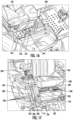
- FIG. 2 illustrates a portion of the tube 156 in accordance with another embodiment.
- the bagging system 150 includes a boost system 168 .
- the boost system 168 can include an air inlet 170 and a tube 172 .
- the tube 172 can fluidly couple the air inlet 170 to another portion of the bagging system 150 , such as the tube 156 .
- a filter (or screen) 174 may be disposed at or near the air inlet 170 to prevent ingress of large debris into the boost system 168 .
- the filter 174 can include a plurality of baffles, fabric, a woven or non-woven mesh, a porous substrate, another suitable filter material, or any combination thereof.
- the boost system 168 can be coupled to the lawnmower 100 .
- the boost system 168 can be coupled with the tube 156 , with the bagger 152 , with the frame 104 , with the mower deck 114 , or with another part of the lawnmower 100 .
- the boost system 168 can have a rigid construction.
- the boost system 168 can be formed from a hard-shelled material.
- at least a portion of the boost system 168 can be flexible.
- the tube 172 can include a flexible material. The flexible tube 172 can be suspended from or connected to any portion of the bagging system 150 .
- the boost system 168 can include a motive device, such as a motor coupled to an air biasing element, such as a fan, to propel airflow from the air inlet 170 to the bagger 152 .
- the motive device is disposed within an enlarged portion 176 of the tube 172 .
- a motor can be mounted to an internal aspect of the tube 172 .
- a fan blade can be coupled to an output shaft of the motor. As the motor rotates, the fan blade can generate airflow through the tube 172 in a direction toward the tube 156 .
- the motive device can be disposed in a separate element, i.e., not part of the enlarged portion 176 of the tube 172 , or operate using a different principle of operation.
- the motive device can be powered by one or more batteries of the lawnmower 100 .
- the motive device can be powered by one or more batteries of the lawnmower 100 configured to propel the lawnmower 100 or drive the cutting implement(s).
- a flow rate of air through the tube 156 is generally controlled by the cutting implement 134 ( FIG. 30 ). As the cutting implement 134 rotates, airflow is generated which propels debris and clippings out of the discharge chute 154 , up the tube 156 to the bagger 152 . As the cutting implement 134 rotates faster, the flow rate of air generally increases. Thus, actual flow rate is a result of the cutting implement 134 .
- the boost system 168 may change (e.g., increase) the actual flow rate of the air as compared to normal operating conditions, i.e., airflow generated by the cutting implement 134 , or even alter a flow characteristic of the air as compared to normal operating conditions.
- the boost system 168 can provide additional force to displace debris from the discharge chute 154 to the bagger 152 . This may be particularly advantageous when using the lawnmower 100 in areas with large amounts of debris, or when mowing in wet or otherwise difficult conditions where the airflow generated by the cutting implement(s) 134 is insufficient to propel the debris to the bagger 152 .
- the boost system 168 can also adjust the flow characteristics of the air, e.g., the air passing through the tube 156 .
- the cutting implement 134 can generate turbulent airflow within the tube 156 . Turbulent air can reduce the flow rate of air through the tube 156 , creating clogging situations.
- Using the boost system 168 can adjust the flow characteristic, e.g., smooth out the turbulence created by the cutting implement 134 , to create better performance.
- the boost system 168 may be selectively controlled by the operator.
- the operator may, for example, turn on and turn off the boost system 168 to selectively generate additional airflow within the boost system 168 .
- the boost system 168 may be particularly useful during heavy duty operations, like when picking up leaves or when the ground is wet, but unnecessary during light duty operations or when the lawnmower 100 is not actively utilizing the bagging system 150 .
- the operator may disengage the motive device, thereby terminating the increased airflow rate within the tube 156 .
- the boost system 168 can be disengaged using a variety of methods.
- the boost system 168 may be controlled by a user interface disposed in a cockpit area of the lawnmower (i.e., within arms reach when seated).
- the user interface may be part of the display described in greater detail hereinafter.
- the boost system 168 may be controlled at a location defined by the boost system 168 , e.g., at a location along the tube 172 .
- the tube 172 can include an ON/OFF switch.
- the boost system 168 may be controlled using an interface located at another location along the tube 156 , such as at the adjustment element 166 ( FIG. 1 ).
- the boost system 168 can be controllable between an ON mode and an OFF mode.
- the boost system 168 can be toggled between the ON and OFF modes using a switch.
- the boost system 168 can be adjustable such that the operator can selectively adjust an operating speed of the boost system 168 , and more particularly, an operating speed of the motive device of the boost system 168 .
- Adjustment of the operating speed of the boost system 168 may be finite or infinitely adjustable. Finite adjustment of the operating speed can include, e.g., a plurality of preset speed settings at which the boost system 168 can operate.
- the boost system 168 can have a LOW setting, a MEDIUM setting, and a HIGH setting.
- the operator can select between the plurality of preset speed settings. Infinite adjustment of the operating speed can include, e.g., a range of speeds over which the operator can select any speed within. For instance, the operator can move a speed controller (e.g., a dial, a lever, or a digital indicator) to any location within a predefined range to selectively control the boost system 168 .
- a speed controller e.g., a dial, a lever, or a digital indicator
- the boost system 168 can include one or more operating modes. As previously described, these operating modes can include an ON mode, an OFF mode, and a variable speed mode. By way of further example, the operating modes can further include a time limited mode or a motor load feedback mode. In the time limited mode, the boost system 168 can remain at a prescribed operating parameter for a set duration of time. In the motor load feedback mode the boost system 168 can increase the rate of airflow in response to the load on the motor, e.g., the current draw of the motor.
- the lawnmower 100 may be configured to automatically control the boost system 168 in view of a detected mowing operation being performed.
- the boost system 168 may automatically turn on in response to a detected condition. For instance, the boost system 168 may automatically turn on when a detected air flow rate within the tube 156 is below a threshold level. By way of another example, the boost system 168 may automatically turn on when a detected moisture content of debris is above a threshold level. In certain instances, the boost system 168 may generate a suggestion to the operator to turn on the boost system 168 . For example, a message can be displayed to the operator on a display described in greater detail below.
- the boost system 168 further includes an internal valve (not illustrated) which selectively opens and closes the tube 172 .
- the tube 172 can be in fluid communication with the tube 156 .
- the valve is closed, the tube 172 is no longer in fluid communication with the tube 156 . It may be desirable to close the valve when the boost system 168 is not actively in use. In certain instances, closing of the valve can occur automatically (e.g., in response to the boost system 168 being inactive). In other instances, the valve can be closed manually.
- the boost system 168 can be used as a suction conduit for other actions, such as leaf pickup.
- utilization of the boost system 168 for leaf pickup can include coupling the air inlet 170 with a hose.
- the motive device of the boost system 168 can be initiated and the hose can then be moved around as necessary to pick up leaves.
- the boost system 168 is detachably coupled to the lawnmower 100 .
- the boost system 168 can be detachably coupled to the tube 156 , the bagger 152 , the mower deck 114 , or the frame 104 .
- the operator can thus save on weight and lateral (width) requirements by removing the boost system 168 when not in use.
- the boost system 168 , or a portion thereof can be repositioned or rearranged when not in use, e.g., the boost system 168 can collapse at one or more pleats, fold, hinge, roll up, disassemble, nest, or the like.
- the boost system 168 can be powered by a main power source of the lawnmower 100 .
- the boost system 168 can be powered by one or more batteries of the lawnmower 100 .
- the boost system 168 automatically connect to the one or more batteries of the lawnmower 100 when the boost system 168 is positioned on the lawnmower 100 .
- the boost system 168 can include a plug which automatically interfaces with a socket of the lawnmower 100 when the boost system 168 is properly installed on the lawnmower 100 .
- the operator can manually couple the boost system 168 with the one or more batteries of the lawnmower 100 .
- the boost system 168 can receive power in addition, or alternatively, using a separate power source, i.e., not from the one or more batteries of the lawnmower 100 .
- the boost system 168 may include an integrated or removable power source, e.g., an integrated or removable battery.
- the bagger 152 can be disposed at the rear end 108 of the lawnmower 100 , e.g., behind the seat 102 .
- the bagger 152 can generally include a support structure 178 configured to engage with the lawnmower 100 , e.g., the frame 104 of the lawnmower 100 , and support one or more bags 180 of the bagger 152 relative to the lawnmower 100 .
- the bags 180 can be flexible ( FIG. 3 ). In other instances, the bags 180 can be relatively rigid ( FIG. 1 ).
- the term “bag” as used with respect to bags 180 is intended to refer to a vessel defining a volume configured to receive debris and clippings from the discharge chute 154 of the mower deck 114 .
- the support structure 178 can be integrated into the one or more bags 180 like as shown in FIG. 1 .
- the support structure 178 and one or more bags 180 may be integral with one another, e.g., formed from a rigid plastic.
- the support structure 178 can include a relatively rigid structure which retains one or more flexible bags 180 like as shown in FIG. 3 .
- the bagger 152 can further include a cover 182 configured to cover the one or more bags 180 and prevent egress of debris therefrom.
- the cover 182 can define the opening 158 in communication with the tube 156 .
- the opening 158 can be part of another portion of the bagger 152 .
- the bags 180 can include handles.
- the handles include a first type of handles 184 (e.g., for handling the bags 180 in an upright position) and a second type of handles 186 (e.g., for handling the bags 180 in an upside down or emptying position).
- FIG. 4 illustrates a partial view of the bagger 152 in accordance with another embodiment.
- the bagger 152 includes a frame 188 which defines a volume 190 .
- the volume 190 can be further defined by one or more sidewalls 192 , as seen in FIG. 5 .
- the sidewalls 192 can include one or more sections, such as one section, two sections, three sections, four sections, or the like.
- the sidewalls 192 can be joined together to enclose the volume 190 .
- the bagger 152 can further include a door 194 .
- the door 194 is disposed at a bottom end 196 of the bagger 152 .
- the door 194 can be moveable with respect to the frame 188 .
- the door 194 can be hinged relative to the frame 188 .
- the door 194 includes a single piece.
- the door 194 can include two or more components which together selectively close the volume 190 .
- the operator can open the door 194 using a release, e.g., a release lever 198 .
- the release lever 198 is disposed at an upper end 200 of the bagger 152 .
- the release lever 198 depicted includes a rigid structure.
- the release can include a wireless release mechanism; a wired release mechanism including, e.g., a cable; or another type of selectively actuatable release mechanism.
- the release lever 198 can extend forward from the bagger 152 toward the front end 106 of the lawnmower 100 so as to be accessible by the operator when seated in the cockpit of the lawnmower 100 .
- an interference piece e.g., a catch
- the door 194 can open under its own weight.
- the door 194 can be coupled to a mechanism configured to reduce the speed at which the door 194 opens.
- the door 194 can be linked to the frame 188 through one or more hydraulic actuators, threaded rod actuators, or the like.
- the operator can close the door 194 by, e.g., returning the release lever 198 to its original (closed) position, manually rotating (e.g., lifting) the door 194 to the closed position, using a motor or other motive device to drive the door 194 to the closed position, another suitable method, or any combination thereof.
- the release lever 198 can be replaced by a cable which the operator can access to release the door 194 .
- Yet other operational methods are contemplated herein.
- the door 194 can be angled relative to the underlying ground surface. That is, the door 194 can be angularly offset from a horizontal plane when the lawnmower 100 is resting on a horizontal surface with the door 194 in the closed position. This angular offset from the horizontal plane can be in a range between 1° and 89°, such as in a range between 10° and 75°, such as in a range between 30° and 60°. Angularly offsetting the door 194 from horizontal can allow the lawnmower 100 to traverse heavily undulating surfaces or potholes which might cause the lawnmower 100 to pitch upward, whereby the bagger 152 becomes displaced downward, towards the underlying ground surface.
- the exemplary frame 188 depicted in FIG. 4 includes a plurality of interconnected tubes.
- the tubes define a static portion 202 which remains relatively static with respect to the lawnmower 100 and a dynamic portion 204 which is linked with the release lever 198 and the door 194 . Pushing the release lever 198 causes the door 194 to open.
- the frame 188 may be collapsible, e.g., for easy storage or transportation.
- the frame 188 may be assembled with quick connect interfaces, e.g., bayonet connections, twist-lock connections, threaded connections, pinned connections, or the like. Disassembling enough of the quick connect interfaces can allow the remaining portions of the frame 188 to remain coupled together during storage. When stowed, the frame 188 may lay flat to save space.
- the bagger 152 can be coupled to the lawnmower 100 through an interface.
- coupled with the static portion 202 can be an interface configured to couple the bagger 152 to the lawnmower 100 .
- the interface depicted in FIG. 4 includes a hook 206 configured to interface with a rail 208 ( FIG. 1 ) of the lawnmower 100 and a linkage 210 configured to interface with a hitch 212 ( FIG. 18 ) disposed at the rear end 108 of the lawnmower 100 .
- the linkage 210 can be removably coupled to the hitch 212 .
- the linkage 210 can include a flange which is supported by a flange of the hitch 212 . Aligned openings in the two flanges can be coupled together by one or more fasteners (e.g., threaded or non-threaded fasteners) to connect the bagger 152 to the lawnmower 100 .
- FIG. 6 depicts the bagger 152 in accordance with another embodiment of the present disclosure.
- the bagger 152 includes different static and dynamic portions 202 and 204 as compared to the bagger 152 illustrated in FIG. 4 .
- the release lever 198 depicted in FIG. 6 is coupled with a cross bar 214 of the bagger 152 .
- the door 196 FIG. 7
- the door 196 FIG. 7
- the frame 188 of the bagger 152 depicted in FIG. 6 can include a portion 216 which is angularly offset from a horizontal plane when the lawnmower 100 is resting on a horizontal surface.
- the angle of the portion 216 may permit the door 196 to move past the frame 188 without contacting the frame 188 when the operator actuates the release lever 198 .
- the door 196 can generally take a path depicted by arrow 218 when moving from the closed position (as shown) to the open position (not shown).
- the door 196 can be maintained in the closed position (as shown) through one or more couplers 220 .
- at least one of the couplers 220 can include a manual release mechanism, such as a latch.
- at least one of the couplers 220 can include a quick release mechanism, such as, e.g., a magnet.
- FIG. 7 illustrates an enlarged view of a portion of FIG. 6 as seen in Circle A.
- the coupler 220 depicted in FIG. 7 is a magnetic coupler including a magnet 222 ( FIG. 8 ) and a support structure 224 coupling the magnet to the frame 188 .
- the support structure 224 can be coupled to the frame 188 through one or more welded connections.
- the support structure 224 can be coupled to the frame 188 using fasteners (e.g., threaded or non-threaded fasteners), clamps, cables, ties, adhesive, or the like.
- the magnet 222 can have a body 226 defining a generally cylindrical shape with a frustoconical recess 228 disposed on a flat end 230 of the body 226 .
- a hole 232 can extend between the frustoconical recess 228 and the other flat end 234 of the body 226 .
- a fastener e.g., a threaded fastener 236 , can pass through the hole 232 and couple the magnet 222 to the support structure 224 .
- Other arrangements and configurations of the coupler 220 are possible. The disclosure herein is not intended to be limited to the exemplary configuration described above.
- the coupler 220 can include a soft portion 238 , such as a portion including a rubber material.
- the soft portion 238 can be disposed between the door 196 ( FIG. 7 ) and the magnet 222 to soften the interface therebetween and prevent the door 196 from colliding with the magnet 222 and potentially damaging the magnet 222 , the door 196 , or both.
- the soft portion 238 can also be disposed between the magnet 222 and the support structure 224 .
- FIG. 9 illustrates a top view of the bagger 152 in accordance with an embodiment.
- the bagger 152 can include a plurality of coupling points 240 configured to couple the bag 180 to the frame 188 .
- the coupling points 240 can be configured for quick connect and quick disconnect.
- the coupling points 240 can include snaps, where each snap is split into two pieces, with one of the pieces coupled to the bag 180 and the other of the two pieces coupled with the frame 188 (or a portion coupled therewith).
- the bag 180 can be quickly configured by the operator using the snaps.
- the coupling points 240 can be covered, e.g., by a sheet of material. The sheet of material can keep the coupling points 240 clean and free of debris. The sheet of material may also increase resistance against debris escaping from the bagger 152 through the coupling points 240 .
- the cockpit of the lawnmower 100 can include a user interface 242 which allows the operator to pilot the lawnmower 100 .
- the user interface 242 is discussed in greater detail hereinafter.
- the user interface 242 is disposed on a first side of the seat 102 .
- a first armrest 244 can be disposed on the first side of the seat 102 .
- a second armrest 246 can be disposed on a second side of the seat 102 , the second side of the seat 102 being opposite the first side.
- the first and second armrests 244 and 246 can have different characteristics or operational capacities. For instance, the first and second armrests 244 and 246 can have different degrees of operational freedom.
- the first armrest 244 may be pivotable relative to the seat 102 or static relative to the seat 102 while the second armrest 246 can pivot relative to the seat 102 and extend relative to the seat 102 .
- the second armrest 246 (on the lateral side of the seat 102 opposite the user interface 242 ) may be more adjustable (or have more degrees of operational freedom) than the first armrest 244 .
- the user interface 242 can include a joystick 248 defined by a handle 250 extending from a boot 252 .
- the boot 252 may be sealed relative to at least one of the joystick 248 or handle 250 to prevent ingress of debris into the components of the user interface 242 .
- the user interface 242 is depicted on a right lateral side of the seat 102 , in another embodiment, the user interface 242 can be disposed at a different location within the cockpit, such as on a left lateral side of the seat 102 . In one or more embodiments, the user interface 242 can be swappable between the left and right lateral sides of the lawnmower 100 .
- FIGS. 10 and 11 illustrate views of a user interface 242 in accordance with an exemplary embodiment of the present disclosure.
- the user interface 242 is coupled to a portion of the frame 104 through one or more supports 254 .
- the supports 254 may be integral with the frame 104 or coupled therewith.
- the handle 250 can be coupled to a lever 256 .
- the lever 256 can extend from the handle 250 to a base 258 .
- the base 258 can define an opening 260 into which the lever 256 can extend into.
- the sidewall of the opening 260 can define a maximum displacement distance of the lever 256 . That is, the lever 256 can be moved relative to the opening 260 up to the sidewall thereof.
- the sidewall of the opening 260 may define the outer perimeter of lever 256 movement.
- the base 258 can define an internal area 262 that receives the lever 256 .
- a detection system 264 can detect relative movement of the lever 256 .
- the detection system 264 can be disposed at least partially within the internal area 262 of the base 258 .
- the detection system 264 can be disposed entirely within the internal area 262 of the base 258 .
- the detection system 264 can generally include components configured to detect relative movement of the joystick 248 .
- the components may include any one or more of contact sensors, gimbals, gyroscopes, hall effect sensors, visual sensors, orientation sensors, electro-mechanical sensors, micro-electro-mechanical sensors (MEMS), or the like.
- the detection system 264 and more particularly one or more components thereof, may be in communication with a processing device (not illustrated) of the lawnmower 100 .
- the processing device can be configured to receive information from the detection system 264 .
- the processing device can utilize the received information to control the lawnmower 100 as described in greater detail hereinafter.
- the joystick 248 may experience one or more forces which are transferred to the operator. This can result in a subjectively rough riding experience.
- the user interface 242 may further include one or more dampeners 266 which are configured to dampen the transfer of forces to the operator.
- the one or more dampeners 266 include four dampeners 266 .
- the dampeners 266 can be spaced apart from one another about the joystick 248 .
- the dampeners 266 can be equally spaced apart, or generally equally spaced apart, from one another.
- the dampeners 266 can all comprise a same type of dampener. In another embodiment, at least one of the dampeners 266 can comprise a different type of dampener as compared to the other dampeners 266 .
- the dampeners 266 can be hydraulic dampeners, electrical dampeners, magnetic dampeners, mechanical dampeners (e.g., rubber spacers), or the like.
- the dampeners 266 are all hydraulic dampeners, including a cylindrical bore 268 configured to receive a piston coupled with a shaft 270 .
- the cylindrical bore 268 can be at least partially filled with a compressible fluid, such as a gas.
- the piston can move within the cylindrical bore 268 which effectively dampens the transfer of force to the operator.
- the dampeners 266 can be controlled by the lawnmower 100 (e.g., by a processing device of the lawnmower 100 ) to maintain a smooth joystick 248 experience.
- the dampeners 266 can include rod ends 272 which couple the shafts 270 of the dampeners 266 with the frame 104 .
- the shafts 270 can be directly coupled to the frame 104 through the rod ends 272 .
- the shafts 270 can be indirectly coupled to the frame 104 .
- Rod ends 274 can couple the cylindrical bores 268 to the joystick 248 . It should be understood that the inverse arrangement is also possible, i.e., the rod ends 272 couple the cylindrical bores 268 to the frame 104 and the rod ends 274 couple the shafts 270 to the joystick 248 .
- the dampeners 266 can be indirectly coupled to the joystick 248 .
- the dampeners 266 may be coupled to the joystick 248 through one or more intermediary members 276 .
- two dampeners 266 are coupled to each one of the intermediary members 276 .
- a first set of dampeners 266 is disposed on the forward end of the joystick 248 and a second set of dampeners 266 is disposed on the rear end of the joystick 248 .
- the intermediary members 276 are coupled together through an interfacing component 278 which is coupled to the joystick 248 .
- FIG. 11 shows another view of the user interface 242 .
- the dampeners 266 are depicted along with the rear end intermediary member 276 . As the operator moves over rough terrain, the dampeners 266 can each operate independently, together, or partially together to dampen the joystick 248 and thereby reduce transfer of force to the operator.
- the joystick 248 depicted in FIG. 11 includes an interface 280 formed between two portions 282 and 284 of the lever 256 .
- the interface 280 can be adjustable to allow for movement between the two portions 282 and 284 .
- the height of the joystick 248 can be adjusted to suit an operator's desired needs.
- the interface 280 is selectively opened to permit movement between the two portions 282 and 284 .
- the movement can include at least translational movement. In some instances, the movement can also include rotational movement. In other instances, rotational movement between the two portions 282 and 284 can be prevented, e.g., by a keyed interface between the two portions 282 and 284 .
- the keyed interface can include, for example, a slot (or other similar recessed feature) disposed on one of the two portions 282 and 284 and a rail (or other similar projecting feature) disposed on the other of the two portions 282 and 284 .
- the second portion 284 can remain at a relatively fixed location with respect to the base 258 while the first portion 282 can be moved relative to the base 258 .
- the first portion 282 can be interchangeable. The first portion 282 can thus be selected from a plurality of first portions each having any one or more of different designs, different sizes, different colors, different textures, or the like.
- the user interface 242 can replace traditional lap bars, steering wheels, and foot pedal steering implements used in traditional lawnmowers.
- the user interface 242 and more particularly the joystick 248 , can steer the lawnmower 100 and provide throttle for moving the lawnmower 100 .
- the joystick 248 may be configured to move about one or more of a yaw axis 286 , a roll axis 288 , and a pitch axis 290 ( FIG. 11 ).
- the joystick 248 can move about all three axis.
- the joystick 248 may be able to pivot about one or more of the three axis and translate along at least one of the three axis.
- the joystick 248 can be self-centering. That is, the joystick 248 can self-return to a central position, e.g., the center of the opening 260 , when the operator releases the joystick 248 .
- the joystick 248 can be biased to a home position at the center of the opening 260 by one or more biasing elements, e.g., springs, hydraulics, or even dampeners 266 .
- the position of the joystick 248 can be detected by the detection system 264 .
- the detection system 264 may detect displacement of the joystick 248 about any one or more of the yaw axis 286 , the roll axis 288 , and the pitch axis 290 .
- the detected displacement may be measured relative to the position of the joystick 248 at the home position, i.e., unbiased and static.
- the relative amount of displacement detected along each of the active axes can inform a particular portion of a mixing algorithm which controls the walking element.
- the mixing algorithm may be executed by a processing device of the lawnmower 100 .
- the processing device can be electrically coupled with a memory device which stores an executable program to perform the mixing algorithm.
- the mixing algorithm can include only a single mixing algorithm.
- the single mixing algorithm may be used to operate the lawnmower 100 during every use.
- the mixing algorithm can include a plurality of different mixing algorithms. Each mixing algorithm can have different properties or attributes which allow for the same detected displacement to result in different operational (e.g., movement) outcomes.
- the operator may be able to switch between the mixing algorithms.
- the processing device may automatically switch between the mixing algorithms, e.g., in response to a changing environmental condition. For example, when wet surfaces are detected, the lawnmower 100 may utilize a first mixing algorithm which causes slower acceleration. When dry surfaces are detected, the lawnmower 100 may utilize a second mixing algorithm which allows faster acceleration with the same amount of detected displacement.
- the joystick 248 can exhibit detected displacement about both the pitch and roll axis 288 and 290 . Movement may be prohibited about the yaw axis 286 or, if the joystick 248 can move about the yaw axis 286 , not detected.
- the first mixing algorithm can output a direction as a result of detected displacement about the roll axis 288 and a throttle response as a result of detected displacement about the pitch axis 290 .
- Clockwise movement about the roll axis 288 can turn the lawnmower 100 right while counterclockwise movement about the roll axis 288 turns the lawnmower 100 left.
- Forward movement about the pitch axis 290 can move the lawnmower 100 forward while rearward movement about the pitch axis 290 can move the lawnmower 100 backwards.
- steering is performed by rotating the joystick 248 about the yaw axis 286 while throttle response is a result of displacing the joystick 248 about the pitch axis 290 .
- the directions of displacement of the joystick 248 and the resulting movement of the lawnmower 100 may be inverted from the above descriptions.
- the operator may be able to select between a normal mode and an inverse mode, where the inverse mode results in the opposite outcome of the normal mode for any one or more given displacement(s) of the joystick 248 .
- the joystick 248 may be translatable along at least one of the yaw, roll, and pitch axis 286 , 288 and 290 .
- the joystick 248 may be translatable along the yaw axis 286 .
- the yaw axis 286 is parallel with the joystick 248 .
- translating the joystick 248 along the yaw axis 286 can result in moving the joystick 248 into and out of the base 258 .
- translating the joystick 248 along the yaw axis 286 can change an operating mode of the lawnmower 100 between a drive mode, a park mode, an accessory mode, a bagger mode, or the like.
- moving the joystick 248 along the yaw axis 286 into the base 258 can change the operating mode of the lawnmower 100 .
- moving the joystick 248 along the yaw axis 286 e.g., toward the base 258
- moving the joystick 248 along the yaw axis 286 out of the base 258 can change the operating mode to drive.
- the pedal 127 FIG. 1
- depressing the pedal 127 may brake the lawnmower 100 while moving the joystick 248 along the yaw axis 286 can cause the lawnmower 100 to change to a parked mode.
- Translation of the joystick 248 along the yaw axis 286 may be prohibited until the lawnmower 100 reaches a complete, or nearly complete, stop.
- the pedal 127 and joystick 248 can be used in lieu of one another to perform similar functions.
- the operator can change the operating mode to park using either one of the pedal 127 or joystick 248 .
- pedal 127 may be particularly useful to utilize the pedal 127 to park the lawnmower 100 if, e.g., the operator is using their hands to perform an operation and does not have readily available access to the joystick 248 .
- the pedal 127 may be omitted or perform a different function from the joystick 248 .
- the joystick 248 can be used to perform yet further functions not described herein.
- the lawnmower can further include a human machine interface (HMI) 292 different from the user interface 242 .
- the HMI 292 may be positioned in a location accessible to the user while seated in seat 102 .
- an HMI 292 may be positioned adjacent to either of armrest 244 , 246 .
- the HMI 292 may both convey information to the operator and receive inputs from the operator.
- the HMI 292 can include a display 294 .
- the display 294 can be a light-emitting diode (LED) display, an organic light-emitting diode (OLED) display, an electroluminescent display (ELD), a plasma display panel (PDP), a liquid crystal display (LCD), a digital light processing (DLP) display, or the like.
- the display 294 can receive electrical power from one or more batteries of the lawnmower 100 .
- the display 294 may automatically turn on when the lawnmower 100 is initiated or used. In other embodiments, the operator can selectively turn on and off the display 294 .
- the display 294 can display information to the operator.
- the information can include, for example, a status of the battery 296 (e.g., strength of charge), a headlight indicator 298 , a bluetooth indicator 300 , an operational indicator 302 (e.g., displaying drive or park), a cutting implement speed gauge 304 , a wheel speed gauge 306 , and the like.
- the display 294 can toggle between a plurality of screens, with each screen depicted a different type of information or a different arrangement of information.
- FIGS. 14 and 15 depict two exemplary screens 1400 and 1500 which may be shown on the display 294 .
- the screen 1400 depicted in FIG. 14 shows the remaining level of charge (RLOC) of the lawnmower's batteries, described in greater detail below.
- RLOC may be displayed as a number (e.g., a percentage of remaining charge or a time remaining) or a graphic (e.g., a plurality of lit and unlit bars).
- the screen 1500 depicted in FIG. 15 shows a Next Blade Check indicator which counts down a number of run-time hours of time until the cutting implement, e.g., blade, should be checked for wear, damage, or the like.
- the screen 1500 further displays an instruction to the operator regarding how to reset the Next Blade Check indicator to, e.g., a factory default setting or a customizable amount of time.
- the HMI 292 can further include a plurality of buttons 308 disposed adjacent to the display 294 .
- the buttons 308 may be configured to adjust one or more characteristics or attributes of the lawnmower 100 .
- one of the buttons 308 can allow the operator to select between two or more ride modes (e.g., eco, light duty, and heavy duty).
- Another button 308 may activate or deactivate one or more lights (not illustrated) of the lawnmower 100 .
- the lights may include any one or more of headlights, tail lights, underbody lights, accessory lights, backlights, or the like.
- Another button 308 can allow the operator to select between two or more mowing modes (e.g., eco, light duty, and heavy duty).
- Another button 308 can activate and deactivate a wireless communication transceiver, such as Bluetooth (which may, for example, permit the HMI 292 to communicate with a corresponding application on a handheld electronic device such as a smartphone, tablet, smartwatch, or the like).
- Another button 308 can activate and deactivate one or more auxiliary ports of the lawnmower 100 , each auxiliary port being configured to be coupled with one or more accessories for use with the lawnmower 100 .
- Yet further buttons 308 with additional functionality may be provided.
- the HMI 292 can include one or more ergonomic features which position the operator in a better position when using the lawnmower 100 .
- the ergonomic feature is a palm rest 310 disposed adjacent to the buttons 308 .
- the palm rest 310 can support the operator's wrist when mowing.
- the palm rest 310 can include a non-slip material, a soft material, a water wicking material, or another material which provides an advantage to the operator.
- Other ergonomic features can include wrist pads, padded armrests, and the like.
- the HMI 292 can further include an interface area 314 having controls associated with one or more functional aspects of the lawnmower 100 .
- the controls can include, for example, an emergency stop button 312 , a key 316 , and an accessory port 318 (e.g., a charging port).
- the interface area 314 can be disposed on one side of the seat 102 and the display 294 can be disposed on the opposite side of the seat 102 .
- the operator can utilize both hands to control different features of the lawnmower 100 .
- the features of the interface area 314 can relate to a first type of lawnmower 100 control while the features of the display 294 can relate to a second type of lawnmower 100 control different from the first type.
- the mower deck 114 may be adjustable, e.g., height adjustable. In this regard, the operator can selectively adjust the mower deck 114 to achieve a desired operating characteristic.
- FIG. 17 illustrates an exemplary height adjustment mechanism 320 for adjusting the height of the mower deck 114 .
- the height adjustment mechanism 320 can be operably coupled to the mower deck 114 such that adjusting the height adjustment mechanism 320 changes the operational height of the mower deck 114 .
- the height adjustment mechanism 320 can include a handle 322 which is accessible to the operator.
- the handle 322 can extend through an interface 324 including a plurality of stop locations 326 each associated with a different operational height of the mower deck 114 .
- each stop location 326 can be in the form of a notch configured to selectively receive the handle 322 (or a portion thereof).
- a channel 328 can extend between two or more stop locations 326 to operationally connect the stop locations together.
- the operator To adjust the operational height of the mower deck 114 , the operator first removes the handle 322 from one of the stop locations 326 to the channel 328 . Once in the channel 328 and clear of the previous stop location 326 , the operator can translate the handle 322 to another stop location 326 . Once the mower deck 114 is at a desired height, the operator can move the handle 322 into a corresponding stop location 326 associated with the desired height.
- the handle 322 can be coupled with the mower deck 114 through one or more components, such as component 330 .
- the component 330 can dynamically couple the handle 322 to the mower deck 114 , e.g., through a dynamic interface 332 .
- the 17 includes a pin and slot interface where the component 330 extends into a slot of the mower deck 114 .
- the component 330 can translate within the slot, e.g., when the mower deck 114 contacts the underlying ground surface, to prevent the height adjustment mechanism 320 from becoming disengaged, e.g., the handle 322 disengaging from the selected stop location 326 .
- the height adjustment mechanism 320 can be formed at least in part by the fairing 144 .
- one or more (such as all) of the stop locations 326 can be defined at least in part by the fairing 144 .
- the fairing 144 can support the height adjustment mechanism 320 .
- the fairing 144 may be bolstered by one or more support elements to prevent the fairing 144 from breaking under load.
- the height adjustment mechanism 320 can be disposed on a same side of the seat 102 as the joystick 248 . In another embodiment, the height adjustment mechanism 320 can be disposed at another location, such as on the opposite side of the seat 102 as compared to the joystick 248 , at a central location of the lawnmower 100 (e.g., in front of the seat 102 ), or at another suitable location.
- the seat 102 can be adjustably coupled to the frame 104 such that the seat 102 can be moved between a plurality of different positions.
- Exemplary adjustments include translating the seat 102 in at least one of a forward/back or lateral direction, raising and lowering the seat, tilting the seat about a laterally extending axis, or even twisting the seat about a vertically extending axis.
- the seat 102 may be adjustable in the height direction.
- a seat height adjustment mechanism 334 can allow the operator to selectively adjust the height of the seat 102 .
- the seat height adjustment mechanism 334 can include a rotary knob 336 which the operator can selectively rotate to change seat height.
- Other seat height adjustment mechanisms 334 can include levers, buttons, cranks, or the like.
- seat height adjustment may be made manually, i.e., the operator imparts force onto the knob 336 .
- seat height adjustment may be at least partially assisted, e.g., by a motor, actuator, or the like.
- height adjustment of the seat height adjustment mechanism 334 can occur between a plurality of preset locations.
- height adjustment can be infinitely adjustable over a range between the minimum height of the seat 102 and the maximum height of the seat 102 .
- the seat 102 may also be adjustable in a forward/back direction.
- the lawnmower 100 may include a seat translation adjustment mechanism 338 . Using the seat translation adjustment mechanism 338 , the operator may be able to translate the seat 102 in the forward and backward directions.
- At least one of the seat height adjustment mechanism 334 and seat translation adjustment mechanism 338 can be at least partially disposed within a protected, or semi-protected, portion of the lawnmower 100 .
- a skirt 340 may extend over the at least one of the seat height adjustment mechanism 334 and seat translation adjustment mechanism 338 .
- the skirt 340 may include an expandable or otherwise dynamic area, such as one or more pleats, which allow the skirt 340 to accept movement of the seat 102 relative to the frame 104 without damaging the skirt 340 .
- FIG. 18 illustrates a rear perspective view of the lawnmower 100 in accordance with an embodiment.
- the bagging system 150 ( FIG. 1 ) is removed.
- a storage area 342 Disposed behind the seat 102 is a storage area 342 defining a volume configured to receive accessories, other yard equipment, or the like.
- the storage area 342 can be disposed along a centerline 344 of the lawnmower 100 .
- the storage area 342 can be defined at least in part by the fairing 144 .
- the fairing 144 can define a structural portion of the storage area 342 , e.g., a structural wall, which can include one or more integrated interfaces 346 . It should be understood that the interfaces 346 may be formed separately from the fairing 144 rather than be integrated into the fairing 144 .
- the integrated interfaces 346 can provide connection points for receiving one or more objects.
- An exemplary object is a divider 348 , such as depicted in FIG. 19 .
- the depicted dividers 348 are pieces of lumber (e.g., 2 ⁇ 4 lumbar). Other divider materials can include, for example, plastic, metal, alloy, or the like.
- the dividers 348 can be supported by the integrated interfaces 346 . The operator can utilize one or more dividers 348 to subdivide the volume of the storage area 342 into two or more segments.
- Another exemplary object is a bin or storage element (not shown) which the operator can selectively install in the storage area 342 , e.g., using the integrated interfaces 346 for support.
- the bagger 152 itself.
- the bagger 152 can include an interface configured to engage with the integrated interfaces 346 . The operator can thus install the bagger 152 on the lawnmower 100 by inserting the interface of the bagger 152 into the integrated interfaces 346 . When not using the bagger 152 , the operator can remove the interface of the bagger 152 from the integrated interfaces 346 , which may optionally then be utilized for a different functionality (e.g., used with dividers 348 ).
- the storage area 342 can overlay one or more batteries of the lawnmower 100 .
- a cover 350 can be disposed between the one or more batteries and the storage area 342 .
- the cover 350 may form a waterproof interface with one or more other surfaces of the lawnmower 100 so as to seal a battery receiving area which houses the one or more batteries.
- the cover 350 may be moveable between an open position and a closed position (as shown in FIG. 18 ). In certain instances, the cover 350 can slide to move between the open and closed positions. In other instances, the cover 350 can rotate between the open and closed positions.
- the cover 350 can be hingedly attached to the lawnmower 100 at a location behind the seat 102 and pivot about a horizontally extending axis. In an embodiment, the cover 350 automatically closes when released by the operator. In another embodiment, the cover 350 can remain open when released by the operator. With the cover 350 in the open position, the operator can access the one or more batteries described below.
- FIG. 20 illustrates a top view of a rear portion of the lawnmower 100 with the cover 350 removed to show a first battery receiving area 352 which is at least partially disposed below at least a portion of the storage area 342 .
- the first battery receiving area 352 can overlap the centerline 344 of the lawnmower 100 .
- the first battery receiving area 352 can be configured to receive a plurality of first batteries 354 , such as at least two first batteries 354 , such as at least three first batteries 354 , such as at least four first batteries 354 .
- Each one of the first batteries 354 can be received in a separate compartment 356 of the first battery receiving area 352 .
- the compartments 356 can be stacked adjacent to one another in a direction along the centerline 344 with major surfaces of the first batteries 354 disposed adjacent to one another. Adjacent compartments 356 can be spaced apart by one or more walls 358 extending through the first battery receiving area 352 .
- the first battery receiving area 352 can include a lock 360 which can be selectively moved between a locked state and an unlocked state.
- the lock 360 can include a rotatable knob which selectively rotates to permit one or more of the first batteries 354 to move relative to the compartments 356 .
- each of the first batteries 354 can include a discrete lock 360 .
- at least one of the locks 360 can selectively lock and unlock two or more of the first batteries 354 .
- the compartments 356 extend downward into the lawnmower 100 along a vertical axis. That is, the compartments 356 have vertical centerlines that are parallel with the vertical axis.
- the compartments 356 are angularly offset, i.e., canted, relative to the vertical axis by an angular displacement.
- the angular displacement can be at least 10° relative to the vertical axis, such as at least 20° relative to the vertical axis, such as at least 30° relative to the vertical axis, such as at least 40° relative to the vertical axis.
- the compartments 356 can cant away from the seat 102 or to either lateral side of the lawnmower 100 .
- the first batteries 354 canted away from the seat 102 , i.e., toward the rear end 108 of the lawnmower 100 , or to either side of the lawnmower 100 , information provided by the first batteries 354 (e.g., on one or more displays of the first batteries) may be more easily viewed by the operator when standing next to the lawnmower 100 .
- the lawnmower 100 can further include a plurality of second batteries 362 disposed in one or more second battery receiving areas 364 .
- the second battery receiving area 364 includes a first portion 364 A and a second portion 364 B.
- the first portion 364 A is disposed on a first side of the seat 102 and the second portion 364 B is disposed on a second side of the seat 102 opposite the first side.
- the number of second batteries 362 in the first portion 364 A can be different from the number of second batteries 362 in the second portion 364 B.
- the first portion 364 A can include three second batteries 362 A and the second portion 364 B can include one second battery 362 B.
- the cockpit may be more easily accessed by way of a particular side of the lawnmower 100 .
- the operator may more easily access the cockpit from the left side 110 of the lawnmower 100 .
- the number of second batteries 362 in the first and second portions 364 A and 364 B may be different from one another.
- the number of second batteries 362 A can be greater than the number of second batteries 362 A.
- more of the second batteries 362 can be easily accessed by the operator when entering and exiting the lawnmower 100 from the left side 110 .
- the bagging system 150 occupies a large area of the right side 112 of the lawnmower 100 which may reduce access to the second batteries 362 B.
- one or more of the second batteries 362 A can be asymmetrically arranged with one or more of the second batteries 362 B about the centerline 344 .
- the forwardmost second battery 362 A can be displaced along the centerline 344 forward of the second battery 362 B and the middle second battery 362 B can be displaced along the centerline 344 rearward of the second battery 362 B.
- the second battery 362 B may not be symmetrical with any one of the second batteries 362 A about the centerline 344 .
- Number differences, symmetrical alignments, or both between the second batteries 362 A and 362 B can allow for various configurations of the lawnmower 100 that are not possible with balanced, symmetrical alignments.
- the bagging system 150 FIG. 1
- the bagging system 150 can cause a greater amount of weight one side of the lawnmower 100 , e.g., the right side 112 ( FIG. 1 ), with the second batteries 362 A disposed on the opposite side, e.g., on the left side 110 , to provide counterbalance over the centerline 344 .
- the number of second batteries 362 A may be greater than the number of second batteries 362 B.
- the second battery receiving area(s) 364 can be water resistant, or even waterproof.
- the lawnmower 100 depicted in FIG. 18 has two second battery receiving areas 364 A and 364 B each having a cover 366 A and 366 B, respectively.
- the covers 366 A and 366 B are selectively moveable to permit access to the second battery receiving areas 364 A and 364 B.
- at least one of the covers 366 A or 364 B can include a window (not illustrated) to view the second battery receiving area(s) 364 A or 364 B.
- the lawnmower 100 can further include a storage receptacle 368 .
- the storage receptacle 368 can be formed, e.g., by a recess 370 formed in the fairing 144 .
- the recess 370 can define a cavity 372 .
- the cavity 372 can be used by the operator to store various items such as personal items, mobile devices, tools, or the like.
- An interface, e.g., an adapter 374 can be disposed at least partially within the cavity 372 .
- the adapter 374 can be used to electrically charge a device positioned with the cavity 372 .
- the adapter 374 includes at least one of a USB outlet, a power outlet, or the like.
- the adapter 374 can include a wireless charging platform, including, e.g., a capacitance-type charger.
- the recess 370 can be spaced apart from the centerline 344 of the lawnmower 100 .
- the recess 370 can be disposed adjacent to the second battery 362 B.
- the recess 370 can be in line with the second battery 362 B.
- the cavity 372 can be selectively covered by a cover (not illustrated).
- the cover for the cavity 372 can be the cover 366 B described with respect to FIG. 18 . That is, the cover 366 B can cover both the second batteries 362 B and the cavity 372 . In other instances, the cover for the cavity 372 can include a discrete cover separate from the cover 366 B.
- the batteries 354 and 362 can be electrically coupled to the lawnmower 100 via electrical interfaces.
- the first batteries 354 can each include a terminal 376 configured to electrically interface with the lawnmower 100 .
- Each terminal 376 can be electrically coupled with a connector 378 ( FIG. 21 ) to electrically interface the first batteries 354 with the lawnmower 100 .
- each of the connectors 378 can be associated with a different compartment 356 of the first battery receiving area 352 .
- the lawnmower 100 can have a separate connector 378 for each one of the first batteries 354 ,
- the connectors 378 can each include a complementary interface configured to be electrically coupled with terminals 376 of the first batteries 354 .
- the complementary interface of each connector 378 can be protected, e.g., by a boot which is disposed at least partially around the connector 378 to increase weather-resistance (e.g., water resistance) of the electrical interface.
- FIG. 22 A depicts a terminal 376 in accordance with an exemplary embodiment.
- the terminal 376 includes a body 380 including one or more features 382 configured to interface with the connector 378 .
- the connector 378 can be coupled to the terminal 376 through an interference fit, a bayonet connection, a fastened connection, a threaded connection, or the like.
- the terminal 376 can include a plurality of interfaces, e.g., pins, including, e.g., a positive pin 384 , a negative pin 386 , a positive communication pin 388 , a negative communication pin 390 , a presence-detecting pin 392 , a low voltage supply pin 394 , and a non-specified pin 396 .
- the non-specified pin 396 is omitted from the terminal 376 .
- the positive and negative pins 384 and 386 can transmit energy from the first battery 354 to the lawnmower 100 .
- the positive and negative communication pins 388 and 390 can communicate with a control unit of the lawnmower 100 , such as through a CANbus protocol.
- the presence-detecting pin 392 can be configured to detect insertion of a charger (not illustrated) to the terminal 376 or detect insertion of a connector of another tool (not illustrated) to the terminal 376 .
- the low voltage supply pin 394 can supply power for electronics of the lawnmower 100 . In certain instances, the low voltage supply pin 394 can be active when operating above a prescribed voltage threshold.
- the non-specified pin 396 can be reserved for one or more auxiliary functionalities.
- the above-described terminal 376 is exemplary only. Other possible arrangements of the interfaces, e.g., pins, are contemplated herein.
- Each of the first batteries 354 can be coupled to the lawnmower 100 through the terminals 376 and connectors 378 such that the same interfaces, e.g., pins, of each one of the first batteries 354 are connected together to form a single bus connection.
- the terminal 376 and connector 378 can be configured such that the positive and negative pins 384 and 386 contact and electrically couple with one another before any of the other interfaces, e.g., pins, of the terminal 376 are electrically coupled with the connector 378 .
- the positive and negative pins 384 and 386 can be taller, i.e., extend further, than the other interfaces, e.g., pins, so as to interface with the connector 378 first.
- FIG. 22 B depicts a terminal 376 in accordance with another exemplary embodiment of the present disclosure.
- the different terminals 376 depicted in FIGS. 22 A and 22 B may be used interchangeably with the lawnmower 100 .
- the lawnmower 100 can be configured to detect which terminal 376 is attached to the connector 378 . The lawnmower 100 can then adjust an operating protocol in response thereto.
- the lawnmower 100 can include different connectors 378 for the different terminals 376 .
- the terminal 376 depicted in FIG. 22 B includes a body 380 having one or more features 382 configured to interface with the connector 378 .
- the connector 378 can be coupled to the terminal 376 through an interference fit, a bayonet connection, a fastened connection, a threaded connection, or the like.
- the terminal 376 can include a plurality of interfaces, e.g., pins, including, e.g., a positive pin 384 , a negative pin 386 , a positive communication pin 388 , a negative communication pin 390 , a presence-detecting pin 392 , a low voltage supply pin 394 , and a non-specified pin 396 .
- the non-specified pin 396 is omitted from the terminal 376 .
- the positive and negative pins 384 and 386 can transmit energy from the first battery 354 to the lawnmower 100 .
- the positive and negative communication pins 388 and 390 can communicate with a control unit of the lawnmower 100 , such as through a CANbus protocol.
- the presence-detecting pin 392 can be configured to detect insertion of a charger (not illustrated) to the terminal 376 or detect insertion of a connector of another tool (not illustrated) to the terminal 376 .
- the low voltage supply pin 394 can supply power for electronics of the lawnmower 100 . In certain instances, the low voltage supply pin 394 can be active when operating above a prescribed voltage threshold.
- the non-specified pin 396 can be reserved for one or more auxiliary functionalities.
- the above-described terminal 376 is exemplary only. Other possible arrangements of the interfaces, e.g., pins, are contemplated herein.
- Each of the first batteries 354 can be coupled to the lawnmower 100 through the terminals 376 and connectors 378 such that the same interfaces, e.g., pins, of each one of the first batteries 354 are connected together to form a single bus connection.
- the terminal 376 and connector 378 can be configured such that the positive and negative pins 384 and 386 contact and electrically couple with one another before any of the other interfaces, e.g., pins, of the terminal 376 are electrically coupled with the connector 378 .
- the positive and negative pins 384 and 386 can be taller, i.e., extend further, than the other interfaces, e.g., pins, so as to interface with the connector 378 first.
- FIG. 22 C depicts a view of a complementary interface 508 of the connector 378 which is configured to interface with the terminal 376 .
- the interface 508 includes ports 510 configured to interface with any one or more of the pins 384 , 386 , 388 , 390 , 392 , 394 and 396 .
- the ports 510 can be in electrical communication with the lawnmower 100 , e.g., a processor of the lawnmower 100 , through one or more wired interfaces 512 .
- the aforementioned one or more features 382 of the terminal 376 can be configured to interface with one or more complementary features 514 of the connector 378 .
- FIG. 22 D depicts a view of a connector 516 for a charger that may be used with the terminal 376 to provide electrical power to the battery 354 .
- the connector 516 can include an interface 518 with an arrangement similar to the aforementioned complementary interface 508 .
- the interface 518 of the connector 516 can include ports 520 which interface with any one or more of the pins 384 , 386 , 388 , 390 , 392 , 394 and 396 .
- the connector 516 may be used when the lawnmower 100 is to be charged while the connector 378 can be used when the lawnmower 100 is being actively used, i.e., the energy contained in the battery 354 is being used to power the lawnmower 100 .
- the batteries may be coupled to a power source, e.g., charged, through a charge connector of the lawnmower.
- the lawnmower can include a terminal for receiving the connector from the charger.
- the terminal can be electrically coupled with the batteries.
- the batteries can be charged without being removed from the lawnmower.
- the batteries may be additionally or alternatively charged outside of the lawnmower, e.g., at their individual terminals.
- the connector can have an interface configured to interface with either/both of the charge connector of the lawnmower and the terminal of the battery.
- FIG. 23 illustrates a perspective view of an exemplary first battery 354 .
- the first battery 354 can generally include a body 398 and one or more handles 400 , such as a first handle 400 A and a second handle 400 B, coupled to the body 398 .
- the first and second handles 400 A and 400 B can be disposed on different sides of the first battery 354 .
- the first and second handles 400 A and 400 B can be disposed at locations which allow the operator to grip the first battery 354 in a plurality of different orientations.
- the first battery 354 may be installable in a plurality of different orientations relative to the compartment 356 or a receiving area of a different piece of equipment.
- the handles 400 can be deformable such that the handles 400 do not interfere with the compartment 356 , e.g., when inserting the first batteries 354 into the compartments 356 .
- the lawnmower 100 can include one or more locks 360 which are engageable with the first battery 354 to secure the first battery 354 within the compartment 356 of the lawnmower 100 .
- the first battery 354 can include a lock receiving area 402 which is configured to interface with the lock 360 to lock the first battery 354 in the compartment 356 .
- the lock receiving area 402 can include a notch or surface which forms an interference fit with the lock 360 . When the lock 360 is in the closed position, the notch or surface can interact with the lock 360 to prevent the first battery 354 from translating out of the compartment 356 .
- the first battery 354 can include a plurality of lock receiving areas 402 .
- the plurality of lock receiving areas 402 can include the lock receiving area 402 illustrated in FIG. 20 and one or more additional lock receiving areas 402 , e.g., as depicted in FIG. 23 .
- the lock receiving areas 402 (depicted in FIGS. 20 and 23 ) can be used with the first battery 354 at a plurality of different orientations relative to the compartment 356 .
- the first battery 354 may also be used with additional types of equipment having different compartment shapes which require different installation orientations of the first battery 354 .
- the first battery 354 can include a display 404 .
- the display 404 can include, e.g., a light-emitting diode (LED) display, an organic light-emitting diode (OLED) display, an electroluminescent display (ELD), a plasma display panel (PDP), a liquid crystal display (LCD), a digital light processing (DLP) display, or the like.
- the display 404 can receive electrical power from the first battery 354 .
- the display 404 may automatically turn on when the first battery 354 is moved, e.g., the display 404 may initiate upon detection of movement.
- the display 404 may automatically turn on when the first battery 354 is electrically coupled to the lawnmower 100 (or another piece of equipment).
- the display 404 can be manually turned on by the operator. In certain instances, the display 404 is configured to remain on for a prescribed duration of time after which the display 404 can turn off.
- the display 404 can display information to the operator.
- the information can include, for example, a status of the first battery 354 or the like.
- the display 404 can be toggled between a plurality of screens, with each screen depicted a different type of information or a different arrangement of information.
- FIG. 24 illustrates an exploded view of the first battery 354 in accordance with an exemplary embodiment.
- FIG. 25 illustrates a partially exploded view of a portion of the first battery 354 .
- the body 398 of the first battery 354 defines an internal cavity 406 .
- the body 398 can have a split shell construction including first and second shells that are coupled together at one or more fluidly resistant interfaces, e.g., waterproof interfaces.
- fluidly resistant interfaces e.g., waterproof interfaces.
- the first battery 354 can include a battery core 408 with a plurality of individual battery cells 410 ( FIG. 25 ) connected together.
- the battery core 408 can include 100 cells arranged in 20 groups of 5 cells connected in series (20s5p).
- the individual battery cells 410 of the battery core 408 may be electrically coupled together.
- the individual battery cells 410 can be electrically coupled together through strap links 412 shown in FIG. 26 .
- the strap links 412 can be fused to the individual battery cells 410 .
- the strap links 412 can be formed from a conductive material.
- the strap links 412 can include channels 414 and landings 416 .
- the landings 416 can be fused to the individual battery cells 410 .
- the channels 414 can extend between and connect the landings 416 .
- the strap links 412 can include frangible portions 418 which are configured to fail if one or more operating parameters (e.g., current) exceeds a threshold value.
- the frangible portions 418 can be disposed on the channels 414 .
- the frangible portions 418 can include narrowed portions of the channel 414 .
- the narrowed portions can be configured to blow if the threshold value of the one or more operating parameters, e.g., current, is exceeded.
- the individual battery cells 410 can operate in parallel while mitigating safety and operational concerns.
- strap links 412 can be integrated into support structure 411 .
- the strap links 412 can be coupled to the support structure 411 using any one or more of tabs, overmolding, adhesive, or the like.
- the individual battery cells 410 can be at least partially contained in a support structure 411 .
- the individual battery cells 410 can extend from, i.e., emerge from, the support structure 411 at a location whereby the individual battery cells can be electrically connected together using one or more of the aforementioned strap links 412 .
- the support structure 411 can include a body 413 which defines a plurality of openings 415 in which the individual battery cells 410 can be disposed.
- the body 413 can be formed from a soft- or medium-hardness material, such as a soft- or medium-hardness ethylene propylene diene monomer (EPDM).
- the material can include one or more additives, such as a flame retardant.
- the body 413 can be shaped such that the material of the support structure 411 has good surface contact with the individual battery cells 410 .
- good surface contact is intended to refer to a condition when at least 95% of the contactable surface area of each individual battery cell 410 (i.e., the portion of each battery cell 410 which does not extend from the support structure 412 ) is contacted by the support structure 411 , such as at least 97% of the contactable surface area is contacted, such as at least 99% of the contactable surface area is contacted, such as at least 99.9% of the contactable surface area is contacted.
- Good surface contact can increase thermal conduction which can in turn help cool the individual battery cells 410 .
- the support structure 411 includes a single body.
- the support structure 411 can include a plurality of discrete components, such as a plurality of elongated, rippled structures 417 that can be stacked together to form the body 413 .
- the support structure 411 can be coupled with other supporting elements.
- FIG. 25 depicts end caps 420 and 422 which can be coupled to the support structure 411 .
- the end caps 420 and 422 can include posts 424 which are received in channels 426 of the support structure 411 .
- the support structure 411 can include the posts 424 which can be received in channels 426 on one or both of the end caps 420 and 422 .
- the end caps 420 and 422 can form a snug fit with the support structure 411 , the individual battery cells 410 , the link 412 , or any combination thereof.
- the core 408 can include a split core, including a plurality of core segments, e.g., segments 428 and 430 depicted in FIG. 24 .
- the segments 428 and 430 can be discrete and separate from one another. That is, for instance, the segments 428 and 430 can be individually assembled. In this regard, detected issues which each segment 428 and 430 can be handled without requiring the entire core 408 be assembled or connected together. This can reduce manufacturing time and costs.
- the segments 428 and 430 can be disposed adjacent to one another within the internal cavity 406 .
- the segment 428 is disposed above the segment 430 .
- the segments 428 and 430 can be joined together prior to installation within the internal cavity 406 .
- FIG. 27 illustrates a view of an exemplary quick connect interface 432 for coupling the segments 428 and 430 .
- the quick connect interface 432 includes a first link 434 associated with the segment 428 and a second link 436 associated with segment 430 .
- the first and second links 434 and 436 can be electrically coupled, e.g., fused, to strap links 412 of each segment 428 and 430 of the core 408 .
- the strap links 412 can be molded into the end caps 420 and 422 and the first and second links 434 and 436 can be separately attached and electrically connected to the segments 428 and 430 , respectively, during manufacturing.
- the first and second links 434 and 436 can each include an interface, e.g., one or more openings 438 , which are alignable with one another.
- a nut 440 can be further aligned with the one or more openings 438 such that a fastener 442 can extend through the one or more openings 438 in both of the first and second links 434 and 436 and engage with the nut 440 .
- the nut 440 may be coupled to one of the segments 428 or 430 , e.g., by a flange installed within a groove of the coupled segment 428 or 430 .
- the fastener 442 can be formed from a conductive material. Thus, engaging the fastener 442 with the nut 440 can electrically connect the first and second links 434 and 436 together.
- the quick connect interface 432 can be duplicated on one or more other sides of the core 408 . In one or more embodiments, the quick connect interface 432 can form a structural interface between the segments 428 and 430 in addition to the aforementioned electrical interface. In another embodiment, the segments 428 and 430 can include other structural connectors, such as, e.g., complementary mating components 444 that receive a fastener therebetween to secure the segments 428 and 430 together.
- the first battery 354 can further include an anchor point 446 configured to receive and anchor an accessory (not illustrated) to the first battery 354 .
- the anchor point 446 can include an opening extending into the body 398 and having a mating interface (e.g., threads, bayonet fitting, interference feature, snap fit features, or the like) configured to be coupled with a complementary mating interface of the accessory.
- the anchor point can include an in-molded nut.
- the accessory can include a spotlight, a speaker, a charging adapter, a tool, or even a solar panel.
- the accessory can include an electrical coupler which can be electrically coupled with the terminal 376 to receive power from (or even charge) the first battery 354 .
- the first battery 354 can further include a circuit board 448 .
- the circuit board 448 can include elements which perform one or more electrical processes.
- a heat sink 450 can be coupled with the circuit board 448 for cooling.
- the circuit board 448 can span the segments 428 and 430 of the core 408 .
- one side of the circuit board 448 can be coupled to segment 428 by one or more fasteners and the other side of the circuit board 448 can be coupled to segment 430 by one or more fasteners.
- the circuit board 448 can act as a support to keep the segments 428 and 430 of the core 408 physically coupled together.
- the core 408 can have one or more sensors, such as one or more current sensing elements 452 .
- the current sensing element(s) 452 can sense current at one or more of the segments 428 and 430 of the core 408 .
- each of the segments 428 and 430 can have its own current sensing element 452 .
- Each current sensing element 452 can provide specific information about its respective segment 428 and 430 . The information can be used by the lawnmower 100 , e.g., a processor of the lawnmower 100 , or by an operator or technician to monitor and even adjust the first battery 354 , the lawnmower 100 , or the like.
- a surface coating can be applied along one or more features of the first battery 354 , such as along the circuit board 448 , the core 408 (or portions thereof), the terminal 376 , or the like.
- the surface coating can form a protective surface against weathering.
- the surface coating can be applied using a vapor deposition process, such as vacuum vapor deposition.
- the surface coating can have a thickness in a range between 1 nanometer (nm) and 10 nm, such as in a range between 3 nm and 5 nm.
- the second batteries 362 can be used in combination with the first batteries 354 to power the lawnmower 100 .
- the first batteries 354 have higher operating voltages than the second batteries 362 .
- the first batteries 354 can be 80V and the second batteries 362 can be 40V batteries.
- the first batteries 354 can operate as primary batteries for powering one or more aspects of the lawnmower 100 .
- the first batteries 354 can power the walking element, the motors 140 , or a combination thereof.
- the second batteries 362 can operate as secondary batteries which support the first batteries 354 .
- the second batteries 362 can power one or more auxiliary aspects of the lawnmower, e.g., the boost system 168 , or provide supplemental power when a detected level of charge of the first batteries 354 is below a threshold amount.
- the lawnmower 100 is operable only when at least one of the first batteries 354 is present and electrically coupled to the lawnmower 100 .
- the second batteries 362 may not be sufficient to power the lawnmower 100 without the first batteries 354 present.
- the second batteries 362 may initiate discharge, i.e., power the lawnmower 100 , only when the lawnmower 100 or a component thereof reaches a prescribed threshold, e.g., at such time when the first batteries 354 are at or below a threshold charge level.
- the threshold charge level can be 30% charge.
- the lawnmower 100 may operate at a reduced capacity when the second batteries 362 are in use.
- the lawnmower 100 may operate at a reduced speed or prevent certain auxiliary functions (e.g., operator cooling) when the second batteries 362 are in use. This may be referred to as a limp home mode.
- limp home mode the lawnmower 100 may automatically disengage use of the cutting implement(s) 132 or reduce operating speed thereof or shutoff/prevent certain auxiliary function in order to reduce energy consumption.
- Such reduced energy consumption may, for example, permit lawnmower 100 to return to a storage location or a location where first batteries 354 can be charged.
- FIG. 28 illustrates a schematic of a power section 454 and one or more accessories 464 of the lawnmower 100 .
- the power section 454 includes four second batteries 362 coupled with boosters 456 .
- the boosters 456 are coupled to the first batteries 354 along a common rail 458 .
- the boosters 456 can boost the voltage supplied by the second batteries 362 to the voltage of the first batteries 354 .
- the common rail 458 can be an 80V rail
- the first batteries 354 can be 80V batteries
- the second batteries 362 can be 40V batteries which are boosted to 80V by the boosters 456 .
- the first batteries can be batteries with an operating voltage greater than 50V, including, 56V, 72V and 80V
- the second batteries can be batteries with an operating voltage less than 50V, including 1.2V, 1.5V, 3.6V, 4V, 4.2V, 10.8V, 12V, 12.6V 14.4V, 18V, 20V, 28V, 40V, and 48V.
- the common rail 458 can be electrically coupled with the terminal 376 which can receive charge from a charger 460 .
- a tool interface controller (TIC) 462 can be in communication with the terminal 376 and one or more accessories 464 of the lawnmower 100 .
- Exemplary accessories 464 include a headlight 466 , a charging port 468 (e.g., adapter 374 ), a power relay 470 , a human machine interface 472 (e.g., a display), and the like.
- other components include a DC/DC buck converter 474 , a key switch 476 , and fuses 478 .
- the accessories 464 can include a solar panel.
- the accessories 464 can be coupled to the power section 454 through a pre-charge circuit 480 .
- the pre-charge circuit 480 can limit current spikes, e.g., when the lawnmower 100 is initially activated and the capacitors of the accessories 464 are not yet up to full charge.
- the pre-charge circuit 480 can be associated with the lawnmower 100 itself. That is, the pre-charge circuit 480 can be part of the lawnmower 100 and remain with the lawnmower 100 even when one or more of the batteries are removed therefrom. In this regard, the pre-charge circuit 480 may not be part of a battery management system (BMS) associated with each one of the batteries. In another embodiment, the pre-charge circuit 480 can be partly disposed on the lawnmower 100 and be part of the BMS.
- BMS battery management system
- the pre-charge circuit 480 may be activated when a power bus of the lawnmower 100 is turned on. This may result from the BMS of one or more of the batteries executing the pre-charge circuit 480 .
- a tool interface controller (TIC) board can execute the pre-charge circuit 480 based on a discharge state request of the operator.
- the pre-charge circuit 480 may reduce electronic wear (e-cap) by reducing in-rush current. Additionally, the pre-charge circuit 480 can reduce relay wear through arc suppression. The pre-charge circuit 480 can allow for more conservative short-circuiting and current overloading thresholds which can enhance hardware protection behaviors. The pre-charge circuit 480 can act as a short-circuit detection at start-up, e.g., at lower currents.
- the bagging system 150 can include a bagger switch 482 .
- the bagger switch 482 can detect when the bagger 152 is present or not present.
- the bagger switch 482 can be in communication with the TIC 462 .
- the TIC 462 may perform a function when the bagger switch 482 detects no bagger 152 is present. For instance, the TIC 462 may disable a tool (e.g., the cutting implements 134 ) of the lawnmower 100 when the bagger 152 is not present.
- FIG. 29 illustrates a motor control schematic in accordance with an exemplary embodiment.
- the motor control schematic depicts left and right wheel motors 484 and 486 , and motors 140 for the left and right cutting implements 134 .
- Each of left and right wheel motors 484 and 486 can be in communication with a drive controller 488 .
- the controllers 488 may be in communication with a mixing board 450 which is configured to execute the aforementioned mixing algorithm(s) in response to input received from the joystick 248 in the pitch axis 288 , the roll axis 290 , and the yaw axis 286 .
- the controllers 488 may be in further communication with a brake switch 490 and an audible generator 492 .
- the motors 140 can be in communication with deck controllers 494 .
- the deck controllers 494 can be in communication, e.g., with a seat switch 496 and a power turn off (PTO) 498 .
- the deck controllers 494 can control the cutting implements 134 in response to the status of the lawnmower 100 .
- FIG. 30 illustrates a bottom view of the lawnmower 100 including one or more cutting implements 134 disposed below the mower deck 114 .
- the cutting implements 134 can be mowing blades.
- the cutting implements 134 can each include a crosscut blade. Dual blade designs may increase performance.
- the crosscut blades can each include a coating configured to disrupt air flow across the blade and a sweep feature configured to minimize air vortices generated by the rotating blades.
- the lawnmower 100 can further include a cooling circuit 500 depicted in FIG. 31 .
- the cooling circuit 500 can be configured to cool the batteries (e.g., the first or second batteries 354 or 362 ), the operator disposed on the seat 102 , or both.
- the cooling circuit 500 can include, e.g., a fan 502 configured to bias cooling fluid, e.g., air, to the operator, the batteries, or both.
- the fan 502 can be operably coupled to the batteries through a first conduit 504 and coupled to the cockpit where the operator resides through a second conduit 506 .
- the fan 502 can selectively bias cooling fluid through the first or second conduits 504 or 506 to the batteries or operator, respectively.
- the conduits 504 and 506 can be selectively closed to direct cooling fluid in a desired manner. For instance, the operator can select to close the second conduit 506 when operator cooling is not desired and utilize only the first conduit 504 to cool the batteries. Conversely, the operator can close the first conduit 504 when battery cooling is not desired and utilize only the second conduit 506 to cool the operator.
- the first and second conduits 504 and 506 can both be opened or closed at the same time to allow for cooling of both the batteries and the operator simultaneously.
- FIG. 32 depicts a flowchart 3200 of a flow of current path control.
- the flowchart 3200 includes a step 3202 where the lawnmower initiates a discharge of power from the batteries.
- one or more of the batteries can enable a pre-discharge circuit at step 3204 . If terminal voltage is above a threshold at step 3206 , the battery enables the discharge FETs. If terminal voltage is not above the threshold at step 3206 for a duration of time, a fault is generated at 3208 . If discharge of current is above a threshold at step 3206 , the battery enables the discharge FETs at step 3210 .
- discharge charge current at step 3212 is above a threshold amount the pack enables the charge FETSs at step 3214 . If the charge current is greater than a prescribed threshold at step 3216 and the individual battery cells are not able to accept the charge at step 3218 , then the battery disables the charge FETs at step 3220 .
- FIG. 33 depicts a method 3300 of operating a lawnmower in accordance with an exemplary embodiment.
- the method 3300 can generally include a step 3302 of installing a tube of a bagging system on the lawnmower.
- the step 3302 can be performed by first removing a fairing of the lawnmower to allow access to an area for the tube.
- the lawnmower may include a fairing which may at least partially define an outer surface of the lawnmower. The operator can remove the fairing to expose a volume of space in which the tube can at least partially be disposed within.
- the step 3302 of installing the tube can be performed by coupling one or more attachment points of the tube to an attachment point used to attach the fairing to the lawnmower.
- the lawnmower can define a first lateral width in a lateral direction, as measured at a maximum width of the lawnmower prior to removing the fairing, and a second lateral width, as measured at a maximum width of the lawnmower after installing the tube on the lawnmower.
- the first and second lateral widths can be within 20% of one another, such as within 15% of one another, such as within 10% of one another, such as within 5% of one another, such as within 4% of one another, such as within 3% of one another, such as within 2% of one another, such as within 1% of one another.
- the first and second lateral widths can be the same as one another.
- the first lateral width may be 36 inches and the second lateral width may be 35 inches (an approximately 3% difference).
- the method 3300 can further include a step 3304 of operating one or more cutting implements of the lawnmower, wherein debris generated by the one or more cutting implements is discharged from a mowing deck of the lawnmower to a bagger through the tube.
- the step 3304 may occur, for example, when the operator is actively performing mowing operations.
- the debris generated at step 3304 can move through the tube at a first flow rate.
- the first flow rate can be associated with a force generated by the one or more cutting implements, e.g., the one or more cutting implements can act like a fan to propel the debris through the tube to the bagger.
- the method 3300 can further include a step 3306 of activating a boost system to increase airflow through the tube.
- the step 3306 of activating the boost system may be performed manually by the operator.
- the operator can manually activate a user interface, e.g., a switch, to engage the boost system.
- the step 3306 of activating the boost system may be performed at least partially automatically, e.g., by a processor of the lawnmower. Automatic activation may occur, for example, in response to a detected condition.
- the lawnmower (or a portion thereof) may detect low flow rate through the tube, a relative condition at the mower deck, e.g., a higher load on the motors driving the cutting implements, or the like. In response to the detected condition, the lawnmower can automatically activate the boost system. In certain instances, the operator may be able to override such activation or initiate automatic detection by the lawnmower with a master control.
- Activating the boost system at step 3306 can increase the flow rate of debris within the tube from the aforementioned first flow rate to a second flow rate.
- the second flow rate may be higher than the first flow rate, as measured when operating at the same operating conditions. For instance, when mowing wet grass, it may be common for the grass to become lodged in the tube when moving at the first flow rate. This may be caused by the increased weight of the grass clippings and the relative stickiness of the grass moving through the tube.
- the grass clippings can be biased by greater force such that the grass clippings move through the tube at a second (faster) flow rate and thus do not become stuck in the tube.
- the method 3300 can further include a step 3308 of emptying the bagger using a release lever, wherein the release lever is accessible from a seat of the lawnmower.
- the step 3308 may be performed, for example, when the bagger reaches a threshold condition, e.g., the bagger becomes full of debris.
- the operator may receive an indication from the lawnmower that the bagger has reached the threshold condition.
- the lawnmower can display a relative fullness of the bagger.
- the operator can activate the release lever at step 3308 to empty the bagger.
- emptying the bagger may require the operator to leave the seat and walk around the lawnmower to the bagger. In other instances, emptying the bagger may be performed entirely from the seated position. That is, for example, activating the release lever may cause the debris to empty from the bagger.
- the method 3300 can further include a step of closing the bagger after emptying operations are complete.
- the lawnmower can again be used to collect debris, e.g., during further operation at step 3304 .
- This process of step 3304 to step 3308 can be repeated until the mowing operation is completed.
- the operator may perform an additional step (not illustrated) of removing the tube from the bagging system. The mower can then be used for different operations. With the tube removed, the lawnmower may have reduced weight. The operator may further remove the bagger to save additional weight and increase operational lifespan of the batteries during future operations.
- a lawnmower comprising: a frame; a walking element coupled to the frame; a motor coupled to the frame, the motor selectively powering the walking element; a user interface comprising: a lever having a home position and being moveable from the home position; a base having a relatively fixed position with respect to the frame, the base defining an area configured to receive the lever such that the lever is accessible by an operator of the lawnmower; and a detection system configured to detect relative movement of the lever and communicate the detected movement to a processor which controls a direction of travel of the lawnmower in response to the detected relative movement of the lever, wherein the lever is moveable from the home position in at least two directions, the two directions being selected from of a group consisting of an X-directional translation, a Y-directional translation, a clockwise rotation, and a counter-clockwise rotation.
- Embodiment 2 The lawnmower of any one or more of the embodiments, wherein the lever is coupled with one or more dampeners configured to dampen movement of the lever.
- Embodiment 3 The lawnmower of any one or more of the embodiments, wherein the lever is configured to self-return to the home position.
- Embodiment 4 The lawnmower of any one or more of the embodiments, wherein the user interface further comprises a handle coupled with the lever, and wherein the handle is keyed relative to the lever such that the handle is couplable to the lever in only a discrete number of orientations with respect to the lever.
- Embodiment 5 The lawnmower of any one or more of the embodiments, wherein the lawnmower does not include a lap bar, and wherein the lawnmower further comprises a foot pedal configured to control an aspect of movement of the lawnmower.
- Embodiment 6 The lawnmower of any one or more of the embodiments, wherein the lawnmower further comprises a seat having a first arm rest and a second arm rest, wherein the first arm rest is disposed on a same side of the seat as the user interface, wherein the first arm rest has a first relative range of movement, wherein the second arm rest has a second relative range of movement, and wherein the second relative range of movement is different than the first relative range of movement.
- Embodiment 7 A user interface for a lawnmower, the user interface comprising: a lever having a home position and being moveable from the home position; a base having a relatively fixed position with respect to a frame of the lawnmower, the base defining an area configured to receive the lever such that the lever is accessible by an operator of the lawnmower; and a detection system configured to detect relative movement of the lever and communicate the detected movement to a processor which controls a direction of travel of the lawnmower in response to the detected relative movement of the lever, wherein the lever is moveable from the home position in at least two directions, the two directions being selected from of a group consisting of an X-directional translation, a Y-directional translation, a clockwise rotation, and a counter-clockwise rotation.
- Embodiment 8 The user interface of any one or more of the embodiments, further comprising a handle coupled to the lever, wherein the handle comprises a rod and a grip, wherein the rod is interfaceable with the lever, and wherein the rod is rotationally keyed relative to the lever.
- Embodiment 9 The user interface of any one or more of the embodiments, wherein the lever is calibrated when the lever is in the home position, not in the home position, or both.
- Embodiment 10 The user interface of any one or more of the embodiments, wherein the lever is coupled with one or more dampeners configured to dampen movement of the lever, and wherein the one or more dampeners are indirectly coupled to the lever through an intermediary component.
- a lawnmower comprising: a frame; a walking element coupled to the frame; a motor selectively powering the walking element; and a user interface configured to control a direction of travel, a speed of travel, or both of the lawnmower.
- Embodiment 12 The lawnmower of any one or more of the embodiments, wherein the user interface comprises a joystick that is moveable from a home position in at least two directions, the two directions being selected from of a group consisting of an X-directional translation, a Y-directional translation, a clockwise rotation about a yaw axis, and a counter-clockwise rotation about a yaw axis.
- the user interface comprises a joystick that is moveable from a home position in at least two directions, the two directions being selected from of a group consisting of an X-directional translation, a Y-directional translation, a clockwise rotation about a yaw axis, and a counter-clockwise rotation about a yaw axis.
- Embodiment 13 The lawnmower of any one or more of the embodiments, wherein the joystick is further moveable in a Z-direction, and wherein moving the joystick in the Z-direction controls at least one aspect of the lawnmower, the at least one aspect being selected from a group consisting of enabling the motor, disabling the motor, engaging a parking brake of the lawnmower, and disengaging the parking brake.
- Embodiment 14 The lawnmower of any one or more of the embodiments, wherein rotating the joystick controls the direction of travel of the lawnmower, and wherein translating the joystick controls a speed of the lawnmower in the direction of travel.
- Embodiment 15 The lawnmower of any one or more of the embodiments, wherein translating the joystick in the X-direction controls the direction of travel of the lawnmower, and wherein translating the joystick in the Y-direction controls a speed of the lawnmower in the direction of travel.
- Embodiment 16 The lawnmower of any one or more of the embodiments, wherein the user interface comprises a joystick, and wherein movement of the joystick is dampened by one or more dampeners.
- Embodiment 17 The lawnmower of any one or more of the embodiments, wherein the one or more dampeners comprises a plurality of dampeners equally spaced apart from one another.
- Embodiment 18 The lawnmower of any one or more of the embodiments, wherein the lawnmower further comprises a seat, and wherein the user interface is repositionable between a left position and a right position with respect to the seat.
- Embodiment 19 The lawnmower of any one or more of the embodiments, wherein the lawnmower further comprises a display configured to show at least one of a current mower status, a change in mower settings, a headlight status, an accessory status, a wireless connection status, a battery status, and a blade status, and wherein the display and/or one or more buttons disposed adjacent to the display are configured to receive inputs from a lawnmower operator.
- Embodiment 20 The lawnmower of any one or more of the embodiments, wherein the lawnmower comprises a wireless communication device configured to communicate information between the lawnmower and one or more wireless devices.
- a lawnmower comprising: a frame; a fairing coupled with the frame, the fairing comprising a recess defining a cavity; and an adapter disposed within the cavity, wherein the adapter is configured to electrically charge a device positioned within the cavity.
- Embodiment 22 The lawnmower of any one or more of the embodiments, wherein the recess is defined by the fairing, and wherein the recess is within a vicinity of one or more battery receiving areas of the lawnmower.
- Embodiment 23 The lawnmower of any one or more of the embodiments, further comprising: a storage area defining a volume; and one or more dividers configured to selectively divide the volume into segments.
- Embodiment 24 The lawnmower of any one or more of the embodiments, wherein the lawnmower defines a centerline, wherein the storage area is disposed along the centerline, and wherein the recess is spaced apart from the centerline.
- Embodiment 25 The lawnmower of any one or more of the embodiments, wherein the storage area is at least partially defined by the fairing, and wherein the fairing comprises integrated interfaces each configured to interface with the one or more dividers.
- Embodiment 26 The lawnmower of any one or more of the embodiments, wherein the integrated interfaces are configured to further interface with an accessory to retain the accessory at the lawnmower.
- Embodiment 27 The lawnmower of any one or more of the embodiments, wherein the storage area is disposed above at least one battery of the lawnmower, the at least one battery providing energy to power a motor to drive a walking element of the lawnmower, and wherein a floor of the storage area is defined at least in part by a moveable cover for the at least one battery.
- Embodiment 28 A lawnmower comprising: a first battery receiving area configured to receive a plurality of first batteries; and a second battery receiving area configured to receive a plurality of second batteries, wherein a direction of inserting the second batteries into the second battery receiving area is in a vertical direction, and wherein a direction of inserting the second batteries into the second battery receiving area is angularly offset from the vertical direction.
- Embodiment 29 The lawnmower of any one or more of the embodiments, wherein the first batteries each comprise a plurality of handles including a first handle and a second handle, and wherein the first and second handles are disposed on different sides of at least one of the plurality of first batteries.
- Embodiment 30 The lawnmower of any one or more of the embodiments, wherein the first battery receiving area comprises a plurality of slots each housing one of the plurality of first batteries.
- Embodiment 31 The lawnmower of any one or more of the embodiments, wherein each slot comprises a separate connector plug, and wherein each connector plug is engageable with one of the plurality of first batteries.
- Embodiment 32 The lawnmower of any one or more of the embodiments, wherein each one of the plurality of first batteries is selectively lockable within one of the slots by a rotating clamp.
- Embodiment 33 The lawnmower of any one or more of the embodiments, wherein the first battery receiving area is disposed along a centerline of the lawnmower, wherein the second battery receiving area is disposed on both sides of the centerline, and wherein a number of second battery receiving areas on a first side of the centerline is different than a number of second battery receiving areas on a second side of the centerline.
- Embodiment 34 The lawnmower of any one or more of the embodiments, wherein the lawnmower comprises a cavity and a cover configured to selectively close the cavity, and wherein the cavity is disposed on the second side of the centerline.
- Embodiment 35 The lawnmower of any one or more of the embodiments, further comprising a photovoltaic panel.
- Embodiment 36 The lawnmower of any one or more of the embodiments, wherein the lawnmower further comprises an accessory port configured to provide electrical power to one or more powered accessories.
- Embodiment 37 A lawnmower comprising: a frame; a walking element; a motor configured to drive the walking element; one or more batteries configured to power the motor; a seat configured to support a lawnmower operator; and a fan configured to generate airflow to a first area with at least one of the one or more batteries and to a second area where the lawnmower operator is disposed.
- Embodiment 38 The lawnmower of any one or more of the embodiments, wherein the fan is selectively operable between two or more of an OFF state, an ON state, and a variable state.
- Embodiment 39 The lawnmower of any one or more of the embodiments, wherein a path of the airflow is selectively adjustable to prevent airflow to one or both of the first or second areas.
- Embodiment 40 The lawnmower of any one or more of the embodiments, wherein the lawnmower further comprises an accessory port configured to provide electrical power to one or more powered accessories.
- Embodiment 41 A lawnmower comprising: a plurality of first batteries each having a first voltage; a plurality of second batteries each having a second voltage different than the first voltage; and one or more boosters configured to boost the second voltage to the first voltage, wherein the one or more boosters are connected in parallel to a common rail operating at the first voltage.
- Embodiment 42 The lawnmower of any one or more of the embodiments, further comprising an interface configured to be coupled with a charger to receive charge, wherein the interface is coupled to the common rail and coupled to a tool interface controller (TIC).
- TIC tool interface controller
- Embodiment 43 The lawnmower of any one or more of the embodiments, wherein the TIC is coupled to one or more accessories, and wherein the TIC is configured to control the one or more accessories in view of a status of the interface.
- Embodiment 44 The lawnmower of any one or more of the embodiments, wherein the TIC comprises a pre-discharge circuit configured to limit inrush current to the one or more accessories or motor controllers.
- Embodiment 45 The lawnmower of any one or more of the embodiments, wherein the first voltage is approximately 80V, and wherein the second voltage is less than 50V.
- Embodiment 46 The lawnmower of any one or more of the embodiments, wherein each the first batteries comprises a shell and a plurality of handles coupled to the shell, wherein the plurality of handles comprises a first handle disposed on a first side of the shell and a second handle disposed on a second side of the shell.
- Embodiment 47 The lawnmower of any one or more of the embodiments, wherein at least one of the plurality of first batteries comprises an anchor point configured to couple an accessory to the at least of the first batteries.
- Embodiment 48 A battery for a power equipment such as a lawnmower, the battery comprising: a core, wherein the core comprises: a first segment having a plurality of battery cells; and a second segment having a plurality of battery cells; and a quick connect interface configured to electrically and structurally connect together the first and second segments of the core.
- Embodiment 49 The battery of any one or more of the embodiments, wherein the quick connect interface comprises: a first link electrically coupled to the first segment, wherein the first link includes a mating interface; a second link electrically coupled to the second segment, wherein the second link includes a mating interface; and one or more fasteners configured to fasten the mating interfaces of the first and second links together to electrically connect the first and second segments together.
- Embodiment 50 The battery of any one or more of the embodiments, wherein the one or more fasteners are engageable with a nut, and wherein the nut is coupled to the first segment.
- Embodiment 51 The battery of any one or more of the embodiments, wherein the first segment comprises a first current sensing element configured to sense current in the first segment, and wherein the second segment comprises a second current sensing element configured to sense current in the second segment.
- Embodiment 52 The battery of any one or more of the embodiments, wherein the first segment comprises a support structure configured to support the plurality of battery cells of the first segment, and wherein the support structure is in close contact with each one of the battery cells.
- Embodiment 53 The battery of any one or more of the embodiments, wherein the support structure comprises ethylene propylene diene monomer (EPDM).
- EPDM ethylene propylene diene monomer
- Embodiment 54 The battery of any one or more of the embodiments, wherein the battery cells of at least the first segment are coupled together through strap links fused to each of the battery cells, and wherein the strap links comprise frangible portions configured to break upon exceeding a desired operating parameter.
- Embodiment 55 The battery of any one or more of the embodiments, wherein the first and second segments are stacked on top of one another, and wherein a circuit board is connected to both the first and second segments.
- Embodiment 56 The battery of any one or more of the embodiments, wherein the battery is in a range of a 60V and 80V battery.
- Embodiment 57 The battery of any one or more of the embodiments, wherein the battery comprises a terminal configured to interface with a connector of the lawnmower, and wherein the battery is configured to be electrically coupled to a common rail of the lawnmower through the connector.
- Embodiment 58 A lawnmower comprising: a power system comprising one or more batteries; an accessory electrically coupled to the power system; and a pre-discharge bypass circuit coupling the accessory to the power system, wherein the pre-discharge bypass circuit is configured to limit current spike to the accessory or motor controllers until one or more capacitors of the accessory are fully charged upon starting the lawnmower.
- Embodiment 59 The lawnmower of any one or more of the embodiments, wherein the accessory is selected from a group consisting of one or more of a headlight, a charging port, a power relay, or a human machine interface.
- Embodiment 60 The lawnmower of any one or more of the embodiments, wherein the one or more batteries comprise a first plurality of batteries and a second plurality of batteries, and wherein the second plurality of batteries are coupled to a common rail with the first plurality of batteries through one or more boosters, buck converters, buck-boost converters, or the like.
- a lawnmower comprising: a seat configured to receive a lawnmower operator; a mowing deck having one or more cutting implements and a discharge chute; and a bagging system in fluid communication with the discharge chute through a tube, wherein the lawnmower has a first configuration when the tube is coupled to the lawnmower, wherein the lawnmower has a second configuration when the tube is not coupled to the lawnmower, wherein the tube is disposed at a lateral side of the lawnmower in the first configuration, wherein the lawnmower defines a maximum lateral width in a lateral direction, and wherein the lateral width is less than 38 inches in both the first configuration and the second configuration.
- Embodiment 62 The lawnmower of any one or more of the embodiments, wherein the tube is disposed at a location corresponding with a fairing of the lawnmower when the lawnmower is in the second configuration.
- Embodiment 63 The lawnmower of any one or more of the embodiments, wherein the bagging system comprises a bagger defining a volume configured to receive debris discharged from the mowing deck through the discharge chute, wherein the bagger has a door, wherein the door of the bagger is configured to be operated by the lawnmower operator using a release accessible from the seat, and wherein the door is angled relative to a horizontal plane when the door is in a closed position.
- Embodiment 64 The lawnmower of any one or more of the embodiments, wherein the bagger comprises a bagger frame and a deformable material, wherein the frame, deformable material, and door together define the volume of the bagger, and wherein the bagger frame is removably coupled to a frame of the lawnmower.
- Embodiment 65 The lawnmower of any one or more of the embodiments, wherein the bagger frame is collapsible from an in-use configuration to a stored configuration.
- Embodiment 66 The lawnmower of any one or more of the embodiments, wherein the bagging system comprises a boost system configured to increase a rate of airflow through the tube, and wherein the boost system is selectively operable.
- the bagging system comprises a boost system configured to increase a rate of airflow through the tube, and wherein the boost system is selectively operable.
- Embodiment 67 The lawnmower of any one or more of the embodiments, wherein the boost system has one or more operating modes selected from a group consisting of an ON mode, an OFF mode, a variable speed mode, a time limited mode, and a motor load feedback mode.
- the boost system has one or more operating modes selected from a group consisting of an ON mode, an OFF mode, a variable speed mode, a time limited mode, and a motor load feedback mode.
- Embodiment 68 The lawnmower of any one or more of the embodiments, wherein the boost system is coupled to the tube downstream of the discharge chute.
- Embodiment 69 The lawnmower of any one or more of the embodiments, wherein the boost system is powered by a battery of the lawnmower, and wherein control of one or more operating modes of the boost system is performed by a control integrated into the lawnmower.
- Embodiment 70 The lawnmower of any one or more of the embodiments, wherein the lawnmower detects a presence of the boost system, and wherein the control is configured to permit control of the boost system when the boost system is present.
- Embodiment 71 The lawnmower of any one or more of the embodiments, wherein the one or more cutting implements each comprises a cross cut blade, the cross cut blades each comprising a coating configured to disrupt air flow across the blade and a sweep feature configured to minimize air vortices.
- Embodiment 72 The lawnmower of any one or more of the embodiments, wherein the mowing deck defines an upper surface and a lower surface, and wherein a sound dampener is disposed along at least a portion of at least one of the upper and lower surfaces.
- Embodiment 73 The lawnmower of any one or more of the embodiments, wherein the lawnmower comprises a maximum width of less than 36 inches.
- Embodiment 74 A lawnmower comprising: a seat configured to receive a lawnmower operator; a mowing deck having one or more cutting implements and a discharge chute; a bagging system in fluid communication with the discharge chute through a tube, the bagging system comprising: a bagger defining a volume configured to receive debris discharged from the mowing deck through the discharge chute, wherein the bagger has a door, the door configured to be operated by the lawnmower operator using a release; and a boost system.
- Embodiment 75 The lawnmower of any one or more of the embodiments, wherein the boost system comprises a user interface integrated into the lawnmower, and wherein at least a portion of the bagging system is removable from the lawnmower.
- Embodiment 76 The lawnmower of any one or more of the embodiments, wherein the mowing deck defines an upper surface and a lower surface, and wherein a sound dampener is disposed along at least a portion of at least one of the upper and lower surfaces.
- Embodiment 77 The lawnmower of any one or more of the embodiments, wherein the mowing deck defines an upper surface and a lower surface, and wherein a sound dampener is disposed along at least a portion of at least one of the upper and lower surfaces.
- Embodiment 78 A method of operating a lawnmower, the method comprising: installing a tube of a bagging system on the lawnmower; operating one or more cutting implements of the lawnmower, wherein debris generated by the one or more cutting implements is discharged from a mowing deck of the lawnmower to a bagger through the tube; activating a boost system to increase airflow through the tube; and emptying the bagger using a release, wherein the release is accessible from a seat of the lawnmower.
- Embodiment 79 The method of any one or more of the embodiments, wherein activating the boost system is performed using a control integrated into the lawnmower.
- Embodiment 80 The method of any one or more of the embodiments, wherein the bagger comprises a door disposed at a relative angle with respect to a horizontal plane when the door is in the closed position, and wherein using the release moves the door from the closed position to an open position.
Landscapes
- Engineering & Computer Science (AREA)
- Life Sciences & Earth Sciences (AREA)
- Environmental Sciences (AREA)
- Power Engineering (AREA)
- Mechanical Engineering (AREA)
- Transportation (AREA)
- Chemical Kinetics & Catalysis (AREA)
- Electrochemistry (AREA)
- General Chemical & Material Sciences (AREA)
- Sustainable Development (AREA)
- Sustainable Energy (AREA)
- Chemical & Material Sciences (AREA)
- Manufacturing & Machinery (AREA)
- Harvester Elements (AREA)
Abstract
Description
Claims (21)
Priority Applications (8)
| Application Number | Priority Date | Filing Date | Title |
|---|---|---|---|
| US17/670,749 US12296694B2 (en) | 2021-03-10 | 2022-02-14 | Lawnmowers |
| AU2022201652A AU2022201652B2 (en) | 2021-03-10 | 2022-03-09 | Lawnmowers |
| CN202210239760.2A CN115067059B (en) | 2021-03-10 | 2022-03-09 | Lawn mower |
| CA3152050A CA3152050A1 (en) | 2021-03-10 | 2022-03-10 | Lawnmowers |
| CA3299778A CA3299778A1 (en) | 2021-03-10 | 2022-03-10 | Lawnmowers |
| MX2022002999A MX2022002999A (en) | 2021-03-10 | 2022-03-10 | Lawnmowers. |
| EP22161444.9A EP4057478A3 (en) | 2021-03-10 | 2022-03-10 | Lawnmowers |
| US18/954,950 US20250083539A1 (en) | 2021-03-10 | 2024-11-21 | Lawnmowers |
Applications Claiming Priority (3)
| Application Number | Priority Date | Filing Date | Title |
|---|---|---|---|
| US202163159256P | 2021-03-10 | 2021-03-10 | |
| US202163288958P | 2021-12-13 | 2021-12-13 | |
| US17/670,749 US12296694B2 (en) | 2021-03-10 | 2022-02-14 | Lawnmowers |
Related Child Applications (1)
| Application Number | Title | Priority Date | Filing Date |
|---|---|---|---|
| US18/954,950 Continuation US20250083539A1 (en) | 2021-03-10 | 2024-11-21 | Lawnmowers |
Publications (2)
| Publication Number | Publication Date |
|---|---|
| US20220289045A1 US20220289045A1 (en) | 2022-09-15 |
| US12296694B2 true US12296694B2 (en) | 2025-05-13 |
Family
ID=80736129
Family Applications (2)
| Application Number | Title | Priority Date | Filing Date |
|---|---|---|---|
| US17/670,749 Active 2042-02-14 US12296694B2 (en) | 2021-03-10 | 2022-02-14 | Lawnmowers |
| US18/954,950 Pending US20250083539A1 (en) | 2021-03-10 | 2024-11-21 | Lawnmowers |
Family Applications After (1)
| Application Number | Title | Priority Date | Filing Date |
|---|---|---|---|
| US18/954,950 Pending US20250083539A1 (en) | 2021-03-10 | 2024-11-21 | Lawnmowers |
Country Status (6)
| Country | Link |
|---|---|
| US (2) | US12296694B2 (en) |
| EP (1) | EP4057478A3 (en) |
| CN (1) | CN115067059B (en) |
| AU (1) | AU2022201652B2 (en) |
| CA (2) | CA3152050A1 (en) |
| MX (1) | MX2022002999A (en) |
Cited By (1)
| Publication number | Priority date | Publication date | Assignee | Title |
|---|---|---|---|---|
| US20230147651A1 (en) * | 2020-03-23 | 2023-05-11 | Techtronic Cordless Gp | Multi-battery management for a portable device |
Families Citing this family (3)
| Publication number | Priority date | Publication date | Assignee | Title |
|---|---|---|---|---|
| JP7390998B2 (en) * | 2020-09-16 | 2023-12-04 | 株式会社クボタ | grass cutting equipment |
| EP4335278A4 (en) * | 2021-11-12 | 2024-11-06 | Nanjing Chervon Industry Co., Ltd. | MOUNTED LAWN MOWER |
| CN115349345B (en) * | 2022-09-27 | 2023-09-15 | 苏州农业职业技术学院 | Highly flexible walking wheel auxiliary components and driverless lawn mowers |
Citations (1898)
| Publication number | Priority date | Publication date | Assignee | Title |
|---|---|---|---|---|
| US923312A (en) | 1908-08-06 | 1909-06-01 | Gen Electric | Single-phase-motor control. |
| US2511124A (en) | 1946-06-10 | 1950-06-13 | William H Phelps | Guard for power mowing machines |
| US2539779A (en) | 1948-02-18 | 1951-01-30 | Patrick P Grosso | Rotating cutting disk type power mower |
| US2701942A (en) | 1954-02-16 | 1955-02-15 | E L Caldwell & Sons | Machine for cutting and harvesting forage or the like |
| US2751030A (en) | 1952-11-13 | 1956-06-19 | Null Fay Edison | Light sensitive automatically controlled steering system |
| US2914902A (en) | 1956-11-13 | 1959-12-01 | Frank R Beymer | Guard for rotary mowers |
| US3057140A (en) | 1961-06-23 | 1962-10-09 | Ridenour Charles Amos | Power-driven lawn mower with pivotal frame construction |
| US3147662A (en) | 1961-06-22 | 1964-09-08 | Joseph Lang Jr | Quick release retainer nut |
| US3311738A (en) | 1962-07-18 | 1967-03-28 | Ca Nat Research Council | Analogue spherical triangle computer |
| US3393598A (en) | 1967-01-10 | 1968-07-23 | Stephen L. Bettinger | Fastener nut, quick action |
| GB1128265A (en) | 1966-09-14 | 1968-09-25 | Webb H C & Co Ltd | Improvements relating to lawn mowers |
| US3500622A (en) | 1967-08-17 | 1970-03-17 | Marvin Bowen | Mower cutting blade |
| US3570227A (en) | 1969-01-16 | 1971-03-16 | Mowbot Inc | Self-propelled random motion lawnmower |
| US3612574A (en) | 1968-05-14 | 1971-10-12 | Fahr Ag Maschf | Hitch and power-takeoff assembly for connecting farm implements to a vehicle |
| US3680295A (en) | 1971-08-20 | 1972-08-01 | Harry T Rutherford | Safety rotary mower |
| GB1288108A (en) | 1969-09-03 | 1972-09-06 | ||
| US3763952A (en) | 1971-10-04 | 1973-10-09 | Deere & Co | Transmission control mechanism |
| DE7345220U (en) | 1973-01-06 | 1974-06-27 | Massey Ferguson Services Nv | Runner for rotary mowers |
| GB1371959A (en) | 1971-05-26 | 1974-10-30 | Fahr Ag Maschf | Rotary mower |
| DE7345211U (en) | 1973-01-06 | 1974-11-28 | Massey Ferguson Services Nv | Rotary mower |
| DE2437756A1 (en) | 1973-08-23 | 1975-03-06 | Belras Ag | Compound propelling nut for soap dispensing or grating machine - has hinged or spring loaded quick release thread element |
| ES199267U (en) | 1973-01-06 | 1975-07-16 | Massey-Fergurson Services N V | ROTARY MOWER. |
| DE2448130A1 (en) | 1974-10-09 | 1976-04-22 | Gerhard Dr Ing Maerz | Thin walled centrifugal bladed grass mower - is motorised and has blades suspended on pins between two discs |
| US3954146A (en) | 1974-04-26 | 1976-05-04 | Deere & Company | Transmission control linkage |
| GB1452308A (en) | 1973-01-06 | 1976-10-13 | Massey Ferguson Perkins Ltd | Rotary mowers |
| US4015406A (en) | 1975-08-04 | 1977-04-05 | The Toro Company | Lawnmower bagging apparatus |
| DE7609000U1 (en) | 1976-03-24 | 1977-09-29 | Josef Bautz Gmbh, 7968 Saulgau | Rotary mower |
| DE2612381A1 (en) | 1976-03-24 | 1977-10-06 | Bautz Gmbh Josef | Rotary mower with vertical pivot axle - has cutter disc and sprung attachments for cutter blades on underneath side, fixed by bolts and stiffening pieces |
| GB1489373A (en) | 1973-01-06 | 1977-10-19 | Massey Ferguson Perkins Ltd | Mowers |
| ES451339A1 (en) | 1975-09-08 | 1977-12-16 | Roper Corp | Procedures in sets of safety cutting discs for swivel cutters of cesped. (Machine-translation by Google Translate, not legally binding) |
| US4065913A (en) | 1975-09-08 | 1978-01-03 | Roper Corporation | Safe cutter disc assembly for rotary lawn mower |
| GB1526519A (en) | 1975-09-08 | 1978-09-27 | Roper Corp | Cutter disc assembly for rotary lawn mower |
| US4126991A (en) | 1977-08-01 | 1978-11-28 | Roper Corporation | Cutter pin for rotary mower having lenticular section |
| US4126990A (en) | 1976-08-18 | 1978-11-28 | Roper Corporation | Cutter disc assembly for rotary lawn mower |
| US4156337A (en) | 1978-03-13 | 1979-05-29 | Allis-Chalmers Corporation | Pivotally mounted grass catcher for riding mower |
| US4165597A (en) | 1975-09-08 | 1979-08-28 | Roper Corporation | Cutter pin for rotary mower |
| GB1557379A (en) | 1976-08-18 | 1979-12-05 | Roper Corp | Rotary cutters for cutting grass and other vegetable matter |
| US4205510A (en) | 1978-07-07 | 1980-06-03 | Raniero John J | Safety lawn mower |
| CA1079076A (en) | 1976-08-18 | 1980-06-10 | Roper Corporation | Cutter pin for rotary mower |
| US4268964A (en) | 1979-07-02 | 1981-05-26 | Ambac Industries, Incorporated | Apparatus for cutting, trimming and edging vegetation and the like |
| US4306375A (en) | 1980-02-14 | 1981-12-22 | Adolph E. Goldfarb | Self-powered four wheel drive vehicle |
| US4333202A (en) | 1979-12-28 | 1982-06-08 | Mcgraw-Edison Company | Floor scrubber with combined solution and recovery tank |
| US4351132A (en) | 1979-09-28 | 1982-09-28 | Pr Processutveckling Ab | Machine for cleaning vertical or inclined surfaces |
| US4393645A (en) | 1981-08-19 | 1983-07-19 | Deere & Company | Rear bagger attachment for lawn mower |
| US4468884A (en) | 1980-02-14 | 1984-09-04 | Adolph E. Goldfarb | Miniature toy vehicle driven at three axes |
| US4492058A (en) | 1980-02-14 | 1985-01-08 | Adolph E. Goldfarb | Ultracompact miniature toy vehicle with four-wheel drive and unusual climbing capability |
| US4511343A (en) | 1980-02-14 | 1985-04-16 | Delmar K. Everitt | Wheeled miniature toy vehicle with easily selectable plural modes of use |
| US4522606A (en) | 1982-11-02 | 1985-06-11 | Delmar K. Everitt | Self-powered miniature toy vehicle with treads and with unusual four-wheel-drive climbing capability |
| US4547166A (en) | 1980-02-14 | 1985-10-15 | Adolph E. Goldfarb | Amphibious self-powered miniature car with unusual climbing capability |
| US4550553A (en) | 1983-10-20 | 1985-11-05 | Richard L. Caslin | Plastic sheet tubing, bag-forming apparatus for lawn mowers |
| US4591347A (en) | 1982-11-02 | 1986-05-27 | Adolph E. Goldfarb | Wheeled miniature toy vehicle with control element that is squeeze-operated at sides |
| US4596412A (en) | 1985-02-21 | 1986-06-24 | The United States Of America As Represented By The Secretary Of The Navy | Tactile bumper for a mobile robot or platform |
| US4627563A (en) | 1985-08-20 | 1986-12-09 | Meyer Dennis W | Device for driving U-shaped anchors into the ground |
| US4652247A (en) | 1980-02-14 | 1987-03-24 | Adolph E. Goldfarb | Amphibious self-powered toy vehicle with integrated four-wheel and steering-water-jet drive |
| US4673370A (en) | 1980-02-14 | 1987-06-16 | Adolph E. Goldfarb | Toy four-wheel-drive climbing vehicle operable on land, over water, and under water |
| US4693656A (en) | 1983-09-01 | 1987-09-15 | 5W Enterprises, Inc. | Quick adjusting nut |
| US4709541A (en) | 1984-02-21 | 1987-12-01 | Outboard Marine Corporation | Grass/lawn debris handling system |
| US4787794A (en) | 1983-09-01 | 1988-11-29 | 5W Enterprises, Inc. | Drill press with quick adjusting stop nut assembly |
| US4826066A (en) | 1987-05-11 | 1989-05-02 | Koester William L | Staple insertion apparatus |
| US4843817A (en) | 1987-11-18 | 1989-07-04 | Shivvers, Inc. | Integrated hydraulic transmission |
| US4845949A (en) | 1987-11-18 | 1989-07-11 | Shivvers, Inc. | Parking brake for integrated transmission |
| US4896506A (en) | 1987-11-18 | 1990-01-30 | Shivvers, Inc. | Transmission with integrated gear reduction |
| US4902260A (en) | 1988-03-08 | 1990-02-20 | Bando Sports, Ltd. | Amphibian toy car |
| US4916813A (en) | 1987-12-31 | 1990-04-17 | Consiglio Nazionale Delle Ricerche | Unit for protecting the blade of a rotary-blade scrub-clearing tool and a scrub-clearing tool using the unit |
| US4920733A (en) | 1989-10-05 | 1990-05-01 | Berrios Joseph E | Self-propelled, walk-behind, hydraulic motor-operated mower |
| FR2641755A1 (en) | 1988-12-27 | 1990-07-20 | Mazenod Antoine | Tractor appliance allowing work on shrubs arranged as a flat and continuous hedge and/or the gathering of fruit |
| US4951985A (en) | 1988-11-01 | 1990-08-28 | Transitions Research Corporation | Bumper for impact detection |
| US4958068A (en) | 1988-11-01 | 1990-09-18 | Transitions Research Corporation | Dual bumper-light curtain obstacle detection sensor |
| US4962453A (en) | 1989-02-07 | 1990-10-09 | Transitions Research Corporation | Autonomous vehicle for working on a surface and method of controlling same |
| US4964265A (en) | 1989-09-11 | 1990-10-23 | Young Carl W | Remotely controlled lawn mower |
| US4968878A (en) | 1989-02-07 | 1990-11-06 | Transitions Research Corporation | Dual bumper-light curtain obstacle detection sensor |
| DE3929388A1 (en) | 1989-09-05 | 1991-03-07 | Mohr Hermann Masch | SUCTION DEVICE WITH SUCTION BOX AND COLLECTIBLE CONTAINER |
| WO1991006435A1 (en) | 1989-10-31 | 1991-05-16 | Hst Hauf Und Schmidt Gmbh | Process and device for preparatory operations on the narrow side of piles of sheets to be bound into books |
| US5024728A (en) | 1988-08-29 | 1991-06-18 | Dainippon Ink And Chemicals, Inc. | Devolatilization of liquid composition containing polymer and volatile constituents |
| US5025969A (en) | 1987-05-11 | 1991-06-25 | Koester William L | Dual actuation staple insertion apparatus |
| FR2666955A1 (en) | 1990-09-21 | 1992-03-27 | Delery Creations | Device making it possible to pick up (cut and gather) and store grass or similar products, and vehicle equipped with such a device |
| US5131483A (en) | 1991-01-28 | 1992-07-21 | Shivvers, Inc. | Single lever control |
| US5323593A (en) | 1993-01-13 | 1994-06-28 | Cline Lohn G | Method and apparatus for mowing lawns |
| US5363633A (en) | 1992-08-07 | 1994-11-15 | Tsuda Masaru | Position adjustment structure using an eccentric shaft |
| EP0628976A1 (en) | 1993-05-20 | 1994-12-14 | Caterpillar Inc. | Non-contacting joystick |
| US5375674A (en) | 1993-04-13 | 1994-12-27 | Mtd Products Inc. | Operator control for lawn and garden vehicles |
| US5402110A (en) | 1994-02-03 | 1995-03-28 | Ransomes America Corporation | Hydraulic fluid leak detection system and method |
| US5406778A (en) | 1994-02-03 | 1995-04-18 | Ransomes America Corporation | Electric drive riding greens mower |
| GB2287170A (en) | 1994-03-11 | 1995-09-13 | Southern Cross Ind | Rotary lawnmowers |
| CA1338206C (en) | 1987-12-17 | 1996-04-02 | White Consolidated Industries, Inc. | Portable rotary power tool |
| US5507137A (en) | 1993-05-21 | 1996-04-16 | Black & Decker Inc. | Grass cutting device |
| US5509258A (en) | 1995-01-30 | 1996-04-23 | Deere & Company | Operator presence control for reel mower |
| US5515669A (en) | 1995-02-03 | 1996-05-14 | The Shivvers Group, Inc. | Anti-buck device for out-front mower tractors |
| GB2295304A (en) | 1994-11-25 | 1996-05-29 | Black & Decker Inc | Steering control of lawn mowers |
| FR2728136A1 (en) | 1994-12-16 | 1996-06-21 | Verts Loisirs | Lawnmower grass cutting collection bin |
| US5561972A (en) | 1992-05-29 | 1996-10-08 | Rolfe; James G. | Cutter |
| US5572856A (en) | 1994-02-18 | 1996-11-12 | Ku; Chingyu J. | Remotely controlled lawn mower |
| US5577868A (en) | 1995-06-29 | 1996-11-26 | Chen; Ruey Z. | Depth stop for a drill press |
| DE19521067A1 (en) | 1995-06-09 | 1996-12-12 | Poettinger Ohg Alois | Disc with diametrically opposed blades for mower |
| GB2305840A (en) | 1995-10-03 | 1997-04-23 | Electrolux Outdoor Prod Ltd | Lawn mower |
| US5669841A (en) | 1996-01-18 | 1997-09-23 | Shivvers, Inc. | Twisted belt tensioner |
| US5673544A (en) | 1995-11-13 | 1997-10-07 | Voigt; Bernard | Diposable lawn mower debris bag system |
| GB2308049B (en) | 1995-12-11 | 1997-11-05 | Sabo Maschinenfabrik Gmbh | Device for ground care |
| US5703569A (en) | 1994-02-03 | 1997-12-30 | Ransomes America Corporation | Retrofit hydraulic fluid leak detection system |
| WO1997049528A1 (en) | 1996-06-23 | 1997-12-31 | Friendly Machines Ltd. | Multiple module appliance |
| USD390237S (en) | 1997-05-21 | 1998-02-03 | Smith Kenneth R | Control handle for a riding mower |
| DE19644057A1 (en) | 1996-10-31 | 1998-05-07 | Friedrich Hensberg | Resilient drawbar with cutting height adjustment thread for lawn mowers |
| US5785480A (en) | 1995-03-16 | 1998-07-28 | Difeo; Mark J. | Adjustable nut |
| US5813202A (en) | 1996-05-13 | 1998-09-29 | Deere & Company | Impact absorbing mower deck mounting mechanism |
| US5816035A (en) | 1996-01-17 | 1998-10-06 | Shivvers, Inc. | Mower deck mounting system |
| US5821731A (en) | 1996-01-30 | 1998-10-13 | Sumitomo Wiring Systems, Ltd. | Connection system and connection method for an electric automotive vehicle |
| US5848520A (en) | 1997-04-28 | 1998-12-15 | Deere & Company | Control for hydrostatic transmissions |
| US5850135A (en) | 1996-01-30 | 1998-12-15 | Sumitomo Wiring Systems, Ltd. | Connecting system and a connection method |
| US5865016A (en) | 1997-02-07 | 1999-02-02 | Ransomes America Corporation | Release mechanism for cutting head of a gang mower |
| DE29823263U1 (en) | 1998-12-31 | 1999-04-15 | Bungenberg, Hans-Joachim, 53804 Much | Solar powered lawn mower with microprocessor control and manual radio remote control |
| USD409208S (en) | 1997-10-05 | 1999-05-04 | Commercial Turf Products, Ltd. | Riding lawn mower |
| FR2771141A1 (en) | 1997-11-14 | 1999-05-21 | Stephane Yves Didier | System of rapid clamping of a guide rod and a nut |
| US5916111A (en) | 1995-02-10 | 1999-06-29 | Husqvarna Ab | Self cleaning cutting head for mowers |
| US5918694A (en) | 1997-10-17 | 1999-07-06 | Deere & Company | Pivotable control lever mechanism |
| US5942869A (en) | 1997-02-13 | 1999-08-24 | Honda Giken Kogyo Kabushiki Kaisha | Mobile robot control device |
| JPH11282560A (en) | 1998-03-30 | 1999-10-15 | Kaneko Agricult Mach Co Ltd | Operating device for running vehicle |
| US5983612A (en) | 1996-11-01 | 1999-11-16 | Textron, Inc. | Removable battery tray system for an electrically powered bunker rake |
| JP3028482B1 (en) | 1998-12-16 | 2000-04-04 | ヤンマー農機株式会社 | Moving agricultural machine |
| US6056074A (en) | 1997-05-29 | 2000-05-02 | The Toro Company | Mower with non-contact drive system interlock |
| US6076025A (en) | 1997-01-29 | 2000-06-13 | Honda Giken Kogyo K.K. | Mobile robot steering method and control device |
| CN2382585Y (en) | 1999-08-18 | 2000-06-14 | 单臣 | Anti-sink tyre of combine |
| US6079193A (en) | 1999-01-29 | 2000-06-27 | Deere & Company | Implement suspension with lost motion coupling |
| US6101795A (en) | 1997-05-13 | 2000-08-15 | Claas Kgaa | Automatic steering mechanism and method for harvesting machine |
| WO2000060921A1 (en) | 1999-04-12 | 2000-10-19 | Solar & Robotics S.A. | Improvements to a self-propelled lawn mower |
| WO2000074466A1 (en) | 1999-06-04 | 2000-12-14 | Solar & Robotics S.A. | Improvements to a cutting attachment |
| DE19933340A1 (en) | 1999-07-16 | 2001-01-18 | Poly Plast Gmbh | Tack system for fixing pipes and cables on hard wooden or similar supports uses fastening clip with metal insert directed straight down without twisting through setting tool having vertical guides and spring-tensioned ram rod |
| US6212917B1 (en) | 1999-06-15 | 2001-04-10 | R-Tex Llc | Quick-release lock assembly with compression/expansion capability |
| US6255793B1 (en) | 1995-05-30 | 2001-07-03 | Friendly Robotics Ltd. | Navigation method and system for autonomous machines with markers defining the working area |
| US6300737B1 (en) | 1997-09-19 | 2001-10-09 | Aktiebolaget Electrolux | Electronic bordering system |
| US6301864B1 (en) | 1999-07-22 | 2001-10-16 | Ariens Company | Interlock for lawnmower |
| US6321515B1 (en) | 1997-03-18 | 2001-11-27 | COLENS ANDRé | Self-propelled lawn mower |
| USD451931S1 (en) | 2000-03-21 | 2001-12-11 | Friendly Robotics Ltd. | Robotic lawnmower |
| US6338013B1 (en) | 1999-03-19 | 2002-01-08 | Bryan John Ruffner | Multifunctional mobile appliance |
| US6339735B1 (en) | 1998-12-29 | 2002-01-15 | Friendly Robotics Ltd. | Method for operating a robot |
| US20020005237A1 (en) | 2000-06-26 | 2002-01-17 | Carl Musat | Tire for zero radius turns |
| US6443509B1 (en) | 2000-03-21 | 2002-09-03 | Friendly Robotics Ltd. | Tactile sensor |
| US6442845B2 (en) | 1998-02-20 | 2002-09-03 | Black & Decker Inc. | Combination string and blade trimmer with auxiliary blower function |
| US6465982B1 (en) | 1998-01-08 | 2002-10-15 | Aktiebolaget Electrolux | Electronic search system |
| US6481515B1 (en) | 2000-05-30 | 2002-11-19 | The Procter & Gamble Company | Autonomous mobile surface treating apparatus |
| US20030029149A1 (en) | 1999-03-25 | 2003-02-13 | Fillman Alan R. | Electric drive mower with trailed auxiliary power source |
| US6525509B1 (en) | 1998-01-08 | 2003-02-25 | Aktiebolaget Electrolux | Docking system for a self-propelled working tool |
| WO2003040846A1 (en) | 2001-11-03 | 2003-05-15 | Dyson Ltd | An autonomous machine |
| US6581704B2 (en) | 2001-06-21 | 2003-06-24 | Deere & Company | Steering controls |
| US6594844B2 (en) | 2000-01-24 | 2003-07-22 | Irobot Corporation | Robot obstacle detection system |
| DE20308046U1 (en) | 2003-05-22 | 2003-07-24 | Fella-Werke GmbH & Co. KG, 90537 Feucht | Rotary mower with quick change device for blades has leaf spring holding blade on retaining bolt and hooked attachment for extra security protruding transversely to axis of bolt opposite cylindrical collar |
| US6598935B2 (en) | 2000-09-15 | 2003-07-29 | New Holland North America, Inc. | Vehicle seat |
| US20030144774A1 (en) | 2002-01-29 | 2003-07-31 | Trissel Ronald L. | Kit and method for converting conventional lawnmower to a robotic lawnmower |
| US6604348B2 (en) | 2001-02-06 | 2003-08-12 | Deere & Company | Mower with engine-driven blade and electrical propulsion |
| US6611738B2 (en) | 1999-07-12 | 2003-08-26 | Bryan J. Ruffner | Multifunctional mobile appliance |
| US6615108B1 (en) | 1998-05-11 | 2003-09-02 | F. Robotics Acquisitions Ltd. | Area coverage with an autonomous robot |
| US6636847B1 (en) | 1999-07-01 | 2003-10-21 | Sandia Corporation | Exhaustive search system and method using space-filling curves |
| EP1364571A2 (en) | 1998-02-20 | 2003-11-26 | Black & Decker Inc. | Combination string and blade trimmer with auxiliary blower function |
| US20030218046A1 (en) | 2002-05-24 | 2003-11-27 | Mangone Peter G. | Fastening device, fastening system and related methods |
| US6662889B2 (en) | 2000-04-04 | 2003-12-16 | Irobot Corporation | Wheeled platforms |
| WO2003103375A1 (en) | 2002-06-07 | 2003-12-18 | Aktiebolaget Electrolux | Self-propelled device with a sensor constituted of a hall effect transducer and an adjustable operational part |
| US20030236590A1 (en) | 2002-06-12 | 2003-12-25 | Samsung Electronics Co., Ltd. | Apparatus and method of recognizing position and direction of mobile robot |
| US20040000823A1 (en) | 2002-06-27 | 2004-01-01 | Gary Patridge | Actuator device |
| US6681880B2 (en) | 2000-10-20 | 2004-01-27 | Deere & Company | Control lever |
| US6698173B2 (en) | 2000-09-02 | 2004-03-02 | Sabo Maschinenfabrik Gmbh | Mower having adjustably lockable handlebar and engine control |
| US6728607B1 (en) | 2002-10-03 | 2004-04-27 | Deere & Company | Method and system for determining an energy-efficient path of a machine |
| US6729115B2 (en) | 2002-04-13 | 2004-05-04 | Excel Industries, Inc. | Mower with combined steering an brake levers |
| US6739116B2 (en) | 2002-09-13 | 2004-05-25 | The Toro Company | Powered actuator system for mower parking brake system |
| US20040103659A1 (en) | 2002-08-12 | 2004-06-03 | Johnson Kevin L. | Electrical means for sensing reverse and neutral and swash plate structures therefore |
| US6763282B2 (en) | 2001-06-04 | 2004-07-13 | Time Domain Corp. | Method and system for controlling a robot |
| US6766706B2 (en) | 2002-11-01 | 2004-07-27 | Deere & Company | Control lever assembly |
| DE10302908A1 (en) | 2003-01-24 | 2004-08-05 | Trolliet, Patrick, Dipl.-Ing. | Automatically guided lawnmower, has an ultrasonic sensor system that detects boundaries and objects and provides input to controller |
| US20040158358A1 (en) | 2003-02-06 | 2004-08-12 | Matsushita Electric Industrial Co., Ltd. | Method of teaching traveling path to robot and robot having function of learning traveling path |
| US6782964B1 (en) | 2002-10-11 | 2004-08-31 | Deere & Company | Mower |
| US20040190376A1 (en) | 2001-03-15 | 2004-09-30 | Jarl Hulden | Sonar transducer |
| US20040187457A1 (en) | 2001-05-28 | 2004-09-30 | Andre Colens | Robotic lawnmower |
| US20040204792A1 (en) | 2003-03-14 | 2004-10-14 | Taylor Charles E. | Robotic vacuum with localized cleaning algorithm |
| US20040200505A1 (en) | 2003-03-14 | 2004-10-14 | Taylor Charles E. | Robot vac with retractable power cord |
| US6809490B2 (en) | 2001-06-12 | 2004-10-26 | Irobot Corporation | Method and system for multi-mode coverage for an autonomous robot |
| US6813557B2 (en) | 2003-03-27 | 2004-11-02 | Deere & Company | Method and system for controlling a vehicle having multiple control modes |
| US6837032B1 (en) | 2000-08-15 | 2005-01-04 | Deere & Company | Pedal actuated height adjustment mechanism for a mower cutting deck |
| WO2005002320A1 (en) | 2003-07-03 | 2005-01-13 | Hedstroem-Lang Lars | Lawn mower |
| US20050010331A1 (en) | 2003-03-14 | 2005-01-13 | Taylor Charles E. | Robot vacuum with floor type modes |
| US6848532B2 (en) | 2002-05-15 | 2005-02-01 | Deere & Company | Transmission control systems |
| US20050034437A1 (en) | 2002-03-26 | 2005-02-17 | Mcmurtry Richard | Environmentally responsive autonomous ground maintenance equipment |
| US6857253B2 (en) | 1995-11-13 | 2005-02-22 | Ransomes America Corporation | Electric riding mower with motor generator set and noise abatement |
| US20050039428A1 (en) | 2002-03-26 | 2005-02-24 | Mcmurtry Richard | Autonomous land maintenance equipment |
| US20050042059A1 (en) | 2003-08-20 | 2005-02-24 | Bremer Mark C. | Slide nut |
| US6870792B2 (en) | 2000-04-04 | 2005-03-22 | Irobot Corporation | Sonar Scanner |
| US6868657B2 (en) | 2002-05-15 | 2005-03-22 | Deere & Company | Mowing machines with ergonomic hand control levers |
| US20050060975A1 (en) | 2003-09-19 | 2005-03-24 | Mcclymonds Dean L. | Remotely controlled mowing device |
| CN2693167Y (en) | 2003-03-14 | 2005-04-20 | 高超明智公司 | Automatic vacuum dust collector with granule detector |
| US6907336B2 (en) | 2003-03-31 | 2005-06-14 | Deere & Company | Method and system for efficiently traversing an area with a work vehicle |
| US6912831B2 (en) | 1994-12-16 | 2005-07-05 | Wright Manufacturing, Inc. | Power mower with pump lock-out system |
| US20050171637A1 (en) | 2004-01-30 | 2005-08-04 | Funai Electric Co., Ltd. | Self-running cleaner with collision obviation capability |
| US20050171644A1 (en) | 2004-01-30 | 2005-08-04 | Funai Electric Co., Ltd. | Autonomous mobile robot cleaner |
| US6934615B2 (en) | 2003-03-31 | 2005-08-23 | Deere & Company | Method and system for determining an efficient vehicle path |
| US6935106B2 (en) | 2003-08-26 | 2005-08-30 | Deere & Company | Neutral start mechanism for a hydrostatic transmission |
| US20050273967A1 (en) | 2004-03-11 | 2005-12-15 | Taylor Charles E | Robot vacuum with boundary cones |
| US20060010844A1 (en) | 2004-06-30 | 2006-01-19 | Self Guided Systems, L.L.C. | Unmanned utility vehicle |
| US6988351B2 (en) | 1998-11-13 | 2006-01-24 | Shivvers Group, Inc. | Midmount mower apparatus with raiseable and accessible mower deck |
| US6990400B2 (en) | 2003-06-09 | 2006-01-24 | Deere & Company | Load anticipating engine/transmission control system |
| US20060020369A1 (en) | 2004-03-11 | 2006-01-26 | Taylor Charles E | Robot vacuum cleaner |
| US20060020370A1 (en) | 2004-07-22 | 2006-01-26 | Shai Abramson | System and method for confining a robot |
| US7010425B2 (en) | 2003-03-31 | 2006-03-07 | Deere & Company | Path planner and a method for planning a path of a work vehicle |
| US7024843B2 (en) | 2003-11-21 | 2006-04-11 | Deere & Company | Self-propelled mower having enhanced maneuverability |
| US7024842B2 (en) | 2003-11-21 | 2006-04-11 | Deere & Company | Self-propelled mower having enhanced maneuverability |
| US7028456B2 (en) | 2003-07-14 | 2006-04-18 | Shivvers Group, Inc. | Mower with flip up mowing deck |
| GB2419430A (en) | 2004-10-22 | 2006-04-26 | Irobot Corp | Systems and Methods for controlling a vehicle |
| US7036248B2 (en) | 2003-10-25 | 2006-05-02 | Deere & Company | Pattern select valve for control levers of a title work vehicle |
| US7053580B2 (en) | 2001-11-03 | 2006-05-30 | Dyson Limited | Autonomous machine |
| US7076348B2 (en) | 2003-09-09 | 2006-07-11 | Ariens Company | Data collection apparatus and method |
| US7079923B2 (en) | 2001-09-26 | 2006-07-18 | F Robotics Acquisitions Ltd. | Robotic vacuum cleaner |
| US7079943B2 (en) | 2003-10-07 | 2006-07-18 | Deere & Company | Point-to-point path planning |
| US7085624B2 (en) | 2001-11-03 | 2006-08-01 | Dyson Technology Limited | Autonomous machine |
| US20060191096A1 (en) | 2005-02-02 | 2006-08-31 | Funai Electric Co., Ltd. | Bumper apparatus of self-advancing cleaner |
| US7103457B2 (en) | 2002-03-28 | 2006-09-05 | Dean Technologies, Inc. | Programmable lawn mower |
| WO2006094889A1 (en) | 2005-03-04 | 2006-09-14 | Quadrat | Method for processing a linked list of time segments |
| WO2006094887A2 (en) | 2005-03-04 | 2006-09-14 | Quadrat | Workflow set-up for healthcare process. |
| US7110881B2 (en) | 2003-10-07 | 2006-09-19 | Deere & Company | Modular path planner |
| JP2006251883A (en) | 2005-03-08 | 2006-09-21 | Funai Electric Co Ltd | Rechargeable travel system |
| US20060212191A1 (en) | 2005-03-08 | 2006-09-21 | Funai Electric Co., Ltd. | Rechargeable traveling system |
| US20060217854A1 (en) | 2005-03-24 | 2006-09-28 | Funai Electric Co., Ltd. | Travel device and self-propelled cleaner |
| US7114318B2 (en) | 2003-04-30 | 2006-10-03 | Deere & Company | Height-of-cut adjustment system for reel mower |
| US20060219838A1 (en) | 2005-03-29 | 2006-10-05 | Leandre Audet | Attachment means for hang glider simulator |
| JP2006268497A (en) | 2005-03-24 | 2006-10-05 | Funai Electric Co Ltd | Rechargeable travel system |
| WO2006102740A1 (en) | 2005-03-29 | 2006-10-05 | Audet Leandre | Attachment means for hang glider simulator |
| US7117660B1 (en) | 2000-04-12 | 2006-10-10 | Colens Andre | Self-propelled lawn mower |
| EP1709859A1 (en) | 2005-04-05 | 2006-10-11 | MULAG Fahrzeugwerk Heinz Wössner GmbH & Co. KG | Method and apparatus for height control |
| US7133746B2 (en) | 2003-07-11 | 2006-11-07 | F Robotics Acquistions, Ltd. | Autonomous machine for docking with a docking station and method for docking |
| AU2006100911A4 (en) | 2006-10-18 | 2006-11-23 | Raymond John Taylor | Tent Peg Hammer |
| US20060272308A1 (en) | 2005-06-03 | 2006-12-07 | Electrolux Professional Outdoor Products, Inc. | Mounting hitch |
| US7146786B2 (en) | 2004-07-27 | 2006-12-12 | Dennis Brandon | Electric linear deck lift assembly |
| US7155308B2 (en) | 2000-01-24 | 2006-12-26 | Irobot Corporation | Robot obstacle detection system |
| US7166983B2 (en) | 2005-04-25 | 2007-01-23 | Lg Electronics Inc. | Position calculation system for mobile robot and charging-stand return system and method using the same |
| US7167775B2 (en) | 2001-09-26 | 2007-01-23 | F Robotics Acquisitions, Ltd. | Robotic vacuum cleaner |
| US7174157B2 (en) | 2001-11-14 | 2007-02-06 | Seiko Epson Corporation | Wireless communication device |
| US7172041B2 (en) | 2001-12-14 | 2007-02-06 | Textron Inc. | Drive-by-wire lawnmower |
| FR2890525A1 (en) | 2005-09-13 | 2007-03-16 | Kubota Kk | GRASS COLLECTOR FOR A MOWER |
| US7211980B1 (en) | 2006-07-05 | 2007-05-01 | Battelle Energy Alliance, Llc | Robotic follow system and method |
| EP1779718A2 (en) | 2005-11-01 | 2007-05-02 | Textron, Inc. | Modular power source for turf care vehicle |
| US20070100496A1 (en) | 2003-05-27 | 2007-05-03 | Stockholmsmassan | Robot system, method and computer program product |
| US7216033B2 (en) | 2003-03-31 | 2007-05-08 | Deere & Company | Path planner and method for planning a contour path of a vehicle |
| US7228214B2 (en) | 2003-03-31 | 2007-06-05 | Deere & Company | Path planner and method for planning a path plan having a spiral component |
| US7227334B2 (en) | 2003-10-21 | 2007-06-05 | Samsung Electronics Co., Ltd. | Charging apparatus used with a mobile robot |
| GB2432922A (en) | 2004-10-22 | 2007-06-06 | Irobot Corp | Systems and methods for autonomous control of a vehicle |
| US7233683B2 (en) | 2005-01-04 | 2007-06-19 | Deere & Company | Method and system for guiding a vehicle with vision-based adjustment |
| US20070145943A1 (en) | 2005-12-27 | 2007-06-28 | Funai Electric Co., Ltd. | Charging apparatus and charging apparatus for self-propelled apparatus |
| US20070143949A1 (en) | 2005-12-27 | 2007-06-28 | E-Supply International Co., Ltd. | Mobile robotic device having quick-release dust-collecting box |
| GB2433791A (en) | 2004-10-22 | 2007-07-04 | Irobot Corp | Means of Controlling a Vehicle |
| US7242791B2 (en) | 2005-01-04 | 2007-07-10 | Deere & Company | Method and system for guiding a vehicle with vision enhancement |
| WO2007091967A1 (en) | 2006-02-07 | 2007-08-16 | Hexagon Metrology Ab | Method for controlling garden or domestic machines, and garden or domestic machine. |
| US20070193239A1 (en) | 2004-04-15 | 2007-08-23 | Satoski Donald J | Mower vacuum system |
| US20070234698A1 (en) | 2006-04-11 | 2007-10-11 | Deere & Company, A Delaware Corporation | DC electric motor to adjust reel functions |
| US7286902B2 (en) | 2003-07-23 | 2007-10-23 | Lg Electronics Inc. | Method and apparatus for detecting position of mobile robot |
| US20070276541A1 (en) | 2006-05-26 | 2007-11-29 | Fujitsu Limited | Mobile robot, and control method and program for the same |
| WO2007140930A1 (en) | 2006-06-08 | 2007-12-13 | BRILL Gloria Haus- und Gartengeräte GmbH | Self-propelled lawn mower |
| USD559867S1 (en) | 2007-03-16 | 2008-01-15 | F Robotics Acquisitions Ltd. | Robotic lawnmower |
| WO2008015479A2 (en) | 2006-08-01 | 2008-02-07 | Robert Bosch Gmbh | Lawn-care apparatus |
| US7332890B2 (en) | 2004-01-21 | 2008-02-19 | Irobot Corporation | Autonomous robot auto-docking and energy management systems and methods |
| DE102006038553A1 (en) | 2006-08-17 | 2008-02-21 | Robert Bosch Gmbh | Lawnmower, has protective cage arranged at mower housing and exhibiting vertical bars that are arranged before cutting unit e.g. edge cutter, where bars exhibit transverse distance that is smaller than dimensions of objects e.g. stones |
| US20080066988A1 (en) | 2006-09-19 | 2008-03-20 | Deere & Company | Joystick deactivation |
| US7353651B2 (en) | 2005-09-22 | 2008-04-08 | Deere & Company | De-stroking dual hydrostatic pump |
| US7369924B2 (en) | 2006-06-05 | 2008-05-06 | Deere & Company | System and method for providing guidance towards a far-point position for a vehicle implementing a satellite-based guidance system |
| CN300775531S (en) | 2007-05-17 | 2008-05-07 | 王怀西 | tire |
| CN101185088A (en) | 2005-03-04 | 2008-05-21 | 夸德拉特公司 | Workflow arrangements for healthcare processes |
| WO2008060689A2 (en) | 2006-10-06 | 2008-05-22 | Irobot Corporation | Autonomous behaviors for a remote vehicle |
| WO2008068494A1 (en) | 2006-12-08 | 2008-06-12 | Advanced Engineering Techniques Limited | Improvements to height adjustment mechanisms for grass treatment devices |
| US7388343B2 (en) | 2001-06-12 | 2008-06-17 | Irobot Corporation | Method and system for multi-mode coverage for an autonomous robot |
| US7393304B2 (en) | 2003-05-15 | 2008-07-01 | Grand Haven Stamped Products | Shifter with gear position indicator |
| US20080163117A1 (en) | 2005-03-04 | 2008-07-03 | Quadrat | User Interface for Appointment Scheduling System Showing Appointment Solutions Within a Day |
| US7395648B1 (en) | 2007-02-16 | 2008-07-08 | Deere & Company | Height of cut adjustment system for reel mower |
| US7401456B2 (en) | 2005-11-08 | 2008-07-22 | Deere & Company | Horizontally retractable mower deck |
| USD573610S1 (en) | 2007-03-16 | 2008-07-22 | F Robotics Acquisitions Ltd. | Robotic lawnmower deck |
| WO2008095715A2 (en) | 2007-02-08 | 2008-08-14 | Kurz, Brigitte | Height-adjustable lawn mower and base for lawn mower |
| US7418328B2 (en) | 2006-05-08 | 2008-08-26 | Deere & Company | Steering logic for self-propelled mower |
| US20080216458A1 (en) * | 2006-10-17 | 2008-09-11 | Lucas Delbert E | Hybrid electric device |
| US7430455B2 (en) | 2000-01-24 | 2008-09-30 | Irobot Corporation | Obstacle following sensor scheme for a mobile robot |
| US7430847B2 (en) | 2007-02-09 | 2008-10-07 | Deere & Company | Electrical switches mounted in steering lever grips of zero turning radius mower |
| CN201127182Y (en) | 2007-11-16 | 2008-10-08 | 浙江大学 | smart lawn mower |
| JP2008239030A (en) | 2007-03-28 | 2008-10-09 | Yanmar Co Ltd | Traveling vehicle |
| US7444214B2 (en) | 2006-05-23 | 2008-10-28 | Samsung Electronics Co., Ltd. | Obstacle detection apparatus, method and medium |
| US20080281470A1 (en) | 2007-05-09 | 2008-11-13 | Irobot Corporation | Autonomous coverage robot sensing |
| US7451865B2 (en) | 2005-01-18 | 2008-11-18 | Commercial Turf Products, Ltd. | Park brake and control lever interlock for ZTR vehicle |
| CN101313319A (en) | 2005-03-04 | 2008-11-26 | 夸德拉特公司 | User interface for appointment scheduling system showing appointment solutions within a day |
| WO2008144135A1 (en) | 2007-05-14 | 2008-11-27 | Irobot Corporation | Autonomous behaviors for a remote vehicle |
| US20080294288A1 (en) | 2005-12-30 | 2008-11-27 | Irobot Corporation | Autonomous Mobile Robot |
| US7458432B2 (en) | 2006-06-16 | 2008-12-02 | Deere & Company | Dual lever steering control mechanism |
| US20080296107A1 (en) | 2007-05-29 | 2008-12-04 | Porter Steven R | Parking brake actuator with spring force provided by flexible actuator cable |
| EP2006708A1 (en) | 2007-06-15 | 2008-12-24 | Robert Bosch GmbH | Localising system for a robotic vehicle |
| US7469525B2 (en) | 2005-09-06 | 2008-12-30 | Husqvarna Outdoor Products Inc. | Flexible guard for ride on mower deck and chassis |
| US7474941B2 (en) | 2003-07-24 | 2009-01-06 | Samsung Gwangju Electronics Co., Ltd. | Robot cleaner |
| US7480958B2 (en) | 2002-07-26 | 2009-01-27 | Samsung Gwangju Electronics Co., Ltd. | Robot cleaner, robot cleaning system and method of controlling same |
| US7480960B2 (en) | 2005-05-17 | 2009-01-27 | Lg Electronics Inc. | Bumper device of robot cleaner and robot cleaner having the same |
| US20090038282A1 (en) | 2007-07-31 | 2009-02-12 | Monchiero & C. S.N.C. | Work Vehicle With A Joystick Command And Control System |
| EP2026161A1 (en) | 2007-07-31 | 2009-02-18 | Robert Bosch Gmbh | Control system and method for a robotic vehicle |
| US7499804B2 (en) | 2004-10-22 | 2009-03-03 | Irobot Corporation | System and method for multi-modal control of an autonomous vehicle |
| US7497053B2 (en) | 2003-09-26 | 2009-03-03 | Nicolet Andre | System for fixing an object in the ground by means of a peg |
| US7499774B2 (en) | 2004-10-22 | 2009-03-03 | Irobot Corporation | System and method for processing safety signals in an autonomous vehicle |
| US7499775B2 (en) | 2004-10-22 | 2009-03-03 | Irobot Corporation | System and method for terrain feature tracking |
| US7499776B2 (en) | 2004-10-22 | 2009-03-03 | Irobot Corporation | Systems and methods for control of an unmanned ground vehicle |
| WO2009036644A1 (en) | 2007-09-21 | 2009-03-26 | Zhejiang University | Robot mower system |
| US7513113B1 (en) | 2002-11-07 | 2009-04-07 | Hydro-Gear Limited Partnership | System and method for electronic actuation of axle driving apparatus |
| CN201226677Y (en) | 2008-04-03 | 2009-04-29 | 杭州亿脑智能科技有限公司 | Mower capable of manually lifting the mowing blade |
| CN201226676Y (en) | 2008-04-03 | 2009-04-29 | 杭州亿脑智能科技有限公司 | Mower capable of automatically lifting the mowing cutter head |
| US20090112679A1 (en) | 2005-03-04 | 2009-04-30 | Quadrat | Appointment Scheduling Method and User Interface |
| CN100485567C (en) | 2007-09-21 | 2009-05-06 | 浙江大学 | Grass cutter intelligence control system |
| US7544147B2 (en) | 2005-07-15 | 2009-06-09 | Cnh America Llc | Apparatus and method providing automatic park brake on an agricultural windrower |
| DE102007053310A1 (en) | 2007-11-08 | 2009-06-10 | Robert Bosch Gmbh | Robotic vehicle has drive device provided for driving and steering robotic vehicle on operating area, and control device is provided for controlling drive device depending on sensor information of sensor device |
| CN100498602C (en) | 2007-09-21 | 2009-06-10 | 浙江大学 | Robot electronic fencing control system |
| WO2009071379A1 (en) | 2007-12-07 | 2009-06-11 | Robert Bosch Gmbh | Autonomously functioning device |
| DE102007060056A1 (en) | 2007-12-13 | 2009-06-18 | Robert Bosch Gmbh | Control system for drive unit of robotic vehicle, comprises sensor unit for detecting boundary of operating area, and electronic unit is provided for generating and storing digital map of operating area |
| CN201260303Y (en) | 2008-05-04 | 2009-06-24 | 上海创绘机器人科技有限公司 | Robot for nursing green land |
| WO2009077239A1 (en) | 2007-12-19 | 2009-06-25 | Robert Bosch Gmbh | Device for landscape maintenance |
| US7555887B2 (en) | 2007-08-01 | 2009-07-07 | Shivvers Group Incorporated | Mower deck enhancement |
| WO2009083319A1 (en) | 2007-12-21 | 2009-07-09 | Robert Bosch Gmbh | Method for controlling an autonomous apparatus, and an autonomous apparatus |
| US20090182464A1 (en) | 2008-01-11 | 2009-07-16 | Samsung Electronics Co., Ltd. | Method and apparatus for planning path of mobile robot |
| US7568873B1 (en) | 2006-04-03 | 2009-08-04 | Rambo Ross W | Wrenchless nut device |
| US7574282B2 (en) | 2002-06-07 | 2009-08-11 | Husqvarna Ab | Electronic directing system |
| US7574850B1 (en) | 2008-06-10 | 2009-08-18 | Deere & Company | Caster wheel locking system for walk-behind mower |
| US7577499B2 (en) | 2006-05-09 | 2009-08-18 | Industrial Technology Research Institute | Obstacle detection device of autonomous mobile system |
| US7578116B1 (en) | 2007-08-10 | 2009-08-25 | Richard D. Meyer | Battery-operated riding rotary mower |
| DE102008011947A1 (en) | 2008-02-29 | 2009-09-03 | Robert Bosch Gmbh | Robotic vehicle and driving method for a robotic vehicle |
| US7587260B2 (en) | 2006-07-05 | 2009-09-08 | Battelle Energy Alliance, Llc | Autonomous navigation system and method |
| US7590413B2 (en) | 2006-04-03 | 2009-09-15 | Research In Motion Limited | Free busy calendar interface |
| US7596934B2 (en) | 2006-08-11 | 2009-10-06 | Wright Manufacturing, Inc. | Lawn mower with belt drive system |
| EP2110295A2 (en) | 2008-04-18 | 2009-10-21 | Kanzaki Kokyukoki Mfg. Co., Ltd. | Electric ground working vehicle |
| US7610123B2 (en) | 2005-01-04 | 2009-10-27 | Deere & Company | Vision-aided system and method for guiding a vehicle |
| US7610122B2 (en) | 2005-08-16 | 2009-10-27 | Deere & Company | Mobile station for an unmanned vehicle |
| US7613543B2 (en) | 2002-06-07 | 2009-11-03 | Aktiebolaget Electrolux | Electronic demarcating system |
| US20090276277A1 (en) | 2005-03-04 | 2009-11-05 | Quadrat | Optimized Appointment Scheduling Method |
| US7614835B2 (en) | 2003-12-01 | 2009-11-10 | Nhk Spring Co., Ltd. | Simple fastening device |
| US7617890B2 (en) | 2006-05-08 | 2009-11-17 | Deere & Company | Steering mechanism for self-propelled mower |
| US20090313038A1 (en) | 2005-03-04 | 2009-12-17 | Quadrat | Method for Processing a Link of Time Segments |
| US7634953B2 (en) | 2007-06-12 | 2009-12-22 | Deere & Company | Neutral adjustment mechanism for dual lever steering controls |
| US7641019B2 (en) | 2007-09-14 | 2010-01-05 | Deere & Company | Joystick positioning mechanism |
| US7647144B2 (en) | 2001-02-28 | 2010-01-12 | Aktiebolaget Electrolux | Obstacle sensing system for an autonomous cleaning apparatus |
| CN101632335A (en) | 2008-07-23 | 2010-01-27 | 苏州宝时得电动工具有限公司 | Handheld operating apparatus |
| USD610072S1 (en) | 2008-06-06 | 2010-02-16 | Bridgestone Americas Tire Operations, Llc | Tire tread |
| US20100057286A1 (en) | 2008-08-26 | 2010-03-04 | Robert Kerchner | Solar crawling lawn mower |
| US20100063652A1 (en) | 2008-09-11 | 2010-03-11 | Noel Wayne Anderson | Garment for Use Near Autonomous Machines |
| US7677371B2 (en) | 2005-11-23 | 2010-03-16 | Parker-Hannifin Corporation | Mower with automatic parking brake |
| EP2163352A2 (en) | 2008-09-12 | 2010-03-17 | KERMI GmbH | Device for fixing pipes or similar objects to a base |
| US20100066587A1 (en) | 2006-07-14 | 2010-03-18 | Brian Masao Yamauchi | Method and System for Controlling a Remote Vehicle |
| US7686108B2 (en) | 2007-02-09 | 2010-03-30 | Great Plains Manufacturing, Inc. | Electrically released parking brake for zero turn radius mower |
| US7690066B2 (en) | 2005-11-03 | 2010-04-06 | Zodiac Pool Care, Inc. | Automatic pool cleaner |
| US7707812B2 (en) | 2008-01-22 | 2010-05-04 | Edward Kwok-Yen Cheung | Compact lawn mower |
| USD615920S1 (en) | 2009-06-02 | 2010-05-18 | Maine Industrial Tire Llc | Tire |
| US7717219B2 (en) | 2007-06-07 | 2010-05-18 | Deere & Company | Unitary rear frame for mounting engine, hydrostatic transmission, and other components to mower |
| US7720572B2 (en) | 2005-09-30 | 2010-05-18 | Irobot Corporation | Companion robot for personal interaction |
| US7729801B2 (en) | 2004-02-03 | 2010-06-01 | F Robotics Acquisitions Ltd. | Robot docking station and robot for use therewith |
| US7730705B2 (en) | 2007-04-20 | 2010-06-08 | Parker-Hannifin Corporation | Electro-hydraulic lift mechanism for lawn mower deck |
| US7748480B2 (en) | 2008-01-22 | 2010-07-06 | Exmark Manufacturing Company, Incorporated | Control system having return-to-neutral biasing mechanism and vehicle incorporating same |
| WO2010077198A1 (en) | 2008-12-30 | 2010-07-08 | Husqvarna Ab | An autonomous robotic lawn mower and a method for establishing a wireless communication link between the lawn mower and a user |
| WO2010079301A1 (en) | 2009-01-09 | 2010-07-15 | Etesia (Societe Par Actions Simplifiee) | Electric lawnmower with a carried driver and with an autonomously operating power supply |
| CN201557392U (en) | 2008-12-03 | 2010-08-25 | 杭州罗盟智能科技有限公司 | Intelligent lawn pruning robot |
| DE202010007832U1 (en) | 2010-06-10 | 2010-08-26 | Fiedler Maschinenbau Und Technikvertrieb Gmbh | Mobile rotor blade for lawn cutting |
| US7787989B2 (en) | 2002-01-31 | 2010-08-31 | Husqvarna | Method for controlling an autonomous mobile robot and related device |
| US7792607B2 (en) | 2005-01-04 | 2010-09-07 | Deere & Company | Vision-aided system and method for guiding a vehicle |
| US7801645B2 (en) | 2003-03-14 | 2010-09-21 | Sharper Image Acquisition Llc | Robotic vacuum cleaner with edge and object detection system |
| US7805676B2 (en) | 2005-12-21 | 2010-09-28 | Vmware, Inc. | Enhanced calendaring functionality in a collaboration suite |
| US7805220B2 (en) | 2003-03-14 | 2010-09-28 | Sharper Image Acquisition Llc | Robot vacuum with internal mapping system |
| US7805918B2 (en) | 2006-04-11 | 2010-10-05 | Deere & Company | Manual or self-adjusting reel mower |
| US7823685B2 (en) | 2007-02-02 | 2010-11-02 | Deere & Company | Operating device for a vehicle |
| US20100275564A1 (en) * | 2008-04-25 | 2010-11-04 | Florin Baetica | Mower |
| EP2248409A1 (en) | 2009-05-07 | 2010-11-10 | MA.RI.NA Systems S.r.l. | Cutting height adjusting system for lawnmower |
| WO2010130479A2 (en) | 2009-05-13 | 2010-11-18 | Robert Bosch Gmbh | Method and arrangement for track control, in particular of mobile vehicles |
| US20100299016A1 (en) | 2007-06-21 | 2010-11-25 | Robert Bosch Gmbh | Activation system for a robotic vehicle |
| US7844396B2 (en) | 2005-09-13 | 2010-11-30 | Deere & Company | Method and system for modular data processing for a vehicle control system |
| USD628145S1 (en) | 2007-10-12 | 2010-11-30 | Balkrishna Industries Limited | Tire tread |
| US7843431B2 (en) | 2007-04-24 | 2010-11-30 | Irobot Corporation | Control system for a remote vehicle |
| CN101292244B (en) | 2005-01-04 | 2010-12-08 | 迪尔公司 | Vision-aided system and method for guiding a vehicle |
| US7853373B2 (en) | 2009-02-10 | 2010-12-14 | Precise Path Robotics, Inc. | System for steering a traction drum driven mobile object |
| EP2269433A1 (en) | 2009-07-01 | 2011-01-05 | Robert Bosch GmbH | Autonomous mobile platform for surface processing and method for surface processing |
| DE102009027557A1 (en) | 2009-07-09 | 2011-01-13 | Robert Bosch Gmbh | Modular working device for use in garden- or agricultural area, has base unit, which consists of drive and control device and work piece connected with base unit |
| US7876927B2 (en) | 2005-01-04 | 2011-01-25 | Deere & Company | Method and system for guiding a vehicle with vision-based adjustment |
| JP2011020615A (en) | 2009-07-17 | 2011-02-03 | Mitsubishi Motors Corp | Instrument panel of vehicle |
| US7885738B2 (en) | 2004-11-26 | 2011-02-08 | Samsung Electronics Co., Ltd. | Method, medium, and apparatus for self-propelled mobile unit with obstacle avoidance during wall-following algorithm |
| EP2286653A2 (en) | 2009-08-17 | 2011-02-23 | Robert Bosch GmbH | Autonomous mobile platform for surface processing |
| US20110046784A1 (en) | 2009-08-18 | 2011-02-24 | Noel Wayne Anderson | Asymmetric stereo vision system |
| US20110046836A1 (en) | 2009-08-18 | 2011-02-24 | Noel Wayne Anderson | Modular and scalable positioning and navigation system |
| CN101982037A (en) | 2010-08-31 | 2011-03-02 | 浙江亚特电器有限公司 | Structure for automatically regulating mowing height of intelligent mower |
| EP2296072A2 (en) | 2009-08-18 | 2011-03-16 | Deere & Company | Asymmetric stereo vision system |
| US7908834B2 (en) | 2006-04-13 | 2011-03-22 | Actioneco Oy | Grass cutting unit |
| US7913800B2 (en) | 2006-10-30 | 2011-03-29 | Deere & Company | Steering system with variable flow rate amplification ratio and associated method |
| US7918303B2 (en) | 2006-09-14 | 2011-04-05 | Deere & Company | Machine control interlocks for an electrohydraulically controlled vehicle |
| US7929504B2 (en) | 2004-12-23 | 2011-04-19 | Xocyst Transfer Ag L.L.C. | Systems and methods for the connection and remote configuration of wireless clients |
| CN201797741U (en) | 2010-08-31 | 2011-04-20 | 浙江亚特电器有限公司 | Automatic mowing height adjusting structure of intelligent mower |
| US20110112713A1 (en) | 2009-11-10 | 2011-05-12 | You-Wei Teng | Control method and cleaning robot utilizing the same |
| US7953526B2 (en) | 2006-01-18 | 2011-05-31 | I-Guide Robotics, Inc. | Robotic vehicle controller |
| CN201846616U (en) | 2010-08-18 | 2011-06-01 | 朱季华 | Sugar cane cutter capable of automatically regulating height |
| US7958709B2 (en) | 2006-12-08 | 2011-06-14 | Advanced Engineering Techniques Limited | Height adjustment mechanisms for grass treatment devices |
| US20110153338A1 (en) | 2009-12-17 | 2011-06-23 | Noel Wayne Anderson | System and method for deploying portable landmarks |
| US20110153172A1 (en) | 2009-12-23 | 2011-06-23 | Noel Wayne Anderson | Area management |
| US7992251B2 (en) | 2007-02-28 | 2011-08-09 | Lg Electronics Inc. | Robot and method for controlling the robot |
| JP2011155925A (en) | 2010-02-02 | 2011-08-18 | Yanmar Co Ltd | Self-propelled riding lawn mower |
| US20110202307A1 (en) | 2008-10-20 | 2011-08-18 | Robert Bosch Gmbh | Method and System for Recognizing the Working Range of a Mobile Tool |
| US8022667B2 (en) | 2011-02-03 | 2011-09-20 | Lawrence Everett Anderson | Electric vehicle charging system |
| US8020657B2 (en) | 2005-10-21 | 2011-09-20 | Deere & Company | Systems and methods for obstacle avoidance |
| WO2011115536A1 (en) | 2010-03-18 | 2011-09-22 | Husqvarna Ab | Robotic lawn mower with edge cutting |
| US8031086B2 (en) | 2008-12-10 | 2011-10-04 | Deere & Company | Method and system for determining a position of a vehicle |
| CN201998815U (en) | 2009-09-10 | 2011-10-05 | 株式会社牧田 | Electric vehicle and combination of electric vehicle and electric tool |
| US8046103B2 (en) | 2006-09-29 | 2011-10-25 | F Robotics Acquisitions Ltd. | System and method for determining the location of a machine |
| US20110260689A1 (en) | 2010-04-22 | 2011-10-27 | Kabushiki Kaisha Toshiba | Information processing apparatus and charge and discharge control method |
| AU2011239326A1 (en) | 2005-10-21 | 2011-11-17 | Deere & Company | Networked multi-role robotic vehicle |
| AU2011239328A1 (en) | 2005-10-21 | 2011-11-17 | Deere & Company | Systems and methods for obstacle avoidance |
| US8065866B2 (en) | 2008-01-09 | 2011-11-29 | Victa Lawncare Pty Ltd. | Lawn mower pivotable mulching flap |
| US20110295423A1 (en) | 2010-05-27 | 2011-12-01 | Noel Wayne Anderson | Condition based keep-out for machines |
| US8078338B2 (en) | 2004-10-22 | 2011-12-13 | Irobot Corporation | System and method for behavior based control of an autonomous vehicle |
| US8079433B2 (en) | 2010-02-16 | 2011-12-20 | Deere & Company | Retractable line guidance for self-propelled machines |
| CN202077380U (en) | 2011-04-01 | 2011-12-21 | 上海大学 | Global positioning system (GPS) navigation mowing robot |
| US8091105B2 (en) | 2008-03-27 | 2012-01-03 | Samsung Electronics Co., Ltd. | Method and apparatus for reproducing contents based on electronic program guide |
| US8087481B2 (en) | 2007-08-29 | 2012-01-03 | Deere & Company | Dual lever steering controls with control stops |
| US8096374B1 (en) | 2010-06-30 | 2012-01-17 | Exmark Manufacturing Company, Incorporated | Control system and vehicle incorporating same |
| USD652431S1 (en) | 2011-03-18 | 2012-01-17 | Husqvarna Ab | Robotic lawnmower |
| US20120012635A1 (en) | 2010-07-16 | 2012-01-19 | Barry Jaffe | Stapler for preventing simultaneous dispensing of multiple staples |
| US8106626B2 (en) | 2008-06-19 | 2012-01-31 | Hong Fu Jin Precision Industry (Shenzhen) Co., Ltd. | Robot for use with robot battery charging station |
| US8108092B2 (en) | 2006-07-14 | 2012-01-31 | Irobot Corporation | Autonomous behaviors for a remote vehicle |
| US20120029752A1 (en) | 2010-07-28 | 2012-02-02 | Johnson David A | Robotic Mower Stuck Detection System |
| US8121730B2 (en) | 2006-10-02 | 2012-02-21 | Industrial Technology Research Institute | Obstacle detection device of autonomous mobile system |
| EP1460182B1 (en) | 2001-07-19 | 2012-02-29 | Yanmar Co., Ltd. | Travelling device with parking brake |
| US8127876B2 (en) | 2006-10-26 | 2012-03-06 | Deere & Company | Cooling enclosure for electronic motor control components |
| EP2425700A2 (en) | 2010-09-02 | 2012-03-07 | GGP Italy S.p.A. | Switch unit for a device, in particular a lawnmower |
| US8135498B2 (en) | 2007-12-26 | 2012-03-13 | Samsung Electronics Co., Ltd. | Method and apparatus for detecting movement error in mobile robot |
| USD656163S1 (en) | 2011-03-08 | 2012-03-20 | Husqvarna Ab | Robotic lawnmower |
| US8150574B2 (en) | 2005-01-04 | 2012-04-03 | Deere & Company | Method and system for guiding a vehicle with vision-based adjustment |
| WO2012047176A1 (en) | 2010-10-06 | 2012-04-12 | Ocko Franjo | Universal cutting head for motor trimmers |
| US20120101679A1 (en) | 2010-10-26 | 2012-04-26 | Noel Wayne Anderson | Method and system for enhancing operating performance of an autonomic mobile robotic device |
| US20120111655A1 (en) | 2010-01-29 | 2012-05-10 | Tomoyuki Ebihara | Electric ride-on mower |
| US8186136B2 (en) | 2009-04-03 | 2012-05-29 | Deere & Company | Agricultural harvester with a draper platform direction shuttle |
| US8195342B2 (en) | 2008-09-11 | 2012-06-05 | Deere & Company | Distributed knowledge base for vehicular localization and work-site management |
| US8195358B2 (en) | 2008-09-11 | 2012-06-05 | Deere & Company | Multi-vehicle high integrity perception |
| US20120143429A1 (en) | 2009-08-18 | 2012-06-07 | Deere & Company | Distributed Robotic Guidance |
| US8209053B2 (en) | 2007-05-31 | 2012-06-26 | Samsung Electronics Co., Ltd. | Cleaning robot |
| CN102523841A (en) | 2010-12-29 | 2012-07-04 | 苏州宝时得电动工具有限公司 | Mower |
| US8224516B2 (en) | 2009-12-17 | 2012-07-17 | Deere & Company | System and method for area coverage using sector decomposition |
| US8224500B2 (en) | 2008-09-11 | 2012-07-17 | Deere & Company | Distributed knowledge base program for vehicular localization and work-site management |
| US8229618B2 (en) | 2008-09-11 | 2012-07-24 | Deere & Company | Leader-follower fully autonomous vehicle with operator on side |
| US8234010B2 (en) | 2010-02-16 | 2012-07-31 | Deere & Company | Tethered robot positioning |
| US8230757B2 (en) | 2008-07-29 | 2012-07-31 | Deere & Company | Lever lockout assembly |
| US8237389B2 (en) | 2008-11-12 | 2012-08-07 | Irobot Corporation | Multi mode safety control module |
| US8235151B2 (en) | 2007-08-14 | 2012-08-07 | Deere & Company | Return to neutral control mechanism for zero turning radius mower |
| US8234848B2 (en) | 2010-07-28 | 2012-08-07 | Deere & Company | Robotic mower height of cut adjustment assembly |
| US8240420B1 (en) | 2008-10-23 | 2012-08-14 | Excel Industries, Inc. | Steering mechanism |
| US20120215380A1 (en) | 2011-02-23 | 2012-08-23 | Microsoft Corporation | Semi-autonomous robot that supports multiple modes of navigation |
| US8255092B2 (en) | 2007-05-14 | 2012-08-28 | Irobot Corporation | Autonomous behaviors for a remote vehicle |
| US20120226381A1 (en) | 2006-12-06 | 2012-09-06 | F Robotics Acquisitions Ltd. | Autonomous robot |
| US8271132B2 (en) | 2008-03-13 | 2012-09-18 | Battelle Energy Alliance, Llc | System and method for seamless task-directed autonomy for robots |
| CN102687620A (en) | 2011-03-21 | 2012-09-26 | 苏州宝时得电动工具有限公司 | Self-driving device |
| CN102687625A (en) | 2011-03-22 | 2012-09-26 | 苏州宝时得电动工具有限公司 | Intelligent mower |
| US8295979B2 (en) | 2010-01-06 | 2012-10-23 | Deere & Company | Adaptive scheduling of a service robot |
| US8297903B2 (en) | 2010-05-03 | 2012-10-30 | Frank Hohmann | Segmented nut for screw connections |
| US8297032B2 (en) | 2010-03-30 | 2012-10-30 | Honda Motor Co., Ltd. | Walk-behind lawnmower |
| CN102771246A (en) | 2012-07-05 | 2012-11-14 | 芜湖鸿宇智能科技有限公司 | Intelligent mower system and intelligent mowing method thereof |
| CN102771259A (en) | 2011-05-13 | 2012-11-14 | 苏州宝时得电动工具有限公司 | Automatic mower |
| AU2012101338A4 (en) | 2011-09-02 | 2012-11-29 | Thompson, Jason | A peg and pegging device and associated installation and manufacturing methods |
| US8326469B2 (en) | 2006-07-14 | 2012-12-04 | Irobot Corporation | Autonomous behaviors for a remote vehicle |
| US8340438B2 (en) | 2009-12-17 | 2012-12-25 | Deere & Company | Automated tagging for landmark identification |
| US8336282B2 (en) | 2010-07-28 | 2012-12-25 | Deere & Company | Robotic mower housing |
| US20130000677A1 (en) | 2010-11-02 | 2013-01-03 | Hayward Industries, Inc. | Pool Cleaning Device With Adjustable Buoyant Element |
| US8352113B2 (en) | 2010-07-28 | 2013-01-08 | Deere & Company | Robotic mower boundary coverage system |
| DE202012011298U1 (en) | 2012-11-23 | 2013-01-15 | Herbert Zemann | Lawn mower with petrol engine |
| CN102880175A (en) | 2011-07-16 | 2013-01-16 | 苏州宝时得电动工具有限公司 | Automatic walking equipment |
| WO2013010475A1 (en) | 2011-07-18 | 2013-01-24 | 苏州宝时得电动工具有限公司 | Self-driving apparatus, guidance system, and moving method therefor |
| WO2013011252A1 (en) | 2011-07-20 | 2013-01-24 | Howe Renovation (Yorks) Limited | Cable clip gun |
| US20130031788A1 (en) | 2011-08-04 | 2013-02-07 | Makita Corporation | Brush cutter |
| US20130031787A1 (en) | 2011-08-04 | 2013-02-07 | Makita Corporation | Brush cutter |
| WO2013025135A1 (en) | 2011-08-18 | 2013-02-21 | Husqvarna Ab | Cutting blade |
| US8392044B2 (en) | 2010-07-28 | 2013-03-05 | Deere & Company | Robotic mower boundary sensing system |
| US8392065B2 (en) | 2008-09-11 | 2013-03-05 | Deere & Company | Leader-follower semi-autonomous vehicle with operator on side |
| US8396592B2 (en) | 2001-06-12 | 2013-03-12 | Irobot Corporation | Method and system for multi-mode coverage for an autonomous robot |
| USD679295S1 (en) | 2012-03-16 | 2013-04-02 | Husqvarna Ab | Robotic mower |
| US8407976B2 (en) | 2008-01-25 | 2013-04-02 | Deere & Company | Grass catcher mounting device for reel mower cutting unit |
| USD679294S1 (en) | 2012-03-16 | 2013-04-02 | Husqvarna Ab | Robotic mower |
| DE202012009375U1 (en) | 2012-09-28 | 2013-04-09 | Viking Gmbh | Wheel and wheeled working tool with a wheel |
| US20130093380A1 (en) | 2011-10-17 | 2013-04-18 | Scott Kennedy Gallert | Solar charge controller with time-variable charging states and time-equal shunting states |
| US8428776B2 (en) | 2009-06-18 | 2013-04-23 | Michael Todd Letsky | Method for establishing a desired area of confinement for an autonomous robot and autonomous robot implementing a control system for executing the same |
| US20130098402A1 (en) | 2011-10-21 | 2013-04-25 | Samsung Electronics Co., Ltd. | Robot cleaner and control method for the same |
| US8433468B2 (en) | 2010-07-28 | 2013-04-30 | Deere & Company | Robotic mower home finding system |
| EP2586283A1 (en) | 2011-10-31 | 2013-05-01 | Robert Bosch Gmbh | Autonomous work device |
| KR20130044130A (en) | 2011-10-21 | 2013-05-02 | 삼성전자주식회사 | Robot cleaner and control method for the same |
| WO2013064301A1 (en) | 2011-11-02 | 2013-05-10 | Robert Bosch Gmbh | Autonomous implement |
| US8447454B2 (en) | 2008-05-15 | 2013-05-21 | Robert Bosch Gmbh | Control method for a robot vehicle, and robot vehicle |
| WO2013081516A1 (en) | 2011-12-01 | 2013-06-06 | Husqvarna Ab | A robotic garden tool with protection for sensor |
| WO2013083311A1 (en) | 2011-12-09 | 2013-06-13 | Robert Bosch Gmbh | Method and control device for guiding an agricultural machine |
| TW201324105A (en) | 2011-12-05 | 2013-06-16 | Acer Inc | Power supply apparatus |
| USD684596S1 (en) | 2012-10-16 | 2013-06-18 | Husqvarna Consumer Outdoor Products N.A., Inc. | Riding lawn care vehicle exhaust system |
| US8471133B1 (en) | 2012-01-06 | 2013-06-25 | K.H.S. Musical Instrument Co., Ltd. | Quick-release cymbal felt locating device |
| US8473187B2 (en) | 2009-06-01 | 2013-06-25 | Robert Bosch Gmbh | Method and apparatus for combining three-dimensional position and two-dimensional intensity mapping for localization |
| US20130167495A1 (en) | 2009-04-17 | 2013-07-04 | Positec Power Tools (Suzhou) Co., Ltd. | Self-propelled lawn mower |
| WO2013102417A1 (en) | 2012-01-05 | 2013-07-11 | 苏州宝时得电动工具有限公司 | Method for identifying boundary signal and boundary system thereof |
| WO2013107374A1 (en) | 2012-01-20 | 2013-07-25 | 苏州宝时得电动工具有限公司 | Automatic work apparatus and control method therefor |
| WO2013107266A1 (en) | 2012-01-18 | 2013-07-25 | 苏州宝时得电动工具有限公司 | Robot and control system thereof |
| US8498788B2 (en) | 2010-10-26 | 2013-07-30 | Deere & Company | Method and system for determining a planned path of a vehicle |
| US8508329B2 (en) | 2008-08-12 | 2013-08-13 | Koninklijke Philips N.V. | Mobile robotic device having a collision sensor |
| USD688276S1 (en) | 2012-06-19 | 2013-08-20 | Gardena Manufacturing Gmbh | Robotic mower |
| US8521329B2 (en) | 2006-10-09 | 2013-08-27 | Samsung Electronics Co., Ltd. | Obstruction-determining apparatus for preventing mobile robot from becoming obstructed and boundary-estimation method and medium using the obstruction-determining apparatus |
| WO2013125992A1 (en) | 2012-02-22 | 2013-08-29 | Husqvarna Ab | Robotic lawn mower with joystick sensor. |
| US8532821B2 (en) | 2010-09-14 | 2013-09-10 | Joseph Y. Ko | Automatic veering structure for floor cleaning apparatus |
| CN103294056A (en) | 2012-03-02 | 2013-09-11 | 苏州宝时得电动工具有限公司 | Automatic walking device and control method thereof |
| GB2500168A (en) | 2012-01-14 | 2013-09-18 | Cosmos Wathingira Ngumi | A cleaning device for identifying microscopic objects |
| CN103324191A (en) | 2012-03-23 | 2013-09-25 | 苏州宝时得电动工具有限公司 | Control method and control system executing same |
| CN103324192A (en) | 2012-03-23 | 2013-09-25 | 苏州宝时得电动工具有限公司 | Boundary setting method and boundary setting system |
| CN203233683U (en) | 2012-12-13 | 2013-10-16 | 苏州宝时得电动工具有限公司 | Intelligent lawn mower |
| US8572266B2 (en) | 2006-04-03 | 2013-10-29 | Disney Enterprises, Inc. | Group management and graphical user interface for associated electronic devices |
| US8577538B2 (en) | 2006-07-14 | 2013-11-05 | Irobot Corporation | Method and system for controlling a remote vehicle |
| US8594842B2 (en) | 2009-05-28 | 2013-11-26 | F Robotics Acquisitions Ltd. | Localisation system |
| WO2013185622A1 (en) | 2012-06-13 | 2013-12-19 | 苏州宝时得电动工具有限公司 | Automatic work system and control method thereof |
| CN103473497A (en) | 2012-06-06 | 2013-12-25 | 苏州宝时得电动工具有限公司 | Automatic walking equipment, code resetting method thereof and automatic walking system |
| US8619141B2 (en) | 2009-12-22 | 2013-12-31 | Deere & Company | Portal management |
| US20140000231A1 (en) | 2012-06-28 | 2014-01-02 | Fabrizio Bernini | Apparatus for cutting grass |
| WO2014007694A1 (en) | 2012-07-04 | 2014-01-09 | Husqvarna Ab | Calibration of cutting height for a robotic mower |
| US8635015B2 (en) | 2009-12-17 | 2014-01-21 | Deere & Company | Enhanced visual landmark for localization |
| US8634960B2 (en) | 2006-03-17 | 2014-01-21 | Irobot Corporation | Lawn care robot |
| EP2687077A2 (en) | 2012-07-17 | 2014-01-22 | AL-KO Kober SE | Robotic mower |
| EP2693072A1 (en) | 2012-08-03 | 2014-02-05 | Robert Bosch Gmbh | Flexible mounting |
| CN103578164A (en) | 2012-08-10 | 2014-02-12 | 苏州宝时得电动工具有限公司 | Automatic walking device and anti-theft protective method thereof |
| US8651589B2 (en) | 2008-02-27 | 2014-02-18 | Mitsubishi Nichiyu Forklift Co., Ltd. | Control device of industrial vehicle, and industrial vehicle loaded with the device |
| US8655539B2 (en) | 2009-11-18 | 2014-02-18 | Samsung Electronics Co., Ltd. | Control method of performing rotational traveling of robot cleaner |
| US8660879B2 (en) | 2005-03-04 | 2014-02-25 | Agfa Healthcare Inc. | Method for processing a linked list of time segments |
| US8666550B2 (en) | 2010-01-05 | 2014-03-04 | Deere & Company | Autonomous cutting element for sculpting grass |
| US8671656B2 (en) | 2011-10-25 | 2014-03-18 | Jack R. Paden | Adverse terrain remote control vegetation cutter system and method |
| US8676378B2 (en) | 2010-11-30 | 2014-03-18 | Positec Power Tools (Suzhou) Co., Ltd. | Robot with docking station, system and method |
| CN103676947A (en) | 2012-09-07 | 2014-03-26 | 苏州宝时得电动工具有限公司 | Automatic walking equipment |
| WO2014056443A1 (en) | 2012-10-10 | 2014-04-17 | 苏州宝时得电动工具有限公司 | Remote monitoring system, remote monitoring method, alarm system and alarming method for automatic walking equipment |
| AU2014201952A1 (en) | 2011-09-29 | 2014-04-24 | Husqvarna Ab | Quick-Change Blade System |
| US8712623B2 (en) | 2010-09-30 | 2014-04-29 | Honda Motor Co., Ltd. | Control apparatus for autonomous operating vehicle |
| CN203575087U (en) | 2013-10-23 | 2014-05-07 | 济南大学 | Automatic lawn pruning vehicle |
| US20140126952A1 (en) | 2012-11-02 | 2014-05-08 | Ii Jeffrey Fay | Knife nut for quick-change knives on a disc mower |
| WO2014071860A1 (en) | 2012-11-09 | 2014-05-15 | 苏州宝时得电动工具有限公司 | Automatic work system |
| US8731295B2 (en) | 2009-07-01 | 2014-05-20 | Mtd Products Inc. | Visual segmentation of lawn grass |
| US8739057B2 (en) | 2007-12-10 | 2014-05-27 | Lg Electronics Inc. | Diagnostic system and method for a mobile communication terminal |
| WO2014079632A1 (en) | 2012-11-26 | 2014-05-30 | Robert Bosch Gmbh | Autonomous transportation device |
| WO2014079363A1 (en) | 2012-11-23 | 2014-05-30 | 苏州宝时得电动工具有限公司 | Automatic work system |
| US8744626B2 (en) | 2010-05-27 | 2014-06-03 | Deere & Company | Managing autonomous machines across multiple areas |
| US8744663B2 (en) | 2010-09-30 | 2014-06-03 | Honda Motor Co., Ltd. | Control apparatus for autonomous operating vehicle |
| US20140163733A1 (en) | 2012-12-11 | 2014-06-12 | Robotics Inventions | System for controlling a robot's collision with an obstacle, a robot equipped with such a system and a method of controlling a robot's collision with an obstacle |
| WO2014086267A1 (en) | 2012-12-05 | 2014-06-12 | 苏州宝时得电动工具有限公司 | Automatic walking device and automatic working system |
| CN103858584A (en) | 2012-12-13 | 2014-06-18 | 苏州宝时得电动工具有限公司 | Intelligent mower |
| US20140165524A1 (en) | 2011-07-14 | 2014-06-19 | Husqvarna Ab | Riding Lawn Mower Including Battery Powered Drive System |
| US8757315B1 (en) | 2013-04-01 | 2014-06-24 | Deere & Company | Drivetrain range selector control |
| US20140173946A1 (en) | 2012-12-20 | 2014-06-26 | Briggs & Stratton Corporation | Zero-turn utility vehicle |
| US8769917B1 (en) | 2009-10-29 | 2014-07-08 | Jeffrey E. Howell | Battery-operated compact riding rotary mower |
| CN203691948U (en) | 2014-02-14 | 2014-07-09 | 上海创绘机器人科技有限公司 | Intelligent mowing robot |
| US20140197222A1 (en) | 2011-07-20 | 2014-07-17 | Howe Renovation (Yorks) Limited | Cable clip gun |
| US8788092B2 (en) | 2000-01-24 | 2014-07-22 | Irobot Corporation | Obstacle following sensor scheme for a mobile robot |
| US20140204510A1 (en) | 2013-01-22 | 2014-07-24 | Dyson Technology Limited | Docking station for a mobile robot |
| US20140203776A1 (en) | 2013-01-22 | 2014-07-24 | Dyson Technology Limited | Docking station for a mobile robot |
| CN203735069U (en) | 2014-01-28 | 2014-07-30 | 苏州宝时得电动工具有限公司 | Intelligent hay mower |
| US8800677B2 (en) | 2012-03-30 | 2014-08-12 | Deere & Company | Aerator hole spacing control with lockout |
| DE102013202075A1 (en) | 2013-02-08 | 2014-08-14 | Robert Bosch Gmbh | Movement strategy development and/or navigation device for use in autonomous lawn mower, has computing unit comprising signature generation function for creating signature of substrate due to detection of information by sensor unit |
| US8818602B2 (en) | 2012-05-23 | 2014-08-26 | Honda Motor Co., Ltd. | Unmanned autonomous operating system |
| US8818567B2 (en) | 2008-09-11 | 2014-08-26 | Deere & Company | High integrity perception for machine localization and safeguarding |
| CN104007765A (en) | 2014-06-16 | 2014-08-27 | 成都北斗群星智能科技有限公司 | Sweeping robot obstacle avoiding and positioning system and method |
| DE202014102390U1 (en) | 2014-05-21 | 2014-09-02 | Multokon Gmbh | Height adjustment for machine carriers, in particular lawn mowers |
| DE102013203549A1 (en) | 2013-03-01 | 2014-09-04 | Robert Bosch Gmbh | Method for controlling agricultural device, involves determining control command to navigate agricultural machine based on position signal representing location of marker in agricultural area |
| CN104025796A (en) | 2013-03-05 | 2014-09-10 | 罗伯特·博世有限公司 | Vehicle device |
| DE102013203705A1 (en) | 2013-03-05 | 2014-09-11 | Robert Bosch Gmbh | vehicle device |
| US8838291B2 (en) | 2010-07-07 | 2014-09-16 | Husqvarna Ab | Communication and safety device for boundary aided systems |
| CN104041239A (en) | 2013-03-15 | 2014-09-17 | 胡斯华纳有限公司 | Lawn Mower |
| US8843244B2 (en) | 2006-10-06 | 2014-09-23 | Irobot Corporation | Autonomous behaviors for a remove vehicle |
| CN203840762U (en) | 2014-05-06 | 2014-09-24 | 杭州菲沃机器人科技有限公司 | Supporting system of obstacle detection mechanism |
| DE202014005547U1 (en) | 2014-06-10 | 2014-09-29 | Harry Ruf | Device for laying a boundary and search cable on a garden or arable land |
| US8844645B2 (en) | 2011-09-26 | 2014-09-30 | Deere & Company | Aerator hole spacing control |
| CN203851480U (en) | 2014-04-30 | 2014-10-01 | 福州大学 | Height coarse adjustment device for mowing robot |
| CN203851502U (en) | 2014-05-08 | 2014-10-01 | 常州格力博有限公司 | Battery pack structure of mower |
| US8856150B2 (en) | 2005-03-04 | 2014-10-07 | Agfa Healthcare Inc. | Managing and displaying solutions for multiple resources in an appointment scheduling system |
| US8857558B2 (en) | 2013-03-15 | 2014-10-14 | Swisher Acquisition, Inc. | System for controlling mower drive wheels |
| CN104094727A (en) | 2013-04-03 | 2014-10-15 | 苏州宝时得电动工具有限公司 | Mowing machine |
| CN104111460A (en) | 2013-04-22 | 2014-10-22 | 苏州宝时得电动工具有限公司 | Automatic walking equipment and obstacle detection method thereof |
| CN104111652A (en) | 2013-04-22 | 2014-10-22 | 苏州宝时得电动工具有限公司 | Automatic working system and docking method thereof |
| CN104111651A (en) | 2013-04-22 | 2014-10-22 | 苏州宝时得电动工具有限公司 | Automatic walking equipment and method for automatic walking equipment to return to stop station |
| CN104111653A (en) | 2013-04-22 | 2014-10-22 | 苏州宝时得电动工具有限公司 | Automatic walking equipment and working region judgment method thereof |
| US8874269B2 (en) | 2007-05-16 | 2014-10-28 | Robert Bosch Gmbh | Robotic vehicle with drive means and method for activating drive means |
| US8869369B1 (en) | 2013-03-15 | 2014-10-28 | Jacob J Roach | Blade change carrier device |
| WO2014173290A1 (en) | 2013-04-22 | 2014-10-30 | 苏州宝时得电动工具有限公司 | Automatic walking device and method for determining working area thereof |
| EP2798937A1 (en) | 2013-04-29 | 2014-11-05 | Viking GmbH | Work device |
| US20140330496A1 (en) | 2013-02-28 | 2014-11-06 | Austin Crouse | Trainable robotic apparatus, system and method |
| GB2513960A (en) | 2013-03-04 | 2014-11-12 | Bosch Gmbh Robert | Vehicle apparatus |
| US8887840B2 (en) | 2012-08-08 | 2014-11-18 | Swisher Acquisition, Inc. | Zero-turn lawnmower with improved control handles |
| US8892352B2 (en) | 2010-04-27 | 2014-11-18 | Robert Bosch Gmbh | Method for detecting a working area and device therefor |
| USD718339S1 (en) | 2014-03-21 | 2014-11-25 | F Robotics Acquistions, Ltd. | Self-powered robotic lawn mower |
| USD718341S1 (en) | 2014-03-21 | 2014-11-25 | F Robotics Acquisitions, Ltd. | Self-powered robotic lawn mower |
| USD718340S1 (en) | 2014-03-21 | 2014-11-25 | F Robotics Acquisitions, Ltd. | Self-powered robotic lawn mower |
| EP2805598A1 (en) | 2010-03-01 | 2014-11-26 | Yanmar Co., Ltd. | Electric riding mower |
| CN104160830A (en) | 2013-05-16 | 2014-11-26 | 苏州宝时得电动工具有限公司 | Intelligent lawn mower with automatic cleaning mechanism |
| USD718793S1 (en) | 2014-03-21 | 2014-12-02 | F Robotics Acquisitions, Ltd. | Self-powered robotic lawn mower |
| CN204014494U (en) | 2014-07-31 | 2014-12-17 | 苏州宝时得电动工具有限公司 | Intelligent grass-removing |
| US8918241B2 (en) | 2012-10-30 | 2014-12-23 | Agait Technology Corporation | Autonomous mobile device and operating method for the same |
| CN204047176U (en) | 2014-07-31 | 2014-12-31 | 苏州宝时得电动工具有限公司 | Intelligent grass-removing |
| GB2515556A (en) | 2013-06-28 | 2014-12-31 | Anthony Richard Howe | Clip gun-projection position |
| US8930024B2 (en) | 2010-03-29 | 2015-01-06 | F Robotics Acquisitions Ltd. | Robotic lawnmower and charging and control systems therefor |
| US8930023B2 (en) | 2009-11-06 | 2015-01-06 | Irobot Corporation | Localization by learning of wave-signal distributions |
| US8925667B2 (en) | 2012-07-11 | 2015-01-06 | Yuyao Jingcheng High & New Technology Co., Ltd. | Fall-proof and anti-collision vacuum cleaner |
| US20150012164A1 (en) | 2013-07-05 | 2015-01-08 | Asia Technology Co., Ltd. | Method and apparatus for controlling driving of robot |
| EP2823936A2 (en) | 2013-06-28 | 2015-01-14 | Howe, Anthony Richard | Cable clip gun with clip magazine |
| US8938318B2 (en) | 2010-03-17 | 2015-01-20 | Husqvarna Ab | Method and system for navigating a robotic garden tool |
| GB2516370A (en) | 2013-06-28 | 2015-01-21 | Anthony Richard Howe | Cable clip dispenser |
| US8942862B2 (en) | 2010-03-17 | 2015-01-27 | Husqvarna Ab | Method and system for guiding a robotic garden tool to a predetermined position |
| WO2015010277A1 (en) | 2013-07-24 | 2015-01-29 | 吉瑞高新科技股份有限公司 | Electronic cigarette |
| CN204143255U (en) | 2014-09-23 | 2015-02-04 | 苏州宝时得电动工具有限公司 | Automatic running device |
| US20150045992A1 (en) | 2013-08-08 | 2015-02-12 | Autonomous Solutions, Inc. | Work vehicle robotic platform |
| US8958939B2 (en) | 2012-01-25 | 2015-02-17 | Honda Research Institute Europe Gmbh | System, method and apparatus for unsupervised adaptation of the perception of an autonomous mower |
| US8958911B2 (en) | 2012-02-29 | 2015-02-17 | Irobot Corporation | Mobile robot |
| CN104360684A (en) | 2014-10-23 | 2015-02-18 | 河南农业大学 | Automatic field self-walking machine row-aligning device and control method thereof |
| DE102014211712A1 (en) | 2013-08-13 | 2015-02-19 | Deere & Company | Arrangement for controlling a device interface of an agricultural work vehicle |
| US8965578B2 (en) | 2006-07-05 | 2015-02-24 | Battelle Energy Alliance, Llc | Real time explosive hazard information sensing, processing, and communication for autonomous operation |
| DE102014112587A1 (en) | 2013-09-02 | 2015-03-05 | Michael Niedermayer | Method and device for applying markings to surfaces |
| US8989972B2 (en) | 2008-09-11 | 2015-03-24 | Deere & Company | Leader-follower fully-autonomous vehicle with operator on side |
| EP2851760A1 (en) | 2013-09-19 | 2015-03-25 | Rigas Tehniska universitate | Multi-robot system |
| US8996177B2 (en) | 2013-03-15 | 2015-03-31 | Brain Corporation | Robotic training apparatus and methods |
| US8996171B2 (en) | 2010-02-02 | 2015-03-31 | Deere & Company | Pheromone for robotic boundary |
| WO2015053488A1 (en) | 2013-10-11 | 2015-04-16 | 김도조 | Mowing robot |
| CN104571102A (en) | 2013-10-21 | 2015-04-29 | 苏州宝时得电动工具有限公司 | Butting system |
| US9026299B2 (en) | 2012-07-09 | 2015-05-05 | Deere & Company | Navigation system and method for autonomous mower |
| US9026302B2 (en) | 2009-11-06 | 2015-05-05 | Irobot Corporation | Methods and systems for complete coverage of a surface by an autonomous robot |
| US9021777B2 (en) | 2012-04-24 | 2015-05-05 | Robert Bosch Gmbh | Cutter guard for a lawn mower |
| US9031050B2 (en) | 2012-04-17 | 2015-05-12 | Qualcomm Incorporated | Using a mobile device to enable another device to connect to a wireless network |
| USD729280S1 (en) | 2014-02-18 | 2015-05-12 | Husqvarna Ab | House for robotic mower |
| US20150128547A1 (en) | 2013-11-11 | 2015-05-14 | Honda Research Institute Europe Gmbh | Lawn mower with remote control |
| US9037294B2 (en) | 2009-06-12 | 2015-05-19 | Samsung Electronics Co., Ltd. | Robot cleaner and control method thereof |
| US9043129B2 (en) | 2010-10-05 | 2015-05-26 | Deere & Company | Method for governing a speed of an autonomous vehicle |
| EP2875712A1 (en) | 2013-11-21 | 2015-05-27 | Robert Bosch Gmbh | Lawnmower battery arrangement |
| CN204362599U (en) | 2014-11-20 | 2015-06-03 | 苏州宝时得电动工具有限公司 | Mower damp-proof device |
| USD731402S1 (en) | 2011-08-26 | 2015-06-09 | Bridgestone Corporation | Tire tread |
| CN104686050A (en) | 2013-12-09 | 2015-06-10 | 苏州宝时得电动工具有限公司 | Intelligent lawn mower |
| CN104704980A (en) | 2013-12-12 | 2015-06-17 | 苏州宝时得电动工具有限公司 | Automatic hay mower |
| CN104704979A (en) | 2013-12-17 | 2015-06-17 | 苏州宝时得电动工具有限公司 | Automatic mowing device |
| US20150163993A1 (en) | 2013-12-12 | 2015-06-18 | Hexagon Technology Center Gmbh | Autonomous gardening vehicle with camera |
| CN104737699A (en) | 2013-12-31 | 2015-07-01 | 苏州宝时得电动工具有限公司 | Intelligent terminal based automatic mowing robot |
| CN104750104A (en) | 2013-12-27 | 2015-07-01 | 苏州宝时得电动工具有限公司 | Return butt-joint control system of automatic walking device |
| US20150181806A1 (en) | 2012-06-07 | 2015-07-02 | Dong Myeong Co., Ltd. | Shock absorption device of safety plate for shrub trimmer |
| US9072219B2 (en) | 2013-06-20 | 2015-07-07 | Deere & Company | Robotic mower navigation system |
| US9072218B2 (en) | 2012-07-09 | 2015-07-07 | Deere & Company | Boundary sensor assembly for a robotic lawn mower, robotic lawn mower and robotic lawn mower system |
| CN204443108U (en) | 2015-01-15 | 2015-07-08 | 杭州菲沃机器人科技有限公司 | For the cutterhead elevating mechanism of hand-push type mower |
| CN204462853U (en) | 2015-04-01 | 2015-07-08 | 山东农业大学 | Automatic travelling device on tobacco harvester ridge |
| CN204495362U (en) | 2014-12-15 | 2015-07-22 | 刘丙炎 | Vehicle travel distance pick-up unit |
| CN104782314A (en) | 2014-01-21 | 2015-07-22 | 苏州宝时得电动工具有限公司 | Lawn mower |
| CN104793614A (en) | 2014-01-16 | 2015-07-22 | 苏州宝时得电动工具有限公司 | Automatic walking equipment return guidance system |
| CN104793617A (en) | 2015-04-01 | 2015-07-22 | 山东农业大学 | Automatic ridge walking device of tobacco harvester |
| US9093868B2 (en) | 2012-04-24 | 2015-07-28 | Robert Bosch Gmbh | Airflow management |
| CN204515530U (en) | 2014-12-30 | 2015-07-29 | 苏州宝时得电动工具有限公司 | Automatic running gear |
| CN204518491U (en) | 2015-03-11 | 2015-08-05 | 创科实业有限公司 | Electric mower |
| US9104206B2 (en) | 2009-07-10 | 2015-08-11 | Robert Bosch Gmbh | Self-steering vehicle |
| CN204539960U (en) | 2014-11-19 | 2015-08-12 | 苏州宝时得电动工具有限公司 | Intelligent grass-removing system and intelligent grass-removing |
| JP2015149963A (en) | 2014-02-18 | 2015-08-24 | 日立工機株式会社 | portable working machine |
| US9113595B2 (en) | 2011-09-29 | 2015-08-25 | Husqvarna Ab | Quick-change blade system |
| EP2717110B1 (en) | 2012-10-04 | 2015-08-26 | Viking GmbH | Self-propelled work device with a charging station |
| US9119341B2 (en) | 2010-04-14 | 2015-09-01 | Husqvarna Ab | Robotic garden tool following wires at a distance using multiple signals |
| CN204613789U (en) | 2015-03-10 | 2015-09-02 | 浙江理工大学 | An Intelligent Wireless Monitoring System Based on Intelligent Lawn Mower |
| CN204649212U (en) | 2015-06-16 | 2015-09-16 | 黄洁 | Intelligent grass-removing mileometer |
| CN104904403A (en) | 2014-03-14 | 2015-09-16 | 宝时得机械(中国)有限公司 | Intelligent mower |
| CN104904404A (en) | 2014-03-14 | 2015-09-16 | 宝时得机械(中国)有限公司 | Intelligent mower |
| US9137943B2 (en) | 2012-07-27 | 2015-09-22 | Honda Research Institute Europe Gmbh | Trainable autonomous lawn mower |
| US20150270729A1 (en) | 2014-03-24 | 2015-09-24 | Toyota Jidosha Kabushiki Kaisha | Battery charger |
| WO2015144998A1 (en) | 2014-03-26 | 2015-10-01 | Azerad Thierry | Holding element made up of an adjusting knob and a rod with adjustment of the length of the rod projecting beyond the adjusting knob |
| AU2015230722A1 (en) | 2012-12-28 | 2015-10-08 | Irobot Corporation | Autonomous coverage robot |
| WO2015154822A1 (en) | 2014-04-11 | 2015-10-15 | Husqvarna Ab | Improved robotic working tool |
| WO2015161829A1 (en) | 2014-04-24 | 2015-10-29 | 苏州宝时得电动工具有限公司 | Electric tool, and device, system and method for collecting remote information about electric tool |
| KR20150125305A (en) | 2014-04-30 | 2015-11-09 | 엘지전자 주식회사 | Lawn mower robot and Controlling Method for the same |
| US9182763B2 (en) | 2007-11-09 | 2015-11-10 | Samsung Electronics Co., Ltd. | Apparatus and method for generating three-dimensional map using structured light |
| DE102014208434A1 (en) | 2014-05-06 | 2015-11-12 | Siemens Aktiengesellschaft | Autonomous vehicle and navigation method for an autonomous vehicle for collision avoidance |
| WO2015169343A1 (en) | 2014-05-06 | 2015-11-12 | Husqvarna Ab | Improved robotic working tool |
| US9186800B2 (en) | 2011-07-06 | 2015-11-17 | Yujin Robot Co., Ltd. | Bumper assembly of mobile robot |
| US9188980B2 (en) | 2008-09-11 | 2015-11-17 | Deere & Company | Vehicle with high integrity perception system |
| WO2015172831A1 (en) | 2014-05-15 | 2015-11-19 | Husqvarna Ab | Automatic sensitivity adjustment in object detection system |
| CN105096177A (en) | 2014-04-25 | 2015-11-25 | 苏州宝时得电动工具有限公司 | Power tool, and rental system and installment system of power tool |
| CN105082080A (en) | 2014-04-24 | 2015-11-25 | 苏州宝时得电动工具有限公司 | Electric tool |
| CN204810982U (en) | 2015-06-01 | 2015-12-02 | 徐建军 | Electric mower equipment |
| WO2015182514A1 (en) | 2014-05-30 | 2015-12-03 | 日立工機株式会社 | Reciprocating tool |
| DE102014210277A1 (en) | 2014-05-30 | 2015-12-03 | Robert Bosch Gmbh | Navigation and / or orientation device of an autonomous locomotion device |
| CN204858702U (en) | 2015-06-26 | 2015-12-09 | 苏州宝时得电动工具有限公司 | Wireless charging system for autonomous walking equipment |
| CN105163037A (en) | 2014-06-04 | 2015-12-16 | 苏州宝时得电动工具有限公司 | Designated area exposure method for intelligent mower, and intelligent mower |
| USD745897S1 (en) | 2013-12-06 | 2015-12-22 | Husqvarna Ab | Robotic mower |
| WO2015192903A1 (en) | 2014-06-19 | 2015-12-23 | Aktiebolaget Electrolux | Autonomous cleaning apparatus |
| US9223312B2 (en) | 2012-06-08 | 2015-12-29 | Irobot Corporation | Carpet drift estimation using differential sensors or visual measurements |
| EP2959764A1 (en) | 2014-06-27 | 2015-12-30 | Robert Bosch Gmbh | Autonomous locomotion device |
| CN204925588U (en) | 2015-07-30 | 2015-12-30 | 苏州宝时得电动工具有限公司 | Automatic heating device that makes a video recording of walking arrangement |
| EP2960742A1 (en) | 2014-06-27 | 2015-12-30 | Robert Bosch Gmbh | Signal processing device for an autonomous service robot |
| EP2960741A2 (en) | 2014-06-27 | 2015-12-30 | Robert Bosch Gmbh | Autonomous service robot |
| US20150379785A1 (en) | 2013-02-07 | 2015-12-31 | Owen J. Brown, Jr. | Wireless monitor maintenance and control system |
| DE102014212399A1 (en) | 2014-06-27 | 2015-12-31 | Robert Bosch Gmbh | Arbeitsbereichsmarkiervorrichtung |
| US9232692B2 (en) | 2012-02-22 | 2016-01-12 | Husqvarna Ab | Robotic lawnmower |
| US9236637B2 (en) | 2009-08-05 | 2016-01-12 | Lawrence Everett Anderson | Electric vehicle solar charging system |
| US9235214B2 (en) | 2008-09-11 | 2016-01-12 | Deere & Company | Distributed knowledge base method for vehicular localization and work-site management |
| CN105230225A (en) | 2015-11-10 | 2016-01-13 | 闫夙 | Intelligentized precision automatic hay mower and control device thereof |
| US20160014957A1 (en) | 2013-03-14 | 2016-01-21 | Husqvarna Ab | Quick-coupling for mower blades |
| US9241441B2 (en) | 2012-02-22 | 2016-01-26 | Husqvarna Ab | Robotic lawnmower |
| USD748568S1 (en) | 2014-11-17 | 2016-02-02 | Artic Investment S.A. | Tire |
| US9258942B2 (en) | 2010-12-29 | 2016-02-16 | Robert Bosch Gmbh | Method for processing a surface by means of a robotic vehicle |
| CN103621244B (en) | 2012-08-28 | 2016-02-17 | 苏州宝时得电动工具有限公司 | Mower |
| US9268331B2 (en) | 2013-04-09 | 2016-02-23 | F Robotics Acquisitions Ltd. | Domestic robotic system and robot therefor |
| CN105353758A (en) | 2015-11-10 | 2016-02-24 | 闫夙 | Precise automatic lawnmower distributed beacon laser positioning and trajectory control system |
| US9276419B2 (en) | 2010-12-20 | 2016-03-01 | Positec Power Tools (Suzhou) Co., Ltd. | Robot, a docking system and a docking method |
| US9278690B2 (en) | 2013-12-18 | 2016-03-08 | Irobot Corporation | Autonomous mobile robot |
| WO2016038512A1 (en) | 2014-09-12 | 2016-03-17 | Sidis Engineering Aps | Suspension |
| EP2783561B1 (en) | 2013-03-27 | 2016-03-23 | Viking GmbH | Self-propelled work device |
| CN105432212A (en) | 2014-06-23 | 2016-03-30 | 苏州宝时得电动工具有限公司 | Robot mower and battery detection method thereof |
| US9301444B2 (en) | 2014-05-02 | 2016-04-05 | Deere & Company | Rotary cutting deck height of cut adjustment mechanism |
| US20160100523A1 (en) | 2014-10-10 | 2016-04-14 | Autonomous Tractor Corporation | Contour following mowing module |
| US9313948B2 (en) | 2011-06-22 | 2016-04-19 | Yanmar Co., Ltd. | Electric work machine |
| US9313953B2 (en) | 2013-03-15 | 2016-04-19 | Mtd Products Inc | Parking brake system for a lap bar controlled zero turn radius mower |
| CN105512689A (en) | 2014-09-23 | 2016-04-20 | 苏州宝时得电动工具有限公司 | Lawn identification method based on images, and lawn maintenance robot |
| EP2692220B1 (en) | 2012-08-03 | 2016-04-27 | Robert Bosch GmbH | Directional obstruction sensor |
| US9335767B2 (en) | 2011-08-22 | 2016-05-10 | Samsung Electronics Co., Ltd. | Robot cleaner and control method thereof |
| US9338130B2 (en) | 2013-02-11 | 2016-05-10 | Broadcom Corporation | Apparatus and method to register Wi-Fi clients on a Wi-Fi network |
| CN105573308A (en) | 2014-10-08 | 2016-05-11 | 苏州宝时得电动工具有限公司 | Mower based on image detection and mower control method |
| CN105573311A (en) | 2014-10-11 | 2016-05-11 | 苏州宝时得电动工具有限公司 | Self-movement robot |
| CN105557175A (en) | 2014-10-10 | 2016-05-11 | 苏州宝时得电动工具有限公司 | Intelligent lawn mower and control method thereof |
| US20160128275A1 (en) | 2014-11-12 | 2016-05-12 | Deere & Company | Robotic mower contact detection system |
| US9348897B2 (en) | 2013-08-07 | 2016-05-24 | Google Inc. | Method and system for providing scheduling suggestions |
| US20160149177A1 (en) | 2013-07-02 | 2016-05-26 | Sony Corporation | Power storage device, power storage system, electronic apparatus, electric vehicle, and electric power system |
| US20160146611A1 (en) | 2013-07-10 | 2016-05-26 | Agco Corporation | Automating distribution of work in a field |
| USD757637S1 (en) | 2015-03-06 | 2016-05-31 | Brian Horowitz | Tread for a tire |
| US20160157275A1 (en) | 2013-07-10 | 2016-06-02 | Agco Corporaton | Automation of networking a group of machines |
| US9357699B2 (en) | 2012-07-04 | 2016-06-07 | Husqvarna Ab | Robotic mower with secured screw-nut interface for adjustable cutting height |
| USD758455S1 (en) | 2015-06-05 | 2016-06-07 | Mtd Products Inc | Robotic mower body |
| US9363945B2 (en) | 2012-10-09 | 2016-06-14 | Husqvarna Ab | Method and system for enhancing a coverage distribution of a robotic garden tool |
| CN105660039A (en) | 2014-11-19 | 2016-06-15 | 苏州宝时得电动工具有限公司 | Intelligent mower system and intelligent mower |
| US20160174140A1 (en) | 2014-12-12 | 2016-06-16 | Xiaomi Inc. | Method and device for performing configuration |
| USD759577S1 (en) | 2014-05-27 | 2016-06-21 | Fortune Gold Enterprises Ltd. | Tire |
| CN105684630A (en) | 2016-01-26 | 2016-06-22 | 北京林业大学 | Remote control intelligent lawn art trimming machine |
| CN205335882U (en) | 2015-12-21 | 2016-06-22 | 苏州宝时得电动工具有限公司 | Charging device and intelligent lawn mower charging system |
| CN105700521A (en) | 2014-11-26 | 2016-06-22 | 苏州宝时得电动工具有限公司 | Mower path safety monitoring method, mower path safety monitoring system and mower |
| WO2016097892A1 (en) | 2014-12-18 | 2016-06-23 | Husqvarna Ab | Multi-function docking/charging station |
| WO2016097897A1 (en) | 2014-12-18 | 2016-06-23 | Husqvarna Ab | Robotic patrol vehicle |
| US20160179095A1 (en) | 2013-08-08 | 2016-06-23 | Israel Aerospace Industries Ltd. | Classification of environment elements |
| WO2016097891A1 (en) | 2014-12-18 | 2016-06-23 | Husqvarna Ab | Robotic vehicle for detecting gps shadow zones |
| US9376027B2 (en) | 2013-09-13 | 2016-06-28 | Deere & Company | Robotic mower inductive charging station |
| US9375842B2 (en) | 2014-05-15 | 2016-06-28 | Irobot Corporation | Autonomous mobile robot confinement system |
| CN205336853U (en) | 2016-01-06 | 2016-06-29 | 上海大学 | Intelligence is kept away and is hindered machine people that mows |
| WO2016103070A1 (en) | 2014-12-22 | 2016-06-30 | Husqvarna Ab | Area exclusion for operation of a robotic vehicle |
| US9380742B2 (en) | 2012-01-13 | 2016-07-05 | Robert Bosch Gmbh | Autonomous implement |
| USD760806S1 (en) | 2015-06-05 | 2016-07-05 | Mtd Products Inc | Robotic mower |
| WO2016108104A1 (en) | 2014-12-29 | 2016-07-07 | Husqvarna Ab | Power machine system and usage planning method |
| WO2016109721A1 (en) | 2014-12-31 | 2016-07-07 | Robert Bosch Gmbh | Autonomous painting apparatus |
| CN105759813A (en) | 2014-12-18 | 2016-07-13 | 苏州宝时得电动工具有限公司 | Self-positioning method and system for intelligent mowing machine |
| US20160198644A1 (en) | 2013-08-16 | 2016-07-14 | Husqvarna Ab | Intelligent grounds management system |
| EP3047719A1 (en) | 2015-01-26 | 2016-07-27 | Fabrizio Bernini | Cutting module |
| US9405294B2 (en) | 2010-10-01 | 2016-08-02 | Husqvarna Ab | Method and system for guiding a robotic garden tool |
| WO2016119751A1 (en) | 2015-01-29 | 2016-08-04 | 苏州宝时得电动工具有限公司 | Intelligent horticulture system and external device in communication therewith |
| US9412515B2 (en) | 2013-09-30 | 2016-08-09 | Elwha, Llc | Communication and control regarding wireless electric vehicle electrical energy transfer |
| CN205431101U (en) | 2015-12-22 | 2016-08-10 | 苏州宝时得电动工具有限公司 | External force detection device and install this external force detection device's intelligent lawn mower |
| US9419453B2 (en) | 2010-05-19 | 2016-08-16 | Husqvarna Ab | Effective charging by multiple contact points |
| CN205489586U (en) | 2016-01-04 | 2016-08-17 | 苏州宝时得电动工具有限公司 | Intelligence lawn mower charging device |
| CN205454604U (en) | 2016-01-22 | 2016-08-17 | 扬州维邦园林机械有限公司 | Battery power lawn car |
| WO2016127923A1 (en) | 2015-02-13 | 2016-08-18 | 苏州宝时得电动工具有限公司 | Multi-region work control system and control method therefor |
| US9421879B2 (en) | 2011-10-11 | 2016-08-23 | Lely Patent N.V. | Vehicle system |
| US9420741B2 (en) | 2014-12-15 | 2016-08-23 | Irobot Corporation | Robot lawnmower mapping |
| WO2016131399A1 (en) | 2015-02-16 | 2016-08-25 | 苏州宝时得电动工具有限公司 | Automatic walking device |
| US9426946B2 (en) | 2014-12-02 | 2016-08-30 | Brain Corporation | Computerized learning landscaping apparatus and methods |
| US9429950B2 (en) | 2013-02-20 | 2016-08-30 | Husqvarna Ab | Method and a robotic work tool system with a charging station and a boundary wire |
| CN205510867U (en) | 2016-04-07 | 2016-08-31 | 常州格力博有限公司 | Electronic zero turns to saddle horse formula lawn mower |
| US9436185B2 (en) | 2010-12-30 | 2016-09-06 | Irobot Corporation | Coverage robot navigating |
| US9440350B2 (en) | 2012-03-02 | 2016-09-13 | Positec Power Tools (Suzhou) Co., Ltd | Automatically travelling device and control method therefor |
| US9439348B2 (en) | 2011-09-09 | 2016-09-13 | Robert Bosch Gmbh | Autonomous working device |
| US9439367B2 (en) | 2014-02-07 | 2016-09-13 | Arthi Abhyanker | Network enabled gardening with a remotely controllable positioning extension |
| US9452685B2 (en) | 2013-09-30 | 2016-09-27 | Elwha Llc | Dwelling related information center associated with communication and control system and method for wireless electric vehicle electrical energy transfer |
| US9457841B2 (en) | 2014-05-23 | 2016-10-04 | Deere & Company | Drive system with serially arranged variable displacement componentry |
| US9456545B2 (en) | 2011-10-19 | 2016-10-04 | Robert Bosch Gmbh | Autonomous implement |
| CN103283404B (en) | 2012-03-02 | 2016-10-05 | 苏州宝时得电动工具有限公司 | Automatic running device and control method thereof |
| CN105988470A (en) | 2015-02-15 | 2016-10-05 | 苏州宝时得电动工具有限公司 | Automatic mower |
| CN105988469A (en) | 2015-02-10 | 2016-10-05 | 苏州宝时得电动工具有限公司 | Automatic walking equipment |
| EP3076457A1 (en) | 2015-04-02 | 2016-10-05 | Kubota Corporation | Battery pack and electric work vehicle |
| CN106020207A (en) | 2016-07-26 | 2016-10-12 | 广东宝乐机器人股份有限公司 | Self-moving robot walking method and device |
| US9471063B2 (en) | 2011-08-11 | 2016-10-18 | Chien Ouyang | Robotic lawn mower with network sensors |
| USD769180S1 (en) | 2015-05-14 | 2016-10-18 | Shandong Linglong Tyre Co., Ltd. | Tire |
| US20160311076A1 (en) | 2014-01-06 | 2016-10-27 | Mitsubishi Heavy Industries Machine Tool Co., Ltd. | Chip sweeping robot |
| US9480201B2 (en) | 2012-02-10 | 2016-11-01 | Honda Motor Co., Ltd. | Lawn mower |
| US9483055B2 (en) | 2012-12-28 | 2016-11-01 | Irobot Corporation | Autonomous coverage robot |
| US20160316619A1 (en) | 2015-05-01 | 2016-11-03 | Deere & Company | Height of cut control system |
| US9491904B2 (en) | 2012-07-05 | 2016-11-15 | Husqvarna Ab | Modular robotic vehicle |
| SE538774C2 (en) | 2014-12-23 | 2016-11-15 | Husqvarna Ab | Improved operation of a robotic work tool by adapting the operation to weather conditions |
| US20160336769A1 (en) | 2015-05-15 | 2016-11-17 | Samsung Sdi Co., Ltd. | Rechargeable battery |
| US9497901B2 (en) | 2012-08-14 | 2016-11-22 | Husqvarna Ab | Boundary definition system for a robotic vehicle |
| CN205694315U (en) | 2016-03-23 | 2016-11-23 | 福建将乐华辰园林景观照明工程有限公司 | The weeding apparatus that a kind of earth-grasping force is strong |
| CN106142023A (en) | 2015-04-24 | 2016-11-23 | 苏州宝时得电动工具有限公司 | Electric tool and electric tool remote information collection device, system and method |
| US20160338262A1 (en) | 2014-01-21 | 2016-11-24 | Positec Power Tools (Suzhou) Co., Ltd. | Autonomous mower |
| WO2016184398A1 (en) | 2015-05-19 | 2016-11-24 | 苏州宝时得电动工具有限公司 | Boundary line pulse signal identification system and method, and intelligent mowing system |
| US9505140B1 (en) | 2015-06-02 | 2016-11-29 | Irobot Corporation | Contact sensors for a mobile robot |
| US9510505B2 (en) | 2014-10-10 | 2016-12-06 | Irobot Corporation | Autonomous robot localization |
| US9510503B2 (en) | 2012-10-17 | 2016-12-06 | Deere & Company | Grass mowing machine operator platform |
| CN106171248A (en) | 2012-08-31 | 2016-12-07 | 苏州宝时得电动工具有限公司 | Intelligent grass-removing and control method thereof |
| US9516806B2 (en) | 2014-10-10 | 2016-12-13 | Irobot Corporation | Robotic lawn mowing boundary determination |
| US20160360695A1 (en) | 2014-02-26 | 2016-12-15 | Husqvarna Ab | Cutting blade |
| CN205829192U (en) | 2015-12-14 | 2016-12-21 | 苏州宝时得电动工具有限公司 | Intelligent grass-removing wireless charging device |
| CN205812811U (en) | 2016-05-05 | 2016-12-21 | 苏州宝时得电动工具有限公司 | Intelligent grass-removing |
| CN205830138U (en) | 2016-06-28 | 2016-12-21 | 苏州宝时得电动工具有限公司 | Water-proof circuit plate and power tool |
| CN103941600B (en) | 2013-01-22 | 2016-12-28 | 苏州宝时得电动工具有限公司 | Automatic working system |
| US9532688B1 (en) | 2014-10-07 | 2017-01-03 | Bobsweep, Inc. | Spherical or ovoid robotic vacuum |
| CN106258166A (en) | 2015-05-14 | 2017-01-04 | 苏州宝时得电动工具有限公司 | Self-movement robot |
| US9543680B2 (en) | 2011-12-30 | 2017-01-10 | Husqvarna Ab | Contact assembly of a robotic garden tool charging device |
| US9538706B2 (en) | 2015-04-17 | 2017-01-10 | Deere & Company | Zero turn mower steering system |
| US9538702B2 (en) | 2014-12-22 | 2017-01-10 | Irobot Corporation | Robotic mowing of separated lawn areas |
| US9545032B2 (en) | 2011-10-26 | 2017-01-10 | Accelerated Systems Inc. | Enclosure for an electronic assembly for a battery powered lawn mower |
| CN106325280A (en) | 2016-10-20 | 2017-01-11 | 上海物景智能科技有限公司 | A multi-robot anti-collision method and system |
| EP3118016A1 (en) | 2015-07-15 | 2017-01-18 | Jorgen Steffensen | Wheel accessory and wheel for self-propelled lawn mower |
| CN106355609A (en) | 2015-07-17 | 2017-01-25 | 苏州宝时得电动工具有限公司 | Automatic walking device and vegetation health condition recognition method thereof |
| US9554508B2 (en) | 2014-03-31 | 2017-01-31 | Irobot Corporation | Autonomous mobile robot |
| US9559461B1 (en) | 2016-04-25 | 2017-01-31 | Fetch Robotics, Inc. | System and method for aligning a robotic charging connector with a mating connector |
| US9563204B2 (en) | 2012-08-14 | 2017-02-07 | Husqvarna Ab | Mower with object detection system |
| US9560800B2 (en) | 2014-04-11 | 2017-02-07 | Deere & Company | Quick change rotary mower blade assembly |
| CN106393094A (en) | 2015-07-30 | 2017-02-15 | 苏州宝时得电动工具有限公司 | Automatic moving robot |
| CN106406301A (en) | 2015-07-29 | 2017-02-15 | 苏州宝时得电动工具有限公司 | Automatic mowing apparatus and safe self-start system and method |
| US20170046663A1 (en) | 2014-04-24 | 2017-02-16 | Positec Power Tools (Suzhou) Co., Ltd. | Electric tool, and device, system and method for collecting remote information about electric tool |
| US9573275B2 (en) | 2013-11-12 | 2017-02-21 | Husqvarna Ab | Navigation for a robotic working tool |
| US9586563B2 (en) | 2012-09-28 | 2017-03-07 | Hitachi, Ltd. | Autonomous moving apparatus and autonomous movement system |
| CN205993268U (en) | 2016-07-22 | 2017-03-08 | 苏州宝时得电动工具有限公司 | Gardening system |
| USD781349S1 (en) | 2016-02-16 | 2017-03-14 | Mtd Products Inc | Robotic mower housing |
| CN106489412A (en) | 2016-09-23 | 2017-03-15 | 珠海巧力林业机械科技有限公司 | A kind of semi-automatic remote control system of brush cutter and method |
| USD781926S1 (en) | 2015-06-05 | 2017-03-21 | Husqvarna Ab | Robotic mower |
| US20170088010A1 (en) | 2015-09-28 | 2017-03-30 | Robert Bosch Gmbh | Ground-Preparation Appliance Device and Method for Operating a Ground-Preparation Appliance Device |
| CN103576681B (en) | 2012-07-26 | 2017-04-12 | 苏州宝时得电动工具有限公司 | Automatic traveling device and control method thereof |
| US9622399B2 (en) | 2014-06-18 | 2017-04-18 | Deere & Company | Arrangement for the control of a device interface of an agricultural work vehicle |
| CN206115269U (en) | 2016-08-26 | 2017-04-19 | 苏州宝时得电动工具有限公司 | Stop station and automatic work systems |
| US9630319B2 (en) | 2015-03-18 | 2017-04-25 | Irobot Corporation | Localization and mapping using physical features |
| US9632489B2 (en) | 2011-09-23 | 2017-04-25 | Robert Bosch Gmbh | Autonomous working device for generating and working dynamic partial surfaces |
| US9643648B2 (en) | 2012-11-30 | 2017-05-09 | Deere & Company | Single pedal propulsion system for straight travel of work vehicle |
| EP3165075A1 (en) | 2015-11-04 | 2017-05-10 | Robert Bosch Gmbh | Garden sensor device |
| CN106647727A (en) | 2015-10-28 | 2017-05-10 | 苏州宝时得电动工具有限公司 | Intelligent mower positioning system |
| EP3167699A1 (en) | 2015-11-13 | 2017-05-17 | Robert Bosch Gmbh | Autonomous work device |
| EP3167700A1 (en) | 2015-11-13 | 2017-05-17 | Robert Bosch Gmbh | Autonomous work device |
| CN106708033A (en) | 2015-11-18 | 2017-05-24 | 苏州宝时得电动工具有限公司 | System and method of eliminating path errors |
| CN206196372U (en) | 2016-05-17 | 2017-05-31 | 苏州宝时得电动工具有限公司 | Charging station and the intelligent grass-removing with the charging station |
| CN106852225A (en) | 2015-12-08 | 2017-06-16 | 苏州宝时得电动工具有限公司 | Intelligent grass-removing |
| CN106877420A (en) | 2015-12-14 | 2017-06-20 | 苏州宝时得电动工具有限公司 | Intelligent grass-removing wireless charging device |
| WO2017101882A1 (en) | 2015-12-17 | 2017-06-22 | 苏州宝时得电动工具有限公司 | Auto-movement robot system |
| CN206274765U (en) | 2016-11-29 | 2017-06-27 | 苏州宝时得电动工具有限公司 | Hay mover |
| CN206278169U (en) | 2016-11-15 | 2017-06-27 | 苏州宝时得电动工具有限公司 | Athey wheel, the creeper undercarriage with the Athey wheel and crawler type intelligent grass-removing |
| US9693501B2 (en) | 2014-08-06 | 2017-07-04 | Shivvers Group Incorporated | Mower with scissor lift mowing height adjustment mechanism |
| US9701020B1 (en) | 2014-12-16 | 2017-07-11 | Bobsweep Inc. | Method and system for robotic surface coverage |
| US9699965B2 (en) | 2011-07-14 | 2017-07-11 | Husqvarna Ab | Articulated riding lawn mower including distributed battery system |
| US9711767B2 (en) | 2012-03-07 | 2017-07-18 | Robert Bosch Gmbh | Lawn-care apparatus with an accessible battery compartment |
| WO2017123137A1 (en) | 2016-01-11 | 2017-07-20 | Husqvarna Ab | A method and a system for navigating a self-propellered robotic tool |
| US9713303B2 (en) | 2013-02-21 | 2017-07-25 | Husqvarna Ab | Robotic working tool |
| US9720417B2 (en) | 2013-12-19 | 2017-08-01 | Husqvarna Ab | Navigation for a robotic working tool |
| US9717175B2 (en) | 2014-04-29 | 2017-08-01 | Cnh Industrial America Llc | Rock guard for quick change knives on a disc mower |
| WO2017129551A1 (en) | 2016-01-25 | 2017-08-03 | Husqvarna Ab | Locking assembly for a lawn mower cutting height adjustment assembly |
| USD794089S1 (en) | 2015-06-05 | 2017-08-08 | Mtd Products Inc | Wheel |
| US9723782B2 (en) | 2013-07-31 | 2017-08-08 | Husqvarna Ab | Quick-change blade cover assembly |
| US9725114B1 (en) | 2014-07-03 | 2017-08-08 | Hydro-Gear Limited Partnership | Control system for a vehicle |
| CN107024910A (en) | 2016-02-01 | 2017-08-08 | 苏州宝时得电动工具有限公司 | Intelligent gardening system and its maintaining method |
| WO2017133625A1 (en) | 2016-02-01 | 2017-08-10 | 苏州宝时得电动工具有限公司 | Intelligent courtyard maintenance system and maintenance method thereof |
| CN107027431A (en) | 2017-05-02 | 2017-08-11 | 宁波动电器有限公司 | A kind of riding type mower |
| US9740210B2 (en) | 2014-01-30 | 2017-08-22 | Husqvarna Ab | Robotic working tool system with a boundary wire |
| US9743581B1 (en) | 2016-02-09 | 2017-08-29 | Deere & Company | Commercial walk behind mower operator controls |
| USD796555S1 (en) | 2016-02-18 | 2017-09-05 | Husqvarna Ab | Robotic mower |
| US9750183B2 (en) | 2015-07-21 | 2017-09-05 | Deere & Company | Quick attach rotary mower blade system |
| WO2017148438A1 (en) | 2016-03-03 | 2017-09-08 | 苏州宝时得电动工具有限公司 | Precise positioning system, and base station and self-movable robot system thereof |
| CN206472500U (en) | 2017-01-19 | 2017-09-08 | 苏州科瓴精密机械科技有限公司 | Grass-removing robot |
| US9766627B2 (en) | 2012-07-05 | 2017-09-19 | Husqvarna Ab | Displacement sensor for a robotic vehicle detecting a lift event and a collision event |
| USD797530S1 (en) | 2015-06-05 | 2017-09-19 | Mtd Products Inc | Blade |
| US20170269595A1 (en) | 2016-03-15 | 2017-09-21 | Lumiplus Technology (Suzhou) Co., Ltd. | System of collision-proofing, collision-deferring and wallside-tracking for a self-propelled apparatus |
| EP3222132A2 (en) | 2016-03-24 | 2017-09-27 | Fabrizio Bernini | Self-propelled lawn mower device |
| WO2017167207A1 (en) | 2016-03-29 | 2017-10-05 | 苏州宝时得电动工具有限公司 | Automatic operating system and operating region map establishment method therefor |
| US9785148B2 (en) | 2015-04-29 | 2017-10-10 | Lg Electronics Inc. | Moving robot and controlling method thereof |
| CN206547363U (en) | 2017-01-20 | 2017-10-13 | 苏州宝时得电动工具有限公司 | Grass-removing robot |
| CN206547328U (en) | 2017-02-15 | 2017-10-13 | 苏州宝时得电动工具有限公司 | A kind of autonomous mobile apparatus |
| US9789759B1 (en) | 2016-08-26 | 2017-10-17 | Deere & Company | Zero turning radius mower |
| US9788481B2 (en) | 2014-10-28 | 2017-10-17 | Deere & Company | Robotic mower navigation system |
| US20170303466A1 (en) | 2014-12-17 | 2017-10-26 | Husqvarna Ab | Robotic vehicle with automatic camera calibration capability |
| US20170308092A1 (en) | 2014-10-11 | 2017-10-26 | Audi Ag | Method for operating an automatically driven, driverless motor vehicle and monitoring system |
| WO2017181995A1 (en) | 2016-04-21 | 2017-10-26 | 苏州宝时得电动工具有限公司 | Automatic working system and control method therefor |
| US9804604B2 (en) | 2013-08-16 | 2017-10-31 | Husqvarna Ab | Intelligent grounds management system integrating robotic rover |
| WO2017186372A1 (en) | 2016-04-25 | 2017-11-02 | Husqvarna Ab | Smart battery for smart garden |
| CN206611812U (en) | 2017-02-15 | 2017-11-07 | 苏州宝时得电动工具有限公司 | A kind of automatically walk hay mover |
| US9807925B2 (en) | 2010-07-28 | 2017-11-07 | Deere & Company | Robotic mower area coverage system |
| CN206611791U (en) | 2017-02-15 | 2017-11-07 | 苏州宝时得电动工具有限公司 | A kind of intelligent grass-removing |
| CN206619022U (en) | 2017-02-15 | 2017-11-07 | 苏州宝时得电动工具有限公司 | Charging station and automatic working system |
| CN206611777U (en) | 2016-09-23 | 2017-11-07 | 苏州宝时得电动工具有限公司 | Automatic working system and charging station |
| US9807930B1 (en) | 2016-08-25 | 2017-11-07 | Irobot Corporation | Blade guard for a robot lawnmower |
| WO2017190784A1 (en) | 2016-05-04 | 2017-11-09 | Alfred Kärcher Gmbh & Co. Kg | Floor treatment system |
| US9817398B2 (en) | 2015-03-27 | 2017-11-14 | Honda Motor Co., Ltd. | Control apparatus for autonomously navigating utility vehicle |
| US20170325648A1 (en) | 2016-05-12 | 2017-11-16 | Ibot Co., Ltd. | Fast detachable automatic cleaning device |
| US9820433B2 (en) | 2012-12-28 | 2017-11-21 | Positec Power Tools (Suzhou Co., Ltd.) | Auto mowing system |
| WO2017198222A1 (en) | 2016-05-19 | 2017-11-23 | 苏州宝时得电动工具有限公司 | Automatic work system, self-moving device and control method therefor |
| US9829891B2 (en) | 2013-03-15 | 2017-11-28 | Mtd Products Inc | Autonomous mobile work system comprising a variable reflectivity base station |
| CN206686605U (en) | 2017-02-15 | 2017-12-01 | 苏州宝时得电动工具有限公司 | A kind of intelligent grass-removing USB module and there is its intelligent grass-removing |
| WO2017206950A1 (en) | 2016-06-03 | 2017-12-07 | 苏州宝时得电动工具有限公司 | Automatic walking device and method for controlling the walking thereof |
| US20170351260A1 (en) | 2014-12-23 | 2017-12-07 | Husqvarna Ab | Control of downhill movement for an autonomous guided vehicle |
| CN107463168A (en) | 2016-06-06 | 2017-12-12 | 苏州宝时得电动工具有限公司 | Localization method and system, map constructing method and system, automatic running device |
| CN107463166A (en) | 2016-06-03 | 2017-12-12 | 苏州宝时得电动工具有限公司 | Automatic running device and its control traveling method |
| US9839179B2 (en) | 2013-02-27 | 2017-12-12 | The Toro Company | Ride-on vehicle with operator access assist bar |
| US9841768B2 (en) | 2014-03-28 | 2017-12-12 | Yanmar Co., Ltd. | Autonomous travelling service vehicle |
| WO2017211308A1 (en) | 2016-06-07 | 2017-12-14 | 苏州宝时得电动工具有限公司 | Automatically-moving gardening device |
| US20170361468A1 (en) | 2016-06-15 | 2017-12-21 | Irobot Corporation | Systems and methods to control an autonomous mobile robot |
| CN107505939A (en) | 2017-05-13 | 2017-12-22 | 大连理工大学 | A full-coverage path planning method for mobile robots |
| CN107515603A (en) | 2016-06-16 | 2017-12-26 | 苏州宝时得电动工具有限公司 | Automatic running device and its in domatic traveling method |
| US9851718B2 (en) | 2014-09-26 | 2017-12-26 | Steven R. Booher | Intelligent control apparatus, system, and method of use |
| US9848532B2 (en) | 2012-06-15 | 2017-12-26 | Mauno Keski-Luopa | Modular lawn maintenance machine and method |
| US9853468B2 (en) | 2013-01-22 | 2017-12-26 | Dyson Technology Limited | Docking station for a mobile robot |
| US9848529B2 (en) | 2015-04-17 | 2017-12-26 | Honda Research Institute Europe Gmbh | Autonomous lawn mower, module for an autonomous lawn mower and system comprising such autonomous lawn mower and module |
| CN107516226A (en) | 2016-06-15 | 2017-12-26 | 苏州宝时得电动工具有限公司 | A kind of intelligent grass-removing screening technique and device |
| CN107517642A (en) | 2016-06-21 | 2017-12-29 | 余姚市卓世电子有限公司 | A kind of solar energy intelligent grass-removing |
| CN206808075U (en) | 2017-02-15 | 2017-12-29 | 苏州宝时得电动工具有限公司 | Hay mover |
| US9854956B2 (en) | 2013-03-23 | 2018-01-02 | Samsung Electronics Co., Ltd. | Robot cleaner and control method thereof |
| US9857025B2 (en) | 2014-09-20 | 2018-01-02 | Viking Gmbh | Self-propelled working device |
| US20180006280A1 (en) * | 2015-01-07 | 2018-01-04 | Eos Energy Storage, Llc | Containment system for battery modules |
| WO2018001340A1 (en) | 2016-06-29 | 2018-01-04 | 苏州宝时得电动工具有限公司 | Self-mobile device |
| CN107544483A (en) | 2016-06-23 | 2018-01-05 | 苏州宝时得电动工具有限公司 | A kind of controlling of path thereof and device |
| USD807281S1 (en) | 2016-09-07 | 2018-01-09 | Bridgestone Americas Tire Operations, Llc | Tire tread |
| US9864396B1 (en) | 2014-08-05 | 2018-01-09 | Hydro-Gear Limited Partnership | Highly maneuverable mowing vehicle with Mecanum wheels |
| US9861035B2 (en) | 2015-05-01 | 2018-01-09 | Deere & Company | Height of cut control system |
| USD807811S1 (en) | 2016-08-30 | 2018-01-16 | Shandong Linglong Tyre Co., Ltd. | Tire |
| WO2018010650A1 (en) | 2016-07-11 | 2018-01-18 | 苏州宝时得电动工具有限公司 | Automatic operating system and return control method of self-moving gardening apparatus |
| CN107600209A (en) | 2016-07-12 | 2018-01-19 | 苏州宝时得电动工具有限公司 | Pedrail mechanism and the hay mover with the pedrail mechanism |
| US9872437B2 (en) | 2013-02-20 | 2018-01-23 | Husqvarna Ab | Robotic work tool system and method comprising a charging station |
| US9876370B2 (en) | 2015-03-27 | 2018-01-23 | Honda Motor Co., Ltd. | Charging station and charging station guide for autonomously navigating utility vehicle |
| US9874876B2 (en) | 2015-02-10 | 2018-01-23 | Honda Motor Co., Ltd. | Control apparatus for autonomously navigating utility vehicle |
| CN107624368A (en) | 2016-07-19 | 2018-01-26 | 苏州宝时得电动工具有限公司 | Hay mover |
| WO2018028624A1 (en) | 2016-08-11 | 2018-02-15 | 苏州宝时得电动工具有限公司 | Lawnmower and blade thereof |
| US9894836B2 (en) | 2016-01-14 | 2018-02-20 | Deere & Company | Machine operation enhancement |
| USD810665S1 (en) | 2016-01-29 | 2018-02-20 | Bridgestone Corporation | Tire tread |
| CN207037461U (en) | 2017-04-11 | 2018-02-23 | 苏州宝时得电动工具有限公司 | Intelligent robot |
| US9901028B2 (en) | 2012-12-07 | 2018-02-27 | Viking Gmbh | Method for controlling a self-propelled lawnmower |
| US9903947B2 (en) | 2015-08-10 | 2018-02-27 | Deere & Company | Boundary signal detection |
| CN207075257U (en) | 2017-02-15 | 2018-03-09 | 苏州宝时得电动工具有限公司 | A kind of mowing machine base and automatic mower |
| CN107800200A (en) | 2016-08-31 | 2018-03-13 | 苏州宝时得电动工具有限公司 | Wireless charging power station and system of mowing automatically |
| US9924847B2 (en) | 2014-09-20 | 2018-03-27 | Viking Gmbh | Self-propelled working device |
| US9924632B2 (en) | 2016-05-20 | 2018-03-27 | Deere & Company | Quick connect mower blade system |
| EP2883437B1 (en) | 2013-12-16 | 2018-03-28 | Fabrizio Bernini | Method and apparatus for cutting grass |
| WO2018057250A1 (en) | 2016-09-20 | 2018-03-29 | Saudi Arabian Oil Company | Underwater pipeline inspection crawler |
| WO2018057589A1 (en) | 2016-09-20 | 2018-03-29 | Saudi Arabian Oil Company | Reusable buoyancy modules for buoyancy control of underwater vehicles |
| WO2018057452A2 (en) | 2016-09-20 | 2018-03-29 | Saudi Arabian Oil Company | Attachment mechanisms for stabilzation of subsea vehicles |
| US9931008B2 (en) | 2012-11-30 | 2018-04-03 | Samsung Electronics Co., Ltd. | Cleaning robot and control method thereof |
| US9931007B2 (en) | 2014-12-24 | 2018-04-03 | Irobot Corporation | Evacuation station |
| DE102016219270A1 (en) | 2016-10-05 | 2018-04-05 | Robert Bosch Gmbh | Lawn mower with hybrid supercapacitor |
| WO2018059323A1 (en) | 2016-09-27 | 2018-04-05 | 苏州宝时得电动工具有限公司 | Mowing machine and blade thereof |
| CN107888751A (en) | 2016-09-30 | 2018-04-06 | 惠州市蓝微电子有限公司 | A kind of upgrade method of intelligent grass-removing system |
| US9936635B2 (en) | 2014-09-20 | 2018-04-10 | Viking Gmbh | Power tool |
| CN207201326U (en) | 2017-08-18 | 2018-04-10 | 苏州科瓴精密机械科技有限公司 | Intelligent grass-removing |
| CN107913034A (en) | 2016-10-06 | 2018-04-17 | 日立空调·家用电器株式会社 | Electric dust collector |
| US20180103583A1 (en) | 2015-03-25 | 2018-04-19 | Husqvarna Ab | Improved impact resistance for a robotic working tool |
| DE202018000417U1 (en) | 2017-01-25 | 2018-04-26 | GRIN S.r.l. | mowing machine |
| CN107960191A (en) | 2016-10-19 | 2018-04-27 | 惠州市蓝微电子有限公司 | A kind of intelligent grass-removing system |
| CN207269396U (en) | 2017-08-15 | 2018-04-27 | 绿友机械集团股份有限公司 | The brake halting mechanism of the electronic curved grass trimmer of zero-turn |
| EP3316067A1 (en) | 2016-10-31 | 2018-05-02 | Honda Motor Co., Ltd. | Contact sensor for utility robotic vehicle |
| US20180120852A1 (en) | 2016-09-20 | 2018-05-03 | Shenzhen Silver Star Intelligent Technology Co., Ltd. | Mobile robot and navigating method for mobile robot |
| US9963065B2 (en) | 2015-08-24 | 2018-05-08 | Deere & Company | Zero turn mower light system |
| US9968024B2 (en) | 2015-06-18 | 2018-05-15 | Honda Motor Co., Ltd. | Control apparatus for utility machine |
| US9972098B1 (en) | 2015-08-23 | 2018-05-15 | AI Incorporated | Remote distance estimation system and method |
| DE102016222659A1 (en) | 2016-11-17 | 2018-05-17 | Robert Bosch Gmbh | Method for operating autonomous or semi-autonomous robotic systems |
| CN108055906A (en) | 2018-02-13 | 2018-05-22 | 杭州慧慧科技有限公司 | Grass-removing robot and intelligent grass-removing robot |
| DE202018100833U1 (en) | 2017-02-15 | 2018-05-22 | Positec Power Tools (Suzhou) Co., Ltd | Self-propelled plant and its key structure |
| DE202018100836U1 (en) | 2017-02-15 | 2018-05-22 | Positec Power Tools (Suzhou) Co., Ltd | mowing machine |
| CN108064539A (en) | 2016-11-17 | 2018-05-25 | 苏州宝时得电动工具有限公司 | Electric tool and control method |
| CN108073179A (en) | 2016-11-11 | 2018-05-25 | 苏州宝时得电动工具有限公司 | From mobile equipment and the control method from mobile equipment |
| DE202018100835U1 (en) | 2017-02-15 | 2018-05-28 | Positec Power Tools (Suzhou) Co., Ltd | mowing machine |
| US9981545B1 (en) | 2017-03-29 | 2018-05-29 | Deere & Company | Zero turning radius mower radiator mounting structure |
| US9983586B2 (en) | 2011-04-28 | 2018-05-29 | Positec Power Tools (Suzhou) Co., Ltd. | Autonomous working system, an autonomous vehicle and a turning method thereof |
| EP3330824A1 (en) | 2016-12-02 | 2018-06-06 | Percision Makers B.V. | Method and robot system for autonomous control of a vehicle |
| WO2018103178A1 (en) | 2016-12-09 | 2018-06-14 | 苏州宝时得电动工具有限公司 | Automatic mobile device, automatic work system and control method thereof |
| CN207496811U (en) | 2017-08-18 | 2018-06-15 | 苏州科瓴精密机械科技有限公司 | One kind is from walking arrangement |
| CN108156957A (en) | 2017-12-29 | 2018-06-15 | 苏州宝时得电动工具有限公司 | Pick up component, pick device, pickup machine and intelligent cleaning equipment |
| EP2743789B1 (en) | 2012-12-17 | 2018-06-20 | Miele & Cie. KG | Self-propelled robot and method for determining a rotation position of at least one drive wheel |
| CN108205313A (en) | 2016-12-19 | 2018-06-26 | 苏州宝时得电动工具有限公司 | Automatic working system, from mobile equipment and its control method |
| US10005358B2 (en) | 2016-08-26 | 2018-06-26 | Deere & Company | Zero turning radius mower |
| WO2018117190A1 (en) | 2016-12-22 | 2018-06-28 | 株式会社クボタ | Work machine |
| US10011180B2 (en) | 2013-09-30 | 2018-07-03 | Elwha, Llc | Communication and control system and method regarding electric vehicle charging equipment for wireless electric vehicle electrical energy transfer |
| US20180184585A1 (en) | 2017-01-02 | 2018-07-05 | Lg Electronics Inc. | Lawn mower robot |
| WO2018125222A1 (en) | 2016-12-30 | 2018-07-05 | Irobot Corporation | Robot lawn mower bumper system |
| US20180184591A1 (en) | 2017-01-02 | 2018-07-05 | Lg Electronics Inc. | Lawn mower robot |
| CN207587788U (en) | 2017-06-01 | 2018-07-06 | 深圳市威誉特通讯设备有限公司 | Drawing and pulling type automobile batteries case |
| WO2018127209A1 (en) | 2017-01-09 | 2018-07-12 | 苏州宝时得电动工具有限公司 | Autonomous moving device, and positioning system, positioning method and control method therefor |
| US10021830B2 (en) | 2016-02-02 | 2018-07-17 | Irobot Corporation | Blade assembly for a grass cutting mobile robot |
| US10024964B2 (en) | 2013-11-01 | 2018-07-17 | Irobot Corporation | Scanning range finder |
| CN207651536U (en) | 2017-12-08 | 2018-07-24 | 苏州宝时得电动工具有限公司 | Electrical equipment and cell apparatus |
| US10029368B2 (en) | 2014-11-07 | 2018-07-24 | F Robotics Acquisitions Ltd. | Domestic robotic system and method |
| CN207639110U (en) | 2017-09-12 | 2018-07-24 | 宝时得科技(中国)有限公司 | Intelligent mobile equipment and intelligence system including the Intelligent mobile equipment |
| US10031527B2 (en) | 2014-02-03 | 2018-07-24 | Husqvarna Ab | Obstacle detection for a robotic working tool |
| CN108323326A (en) | 2017-01-20 | 2018-07-27 | 苏州宝时得电动工具有限公司 | Grass-removing robot |
| CN207653023U (en) | 2017-05-02 | 2018-07-27 | 浙江动一新能源动力科技股份有限公司 | A kind of riding type mower |
| CN108345298A (en) | 2017-01-25 | 2018-07-31 | 苏州宝时得电动工具有限公司 | One kind is from mobile device and its control method and automatic working system |
| CN108337987A (en) | 2018-02-13 | 2018-07-31 | 杭州慧慧科技有限公司 | A kind of automatic mowing system and grass trimmer control method |
| US10034421B2 (en) | 2015-07-24 | 2018-07-31 | Irobot Corporation | Controlling robotic lawnmowers |
| CN108345297A (en) | 2017-01-24 | 2018-07-31 | 苏州宝时得电动工具有限公司 | Automatic working system |
| US10038176B2 (en) | 2016-03-11 | 2018-07-31 | Kubota Corporation | Electric work vehicle |
| CN207692389U (en) | 2017-11-24 | 2018-08-07 | 郭建文 | A kind of baffled efficient grass mower |
| EP1985487B1 (en) | 2007-04-24 | 2018-08-08 | Kanzaki Kokyukoki Mfg. Co., Ltd. | Riding lawn mower |
| US10046130B2 (en) | 2015-05-21 | 2018-08-14 | Laerdal Medical As | Airway-tube holder |
| US10045485B2 (en) | 2014-05-08 | 2018-08-14 | Husqvarna Ab | Lawn care vehicle brake system |
| US20180232134A1 (en) | 2015-09-30 | 2018-08-16 | AI Incorporated | Robotic floor-cleaning system manager |
| WO2018146518A1 (en) | 2017-02-10 | 2018-08-16 | Airmow Holdings Pty Ltd | Method and apparatus for estimating area |
| US10057813B1 (en) | 2014-05-09 | 2018-08-21 | Plume Design, Inc. | Onboarding and configuring Wi-Fi enabled devices |
| US10054924B2 (en) | 2013-02-01 | 2018-08-21 | Husqvarna Ab | Method and device for identifying a power equipment work pattern |
| EP3366102A1 (en) | 2017-02-24 | 2018-08-29 | Robert Bosch GmbH | Method for protecting a part of a body |
| WO2018153599A1 (en) | 2017-02-24 | 2018-08-30 | Robert Bosch Gmbh | Method for sensing at least one working region of an autonomous working device |
| US20180246516A1 (en) | 2017-02-28 | 2018-08-30 | Honda Research Institute Europe Gmbh | Navigation system based on slow feature gradients |
| US10071475B2 (en) | 2014-10-31 | 2018-09-11 | Vivint, Inc. | Smart home system with existing home robot platforms |
| CN207851614U (en) | 2016-04-21 | 2018-09-11 | 苏州宝时得电动工具有限公司 | Parking system and automatic working system |
| US10078336B2 (en) | 2013-12-19 | 2018-09-18 | Husqvarna Ab | System and method for navigating a robotic working tool |
| US20180263182A1 (en) | 2014-12-29 | 2018-09-20 | Husqvarna Ab | User identification and customization for outdoor power machines |
| US20180267552A1 (en) | 2015-11-17 | 2018-09-20 | RobArt GmbH | Robot-assisted processing of a surface using a robot |
| US10080326B2 (en) | 2016-03-31 | 2018-09-25 | Honda Motor Co., Ltd | Control apparatus for utility vehicle that controls mowing height |
| DE102017204865A1 (en) | 2017-03-23 | 2018-09-27 | Robert Bosch Gmbh | Anti-theft system and method of protecting a mobile device unit from theft |
| WO2018174777A1 (en) | 2017-03-23 | 2018-09-27 | Husqvarna Ab | A robotic work tool and a method for use in a robotic work tool comprising a lift and collision detection |
| EP3381258A1 (en) | 2014-01-29 | 2018-10-03 | LG Electronics Inc. | Lawn mower robot and method of controlling the same |
| US10093194B2 (en) | 2013-09-30 | 2018-10-09 | Elwha Llc | Communication and control system and method regarding electric vehicle for wireless electric vehicle electrical energy transfer |
| US10093259B2 (en) | 2016-02-05 | 2018-10-09 | Kinpo Electronics, Inc. | Protection device of self-propelled vehicle |
| USD830418S1 (en) | 2017-03-29 | 2018-10-09 | Husqvarna Ab | Robotic lawnmower |
| WO2018185376A1 (en) | 2017-04-05 | 2018-10-11 | Keski Luopa Mauno | Modular multipurpose machine or vehicle |
| CN207965652U (en) | 2018-03-01 | 2018-10-12 | 苏州宝时得电动工具有限公司 | Capacitance sensor and automatic running device |
| CN108664014A (en) | 2017-03-29 | 2018-10-16 | 苏州宝时得电动工具有限公司 | A kind of automatic running device returns the control method and device of charging |
| US10098278B2 (en) | 2015-02-20 | 2018-10-16 | Black & Decker Inc. | Mower |
| US10098277B2 (en) | 2011-08-11 | 2018-10-16 | Chien Ouyang | Robotic lawn mower with boundary stands |
| CN108693873A (en) | 2017-04-11 | 2018-10-23 | 苏州宝时得电动工具有限公司 | Intelligent robot |
| US10104835B2 (en) | 2013-07-15 | 2018-10-23 | Husqvarna Ab | System for monitoring and controlling activities of at least one gardening tool within at least one activity zone |
| US10108198B2 (en) | 2015-03-26 | 2018-10-23 | Husqvarna Ab | Lift/collison detection |
| WO2018199829A1 (en) | 2017-04-25 | 2018-11-01 | Husqvarna Ab | Adaptive signal synchronization in a robotic lawnmower system |
| US10117379B2 (en) | 2015-07-24 | 2018-11-06 | Deere & Company | Blade rotor of a cutter bar for a mowing device |
| US20180317368A1 (en) | 2016-01-21 | 2018-11-08 | Positec Power Tools (Suzhou) Co., Ltd. | Self-Moving Device and Control Method for Self-Moving Device |
| US10124494B2 (en) | 2016-09-20 | 2018-11-13 | Saudi Arabian Oil Company | Coordinated water environment mobile robots |
| US10123479B2 (en) | 2014-09-05 | 2018-11-13 | Mtd Products Inc | Quick change lawn mower blades |
| US10131057B2 (en) | 2016-09-20 | 2018-11-20 | Saudi Arabian Oil Company | Attachment mechanisms for stabilzation of subsea vehicles |
| USD834185S1 (en) | 2015-05-21 | 2018-11-20 | Laerdal Medical As | Airway-tube holder |
| US10130037B2 (en) | 2014-12-31 | 2018-11-20 | Mean Green Products, LLC | Electric mower apparatus and method of use |
| SE540834C2 (en) | 2013-02-22 | 2018-11-27 | Husqvarna Ab | Robotic lawn mower with LED, which emits visible light, arranged to convey a message |
| USD834504S1 (en) | 2015-12-21 | 2018-11-27 | Compagnie Generale Des Etablissements Michelin | Tire tread |
| US10136576B2 (en) | 2013-11-12 | 2018-11-27 | Husqvarna Ab | Navigation for a robotic working tool |
| USD834505S1 (en) | 2017-08-04 | 2018-11-27 | Shandong Linglong Tyre Co., Ltd. | Tire |
| CN108919814A (en) | 2018-08-15 | 2018-11-30 | 杭州慧慧科技有限公司 | Grass trimmer working region generation method, apparatus and system |
| CN208159284U (en) | 2018-02-13 | 2018-11-30 | 杭州慧慧科技有限公司 | Obstacle avoidance apparatus and grass-removing robot |
| CN208175354U (en) | 2017-02-15 | 2018-12-04 | 苏州宝时得电动工具有限公司 | From mobile device and its key structure |
| US20180344116A1 (en) | 2017-06-02 | 2018-12-06 | Irobot Corporation | Scheduling and control system for autonomous robots |
| CN108957512A (en) | 2017-05-26 | 2018-12-07 | 苏州宝时得电动工具有限公司 | Positioning device and method and automatic running device |
| US10149430B2 (en) | 2013-02-20 | 2018-12-11 | Husqvarna Ab | Robotic work tool configured for improved turning in a slope, a robotic work tool system, and a method for use in the robot work tool |
| GB2563347A (en) | 2013-06-28 | 2018-12-12 | Bosch Gmbh Robert | Method for a working region acquisition of at least one working region of an autonomous service robot |
| CN109075284A (en) | 2017-01-18 | 2018-12-21 | 苏州宝时得电动工具有限公司 | Self-moving device and automatic working method thereof |
| CN109062225A (en) | 2018-09-10 | 2018-12-21 | 扬州方棱机械有限公司 | The method of grass-removing robot and its generation virtual boundary based on numerical map |
| CN208285831U (en) | 2018-01-03 | 2018-12-28 | 宝时得科技(中国)有限公司 | Grass trimmer |
| US10165725B2 (en) | 2016-09-30 | 2019-01-01 | Deere & Company | Controlling ground engaging elements based on images |
| USD837150S1 (en) | 2017-03-29 | 2019-01-01 | Husqvarna Ab | Charging station |
| US10172282B2 (en) | 2014-02-03 | 2019-01-08 | Husqvarna Ab | Plate spring adapted to hold a tool, a tool, a tool holder, a robotic work tool and a robotic working tool system |
| CN109213123A (en) | 2012-07-26 | 2019-01-15 | 苏州宝时得电动工具有限公司 | The control method and robot system of robot |
| EP3427994A1 (en) | 2017-07-13 | 2019-01-16 | Kubota Corporation | Battery pack monitoring system |
| CN208387297U (en) | 2018-04-23 | 2019-01-18 | 钱正 | A kind of outdoor use is convenient for the grass trimmer of adjustable type |
| US10183701B2 (en) | 2017-03-18 | 2019-01-22 | AI Incorporated | Integrated bumper |
| US10185325B2 (en) | 2013-12-19 | 2019-01-22 | Husqvarna Ab | Obstacle detection for a robotic working tool |
| US20190041869A1 (en) | 2016-04-12 | 2019-02-07 | Positec Power Tools (Suzhou) Co., Ltd. | Automatic Working System, Self-Moving Device, and Methods for Controlling Same |
| US10201261B2 (en) | 2014-04-22 | 2019-02-12 | Toshiba Lifestyle Products & Services Corporation | Autonomous traveling body |
| CN208480301U (en) | 2018-06-13 | 2019-02-12 | 苏州宝时得电动工具有限公司 | Intelligent grass-removing |
| US20190049968A1 (en) | 2017-08-10 | 2019-02-14 | Patroness, LLC | Systems and Methods for Enhanced Autonomous Operations of A Motorized Mobile System |
| US20190049593A1 (en) | 2016-04-13 | 2019-02-14 | Positec Power Tools (Suzhou) Co., Ltd. | Differential Global Positioning System and Positioning Method Thereof |
| US20190049984A1 (en) | 2016-04-15 | 2019-02-14 | Positec Power Tools (Suzhou) Co., Ltd. | Automatic Working System and Control Method Thereof |
| CN105875063B (en) | 2015-02-17 | 2019-02-19 | 苏州宝时得电动工具有限公司 | Grass trimmer |
| US10207557B2 (en) | 2014-06-19 | 2019-02-19 | Husqvarna Ab | Robotic working tool |
| CN208521989U (en) | 2018-01-31 | 2019-02-19 | 苏州科瓴精密机械科技有限公司 | A kind of battery cabin door structure, toolroom machine and grass-removing robot |
| WO2019034382A1 (en) | 2017-08-17 | 2019-02-21 | Robert Bosch Gmbh | METHOD FOR DETECTING A POSITION OF A MOBILE ROBOT VEHICLE AND ROBOT VEHICLE AND SYSTEM |
| US10212880B2 (en) | 2016-06-24 | 2019-02-26 | Mtd Products Inc | High-efficiency cutting system |
| US20190069330A1 (en) | 2017-08-22 | 2019-02-28 | AI Incorporated | Methods and systems for pairing mobile robotic device docking stations with a wireless router and cloud service |
| CN208638993U (en) | 2017-02-15 | 2019-03-26 | 苏州宝时得电动工具有限公司 | Automatic mower |
| CN109542092A (en) | 2017-09-22 | 2019-03-29 | 苏州宝时得电动工具有限公司 | Automatic running device |
| US10246907B2 (en) | 2017-08-04 | 2019-04-02 | King Roof Industrial Co., Ltd | Spinning knob |
| WO2019063012A1 (en) | 2017-09-30 | 2019-04-04 | 苏州宝时得电动工具有限公司 | Mower, intelligent mower and cutter |
| CN109566065A (en) | 2017-09-28 | 2019-04-05 | 苏州宝时得电动工具有限公司 | Intelligent lawn care machine device people system and its sprinkling method |
| CN109601114A (en) | 2019-01-30 | 2019-04-12 | 浙江理工大学 | A new type of weeding device |
| CN208739598U (en) | 2018-07-19 | 2019-04-16 | 安徽灵翔智能机器人技术有限公司 | A kind of Combined type grass cutting robot |
| USD845877S1 (en) | 2017-06-13 | 2019-04-16 | Hebei Wanda Tyre Co., Ltd | All-terrain vehicle tire |
| US10259498B2 (en) | 2014-12-02 | 2019-04-16 | Husqvarna Ab | All wheel drive robotic vehicle with steering brake |
| CN208752461U (en) | 2018-09-03 | 2019-04-16 | 苏州宝时得电动工具有限公司 | Intelligent grass-removing |
| US20190113931A1 (en) | 2016-03-30 | 2019-04-18 | Positec Power Tools (Suzhou) Co., Ltd | Autonomous working system, autonomous vehicle and steering method thereof |
| CN109658937A (en) | 2017-10-10 | 2019-04-19 | 苏州宝时得电动工具有限公司 | Sound control method, device, system and the intelligent grass-removing of intelligent grass-removing |
| US10268206B2 (en) | 2016-03-31 | 2019-04-23 | Honda Motor Co., Ltd. | Control apparatus for utility vehicle |
| US20190118877A1 (en) | 2016-04-27 | 2019-04-25 | Positec Power Tools (Suzhou) Co., Ltd. | Autonomous Track-Type Moving Device |
| CN109683604A (en) | 2017-10-18 | 2019-04-26 | 苏州宝时得电动工具有限公司 | Automatic running device and its localization method and device |
| CN109682371A (en) | 2017-10-18 | 2019-04-26 | 苏州宝时得电动工具有限公司 | Automatic running device and its localization method and device |
| CN109682368A (en) | 2018-11-30 | 2019-04-26 | 上海肇观电子科技有限公司 | Robot and map constructing method, localization method, electronic equipment, storage medium |
| CN109696888A (en) | 2017-10-24 | 2019-04-30 | 苏州宝时得电动工具有限公司 | Operating area smart machine control method, device, storage medium and system |
| EP3325305B1 (en) | 2015-07-21 | 2019-05-01 | Husqvarna AB | Lawn care vehicle with on-board battery charging |
| WO2019080935A1 (en) | 2017-10-27 | 2019-05-02 | 苏州宝时得电动工具有限公司 | Automatic working system |
| US10281912B2 (en) | 2016-08-03 | 2019-05-07 | Kevin Cole Hollister | Autonomous inspection system |
| EP3479682A1 (en) | 2017-11-02 | 2019-05-08 | Andreas Maurer | Self-propelled irrigation device and method for autonomous watering of a ground area |
| USD848488S1 (en) | 2016-08-23 | 2019-05-14 | Mtd Products Inc | Robotic mower housing |
| CN109757189A (en) | 2015-04-02 | 2019-05-17 | 苏州宝时得电动工具有限公司 | Intelligent grass-removing and its control method |
| WO2019096463A1 (en) | 2017-11-14 | 2019-05-23 | Robert Bosch Gmbh | Method for automatically guiding a vehicle along a virtual rail system |
| WO2019096052A1 (en) | 2017-11-16 | 2019-05-23 | 苏州宝时得电动工具有限公司 | Self-moving device operating system and control method therefor |
| US20190160972A1 (en) | 2016-08-10 | 2019-05-30 | Briggs & Stratton Corporation | User-scalable power unit including removable battery packs |
| US20190166487A1 (en) | 2017-11-24 | 2019-05-30 | Andreas Stihl Ag & Co. Kg | Method for Operating a Wireless Transmitter and a Wireless Receiver, and System |
| US10310510B2 (en) | 2014-12-22 | 2019-06-04 | Husqvarna Ab | Robotic vehicle grass structure detection |
| CN106982585B (en) | 2016-01-21 | 2019-06-04 | 苏州宝时得电动工具有限公司 | Crawler-type hay mower and its forward method |
| US10315306B2 (en) | 2015-10-21 | 2019-06-11 | F Robotics Acquisitions Ltd. | Domestic robotic system |
| US20190176321A1 (en) | 2015-09-30 | 2019-06-13 | AI Incorporated | Robotic floor-cleaning system manager |
| WO2019109982A1 (en) | 2017-12-06 | 2019-06-13 | 苏州宝时得电动工具有限公司 | Lawn mower |
| WO2019110013A1 (en) | 2017-12-08 | 2019-06-13 | 苏州宝时得电动工具有限公司 | Charging station for autonomous moving device, and automatic working system thereof |
| CN109892096A (en) | 2017-12-08 | 2019-06-18 | 苏州宝时得电动工具有限公司 | Intelligent grass-removing |
| US10321625B2 (en) | 2015-12-30 | 2019-06-18 | Honda Research Institute Europe Gmbh | Autonomous working machine such as autonomous lawn mower |
| EP3497764A1 (en) | 2016-08-08 | 2019-06-19 | Commscope Technologies LLC | Cable management device |
| US20190187714A1 (en) | 2016-08-19 | 2019-06-20 | Positec Power Tools (Suzhou) Co., Ltd. | Automatic Working System |
| CN209002393U (en) | 2017-02-15 | 2019-06-21 | 苏州宝时得电动工具有限公司 | A kind of mainboard mounting structure and its grass trimmer |
| CN209002355U (en) | 2018-07-04 | 2019-06-21 | 苏州宝时得电动工具有限公司 | Hand pushed wheel type vehicle |
| USD852232S1 (en) | 2018-03-23 | 2019-06-25 | Husqvarna Ab | Robotic mower body |
| US20190199120A1 (en) | 2017-12-27 | 2019-06-27 | Green Industry Innovators, L.L.C. | Charging station mounted on a powered driveable machine |
| CN109962512A (en) | 2017-12-22 | 2019-07-02 | 苏州宝时得电动工具有限公司 | Device systems and its working method |
| CN109960253A (en) | 2017-12-26 | 2019-07-02 | 苏州宝时得电动工具有限公司 | Automatic working system |
| US10334777B2 (en) | 2017-05-24 | 2019-07-02 | Kubota Corporation | Electric work vehicle |
| US10338602B2 (en) | 2014-12-17 | 2019-07-02 | Husqvarna Ab | Multi-sensor, autonomous robotic vehicle with mapping capability |
| CN109983907A (en) | 2017-12-29 | 2019-07-09 | 苏州宝时得电动工具有限公司 | Electric tool |
| USD853448S1 (en) | 2017-09-20 | 2019-07-09 | Husqvarna Ab | Robotic lawnmower |
| USD853447S1 (en) | 2017-09-20 | 2019-07-09 | Husqvarna Ab | Robotic lawnmower |
| USD853449S1 (en) | 2017-09-20 | 2019-07-09 | Husqvarna Ab | Robotic lawnmower |
| US10346995B1 (en) | 2016-08-22 | 2019-07-09 | AI Incorporated | Remote distance estimation system and method |
| CN109983908A (en) | 2018-01-03 | 2019-07-09 | 宝时得科技(中国)有限公司 | Grass trimmer |
| US10353399B2 (en) | 2017-07-21 | 2019-07-16 | AI Incorporated | Polymorphic path planning for robotic devices |
| CN110018686A (en) | 2019-03-26 | 2019-07-16 | 宁波大叶园林设备股份有限公司 | A kind of paths planning method of intelligent grass-removing |
| US20190227574A1 (en) | 2016-07-21 | 2019-07-25 | Positec Power Tools (Suzhou) Co., Ltd. | Self-Moving Device Capable of Automatically Recognizing an Object in Front, and Recognition Method Thereof |
| US20190229580A1 (en) | 2016-10-04 | 2019-07-25 | Black & Decker Inc. | Battery pack charger system |
| US10365661B2 (en) | 2014-06-30 | 2019-07-30 | Husqvarna Ab | Navigation for a robotic working tool |
| CN209170907U (en) | 2018-10-11 | 2019-07-30 | 苏州宝时得电动工具有限公司 | From mobile device and back work module |
| WO2019144916A1 (en) | 2018-01-24 | 2019-08-01 | 苏州宝时得电动工具有限公司 | Self-mobile device and control method therefor |
| US10372140B2 (en) | 2016-04-29 | 2019-08-06 | Lg Electronics Inc. | Moving robot and control method thereof |
| EP2960100B1 (en) | 2014-06-27 | 2019-08-07 | Robert Bosch Gmbh | Service robot systems |
| EP3520593A1 (en) | 2013-02-19 | 2019-08-07 | Husqvarna Ab | Improved robotic working tool |
| US20190239428A1 (en) | 2016-07-18 | 2019-08-08 | F Robotics Accuisitions Ltd. | Improvements relating to lawnmowers and in particular robotic lawnmowers |
| US10375880B2 (en) | 2016-12-30 | 2019-08-13 | Irobot Corporation | Robot lawn mower bumper system |
| US10377035B2 (en) | 2014-11-19 | 2019-08-13 | Positec Technology (China) Co., Ltd | Self-moving robot |
| US10379172B2 (en) | 2015-06-05 | 2019-08-13 | Irobot Corporation | Magnetic field localization and navigation |
| US20190248007A1 (en) | 2018-02-12 | 2019-08-15 | Brain Corporation | Autonomous multi-tasking modular robotic system |
| CN209265268U (en) | 2019-01-30 | 2019-08-16 | 宁波大叶园林设备股份有限公司 | A kind of automatic working system |
| US10386844B2 (en) | 2015-09-30 | 2019-08-20 | Deere & Company | System and method for using geo-fenced guidance lines |
| US10384346B2 (en) | 2017-09-08 | 2019-08-20 | Niantic, Inc. | Collision detection, estimation, and avoidance |
| EP3528213A1 (en) | 2018-02-14 | 2019-08-21 | TTI (Macao Commercial Offshore) Limited | Method for controlling operation of non-autonomous electric garden tool |
| WO2019158090A1 (en) | 2018-02-13 | 2019-08-22 | 苏州宝时得电动工具有限公司 | Automatic work system, and self-mobile device and control method thereof |
| WO2019157841A1 (en) | 2018-02-13 | 2019-08-22 | 杭州慧慧科技有限公司 | Mower robot, mower working area generation system, generation method, obstacle avoiding device and automated mowing system |
| WO2019158452A1 (en) | 2018-02-13 | 2019-08-22 | Robert Bosch Gmbh | Autonomous agricultural system and method for operating the agricultural system |
| CN209299766U (en) | 2017-11-10 | 2019-08-27 | 宝时得科技(中国)有限公司 | Grass trimmer |
| US10392007B1 (en) | 2015-03-26 | 2019-08-27 | Hydro-Gear Limited Partnership | Stability control system |
| CN110177456A (en) | 2016-12-26 | 2019-08-27 | 本田技研工业株式会社 | Grass trimmer |
| US20190265724A1 (en) | 2016-08-31 | 2019-08-29 | Positec Power Tools (Suzhou) Co., Ltd. | Autonomous Lawn Mower, Self-Moving Device, and Method for Recognizing Obstacle By Same |
| USD858424S1 (en) | 2017-03-22 | 2019-09-03 | Ceat Specialty Tyres Limited. | Tire |
| CN209336712U (en) | 2018-12-29 | 2019-09-03 | 扬州维邦园林机械有限公司 | A kind of Lawn vehicle of automatic parking |
| CN106155056B (en) | 2016-07-26 | 2019-09-03 | 广东宝乐机器人股份有限公司 | Self-mobile robot walking method and device |
| EP3534183A1 (en) | 2018-03-01 | 2019-09-04 | Robert Bosch GmbH | Agricultural system |
| US20190270435A1 (en) | 2018-03-05 | 2019-09-05 | Kanzaki Kokyukoki Mfg. Co., Ltd. | Hydraulic transaxle |
| US20190270124A1 (en) | 2016-07-14 | 2019-09-05 | Lg Electronics Inc. | Cleaner washing apparatus |
| WO2019168069A1 (en) | 2018-02-28 | 2019-09-06 | Honda Motor Co., Ltd. | Lawn ground management system |
| US10405488B2 (en) | 2014-12-23 | 2019-09-10 | Husqvarna Ab | Zone control system for a robotic vehicle |
| CN110221594A (en) | 2018-03-01 | 2019-09-10 | 苏州宝时得电动工具有限公司 | Capacitance sensor and automatic running device |
| WO2019170142A1 (en) | 2018-03-09 | 2019-09-12 | 苏州宝时得电动工具有限公司 | Self-propelled gardening robot |
| US20190278269A1 (en) | 2016-07-19 | 2019-09-12 | Positec Power Tools (Suzhou) Co., Ltd. | Self-Moving Gardening Robot and System Thereof |
| CN209409782U (en) | 2018-12-27 | 2019-09-20 | 苏州宝时得电动工具有限公司 | From mobile device |
| US10425488B2 (en) | 2014-08-14 | 2019-09-24 | Husqvarna Ab | Distributed intelligent grounds management system |
| CN110268858A (en) | 2019-08-05 | 2019-09-24 | 兰州石化职业技术学院 | A kind of turf-mown and pattern modelling robot and its control system and control method |
| US20190291779A1 (en) | 2018-03-26 | 2019-09-26 | Briggs & Stratton Corporation | Electric outdoor ride-on power equipment |
| US20190289785A1 (en) | 2016-10-31 | 2019-09-26 | Honda Motor Co., Ltd. | Utility vehicle |
| EP3545750A1 (en) | 2016-12-26 | 2019-10-02 | Honda Motor Co., Ltd. | Work machine |
| US20190297869A1 (en) | 2016-08-19 | 2019-10-03 | Robert Bosch Gmbh | Weed-damaging device |
| US20190299398A1 (en) | 2016-07-12 | 2019-10-03 | Husqvarna Ab | All wheel drive robotic vehicle with steering brake |
| US10444756B2 (en) | 2014-12-11 | 2019-10-15 | Husqvarna Ab | Navigation for a robotic working tool |
| US10444760B2 (en) | 2014-12-17 | 2019-10-15 | Husqvarna Ab | Robotic vehicle learning site boundary |
| US10444757B2 (en) | 2016-02-03 | 2019-10-15 | Positec Power Tools (Suzhou) Co., Ltd. | Self-moving device and control method therefor |
| US10440879B2 (en) | 2014-04-25 | 2019-10-15 | Husqvarna Ab | Robotic work tool |
| US20190313576A1 (en) | 2016-12-28 | 2019-10-17 | Honda Motor Co.,Ltd. | Control device, work machine and non-transitory computer readable medium storing program |
| CN110347144A (en) | 2018-04-03 | 2019-10-18 | 苏州宝时得电动工具有限公司 | From mobile device and its self-learning method, readable storage medium storing program for executing |
| US10454287B2 (en) | 2016-03-31 | 2019-10-22 | Honda Motor Co., Ltd. | Charging station for utility vehicle |
| USD864256S1 (en) | 2018-03-23 | 2019-10-22 | Husqvarna Ab | Robotic mower wheels |
| CN110366368A (en) | 2017-09-12 | 2019-10-22 | 苏州宝时得电动工具有限公司 | Self-moving equipment and its automatic working system |
| US10448565B2 (en) | 2014-06-19 | 2019-10-22 | Husqvarna Ab | Garden visualization and mapping via robotic vehicle |
| US20190320580A1 (en) | 2016-12-28 | 2019-10-24 | Honda Motor Co.,Ltd. | Work machine, control device and control program |
| US10459452B2 (en) | 2014-12-16 | 2019-10-29 | Robert Bosch Gmbh | Method for detecting a working area of an autonomous working device, and a working device |
| US20190327895A1 (en) | 2018-04-26 | 2019-10-31 | Kubota Corporation | Grass mower |
| WO2019206274A1 (en) | 2018-04-26 | 2019-10-31 | 苏州宝时得电动工具有限公司 | Autonomous gardening apparatus |
| US10466710B2 (en) | 2014-06-27 | 2019-11-05 | Robert Bosch Gmbh | Autonomous work device |
| US10462961B2 (en) | 2014-12-23 | 2019-11-05 | Husqvarna Ab | Navigation for a robotic lawnmower |
| US10464206B2 (en) | 2014-10-31 | 2019-11-05 | Vivint, Inc. | Smart home robot assistant |
| US20190339719A1 (en) | 2017-01-18 | 2019-11-07 | Positec Power Tools (Suzhou) Co., Ltd | Self-moving device and automatic working method of same |
| DE102018206803A1 (en) | 2018-05-03 | 2019-11-07 | Robert Bosch Gmbh | Method for the satellite-based determination of a vehicle position by means of a motion and position sensor |
| US20190346848A1 (en) | 2016-12-15 | 2019-11-14 | Positec Power Tools (Suzhou) Co., Ltd. | Dividing method for working region of self-moving device, dividing apparatus, and electronic device |
| US20190343040A1 (en) | 2017-01-25 | 2019-11-14 | Positec Power Tools (Suzhou) Co., Ltd | Lawn mower |
| US20190344419A1 (en) | 2016-09-20 | 2019-11-14 | Positec Power Tools (Suzhou) Co., Ltd. | Power Device, Electric Power Tool, and System |
| CN110447372A (en) | 2019-08-30 | 2019-11-15 | 上海工程技术大学 | A kind of dispatching method of the grass-removing robot based on machine vision |
| US10488865B2 (en) | 2014-12-16 | 2019-11-26 | Al Incorporated | Methods and systems for robotic surface coverage |
| US10485164B2 (en) | 2009-06-18 | 2019-11-26 | Michael Todd Letsky | System and method for controlling and monitoring operation of an autonomous robot |
| CN209676901U (en) | 2017-12-29 | 2019-11-26 | 苏州宝时得电动工具有限公司 | Pick device, pickup machine and intelligent cleaning equipment |
| US20190357431A1 (en) | 2017-01-19 | 2019-11-28 | Husqvarna Ab | Improved work scheduling for a robotic lawnmower |
| US20190357430A1 (en) | 2018-05-25 | 2019-11-28 | The Toro Company | Autonomous grounds maintenance machines with path planning for trap and obstacle avoidance |
| CN209710730U (en) | 2017-12-28 | 2019-12-03 | 南京德朔实业有限公司 | Ride-on Electric Lawn Mower |
| US20190369629A1 (en) | 2017-02-15 | 2019-12-05 | Positec Power Tools (Suzhou) Co., Ltd | Automatic working system, self-moving apparatus and control method thereof |
| US20190369620A1 (en) | 2016-12-15 | 2019-12-05 | Positec Power Tools (Suzhou) Co., Ltd | Returning method of self-moving device, self-moving device, storage medium, and server |
| US20190378360A1 (en) | 2018-06-07 | 2019-12-12 | Husqvarna Ab | Robotic working tool |
| US20190384306A1 (en) | 2016-07-14 | 2019-12-19 | Lg Electronics Inc. | Moving robot and method of controlling the same |
| US20190381900A1 (en) | 2018-06-19 | 2019-12-19 | Kubota Corporation | Electric Work Vehicle |
| US20190380266A1 (en) | 2017-03-02 | 2019-12-19 | Husqvarna Ab | Improved reduction of wheel tracks for robotic lawnmower |
| WO2019238099A1 (en) | 2018-06-13 | 2019-12-19 | 苏州宝时得电动工具有限公司 | Automated moving device |
| US20190380265A1 (en) | 2018-06-13 | 2019-12-19 | Kubota Corporation | Work Evaluation System |
| CN110584551A (en) | 2019-11-08 | 2019-12-20 | 谌薏冰 | Household multifunctional intelligent robot |
| US10514701B2 (en) | 2016-09-30 | 2019-12-24 | Vorwerk & Co. Interholding Gmbh | Self-propelled surface treating device |
| US20190391589A1 (en) | 2018-06-21 | 2019-12-26 | Kubota Corporation | Work Vehicle and Base Station |
| CN110622680A (en) | 2018-06-21 | 2019-12-31 | 苏州宝时得电动工具有限公司 | Grass cutter |
| US10517211B2 (en) | 2014-04-29 | 2019-12-31 | Husqvarna Ab | Robotic work tool with hub-mounted skid plate |
| US10518651B2 (en) | 2014-01-16 | 2019-12-31 | Husqvarna Ab | Robotic work tool system and a charging connector arrangement for a robotic work tool system |
| US10520113B1 (en) | 2018-08-17 | 2019-12-31 | William J. Thompson | Threaded rod locking and ratcheting device and method of making |
| CN209861609U (en) | 2019-01-31 | 2019-12-31 | 苏州宝时得电动工具有限公司 | Button structure and robot lawn mower |
| US20200000023A1 (en) | 2018-06-29 | 2020-01-02 | Tti (Macao Commercial Offshore) Limited | Walk-behind electric gardening device |
| JP2020001436A (en) | 2018-06-25 | 2020-01-09 | 株式会社クボタ | Work vehicle |
| US20200019156A1 (en) | 2018-07-13 | 2020-01-16 | Irobot Corporation | Mobile Robot Cleaning System |
| CN209955654U (en) | 2019-04-30 | 2020-01-17 | 天津中科先进技术研究院有限公司 | A non-slip picking robot walking wheel |
| CN209964645U (en) | 2019-02-01 | 2020-01-21 | 宁波大叶园林设备股份有限公司 | Intelligent mower |
| EP3597090A1 (en) | 2018-07-17 | 2020-01-22 | Miele & Cie. KG | Vacuum robot, charging station for a vacuum robot and method for operating a vacuum robot |
| US20200022553A1 (en) | 2018-07-20 | 2020-01-23 | Sharkninja Operating, Llc | Robotic cleaner debris removal docking station |
| US10542667B2 (en) | 2017-01-02 | 2020-01-28 | Lg Electronics Inc. | Lawn mower robot |
| DE202015009764U1 (en) | 2015-03-25 | 2020-01-28 | Husqvarna Ab | Improved impact resistance for a work tool of a tool robot |
| US20200033386A1 (en) | 2016-09-29 | 2020-01-30 | F Robotics Acquisitions Ltd. | Demarcating system |
| WO2020020652A1 (en) | 2018-07-25 | 2020-01-30 | Robert Bosch Gmbh | Autonomous work device |
| US10549646B2 (en) | 2016-06-30 | 2020-02-04 | Robert Bosch Gmbh | Ground treatment appliance |
| CN210016305U (en) | 2019-06-25 | 2020-02-04 | 宝时得科技(中国)有限公司 | Charging station and automatic control system |
| CN110741810A (en) | 2019-12-09 | 2020-02-04 | 重庆大江动力设备制造有限公司 | Riding type mower |
| US10551844B2 (en) | 2014-12-16 | 2020-02-04 | Robert Bosch Gmbh | Method for mapping a processing area for autonomous robot vehicles |
| US10552770B2 (en) | 2017-05-09 | 2020-02-04 | Microsoft Technology Licensing, Llc | Efficient schedule item creation |
| US20200042011A1 (en) | 2017-03-28 | 2020-02-06 | Husqvarna Ab | Improved Perimeter Marking for a Robotic Working Tool |
| US20200037498A1 (en) | 2018-08-03 | 2020-02-06 | Lg Electronics Inc. | Moving robot, method for controlling moving robot, and moving robot system |
| US20200044212A1 (en) | 2017-03-31 | 2020-02-06 | Tti (Macao Commercial Offshore) Limited | Scalable battery system |
| US20200039079A1 (en) | 2018-07-31 | 2020-02-06 | Bissell Homecare, Inc. | Autonomous floor cleaner |
| US20200044401A1 (en) | 2018-08-02 | 2020-02-06 | Kubota Corporation | Battery Connector Assembly and Battery Device |
| CN110764495A (en) | 2018-07-09 | 2020-02-07 | 苏州宝时得电动工具有限公司 | Mower and control method thereof |
| US10555457B2 (en) | 2017-01-02 | 2020-02-11 | Lg Electronics Inc. | Lawn mower robot |
| US20200050208A1 (en) | 2018-08-08 | 2020-02-13 | The Toro Company | Autonomous machine navigation and training using vision system |
| CN210074814U (en) | 2019-06-24 | 2020-02-14 | 宁波市德霖机械有限公司 | Battery pack for riding type mower |
| US10561063B2 (en) | 2018-01-10 | 2020-02-18 | Honda Motor Co., Ltd. | Autonomous lawnmower using laser scanner |
| US10568258B2 (en) | 2014-12-23 | 2020-02-25 | Husqvarna Ab | Robotic vehicle with adjustable operating area |
| US10571905B2 (en) | 2016-03-31 | 2020-02-25 | Honda Motor Co., Ltd. | Control apparatus for utility vehicle |
| SE542098C2 (en) | 2017-12-21 | 2020-02-25 | Husqvarna Ab | System method and a detecting device related to robotic working tools for detecting a break in a robotic work tool system boundary wire |
| CN110850860A (en) | 2018-08-02 | 2020-02-28 | 苏州宝时得电动工具有限公司 | Object detection method and device for automatic mower and automatic mower |
| CN110850858A (en) | 2018-07-27 | 2020-02-28 | 宝时得科技(中国)有限公司 | Self-moving equipment and working methods of self-moving equipment |
| CN110852133A (en) | 2018-07-27 | 2020-02-28 | 宝时得科技(中国)有限公司 | Automatic walking equipment, control method and control device thereof, and computer equipment |
| CN210116329U (en) | 2019-05-31 | 2020-02-28 | 宝时得科技(中国)有限公司 | Tire, tire assembly and self-moving equipment |
| US10575696B2 (en) | 2016-07-13 | 2020-03-03 | Irobot Corporation | Autonomous robot auto-docking and energy management systems and methods |
| US10575465B2 (en) | 2015-10-13 | 2020-03-03 | Positec Technology (China) Co., Ltd. | Mower with side and bottom protection for cutting mechanism |
| US20200073403A1 (en) | 2018-08-31 | 2020-03-05 | Mtd Products Inc | Zone mobility system and method for an autonomous device |
| US20200083706A1 (en) * | 2015-07-23 | 2020-03-12 | Briggs & Stratton Corporation | Lithium-ion battery including two power supplies |
| US10588255B2 (en) | 2016-09-05 | 2020-03-17 | Lg Electronics Inc. | Charging device of moving robot and control method thereof |
| CN110881903A (en) | 2018-09-07 | 2020-03-17 | 日立环球生活方案株式会社 | Autonomous walking type electric dust collector |
| US10594117B2 (en) | 2016-05-02 | 2020-03-17 | Lg Electronics Inc. | Wire installation apparatus and control method thereof |
| US10589418B2 (en) | 2014-10-31 | 2020-03-17 | Vivint, Inc. | Package delivery techniques |
| US10592998B2 (en) | 2009-07-22 | 2020-03-17 | Google Llc | Graphical user interface based airline travel planning |
| CN110895411A (en) | 2018-09-11 | 2020-03-20 | 苏州宝时得电动工具有限公司 | Automatic work system, signal station and charging station |
| US10595459B2 (en) | 2018-02-08 | 2020-03-24 | Firefly Automatix, Inc. | Adaptive control of a mower |
| US10598793B2 (en) | 2014-12-24 | 2020-03-24 | Husqvarna Ab | Navigation for a robotic work tool |
| US10599154B2 (en) | 2017-08-10 | 2020-03-24 | Patroness, LLC | Method for accurate object detection with multiple sensors |
| US20200093058A1 (en) | 2017-06-09 | 2020-03-26 | Andreas Stihl Ag & Co. Kg | Green Area Maintenance System, Method for Sensing at Least One Section of a Delimiting Border of an Area to Be Maintained, and Method for Operating an Autonomous Mobile Green Area Maintenance Robot |
| CN110915409A (en) | 2019-11-15 | 2020-03-27 | 江苏若博机器人科技有限公司 | Single-core four-wheel drive mowing robot and control method thereof |
| CN110928280A (en) | 2018-09-03 | 2020-03-27 | 苏州宝时得电动工具有限公司 | Intelligent mower |
| CN107493797B (en) | 2016-06-14 | 2020-03-27 | 苏州宝时得电动工具有限公司 | Position recognition system |
| CN105988472B (en) | 2015-02-16 | 2020-03-27 | 苏州宝时得电动工具有限公司 | Intelligent mowing system, intelligent mower and trimming method thereof |
| CN110928285A (en) | 2018-09-20 | 2020-03-27 | 宝时得科技(中国)有限公司 | Automatic walking equipment and cliff identification method and device thereof |
| US10606279B2 (en) | 2014-12-23 | 2020-03-31 | Husqvarna Ab | 3D map generation by a robotic work tool |
| US20200100425A1 (en) | 2017-09-28 | 2020-04-02 | Zhejiang Geely Holding Group Co., Ltd. | Automatic lawn trimmer and automatic lawn trimming method |
| US20200101920A1 (en) | 2009-11-12 | 2020-04-02 | Excel Industries, Inc. | Control system for a terrain working vehicle having an operator protection appartus |
| WO2020063811A1 (en) | 2018-09-27 | 2020-04-02 | 苏州宝时得电动工具有限公司 | Automatic lawnmower and method for controlling automatic lawnmower |
| WO2020064087A1 (en) | 2018-09-25 | 2020-04-02 | Robert Bosch Gmbh | Robotic system and method for performing a task |
| USD880532S1 (en) | 2018-05-25 | 2020-04-07 | Husqvarna Ab | Robotic mower |
| US10613541B1 (en) | 2016-02-16 | 2020-04-07 | AI Incorporated | Surface coverage optimization method for autonomous mobile machines |
| US10611028B1 (en) | 2018-11-30 | 2020-04-07 | NextVPU (Shanghai) Co., Ltd. | Map building and positioning of robot |
| US10609862B2 (en) | 2014-09-23 | 2020-04-07 | Positec Technology (China) Co., Ltd. | Self-moving robot |
| US10612929B2 (en) | 2017-10-17 | 2020-04-07 | AI Incorporated | Discovering and plotting the boundary of an enclosure |
| USD881252S1 (en) | 2018-12-03 | 2020-04-14 | Husqvarna Ab | Robotic mower |
| CN107643751B (en) | 2016-07-21 | 2020-04-14 | 苏州宝时得电动工具有限公司 | Slope identification method and system for intelligent walking equipment |
| US10621537B2 (en) | 2012-01-17 | 2020-04-14 | Eran Ben-Alexander | Terminal resources and traffic flow management |
| WO2020077176A1 (en) | 2018-10-12 | 2020-04-16 | Briggs & Stratton Corporation | Battery assembly for battery powered equipment |
| CN111045423A (en) | 2019-11-15 | 2020-04-21 | 江苏若博机器人科技有限公司 | Intelligent four-wheel drive UWB positioning mowing robot and control method thereof |
| CN111034450A (en) | 2018-10-11 | 2020-04-21 | 苏州宝时得电动工具有限公司 | Self-moving equipment and auxiliary working module |
| USD882640S1 (en) | 2018-04-05 | 2020-04-28 | Husqvarna Ab | Robotic weed eater wheel |
| US20200128750A1 (en) | 2017-04-27 | 2020-04-30 | Husqvarna Ab | Switching Mechanism for an Outdoor Robotic Tool |
| US20200129029A1 (en) | 2016-07-14 | 2020-04-30 | Lg Electronics Inc. | Cleaner |
| US10643377B2 (en) | 2014-12-22 | 2020-05-05 | Husqvarna Ab | Garden mapping and planning via robotic vehicle |
| CN210444878U (en) | 2019-06-10 | 2020-05-05 | 广州科语机器人有限公司 | Rainwater detection device and mowing robot |
| CN111123910A (en) | 2019-11-15 | 2020-05-08 | 江苏若博机器人科技有限公司 | Dual-core four-wheel drive UWB positioning mowing robot and control method thereof |
| US10649466B2 (en) | 2015-12-02 | 2020-05-12 | Husqvarna Ab | Navigation for a vehicle by implementing two operating modes |
| US10651594B1 (en) | 2019-02-19 | 2020-05-12 | Quanta Computer Inc. | Detachable robotic system |
| WO2020093970A1 (en) | 2018-11-08 | 2020-05-14 | 苏州宝时得电动工具有限公司 | Automated lawnmower and control method therefor |
| US20200146214A1 (en) | 2017-10-26 | 2020-05-14 | Husqvarna Ab | Lawn Care Vehicle Brake System |
| WO2020093992A1 (en) | 2018-11-05 | 2020-05-14 | 苏州宝时得电动工具有限公司 | Self-moving device, wireless charging station, automatic working system, and charging method therefor |
| CN111165158A (en) | 2020-01-22 | 2020-05-19 | 南京苏美达智能技术有限公司 | Collision detection device and self-walking equipment |
| US10653057B2 (en) | 2016-09-05 | 2020-05-19 | Lg Electronics Inc. | Moving robot and control method thereof |
| USD884762S1 (en) | 2018-05-25 | 2020-05-19 | Husqvarna Ab | Robotic mower |
| US10653282B2 (en) | 2016-12-23 | 2020-05-19 | Lg Electronics Inc. | Cleaning robot |
| USD884763S1 (en) | 2018-11-26 | 2020-05-19 | Husqvarna Ab | Robotic mower |
| US10653058B2 (en) | 2016-03-17 | 2020-05-19 | Honda Motor Co., Ltd. | Unmanned operation vehicle |
| US20200154637A1 (en) | 2017-07-14 | 2020-05-21 | Irobot Corporation | Blade assembly for a grass cutting mobile robot |
| CN107643750B (en) | 2016-07-21 | 2020-05-22 | 苏州宝时得电动工具有限公司 | Method for identifying slope of intelligent walking equipment and intelligent walking equipment |
| WO2020098666A1 (en) | 2018-11-16 | 2020-05-22 | 苏州科瓴精密机械科技有限公司 | Autonomous lawn mowing robot |
| CN210580043U (en) | 2019-03-28 | 2020-05-22 | 宝时得科技(中国)有限公司 | Protection piece, blade subassembly and lawn mower |
| CN108142070B (en) | 2016-12-06 | 2020-05-22 | 苏州宝时得电动工具有限公司 | Automatic mowing system and control method thereof |
| WO2020098670A1 (en) | 2018-11-13 | 2020-05-22 | 苏州宝时得电动工具有限公司 | Self-moving device, alarm module of self-moving device, and alarm method therefor |
| WO2020104242A1 (en) | 2018-11-21 | 2020-05-28 | Husqvarna Ab | Steering control arrangement, method of steering a robotic tool, and related devices |
| WO2020103696A1 (en) | 2018-11-19 | 2020-05-28 | 苏州宝时得电动工具有限公司 | Automatic walking device and control method therefor |
| WO2020107007A1 (en) | 2018-11-21 | 2020-05-28 | Ali Ebrahimi Afrouzi | Methods and systems for robotic surface coverage |
| US10670406B2 (en) | 2014-10-21 | 2020-06-02 | Honda Motor Co., Ltd. | Control, apparatus for autonomously navigating utility vehicle |
| US10673630B2 (en) | 2017-05-11 | 2020-06-02 | Airties Kablosuz Iletisim Sanayi Ve Dis Ticaret A.S. | Cloud based WiFi network setup for multiple access points |
| WO2020108267A1 (en) | 2018-11-30 | 2020-06-04 | 苏州宝时得电动工具有限公司 | Autonomous traveling device and obstacle avoidance method and apparatus thereof |
| US20200170180A1 (en) | 2017-08-18 | 2020-06-04 | Suzhou Cleva Precision Machinery & Technology Co., Ltd. | Smart mower |
| WO2020110247A1 (en) | 2018-11-29 | 2020-06-04 | 本田技研工業株式会社 | Control system, control device, autonomous working machine, method for operating control device, method for controlling autonomous working machine, and program |
| US20200172166A1 (en) | 2018-12-02 | 2020-06-04 | Mtd Products Inc | Differential traction drive and steering axis coordination system and method |
| WO2020108550A1 (en) | 2018-11-29 | 2020-06-04 | 天佑电器(苏州)有限公司 | Robot, and traveling control method for same |
| US20200173784A1 (en) | 2018-12-02 | 2020-06-04 | Mtd Products Inc | Autonomous mower navigation system and method |
| CN111226569A (en) | 2020-03-18 | 2020-06-05 | 福建省云宇机电有限公司 | Crawler-type automatic mower |
| US10674660B2 (en) | 2015-12-24 | 2020-06-09 | Honda Motor Co., Ltd | Autonomous lawn mower with movable cover |
| WO2020114415A1 (en) | 2017-12-08 | 2020-06-11 | 宝时得科技(中国)有限公司 | Self-moving device and system |
| US10681864B2 (en) | 2017-06-09 | 2020-06-16 | Andreas Stihl Ag & Co. Kg | Charging station with a data connection for a ground working system |
| USD887464S1 (en) | 2018-05-25 | 2020-06-16 | Husqvarna Ab | Robotic mower |
| USD887465S1 (en) | 2018-05-25 | 2020-06-16 | Husqvarna Ab | Robotic mower |
| USD887466S1 (en) | 2018-05-25 | 2020-06-16 | Husqvarna Ab | Robotic mower |
| US10681863B2 (en) | 2017-06-09 | 2020-06-16 | Andreas Stihl Ag & Co. Kg | Autonomous mobile green area maintenance robot |
| US10681867B2 (en) | 2018-03-08 | 2020-06-16 | Deere & Company | Zero turning radius mower park brake system |
| US20200193071A1 (en) | 2018-12-12 | 2020-06-18 | Lg Electronics Inc. | Moving robot and method for controlling the same |
| CN111296044A (en) | 2020-03-26 | 2020-06-19 | 常州格力博有限公司 | Mower and battery management system |
| CN210782124U (en) | 2019-08-16 | 2020-06-19 | 宝时得科技(中国)有限公司 | A positioning mechanism and intelligent lawn mower for intelligent lawn mower |
| CN210821640U (en) | 2019-07-30 | 2020-06-23 | 鞠发维 | Mower driving wheel with anti-skidding function |
| CN210839520U (en) | 2019-11-06 | 2020-06-23 | 苏州宝时得电动工具有限公司 | Electric tool |
| US10691000B2 (en) | 2015-07-17 | 2020-06-23 | Positec Power Tools (Suzhou) Co., Ltd. | Autonomous moving device |
| CN210808273U (en) | 2019-04-10 | 2020-06-23 | 宝时得科技(中国)有限公司 | Intelligent mower |
| US20200198488A1 (en) | 2017-04-25 | 2020-06-25 | Husqvarna Ab | Improved Reception of Frequency Spectra on the Receiver Side |
| US20200201328A1 (en) | 2018-12-21 | 2020-06-25 | Mtd Products Inc | Outdoor power equipment machine with presence detection |
| US20200201347A1 (en) | 2017-08-30 | 2020-06-25 | Positec Power Tools (Suzhou) Co., Ltd | Self-moving device and method for controlling movement path of same |
| WO2020125450A1 (en) | 2018-12-21 | 2020-06-25 | 苏州宝时得电动工具有限公司 | Intelligent mower |
| US10698417B2 (en) | 2016-05-06 | 2020-06-30 | Mtd Products Inc | Autonomous mower navigation system and method |
| US20200206896A1 (en) | 2017-09-12 | 2020-07-02 | Positec Power Tools (Suzhou) Co., Ltd | Self-moving device and automatic working system thereof |
| WO2020134667A1 (en) | 2018-12-24 | 2020-07-02 | 苏州宝时得电动工具有限公司 | Automatic walking device, and walking control method and apparatus therefor |
| CN210900401U (en) | 2019-07-29 | 2020-07-03 | 徐州世澳木业有限公司 | Agricultural is with weeding device of being convenient for adjust weeding height |
| USD889517S1 (en) | 2019-01-31 | 2020-07-07 | Mtd Products Inc | Robotic mower body |
| CN106717462B (en) | 2015-11-19 | 2020-07-14 | 苏州宝时得电动工具有限公司 | Intelligent mower and working method thereof |
| CN210987056U (en) | 2019-08-20 | 2020-07-14 | 宝时得科技(中国)有限公司 | Cutting assembly and lawn mower |
| CN108811699B (en) | 2013-09-30 | 2020-07-14 | 苏州宝时得电动工具有限公司 | Intelligent mower |
| CN211015146U (en) | 2019-12-11 | 2020-07-14 | 苏州宝时得电动工具有限公司 | Autonomous robot |
| US20200221633A1 (en) | 2019-01-15 | 2020-07-16 | Honda Research Institute Europe Gmbh | System comprising an autonomous mobile device and a base station communicating via a boundary wire |
| US10716258B2 (en) | 2016-04-18 | 2020-07-21 | Pellenc | Mower having a parking brake |
| WO2020147841A1 (en) | 2019-01-18 | 2020-07-23 | 苏州宝时得电动工具有限公司 | Mower and wheeled moving vehicle |
| US20200233658A1 (en) | 2017-11-30 | 2020-07-23 | Nanjing Chervon Industry Co., Ltd. | Power tool system and upgrading method for the same |
| US20200229344A1 (en) | 2019-01-21 | 2020-07-23 | Aukey Technology Co., Ltd | Visual obstacle avoidance method for robot mower, robot, control device, and storage medium |
| WO2020148138A1 (en) | 2019-01-15 | 2020-07-23 | Husqvarna Ab | Robotic tool |
| US10721860B2 (en) | 2017-04-25 | 2020-07-28 | Husqvarna Ab | Adaptive signal reception |
| US20200239090A1 (en) | 2017-02-27 | 2020-07-30 | Suzhou Cleva Precision Machinery & Technology Co., Ltd. | Walking Mechanism, Robot Having Same, and Self-Walking Mower |
| CN111487982A (en) | 2020-06-03 | 2020-08-04 | 格力博(江苏)股份有限公司 | Self-propelled power equipment and recharging path planning method for self-propelled power equipment |
| USD892187S1 (en) | 2018-11-30 | 2020-08-04 | Mtd Products Inc | Robotic mower |
| US20200245550A1 (en) | 2019-02-03 | 2020-08-06 | Mtd Products Inc | Operator control system for an outdoor power equipment machine |
| US20200245560A1 (en) | 2019-01-31 | 2020-08-06 | The Toro Company | Hybrid powered mower with ganged reel cutting units, automatic clip control, generator power output control, regenerative braking absorption, and automatic maximum ground speed reductions during turns |
| WO2020156684A1 (en) | 2019-02-01 | 2020-08-06 | Positec Power Tools (Suzhou) Co., Ltd. | Self moving device and magnetic boundary system |
| WO2020156519A1 (en) | 2019-02-02 | 2020-08-06 | 苏州宝时得电动工具有限公司 | Working method and device for self-moving apparatus, and self-moving apparatus |
| WO2020155853A1 (en) | 2019-02-02 | 2020-08-06 | 苏州宝时得电动工具有限公司 | Lawn mower wireless network connection method and system, and lawn mower |
| WO2020156851A1 (en) | 2019-01-30 | 2020-08-06 | Robert Bosch Gmbh | Autonomous work device |
| CN111492783A (en) | 2019-01-30 | 2020-08-07 | 南京德朔实业有限公司 | Riding type lawn nursing vehicle |
| US10737395B2 (en) | 2017-12-29 | 2020-08-11 | Irobot Corporation | Mobile robot docking systems and methods |
| CN111512766A (en) | 2019-02-01 | 2020-08-11 | 宁波大叶园林设备股份有限公司 | A smart lawn mower |
| CN211212948U (en) | 2019-09-12 | 2020-08-11 | 禧涤智能(北京)科技有限公司 | Battery compartment water-proof flow guiding structure of cleaning robot |
| US10737369B2 (en) | 2017-01-17 | 2020-08-11 | Drum Workshop, Inc. | Nut devices for instrument stand |
| US10738495B2 (en) | 2016-11-22 | 2020-08-11 | Aqua Products, Inc. | Self-propelled robotic pool cleaner and water skimmer |
| US20200256369A1 (en) | 2019-02-12 | 2020-08-13 | Jin Gao | Toolless fastener system with multiple locking positions |
| WO2020161021A1 (en) | 2019-02-07 | 2020-08-13 | Robert Bosch Gmbh | Autonomous work device |
| US10747413B2 (en) | 2015-11-05 | 2020-08-18 | Fraunhofer-Gesellschaft zur Förderung der angewandten Forschung e.V. | Apparatuses, methods and computer programs for controlling a machine |
| CN111543167A (en) | 2019-02-11 | 2020-08-18 | 创科无线普通合伙 | Mower blade and attachment system |
| US20200260638A1 (en) | 2019-02-15 | 2020-08-20 | Deere & Company | Ground contour sensing system for crop mowing head |
| US10750918B2 (en) | 2014-07-01 | 2020-08-25 | Samsung Electronics Co., Ltd. | Cleaning robot and controlling method thereof |
| WO2020170933A1 (en) | 2019-02-20 | 2020-08-27 | シャープ株式会社 | Self-propelled electronic device |
| US20200267903A1 (en) | 2017-09-27 | 2020-08-27 | Positec Technology (China) Co., Ltd | Self-moving device and automatic working system thereof |
| US20200269914A1 (en) | 2019-02-22 | 2020-08-27 | Thomas Towles Lawson, Jr. | Steering axle drive assembly and method for controlling said drive assembly |
| CN211353152U (en) | 2019-12-05 | 2020-08-28 | 格力博(江苏)股份有限公司 | Lawn mower and battery pack assembly |
| US20200278680A1 (en) | 2017-11-27 | 2020-09-03 | Robert Bosch Gmbh | Method and Device for Operating a Mobile System |
| WO2020174046A1 (en) | 2019-02-28 | 2020-09-03 | Robert Bosch Gmbh | Driven floor or ground maintenance apparatus |
| US20200277923A1 (en) | 2017-10-02 | 2020-09-03 | Walbro Llc | Multi-function engine control and input system |
| US10765284B2 (en) | 2016-12-23 | 2020-09-08 | Lg Electronics Inc. | Cleaning robot |
| GB2581956A (en) | 2019-02-20 | 2020-09-09 | Honda Motor Europe Ltd | Utility system and method of charging a utility vehicle |
| US20200282863A1 (en) * | 2017-11-28 | 2020-09-10 | Ningbo Geely Automobile Research & Development Co., Ltd. | Internal heating of a battery |
| US20200281114A1 (en) | 2019-03-05 | 2020-09-10 | Husqvarna Ab | Robotic Work Tool System and Method for Controlling a Robotic Work Tool System |
| US20200287397A1 (en) | 2017-10-27 | 2020-09-10 | Positec Power Tools (Suzhou) Co., Ltd. | Automatic working system |
| US20200282972A1 (en) | 2019-03-06 | 2020-09-10 | Kubota Corporation | Work Vehicle |
| US20200285963A1 (en) | 2019-03-06 | 2020-09-10 | Robert Bosch Gmbh | Padding method for a convolutional neural network |
| US10777000B2 (en) | 2014-12-27 | 2020-09-15 | Husqvarna Ab | Garden street view |
| EP3708399A1 (en) | 2019-03-12 | 2020-09-16 | Kubota Corporation | Electric work vehicle |
| USD896737S1 (en) | 2018-05-25 | 2020-09-22 | Otico | Wheel for tamping or closing furrows |
| CN105988471B (en) | 2015-02-15 | 2020-09-22 | 苏州宝时得电动工具有限公司 | Intelligent mowing system and mowing control method of mower |
| CN111685651A (en) | 2019-03-11 | 2020-09-22 | 江苏美的清洁电器股份有限公司 | Cleaning device and control method thereof |
| CN211531846U (en) | 2019-11-20 | 2020-09-22 | 苏州宝时得电动工具有限公司 | Intelligent mower |
| US20200300206A1 (en) | 2017-10-18 | 2020-09-24 | Briggs & Stratton Corporation | Outdoor power equipment with electronic start |
| US20200300203A1 (en) | 2018-06-04 | 2020-09-24 | GT Technologies | Tappet Assembly for Use in a High-Pressure Fuel System of an Internal Combustion Engine |
| US20200297180A1 (en) | 2019-03-19 | 2020-09-24 | Lg Electronics Inc. | Air purifying system and control method for the air purifying system |
| US10788832B2 (en) | 2018-07-13 | 2020-09-29 | Deere & Company | Method of determining an acquisition guidance path for a vehicle and an acquisition guidance path system for a vehicle |
| SE543019C2 (en) | 2018-04-05 | 2020-09-29 | Husqvarna Ab | Improving the navigation of robotic lawnmower by determining that a navigational beacon has moved based on the position of the robotic lawnmower |
| CN211580673U (en) | 2019-11-15 | 2020-09-29 | 江苏若博机器人科技有限公司 | Single-core four-wheel drive's robot of mowing |
| WO2020193513A1 (en) | 2019-03-27 | 2020-10-01 | Robert Bosch Gmbh | Method for controlling at least one autonomous working device |
| US10795377B2 (en) | 2018-01-03 | 2020-10-06 | AI Incorporated | Method for autonomously controlling speed of components and functions of a robot |
| US10791684B2 (en) | 2015-01-29 | 2020-10-06 | Positec Power Tools (Suzhou) Co., Ltd | Intelligent gardening system and external device communicating therewith |
| WO2020199055A1 (en) | 2019-03-29 | 2020-10-08 | 深圳市大疆创新科技有限公司 | Communication method, apparatus and system |
| US20200315087A1 (en) | 2017-03-23 | 2020-10-08 | Husqvarna Ab | A Robotic Work Tool and a Method for Use in a Robotic Work Tool Comprising a Lift/Collision Detection Device |
| CN111742692A (en) | 2019-03-28 | 2020-10-09 | 宝时得科技(中国)有限公司 | Protectors, Blade Assemblies and Lawn Mowers |
| CN111766589A (en) | 2019-03-12 | 2020-10-13 | 江苏美的清洁电器股份有限公司 | Detection component, sweeping robot, and method and system for detecting its walking condition |
| US20200323191A1 (en) | 2017-10-27 | 2020-10-15 | Positec Power Tools (Suzhou) Co., Ltd | Self-moving device, charging station, automatic working system, and insect suppression device thereof |
| CN211671358U (en) | 2019-12-31 | 2020-10-16 | 南京德朔实业有限公司 | riding lawn mower |
| CN211671381U (en) | 2019-12-31 | 2020-10-16 | 南京德朔实业有限公司 | riding lawn mower |
| US10806075B2 (en) | 2014-12-17 | 2020-10-20 | Husqvarna Ab | Multi-sensor, autonomous robotic vehicle with lawn care function |
| CN107637255B (en) | 2016-07-22 | 2020-10-20 | 苏州宝时得电动工具有限公司 | Walking path control method and automatic working system of intelligent mower |
| US10809740B2 (en) | 2017-06-09 | 2020-10-20 | Andreas Stihl Ag & Co. Kg | Method for identifying at least one section of a boundary edge of an area to be treated, method for operating an autonomous mobile green area maintenance robot, identifying system and green area maintenance system |
| EP3725146A1 (en) | 2019-04-18 | 2020-10-21 | Fabrizio Bernini | A tyre for self-propelled lawn mower robots |
| CN211721119U (en) | 2019-11-27 | 2020-10-23 | 苏州宝时得电动工具有限公司 | Automatic mower |
| CN211721118U (en) | 2019-08-30 | 2020-10-23 | 宝时得科技(中国)有限公司 | Intelligent mower |
| CN211741921U (en) | 2019-11-27 | 2020-10-23 | 苏州宝时得电动工具有限公司 | Automatic walking equipment and automatic working system |
| CN211741924U (en) | 2019-03-21 | 2020-10-23 | 苏州宝时得电动工具有限公司 | Self-moving equipment |
| CN110754204B (en) | 2019-09-27 | 2020-10-27 | 西安交通大学 | A lawn three-dimensional pattern trimming robot system and method |
| CN111819988A (en) | 2019-04-22 | 2020-10-27 | 广州科语机器人有限公司 | Knife assembly for mowing and self-moving mowing robot having the same |
| SE543247C2 (en) | 2019-01-15 | 2020-10-27 | Husqvarna Ab | Robotic work tool system for detecting a lift event and method for use in a robotic work tool system |
| US20200337201A1 (en) | 2017-11-02 | 2020-10-29 | Melos Gmbh | Artificial turf maintenance robot |
| WO2020218960A1 (en) | 2019-04-25 | 2020-10-29 | Husqvarna Ab | Propulsion control arrangement, robotic tool, and method of propelling robotic tool |
| US20200337226A1 (en) | 2019-04-26 | 2020-10-29 | Nanjing Chervon Industry Co., Ltd. | Power tool and control method for the same |
| CN211793024U (en) | 2019-12-09 | 2020-10-30 | 重庆大江动力设备制造有限公司 | Riding type mower |
| US10820493B2 (en) | 2017-06-09 | 2020-11-03 | Andreas Stihl Ag & Co. Kg | Ground working system with signal adaptation |
| US10824163B2 (en) | 2017-03-28 | 2020-11-03 | Honda Research Institute Europe Gmbh | Method for generating a representation of a working area of an autonomous lawn mower and autonomous lawn mower system |
| US20200352091A1 (en) | 2017-12-11 | 2020-11-12 | Husqvarna Ab | Lawnmower and method of cleaning a rolling surface of a wheel of a lawnmower |
| US20200352082A1 (en) | 2019-05-08 | 2020-11-12 | Deere & Company | Apparatus and methods for field operations based on historical field operation data |
| US20200356093A1 (en) | 2018-02-28 | 2020-11-12 | Honda Motor Co.,Ltd. | Management apparatus, management system, moving object, and computer readable storage medium |
| EP3739658A1 (en) | 2019-05-14 | 2020-11-18 | Kubota Corporation | Battery pack for electric work vehicle |
| US20200363810A1 (en) | 2019-05-14 | 2020-11-19 | Robert Bosch Gmbh | Method of controlling a vehicle and apparatus for controlling a vehicle |
| DE102019206856A1 (en) | 2019-05-13 | 2020-11-19 | Robert Bosch Gmbh | Procedure for securing an autonomous working device |
| US20200362536A1 (en) | 2018-02-28 | 2020-11-19 | Honda Motor Co.,Ltd. | Control apparatus, work machine, control method, and computer readable storage medium |
| US10845804B2 (en) | 2014-12-18 | 2020-11-24 | Husqvarna Ab | Parcel mapping via electrical resistance detection of a robotic vehicle |
| US10842074B2 (en) | 2014-12-23 | 2020-11-24 | Husqvarna Ab | Operation of a robotic work tool by adapting the operation to weather conditions |
| US20200369080A1 (en) | 2019-05-24 | 2020-11-26 | Mtd Products Inc | Low impact turf wheel and wheel cleaning system |
| US20200367429A1 (en) | 2017-12-20 | 2020-11-26 | Suzhou Cleva Precision Machinery & Technology Co., Ltd. | Robot and Control Method Therefor |
| CN212034865U (en) | 2019-12-31 | 2020-12-01 | 南京德朔实业有限公司 | Riding type mower |
| CN212034879U (en) | 2019-12-31 | 2020-12-01 | 南京德朔实业有限公司 | Riding type mower |
| US10850400B2 (en) | 2019-08-07 | 2020-12-01 | Lg Electronics Inc. | Robot with anti-noise speaker |
| US10852735B2 (en) | 2015-12-17 | 2020-12-01 | Positec Power Tools (Suzhou) Co., Ltd. | Self-moving robot system |
| US10852738B2 (en) | 2016-01-11 | 2020-12-01 | Husqvarna Ab | Self-propelled robotic tool navigation |
| CN212034881U (en) | 2019-12-31 | 2020-12-01 | 南京德朔实业有限公司 | Riding type mower |
| CN212046920U (en) | 2019-12-31 | 2020-12-01 | 南京德朔实业有限公司 | Riding type mower |
| CN112009175A (en) | 2019-05-31 | 2020-12-01 | 宝时得科技(中国)有限公司 | Tire, tire assembly and self-moving equipment |
| US10849267B2 (en) | 2014-11-26 | 2020-12-01 | Husqvarna Ab | Remote interaction with a robotic vehicle |
| CN212061111U (en) | 2020-03-26 | 2020-12-01 | 苏州宝时得电动工具有限公司 | Self-moving equipment |
| CN212034862U (en) | 2019-12-31 | 2020-12-01 | 南京德朔实业有限公司 | Riding type mower |
| US20200375096A1 (en) | 2019-05-28 | 2020-12-03 | Mtd Products Inc | Calibration of power equipment utilizing objective data of equipment output |
| US20200375097A1 (en) | 2019-05-28 | 2020-12-03 | Mtd Products Inc | Device and method for calibrating outdoor power equipment and quality of cut |
| US20200375098A1 (en) | 2018-02-28 | 2020-12-03 | Honda Motor Co.,Ltd. | Information processing apparatus, information processing method, and computer readable storage medium |
| US10856467B2 (en) | 2017-04-06 | 2020-12-08 | Mtd Products Inc | Autonomous mower cutting systems |
| EP3542614B1 (en) | 2016-12-26 | 2020-12-09 | Honda Motor Co., Ltd. | Work machine |
| US20200383265A1 (en) | 2017-12-14 | 2020-12-10 | Husqvarna Ab | A Robotic Working Tool and Work Area Boundary Sensing Method |
| CN212116218U (en) | 2019-07-02 | 2020-12-11 | 苏州宝时得电动工具有限公司 | automatic lawn mower |
| CN212116223U (en) | 2020-03-10 | 2020-12-11 | 苏州宝时得电动工具有限公司 | Cutting device and intelligent mower |
| US20200393844A1 (en) | 2019-06-14 | 2020-12-17 | Andreas Stihl Ag & Co. Kg | Method for Docking an Autonomous Mobile Green Area Maintenance Robot to a Docking Station, Docking Station System, Green Area Maintenance System, and System |
| US10873194B2 (en) | 2018-07-11 | 2020-12-22 | Irobot Corporation | Docking station for autonomous mobile robots |
| US10869432B2 (en) | 2014-12-23 | 2020-12-22 | Husqvarna Ab | Lawn monitoring and maintenance via a robotic vehicle |
| EP3753387A1 (en) | 2019-06-19 | 2020-12-23 | Stiga S.P.A. | Robotic vehicle for movable operation in a work area |
| US20200401146A1 (en) | 2018-03-30 | 2020-12-24 | Globe (jiangsu) Co., Ltd. | Robotic mower and method for controlling a robotic mower |
| WO2020253821A1 (en) | 2019-06-21 | 2020-12-24 | 南京德朔实业有限公司 | Ride-on lawnmower |
| WO2020253003A1 (en) | 2019-06-20 | 2020-12-24 | 南京德朔实业有限公司 | Battery pack and combination of electric tool and battery pack |
| WO2020256619A1 (en) | 2019-06-18 | 2020-12-24 | Husqvarna Ab | Control signal sensing for a robotic working tool |
| CN112119742A (en) | 2019-06-25 | 2020-12-25 | 宝时得科技(中国)有限公司 | Intelligent mower and automatic control method of intelligent mower |
| CN112134314A (en) | 2019-06-25 | 2020-12-25 | 宝时得科技(中国)有限公司 | Charging station, automatic control system and method |
| CN112120620A (en) | 2020-10-16 | 2020-12-25 | 广州科语机器人有限公司 | Robot cooperation subassembly that charges of sweeping floor |
| US10874278B2 (en) | 2017-06-09 | 2020-12-29 | Andreas Stihl Ag & Co. Kg | Ground working system with multiple charging stations |
| US10874054B2 (en) | 2014-09-24 | 2020-12-29 | Mtd Products Inc | Park brake and traction drive bypass interlock |
| CN112147992A (en) | 2019-06-10 | 2020-12-29 | 苏州宝时得电动工具有限公司 | Automatic working system and control method of automatic working system |
| USD906373S1 (en) | 2018-06-28 | 2020-12-29 | Robot Corporation | Robotic lawnmower having antenna thereon |
| WO2020259586A1 (en) | 2019-06-25 | 2020-12-30 | 苏州宝时得电动工具有限公司 | Automatic control system and working method thereof |
| CN212304892U (en) | 2020-06-18 | 2021-01-05 | 苏州宝时得电动工具有限公司 | Wireless charging system |
| CN212290131U (en) | 2020-05-26 | 2021-01-05 | 重庆大江动力设备制造有限公司 | Manual brake control structure |
| CN212305863U (en) | 2020-06-16 | 2021-01-05 | 苏州宝时得电动工具有限公司 | Positioning module and automatic walking equipment |
| US10882187B2 (en) | 2017-08-31 | 2021-01-05 | Zhuhai Amicro Semiconductor Co., Ltd. | Method of planning a cleaning route for a cleaning robot and a chip for achieving the same |
| EP3760021A1 (en) | 2018-03-28 | 2021-01-06 | Nanjing Chervon Industry Co., Ltd. | Riding lawn mower and operation device thereof |
| WO2021000947A1 (en) | 2019-07-03 | 2021-01-07 | 苏州宝时得电动工具有限公司 | Electric lawn mower, electric wheeled vehicle, battery device, and electric tool |
| US20210000005A1 (en) | 2019-07-05 | 2021-01-07 | Deere & Company | Methods and apparatus to control vehicle steering |
| US20210004895A1 (en) | 2018-03-27 | 2021-01-07 | Honda Motor Co., Ltd. | Sharing service control device, control method, and non-transitory storage medium |
| US20210003405A1 (en) | 2019-07-05 | 2021-01-07 | Lg Electronics Inc. | Moving robot and control method thereof |
| US10892625B1 (en) * | 2017-02-17 | 2021-01-12 | Apple Inc. | Cases and folios for carrying and charging accessories |
| CN212324777U (en) | 2020-03-26 | 2021-01-12 | 格力博(江苏)股份有限公司 | Ride type electric tool and ride type lawn mower |
| US10890921B2 (en) | 2018-05-31 | 2021-01-12 | Carla R. Gillett | Robot and drone array |
| US10888046B2 (en) | 2017-06-09 | 2021-01-12 | Andreas Stihl Ag & Co. Kg | Method for operating an autonomous mobile lawn mower robot and lawn mowing system |
| US10888047B2 (en) | 2018-02-01 | 2021-01-12 | Kanzaki Kokyukoki Mfg. Co., Ltd. | Parking brake apparatus for vehicle |
| CN112230644A (en) | 2019-07-15 | 2021-01-15 | 苏州宝时得电动工具有限公司 | Autonomous robot, edgewise control method and device thereof, and storage medium |
| CN112230636A (en) | 2019-06-27 | 2021-01-15 | 深圳拓邦股份有限公司 | Self-adaptive method for boundary signal of mower system and mower system |
| CN112230637A (en) | 2019-06-27 | 2021-01-15 | 深圳拓邦股份有限公司 | Method for self-adapting to power supply current direction of mower system and mower system |
| CN112235760A (en) | 2020-09-25 | 2021-01-15 | 深圳市杉川机器人有限公司 | A robot pairing method, device, terminal device and storage medium |
| CN212367916U (en) | 2019-12-31 | 2021-01-19 | 南京德朔实业有限公司 | Riding type mower |
| US10895876B2 (en) | 2017-06-09 | 2021-01-19 | Andreas Stihl Ag & Co. Kg | Method for determining a specific control parameter range of an autonomous mobile green area maintenance robot, method for operating an autonomous mobile green area maintenance robot, system and autonomous mobile green area maintenance robot |
| CN212367908U (en) | 2019-12-31 | 2021-01-19 | 南京德朔实业有限公司 | Riding type mower |
| US20210018927A1 (en) | 2019-07-15 | 2021-01-21 | Deere & Company | Robotic mower boundary detection system |
| CN112261631A (en) | 2020-09-29 | 2021-01-22 | 四川虹美智能科技有限公司 | Intelligent household appliance network distribution system and network distribution method |
| CN112259866A (en) | 2020-11-06 | 2021-01-22 | 格力博(江苏)股份有限公司 | Battery pack, electric tool and system |
| USD908597S1 (en) | 2019-07-05 | 2021-01-26 | XUZHOU ARMOUR RUBBER Co., Ltd. | Agricultural tire |
| US10899171B2 (en) | 2017-11-28 | 2021-01-26 | Mtd Products Inc | Low impact turf wheel |
| USD908598S1 (en) | 2019-06-27 | 2021-01-26 | XUZHOU ARMOUR RUBBER Co., Ltd. | Tire |
| WO2021013173A1 (en) | 2019-07-24 | 2021-01-28 | 苏州宝时得电动工具有限公司 | Method for controlling automatic traveling device to return to docking station, and automatic traveling device |
| CN112306049A (en) | 2019-07-15 | 2021-02-02 | 苏州宝时得电动工具有限公司 | Autonomous robot, obstacle avoidance method and device thereof, and storage medium |
| US20210029874A1 (en) | 2018-04-04 | 2021-02-04 | Husqvarna Ab | Improved Maintenance for a Robotic Working Tool |
| US20210031367A1 (en) | 2019-07-31 | 2021-02-04 | Brain Corporation | Systems, apparatuses, and methods for rapid machine learning for floor segmentation for robotic devices |
| CN109247117B (en) | 2017-07-14 | 2021-02-09 | 苏州宝时得电动工具有限公司 | Method and device for automatically detecting boundary line breakage and intelligent mower |
| CN212499740U (en) | 2020-06-09 | 2021-02-09 | 苏州宝时得电动工具有限公司 | Tire and cleaning robot |
| CN212515710U (en) | 2020-05-25 | 2021-02-09 | 苏州宝时得电动工具有限公司 | Self-moving equipment |
| CN106909140B (en) | 2015-12-22 | 2021-02-09 | 苏州宝时得电动工具有限公司 | Route regression method and system |
| CN109683556B (en) | 2017-10-18 | 2021-02-09 | 苏州宝时得电动工具有限公司 | Cooperative work control method and device for self-moving equipment and storage medium |
| US10912253B2 (en) | 2016-09-22 | 2021-02-09 | Honda Research Institute Europe Gmbh | Robotic gardening device and method for controlling the same |
| US20210041871A1 (en) | 2018-03-09 | 2021-02-11 | Amicro Semicoductor Co.,Ltd. | Along-edge Walking Control Method for Autonomous Mobile Robot |
| WO2021023227A1 (en) | 2019-08-05 | 2021-02-11 | 苏州宝时得电动工具有限公司 | Automatic working system |
| US20210039501A1 (en) | 2017-10-16 | 2021-02-11 | Kubota Corporation | Electric Travelling Vehicle and Grass Mower |
| US20210037703A1 (en) | 2018-01-31 | 2021-02-11 | Husqvarna Ab | System and method for navigating a robotic lawnmower into a docketing position |
| CN212539202U (en) | 2020-06-01 | 2021-02-12 | 上海丛远机械有限公司 | Control circuit for autonomous working apparatus and autonomous working apparatus |
| CN212520009U (en) | 2020-06-28 | 2021-02-12 | 仲恺农业工程学院 | A garden weeding robot |
| EP3542612B1 (en) | 2016-12-26 | 2021-02-17 | Honda Motor Co., Ltd. | Work machine |
| US20210048831A1 (en) | 2019-08-16 | 2021-02-18 | Lg Electronics Inc. | Moving robot |
| CN212572469U (en) | 2020-06-15 | 2021-02-19 | 焦瑞敏 | Mountain region photovoltaic intelligence motor sweeper |
| CN212573554U (en) | 2020-03-26 | 2021-02-23 | 格力博(江苏)股份有限公司 | Mower and battery management system |
| CN112385401A (en) | 2019-08-16 | 2021-02-23 | 宝时得科技(中国)有限公司 | A positioning mechanism and intelligent lawn mower for intelligent lawn mower |
| US10928833B2 (en) | 2015-12-02 | 2021-02-23 | Husqvarna Ab | Navigation for a robotic work tool |
| WO2021031451A1 (en) | 2019-08-16 | 2021-02-25 | 宝时得科技(中国)有限公司 | Gps positioning mechanism and lawn mower |
| WO2021031423A1 (en) | 2019-07-01 | 2021-02-25 | 苏州科瓴精密机械科技有限公司 | Electric wire mounting device |
| WO2021031418A1 (en) | 2019-08-20 | 2021-02-25 | 苏州科瓴精密机械科技有限公司 | Autonomous walking robot and control method thereof |
| US20210057694A1 (en) | 2018-05-04 | 2021-02-25 | Briggs & Stratton, Llc | Modular battery assembly for battery powered equipment |
| CN212621511U (en) | 2020-03-03 | 2021-02-26 | 上海丛远机械有限公司 | Rain sensor and autonomous operation equipment |
| CN112400453A (en) | 2019-08-20 | 2021-02-26 | 宝时得科技(中国)有限公司 | Cutting assembly and lawn mower |
| US10932409B2 (en) | 2017-11-20 | 2021-03-02 | The Toro Company | System and method for operating an autonomous robotic working machine within a travelling containment zone |
| CN112435422A (en) | 2020-12-07 | 2021-03-02 | 格力博(江苏)股份有限公司 | Electric tool antitheft alarm method and system and electric tool |
| CN212637167U (en) | 2020-09-07 | 2021-03-02 | 山东临工工程机械有限公司 | Hydrostatic electric loader |
| US20210064036A1 (en) | 2018-03-19 | 2021-03-04 | Honda Motor Co., Ltd. | Autonomous traveling work machine |
| WO2021036033A1 (en) | 2019-08-30 | 2021-03-04 | 宝时得科技(中国)有限公司 | Smart mower |
| US20210059112A1 (en) | 2019-09-03 | 2021-03-04 | Lg Electronics Inc. | Lawn mower robot and method of controlling the same |
| US20210059116A1 (en) | 2019-08-30 | 2021-03-04 | Briggs & Stratton Corporation | Mower deck |
| WO2021036077A1 (en) | 2019-08-27 | 2021-03-04 | 苏州宝时得电动工具有限公司 | Automatic lawn mower |
| US20210064050A1 (en) | 2019-08-30 | 2021-03-04 | Deere & Company | Methods and apparatus to record and execute mission plan |
| CN112438114A (en) | 2019-08-27 | 2021-03-05 | 南京德朔实业有限公司 | Self-walking mower |
| CN112445221A (en) | 2019-09-04 | 2021-03-05 | 宝时得科技(中国)有限公司 | Automatic working system and regression method |
| CN112449842A (en) | 2020-03-31 | 2021-03-09 | 丰疆智能软件科技(南京)有限公司 | Brake release device and electric mowing machine |
| CN112449864A (en) | 2020-10-30 | 2021-03-09 | 无锡卡尔曼导航技术有限公司 | Intelligent mower system |
| US10939611B2 (en) | 2017-04-25 | 2021-03-09 | Husqvarna Ab | Adaptive signal transmission |
| CN112449846A (en) | 2019-09-10 | 2021-03-09 | 丰疆智能科技股份有限公司 | Mower and control mechanism thereof |
| US20210072764A1 (en) | 2019-09-11 | 2021-03-11 | Deere & Company | Mobile work machine with object detection using vision recognition |
| US20210070356A1 (en) | 2019-09-09 | 2021-03-11 | Mtd Products Inc | Real time kinematics power equipment device with auto-steering |
| CN212696648U (en) | 2020-03-06 | 2021-03-16 | 苏州宝时得电动工具有限公司 | Self-moving equipment |
| CN212696668U (en) | 2020-08-10 | 2021-03-16 | 苏州宝时得电动工具有限公司 | Outdoor robot |
| CN112492956A (en) | 2020-11-26 | 2021-03-16 | 江苏沃得植保机械有限公司 | Mower and automatic driving method thereof |
| EP3791708A1 (en) | 2019-09-13 | 2021-03-17 | Fabrizio Bernini | Lawn mower robot |
| WO2021047602A1 (en) | 2019-09-10 | 2021-03-18 | 宝时得科技(中国)有限公司 | Self-moving device and automatic operating system thereof |
| US20210076563A1 (en) | 2018-03-30 | 2021-03-18 | Positec Power Tools (Suzhou) Co., Ltd | Automatic lawnmower |
| WO2021047068A1 (en) | 2019-09-12 | 2021-03-18 | 苏州宝时得电动工具有限公司 | Automatic working system and control method therefor |
| WO2021047063A1 (en) | 2019-09-12 | 2021-03-18 | 苏州宝时得电动工具有限公司 | Automatic work system and turning method therefor, and self-moving device |
| US20210076561A1 (en) | 2019-09-13 | 2021-03-18 | Kanzaki Kokyukoki Mfg. Co., Ltd. | Lawn mower with autonomous traveling function |
| US20210083494A1 (en) | 2019-09-13 | 2021-03-18 | Echo Incorporated | System for facilitating the charging of a wheeled battery-operated apparatus |
| WO2021047195A1 (en) | 2019-09-10 | 2021-03-18 | 丰疆智能科技股份有限公司 | Electric control method for mowing machine and mowing machine |
| WO2021047196A1 (en) | 2019-09-10 | 2021-03-18 | 丰疆智能科技股份有限公司 | Lawn mowing machine |
| CN112514637A (en) | 2020-11-30 | 2021-03-19 | 山东得知科技发展有限公司 | All-terrain mower and using method thereof |
| US20210084821A1 (en) | 2018-06-11 | 2021-03-25 | Nanjing Chervon Industry Co., Ltd. | Riding mower |
| US20210086831A1 (en) | 2019-09-24 | 2021-03-25 | Kubota Corporation | Work Vehicle |
| US20210084815A1 (en) | 2019-09-23 | 2021-03-25 | Globe (Jiangsu) Co., Ltd | Mower |
| US20210089034A1 (en) | 2019-09-25 | 2021-03-25 | Husqvarna Ab | Propulsion Control Arrangement, Robotic Tool, Method of Propelling Robotic Tool, and Related Devices |
| CN112544239A (en) | 2020-12-26 | 2021-03-26 | 格力博(江苏)股份有限公司 | Start and stop control device and have this lawn mower who opens and stop control device |
| SE2150377A1 (en) | 2017-04-25 | 2021-03-29 | Husqvarna Ab | Imprived reception of frequency spectra on the receiver side |
| US10959371B2 (en) | 2016-02-06 | 2021-03-30 | Positec Power Tools (Suzhou) Co., Ltd. | Automatic working system, self-moving device and control method thereof |
| CN112567959A (en) | 2019-09-12 | 2021-03-30 | 南京德朔实业有限公司 | Self-walking mowing system and method for supplementing operation of missed cutting area of self-walking mowing system |
| CN112567961A (en) | 2020-12-21 | 2021-03-30 | 格力博(江苏)股份有限公司 | Support piece and mower |
| DE102019214995A1 (en) | 2019-09-30 | 2021-04-01 | Robert Bosch Gmbh | Procedure for checking a connection quality |
| CN112602441A (en) | 2020-12-24 | 2021-04-06 | 浙江高登园林机械有限公司 | All-round intelligent lawn mower |
| CN212906002U (en) | 2020-04-27 | 2021-04-06 | 苏州宝时得电动工具有限公司 | Self-moving equipment |
| CN212876733U (en) | 2020-03-30 | 2021-04-06 | 苏州宝时得电动工具有限公司 | Boundary accessory and mowing system |
| US10967752B2 (en) | 2015-06-26 | 2021-04-06 | Positec Power Tools (Suzhou) Co., Ltd. | Autonomous mobile device and wireless charging system thereof |
| US10966368B2 (en) | 2019-02-20 | 2021-04-06 | Honda Motor Co., Ltd. | Cutter housing assembly for a lawnmower and lawnmower having same |
| US20210100160A1 (en) | 2019-10-02 | 2021-04-08 | Samsung Electronics Co., Ltd. | Moving robot and method of controlling the same |
| CN212933333U (en) | 2020-06-01 | 2021-04-09 | 上海丛远机械有限公司 | Control circuit for controlling autonomous working apparatus and autonomous working system |
| US10974597B1 (en) | 2019-10-30 | 2021-04-13 | Kubota Corporation | Traveling vehicle |
| US10973168B2 (en) | 2017-06-09 | 2021-04-13 | Andreas Stihl Ag & Co. Kg | Green area maintenance system and method for identifying at least a section of a boundary edge of an area to be treated |
| CN212936733U (en) | 2020-03-31 | 2021-04-13 | 丰疆智能软件科技(南京)有限公司 | Brake Releases and Electric Lawn Mowers |
| US20210107363A1 (en) | 2019-10-10 | 2021-04-15 | Lg Electronics Inc. | Charging station of moving robot and moving robot system |
| WO2021068928A1 (en) | 2019-10-10 | 2021-04-15 | 苏州宝时得电动工具有限公司 | Intelligent mower traveling control method, and intelligent mower |
| US20210111384A1 (en) | 2019-10-11 | 2021-04-15 | Briggs & Stratton, Llc | Commercial flexible battery pack with secondary output control |
| WO2021071652A1 (en) | 2019-10-11 | 2021-04-15 | Ariens Company | Electric motor and blade assembly for a lawn mower |
| WO2021068370A1 (en) | 2019-10-09 | 2021-04-15 | 苏州宝时得电动工具有限公司 | Automatic traveling apparatus control method and self-moving apparatus |
| WO2021071655A1 (en) | 2019-10-11 | 2021-04-15 | Ariens Company | Power source and control system for a lawn mower |
| CN212970834U (en) | 2020-05-07 | 2021-04-16 | 格力博(江苏)股份有限公司 | Light guide parts and garden tools |
| US10980173B2 (en) | 2017-09-13 | 2021-04-20 | Black & Decker Inc. | Riding mower with removeable battery module |
| US20210112712A1 (en) | 2019-10-22 | 2021-04-22 | Honda Motor Co., Ltd. | Lawnmower propulsion system for use with dc power source |
| DE102019215913A1 (en) | 2019-10-16 | 2021-04-22 | Robert Bosch Gmbh | Method and apparatus for operating a mobile agent |
| US20210116933A1 (en) | 2011-08-11 | 2021-04-22 | Chien Ouyang | Mapping and tracking system for robots |
| US20210114810A1 (en) | 2019-10-21 | 2021-04-22 | Toyota Jidosha Kabushiki Kaisha | Robot system, robot control method, and storage medium |
| US20210116911A1 (en) | 2016-11-29 | 2021-04-22 | Briggs & Stratton Corporation | Robotic lawn mower including removable rechargeable battery module |
| CN112706602A (en) | 2020-12-24 | 2021-04-27 | 格力博(江苏)股份有限公司 | Electric vehicle |
| US10986775B2 (en) | 2017-06-09 | 2021-04-27 | Andreas Stihl Ag & Co. Kg | Ground working system with an endless boundary wire |
| US10986971B1 (en) | 2018-01-09 | 2021-04-27 | Ali Ebrahimi Afrouzi | Charging station with magnetic charging contacts for mobile robotic device |
| US20210125366A1 (en) | 2019-10-24 | 2021-04-29 | Robert Bosch Gmbh | Method for training a neural convolutional network for determining a localization pose |
| WO2021078220A1 (en) | 2019-10-23 | 2021-04-29 | 苏州宝时得电动工具有限公司 | Automatic lawnmower and control method therefor |
| WO2021079176A1 (en) | 2019-10-24 | 2021-04-29 | Husqvarna Ab | Lawn care vehicle having collection and mulching modes |
| CN112731935A (en) | 2020-12-25 | 2021-04-30 | 格力博(江苏)股份有限公司 | Path planning method, system and equipment of automatic mower and automatic mower |
| CN213091901U (en) | 2020-08-05 | 2021-04-30 | 上海山科机器人有限公司 | Rain sensor, autonomous operation equipment, stop station and autonomous operation system |
| CN112720451A (en) | 2019-10-28 | 2021-04-30 | 深圳市行知行机器人技术有限公司 | Automatic operation robot and control method thereof for automatic operation according to planned path |
| CN213075541U (en) | 2020-04-29 | 2021-04-30 | 上海山科机器人有限公司 | Autonomous working apparatus |
| CN112740893A (en) | 2019-10-29 | 2021-05-04 | 南京德朔实业有限公司 | Riding type mower |
| CN112740889A (en) | 2020-12-25 | 2021-05-04 | 格力博(江苏)股份有限公司 | Path planning method, system and equipment of automatic mower and automatic mower |
| US10993598B2 (en) | 2016-07-14 | 2021-05-04 | Lg Electronics Inc. | Robot cleaner and method of controlling the same |
| CN112740892A (en) | 2019-10-29 | 2021-05-04 | 南京德朔实业有限公司 | Riding type mower |
| US20210129904A1 (en) | 2019-10-30 | 2021-05-06 | Kubota Corporation | Traveling Vehicle |
| WO2021082817A1 (en) | 2019-10-28 | 2021-05-06 | 苏州宝时得电动工具有限公司 | Working method for self-moving device, and self-moving device |
| US20210132624A1 (en) | 2018-03-30 | 2021-05-06 | Positec Power Tools (Suzhou) Co., Ltd | Self-moving device, working system, automatic scheduling method and method for calculating area |
| US20210132604A1 (en) | 2018-05-31 | 2021-05-06 | Carla R. Gillett | Autonomous passenger vehicle system |
| US20210127569A1 (en) | 2019-10-31 | 2021-05-06 | Andreas Stihl Ag & Co. Kg | Method for Teaching At Least One Section of a Delimiting Border of a Land Area for a Green Area Maintenance System, Method for Operating a Green Area Maintenance System, Teach-In System and Green Area Maintenance System |
| US20210127577A1 (en) | 2019-11-04 | 2021-05-06 | Ricky A. Weihl | Mower assembly |
| US20210132625A1 (en) | 2018-05-31 | 2021-05-06 | Carla R Gillett | Modular delivery vehicle system |
| CN112764419A (en) | 2020-12-25 | 2021-05-07 | 格力博(江苏)股份有限公司 | Path planning method, system and equipment of automatic mower and automatic mower |
| CN112769424A (en) | 2019-11-06 | 2021-05-07 | 苏州宝时得电动工具有限公司 | Electric tool and automatic identification method in electric tool |
| US11003192B2 (en) | 2015-11-10 | 2021-05-11 | Positec Power Tools (Suzhou) Co., Ltd. | Automatic working system and control method thereof and automatic moving device |
| CN112773264A (en) | 2019-11-10 | 2021-05-11 | 佛山市云米电器科技有限公司 | Maintenance station and sweeping robot |
| US20210143650A1 (en) | 2018-08-01 | 2021-05-13 | Nanjing Chervon Industry Co., Ltd. | Riding-type mower and current-limiting protection method thereof |
| CN112799399A (en) | 2020-12-25 | 2021-05-14 | 格力博(江苏)股份有限公司 | Path planning method, system and equipment of automatic mower and automatic mower |
| WO2021088553A1 (en) | 2019-11-07 | 2021-05-14 | 苏州宝时得电动工具有限公司 | Intelligent mower |
| CN213210764U (en) | 2020-10-29 | 2021-05-14 | 苏州宝时得电动工具有限公司 | Docking station and automatic traveling system |
| CN213187216U (en) | 2020-03-25 | 2021-05-14 | 苏州宝时得电动工具有限公司 | Intelligent mower |
| WO2021088551A1 (en) | 2019-11-06 | 2021-05-14 | 苏州宝时得电动工具有限公司 | Electric tool and automatic recognition method in electric tool |
| CN112799395A (en) | 2020-12-25 | 2021-05-14 | 格力博(江苏)股份有限公司 | Path planning method, system and equipment of automatic mower and automatic mower |
| WO2021088558A1 (en) | 2019-11-04 | 2021-05-14 | 苏州宝时得电动工具有限公司 | Electric tool |
| CN213240579U (en) | 2020-05-14 | 2021-05-18 | 格力博(江苏)股份有限公司 | Charging device and charging system |
| US11009869B2 (en) | 2016-10-31 | 2021-05-18 | Honda Motor Co., Ltd. | Autonomously navigating vehicle |
| CN213214364U (en) | 2020-06-03 | 2021-05-18 | 格力博(江苏)股份有限公司 | Shell assembly and intelligent mower |
| WO2021093526A1 (en) | 2019-11-12 | 2021-05-20 | 苏州宝时得电动工具有限公司 | Land-based autonomous mobile robot, and notification sound control method |
| WO2021093474A1 (en) | 2019-11-12 | 2021-05-20 | 苏州宝时得电动工具有限公司 | Lawn mower navigation method and apparatus, and lawn mower |
| WO2021093851A1 (en) | 2019-11-14 | 2021-05-20 | 苏州宝时得电动工具有限公司 | Self-moving device and working method therefor |
| CN112824993A (en) | 2019-11-15 | 2021-05-21 | 南京德朔实业有限公司 | Intelligent mowing system |
| CN112823584A (en) | 2019-11-20 | 2021-05-21 | 苏州宝时得电动工具有限公司 | Intelligent mower |
| US11016481B2 (en) | 2015-05-04 | 2021-05-25 | Husqvarna Ab | Error detection and resetting of a robotic work tool |
| CN112826376A (en) | 2021-02-22 | 2021-05-25 | 广州科语机器人有限公司 | Center of gravity adjusting device, cleaning robot and obstacle crossing method |
| CN112838656A (en) | 2019-11-25 | 2021-05-25 | 南京德朔实业有限公司 | Riding lawn mower and charging method thereof |
| US11013655B1 (en) | 2018-04-30 | 2021-05-25 | AI Incorporated | Autonomous hospital bed |
| US20210153710A1 (en) | 2019-11-22 | 2021-05-27 | Vorwerk & Co. Interholding Gmbh | System with at least two automatically moving floor processing devices as well as a method for operating a system |
| US20210157331A1 (en) | 2018-04-19 | 2021-05-27 | Positec Power Tools (Suzhou) Co., Ltd | Self-moving device, server, and automatic working system thereof |
| US20210153428A1 (en) | 2019-11-27 | 2021-05-27 | Andreas Stihl Ag & Co. Kg | Method for Determining a Robot Position of an Autonomous Mobile Green Area Maintenance Robot on an Area to be Maintained, Method for Operating an Autonomous Mobile Green Area Maintenance Robot on an Area to be Maintained, and Green Area Maintenance System |
| US20210153431A1 (en) | 2019-11-21 | 2021-05-27 | Husqvarna Ab | Battery Adapter Plate for Wheeled Outdoor Power Equipment |
| WO2021098382A1 (en) | 2019-11-20 | 2021-05-27 | 苏州宝时得电动工具有限公司 | Intelligent mower |
| CN112840828A (en) | 2019-11-27 | 2021-05-28 | 苏州宝时得电动工具有限公司 | Automatic mower |
| CN112859828A (en) | 2019-11-27 | 2021-05-28 | 苏州宝时得电动工具有限公司 | Automatic walking equipment and automatic working system |
| US11020857B2 (en) | 2018-06-28 | 2021-06-01 | UBTECH Robotics Corp. | Robot distance measuring method, apparatus and robot using the same |
| CN213306269U (en) | 2020-07-21 | 2021-06-01 | 林少慧 | Weeding plate structure of lawn mower |
| US11019975B2 (en) | 2016-07-14 | 2021-06-01 | Lg Electronics Inc. | Robot cleaner |
| US20210165411A1 (en) | 2018-06-13 | 2021-06-03 | Positec Power Tools (Suzhou) Co. Ltd. | Self-moving device, functional module, and automatic working system |
| WO2021103804A1 (en) | 2019-11-27 | 2021-06-03 | 苏州宝时得电动工具有限公司 | Automatic mower |
| US20210165109A1 (en) | 2017-05-26 | 2021-06-03 | Positec Power Tools (Suzhou) Co., Ltd | Positioning apparatus and method and self-moving device |
| WO2021103803A1 (en) | 2019-11-27 | 2021-06-03 | 苏州宝时得电动工具有限公司 | Automatic walking device and automatic working system |
| US20210161065A1 (en) | 2018-06-26 | 2021-06-03 | Husqvarna Ab | Method for Updating a Collision Detection Algorithm in a Self-Propelled Robotic Tool |
| SE1951390A1 (en) | 2019-12-04 | 2021-06-05 | Husqvarna Ab | Robotic work tool, rootic work tool system, and method of processing a work area |
| SE2150080A1 (en) | 2019-12-04 | 2021-06-05 | Husqvarna Ab | Lawnmower |
| EP3831544A1 (en) | 2018-08-21 | 2021-06-09 | Siemens Aktiengesellschaft | Method, device and system for correcting offline programming program, medium, and terminal |
| WO2021110414A1 (en) | 2019-12-04 | 2021-06-10 | Husqvarna Ab | Lawnmower |
| US20210170852A1 (en) | 2019-12-05 | 2021-06-10 | Globe (Jiangsu) Co., Ltd | Lawn mower and battery package assembly thereof |
| US20210168999A1 (en) | 2019-12-07 | 2021-06-10 | Nanjing Chervon Industry Co., Ltd. | Robotic lawn mower |
| CN112947399A (en) | 2019-12-11 | 2021-06-11 | 苏州宝时得电动工具有限公司 | Autonomous robot, control method thereof, and computer storage medium |
| CN107976995B (en) | 2016-10-24 | 2021-06-11 | 苏州宝时得电动工具有限公司 | Intelligent mobile system, intelligent mobile device and mobile method thereof |
| CN110122045B (en) | 2018-02-09 | 2021-06-11 | 苏州宝时得电动工具有限公司 | Blade replacement prompting method, device, storage medium and system of mower |
| USD922444S1 (en) | 2018-06-28 | 2021-06-15 | Irobot Corporation | Robotic lawnmower having inwardly indented portions along a periphery thereof |
| US11032973B2 (en) | 2019-07-26 | 2021-06-15 | Generac Power Systems, Inc. | Battery-operated electric mower |
| WO2021115364A1 (en) | 2019-12-13 | 2021-06-17 | 苏州宝时得电动工具有限公司 | Mobile device |
| US20210176915A1 (en) | 2018-08-28 | 2021-06-17 | Techtronic Cordless Gp | An autonomous lawn mower and a system for navigating thereof |
| US20210179137A1 (en) | 2018-05-31 | 2021-06-17 | Carla R. Gillett | Autonomous dining vehicle |
| WO2021114988A1 (en) | 2019-12-11 | 2021-06-17 | 苏州宝时得电动工具有限公司 | Autonomous robot and control method therefor, and computer storage medium |
| CN112970414A (en) | 2019-12-13 | 2021-06-18 | 苏州宝时得电动工具有限公司 | Working assembly of intelligent mower, intelligent mower and tool combination |
| US11039582B2 (en) | 2015-04-10 | 2021-06-22 | Husqvarna Ab | Simplified interface and operation in a watering system |
| US11039583B2 (en) | 2015-04-10 | 2021-06-22 | Husqvarna Ab | Watering system with adaptive components |
| EP3837944A1 (en) | 2019-12-19 | 2021-06-23 | Stiga S.p.A. in breve anche St. S.p.A. | Land monitoring system and related method |
| EP3837946A1 (en) | 2019-12-19 | 2021-06-23 | Stiga S.p.A. in breve anche St. S.p.A. | Land inspection system and related method |
| EP3837945A1 (en) | 2019-12-19 | 2021-06-23 | Stiga S.p.A. in breve anche St. S.p.A. | Land maintenance system and related method |
| US20210191764A1 (en) | 2018-05-22 | 2021-06-24 | Positec Power Tools (Suzhou) Co., Ltd | Automatic working system, forwarding device, and task execution device |
| US20210185911A1 (en) | 2018-07-12 | 2021-06-24 | Husqvarna Ab | Robotic Lawnmower Cutting Arrangement, Robotic Lawnmower, Cutting Blade, and Methods |
| CN113039919A (en) | 2019-12-26 | 2021-06-29 | 南京德朔实业有限公司 | Intelligent mowing equipment |
| US11044844B2 (en) | 2012-06-15 | 2021-06-29 | Mauno Keski-Luopa | Maintenance and transportation method, system, and apparatus |
| US20210200226A1 (en) | 2019-12-26 | 2021-07-01 | Nanjing Chervon Industry Co., Ltd. | Self-propelled device system and boundary wire break detection method thereof |
| US20210200228A1 (en) | 2018-06-07 | 2021-07-01 | Husqvarna Ab | Robotic Work Tool System and Method for Defining a Working Area |
| CN113064419A (en) | 2019-12-30 | 2021-07-02 | 南京德朔实业有限公司 | Intelligent mowing system and channel identification method thereof |
| US11051671B2 (en) | 2016-07-14 | 2021-07-06 | Lg Electronics Inc. | Cleaner |
| US11054822B2 (en) | 2016-04-20 | 2021-07-06 | Lely Patent N.V. | Autonomous vehicle with bumper device |
| US11051449B2 (en) | 2018-03-29 | 2021-07-06 | Husqvarna Ab | Lawnmower cutting deck with angled cutter shafts |
| US11054836B2 (en) | 2017-09-25 | 2021-07-06 | Shenzhen Rock Times Technology Co., Ltd. | Autonomous mobile robot, method for docking an autonomous mobile robot, control device and smart cleaning system |
| US11052535B2 (en) | 2019-01-29 | 2021-07-06 | Invia Robotics, Inc. | Floor-to-height object retrieval robot |
| WO2021134826A1 (en) | 2019-12-31 | 2021-07-08 | 南京德朔实业有限公司 | Riding lawnmower |
| US20210206367A1 (en) | 2018-09-26 | 2021-07-08 | Huawei Technologies Co., Ltd. | Information processing method, server, and intelligent mobile robot |
| US20210204473A1 (en) | 2018-05-22 | 2021-07-08 | Positec Power Tools (Suzhou) Co., Ltd. | Autonomous lawnmower and steering method thereof |
| WO2021136234A1 (en) | 2020-01-03 | 2021-07-08 | 苏州宝时得电动工具有限公司 | Self-moving device and automatic moving and working method therefor, and storage medium |
| US11058053B2 (en) | 2018-03-30 | 2021-07-13 | Irobot Corporation | Blade guard for a robot lawnmower |
| WO2021139685A1 (en) | 2020-01-06 | 2021-07-15 | 苏州宝时得电动工具有限公司 | Automatic operation system |
| WO2021139683A1 (en) | 2020-01-06 | 2021-07-15 | 苏州宝时得电动工具有限公司 | Self-moving device |
| DE102021100122A1 (en) | 2020-01-09 | 2021-07-15 | Honda Motor Co., Ltd. | STUCK RELEASE DEVICE FOR A ROBOT WORK MACHINE |
| WO2021139389A1 (en) | 2020-01-10 | 2021-07-15 | 苏州宝时得电动工具有限公司 | Smart lawn mower |
| US20210216070A1 (en) | 2020-01-10 | 2021-07-15 | Bissell Inc. | Autonomous floor cleaner and method for autonomous floor cleaning |
| WO2021139809A1 (en) | 2020-01-09 | 2021-07-15 | 苏州宝时得电动工具有限公司 | Self-moving apparatus |
| CN113115625A (en) | 2019-12-31 | 2021-07-16 | 南京德朔实业有限公司 | Riding type mower |
| CN113115624A (en) | 2019-12-31 | 2021-07-16 | 南京德朔实业有限公司 | Riding type mower |
| CN113115626A (en) | 2019-12-31 | 2021-07-16 | 南京德朔实业有限公司 | Riding type mower |
| US11069082B1 (en) | 2015-08-23 | 2021-07-20 | AI Incorporated | Remote distance estimation system and method |
| US11065762B2 (en) | 2018-03-02 | 2021-07-20 | Hitachi, Ltd. | Robot work system and method of controlling robot work system |
| US11069936B2 (en) | 2016-07-22 | 2021-07-20 | Kubota Corporation | Electric work vehicle |
| US11064652B2 (en) | 2017-06-09 | 2021-07-20 | Andreas Stihl Ag & Co. Kg | Ground working system with at least one intensive zone |
| US20210219488A1 (en) | 2018-05-30 | 2021-07-22 | Positec Power Tools (Suzhou) Co., Ltd | Autonomous lawn mower and control method thereof |
| US20210223787A1 (en) | 2018-04-27 | 2021-07-22 | Positec Power Tools (Suzhou) Co., Ltd | Automatic return apparatus, and system, and automatic return method for automatic traveling device |
| CN113156928A (en) | 2020-01-03 | 2021-07-23 | 苏州宝时得电动工具有限公司 | Method for automatically updating data model from mobile equipment, terminal and server |
| CN113156929A (en) | 2020-01-06 | 2021-07-23 | 苏州宝时得电动工具有限公司 | Self-moving equipment |
| US11075910B2 (en) | 2017-08-10 | 2021-07-27 | Patroness, LLC | Secure systems architecture for integrated motorized mobile systems |
| US11071429B2 (en) | 2016-07-14 | 2021-07-27 | Lg Electronics Inc. | Robot cleaner |
| WO2021147792A1 (en) | 2020-01-21 | 2021-07-29 | 苏州宝时得电动工具有限公司 | Self-moving device |
| WO2021147494A1 (en) | 2020-01-21 | 2021-07-29 | 苏州宝时得电动工具有限公司 | Automatic lawn mower |
| US20210230622A1 (en) | 2018-05-22 | 2021-07-29 | Pioneer Hi-Bred International, Inc. | Plant regulatory elements and methods of use thereof |
| US11079755B2 (en) | 2019-04-05 | 2021-08-03 | Equipmentshare.Com Inc. | System and method for autonomous operation of a machine |
| US11076529B2 (en) | 2017-11-16 | 2021-08-03 | Nanjing Chervon Industry Co., Ltd. | Intelligent mowing system |
| CN213850492U (en) | 2020-09-01 | 2021-08-03 | 广东立霖智能科技有限公司 | Intelligent floor sweeping robot system |
| US20210235616A1 (en) | 2018-06-21 | 2021-08-05 | Husqvarna Ab | Robotic Lawn Mower with Sensor For Detecting Relative Movement Between Body Parts of the Lawn Mower |
| CN106300578B (en) | 2015-06-26 | 2021-08-10 | 苏州宝时得电动工具有限公司 | Autonomous mobile device and wireless charging system thereof |
| CN108781704B (en) | 2017-04-28 | 2021-08-10 | 苏州宝时得电动工具有限公司 | Automatic mower system and automatic mower thereof |
| CN213921292U (en) | 2020-11-11 | 2021-08-10 | 苏州宝时得电动工具有限公司 | Self-moving equipment |
| EP3861911A2 (en) | 2016-05-20 | 2021-08-11 | LG Electronics Inc. | Robot cleaner |
| CN113243190A (en) | 2021-06-16 | 2021-08-13 | 格力博(江苏)股份有限公司 | Garden tool |
| US11089732B2 (en) | 2017-01-11 | 2021-08-17 | Husqvarna Ab | Collision detection for a robotic work tool |
| US20210257951A1 (en) * | 2020-02-17 | 2021-08-19 | Hyundai Motor Company | Vehicle power conversion apparatus and method |
| US20210255638A1 (en) | 2020-02-19 | 2021-08-19 | Positec Power Tools (Suzhou) Co., Ltd. | Area Division and Path Forming Method and Apparatus for Self-Moving Device and Automatic Working System |
| US20210257843A1 (en) * | 2020-02-17 | 2021-08-19 | GM Global Technology Operations LLC | Battery system and a method for use in the battery system |
| US11099572B2 (en) | 2016-05-19 | 2021-08-24 | Positec Power Tools (Suzhou) Co., Ltd. | Self-moving device and control method thereof |
| US20210263529A1 (en) | 2018-11-20 | 2021-08-26 | Honda Motor Co., Ltd. | Autonomous work machine, control method of autonomous work machine, and storage medium |
| US20210263131A1 (en) | 2018-06-26 | 2021-08-26 | Positec Power Tools (Suzhou) Co., Ltd | Electric device which applies radar |
| WO2021164738A1 (en) | 2020-02-19 | 2021-08-26 | Positec Power Tools (Suzhou) Co., Ltd. | Area division and path forming method and apparatus for self-moving device and automatic working system |
| CN113311830A (en) | 2016-06-03 | 2021-08-27 | 苏州宝时得电动工具有限公司 | Automatic walking equipment and target area identification method |
| SE2050216A1 (en) | 2020-02-27 | 2021-08-28 | Husqvarna Ab | Robotic tool and method of processing a work area |
| US11106215B2 (en) | 2016-12-09 | 2021-08-31 | Positec Power Tools (Suzhou) Co., Ltd. | Automatic moving device, automatic working system and control method thereof |
| US20210272438A1 (en) | 2018-08-09 | 2021-09-02 | Husqvarna Ab | Finding of a Break in a Wire of a Robotic Working Tool System |
| US20210270338A1 (en) | 2018-02-16 | 2021-09-02 | Husqvarna Ab | Suspension for outdoor robotic tools |
| US20210270225A1 (en) | 2018-07-12 | 2021-09-02 | Briggs & Stratton, Llc | Internal combustion engine with electric starting system |
| CN214151499U (en) | 2020-12-25 | 2021-09-07 | 格力博(江苏)股份有限公司 | Path planning equipment for automatic lawn mowers |
| CN214126036U (en) | 2020-11-26 | 2021-09-07 | 苏州宝时得电动工具有限公司 | Intelligent mower |
| US11109528B2 (en) | 2015-12-16 | 2021-09-07 | Vorwerk & Co. Interholding Gmbh | System and method for processing a ground with a mobile robot unit |
| US11109731B2 (en) | 2016-07-14 | 2021-09-07 | Lg Electronics Inc. | Moving robot |
| US11115798B2 (en) | 2015-07-23 | 2021-09-07 | Irobot Corporation | Pairing a beacon with a mobile robot |
| US11112532B2 (en) | 2014-12-27 | 2021-09-07 | Husqvarna Ab | Weather collection and aggregation via robotic vehicle |
| DE102020202740A1 (en) | 2020-03-04 | 2021-09-09 | Robert Bosch Gesellschaft mit beschränkter Haftung | Autonomous working device |
| US20210274705A1 (en) | 2020-03-03 | 2021-09-09 | Husqvarna Ab | Robotic work tool system and method for redefining a work area perimeter |
| CN113366964A (en) | 2020-03-10 | 2021-09-10 | 苏州宝时得电动工具有限公司 | Cutting device and intelligent mower |
| WO2021175331A1 (en) | 2020-03-06 | 2021-09-10 | 苏州宝时得电动工具有限公司 | Autonomous mobile gardening robot, and operation method for same |
| CN214178073U (en) | 2020-12-29 | 2021-09-14 | 常州天聚星工具有限公司 | Lawn mower tire pattern structure |
| US11117264B2 (en) | 2018-06-28 | 2021-09-14 | Quanta Computer Inc. | Robotic system |
| WO2021180123A1 (en) | 2020-03-10 | 2021-09-16 | 苏州宝时得电动工具有限公司 | Cutting device and intelligent mower |
| US20210282322A1 (en) | 2020-03-16 | 2021-09-16 | Samsung Electronics Co., Ltd. | Robot lawnmower |
| CN214228929U (en) | 2020-12-24 | 2021-09-21 | 格力博(江苏)股份有限公司 | Riding type garden tool |
| US11126193B2 (en) | 2014-06-19 | 2021-09-21 | Husqvarna Ab | Automatic beacon position determination |
| US11125291B2 (en) | 2018-01-15 | 2021-09-21 | Kanzaki Kokyukoki Mfg. Co., Ltd. | Parking brake apparatus for vehicle |
| CN214240309U (en) | 2020-11-16 | 2021-09-21 | 常州科伶洁清洁设备有限公司 | Anti-skidding structure and walking wheel of lawn mower |
| US20210294348A1 (en) | 2018-08-08 | 2021-09-23 | Positec Power Tools (Suzhou) Co., Ltd. | Self-moving device, automatic working system, and control method therefor |
| US20210289695A1 (en) | 2017-04-18 | 2021-09-23 | Husqvarna Ab | Method for Detecting Lifting of a Self-Propelled Tool from the Ground |
| CN113439526A (en) | 2021-07-27 | 2021-09-28 | 福建省晋江市三力机车有限公司 | Full-automatic gardens lawn trimmer and have trimming system of lawn trimmer |
| CN113448259A (en) | 2020-03-26 | 2021-09-28 | 苏州宝时得电动工具有限公司 | Self-moving equipment |
| SE543941C2 (en) | 2019-06-18 | 2021-09-28 | Husqvarna Ab | Boundary system with two work areas for robotic working tool |
| SE543943C2 (en) | 2020-04-21 | 2021-09-28 | Husqvarna Ab | Automower fender and robotic work tool including a fender |
| US20210302999A1 (en) | 2020-03-31 | 2021-09-30 | Honda Motor Co., Ltd. | Autonomous work system, autonomous work setting method, and storage medium |
| WO2021190612A1 (en) | 2020-03-26 | 2021-09-30 | 格力博(江苏)股份有限公司 | Electric vehicle and battery system |
| US20210298232A1 (en) | 2020-03-30 | 2021-09-30 | Andreas Stihl Ag & Co. Kg | Cutting Mechanism for a Lawnmower and/or a Motor Scythe, Lawnmower and/or Motor Scythe and Method for Assembling a Cutting Mechanism and/or a Lawnmower and/or a Motor Scythe |
| WO2021190627A1 (en) | 2020-03-26 | 2021-09-30 | 苏州宝时得电动工具有限公司 | Self-moving apparatus |
| CN113455167A (en) | 2020-03-30 | 2021-10-01 | 苏州宝时得电动工具有限公司 | Boundary accessory and mowing system |
| US11134609B2 (en) | 2014-12-23 | 2021-10-05 | Husqvarna Ab | Robotic work tool and method for detecting tool damage or loss |
| SE2150193A1 (en) | 2020-04-06 | 2021-10-07 | Husqvarna Ab | Adaptable operation for a robotic work tool, such as a robotic lawn mower |
| US20210311484A1 (en) | 2018-09-14 | 2021-10-07 | Techtronic Cordless Gp | A navigation system for use in an autonomous tool and a method for controlling an autonomous tool |
| SE2150394A1 (en) | 2020-04-06 | 2021-10-07 | Husqvarna Ab | Adaptable operation for a robotic work tool, such as a robotic lawn mower |
| US11141034B2 (en) | 2016-07-14 | 2021-10-12 | Lg Electronics Inc. | Cleaner |
| US11140815B2 (en) | 2017-04-19 | 2021-10-12 | Andreas Stihl Ag & Co. Kg | Method for operating a system of self-driving ground working devices |
| US20210315162A1 (en) | 2020-04-14 | 2021-10-14 | Kanzaki Kokyukoki Mfg. Co., Ltd. | Control system of lawn mowing vehicle |
| US20210315155A1 (en) | 2018-09-28 | 2021-10-14 | Techtronic Cordless Gp | A docking station for use with an autonomous tool, an autonomous lawn mower and a method of guiding an autonomous tool towards a docking station |
| US11147209B1 (en) | 2021-04-01 | 2021-10-19 | Ataco Steel Products Corp. | Riding lawn mower |
| WO2021208308A1 (en) | 2020-04-17 | 2021-10-21 | 苏州科瓴精密机械科技有限公司 | Method and system for improving traversal balancing performance, robot, and readable storage medium |
| US20210321854A1 (en) | 2019-01-04 | 2021-10-21 | Yunjing Intelligence Technology (Dongguan) Co., Ltd. | Mobile robot |
| CN113552874A (en) | 2020-04-03 | 2021-10-26 | 南京德朔实业有限公司 | Intelligent mowing system |
| US11154442B1 (en) | 2017-04-28 | 2021-10-26 | Patroness, LLC | Federated sensor array for use with a motorized mobile system and method of use |
| US11154006B2 (en) | 2017-04-25 | 2021-10-26 | Husqvarna Ab | Compensating for stray capacitances for a robotic lawnmower |
| CN113552873A (en) | 2020-04-03 | 2021-10-26 | 南京德朔实业有限公司 | Smart mowing system |
| US20210329836A1 (en) | 2019-01-11 | 2021-10-28 | Nanjing Chervon Industry Co., Ltd. | Riding lawn mower |
| US20210329841A1 (en) | 2020-03-31 | 2021-10-28 | Globe (jiangsu) Co., Ltd. | Robotic Mower with Integrated Assemblies |
| WO2021215980A1 (en) | 2020-04-21 | 2021-10-28 | Husqvarna Ab | Lawnmower and lawnmower drive wheel |
| CN214508006U (en) | 2021-04-06 | 2021-10-29 | 深圳市来语飞智能科技有限公司 | Electric height adjusting mechanism for cutting system of automatic mower |
| US11161578B2 (en) | 2019-07-04 | 2021-11-02 | Institute Of Automation, Chinese Academy Of Sciences | Biomimetic robotic manta ray |
| US11163292B2 (en) | 2017-04-28 | 2021-11-02 | Deere & Company | Apparatus, method and computer-readable medium for controlling a machine using a mobile communication device |
| US11161422B2 (en) | 2014-08-07 | 2021-11-02 | Positec Power Tools (Suzhou) Co., Ltd. | Wireless charging station, automatic mower and automatic mowing system |
| US11161381B2 (en) | 2017-02-21 | 2021-11-02 | Husqvarna Ab | Self-propelled robotic lawnmower comprising wheels arranged with a negative camber angle |
| US20210344299A1 (en) | 2020-04-30 | 2021-11-04 | University Of Tennessee Research Foundation | Solar powered robotic mower power shed and related methods of use |
| US11166411B2 (en) | 2018-03-06 | 2021-11-09 | Yamabiko Corporation | Lawn mower |
| US11169530B1 (en) | 2020-05-08 | 2021-11-09 | Husqvarna Ab | Outdoor robotic work tool comprising an environmental detection system |
| US11171497B2 (en) | 2016-09-23 | 2021-11-09 | Positec Power Tools (Suzhou) Co., Ltd. | Automatic working system, charging station and method for returning robotic mower to charging station |
| US11169527B2 (en) | 2016-12-12 | 2021-11-09 | Positec Power Tools (Suzhou) Co., Ltd. | Automatic working system, self-moving device and control method therefor |
| US20210345544A1 (en) | 2020-05-11 | 2021-11-11 | Lg Electronics Inc. | Transmitter of moving robot system and method for detecting removal of transmitter |
| WO2021225494A1 (en) | 2020-05-07 | 2021-11-11 | Husqvarna Ab | Robotic lawnmower cutter assembly, robotic lawnmower, and method of attaching a lawnmower cutter assembly to a lawnmower |
| US20210345545A1 (en) | 2018-09-27 | 2021-11-11 | Positec Power Tools (Suzhou) Co., Ltd (Non-Small Entity) | Automatic mower, method and apparatus for operating and controlling same, and electronic device |
| US20210347204A1 (en) | 2020-05-06 | 2021-11-11 | Mtd Products Inc | Caster wheel assembly for an outdoor power equipment machine |
| US11173594B2 (en) | 2018-06-25 | 2021-11-16 | Lg Electronics Inc. | Robot |
| US11175374B2 (en) | 2018-02-28 | 2021-11-16 | Honda Motor Co., Ltd. | Location estimation apparatus, moving object, location estimation method, and computer readable storage medium |
| WO2021230791A1 (en) | 2020-05-14 | 2021-11-18 | Husqvarna Ab | Mobile signal generator for a robotic working tool |
| US20210352841A1 (en) | 2018-10-24 | 2021-11-18 | Husqvarna Ab | Articulated Robotic Working Tool With Articulation Sensor |
| US20210352842A1 (en) | 2020-05-14 | 2021-11-18 | Globe (jiangsu) Co., Ltd. | Robotic Mower with Collision and Detection Assemblies |
| US20210352843A1 (en) | 2018-09-12 | 2021-11-18 | Positec Power Tools (Suzhou) Co., Ltd | Self-moving device and automatic working system thereof |
| US20210360853A1 (en) | 2020-05-22 | 2021-11-25 | Jose Ricardo Herrera | Autonomous System For Automating Garden Tasks And A Method For Automating Customizable Lawn Patterns |
| US20210365044A1 (en) | 2020-05-22 | 2021-11-25 | Globe (jiangsu) Co., Ltd. | Mower fleet management device, method, and system |
| WO2021233205A1 (en) | 2020-05-20 | 2021-11-25 | 纳恩博(北京)科技有限公司 | Height adjusting mechanism and lawn mower |
| CN214852822U (en) | 2021-02-03 | 2021-11-26 | 深圳市杉川机器人有限公司 | Rain sensor and lawn mower |
| USD937181S1 (en) | 2020-06-15 | 2021-11-30 | Interco Tire Corporation | Tire |
| CN113721749A (en) | 2020-05-25 | 2021-11-30 | 苏州宝时得电动工具有限公司 | Self-moving equipment |
| CN113759377A (en) | 2021-08-26 | 2021-12-07 | 追觅创新科技(苏州)有限公司 | Self-moving device positioning method, device, storage medium, device and system |
| CN215041875U (en) | 2021-06-24 | 2021-12-07 | 天津万达轮胎有限公司 | Special mower inflation-free tire |
| CN215011658U (en) | 2020-12-25 | 2021-12-07 | 南京苏美达智能技术有限公司 | Blade replacing structure and detaching element for mower |
| CN113759886A (en) | 2020-06-01 | 2021-12-07 | 上海山科机器人有限公司 | Control circuit of autonomous operation equipment, autonomous operation equipment and control method thereof |
| US20210382476A1 (en) | 2020-06-05 | 2021-12-09 | Scythe Robotics, Inc. | Autonomous lawn mowing system |
| CN113778084A (en) | 2021-08-30 | 2021-12-10 | 普达迪泰(天津)智能装备科技有限公司 | Complex grassland environment intelligent obstacle avoidance system based on multispectral detection |
| CN113771556A (en) | 2020-06-09 | 2021-12-10 | 苏州宝时得电动工具有限公司 | Tire and cleaning robot |
| CN215073955U (en) | 2021-06-21 | 2021-12-10 | 大连职业技术学院 | Intelligent mowing robot |
| US11199853B1 (en) | 2018-07-11 | 2021-12-14 | AI Incorporated | Versatile mobile platform |
| CN215122126U (en) | 2020-12-25 | 2021-12-14 | 格力博(江苏)股份有限公司 | Path planning equipment of automatic mower |
| US11197414B2 (en) | 2018-01-26 | 2021-12-14 | Briggs & Stratton, Llc | Systems and devices for autonomous lawn care |
| CN113805573A (en) | 2020-06-01 | 2021-12-17 | 上海山科机器人有限公司 | Control circuit for controlling autonomous working apparatus and autonomous working system |
| CN215244172U (en) | 2021-02-04 | 2021-12-21 | 莱克电气绿能科技(苏州)有限公司 | Travelling wheel for automatic travelling equipment and automatic travelling equipment |
| US11202547B2 (en) | 2016-07-14 | 2021-12-21 | Lg Electronics Inc. | Cleaner |
| CN215223140U (en) | 2021-07-14 | 2021-12-21 | 福建省晋江市三力机车有限公司 | Self-propelled lawn trimmer capable of preventing accidental touch |
| CN113812251A (en) | 2020-06-18 | 2021-12-21 | 南京德朔实业有限公司 | Mowing robot and control method of mowing robot |
| CN215223139U (en) | 2021-04-07 | 2021-12-21 | 苏州艾维科斯园林设备有限公司 | But lawn mower of quick replacement installation blade |
| CN215269503U (en) | 2021-01-14 | 2021-12-24 | 烟台成峰机械科技有限公司 | Collision protection device of remote control mower |
| CN215321765U (en) | 2020-12-10 | 2021-12-28 | 无锡奥富来车轮有限公司 | Tire rim convenient to clearance for lawn car |
| CN113892332A (en) | 2020-06-18 | 2022-01-07 | 南京德朔实业有限公司 | Mowing robot and correction method for correcting path of mowing robot |
| US11221628B2 (en) | 2017-08-23 | 2022-01-11 | Husqvarna Ab | Work area marking for a robotic working tool |
| US11225228B2 (en) | 2020-03-11 | 2022-01-18 | Baidu Usa Llc | Method for enhancing in-path obstacle detection with safety redundancy autonomous system |
| US11229154B2 (en) | 2018-09-04 | 2022-01-25 | Deere & Company | Automatic path correction for guided vehicles |
| CN113970918A (en) | 2020-07-10 | 2022-01-25 | 苏州宝时得电动工具有限公司 | an automatic walking device |
| US11231708B2 (en) | 2017-03-03 | 2022-01-25 | Honda Motor Co., Ltd. | Display control apparatus, display control method, and storage medium |
| US20220029477A1 (en) | 2018-11-05 | 2022-01-27 | Positec Power Tools (Suzhou) Co., Ltd | Wireless charging station, self-moving device, and wireless charging system |
| US20220022386A1 (en) | 2018-09-27 | 2022-01-27 | Husqvarna Ab | A striper arrangement for striping a lawn and a robotic work tool comprising the striper arrangement |
| US20220022371A1 (en) | 2019-01-15 | 2022-01-27 | Husqvarna Ab | Improved Lift Detection for a Robotic Work Tool |
| US11235451B2 (en) | 2018-06-02 | 2022-02-01 | Michael Allen Bombulie | Staple device with extension rod |
| US20220030766A1 (en) | 2018-09-13 | 2022-02-03 | Husqvarna Ab | Cutting Blade for a Robotic Work Tool |
| US20220039313A1 (en) | 2020-08-05 | 2022-02-10 | Scythe Robotics, Inc. | Autonomous lawn mower |
| CN215774282U (en) | 2021-04-27 | 2022-02-11 | 苏州宝时得电动工具有限公司 | Self-moving equipment |
| CN215813854U (en) | 2020-07-10 | 2022-02-11 | 苏州宝时得电动工具有限公司 | Automatic walking equipment |
| USD943638S1 (en) | 2020-02-27 | 2022-02-15 | Husqvarna Ab | Robotic mower wheel |
| US11253126B2 (en) | 2016-07-14 | 2022-02-22 | Lg Electronics Inc. | Robot cleaner |
| CN215911524U (en) | 2020-11-06 | 2022-02-25 | 格力博(江苏)股份有限公司 | Electric tool system |
| CN114089423A (en) | 2020-08-05 | 2022-02-25 | 上海山科机器人有限公司 | Rain sensor, autonomous operation equipment, stop station and autonomous operation system |
| CN114097400A (en) | 2021-11-19 | 2022-03-01 | 江苏科技大学 | Domestic robot of mowing based on single line laser radar balancing unit |
| US11260765B2 (en) | 2019-03-28 | 2022-03-01 | Honda Motor Co., Ltd. | Autonomous travel work machine and charging station |
| WO2022042362A1 (en) | 2020-08-26 | 2022-03-03 | 深圳市杉川机器人有限公司 | Self-moving device, and system, and method for establishing working area map |
| US20220066456A1 (en) | 2016-02-29 | 2022-03-03 | AI Incorporated | Obstacle recognition method for autonomous robots |
| US11269349B2 (en) | 2016-11-11 | 2022-03-08 | Positec Power Tools (Suzhou) Co., Ltd | Automatic working system and control method thereof |
| US11274929B1 (en) | 2017-10-17 | 2022-03-15 | AI Incorporated | Method for constructing a map while performing work |
| US20220083075A1 (en) | 2020-09-15 | 2022-03-17 | Infineon Technologies Ag | Robot Guiding System and Method |
| US11278177B2 (en) | 2018-12-07 | 2022-03-22 | Midea Robozone Technology Co., Ltd. | Cleaning control method and device for cleaning robot, and cleaning robot |
| US11278176B2 (en) | 2018-09-06 | 2022-03-22 | Irobot Corporation | Scheduling system for autonomous robots |
| US20220091257A1 (en) | 2019-01-24 | 2022-03-24 | Acconeer Ab | Autonomous moving object with radar sensor |
| US11284766B2 (en) | 2016-07-14 | 2022-03-29 | Lg Electronics Inc. | Robot cleaner and maintenance device for the same |
| US20220100197A1 (en) | 2020-09-30 | 2022-03-31 | Hobot Technology Inc. | Self-propelled device and method for controlling the same |
| CN216153511U (en) | 2021-09-18 | 2022-04-01 | 深圳市杉川机器人有限公司 | Tire for intelligent mower and intelligent mower |
| FR3114537A1 (en) | 2020-09-28 | 2022-04-01 | Elwedys | OFF-CENTRE HUB WHEEL ASSEMBLY |
| US11291343B2 (en) | 2016-07-14 | 2022-04-05 | Lg Electronics Inc. | Robot cleaner and maintenance device for the same |
| US11298831B2 (en) | 2018-06-28 | 2022-04-12 | Quanta Computer Inc. | Robotic system capable of facilitating return alignment |
| CN216253986U (en) | 2021-12-02 | 2022-04-12 | 苏州科瓴精密机械科技有限公司 | Lawn mower drench structure and lawn mower |
| US11300975B2 (en) | 2017-11-16 | 2022-04-12 | Positec Power Tools (Suzhou) Co., Ltd. | Self-moving device and working system, identification method, and working method thereof |
| US20220124973A1 (en) | 2019-01-08 | 2022-04-28 | Husqvarna Ab | A Robotic Tool, and Methods of Navigating and Defining a Work Area for the Same |
| US20220129000A1 (en) | 2019-03-22 | 2022-04-28 | The Toro Company | Smart scheduling for autonomous machine operation |
| US11320828B1 (en) | 2018-03-08 | 2022-05-03 | AI Incorporated | Robotic cleaner |
| US11325590B2 (en) | 2018-02-28 | 2022-05-10 | Samsung Electronics Co., Ltd. | Autonomous driving device and driving method thereof |
| US20220142438A1 (en) | 2019-03-11 | 2022-05-12 | Midea Robozone Technology Co., Ltd. | Detection assembly, robotic vacuum cleaner, and walking floor status detection method and control method for robotic vacuum cleaner |
| CN216507708U (en) | 2021-12-11 | 2022-05-13 | 深圳市正浩创新科技股份有限公司 | Rotating wheel, omnidirectional wheel and mower |
| US20220151147A1 (en) | 2019-08-27 | 2022-05-19 | Nanjing Chervon Industry Co., Ltd. | Self-moving lawn mower and supplementary operation method for an unmowed region thereof |
| US20220151143A1 (en) | 2019-02-20 | 2022-05-19 | Husqvarna Ab | Robotic Work Tool and Method for Improved Collision Handling |
| US11340079B1 (en) | 2018-05-21 | 2022-05-24 | AI Incorporated | Simultaneous collaboration, localization, and mapping |
| CN216610752U (en) | 2021-11-18 | 2022-05-27 | 广东美的白色家电技术创新中心有限公司 | Tires, rollers and lawn mowers |
| US11347230B2 (en) | 2017-09-25 | 2022-05-31 | Shenzhen Rock Times Technology Co., Ltd. | Autonomous mobile robot, method for docking autonomous mobile robot, control device and smart cleaning system |
| US20220167552A1 (en) | 2019-03-25 | 2022-06-02 | The Toro Company | Autonomous working machine with computer vision-based monitoring and security system |
| US20220167553A1 (en) | 2019-04-09 | 2022-06-02 | Husqvarna Ab | System and Method for Signal Reception for a Robotic Work Tool |
| US20220174868A1 (en) | 2019-08-29 | 2022-06-09 | Husqvarna Ab | Energy Efficient Lawn Care Vehicle |
| US20220180282A1 (en) | 2019-10-21 | 2022-06-09 | Husqvarna Ab | Worksite Equipment Path Planning |
| US20220176787A1 (en) * | 2020-12-07 | 2022-06-09 | Dr. Ing. H.C. F. Porsche Aktiengesellschaft | Body floor for a battery electric vehicle |
| US11357167B2 (en) | 2018-02-08 | 2022-06-14 | Firefly Automatix, Inc. | Adaptive control of a mower |
| US11357166B2 (en) | 2016-06-30 | 2022-06-14 | Techtronic Outdoor Products Technology Limited | Autonomous lawn mower and a system for navigating thereof |
| US20220183226A1 (en) | 2019-03-28 | 2022-06-16 | Positec Technology (China) Co., Ltd | Protective member, blade assembly, and lawnmower |
| US20220183223A1 (en) | 2019-02-22 | 2022-06-16 | Husqvarna Ab | Robotic Lawnmower with Folding Mechanism and Locking Mechanism |
| US20220201845A1 (en) * | 2020-12-23 | 2022-06-23 | GM Global Technology Operations LLC | Printed circuit board based solid state relay |
| US11378979B2 (en) | 2017-05-26 | 2022-07-05 | Positec Power Tools (Suzhou) Co., Ltd. | Moving object and positioning method therefor, automated working system, and storage medium |
| US11380320B2 (en) | 2017-09-25 | 2022-07-05 | Positec Power Tools (Suzhou) Co., Ltd. | Electric tool system, charger, electric tool, and voice control method thereof, automatic working system, charging station, self-moving device, and voice control method thereof |
| US20220217902A1 (en) | 2019-10-18 | 2022-07-14 | Nanjing Chervon Industry Co., Ltd. | Self-moving mowing system, self-moving mower and outdoor self-moving device |
| US20220217904A1 (en) | 2019-05-28 | 2022-07-14 | Husqvarna Ab | Autonomous Robotic Lawnmower Comprising Suspension Means Progressively Limiting Pivotal Movement of a Cutting Unit |
| US11393114B1 (en) | 2017-11-08 | 2022-07-19 | AI Incorporated | Method and system for collaborative construction of a map |
| US20220240444A1 (en) | 2019-11-15 | 2022-08-04 | Nanjing Chervon Industry Co., Ltd. | Smart mowing system |
| US11415998B2 (en) | 2018-02-07 | 2022-08-16 | Globe (jiangsu) Co., Ltd. | System and method for docking a robotic mower |
| US20220261006A1 (en) | 2019-07-09 | 2022-08-18 | Robodeck Ltd. | Autonomous wood deck maintenance apparatus |
| US20220272897A1 (en) | 2019-08-20 | 2022-09-01 | Positec Power Tools (Suzhou) Co., Ltd. | Cutting assembly and lawn mower |
| US20220295696A1 (en) | 2019-08-22 | 2022-09-22 | Husqvarna Ab | Improved Operation for a Robotic Work Tool |
| US20220295709A1 (en) | 2019-06-26 | 2022-09-22 | Lely Patent N.V. | Self propelled mower with safety device |
| US20220322908A1 (en) | 2019-09-27 | 2022-10-13 | Lg Electronics Inc. | Robotic cleaner |
| US20220326709A1 (en) | 2019-09-12 | 2022-10-13 | Posltec Power Tools (Suzhou) Co., Ltd. | Outdoor robot and control method therefor |
| US20220322603A1 (en) | 2019-09-27 | 2022-10-13 | Yamabiko Corporation | Autonomous travel robotic working machine |
| US20220334244A1 (en) | 2019-12-23 | 2022-10-20 | Huawei Technologies Co., Ltd. | Radar ranging method and device, radar and in-vehicle system |
| US20220342425A1 (en) | 2019-09-30 | 2022-10-27 | Husqvarna Ab | Robotic Work Tool System and Method for Transporting a Robotic Work Tool Between Different Areas |
| US20220354050A1 (en) | 2019-06-18 | 2022-11-10 | Positec Power Tools (Suzhou) Co., Ltd | Autonomous lawn mower |
| US20220396969A1 (en) | 2019-11-14 | 2022-12-15 | Husqvarna Ab | Robotic lawnmower fence |
| US20230008134A1 (en) | 2019-12-06 | 2023-01-12 | Husqvarna Ab | Robotic work tool system and method for defining a working area perimeter |
| US20230009964A1 (en) | 2019-12-13 | 2023-01-12 | Husqvarna Ab | Improved scheduling for a robotic work tool |
| US20230010420A1 (en) | 2019-12-04 | 2023-01-12 | Husqvarna Ab | Robotic work tool, system, and method for operation thereof |
| US20230017821A1 (en) | 2020-03-03 | 2023-01-19 | Shanghai Sunseeker Robotic Technology Co., Ltd. | Autonomous working system |
| US20230015812A1 (en) | 2019-12-06 | 2023-01-19 | Husqvarna Ab | Robotic work tool system, and method for defining a working area perimeter |
| CN115666221A (en) | 2020-05-14 | 2023-01-31 | 格力博(江苏)股份有限公司 | Grass cutter |
| US20230034100A1 (en) | 2019-12-12 | 2023-02-02 | Husqvarna Ab | Exit path determination for a robotic work tool |
| US20230042864A1 (en) | 2020-02-06 | 2023-02-09 | Husqvarna Ab | Control arrangement for robotic lawnmower and method of operating robotic lawnmower |
| US20230059610A1 (en) | 2020-06-18 | 2023-02-23 | Nanjing Chervon Industry Co., Ltd. | Robotic lawn mower |
| US11596117B2 (en) | 2019-12-11 | 2023-03-07 | Husqvarna Ab | System for operating a garden equipment control device |
| US20230074101A1 (en) | 2020-03-03 | 2023-03-09 | Husqvarna Ab | Robotic work tool system and method for defining a stay-out area within a work area |
| US20230071262A1 (en) | 2020-06-03 | 2023-03-09 | Globe (jiangsu) Co., Ltd. | Robotic mower and method, system and device of path planning thereof |
| US20230085538A1 (en) | 2020-06-03 | 2023-03-16 | Globe (jiangsu) Co., Ltd. | Robotic mower and method, system and device of path planning thereof |
| US20230092131A1 (en) | 2020-05-30 | 2023-03-23 | Huawei Technologies Co., Ltd. | Radar signal transmitting method, radar signal receiving method, and apparatus |
| US11614744B2 (en) | 2017-11-14 | 2023-03-28 | Positec Power Tools (Suzhou) Co., Ltd. | Self-moving apparatus and method for controlling same |
| US20230117845A1 (en) | 2020-03-10 | 2023-04-20 | Husqvarna Ab | System and method for improved navigation of a robotic work tool |
| US20230119277A1 (en) | 2020-04-06 | 2023-04-20 | Husqvarna Ab | Adaptable operation for a robotic work tool, such as a robotic lawn mower |
| US20230138339A1 (en) | 2020-04-07 | 2023-05-04 | Husqvarna Ab | Robotic working tool system and method |
| US20230145580A1 (en) | 2020-03-20 | 2023-05-11 | Lg Electronics Inc. | Robot cleaner |
| US20230152817A1 (en) | 2020-04-27 | 2023-05-18 | Irobot Corporation | Systems and methods for monitoring autonomous robotic lawnmowers |
| US11654574B2 (en) | 2018-01-24 | 2023-05-23 | Qfeeltech (Beijing) Co., Ltd. | Cleaning robot |
| US20230161357A1 (en) | 2020-04-14 | 2023-05-25 | Husqvarna Ab | Robotic work tool system and method for defining a working area |
| US20230176000A1 (en) | 2020-04-29 | 2023-06-08 | Robert Bosch Gmbh | Rain Detection Device, Garden Appliance Having the Rain Detection Device, and Method for Sensing Rain Drops on a Surface by Means of a Rain Detection Device |
| US20230176225A1 (en) | 2020-03-18 | 2023-06-08 | Husqvarna Ab | Robotic working tool system and method |
| US20230185309A1 (en) | 2020-04-06 | 2023-06-15 | Husqvarna Ab | Improved navigation for a robotic work tool |
| US20230189705A1 (en) | 2020-05-08 | 2023-06-22 | Husqvarna Ab | Lawn mower provided with a divider plate dividing an enclosed space into an upper space and a cutting space |
Family Cites Families (11)
| Publication number | Priority date | Publication date | Assignee | Title |
|---|---|---|---|---|
| US20050064785A1 (en) * | 2003-09-16 | 2005-03-24 | New Bright Industrial Co., Ltd. | High performance rechargeable battery pack for toy vehicles |
| EP1517385A3 (en) * | 2003-09-16 | 2008-07-09 | New Bright Industrial Co., Ltd. | High performance rechargeable battery pack for toy vehicles |
| US7728534B2 (en) * | 2006-10-17 | 2010-06-01 | Mtd Products Inc | Hybrid electric lawnmower |
| US20090266042A1 (en) * | 2008-04-25 | 2009-10-29 | Mooney P Wade | Mower |
| US20130207611A1 (en) * | 2012-02-09 | 2013-08-15 | Timothy P. Sosnowski | System and method of managing a lithium ion battery pack in a walk mower |
| JP6394964B2 (en) * | 2014-12-22 | 2018-09-26 | 株式会社オートネットワーク技術研究所 | Power storage module |
| JP6628501B2 (en) * | 2015-06-08 | 2020-01-08 | 株式会社マキタ | Charge control device, charger and charging system |
| CN108093837A (en) * | 2017-12-15 | 2018-06-01 | 宁波大叶园林设备股份有限公司 | The intelligent gardens working machine of system formation charge control is made using signal laser transmitting |
| US11166409B2 (en) * | 2018-04-06 | 2021-11-09 | Lg Electronics Inc. | Lawn mower robot |
| DE102019119242A1 (en) * | 2019-07-16 | 2021-01-21 | Metabowerke Gmbh | Battery pack |
| CN210617901U (en) * | 2019-10-10 | 2020-05-26 | 重庆邮电大学移通学院 | A lithium battery balance control system for electric vehicles |
-
2022
- 2022-02-14 US US17/670,749 patent/US12296694B2/en active Active
- 2022-03-09 AU AU2022201652A patent/AU2022201652B2/en active Active
- 2022-03-09 CN CN202210239760.2A patent/CN115067059B/en active Active
- 2022-03-10 CA CA3152050A patent/CA3152050A1/en active Pending
- 2022-03-10 MX MX2022002999A patent/MX2022002999A/en unknown
- 2022-03-10 EP EP22161444.9A patent/EP4057478A3/en active Pending
- 2022-03-10 CA CA3299778A patent/CA3299778A1/en active Pending
-
2024
- 2024-11-21 US US18/954,950 patent/US20250083539A1/en active Pending
Patent Citations (2253)
| Publication number | Priority date | Publication date | Assignee | Title |
|---|---|---|---|---|
| CN303058887S (en) | 2014-12-31 | |||
| CN306839148S (en) | 2021-09-21 | |||
| CN305261166S (en) | 2019-07-16 | |||
| CN305261165S (en) | 2019-07-16 | |||
| CN305503785S (en) | 2019-12-20 | |||
| CN304565875S (en) | 2018-04-03 | |||
| CN305757781S (en) | 2020-05-05 | |||
| CN302881351S (en) | 2014-07-16 | |||
| CN305789888S (en) | 2020-05-19 | |||
| CN305827503S (en) | 2020-06-05 | |||
| CN303408640S (en) | 2015-10-14 | |||
| CN305946760S (en) | 2020-07-28 | |||
| CN302943247S (en) | 2014-09-17 | |||
| CN302943249S (en) | 2014-09-17 | |||
| CN306236075S (en) | 2020-12-18 | |||
| CN306328112S (en) | 2021-02-12 | |||
| CN304241160S (en) | 2017-08-11 | |||
| CN302974154S (en) | 2014-10-22 | |||
| CN302993652S (en) | 2014-11-05 | |||
| CN306753239S (en) | 2021-08-13 | |||
| CN305017366S (en) | 2019-01-29 | |||
| CN303075143S (en) | 2015-01-14 | |||
| CN303933081S (en) | 2016-11-23 | |||
| CN303888354S (en) | 2016-10-12 | |||
| CN303888360S (en) | 2016-10-12 | |||
| CN303862286S (en) | 2016-09-21 | |||
| CN303232131S (en) | 2015-06-03 | |||
| CN307202311S (en) | 2022-03-25 | |||
| CN307325242S (en) | 2022-05-10 | |||
| CN303778782S (en) | 2016-08-03 | |||
| CN307337031S (en) | 2022-05-13 | |||
| CN307347757S (en) | 2022-05-17 | |||
| CN307347754S (en) | 2022-05-17 | |||
| CN303690781S (en) | 2016-06-01 | |||
| CN303579400S (en) | 2016-02-03 | |||
| CN303452341S (en) | 2015-11-18 | |||
| CN303670522S (en) | 2016-05-11 | |||
| CN307278029S (en) | 2022-04-19 | |||
| CN303478376S (en) | 2015-12-02 | |||
| US923312A (en) | 1908-08-06 | 1909-06-01 | Gen Electric | Single-phase-motor control. |
| US2511124A (en) | 1946-06-10 | 1950-06-13 | William H Phelps | Guard for power mowing machines |
| US2539779A (en) | 1948-02-18 | 1951-01-30 | Patrick P Grosso | Rotating cutting disk type power mower |
| US2751030A (en) | 1952-11-13 | 1956-06-19 | Null Fay Edison | Light sensitive automatically controlled steering system |
| US2701942A (en) | 1954-02-16 | 1955-02-15 | E L Caldwell & Sons | Machine for cutting and harvesting forage or the like |
| US2914902A (en) | 1956-11-13 | 1959-12-01 | Frank R Beymer | Guard for rotary mowers |
| US3147662A (en) | 1961-06-22 | 1964-09-08 | Joseph Lang Jr | Quick release retainer nut |
| US3057140A (en) | 1961-06-23 | 1962-10-09 | Ridenour Charles Amos | Power-driven lawn mower with pivotal frame construction |
| US3311738A (en) | 1962-07-18 | 1967-03-28 | Ca Nat Research Council | Analogue spherical triangle computer |
| GB1128265A (en) | 1966-09-14 | 1968-09-25 | Webb H C & Co Ltd | Improvements relating to lawn mowers |
| US3393598A (en) | 1967-01-10 | 1968-07-23 | Stephen L. Bettinger | Fastener nut, quick action |
| US3500622A (en) | 1967-08-17 | 1970-03-17 | Marvin Bowen | Mower cutting blade |
| US3612574A (en) | 1968-05-14 | 1971-10-12 | Fahr Ag Maschf | Hitch and power-takeoff assembly for connecting farm implements to a vehicle |
| US3776327A (en) | 1968-05-14 | 1973-12-04 | Fahr Ag Maschf | Power-takeoff assembly for connecting farm implements to a vehicle |
| US3570227A (en) | 1969-01-16 | 1971-03-16 | Mowbot Inc | Self-propelled random motion lawnmower |
| GB1288108A (en) | 1969-09-03 | 1972-09-06 | ||
| GB1371959A (en) | 1971-05-26 | 1974-10-30 | Fahr Ag Maschf | Rotary mower |
| US3680295A (en) | 1971-08-20 | 1972-08-01 | Harry T Rutherford | Safety rotary mower |
| US3763952A (en) | 1971-10-04 | 1973-10-09 | Deere & Co | Transmission control mechanism |
| GB1452308A (en) | 1973-01-06 | 1976-10-13 | Massey Ferguson Perkins Ltd | Rotary mowers |
| GB1489373A (en) | 1973-01-06 | 1977-10-19 | Massey Ferguson Perkins Ltd | Mowers |
| DE7345220U (en) | 1973-01-06 | 1974-06-27 | Massey Ferguson Services Nv | Runner for rotary mowers |
| GB1451896A (en) | 1973-01-06 | 1976-10-06 | Massey Ferguson Perkins Ltd | Rotary mowers |
| DE7345211U (en) | 1973-01-06 | 1974-11-28 | Massey Ferguson Services Nv | Rotary mower |
| ES199267U (en) | 1973-01-06 | 1975-07-16 | Massey-Fergurson Services N V | ROTARY MOWER. |
| DE2437756A1 (en) | 1973-08-23 | 1975-03-06 | Belras Ag | Compound propelling nut for soap dispensing or grating machine - has hinged or spring loaded quick release thread element |
| US3954146A (en) | 1974-04-26 | 1976-05-04 | Deere & Company | Transmission control linkage |
| DE2448130A1 (en) | 1974-10-09 | 1976-04-22 | Gerhard Dr Ing Maerz | Thin walled centrifugal bladed grass mower - is motorised and has blades suspended on pins between two discs |
| US4015406A (en) | 1975-08-04 | 1977-04-05 | The Toro Company | Lawnmower bagging apparatus |
| US4165597A (en) | 1975-09-08 | 1979-08-28 | Roper Corporation | Cutter pin for rotary mower |
| ES451339A1 (en) | 1975-09-08 | 1977-12-16 | Roper Corp | Procedures in sets of safety cutting discs for swivel cutters of cesped. (Machine-translation by Google Translate, not legally binding) |
| US4065913A (en) | 1975-09-08 | 1978-01-03 | Roper Corporation | Safe cutter disc assembly for rotary lawn mower |
| GB1526519A (en) | 1975-09-08 | 1978-09-27 | Roper Corp | Cutter disc assembly for rotary lawn mower |
| DE7609000U1 (en) | 1976-03-24 | 1977-09-29 | Josef Bautz Gmbh, 7968 Saulgau | Rotary mower |
| DE2612381A1 (en) | 1976-03-24 | 1977-10-06 | Bautz Gmbh Josef | Rotary mower with vertical pivot axle - has cutter disc and sprung attachments for cutter blades on underneath side, fixed by bolts and stiffening pieces |
| US4126990A (en) | 1976-08-18 | 1978-11-28 | Roper Corporation | Cutter disc assembly for rotary lawn mower |
| GB1557379A (en) | 1976-08-18 | 1979-12-05 | Roper Corp | Rotary cutters for cutting grass and other vegetable matter |
| CA1079076A (en) | 1976-08-18 | 1980-06-10 | Roper Corporation | Cutter pin for rotary mower |
| US4126991A (en) | 1977-08-01 | 1978-11-28 | Roper Corporation | Cutter pin for rotary mower having lenticular section |
| US4156337A (en) | 1978-03-13 | 1979-05-29 | Allis-Chalmers Corporation | Pivotally mounted grass catcher for riding mower |
| US4205510A (en) | 1978-07-07 | 1980-06-03 | Raniero John J | Safety lawn mower |
| US4268964A (en) | 1979-07-02 | 1981-05-26 | Ambac Industries, Incorporated | Apparatus for cutting, trimming and edging vegetation and the like |
| US4351132A (en) | 1979-09-28 | 1982-09-28 | Pr Processutveckling Ab | Machine for cleaning vertical or inclined surfaces |
| US4333202A (en) | 1979-12-28 | 1982-06-08 | Mcgraw-Edison Company | Floor scrubber with combined solution and recovery tank |
| US4673370A (en) | 1980-02-14 | 1987-06-16 | Adolph E. Goldfarb | Toy four-wheel-drive climbing vehicle operable on land, over water, and under water |
| US4511343A (en) | 1980-02-14 | 1985-04-16 | Delmar K. Everitt | Wheeled miniature toy vehicle with easily selectable plural modes of use |
| US4652247A (en) | 1980-02-14 | 1987-03-24 | Adolph E. Goldfarb | Amphibious self-powered toy vehicle with integrated four-wheel and steering-water-jet drive |
| US4306375A (en) | 1980-02-14 | 1981-12-22 | Adolph E. Goldfarb | Self-powered four wheel drive vehicle |
| US4547166A (en) | 1980-02-14 | 1985-10-15 | Adolph E. Goldfarb | Amphibious self-powered miniature car with unusual climbing capability |
| US4468884A (en) | 1980-02-14 | 1984-09-04 | Adolph E. Goldfarb | Miniature toy vehicle driven at three axes |
| US4492058A (en) | 1980-02-14 | 1985-01-08 | Adolph E. Goldfarb | Ultracompact miniature toy vehicle with four-wheel drive and unusual climbing capability |
| EP0072572B1 (en) | 1981-08-19 | 1986-02-12 | Deere & Company | Grass collecting device for lawn mowers |
| US4393645A (en) | 1981-08-19 | 1983-07-19 | Deere & Company | Rear bagger attachment for lawn mower |
| US4522606A (en) | 1982-11-02 | 1985-06-11 | Delmar K. Everitt | Self-powered miniature toy vehicle with treads and with unusual four-wheel-drive climbing capability |
| US4591347A (en) | 1982-11-02 | 1986-05-27 | Adolph E. Goldfarb | Wheeled miniature toy vehicle with control element that is squeeze-operated at sides |
| US4693656A (en) | 1983-09-01 | 1987-09-15 | 5W Enterprises, Inc. | Quick adjusting nut |
| US4787794A (en) | 1983-09-01 | 1988-11-29 | 5W Enterprises, Inc. | Drill press with quick adjusting stop nut assembly |
| US4550553A (en) | 1983-10-20 | 1985-11-05 | Richard L. Caslin | Plastic sheet tubing, bag-forming apparatus for lawn mowers |
| US4709541A (en) | 1984-02-21 | 1987-12-01 | Outboard Marine Corporation | Grass/lawn debris handling system |
| US4596412A (en) | 1985-02-21 | 1986-06-24 | The United States Of America As Represented By The Secretary Of The Navy | Tactile bumper for a mobile robot or platform |
| US4627563A (en) | 1985-08-20 | 1986-12-09 | Meyer Dennis W | Device for driving U-shaped anchors into the ground |
| US4826066A (en) | 1987-05-11 | 1989-05-02 | Koester William L | Staple insertion apparatus |
| US5025969A (en) | 1987-05-11 | 1991-06-25 | Koester William L | Dual actuation staple insertion apparatus |
| US4896506A (en) | 1987-11-18 | 1990-01-30 | Shivvers, Inc. | Transmission with integrated gear reduction |
| US4843817A (en) | 1987-11-18 | 1989-07-04 | Shivvers, Inc. | Integrated hydraulic transmission |
| US4845949A (en) | 1987-11-18 | 1989-07-11 | Shivvers, Inc. | Parking brake for integrated transmission |
| CA1338206C (en) | 1987-12-17 | 1996-04-02 | White Consolidated Industries, Inc. | Portable rotary power tool |
| US4916813A (en) | 1987-12-31 | 1990-04-17 | Consiglio Nazionale Delle Ricerche | Unit for protecting the blade of a rotary-blade scrub-clearing tool and a scrub-clearing tool using the unit |
| US4902260A (en) | 1988-03-08 | 1990-02-20 | Bando Sports, Ltd. | Amphibian toy car |
| US5024728A (en) | 1988-08-29 | 1991-06-18 | Dainippon Ink And Chemicals, Inc. | Devolatilization of liquid composition containing polymer and volatile constituents |
| US4951985A (en) | 1988-11-01 | 1990-08-28 | Transitions Research Corporation | Bumper for impact detection |
| US4958068A (en) | 1988-11-01 | 1990-09-18 | Transitions Research Corporation | Dual bumper-light curtain obstacle detection sensor |
| FR2641755A1 (en) | 1988-12-27 | 1990-07-20 | Mazenod Antoine | Tractor appliance allowing work on shrubs arranged as a flat and continuous hedge and/or the gathering of fruit |
| US4962453A (en) | 1989-02-07 | 1990-10-09 | Transitions Research Corporation | Autonomous vehicle for working on a surface and method of controlling same |
| US4968878A (en) | 1989-02-07 | 1990-11-06 | Transitions Research Corporation | Dual bumper-light curtain obstacle detection sensor |
| DE3929388A1 (en) | 1989-09-05 | 1991-03-07 | Mohr Hermann Masch | SUCTION DEVICE WITH SUCTION BOX AND COLLECTIBLE CONTAINER |
| US4964265A (en) | 1989-09-11 | 1990-10-23 | Young Carl W | Remotely controlled lawn mower |
| US4920733A (en) | 1989-10-05 | 1990-05-01 | Berrios Joseph E | Self-propelled, walk-behind, hydraulic motor-operated mower |
| WO1991006435A1 (en) | 1989-10-31 | 1991-05-16 | Hst Hauf Und Schmidt Gmbh | Process and device for preparatory operations on the narrow side of piles of sheets to be bound into books |
| FR2666955A1 (en) | 1990-09-21 | 1992-03-27 | Delery Creations | Device making it possible to pick up (cut and gather) and store grass or similar products, and vehicle equipped with such a device |
| US5131483A (en) | 1991-01-28 | 1992-07-21 | Shivvers, Inc. | Single lever control |
| US5561972A (en) | 1992-05-29 | 1996-10-08 | Rolfe; James G. | Cutter |
| US5363633A (en) | 1992-08-07 | 1994-11-15 | Tsuda Masaru | Position adjustment structure using an eccentric shaft |
| US5323593A (en) | 1993-01-13 | 1994-06-28 | Cline Lohn G | Method and apparatus for mowing lawns |
| US5375674A (en) | 1993-04-13 | 1994-12-27 | Mtd Products Inc. | Operator control for lawn and garden vehicles |
| EP0628976A1 (en) | 1993-05-20 | 1994-12-14 | Caterpillar Inc. | Non-contacting joystick |
| US5507137A (en) | 1993-05-21 | 1996-04-16 | Black & Decker Inc. | Grass cutting device |
| US5406778A (en) | 1994-02-03 | 1995-04-18 | Ransomes America Corporation | Electric drive riding greens mower |
| US5402110A (en) | 1994-02-03 | 1995-03-28 | Ransomes America Corporation | Hydraulic fluid leak detection system and method |
| US5540037A (en) | 1994-02-03 | 1996-07-30 | Ransomes America Corporation | Control system for electric drive riding mower |
| US5548278A (en) | 1994-02-03 | 1996-08-20 | Ransomes America Corporation | Self-calibrating hydraulic fluid leak detection system |
| US5553445A (en) | 1994-02-03 | 1996-09-10 | Ransomes America Corporation | Riding mower with swingout center mower head |
| US5703569A (en) | 1994-02-03 | 1997-12-30 | Ransomes America Corporation | Retrofit hydraulic fluid leak detection system |
| US5572856A (en) | 1994-02-18 | 1996-11-12 | Ku; Chingyu J. | Remotely controlled lawn mower |
| GB2287170A (en) | 1994-03-11 | 1995-09-13 | Southern Cross Ind | Rotary lawnmowers |
| GB2295304A (en) | 1994-11-25 | 1996-05-29 | Black & Decker Inc | Steering control of lawn mowers |
| FR2728136A1 (en) | 1994-12-16 | 1996-06-21 | Verts Loisirs | Lawnmower grass cutting collection bin |
| US6912831B2 (en) | 1994-12-16 | 2005-07-05 | Wright Manufacturing, Inc. | Power mower with pump lock-out system |
| US5509258A (en) | 1995-01-30 | 1996-04-23 | Deere & Company | Operator presence control for reel mower |
| US5515669A (en) | 1995-02-03 | 1996-05-14 | The Shivvers Group, Inc. | Anti-buck device for out-front mower tractors |
| US5916111A (en) | 1995-02-10 | 1999-06-29 | Husqvarna Ab | Self cleaning cutting head for mowers |
| US5785480A (en) | 1995-03-16 | 1998-07-28 | Difeo; Mark J. | Adjustable nut |
| US6417641B2 (en) | 1995-05-30 | 2002-07-09 | Friendly Robotics Ltd. | Navigation method and system for autonomous machines with markers defining the working area |
| US6255793B1 (en) | 1995-05-30 | 2001-07-03 | Friendly Robotics Ltd. | Navigation method and system for autonomous machines with markers defining the working area |
| US6850024B2 (en) | 1995-05-30 | 2005-02-01 | F Robotics Acquisitions Ltd. | Navigation method and system for autonomous machines with markers defining the working area |
| US6984952B2 (en) | 1995-05-30 | 2006-01-10 | F Robotics Acquisitions Ltd. | Navigation method and system for autonomous machines with markers defining the working area |
| DE19521067A1 (en) | 1995-06-09 | 1996-12-12 | Poettinger Ohg Alois | Disc with diametrically opposed blades for mower |
| US5577868A (en) | 1995-06-29 | 1996-11-26 | Chen; Ruey Z. | Depth stop for a drill press |
| GB2305840A (en) | 1995-10-03 | 1997-04-23 | Electrolux Outdoor Prod Ltd | Lawn mower |
| US6857253B2 (en) | 1995-11-13 | 2005-02-22 | Ransomes America Corporation | Electric riding mower with motor generator set and noise abatement |
| US5673544A (en) | 1995-11-13 | 1997-10-07 | Voigt; Bernard | Diposable lawn mower debris bag system |
| GB2308049B (en) | 1995-12-11 | 1997-11-05 | Sabo Maschinenfabrik Gmbh | Device for ground care |
| US5816035A (en) | 1996-01-17 | 1998-10-06 | Shivvers, Inc. | Mower deck mounting system |
| US5669841A (en) | 1996-01-18 | 1997-09-23 | Shivvers, Inc. | Twisted belt tensioner |
| US5850135A (en) | 1996-01-30 | 1998-12-15 | Sumitomo Wiring Systems, Ltd. | Connecting system and a connection method |
| US5821731A (en) | 1996-01-30 | 1998-10-13 | Sumitomo Wiring Systems, Ltd. | Connection system and connection method for an electric automotive vehicle |
| US5813202A (en) | 1996-05-13 | 1998-09-29 | Deere & Company | Impact absorbing mower deck mounting mechanism |
| WO1997049528A1 (en) | 1996-06-23 | 1997-12-31 | Friendly Machines Ltd. | Multiple module appliance |
| DE19644057A1 (en) | 1996-10-31 | 1998-05-07 | Friedrich Hensberg | Resilient drawbar with cutting height adjustment thread for lawn mowers |
| US5983612A (en) | 1996-11-01 | 1999-11-16 | Textron, Inc. | Removable battery tray system for an electrically powered bunker rake |
| US6076025A (en) | 1997-01-29 | 2000-06-13 | Honda Giken Kogyo K.K. | Mobile robot steering method and control device |
| US5865016A (en) | 1997-02-07 | 1999-02-02 | Ransomes America Corporation | Release mechanism for cutting head of a gang mower |
| US5942869A (en) | 1997-02-13 | 1999-08-24 | Honda Giken Kogyo Kabushiki Kaisha | Mobile robot control device |
| US6321515B1 (en) | 1997-03-18 | 2001-11-27 | COLENS ANDRé | Self-propelled lawn mower |
| US5848520A (en) | 1997-04-28 | 1998-12-15 | Deere & Company | Control for hydrostatic transmissions |
| US6101795A (en) | 1997-05-13 | 2000-08-15 | Claas Kgaa | Automatic steering mechanism and method for harvesting machine |
| USD390237S (en) | 1997-05-21 | 1998-02-03 | Smith Kenneth R | Control handle for a riding mower |
| US6056074A (en) | 1997-05-29 | 2000-05-02 | The Toro Company | Mower with non-contact drive system interlock |
| US6300737B1 (en) | 1997-09-19 | 2001-10-09 | Aktiebolaget Electrolux | Electronic bordering system |
| USD409208S (en) | 1997-10-05 | 1999-05-04 | Commercial Turf Products, Ltd. | Riding lawn mower |
| US5918694A (en) | 1997-10-17 | 1999-07-06 | Deere & Company | Pivotable control lever mechanism |
| FR2771141A1 (en) | 1997-11-14 | 1999-05-21 | Stephane Yves Didier | System of rapid clamping of a guide rod and a nut |
| US6525509B1 (en) | 1998-01-08 | 2003-02-25 | Aktiebolaget Electrolux | Docking system for a self-propelled working tool |
| US6586908B2 (en) | 1998-01-08 | 2003-07-01 | Aktiebolaget Electrolux | Docking system for a self-propelled working tool |
| US6465982B1 (en) | 1998-01-08 | 2002-10-15 | Aktiebolaget Electrolux | Electronic search system |
| US6442845B2 (en) | 1998-02-20 | 2002-09-03 | Black & Decker Inc. | Combination string and blade trimmer with auxiliary blower function |
| EP1364571A2 (en) | 1998-02-20 | 2003-11-26 | Black & Decker Inc. | Combination string and blade trimmer with auxiliary blower function |
| US6460253B1 (en) | 1998-02-20 | 2002-10-08 | Black & Decker Inc. | Combination string and blade trimmer with auxiliary blower function |
| JPH11282560A (en) | 1998-03-30 | 1999-10-15 | Kaneko Agricult Mach Co Ltd | Operating device for running vehicle |
| US7155309B2 (en) | 1998-05-11 | 2006-12-26 | F Robotics Ltd. | Area coverage with an autonomous robot |
| US7349759B2 (en) | 1998-05-11 | 2008-03-25 | F Robotics Acquisitions Ltd. | Area coverage with an autonomous robot |
| US6885912B2 (en) | 1998-05-11 | 2005-04-26 | F Robotics Acquistions Ltd. | Area coverage with an autonomous robot |
| US6615108B1 (en) | 1998-05-11 | 2003-09-02 | F. Robotics Acquisitions Ltd. | Area coverage with an autonomous robot |
| US20070150109A1 (en) | 1998-05-11 | 2007-06-28 | Ehud Peless | Area coverage with an autonomous robot |
| US20080167753A1 (en) | 1998-05-11 | 2008-07-10 | Ehud Peless | Area Coverage With An Autonomous Robot |
| US6988351B2 (en) | 1998-11-13 | 2006-01-24 | Shivvers Group, Inc. | Midmount mower apparatus with raiseable and accessible mower deck |
| JP3028482B1 (en) | 1998-12-16 | 2000-04-04 | ヤンマー農機株式会社 | Moving agricultural machine |
| US6493613B2 (en) | 1998-12-29 | 2002-12-10 | Friendly Robotics Ltd. | Method for operating a robot |
| US6339735B1 (en) | 1998-12-29 | 2002-01-15 | Friendly Robotics Ltd. | Method for operating a robot |
| DE29823263U1 (en) | 1998-12-31 | 1999-04-15 | Bungenberg, Hans-Joachim, 53804 Much | Solar powered lawn mower with microprocessor control and manual radio remote control |
| US6079193A (en) | 1999-01-29 | 2000-06-27 | Deere & Company | Implement suspension with lost motion coupling |
| US6650975B2 (en) | 1999-03-19 | 2003-11-18 | Bryan John Ruffner | Multifunctional mobile appliance |
| US6600981B2 (en) | 1999-03-19 | 2003-07-29 | Bryan John Ruffner | Multifunctional mobile appliance |
| US6338013B1 (en) | 1999-03-19 | 2002-01-08 | Bryan John Ruffner | Multifunctional mobile appliance |
| US6502017B2 (en) | 1999-03-19 | 2002-12-31 | Bryan John Ruffner | Multifunctional mobile appliance |
| US6938400B2 (en) | 1999-03-25 | 2005-09-06 | Textron Inc. | Electric drive mower with trailed auxiliary power source |
| US20030029149A1 (en) | 1999-03-25 | 2003-02-13 | Fillman Alan R. | Electric drive mower with trailed auxiliary power source |
| WO2000060921A1 (en) | 1999-04-12 | 2000-10-19 | Solar & Robotics S.A. | Improvements to a self-propelled lawn mower |
| WO2000074466A1 (en) | 1999-06-04 | 2000-12-14 | Solar & Robotics S.A. | Improvements to a cutting attachment |
| US6212917B1 (en) | 1999-06-15 | 2001-04-10 | R-Tex Llc | Quick-release lock assembly with compression/expansion capability |
| US6636847B1 (en) | 1999-07-01 | 2003-10-21 | Sandia Corporation | Exhaustive search system and method using space-filling curves |
| US6611738B2 (en) | 1999-07-12 | 2003-08-26 | Bryan J. Ruffner | Multifunctional mobile appliance |
| DE19933340A1 (en) | 1999-07-16 | 2001-01-18 | Poly Plast Gmbh | Tack system for fixing pipes and cables on hard wooden or similar supports uses fastening clip with metal insert directed straight down without twisting through setting tool having vertical guides and spring-tensioned ram rod |
| US6301864B1 (en) | 1999-07-22 | 2001-10-16 | Ariens Company | Interlock for lawnmower |
| CN2382585Y (en) | 1999-08-18 | 2000-06-14 | 单臣 | Anti-sink tyre of combine |
| US8565920B2 (en) | 2000-01-24 | 2013-10-22 | Irobot Corporation | Obstacle following sensor scheme for a mobile robot |
| US7155308B2 (en) | 2000-01-24 | 2006-12-26 | Irobot Corporation | Robot obstacle detection system |
| US6594844B2 (en) | 2000-01-24 | 2003-07-22 | Irobot Corporation | Robot obstacle detection system |
| US11084172B2 (en) | 2000-01-24 | 2021-08-10 | Irobot Corporation | Obstacle following sensor scheme for a mobile robot |
| US9446521B2 (en) | 2000-01-24 | 2016-09-20 | Irobot Corporation | Obstacle following sensor scheme for a mobile robot |
| US8761935B2 (en) | 2000-01-24 | 2014-06-24 | Irobot Corporation | Obstacle following sensor scheme for a mobile robot |
| US8478442B2 (en) | 2000-01-24 | 2013-07-02 | Irobot Corporation | Obstacle following sensor scheme for a mobile robot |
| US8788092B2 (en) | 2000-01-24 | 2014-07-22 | Irobot Corporation | Obstacle following sensor scheme for a mobile robot |
| US8412377B2 (en) | 2000-01-24 | 2013-04-02 | Irobot Corporation | Obstacle following sensor scheme for a mobile robot |
| US7430455B2 (en) | 2000-01-24 | 2008-09-30 | Irobot Corporation | Obstacle following sensor scheme for a mobile robot |
| USD451931S1 (en) | 2000-03-21 | 2001-12-11 | Friendly Robotics Ltd. | Robotic lawnmower |
| US6443509B1 (en) | 2000-03-21 | 2002-09-03 | Friendly Robotics Ltd. | Tactile sensor |
| US6662889B2 (en) | 2000-04-04 | 2003-12-16 | Irobot Corporation | Wheeled platforms |
| US20130214498A1 (en) | 2000-04-04 | 2013-08-22 | Irobot Corporation | Wheeled Platforms |
| US20080143065A1 (en) | 2000-04-04 | 2008-06-19 | Irobot Corporation | Wheeled platforms |
| US7363994B1 (en) | 2000-04-04 | 2008-04-29 | Irobot Corporation | Wheeled platforms |
| US8292007B2 (en) | 2000-04-04 | 2012-10-23 | Irobot Corporation | Wheeled platforms |
| US6870792B2 (en) | 2000-04-04 | 2005-03-22 | Irobot Corporation | Sonar Scanner |
| US7117660B1 (en) | 2000-04-12 | 2006-10-10 | Colens Andre | Self-propelled lawn mower |
| US6779217B2 (en) | 2000-05-30 | 2004-08-24 | The Procter & Gamble Company | Appendage for a robot |
| US6481515B1 (en) | 2000-05-30 | 2002-11-19 | The Procter & Gamble Company | Autonomous mobile surface treating apparatus |
| US20020005237A1 (en) | 2000-06-26 | 2002-01-17 | Carl Musat | Tire for zero radius turns |
| US8295125B2 (en) | 2000-08-03 | 2012-10-23 | Irobot Corporation | Sonar scanner |
| US8107318B2 (en) | 2000-08-03 | 2012-01-31 | Irobot Corporation | Sonar scanner |
| US7688676B2 (en) | 2000-08-03 | 2010-03-30 | Irobot Corporation | Sonar scanner |
| US7369460B2 (en) | 2000-08-03 | 2008-05-06 | Irobot Corporation | Sonar scanner |
| US8599645B2 (en) | 2000-08-03 | 2013-12-03 | Irobot Corporation | Sonar scanner |
| US6837032B1 (en) | 2000-08-15 | 2005-01-04 | Deere & Company | Pedal actuated height adjustment mechanism for a mower cutting deck |
| US6698173B2 (en) | 2000-09-02 | 2004-03-02 | Sabo Maschinenfabrik Gmbh | Mower having adjustably lockable handlebar and engine control |
| US6598935B2 (en) | 2000-09-15 | 2003-07-29 | New Holland North America, Inc. | Vehicle seat |
| US6681880B2 (en) | 2000-10-20 | 2004-01-27 | Deere & Company | Control lever |
| US6604348B2 (en) | 2001-02-06 | 2003-08-12 | Deere & Company | Mower with engine-driven blade and electrical propulsion |
| US7647144B2 (en) | 2001-02-28 | 2010-01-12 | Aktiebolaget Electrolux | Obstacle sensing system for an autonomous cleaning apparatus |
| US20040190376A1 (en) | 2001-03-15 | 2004-09-30 | Jarl Hulden | Sonar transducer |
| US20040187457A1 (en) | 2001-05-28 | 2004-09-30 | Andre Colens | Robotic lawnmower |
| US6879878B2 (en) | 2001-06-04 | 2005-04-12 | Time Domain Corporation | Method and system for controlling a robot |
| US6763282B2 (en) | 2001-06-04 | 2004-07-13 | Time Domain Corp. | Method and system for controlling a robot |
| US7069111B2 (en) | 2001-06-04 | 2006-06-27 | Time Domain Corp. | Method and system for controlling a robot |
| US8838274B2 (en) | 2001-06-12 | 2014-09-16 | Irobot Corporation | Method and system for multi-mode coverage for an autonomous robot |
| US20160354931A1 (en) | 2001-06-12 | 2016-12-08 | Irobot Corporation | Method and System for Multi-Mode Coverage For An Autonomous Robot |
| US9104204B2 (en) | 2001-06-12 | 2015-08-11 | Irobot Corporation | Method and system for multi-mode coverage for an autonomous robot |
| US8396592B2 (en) | 2001-06-12 | 2013-03-12 | Irobot Corporation | Method and system for multi-mode coverage for an autonomous robot |
| US9327407B2 (en) | 2001-06-12 | 2016-05-03 | Irobot Corporation | Method and system for multi-mode coverage for an autonomous robot |
| US7663333B2 (en) | 2001-06-12 | 2010-02-16 | Irobot Corporation | Method and system for multi-mode coverage for an autonomous robot |
| US7388343B2 (en) | 2001-06-12 | 2008-06-17 | Irobot Corporation | Method and system for multi-mode coverage for an autonomous robot |
| US6809490B2 (en) | 2001-06-12 | 2004-10-26 | Irobot Corporation | Method and system for multi-mode coverage for an autonomous robot |
| US7429843B2 (en) | 2001-06-12 | 2008-09-30 | Irobot Corporation | Method and system for multi-mode coverage for an autonomous robot |
| US7173391B2 (en) | 2001-06-12 | 2007-02-06 | Irobot Corporation | Method and system for multi-mode coverage for an autonomous robot |
| US8463438B2 (en) | 2001-06-12 | 2013-06-11 | Irobot Corporation | Method and system for multi-mode coverage for an autonomous robot |
| US6581704B2 (en) | 2001-06-21 | 2003-06-24 | Deere & Company | Steering controls |
| EP1460182B1 (en) | 2001-07-19 | 2012-02-29 | Yanmar Co., Ltd. | Travelling device with parking brake |
| US7079923B2 (en) | 2001-09-26 | 2006-07-18 | F Robotics Acquisitions Ltd. | Robotic vacuum cleaner |
| US7167775B2 (en) | 2001-09-26 | 2007-01-23 | F Robotics Acquisitions, Ltd. | Robotic vacuum cleaner |
| US8311674B2 (en) | 2001-09-26 | 2012-11-13 | F Robotics Acquisitions Ltd. | Robotic vacuum cleaner |
| US7769490B2 (en) | 2001-09-26 | 2010-08-03 | F Robotics Acquisitions Ltd. | Robotic vacuum cleaner |
| US7085624B2 (en) | 2001-11-03 | 2006-08-01 | Dyson Technology Limited | Autonomous machine |
| WO2003040846A1 (en) | 2001-11-03 | 2003-05-15 | Dyson Ltd | An autonomous machine |
| US7053580B2 (en) | 2001-11-03 | 2006-05-30 | Dyson Limited | Autonomous machine |
| US7174157B2 (en) | 2001-11-14 | 2007-02-06 | Seiko Epson Corporation | Wireless communication device |
| US7172041B2 (en) | 2001-12-14 | 2007-02-06 | Textron Inc. | Drive-by-wire lawnmower |
| US20030144774A1 (en) | 2002-01-29 | 2003-07-31 | Trissel Ronald L. | Kit and method for converting conventional lawnmower to a robotic lawnmower |
| US7787989B2 (en) | 2002-01-31 | 2010-08-31 | Husqvarna | Method for controlling an autonomous mobile robot and related device |
| US20050039428A1 (en) | 2002-03-26 | 2005-02-24 | Mcmurtry Richard | Autonomous land maintenance equipment |
| US20050034437A1 (en) | 2002-03-26 | 2005-02-17 | Mcmurtry Richard | Environmentally responsive autonomous ground maintenance equipment |
| US7103457B2 (en) | 2002-03-28 | 2006-09-05 | Dean Technologies, Inc. | Programmable lawn mower |
| US6729115B2 (en) | 2002-04-13 | 2004-05-04 | Excel Industries, Inc. | Mower with combined steering an brake levers |
| US6868657B2 (en) | 2002-05-15 | 2005-03-22 | Deere & Company | Mowing machines with ergonomic hand control levers |
| US6848532B2 (en) | 2002-05-15 | 2005-02-01 | Deere & Company | Transmission control systems |
| US20030218046A1 (en) | 2002-05-24 | 2003-11-27 | Mangone Peter G. | Fastening device, fastening system and related methods |
| US20050028346A1 (en) | 2002-05-24 | 2005-02-10 | Mangone Peter G. | Fastening device, fastening system and related methods |
| US7574282B2 (en) | 2002-06-07 | 2009-08-11 | Husqvarna Ab | Electronic directing system |
| US7613543B2 (en) | 2002-06-07 | 2009-11-03 | Aktiebolaget Electrolux | Electronic demarcating system |
| WO2003103375A1 (en) | 2002-06-07 | 2003-12-18 | Aktiebolaget Electrolux | Self-propelled device with a sensor constituted of a hall effect transducer and an adjustable operational part |
| US20030236590A1 (en) | 2002-06-12 | 2003-12-25 | Samsung Electronics Co., Ltd. | Apparatus and method of recognizing position and direction of mobile robot |
| US20040000823A1 (en) | 2002-06-27 | 2004-01-01 | Gary Patridge | Actuator device |
| US7480958B2 (en) | 2002-07-26 | 2009-01-27 | Samsung Gwangju Electronics Co., Ltd. | Robot cleaner, robot cleaning system and method of controlling same |
| US20040103659A1 (en) | 2002-08-12 | 2004-06-03 | Johnson Kevin L. | Electrical means for sensing reverse and neutral and swash plate structures therefore |
| US6739116B2 (en) | 2002-09-13 | 2004-05-25 | The Toro Company | Powered actuator system for mower parking brake system |
| US6728607B1 (en) | 2002-10-03 | 2004-04-27 | Deere & Company | Method and system for determining an energy-efficient path of a machine |
| US6782964B1 (en) | 2002-10-11 | 2004-08-31 | Deere & Company | Mower |
| US6766706B2 (en) | 2002-11-01 | 2004-07-27 | Deere & Company | Control lever assembly |
| US7513113B1 (en) | 2002-11-07 | 2009-04-07 | Hydro-Gear Limited Partnership | System and method for electronic actuation of axle driving apparatus |
| DE10302908A1 (en) | 2003-01-24 | 2004-08-05 | Trolliet, Patrick, Dipl.-Ing. | Automatically guided lawnmower, has an ultrasonic sensor system that detects boundaries and objects and provides input to controller |
| US20040158358A1 (en) | 2003-02-06 | 2004-08-12 | Matsushita Electric Industrial Co., Ltd. | Method of teaching traveling path to robot and robot having function of learning traveling path |
| US20050010331A1 (en) | 2003-03-14 | 2005-01-13 | Taylor Charles E. | Robot vacuum with floor type modes |
| US20040244138A1 (en) | 2003-03-14 | 2004-12-09 | Taylor Charles E. | Robot vacuum |
| US20040211444A1 (en) | 2003-03-14 | 2004-10-28 | Taylor Charles E. | Robot vacuum with particulate detector |
| US20040236468A1 (en) | 2003-03-14 | 2004-11-25 | Taylor Charles E. | Robot vacuum with remote control mode |
| US20040200505A1 (en) | 2003-03-14 | 2004-10-14 | Taylor Charles E. | Robot vac with retractable power cord |
| CN2693167Y (en) | 2003-03-14 | 2005-04-20 | 高超明智公司 | Automatic vacuum dust collector with granule detector |
| US20040204792A1 (en) | 2003-03-14 | 2004-10-14 | Taylor Charles E. | Robotic vacuum with localized cleaning algorithm |
| US7801645B2 (en) | 2003-03-14 | 2010-09-21 | Sharper Image Acquisition Llc | Robotic vacuum cleaner with edge and object detection system |
| US7805220B2 (en) | 2003-03-14 | 2010-09-28 | Sharper Image Acquisition Llc | Robot vacuum with internal mapping system |
| US6813557B2 (en) | 2003-03-27 | 2004-11-02 | Deere & Company | Method and system for controlling a vehicle having multiple control modes |
| US7228214B2 (en) | 2003-03-31 | 2007-06-05 | Deere & Company | Path planner and method for planning a path plan having a spiral component |
| US6934615B2 (en) | 2003-03-31 | 2005-08-23 | Deere & Company | Method and system for determining an efficient vehicle path |
| US7010425B2 (en) | 2003-03-31 | 2006-03-07 | Deere & Company | Path planner and a method for planning a path of a work vehicle |
| US7216033B2 (en) | 2003-03-31 | 2007-05-08 | Deere & Company | Path planner and method for planning a contour path of a vehicle |
| US7505848B2 (en) | 2003-03-31 | 2009-03-17 | Deere & Company | Path planner and method for planning a contour path of a vehicle |
| US6907336B2 (en) | 2003-03-31 | 2005-06-14 | Deere & Company | Method and system for efficiently traversing an area with a work vehicle |
| US7114318B2 (en) | 2003-04-30 | 2006-10-03 | Deere & Company | Height-of-cut adjustment system for reel mower |
| US7393304B2 (en) | 2003-05-15 | 2008-07-01 | Grand Haven Stamped Products | Shifter with gear position indicator |
| DE20308046U1 (en) | 2003-05-22 | 2003-07-24 | Fella-Werke GmbH & Co. KG, 90537 Feucht | Rotary mower with quick change device for blades has leaf spring holding blade on retaining bolt and hooked attachment for extra security protruding transversely to axis of bolt opposite cylindrical collar |
| US20070100496A1 (en) | 2003-05-27 | 2007-05-03 | Stockholmsmassan | Robot system, method and computer program product |
| US6990400B2 (en) | 2003-06-09 | 2006-01-24 | Deere & Company | Load anticipating engine/transmission control system |
| WO2005002320A1 (en) | 2003-07-03 | 2005-01-13 | Hedstroem-Lang Lars | Lawn mower |
| US20070142972A1 (en) | 2003-07-11 | 2007-06-21 | Shai Abramson | Autonomous machine for docking with a docking station and method for docking |
| US7133746B2 (en) | 2003-07-11 | 2006-11-07 | F Robotics Acquistions, Ltd. | Autonomous machine for docking with a docking station and method for docking |
| US7028456B2 (en) | 2003-07-14 | 2006-04-18 | Shivvers Group, Inc. | Mower with flip up mowing deck |
| US7286902B2 (en) | 2003-07-23 | 2007-10-23 | Lg Electronics Inc. | Method and apparatus for detecting position of mobile robot |
| US7474941B2 (en) | 2003-07-24 | 2009-01-06 | Samsung Gwangju Electronics Co., Ltd. | Robot cleaner |
| US20050042059A1 (en) | 2003-08-20 | 2005-02-24 | Bremer Mark C. | Slide nut |
| US6935106B2 (en) | 2003-08-26 | 2005-08-30 | Deere & Company | Neutral start mechanism for a hydrostatic transmission |
| US7076348B2 (en) | 2003-09-09 | 2006-07-11 | Ariens Company | Data collection apparatus and method |
| US20050060975A1 (en) | 2003-09-19 | 2005-03-24 | Mcclymonds Dean L. | Remotely controlled mowing device |
| US7497053B2 (en) | 2003-09-26 | 2009-03-03 | Nicolet Andre | System for fixing an object in the ground by means of a peg |
| US7079943B2 (en) | 2003-10-07 | 2006-07-18 | Deere & Company | Point-to-point path planning |
| US7110881B2 (en) | 2003-10-07 | 2006-09-19 | Deere & Company | Modular path planner |
| US7227334B2 (en) | 2003-10-21 | 2007-06-05 | Samsung Electronics Co., Ltd. | Charging apparatus used with a mobile robot |
| US7036248B2 (en) | 2003-10-25 | 2006-05-02 | Deere & Company | Pattern select valve for control levers of a title work vehicle |
| US7024842B2 (en) | 2003-11-21 | 2006-04-11 | Deere & Company | Self-propelled mower having enhanced maneuverability |
| US7024843B2 (en) | 2003-11-21 | 2006-04-11 | Deere & Company | Self-propelled mower having enhanced maneuverability |
| US7047712B1 (en) | 2003-11-21 | 2006-05-23 | Deere & Company | Self-propelled mower having enhanced maneuverability |
| US7614835B2 (en) | 2003-12-01 | 2009-11-10 | Nhk Spring Co., Ltd. | Simple fastening device |
| US8854001B2 (en) | 2004-01-21 | 2014-10-07 | Irobot Corporation | Autonomous robot auto-docking and energy management systems and methods |
| US9215957B2 (en) | 2004-01-21 | 2015-12-22 | Irobot Corporation | Autonomous robot auto-docking and energy management systems and methods |
| US7332890B2 (en) | 2004-01-21 | 2008-02-19 | Irobot Corporation | Autonomous robot auto-docking and energy management systems and methods |
| US8749196B2 (en) | 2004-01-21 | 2014-06-10 | Irobot Corporation | Autonomous robot auto-docking and energy management systems and methods |
| US9550294B2 (en) | 2004-01-21 | 2017-01-24 | Irobot Corporation | Autonomous robot auto-docking and energy management systems and methods |
| US9931750B2 (en) | 2004-01-21 | 2018-04-03 | Irobot Corporation | Autonomous robot auto-docking and energy management systems and methods |
| US20200323408A1 (en) | 2004-01-21 | 2020-10-15 | Irobot Corporation | Autonomous robot auto-docking and energy management systems and methods |
| US8390251B2 (en) | 2004-01-21 | 2013-03-05 | Irobot Corporation | Autonomous robot auto-docking and energy management systems and methods |
| US8461803B2 (en) | 2004-01-21 | 2013-06-11 | Irobot Corporation | Autonomous robot auto-docking and energy management systems and methods |
| US9884423B2 (en) | 2004-01-21 | 2018-02-06 | Irobot Corporation | Autonomous robot auto-docking and energy management systems and methods |
| US10758100B2 (en) | 2004-01-21 | 2020-09-01 | Irobot Corporation | Autonomous robot auto-docking and energy management systems and methods |
| US20050171644A1 (en) | 2004-01-30 | 2005-08-04 | Funai Electric Co., Ltd. | Autonomous mobile robot cleaner |
| US20050171637A1 (en) | 2004-01-30 | 2005-08-04 | Funai Electric Co., Ltd. | Self-running cleaner with collision obviation capability |
| US7729801B2 (en) | 2004-02-03 | 2010-06-01 | F Robotics Acquisitions Ltd. | Robot docking station and robot for use therewith |
| US9606541B2 (en) | 2004-02-03 | 2017-03-28 | F Robotics Acquisitions Ltd. | Robot docking station and robot for use therewith |
| US20060020369A1 (en) | 2004-03-11 | 2006-01-26 | Taylor Charles E | Robot vacuum cleaner |
| US20050273967A1 (en) | 2004-03-11 | 2005-12-15 | Taylor Charles E | Robot vacuum with boundary cones |
| US20070193239A1 (en) | 2004-04-15 | 2007-08-23 | Satoski Donald J | Mower vacuum system |
| US20060010844A1 (en) | 2004-06-30 | 2006-01-19 | Self Guided Systems, L.L.C. | Unmanned utility vehicle |
| US20060020370A1 (en) | 2004-07-22 | 2006-01-26 | Shai Abramson | System and method for confining a robot |
| US20070119137A1 (en) | 2004-07-27 | 2007-05-31 | Dennis Brandon | Electric linear deck lift assembly |
| US7146786B2 (en) | 2004-07-27 | 2006-12-12 | Dennis Brandon | Electric linear deck lift assembly |
| GB2432922A (en) | 2004-10-22 | 2007-06-06 | Irobot Corp | Systems and methods for autonomous control of a vehicle |
| US7979175B2 (en) | 2004-10-22 | 2011-07-12 | Irobot Corporation | Systems and methods for control of an unmanned ground vehicle |
| US8078338B2 (en) | 2004-10-22 | 2011-12-13 | Irobot Corporation | System and method for behavior based control of an autonomous vehicle |
| US20160187885A1 (en) | 2004-10-22 | 2016-06-30 | Irobot Corporation | System and Method for Behavior Based Control of an Autonomous Vehicle |
| US7499774B2 (en) | 2004-10-22 | 2009-03-03 | Irobot Corporation | System and method for processing safety signals in an autonomous vehicle |
| US7499804B2 (en) | 2004-10-22 | 2009-03-03 | Irobot Corporation | System and method for multi-modal control of an autonomous vehicle |
| US9110471B2 (en) | 2004-10-22 | 2015-08-18 | Irobot Corporation | Systems and methods for multi-modal control of a vehicle |
| GB2419430A (en) | 2004-10-22 | 2006-04-26 | Irobot Corp | Systems and Methods for controlling a vehicle |
| US7499776B2 (en) | 2004-10-22 | 2009-03-03 | Irobot Corporation | Systems and methods for control of an unmanned ground vehicle |
| US7499775B2 (en) | 2004-10-22 | 2009-03-03 | Irobot Corporation | System and method for terrain feature tracking |
| GB2433791A (en) | 2004-10-22 | 2007-07-04 | Irobot Corp | Means of Controlling a Vehicle |
| US7885738B2 (en) | 2004-11-26 | 2011-02-08 | Samsung Electronics Co., Ltd. | Method, medium, and apparatus for self-propelled mobile unit with obstacle avoidance during wall-following algorithm |
| US7929504B2 (en) | 2004-12-23 | 2011-04-19 | Xocyst Transfer Ag L.L.C. | Systems and methods for the connection and remote configuration of wireless clients |
| US7792607B2 (en) | 2005-01-04 | 2010-09-07 | Deere & Company | Vision-aided system and method for guiding a vehicle |
| US7242791B2 (en) | 2005-01-04 | 2007-07-10 | Deere & Company | Method and system for guiding a vehicle with vision enhancement |
| US7610123B2 (en) | 2005-01-04 | 2009-10-27 | Deere & Company | Vision-aided system and method for guiding a vehicle |
| CN101292244B (en) | 2005-01-04 | 2010-12-08 | 迪尔公司 | Vision-aided system and method for guiding a vehicle |
| US7876927B2 (en) | 2005-01-04 | 2011-01-25 | Deere & Company | Method and system for guiding a vehicle with vision-based adjustment |
| US7233683B2 (en) | 2005-01-04 | 2007-06-19 | Deere & Company | Method and system for guiding a vehicle with vision-based adjustment |
| US8150574B2 (en) | 2005-01-04 | 2012-04-03 | Deere & Company | Method and system for guiding a vehicle with vision-based adjustment |
| US7451865B2 (en) | 2005-01-18 | 2008-11-18 | Commercial Turf Products, Ltd. | Park brake and control lever interlock for ZTR vehicle |
| US20060191096A1 (en) | 2005-02-02 | 2006-08-31 | Funai Electric Co., Ltd. | Bumper apparatus of self-advancing cleaner |
| US20080163117A1 (en) | 2005-03-04 | 2008-07-03 | Quadrat | User Interface for Appointment Scheduling System Showing Appointment Solutions Within a Day |
| CN101313319A (en) | 2005-03-04 | 2008-11-26 | 夸德拉特公司 | User interface for appointment scheduling system showing appointment solutions within a day |
| US20090112679A1 (en) | 2005-03-04 | 2009-04-30 | Quadrat | Appointment Scheduling Method and User Interface |
| CN101185088A (en) | 2005-03-04 | 2008-05-21 | 夸德拉特公司 | Workflow arrangements for healthcare processes |
| US20090276277A1 (en) | 2005-03-04 | 2009-11-05 | Quadrat | Optimized Appointment Scheduling Method |
| WO2006094887A2 (en) | 2005-03-04 | 2006-09-14 | Quadrat | Workflow set-up for healthcare process. |
| US8660879B2 (en) | 2005-03-04 | 2014-02-25 | Agfa Healthcare Inc. | Method for processing a linked list of time segments |
| WO2006094889A1 (en) | 2005-03-04 | 2006-09-14 | Quadrat | Method for processing a linked list of time segments |
| US20090313038A1 (en) | 2005-03-04 | 2009-12-17 | Quadrat | Method for Processing a Link of Time Segments |
| US8856150B2 (en) | 2005-03-04 | 2014-10-07 | Agfa Healthcare Inc. | Managing and displaying solutions for multiple resources in an appointment scheduling system |
| JP2006251883A (en) | 2005-03-08 | 2006-09-21 | Funai Electric Co Ltd | Rechargeable travel system |
| US20060212191A1 (en) | 2005-03-08 | 2006-09-21 | Funai Electric Co., Ltd. | Rechargeable traveling system |
| US20060217854A1 (en) | 2005-03-24 | 2006-09-28 | Funai Electric Co., Ltd. | Travel device and self-propelled cleaner |
| JP2006268497A (en) | 2005-03-24 | 2006-10-05 | Funai Electric Co Ltd | Rechargeable travel system |
| US20060219838A1 (en) | 2005-03-29 | 2006-10-05 | Leandre Audet | Attachment means for hang glider simulator |
| WO2006102740A1 (en) | 2005-03-29 | 2006-10-05 | Audet Leandre | Attachment means for hang glider simulator |
| EP1709859A1 (en) | 2005-04-05 | 2006-10-11 | MULAG Fahrzeugwerk Heinz Wössner GmbH & Co. KG | Method and apparatus for height control |
| US7166983B2 (en) | 2005-04-25 | 2007-01-23 | Lg Electronics Inc. | Position calculation system for mobile robot and charging-stand return system and method using the same |
| US7480960B2 (en) | 2005-05-17 | 2009-01-27 | Lg Electronics Inc. | Bumper device of robot cleaner and robot cleaner having the same |
| US20060272308A1 (en) | 2005-06-03 | 2006-12-07 | Electrolux Professional Outdoor Products, Inc. | Mounting hitch |
| US7544147B2 (en) | 2005-07-15 | 2009-06-09 | Cnh America Llc | Apparatus and method providing automatic park brake on an agricultural windrower |
| US7610122B2 (en) | 2005-08-16 | 2009-10-27 | Deere & Company | Mobile station for an unmanned vehicle |
| US8442700B2 (en) | 2005-08-16 | 2013-05-14 | Deere & Company | Mobile station for unmanned vehicle |
| US20120253581A1 (en) | 2005-08-16 | 2012-10-04 | Deere & Company | Mobile Station for an Unmanned Vehicle |
| US7957850B2 (en) | 2005-08-16 | 2011-06-07 | Deere & Company | Mobile station for unmanned vehicle |
| US7469525B2 (en) | 2005-09-06 | 2008-12-30 | Husqvarna Outdoor Products Inc. | Flexible guard for ride on mower deck and chassis |
| FR2890525A1 (en) | 2005-09-13 | 2007-03-16 | Kubota Kk | GRASS COLLECTOR FOR A MOWER |
| US7844396B2 (en) | 2005-09-13 | 2010-11-30 | Deere & Company | Method and system for modular data processing for a vehicle control system |
| US7353651B2 (en) | 2005-09-22 | 2008-04-08 | Deere & Company | De-stroking dual hydrostatic pump |
| US20120303160A1 (en) | 2005-09-30 | 2012-11-29 | Irobot Corporation | Companion robot for personal interaction |
| US7720572B2 (en) | 2005-09-30 | 2010-05-18 | Irobot Corporation | Companion robot for personal interaction |
| US8195333B2 (en) | 2005-09-30 | 2012-06-05 | Irobot Corporation | Companion robot for personal interaction |
| US9452525B2 (en) | 2005-09-30 | 2016-09-27 | Irobot Corporation | Companion robot for personal interaction |
| US7957837B2 (en) | 2005-09-30 | 2011-06-07 | Irobot Corporation | Companion robot for personal interaction |
| US8020657B2 (en) | 2005-10-21 | 2011-09-20 | Deere & Company | Systems and methods for obstacle avoidance |
| AU2011239328A1 (en) | 2005-10-21 | 2011-11-17 | Deere & Company | Systems and methods for obstacle avoidance |
| AU2011239326A1 (en) | 2005-10-21 | 2011-11-17 | Deere & Company | Networked multi-role robotic vehicle |
| US8874300B2 (en) | 2005-10-21 | 2014-10-28 | Deere & Company | Systems and methods for obstacle avoidance |
| US9043016B2 (en) | 2005-10-21 | 2015-05-26 | Deere & Company | Versatile robotic control module |
| US20150301532A1 (en) | 2005-10-21 | 2015-10-22 | Irobot Corporation | Networked multi-role robotic vehicle |
| EP1779718A3 (en) | 2005-11-01 | 2007-05-23 | Textron, Inc. | Modular power source for turf care vehicle |
| EP1779718A2 (en) | 2005-11-01 | 2007-05-02 | Textron, Inc. | Modular power source for turf care vehicle |
| US7690066B2 (en) | 2005-11-03 | 2010-04-06 | Zodiac Pool Care, Inc. | Automatic pool cleaner |
| US7401456B2 (en) | 2005-11-08 | 2008-07-22 | Deere & Company | Horizontally retractable mower deck |
| US7677371B2 (en) | 2005-11-23 | 2010-03-16 | Parker-Hannifin Corporation | Mower with automatic parking brake |
| US7805676B2 (en) | 2005-12-21 | 2010-09-28 | Vmware, Inc. | Enhanced calendaring functionality in a collaboration suite |
| US20070145943A1 (en) | 2005-12-27 | 2007-06-28 | Funai Electric Co., Ltd. | Charging apparatus and charging apparatus for self-propelled apparatus |
| US20070143949A1 (en) | 2005-12-27 | 2007-06-28 | E-Supply International Co., Ltd. | Mobile robotic device having quick-release dust-collecting box |
| US7539557B2 (en) | 2005-12-30 | 2009-05-26 | Irobot Corporation | Autonomous mobile robot |
| US20110208357A1 (en) | 2005-12-30 | 2011-08-25 | Yamauchi Brian | Autonomous Mobile Robot |
| US20160378111A1 (en) | 2005-12-30 | 2016-12-29 | Irobot Corporation | Method and System for Controlling a Remote Vehicle |
| US20080294288A1 (en) | 2005-12-30 | 2008-11-27 | Irobot Corporation | Autonomous Mobile Robot |
| US7953526B2 (en) | 2006-01-18 | 2011-05-31 | I-Guide Robotics, Inc. | Robotic vehicle controller |
| WO2007091967A1 (en) | 2006-02-07 | 2007-08-16 | Hexagon Metrology Ab | Method for controlling garden or domestic machines, and garden or domestic machine. |
| US9043953B2 (en) | 2006-03-17 | 2015-06-02 | Irobot Corporation | Lawn care robot |
| US8781627B2 (en) | 2006-03-17 | 2014-07-15 | Irobot Corporation | Robot confinement |
| US9043952B2 (en) | 2006-03-17 | 2015-06-02 | Irobot Corporation | Lawn care robot |
| US8634960B2 (en) | 2006-03-17 | 2014-01-21 | Irobot Corporation | Lawn care robot |
| US8954193B2 (en) | 2006-03-17 | 2015-02-10 | Irobot Corporation | Lawn care robot |
| US9713302B2 (en) | 2006-03-17 | 2017-07-25 | Irobot Corporation | Robot confinement |
| US8868237B2 (en) | 2006-03-17 | 2014-10-21 | Irobot Corporation | Robot confinement |
| US10037038B2 (en) | 2006-03-17 | 2018-07-31 | Irobot Corporation | Lawn care robot |
| US20180348787A1 (en) | 2006-03-17 | 2018-12-06 | Irobot Corporation | Lawn Care Robot |
| US8208907B2 (en) | 2006-04-03 | 2012-06-26 | Research In Motion Limited | Free busy calendar interface |
| US8572266B2 (en) | 2006-04-03 | 2013-10-29 | Disney Enterprises, Inc. | Group management and graphical user interface for associated electronic devices |
| US7840210B2 (en) | 2006-04-03 | 2010-11-23 | Research In Motion Limited | Free busy calendar interface |
| US7590413B2 (en) | 2006-04-03 | 2009-09-15 | Research In Motion Limited | Free busy calendar interface |
| US7568873B1 (en) | 2006-04-03 | 2009-08-04 | Rambo Ross W | Wrenchless nut device |
| US9590862B2 (en) | 2006-04-03 | 2017-03-07 | Disney Enterprises, Inc. | Group management and graphical user interface for associated electronic devices |
| US7805918B2 (en) | 2006-04-11 | 2010-10-05 | Deere & Company | Manual or self-adjusting reel mower |
| US20070234698A1 (en) | 2006-04-11 | 2007-10-11 | Deere & Company, A Delaware Corporation | DC electric motor to adjust reel functions |
| US7908834B2 (en) | 2006-04-13 | 2011-03-22 | Actioneco Oy | Grass cutting unit |
| US7418328B2 (en) | 2006-05-08 | 2008-08-26 | Deere & Company | Steering logic for self-propelled mower |
| US7617890B2 (en) | 2006-05-08 | 2009-11-17 | Deere & Company | Steering mechanism for self-propelled mower |
| US7577499B2 (en) | 2006-05-09 | 2009-08-18 | Industrial Technology Research Institute | Obstacle detection device of autonomous mobile system |
| US9791860B2 (en) | 2006-05-12 | 2017-10-17 | Irobot Defense Holdings Inc. | Autonomous behaviors for a remote vehicle |
| US7444214B2 (en) | 2006-05-23 | 2008-10-28 | Samsung Electronics Co., Ltd. | Obstacle detection apparatus, method and medium |
| US20070276541A1 (en) | 2006-05-26 | 2007-11-29 | Fujitsu Limited | Mobile robot, and control method and program for the same |
| US20090157259A1 (en) | 2006-06-05 | 2009-06-18 | Deere & Company | System and method for providing guidance towards a far-point position for a vehicle implementing a satellite-based guidance system |
| US7369924B2 (en) | 2006-06-05 | 2008-05-06 | Deere & Company | System and method for providing guidance towards a far-point position for a vehicle implementing a satellite-based guidance system |
| WO2007140930A1 (en) | 2006-06-08 | 2007-12-13 | BRILL Gloria Haus- und Gartengeräte GmbH | Self-propelled lawn mower |
| US7458432B2 (en) | 2006-06-16 | 2008-12-02 | Deere & Company | Dual lever steering control mechanism |
| US8965578B2 (en) | 2006-07-05 | 2015-02-24 | Battelle Energy Alliance, Llc | Real time explosive hazard information sensing, processing, and communication for autonomous operation |
| US9213934B1 (en) | 2006-07-05 | 2015-12-15 | Battelle Energy Alliance, Llc | Real time explosive hazard information sensing, processing, and communication for autonomous operation |
| US7211980B1 (en) | 2006-07-05 | 2007-05-01 | Battelle Energy Alliance, Llc | Robotic follow system and method |
| US7587260B2 (en) | 2006-07-05 | 2009-09-08 | Battelle Energy Alliance, Llc | Autonomous navigation system and method |
| US8577538B2 (en) | 2006-07-14 | 2013-11-05 | Irobot Corporation | Method and system for controlling a remote vehicle |
| US8108092B2 (en) | 2006-07-14 | 2012-01-31 | Irobot Corporation | Autonomous behaviors for a remote vehicle |
| US8396611B2 (en) | 2006-07-14 | 2013-03-12 | Irobot Corporation | Autonomous behaviors for a remote vehicle |
| US8326469B2 (en) | 2006-07-14 | 2012-12-04 | Irobot Corporation | Autonomous behaviors for a remote vehicle |
| US20100066587A1 (en) | 2006-07-14 | 2010-03-18 | Brian Masao Yamauchi | Method and System for Controlling a Remote Vehicle |
| US8577517B2 (en) | 2006-07-14 | 2013-11-05 | Irobot Corporation | Autonomous behaviors for a remote vehicle |
| WO2008015479A2 (en) | 2006-08-01 | 2008-02-07 | Robert Bosch Gmbh | Lawn-care apparatus |
| US7596934B2 (en) | 2006-08-11 | 2009-10-06 | Wright Manufacturing, Inc. | Lawn mower with belt drive system |
| DE102006038553A1 (en) | 2006-08-17 | 2008-02-21 | Robert Bosch Gmbh | Lawnmower, has protective cage arranged at mower housing and exhibiting vertical bars that are arranged before cutting unit e.g. edge cutter, where bars exhibit transverse distance that is smaller than dimensions of objects e.g. stones |
| US7918303B2 (en) | 2006-09-14 | 2011-04-05 | Deere & Company | Machine control interlocks for an electrohydraulically controlled vehicle |
| CN101516760A (en) | 2006-09-19 | 2009-08-26 | 迪尔公司 | Joystick deactivation |
| US20080066988A1 (en) | 2006-09-19 | 2008-03-20 | Deere & Company | Joystick deactivation |
| US8046103B2 (en) | 2006-09-29 | 2011-10-25 | F Robotics Acquisitions Ltd. | System and method for determining the location of a machine |
| US8532822B2 (en) | 2006-09-29 | 2013-09-10 | F Robotics Acquisitions Ltd. | System and method for determining the location of a machine |
| US8121730B2 (en) | 2006-10-02 | 2012-02-21 | Industrial Technology Research Institute | Obstacle detection device of autonomous mobile system |
| US8843244B2 (en) | 2006-10-06 | 2014-09-23 | Irobot Corporation | Autonomous behaviors for a remove vehicle |
| WO2008060689A2 (en) | 2006-10-06 | 2008-05-22 | Irobot Corporation | Autonomous behaviors for a remote vehicle |
| US8521329B2 (en) | 2006-10-09 | 2013-08-27 | Samsung Electronics Co., Ltd. | Obstruction-determining apparatus for preventing mobile robot from becoming obstructed and boundary-estimation method and medium using the obstruction-determining apparatus |
| US20080216458A1 (en) * | 2006-10-17 | 2008-09-11 | Lucas Delbert E | Hybrid electric device |
| AU2006100911A4 (en) | 2006-10-18 | 2006-11-23 | Raymond John Taylor | Tent Peg Hammer |
| US8127876B2 (en) | 2006-10-26 | 2012-03-06 | Deere & Company | Cooling enclosure for electronic motor control components |
| US7913800B2 (en) | 2006-10-30 | 2011-03-29 | Deere & Company | Steering system with variable flow rate amplification ratio and associated method |
| US9079303B2 (en) | 2006-12-06 | 2015-07-14 | F Robotics Acquisitions Ltd. | Autonomous robot |
| US20120226381A1 (en) | 2006-12-06 | 2012-09-06 | F Robotics Acquisitions Ltd. | Autonomous robot |
| US8306659B2 (en) | 2006-12-06 | 2012-11-06 | F Robotics Acquisitions Ltd. | Autonomous robot |
| WO2008068494A1 (en) | 2006-12-08 | 2008-06-12 | Advanced Engineering Techniques Limited | Improvements to height adjustment mechanisms for grass treatment devices |
| US7958709B2 (en) | 2006-12-08 | 2011-06-14 | Advanced Engineering Techniques Limited | Height adjustment mechanisms for grass treatment devices |
| US7823685B2 (en) | 2007-02-02 | 2010-11-02 | Deere & Company | Operating device for a vehicle |
| WO2008095715A2 (en) | 2007-02-08 | 2008-08-14 | Kurz, Brigitte | Height-adjustable lawn mower and base for lawn mower |
| US7430847B2 (en) | 2007-02-09 | 2008-10-07 | Deere & Company | Electrical switches mounted in steering lever grips of zero turning radius mower |
| US7686108B2 (en) | 2007-02-09 | 2010-03-30 | Great Plains Manufacturing, Inc. | Electrically released parking brake for zero turn radius mower |
| US7395648B1 (en) | 2007-02-16 | 2008-07-08 | Deere & Company | Height of cut adjustment system for reel mower |
| US7992251B2 (en) | 2007-02-28 | 2011-08-09 | Lg Electronics Inc. | Robot and method for controlling the robot |
| USD573610S1 (en) | 2007-03-16 | 2008-07-22 | F Robotics Acquisitions Ltd. | Robotic lawnmower deck |
| USD559867S1 (en) | 2007-03-16 | 2008-01-15 | F Robotics Acquisitions Ltd. | Robotic lawnmower |
| JP2008239030A (en) | 2007-03-28 | 2008-10-09 | Yanmar Co Ltd | Traveling vehicle |
| US7730705B2 (en) | 2007-04-20 | 2010-06-08 | Parker-Hannifin Corporation | Electro-hydraulic lift mechanism for lawn mower deck |
| US8350810B2 (en) | 2007-04-24 | 2013-01-08 | Irobot Corporation | Control system for a remote vehicle |
| US8199109B2 (en) | 2007-04-24 | 2012-06-12 | Irobot Corporation | Control system for a remote vehicle |
| US7843431B2 (en) | 2007-04-24 | 2010-11-30 | Irobot Corporation | Control system for a remote vehicle |
| EP1985487B1 (en) | 2007-04-24 | 2018-08-08 | Kanzaki Kokyukoki Mfg. Co., Ltd. | Riding lawn mower |
| US9195256B2 (en) | 2007-04-24 | 2015-11-24 | Irobot Corporation | Control system for a remote vehicle |
| US8760397B2 (en) | 2007-04-24 | 2014-06-24 | Irobot Corporation | Control system for a remote vehicle |
| US10070764B2 (en) | 2007-05-09 | 2018-09-11 | Irobot Corporation | Compact autonomous coverage robot |
| US20190246862A1 (en) | 2007-05-09 | 2019-08-15 | Irobot Corporation | Autonomous coverage robot |
| US8438695B2 (en) | 2007-05-09 | 2013-05-14 | Irobot Corporation | Autonomous coverage robot sensing |
| US20080281470A1 (en) | 2007-05-09 | 2008-11-13 | Irobot Corporation | Autonomous coverage robot sensing |
| US11072250B2 (en) | 2007-05-09 | 2021-07-27 | Irobot Corporation | Autonomous coverage robot sensing |
| US8239992B2 (en) | 2007-05-09 | 2012-08-14 | Irobot Corporation | Compact autonomous coverage robot |
| US20220009363A1 (en) | 2007-05-09 | 2022-01-13 | Irobot Corporation | Autonomous coverage robot sensing |
| US20120265346A1 (en) | 2007-05-09 | 2012-10-18 | Irobot Corporation | Autonomous coverage robot sensing |
| US8370985B2 (en) | 2007-05-09 | 2013-02-12 | Irobot Corporation | Compact autonomous coverage robot |
| US8726454B2 (en) | 2007-05-09 | 2014-05-20 | Irobot Corporation | Autonomous coverage robot |
| US8839477B2 (en) | 2007-05-09 | 2014-09-23 | Irobot Corporation | Compact autonomous coverage robot |
| US10299652B2 (en) | 2007-05-09 | 2019-05-28 | Irobot Corporation | Autonomous coverage robot |
| US8347444B2 (en) | 2007-05-09 | 2013-01-08 | Irobot Corporation | Compact autonomous coverage robot |
| US11014460B2 (en) | 2007-05-09 | 2021-05-25 | Irobot Corporation | Compact autonomous coverage robot |
| US8447440B2 (en) | 2007-05-14 | 2013-05-21 | iRobot Coporation | Autonomous behaviors for a remote vehicle |
| WO2008144135A1 (en) | 2007-05-14 | 2008-11-27 | Irobot Corporation | Autonomous behaviors for a remote vehicle |
| US8255092B2 (en) | 2007-05-14 | 2012-08-28 | Irobot Corporation | Autonomous behaviors for a remote vehicle |
| US8874269B2 (en) | 2007-05-16 | 2014-10-28 | Robert Bosch Gmbh | Robotic vehicle with drive means and method for activating drive means |
| CN300775531S (en) | 2007-05-17 | 2008-05-07 | 王怀西 | tire |
| US20080296107A1 (en) | 2007-05-29 | 2008-12-04 | Porter Steven R | Parking brake actuator with spring force provided by flexible actuator cable |
| US8209053B2 (en) | 2007-05-31 | 2012-06-26 | Samsung Electronics Co., Ltd. | Cleaning robot |
| US7717219B2 (en) | 2007-06-07 | 2010-05-18 | Deere & Company | Unitary rear frame for mounting engine, hydrostatic transmission, and other components to mower |
| US7634953B2 (en) | 2007-06-12 | 2009-12-22 | Deere & Company | Neutral adjustment mechanism for dual lever steering controls |
| EP2006708A1 (en) | 2007-06-15 | 2008-12-24 | Robert Bosch GmbH | Localising system for a robotic vehicle |
| US20100299016A1 (en) | 2007-06-21 | 2010-11-25 | Robert Bosch Gmbh | Activation system for a robotic vehicle |
| EP2026161A1 (en) | 2007-07-31 | 2009-02-18 | Robert Bosch Gmbh | Control system and method for a robotic vehicle |
| US7788888B2 (en) | 2007-07-31 | 2010-09-07 | Monchiero & C. S.N.C. | Work vehicle with a joystick command and control system |
| US20090038282A1 (en) | 2007-07-31 | 2009-02-12 | Monchiero & C. S.N.C. | Work Vehicle With A Joystick Command And Control System |
| US7555887B2 (en) | 2007-08-01 | 2009-07-07 | Shivvers Group Incorporated | Mower deck enhancement |
| US7578116B1 (en) | 2007-08-10 | 2009-08-25 | Richard D. Meyer | Battery-operated riding rotary mower |
| US8235151B2 (en) | 2007-08-14 | 2012-08-07 | Deere & Company | Return to neutral control mechanism for zero turning radius mower |
| US8087481B2 (en) | 2007-08-29 | 2012-01-03 | Deere & Company | Dual lever steering controls with control stops |
| US7641019B2 (en) | 2007-09-14 | 2010-01-05 | Deere & Company | Joystick positioning mechanism |
| WO2009036644A1 (en) | 2007-09-21 | 2009-03-26 | Zhejiang University | Robot mower system |
| CN100485567C (en) | 2007-09-21 | 2009-05-06 | 浙江大学 | Grass cutter intelligence control system |
| CN100498602C (en) | 2007-09-21 | 2009-06-10 | 浙江大学 | Robot electronic fencing control system |
| USD628145S1 (en) | 2007-10-12 | 2010-11-30 | Balkrishna Industries Limited | Tire tread |
| DE102007053310A1 (en) | 2007-11-08 | 2009-06-10 | Robert Bosch Gmbh | Robotic vehicle has drive device provided for driving and steering robotic vehicle on operating area, and control device is provided for controlling drive device depending on sensor information of sensor device |
| US9182763B2 (en) | 2007-11-09 | 2015-11-10 | Samsung Electronics Co., Ltd. | Apparatus and method for generating three-dimensional map using structured light |
| CN201127182Y (en) | 2007-11-16 | 2008-10-08 | 浙江大学 | smart lawn mower |
| WO2009071379A1 (en) | 2007-12-07 | 2009-06-11 | Robert Bosch Gmbh | Autonomously functioning device |
| US8739057B2 (en) | 2007-12-10 | 2014-05-27 | Lg Electronics Inc. | Diagnostic system and method for a mobile communication terminal |
| DE102007060056A1 (en) | 2007-12-13 | 2009-06-18 | Robert Bosch Gmbh | Control system for drive unit of robotic vehicle, comprises sensor unit for detecting boundary of operating area, and electronic unit is provided for generating and storing digital map of operating area |
| WO2009077239A1 (en) | 2007-12-19 | 2009-06-25 | Robert Bosch Gmbh | Device for landscape maintenance |
| WO2009083319A1 (en) | 2007-12-21 | 2009-07-09 | Robert Bosch Gmbh | Method for controlling an autonomous apparatus, and an autonomous apparatus |
| US8135498B2 (en) | 2007-12-26 | 2012-03-13 | Samsung Electronics Co., Ltd. | Method and apparatus for detecting movement error in mobile robot |
| US8065866B2 (en) | 2008-01-09 | 2011-11-29 | Victa Lawncare Pty Ltd. | Lawn mower pivotable mulching flap |
| US20090182464A1 (en) | 2008-01-11 | 2009-07-16 | Samsung Electronics Co., Ltd. | Method and apparatus for planning path of mobile robot |
| US7748480B2 (en) | 2008-01-22 | 2010-07-06 | Exmark Manufacturing Company, Incorporated | Control system having return-to-neutral biasing mechanism and vehicle incorporating same |
| US7707812B2 (en) | 2008-01-22 | 2010-05-04 | Edward Kwok-Yen Cheung | Compact lawn mower |
| US7958712B2 (en) | 2008-01-22 | 2011-06-14 | Edward Kwok-Yen Cheung | Compact lawn mower motor adjustment |
| US8407976B2 (en) | 2008-01-25 | 2013-04-02 | Deere & Company | Grass catcher mounting device for reel mower cutting unit |
| US8651589B2 (en) | 2008-02-27 | 2014-02-18 | Mitsubishi Nichiyu Forklift Co., Ltd. | Control device of industrial vehicle, and industrial vehicle loaded with the device |
| DE102008011947A1 (en) | 2008-02-29 | 2009-09-03 | Robert Bosch Gmbh | Robotic vehicle and driving method for a robotic vehicle |
| US8271132B2 (en) | 2008-03-13 | 2012-09-18 | Battelle Energy Alliance, Llc | System and method for seamless task-directed autonomy for robots |
| US8091105B2 (en) | 2008-03-27 | 2012-01-03 | Samsung Electronics Co., Ltd. | Method and apparatus for reproducing contents based on electronic program guide |
| CN201226676Y (en) | 2008-04-03 | 2009-04-29 | 杭州亿脑智能科技有限公司 | Mower capable of automatically lifting the mowing cutter head |
| CN201226677Y (en) | 2008-04-03 | 2009-04-29 | 杭州亿脑智能科技有限公司 | Mower capable of manually lifting the mowing blade |
| US20090260901A1 (en) | 2008-04-18 | 2009-10-22 | Kanzaki Kokyukoki Mfg. Co., Ltd. | Electric ground working vehicle |
| EP2110295A2 (en) | 2008-04-18 | 2009-10-21 | Kanzaki Kokyukoki Mfg. Co., Ltd. | Electric ground working vehicle |
| US8653786B2 (en) | 2008-04-25 | 2014-02-18 | Black & Decker Inc. | Cordless mower including battery with two charging connectors |
| US20100275564A1 (en) * | 2008-04-25 | 2010-11-04 | Florin Baetica | Mower |
| CN201260303Y (en) | 2008-05-04 | 2009-06-24 | 上海创绘机器人科技有限公司 | Robot for nursing green land |
| US8447454B2 (en) | 2008-05-15 | 2013-05-21 | Robert Bosch Gmbh | Control method for a robot vehicle, and robot vehicle |
| USD610072S1 (en) | 2008-06-06 | 2010-02-16 | Bridgestone Americas Tire Operations, Llc | Tire tread |
| US7574850B1 (en) | 2008-06-10 | 2009-08-18 | Deere & Company | Caster wheel locking system for walk-behind mower |
| US8106626B2 (en) | 2008-06-19 | 2012-01-31 | Hong Fu Jin Precision Industry (Shenzhen) Co., Ltd. | Robot for use with robot battery charging station |
| US8476867B2 (en) | 2008-06-19 | 2013-07-02 | Hong Fu Jin Precision Industry (Shenzhen) Co., Ltd. | Robot battery charging station |
| CN101632335A (en) | 2008-07-23 | 2010-01-27 | 苏州宝时得电动工具有限公司 | Handheld operating apparatus |
| US8230757B2 (en) | 2008-07-29 | 2012-07-31 | Deere & Company | Lever lockout assembly |
| US8508329B2 (en) | 2008-08-12 | 2013-08-13 | Koninklijke Philips N.V. | Mobile robotic device having a collision sensor |
| US20100057286A1 (en) | 2008-08-26 | 2010-03-04 | Robert Kerchner | Solar crawling lawn mower |
| US8666587B2 (en) | 2008-09-11 | 2014-03-04 | Deere & Company | Multi-vehicle high integrity perception |
| US8989972B2 (en) | 2008-09-11 | 2015-03-24 | Deere & Company | Leader-follower fully-autonomous vehicle with operator on side |
| US8467928B2 (en) | 2008-09-11 | 2013-06-18 | Deere & Company | Multi-vehicle high integrity perception |
| US8224500B2 (en) | 2008-09-11 | 2012-07-17 | Deere & Company | Distributed knowledge base program for vehicular localization and work-site management |
| US8229618B2 (en) | 2008-09-11 | 2012-07-24 | Deere & Company | Leader-follower fully autonomous vehicle with operator on side |
| US8195342B2 (en) | 2008-09-11 | 2012-06-05 | Deere & Company | Distributed knowledge base for vehicular localization and work-site management |
| US8818567B2 (en) | 2008-09-11 | 2014-08-26 | Deere & Company | High integrity perception for machine localization and safeguarding |
| US8392065B2 (en) | 2008-09-11 | 2013-03-05 | Deere & Company | Leader-follower semi-autonomous vehicle with operator on side |
| US8560145B2 (en) | 2008-09-11 | 2013-10-15 | Deere & Company | Distributed knowledge base program for vehicular localization and work-site management |
| US8200428B2 (en) | 2008-09-11 | 2012-06-12 | Deere & Company | Multi-vehicle high integrity perception |
| US8195358B2 (en) | 2008-09-11 | 2012-06-05 | Deere & Company | Multi-vehicle high integrity perception |
| US9235214B2 (en) | 2008-09-11 | 2016-01-12 | Deere & Company | Distributed knowledge base method for vehicular localization and work-site management |
| US20100063652A1 (en) | 2008-09-11 | 2010-03-11 | Noel Wayne Anderson | Garment for Use Near Autonomous Machines |
| US9188980B2 (en) | 2008-09-11 | 2015-11-17 | Deere & Company | Vehicle with high integrity perception system |
| EP2163352A2 (en) | 2008-09-12 | 2010-03-17 | KERMI GmbH | Device for fixing pipes or similar objects to a base |
| US20110202307A1 (en) | 2008-10-20 | 2011-08-18 | Robert Bosch Gmbh | Method and System for Recognizing the Working Range of a Mobile Tool |
| CN301144405S (en) | 2008-10-20 | 2010-02-24 | 索利迪尔控股公司 | tire |
| US8240420B1 (en) | 2008-10-23 | 2012-08-14 | Excel Industries, Inc. | Steering mechanism |
| US8237389B2 (en) | 2008-11-12 | 2012-08-07 | Irobot Corporation | Multi mode safety control module |
| CN201557392U (en) | 2008-12-03 | 2010-08-25 | 杭州罗盟智能科技有限公司 | Intelligent lawn pruning robot |
| US8031086B2 (en) | 2008-12-10 | 2011-10-04 | Deere & Company | Method and system for determining a position of a vehicle |
| WO2010077198A1 (en) | 2008-12-30 | 2010-07-08 | Husqvarna Ab | An autonomous robotic lawn mower and a method for establishing a wireless communication link between the lawn mower and a user |
| EP2385755B1 (en) | 2009-01-09 | 2013-03-13 | Etesia (Societe Par Actions Simplifiee) | Electric lawnmower with a carried driver and with an autonomously operating power supply |
| WO2010079301A1 (en) | 2009-01-09 | 2010-07-15 | Etesia (Societe Par Actions Simplifiee) | Electric lawnmower with a carried driver and with an autonomously operating power supply |
| US7853373B2 (en) | 2009-02-10 | 2010-12-14 | Precise Path Robotics, Inc. | System for steering a traction drum driven mobile object |
| US8186136B2 (en) | 2009-04-03 | 2012-05-29 | Deere & Company | Agricultural harvester with a draper platform direction shuttle |
| US20130167495A1 (en) | 2009-04-17 | 2013-07-04 | Positec Power Tools (Suzhou) Co., Ltd. | Self-propelled lawn mower |
| EP2248409A1 (en) | 2009-05-07 | 2010-11-10 | MA.RI.NA Systems S.r.l. | Cutting height adjusting system for lawnmower |
| WO2010130479A2 (en) | 2009-05-13 | 2010-11-18 | Robert Bosch Gmbh | Method and arrangement for track control, in particular of mobile vehicles |
| US8594842B2 (en) | 2009-05-28 | 2013-11-26 | F Robotics Acquisitions Ltd. | Localisation system |
| US8473187B2 (en) | 2009-06-01 | 2013-06-25 | Robert Bosch Gmbh | Method and apparatus for combining three-dimensional position and two-dimensional intensity mapping for localization |
| USD615920S1 (en) | 2009-06-02 | 2010-05-18 | Maine Industrial Tire Llc | Tire |
| US9844876B2 (en) | 2009-06-12 | 2017-12-19 | Samsung Electronics Co., Ltd. | Robot cleaner and control method thereof |
| US9037294B2 (en) | 2009-06-12 | 2015-05-19 | Samsung Electronics Co., Ltd. | Robot cleaner and control method thereof |
| US8428776B2 (en) | 2009-06-18 | 2013-04-23 | Michael Todd Letsky | Method for establishing a desired area of confinement for an autonomous robot and autonomous robot implementing a control system for executing the same |
| US10485164B2 (en) | 2009-06-18 | 2019-11-26 | Michael Todd Letsky | System and method for controlling and monitoring operation of an autonomous robot |
| US8731295B2 (en) | 2009-07-01 | 2014-05-20 | Mtd Products Inc. | Visual segmentation of lawn grass |
| US9349187B2 (en) | 2009-07-01 | 2016-05-24 | Mtd Products Inc | Visual segmentation of lawn grass |
| EP2269433A1 (en) | 2009-07-01 | 2011-01-05 | Robert Bosch GmbH | Autonomous mobile platform for surface processing and method for surface processing |
| US10157334B2 (en) | 2009-07-01 | 2018-12-18 | Mtd Products Inc | Visual segmentation of lawn grass |
| CN301276003S (en) | 2009-07-07 | 2010-06-30 | 贵州轮胎股份有限公司 | Tire (r-1s) |
| DE102009027557A1 (en) | 2009-07-09 | 2011-01-13 | Robert Bosch Gmbh | Modular working device for use in garden- or agricultural area, has base unit, which consists of drive and control device and work piece connected with base unit |
| US9104206B2 (en) | 2009-07-10 | 2015-08-11 | Robert Bosch Gmbh | Self-steering vehicle |
| JP2011020615A (en) | 2009-07-17 | 2011-02-03 | Mitsubishi Motors Corp | Instrument panel of vehicle |
| US10592998B2 (en) | 2009-07-22 | 2020-03-17 | Google Llc | Graphical user interface based airline travel planning |
| US9236637B2 (en) | 2009-08-05 | 2016-01-12 | Lawrence Everett Anderson | Electric vehicle solar charging system |
| EP2286653A2 (en) | 2009-08-17 | 2011-02-23 | Robert Bosch GmbH | Autonomous mobile platform for surface processing |
| US20110046836A1 (en) | 2009-08-18 | 2011-02-24 | Noel Wayne Anderson | Modular and scalable positioning and navigation system |
| US8396597B2 (en) | 2009-08-18 | 2013-03-12 | Deere & Company | Distributed robotic guidance |
| US20120143429A1 (en) | 2009-08-18 | 2012-06-07 | Deere & Company | Distributed Robotic Guidance |
| US20110046784A1 (en) | 2009-08-18 | 2011-02-24 | Noel Wayne Anderson | Asymmetric stereo vision system |
| EP2296072A2 (en) | 2009-08-18 | 2011-03-16 | Deere & Company | Asymmetric stereo vision system |
| CN201998815U (en) | 2009-09-10 | 2011-10-05 | 株式会社牧田 | Electric vehicle and combination of electric vehicle and electric tool |
| US9282695B2 (en) | 2009-09-10 | 2016-03-15 | Makita Corporation | Electric power mower |
| CN301328063S (en) | 2009-10-22 | 2010-08-25 | 杭州中策橡胶有限公司 | Tire (cb538) |
| US8769917B1 (en) | 2009-10-29 | 2014-07-08 | Jeffrey E. Howell | Battery-operated compact riding rotary mower |
| US9895808B2 (en) | 2009-11-06 | 2018-02-20 | Irobot Corporation | Methods and systems for complete coverage of a surface by an autonomous robot |
| US9188983B2 (en) | 2009-11-06 | 2015-11-17 | Irobot Corporation | Methods and systems for complete coverage of a surface by an autonomous robot |
| US9623557B2 (en) | 2009-11-06 | 2017-04-18 | Irobot Corporation | Localization by learning of wave-signal distributions |
| US9440354B2 (en) | 2009-11-06 | 2016-09-13 | Irobot Corporation | Localization by learning of wave-signal distributions |
| US9026302B2 (en) | 2009-11-06 | 2015-05-05 | Irobot Corporation | Methods and systems for complete coverage of a surface by an autonomous robot |
| US8930023B2 (en) | 2009-11-06 | 2015-01-06 | Irobot Corporation | Localization by learning of wave-signal distributions |
| US11052540B2 (en) | 2009-11-06 | 2021-07-06 | Irobot Corporation | Methods and systems for complete coverage of a surface by an autonomous robot |
| US10583562B2 (en) | 2009-11-06 | 2020-03-10 | Irobot Corporation | Methods and systems for complete coverage of a surface by an autonomous robot |
| US20110112713A1 (en) | 2009-11-10 | 2011-05-12 | You-Wei Teng | Control method and cleaning robot utilizing the same |
| US20200101920A1 (en) | 2009-11-12 | 2020-04-02 | Excel Industries, Inc. | Control system for a terrain working vehicle having an operator protection appartus |
| US8655539B2 (en) | 2009-11-18 | 2014-02-18 | Samsung Electronics Co., Ltd. | Control method of performing rotational traveling of robot cleaner |
| US8340438B2 (en) | 2009-12-17 | 2012-12-25 | Deere & Company | Automated tagging for landmark identification |
| US8635015B2 (en) | 2009-12-17 | 2014-01-21 | Deere & Company | Enhanced visual landmark for localization |
| US8224516B2 (en) | 2009-12-17 | 2012-07-17 | Deere & Company | System and method for area coverage using sector decomposition |
| US8989946B2 (en) | 2009-12-17 | 2015-03-24 | Deere & Company | System and method for area coverage using sector decomposition |
| US20110153338A1 (en) | 2009-12-17 | 2011-06-23 | Noel Wayne Anderson | System and method for deploying portable landmarks |
| US8666554B2 (en) | 2009-12-17 | 2014-03-04 | Deere & Company | System and method for area coverage using sector decomposition |
| CN301290512S (en) | 2009-12-18 | 2010-07-21 | 青岛泰凯英轮胎有限公司 | Tires (2) |
| US8619141B2 (en) | 2009-12-22 | 2013-12-31 | Deere & Company | Portal management |
| US20110153172A1 (en) | 2009-12-23 | 2011-06-23 | Noel Wayne Anderson | Area management |
| US8666550B2 (en) | 2010-01-05 | 2014-03-04 | Deere & Company | Autonomous cutting element for sculpting grass |
| US8295979B2 (en) | 2010-01-06 | 2012-10-23 | Deere & Company | Adaptive scheduling of a service robot |
| US8578687B2 (en) | 2010-01-29 | 2013-11-12 | Yanmar Co., Ltd. | Mower deck lifting device of ride-on mower |
| US20120111655A1 (en) | 2010-01-29 | 2012-05-10 | Tomoyuki Ebihara | Electric ride-on mower |
| US8996171B2 (en) | 2010-02-02 | 2015-03-31 | Deere & Company | Pheromone for robotic boundary |
| JP2011155925A (en) | 2010-02-02 | 2011-08-18 | Yanmar Co Ltd | Self-propelled riding lawn mower |
| US8234010B2 (en) | 2010-02-16 | 2012-07-31 | Deere & Company | Tethered robot positioning |
| US8079433B2 (en) | 2010-02-16 | 2011-12-20 | Deere & Company | Retractable line guidance for self-propelled machines |
| EP2805598A1 (en) | 2010-03-01 | 2014-11-26 | Yanmar Co., Ltd. | Electric riding mower |
| US9288942B2 (en) | 2010-03-01 | 2016-03-22 | Yanmar Co., Ltd. | Electric riding mower having air-cooled chassis and pivotable protective cowling |
| US8942862B2 (en) | 2010-03-17 | 2015-01-27 | Husqvarna Ab | Method and system for guiding a robotic garden tool to a predetermined position |
| US8938318B2 (en) | 2010-03-17 | 2015-01-20 | Husqvarna Ab | Method and system for navigating a robotic garden tool |
| WO2011115536A1 (en) | 2010-03-18 | 2011-09-22 | Husqvarna Ab | Robotic lawn mower with edge cutting |
| US8930024B2 (en) | 2010-03-29 | 2015-01-06 | F Robotics Acquisitions Ltd. | Robotic lawnmower and charging and control systems therefor |
| US8297032B2 (en) | 2010-03-30 | 2012-10-30 | Honda Motor Co., Ltd. | Walk-behind lawnmower |
| US9119341B2 (en) | 2010-04-14 | 2015-09-01 | Husqvarna Ab | Robotic garden tool following wires at a distance using multiple signals |
| US20110260689A1 (en) | 2010-04-22 | 2011-10-27 | Kabushiki Kaisha Toshiba | Information processing apparatus and charge and discharge control method |
| US8892352B2 (en) | 2010-04-27 | 2014-11-18 | Robert Bosch Gmbh | Method for detecting a working area and device therefor |
| US8911192B2 (en) | 2010-05-03 | 2014-12-16 | Frank Hohmann | Segmented nut for screw connections |
| US8297903B2 (en) | 2010-05-03 | 2012-10-30 | Frank Hohmann | Segmented nut for screw connections |
| CN301611305S (en) | 2010-05-07 | 2011-07-13 | 米其林技术公司 | tire |
| US9419453B2 (en) | 2010-05-19 | 2016-08-16 | Husqvarna Ab | Effective charging by multiple contact points |
| US8744626B2 (en) | 2010-05-27 | 2014-06-03 | Deere & Company | Managing autonomous machines across multiple areas |
| US20110295423A1 (en) | 2010-05-27 | 2011-12-01 | Noel Wayne Anderson | Condition based keep-out for machines |
| DE202010007832U1 (en) | 2010-06-10 | 2010-08-26 | Fiedler Maschinenbau Und Technikvertrieb Gmbh | Mobile rotor blade for lawn cutting |
| US8096374B1 (en) | 2010-06-30 | 2012-01-17 | Exmark Manufacturing Company, Incorporated | Control system and vehicle incorporating same |
| US8838291B2 (en) | 2010-07-07 | 2014-09-16 | Husqvarna Ab | Communication and safety device for boundary aided systems |
| US20120012635A1 (en) | 2010-07-16 | 2012-01-19 | Barry Jaffe | Stapler for preventing simultaneous dispensing of multiple staples |
| CN203423971U (en) | 2010-07-19 | 2014-02-12 | 布莱克和戴克公司 | Battery-powered lawn mower and removable battery |
| US8336282B2 (en) | 2010-07-28 | 2012-12-25 | Deere & Company | Robotic mower housing |
| US8706339B2 (en) | 2010-07-28 | 2014-04-22 | Deere & Company | Robotic mower boundary sensing system |
| US8433468B2 (en) | 2010-07-28 | 2013-04-30 | Deere & Company | Robotic mower home finding system |
| US20120029752A1 (en) | 2010-07-28 | 2012-02-02 | Johnson David A | Robotic Mower Stuck Detection System |
| US8392044B2 (en) | 2010-07-28 | 2013-03-05 | Deere & Company | Robotic mower boundary sensing system |
| US8725316B2 (en) | 2010-07-28 | 2014-05-13 | Deere & Company | Robotic mower boundary sensing system |
| US8352113B2 (en) | 2010-07-28 | 2013-01-08 | Deere & Company | Robotic mower boundary coverage system |
| US9807925B2 (en) | 2010-07-28 | 2017-11-07 | Deere & Company | Robotic mower area coverage system |
| US8234848B2 (en) | 2010-07-28 | 2012-08-07 | Deere & Company | Robotic mower height of cut adjustment assembly |
| CN201846616U (en) | 2010-08-18 | 2011-06-01 | 朱季华 | Sugar cane cutter capable of automatically regulating height |
| CN101982037A (en) | 2010-08-31 | 2011-03-02 | 浙江亚特电器有限公司 | Structure for automatically regulating mowing height of intelligent mower |
| CN201797741U (en) | 2010-08-31 | 2011-04-20 | 浙江亚特电器有限公司 | Automatic mowing height adjusting structure of intelligent mower |
| EP2425700A2 (en) | 2010-09-02 | 2012-03-07 | GGP Italy S.p.A. | Switch unit for a device, in particular a lawnmower |
| CN301742022S (en) | 2010-09-13 | 2011-11-30 | 泰坦国际公司 | tire |
| US8532821B2 (en) | 2010-09-14 | 2013-09-10 | Joseph Y. Ko | Automatic veering structure for floor cleaning apparatus |
| CN301506267S (en) | 2010-09-19 | 2011-04-06 | 周爱兵 | Tire (r1) |
| US8712623B2 (en) | 2010-09-30 | 2014-04-29 | Honda Motor Co., Ltd. | Control apparatus for autonomous operating vehicle |
| US8744663B2 (en) | 2010-09-30 | 2014-06-03 | Honda Motor Co., Ltd. | Control apparatus for autonomous operating vehicle |
| US9405294B2 (en) | 2010-10-01 | 2016-08-02 | Husqvarna Ab | Method and system for guiding a robotic garden tool |
| US9043129B2 (en) | 2010-10-05 | 2015-05-26 | Deere & Company | Method for governing a speed of an autonomous vehicle |
| WO2012047176A1 (en) | 2010-10-06 | 2012-04-12 | Ocko Franjo | Universal cutting head for motor trimmers |
| US8498788B2 (en) | 2010-10-26 | 2013-07-30 | Deere & Company | Method and system for determining a planned path of a vehicle |
| US20120101679A1 (en) | 2010-10-26 | 2012-04-26 | Noel Wayne Anderson | Method and system for enhancing operating performance of an autonomic mobile robotic device |
| US8869337B2 (en) | 2010-11-02 | 2014-10-28 | Hayward Industries, Inc. | Pool cleaning device with adjustable buoyant element |
| US20130000677A1 (en) | 2010-11-02 | 2013-01-03 | Hayward Industries, Inc. | Pool Cleaning Device With Adjustable Buoyant Element |
| US8676378B2 (en) | 2010-11-30 | 2014-03-18 | Positec Power Tools (Suzhou) Co., Ltd. | Robot with docking station, system and method |
| CN301573109S (en) | 2010-12-14 | 2011-06-08 | 四川轮胎橡胶(集团)股份有限公司 | Tire (alt704) |
| US9276419B2 (en) | 2010-12-20 | 2016-03-01 | Positec Power Tools (Suzhou) Co., Ltd. | Robot, a docking system and a docking method |
| CN102523841A (en) | 2010-12-29 | 2012-07-04 | 苏州宝时得电动工具有限公司 | Mower |
| US9258942B2 (en) | 2010-12-29 | 2016-02-16 | Robert Bosch Gmbh | Method for processing a surface by means of a robotic vehicle |
| US10152062B2 (en) | 2010-12-30 | 2018-12-11 | Irobot Corporation | Coverage robot navigating |
| US11157015B2 (en) | 2010-12-30 | 2021-10-26 | Irobot Corporation | Coverage robot navigating |
| US9436185B2 (en) | 2010-12-30 | 2016-09-06 | Irobot Corporation | Coverage robot navigating |
| CN301653707S (en) | 2011-01-07 | 2011-08-24 | 上海轮胎橡胶(集团)股份有限公司轮胎研究所 | Tire (rem16) |
| US8022667B2 (en) | 2011-02-03 | 2011-09-20 | Lawrence Everett Anderson | Electric vehicle charging system |
| US20120215380A1 (en) | 2011-02-23 | 2012-08-23 | Microsoft Corporation | Semi-autonomous robot that supports multiple modes of navigation |
| CN302020661S (en) | 2011-03-08 | 2012-08-01 | 胡斯华纳有限公司 | Automatic lawn mower |
| USD656163S1 (en) | 2011-03-08 | 2012-03-20 | Husqvarna Ab | Robotic lawnmower |
| USD652431S1 (en) | 2011-03-18 | 2012-01-17 | Husqvarna Ab | Robotic lawnmower |
| CN102687620A (en) | 2011-03-21 | 2012-09-26 | 苏州宝时得电动工具有限公司 | Self-driving device |
| CN102687625A (en) | 2011-03-22 | 2012-09-26 | 苏州宝时得电动工具有限公司 | Intelligent mower |
| CN202077380U (en) | 2011-04-01 | 2011-12-21 | 上海大学 | Global positioning system (GPS) navigation mowing robot |
| CN301660006S (en) | 2011-04-23 | 2011-08-31 | 赵延辉 | Wheels for lawn mowers |
| US11287821B2 (en) | 2011-04-28 | 2022-03-29 | Positec Power Tools (Suzhou) Co., Ltd. | Autonomous working system, an autonomous vehicle and a turning method thereof |
| US9983586B2 (en) | 2011-04-28 | 2018-05-29 | Positec Power Tools (Suzhou) Co., Ltd. | Autonomous working system, an autonomous vehicle and a turning method thereof |
| CN102771259A (en) | 2011-05-13 | 2012-11-14 | 苏州宝时得电动工具有限公司 | Automatic mower |
| US9313948B2 (en) | 2011-06-22 | 2016-04-19 | Yanmar Co., Ltd. | Electric work machine |
| US9186800B2 (en) | 2011-07-06 | 2015-11-17 | Yujin Robot Co., Ltd. | Bumper assembly of mobile robot |
| US9699965B2 (en) | 2011-07-14 | 2017-07-11 | Husqvarna Ab | Articulated riding lawn mower including distributed battery system |
| US20140165524A1 (en) | 2011-07-14 | 2014-06-19 | Husqvarna Ab | Riding Lawn Mower Including Battery Powered Drive System |
| CN102880175A (en) | 2011-07-16 | 2013-01-16 | 苏州宝时得电动工具有限公司 | Automatic walking equipment |
| WO2013010475A1 (en) | 2011-07-18 | 2013-01-24 | 苏州宝时得电动工具有限公司 | Self-driving apparatus, guidance system, and moving method therefor |
| US20140197222A1 (en) | 2011-07-20 | 2014-07-17 | Howe Renovation (Yorks) Limited | Cable clip gun |
| WO2013011252A1 (en) | 2011-07-20 | 2013-01-24 | Howe Renovation (Yorks) Limited | Cable clip gun |
| US20130031788A1 (en) | 2011-08-04 | 2013-02-07 | Makita Corporation | Brush cutter |
| US20130031787A1 (en) | 2011-08-04 | 2013-02-07 | Makita Corporation | Brush cutter |
| US11048268B2 (en) | 2011-08-11 | 2021-06-29 | Chien Ouyang | Mapping and tracking system for robots |
| US20210116933A1 (en) | 2011-08-11 | 2021-04-22 | Chien Ouyang | Mapping and tracking system for robots |
| US10098277B2 (en) | 2011-08-11 | 2018-10-16 | Chien Ouyang | Robotic lawn mower with boundary stands |
| US9471063B2 (en) | 2011-08-11 | 2016-10-18 | Chien Ouyang | Robotic lawn mower with network sensors |
| WO2013025135A1 (en) | 2011-08-18 | 2013-02-21 | Husqvarna Ab | Cutting blade |
| US9335767B2 (en) | 2011-08-22 | 2016-05-10 | Samsung Electronics Co., Ltd. | Robot cleaner and control method thereof |
| USD731402S1 (en) | 2011-08-26 | 2015-06-09 | Bridgestone Corporation | Tire tread |
| AU2012101338A4 (en) | 2011-09-02 | 2012-11-29 | Thompson, Jason | A peg and pegging device and associated installation and manufacturing methods |
| US9439348B2 (en) | 2011-09-09 | 2016-09-13 | Robert Bosch Gmbh | Autonomous working device |
| US9632489B2 (en) | 2011-09-23 | 2017-04-25 | Robert Bosch Gmbh | Autonomous working device for generating and working dynamic partial surfaces |
| US8844645B2 (en) | 2011-09-26 | 2014-09-30 | Deere & Company | Aerator hole spacing control |
| US9113595B2 (en) | 2011-09-29 | 2015-08-25 | Husqvarna Ab | Quick-change blade system |
| US9699964B2 (en) | 2011-09-29 | 2017-07-11 | Husqvarna Ab | Quick-change blade system |
| US9736981B2 (en) | 2011-09-29 | 2017-08-22 | Husqvarna Ab | Quick-change blade system |
| US9788483B2 (en) | 2011-09-29 | 2017-10-17 | Husqvarna Ab | Quick-change blade system |
| AU2014201952A1 (en) | 2011-09-29 | 2014-04-24 | Husqvarna Ab | Quick-Change Blade System |
| US9421879B2 (en) | 2011-10-11 | 2016-08-23 | Lely Patent N.V. | Vehicle system |
| US20130093380A1 (en) | 2011-10-17 | 2013-04-18 | Scott Kennedy Gallert | Solar charge controller with time-variable charging states and time-equal shunting states |
| US9456545B2 (en) | 2011-10-19 | 2016-10-04 | Robert Bosch Gmbh | Autonomous implement |
| US20130098402A1 (en) | 2011-10-21 | 2013-04-25 | Samsung Electronics Co., Ltd. | Robot cleaner and control method for the same |
| KR20130044130A (en) | 2011-10-21 | 2013-05-02 | 삼성전자주식회사 | Robot cleaner and control method for the same |
| US8671656B2 (en) | 2011-10-25 | 2014-03-18 | Jack R. Paden | Adverse terrain remote control vegetation cutter system and method |
| US9144193B2 (en) | 2011-10-25 | 2015-09-29 | Jack R. Paden | Cutting head with spiral flail line storage |
| US9545032B2 (en) | 2011-10-26 | 2017-01-10 | Accelerated Systems Inc. | Enclosure for an electronic assembly for a battery powered lawn mower |
| EP2586283A1 (en) | 2011-10-31 | 2013-05-01 | Robert Bosch Gmbh | Autonomous work device |
| WO2013064301A1 (en) | 2011-11-02 | 2013-05-10 | Robert Bosch Gmbh | Autonomous implement |
| WO2013081516A1 (en) | 2011-12-01 | 2013-06-06 | Husqvarna Ab | A robotic garden tool with protection for sensor |
| TW201324105A (en) | 2011-12-05 | 2013-06-16 | Acer Inc | Power supply apparatus |
| WO2013083311A1 (en) | 2011-12-09 | 2013-06-13 | Robert Bosch Gmbh | Method and control device for guiding an agricultural machine |
| US9543680B2 (en) | 2011-12-30 | 2017-01-10 | Husqvarna Ab | Contact assembly of a robotic garden tool charging device |
| WO2013102417A1 (en) | 2012-01-05 | 2013-07-11 | 苏州宝时得电动工具有限公司 | Method for identifying boundary signal and boundary system thereof |
| US8471133B1 (en) | 2012-01-06 | 2013-06-25 | K.H.S. Musical Instrument Co., Ltd. | Quick-release cymbal felt locating device |
| US9380742B2 (en) | 2012-01-13 | 2016-07-05 | Robert Bosch Gmbh | Autonomous implement |
| GB2500168A (en) | 2012-01-14 | 2013-09-18 | Cosmos Wathingira Ngumi | A cleaning device for identifying microscopic objects |
| US10621537B2 (en) | 2012-01-17 | 2020-04-14 | Eran Ben-Alexander | Terminal resources and traffic flow management |
| WO2013107266A1 (en) | 2012-01-18 | 2013-07-25 | 苏州宝时得电动工具有限公司 | Robot and control system thereof |
| WO2013107374A1 (en) | 2012-01-20 | 2013-07-25 | 苏州宝时得电动工具有限公司 | Automatic work apparatus and control method therefor |
| US8958939B2 (en) | 2012-01-25 | 2015-02-17 | Honda Research Institute Europe Gmbh | System, method and apparatus for unsupervised adaptation of the perception of an autonomous mower |
| US9480201B2 (en) | 2012-02-10 | 2016-11-01 | Honda Motor Co., Ltd. | Lawn mower |
| WO2013125992A1 (en) | 2012-02-22 | 2013-08-29 | Husqvarna Ab | Robotic lawn mower with joystick sensor. |
| US9232692B2 (en) | 2012-02-22 | 2016-01-12 | Husqvarna Ab | Robotic lawnmower |
| US9241441B2 (en) | 2012-02-22 | 2016-01-26 | Husqvarna Ab | Robotic lawnmower |
| US20150120057A1 (en) | 2012-02-29 | 2015-04-30 | Irobot Corporation | Mobile Robot |
| US8958911B2 (en) | 2012-02-29 | 2015-02-17 | Irobot Corporation | Mobile robot |
| CN103283404B (en) | 2012-03-02 | 2016-10-05 | 苏州宝时得电动工具有限公司 | Automatic running device and control method thereof |
| US9440350B2 (en) | 2012-03-02 | 2016-09-13 | Positec Power Tools (Suzhou) Co., Ltd | Automatically travelling device and control method therefor |
| CN302080704S (en) | 2012-03-02 | 2012-09-19 | 山东玲珑轮胎股份有限公司 | Tire (LR861) |
| US10105838B2 (en) | 2012-03-02 | 2018-10-23 | Positec Power Tools (Suzhou) Co., Ltd | Automatically travelling device and control method therefor |
| CN103294056A (en) | 2012-03-02 | 2013-09-11 | 苏州宝时得电动工具有限公司 | Automatic walking device and control method thereof |
| US9711767B2 (en) | 2012-03-07 | 2017-07-18 | Robert Bosch Gmbh | Lawn-care apparatus with an accessible battery compartment |
| CN302299693S (en) | 2012-03-16 | 2013-01-23 | 胡斯华纳有限公司 | Lawn mower |
| USD679294S1 (en) | 2012-03-16 | 2013-04-02 | Husqvarna Ab | Robotic mower |
| USD679295S1 (en) | 2012-03-16 | 2013-04-02 | Husqvarna Ab | Robotic mower |
| CN302218376S (en) | 2012-03-21 | 2012-12-05 | 株式会社普利司通 | tire |
| CN103324191A (en) | 2012-03-23 | 2013-09-25 | 苏州宝时得电动工具有限公司 | Control method and control system executing same |
| CN103324192A (en) | 2012-03-23 | 2013-09-25 | 苏州宝时得电动工具有限公司 | Boundary setting method and boundary setting system |
| US8800677B2 (en) | 2012-03-30 | 2014-08-12 | Deere & Company | Aerator hole spacing control with lockout |
| US9031050B2 (en) | 2012-04-17 | 2015-05-12 | Qualcomm Incorporated | Using a mobile device to enable another device to connect to a wireless network |
| US9093868B2 (en) | 2012-04-24 | 2015-07-28 | Robert Bosch Gmbh | Airflow management |
| US9021777B2 (en) | 2012-04-24 | 2015-05-05 | Robert Bosch Gmbh | Cutter guard for a lawn mower |
| CN302456271S (en) | 2012-04-24 | 2013-06-05 | 罗伯特·博世有限公司 | lawn mower wheels |
| US8818602B2 (en) | 2012-05-23 | 2014-08-26 | Honda Motor Co., Ltd. | Unmanned autonomous operating system |
| CN103473497A (en) | 2012-06-06 | 2013-12-25 | 苏州宝时得电动工具有限公司 | Automatic walking equipment, code resetting method thereof and automatic walking system |
| US20150181806A1 (en) | 2012-06-07 | 2015-07-02 | Dong Myeong Co., Ltd. | Shock absorption device of safety plate for shrub trimmer |
| US9223312B2 (en) | 2012-06-08 | 2015-12-29 | Irobot Corporation | Carpet drift estimation using differential sensors or visual measurements |
| US20160075032A1 (en) | 2012-06-08 | 2016-03-17 | Irobot Corporation | Carpet drift estimation using differential sensors or visual measurements |
| WO2013185622A1 (en) | 2012-06-13 | 2013-12-19 | 苏州宝时得电动工具有限公司 | Automatic work system and control method thereof |
| US20210337726A1 (en) | 2012-06-15 | 2021-11-04 | Mauno Keski-Luopa | Maintenance and transportation method, system, and apparatus |
| US9848532B2 (en) | 2012-06-15 | 2017-12-26 | Mauno Keski-Luopa | Modular lawn maintenance machine and method |
| US11044844B2 (en) | 2012-06-15 | 2021-06-29 | Mauno Keski-Luopa | Maintenance and transportation method, system, and apparatus |
| CN302483861S (en) | 2012-06-19 | 2013-06-26 | 加德纳制造有限责任公司 | Lawn mower |
| USD688276S1 (en) | 2012-06-19 | 2013-08-20 | Gardena Manufacturing Gmbh | Robotic mower |
| US20140000231A1 (en) | 2012-06-28 | 2014-01-02 | Fabrizio Bernini | Apparatus for cutting grass |
| WO2014007694A1 (en) | 2012-07-04 | 2014-01-09 | Husqvarna Ab | Calibration of cutting height for a robotic mower |
| US9357699B2 (en) | 2012-07-04 | 2016-06-07 | Husqvarna Ab | Robotic mower with secured screw-nut interface for adjustable cutting height |
| US9766627B2 (en) | 2012-07-05 | 2017-09-19 | Husqvarna Ab | Displacement sensor for a robotic vehicle detecting a lift event and a collision event |
| CN102771246A (en) | 2012-07-05 | 2012-11-14 | 芜湖鸿宇智能科技有限公司 | Intelligent mower system and intelligent mowing method thereof |
| US9491904B2 (en) | 2012-07-05 | 2016-11-15 | Husqvarna Ab | Modular robotic vehicle |
| US10178826B2 (en) | 2012-07-05 | 2019-01-15 | Husqvarna Ab | Modular robotic vehicle |
| US9072218B2 (en) | 2012-07-09 | 2015-07-07 | Deere & Company | Boundary sensor assembly for a robotic lawn mower, robotic lawn mower and robotic lawn mower system |
| US9026299B2 (en) | 2012-07-09 | 2015-05-05 | Deere & Company | Navigation system and method for autonomous mower |
| US8925667B2 (en) | 2012-07-11 | 2015-01-06 | Yuyao Jingcheng High & New Technology Co., Ltd. | Fall-proof and anti-collision vacuum cleaner |
| EP2687077A2 (en) | 2012-07-17 | 2014-01-22 | AL-KO Kober SE | Robotic mower |
| CN103576681B (en) | 2012-07-26 | 2017-04-12 | 苏州宝时得电动工具有限公司 | Automatic traveling device and control method thereof |
| CN109213123A (en) | 2012-07-26 | 2019-01-15 | 苏州宝时得电动工具有限公司 | The control method and robot system of robot |
| US9137943B2 (en) | 2012-07-27 | 2015-09-22 | Honda Research Institute Europe Gmbh | Trainable autonomous lawn mower |
| EP2692220B1 (en) | 2012-08-03 | 2016-04-27 | Robert Bosch GmbH | Directional obstruction sensor |
| EP2693072A1 (en) | 2012-08-03 | 2014-02-05 | Robert Bosch Gmbh | Flexible mounting |
| US20140345240A1 (en) | 2012-08-08 | 2014-11-27 | Swisher Acquisition Inc. | Zero-turn lawnmower with improved control handles |
| US8887840B2 (en) | 2012-08-08 | 2014-11-18 | Swisher Acquisition, Inc. | Zero-turn lawnmower with improved control handles |
| CN103578164A (en) | 2012-08-10 | 2014-02-12 | 苏州宝时得电动工具有限公司 | Automatic walking device and anti-theft protective method thereof |
| US9497901B2 (en) | 2012-08-14 | 2016-11-22 | Husqvarna Ab | Boundary definition system for a robotic vehicle |
| US9563204B2 (en) | 2012-08-14 | 2017-02-07 | Husqvarna Ab | Mower with object detection system |
| CN103621244B (en) | 2012-08-28 | 2016-02-17 | 苏州宝时得电动工具有限公司 | Mower |
| CN106171248A (en) | 2012-08-31 | 2016-12-07 | 苏州宝时得电动工具有限公司 | Intelligent grass-removing and control method thereof |
| CN103676947A (en) | 2012-09-07 | 2014-03-26 | 苏州宝时得电动工具有限公司 | Automatic walking equipment |
| CN302350176S (en) | 2012-09-19 | 2013-03-13 | 风神轮胎股份有限公司 | Tire (amp35) |
| DE202012009375U1 (en) | 2012-09-28 | 2013-04-09 | Viking Gmbh | Wheel and wheeled working tool with a wheel |
| US9586563B2 (en) | 2012-09-28 | 2017-03-07 | Hitachi, Ltd. | Autonomous moving apparatus and autonomous movement system |
| EP2717110B1 (en) | 2012-10-04 | 2015-08-26 | Viking GmbH | Self-propelled work device with a charging station |
| US9363945B2 (en) | 2012-10-09 | 2016-06-14 | Husqvarna Ab | Method and system for enhancing a coverage distribution of a robotic garden tool |
| WO2014056443A1 (en) | 2012-10-10 | 2014-04-17 | 苏州宝时得电动工具有限公司 | Remote monitoring system, remote monitoring method, alarm system and alarming method for automatic walking equipment |
| USD684596S1 (en) | 2012-10-16 | 2013-06-18 | Husqvarna Consumer Outdoor Products N.A., Inc. | Riding lawn care vehicle exhaust system |
| US9510503B2 (en) | 2012-10-17 | 2016-12-06 | Deere & Company | Grass mowing machine operator platform |
| US8918241B2 (en) | 2012-10-30 | 2014-12-23 | Agait Technology Corporation | Autonomous mobile device and operating method for the same |
| US20140126952A1 (en) | 2012-11-02 | 2014-05-08 | Ii Jeffrey Fay | Knife nut for quick-change knives on a disc mower |
| WO2014071860A1 (en) | 2012-11-09 | 2014-05-15 | 苏州宝时得电动工具有限公司 | Automatic work system |
| WO2014079363A1 (en) | 2012-11-23 | 2014-05-30 | 苏州宝时得电动工具有限公司 | Automatic work system |
| DE202012011298U1 (en) | 2012-11-23 | 2013-01-15 | Herbert Zemann | Lawn mower with petrol engine |
| WO2014079632A1 (en) | 2012-11-26 | 2014-05-30 | Robert Bosch Gmbh | Autonomous transportation device |
| US9931008B2 (en) | 2012-11-30 | 2018-04-03 | Samsung Electronics Co., Ltd. | Cleaning robot and control method thereof |
| US9643648B2 (en) | 2012-11-30 | 2017-05-09 | Deere & Company | Single pedal propulsion system for straight travel of work vehicle |
| WO2014086267A1 (en) | 2012-12-05 | 2014-06-12 | 苏州宝时得电动工具有限公司 | Automatic walking device and automatic working system |
| US9901028B2 (en) | 2012-12-07 | 2018-02-27 | Viking Gmbh | Method for controlling a self-propelled lawnmower |
| US20140163733A1 (en) | 2012-12-11 | 2014-06-12 | Robotics Inventions | System for controlling a robot's collision with an obstacle, a robot equipped with such a system and a method of controlling a robot's collision with an obstacle |
| CN103858584A (en) | 2012-12-13 | 2014-06-18 | 苏州宝时得电动工具有限公司 | Intelligent mower |
| CN203233683U (en) | 2012-12-13 | 2013-10-16 | 苏州宝时得电动工具有限公司 | Intelligent lawn mower |
| EP2743789B1 (en) | 2012-12-17 | 2018-06-20 | Miele & Cie. KG | Self-propelled robot and method for determining a rotation position of at least one drive wheel |
| US20140173946A1 (en) | 2012-12-20 | 2014-06-26 | Briggs & Stratton Corporation | Zero-turn utility vehicle |
| US9820433B2 (en) | 2012-12-28 | 2017-11-21 | Positec Power Tools (Suzhou Co., Ltd.) | Auto mowing system |
| US9483055B2 (en) | 2012-12-28 | 2016-11-01 | Irobot Corporation | Autonomous coverage robot |
| US10555456B2 (en) | 2012-12-28 | 2020-02-11 | Positec Power Tools (Suzhou) Co., Ltd. | Auto mowing system |
| AU2015230722A1 (en) | 2012-12-28 | 2015-10-08 | Irobot Corporation | Autonomous coverage robot |
| US10162359B2 (en) | 2012-12-28 | 2018-12-25 | Irobot Corporation | Autonomous coverage robot |
| CN103941600B (en) | 2013-01-22 | 2016-12-28 | 苏州宝时得电动工具有限公司 | Automatic working system |
| US20140204510A1 (en) | 2013-01-22 | 2014-07-24 | Dyson Technology Limited | Docking station for a mobile robot |
| US20140203776A1 (en) | 2013-01-22 | 2014-07-24 | Dyson Technology Limited | Docking station for a mobile robot |
| US9853468B2 (en) | 2013-01-22 | 2017-12-26 | Dyson Technology Limited | Docking station for a mobile robot |
| US10054924B2 (en) | 2013-02-01 | 2018-08-21 | Husqvarna Ab | Method and device for identifying a power equipment work pattern |
| US20150379785A1 (en) | 2013-02-07 | 2015-12-31 | Owen J. Brown, Jr. | Wireless monitor maintenance and control system |
| DE102013202075A1 (en) | 2013-02-08 | 2014-08-14 | Robert Bosch Gmbh | Movement strategy development and/or navigation device for use in autonomous lawn mower, has computing unit comprising signature generation function for creating signature of substrate due to detection of information by sensor unit |
| US9338130B2 (en) | 2013-02-11 | 2016-05-10 | Broadcom Corporation | Apparatus and method to register Wi-Fi clients on a Wi-Fi network |
| EP3520593A1 (en) | 2013-02-19 | 2019-08-07 | Husqvarna Ab | Improved robotic working tool |
| US9429950B2 (en) | 2013-02-20 | 2016-08-30 | Husqvarna Ab | Method and a robotic work tool system with a charging station and a boundary wire |
| US9872437B2 (en) | 2013-02-20 | 2018-01-23 | Husqvarna Ab | Robotic work tool system and method comprising a charging station |
| US10149430B2 (en) | 2013-02-20 | 2018-12-11 | Husqvarna Ab | Robotic work tool configured for improved turning in a slope, a robotic work tool system, and a method for use in the robot work tool |
| US9713303B2 (en) | 2013-02-21 | 2017-07-25 | Husqvarna Ab | Robotic working tool |
| SE540834C2 (en) | 2013-02-22 | 2018-11-27 | Husqvarna Ab | Robotic lawn mower with LED, which emits visible light, arranged to convey a message |
| US9839179B2 (en) | 2013-02-27 | 2017-12-12 | The Toro Company | Ride-on vehicle with operator access assist bar |
| US20140330496A1 (en) | 2013-02-28 | 2014-11-06 | Austin Crouse | Trainable robotic apparatus, system and method |
| DE102013203549A1 (en) | 2013-03-01 | 2014-09-04 | Robert Bosch Gmbh | Method for controlling agricultural device, involves determining control command to navigate agricultural machine based on position signal representing location of marker in agricultural area |
| GB2513960A (en) | 2013-03-04 | 2014-11-12 | Bosch Gmbh Robert | Vehicle apparatus |
| DE102013203705A1 (en) | 2013-03-05 | 2014-09-11 | Robert Bosch Gmbh | vehicle device |
| CN104025796A (en) | 2013-03-05 | 2014-09-10 | 罗伯特·博世有限公司 | Vehicle device |
| US20160014957A1 (en) | 2013-03-14 | 2016-01-21 | Husqvarna Ab | Quick-coupling for mower blades |
| US10849270B2 (en) | 2013-03-14 | 2020-12-01 | Husqvarna Ab | Quick-coupling for mower blades |
| US10327384B2 (en) | 2013-03-14 | 2019-06-25 | Husqvarna Ab | Quick-coupling for mower blades |
| US9313953B2 (en) | 2013-03-15 | 2016-04-19 | Mtd Products Inc | Parking brake system for a lap bar controlled zero turn radius mower |
| US10281922B2 (en) | 2013-03-15 | 2019-05-07 | Mtd Products Inc | Method and system for mobile work system confinement and localization |
| US9829891B2 (en) | 2013-03-15 | 2017-11-28 | Mtd Products Inc | Autonomous mobile work system comprising a variable reflectivity base station |
| US8857558B2 (en) | 2013-03-15 | 2014-10-14 | Swisher Acquisition, Inc. | System for controlling mower drive wheels |
| CN104041239A (en) | 2013-03-15 | 2014-09-17 | 胡斯华纳有限公司 | Lawn Mower |
| US8869369B1 (en) | 2013-03-15 | 2014-10-28 | Jacob J Roach | Blade change carrier device |
| US8996177B2 (en) | 2013-03-15 | 2015-03-31 | Brain Corporation | Robotic training apparatus and methods |
| US9854956B2 (en) | 2013-03-23 | 2018-01-02 | Samsung Electronics Co., Ltd. | Robot cleaner and control method thereof |
| EP2783561B1 (en) | 2013-03-27 | 2016-03-23 | Viking GmbH | Self-propelled work device |
| US8757315B1 (en) | 2013-04-01 | 2014-06-24 | Deere & Company | Drivetrain range selector control |
| CN104094727A (en) | 2013-04-03 | 2014-10-15 | 苏州宝时得电动工具有限公司 | Mowing machine |
| US9268331B2 (en) | 2013-04-09 | 2016-02-23 | F Robotics Acquisitions Ltd. | Domestic robotic system and robot therefor |
| CN104111651A (en) | 2013-04-22 | 2014-10-22 | 苏州宝时得电动工具有限公司 | Automatic walking equipment and method for automatic walking equipment to return to stop station |
| CN104111460A (en) | 2013-04-22 | 2014-10-22 | 苏州宝时得电动工具有限公司 | Automatic walking equipment and obstacle detection method thereof |
| WO2014173290A1 (en) | 2013-04-22 | 2014-10-30 | 苏州宝时得电动工具有限公司 | Automatic walking device and method for determining working area thereof |
| CN104111652A (en) | 2013-04-22 | 2014-10-22 | 苏州宝时得电动工具有限公司 | Automatic working system and docking method thereof |
| CN104111653A (en) | 2013-04-22 | 2014-10-22 | 苏州宝时得电动工具有限公司 | Automatic walking equipment and working region judgment method thereof |
| EP2798937A1 (en) | 2013-04-29 | 2014-11-05 | Viking GmbH | Work device |
| CN104160830A (en) | 2013-05-16 | 2014-11-26 | 苏州宝时得电动工具有限公司 | Intelligent lawn mower with automatic cleaning mechanism |
| US9072219B2 (en) | 2013-06-20 | 2015-07-07 | Deere & Company | Robotic mower navigation system |
| GB2516370A (en) | 2013-06-28 | 2015-01-21 | Anthony Richard Howe | Cable clip dispenser |
| GB2515556A (en) | 2013-06-28 | 2014-12-31 | Anthony Richard Howe | Clip gun-projection position |
| GB2563347A (en) | 2013-06-28 | 2018-12-12 | Bosch Gmbh Robert | Method for a working region acquisition of at least one working region of an autonomous service robot |
| EP2823936A2 (en) | 2013-06-28 | 2015-01-14 | Howe, Anthony Richard | Cable clip gun with clip magazine |
| US20160149177A1 (en) | 2013-07-02 | 2016-05-26 | Sony Corporation | Power storage device, power storage system, electronic apparatus, electric vehicle, and electric power system |
| US20150012164A1 (en) | 2013-07-05 | 2015-01-08 | Asia Technology Co., Ltd. | Method and apparatus for controlling driving of robot |
| US20160157275A1 (en) | 2013-07-10 | 2016-06-02 | Agco Corporaton | Automation of networking a group of machines |
| US20160146611A1 (en) | 2013-07-10 | 2016-05-26 | Agco Corporation | Automating distribution of work in a field |
| US10238026B2 (en) | 2013-07-15 | 2019-03-26 | Husqvarna Ab | System for monitoring and controlling activities of at least one gardening tool within at least one activity zone |
| US10104835B2 (en) | 2013-07-15 | 2018-10-23 | Husqvarna Ab | System for monitoring and controlling activities of at least one gardening tool within at least one activity zone |
| WO2015010277A1 (en) | 2013-07-24 | 2015-01-29 | 吉瑞高新科技股份有限公司 | Electronic cigarette |
| US9723782B2 (en) | 2013-07-31 | 2017-08-08 | Husqvarna Ab | Quick-change blade cover assembly |
| US9348897B2 (en) | 2013-08-07 | 2016-05-24 | Google Inc. | Method and system for providing scheduling suggestions |
| US20150045992A1 (en) | 2013-08-08 | 2015-02-12 | Autonomous Solutions, Inc. | Work vehicle robotic platform |
| US20160179095A1 (en) | 2013-08-08 | 2016-06-23 | Israel Aerospace Industries Ltd. | Classification of environment elements |
| DE102014211712A1 (en) | 2013-08-13 | 2015-02-19 | Deere & Company | Arrangement for controlling a device interface of an agricultural work vehicle |
| US9804604B2 (en) | 2013-08-16 | 2017-10-31 | Husqvarna Ab | Intelligent grounds management system integrating robotic rover |
| US20160198644A1 (en) | 2013-08-16 | 2016-07-14 | Husqvarna Ab | Intelligent grounds management system |
| DE102014112587A1 (en) | 2013-09-02 | 2015-03-05 | Michael Niedermayer | Method and device for applying markings to surfaces |
| US9376027B2 (en) | 2013-09-13 | 2016-06-28 | Deere & Company | Robotic mower inductive charging station |
| EP2851760A1 (en) | 2013-09-19 | 2015-03-25 | Rigas Tehniska universitate | Multi-robot system |
| US9457677B2 (en) | 2013-09-30 | 2016-10-04 | Elwha Llc | User interface to employment related information center associated with communication and control system and method for wireless electric vehicle electrical energy transfer |
| US9463704B2 (en) | 2013-09-30 | 2016-10-11 | Elwha Llc | Employment related information center associated with communication and control system and method for wireless electric vehicle electrical energy |
| US9452685B2 (en) | 2013-09-30 | 2016-09-27 | Elwha Llc | Dwelling related information center associated with communication and control system and method for wireless electric vehicle electrical energy transfer |
| US9412515B2 (en) | 2013-09-30 | 2016-08-09 | Elwha, Llc | Communication and control regarding wireless electric vehicle electrical energy transfer |
| CN108811699B (en) | 2013-09-30 | 2020-07-14 | 苏州宝时得电动工具有限公司 | Intelligent mower |
| US10093194B2 (en) | 2013-09-30 | 2018-10-09 | Elwha Llc | Communication and control system and method regarding electric vehicle for wireless electric vehicle electrical energy transfer |
| US10011180B2 (en) | 2013-09-30 | 2018-07-03 | Elwha, Llc | Communication and control system and method regarding electric vehicle charging equipment for wireless electric vehicle electrical energy transfer |
| WO2015053488A1 (en) | 2013-10-11 | 2015-04-16 | 김도조 | Mowing robot |
| CN104571102A (en) | 2013-10-21 | 2015-04-29 | 苏州宝时得电动工具有限公司 | Butting system |
| CN203575087U (en) | 2013-10-23 | 2014-05-07 | 济南大学 | Automatic lawn pruning vehicle |
| US10845481B2 (en) | 2013-11-01 | 2020-11-24 | Irobot Corporation | Scanning range finder |
| US10024964B2 (en) | 2013-11-01 | 2018-07-17 | Irobot Corporation | Scanning range finder |
| US20150128547A1 (en) | 2013-11-11 | 2015-05-14 | Honda Research Institute Europe Gmbh | Lawn mower with remote control |
| US9573275B2 (en) | 2013-11-12 | 2017-02-21 | Husqvarna Ab | Navigation for a robotic working tool |
| US10136576B2 (en) | 2013-11-12 | 2018-11-27 | Husqvarna Ab | Navigation for a robotic working tool |
| US10646997B2 (en) | 2013-11-12 | 2020-05-12 | Husqvarna Ab | Navigation for a robotic working tool |
| EP2875712B1 (en) | 2013-11-21 | 2016-10-19 | Robert Bosch Gmbh | Lawnmower battery arrangement |
| EP2875712A1 (en) | 2013-11-21 | 2015-05-27 | Robert Bosch Gmbh | Lawnmower battery arrangement |
| USD745897S1 (en) | 2013-12-06 | 2015-12-22 | Husqvarna Ab | Robotic mower |
| CN104686050A (en) | 2013-12-09 | 2015-06-10 | 苏州宝时得电动工具有限公司 | Intelligent lawn mower |
| US20150163993A1 (en) | 2013-12-12 | 2015-06-18 | Hexagon Technology Center Gmbh | Autonomous gardening vehicle with camera |
| CN104704980A (en) | 2013-12-12 | 2015-06-17 | 苏州宝时得电动工具有限公司 | Automatic hay mower |
| EP2883437B1 (en) | 2013-12-16 | 2018-03-28 | Fabrizio Bernini | Method and apparatus for cutting grass |
| CN104704979A (en) | 2013-12-17 | 2015-06-17 | 苏州宝时得电动工具有限公司 | Automatic mowing device |
| US9278690B2 (en) | 2013-12-18 | 2016-03-08 | Irobot Corporation | Autonomous mobile robot |
| US10078336B2 (en) | 2013-12-19 | 2018-09-18 | Husqvarna Ab | System and method for navigating a robotic working tool |
| US9720417B2 (en) | 2013-12-19 | 2017-08-01 | Husqvarna Ab | Navigation for a robotic working tool |
| US10782705B2 (en) | 2013-12-19 | 2020-09-22 | Husqvarna Ab | Obstacle detection for a robotic working tool |
| US10185325B2 (en) | 2013-12-19 | 2019-01-22 | Husqvarna Ab | Obstacle detection for a robotic working tool |
| CN104750104A (en) | 2013-12-27 | 2015-07-01 | 苏州宝时得电动工具有限公司 | Return butt-joint control system of automatic walking device |
| CN104737699A (en) | 2013-12-31 | 2015-07-01 | 苏州宝时得电动工具有限公司 | Intelligent terminal based automatic mowing robot |
| US20160311076A1 (en) | 2014-01-06 | 2016-10-27 | Mitsubishi Heavy Industries Machine Tool Co., Ltd. | Chip sweeping robot |
| US11072255B2 (en) | 2014-01-16 | 2021-07-27 | Husqvarna Ab | Robotic work tool system and a charging connector arrangement for a robotic work tool system |
| US20210331594A1 (en) | 2014-01-16 | 2021-10-28 | Husqvarna Ab | Robotic Work Tool System and a Charging Connector Arrangement for a Robotic Work Tool System |
| CN104793614A (en) | 2014-01-16 | 2015-07-22 | 苏州宝时得电动工具有限公司 | Automatic walking equipment return guidance system |
| US10518651B2 (en) | 2014-01-16 | 2019-12-31 | Husqvarna Ab | Robotic work tool system and a charging connector arrangement for a robotic work tool system |
| US20160338262A1 (en) | 2014-01-21 | 2016-11-24 | Positec Power Tools (Suzhou) Co., Ltd. | Autonomous mower |
| US20190141886A1 (en) | 2014-01-21 | 2019-05-16 | Positec Power Tools(Suzhou) Co., Ltd. | Autonomous mower |
| CN104782314A (en) | 2014-01-21 | 2015-07-22 | 苏州宝时得电动工具有限公司 | Lawn mower |
| US20200120863A1 (en) | 2014-01-21 | 2020-04-23 | Positec Power Tools (Suzhou) Co., Ltd. | Autonomous mower |
| CN203735069U (en) | 2014-01-28 | 2014-07-30 | 苏州宝时得电动工具有限公司 | Intelligent hay mower |
| EP3381258A1 (en) | 2014-01-29 | 2018-10-03 | LG Electronics Inc. | Lawn mower robot and method of controlling the same |
| US9740210B2 (en) | 2014-01-30 | 2017-08-22 | Husqvarna Ab | Robotic working tool system with a boundary wire |
| US10031527B2 (en) | 2014-02-03 | 2018-07-24 | Husqvarna Ab | Obstacle detection for a robotic working tool |
| US10172282B2 (en) | 2014-02-03 | 2019-01-08 | Husqvarna Ab | Plate spring adapted to hold a tool, a tool, a tool holder, a robotic work tool and a robotic working tool system |
| US9439367B2 (en) | 2014-02-07 | 2016-09-13 | Arthi Abhyanker | Network enabled gardening with a remotely controllable positioning extension |
| CN203691948U (en) | 2014-02-14 | 2014-07-09 | 上海创绘机器人科技有限公司 | Intelligent mowing robot |
| USD729280S1 (en) | 2014-02-18 | 2015-05-12 | Husqvarna Ab | House for robotic mower |
| JP2015149963A (en) | 2014-02-18 | 2015-08-24 | 日立工機株式会社 | portable working machine |
| US20160360695A1 (en) | 2014-02-26 | 2016-12-15 | Husqvarna Ab | Cutting blade |
| CN104904404A (en) | 2014-03-14 | 2015-09-16 | 宝时得机械(中国)有限公司 | Intelligent mower |
| CN104904403A (en) | 2014-03-14 | 2015-09-16 | 宝时得机械(中国)有限公司 | Intelligent mower |
| USD718340S1 (en) | 2014-03-21 | 2014-11-25 | F Robotics Acquisitions, Ltd. | Self-powered robotic lawn mower |
| USD718339S1 (en) | 2014-03-21 | 2014-11-25 | F Robotics Acquistions, Ltd. | Self-powered robotic lawn mower |
| USD718793S1 (en) | 2014-03-21 | 2014-12-02 | F Robotics Acquisitions, Ltd. | Self-powered robotic lawn mower |
| USD718341S1 (en) | 2014-03-21 | 2014-11-25 | F Robotics Acquisitions, Ltd. | Self-powered robotic lawn mower |
| US20150270729A1 (en) | 2014-03-24 | 2015-09-24 | Toyota Jidosha Kabushiki Kaisha | Battery charger |
| WO2015144998A1 (en) | 2014-03-26 | 2015-10-01 | Azerad Thierry | Holding element made up of an adjusting knob and a rod with adjustment of the length of the rod projecting beyond the adjusting knob |
| US9841768B2 (en) | 2014-03-28 | 2017-12-12 | Yanmar Co., Ltd. | Autonomous travelling service vehicle |
| US9554508B2 (en) | 2014-03-31 | 2017-01-31 | Irobot Corporation | Autonomous mobile robot |
| US10390483B2 (en) | 2014-03-31 | 2019-08-27 | Irobot Corporation | Autonomous mobile robot |
| US10091930B2 (en) | 2014-03-31 | 2018-10-09 | Irobot Corporation | Autonomous mobile robot |
| WO2015154822A1 (en) | 2014-04-11 | 2015-10-15 | Husqvarna Ab | Improved robotic working tool |
| US9560800B2 (en) | 2014-04-11 | 2017-02-07 | Deere & Company | Quick change rotary mower blade assembly |
| US10201261B2 (en) | 2014-04-22 | 2019-02-12 | Toshiba Lifestyle Products & Services Corporation | Autonomous traveling body |
| US20170046663A1 (en) | 2014-04-24 | 2017-02-16 | Positec Power Tools (Suzhou) Co., Ltd. | Electric tool, and device, system and method for collecting remote information about electric tool |
| WO2015161829A1 (en) | 2014-04-24 | 2015-10-29 | 苏州宝时得电动工具有限公司 | Electric tool, and device, system and method for collecting remote information about electric tool |
| CN105082080A (en) | 2014-04-24 | 2015-11-25 | 苏州宝时得电动工具有限公司 | Electric tool |
| US10440879B2 (en) | 2014-04-25 | 2019-10-15 | Husqvarna Ab | Robotic work tool |
| CN105096177A (en) | 2014-04-25 | 2015-11-25 | 苏州宝时得电动工具有限公司 | Power tool, and rental system and installment system of power tool |
| US9717175B2 (en) | 2014-04-29 | 2017-08-01 | Cnh Industrial America Llc | Rock guard for quick change knives on a disc mower |
| US10517211B2 (en) | 2014-04-29 | 2019-12-31 | Husqvarna Ab | Robotic work tool with hub-mounted skid plate |
| CN203851480U (en) | 2014-04-30 | 2014-10-01 | 福州大学 | Height coarse adjustment device for mowing robot |
| KR20150125305A (en) | 2014-04-30 | 2015-11-09 | 엘지전자 주식회사 | Lawn mower robot and Controlling Method for the same |
| US9301444B2 (en) | 2014-05-02 | 2016-04-05 | Deere & Company | Rotary cutting deck height of cut adjustment mechanism |
| DE102014208434A1 (en) | 2014-05-06 | 2015-11-12 | Siemens Aktiengesellschaft | Autonomous vehicle and navigation method for an autonomous vehicle for collision avoidance |
| WO2015169343A1 (en) | 2014-05-06 | 2015-11-12 | Husqvarna Ab | Improved robotic working tool |
| CN203840762U (en) | 2014-05-06 | 2014-09-24 | 杭州菲沃机器人科技有限公司 | Supporting system of obstacle detection mechanism |
| CN203851502U (en) | 2014-05-08 | 2014-10-01 | 常州格力博有限公司 | Battery pack structure of mower |
| US10045485B2 (en) | 2014-05-08 | 2018-08-14 | Husqvarna Ab | Lawn care vehicle brake system |
| US10057813B1 (en) | 2014-05-09 | 2018-08-21 | Plume Design, Inc. | Onboarding and configuring Wi-Fi enabled devices |
| WO2015172831A1 (en) | 2014-05-15 | 2015-11-19 | Husqvarna Ab | Automatic sensitivity adjustment in object detection system |
| US9375842B2 (en) | 2014-05-15 | 2016-06-28 | Irobot Corporation | Autonomous mobile robot confinement system |
| DE202014102390U1 (en) | 2014-05-21 | 2014-09-02 | Multokon Gmbh | Height adjustment for machine carriers, in particular lawn mowers |
| US9457841B2 (en) | 2014-05-23 | 2016-10-04 | Deere & Company | Drive system with serially arranged variable displacement componentry |
| USD759577S1 (en) | 2014-05-27 | 2016-06-21 | Fortune Gold Enterprises Ltd. | Tire |
| WO2015182514A1 (en) | 2014-05-30 | 2015-12-03 | 日立工機株式会社 | Reciprocating tool |
| DE102014210277A1 (en) | 2014-05-30 | 2015-12-03 | Robert Bosch Gmbh | Navigation and / or orientation device of an autonomous locomotion device |
| CN105163037A (en) | 2014-06-04 | 2015-12-16 | 苏州宝时得电动工具有限公司 | Designated area exposure method for intelligent mower, and intelligent mower |
| DE202014005547U1 (en) | 2014-06-10 | 2014-09-29 | Harry Ruf | Device for laying a boundary and search cable on a garden or arable land |
| CN104007765A (en) | 2014-06-16 | 2014-08-27 | 成都北斗群星智能科技有限公司 | Sweeping robot obstacle avoiding and positioning system and method |
| US9622399B2 (en) | 2014-06-18 | 2017-04-18 | Deere & Company | Arrangement for the control of a device interface of an agricultural work vehicle |
| WO2015192903A1 (en) | 2014-06-19 | 2015-12-23 | Aktiebolaget Electrolux | Autonomous cleaning apparatus |
| US10448565B2 (en) | 2014-06-19 | 2019-10-22 | Husqvarna Ab | Garden visualization and mapping via robotic vehicle |
| US11126193B2 (en) | 2014-06-19 | 2021-09-21 | Husqvarna Ab | Automatic beacon position determination |
| US10207557B2 (en) | 2014-06-19 | 2019-02-19 | Husqvarna Ab | Robotic working tool |
| CN105432212A (en) | 2014-06-23 | 2016-03-30 | 苏州宝时得电动工具有限公司 | Robot mower and battery detection method thereof |
| EP2959764A1 (en) | 2014-06-27 | 2015-12-30 | Robert Bosch Gmbh | Autonomous locomotion device |
| EP2960742A1 (en) | 2014-06-27 | 2015-12-30 | Robert Bosch Gmbh | Signal processing device for an autonomous service robot |
| EP2960100B1 (en) | 2014-06-27 | 2019-08-07 | Robert Bosch Gmbh | Service robot systems |
| US10466710B2 (en) | 2014-06-27 | 2019-11-05 | Robert Bosch Gmbh | Autonomous work device |
| DE102014212399A1 (en) | 2014-06-27 | 2015-12-31 | Robert Bosch Gmbh | Arbeitsbereichsmarkiervorrichtung |
| EP2960741A2 (en) | 2014-06-27 | 2015-12-30 | Robert Bosch Gmbh | Autonomous service robot |
| US10365661B2 (en) | 2014-06-30 | 2019-07-30 | Husqvarna Ab | Navigation for a robotic working tool |
| US10750918B2 (en) | 2014-07-01 | 2020-08-25 | Samsung Electronics Co., Ltd. | Cleaning robot and controlling method thereof |
| US9725114B1 (en) | 2014-07-03 | 2017-08-08 | Hydro-Gear Limited Partnership | Control system for a vehicle |
| CN204047176U (en) | 2014-07-31 | 2014-12-31 | 苏州宝时得电动工具有限公司 | Intelligent grass-removing |
| CN204014494U (en) | 2014-07-31 | 2014-12-17 | 苏州宝时得电动工具有限公司 | Intelligent grass-removing |
| US9864396B1 (en) | 2014-08-05 | 2018-01-09 | Hydro-Gear Limited Partnership | Highly maneuverable mowing vehicle with Mecanum wheels |
| US9693501B2 (en) | 2014-08-06 | 2017-07-04 | Shivvers Group Incorporated | Mower with scissor lift mowing height adjustment mechanism |
| US11161422B2 (en) | 2014-08-07 | 2021-11-02 | Positec Power Tools (Suzhou) Co., Ltd. | Wireless charging station, automatic mower and automatic mowing system |
| US10425488B2 (en) | 2014-08-14 | 2019-09-24 | Husqvarna Ab | Distributed intelligent grounds management system |
| US10299431B2 (en) | 2014-09-05 | 2019-05-28 | Mtd Products Inc | Quick change lawn mower blades |
| US10257976B2 (en) | 2014-09-05 | 2019-04-16 | Mtd Products Inc | Quick change lawn mower blades |
| US10362730B2 (en) | 2014-09-05 | 2019-07-30 | Mtd Products Inc | Quick change lawn mower blades |
| US10874049B2 (en) | 2014-09-05 | 2020-12-29 | Mtd Products Inc | Quick change lawn mower blades |
| US10674659B2 (en) | 2014-09-05 | 2020-06-09 | Mtd Products Inc | Quick change lawn mower blades |
| US10123479B2 (en) | 2014-09-05 | 2018-11-13 | Mtd Products Inc | Quick change lawn mower blades |
| US20200253116A1 (en) | 2014-09-05 | 2020-08-13 | Mtd Products Inc | Quick change lawn mower blades |
| WO2016038512A1 (en) | 2014-09-12 | 2016-03-17 | Sidis Engineering Aps | Suspension |
| US9857025B2 (en) | 2014-09-20 | 2018-01-02 | Viking Gmbh | Self-propelled working device |
| US9936635B2 (en) | 2014-09-20 | 2018-04-10 | Viking Gmbh | Power tool |
| US9924847B2 (en) | 2014-09-20 | 2018-03-27 | Viking Gmbh | Self-propelled working device |
| CN105512689A (en) | 2014-09-23 | 2016-04-20 | 苏州宝时得电动工具有限公司 | Lawn identification method based on images, and lawn maintenance robot |
| US10609862B2 (en) | 2014-09-23 | 2020-04-07 | Positec Technology (China) Co., Ltd. | Self-moving robot |
| CN204143255U (en) | 2014-09-23 | 2015-02-04 | 苏州宝时得电动工具有限公司 | Automatic running device |
| US10874054B2 (en) | 2014-09-24 | 2020-12-29 | Mtd Products Inc | Park brake and traction drive bypass interlock |
| US9851718B2 (en) | 2014-09-26 | 2017-12-26 | Steven R. Booher | Intelligent control apparatus, system, and method of use |
| US9532688B1 (en) | 2014-10-07 | 2017-01-03 | Bobsweep, Inc. | Spherical or ovoid robotic vacuum |
| CN105573308A (en) | 2014-10-08 | 2016-05-11 | 苏州宝时得电动工具有限公司 | Mower based on image detection and mower control method |
| US20160100523A1 (en) | 2014-10-10 | 2016-04-14 | Autonomous Tractor Corporation | Contour following mowing module |
| CN105557175A (en) | 2014-10-10 | 2016-05-11 | 苏州宝时得电动工具有限公司 | Intelligent lawn mower and control method thereof |
| US9854737B2 (en) | 2014-10-10 | 2018-01-02 | Irobot Corporation | Robotic lawn mowing boundary determination |
| US9516806B2 (en) | 2014-10-10 | 2016-12-13 | Irobot Corporation | Robotic lawn mowing boundary determination |
| US10067232B2 (en) | 2014-10-10 | 2018-09-04 | Irobot Corporation | Autonomous robot localization |
| US20210029873A1 (en) | 2014-10-10 | 2021-02-04 | Irobot Corporation | Robotic Lawn Mowing Boundary Determination |
| US9510505B2 (en) | 2014-10-10 | 2016-12-06 | Irobot Corporation | Autonomous robot localization |
| US10750667B2 (en) | 2014-10-10 | 2020-08-25 | Irobot Corporation | Robotic lawn mowing boundary determination |
| CN105573311A (en) | 2014-10-11 | 2016-05-11 | 苏州宝时得电动工具有限公司 | Self-movement robot |
| US20170308092A1 (en) | 2014-10-11 | 2017-10-26 | Audi Ag | Method for operating an automatically driven, driverless motor vehicle and monitoring system |
| US10670406B2 (en) | 2014-10-21 | 2020-06-02 | Honda Motor Co., Ltd. | Control, apparatus for autonomously navigating utility vehicle |
| CN104360684A (en) | 2014-10-23 | 2015-02-18 | 河南农业大学 | Automatic field self-walking machine row-aligning device and control method thereof |
| US9788481B2 (en) | 2014-10-28 | 2017-10-17 | Deere & Company | Robotic mower navigation system |
| US10071475B2 (en) | 2014-10-31 | 2018-09-11 | Vivint, Inc. | Smart home system with existing home robot platforms |
| US20200139536A1 (en) | 2014-10-31 | 2020-05-07 | Vivint, Inc. | Smart home robot assistant |
| US10589418B2 (en) | 2014-10-31 | 2020-03-17 | Vivint, Inc. | Package delivery techniques |
| US10464206B2 (en) | 2014-10-31 | 2019-11-05 | Vivint, Inc. | Smart home robot assistant |
| US10442083B2 (en) | 2014-11-07 | 2019-10-15 | F Robotics Acquisitions Ltd. | Domestic robotic system and method |
| US10029368B2 (en) | 2014-11-07 | 2018-07-24 | F Robotics Acquisitions Ltd. | Domestic robotic system and method |
| US11351670B2 (en) | 2014-11-07 | 2022-06-07 | Mtd Products Inc | Domestic robotic system and method |
| US20220324112A1 (en) | 2014-11-07 | 2022-10-13 | Mtd Products Inc | Domestic robotic system and method |
| US20160128275A1 (en) | 2014-11-12 | 2016-05-12 | Deere & Company | Robotic mower contact detection system |
| USD748568S1 (en) | 2014-11-17 | 2016-02-02 | Artic Investment S.A. | Tire |
| US10377035B2 (en) | 2014-11-19 | 2019-08-13 | Positec Technology (China) Co., Ltd | Self-moving robot |
| CN204539960U (en) | 2014-11-19 | 2015-08-12 | 苏州宝时得电动工具有限公司 | Intelligent grass-removing system and intelligent grass-removing |
| US11161235B2 (en) | 2014-11-19 | 2021-11-02 | Positec Technology (China) Co., Ltd. | Self-moving robot |
| CN105660039A (en) | 2014-11-19 | 2016-06-15 | 苏州宝时得电动工具有限公司 | Intelligent mower system and intelligent mower |
| CN204362599U (en) | 2014-11-20 | 2015-06-03 | 苏州宝时得电动工具有限公司 | Mower damp-proof device |
| US10849267B2 (en) | 2014-11-26 | 2020-12-01 | Husqvarna Ab | Remote interaction with a robotic vehicle |
| CN105700521A (en) | 2014-11-26 | 2016-06-22 | 苏州宝时得电动工具有限公司 | Mower path safety monitoring method, mower path safety monitoring system and mower |
| US10259498B2 (en) | 2014-12-02 | 2019-04-16 | Husqvarna Ab | All wheel drive robotic vehicle with steering brake |
| US10858041B2 (en) | 2014-12-02 | 2020-12-08 | Husqvarna Ab | All wheel drive robotic vehicle with steering brake |
| US9426946B2 (en) | 2014-12-02 | 2016-08-30 | Brain Corporation | Computerized learning landscaping apparatus and methods |
| US10444756B2 (en) | 2014-12-11 | 2019-10-15 | Husqvarna Ab | Navigation for a robotic working tool |
| US20160174140A1 (en) | 2014-12-12 | 2016-06-16 | Xiaomi Inc. | Method and device for performing configuration |
| US20190250604A1 (en) | 2014-12-15 | 2019-08-15 | Irobot Corporation | Robot Lawnmower Mapping |
| US10274954B2 (en) | 2014-12-15 | 2019-04-30 | Irobot Corporation | Robot lawnmower mapping |
| US9420741B2 (en) | 2014-12-15 | 2016-08-23 | Irobot Corporation | Robot lawnmower mapping |
| CN204495362U (en) | 2014-12-15 | 2015-07-22 | 刘丙炎 | Vehicle travel distance pick-up unit |
| US11119496B1 (en) | 2014-12-16 | 2021-09-14 | AI Incorporated | Methods and systems for robotic surface coverage |
| US10459452B2 (en) | 2014-12-16 | 2019-10-29 | Robert Bosch Gmbh | Method for detecting a working area of an autonomous working device, and a working device |
| US9701020B1 (en) | 2014-12-16 | 2017-07-11 | Bobsweep Inc. | Method and system for robotic surface coverage |
| US10343280B1 (en) | 2014-12-16 | 2019-07-09 | Bobsweep Inc | Method and system for robotic surface coverage |
| US10488865B2 (en) | 2014-12-16 | 2019-11-26 | Al Incorporated | Methods and systems for robotic surface coverage |
| US10551844B2 (en) | 2014-12-16 | 2020-02-04 | Robert Bosch Gmbh | Method for mapping a processing area for autonomous robot vehicles |
| US10444760B2 (en) | 2014-12-17 | 2019-10-15 | Husqvarna Ab | Robotic vehicle learning site boundary |
| US10806075B2 (en) | 2014-12-17 | 2020-10-20 | Husqvarna Ab | Multi-sensor, autonomous robotic vehicle with lawn care function |
| US20170303466A1 (en) | 2014-12-17 | 2017-10-26 | Husqvarna Ab | Robotic vehicle with automatic camera calibration capability |
| US10338602B2 (en) | 2014-12-17 | 2019-07-02 | Husqvarna Ab | Multi-sensor, autonomous robotic vehicle with mapping capability |
| WO2016097897A1 (en) | 2014-12-18 | 2016-06-23 | Husqvarna Ab | Robotic patrol vehicle |
| WO2016097891A1 (en) | 2014-12-18 | 2016-06-23 | Husqvarna Ab | Robotic vehicle for detecting gps shadow zones |
| US10845804B2 (en) | 2014-12-18 | 2020-11-24 | Husqvarna Ab | Parcel mapping via electrical resistance detection of a robotic vehicle |
| CN105759813A (en) | 2014-12-18 | 2016-07-13 | 苏州宝时得电动工具有限公司 | Self-positioning method and system for intelligent mowing machine |
| WO2016097892A1 (en) | 2014-12-18 | 2016-06-23 | Husqvarna Ab | Multi-function docking/charging station |
| US10310510B2 (en) | 2014-12-22 | 2019-06-04 | Husqvarna Ab | Robotic vehicle grass structure detection |
| US9826678B2 (en) | 2014-12-22 | 2017-11-28 | Irobot Corporation | Robotic mowing of separated lawn areas |
| US10874045B2 (en) | 2014-12-22 | 2020-12-29 | Irobot Corporation | Robotic mowing of separated lawn areas |
| US20210100161A1 (en) | 2014-12-22 | 2021-04-08 | Irobot Corporation | Robotic Mowing of Separated Lawn Areas |
| US10159180B2 (en) | 2014-12-22 | 2018-12-25 | Irobot Corporation | Robotic mowing of separated lawn areas |
| WO2016103070A1 (en) | 2014-12-22 | 2016-06-30 | Husqvarna Ab | Area exclusion for operation of a robotic vehicle |
| US10643377B2 (en) | 2014-12-22 | 2020-05-05 | Husqvarna Ab | Garden mapping and planning via robotic vehicle |
| US20190141888A1 (en) | 2014-12-22 | 2019-05-16 | Irobot Corporation | Robotic Mowing of Separated Lawn Areas |
| US9538702B2 (en) | 2014-12-22 | 2017-01-10 | Irobot Corporation | Robotic mowing of separated lawn areas |
| US10869432B2 (en) | 2014-12-23 | 2020-12-22 | Husqvarna Ab | Lawn monitoring and maintenance via a robotic vehicle |
| US10842074B2 (en) | 2014-12-23 | 2020-11-24 | Husqvarna Ab | Operation of a robotic work tool by adapting the operation to weather conditions |
| US10606279B2 (en) | 2014-12-23 | 2020-03-31 | Husqvarna Ab | 3D map generation by a robotic work tool |
| US10462961B2 (en) | 2014-12-23 | 2019-11-05 | Husqvarna Ab | Navigation for a robotic lawnmower |
| US10568258B2 (en) | 2014-12-23 | 2020-02-25 | Husqvarna Ab | Robotic vehicle with adjustable operating area |
| US11134609B2 (en) | 2014-12-23 | 2021-10-05 | Husqvarna Ab | Robotic work tool and method for detecting tool damage or loss |
| US20170351260A1 (en) | 2014-12-23 | 2017-12-07 | Husqvarna Ab | Control of downhill movement for an autonomous guided vehicle |
| US10405488B2 (en) | 2014-12-23 | 2019-09-10 | Husqvarna Ab | Zone control system for a robotic vehicle |
| SE538774C2 (en) | 2014-12-23 | 2016-11-15 | Husqvarna Ab | Improved operation of a robotic work tool by adapting the operation to weather conditions |
| US20200146211A1 (en) | 2014-12-23 | 2020-05-14 | Husqvarna Ab | Robotic Vehicle with Adjustable Operating Area |
| US20210092912A1 (en) | 2014-12-23 | 2021-04-01 | Husqvarna Ab | Lawn Monitoring and Maintenance VIA a Robotic Vehicle |
| US11112505B2 (en) | 2014-12-24 | 2021-09-07 | Husqvarna Ab | Navigation for a robotic work tool |
| US20200281430A1 (en) | 2014-12-24 | 2020-09-10 | Irobot Corporation | Evacuation Station |
| US10595692B2 (en) | 2014-12-24 | 2020-03-24 | Irobot Corporation | Evacuation station |
| US10598793B2 (en) | 2014-12-24 | 2020-03-24 | Husqvarna Ab | Navigation for a robotic work tool |
| US10463215B2 (en) | 2014-12-24 | 2019-11-05 | Irobot Corporation | Evacuation station |
| US9931007B2 (en) | 2014-12-24 | 2018-04-03 | Irobot Corporation | Evacuation station |
| US10777000B2 (en) | 2014-12-27 | 2020-09-15 | Husqvarna Ab | Garden street view |
| US11112532B2 (en) | 2014-12-27 | 2021-09-07 | Husqvarna Ab | Weather collection and aggregation via robotic vehicle |
| US20180263182A1 (en) | 2014-12-29 | 2018-09-20 | Husqvarna Ab | User identification and customization for outdoor power machines |
| WO2016108104A1 (en) | 2014-12-29 | 2016-07-07 | Husqvarna Ab | Power machine system and usage planning method |
| CN204515530U (en) | 2014-12-30 | 2015-07-29 | 苏州宝时得电动工具有限公司 | Automatic running gear |
| WO2016109721A1 (en) | 2014-12-31 | 2016-07-07 | Robert Bosch Gmbh | Autonomous painting apparatus |
| US10130037B2 (en) | 2014-12-31 | 2018-11-20 | Mean Green Products, LLC | Electric mower apparatus and method of use |
| US20180006280A1 (en) * | 2015-01-07 | 2018-01-04 | Eos Energy Storage, Llc | Containment system for battery modules |
| CN204443108U (en) | 2015-01-15 | 2015-07-08 | 杭州菲沃机器人科技有限公司 | For the cutterhead elevating mechanism of hand-push type mower |
| EP3047719A1 (en) | 2015-01-26 | 2016-07-27 | Fabrizio Bernini | Cutting module |
| US10791684B2 (en) | 2015-01-29 | 2020-10-06 | Positec Power Tools (Suzhou) Co., Ltd | Intelligent gardening system and external device communicating therewith |
| US20200396916A1 (en) | 2015-01-29 | 2020-12-24 | Positec Power Tools (Suzhou) Co., Ltd | Intelligent gardening system and external device communicating therewith |
| WO2016119751A1 (en) | 2015-01-29 | 2016-08-04 | 苏州宝时得电动工具有限公司 | Intelligent horticulture system and external device in communication therewith |
| US9874876B2 (en) | 2015-02-10 | 2018-01-23 | Honda Motor Co., Ltd. | Control apparatus for autonomously navigating utility vehicle |
| CN105988469A (en) | 2015-02-10 | 2016-10-05 | 苏州宝时得电动工具有限公司 | Automatic walking equipment |
| WO2016127923A1 (en) | 2015-02-13 | 2016-08-18 | 苏州宝时得电动工具有限公司 | Multi-region work control system and control method therefor |
| CN105988470A (en) | 2015-02-15 | 2016-10-05 | 苏州宝时得电动工具有限公司 | Automatic mower |
| CN105988471B (en) | 2015-02-15 | 2020-09-22 | 苏州宝时得电动工具有限公司 | Intelligent mowing system and mowing control method of mower |
| CN105988472B (en) | 2015-02-16 | 2020-03-27 | 苏州宝时得电动工具有限公司 | Intelligent mowing system, intelligent mower and trimming method thereof |
| WO2016131399A1 (en) | 2015-02-16 | 2016-08-25 | 苏州宝时得电动工具有限公司 | Automatic walking device |
| CN105875063B (en) | 2015-02-17 | 2019-02-19 | 苏州宝时得电动工具有限公司 | Grass trimmer |
| US10098278B2 (en) | 2015-02-20 | 2018-10-16 | Black & Decker Inc. | Mower |
| USD757637S1 (en) | 2015-03-06 | 2016-05-31 | Brian Horowitz | Tread for a tire |
| CN204613789U (en) | 2015-03-10 | 2015-09-02 | 浙江理工大学 | An Intelligent Wireless Monitoring System Based on Intelligent Lawn Mower |
| CN204518491U (en) | 2015-03-11 | 2015-08-05 | 创科实业有限公司 | Electric mower |
| US20200108499A1 (en) | 2015-03-18 | 2020-04-09 | Irobot Corporation | Localization and Mapping Using Physical Features |
| US9630319B2 (en) | 2015-03-18 | 2017-04-25 | Irobot Corporation | Localization and mapping using physical features |
| US10500722B2 (en) | 2015-03-18 | 2019-12-10 | Irobot Corporation | Localization and mapping using physical features |
| DE202015009764U1 (en) | 2015-03-25 | 2020-01-28 | Husqvarna Ab | Improved impact resistance for a work tool of a tool robot |
| US20180103583A1 (en) | 2015-03-25 | 2018-04-19 | Husqvarna Ab | Improved impact resistance for a robotic working tool |
| US10392007B1 (en) | 2015-03-26 | 2019-08-27 | Hydro-Gear Limited Partnership | Stability control system |
| US10108198B2 (en) | 2015-03-26 | 2018-10-23 | Husqvarna Ab | Lift/collison detection |
| US9876370B2 (en) | 2015-03-27 | 2018-01-23 | Honda Motor Co., Ltd. | Charging station and charging station guide for autonomously navigating utility vehicle |
| US9817398B2 (en) | 2015-03-27 | 2017-11-14 | Honda Motor Co., Ltd. | Control apparatus for autonomously navigating utility vehicle |
| CN204462853U (en) | 2015-04-01 | 2015-07-08 | 山东农业大学 | Automatic travelling device on tobacco harvester ridge |
| CN104793617A (en) | 2015-04-01 | 2015-07-22 | 山东农业大学 | Automatic ridge walking device of tobacco harvester |
| EP3076457A1 (en) | 2015-04-02 | 2016-10-05 | Kubota Corporation | Battery pack and electric work vehicle |
| US10020470B2 (en) | 2015-04-02 | 2018-07-10 | Kubota Corporation | Battery pack and electric work vehicle |
| CN109757189A (en) | 2015-04-02 | 2019-05-17 | 苏州宝时得电动工具有限公司 | Intelligent grass-removing and its control method |
| US11039582B2 (en) | 2015-04-10 | 2021-06-22 | Husqvarna Ab | Simplified interface and operation in a watering system |
| US11039583B2 (en) | 2015-04-10 | 2021-06-22 | Husqvarna Ab | Watering system with adaptive components |
| US9848529B2 (en) | 2015-04-17 | 2017-12-26 | Honda Research Institute Europe Gmbh | Autonomous lawn mower, module for an autonomous lawn mower and system comprising such autonomous lawn mower and module |
| US9538706B2 (en) | 2015-04-17 | 2017-01-10 | Deere & Company | Zero turn mower steering system |
| CN106142023A (en) | 2015-04-24 | 2016-11-23 | 苏州宝时得电动工具有限公司 | Electric tool and electric tool remote information collection device, system and method |
| US9785148B2 (en) | 2015-04-29 | 2017-10-10 | Lg Electronics Inc. | Moving robot and controlling method thereof |
| US20160316619A1 (en) | 2015-05-01 | 2016-11-03 | Deere & Company | Height of cut control system |
| US9861035B2 (en) | 2015-05-01 | 2018-01-09 | Deere & Company | Height of cut control system |
| US11016481B2 (en) | 2015-05-04 | 2021-05-25 | Husqvarna Ab | Error detection and resetting of a robotic work tool |
| USD769180S1 (en) | 2015-05-14 | 2016-10-18 | Shandong Linglong Tyre Co., Ltd. | Tire |
| CN106258166A (en) | 2015-05-14 | 2017-01-04 | 苏州宝时得电动工具有限公司 | Self-movement robot |
| US20160336769A1 (en) | 2015-05-15 | 2016-11-17 | Samsung Sdi Co., Ltd. | Rechargeable battery |
| WO2016184398A1 (en) | 2015-05-19 | 2016-11-24 | 苏州宝时得电动工具有限公司 | Boundary line pulse signal identification system and method, and intelligent mowing system |
| USD834185S1 (en) | 2015-05-21 | 2018-11-20 | Laerdal Medical As | Airway-tube holder |
| US10046130B2 (en) | 2015-05-21 | 2018-08-14 | Laerdal Medical As | Airway-tube holder |
| CN204810982U (en) | 2015-06-01 | 2015-12-02 | 徐建军 | Electric mower equipment |
| US10035270B2 (en) | 2015-06-02 | 2018-07-31 | Irobot Corporation | Contact sensors for a mobile robot |
| US11104006B2 (en) | 2015-06-02 | 2021-08-31 | Irobot Corporation | Contact sensors for a mobile robot |
| US9505140B1 (en) | 2015-06-02 | 2016-11-29 | Irobot Corporation | Contact sensors for a mobile robot |
| USD758455S1 (en) | 2015-06-05 | 2016-06-07 | Mtd Products Inc | Robotic mower body |
| USD781926S1 (en) | 2015-06-05 | 2017-03-21 | Husqvarna Ab | Robotic mower |
| USD760806S1 (en) | 2015-06-05 | 2016-07-05 | Mtd Products Inc | Robotic mower |
| USD794089S1 (en) | 2015-06-05 | 2017-08-08 | Mtd Products Inc | Wheel |
| USD797530S1 (en) | 2015-06-05 | 2017-09-19 | Mtd Products Inc | Blade |
| US10379172B2 (en) | 2015-06-05 | 2019-08-13 | Irobot Corporation | Magnetic field localization and navigation |
| USD776169S1 (en) | 2015-06-05 | 2017-01-10 | Mtd Products Inc | Robotic mower |
| US20190383887A1 (en) | 2015-06-05 | 2019-12-19 | Irobot Corporation | Magnetic field localization and navigation |
| CN204649212U (en) | 2015-06-16 | 2015-09-16 | 黄洁 | Intelligent grass-removing mileometer |
| US9968024B2 (en) | 2015-06-18 | 2018-05-15 | Honda Motor Co., Ltd. | Control apparatus for utility machine |
| US10967752B2 (en) | 2015-06-26 | 2021-04-06 | Positec Power Tools (Suzhou) Co., Ltd. | Autonomous mobile device and wireless charging system thereof |
| US20210221246A1 (en) | 2015-06-26 | 2021-07-22 | Positec Power Tools (Suzhou) Co., Ltd. | Autonomous Mobile Device and Wireless Charging System Thereof |
| CN204858702U (en) | 2015-06-26 | 2015-12-09 | 苏州宝时得电动工具有限公司 | Wireless charging system for autonomous walking equipment |
| CN106300578B (en) | 2015-06-26 | 2021-08-10 | 苏州宝时得电动工具有限公司 | Autonomous mobile device and wireless charging system thereof |
| EP3118016A1 (en) | 2015-07-15 | 2017-01-18 | Jorgen Steffensen | Wheel accessory and wheel for self-propelled lawn mower |
| US10691000B2 (en) | 2015-07-17 | 2020-06-23 | Positec Power Tools (Suzhou) Co., Ltd. | Autonomous moving device |
| CN106355609A (en) | 2015-07-17 | 2017-01-25 | 苏州宝时得电动工具有限公司 | Automatic walking device and vegetation health condition recognition method thereof |
| US9750183B2 (en) | 2015-07-21 | 2017-09-05 | Deere & Company | Quick attach rotary mower blade system |
| EP3325305B1 (en) | 2015-07-21 | 2019-05-01 | Husqvarna AB | Lawn care vehicle with on-board battery charging |
| US11115798B2 (en) | 2015-07-23 | 2021-09-07 | Irobot Corporation | Pairing a beacon with a mobile robot |
| US20200083706A1 (en) * | 2015-07-23 | 2020-03-12 | Briggs & Stratton Corporation | Lithium-ion battery including two power supplies |
| US10785907B2 (en) | 2015-07-24 | 2020-09-29 | Irobot Corporation | Controlling robotic lawnmowers based on fluctuating weather conditions |
| US10117379B2 (en) | 2015-07-24 | 2018-11-06 | Deere & Company | Blade rotor of a cutter bar for a mowing device |
| US20190053423A1 (en) | 2015-07-24 | 2019-02-21 | Deere & Company | Blade rotor of a cutter bar for a mowing device |
| US20210076562A1 (en) | 2015-07-24 | 2021-03-18 | Irobot Corporation | Controlling robotic lawnmowers |
| US10034421B2 (en) | 2015-07-24 | 2018-07-31 | Irobot Corporation | Controlling robotic lawnmowers |
| CN106406301A (en) | 2015-07-29 | 2017-02-15 | 苏州宝时得电动工具有限公司 | Automatic mowing apparatus and safe self-start system and method |
| CN204925588U (en) | 2015-07-30 | 2015-12-30 | 苏州宝时得电动工具有限公司 | Automatic heating device that makes a video recording of walking arrangement |
| CN106393094A (en) | 2015-07-30 | 2017-02-15 | 苏州宝时得电动工具有限公司 | Automatic moving robot |
| US9903947B2 (en) | 2015-08-10 | 2018-02-27 | Deere & Company | Boundary signal detection |
| US9972098B1 (en) | 2015-08-23 | 2018-05-15 | AI Incorporated | Remote distance estimation system and method |
| US11069082B1 (en) | 2015-08-23 | 2021-07-20 | AI Incorporated | Remote distance estimation system and method |
| US9963065B2 (en) | 2015-08-24 | 2018-05-08 | Deere & Company | Zero turn mower light system |
| US20170088010A1 (en) | 2015-09-28 | 2017-03-30 | Robert Bosch Gmbh | Ground-Preparation Appliance Device and Method for Operating a Ground-Preparation Appliance Device |
| US10386844B2 (en) | 2015-09-30 | 2019-08-20 | Deere & Company | System and method for using geo-fenced guidance lines |
| US20180232134A1 (en) | 2015-09-30 | 2018-08-16 | AI Incorporated | Robotic floor-cleaning system manager |
| US10496262B1 (en) | 2015-09-30 | 2019-12-03 | AI Incorporated | Robotic floor-cleaning system manager |
| US20190176321A1 (en) | 2015-09-30 | 2019-06-13 | AI Incorporated | Robotic floor-cleaning system manager |
| US10575465B2 (en) | 2015-10-13 | 2020-03-03 | Positec Technology (China) Co., Ltd. | Mower with side and bottom protection for cutting mechanism |
| US20200196523A1 (en) | 2015-10-13 | 2020-06-25 | Positec Technology (China) Co., Ltd. | Mower |
| US10315306B2 (en) | 2015-10-21 | 2019-06-11 | F Robotics Acquisitions Ltd. | Domestic robotic system |
| US20190275666A1 (en) | 2015-10-21 | 2019-09-12 | F Robotics Acquisitions Ltd | Domestic robotic system |
| CN106647727A (en) | 2015-10-28 | 2017-05-10 | 苏州宝时得电动工具有限公司 | Intelligent mower positioning system |
| EP3165075A1 (en) | 2015-11-04 | 2017-05-10 | Robert Bosch Gmbh | Garden sensor device |
| US10747413B2 (en) | 2015-11-05 | 2020-08-18 | Fraunhofer-Gesellschaft zur Förderung der angewandten Forschung e.V. | Apparatuses, methods and computer programs for controlling a machine |
| CN105353758A (en) | 2015-11-10 | 2016-02-24 | 闫夙 | Precise automatic lawnmower distributed beacon laser positioning and trajectory control system |
| US11003192B2 (en) | 2015-11-10 | 2021-05-11 | Positec Power Tools (Suzhou) Co., Ltd. | Automatic working system and control method thereof and automatic moving device |
| CN105230225A (en) | 2015-11-10 | 2016-01-13 | 闫夙 | Intelligentized precision automatic hay mower and control device thereof |
| EP3167699A1 (en) | 2015-11-13 | 2017-05-17 | Robert Bosch Gmbh | Autonomous work device |
| EP3167700A1 (en) | 2015-11-13 | 2017-05-17 | Robert Bosch Gmbh | Autonomous work device |
| US20180267552A1 (en) | 2015-11-17 | 2018-09-20 | RobArt GmbH | Robot-assisted processing of a surface using a robot |
| CN106708033A (en) | 2015-11-18 | 2017-05-24 | 苏州宝时得电动工具有限公司 | System and method of eliminating path errors |
| CN106717462B (en) | 2015-11-19 | 2020-07-14 | 苏州宝时得电动工具有限公司 | Intelligent mower and working method thereof |
| US10928833B2 (en) | 2015-12-02 | 2021-02-23 | Husqvarna Ab | Navigation for a robotic work tool |
| US10649466B2 (en) | 2015-12-02 | 2020-05-12 | Husqvarna Ab | Navigation for a vehicle by implementing two operating modes |
| CN106852225A (en) | 2015-12-08 | 2017-06-16 | 苏州宝时得电动工具有限公司 | Intelligent grass-removing |
| CN205829192U (en) | 2015-12-14 | 2016-12-21 | 苏州宝时得电动工具有限公司 | Intelligent grass-removing wireless charging device |
| CN106877420A (en) | 2015-12-14 | 2017-06-20 | 苏州宝时得电动工具有限公司 | Intelligent grass-removing wireless charging device |
| US11109528B2 (en) | 2015-12-16 | 2021-09-07 | Vorwerk & Co. Interholding Gmbh | System and method for processing a ground with a mobile robot unit |
| US10852735B2 (en) | 2015-12-17 | 2020-12-01 | Positec Power Tools (Suzhou) Co., Ltd. | Self-moving robot system |
| WO2017101882A1 (en) | 2015-12-17 | 2017-06-22 | 苏州宝时得电动工具有限公司 | Auto-movement robot system |
| CN205335882U (en) | 2015-12-21 | 2016-06-22 | 苏州宝时得电动工具有限公司 | Charging device and intelligent lawn mower charging system |
| USD834504S1 (en) | 2015-12-21 | 2018-11-27 | Compagnie Generale Des Etablissements Michelin | Tire tread |
| CN205431101U (en) | 2015-12-22 | 2016-08-10 | 苏州宝时得电动工具有限公司 | External force detection device and install this external force detection device's intelligent lawn mower |
| CN106909140B (en) | 2015-12-22 | 2021-02-09 | 苏州宝时得电动工具有限公司 | Route regression method and system |
| US10674660B2 (en) | 2015-12-24 | 2020-06-09 | Honda Motor Co., Ltd | Autonomous lawn mower with movable cover |
| US10321625B2 (en) | 2015-12-30 | 2019-06-18 | Honda Research Institute Europe Gmbh | Autonomous working machine such as autonomous lawn mower |
| CN205489586U (en) | 2016-01-04 | 2016-08-17 | 苏州宝时得电动工具有限公司 | Intelligence lawn mower charging device |
| CN205336853U (en) | 2016-01-06 | 2016-06-29 | 上海大学 | Intelligence is kept away and is hindered machine people that mows |
| WO2017123137A1 (en) | 2016-01-11 | 2017-07-20 | Husqvarna Ab | A method and a system for navigating a self-propellered robotic tool |
| US10852738B2 (en) | 2016-01-11 | 2020-12-01 | Husqvarna Ab | Self-propelled robotic tool navigation |
| US9894836B2 (en) | 2016-01-14 | 2018-02-20 | Deere & Company | Machine operation enhancement |
| US20180317368A1 (en) | 2016-01-21 | 2018-11-08 | Positec Power Tools (Suzhou) Co., Ltd. | Self-Moving Device and Control Method for Self-Moving Device |
| CN106982585B (en) | 2016-01-21 | 2019-06-04 | 苏州宝时得电动工具有限公司 | Crawler-type hay mower and its forward method |
| CN205454604U (en) | 2016-01-22 | 2016-08-17 | 扬州维邦园林机械有限公司 | Battery power lawn car |
| WO2017129551A1 (en) | 2016-01-25 | 2017-08-03 | Husqvarna Ab | Locking assembly for a lawn mower cutting height adjustment assembly |
| CN105684630A (en) | 2016-01-26 | 2016-06-22 | 北京林业大学 | Remote control intelligent lawn art trimming machine |
| USD810664S1 (en) | 2016-01-29 | 2018-02-20 | Bridgestone Corporation | Tire tread |
| USD810665S1 (en) | 2016-01-29 | 2018-02-20 | Bridgestone Corporation | Tire tread |
| CN107024910A (en) | 2016-02-01 | 2017-08-08 | 苏州宝时得电动工具有限公司 | Intelligent gardening system and its maintaining method |
| WO2017133625A1 (en) | 2016-02-01 | 2017-08-10 | 苏州宝时得电动工具有限公司 | Intelligent courtyard maintenance system and maintenance method thereof |
| US10426083B2 (en) | 2016-02-02 | 2019-10-01 | Irobot Corporation | Blade assembly for a grass cutting mobile robot |
| US10021830B2 (en) | 2016-02-02 | 2018-07-17 | Irobot Corporation | Blade assembly for a grass cutting mobile robot |
| US10444757B2 (en) | 2016-02-03 | 2019-10-15 | Positec Power Tools (Suzhou) Co., Ltd. | Self-moving device and control method therefor |
| US10093259B2 (en) | 2016-02-05 | 2018-10-09 | Kinpo Electronics, Inc. | Protection device of self-propelled vehicle |
| US10959371B2 (en) | 2016-02-06 | 2021-03-30 | Positec Power Tools (Suzhou) Co., Ltd. | Automatic working system, self-moving device and control method thereof |
| US20210227744A1 (en) | 2016-02-06 | 2021-07-29 | Positec Power Tools (Suzhou) Co., Ltd. | Automatic Working System, Self-Moving Device And Control Method Thereof |
| US9743581B1 (en) | 2016-02-09 | 2017-08-29 | Deere & Company | Commercial walk behind mower operator controls |
| USD799555S1 (en) | 2016-02-16 | 2017-10-10 | Mtd Products Inc | Robotic mower housing |
| US10613541B1 (en) | 2016-02-16 | 2020-04-07 | AI Incorporated | Surface coverage optimization method for autonomous mobile machines |
| USD781349S1 (en) | 2016-02-16 | 2017-03-14 | Mtd Products Inc | Robotic mower housing |
| USD796555S1 (en) | 2016-02-18 | 2017-09-05 | Husqvarna Ab | Robotic mower |
| US20220066456A1 (en) | 2016-02-29 | 2022-03-03 | AI Incorporated | Obstacle recognition method for autonomous robots |
| WO2017148438A1 (en) | 2016-03-03 | 2017-09-08 | 苏州宝时得电动工具有限公司 | Precise positioning system, and base station and self-movable robot system thereof |
| US10038176B2 (en) | 2016-03-11 | 2018-07-31 | Kubota Corporation | Electric work vehicle |
| US20170269595A1 (en) | 2016-03-15 | 2017-09-21 | Lumiplus Technology (Suzhou) Co., Ltd. | System of collision-proofing, collision-deferring and wallside-tracking for a self-propelled apparatus |
| US10653058B2 (en) | 2016-03-17 | 2020-05-19 | Honda Motor Co., Ltd. | Unmanned operation vehicle |
| CN205694315U (en) | 2016-03-23 | 2016-11-23 | 福建将乐华辰园林景观照明工程有限公司 | The weeding apparatus that a kind of earth-grasping force is strong |
| EP3222132A2 (en) | 2016-03-24 | 2017-09-27 | Fabrizio Bernini | Self-propelled lawn mower device |
| WO2017167207A1 (en) | 2016-03-29 | 2017-10-05 | 苏州宝时得电动工具有限公司 | Automatic operating system and operating region map establishment method therefor |
| US20190113931A1 (en) | 2016-03-30 | 2019-04-18 | Positec Power Tools (Suzhou) Co., Ltd | Autonomous working system, autonomous vehicle and steering method thereof |
| US10454287B2 (en) | 2016-03-31 | 2019-10-22 | Honda Motor Co., Ltd. | Charging station for utility vehicle |
| US10268206B2 (en) | 2016-03-31 | 2019-04-23 | Honda Motor Co., Ltd. | Control apparatus for utility vehicle |
| US10571905B2 (en) | 2016-03-31 | 2020-02-25 | Honda Motor Co., Ltd. | Control apparatus for utility vehicle |
| US10080326B2 (en) | 2016-03-31 | 2018-09-25 | Honda Motor Co., Ltd | Control apparatus for utility vehicle that controls mowing height |
| CN205510867U (en) | 2016-04-07 | 2016-08-31 | 常州格力博有限公司 | Electronic zero turns to saddle horse formula lawn mower |
| US20190041869A1 (en) | 2016-04-12 | 2019-02-07 | Positec Power Tools (Suzhou) Co., Ltd. | Automatic Working System, Self-Moving Device, and Methods for Controlling Same |
| US20190049593A1 (en) | 2016-04-13 | 2019-02-14 | Positec Power Tools (Suzhou) Co., Ltd. | Differential Global Positioning System and Positioning Method Thereof |
| US20190049984A1 (en) | 2016-04-15 | 2019-02-14 | Positec Power Tools (Suzhou) Co., Ltd. | Automatic Working System and Control Method Thereof |
| US10716258B2 (en) | 2016-04-18 | 2020-07-21 | Pellenc | Mower having a parking brake |
| US11054822B2 (en) | 2016-04-20 | 2021-07-06 | Lely Patent N.V. | Autonomous vehicle with bumper device |
| CN207851614U (en) | 2016-04-21 | 2018-09-11 | 苏州宝时得电动工具有限公司 | Parking system and automatic working system |
| WO2017181995A1 (en) | 2016-04-21 | 2017-10-26 | 苏州宝时得电动工具有限公司 | Automatic working system and control method therefor |
| US9559461B1 (en) | 2016-04-25 | 2017-01-31 | Fetch Robotics, Inc. | System and method for aligning a robotic charging connector with a mating connector |
| WO2017186372A1 (en) | 2016-04-25 | 2017-11-02 | Husqvarna Ab | Smart battery for smart garden |
| US20190118877A1 (en) | 2016-04-27 | 2019-04-25 | Positec Power Tools (Suzhou) Co., Ltd. | Autonomous Track-Type Moving Device |
| US10571928B2 (en) | 2016-04-29 | 2020-02-25 | Lg Electronics Inc. | Moving robot and control method thereof |
| US10372140B2 (en) | 2016-04-29 | 2019-08-06 | Lg Electronics Inc. | Moving robot and control method thereof |
| US10594117B2 (en) | 2016-05-02 | 2020-03-17 | Lg Electronics Inc. | Wire installation apparatus and control method thereof |
| WO2017190784A1 (en) | 2016-05-04 | 2017-11-09 | Alfred Kärcher Gmbh & Co. Kg | Floor treatment system |
| CN205812811U (en) | 2016-05-05 | 2016-12-21 | 苏州宝时得电动工具有限公司 | Intelligent grass-removing |
| US20200326725A1 (en) | 2016-05-06 | 2020-10-15 | Mtd Products Inc | Autonomous mower navigation system and method |
| US10698417B2 (en) | 2016-05-06 | 2020-06-30 | Mtd Products Inc | Autonomous mower navigation system and method |
| US20170325648A1 (en) | 2016-05-12 | 2017-11-16 | Ibot Co., Ltd. | Fast detachable automatic cleaning device |
| CN206196372U (en) | 2016-05-17 | 2017-05-31 | 苏州宝时得电动工具有限公司 | Charging station and the intelligent grass-removing with the charging station |
| WO2017198222A1 (en) | 2016-05-19 | 2017-11-23 | 苏州宝时得电动工具有限公司 | Automatic work system, self-moving device and control method therefor |
| US11099572B2 (en) | 2016-05-19 | 2021-08-24 | Positec Power Tools (Suzhou) Co., Ltd. | Self-moving device and control method thereof |
| US9924632B2 (en) | 2016-05-20 | 2018-03-27 | Deere & Company | Quick connect mower blade system |
| EP3861911A2 (en) | 2016-05-20 | 2021-08-11 | LG Electronics Inc. | Robot cleaner |
| CN107463166A (en) | 2016-06-03 | 2017-12-12 | 苏州宝时得电动工具有限公司 | Automatic running device and its control traveling method |
| WO2017206950A1 (en) | 2016-06-03 | 2017-12-07 | 苏州宝时得电动工具有限公司 | Automatic walking device and method for controlling the walking thereof |
| CN113311830A (en) | 2016-06-03 | 2021-08-27 | 苏州宝时得电动工具有限公司 | Automatic walking equipment and target area identification method |
| CN107463168A (en) | 2016-06-06 | 2017-12-12 | 苏州宝时得电动工具有限公司 | Localization method and system, map constructing method and system, automatic running device |
| WO2017211308A1 (en) | 2016-06-07 | 2017-12-14 | 苏州宝时得电动工具有限公司 | Automatically-moving gardening device |
| CN107493797B (en) | 2016-06-14 | 2020-03-27 | 苏州宝时得电动工具有限公司 | Position recognition system |
| US20170361468A1 (en) | 2016-06-15 | 2017-12-21 | Irobot Corporation | Systems and methods to control an autonomous mobile robot |
| CN107516226A (en) | 2016-06-15 | 2017-12-26 | 苏州宝时得电动工具有限公司 | A kind of intelligent grass-removing screening technique and device |
| CN107515603A (en) | 2016-06-16 | 2017-12-26 | 苏州宝时得电动工具有限公司 | Automatic running device and its in domatic traveling method |
| CN107517642A (en) | 2016-06-21 | 2017-12-29 | 余姚市卓世电子有限公司 | A kind of solar energy intelligent grass-removing |
| CN107544483A (en) | 2016-06-23 | 2018-01-05 | 苏州宝时得电动工具有限公司 | A kind of controlling of path thereof and device |
| US10542670B2 (en) | 2016-06-24 | 2020-01-28 | Mtd Products Inc | High-efficiency cutting system |
| US10212880B2 (en) | 2016-06-24 | 2019-02-26 | Mtd Products Inc | High-efficiency cutting system |
| US11464164B2 (en) | 2016-06-24 | 2022-10-11 | Mtd Products Inc | High-efficiency cutting system |
| CN205830138U (en) | 2016-06-28 | 2016-12-21 | 苏州宝时得电动工具有限公司 | Water-proof circuit plate and power tool |
| WO2018001340A1 (en) | 2016-06-29 | 2018-01-04 | 苏州宝时得电动工具有限公司 | Self-mobile device |
| US10549646B2 (en) | 2016-06-30 | 2020-02-04 | Robert Bosch Gmbh | Ground treatment appliance |
| US11357166B2 (en) | 2016-06-30 | 2022-06-14 | Techtronic Outdoor Products Technology Limited | Autonomous lawn mower and a system for navigating thereof |
| WO2018010650A1 (en) | 2016-07-11 | 2018-01-18 | 苏州宝时得电动工具有限公司 | Automatic operating system and return control method of self-moving gardening apparatus |
| US20190299398A1 (en) | 2016-07-12 | 2019-10-03 | Husqvarna Ab | All wheel drive robotic vehicle with steering brake |
| CN107600209A (en) | 2016-07-12 | 2018-01-19 | 苏州宝时得电动工具有限公司 | Pedrail mechanism and the hay mover with the pedrail mechanism |
| US10575696B2 (en) | 2016-07-13 | 2020-03-03 | Irobot Corporation | Autonomous robot auto-docking and energy management systems and methods |
| US20190384306A1 (en) | 2016-07-14 | 2019-12-19 | Lg Electronics Inc. | Moving robot and method of controlling the same |
| US20200129029A1 (en) | 2016-07-14 | 2020-04-30 | Lg Electronics Inc. | Cleaner |
| US10993598B2 (en) | 2016-07-14 | 2021-05-04 | Lg Electronics Inc. | Robot cleaner and method of controlling the same |
| US11202547B2 (en) | 2016-07-14 | 2021-12-21 | Lg Electronics Inc. | Cleaner |
| US20210228043A1 (en) | 2016-07-14 | 2021-07-29 | Lg Electronics Inc. | Cleaner washing apparatus |
| US20210259497A1 (en) | 2016-07-14 | 2021-08-26 | Lg Electronics Inc. | Robot cleaner and method of controlling the same |
| US11019975B2 (en) | 2016-07-14 | 2021-06-01 | Lg Electronics Inc. | Robot cleaner |
| US11071429B2 (en) | 2016-07-14 | 2021-07-27 | Lg Electronics Inc. | Robot cleaner |
| US11141034B2 (en) | 2016-07-14 | 2021-10-12 | Lg Electronics Inc. | Cleaner |
| US11109731B2 (en) | 2016-07-14 | 2021-09-07 | Lg Electronics Inc. | Moving robot |
| US11253126B2 (en) | 2016-07-14 | 2022-02-22 | Lg Electronics Inc. | Robot cleaner |
| US11291343B2 (en) | 2016-07-14 | 2022-04-05 | Lg Electronics Inc. | Robot cleaner and maintenance device for the same |
| US20190270124A1 (en) | 2016-07-14 | 2019-09-05 | Lg Electronics Inc. | Cleaner washing apparatus |
| US11051671B2 (en) | 2016-07-14 | 2021-07-06 | Lg Electronics Inc. | Cleaner |
| US20220071465A1 (en) | 2016-07-14 | 2022-03-10 | Lg Electronics Inc. | Cleaner |
| US11284766B2 (en) | 2016-07-14 | 2022-03-29 | Lg Electronics Inc. | Robot cleaner and maintenance device for the same |
| US20190239428A1 (en) | 2016-07-18 | 2019-08-08 | F Robotics Accuisitions Ltd. | Improvements relating to lawnmowers and in particular robotic lawnmowers |
| US20220071086A1 (en) | 2016-07-18 | 2022-03-10 | Mtd Products Inc | Robotic lawnmower with passive cleaning assembly |
| US20190278269A1 (en) | 2016-07-19 | 2019-09-12 | Positec Power Tools (Suzhou) Co., Ltd. | Self-Moving Gardening Robot and System Thereof |
| CN107624368A (en) | 2016-07-19 | 2018-01-26 | 苏州宝时得电动工具有限公司 | Hay mover |
| CN107643751B (en) | 2016-07-21 | 2020-04-14 | 苏州宝时得电动工具有限公司 | Slope identification method and system for intelligent walking equipment |
| US20190227574A1 (en) | 2016-07-21 | 2019-07-25 | Positec Power Tools (Suzhou) Co., Ltd. | Self-Moving Device Capable of Automatically Recognizing an Object in Front, and Recognition Method Thereof |
| CN107643750B (en) | 2016-07-21 | 2020-05-22 | 苏州宝时得电动工具有限公司 | Method for identifying slope of intelligent walking equipment and intelligent walking equipment |
| CN205993268U (en) | 2016-07-22 | 2017-03-08 | 苏州宝时得电动工具有限公司 | Gardening system |
| US11069936B2 (en) | 2016-07-22 | 2021-07-20 | Kubota Corporation | Electric work vehicle |
| CN107637255B (en) | 2016-07-22 | 2020-10-20 | 苏州宝时得电动工具有限公司 | Walking path control method and automatic working system of intelligent mower |
| CN106020207A (en) | 2016-07-26 | 2016-10-12 | 广东宝乐机器人股份有限公司 | Self-moving robot walking method and device |
| CN106155056B (en) | 2016-07-26 | 2019-09-03 | 广东宝乐机器人股份有限公司 | Self-mobile robot walking method and device |
| US10281912B2 (en) | 2016-08-03 | 2019-05-07 | Kevin Cole Hollister | Autonomous inspection system |
| EP3497764A1 (en) | 2016-08-08 | 2019-06-19 | Commscope Technologies LLC | Cable management device |
| US20190160972A1 (en) | 2016-08-10 | 2019-05-30 | Briggs & Stratton Corporation | User-scalable power unit including removable battery packs |
| WO2018028624A1 (en) | 2016-08-11 | 2018-02-15 | 苏州宝时得电动工具有限公司 | Lawnmower and blade thereof |
| US20190297869A1 (en) | 2016-08-19 | 2019-10-03 | Robert Bosch Gmbh | Weed-damaging device |
| US20190187714A1 (en) | 2016-08-19 | 2019-06-20 | Positec Power Tools (Suzhou) Co., Ltd. | Automatic Working System |
| US10346995B1 (en) | 2016-08-22 | 2019-07-09 | AI Incorporated | Remote distance estimation system and method |
| USD848488S1 (en) | 2016-08-23 | 2019-05-14 | Mtd Products Inc | Robotic mower housing |
| US10244678B2 (en) | 2016-08-25 | 2019-04-02 | Irobot Corporation | Blade guard for a robot lawnmower |
| US9807930B1 (en) | 2016-08-25 | 2017-11-07 | Irobot Corporation | Blade guard for a robot lawnmower |
| US9789759B1 (en) | 2016-08-26 | 2017-10-17 | Deere & Company | Zero turning radius mower |
| CN206115269U (en) | 2016-08-26 | 2017-04-19 | 苏州宝时得电动工具有限公司 | Stop station and automatic work systems |
| US10005358B2 (en) | 2016-08-26 | 2018-06-26 | Deere & Company | Zero turning radius mower |
| USD807811S1 (en) | 2016-08-30 | 2018-01-16 | Shandong Linglong Tyre Co., Ltd. | Tire |
| CN107800200A (en) | 2016-08-31 | 2018-03-13 | 苏州宝时得电动工具有限公司 | Wireless charging power station and system of mowing automatically |
| US20190265724A1 (en) | 2016-08-31 | 2019-08-29 | Positec Power Tools (Suzhou) Co., Ltd. | Autonomous Lawn Mower, Self-Moving Device, and Method for Recognizing Obstacle By Same |
| US10588255B2 (en) | 2016-09-05 | 2020-03-17 | Lg Electronics Inc. | Charging device of moving robot and control method thereof |
| US20200236846A1 (en) | 2016-09-05 | 2020-07-30 | Lg Electronics Inc. | Moving robot and control method thereof |
| US10653057B2 (en) | 2016-09-05 | 2020-05-19 | Lg Electronics Inc. | Moving robot and control method thereof |
| USD807281S1 (en) | 2016-09-07 | 2018-01-09 | Bridgestone Americas Tire Operations, Llc | Tire tread |
| US20210016453A1 (en) | 2016-09-20 | 2021-01-21 | Saudi Arabian Oil Company | Attachment mechanisms for stabilzation of subsea vehicles |
| US10589432B2 (en) | 2016-09-20 | 2020-03-17 | Saudi Arabian Oil Company | Underwater pipeline inspection crawler |
| US10589433B2 (en) | 2016-09-20 | 2020-03-17 | Saudi Arabian Oil Company | Underwater pipeline inspection crawler |
| WO2018057452A2 (en) | 2016-09-20 | 2018-03-29 | Saudi Arabian Oil Company | Attachment mechanisms for stabilzation of subsea vehicles |
| US20190344419A1 (en) | 2016-09-20 | 2019-11-14 | Positec Power Tools (Suzhou) Co., Ltd. | Power Device, Electric Power Tool, and System |
| US11097428B2 (en) | 2016-09-20 | 2021-08-24 | Saudi Arabian Oil Company | Underwater pipeline inspection crawler |
| WO2018057589A1 (en) | 2016-09-20 | 2018-03-29 | Saudi Arabian Oil Company | Reusable buoyancy modules for buoyancy control of underwater vehicles |
| US10456924B2 (en) | 2016-09-20 | 2019-10-29 | Saudi Arabian Oil Company | Coordinated, complementary water environment mobile robots |
| US10766147B2 (en) | 2016-09-20 | 2020-09-08 | Saudi Arabian Oil Company | Reusable buoyancy modules for buoyancy control of underwater vehicles |
| US20180120852A1 (en) | 2016-09-20 | 2018-05-03 | Shenzhen Silver Star Intelligent Technology Co., Ltd. | Mobile robot and navigating method for mobile robot |
| US10369705B2 (en) | 2016-09-20 | 2019-08-06 | Saudi Arabian Oil Company | Reusable buoyancy modules for buoyancy control of underwater vehicles |
| US10814495B2 (en) | 2016-09-20 | 2020-10-27 | Saudi Arabian Oil Company | Attachment mechanisms for stabilization of subsea vehicles |
| US11235472B2 (en) | 2016-09-20 | 2022-02-01 | Saudi Arabian Oil Company | Underwater pipeline inspection crawler |
| WO2018057250A1 (en) | 2016-09-20 | 2018-03-29 | Saudi Arabian Oil Company | Underwater pipeline inspection crawler |
| US10131057B2 (en) | 2016-09-20 | 2018-11-20 | Saudi Arabian Oil Company | Attachment mechanisms for stabilzation of subsea vehicles |
| US10124494B2 (en) | 2016-09-20 | 2018-11-13 | Saudi Arabian Oil Company | Coordinated water environment mobile robots |
| US10183400B2 (en) | 2016-09-20 | 2019-01-22 | Saudi Arabian Oil Company | Reusable buoyancy modules for buoyancy control of underwater vehicles |
| US10912253B2 (en) | 2016-09-22 | 2021-02-09 | Honda Research Institute Europe Gmbh | Robotic gardening device and method for controlling the same |
| CN206611777U (en) | 2016-09-23 | 2017-11-07 | 苏州宝时得电动工具有限公司 | Automatic working system and charging station |
| CN106489412A (en) | 2016-09-23 | 2017-03-15 | 珠海巧力林业机械科技有限公司 | A kind of semi-automatic remote control system of brush cutter and method |
| US11171497B2 (en) | 2016-09-23 | 2021-11-09 | Positec Power Tools (Suzhou) Co., Ltd. | Automatic working system, charging station and method for returning robotic mower to charging station |
| WO2018059323A1 (en) | 2016-09-27 | 2018-04-05 | 苏州宝时得电动工具有限公司 | Mowing machine and blade thereof |
| US20200033386A1 (en) | 2016-09-29 | 2020-01-30 | F Robotics Acquisitions Ltd. | Demarcating system |
| US10165725B2 (en) | 2016-09-30 | 2019-01-01 | Deere & Company | Controlling ground engaging elements based on images |
| US10514701B2 (en) | 2016-09-30 | 2019-12-24 | Vorwerk & Co. Interholding Gmbh | Self-propelled surface treating device |
| CN107888751A (en) | 2016-09-30 | 2018-04-06 | 惠州市蓝微电子有限公司 | A kind of upgrade method of intelligent grass-removing system |
| US20190229580A1 (en) | 2016-10-04 | 2019-07-25 | Black & Decker Inc. | Battery pack charger system |
| DE102016219270A1 (en) | 2016-10-05 | 2018-04-05 | Robert Bosch Gmbh | Lawn mower with hybrid supercapacitor |
| CN107913034A (en) | 2016-10-06 | 2018-04-17 | 日立空调·家用电器株式会社 | Electric dust collector |
| CN107960191A (en) | 2016-10-19 | 2018-04-27 | 惠州市蓝微电子有限公司 | A kind of intelligent grass-removing system |
| CN106325280A (en) | 2016-10-20 | 2017-01-11 | 上海物景智能科技有限公司 | A multi-robot anti-collision method and system |
| CN107976995B (en) | 2016-10-24 | 2021-06-11 | 苏州宝时得电动工具有限公司 | Intelligent mobile system, intelligent mobile device and mobile method thereof |
| EP3316067A1 (en) | 2016-10-31 | 2018-05-02 | Honda Motor Co., Ltd. | Contact sensor for utility robotic vehicle |
| US20190289785A1 (en) | 2016-10-31 | 2019-09-26 | Honda Motor Co., Ltd. | Utility vehicle |
| US10874051B2 (en) | 2016-10-31 | 2020-12-29 | Honda Motor Co., Ltd. | Utility vehicle with noise inhibition |
| US11009869B2 (en) | 2016-10-31 | 2021-05-18 | Honda Motor Co., Ltd. | Autonomously navigating vehicle |
| US11269349B2 (en) | 2016-11-11 | 2022-03-08 | Positec Power Tools (Suzhou) Co., Ltd | Automatic working system and control method thereof |
| CN108073179A (en) | 2016-11-11 | 2018-05-25 | 苏州宝时得电动工具有限公司 | From mobile equipment and the control method from mobile equipment |
| CN206278169U (en) | 2016-11-15 | 2017-06-27 | 苏州宝时得电动工具有限公司 | Athey wheel, the creeper undercarriage with the Athey wheel and crawler type intelligent grass-removing |
| CN108064539A (en) | 2016-11-17 | 2018-05-25 | 苏州宝时得电动工具有限公司 | Electric tool and control method |
| DE102016222659A1 (en) | 2016-11-17 | 2018-05-17 | Robert Bosch Gmbh | Method for operating autonomous or semi-autonomous robotic systems |
| US10738495B2 (en) | 2016-11-22 | 2020-08-11 | Aqua Products, Inc. | Self-propelled robotic pool cleaner and water skimmer |
| US11105109B2 (en) | 2016-11-22 | 2021-08-31 | Zodiac Pool Sysiems Llc | Self-propelled robotic pool cleaner and water skimmer |
| US20210116911A1 (en) | 2016-11-29 | 2021-04-22 | Briggs & Stratton Corporation | Robotic lawn mower including removable rechargeable battery module |
| CN206274765U (en) | 2016-11-29 | 2017-06-27 | 苏州宝时得电动工具有限公司 | Hay mover |
| EP3330824A1 (en) | 2016-12-02 | 2018-06-06 | Percision Makers B.V. | Method and robot system for autonomous control of a vehicle |
| CN108142070B (en) | 2016-12-06 | 2020-05-22 | 苏州宝时得电动工具有限公司 | Automatic mowing system and control method thereof |
| US11106215B2 (en) | 2016-12-09 | 2021-08-31 | Positec Power Tools (Suzhou) Co., Ltd. | Automatic moving device, automatic working system and control method thereof |
| WO2018103178A1 (en) | 2016-12-09 | 2018-06-14 | 苏州宝时得电动工具有限公司 | Automatic mobile device, automatic work system and control method thereof |
| US11169527B2 (en) | 2016-12-12 | 2021-11-09 | Positec Power Tools (Suzhou) Co., Ltd. | Automatic working system, self-moving device and control method therefor |
| US20190346848A1 (en) | 2016-12-15 | 2019-11-14 | Positec Power Tools (Suzhou) Co., Ltd. | Dividing method for working region of self-moving device, dividing apparatus, and electronic device |
| US20190369640A1 (en) | 2016-12-15 | 2019-12-05 | Positec Power Tools (Suzhou) Co., Ltd | Self-moving device, method for providing alarm about positioning fault in same, self-moving device, and automatic working system |
| US20190369620A1 (en) | 2016-12-15 | 2019-12-05 | Positec Power Tools (Suzhou) Co., Ltd | Returning method of self-moving device, self-moving device, storage medium, and server |
| CN108205313A (en) | 2016-12-19 | 2018-06-26 | 苏州宝时得电动工具有限公司 | Automatic working system, from mobile equipment and its control method |
| WO2018117190A1 (en) | 2016-12-22 | 2018-06-28 | 株式会社クボタ | Work machine |
| US10653282B2 (en) | 2016-12-23 | 2020-05-19 | Lg Electronics Inc. | Cleaning robot |
| US20200237169A1 (en) | 2016-12-23 | 2020-07-30 | Lg Electronics Inc. | Cleaning Robot |
| US10765284B2 (en) | 2016-12-23 | 2020-09-08 | Lg Electronics Inc. | Cleaning robot |
| EP3545750A1 (en) | 2016-12-26 | 2019-10-02 | Honda Motor Co., Ltd. | Work machine |
| CN110177456A (en) | 2016-12-26 | 2019-08-27 | 本田技研工业株式会社 | Grass trimmer |
| EP3545750A4 (en) | 2016-12-26 | 2019-12-11 | Honda Motor Co., Ltd. | WORKING MACHINE |
| EP3542614B1 (en) | 2016-12-26 | 2020-12-09 | Honda Motor Co., Ltd. | Work machine |
| EP3542612B1 (en) | 2016-12-26 | 2021-02-17 | Honda Motor Co., Ltd. | Work machine |
| US20190313576A1 (en) | 2016-12-28 | 2019-10-17 | Honda Motor Co.,Ltd. | Control device, work machine and non-transitory computer readable medium storing program |
| US20190320580A1 (en) | 2016-12-28 | 2019-10-24 | Honda Motor Co.,Ltd. | Work machine, control device and control program |
| US10375880B2 (en) | 2016-12-30 | 2019-08-13 | Irobot Corporation | Robot lawn mower bumper system |
| WO2018125222A1 (en) | 2016-12-30 | 2018-07-05 | Irobot Corporation | Robot lawn mower bumper system |
| US20180184585A1 (en) | 2017-01-02 | 2018-07-05 | Lg Electronics Inc. | Lawn mower robot |
| US10542667B2 (en) | 2017-01-02 | 2020-01-28 | Lg Electronics Inc. | Lawn mower robot |
| US20180184591A1 (en) | 2017-01-02 | 2018-07-05 | Lg Electronics Inc. | Lawn mower robot |
| US10555457B2 (en) | 2017-01-02 | 2020-02-11 | Lg Electronics Inc. | Lawn mower robot |
| WO2018127209A1 (en) | 2017-01-09 | 2018-07-12 | 苏州宝时得电动工具有限公司 | Autonomous moving device, and positioning system, positioning method and control method therefor |
| US11089732B2 (en) | 2017-01-11 | 2021-08-17 | Husqvarna Ab | Collision detection for a robotic work tool |
| US10737369B2 (en) | 2017-01-17 | 2020-08-11 | Drum Workshop, Inc. | Nut devices for instrument stand |
| US20190339719A1 (en) | 2017-01-18 | 2019-11-07 | Positec Power Tools (Suzhou) Co., Ltd | Self-moving device and automatic working method of same |
| CN109075284A (en) | 2017-01-18 | 2018-12-21 | 苏州宝时得电动工具有限公司 | Self-moving device and automatic working method thereof |
| CN206472500U (en) | 2017-01-19 | 2017-09-08 | 苏州科瓴精密机械科技有限公司 | Grass-removing robot |
| US20190357431A1 (en) | 2017-01-19 | 2019-11-28 | Husqvarna Ab | Improved work scheduling for a robotic lawnmower |
| CN108323326A (en) | 2017-01-20 | 2018-07-27 | 苏州宝时得电动工具有限公司 | Grass-removing robot |
| CN206547363U (en) | 2017-01-20 | 2017-10-13 | 苏州宝时得电动工具有限公司 | Grass-removing robot |
| CN108345297A (en) | 2017-01-24 | 2018-07-31 | 苏州宝时得电动工具有限公司 | Automatic working system |
| DE202018000417U1 (en) | 2017-01-25 | 2018-04-26 | GRIN S.r.l. | mowing machine |
| US20190343040A1 (en) | 2017-01-25 | 2019-11-14 | Positec Power Tools (Suzhou) Co., Ltd | Lawn mower |
| CN108345298A (en) | 2017-01-25 | 2018-07-31 | 苏州宝时得电动工具有限公司 | One kind is from mobile device and its control method and automatic working system |
| WO2018146518A1 (en) | 2017-02-10 | 2018-08-16 | Airmow Holdings Pty Ltd | Method and apparatus for estimating area |
| CN208175354U (en) | 2017-02-15 | 2018-12-04 | 苏州宝时得电动工具有限公司 | From mobile device and its key structure |
| DE202018100833U1 (en) | 2017-02-15 | 2018-05-22 | Positec Power Tools (Suzhou) Co., Ltd | Self-propelled plant and its key structure |
| CN206547328U (en) | 2017-02-15 | 2017-10-13 | 苏州宝时得电动工具有限公司 | A kind of autonomous mobile apparatus |
| CN207075257U (en) | 2017-02-15 | 2018-03-09 | 苏州宝时得电动工具有限公司 | A kind of mowing machine base and automatic mower |
| CN208638993U (en) | 2017-02-15 | 2019-03-26 | 苏州宝时得电动工具有限公司 | Automatic mower |
| DE202018100835U1 (en) | 2017-02-15 | 2018-05-28 | Positec Power Tools (Suzhou) Co., Ltd | mowing machine |
| CN206619022U (en) | 2017-02-15 | 2017-11-07 | 苏州宝时得电动工具有限公司 | Charging station and automatic working system |
| CN206686605U (en) | 2017-02-15 | 2017-12-01 | 苏州宝时得电动工具有限公司 | A kind of intelligent grass-removing USB module and there is its intelligent grass-removing |
| US20190369629A1 (en) | 2017-02-15 | 2019-12-05 | Positec Power Tools (Suzhou) Co., Ltd | Automatic working system, self-moving apparatus and control method thereof |
| CN206611791U (en) | 2017-02-15 | 2017-11-07 | 苏州宝时得电动工具有限公司 | A kind of intelligent grass-removing |
| DE202018100836U1 (en) | 2017-02-15 | 2018-05-22 | Positec Power Tools (Suzhou) Co., Ltd | mowing machine |
| CN206808075U (en) | 2017-02-15 | 2017-12-29 | 苏州宝时得电动工具有限公司 | Hay mover |
| CN206611812U (en) | 2017-02-15 | 2017-11-07 | 苏州宝时得电动工具有限公司 | A kind of automatically walk hay mover |
| CN209002393U (en) | 2017-02-15 | 2019-06-21 | 苏州宝时得电动工具有限公司 | A kind of mainboard mounting structure and its grass trimmer |
| US10892625B1 (en) * | 2017-02-17 | 2021-01-12 | Apple Inc. | Cases and folios for carrying and charging accessories |
| US11161381B2 (en) | 2017-02-21 | 2021-11-02 | Husqvarna Ab | Self-propelled robotic lawnmower comprising wheels arranged with a negative camber angle |
| EP3366102A1 (en) | 2017-02-24 | 2018-08-29 | Robert Bosch GmbH | Method for protecting a part of a body |
| WO2018153599A1 (en) | 2017-02-24 | 2018-08-30 | Robert Bosch Gmbh | Method for sensing at least one working region of an autonomous working device |
| US20200239090A1 (en) | 2017-02-27 | 2020-07-30 | Suzhou Cleva Precision Machinery & Technology Co., Ltd. | Walking Mechanism, Robot Having Same, and Self-Walking Mower |
| US20180246516A1 (en) | 2017-02-28 | 2018-08-30 | Honda Research Institute Europe Gmbh | Navigation system based on slow feature gradients |
| US20190380266A1 (en) | 2017-03-02 | 2019-12-19 | Husqvarna Ab | Improved reduction of wheel tracks for robotic lawnmower |
| US11231708B2 (en) | 2017-03-03 | 2022-01-25 | Honda Motor Co., Ltd. | Display control apparatus, display control method, and storage medium |
| US10843734B1 (en) | 2017-03-18 | 2020-11-24 | Ali Ebrahimi Afrouzi | Integrated bumper |
| US10843735B1 (en) | 2017-03-18 | 2020-11-24 | Ali Ebrahimi Afrouzi | Integrated bumper |
| US10183701B2 (en) | 2017-03-18 | 2019-01-22 | AI Incorporated | Integrated bumper |
| USD858424S1 (en) | 2017-03-22 | 2019-09-03 | Ceat Specialty Tyres Limited. | Tire |
| US20210000008A1 (en) | 2017-03-23 | 2021-01-07 | Husqvarna Ab | A Robotic Work Tool and a Method for Use in a Robotic Work Tool Comprising a Lift and Collision Detection |
| WO2018174777A1 (en) | 2017-03-23 | 2018-09-27 | Husqvarna Ab | A robotic work tool and a method for use in a robotic work tool comprising a lift and collision detection |
| DE102017204865A1 (en) | 2017-03-23 | 2018-09-27 | Robert Bosch Gmbh | Anti-theft system and method of protecting a mobile device unit from theft |
| US20200315087A1 (en) | 2017-03-23 | 2020-10-08 | Husqvarna Ab | A Robotic Work Tool and a Method for Use in a Robotic Work Tool Comprising a Lift/Collision Detection Device |
| US20200042011A1 (en) | 2017-03-28 | 2020-02-06 | Husqvarna Ab | Improved Perimeter Marking for a Robotic Working Tool |
| US10824163B2 (en) | 2017-03-28 | 2020-11-03 | Honda Research Institute Europe Gmbh | Method for generating a representation of a working area of an autonomous lawn mower and autonomous lawn mower system |
| US9981545B1 (en) | 2017-03-29 | 2018-05-29 | Deere & Company | Zero turning radius mower radiator mounting structure |
| CN108664014A (en) | 2017-03-29 | 2018-10-16 | 苏州宝时得电动工具有限公司 | A kind of automatic running device returns the control method and device of charging |
| USD830418S1 (en) | 2017-03-29 | 2018-10-09 | Husqvarna Ab | Robotic lawnmower |
| USD837150S1 (en) | 2017-03-29 | 2019-01-01 | Husqvarna Ab | Charging station |
| US20200044212A1 (en) | 2017-03-31 | 2020-02-06 | Tti (Macao Commercial Offshore) Limited | Scalable battery system |
| WO2018185376A1 (en) | 2017-04-05 | 2018-10-11 | Keski Luopa Mauno | Modular multipurpose machine or vehicle |
| US10856467B2 (en) | 2017-04-06 | 2020-12-08 | Mtd Products Inc | Autonomous mower cutting systems |
| CN108693873A (en) | 2017-04-11 | 2018-10-23 | 苏州宝时得电动工具有限公司 | Intelligent robot |
| CN207037461U (en) | 2017-04-11 | 2018-02-23 | 苏州宝时得电动工具有限公司 | Intelligent robot |
| US20210289695A1 (en) | 2017-04-18 | 2021-09-23 | Husqvarna Ab | Method for Detecting Lifting of a Self-Propelled Tool from the Ground |
| US11140815B2 (en) | 2017-04-19 | 2021-10-12 | Andreas Stihl Ag & Co. Kg | Method for operating a system of self-driving ground working devices |
| SE2150377A1 (en) | 2017-04-25 | 2021-03-29 | Husqvarna Ab | Imprived reception of frequency spectra on the receiver side |
| US10721860B2 (en) | 2017-04-25 | 2020-07-28 | Husqvarna Ab | Adaptive signal reception |
| US10939611B2 (en) | 2017-04-25 | 2021-03-09 | Husqvarna Ab | Adaptive signal transmission |
| US11154006B2 (en) | 2017-04-25 | 2021-10-26 | Husqvarna Ab | Compensating for stray capacitances for a robotic lawnmower |
| WO2018199829A1 (en) | 2017-04-25 | 2018-11-01 | Husqvarna Ab | Adaptive signal synchronization in a robotic lawnmower system |
| US20200198488A1 (en) | 2017-04-25 | 2020-06-25 | Husqvarna Ab | Improved Reception of Frequency Spectra on the Receiver Side |
| US20200128750A1 (en) | 2017-04-27 | 2020-04-30 | Husqvarna Ab | Switching Mechanism for an Outdoor Robotic Tool |
| US11163292B2 (en) | 2017-04-28 | 2021-11-02 | Deere & Company | Apparatus, method and computer-readable medium for controlling a machine using a mobile communication device |
| US11154442B1 (en) | 2017-04-28 | 2021-10-26 | Patroness, LLC | Federated sensor array for use with a motorized mobile system and method of use |
| CN108781704B (en) | 2017-04-28 | 2021-08-10 | 苏州宝时得电动工具有限公司 | Automatic mower system and automatic mower thereof |
| CN107027431A (en) | 2017-05-02 | 2017-08-11 | 宁波动电器有限公司 | A kind of riding type mower |
| CN207653023U (en) | 2017-05-02 | 2018-07-27 | 浙江动一新能源动力科技股份有限公司 | A kind of riding type mower |
| US10552770B2 (en) | 2017-05-09 | 2020-02-04 | Microsoft Technology Licensing, Llc | Efficient schedule item creation |
| US20200366481A1 (en) | 2017-05-11 | 2020-11-19 | Airties Kablosuz Iletisim Sanayi Ve Dis Ticaret A.S. | Cloud based wifi network setup for multiple access points |
| US10673630B2 (en) | 2017-05-11 | 2020-06-02 | Airties Kablosuz Iletisim Sanayi Ve Dis Ticaret A.S. | Cloud based WiFi network setup for multiple access points |
| CN107505939A (en) | 2017-05-13 | 2017-12-22 | 大连理工大学 | A full-coverage path planning method for mobile robots |
| US10334777B2 (en) | 2017-05-24 | 2019-07-02 | Kubota Corporation | Electric work vehicle |
| US20210165109A1 (en) | 2017-05-26 | 2021-06-03 | Positec Power Tools (Suzhou) Co., Ltd | Positioning apparatus and method and self-moving device |
| CN108957512A (en) | 2017-05-26 | 2018-12-07 | 苏州宝时得电动工具有限公司 | Positioning device and method and automatic running device |
| US11378979B2 (en) | 2017-05-26 | 2022-07-05 | Positec Power Tools (Suzhou) Co., Ltd. | Moving object and positioning method therefor, automated working system, and storage medium |
| CN207587788U (en) | 2017-06-01 | 2018-07-06 | 深圳市威誉特通讯设备有限公司 | Drawing and pulling type automobile batteries case |
| US20210076892A1 (en) | 2017-06-02 | 2021-03-18 | Irobot Corporation | Scheduling and control system for autonomous robots |
| US20180344116A1 (en) | 2017-06-02 | 2018-12-06 | Irobot Corporation | Scheduling and control system for autonomous robots |
| US11064652B2 (en) | 2017-06-09 | 2021-07-20 | Andreas Stihl Ag & Co. Kg | Ground working system with at least one intensive zone |
| US10681863B2 (en) | 2017-06-09 | 2020-06-16 | Andreas Stihl Ag & Co. Kg | Autonomous mobile green area maintenance robot |
| US10820493B2 (en) | 2017-06-09 | 2020-11-03 | Andreas Stihl Ag & Co. Kg | Ground working system with signal adaptation |
| US10874278B2 (en) | 2017-06-09 | 2020-12-29 | Andreas Stihl Ag & Co. Kg | Ground working system with multiple charging stations |
| US10809740B2 (en) | 2017-06-09 | 2020-10-20 | Andreas Stihl Ag & Co. Kg | Method for identifying at least one section of a boundary edge of an area to be treated, method for operating an autonomous mobile green area maintenance robot, identifying system and green area maintenance system |
| US10888046B2 (en) | 2017-06-09 | 2021-01-12 | Andreas Stihl Ag & Co. Kg | Method for operating an autonomous mobile lawn mower robot and lawn mowing system |
| US10895876B2 (en) | 2017-06-09 | 2021-01-19 | Andreas Stihl Ag & Co. Kg | Method for determining a specific control parameter range of an autonomous mobile green area maintenance robot, method for operating an autonomous mobile green area maintenance robot, system and autonomous mobile green area maintenance robot |
| US10973168B2 (en) | 2017-06-09 | 2021-04-13 | Andreas Stihl Ag & Co. Kg | Green area maintenance system and method for identifying at least a section of a boundary edge of an area to be treated |
| US20200093058A1 (en) | 2017-06-09 | 2020-03-26 | Andreas Stihl Ag & Co. Kg | Green Area Maintenance System, Method for Sensing at Least One Section of a Delimiting Border of an Area to Be Maintained, and Method for Operating an Autonomous Mobile Green Area Maintenance Robot |
| US10681864B2 (en) | 2017-06-09 | 2020-06-16 | Andreas Stihl Ag & Co. Kg | Charging station with a data connection for a ground working system |
| US10986775B2 (en) | 2017-06-09 | 2021-04-27 | Andreas Stihl Ag & Co. Kg | Ground working system with an endless boundary wire |
| USD845877S1 (en) | 2017-06-13 | 2019-04-16 | Hebei Wanda Tyre Co., Ltd | All-terrain vehicle tire |
| EP3427994A1 (en) | 2017-07-13 | 2019-01-16 | Kubota Corporation | Battery pack monitoring system |
| US20200154637A1 (en) | 2017-07-14 | 2020-05-21 | Irobot Corporation | Blade assembly for a grass cutting mobile robot |
| CN109247117B (en) | 2017-07-14 | 2021-02-09 | 苏州宝时得电动工具有限公司 | Method and device for automatically detecting boundary line breakage and intelligent mower |
| US11287832B2 (en) | 2017-07-21 | 2022-03-29 | AI Incorporated | Polymorphic path planning for robotic devices |
| US10353399B2 (en) | 2017-07-21 | 2019-07-16 | AI Incorporated | Polymorphic path planning for robotic devices |
| USD834505S1 (en) | 2017-08-04 | 2018-11-27 | Shandong Linglong Tyre Co., Ltd. | Tire |
| US10246907B2 (en) | 2017-08-04 | 2019-04-02 | King Roof Industrial Co., Ltd | Spinning knob |
| US10656652B2 (en) | 2017-08-10 | 2020-05-19 | Patroness, LLC | System and methods for sensor integration in support of situational awareness for a motorized mobile system |
| US20210328991A1 (en) | 2017-08-10 | 2021-10-21 | Patroness, LLC | Systems and Methods for a Secure Tipping Notification for a Motorized Mobile Chair |
| US20200278683A1 (en) | 2017-08-10 | 2020-09-03 | Patroness, LLC | Systems and Methods For Crowd Navigation In Support of Collision Avoidance For a Motorized Mobile System |
| US10599154B2 (en) | 2017-08-10 | 2020-03-24 | Patroness, LLC | Method for accurate object detection with multiple sensors |
| US11075910B2 (en) | 2017-08-10 | 2021-07-27 | Patroness, LLC | Secure systems architecture for integrated motorized mobile systems |
| US10606275B2 (en) | 2017-08-10 | 2020-03-31 | Patroness, LLC | System for accurate object detection with multiple sensors |
| US20190049968A1 (en) | 2017-08-10 | 2019-02-14 | Patroness, LLC | Systems and Methods for Enhanced Autonomous Operations of A Motorized Mobile System |
| US10739769B2 (en) | 2017-08-10 | 2020-08-11 | Patroness, LLC | Systems and methods for predictions of state and uncertainty of objects for a motorized mobile system |
| CN207269396U (en) | 2017-08-15 | 2018-04-27 | 绿友机械集团股份有限公司 | The brake halting mechanism of the electronic curved grass trimmer of zero-turn |
| WO2019034382A1 (en) | 2017-08-17 | 2019-02-21 | Robert Bosch Gmbh | METHOD FOR DETECTING A POSITION OF A MOBILE ROBOT VEHICLE AND ROBOT VEHICLE AND SYSTEM |
| CN207201326U (en) | 2017-08-18 | 2018-04-10 | 苏州科瓴精密机械科技有限公司 | Intelligent grass-removing |
| US20200170180A1 (en) | 2017-08-18 | 2020-06-04 | Suzhou Cleva Precision Machinery & Technology Co., Ltd. | Smart mower |
| CN207496811U (en) | 2017-08-18 | 2018-06-15 | 苏州科瓴精密机械科技有限公司 | One kind is from walking arrangement |
| US20190069330A1 (en) | 2017-08-22 | 2019-02-28 | AI Incorporated | Methods and systems for pairing mobile robotic device docking stations with a wireless router and cloud service |
| US11221628B2 (en) | 2017-08-23 | 2022-01-11 | Husqvarna Ab | Work area marking for a robotic working tool |
| US20200201347A1 (en) | 2017-08-30 | 2020-06-25 | Positec Power Tools (Suzhou) Co., Ltd | Self-moving device and method for controlling movement path of same |
| US10882187B2 (en) | 2017-08-31 | 2021-01-05 | Zhuhai Amicro Semiconductor Co., Ltd. | Method of planning a cleaning route for a cleaning robot and a chip for achieving the same |
| US10384346B2 (en) | 2017-09-08 | 2019-08-20 | Niantic, Inc. | Collision detection, estimation, and avoidance |
| US20200206896A1 (en) | 2017-09-12 | 2020-07-02 | Positec Power Tools (Suzhou) Co., Ltd | Self-moving device and automatic working system thereof |
| CN110366368A (en) | 2017-09-12 | 2019-10-22 | 苏州宝时得电动工具有限公司 | Self-moving equipment and its automatic working system |
| CN207639110U (en) | 2017-09-12 | 2018-07-24 | 宝时得科技(中国)有限公司 | Intelligent mobile equipment and intelligence system including the Intelligent mobile equipment |
| US10980173B2 (en) | 2017-09-13 | 2021-04-20 | Black & Decker Inc. | Riding mower with removeable battery module |
| USD853448S1 (en) | 2017-09-20 | 2019-07-09 | Husqvarna Ab | Robotic lawnmower |
| USD853449S1 (en) | 2017-09-20 | 2019-07-09 | Husqvarna Ab | Robotic lawnmower |
| USD853447S1 (en) | 2017-09-20 | 2019-07-09 | Husqvarna Ab | Robotic lawnmower |
| CN109542092A (en) | 2017-09-22 | 2019-03-29 | 苏州宝时得电动工具有限公司 | Automatic running device |
| US11380320B2 (en) | 2017-09-25 | 2022-07-05 | Positec Power Tools (Suzhou) Co., Ltd. | Electric tool system, charger, electric tool, and voice control method thereof, automatic working system, charging station, self-moving device, and voice control method thereof |
| US11054836B2 (en) | 2017-09-25 | 2021-07-06 | Shenzhen Rock Times Technology Co., Ltd. | Autonomous mobile robot, method for docking an autonomous mobile robot, control device and smart cleaning system |
| US11347230B2 (en) | 2017-09-25 | 2022-05-31 | Shenzhen Rock Times Technology Co., Ltd. | Autonomous mobile robot, method for docking autonomous mobile robot, control device and smart cleaning system |
| US20200267903A1 (en) | 2017-09-27 | 2020-08-27 | Positec Technology (China) Co., Ltd | Self-moving device and automatic working system thereof |
| CN109566065A (en) | 2017-09-28 | 2019-04-05 | 苏州宝时得电动工具有限公司 | Intelligent lawn care machine device people system and its sprinkling method |
| US20200100425A1 (en) | 2017-09-28 | 2020-04-02 | Zhejiang Geely Holding Group Co., Ltd. | Automatic lawn trimmer and automatic lawn trimming method |
| WO2019063012A1 (en) | 2017-09-30 | 2019-04-04 | 苏州宝时得电动工具有限公司 | Mower, intelligent mower and cutter |
| US20200277923A1 (en) | 2017-10-02 | 2020-09-03 | Walbro Llc | Multi-function engine control and input system |
| CN109658937A (en) | 2017-10-10 | 2019-04-19 | 苏州宝时得电动工具有限公司 | Sound control method, device, system and the intelligent grass-removing of intelligent grass-removing |
| US20210039501A1 (en) | 2017-10-16 | 2021-02-11 | Kubota Corporation | Electric Travelling Vehicle and Grass Mower |
| US10612929B2 (en) | 2017-10-17 | 2020-04-07 | AI Incorporated | Discovering and plotting the boundary of an enclosure |
| US11274929B1 (en) | 2017-10-17 | 2022-03-15 | AI Incorporated | Method for constructing a map while performing work |
| US10935383B1 (en) | 2017-10-17 | 2021-03-02 | AI Incorporated | Methods for finding the perimeter of a place using observed coordinates |
| US11215461B1 (en) | 2017-10-17 | 2022-01-04 | AI Incorporated | Method for constructing a map while performing work |
| US10809071B2 (en) | 2017-10-17 | 2020-10-20 | AI Incorporated | Method for constructing a map while performing work |
| US20200300206A1 (en) | 2017-10-18 | 2020-09-24 | Briggs & Stratton Corporation | Outdoor power equipment with electronic start |
| CN109683604A (en) | 2017-10-18 | 2019-04-26 | 苏州宝时得电动工具有限公司 | Automatic running device and its localization method and device |
| CN109683556B (en) | 2017-10-18 | 2021-02-09 | 苏州宝时得电动工具有限公司 | Cooperative work control method and device for self-moving equipment and storage medium |
| CN109682371A (en) | 2017-10-18 | 2019-04-26 | 苏州宝时得电动工具有限公司 | Automatic running device and its localization method and device |
| CN109696888A (en) | 2017-10-24 | 2019-04-30 | 苏州宝时得电动工具有限公司 | Operating area smart machine control method, device, storage medium and system |
| US10834870B2 (en) | 2017-10-26 | 2020-11-17 | Husqvarna Ab | Lawn care vehicle brake system |
| US20200146214A1 (en) | 2017-10-26 | 2020-05-14 | Husqvarna Ab | Lawn Care Vehicle Brake System |
| US20200287397A1 (en) | 2017-10-27 | 2020-09-10 | Positec Power Tools (Suzhou) Co., Ltd. | Automatic working system |
| WO2019080935A1 (en) | 2017-10-27 | 2019-05-02 | 苏州宝时得电动工具有限公司 | Automatic working system |
| US20200323191A1 (en) | 2017-10-27 | 2020-10-15 | Positec Power Tools (Suzhou) Co., Ltd | Self-moving device, charging station, automatic working system, and insect suppression device thereof |
| EP3479682A1 (en) | 2017-11-02 | 2019-05-08 | Andreas Maurer | Self-propelled irrigation device and method for autonomous watering of a ground area |
| US20200337201A1 (en) | 2017-11-02 | 2020-10-29 | Melos Gmbh | Artificial turf maintenance robot |
| US11393114B1 (en) | 2017-11-08 | 2022-07-19 | AI Incorporated | Method and system for collaborative construction of a map |
| CN209299766U (en) | 2017-11-10 | 2019-08-27 | 宝时得科技(中国)有限公司 | Grass trimmer |
| WO2019096463A1 (en) | 2017-11-14 | 2019-05-23 | Robert Bosch Gmbh | Method for automatically guiding a vehicle along a virtual rail system |
| US11614744B2 (en) | 2017-11-14 | 2023-03-28 | Positec Power Tools (Suzhou) Co., Ltd. | Self-moving apparatus and method for controlling same |
| US11300975B2 (en) | 2017-11-16 | 2022-04-12 | Positec Power Tools (Suzhou) Co., Ltd. | Self-moving device and working system, identification method, and working method thereof |
| WO2019096052A1 (en) | 2017-11-16 | 2019-05-23 | 苏州宝时得电动工具有限公司 | Self-moving device operating system and control method therefor |
| US11076529B2 (en) | 2017-11-16 | 2021-08-03 | Nanjing Chervon Industry Co., Ltd. | Intelligent mowing system |
| US11140819B2 (en) | 2017-11-16 | 2021-10-12 | Nanjing Chervon Industry Co., Ltd. | Intelligent mowing system |
| US10932409B2 (en) | 2017-11-20 | 2021-03-02 | The Toro Company | System and method for operating an autonomous robotic working machine within a travelling containment zone |
| CN207692389U (en) | 2017-11-24 | 2018-08-07 | 郭建文 | A kind of baffled efficient grass mower |
| US20190166487A1 (en) | 2017-11-24 | 2019-05-30 | Andreas Stihl Ag & Co. Kg | Method for Operating a Wireless Transmitter and a Wireless Receiver, and System |
| US20200278680A1 (en) | 2017-11-27 | 2020-09-03 | Robert Bosch Gmbh | Method and Device for Operating a Mobile System |
| US10899171B2 (en) | 2017-11-28 | 2021-01-26 | Mtd Products Inc | Low impact turf wheel |
| US20200282863A1 (en) * | 2017-11-28 | 2020-09-10 | Ningbo Geely Automobile Research & Development Co., Ltd. | Internal heating of a battery |
| US20210094346A1 (en) | 2017-11-28 | 2021-04-01 | Mtd Products Inc | Low impact turf wheel |
| US20200233658A1 (en) | 2017-11-30 | 2020-07-23 | Nanjing Chervon Industry Co., Ltd. | Power tool system and upgrading method for the same |
| WO2019109982A1 (en) | 2017-12-06 | 2019-06-13 | 苏州宝时得电动工具有限公司 | Lawn mower |
| WO2020114415A1 (en) | 2017-12-08 | 2020-06-11 | 宝时得科技(中国)有限公司 | Self-moving device and system |
| WO2019110013A1 (en) | 2017-12-08 | 2019-06-13 | 苏州宝时得电动工具有限公司 | Charging station for autonomous moving device, and automatic working system thereof |
| CN109892096A (en) | 2017-12-08 | 2019-06-18 | 苏州宝时得电动工具有限公司 | Intelligent grass-removing |
| CN207651536U (en) | 2017-12-08 | 2018-07-24 | 苏州宝时得电动工具有限公司 | Electrical equipment and cell apparatus |
| US20200352091A1 (en) | 2017-12-11 | 2020-11-12 | Husqvarna Ab | Lawnmower and method of cleaning a rolling surface of a wheel of a lawnmower |
| US20200383265A1 (en) | 2017-12-14 | 2020-12-10 | Husqvarna Ab | A Robotic Working Tool and Work Area Boundary Sensing Method |
| US20200367429A1 (en) | 2017-12-20 | 2020-11-26 | Suzhou Cleva Precision Machinery & Technology Co., Ltd. | Robot and Control Method Therefor |
| SE542098C2 (en) | 2017-12-21 | 2020-02-25 | Husqvarna Ab | System method and a detecting device related to robotic working tools for detecting a break in a robotic work tool system boundary wire |
| CN109962512A (en) | 2017-12-22 | 2019-07-02 | 苏州宝时得电动工具有限公司 | Device systems and its working method |
| CN109960253A (en) | 2017-12-26 | 2019-07-02 | 苏州宝时得电动工具有限公司 | Automatic working system |
| US20190199120A1 (en) | 2017-12-27 | 2019-06-27 | Green Industry Innovators, L.L.C. | Charging station mounted on a powered driveable machine |
| US20200315095A1 (en) | 2017-12-28 | 2020-10-08 | Nanjing Chervon Industry Co., Ltd. | Electric riding lawn mower |
| CN209710730U (en) | 2017-12-28 | 2019-12-03 | 南京德朔实业有限公司 | Ride-on Electric Lawn Mower |
| CN109983907A (en) | 2017-12-29 | 2019-07-09 | 苏州宝时得电动工具有限公司 | Electric tool |
| CN108156957A (en) | 2017-12-29 | 2018-06-15 | 苏州宝时得电动工具有限公司 | Pick up component, pick device, pickup machine and intelligent cleaning equipment |
| US11292136B2 (en) | 2017-12-29 | 2022-04-05 | Irobot Corporation | Mobile robot docking systems and methods |
| CN209676901U (en) | 2017-12-29 | 2019-11-26 | 苏州宝时得电动工具有限公司 | Pick device, pickup machine and intelligent cleaning equipment |
| US10737395B2 (en) | 2017-12-29 | 2020-08-11 | Irobot Corporation | Mobile robot docking systems and methods |
| CN208285831U (en) | 2018-01-03 | 2018-12-28 | 宝时得科技(中国)有限公司 | Grass trimmer |
| CN109983908A (en) | 2018-01-03 | 2019-07-09 | 宝时得科技(中国)有限公司 | Grass trimmer |
| US10795377B2 (en) | 2018-01-03 | 2020-10-06 | AI Incorporated | Method for autonomously controlling speed of components and functions of a robot |
| US10986971B1 (en) | 2018-01-09 | 2021-04-27 | Ali Ebrahimi Afrouzi | Charging station with magnetic charging contacts for mobile robotic device |
| US10561063B2 (en) | 2018-01-10 | 2020-02-18 | Honda Motor Co., Ltd. | Autonomous lawnmower using laser scanner |
| US11125291B2 (en) | 2018-01-15 | 2021-09-21 | Kanzaki Kokyukoki Mfg. Co., Ltd. | Parking brake apparatus for vehicle |
| WO2019144916A1 (en) | 2018-01-24 | 2019-08-01 | 苏州宝时得电动工具有限公司 | Self-mobile device and control method therefor |
| US11654574B2 (en) | 2018-01-24 | 2023-05-23 | Qfeeltech (Beijing) Co., Ltd. | Cleaning robot |
| US20220061212A1 (en) | 2018-01-26 | 2022-03-03 | Briggs & Stratton, Llc | Systems and devices for lawn care |
| US11197414B2 (en) | 2018-01-26 | 2021-12-14 | Briggs & Stratton, Llc | Systems and devices for autonomous lawn care |
| CN208521989U (en) | 2018-01-31 | 2019-02-19 | 苏州科瓴精密机械科技有限公司 | A kind of battery cabin door structure, toolroom machine and grass-removing robot |
| US20210037703A1 (en) | 2018-01-31 | 2021-02-11 | Husqvarna Ab | System and method for navigating a robotic lawnmower into a docketing position |
| US10888047B2 (en) | 2018-02-01 | 2021-01-12 | Kanzaki Kokyukoki Mfg. Co., Ltd. | Parking brake apparatus for vehicle |
| US11415998B2 (en) | 2018-02-07 | 2022-08-16 | Globe (jiangsu) Co., Ltd. | System and method for docking a robotic mower |
| US10595459B2 (en) | 2018-02-08 | 2020-03-24 | Firefly Automatix, Inc. | Adaptive control of a mower |
| US11357167B2 (en) | 2018-02-08 | 2022-06-14 | Firefly Automatix, Inc. | Adaptive control of a mower |
| CN110122045B (en) | 2018-02-09 | 2021-06-11 | 苏州宝时得电动工具有限公司 | Blade replacement prompting method, device, storage medium and system of mower |
| US20190248007A1 (en) | 2018-02-12 | 2019-08-15 | Brain Corporation | Autonomous multi-tasking modular robotic system |
| CN108337987A (en) | 2018-02-13 | 2018-07-31 | 杭州慧慧科技有限公司 | A kind of automatic mowing system and grass trimmer control method |
| CN108055906A (en) | 2018-02-13 | 2018-05-22 | 杭州慧慧科技有限公司 | Grass-removing robot and intelligent grass-removing robot |
| WO2019158090A1 (en) | 2018-02-13 | 2019-08-22 | 苏州宝时得电动工具有限公司 | Automatic work system, and self-mobile device and control method thereof |
| WO2019157841A1 (en) | 2018-02-13 | 2019-08-22 | 杭州慧慧科技有限公司 | Mower robot, mower working area generation system, generation method, obstacle avoiding device and automated mowing system |
| WO2019158452A1 (en) | 2018-02-13 | 2019-08-22 | Robert Bosch Gmbh | Autonomous agricultural system and method for operating the agricultural system |
| CN208159284U (en) | 2018-02-13 | 2018-11-30 | 杭州慧慧科技有限公司 | Obstacle avoidance apparatus and grass-removing robot |
| EP3528213A1 (en) | 2018-02-14 | 2019-08-21 | TTI (Macao Commercial Offshore) Limited | Method for controlling operation of non-autonomous electric garden tool |
| US20210270338A1 (en) | 2018-02-16 | 2021-09-02 | Husqvarna Ab | Suspension for outdoor robotic tools |
| US11175374B2 (en) | 2018-02-28 | 2021-11-16 | Honda Motor Co., Ltd. | Location estimation apparatus, moving object, location estimation method, and computer readable storage medium |
| US20200362536A1 (en) | 2018-02-28 | 2020-11-19 | Honda Motor Co.,Ltd. | Control apparatus, work machine, control method, and computer readable storage medium |
| WO2019168069A1 (en) | 2018-02-28 | 2019-09-06 | Honda Motor Co., Ltd. | Lawn ground management system |
| US20200356093A1 (en) | 2018-02-28 | 2020-11-12 | Honda Motor Co.,Ltd. | Management apparatus, management system, moving object, and computer readable storage medium |
| US20200375098A1 (en) | 2018-02-28 | 2020-12-03 | Honda Motor Co.,Ltd. | Information processing apparatus, information processing method, and computer readable storage medium |
| US11325590B2 (en) | 2018-02-28 | 2022-05-10 | Samsung Electronics Co., Ltd. | Autonomous driving device and driving method thereof |
| CN110221594A (en) | 2018-03-01 | 2019-09-10 | 苏州宝时得电动工具有限公司 | Capacitance sensor and automatic running device |
| CN207965652U (en) | 2018-03-01 | 2018-10-12 | 苏州宝时得电动工具有限公司 | Capacitance sensor and automatic running device |
| EP3534183A1 (en) | 2018-03-01 | 2019-09-04 | Robert Bosch GmbH | Agricultural system |
| US11065762B2 (en) | 2018-03-02 | 2021-07-20 | Hitachi, Ltd. | Robot work system and method of controlling robot work system |
| US20190270435A1 (en) | 2018-03-05 | 2019-09-05 | Kanzaki Kokyukoki Mfg. Co., Ltd. | Hydraulic transaxle |
| US11166411B2 (en) | 2018-03-06 | 2021-11-09 | Yamabiko Corporation | Lawn mower |
| US10681867B2 (en) | 2018-03-08 | 2020-06-16 | Deere & Company | Zero turning radius mower park brake system |
| US11320828B1 (en) | 2018-03-08 | 2022-05-03 | AI Incorporated | Robotic cleaner |
| WO2019170142A1 (en) | 2018-03-09 | 2019-09-12 | 苏州宝时得电动工具有限公司 | Self-propelled gardening robot |
| US20210041871A1 (en) | 2018-03-09 | 2021-02-11 | Amicro Semicoductor Co.,Ltd. | Along-edge Walking Control Method for Autonomous Mobile Robot |
| US20210064036A1 (en) | 2018-03-19 | 2021-03-04 | Honda Motor Co., Ltd. | Autonomous traveling work machine |
| USD864256S1 (en) | 2018-03-23 | 2019-10-22 | Husqvarna Ab | Robotic mower wheels |
| USD852232S1 (en) | 2018-03-23 | 2019-06-25 | Husqvarna Ab | Robotic mower body |
| US20190291779A1 (en) | 2018-03-26 | 2019-09-26 | Briggs & Stratton Corporation | Electric outdoor ride-on power equipment |
| US20210004895A1 (en) | 2018-03-27 | 2021-01-07 | Honda Motor Co., Ltd. | Sharing service control device, control method, and non-transitory storage medium |
| EP3760021A1 (en) | 2018-03-28 | 2021-01-06 | Nanjing Chervon Industry Co., Ltd. | Riding lawn mower and operation device thereof |
| US11051449B2 (en) | 2018-03-29 | 2021-07-06 | Husqvarna Ab | Lawnmower cutting deck with angled cutter shafts |
| US20200401146A1 (en) | 2018-03-30 | 2020-12-24 | Globe (jiangsu) Co., Ltd. | Robotic mower and method for controlling a robotic mower |
| US20210076563A1 (en) | 2018-03-30 | 2021-03-18 | Positec Power Tools (Suzhou) Co., Ltd | Automatic lawnmower |
| US20210132624A1 (en) | 2018-03-30 | 2021-05-06 | Positec Power Tools (Suzhou) Co., Ltd | Self-moving device, working system, automatic scheduling method and method for calculating area |
| US11058053B2 (en) | 2018-03-30 | 2021-07-13 | Irobot Corporation | Blade guard for a robot lawnmower |
| CN110347144A (en) | 2018-04-03 | 2019-10-18 | 苏州宝时得电动工具有限公司 | From mobile device and its self-learning method, readable storage medium storing program for executing |
| US20210029874A1 (en) | 2018-04-04 | 2021-02-04 | Husqvarna Ab | Improved Maintenance for a Robotic Working Tool |
| SE543019C2 (en) | 2018-04-05 | 2020-09-29 | Husqvarna Ab | Improving the navigation of robotic lawnmower by determining that a navigational beacon has moved based on the position of the robotic lawnmower |
| USD882640S1 (en) | 2018-04-05 | 2020-04-28 | Husqvarna Ab | Robotic weed eater wheel |
| US20210157331A1 (en) | 2018-04-19 | 2021-05-27 | Positec Power Tools (Suzhou) Co., Ltd | Self-moving device, server, and automatic working system thereof |
| CN208387297U (en) | 2018-04-23 | 2019-01-18 | 钱正 | A kind of outdoor use is convenient for the grass trimmer of adjustable type |
| US20190327895A1 (en) | 2018-04-26 | 2019-10-31 | Kubota Corporation | Grass mower |
| WO2019206274A1 (en) | 2018-04-26 | 2019-10-31 | 苏州宝时得电动工具有限公司 | Autonomous gardening apparatus |
| US20210223787A1 (en) | 2018-04-27 | 2021-07-22 | Positec Power Tools (Suzhou) Co., Ltd | Automatic return apparatus, and system, and automatic return method for automatic traveling device |
| US11013655B1 (en) | 2018-04-30 | 2021-05-25 | AI Incorporated | Autonomous hospital bed |
| DE102018206803A1 (en) | 2018-05-03 | 2019-11-07 | Robert Bosch Gmbh | Method for the satellite-based determination of a vehicle position by means of a motion and position sensor |
| US20210057694A1 (en) | 2018-05-04 | 2021-02-25 | Briggs & Stratton, Llc | Modular battery assembly for battery powered equipment |
| US11340079B1 (en) | 2018-05-21 | 2022-05-24 | AI Incorporated | Simultaneous collaboration, localization, and mapping |
| US20210191764A1 (en) | 2018-05-22 | 2021-06-24 | Positec Power Tools (Suzhou) Co., Ltd | Automatic working system, forwarding device, and task execution device |
| US20210230622A1 (en) | 2018-05-22 | 2021-07-29 | Pioneer Hi-Bred International, Inc. | Plant regulatory elements and methods of use thereof |
| US20210204473A1 (en) | 2018-05-22 | 2021-07-08 | Positec Power Tools (Suzhou) Co., Ltd. | Autonomous lawnmower and steering method thereof |
| USD896737S1 (en) | 2018-05-25 | 2020-09-22 | Otico | Wheel for tamping or closing furrows |
| US20190357430A1 (en) | 2018-05-25 | 2019-11-28 | The Toro Company | Autonomous grounds maintenance machines with path planning for trap and obstacle avoidance |
| USD884762S1 (en) | 2018-05-25 | 2020-05-19 | Husqvarna Ab | Robotic mower |
| USD887465S1 (en) | 2018-05-25 | 2020-06-16 | Husqvarna Ab | Robotic mower |
| USD887464S1 (en) | 2018-05-25 | 2020-06-16 | Husqvarna Ab | Robotic mower |
| USD887466S1 (en) | 2018-05-25 | 2020-06-16 | Husqvarna Ab | Robotic mower |
| USD880532S1 (en) | 2018-05-25 | 2020-04-07 | Husqvarna Ab | Robotic mower |
| US20210219488A1 (en) | 2018-05-30 | 2021-07-22 | Positec Power Tools (Suzhou) Co., Ltd | Autonomous lawn mower and control method thereof |
| US20210132626A1 (en) | 2018-05-31 | 2021-05-06 | Carla R. Gillett | Robot and drone game system |
| US20210132604A1 (en) | 2018-05-31 | 2021-05-06 | Carla R. Gillett | Autonomous passenger vehicle system |
| US20210132625A1 (en) | 2018-05-31 | 2021-05-06 | Carla R Gillett | Modular delivery vehicle system |
| US20210179137A1 (en) | 2018-05-31 | 2021-06-17 | Carla R. Gillett | Autonomous dining vehicle |
| US10890921B2 (en) | 2018-05-31 | 2021-01-12 | Carla R. Gillett | Robot and drone array |
| US11235451B2 (en) | 2018-06-02 | 2022-02-01 | Michael Allen Bombulie | Staple device with extension rod |
| US20200300203A1 (en) | 2018-06-04 | 2020-09-24 | GT Technologies | Tappet Assembly for Use in a High-Pressure Fuel System of an Internal Combustion Engine |
| US20190378360A1 (en) | 2018-06-07 | 2019-12-12 | Husqvarna Ab | Robotic working tool |
| US20210200228A1 (en) | 2018-06-07 | 2021-07-01 | Husqvarna Ab | Robotic Work Tool System and Method for Defining a Working Area |
| US20210084821A1 (en) | 2018-06-11 | 2021-03-25 | Nanjing Chervon Industry Co., Ltd. | Riding mower |
| US20190380265A1 (en) | 2018-06-13 | 2019-12-19 | Kubota Corporation | Work Evaluation System |
| CN208480301U (en) | 2018-06-13 | 2019-02-12 | 苏州宝时得电动工具有限公司 | Intelligent grass-removing |
| WO2019238099A1 (en) | 2018-06-13 | 2019-12-19 | 苏州宝时得电动工具有限公司 | Automated moving device |
| US20210165411A1 (en) | 2018-06-13 | 2021-06-03 | Positec Power Tools (Suzhou) Co. Ltd. | Self-moving device, functional module, and automatic working system |
| EP3584108A1 (en) | 2018-06-19 | 2019-12-25 | Kubota Corporation | Electric work vehicle |
| US20190381900A1 (en) | 2018-06-19 | 2019-12-19 | Kubota Corporation | Electric Work Vehicle |
| US20210235616A1 (en) | 2018-06-21 | 2021-08-05 | Husqvarna Ab | Robotic Lawn Mower with Sensor For Detecting Relative Movement Between Body Parts of the Lawn Mower |
| CN110622680A (en) | 2018-06-21 | 2019-12-31 | 苏州宝时得电动工具有限公司 | Grass cutter |
| US20190391589A1 (en) | 2018-06-21 | 2019-12-26 | Kubota Corporation | Work Vehicle and Base Station |
| JP2020001436A (en) | 2018-06-25 | 2020-01-09 | 株式会社クボタ | Work vehicle |
| US11173594B2 (en) | 2018-06-25 | 2021-11-16 | Lg Electronics Inc. | Robot |
| US20210161065A1 (en) | 2018-06-26 | 2021-06-03 | Husqvarna Ab | Method for Updating a Collision Detection Algorithm in a Self-Propelled Robotic Tool |
| US20210263131A1 (en) | 2018-06-26 | 2021-08-26 | Positec Power Tools (Suzhou) Co., Ltd | Electric device which applies radar |
| USD906373S1 (en) | 2018-06-28 | 2020-12-29 | Robot Corporation | Robotic lawnmower having antenna thereon |
| US11117264B2 (en) | 2018-06-28 | 2021-09-14 | Quanta Computer Inc. | Robotic system |
| US11020857B2 (en) | 2018-06-28 | 2021-06-01 | UBTECH Robotics Corp. | Robot distance measuring method, apparatus and robot using the same |
| US11298831B2 (en) | 2018-06-28 | 2022-04-12 | Quanta Computer Inc. | Robotic system capable of facilitating return alignment |
| USD922444S1 (en) | 2018-06-28 | 2021-06-15 | Irobot Corporation | Robotic lawnmower having inwardly indented portions along a periphery thereof |
| US20200000023A1 (en) | 2018-06-29 | 2020-01-02 | Tti (Macao Commercial Offshore) Limited | Walk-behind electric gardening device |
| CN209002355U (en) | 2018-07-04 | 2019-06-21 | 苏州宝时得电动工具有限公司 | Hand pushed wheel type vehicle |
| CN110764495A (en) | 2018-07-09 | 2020-02-07 | 苏州宝时得电动工具有限公司 | Mower and control method thereof |
| US11199853B1 (en) | 2018-07-11 | 2021-12-14 | AI Incorporated | Versatile mobile platform |
| US10873194B2 (en) | 2018-07-11 | 2020-12-22 | Irobot Corporation | Docking station for autonomous mobile robots |
| US20210270225A1 (en) | 2018-07-12 | 2021-09-02 | Briggs & Stratton, Llc | Internal combustion engine with electric starting system |
| US20210185911A1 (en) | 2018-07-12 | 2021-06-24 | Husqvarna Ab | Robotic Lawnmower Cutting Arrangement, Robotic Lawnmower, Cutting Blade, and Methods |
| US10788832B2 (en) | 2018-07-13 | 2020-09-29 | Deere & Company | Method of determining an acquisition guidance path for a vehicle and an acquisition guidance path system for a vehicle |
| US20200019156A1 (en) | 2018-07-13 | 2020-01-16 | Irobot Corporation | Mobile Robot Cleaning System |
| EP3597090A1 (en) | 2018-07-17 | 2020-01-22 | Miele & Cie. KG | Vacuum robot, charging station for a vacuum robot and method for operating a vacuum robot |
| CN208739598U (en) | 2018-07-19 | 2019-04-16 | 安徽灵翔智能机器人技术有限公司 | A kind of Combined type grass cutting robot |
| US10952578B2 (en) | 2018-07-20 | 2021-03-23 | Sharkninja Operating Llc | Robotic cleaner debris removal docking station |
| US11191403B2 (en) | 2018-07-20 | 2021-12-07 | Sharkninja Operating Llc | Robotic cleaner debris removal docking station |
| US20200022553A1 (en) | 2018-07-20 | 2020-01-23 | Sharkninja Operating, Llc | Robotic cleaner debris removal docking station |
| WO2020020652A1 (en) | 2018-07-25 | 2020-01-30 | Robert Bosch Gmbh | Autonomous work device |
| CN110852133A (en) | 2018-07-27 | 2020-02-28 | 宝时得科技(中国)有限公司 | Automatic walking equipment, control method and control device thereof, and computer equipment |
| CN110850858A (en) | 2018-07-27 | 2020-02-28 | 宝时得科技(中国)有限公司 | Self-moving equipment and working methods of self-moving equipment |
| US20200039079A1 (en) | 2018-07-31 | 2020-02-06 | Bissell Homecare, Inc. | Autonomous floor cleaner |
| US20210143650A1 (en) | 2018-08-01 | 2021-05-13 | Nanjing Chervon Industry Co., Ltd. | Riding-type mower and current-limiting protection method thereof |
| US20200044401A1 (en) | 2018-08-02 | 2020-02-06 | Kubota Corporation | Battery Connector Assembly and Battery Device |
| CN110850860A (en) | 2018-08-02 | 2020-02-28 | 苏州宝时得电动工具有限公司 | Object detection method and device for automatic mower and automatic mower |
| US20200037498A1 (en) | 2018-08-03 | 2020-02-06 | Lg Electronics Inc. | Moving robot, method for controlling moving robot, and moving robot system |
| US20210294348A1 (en) | 2018-08-08 | 2021-09-23 | Positec Power Tools (Suzhou) Co., Ltd. | Self-moving device, automatic working system, and control method therefor |
| US20200050208A1 (en) | 2018-08-08 | 2020-02-13 | The Toro Company | Autonomous machine navigation and training using vision system |
| US20210272438A1 (en) | 2018-08-09 | 2021-09-02 | Husqvarna Ab | Finding of a Break in a Wire of a Robotic Working Tool System |
| CN108919814A (en) | 2018-08-15 | 2018-11-30 | 杭州慧慧科技有限公司 | Grass trimmer working region generation method, apparatus and system |
| US10520113B1 (en) | 2018-08-17 | 2019-12-31 | William J. Thompson | Threaded rod locking and ratcheting device and method of making |
| EP3831544A1 (en) | 2018-08-21 | 2021-06-09 | Siemens Aktiengesellschaft | Method, device and system for correcting offline programming program, medium, and terminal |
| US20210176915A1 (en) | 2018-08-28 | 2021-06-17 | Techtronic Cordless Gp | An autonomous lawn mower and a system for navigating thereof |
| US20200073403A1 (en) | 2018-08-31 | 2020-03-05 | Mtd Products Inc | Zone mobility system and method for an autonomous device |
| CN110928280A (en) | 2018-09-03 | 2020-03-27 | 苏州宝时得电动工具有限公司 | Intelligent mower |
| CN208752461U (en) | 2018-09-03 | 2019-04-16 | 苏州宝时得电动工具有限公司 | Intelligent grass-removing |
| US11229154B2 (en) | 2018-09-04 | 2022-01-25 | Deere & Company | Automatic path correction for guided vehicles |
| US11278176B2 (en) | 2018-09-06 | 2022-03-22 | Irobot Corporation | Scheduling system for autonomous robots |
| CN110881903A (en) | 2018-09-07 | 2020-03-17 | 日立环球生活方案株式会社 | Autonomous walking type electric dust collector |
| CN109062225A (en) | 2018-09-10 | 2018-12-21 | 扬州方棱机械有限公司 | The method of grass-removing robot and its generation virtual boundary based on numerical map |
| CN110895411A (en) | 2018-09-11 | 2020-03-20 | 苏州宝时得电动工具有限公司 | Automatic work system, signal station and charging station |
| US20210352843A1 (en) | 2018-09-12 | 2021-11-18 | Positec Power Tools (Suzhou) Co., Ltd | Self-moving device and automatic working system thereof |
| US20220030766A1 (en) | 2018-09-13 | 2022-02-03 | Husqvarna Ab | Cutting Blade for a Robotic Work Tool |
| US20210311484A1 (en) | 2018-09-14 | 2021-10-07 | Techtronic Cordless Gp | A navigation system for use in an autonomous tool and a method for controlling an autonomous tool |
| CN110928285A (en) | 2018-09-20 | 2020-03-27 | 宝时得科技(中国)有限公司 | Automatic walking equipment and cliff identification method and device thereof |
| WO2020064087A1 (en) | 2018-09-25 | 2020-04-02 | Robert Bosch Gmbh | Robotic system and method for performing a task |
| US20210206367A1 (en) | 2018-09-26 | 2021-07-08 | Huawei Technologies Co., Ltd. | Information processing method, server, and intelligent mobile robot |
| WO2020063811A1 (en) | 2018-09-27 | 2020-04-02 | 苏州宝时得电动工具有限公司 | Automatic lawnmower and method for controlling automatic lawnmower |
| US20210345545A1 (en) | 2018-09-27 | 2021-11-11 | Positec Power Tools (Suzhou) Co., Ltd (Non-Small Entity) | Automatic mower, method and apparatus for operating and controlling same, and electronic device |
| US20220022386A1 (en) | 2018-09-27 | 2022-01-27 | Husqvarna Ab | A striper arrangement for striping a lawn and a robotic work tool comprising the striper arrangement |
| US20210315155A1 (en) | 2018-09-28 | 2021-10-14 | Techtronic Cordless Gp | A docking station for use with an autonomous tool, an autonomous lawn mower and a method of guiding an autonomous tool towards a docking station |
| CN209170907U (en) | 2018-10-11 | 2019-07-30 | 苏州宝时得电动工具有限公司 | From mobile device and back work module |
| CN111034450A (en) | 2018-10-11 | 2020-04-21 | 苏州宝时得电动工具有限公司 | Self-moving equipment and auxiliary working module |
| WO2020077176A1 (en) | 2018-10-12 | 2020-04-16 | Briggs & Stratton Corporation | Battery assembly for battery powered equipment |
| US20210352841A1 (en) | 2018-10-24 | 2021-11-18 | Husqvarna Ab | Articulated Robotic Working Tool With Articulation Sensor |
| US20220029477A1 (en) | 2018-11-05 | 2022-01-27 | Positec Power Tools (Suzhou) Co., Ltd | Wireless charging station, self-moving device, and wireless charging system |
| WO2020093992A1 (en) | 2018-11-05 | 2020-05-14 | 苏州宝时得电动工具有限公司 | Self-moving device, wireless charging station, automatic working system, and charging method therefor |
| WO2020093970A1 (en) | 2018-11-08 | 2020-05-14 | 苏州宝时得电动工具有限公司 | Automated lawnmower and control method therefor |
| WO2020098670A1 (en) | 2018-11-13 | 2020-05-22 | 苏州宝时得电动工具有限公司 | Self-moving device, alarm module of self-moving device, and alarm method therefor |
| WO2020098666A1 (en) | 2018-11-16 | 2020-05-22 | 苏州科瓴精密机械科技有限公司 | Autonomous lawn mowing robot |
| WO2020103696A1 (en) | 2018-11-19 | 2020-05-28 | 苏州宝时得电动工具有限公司 | Automatic walking device and control method therefor |
| US20210263529A1 (en) | 2018-11-20 | 2021-08-26 | Honda Motor Co., Ltd. | Autonomous work machine, control method of autonomous work machine, and storage medium |
| WO2020104242A1 (en) | 2018-11-21 | 2020-05-28 | Husqvarna Ab | Steering control arrangement, method of steering a robotic tool, and related devices |
| WO2020107007A1 (en) | 2018-11-21 | 2020-05-28 | Ali Ebrahimi Afrouzi | Methods and systems for robotic surface coverage |
| USD884763S1 (en) | 2018-11-26 | 2020-05-19 | Husqvarna Ab | Robotic mower |
| WO2020110247A1 (en) | 2018-11-29 | 2020-06-04 | 本田技研工業株式会社 | Control system, control device, autonomous working machine, method for operating control device, method for controlling autonomous working machine, and program |
| WO2020108550A1 (en) | 2018-11-29 | 2020-06-04 | 天佑电器(苏州)有限公司 | Robot, and traveling control method for same |
| US10611028B1 (en) | 2018-11-30 | 2020-04-07 | NextVPU (Shanghai) Co., Ltd. | Map building and positioning of robot |
| EP3660618A1 (en) | 2018-11-30 | 2020-06-03 | Nextvpu (Shanghai) Co., Ltd. | Map construction and positioning of robot |
| USD892187S1 (en) | 2018-11-30 | 2020-08-04 | Mtd Products Inc | Robotic mower |
| CN109682368A (en) | 2018-11-30 | 2019-04-26 | 上海肇观电子科技有限公司 | Robot and map constructing method, localization method, electronic equipment, storage medium |
| WO2020108267A1 (en) | 2018-11-30 | 2020-06-04 | 苏州宝时得电动工具有限公司 | Autonomous traveling device and obstacle avoidance method and apparatus thereof |
| WO2020107772A1 (en) | 2018-11-30 | 2020-06-04 | 上海肇观电子科技有限公司 | Map building method and localization method for robot |
| US20200172166A1 (en) | 2018-12-02 | 2020-06-04 | Mtd Products Inc | Differential traction drive and steering axis coordination system and method |
| US20200173784A1 (en) | 2018-12-02 | 2020-06-04 | Mtd Products Inc | Autonomous mower navigation system and method |
| USD881252S1 (en) | 2018-12-03 | 2020-04-14 | Husqvarna Ab | Robotic mower |
| US11278177B2 (en) | 2018-12-07 | 2022-03-22 | Midea Robozone Technology Co., Ltd. | Cleaning control method and device for cleaning robot, and cleaning robot |
| US20200193071A1 (en) | 2018-12-12 | 2020-06-18 | Lg Electronics Inc. | Moving robot and method for controlling the same |
| US20200201328A1 (en) | 2018-12-21 | 2020-06-25 | Mtd Products Inc | Outdoor power equipment machine with presence detection |
| WO2020125450A1 (en) | 2018-12-21 | 2020-06-25 | 苏州宝时得电动工具有限公司 | Intelligent mower |
| US20230081732A1 (en) | 2018-12-21 | 2023-03-16 | Mtd Products Inc | Outdoor power equipment machine with presence detection |
| WO2020134667A1 (en) | 2018-12-24 | 2020-07-02 | 苏州宝时得电动工具有限公司 | Automatic walking device, and walking control method and apparatus therefor |
| CN209409782U (en) | 2018-12-27 | 2019-09-20 | 苏州宝时得电动工具有限公司 | From mobile device |
| CN209336712U (en) | 2018-12-29 | 2019-09-03 | 扬州维邦园林机械有限公司 | A kind of Lawn vehicle of automatic parking |
| US20210321854A1 (en) | 2019-01-04 | 2021-10-21 | Yunjing Intelligence Technology (Dongguan) Co., Ltd. | Mobile robot |
| US20220124973A1 (en) | 2019-01-08 | 2022-04-28 | Husqvarna Ab | A Robotic Tool, and Methods of Navigating and Defining a Work Area for the Same |
| US20210329836A1 (en) | 2019-01-11 | 2021-10-28 | Nanjing Chervon Industry Co., Ltd. | Riding lawn mower |
| US20200221633A1 (en) | 2019-01-15 | 2020-07-16 | Honda Research Institute Europe Gmbh | System comprising an autonomous mobile device and a base station communicating via a boundary wire |
| US20220022371A1 (en) | 2019-01-15 | 2022-01-27 | Husqvarna Ab | Improved Lift Detection for a Robotic Work Tool |
| WO2020148138A1 (en) | 2019-01-15 | 2020-07-23 | Husqvarna Ab | Robotic tool |
| SE543247C2 (en) | 2019-01-15 | 2020-10-27 | Husqvarna Ab | Robotic work tool system for detecting a lift event and method for use in a robotic work tool system |
| WO2020147841A1 (en) | 2019-01-18 | 2020-07-23 | 苏州宝时得电动工具有限公司 | Mower and wheeled moving vehicle |
| CN212696647U (en) | 2019-01-18 | 2021-03-16 | 苏州宝时得电动工具有限公司 | Mower and wheeled mobile vehicle |
| US20200229344A1 (en) | 2019-01-21 | 2020-07-23 | Aukey Technology Co., Ltd | Visual obstacle avoidance method for robot mower, robot, control device, and storage medium |
| US20220091257A1 (en) | 2019-01-24 | 2022-03-24 | Acconeer Ab | Autonomous moving object with radar sensor |
| US11052535B2 (en) | 2019-01-29 | 2021-07-06 | Invia Robotics, Inc. | Floor-to-height object retrieval robot |
| CN111492783A (en) | 2019-01-30 | 2020-08-07 | 南京德朔实业有限公司 | Riding type lawn nursing vehicle |
| WO2020156851A1 (en) | 2019-01-30 | 2020-08-06 | Robert Bosch Gmbh | Autonomous work device |
| CN209265268U (en) | 2019-01-30 | 2019-08-16 | 宁波大叶园林设备股份有限公司 | A kind of automatic working system |
| CN109601114A (en) | 2019-01-30 | 2019-04-12 | 浙江理工大学 | A new type of weeding device |
| CN209861609U (en) | 2019-01-31 | 2019-12-31 | 苏州宝时得电动工具有限公司 | Button structure and robot lawn mower |
| USD889517S1 (en) | 2019-01-31 | 2020-07-07 | Mtd Products Inc | Robotic mower body |
| US20200245560A1 (en) | 2019-01-31 | 2020-08-06 | The Toro Company | Hybrid powered mower with ganged reel cutting units, automatic clip control, generator power output control, regenerative braking absorption, and automatic maximum ground speed reductions during turns |
| WO2020156684A1 (en) | 2019-02-01 | 2020-08-06 | Positec Power Tools (Suzhou) Co., Ltd. | Self moving device and magnetic boundary system |
| CN111512766A (en) | 2019-02-01 | 2020-08-11 | 宁波大叶园林设备股份有限公司 | A smart lawn mower |
| CN209964645U (en) | 2019-02-01 | 2020-01-21 | 宁波大叶园林设备股份有限公司 | Intelligent mower |
| WO2020155853A1 (en) | 2019-02-02 | 2020-08-06 | 苏州宝时得电动工具有限公司 | Lawn mower wireless network connection method and system, and lawn mower |
| WO2020156519A1 (en) | 2019-02-02 | 2020-08-06 | 苏州宝时得电动工具有限公司 | Working method and device for self-moving apparatus, and self-moving apparatus |
| US20200245550A1 (en) | 2019-02-03 | 2020-08-06 | Mtd Products Inc | Operator control system for an outdoor power equipment machine |
| WO2020161021A1 (en) | 2019-02-07 | 2020-08-13 | Robert Bosch Gmbh | Autonomous work device |
| CN111543167A (en) | 2019-02-11 | 2020-08-18 | 创科无线普通合伙 | Mower blade and attachment system |
| US20200256369A1 (en) | 2019-02-12 | 2020-08-13 | Jin Gao | Toolless fastener system with multiple locking positions |
| US20200260638A1 (en) | 2019-02-15 | 2020-08-20 | Deere & Company | Ground contour sensing system for crop mowing head |
| US10651594B1 (en) | 2019-02-19 | 2020-05-12 | Quanta Computer Inc. | Detachable robotic system |
| US10966368B2 (en) | 2019-02-20 | 2021-04-06 | Honda Motor Co., Ltd. | Cutter housing assembly for a lawnmower and lawnmower having same |
| US20220151143A1 (en) | 2019-02-20 | 2022-05-19 | Husqvarna Ab | Robotic Work Tool and Method for Improved Collision Handling |
| WO2020170933A1 (en) | 2019-02-20 | 2020-08-27 | シャープ株式会社 | Self-propelled electronic device |
| GB2581956A (en) | 2019-02-20 | 2020-09-09 | Honda Motor Europe Ltd | Utility system and method of charging a utility vehicle |
| US20220183223A1 (en) | 2019-02-22 | 2022-06-16 | Husqvarna Ab | Robotic Lawnmower with Folding Mechanism and Locking Mechanism |
| US20200269914A1 (en) | 2019-02-22 | 2020-08-27 | Thomas Towles Lawson, Jr. | Steering axle drive assembly and method for controlling said drive assembly |
| WO2020174046A1 (en) | 2019-02-28 | 2020-09-03 | Robert Bosch Gmbh | Driven floor or ground maintenance apparatus |
| US20200281114A1 (en) | 2019-03-05 | 2020-09-10 | Husqvarna Ab | Robotic Work Tool System and Method for Controlling a Robotic Work Tool System |
| US20200285963A1 (en) | 2019-03-06 | 2020-09-10 | Robert Bosch Gmbh | Padding method for a convolutional neural network |
| US20200282972A1 (en) | 2019-03-06 | 2020-09-10 | Kubota Corporation | Work Vehicle |
| US20220142438A1 (en) | 2019-03-11 | 2022-05-12 | Midea Robozone Technology Co., Ltd. | Detection assembly, robotic vacuum cleaner, and walking floor status detection method and control method for robotic vacuum cleaner |
| CN111685651A (en) | 2019-03-11 | 2020-09-22 | 江苏美的清洁电器股份有限公司 | Cleaning device and control method thereof |
| EP3708399A1 (en) | 2019-03-12 | 2020-09-16 | Kubota Corporation | Electric work vehicle |
| CN111766589A (en) | 2019-03-12 | 2020-10-13 | 江苏美的清洁电器股份有限公司 | Detection component, sweeping robot, and method and system for detecting its walking condition |
| US20200297180A1 (en) | 2019-03-19 | 2020-09-24 | Lg Electronics Inc. | Air purifying system and control method for the air purifying system |
| CN211741924U (en) | 2019-03-21 | 2020-10-23 | 苏州宝时得电动工具有限公司 | Self-moving equipment |
| US20220129000A1 (en) | 2019-03-22 | 2022-04-28 | The Toro Company | Smart scheduling for autonomous machine operation |
| US20220167552A1 (en) | 2019-03-25 | 2022-06-02 | The Toro Company | Autonomous working machine with computer vision-based monitoring and security system |
| CN110018686A (en) | 2019-03-26 | 2019-07-16 | 宁波大叶园林设备股份有限公司 | A kind of paths planning method of intelligent grass-removing |
| WO2020193513A1 (en) | 2019-03-27 | 2020-10-01 | Robert Bosch Gmbh | Method for controlling at least one autonomous working device |
| CN210580043U (en) | 2019-03-28 | 2020-05-22 | 宝时得科技(中国)有限公司 | Protection piece, blade subassembly and lawn mower |
| US11260765B2 (en) | 2019-03-28 | 2022-03-01 | Honda Motor Co., Ltd. | Autonomous travel work machine and charging station |
| US20220183226A1 (en) | 2019-03-28 | 2022-06-16 | Positec Technology (China) Co., Ltd | Protective member, blade assembly, and lawnmower |
| CN111742692A (en) | 2019-03-28 | 2020-10-09 | 宝时得科技(中国)有限公司 | Protectors, Blade Assemblies and Lawn Mowers |
| WO2020199055A1 (en) | 2019-03-29 | 2020-10-08 | 深圳市大疆创新科技有限公司 | Communication method, apparatus and system |
| US20210325877A1 (en) | 2019-04-05 | 2021-10-21 | Equipmentshare.Com Inc | System and method for autonomous operation of a machine |
| US11079755B2 (en) | 2019-04-05 | 2021-08-03 | Equipmentshare.Com Inc. | System and method for autonomous operation of a machine |
| US11662723B2 (en) | 2019-04-05 | 2023-05-30 | Equipmentshare.Com Inc | System and method for autonomous operation of a machine |
| US20210325872A1 (en) | 2019-04-05 | 2021-10-21 | Equipmentshare.Com Inc | System and method for autonomous operation of a machine |
| US20210325878A1 (en) | 2019-04-05 | 2021-10-21 | Equipmentshare.Com Inc | System and method for autonomous operation of a machine |
| US20210325874A1 (en) | 2019-04-05 | 2021-10-21 | Equipmentshare.Com Inc | System and method for autonomous operation of a machine |
| US20210325876A1 (en) | 2019-04-05 | 2021-10-21 | Equipmentshare.Com Inc | System and method for autonomous operation of a machine |
| US20210325875A1 (en) | 2019-04-05 | 2021-10-21 | Equipmentshare.Com Inc | System and method for autonomous operation of a machine |
| US20220167553A1 (en) | 2019-04-09 | 2022-06-02 | Husqvarna Ab | System and Method for Signal Reception for a Robotic Work Tool |
| CN210808273U (en) | 2019-04-10 | 2020-06-23 | 宝时得科技(中国)有限公司 | Intelligent mower |
| EP3725146A1 (en) | 2019-04-18 | 2020-10-21 | Fabrizio Bernini | A tyre for self-propelled lawn mower robots |
| CN111819988A (en) | 2019-04-22 | 2020-10-27 | 广州科语机器人有限公司 | Knife assembly for mowing and self-moving mowing robot having the same |
| WO2020218960A1 (en) | 2019-04-25 | 2020-10-29 | Husqvarna Ab | Propulsion control arrangement, robotic tool, and method of propelling robotic tool |
| US20200337226A1 (en) | 2019-04-26 | 2020-10-29 | Nanjing Chervon Industry Co., Ltd. | Power tool and control method for the same |
| CN209955654U (en) | 2019-04-30 | 2020-01-17 | 天津中科先进技术研究院有限公司 | A non-slip picking robot walking wheel |
| US20200352082A1 (en) | 2019-05-08 | 2020-11-12 | Deere & Company | Apparatus and methods for field operations based on historical field operation data |
| DE102019206856A1 (en) | 2019-05-13 | 2020-11-19 | Robert Bosch Gmbh | Procedure for securing an autonomous working device |
| EP3739658A1 (en) | 2019-05-14 | 2020-11-18 | Kubota Corporation | Battery pack for electric work vehicle |
| US20200363810A1 (en) | 2019-05-14 | 2020-11-19 | Robert Bosch Gmbh | Method of controlling a vehicle and apparatus for controlling a vehicle |
| US20200369080A1 (en) | 2019-05-24 | 2020-11-26 | Mtd Products Inc | Low impact turf wheel and wheel cleaning system |
| US20200375097A1 (en) | 2019-05-28 | 2020-12-03 | Mtd Products Inc | Device and method for calibrating outdoor power equipment and quality of cut |
| US20200375096A1 (en) | 2019-05-28 | 2020-12-03 | Mtd Products Inc | Calibration of power equipment utilizing objective data of equipment output |
| US20220217904A1 (en) | 2019-05-28 | 2022-07-14 | Husqvarna Ab | Autonomous Robotic Lawnmower Comprising Suspension Means Progressively Limiting Pivotal Movement of a Cutting Unit |
| CN210116329U (en) | 2019-05-31 | 2020-02-28 | 宝时得科技(中国)有限公司 | Tire, tire assembly and self-moving equipment |
| CN112009175A (en) | 2019-05-31 | 2020-12-01 | 宝时得科技(中国)有限公司 | Tire, tire assembly and self-moving equipment |
| CN210444878U (en) | 2019-06-10 | 2020-05-05 | 广州科语机器人有限公司 | Rainwater detection device and mowing robot |
| CN112147992A (en) | 2019-06-10 | 2020-12-29 | 苏州宝时得电动工具有限公司 | Automatic working system and control method of automatic working system |
| US20200393844A1 (en) | 2019-06-14 | 2020-12-17 | Andreas Stihl Ag & Co. Kg | Method for Docking an Autonomous Mobile Green Area Maintenance Robot to a Docking Station, Docking Station System, Green Area Maintenance System, and System |
| US20220354050A1 (en) | 2019-06-18 | 2022-11-10 | Positec Power Tools (Suzhou) Co., Ltd | Autonomous lawn mower |
| SE543941C2 (en) | 2019-06-18 | 2021-09-28 | Husqvarna Ab | Boundary system with two work areas for robotic working tool |
| WO2020256619A1 (en) | 2019-06-18 | 2020-12-24 | Husqvarna Ab | Control signal sensing for a robotic working tool |
| EP3753387A1 (en) | 2019-06-19 | 2020-12-23 | Stiga S.P.A. | Robotic vehicle for movable operation in a work area |
| WO2020253003A1 (en) | 2019-06-20 | 2020-12-24 | 南京德朔实业有限公司 | Battery pack and combination of electric tool and battery pack |
| WO2020253821A1 (en) | 2019-06-21 | 2020-12-24 | 南京德朔实业有限公司 | Ride-on lawnmower |
| CN210074814U (en) | 2019-06-24 | 2020-02-14 | 宁波市德霖机械有限公司 | Battery pack for riding type mower |
| CN210016305U (en) | 2019-06-25 | 2020-02-04 | 宝时得科技(中国)有限公司 | Charging station and automatic control system |
| CN112119742A (en) | 2019-06-25 | 2020-12-25 | 宝时得科技(中国)有限公司 | Intelligent mower and automatic control method of intelligent mower |
| CN112134314A (en) | 2019-06-25 | 2020-12-25 | 宝时得科技(中国)有限公司 | Charging station, automatic control system and method |
| WO2020259586A1 (en) | 2019-06-25 | 2020-12-30 | 苏州宝时得电动工具有限公司 | Automatic control system and working method thereof |
| US20220295709A1 (en) | 2019-06-26 | 2022-09-22 | Lely Patent N.V. | Self propelled mower with safety device |
| USD908598S1 (en) | 2019-06-27 | 2021-01-26 | XUZHOU ARMOUR RUBBER Co., Ltd. | Tire |
| CN112230637A (en) | 2019-06-27 | 2021-01-15 | 深圳拓邦股份有限公司 | Method for self-adapting to power supply current direction of mower system and mower system |
| CN112230636A (en) | 2019-06-27 | 2021-01-15 | 深圳拓邦股份有限公司 | Self-adaptive method for boundary signal of mower system and mower system |
| WO2021031423A1 (en) | 2019-07-01 | 2021-02-25 | 苏州科瓴精密机械科技有限公司 | Electric wire mounting device |
| CN212116218U (en) | 2019-07-02 | 2020-12-11 | 苏州宝时得电动工具有限公司 | automatic lawn mower |
| WO2021000947A1 (en) | 2019-07-03 | 2021-01-07 | 苏州宝时得电动工具有限公司 | Electric lawn mower, electric wheeled vehicle, battery device, and electric tool |
| US11161578B2 (en) | 2019-07-04 | 2021-11-02 | Institute Of Automation, Chinese Academy Of Sciences | Biomimetic robotic manta ray |
| US20210000005A1 (en) | 2019-07-05 | 2021-01-07 | Deere & Company | Methods and apparatus to control vehicle steering |
| USD908597S1 (en) | 2019-07-05 | 2021-01-26 | XUZHOU ARMOUR RUBBER Co., Ltd. | Agricultural tire |
| US20210003405A1 (en) | 2019-07-05 | 2021-01-07 | Lg Electronics Inc. | Moving robot and control method thereof |
| US20220261006A1 (en) | 2019-07-09 | 2022-08-18 | Robodeck Ltd. | Autonomous wood deck maintenance apparatus |
| CN112230644A (en) | 2019-07-15 | 2021-01-15 | 苏州宝时得电动工具有限公司 | Autonomous robot, edgewise control method and device thereof, and storage medium |
| US20210018927A1 (en) | 2019-07-15 | 2021-01-21 | Deere & Company | Robotic mower boundary detection system |
| CN112306049A (en) | 2019-07-15 | 2021-02-02 | 苏州宝时得电动工具有限公司 | Autonomous robot, obstacle avoidance method and device thereof, and storage medium |
| WO2021013173A1 (en) | 2019-07-24 | 2021-01-28 | 苏州宝时得电动工具有限公司 | Method for controlling automatic traveling device to return to docking station, and automatic traveling device |
| US11032973B2 (en) | 2019-07-26 | 2021-06-15 | Generac Power Systems, Inc. | Battery-operated electric mower |
| CN210900401U (en) | 2019-07-29 | 2020-07-03 | 徐州世澳木业有限公司 | Agricultural is with weeding device of being convenient for adjust weeding height |
| CN210821640U (en) | 2019-07-30 | 2020-06-23 | 鞠发维 | Mower driving wheel with anti-skidding function |
| US20210031367A1 (en) | 2019-07-31 | 2021-02-04 | Brain Corporation | Systems, apparatuses, and methods for rapid machine learning for floor segmentation for robotic devices |
| WO2021023227A1 (en) | 2019-08-05 | 2021-02-11 | 苏州宝时得电动工具有限公司 | Automatic working system |
| CN110268858A (en) | 2019-08-05 | 2019-09-24 | 兰州石化职业技术学院 | A kind of turf-mown and pattern modelling robot and its control system and control method |
| US10850400B2 (en) | 2019-08-07 | 2020-12-01 | Lg Electronics Inc. | Robot with anti-noise speaker |
| US20210048831A1 (en) | 2019-08-16 | 2021-02-18 | Lg Electronics Inc. | Moving robot |
| CN210782124U (en) | 2019-08-16 | 2020-06-19 | 宝时得科技(中国)有限公司 | A positioning mechanism and intelligent lawn mower for intelligent lawn mower |
| CN112385401A (en) | 2019-08-16 | 2021-02-23 | 宝时得科技(中国)有限公司 | A positioning mechanism and intelligent lawn mower for intelligent lawn mower |
| WO2021031451A1 (en) | 2019-08-16 | 2021-02-25 | 宝时得科技(中国)有限公司 | Gps positioning mechanism and lawn mower |
| CN112400453A (en) | 2019-08-20 | 2021-02-26 | 宝时得科技(中国)有限公司 | Cutting assembly and lawn mower |
| CN210987056U (en) | 2019-08-20 | 2020-07-14 | 宝时得科技(中国)有限公司 | Cutting assembly and lawn mower |
| US20220272897A1 (en) | 2019-08-20 | 2022-09-01 | Positec Power Tools (Suzhou) Co., Ltd. | Cutting assembly and lawn mower |
| WO2021031418A1 (en) | 2019-08-20 | 2021-02-25 | 苏州科瓴精密机械科技有限公司 | Autonomous walking robot and control method thereof |
| US20220295696A1 (en) | 2019-08-22 | 2022-09-22 | Husqvarna Ab | Improved Operation for a Robotic Work Tool |
| US20220151147A1 (en) | 2019-08-27 | 2022-05-19 | Nanjing Chervon Industry Co., Ltd. | Self-moving lawn mower and supplementary operation method for an unmowed region thereof |
| CN112438114A (en) | 2019-08-27 | 2021-03-05 | 南京德朔实业有限公司 | Self-walking mower |
| WO2021036077A1 (en) | 2019-08-27 | 2021-03-04 | 苏州宝时得电动工具有限公司 | Automatic lawn mower |
| US20220174868A1 (en) | 2019-08-29 | 2022-06-09 | Husqvarna Ab | Energy Efficient Lawn Care Vehicle |
| US20210059116A1 (en) | 2019-08-30 | 2021-03-04 | Briggs & Stratton Corporation | Mower deck |
| US20210064050A1 (en) | 2019-08-30 | 2021-03-04 | Deere & Company | Methods and apparatus to record and execute mission plan |
| CN211721118U (en) | 2019-08-30 | 2020-10-23 | 宝时得科技(中国)有限公司 | Intelligent mower |
| CN110447372A (en) | 2019-08-30 | 2019-11-15 | 上海工程技术大学 | A kind of dispatching method of the grass-removing robot based on machine vision |
| WO2021036033A1 (en) | 2019-08-30 | 2021-03-04 | 宝时得科技(中国)有限公司 | Smart mower |
| US20210059112A1 (en) | 2019-09-03 | 2021-03-04 | Lg Electronics Inc. | Lawn mower robot and method of controlling the same |
| CN112445221A (en) | 2019-09-04 | 2021-03-05 | 宝时得科技(中国)有限公司 | Automatic working system and regression method |
| US20210070356A1 (en) | 2019-09-09 | 2021-03-11 | Mtd Products Inc | Real time kinematics power equipment device with auto-steering |
| WO2021047602A1 (en) | 2019-09-10 | 2021-03-18 | 宝时得科技(中国)有限公司 | Self-moving device and automatic operating system thereof |
| CN112449846A (en) | 2019-09-10 | 2021-03-09 | 丰疆智能科技股份有限公司 | Mower and control mechanism thereof |
| WO2021047195A1 (en) | 2019-09-10 | 2021-03-18 | 丰疆智能科技股份有限公司 | Electric control method for mowing machine and mowing machine |
| WO2021047196A1 (en) | 2019-09-10 | 2021-03-18 | 丰疆智能科技股份有限公司 | Lawn mowing machine |
| US20210072764A1 (en) | 2019-09-11 | 2021-03-11 | Deere & Company | Mobile work machine with object detection using vision recognition |
| CN211212948U (en) | 2019-09-12 | 2020-08-11 | 禧涤智能(北京)科技有限公司 | Battery compartment water-proof flow guiding structure of cleaning robot |
| WO2021047068A1 (en) | 2019-09-12 | 2021-03-18 | 苏州宝时得电动工具有限公司 | Automatic working system and control method therefor |
| CN112567959A (en) | 2019-09-12 | 2021-03-30 | 南京德朔实业有限公司 | Self-walking mowing system and method for supplementing operation of missed cutting area of self-walking mowing system |
| US20220326709A1 (en) | 2019-09-12 | 2022-10-13 | Posltec Power Tools (Suzhou) Co., Ltd. | Outdoor robot and control method therefor |
| WO2021047063A1 (en) | 2019-09-12 | 2021-03-18 | 苏州宝时得电动工具有限公司 | Automatic work system and turning method therefor, and self-moving device |
| US20210083492A1 (en) | 2019-09-13 | 2021-03-18 | Echo Incorporated | System for facilitating the charging of a battery-operated apparatus |
| US20210083493A1 (en) | 2019-09-13 | 2021-03-18 | Echo Incorporated | System for facilitating connection between a charging station and a rechargeable power supply on an operating unit |
| US20210083494A1 (en) | 2019-09-13 | 2021-03-18 | Echo Incorporated | System for facilitating the charging of a wheeled battery-operated apparatus |
| EP3791708A1 (en) | 2019-09-13 | 2021-03-17 | Fabrizio Bernini | Lawn mower robot |
| US20210076561A1 (en) | 2019-09-13 | 2021-03-18 | Kanzaki Kokyukoki Mfg. Co., Ltd. | Lawn mower with autonomous traveling function |
| US20210084815A1 (en) | 2019-09-23 | 2021-03-25 | Globe (Jiangsu) Co., Ltd | Mower |
| US20210086831A1 (en) | 2019-09-24 | 2021-03-25 | Kubota Corporation | Work Vehicle |
| US20210089034A1 (en) | 2019-09-25 | 2021-03-25 | Husqvarna Ab | Propulsion Control Arrangement, Robotic Tool, Method of Propelling Robotic Tool, and Related Devices |
| CN110754204B (en) | 2019-09-27 | 2020-10-27 | 西安交通大学 | A lawn three-dimensional pattern trimming robot system and method |
| US20220322603A1 (en) | 2019-09-27 | 2022-10-13 | Yamabiko Corporation | Autonomous travel robotic working machine |
| US20220322908A1 (en) | 2019-09-27 | 2022-10-13 | Lg Electronics Inc. | Robotic cleaner |
| US20220342425A1 (en) | 2019-09-30 | 2022-10-27 | Husqvarna Ab | Robotic Work Tool System and Method for Transporting a Robotic Work Tool Between Different Areas |
| DE102019214995A1 (en) | 2019-09-30 | 2021-04-01 | Robert Bosch Gmbh | Procedure for checking a connection quality |
| US20210100160A1 (en) | 2019-10-02 | 2021-04-08 | Samsung Electronics Co., Ltd. | Moving robot and method of controlling the same |
| WO2021068370A1 (en) | 2019-10-09 | 2021-04-15 | 苏州宝时得电动工具有限公司 | Automatic traveling apparatus control method and self-moving apparatus |
| WO2021068928A1 (en) | 2019-10-10 | 2021-04-15 | 苏州宝时得电动工具有限公司 | Intelligent mower traveling control method, and intelligent mower |
| US20210107363A1 (en) | 2019-10-10 | 2021-04-15 | Lg Electronics Inc. | Charging station of moving robot and moving robot system |
| WO2021071652A1 (en) | 2019-10-11 | 2021-04-15 | Ariens Company | Electric motor and blade assembly for a lawn mower |
| US20210111384A1 (en) | 2019-10-11 | 2021-04-15 | Briggs & Stratton, Llc | Commercial flexible battery pack with secondary output control |
| WO2021071655A1 (en) | 2019-10-11 | 2021-04-15 | Ariens Company | Power source and control system for a lawn mower |
| DE102019215913A1 (en) | 2019-10-16 | 2021-04-22 | Robert Bosch Gmbh | Method and apparatus for operating a mobile agent |
| US20220217902A1 (en) | 2019-10-18 | 2022-07-14 | Nanjing Chervon Industry Co., Ltd. | Self-moving mowing system, self-moving mower and outdoor self-moving device |
| US20220180282A1 (en) | 2019-10-21 | 2022-06-09 | Husqvarna Ab | Worksite Equipment Path Planning |
| US20210114810A1 (en) | 2019-10-21 | 2021-04-22 | Toyota Jidosha Kabushiki Kaisha | Robot system, robot control method, and storage medium |
| US20210112712A1 (en) | 2019-10-22 | 2021-04-22 | Honda Motor Co., Ltd. | Lawnmower propulsion system for use with dc power source |
| WO2021078220A1 (en) | 2019-10-23 | 2021-04-29 | 苏州宝时得电动工具有限公司 | Automatic lawnmower and control method therefor |
| WO2021079176A1 (en) | 2019-10-24 | 2021-04-29 | Husqvarna Ab | Lawn care vehicle having collection and mulching modes |
| US20210125366A1 (en) | 2019-10-24 | 2021-04-29 | Robert Bosch Gmbh | Method for training a neural convolutional network for determining a localization pose |
| CN112720451A (en) | 2019-10-28 | 2021-04-30 | 深圳市行知行机器人技术有限公司 | Automatic operation robot and control method thereof for automatic operation according to planned path |
| WO2021082817A1 (en) | 2019-10-28 | 2021-05-06 | 苏州宝时得电动工具有限公司 | Working method for self-moving device, and self-moving device |
| CN112740892A (en) | 2019-10-29 | 2021-05-04 | 南京德朔实业有限公司 | Riding type mower |
| CN112740893A (en) | 2019-10-29 | 2021-05-04 | 南京德朔实业有限公司 | Riding type mower |
| US10974597B1 (en) | 2019-10-30 | 2021-04-13 | Kubota Corporation | Traveling vehicle |
| US20210129904A1 (en) | 2019-10-30 | 2021-05-06 | Kubota Corporation | Traveling Vehicle |
| US20210127569A1 (en) | 2019-10-31 | 2021-05-06 | Andreas Stihl Ag & Co. Kg | Method for Teaching At Least One Section of a Delimiting Border of a Land Area for a Green Area Maintenance System, Method for Operating a Green Area Maintenance System, Teach-In System and Green Area Maintenance System |
| WO2021088558A1 (en) | 2019-11-04 | 2021-05-14 | 苏州宝时得电动工具有限公司 | Electric tool |
| US20210127577A1 (en) | 2019-11-04 | 2021-05-06 | Ricky A. Weihl | Mower assembly |
| CN112769424A (en) | 2019-11-06 | 2021-05-07 | 苏州宝时得电动工具有限公司 | Electric tool and automatic identification method in electric tool |
| WO2021088551A1 (en) | 2019-11-06 | 2021-05-14 | 苏州宝时得电动工具有限公司 | Electric tool and automatic recognition method in electric tool |
| CN210839520U (en) | 2019-11-06 | 2020-06-23 | 苏州宝时得电动工具有限公司 | Electric tool |
| WO2021088553A1 (en) | 2019-11-07 | 2021-05-14 | 苏州宝时得电动工具有限公司 | Intelligent mower |
| CN110584551A (en) | 2019-11-08 | 2019-12-20 | 谌薏冰 | Household multifunctional intelligent robot |
| CN112773264A (en) | 2019-11-10 | 2021-05-11 | 佛山市云米电器科技有限公司 | Maintenance station and sweeping robot |
| WO2021093526A1 (en) | 2019-11-12 | 2021-05-20 | 苏州宝时得电动工具有限公司 | Land-based autonomous mobile robot, and notification sound control method |
| WO2021093474A1 (en) | 2019-11-12 | 2021-05-20 | 苏州宝时得电动工具有限公司 | Lawn mower navigation method and apparatus, and lawn mower |
| WO2021093851A1 (en) | 2019-11-14 | 2021-05-20 | 苏州宝时得电动工具有限公司 | Self-moving device and working method therefor |
| US20220396969A1 (en) | 2019-11-14 | 2022-12-15 | Husqvarna Ab | Robotic lawnmower fence |
| CN112824993A (en) | 2019-11-15 | 2021-05-21 | 南京德朔实业有限公司 | Intelligent mowing system |
| CN110915409A (en) | 2019-11-15 | 2020-03-27 | 江苏若博机器人科技有限公司 | Single-core four-wheel drive mowing robot and control method thereof |
| CN111123910A (en) | 2019-11-15 | 2020-05-08 | 江苏若博机器人科技有限公司 | Dual-core four-wheel drive UWB positioning mowing robot and control method thereof |
| US20220240444A1 (en) | 2019-11-15 | 2022-08-04 | Nanjing Chervon Industry Co., Ltd. | Smart mowing system |
| CN211580673U (en) | 2019-11-15 | 2020-09-29 | 江苏若博机器人科技有限公司 | Single-core four-wheel drive's robot of mowing |
| CN111045423A (en) | 2019-11-15 | 2020-04-21 | 江苏若博机器人科技有限公司 | Intelligent four-wheel drive UWB positioning mowing robot and control method thereof |
| CN112823584A (en) | 2019-11-20 | 2021-05-21 | 苏州宝时得电动工具有限公司 | Intelligent mower |
| WO2021098382A1 (en) | 2019-11-20 | 2021-05-27 | 苏州宝时得电动工具有限公司 | Intelligent mower |
| CN211531846U (en) | 2019-11-20 | 2020-09-22 | 苏州宝时得电动工具有限公司 | Intelligent mower |
| US20210153431A1 (en) | 2019-11-21 | 2021-05-27 | Husqvarna Ab | Battery Adapter Plate for Wheeled Outdoor Power Equipment |
| US20210153710A1 (en) | 2019-11-22 | 2021-05-27 | Vorwerk & Co. Interholding Gmbh | System with at least two automatically moving floor processing devices as well as a method for operating a system |
| CN112838656A (en) | 2019-11-25 | 2021-05-25 | 南京德朔实业有限公司 | Riding lawn mower and charging method thereof |
| WO2021103804A1 (en) | 2019-11-27 | 2021-06-03 | 苏州宝时得电动工具有限公司 | Automatic mower |
| CN211741921U (en) | 2019-11-27 | 2020-10-23 | 苏州宝时得电动工具有限公司 | Automatic walking equipment and automatic working system |
| CN211721119U (en) | 2019-11-27 | 2020-10-23 | 苏州宝时得电动工具有限公司 | Automatic mower |
| CN112859828A (en) | 2019-11-27 | 2021-05-28 | 苏州宝时得电动工具有限公司 | Automatic walking equipment and automatic working system |
| WO2021103803A1 (en) | 2019-11-27 | 2021-06-03 | 苏州宝时得电动工具有限公司 | Automatic walking device and automatic working system |
| CN112840828A (en) | 2019-11-27 | 2021-05-28 | 苏州宝时得电动工具有限公司 | Automatic mower |
| US20210153428A1 (en) | 2019-11-27 | 2021-05-27 | Andreas Stihl Ag & Co. Kg | Method for Determining a Robot Position of an Autonomous Mobile Green Area Maintenance Robot on an Area to be Maintained, Method for Operating an Autonomous Mobile Green Area Maintenance Robot on an Area to be Maintained, and Green Area Maintenance System |
| SE2150080A1 (en) | 2019-12-04 | 2021-06-05 | Husqvarna Ab | Lawnmower |
| US20230010420A1 (en) | 2019-12-04 | 2023-01-12 | Husqvarna Ab | Robotic work tool, system, and method for operation thereof |
| SE1951390A1 (en) | 2019-12-04 | 2021-06-05 | Husqvarna Ab | Robotic work tool, rootic work tool system, and method of processing a work area |
| WO2021110414A1 (en) | 2019-12-04 | 2021-06-10 | Husqvarna Ab | Lawnmower |
| US20210170852A1 (en) | 2019-12-05 | 2021-06-10 | Globe (Jiangsu) Co., Ltd | Lawn mower and battery package assembly thereof |
| CN211353152U (en) | 2019-12-05 | 2020-08-28 | 格力博(江苏)股份有限公司 | Lawn mower and battery pack assembly |
| US20230015812A1 (en) | 2019-12-06 | 2023-01-19 | Husqvarna Ab | Robotic work tool system, and method for defining a working area perimeter |
| US20230008134A1 (en) | 2019-12-06 | 2023-01-12 | Husqvarna Ab | Robotic work tool system and method for defining a working area perimeter |
| US20210168999A1 (en) | 2019-12-07 | 2021-06-10 | Nanjing Chervon Industry Co., Ltd. | Robotic lawn mower |
| CN110741810A (en) | 2019-12-09 | 2020-02-04 | 重庆大江动力设备制造有限公司 | Riding type mower |
| CN211793024U (en) | 2019-12-09 | 2020-10-30 | 重庆大江动力设备制造有限公司 | Riding type mower |
| US11596117B2 (en) | 2019-12-11 | 2023-03-07 | Husqvarna Ab | System for operating a garden equipment control device |
| CN112947399A (en) | 2019-12-11 | 2021-06-11 | 苏州宝时得电动工具有限公司 | Autonomous robot, control method thereof, and computer storage medium |
| WO2021114988A1 (en) | 2019-12-11 | 2021-06-17 | 苏州宝时得电动工具有限公司 | Autonomous robot and control method therefor, and computer storage medium |
| CN211015146U (en) | 2019-12-11 | 2020-07-14 | 苏州宝时得电动工具有限公司 | Autonomous robot |
| US20230034100A1 (en) | 2019-12-12 | 2023-02-02 | Husqvarna Ab | Exit path determination for a robotic work tool |
| WO2021115364A1 (en) | 2019-12-13 | 2021-06-17 | 苏州宝时得电动工具有限公司 | Mobile device |
| US20230009964A1 (en) | 2019-12-13 | 2023-01-12 | Husqvarna Ab | Improved scheduling for a robotic work tool |
| CN112970414A (en) | 2019-12-13 | 2021-06-18 | 苏州宝时得电动工具有限公司 | Working assembly of intelligent mower, intelligent mower and tool combination |
| EP3837945A1 (en) | 2019-12-19 | 2021-06-23 | Stiga S.p.A. in breve anche St. S.p.A. | Land maintenance system and related method |
| EP3837944A1 (en) | 2019-12-19 | 2021-06-23 | Stiga S.p.A. in breve anche St. S.p.A. | Land monitoring system and related method |
| EP3837946A1 (en) | 2019-12-19 | 2021-06-23 | Stiga S.p.A. in breve anche St. S.p.A. | Land inspection system and related method |
| US20220334244A1 (en) | 2019-12-23 | 2022-10-20 | Huawei Technologies Co., Ltd. | Radar ranging method and device, radar and in-vehicle system |
| US20210200226A1 (en) | 2019-12-26 | 2021-07-01 | Nanjing Chervon Industry Co., Ltd. | Self-propelled device system and boundary wire break detection method thereof |
| CN113039919A (en) | 2019-12-26 | 2021-06-29 | 南京德朔实业有限公司 | Intelligent mowing equipment |
| CN113064419A (en) | 2019-12-30 | 2021-07-02 | 南京德朔实业有限公司 | Intelligent mowing system and channel identification method thereof |
| CN212034865U (en) | 2019-12-31 | 2020-12-01 | 南京德朔实业有限公司 | Riding type mower |
| CN212034879U (en) | 2019-12-31 | 2020-12-01 | 南京德朔实业有限公司 | Riding type mower |
| CN212034881U (en) | 2019-12-31 | 2020-12-01 | 南京德朔实业有限公司 | Riding type mower |
| CN211671381U (en) | 2019-12-31 | 2020-10-16 | 南京德朔实业有限公司 | riding lawn mower |
| CN212367916U (en) | 2019-12-31 | 2021-01-19 | 南京德朔实业有限公司 | Riding type mower |
| CN212046920U (en) | 2019-12-31 | 2020-12-01 | 南京德朔实业有限公司 | Riding type mower |
| CN113115625A (en) | 2019-12-31 | 2021-07-16 | 南京德朔实业有限公司 | Riding type mower |
| CN212034862U (en) | 2019-12-31 | 2020-12-01 | 南京德朔实业有限公司 | Riding type mower |
| CN211671358U (en) | 2019-12-31 | 2020-10-16 | 南京德朔实业有限公司 | riding lawn mower |
| CN113115626A (en) | 2019-12-31 | 2021-07-16 | 南京德朔实业有限公司 | Riding type mower |
| CN212367908U (en) | 2019-12-31 | 2021-01-19 | 南京德朔实业有限公司 | Riding type mower |
| CN113115624A (en) | 2019-12-31 | 2021-07-16 | 南京德朔实业有限公司 | Riding type mower |
| WO2021134826A1 (en) | 2019-12-31 | 2021-07-08 | 南京德朔实业有限公司 | Riding lawnmower |
| WO2021136234A1 (en) | 2020-01-03 | 2021-07-08 | 苏州宝时得电动工具有限公司 | Self-moving device and automatic moving and working method therefor, and storage medium |
| CN113156928A (en) | 2020-01-03 | 2021-07-23 | 苏州宝时得电动工具有限公司 | Method for automatically updating data model from mobile equipment, terminal and server |
| WO2021139685A1 (en) | 2020-01-06 | 2021-07-15 | 苏州宝时得电动工具有限公司 | Automatic operation system |
| WO2021139683A1 (en) | 2020-01-06 | 2021-07-15 | 苏州宝时得电动工具有限公司 | Self-moving device |
| CN113156929A (en) | 2020-01-06 | 2021-07-23 | 苏州宝时得电动工具有限公司 | Self-moving equipment |
| WO2021139809A1 (en) | 2020-01-09 | 2021-07-15 | 苏州宝时得电动工具有限公司 | Self-moving apparatus |
| DE102021100122A1 (en) | 2020-01-09 | 2021-07-15 | Honda Motor Co., Ltd. | STUCK RELEASE DEVICE FOR A ROBOT WORK MACHINE |
| WO2021139389A1 (en) | 2020-01-10 | 2021-07-15 | 苏州宝时得电动工具有限公司 | Smart lawn mower |
| US20210216070A1 (en) | 2020-01-10 | 2021-07-15 | Bissell Inc. | Autonomous floor cleaner and method for autonomous floor cleaning |
| WO2021147792A1 (en) | 2020-01-21 | 2021-07-29 | 苏州宝时得电动工具有限公司 | Self-moving device |
| WO2021147494A1 (en) | 2020-01-21 | 2021-07-29 | 苏州宝时得电动工具有限公司 | Automatic lawn mower |
| CN111165158A (en) | 2020-01-22 | 2020-05-19 | 南京苏美达智能技术有限公司 | Collision detection device and self-walking equipment |
| US20230042864A1 (en) | 2020-02-06 | 2023-02-09 | Husqvarna Ab | Control arrangement for robotic lawnmower and method of operating robotic lawnmower |
| US20210257843A1 (en) * | 2020-02-17 | 2021-08-19 | GM Global Technology Operations LLC | Battery system and a method for use in the battery system |
| US20210257951A1 (en) * | 2020-02-17 | 2021-08-19 | Hyundai Motor Company | Vehicle power conversion apparatus and method |
| US20210255638A1 (en) | 2020-02-19 | 2021-08-19 | Positec Power Tools (Suzhou) Co., Ltd. | Area Division and Path Forming Method and Apparatus for Self-Moving Device and Automatic Working System |
| WO2021164738A1 (en) | 2020-02-19 | 2021-08-26 | Positec Power Tools (Suzhou) Co., Ltd. | Area division and path forming method and apparatus for self-moving device and automatic working system |
| SE2050216A1 (en) | 2020-02-27 | 2021-08-28 | Husqvarna Ab | Robotic tool and method of processing a work area |
| USD943638S1 (en) | 2020-02-27 | 2022-02-15 | Husqvarna Ab | Robotic mower wheel |
| US20230017821A1 (en) | 2020-03-03 | 2023-01-19 | Shanghai Sunseeker Robotic Technology Co., Ltd. | Autonomous working system |
| US20210274705A1 (en) | 2020-03-03 | 2021-09-09 | Husqvarna Ab | Robotic work tool system and method for redefining a work area perimeter |
| US20230074101A1 (en) | 2020-03-03 | 2023-03-09 | Husqvarna Ab | Robotic work tool system and method for defining a stay-out area within a work area |
| CN212621511U (en) | 2020-03-03 | 2021-02-26 | 上海丛远机械有限公司 | Rain sensor and autonomous operation equipment |
| DE102020202740A1 (en) | 2020-03-04 | 2021-09-09 | Robert Bosch Gesellschaft mit beschränkter Haftung | Autonomous working device |
| CN212696648U (en) | 2020-03-06 | 2021-03-16 | 苏州宝时得电动工具有限公司 | Self-moving equipment |
| WO2021175331A1 (en) | 2020-03-06 | 2021-09-10 | 苏州宝时得电动工具有限公司 | Autonomous mobile gardening robot, and operation method for same |
| WO2021180123A1 (en) | 2020-03-10 | 2021-09-16 | 苏州宝时得电动工具有限公司 | Cutting device and intelligent mower |
| CN212116223U (en) | 2020-03-10 | 2020-12-11 | 苏州宝时得电动工具有限公司 | Cutting device and intelligent mower |
| US20230117845A1 (en) | 2020-03-10 | 2023-04-20 | Husqvarna Ab | System and method for improved navigation of a robotic work tool |
| CN113366964A (en) | 2020-03-10 | 2021-09-10 | 苏州宝时得电动工具有限公司 | Cutting device and intelligent mower |
| US11225228B2 (en) | 2020-03-11 | 2022-01-18 | Baidu Usa Llc | Method for enhancing in-path obstacle detection with safety redundancy autonomous system |
| US20210282322A1 (en) | 2020-03-16 | 2021-09-16 | Samsung Electronics Co., Ltd. | Robot lawnmower |
| US20230176225A1 (en) | 2020-03-18 | 2023-06-08 | Husqvarna Ab | Robotic working tool system and method |
| CN111226569A (en) | 2020-03-18 | 2020-06-05 | 福建省云宇机电有限公司 | Crawler-type automatic mower |
| US20230145580A1 (en) | 2020-03-20 | 2023-05-11 | Lg Electronics Inc. | Robot cleaner |
| CN213187216U (en) | 2020-03-25 | 2021-05-14 | 苏州宝时得电动工具有限公司 | Intelligent mower |
| WO2021190612A1 (en) | 2020-03-26 | 2021-09-30 | 格力博(江苏)股份有限公司 | Electric vehicle and battery system |
| WO2021190627A1 (en) | 2020-03-26 | 2021-09-30 | 苏州宝时得电动工具有限公司 | Self-moving apparatus |
| CN113448259A (en) | 2020-03-26 | 2021-09-28 | 苏州宝时得电动工具有限公司 | Self-moving equipment |
| CN212324777U (en) | 2020-03-26 | 2021-01-12 | 格力博(江苏)股份有限公司 | Ride type electric tool and ride type lawn mower |
| CN212573554U (en) | 2020-03-26 | 2021-02-23 | 格力博(江苏)股份有限公司 | Mower and battery management system |
| CN111296044A (en) | 2020-03-26 | 2020-06-19 | 常州格力博有限公司 | Mower and battery management system |
| CN212061111U (en) | 2020-03-26 | 2020-12-01 | 苏州宝时得电动工具有限公司 | Self-moving equipment |
| US20210298232A1 (en) | 2020-03-30 | 2021-09-30 | Andreas Stihl Ag & Co. Kg | Cutting Mechanism for a Lawnmower and/or a Motor Scythe, Lawnmower and/or Motor Scythe and Method for Assembling a Cutting Mechanism and/or a Lawnmower and/or a Motor Scythe |
| CN113455167A (en) | 2020-03-30 | 2021-10-01 | 苏州宝时得电动工具有限公司 | Boundary accessory and mowing system |
| CN212876733U (en) | 2020-03-30 | 2021-04-06 | 苏州宝时得电动工具有限公司 | Boundary accessory and mowing system |
| US20210329841A1 (en) | 2020-03-31 | 2021-10-28 | Globe (jiangsu) Co., Ltd. | Robotic Mower with Integrated Assemblies |
| US20210302999A1 (en) | 2020-03-31 | 2021-09-30 | Honda Motor Co., Ltd. | Autonomous work system, autonomous work setting method, and storage medium |
| CN212936733U (en) | 2020-03-31 | 2021-04-13 | 丰疆智能软件科技(南京)有限公司 | Brake Releases and Electric Lawn Mowers |
| CN112449842A (en) | 2020-03-31 | 2021-03-09 | 丰疆智能软件科技(南京)有限公司 | Brake release device and electric mowing machine |
| US20230008169A1 (en) | 2020-03-31 | 2023-01-12 | Globe (jiangsu) Co., Ltd. | A Robotic Mower with Integrated Assemblies |
| CN113552873A (en) | 2020-04-03 | 2021-10-26 | 南京德朔实业有限公司 | Smart mowing system |
| CN113552874A (en) | 2020-04-03 | 2021-10-26 | 南京德朔实业有限公司 | Intelligent mowing system |
| US20230185309A1 (en) | 2020-04-06 | 2023-06-15 | Husqvarna Ab | Improved navigation for a robotic work tool |
| US20230119277A1 (en) | 2020-04-06 | 2023-04-20 | Husqvarna Ab | Adaptable operation for a robotic work tool, such as a robotic lawn mower |
| SE2150394A1 (en) | 2020-04-06 | 2021-10-07 | Husqvarna Ab | Adaptable operation for a robotic work tool, such as a robotic lawn mower |
| SE2150193A1 (en) | 2020-04-06 | 2021-10-07 | Husqvarna Ab | Adaptable operation for a robotic work tool, such as a robotic lawn mower |
| US20230138339A1 (en) | 2020-04-07 | 2023-05-04 | Husqvarna Ab | Robotic working tool system and method |
| US20230161357A1 (en) | 2020-04-14 | 2023-05-25 | Husqvarna Ab | Robotic work tool system and method for defining a working area |
| US20210315162A1 (en) | 2020-04-14 | 2021-10-14 | Kanzaki Kokyukoki Mfg. Co., Ltd. | Control system of lawn mowing vehicle |
| WO2021208308A1 (en) | 2020-04-17 | 2021-10-21 | 苏州科瓴精密机械科技有限公司 | Method and system for improving traversal balancing performance, robot, and readable storage medium |
| SE543943C2 (en) | 2020-04-21 | 2021-09-28 | Husqvarna Ab | Automower fender and robotic work tool including a fender |
| WO2021215980A1 (en) | 2020-04-21 | 2021-10-28 | Husqvarna Ab | Lawnmower and lawnmower drive wheel |
| CN212906002U (en) | 2020-04-27 | 2021-04-06 | 苏州宝时得电动工具有限公司 | Self-moving equipment |
| US20230152817A1 (en) | 2020-04-27 | 2023-05-18 | Irobot Corporation | Systems and methods for monitoring autonomous robotic lawnmowers |
| CN213075541U (en) | 2020-04-29 | 2021-04-30 | 上海山科机器人有限公司 | Autonomous working apparatus |
| US20230176000A1 (en) | 2020-04-29 | 2023-06-08 | Robert Bosch Gmbh | Rain Detection Device, Garden Appliance Having the Rain Detection Device, and Method for Sensing Rain Drops on a Surface by Means of a Rain Detection Device |
| US20210344299A1 (en) | 2020-04-30 | 2021-11-04 | University Of Tennessee Research Foundation | Solar powered robotic mower power shed and related methods of use |
| US20210347204A1 (en) | 2020-05-06 | 2021-11-11 | Mtd Products Inc | Caster wheel assembly for an outdoor power equipment machine |
| WO2021225494A1 (en) | 2020-05-07 | 2021-11-11 | Husqvarna Ab | Robotic lawnmower cutter assembly, robotic lawnmower, and method of attaching a lawnmower cutter assembly to a lawnmower |
| CN212970834U (en) | 2020-05-07 | 2021-04-16 | 格力博(江苏)股份有限公司 | Light guide parts and garden tools |
| US11169530B1 (en) | 2020-05-08 | 2021-11-09 | Husqvarna Ab | Outdoor robotic work tool comprising an environmental detection system |
| US20230189705A1 (en) | 2020-05-08 | 2023-06-22 | Husqvarna Ab | Lawn mower provided with a divider plate dividing an enclosed space into an upper space and a cutting space |
| US20210345544A1 (en) | 2020-05-11 | 2021-11-11 | Lg Electronics Inc. | Transmitter of moving robot system and method for detecting removal of transmitter |
| US20230051150A1 (en) | 2020-05-14 | 2023-02-16 | Globe (jiangsu) Co., Ltd. | Robotic Mower with Collision and Detection Assemblies |
| WO2021230791A1 (en) | 2020-05-14 | 2021-11-18 | Husqvarna Ab | Mobile signal generator for a robotic working tool |
| US20210352842A1 (en) | 2020-05-14 | 2021-11-18 | Globe (jiangsu) Co., Ltd. | Robotic Mower with Collision and Detection Assemblies |
| CN213240579U (en) | 2020-05-14 | 2021-05-18 | 格力博(江苏)股份有限公司 | Charging device and charging system |
| CN115666221A (en) | 2020-05-14 | 2023-01-31 | 格力博(江苏)股份有限公司 | Grass cutter |
| WO2021233205A1 (en) | 2020-05-20 | 2021-11-25 | 纳恩博(北京)科技有限公司 | Height adjusting mechanism and lawn mower |
| US20210360853A1 (en) | 2020-05-22 | 2021-11-25 | Jose Ricardo Herrera | Autonomous System For Automating Garden Tasks And A Method For Automating Customizable Lawn Patterns |
| US20210365044A1 (en) | 2020-05-22 | 2021-11-25 | Globe (jiangsu) Co., Ltd. | Mower fleet management device, method, and system |
| CN212515710U (en) | 2020-05-25 | 2021-02-09 | 苏州宝时得电动工具有限公司 | Self-moving equipment |
| CN113721749A (en) | 2020-05-25 | 2021-11-30 | 苏州宝时得电动工具有限公司 | Self-moving equipment |
| CN212290131U (en) | 2020-05-26 | 2021-01-05 | 重庆大江动力设备制造有限公司 | Manual brake control structure |
| US20230092131A1 (en) | 2020-05-30 | 2023-03-23 | Huawei Technologies Co., Ltd. | Radar signal transmitting method, radar signal receiving method, and apparatus |
| CN113805573A (en) | 2020-06-01 | 2021-12-17 | 上海山科机器人有限公司 | Control circuit for controlling autonomous working apparatus and autonomous working system |
| CN212933333U (en) | 2020-06-01 | 2021-04-09 | 上海丛远机械有限公司 | Control circuit for controlling autonomous working apparatus and autonomous working system |
| CN113759886A (en) | 2020-06-01 | 2021-12-07 | 上海山科机器人有限公司 | Control circuit of autonomous operation equipment, autonomous operation equipment and control method thereof |
| CN212539202U (en) | 2020-06-01 | 2021-02-12 | 上海丛远机械有限公司 | Control circuit for autonomous working apparatus and autonomous working apparatus |
| CN111487982A (en) | 2020-06-03 | 2020-08-04 | 格力博(江苏)股份有限公司 | Self-propelled power equipment and recharging path planning method for self-propelled power equipment |
| US20230071262A1 (en) | 2020-06-03 | 2023-03-09 | Globe (jiangsu) Co., Ltd. | Robotic mower and method, system and device of path planning thereof |
| US20230085538A1 (en) | 2020-06-03 | 2023-03-16 | Globe (jiangsu) Co., Ltd. | Robotic mower and method, system and device of path planning thereof |
| CN213214364U (en) | 2020-06-03 | 2021-05-18 | 格力博(江苏)股份有限公司 | Shell assembly and intelligent mower |
| US20210382476A1 (en) | 2020-06-05 | 2021-12-09 | Scythe Robotics, Inc. | Autonomous lawn mowing system |
| CN113771556A (en) | 2020-06-09 | 2021-12-10 | 苏州宝时得电动工具有限公司 | Tire and cleaning robot |
| CN212499740U (en) | 2020-06-09 | 2021-02-09 | 苏州宝时得电动工具有限公司 | Tire and cleaning robot |
| CN212572469U (en) | 2020-06-15 | 2021-02-19 | 焦瑞敏 | Mountain region photovoltaic intelligence motor sweeper |
| USD937181S1 (en) | 2020-06-15 | 2021-11-30 | Interco Tire Corporation | Tire |
| CN212305863U (en) | 2020-06-16 | 2021-01-05 | 苏州宝时得电动工具有限公司 | Positioning module and automatic walking equipment |
| US20230059610A1 (en) | 2020-06-18 | 2023-02-23 | Nanjing Chervon Industry Co., Ltd. | Robotic lawn mower |
| CN113812251A (en) | 2020-06-18 | 2021-12-21 | 南京德朔实业有限公司 | Mowing robot and control method of mowing robot |
| CN113892332A (en) | 2020-06-18 | 2022-01-07 | 南京德朔实业有限公司 | Mowing robot and correction method for correcting path of mowing robot |
| CN212304892U (en) | 2020-06-18 | 2021-01-05 | 苏州宝时得电动工具有限公司 | Wireless charging system |
| CN212520009U (en) | 2020-06-28 | 2021-02-12 | 仲恺农业工程学院 | A garden weeding robot |
| CN215813854U (en) | 2020-07-10 | 2022-02-11 | 苏州宝时得电动工具有限公司 | Automatic walking equipment |
| CN113970918A (en) | 2020-07-10 | 2022-01-25 | 苏州宝时得电动工具有限公司 | an automatic walking device |
| CN213306269U (en) | 2020-07-21 | 2021-06-01 | 林少慧 | Weeding plate structure of lawn mower |
| CN213091901U (en) | 2020-08-05 | 2021-04-30 | 上海山科机器人有限公司 | Rain sensor, autonomous operation equipment, stop station and autonomous operation system |
| CN114089423A (en) | 2020-08-05 | 2022-02-25 | 上海山科机器人有限公司 | Rain sensor, autonomous operation equipment, stop station and autonomous operation system |
| US20220039313A1 (en) | 2020-08-05 | 2022-02-10 | Scythe Robotics, Inc. | Autonomous lawn mower |
| CN212696668U (en) | 2020-08-10 | 2021-03-16 | 苏州宝时得电动工具有限公司 | Outdoor robot |
| WO2022042362A1 (en) | 2020-08-26 | 2022-03-03 | 深圳市杉川机器人有限公司 | Self-moving device, and system, and method for establishing working area map |
| CN213850492U (en) | 2020-09-01 | 2021-08-03 | 广东立霖智能科技有限公司 | Intelligent floor sweeping robot system |
| CN212637167U (en) | 2020-09-07 | 2021-03-02 | 山东临工工程机械有限公司 | Hydrostatic electric loader |
| US20220083075A1 (en) | 2020-09-15 | 2022-03-17 | Infineon Technologies Ag | Robot Guiding System and Method |
| CN112235760A (en) | 2020-09-25 | 2021-01-15 | 深圳市杉川机器人有限公司 | A robot pairing method, device, terminal device and storage medium |
| FR3114537A1 (en) | 2020-09-28 | 2022-04-01 | Elwedys | OFF-CENTRE HUB WHEEL ASSEMBLY |
| CN112261631A (en) | 2020-09-29 | 2021-01-22 | 四川虹美智能科技有限公司 | Intelligent household appliance network distribution system and network distribution method |
| US20220100197A1 (en) | 2020-09-30 | 2022-03-31 | Hobot Technology Inc. | Self-propelled device and method for controlling the same |
| CN112120620A (en) | 2020-10-16 | 2020-12-25 | 广州科语机器人有限公司 | Robot cooperation subassembly that charges of sweeping floor |
| CN213210764U (en) | 2020-10-29 | 2021-05-14 | 苏州宝时得电动工具有限公司 | Docking station and automatic traveling system |
| CN112449864A (en) | 2020-10-30 | 2021-03-09 | 无锡卡尔曼导航技术有限公司 | Intelligent mower system |
| CN112259866A (en) | 2020-11-06 | 2021-01-22 | 格力博(江苏)股份有限公司 | Battery pack, electric tool and system |
| CN215911524U (en) | 2020-11-06 | 2022-02-25 | 格力博(江苏)股份有限公司 | Electric tool system |
| CN213921292U (en) | 2020-11-11 | 2021-08-10 | 苏州宝时得电动工具有限公司 | Self-moving equipment |
| CN214240309U (en) | 2020-11-16 | 2021-09-21 | 常州科伶洁清洁设备有限公司 | Anti-skidding structure and walking wheel of lawn mower |
| CN214126036U (en) | 2020-11-26 | 2021-09-07 | 苏州宝时得电动工具有限公司 | Intelligent mower |
| CN112492956A (en) | 2020-11-26 | 2021-03-16 | 江苏沃得植保机械有限公司 | Mower and automatic driving method thereof |
| CN112514637A (en) | 2020-11-30 | 2021-03-19 | 山东得知科技发展有限公司 | All-terrain mower and using method thereof |
| CN112435422A (en) | 2020-12-07 | 2021-03-02 | 格力博(江苏)股份有限公司 | Electric tool antitheft alarm method and system and electric tool |
| US20220176787A1 (en) * | 2020-12-07 | 2022-06-09 | Dr. Ing. H.C. F. Porsche Aktiengesellschaft | Body floor for a battery electric vehicle |
| CN215321765U (en) | 2020-12-10 | 2021-12-28 | 无锡奥富来车轮有限公司 | Tire rim convenient to clearance for lawn car |
| CN112567961A (en) | 2020-12-21 | 2021-03-30 | 格力博(江苏)股份有限公司 | Support piece and mower |
| US20220201845A1 (en) * | 2020-12-23 | 2022-06-23 | GM Global Technology Operations LLC | Printed circuit board based solid state relay |
| CN112602441A (en) | 2020-12-24 | 2021-04-06 | 浙江高登园林机械有限公司 | All-round intelligent lawn mower |
| CN214228929U (en) | 2020-12-24 | 2021-09-21 | 格力博(江苏)股份有限公司 | Riding type garden tool |
| CN112706602A (en) | 2020-12-24 | 2021-04-27 | 格力博(江苏)股份有限公司 | Electric vehicle |
| CN112764419A (en) | 2020-12-25 | 2021-05-07 | 格力博(江苏)股份有限公司 | Path planning method, system and equipment of automatic mower and automatic mower |
| CN112740889A (en) | 2020-12-25 | 2021-05-04 | 格力博(江苏)股份有限公司 | Path planning method, system and equipment of automatic mower and automatic mower |
| CN112799399A (en) | 2020-12-25 | 2021-05-14 | 格力博(江苏)股份有限公司 | Path planning method, system and equipment of automatic mower and automatic mower |
| CN112731935A (en) | 2020-12-25 | 2021-04-30 | 格力博(江苏)股份有限公司 | Path planning method, system and equipment of automatic mower and automatic mower |
| CN215122126U (en) | 2020-12-25 | 2021-12-14 | 格力博(江苏)股份有限公司 | Path planning equipment of automatic mower |
| CN215011658U (en) | 2020-12-25 | 2021-12-07 | 南京苏美达智能技术有限公司 | Blade replacing structure and detaching element for mower |
| CN112799395A (en) | 2020-12-25 | 2021-05-14 | 格力博(江苏)股份有限公司 | Path planning method, system and equipment of automatic mower and automatic mower |
| CN214151499U (en) | 2020-12-25 | 2021-09-07 | 格力博(江苏)股份有限公司 | Path planning equipment for automatic lawn mowers |
| CN112544239A (en) | 2020-12-26 | 2021-03-26 | 格力博(江苏)股份有限公司 | Start and stop control device and have this lawn mower who opens and stop control device |
| CN214178073U (en) | 2020-12-29 | 2021-09-14 | 常州天聚星工具有限公司 | Lawn mower tire pattern structure |
| CN215269503U (en) | 2021-01-14 | 2021-12-24 | 烟台成峰机械科技有限公司 | Collision protection device of remote control mower |
| CN214852822U (en) | 2021-02-03 | 2021-11-26 | 深圳市杉川机器人有限公司 | Rain sensor and lawn mower |
| CN215244172U (en) | 2021-02-04 | 2021-12-21 | 莱克电气绿能科技(苏州)有限公司 | Travelling wheel for automatic travelling equipment and automatic travelling equipment |
| CN112826376A (en) | 2021-02-22 | 2021-05-25 | 广州科语机器人有限公司 | Center of gravity adjusting device, cleaning robot and obstacle crossing method |
| US11147209B1 (en) | 2021-04-01 | 2021-10-19 | Ataco Steel Products Corp. | Riding lawn mower |
| CN214508006U (en) | 2021-04-06 | 2021-10-29 | 深圳市来语飞智能科技有限公司 | Electric height adjusting mechanism for cutting system of automatic mower |
| CN215223139U (en) | 2021-04-07 | 2021-12-21 | 苏州艾维科斯园林设备有限公司 | But lawn mower of quick replacement installation blade |
| CN215774282U (en) | 2021-04-27 | 2022-02-11 | 苏州宝时得电动工具有限公司 | Self-moving equipment |
| CN113243190A (en) | 2021-06-16 | 2021-08-13 | 格力博(江苏)股份有限公司 | Garden tool |
| CN215073955U (en) | 2021-06-21 | 2021-12-10 | 大连职业技术学院 | Intelligent mowing robot |
| CN215041875U (en) | 2021-06-24 | 2021-12-07 | 天津万达轮胎有限公司 | Special mower inflation-free tire |
| CN215223140U (en) | 2021-07-14 | 2021-12-21 | 福建省晋江市三力机车有限公司 | Self-propelled lawn trimmer capable of preventing accidental touch |
| CN113439526A (en) | 2021-07-27 | 2021-09-28 | 福建省晋江市三力机车有限公司 | Full-automatic gardens lawn trimmer and have trimming system of lawn trimmer |
| CN113759377A (en) | 2021-08-26 | 2021-12-07 | 追觅创新科技(苏州)有限公司 | Self-moving device positioning method, device, storage medium, device and system |
| CN113778084A (en) | 2021-08-30 | 2021-12-10 | 普达迪泰(天津)智能装备科技有限公司 | Complex grassland environment intelligent obstacle avoidance system based on multispectral detection |
| CN216153511U (en) | 2021-09-18 | 2022-04-01 | 深圳市杉川机器人有限公司 | Tire for intelligent mower and intelligent mower |
| CN216610752U (en) | 2021-11-18 | 2022-05-27 | 广东美的白色家电技术创新中心有限公司 | Tires, rollers and lawn mowers |
| CN114097400A (en) | 2021-11-19 | 2022-03-01 | 江苏科技大学 | Domestic robot of mowing based on single line laser radar balancing unit |
| CN216253986U (en) | 2021-12-02 | 2022-04-12 | 苏州科瓴精密机械科技有限公司 | Lawn mower drench structure and lawn mower |
| CN216507708U (en) | 2021-12-11 | 2022-05-13 | 深圳市正浩创新科技股份有限公司 | Rotating wheel, omnidirectional wheel and mower |
Non-Patent Citations (22)
| Title |
|---|
| "Car Family", Nan Chen, pP. 213, Shangdong People's Press, Jan. 2011, 1st edition. |
| "Principles and Maintenance of Automatic Transmissions", Zhao Zhenning, pp. 18-22, Beijing Institute of Technology Press, Jul. 2008, 1st edition. |
| "Product Form Design", Li Xiyun et al., pp. 114-115, China Light Industry Press, Jun. 2019, 1st edition. |
| Australian Office Action Corresponding with Application No. 2022201647 on Oct. 31, 2023 (1 page). |
| Australian Office Action Corresponding with Application No. 2022201652 on Oct. 30, 2023 (1 page). |
| Canadian Office Action Corresponding with Application No. 3,152,026 on May 12, 2023 (1 page). |
| Canadian Office Action Corresponding with Application No. 3,152,034 on May 24, 2023 (1 page). |
| Canadian Office Action Corresponding with Application No. 3,152,050 on May 25, 2023 (1 page). |
| Chinese Office Action Corresponding with Application No. 202210239760.2 on May 8, 2023 (1 page). |
| Chinese Office Action Corresponding with Application No. 202210240058.8 on Apr. 15, 2023 (1 page). |
| Chinese Office Action Corresponding with Application No. 202210263784.1 on Mar. 30, 2023 (2 pages). |
| European Office Action Corresponding to Applicaton No. 22161440 on Dec. 13, 2024. |
| European Search Report Corresponding with Application No. EP23161704 on Jul. 19, 2023 (1 page). |
| European Search Report Corresponding with Patent Application No. EP22161440 on Jul. 14, 2022 (1 page). |
| European Search Report Corresponding with Patent Application No. EP22161444 on Jul. 13, 2022 (1 page). |
| European Search Report Corresponding with Patent Application No. EP22161445 on Jul. 13, 2022 (1 page). |
| European Search Report Corresponding with Patent Application No. EP22161447 on Jul. 14, 2022 (1 page). |
| US 10,675,758 B2, 06/2020, Cohen et al. (withdrawn) |
| US 10,798,874 B2, 10/2020, Balutis et al. (withdrawn) |
| US 10,952,370 B2, 03/2021, Sebastian et al. (withdrawn) |
| US 8,272,092 B2, 09/2012, Schnittman et al. (withdrawn) |
| US 8,275,482 B2, 09/2012, Casey et al. (withdrawn) |
Cited By (1)
| Publication number | Priority date | Publication date | Assignee | Title |
|---|---|---|---|---|
| US20230147651A1 (en) * | 2020-03-23 | 2023-05-11 | Techtronic Cordless Gp | Multi-battery management for a portable device |
Also Published As
| Publication number | Publication date |
|---|---|
| CA3299778A1 (en) | 2026-03-02 |
| EP4057478A3 (en) | 2022-11-23 |
| US20220289045A1 (en) | 2022-09-15 |
| CA3152050A1 (en) | 2022-09-10 |
| AU2022201652A1 (en) | 2022-09-29 |
| MX2022002999A (en) | 2022-09-12 |
| CN115067059A (en) | 2022-09-20 |
| AU2022201652B2 (en) | 2024-05-23 |
| EP4057478A2 (en) | 2022-09-14 |
| CN115067059B (en) | 2024-06-28 |
| US20250083539A1 (en) | 2025-03-13 |
Similar Documents
| Publication | Publication Date | Title |
|---|---|---|
| AU2022201653B2 (en) | Lawnmowers | |
| AU2022201658B2 (en) | Lawnmowers | |
| US12296694B2 (en) | Lawnmowers | |
| US20230180657A1 (en) | Electric stand-on mower with counter rotating blades | |
| AU2022201647B2 (en) | Lawnmowers | |
| CN218634775U (en) | Mowing tractor | |
| CN116114474A (en) | Riding type mowing equipment | |
| CN221104138U (en) | Manned mower | |
| CN218892647U (en) | Saddle-riding type vehicle | |
| CN116114460B (en) | Riding type mowing equipment | |
| CN218680092U (en) | Mowing tractor | |
| CN221104140U (en) | Outdoor walking equipment | |
| CN221104139U (en) | Manned lawn mowers and outdoor walking equipment | |
| CN221104137U (en) | Manned lawn mowers and outdoor walking equipment | |
| CN116114457B (en) | mowing tractor | |
| CN116118497A (en) | Mowing tractor | |
| CN116118915A (en) | Saddle-riding type vehicle | |
| CA3225616A1 (en) | Riding mowing device | |
| CN118340017A (en) | Lawn mower and related features and methods |
Legal Events
| Date | Code | Title | Description |
|---|---|---|---|
| FEPP | Fee payment procedure |
Free format text: ENTITY STATUS SET TO UNDISCOUNTED (ORIGINAL EVENT CODE: BIG.); ENTITY STATUS OF PATENT OWNER: LARGE ENTITY |
|
| AS | Assignment |
Owner name: TECHTRONIC CORDLESS GP, SOUTH CAROLINA Free format text: ASSIGNMENT OF ASSIGNORS INTEREST;ASSIGNORS:FELDKAMP, JONATHAN;SHAO, SHUAI;MIKA, NIKOLAS;AND OTHERS;SIGNING DATES FROM 20220217 TO 20220225;REEL/FRAME:059155/0279 |
|
| STPP | Information on status: patent application and granting procedure in general |
Free format text: DOCKETED NEW CASE - READY FOR EXAMINATION |
|
| STPP | Information on status: patent application and granting procedure in general |
Free format text: NON FINAL ACTION MAILED |
|
| STPP | Information on status: patent application and granting procedure in general |
Free format text: RESPONSE TO NON-FINAL OFFICE ACTION ENTERED AND FORWARDED TO EXAMINER |
|
| STPP | Information on status: patent application and granting procedure in general |
Free format text: FINAL REJECTION MAILED |
|
| STPP | Information on status: patent application and granting procedure in general |
Free format text: DOCKETED NEW CASE - READY FOR EXAMINATION |
|
| STPP | Information on status: patent application and granting procedure in general |
Free format text: AWAITING TC RESP., ISSUE FEE NOT PAID |
|
| STPP | Information on status: patent application and granting procedure in general |
Free format text: NOTICE OF ALLOWANCE MAILED -- APPLICATION RECEIVED IN OFFICE OF PUBLICATIONS |
|
| STPP | Information on status: patent application and granting procedure in general |
Free format text: AWAITING TC RESP., ISSUE FEE NOT PAID |
|
| STPP | Information on status: patent application and granting procedure in general |
Free format text: NOTICE OF ALLOWANCE MAILED -- APPLICATION RECEIVED IN OFFICE OF PUBLICATIONS |
|
| STCF | Information on status: patent grant |
Free format text: PATENTED CASE |