EP2248409A1 - Cutting height adjusting system for lawnmower - Google Patents
Cutting height adjusting system for lawnmower Download PDFInfo
- Publication number
- EP2248409A1 EP2248409A1 EP09425175A EP09425175A EP2248409A1 EP 2248409 A1 EP2248409 A1 EP 2248409A1 EP 09425175 A EP09425175 A EP 09425175A EP 09425175 A EP09425175 A EP 09425175A EP 2248409 A1 EP2248409 A1 EP 2248409A1
- Authority
- EP
- European Patent Office
- Prior art keywords
- lawnmower
- adjusting system
- height adjusting
- cutting height
- axle
- Prior art date
- Legal status (The legal status is an assumption and is not a legal conclusion. Google has not performed a legal analysis and makes no representation as to the accuracy of the status listed.)
- Granted
Links
Images


Classifications
-
- A—HUMAN NECESSITIES
- A01—AGRICULTURE; FORESTRY; ANIMAL HUSBANDRY; HUNTING; TRAPPING; FISHING
- A01D—HARVESTING; MOWING
- A01D34/00—Mowers; Mowing apparatus of harvesters
- A01D34/01—Mowers; Mowing apparatus of harvesters characterised by features relating to the type of cutting apparatus
- A01D34/412—Mowers; Mowing apparatus of harvesters characterised by features relating to the type of cutting apparatus having rotating cutters
- A01D34/63—Mowers; Mowing apparatus of harvesters characterised by features relating to the type of cutting apparatus having rotating cutters having cutters rotating about a vertical axis
- A01D34/74—Cutting-height adjustment
Definitions
- the present invention relates to a cutting height adjusting system for lawnmower.
- the lawnmowers currently available on the market provide several systems for adjusting the cutting height, that is for adjusting the distance of the lawn cutting blades in respect of the ground.
- the aforesaid systems are different from one another mainly because of adjusting accuracy and comfort the operator can carry out the aforesaid adjusting operation by.
- the solutions provided in more accurate systems are rightly expected to correspond to higher manufacturing costs due to both higher quality level of the members involved and higher technical complexity of the arrangement adopted for said members.
- each adjusting system is suitably manufactured in order to suit the frame structure and the cutting blade unit of the particular lawnmower considered.
- This particular feature is not marginal at all, but instead it is extremely useful, for example, in trimming the lawn within areas contiguous to lawns just trimmed up to a given height: in this case the measurable in millimetres adjusting of the system of the present invention allows for setting a cutting height exactly equal to the height of the contiguous areas thus avoiding to generates on the whole lawn steps anaesthetic and, sometimes, dangerous as in sport fields (golf, cricket, soccer etc.).
- Object of the present invention is therefore to provide a cutting height adjusting system for lawnmowers cheap but having high accuracy characteristics.
- Further object of the present invention is, moreover, to provide a cutting height adjusting system for lawnmowers applicable on any lawnmower, either it has the cutting blade unit integral with the frame of the same lawnmower or said unit is movable in respect of said frame.
- a lawnmower having, at a position easily accessible for an operator even with the lawnmower moving, a knob 1 keyed in a stable manner on a worn screw 2a, in turn, coupled to a lead screw nut 2b. Therefore a rotation of said knob 1 actuates said lead screw nut 2b, thus causing it to translate along the longitudinal axis of said worn screw 2a.
- a pin 7a adapted to receive one end of a cable 7, typically in metallic material, whilst the other end of said cable 7 is engaged in an eccentric member 8.
- Said eccentric member 8 provides a pair of through holes at points A and O, illustrated in fig. 3 , for passing of the coupling pins of the rear axle to the frame of said lawnmower and of the wheel to said axle, respectively.
- said eccentric member 8 provides, at the point C in fig. 3 , a mount for the second end of said cable 7. Therefore a rotation of the knob 1 leading the lead screw nut 2b to a translation in a proximal direction produces a strain within the cable 7, considerable inextensible in the range of the expected strains, fully and directly transmitted to said mount at the point C, which will see its own height raising in respect of the ground, and the point A as well which, being integral with the frame, will raise the latter in respect of the ground.
- the cutting height adjusting system may be equally applicable even to lawnmowers the cutting blade unit of which is not rigidly constrained in respect of the same lawnmower frame but it can be movable in respect of the latter: in this case obviously the described arrangement has to be modified by causing the eccentric member 8 and the cutting blade unit to be hinged at the point A.
- the just described preferred embodiment according to the present invention could be defined by several dimensions of the centre distance OA so as to obtain several ranges for adjusting the cutting height depending on the requirements the particular lawnmower, on which the system is installed, has to meet.
- the description provides a solution for the technical problem initially placed by providing an economically feasible adjusting system due to the use of cheap mechanical members such as a steel cable, a well-known system like worn screw - lead screw nut and an eccentric member. Further, the description provides a system able to assure high accuracy by the adoption of a worn screw coupled with a lead screw nut the performances of which are well known to those skilled in the art, for which reason they will not shown herein.
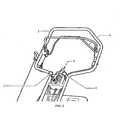
- the adjusting system of the present invention is actuable by the operator at any time, also with the lawnmower moving, with no need of expensive device for decoupling the drive motion from the cutting blade unit, given also the noticeable ease for accessing said knob 1, which in the shown embodiment (see fig. 2 ) is next to the safety lever 3, the accelerator lever 4, the self-movement actuation lever 5 and the speed selector lever 6.
Abstract
Description
- The present invention relates to a cutting height adjusting system for lawnmower.
- The lawnmowers currently available on the market provide several systems for adjusting the cutting height, that is for adjusting the distance of the lawn cutting blades in respect of the ground. The aforesaid systems are different from one another mainly because of adjusting accuracy and comfort the operator can carry out the aforesaid adjusting operation by. The solutions provided in more accurate systems are rightly expected to correspond to higher manufacturing costs due to both higher quality level of the members involved and higher technical complexity of the arrangement adopted for said members. Therefore, if on one hand the more expensive solutions make the cutting height adjustment easier by, for example, the shifting of a single lever also having an easy access and connected to complex linkage systems raising the lawnmower frame, on the other hand the cheaper systems allow for opportunities of less accurate and complex adjustments to be executed both in regard of the position and the number of levers to be shifted in order to reach the desired height of the cutting blades in respect of the ground.
- Moreover the opportunity of adopting the aforesaid systems depends on the lawnmower type, in other words each adjusting system is suitably manufactured in order to suit the frame structure and the cutting blade unit of the particular lawnmower considered.
- Further difference of the adjusting cutting height of lawnmowers between several currently known systems and the system according to the present invention is given by the fact that within said known systems the adjusting occurs in a discrete manner - typically along 4 to 7 different values - whilst in the system of the present invention it is allowed to chose any value measurable in millimetres - typically in a range from 20 mm to 70 mm - comprised between the maximum and the minimum height provided for the blade unit. This particular feature is not marginal at all, but instead it is extremely useful, for example, in trimming the lawn within areas contiguous to lawns just trimmed up to a given height: in this case the measurable in millimetres adjusting of the system of the present invention allows for setting a cutting height exactly equal to the height of the contiguous areas thus avoiding to generates on the whole lawn steps anaesthetic and, sometimes, dangerous as in sport fields (golf, cricket, soccer etc.).
- Object of the present invention is therefore to provide a cutting height adjusting system for lawnmowers cheap but having high accuracy characteristics.
- Further object of the present invention is, moreover, to provide a cutting height adjusting system for lawnmowers applicable on any lawnmower, either it has the cutting blade unit integral with the frame of the same lawnmower or said unit is movable in respect of said frame.
- A detailed description of a preferred embodiment of the cutting height adjusting system for lawnmowers according to the present invention will be provided with reference to the annexed drawings, wherein:
-
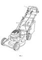
fig. 1 is a perspective view of a lawnmower provided with the cutting height adjusting system according to a preferred embodiment of the present invention, -
fig. 2 is a perspective view of an enlarged detail offig. 1 , -
fig. 3 is a perspective view of the raising system of the cutting blade unit of the lawnmower infig. 1 , -
fig. 4 is a perspective view showing the members linking two axles of the lawnmower infig. 1 , and -
fig. 5 is a perspective view of the mechanical drive of the system of the present invention. - Referring now to the annexed drawings, there is shown (
fig. 5 ) a lawnmower having, at a position easily accessible for an operator even with the lawnmower moving, aknob 1 keyed in a stable manner on aworn screw 2a, in turn, coupled to alead screw nut 2b. Therefore a rotation of saidknob 1 actuates saidlead screw nut 2b, thus causing it to translate along the longitudinal axis of saidworn screw 2a. On saidlead screw nut 2b there is mounted, fixedly or in a removable manner, apin 7a adapted to receive one end of acable 7, typically in metallic material, whilst the other end of saidcable 7 is engaged in aneccentric member 8. Saideccentric member 8 provides a pair of through holes at points A and O, illustrated infig. 3 , for passing of the coupling pins of the rear axle to the frame of said lawnmower and of the wheel to said axle, respectively. Finally, saideccentric member 8 provides, at the point C infig. 3 , a mount for the second end of saidcable 7. Therefore a rotation of theknob 1 leading thelead screw nut 2b to a translation in a proximal direction produces a strain within thecable 7, considerable inextensible in the range of the expected strains, fully and directly transmitted to said mount at the point C, which will see its own height raising in respect of the ground, and the point A as well which, being integral with the frame, will raise the latter in respect of the ground. In order to assure an unchanging horizontal trim of the lawnmower the front axle will be linked to the rear axle by a conventional articulated quadrilateral 9. Consequently even the cutting blade unit will be raised for an equal height in respect of the frame of the lawnmower, since it is integral therewith. - Alternatively the cutting height adjusting system may be equally applicable even to lawnmowers the cutting blade unit of which is not rigidly constrained in respect of the same lawnmower frame but it can be movable in respect of the latter: in this case obviously the described arrangement has to be modified by causing the
eccentric member 8 and the cutting blade unit to be hinged at the point A. - The just described preferred embodiment according to the present invention could be defined by several dimensions of the centre distance OA so as to obtain several ranges for adjusting the cutting height depending on the requirements the particular lawnmower, on which the system is installed, has to meet.
- Further embodiments can provide other types of mechanical drive in place of said worn screw - lead screw nut, eventually with no manual control but, for example, with electric/electronic control.
- It is now possible to notice how the description provides a solution for the technical problem initially placed by providing an economically feasible adjusting system due to the use of cheap mechanical members such as a steel cable, a well-known system like worn screw - lead screw nut and an eccentric member. Further, the description provides a system able to assure high accuracy by the adoption of a worn screw coupled with a lead screw nut the performances of which are well known to those skilled in the art, for which reason they will not shown herein. Moreover, the adjusting system of the present invention is actuable by the operator at any time, also with the lawnmower moving, with no need of expensive device for decoupling the drive motion from the cutting blade unit, given also the noticeable ease for accessing said
knob 1, which in the shown embodiment (seefig. 2 ) is next to thesafety lever 3, the accelerator lever 4, the self-movement actuation lever 5 and thespeed selector lever 6.
Claims (7)
- A cutting height adjusting system of a cutting blade unit, particularly suitable for lawnmowers, comprising:(i) a mechanical drive adapted to the moving of(ii) a mount for engaging a first end of(iii) a cable (7) operatively connected at the second end to(iv) an eccentric member (8) provided with at least two through holes (O, A) for coupling the axle of said lawnmower and a point of member of said lawnmower to be raised in respect of said axle.
- The cutting height adjusting system according to claim 1, wherein said axle is connected to other axle of said lawnmower by a articulated quadrilateral.
- The cutting height adjusting system according to claim 1, wherein said mechanical drive comprises a knob (1) integral with a worn screw, in turn, operatively coupled to a lead screw nut translating integrally with said mount.
- The cutting height adjusting system according to claim 1, wherein said knob (1) is in a proximal position in respect of the operator.
- The cutting height adjusting system according to claim 1, wherein said member of said lawnmower to be raised is the frame.
- The cutting height adjusting system according to claim 1, wherein said member of said lawnmower to be raised is the cutting blade unit.
- The cutting height adjusting system according to claim 1, wherein said cable (7) is formed with metallic material, for example, steel or other material being inextensible under tensile stress at least within the range of expected stresses.
Priority Applications (1)
| Application Number | Priority Date | Filing Date | Title |
|---|---|---|---|
| EP20090425175 EP2248409B1 (en) | 2009-05-07 | 2009-05-07 | Cutting height adjusting system for lawnmower |
Applications Claiming Priority (1)
| Application Number | Priority Date | Filing Date | Title |
|---|---|---|---|
| EP20090425175 EP2248409B1 (en) | 2009-05-07 | 2009-05-07 | Cutting height adjusting system for lawnmower |
Publications (2)
| Publication Number | Publication Date |
|---|---|
| EP2248409A1 true EP2248409A1 (en) | 2010-11-10 |
| EP2248409B1 EP2248409B1 (en) | 2012-11-28 |
Family
ID=41119907
Family Applications (1)
| Application Number | Title | Priority Date | Filing Date |
|---|---|---|---|
| EP20090425175 Not-in-force EP2248409B1 (en) | 2009-05-07 | 2009-05-07 | Cutting height adjusting system for lawnmower |
Country Status (1)
| Country | Link |
|---|---|
| EP (1) | EP2248409B1 (en) |
Cited By (2)
| Publication number | Priority date | Publication date | Assignee | Title |
|---|---|---|---|---|
| DE202012102766U1 (en) | 2012-07-24 | 2012-09-20 | Einhell Germany Ag | Mowing device with engagement area |
| EP3295781B1 (en) | 2012-07-04 | 2022-08-31 | Husqvarna AB | Robotic mower |
Families Citing this family (3)
| Publication number | Priority date | Publication date | Assignee | Title |
|---|---|---|---|---|
| EP3508049B1 (en) | 2016-06-30 | 2022-08-24 | Techtronic Outdoor Products Technology Limited | An autonomous lawn mower |
| US11172607B2 (en) | 2016-06-30 | 2021-11-16 | Tti (Macao Commercial Offshore) Limited | Autonomous lawn mower and a system for navigating thereof |
| US11570948B2 (en) * | 2018-08-31 | 2023-02-07 | Briggs & Stratton, Llc | Single height adjustment and control assembly for walk-behind outdoor power equipment |
Citations (5)
| Publication number | Priority date | Publication date | Assignee | Title |
|---|---|---|---|---|
| US4321784A (en) | 1980-07-15 | 1982-03-30 | The Toro Company | Height of cut adjustment |
| DE10209717A1 (en) * | 2002-03-06 | 2003-09-25 | Bermatingen Maschf | Lawn mower, comprising mechanism for adjustment of cutting height during mowing process while engine is running |
| US7013626B1 (en) | 2003-07-18 | 2006-03-21 | Auburn Consolidated Industries, Inc. | Walk behind mower |
| US20070169456A1 (en) | 2006-01-26 | 2007-07-26 | Kubota Corporation | Riding type mower |
| EP1817953A2 (en) * | 2006-02-14 | 2007-08-15 | SABO-Maschinenfabrik GmbH | Device for lawn, garden or terrain maintenance and working height adjusting device |
-
2009
- 2009-05-07 EP EP20090425175 patent/EP2248409B1/en not_active Not-in-force
Patent Citations (5)
| Publication number | Priority date | Publication date | Assignee | Title |
|---|---|---|---|---|
| US4321784A (en) | 1980-07-15 | 1982-03-30 | The Toro Company | Height of cut adjustment |
| DE10209717A1 (en) * | 2002-03-06 | 2003-09-25 | Bermatingen Maschf | Lawn mower, comprising mechanism for adjustment of cutting height during mowing process while engine is running |
| US7013626B1 (en) | 2003-07-18 | 2006-03-21 | Auburn Consolidated Industries, Inc. | Walk behind mower |
| US20070169456A1 (en) | 2006-01-26 | 2007-07-26 | Kubota Corporation | Riding type mower |
| EP1817953A2 (en) * | 2006-02-14 | 2007-08-15 | SABO-Maschinenfabrik GmbH | Device for lawn, garden or terrain maintenance and working height adjusting device |
Cited By (2)
| Publication number | Priority date | Publication date | Assignee | Title |
|---|---|---|---|---|
| EP3295781B1 (en) | 2012-07-04 | 2022-08-31 | Husqvarna AB | Robotic mower |
| DE202012102766U1 (en) | 2012-07-24 | 2012-09-20 | Einhell Germany Ag | Mowing device with engagement area |
Also Published As
| Publication number | Publication date |
|---|---|
| EP2248409B1 (en) | 2012-11-28 |
Similar Documents
| Publication | Publication Date | Title |
|---|---|---|
| EP2248409A1 (en) | Cutting height adjusting system for lawnmower | |
| US8371095B2 (en) | Height of cut adjustment system for a walk behind mower | |
| US7051499B2 (en) | Riding mower provided with hydrostatic transmissions | |
| US7448191B2 (en) | Mower deck lift system with transport lock | |
| CA2527797C (en) | Crop cutting header with speed control of driven element using valve profiling | |
| CA3004684C (en) | Control system for adjusting forming shield of windrowing work vehicle | |
| US9861035B2 (en) | Height of cut control system | |
| US20070068711A1 (en) | De-stroking dual hydrostatic pump | |
| US11849669B2 (en) | Flexible mower deck | |
| US10645873B2 (en) | Grass mower | |
| EP2734032A1 (en) | Lifting system for a harvester | |
| US20150296711A1 (en) | Mower deck leveling system | |
| US20160316619A1 (en) | Height of cut control system | |
| US10363927B2 (en) | Speed change control apparatus for work vehicle | |
| US6688418B2 (en) | Drive system for a utility vehicle | |
| US20220124975A1 (en) | Flexible mower deck | |
| US11758842B2 (en) | Mower mounted on work vehicle having lifting links | |
| US8266879B2 (en) | Riding mower | |
| JP7057614B2 (en) | Riding mower | |
| CN110432004B (en) | Steering mechanism | |
| JPS5824083B2 (en) | Combine speed control device | |
| JP6280845B2 (en) | Harvesting machine | |
| CN219628360U (en) | Electric mower | |
| US20230189702A1 (en) | Adaptive cutting system, a lawnmower including same, and method for adjusting a lawnmower | |
| JP5123886B2 (en) | Vehicle speed control device |
Legal Events
| Date | Code | Title | Description |
|---|---|---|---|
| PUAI | Public reference made under article 153(3) epc to a published international application that has entered the european phase |
Free format text: ORIGINAL CODE: 0009012 |
|
| AK | Designated contracting states |
Kind code of ref document: A1 Designated state(s): AT BE BG CH CY CZ DE DK EE ES FI FR GB GR HR HU IE IS IT LI LT LU LV MC MK MT NL NO PL PT RO SE SI SK TR |
|
| AX | Request for extension of the european patent |
Extension state: AL BA RS |
|
| 17P | Request for examination filed |
Effective date: 20110510 |
|
| 17Q | First examination report despatched |
Effective date: 20110621 |
|
| GRAP | Despatch of communication of intention to grant a patent |
Free format text: ORIGINAL CODE: EPIDOSNIGR1 |
|
| R17C | First examination report despatched (corrected) |
Effective date: 20110621 |
|
| RIN1 | Information on inventor provided before grant (corrected) |
Inventor name: RAIMONDI, MARCO |
|
| GRAS | Grant fee paid |
Free format text: ORIGINAL CODE: EPIDOSNIGR3 |
|
| GRAA | (expected) grant |
Free format text: ORIGINAL CODE: 0009210 |
|
| AK | Designated contracting states |
Kind code of ref document: B1 Designated state(s): AT BE BG CH CY CZ DE DK EE ES FI FR GB GR HR HU IE IS IT LI LT LU LV MC MK MT NL NO PL PT RO SE SI SK TR |
|
| REG | Reference to a national code |
Ref country code: GB Ref legal event code: FG4D |
|
| REG | Reference to a national code |
Ref country code: CH Ref legal event code: EP |
|
| REG | Reference to a national code |
Ref country code: AT Ref legal event code: REF Ref document number: 585649 Country of ref document: AT Kind code of ref document: T Effective date: 20121215 |
|
| REG | Reference to a national code |
Ref country code: IE Ref legal event code: FG4D |
|
| REG | Reference to a national code |
Ref country code: DE Ref legal event code: R096 Ref document number: 602009011511 Country of ref document: DE Effective date: 20130124 |
|
| REG | Reference to a national code |
Ref country code: CH Ref legal event code: NV Representative=s name: TROESCH SCHEIDEGGER WERNER AG, CH |
|
| REG | Reference to a national code |
Ref country code: AT Ref legal event code: MK05 Ref document number: 585649 Country of ref document: AT Kind code of ref document: T Effective date: 20121128 |
|
| REG | Reference to a national code |
Ref country code: NL Ref legal event code: VDEP Effective date: 20121128 |
|
| REG | Reference to a national code |
Ref country code: LT Ref legal event code: MG4D |
|
| PG25 | Lapsed in a contracting state [announced via postgrant information from national office to epo] |
Ref country code: FI Free format text: LAPSE BECAUSE OF FAILURE TO SUBMIT A TRANSLATION OF THE DESCRIPTION OR TO PAY THE FEE WITHIN THE PRESCRIBED TIME-LIMIT Effective date: 20121128 Ref country code: SE Free format text: LAPSE BECAUSE OF FAILURE TO SUBMIT A TRANSLATION OF THE DESCRIPTION OR TO PAY THE FEE WITHIN THE PRESCRIBED TIME-LIMIT Effective date: 20121128 Ref country code: NO Free format text: LAPSE BECAUSE OF FAILURE TO SUBMIT A TRANSLATION OF THE DESCRIPTION OR TO PAY THE FEE WITHIN THE PRESCRIBED TIME-LIMIT Effective date: 20130228 Ref country code: ES Free format text: LAPSE BECAUSE OF FAILURE TO SUBMIT A TRANSLATION OF THE DESCRIPTION OR TO PAY THE FEE WITHIN THE PRESCRIBED TIME-LIMIT Effective date: 20130311 Ref country code: LT Free format text: LAPSE BECAUSE OF FAILURE TO SUBMIT A TRANSLATION OF THE DESCRIPTION OR TO PAY THE FEE WITHIN THE PRESCRIBED TIME-LIMIT Effective date: 20121128 |
|
| PG25 | Lapsed in a contracting state [announced via postgrant information from national office to epo] |
Ref country code: GR Free format text: LAPSE BECAUSE OF FAILURE TO SUBMIT A TRANSLATION OF THE DESCRIPTION OR TO PAY THE FEE WITHIN THE PRESCRIBED TIME-LIMIT Effective date: 20130301 Ref country code: PL Free format text: LAPSE BECAUSE OF FAILURE TO SUBMIT A TRANSLATION OF THE DESCRIPTION OR TO PAY THE FEE WITHIN THE PRESCRIBED TIME-LIMIT Effective date: 20121128 Ref country code: BE Free format text: LAPSE BECAUSE OF FAILURE TO SUBMIT A TRANSLATION OF THE DESCRIPTION OR TO PAY THE FEE WITHIN THE PRESCRIBED TIME-LIMIT Effective date: 20121128 Ref country code: SI Free format text: LAPSE BECAUSE OF FAILURE TO SUBMIT A TRANSLATION OF THE DESCRIPTION OR TO PAY THE FEE WITHIN THE PRESCRIBED TIME-LIMIT Effective date: 20121128 Ref country code: PT Free format text: LAPSE BECAUSE OF FAILURE TO SUBMIT A TRANSLATION OF THE DESCRIPTION OR TO PAY THE FEE WITHIN THE PRESCRIBED TIME-LIMIT Effective date: 20130328 Ref country code: LV Free format text: LAPSE BECAUSE OF FAILURE TO SUBMIT A TRANSLATION OF THE DESCRIPTION OR TO PAY THE FEE WITHIN THE PRESCRIBED TIME-LIMIT Effective date: 20121128 |
|
| PG25 | Lapsed in a contracting state [announced via postgrant information from national office to epo] |
Ref country code: AT Free format text: LAPSE BECAUSE OF FAILURE TO SUBMIT A TRANSLATION OF THE DESCRIPTION OR TO PAY THE FEE WITHIN THE PRESCRIBED TIME-LIMIT Effective date: 20121128 |
|
| PG25 | Lapsed in a contracting state [announced via postgrant information from national office to epo] |
Ref country code: CZ Free format text: LAPSE BECAUSE OF FAILURE TO SUBMIT A TRANSLATION OF THE DESCRIPTION OR TO PAY THE FEE WITHIN THE PRESCRIBED TIME-LIMIT Effective date: 20121128 Ref country code: EE Free format text: LAPSE BECAUSE OF FAILURE TO SUBMIT A TRANSLATION OF THE DESCRIPTION OR TO PAY THE FEE WITHIN THE PRESCRIBED TIME-LIMIT Effective date: 20121128 Ref country code: BG Free format text: LAPSE BECAUSE OF FAILURE TO SUBMIT A TRANSLATION OF THE DESCRIPTION OR TO PAY THE FEE WITHIN THE PRESCRIBED TIME-LIMIT Effective date: 20130228 Ref country code: DK Free format text: LAPSE BECAUSE OF FAILURE TO SUBMIT A TRANSLATION OF THE DESCRIPTION OR TO PAY THE FEE WITHIN THE PRESCRIBED TIME-LIMIT Effective date: 20121128 Ref country code: SK Free format text: LAPSE BECAUSE OF FAILURE TO SUBMIT A TRANSLATION OF THE DESCRIPTION OR TO PAY THE FEE WITHIN THE PRESCRIBED TIME-LIMIT Effective date: 20121128 |
|
| PG25 | Lapsed in a contracting state [announced via postgrant information from national office to epo] |
Ref country code: RO Free format text: LAPSE BECAUSE OF FAILURE TO SUBMIT A TRANSLATION OF THE DESCRIPTION OR TO PAY THE FEE WITHIN THE PRESCRIBED TIME-LIMIT Effective date: 20121128 Ref country code: NL Free format text: LAPSE BECAUSE OF FAILURE TO SUBMIT A TRANSLATION OF THE DESCRIPTION OR TO PAY THE FEE WITHIN THE PRESCRIBED TIME-LIMIT Effective date: 20121128 |
|
| PLBE | No opposition filed within time limit |
Free format text: ORIGINAL CODE: 0009261 |
|
| STAA | Information on the status of an ep patent application or granted ep patent |
Free format text: STATUS: NO OPPOSITION FILED WITHIN TIME LIMIT |
|
| 26N | No opposition filed |
Effective date: 20130829 |
|
| PG25 | Lapsed in a contracting state [announced via postgrant information from national office to epo] |
Ref country code: CY Free format text: LAPSE BECAUSE OF FAILURE TO SUBMIT A TRANSLATION OF THE DESCRIPTION OR TO PAY THE FEE WITHIN THE PRESCRIBED TIME-LIMIT Effective date: 20121128 |
|
| REG | Reference to a national code |
Ref country code: DE Ref legal event code: R097 Ref document number: 602009011511 Country of ref document: DE Effective date: 20130829 |
|
| PG25 | Lapsed in a contracting state [announced via postgrant information from national office to epo] |
Ref country code: MC Free format text: LAPSE BECAUSE OF FAILURE TO SUBMIT A TRANSLATION OF THE DESCRIPTION OR TO PAY THE FEE WITHIN THE PRESCRIBED TIME-LIMIT Effective date: 20121128 |
|
| PG25 | Lapsed in a contracting state [announced via postgrant information from national office to epo] |
Ref country code: HR Free format text: LAPSE BECAUSE OF FAILURE TO SUBMIT A TRANSLATION OF THE DESCRIPTION OR TO PAY THE FEE WITHIN THE PRESCRIBED TIME-LIMIT Effective date: 20130731 |
|
| REG | Reference to a national code |
Ref country code: IE Ref legal event code: MM4A |
|
| PG25 | Lapsed in a contracting state [announced via postgrant information from national office to epo] |
Ref country code: IE Free format text: LAPSE BECAUSE OF NON-PAYMENT OF DUE FEES Effective date: 20130507 |
|
| PG25 | Lapsed in a contracting state [announced via postgrant information from national office to epo] |
Ref country code: MT Free format text: LAPSE BECAUSE OF FAILURE TO SUBMIT A TRANSLATION OF THE DESCRIPTION OR TO PAY THE FEE WITHIN THE PRESCRIBED TIME-LIMIT Effective date: 20121128 |
|
| PG25 | Lapsed in a contracting state [announced via postgrant information from national office to epo] |
Ref country code: TR Free format text: LAPSE BECAUSE OF FAILURE TO SUBMIT A TRANSLATION OF THE DESCRIPTION OR TO PAY THE FEE WITHIN THE PRESCRIBED TIME-LIMIT Effective date: 20121128 |
|
| PG25 | Lapsed in a contracting state [announced via postgrant information from national office to epo] |
Ref country code: HU Free format text: LAPSE BECAUSE OF FAILURE TO SUBMIT A TRANSLATION OF THE DESCRIPTION OR TO PAY THE FEE WITHIN THE PRESCRIBED TIME-LIMIT; INVALID AB INITIO Effective date: 20090507 Ref country code: LU Free format text: LAPSE BECAUSE OF NON-PAYMENT OF DUE FEES Effective date: 20130507 Ref country code: MK Free format text: LAPSE BECAUSE OF FAILURE TO SUBMIT A TRANSLATION OF THE DESCRIPTION OR TO PAY THE FEE WITHIN THE PRESCRIBED TIME-LIMIT Effective date: 20121128 |
|
| REG | Reference to a national code |
Ref country code: FR Ref legal event code: PLFP Year of fee payment: 8 |
|
| PG25 | Lapsed in a contracting state [announced via postgrant information from national office to epo] |
Ref country code: IS Free format text: LAPSE BECAUSE OF FAILURE TO SUBMIT A TRANSLATION OF THE DESCRIPTION OR TO PAY THE FEE WITHIN THE PRESCRIBED TIME-LIMIT Effective date: 20121128 |
|
| REG | Reference to a national code |
Ref country code: FR Ref legal event code: PLFP Year of fee payment: 9 |
|
| PGFP | Annual fee paid to national office [announced via postgrant information from national office to epo] |
Ref country code: FR Payment date: 20170518 Year of fee payment: 9 Ref country code: GB Payment date: 20170522 Year of fee payment: 9 Ref country code: DE Payment date: 20170421 Year of fee payment: 9 Ref country code: CH Payment date: 20170509 Year of fee payment: 9 |
|
| PGFP | Annual fee paid to national office [announced via postgrant information from national office to epo] |
Ref country code: IT Payment date: 20170516 Year of fee payment: 9 |
|
| REG | Reference to a national code |
Ref country code: DE Ref legal event code: R082 Ref document number: 602009011511 Country of ref document: DE Representative=s name: FLACH BAUER STAHL PATENTANWAELTE PARTNERSCHAFT, DE |
|
| REG | Reference to a national code |
Ref country code: DE Ref legal event code: R119 Ref document number: 602009011511 Country of ref document: DE |
|
| REG | Reference to a national code |
Ref country code: CH Ref legal event code: PL |
|
| GBPC | Gb: european patent ceased through non-payment of renewal fee |
Effective date: 20180507 |
|
| PG25 | Lapsed in a contracting state [announced via postgrant information from national office to epo] |
Ref country code: CH Free format text: LAPSE BECAUSE OF NON-PAYMENT OF DUE FEES Effective date: 20180531 Ref country code: LI Free format text: LAPSE BECAUSE OF NON-PAYMENT OF DUE FEES Effective date: 20180531 |
|
| PG25 | Lapsed in a contracting state [announced via postgrant information from national office to epo] |
Ref country code: FR Free format text: LAPSE BECAUSE OF NON-PAYMENT OF DUE FEES Effective date: 20180531 Ref country code: GB Free format text: LAPSE BECAUSE OF NON-PAYMENT OF DUE FEES Effective date: 20180507 Ref country code: IT Free format text: LAPSE BECAUSE OF NON-PAYMENT OF DUE FEES Effective date: 20180507 Ref country code: DE Free format text: LAPSE BECAUSE OF NON-PAYMENT OF DUE FEES Effective date: 20181201 |