EP3295781B1 - Robotic mower - Google Patents
Robotic mower Download PDFInfo
- Publication number
- EP3295781B1 EP3295781B1 EP17198526.0A EP17198526A EP3295781B1 EP 3295781 B1 EP3295781 B1 EP 3295781B1 EP 17198526 A EP17198526 A EP 17198526A EP 3295781 B1 EP3295781 B1 EP 3295781B1
- Authority
- EP
- European Patent Office
- Prior art keywords
- height adjustment
- adjustment screw
- motor
- height
- screw
- Prior art date
- Legal status (The legal status is an assumption and is not a legal conclusion. Google has not performed a legal analysis and makes no representation as to the accuracy of the status listed.)
- Active
Links
- 238000005520 cutting process Methods 0.000 claims description 87
- 238000004891 communication Methods 0.000 claims description 19
- 238000012545 processing Methods 0.000 description 24
- 230000000875 corresponding effect Effects 0.000 description 12
- 238000000034 method Methods 0.000 description 10
- 238000012544 monitoring process Methods 0.000 description 10
- 230000006870 function Effects 0.000 description 5
- 238000010586 diagram Methods 0.000 description 4
- 230000007246 mechanism Effects 0.000 description 4
- 244000025254 Cannabis sativa Species 0.000 description 3
- 230000001419 dependent effect Effects 0.000 description 2
- 238000001514 detection method Methods 0.000 description 2
- 230000003993 interaction Effects 0.000 description 2
- 238000012423 maintenance Methods 0.000 description 2
- 230000003287 optical effect Effects 0.000 description 2
- 230000004044 response Effects 0.000 description 2
- 238000012546 transfer Methods 0.000 description 2
- 230000000007 visual effect Effects 0.000 description 2
- 241001494496 Leersia Species 0.000 description 1
- 230000001276 controlling effect Effects 0.000 description 1
- 230000002596 correlated effect Effects 0.000 description 1
- 230000008878 coupling Effects 0.000 description 1
- 238000010168 coupling process Methods 0.000 description 1
- 238000005859 coupling reaction Methods 0.000 description 1
- 230000000694 effects Effects 0.000 description 1
- 230000000977 initiatory effect Effects 0.000 description 1
- 239000000463 material Substances 0.000 description 1
- 238000005259 measurement Methods 0.000 description 1
- 239000002184 metal Substances 0.000 description 1
- 238000012986 modification Methods 0.000 description 1
- 230000004048 modification Effects 0.000 description 1
- 238000004904 shortening Methods 0.000 description 1
- 238000001228 spectrum Methods 0.000 description 1
Images


Classifications
-
- A—HUMAN NECESSITIES
- A01—AGRICULTURE; FORESTRY; ANIMAL HUSBANDRY; HUNTING; TRAPPING; FISHING
- A01D—HARVESTING; MOWING
- A01D34/00—Mowers; Mowing apparatus of harvesters
- A01D34/006—Control or measuring arrangements
- A01D34/008—Control or measuring arrangements for automated or remotely controlled operation
-
- A—HUMAN NECESSITIES
- A01—AGRICULTURE; FORESTRY; ANIMAL HUSBANDRY; HUNTING; TRAPPING; FISHING
- A01D—HARVESTING; MOWING
- A01D34/00—Mowers; Mowing apparatus of harvesters
- A01D34/01—Mowers; Mowing apparatus of harvesters characterised by features relating to the type of cutting apparatus
- A01D34/412—Mowers; Mowing apparatus of harvesters characterised by features relating to the type of cutting apparatus having rotating cutters
- A01D34/63—Mowers; Mowing apparatus of harvesters characterised by features relating to the type of cutting apparatus having rotating cutters having cutters rotating about a vertical axis
- A01D34/74—Cutting-height adjustment
-
- B—PERFORMING OPERATIONS; TRANSPORTING
- B60—VEHICLES IN GENERAL
- B60L—PROPULSION OF ELECTRICALLY-PROPELLED VEHICLES; SUPPLYING ELECTRIC POWER FOR AUXILIARY EQUIPMENT OF ELECTRICALLY-PROPELLED VEHICLES; ELECTRODYNAMIC BRAKE SYSTEMS FOR VEHICLES IN GENERAL; MAGNETIC SUSPENSION OR LEVITATION FOR VEHICLES; MONITORING OPERATING VARIABLES OF ELECTRICALLY-PROPELLED VEHICLES; ELECTRIC SAFETY DEVICES FOR ELECTRICALLY-PROPELLED VEHICLES
- B60L1/00—Supplying electric power to auxiliary equipment of vehicles
- B60L1/003—Supplying electric power to auxiliary equipment of vehicles to auxiliary motors, e.g. for pumps, compressors
-
- B—PERFORMING OPERATIONS; TRANSPORTING
- B60—VEHICLES IN GENERAL
- B60L—PROPULSION OF ELECTRICALLY-PROPELLED VEHICLES; SUPPLYING ELECTRIC POWER FOR AUXILIARY EQUIPMENT OF ELECTRICALLY-PROPELLED VEHICLES; ELECTRODYNAMIC BRAKE SYSTEMS FOR VEHICLES IN GENERAL; MAGNETIC SUSPENSION OR LEVITATION FOR VEHICLES; MONITORING OPERATING VARIABLES OF ELECTRICALLY-PROPELLED VEHICLES; ELECTRIC SAFETY DEVICES FOR ELECTRICALLY-PROPELLED VEHICLES
- B60L15/00—Methods, circuits, or devices for controlling the traction-motor speed of electrically-propelled vehicles
- B60L15/20—Methods, circuits, or devices for controlling the traction-motor speed of electrically-propelled vehicles for control of the vehicle or its driving motor to achieve a desired performance, e.g. speed, torque, programmed variation of speed
-
- B—PERFORMING OPERATIONS; TRANSPORTING
- B60—VEHICLES IN GENERAL
- B60L—PROPULSION OF ELECTRICALLY-PROPELLED VEHICLES; SUPPLYING ELECTRIC POWER FOR AUXILIARY EQUIPMENT OF ELECTRICALLY-PROPELLED VEHICLES; ELECTRODYNAMIC BRAKE SYSTEMS FOR VEHICLES IN GENERAL; MAGNETIC SUSPENSION OR LEVITATION FOR VEHICLES; MONITORING OPERATING VARIABLES OF ELECTRICALLY-PROPELLED VEHICLES; ELECTRIC SAFETY DEVICES FOR ELECTRICALLY-PROPELLED VEHICLES
- B60L3/00—Electric devices on electrically-propelled vehicles for safety purposes; Monitoring operating variables, e.g. speed, deceleration or energy consumption
- B60L3/0023—Detecting, eliminating, remedying or compensating for drive train abnormalities, e.g. failures within the drive train
- B60L3/0061—Detecting, eliminating, remedying or compensating for drive train abnormalities, e.g. failures within the drive train relating to electrical machines
-
- B—PERFORMING OPERATIONS; TRANSPORTING
- B60—VEHICLES IN GENERAL
- B60L—PROPULSION OF ELECTRICALLY-PROPELLED VEHICLES; SUPPLYING ELECTRIC POWER FOR AUXILIARY EQUIPMENT OF ELECTRICALLY-PROPELLED VEHICLES; ELECTRODYNAMIC BRAKE SYSTEMS FOR VEHICLES IN GENERAL; MAGNETIC SUSPENSION OR LEVITATION FOR VEHICLES; MONITORING OPERATING VARIABLES OF ELECTRICALLY-PROPELLED VEHICLES; ELECTRIC SAFETY DEVICES FOR ELECTRICALLY-PROPELLED VEHICLES
- B60L50/00—Electric propulsion with power supplied within the vehicle
- B60L50/50—Electric propulsion with power supplied within the vehicle using propulsion power supplied by batteries or fuel cells
- B60L50/52—Electric propulsion with power supplied within the vehicle using propulsion power supplied by batteries or fuel cells characterised by DC-motors
-
- B—PERFORMING OPERATIONS; TRANSPORTING
- B60—VEHICLES IN GENERAL
- B60L—PROPULSION OF ELECTRICALLY-PROPELLED VEHICLES; SUPPLYING ELECTRIC POWER FOR AUXILIARY EQUIPMENT OF ELECTRICALLY-PROPELLED VEHICLES; ELECTRODYNAMIC BRAKE SYSTEMS FOR VEHICLES IN GENERAL; MAGNETIC SUSPENSION OR LEVITATION FOR VEHICLES; MONITORING OPERATING VARIABLES OF ELECTRICALLY-PROPELLED VEHICLES; ELECTRIC SAFETY DEVICES FOR ELECTRICALLY-PROPELLED VEHICLES
- B60L50/00—Electric propulsion with power supplied within the vehicle
- B60L50/50—Electric propulsion with power supplied within the vehicle using propulsion power supplied by batteries or fuel cells
- B60L50/60—Electric propulsion with power supplied within the vehicle using propulsion power supplied by batteries or fuel cells using power supplied by batteries
- B60L50/66—Arrangements of batteries
-
- B—PERFORMING OPERATIONS; TRANSPORTING
- B60—VEHICLES IN GENERAL
- B60L—PROPULSION OF ELECTRICALLY-PROPELLED VEHICLES; SUPPLYING ELECTRIC POWER FOR AUXILIARY EQUIPMENT OF ELECTRICALLY-PROPELLED VEHICLES; ELECTRODYNAMIC BRAKE SYSTEMS FOR VEHICLES IN GENERAL; MAGNETIC SUSPENSION OR LEVITATION FOR VEHICLES; MONITORING OPERATING VARIABLES OF ELECTRICALLY-PROPELLED VEHICLES; ELECTRIC SAFETY DEVICES FOR ELECTRICALLY-PROPELLED VEHICLES
- B60L53/00—Methods of charging batteries, specially adapted for electric vehicles; Charging stations or on-board charging equipment therefor; Exchange of energy storage elements in electric vehicles
- B60L53/10—Methods of charging batteries, specially adapted for electric vehicles; Charging stations or on-board charging equipment therefor; Exchange of energy storage elements in electric vehicles characterised by the energy transfer between the charging station and the vehicle
- B60L53/14—Conductive energy transfer
- B60L53/16—Connectors, e.g. plugs or sockets, specially adapted for charging electric vehicles
-
- B—PERFORMING OPERATIONS; TRANSPORTING
- B60—VEHICLES IN GENERAL
- B60L—PROPULSION OF ELECTRICALLY-PROPELLED VEHICLES; SUPPLYING ELECTRIC POWER FOR AUXILIARY EQUIPMENT OF ELECTRICALLY-PROPELLED VEHICLES; ELECTRODYNAMIC BRAKE SYSTEMS FOR VEHICLES IN GENERAL; MAGNETIC SUSPENSION OR LEVITATION FOR VEHICLES; MONITORING OPERATING VARIABLES OF ELECTRICALLY-PROPELLED VEHICLES; ELECTRIC SAFETY DEVICES FOR ELECTRICALLY-PROPELLED VEHICLES
- B60L8/00—Electric propulsion with power supply from forces of nature, e.g. sun or wind
- B60L8/003—Converting light into electric energy, e.g. by using photo-voltaic systems
-
- G—PHYSICS
- G05—CONTROLLING; REGULATING
- G05D—SYSTEMS FOR CONTROLLING OR REGULATING NON-ELECTRIC VARIABLES
- G05D1/00—Control of position, course or altitude of land, water, air, or space vehicles, e.g. automatic pilot
- G05D1/02—Control of position or course in two dimensions
- G05D1/021—Control of position or course in two dimensions specially adapted to land vehicles
- G05D1/0259—Control of position or course in two dimensions specially adapted to land vehicles using magnetic or electromagnetic means
- G05D1/0265—Control of position or course in two dimensions specially adapted to land vehicles using magnetic or electromagnetic means using buried wires
-
- B—PERFORMING OPERATIONS; TRANSPORTING
- B60—VEHICLES IN GENERAL
- B60L—PROPULSION OF ELECTRICALLY-PROPELLED VEHICLES; SUPPLYING ELECTRIC POWER FOR AUXILIARY EQUIPMENT OF ELECTRICALLY-PROPELLED VEHICLES; ELECTRODYNAMIC BRAKE SYSTEMS FOR VEHICLES IN GENERAL; MAGNETIC SUSPENSION OR LEVITATION FOR VEHICLES; MONITORING OPERATING VARIABLES OF ELECTRICALLY-PROPELLED VEHICLES; ELECTRIC SAFETY DEVICES FOR ELECTRICALLY-PROPELLED VEHICLES
- B60L2200/00—Type of vehicles
- B60L2200/40—Working vehicles
-
- B—PERFORMING OPERATIONS; TRANSPORTING
- B60—VEHICLES IN GENERAL
- B60L—PROPULSION OF ELECTRICALLY-PROPELLED VEHICLES; SUPPLYING ELECTRIC POWER FOR AUXILIARY EQUIPMENT OF ELECTRICALLY-PROPELLED VEHICLES; ELECTRODYNAMIC BRAKE SYSTEMS FOR VEHICLES IN GENERAL; MAGNETIC SUSPENSION OR LEVITATION FOR VEHICLES; MONITORING OPERATING VARIABLES OF ELECTRICALLY-PROPELLED VEHICLES; ELECTRIC SAFETY DEVICES FOR ELECTRICALLY-PROPELLED VEHICLES
- B60L2240/00—Control parameters of input or output; Target parameters
- B60L2240/10—Vehicle control parameters
- B60L2240/36—Temperature of vehicle components or parts
-
- B—PERFORMING OPERATIONS; TRANSPORTING
- B60—VEHICLES IN GENERAL
- B60L—PROPULSION OF ELECTRICALLY-PROPELLED VEHICLES; SUPPLYING ELECTRIC POWER FOR AUXILIARY EQUIPMENT OF ELECTRICALLY-PROPELLED VEHICLES; ELECTRODYNAMIC BRAKE SYSTEMS FOR VEHICLES IN GENERAL; MAGNETIC SUSPENSION OR LEVITATION FOR VEHICLES; MONITORING OPERATING VARIABLES OF ELECTRICALLY-PROPELLED VEHICLES; ELECTRIC SAFETY DEVICES FOR ELECTRICALLY-PROPELLED VEHICLES
- B60L2240/00—Control parameters of input or output; Target parameters
- B60L2240/40—Drive Train control parameters
- B60L2240/42—Drive Train control parameters related to electric machines
- B60L2240/421—Speed
-
- B—PERFORMING OPERATIONS; TRANSPORTING
- B60—VEHICLES IN GENERAL
- B60L—PROPULSION OF ELECTRICALLY-PROPELLED VEHICLES; SUPPLYING ELECTRIC POWER FOR AUXILIARY EQUIPMENT OF ELECTRICALLY-PROPELLED VEHICLES; ELECTRODYNAMIC BRAKE SYSTEMS FOR VEHICLES IN GENERAL; MAGNETIC SUSPENSION OR LEVITATION FOR VEHICLES; MONITORING OPERATING VARIABLES OF ELECTRICALLY-PROPELLED VEHICLES; ELECTRIC SAFETY DEVICES FOR ELECTRICALLY-PROPELLED VEHICLES
- B60L2260/00—Operating Modes
- B60L2260/20—Drive modes; Transition between modes
- B60L2260/32—Auto pilot mode
-
- Y—GENERAL TAGGING OF NEW TECHNOLOGICAL DEVELOPMENTS; GENERAL TAGGING OF CROSS-SECTIONAL TECHNOLOGIES SPANNING OVER SEVERAL SECTIONS OF THE IPC; TECHNICAL SUBJECTS COVERED BY FORMER USPC CROSS-REFERENCE ART COLLECTIONS [XRACs] AND DIGESTS
- Y02—TECHNOLOGIES OR APPLICATIONS FOR MITIGATION OR ADAPTATION AGAINST CLIMATE CHANGE
- Y02T—CLIMATE CHANGE MITIGATION TECHNOLOGIES RELATED TO TRANSPORTATION
- Y02T10/00—Road transport of goods or passengers
- Y02T10/60—Other road transportation technologies with climate change mitigation effect
- Y02T10/64—Electric machine technologies in electromobility
-
- Y—GENERAL TAGGING OF NEW TECHNOLOGICAL DEVELOPMENTS; GENERAL TAGGING OF CROSS-SECTIONAL TECHNOLOGIES SPANNING OVER SEVERAL SECTIONS OF THE IPC; TECHNICAL SUBJECTS COVERED BY FORMER USPC CROSS-REFERENCE ART COLLECTIONS [XRACs] AND DIGESTS
- Y02—TECHNOLOGIES OR APPLICATIONS FOR MITIGATION OR ADAPTATION AGAINST CLIMATE CHANGE
- Y02T—CLIMATE CHANGE MITIGATION TECHNOLOGIES RELATED TO TRANSPORTATION
- Y02T10/00—Road transport of goods or passengers
- Y02T10/60—Other road transportation technologies with climate change mitigation effect
- Y02T10/70—Energy storage systems for electromobility, e.g. batteries
-
- Y—GENERAL TAGGING OF NEW TECHNOLOGICAL DEVELOPMENTS; GENERAL TAGGING OF CROSS-SECTIONAL TECHNOLOGIES SPANNING OVER SEVERAL SECTIONS OF THE IPC; TECHNICAL SUBJECTS COVERED BY FORMER USPC CROSS-REFERENCE ART COLLECTIONS [XRACs] AND DIGESTS
- Y02—TECHNOLOGIES OR APPLICATIONS FOR MITIGATION OR ADAPTATION AGAINST CLIMATE CHANGE
- Y02T—CLIMATE CHANGE MITIGATION TECHNOLOGIES RELATED TO TRANSPORTATION
- Y02T10/00—Road transport of goods or passengers
- Y02T10/60—Other road transportation technologies with climate change mitigation effect
- Y02T10/7072—Electromobility specific charging systems or methods for batteries, ultracapacitors, supercapacitors or double-layer capacitors
-
- Y—GENERAL TAGGING OF NEW TECHNOLOGICAL DEVELOPMENTS; GENERAL TAGGING OF CROSS-SECTIONAL TECHNOLOGIES SPANNING OVER SEVERAL SECTIONS OF THE IPC; TECHNICAL SUBJECTS COVERED BY FORMER USPC CROSS-REFERENCE ART COLLECTIONS [XRACs] AND DIGESTS
- Y02—TECHNOLOGIES OR APPLICATIONS FOR MITIGATION OR ADAPTATION AGAINST CLIMATE CHANGE
- Y02T—CLIMATE CHANGE MITIGATION TECHNOLOGIES RELATED TO TRANSPORTATION
- Y02T10/00—Road transport of goods or passengers
- Y02T10/60—Other road transportation technologies with climate change mitigation effect
- Y02T10/72—Electric energy management in electromobility
-
- Y—GENERAL TAGGING OF NEW TECHNOLOGICAL DEVELOPMENTS; GENERAL TAGGING OF CROSS-SECTIONAL TECHNOLOGIES SPANNING OVER SEVERAL SECTIONS OF THE IPC; TECHNICAL SUBJECTS COVERED BY FORMER USPC CROSS-REFERENCE ART COLLECTIONS [XRACs] AND DIGESTS
- Y02—TECHNOLOGIES OR APPLICATIONS FOR MITIGATION OR ADAPTATION AGAINST CLIMATE CHANGE
- Y02T—CLIMATE CHANGE MITIGATION TECHNOLOGIES RELATED TO TRANSPORTATION
- Y02T90/00—Enabling technologies or technologies with a potential or indirect contribution to GHG emissions mitigation
- Y02T90/10—Technologies relating to charging of electric vehicles
- Y02T90/14—Plug-in electric vehicles
Definitions
- Example embodiments generally relate to robotic mowers and, more particularly, relate to a calibration system for a robotic mower that has an adjustable cutting height.
- Yard maintenance tasks are commonly performed using various tools and/or machines that are configured for the performance of corresponding specific tasks. Certain tasks, like grass cutting, are typically performed by lawn mowers. Lawn mowers themselves may have many different configurations to support the needs and budgets of consumers. Walk-behind lawn mowers are typically compact, have comparatively small engines and are relatively inexpensive. Meanwhile, at the other end of the spectrum, riding lawn mowers, such as lawn tractors, can be quite large. More recently, robotic mowers and/or remote controlled mowers have also become options for consumers to consider.
- Lawn mowers are typically capable of transiting over even and uneven terrain to execute yard maintenance activities relating to mowing. However, most lawn mowers are repeatedly exposed to the same operating environments over the course of their lifetimes. For example, a lawn mower may operate to cut a single yard over its entire life, or may operate to cut a relatively fixed series of yards or parcels if it is used for commercial purposes. Given that computing devices are becoming more ubiquitous, it is to be expected that they may be employed to assist in operation of lawn mowers. As such, many additional functionalities may be provided or supported by the employment of computing devices on lawn mowers EP1495661 A1 discloses a user interface and control system for adjusting the reel of a cutting reel unit.
- Some example embodiments not according to the invention may provide a robotic device having control circuitry that can be used in connection with accurately setting the cutting height of the device.
- the control circuitry may control a height adjustment motor and may utilize information indicative of the number of revolutions of a height adjustment screw to determine cutting height.
- some embodiments may enable the cutting height to be accurately determined using a calibration system.
- a clutch may be employed to selectively decouple the height adjustment screw from the height adjustment motor.
- a robotic mower may include a chassis, a cutting motor driving at least one cutting blade, a height adjustment assembly and control circuitry.
- the height adjustment assembly may include a height adjustment motor configured to adjust a height of a motor bracket via rotation of a height adjustment screw driven by the height adjustment motor.
- the motor bracket may provide structural support for the cutting motor at an adjustable level relative to the chassis.
- the control circuitry may be configured to control operation of the height adjustment motor for positioning of the motor bracket based at least in part on information received by the control circuitry. The received information may be indicative of an amount of rotation of the height adjustment screw.
- a height adjustment assembly for a robotic mower may include a chassis, a cutting motor driving at least one cutting blade, and control circuitry.
- the height adjustment assembly may include a motor bracket, a height adjustment screw and a height adjustment motor.
- the motor bracket may provide structural support for the cutting motor at an adjustable level relative to the chassis.
- the height adjustment screw may be operably coupled to the motor bracket and support the motor bracket at the adjustable level.
- the height adjustment motor may be configured to drive rotation of the height adjustment screw to adjust motor bracket position.
- the control circuitry may be configured to control operation of the height adjustment motor for positioning of the motor bracket based at least in part on information received by the control circuitry. The received information may indicative of an amount of rotation of the height adjustment screw.
- a method of adjusting cutting height for a robotic mower includes providing a motor bracket that has an adjustable level relative to a chassis of the robotic mower to structurally support a cutting motor of the robotic mower.
- the motor bracket may be supported by a height adjustment screw that is rotatable to adjust the level of the motor bracket.
- the method may further include monitoring rotation of the height adjustment screw to generate information indicative of an amount of rotation of the height adjustment screw and utilizing processing circuitry to control operation of a height adjustment motor operably coupled to rotate the height adjustment screw based on the received information.
- Some example embodiments may improve the ability of operators to control the cutting height of an autonomous mowing device.
- Robotic vehicles such as robotic mowers, robotic watering devices, and/or the like, typically operate in an area that is defined by any boundary that can be technically or physically defined.
- a technical means by which to define such a boundary may include a guide wire that bounds the area to be mowed. The robotic vehicle then roams within the bounded area to ensure that the entire area is mowed, watered, etc., but the robotic vehicle does not go outside of the bounded area.
- FIG. 1 illustrates an example operating environment for a robotic mower 10 that may employ a system bounded by such a guide wire.
- the robotic mower 10 may operate to cut grass on a parcel 20 (i.e., a land lot), the boundaries of which may be defined using one or more physical boundaries (e.g., a fence, wall, curb and/or the like), a guide wire 30 or combinations thereof.
- the guide wire 30 may emit electrical signals that are detectable by the robotic mower 10 to inform the robotic mower 10 when a boundary of the parcel 20 has been reached.
- the robotic mower 10 may be controlled, at least in part, via control circuitry 12 located onboard.
- the control circuitry 12 may include, among other things, the ability to detect the guide wire 30 to redirect the robotic mower 10 to other areas within the parcel 20.
- the robotic mower 10 may be battery powered via one or more rechargeable batteries. Accordingly, the robotic mower 10 may be configured to return to a charge station 40 that may be located at some position on the parcel 20 in order to recharge the batteries.
- the batteries may power a drive system and a blade control system of the robotic mower 10.
- the control circuitry 12 of the robotic mower 10 may selectively control the application of power or other control signals to the drive system and/or the blade control system to direct the operation of the drive system and/or blade control system. Accordingly, movement of the robotic mower 10 over the parcel 20 may be controlled by the control circuitry in a manner that enables the robotic mower 10 to systematically traverse the parcel 20 while operating a cutting blade to cut the grass on the work area of the parcel 20.
- the operator of the robotic mower 10 may be configured to communicate wirelessly with an electronic device 42 (e.g., a computer, mobile telephone, PDA, smart phone, and/or the like) of a remote operator 44 via a wireless communication network 46.
- the wireless network 46 and other remote devices may not be employed in some embodiments.
- the wireless network 46 may be a data network, such as a local area network (LAN), a metropolitan area network (MAN), a wide area network (WAN) (e.g., the Internet), and/or the like, which may couple the robotic mower 10 to devices such as processing elements (e.g., personal computers, server computers or the like) or databases. Communication between the wireless network 46 and the devices or databases (e.g., servers, electronic device 42, control circuitry 12, etc.) may be accomplished by either wireline or wireless communication mechanisms and corresponding protocols.
- FIG. 2 which includes FIGS. 2A and 2B , illustrates some of the parts that may be employed in connection with an example of the robotic mower 10. However, it should be appreciated that example embodiments may be employed on numerous other vehicles that may employ different designs.
- FIG. 2A illustrates a schematic view of a lower chassis and various components of the robotic mower according to an example embodiment
- FIG. 2B illustrates a schematic view of an upper chassis and various other components of the robotic mower according to an example embodiment.
- the robotic mower 10 may include a lower chassis 50, an upper chassis 52 and a body 54.
- the upper chassis 52 may be configured to be arranged on top of the lower chassis 50 and the body 54 may be configured to be arranged on top of the upper chassis 52.
- the lower chassis 50 may form a support structure from which one or more front wheels 56 and one or more rear wheels 58 may be supported.
- the one or more rear wheels 58 may be relatively large as compared to the one or more front wheels 56.
- the one or more rear wheels 58 may be configured to operate either in a forward or backward direction.
- the front wheels 56 may be pivoting wheels.
- the lower chassis 50 may further include one or more sensors 60 that may be used to detect the guide wire 20 and/or objects that may form part of the boundary of the parcel.
- the sensors 60 may also detect objects that may be encountered during operation of the robotic mower 10 within the boundaries of the parcel 20. These objects may be fixed or temporary (e.g., movable) objects.
- the sensors 60 may include a front sensor and a rear sensor. However, it should be appreciated that any number of sensors may be employed and they may be disposed at any desirable location on the robotic mower 10.
- the sensors 60 may include sensors related to positional determination (e.g., a GPS receiver, an accelerometer, a camera, a radar transmitter/detector, an ultrasonic sensor, a laser scanner and/or the like).
- positional determinations may be made using GPS, inertial navigation, optical flow, radio navigation, visual location (e.g., VSLAM) and/or other positioning techniques or combinations thereof.
- the sensors 60 may be used, at least in part, for determining the location of the robotic mower 10 relative to boundaries or other points of interest (e.g., a starting point, the guide wire or other key features) of the parcel 20, or determining a position history or track of the robotic mower 10 over time.
- the lower chassis 50 may further support a cutting motor 62 configured to drive a cutting blade or other cutters of the robotic mower 10.
- the body 54 and the upper chassis 52 may be plastic, light metal, or other similarly lightweight components.
- the upper chassis 52 and/or the body 54 may support a user interface (e.g., display 66).
- the display 66 may be employed to interface with the control circuitry 12 for controlling operations of the robotic mower 10.
- the sensors 60 may include sensors specifically provided for detecting objects (other than the guide wire 20 or objects forming boundaries of the parcel 20) and/or sensors for detecting lifting (or tipping beyond a threshold amount) of the robotic mower 10.
- sensors e.g., collision sensors 70 and lifting sensors 72
- the sensors 60 may include a camera, which may be used to optically determine the existence of objects in view of the camera and, in some embodiments, may be configured to determine or distinguish an identity of the object (e.g., to determine if an object is a reference object).
- the cutting height at which the robotic mower 10 operates may be adjustable. In some cases, adjustment of the cutting height may be accomplished by adjusting the height of the blade or blades that perform the cutting operation.
- One mechanism for adjusting blade height could include an apparent lengthening or shortening of the shaft to which the blade or blades are mounted. However, in practice, this may be difficult to accomplish.
- some embodiments may instead employ a fixed length for the shaft and enable adjustment of the vertical position of the cutting motor 62, the shaft and the cutting blade or blades relative to a fixed part of the chassis of the robotic mower 10.
- the entirety of the cutting system may be linearly adjustable in a substantially vertical direction by mounting the cutting system on a linear bearing assembly. The linear bearing assembly may then support adjustment of the height of the cutting system via operation of a cutting height adjustment motor that may be controlled at least in part via the control circuitry 12.
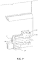
- FIG. 3 illustrates a side view of a portion of a robotic mower employing such a linear bearing assembly according to an example embodiment.
- FIG. 3 illustrates the lower chassis 50 forming a fixed part of the chassis of the robotic mower 10.
- the lower chassis 50 supports a motor bowl 100 (e.g., motor bracket, motor mount, or motor fixing) that supports the cutting motor 62.
- the motor bowl 100 of an example embodiment provides structural support for the cutting motor 62 at an adjustable elevation or height relative to the ground beneath the robotic mower 10.
- a cutting disc 110 is disposed at the end of a shaft 112 that is turned by the cutting motor 62 and extends linearly therefrom in a direction toward an underside of the robotic mower 10.
- a bellows 120 may be disposed between the cutting disc 110 and the lower chassis 50 to prevent moisture and/or debris from fouling the cutting motor 62 or other internal components of the robotic mower 10.
- the motor bowl 100 may be operably coupled to a height adjustment assembly 130 to provide for the adjustable elevation characteristic of the motor bowl 100.
- the height adjustment assembly 130 may include components that enable the motor bowl 100 to be elevated or lowered relative to the lower chassis 50 within a predefined range in order to control the cutting height of the robotic mower 10.
- the motor bowl 100 provides a structure to support the cutting motor 62 at an adjustable level relative to the ground and the chassis (e.g., lower chassis 50) of the robotic mower 10.
- the height adjustment assembly 130 may include linear bearings 132 with which a portion of the motor bowl 100 is slideably engaged.
- the motor bowl 100 may have a rack assembly 134 attached thereto in order to enable the rack assembly 134 to ride within grooves of a height adjustment screw 136 (or worm gear).
- the rack assembly 134 may be fixed to the motor bowl 100, but may ride in the linear bearings 132 to enable a height adjustment to be accomplished via raising or lowering of the rack assembly 134 responsive to turning of the height adjustment screw 136.
- a height adjustment motor 140 may be provided to turn the height adjustment screw 136.
- the height adjustment motor 140 may be an electric motor that may receive control inputs at least in part via the control circuitry 12.
- the control circuitry 12 may provide a signal to the height adjustment motor 140 to adjust the height of the cutting disc 110.
- the height adjustment motor 140 may operate accordingly to turn the height adjustment screw 136. Turning of the height adjustment screw 136 may cause threads on the height adjustment screw 136 to be passed through slots between teeth of the rack assembly 134.
- the rack assembly 134 may receive a lifting force or lowering force and the motor bowl 100 may slide within the linear bearings 132 in a corresponding direction to adjust the height of the cutting disc 110 and thereby also adjust the height of the grass that is cut by the robotic mower 10.
- the robotic mower 10 may be desirable to simply define a specific cutting height and have the robotic mower 10 adjust its cutting disc 110 to the corresponding desired height.
- an input may be provided to the control circuitry 12 and the control circuitry 12 may direct movement of the height adjustment motor 140 to achieve a desired cutting height based on predefined information correlating a desired cutting height to a determinable position of some components of the robotic mower 10. For example, a two inch cutting height may be correlated to a certain motor bowl 100 height.
- some example embodiments may provide structural components and corresponding methods of employing those components in order to determine a motor bowl 100 height and further to associate a given motor bowl 100 height with a cutting height.
- some embodiments may further employ a calibration system to enable the robotic mower 10 to maintain an accurate accounting for cutting height.
- FIG. 4 illustrates a perspective view of some components of a calibration system 200 for automatic cutting height adjustment according to an example embodiment.
- FIG. 4 is depicted such that many surrounding components are removed in order to give a clearer view of the calibration system 200.
- the calibration system 200 may include or interact with other components that are not shown in FIG. 4 .
- FIG. 4 shows the rack assembly 134 of FIG. 3 in greater detail and illustrates a screw engagement nut 210 that includes multiple teeth 212 that are configured to engage threads 220 of the height adjustment screw 136.
- the teeth 212 may be spaced apart and sized to ride within the threads 220 such that turning of the height adjustment screw 136 causes the screw engagement nut 210 to be translated along the height adjustment screw 136 accordingly and to thereby adjust the height of the motor bowl 100, which is supported vertically via the linear bearings 132 at a height that is determined by the position of the screw engagement nut 210 relative to the height adjustment screw 136.
- the height adjustment screw 136 is arranged such that an axis of the height adjustment screw 136 is substantially parallel to the direction of linear movement of the motor bowl 100 when height adjustments are made. Thus, the height adjustment screw 136 itself does not move vertically. Instead, the height adjustment screw 136 rotates about its axis but maintains a constant vertical orientation. To cause the rotation of the height adjustment screw 136, motion may be transferred from rotation of a shaft of the height adjustment motor 140 to the height adjustment screw 136. In an example embodiment, a gear assembly 230 may be employed to transfer rotation of the shaft of the height adjustment motor 140 to the height adjustment screw 136.
- the gear assembly 230 may include a motor gear 232 operably coupled to the shaft of the height adjustment motor 140.
- the motor gear 232 may be affixed to the shaft.
- the motor gear 232 may therefore turn with the shaft responsive to operation of the height adjustment motor 140.
- the motor gear 232 may include teeth that are operably coupled to corresponding teeth of a screw gear 234.
- the screw gear 234 may be operably coupled to the height adjustment screw 136. Accordingly, turning of the motor gear 232 may be translated into corresponding turning of the screw gear 234.
- Relative sizes of the motor gear 232 and the screw gear 234 may be adjusted to provide any desirable turning ratio such that rotation of the motor gear 232 at a given speed may result in a relatively faster rotation of the screw gear 234 (e.g., if the screw gear 234 is smaller than the motor gear 232) or result in relatively slower rotation of the screw gear 234 (e.g., if the screw gear 234 is larger than the motor gear 232).
- Some methods for making a determination as to the cutting height may include the attachment of a rod or other elongate member onto the motor bowl 110 and having a portion of the rod pass through a scale that is visible external to the robotic mower 10.
- the rod may have a marking that points to a value on the scale and indicates the cutting height.
- this type of height determination may be useful for enabling an operator to see the cutting height, it is not particularly useful when automatic control is desired. Accordingly, in some embodiments, a determination regarding cutting height may be made in a manner that enables the control circuitry 12 to be aware of cutting height and/or provide inputs regarding specific settings for cutting height.
- One way to enable the control circuitry 12 to be aware of cutting height may be to measure cutting height on the basis of the number of revolutions that the height adjustment screw 136 has made from a known or reference location.
- the number of revolutions made by the height adjustment screw 136 may be monitored either directly or indirectly.
- Direct monitoring may include monitoring of the height adjustment screw 136 itself, while indirect monitoring may include monitoring of a component known to turn at a fixed rate relative to the turning of the height adjustment screw 136.
- the number of revolutions of the motor gear 232 could be monitored and the corresponding number of revolutions of the screw gear 234 may be determined (e.g., based on the gear ratio between the motor gear 232 and the screw gear 234) as an example of indirect monitoring.
- direct monitoring may be performed by marking the height adjustment screw 136, or by fixing a marked reference wheel 240 to the height adjustment screw 136 and monitoring the number of revolutions of the reference wheel 240.
- the reference wheel 240 may include one or more slots 242 (or other markings including, for example, transparent window 242') disposed along the reference wheel 240.
- the slots 242 may be provided at fixed and known intervals. For example, a single slot could be provided to indicate one full revolution. Alternatively, two slots could be provided to indicate half revolutions. As yet another alternative, four slots could be provided to indicate quarter revolutions. Moreover, any number of slots could be provided to indicate any desirable degree of accuracy relative to determining partial revolutions of the height adjustment screw 136.
- the slots 242 may have different characteristics (e.g., shape, color, size, etc.) to enable the characteristics to be differentiated and thereby indicate specific information relative to the motion of the height adjustment screw 136. For example, by determining the characteristics of the slots 242 encountered (or the order of encountering slots having certain characteristics), the direction of rotation of the height adjustment screw 136 may be determined. Additionally or alternatively, slots at certain positions may have corresponding certain characteristics so that a slot of a certain shape, color or size can be recognized as indicating that a quarter turn has been achieved, while a slot of a different shape, color or size may be recognized as indicating that a half turn has been achieved. By counting the number of revolutions and/or the fractions of full revolutions that have been made from a known reference, the control circuitry 12 may determine the cutting height.
- characteristics e.g., shape, color, size, etc.
- a height sensor 250 may be provided to detect markings on the reference wheel 240.
- FIG. 5 illustrates a perspective view of the calibration system 200 including the height sensor 250 according to an example embodiment.
- the height sensor 250 may be an optical sensor that can optically read markings, transparent windows or slots on the reference wheel 240.
- the height sensor 250 may be a magnetic device that detects slots, magnets or other markings on the reference wheel 240 as they pass by the height sensor 250.
- the height sensor 250 may include mechanical components for detecting slots 242.
- the height sensor 250 may be embodied in any of a variety of devices capable of determining the existence of a marking, transparent window, slot or the like on the reference wheel 240 and, in some cases, also determining characteristics of a marking, transparent window, slot or the like on the reference wheel 240.
- the height sensor 250 may be in communication with the control circuitry 12 to inform the control circuitry 12, for example, when a marking is encountered and, if appropriate, any characteristics of the marking that were determined.
- the control circuitry 12 may then determine cutting height on the basis of the information received.
- the control circuitry 12 may be configured to determine current motor bowl 100 height, and therefore also the cutting height, based on counting a number of revolutions of the height adjustment screw 136 relative to a known location.
- the known location may be defined at one or both of the ends of the range of travel of the screw engagement nut 210 along the height adjustment screw 136.
- the control circuitry 12 may use any information received thereafter regarding height adjustment screw 136 rotation as information that is indicative of the cutting height of the robotic mower 10.
- any cutting height adjustment or setting may be made responsive to an initial movement of the screw engagement nut 210 to either the top or the bottom of the height adjustment screw 136.
- the movement of the screw engagement nut 210 to either the top or the bottom of the height adjustment screw 136 may essentially reset the position information to a known reference location. Rotation thereafter may therefore be in an unambiguously determinable direction (e.g., down if the reset was to the top of the height adjustment screw 136 or upward if the reset was to the bottom of the height adjustment screw 136).
- the height sensor 250 may monitor the markings encountered during rotation of the height adjustment screw 136.
- the control circuitry 12 may be configured to determine (or set) the current cutting height based on monitoring the revolutions of the height adjustment screw 136 since each full revolution from one end of the range of motion of the screw engagement nut 210 (e.g., from the top to the bottom of the height adjustment screw 136) may have a known correlation to cutting height. Thus, for example, if the operator selects a specific cutting height, the control circuitry 12 may direct the height adjustment motor 140 to turn until the screw engagement nut 210 is raised to the top (or bottom) of the height adjustment screw 136 and then lower (or raise) the screw engagement nut 210 while counting the number of revolutions (or partial revolutions) based on the markings detected by the height sensor 250 after the extremity of the range is reached.
- the processing circuitry 12 may be configured to remember a last entered cutting height. Thus, any adjustment to cutting height or newly entered cutting height may be achieved with reference to the last entered cutting height. For example, if a particular cutting height is initially selected and the height adjustment motor 140 turns until the screw engagement nut 210 is raised from the top (or bottom) of the height adjustment screw 136 to the selected height based on a determination that the number of revolutions (or partial revolutions) of the height adjustment screw 136 corresponds to the initially selected height, the processing circuitry 12 may store information indicative of the corresponding initially selected height and/or the number of revolutions (or partial revolutions). If an adjustment to the initially selected height is then made, the processing circuitry 12 may reference the current cutting height and the number of revolutions and turn the height adjustment screw 136 an additional number of turns (or partial turns) in an appropriate direction to achieve the height desired according to the adjustment.
- some scenarios of operation may cause the height engagement screw 136 to be repeatedly turned with the intention of moving the screw engagement nut 210 to the top or bottom of the height adjustment screw 136, there may be potential for damaging the height adjustment motor 140 or other components when a limit to the movement range is reached.
- some embodiments may utilize a clutch 300 in connection with the screw gear 234.
- FIG. 6 illustrates a partially cutaway view of the underside of the screw gear 234 according to an example embodiment.
- the clutch 300 of FIG. 6 may be embodied in the form of a releasable connection between the screw gear 234 and the height adjustment screw 136.
- the clutch 300 may include a connecting pin 310 that is in fixed connection with the screw gear 234, but releasable connection with the height adjustment screw 136.
- the fixed connection between the connecting pin 310 and the screw gear 234 may be provided by the connecting pint 310 being fit within a slot 330 in an interior portion of the screw gear 234.
- the connecting pin 310 may sit perpendicular to an axis of rotation of the screw gear 234 and extend transversely across the screw gear 234.
- the releasable connection between the connecting pin 310 and the height adjustment screw 136 may be provided by enabling the connecting pin 310 to slide out of a slot 340 defined in the height adjustment screw 136.
- the slot 340 may extend entirely through a portion of the height adjustment screw 136 so that when the connecting pin 310 is seated both in the slot 330 of the screw gear 234 and the slot 340 of the height adjustment screw 136, rotation of the screw gear 234 is translated directly into corresponding rotation of the height adjustment screw 136.
- the connecting pin 310 may be enabled to move out of the slot 340 of the height adjustment screw 136 responsive to the exertion of a predetermined amount of force on the connecting pin 310.
- the predetermined amount of force may be achieved when one of the range limitations for movement of the screw engagement nut 210 along the height adjustment screw 136 is reached.
- the releasable connection between the connecting pin 310 and the height adjustment screw 136 may be activated to remove the connecting pin 310 from to slot 340 when the screw engagement nut 210 can no longer be moved further up or down the height adjustment screw 136.
- stops may be provided on the height adjustment screw 136 so that a force is generated to counteract the turning force of the height adjustment screw 136 as provided by the height adjustment motor 140 via the gear assembly 230 responsive to the screw engagement nut 210 hitting one of the stops.
- the connecting pin 310 may come out of the slot 340 to decouple the height adjustment screw 136 from the screw gear 234.
- the connecting pin 310 may be held into the slot 340 by a spring 350 that is shown in FIG. 7 , which shows the same view as FIG. 6 except that the spring 350 is added.
- the spring 350 may be configured to hold the connecting pin 310 into the slot 340 with the predetermined amount of force.
- the connecting pin 310 responsive to continued turning of the screw gear 234 may then continue to turn with the screw gear 234, but may not reseat itself into the slot 340 until movement in the other direction is initiated.
- the force of the spring 350 may be sufficient to seat the connecting pin 310 in the slot 340 when the orientation of the connecting pin 310 is aligned with the slot 340.
- FIG. 8 illustrates an isolated side view of the height adjustment screw 136 to show the stops 360.
- FIG. 9 illustrates an isolated front view of the screw engagement nut 210 to show the teeth 212 disposed thereon.
- the teeth 212 may include a partial tooth 214 on both a top part of the screw engagement nut 210 and a bottom part thereof.
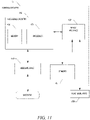
- FIG. 11 illustrates a block diagram of various components of the control circuitry 12 to illustrate some of the components that enable the functional performance of the robotic mower 10 and to facilitate description of an example embodiment.
- the control circuitry 12 may include processing circuitry 400 that may be configured to perform data processing, control function execution and/or other processing and management services according to an example embodiment of the present disclosure.
- the processing circuitry 400 may be embodied as a chip or chip set.
- the processing circuitry 400 may comprise one or more physical packages (e.g., chips) including materials, components and/or wires on a structural assembly (e.g., a baseboard).
- the structural assembly may provide physical strength, conservation of size, and/or limitation of electrical interaction for component circuitry included thereon.
- the processing circuitry 400 may therefore, in some cases, be configured to implement an embodiment of the present disclosure on a single chip or as a single "system on a chip.” As such, in some cases, a chip or chipset may constitute means for performing one or more operations for providing the functionalities described herein.
- the processing circuitry 400 may include one or more instances of a processor 412 and memory 414 that may be in communication with or otherwise control a device interface 420 and a user interface 430.
- the processing circuitry 400 may be embodied as a circuit chip (e.g., an integrated circuit chip) configured (e.g., with hardware, software or a combination of hardware and software) to perform operations described herein.
- the processing circuitry 400 may be embodied as a portion of an on-board computer.
- the processing circuitry 400 may communicate with electronic components, motor controllers and/or sensors (e.g., sensors 60, collision sensors 70 and/or lifting sensors 72) of the robotic mower 10 via a single data bus.
- the data bus may connect to a plurality or all of the switching components and/or other electrically controlled components of the robotic mower 10.
- the processor 412 may be embodied in a number of different ways.
- the processor 412 may be embodied as various processing means such as one or more of a microprocessor or other processing element, a coprocessor, a controller or various other computing or processing devices including integrated circuits such as, for example, an ASIC (application specific integrated circuit), an FPGA (field programmable gate array), or the like.
- the processor 412 may be configured to execute instructions stored in the memory 414 or otherwise accessible to the processor 412.
- the processor 412 may represent an entity (e.g., physically embodied in circuitry - in the form of processing circuitry 400) capable of performing operations according to embodiments of the present disclosure while configured accordingly.
- the processor 412 when the processor 412 is embodied as an ASIC, FPGA or the like, the processor 412 may be specifically configured hardware for conducting the operations described herein.
- the processor 412 when the processor 412 is embodied as an executor of software instructions, the instructions may specifically configure the processor 412 to perform the operations described herein.
- the memory 414 may include one or more non-transitory memory devices such as, for example, volatile and/or non-volatile memory that may be either fixed or removable.
- the memory 414 may be configured to store information, data, applications, instructions or the like for enabling the robotic mower 10 to carry out various functions in accordance with exemplary embodiments of the present disclosure.
- the memory 414 could be configured to buffer input data for processing by the processor 412.
- the memory 414 could be configured to store instructions for execution by the processor 412.
- the memory 414 may include one or more databases that may store a variety of data sets responsive to input from the sensor network.
- applications may be stored for execution by the processor 412 in order to carry out the functionality associated with each respective application.
- the device interface 420 may include one or more interface mechanisms for enabling communication with other devices (e.g., sensors of a sensor network including sensors 60, and/or other accessories or functional units 450 such as motors, servos, switches or other operational control devices for automatic responses).
- the device interface 420 may be any means such as a device or circuitry embodied in either hardware, or a combination of hardware and software that is configured to receive and/or transmit data from/to sensors or other internal/external devices in communication with the processing circuitry 400.
- the device interface 420 may provide interfaces for communication of components internal to robotic mower 10 or external to the robotic mower 10 so that the device interface 420 may provide interface capabilities for interaction with such components. Settings, programming and instructions for initiation of automatic responses such as operational control functions that implement automatic actions to be taken responsive to detection of certain stimuli may therefore be provided via the device interface 420.
- the user interface 430 may be in communication with the processing circuitry 400 to receive an indication of a user input at the user interface 430 and/or to provide an audible, visual, mechanical or other output to the user.
- the user interface 430 may include, for example, a display (e.g., display 66), one or more buttons or keys (e.g., function buttons), and/or other input/output mechanisms (e.g., microphone, speakers, cursor, joystick, lights and/or the like).
- the memory 414 may store instructions for correlating a cutting height to a number of revolutions of the height adjustment screw 136. Accordingly, for example, the processor 412 may execute instructions to determine a current cutting height based on a number of revolutions detected from a reference position using information from the sensor 250. The processor 412 may also be enabled to direct rotation of the height adjustment motor 140 to achieve a desired height based on a known current height or by directing a reset for calibrated positioning as described above.
- some embodiments may provide a robotic vehicle (e.g., an autonomously operable robotic mower) that employs a gear assembly to transfer rotational motion from a cutting height adjustment motor to a height adjustment screw.
- the height adjustment screw may rotate to cause a screw engagement nut to be lifted or lowered (dependent upon the direction of rotation of the height adjustment screw) to raise or lower the cutting height under the control of control circuitry of the robotic vehicle.
- a robotic mower may include a chassis, a cutting motor driving at least one cutting blade, a height adjustment assembly and control circuitry.
- the height adjustment assembly may include a height adjustment motor configured to adjust a height of a motor bowl via rotation of a height adjustment screw driven by the height adjustment motor.
- the motor bowl may provide structural support for the cutting motor at an adjustable level relative to the chassis.
- the control circuitry may be configured to control operation of the height adjustment motor for positioning of the motor bowl based at least in part on information received by the control circuitry. The received information may be indicative of an amount of rotation of the height adjustment screw.
- the robotic mower described above may further provide that the control circuitry is in communication with a calibration system configured to monitor rotation of the height adjustment screw relative to a reference location. Moreover, the received information may define the amount of rotation of the height adjustment screw relative to the reference location. In some cases, the reference location may be defined at an end of the height adjustment screw. In an example embodiment, the control circuitry may be configured to reset motor bowl height to the end of the height adjustment screw to adjust motor bowl height relative to the reference location each time an adjustment is made to motor bowl height to select a cutting height of the at least one cutting blade.
- the calibration system may include a sensor configured to monitor rotation of the height adjustment screw via detection of at least one marking that rotates proportional to rotation of the height adjustment screw.
- a reference wheel may be provided that rotates with the height adjustment screw.
- the reference wheel may have the at least one marking disposed thereon and may be disposed proximate to the sensor.
- the reference wheel may include a plurality of markings, each of the markings being indicative of a corresponding fraction of a revolution of the height adjustment screw.
- at least some of the markings may have different characteristics that are determinable by the sensor and the received information may further indicate information specific to a determined characteristic of at least one of the markings.
- any of the modifications described above may be incorporated along the height adjustment motor being provided to drive a first gear in operable communication with a second gear in operable communication with the height adjustment screw.
- the operable communication between the height adjustment motor and the first gear, or between the second gear and the height adjustment screw, may be a releasable connection provided via a clutch.
- the height adjustment motor may drive a first gear in operable communication with a second gear and the second gear may be releasably connected to the height adjustment screw via a connection pin that moves out of a slot in the height adjustment screw responsive to a predetermined amount of force being applied to the connection pin.
- the height adjustment motor may drive a first gear in operable communication with a second gear where the second gear is releasably connected to the height adjustment screw via a spring loaded connection pin that moves out of a slot in the height adjustment screw responsive to a force being applied to the connection pin that is greater than a spring force of the spring being applied to hold the connection pin in the slot.
- the height adjustment assembly further comprises a screw engagement nut operably coupled to the motor bowl.
- the screw engagement nut may have teeth configured to engage threads of the height adjustment screw and, responsive to rotation of the height adjustment screw, move up or down along a length of the height adjustment screw.
- the height adjustment screw may include at least one stop disposed at an end of a threaded portion of the height adjustment screw.
- the height adjustment motor may drive a first gear in operable communication with a second gear and the second gear may be releasably connected to the height adjustment screw to release responsive to the screw engagement nut reaching the at least one stop.
- FIG. 12 illustrates a block diagram of a method of adjusting cutting height for a robotic mower according to an example embodiment.
- the method includes providing a motor bowl that has an adjustable level relative to a chassis of the robotic mower to structurally support a cutting motor of the robotic mower at operation 500.
- the motor bowl may be supported by a height adjustment screw that is rotatable to adjust the level of the motor bowl.
- the method may further include monitoring rotation of the height adjustment screw to generate information indicative of an amount of rotation of the height adjustment screw at operation 510 and utilizing processing circuitry to control operation of a height adjustment motor operably coupled to rotate the height adjustment screw based on the received information at operation 520.
Description
- Example embodiments generally relate to robotic mowers and, more particularly, relate to a calibration system for a robotic mower that has an adjustable cutting height.
- Yard maintenance tasks are commonly performed using various tools and/or machines that are configured for the performance of corresponding specific tasks. Certain tasks, like grass cutting, are typically performed by lawn mowers. Lawn mowers themselves may have many different configurations to support the needs and budgets of consumers. Walk-behind lawn mowers are typically compact, have comparatively small engines and are relatively inexpensive. Meanwhile, at the other end of the spectrum, riding lawn mowers, such as lawn tractors, can be quite large. More recently, robotic mowers and/or remote controlled mowers have also become options for consumers to consider.
- Lawn mowers are typically capable of transiting over even and uneven terrain to execute yard maintenance activities relating to mowing. However, most lawn mowers are repeatedly exposed to the same operating environments over the course of their lifetimes. For example, a lawn mower may operate to cut a single yard over its entire life, or may operate to cut a relatively fixed series of yards or parcels if it is used for commercial purposes. Given that computing devices are becoming more ubiquitous, it is to be expected that they may be employed to assist in operation of lawn mowers. As such, many additional functionalities may be provided or supported by the employment of computing devices on lawn mowers
EP1495661 A1 discloses a user interface and control system for adjusting the reel of a cutting reel unit. - The invention is defined by the claims. Some example embodiments not according to the invention may provide a robotic device having control circuitry that can be used in connection with accurately setting the cutting height of the device. In this regard, for example, the control circuitry may control a height adjustment motor and may utilize information indicative of the number of revolutions of a height adjustment screw to determine cutting height. However, some embodiments may enable the cutting height to be accurately determined using a calibration system. Moreover, in some cases, a clutch may be employed to selectively decouple the height adjustment screw from the height adjustment motor.
- According to one example embodiment, a robotic mower is provided. The robotic mower may include a chassis, a cutting motor driving at least one cutting blade, a height adjustment assembly and control circuitry. The height adjustment assembly may include a height adjustment motor configured to adjust a height of a motor bracket via rotation of a height adjustment screw driven by the height adjustment motor. The motor bracket may provide structural support for the cutting motor at an adjustable level relative to the chassis. The control circuitry may be configured to control operation of the height adjustment motor for positioning of the motor bracket based at least in part on information received by the control circuitry. The received information may be indicative of an amount of rotation of the height adjustment screw.
- According to another example embodiment, a height adjustment assembly for a robotic mower is provided. The robotic mower may include a chassis, a cutting motor driving at least one cutting blade, and control circuitry. The height adjustment assembly may include a motor bracket, a height adjustment screw and a height adjustment motor. The motor bracket may provide structural support for the cutting motor at an adjustable level relative to the chassis. The height adjustment screw may be operably coupled to the motor bracket and support the motor bracket at the adjustable level. The height adjustment motor may be configured to drive rotation of the height adjustment screw to adjust motor bracket position. The control circuitry may be configured to control operation of the height adjustment motor for positioning of the motor bracket based at least in part on information received by the control circuitry. The received information may indicative of an amount of rotation of the height adjustment screw.
- In another example embodiment, a method of adjusting cutting height for a robotic mower is provided. The method includes providing a motor bracket that has an adjustable level relative to a chassis of the robotic mower to structurally support a cutting motor of the robotic mower. The motor bracket may be supported by a height adjustment screw that is rotatable to adjust the level of the motor bracket. The method may further include monitoring rotation of the height adjustment screw to generate information indicative of an amount of rotation of the height adjustment screw and utilizing processing circuitry to control operation of a height adjustment motor operably coupled to rotate the height adjustment screw based on the received information.
- Some example embodiments may improve the ability of operators to control the cutting height of an autonomous mowing device.
- Having thus described the invention in general terms, reference will now be made to the accompanying drawings, which are not necessarily drawn to scale, and wherein:
-
FIG. 1 illustrates an example operating environment for a robotic mower; -
FIG. 2A illustrates a schematic view of a lower chassis and various components of the robotic mower according to an example embodiment; -
FIG. 2B illustrates a schematic view of an upper chassis and various other components of the robotic mower according to an example embodiment; -
FIG. 3 illustrates a side view of a portion of a robotic mower employing such a linear bearing assembly according to an example embodiment; -
FIG. 4 illustrates a perspective view of some components of a calibration system for automatic cutting height adjustment according to an example embodiment; -
FIG. 5 illustrates a perspective view of the calibration system including the height sensor according to an example embodiment; -
FIG. 6 illustrates a partially cutaway view of the underside of a screw gear according to an example embodiment; -
FIG. 7 illustrates the partially cutaway view ofFIG. 6 with a spring added to hold a connection pin in a slot according to an example embodiment; -
FIG. 8 illustrates an isolated side view of the height adjustment screw to show stops according to an example embodiment; -
FIG. 9 illustrates an isolated front view of the screw engagement nut to show teeth disposed thereon according to an example embodiment; -
FIG. 10 illustrates an example in which a partial tooth at the top of the screw engagement nut has reached the stop at the top of the height adjustment screw according to an example embodiment; -
FIG. 11 illustrates a block diagram of various components of control circuitry of the robotic mower to illustrate some of the components that enable the functional performance of the robotic mower according to an example embodiment; and -
FIG. 12 illustrates a block diagram of a method of adjusting cutting height for a robotic mower according to an example embodiment. - Some example embodiments now will be described more fully hereinafter with reference to the accompanying drawings, in which some, but not all example embodiments are shown. Indeed, the examples described and pictured herein should not be construed as being limiting as to the scope, applicability or configuration of the present disclosure. Rather, these example embodiments are provided so that this disclosure will satisfy applicable legal requirements. Like reference numerals refer to like elements throughout. Furthermore, as used herein, the term "or" is to be interpreted as a logical operator that results in true whenever one or more of its operands are true. As used herein, operable coupling should be understood to relate to direct or indirect connection that, in either case, enables functional interconnection of components that are operably coupled to each other.
- Robotic vehicles such as robotic mowers, robotic watering devices, and/or the like, typically operate in an area that is defined by any boundary that can be technically or physically defined. In one example, a technical means by which to define such a boundary may include a guide wire that bounds the area to be mowed. The robotic vehicle then roams within the bounded area to ensure that the entire area is mowed, watered, etc., but the robotic vehicle does not go outside of the bounded area.
FIG. 1 illustrates an example operating environment for arobotic mower 10 that may employ a system bounded by such a guide wire. Therobotic mower 10 may operate to cut grass on a parcel 20 (i.e., a land lot), the boundaries of which may be defined using one or more physical boundaries (e.g., a fence, wall, curb and/or the like), aguide wire 30 or combinations thereof. Theguide wire 30 may emit electrical signals that are detectable by therobotic mower 10 to inform therobotic mower 10 when a boundary of theparcel 20 has been reached. Therobotic mower 10 may be controlled, at least in part, viacontrol circuitry 12 located onboard. Thecontrol circuitry 12 may include, among other things, the ability to detect theguide wire 30 to redirect therobotic mower 10 to other areas within theparcel 20. - In an example embodiment, the
robotic mower 10 may be battery powered via one or more rechargeable batteries. Accordingly, therobotic mower 10 may be configured to return to acharge station 40 that may be located at some position on theparcel 20 in order to recharge the batteries. The batteries may power a drive system and a blade control system of therobotic mower 10. However, thecontrol circuitry 12 of therobotic mower 10 may selectively control the application of power or other control signals to the drive system and/or the blade control system to direct the operation of the drive system and/or blade control system. Accordingly, movement of therobotic mower 10 over theparcel 20 may be controlled by the control circuitry in a manner that enables therobotic mower 10 to systematically traverse theparcel 20 while operating a cutting blade to cut the grass on the work area of theparcel 20. - In some embodiments, the operator of the
robotic mower 10 may be configured to communicate wirelessly with an electronic device 42 (e.g., a computer, mobile telephone, PDA, smart phone, and/or the like) of aremote operator 44 via awireless communication network 46. However, thewireless network 46 and other remote devices may not be employed in some embodiments. If employed, thewireless network 46 may be a data network, such as a local area network (LAN), a metropolitan area network (MAN), a wide area network (WAN) (e.g., the Internet), and/or the like, which may couple therobotic mower 10 to devices such as processing elements (e.g., personal computers, server computers or the like) or databases. Communication between thewireless network 46 and the devices or databases (e.g., servers,electronic device 42,control circuitry 12, etc.) may be accomplished by either wireline or wireless communication mechanisms and corresponding protocols. -
FIG. 2 , which includesFIGS. 2A and 2B , illustrates some of the parts that may be employed in connection with an example of therobotic mower 10. However, it should be appreciated that example embodiments may be employed on numerous other vehicles that may employ different designs.FIG. 2A illustrates a schematic view of a lower chassis and various components of the robotic mower according to an example embodiment andFIG. 2B illustrates a schematic view of an upper chassis and various other components of the robotic mower according to an example embodiment. - Referring to
FIGS. 1 and2 , therobotic mower 10 may include alower chassis 50, anupper chassis 52 and abody 54. Theupper chassis 52 may be configured to be arranged on top of thelower chassis 50 and thebody 54 may be configured to be arranged on top of theupper chassis 52. Thelower chassis 50 may form a support structure from which one or morefront wheels 56 and one or morerear wheels 58 may be supported. In some embodiments, the one or morerear wheels 58 may be relatively large as compared to the one or morefront wheels 56. Moreover, the one or morerear wheels 58 may be configured to operate either in a forward or backward direction. In some embodiments, thefront wheels 56 may be pivoting wheels. - In an example embodiment, the
lower chassis 50 may further include one ormore sensors 60 that may be used to detect theguide wire 20 and/or objects that may form part of the boundary of the parcel. Thesensors 60 may also detect objects that may be encountered during operation of therobotic mower 10 within the boundaries of theparcel 20. These objects may be fixed or temporary (e.g., movable) objects. In some cases, thesensors 60 may include a front sensor and a rear sensor. However, it should be appreciated that any number of sensors may be employed and they may be disposed at any desirable location on therobotic mower 10. Thesensors 60 may include sensors related to positional determination (e.g., a GPS receiver, an accelerometer, a camera, a radar transmitter/detector, an ultrasonic sensor, a laser scanner and/or the like). Thus, for example, positional determinations may be made using GPS, inertial navigation, optical flow, radio navigation, visual location (e.g., VSLAM) and/or other positioning techniques or combinations thereof. Accordingly, thesensors 60 may be used, at least in part, for determining the location of therobotic mower 10 relative to boundaries or other points of interest (e.g., a starting point, the guide wire or other key features) of theparcel 20, or determining a position history or track of therobotic mower 10 over time. - The
lower chassis 50 may further support a cuttingmotor 62 configured to drive a cutting blade or other cutters of therobotic mower 10. In some embodiments, thebody 54 and theupper chassis 52 may be plastic, light metal, or other similarly lightweight components. Theupper chassis 52 and/or thebody 54 may support a user interface (e.g., display 66). Thedisplay 66 may be employed to interface with thecontrol circuitry 12 for controlling operations of therobotic mower 10. - In some embodiments, the
sensors 60 may include sensors specifically provided for detecting objects (other than theguide wire 20 or objects forming boundaries of the parcel 20) and/or sensors for detecting lifting (or tipping beyond a threshold amount) of therobotic mower 10. Alternatively, separate sensors (e.g.,collision sensors 70 and lifting sensors 72) may be provided for each function, and those sensors may be capable of communicating with thecontrol circuitry 12 in addition to thesensors 60. In an example embodiment, thesensors 60 may include a camera, which may be used to optically determine the existence of objects in view of the camera and, in some embodiments, may be configured to determine or distinguish an identity of the object (e.g., to determine if an object is a reference object). - In some embodiments, the cutting height at which the
robotic mower 10 operates may be adjustable. In some cases, adjustment of the cutting height may be accomplished by adjusting the height of the blade or blades that perform the cutting operation. One mechanism for adjusting blade height could include an apparent lengthening or shortening of the shaft to which the blade or blades are mounted. However, in practice, this may be difficult to accomplish. Thus, some embodiments may instead employ a fixed length for the shaft and enable adjustment of the vertical position of the cuttingmotor 62, the shaft and the cutting blade or blades relative to a fixed part of the chassis of therobotic mower 10. In other words, the entirety of the cutting system may be linearly adjustable in a substantially vertical direction by mounting the cutting system on a linear bearing assembly. The linear bearing assembly may then support adjustment of the height of the cutting system via operation of a cutting height adjustment motor that may be controlled at least in part via thecontrol circuitry 12. -
FIG. 3 illustrates a side view of a portion of a robotic mower employing such a linear bearing assembly according to an example embodiment. In this regard, for example,FIG. 3 illustrates thelower chassis 50 forming a fixed part of the chassis of therobotic mower 10. Thelower chassis 50 supports a motor bowl 100 (e.g., motor bracket, motor mount, or motor fixing) that supports the cuttingmotor 62. In this regard, themotor bowl 100 of an example embodiment provides structural support for the cuttingmotor 62 at an adjustable elevation or height relative to the ground beneath therobotic mower 10. Acutting disc 110 is disposed at the end of ashaft 112 that is turned by the cuttingmotor 62 and extends linearly therefrom in a direction toward an underside of therobotic mower 10. In some embodiments, abellows 120 may be disposed between thecutting disc 110 and thelower chassis 50 to prevent moisture and/or debris from fouling the cuttingmotor 62 or other internal components of therobotic mower 10. - The
motor bowl 100 may be operably coupled to aheight adjustment assembly 130 to provide for the adjustable elevation characteristic of themotor bowl 100. Theheight adjustment assembly 130 may include components that enable themotor bowl 100 to be elevated or lowered relative to thelower chassis 50 within a predefined range in order to control the cutting height of therobotic mower 10. As such, themotor bowl 100 provides a structure to support the cuttingmotor 62 at an adjustable level relative to the ground and the chassis (e.g., lower chassis 50) of therobotic mower 10. In an example embodiment, theheight adjustment assembly 130 may includelinear bearings 132 with which a portion of themotor bowl 100 is slideably engaged. For example, themotor bowl 100 may have arack assembly 134 attached thereto in order to enable therack assembly 134 to ride within grooves of a height adjustment screw 136 (or worm gear). In some cases, therack assembly 134 may be fixed to themotor bowl 100, but may ride in thelinear bearings 132 to enable a height adjustment to be accomplished via raising or lowering of therack assembly 134 responsive to turning of theheight adjustment screw 136. In an example embodiment, aheight adjustment motor 140 may be provided to turn theheight adjustment screw 136. Theheight adjustment motor 140 may be an electric motor that may receive control inputs at least in part via thecontrol circuitry 12. - During operation, the
control circuitry 12 may provide a signal to theheight adjustment motor 140 to adjust the height of thecutting disc 110. Theheight adjustment motor 140 may operate accordingly to turn theheight adjustment screw 136. Turning of theheight adjustment screw 136 may cause threads on theheight adjustment screw 136 to be passed through slots between teeth of therack assembly 134. Dependent upon the direction of rotation of theheight adjustment screw 136, therack assembly 134 may receive a lifting force or lowering force and themotor bowl 100 may slide within thelinear bearings 132 in a corresponding direction to adjust the height of thecutting disc 110 and thereby also adjust the height of the grass that is cut by therobotic mower 10. - In some cases, rather than adjusting blade height and then operating the
robotic mower 10 to observe the cutting height to make cutting height adjustments based on lowering or raising the cutting height from the observed level, it may be desirable to simply define a specific cutting height and have therobotic mower 10 adjust itscutting disc 110 to the corresponding desired height. To make such an adjustment, an input may be provided to thecontrol circuitry 12 and thecontrol circuitry 12 may direct movement of theheight adjustment motor 140 to achieve a desired cutting height based on predefined information correlating a desired cutting height to a determinable position of some components of therobotic mower 10. For example, a two inch cutting height may be correlated to acertain motor bowl 100 height. Thus, some example embodiments may provide structural components and corresponding methods of employing those components in order to determine amotor bowl 100 height and further to associate a givenmotor bowl 100 height with a cutting height. However, since therobotic mower 10 operates in relatively harsh conditions, it is possible that component slippage, electrical fluctuations, or other irregularities may be encountered that could impact the accuracy of such readings. Accordingly, some embodiments may further employ a calibration system to enable therobotic mower 10 to maintain an accurate accounting for cutting height. -
FIG. 4 illustrates a perspective view of some components of acalibration system 200 for automatic cutting height adjustment according to an example embodiment.FIG. 4 is depicted such that many surrounding components are removed in order to give a clearer view of thecalibration system 200. However, it should be appreciated that thecalibration system 200 may include or interact with other components that are not shown inFIG. 4 . -
FIG. 4 shows therack assembly 134 ofFIG. 3 in greater detail and illustrates ascrew engagement nut 210 that includesmultiple teeth 212 that are configured to engagethreads 220 of theheight adjustment screw 136. Theteeth 212 may be spaced apart and sized to ride within thethreads 220 such that turning of theheight adjustment screw 136 causes thescrew engagement nut 210 to be translated along theheight adjustment screw 136 accordingly and to thereby adjust the height of themotor bowl 100, which is supported vertically via thelinear bearings 132 at a height that is determined by the position of thescrew engagement nut 210 relative to theheight adjustment screw 136. - The
height adjustment screw 136 is arranged such that an axis of theheight adjustment screw 136 is substantially parallel to the direction of linear movement of themotor bowl 100 when height adjustments are made. Thus, theheight adjustment screw 136 itself does not move vertically. Instead, theheight adjustment screw 136 rotates about its axis but maintains a constant vertical orientation. To cause the rotation of theheight adjustment screw 136, motion may be transferred from rotation of a shaft of theheight adjustment motor 140 to theheight adjustment screw 136. In an example embodiment, agear assembly 230 may be employed to transfer rotation of the shaft of theheight adjustment motor 140 to theheight adjustment screw 136. - In an example embodiment, the
gear assembly 230 may include amotor gear 232 operably coupled to the shaft of theheight adjustment motor 140. In some cases, themotor gear 232 may be affixed to the shaft. Themotor gear 232 may therefore turn with the shaft responsive to operation of theheight adjustment motor 140. Themotor gear 232 may include teeth that are operably coupled to corresponding teeth of ascrew gear 234. Thescrew gear 234 may be operably coupled to theheight adjustment screw 136. Accordingly, turning of themotor gear 232 may be translated into corresponding turning of thescrew gear 234. Relative sizes of themotor gear 232 and thescrew gear 234 may be adjusted to provide any desirable turning ratio such that rotation of themotor gear 232 at a given speed may result in a relatively faster rotation of the screw gear 234 (e.g., if thescrew gear 234 is smaller than the motor gear 232) or result in relatively slower rotation of the screw gear 234 (e.g., if thescrew gear 234 is larger than the motor gear 232). - Some methods for making a determination as to the cutting height may include the attachment of a rod or other elongate member onto the
motor bowl 110 and having a portion of the rod pass through a scale that is visible external to therobotic mower 10. The rod may have a marking that points to a value on the scale and indicates the cutting height. Although this type of height determination may be useful for enabling an operator to see the cutting height, it is not particularly useful when automatic control is desired. Accordingly, in some embodiments, a determination regarding cutting height may be made in a manner that enables thecontrol circuitry 12 to be aware of cutting height and/or provide inputs regarding specific settings for cutting height. - One way to enable the
control circuitry 12 to be aware of cutting height may be to measure cutting height on the basis of the number of revolutions that theheight adjustment screw 136 has made from a known or reference location. Thus, for example, the number of revolutions made by theheight adjustment screw 136 may be monitored either directly or indirectly. Direct monitoring may include monitoring of theheight adjustment screw 136 itself, while indirect monitoring may include monitoring of a component known to turn at a fixed rate relative to the turning of theheight adjustment screw 136. Thus, for example, the number of revolutions of themotor gear 232 could be monitored and the corresponding number of revolutions of thescrew gear 234 may be determined (e.g., based on the gear ratio between themotor gear 232 and the screw gear 234) as an example of indirect monitoring. - In an example embodiment, direct monitoring may be performed by marking the
height adjustment screw 136, or by fixing amarked reference wheel 240 to theheight adjustment screw 136 and monitoring the number of revolutions of thereference wheel 240. In an example embodiment, thereference wheel 240 may include one or more slots 242 (or other markings including, for example, transparent window 242') disposed along thereference wheel 240. In some cases, theslots 242 may be provided at fixed and known intervals. For example, a single slot could be provided to indicate one full revolution. Alternatively, two slots could be provided to indicate half revolutions. As yet another alternative, four slots could be provided to indicate quarter revolutions. Moreover, any number of slots could be provided to indicate any desirable degree of accuracy relative to determining partial revolutions of theheight adjustment screw 136. - In some embodiments, the
slots 242 may have different characteristics (e.g., shape, color, size, etc.) to enable the characteristics to be differentiated and thereby indicate specific information relative to the motion of theheight adjustment screw 136. For example, by determining the characteristics of theslots 242 encountered (or the order of encountering slots having certain characteristics), the direction of rotation of theheight adjustment screw 136 may be determined. Additionally or alternatively, slots at certain positions may have corresponding certain characteristics so that a slot of a certain shape, color or size can be recognized as indicating that a quarter turn has been achieved, while a slot of a different shape, color or size may be recognized as indicating that a half turn has been achieved. By counting the number of revolutions and/or the fractions of full revolutions that have been made from a known reference, thecontrol circuitry 12 may determine the cutting height. - In an example embodiment, a
height sensor 250 may be provided to detect markings on thereference wheel 240.FIG. 5 illustrates a perspective view of thecalibration system 200 including theheight sensor 250 according to an example embodiment. Theheight sensor 250 may be an optical sensor that can optically read markings, transparent windows or slots on thereference wheel 240. An example of a detectable transparent window 242', which may be employed instead of or in addition to one of theslots 242, is shown inFIG. 4 . However, in other embodiments, theheight sensor 250 may be a magnetic device that detects slots, magnets or other markings on thereference wheel 240 as they pass by theheight sensor 250. In other embodiments, theheight sensor 250 may include mechanical components for detectingslots 242. Accordingly, theheight sensor 250 may be embodied in any of a variety of devices capable of determining the existence of a marking, transparent window, slot or the like on thereference wheel 240 and, in some cases, also determining characteristics of a marking, transparent window, slot or the like on thereference wheel 240. - The
height sensor 250 may be in communication with thecontrol circuitry 12 to inform thecontrol circuitry 12, for example, when a marking is encountered and, if appropriate, any characteristics of the marking that were determined. Thecontrol circuitry 12 may then determine cutting height on the basis of the information received. In some embodiments, thecontrol circuitry 12 may be configured to determinecurrent motor bowl 100 height, and therefore also the cutting height, based on counting a number of revolutions of theheight adjustment screw 136 relative to a known location. In an example embodiment, the known location may be defined at one or both of the ends of the range of travel of thescrew engagement nut 210 along theheight adjustment screw 136. Thus, for example, when thescrew engagement nut 210 is at either the top or the bottom of theheight adjustment screw 136, thecontrol circuitry 12 may use any information received thereafter regardingheight adjustment screw 136 rotation as information that is indicative of the cutting height of therobotic mower 10. - In some embodiments, in order to provide a consistently accurate height measurement, any cutting height adjustment or setting may be made responsive to an initial movement of the
screw engagement nut 210 to either the top or the bottom of theheight adjustment screw 136. The movement of thescrew engagement nut 210 to either the top or the bottom of theheight adjustment screw 136 may essentially reset the position information to a known reference location. Rotation thereafter may therefore be in an unambiguously determinable direction (e.g., down if the reset was to the top of theheight adjustment screw 136 or upward if the reset was to the bottom of the height adjustment screw 136). Having a known reference starting point, theheight sensor 250 may monitor the markings encountered during rotation of theheight adjustment screw 136. Thecontrol circuitry 12 may be configured to determine (or set) the current cutting height based on monitoring the revolutions of theheight adjustment screw 136 since each full revolution from one end of the range of motion of the screw engagement nut 210 (e.g., from the top to the bottom of the height adjustment screw 136) may have a known correlation to cutting height. Thus, for example, if the operator selects a specific cutting height, thecontrol circuitry 12 may direct theheight adjustment motor 140 to turn until thescrew engagement nut 210 is raised to the top (or bottom) of theheight adjustment screw 136 and then lower (or raise) thescrew engagement nut 210 while counting the number of revolutions (or partial revolutions) based on the markings detected by theheight sensor 250 after the extremity of the range is reached. - As an alternative to essentially resetting the initial location for each selected cutting height entered into the
processing circuitry 12, theprocessing circuitry 12 may be configured to remember a last entered cutting height. Thus, any adjustment to cutting height or newly entered cutting height may be achieved with reference to the last entered cutting height. For example, if a particular cutting height is initially selected and theheight adjustment motor 140 turns until thescrew engagement nut 210 is raised from the top (or bottom) of theheight adjustment screw 136 to the selected height based on a determination that the number of revolutions (or partial revolutions) of theheight adjustment screw 136 corresponds to the initially selected height, theprocessing circuitry 12 may store information indicative of the corresponding initially selected height and/or the number of revolutions (or partial revolutions). If an adjustment to the initially selected height is then made, theprocessing circuitry 12 may reference the current cutting height and the number of revolutions and turn theheight adjustment screw 136 an additional number of turns (or partial turns) in an appropriate direction to achieve the height desired according to the adjustment. - In an example embodiment, since some scenarios of operation may cause the
height engagement screw 136 to be repeatedly turned with the intention of moving thescrew engagement nut 210 to the top or bottom of theheight adjustment screw 136, there may be potential for damaging theheight adjustment motor 140 or other components when a limit to the movement range is reached. To prevent any such damage, some embodiments may utilize a clutch 300 in connection with thescrew gear 234. -
FIG. 6 illustrates a partially cutaway view of the underside of thescrew gear 234 according to an example embodiment. The clutch 300 ofFIG. 6 may be embodied in the form of a releasable connection between thescrew gear 234 and theheight adjustment screw 136. In this regard, the clutch 300 may include a connectingpin 310 that is in fixed connection with thescrew gear 234, but releasable connection with theheight adjustment screw 136. The fixed connection between the connectingpin 310 and thescrew gear 234 may be provided by the connectingpint 310 being fit within aslot 330 in an interior portion of thescrew gear 234. Thus, the connectingpin 310 may sit perpendicular to an axis of rotation of thescrew gear 234 and extend transversely across thescrew gear 234. The releasable connection between the connectingpin 310 and theheight adjustment screw 136 may be provided by enabling the connectingpin 310 to slide out of aslot 340 defined in theheight adjustment screw 136. - As shown in
FIG. 6 , theslot 340 may extend entirely through a portion of theheight adjustment screw 136 so that when the connectingpin 310 is seated both in theslot 330 of thescrew gear 234 and theslot 340 of theheight adjustment screw 136, rotation of thescrew gear 234 is translated directly into corresponding rotation of theheight adjustment screw 136. However, the connectingpin 310 may be enabled to move out of theslot 340 of theheight adjustment screw 136 responsive to the exertion of a predetermined amount of force on the connectingpin 310. - The predetermined amount of force may be achieved when one of the range limitations for movement of the
screw engagement nut 210 along theheight adjustment screw 136 is reached. Thus, for example, the releasable connection between the connectingpin 310 and theheight adjustment screw 136 may be activated to remove the connectingpin 310 from to slot 340 when thescrew engagement nut 210 can no longer be moved further up or down theheight adjustment screw 136. In an example embodiment, stops may be provided on theheight adjustment screw 136 so that a force is generated to counteract the turning force of theheight adjustment screw 136 as provided by theheight adjustment motor 140 via thegear assembly 230 responsive to thescrew engagement nut 210 hitting one of the stops. When the force generated exceeds a predetermined or threshold amount of force, the connectingpin 310 may come out of theslot 340 to decouple theheight adjustment screw 136 from thescrew gear 234. - In an example embodiment, the connecting
pin 310 may be held into theslot 340 by aspring 350 that is shown inFIG. 7 , which shows the same view asFIG. 6 except that thespring 350 is added. Thespring 350 may be configured to hold the connectingpin 310 into theslot 340 with the predetermined amount of force. Thus, when thescrew engagement nut 210 hits one of the stops, the force exerted by thespring 350 to hold the connectingpin 310 in theslot 340 is overcome and the connectingpin 310 comes out of theslot 340 decoupling thescrew gear 234 and theheight adjustment screw 136 so that thescrew gear 234 may continue to turn responsive to input from theheight adjustment motor 140, but theheight adjustment screw 136 will not turn. The connectingpin 310, responsive to continued turning of thescrew gear 234 may then continue to turn with thescrew gear 234, but may not reseat itself into theslot 340 until movement in the other direction is initiated. When movement in the other direction is initiated, the force of thespring 350 may be sufficient to seat the connectingpin 310 in theslot 340 when the orientation of the connectingpin 310 is aligned with theslot 340. -
FIG. 8 illustrates an isolated side view of theheight adjustment screw 136 to show the stops 360.FIG. 9 illustrates an isolated front view of thescrew engagement nut 210 to show theteeth 212 disposed thereon. Theteeth 212 may include apartial tooth 214 on both a top part of thescrew engagement nut 210 and a bottom part thereof. When the partial tooth 214 (at the top or bottom of the screw engagement nut 210) hits one of thestops 360 responsive to turning of theheight adjustment screw 136, a force will be generated to counteract the turning of theheight adjustment screw 136, as described above, and when the force is sufficient to overcome the force provided by thespring 350, thescrew gear 234 may be decoupled from theheight adjustment screw 234.FIG. 10 illustrates an example in which thepartial tooth 214 at the top of thescrew engagement nut 210 has reached thestop 360 at the top of theheight adjustment screw 136. -
FIG. 11 illustrates a block diagram of various components of thecontrol circuitry 12 to illustrate some of the components that enable the functional performance of therobotic mower 10 and to facilitate description of an example embodiment. In some example embodiments, thecontrol circuitry 12 may include processingcircuitry 400 that may be configured to perform data processing, control function execution and/or other processing and management services according to an example embodiment of the present disclosure. In some embodiments, theprocessing circuitry 400 may be embodied as a chip or chip set. In other words, theprocessing circuitry 400 may comprise one or more physical packages (e.g., chips) including materials, components and/or wires on a structural assembly (e.g., a baseboard). The structural assembly may provide physical strength, conservation of size, and/or limitation of electrical interaction for component circuitry included thereon. Theprocessing circuitry 400 may therefore, in some cases, be configured to implement an embodiment of the present disclosure on a single chip or as a single "system on a chip." As such, in some cases, a chip or chipset may constitute means for performing one or more operations for providing the functionalities described herein. - In an example embodiment, the
processing circuitry 400 may include one or more instances of aprocessor 412 andmemory 414 that may be in communication with or otherwise control adevice interface 420 and auser interface 430. As such, theprocessing circuitry 400 may be embodied as a circuit chip (e.g., an integrated circuit chip) configured (e.g., with hardware, software or a combination of hardware and software) to perform operations described herein. However, in some embodiments, theprocessing circuitry 400 may be embodied as a portion of an on-board computer. In some embodiments, theprocessing circuitry 400 may communicate with electronic components, motor controllers and/or sensors (e.g.,sensors 60,collision sensors 70 and/or lifting sensors 72) of therobotic mower 10 via a single data bus. As such, the data bus may connect to a plurality or all of the switching components and/or other electrically controlled components of therobotic mower 10. - The
processor 412 may be embodied in a number of different ways. For example, theprocessor 412 may be embodied as various processing means such as one or more of a microprocessor or other processing element, a coprocessor, a controller or various other computing or processing devices including integrated circuits such as, for example, an ASIC (application specific integrated circuit), an FPGA (field programmable gate array), or the like. In an example embodiment, theprocessor 412 may be configured to execute instructions stored in thememory 414 or otherwise accessible to theprocessor 412. As such, whether configured by hardware or by a combination of hardware and software, theprocessor 412 may represent an entity (e.g., physically embodied in circuitry - in the form of processing circuitry 400) capable of performing operations according to embodiments of the present disclosure while configured accordingly. Thus, for example, when theprocessor 412 is embodied as an ASIC, FPGA or the like, theprocessor 412 may be specifically configured hardware for conducting the operations described herein. Alternatively, as another example, when theprocessor 412 is embodied as an executor of software instructions, the instructions may specifically configure theprocessor 412 to perform the operations described herein. - In an example embodiment, the
memory 414 may include one or more non-transitory memory devices such as, for example, volatile and/or non-volatile memory that may be either fixed or removable. Thememory 414 may be configured to store information, data, applications, instructions or the like for enabling therobotic mower 10 to carry out various functions in accordance with exemplary embodiments of the present disclosure. For example, thememory 414 could be configured to buffer input data for processing by theprocessor 412. Additionally or alternatively, thememory 414 could be configured to store instructions for execution by theprocessor 412. As yet another alternative, thememory 414 may include one or more databases that may store a variety of data sets responsive to input from the sensor network. Among the contents of thememory 414, applications may be stored for execution by theprocessor 412 in order to carry out the functionality associated with each respective application. - The
device interface 420 may include one or more interface mechanisms for enabling communication with other devices (e.g., sensors of a sensornetwork including sensors 60, and/or other accessories orfunctional units 450 such as motors, servos, switches or other operational control devices for automatic responses). Thus, in some embodiments, thedevice interface 420 may be any means such as a device or circuitry embodied in either hardware, or a combination of hardware and software that is configured to receive and/or transmit data from/to sensors or other internal/external devices in communication with theprocessing circuitry 400. In some example embodiments, thedevice interface 420 may provide interfaces for communication of components internal torobotic mower 10 or external to therobotic mower 10 so that thedevice interface 420 may provide interface capabilities for interaction with such components. Settings, programming and instructions for initiation of automatic responses such as operational control functions that implement automatic actions to be taken responsive to detection of certain stimuli may therefore be provided via thedevice interface 420. - The user interface 430 (if implemented) may be in communication with the
processing circuitry 400 to receive an indication of a user input at theuser interface 430 and/or to provide an audible, visual, mechanical or other output to the user. As such, theuser interface 430 may include, for example, a display (e.g., display 66), one or more buttons or keys (e.g., function buttons), and/or other input/output mechanisms (e.g., microphone, speakers, cursor, joystick, lights and/or the like). - In an example embodiment, the
memory 414 may store instructions for correlating a cutting height to a number of revolutions of theheight adjustment screw 136. Accordingly, for example, theprocessor 412 may execute instructions to determine a current cutting height based on a number of revolutions detected from a reference position using information from thesensor 250. Theprocessor 412 may also be enabled to direct rotation of theheight adjustment motor 140 to achieve a desired height based on a known current height or by directing a reset for calibrated positioning as described above. - As indicated above, some embodiments may provide a robotic vehicle (e.g., an autonomously operable robotic mower) that employs a gear assembly to transfer rotational motion from a cutting height adjustment motor to a height adjustment screw. The height adjustment screw may rotate to cause a screw engagement nut to be lifted or lowered (dependent upon the direction of rotation of the height adjustment screw) to raise or lower the cutting height under the control of control circuitry of the robotic vehicle.
- In on example embodiment, a robotic mower is provided that may include a chassis, a cutting motor driving at least one cutting blade, a height adjustment assembly and control circuitry. The height adjustment assembly may include a height adjustment motor configured to adjust a height of a motor bowl via rotation of a height adjustment screw driven by the height adjustment motor. The motor bowl may provide structural support for the cutting motor at an adjustable level relative to the chassis. The control circuitry may be configured to control operation of the height adjustment motor for positioning of the motor bowl based at least in part on information received by the control circuitry. The received information may be indicative of an amount of rotation of the height adjustment screw.
- The robotic mower described above may further provide that the control circuitry is in communication with a calibration system configured to monitor rotation of the height adjustment screw relative to a reference location. Moreover, the received information may define the amount of rotation of the height adjustment screw relative to the reference location. In some cases, the reference location may be defined at an end of the height adjustment screw. In an example embodiment, the control circuitry may be configured to reset motor bowl height to the end of the height adjustment screw to adjust motor bowl height relative to the reference location each time an adjustment is made to motor bowl height to select a cutting height of the at least one cutting blade.
- In some embodiments, the calibration system may include a sensor configured to monitor rotation of the height adjustment screw via detection of at least one marking that rotates proportional to rotation of the height adjustment screw. In some cases, a reference wheel may be provided that rotates with the height adjustment screw. The reference wheel may have the at least one marking disposed thereon and may be disposed proximate to the sensor. In an example embodiment, the reference wheel may include a plurality of markings, each of the markings being indicative of a corresponding fraction of a revolution of the height adjustment screw. In some cases, at least some of the markings may have different characteristics that are determinable by the sensor and the received information may further indicate information specific to a determined characteristic of at least one of the markings.
- In an example embodiment, any of the modifications described above may be incorporated along the height adjustment motor being provided to drive a first gear in operable communication with a second gear in operable communication with the height adjustment screw. The operable communication between the height adjustment motor and the first gear, or between the second gear and the height adjustment screw, may be a releasable connection provided via a clutch. Alternatively, the height adjustment motor may drive a first gear in operable communication with a second gear and the second gear may be releasably connected to the height adjustment screw via a connection pin that moves out of a slot in the height adjustment screw responsive to a predetermined amount of force being applied to the connection pin. As yet another alternative, the height adjustment motor may drive a first gear in operable communication with a second gear where the second gear is releasably connected to the height adjustment screw via a spring loaded connection pin that moves out of a slot in the height adjustment screw responsive to a force being applied to the connection pin that is greater than a spring force of the spring being applied to hold the connection pin in the slot.
- In some embodiments, the height adjustment assembly further comprises a screw engagement nut operably coupled to the motor bowl. The screw engagement nut may have teeth configured to engage threads of the height adjustment screw and, responsive to rotation of the height adjustment screw, move up or down along a length of the height adjustment screw. In such an example, the height adjustment screw may include at least one stop disposed at an end of a threaded portion of the height adjustment screw. The height adjustment motor may drive a first gear in operable communication with a second gear and the second gear may be releasably connected to the height adjustment screw to release responsive to the screw engagement nut reaching the at least one stop.
-
FIG. 12 illustrates a block diagram of a method of adjusting cutting height for a robotic mower according to an example embodiment. The method includes providing a motor bowl that has an adjustable level relative to a chassis of the robotic mower to structurally support a cutting motor of the robotic mower atoperation 500. The motor bowl may be supported by a height adjustment screw that is rotatable to adjust the level of the motor bowl. The method may further include monitoring rotation of the height adjustment screw to generate information indicative of an amount of rotation of the height adjustment screw atoperation 510 and utilizing processing circuitry to control operation of a height adjustment motor operably coupled to rotate the height adjustment screw based on the received information atoperation 520.
Claims (4)
- A robotic mower (10) comprising:a chassis;a cutting motor (62) driving at least one cutting blade; anda height adjustment assembly (130) including a height adjustment motor (140) configured to adjust a height of a motor bracket via rotation of a height adjustment screw (136) driven by the height adjustment motor (140), the motor bracket providing structural support for the cutting motor (62) at an adjustable level relative to the chassis, wherein the height adjustment assembly (130) further comprises a screw engagement nut (210) operably coupled to the motor bracket, the screw engagement nut (210) having teeth configured to engage threads (220) of the height adjustment screw (136) and, responsive to rotation of the height adjustment screw (136), move up or down along a length of the height adjustment screw (136).
- The robotic mower of claim 1, wherein the height adjustment motor (140) drives a first gear (232) in operable communication with a second gear (234), the second gear being releasably connected to the height adjustment screw (136) via a connection pin (310) that moves out of a slot (340) in the height adjustment screw (136) responsive to a predetermined amount of force being applied to the connection pin (310).
- The robotic mower of any of claims 1 to 2, wherein the height adjustment motor drives a first gear (232) in operable communication with a second gear (234), the second gear (234) being releasably connected to the height adjustment screw (236) via a spring loaded connection pin (310) that moves out of a slot (340) in the height adjustment screw (136) responsive to a force being applied to the connection pin (310) that is greater than a spring force of a spring (350) being applied to hold the connection pin (310) in the slot (340).
- The robotic mower according to any of the previous claims , wherein the height adjustment screw (136) comprises at least one stop (360) disposed at an end of a threaded portion of the height adjustment screw, and wherein the height adjustment motor drives a first gear in operable communication with a second gear, the second gear being releasably connected to the height adjustment screw to release responsive to the screw engagement nut reaching the at least one stop.
Priority Applications (3)
| Application Number | Priority Date | Filing Date | Title |
|---|---|---|---|
| PL17198526.0T PL3295781T3 (en) | 2012-07-04 | 2012-07-04 | Robotic mower |
| EP22192204.0A EP4173465A1 (en) | 2012-07-04 | 2012-07-04 | Calibration of cutting height for a robotic mower |
| EP17198526.0A EP3295781B1 (en) | 2012-07-04 | 2012-07-04 | Robotic mower |
Applications Claiming Priority (3)
| Application Number | Priority Date | Filing Date | Title |
|---|---|---|---|
| PCT/SE2012/050772 WO2014007694A1 (en) | 2012-07-04 | 2012-07-04 | Calibration of cutting height for a robotic mower |
| EP12880318.6A EP2869690B1 (en) | 2012-07-04 | 2012-07-04 | Adjustment of cutting height for a robotic mower |
| EP17198526.0A EP3295781B1 (en) | 2012-07-04 | 2012-07-04 | Robotic mower |
Related Parent Applications (1)
| Application Number | Title | Priority Date | Filing Date |
|---|---|---|---|
| EP12880318.6A Division EP2869690B1 (en) | 2012-07-04 | 2012-07-04 | Adjustment of cutting height for a robotic mower |
Related Child Applications (1)
| Application Number | Title | Priority Date | Filing Date |
|---|---|---|---|
| EP22192204.0A Division EP4173465A1 (en) | 2012-07-04 | 2012-07-04 | Calibration of cutting height for a robotic mower |
Publications (2)
| Publication Number | Publication Date |
|---|---|
| EP3295781A1 EP3295781A1 (en) | 2018-03-21 |
| EP3295781B1 true EP3295781B1 (en) | 2022-08-31 |
Family
ID=49882320
Family Applications (3)
| Application Number | Title | Priority Date | Filing Date |
|---|---|---|---|
| EP12880318.6A Active EP2869690B1 (en) | 2012-07-04 | 2012-07-04 | Adjustment of cutting height for a robotic mower |
| EP17198526.0A Active EP3295781B1 (en) | 2012-07-04 | 2012-07-04 | Robotic mower |
| EP22192204.0A Pending EP4173465A1 (en) | 2012-07-04 | 2012-07-04 | Calibration of cutting height for a robotic mower |
Family Applications Before (1)
| Application Number | Title | Priority Date | Filing Date |
|---|---|---|---|
| EP12880318.6A Active EP2869690B1 (en) | 2012-07-04 | 2012-07-04 | Adjustment of cutting height for a robotic mower |
Family Applications After (1)
| Application Number | Title | Priority Date | Filing Date |
|---|---|---|---|
| EP22192204.0A Pending EP4173465A1 (en) | 2012-07-04 | 2012-07-04 | Calibration of cutting height for a robotic mower |
Country Status (3)
| Country | Link |
|---|---|
| EP (3) | EP2869690B1 (en) |
| PL (1) | PL3295781T3 (en) |
| WO (1) | WO2014007694A1 (en) |
Families Citing this family (21)
| Publication number | Priority date | Publication date | Assignee | Title |
|---|---|---|---|---|
| CN106458273B (en) | 2014-06-19 | 2019-11-01 | 胡斯华纳有限公司 | Improved robot Work tool |
| WO2016103071A1 (en) * | 2014-12-23 | 2016-06-30 | Husqvarna Ab | Lawn monitoring and maintenance via a robotic vehicle |
| AU2016323793B2 (en) | 2015-09-17 | 2021-03-11 | J&J SOLUTIONS, INC. d/b/a Corvida Medical | Medicament vial assembly |
| EP3362114B1 (en) * | 2015-10-13 | 2024-03-27 | Cormed Ltd | Automated compounding equipment for closed fluid transfer system |
| CN106605488B (en) * | 2015-10-23 | 2019-10-22 | 科沃斯机器人股份有限公司 | Height adjustment mechanism and its automatic mower |
| JP6141956B1 (en) | 2015-12-25 | 2017-06-07 | 本田技研工業株式会社 | Automatic lawn mower |
| JP6263567B2 (en) | 2016-03-31 | 2018-01-17 | 本田技研工業株式会社 | Control device for autonomous vehicle |
| US11172607B2 (en) | 2016-06-30 | 2021-11-16 | Tti (Macao Commercial Offshore) Limited | Autonomous lawn mower and a system for navigating thereof |
| EP3508049B1 (en) | 2016-06-30 | 2022-08-24 | Techtronic Outdoor Products Technology Limited | An autonomous lawn mower |
| AU2017367062A1 (en) | 2016-11-29 | 2019-07-18 | Briggs & Stratton, Llc | Robotic lawn mower including removable rechargeable battery module |
| CN107873226A (en) * | 2017-10-27 | 2018-04-06 | 苏州科瓴精密机械科技有限公司 | It is a kind of from walking arrangement |
| US10806181B2 (en) | 2017-12-08 | 2020-10-20 | Rai Strategic Holdings, Inc. | Quasi-resonant flyback converter for an induction-based aerosol delivery device |
| US11696526B2 (en) | 2018-12-03 | 2023-07-11 | The Toro Company | Autonomous mower with adjustable cutting height |
| WO2020161856A1 (en) * | 2019-02-07 | 2020-08-13 | 本田技研工業株式会社 | Work machine, work machine control method, and program |
| CN110447371A (en) * | 2019-08-06 | 2019-11-15 | 深圳拓邦股份有限公司 | A kind of control method and grass trimmer of grass trimmer |
| CN111056266B (en) * | 2019-12-11 | 2021-03-30 | 岳西十行机械设备有限公司 | Discharging mechanism |
| JP7458826B2 (en) | 2020-03-06 | 2024-04-01 | 本田技研工業株式会社 | Control device, work system, work equipment and control method |
| CN112124104B (en) * | 2020-09-18 | 2022-01-18 | 昆山斯沃普智能装备有限公司 | A adjustable base for new energy automobile battery charging outfit |
| US20230180648A1 (en) * | 2021-12-15 | 2023-06-15 | Willand (Beijing) Technology Co., Ltd. | Mowing height adjusting device and automatic mower having same |
| EP4215035A1 (en) * | 2022-01-25 | 2023-07-26 | Nanjing Chervon Industry Co., Ltd. | Mower |
| CN114776942B (en) * | 2022-03-28 | 2023-09-12 | 杭州方象品牌管理有限公司 | Topography detection device for landscape design |
Citations (41)
| Publication number | Priority date | Publication date | Assignee | Title |
|---|---|---|---|---|
| GB799022A (en) | 1954-08-07 | 1958-07-30 | Taylor & Sons Manchester Ltd F | Improvements in or relating to drill units for machines for drilling rock faces and the like |
| US2948544A (en) | 1958-05-08 | 1960-08-09 | George L Rowe | Wheel-adjusting mechanisms for lawn mowers |
| US3114229A (en) | 1962-05-25 | 1963-12-17 | Wilson Floyd Thomas | Rotary mower blade height adjuster |
| JPH0374219U (en) | 1989-11-20 | 1991-07-25 | ||
| EP0355365B1 (en) | 1988-08-17 | 1994-01-12 | Brill Produktions Gmbh | Lawn mower |
| EP0628239A1 (en) | 1993-05-21 | 1994-12-14 | Black & Decker Inc. | Grass cutting device |
| EP0634091A1 (en) | 1993-06-11 | 1995-01-18 | Kverneland Kidd Limited | Mower |
| JPH106890A (en) | 1996-06-19 | 1998-01-13 | Hitachi Ltd | Bumper for automatic running machine |
| WO2000026531A1 (en) | 1998-10-30 | 2000-05-11 | Briggs & Stratton Corporation | Starting and stopping device for internal combustion engine |
| WO2000060921A1 (en) | 1999-04-12 | 2000-10-19 | Solar & Robotics S.A. | Improvements to a self-propelled lawn mower |
| WO2003103375A1 (en) | 2002-06-07 | 2003-12-18 | Aktiebolaget Electrolux | Self-propelled device with a sensor constituted of a hall effect transducer and an adjustable operational part |
| EP1495661A1 (en) | 2003-07-10 | 2005-01-12 | Deere & Company | User Interface And Control For Cutting Reel System |
| US20060010844A1 (en) | 2004-06-30 | 2006-01-19 | Self Guided Systems, L.L.C. | Unmanned utility vehicle |
| US7013626B1 (en) | 2003-07-18 | 2006-03-21 | Auburn Consolidated Industries, Inc. | Walk behind mower |
| US20060059880A1 (en) | 2004-09-13 | 2006-03-23 | Angott Paul G | Unmanned utility vehicle |
| US20060085095A1 (en) | 2003-09-19 | 2006-04-20 | Royal Appliance Mfg. Co. | Sensors and associated methods for controlling a vacuum cleaner |
| DE102005059480A1 (en) | 2004-12-23 | 2006-07-06 | Milan Marinkovic | Lifting ramp`s position measuring system, for motor vehicle, has measuring slide fixed at supporter, which interacts with movement of slide along rod, and Hall effect sensors recording momentary position of slide |
| US7117660B1 (en) | 2000-04-12 | 2006-10-10 | Colens Andre | Self-propelled lawn mower |
| EP1745686A1 (en) | 2005-07-22 | 2007-01-24 | Fabrizio Bernini | Automatic lawn mower |
| DE102006022247A1 (en) | 2006-05-06 | 2007-11-08 | Hidde, Axel R., Dr. Ing. | Remotely controlled omni directional all wheel electric drive combination especially for a quiet lawnmower has lightweight tube chassis with all wheel electrical drive and control and energy store |
| US7395648B1 (en) | 2007-02-16 | 2008-07-08 | Deere & Company | Height of cut adjustment system for reel mower |
| WO2009036644A1 (en) | 2007-09-21 | 2009-03-26 | Zhejiang University | Robot mower system |
| CN201226676Y (en) | 2008-04-03 | 2009-04-29 | 杭州亿脑智能科技有限公司 | Mower capable of automatically lifting the mowing cutter head |
| US20090211216A1 (en) | 2006-04-13 | 2009-08-27 | Actioneco Oy | Grass cutting unit |
| KR20090116973A (en) | 2008-05-08 | 2009-11-12 | 한밭대학교 산학협력단 | A lawn mower controlled by remote controller |
| US20090282795A1 (en) | 2008-05-15 | 2009-11-19 | Rachael Anne Batchelder | Blower and rotary rake for debris herding |
| US7647756B2 (en) | 2008-04-07 | 2010-01-19 | Deere & Company | Belt tensioning mechanism for auxiliary drive on reel mower cutting unit |
| DE102008038199A1 (en) | 2008-08-18 | 2010-03-04 | Robocut Gmbh | Automatically operable lawn mower, has supporting device for lifting lawn mower and connected with control device, with which operation of cutting device of lawn mower is stopped, where cutting device has cutting spindle |
| KR20100032488A (en) | 2008-09-18 | 2010-03-26 | 한밭대학교 산학협력단 | Robotic unmanned lawnmower |
| CN201557392U (en) | 2008-12-03 | 2010-08-25 | 杭州罗盟智能科技有限公司 | Intelligent lawn pruning robot |
| EP2248409A1 (en) | 2009-05-07 | 2010-11-10 | MA.RI.NA Systems S.r.l. | Cutting height adjusting system for lawnmower |
| WO2011026419A1 (en) | 2009-09-04 | 2011-03-10 | 嘉兴亚特园林机械研究所 | Mowing height automatically adjusting structure of intelligent lawn mower |
| CN201797741U (en) | 2010-08-31 | 2011-04-20 | 浙江亚特电器有限公司 | Automatic mowing height adjusting structure of intelligent mower |
| CN201846616U (en) | 2010-08-18 | 2011-06-01 | 朱季华 | Sugar cane cutter capable of automatically regulating height |
| DE202010008414U1 (en) | 2010-08-31 | 2011-12-07 | Al-Ko Kober Ag | gardening equipment |
| EP2412220A1 (en) | 2010-07-28 | 2012-02-01 | Deere & Company | Robotic mower height of cut adjustment assembly and robotic mower |
| US20120023887A1 (en) | 2010-07-28 | 2012-02-02 | Messina Thomas M | Robotic mower housing |
| EP2425701A2 (en) | 2010-09-02 | 2012-03-07 | GGP Italy S.p.A. | Autonomously operating lawnmower having a height adjustment device and method for controlling/regulating the cutting height of an autonomously driving lawnmower |
| EP2425700A2 (en) | 2010-09-02 | 2012-03-07 | GGP Italy S.p.A. | Switch unit for a device, in particular a lawnmower |
| GB2483975A (en) | 2010-09-27 | 2012-03-28 | Hitachi Koki Kk | Lawn mower wherein the distance between a fixed and rotary blade can be varied |
| EP1976368B1 (en) | 2006-01-24 | 2012-06-06 | David Michel | Height adjuster mechanism for a grass/ground treatment machine |
-
2012
- 2012-07-04 EP EP12880318.6A patent/EP2869690B1/en active Active
- 2012-07-04 PL PL17198526.0T patent/PL3295781T3/en unknown
- 2012-07-04 EP EP17198526.0A patent/EP3295781B1/en active Active
- 2012-07-04 WO PCT/SE2012/050772 patent/WO2014007694A1/en active Application Filing
- 2012-07-04 EP EP22192204.0A patent/EP4173465A1/en active Pending
Patent Citations (43)
| Publication number | Priority date | Publication date | Assignee | Title |
|---|---|---|---|---|
| GB799022A (en) | 1954-08-07 | 1958-07-30 | Taylor & Sons Manchester Ltd F | Improvements in or relating to drill units for machines for drilling rock faces and the like |
| US2948544A (en) | 1958-05-08 | 1960-08-09 | George L Rowe | Wheel-adjusting mechanisms for lawn mowers |
| US3114229A (en) | 1962-05-25 | 1963-12-17 | Wilson Floyd Thomas | Rotary mower blade height adjuster |
| EP0355365B1 (en) | 1988-08-17 | 1994-01-12 | Brill Produktions Gmbh | Lawn mower |
| JPH0374219U (en) | 1989-11-20 | 1991-07-25 | ||
| EP0628239A1 (en) | 1993-05-21 | 1994-12-14 | Black & Decker Inc. | Grass cutting device |
| EP0634091A1 (en) | 1993-06-11 | 1995-01-18 | Kverneland Kidd Limited | Mower |
| JPH106890A (en) | 1996-06-19 | 1998-01-13 | Hitachi Ltd | Bumper for automatic running machine |
| WO2000026531A1 (en) | 1998-10-30 | 2000-05-11 | Briggs & Stratton Corporation | Starting and stopping device for internal combustion engine |
| WO2000060921A1 (en) | 1999-04-12 | 2000-10-19 | Solar & Robotics S.A. | Improvements to a self-propelled lawn mower |
| US7117660B1 (en) | 2000-04-12 | 2006-10-10 | Colens Andre | Self-propelled lawn mower |
| WO2003103375A1 (en) | 2002-06-07 | 2003-12-18 | Aktiebolaget Electrolux | Self-propelled device with a sensor constituted of a hall effect transducer and an adjustable operational part |
| EP1495661A1 (en) | 2003-07-10 | 2005-01-12 | Deere & Company | User Interface And Control For Cutting Reel System |
| EP1495661B1 (en) | 2003-07-10 | 2006-11-22 | Deere & Company | User Interface And Control For Cutting Reel System |
| US7013626B1 (en) | 2003-07-18 | 2006-03-21 | Auburn Consolidated Industries, Inc. | Walk behind mower |
| US20060085095A1 (en) | 2003-09-19 | 2006-04-20 | Royal Appliance Mfg. Co. | Sensors and associated methods for controlling a vacuum cleaner |
| US20060010844A1 (en) | 2004-06-30 | 2006-01-19 | Self Guided Systems, L.L.C. | Unmanned utility vehicle |
| US20060059880A1 (en) | 2004-09-13 | 2006-03-23 | Angott Paul G | Unmanned utility vehicle |
| DE102005059480A1 (en) | 2004-12-23 | 2006-07-06 | Milan Marinkovic | Lifting ramp`s position measuring system, for motor vehicle, has measuring slide fixed at supporter, which interacts with movement of slide along rod, and Hall effect sensors recording momentary position of slide |
| EP1745686A1 (en) | 2005-07-22 | 2007-01-24 | Fabrizio Bernini | Automatic lawn mower |
| EP1976368B1 (en) | 2006-01-24 | 2012-06-06 | David Michel | Height adjuster mechanism for a grass/ground treatment machine |
| US20090211216A1 (en) | 2006-04-13 | 2009-08-27 | Actioneco Oy | Grass cutting unit |
| DE102006022247A1 (en) | 2006-05-06 | 2007-11-08 | Hidde, Axel R., Dr. Ing. | Remotely controlled omni directional all wheel electric drive combination especially for a quiet lawnmower has lightweight tube chassis with all wheel electrical drive and control and energy store |
| US7395648B1 (en) | 2007-02-16 | 2008-07-08 | Deere & Company | Height of cut adjustment system for reel mower |
| WO2009036644A1 (en) | 2007-09-21 | 2009-03-26 | Zhejiang University | Robot mower system |
| CN201226676Y (en) | 2008-04-03 | 2009-04-29 | 杭州亿脑智能科技有限公司 | Mower capable of automatically lifting the mowing cutter head |
| US7647756B2 (en) | 2008-04-07 | 2010-01-19 | Deere & Company | Belt tensioning mechanism for auxiliary drive on reel mower cutting unit |
| KR20090116973A (en) | 2008-05-08 | 2009-11-12 | 한밭대학교 산학협력단 | A lawn mower controlled by remote controller |
| US20090282795A1 (en) | 2008-05-15 | 2009-11-19 | Rachael Anne Batchelder | Blower and rotary rake for debris herding |
| DE102008038199A1 (en) | 2008-08-18 | 2010-03-04 | Robocut Gmbh | Automatically operable lawn mower, has supporting device for lifting lawn mower and connected with control device, with which operation of cutting device of lawn mower is stopped, where cutting device has cutting spindle |
| KR20100032488A (en) | 2008-09-18 | 2010-03-26 | 한밭대학교 산학협력단 | Robotic unmanned lawnmower |
| CN201557392U (en) | 2008-12-03 | 2010-08-25 | 杭州罗盟智能科技有限公司 | Intelligent lawn pruning robot |
| EP2248409A1 (en) | 2009-05-07 | 2010-11-10 | MA.RI.NA Systems S.r.l. | Cutting height adjusting system for lawnmower |
| WO2011026419A1 (en) | 2009-09-04 | 2011-03-10 | 嘉兴亚特园林机械研究所 | Mowing height automatically adjusting structure of intelligent lawn mower |
| US20120023887A1 (en) | 2010-07-28 | 2012-02-02 | Messina Thomas M | Robotic mower housing |
| EP2412220A1 (en) | 2010-07-28 | 2012-02-01 | Deere & Company | Robotic mower height of cut adjustment assembly and robotic mower |
| CN201846616U (en) | 2010-08-18 | 2011-06-01 | 朱季华 | Sugar cane cutter capable of automatically regulating height |
| CN201797741U (en) | 2010-08-31 | 2011-04-20 | 浙江亚特电器有限公司 | Automatic mowing height adjusting structure of intelligent mower |
| EP2422602A1 (en) | 2010-08-31 | 2012-02-29 | AL-KO Kober AG | Garden device |
| DE202010008414U1 (en) | 2010-08-31 | 2011-12-07 | Al-Ko Kober Ag | gardening equipment |
| EP2425701A2 (en) | 2010-09-02 | 2012-03-07 | GGP Italy S.p.A. | Autonomously operating lawnmower having a height adjustment device and method for controlling/regulating the cutting height of an autonomously driving lawnmower |
| EP2425700A2 (en) | 2010-09-02 | 2012-03-07 | GGP Italy S.p.A. | Switch unit for a device, in particular a lawnmower |
| GB2483975A (en) | 2010-09-27 | 2012-03-28 | Hitachi Koki Kk | Lawn mower wherein the distance between a fixed and rotary blade can be varied |
Non-Patent Citations (5)
| Title |
|---|
| ANONYMOUS: "Leadscrew", WAYBACK MACHINE / WIKIPEDIA, 9 May 2012 (2012-05-09), XP093119712, Retrieved from the Internet <URL: https://web.archive.org/web/20120509093045/https://en.wikipedia.org/wiki/Leadscrew > [retrieved on 20240115] |
| ANONYMOUS: "Split nut", WAYBACK MACHINE / WIKIPEDIA, 13 September 2006 (2006-09-13), XP093119711, Retrieved from the Internet <URL: https://web.archive.org/web/20060913000000/http://en.wikipedia.org/wiki/Split_nut > [retrieved on 20240115] |
| ANONYMOUS: "Torque limiter", WAYBACK MACHINE / WIKIPEDIA, 19 April 2013 (2013-04-19), XP093119717, Retrieved from the Internet <URL: https://web.archive.org/web/20130419195651/http://en.wikipedia.org/wiki/Torque_limiter> [retrieved on 20240115] |
| ANONYMOUS: "Torque wrench", WAYBACK MACHINE / WIKIPEDIA, 6 April 2012 (2012-04-06), XP093119714, Retrieved from the Internet <URL: https://web.archive.org/web/20120406154554/http://en.wikipedia.org/wiki/Torque_wrench> [retrieved on 20240115] |
| WHITNEY WILLIAM DWIGHT: "Excerpt from The Century Dictionary of the English Language", THE CENTURY DICTIONARY OF THE ENGLISH LANGUAGE, 1 January 1890 (1890-01-01), XP093119720, [retrieved on 20240115] |
Also Published As
| Publication number | Publication date |
|---|---|
| EP2869690B1 (en) | 2017-11-01 |
| EP2869690A4 (en) | 2016-05-11 |
| EP2869690A1 (en) | 2015-05-13 |
| PL3295781T3 (en) | 2022-12-12 |
| EP3295781A1 (en) | 2018-03-21 |
| WO2014007694A1 (en) | 2014-01-09 |
| EP4173465A1 (en) | 2023-05-03 |
Similar Documents
| Publication | Publication Date | Title |
|---|---|---|
| EP3295781B1 (en) | Robotic mower | |
| US10869424B2 (en) | Power tool, lawn mower, and control method thereof | |
| US9357699B2 (en) | Robotic mower with secured screw-nut interface for adjustable cutting height | |
| US9766627B2 (en) | Displacement sensor for a robotic vehicle detecting a lift event and a collision event | |
| CN109937677B (en) | Autonomous mower and navigation system thereof | |
| EP2885684B1 (en) | Mower with object detection system | |
| US11126193B2 (en) | Automatic beacon position determination | |
| EP1992211B1 (en) | Lawn-mower | |
| US10845804B2 (en) | Parcel mapping via electrical resistance detection of a robotic vehicle | |
| EP2885683A1 (en) | Boundary definition system for a robotic vehicle | |
| EP3237984A1 (en) | Area exclusion for operation of a robotic vehicle | |
| US20220174868A1 (en) | Energy Efficient Lawn Care Vehicle | |
| EP3657292B1 (en) | Automatic sensitivity adjustment in object detection system | |
| US20220151143A1 (en) | Robotic Work Tool and Method for Improved Collision Handling | |
| AU2018101484A4 (en) | Power tool, lawn mower, and control method thereof |
Legal Events
| Date | Code | Title | Description |
|---|---|---|---|
| PUAI | Public reference made under article 153(3) epc to a published international application that has entered the european phase |
Free format text: ORIGINAL CODE: 0009012 |
|
| STAA | Information on the status of an ep patent application or granted ep patent |
Free format text: STATUS: REQUEST FOR EXAMINATION WAS MADE |
|
| 17P | Request for examination filed |
Effective date: 20171026 |
|
| AC | Divisional application: reference to earlier application |
Ref document number: 2869690 Country of ref document: EP Kind code of ref document: P |
|
| AK | Designated contracting states |
Kind code of ref document: A1 Designated state(s): AL AT BE BG CH CY CZ DE DK EE ES FI FR GB GR HR HU IE IS IT LI LT LU LV MC MK MT NL NO PL PT RO RS SE SI SK SM TR |
|
| RBV | Designated contracting states (corrected) |
Designated state(s): AL AT BE BG CH CY CZ DE DK EE ES FI FR GB GR HR HU IE IS IT LI LT LU LV MC MK MT NL NO PL PT RO RS SE SI SK SM TR |
|
| STAA | Information on the status of an ep patent application or granted ep patent |
Free format text: STATUS: EXAMINATION IS IN PROGRESS |
|
| 17Q | First examination report despatched |
Effective date: 20190206 |
|
| STAA | Information on the status of an ep patent application or granted ep patent |
Free format text: STATUS: EXAMINATION IS IN PROGRESS |
|
| REG | Reference to a national code |
Ref country code: DE Ref legal event code: R079 Ref document number: 602012078696 Country of ref document: DE Free format text: PREVIOUS MAIN CLASS: A01D0034740000 Ipc: B60L0053160000 |
|
| GRAP | Despatch of communication of intention to grant a patent |
Free format text: ORIGINAL CODE: EPIDOSNIGR1 |
|
| STAA | Information on the status of an ep patent application or granted ep patent |
Free format text: STATUS: GRANT OF PATENT IS INTENDED |
|
| RIC1 | Information provided on ipc code assigned before grant |
Ipc: B60L 8/00 20060101ALI20220412BHEP Ipc: B60L 50/60 20190101ALI20220412BHEP Ipc: G05D 1/02 20060101ALI20220412BHEP Ipc: B60L 15/20 20060101ALI20220412BHEP Ipc: B60L 3/00 20060101ALI20220412BHEP Ipc: B60L 1/00 20060101ALI20220412BHEP Ipc: A01D 34/74 20060101ALI20220412BHEP Ipc: A01D 34/00 20060101ALI20220412BHEP Ipc: B60L 50/52 20190101ALI20220412BHEP Ipc: B60L 53/16 20190101AFI20220412BHEP |
|
| INTG | Intention to grant announced |
Effective date: 20220506 |
|
| GRAS | Grant fee paid |
Free format text: ORIGINAL CODE: EPIDOSNIGR3 |
|
| GRAA | (expected) grant |
Free format text: ORIGINAL CODE: 0009210 |
|
| STAA | Information on the status of an ep patent application or granted ep patent |
Free format text: STATUS: THE PATENT HAS BEEN GRANTED |
|
| AC | Divisional application: reference to earlier application |
Ref document number: 2869690 Country of ref document: EP Kind code of ref document: P |
|
| AK | Designated contracting states |
Kind code of ref document: B1 Designated state(s): AL AT BE BG CH CY CZ DE DK EE ES FI FR GB GR HR HU IE IS IT LI LT LU LV MC MK MT NL NO PL PT RO RS SE SI SK SM TR |
|
| REG | Reference to a national code |
Ref country code: CH Ref legal event code: EP Ref country code: GB Ref legal event code: FG4D |
|
| REG | Reference to a national code |
Ref country code: AT Ref legal event code: REF Ref document number: 1515056 Country of ref document: AT Kind code of ref document: T Effective date: 20220915 Ref country code: DE Ref legal event code: R096 Ref document number: 602012078696 Country of ref document: DE |
|
| REG | Reference to a national code |
Ref country code: IE Ref legal event code: FG4D |
|
| REG | Reference to a national code |
Ref country code: SE Ref legal event code: TRGR |
|
| REG | Reference to a national code |
Ref country code: NL Ref legal event code: FP |
|
| REG | Reference to a national code |
Ref country code: LT Ref legal event code: MG9D |
|
| PG25 | Lapsed in a contracting state [announced via postgrant information from national office to epo] |
Ref country code: RS Free format text: LAPSE BECAUSE OF FAILURE TO SUBMIT A TRANSLATION OF THE DESCRIPTION OR TO PAY THE FEE WITHIN THE PRESCRIBED TIME-LIMIT Effective date: 20220831 Ref country code: NO Free format text: LAPSE BECAUSE OF FAILURE TO SUBMIT A TRANSLATION OF THE DESCRIPTION OR TO PAY THE FEE WITHIN THE PRESCRIBED TIME-LIMIT Effective date: 20221130 Ref country code: LV Free format text: LAPSE BECAUSE OF FAILURE TO SUBMIT A TRANSLATION OF THE DESCRIPTION OR TO PAY THE FEE WITHIN THE PRESCRIBED TIME-LIMIT Effective date: 20220831 Ref country code: LT Free format text: LAPSE BECAUSE OF FAILURE TO SUBMIT A TRANSLATION OF THE DESCRIPTION OR TO PAY THE FEE WITHIN THE PRESCRIBED TIME-LIMIT Effective date: 20220831 Ref country code: FI Free format text: LAPSE BECAUSE OF FAILURE TO SUBMIT A TRANSLATION OF THE DESCRIPTION OR TO PAY THE FEE WITHIN THE PRESCRIBED TIME-LIMIT Effective date: 20220831 Ref country code: ES Free format text: LAPSE BECAUSE OF FAILURE TO SUBMIT A TRANSLATION OF THE DESCRIPTION OR TO PAY THE FEE WITHIN THE PRESCRIBED TIME-LIMIT Effective date: 20220831 |
|
| PG25 | Lapsed in a contracting state [announced via postgrant information from national office to epo] |
Ref country code: IS Free format text: LAPSE BECAUSE OF FAILURE TO SUBMIT A TRANSLATION OF THE DESCRIPTION OR TO PAY THE FEE WITHIN THE PRESCRIBED TIME-LIMIT Effective date: 20221231 Ref country code: HR Free format text: LAPSE BECAUSE OF FAILURE TO SUBMIT A TRANSLATION OF THE DESCRIPTION OR TO PAY THE FEE WITHIN THE PRESCRIBED TIME-LIMIT Effective date: 20220831 Ref country code: GR Free format text: LAPSE BECAUSE OF FAILURE TO SUBMIT A TRANSLATION OF THE DESCRIPTION OR TO PAY THE FEE WITHIN THE PRESCRIBED TIME-LIMIT Effective date: 20221201 |
|
| PG25 | Lapsed in a contracting state [announced via postgrant information from national office to epo] |
Ref country code: SM Free format text: LAPSE BECAUSE OF FAILURE TO SUBMIT A TRANSLATION OF THE DESCRIPTION OR TO PAY THE FEE WITHIN THE PRESCRIBED TIME-LIMIT Effective date: 20220831 Ref country code: RO Free format text: LAPSE BECAUSE OF FAILURE TO SUBMIT A TRANSLATION OF THE DESCRIPTION OR TO PAY THE FEE WITHIN THE PRESCRIBED TIME-LIMIT Effective date: 20220831 Ref country code: PT Free format text: LAPSE BECAUSE OF FAILURE TO SUBMIT A TRANSLATION OF THE DESCRIPTION OR TO PAY THE FEE WITHIN THE PRESCRIBED TIME-LIMIT Effective date: 20230102 Ref country code: DK Free format text: LAPSE BECAUSE OF FAILURE TO SUBMIT A TRANSLATION OF THE DESCRIPTION OR TO PAY THE FEE WITHIN THE PRESCRIBED TIME-LIMIT Effective date: 20220831 Ref country code: CZ Free format text: LAPSE BECAUSE OF FAILURE TO SUBMIT A TRANSLATION OF THE DESCRIPTION OR TO PAY THE FEE WITHIN THE PRESCRIBED TIME-LIMIT Effective date: 20220831 |
|
| PG25 | Lapsed in a contracting state [announced via postgrant information from national office to epo] |
Ref country code: SK Free format text: LAPSE BECAUSE OF FAILURE TO SUBMIT A TRANSLATION OF THE DESCRIPTION OR TO PAY THE FEE WITHIN THE PRESCRIBED TIME-LIMIT Effective date: 20220831 Ref country code: EE Free format text: LAPSE BECAUSE OF FAILURE TO SUBMIT A TRANSLATION OF THE DESCRIPTION OR TO PAY THE FEE WITHIN THE PRESCRIBED TIME-LIMIT Effective date: 20220831 |
|
| REG | Reference to a national code |
Ref country code: DE Ref legal event code: R026 Ref document number: 602012078696 Country of ref document: DE |
|
| PLBI | Opposition filed |
Free format text: ORIGINAL CODE: 0009260 |
|
| P01 | Opt-out of the competence of the unified patent court (upc) registered |
Effective date: 20230419 |
|
| PLAX | Notice of opposition and request to file observation + time limit sent |
Free format text: ORIGINAL CODE: EPIDOSNOBS2 |
|
| PG25 | Lapsed in a contracting state [announced via postgrant information from national office to epo] |
Ref country code: AL Free format text: LAPSE BECAUSE OF FAILURE TO SUBMIT A TRANSLATION OF THE DESCRIPTION OR TO PAY THE FEE WITHIN THE PRESCRIBED TIME-LIMIT Effective date: 20220831 |
|
| 26 | Opposition filed |
Opponent name: STIGA S.P.A. IN BREVE ANCHE ST. S.P.A. Effective date: 20230531 Opponent name: KILBURN & STRODE LLP Effective date: 20230531 Opponent name: ANDREAS STIHL AG & CO. KG Effective date: 20230531 |
|
| PGFP | Annual fee paid to national office [announced via postgrant information from national office to epo] |
Ref country code: NL Payment date: 20230612 Year of fee payment: 12 Ref country code: FR Payment date: 20230612 Year of fee payment: 12 |
|
| PG25 | Lapsed in a contracting state [announced via postgrant information from national office to epo] |
Ref country code: SI Free format text: LAPSE BECAUSE OF FAILURE TO SUBMIT A TRANSLATION OF THE DESCRIPTION OR TO PAY THE FEE WITHIN THE PRESCRIBED TIME-LIMIT Effective date: 20220831 |
|
| PGFP | Annual fee paid to national office [announced via postgrant information from national office to epo] |
Ref country code: SE Payment date: 20230608 Year of fee payment: 12 Ref country code: PL Payment date: 20230614 Year of fee payment: 12 |
|
| REG | Reference to a national code |
Ref country code: AT Ref legal event code: UEP Ref document number: 1515056 Country of ref document: AT Kind code of ref document: T Effective date: 20220831 |
|
| PGFP | Annual fee paid to national office [announced via postgrant information from national office to epo] |
Ref country code: BE Payment date: 20230613 Year of fee payment: 12 |
|
| PLBB | Reply of patent proprietor to notice(s) of opposition received |
Free format text: ORIGINAL CODE: EPIDOSNOBS3 |
|
| PGFP | Annual fee paid to national office [announced via postgrant information from national office to epo] |
Ref country code: GB Payment date: 20230607 Year of fee payment: 12 Ref country code: CH Payment date: 20230801 Year of fee payment: 12 Ref country code: AT Payment date: 20230607 Year of fee payment: 12 |
|
| PGFP | Annual fee paid to national office [announced via postgrant information from national office to epo] |
Ref country code: DE Payment date: 20230612 Year of fee payment: 12 |
|
| PG25 | Lapsed in a contracting state [announced via postgrant information from national office to epo] |
Ref country code: MC Free format text: LAPSE BECAUSE OF FAILURE TO SUBMIT A TRANSLATION OF THE DESCRIPTION OR TO PAY THE FEE WITHIN THE PRESCRIBED TIME-LIMIT Effective date: 20220831 |
|
| PG25 | Lapsed in a contracting state [announced via postgrant information from national office to epo] |
Ref country code: MC Free format text: LAPSE BECAUSE OF FAILURE TO SUBMIT A TRANSLATION OF THE DESCRIPTION OR TO PAY THE FEE WITHIN THE PRESCRIBED TIME-LIMIT Effective date: 20220831 |
|
| PG25 | Lapsed in a contracting state [announced via postgrant information from national office to epo] |
Ref country code: LU Free format text: LAPSE BECAUSE OF NON-PAYMENT OF DUE FEES Effective date: 20230704 |
|
| PG25 | Lapsed in a contracting state [announced via postgrant information from national office to epo] |
Ref country code: LU Free format text: LAPSE BECAUSE OF NON-PAYMENT OF DUE FEES Effective date: 20230704 |