JP5819863B2 - Infinite gear ratio transmission, continuously variable transmission, method therefor, assembly, subassembly and component - Google Patents
Infinite gear ratio transmission, continuously variable transmission, method therefor, assembly, subassembly and component Download PDFInfo
- Publication number
- JP5819863B2 JP5819863B2 JP2012556188A JP2012556188A JP5819863B2 JP 5819863 B2 JP5819863 B2 JP 5819863B2 JP 2012556188 A JP2012556188 A JP 2012556188A JP 2012556188 A JP2012556188 A JP 2012556188A JP 5819863 B2 JP5819863 B2 JP 5819863B2
- Authority
- JP
- Japan
- Prior art keywords
- carrier
- carrier member
- ivt
- coupled
- longitudinal axis
- Prior art date
- Legal status (The legal status is an assumption and is not a legal conclusion. Google has not performed a legal analysis and makes no representation as to the accuracy of the status listed.)
- Expired - Fee Related
Links
Images


Classifications
-
- F—MECHANICAL ENGINEERING; LIGHTING; HEATING; WEAPONS; BLASTING
- F16—ENGINEERING ELEMENTS AND UNITS; GENERAL MEASURES FOR PRODUCING AND MAINTAINING EFFECTIVE FUNCTIONING OF MACHINES OR INSTALLATIONS; THERMAL INSULATION IN GENERAL
- F16H—GEARING
- F16H15/00—Gearings for conveying rotary motion with variable gear ratio, or for reversing rotary motion, by friction between rotary members
- F16H15/48—Gearings for conveying rotary motion with variable gear ratio, or for reversing rotary motion, by friction between rotary members with members having orbital motion
- F16H15/50—Gearings providing a continuous range of gear ratios
-
- F—MECHANICAL ENGINEERING; LIGHTING; HEATING; WEAPONS; BLASTING
- F16—ENGINEERING ELEMENTS AND UNITS; GENERAL MEASURES FOR PRODUCING AND MAINTAINING EFFECTIVE FUNCTIONING OF MACHINES OR INSTALLATIONS; THERMAL INSULATION IN GENERAL
- F16H—GEARING
- F16H15/00—Gearings for conveying rotary motion with variable gear ratio, or for reversing rotary motion, by friction between rotary members
- F16H15/02—Gearings for conveying rotary motion with variable gear ratio, or for reversing rotary motion, by friction between rotary members without members having orbital motion
- F16H15/04—Gearings providing a continuous range of gear ratios
- F16H15/06—Gearings providing a continuous range of gear ratios in which a member A of uniform effective diameter mounted on a shaft may co-operate with different parts of a member B
- F16H15/26—Gearings providing a continuous range of gear ratios in which a member A of uniform effective diameter mounted on a shaft may co-operate with different parts of a member B in which the member B has a spherical friction surface centered on its axis of revolution
- F16H15/28—Gearings providing a continuous range of gear ratios in which a member A of uniform effective diameter mounted on a shaft may co-operate with different parts of a member B in which the member B has a spherical friction surface centered on its axis of revolution with external friction surface
-
- F—MECHANICAL ENGINEERING; LIGHTING; HEATING; WEAPONS; BLASTING
- F16—ENGINEERING ELEMENTS AND UNITS; GENERAL MEASURES FOR PRODUCING AND MAINTAINING EFFECTIVE FUNCTIONING OF MACHINES OR INSTALLATIONS; THERMAL INSULATION IN GENERAL
- F16H—GEARING
- F16H3/00—Toothed gearings for conveying rotary motion with variable gear ratio or for reversing rotary motion
- F16H3/44—Toothed gearings for conveying rotary motion with variable gear ratio or for reversing rotary motion using gears having orbital motion
- F16H3/76—Toothed gearings for conveying rotary motion with variable gear ratio or for reversing rotary motion using gears having orbital motion with an orbital gear having teeth formed or arranged for obtaining multiple gear ratios, e.g. nearly infinitely variable
-
- B—PERFORMING OPERATIONS; TRANSPORTING
- B62—LAND VEHICLES FOR TRAVELLING OTHERWISE THAN ON RAILS
- B62M—RIDER PROPULSION OF WHEELED VEHICLES OR SLEDGES; POWERED PROPULSION OF SLEDGES OR SINGLE-TRACK CYCLES; TRANSMISSIONS SPECIALLY ADAPTED FOR SUCH VEHICLES
- B62M23/00—Transmissions characterised by use of other elements; Other transmissions
-
- F—MECHANICAL ENGINEERING; LIGHTING; HEATING; WEAPONS; BLASTING
- F16—ENGINEERING ELEMENTS AND UNITS; GENERAL MEASURES FOR PRODUCING AND MAINTAINING EFFECTIVE FUNCTIONING OF MACHINES OR INSTALLATIONS; THERMAL INSULATION IN GENERAL
- F16H—GEARING
- F16H15/00—Gearings for conveying rotary motion with variable gear ratio, or for reversing rotary motion, by friction between rotary members
- F16H15/48—Gearings for conveying rotary motion with variable gear ratio, or for reversing rotary motion, by friction between rotary members with members having orbital motion
- F16H15/50—Gearings providing a continuous range of gear ratios
- F16H15/503—Gearings providing a continuous range of gear ratios in which two members co-operate by means of balls or rollers of uniform effective diameter, not mounted on shafts
-
- F—MECHANICAL ENGINEERING; LIGHTING; HEATING; WEAPONS; BLASTING
- F16—ENGINEERING ELEMENTS AND UNITS; GENERAL MEASURES FOR PRODUCING AND MAINTAINING EFFECTIVE FUNCTIONING OF MACHINES OR INSTALLATIONS; THERMAL INSULATION IN GENERAL
- F16H—GEARING
- F16H57/00—General details of gearing
- F16H57/02—Gearboxes; Mounting gearing therein
- F16H57/021—Shaft support structures, e.g. partition walls, bearing eyes, casing walls or covers with bearings
-
- F—MECHANICAL ENGINEERING; LIGHTING; HEATING; WEAPONS; BLASTING
- F16—ENGINEERING ELEMENTS AND UNITS; GENERAL MEASURES FOR PRODUCING AND MAINTAINING EFFECTIVE FUNCTIONING OF MACHINES OR INSTALLATIONS; THERMAL INSULATION IN GENERAL
- F16H—GEARING
- F16H57/00—General details of gearing
- F16H57/02—Gearboxes; Mounting gearing therein
- F16H57/023—Mounting or installation of gears or shafts in the gearboxes, e.g. methods or means for assembly
-
- F—MECHANICAL ENGINEERING; LIGHTING; HEATING; WEAPONS; BLASTING
- F16—ENGINEERING ELEMENTS AND UNITS; GENERAL MEASURES FOR PRODUCING AND MAINTAINING EFFECTIVE FUNCTIONING OF MACHINES OR INSTALLATIONS; THERMAL INSULATION IN GENERAL
- F16H—GEARING
- F16H63/00—Control outputs from the control unit to change-speed- or reversing-gearings for conveying rotary motion or to other devices than the final output mechanism
- F16H63/02—Final output mechanisms therefor; Actuating means for the final output mechanisms
- F16H63/30—Constructional features of the final output mechanisms
- F16H63/32—Gear shift yokes, e.g. shift forks
-
- F—MECHANICAL ENGINEERING; LIGHTING; HEATING; WEAPONS; BLASTING
- F16—ENGINEERING ELEMENTS AND UNITS; GENERAL MEASURES FOR PRODUCING AND MAINTAINING EFFECTIVE FUNCTIONING OF MACHINES OR INSTALLATIONS; THERMAL INSULATION IN GENERAL
- F16H—GEARING
- F16H15/00—Gearings for conveying rotary motion with variable gear ratio, or for reversing rotary motion, by friction between rotary members
- F16H15/02—Gearings for conveying rotary motion with variable gear ratio, or for reversing rotary motion, by friction between rotary members without members having orbital motion
- F16H15/04—Gearings providing a continuous range of gear ratios
- F16H15/40—Gearings providing a continuous range of gear ratios in which two members co-operative by means of balls, or rollers of uniform effective diameter, not mounted on shafts
-
- F—MECHANICAL ENGINEERING; LIGHTING; HEATING; WEAPONS; BLASTING
- F16—ENGINEERING ELEMENTS AND UNITS; GENERAL MEASURES FOR PRODUCING AND MAINTAINING EFFECTIVE FUNCTIONING OF MACHINES OR INSTALLATIONS; THERMAL INSULATION IN GENERAL
- F16H—GEARING
- F16H2306/00—Shifting
Description
関連出願の相互参照
本出願は2010年3月3日発行の米国仮特許出願第61/310,224号明細書の利益を主張するものであり、その全体が参照により本明細書に組み込まれる。
CROSS REFERENCE TO RELATED APPLICATIONS This application claims the benefit of US Provisional Patent Application No. 61 / 310,224, issued March 3, 2010, which is incorporated herein by reference in its entirety.
本発明の分野は、概して、変速機に関し、特に発明の実施形態は、無段変速機(CVT)および変速比無限大変速機(IVT)に関する。 The field of the invention relates generally to transmissions, and in particular, embodiments of the invention relate to continuously variable transmissions (CVT) and infinite transmission ratio transmissions (IVT).
特定のシステムにおいて、動力はトルクおよび回転速度を特徴とする。特に、これらシステムにおける動力は一般にトルクと回転速度との積として定義される。通常、変速機は特定の入力トルクを特定の入力速度で供給する動力入力部に結合する。変速機は、出力トルクおよび出力速度を要求する負荷にも結合するが、この出力トルクおよび出力速度は、入力トルクおよび入力速度とは異なる可能性がある。通常および一般に、原動機が動力入力を変速機に供給し、従動デバイスまたは負荷は変速機から動力出力を受容する。変速機の主要な機能は、動力出力を従動デバイスに所望の入力速度対出力速度比(「速度比」)で伝達するように動力入力を調整することである。 In certain systems, power is characterized by torque and rotational speed. In particular, the power in these systems is generally defined as the product of torque and rotational speed. Typically, the transmission is coupled to a power input that supplies a specific input torque at a specific input speed. The transmission also couples to a load that requires output torque and output speed, which may be different from the input torque and input speed. Typically and generally, the prime mover provides power input to the transmission, and the driven device or load receives power output from the transmission. The primary function of the transmission is to adjust the power input to transmit the power output to the driven device at a desired input speed to output speed ratio (“speed ratio”).
機械的なドライブには、有段比、離散変速比、または固定比として知られるタイプの変速機を含むものがある。これらの変速機は、所定の速度比の範囲の離散的または有段の速度比を提供するよう構成されている。例えば、このような変速機は、1:2、1:1、または2:1の速度比を提供しうるが、このような変速機は、例えば、1:1.5、1:1.75、1.5:1、または1.75:1のような中間速度比を供給できない。他の駆動装置は、無段変速機(または「CVT」)として一般に知られるタイプの変速機を含み、これには連続可変変速装置が含まれる。有段比変速機と対照的に、CVTは所定の速度比範囲のあらゆる分数比を提供するように構成されている。例えば、上に言及した範囲では、CVTは一般に1:2〜2:1の間の任意の所望の速度比を提供することができ、これには、1:1.9、1:1.1、1.3:1、1.7:1等のような速度比が含まれるであろう。さらに他の駆動装置は変速比無限大変速機(または「IVT」)を採用している。CVTと同様に、IVTは所定の比率範囲のあらゆる速度比を生成することができる。しかしながら、CVTとは対照的に、IVTは、安定した入力速度によるゼロ出力速度(「動力ゼロ」状態)を供給するように構成される。したがって、速度比の定義を入力速度対出力速度比とすると、IVTは無限の組の速度比を供給でき、IVTは所定の比率範囲には限定されない。いくつかの変速機は分割動力構成の他の伝動装置および/またはクラッチに結合した連続可変変速装置を使用してIVT機能を生成することに留意されたい。しかしながら、本明細書で使用されるように、IVTという用語は、第一に、追加の伝動装置および/またはクラッチに必ずしも結合されることなくIVTの機能を生成する無段可変変速装置を含むと理解される。 Some mechanical drives include a type of transmission known as a stepped ratio, a discrete transmission ratio, or a fixed ratio. These transmissions are configured to provide discrete or stepped speed ratios in a predetermined speed ratio range. For example, such transmissions may provide a speed ratio of 1: 2, 1: 1, or 2: 1, while such transmissions are, for example, 1: 1.5, 1: 1.75. , 1.5: 1, or 1.75: 1 intermediate speed ratios cannot be supplied. Other drives include a type of transmission commonly known as a continuously variable transmission (or “CVT”), which includes a continuously variable transmission. In contrast to stepped ratio transmissions, CVTs are configured to provide any fractional ratio within a predetermined speed ratio range. For example, in the ranges mentioned above, CVT can provide any desired speed ratio generally between 1: 2 and 2: 1, including 1: 1.9, 1: 1.1 , 1.3: 1, 1.7: 1, etc. will be included. Yet another drive employs an infinite gear ratio transmission (or “IVT”). Like CVT, IVT can generate any speed ratio in a predetermined ratio range. However, in contrast to CVT, the IVT is configured to provide a zero output speed with a stable input speed (“zero power” condition). Thus, if the speed ratio is defined as input speed to output speed ratio, the IVT can supply an infinite set of speed ratios, and the IVT is not limited to a predetermined ratio range. Note that some transmissions use continuously variable transmissions coupled to other transmissions and / or clutches in a split power configuration to generate IVT functions. However, as used herein, the term IVT includes primarily continuously variable transmissions that generate IVT functionality without necessarily being coupled to additional transmissions and / or clutches. Understood.
機械的な動力伝達の分野では、いくつかの種類の連続または無段変速装置が知られている。例えば、公知の1つのクラスの連続式変速装置はベルト可変半径プーリ変速装置である。他の公知の変速装置は、流体静力学式、トロイド式およびコーンリング式変速装置を含む。場合によっては、これら変速装置は他の伝動装置に結合してIVT機能を提供する。いくつかの油圧機械式変速装置は追加の伝動装置なしで無限比の可変性を提供することができる。連続可変および/または無段可変のいくつかの変速装置は摩擦または牽引変速装置として分類される。それは、それらが乾燥摩擦または弾性流体力学的牽引にそれぞれ依存してトルクを変速装置全体に伝達するためである。牽引変速装置の1つの例はトルク伝達要素間に球形の要素が固定されるボール変速装置であり、弾性流体力学的流体の薄い層が球形の要素とトルク伝達要素との間におけるトルク伝達路として機能する。本明細書で開示する発明の実施形態に最も関係するのはこの後者の分類の変速装置である。 In the field of mechanical power transmission, several types of continuous or continuously variable transmissions are known. For example, one known class of continuous transmission is a belt variable radius pulley transmission. Other known transmissions include hydrostatic, toroidal and cone ring transmissions. In some cases, these transmissions are coupled to other transmissions to provide IVT functions. Some hydromechanical transmissions can provide infinite ratio variability without additional transmissions. Some continuously variable and / or continuously variable transmissions are classified as friction or traction transmissions. This is because they transmit torque throughout the transmission depending on dry friction or elastohydrodynamic traction, respectively. One example of a traction transmission is a ball transmission in which a spherical element is fixed between torque transmitting elements, and a thin layer of elastohydrodynamic fluid serves as a torque transmission path between the spherical element and the torque transmitting element. Function. It is this latter class of transmission that is most relevant to the embodiments of the invention disclosed herein.
CVT/IVT業界においては、とりわけ効率およびパッケージングの柔軟性の向上、操作の簡略化およびコスト、サイズおよび複雑さの低減における変速機および変速装置の改良に対する継続的な需要がある。以下に開示するCVTおよび/またはIVTの方法、システム、サブアセンブリ、構成要素等の発明の実施形態はこの需要のいくつかまたはすべての面に対処する。 In the CVT / IVT industry, there is a continuing need for improved transmissions and transmissions, especially in increasing efficiency and packaging flexibility, simplifying operations and reducing cost, size and complexity. Inventive embodiments of CVT and / or IVT methods, systems, subassemblies, components, etc. disclosed below address some or all aspects of this demand.
本発明のシステムおよび方法は、いくつかの特徴を有し、その特徴の1つのみが単独で望ましい属性を担うものではない。以下の特許請求の範囲により明示されるような範囲を限定せずに、ここで、さらに顕著な特徴を簡潔に説明する。この説明を考慮すれば、また特に「発明を実施するための形態」と題したセクションを読めば、システムおよび方法の特徴によって従来のシステムおよび方法に勝るいくつかの利点がいかに提供されるかが理解されるであろう。 The system and method of the present invention has several features, and only one of the features alone does not carry the desired attributes. Without limiting the scope as defined by the following claims, the more prominent features will now be described briefly. In view of this description, and particularly when reading the section entitled “DETAILED DESCRIPTION”, how the features of the system and method provide several advantages over conventional systems and methods. Will be understood.
本発明の一態様は、長手方向の軸線と、長手方向の軸線を中心として角度的に配置された一組の牽引遊星アセンブリとを有する変速比無限大変速機(IVT)のためのシフト機構に関する。一実施形態において、シフト機構は牽引遊星アセンブリのそれぞれに結合した第1のキャリア部材を有する。第1のキャリア部材は牽引遊星アセンブリを案内するように構成されている。シフト機構は牽引遊星アセンブリのそれぞれに結合した第2のキャリア部材を有する。第2のキャリア部材は牽引遊星アセンブリを案内するように構成されている。第1のキャリア部材は第2のキャリア部材に対して回転することができる。キャリアドライバナットが第1のキャリア部材に結合している。キャリアドライバナットは軸方向に並進するように構成されている。キャリアドライバナットの軸方向並進は第2のキャリア部材に対する第1のキャリア部材の回転に一致する。 One aspect of the present invention relates to a shift mechanism for an infinite ratio transmission (IVT) having a longitudinal axis and a set of tow planetary assemblies angularly disposed about the longitudinal axis. . In one embodiment, the shift mechanism has a first carrier member coupled to each of the traction planet assemblies. The first carrier member is configured to guide the traction planet assembly. The shift mechanism has a second carrier member coupled to each of the traction planet assemblies. The second carrier member is configured to guide the tow planetary assembly. The first carrier member can rotate relative to the second carrier member. A carrier driver nut is coupled to the first carrier member. The carrier driver nut is configured to translate in the axial direction. The axial translation of the carrier driver nut coincides with the rotation of the first carrier member relative to the second carrier member.
本発明の一態様は、長手方向の軸線を有する変速比無限大変速機(IVT)に関する。一実施形態において、IVTは長手方向の軸線を中心として角度的に配置されたいくつかの牽引遊星アセンブリを有する。IVTには牽引遊星アセンブリのそれぞれに結合した第1のキャリア部材が設けられている。第1のキャリア部材にはいくつかの半径方向にオフセットしたスロットが設けられている。第1のキャリア部材は牽引遊星アセンブリを案内するように構成されている。IVTは牽引遊星アセンブリのそれぞれに結合した第2のキャリア部材を含むことができる。第2のキャリア部材にはいくつかの半径方向のスロットが設けられている。第1のキャリア部材および第2のキャリア部材は回転動力入力を受け取るように構成されている。一実施形態において、第1のキャリア部材は第2のキャリア部材に対して回転することができる。IVTは第1のキャリア部材に結合したキャリアドライバナットも含む。キャリアドライバナットは軸方向に並進するように構成されている。キャリアドライバナットの軸方向並進は第2のキャリア部材に対する第1のキャリア部材の回転に一致する。代替的な一実施形態において、IVTは長手方向の軸線に沿って配置された主軸を有する。主軸は第1のキャリア部材と第2のキャリア部材とに動作可能に連結している。主軸はキャリアドライバナットに結合するように構成された一組のヘリカルスプラインを有することができる。さらに別の代替的な実施形態において、キャリアドライバナットは主軸に沿って軸方向に並進するように構成されている。キャリアドライバナットの軸方向並進はキャリアドライバナットの回転に一致する。いくつかの実施形態では、IVTは各牽引遊星アセンブリに結合した第1の牽引リングを有する。第1の牽引リングは長手方向の軸線を中心として実質的に回転不能である。IVTには各牽引遊星アセンブリに結合した第2の牽引リングを設けることができる。第2の牽引リングはIVTから動力出力を供給するように構成されている。代替的な一実施形態において、第1のキャリア部材および第2のキャリア部材は主軸から回転動力を受け取るように構成されている。一実施形態において、IVTはキャリアドライバナットに動作可能に連結したシフトフォークを有する。シフトフォークは長手方向の軸線からオフセットした旋回軸線を有することができる。シフトフォークの旋回はキャリアドライバナットの軸方向並進に一致する。キャリアドライバナットの軸方向並進は長手方向の軸線を中心としたキャリアドライバの回転に一致する。代替的な一実施形態において、IVTには主軸に動作可能に連結したポンプが設けられている。さらに別の実施形態において、IVTは第1の牽引リングに結合したグランドリングを有する。グランドリングはIVTのハウジングに結合している。 One aspect of the invention relates to an infinite transmission ratio transmission (IVT) having a longitudinal axis. In one embodiment, the IVT has a number of towed planet assemblies that are angularly arranged about a longitudinal axis. The IVT is provided with a first carrier member coupled to each of the traction planet assemblies. The first carrier member is provided with a number of radially offset slots. The first carrier member is configured to guide the traction planet assembly. The IVT can include a second carrier member coupled to each of the towed planet assemblies. The second carrier member is provided with a number of radial slots. The first carrier member and the second carrier member are configured to receive rotational power input. In one embodiment, the first carrier member can rotate relative to the second carrier member. The IVT also includes a carrier driver nut coupled to the first carrier member. The carrier driver nut is configured to translate in the axial direction. The axial translation of the carrier driver nut coincides with the rotation of the first carrier member relative to the second carrier member. In an alternative embodiment, the IVT has a major axis disposed along a longitudinal axis. The main shaft is operably connected to the first carrier member and the second carrier member. The main shaft can have a set of helical splines configured to couple to the carrier driver nut. In yet another alternative embodiment, the carrier driver nut is configured to translate axially along the main axis. The axial translation of the carrier driver nut coincides with the rotation of the carrier driver nut. In some embodiments, the IVT has a first traction ring coupled to each traction planet assembly. The first traction ring is substantially non-rotatable about the longitudinal axis. The IVT may be provided with a second traction ring coupled to each traction planet assembly. The second traction ring is configured to provide power output from the IVT. In an alternative embodiment, the first carrier member and the second carrier member are configured to receive rotational power from the main shaft. In one embodiment, the IVT has a shift fork operably connected to the carrier driver nut. The shift fork may have a pivot axis that is offset from the longitudinal axis. The turning of the shift fork coincides with the axial translation of the carrier driver nut. The axial translation of the carrier driver nut coincides with the rotation of the carrier driver about the longitudinal axis. In an alternative embodiment, the IVT is provided with a pump operably connected to the main shaft. In yet another embodiment, the IVT has a ground ring coupled to the first traction ring. The ground ring is coupled to the IVT housing.
本発明の別の態様は、長手方向の軸線を有する変速比無限大変速機(IVT)に関する。IVTは長手方向の軸線に沿って配置された主軸を含む。主軸には一組のヘリカルスプラインが設けられている。IVTは長手方向の軸線を中心として角度的に配置された牽引遊星アセンブリの群を有する。一実施形態において、IVTは牽引遊星アセンブリのそれぞれに結合した第1のキャリア部材を有する。第1のキャリア部材にはいくつかの半径方向にオフセットしたスロットが設けられている。第1のキャリア部材は牽引遊星アセンブリを案内するように構成されている。IVTは牽引遊星アセンブリのそれぞれに結合した第2のキャリア部材を含む。第2のキャリア部材にはいくつかの半径方向のスロットが設けられている。第1のキャリア部材および第2のキャリア部材は回転動力源に結合している。一実施形態において、IVTはシフトフォークを有するシフト機構を含む。シフトフォークは長手方向の軸線からオフセットした旋回ピンを有する。シフト機構はシフトフォークに動作可能に連結したキャリアドライバナットを含む。キャリアドライバナットは主軸のヘリカルスプラインに係合するように構成された内部穴を有する。キャリアドライバナットは長手方向の軸線を中心として回転するように構成されている。一実施形態において、旋回ピンを中心としたシフトフォークの動きはキャリアドライバナットの軸方向の動きに一致する。キャリアドライバナットの軸方向の動きは第2のキャリア部材に対する第1のキャリア部材の回転に一致する。いくつかの実施形態では、IVTは各牽引遊星アセンブリに接している第1の牽引リングを有する。第1の牽引リングは主軸を中心として実質的に回転不能である。IVTは各牽引遊星アセンブリに接している第2の牽引リングを有することができる。第2の牽引リングはIVTからの動力出力を供給するように構成されている。いくつかの実施形態では、出力軸は第2の牽引リングに動作可能に連結している。代替的な一実施形態において、解放機構が出力軸に動作可能に連結している。さらに別の実施形態において、トルクリミッタが第2のキャリア部材に結合している。トルクリミッタは主軸にも結合することができる。いくつかの実施形態では、トルクリミッタは第2のキャリア部材と主軸とに結合したいくつかのバネを含む。 Another aspect of the invention relates to an infinite transmission ratio transmission (IVT) having a longitudinal axis. The IVT includes a main axis disposed along a longitudinal axis. A set of helical splines is provided on the main shaft. The IVT has a group of towed planet assemblies that are angularly arranged about a longitudinal axis. In one embodiment, the IVT has a first carrier member coupled to each of the traction planet assemblies. The first carrier member is provided with a number of radially offset slots. The first carrier member is configured to guide the traction planet assembly. The IVT includes a second carrier member coupled to each of the traction planet assemblies. The second carrier member is provided with a number of radial slots. The first carrier member and the second carrier member are coupled to a rotational power source. In one embodiment, the IVT includes a shift mechanism having a shift fork. The shift fork has a pivot pin offset from the longitudinal axis. The shift mechanism includes a carrier driver nut operably connected to the shift fork. The carrier driver nut has an internal hole configured to engage the helical spline of the main shaft. The carrier driver nut is configured to rotate about a longitudinal axis. In one embodiment, the movement of the shift fork about the pivot pin coincides with the axial movement of the carrier driver nut. The axial movement of the carrier driver nut coincides with the rotation of the first carrier member relative to the second carrier member. In some embodiments, the IVT has a first traction ring in contact with each traction planet assembly. The first traction ring is substantially non-rotatable about the main axis. The IVT can have a second traction ring in contact with each traction planet assembly. The second traction ring is configured to provide power output from the IVT. In some embodiments, the output shaft is operably connected to the second traction ring. In an alternative embodiment, a release mechanism is operably connected to the output shaft. In yet another embodiment, a torque limiter is coupled to the second carrier member. The torque limiter can also be coupled to the main shaft. In some embodiments, the torque limiter includes a number of springs coupled to the second carrier member and the main shaft.
本発明の一態様は、IVTの長手方向の軸線に沿って配置された主軸と、主軸を中心として角度的に配置された牽引遊星アセンブリの群とを有する変速比無限大変速機(IVT)のためのシフト機構に関する。牽引遊星アセンブリは第1のキャリア部材と第2のキャリア部材とに結合している。第1のキャリア部材にはいくつかの半径方向にオフセットしたガイドスロットが設けられている。第1のキャリア部材および第2のキャリア部材は回転動力を受け取るように構成されている。一実施形態において、シフト機構はシフトフォークを含む。シフトフォークは長手方向の軸線からオフセットした旋回ピンを有する。シフト機構はシフトフォークに動作可能に連結したキャリアドライバナットを有する。キャリアドライバナットは主軸に形成されたいくつかのヘリカルスプラインに係合するように構成された内部穴を有する。キャリアドライバナットは長手方向の軸線を中心として回転するように構成されている。キャリアドライバナットは長手方向の軸線に沿って軸方向に並進するように構成されている。旋回ピンを中心としたシフトフォークの動きはキャリアドライバナットの軸方向の動きに一致する。キャリアドライバナットの軸方向の動きは第2のキャリア部材に対する第1のキャリア部材の回転に一致する。代替的な一実施形態において、シフト機構はシフトフォークに動作可能に連結したシフトカラーを含む。軸受はシフトカラーに結合することができ、かつキャリアドライバナットに結合するように構成されている。さらに別の実施形態において、シフト機構はシフトフォークに結合したロッカアームを有する。 One aspect of the present invention is an infinite ratio transmission (IVT) having a main shaft disposed along a longitudinal axis of the IVT and a group of tow planetary assemblies disposed angularly about the main shaft. The present invention relates to a shift mechanism. The tow planetary assembly is coupled to the first carrier member and the second carrier member. The first carrier member is provided with a number of radially offset guide slots. The first carrier member and the second carrier member are configured to receive rotational power. In one embodiment, the shift mechanism includes a shift fork. The shift fork has a pivot pin offset from the longitudinal axis. The shift mechanism has a carrier driver nut operably connected to the shift fork. The carrier driver nut has an internal hole configured to engage a number of helical splines formed in the main shaft. The carrier driver nut is configured to rotate about a longitudinal axis. The carrier driver nut is configured to translate in the axial direction along the longitudinal axis. The movement of the shift fork around the pivot pin coincides with the axial movement of the carrier driver nut. The axial movement of the carrier driver nut coincides with the rotation of the first carrier member relative to the second carrier member. In an alternative embodiment, the shift mechanism includes a shift collar operably coupled to the shift fork. The bearing can be coupled to the shift collar and is configured to couple to the carrier driver nut. In yet another embodiment, the shift mechanism has a rocker arm coupled to the shift fork.
本発明の別の態様は、長手方向の軸線を有する変速比無限大変速機(IVT)に関する。IVTは長手方向の軸線を中心として角度的に配置された牽引遊星の群を有する。IVTは牽引遊星アセンブリのそれぞれに結合した第1のキャリア部材を含む。第1のキャリア部材にはいくつかの半径方向にオフセットしたスロットが設けられている。第1のキャリア部材は牽引遊星アセンブリを案内するように構成されている。IVTは牽引遊星アセンブリのそれぞれに結合した第2のキャリア部材を有する。第2のキャリア部材には半径方向のスロットの群が設けられている。第1のキャリア部材および第2のキャリア部材は回転動力源に結合している。一実施形態において、IVTは第1のキャリア部材および第2のキャリア部材の半径方向外側に配置されたキャリアドライバを有する。キャリアドライバはいくつかの長手方向の溝を有する。少なくとも1つの溝が長手方向の軸線と平行して並んでおり、前記溝は第1のキャリア部材に結合している。一実施形態において、少なくとも1つの溝は長手方向の軸線に対して角度をなしており、前記溝は第2のキャリア部材に結合している。他の実施形態において、キャリアドライバは軸方向に並進するように構成されている。いくつかの実施形態では、キャリアドライバの軸方向並進は第2のキャリア部材に対する第1のキャリア部材の回転に一致する。さらに別の実施形態において、IVTは第1のキャリア部材に結合したポンプを有する。 Another aspect of the invention relates to an infinite transmission ratio transmission (IVT) having a longitudinal axis. The IVT has a group of tow planets arranged angularly about a longitudinal axis. The IVT includes a first carrier member coupled to each of the traction planet assemblies. The first carrier member is provided with a number of radially offset slots. The first carrier member is configured to guide the traction planet assembly. The IVT has a second carrier member coupled to each of the towed planet assemblies. The second carrier member is provided with a group of radial slots. The first carrier member and the second carrier member are coupled to a rotational power source. In one embodiment, the IVT has a carrier driver disposed radially outward of the first carrier member and the second carrier member. The carrier driver has several longitudinal grooves. At least one groove is aligned parallel to the longitudinal axis, and the groove is coupled to the first carrier member. In one embodiment, the at least one groove is angled with respect to the longitudinal axis, the groove being coupled to the second carrier member. In other embodiments, the carrier driver is configured to translate axially. In some embodiments, the axial translation of the carrier driver corresponds to the rotation of the first carrier member relative to the second carrier member. In yet another embodiment, the IVT has a pump coupled to the first carrier member.
本発明の別の態様は、長手方向の軸線を有する変速比無限大変速機(IVT)に関する。一実施形態において、IVTは長手方向の軸線を中心として角度的に配置されたいくつかの牽引遊星を有する。IVTには牽引遊星アセンブリのそれぞれに結合した第1のキャリア部材が設けられている。第1のキャリア部材にはいくつかの半径方向にオフセットしたスロットが設けられている。半径方向にオフセットしたスロットは牽引遊星アセンブリを案内するように構成されている。第1のキャリア部材にはいくつかの長手方向のガイドスロットが設けられており、前記長手方向のガイドスロットは長手方向の軸線に対して角度を有して形成されている。一実施形態において、IVTは牽引遊星アセンブリのそれぞれに結合した第2のキャリア部材を有する。第2のキャリア部材にはいくつかの半径方向のスロットが設けられている。半径方向のスロットは牽引遊星アセンブリを案内するように構成されている。第2のキャリア部材にはいくつかの長手方向のガイドスロットが設けられており、前記長手方向のガイドスロットは長手方向の軸線に平行して配置されている。一実施形態において、第1のキャリア部材および第2のキャリア部材は回転動力源に結合するように構成されている。IVTは第1のキャリア部材と第2のキャリア部材とに結合したキャリアドライバも有する。キャリアドライバは長手方向の軸線を中心として回転するように構成されている。キャリアドライバは軸方向に並進するように構成されている。一実施形態において、キャリアドライバの軸方向並進は第2のキャリア部材に対する第1のキャリア部材の回転に一致する。いくつかの実施形態では、キャリアドライバは中心の円筒状のハブから半径方向外側に延びた一組のシフトピンを有する。円筒状のハブは長手方向の軸線と同軸である。他の実施形態において、IVTはキャリアドライバに結合したバネを有する。さらに別の実施形態において、キャリアドライバの軸方向並進はIVTの変速比の変更に一致する。 Another aspect of the invention relates to an infinite transmission ratio transmission (IVT) having a longitudinal axis. In one embodiment, the IVT has a number of tow planets arranged angularly about a longitudinal axis. The IVT is provided with a first carrier member coupled to each of the traction planet assemblies. The first carrier member is provided with a number of radially offset slots. The radially offset slot is configured to guide the tow planetary assembly. The first carrier member is provided with a number of longitudinal guide slots, the longitudinal guide slots being formed at an angle with respect to the longitudinal axis. In one embodiment, the IVT has a second carrier member coupled to each of the traction planet assemblies. The second carrier member is provided with a number of radial slots. The radial slot is configured to guide the tow planetary assembly. The second carrier member is provided with several longitudinal guide slots, the longitudinal guide slots being arranged parallel to the longitudinal axis. In one embodiment, the first carrier member and the second carrier member are configured to couple to a rotational power source. The IVT also has a carrier driver coupled to the first carrier member and the second carrier member. The carrier driver is configured to rotate about a longitudinal axis. The carrier driver is configured to translate in the axial direction. In one embodiment, the axial translation of the carrier driver corresponds to the rotation of the first carrier member relative to the second carrier member. In some embodiments, the carrier driver has a set of shift pins that extend radially outward from a central cylindrical hub. The cylindrical hub is coaxial with the longitudinal axis. In other embodiments, the IVT has a spring coupled to the carrier driver. In yet another embodiment, the carrier driver's axial translation coincides with a change in IVT transmission ratio.
本発明の別の態様は、牽引遊星アセンブリの群を有する変速比無限大変速機(IVT)のためのシフト機構に関する。一実施形態において、シフト機構はいくつかの半径方向にオフセットしたガイドスロットを有する第1のキャリア部材を有する。半径方向にオフセットしたガイドスロットは牽引遊星アセンブリを案内するように配置されている。第1のキャリア部材はいくつかの長手方向のスロットを有し、前記長手方向のスロットは長手方向の軸線に対して角度をなしている。シフト機構は長手方向の軸線を中心として配置されたいくつかのガイドスロットを有する第2のキャリア部材を含む。ガイドスロットは牽引遊星アセンブリを案内するように配置されている。第2のキャリア部材はいくつかの長手方向のスロットを有し、前記長手方向のスロットは長手方向の軸線に平行している。シフト機構は第1のキャリア部材と第2のキャリア部材とに結合したキャリアドライバを有する。キャリアドライバは中心ハブから延びるいくつかのシフトピンを有する。シフトピンは第1のキャリア部材および第2のキャリア部材に形成された長手方向のスロットに係合している。キャリアドライバの軸方向並進は第2のキャリア部材に対する第1のキャリア部材の回転に一致する。いくつかの実施形態では、キャリアドライバと、第1のキャリア部材と、第2のキャリア部材とは、IVTに結合した動力源の入力速度にほぼ等しい速度で長手方向の軸線を中心として回転するように構成されている。他の実施形態において、シフト機構は各シフトピンに結合したシフトローラを有する。シフトローラは第1のキャリア部材の長手方向のスロットに接している。 Another aspect of the invention relates to a shift mechanism for an infinite ratio transmission (IVT) having a group of tow planetary assemblies. In one embodiment, the shift mechanism has a first carrier member having a number of radially offset guide slots. The radially offset guide slots are arranged to guide the tow planetary assembly. The first carrier member has a number of longitudinal slots, the longitudinal slots being angled with respect to the longitudinal axis. The shift mechanism includes a second carrier member having a number of guide slots disposed about a longitudinal axis. The guide slot is arranged to guide the tow planetary assembly. The second carrier member has a number of longitudinal slots, the longitudinal slots being parallel to the longitudinal axis. The shift mechanism has a carrier driver coupled to the first carrier member and the second carrier member. The carrier driver has several shift pins extending from the central hub. The shift pin engages a longitudinal slot formed in the first carrier member and the second carrier member. The axial translation of the carrier driver coincides with the rotation of the first carrier member relative to the second carrier member. In some embodiments, the carrier driver, the first carrier member, and the second carrier member rotate about a longitudinal axis at a speed approximately equal to an input speed of a power source coupled to the IVT. It is configured. In other embodiments, the shift mechanism has a shift roller coupled to each shift pin. The shift roller is in contact with the longitudinal slot of the first carrier member.
本発明の別の態様は、長手方向の軸線を有する変速比無限大変速機(IVT)を制御する方法に関する。方法には、長手方向の軸線を中心として角度的に配置された牽引遊星アセンブリの群を提供するステップを含む。方法には、各牽引遊星アセンブリに結合した第1のキャリア部材を提供するステップを含むことができる。第1のキャリア部材は牽引遊星アセンブリを案内するように配置されたいくつかの半径方向にオフセットしたガイドスロットを有する。一実施形態において、方法には、各牽引遊星アセンブリに結合した第2のキャリア部材を提供するステップを含む。第2のキャリア部材は牽引遊星アセンブリを案内するように配置されたいくつかの半径方向のガイドスロットを有する。方法には、第1のキャリア部材および第2のキャリア部材を回転動力源に結合するステップを含むことができる。方法には、第1のキャリア部材に結合したキャリアドライバナットを提供するステップを含む。方法には、キャリアドライバナットを長手方向の軸線に沿って平行移動させるステップも含む。代替的な一実施形態において、キャリアドライバナットを平行移動させるステップには、第1のキャリア部材を第2のキャリア部材に対して回転させるステップを含む。いくつかの実施形態では、方法には、キャリアドライバナットをシフトフォークに動作可能に結合したステップを含む。いくつかの実施形態では、方法には、トルクリミッタを第2のキャリア部材に結合するステップを含む。さらに他の実施形態では、方法には、トルクリミッタを回転動力源に結合するステップを含む。いくつかの実施形態では、方法には、第2のキャリア部材にかかるトルクを検出するステップを含む。方法には、また、検出したトルクを少なくとも部分的に基にして第2のキャリア部材を回転させるステップを含むことができる。第2のキャリア部材を回転させるステップには変速比を調整するステップを含むことができる。 Another aspect of the invention relates to a method of controlling an infinite transmission ratio transmission (IVT) having a longitudinal axis. The method includes providing a group of tow planet assemblies that are angularly arranged about a longitudinal axis. The method can include providing a first carrier member coupled to each traction planet assembly. The first carrier member has a number of radially offset guide slots arranged to guide the traction planet assembly. In one embodiment, the method includes providing a second carrier member coupled to each traction planet assembly. The second carrier member has a number of radial guide slots arranged to guide the traction planet assembly. The method can include coupling the first carrier member and the second carrier member to a rotational power source. The method includes providing a carrier driver nut coupled to the first carrier member. The method also includes translating the carrier driver nut along the longitudinal axis. In an alternative embodiment, translating the carrier driver nut includes rotating the first carrier member relative to the second carrier member. In some embodiments, the method includes operably coupling a carrier driver nut to the shift fork. In some embodiments, the method includes coupling a torque limiter to the second carrier member. In yet another embodiment, the method includes coupling a torque limiter to the rotational power source. In some embodiments, the method includes detecting a torque on the second carrier member. The method can also include rotating the second carrier member based at least in part on the detected torque. The step of rotating the second carrier member may include a step of adjusting a transmission ratio.
ここで、添付の図面を参照して好適な実施形態について説明する。諸図を通じて、類似の数字は類似の要素を指す。以下の説明において使用される用語は、いかなる場合も、単に本発明のある特定の実施形態の詳細説明に関連して使用されているという理由で限定的または制限的に解釈されるべきものではない。さらに、本発明の実施形態はいくつかの発明的特徴を含む場合があるが、そのいずれも、その望ましい属性を単独で担うものではなく、また説明されている発明を実施する上で不可欠なものでもない。本明細書で記載する特定の無段変速機(CVT)および変速比無限大変速機(IVT)の実施形態は、概して、米国特許第6,241,636号明細書、米国特許第6,419,608号明細書、米国特許第6,689,012号明細書、米国特許第7,011,600号明細書、米国特許第7,166,052号明細書、米国特許出願第11/243,484号明細書および米国特許出願第11/543,311号明細書および特許協力条約国際出願PCT/IB2006/054911号明細書、国際出願PCT/US2008/068929号明細書、国際出願PCT/US2007/023315号明細書、国際出願PCT/US2008/074496号明細書および国際出願PCT/US2008/079879号明細書に開示されている種類に関する。これらの特許および特許出願の各々の開示内容は全て、参照により本明細書に組み込まれる。 Preferred embodiments will now be described with reference to the accompanying drawings. Like numbers refer to like elements throughout the figures. The terms used in the following description should not be construed as limiting or limiting in any way, merely because they are used in connection with a detailed description of certain specific embodiments of the invention. . Furthermore, embodiments of the present invention may include several inventive features, none of which are solely responsible for their desired attributes and are essential to the practice of the described invention. not. The particular continuously variable transmission (CVT) and infinite gear ratio (IVT) embodiments described herein are generally described in US Pat. No. 6,241,636, US Pat. No. 6,419. 608, U.S. Patent 6,689,012, U.S. Patent 7,011,600, U.S. Patent 7,166,052, U.S. Patent Application No. 11/243, No. 484 and U.S. Patent Application No. 11 / 543,311 and Patent Cooperation Treaty International Application PCT / IB2006 / 054911, International Application PCT / US2008 / 068929, International Application PCT / US2007 / 023315. Disclosed in the specification of International Application No. PCT / US2008 / 074496 and International Application No. PCT / US2008 / 0779879 About the type that is. The entire disclosure of each of these patents and patent applications is hereby incorporated by reference.
本明細書で使用される、「動作的に連結する」、「動作的に結合する」、「動作的に連接する」、「動作可能に連結する」、「動作可能に結合する」、「動作可能に連接する」という用語および同様の用語は、1つの要素の動作が第2の要素の対応する、後続するまたは同時に起こる動作または作動につながる要素間の関係(機械的、リンク、結合等)を意味する。発明の実施形態を説明するために前記用語を使用するにあたり、通常、要素を連接または結合する特定の構造または機構について説明することに留意されたい。しかしながら、特に明記しない限り、前記用語の1つを使用した場合、この用語は、実際のリンクまたは結合が種々の形態をとってもよいことを意味し、このことは、特定の場合において当技術分野の通常の技量を有する者には容易に明らかとなろう。 As used herein, “operably coupled”, “operably coupled”, “operably coupled”, “operably coupled”, “operably coupled”, “operation The term "possibly connected" and similar terms refer to relationships between elements in which the operation of one element leads to a corresponding, subsequent or simultaneous operation or actuation of a second element (mechanical, link, coupling, etc.) Means. In using the terminology to describe embodiments of the invention, it should be noted that it usually describes a particular structure or mechanism that connects or couples elements. However, unless stated otherwise, when one of the terms is used, it means that the actual link or connection may take a variety of forms, which in certain cases is known in the art. It will be readily apparent to those with ordinary skill.
説明目的のため、本明細書で「半径方向」という用語は変速機または変速装置の長手方向の軸線に対して垂直な方向または位置を示すために使用する。本明細書で使用する「軸方向」という用語は変速機または変速装置の主軸または長手方向の軸線に平行する軸線に沿う方向または位置を意味する。明確かつ簡潔にするため、類似する構成要素に類似の符号を付す場合もある。 For illustrative purposes, the term “radial” is used herein to indicate a direction or position perpendicular to the longitudinal axis of the transmission or transmission. As used herein, the term “axial direction” means a direction or position along an axis parallel to the main axis or longitudinal axis of the transmission or transmission. For the sake of clarity and simplicity, similar components may be labeled with similar reference numerals.
本明細書において「牽引」と言及することが、動力伝達の支配的または排他的態様が「摩擦」による用途を排除しないことに留意されたい。本明細書では牽引駆動装置と摩擦駆動装置との間に分類的な差を設けようとするものではなく、一般にこれらは異なる領域の動力伝達として理解されうる。牽引駆動装置には、通常、要素間に捕捉した薄い流体層におけるせん断力による2つの要素間における動力の伝達を伴う。これら用途に使用される流体は、通常、従来の鉱油よりも大きな牽引係数を呈する。牽引係数(μ)は接触部品のインターフェースにおいて利用可能であろう最大利用可能牽引力を示し、かつ最大利用可能駆動トルクの尺度である。通常、摩擦駆動装置は一般に要素間における摩擦力によって2つの要素間に動力を伝達することに関する。本開示の目的のため、本明細書で記載するIVTは牽引用途および摩擦用途の両方において動作してもよいことを理解すべきである。例えば、IVTを自転車用途に使用する実施形態において、動作時に存在するトルクおよび速度条件によって、IVTは摩擦駆動装置として動作しうる場合もあり、牽引駆動装置として動作しうる場合もある。 It should be noted that reference herein to “traction” does not exclude the use of “friction” by the dominant or exclusive aspect of power transmission. This document does not attempt to provide a categorical difference between the traction drive and the friction drive, but these can generally be understood as different areas of power transmission. Traction drives typically involve the transmission of power between two elements due to shear forces in a thin fluid layer trapped between the elements. The fluids used for these applications usually exhibit a higher traction coefficient than conventional mineral oils. The traction coefficient (μ) indicates the maximum available traction force that would be available at the interface of the contact part and is a measure of the maximum available drive torque. Usually, friction drives generally relate to transmitting power between two elements by frictional forces between the elements. For the purposes of this disclosure, it should be understood that the IVT described herein may operate in both traction and friction applications. For example, in an embodiment where the IVT is used for bicycle applications, depending on the torque and speed conditions present during operation, the IVT may operate as a friction drive or may operate as a traction drive.
本明細書で開示する本発明の実施形態は、動作時、所望の入力速度対出力速度比を得るために調整することができる傾斜可能な回転軸線(本明細書では「遊星回転軸線」と呼ぶ場合がある)をそれぞれが有する略球形の遊星を使用した変速装置および/またはIVTの制御に関する。いくつかの実施形態では、前記回転軸線の調整には、第2の面における遊星回転軸線の角度調整を得るための第1の面における遊星軸線の角度ミスアライメントを伴い、それによって変速装置の速度比を調整する。第1の面における角度ミスアライメントは本明細書では「スキュー」または「スキュー角度」と呼ぶ。この種類の変速装置制御は、一般に、米国特許出願第12/198,402号明細書および米国特許出願第12/251,325号明細書に記載されており、これら特許出願各々の開示全体を参照により本明細書中に組み込む。一実施形態において、制御システムが、第2の面において遊星回転軸線を傾斜させる力を変速装置内の特定の接触部品間に発生させるためのスキュー角の使用を調整する。遊星回転軸線の傾斜によって変速装置の速度比を調整する。変速装置の所望の速度比を得るためのスキュー制御システムおよびスキュー角度作動デバイスの実施形態(本明細書では「スキュー式制御システム」と呼ぶ場合がある)について説明する。 The embodiments of the present invention disclosed herein are tiltable rotation axes (referred to herein as “planetary rotation axes”) that can be adjusted during operation to obtain a desired input speed to output speed ratio. The present invention relates to a transmission and / or control of an IVT using substantially spherical planets, each of which has In some embodiments, the adjustment of the rotational axis involves an angular misalignment of the planetary axis on the first surface to obtain an angular adjustment of the planetary rotational axis on the second surface, thereby speeding up the transmission. Adjust the ratio. Angular misalignment in the first plane is referred to herein as “skew” or “skew angle”. This type of transmission control is generally described in US patent application Ser. No. 12 / 198,402 and US patent application Ser. No. 12 / 251,325, see the entire disclosure of each of these patent applications. Are incorporated herein by reference. In one embodiment, the control system coordinates the use of the skew angle to generate a force between the particular contact components in the transmission that tilts the planetary axis of rotation in the second plane. The speed ratio of the transmission is adjusted by the inclination of the planetary rotation axis. Embodiments of a skew control system and a skew angle actuation device (sometimes referred to herein as a “skew control system”) to obtain a desired speed ratio of a transmission are described.
ここで変速比無限大変速機(IVT)およびその構成要素およびサブアセンブリの実施形態を図1〜38を参照して説明する。同様に、2つのディスク状の変速機部材の間における相対的な位置角を制御するためのシフト機構の実施形態について記載する。これらシフト機構は様々なタイプの変速比無限大変速機の制御を向上することができ、ここで例証的な目的のために特定の実施形態において示す。図1は、人力車両(例えば、自転車)、小型電動車両、ハイブリッド人力、電気または内燃駆動車両、産業機器、風力タービン等を含むが、それらに限定されない多くの用途に使用することができるIVT100を示す。動力入力部と動力シンク(例えば、負荷)との間における機械的動力伝達の調整を必要とするあらゆる技術的な用途では、その伝動機構にIVT100の実施形態を実施することができる。
An embodiment of an infinite gear ratio transmission (IVT) and its components and subassemblies will now be described with reference to FIGS. Similarly, an embodiment of a shift mechanism for controlling the relative position angle between two disc-shaped transmission members will be described. These shift mechanisms can improve the control of various types of infinite gear ratio transmissions and are shown here in particular embodiments for illustrative purposes. FIG. 1 illustrates an
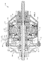
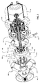
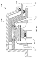
ここで図1および図2を参照すると、一実施形態において、IVT100はハウジングキャップ104に結合したハウジング102を含む。ハウジング102およびハウジングキャップ104はプーリ106などの動力入力インターフェースおよびアクチュエータ継手108などの制御インターフェースを支持している。プーリ106は内燃機関(図示せず)などの回転動力源によって駆動されるドライブベルトに結合することができる。一実施形態において、IVT100にはIVT100の長手方向の軸線を実質的に画定する主軸110が設けられている。主軸110はプーリ106に結合している。主軸110はハウジングキャップ104内の軸受112によって支持されている。IVT100は主軸110を中心として角度的に配置された複数の牽引遊星アセンブリ114含む。各牽引遊星アセンブリ114は第1のキャリア部材116と第2のキャリア部材118とにそれぞれ結合している。主軸110は第1のキャリア部材116に結合している。第1のキャリア部材116および第2のキャリア部材118は主軸110と同軸である。一実施形態において、各牽引遊星アセンブリ114は第1の牽引リング120と第2の牽引リング122とにそれぞれ結合している。各牽引遊星アセンブリ114は半径方向内側位置においてアイドラアセンブリ121に接している。第1の牽引リング120は第1の軸力発生器アセンブリ124に結合している。第1の牽引リング120および第1の軸力発生器アセンブリ124はハウジング102に対して実質的に回転不能である。一実施形態において、第1の軸力発生器アセンブリ124はグランドリング125に結合している。グランドリング125はハウジングキャップ104から延びる肩部123に取り付けられている。第2の牽引リング122は第2の軸力発生器126に結合している。第2の牽引リング122および第2の軸力発生器126は出力動力インターフェース128に結合している。出力動力インターフェース128は負荷(図示せず)に結合することができる。一実施形態において、出力動力インターフェース128は第2の牽引リング122を負荷から機械的に分離するように構成された解放機構130を含む。
With reference now to FIGS. 1 and 2, in one embodiment, the
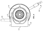
ここで図1〜4を参照すると、一実施形態において、IVT100はシフト制御機構140とともに使用することができる。シフト制御機構140には他の種類の変速機を使用することができ、本明細書では一例としてIVT100で示される。シフト制御機構140はロッカアーム142に結合したアクチュエータ継手108を含むことができる。ロッカアーム142は旋回ピン146を中心として回転するように構成されたシフトフォーク144に結合している。一実施形態において、旋回ピン146は長手方向の軸線からオフセットしている。シフトフォーク144はシフトカラー148に結合している。シフトカラー148は軸受150を支持している。軸受150はキャリアドライバナット152に結合している。キャリアドライバナット152は主軸110と第1のキャリア部材116とに結合している。
1-4, in one embodiment, the
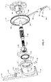
ここで図5を参照するとともに、なお図1〜4を参照すると、一実施形態において、ロッカアーム142は枢軸部143に回転自在に結合している。枢軸部143はシフトフォーク144に取り付けられただぼとすることができる。シフトフォーク144は一組のスロット154を有することができる。スロット154はシフトカラー148に取り付けられた一組の係合だぼ156を案内する。一実施形態において、シフトカラー148には4つの係合だぼ156が設けられている。いくつかの実施形態では、2つの係合だぼ156がスロット154内に載るように配置されている一方、2つの係合だぼ156はハウジングキャップ104の肩部123に形成された一組のスロット155(図2)内に載るように配置されている。一実施形態において、キャリアドライバナット152はヘリカルスプラインを備えて形成された内部穴158を有する。内部穴158は主軸110に形成された相手ヘリカルスプライン160に結合している。キャリアドライバナット152は内部穴158から半径方向外側に延びているいくつかの案内面162が設けられている。案内面162は第1のキャリア部材116に形成された相手案内面164に結合している。
Referring now to FIG. 5 and still referring to FIGS. 1-4, in one embodiment, the
ここで図6を参照すると、一実施形態において、第2のキャリア部材118には中心穴171の周りに角度的に配置されたいくつかのガイドスロット170を設けることができる。図6のページの面において見た場合、ガイドスロット170は半径方向構造線76に並んでいる。ガイドスロット170は遊星アクスル115(図1)の一端を受容するように構成されている。いくつかの実施形態では、ガイドスロット170の半径方向内側部分172は牽引遊星アクスル115を収容するような大きさに作られた湾曲した輪郭で形成される。一実施形態において、第1のキャリア部材116には中心穴175の周りに角度的に配置されたいくつかの半径方向にオフセットしたガイドスロット174が設けられている。各半径方向にオフセットしたガイドスロット174は第1のキャリア部材116の継手を遊星アクスル115に収容するような大きさに作られている。図6のページの面において見た場合、半径方向にオフセットしたガイドスロット174は半径方向構造線76から角度的にオフセットしている。角度的なオフセットは角度88によって概算することができる。角度88は半径方向構造線76と構造線90との間に形成されている。図6のページの面において見た場合、構造線90は半径方向にオフセットしたガイドスロット174を実質的に二分している。いくつかの実施形態では、角度88は3度と45度との間である。小さな角度88によって変速比変更における応答性が高くなるが、場合によっては、制御する、または安定させることがより困難となる。その一方で、大きな角度では変速比変更における応答性が低くなるおそれがあるが、比較すると制御が簡単である。高速の、速いシフト速度を有することが望ましいいくつかの実施形態では、角度88は、例えば、10度とすることができる。より低速の、変速比の精密な制御を有することが望ましい他の実施形態では、角度88は約30度とすることができる。しかしながら、角度88の前記値は説明的な例として提供するものであり、角度88は設計者が所望する任意の手法で変更することができる。いくつかの実施形態では、角度88は10〜25度の範囲の任意の角度とすることができ、その間のあらゆる角度またはその小数部も含む。例えば、角度88は、10、11、12、13、14、15、16、17、18、19、20、21、22、23、24、25またはその任意の一部とすることができる。他の実施形態において、角度88は20度とすることができる。一実施形態において、構造線90が構造線91から距離92だけ半径方向にオフセットするように、半径方向にオフセットしたガイドスロット174を配置することができる。構造線91は構造線90に平行し、かつ第1のキャリア部材116の中心に交差している。
Referring now to FIG. 6, in one embodiment, the
IVT100の動作中、変速比の変更はアクチュエータ継手108を回転することによって得られる。いくつかの実施形態では、アクチュエータ継手108はユーザの手で作動される機械的なリンクとすることができるユーザ制御部(図示せず)に取り付けられている。他の実施形態において、アクチュエータ継手108は、IVT100の所望の変速比を示す回転運動をアクチュエータ継手108に付与することができる電気または油圧アクチュエータに結合することができる。アクチュエータ継手108が長手方向の軸線に対して軸方向に固定されているため、アクチュエータ継手108の回転がロッカアーム142を回転させる傾向にあり、それによって枢軸部143を回転させ、かつ軸方向並進させる。枢軸部143の動きがシフトフォーク144を旋回ピン146を中心として回転させる傾向にある。旋回ピン146を中心としたシフトフォーク144の回転がスロット154の軸方向並進に一致するように、旋回ピン146は主軸110からオフセットする。スロット154の軸方向の動きがシフトカラー148を主軸110に対して軸方向に動かす傾向にある。キャリアドライバナット152がシフトカラー148に動作可能に結合しているため、シフトカラー148の軸方向並進はキャリアドライバナット152の軸方向並進に一致する。キャリアドライバナット152は主軸110のヘリカルスプライン160に結合している。キャリアドライバナット152の軸方向並進は主軸110に対するキャリアドライバナット152の相対回転を容易にする。キャリアドライバナット152が第1のキャリア部材116の案内面164に係合するため、主軸110に対するキャリアドライバナット152の回転は主軸110に対する第1のキャリア部材116の回転に一致する。第2のキャリア部材118に対する第1のキャリア部材116の回転がIVT100の変速比を変更する傾向にある。
During operation of the
設計者は、スロット154に対するロッカ142、枢軸部143および旋回ピン146の位置を、アクチュエータ継手108に適用される回転とキャリアドライバナット152の軸方向変位量との間の所望の関係を得るように構成することができることに留意されたい。いくつかの実施形態では、設計者は、ロッカ142、枢軸部143および旋回ピン146の位置を、アクチュエータ継手108に適用される所望の力またはトルクを供給するように選択し、変速比の変更を達成してもよい。同様に、設計者は、ヘリカルスプライン160のピッチおよびリードがキャリアドライバナット152の軸方向変位量と第1のキャリア部材116の回転との間の所望の関係を得るように選択することができる。
The designer positions the
再度図5および図6を参照すると、一実施形態において、IVT100にはポンプアセンブリ180を設けることができる。ポンプアセンブリ180は第1のキャリア部材116に形成されたローブ184に結合しているポンプドライバ182を含む。ポンプアセンブリ180はポンプドライバ182に取り付けられたポンププランジャ186を含む。ポンププランジャ186は弁体188とバルブプランジャ190とを取り囲んでいる。一実施形態において、ローブ184は第1のキャリア部材116の中心192からオフセットした中心191(図6)を有する。いくつかの実施形態では、ローブ184は、主軸110上に、または保持ナット193上に形成することができる。同様に、ポンプドライバ182がローブ184に係合することができるように、ポンプアセンブリ180は軸方向に適切に配置されている。IVT100の動作中、主軸110は長手方向の軸線を中心として回転し、それによって第1のキャリア部材116を駆動する。第1のキャリア部材116が長手方向の軸線を中心として回転すると、ローブ184はポンプドライバ182を往復運動で駆動する。一実施形態において、グランドリング125にはポンプドライバ182を受容するように構成された案内溝194が設けられている。グランドリング125には、係合だぼ156とシフトフォーク144とにクリアランスを提供するような大きさに適切に作られるいくつかのクリアランス逃げ(clearance reliefs)196も設けることができる。
Referring again to FIGS. 5 and 6, in one embodiment, the
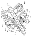
ここで図7〜10に移ると、IVT200は長手方向の軸線204を中心として角度的に配置されたいくつかの牽引遊星アセンブリ202を含むことができる。明確にするため、ハウジングおよびIVT200のいくつかの内部構成要素は図示しない。各牽引遊星アセンブリ202にはボールアクスル206が設けられている。ボールアクスル206は第1のキャリア部材208と第2のキャリア部材210それぞれに動作可能に結合している。第1のキャリア部材208と第2のキャリア部材210は第1のキャリア部材116と第2のキャリア部材118それぞれに実質的に類似しうる。一実施形態において、第1のキャリア部材208および第2のキャリア部材210は回転動力源(図示せず)に結合している。IVT200には牽引遊星アセンブリ202のそれぞれの半径方向外側にあるキャリアドライバリング212が設けられている。キャリアドライバリング212は一組の軸受215によってシフトUリンク214に結合している。軸受215は、例えば、複数のだぼ217を備えたキャリアドライブリング212に回転的に拘束されうる。一実施形態において、シフトUリンク214にはねじ状の穴213が設けられている。ねじ状の穴213は長手方向の軸線204にほぼ平行している。ねじ状の穴213はシフトUリンク214の軸方向並進を容易にするためにねじ状のシフトロッド(図示せず)に結合することができる。
Turning now to FIGS. 7-10, the
特に図9および図10を参照すると、キャリアドライバリング212はキャリアドライバリング212の内周に形成された一組の長手方向の溝220を有する。長手方向の溝220は長手方向の軸線204に実質的に平行している。キャリアドライバリング212は内周に形成された一組のオフセットした長手方向の溝222を有する。オフセットした長手方向の溝222は長手方向の軸線204に対して角度をなしている。図9の面において見た場合、オフセットした長手方向の溝222は長手方向の軸線204に対して角度224を形成している。いくつかの実施形態では、角度224は0〜30度の範囲の任意の角度とすることができ、その間のあらゆる角度またはその小数部も含む。例えば、角度224は、0、1、2、3、4、5、6、7、8、9、10、11、12、13、14、15、16、17、18、19、20、21、22、23、24、25、26、27、28、29、30またはその任意の一部とすることができる。一実施形態において、第1のキャリア部材208にはいくつかのだぼ228が設けられている。だぼ228は長手方向の溝220に結合し、かつ長手方向の溝220によって案内される。第2のキャリア部材210にはいくつかのだぼ230が設けられている。だぼ230はオフセットした長手方向の溝222に結合し、かつオフセットした長手方向の溝222によって案内される。
With particular reference to FIGS. 9 and 10, the
IVT200の動作中、変速比の変更はシフトUリンク214を軸方向に平行移動することによって達成することができる。シフトUリンク214の軸方向並進がキャリアドライバリング212を軸方向に並進させる傾向にある。キャリアドライバリング212の軸方向並進がだぼ228、230を溝220、222内にそれぞれ案内する傾向にある。第1のキャリア部材208および第2のキャリア部材210は軸方向に実質的に固定されているため、第1のキャリア部材208および第2のキャリア部材210はだぼ228、230が溝220、222内においてそれぞれ軸方向に移動すると互いに対して回転する。
During operation of the
特にここで図11〜13を参照すると、キャリアドライバリング212に形成された長手方向の溝は、第2のキャリア部材210に対する第1のキャリア部材208の所望の相対回転を提供するために多くの形態をとることができる。例えば、図11は、長手方向の溝220およびオフセットした長手方向の溝222を示す。キャリアドライバリング212の一方の側において、溝220、222は距離232だけ離れている。キャリアドライバリング212の逆側において、溝220、222は距離234だけ離れている。図12に示す実施形態において、キャリアドライバリング212には長手方向の溝220および一組の湾曲した溝236が設けられている。図13に示す実施形態において、キャリアドライバリング212には一組のプラスにオフセットした長手方向の溝238および一組のマイナスにオフセットした長手方向の溝240が設けられている。本明細書で記載した実施形態は例証的な目的のためであり、キャリアリング212に形成される溝の形状および寸法は所望のシフト性能を達成するように設計者が構成することができることに留意されたい。例えば、長手方向の溝220とオフセットした長手方向の溝222との間の距離232はキャリアドライバリング212の逆側における距離234未満とすることができる。距離232と距離234との間の差は、長手方向の軸線204に沿ったキャリアドライバリング212の軸方向変位量にわたって第2のキャリア部材210に対する第1のキャリア部材208の所望の回転を生成するように構成することができる。
With particular reference now to FIGS. 11-13, the longitudinal groove formed in the
ここで図14に移ると、一実施形態において、IVT300はIVT200に実質的に類似しうる。IVT300は、IVT300の内部構成要素を実質的に収容するように構成されたハウジング302を含むことができる。IVT300にはキャリアドライバリング304を設けることができる。キャリアドライバリング304はキャリアドライバリング212と類似の様式で第1のキャリア部材208と第2のキャリア部材210とに結合することができる。キャリアドライバリング304はモータ(図示せず)などのアクチュエータによって軸方向に並進するように構成することができる。一実施形態において、キャリアドライバリング304は出力リング306上に半径方向に支持される。出力リング306は牽引遊星アセンブリ202のそれぞれに動作可能に結合している。
Turning now to FIG. 14, in one embodiment, the
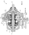
ここで図15を参照すると、一実施形態において、IVT400は主軸404を中心として角度的に配置されたいくつかの牽引遊星アセンブリ402を有することができる。各牽引遊星アセンブリ402は第1の牽引リング406と第2の牽引リング408とのそれぞれに結合している。各牽引遊星アセンブリ402はアイドラアセンブリ410に結合している。アイドラアセンブリ410は各牽引遊星アセンブリ402の半径方向内側にある。一実施形態において、各牽引遊星アセンブリ402は第1のキャリア部材412と第2のキャリア部材414とに結合している。第1のキャリア部材412と第2のキャリア部材414は第1のキャリア部材116と第2のキャリア部材118とのそれぞれに実質的に類似しうる。一実施形態において、第1のキャリア部材412は主軸404に強固に取り付けられている。第1のキャリア部材412および第2のキャリア部材414ならびに主軸404は回転動力源(図示せず)に動作可能に結合するように構成することができる。第2のキャリア部材414は第1のキャリア部材412に対して回転するように構成されている。一実施形態において、第2のキャリア414はトーションプレート416に結合している。トーションプレート416は第2のキャリア414と同軸であり、スプライン、溶接または他の適切な固定手段を用いて第2のキャリアプレート414に強固に取り付けることができる。一実施形態において、トーションプレートでは一般的なように、トーションプレート416は回転方向において剛性があるか、堅いが、軸方向においてわずかな可撓性を有する。軸方向におけるこのわずかな可撓性がバネのようなコンプライアンスをトーションプレート416に付与する。トーションプレート416は半径方向内側位置においてキャリアドライバナット418に結合している。キャリアドライバナット418は、主軸404に形成されたヘリカルスプラインに係合するように配置されたヘリカルスプライン420を備えて形成された内部穴を有する。キャリアドライバナット418はアクチュエータ継手422に動作可能に結合している。一実施形態において、アクチュエータ継手422は図15にベクトル424として示される力を生成するサーボモータまたは手動レバー(図示せず)などのリニアアクチュエータに結合している。一実施形態において、アクチュエータ継手422は主軸404を中心として実質的に回転不能である。
Referring now to FIG. 15, in one embodiment, the
IVT400の動作中、変速比の変更はアクチュエータ継手422を軸方向に平行移動させることによって達成される。アクチュエータ継手422の軸方向並進がキャリアドライバナット418を軸方向に並進させる傾向にある。キャリアドライバナット418がヘリカルスプライン420において主軸404に係合するため、主軸404に対するキャリアドライバナット418の軸方向並進がキャリアドライバナット418と主軸404との間の相対回転を容易にする傾向にある。キャリアドライバナット418が回転するとトーションプレート416は回転し、これが第2のキャリア部材414を第1のキャリア部材412に対して回転させる傾向にある。
During operation of the
ここで図16〜19を参照すると、一実施形態において、IVT500には、アイドラアセンブリ504に接しており、かつアイドラアセンブリ504の半径方向外側にあるいくつかの牽引遊星アセンブリ502を設けることができる。各牽引遊星アセンブリ502は第1の牽引リング506と第2の牽引リング508とのそれぞれに接している。一実施形態において、第1の牽引リング506は実質的に回転不能である。IVT500には出力軸510を設けることができる。出力軸510は、第2の牽引リング508に係合するように構成された共通の軸力発生器継手512に結合している。各牽引遊星アセンブリ502は第1のキャリア部材514と第2のキャリア部材516とのそれぞれによって案内され、かつ支持されている。第1のキャリア部材514と第2のキャリア部材516にはガイドスロット513、515がそれぞれ設けられている。一実施形態において、ガイドスロット513、515はガイドスロット170、174のそれぞれに実質的に類似する。第1のキャリア部材514と第2のキャリア部材516は回転動力源(図示せず)から動力入力を受け取るように構成されている。一実施形態において、入力軸518はキャリアギア522に係合するドライブギア520に結合することができる。キャリアギア522は第1のキャリア部材514と第2のキャリア部材516への動力の伝達を容易にする。出力軸510は軸受によって、例えば、ハウジング524上に支持することができる。一実施形態において、ハウジング524はIVT500の内部構成要素を実質的に収容するために互いに固定された2つの部品によって形成される。
Referring now to FIGS. 16-19, in one embodiment, the
一実施形態において、IVT500にはIVT500の長手方向の軸線を実質的に画定する中心軸526が設けられている。中心軸526は第1のキャリア部材514および第2のキャリア部材516を支持するように構成することができる。いくつかの実施形態では、第2のキャリア部材516は中心軸526に強固に取り付けられている。第1のキャリア部材514が第2のキャリア部材516に対して回転することができるように、第1のキャリア部材514を中心軸526上に案内することができる。中心軸526の一端はアクチュエータ継手528を支持するように構成することができる。一実施形態において、軸受529は中心軸514上にアクチュエータ継手528を支持する。軸受529は中心軸526に対するアクチュエータ継手528の軸方向並進を可能にするように構成されている。アクチュエータ継手528はスプラインによってハウジング524に取り付けられており、中心軸526に対して実質的に回転不能である。一実施形態において、アクチュエータ継手528はアクチュエータ継手528の軸方向並進を容易にするためにリニアアクチュエータ(図示せず)に結合している。アクチュエータ継手528は軸受530によってキャリアドライバハブ532に結合している。キャリアドライバハブ532は第1のキャリア部材514と第2のキャリア部材516とに結合している。
In one embodiment, the
ここで特に図17〜19を参照すると、キャリアドライバハブ532には実質的に円筒の本体から延びるいくつかのロッド534を設けることができる。ロッド534のそれぞれにはローラ536が設けられている。ロッド534は第2のキャリア部材516上に形成されたいくつかの長手方向のスロット538に係合している。ローラ536は第1のキャリア部材514上に形成されたいくつかの長手方向のスロット540に係合している。長手方向のスロット538はIVT500の長手方向の軸線と実質的に平行している。図19のページの面において見た場合、長手方向のスロット540はIVT500の長手方向の軸線に対して角度をなしている。
With particular reference now to FIGS. 17-19, the
IVT500の動作中、変速比の変更はアクチュエータ継手528を軸方向に平行移動することによって達成される。アクチュエータ継手528の軸方向並進はキャリアドライバハブ532を軸方向に並進させる傾向にある。キャリアドライバハブ532が軸方向に並進すると、ロッド534およびローラ536は長手方向のスロット538、540それぞれに沿って軸方向に並進する。長手方向のスロット540が長手方向のスロット540に対して角度をなしているため、ロッド534とローラ536の軸方向並進が第1のキャリア部材514と第2のキャリア部材516との間の相対回転を発生させ、それによってIVT500の比を変更する傾向にある。いくつかの実施形態では、IVT500に、キャリアドライバハブ532をIVT500の軸方向端部の1つに押し動かすように構成したバネ542を設けることができる。
During operation of the
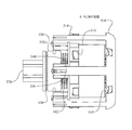
ここで図20および図21を参照すると、一実施形態において、IVT600はハウジングキャップ604に結合したハウジング602を含む。ハウジング602およびハウジングキャップ604はプーリ606およびシフトアクチュエータ608などの動力入力インターフェースを支持する。プーリ606は内燃機関(図示せず)などの回転動力源によって駆動するドライブベルトに結合することができる。一実施形態において、IVT600にはIVT600の長手方向の軸線を実質的に画定する主軸610が設けられている。主軸610はプーリ606に結合している。IVT600は、第1のキャリア部材616と第2のキャリア部材618とのそれぞれに結合した複数の牽引遊星アセンブリ614を含む。第1のキャリア部材616および第2のキャリア部材618には、ガイドスロット170および半径方向にオフセットしたガイドスロット174に実質的に類似するガイドスロットが設けられている。一実施形態において、第1のキャリア部材616および第2のキャリア部材618は図21のページの面において見た場合、薄く、実質的に均一な断面を有し、これによって金属プレス加工などの種々の製造技術を第1のキャリア部材616および第2のキャリア部材618の製造に用いることを可能にする。
Referring now to FIGS. 20 and 21, in one embodiment, the
なお図20および図21を参照すると、一実施形態において、主軸610は第1のキャリア部材616に結合している。各牽引遊星アセンブリ614は第1の牽引リング620と第2の牽引リング622とにそれぞれ接している。各牽引遊星アセンブリ614は半径方向内側位置においてアイドラアセンブリ621に接している。第2の牽引リング622は軸力発生器624に結合している。軸力発生器624は出力ドライバ626に結合している。一実施形態において、第1の牽引リング620はグランドリング625に結合し、ハウジング602に対して実質的に回転不能である。IVT600は出力ドライバ626に結合した出力軸627を有する。出力軸627はIVT600からの回転動力を伝達する。一実施形態において、出力軸627は、アンギュラ接触軸受628とラジアル玉軸受629とによってハウジング602内に支持されている(例えば、図23を参照)。いくつかの実施形態では、シャフトシール631は出力軸627とハウジング602とに結合することができる。
Referring to FIGS. 20 and 21, in one embodiment, the
いくつかの実施形態では、IVT600には、第2のキャリア部材618と主軸610とに結合しているトルクリミッタ630を設けることができる。IVT600には、主軸610に結合しているポンプアセンブリ635も設けることができる(例えば、図22を参照)。一実施形態において、ポンプアセンブリ635では、トランスミッション流体を加圧し、それをIVT600の内部構成要素に分配するためのジーロータ式ポンプを使用することができる。ポンプアセンブリ635は、トランスミッション流体を送るためのホースおよび/またはラインを適切に備えることができる。IVT600の動作中、ポンプアセンブリ635は主軸610によって駆動する。
In some embodiments, the
ここで図22および図23を参照すると、一実施形態において、IVT600にはシフト制御機構640が設けられている。シフト制御機構640は他の種類の変速機において使用することができ、ここでは一例としてIVT600とともに示される。シフト制御機構640はシフトアクチュエータ608に結合したアクチュエータリンク642を含むことができる。シフトアクチュエータ608はシフトフォーク644に結合することができる。一実施形態において、シフトアクチュエータ608は軸線646を中心としてシフトフォーク644を旋回させるように構成されている。一実施形態において、軸線646はIVT600の長手方向の軸線からオフセットしている。シフトフォーク644はハウジングキャップ604内に支持することができる。シフトフォーク644はシフトカラー648に結合することができる。シフトカラー648は軸受650を支持する。シフトフォーク644とシフトカラー648とは、例えば、ピン651によって結合することができる。シフトフォーク644およびシフトカラー648はIVT600の長手方向の軸線を中心として実質的に回転不能である。一実施形態において、シフト制御機構640はキャリアドライバナット652を含む。キャリアドライバナット652は一組のヘリカルスプライン654を介して主軸610に結合している。キャリアドライバナット652はキャリア延長部656を介して第1のキャリア部材616に結合している。一実施形態において、キャリア延長部656はキャリアドライバナット652に係合するように構成されている一組の軸方向のガイドスロットを有する。
Referring now to FIGS. 22 and 23, in one embodiment, the
IVT600の動作中、変速比の切り替えはアクチュエータリンク642を動かし、それによってシフトアクチュエータ608を回転することによって達成することができる。シフトアクチュエータ608の回転は軸線646を中心としたシフトフォーク644の旋回に一致する。シフトフォーク644の旋回はシフトカラー648を主軸610に対して軸方向に押し動かす。シフトカラー648はそれによって軸受650およびキャリアドライバナット652を軸方向に並進する。ヘリカルスプライン654は、キャリアドライバナット652が軸方向に動くとキャリアドライバナット652を回転させる傾向がある。キャリアドライバナット652の回転は通常小角度である。キャリア延長部656、したがって、第1のキャリア部材616はキャリアドライバナット652による回転を通じて案内される。前に図6を参照して説明したように、第2のキャリア部材618に対する第1のキャリア部材616の回転がIVT600の変速比の切り替えを生じさせる。
During operation of the
一実施形態において、ヘリカルスプライン654は200〜1000mmの範囲のリードを有する。いくつかの用途においては、リードは400〜800mmの範囲である。リードはバックトルクの伝達として公知の現象を相殺することができる摩擦がシステム内にどれほどあるかに関連する。リードは、キャリアドライバナット652に対する入力と、比全体を通じて切り替えるのに必要とされる第1のキャリア部材616の回転と、利用可能なパッケージスペースを低減するような大きさに作ることができる。リードのサイジングは設計要件の対象であり、また、試験結果に影響される可能性がある。
In one embodiment,
ここで図24および図25を参照すると、一実施形態において、IVT600には、第2のキャリア部材618に結合しているトルクリミッタ630を設けることができる。トルクリミッタ630は、他の種類の変速機において使用することができ、本明細書で一例としてIVT600とともに示される。第2のキャリア部材618には、主軸610に案内するように構成されている案内肩部660が設けられている。第2のキャリア部材618は、案内肩部660の周りに半径方向に配置されたいくつかの開口部662を有する。開口部662は複数のバネ664に結合するのに適切な大きさに作られる。一実施形態において、バネ664はエンドキャップ666を有するコイルバネである。トルクリミッタ630はバネキャリア668を含む。バネ664はバネキャリア668に結合している。いくつかの実施形態では、バネ664をバネキャリア668上に保持することを容易にするために、各エンドキャップ666と係合するいくつかの保持用だぼ670がバネキャリア668上に設けられる。バネキャリア668はスプライン式の内部穴672によって主軸610に結合している。
Referring now to FIGS. 24 and 25, in one embodiment, the
一実施形態において、トルクリミッタ630は、第2のキャリア部材618に結合しているキャリアキャップ676を含む。いくつかの実施形態では、バネキャリア668は第2のキャリア部材618とキャリアキャップ676との間に軸方向に配置されている。キャリアキャップ676には、例えばリベット679により第2のキャリア部材618に取り付けることを容易にするためのいくつかのタブ678を設けることができる。キャリアキャップ676には、案内肩部682の周りに半径方向に配置されたいくつかの開口部680を設けることができる。一実施形態において、案内肩部682はバネキャリア668上に形成された相手肩部684と協働する。
In one embodiment,
IVT600の動作中、トルクリミッタ630を使用することによってトルクを予定値に制限することができる。主軸610はプーリ606から回転動力を受け取るように構成されている。回転動力は第1のキャリア部材616とバネキャリア668とに伝達される。バネキャリア668は、バネ664を介して第2のキャリア部材618に回転動力を伝達する。バネ664は、出力トルクが予定値を超えた場合、または第2のキャリア部材618にかかるトルクが予定値を超えた場合、バネ664がたわむように適切な大きさに作られる。バネ664のたわみは第1のキャリア部材616に対する第2のキャリア部材618の回転に一致し、それによって変速比を切り替える。変速比の切り替えによって第2のキャリア部材618のトルクが減少する。
During operation of the
ここで図26〜29を参照すると、一実施形態において、IVT600に解放機構700を設けることができる。解放機構700は他の種類の変速機において使用することができ、本明細書では一例としてIVT600とともに示される。一実施形態において、解放機構700は、継手リング704に結合した外部リング702を含む。継手リング704は牽引リング620に取り付けられている。いくつかの実施形態では、外部リング702と継手リング704はグランドリング625の代わりとなる。外部リング702はハウジング602とハウジングキャップ604とに結合する。いくつかの実施形態では、アクチュエータ(図示せず)が外部リング702に結合している。例えば、アクチュエータは、ハウジング602中に延在し、それによって外部リング702を回転させることを可能にするレバー(図示せず)とすることができる。外部リング702には内周の周りにいくつかのランプ706が設けられている。ランプ706は内部リング704の外側周縁部に形成した一組のスプライン708に結合している。IVT600の動作中、出力からの入力の分離は外部リング706を回転することによって達成することができる。外部リング706の回転は牽引遊星アセンブリ614からの牽引リング620の軸方向変位量に一致する。
Referring now to FIGS. 26-29, in one embodiment, the
ここで図29〜30に移ると、一実施形態において、IVT600には解放機構800を設けることができる。解放機構800は他の種類の変速機において使用することができ、本明細書では一例としてIVT600とともに示される。いくつかの実施形態では、解放機構800は継手806を使用して出力軸804に選択的に結合することができる駆動軸802を有する。駆動軸802を組み立てると、出力軸804は出力軸627の代わりに使用することができる。継手806は出力軸804の内径に形成した一組のスプライン808に係合するように構成されている。いくつかの実施形態では、継手と出力軸804との間にバネ(図示せず)を挿入することができる。バネは継手806を図29に示される位置である、係合位置に付勢する傾向にある。継手806はケーブル牽引部(cable pull)810に取り付けられている。ケーブル牽引部810は軸受812によって継手806の内方穴に支持することができる。ケーブル牽引部810はプッシュプルケーブル(図示せず)に取り付けることができる。ケーブルは、ケーブルに張力をかけ、継手806を軸方向に動かすように作動することができる外部リンクに結合することができる。ケーブルガイド814によってケーブルが干渉することなく出力軸814の内部穴に入ることができる道が提供される。ケーブルガイド814は軸受816によって支持される。IVT600の動作中、図30に示すように、ケーブル(図示せず)に張力をかけることによって、および継手806を軸方向に平行移動することによって、出力軸804を係合位置に選択的に結合することができる。
Turning now to FIGS. 29-30, in one embodiment, the
ここで図31〜34を参照すると、一実施形態において、IVT600に解放機構900を設けることができる。解放機構900を他の種類の変速機において使用することができ、ここでは一例としてIVT600とともに示される。一実施形態において、解放機構900を出力軸627の代わりにすることができる。解放機構900は、軸受628、629およびシール630によってハウジング602内に支持されるように適切に構成された細長いシャフト902を含むことができる。細長いシャフト902は第1の端部901および第2の端部903を有することができる。第1の端部901は、例えば、キー溝または他の固定手段によって出力負荷に結合するように構成することができる。シャフト902の第2の端部903にはいくつかの進退可能な歯904が設けられている。進退可能な歯904は端部903の周縁を中心として半径方向に配置される。進退可能な歯904は端部903に形成した軸方向延長部906間に挿入され、軸方向延長部906によって保持されうる。進退可能な歯904は摺動部材908に動作可能に結合している。摺動部材908はアクチュエータ継手910に結合している。摺動部材908は進退可能な歯904を係合位置または解放位置のいずれかに案内する。一実施形態において、進退可能な歯904は、進退可能な歯904を図31および図32に示した位置に付勢するように構成されたバネ部材(図示せず)に結合することができる。前記位置において、進退可能な歯904は、例えば、出力ドライバ626に係合することができる。摺動部材908の動きを容易にし、それに応じて歯904を図33および図34に示す第2の位置に動かすために、アクチュエータ(図示せず)がシャフト902の内部穴を通じてアクチュエータ継手910に結合するように構成することができる。前記位置において、歯904は出力ドライバ626がシャフト902から分離されるように半径方向にずらされる。
Referring now to FIGS. 31-34, in one embodiment, the
ここで図35を参照すると、一実施形態において、IVT100、IVT600または変速機の他の実施形態に油圧システム950が使用されうる。油圧システム950は充填深さ954を有するサンプ952を含む。いくつかの実施形態では、サンプ952は、例えば、ハウジング602の下部内に形成される。説明目的のため、IVT600の回転構成要素は回転構成要素955として図35に示される。油圧システム950は、例えば、ポンプアセンブリ635に実質的に類似しうるポンプ956を含む。ポンプ956は、流体をサンプ952からリザーバ958に送る。一実施形態において、リザーバ958には第1のオリフィス960および第2のオリフィス962が設けられている。第1のオリフィス960は第2のオリフィス960の上方に配置される。リザーバ958は回転構成要素955およびサンプ952の上方にある。一実施形態において、リザーバ958は、例えば、ハウジング602上に形成することができる。他の実施形態において、リザーバ958はハウジング602の外側に取り付けられ、回転構成要素958とサンプ952とに流体連通を設けるように構成されている。
Referring now to FIG. 35, in one embodiment, a
IVT600の組み立て時、例えば、流体がサンプ952に添加される。いくつかの実施形態では、サンプ952の容積は小さくされうるため、サンプ952に添加される流体量の変化は充填深さ954に多大な影響を与える可能性がある。いくつかの例において、充填深さ954はサンプ952内の流体を回転構成要素955に接触させるのに十分な高さとすることができる。サンプ952内の流体と回転構成要素955との間の接触が抗力および風損を生じさせるおそれがあり、これらは問題として公知である。しかしながら、特定の例においては、サンプ952に添加される流体の量を増加させることが望ましいこともある。例えば、流体の量を増加すると、熱特性、耐久性および保守が向上する可能性がある。したがって、油圧システム952はサンプ952に添加される流体量を増加し、充填深さ954を回転構成要素955より下に維持することを容易にするために実装されうる。
During assembly of the
IVT600の動作中、例えば、流体がサンプ952からポンプ956によって引き出され、充填深さ954を低下させる。流体が加圧され、ポンプ956によってリザーバ958に送られる。リザーバ958は加圧流体を受容し、リザーバ958の容積を充填する。第1のオリフィス960および第2のオリフィス962は、リザーバ958が加圧されると、流体が第1のオリフィス960から流れることができるが、第2のオリフィス962からは実質的に流体が流れないような適切な大きさに作られる。いくつかの実施形態では、第2のオリフィス962は、リザーバ958が減圧されると開き、リザーバ958が加圧されると閉じるように構成される逆止弁とすることができる。第1のオリフィス960から流れる流体は潤滑および冷却を提供するために回転構成要素955に案内される。IVT600の動作中、例えば、リザーバ958は一定量の流体を蓄積する。IVT600の動作が停止すると、蓄積された量がリザーバ958から排出され、サンプ952に戻る。
During operation of the
ここで図36〜38を参照すると、一実施形態において、IVT1000はIVT100に実質的に類似しうる。明確化のため、IVT1000の特定の内部構成要素のみを示す。一実施形態において、IVT1000は長手方向の軸線1002を中心として角度的に配置されたいくつかのボール1001を含む。各ボール1001は傾斜可能な軸線を形成するアクスル1003の周りを回転するように構成されている。アクスル1003の一端に球形のころ1004が設けられている。アクスル1003の反対端が、例えば、ピン1010によってガイドブロック1005に結合している。一実施形態において、ガイドブロック1005は延長部1006を有する。IVT1000はキャリア部材118に実質的に類似する第1のキャリア部材1007を含むことができる。第1のキャリア部材1007はアクスル1003に適切な自由度を付与するために球形のころ1004に結合するように構成される。IVT1000は、ガイドブロック1005に動作可能に結合するように構成された第2のキャリア部材1008を含むことができる。IVT100には、第1のキャリア部材1007と第2のキャリア部材1008と同軸に配置されたシフトプレート1012が設けられている。シフトプレート1012は延長部1006に結合している。一実施形態において、シフトプレート1012は、例えば、シフト制御機構140によって作動することができる。シフトプレート1012は第1のキャリア部材1007と第2のキャリア部材1008に対して回転するように構成される。
With reference now to FIGS. 36-38, in one embodiment, the
特にここで図38を参照すると、一実施形態において、シフトプレート1012にはいくつかのスロット1014が設けられている。延長部1006はスロット1014に結合している。説明目的のため、スロット1014の1つのみを示す。スロット1014は3つの部分、第1の部分1015と、中間部分1016と、第3の部分1017とを有するものとして示されうる。中間部分1016は一組の半径方向構造線1018、1019それぞれの間のアーク長として画定することができる。第1の部分1015および第3の部分1017は、半径方向にオフセットしたガイドスロット174が半径方向構造線76からオフセットするのと実質的に類似する様式で半径方向構造線1018、1019それぞれから角度的にオフセットしている。IVT1000の動作中、変速比の変更は第1のキャリア部材1007と第2のキャリア部材1008とに対してシフトプレート1012を回転させることによって達成することができる。延長部1006はスロット1014によって案内される。延長部1006がスロット1014の第1の部分1015に配置されると、変速比は前進または正の比率とすることができる。延長部1006がスロット1014の第3の部分1017に配置されると、変速比は後進または負の比率とすることができる。延長部1006が中間部分1016に配置されると、変速比はニュートラルまたは「動力ゼロ」と呼ばれる状態にある。スロット1014の寸法を、変速比の変更と、変更、例えば、アクチュエータ位置の変更との間の所望の関係に適切に対応するような大きさにすることができる。
With particular reference now to FIG. 38, in one embodiment, the
上記説明では特定の構成要素またはサブアセンブリの寸法を提供したことに留意されたい。言及した寸法または寸法の範囲は最良実施態様などの特定の法的要件を可能な限り最良に遵守するために提供するものである。しかしながら、本明細書中に記載される本発明の範囲は特許請求の範囲の文言のみによって決定されるべきであり、したがって、いずれか1つの請求項に特定の寸法またはその範囲、請求項の特徴を記載する限りを除いては言及した寸法のいずれも発明の実施形態を限定するとみなされるべきではない。 It should be noted that the above description provided specific component or subassembly dimensions. The dimensions or range of dimensions referred to are provided in order to best comply with certain legal requirements such as best embodiments. However, the scope of the invention described herein should be determined solely by the language of the claims, and accordingly, any one particular claim or its scope, the features of the claim None of the dimensions mentioned should be considered as limiting the embodiments of the invention except as described.
以上の説明は、本発明のある実施形態に関する詳述である。しかしながら、これまでの説明がいかに詳細に見えようと、本明細書に開示されている発明が多くの方法で実施可能であることは認識されるであろう。本発明の特定の実施形態の特徴または態様を記載する際の特定用語の使用は、その用語が、当該用語が関連している発明の機能または態様の任意の特定の特徴を含むものと限定されるべく本明細書において再定義されていることを含意するものとして、解釈されるべきでない点は留意されるべきである。 The above description is a detailed description of an embodiment of the present invention. However, it will be appreciated that no matter how detailed the foregoing description may appear, the invention disclosed herein may be implemented in many ways. The use of a particular term in describing a feature or aspect of a particular embodiment of the invention is limited as that term includes any particular feature of the function or aspect of the invention to which the term relates. It should be noted that this should not be construed as implying that it has been redefined herein.
Claims (33)
前記牽引遊星アセンブリのそれぞれに結合している第1のキャリア部材であって、前記牽引遊星アセンブリを案内するように構成された第1のキャリア部材と、
前記牽引遊星アセンブリのそれぞれに結合している第2のキャリア部材であって、前記牽引遊星アセンブリを案内するように構成された第2のキャリア部材と、
前記第1のキャリア部材に結合しているキャリアドライバナットであって、軸方向に平行移動するように構成されたキャリアドライバナットと、
を備え、
前記第1のキャリア部材と前記第2のキャリア部材とが前記長手方向の軸線周りを回転可能であり、
前記キャリアドライバナットの軸方向の平行移動が前記第2のキャリア部材に対する前記第1のキャリア部材の回転に対応する、
シフト機構。 A shift mechanism for an infinite transmission ratio transmission (IVT) having a longitudinal axis and a plurality of tow planetary assemblies arranged at an angle about the longitudinal axis,
A first carrier member coupled to each of the traction planet assemblies, the first carrier member configured to guide the traction planet assembly;
A second carrier member coupled to each of the traction planet assemblies, the second carrier member configured to guide the traction planet assembly;
A carrier driver nut coupled to the first carrier member, the carrier driver nut configured to translate in an axial direction; and
With
The first carrier member and the second carrier member are rotatable about the longitudinal axis;
The axial translation of the carrier driver nut corresponds to the rotation of the first carrier member relative to the second carrier member;
Shift mechanism.
請求項1に記載のシフト機構。 A plurality of radially offset slots are provided in the first carrier member;
The shift mechanism according to claim 1.
をさらに備える、
請求項2に記載のシフト機構。 A main shaft disposed along the longitudinal axis;
Further comprising
The shift mechanism according to claim 2.
請求項3に記載のシフト機構。 The main shaft is operably coupled to the first carrier member and the second carrier member;
The shift mechanism according to claim 3.
請求項4に記載のシフト機構。 A plurality of helical splines are provided on the main shaft,
The shift mechanism according to claim 4.
請求項5に記載のシフト機構。 The carrier driver nut is configured to translate in the axial direction along the main axis,
The shift mechanism according to claim 5.
請求項6に記載のシフト機構。 The carrier driver nut is coupled to the helical spline;
The shift mechanism according to claim 6.
前記長手方向の軸線からオフセットした旋回ピンを有するシフトフォークと、
をさらに備え、
前記キャリアドライバナットは、前記シフトフォークに動作可能に結合しており、前記主軸の前記ヘリカルスプラインに係合するように構成されている内部穴を有し、前記長手方向の軸線周りを回転するように構成されており、
前記旋回ピン周りの前記シフトフォークの動きは、前記キャリアドライバナットの軸方向の動きに対応する、
請求項1に記載のシフト機構。 A main shaft disposed along the longitudinal axis and provided with a plurality of helical spline splines;
A shift fork having a pivot pin offset from the longitudinal axis;
Further comprising
The carrier driver nut is operably coupled to the shift fork, has an internal hole configured to engage the helical spline of the main shaft, and rotates about the longitudinal axis. Is composed of
The movement of the shift fork about the pivot pin corresponds to the axial movement of the carrier driver nut;
The shift mechanism according to claim 1.
前記長手方向の軸線周りに角度を付けて配置された複数の牽引遊星アセンブリと、
前記牽引遊星アセンブリのそれぞれに結合している第1のキャリア部材であって、複数の半径方向にオフセットしたスロットが設けられており、前記牽引遊星アセンブリを案内するように構成された第1のキャリア部材と、
前記牽引遊星アセンブリのそれぞれに結合している第2のキャリア部材であって、複数の半径方向スロットが設けられている第2のキャリア部材と、
前記第1のキャリア部材に結合しているキャリアドライバナットであって、軸方向に平行移動するように構成されたキャリアドライバナットと、
を備え、
前記第1及び前記第2のキャリア部材は、回転動力入力を受け取るように構成されており、前記第1のキャリア部材は、前記第2のキャリア部材に対して回転可能であり、
前記キャリアドライバナットの軸方向の平行移動が前記第2のキャリア部材に対する前記第1のキャリア部材の回転に対応する、
IVT。 An infinite transmission (IVT) transmission having a longitudinal axis,
A plurality of tow planetary assemblies disposed at an angle about the longitudinal axis;
A first carrier member coupled to each of the tow planetary assemblies, wherein the first carrier is configured to guide the towed planetary assembly with a plurality of radially offset slots. Members,
A second carrier member coupled to each of said traction planet assemblies, wherein the second carrier member is provided with a plurality of radial slots;
A carrier driver nut coupled to the first carrier member, the carrier driver nut configured to translate in an axial direction; and
With
The first and second carrier members are configured to receive rotational power input, the first carrier member being rotatable relative to the second carrier member;
The axial translation of the carrier driver nut corresponds to the rotation of the first carrier member relative to the second carrier member;
IVT.
をさらに備える、
請求項9に記載のIVT。 A main shaft disposed along the longitudinal axis;
Further comprising
The IVT according to claim 9.
請求項10に記載のIVT。 The main shaft is operably coupled to the first and second carrier members;
The IVT according to claim 10.
請求項11に記載のIVT。 A plurality of helical splines are provided on the main shaft,
The IVT of claim 11.
請求項12に記載のシフト機構。 The carrier driver nut is configured to translate in the axial direction along the main shaft,
The shift mechanism according to claim 12.
前記長手方向の軸線からオフセットした旋回ピンを有するシフトフォークと、
をさらに備え、
前記キャリアドライバナットは、前記シフトフォークに動作可能に結合しており、前記主軸の前記ヘリカルスプラインに係合するように構成されている内部穴を有し、前記長手方向の軸線周りを回転するように構成されており、
前記旋回ピン周りの前記シフトフォークの動きは、前記キャリアドライバナットの軸方向の動きに対応する、
請求項9に記載のIVT。 A main shaft disposed along the longitudinal axis and provided with a plurality of helical spline splines;
A shift fork having a pivot pin offset from the longitudinal axis;
Further comprising
The carrier driver nut is operably coupled to the shift fork, has an internal hole configured to engage the helical spline of the main shaft, and rotates about the longitudinal axis. Is composed of
The movement of the shift fork about the pivot pin corresponds to the axial movement of the carrier driver nut;
The IVT according to claim 9.
前記長手方向の軸線周りに角度を付けて配置された複数の牽引遊星アセンブリを提供するステップと、
前記牽引遊星アセンブリのそれぞれに結合している第1のキャリア部材であって、前記牽引遊星アセンブリを案内するように構成された複数の半径方向にオフセットしたスロットを有する第1のキャリア部材を提供するステップと、
前記牽引遊星アセンブリのそれぞれに結合している第2のキャリア部材であって、前記牽引遊星アセンブリを案内するように構成された複数の半径方向案内スロットを有する第2のキャリア部材を提供するステップと、
前記第1及び第2のキャリア部材を回転動力源に接続するステップと、
前記第1のキャリア部材に結合しているキャリアドライバナットを提供するステップと、
前記長手方向の軸線に沿って前記キャリアドライバナットを平行移動させるステップと
を備え、
前記キャリアドライバナットを平行移動させる前記ステップは、前記第2のキャリア部材に対して前記第1のキャリア部材を回転させるステップを含む、方法。 A method for controlling an infinite transmission ratio transmission (IVT) having a longitudinal axis comprising:
Providing a plurality of tow planetary assemblies disposed at an angle about the longitudinal axis;
A first carrier member coupled to each of the traction planet assemblies, the first carrier member having a plurality of radially offset slots configured to guide the traction planet assembly. Steps,
Providing a second carrier member coupled to each of the tow planetary assemblies, the second carrier member having a plurality of radial guide slots configured to guide the tow planetary assemblies; ,
Connecting the first and second carrier members to a rotational power source;
Providing a carrier driver nut coupled to the first carrier member;
Translating the carrier driver nut along the longitudinal axis ;
The method of translating the carrier driver nut includes rotating the first carrier member relative to the second carrier member .
をさらに備える、請求項15に記載の方法。 Operatively coupling the carrier driver nut to a shift fork;
The method of claim 15, further comprising:
をさらに備える、請求項15に記載の方法。 Connecting a torque limiter to the second carrier member;
The method of claim 15, further comprising:
をさらに備える、請求項17に記載の方法。 Connecting the torque limiter to the rotational power source;
The method of claim 17 , further comprising:
をさらに備える、請求項15に記載の方法。 Sensing a torque applied to the second carrier member;
The method of claim 15, further comprising:
をさらに備える、請求項19に記載の方法。 Rotating the second carrier member based at least in part on the sensed torque;
20. The method of claim 19 , further comprising:
請求項20に記載の方法。 The step of rotating the second carrier member includes the step of adjusting the speed ratio.
The method of claim 20 .
前記長手方向の軸線に沿って配置され、複数のヘリカルスプラインが設けられている主軸と、
前記長手方向の軸線周りに角度を付けて配置された複数の牽引遊星アセンブリと、
前記牽引遊星アセンブリのそれぞれに結合している第1のキャリア部材であって、複数の半径方向にオフセットしたスロットが設けられており、前記牽引遊星アセンブリを案内するように構成された第1のキャリア部材と、
前記牽引遊星アセンブリのそれぞれに結合している第2のキャリア部材であって、複数の半径方向スロットが設けられている第2のキャリア部材と、
シフト機構と、
を備え、
前記第1及び前記第2のキャリア部材は、回転動力源に接続されており、
前記シフト機構は、
前記長手方向の軸線からオフセットした旋回ピンを有するシフトフォークと、
前記シフトフォークに動作可能に結合しており、前記主軸の前記ヘリカルスプラインに係合するように構成されている内部穴を有し、前記長手方向の軸線周りを回転するように構成されたキャリアドライバナットと、
を含み、
前記旋回ピン周りの前記シフトフォークの動きは、前記キャリアドライバナットの軸方向の動きに対応し、前記キャリアドライバナットの軸方向の動きは、前記第2のキャリア部材に対する前記第1のキャリア部材の回転に対応する、IVT。 An infinite transmission (IVT) transmission having a longitudinal axis,
A main shaft disposed along the longitudinal axis and provided with a plurality of helical splines;
A plurality of tow planetary assemblies disposed at an angle about the longitudinal axis;
A first carrier member coupled to each of the tow planetary assemblies, wherein the first carrier is configured to guide the towed planetary assembly with a plurality of radially offset slots. Members,
A second carrier member coupled to each of said traction planet assemblies, wherein the second carrier member is provided with a plurality of radial slots;
A shift mechanism;
With
The first and second carrier members are connected to a rotational power source;
The shift mechanism is
A shift fork having a pivot pin offset from the longitudinal axis;
A carrier driver operably coupled to the shift fork and having an internal hole configured to engage the helical spline of the main shaft and configured to rotate about the longitudinal axis With nuts,
Including
The movement of the shift fork around the pivot pin corresponds to the movement of the carrier driver nut in the axial direction, and the movement of the carrier driver nut in the axial direction of the first carrier member relative to the second carrier member. IVT corresponding to rotation.
をさらに備える、
請求項22に記載のIVT。 A first traction ring that contacts each of the traction planet assemblies and is substantially non-rotatable about the main axis;
Further comprising
24. The IVT of claim 22 .
をさらに備える、
請求項23に記載のIVT。 A second traction ring configured to contact each of the traction planet assemblies and provide power output from the IVT;
Further comprising
24. The IVT of claim 23 .
をさらに備える、請求項24に記載のIVT。 An output shaft operably coupled to the second traction ring;
25. The IVT of claim 24 , further comprising:
をさらに備える、請求項25に記載のIVT。 A release mechanism operably coupled to the output shaft;
26. The IVT of claim 25 , further comprising:
をさらに備える、請求項26に記載のIVT。 A torque limiter coupled to the second carrier member;
27. The IVT of claim 26 , further comprising:
請求項26に記載のIVT。 The torque limiter is coupled to the main shaft;
27. The IVT of claim 26 .
請求項28に記載のIVT。 The torque limiter includes a plurality of springs operably coupled to the second carrier member and the main shaft;
29. The IVT of claim 28 .
前記第1のキャリア部材には、複数の半径方向にオフセットした案内スロットが設けられており、前記第1及び第2のキャリア部材は、回転動力を受け取るように構成されており、
前記シフト機構は、
前記長手方向の軸線からオフセットした旋回ピンを有するシフトフォークと、
前記シフトフォークに動作可能に結合しており、前記主軸上に形成されている複数のヘリカルスプラインに係合するように構成されている内部穴を有し、前記長手方向の軸線周りを回転するように構成されており、前記長手方向に沿って軸方向に平行移動するように構成されているキャリアドライバナットと、
を含み、
前記旋回ピン周りの前記シフトフォークの動きは、前記キャリアドライバナットの軸方向の動きに対応し、前記キャリアドライバナットの軸方向の動きは、前記第2のキャリア部材に対する前記第1のキャリア部材の回転に対応する、
IVT。 A main shaft disposed along a longitudinal axis of an infinite transmission ratio transmission (IVT) and a plurality of tractions disposed at an angle around the main shaft and coupled to the first and second carrier members A shift mechanism for the IVT having a planetary assembly,
The first carrier member is provided with a plurality of radially offset guide slots, and the first and second carrier members are configured to receive rotational power,
The shift mechanism is
A shift fork having a pivot pin offset from the longitudinal axis;
Operatively coupled to the shift fork, having an internal hole configured to engage a plurality of helical splines formed on the main shaft, and rotating about the longitudinal axis A carrier driver nut configured to translate in the axial direction along the longitudinal direction;
Including
The movement of the shift fork around the pivot pin corresponds to the movement of the carrier driver nut in the axial direction, and the movement of the carrier driver nut in the axial direction of the first carrier member relative to the second carrier member. Corresponding to rotation,
IVT.
をさらに備える、
請求項30に記載のIVT。 A shift collar operably coupled to the shift fork,
Further comprising
32. The IVT of claim 30 .
をさらに備える、
請求項31に記載のIVT。 A bearing coupled to the shift collar and configured to couple with the carrier driver nut;
Further comprising
32. The IVT of claim 31 .
をさらに備える、
請求項30に記載のIVT。
A rocker arm operably coupled to the shift fork,
Further comprising
32. The IVT of claim 30 .
Applications Claiming Priority (3)
| Application Number | Priority Date | Filing Date | Title |
|---|---|---|---|
| US31022410P | 2010-03-03 | 2010-03-03 | |
| US61/310,224 | 2010-03-03 | ||
| PCT/US2011/026756 WO2011109444A1 (en) | 2010-03-03 | 2011-03-01 | Infinitely variable transmissions, continuously variable transmissions, methods, assemblies, subassemblies, and components therefor |
Related Child Applications (1)
| Application Number | Title | Priority Date | Filing Date |
|---|---|---|---|
| JP2015193675A Division JP6321600B2 (en) | 2010-03-03 | 2015-09-30 | Infinite gear ratio transmission, continuously variable transmission, method therefor, assembly, subassembly and component |
Publications (3)
| Publication Number | Publication Date |
|---|---|
| JP2013521452A JP2013521452A (en) | 2013-06-10 |
| JP2013521452A5 JP2013521452A5 (en) | 2014-05-22 |
| JP5819863B2 true JP5819863B2 (en) | 2015-11-24 |
Family
ID=43974808
Family Applications (2)
| Application Number | Title | Priority Date | Filing Date |
|---|---|---|---|
| JP2012556188A Expired - Fee Related JP5819863B2 (en) | 2010-03-03 | 2011-03-01 | Infinite gear ratio transmission, continuously variable transmission, method therefor, assembly, subassembly and component |
| JP2015193675A Active JP6321600B2 (en) | 2010-03-03 | 2015-09-30 | Infinite gear ratio transmission, continuously variable transmission, method therefor, assembly, subassembly and component |
Family Applications After (1)
| Application Number | Title | Priority Date | Filing Date |
|---|---|---|---|
| JP2015193675A Active JP6321600B2 (en) | 2010-03-03 | 2015-09-30 | Infinite gear ratio transmission, continuously variable transmission, method therefor, assembly, subassembly and component |
Country Status (12)
| Country | Link |
|---|---|
| US (5) | US8512195B2 (en) |
| EP (2) | EP3021004B1 (en) |
| JP (2) | JP5819863B2 (en) |
| KR (3) | KR102021255B1 (en) |
| CN (2) | CN106246836B (en) |
| BR (1) | BR112012022240A8 (en) |
| CA (1) | CA2791307C (en) |
| MX (1) | MX2012010016A (en) |
| PL (1) | PL3021004T3 (en) |
| RU (1) | RU2584635C2 (en) |
| TW (3) | TWI622520B (en) |
| WO (1) | WO2011109444A1 (en) |
Families Citing this family (63)
| Publication number | Priority date | Publication date | Assignee | Title |
|---|---|---|---|---|
| US7011600B2 (en) | 2003-02-28 | 2006-03-14 | Fallbrook Technologies Inc. | Continuously variable transmission |
| ATE550573T1 (en) | 2004-10-05 | 2012-04-15 | Fallbrook Technologies Inc | CONTINUOUSLY ADJUSTABLE GEARBOX |
| CN102425649B (en) | 2005-10-28 | 2014-09-24 | 福博科知识产权有限责任公司 | Electromotive drives |
| DK1954959T3 (en) | 2005-11-22 | 2013-08-26 | Fallbrook Ip Co Llc | Continuously variable transmission |
| CN101454596B (en) | 2005-12-09 | 2011-06-29 | 瀑溪技术公司 | Continuously variable transmission |
| EP1811202A1 (en) | 2005-12-30 | 2007-07-25 | Fallbrook Technologies, Inc. | A continuously variable gear transmission |
| US7882762B2 (en) | 2006-01-30 | 2011-02-08 | Fallbrook Technologies Inc. | System for manipulating a continuously variable transmission |
| CN102269056B (en) | 2006-06-26 | 2013-10-23 | 福博科技术公司 | Continuously variable transmission |
| PL2089642T3 (en) * | 2006-11-08 | 2013-09-30 | Fallbrook Ip Co Llc | Clamping force generator |
| US8738255B2 (en) | 2007-02-01 | 2014-05-27 | Fallbrook Intellectual Property Company Llc | Systems and methods for control of transmission and/or prime mover |
| US20100093479A1 (en) | 2007-02-12 | 2010-04-15 | Fallbrook Technologies Inc. | Continuously variable transmissions and methods therefor |
| EP2700843A3 (en) | 2007-02-16 | 2017-11-08 | Fallbrook Intellectual Property Company LLC | Infinitely variable transmissions, continuously variable transmissions, methods, assemblies, subassemblies, and components therefor |
| CN102943855B (en) | 2007-04-24 | 2016-01-27 | 福博科技术公司 | Electric traction drives |
| WO2008154437A1 (en) | 2007-06-11 | 2008-12-18 | Fallbrook Technologies Inc. | Continuously variable transmission |
| CA2692476C (en) | 2007-07-05 | 2017-11-21 | Fallbrook Technologies Inc. | Continuously variable transmission |
| CN101861482B (en) | 2007-11-16 | 2014-05-07 | 福博科知识产权有限责任公司 | Controller for variable transmission |
| CN102317146B (en) | 2007-12-21 | 2015-11-25 | 福博科知识产权有限责任公司 | Automatic transmission and for its method |
| CA2942806C (en) | 2008-02-29 | 2018-10-23 | Fallbrook Intellectual Property Company Llc | Continuously and/or infinitely variable transmissions and methods therefor |
| US8317651B2 (en) | 2008-05-07 | 2012-11-27 | Fallbrook Intellectual Property Company Llc | Assemblies and methods for clamping force generation |
| JP5457438B2 (en) | 2008-06-06 | 2014-04-02 | フォールブルック インテレクチュアル プロパティー カンパニー エルエルシー | Infinitely variable transmission and control system for infinitely variable transmission |
| CN107246463A (en) | 2008-06-23 | 2017-10-13 | 福博科知识产权有限责任公司 | Buncher |
| WO2010017242A1 (en) | 2008-08-05 | 2010-02-11 | Fallbrook Technologies Inc. | Methods for control of transmission and prime mover |
| US8469856B2 (en) | 2008-08-26 | 2013-06-25 | Fallbrook Intellectual Property Company Llc | Continuously variable transmission |
| US8167759B2 (en) | 2008-10-14 | 2012-05-01 | Fallbrook Technologies Inc. | Continuously variable transmission |
| US9464701B2 (en) * | 2009-01-22 | 2016-10-11 | Orbital Traction, Ltd. | Fluid movement systems including a continuously variable transmission |
| CA2964358A1 (en) | 2009-04-16 | 2010-10-21 | Fallbrook Intellectual Property Company Llc | Stator assembly and shifting mechanism for a continuously variable transmission |
| US8512195B2 (en) | 2010-03-03 | 2013-08-20 | Fallbrook Intellectual Property Company Llc | Infinitely variable transmissions, continuously variable transmissions, methods, assemblies, subassemblies, and components therefor |
| US8888643B2 (en) | 2010-11-10 | 2014-11-18 | Fallbrook Intellectual Property Company Llc | Continuously variable transmission |
| CA2830929A1 (en) | 2011-04-04 | 2012-10-11 | Fallbrook Intellectual Property Company Llc | Auxiliary power unit having a continuously variable transmission |
| JP5720781B2 (en) * | 2011-06-10 | 2015-05-20 | トヨタ自動車株式会社 | Continuously variable transmission |
| CA2850224A1 (en) * | 2011-10-03 | 2013-04-11 | Fallbrook Intellectual Property Company Llc | Refrigeration system having a continuously variable transmission |
| CA2861889A1 (en) * | 2012-01-23 | 2013-08-01 | Fallbrook Intellectual Property Company Llc | Infinitely variable transmissions, continuously variable transmissions, methods, assemblies, subassemblies, and components therefor |
| WO2013165491A1 (en) * | 2012-05-02 | 2013-11-07 | Parker-Hannifin Corporation | Splash gear and lubrication system |
| US20140219598A1 (en) * | 2012-10-02 | 2014-08-07 | Andrew P. Grosskopf | Variable frequency generator input shaft bearing |
| WO2014117167A1 (en) | 2013-01-28 | 2014-07-31 | Robert Hornblower Meyer | Continuously variable drive mechanism |
| CN105008167B (en) * | 2013-03-13 | 2018-05-29 | 艾里逊变速箱公司 | Final driving release mechanism |
| US9322461B2 (en) * | 2013-03-14 | 2016-04-26 | Team Industries, Inc. | Continuously variable transmission with input/output planetary ratio assembly |
| CN109018173B (en) | 2013-04-19 | 2021-05-28 | 福博科知识产权有限责任公司 | Continuously variable transmission |
| US10012304B2 (en) * | 2013-05-07 | 2018-07-03 | Transmission Cvtcorp Inc. | Continuously variable transmission provided with a gerotor pump |
| CN103600805B (en) * | 2013-10-28 | 2016-02-24 | 南通雷圣特种电机有限公司 | The dynamic structure of novel assisted electric bicycle |
| DE102014221514A1 (en) * | 2014-10-23 | 2016-04-28 | Robert Bosch Gmbh | Adjustable friction-ring gearbox for a motor-powered and / or pedal-operated vehicle |
| WO2016148721A1 (en) * | 2015-03-19 | 2016-09-22 | Allison Transmission, Inc. | Variator stator functional and manufacturing improvements |
| US10400872B2 (en) | 2015-03-31 | 2019-09-03 | Fallbrook Intellectual Property Company Llc | Balanced split sun assemblies with integrated differential mechanisms, and variators and drive trains including balanced split sun assemblies |
| CN105276110B (en) * | 2015-07-29 | 2017-05-31 | 四川大学 | One kind is without the towed buncher that spins |
| JP5885371B1 (en) * | 2015-08-07 | 2016-03-15 | 株式会社エフ・シー・シー | Continuously variable transmission |
| CN105114620B (en) * | 2015-09-18 | 2017-05-10 | 湖南农业大学 | Gear shifting control device for continuously variable transmission |
| EP3187751B1 (en) * | 2015-12-30 | 2019-03-06 | Rolless GmbH | Infinitely adjustable planetary gear |
| US10047861B2 (en) | 2016-01-15 | 2018-08-14 | Fallbrook Intellectual Property Company Llc | Systems and methods for controlling rollback in continuously variable transmissions |
| WO2017151610A1 (en) * | 2016-03-01 | 2017-09-08 | Dana Limited | Carrier skew shift actuator mechanism for a continuously variable ball planetary transmission having a rotataing carrier |
| CN109154368B (en) | 2016-03-18 | 2022-04-01 | 福博科知识产权有限责任公司 | Continuously variable transmission, system and method |
| US10023266B2 (en) | 2016-05-11 | 2018-07-17 | Fallbrook Intellectual Property Company Llc | Systems and methods for automatic configuration and automatic calibration of continuously variable transmissions and bicycles having continuously variable transmissions |
| JP6773297B2 (en) * | 2016-10-14 | 2020-10-21 | 日本電産シンポ株式会社 | Continuously variable transmission and bicycle |
| TWI610038B (en) * | 2017-02-07 | 2018-01-01 | Motive Power Industry Co Ltd | Stepless shifting ring seat drive mechanism |
| TWI648494B (en) * | 2017-02-07 | 2019-01-21 | 摩特動力工業股份有限公司 | Stepless speed change mechanism |
| WO2018187424A1 (en) * | 2017-04-05 | 2018-10-11 | Dana Limited | Passive ratio control methods for a ball-type planetary transmission |
| US10859142B2 (en) | 2017-11-02 | 2020-12-08 | Stephen Douglas Williams | Slip-modulated proprioceptive infinitely variable transmission and robotic power distribution system |
| TWI648491B (en) * | 2017-11-21 | 2019-01-21 | 摩特動力工業股份有限公司 | Coaxial electric power stepless transmission |
| US11215268B2 (en) | 2018-11-06 | 2022-01-04 | Fallbrook Intellectual Property Company Llc | Continuously variable transmissions, synchronous shifting, twin countershafts and methods for control of same |
| CN111219446B (en) * | 2018-11-27 | 2023-01-17 | 富田电机股份有限公司 | Integrated power module of electric locomotive |
| US11174922B2 (en) | 2019-02-26 | 2021-11-16 | Fallbrook Intellectual Property Company Llc | Reversible variable drives and systems and methods for control in forward and reverse directions |
| US11486470B2 (en) | 2020-02-04 | 2022-11-01 | Dana Heavy Vehicle Systems Group, Llc | Methods and systems for an actuation system |
| DE112021001604T5 (en) | 2020-03-12 | 2022-12-29 | Sumitomo Heavy Industries, Ltd. | FRICTION GEAR DEVICE |
| CN111559458A (en) * | 2020-05-08 | 2020-08-21 | 江苏创斯达科技有限公司 | Rear wheel driving device of power-assisted bicycle |
Family Cites Families (684)
| Publication number | Priority date | Publication date | Assignee | Title |
|---|---|---|---|---|
| USRE22761E (en) * | 1946-05-28 | Transmission | ||
| GB592320A (en) | 1945-03-13 | 1947-09-15 | Frederick Whigham Mcconnel | Improvements in or relating to variable speed-gears |
| US2675713A (en) | 1954-04-20 | Protective mechanism for variable | ||
| US1121210A (en) | 1914-12-15 | Fried Krupp Germaniawerft Ag | Submarine boat. | |
| US719595A (en) * | 1901-07-06 | 1903-02-03 | Jacob B Huss | Bicycle driving mechanism. |
| US1207985A (en) | 1914-08-17 | 1916-12-12 | Charles I Null | Antifriction-hanger. |
| US1175677A (en) * | 1914-10-24 | 1916-03-14 | Roderick Mcclure | Power-transmitting device. |
| US1380006A (en) | 1917-08-04 | 1921-05-31 | Hamilton Beach Mfg Co | Variable-speed transmission |
| JP3223241B2 (en) * | 1997-03-17 | 2001-10-29 | 本田技研工業株式会社 | Belt type continuously variable transmission |
| US1390971A (en) | 1921-01-24 | 1921-09-13 | Samain Pierre | Gearing |
| US1558222A (en) | 1924-01-14 | 1925-10-20 | Beetow Albert | Backlash take-up for gears |
| US1629902A (en) | 1924-08-07 | 1927-05-24 | Arter Jakob | Power-transmitting device |
| CH118064A (en) | 1924-08-07 | 1926-12-16 | Jakob Arter | Friction change transmission. |
| US1686446A (en) | 1926-04-15 | 1928-10-02 | John A Gilman | Planetary transmission mechanism |
| FR620375A (en) | 1926-06-24 | 1927-04-21 | Automatic pressure device for friction plates | |
| US1774254A (en) | 1927-06-28 | 1930-08-26 | John F Daukus | Clutch mechanism |
| US1903228A (en) * | 1927-10-21 | 1933-03-28 | Gen Motors Corp | Frictional gearing |
| DE498701C (en) | 1927-11-18 | 1930-05-31 | Jakob Arter | Friction ball change gear |
| US1865102A (en) | 1929-05-07 | 1932-06-28 | Frank A Hayes | Variable speed transmission mechanism |
| US1793571A (en) * | 1929-12-14 | 1931-02-24 | Frank O Vaughn | Variable-speed drive |
| US1847027A (en) * | 1930-02-19 | 1932-02-23 | Thomsen Thomas Peter | Change-speed gear |
| US1978439A (en) | 1930-04-01 | 1934-10-30 | John S Sharpe | Variable transmission |
| US1850189A (en) * | 1930-07-16 | 1932-03-22 | Carl W Weiss | Transmission device |
| GB391448A (en) | 1930-08-02 | 1933-04-27 | Frank Anderson Hayes | Improvements in or relating to friction transmission |
| US1858696A (en) | 1931-07-08 | 1932-05-17 | Carl W Weiss | Transmission |
| US2131158A (en) | 1932-02-03 | 1938-09-27 | Gen Motors Corp | Continuously variable transmission |
| US2086491A (en) | 1932-04-11 | 1937-07-06 | Adiel Y Dodge | Variable speed transmission |
| US2109845A (en) * | 1932-07-23 | 1938-03-01 | Erban Operating Corp | Power transmission mechanism |
| US2196064A (en) * | 1933-02-04 | 1940-04-02 | Erban Patents Corp | Driving energy consumer |
| US2060884A (en) | 1933-09-19 | 1936-11-17 | Erban Operating Corp | Power transmission mechanism |
| US2112763A (en) * | 1933-12-28 | 1938-03-29 | Cloudsley John Leslie | Variable speed power transmission mechanism |
| US2030203A (en) * | 1934-05-31 | 1936-02-11 | Gen Motors Corp | Torque loading lash adjusting device for friction roller transmissions |
| US2134225A (en) | 1935-03-13 | 1938-10-25 | Christiansen Ejnar | Variable speed friction gear |
| US2152796A (en) * | 1935-03-13 | 1939-04-04 | Erban Patents Corp | Variable speed transmission |
| US2100629A (en) | 1936-07-18 | 1937-11-30 | Chilton Roland | Transmission |
| US2209254A (en) | 1938-07-29 | 1940-07-23 | Yrjo A Ahnger | Friction transmission device |
| US2259933A (en) | 1939-02-20 | 1941-10-21 | John O Holloway | Clutch coupling for motor vehicles |
| US2325502A (en) | 1940-03-08 | 1943-07-27 | Georges Auguste Felix | Speed varying device |
| US2269434A (en) | 1940-11-18 | 1942-01-13 | Cuyler W Brooks | Automatic transmission mechanism |
| US2595367A (en) | 1943-11-09 | 1952-05-06 | Picanol Jaime | Toroidal variable-speed gear drive |
| US2480968A (en) | 1944-08-30 | 1949-09-06 | Ronai Ernest | Variable transmission means |
| US2469653A (en) | 1945-02-01 | 1949-05-10 | Kopp Jean | Stepless variable change-speed gear with roller bodies |
| US2461258A (en) | 1946-06-06 | 1949-02-08 | Cuyler W Brooks | Automatic transmission mechanism |
| US2596538A (en) | 1946-07-24 | 1952-05-13 | Allen A Dicke | Power transmission |
| US2553465A (en) | 1946-11-30 | 1951-05-15 | Monge Jean Raymond Barthelemy | Manual or power-operated planetary transmission |
| NL82920C (en) | 1948-04-17 | |||
| US2586725A (en) | 1950-02-08 | 1952-02-19 | Roller Gear Corp | Variable-speed transmission |
| US2696888A (en) | 1951-05-26 | 1954-12-14 | Curtiss Wright Corp | Propeller having variable ratio transmission for changing its pitch |
| US2716357A (en) | 1952-07-07 | 1955-08-30 | Rennerfelt Sven Bernhard | Continuously variable speed gears |
| US2730904A (en) * | 1952-07-14 | 1956-01-17 | Rennerfelt Sven Bernhard | Continuously variable speed gears |
| US2748614A (en) | 1953-06-23 | 1956-06-05 | Zenas V Weisel | Variable speed transmission |
| US2901924A (en) | 1954-08-05 | 1959-09-01 | New Prod Corp | Accessory drive |
| US2868038A (en) * | 1955-05-26 | 1959-01-13 | Liquid Controls Corp | Infinitely variable planetary transmission |
| US2873911A (en) | 1955-05-26 | 1959-02-17 | Librascope Inc | Mechanical integrating apparatus |
| US2913932A (en) | 1955-10-04 | 1959-11-24 | Mcculloch Motors Corp | Variable speed planetary type drive |
| US2874592A (en) * | 1955-11-07 | 1959-02-24 | Mcculloch Motors Corp | Self-controlled variable speed planetary type drive |
| US2959063A (en) | 1956-09-11 | 1960-11-08 | Perbury Engineering Ltd | Infinitely variable change speed gears |
| US2891213A (en) | 1956-10-30 | 1959-06-16 | Electric Control Corp | Constant frequency variable input speed alternator apparatuses |
| US2931234A (en) | 1957-11-12 | 1960-04-05 | George Cohen 600 Group Ltd | Variable speed friction drive trans-mission units |
| US2931235A (en) | 1957-11-12 | 1960-04-05 | George Cohen 600 Group Ltd | Variable speed friction drive transmissions |
| US2883883A (en) | 1957-11-13 | 1959-04-28 | Curtiss Wright Corp | Variable speed transmission |
| US2964959A (en) | 1957-12-06 | 1960-12-20 | Gen Motors Corp | Accessory drive transmission |
| BE574149A (en) | 1958-01-09 | 1959-04-16 | Fabrications Unicum Soc D | Pressure device of friction speed variators |
| DE1171692B (en) | 1958-01-09 | 1964-06-04 | Fabrications Unicum Soc D | Friction gear with several flat friction discs |
| US3048056A (en) | 1958-04-10 | 1962-08-07 | Gen Motors Corp | Drive system |
| US3035460A (en) | 1958-12-02 | 1962-05-22 | Guichard Louis | Automatic infinitely variablespeed drive |
| US2959070A (en) | 1959-01-09 | 1960-11-08 | Borg Warner | Accessory drive |
| US2959972A (en) | 1959-02-11 | 1960-11-15 | Avco Mfg Corp | Single ball joint roller support for toroidal variable ratio transmissions |
| US3051020A (en) | 1959-02-16 | 1962-08-28 | Thornton Axle Inc | Locking differential with pressure relief device |
| US3008061A (en) | 1959-04-21 | 1961-11-07 | Barden Corp | Slow speed motor |
| US2949800A (en) | 1959-05-11 | 1960-08-23 | Neuschotz Robert | Tool for installing threaded elements |
| US3248960A (en) | 1959-11-13 | 1966-05-03 | Roller Gear Ltd | Variable speed drive transmission |
| DE1178259B (en) | 1959-12-03 | 1964-09-17 | Motoren Werke Mannheim Ag | Main and secondary connecting rod for V machines |
| US3204476A (en) | 1960-04-05 | 1965-09-07 | William S Rouverol | Variable speed transmission |
| US3237468A (en) | 1960-05-13 | 1966-03-01 | Roller Gear Ltd | Variable speed drive transmission |
| DE1217166B (en) | 1960-11-04 | 1966-05-18 | Manabu Kashihara | Ball friction gear with swiveling balls |
| US3246531A (en) | 1960-11-04 | 1966-04-19 | Kashihara Manabu | Infinitely variable speed change gear |
| BE629125A (en) | 1961-03-08 | |||
| US3229538A (en) | 1961-09-25 | 1966-01-18 | Roller Gear Ltd | Variable speed drive transmission |
| US3154957A (en) | 1961-10-16 | 1964-11-03 | Kashihara Manabu | Infinitely variable speed change gear utilizing a ball |
| US3086704A (en) | 1961-11-24 | 1963-04-23 | Ryan Aeronautical Co | Cosine-secant multiplier |
| CH398236A (en) | 1962-09-20 | 1965-08-31 | Yamamoto Sota | Friction stepless speed variator |
| US3216283A (en) | 1963-03-04 | 1965-11-09 | Ford Motor Co | Variable speed torque transmitting means |
| US3283614A (en) | 1963-04-10 | 1966-11-08 | Gen Motors Corp | Friction drive mechanism |
| US3163050A (en) | 1963-06-19 | 1964-12-29 | Excelermatic | Toroidal transmission bearing means |
| US3184983A (en) | 1963-10-30 | 1965-05-25 | Excelermatic | Toroidal transmission mechanism with torque loading cam means |
| US3211364A (en) | 1963-10-30 | 1965-10-12 | Lau Blower Co | Blower wheel |
| FR1376401A (en) | 1963-12-05 | 1964-10-23 | Fabrications Unicum Soc D | Improvements to the adjustment device of friction speed variators in particular |
| JPS441098Y1 (en) | 1964-12-24 | 1969-01-17 | ||
| JPS422843Y1 (en) | 1965-01-18 | 1967-02-20 | ||
| US3273468A (en) | 1965-01-26 | 1966-09-20 | Fawick Corp | Hydraulic system with regenerative position |
| JPS422844Y1 (en) | 1965-02-06 | 1967-02-20 | ||
| JPS413126Y1 (en) | 1965-08-04 | 1966-02-23 | ||
| US3340895A (en) | 1965-08-27 | 1967-09-12 | Sanders Associates Inc | Modular pressure regulating and transfer valve |
| GB1119988A (en) | 1965-10-14 | 1968-07-17 | Nat Res Dev | Transmission system for interconnecting two rotary machines |
| US3464281A (en) | 1965-10-27 | 1969-09-02 | Hiroshi Azuma | Friction-type automatic variable speed means |
| GB1132473A (en) | 1965-11-15 | 1968-11-06 | James Robert Young | Variable ratio friction transmission and control system therefor |
| US3280646A (en) | 1966-02-02 | 1966-10-25 | Ford Motor Co | Control system for an infinitely variable speed friction drive |
| GB1135141A (en) * | 1966-07-04 | 1968-11-27 | Self Changing Gears Ltd | Improved auxiliary overdrive gear |
| JPS47448B1 (en) | 1966-07-08 | 1972-01-07 | ||
| US3430504A (en) | 1966-08-29 | 1969-03-04 | Gen Motors Corp | Transmission |
| GB1195205A (en) | 1966-09-12 | 1970-06-17 | Nat Res Dev | Improvements in or relating to Toroidal Race Transmission Units. |
| SE316664B (en) * | 1966-11-30 | 1969-10-27 | B Gustavsson | |
| US3407687A (en) | 1967-03-27 | 1968-10-29 | Hayashi Tadashi | Variable ratio power transmission device |
| JPS47962Y1 (en) | 1967-05-09 | 1972-01-14 | ||
| US3477315A (en) | 1967-12-18 | 1969-11-11 | Elmer Fred Macks | Dynamoelectric device with speed change mechanism |
| JPS47448Y1 (en) | 1967-12-27 | 1972-01-10 | ||
| JPS4720535Y1 (en) | 1968-06-14 | 1972-07-10 | ||
| JPS47207Y1 (en) | 1968-06-24 | 1972-01-07 | ||
| JPS4912742Y1 (en) | 1968-12-18 | 1974-03-28 | ||
| JPS4729762Y1 (en) | 1969-03-03 | 1972-09-06 | ||
| US3581587A (en) | 1969-05-06 | 1971-06-01 | Gen Motors Corp | Transmission |
| US3574289A (en) | 1969-05-06 | 1971-04-13 | Gen Motors Corp | Transmission and control system |
| BE732960A (en) | 1969-05-13 | 1969-10-16 | ||
| JPS4912742B1 (en) * | 1969-10-15 | 1974-03-27 | ||
| JPS4941536B1 (en) | 1969-11-27 | 1974-11-09 | ||
| NL7004605A (en) | 1970-04-01 | 1971-10-05 | ||
| US3707888A (en) | 1970-07-31 | 1973-01-02 | Roller Gear Ltd | Variable speed transmission |
| JPS4913823Y1 (en) | 1970-10-31 | 1974-04-05 | ||
| US3695120A (en) | 1971-01-14 | 1972-10-03 | Georg Titt | Infinitely variable friction mechanism |
| CH534826A (en) | 1971-02-18 | 1973-03-15 | Zuercher Andre | Friction gear |
| US3727473A (en) | 1971-04-14 | 1973-04-17 | E Bayer | Variable speed drive mechanisms |
| JPS5235481Y2 (en) | 1971-05-13 | 1977-08-12 | ||
| US3727474A (en) | 1971-10-04 | 1973-04-17 | Fullerton Transiission Co | Automotive transmission |
| JPS5032867Y2 (en) | 1971-10-21 | 1975-09-25 | ||
| JPS5125903B2 (en) | 1971-11-13 | 1976-08-03 | ||
| US3768715A (en) | 1972-05-01 | 1973-10-30 | Bell & Howell Co | Planetary differential and speed servo |
| JPS4941536U (en) | 1972-07-14 | 1974-04-12 | ||
| JPS5348166Y2 (en) | 1972-07-29 | 1978-11-17 | ||
| US3802284A (en) | 1972-08-02 | 1974-04-09 | Rotax Ltd | Variable-ratio toric drive with hydraulic relief means |
| US3987681A (en) | 1972-08-09 | 1976-10-26 | Gulf & Western Industrial Products Company | Clamp for presses |
| US3810398A (en) | 1972-11-16 | 1974-05-14 | Tracor | Toric transmission with hydraulic controls and roller damping means |
| US3820416A (en) | 1973-01-05 | 1974-06-28 | Excelermatic | Variable ratio rotary motion transmitting device |
| DE2310880A1 (en) | 1973-03-05 | 1974-09-12 | Helmut Koerner | RING ADJUSTMENT DEVICE FOR CONTINUOUSLY ADJUSTABLE BALL REVERSING GEAR |
| IT1016679B (en) | 1973-07-30 | 1977-06-20 | Valdenaire J | TRANSMISSION DEVICE PARTS COLARLY FOR MOTOR VEHICLES |
| GB1376057A (en) | 1973-08-01 | 1974-12-04 | Allspeeds Ltd | Steplessly variable friction transmission gears |
| US4023442A (en) | 1973-08-16 | 1977-05-17 | Oklahoma State University | Automatic control means for infinitely variable transmission |
| JPS5125903Y2 (en) | 1973-11-06 | 1976-07-01 | ||
| GB1494895A (en) * | 1973-12-15 | 1977-12-14 | Raleigh Industries Ltd | Epicyclic change speed gears |
| JPS547337B2 (en) | 1974-02-27 | 1979-04-05 | ||
| JPS5618748Y2 (en) | 1974-02-28 | 1981-05-01 | ||
| US3866985A (en) * | 1974-03-04 | 1975-02-18 | Caterpillar Tractor Co | Track roller |
| GB1469776A (en) | 1974-03-05 | 1977-04-06 | Cam Gears Ltd | Speed control devices |
| US3891235A (en) | 1974-07-02 | 1975-06-24 | Cordova James De | Bicycle wheel drive |
| US3954282A (en) | 1974-07-15 | 1976-05-04 | Hege Advanced Systems Corporation | Variable speed reciprocating lever drive mechanism |
| JPS51150380U (en) | 1975-05-26 | 1976-12-01 | ||
| JPS51150380A (en) | 1975-06-18 | 1976-12-23 | Babcock Hitachi Kk | Response property variable ae sensor |
| DE2532661C3 (en) | 1975-07-22 | 1978-03-09 | Jean Walterscheid Gmbh, 5204 Lohmar | Telescopic shaft, in particular for agricultural machinery |
| JPS5916719B2 (en) | 1975-09-13 | 1984-04-17 | 松下電工株式会社 | discharge lamp starting device |
| US4098146A (en) * | 1976-09-10 | 1978-07-04 | Textron Inc. | Traction-drive transmission |
| JPS5348166A (en) | 1976-10-13 | 1978-05-01 | Toyoda Mach Works Ltd | Stepless change gear |
| JPS5647231Y2 (en) | 1977-05-17 | 1981-11-05 | ||
| US4177683A (en) | 1977-09-19 | 1979-12-11 | Darmo Corporation | Power transmission mechanism |
| US4159653A (en) | 1977-10-05 | 1979-07-03 | General Motors Corporation | Torque-equalizing means |
| US4169609A (en) | 1978-01-26 | 1979-10-02 | Zampedro George P | Bicycle wheel drive |
| GB1600646A (en) | 1978-03-22 | 1981-10-21 | Olesen H T | Power transmission having a continuously variable gear ratio |
| CA1115218A (en) | 1978-09-01 | 1981-12-29 | Yves J. Kemper | Hybrid power system and method for operating same |
| GB2035481B (en) | 1978-11-16 | 1983-01-19 | Cam Gears Ltd | Speed control systems |
| US4314485A (en) | 1978-11-16 | 1982-02-09 | Cam Gears Limited | Speed control systems |
| CH632071A5 (en) | 1978-11-20 | 1982-09-15 | Beka St Aubin Sa | VARIATOR. |
| US4227712A (en) | 1979-02-14 | 1980-10-14 | Timber Dick | Pedal driven vehicle |
| JPS5834381Y2 (en) | 1979-03-20 | 1983-08-02 | 株式会社ガスタ− | Solar hot water heating storage device |
| JPS55135259A (en) | 1979-04-05 | 1980-10-21 | Toyota Motor Corp | Cup-type stepless speed change gear |
| FR2460427A1 (en) | 1979-06-29 | 1981-01-23 | Seux Jean | Speed variator with coaxial input and output shafts - has friction discs on intermediate spheres with variable axes retained by thrust washers |
| JPS5624251A (en) | 1979-07-31 | 1981-03-07 | Mitsubishi Heavy Ind Ltd | Rolling transmission planetary roller device with combined clutch function |
| JPS5647231A (en) | 1979-09-25 | 1981-04-28 | Komatsu Metsuku Kk | Forming method for fan blade of cooling fan |
| JPS56101448A (en) | 1980-01-10 | 1981-08-14 | Nissan Motor Co Ltd | Frictional transmission device |
| JPS6120285Y2 (en) | 1980-02-29 | 1986-06-18 | ||
| JPS56127852A (en) | 1980-03-12 | 1981-10-06 | Toyoda Mach Works Ltd | Stepless transmission device |
| DE3169011D1 (en) | 1980-05-31 | 1985-03-28 | Bl Tech Ltd | Control systems for continuously variable ratio transmissions |
| GB2080452A (en) | 1980-07-17 | 1982-02-03 | Franklin John Warrender | Variable speed gear box |
| US4391156A (en) | 1980-11-10 | 1983-07-05 | William R. Loeffler | Electric motor drive with infinitely variable speed transmission |
| US4382186A (en) | 1981-01-12 | 1983-05-03 | Energy Sciences Inc. | Process and apparatus for converged fine line electron beam treatment of objects |
| US4382188A (en) | 1981-02-17 | 1983-05-03 | Lockheed Corporation | Dual-range drive configurations for synchronous and induction generators |
| US4526255A (en) | 1981-03-03 | 1985-07-02 | J. I. Case Company | Fluid drive transmission employing lockup clutch |
| US4631469A (en) | 1981-04-14 | 1986-12-23 | Honda Giken Kogyo Kabushiki Kaisha | Device for driving electrical current generator for use in motorcycle |
| DE3215221C2 (en) * | 1981-06-09 | 1984-03-22 | Georg 3300 Braunschweig Ortner | Sample container for perfume or the like. |
| US4369667A (en) * | 1981-07-10 | 1983-01-25 | Vadetec Corporation | Traction surface cooling method and apparatus |
| JPS5814872U (en) | 1981-07-20 | 1983-01-29 | 株式会社森本製作所 | Automatic thread cutting device for sewing machine |
| DE3278072D1 (en) | 1981-08-27 | 1988-03-10 | Nissan Motor | Control apparatus and method for engine-continuously variable transmission |
| JPS5865361A (en) | 1981-10-09 | 1983-04-19 | Mitsubishi Electric Corp | Roller speed change gear |
| JPS5831883Y2 (en) | 1981-10-29 | 1983-07-14 | 秀夫 椿 | Electroless plating device for thin plates with through holes |
| JPS5899548A (en) | 1981-12-10 | 1983-06-13 | Honda Motor Co Ltd | Belt type infinitely variable gear |
| US4700581A (en) | 1982-02-05 | 1987-10-20 | William R. Loeffler | Single ball traction drive assembly |
| US4459873A (en) | 1982-02-22 | 1984-07-17 | Twin Disc, Incorporated | Marine propulsion system |
| DE3272965D1 (en) | 1982-02-25 | 1986-10-09 | Fiat Auto Spa | Epicyclic transmission with steplessly-variable speed control, having tapered planet wheels of dual conicity |
| US4574649A (en) * | 1982-03-10 | 1986-03-11 | B. D. Yim | Propulsion and speed change mechanism for lever propelled bicycles |
| US4494524A (en) * | 1982-07-19 | 1985-01-22 | Lee Wagner | Centrifugal heating unit |
| JPS5926657A (en) | 1982-08-04 | 1984-02-10 | Toyota Motor Corp | Control apparatus for vehicle equipped with stepless transmission type power transmitting mechanism |
| US4501172A (en) | 1982-08-16 | 1985-02-26 | Excelermatic Inc. | Hydraulic speed control arrangement for an infinitely variable transmission |
| JPS5969565A (en) | 1982-10-13 | 1984-04-19 | Mitsubishi Electric Corp | Stepless speed change gear |
| JPS5969565U (en) | 1982-10-29 | 1984-05-11 | コニカ株式会社 | Video camera |
| JPS59144826A (en) | 1983-02-02 | 1984-08-20 | Nippon Denso Co Ltd | One-way clutch |
| JPS59190557A (en) | 1983-04-13 | 1984-10-29 | Tokyo Gijutsu Kenkyusho:Kk | Friction ball type stepless transmission |
| JPS59217051A (en) | 1983-05-23 | 1984-12-07 | Toyota Motor Corp | Control for stepless speed change gear for car |
| JPS59190557U (en) | 1983-06-01 | 1984-12-18 | 東芝テック株式会社 | Printer paper detection device |
| JPS60153828U (en) | 1984-03-23 | 1985-10-14 | 三菱電機株式会社 | Engine auxiliary drive device |
| US4781663A (en) | 1984-03-27 | 1988-11-01 | Reswick James B | Torque responsive automatic bicycle transmission with hold system |
| US4617838A (en) | 1984-04-06 | 1986-10-21 | Nastec, Inc. | Variable preload ball drive |
| JPS60247011A (en) | 1984-05-22 | 1985-12-06 | Nippon Seiko Kk | Engine accessory drive device |
| US4569670A (en) | 1984-05-31 | 1986-02-11 | Borg-Warner Corporation | Variable pulley accessory drive |
| US4567781A (en) | 1984-06-08 | 1986-02-04 | Norman Russ | Steady power |
| JPS6131754A (en) | 1984-07-21 | 1986-02-14 | Yutaka Abe | Non-stage transmission with semispherical top |
| JPS6153423A (en) | 1984-08-20 | 1986-03-17 | Diesel Kiki Co Ltd | Engine auxiliary machine driving controller |
| JPS6153423U (en) | 1984-09-14 | 1986-04-10 | ||
| US4585429A (en) | 1984-09-19 | 1986-04-29 | Yamaha Hatsudoki Kabushiki Kaisha | V-belt type continuously variable transmission |
| US4735430A (en) | 1984-11-13 | 1988-04-05 | Philip Tomkinson | Racing bicycle having a continuously variable traction drive |
| JPS61144466A (en) | 1984-12-17 | 1986-07-02 | Mitsubishi Electric Corp | Auxiliary equipment drive unit for engine |
| JPH0646900B2 (en) | 1985-01-25 | 1994-06-22 | ヤンマー農機株式会社 | Nursery facility |
| JPS61144466U (en) | 1985-02-28 | 1986-09-06 | ||
| US4713976A (en) | 1985-03-22 | 1987-12-22 | Vern Heinrichs | Differential having a generally spherical differencing element |
| JPS61228155A (en) | 1985-04-01 | 1986-10-11 | Mitsubishi Electric Corp | Auxiliary driving apparatus for engine |
| JPS61169464U (en) | 1985-04-03 | 1986-10-21 | ||
| JPH0330583Y2 (en) | 1985-04-17 | 1991-06-27 | ||
| JPS61270552A (en) | 1985-05-25 | 1986-11-29 | Matsushita Electric Works Ltd | Transmission |
| US4630839A (en) | 1985-07-29 | 1986-12-23 | Alenax Corp. | Propulsion mechanism for lever propelled bicycles |
| GB8522747D0 (en) | 1985-09-13 | 1985-10-16 | Fellows T G | Transmission systems |
| JPS6275170A (en) | 1985-09-28 | 1987-04-07 | Daihatsu Motor Co Ltd | Torque cam device |
| JPH0426603Y2 (en) | 1985-10-31 | 1992-06-25 | ||
| US4744261A (en) | 1985-11-27 | 1988-05-17 | Honeywell Inc. | Ball coupled compound traction drive |
| JPS62127556A (en) | 1985-11-27 | 1987-06-09 | スペリ− コ−ポレイシヨン | Ball coupling composite traction drive |
| US4717368A (en) * | 1986-01-23 | 1988-01-05 | Aisin-Warner Kabushiki Kaisha | Stepless belt transmission |
| US4838122A (en) | 1986-09-18 | 1989-06-13 | Bridgestone Cycle Co., Ltd. | Speed change device for bicycle |
| JPH0776582B2 (en) | 1986-11-15 | 1995-08-16 | シンポ工業株式会社 | Vehicle automatic transmission |
| JPS63160465A (en) | 1986-12-24 | 1988-07-04 | Nec Corp | Facsimile scanning system |
| DE3706716A1 (en) | 1987-03-02 | 1988-09-15 | Planetroll Antriebe Gmbh | TRANSMISSION |
| US4869130A (en) | 1987-03-10 | 1989-09-26 | Ryszard Wiecko | Winder |
| JPS63219953A (en) | 1987-03-10 | 1988-09-13 | Kubota Ltd | Disc type continuously variable transmission |
| JPH0722526Y2 (en) | 1987-04-09 | 1995-05-24 | 日産自動車株式会社 | Variable speed auxiliary drive control device for internal combustion engine |
| JPS63262877A (en) | 1987-04-20 | 1988-10-31 | Semiconductor Energy Lab Co Ltd | Superconducting element |
| CA1296548C (en) | 1987-04-24 | 1992-03-03 | Torao Hattori | Belt type continuously variable transmission for vehicles |
| JP2607889B2 (en) | 1987-08-04 | 1997-05-07 | 光洋精工株式会社 | Reduction motor |
| JPS6460440A (en) | 1987-08-31 | 1989-03-07 | Fuji Heavy Ind Ltd | Control device for constant speed traveling of vehicle with continuously variable transmission |
| ES2008251A6 (en) * | 1987-10-06 | 1989-07-16 | Aranceta Angoitia Inaki | Transmission for bicycles. |
| JPH01286750A (en) | 1988-05-10 | 1989-11-17 | Fuji Heavy Ind Ltd | Generator for motorcar |
| US4909101A (en) * | 1988-05-18 | 1990-03-20 | Terry Sr Maurice C | Continuously variable transmission |
| JP2708469B2 (en) | 1988-06-01 | 1998-02-04 | マツダ株式会社 | Engine charging and generating equipment |
| US5025685A (en) | 1988-07-29 | 1991-06-25 | Honda Giken Kogyo Kabushiki Kaisha | Controlling device for non-stage transmission for vehicles |
| US4964312A (en) | 1988-10-17 | 1990-10-23 | Excelermatic Inc. | Infinitely variable traction roller transmission |
| US5020384A (en) | 1988-10-17 | 1991-06-04 | Excelermatic Inc. | Infinitely variable traction roller transmission |
| JPH02130224A (en) | 1988-11-09 | 1990-05-18 | Mitsuboshi Belting Ltd | Auxiliary machinery driving device |
| JPH02157483A (en) | 1988-12-07 | 1990-06-18 | Nippon Seiko Kk | Wind power generating device |
| JP2734583B2 (en) | 1988-12-16 | 1998-03-30 | 日産自動車株式会社 | Transmission control device for continuously variable transmission |
| JPH02182593A (en) | 1989-01-10 | 1990-07-17 | Shimpo Ind Co Ltd | Automatic speed change device for motorcycle |
| JPH0650358Y2 (en) | 1989-01-27 | 1994-12-21 | 共同印刷株式会社 | Powder packaging container |
| US5006093A (en) | 1989-02-13 | 1991-04-09 | Toyota Jidosha Kabushiki Kaisha | Hydraulic control apparatus for vehicle power transmitting system having continuously variable transmission |
| JPH02271142A (en) | 1989-04-12 | 1990-11-06 | Nippondenso Co Ltd | Frictional type continuously variable transmission |
| JP2568684B2 (en) | 1989-04-25 | 1997-01-08 | 日産自動車株式会社 | Friction wheel type continuously variable transmission |
| JPH0826924B2 (en) | 1989-09-06 | 1996-03-21 | 日産自動車株式会社 | Toroidal type continuously variable transmission |
| JPH03149442A (en) | 1989-11-02 | 1991-06-26 | Mitsuo Okamoto | Friction type continuously variable transmission |
| JPH0742799Y2 (en) | 1989-11-16 | 1995-10-04 | 武藤工業株式会社 | Backlight type coordinate analyzer |
| US5044214A (en) | 1989-12-11 | 1991-09-03 | Barber Jr John S | Toroidal transmission with split torque and equalization planetary drive |
| DE3940919A1 (en) | 1989-12-12 | 1991-06-13 | Fichtel & Sachs Ag | DRIVE HUB WITH CONTINUOUSLY ADJUSTABLE FRICTION GEARBOX |
| EP0457863B1 (en) | 1989-12-12 | 1995-04-26 | Ascom Tech Ag | Transmission device with an optical transmission path |
| DE3941768C1 (en) * | 1989-12-18 | 1991-02-07 | Qingshan 8000 Muenchen De Liu | |
| JPH03223555A (en) * | 1990-01-26 | 1991-10-02 | Nippon Seiko Kk | Troidal type continuously variable transmission |
| CN1054340A (en) | 1990-02-24 | 1991-09-04 | 李培基 | The differential variable-frequency generating set |
| JP2832283B2 (en) | 1990-04-13 | 1998-12-09 | 富士重工業株式会社 | Control device for continuously variable transmission |
| US5059158A (en) | 1990-05-08 | 1991-10-22 | E.B.T., Inc. | Electronic transmission control system for a bicycle |
| GB9018082D0 (en) * | 1990-08-17 | 1990-10-03 | Fellows Thomas G | Improvements in or relating to transmissions of the toroidal-race,rolling-traction type |
| US5121654A (en) | 1990-09-04 | 1992-06-16 | Hector G. Fasce | Propulsion and transmission mechanism for bicycles, similar vehicles and exercise apparatus |
| JPH04151053A (en) | 1990-10-12 | 1992-05-25 | Takashi Takahashi | Traction type gear shifter |
| JPH04166619A (en) | 1990-10-30 | 1992-06-12 | Mazda Motor Corp | Accessory driving device in power unit |
| US5125677A (en) | 1991-01-28 | 1992-06-30 | Ogilvie Frank R | Human powered machine and conveyance with reciprocating pedals |
| US5156412A (en) | 1991-02-08 | 1992-10-20 | Ohannes Meguerditchian | Rectilinear pedal movement drive system |
| US5236211A (en) | 1991-02-08 | 1993-08-17 | Ohannes Meguerditchian | Drive system |
| JPH04272553A (en) | 1991-02-26 | 1992-09-29 | Suzuki Motor Corp | Friction continuously variable transmission |
| US5562564A (en) | 1991-03-14 | 1996-10-08 | Synkinetics, Inc. | Integral balls and cams type motorized speed converter with bearings arrangement |
| JPH04327055A (en) | 1991-04-23 | 1992-11-16 | Nissan Motor Co Ltd | Continuously variable transmission |
| JP2666608B2 (en) | 1991-05-28 | 1997-10-22 | 日産自動車株式会社 | Friction wheel type continuously variable transmission |
| DE4120540C1 (en) | 1991-06-21 | 1992-11-05 | Dr.Ing.H.C. F. Porsche Ag, 7000 Stuttgart, De | |
| DE4127043A1 (en) | 1991-08-16 | 1993-02-18 | Fichtel & Sachs Ag | DRIVE HUB WITH CONTINUOUSLY ADJUSTABLE GEAR RATIO |
| DE4126993A1 (en) | 1991-08-16 | 1993-02-18 | Fichtel & Sachs Ag | Drive hub for a vehicle, especially a bicycle, with a continuously variable transmission ratio. |
| DE4127030A1 (en) * | 1991-08-16 | 1993-02-18 | Fichtel & Sachs Ag | DRIVE HUB WITH CONTINUOUSLY ADJUSTABLE GEAR RATIO |
| JPH0792107B2 (en) | 1991-09-26 | 1995-10-09 | エヌティエヌ株式会社 | Torque limiter |
| JP3200901B2 (en) | 1991-12-20 | 2001-08-20 | 株式会社日立製作所 | Electric vehicle drive |
| US5138894A (en) | 1992-01-06 | 1992-08-18 | Excelermatic Inc. | Axial loading cam arrangement in or for a traction roller transmission |
| JP2578448Y2 (en) * | 1992-03-13 | 1998-08-13 | 日産自動車株式会社 | Loading cam device |
| EP0630451A1 (en) | 1992-03-17 | 1994-12-28 | Eryx Limited | Continuously variable transmission system |
| JP3369594B2 (en) * | 1992-05-29 | 2003-01-20 | 本田技研工業株式会社 | Electric traveling car |
| JP2588342B2 (en) * | 1992-07-22 | 1997-03-05 | 安徳 佐藤 | Bicycle hydraulic drive |
| JPH0650358A (en) | 1992-07-30 | 1994-02-22 | Ntn Corp | Torque limitter equipped with automatic reset function |
| JPH0650169A (en) | 1992-07-31 | 1994-02-22 | Koyo Seiko Co Ltd | Gear shift unit for driving engine auxiliary machine |
| TW218909B (en) | 1992-09-02 | 1994-01-11 | Song-Tyan Uen | A continuous transmission of eccentric slide block clutch type |
| JPH0650169Y2 (en) | 1992-10-19 | 1994-12-21 | 池上金型工業株式会社 | Multiple molding die device |
| CA2085022C (en) | 1992-12-10 | 1998-12-08 | Irwin W. Knight | Transmission having torque converter and planetary gear train |
| US5330396A (en) | 1992-12-16 | 1994-07-19 | The Torax Company, Inc. | Loading device for continuously variable transmission |
| GB9300862D0 (en) | 1993-01-18 | 1993-03-10 | Fellows Thomas G | Improvements in or relating to transmissions of the toroidal-race,rolling-traction type |
| US5451070A (en) | 1993-05-26 | 1995-09-19 | Lindsay; Stuart M. W. | Treadle drive system with positive engagement clutch |
| IL106440A0 (en) | 1993-07-21 | 1993-11-15 | Ashot Ashkelon Ind Ltd | Wind turbine transmission apparatus |
| JPH0742799A (en) | 1993-08-02 | 1995-02-10 | Koyo Seiko Co Ltd | Auxiliary driving device |
| US5385514A (en) | 1993-08-11 | 1995-01-31 | Excelermalic Inc. | High ratio planetary transmission |
| US5375865A (en) | 1993-09-16 | 1994-12-27 | Terry, Sr.; Maurice C. | Multiple rider bicycle drive line system including multiple continuously variable transmissions |
| US5664636A (en) | 1993-10-29 | 1997-09-09 | Yamaha Hatsudoki Kabushiki Kaisha | Vehicle with electric motor |
| JPH07133857A (en) * | 1993-11-10 | 1995-05-23 | Mitsubishi Heavy Ind Ltd | Continuously variable transmission for normal and reverse rotation |
| JPH07139600A (en) | 1993-11-15 | 1995-05-30 | Mazda Motor Corp | Toroidal type continuously variable transmission |
| US5383677A (en) * | 1994-03-14 | 1995-01-24 | Thomas; Timothy N. | Bicycle body support apparatus |
| JP3448337B2 (en) | 1994-03-17 | 2003-09-22 | 川崎重工業株式会社 | Hydraulic continuously variable transmission |
| JP3058005B2 (en) * | 1994-04-28 | 2000-07-04 | 日産自動車株式会社 | Control device for continuously variable transmission |
| ES2122608T3 (en) | 1994-05-04 | 1998-12-16 | Jean Valdenaire | MECHANICAL TRANSMISSION OF AUTOMATIC CONTINUOUS VARIATION AND ITS PROCEDURE OF PUTTING INTO ACTION. |
| US5746676A (en) | 1994-05-31 | 1998-05-05 | Ntn Corporation | Friction type continuously variable transmission |
| JP3456267B2 (en) | 1994-08-26 | 2003-10-14 | 日本精工株式会社 | Toroidal type continuously variable transmission |
| JPH08135748A (en) | 1994-11-04 | 1996-05-31 | Isao Matsui | Automatic continuously variable transmitter |
| EP0712731B1 (en) | 1994-11-21 | 1999-10-06 | Riso Kagaku Corporation | Rotary stencil printing machine |
| US5508574A (en) | 1994-11-23 | 1996-04-16 | Vlock; Alexander | Vehicle transmission system with variable speed drive |
| US5799541A (en) | 1994-12-02 | 1998-09-01 | Fichtel & Sachs Ag | Twist-grip shifter for bicycles and a bicycle having a twist-grip shifter |
| JPH08170706A (en) | 1994-12-14 | 1996-07-02 | Yasukuni Nakawa | Automatic continuously variable transmission |
| JP3595887B2 (en) | 1995-03-07 | 2004-12-02 | 光洋精工株式会社 | Continuously variable transmission |
| US6042132A (en) * | 1995-03-13 | 2000-03-28 | Sakae Co., Ltd. | Bicycle and bicycle speed change operation assembly |
| GB9505346D0 (en) | 1995-03-16 | 1995-05-03 | Fellows Thomas G | Improvements in or relating to continuously-variable-ratio transmissions |
| JP3404973B2 (en) | 1995-03-29 | 2003-05-12 | 日産自動車株式会社 | Transmission control device for toroidal type continuously variable transmission |
| JP2973920B2 (en) | 1995-05-24 | 1999-11-08 | トヨタ自動車株式会社 | Hybrid electric vehicle |
| US6054844A (en) | 1998-04-21 | 2000-04-25 | The Regents Of The University Of California | Control method and apparatus for internal combustion engine electric hybrid vehicles |
| JP3097505B2 (en) | 1995-07-13 | 2000-10-10 | トヨタ自動車株式会社 | Vehicle drive system |
| JP3414059B2 (en) | 1995-07-19 | 2003-06-09 | アイシン・エィ・ダブリュ株式会社 | Vehicle drive system |
| CN2245830Y (en) | 1995-07-30 | 1997-01-22 | 朱向阳 | Electromagnetism-planet driving infinitely speed variator |
| US5690346A (en) | 1995-07-31 | 1997-11-25 | Keskitalo; Antti M. | Human powered drive-mechanism with versatile driving modes |
| JPH0989064A (en) | 1995-09-27 | 1997-03-31 | Ntn Corp | Friction type continuously variable transmission |
| DE69513693T2 (en) | 1995-11-20 | 2000-04-06 | Torotrak Dev Ltd | POSITION SERVO SYSTEM |
| WO1997018982A1 (en) | 1995-11-20 | 1997-05-29 | Torotrak (Development) Limited | Improvements in or relating to position servo systems |
| JP3585617B2 (en) | 1995-12-28 | 2004-11-04 | 本田技研工業株式会社 | Power unit with continuously variable transmission |
| DE59605832D1 (en) | 1996-01-11 | 2000-10-05 | Siemens Ag | CONTROL FOR A DEVICE IN A MOTOR VEHICLE |
| JP3911749B2 (en) | 1996-03-29 | 2007-05-09 | マツダ株式会社 | Control device for automatic transmission |
| JPH09267647A (en) | 1996-04-02 | 1997-10-14 | Honda Motor Co Ltd | Power transmitting mechanism for hybrid car |
| DE19713423C5 (en) | 1996-04-03 | 2015-11-26 | Schaeffler Technologies AG & Co. KG | Device and method for actuating a transmission |
| JP3314614B2 (en) | 1996-04-26 | 2002-08-12 | 日産自動車株式会社 | Loading cam for toroidal type continuously variable transmission |
| JP3355941B2 (en) | 1996-07-16 | 2002-12-09 | 日産自動車株式会社 | Toroidal type continuously variable transmission |
| JPH1061739A (en) | 1996-08-22 | 1998-03-06 | Mamoru Ishikuri | Continuously variable transmission |
| JPH1078094A (en) | 1996-08-30 | 1998-03-24 | Mamoru Ishikuri | Continuously variable transmission using casing as pulley |
| JPH1089435A (en) | 1996-09-11 | 1998-04-07 | Mamoru Ishikuri | Continuously variable transmission |
| JP3480261B2 (en) | 1996-09-19 | 2003-12-15 | トヨタ自動車株式会社 | Electric vehicle drive |
| JP3284060B2 (en) | 1996-09-20 | 2002-05-20 | 株式会社シマノ | Bicycle shift control method and shift control device thereof |
| EP0832816A1 (en) | 1996-09-26 | 1998-04-01 | Mitsubishi Heavy Industries, Ltd. | Driving unit for electric motor driven bicycle |
| JPH10115355A (en) | 1996-10-08 | 1998-05-06 | Mamoru Ishikuri | Driven biaxial continuously variable transmission |
| JPH10115356A (en) | 1996-10-11 | 1998-05-06 | Isuzu Motors Ltd | Planetary friction wheel type continuously variable transmission |
| CN1167221A (en) | 1996-11-08 | 1997-12-10 | 邢万义 | Planetary gearing stepless speed regulator |
| US5888160A (en) * | 1996-11-13 | 1999-03-30 | Nsk Ltd. | Continuously variable transmission |
| JP3385882B2 (en) | 1996-11-19 | 2003-03-10 | 日産自動車株式会社 | Hydraulic control device for toroidal type continuously variable transmission |
| JPH10194186A (en) | 1997-01-13 | 1998-07-28 | Yamaha Motor Co Ltd | Motor-assisted bicycle |
| JP3670430B2 (en) | 1997-02-05 | 2005-07-13 | 株式会社モリック | Electric bicycle drive device |
| US6113513A (en) | 1997-02-26 | 2000-09-05 | Nsk Ltd. | Toroidal type continuously variable transmission |
| JP3409669B2 (en) * | 1997-03-07 | 2003-05-26 | 日産自動車株式会社 | Transmission control device for continuously variable transmission |
| JP3711688B2 (en) | 1997-03-22 | 2005-11-02 | マツダ株式会社 | Toroidal continuously variable transmission |
| US6186922B1 (en) * | 1997-03-27 | 2001-02-13 | Synkinetics, Inc. | In-line transmission with counter-rotating outputs |
| US6004239A (en) | 1997-03-31 | 1999-12-21 | Ntn Corporation | Friction type continuously variable speed changing mechanism |
| US6079726A (en) | 1997-05-13 | 2000-06-27 | Gt Bicycles, Inc. | Direct drive bicycle |
| JP3341633B2 (en) | 1997-06-27 | 2002-11-05 | 日産自動車株式会社 | Shift shock reduction device for vehicles with continuously variable transmission |
| US5995895A (en) | 1997-07-15 | 1999-11-30 | Case Corporation | Control of vehicular systems in response to anticipated conditions predicted using predetermined geo-referenced maps |
| US6101895A (en) | 1997-07-25 | 2000-08-15 | Shimano, Inc. | Grip for a bicycle shift control device |
| US6119800A (en) | 1997-07-29 | 2000-09-19 | The Gates Corporation | Direct current electric vehicle drive |
| JPH1163130A (en) | 1997-08-07 | 1999-03-05 | Nidec Shimpo Corp | Traction transmission gear |
| JP3618967B2 (en) | 1997-08-08 | 2005-02-09 | 日産自動車株式会社 | Toroidal continuously variable transmission for vehicles |
| US6171210B1 (en) * | 1997-08-12 | 2001-01-09 | Nsk Ltd. | Toroidal type continuous variable transmission system |
| US6419608B1 (en) | 1999-10-22 | 2002-07-16 | Motion Technologies, Llc | Continuously variable transmission |
| US6551210B2 (en) | 2000-10-24 | 2003-04-22 | Motion Technologies, Llc. | Continuously variable transmission |
| US6000707A (en) | 1997-09-02 | 1999-12-14 | Linear Bicycles, Inc. | Linear driving apparatus |
| US6241636B1 (en) | 1997-09-02 | 2001-06-05 | Motion Technologies, Llc | Continuously variable transmission |
| TW401496B (en) | 1997-09-11 | 2000-08-11 | Honda Motor Co Ltd | Swash plate type continuously variable transmission |
| JP3293531B2 (en) | 1997-09-19 | 2002-06-17 | 日産自動車株式会社 | Control device for continuously variable transmission |
| US6261200B1 (en) | 1997-10-02 | 2001-07-17 | Nsk Ltd. | Continuously variable transmission |
| JPH11108147A (en) | 1997-10-02 | 1999-04-20 | Nippon Seiko Kk | Continuously variable transmission |
| EP1925545A3 (en) * | 1997-10-22 | 2008-11-19 | Fallbrook Technologies Inc. | Continuously variable transmission |
| DE19851995B4 (en) | 1997-11-11 | 2006-01-12 | Nsk Ltd. | Continuously adjustable toroidal transmission |
| AU1399399A (en) | 1997-11-12 | 1999-05-31 | Folsom Technologies, Inc. | Hydraulic machine |
| GB9727295D0 (en) | 1997-12-24 | 1998-02-25 | Torotrak Dev Ltd | Improvements in or relating to steplessly-variable-ratio transmission apparatus |
| JP4056130B2 (en) | 1997-12-26 | 2008-03-05 | 松下電器産業株式会社 | Driving assistance device in a battery-assisted bicycle |
| US6461268B1 (en) | 1998-01-12 | 2002-10-08 | Orbital Traction Ltd. | Continuously variable transmission device |
| JP4478225B2 (en) | 1998-01-26 | 2010-06-09 | 東京自動機工株式会社 | Transmission vehicle |
| US6119539A (en) | 1998-02-06 | 2000-09-19 | Galaxy Shipping Enterprises, Inc. | Infinitely and continuously variable transmission system |
| CA2259771C (en) | 1998-02-19 | 2003-04-01 | Hitachi, Ltd. | Transmission, and vehicle and bicycle using the same |
| JPH11257479A (en) | 1998-03-10 | 1999-09-21 | Honda Motor Co Ltd | Control device for toroidal type continuously variable transmission |
| JP3853963B2 (en) * | 1998-03-20 | 2006-12-06 | 本田技研工業株式会社 | Power unit |
| TW360184U (en) | 1998-04-18 | 1999-06-01 | Jun-Liang Chen | Improved structure for bicycle |
| GB2337090A (en) | 1998-05-08 | 1999-11-10 | Torotrak Dev Ltd | Hydraulic control circuit for a continuously-variable ratio transmission |
| JP2000006877A (en) | 1998-06-22 | 2000-01-11 | Yamaha Motor Co Ltd | Power unit for motor-driven vehicle |
| JP3259684B2 (en) | 1998-06-22 | 2002-02-25 | 日産自動車株式会社 | Toroidal type continuously variable transmission for vehicles |
| JP2000153795A (en) * | 1998-06-29 | 2000-06-06 | Yamaha Motor Co Ltd | Electrically assisted vehicle |
| JP3409701B2 (en) | 1998-07-03 | 2003-05-26 | 日産自動車株式会社 | Control device for hybrid vehicle |
| DE19831502A1 (en) | 1998-07-14 | 2000-01-20 | Zahnradfabrik Friedrichshafen | Control method for displacement or angle setting device in automobile e.g. for continuously variable drive transmission |
| JP2000046135A (en) | 1998-07-28 | 2000-02-18 | Nissan Motor Co Ltd | Speed change control device for toroidal type continuously variable transmission |
| US6076846A (en) | 1998-08-06 | 2000-06-20 | Clardy; Carl S. | Bicycle chest rest system |
| WO2000013927A2 (en) | 1998-09-09 | 2000-03-16 | Luk Lamellen Und Kupplungsbau Gmbh | Interaction between a drive train and an electric machine with several self-adjusting speed increasing ratios |
| JP2000120822A (en) | 1998-10-21 | 2000-04-28 | Nsk Ltd | Continuously variable transmission device |
| JP3514142B2 (en) | 1998-11-04 | 2004-03-31 | 日産自動車株式会社 | Vehicle control device |
| DE19851738A1 (en) | 1998-11-10 | 2000-05-18 | Getrag Getriebe Zahnrad | Drive train for motor vehicle has input for engine connection, wheel drive output and control element that is axially displaceable on shaft by at least one electromechanical actuator |
| US5918607A (en) * | 1998-11-13 | 1999-07-06 | Wheel Technology Ltd. | Apparatus and method for hair treatment |
| US6676549B1 (en) | 1998-12-18 | 2004-01-13 | Shimano, Inc. | Motion sensor for use with a bicycle sprocket assembly |
| DE19858553A1 (en) | 1998-12-18 | 2000-06-21 | Zahnradfabrik Friedrichshafen | Infinitely-variable automotive gear reduces the load on the variator through the whole speed range, minimises noise and manufacturing costs |
| JP3498901B2 (en) | 1998-12-25 | 2004-02-23 | 日産自動車株式会社 | Control device for belt-type continuously variable transmission |
| US6095940A (en) | 1999-02-12 | 2000-08-01 | The Timken Company | Traction drive transmission |
| JP2000230622A (en) | 1999-02-15 | 2000-08-22 | Nissan Motor Co Ltd | Continuously variable transmission with infinite transmission gear ratio and its assembling method |
| DE19908250A1 (en) | 1999-02-25 | 2000-08-31 | Zahnradfabrik Friedrichshafen | Transmission ratio regulation for continuous automatic gearbox involves correction element taking account of internal and external system parameters in physical mathematical model |
| TW512211B (en) | 1999-03-16 | 2002-12-01 | Sumitomo Heavy Industries | Driving device |
| US6325386B1 (en) | 1999-03-30 | 2001-12-04 | Shimano, Inc. | Rotatable seal assembly for a bicycle hub transmission |
| US6099431A (en) | 1999-05-06 | 2000-08-08 | Ford Global Technologies, Inc. | Method for operating a traction drive automatic transmission for automotive vehicles |
| US6312358B1 (en) | 1999-05-21 | 2001-11-06 | Advanced Technology Institute Of Commuter-Helicopter, Ltd. | Constant speed drive apparatus for aircraft generator and traction speed change apparatus |
| US6045477A (en) | 1999-06-14 | 2000-04-04 | General Motors Corporation | Continuously variable multi-range powertrain with a geared neutral |
| DE19929424A1 (en) | 1999-06-26 | 2001-01-11 | Bosch Gmbh Robert | Friction wheel epicyclic gear with bevel gears |
| JP2001027298A (en) | 1999-07-15 | 2001-01-30 | Nsk Ltd | Rotating shaft for toroidal type continuously variable transmission |
| JP2001071986A (en) | 1999-09-03 | 2001-03-21 | Akebono Brake Ind Co Ltd | Automatic transmission for bicycle |
| AU7707100A (en) | 1999-09-20 | 2001-04-24 | Transmission Technologies Corporation | Dual strategy control for a toroidal drive type continuously variable transmission |
| JP3547347B2 (en) | 1999-09-20 | 2004-07-28 | 株式会社日立製作所 | Motor generator for vehicles |
| JP2001107827A (en) | 1999-10-07 | 2001-04-17 | Toyota Motor Corp | Starting device and starting method for internal combustion engine |
| JP3824821B2 (en) | 1999-10-08 | 2006-09-20 | 本田技研工業株式会社 | Regenerative control device for hybrid vehicle |
| DE60032780T2 (en) | 1999-10-14 | 2007-11-08 | Kaken Pharmaceutical Co., Ltd. | Tetrahydroquinoline DERIVATIVES |
| JP2001165296A (en) | 1999-12-06 | 2001-06-19 | Nissan Motor Co Ltd | Transmission control device of continuously variable transmission with unlimited transmission gear ratio |
| US6499373B2 (en) | 1999-12-17 | 2002-12-31 | Dale E. Van Cor | Stack of gears and transmission system utilizing the same |
| US6375412B1 (en) | 1999-12-23 | 2002-04-23 | Daniel Christopher Dial | Viscous drag impeller components incorporated into pumps, turbines and transmissions |
| EP1114952B1 (en) | 2000-01-07 | 2003-07-02 | Nissan Motor Co., Ltd. | Infinite speed ratio continuously variable transmission |
| TW582363U (en) | 2000-01-14 | 2004-04-01 | World Ind Co Ltd | Apparatus for changing speed of bicycles |
| JP3804383B2 (en) | 2000-01-19 | 2006-08-02 | トヨタ自動車株式会社 | Control device for vehicle having fuel cell |
| JP2001234999A (en) | 2000-02-21 | 2001-08-31 | Advanced Technology Inst Of Commuter Helicopter Ltd | Axial force generating device and traction transmission |
| JP3539335B2 (en) | 2000-03-10 | 2004-07-07 | トヨタ自動車株式会社 | Control device for vehicle with continuously variable transmission |
| JP2001328466A (en) | 2000-03-14 | 2001-11-27 | Nissan Motor Co Ltd | Driving force control device for continuously variable transmission with infinite change gear ratio |
| JP3696474B2 (en) | 2000-03-17 | 2005-09-21 | ジヤトコ株式会社 | Hydraulic control device for continuously variable transmission |
| JP3628932B2 (en) | 2000-03-21 | 2005-03-16 | ジヤトコ株式会社 | Control device for continuously variable transmission |
| DE10014464A1 (en) * | 2000-03-23 | 2001-09-27 | Zahnradfabrik Friedrichshafen | Precision assembly process for planet wheel unit involves setting tolerance, clamping in tool, closing tool and pressing on bolt journal |
| JP3630297B2 (en) | 2000-03-23 | 2005-03-16 | 日産自動車株式会社 | Toroidal continuously variable transmission for automobiles |
| KR20010093412A (en) | 2000-03-29 | 2001-10-29 | 정헌필 | Continuous variable speed change transmission |
| JP3458818B2 (en) | 2000-03-30 | 2003-10-20 | 日産自動車株式会社 | Control device for infinitely variable speed ratio transmission |
| DE10021912A1 (en) | 2000-05-05 | 2001-11-08 | Daimler Chrysler Ag | Drive train for motor vehicle has second planet wheel with diameter such that for stepping up of variable speed gear contact point of second planet wheel with driven element corresponds to center of rotation of second planet wheel |
| JP3785901B2 (en) | 2000-05-19 | 2006-06-14 | トヨタ自動車株式会社 | Shift control device for continuously variable transmission |
| JP3738665B2 (en) * | 2000-05-19 | 2006-01-25 | トヨタ自動車株式会社 | Hydraulic control device for transmission |
| JP3855599B2 (en) | 2000-05-23 | 2006-12-13 | トヨタ自動車株式会社 | Control device for continuously variable transmission for vehicle |
| US6492785B1 (en) | 2000-06-27 | 2002-12-10 | Deere & Company | Variable current limit control for vehicle electric drive system |
| US6358178B1 (en) * | 2000-07-07 | 2002-03-19 | General Motors Corporation | Planetary gearing for a geared neutral traction drive |
| JP3458830B2 (en) | 2000-07-21 | 2003-10-20 | 日産自動車株式会社 | Control device for infinitely variable speed ratio transmission |
| JP2002039319A (en) | 2000-07-27 | 2002-02-06 | Honda Motor Co Ltd | Continuously variable transmission for vehicle |
| US6406399B1 (en) | 2000-07-28 | 2002-06-18 | The Timken Company | Planetary traction drive transmission |
| DE10040039A1 (en) | 2000-08-11 | 2002-02-21 | Daimler Chrysler Ag | Change gear assembly |
| US6371878B1 (en) * | 2000-08-22 | 2002-04-16 | New Venture Gear, Inc. | Electric continuously variable transmission |
| JP3672808B2 (en) | 2000-09-06 | 2005-07-20 | 松下電器産業株式会社 | Wireless communication terminal apparatus and interference canceling method |
| DE10139119A1 (en) | 2000-09-08 | 2002-03-21 | Luk Lamellen & Kupplungsbau | Torque sensor for continuously variable transmission, has transmission body between input part receiving torque and output part providing corresponding pressure |
| US6367833B1 (en) | 2000-09-13 | 2002-04-09 | Shimano, Inc. | Automatic shifting control device for a bicycle |
| SE520904C2 (en) | 2000-09-28 | 2003-09-09 | Seco Tools Ab Publ | Drill with a countersunk connected to the chip channel in two halves |
| JP3415601B2 (en) | 2000-10-23 | 2003-06-09 | 本田技研工業株式会社 | Control device for hybrid vehicle |
| JP3726670B2 (en) | 2000-10-25 | 2005-12-14 | 日産自動車株式会社 | Toroidal continuously variable transmission |
| JP4254051B2 (en) | 2000-11-15 | 2009-04-15 | 日本精工株式会社 | Toroidal continuously variable transmission |
| GB2369164A (en) | 2000-11-16 | 2002-05-22 | Torotrak Dev Ltd | Hydraulic control of a continuously-variable ratio transmission |
| DE10059450A1 (en) * | 2000-11-30 | 2002-06-13 | Zf Batavia Llc | Variator slip detection method for continuously variable transmission uses detection and analysis of vibration noise |
| JP2002250421A (en) | 2000-12-21 | 2002-09-06 | Kayseven Co Ltd | Variable speed change gear |
| KR100368658B1 (en) | 2000-12-27 | 2003-01-24 | 현대자동차주식회사 | Clutch of vehicle |
| JP3531607B2 (en) | 2000-12-28 | 2004-05-31 | トヨタ自動車株式会社 | Toroidal continuously variable transmission and full toroidal continuously variable transmission |
| JP2004527193A (en) | 2001-01-03 | 2004-09-02 | ザ リージェンツ オブ ザ ユニバーシティ オブ カリフォルニア | Method for controlling operating characteristics of hybrid electric vehicle |
| JP3680739B2 (en) | 2001-02-06 | 2005-08-10 | 日産自動車株式会社 | Shift control device for continuously variable transmission |
| US6626253B2 (en) | 2001-02-27 | 2003-09-30 | Baker Hughes Incorporated | Oscillating shear valve for mud pulse telemetry |
| JP3638876B2 (en) | 2001-03-01 | 2005-04-13 | 株式会社日立製作所 | Vehicle drive device and vehicle |
| JP3942836B2 (en) | 2001-03-09 | 2007-07-11 | ジヤトコ株式会社 | Hydraulic oil cooling device for automatic transmission for vehicle |
| JP3719653B2 (en) * | 2001-03-12 | 2005-11-24 | 淳一 櫛引 | Material evaluation method by sound velocity measurement |
| US6482094B2 (en) | 2001-03-16 | 2002-11-19 | Schenck Rotec Gmbh | Self-aligning splined male shaft head and engagement method |
| JP2002307956A (en) | 2001-04-11 | 2002-10-23 | Suzuki Motor Corp | Driving device for vehicle |
| US6390945B1 (en) | 2001-04-13 | 2002-05-21 | Ratio Disc Corp. | Friction gearing continuously variable transmission |
| JP3914999B2 (en) | 2001-04-19 | 2007-05-16 | 川崎重工業株式会社 | Shift control method and shift control apparatus |
| AU2002303524B2 (en) | 2001-04-26 | 2008-03-06 | Fallbrook Intellectual Property Company Llc | Continuously variable transmission |
| JP3838052B2 (en) | 2001-05-08 | 2006-10-25 | 日産自動車株式会社 | Toroidal continuously variable transmission |
| JP4378898B2 (en) | 2001-05-08 | 2009-12-09 | 日本精工株式会社 | Toroidal continuously variable transmission and continuously variable transmission |
| DE10124265B4 (en) | 2001-05-18 | 2015-10-29 | Gustav Klauke Gmbh | pump |
| US20020179348A1 (en) | 2001-05-30 | 2002-12-05 | Goro Tamai | Apparatus and method for controlling a hybrid vehicle |
| GB0113523D0 (en) | 2001-06-04 | 2001-07-25 | Torotrak Dev Ltd | An Hydraulic control circuit for a continuosly variable transmission |
| JP2002372114A (en) | 2001-06-13 | 2002-12-26 | Ntn Corp | Frictional continuously variable transmission |
| US6532890B2 (en) * | 2001-06-14 | 2003-03-18 | Ad-Ii Engineering Inc. | Speed indicator for a shifting device of bicycle |
| US6434960B1 (en) | 2001-07-02 | 2002-08-20 | Carrier Corporation | Variable speed drive chiller system |
| US6814170B2 (en) * | 2001-07-18 | 2004-11-09 | Nissan Motor Co., Ltd. | Hybrid vehicle |
| JP3632634B2 (en) * | 2001-07-18 | 2005-03-23 | 日産自動車株式会社 | Control device for hybrid vehicle |
| JP2003028258A (en) | 2001-07-19 | 2003-01-29 | Nsk Ltd | Toroidal type continuously variable transmission |
| JP4186438B2 (en) * | 2001-07-26 | 2008-11-26 | トヨタ自動車株式会社 | Vehicle control apparatus equipped with continuously variable transmission |
| JP2003056662A (en) | 2001-08-09 | 2003-02-26 | Nsk Ltd | Toroidal continuously variable transmission |
| GB0121739D0 (en) | 2001-09-08 | 2001-10-31 | Milner Peter J | An improved continuously variable transmission |
| JP2003097669A (en) | 2001-09-27 | 2003-04-03 | Jatco Ltd | Torque split type continuously variable transmission with infinite gear ratio |
| JP3758546B2 (en) | 2001-10-05 | 2006-03-22 | 日本精工株式会社 | Continuously variable transmission |
| JP3535490B2 (en) | 2001-10-19 | 2004-06-07 | 本田技研工業株式会社 | Power transmission device |
| JP3714226B2 (en) * | 2001-10-19 | 2005-11-09 | 日本精工株式会社 | Toroidal continuously variable transmission |
| DE10155372A1 (en) | 2001-11-10 | 2003-05-22 | Bosch Gmbh Robert | System and method for specifying an engine torque and a transmission ratio in a vehicle with a continuously variable transmission |
| JP3758151B2 (en) | 2001-11-22 | 2006-03-22 | 日本精工株式会社 | Toroidal continuously variable transmission |
| JP2003161357A (en) | 2001-11-27 | 2003-06-06 | Ntn Corp | Speed-increasing gear for wind power generator |
| JP4284905B2 (en) | 2001-12-04 | 2009-06-24 | 日産自動車株式会社 | Shift control device for continuously variable transmission |
| TWI268320B (en) * | 2001-12-04 | 2006-12-11 | Yamaha Motor Co Ltd | Continuously variable transmission and method of controlling it allowing for control of the axial position of a movable sheave without a sensor for measuring the axial position of the movable sheave on a rotational shaft and for stable control with the movable sheave being held in position |
| US6932739B2 (en) | 2001-12-25 | 2005-08-23 | Nsk Ltd. | Continuously variable transmission apparatus |
| JP2003194207A (en) | 2001-12-25 | 2003-07-09 | Nsk Ltd | Toroidal type continuously variable transmission |
| JP3980352B2 (en) | 2001-12-28 | 2007-09-26 | ジヤトコ株式会社 | Torque shift compensator for toroidal continuously variable transmission |
| JP3775660B2 (en) | 2002-01-17 | 2006-05-17 | 日本精工株式会社 | Cage for loading cam device of toroidal type continuously variable transmission |
| CN1434229A (en) | 2002-01-19 | 2003-08-06 | 刘亚军 | Multiple transmission pair stepless speed variation transmission device |
| US6709355B2 (en) | 2002-01-28 | 2004-03-23 | O'hora Gerard M. | Continuously variable transmission |
| US7493203B2 (en) | 2002-02-07 | 2009-02-17 | Luk Lamellen Und Kupplungsbau Beteiligungs Kg | Methods for regulating the gear ratio of an automatic power-branched transmission, and automatic power-branched transmission |
| JP3654868B2 (en) | 2002-02-21 | 2005-06-02 | 株式会社シマノ | Bicycle shift control device and bicycle shift control method |
| US7011592B2 (en) | 2002-03-08 | 2006-03-14 | Shimano, Inc. | Sprocket assembly for a bicycle |
| US6839617B2 (en) | 2002-04-11 | 2005-01-04 | Nissan Motor Co., Ltd. | Extension of operating range of feedback in CVT ratio control |
| JP4168785B2 (en) | 2002-04-18 | 2008-10-22 | 日本精工株式会社 | Method and apparatus for controlling gear ratio of toroidal continuously variable transmission unit for continuously variable transmission |
| US6740003B2 (en) | 2002-05-02 | 2004-05-25 | Shimano, Inc. | Method and apparatus for controlling a bicycle transmission |
| JP4198937B2 (en) | 2002-05-17 | 2008-12-17 | 株式会社豊田中央研究所 | Toroidal CVT shift control device |
| DE10223425A1 (en) | 2002-05-25 | 2003-12-04 | Bayerische Motoren Werke Ag | Infinitely variable friction roller toroidal gear |
| JP4115166B2 (en) | 2002-05-31 | 2008-07-09 | 本田技研工業株式会社 | Bicycle with continuously variable transmission |
| US6931316B2 (en) | 2002-06-05 | 2005-08-16 | Nissan Motor Co., Ltd. | Toroidal continuously variable transmission control apparatus |
| JP4214720B2 (en) | 2002-06-10 | 2009-01-28 | 日産自動車株式会社 | Toroidal continuously variable transmission |
| TWI235214B (en) | 2002-06-18 | 2005-07-01 | Yung-Tung Chen | Transmission system |
| JP2004038722A (en) | 2002-07-05 | 2004-02-05 | Sunstar Eng Inc | Server system for providing power-assisted bicycle |
| US6852064B2 (en) | 2002-07-18 | 2005-02-08 | Sauer-Danfoss, Inc. | Hydromechanical transmission electronic control system for high speed vehicles |
| US6781510B2 (en) | 2002-07-24 | 2004-08-24 | Shimano, Inc. | Bicycle computer control arrangement and method |
| US7303503B2 (en) | 2002-08-02 | 2007-12-04 | Nsk Ltd. | Toroidal-type continuously variable transmission |
| JP3921148B2 (en) * | 2002-08-07 | 2007-05-30 | ジヤトコ株式会社 | Power split type continuously variable transmission |
| US20050233846A1 (en) | 2002-08-12 | 2005-10-20 | Green Arthur G | Variable radius continuously variable transmission |
| JP4123869B2 (en) * | 2002-08-23 | 2008-07-23 | 日本精工株式会社 | Toroidal continuously variable transmission and continuously variable transmission |
| WO2004022449A1 (en) | 2002-09-04 | 2004-03-18 | Sun A. Kaken Co., Ltd. | Cushioning packaging body containing packaged article, and method and device for manufacturing the packaging body |
| US6682432B1 (en) * | 2002-09-04 | 2004-01-27 | Kinzou Shinozuka | Multiple shaft diameter flexible coupling system |
| CA2401474C (en) | 2002-09-05 | 2011-06-21 | Ecole De Technologie Superieure | Drive roller control for toric-drive transmission |
| DE10241006A1 (en) * | 2002-09-05 | 2004-03-25 | Zf Friedrichshafen Ag | Electromagnetic switching device of a two-stage planetary gear |
| WO2004031620A2 (en) * | 2002-09-30 | 2004-04-15 | Ulrich Rohs | Transmission |
| DE10249485A1 (en) | 2002-10-24 | 2004-05-06 | Zf Friedrichshafen Ag | Power split transmission |
| US7111860B1 (en) | 2002-10-25 | 2006-09-26 | Jorge Grimaldos | Treadle scooter |
| JP2004162652A (en) | 2002-11-14 | 2004-06-10 | Nsk Ltd | Wind power generation device |
| JP3832424B2 (en) | 2002-11-28 | 2006-10-11 | 日本精工株式会社 | Continuously variable transmission |
| JP3951904B2 (en) | 2002-11-29 | 2007-08-01 | 株式会社エクォス・リサーチ | Hybrid vehicle drive system |
| JP3896958B2 (en) | 2002-12-05 | 2007-03-22 | 日本精工株式会社 | Continuously variable transmission |
| ATE353814T1 (en) | 2002-12-06 | 2007-03-15 | Campagnolo Srl | ELECTRONIC, SERVO OPERATED BICYCLE GEARSHIFT AND ASSOCIATED METHOD |
| JP4064806B2 (en) | 2002-12-19 | 2008-03-19 | ヤマハモーターエレクトロニクス株式会社 | Structure of synchronous motor for power assist |
| JP3817516B2 (en) | 2002-12-26 | 2006-09-06 | 本田技研工業株式会社 | Drive control apparatus for hybrid vehicle |
| US7028570B2 (en) | 2003-01-21 | 2006-04-18 | Honda Motor Co., Ltd. | Transmission |
| US6868949B2 (en) | 2003-02-06 | 2005-03-22 | Borgwarner, Inc. | Start-up clutch assembly |
| WO2004070233A1 (en) | 2003-02-10 | 2004-08-19 | Ntn Corporation | Traction drive type continuously variable transmission |
| JP2004245326A (en) | 2003-02-14 | 2004-09-02 | Nsk Ltd | Continuously variable transmission |
| US6808053B2 (en) | 2003-02-21 | 2004-10-26 | New Venture Gear, Inc. | Torque transfer device having an electric motor/brake actuator and friction clutch |
| JP4216093B2 (en) | 2003-02-26 | 2009-01-28 | 日本トムソン株式会社 | Manufacturing method of rolling bearing with solid lubricant |
| US6991053B2 (en) | 2003-02-27 | 2006-01-31 | Ford Global Technologies, Llc | Closed-loop power control for hybrid electric vehicles |
| US7011600B2 (en) | 2003-02-28 | 2006-03-14 | Fallbrook Technologies Inc. | Continuously variable transmission |
| CN1283258C (en) | 2003-03-11 | 2006-11-08 | 北京金桥时代生物医药研究发展中心 | Medicine for preventing fibrous liver and preparing method thereof |
| WO2004083870A2 (en) | 2003-03-19 | 2004-09-30 | The Regents Of The University Of California | Method and system for controlling rate of change of ratio in a continuously variable transmission |
| GB0307038D0 (en) | 2003-03-27 | 2003-04-30 | Torotrak Dev Ltd | System and method for controlling a continuously variable transmission |
| JP2004301251A (en) | 2003-03-31 | 2004-10-28 | Koyo Seiko Co Ltd | Full toroidal-type continuously variable transmission |
| NL1023319C2 (en) | 2003-05-01 | 2004-11-03 | Govers Henricus Johannes Anton | Road vehicle with auxiliary device. |
| US7028475B2 (en) | 2003-05-20 | 2006-04-18 | Denso Corporation | Fluid machine |
| JP2005003063A (en) | 2003-06-11 | 2005-01-06 | Nissan Motor Co Ltd | Vibration reducing device for internal combustion engine |
| JP4370842B2 (en) * | 2003-07-14 | 2009-11-25 | 日本精工株式会社 | Continuously variable transmission |
| US7214159B2 (en) | 2003-08-11 | 2007-05-08 | Fallbrook Technologies Inc. | Continuously variable planetary gear set |
| US7166052B2 (en) | 2003-08-11 | 2007-01-23 | Fallbrook Technologies Inc. | Continuously variable planetary gear set |
| US7070530B2 (en) | 2003-08-26 | 2006-07-04 | The Timken Company | Method and apparatus for power flow management in electro-mechanical transmissions |
| TWI225912B (en) | 2003-09-12 | 2005-01-01 | Ind Tech Res Inst | The mechanism for reverse gear of a belt-type continuously variable transmission |
| JP4054739B2 (en) | 2003-09-24 | 2008-03-05 | 株式会社シマノ | Bicycle shift control device |
| CN1300355C (en) | 2003-12-16 | 2007-02-14 | 兰州理工大学 | Aluminium and bronze alloy and process for preparing same |
| JP2005188694A (en) | 2003-12-26 | 2005-07-14 | Koyo Seiko Co Ltd | Toroidal continuously variable transmission |
| DE102004001278B4 (en) | 2004-01-07 | 2015-08-13 | Volkswagen Ag | Double clutch transmission for a motor vehicle |
| US7316628B2 (en) | 2004-01-13 | 2008-01-08 | The Gates Corporation Ip Law Dept. | Two speed transmission and belt drive system |
| US7010406B2 (en) | 2004-02-14 | 2006-03-07 | General Motors Corporation | Shift inhibit control for multi-mode hybrid drive |
| US7086981B2 (en) | 2004-02-18 | 2006-08-08 | The Gates Corporation | Transmission and constant speed accessory drive |
| US7029075B2 (en) | 2004-02-20 | 2006-04-18 | Shimano Inc. | Bicycle hub sealing assembly |
| JP4588333B2 (en) | 2004-02-27 | 2010-12-01 | 株式会社モートロン・ドライブ | Rotating cam pressure regulator |
| EP1735547B1 (en) | 2004-04-01 | 2010-05-05 | Bhsci Llc | Continuously variable transmission |
| JP4332796B2 (en) | 2004-04-19 | 2009-09-16 | トヨタ自動車株式会社 | Rotating electric machine having planetary gear transmission and method for manufacturing rotor support shaft constituting the same |
| DE102004022356B3 (en) | 2004-04-30 | 2005-12-01 | Getrag Getriebe- Und Zahnradfabrik Hermann Hagenmeyer Gmbh & Cie Kg | toroidal |
| EP1759322A4 (en) | 2004-05-01 | 2008-03-12 | Cadence Design Systems Inc | Methos and apparatus for designing integrated circuit layouts |
| JP4151607B2 (en) | 2004-05-06 | 2008-09-17 | トヨタ自動車株式会社 | Belt type continuously variable transmission |
| CN2714896Y (en) | 2004-05-08 | 2005-08-03 | 颜广博 | Electronic multifunctional stepless speed change device |
| DE102004024031A1 (en) | 2004-05-11 | 2005-12-08 | Getrag Getriebe- Und Zahnradfabrik Hermann Hagenmeyer Gmbh & Cie Kg | Hydraulic circuit for a toroidal transmission |
| US7383748B2 (en) | 2004-05-28 | 2008-06-10 | Rankin Charles G | Automotive drivetrain having deflection compensation |
| US7475758B2 (en) | 2004-06-18 | 2009-01-13 | Hayes Bicycle Group, Inc. | Bicycle disc brake having non-continuous spline surface for quick connection to or release from a wheel hub |
| DE102005063529B4 (en) | 2004-06-21 | 2020-01-16 | Schaeffler Technologies AG & Co. KG | Wet-running double clutch in multi-plate design |
| JP4729753B2 (en) | 2004-07-02 | 2011-07-20 | 独立行政法人海上技術安全研究所 | Manual wheelchair with continuously variable transmission mechanism |
| JP2006046633A (en) | 2004-07-02 | 2006-02-16 | Yamaha Motor Co Ltd | Vehicle |
| EP1781967A2 (en) | 2004-07-07 | 2007-05-09 | Eaton Corporation | Shift point strategy for hybrid electric vehicle transmission |
| CN100554728C (en) | 2004-07-21 | 2009-10-28 | 瀑溪技术公司 | The Gear Planet Transmission of rolling traction |
| US7063195B2 (en) | 2004-07-27 | 2006-06-20 | Ford Global Technologies, Llc | Dual clutch assembly for a motor vehicle powertrain |
| JP4553298B2 (en) | 2004-08-05 | 2010-09-29 | 本田技研工業株式会社 | Motor cooling structure for electric vehicles |
| CA2479890A1 (en) | 2004-09-27 | 2006-03-27 | Samuel Beaudoin | High efficiency generator system and continuously variable transmission therefor |
| CA2522685C (en) | 2004-10-01 | 2011-09-20 | Laboratoires Mobilis Inc. | Continuously variable transmission |
| ATE550573T1 (en) | 2004-10-05 | 2012-04-15 | Fallbrook Technologies Inc | CONTINUOUSLY ADJUSTABLE GEARBOX |
| US7332881B2 (en) | 2004-10-28 | 2008-02-19 | Textron Inc. | AC drive system for electrically operated vehicle |
| DE102004060351A1 (en) | 2004-12-15 | 2006-07-06 | Siemens Ag | Electric motor for rotation and axial movement |
| US7238139B2 (en) | 2005-01-06 | 2007-07-03 | Ford Global Technologies, Inc. | Electric and hybrid electric powertrain for motor vehicles |
| JP2006200549A (en) | 2005-01-18 | 2006-08-03 | Fujitsu Ten Ltd | Control method for continuously variable transmission and its device |
| TWI302501B (en) | 2005-02-15 | 2008-11-01 | Honda Motor Co Ltd | Power control unit |
| CA2598641C (en) | 2005-02-22 | 2014-10-14 | Timken Us Corporation | Thrust bearing assembly |
| JP4637632B2 (en) | 2005-03-31 | 2011-02-23 | 株式会社エクォス・リサーチ | Continuously variable transmission |
| JP2006283900A (en) | 2005-04-01 | 2006-10-19 | Nsk Ltd | Toroidal continuously variable transmission and continuously variable transmisson |
| EP1710477B1 (en) | 2005-04-07 | 2009-02-25 | Getrag Ford Transmissions GmbH | Shift valve for a gear shift system of a transmission |
| JP4867192B2 (en) | 2005-04-14 | 2012-02-01 | 三菱自動車工業株式会社 | Control device for continuously variable transmission |
| US7473202B2 (en) | 2005-04-15 | 2009-01-06 | Eaton Corporation | Continuously variable dual mode transmission |
| TW200637745A (en) | 2005-04-18 | 2006-11-01 | Sanyang Industry Co Ltd | Motorbike mixed power apparatus |
| JP2006300241A (en) | 2005-04-21 | 2006-11-02 | Pentax Corp | One-way input/output rotation transmission mechanism |
| JP4641222B2 (en) * | 2005-06-30 | 2011-03-02 | 本田技研工業株式会社 | Continuously variable transmission control device |
| DE102005031764A1 (en) | 2005-07-07 | 2007-01-18 | Zf Friedrichshafen Ag | A method of controlling a drive train of a vehicle having a prime mover and a transmission |
| JP4157883B2 (en) | 2005-07-29 | 2008-10-01 | 株式会社シマノ | Cap member for bicycle internal gear shifting hub |
| ES2439236T3 (en) * | 2005-08-24 | 2014-01-22 | Fallbrook Intellectual Property Company Llc | Wind turbine |
| JP4814598B2 (en) | 2005-09-20 | 2011-11-16 | ヤンマー株式会社 | Hydraulic continuously variable transmission |
| JP2007085514A (en) | 2005-09-26 | 2007-04-05 | Nidec-Shimpo Corp | Gearless drive mechanism |
| US7343236B2 (en) | 2005-10-24 | 2008-03-11 | Autocraft Industries, Inc. | Electronic control system |
| US7285068B2 (en) | 2005-10-25 | 2007-10-23 | Yamaha Hatsudoki Kabushiki Kaisha | Continuously variable transmission and engine |
| CN102425649B (en) | 2005-10-28 | 2014-09-24 | 福博科知识产权有限责任公司 | Electromotive drives |
| JP4375321B2 (en) | 2005-10-31 | 2009-12-02 | トヨタ自動車株式会社 | Shift control device for continuously variable transmission |
| TWM294598U (en) | 2005-11-08 | 2006-07-21 | Tuan Huei | Improved continuous stepless transmission structure |
| DK1954959T3 (en) * | 2005-11-22 | 2013-08-26 | Fallbrook Ip Co Llc | Continuously variable transmission |
| CN101454596B (en) | 2005-12-09 | 2011-06-29 | 瀑溪技术公司 | Continuously variable transmission |
| EP1811202A1 (en) | 2005-12-30 | 2007-07-25 | Fallbrook Technologies, Inc. | A continuously variable gear transmission |
| US7882762B2 (en) | 2006-01-30 | 2011-02-08 | Fallbrook Technologies Inc. | System for manipulating a continuously variable transmission |
| EP2674644B1 (en) * | 2006-03-14 | 2019-07-24 | Fallbrook Intellectual Property Company LLC | Scooter shifter |
| WO2007106874A2 (en) | 2006-03-14 | 2007-09-20 | Autocraft Industries, Inc. | Improved wheelchair |
| US20070228687A1 (en) | 2006-03-17 | 2007-10-04 | Rodger Parker | Bicycle propulsion mechanism |
| JP2007321931A (en) | 2006-06-02 | 2007-12-13 | Nsk Ltd | Toroidal type continuously variable transmission |
| CN102269056B (en) | 2006-06-26 | 2013-10-23 | 福博科技术公司 | Continuously variable transmission |
| US7479090B2 (en) | 2006-07-06 | 2009-01-20 | Eaton Corporation | Method and apparatus for controlling a continuously variable transmission |
| US7547264B2 (en) | 2006-08-14 | 2009-06-16 | Gm Global Technology Operations, Inc. | Starter alternator accessory drive system for a hybrid vehicle |
| JP2008057614A (en) * | 2006-08-30 | 2008-03-13 | Yamaha Motor Co Ltd | Belt type continuously variable transmission |
| US8251863B2 (en) | 2006-09-01 | 2012-08-28 | Hdt Robotics, Inc. | Continuously variable transmission with multiple outputs |
| US20080074496A1 (en) | 2006-09-22 | 2008-03-27 | Object Video, Inc. | Video analytics for banking business process monitoring |
| JP2008089626A (en) | 2006-09-29 | 2008-04-17 | Seiko Epson Corp | Liquid crystal device and electronic equipment |
| PL2089642T3 (en) | 2006-11-08 | 2013-09-30 | Fallbrook Ip Co Llc | Clamping force generator |
| JP4928239B2 (en) | 2006-11-28 | 2012-05-09 | 株式会社クボタ | Work vehicle |
| US7860631B2 (en) | 2006-12-08 | 2010-12-28 | Sauer-Danfoss, Inc. | Engine speed control for a low power hydromechanical transmission |
| FR2909938B1 (en) | 2006-12-15 | 2009-07-17 | Valeo Equip Electr Moteur | COUPLING BETWEEN THE THERMAL MOTOR AND THE AIR CONDITIONING COMPRESSOR OF A MOTOR VEHICLE |
| JP2008155802A (en) | 2006-12-25 | 2008-07-10 | Toyota Motor Corp | Control device of vehicle driving device |
| DE102008003047A1 (en) | 2007-01-24 | 2008-07-31 | Luk Lamellen Und Kupplungsbau Beteiligungs Kg | Adjusting device for use in vehicle e.g. motor vehicle and drive train, has adjusting unit connected with sun wheel on axial drive in such manner that adjusting unit is axially adjusted relative to wheel during rotation |
| US7641588B2 (en) | 2007-01-31 | 2010-01-05 | Caterpillar Inc. | CVT system having discrete selectable speed ranges |
| US8738255B2 (en) | 2007-02-01 | 2014-05-27 | Fallbrook Intellectual Property Company Llc | Systems and methods for control of transmission and/or prime mover |
| US20100093479A1 (en) | 2007-02-12 | 2010-04-15 | Fallbrook Technologies Inc. | Continuously variable transmissions and methods therefor |
| EP2700843A3 (en) | 2007-02-16 | 2017-11-08 | Fallbrook Intellectual Property Company LLC | Infinitely variable transmissions, continuously variable transmissions, methods, assemblies, subassemblies, and components therefor |
| CN102943855B (en) * | 2007-04-24 | 2016-01-27 | 福博科技术公司 | Electric traction drives |
| US7679207B2 (en) | 2007-05-16 | 2010-03-16 | V3 Technologies, L.L.C. | Augmented wind power generation system using continuously variable transmission and method of operation |
| DE102008026862B4 (en) | 2007-06-06 | 2013-02-21 | Nsk Ltd. | Stepless toroidal transmission |
| WO2008154437A1 (en) | 2007-06-11 | 2008-12-18 | Fallbrook Technologies Inc. | Continuously variable transmission |
| CA2692476C (en) * | 2007-07-05 | 2017-11-21 | Fallbrook Technologies Inc. | Continuously variable transmission |
| JP2008002687A (en) | 2007-09-25 | 2008-01-10 | Fujitsu Ten Ltd | Control device for continuously variable transmission |
| JP5029290B2 (en) | 2007-10-29 | 2012-09-19 | 日産自動車株式会社 | Variable compression ratio engine |
| US7887032B2 (en) | 2007-11-07 | 2011-02-15 | Fallbrook Technologies Inc. | Self-centering control rod |
| CN101861482B (en) | 2007-11-16 | 2014-05-07 | 福博科知识产权有限责任公司 | Controller for variable transmission |
| CN102317146B (en) | 2007-12-21 | 2015-11-25 | 福博科知识产权有限责任公司 | Automatic transmission and for its method |
| CA2942806C (en) | 2008-02-29 | 2018-10-23 | Fallbrook Intellectual Property Company Llc | Continuously and/or infinitely variable transmissions and methods therefor |
| GB0805213D0 (en) | 2008-03-20 | 2008-04-30 | Torotrak Dev Ltd | An electric controller for a continuously variable transmission and a method of control of a continuously variable transmission |
| US8317651B2 (en) | 2008-05-07 | 2012-11-27 | Fallbrook Intellectual Property Company Llc | Assemblies and methods for clamping force generation |
| JP5457438B2 (en) * | 2008-06-06 | 2014-04-02 | フォールブルック インテレクチュアル プロパティー カンパニー エルエルシー | Infinitely variable transmission and control system for infinitely variable transmission |
| CN107246463A (en) | 2008-06-23 | 2017-10-13 | 福博科知识产权有限责任公司 | Buncher |
| WO2010017242A1 (en) | 2008-08-05 | 2010-02-11 | Fallbrook Technologies Inc. | Methods for control of transmission and prime mover |
| US8469856B2 (en) | 2008-08-26 | 2013-06-25 | Fallbrook Intellectual Property Company Llc | Continuously variable transmission |
| JP4668307B2 (en) | 2008-08-29 | 2011-04-13 | ジヤトコ株式会社 | transmission |
| JP4603607B2 (en) | 2008-09-18 | 2010-12-22 | 国立大学法人東北大学 | Wheel drive wheel drive swivel |
| BRPI0805746B1 (en) | 2008-10-02 | 2020-06-09 | Luis Andre Parise | continuous transition exchange - ctc |
| US8167759B2 (en) | 2008-10-14 | 2012-05-01 | Fallbrook Technologies Inc. | Continuously variable transmission |
| US20100181130A1 (en) | 2009-01-21 | 2010-07-22 | Wen-Cheng Chou | Dual-Drivetrain of Power-Assist Vehicle |
| JP5158216B2 (en) | 2009-02-10 | 2013-03-06 | トヨタ自動車株式会社 | Continuously variable transmission mechanism and transmission using the continuously variable transmission mechanism |
| CA2964358A1 (en) | 2009-04-16 | 2010-10-21 | Fallbrook Intellectual Property Company Llc | Stator assembly and shifting mechanism for a continuously variable transmission |
| DE112009005214B3 (en) | 2009-04-23 | 2020-08-20 | Toyota Jidosha Kabushiki Kaisha | Shift control system for a transmission of a vehicle |
| CN102428328B (en) | 2009-05-19 | 2015-11-25 | 开利公司 | Speed changeable compressor |
| US8827864B2 (en) | 2009-10-08 | 2014-09-09 | Ultimate Transmissions Pty Ltd | Full toroidal traction drive |
| US8230961B2 (en) | 2009-11-04 | 2012-07-31 | Toyota Motor Engineering & Manufacturing North America, Inc. | Energy recovery systems for vehicles and wheels comprising the same |
| GB0920546D0 (en) | 2009-11-24 | 2010-01-06 | Torotrak Dev Ltd | Drive mechanism for infinitely variable transmission |
| US8172022B2 (en) | 2009-11-30 | 2012-05-08 | Toyota Motor Engineering & Manufacturing North America, Inc. | Energy recovery systems for vehicles and vehicle wheels comprising the same |
| WO2011101991A1 (en) | 2010-02-22 | 2011-08-25 | トヨタ自動車株式会社 | Power transmission device |
| US8512195B2 (en) | 2010-03-03 | 2013-08-20 | Fallbrook Intellectual Property Company Llc | Infinitely variable transmissions, continuously variable transmissions, methods, assemblies, subassemblies, and components therefor |
| CN102265063B (en) | 2010-03-18 | 2014-04-09 | 丰田自动车株式会社 | Continuously variable transmission |
| JP5310938B2 (en) | 2010-03-30 | 2013-10-09 | トヨタ自動車株式会社 | Engine start control device for hybrid vehicle |
| US8581463B2 (en) | 2010-06-01 | 2013-11-12 | Lawrence Livermore National Laboratory, Llc | Magnetic bearing element with adjustable stiffness |
| US8382631B2 (en) | 2010-07-21 | 2013-02-26 | Ford Global Technologies, Llc | Accessory drive and engine restarting system |
| US20120035011A1 (en) | 2010-08-09 | 2012-02-09 | Menachem Haim | Electro mechanical bicycle derailleur actuator system and method |
| NL2005297C2 (en) | 2010-09-01 | 2012-03-05 | Fides5 B V | BICYCLE WITH ELECTRIC DRIVE. |
| US8888643B2 (en) | 2010-11-10 | 2014-11-18 | Fallbrook Intellectual Property Company Llc | Continuously variable transmission |
| US8376889B2 (en) | 2010-12-07 | 2013-02-19 | Ford Global Technologies, Llc | Transmission producing continuously variable speed ratios |
| DE112011104534B4 (en) | 2010-12-23 | 2023-06-15 | Vandyne Superturbo, Inc. | Method and system for transmission of mechanical rotational energy |
| US8517888B1 (en) | 2011-01-07 | 2013-08-27 | Ernie Brookins | Mechanical power transmission system and method |
| WO2012105663A1 (en) | 2011-02-03 | 2012-08-09 | 日本精工株式会社 | Toroidal continuously variable transmission |
| JP2012172685A (en) | 2011-02-17 | 2012-09-10 | Nsk Ltd | Toroidal type continuously variable transmission |
| JP5201272B2 (en) | 2011-03-29 | 2013-06-05 | トヨタ自動車株式会社 | Continuously variable transmission |
| CA2830929A1 (en) | 2011-04-04 | 2012-10-11 | Fallbrook Intellectual Property Company Llc | Auxiliary power unit having a continuously variable transmission |
| DE102011016672A1 (en) | 2011-04-09 | 2012-10-11 | Peter Strauss | Stepless gearbox for e.g. pedal electric cycle, has frictional bodies whose rotational axis is inclined to main axis and lies tangential or perpendicular to imaginary cylindrical periphery of main axis |
| JP5500118B2 (en) | 2011-04-18 | 2014-05-21 | トヨタ自動車株式会社 | Continuously variable transmission |
| WO2013042226A1 (en) | 2011-09-21 | 2013-03-28 | トヨタ自動車株式会社 | Continuously variable transmission |
| CA2861889A1 (en) | 2012-01-23 | 2013-08-01 | Fallbrook Intellectual Property Company Llc | Infinitely variable transmissions, continuously variable transmissions, methods, assemblies, subassemblies, and components therefor |
| EP2893219A4 (en) | 2012-09-06 | 2016-12-28 | Dana Ltd | Transmission having a continuously or infinitely variable variator drive |
| DE102012023551A1 (en) | 2012-12-01 | 2014-06-05 | Peter Strauss | Infinitely variable gear system for e.g. bicycles, has chain drive whose gear is located outside gear housing, and pinion bolt driven over chain of chain ring that is rotationally and axial fixedly connected to drive wheel of bicycle |
| US8827856B1 (en) | 2013-03-14 | 2014-09-09 | Team Industries, Inc. | Infinitely variable transmission with an IVT stator controlling assembly |
| JP2016512312A (en) | 2013-03-14 | 2016-04-25 | デーナ リミテッド | Ball-type continuously variable transmission |
| CN109018173B (en) | 2013-04-19 | 2021-05-28 | 福博科知识产权有限责任公司 | Continuously variable transmission |
| WO2014186732A1 (en) | 2013-05-17 | 2014-11-20 | Dana Limited | 3-mode front-wheel drive continuously variable planetary transmission with stacked gearsets |
| DE102014007271A1 (en) | 2013-06-15 | 2014-12-18 | Peter Strauss | Stepless bottom bracket gearbox for LEVs (Light electric vehicles) with integrated electric motor |
| JP2015227691A (en) | 2014-05-30 | 2015-12-17 | トヨタ自動車株式会社 | Continuously variable transmission |
| JP2015227690A (en) | 2014-05-30 | 2015-12-17 | トヨタ自動車株式会社 | Continuously variable transmission |
| JP5880624B2 (en) | 2014-05-30 | 2016-03-09 | トヨタ自動車株式会社 | Continuously variable transmission |
| JP2016014435A (en) | 2014-07-02 | 2016-01-28 | 株式会社デンソー | Shift range switching control unit |
| US9682744B2 (en) | 2014-07-30 | 2017-06-20 | Shimano Inc. | Bicycle shifting control apparatus |
| DE102014221514A1 (en) | 2014-10-23 | 2016-04-28 | Robert Bosch Gmbh | Adjustable friction-ring gearbox for a motor-powered and / or pedal-operated vehicle |
| CN107428393B (en) | 2015-02-13 | 2020-05-15 | 斯沃莱茨德塞格尔公司 | Electric bicycle transmission system, method and apparatus |
| US10400872B2 (en) | 2015-03-31 | 2019-09-03 | Fallbrook Intellectual Property Company Llc | Balanced split sun assemblies with integrated differential mechanisms, and variators and drive trains including balanced split sun assemblies |
| US9896152B2 (en) | 2015-05-25 | 2018-02-20 | Shimano Inc. | Bicycle transmission system |
| US10030594B2 (en) | 2015-09-18 | 2018-07-24 | Dana Limited | Abuse mode torque limiting control method for a ball-type continuously variable transmission |
| US10546052B2 (en) | 2015-10-12 | 2020-01-28 | Sugarcrm Inc. | Structured touch screen interface for mobile forms generation for customer relationship management (CRM) |
| US10047861B2 (en) | 2016-01-15 | 2018-08-14 | Fallbrook Intellectual Property Company Llc | Systems and methods for controlling rollback in continuously variable transmissions |
| CN109154368B (en) | 2016-03-18 | 2022-04-01 | 福博科知识产权有限责任公司 | Continuously variable transmission, system and method |
| JP6593261B2 (en) * | 2016-06-30 | 2019-10-23 | 株式会社三洋物産 | Game machine |
-
2011
- 2011-02-25 US US13/035,683 patent/US8512195B2/en active Active
- 2011-03-01 EP EP15195722.2A patent/EP3021004B1/en not_active Not-in-force
- 2011-03-01 RU RU2012140712/11A patent/RU2584635C2/en not_active IP Right Cessation
- 2011-03-01 KR KR1020187028034A patent/KR102021255B1/en active IP Right Grant
- 2011-03-01 PL PL15195722T patent/PL3021004T3/en unknown
- 2011-03-01 EP EP11709240.3A patent/EP2542800B1/en active Active
- 2011-03-01 CA CA2791307A patent/CA2791307C/en active Active
- 2011-03-01 CN CN201610635634.3A patent/CN106246836B/en active Active
- 2011-03-01 MX MX2012010016A patent/MX2012010016A/en active IP Right Grant
- 2011-03-01 KR KR1020127025783A patent/KR101791012B1/en active IP Right Grant
- 2011-03-01 BR BR112012022240A patent/BR112012022240A8/en active Search and Examination
- 2011-03-01 KR KR1020177030044A patent/KR101906331B1/en active IP Right Grant
- 2011-03-01 WO PCT/US2011/026756 patent/WO2011109444A1/en active Application Filing
- 2011-03-01 CN CN201180020750.XA patent/CN102869900B/en active Active
- 2011-03-01 JP JP2012556188A patent/JP5819863B2/en not_active Expired - Fee Related
- 2011-03-02 TW TW105139626A patent/TWI622520B/en not_active IP Right Cessation
- 2011-03-02 TW TW100106896A patent/TWI547409B/en not_active IP Right Cessation
- 2011-03-02 TW TW105118876A patent/TWI574882B/en not_active IP Right Cessation
-
2013
- 2013-08-19 US US13/970,035 patent/US8721485B2/en active Active
-
2014
- 2014-05-09 US US14/274,043 patent/US9360089B2/en active Active
-
2015
- 2015-09-30 JP JP2015193675A patent/JP6321600B2/en active Active
-
2016
- 2016-06-03 US US15/172,668 patent/US10066712B2/en active Active
-
2018
- 2018-08-31 US US16/120,024 patent/US20180372192A1/en not_active Abandoned
Also Published As
Similar Documents
| Publication | Publication Date | Title |
|---|---|---|
| JP6321600B2 (en) | Infinite gear ratio transmission, continuously variable transmission, method therefor, assembly, subassembly and component | |
| JP6780053B2 (en) | Stator assembly and shift mechanism for continuously variable transmission |
Legal Events
| Date | Code | Title | Description |
|---|---|---|---|
| A621 | Written request for application examination |
Free format text: JAPANESE INTERMEDIATE CODE: A621 Effective date: 20140225 |
|
| A521 | Request for written amendment filed |
Free format text: JAPANESE INTERMEDIATE CODE: A523 Effective date: 20140402 |
|
| A977 | Report on retrieval |
Free format text: JAPANESE INTERMEDIATE CODE: A971007 Effective date: 20140911 |
|
| A131 | Notification of reasons for refusal |
Free format text: JAPANESE INTERMEDIATE CODE: A131 Effective date: 20141021 |
|
| A601 | Written request for extension of time |
Free format text: JAPANESE INTERMEDIATE CODE: A601 Effective date: 20150120 |
|
| A521 | Request for written amendment filed |
Free format text: JAPANESE INTERMEDIATE CODE: A523 Effective date: 20150212 |
|
| TRDD | Decision of grant or rejection written | ||
| A01 | Written decision to grant a patent or to grant a registration (utility model) |
Free format text: JAPANESE INTERMEDIATE CODE: A01 Effective date: 20150901 |
|
| A61 | First payment of annual fees (during grant procedure) |
Free format text: JAPANESE INTERMEDIATE CODE: A61 Effective date: 20151001 |
|
| R150 | Certificate of patent or registration of utility model |
Ref document number: 5819863 Country of ref document: JP Free format text: JAPANESE INTERMEDIATE CODE: R150 |
|
| R250 | Receipt of annual fees |
Free format text: JAPANESE INTERMEDIATE CODE: R250 |
|
| LAPS | Cancellation because of no payment of annual fees |