JP3638876B2 - Vehicle drive device and vehicle - Google Patents
Vehicle drive device and vehicle Download PDFInfo
- Publication number
- JP3638876B2 JP3638876B2 JP2001056949A JP2001056949A JP3638876B2 JP 3638876 B2 JP3638876 B2 JP 3638876B2 JP 2001056949 A JP2001056949 A JP 2001056949A JP 2001056949 A JP2001056949 A JP 2001056949A JP 3638876 B2 JP3638876 B2 JP 3638876B2
- Authority
- JP
- Japan
- Prior art keywords
- transmission
- shaft
- driving
- driving force
- vehicle
- Prior art date
- Legal status (The legal status is an assumption and is not a legal conclusion. Google has not performed a legal analysis and makes no representation as to the accuracy of the status listed.)
- Expired - Fee Related
Links
- 230000005540 biological transmission Effects 0.000 claims description 125
- 238000002485 combustion reaction Methods 0.000 claims description 23
- 230000007246 mechanism Effects 0.000 claims description 23
- 238000000034 method Methods 0.000 claims description 19
- 230000008859 change Effects 0.000 claims description 16
- 238000010586 diagram Methods 0.000 description 23
- 230000008569 process Effects 0.000 description 11
- 230000035939 shock Effects 0.000 description 8
- 239000000446 fuel Substances 0.000 description 7
- 230000007423 decrease Effects 0.000 description 4
- 238000002347 injection Methods 0.000 description 4
- 239000007924 injection Substances 0.000 description 4
- 230000007935 neutral effect Effects 0.000 description 3
- 230000004044 response Effects 0.000 description 3
- 230000001360 synchronised effect Effects 0.000 description 3
- 230000003247 decreasing effect Effects 0.000 description 2
- 230000000694 effects Effects 0.000 description 2
- 230000005484 gravity Effects 0.000 description 1
- 230000009467 reduction Effects 0.000 description 1
- 230000008929 regeneration Effects 0.000 description 1
- 238000011069 regeneration method Methods 0.000 description 1
- 230000004043 responsiveness Effects 0.000 description 1
Images


Classifications
-
- B—PERFORMING OPERATIONS; TRANSPORTING
- B60—VEHICLES IN GENERAL
- B60K—ARRANGEMENT OR MOUNTING OF PROPULSION UNITS OR OF TRANSMISSIONS IN VEHICLES; ARRANGEMENT OR MOUNTING OF PLURAL DIVERSE PRIME-MOVERS IN VEHICLES; AUXILIARY DRIVES FOR VEHICLES; INSTRUMENTATION OR DASHBOARDS FOR VEHICLES; ARRANGEMENTS IN CONNECTION WITH COOLING, AIR INTAKE, GAS EXHAUST OR FUEL SUPPLY OF PROPULSION UNITS IN VEHICLES
- B60K7/00—Disposition of motor in, or adjacent to, traction wheel
-
- B—PERFORMING OPERATIONS; TRANSPORTING
- B60—VEHICLES IN GENERAL
- B60W—CONJOINT CONTROL OF VEHICLE SUB-UNITS OF DIFFERENT TYPE OR DIFFERENT FUNCTION; CONTROL SYSTEMS SPECIALLY ADAPTED FOR HYBRID VEHICLES; ROAD VEHICLE DRIVE CONTROL SYSTEMS FOR PURPOSES NOT RELATED TO THE CONTROL OF A PARTICULAR SUB-UNIT
- B60W20/00—Control systems specially adapted for hybrid vehicles
- B60W20/30—Control strategies involving selection of transmission gear ratio
-
- B—PERFORMING OPERATIONS; TRANSPORTING
- B60—VEHICLES IN GENERAL
- B60K—ARRANGEMENT OR MOUNTING OF PROPULSION UNITS OR OF TRANSMISSIONS IN VEHICLES; ARRANGEMENT OR MOUNTING OF PLURAL DIVERSE PRIME-MOVERS IN VEHICLES; AUXILIARY DRIVES FOR VEHICLES; INSTRUMENTATION OR DASHBOARDS FOR VEHICLES; ARRANGEMENTS IN CONNECTION WITH COOLING, AIR INTAKE, GAS EXHAUST OR FUEL SUPPLY OF PROPULSION UNITS IN VEHICLES
- B60K6/00—Arrangement or mounting of plural diverse prime-movers for mutual or common propulsion, e.g. hybrid propulsion systems comprising electric motors and internal combustion engines ; Control systems therefor, i.e. systems controlling two or more prime movers, or controlling one of these prime movers and any of the transmission, drive or drive units Informative references: mechanical gearings with secondary electric drive F16H3/72; arrangements for handling mechanical energy structurally associated with the dynamo-electric machine H02K7/00; machines comprising structurally interrelated motor and generator parts H02K51/00; dynamo-electric machines not otherwise provided for in H02K see H02K99/00
- B60K6/20—Arrangement or mounting of plural diverse prime-movers for mutual or common propulsion, e.g. hybrid propulsion systems comprising electric motors and internal combustion engines ; Control systems therefor, i.e. systems controlling two or more prime movers, or controlling one of these prime movers and any of the transmission, drive or drive units Informative references: mechanical gearings with secondary electric drive F16H3/72; arrangements for handling mechanical energy structurally associated with the dynamo-electric machine H02K7/00; machines comprising structurally interrelated motor and generator parts H02K51/00; dynamo-electric machines not otherwise provided for in H02K see H02K99/00 the prime-movers consisting of electric motors and internal combustion engines, e.g. HEVs
- B60K6/22—Arrangement or mounting of plural diverse prime-movers for mutual or common propulsion, e.g. hybrid propulsion systems comprising electric motors and internal combustion engines ; Control systems therefor, i.e. systems controlling two or more prime movers, or controlling one of these prime movers and any of the transmission, drive or drive units Informative references: mechanical gearings with secondary electric drive F16H3/72; arrangements for handling mechanical energy structurally associated with the dynamo-electric machine H02K7/00; machines comprising structurally interrelated motor and generator parts H02K51/00; dynamo-electric machines not otherwise provided for in H02K see H02K99/00 the prime-movers consisting of electric motors and internal combustion engines, e.g. HEVs characterised by apparatus, components or means specially adapted for HEVs
- B60K6/36—Arrangement or mounting of plural diverse prime-movers for mutual or common propulsion, e.g. hybrid propulsion systems comprising electric motors and internal combustion engines ; Control systems therefor, i.e. systems controlling two or more prime movers, or controlling one of these prime movers and any of the transmission, drive or drive units Informative references: mechanical gearings with secondary electric drive F16H3/72; arrangements for handling mechanical energy structurally associated with the dynamo-electric machine H02K7/00; machines comprising structurally interrelated motor and generator parts H02K51/00; dynamo-electric machines not otherwise provided for in H02K see H02K99/00 the prime-movers consisting of electric motors and internal combustion engines, e.g. HEVs characterised by apparatus, components or means specially adapted for HEVs characterised by the transmission gearings
- B60K6/365—Arrangement or mounting of plural diverse prime-movers for mutual or common propulsion, e.g. hybrid propulsion systems comprising electric motors and internal combustion engines ; Control systems therefor, i.e. systems controlling two or more prime movers, or controlling one of these prime movers and any of the transmission, drive or drive units Informative references: mechanical gearings with secondary electric drive F16H3/72; arrangements for handling mechanical energy structurally associated with the dynamo-electric machine H02K7/00; machines comprising structurally interrelated motor and generator parts H02K51/00; dynamo-electric machines not otherwise provided for in H02K see H02K99/00 the prime-movers consisting of electric motors and internal combustion engines, e.g. HEVs characterised by apparatus, components or means specially adapted for HEVs characterised by the transmission gearings with the gears having orbital motion
-
- B—PERFORMING OPERATIONS; TRANSPORTING
- B60—VEHICLES IN GENERAL
- B60K—ARRANGEMENT OR MOUNTING OF PROPULSION UNITS OR OF TRANSMISSIONS IN VEHICLES; ARRANGEMENT OR MOUNTING OF PLURAL DIVERSE PRIME-MOVERS IN VEHICLES; AUXILIARY DRIVES FOR VEHICLES; INSTRUMENTATION OR DASHBOARDS FOR VEHICLES; ARRANGEMENTS IN CONNECTION WITH COOLING, AIR INTAKE, GAS EXHAUST OR FUEL SUPPLY OF PROPULSION UNITS IN VEHICLES
- B60K6/00—Arrangement or mounting of plural diverse prime-movers for mutual or common propulsion, e.g. hybrid propulsion systems comprising electric motors and internal combustion engines ; Control systems therefor, i.e. systems controlling two or more prime movers, or controlling one of these prime movers and any of the transmission, drive or drive units Informative references: mechanical gearings with secondary electric drive F16H3/72; arrangements for handling mechanical energy structurally associated with the dynamo-electric machine H02K7/00; machines comprising structurally interrelated motor and generator parts H02K51/00; dynamo-electric machines not otherwise provided for in H02K see H02K99/00
- B60K6/20—Arrangement or mounting of plural diverse prime-movers for mutual or common propulsion, e.g. hybrid propulsion systems comprising electric motors and internal combustion engines ; Control systems therefor, i.e. systems controlling two or more prime movers, or controlling one of these prime movers and any of the transmission, drive or drive units Informative references: mechanical gearings with secondary electric drive F16H3/72; arrangements for handling mechanical energy structurally associated with the dynamo-electric machine H02K7/00; machines comprising structurally interrelated motor and generator parts H02K51/00; dynamo-electric machines not otherwise provided for in H02K see H02K99/00 the prime-movers consisting of electric motors and internal combustion engines, e.g. HEVs
- B60K6/22—Arrangement or mounting of plural diverse prime-movers for mutual or common propulsion, e.g. hybrid propulsion systems comprising electric motors and internal combustion engines ; Control systems therefor, i.e. systems controlling two or more prime movers, or controlling one of these prime movers and any of the transmission, drive or drive units Informative references: mechanical gearings with secondary electric drive F16H3/72; arrangements for handling mechanical energy structurally associated with the dynamo-electric machine H02K7/00; machines comprising structurally interrelated motor and generator parts H02K51/00; dynamo-electric machines not otherwise provided for in H02K see H02K99/00 the prime-movers consisting of electric motors and internal combustion engines, e.g. HEVs characterised by apparatus, components or means specially adapted for HEVs
- B60K6/38—Arrangement or mounting of plural diverse prime-movers for mutual or common propulsion, e.g. hybrid propulsion systems comprising electric motors and internal combustion engines ; Control systems therefor, i.e. systems controlling two or more prime movers, or controlling one of these prime movers and any of the transmission, drive or drive units Informative references: mechanical gearings with secondary electric drive F16H3/72; arrangements for handling mechanical energy structurally associated with the dynamo-electric machine H02K7/00; machines comprising structurally interrelated motor and generator parts H02K51/00; dynamo-electric machines not otherwise provided for in H02K see H02K99/00 the prime-movers consisting of electric motors and internal combustion engines, e.g. HEVs characterised by apparatus, components or means specially adapted for HEVs characterised by the driveline clutches
- B60K6/383—One-way clutches or freewheel devices
-
- B—PERFORMING OPERATIONS; TRANSPORTING
- B60—VEHICLES IN GENERAL
- B60K—ARRANGEMENT OR MOUNTING OF PROPULSION UNITS OR OF TRANSMISSIONS IN VEHICLES; ARRANGEMENT OR MOUNTING OF PLURAL DIVERSE PRIME-MOVERS IN VEHICLES; AUXILIARY DRIVES FOR VEHICLES; INSTRUMENTATION OR DASHBOARDS FOR VEHICLES; ARRANGEMENTS IN CONNECTION WITH COOLING, AIR INTAKE, GAS EXHAUST OR FUEL SUPPLY OF PROPULSION UNITS IN VEHICLES
- B60K6/00—Arrangement or mounting of plural diverse prime-movers for mutual or common propulsion, e.g. hybrid propulsion systems comprising electric motors and internal combustion engines ; Control systems therefor, i.e. systems controlling two or more prime movers, or controlling one of these prime movers and any of the transmission, drive or drive units Informative references: mechanical gearings with secondary electric drive F16H3/72; arrangements for handling mechanical energy structurally associated with the dynamo-electric machine H02K7/00; machines comprising structurally interrelated motor and generator parts H02K51/00; dynamo-electric machines not otherwise provided for in H02K see H02K99/00
- B60K6/20—Arrangement or mounting of plural diverse prime-movers for mutual or common propulsion, e.g. hybrid propulsion systems comprising electric motors and internal combustion engines ; Control systems therefor, i.e. systems controlling two or more prime movers, or controlling one of these prime movers and any of the transmission, drive or drive units Informative references: mechanical gearings with secondary electric drive F16H3/72; arrangements for handling mechanical energy structurally associated with the dynamo-electric machine H02K7/00; machines comprising structurally interrelated motor and generator parts H02K51/00; dynamo-electric machines not otherwise provided for in H02K see H02K99/00 the prime-movers consisting of electric motors and internal combustion engines, e.g. HEVs
- B60K6/42—Arrangement or mounting of plural diverse prime-movers for mutual or common propulsion, e.g. hybrid propulsion systems comprising electric motors and internal combustion engines ; Control systems therefor, i.e. systems controlling two or more prime movers, or controlling one of these prime movers and any of the transmission, drive or drive units Informative references: mechanical gearings with secondary electric drive F16H3/72; arrangements for handling mechanical energy structurally associated with the dynamo-electric machine H02K7/00; machines comprising structurally interrelated motor and generator parts H02K51/00; dynamo-electric machines not otherwise provided for in H02K see H02K99/00 the prime-movers consisting of electric motors and internal combustion engines, e.g. HEVs characterised by the architecture of the hybrid electric vehicle
- B60K6/44—Series-parallel type
-
- B—PERFORMING OPERATIONS; TRANSPORTING
- B60—VEHICLES IN GENERAL
- B60K—ARRANGEMENT OR MOUNTING OF PROPULSION UNITS OR OF TRANSMISSIONS IN VEHICLES; ARRANGEMENT OR MOUNTING OF PLURAL DIVERSE PRIME-MOVERS IN VEHICLES; AUXILIARY DRIVES FOR VEHICLES; INSTRUMENTATION OR DASHBOARDS FOR VEHICLES; ARRANGEMENTS IN CONNECTION WITH COOLING, AIR INTAKE, GAS EXHAUST OR FUEL SUPPLY OF PROPULSION UNITS IN VEHICLES
- B60K6/00—Arrangement or mounting of plural diverse prime-movers for mutual or common propulsion, e.g. hybrid propulsion systems comprising electric motors and internal combustion engines ; Control systems therefor, i.e. systems controlling two or more prime movers, or controlling one of these prime movers and any of the transmission, drive or drive units Informative references: mechanical gearings with secondary electric drive F16H3/72; arrangements for handling mechanical energy structurally associated with the dynamo-electric machine H02K7/00; machines comprising structurally interrelated motor and generator parts H02K51/00; dynamo-electric machines not otherwise provided for in H02K see H02K99/00
- B60K6/20—Arrangement or mounting of plural diverse prime-movers for mutual or common propulsion, e.g. hybrid propulsion systems comprising electric motors and internal combustion engines ; Control systems therefor, i.e. systems controlling two or more prime movers, or controlling one of these prime movers and any of the transmission, drive or drive units Informative references: mechanical gearings with secondary electric drive F16H3/72; arrangements for handling mechanical energy structurally associated with the dynamo-electric machine H02K7/00; machines comprising structurally interrelated motor and generator parts H02K51/00; dynamo-electric machines not otherwise provided for in H02K see H02K99/00 the prime-movers consisting of electric motors and internal combustion engines, e.g. HEVs
- B60K6/42—Arrangement or mounting of plural diverse prime-movers for mutual or common propulsion, e.g. hybrid propulsion systems comprising electric motors and internal combustion engines ; Control systems therefor, i.e. systems controlling two or more prime movers, or controlling one of these prime movers and any of the transmission, drive or drive units Informative references: mechanical gearings with secondary electric drive F16H3/72; arrangements for handling mechanical energy structurally associated with the dynamo-electric machine H02K7/00; machines comprising structurally interrelated motor and generator parts H02K51/00; dynamo-electric machines not otherwise provided for in H02K see H02K99/00 the prime-movers consisting of electric motors and internal combustion engines, e.g. HEVs characterised by the architecture of the hybrid electric vehicle
- B60K6/48—Parallel type
-
- B—PERFORMING OPERATIONS; TRANSPORTING
- B60—VEHICLES IN GENERAL
- B60K—ARRANGEMENT OR MOUNTING OF PROPULSION UNITS OR OF TRANSMISSIONS IN VEHICLES; ARRANGEMENT OR MOUNTING OF PLURAL DIVERSE PRIME-MOVERS IN VEHICLES; AUXILIARY DRIVES FOR VEHICLES; INSTRUMENTATION OR DASHBOARDS FOR VEHICLES; ARRANGEMENTS IN CONNECTION WITH COOLING, AIR INTAKE, GAS EXHAUST OR FUEL SUPPLY OF PROPULSION UNITS IN VEHICLES
- B60K6/00—Arrangement or mounting of plural diverse prime-movers for mutual or common propulsion, e.g. hybrid propulsion systems comprising electric motors and internal combustion engines ; Control systems therefor, i.e. systems controlling two or more prime movers, or controlling one of these prime movers and any of the transmission, drive or drive units Informative references: mechanical gearings with secondary electric drive F16H3/72; arrangements for handling mechanical energy structurally associated with the dynamo-electric machine H02K7/00; machines comprising structurally interrelated motor and generator parts H02K51/00; dynamo-electric machines not otherwise provided for in H02K see H02K99/00
- B60K6/20—Arrangement or mounting of plural diverse prime-movers for mutual or common propulsion, e.g. hybrid propulsion systems comprising electric motors and internal combustion engines ; Control systems therefor, i.e. systems controlling two or more prime movers, or controlling one of these prime movers and any of the transmission, drive or drive units Informative references: mechanical gearings with secondary electric drive F16H3/72; arrangements for handling mechanical energy structurally associated with the dynamo-electric machine H02K7/00; machines comprising structurally interrelated motor and generator parts H02K51/00; dynamo-electric machines not otherwise provided for in H02K see H02K99/00 the prime-movers consisting of electric motors and internal combustion engines, e.g. HEVs
- B60K6/50—Architecture of the driveline characterised by arrangement or kind of transmission units
- B60K6/52—Driving a plurality of drive axles, e.g. four-wheel drive
-
- B—PERFORMING OPERATIONS; TRANSPORTING
- B60—VEHICLES IN GENERAL
- B60K—ARRANGEMENT OR MOUNTING OF PROPULSION UNITS OR OF TRANSMISSIONS IN VEHICLES; ARRANGEMENT OR MOUNTING OF PLURAL DIVERSE PRIME-MOVERS IN VEHICLES; AUXILIARY DRIVES FOR VEHICLES; INSTRUMENTATION OR DASHBOARDS FOR VEHICLES; ARRANGEMENTS IN CONNECTION WITH COOLING, AIR INTAKE, GAS EXHAUST OR FUEL SUPPLY OF PROPULSION UNITS IN VEHICLES
- B60K6/00—Arrangement or mounting of plural diverse prime-movers for mutual or common propulsion, e.g. hybrid propulsion systems comprising electric motors and internal combustion engines ; Control systems therefor, i.e. systems controlling two or more prime movers, or controlling one of these prime movers and any of the transmission, drive or drive units Informative references: mechanical gearings with secondary electric drive F16H3/72; arrangements for handling mechanical energy structurally associated with the dynamo-electric machine H02K7/00; machines comprising structurally interrelated motor and generator parts H02K51/00; dynamo-electric machines not otherwise provided for in H02K see H02K99/00
- B60K6/20—Arrangement or mounting of plural diverse prime-movers for mutual or common propulsion, e.g. hybrid propulsion systems comprising electric motors and internal combustion engines ; Control systems therefor, i.e. systems controlling two or more prime movers, or controlling one of these prime movers and any of the transmission, drive or drive units Informative references: mechanical gearings with secondary electric drive F16H3/72; arrangements for handling mechanical energy structurally associated with the dynamo-electric machine H02K7/00; machines comprising structurally interrelated motor and generator parts H02K51/00; dynamo-electric machines not otherwise provided for in H02K see H02K99/00 the prime-movers consisting of electric motors and internal combustion engines, e.g. HEVs
- B60K6/50—Architecture of the driveline characterised by arrangement or kind of transmission units
- B60K6/54—Transmission for changing ratio
- B60K6/547—Transmission for changing ratio the transmission being a stepped gearing
-
- B—PERFORMING OPERATIONS; TRANSPORTING
- B60—VEHICLES IN GENERAL
- B60W—CONJOINT CONTROL OF VEHICLE SUB-UNITS OF DIFFERENT TYPE OR DIFFERENT FUNCTION; CONTROL SYSTEMS SPECIALLY ADAPTED FOR HYBRID VEHICLES; ROAD VEHICLE DRIVE CONTROL SYSTEMS FOR PURPOSES NOT RELATED TO THE CONTROL OF A PARTICULAR SUB-UNIT
- B60W10/00—Conjoint control of vehicle sub-units of different type or different function
- B60W10/02—Conjoint control of vehicle sub-units of different type or different function including control of driveline clutches
-
- B—PERFORMING OPERATIONS; TRANSPORTING
- B60—VEHICLES IN GENERAL
- B60W—CONJOINT CONTROL OF VEHICLE SUB-UNITS OF DIFFERENT TYPE OR DIFFERENT FUNCTION; CONTROL SYSTEMS SPECIALLY ADAPTED FOR HYBRID VEHICLES; ROAD VEHICLE DRIVE CONTROL SYSTEMS FOR PURPOSES NOT RELATED TO THE CONTROL OF A PARTICULAR SUB-UNIT
- B60W10/00—Conjoint control of vehicle sub-units of different type or different function
- B60W10/04—Conjoint control of vehicle sub-units of different type or different function including control of propulsion units
- B60W10/06—Conjoint control of vehicle sub-units of different type or different function including control of propulsion units including control of combustion engines
-
- B—PERFORMING OPERATIONS; TRANSPORTING
- B60—VEHICLES IN GENERAL
- B60W—CONJOINT CONTROL OF VEHICLE SUB-UNITS OF DIFFERENT TYPE OR DIFFERENT FUNCTION; CONTROL SYSTEMS SPECIALLY ADAPTED FOR HYBRID VEHICLES; ROAD VEHICLE DRIVE CONTROL SYSTEMS FOR PURPOSES NOT RELATED TO THE CONTROL OF A PARTICULAR SUB-UNIT
- B60W10/00—Conjoint control of vehicle sub-units of different type or different function
- B60W10/04—Conjoint control of vehicle sub-units of different type or different function including control of propulsion units
- B60W10/08—Conjoint control of vehicle sub-units of different type or different function including control of propulsion units including control of electric propulsion units, e.g. motors or generators
-
- B—PERFORMING OPERATIONS; TRANSPORTING
- B60—VEHICLES IN GENERAL
- B60W—CONJOINT CONTROL OF VEHICLE SUB-UNITS OF DIFFERENT TYPE OR DIFFERENT FUNCTION; CONTROL SYSTEMS SPECIALLY ADAPTED FOR HYBRID VEHICLES; ROAD VEHICLE DRIVE CONTROL SYSTEMS FOR PURPOSES NOT RELATED TO THE CONTROL OF A PARTICULAR SUB-UNIT
- B60W10/00—Conjoint control of vehicle sub-units of different type or different function
- B60W10/10—Conjoint control of vehicle sub-units of different type or different function including control of change-speed gearings
- B60W10/11—Stepped gearings
-
- B—PERFORMING OPERATIONS; TRANSPORTING
- B60—VEHICLES IN GENERAL
- B60W—CONJOINT CONTROL OF VEHICLE SUB-UNITS OF DIFFERENT TYPE OR DIFFERENT FUNCTION; CONTROL SYSTEMS SPECIALLY ADAPTED FOR HYBRID VEHICLES; ROAD VEHICLE DRIVE CONTROL SYSTEMS FOR PURPOSES NOT RELATED TO THE CONTROL OF A PARTICULAR SUB-UNIT
- B60W30/00—Purposes of road vehicle drive control systems not related to the control of a particular sub-unit, e.g. of systems using conjoint control of vehicle sub-units
- B60W30/18—Propelling the vehicle
- B60W30/19—Improvement of gear change, e.g. by synchronisation or smoothing gear shift
-
- F—MECHANICAL ENGINEERING; LIGHTING; HEATING; WEAPONS; BLASTING
- F16—ENGINEERING ELEMENTS AND UNITS; GENERAL MEASURES FOR PRODUCING AND MAINTAINING EFFECTIVE FUNCTIONING OF MACHINES OR INSTALLATIONS; THERMAL INSULATION IN GENERAL
- F16H—GEARING
- F16H61/00—Control functions within control units of change-speed- or reversing-gearings for conveying rotary motion ; Control of exclusively fluid gearing, friction gearing, gearings with endless flexible members or other particular types of gearing
- F16H61/04—Smoothing ratio shift
- F16H61/0437—Smoothing ratio shift by using electrical signals
-
- B—PERFORMING OPERATIONS; TRANSPORTING
- B60—VEHICLES IN GENERAL
- B60W—CONJOINT CONTROL OF VEHICLE SUB-UNITS OF DIFFERENT TYPE OR DIFFERENT FUNCTION; CONTROL SYSTEMS SPECIALLY ADAPTED FOR HYBRID VEHICLES; ROAD VEHICLE DRIVE CONTROL SYSTEMS FOR PURPOSES NOT RELATED TO THE CONTROL OF A PARTICULAR SUB-UNIT
- B60W20/00—Control systems specially adapted for hybrid vehicles
-
- B—PERFORMING OPERATIONS; TRANSPORTING
- B60—VEHICLES IN GENERAL
- B60W—CONJOINT CONTROL OF VEHICLE SUB-UNITS OF DIFFERENT TYPE OR DIFFERENT FUNCTION; CONTROL SYSTEMS SPECIALLY ADAPTED FOR HYBRID VEHICLES; ROAD VEHICLE DRIVE CONTROL SYSTEMS FOR PURPOSES NOT RELATED TO THE CONTROL OF A PARTICULAR SUB-UNIT
- B60W2300/00—Indexing codes relating to the type of vehicle
- B60W2300/18—Four-wheel drive vehicles
-
- B—PERFORMING OPERATIONS; TRANSPORTING
- B60—VEHICLES IN GENERAL
- B60W—CONJOINT CONTROL OF VEHICLE SUB-UNITS OF DIFFERENT TYPE OR DIFFERENT FUNCTION; CONTROL SYSTEMS SPECIALLY ADAPTED FOR HYBRID VEHICLES; ROAD VEHICLE DRIVE CONTROL SYSTEMS FOR PURPOSES NOT RELATED TO THE CONTROL OF A PARTICULAR SUB-UNIT
- B60W2710/00—Output or target parameters relating to a particular sub-units
- B60W2710/06—Combustion engines, Gas turbines
- B60W2710/0666—Engine torque
-
- F—MECHANICAL ENGINEERING; LIGHTING; HEATING; WEAPONS; BLASTING
- F16—ENGINEERING ELEMENTS AND UNITS; GENERAL MEASURES FOR PRODUCING AND MAINTAINING EFFECTIVE FUNCTIONING OF MACHINES OR INSTALLATIONS; THERMAL INSULATION IN GENERAL
- F16H—GEARING
- F16H3/00—Toothed gearings for conveying rotary motion with variable gear ratio or for reversing rotary motion
- F16H3/02—Toothed gearings for conveying rotary motion with variable gear ratio or for reversing rotary motion without gears having orbital motion
- F16H3/08—Toothed gearings for conveying rotary motion with variable gear ratio or for reversing rotary motion without gears having orbital motion exclusively or essentially with continuously meshing gears, that can be disengaged from their shafts
- F16H2003/0818—Toothed gearings for conveying rotary motion with variable gear ratio or for reversing rotary motion without gears having orbital motion exclusively or essentially with continuously meshing gears, that can be disengaged from their shafts comprising means for power-shifting
-
- F—MECHANICAL ENGINEERING; LIGHTING; HEATING; WEAPONS; BLASTING
- F16—ENGINEERING ELEMENTS AND UNITS; GENERAL MEASURES FOR PRODUCING AND MAINTAINING EFFECTIVE FUNCTIONING OF MACHINES OR INSTALLATIONS; THERMAL INSULATION IN GENERAL
- F16H—GEARING
- F16H61/00—Control functions within control units of change-speed- or reversing-gearings for conveying rotary motion ; Control of exclusively fluid gearing, friction gearing, gearings with endless flexible members or other particular types of gearing
- F16H61/04—Smoothing ratio shift
- F16H61/0403—Synchronisation before shifting
- F16H2061/0422—Synchronisation before shifting by an electric machine, e.g. by accelerating or braking the input shaft
-
- F—MECHANICAL ENGINEERING; LIGHTING; HEATING; WEAPONS; BLASTING
- F16—ENGINEERING ELEMENTS AND UNITS; GENERAL MEASURES FOR PRODUCING AND MAINTAINING EFFECTIVE FUNCTIONING OF MACHINES OR INSTALLATIONS; THERMAL INSULATION IN GENERAL
- F16H—GEARING
- F16H61/00—Control functions within control units of change-speed- or reversing-gearings for conveying rotary motion ; Control of exclusively fluid gearing, friction gearing, gearings with endless flexible members or other particular types of gearing
- F16H61/04—Smoothing ratio shift
- F16H2061/0425—Bridging torque interruption
- F16H2061/0433—Bridging torque interruption by torque supply with an electric motor
-
- F—MECHANICAL ENGINEERING; LIGHTING; HEATING; WEAPONS; BLASTING
- F16—ENGINEERING ELEMENTS AND UNITS; GENERAL MEASURES FOR PRODUCING AND MAINTAINING EFFECTIVE FUNCTIONING OF MACHINES OR INSTALLATIONS; THERMAL INSULATION IN GENERAL
- F16H—GEARING
- F16H2200/00—Transmissions for multiple ratios
- F16H2200/003—Transmissions for multiple ratios characterised by the number of forward speeds
- F16H2200/0034—Transmissions for multiple ratios characterised by the number of forward speeds the gear ratios comprising two forward speeds
-
- F—MECHANICAL ENGINEERING; LIGHTING; HEATING; WEAPONS; BLASTING
- F16—ENGINEERING ELEMENTS AND UNITS; GENERAL MEASURES FOR PRODUCING AND MAINTAINING EFFECTIVE FUNCTIONING OF MACHINES OR INSTALLATIONS; THERMAL INSULATION IN GENERAL
- F16H—GEARING
- F16H2200/00—Transmissions for multiple ratios
- F16H2200/003—Transmissions for multiple ratios characterised by the number of forward speeds
- F16H2200/0043—Transmissions for multiple ratios characterised by the number of forward speeds the gear ratios comprising four forward speeds
-
- F—MECHANICAL ENGINEERING; LIGHTING; HEATING; WEAPONS; BLASTING
- F16—ENGINEERING ELEMENTS AND UNITS; GENERAL MEASURES FOR PRODUCING AND MAINTAINING EFFECTIVE FUNCTIONING OF MACHINES OR INSTALLATIONS; THERMAL INSULATION IN GENERAL
- F16H—GEARING
- F16H2200/00—Transmissions for multiple ratios
- F16H2200/003—Transmissions for multiple ratios characterised by the number of forward speeds
- F16H2200/0047—Transmissions for multiple ratios characterised by the number of forward speeds the gear ratios comprising five forward speeds
-
- F—MECHANICAL ENGINEERING; LIGHTING; HEATING; WEAPONS; BLASTING
- F16—ENGINEERING ELEMENTS AND UNITS; GENERAL MEASURES FOR PRODUCING AND MAINTAINING EFFECTIVE FUNCTIONING OF MACHINES OR INSTALLATIONS; THERMAL INSULATION IN GENERAL
- F16H—GEARING
- F16H3/00—Toothed gearings for conveying rotary motion with variable gear ratio or for reversing rotary motion
- F16H3/02—Toothed gearings for conveying rotary motion with variable gear ratio or for reversing rotary motion without gears having orbital motion
- F16H3/08—Toothed gearings for conveying rotary motion with variable gear ratio or for reversing rotary motion without gears having orbital motion exclusively or essentially with continuously meshing gears, that can be disengaged from their shafts
- F16H3/087—Toothed gearings for conveying rotary motion with variable gear ratio or for reversing rotary motion without gears having orbital motion exclusively or essentially with continuously meshing gears, that can be disengaged from their shafts characterised by the disposition of the gears
- F16H3/089—Toothed gearings for conveying rotary motion with variable gear ratio or for reversing rotary motion without gears having orbital motion exclusively or essentially with continuously meshing gears, that can be disengaged from their shafts characterised by the disposition of the gears all of the meshing gears being supported by a pair of parallel shafts, one being the input shaft and the other the output shaft, there being no countershaft involved
-
- F—MECHANICAL ENGINEERING; LIGHTING; HEATING; WEAPONS; BLASTING
- F16—ENGINEERING ELEMENTS AND UNITS; GENERAL MEASURES FOR PRODUCING AND MAINTAINING EFFECTIVE FUNCTIONING OF MACHINES OR INSTALLATIONS; THERMAL INSULATION IN GENERAL
- F16H—GEARING
- F16H3/00—Toothed gearings for conveying rotary motion with variable gear ratio or for reversing rotary motion
- F16H3/02—Toothed gearings for conveying rotary motion with variable gear ratio or for reversing rotary motion without gears having orbital motion
- F16H3/08—Toothed gearings for conveying rotary motion with variable gear ratio or for reversing rotary motion without gears having orbital motion exclusively or essentially with continuously meshing gears, that can be disengaged from their shafts
- F16H3/087—Toothed gearings for conveying rotary motion with variable gear ratio or for reversing rotary motion without gears having orbital motion exclusively or essentially with continuously meshing gears, that can be disengaged from their shafts characterised by the disposition of the gears
- F16H3/091—Toothed gearings for conveying rotary motion with variable gear ratio or for reversing rotary motion without gears having orbital motion exclusively or essentially with continuously meshing gears, that can be disengaged from their shafts characterised by the disposition of the gears including a single countershaft
- F16H3/0915—Toothed gearings for conveying rotary motion with variable gear ratio or for reversing rotary motion without gears having orbital motion exclusively or essentially with continuously meshing gears, that can be disengaged from their shafts characterised by the disposition of the gears including a single countershaft with coaxial input and output shafts
-
- F—MECHANICAL ENGINEERING; LIGHTING; HEATING; WEAPONS; BLASTING
- F16—ENGINEERING ELEMENTS AND UNITS; GENERAL MEASURES FOR PRODUCING AND MAINTAINING EFFECTIVE FUNCTIONING OF MACHINES OR INSTALLATIONS; THERMAL INSULATION IN GENERAL
- F16H—GEARING
- F16H3/00—Toothed gearings for conveying rotary motion with variable gear ratio or for reversing rotary motion
- F16H3/02—Toothed gearings for conveying rotary motion with variable gear ratio or for reversing rotary motion without gears having orbital motion
- F16H3/08—Toothed gearings for conveying rotary motion with variable gear ratio or for reversing rotary motion without gears having orbital motion exclusively or essentially with continuously meshing gears, that can be disengaged from their shafts
- F16H3/12—Toothed gearings for conveying rotary motion with variable gear ratio or for reversing rotary motion without gears having orbital motion exclusively or essentially with continuously meshing gears, that can be disengaged from their shafts with means for synchronisation not incorporated in the clutches
- F16H3/126—Toothed gearings for conveying rotary motion with variable gear ratio or for reversing rotary motion without gears having orbital motion exclusively or essentially with continuously meshing gears, that can be disengaged from their shafts with means for synchronisation not incorporated in the clutches using an electric drive
-
- F—MECHANICAL ENGINEERING; LIGHTING; HEATING; WEAPONS; BLASTING
- F16—ENGINEERING ELEMENTS AND UNITS; GENERAL MEASURES FOR PRODUCING AND MAINTAINING EFFECTIVE FUNCTIONING OF MACHINES OR INSTALLATIONS; THERMAL INSULATION IN GENERAL
- F16H—GEARING
- F16H3/00—Toothed gearings for conveying rotary motion with variable gear ratio or for reversing rotary motion
- F16H3/44—Toothed gearings for conveying rotary motion with variable gear ratio or for reversing rotary motion using gears having orbital motion
- F16H3/72—Toothed gearings for conveying rotary motion with variable gear ratio or for reversing rotary motion using gears having orbital motion with a secondary drive, e.g. regulating motor, in order to vary speed continuously
- F16H3/724—Toothed gearings for conveying rotary motion with variable gear ratio or for reversing rotary motion using gears having orbital motion with a secondary drive, e.g. regulating motor, in order to vary speed continuously using external powered electric machines
- F16H3/725—Toothed gearings for conveying rotary motion with variable gear ratio or for reversing rotary motion using gears having orbital motion with a secondary drive, e.g. regulating motor, in order to vary speed continuously using external powered electric machines with means to change ratio in the mechanical gearing
-
- Y—GENERAL TAGGING OF NEW TECHNOLOGICAL DEVELOPMENTS; GENERAL TAGGING OF CROSS-SECTIONAL TECHNOLOGIES SPANNING OVER SEVERAL SECTIONS OF THE IPC; TECHNICAL SUBJECTS COVERED BY FORMER USPC CROSS-REFERENCE ART COLLECTIONS [XRACs] AND DIGESTS
- Y02—TECHNOLOGIES OR APPLICATIONS FOR MITIGATION OR ADAPTATION AGAINST CLIMATE CHANGE
- Y02T—CLIMATE CHANGE MITIGATION TECHNOLOGIES RELATED TO TRANSPORTATION
- Y02T10/00—Road transport of goods or passengers
- Y02T10/60—Other road transportation technologies with climate change mitigation effect
- Y02T10/62—Hybrid vehicles
-
- Y—GENERAL TAGGING OF NEW TECHNOLOGICAL DEVELOPMENTS; GENERAL TAGGING OF CROSS-SECTIONAL TECHNOLOGIES SPANNING OVER SEVERAL SECTIONS OF THE IPC; TECHNICAL SUBJECTS COVERED BY FORMER USPC CROSS-REFERENCE ART COLLECTIONS [XRACs] AND DIGESTS
- Y10—TECHNICAL SUBJECTS COVERED BY FORMER USPC
- Y10S—TECHNICAL SUBJECTS COVERED BY FORMER USPC CROSS-REFERENCE ART COLLECTIONS [XRACs] AND DIGESTS
- Y10S903/00—Hybrid electric vehicles, HEVS
- Y10S903/902—Prime movers comprising electrical and internal combustion motors
- Y10S903/903—Prime movers comprising electrical and internal combustion motors having energy storing means, e.g. battery, capacitor
- Y10S903/904—Component specially adapted for hev
- Y10S903/905—Combustion engine
-
- Y—GENERAL TAGGING OF NEW TECHNOLOGICAL DEVELOPMENTS; GENERAL TAGGING OF CROSS-SECTIONAL TECHNOLOGIES SPANNING OVER SEVERAL SECTIONS OF THE IPC; TECHNICAL SUBJECTS COVERED BY FORMER USPC CROSS-REFERENCE ART COLLECTIONS [XRACs] AND DIGESTS
- Y10—TECHNICAL SUBJECTS COVERED BY FORMER USPC
- Y10S—TECHNICAL SUBJECTS COVERED BY FORMER USPC CROSS-REFERENCE ART COLLECTIONS [XRACs] AND DIGESTS
- Y10S903/00—Hybrid electric vehicles, HEVS
- Y10S903/902—Prime movers comprising electrical and internal combustion motors
- Y10S903/903—Prime movers comprising electrical and internal combustion motors having energy storing means, e.g. battery, capacitor
- Y10S903/904—Component specially adapted for hev
- Y10S903/906—Motor or generator
-
- Y—GENERAL TAGGING OF NEW TECHNOLOGICAL DEVELOPMENTS; GENERAL TAGGING OF CROSS-SECTIONAL TECHNOLOGIES SPANNING OVER SEVERAL SECTIONS OF THE IPC; TECHNICAL SUBJECTS COVERED BY FORMER USPC CROSS-REFERENCE ART COLLECTIONS [XRACs] AND DIGESTS
- Y10—TECHNICAL SUBJECTS COVERED BY FORMER USPC
- Y10S—TECHNICAL SUBJECTS COVERED BY FORMER USPC CROSS-REFERENCE ART COLLECTIONS [XRACs] AND DIGESTS
- Y10S903/00—Hybrid electric vehicles, HEVS
- Y10S903/902—Prime movers comprising electrical and internal combustion motors
- Y10S903/903—Prime movers comprising electrical and internal combustion motors having energy storing means, e.g. battery, capacitor
- Y10S903/904—Component specially adapted for hev
- Y10S903/909—Gearing
- Y10S903/91—Orbital, e.g. planetary gears
-
- Y—GENERAL TAGGING OF NEW TECHNOLOGICAL DEVELOPMENTS; GENERAL TAGGING OF CROSS-SECTIONAL TECHNOLOGIES SPANNING OVER SEVERAL SECTIONS OF THE IPC; TECHNICAL SUBJECTS COVERED BY FORMER USPC CROSS-REFERENCE ART COLLECTIONS [XRACs] AND DIGESTS
- Y10—TECHNICAL SUBJECTS COVERED BY FORMER USPC
- Y10S—TECHNICAL SUBJECTS COVERED BY FORMER USPC CROSS-REFERENCE ART COLLECTIONS [XRACs] AND DIGESTS
- Y10S903/00—Hybrid electric vehicles, HEVS
- Y10S903/902—Prime movers comprising electrical and internal combustion motors
- Y10S903/903—Prime movers comprising electrical and internal combustion motors having energy storing means, e.g. battery, capacitor
- Y10S903/904—Component specially adapted for hev
- Y10S903/912—Drive line clutch
- Y10S903/913—One way
-
- Y—GENERAL TAGGING OF NEW TECHNOLOGICAL DEVELOPMENTS; GENERAL TAGGING OF CROSS-SECTIONAL TECHNOLOGIES SPANNING OVER SEVERAL SECTIONS OF THE IPC; TECHNICAL SUBJECTS COVERED BY FORMER USPC CROSS-REFERENCE ART COLLECTIONS [XRACs] AND DIGESTS
- Y10—TECHNICAL SUBJECTS COVERED BY FORMER USPC
- Y10S—TECHNICAL SUBJECTS COVERED BY FORMER USPC CROSS-REFERENCE ART COLLECTIONS [XRACs] AND DIGESTS
- Y10S903/00—Hybrid electric vehicles, HEVS
- Y10S903/902—Prime movers comprising electrical and internal combustion motors
- Y10S903/903—Prime movers comprising electrical and internal combustion motors having energy storing means, e.g. battery, capacitor
- Y10S903/904—Component specially adapted for hev
- Y10S903/912—Drive line clutch
- Y10S903/914—Actuated, e.g. engaged or disengaged by electrical, hydraulic or mechanical means
-
- Y—GENERAL TAGGING OF NEW TECHNOLOGICAL DEVELOPMENTS; GENERAL TAGGING OF CROSS-SECTIONAL TECHNOLOGIES SPANNING OVER SEVERAL SECTIONS OF THE IPC; TECHNICAL SUBJECTS COVERED BY FORMER USPC CROSS-REFERENCE ART COLLECTIONS [XRACs] AND DIGESTS
- Y10—TECHNICAL SUBJECTS COVERED BY FORMER USPC
- Y10S—TECHNICAL SUBJECTS COVERED BY FORMER USPC CROSS-REFERENCE ART COLLECTIONS [XRACs] AND DIGESTS
- Y10S903/00—Hybrid electric vehicles, HEVS
- Y10S903/902—Prime movers comprising electrical and internal combustion motors
- Y10S903/903—Prime movers comprising electrical and internal combustion motors having energy storing means, e.g. battery, capacitor
- Y10S903/904—Component specially adapted for hev
- Y10S903/915—Specific drive or transmission adapted for hev
- Y10S903/916—Specific drive or transmission adapted for hev with plurality of drive axles
-
- Y—GENERAL TAGGING OF NEW TECHNOLOGICAL DEVELOPMENTS; GENERAL TAGGING OF CROSS-SECTIONAL TECHNOLOGIES SPANNING OVER SEVERAL SECTIONS OF THE IPC; TECHNICAL SUBJECTS COVERED BY FORMER USPC CROSS-REFERENCE ART COLLECTIONS [XRACs] AND DIGESTS
- Y10—TECHNICAL SUBJECTS COVERED BY FORMER USPC
- Y10S—TECHNICAL SUBJECTS COVERED BY FORMER USPC CROSS-REFERENCE ART COLLECTIONS [XRACs] AND DIGESTS
- Y10S903/00—Hybrid electric vehicles, HEVS
- Y10S903/902—Prime movers comprising electrical and internal combustion motors
- Y10S903/903—Prime movers comprising electrical and internal combustion motors having energy storing means, e.g. battery, capacitor
- Y10S903/904—Component specially adapted for hev
- Y10S903/915—Specific drive or transmission adapted for hev
- Y10S903/917—Specific drive or transmission adapted for hev with transmission for changing gear ratio
- Y10S903/919—Stepped shift
-
- Y—GENERAL TAGGING OF NEW TECHNOLOGICAL DEVELOPMENTS; GENERAL TAGGING OF CROSS-SECTIONAL TECHNOLOGIES SPANNING OVER SEVERAL SECTIONS OF THE IPC; TECHNICAL SUBJECTS COVERED BY FORMER USPC CROSS-REFERENCE ART COLLECTIONS [XRACs] AND DIGESTS
- Y10—TECHNICAL SUBJECTS COVERED BY FORMER USPC
- Y10S—TECHNICAL SUBJECTS COVERED BY FORMER USPC CROSS-REFERENCE ART COLLECTIONS [XRACs] AND DIGESTS
- Y10S903/00—Hybrid electric vehicles, HEVS
- Y10S903/902—Prime movers comprising electrical and internal combustion motors
- Y10S903/903—Prime movers comprising electrical and internal combustion motors having energy storing means, e.g. battery, capacitor
- Y10S903/945—Characterized by control of gearing, e.g. control of transmission ratio
-
- Y—GENERAL TAGGING OF NEW TECHNOLOGICAL DEVELOPMENTS; GENERAL TAGGING OF CROSS-SECTIONAL TECHNOLOGIES SPANNING OVER SEVERAL SECTIONS OF THE IPC; TECHNICAL SUBJECTS COVERED BY FORMER USPC CROSS-REFERENCE ART COLLECTIONS [XRACs] AND DIGESTS
- Y10—TECHNICAL SUBJECTS COVERED BY FORMER USPC
- Y10S—TECHNICAL SUBJECTS COVERED BY FORMER USPC CROSS-REFERENCE ART COLLECTIONS [XRACs] AND DIGESTS
- Y10S903/00—Hybrid electric vehicles, HEVS
- Y10S903/902—Prime movers comprising electrical and internal combustion motors
- Y10S903/903—Prime movers comprising electrical and internal combustion motors having energy storing means, e.g. battery, capacitor
- Y10S903/951—Assembly or relative location of components
Landscapes
- Engineering & Computer Science (AREA)
- Chemical & Material Sciences (AREA)
- Combustion & Propulsion (AREA)
- Mechanical Engineering (AREA)
- Transportation (AREA)
- General Engineering & Computer Science (AREA)
- Automation & Control Theory (AREA)
- Hybrid Electric Vehicles (AREA)
- Electric Propulsion And Braking For Vehicles (AREA)
- Control Of Vehicle Engines Or Engines For Specific Uses (AREA)
- Control Of Transmission Device (AREA)
- Control Of Driving Devices And Active Controlling Of Vehicle (AREA)
- Structure Of Transmissions (AREA)
Description
【0001】
【発明の属する技術分野】
本発明は内燃機関とモータジェネレータと差動機構とから構成される車両駆動装置と、それを用いた車両に関する。
【0002】
【従来の技術】
自動車の変速機には手動変速機のように噛合い歯車を用いた同期式と自動変速機などのように遊星歯車を用いた遊星式とがある。このうち、同期式は噛合い歯車の特性上、変速時にはエンジン駆動力の伝達を一時中断させる必要がある。そのため、駆動力の中断によるトルク不足感が発生する。それに対し、ハイブリッド車が搭載するM/Gを制御して変速時のトルク変動を抑制するシステムがある。例えば、特開平10-21779号公報には、手動変速機内と後輪駆動軸にM/Gを配し、手動変速機の変速時に発生するトルク中断を前後のM/Gを用いて埋合わせることにより、運転者に違和感の無い変速性能を実現するシステムが開示されている。
【0003】
また、特開2000-225862号公報には、エンジンを停止してモータのみで走行する場合の発電機による連れ回り損失を回避するために、エンジンの出力をモータに接続された遊星歯車を介して車両駆動軸に伝達する第1の動力伝達経路と、エンジンの出力を歯車を介して車両駆動軸に伝達する第2の動力伝達経路と、これらの動力伝達経路を切り替える動力伝達切り替え手段を有する変速装置が開示されている。
【0004】
【発明が解決しようとする課題】
しかし、上記前者の方法ではトルク中断をM/Gで埋合わせるため、M/Gの出力の総和はエンジンと等しいものが要求され、システムの搭載性や低コスト化を計ることが困難である。また、変速機内に配置されたM/Gは常にエンジン回転数よりも高くなるようなギア比となっているため、高速走行時に連れ回り損失が増大する。
【0005】
また、上記後者の方法では、変速時における動力伝達経路の切り替えに際して、回転数差、換言すると動力伝達経路間のトルク段差によるショックが発生する。
【0006】
本発明の目的は、上記の不具合をなくすために、遊星歯車を用いてM/G等の回転電機を大幅に小型化した、軽量コンパクトな車両駆動システム及びそれを用いた車両を提供することにある。
【0007】
本発明の他の目的は、変速時における動力伝達経路間のトルク段差によるショックを軽減した駆動システム及びそれを用いた車両を提供することにある。
【0008】
本発明は、回転電機により回転数差を制御する差動機構を備え、この差動機構を変速機の伝達軸の双方に接続することにより上記の目的を達成するものである。
【0009】
本発明の特徴は、内燃機関の駆動力が伝達される入力軸と、該入力軸の駆動力が歯車対を介して伝達されると共に車両駆動輪の駆動軸に前記駆動力を伝達する出力軸を有する変速機と、該変速機の変速時に前記入力軸の駆動力を前記出力軸に伝達する回転電機とを備えたことにある。
【0010】
本発明の他の特徴は、内燃機関の駆動力が伝達される入力軸と、該入力軸の駆動力が歯車対を介して伝達されると共に車両駆動輪の駆動軸に前記駆動力を伝達する出力軸を有する変速機とを備え、該変速機の変速時に回転電機を介して前記入力軸の駆動力を、かつ、該回転電機の速度を制御しながら前記出力軸に伝達することにある。
【0011】
本発明の他の特徴は、互いに平行に配置される2軸上に歯車対からなる変速機構を複数有する変速機において、前記変速機は内燃機関からの駆動力を入力する入力軸と、前記歯車対により変換された駆動力を駆動輪に伝達する出力軸とを備え、 3軸以上の入出力軸を有する差動機構を有し、該差動機構の何れかの軸と前記入力軸または前記出力軸を接続し、該差動機構の残りの少なくとも1軸に第1のモータジェネレータを接続し、前記入力軸もしくは前記出力軸の少なくとも一方は歯車を介して前記差動機構と接続することにある。
【0012】
本発明によれば、回転電機により回転数差を制御する差動機構を設けたことにより、車両の駆動力を連続的に制御するモータを小型化することができる。また、モータが発生するトルクが小さいため電流を供給する際に生じる電気的損失を抑制できるため、低燃費でスムーズな動特性を有するハイブリッド車両を提供できる。
【0013】
また、発明によれば、回転電機により回転数差を制御する差動機構を設けたことにより、変速時における動力伝達経路間のトルク段差によるショックを軽減した駆動システム及びそれを用いた車両を提供できる。
【0014】
【発明の実施の形態】
以下本発明の実施の形態を説明する。
図1は、本発明による駆動装置を搭載した車両の一実施形態のシステム構成図である。エンジン11は内燃機関であり、燃料と空気を供給して動力を発生する。変速機12は車両状態に応じて、エンジン11の駆動力を変速させる機構である。変速機12を介したエンジン11の駆動力はデファレンシャル13を介して前輪駆動軸14に伝達する。一方、車両は後輪にもデファレンシャル15と後輪駆動軸16を備えている。
【0015】
モータジェネレータ(M/G)17は外部から電力の供給を受けて動力を発生したり、外部から動力の供給を受けて電力を発生したりする回転電動機である。M/G17は、インバータ等のモータコントローラ18により駆動力や発電電力が制御される。同様に、M/G19は、インバータ等のモータコントローラ20により駆動力や発電電力が制御される。バッテリ21は(M/G)17や M/G19の出力電力の貯蔵を担う。
【0016】
クラッチ22はエンジン11の駆動力を駆動軸に伝達、中断する機構である。クラッチアクチュエータ23はクラッチ22の締結、開放を制御する装置である。
【0017】
遊星歯車24はサン、キャリア、リングの3入出力軸からなる。これらの入出力軸のうちサンはM/G17と接続され、キャリアは遊星歯車出力軸25と接続し、リングは変速機12のギアと噛合する。ここでは、2速入力ギア32eと噛合している。
【0018】
遊星歯車出力軸25上には低速ギア26と高速ギア27が配置されている。変速段に応じて使用するギアが切換えられる。また、ワンウェイクラッチ28は遊星歯車出力軸25の回転方向を制限する機構であり、M/G17によるトルクアシストやエンジン11の始動などの時に作動する。
【0019】
次に、変速機12の内部構造について述べる。変速機12はクラッチ22を介してエンジン11に接続される入力軸29と、デファレンシャル13を介して線輪駆動軸14に接続される出力軸30とを有している。入力軸29と出力軸30は平歯車対からなる前進5速、後進1速の変速段により接続されている。変速機12は従来の手動変速機のと同様の構成となっている。ここでは5段を選んだが、それ以外の段数でも問題無い。
【0020】
変速機12の1速入力ギア31eは1速出力ギア31vと噛合している。同様に、2速入力ギア32eは2速出力ギア32vと、 3速入力ギア33eは3速出力ギア33vと、4速入力ギア34eは4速出力ギア34vと、5速入力ギア35eは5速出力ギア35vと、後進入力ギア36eは後進出力ギア36vと噛合している。
【0021】
これらのうち、1速入力ギア31e、2速入力ギア32e、5速入力ギア35e、後進入力ギア36eは入力軸29にされている。また、3速出力ギア33v、4速出力ギア34vは出力軸30に接続されている。一方、1速出力ギア31v、2速出力ギア32v、5速出力ギア35v、後進出力ギア36vは中空ギアであり、出力軸30上で回転自在である。また、3速入力ギア33e、4速入力ギア34eは中空ギアであり、入力軸29上で回転自在である。
【0022】
ドッグクラッチ40は同期式歯車であり、出力軸30上で出力軸30と同じ回転数で回転する。1速出力ギア31vと出力軸30との回転数が等しくなったとき、ドッグクラッチ40は1速出力ギア31vと締結可能である。また、1速出力ギア31vに伝達するエンジン11の駆動力がゼロのときドッグクラッチ40は1速出力ギア31vから開放することができる。ドッグクラッチ40は2速出力ギア32vとも締結、開放可能であり、何れのギアにも接続しない中立状態となることも可能である。同様に、ドッグクラッチ41は3速入力ギア33eおよび4速入力ギア34eと締結可能であり、ドッグクラッチ42は5速出力ギア35vおよび後進出力ギア36vと締結可能である。また、ドッグクラッチ43は遊星歯車出力軸25上にあり、低速ギア26および高速ギア27と締結可能である。
【0023】
これら、ドッグクラッチはシフトコントローラ44により駆動される。シフトコントローラ44はクラッチアクチュエータ23も制御する。
エンジン11、M/G17、M/G19、および、シフトコントローラ44を統括制御するのがハイブリッドコントローラモジュール(HCM)45である。なお、ハイブリッドコントローラモジュール(HCM)45の詳細については、後で説明する。
【0024】
エンジンコントロールユニット(ECU)46はHCM45の指令により、エンジンの燃料噴射量、吸入空気量などエンジンの出力特性および排気特性に起因する要素を制御する。
【0025】
図1の構成による本発明の車両駆動装置の構造的な特徴を以下に述べる。
本発明の車両駆動装置によれば、M/G19によるモータ走行が可能である。
また、M/G17によるモータ走行も可能である。すなわち、ドッグクラッチ43を開放し、走行条件に応じて変速機12内の何れかのドッグクラッチを締結する。ここでは、ドッグクラッチ40を1速出力ギア31vに締結する。クラッチ22は開放しておく。ワンウェイクラッチ28が作動するようにM/G17を制御する。遊星歯車出力軸25が固定されることにより、M/G17の駆動力は倍増されてリングギアから2速入力ギア32eへ伝達する。2速入力ギア32eに伝達した駆動力は1速入力ギア31e、1速出力ギア31vを介することによりさらに倍増され、前輪駆動軸14へ伝達する。遊星歯車、1速ギアと2段階の変速段があるため、M/G17は小さなトルクで車両を動かすことが可能である。
【0026】
また、本発明の車両駆動装置によれば、M/G17によるエンジン始動が可能である。
すなわち、ドッグクラッチ40、41、42、および43を開放し、すべて中立状態とする。クラッチ22は締結する。ワンウェイクラッチ28を作動させるようにM/G17を制御する。遊星歯車出力軸25が固定されることにより、M/G17の駆動力は倍増されてリングギアから2速入力ギア32eへ伝達される。2速入力ギア32eに伝達された駆動力により、エンジン11は始動させられる。M/G17のトルクは遊星歯車24で倍増されるため、M/G17は小さなトルクでエンジン11を始動させることが可能である。
【0027】
また、本発明の車両駆動装置によれば、エンジン11でゼロ速度時に駆動力を発生させることが可能である。
すなわち、ドッグクラッチ43を低速ギア26に締結し、エンジン11の駆動力を、遊星歯車24を介して前輪駆動軸14に伝達する。このとき、遊星歯車24における各入出力軸の回転数の関係は線形であるため、M/G17の回転数を制御することにより、遊星歯車出力軸25の回転数をゼロにすることが可能である。つまり、車両速度がゼロのときにも、エンジンの駆動力を前輪駆動軸に伝達させることが可能である。
【0028】
本発明の車両駆動装置によれば、M/G17およびM/G19でトルクアシストも可能である。すなわち、ドッグクラッチ43を作動させて、M/G17のトルクを遊星歯車24で倍増させて前輪駆動軸14にトルクアシストすることが可能である。同様に、M/G17およびM/G19で回生することも可能である。
【0029】
また、本発明の車両駆動装置によれば、M/G17の連れ回り損失を抑制できる。
【0030】
すなわち、ドッグクラッチ40を中立状態とすることにより、遊星歯車24のトルクバランスから、M/G17は自らのコギングトルクで停止し、キャリアとリングが空回りする。そのため、M/G17の連れ回り損失を抑制できる。
【0031】
本発明の車両駆動装置によれば、ショックレス変速も可能である。すなわち、M/G17を制御して、エンジン11の駆動力を、遊星歯車24を介して伝達させることにより車両の駆動力を確保しつつ、変速機12のドッグクラッチに掛かるエンジン11の駆動力をゼロ程度にし、ドッグクラッチの切換えを可能する。
【0032】
以下、本発明の特徴の1つであるショックレス変速の制御装置及びショックレス変速動作について説明する。
まず、ショックレス変速の制御装置について説明する。図2にハイブリッドコントローラモジュール(HCM)45やエンジンコントロールユニットECU46を含む制御装置の概略図を示す。
【0033】
ハイブリッドコントローラモジュールHCM45には、運転者の意図に応じて、エンジン11の最適動作点やM/G17、M/G19によるトルクアシスト量などを決める上位コントローラ50がある。ECU46は上位コントローラ50からの指令やエンジンの状態情報などにより、エンジン11の吸入空気量や燃料噴射量などを制御する装置である。シフトコントローラ53はシフトアクチュエータ44にドッグクラッチの動作時期等の指令を与える。M/G17制御装置51はインバータ18にM/G17の駆動指令を与える。M/G19制御装置52はインバータ20にM/G19の駆動指令を与える。
【0034】
M/G17制御装置51は駆動力指令と変速比指令とからM/G17の駆動力指令を作成する。M/G19制御装置52はM/G17制御装置51のM/G17駆動指令と上位コントローラ50からの車両駆動指令とからM/G19の駆動指令を作成する。そのため、M/G17とM/G19は協調制御となる。シフトコントローラ53は、M/G17の駆動指令と車両の駆動力指令からシフトアクチュエータ44にドッグクラッチ動作指令を与える。シフトコントローラ53もM/G17および19と協調して制御される。
【0035】
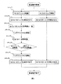
次に、図3によりショックレス変速の制御フローについて説明する。ここでは、2速から3速に変速する動作について説明する。
まず、変速動作開始指令により、ステップ1へ移行する。ステップ1ではM/G17およびM/G19をトルク制御する。
【0036】
ステップ2ではM/G17、M/G19共にトルク制御の応答性を調整する。その調整量は車両の状態と運転者の意図、エンジンやバッテリの状態により上位コントローラで演算される。予めマップもしくは関数で与えてもよい。また、固定値でも運転者に違和感の無いように制御することが可能である。ステップ2を経て、M/G17のトルクが目標値と一致するステップ3へ移行する。M/G17の目標値はエンジンやバッテリの状態により上位コントローラで演算される。
【0037】
ステップ3でM/G17のトルクが目標値と等しくなると、ステップ4へ移行する。
【0038】
ステップ4ではドッグクラッチ40を開放する。ステップ3において、M/G17のトルクを目標値となったとき、エンジントルクは遊星歯車を介して駆動軸伝達するため、ドッグクラッチ40に掛かるエンジントルクはゼロ程度となる。そのため、ドッグクラッチ40を容易に開放することが可能となる。
【0039】
続いて、ステップ5ではM/G17を速度制御する。エンジンの回転数は2速相当の回転数であるので、エンジン回転数を3速相当の回転数まで変化させる。この間、M/G19はトルク制御である。
【0040】
ステップ6ではエンジン回転数と3速入力ギア33eの回転数を比較する。エンジン回転数と3速入力ギア33eの回転数とが一致すれば、ステップ7へ移行する。一致しない場合では、ステップ5に戻り、エンジン回転数の制御を行う。
【0041】
ステップ7ではドッグクラッチ41を締結する。エンジン回転数と3速入力ギア33eの回転数とが一致しているため、ドッグクラッチ41を容易に締結することが可能である。ステップ7終了後、ステップ8へ移行する。
【0042】
ステップ8では、M/G17およびM/G19のトルクを減少させる。このときの減少度は車両の状態と運転者の意図、エンジンやバッテリの状態により上位コントローラで演算される。M/G17およびM/G19のトルクがゼロとなった時点で変速動作は終了する。
【0043】
次に、図4に、ショックレス変速時の各コンポーネンツの動作を模式的に表す。ここでは、2速から3速に変速する動作について説明する。
2速で走行している状態において、ドッグクラッチ43を低速ギア26に締結する。このとき、M/G17のトルクをゼロにすることにより、遊星歯車24の各入出力軸は回転自在となり、容易に締結できると共に、締結時のショックは発生しない。
【0044】
変速動作において、まず始めに、M/G17のトルクを増加させる。これにより、遊星歯車のリングギアに発生するトルクを増大させ、エンジン11の駆動力を遊星歯車24内に吸上げる。この状態をトルク制御モード1と称する。
【0045】
トルク制御モード1のとき、M/G17はトルク制御を行う。M/G17のトルク増加に応じて、2速ギア出力トルクは減少してゆく。そのため、エンジン11の駆動力のみでは車両駆動力が不足する。そこで、その不足分をM/G19で補償する。M/G19はトルク制御である。リングに発生するトルクがエンジン11のトルクと等しくなったとき2速に締結しているドッグクラッチ40を開放する。このとき、2速出力ギア32vのトルクはゼロ程度となるため、ドッグクラッチ40の開放は容易である。
【0046】
変速動作の次の段階では、エンジン11の回転数を3速の回転数に推移させる。すなわち、2速から3速の間を無段変速する。このとき、この状態を速度制御モードと称する。
速度制御モードにおいて、M/G17は速度制御となる。エンジン11の駆動力は遊星歯車24を介して前輪駆動軸14に伝達される。遊星歯車出力トルク25はM/G17のトルクと線形であるため、駆動力の過不足が発生する。そこで、先と同様、M/G19で駆動力の補正を行う。M/G19はトルク制御である。
【0047】
変速動作の最後の段階では、エンジン11の回転数と3速入力ギア33eの回転数が一致したときに、ドッグクラッチ41を締結させる。その後、M/G17およびM/G19のトルクを減少させる。この状態をトルク制御モード2と称する。
トルク制御モード2において、M/G17およびM/G19のトルクがゼロとなったときに変速動作が終了する。
【0048】
次に、図5は本発明の他の実施形態による駆動装置を搭載した車両のシステム構成を示す図である。
この実施形態において、エンジン111の駆動力は、車両の状態に応じ変速機112により変速され、デファレンシャル113を介して駆動軸114に伝達される。変速機112はエンジン111側の軸と、駆動軸114側の軸が平行に配置された変速機であり、前進5段、後進1段を有している。1速131、2速132、5速135、および、後進136は駆動軸114側の軸上に、変速機112の軸と各変速段を締結ならびに開放するドッグクラッチを有している。3速133、4速134はエンジン111側の軸上に、変速機112の軸と各変速段を締結ならびに開放するドッグクラッチを有している。図示していないが、各ドッグクラッチはシフトアクチュエータにより締結、開放状態を実現する。
【0049】
クラッチ121はエンジン111の駆動力を変速機112に伝達、中断する装置である。クラッチアクチュエータ122はクラッチ121を動作させる装置である。
【0050】
M/G 115、M/G116は回転電動機であり、M/G115駆動装置117、M/G116駆動装置118によりそれぞれ駆動される。バッテリ119はM/G 115、M/G116に駆動電力を供給したり、発電電力を貯蔵したりする電力貯蔵装置である。
【0051】
遊星歯車123はサン、キャリア、リングの入出力軸を有し、サンはM/G115に、キャリアは遊星歯車出力軸124に、リングは変速機112の2速132のエンジン111側軸上に配置された入力ギアにそれぞれ接続されている。遊星歯車出力軸124上には、変速機112の3速133のエンジン111軸上に配置された入力ギアと噛合する低速ギア126と、変速機112の4速134のエンジン111軸上に配置された入力ギアと噛合する高速ギア127とが配置されている。同じく、遊星歯車出力軸124上のドッグクラッチ128により、低速ギア126および高速ギア127は遊星歯車出力軸124と選択的に締結および開放状態となる。
【0052】
回転電動機M/G115で変速時にトルクアシスト等を行う場合は、ワンウェイクラッチ125を差動させ、遊星歯車123でトルクを増幅させて伝達させることが可能である。
なお、回転電動機M/G116は、変速機112の駆動軸114側の軸と接続されている。
【0053】
図5の構成では、同駆動軸上にM/G115、116を配しているため、図1の構成よりもショックレス変速の制御が容易である。
【0054】
次に、図6は本発明他の実施形態による駆動装置を搭載した車両のシステム構成を示す図である。
エンジン211の駆動力は、車両の状態に応じ変速機212により変速され、デファレンシャル213を介して駆動軸214に伝達される。変速機212はエンジン211側の軸と、駆動軸214側の軸が平行に配置された変速機であり、前進5段、後進1段を有している。1速231、後進236は駆動軸214側の軸上に、変速機212の軸と各変速段を締結ならびに開放するドッグクラッチを有している。2速232、3速233、4速234、および、5速235はエンジン211側の軸上に、変速機212の軸と各変速段を締結ならびに開放するドッグクラッチを有している。図示していないが、各ドッグクラッチはシフトアクチュエータにより締結、開放状態を実現する。
【0055】
クラッチ222はエンジン211の駆動力を変速機212に伝達、中断する装置である。クラッチアクチュエータ223はクラッチ222を動作させる装置である。
【0056】
M/G 217、M/G218は回転電動機であり、M/G217駆動装置219、M/G218駆動装置220により駆動される。バッテリ221はM/G 217、M/G218に駆動電力を供給したり、発電電力を貯蔵したりする電力貯蔵装置である。
【0057】
遊星歯車240はサン、キャリア、リングの入出力軸を有し、サンはM/G217に、キャリアは遊星歯車出力軸241に、リングは変速機212の1速231のエンジン軸上に配置された入力ギアにそれぞれ接続している。遊星歯車出力軸241上には2速232、3速233、4速234、5速235のエンジン211側軸上の歯車とそれぞれ噛合する1-2変速用ギア242、2-3変速用ギア243、3-4変速用ギア244、4-5変速用ギア245が配置されている。
【0058】
M/G218の出力軸はデファレンシャル215と接続し、M/G218の駆動力はデファレンシャル215を介して駆動軸216に伝達される。M/G217でトルクアシスト等を行う場合は、ワンウェイクラッチ246を差動させ、遊星歯車240でトルクを増幅させて伝達させることが可能である。
【0059】
図6の構成では、変速に応じて遊星歯車出力軸241上の 1-2変速用ギア242、2-3変速用ギア243、3-4変速用ギア244、4-5変速用ギア245を切替えることにより、少ないモータ容量ですべての変速段の間を無段変速する事が可能である。
【0060】
図7は本発明他の実施形態による駆動装置を搭載した車両のシステム構成を示す図であり、特に後輪駆動車に適した構成である。
エンジン410の駆動力は、車両の状態に応じ変速機411により変速され、デファレンシャル412を介して駆動軸413に伝達される。クラッチ414はエンジン410の駆動力を変速機411に伝達あるいは中断する装置である。クラッチアクチュエータ415はクラッチ414を動かす装置である。変速機411はカウンターシャフト416と出力軸417とが平行に配置された変速機であり、前進5段、後進1段を有している。エンジン410の駆動力は変速段418を介してカウンターシャフト416に伝達する。1速ギア対421、2速ギア対422、3速ギア対423、5速ギア対424、後進ギア対425は歯車対からなり、4速はドッグクラッチ426をエンジン410と直結して実現する。
【0061】
また、ドッグクラッチ426が1速ギア対421と締結することにより1速を実現する。ドッグクラッチ427は2速ギア対422もしくは3速ギア対423に締結して2速および3速を実現する。ドッグクラッチ428は5速ギア対424もしくは後進ギア対425に締結して5速および後進を実現する。図示していないが、各ドッグクラッチはシフトアクチュエータにより締結、開放状態を実現する。
【0062】
M/G430、M/G431は回転電動機であり、M/G430駆動装置432、M/G431駆動装置433により駆動される。バッテリ434はM/G430、M/G431に駆動電力を供給したり、発電電力を貯蔵したりする電力貯蔵装置である。
【0063】
遊星歯車434はサン、キャリア、リングの入出力軸を有し、サンはM/G430に、キャリアは遊星歯車出力軸440に、リングは変速機411のカウンターシャフト416に接続している。遊星歯車出力軸440上には、低速ギア対436および高速ギア対437の2組のギア対が配置され、ドッグクラッチ438により選択的に出力軸417と締結される。
【0064】
また、M/G431は出力軸417上に配置されている。
この構成では、図1のように遊星歯車からの出力の伝達経路として、従来の変速機のギアを利用しないため、低速ギア436、高速ギア437のギア比を自由に設計できるため、M/G駆動力設計が容易となる。
【0065】
ここでは、遊星歯車出力軸440上に2組のギア対を配しているが、2組以上配置することにより、更なるM/Gの小型化、ショックレス化が計ることが可能である。
【0066】
図8は本発明の他の実施形態による駆動装置を搭載した車両のシステム構成を示す図であり、特に、後輪駆動車に適した構成である。
【0067】
エンジン510の駆動力は、車両の状態に応じ変速機511により変速され、デファレンシャル512を介して駆動軸513に伝達される。クラッチ514はエンジン510の駆動力を変速機511に伝達あるいは中断する装置である。クラッチアクチュエータ515はクラッチ514を動かす装置である。変速機511はカウンターシャフト516と出力軸517とが平行に配置された変速機であり、前進5段、後進1段を有している。エンジン510の駆動力は変速段518を介してカウンターシャフト516に伝達する。1速ギア対521、2速ギア対522、3速ギア対523、5速ギア対524、後進ギア対525は歯車対からなり、4速はドッグクラッチ526をエンジン510と直結して実現する。また、ドッグクラッチ526が1速ギア対521と締結することにより1速を実現する。ドッグクラッチ527は2速ギア対522もしくは3速ギア対523に締結して2速および3速を実現する。ドッグクラッチ528は5速ギア対524もしくは後進ギア対525に締結して5速および後進を実現する。図示していないが、各ドッグクラッチはシフトアクチュエータにより締結、開放状態を実現する。
【0068】
M/G530、M/G531は回転電動機であり、M/G530駆動装置532、M/G531駆動装置533により駆動される。バッテリ534はM/G530、M/G531に駆動電力を供給したり、発電電力を貯蔵したりする電力貯蔵装置である。
【0069】
遊星歯車534はサン、キャリア、リングの入出力軸を有し、サンはM/G530に、キャリアは遊星歯車出力軸540に、リングは変速機511のカウンターシャフト516に接続している。遊星歯車出力軸540上には、低速ギア対536および高速ギア対537の2組のギア対が配置され、ドッグクラッチ538により選択的に出力軸517と締結される。
【0070】
また、M/G531はデファレンシャル535を介して駆動軸536を駆動する。
この構成では、後輪駆動車を容易に4WD とすることが可能である。
【0071】
図9は本発明の他の実施形態による駆動装置を搭載した車両のシステム構成を示す図である。
エンジン1010の駆動力は、車両の状態に応じ変速機1011により変速され、デファレンシャル1012を介して駆動軸1013に伝達される。クラッチ1014はエンジン1010の駆動力を変速機1011に伝達あるいは中断する装置である。クラッチアクチュエータ1015はクラッチ1014を動かす装置である。変速機1011は入力軸であるカウンターシャフト1016と出力軸1017とが平行に配置された変速機であり、前進5段、後進1段を有している。エンジン1010の駆動力は変速段1018を介してカウンターシャフト1016に伝達する。1速ギア対1021、2速ギア対1022、3速ギア対1023、5速ギア対1024、後進ギア対1025は歯車対からなり、4速はドッグクラッチ1026をエンジン1010と直結して実現する。また、ドッグクラッチ1026が1速ギア対1021と締結することにより1速を実現する。ドッグクラッチ1027は2速ギア対1022もしくは3速ギア対1023に締結して2速および3速を実現する。ドッグクラッチ1028は5速ギア対1024もしくは後進ギア対1025に締結して5速および後進を実現する。各ドッグクラッチはシフトアクチュエータ1039により締結、開放状態を実現する。
【0072】
M/G1030は回転電動機であり、インバータ1031により駆動される。バッテリ1032はM/G1030に駆動電力を供給したり、発電電力を貯蔵したりする電力貯蔵装置である。
【0073】
遊星歯車1035はサン、キャリア、リングの入出力軸を有し、サンはM/G1030に、キャリアは遊星歯車出力軸1036に、リングは変速機1011のカウンターシャフト1016に接続されている。遊星歯車出力軸1036上には、低速ギア対1033、高速ギア対1034およびバックギア1025の3組のギア対が配置されており、ドッグクラッチ1035および1028により選択的に出力軸1017と締結される。
【0074】
ツーウェイクラッチ1037は遊星歯車出力軸1036の回転方向を制限可能である。ツーウェイクラッチ1037はバックギア1025を使用するときは遊星歯車出力軸1036の回動をフリーとし、バックギア1025以外のギアを用いる場合は遊星歯車出力軸1036の回転方向を制限する。
【0075】
エンジン1010、M/G1030、および、シフトアクチュエータ1039を統括制御するのがハイブリッドコントローラモジュール(HCM)1040である。エンジンコントロールユニット(ECU)1038はHCM1040の指令により、エンジン1010の燃料噴射量、吸入空気量などエンジンの出力特性および排気特性に起因する要素を制御する。
【0076】
この構成では、図1のように遊星歯車からの出力の伝達経路として、従来の変速機のギアを利用しないため、低速ギア1033、高速ギア1034のギア比を自由に設計できるため、M/G1030駆動力設計が容易となる。
【0077】
また、遊星歯車出力軸1036上にバックギア1025が配されているため、バックギア1025を活用して、M/G1030のトルクを倍増することが可能である。このとき、ツーウェイクラッチ1037は遊星歯車出力軸1036の回動をフリーにする。
【0078】
この構成でのショックレス変速は、エンジン1010とM/G1030の協調制御により行う。以下に、エンジン1010とM/G1030の協調制御によるショックレス変速について説明する。
【0079】
図10に、図9の実施形態におけるハイブリッドコントローラモジュール(HCM)1040を含む制御装置の概略図を示す。
ハイブリッドコントローラモジュールHCM1040には、運転者の意図に応じて、エンジン1010の最適動作点やM/G1030によるトルクアシスト量などを決める上位コントローラ1050がある。ECU1038は上位コントローラ1050からの指令やエンジン10の状態情報などにより、エンジン1010の吸入空気量や燃料噴射量などを制御する装置である。シフトコントローラ1052はシフトアクチュエータ1039にドッグクラッチの動作時期等の指令を与える。M/G1030制御装置1051はインバータ1031にM/G1030の駆動指令を与える。
【0080】
ECU1038はM/G1030制御装置1051にエンジン1010の駆動力指令を伝える。また、M/G1030制御装置1051はECU1038にM/G1030の駆動力指令を伝える。
【0081】
M/G1030制御装置1051はECU1038からのエンジン1010駆動力指令と上位コントローラ50からの車両駆動指令と、変速比指令とからM/G1030の駆動指令を作成する。そのため、エンジン1010とM/G1030は協調制御となる。シフトコントローラ1052はM/G1030の駆動指令と車両の駆動力指令からシフトアクチュエータ1039にドッグクラッチ動作指令を与える。シフトコントローラ1052もM/G1030と協調して制御される。
【0082】
次に、図9の実施形態におけるショックレス変速の制御フローについて図11を用いて説明する。ここでは、2速から3速に変速する動作について説明する。
【0083】
変速動作開始指令により、ステップ11へ移行する。ステップ11ではM/G1030およびエンジン1010をトルク制御する。
【0084】
ステップ12では、M/G1030およびエンジン1010にトルク制御の応答性を調整する。その調整量は車両の状態と運転者の意図、エンジンやバッテリの状態により上位コントローラで演算される。予めマップもしくは関数で与えてもよい。また、固定値でも運転者に違和感の無いように制御することが可能である。ステップ12を経て、M/G1030のトルクが目標値と一致するステップ13へ移行する。M/G1030のトルクの目標値は、ドッグクラッチ1027に掛かるトルクがドッグクラッチ開放可能な程度であり、エンジンやバッテリの状態により上位コントローラで演算される。
【0085】
ステップ13でM/G1030のトルクが目標値と等しくなると、ステップ14へ移行する。
ステップ14ではドッグクラッチ1027を2速から開放する。ステップ13において、M/G1030のトルクを目標値となったとき、エンジントルクは遊星歯車を介して駆動軸伝達するため、ドッグクラッチ1027に掛かるエンジントルクはゼロ程度となる。そのため、ドッグクラッチ1027を容易に開放することが可能となる。
続いて、ステップ15ではM/G1030を速度制御する。エンジンの回転数は2速相当の回転数であるので、エンジン回転数を3速相当の回転数まで変化させる。
【0086】
ステップ16ではエンジン1010回転数と3速出力ギアの回転数を比較する。エンジン回転数と3速出力ギアの回転数とが一致すれば、ステップ17へ移行する。一致しない場合では、ステップ15に戻り、エンジン回転数の一致させるためM/G1030の速度制御を行う。この間、エンジン1010は車両駆動力が一定となるようにトルクを制御する。
【0087】
ステップ17ではドッグクラッチ1027を3速に締結する。エンジン回転数と3速入力ギア33eの回転数とが一致しているため、ドッグクラッチ1027を容易に締結することが可能である。ステップ17終了後、ステップ18へ移行する。
【0088】
ステップ18では、M/G1030のトルクを減少させる。このときの減少度は車両の状態と運転者の意図、エンジンやバッテリの状態により上位コントローラで演算される。M/G1030のトルクがゼロとなった時点で変速動作は終了する。このとき、エンジン1010は運転者に違和感が無いように出力トルクを調整する。
【0089】
図12に、図9の実施形態におけるショックレス変速制御の動作、すなわちM/G1030とエンジン1010の協調制御によるショックレス変速時の各コンポーネンツの動作を模式的に表す。ここでは、2速から3速に変速する動作について説明する。
【0090】
最初は2速で走行する状態にある。ドッグクラッチ1035を低速ギア1033に締結する。このとき、M/G1030のトルクをゼロにすることにより、遊星歯車1035の各入出力軸は回転自在となり、容易に締結できると共に、締結時のショックは発生しない。
【0091】
まず始めのトルク制御モード1において、M/G1030のトルクを増加させる。これにより、遊星歯車のリングギアに発生するトルクを増大させ、エンジン1010の駆動力を遊星歯車1035内に吸上げる。このとき、M/G1030はトルク制御である。M/G1030のトルク増加に応じて、2速ギア出力トルクは減少してゆく。そのため、エンジン1010はトルクを増大させ、車両駆動力を補償する。エンジン1010はトルク制御である。リングに発生するトルクがエンジン1010のトルクと等しくなったとき2速に締結しているドッグクラッチ1027を開放する。このとき、2速ギアのトルクはゼロ程度となるため、ドッグクラッチ1027の開放は容易である。
【0092】
次に、速度制御モードとなり、エンジン1010の回転数を3速の回転数に推移させる。すなわち、2速から3速の間を無段変速する。M/G1030は速度制御となる。エンジン1010の駆動力は遊星歯車1035を介して駆動軸1013に伝達する。
【0093】
エンジン1010の回転数と3速ギアの回転数が一致したときに、トルク制御モード2となり、ドッグクラッチ1027を3速に締結させる。その後、M/G1030のトルクを減少させる。M/G1030のトルクがゼロとなったときに変速動作が終了する。
【0094】
次に、図13は本発明の他の実施形態による駆動装置を搭載した車両のシステム構成を示す図である。
エンジン910の駆動力は、車両の状態に応じ変速機911により変速され、デファレンシャル912を介して駆動軸913に伝達する。クラッチ914はエンジン910の駆動力を変速機911に伝達あるいは中断する装置である。クラッチアクチュエータ915はクラッチ914を動かす装置である。変速機911は入力軸であるカウンターシャフト916と出力軸917とが平行に配置された変速機であり、前進5段、後進1段を有している。エンジン910の駆動力は変速段918を介してカウンターシャフト916に伝達する。1速ギア対921、2速ギア対922、3速ギア対923、5速ギア対924、後進ギア対925は歯車対からなり、4速はドッグクラッチ926をエンジン910と直結して実現する。また、ドッグクラッチ926が1速ギア対921と締結することにより1速を実現する。ドッグクラッチ927は2速ギア対922もしくは3速ギア対923に締結して2速および3速を実現する。ドッグクラッチ928は5速ギア対924もしくは後進ギア対925に締結して5速および後進を実現する。各ドッグクラッチは図示していないが、シフトアクチュエータにより締結、開放状態を実現する。
【0095】
M/G930は回転電動機であり、インバータ931により駆動される。バッテリ932はM/G930に駆動電力を供給したり、発電電力を貯蔵したりする電力貯蔵装置である。
【0096】
遊星歯車935はサン、キャリア、リングの入出力軸を有し、サンはM/G930に、キャリアは遊星歯車出力軸936に、リングは変速機1011のカウンターシャフト1016に接続している。遊星歯車出力軸1036上には、低速ギア対933、高速ギア対934の2組のギア対が配置されており、ドッグクラッチ938により選択的に出力軸917と締結される。
【0097】
ワンウェイクラッチ937は遊星歯車出力軸936の回転方向を制限可能である。
【0098】
この構成では、図1のように遊星歯車からの出力の伝達経路として、従来の変速機のギアを利用しないため、低速ギア933、高速ギア934のギア比を自由に設計できるため、M/G930駆動力設計が容易となる。また、従来のMTに遊星歯車935とM/G930をアドオンすることでシステムを構成することができるため、システムの低コスト化が計れる。
【0099】
図14は本発明の他の実施形態による駆動装置を搭載した車両のシステム構成を示す図である。
この実施形態では、エンジン311の駆動力は、車両の状態に応じ変速機312により変速され、デファレンシャル313を介して駆動軸314に伝達される。変速機312はエンジン311側の軸と、駆動軸314側の軸が平行に配置された変速機であり、前進5段、後進1段を有している。1速331、2速332、5速335、および、後進336は駆動軸314側の軸上に、変速機312の軸と各変速段を締結ならびに開放するドッグクラッチを有している。3速333、4速334はエンジン311側の軸上に、変速機312の軸と各変速段を締結ならびに開放するドッグクラッチを有している。図示していないが、各ドッグクラッチはシフトアクチュエータにより締結、開放状態を実現する。
【0100】
クラッチ319はエンジン311の駆動力を変速機312に伝達、中断する装置である。クラッチアクチュエータ320はクラッチ319を動作させる装置である。
M/G 315は回転電動機であり、M/G315駆動装置316により駆動される。バッテリ318は、M/G315に駆動電力を供給したり、発電電力を貯蔵したりする電力貯蔵装置である。
【0101】
遊星歯車321はサン、キャリア、リングの入出力軸を有し、サンはM/G315に、キャリアは遊星歯車出力軸322に、リングは変速機312の2速332のエンジン311側軸上に配置された入力ギアにそれぞれ接続している。遊星歯車出力軸322上には、変速機312の3速333のエンジン311軸上に配置された入力ギアと噛合する低速ギア324と、4速334のエンジン311軸上に配置された入力ギアと噛合する高速ギア325とが配置されている。同じく、遊星歯車出力軸322上のドッグクラッチ326により、低速ギア324および高速ギア325は遊星歯車出力軸322と選択的に締結および開放状態となる。
M/G315でトルクアシスト等を行う場合は、ワンウェイクラッチ323を差動させ、遊星歯車321でトルクを増幅させて伝達させることが可能である。
【0102】
さらに、図15は本発明の他の実施形態による駆動装置を搭載した車両のシステム構成を示す図である。この実施形態では、駆動装置に多板クラッチ624を配している。このとき、遊星歯車622の各入出力軸は、サンはM/G617、キャリアは変速機612の2速入力ギア、リングは遊星歯車出力軸623と接続している。この構成では、多板クラッチを用いて3速までの変速をショックレス変速し、3速から5速までをM/G617を用いてショックレス変速を行うことが可能となり、M/G617を小型化することが可能となる。
【0103】
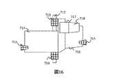
図16は本発明の他の実施形態による駆動装置を搭載した車両のシステム構成を示す図である。
この実施形態では、エンジン710と変速機711を車両に搭載するため、サブフレーム712上にマウント装置713、714を配し、また、サブフレーム712が接続する車体を構成するフレームとの接続としてマウント装置715、716を配している。このとき、M/G717と遊星歯車を含む変速機構718は、重量の重いM/G717がエンジン710と変速機712の重心位置に近いように配置される。これにより、駆動系のバランスが保たれ、損失の少ない駆動系を実現できる。
【0104】
図17は本発明の他の実施形態による駆動装置を搭載した車両のシステム構成を示す図である。
この実施形態では、後輪駆動車ベースの4WDにおいて、クラッチを含むクラッチハウジング811と変速機812、出力軸813が直列に配置され、遊星歯車を含むギア構造814とM/G815、M/G816をトランスファーケース位置に搭載することにより、車両形状の変更を最小限に抑えることができる。また、M/G816の出力軸を既存の前輪駆動用のプロペラシャフト817と接続することにより容易に4WD化することができる。
【0105】
【発明の効果】
本発明によれば、車両の駆動力を連続的に制御するモータを小型化することができ、また、モータが発生するトルクが小さいため電流を供給するさいに生じる電気的損失を抑制できるため、低燃費でスムーズな動特性を有するハイブリッド車両を提供できるという効果がある。また、変速時における動力伝達経路間のトルク段差によるショックを軽減した駆動システム及びそれを用いた車両を提供することができる。
【図面の簡単な説明】
【図1】本発明の一実施例に係るハイブリッド車のシステム構成である。
【図2】図1の実施例におけるショックレス変速制御装置のシステム構成概念である。
【図3】図1の実施例におけるショックレス変速動作のフローチャートである。
【図4】図1の実施例におけるショックレス変速動作の各コンポーネンツの動作概念である。
【図5】本発明の他の実施形態による駆動装置を搭載した車両のシステム構成を示す図である。
【図6】本発明の他の実施形態による駆動装置を搭載した車両のシステム構成を示す図である。
【図7】本発明の他の実施形態による駆動装置を搭載した車両のシステム構成を示す図である。
【図8】本発明の他の実施形態による駆動装置を搭載した車両のシステム構成を示す図である。
【図9】本発明の他の実施形態による駆動装置を搭載した車両のシステム構成を示す図である。
【図10】図9の実施形態におけるショックレス変速制御装置のシステム構成概念である。
【図11】図9の実施形態におけるショックレス変速動作のフローチャートである。
【図12】図9の実施形態におけるショックレス変速動作の各コンポーネンツの動作概念である。
【図13】本発明の他の実施形態による駆動装置を搭載した車両のシステム構成を示す図である。
【図14】本発明の他の実施形態による駆動装置を搭載した車両のシステム構成を示す図である。
【図15】本発明の他の実施形態による駆動装置を搭載した車両のシステム構成を示す図である。
【図16】本発明の他の実施形態による駆動装置を搭載した車両のシステム構成を示す図である。
【図17】本発明の他の実施形態による駆動装置を搭載した車両のシステム構成を示す図である。
【符号の説明】
11…エンジン、12…変速機、13…デファレンシャル、14…前輪駆動軸、
15…デファレンシャル、16…後輪駆動軸、17…モータジェネレータ、18…モータコントローラ、19…モータジェネレータ、20…モータコントローラ20、21…バッテリ、22…クラッチ、23…クラッチアクチュエータ、24…遊星歯車、25…遊星歯車出力軸、26…低速ギア、27…高速ギア27、28…ワンウェイクラッチ、29…入力軸、30…出力軸、31e…1速入力ギア、31v…1速出力ギア、32e…2速入力ギア、32v…2速出力ギア、33e…3速入力ギア、33v…3速出力ギア、34e…4速入力ギア、34v…4速出力ギア、35e…5速入力ギア、35v…5速出力ギア、36e…後進入力ギア、36v…後進力ギア、40…ドッグクラッチ、41…ドッグクラッチ、42…ドッグクラッチ、43…ドッグクラッチ、44…シフトコントローラ、45…ハイブリッドコントローラHCM、46…エンジンコントロールユニットECU、50…上位コントローラ、51…M/G17制御装置、52…M/G19制御装置、53…シフトコントローラ。[0001]
BACKGROUND OF THE INVENTION
The present invention relates to a vehicle drive device including an internal combustion engine, a motor generator, and a differential mechanism, and a vehicle using the same.
[0002]
[Prior art]
There are two types of transmissions for automobiles: a synchronous type using a meshing gear like a manual transmission and a planetary type using a planetary gear like an automatic transmission. Among them, the synchronous type needs to temporarily interrupt the transmission of the engine driving force at the time of shifting due to the characteristics of the meshing gear. Therefore, a torque shortage due to the interruption of the driving force occurs. On the other hand, there is a system that controls M / G mounted on a hybrid vehicle to suppress torque fluctuation at the time of shifting. For example, in Japanese Patent Laid-Open No. 10-21779, an M / G is arranged in the manual transmission and the rear wheel drive shaft, and the torque interruption that occurs when shifting the manual transmission is compensated by using the front and rear M / G. Therefore, a system that realizes a speed change performance that does not give the driver a sense of incongruity is disclosed.
[0003]
Japanese Patent Laid-Open No. 2000-225862 discloses that the output of the engine is connected via a planetary gear connected to the motor in order to avoid the follow-up loss caused by the generator when the engine is stopped and the vehicle runs alone. A shift having a first power transmission path for transmitting to the vehicle drive shaft, a second power transmission path for transmitting engine output to the vehicle drive shaft via a gear, and a power transmission switching means for switching these power transmission paths. An apparatus is disclosed.
[0004]
[Problems to be solved by the invention]
However, in the former method, torque interruption is compensated by M / G, so that the total output of M / G is required to be equal to that of the engine, and it is difficult to achieve system mountability and cost reduction. Further, since the M / G disposed in the transmission has a gear ratio that is always higher than the engine speed, the follow-up loss increases at high speeds.
[0005]
In the latter method, when the power transmission path is switched at the time of shifting, a shock is generated due to a difference in the rotational speed, in other words, a torque step between the power transmission paths.
[0006]
The object of the present invention is to eliminate the above-mentioned problems by using planetary gears such as M / G. Rotating electric machine It is to provide a lightweight and compact vehicle drive system and a vehicle using the same.
[0007]
Another object of the present invention is to provide a drive system that reduces a shock caused by a torque step between power transmission paths during a shift, and a vehicle using the drive system.
[0008]
The present invention Rotating electric machine The above-mentioned object is achieved by providing a differential mechanism for controlling the rotational speed difference by connecting the differential mechanism to both transmission shafts of the transmission.
[0009]
The present invention is characterized in that an input shaft to which a driving force of an internal combustion engine is transmitted, and an output shaft that transmits the driving force to the driving shaft of a vehicle driving wheel while the driving force of the input shaft is transmitted through a pair of gears. And a rotating electrical machine that transmits the driving force of the input shaft to the output shaft when the transmission is shifted.
[0010]
Another feature of the present invention is that an input shaft to which the driving force of the internal combustion engine is transmitted, the driving force of the input shaft is transmitted through a gear pair, and the driving force is transmitted to the driving shaft of the vehicle driving wheel. A transmission having an output shaft, and transmitting the driving force of the input shaft to the output shaft through the rotating electrical machine and controlling the speed of the rotating electrical machine when shifting the transmission.
[0011]
Another feature of the present invention is a transmission having a plurality of speed change mechanisms including a pair of gears on two shafts arranged in parallel to each other, wherein the transmission has an input shaft for inputting a driving force from an internal combustion engine, and the gears. An output shaft for transmitting the driving force converted by the pair to the drive wheel, and having a differential mechanism having three or more input / output shafts, and any of the shafts of the differential mechanism and the input shaft or the An output shaft is connected, a first motor generator is connected to at least one remaining shaft of the differential mechanism, and at least one of the input shaft or the output shaft is connected to the differential mechanism via a gear. is there.
[0012]
According to the present invention, Rotating electric machine By providing the differential mechanism for controlling the rotational speed difference, the motor that continuously controls the driving force of the vehicle can be reduced in size. In addition, since the torque generated by the motor is small, it is possible to suppress electrical loss that occurs when supplying current, and therefore, it is possible to provide a hybrid vehicle having low fuel consumption and smooth dynamic characteristics.
[0013]
Moreover, according to the invention, Rotating electric machine By providing the differential mechanism for controlling the rotational speed difference, it is possible to provide a drive system that reduces a shock caused by a torque step between the power transmission paths at the time of shifting, and a vehicle using the drive system.
[0014]
DETAILED DESCRIPTION OF THE INVENTION
Embodiments of the present invention will be described below.
FIG. 1 is a system configuration diagram of an embodiment of a vehicle equipped with a drive device according to the present invention. The
[0015]
The motor generator (M / G) 17 is a rotary electric motor that generates power by receiving power supplied from the outside or generates power by receiving power supplied from the outside. In the M / G 17, driving force and generated power are controlled by a
[0016]
The
[0017]
The planetary gear 24 includes three input / output shafts of sun, carrier, and ring. Of these input / output shafts, the sun is connected to the M / G 17, the carrier is connected to the planetary gear output shaft 25, and the ring meshes with the gear of the transmission 12. Here, it meshes with the second-speed input gear 32e.
[0018]
A low speed gear 26 and a high speed gear 27 are disposed on the planetary gear output shaft 25. The gear to be used is switched according to the gear position. The one-way clutch 28 is a mechanism that limits the rotation direction of the planetary gear output shaft 25, and operates when the torque assist by the M / G 17 or the
[0019]
Next, the internal structure of the transmission 12 will be described. The transmission 12 has an
[0020]
The first speed input gear 31e of the transmission 12 meshes with the first speed output gear 31v. Similarly, 2-speed input gear 32e is 2-speed output gear 32v, 3-speed input gear 33e is 3-speed output gear 33v, 4-
[0021]
Among these, the first-speed input gear 31e, the second-speed input gear 32e, the fifth-speed input gear 35e, and the
[0022]
The
[0023]
These dog clutches are driven by a shift controller 44. The shift controller 44 also controls the
A hybrid controller module (HCM) 45 performs overall control of the
[0024]
An engine control unit (ECU) 46 controls elements caused by engine output characteristics and exhaust characteristics such as the fuel injection amount and intake air amount of the engine in accordance with commands of the
[0025]
The structural features of the vehicle drive device of the present invention having the configuration shown in FIG. 1 will be described below.
According to the vehicle drive device of the present invention, motor travel by M /
Moreover, motor traveling by M / G17 is also possible. That is, the dog clutch 43 is released, and any one of the dog clutches in the transmission 12 is engaged according to the traveling conditions. Here, the
[0026]
Further, according to the vehicle drive device of the present invention, the engine can be started by M / G17.
That is, the
[0027]
In addition, according to the vehicle drive device of the present invention, it is possible to generate a driving force at zero speed with the
That is, the dog clutch 43 is fastened to the low speed gear 26, and the driving force of the
[0028]
According to the vehicle drive device of the present invention, torque assist is also possible with M / G17 and M / G19. That is, the torque of the M / G 17 can be doubled by the planetary gear 24 by operating the dog clutch 43 to assist the front
[0029]
Moreover, according to the vehicle drive device of the present invention, the accompanying loss of M / G17 can be suppressed.
[0030]
That is, by setting the
[0031]
According to the vehicle drive device of the present invention, shockless speed change is also possible. That is, by controlling the M / G 17 and transmitting the driving force of the
[0032]
Hereinafter, a shockless shift control device and a shockless shift operation, which are one of the features of the present invention, will be described.
First, a control device for shockless shift will be described. FIG. 2 shows a schematic diagram of a control device including a hybrid controller module (HCM) 45 and an engine
[0033]
The hybrid controller module HCM45 has a
[0034]
The M / G17 control device 51 creates an M / G17 driving force command from the driving force command and the gear ratio command. The M / G19 control device 52 creates an M / G19 drive command from the M / G17 drive command from the M / G17 control device 51 and the vehicle drive command from the
[0035]
Next, the control flow of the shockless shift will be described with reference to FIG. Here, the operation of shifting from the second speed to the third speed will be described.
First, the process proceeds to step 1 in response to a shift operation start command. In
[0036]
In
[0037]
When the torque of M / G17 becomes equal to the target value in
[0038]
In step 4, the
[0039]
Subsequently, in step 5, the speed of the M / G 17 is controlled. Since the engine speed is the speed corresponding to the second speed, the engine speed is changed to the speed corresponding to the third speed. During this time, M /
[0040]
In step 6, the engine speed is compared with the speed of the 3-speed input gear 33e. If the engine speed matches the speed of the third speed input gear 33e, the process proceeds to step 7. If they do not match, the process returns to step 5 to control the engine speed.
[0041]
In step 7, the dog clutch 41 is engaged. Since the engine speed and the speed of the third speed input gear 33e match, the dog clutch 41 can be easily engaged. After step 7, the process proceeds to step 8.
[0042]
In step 8, the torques of M / G17 and M / G19 are reduced. The degree of decrease at this time is calculated by the host controller according to the state of the vehicle, the intention of the driver, and the state of the engine and battery. The shifting operation ends when the torques of M / G17 and M / G19 become zero.
[0043]
Next, FIG. 4 schematically shows the operation of each component during a shockless shift. Here, the operation of shifting from the second speed to the third speed will be described.
The dog clutch 43 is engaged with the low speed gear 26 while traveling at the second speed. At this time, by making the torque of the M / G 17 zero, the input / output shafts of the planetary gear 24 become rotatable and can be easily engaged, and no shock is generated at the time of engagement.
[0044]
In the shifting operation, first, the torque of M / G17 is increased. Thereby, the torque generated in the ring gear of the planetary gear is increased, and the driving force of the
[0045]
In the
[0046]
In the next stage of the speed change operation, the rotation speed of the
In the speed control mode, the M / G 17 is speed controlled. The driving force of the
[0047]
In the final stage of the speed change operation, the dog clutch 41 is engaged when the rotational speed of the
In
[0048]
Next, FIG. 5 is a diagram showing a system configuration of a vehicle equipped with a drive device according to another embodiment of the present invention.
In this embodiment, the driving force of the
[0049]
The clutch 121 is a device that transmits and interrupts the driving force of the
[0050]
M /
[0051]
The
[0052]
When torque assist or the like is performed at the time of shifting with the rotary motor M /
The rotary electric motor M / G 116 is connected to the shaft on the
[0053]
In the configuration of FIG. 5, since the M /
[0054]
Next, FIG. 6 is a diagram showing a system configuration of a vehicle equipped with a drive device according to another embodiment of the present invention.
The driving force of the
[0055]
The clutch 222 is a device that transmits and interrupts the driving force of the
[0056]
M /
[0057]
The
[0058]
The output shaft of the M / G 218 is connected to the differential 215, and the driving force of the M / G 218 is transmitted to the driving
[0059]
In the configuration of FIG. 6, the 1-2
[0060]
FIG. 7 is a diagram showing a system configuration of a vehicle equipped with a drive device according to another embodiment of the present invention, and is particularly suitable for a rear wheel drive vehicle.
The driving force of the
[0061]
The first speed is realized by the
[0062]
M / G430 and M / G431 are rotary electric motors and are driven by an M /
[0063]
The
[0064]
Further, the M /
In this configuration, the gear ratio of the low-
[0065]
Here, although two sets of gear pairs are arranged on the planetary
[0066]
FIG. 8 is a diagram showing a system configuration of a vehicle equipped with a drive device according to another embodiment of the present invention, and is particularly suitable for a rear wheel drive vehicle.
[0067]
The driving force of the
[0068]
M / G530 and M / G531 are rotary motors, and are driven by an M /
[0069]
The
[0070]
Further, the M /
In this configuration, the rear wheel drive vehicle can be easily set to 4WD.
[0071]
FIG. 9 is a diagram showing a system configuration of a vehicle equipped with a drive device according to another embodiment of the present invention.
The driving force of the
[0072]
M /
[0073]
The
[0074]
The two-way clutch 1037 can limit the rotation direction of the planetary
[0075]
A hybrid controller module (HCM) 1040 controls the
[0076]
In this configuration, the gear ratio of the low-
[0077]
Further, since the
[0078]
The shockless shift in this configuration is performed by cooperative control of the
[0079]
FIG. 10 shows a schematic diagram of a control device including a hybrid controller module (HCM) 1040 in the embodiment of FIG.
The hybrid controller module HCM1040 includes a
[0080]
The
[0081]
The M /
[0082]
Next, the control flow of the shockless shift in the embodiment of FIG. 9 will be described using FIG. Here, the operation of shifting from the second speed to the third speed will be described.
[0083]
The process proceeds to step 11 in response to the shift operation start command. In
[0084]
In step 12, the responsiveness of torque control is adjusted for the M /
[0085]
When the torque of M /
In
Subsequently, in
[0086]
In
[0087]
In step 17, the
[0088]
In
[0089]
FIG. 12 schematically shows the operation of shockless shift control in the embodiment of FIG. 9, that is, the operation of each component at the time of shockless shift by cooperative control of the M /
[0090]
Initially, the car is in 2nd speed. The
[0091]
First, in
[0092]
Next, the speed control mode is set, and the rotation speed of the
[0093]
When the rotational speed of the
[0094]
Next, FIG. 13 is a diagram showing a system configuration of a vehicle equipped with a drive device according to another embodiment of the present invention.
The driving force of the
[0095]
M /
[0096]
The
[0097]
The one-way clutch 937 can limit the rotation direction of the planetary
[0098]
In this configuration, the gear ratio of the
[0099]
FIG. 14 is a diagram showing a system configuration of a vehicle equipped with a drive device according to another embodiment of the present invention.
In this embodiment, the driving force of the
[0100]
The clutch 319 is a device that transmits and interrupts the driving force of the
M /
[0101]
The
When performing torque assist or the like with the M /
[0102]
Further, FIG. 15 is a diagram showing a system configuration of a vehicle equipped with a drive device according to another embodiment of the present invention. In this embodiment, a
[0103]
FIG. 16 is a diagram showing a system configuration of a vehicle equipped with a drive device according to another embodiment of the present invention.
In this embodiment, in order to mount the
[0104]
FIG. 17 is a diagram showing a system configuration of a vehicle equipped with a drive device according to another embodiment of the present invention.
In this embodiment, in a 4WD based on a rear wheel drive vehicle, a
[0105]
【The invention's effect】
According to the present invention, the motor that continuously controls the driving force of the vehicle can be reduced in size, and since the torque generated by the motor is small, the electrical loss that occurs when supplying current can be suppressed. There is an effect that it is possible to provide a hybrid vehicle having low fuel consumption and smooth dynamic characteristics. In addition, it is possible to provide a drive system that reduces a shock caused by a torque step between power transmission paths at the time of shifting, and a vehicle using the drive system.
[Brief description of the drawings]
FIG. 1 is a system configuration of a hybrid vehicle according to an embodiment of the present invention.
FIG. 2 is a system configuration concept of a shockless speed change control device in the embodiment of FIG. 1;
FIG. 3 is a flowchart of a shockless shift operation in the embodiment of FIG.
4 is an operation concept of each component of a shockless speed change operation in the embodiment of FIG.
FIG. 5 is a diagram showing a system configuration of a vehicle equipped with a drive device according to another embodiment of the present invention.
FIG. 6 is a diagram showing a system configuration of a vehicle equipped with a drive device according to another embodiment of the present invention.
FIG. 7 is a diagram showing a system configuration of a vehicle equipped with a drive device according to another embodiment of the present invention.
FIG. 8 is a diagram showing a system configuration of a vehicle equipped with a drive device according to another embodiment of the present invention.
FIG. 9 is a diagram showing a system configuration of a vehicle equipped with a drive device according to another embodiment of the present invention.
10 is a system configuration concept of the shockless speed change control device in the embodiment of FIG. 9;
11 is a flowchart of a shockless speed change operation in the embodiment of FIG.
12 is an operation concept of each component of the shockless speed change operation in the embodiment of FIG. 9;
FIG. 13 is a diagram showing a system configuration of a vehicle equipped with a drive device according to another embodiment of the present invention.
FIG. 14 is a diagram showing a system configuration of a vehicle equipped with a drive device according to another embodiment of the present invention.
FIG. 15 is a diagram showing a system configuration of a vehicle equipped with a drive device according to another embodiment of the present invention.
FIG. 16 is a diagram showing a system configuration of a vehicle equipped with a drive device according to another embodiment of the present invention.
FIG. 17 is a diagram showing a system configuration of a vehicle equipped with a drive device according to another embodiment of the present invention.
[Explanation of symbols]
11 ... Engine, 12 ... Transmission, 13 ... Differential, 14 ... Front wheel drive shaft,
15 ... Differential, 16 ... Rear wheel drive shaft, 17 ... Motor generator, 18 ... Motor controller, 19 ... Motor generator, 20 ...
Claims (15)
前記接続手段を切換える切換手段とを有することを特徴とする車両の駆動装置。The differential mechanism according to claim 5, wherein the differential mechanism includes a plurality of connecting means connected to the second transmission shaft ;
Drive device of the vehicle; and a switching means for switching said connecting means.
前記変速機の変速時に前記第1の回転電機を介して、前記入力軸の駆動力を前記出力軸に伝達し、かつ、該第1の回転電機の速度を制御することを特徴とする車両の駆動方法。An internal combustion engine that drives the front wheels, an input shaft to which the driving force of the internal combustion engine is transmitted via a clutch, and the driving force of the input shaft is transmitted via a gear pair and the drive to the driving shaft of the front wheels a transmission having an output shaft for transmitting the force, driven from the input shaft of a vehicle equipped with a first rotating electric machine capable of transmitting torque to the output shaft, and a second rotating electric machine for driving the rear wheels A method,
A vehicle that transmits the driving force of the input shaft to the output shaft via the first rotating electric machine and controls the speed of the first rotating electric machine during the shifting of the transmission. Driving method.
後輪を駆動する第2の回転電機と、を備えた車両の駆動方法であって、
前記変速機の変速時に前記第1の回転電機を介して、前記入力軸の駆動力を前記出力軸に伝達し、かつ、車両の駆動トルクの変化を補償するように前記第2の回転電機を制御することを特徴とする車両の駆動方法。An internal combustion engine that drives the front wheels, an input shaft to which the driving force of the internal combustion engine is transmitted via a clutch, and the driving force of the input shaft is transmitted via a gear pair and the drive to the driving shaft of the front wheels A transmission having an output shaft for transmitting force; a first rotating electrical machine capable of transmitting torque from the input shaft to the output shaft;
A second dynamo-electric machine for driving rear wheels, and a vehicle driving method comprising:
The second rotating electrical machine is transmitted so as to transmit the driving force of the input shaft to the output shaft via the first rotating electrical machine at the time of shifting of the transmission and to compensate for a change in driving torque of the vehicle. A vehicle driving method comprising: controlling the vehicle.
Priority Applications (5)
| Application Number | Priority Date | Filing Date | Title |
|---|---|---|---|
| JP2001056949A JP3638876B2 (en) | 2001-03-01 | 2001-03-01 | Vehicle drive device and vehicle |
| US09/942,683 US6685591B2 (en) | 2001-03-01 | 2001-08-31 | Driving apparatus for a vehicle |
| DE60142957T DE60142957D1 (en) | 2001-03-01 | 2001-09-06 | Drive device for controlling the gear change in a hybrid vehicle |
| EP01120753A EP1236603B1 (en) | 2001-03-01 | 2001-09-06 | A driving apparatus for controlling gear shifting in a hybrid vehicle |
| KR1020010057923A KR20020071699A (en) | 2001-03-01 | 2001-09-19 | A driving apparatus for a vehicle |
Applications Claiming Priority (1)
| Application Number | Priority Date | Filing Date | Title |
|---|---|---|---|
| JP2001056949A JP3638876B2 (en) | 2001-03-01 | 2001-03-01 | Vehicle drive device and vehicle |
Publications (3)
| Publication Number | Publication Date |
|---|---|
| JP2002262409A JP2002262409A (en) | 2002-09-13 |
| JP2002262409A5 JP2002262409A5 (en) | 2004-11-25 |
| JP3638876B2 true JP3638876B2 (en) | 2005-04-13 |
Family
ID=18916897
Family Applications (1)
| Application Number | Title | Priority Date | Filing Date |
|---|---|---|---|
| JP2001056949A Expired - Fee Related JP3638876B2 (en) | 2001-03-01 | 2001-03-01 | Vehicle drive device and vehicle |
Country Status (5)
| Country | Link |
|---|---|
| US (1) | US6685591B2 (en) |
| EP (1) | EP1236603B1 (en) |
| JP (1) | JP3638876B2 (en) |
| KR (1) | KR20020071699A (en) |
| DE (1) | DE60142957D1 (en) |
Families Citing this family (102)
| Publication number | Priority date | Publication date | Assignee | Title |
|---|---|---|---|---|
| JP3230416B2 (en) * | 1995-07-14 | 2001-11-19 | 日本鋼管株式会社 | Steam aging treatment method for steelmaking slag |
| JP4345241B2 (en) * | 2001-04-24 | 2009-10-14 | 日産自動車株式会社 | Hybrid vehicle power unit |
| US7163480B2 (en) * | 2001-05-03 | 2007-01-16 | Ford Global Technologies, Llc | Powertrain for a hybrid vehicle with all-wheel drive capability and method for controlling wheel slip |
| JP4104406B2 (en) * | 2002-09-20 | 2008-06-18 | 本田技研工業株式会社 | Hybrid vehicle |
| CN101844558B (en) * | 2002-12-25 | 2012-11-07 | 丰田自动车株式会社 | Control device of hybrid drive unit |
| JP3852402B2 (en) | 2002-12-25 | 2006-11-29 | トヨタ自動車株式会社 | Control device for hybrid drive |
| US7011600B2 (en) | 2003-02-28 | 2006-03-14 | Fallbrook Technologies Inc. | Continuously variable transmission |
| JP3758650B2 (en) | 2003-06-16 | 2006-03-22 | トヨタ自動車株式会社 | Control device for hybrid drive |
| KR100507494B1 (en) | 2003-07-07 | 2005-08-17 | 현대자동차주식회사 | Power train system of hybrid electric vehicle |
| DE10335421A1 (en) | 2003-08-02 | 2005-02-17 | Daimlerchrysler Ag | Control method for automobile hybrid drive has initial acceleration of automobile from standstill provided solely by electric motor |
| EP1504946B1 (en) * | 2003-08-06 | 2008-11-26 | Nissan Motor Co., Ltd. | Transmission for an hybrid vehicle |
| JP3845400B2 (en) * | 2003-08-18 | 2006-11-15 | 本田技研工業株式会社 | Hybrid vehicle |
| FR2859141A1 (en) * | 2003-08-29 | 2005-03-04 | Renault Sa | Transmission for motor vehicle, has selection mechanism to select coupling of electrical line placed on output shaft of electric machine and drive pinion placed on output shaft |
| JP4082336B2 (en) * | 2003-11-14 | 2008-04-30 | 日産自動車株式会社 | Control device and control method for motor-driven 4WD vehicle |
| JP4063199B2 (en) * | 2003-11-14 | 2008-03-19 | 日産自動車株式会社 | Control device for motor-driven 4WD vehicle |
| JP4082338B2 (en) | 2003-11-27 | 2008-04-30 | 日産自動車株式会社 | Control device and control method for motor-driven 4WD vehicle |
| JP2005186740A (en) * | 2003-12-25 | 2005-07-14 | Aisin Seiki Co Ltd | Shift control device for vehicle |
| US7125362B2 (en) | 2004-01-23 | 2006-10-24 | Eaton Corporation | Hybrid powertrain system including smooth shifting automated transmission |
| KR20080032011A (en) * | 2004-04-27 | 2008-04-11 | 도요다 지도샤 가부시끼가이샤 | Control device for vehicular drive system |
| US7214156B2 (en) * | 2004-06-18 | 2007-05-08 | Eaton Corporation | Start and operation sequences for hybrid motor vehicles |
| ATE550573T1 (en) | 2004-10-05 | 2012-04-15 | Fallbrook Technologies Inc | CONTINUOUSLY ADJUSTABLE GEARBOX |
| JP4179266B2 (en) * | 2004-11-08 | 2008-11-12 | 日産自動車株式会社 | Hybrid four-wheel drive system |
| JP2006214454A (en) * | 2005-02-01 | 2006-08-17 | Hitachi Ltd | Automobile transmission controller and automatic transmission |
| JP4207966B2 (en) * | 2005-08-25 | 2009-01-14 | トヨタ自動車株式会社 | POWER OUTPUT DEVICE, ITS CONTROL METHOD, AND VEHICLE |
| DE102005042352A1 (en) * | 2005-09-07 | 2007-03-15 | Zf Friedrichshafen Ag | Device and method for reducing traction interruption in drive trains with automated manual transmissions |
| CN101346266B (en) * | 2005-10-28 | 2011-11-23 | 福博科技术公司 | Electromotive drives |
| US20070095587A1 (en) * | 2005-11-03 | 2007-05-03 | Hybrid Dynamics Corp. | Hybrid vehicle drive train and method |
| KR101422475B1 (en) | 2005-11-22 | 2014-07-28 | 폴브룩 인텔렉츄얼 프로퍼티 컴퍼니 엘엘씨 | A bicycle with continuously variable transmission |
| CN102226467B (en) | 2005-12-09 | 2014-06-25 | 福博科知识产权有限责任公司 | Continuously variable transmission |
| EP1811202A1 (en) | 2005-12-30 | 2007-07-25 | Fallbrook Technologies, Inc. | A continuously variable gear transmission |
| DE102006003711A1 (en) * | 2006-01-26 | 2007-08-02 | Zf Friedrichshafen Ag | Method for control of vehicle with internal combustion engine and electric drive, comprises proportional reduction of torque at both drives |
| JP4887058B2 (en) * | 2006-02-22 | 2012-02-29 | 日立オートモティブシステムズ株式会社 | Control apparatus and control method for automobile |
| FR2899548B1 (en) * | 2006-04-05 | 2009-04-17 | Peugeot Citroen Automobiles Sa | POWER TRANSMISSION METHOD |
| WO2008002457A2 (en) | 2006-06-26 | 2008-01-03 | Fallbrook Technologies Inc. | Continuously variable transmission |
| JP4293275B2 (en) | 2006-09-12 | 2009-07-08 | トヨタ自動車株式会社 | Vehicle driving force control device |
| FR2908086B1 (en) * | 2006-11-07 | 2010-02-26 | Peugeot Citroen Automobiles Sa | METHOD FOR CONTROLLING A HYBRID VEHICLE FOR RECHARGING ELECTRIC ENERGY STORAGE MEANS AND HYBRID VEHICLE |
| US8738255B2 (en) | 2007-02-01 | 2014-05-27 | Fallbrook Intellectual Property Company Llc | Systems and methods for control of transmission and/or prime mover |
| CN101657653B (en) | 2007-02-12 | 2014-07-16 | 福博科知识产权有限责任公司 | Continuously variable transmissions and methods therefor |
| EP2700843A3 (en) | 2007-02-16 | 2017-11-08 | Fallbrook Intellectual Property Company LLC | Infinitely variable transmissions, continuously variable transmissions, methods, assemblies, subassemblies, and components therefor |
| JP4240128B2 (en) * | 2007-02-28 | 2009-03-18 | トヨタ自動車株式会社 | Control device for hybrid drive |
| CN101720397B (en) | 2007-04-24 | 2013-01-02 | 福博科技术公司 | Electric traction drives |
| WO2008154437A1 (en) | 2007-06-11 | 2008-12-18 | Fallbrook Technologies Inc. | Continuously variable transmission |
| CN103697120B (en) | 2007-07-05 | 2017-04-12 | 福博科技术公司 | Continuously variable transmission |
| JP5246466B2 (en) * | 2007-10-19 | 2013-07-24 | アイシン・エィ・ダブリュ株式会社 | Hybrid drive device |
| US8996263B2 (en) | 2007-11-16 | 2015-03-31 | Fallbrook Intellectual Property Company Llc | Controller for variable transmission |
| EP2226228A4 (en) * | 2007-12-20 | 2014-10-29 | Bosch Corp | Hybrid system control method |
| CA2708634C (en) | 2007-12-21 | 2017-08-01 | Fallbrook Technologies Inc. | Automatic transmissions and methods therefor |
| JP2009166538A (en) * | 2008-01-11 | 2009-07-30 | Hino Motors Ltd | Control device for hybrid vehicle |
| US8313405B2 (en) | 2008-02-29 | 2012-11-20 | Fallbrook Intellectual Property Company Llc | Continuously and/or infinitely variable transmissions and methods therefor |
| JP5457438B2 (en) | 2008-06-06 | 2014-04-02 | フォールブルック インテレクチュアル プロパティー カンパニー エルエルシー | Infinitely variable transmission and control system for infinitely variable transmission |
| CN102084155B (en) | 2008-06-23 | 2014-06-11 | 福博科知识产权有限责任公司 | Continuously variable transmission |
| CA2732668C (en) | 2008-08-05 | 2017-11-14 | Fallbrook Technologies Inc. | Methods for control of transmission and prime mover |
| US8469856B2 (en) | 2008-08-26 | 2013-06-25 | Fallbrook Intellectual Property Company Llc | Continuously variable transmission |
| CN101659202A (en) * | 2008-08-28 | 2010-03-03 | 比亚迪股份有限公司 | Hybrid power driving system and driving method thereof |
| US8167759B2 (en) | 2008-10-14 | 2012-05-01 | Fallbrook Technologies Inc. | Continuously variable transmission |
| US20110239819A1 (en) * | 2008-12-18 | 2011-10-06 | Honda Motor Co., Ltd | Transmission for hybrid vehicle |
| WO2010120933A1 (en) | 2009-04-16 | 2010-10-21 | Fallbrook Technologies Inc. | Stator assembly and shifting mechanism for a continuously variable transmission |
| JP5446535B2 (en) * | 2009-07-16 | 2014-03-19 | いすゞ自動車株式会社 | Control device for hybrid vehicle |
| US20110029177A1 (en) * | 2009-07-30 | 2011-02-03 | Hybrid Kinetic Automotive Holdings | Multi-Fuel and Electric-Drive Hybrid Power Train and Vehicle Using the Same |
| FR2954253B1 (en) * | 2009-12-17 | 2012-07-13 | Peugeot Citroen Automobiles Sa | METHOD AND DEVICE FOR COMPENSATING A LOST VEHICLE TRACTION TORQUE VALUE |
| US8512195B2 (en) | 2010-03-03 | 2013-08-20 | Fallbrook Intellectual Property Company Llc | Infinitely variable transmissions, continuously variable transmissions, methods, assemblies, subassemblies, and components therefor |
| CN102310852B (en) * | 2010-06-30 | 2014-12-17 | 上海捷能汽车技术有限公司 | Gear shifting control method for automobile double-clutch power coupling synchronizer and device thereof |
| CN102310853B (en) * | 2010-06-30 | 2015-03-25 | 上海捷能汽车技术有限公司 | Gear shifting control method for automobile double-clutch power coupling synchronizer and device thereof |
| JP5108071B2 (en) * | 2010-09-22 | 2012-12-26 | 富士重工業株式会社 | Drive device for hybrid vehicle |
| US8888643B2 (en) | 2010-11-10 | 2014-11-18 | Fallbrook Intellectual Property Company Llc | Continuously variable transmission |
| JP2014168966A (en) * | 2011-05-24 | 2014-09-18 | Jatco Ltd | Shift control device of hybrid vehicle |
| SE536050C2 (en) * | 2011-06-27 | 2013-04-16 | Scania Cv Ab | Drive device for a vehicle and method for controlling such a drive |
| KR101262980B1 (en) | 2011-11-11 | 2013-05-08 | 현대자동차주식회사 | Automated manual transmission |
| JP5942412B2 (en) * | 2011-12-20 | 2016-06-29 | アイシン精機株式会社 | Vehicle drive device |
| EP2807403B8 (en) | 2012-01-23 | 2020-06-17 | Fallbrook Intellectual Property Company LLC | Infinitely variable transmissions, continuously variable transmissions methods, assemblies, subassemblies, and components therefor |
| US9682700B2 (en) | 2012-03-08 | 2017-06-20 | Toyota Jidosha Kabushiki Kaisha | Hybrid system control device |
| DE102013202316A1 (en) * | 2012-03-09 | 2013-09-12 | Schaeffler Technologies AG & Co. KG | Axis hybrid drive |
| FR2995830B1 (en) * | 2012-09-26 | 2015-07-17 | IFP Energies Nouvelles | DRIVE SYSTEM FOR MOVING A HYBRID VEHICLE |
| JP2014091428A (en) * | 2012-11-05 | 2014-05-19 | Aisin Ai Co Ltd | Power transmission device of hybrid vehicle |
| DE102012111034B4 (en) * | 2012-11-16 | 2024-08-29 | Dr. Ing. H.C. F. Porsche Aktiengesellschaft | Drivetrain of a motor vehicle with combustion engine and starter generator |
| KR102433297B1 (en) | 2013-04-19 | 2022-08-16 | 폴브룩 인텔렉츄얼 프로퍼티 컴퍼니 엘엘씨 | Continuously variable transmission |
| JP6060850B2 (en) * | 2013-08-09 | 2017-01-18 | トヨタ自動車株式会社 | Control device for hybrid vehicle |
| JP2015116953A (en) * | 2013-12-19 | 2015-06-25 | 日産自動車株式会社 | Driving device of hybrid vehicle |
| DE102015203197B3 (en) * | 2015-02-23 | 2016-08-11 | Schaeffler Technologies AG & Co. KG | Hybrid transmission for a vehicle and vehicle with the hybrid transmission |
| US10400872B2 (en) | 2015-03-31 | 2019-09-03 | Fallbrook Intellectual Property Company Llc | Balanced split sun assemblies with integrated differential mechanisms, and variators and drive trains including balanced split sun assemblies |
| DE102015222694A1 (en) * | 2015-11-17 | 2017-05-18 | Volkswagen Aktiengesellschaft | Operating a drive device of a hybrid vehicle and hybrid vehicle |
| US10047861B2 (en) | 2016-01-15 | 2018-08-14 | Fallbrook Intellectual Property Company Llc | Systems and methods for controlling rollback in continuously variable transmissions |
| US10458526B2 (en) | 2016-03-18 | 2019-10-29 | Fallbrook Intellectual Property Company Llc | Continuously variable transmissions, systems and methods |
| US10023266B2 (en) | 2016-05-11 | 2018-07-17 | Fallbrook Intellectual Property Company Llc | Systems and methods for automatic configuration and automatic calibration of continuously variable transmissions and bicycles having continuously variable transmissions |
| JP6819083B2 (en) | 2016-06-13 | 2021-01-27 | 三菱自動車工業株式会社 | Transaxle device |
| EP3261233A1 (en) * | 2016-06-22 | 2017-12-27 | AVL List GmbH | Powertrain for a vehicle |
| US9884547B1 (en) * | 2016-10-18 | 2018-02-06 | GM Global Technology Operations LLC | Manual transmission with electric motor input |
| DE102018204291B4 (en) * | 2018-03-21 | 2020-09-10 | Audi Ag | Driving device for an electrically operated vehicle |
| US11215268B2 (en) | 2018-11-06 | 2022-01-04 | Fallbrook Intellectual Property Company Llc | Continuously variable transmissions, synchronous shifting, twin countershafts and methods for control of same |
| US11174922B2 (en) | 2019-02-26 | 2021-11-16 | Fallbrook Intellectual Property Company Llc | Reversible variable drives and systems and methods for control in forward and reverse directions |
| WO2021104612A1 (en) * | 2019-11-26 | 2021-06-03 | Volvo Truck Corporation | Powertrain for a mild hybrid vehicle and vehivle comprising the same |
| DE102020202652A1 (en) | 2020-03-02 | 2021-09-02 | Zf Friedrichshafen Ag | Motor vehicle |
| JP7375779B2 (en) * | 2021-01-21 | 2023-11-08 | トヨタ自動車株式会社 | Hybrid vehicle control device |
| JP7444087B2 (en) * | 2021-01-21 | 2024-03-06 | トヨタ自動車株式会社 | Hybrid vehicle control device |
| JP7375780B2 (en) * | 2021-01-21 | 2023-11-08 | トヨタ自動車株式会社 | Hybrid vehicle control device |
| DE102021203414B4 (en) | 2021-04-07 | 2024-06-27 | Zf Friedrichshafen Ag | Powershift hybrid transmission with gear pre-selection |
| DE102021208101A1 (en) | 2021-07-27 | 2023-02-02 | Zf Friedrichshafen Ag | Hybrid drive train with paraxial drive machines |
| DE102021205333A1 (en) | 2021-05-26 | 2022-12-01 | Zf Friedrichshafen Ag | Hybrid drive train with paraxial drive machines |
| DE102021205930B4 (en) | 2021-06-11 | 2024-09-19 | Zf Friedrichshafen Ag | Powershift DHT hybrid transmission |
| DE102021206517A1 (en) | 2021-06-24 | 2022-12-29 | Zf Friedrichshafen Ag | Power shiftable 5-speed hybrid transmission |
| DE102021206523A1 (en) | 2021-06-24 | 2022-12-29 | Zf Friedrichshafen Ag | Hybrid transmission device and motor vehicle with a hybrid transmission device |
| DE102022209178A1 (en) * | 2022-09-05 | 2024-03-07 | Zf Friedrichshafen Ag | Electric vehicle transmission in mixed design |
Family Cites Families (18)
| Publication number | Priority date | Publication date | Assignee | Title |
|---|---|---|---|---|
| JP2664674B2 (en) * | 1987-02-18 | 1997-10-15 | アイシン・エィ・ダブリュ株式会社 | Driving force control device for hybrid drive vehicle |
| US5547469A (en) | 1994-05-13 | 1996-08-20 | Boston Scientific Corporation | Apparatus for performing diagnostic and therapeutic modalities in the biliary tree |
| JP3291916B2 (en) | 1994-06-06 | 2002-06-17 | 株式会社エクォス・リサーチ | Hybrid vehicle |
| US5713425A (en) * | 1996-01-16 | 1998-02-03 | Ford Global Technologies, Inc. | Parallel hybrid powertrain for an automotive vehicle |
| EP0845618B1 (en) * | 1996-11-30 | 2003-05-14 | Volkswagen Aktiengesellschaft | Contiuously-variable multi-speed transmission |
| GB9700960D0 (en) * | 1997-01-17 | 1997-03-05 | Rover Group | Hybrid vehicle powertrain control |
| JPH10217779A (en) | 1997-01-31 | 1998-08-18 | Toyota Motor Corp | Hybrid driving device |
| US6019698A (en) * | 1997-12-01 | 2000-02-01 | Daimlerchysler Corporation | Automated manual transmission shift sequence controller |
| CA2259771C (en) * | 1998-02-19 | 2003-04-01 | Hitachi, Ltd. | Transmission, and vehicle and bicycle using the same |
| JP2003529477A (en) * | 1998-10-02 | 2003-10-07 | ルーク ラメレン ウント クツプルングスバウ ベタイリグングス コマンディートゲゼルシャフト | Car |
| JP2000203287A (en) * | 1999-01-13 | 2000-07-25 | Toyota Motor Corp | Power outputting device and hybrid vehicle therewith |
| GB2346124A (en) * | 1999-01-27 | 2000-08-02 | Rover Group | Hybrid vehicle powertrain control |
| JP3449277B2 (en) | 1999-02-05 | 2003-09-22 | 株式会社日立製作所 | Hybrid vehicle and control device thereof |
| JP3515006B2 (en) * | 1999-02-23 | 2004-04-05 | 本田技研工業株式会社 | Hybrid vehicle control device |
| JP3991538B2 (en) * | 1999-12-02 | 2007-10-17 | トヨタ自動車株式会社 | Vehicle control device |
| WO2001060651A1 (en) * | 2000-02-15 | 2001-08-23 | Luk Lamellen Und Kupplungsbau Beteiligungs Kg | Gearbox |
| US6319168B1 (en) * | 2000-04-25 | 2001-11-20 | General Motors Corporation | Apparatus and method for active transmission synchronization and shifting |
| JP3579888B2 (en) * | 2000-11-24 | 2004-10-20 | 本田技研工業株式会社 | Power transmission device |
-
2001
- 2001-03-01 JP JP2001056949A patent/JP3638876B2/en not_active Expired - Fee Related
- 2001-08-31 US US09/942,683 patent/US6685591B2/en not_active Expired - Fee Related
- 2001-09-06 EP EP01120753A patent/EP1236603B1/en not_active Expired - Lifetime
- 2001-09-06 DE DE60142957T patent/DE60142957D1/en not_active Expired - Lifetime
- 2001-09-19 KR KR1020010057923A patent/KR20020071699A/en not_active Application Discontinuation
Also Published As
| Publication number | Publication date |
|---|---|
| DE60142957D1 (en) | 2010-10-14 |
| KR20020071699A (en) | 2002-09-13 |
| US20020123407A1 (en) | 2002-09-05 |
| JP2002262409A (en) | 2002-09-13 |
| EP1236603A2 (en) | 2002-09-04 |
| EP1236603B1 (en) | 2010-09-01 |
| US6685591B2 (en) | 2004-02-03 |
| EP1236603A3 (en) | 2004-08-18 |
Similar Documents
| Publication | Publication Date | Title |
|---|---|---|
| JP3638876B2 (en) | Vehicle drive device and vehicle | |
| JP4401284B2 (en) | Double clutch transmission for hybrid electric vehicles | |
| EP2345829B1 (en) | Transmission | |
| JP4228954B2 (en) | Hybrid vehicle drive system | |
| US7125362B2 (en) | Hybrid powertrain system including smooth shifting automated transmission | |
| JP4140647B2 (en) | Power output device and hybrid vehicle | |
| JP4466685B2 (en) | Power transmission device for vehicle | |
| US6527659B1 (en) | Two-mode input-compound split electromechanical transmission for front wheel drive vehicles | |
| WO2008029708A1 (en) | Power output device and hybrid vehicle | |
| WO2008029707A1 (en) | Power output device and hybrid vehicle | |
| CN108349370B (en) | Transmission for a hybrid vehicle, drivetrain having such a transmission and method for operating the drivetrain | |
| CN108116218B (en) | Multi-gear series-parallel driving system based on planetary gear train | |
| JP3823960B2 (en) | Vehicle transmission | |
| CN111976464A (en) | Hybrid vehicle driving system for regulating speed by using motor during gear shifting | |
| US10543740B2 (en) | Lockup clutch for powersplit hybrid transmission | |
| CN113276658A (en) | Two keep off bi-motor planet row power split drive system | |
| JP2002160540A (en) | Drive unit for hybrid vehicle | |
| JP3097528B2 (en) | Hybrid drive | |
| JP2008179356A (en) | Driving device for hybrid vehicle | |
| US20190092156A1 (en) | Lockup Clutch for Powersplit Hybrid Transmission | |
| JP2022111747A (en) | Vehicle drive device control device | |
| JP2011213132A (en) | Hybrid vehicle | |
| JPH11198671A (en) | Automobile drive system | |
| JP2006090347A (en) | Hybrid vehicle | |
| JP2011230742A (en) | Hybrid vehicle |
Legal Events
| Date | Code | Title | Description |
|---|---|---|---|
| A521 | Request for written amendment filed |
Free format text: JAPANESE INTERMEDIATE CODE: A523 Effective date: 20031204 |
|
| A131 | Notification of reasons for refusal |
Free format text: JAPANESE INTERMEDIATE CODE: A131 Effective date: 20040406 |
|
| A521 | Request for written amendment filed |
Free format text: JAPANESE INTERMEDIATE CODE: A523 Effective date: 20040604 |
|
| TRDD | Decision of grant or rejection written | ||
| A01 | Written decision to grant a patent or to grant a registration (utility model) |
Free format text: JAPANESE INTERMEDIATE CODE: A01 Effective date: 20041228 |
|
| A61 | First payment of annual fees (during grant procedure) |
Free format text: JAPANESE INTERMEDIATE CODE: A61 Effective date: 20050112 |
|
| R150 | Certificate of patent or registration of utility model |
Free format text: JAPANESE INTERMEDIATE CODE: R150 |
|
| FPAY | Renewal fee payment (event date is renewal date of database) |
Free format text: PAYMENT UNTIL: 20080121 Year of fee payment: 3 |
|
| FPAY | Renewal fee payment (event date is renewal date of database) |
Free format text: PAYMENT UNTIL: 20090121 Year of fee payment: 4 |
|
| FPAY | Renewal fee payment (event date is renewal date of database) |
Free format text: PAYMENT UNTIL: 20090121 Year of fee payment: 4 |
|
| FPAY | Renewal fee payment (event date is renewal date of database) |
Free format text: PAYMENT UNTIL: 20100121 Year of fee payment: 5 |
|
| FPAY | Renewal fee payment (event date is renewal date of database) |
Free format text: PAYMENT UNTIL: 20110121 Year of fee payment: 6 |
|
| FPAY | Renewal fee payment (event date is renewal date of database) |
Free format text: PAYMENT UNTIL: 20110121 Year of fee payment: 6 |
|
| S111 | Request for change of ownership or part of ownership |
Free format text: JAPANESE INTERMEDIATE CODE: R313111 |
|
| FPAY | Renewal fee payment (event date is renewal date of database) |
Free format text: PAYMENT UNTIL: 20110121 Year of fee payment: 6 |
|
| R350 | Written notification of registration of transfer |
Free format text: JAPANESE INTERMEDIATE CODE: R350 |
|
| FPAY | Renewal fee payment (event date is renewal date of database) |
Free format text: PAYMENT UNTIL: 20110121 Year of fee payment: 6 |
|
| FPAY | Renewal fee payment (event date is renewal date of database) |
Free format text: PAYMENT UNTIL: 20120121 Year of fee payment: 7 |
|
| FPAY | Renewal fee payment (event date is renewal date of database) |
Free format text: PAYMENT UNTIL: 20130121 Year of fee payment: 8 |
|
| LAPS | Cancellation because of no payment of annual fees |