JP2008155802A - Control device of vehicle driving device - Google Patents
Control device of vehicle driving device Download PDFInfo
- Publication number
- JP2008155802A JP2008155802A JP2006347770A JP2006347770A JP2008155802A JP 2008155802 A JP2008155802 A JP 2008155802A JP 2006347770 A JP2006347770 A JP 2006347770A JP 2006347770 A JP2006347770 A JP 2006347770A JP 2008155802 A JP2008155802 A JP 2008155802A
- Authority
- JP
- Japan
- Prior art keywords
- shift
- storage device
- power storage
- engine
- charging
- Prior art date
- Legal status (The legal status is an assumption and is not a legal conclusion. Google has not performed a legal analysis and makes no representation as to the accuracy of the status listed.)
- Withdrawn
Links
Images


Classifications
-
- B—PERFORMING OPERATIONS; TRANSPORTING
- B60—VEHICLES IN GENERAL
- B60W—CONJOINT CONTROL OF VEHICLE SUB-UNITS OF DIFFERENT TYPE OR DIFFERENT FUNCTION; CONTROL SYSTEMS SPECIALLY ADAPTED FOR HYBRID VEHICLES; ROAD VEHICLE DRIVE CONTROL SYSTEMS FOR PURPOSES NOT RELATED TO THE CONTROL OF A PARTICULAR SUB-UNIT
- B60W20/00—Control systems specially adapted for hybrid vehicles
- B60W20/10—Controlling the power contribution of each of the prime movers to meet required power demand
- B60W20/13—Controlling the power contribution of each of the prime movers to meet required power demand in order to stay within battery power input or output limits; in order to prevent overcharging or battery depletion
-
- B—PERFORMING OPERATIONS; TRANSPORTING
- B60—VEHICLES IN GENERAL
- B60K—ARRANGEMENT OR MOUNTING OF PROPULSION UNITS OR OF TRANSMISSIONS IN VEHICLES; ARRANGEMENT OR MOUNTING OF PLURAL DIVERSE PRIME-MOVERS IN VEHICLES; AUXILIARY DRIVES FOR VEHICLES; INSTRUMENTATION OR DASHBOARDS FOR VEHICLES; ARRANGEMENTS IN CONNECTION WITH COOLING, AIR INTAKE, GAS EXHAUST OR FUEL SUPPLY OF PROPULSION UNITS IN VEHICLES
- B60K6/00—Arrangement or mounting of plural diverse prime-movers for mutual or common propulsion, e.g. hybrid propulsion systems comprising electric motors and internal combustion engines ; Control systems therefor, i.e. systems controlling two or more prime movers, or controlling one of these prime movers and any of the transmission, drive or drive units Informative references: mechanical gearings with secondary electric drive F16H3/72; arrangements for handling mechanical energy structurally associated with the dynamo-electric machine H02K7/00; machines comprising structurally interrelated motor and generator parts H02K51/00; dynamo-electric machines not otherwise provided for in H02K see H02K99/00
- B60K6/20—Arrangement or mounting of plural diverse prime-movers for mutual or common propulsion, e.g. hybrid propulsion systems comprising electric motors and internal combustion engines ; Control systems therefor, i.e. systems controlling two or more prime movers, or controlling one of these prime movers and any of the transmission, drive or drive units Informative references: mechanical gearings with secondary electric drive F16H3/72; arrangements for handling mechanical energy structurally associated with the dynamo-electric machine H02K7/00; machines comprising structurally interrelated motor and generator parts H02K51/00; dynamo-electric machines not otherwise provided for in H02K see H02K99/00 the prime-movers consisting of electric motors and internal combustion engines, e.g. HEVs
- B60K6/22—Arrangement or mounting of plural diverse prime-movers for mutual or common propulsion, e.g. hybrid propulsion systems comprising electric motors and internal combustion engines ; Control systems therefor, i.e. systems controlling two or more prime movers, or controlling one of these prime movers and any of the transmission, drive or drive units Informative references: mechanical gearings with secondary electric drive F16H3/72; arrangements for handling mechanical energy structurally associated with the dynamo-electric machine H02K7/00; machines comprising structurally interrelated motor and generator parts H02K51/00; dynamo-electric machines not otherwise provided for in H02K see H02K99/00 the prime-movers consisting of electric motors and internal combustion engines, e.g. HEVs characterised by apparatus, components or means specially adapted for HEVs
- B60K6/36—Arrangement or mounting of plural diverse prime-movers for mutual or common propulsion, e.g. hybrid propulsion systems comprising electric motors and internal combustion engines ; Control systems therefor, i.e. systems controlling two or more prime movers, or controlling one of these prime movers and any of the transmission, drive or drive units Informative references: mechanical gearings with secondary electric drive F16H3/72; arrangements for handling mechanical energy structurally associated with the dynamo-electric machine H02K7/00; machines comprising structurally interrelated motor and generator parts H02K51/00; dynamo-electric machines not otherwise provided for in H02K see H02K99/00 the prime-movers consisting of electric motors and internal combustion engines, e.g. HEVs characterised by apparatus, components or means specially adapted for HEVs characterised by the transmission gearings
- B60K6/365—Arrangement or mounting of plural diverse prime-movers for mutual or common propulsion, e.g. hybrid propulsion systems comprising electric motors and internal combustion engines ; Control systems therefor, i.e. systems controlling two or more prime movers, or controlling one of these prime movers and any of the transmission, drive or drive units Informative references: mechanical gearings with secondary electric drive F16H3/72; arrangements for handling mechanical energy structurally associated with the dynamo-electric machine H02K7/00; machines comprising structurally interrelated motor and generator parts H02K51/00; dynamo-electric machines not otherwise provided for in H02K see H02K99/00 the prime-movers consisting of electric motors and internal combustion engines, e.g. HEVs characterised by apparatus, components or means specially adapted for HEVs characterised by the transmission gearings with the gears having orbital motion
-
- B—PERFORMING OPERATIONS; TRANSPORTING
- B60—VEHICLES IN GENERAL
- B60K—ARRANGEMENT OR MOUNTING OF PROPULSION UNITS OR OF TRANSMISSIONS IN VEHICLES; ARRANGEMENT OR MOUNTING OF PLURAL DIVERSE PRIME-MOVERS IN VEHICLES; AUXILIARY DRIVES FOR VEHICLES; INSTRUMENTATION OR DASHBOARDS FOR VEHICLES; ARRANGEMENTS IN CONNECTION WITH COOLING, AIR INTAKE, GAS EXHAUST OR FUEL SUPPLY OF PROPULSION UNITS IN VEHICLES
- B60K6/00—Arrangement or mounting of plural diverse prime-movers for mutual or common propulsion, e.g. hybrid propulsion systems comprising electric motors and internal combustion engines ; Control systems therefor, i.e. systems controlling two or more prime movers, or controlling one of these prime movers and any of the transmission, drive or drive units Informative references: mechanical gearings with secondary electric drive F16H3/72; arrangements for handling mechanical energy structurally associated with the dynamo-electric machine H02K7/00; machines comprising structurally interrelated motor and generator parts H02K51/00; dynamo-electric machines not otherwise provided for in H02K see H02K99/00
- B60K6/20—Arrangement or mounting of plural diverse prime-movers for mutual or common propulsion, e.g. hybrid propulsion systems comprising electric motors and internal combustion engines ; Control systems therefor, i.e. systems controlling two or more prime movers, or controlling one of these prime movers and any of the transmission, drive or drive units Informative references: mechanical gearings with secondary electric drive F16H3/72; arrangements for handling mechanical energy structurally associated with the dynamo-electric machine H02K7/00; machines comprising structurally interrelated motor and generator parts H02K51/00; dynamo-electric machines not otherwise provided for in H02K see H02K99/00 the prime-movers consisting of electric motors and internal combustion engines, e.g. HEVs
- B60K6/22—Arrangement or mounting of plural diverse prime-movers for mutual or common propulsion, e.g. hybrid propulsion systems comprising electric motors and internal combustion engines ; Control systems therefor, i.e. systems controlling two or more prime movers, or controlling one of these prime movers and any of the transmission, drive or drive units Informative references: mechanical gearings with secondary electric drive F16H3/72; arrangements for handling mechanical energy structurally associated with the dynamo-electric machine H02K7/00; machines comprising structurally interrelated motor and generator parts H02K51/00; dynamo-electric machines not otherwise provided for in H02K see H02K99/00 the prime-movers consisting of electric motors and internal combustion engines, e.g. HEVs characterised by apparatus, components or means specially adapted for HEVs
- B60K6/40—Arrangement or mounting of plural diverse prime-movers for mutual or common propulsion, e.g. hybrid propulsion systems comprising electric motors and internal combustion engines ; Control systems therefor, i.e. systems controlling two or more prime movers, or controlling one of these prime movers and any of the transmission, drive or drive units Informative references: mechanical gearings with secondary electric drive F16H3/72; arrangements for handling mechanical energy structurally associated with the dynamo-electric machine H02K7/00; machines comprising structurally interrelated motor and generator parts H02K51/00; dynamo-electric machines not otherwise provided for in H02K see H02K99/00 the prime-movers consisting of electric motors and internal combustion engines, e.g. HEVs characterised by apparatus, components or means specially adapted for HEVs characterised by the assembly or relative disposition of components
-
- B—PERFORMING OPERATIONS; TRANSPORTING
- B60—VEHICLES IN GENERAL
- B60K—ARRANGEMENT OR MOUNTING OF PROPULSION UNITS OR OF TRANSMISSIONS IN VEHICLES; ARRANGEMENT OR MOUNTING OF PLURAL DIVERSE PRIME-MOVERS IN VEHICLES; AUXILIARY DRIVES FOR VEHICLES; INSTRUMENTATION OR DASHBOARDS FOR VEHICLES; ARRANGEMENTS IN CONNECTION WITH COOLING, AIR INTAKE, GAS EXHAUST OR FUEL SUPPLY OF PROPULSION UNITS IN VEHICLES
- B60K6/00—Arrangement or mounting of plural diverse prime-movers for mutual or common propulsion, e.g. hybrid propulsion systems comprising electric motors and internal combustion engines ; Control systems therefor, i.e. systems controlling two or more prime movers, or controlling one of these prime movers and any of the transmission, drive or drive units Informative references: mechanical gearings with secondary electric drive F16H3/72; arrangements for handling mechanical energy structurally associated with the dynamo-electric machine H02K7/00; machines comprising structurally interrelated motor and generator parts H02K51/00; dynamo-electric machines not otherwise provided for in H02K see H02K99/00
- B60K6/20—Arrangement or mounting of plural diverse prime-movers for mutual or common propulsion, e.g. hybrid propulsion systems comprising electric motors and internal combustion engines ; Control systems therefor, i.e. systems controlling two or more prime movers, or controlling one of these prime movers and any of the transmission, drive or drive units Informative references: mechanical gearings with secondary electric drive F16H3/72; arrangements for handling mechanical energy structurally associated with the dynamo-electric machine H02K7/00; machines comprising structurally interrelated motor and generator parts H02K51/00; dynamo-electric machines not otherwise provided for in H02K see H02K99/00 the prime-movers consisting of electric motors and internal combustion engines, e.g. HEVs
- B60K6/42—Arrangement or mounting of plural diverse prime-movers for mutual or common propulsion, e.g. hybrid propulsion systems comprising electric motors and internal combustion engines ; Control systems therefor, i.e. systems controlling two or more prime movers, or controlling one of these prime movers and any of the transmission, drive or drive units Informative references: mechanical gearings with secondary electric drive F16H3/72; arrangements for handling mechanical energy structurally associated with the dynamo-electric machine H02K7/00; machines comprising structurally interrelated motor and generator parts H02K51/00; dynamo-electric machines not otherwise provided for in H02K see H02K99/00 the prime-movers consisting of electric motors and internal combustion engines, e.g. HEVs characterised by the architecture of the hybrid electric vehicle
- B60K6/44—Series-parallel type
- B60K6/445—Differential gearing distribution type
-
- B—PERFORMING OPERATIONS; TRANSPORTING
- B60—VEHICLES IN GENERAL
- B60K—ARRANGEMENT OR MOUNTING OF PROPULSION UNITS OR OF TRANSMISSIONS IN VEHICLES; ARRANGEMENT OR MOUNTING OF PLURAL DIVERSE PRIME-MOVERS IN VEHICLES; AUXILIARY DRIVES FOR VEHICLES; INSTRUMENTATION OR DASHBOARDS FOR VEHICLES; ARRANGEMENTS IN CONNECTION WITH COOLING, AIR INTAKE, GAS EXHAUST OR FUEL SUPPLY OF PROPULSION UNITS IN VEHICLES
- B60K6/00—Arrangement or mounting of plural diverse prime-movers for mutual or common propulsion, e.g. hybrid propulsion systems comprising electric motors and internal combustion engines ; Control systems therefor, i.e. systems controlling two or more prime movers, or controlling one of these prime movers and any of the transmission, drive or drive units Informative references: mechanical gearings with secondary electric drive F16H3/72; arrangements for handling mechanical energy structurally associated with the dynamo-electric machine H02K7/00; machines comprising structurally interrelated motor and generator parts H02K51/00; dynamo-electric machines not otherwise provided for in H02K see H02K99/00
- B60K6/20—Arrangement or mounting of plural diverse prime-movers for mutual or common propulsion, e.g. hybrid propulsion systems comprising electric motors and internal combustion engines ; Control systems therefor, i.e. systems controlling two or more prime movers, or controlling one of these prime movers and any of the transmission, drive or drive units Informative references: mechanical gearings with secondary electric drive F16H3/72; arrangements for handling mechanical energy structurally associated with the dynamo-electric machine H02K7/00; machines comprising structurally interrelated motor and generator parts H02K51/00; dynamo-electric machines not otherwise provided for in H02K see H02K99/00 the prime-movers consisting of electric motors and internal combustion engines, e.g. HEVs
- B60K6/50—Architecture of the driveline characterised by arrangement or kind of transmission units
- B60K6/54—Transmission for changing ratio
- B60K6/547—Transmission for changing ratio the transmission being a stepped gearing
-
- B—PERFORMING OPERATIONS; TRANSPORTING
- B60—VEHICLES IN GENERAL
- B60L—PROPULSION OF ELECTRICALLY-PROPELLED VEHICLES; SUPPLYING ELECTRIC POWER FOR AUXILIARY EQUIPMENT OF ELECTRICALLY-PROPELLED VEHICLES; ELECTRODYNAMIC BRAKE SYSTEMS FOR VEHICLES IN GENERAL; MAGNETIC SUSPENSION OR LEVITATION FOR VEHICLES; MONITORING OPERATING VARIABLES OF ELECTRICALLY-PROPELLED VEHICLES; ELECTRIC SAFETY DEVICES FOR ELECTRICALLY-PROPELLED VEHICLES
- B60L50/00—Electric propulsion with power supplied within the vehicle
- B60L50/10—Electric propulsion with power supplied within the vehicle using propulsion power supplied by engine-driven generators, e.g. generators driven by combustion engines
- B60L50/16—Electric propulsion with power supplied within the vehicle using propulsion power supplied by engine-driven generators, e.g. generators driven by combustion engines with provision for separate direct mechanical propulsion
-
- B—PERFORMING OPERATIONS; TRANSPORTING
- B60—VEHICLES IN GENERAL
- B60L—PROPULSION OF ELECTRICALLY-PROPELLED VEHICLES; SUPPLYING ELECTRIC POWER FOR AUXILIARY EQUIPMENT OF ELECTRICALLY-PROPELLED VEHICLES; ELECTRODYNAMIC BRAKE SYSTEMS FOR VEHICLES IN GENERAL; MAGNETIC SUSPENSION OR LEVITATION FOR VEHICLES; MONITORING OPERATING VARIABLES OF ELECTRICALLY-PROPELLED VEHICLES; ELECTRIC SAFETY DEVICES FOR ELECTRICALLY-PROPELLED VEHICLES
- B60L50/00—Electric propulsion with power supplied within the vehicle
- B60L50/50—Electric propulsion with power supplied within the vehicle using propulsion power supplied by batteries or fuel cells
- B60L50/60—Electric propulsion with power supplied within the vehicle using propulsion power supplied by batteries or fuel cells using power supplied by batteries
- B60L50/61—Electric propulsion with power supplied within the vehicle using propulsion power supplied by batteries or fuel cells using power supplied by batteries by batteries charged by engine-driven generators, e.g. series hybrid electric vehicles
-
- B—PERFORMING OPERATIONS; TRANSPORTING
- B60—VEHICLES IN GENERAL
- B60W—CONJOINT CONTROL OF VEHICLE SUB-UNITS OF DIFFERENT TYPE OR DIFFERENT FUNCTION; CONTROL SYSTEMS SPECIALLY ADAPTED FOR HYBRID VEHICLES; ROAD VEHICLE DRIVE CONTROL SYSTEMS FOR PURPOSES NOT RELATED TO THE CONTROL OF A PARTICULAR SUB-UNIT
- B60W10/00—Conjoint control of vehicle sub-units of different type or different function
- B60W10/04—Conjoint control of vehicle sub-units of different type or different function including control of propulsion units
- B60W10/08—Conjoint control of vehicle sub-units of different type or different function including control of propulsion units including control of electric propulsion units, e.g. motors or generators
-
- B—PERFORMING OPERATIONS; TRANSPORTING
- B60—VEHICLES IN GENERAL
- B60W—CONJOINT CONTROL OF VEHICLE SUB-UNITS OF DIFFERENT TYPE OR DIFFERENT FUNCTION; CONTROL SYSTEMS SPECIALLY ADAPTED FOR HYBRID VEHICLES; ROAD VEHICLE DRIVE CONTROL SYSTEMS FOR PURPOSES NOT RELATED TO THE CONTROL OF A PARTICULAR SUB-UNIT
- B60W10/00—Conjoint control of vehicle sub-units of different type or different function
- B60W10/10—Conjoint control of vehicle sub-units of different type or different function including control of change-speed gearings
- B60W10/11—Stepped gearings
- B60W10/115—Stepped gearings with planetary gears
-
- B—PERFORMING OPERATIONS; TRANSPORTING
- B60—VEHICLES IN GENERAL
- B60W—CONJOINT CONTROL OF VEHICLE SUB-UNITS OF DIFFERENT TYPE OR DIFFERENT FUNCTION; CONTROL SYSTEMS SPECIALLY ADAPTED FOR HYBRID VEHICLES; ROAD VEHICLE DRIVE CONTROL SYSTEMS FOR PURPOSES NOT RELATED TO THE CONTROL OF A PARTICULAR SUB-UNIT
- B60W10/00—Conjoint control of vehicle sub-units of different type or different function
- B60W10/24—Conjoint control of vehicle sub-units of different type or different function including control of energy storage means
- B60W10/26—Conjoint control of vehicle sub-units of different type or different function including control of energy storage means for electrical energy, e.g. batteries or capacitors
-
- F—MECHANICAL ENGINEERING; LIGHTING; HEATING; WEAPONS; BLASTING
- F16—ENGINEERING ELEMENTS AND UNITS; GENERAL MEASURES FOR PRODUCING AND MAINTAINING EFFECTIVE FUNCTIONING OF MACHINES OR INSTALLATIONS; THERMAL INSULATION IN GENERAL
- F16H—GEARING
- F16H61/00—Control functions within control units of change-speed- or reversing-gearings for conveying rotary motion ; Control of exclusively fluid gearing, friction gearing, gearings with endless flexible members or other particular types of gearing
- F16H61/02—Control functions within control units of change-speed- or reversing-gearings for conveying rotary motion ; Control of exclusively fluid gearing, friction gearing, gearings with endless flexible members or other particular types of gearing characterised by the signals used
- F16H61/0202—Control functions within control units of change-speed- or reversing-gearings for conveying rotary motion ; Control of exclusively fluid gearing, friction gearing, gearings with endless flexible members or other particular types of gearing characterised by the signals used the signals being electric
- F16H61/0204—Control functions within control units of change-speed- or reversing-gearings for conveying rotary motion ; Control of exclusively fluid gearing, friction gearing, gearings with endless flexible members or other particular types of gearing characterised by the signals used the signals being electric for gearshift control, e.g. control functions for performing shifting or generation of shift signal
- F16H61/0213—Control functions within control units of change-speed- or reversing-gearings for conveying rotary motion ; Control of exclusively fluid gearing, friction gearing, gearings with endless flexible members or other particular types of gearing characterised by the signals used the signals being electric for gearshift control, e.g. control functions for performing shifting or generation of shift signal characterised by the method for generating shift signals
-
- B—PERFORMING OPERATIONS; TRANSPORTING
- B60—VEHICLES IN GENERAL
- B60K—ARRANGEMENT OR MOUNTING OF PROPULSION UNITS OR OF TRANSMISSIONS IN VEHICLES; ARRANGEMENT OR MOUNTING OF PLURAL DIVERSE PRIME-MOVERS IN VEHICLES; AUXILIARY DRIVES FOR VEHICLES; INSTRUMENTATION OR DASHBOARDS FOR VEHICLES; ARRANGEMENTS IN CONNECTION WITH COOLING, AIR INTAKE, GAS EXHAUST OR FUEL SUPPLY OF PROPULSION UNITS IN VEHICLES
- B60K1/00—Arrangement or mounting of electrical propulsion units
- B60K1/02—Arrangement or mounting of electrical propulsion units comprising more than one electric motor
-
- B—PERFORMING OPERATIONS; TRANSPORTING
- B60—VEHICLES IN GENERAL
- B60L—PROPULSION OF ELECTRICALLY-PROPELLED VEHICLES; SUPPLYING ELECTRIC POWER FOR AUXILIARY EQUIPMENT OF ELECTRICALLY-PROPELLED VEHICLES; ELECTRODYNAMIC BRAKE SYSTEMS FOR VEHICLES IN GENERAL; MAGNETIC SUSPENSION OR LEVITATION FOR VEHICLES; MONITORING OPERATING VARIABLES OF ELECTRICALLY-PROPELLED VEHICLES; ELECTRIC SAFETY DEVICES FOR ELECTRICALLY-PROPELLED VEHICLES
- B60L2220/00—Electrical machine types; Structures or applications thereof
- B60L2220/10—Electrical machine types
- B60L2220/14—Synchronous machines
-
- B—PERFORMING OPERATIONS; TRANSPORTING
- B60—VEHICLES IN GENERAL
- B60L—PROPULSION OF ELECTRICALLY-PROPELLED VEHICLES; SUPPLYING ELECTRIC POWER FOR AUXILIARY EQUIPMENT OF ELECTRICALLY-PROPELLED VEHICLES; ELECTRODYNAMIC BRAKE SYSTEMS FOR VEHICLES IN GENERAL; MAGNETIC SUSPENSION OR LEVITATION FOR VEHICLES; MONITORING OPERATING VARIABLES OF ELECTRICALLY-PROPELLED VEHICLES; ELECTRIC SAFETY DEVICES FOR ELECTRICALLY-PROPELLED VEHICLES
- B60L2250/00—Driver interactions
- B60L2250/30—Driver interactions by voice
-
- B—PERFORMING OPERATIONS; TRANSPORTING
- B60—VEHICLES IN GENERAL
- B60L—PROPULSION OF ELECTRICALLY-PROPELLED VEHICLES; SUPPLYING ELECTRIC POWER FOR AUXILIARY EQUIPMENT OF ELECTRICALLY-PROPELLED VEHICLES; ELECTRODYNAMIC BRAKE SYSTEMS FOR VEHICLES IN GENERAL; MAGNETIC SUSPENSION OR LEVITATION FOR VEHICLES; MONITORING OPERATING VARIABLES OF ELECTRICALLY-PROPELLED VEHICLES; ELECTRIC SAFETY DEVICES FOR ELECTRICALLY-PROPELLED VEHICLES
- B60L2270/00—Problem solutions or means not otherwise provided for
- B60L2270/10—Emission reduction
- B60L2270/14—Emission reduction of noise
- B60L2270/145—Structure borne vibrations
-
- B—PERFORMING OPERATIONS; TRANSPORTING
- B60—VEHICLES IN GENERAL
- B60W—CONJOINT CONTROL OF VEHICLE SUB-UNITS OF DIFFERENT TYPE OR DIFFERENT FUNCTION; CONTROL SYSTEMS SPECIALLY ADAPTED FOR HYBRID VEHICLES; ROAD VEHICLE DRIVE CONTROL SYSTEMS FOR PURPOSES NOT RELATED TO THE CONTROL OF A PARTICULAR SUB-UNIT
- B60W20/00—Control systems specially adapted for hybrid vehicles
-
- B—PERFORMING OPERATIONS; TRANSPORTING
- B60—VEHICLES IN GENERAL
- B60W—CONJOINT CONTROL OF VEHICLE SUB-UNITS OF DIFFERENT TYPE OR DIFFERENT FUNCTION; CONTROL SYSTEMS SPECIALLY ADAPTED FOR HYBRID VEHICLES; ROAD VEHICLE DRIVE CONTROL SYSTEMS FOR PURPOSES NOT RELATED TO THE CONTROL OF A PARTICULAR SUB-UNIT
- B60W2510/00—Input parameters relating to a particular sub-units
- B60W2510/06—Combustion engines, Gas turbines
- B60W2510/0676—Engine temperature
-
- B—PERFORMING OPERATIONS; TRANSPORTING
- B60—VEHICLES IN GENERAL
- B60W—CONJOINT CONTROL OF VEHICLE SUB-UNITS OF DIFFERENT TYPE OR DIFFERENT FUNCTION; CONTROL SYSTEMS SPECIALLY ADAPTED FOR HYBRID VEHICLES; ROAD VEHICLE DRIVE CONTROL SYSTEMS FOR PURPOSES NOT RELATED TO THE CONTROL OF A PARTICULAR SUB-UNIT
- B60W2520/00—Input parameters relating to overall vehicle dynamics
- B60W2520/10—Longitudinal speed
-
- F—MECHANICAL ENGINEERING; LIGHTING; HEATING; WEAPONS; BLASTING
- F16—ENGINEERING ELEMENTS AND UNITS; GENERAL MEASURES FOR PRODUCING AND MAINTAINING EFFECTIVE FUNCTIONING OF MACHINES OR INSTALLATIONS; THERMAL INSULATION IN GENERAL
- F16H—GEARING
- F16H37/00—Combinations of mechanical gearings, not provided for in groups F16H1/00 - F16H35/00
- F16H37/02—Combinations of mechanical gearings, not provided for in groups F16H1/00 - F16H35/00 comprising essentially only toothed or friction gearings
- F16H37/06—Combinations of mechanical gearings, not provided for in groups F16H1/00 - F16H35/00 comprising essentially only toothed or friction gearings with a plurality of driving or driven shafts; with arrangements for dividing torque between two or more intermediate shafts
- F16H37/08—Combinations of mechanical gearings, not provided for in groups F16H1/00 - F16H35/00 comprising essentially only toothed or friction gearings with a plurality of driving or driven shafts; with arrangements for dividing torque between two or more intermediate shafts with differential gearing
- F16H37/0833—Combinations of mechanical gearings, not provided for in groups F16H1/00 - F16H35/00 comprising essentially only toothed or friction gearings with a plurality of driving or driven shafts; with arrangements for dividing torque between two or more intermediate shafts with differential gearing with arrangements for dividing torque between two or more intermediate shafts, i.e. with two or more internal power paths
- F16H37/084—Combinations of mechanical gearings, not provided for in groups F16H1/00 - F16H35/00 comprising essentially only toothed or friction gearings with a plurality of driving or driven shafts; with arrangements for dividing torque between two or more intermediate shafts with differential gearing with arrangements for dividing torque between two or more intermediate shafts, i.e. with two or more internal power paths at least one power path being a continuously variable transmission, i.e. CVT
- F16H2037/0866—Power split variators with distributing differentials, with the output of the CVT connected or connectable to the output shaft
- F16H2037/0873—Power split variators with distributing differentials, with the output of the CVT connected or connectable to the output shaft with switching, e.g. to change ranges
-
- F—MECHANICAL ENGINEERING; LIGHTING; HEATING; WEAPONS; BLASTING
- F16—ENGINEERING ELEMENTS AND UNITS; GENERAL MEASURES FOR PRODUCING AND MAINTAINING EFFECTIVE FUNCTIONING OF MACHINES OR INSTALLATIONS; THERMAL INSULATION IN GENERAL
- F16H—GEARING
- F16H61/00—Control functions within control units of change-speed- or reversing-gearings for conveying rotary motion ; Control of exclusively fluid gearing, friction gearing, gearings with endless flexible members or other particular types of gearing
- F16H61/02—Control functions within control units of change-speed- or reversing-gearings for conveying rotary motion ; Control of exclusively fluid gearing, friction gearing, gearings with endless flexible members or other particular types of gearing characterised by the signals used
- F16H61/0202—Control functions within control units of change-speed- or reversing-gearings for conveying rotary motion ; Control of exclusively fluid gearing, friction gearing, gearings with endless flexible members or other particular types of gearing characterised by the signals used the signals being electric
- F16H61/0204—Control functions within control units of change-speed- or reversing-gearings for conveying rotary motion ; Control of exclusively fluid gearing, friction gearing, gearings with endless flexible members or other particular types of gearing characterised by the signals used the signals being electric for gearshift control, e.g. control functions for performing shifting or generation of shift signal
- F16H61/0213—Control functions within control units of change-speed- or reversing-gearings for conveying rotary motion ; Control of exclusively fluid gearing, friction gearing, gearings with endless flexible members or other particular types of gearing characterised by the signals used the signals being electric for gearshift control, e.g. control functions for performing shifting or generation of shift signal characterised by the method for generating shift signals
- F16H2061/0227—Shift map selection, i.e. methods for controlling selection between different shift maps, e.g. to initiate switch to a map for up-hill driving
-
- F—MECHANICAL ENGINEERING; LIGHTING; HEATING; WEAPONS; BLASTING
- F16—ENGINEERING ELEMENTS AND UNITS; GENERAL MEASURES FOR PRODUCING AND MAINTAINING EFFECTIVE FUNCTIONING OF MACHINES OR INSTALLATIONS; THERMAL INSULATION IN GENERAL
- F16H—GEARING
- F16H2200/00—Transmissions for multiple ratios
- F16H2200/003—Transmissions for multiple ratios characterised by the number of forward speeds
- F16H2200/0043—Transmissions for multiple ratios characterised by the number of forward speeds the gear ratios comprising four forward speeds
-
- F—MECHANICAL ENGINEERING; LIGHTING; HEATING; WEAPONS; BLASTING
- F16—ENGINEERING ELEMENTS AND UNITS; GENERAL MEASURES FOR PRODUCING AND MAINTAINING EFFECTIVE FUNCTIONING OF MACHINES OR INSTALLATIONS; THERMAL INSULATION IN GENERAL
- F16H—GEARING
- F16H2200/00—Transmissions for multiple ratios
- F16H2200/20—Transmissions using gears with orbital motion
- F16H2200/2002—Transmissions using gears with orbital motion characterised by the number of sets of orbital gears
- F16H2200/2012—Transmissions using gears with orbital motion characterised by the number of sets of orbital gears with four sets of orbital gears
-
- F—MECHANICAL ENGINEERING; LIGHTING; HEATING; WEAPONS; BLASTING
- F16—ENGINEERING ELEMENTS AND UNITS; GENERAL MEASURES FOR PRODUCING AND MAINTAINING EFFECTIVE FUNCTIONING OF MACHINES OR INSTALLATIONS; THERMAL INSULATION IN GENERAL
- F16H—GEARING
- F16H2200/00—Transmissions for multiple ratios
- F16H2200/20—Transmissions using gears with orbital motion
- F16H2200/203—Transmissions using gears with orbital motion characterised by the engaging friction means not of the freewheel type, e.g. friction clutches or brakes
- F16H2200/2043—Transmissions using gears with orbital motion characterised by the engaging friction means not of the freewheel type, e.g. friction clutches or brakes with five engaging means
-
- F—MECHANICAL ENGINEERING; LIGHTING; HEATING; WEAPONS; BLASTING
- F16—ENGINEERING ELEMENTS AND UNITS; GENERAL MEASURES FOR PRODUCING AND MAINTAINING EFFECTIVE FUNCTIONING OF MACHINES OR INSTALLATIONS; THERMAL INSULATION IN GENERAL
- F16H—GEARING
- F16H3/00—Toothed gearings for conveying rotary motion with variable gear ratio or for reversing rotary motion
- F16H3/44—Toothed gearings for conveying rotary motion with variable gear ratio or for reversing rotary motion using gears having orbital motion
- F16H3/72—Toothed gearings for conveying rotary motion with variable gear ratio or for reversing rotary motion using gears having orbital motion with a secondary drive, e.g. regulating motor, in order to vary speed continuously
- F16H3/727—Toothed gearings for conveying rotary motion with variable gear ratio or for reversing rotary motion using gears having orbital motion with a secondary drive, e.g. regulating motor, in order to vary speed continuously with at least two dynamo electric machines for creating an electric power path inside the gearing, e.g. using generator and motor for a variable power torque path
- F16H3/728—Toothed gearings for conveying rotary motion with variable gear ratio or for reversing rotary motion using gears having orbital motion with a secondary drive, e.g. regulating motor, in order to vary speed continuously with at least two dynamo electric machines for creating an electric power path inside the gearing, e.g. using generator and motor for a variable power torque path with means to change ratio in the mechanical gearing
-
- F—MECHANICAL ENGINEERING; LIGHTING; HEATING; WEAPONS; BLASTING
- F16—ENGINEERING ELEMENTS AND UNITS; GENERAL MEASURES FOR PRODUCING AND MAINTAINING EFFECTIVE FUNCTIONING OF MACHINES OR INSTALLATIONS; THERMAL INSULATION IN GENERAL
- F16H—GEARING
- F16H61/00—Control functions within control units of change-speed- or reversing-gearings for conveying rotary motion ; Control of exclusively fluid gearing, friction gearing, gearings with endless flexible members or other particular types of gearing
- F16H61/68—Control functions within control units of change-speed- or reversing-gearings for conveying rotary motion ; Control of exclusively fluid gearing, friction gearing, gearings with endless flexible members or other particular types of gearing specially adapted for stepped gearings
- F16H61/684—Control functions within control units of change-speed- or reversing-gearings for conveying rotary motion ; Control of exclusively fluid gearing, friction gearing, gearings with endless flexible members or other particular types of gearing specially adapted for stepped gearings without interruption of drive
- F16H61/686—Control functions within control units of change-speed- or reversing-gearings for conveying rotary motion ; Control of exclusively fluid gearing, friction gearing, gearings with endless flexible members or other particular types of gearing specially adapted for stepped gearings without interruption of drive with orbital gears
-
- Y—GENERAL TAGGING OF NEW TECHNOLOGICAL DEVELOPMENTS; GENERAL TAGGING OF CROSS-SECTIONAL TECHNOLOGIES SPANNING OVER SEVERAL SECTIONS OF THE IPC; TECHNICAL SUBJECTS COVERED BY FORMER USPC CROSS-REFERENCE ART COLLECTIONS [XRACs] AND DIGESTS
- Y02—TECHNOLOGIES OR APPLICATIONS FOR MITIGATION OR ADAPTATION AGAINST CLIMATE CHANGE
- Y02T—CLIMATE CHANGE MITIGATION TECHNOLOGIES RELATED TO TRANSPORTATION
- Y02T10/00—Road transport of goods or passengers
- Y02T10/60—Other road transportation technologies with climate change mitigation effect
- Y02T10/62—Hybrid vehicles
-
- Y—GENERAL TAGGING OF NEW TECHNOLOGICAL DEVELOPMENTS; GENERAL TAGGING OF CROSS-SECTIONAL TECHNOLOGIES SPANNING OVER SEVERAL SECTIONS OF THE IPC; TECHNICAL SUBJECTS COVERED BY FORMER USPC CROSS-REFERENCE ART COLLECTIONS [XRACs] AND DIGESTS
- Y02—TECHNOLOGIES OR APPLICATIONS FOR MITIGATION OR ADAPTATION AGAINST CLIMATE CHANGE
- Y02T—CLIMATE CHANGE MITIGATION TECHNOLOGIES RELATED TO TRANSPORTATION
- Y02T10/00—Road transport of goods or passengers
- Y02T10/60—Other road transportation technologies with climate change mitigation effect
- Y02T10/70—Energy storage systems for electromobility, e.g. batteries
-
- Y—GENERAL TAGGING OF NEW TECHNOLOGICAL DEVELOPMENTS; GENERAL TAGGING OF CROSS-SECTIONAL TECHNOLOGIES SPANNING OVER SEVERAL SECTIONS OF THE IPC; TECHNICAL SUBJECTS COVERED BY FORMER USPC CROSS-REFERENCE ART COLLECTIONS [XRACs] AND DIGESTS
- Y02—TECHNOLOGIES OR APPLICATIONS FOR MITIGATION OR ADAPTATION AGAINST CLIMATE CHANGE
- Y02T—CLIMATE CHANGE MITIGATION TECHNOLOGIES RELATED TO TRANSPORTATION
- Y02T10/00—Road transport of goods or passengers
- Y02T10/60—Other road transportation technologies with climate change mitigation effect
- Y02T10/7072—Electromobility specific charging systems or methods for batteries, ultracapacitors, supercapacitors or double-layer capacitors
Abstract
Description
本発明は、差動作用が作動可能な差動機構を有する電気式差動部と、その電気式差動部から駆動輪への動力伝達経路に設けられた変速部とを備える車両用駆動装置の制御装置に係り、特に、蓄電装置の充電または放電が制限されるときに関するものである。 The present invention relates to a vehicle drive device including an electric differential unit having a differential mechanism capable of operating a differential action, and a transmission unit provided in a power transmission path from the electric differential unit to a drive wheel. In particular, the present invention relates to a case where charging or discharging of the power storage device is restricted.
エンジンに連結された第1要素と第1電動機に連結された第2要素と伝達部材に連結された第3要素とを有してエンジンの出力を第1電動機および伝達部材へ分配する差動機構を有する電気式差動部と、伝達部材から駆動輪への動力伝達経路に設けられた変速部とを備える車両用駆動装置の制御装置が良く知られている。
A differential mechanism having a first element connected to the engine, a second element connected to the first electric motor, and a third element connected to the transmission member, and distributing the output of the engine to the first electric motor and the
例えば、特許文献1には、上記差動機構が遊星歯車装置で構成されると共に伝達部材に作動的に連結された第2電動機を更に備える電気式差動部と、有段式の自動変速機で構成される変速部とを備える車両用駆動装置の制御装置が記載されている。このような車両用駆動装置の制御装置においては、変速部の変速に伴って変速部の入力回転速度(すなわち伝達部材の回転速度)が変化させられたとしても、第1電動機の回転速度を制御することによりエンジン回転速度を所定の回転速度に制御することが可能である。例えば、エンジンを効率のよい作動域で作動させるという観点から、変速部の変速前後でエンジンが良く知られた最適燃費率曲線に沿って作動させられるようにそのエンジンの駆動状態(例えばエンジン回転速度やエンジントルク)を制御することが可能である。
For example,
ところで、上記特許文献1に記載された車両用駆動装置の制御装置においては、第1電動機に分配されるエンジンの出力に応じた反力を第1電動機M1の発電により発生させて第1電動機の回転速度を制御しており、その第1電動機M1により発電された電気エネルギは例えばインバータを通して蓄電装置や第2電動機へ供給される。
Incidentally, in the control device for a vehicle drive device described in
一方で、上記蓄電装置はそれ自体の温度や充電容量に応じて充電または放電可能となる電力(パワー)が変化することから、耐久性を低下させないようにその充電または放電可能となる電力に基づいて蓄電装置の充電または放電が制限されることがある。或いはまた、第2電動機はそれ自体の温度に応じて可能な出力(パワー)が変化することから、その可能な出力の範囲で駆動するように第2電動機の出力が制限されることがある。 On the other hand, since the electric power that can be charged or discharged changes according to its own temperature or charge capacity, the power storage device is based on the electric power that can be charged or discharged so as not to decrease the durability. Thus, charging or discharging of the power storage device may be limited. Alternatively, since the possible output (power) of the second electric motor changes according to its own temperature, the output of the second electric motor may be limited so as to drive within the range of the possible output.
そうすると、蓄電装置の充電制限または放電制限や第2電動機の出力制限がかかっている場合には、電力収支をバランス(均衡)できないために、変速部の変速が行われた際に第1電動機の回転速度を適切に制御できない可能性があり、変速ショックが増大するおそれがあった。 Then, when the charge limitation or discharge limitation of the power storage device or the output limitation of the second electric motor is applied, the electric power balance cannot be balanced (balanced). There is a possibility that the rotation speed cannot be properly controlled, and there is a possibility that the shift shock increases.
また、上記特許文献1に記載された車両用駆動装置の制御装置においては、第2電動機のみを駆動力源とするモータ走行が可能である。このモータ走行時には、停止しているエンジン自体の引き摺り(静止摩擦抵抗)を抑制するために、例えば第1電動機を空転させて、その引き摺りおよび電気式差動部の差動作用によりエンジン回転速度が零乃至略零に維持される。
Further, in the control device for a vehicle drive device described in
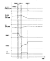
しかしながら、上記モータ走行時に変速部の変速が行われると、変速部の入力回転速度が変化させられ、そのイナーシャ影響がエンジン自体の引き摺りよりも大きいときには、第1電動機を空転させていることもあってエンジン回転速度が零乃至略零に維持されず変化する可能性があった。特に、以下の図18に例示するように、モータ走行時に変速部のアップシフトが行われると、エンジン回転速度が負回転域に入る可能性があった。 However, when the speed change of the speed change unit is performed during the motor running, the input rotation speed of the speed change unit is changed, and when the inertia influence is larger than the drag of the engine itself, the first electric motor may be idling. As a result, the engine speed may change without being maintained at zero or substantially zero. In particular, as illustrated in FIG. 18 below, if the speed change unit is upshifted during motor travel, the engine rotational speed may enter a negative rotation range.
図18は、電気式差動部を構成する各回転要素の回転速度を示す良く知られた共線図であって、モータ走行中に変速部の1→2アップシフトが行われたときの上記各回転要素の回転変化の一例をその共線図上に表した図である。図18において、[ENG]はエンジンに連結された第1回転要素(第1要素)の回転速度、[M1]は第1電動機に連結された第2回転要素(第2要素)の回転速度、[M2]は伝達部材および第2電動機に連結された第3回転要素(第3要素)の回転速度をそれぞれ示している。また、電気式差動部における各直線は各回転要素の回転速度の相対関係を示すものであって、実線aはアップシフト前の相対関係を示し、実線bはアップシフト後の相対関係を示している。 FIG. 18 is a well-known collinear diagram showing the rotational speeds of the rotating elements constituting the electric differential unit, and the above-mentioned when a 1 → 2 upshift of the transmission unit is performed during motor running. It is the figure which represented on the collinear diagram an example of the rotation change of each rotation element. In FIG. 18, [ENG] is the rotation speed of the first rotation element (first element) connected to the engine, [M1] is the rotation speed of the second rotation element (second element) connected to the first electric motor, [M2] indicates the rotational speed of the third rotating element (third element) connected to the transmission member and the second electric motor, respectively. In addition, each straight line in the electric differential section indicates a relative relationship between the rotational speeds of the respective rotating elements, a solid line a indicates a relative relationship before the upshift, and a solid line b indicates a relative relationship after the upshift. ing.
そして、図18に示すように変速部の1→2アップシフトに伴って第3要素の回転速度[M2]が低下させられると、第1電動機が空転させているためエンジン自体の引き摺りおよび電気式差動部の差動作用によりエンジン回転速度はそのまま零乃至略零に維持される。しかし、この変速の際のイナーシャ影響がエンジン自体の引き摺りよりも大きいと、エンジン回転速度が負回転域に入る可能性がある。 Then, as shown in FIG. 18, when the rotational speed [M2] of the third element is lowered with the 1 → 2 upshift of the transmission unit, the first motor is idling, so the drag of the engine itself and the electric type Due to the differential action of the differential section, the engine speed is maintained at zero or substantially zero. However, if the influence of inertia at the time of this shift is greater than the drag of the engine itself, the engine rotation speed may enter a negative rotation range.
このような現象は、エンジンの耐久性を低下させる可能性があると共に、イナーシャ影響が電気式差動部の出力回転部材(すなわち変速部の入力回転部材)に影響してドライバビリティを悪化させる可能性があるが、このような課題は従来では検討されておらず、未公知の課題であった。これに対し、モータ走行中の変速部のアップシフト時には、例えば第1電動機を一時的に駆動して第1電動機の回転速度を制御することによりエンジン回転速度を零以上の所定回転速度に維持して、エンジン回転速度が負回転域に入らないようにすることが考えられる。このとき、前述したように、蓄電装置に充電制限または放電制限がかかっている場合には、モータ走行時に変速部の変速が行われた際に第1電動機の回転速度を適切に制御できない可能性があった。 Such a phenomenon may reduce the durability of the engine, and the influence of inertia may affect the output rotation member of the electric differential unit (that is, the input rotation member of the transmission unit) and deteriorate drivability. However, such a problem has not been studied in the past and has not been known. On the other hand, at the time of upshifting the speed change unit during motor running, for example, the engine speed is maintained at a predetermined rotation speed of zero or more by temporarily driving the first motor and controlling the rotation speed of the first motor. Thus, it is conceivable to prevent the engine speed from entering the negative rotation range. At this time, as described above, when the power storage device is charged or discharged, there is a possibility that the rotation speed of the first electric motor cannot be controlled appropriately when the speed change unit is changed during motor traveling. was there.
本発明は、以上の事情を背景として為されたものであり、その目的とするところは、第1電動機の駆動時または発電時における電力を供給または充電する蓄電装置の充電または放電が制限されているときの変速部の変速の際に、第1電動機の回転速度を適切に制御することができる車両用駆動装置の制御装置を提供することにある。 The present invention has been made in the background of the above circumstances, and its purpose is that charging or discharging of a power storage device that supplies or charges power when the first motor is driven or generated is limited. An object of the present invention is to provide a control device for a vehicle drive device that can appropriately control the rotation speed of a first electric motor when the speed change portion of the speed change portion is shifted.
かかる目的を達成するための請求項1にかかる発明の要旨とするところは、(a) エンジンに連結された第1要素と第1電動機に連結された第2要素と伝達部材に連結された第3要素とを有してそのエンジンの出力をその第1電動機およびその伝達部材へ分配する差動機構を有する電気式差動部と、その伝達部材から駆動輪への動力伝達経路に設けられた変速部とを備え、前記変速部の変速の際に前記第1電動機の回転速度を制御することによりエンジン回転速度を所定の回転速度に制御する車両用駆動装置の制御装置であって、(b) 前記第1電動機の駆動時または発電時における電力を供給または充電する蓄電装置の充電または放電が制限されるときには、その蓄電装置の充電または放電が制限されないときに比較して、その蓄電装置の充電または放電の電力が少なくなるように前記変速部の変速判断を行う充放電制限時変速制御手段を含むことにある。
To achieve this object, the gist of the invention according to
このようにすれば、第1電動機の駆動時または発電時における電力を供給または充電する蓄電装置の充電または放電が制限されるときには、蓄電装置の充電または放電が制限されないときに比較して、充放電制限時変速制御手段により蓄電装置の充電または放電の電力が少なくなるように変速部の変速判断が行われるので、蓄電装置の充電または放電が制限されているときの変速部の変速の際に、第1電動機の回転速度を適切に制御することができる。この結果、蓄電装置の耐久性が向上すると共に、蓄電装置の充電または放電が制限されたことで変速部の変速の際に第1電動機の回転速度を適切に制御できないことによる変速ショックを抑制することができる。 According to this configuration, when charging or discharging of the power storage device that supplies or charges power during driving or power generation of the first motor is limited, charging or discharging of the power storage device is not limited compared to when charging or discharging is not limited. Since the shift control unit determines whether to change the speed of the speed change unit so that the power for charging or discharging the power storage device is reduced by the speed control means when discharging is limited, The rotational speed of the first electric motor can be appropriately controlled. As a result, the durability of the power storage device is improved, and the shift shock due to the fact that the rotation speed of the first motor cannot be properly controlled during the shift of the transmission unit due to the limited charging or discharging of the power storage device is suppressed. be able to.
また、請求項2にかかる発明は、請求項1に記載の車両用駆動装置の制御装置において、前記充放電制限時変速制御手段は、前記蓄電装置の充電または放電が制限されるときには、その蓄電装置の充電または放電が制限されないときに比較して、低車速側で前記変速部が変速されるようにするものである。このようにすれば、変速部の変速の際に変速部の入力回転部材の変化量(すなわち伝達部材の回転速度の変化量)が少なくなり、エンジン回転速度を所定の回転速度に制御する際に第1電動機の駆動に必要な電力或いは第1電動機の発電による電力が減少させられることから、蓄電装置の充電または放電が制限されたとしても第1電動機の回転速度を適切に制御することができる。 According to a second aspect of the present invention, in the control device for a vehicle drive device according to the first aspect, the charge / discharge limiting shift control means is configured to store the power storage when charging or discharging of the power storage device is limited. Compared to when the charging or discharging of the device is not restricted, the speed change portion is shifted on the low vehicle speed side. In this way, the amount of change in the input rotation member of the transmission unit (that is, the amount of change in the rotation speed of the transmission member) is reduced when the transmission unit is shifted, and the engine rotation speed is controlled to a predetermined rotation speed. Since the electric power required for driving the first electric motor or the electric power generated by the first electric motor is reduced, the rotation speed of the first electric motor can be appropriately controlled even when charging or discharging of the power storage device is restricted. .
また、請求項3にかかる発明は、請求項2に記載の車両用駆動装置の制御装置において、前記充放電制限時変速制御手段は、前記蓄電装置の充電または放電が制限を受ける程、より低車速側で前記変速部が変速されるようにするものである。このようにすれば、蓄電装置の充電または放電の制限に応じて第1電動機の回転速度を一層適切に制御することができる。 According to a third aspect of the present invention, in the control device for a vehicle drive device according to the second aspect, the charge / discharge limiting shift control means is lower as charging or discharging of the power storage device is restricted. The speed change portion is shifted on the vehicle speed side. In this way, it is possible to more appropriately control the rotation speed of the first electric motor in accordance with restrictions on charging or discharging of the power storage device.
また、請求項4にかかる発明は、請求項1に記載の車両用駆動装置の制御装置において、前記変速部は、予め定められた第1変速マップに従って変速が実行される自動変速機であり、前記充放電制限時変速制御手段は、前記第1変速マップよりも低車速側で変速する第2変速マップに従って変速を実行するものである。このようにすれば、変速部の変速の際に変速部の入力回転部材の変化量(すなわち伝達部材の回転速度の変化量)が少なくなり、エンジン回転速度を所定の回転速度に制御する際に第1電動機の駆動に必要な電力或いは第1電動機の発電による電力が減少させられることから、蓄電装置の充電または放電が制限されたとしても第1電動機の回転速度を適切に制御することができる。 According to a fourth aspect of the present invention, in the control device for a vehicle drive device according to the first aspect, the transmission unit is an automatic transmission in which a shift is executed according to a predetermined first shift map. The charge / discharge limiting shift control means executes a shift according to a second shift map that shifts at a lower vehicle speed side than the first shift map. In this way, the amount of change in the input rotation member of the transmission unit (that is, the amount of change in the rotation speed of the transmission member) is reduced when the transmission unit is shifted, and the engine rotation speed is controlled to a predetermined rotation speed. Since the electric power required for driving the first electric motor or the electric power generated by the first electric motor is reduced, the rotation speed of the first electric motor can be appropriately controlled even when charging or discharging of the power storage device is restricted. .
また、請求項5にかかる発明は、請求項4に記載の車両用駆動装置の制御装置において、前記充放電制限時変速制御手段は、前記蓄電装置の充電または放電が制限を受ける程、変速点をより低車速側へ変更するものである。このようにすれば、蓄電装置の充電または放電の制限に応じて第1電動機の回転速度を一層適切に制御することができる。 According to a fifth aspect of the present invention, in the control apparatus for a vehicle drive device according to the fourth aspect, the charge / discharge limiting shift control means shifts the shift point so that charging or discharging of the power storage device is limited. Is changed to a lower vehicle speed side. In this way, it is possible to more appropriately control the rotation speed of the first electric motor in accordance with restrictions on charging or discharging of the power storage device.
また、請求項6にかかる発明は、請求項1乃至5のいずれかに記載の車両用駆動装置の制御装置において、前記充放電制限時変速制御手段は、前記蓄電装置の充電のみが制限されるときには、その蓄電装置が放電される場合か或いはその蓄電装置へ充電される電力が可及的に少なくなるように前記変速部の変速判断を行うものである。このようにすれば、蓄電装置の充電または放電の制限状態に合わせて第1電動機の回転速度を一層適切に制御することができる。例えば、蓄電装置の充電のみが制限されるときに蓄電装置の充電または放電の電力が少なくなるように一律に変速部の変速判断を行うことに比較して、蓄電装置の充電または放電が制限されないときに通常行われる変速部の変速判断機会が広がる。 According to a sixth aspect of the present invention, in the vehicle drive device control device according to any one of the first to fifth aspects, the charge / discharge limiting shift control means is limited only to charging the power storage device. Sometimes, the shift determination of the transmission unit is performed so that the power storage device is discharged or the power charged in the power storage device is reduced as much as possible. In this way, it is possible to more appropriately control the rotation speed of the first electric motor in accordance with the charging or discharging restriction state of the power storage device. For example, the charging or discharging of the power storage device is not limited as compared with the case where the shift determination of the transmission unit is uniformly performed so that the power of charging or discharging of the power storage device is reduced when only the charging of the power storage device is limited. Occasionally, a shift determination opportunity of the transmission unit that is normally performed is expanded.
また、請求項7にかかる発明は、請求項1乃至6のいずれかに記載の車両用駆動装置の制御装置において、前記充放電制限時変速制御手段は、前記蓄電装置の放電のみが制限されるときには、その蓄電装置が充電される場合か或いはその蓄電装置から放電される電力が可及的に少なくなるように前記変速部の変速判断を行うものである。このようにすれば、蓄電装置の充電または放電の制限状態に合わせて第1電動機の回転速度を一層適切に制御することができる。例えば、蓄電装置の放電のみが制限されるときに蓄電装置の充電または放電の電力が少なくなるように一律に変速部の変速判断を行うことに比較して、蓄電装置の充電または放電が制限されないときに通常行われる変速部の変速判断機会が広がる。 According to a seventh aspect of the present invention, in the vehicle drive device control device according to any one of the first to sixth aspects, the charge / discharge limiting shift control means is limited only to discharging the power storage device. Sometimes, the shift determination of the transmission unit is performed so that the power storage device is charged or the power discharged from the power storage device is reduced as much as possible. In this way, it is possible to more appropriately control the rotation speed of the first electric motor in accordance with the charging or discharging restriction state of the power storage device. For example, the charging or discharging of the power storage device is not limited as compared with the case where the shift determination of the transmission unit is uniformly performed so that the power of charging or discharging of the power storage device is reduced when only the discharging of the power storage device is limited. Occasionally, a shift determination opportunity of the transmission unit that is normally performed is expanded.
また、請求項8にかかる発明は、請求項1乃至7のいずれかに記載の車両用駆動装置の制御装置において、前記伝達部材に連結された第2電動機を備え、前記充放電制限時変速制御手段は、前記第2電動機のみを駆動力源とするモータ走行時に前記蓄電装置の充電または放電が制限されるときには、その蓄電装置の充電または放電が制限されないときに比較して、その蓄電装置の充電または放電の電力が少なくなるように前記変速部の変速判断を行うものである。このようにすれば、モータ走行時に変速部の変速が行われた際に第1電動機の回転速度を適切に制御することができる。特に、変速部のアップシフトにおいてはエンジン回転速度が負回転領域に入ることを抑制することができてエンジンの耐久性を向上することができる。
The invention according to
また、請求項9にかかる発明は、請求項8に記載の車両用駆動装置の制御装置において、前記充放電制限時変速制御手段は、前記第2電動機の駆動時における電力を考慮して、前記蓄電装置の充電または放電の電力が少なくなるように前記変速部の変速判断を行うものである。このようにすれば、モータ走行時に変速部の変速が行われた際に第1電動機の回転速度を一層適切に制御することができる。例えば、蓄電装置の耐久性を考慮すると充電および放電がともに好ましくない場合であっても、電力収支を零乃至零近傍とするように変速することも可能となり、第1電動機の回転速度を一層適切に制御することができる。
The invention according to claim 9 is the control device for a vehicle drive device according to
また、請求項10にかかる発明は、請求項1乃至9のいずれかに記載の車両用駆動装置の制御装置において、前記蓄電装置の充電または放電は、その蓄電装置の温度に基づいて制限されるものである。このようにすれば、蓄電装置の充電または放電を適切に制限することができて、蓄電装置の耐久性低下を抑制することができる。 According to a tenth aspect of the present invention, in the control device for a vehicle drive device according to any one of the first to ninth aspects, charging or discharging of the power storage device is limited based on a temperature of the power storage device. Is. In this way, charging or discharging of the power storage device can be appropriately restricted, and a decrease in durability of the power storage device can be suppressed.
また、請求項11にかかる発明は、請求項1乃至10のいずれかに記載の車両用駆動装置の制御装置において、前記蓄電装置の充電または放電は、その蓄電装置の充電容量に基づいて制限されるものである。このようにすれば、蓄電装置の充電または放電を適切に制限することができて、蓄電装置の耐久性低下を抑制することができる。
The invention according to
また、請求項12にかかる発明は、請求項1乃至11のいずれかに記載の車両用駆動装置の制御装置において、前記電気式差動部は、前記第1電動機の運転状態が制御されることにより無段変速機として作動するものである。このようにすれば、電気式差動部と変速部とで無段変速機が構成され、滑らかに駆動トルクを変化させることが可能である。尚、電気式差動部は、変速比を連続的に変化させて電気的な無段変速機として作動させる他に変速比を段階的に変化させて有段変速機として作動させることも可能である。 According to a twelfth aspect of the present invention, in the control device for a vehicle drive device according to any one of the first to eleventh aspects, the electric differential unit is configured such that an operating state of the first electric motor is controlled. Therefore, it operates as a continuously variable transmission. In this way, the continuously variable transmission is configured by the electric differential unit and the transmission unit, and the drive torque can be changed smoothly. The electric differential unit can be operated as a stepped transmission by changing the gear ratio stepwise, in addition to continuously changing the gear ratio and operating as an electric continuously variable transmission. is there.
ここで、好適には、前記差動機構は、前記エンジンに連結された第1要素と前記第1電動機に連結された第2要素と前記伝達部材に連結された第3要素とを有する遊星歯車装置であり、前記第1要素はその遊星歯車装置のキャリヤであり、前記第2要素はその遊星歯車装置のサンギヤであり、前記第3要素はその遊星歯車装置のリングギヤである。このようにすれば、前記差動機構の軸方向寸法が小さくなる。また、差動機構が1つの遊星歯車装置によって簡単に構成され得る。 Here, preferably, the differential mechanism includes a planetary gear having a first element connected to the engine, a second element connected to the first electric motor, and a third element connected to the transmission member. The first element is a carrier of the planetary gear set, the second element is a sun gear of the planetary gear set, and the third element is a ring gear of the planetary gear set. In this way, the axial dimension of the differential mechanism is reduced. Further, the differential mechanism can be easily constituted by one planetary gear device.
また、好適には、前記遊星歯車装置はシングルピニオン型遊星歯車装置である。このようにすれば、前記差動機構の軸方向寸法が小さくなる。また、差動機構が1つのシングルピニオン型遊星歯車装置によって簡単に構成される。 Preferably, the planetary gear device is a single pinion type planetary gear device. In this way, the axial dimension of the differential mechanism is reduced. Further, the differential mechanism is simply constituted by one single pinion type planetary gear device.
また、好適には、前記変速部の変速比(ギヤ比)と前記電気式差動部の変速比とに基づいて前記車両用駆動装置の総合変速比が形成されるものである。このようにすれば、変速部の変速比を利用することによって駆動力が幅広く得られるようになる。 Preferably, the overall transmission ratio of the vehicle drive device is formed based on the transmission ratio (gear ratio) of the transmission unit and the transmission ratio of the electric differential unit. In this way, a wide driving force can be obtained by utilizing the gear ratio of the transmission unit.
また、好適には、前記変速部は有段式の自動変速機である。このようにすれば、例えば電気的な無段変速機として機能させられる電気式差動部と有段式自動変速機とで無段変速機が構成され、滑らかに駆動トルクを変化させることが可能であると共に、電気式差動部の変速比を一定となるように制御した状態においては電気式差動部と有段式自動変速機とで有段変速機と同等の状態が構成され、車両用駆動装置の総合変速が段階的に変化させられて速やかに駆動トルクを得ることも可能となる。 Preferably, the transmission unit is a stepped automatic transmission. In this way, for example, a continuously variable transmission is configured by an electric differential section that functions as an electric continuously variable transmission and a stepped automatic transmission, and the drive torque can be changed smoothly. In addition, in a state in which the gear ratio of the electric differential unit is controlled to be constant, the electric differential unit and the stepped automatic transmission constitute a state equivalent to a stepped transmission, and the vehicle It is also possible to quickly obtain the drive torque by changing the overall shift of the drive device for use in stages.
以下、本発明の実施例を図面を参照しつつ詳細に説明する。 Hereinafter, embodiments of the present invention will be described in detail with reference to the drawings.
図1は、本発明が適用されるハイブリッド車両の駆動装置の一部を構成する変速機構10を説明する骨子図である。図1において、変速機構10は車体に取り付けられる非回転部材としてのトランスミッションケース12(以下、ケース12という)内において共通の軸心上に配設された入力回転部材としての入力軸14と、この入力軸14に直接に或いは図示しない脈動吸収ダンパー(振動減衰装置)などを介して間接に連結された無段変速部としての電気式差動部(以下、差動部という)11と、その差動部11と駆動輪34(図7参照)との間の動力伝達経路で伝達部材(伝動軸)18を介して直列に連結されている動力伝達部としての自動変速部20と、この自動変速部20に連結されている出力回転部材としての出力軸22とを直列に備えている。この変速機構10は、例えば車両において縦置きされるFR(フロントエンジン・リヤドライブ)型車両に好適に用いられるものであり、入力軸14に直接に或いは図示しない脈動吸収ダンパーを介して直接的に連結された走行用の駆動力源として例えばガソリンエンジンやディーゼルエンジン等の内燃機関であるエンジン8と一対の駆動輪34との間に設けられて、エンジン8からの動力を動力伝達経路の一部を構成する差動歯車装置(終減速機)32(図7参照)および一対の車軸等を順次介して一対の駆動輪34へ伝達する。
FIG. 1 is a skeleton diagram illustrating a
このように、本実施例の変速機構10においてはエンジン8と差動部11とは直結されている。この直結にはトルクコンバータやフルードカップリング等の流体式伝動装置を介することなく連結されているということであり、例えば上記脈動吸収ダンパーなどを介する連結はこの直結に含まれる。なお、変速機構10はその軸心に対して対称的に構成されているため、図1の骨子図においてはその下側が省略されている。以下の各実施例についても同様である。
Thus, in the
差動部11は、第1電動機M1と、入力軸14に入力されたエンジン8の出力を機械的に分配する機械的機構であってエンジン8の出力を第1電動機M1および伝達部材18に分配する差動機構としての動力分配機構16と、伝達部材18と一体的に回転するように作動的に連結されている第2電動機M2とを備えている。本実施例の第1電動機M1および第2電動機M2は発電機能をも有する所謂モータジェネレータであるが、第1電動機M1は反力を発生させるためのジェネレータ(発電)機能を少なくとも備え、第2電動機M2は走行用の駆動力源として駆動力を出力するためのモータ(電動機)機能を少なくとも備える。
The
動力分配機構16は、例えば「0.418」程度の所定のギヤ比ρ1を有するシングルピニオン型の第1遊星歯車装置24を主体として構成されている。この第1遊星歯車装置24は、第1サンギヤS1、第1遊星歯車P1、その第1遊星歯車P1を自転および公転可能に支持する第1キャリヤCA1、第1遊星歯車P1を介して第1サンギヤS1と噛み合う第1リングギヤR1を回転要素(要素)として備えている。第1サンギヤS1の歯数をZS1、第1リングギヤR1の歯数をZR1とすると、上記ギヤ比ρ1はZS1/ZR1である。
The
この動力分配機構16においては、第1キャリヤCA1は入力軸14すなわちエンジン8に連結され、第1サンギヤS1は第1電動機M1に連結され、第1リングギヤR1は伝達部材18に連結されている。このように構成された動力分配機構16は、第1遊星歯車装置24の3要素である第1サンギヤS1、第1キャリヤCA1、第1リングギヤR1がそれぞれ相互に相対回転可能とされて差動作用が作動可能なすなわち差動作用が働く差動状態とされることから、エンジン8の出力が第1電動機M1と伝達部材18とに分配されるとともに、分配されたエンジン8の出力の一部で第1電動機M1から発生させられた電気エネルギで蓄電されたり第2電動機M2が回転駆動されるので、差動部11(動力分配機構16)は電気的な差動装置として機能させられて例えば差動部11は所謂無段変速状態(電気的CVT状態)とされて、エンジン8の所定回転に拘わらず伝達部材18の回転が連続的に変化させられる。すなわち、差動部11はその変速比γ0(入力軸14の回転速度NIN/伝達部材18の回転速度N18)が最小値γ0min から最大値γ0max まで連続的に変化させられる電気的な無段変速機として機能する。
In the
自動変速部20は、シングルピニオン型の第2遊星歯車装置26、シングルピニオン型の第3遊星歯車装置28、およびシングルピニオン型の第4遊星歯車装置30を備え、有段式の自動変速機として機能する遊星歯車式の多段変速機である。第2遊星歯車装置26は、第2サンギヤS2、第2遊星歯車P2、その第2遊星歯車P2を自転および公転可能に支持する第2キャリヤCA2、第2遊星歯車P2を介して第2サンギヤS2と噛み合う第2リングギヤR2を備えており、例えば「0.562」程度の所定のギヤ比ρ2を有している。第3遊星歯車装置28は、第3サンギヤS3、第3遊星歯車P3、その第3遊星歯車P3を自転および公転可能に支持する第3キャリヤCA3、第3遊星歯車P3を介して第3サンギヤS3と噛み合う第3リングギヤR3を備えており、例えば「0.425」程度の所定のギヤ比ρ3を有している。第4遊星歯車装置30は、第4サンギヤS4、第4遊星歯車P4、その第4遊星歯車P4を自転および公転可能に支持する第4キャリヤCA4、第4遊星歯車P4を介して第4サンギヤS4と噛み合う第4リングギヤR4を備えており、例えば「0.421」程度の所定のギヤ比ρ4を有している。第2サンギヤS2の歯数をZS2、第2リングギヤR2の歯数をZR2、第3サンギヤS3の歯数をZS3、第3リングギヤR3の歯数をZR3、第4サンギヤS4の歯数をZS4、第4リングギヤR4の歯数をZR4とすると、上記ギヤ比ρ2はZS2/ZR2、上記ギヤ比ρ3はZS3/ZR3、上記ギヤ比ρ4はZS4/ZR4である。
The
自動変速部20では、第2サンギヤS2と第3サンギヤS3とが一体的に連結されて第2クラッチC2を介して伝達部材18に選択的に連結されるとともに第1ブレーキB1を介してケース12に選択的に連結され、第2キャリヤCA2は第2ブレーキB2を介してケース12に選択的に連結され、第4リングギヤR4は第3ブレーキB3を介してケース12に選択的に連結され、第2リングギヤR2と第3キャリヤCA3と第4キャリヤCA4とが一体的に連結されて出力軸22に連結され、第3リングギヤR3と第4サンギヤS4とが一体的に連結されて第1クラッチC1を介して伝達部材18に選択的に連結されている。
In the
このように、自動変速部20内と差動部11(伝達部材18)とは自動変速部20の各ギヤ段(変速段)を成立させるために用いられる第1クラッチC1または第2クラッチC2を介して選択的に連結されている。言い換えれば、第1クラッチC1および第2クラッチC2は、伝達部材18と自動変速部20との間の動力伝達経路すなわち差動部11(伝達部材18)から駆動輪34への動力伝達経路を、その動力伝達経路の動力伝達を可能とする動力伝達可能状態と、その動力伝達経路の動力伝達を遮断する動力伝達遮断状態とに選択的に切り換える係合装置として機能している。つまり、第1クラッチC1および第2クラッチC2の少なくとの一方が係合されることで上記動力伝達経路が動力伝達可能状態とされ、或いは第1クラッチC1および第2クラッチC2が解放されることで上記動力伝達経路が動力伝達遮断状態とされる。
As described above, the
また、この自動変速部20は、解放側係合装置の解放と係合側係合装置の係合とによりクラッチツウクラッチ変速が実行されて各ギヤ段が選択的に成立させられることにより、略等比的に変化する変速比γ(=伝達部材18の回転速度N18/出力軸22の回転速度NOUT)が各ギヤ段毎に得られる。例えば、図2の係合作動表に示されるように、第1クラッチC1および第3ブレーキB3の係合により変速比γ1が最大値例えば「3.357」程度である第1速ギヤ段が成立させられ、第1クラッチC1および第2ブレーキB2の係合により変速比γ2が第1速ギヤ段よりも小さい値例えば「2.180」程度である第2速ギヤ段が成立させられ、第1クラッチC1および第1ブレーキB1の係合により変速比γ3が第2速ギヤ段よりも小さい値例えば「1.424」程度である第3速ギヤ段が成立させられ、第1クラッチC1および第2クラッチC2の係合により変速比γ4が第3速ギヤ段よりも小さい値例えば「1.000」程度である第4速ギヤ段が成立させられる。また、第2クラッチC2および第3ブレーキB3の係合により変速比γRが第1速ギヤ段と第2速ギヤ段との間の値例えば「3.209」程度である後進ギヤ段(後進変速段)が成立させられる。また、第1クラッチC1、第2クラッチC2、第1ブレーキB1、第2ブレーキB2、および第3ブレーキB3の解放によりニュートラル「N」状態とされる。
In addition, the
前記第1クラッチC1、第2クラッチC2、第1ブレーキB1、第2ブレーキB2、および第3ブレーキB3(以下、特に区別しない場合はクラッチC、ブレーキBと表す)は、従来の車両用自動変速機においてよく用いられている係合要素としての油圧式摩擦係合装置であって、互いに重ねられた複数枚の摩擦板が油圧アクチュエータにより押圧される湿式多板型や、回転するドラムの外周面に巻き付けられた1本または2本のバンドの一端が油圧アクチュエータによって引き締められるバンドブレーキなどにより構成され、それが介挿されている両側の部材を選択的に連結するためのものである。 The first clutch C1, the second clutch C2, the first brake B1, the second brake B2, and the third brake B3 (hereinafter referred to as the clutch C and the brake B unless otherwise specified) are conventional automatic transmissions for vehicles. A hydraulic friction engagement device as an engagement element often used in a machine, and a wet multi-plate type in which a plurality of friction plates stacked on each other are pressed by a hydraulic actuator, or an outer peripheral surface of a rotating drum One end of one or two bands wound around is composed of a band brake or the like that is tightened by a hydraulic actuator, and is for selectively connecting the members on both sides of the band brake.
以上のように構成された変速機構10において、無段変速機として機能する差動部11と自動変速部20とで全体として無段変速機が構成される。また、差動部11の変速比を一定となるように制御することにより、差動部11と自動変速部20とで有段変速機と同等の状態を構成することが可能とされる。
In the
具体的には、差動部11が無段変速機として機能し、且つ差動部11に直列の自動変速部20が有段変速機として機能することにより、自動変速部20の少なくとも1つの変速段Mに対して自動変速部20に入力される回転速度(以下、自動変速部20の入力回転速度)すなわち伝達部材18の回転速度(以下、伝達部材回転速度N18)が無段的に変化させられてその変速段Mにおいて無段的な変速比幅が得られる。したがって、変速機構10の総合変速比γT(=入力軸14の回転速度NIN/出力軸22の回転速度NOUT)が無段階に得られ、変速機構10において無段変速機が構成される。この変速機構10の総合変速比γTは、差動部11の変速比γ0と自動変速部20の変速比γとに基づいて形成される変速機構10全体としてのトータル変速比γTである。
Specifically, the
例えば、図2の係合作動表に示される自動変速部20の第1速ギヤ段乃至第4速ギヤ段や後進ギヤ段の各ギヤ段に対し伝達部材回転速度N18が無段的に変化させられて各ギヤ段は無段的な変速比幅が得られる。したがって、その各ギヤ段の間が無段的に連続変化可能な変速比となって、変速機構10全体としてのトータル変速比γTが無段階に得られる。
For example, first gear or transmission member rotational speed N 18 is continuously variable varying for each gear of the fourth gear and the reverse gear position of the
また、差動部11の変速比が一定となるように制御され、且つクラッチCおよびブレーキBが選択的に係合作動させられて第1速ギヤ段乃至第4速ギヤ段のいずれか或いは後進ギヤ段(後進変速段)が選択的に成立させられることにより、略等比的に変化する変速機構10のトータル変速比γTが各ギヤ段毎に得られる。したがって、変速機構10において有段変速機と同等の状態が構成される。
Further, the gear ratio of the
例えば、差動部11の変速比γ0が「1」に固定されるように制御されると、図2の係合作動表に示されるように自動変速部20の第1速ギヤ段乃至第4速ギヤ段や後進ギヤ段の各ギヤ段に対応する変速機構10のトータル変速比γTが各ギヤ段毎に得られる。また、自動変速部20の第4速ギヤ段において差動部11の変速比γ0が「1」より小さい値例えば0.7程度に固定されるように制御されると、第4速ギヤ段よりも小さい値例えば「0.7」程度であるトータル変速比γTが得られる。
For example, when the gear ratio γ0 of the
図3は、差動部11と自動変速部20とから構成される変速機構10において、ギヤ段毎に連結状態が異なる各回転要素の回転速度の相対関係を直線上で表すことができる共線図を示している。この図3の共線図は、各遊星歯車装置24、26、28、30のギヤ比ρの関係を示す横軸と、相対的回転速度を示す縦軸とから成る二次元座標であり、横線X1が回転速度零を示し、横線X2が回転速度「1.0」すなわち入力軸14に連結されたエンジン8の回転速度NEを示し、横線XGが伝達部材18の回転速度を示している。
FIG. 3 is a collinear diagram that can represent, on a straight line, the relative relationship between the rotational speeds of the rotating elements having different connection states for each gear stage in the
また、差動部11を構成する動力分配機構16の3つの要素に対応する3本の縦線Y1、Y2、Y3は、左側から順に第2回転要素(第2要素)RE2に対応する第1サンギヤS1、第1回転要素(第1要素)RE1に対応する第1キャリヤCA1、第3回転要素(第3要素)RE3に対応する第1リングギヤR1の相対回転速度を示すものであり、それらの間隔は第1遊星歯車装置24のギヤ比ρ1に応じて定められている。さらに、自動変速部20の5本の縦線Y4、Y5、Y6、Y7、Y8は、左から順に、第4回転要素(第4要素)RE4に対応し且つ相互に連結された第2サンギヤS2および第3サンギヤS3を、第5回転要素(第5要素)RE5に対応する第2キャリヤCA2を、第6回転要素(第6要素)RE6に対応する第4リングギヤR4を、第7回転要素(第7要素)RE7に対応し且つ相互に連結された第2リングギヤR2、第3キャリヤCA3、第4キャリヤCA4を、第8回転要素(第8要素)RE8に対応し且つ相互に連結された第3リングギヤR3、第4サンギヤS4をそれぞれ表し、それらの間隔は第2、第3、第4遊星歯車装置26、28、30のギヤ比ρ2、ρ3、ρ4に応じてそれぞれ定められている。共線図の縦軸間の関係においてサンギヤとキャリヤとの間が「1」に対応する間隔とされるとキャリヤとリングギヤとの間が遊星歯車装置のギヤ比ρに対応する間隔とされる。すなわち、差動部11では縦線Y1とY2との縦線間が「1」に対応する間隔に設定され、縦線Y2とY3との間隔はギヤ比ρ1に対応する間隔に設定される。また、自動変速部20では各第2、第3、第4遊星歯車装置26、28、30毎にそのサンギヤとキャリヤとの間が「1」に対応する間隔に設定され、キャリヤとリングギヤとの間がρに対応する間隔に設定される。
In addition, three vertical lines Y1, Y2, and Y3 corresponding to the three elements of the
上記図3の共線図を用いて表現すれば、本実施例の変速機構10は、動力分配機構16(差動部11)において、第1遊星歯車装置24の第1回転要素RE1(第1キャリヤCA1)が入力軸14すなわちエンジン8に連結され、第2回転要素RE2が第1電動機M1に連結され、第3回転要素(第1リングギヤR1)RE3が伝達部材18および第2電動機M2に連結されて、入力軸14の回転を伝達部材18を介して自動変速部20へ伝達する(入力させる)ように構成されている。このとき、Y2とX2の交点を通る斜めの直線L0により第1サンギヤS1の回転速度と第1リングギヤR1の回転速度との関係が示される。
If expressed using the collinear diagram of FIG. 3 described above, the
例えば、差動部11においては、第1回転要素RE1乃至第3回転要素RE3が相互に相対回転可能とされる差動状態とされており、直線L0と縦線Y3との交点で示される第1リングギヤR1の回転速度が車速Vに拘束されて略一定である場合には、エンジン回転速度NEを制御することによって直線L0と縦線Y2との交点で示される第1キャリヤCA1の回転速度が上昇或いは下降させられると、直線L0と縦線Y1との交点で示される第1サンギヤS1の回転速度すなわち第1電動機M1の回転速度が上昇或いは下降させられる
For example, in the
また、差動部11の変速比γ0が「1」に固定されるように第1電動機M1の回転速度を制御することによって第1サンギヤS1の回転がエンジン回転速度NEと同じ回転とされると、直線L0は横線X2と一致させられ、エンジン回転速度NEと同じ回転で第1リングギヤR1の回転速度すなわち伝達部材18が回転させられる。或いは、差動部11の変速比γ0が「1」より小さい値例えば0.7程度に固定されるように第1電動機M1の回転速度を制御することによって第1サンギヤS1の回転が零とされると、エンジン回転速度NEよりも増速された回転で伝達部材回転速度N18が回転させられる。
The rotation of first sun gear S1 are the same speed as the engine speed N E by controlling the speed of the first electric motor M1 such speed ratio γ0 of the
また、自動変速部20において第4回転要素RE4は第2クラッチC2を介して伝達部材18に選択的に連結されるとともに第1ブレーキB1を介してケース12に選択的に連結され、第5回転要素RE5は第2ブレーキB2を介してケース12に選択的に連結され、第6回転要素RE6は第3ブレーキB3を介してケース12に選択的に連結され、第7回転要素RE7は出力軸22に連結され、第8回転要素RE8は第1クラッチC1を介して伝達部材18に選択的に連結されている。
Further, in the
自動変速部20では、差動部11において直線L0が横線X2と一致させられてエンジン回転速度NEと同じ回転速度が差動部11から第8回転要素RE8に入力されると、図3に示すように、第1クラッチC1と第3ブレーキB3とが係合させられることにより、第8回転要素RE8の回転速度を示す縦線Y8と横線X2との交点と第6回転要素RE6の回転速度を示す縦線Y6と横線X1との交点とを通る斜めの直線L1と、出力軸22と連結された第7回転要素RE7の回転速度を示す縦線Y7との交点で第1速(1st)の出力軸22の回転速度が示される。同様に、第1クラッチC1と第2ブレーキB2とが係合させられることにより決まる斜めの直線L2と出力軸22と連結された第7回転要素RE7の回転速度を示す縦線Y7との交点で第2速(2nd)の出力軸22の回転速度が示され、第1クラッチC1と第1ブレーキB1とが係合させられることにより決まる斜めの直線L3と出力軸22と連結された第7回転要素RE7の回転速度を示す縦線Y7との交点で第3速(3rd)の出力軸22の回転速度が示され、第1クラッチC1と第2クラッチC2とが係合させられることにより決まる水平な直線L4と出力軸22と連結された第7回転要素RE7の回転速度を示す縦線Y7との交点で第4速(4th)の出力軸22の回転速度が示される。
In the
図4は、本実施例の変速機構10を制御するための電子制御装置80に入力される信号及びその電子制御装置80から出力される信号を例示している。この電子制御装置80は、CPU、ROM、RAM、及び入出力インターフェースなどから成る所謂マイクロコンピュータを含んで構成されており、RAMの一時記憶機能を利用しつつROMに予め記憶されたプログラムに従って信号処理を行うことによりエンジン8、第1、第2電動機M1、M2に関するハイブリッド駆動制御、自動変速部20の変速制御等の駆動制御を実行するものである。
FIG. 4 illustrates a signal input to the electronic control device 80 for controlling the
電子制御装置80には、図4に示すような各センサやスイッチなどから、エンジン水温TEMPWを表す信号、シフトレバー52(図6参照)のシフトポジションPSHや「M」ポジションにおける操作回数等を表す信号、エンジン8の回転速度であるエンジン回転速度NEを表す信号、Mモード(手動変速走行モード)を指令する信号、エアコンの作動を表す信号、出力軸22の回転速度(以下、出力軸回転速度)NOUTに対応する車速Vを表す信号、自動変速部20の作動油温TOILを表す信号、サイドブレーキ操作を表す信号、フットブレーキ操作を表す信号、触媒温度を表す信号、運転者の出力要求量に対応するアクセルペダルの操作量であるアクセル開度Accを表す信号、カム角を表す信号、スノーモード設定を表す信号、車両の前後加速度Gを表す信号、オートクルーズ走行を表す信号、車両の重量(車重)を表す信号、各車輪の車輪速を表す信号、第1電動機M1の回転速度NM1(以下、第1電動機回転速度NM1という)を表す信号、第2電動機M2の回転速度NM2(以下、第2電動機回転速度NM2という)を表す信号、第1電動機M1の温度(以下、第1電動機温度という)THM1を表す信号、第2電動機M2の温度(以下、第2電動機温度という)THM2を表す信号、蓄電装置56(図7参照)の温度(以下、蓄電装置温度という)THBATを表す信号、蓄電装置56の充電電流または放電電流(以下、充放電電流或いは入出力電流という)ICDを表す信号、蓄電装置56の電圧VBATを表す信号、上記蓄電装置温度THBAT、充放電電流ICD、および電圧VBATに基づいて算出された蓄電装置56の充電容量(充電状態)SOCを表す信号などが、それぞれ供給される。
The electronic control device 80 receives signals indicating the engine water temperature TEMP W , the number of operations at the shift position P SH of the shift lever 52 (see FIG. 6), the “M” position, etc. signal representing the signal indicative of engine rotational speed N E is the rotational speed of the engine 8, a signal for commanding the M mode (manual shift running mode), a signal representing the operation of the air conditioner, the rotational speed of the output shaft 22 (hereinafter, the output (Shaft rotation speed) signal representing vehicle speed V corresponding to N OUT , signal representing hydraulic oil temperature T OIL of automatic transmission unit 20, signal representing side brake operation, signal representing foot brake operation, signal representing catalyst temperature, driving A signal representing the accelerator opening Acc, which is the amount of operation of the accelerator pedal corresponding to the person's output request amount, a signal representing the cam angle, a signal representing the snow mode setting, A signal representing the longitudinal acceleration G of the vehicle, a signal representing auto-cruise traveling, a signal representing the weight (vehicle weight) of the vehicle, a signal representing the wheel speed of each wheel, the rotational speed N M1 of the first electric motor M1 (hereinafter referred to as the first) A signal representing the motor rotation speed N M1 , a signal representing the rotation speed N M2 of the second motor M2 (hereinafter referred to as the second motor rotation speed N M2 ), and a temperature of the first motor M1 (hereinafter referred to as the first motor temperature). ) A signal representing TH M1 , a signal representing the temperature of the second motor M2 (hereinafter referred to as the second motor temperature) TH M2, and a temperature of the power storage device 56 (see FIG. 7) (hereinafter referred to as the power storage device temperature) TH BAT . signal, the charging current or discharging current of the battery 56 (hereinafter, the charge and discharge current or output current of) signals representing the I CD, a signal representative of the voltage V BAT of the
また、上記電子制御装置80からは、エンジン出力を制御するエンジン出力制御装置58(図7参照)への制御信号例えばエンジン8の吸気管60に備えられた電子スロットル弁62のスロットル弁開度θTHを操作するスロットルアクチュエータ64への駆動信号や燃料噴射装置66による吸気管60或いはエンジン8の筒内への燃料供給量を制御する燃料供給量信号や点火装置68によるエンジン8の点火時期を指令する点火信号、過給圧を調整するための過給圧調整信号、電動エアコンを作動させるための電動エアコン駆動信号、電動機M1およびM2の作動を指令する指令信号、シフトインジケータを作動させるためのシフトポジション(操作位置)表示信号、ギヤ比を表示させるためのギヤ比表示信号、スノーモードであることを表示させるためのスノーモード表示信号、制動時の車輪のスリップを防止するABSアクチュエータを作動させるためのABS作動信号、Mモードが選択されていることを表示させるMモード表示信号、差動部11や自動変速部20の油圧式摩擦係合装置の油圧アクチュエータを制御するために油圧制御回路70(図5、図7参照)に含まれる電磁弁(リニアソレノイドバルブ)を作動させるバルブ指令信号、この油圧制御回路70に設けられたレギュレータバルブ(調圧弁)によりライン油圧PLを調圧するための信号、そのライン油圧PLが調圧されるための元圧の油圧源である電動油圧ポンプを作動させるための駆動指令信号、電動ヒータを駆動するための信号、クルーズコントロール制御用コンピュータへの信号等が、それぞれ出力される。
Further, a control signal from the electronic control unit 80 to an engine output control unit 58 (see FIG. 7) for controlling the engine output, for example, a throttle valve opening θ of an
図5は、油圧制御回路70のうちクラッチC1、C2、およびブレーキB1〜B3の各油圧アクチュエータ(油圧シリンダ)AC1、AC2、AB1、AB2、AB3の作動を制御するリニアソレノイドバルブSL1〜SL5に関する回路図である。
FIG. 5 is a circuit relating to linear solenoid valves SL1 to SL5 for controlling the operation of the hydraulic actuators (hydraulic cylinders) AC1, AC2, AB1, AB2, and AB3 of the clutches C1 and C2 and the brakes B1 to B3 in the
図5において、各油圧アクチュエータAC1、AC2、AB1、AB2、AB3には、ライン油圧PLがそれぞれリニアソレノイドバルブSL1〜SL5により電子制御装置80からの指令信号に応じた係合圧PC1、PC2、PB1、PB2、PB3に調圧されてそれぞれ直接的に供給されるようになっている。このライン油圧PLは、図示しない電動オイルポンプやエンジン30により回転駆動される機械式オイルポンプから発生する油圧を元圧として例えばリリーフ型調圧弁(レギュレータバルブ)によって、アクセル開度Acc或いはスロットル弁開度θTHで表されるエンジン負荷等に応じた値に調圧されるようになっている。
In FIG. 5, each hydraulic actuator AC1, AC2, AB1, AB2, AB3 has an engagement pressure PC1, PC2, PB1 corresponding to a command signal from the electronic control unit 80 by the linear solenoid valves SL1 to SL5. , PB2 and PB3 are respectively regulated and supplied directly. This line oil pressure PL is based on the hydraulic pressure generated from an electric oil pump (not shown) or a mechanical oil pump that is driven to rotate by the
リニアソレノイドバルブSL1〜SL5は、基本的には何れも同じ構成で、電子制御装置80により独立に励磁、非励磁され、各油圧アクチュエータAC1、AC2、AB1、AB2、AB3の油圧が独立に調圧制御されてクラッチC1〜C4、ブレーキB1、B2の係合圧PC1、PC2、PB1、PB2、PB3が制御される。そして、自動変速部20は、例えば図2の係合作動表に示すように予め定められた係合装置が係合されることによって各変速段が成立させられる。また、自動変速部20の変速制御においては、例えば変速に関与するクラッチCやブレーキBの解放と係合とが同時に制御される所謂クラッチツウクラッチ変速が実行される。
The linear solenoid valves SL1 to SL5 are basically the same in configuration and are excited and de-energized independently by the electronic control unit 80, and the hydraulic pressures of the hydraulic actuators AC1, AC2, AB1, AB2, and AB3 are independently regulated. Thus, the engagement pressures PC1, PC2, PB1, PB2, and PB3 of the clutches C1 to C4 and the brakes B1 and B2 are controlled. In the
図6は複数種類のシフトポジションPSHを人為的操作により切り換える切換装置としてのシフト操作装置50の一例を示す図である。このシフト操作装置50は、例えば運転席の横に配設され、複数種類のシフトポジションPSHを選択するために操作されるシフトレバー52を備えている。
FIG. 6 is a diagram illustrating an example of a
そのシフトレバー52は、変速機構10内つまり自動変速部20内の動力伝達経路が遮断されたニュートラル状態すなわち中立状態とし且つ自動変速部20の出力軸22をロックするための駐車ポジション「P(パーキング)」、後進走行のための後進走行ポジション「R(リバース)」、変速機構10内の動力伝達経路が遮断された中立状態とするための中立ポジション「N(ニュートラル)」、自動変速モードを成立させて差動部11の無段的な変速比幅と自動変速部20の第1速ギヤ段乃至第4速ギヤ段の範囲で自動変速制御される各ギヤ段とで得られる変速機構10の変速可能なトータル変速比γTの変化範囲内で自動変速制御を実行させる前進自動変速走行ポジション「D(ドライブ)」、または手動変速走行モード(手動モード)を成立させて自動変速部20の自動変速制御における高速側の変速段を制限する所謂変速レンジを設定するための前進手動変速走行ポジション「M(マニュアル)」へ手動操作されるように設けられている。
The
上記シフトレバー52の各シフトポジションPSHへの手動操作に連動して図2の係合作動表に示す後進ギヤ段「R」、ニュートラル「N」、前進ギヤ段「D」における各変速段等が成立するように、例えば油圧制御回路70が電気的に切り換えられる。
The reverse gear "R" shown in the engagement operation table of FIG 2 in conjunction with the manual operation of the various shift positions P SH of the
上記「P」乃至「M」ポジションに示す各シフトポジションPSHにおいて、「P」ポジションおよび「N」ポジションは、車両を走行させないときに選択される非走行ポジションであって、例えば図2の係合作動表に示されるように第1クラッチC1および第2クラッチC2のいずれもが解放されるような自動変速部20内の動力伝達経路が遮断された車両を駆動不能とする第1クラッチC1および第2クラッチC2による動力伝達経路の動力伝達遮断状態へ切換えを選択するための非駆動ポジションである。また、「R」ポジション、「D」ポジションおよび「M」ポジションは、車両を走行させるときに選択される走行ポジションであって、例えば図2の係合作動表に示されるように第1クラッチC1および第2クラッチC2の少なくとも一方が係合されるような自動変速部20内の動力伝達経路が連結された車両を駆動可能とする第1クラッチC1および/または第2クラッチC2による動力伝達経路の動力伝達可能状態への切換えを選択するための駆動ポジションでもある。
In the shift positions P SH shown in the “P” to “M” positions, the “P” position and the “N” position are non-traveling positions that are selected when the vehicle is not traveling. As shown in the combined operation table, the first clutch C1 that disables driving of the vehicle in which the power transmission path in the
具体的には、シフトレバー52が「P」ポジション或いは「N」ポジションから「R」ポジションへ手動操作されることで、第2クラッチC2が係合されて自動変速部20内の動力伝達経路が動力伝達遮断状態から動力伝達可能状態とされ、シフトレバー52が「N」ポジションから「D」ポジションへ手動操作されることで、少なくとも第1クラッチC1が係合されて自動変速部20内の動力伝達経路が動力伝達遮断状態から動力伝達可能状態とされる。また、シフトレバー52が「R」ポジションから「P」ポジション或いは「N」ポジションへ手動操作されることで、第2クラッチC2が解放されて自動変速部20内の動力伝達経路が動力伝達可能状態から動力伝達遮断状態とされ、シフトレバー52が「D」ポジションから「N」ポジションへ手動操作されることで、第1クラッチC1および第2クラッチC2が解放されて自動変速部20内の動力伝達経路が動力伝達可能状態から動力伝達遮断状態とされる。
Specifically, when the
図7は、電子制御装置80による制御機能の要部を説明する機能ブロック線図である。図7において、有段変速制御手段82は、図8に示すような車速Vと自動変速部20の出力トルクTOUTとを変数として予め記憶されたアップシフト線(実線)およびダウンシフト線(一点鎖線)を有する関係(変速線図、変速マップ)から実際の車速Vおよび自動変速部20の要求出力トルクTOUTで示される車両状態に基づいて、自動変速部20の変速を実行すべきか否かを判断しすなわち自動変速部20の変速すべき変速段を判断し、その判断した変速段が得られるように自動変速部20の自動変速制御を実行する。
FIG. 7 is a functional block diagram for explaining the main part of the control function by the electronic control unit 80. In FIG. 7, the stepped shift control means 82 includes an upshift line (solid line) and a downshift line (one point) stored in advance with the vehicle speed V and the output torque T OUT of the
このとき、有段変速制御手段82は、例えば図2に示す係合表に従って変速段が達成されるように、自動変速部20の変速に関与する油圧式摩擦係合装置を係合および/または解放させる指令(変速出力指令、油圧指令)を、すなわち自動変速部20の変速に関与する解放側係合装置を解放すると共に係合側係合装置を係合することによりクラッチツウクラッチ変速を実行させる指令を油圧制御回路70へ出力する。油圧制御回路70は、その指令に従って、例えば解放側係合装置を解放すると共に係合側係合装置を係合して自動変速部20の変速が実行されるように、油圧制御回路70内のリニアソレノイドバルブSLを作動させてその変速に関与する油圧式摩擦係合装置の油圧アクチュエータを作動させる。
At this time, the stepped shift control means 82 engages and / or engages the hydraulic friction engagement device involved in the shift of the
ハイブリッド制御手段84は、エンジン8を効率のよい作動域で作動させる一方で、エンジン8と第2電動機M2との駆動力の配分や第1電動機M1の発電による反力を最適になるように変化させて差動部11の電気的な無段変速機としての変速比γ0を制御する。例えば、そのときの走行車速Vにおいて、運転者の出力要求量としてのアクセル開度Accや車速Vから車両の目標(要求)出力を算出し、その車両の目標出力と充電要求値から必要なトータル目標出力を算出し、そのトータル目標出力が得られるように伝達損失、補機負荷、第2電動機M2のアシストトルク等を考慮して目標エンジン出力を算出し、その目標エンジン出力が得られるエンジン回転速度NEとエンジントルクTEとなるようにエンジン8を制御するとともに第1電動機M1の発電量を制御する。
The hybrid control means 84 operates the
例えば、ハイブリッド制御手段84は、その制御を動力性能や燃費向上などのために自動変速部20の変速段を考慮して実行する。このようなハイブリッド制御では、エンジン8を効率のよい作動域で作動させるために定まるエンジン回転速度NEと車速Vおよび自動変速部20の変速段で定まる伝達部材18の回転速度とを整合させるために、差動部11が電気的な無段変速機として機能させられる。すなわち、ハイブリッド制御手段84は、エンジン回転速度NEとエンジン8の出力トルク(エンジントルク)TEとで構成される二次元座標内において無段変速走行の時に運転性と燃費性とを両立するように予め実験的に求められて記憶された図9の破線に示すようなエンジン8の最適燃費率曲線(燃費マップ、関係)に沿ってエンジン8が作動させられるように、例えば目標出力(トータル目標出力、要求駆動力)を充足するために必要なエンジン出力を発生するためのエンジントルクTEとエンジン回転速度NEとなるように、変速機構10のトータル変速比γTの目標値を定め、その目標値が得られるように自動変速部20の変速段を考慮して差動部11の変速比γ0を制御し、トータル変速比γTをその変速可能な変化範囲内で無段階に制御する。
For example, the hybrid control means 84 executes the control in consideration of the gear position of the
このとき、ハイブリッド制御手段84は、第1電動機M1により発電された電気エネルギをインバータ54を通して蓄電装置56や第2電動機M2へ供給するので、エンジン8の動力の主要部は機械的に伝達部材18へ伝達されるが、エンジン8の動力の一部は第1電動機M1の発電のために消費されてそこで電気エネルギに変換され、インバータ54を通してその電気エネルギが第2電動機M2へ供給され、その第2電動機M2が駆動されて第2電動機M2から伝達部材18へ伝達される。この電気エネルギの発生から第2電動機M2で消費されるまでに関連する機器により、エンジン8の動力の一部を電気エネルギに変換し、その電気エネルギを機械的エネルギに変換するまでの電気パスが構成される。
At this time, the hybrid control means 84 supplies the electric energy generated by the first electric motor M1 to the
また、ハイブリッド制御手段84は、車両の停止中又は走行中に拘わらず、差動部11の電気的CVT機能によって例えば第1電動機回転速度NM1を制御してエンジン回転速度NEを略一定に維持したり任意の回転速度に回転制御させられる。言い換えれば、ハイブリッド制御手段84は、エンジン回転速度NEを略一定に維持したり任意の回転速度に制御しつつ第1電動機回転速度NM1を任意の回転速度に回転制御することができる。
The hybrid control means 84, regardless of the stopping or during running of the vehicle, and controls the electric CVT first electric motor speed N M1 for example the function of the
例えば、図3の共線図からもわかるようにハイブリッド制御手段84は車両走行中にエンジン回転速度NEを引き上げる場合には、車速V(駆動輪34)に拘束される第2電動機回転速度NM2を略一定に維持しつつ第1電動機回転速度NM1の引き上げを実行する。また、ハイブリッド制御手段84は自動変速部20の変速の際に第1電動機回転速度NM1を制御することによりエンジン回転速度NEを所定の回転速度に制御する。例えば、ハイブリッド制御手段84は自動変速部20の変速中にエンジン回転速度NEを略一定に維持する場合には、エンジン回転速度NEを略一定に維持しつつ自動変速部20の変速に伴う第2電動機回転速度NM2の変化とは反対方向に第1電動機回転速度NM1を変化させる。
For example, the hybrid control means 84 as can be seen from the diagram of FIG. 3 when raising the engine rotation speed N E during running of the vehicle, the vehicle speed V the second electric motor rotation speed N which is bound to the (drive wheels 34) The first motor rotation speed N M1 is increased while maintaining M2 substantially constant. The hybrid control means 84 controls the engine rotational speed N E to a predetermined rotational speed by controlling the first electric motor speed N M1 during shifting of the automatic shifting
また、ハイブリッド制御手段84は、スロットル制御のためにスロットルアクチュエータ64により電子スロットル弁62を開閉制御させる他、燃料噴射制御のために燃料噴射装置66による燃料噴射量や噴射時期を制御させ、点火時期制御のためにイグナイタ等の点火装置68による点火時期を制御させる指令を単独で或いは組み合わせてエンジン出力制御装置58に出力して、必要なエンジン出力を発生するようにエンジン8の出力制御を実行するエンジン出力制御手段を機能的に備えている。
Further, the hybrid control means 84 controls the opening and closing of the
例えば、ハイブリッド制御手段84は、基本的には図示しない予め記憶された関係からアクセル開度Accに基づいてスロットルアクチュエータ60を駆動し、アクセル開度Accが増加するほどスロットル弁開度θTHを増加させるようにスロットル制御を実行する。また、このエンジン出力制御装置58は、ハイブリッド制御手段84による指令に従って、スロットル制御のためにスロットルアクチュエータ64により電子スロットル弁62を開閉制御する他、燃料噴射制御のために燃料噴射装置66による燃料噴射を制御し、点火時期制御のためにイグナイタ等の点火装置68による点火時期を制御するなどしてエンジントルク制御を実行する。
For example, the hybrid control means 84 basically drives the throttle actuator 60 based on the accelerator opening Acc from a previously stored relationship (not shown), and increases the throttle valve opening θ TH as the accelerator opening Acc increases. Throttle control is executed so that Further, the engine
また、ハイブリッド制御手段84は、エンジン8の停止又はアイドル状態に拘わらず、差動部11の電気的CVT機能(差動作用)によってモータ走行させることができる。
Further, the hybrid control means 84 can drive the motor by the electric CVT function (differential action) of the
例えば、ハイブリッド制御手段84は、図8に示すような車速Vと自動変速部20の出力トルクTOUTとを変数として予め記憶された走行用駆動力源をエンジン8と第2電動機M2とで切り換えるためのエンジン走行領域とモータ走行領域との境界線を有する関係(駆動力源切換線図、駆動力源マップ)から実際の車速Vおよび自動変速部20の要求出力トルクTOUTで示される車両状態に基づいて、モータ走行領域とエンジン走行領域との何れであるかを判断してモータ走行或いはエンジン走行を実行する。図8の実線Aに示す駆動力源マップは、例えば同じ図8中の実線および一点鎖線に示す変速マップと共に予め記憶されている。このように、ハイブリッド制御手段84によるモータ走行は、図8から明らかなように一般的にエンジン効率が高トルク域に比較して悪いとされる比較的低出力トルクTOUT域すなわち低エンジントルクTE域、或いは車速Vの比較的低車速域すなわち低負荷域で実行される。
For example, the hybrid control means 84 switches the driving power source for driving stored in advance between the
ハイブリッド制御手段84は、このモータ走行時には、停止しているエンジン8の引き摺りを抑制して燃費を向上させるために、第1電動機回転速度NM1を負の回転速度で制御して例えば第1電動機M1を無負荷状態とすることにより空転させて、差動部11の電気的CVT機能(差動作用)により必要に応じてエンジン回転速度NEを零乃至略零に維持する。
The hybrid control means 84 controls the first motor rotation speed N M1 at a negative rotation speed to suppress dragging of the stopped
また、ハイブリッド制御手段84は、エンジン走行領域であっても、上述した電気パスによる第1電動機M1からの電気エネルギおよび/または蓄電装置56からの電気エネルギを第2電動機M2へ供給し、その第2電動機M2を駆動して駆動輪34にトルクを付与することにより、エンジン8の動力を補助するための所謂トルクアシストが可能である。
Further, even in the engine traveling region, the hybrid control means 84 supplies the second motor M2 with the electric energy from the first electric motor M1 and / or the electric energy from the
また、ハイブリッド制御手段84は、第1電動機M1を無負荷状態として自由回転すなわち空転させることにより、差動部11がトルクの伝達を不能な状態すなわち差動部11内の動力伝達経路が遮断された状態と同等の状態であって、且つ差動部11からの出力が発生されない状態とすることが可能である。すなわち、ハイブリッド制御手段84は、第1電動機M1を無負荷状態とすることにより差動部11をその動力伝達経路が電気的に遮断される中立状態(ニュートラル状態)とすることが可能である。
Further, the hybrid control means 84 makes the first electric motor M1 in a no-load state and freely rotates, that is, idles, so that the
ところで、図8に示す変速マップおよび駆動力源マップから明らかなように、車両状態によっては前記図18に示すようにモータ走行中においても自動変速部20の変速が行われる場合がある。このような場合、入力軸14の回転速度NINが変化し、そのイナーシャ影響がエンジン8自体の引き摺りよりも大きいときには、モータ走行中に第1電動機M1を空転させていることもあってエンジン回転速度NEが零乃至略零に維持されず変化する可能性がある。このような現象は、イナーシャ影響が差動部11の出力回転部材(すなわち伝達部材18)に影響してドライバビリティを悪化させる可能性がある。特に、図18に示すように、モータ走行時に自動変速部20のアップシフトが行われると、エンジン回転速度NEが負回転域に入り、エンジン8の耐久性を低下させる可能性がある。
Incidentally, as is apparent from the shift map and the driving force source map shown in FIG. 8, depending on the vehicle state, the shift of the
そこで、本実施例では、モータ走行中の自動変速部20の変速時には、エンジン回転速度NEを零より高い所定回転速度NE’に維持するモータ走行変速時エンジン回転制御手段86を備える。見方を換えると、このモータ走行変速時エンジン回転制御手段86は、モータ走行中の自動変速部20の変速時には、第1電動機M1を一時的に駆動してエンジン回転速度NEが所定回転速度NE’となるように自動変速部20の変速の進行に合わせて同期制御を行う。
Therefore, in this embodiment, when shifting of the automatic shifting
上記所定回転速度NE’は、モータ走行中の自動変速部20の変速時に一時的に設定される零よりも高い回転速度であって、その自動変速部20の変速に伴うイナーシャ影響によりエンジン回転速度NEが変化したとしてもエンジン回転速度NEが負回転域に入らないようにするための予め実験的に求められて記憶された目標エンジン回転速度NE’である。尚、この所定回転速度NE’は所定値であるが、所定の範囲(例えば20rpm)でエンジン回転速度の変化を許容するという観点から、それに替えて所定域として所定回転速度域が設定されても良い。
The predetermined rotational speed N E ′ is a rotational speed that is temporarily higher than zero, which is temporarily set at the time of shifting of the
これにより、モータ走行中の自動変速部20の変速の際にイナーシャ影響によるエンジン回転速度NEの変化が抑制されるので、差動部11の出力回転部材への影響が抑制されてドライバビリティが向上する。特に、自動変速部20のアップシフト時にエンジン回転速度NEが負回転域に入りことが抑制されるので、エンジン8の耐久性が向上する。
Thus, the change in the engine rotational speed N E by the inertia effect during shifting of the automatic shifting
具体的には、エンジン引き摺り判定手段88は、エンジン8の引き摺りが所定値を超えているか否かを判定する。このエンジン8の引き摺りは、エンジンオイルの粘度が低くなる高油温程小さくなるものであり、例えばエンジン引き摺り判定手段88は、図示しない油温センサにより検出されたエンジンオイルの温度が所定温度以下であるか否かに基づいて、エンジン8の引き摺りが所定値を超えているか否かを判定する。上記所定値は、モータ走行時にエンジン回転速度NEが零乃至略零に維持可能とされる正常なエンジン8の引き摺りであり、上記所定温度は、その正常なエンジン8の引き摺りを超えているエンジンオイルの温度であることが予め実験的に求められて設定された判定温度である。このように、エンジン引き摺り判定手段88は、エンジン8の引き摺りが正常であるか否かを判定するものである。
Specifically, the engine
前記ハイブリッド制御手段84は、前記エンジン引き摺り判定手段88によりエンジン8の引き摺りが正常でないと判定された場合には、例えば図8に示すような駆動力源マップから車両状態に基づいてモータ走行領域であると判断しても、モータ走行を禁止してエンジン走行を継続するかエンジン走行への切換えを実行する。
When the engine
モータ走行中判定手段90は、前記ハイブリッド制御手段84によりモータ走行領域であると判断されてモータ走行が実行されているか否かを判定する。 The motor traveling determination means 90 determines whether the hybrid control means 84 determines that the motor traveling region is in effect and the motor traveling is being executed.
変速部変速発生判定手段92は、前記有段変速制御手段82により自動変速部20の変速すべき変速段が判断されて自動変速部20の変速が発生したか否かを判定する。
The shift part shift
モータ走行変速時目標エンジン回転設定手段94は、前記エンジン引き摺り判定手段88によりエンジン8の引き摺りが正常であると判定され、且つ前記モータ走行中判定手段90により前記ハイブリッド制御手段84によるモータ走行が判定され、且つ前記変速部変速発生判定手段92により自動変速部20の変速が発生したと判定された場合には、前記有段変速制御手段82による自動変速部20の変速中において例えば有段変速制御手段82による自動変速部20の変速判断から変速終了までの期間において、前記目標エンジン回転速度NE’を一時的に設定する。この変速終了は、例えばイナーシャ相終了時点であり、実際の入力軸14の回転速度NINと変速後の入力軸14の回転速度NINの推定値(=出力軸回転速度NOUT×変速後の自動変速部20の変速段に対応する変速比γ)との回転速度差が変速終了と判断できるための予め実験的に求められて定められた所定回転速度差以内となった時点である。
The target engine rotation setting means 94 at the time of motor traveling shift is determined by the engine
上記目標エンジン回転速度NE’は一定の値を設定しても良いが、例えばモータ走行中の自動変速部20の変速に伴ってエンジン回転速度NEが負回転域に入らない範囲で可及的に小さな値とすることにより第1電動機M1を駆動するための電力消費を抑制することができる。
The target engine rotational speed N E 'may be set to a constant value, for example Kakyu with the shifting action of the
図10は、自動変速部20の変速前の各変速段毎に設定される目標エンジン回転速度NE1乃至NE4の一例を示している。図2に示すように変速比ステップ(=γ(n)/γ(n+1))が略同じであるときには、同一車速で見れば低車速側の変速程変速時の入力軸14の回転速度変化量(変化幅)が大きくイナーシャ影響が大きくなることから、エンジン回転速度NEが負回転域に入らないための余裕代を大きく取るという観点で、低車速側の変速段程(すなわち変速比が大きい変速段程)高い目標エンジン回転速度NE’が設定されている。すなわち、第1速ギヤ段で走行中に設定される目標エンジン回転速度NE1は最も高い値が設定され、高速側変速段となるに従って順次低くされ、第4速ギヤ段で走行中に設定される目標エンジン回転速度NE4は最も低い値が設定される。
FIG. 10 shows an example of target engine rotation speeds
前記モータ走行変速時エンジン回転制御手段86は、モータ走行中の自動変速部20の変速中において例えばその変速中のイナーシャ相開始より所定時間前からイナーシャ相終了までの期間において、エンジン回転速度NEを前記モータ走行変速時目標エンジン回転設定手段94により設定された目標エンジン回転速度NE’に維持する。例えば、モータ走行変速時エンジン回転制御手段86は、イナーシャ相開始より所定時間前から例えば前記有段変速制御手段82による自動変速部20の変速指令出力から予め実験的に求められて定められた時間が経過したときから第1電動機M1を駆動して第1電動機回転速度NM1を引き上げることによりエンジン回転速度NEを速やかに目標エンジン回転速度NE’とすると共に、イナーシャ相の開始からその終了までの期間において上記目標エンジン回転速度NE’を維持するように自動変速部20の変速に伴う入力軸14の回転速度変化に合わせた目標第1電動機回転速度変化率(以下、目標M1変化率という)ΔNM1’に従って第1電動機M1を駆動して第1電動機回転速度NM1を変化させる同期制御を行う指令を前記ハイブリッド制御手段84に出力する。
The motor drive gear shifting engine speed control means 86, during the period from a predetermined time before, for example, in the inertia phase start of the shifting during the shifting of the automatic shifting
上記イナーシャ相開始より所定時間前は、例えばイナーシャ相の開始時点でエンジン回転速度NEが既に目標エンジン回転速度NE’に引き上げられているために必要とされる時間前である。また、イナーシャ相の開始は、例えば実際の入力軸14の回転速度NINの回転変化量がイナーシャ相開始が開始されたと判断するための予め実験的に求められて定められた所定回転変化量を超えた時点である。
Before a predetermined time from the inertia phase start, for example, at the start of the inertia phase engine rotational speed N E is before already time required for being raised to the target engine rotational speed N E '. In addition, the start of the inertia phase is, for example, a predetermined rotation change amount that is determined experimentally and determined in advance to determine that the rotation change amount of the actual rotational speed NIN of the
前記図10はまた、自動変速部20の変速前の各変速段毎に設定される目標M1変化率ΔNM11乃至ΔNM14の一例も示している。前記目標エンジン回転速度NE’を設定する際の考え方と同様に、低車速側の変速程変速時の入力軸14の回転速度変化量が大きくなることから、低車速側の変速段程大きい目標M1変化率ΔNM1’が設定されている。すなわち、目標M1変化率ΔNM11は最も大きい値が設定され、高速側変速段となるに従って順次小さくされ、目標M1変化率ΔNM14は最も小さい値が設定される。
FIG. 10 also shows an example of target M1 change rates ΔN M1 1 to
このように、モータ走行中の自動変速部20の変速の際には、前記モータ走行変速時エンジン回転制御手段86により、モータ走行中の自動変速部20の変速時には、第1電動機M1が一時的に駆動されてエンジン回転速度NEが目標エンジン回転速度NE’に維持される。このとき第1電動機M1は蓄電装置56から電力の供給を受けることで駆動されている。
As described above, when the
これとは別に、自動変速部20の変速の際には、前記ハイブリッド制御手段84によりエンジン8の動作点が最適燃費率曲線に沿って作動させられるように例えば変速前後でエンジン8の動作点が略一定に維持されるように自動変速部20の変速段を考慮して第1電動機回転速度NM1が制御されて差動部11の変速が行われる。このとき第1電動機回転速度NM1が制御される際に第1電動機M1により発電された電力はインバータ54を通して蓄電装置56や第2電動機M2へ供給されている。
Separately from this, for example, the operating point of the
ここで、蓄電装置56は蓄電装置温度THBATや充電容量SOCに応じて充電可能または放電可能(以下、充放電可能という)な電力(パワー)すなわち入力制限または出力制限(以下、入出力制限という)WIN/WOUTが変化することから、耐久性を低下させないように入出力制限WIN/WOUTに基づいて蓄電装置56の充電または放電(以下、充放電という)を制限する必要が生じる。或いはまた、第2電動機M2は第2電動機温度THM2に応じて可能な出力(パワー)PM2が変化することから、出力PM2が制限される。その可能な出力PM2の範囲で駆動するように第2電動機M2の出力を制限する必要が生じる。
Here, the
そうすると、蓄電装置56の充放電制限や第2電動機M2の出力制限がかかっている場合には、上述した第1電動機M1の駆動時に蓄電装置56から供給される電力、或いはまた第1電動機M1の発電時に蓄電装置56や第2電動機M2へ供給される電力との電力収支をバランス(均衡)できない可能性があり、自動変速部20の変速が行われた際に第1電動機回転速度NM1を適切に制御できず変速ショックが増大するおそれがある。これとは別に、第1電動機M1の出力制限がかかっている場合にも、自動変速部20の変速が行われた際に第1電動機回転速度NM1を適切に制御できない可能性がある。
Then, when charge / discharge restriction of the
そこで、本実施例では、第1電動機M1の駆動時または発電時における電力を供給または充電する蓄電装置56の充放電が制限されるときには、蓄電装置56の充放電が制限されないときに比較して、蓄電装置56の充放電の電力が少なくなるように自動変速部20の変速判断を行う充放電制限時変速制御手段96を備える。
Therefore, in the present embodiment, when charging / discharging of the
具体的には、充放電制限判定手段98は、蓄電装置56の電力の受け渡しが制限されているか否かすなわち蓄電装置56の充放電が制限されているか否かを判定する。例えば、充放電制限判定手段98は、蓄電装置温度THBATおよび充電容量SOCに基づいて入力制限WINおよび出力制限WOUTを算出し、その入力制限WINが予め充電制限判定値として設定された入力制限閾値WINth以下であるか、および出力制限WOUT予め放電制限判定値として設定された出力制限閾値WOUTth以下であるかの少なくとも一方が成立するか否かに基づいて蓄電装置56の充放電が制限されているか否かを判定する。
Specifically, the charge / discharge
図11は、蓄電装置温度THBATと入出力制限WIN/WOUTとの予め実験的に求められて定められた関係(入出力制限マップ)である。また、図12は、充電容量SOCと入出力制限WIN/WOUTの補正係数との予め実験的に求められて定められた関係(入出力制限用補正係数マップ)である。そして、前記充放電制限判定手段98は、例えば図11の入出力制限マップから蓄電装置温度THBATに基づいて入力制限WINおよび出力制限WOUTの基本値をそれぞれ算出し、図12の入出力制限用補正係数マップから充電容量SOCに基づいて入力制限用補正係数および出力制限用補正係数をそれぞれ算出し、入力制限WINおよび出力制限WOUTの基本値に入力制限用補正係数および出力制限用補正係数をそれぞれ乗算して入力制限WINおよび出力制限WOUTを算出する。 FIG. 11 shows a relationship (input / output restriction map) obtained and determined experimentally in advance between the power storage device temperature TH BAT and the input / output restriction W IN / W OUT . FIG. 12 is a relationship (input / output limiting correction coefficient map) determined in advance and determined experimentally between the charge capacity SOC and the correction coefficient of the input / output limiting W IN / W OUT . Then, the charge / discharge restriction determination means 98 calculates the basic values of the input restriction W IN and the output restriction W OUT based on the power storage device temperature TH BAT from the input / output restriction map of FIG. limit correction coefficient map from the correction input limit based on the charge capacity SOC coefficient and output limit correction coefficient are calculated, respectively, the input limit W iN and the output limit W OUT for input limit correction to the basic value coefficient and an output limit of The input limit W IN and the output limit W OUT are calculated by multiplying the correction coefficients, respectively.
電動機出力制限判定手段100は、第1電動機M1および/または第2電動機M2が出力制限されているか否かを判定する。例えば、電動機出力制限判定手段100は、図13に示すような電動機温度THMと電動機出力(駆動/発電)PMとの予め実験的に求められて定められた関係(電動機出力マップ)関係から実際の電動機温度THM1、THM2に基づいてそれぞれ出力可能な電動機出力PM1、PM2を算出し、その第1電動機出力PM1が予め出力制限判定値として設定された第1電動機出力制限閾値PM1th以下であるか、および第2電動機出力PM2が予め出力制限判定値として設定された第2電動機出力制限閾値PM2th以下であるかの少なくとも一方が成立するか否かに基づいて電動機M1/M2が出力制限されているか否かを判定する。
The motor output limit determination means 100 determines whether the output of the first motor M1 and / or the second motor M2 is limited. For example, the motor output
前記充放電制限時変速制御手段96は、前記充放電制限判定手段98により蓄電装置56の充放電が制限されていると判定されたときには蓄電装置56の充放電が制限されていないときに比較して、或いはまた前記電動機出力制限判定手段100により電動機M1/M2が出力制限されていると判定されたときには電動機M1/M2が出力制限されていないときに比較して、低車速側で自動変速部20が変速されるようにする。つまり、自動変速部20の変速が行われた際に入力軸14の回転速度変化を小さくして第1電動機M1の駆動または発電における電力が抑制されるように、低車速側で自動変速部20が変速されるようにする。
The charge / discharge limiting shift control means 96 compares the charging / discharging of the
図14は、前記図8に示した変速マップおよび駆動力源マップにおけるモーター走行領域を拡大した図である。図14(a) は、蓄電装置56の充放電が制限されていないとき、或いはまた電動機M1/M2が出力制限されていないときに、通常設定される例えば第1変速マップ(変速マップA)における1−2変速線の一例である。また、図14(b) は、蓄電装置56の充放電が制限されているとき、或いはまた電動機M1/M2が出力制限されているときに、設定される例えば第2変速マップ(変速マップB)における1−2変速線の一例である。この図14(b) に示した変速マップBは、上記図14(a) に示した通常設定される変速マップAに対して低車速側で変速が実行されるように設定されている。つまり、制限されているときの自動変速部20の変速の際に、通常の変速に比較してより低車速で変速を実行されて入力軸14の回転速度変化が小さくなるように設定されている。例えば、1→2アップシフトの際に第1電動機M1により第1サンギヤS1を持ち上げるエネルギー量(電力量)が少なく済むように1→2アップシフト線が設定されている。
FIG. 14 is an enlarged view of the motor travel region in the shift map and the driving force source map shown in FIG. FIG. 14A shows, for example, a first shift map (shift map A) that is normally set when charging / discharging of the
前記充放電制限時変速制御手段96は、前記充放電制限判定手段98により蓄電装置56の充放電が制限されていないと判定され且つ前記電動機出力制限判定手段100により電動機M1/M2が出力制限されていないと判定されたときには、通常設定される変速マップAを選択する。一方で、充放電制限時変速制御手段96は、充放電制限判定手段98により蓄電装置56の充放電が制限されていると判定されたときには蓄電装置56の充放電が制限されていないときに比較して、或いはまた電動機出力制限判定手段100により電動機M1/M2が出力制限されていると判定されたときには電動機M1/M2が出力制限されていないときに比較して、通常設定される変速マップAに替えて、入力軸14の回転速度変化が小さくなるように変速点が通常の変速点よりも低車速側へ変更された変速マップBを選択する。前記有段変速制御手段82は、充放電制限時変速制御手段96により選択された変速マップに従って自動変速部20の変速を判断し、自動変速部20の変速を実行する。見方を替えれば、この充放電制限時変速制御手段96は、蓄電装置56の充放電が制限されているときには、或いはまた電動機M1/M2が出力制限されているときには、変速マップが有している通常の変速点を低車速側へ変更するものであるともいえる。
The charging / discharging limiting shift control means 96 determines that charging / discharging of the
これにより、自動変速部20の変速が行われた際に第1電動機M1の駆動または発電における電力が抑制されるので、蓄電装置56の充放電が制限されていたとしても、或いはまた電動機M1/M2が出力制限されていたとしても、自動変速部20の変速が行われた際に第1電動機回転速度NM1を適切に制御できないことを理由として自動変速部20の変速を禁止したり或いはモータ走行を禁止したりすることを回避できる。また、自動変速部20の変速が行われた際に第1電動機M1の発電電力が抑制されるので、第2電動機M2へ供給される電力も抑制される。このことは、前記充放電制限時変速制御手段96が、蓄電装置56の充放電の電力が少なくなるように自動変速部20の変速判断を行う際に、第2電動機M2の駆動時における電力を考慮していると見ることができる。
Thereby, when the
図15は、電子制御装置80の制御作動の要部すなわちモータ走行中に自動変速部20の変速を行うときにドライバビリティを向上する為の制御作動、特に自動変速部20の変速がアップシフトである場合にはドライバビリティの向上に加えエンジン8の耐久性を向上する為の制御作動を説明するフローチャートであり、例えば数msec乃至数十msec程度の極めて短いサイクルタイムで繰り返し実行されるものである。
FIG. 15 shows the main part of the control operation of the electronic control unit 80, that is, the control operation for improving the drivability when shifting the
また、図16は、電子制御装置80の制御作動の要部すなわち蓄電装置56の充放電が制限されているときの上記図15のフローチャート中における自動変速部20の変速の際に、第1電動機回転速度NM1を適切に制御する為の制御作動を説明するフローチャートであり、例えば数msec乃至数十msec程度の極めて短いサイクルタイムで繰り返し実行されるものである。
Also, FIG. 16 shows the first electric motor when shifting the
さらに、図17は、図15および図16のフローチャートに示す制御作動を説明するタイムチャートであって、モータ走行中に自動変速部20の1→2アップシフトが行われた場合の一例である。
Further, FIG. 17 is a time chart for explaining the control operation shown in the flowcharts of FIGS. 15 and 16, and is an example in a case where the 1 → 2 upshift of the
図15において、先ず、前記エンジン引き摺り判定手段88に対応するステップ(以下、ステップを省略する)S1において、エンジン8の引き摺りが所定値を超えているか否かが判定される。例えば、エンジン8の引き摺りが所定値以下になるのはエンジンオイルの粘度が低くなる高油温時や、適正でないエンジンオイルが注入された時等が該当する。
In FIG. 15, first, in a step (hereinafter, step is omitted) S1 corresponding to the engine
前記S1の判断が否定される場合は前記ハイブリッド制御手段84に対応するS7において、モータ走行時にエンジン回転速度NEが零乃至略零に維持されない可能性があることから、例えば車両状態が図8に示すような駆動力源マップにおけるモータ走行領域であったとしても、モータ走行が禁止されてエンジン走行が継続されるか或いはエンジン走行への切換えが実行される。
Step S7 when the determination in S1 is negative corresponding to the hybrid control means 84, since the engine rotational speed during motor running N E may not be maintained at zero or substantially zero, for example, the
前記S1の判断が肯定される場合は前記モータ走行中判定手段90に対応するS2において、例えば図8に示すような駆動力源マップから車両状態に基づいてモータ走行領域であると判断されてモータ走行が実行されているモーター走行中であるか否かが判定される。 If the determination in S1 is affirmative, in S2 corresponding to the motor traveling determination means 90, for example, the motor traveling region is determined based on the vehicle state from the driving force source map as shown in FIG. It is determined whether or not the running motor is running.
前記S2の判断が否定される場合は本ルーチンが終了させられるが肯定される場合は前記変速部変速発生判定手段92に対応するS3において、例えば図8に示すような変速マップから車両状態に基づいて自動変速部20の変速すべき変速段が判断されて自動変速部20の変速が発生したか否かが判定される。
If the determination in S2 is negative, this routine is terminated. If the determination is positive, in S3 corresponding to the shift unit shift generation determination means 92, for example, based on the vehicle state from a shift map as shown in FIG. Thus, it is determined whether or not the shift stage of the
前記S3の判断が肯定される場合は前記モータ走行変速時目標エンジン回転設定手段94に対応するS4において、自動変速部20の変速中において例えば自動変速部20の変速判断から変速終了までの期間において、例えば図10に示すような目標エンジン回転速度NE’が自動変速部20の変速前の変速段に応じて一時的に設定される。例えば、第1速ギヤ段にて走行中のアップシフト時には、目標エンジン回転速度NE’がNE1に設定される。
When the determination in S3 is affirmative, in S4 corresponding to the motor travel shift target engine rotation setting means 94, during the shift of the
次いで、前記モータ走行変速時エンジン回転制御手段86に対応するS5において、モータ走行中の自動変速部20の変速中例えばその変速中のイナーシャ相開始より所定時間前からイナーシャ相終了までの期間は、エンジン回転速度NEが前記S4にて設定された目標エンジン回転速度NE’に維持される。例えば、自動変速部20の変速指令出力から予め実験的に求められて定められた時間が経過したときから第1電動機M1を駆動して第1電動機回転速度NM1を引き上げることによりエンジン回転速度NEを速やかに目標エンジン回転速度NE’とすると共に、イナーシャ相の開始からその終了までの期間において目標エンジン回転速度NE’を維持するようになるように自動変速部20の変速に伴う入力軸14の回転速度変化に合わせた例えば図10に示すような目標M1変化率ΔNM1’に従って第1電動機M1を駆動して第1電動機回転速度NM1を変化させる同期制御を行う指令が出力される。この同期制御では、例えば実際のエンジン回転速度NEが目標エンジン回転速度NE’に対して所定範囲に入るようにフィードバック制御されても良い。或いはまた、入力軸14の回転速度または回転速度変化に基づいて第1電動機回転速度NM1を変化させ、その第1電動機回転速度NM1が目標エンジン回転速度NE’に対して所定範囲に入るようにフィードバック制御されても良い。
Next, in S5 corresponding to the engine rotation control means 86 at the time of the motor travel shift, the period from the start of the inertia phase during the shift to the end of the inertia phase during the shift of the
このように、モータ走行中の自動変速部20の変速に際して、第1電動機M1を駆動してエンジン回転速度NEが目標エンジン回転速度NE’に維持される。このとき、より適切にエンジン回転速度NEが目標エンジン回転速度NE’に維持されるように、このS3乃至S5における制御作動の結果に基づいて、目標エンジン回転速度NE’または目標M1変化率ΔNM1’が学習制御されても良い。
Thus, the process of shifting the automatic shifting
例えば、実際のエンジン回転速度NEが目標エンジン回転速度NE’からの乖離が大きい場合には、エンジン回転速度NEが零に近づかないように次回の同一変速段における目標エンジン回転速度NE’を補正する。すなわち、目標エンジン回転速度NE’に対して実際のエンジン回転速度NEが零に近くなった場合には次回の同一変速段における目標エンジン回転速度NE’を高く設定する。 For example, when the actual engine rotational speed N E is large deviation from the target engine rotational speed N E 'is the target engine rotation in the next identical shift speed to the engine speed N E does not approach zero speed N E Correct '. In other words, 'the target engine rotational speed N E at the next identical shift speed when the actual engine rotational speed N E with respect to is close to zero' to set a high target engine speed N E.
また、例えば、実際のエンジン回転速度NEが目標エンジン回転速度NE’からの乖離が大きい場合には、エンジン回転速度NEが零に近づかないように次回の同一変速段における目標M1変化率ΔNM1’を補正する。すなわち、目標エンジン回転速度NE’に対して実際のエンジン回転速度NEが零に近くなった場合には次回の同一変速段における目標M1変化率ΔNM1’の設定値を早くなる側に設定する。 For example, when the actual engine rotational speed N E is large deviation from the target engine rotational speed N E ', the target M1 change rate in the next identical shift speed to the engine speed N E does not approach zero Correct ΔN M1 ′. That is, when the actual engine speed N E becomes close to zero with respect to the target engine speed N E ′, the set value of the target M1 rate of change ΔN M1 ′ at the next same gear stage is set to an earlier side. To do.
一方で、前記S3の判断が否定される場合は前記モータ走行変速時目標エンジン回転設定手段94および前記モータ走行変速時エンジン回転制御手段86に対応するS6において、自動変速部20の変速が行われないことから、前記S4において設定されたような目標エンジン回転速度NE’が設定される必要はないし、前記S5において実行されたようなその目標エンジン回転速度NE’に基づくエンジン回転速度制御も行われない。
On the other hand, if the determination in S3 is negative, the
図16において、先ず、前記充放電制限判定手段98に対応するS11において、蓄電装置56の電力の受け渡しが制限されているか否かすなわち蓄電装置56の充放電が制限されているか否かが判定される。
In FIG. 16, first, in S11 corresponding to the charge / discharge restriction determination means 98, it is determined whether or not the power transfer of the
前記S11の判断が否定される場合は前記電動機出力制限判定手段100に対応するS12において、例えば発熱等により第1電動機M1および/または第2電動機M2が出力制限されているか否かが判定される。 If the determination in S11 is negative, it is determined in S12 corresponding to the motor output limit determination means 100 whether, for example, the output of the first motor M1 and / or the second motor M2 is limited due to heat generation or the like. .
前記S12の判断が否定される場合は前記充放電制限時変速制御手段96に対応するS14において、通常設定される変速マップAが選択される。そして、前記図15のS3においてはこの変速マップAに従って自動変速部20の変速が判断され、自動変速部20の変速が実行される。
If the determination in S12 is negative, a normally set shift map A is selected in S14 corresponding to the charge / discharge limiting shift control means 96. In S3 of FIG. 15, the shift of the
一方で、前記S11の判断が肯定されるか、或いは前記S12の判断が肯定される場合は前記充放電制限時変速制御手段96に対応するS13において、前記S14にて通常設定される変速マップAに替えて、入力軸14の回転速度変化が小さくなるように変速点が通常の変速点よりも低車速側へ変更された変速マップBが選択される。そして、前記図15のS3においてはこの変速マップBに従って自動変速部20の変速が判断され、自動変速部20の変速が実行される。これにより、蓄電装置56への電力の受け渡し量が低減される。同様に、電動機M1、M2の出力も低減される。
On the other hand, if the determination in S11 is affirmed, or if the determination in S12 is affirmative, a shift map A that is normally set in S14 in S13 corresponding to the charge / discharge limiting shift control means 96. Instead, the shift map B in which the shift point is changed to the lower vehicle speed side than the normal shift point is selected so that the change in the rotation speed of the
図17において、t1時点は、モータ走行中に自動変速部20の1→2アップシフトが判断され、同時に目標エンジン回転速度NE’がNE1に設定されたことを示している。そして、t2時点から自動変速部20の変速用の解放圧および係合圧の各油圧指令値が出力され、自動変速部20の1→2アップシフトが進行する。t4時点は1→2アップシフトの進行に伴い入力軸14の回転速度NINに回転変化が生じ始めたイナーシャ相開始時点であり、t5時点はそのイナーシャ相が終了した変速終了時点である。
In FIG. 17, the time point t 1 indicates that the 1 → 2 upshift of the
上記モータ走行中の自動変速部20の1→2アップシフトにおいて、t4時点より所定時間前のt3時点から第1電動機M1を駆動して第1電動機回転速度NM1を速やかに引き上げて、t4時点では既にエンジン回転速度NEが目標回転速度NE1に引き上げられる。また、t4時点からt5時点までの期間では、自動変速部20の1→2アップシフトに伴う入力軸14の回転速度変化に合わせた目標M1変化率ΔNM11に従って第1電動機回転速度NM1を上げて目標回転速度NE1を維持する第1電動機M1による同期制御を行う。この同期制御では、例えば実際のエンジン回転速度NEが目標回転速度NE1に対して所定範囲に入るようにフィードバック制御されても良い。或いはまた、入力軸14の回転速度または回転速度変化に基づいて第1電動機回転速度NM1を変化させ、その第1電動機回転速度NM1が目標エンジン回転速度NE1に対して所定範囲に入るようにフィードバック制御されても良い。
In 1 → 2 upshift of the
また、上記目標エンジン回転速度NE1または目標M1変化率ΔNM11が一連の自動変速部20の1→2アップシフト結果から学習制御されても良い。例えば、実際のエンジン回転速度NEが目標エンジン回転速度NE1からの乖離が大きい場合には、エンジン回転速度NEが零に近づかないように次回の目標エンジン回転速度NE1を補正する。すなわち、目標エンジン回転速度NE1に対して実際のエンジン回転速度NEが零に近くなった場合には次回の目標エンジン回転速度NE1を高く設定する。また、例えば、実際のエンジン回転速度NEが目標エンジン回転速度NE1からの乖離が大きい場合には、エンジン回転速度NEが零に近づかないように次回の目標M1変化率ΔNM11を補正する。すなわち、目標エンジン回転速度NE1に対して実際のエンジン回転速度NEが零に近くなった場合には次回の目標M1変化率ΔNM11の設定値を早くなる側に設定する。
Further, the target engine
これによって、モータ走行中の自動変速部20の1→2アップシフトにおいて、イナーシャ影響によるエンジン回転速度NEの変化が抑制されることで、差動部11の出力回転部材への影響が抑制されてドライバビリティが向上する。特に、自動変速部20の変速がアップシフトであることからそのアップシフト時にエンジン回転速度NEが負回転域に入ることが抑制されるので、エンジン8の耐久性が向上する。
Thereby, in the 1 → 2 upshift of the automatic shifting
また、t1時点での自動変速部20の1→2アップシフト判断においては、通常は第2電動機M2の効率を含めたシステム効率が最大となる車速Vでモータ走行中の変速が実行されるように設定された変速パターンAが選択される。一方で、蓄電装置56の充放電が制限されているか或いは第1電動機M1および/または第2電動機M2が出力制限されているときには、その変速パターンAに対して低車速側で変速が実行されるように設定された変速パターンBが選択される。これによって、より低車速で自動変速部20の変速が実行され、1→2アップシフト中の上記第1電動機M1による同期制御中に第1電動機M1が第1サンギヤS1を持ち上げるエネルギー量(電力量)が少なくて済むので、例えば蓄電装置56の充放電が制限されたとしても第1電動機回転速度NM1を適切に制御することができる。
Further, in the 1 → 2 upshift determination of the
上述のように、本実施例によれば、蓄電装置56の充放電が制限されるときには、蓄電装置56の充放電が制限されないときに比較して、充放電制限時変速制御手段96により蓄電装置56の充放電の電力が少なくなるように自動変速部20の変速判断が行われるので、蓄電装置56の充放電が制限されているときの自動変速部20の変速の際に、第1電動機回転速度NM1を適切に制御することができる。この結果、蓄電装置56の耐久性が向上すると共に、蓄電装置56の充放電が制限されたことで自動変速部20の変速の際に第1電動機回転速度NM1を適切に制御できないことによる変速ショックを抑制することができる。
As described above, according to the present embodiment, when the charging / discharging of the
また、本実施例によれば、充放電制限時変速制御手段96により、蓄電装置56の充放電が制限されるときには制限されないときに比較して、低車速側で自動変速部20が変速させられるので、つまり自動変速部20の各変速を判断するために変速マップが有している変速点が低車速側へ変更されるので、自動変速部20の変速の際に入力軸14の回転速度変化量が少なくなり、エンジン回転速度NEを目標エンジン回転速度NE’に制御する際に第1電動機M1の駆動に必要な電力或いは第1電動機M1の発電による電力が減少させられることから、蓄電装置56の充放電が制限されたとしても第1電動機回転速度NM1を適切に制御することができる。
Further, according to the present embodiment, the
また、本実施例によれば、第2電動機M2のみを駆動力源とするモータ走行時に蓄電装置56の充放電が制限されるときには制限されないときに比較して、充放電制限時変速制御手段96により蓄電装置56の充放電の電力が少なくなるように自動変速部20の変速判断が行われるので、モータ走行時に自動変速部20の変速が行われた際に第1電動機回転速度NM1を適切に制御することができる。特に、自動変速部20のアップシフトにおいてはエンジン回転速度NEが負回転領域に入ることを抑制することができてエンジン8の耐久性を向上することができる。
Further, according to the present embodiment, the charge / discharge restriction shift control means 96 is compared with the case where charging / discharging of the
また、本実施例によれば、充放電制限時変速制御手段96により、第2電動機M2の駆動時における電力を考慮して、蓄電装置56の充放電の電力が少なくなるように自動変速部20の変速判断が行われるので、モータ走行時に自動変速部20の変速が行われた際に第1電動機回転速度NM1を一層適切に制御することができる。例えば、蓄電装置56の耐久性を考慮すると充電および放電がともに好ましくない場合であっても、電力収支を零乃至零近傍とするように自動変速部20を変速することも可能となり、第1電動機回転速度NM1を一層適切に制御することができる。
Further, according to the present embodiment, the
また、本実施例によれば、蓄電装置56の充放電は、蓄電装置温度THBATや充電容量SOCに基づいて制限されるので、蓄電装置56の充放電を適切に制限することができて蓄電装置56の耐久性低下を抑制することができる。
In addition, according to the present embodiment, charging / discharging of the
以上、本発明の実施例を図面に基づいて詳細に説明したが、本発明はその他の態様においても適用される。 As mentioned above, although the Example of this invention was described in detail based on drawing, this invention is applied also in another aspect.
例えば、前述の実施例では、例えば蓄電装置56の充放電が制限されないときの変速パターンAと制限されるときの変速パターンBとの2種類の変速パターンを例示したが、これに限らず種々の変速パターンを用いても良い。例えば、蓄電装置56の充放電が制限を受ける程、或いは第1電動機M1および/または第2電動機M2の出力制限が大きい程、より低車速側で自動変速部20が変速されるようにしても良い。つまり、変速マップが有している変速点をより低車速側に例えば連続的に移行(変更)しても良い。このようにすれば、蓄電装置56の充放電の制限に応じて(或いは第1電動機M1および/または第2電動機M2の出力制限に応じて)第1電動機回転速度NM1を一層適切に制御することができる。
For example, in the above-described embodiment, two types of shift patterns, i.e., the shift pattern A when charging / discharging of the
また、前述の実施例では、図16のフローチャートを、図15のフローチャート中におけるモータ走行中の自動変速部20の変速判断に用いられる変速マップを選択する為の制御作動として説明したが、この図16の制御作動はモータ走行中以外の自動変速部20の変速判断であっても適用され得る。例えば、自動変速部20の変速の際に第1電動機回転速度NM1を制御することによりエンジン回転速度NEを所定の回転速度に制御するような場合、すなわちエンジン走行中の自動変速部20の変速前後でエンジン8の動作点を略一定に維持するような場合における自動変速部20の変速判断であっても適用され得る。
Further, in the above-described embodiment, the flowchart of FIG. 16 has been described as a control operation for selecting a shift map used for shifting determination of the
また、前述の実施例では、蓄電装置56の充電或いは放電が制限されるときには変速点が低車速側に変速された変速マップを一律に選択したが、蓄電装置56の充電のみが制限されるとき或いは放電のみが制限されるときに合わせて、変速マップを選択しても良い。例えば、充放電制限時変速制御手段96は、蓄電装置56の充電のみが制限されるときには、蓄電装置56が放電される場合か或いは蓄電装置56へ充電される電力が可及的に少なくなるように自動変速部20の変速判断を行っても良い。或いはまた、充放電制限時変速制御手段96は、蓄電装置56の放電のみが制限されるときには、蓄電装置56が充電される場合か或いは蓄電装置56から放電される電力が可及的に少なくなるように自動変速部20の変速判断を行っても良い。より具体的には、蓄電装置56の充電のみが制限されるときには、第1電動機M1が発電状態となるエンジン走行中の自動変速部20の変速判断では低車速側に変速された変速マップが選択されるが第1電動機M1が駆動状態となるモータ走行中の自動変速部20の変速判断では通常の変速マップが選択される。反対に、蓄電装置56の放電のみが制限されるときには、第1電動機M1が駆動状態となるモータ走行中の自動変速部20の変速判断では低車速側に変速された変速マップが選択されるが第1電動機M1が発電状態となるエンジン走行中の自動変速部20の変速判断では通常の変速マップが選択される。このようにすれば、蓄電装置56の充放電の制限状態に合わせて第1電動機回転速度NEを一層適切に制御することができる。例えば、蓄電装置56の充電(或いは放電)のみが制限されるときに蓄電装置56の充放電の電力が少なくなるように一律に自動変速部20の変速判断を行うことに比較して、蓄電装置56の充放電が制限されないときに通常行われる自動変速部20の変速判断機会が広がる。結果として、第2電動機M2の効率を含めたシステム効率が最大となるように設定された通常の変速パターンを用いて変速を判断する機会が広がるという利点がある。
In the above-described embodiment, when the charging or discharging of the
また、前述の実施例では、より適切にエンジン回転速度NEが目標エンジン回転速度NE’に維持されるように、目標エンジン回転速度NE’または目標M1変化率ΔNM1’を変速結果に基づいて学習制御した。このように学習しても尚、例えば正常油温において極端にエンジン回転速度NEの維持性が改善されないときには、エンジン引き摺り判定手段88(図15のS1)はエンジン8の引き摺りが所定値以下と見直しても良い。これにより、ハイブリッド制御手段84(図15のS7)は、モータ走行を禁止しても良い。
In the illustrated embodiment, 'so as to maintain the target engine rotational speed N E' better engine rotational speed N E is the target engine speed N E or the target M1 change rate .DELTA.N M1 'shift results Based on learning control. Be learned Thus Incidentally, when the example is not improved maintenance of extremely engine rotational speed N E in normal oil temperature is, (S1 in FIG. 15) the engine
また、前述の実施例では、モータ走行変速時目標エンジン回転設定手段94は、有段変速制御手段82による自動変速部20の変速判断から変速終了までの期間において目標エンジン回転速度NE’を一時的に設定したが、自動変速部20の変速判断から設定する必要はなく、モータ走行変速時エンジン回転制御手段86が第1電動機M1を駆動してエンジン回転速度NEを目標エンジン回転速度NE’へ向かって引き上げ開始するイナーシャ相開始より所定時間前において少なくとも設定されているようにすれば良い。
Further, in the above-described embodiment, the target engine rotation setting means 94 at the time of motor traveling shift temporarily sets the target engine speed N E ′ during the period from the shift determination of the
また、前述の実施例において、ガス欠等の状況における退避走行領域拡大のため、蓄電装置56への充電量を増やす側の変速点を用いてモータ走行領域を拡大するようにしても良い。
In the above-described embodiment, the motor travel area may be expanded using a shift point on the side where the amount of charge to the
また、前述の実施例では、差動部11(動力分配機構16)はそのギヤ比γ0が最小値γ0min から最大値γ0max まで連続的に変化させられる電気的な無段変速機として機能するものであったが、例えば差動部11の変速比γ0を連続的ではなく差動作用を利用して敢えて段階的に変化させるものであっても本発明は適用され得る。
In the above-described embodiment, the differential unit 11 (power distribution mechanism 16) functions as an electric continuously variable transmission whose gear ratio γ0 is continuously changed from the minimum value γ0min to the maximum value γ0max. However, for example, the present invention can be applied even if the gear ratio γ0 of the
また、前述の実施例において、差動部11は、動力分配機構16に設けられて差動作用を制限することにより少なくとも前進2段の有段変速機としても作動させられる差動制限装置を備えたものであっても良い。本発明は、専らこの差動制限装置により差動部11(動力分配機構16)の差動作用が制限されないときの車両走行時に適用される。
In the above-described embodiment, the
また、前述の実施例の動力分配機構16では、第1キャリヤCA1がエンジン8に連結され、第1サンギヤS1が第1電動機M1に連結され、第1リングギヤR1が伝達部材18に連結されていたが、それらの連結関係は、必ずしもそれに限定されるものではなく、エンジン8、第1電動機M1、伝達部材18は、第1遊星歯車装置24の3要素CA1、S1、R1のうちのいずれと連結されていても差し支えない。
In the
また、前述の実施例では、エンジン8は入力軸14と直結されていたが、例えばギヤ、ベルト等を介して作動的に連結されておればよく、共通の軸心上に配置される必要もない。
In the above-described embodiment, the
また、前述の実施例では、第1電動機M1および第2電動機M2は、入力軸14に同心に配置されて第1電動機M1は第1サンギヤS1に連結され第2電動機M2は伝達部材18に連結されていたが、必ずしもそのように配置される必要はなく、例えばギヤ、ベルト、減速機等を介して作動的に第1電動機M1は第1サンギヤS1に連結され、第2電動機M2は伝達部材18に連結されてもよい。
In the above-described embodiment, the first motor M1 and the second motor M2 are disposed concentrically with the
また、前述の実施例では、第1クラッチC1や第2クラッチC2などの油圧式摩擦係合装置は、パウダー(磁粉)クラッチ、電磁クラッチ、噛み合い型のドグクラッチなどの磁粉式、電磁式、機械式係合装置から構成されていてもよい。例えば電磁クラッチであるような場合には、油圧制御回路70は油路を切り換える弁装置ではなく電磁クラッチへの電気的な指令信号回路を切り換えるスイッチング装置や電磁切換装置等により構成される。
Further, in the above-described embodiments, the hydraulic friction engagement devices such as the first clutch C1 and the second clutch C2 are magnetic powder type, electromagnetic type, mechanical type such as powder (magnetic powder) clutch, electromagnetic clutch, and meshing type dog clutch. You may be comprised from the engaging apparatus. For example, in the case of an electromagnetic clutch, the
また、前述の実施例では、差動部11すなわち動力分配機構16の出力部材である伝達部材18と駆動輪34との間の動力伝達経路に、自動変速部20が介挿されていたが、例えば自動変速機の一種である無段変速機(CVT)、手動変速機としてよく知られた常時噛合式平行2軸型ではあるがセレクトシリンダおよびシフトシリンダによりギヤ段が自動的に切り換えられることが可能な自動変速機等の他の形式の変速部(変速機)が設けられていてもよい。このようにしても、本発明は適用され得る。
In the above-described embodiment, the
また、前述の実施例では、自動変速部20は伝達部材18を介して差動部11と直列に連結されていたが、入力軸14と平行にカウンタ軸が設けられそのカウンタ軸上に同心に自動変速部20が配設されてもよい。この場合には、差動部11と自動変速部20とは、例えば伝達部材18としてのカウンタギヤ対、スプロケットおよびチェーンで構成される1組の伝達部材などを介して動力伝達可能に連結される。
In the above-described embodiment, the
また、前述の実施例の差動機構としての動力分配機構16は、例えばエンジンによって回転駆動されるピニオンと、そのピニオンに噛み合う一対のかさ歯車が第1電動機M1および伝達部材18(第2電動機M2)に作動的に連結された差動歯車装置であってもよい。
The
また、前述の実施例の動力分配機構16は、1組の遊星歯車装置から構成されていたが、2以上の遊星歯車装置から構成されて、非差動状態(定変速状態)では3段以上の変速機として機能するものであってもよい。また、その遊星歯車装置はシングルピニオン型に限られたものではなくダブルピニオン型の遊星歯車装置であってもよい。
In addition, the
また、前述の実施例のシフト操作装置50は、複数種類のシフトポジションPSHを選択するために操作されるシフトレバー52を備えていたが、そのシフトレバー52に替えて、例えば押しボタン式のスイッチやスライド式スイッチ等の複数種類のシフトポジションPSHを選択可能なスイッチ、或いは手動操作に因らず運転者の音声に反応して複数種類のシフトポジションPSHを切り換えられる装置や足の操作により複数種類のシフトポジションPSHを切り換えられる装置等であってもよい。また、シフトレバー52が「M」ポジションへ操作されることにより、変速レンジが設定されるものであったがギヤ段が設定されることすなわち各変速レンジの最高速ギヤ段がギヤ段として設定されてもよい。この場合、自動変速部20ではギヤ段が切り換えられて変速が実行される。例えば、シフトレバー52が「M」ポジションにおけるアップシフト位置「+」またはダウンシフト位置「−」へ手動操作されると、自動変速部20では第1速ギヤ段乃至第4速ギヤ段の何れかがシフトレバー52の操作に応じて設定される。
Further, the
なお、上述したのはあくまでも一実施形態であり、本発明は当業者の知識に基づいて種々の変更、改良を加えた態様で実施することができる。 The above description is only an embodiment, and the present invention can be implemented in variously modified and improved forms based on the knowledge of those skilled in the art.
8:エンジン
10:変速機構(車両用駆動装置)
11:電気式差動部
16:動力分配機構(差動機構)
18:伝達部材
20:自動変速部(変速部、自動変速機)
34:駆動輪
80:電子制御装置(制御装置)
96:充放電制限時変速制御手段
M1:第1電動機
M2:第2電動機
8: Engine 10: Transmission mechanism (vehicle drive device)
11: Electric differential unit 16: Power distribution mechanism (differential mechanism)
18: Transmission member 20: Automatic transmission unit (transmission unit, automatic transmission)
34: Drive wheel 80: Electronic control device (control device)
96: Charging / discharging limiting shift control means M1: first electric motor M2: second electric motor
Claims (12)
前記第1電動機の駆動時または発電時における電力を供給または充電する蓄電装置の充電または放電が制限されるときには、該蓄電装置の充電または放電が制限されないときに比較して、該蓄電装置の充電または放電の電力が少なくなるように前記変速部の変速判断を行う充放電制限時変速制御手段を含むことを特徴とする車両用駆動装置の制御装置。 A first element connected to the engine, a second element connected to the first electric motor, and a third element connected to the transmission member, and distributing the output of the engine to the first electric motor and the transmission member An electrical differential unit having a differential mechanism and a transmission unit provided in a power transmission path from the transmission member to the drive wheel, and controlling the rotation speed of the first electric motor when shifting the transmission unit By controlling the engine rotation speed to a predetermined rotation speed, a control device for a vehicle drive device,
When the charging or discharging of the power storage device that supplies or charges power when the first motor is driven or during power generation is restricted, the charging of the power storage device is less than when charging or discharging of the power storage device is not restricted Alternatively, the control device for a vehicle drive device includes a charge / discharge limit shift control means for performing shift determination of the shift portion so that electric power of discharge is reduced.
前記充放電制限時変速制御手段は、前記第1変速マップよりも低車速側で変速する第2変速マップに従って変速を実行するものである請求項1の車両用駆動装置の制御装置。 The transmission unit is an automatic transmission that performs a shift according to a predetermined first shift map,
2. The vehicle drive device control device according to claim 1, wherein the charge / discharge limiting shift control means executes a shift according to a second shift map that shifts at a lower vehicle speed than the first shift map. 3.
前記充放電制限時変速制御手段は、前記第2電動機のみを駆動力源とするモータ走行時に前記蓄電装置の充電または放電が制限されるときには、該蓄電装置の充電または放電が制限されないときに比較して、該蓄電装置の充電または放電の電力が少なくなるように前記変速部の変速判断を行うものである請求項1乃至7のいずれかの車両用駆動装置の制御装置。 A second electric motor coupled to the transmission member;
The shift control means at the time of charging / discharging limitation is compared with the case where charging or discharging of the power storage device is not limited when charging or discharging of the power storage device is limited when the motor travels using only the second electric motor as a driving force source. The vehicle drive device control device according to any one of claims 1 to 7, wherein the shift determination of the transmission unit is performed such that the power for charging or discharging the power storage device is reduced.
Priority Applications (4)
| Application Number | Priority Date | Filing Date | Title |
|---|---|---|---|
| JP2006347770A JP2008155802A (en) | 2006-12-25 | 2006-12-25 | Control device of vehicle driving device |
| US12/004,040 US20080149407A1 (en) | 2006-12-25 | 2007-12-20 | Control apparatus and control method for vehicular drive system |
| DE102007055918A DE102007055918A1 (en) | 2006-12-25 | 2007-12-21 | Control device and control method for a vehicle drive system |
| CNA2007101605355A CN101209709A (en) | 2006-12-25 | 2007-12-25 | Control apparatus and control method for vehicular drive system |
Applications Claiming Priority (1)
| Application Number | Priority Date | Filing Date | Title |
|---|---|---|---|
| JP2006347770A JP2008155802A (en) | 2006-12-25 | 2006-12-25 | Control device of vehicle driving device |
Publications (1)
| Publication Number | Publication Date |
|---|---|
| JP2008155802A true JP2008155802A (en) | 2008-07-10 |
Family
ID=39510017
Family Applications (1)
| Application Number | Title | Priority Date | Filing Date |
|---|---|---|---|
| JP2006347770A Withdrawn JP2008155802A (en) | 2006-12-25 | 2006-12-25 | Control device of vehicle driving device |
Country Status (4)
| Country | Link |
|---|---|
| US (1) | US20080149407A1 (en) |
| JP (1) | JP2008155802A (en) |
| CN (1) | CN101209709A (en) |
| DE (1) | DE102007055918A1 (en) |
Cited By (9)
| Publication number | Priority date | Publication date | Assignee | Title |
|---|---|---|---|---|
| JP2010036866A (en) * | 2008-08-08 | 2010-02-18 | Toyota Motor Corp | Controller for vehicular power transmission |
| CN102082484A (en) * | 2011-02-01 | 2011-06-01 | 江阴江顺精密机械零部件有限公司 | High starting torque motor or high starting torque starter |
| JP2011189753A (en) * | 2010-03-11 | 2011-09-29 | Toyota Motor Corp | Drive control device for vehicle |
| JP2011201397A (en) * | 2010-03-25 | 2011-10-13 | Toyota Motor Corp | Drive controller for vehicle |
| JP2012240441A (en) * | 2011-05-16 | 2012-12-10 | Toyota Motor Corp | Device for controlling vehicular power transmission device |
| JPWO2013140696A1 (en) * | 2012-03-23 | 2015-08-03 | アイシン・エィ・ダブリュ株式会社 | Control device for automatic transmission for hybrid vehicle |
| JP2016011062A (en) * | 2014-06-30 | 2016-01-21 | 株式会社デンソー | Vehicle control device |
| JP2017105370A (en) * | 2015-12-10 | 2017-06-15 | トヨタ自動車株式会社 | Control apparatus for power transmission device |
| JP2018099945A (en) * | 2016-12-19 | 2018-06-28 | トヨタ自動車株式会社 | Control device for hybrid vehicle |
Families Citing this family (54)
| Publication number | Priority date | Publication date | Assignee | Title |
|---|---|---|---|---|
| US7011600B2 (en) | 2003-02-28 | 2006-03-14 | Fallbrook Technologies Inc. | Continuously variable transmission |
| KR101276080B1 (en) | 2004-10-05 | 2013-06-18 | 폴브룩 테크놀로지즈 인크 | Continuously variable transmission |
| JP3927584B2 (en) * | 2005-10-26 | 2007-06-13 | 三菱電機株式会社 | Power control device for automobile |
| EP3521119A1 (en) | 2005-10-28 | 2019-08-07 | Fallbrook Intellectual Property Company LLC | Vehicle comprising a continuously variable transmission |
| US20070155567A1 (en) | 2005-11-22 | 2007-07-05 | Fallbrook Technologies Inc. | Continuously variable transmission |
| CA2858525C (en) | 2005-12-09 | 2016-07-26 | Fallbrook Intellectual Property Company Llc | Continuously variable transmission |
| EP1811202A1 (en) | 2005-12-30 | 2007-07-25 | Fallbrook Technologies, Inc. | A continuously variable gear transmission |
| US7882762B2 (en) | 2006-01-30 | 2011-02-08 | Fallbrook Technologies Inc. | System for manipulating a continuously variable transmission |
| WO2008002457A2 (en) | 2006-06-26 | 2008-01-03 | Fallbrook Technologies Inc. | Continuously variable transmission |
| US8376903B2 (en) | 2006-11-08 | 2013-02-19 | Fallbrook Intellectual Property Company Llc | Clamping force generator |
| EP2125469A2 (en) | 2007-02-01 | 2009-12-02 | Fallbrook Technologies Inc. | System and methods for control of transmission and/or prime mover |
| WO2008100792A1 (en) | 2007-02-12 | 2008-08-21 | Fallbrook Technologies Inc. | Continuously variable transmissions and methods therefor |
| EP2122198B1 (en) | 2007-02-16 | 2014-04-16 | Fallbrook Intellectual Property Company LLC | Method and assembly |
| WO2008131353A2 (en) | 2007-04-24 | 2008-10-30 | Fallbrook Technologies Inc. | Electric traction drives |
| WO2008154437A1 (en) | 2007-06-11 | 2008-12-18 | Fallbrook Technologies Inc. | Continuously variable transmission |
| CN103697120B (en) | 2007-07-05 | 2017-04-12 | 福博科技术公司 | Continuously variable transmission |
| JP4957475B2 (en) * | 2007-09-13 | 2012-06-20 | トヨタ自動車株式会社 | Control device for vehicle power transmission device |
| GB0721929D0 (en) * | 2007-11-08 | 2007-12-19 | Evo Electric Ltd | A drivetrain for a hybrid electric vehicle |
| US8996263B2 (en) | 2007-11-16 | 2015-03-31 | Fallbrook Intellectual Property Company Llc | Controller for variable transmission |
| US8321097B2 (en) | 2007-12-21 | 2012-11-27 | Fallbrook Intellectual Property Company Llc | Automatic transmissions and methods therefor |
| NL2001192C1 (en) * | 2008-01-17 | 2008-12-09 | Eeuwe Durk Kooi | Vehicle comprising an air conditioning system. |
| US8313405B2 (en) | 2008-02-29 | 2012-11-20 | Fallbrook Intellectual Property Company Llc | Continuously and/or infinitely variable transmissions and methods therefor |
| US8317651B2 (en) | 2008-05-07 | 2012-11-27 | Fallbrook Intellectual Property Company Llc | Assemblies and methods for clamping force generation |
| WO2009148461A1 (en) | 2008-06-06 | 2009-12-10 | Fallbrook Technologies Inc. | Infinitely variable transmissions, continuously variable transmissions, methods, assemblies, subassemblies, and components therefor |
| WO2009157920A1 (en) | 2008-06-23 | 2009-12-30 | Fallbrook Technologies Inc. | Continuously variable transmission |
| WO2010017242A1 (en) | 2008-08-05 | 2010-02-11 | Fallbrook Technologies Inc. | Methods for control of transmission and prime mover |
| US8469856B2 (en) | 2008-08-26 | 2013-06-25 | Fallbrook Intellectual Property Company Llc | Continuously variable transmission |
| US8167759B2 (en) | 2008-10-14 | 2012-05-01 | Fallbrook Technologies Inc. | Continuously variable transmission |
| ES2439647T3 (en) | 2009-04-16 | 2014-01-24 | Fallbrook Intellectual Property Company Llc | Stator set and speed change mechanism for a continuously variable transmission |
| US8512195B2 (en) | 2010-03-03 | 2013-08-20 | Fallbrook Intellectual Property Company Llc | Infinitely variable transmissions, continuously variable transmissions, methods, assemblies, subassemblies, and components therefor |
| US8888643B2 (en) | 2010-11-10 | 2014-11-18 | Fallbrook Intellectual Property Company Llc | Continuously variable transmission |
| AU2012240435B2 (en) | 2011-04-04 | 2016-04-28 | Fallbrook Intellectual Property Company Llc | Auxiliary power unit having a continuously variable transmission |
| US8880276B2 (en) * | 2011-05-26 | 2014-11-04 | Continental Automotive Systems, Inc. | Engine friction based oil viscosity monitor |
| JP5796637B2 (en) * | 2011-12-20 | 2015-10-21 | トヨタ自動車株式会社 | Vehicle drive device |
| RU2618553C2 (en) | 2012-01-23 | 2017-05-04 | Фоллбрук Интеллекчуал Проперти Компани Ллс | Progressive transmissions, continuously variable transmissions, methods, assemblies, subassemblies and components |
| US20130297162A1 (en) * | 2012-05-07 | 2013-11-07 | Ford Global Technologies, Llc | Dynamic shift scheduling in a hybrid vehicle having a step ratio automatic transmission |
| US8862351B2 (en) * | 2012-05-31 | 2014-10-14 | Caterpillar Inc. | System and method for controlling shift hunting in variable transmissions |
| US8766567B2 (en) | 2012-08-02 | 2014-07-01 | Snap-On Incorporated | Battery control and protective element validation method |
| KR101427932B1 (en) * | 2012-12-07 | 2014-08-08 | 현대자동차 주식회사 | Shift control method and system of hybrid electric vehicle including motor speed control |
| WO2014172422A1 (en) | 2013-04-19 | 2014-10-23 | Fallbrook Intellectual Property Company Llc | Continuously variable transmission |
| JP6102753B2 (en) * | 2014-01-08 | 2017-03-29 | トヨタ自動車株式会社 | Control device for hybrid vehicle |
| US9637114B2 (en) * | 2014-04-08 | 2017-05-02 | Ford Global Technologies, Llc | Step-ratio transmission control for a hybrid vehicle |
| US9809216B2 (en) * | 2014-07-25 | 2017-11-07 | Nissan Motor Co., Ltd. | Vehicle control device and control method |
| JP6281531B2 (en) * | 2015-07-10 | 2018-02-21 | トヨタ自動車株式会社 | Power transmission control device |
| WO2017056186A1 (en) * | 2015-09-29 | 2017-04-06 | 新潟原動機株式会社 | Ship propulsion method and ship propulsion device |
| US10047861B2 (en) | 2016-01-15 | 2018-08-14 | Fallbrook Intellectual Property Company Llc | Systems and methods for controlling rollback in continuously variable transmissions |
| KR102364407B1 (en) | 2016-03-18 | 2022-02-16 | 폴브룩 인텔렉츄얼 프로퍼티 컴퍼니 엘엘씨 | continuously variable transmission system and method |
| US10023266B2 (en) | 2016-05-11 | 2018-07-17 | Fallbrook Intellectual Property Company Llc | Systems and methods for automatic configuration and automatic calibration of continuously variable transmissions and bicycles having continuously variable transmissions |
| JP6352990B2 (en) * | 2016-07-26 | 2018-07-04 | 株式会社Subaru | Power transmission device |
| CA3122836A1 (en) | 2017-01-20 | 2018-07-26 | Polaris Industries Inc. | Diagnostic systems and methods of a continuously variable transmission |
| US11215268B2 (en) | 2018-11-06 | 2022-01-04 | Fallbrook Intellectual Property Company Llc | Continuously variable transmissions, synchronous shifting, twin countershafts and methods for control of same |
| WO2020176392A1 (en) | 2019-02-26 | 2020-09-03 | Fallbrook Intellectual Property Company Llc | Reversible variable drives and systems and methods for control in forward and reverse directions |
| JP7372088B2 (en) * | 2019-09-10 | 2023-10-31 | 株式会社Subaru | hybrid vehicle system |
| US11505175B2 (en) * | 2019-12-09 | 2022-11-22 | Ford Global Technologies, Llc | Systems and methods for managing temperature of an electric machine of a hybrid electric vehicle |
Family Cites Families (10)
| Publication number | Priority date | Publication date | Assignee | Title |
|---|---|---|---|---|
| US4775938A (en) * | 1984-10-31 | 1988-10-04 | Mitsubishi Jidosha Kogyo Kabushiki Kaisha | System and method for controlling a power transmission of a vehicle |
| JP3445291B2 (en) * | 1992-10-13 | 2003-09-08 | 株式会社日立製作所 | Drive torque control device |
| JP3412352B2 (en) * | 1995-08-15 | 2003-06-03 | アイシン・エィ・ダブリュ株式会社 | Control device for vehicle drive unit |
| JP3216501B2 (en) * | 1995-10-13 | 2001-10-09 | トヨタ自動車株式会社 | Hybrid drive |
| JP3292113B2 (en) * | 1997-09-25 | 2002-06-17 | トヨタ自動車株式会社 | Power output device and method of stopping motor in this device |
| US6428444B1 (en) * | 1999-09-06 | 2002-08-06 | Toyota Jidosha Kabushiki Kaisha | Apparatus for controlling a vehicle and a method of controlling the vehicle |
| DE50114350D1 (en) * | 2000-07-18 | 2008-11-06 | Continental Automotive Gmbh | CONTROL UNIT FOR A TRANSMISSION AND ASSOCIATED OPERATING METHOD |
| JP3893938B2 (en) | 2001-10-22 | 2007-03-14 | トヨタ自動車株式会社 | Hybrid vehicle drive structure with transmission |
| JP3852402B2 (en) * | 2002-12-25 | 2006-11-29 | トヨタ自動車株式会社 | Control device for hybrid drive |
| JP4360492B2 (en) * | 2004-08-05 | 2009-11-11 | 本田技研工業株式会社 | Shift control device for continuously variable transmission in hybrid vehicle |
-
2006
- 2006-12-25 JP JP2006347770A patent/JP2008155802A/en not_active Withdrawn
-
2007
- 2007-12-20 US US12/004,040 patent/US20080149407A1/en not_active Abandoned
- 2007-12-21 DE DE102007055918A patent/DE102007055918A1/en not_active Withdrawn
- 2007-12-25 CN CNA2007101605355A patent/CN101209709A/en active Pending
Cited By (10)
| Publication number | Priority date | Publication date | Assignee | Title |
|---|---|---|---|---|
| JP2010036866A (en) * | 2008-08-08 | 2010-02-18 | Toyota Motor Corp | Controller for vehicular power transmission |
| JP2011189753A (en) * | 2010-03-11 | 2011-09-29 | Toyota Motor Corp | Drive control device for vehicle |
| JP2011201397A (en) * | 2010-03-25 | 2011-10-13 | Toyota Motor Corp | Drive controller for vehicle |
| CN102082484A (en) * | 2011-02-01 | 2011-06-01 | 江阴江顺精密机械零部件有限公司 | High starting torque motor or high starting torque starter |
| JP2012240441A (en) * | 2011-05-16 | 2012-12-10 | Toyota Motor Corp | Device for controlling vehicular power transmission device |
| JPWO2013140696A1 (en) * | 2012-03-23 | 2015-08-03 | アイシン・エィ・ダブリュ株式会社 | Control device for automatic transmission for hybrid vehicle |
| JP2016011062A (en) * | 2014-06-30 | 2016-01-21 | 株式会社デンソー | Vehicle control device |
| JP2017105370A (en) * | 2015-12-10 | 2017-06-15 | トヨタ自動車株式会社 | Control apparatus for power transmission device |
| CN107010045A (en) * | 2015-12-10 | 2017-08-04 | 丰田自动车株式会社 | Control system for power-transmission system |
| JP2018099945A (en) * | 2016-12-19 | 2018-06-28 | トヨタ自動車株式会社 | Control device for hybrid vehicle |
Also Published As
| Publication number | Publication date |
|---|---|
| DE102007055918A1 (en) | 2008-07-17 |
| US20080149407A1 (en) | 2008-06-26 |
| CN101209709A (en) | 2008-07-02 |
Similar Documents
| Publication | Publication Date | Title |
|---|---|---|
| JP2008155802A (en) | Control device of vehicle driving device | |
| JP4973165B2 (en) | Control device for vehicle drive device | |
| JP4215092B2 (en) | Engine starter for hybrid vehicle | |
| JP4983453B2 (en) | Control device for vehicle drive device | |
| JP4840135B2 (en) | Control device for vehicle drive device | |
| JP5066905B2 (en) | Control device for vehicle drive device | |
| JP5098402B2 (en) | Control device for vehicle drive device | |
| JP4462259B2 (en) | Control device for vehicle drive device | |
| JP4930261B2 (en) | Control device for vehicle power transmission device | |
| JP2008207690A (en) | Control system of vehicular drive system | |
| JP4858310B2 (en) | Control device for vehicle power transmission device | |
| JP2008137619A (en) | Controller for driving device for vehicle | |
| JP4470938B2 (en) | Control device for vehicle drive device | |
| JP5076654B2 (en) | Control device for vehicle power transmission device | |
| JP2008121475A (en) | Controller of drive device for vehicle | |
| JP2008290555A (en) | Control device for vehicular drive unit | |
| JP2008296610A (en) | Control device of transmission system for vehicle | |
| JP2010215040A (en) | Controller of power transmission device | |
| JP2009280176A (en) | Controller for vehicular power transmission device | |
| JP4998072B2 (en) | Control device for vehicle power transmission device | |
| JP5298539B2 (en) | Control device for vehicle drive device | |
| JP4561760B2 (en) | Control device for vehicle drive device | |
| JP2009149133A (en) | Control apparatus for power transmission apparatus for vehicle | |
| JP4967634B2 (en) | Control device for vehicle drive device | |
| JP5293653B2 (en) | Vehicle drive control device |
Legal Events
| Date | Code | Title | Description |
|---|---|---|---|
| A621 | Written request for application examination |
Free format text: JAPANESE INTERMEDIATE CODE: A621 Effective date: 20091102 |
|
| A761 | Written withdrawal of application |
Free format text: JAPANESE INTERMEDIATE CODE: A761 Effective date: 20110905 |