JP4668307B2 - transmission - Google Patents
transmission Download PDFInfo
- Publication number
- JP4668307B2 JP4668307B2 JP2008221116A JP2008221116A JP4668307B2 JP 4668307 B2 JP4668307 B2 JP 4668307B2 JP 2008221116 A JP2008221116 A JP 2008221116A JP 2008221116 A JP2008221116 A JP 2008221116A JP 4668307 B2 JP4668307 B2 JP 4668307B2
- Authority
- JP
- Japan
- Prior art keywords
- disk
- input
- output
- transmission
- pair
- Prior art date
- Legal status (The legal status is an assumption and is not a legal conclusion. Google has not performed a legal analysis and makes no representation as to the accuracy of the status listed.)
- Expired - Fee Related
Links
Images


Classifications
-
- F—MECHANICAL ENGINEERING; LIGHTING; HEATING; WEAPONS; BLASTING
- F16—ENGINEERING ELEMENTS AND UNITS; GENERAL MEASURES FOR PRODUCING AND MAINTAINING EFFECTIVE FUNCTIONING OF MACHINES OR INSTALLATIONS; THERMAL INSULATION IN GENERAL
- F16H—GEARING
- F16H15/00—Gearings for conveying rotary motion with variable gear ratio, or for reversing rotary motion, by friction between rotary members
- F16H15/02—Gearings for conveying rotary motion with variable gear ratio, or for reversing rotary motion, by friction between rotary members without members having orbital motion
- F16H15/46—Gearings providing a discontinuous or stepped range of gear ratios
-
- F—MECHANICAL ENGINEERING; LIGHTING; HEATING; WEAPONS; BLASTING
- F16—ENGINEERING ELEMENTS AND UNITS; GENERAL MEASURES FOR PRODUCING AND MAINTAINING EFFECTIVE FUNCTIONING OF MACHINES OR INSTALLATIONS; THERMAL INSULATION IN GENERAL
- F16H—GEARING
- F16H15/00—Gearings for conveying rotary motion with variable gear ratio, or for reversing rotary motion, by friction between rotary members
- F16H15/02—Gearings for conveying rotary motion with variable gear ratio, or for reversing rotary motion, by friction between rotary members without members having orbital motion
- F16H15/04—Gearings providing a continuous range of gear ratios
- F16H15/06—Gearings providing a continuous range of gear ratios in which a member A of uniform effective diameter mounted on a shaft may co-operate with different parts of a member B
- F16H15/16—Gearings providing a continuous range of gear ratios in which a member A of uniform effective diameter mounted on a shaft may co-operate with different parts of a member B in which the member B has a conical friction surface
- F16H15/18—Gearings providing a continuous range of gear ratios in which a member A of uniform effective diameter mounted on a shaft may co-operate with different parts of a member B in which the member B has a conical friction surface externally
-
- F—MECHANICAL ENGINEERING; LIGHTING; HEATING; WEAPONS; BLASTING
- F16—ENGINEERING ELEMENTS AND UNITS; GENERAL MEASURES FOR PRODUCING AND MAINTAINING EFFECTIVE FUNCTIONING OF MACHINES OR INSTALLATIONS; THERMAL INSULATION IN GENERAL
- F16H—GEARING
- F16H15/00—Gearings for conveying rotary motion with variable gear ratio, or for reversing rotary motion, by friction between rotary members
- F16H15/02—Gearings for conveying rotary motion with variable gear ratio, or for reversing rotary motion, by friction between rotary members without members having orbital motion
- F16H15/04—Gearings providing a continuous range of gear ratios
- F16H15/06—Gearings providing a continuous range of gear ratios in which a member A of uniform effective diameter mounted on a shaft may co-operate with different parts of a member B
- F16H15/08—Gearings providing a continuous range of gear ratios in which a member A of uniform effective diameter mounted on a shaft may co-operate with different parts of a member B in which the member B is a disc with a flat or approximately flat friction surface
- F16H15/14—Gearings providing a continuous range of gear ratios in which a member A of uniform effective diameter mounted on a shaft may co-operate with different parts of a member B in which the member B is a disc with a flat or approximately flat friction surface in which the axes of the members are parallel or approximately parallel
-
- F—MECHANICAL ENGINEERING; LIGHTING; HEATING; WEAPONS; BLASTING
- F16—ENGINEERING ELEMENTS AND UNITS; GENERAL MEASURES FOR PRODUCING AND MAINTAINING EFFECTIVE FUNCTIONING OF MACHINES OR INSTALLATIONS; THERMAL INSULATION IN GENERAL
- F16H—GEARING
- F16H15/00—Gearings for conveying rotary motion with variable gear ratio, or for reversing rotary motion, by friction between rotary members
- F16H15/02—Gearings for conveying rotary motion with variable gear ratio, or for reversing rotary motion, by friction between rotary members without members having orbital motion
- F16H15/04—Gearings providing a continuous range of gear ratios
- F16H15/06—Gearings providing a continuous range of gear ratios in which a member A of uniform effective diameter mounted on a shaft may co-operate with different parts of a member B
- F16H15/16—Gearings providing a continuous range of gear ratios in which a member A of uniform effective diameter mounted on a shaft may co-operate with different parts of a member B in which the member B has a conical friction surface
- F16H15/18—Gearings providing a continuous range of gear ratios in which a member A of uniform effective diameter mounted on a shaft may co-operate with different parts of a member B in which the member B has a conical friction surface externally
- F16H15/22—Gearings providing a continuous range of gear ratios in which a member A of uniform effective diameter mounted on a shaft may co-operate with different parts of a member B in which the member B has a conical friction surface externally the axes of the members being parallel or approximately parallel
Abstract
Description
本発明は、車両用変速機等に適用され、薄い円板状ディスクの弾性変形を利用して駆動伝達部分を接触させる方式の摩擦伝導機構を備えた変速機に関する。 The present invention relates to a transmission which is applied to a transmission for a vehicle and the like and includes a frictional conduction mechanism of a type in which a drive transmission portion is brought into contact using elastic deformation of a thin disk-shaped disk.
従来、ディスクを用いた変速機としては、複数のコーンディスクと複数のフランジディスクによる摩擦伝導機構を備えたバイエル変速機と呼ばれるものが知られている(例えば、特許文献1の第3図及び第4図参照)。 2. Description of the Related Art Conventionally, as a transmission using a disk, a so-called Bayer transmission having a frictional conduction mechanism including a plurality of cone disks and a plurality of flange disks is known (for example, FIG. 3 and FIG. (See Fig. 4).
このバイエル変速機は、入力軸に入力された動力を、歯車を介して多数のスプライン軸に伝達し、さらに複数のコーンディスク群に均等に配分する。コーンディスク群は、中央に配置された複数のフランジディスク群の間に交互に挟まれた配置とされ、バネとフェーカムによる圧接力で押し付けられる。また、コーンディスク群は、フランジディスク群の外周上の3箇所に配置され、変速操作リンク機構が設けられ、コーンディスク群をフランジディスク群に出入りさせることにより変速操作を行う。 In this Bayer transmission, the power input to the input shaft is transmitted to a large number of spline shafts via gears, and further distributed evenly to a plurality of cone disk groups. The cone disk group is alternately arranged between a plurality of flange disk groups arranged at the center, and is pressed by a pressing force of a spring and a face cam. Further, the cone disk group is arranged at three positions on the outer periphery of the flange disk group, provided with a shift operation link mechanism, and performs a shift operation by moving the cone disk group into and out of the flange disk group.
入力軸からの動力は、コーンディスク群から油膜を介してフランジディスク群に伝達され、フェースカムを経て出力軸に伝達される。このとき、フランジディスク群の接触点がコーンディスク群の中心に近いほど出力軸が低速となり、フランジディスク群の接触点がコーンディスク群の外周に近いほど出力軸が高速となる。
しかしながら、従来のバイエル変速機にあっては、中央に配置されたフランジディスク群の外周部に形成されたフランジ部分にてコーンディスク群を挟み込む構造であり、出力側のフランジ駆動半径が固定径として決められている。このため、入力側のコーンディスク群の可変駆動半径に比べ出力側のフランジディスク群のフランジ駆動半径が大きくなり、変速比として、1以下の減速側変速比が得られるのみとなる。つまり、設定可能な変速比の範囲が狭くなり、例えば、増速側変速比の要求がある場合、この要求に応えることができない、という問題があった。 However, the conventional Bayer transmission has a structure in which the cone disk group is sandwiched by the flange portion formed on the outer peripheral portion of the flange disk group disposed in the center, and the flange drive radius on the output side is set as the fixed diameter. It has been decided. For this reason, the flange drive radius of the output side flange disk group is larger than the variable drive radius of the input side cone disk group, and only a reduction-side speed ratio of 1 or less is obtained as the speed ratio. That is, there is a problem that the range of the speed ratio that can be set becomes narrow. For example, when there is a request for the speed increasing side gear ratio, this demand cannot be met.
また、スティックさせずに安定動作させるため、中央に配置されたフランジディスク群の外周上の3箇所にコーンディスク群を配置し、かつ、3箇所のコーンディスク群を可動軸で保持し、隣接するコーンディスク群の空間位置に変速操作リンク機構を配置する構成が採用されている。このため、軸側ほど厚くなるテーパー形状のコーンディスク群が重量増になると共に、構造が複雑で、部品点数も多く、可動スペースが必要であるため、高コストになると共に、軽量化やコンパクト化を達成できない、という問題があった。 Further, in order to stably operate without sticking, the cone disk groups are arranged at three positions on the outer periphery of the flange disk group arranged at the center, and the three cone disk groups are held by the movable shaft and adjacent to each other. A configuration is adopted in which a speed change operation link mechanism is arranged at a spatial position of the cone disk group. This increases the weight of the tapered cone disk group that becomes thicker on the shaft side, and the structure is complex, the number of parts is large, and movable space is required. There was a problem that could not be achieved.
さらに、フランジディスク群とコーンディスク群の押付力を、出力側に設けられたフェースカム(ローディングカム)とバネにより得るものである。このため、バイエル変速機のように、出力側の駆動半径が固定で、入力側の駆動半径のみ変動する場合は、「必要な押付力≒出力トルク」となり適用可能である。しかし、入出力の駆動半径が変速比により各々変化する場合は、「必要な押付力≠出力トルク(変速比で異なる)」となり、出力側に設けられたフェースカムでは対応できない。つまり、入出力の駆動半径が変速比により各々変化する変速機にフェースカムを適用すると、増速比側では押付力が不足し、減速比側では押付力が過剰気味になり、耐久性の劣化が促される、という問題があった。 Further, the pressing force of the flange disk group and the cone disk group is obtained by a face cam (loading cam) and a spring provided on the output side. For this reason, when the output-side drive radius is fixed and only the input-side drive radius varies, as in the Bayer transmission, “necessary pressing force≈output torque” is applicable. However, when the input / output drive radii change depending on the gear ratio, the necessary pressing force is not equal to the output torque (differs depending on the gear ratio), which cannot be handled by the face cam provided on the output side. In other words, if a face cam is applied to a transmission whose input / output drive radii vary with the gear ratio, the pressing force is insufficient on the speed increasing ratio side, and the pressing force becomes excessive on the speed reducing ratio side, resulting in deterioration of durability. There was a problem of being encouraged.
本発明は、上記問題に着目してなされたもので、低コスト化・軽量化・コンパクト化を達成しながら、増速比を含む高い変速比の設定自由度を持つ変速機能と、トルク伝達/遮断を切り替えるクラッチ機能を併せて発揮することができると共に、変速比に応じた最適な挟持押圧力の付与により耐久性の向上を図ることができる変速機を提供することを目的とする。 The present invention has been made by paying attention to the above-described problems, and achieves a gear shifting function having a high degree of freedom in setting a gear ratio, including a speed increasing ratio, while achieving low cost, light weight, and compactness, and torque transmission / It is an object of the present invention to provide a transmission that can exhibit a clutch function for switching off and can improve durability by applying an optimum clamping pressure according to a gear ratio.
上記目的を達成するため、本発明の変速機では、
原動機に接続され、変速機ケース部材に支持される入力軸と、
前記入力軸に平行配置され、変速機ケース部材に支持される出力軸と、
前記入力軸に設けられ、複数枚の入力ディスクを軸方向に配列することにより構成されるプライマリディスク群を有し、外周端を前記出力軸に近接配置した円板状の入力ディスクと、
前記出力軸に設けられ、複数枚の出力ディスクを軸方向に配列することにより構成されるセカンダリディスク群を有し、外周端を前記入力軸に近接配置した円板状の出力ディスクと、
前記プライマリディスク群と前記セカンダリディスク群が互いに重なり合うディスク重合領域を形成し、前記ディスク重合領域のうち、前記入力軸の軸心と前記出力軸の軸心を結ぶ軸心連結線上に沿って移動可能に設けられ、要求変速比に応じた位置にて前記ディスク重合領域の両側位置から挟持押圧し、両ディスクの弾性変形によりトルク伝達接触部を形成し、両ディスクを挟持押圧する押圧力を解除すると両ディスクの弾性復元力によりトルク伝達を遮断する一対の押圧手段と、を備え、
前記一対の押圧手段は、両ディスクの挟持押圧力として一定の付勢力と調整可能な付勢力の付勢力差による付勢力を付与する付勢手段と、変速条件に応じた最適な挟持押圧力を得るように、前記付勢手段による付勢力を調整する付勢力調整手段と、を有することを特徴とする。
In order to achieve the above object, in the transmission of the present invention,
An input shaft connected to the prime mover and supported by the transmission case member;
An output shaft disposed in parallel to the input shaft and supported by a transmission case member;
A disk-shaped input disk provided on the input shaft, having a primary disk group configured by arranging a plurality of input disks in the axial direction, and having an outer peripheral end disposed close to the output shaft;
A disk-shaped output disk provided on the output shaft, having a secondary disk group configured by arranging a plurality of output disks in the axial direction, and having an outer peripheral end disposed close to the input shaft;
The primary disk group and the secondary disk group form a disk overlapping area where the primary disk group and the secondary disk group overlap each other, and the disk overlapping area is movable along an axis connecting line connecting the axis of the input shaft and the axis of the output shaft. And is held and pressed from both side positions of the disk overlapping region at a position corresponding to the required speed ratio, and a torque transmission contact portion is formed by elastic deformation of both disks, and the pressing force for holding and pressing both disks is released. A pair of pressing means for blocking torque transmission by the elastic restoring force of both disks ,
The pair of pressing means includes an urging means for applying an urging force based on a urging force difference between a constant urging force and an adjustable urging force as a nip pressing force between both disks, and an optimum nip pressing force according to a shift condition. And an urging force adjusting means for adjusting the urging force by the urging means.
よって、本発明の変速機にあっては、一対の押圧手段によりディスク重合領域の両側位置から両ディスクを挟持押圧すると、両ディスクの弾性変形によりトルク伝達接触部が形成される。このトルク伝達接触部を、軸心連結線上の中間位置に形成すると、入力側接触円の軸心からの入力側駆動半径と、出力側接触円の軸心からの出力側駆動半径が同じとなり、入力軸と出力軸の間で等速比が得られる。この等速比の位置から入力軸側に移動させた位置にトルク伝達接触部を形成すると、入力側駆動半径が短くなり、出力側駆動半径が長くなり、入力軸と出力軸との間で減速比(ロー側変速比)が得られる。一方、等速比の位置から出力軸側に移動させた位置にトルク伝達接触部を形成すると、入力側駆動半径が長くなり、出力側駆動半径が短くなり、入力軸と出力軸との間で増速比(ハイ側変速比)が得られる。
そして、押圧手段により両ディスクを挟持押圧する押圧力を解除すると、両ディスクの弾性復元力により、入力軸から出力軸へのトルク伝達が遮断される。
さらに、一対の押圧手段には、両ディスクの挟持押圧力として一定の付勢力と調整可能な付勢力の付勢力差による付勢力を付与する付勢手段が設けられ、付勢力調整手段において、変速条件に応じた最適な挟持押圧力を得るように付勢手段による付勢力が調整される。このため、増速比側で押圧力が不足したり、減速比側で押圧力が過剰気味になったりすることが防止される。
この結果、従来のバイエル変速機に比べて構造が簡単で部品点数も少なく、低コスト化・軽量化・コンパクト化を達成しながら、増速比を含む高い変速比の設定自由度を持つ変速機能と、トルク伝達/遮断を切り替えるクラッチ機能を併せて発揮することができると共に、変速比に応じた最適な挟持押圧力の付与により耐久性の向上を図ることができる。加えて、プライマリディスク群を有する入力ディスクの枚数設定とセカンダリディスク群を有する出力ディスクの枚数設定により、要求される伝達トルク容量に対応することができると共に、ディスク枚数を増すことで挟持押圧力の低減を図ることができる。
Therefore, in the transmission of the present invention, when both disks are sandwiched and pressed from both side positions of the disk overlapping region by the pair of pressing means, the torque transmission contact portion is formed by elastic deformation of both disks . If this torque transmission contact portion is formed at an intermediate position on the shaft connection line, the input side drive radius from the axis of the input side contact circle is the same as the output side drive radius from the axis of the output side contact circle, A constant speed ratio is obtained between the input shaft and the output shaft. If the torque transmission contact part is formed at a position moved from the constant speed ratio position to the input shaft side, the input side drive radius is shortened, the output side drive radius is lengthened, and the speed is reduced between the input shaft and the output shaft. Ratio (low side transmission ratio) is obtained. On the other hand, if the torque transmission contact portion is formed at a position moved from the constant speed ratio position to the output shaft side, the input side drive radius becomes longer, the output side drive radius becomes shorter, and between the input shaft and the output shaft, The speed increasing ratio (high side gear ratio) is obtained.
When the pressing force that sandwiches and presses both disks by the pressing means is released, torque transmission from the input shaft to the output shaft is interrupted by the elastic restoring force of both disks .
Further, the pair of pressing means is provided with an urging means for applying an urging force based on the urging force difference between the constant urging force and the adjustable urging force as the clamping pressing force of both disks. The urging force by the urging means is adjusted so as to obtain an optimum clamping pressing force according to the conditions. For this reason, it is possible to prevent the pressing force from being insufficient on the speed increasing ratio side or the pressing force from being excessively excessive on the speed reducing ratio side.
As a result, the speed change function has a high degree of freedom in setting the gear ratio, including the speed increase ratio, while having a simpler structure and fewer parts compared to conventional Bayer transmissions, while achieving cost reduction, weight reduction, and compactness. In addition, a clutch function for switching between torque transmission / interruption can be exhibited together, and durability can be improved by applying an optimum clamping pressing force according to the gear ratio. In addition, by setting the number of input disks having the primary disk group and setting the number of output disks having the secondary disk group, it is possible to cope with the required transmission torque capacity and increase the number of disks to reduce the holding pressure. Reduction can be achieved.
以下、本発明の変速機を実現する最良の形態を、図面に示す実施例1に基づいて説明する。 Hereinafter, the best mode for realizing the transmission of the present invention will be described based on Example 1 shown in the drawings.
まず、構成を説明する。
図1は、実施例1のマルチディスク多段変速ユニットT/U(変速機の一例)が適用された車両用自動変速システムを示す全体概略図である。
First, the configuration will be described.
FIG. 1 is an overall schematic diagram showing a vehicular automatic transmission system to which a multi-disc multi-stage transmission unit T / U (an example of a transmission) according to a first embodiment is applied.
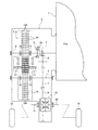
実施例1のマルチディスク多段変速ユニットT/Uが適用された車両用自動変速システムは、図1に示すように、エンジン1(原動機)と、変速機ケース2と、入力軸3と、マルチディスク多段変速ユニットT/Uと、出力軸4と、リバースギア5と、リバースアイドラーギア6と、出力ギア7と、シンクロ機構8と、ファイナルギア9と、デファレンシャルギアユニット10と、左右の駆動軸11,12と、左右の駆動輪13,14と、を備えている。
As shown in FIG. 1, an automatic transmission system for a vehicle to which a multi-disc multi-stage transmission unit T / U of
前記マルチディスク多段変速ユニットT/Uは、複数枚の入力ディスク15により構成されたプライマリディスク群150と、複数枚の出力ディスク16により構成されたセカンダリディスク群160と、押圧手段としての一対の押圧ローラー17,17と、入力軸3を支持する入力軸支持枠18,18と、出力軸4を支持する出力軸支持枠19,19と、を備えている。
The multi-disc multi-stage transmission unit T / U includes a
すなわち、実施例1のマルチディスク多段変速ユニットT/Uが適用された車両用自動変速システムは、入力軸3と出力軸4と左右の駆動軸11,12による三軸構成とされる。また、Dレンジ(ドライブレンジ)の選択時、前記マルチディスク多段変速ユニットT/Uにより7速自動変速での前進走行を達成し、Rレンジ(リバースレンジ)の選択時、前記シンクロ機構8の同期噛み合いにより1速の後退走行を達成する。
That is, the vehicular automatic transmission system to which the multi-disc multi-stage transmission unit T / U of the first embodiment is applied has a three-axis configuration including the
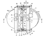
図2は、実施例1のマルチディスク多段変速ユニットT/Uを示す全体斜視図である。図3は、実施例1のマルチディスク多段変速ユニットT/Uを示す図2のA−A線断面図である。以下、マルチディスク多段変速ユニットT/Uの全体構成について説明する。 FIG. 2 is an overall perspective view showing the multi-disc multi-stage transmission unit T / U according to the first embodiment. 3 is a cross-sectional view taken along line AA of FIG. 2 showing the multi-disc multi-stage transmission unit T / U according to the first embodiment. Hereinafter, the overall configuration of the multi-disc multi-stage transmission unit T / U will be described.
実施例1のマルチディスク多段変速ユニットT/Uは、図2に示すように、入力軸3と、出力軸4と、複数枚の入力ディスク15により構成されたプライマリディスク群150と、複数枚の出力ディスク16により構成されたセカンダリディスク群160と、一対の押圧ローラー17,17(押圧手段)と、入力軸支持枠18,18(変速機ケース部材)と、出力軸支持枠19,19(変速機ケース部材)と、ローラー回転軸20と、を備えている。
As shown in FIG. 2, the multi-disk multi-stage transmission unit T / U of the first embodiment includes an
前記入力軸3は、エンジン1に接続され、入力軸支持枠18,18に回転可能に両端支持される。この入力軸3には、図2及び図3に示すように、外周端を出力軸4に近接配置した円板状の入力ディスク15を軸方向に等間隔にて複数枚配列することにより構成されたプライマリディスク群150を有する。
The
前記出力軸4は、入力軸3に平行配置され、出力軸支持枠19,19に回転可能に両端支持される。この出力軸4には、図2及び図3に示すように、外周端を入力軸3に近接配置した円板状の出力ディスク16を軸方向に等間隔にて複数枚配列することにより構成されたセカンダリディスク群160を有する。
The
前記一対の押圧ローラー17,17は、複数枚の入力ディスク15の隣接する軸方向隙間のそれぞれに出力ディスク16を挿入配置することで、プライマリディスク群150とセカンダリディスク群160が互いに重なり合うディスク重合領域を形成する。そして、このディスク重合領域のうち、入力軸3の軸心O3と出力軸4の軸心O4を結ぶ軸心連結線CL上に沿って移動可能に設けられ、要求変速比に応じた位置にて両ディスク群150,160を両側位置から挟持押圧し、両ディスク群150,160の弾性変形によりトルク伝達接触部を形成する。
The pair of pressing
前記一対の押圧ローラー17,17は、プライマリディスク群150とセカンダリディスク群160を挟持押圧しながら、両ディスク群150,160の回転にしたがって転動する。そして、一対の押圧ローラー17,17は、要求変速比(変速段)の変化がなく位置固定であるとき、軸心連結線CLと平行なローラー回転軸線を保ち、要求変速比(変速段)の変化により位置移動するとき、軸心連結線CL上に沿った移動方向に応じてローラー回転軸線の微小傾動を許容する取り付けとしている。つまり、押圧ローラー17は、図3に示すように、一対の押圧ローラー17,17を回転可能に支持するローラー回転軸20を、意図的に微小隙間(ガタ)を残したままの支持としている。
The pair of pressing
前記入力ディスク15は、図3に示すように、そのディスク面に入力軸3の軸心O3から同心状に形成された異なる半径による複数の入力側突条15a,15b,15c,15d,15e,15f,15gを有している。前記出力ディスク16は、図3に示すように、そのディスク面には出力軸4の軸心O4から同心状に形成された異なる半径による複数の出力側突条16a,16b,16c,16d,16e,16f,16gを有している。前記入力側突条15a,15b,15c,15d,15e,15f,15gの各半径と、前記出力側突条16a,16b,16c,16d,16e,16f,16gの各半径は、複数の要求変速比に応じて、軸心連結線CLの長さを入力側半径と出力側半径に振り分けた設定としている。
The
前記一対の押圧ローラー17,17は、図3に示すように、挟持押圧力の解除時に微小隙間が保たれた前記入力側突条15a,15b,15c,15d,15e,15f,15gと前記出力側突条16a,16b,16c,16d,16e,16f,16gの頂部同士を、要求される1速段(低速段)から7速段(高速段)までの有段階の変速比に応じて挟持押圧する。なお、入出力側突条15a,16gの組み合わせで1速段を達成する。入出力側突条15b,16fの組み合わせで2速段を達成する。入出力側突条15c,16eの組み合わせで3速段を達成する。入出力側突条15d,16dの組み合わせで4速段を達成する。入出力側突条15e,16cの組み合わせで5速段を達成する。入出力側突条15f,16bの組み合わせで6速段(OD段)を達成する。入出力側突条15g,16aの組み合わせで7速段(スーパーOD段)を達成する。
As shown in FIG. 3, the pair of pressing
前記一対の押圧ローラー17,17は、前記軸心連結線CLと一致する方向に移動可能な移動枠21に回転可能に支持され、移動枠21に設定された皿バネ22(付勢手段)による付勢力をトルク伝達接触部への挟持押圧力とする。
すなわち、移動枠21は、図2に示すように、プライマリディスク群150とセカンダリディスク群160が互いに重なり合うディスク群重合領域の外周部を囲み、軸心連結線CLと一致する方向に移動可能に配置している。そして、移動枠21のうち、ディスク面に対向する一対のローラー保持枠部21a,21aに、軸心連結線CLと平行な一対のローラー回転軸20,20を支持している。また、移動枠20のうち、一対のローラー保持枠部21a,21aを両端部位置にて連結する一対の連結枠部21b,21bに、一対のローラー保持枠部21a,21aの間隔を狭める方向に付勢力を付与する皿バネ22を設けている。
The pair of pressing
That is, as shown in FIG. 2, the moving
前記移動枠21は、ステッピングモータ23(モータアクチュエータ)により回転するスクリューネジ24を使って、軸心連結線CLの方向に移動可能に設けている。
すなわち、入力軸3を支持する入力軸支持枠18に第1スクリューネジ支持構造25を設け、出力軸4を支持する出力軸支持枠19に第2スクリューネジ支持構造26を設け、ローラー保持枠部21aにボールスクリュー構造27を設けている。そして、第1スクリューネジ支持構造25と第2スクリューネジ支持構造26とボールスクリュー構造27に跨ってスクリューネジ24を支持すると共に、スクリューネジ24の端部にステッピングモータ23を設けている。
The moving
That is, the first screw
前記一対の押圧ローラー17,17による付勢力調整手段は、皿バネ22による付勢力Fsを調整するカム面28a,28aを形成したテンプレート28,28と、カム面28a,28aの面形状に沿って移動するカムフォロア29,29と、を有して構成している。
すなわち、前記テンプレート28,28は、コイルスプリング30,30による付勢力Fsが、互いに引き離す方向に作用する設定により、移動枠21の両端位置にそれぞれ一対配置される。前記カムフォロア29,29は、一対のローラー保持枠部21a,21aの端部位置に設けられ、皿バネ22による付勢力Fdが、一対のテンプレート28,28のカム面28a,28aとの接触面に作用する設定としている。そして、一対の押圧ローラー17,17に加わる付勢力F(皿バネ22による付勢力Fdとコイルスプリング30による付勢力Fsの付勢力差(Fd−Fs))を、一対のテンプレート28,28のカム面28a,28aの面形状の設定により調整している。
The urging force adjusting means by the pair of pressing
That is, a pair of the
図4は、実施例1のマルチディスク多段変速ユニットの入出力ディスクの端部間隔保持構造を示す図3のB部拡大断面図である。図5は、実施例1のマルチディスク多段変速ユニットの入出力ディスクの詳細構造を示す図3のC部拡大断面図である。以下、マルチディスク多段変速ユニットT/Uの入出力ディスク15,16の構成について説明する。
FIG. 4 is an enlarged cross-sectional view of a portion B in FIG. 3 showing a structure for holding the end portion spacing of the input / output disc of the multi-disc multi-stage transmission unit of the first embodiment. FIG. 5 is an enlarged cross-sectional view of a portion C in FIG. 3 showing the detailed structure of the input / output disk of the multi-disk multi-stage transmission unit of the first embodiment. Hereinafter, the configuration of the input /
前記プライマリディスク群150と前記セカンダリディスク群160は、入力軸3の外周部位置と出力軸4の外周部位置に、軸方向に隣接する入力ディスク15と出力ディスク16の端部隙間を一定間隔に保つ端部間隔保持構造を有する。
すなわち、入力軸3の外周部位置に有する端部間隔保持構造は、図4に示すように、入力軸3と隣接する入力ディスク15,15とで形成されるディスク基部空間に、それぞれカラー31を配置することで、複数枚の入力ディスク15,15を等間隔に配列している。そして、入力軸3に螺合する締め付けナット32と、入力軸3に形成されたストッパ突起3aを用い、締め付けナット32を一端側から締め付けることで、複数枚の入力ディスク15,15を、等間隔に保ちながら入力軸3に挟持固定している。
また、前記カラー31の外周位置には、保持器により保持された一対のボール33,33が配置され、この一対のボール33,33により、複数枚の出力ディスク16,16の外周端部を等間隔に保つようにしている。なお、出力軸4の外周部位置に有する端部間隔保持構造についても同様である(図3を参照)。
The
That is, as shown in FIG. 4, the end gap holding structure at the outer peripheral portion of the
In addition, a pair of
前記複数の入力側突条15a,15b,15c,15d,15e,15f,15gと前記出力側突条16a,16b,16c,16d,16e,16f,16gは、入力軸3側の入力側突条15aと、出力軸4側の出力側突条16aの高さを最も高くし、外周側へ向けて突条の高さが徐々に低くなるように設定している(図3を参照)。
すなわち、上記端部間隔保持構造と相俟って、前記一対の押圧ローラー17,17によるディスクへの挟持押圧力を解除したとき、対向する入出力側突条15a,16g、入出力側突条15b,16f、入出力側突条15c,16e、入出力側突条15d,16d、入出力側突条15e,16c、入出力側突条15f,16b、入出力側突条15g,16aの隙間を確保している。
The plurality of
That is, in combination with the end interval holding structure, when the holding pressing force to the disk by the pair of pressing
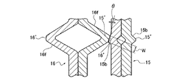
前記複数の入力側突条15a,15b,15c,15d,15e,15f,15gと前記出力側突条16a,16b,16c,16d,16e,16f,16gは、図5に示すように、三角断面形状の頂部15’,16’を軸方向に下り傾斜角を有する傾斜頂部形状とし、対向する傾斜頂部形状同士を、接触角θを有して押圧するようにしている。
The plurality of
前記入力ディスク15は、図5に示すように、断面三角形状の入力側突条15eを形成した2枚のプレートを用意し、前記2枚のプレートの裏面同士を、入力側突条15eの位置を一致させて貼り合わせることにより構成している。前記出力ディスク16は、図5に示すように、断面三角形状の出力側突条16cを形成した2枚のプレートを用意し、前記2枚のプレートの裏面同士を、出力側突条16cの位置を一致させて貼り合わせることにより構成している。そして、前記入力ディスク15と前記出力ディスク16は、板材からのプレス加工により、断面三角形状の突条を形成したプレートを製造するようにしている。なお、入出力ディスク15,16の素材としては、例えば、耐摩耗性に富む疲労強度の高い特殊合金鋼等が使用される。また、接触面間に油膜を常に保持するため、遠心潤滑や掻き上げ潤滑等を用いて接触部に潤滑油が供給される。
As shown in FIG. 5, the
図6は、実施例1のマルチディスク多段変速ユニットの付勢力調整用のテンプレートとカムフォロアを示す平面図である。図7は、実施例1のマルチディスク多段変速ユニットのテンプレートとカムフォロアによる付勢力調整状態を示す図で、(a)は付勢力解除状態をあらわし、(b)は最大付勢力付与状態をあらわす。以下、マルチディスク多段変速ユニットT/Uでの押圧ローラー17,17への付勢力調整手段の構成について説明する。
FIG. 6 is a plan view showing an urging force adjusting template and a cam follower of the multi-disc multi-stage transmission unit according to the first embodiment. 7A and 7B are diagrams showing an urging force adjustment state by the template and the cam follower of the multi-disc multi-stage transmission unit according to the first embodiment. FIG. 7A shows an urging force release state, and FIG. 7B shows a maximum urging force application state. The configuration of the biasing force adjusting means for the
前記一対のテンプレート28,28は、図6に示すように、入力軸支持枠18,18と出力軸支持枠19,19に端部が固定された支持ピン34,34に対しピン軸方向に摺動可能に設けられている。そして、一対のテンプレート28,28の両端部にコイルスプリング30,30を介装し、コイルスプリング30,30による付勢力Fsが、一対のテンプレート28,28を互いに引き離す方向に作用する設定とされている。
As shown in FIG. 6, the pair of
前記一対のカムフォロア29,29は、図6及び図7に示すように、皿バネ22による付勢力Fdが、一対のテンプレート28,28のカム面28a,28aとの接触面に作用する設定とされる。すなわち、一対の押圧ローラー17,17に加わる付勢力Fを、皿バネ22による付勢力Fdとコイルスプリング30による付勢力Fsの付勢力差(Fd−Fs)により得る構成とし、この付勢力Fを、一対のテンプレート28,28のカム面28a,28aの面形状の設定により、変速条件に応じた最適な挟持押圧力を得るように調整している。
As shown in FIGS. 6 and 7, the pair of
前記一対のテンプレート28,28のカム面28a,28aの面形状は、下記のように設定される。
The surface shapes of the cam surfaces 28a, 28a of the pair of
まず、一対のカムフォロア29,29が、図6に示すリバースレンジ位置(REV)とニュートラルレンジ位置(N)にあるときは、図7(a)に示すように、コイルスプリング30の縮み量を最大とすることで、コイルスプリング30による付勢力Fsが最大になるように設定する。
First, when the pair of
一方、一対のカムフォロア29,29が、図6に示すパーキングレンジ位置(P)にあるときは、図7(b)に示すように、コイルスプリング30の伸び量を最大とすることで、コイルスプリング30による付勢力Fsが最小になるように設定する。
On the other hand, when the pair of
さらに、一対のカムフォロア29,29が、図6に示すドライブレンジ位置(D)にあるときは、コイルスプリング30を1速段から7速段に向かうにしたがって段階的に縮めることで、コイルスプリング30による付勢力Fsが、1速段から7速段に向かうにしたがって大きくなるように設定する。
Furthermore, when the pair of
加えて、一対のカムフォロア29,29が、図6に示すドライブレンジ位置(D)にあるときは、隣接する変速段へ移行する変速中(アップシフト中やダウンシフト中)、コイルスプリング30を一時的に縮めることで、変速中のコイルスプリング30による付勢力Fsが、変速前後の変速段でのコイルスプリング30の付勢力Fsよりも大きくなるように設定する。
In addition, when the pair of
次に、作用を説明する。
実施例1のマルチディスク多段変速ユニットT/Uにおける作用を、「ディスクの弾性変形を利用した変速原理」、「弾性変形ディスクにより駆動力を伝達する変速機の有利性」、「Rレンジ選択時のクラッチ作用」、「Pレンジ選択時のパーキング作用」、「N→D切り替え時の発進作用」、「Dレンジ選択時の自動変速作用」、「変速レスポンスの向上作用」に分けて説明する。
Next, the operation will be described.
The effects of the multi-disc multi-stage transmission unit T / U of the first embodiment are as follows: “transmission principle using elastic deformation of the disc”, “advantage of transmission that transmits driving force by elastic deformation disc”, “when R range is selected” The "clutch action", "parking action when the P range is selected", "starting action when switching from N to D", "automatic shifting action when the D range is selected", and "shifting response improving action".
[ディスクの弾性変形を利用した変速原理]
図8は、実施例1のマルチディスク多段変速ユニットT/Uにおけるディスクの弾性変形を利用した変速原理を示す原理説明平面図である。図9は、実施例1のマルチディスク多段変速ユニットT/Uにおけるディスクの弾性変形を利用した変速原理を示す原理説明正面図である。
[Speed change principle using elastic deformation of disk]
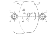
FIG. 8 is a principle explanatory plan view showing a shift principle using elastic deformation of the disk in the multi-disk multi-stage transmission unit T / U of the first embodiment. FIG. 9 is a principle explanatory front view showing a speed change principle using elastic deformation of the disk in the multi-disk multi-speed transmission unit T / U of the first embodiment.
変速原理を説明する変速機として、図8及び図9に示すように、入力軸に設けられ、外周端を出力軸に近接配置した円板状の入力ディスクと、出力軸に設けられ、外周端を入力軸に近接配置した円板状の出力ディスクと、入力ディスクと出力ディスクが互いに重なり合うディスク重合領域のうち、入力軸の軸心と前記出力軸の軸心を結ぶ軸心連結線上に沿って移動可能に設けられ、要求変速比に応じた位置にて両ディスクを挟持押圧し、両ディスクの弾性変形によりトルク伝達接触部を形成する一対の押圧手段と、を有するものを想定する。 As shown in FIGS. 8 and 9, as a transmission for explaining the speed change principle, a disc-shaped input disk provided on the input shaft and having an outer peripheral end disposed close to the output shaft, and an output shaft provided on the output shaft. Of the disk-shaped output disk arranged close to the input shaft, and a disk overlapping region where the input disk and the output disk overlap with each other, along the axis connecting line connecting the axis of the input shaft and the axis of the output shaft It is assumed that there is a pair of pressing means that are movably provided and sandwich and press both disks at a position corresponding to the required gear ratio and form a torque transmission contact portion by elastic deformation of both disks.
この変速機にあっては、図8に示すように、一対の押圧手段により両ディスクを挟持押圧すると、入力ディスクと出力ディスクが部分的に弾性変形することにより、トルク伝達接触部が形成される。すなわち、両持ち梁(ディスク)に集中荷重を加えたとき、集中荷重を加えた部分の梁が大きく撓むという原理を使って、入出力ディスクにトルク伝達接触部を形成するようにしている。 In this transmission, as shown in FIG. 8, when both disks are sandwiched and pressed by a pair of pressing means, the input disk and the output disk are partially elastically deformed to form a torque transmission contact portion. . That is, when a concentrated load is applied to a doubly supported beam (disk), the torque transmission contact portion is formed on the input / output disk using the principle that the beam at the portion where the concentrated load is applied is greatly bent.
そして、トルク伝達接触部を、入力軸の軸心と出力軸の軸心を結ぶ線上の中間位置(図9のP1位置)に形成すると、入力側接触円の軸心からの入力側駆動半径R2と、出力側接触円の軸心からの出力側駆動半径R2が同じとなり、入力軸と出力軸の間で等速比が得られることになる。 When the torque transmission contact portion is formed at an intermediate position (P1 position in FIG. 9) on the line connecting the axis of the input shaft and the axis of the output shaft, the input side drive radius R2 from the axis of the input side contact circle. Thus, the output side drive radius R2 from the axis of the output side contact circle becomes the same, and a constant speed ratio is obtained between the input shaft and the output shaft.
また、トルク伝達接触部を、等速比の位置(図9のP1位置)から入力軸側に移動させた位置(図9のP2位置)に形成すると、入力側接触円の軸心からの入力側駆動半径R1が短くなり、出力側接触円の軸心からの出力側駆動半径R3が長くなり、入力軸と出力軸との間で減速比(ロー側変速比)が得られる。 Further, if the torque transmission contact portion is formed at the position (P2 position in FIG. 9) moved from the constant speed ratio position (P1 position in FIG. 9) to the input shaft side, the input from the shaft center of the input side contact circle is performed. The side drive radius R1 is shortened, the output side drive radius R3 from the axis of the output side contact circle is lengthened, and a reduction ratio (low side transmission ratio) is obtained between the input shaft and the output shaft.
さらに、トルク伝達接触部を、等速比の位置(図9のP1位置)から出力軸側に移動させた位置(図9のP3位置)に形成すると、入力側接触円の軸心からの入力側駆動半径R3が長くなり、出力側接触円の軸心からの出力側駆動半径R1が短くなり、入力軸と出力軸との間で増速比(ハイ側変速比)が得られる。 Further, when the torque transmission contact portion is formed at the position (P3 position in FIG. 9) moved from the constant speed ratio position (P1 position in FIG. 9) to the output shaft side, the input from the axis of the input side contact circle is input. The side drive radius R3 becomes longer, the output side drive radius R1 from the axis of the output side contact circle becomes shorter, and a speed increasing ratio (high side speed ratio) is obtained between the input shaft and the output shaft.
[弾性変形ディスクにより駆動力を伝達する変速機の有利性]
上記のように、本発明の変速機は、弾性変形ディスクにより駆動力を伝達するトラクションドライブ方式の変速機ということができる。そして、この変速機は、広い範囲で変速比の設定自由度を持つ変速機能を発揮する、クラッチ機能を発揮する、低コスト化・軽量化・コンパクト化を狙うことができる、効率の良いトルク伝達接触部の冷却や潤滑を狙うことができる、という有利性を備えている。以下、各有利性について説明する。
[Advantages of a transmission that transmits driving force by an elastically deformable disk]
As described above, the transmission of the present invention can be said to be a traction drive type transmission that transmits a driving force by an elastically deformable disk. In addition, this transmission exhibits a gear shifting function with a wide range of gear ratio setting freedom, exhibits a clutch function, and can achieve cost reduction, weight reduction, and compactness with efficient torque transmission. It has the advantage that it can aim at cooling and lubrication of the contact portion. Hereinafter, each advantage will be described.
(変速機能)
本発明の変速機は、増速比を含む高い変速比の設定自由度を持つ変速機能を発揮する。
例えば、変速比の設定範囲(レシオカバー)が8〜11となり、多段変速機として用いた場合には、高速燃費向上を狙える多段化要求に応えることができるし、無段変速機として用いた場合も変速比幅の拡大を図ることができる。特に、終減速機等により等速比位置を増速比側にシフトとした場合には、減速比側の変速比設定自由度がさらに増す。また、ディスク枚数を自由に設定できることで、汎用化が狙えるし、ディスク枚数の追加で伝達トルクアップを狙うこともできる。
(Shifting function)
The transmission of the present invention exhibits a speed change function having a high degree of freedom in setting a speed ratio including the speed increasing ratio.
For example, when the gear ratio setting range (ratio cover) is 8 to 11 and it is used as a multi-stage transmission, it can meet the demand for multi-stage to improve high-speed fuel consumption, and when used as a continuously variable transmission The gear ratio range can also be increased. In particular, when the constant speed ratio position is shifted to the speed increasing ratio side by a final reduction gear or the like, the speed ratio setting freedom on the speed reducing ratio side is further increased. Further, since the number of disks can be set freely, generalization can be aimed at, and transmission torque can be increased by adding the number of disks.
(クラッチ機能)
本発明の変速機は、押圧手段により両ディスクを挟持押圧する押圧力を解除すると、入力ディスクと出力ディスクは弾性復元力により平板状のプレートディスクに戻り、部分的な弾性変形により形成されたトルク伝達接触部が無くなる。このため、入力軸から出力軸へのトルク伝達が遮断され、入力軸から出力軸へのトルク伝達と、入力軸から出力軸へのトルク遮断を切り替えるクラッチ機能を発揮する。
例えば、車両用無段変速機(ベルトCVTやトロイダルCVT等)の場合、常にトルク伝達接触部を有し、変速機能のみを持つため、ニュートラル状態を確保するべくクラッチ機構やトルクコンバータ等のクラッチ機能部品を併用する必要がある。これに対し、本発明の変速機では、クラッチ機能部品を省略することが可能である。
(Clutch function)
In the transmission of the present invention, when the pressing force for holding and pressing both disks by the pressing means is released, the input disk and the output disk return to the flat plate disk by the elastic restoring force, and the torque formed by the partial elastic deformation There is no transmission contact. For this reason, torque transmission from the input shaft to the output shaft is interrupted, and a clutch function that switches between torque transmission from the input shaft to the output shaft and torque interruption from the input shaft to the output shaft is exhibited.
For example, in the case of a continuously variable transmission for a vehicle (belt CVT, toroidal CVT, etc.), since it always has a torque transmission contact portion and has only a speed change function, a clutch function such as a clutch mechanism or a torque converter to ensure a neutral state It is necessary to use parts together. On the other hand, in the transmission of the present invention, it is possible to omit the clutch functional parts.
(低コスト化・軽量化・コンパクト化)
本発明の変速機は、ディスクを挟持押圧する押圧力がトルク伝達接触部にて互いに相殺され、入力軸と出力軸には荷重が作用しないため、高い剛性を持つ構造とする必要が無く、小さな径の入出力軸とすることができるし(変速比幅の拡大にも有効)、ディスクを薄い鋼板によりプレス成形等にて製造することができる。
入出力軸と円板状の入出力ディスクと押圧手段を構成要素とするため、従来のバイエル変速機に比べ、構造が簡単で、部品点数も少ない。
入力軸と出力軸の間の領域にて押圧手段を移動させるだけの僅かな可動スペースが必要なだけであり、従来のバイエル変速機に比べ、可動スペースが大幅に減少する。
入力ディスクと出力ディスクを互いに重合させているため、ユニット長としてディス径の1.5倍強の長さを確保すれば良く、狭いスペース内に変速機が収まる。
これらの相乗作用により、車両に既に搭載されている周知の変速機と比べた場合、コスト面と重量面と必要スペース面の全てにおいて、低コスト化・軽量化・コンパクト化を達成することができる。
(Low cost, light weight, compact size)
In the transmission according to the present invention, the pressing force for holding and pressing the disk is canceled by the torque transmission contact portion, and no load acts on the input shaft and the output shaft. The input / output shaft of the diameter can be used (also effective for increasing the transmission ratio width), and the disk can be manufactured by press forming or the like with a thin steel plate.
Since the input / output shaft, the disk-shaped input / output disk, and the pressing means are used as components, the structure is simpler and the number of parts is smaller than that of a conventional Bayer transmission.
Only a small movable space is required to move the pressing means in the region between the input shaft and the output shaft, and the movable space is greatly reduced as compared with the conventional Bayer transmission.
Since the input disk and the output disk are overlapped with each other, it is sufficient to secure a length that is slightly more than 1.5 times the diameter of the disk as the unit length, and the transmission can be accommodated in a narrow space.
By these synergistic effects, it is possible to achieve cost reduction, weight reduction, and compactness in all aspects of cost, weight, and required space when compared with known transmissions already installed in vehicles. .
(冷却・潤滑機能)
本発明の変速機は、固定された入力軸と出力軸の2軸構造であり、かつ、トルク伝達接触部が1箇所に集中するため、その部分を狙って油を吹き付けるだけで、冷却効果の高い潤滑を行うことができるし、遠心潤滑や掻き上げ潤滑等を活用することで、オイルポンプを不要とすることも可能である。
(Cooling / lubrication function)
The transmission according to the present invention has a fixed input shaft and output shaft, and the torque transmission contact portion is concentrated at one location. High lubrication can be performed, and an oil pump can be eliminated by utilizing centrifugal lubrication, scraping lubrication, or the like.
[Rレンジ選択時のクラッチ作用]
図10は、実施例1のマルチディスク多段変速ユニットT/Uが適用された車両用自動変速システムにおけるRレンジ選択時のテンプレートとカムフォロワの位置関係を示す平面図である。
[Clutch action when R range is selected]
FIG. 10 is a plan view showing the positional relationship between the template and the cam follower when the R range is selected in the vehicle automatic transmission system to which the multi-disc multi-stage transmission unit T / U according to the first embodiment is applied.
車両用自動変速システムでのRレンジ選択による後退走行時には、マルチディスク多段変速ユニットT/Uの押圧ローラー17,17による挟持押圧を解除してトルク伝達を遮断し、シンクロ機構8のカップリングスリーブ8aを図1の右方向にストロークし、リバースギア5を入力軸3に固定する。
During reverse running by selecting the R range in the automatic transmission system for a vehicle, the clamping pressure by the
すなわち、Rレンジ選択時には、一対のカムフォロア29,29が、一対のテンプレート28,28のカム面28a,28aの面形状のうち、図10に示すリバースレンジ位置(REV)にある。このときは、コイルスプリング30の縮み量が最大とされ、これに伴いコイルスプリング30の付勢力Fsが最大になる。したがって、コイルスプリング30の付勢力Fsが、皿バネ22による付勢力Fdと等しい、あるいは、皿バネ22による付勢力Fdより僅かに大きくなる(図15を参照)。その結果、付勢力差(Fd−Fs)がほぼゼロになることで、一対の押圧ローラー17,17によるディスクの挟持押圧が解除され、マルチディスク多段変速ユニットT/Uによるトルク伝達が遮断される、つまり、クラッチ解除機能が発揮されることになる。
That is, when the R range is selected, the pair of
したがって、Rレンジ選択時には、図1に示すように、エンジン1からの駆動トルクが、入力軸3→シンクロ機構8→リバースギア5→リバースアイドラーギア6→出力ギア7→ファイナルギア9→デファレンシャルギアユニット10→左右の駆動軸11,12→左右の駆動輪13,14へと伝達され、後退1速が達成される。
Therefore, when the R range is selected, as shown in FIG. 1, the drive torque from the
[Pレンジ選択時のパーキング作用]
図11は、実施例1のマルチディスク多段変速ユニットT/Uが適用された車両用自動変速システムにおけるPレンジ選択時のテンプレートとカムフォロワの位置関係を示す平面図である。図12は、実施例1のマルチディスク多段変速ユニットT/Uが適用された車両用自動変速システムにおけるPレンジ選択時にディスクに形成されるトルク伝達接触部を示す正面図である。
[Parking action when P range is selected]
FIG. 11 is a plan view showing the positional relationship between the template and the cam follower when the P range is selected in the vehicle automatic transmission system to which the multi-disc multi-stage transmission unit T / U according to the first embodiment is applied. FIG. 12 is a front view showing a torque transmission contact portion formed on the disc when the P range is selected in the vehicle automatic transmission system to which the multi-disc multi-stage transmission unit T / U according to the first embodiment is applied.
車両用自動変速システムでのPレンジ選択による停車時には、入出力ディスク15,16を互いに強く締結することで、入出力ディスク15,16が、一体的に固定連結することによりロック状態とされ、出力軸4を固定するパーキング機能が発揮される。
When the vehicle is stopped by selecting the P range in the automatic transmission system for vehicles, the input /
すなわち、Pレンジ選択時には、一対のカムフォロア29,29が、一対のテンプレート28,28のカム面28a,28aの面形状のうち、図11に示すパーキングレンジ位置(P)にある。このときは、コイルスプリング30の伸び量が最大とされ、これに伴ってコイルスプリング30の付勢力Fsが最小になる。したがって、皿バネ22による付勢力Fdとコイルスプリング30の付勢力Fsの付勢力差(Fd−Fs)が最大になることで(図15を参照)、一対の押圧ローラー17,17により入出力ディスク15,16を強く挟持押圧する。
That is, when the P range is selected, the pair of
この結果、図12に示すように、一対の押圧ローラー17,17の設定位置を中心としてその周囲にわたってトルク伝達接触部TCが複数形成され、入出力ディスク15,16が相対回転を許容しないロック状態とされる。
As a result, as shown in FIG. 12, a plurality of torque transmission contact portions TC are formed around the set positions of the pair of pressing
[N→D切り替え時の発進作用]
図13は、実施例1のマルチディスク多段変速ユニットT/Uが適用された車両用自動変速システムにおけるNレンジ選択からDレンジ選択へ切り替え時のテンプレートとカムフォロワの位置関係を示す平面図で、(a)はニュートラル選択時をあらわし、(b)はニュートラルから1速段への選択時をあらわし、(c)は1速段フル負荷選択時をあらわし、(d)は1速段軽負荷選択時をあらわし、(e)は1速段から2速段への選択時をあらわし、(f)は2速段選択時をあらわす。
[Starting action when switching from N to D]
FIG. 13 is a plan view showing the positional relationship between the template and the cam follower when switching from the N range selection to the D range selection in the vehicle automatic transmission system to which the multi-disc multi-stage transmission unit T / U of the first embodiment is applied. a) shows when neutral is selected, (b) shows when neutral to 1st gear is selected, (c) shows when 1st gear full load is selected, and (d) shows when 1st gear is lightly loaded. (E) indicates the time when the first gear is selected to the second gear, and (f) indicates the time when the second gear is selected.
車両用自動変速システムでのNレンジ選択時には、マルチディスク多段変速ユニットT/Uの押圧ローラー17,17による挟持押圧を解除してトルク伝達を遮断し、シンクロ機構8のカップリングスリーブ8aを図1の左方向にストロークした位置とする。
When the N range is selected in the automatic transmission system for a vehicle, the clamping pressure by the
このNレンジ選択により、一対のカムフォロア29,29が、一対のテンプレート28,28のカム面28a,28aの面形状のうち、図13(a)に示すニュートラルレンジ位置(N)にあるときは、コイルスプリング30の縮み量を最大とすることで、コイルスプリング30の付勢力Fsが最大になる。したがって、コイルスプリング30の付勢力Fsが、皿バネ22による付勢力Fdより僅かに大きくなり(図15を参照)、その結果、付勢力差(Fd−Fs)が負の値になることで、一対の押圧ローラー17,17によるディスクの挟持押圧が解除され、マルチディスク多段変速ユニットT/Uによるトルク伝達が遮断されたニュートラル状態とされる。
With this N range selection, when the pair of
そして、Nレンジ選択からDレンジ選択に切り替えると、一対のカムフォロア29,29が、一対のテンプレート28,28のカム面28a,28aの面形状のうち、図13(b)に示すように1速側に向かって移動するときは、移動に伴いコイルスプリング30を徐々に伸ばしてゆくことで、コイルスプリング30の付勢力Fsが徐々に小さくなる。したがって、皿バネ22による付勢力Fdとコイルスプリング30の付勢力Fsの付勢力差(Fd−Fs)が増大し、一対の押圧ローラー17,17によるディスクの挟持押圧力が高まる。
Then, when switching from the N range selection to the D range selection, the pair of
このN→D切り替え時、アクセル開度が高開度域であることによりフル負荷であると判断されると、一対のカムフォロア29,29が、一対のテンプレート28,28のカム面28a,28aの面形状のうち、図13(c)に示す1速フル負荷位置とされ、コイルスプリング30の伸び量を最大とすることで、コイルスプリング30の付勢力Fsが最小になる。したがって、皿バネ22による付勢力Fdとコイルスプリング30の付勢力Fsの付勢力差(Fd−Fs)が全変速段中で最も大きくなることで(図15を参照)、一対の押圧ローラー17,17により1速段の入力側突条15aと出力側突条16gが交わる位置で入出力ディスク15,16を挟持押圧し、1速段の変速比により車両をフル負荷発進させることができる。
At the time of switching from N to D, if it is determined that the accelerator opening is a full load due to the high opening range, the pair of
このN→D切り替え時、アクセル開度が低開度域であることにより軽負荷であると判断されると、一対のカムフォロア29,29が、一対のテンプレート28,28のカム面28a,28aの面形状のうち、図13(d)に示す1速軽負荷位置とされ、コイルスプリング30の伸び量を最大域とすることで、コイルスプリング30の付勢力Fsがフル負荷時より少し大きくなる。したがって、皿バネ22による付勢力Fdとコイルスプリング30の付勢力Fsの付勢力差(Fd−Fs)が、フル負荷1速に次いで大きくなることで(図15を参照)、一対の押圧ローラー17,17により1速段の入力側突条15aと出力側突条16gが交わる位置で入出力ディスク15,16を挟持押圧し、1速段の変速比により車両を軽負荷発進させることができる。
At the time of switching from N to D, if it is determined that the accelerator opening is in a low opening range and the load is light, the pair of
なお、フル負荷や軽負荷に対応する挟持押圧力の調整に関しては、この機能を、一対のテンプレート28,28のカム面28a,28aの面形状の設定に代え、例えば、エンジン1からの入力トルクの大きさにより作動するローディングカムを設け、カム動作量を利用して負荷に対応する挟持押圧力の調整を行うようにしても良い。
For adjusting the clamping pressure corresponding to the full load or the light load, this function is replaced with the setting of the surface shapes of the cam surfaces 28a, 28a of the pair of
[Dレンジ選択時の自動変速作用]
図14は、実施例1のマルチディスク多段変速ユニットT/Uが適用された車両用自動変速システムにおけるDレンジ選択時のトルク伝達接触部を示す拡大断面図である。図15は、実施例1のマルチディスク多段変速ユニットT/Uが適用された車両用自動変速システムにおけるDレンジ選択時に各変速段にてトルク伝達接触部に作用する付勢力(=挟持押圧力)の関係を示す付勢力特性図である。
[Automatic shifting when D range is selected]
FIG. 14 is an enlarged cross-sectional view showing a torque transmission contact portion when the D range is selected in the vehicle automatic transmission system to which the multi-disc multi-stage transmission unit T / U according to the first embodiment is applied. FIG. 15 shows an urging force (= clamping pressing force) acting on the torque transmission contact portion at each gear position when the D range is selected in the vehicle automatic transmission system to which the multi-disc multi-speed transmission unit T / U according to the first embodiment is applied. It is a biasing force characteristic diagram showing the relationship.
車両用自動変速システムでのDレンジ選択による前進走行時には、図1に示すように、エンジン1からの駆動トルクが、入力軸3→マルチディスク多段変速ユニットT/U→出力軸4→出力ギア7→ファイナルギア9→デファレンシャルギアユニット10→左右の駆動軸11,12→左右の駆動輪13,14へと伝達される。このとき、マルチディスク多段変速ユニットT/Uの押圧ローラー17,17による挟持押圧位置を移動することにより前進7速を達成する。
During forward traveling by selecting the D range in the automatic transmission system for a vehicle, as shown in FIG. 1, the driving torque from the
例えば、Dレンジでの走行時、1速から2速へのアップシフト指令が出力されると、一対のカムフォロア29,29が、図13(c)または図13(d)の1速位置から図13(e)に示すように2速側に向かって移動するときは、移動に伴いコイルスプリング30を徐々に縮めてゆくことで、コイルスプリング30の付勢力Fsが徐々に大きくなる。したがって、皿バネ22による付勢力Fdとコイルスプリング30の付勢力Fsの付勢力差(Fd−Fs)が減少し、一対の押圧ローラー17,17によるディスクの挟持押圧力が低下する。
For example, when traveling in the D range, if an upshift command from the first speed to the second speed is output, the pair of
そして、一対のテンプレート28,28のカム面28a,28aの面形状のうち、図13(f)に示す2速位置まで移動すると、コイルスプリング30が伸びることで、コイルスプリング30の付勢力Fsが、図13(e)の変速中より小さくなる。したがって、皿バネ22による付勢力Fdとコイルスプリング30の付勢力Fsの付勢力差(Fd−Fs)は、1速から2速への変速中に一時的に小さく抑えられ、2速になる直前位置から再び大きくなるという変化を経過し、一対の押圧ローラー17,17により2速段の入力側突条15bと出力側突条16fが交わる位置で入出力ディスク15,16を挟持押圧し、2速段にアップシフトさせることができる。
And if it moves to the 2nd speed position shown in FIG.13 (f) among the surface shapes of the cam surfaces 28a and 28a of a pair of
この2速段での走行時には、図14に示すように、2速段にて挟持押圧力を受ける入力側突条15bと出力側突条16fは、三角断面形状の頂部15’,16’同士の接触となるため、トルク伝達接触部の接触幅W(例えば、2mm程度)が小さくなる。したがって、接触面積が広いほど大きくなるトルク伝達接触部TCでのスピン損失を小さく抑えることができる。
When traveling at the second gear, as shown in FIG. 14, the input-
さらに、入力側突条15bと出力側突条16fの三角断面形状の頂部15’,16’を軸方向に下り傾斜角を有する傾斜頂部形状としているため、対向する傾斜頂部形状同士が、僅かに接触角θ(例えば、1.7°程度)を有して押圧されることになる。したがって、滑りを抑えた傾斜面嵌合によるトルク伝達となり、高いトルク伝達効率を達成することができる。
Further, since the apex portions 15 'and 16' of the triangular cross-sectional shape of the input-
上記自動変速作用は、Dレンジでの走行時、2速段から3速段へのアップシフト時、3速段から4速段へのアップシフト時、5速段から6速段(OD)へのアップシフト時、6速段から7速段(スーパーOD)へのアップシフト時にも同様な作用を示す。さらに、Dレンジでの走行時における各ダウンシフト時にも同様な作用を示す。 The above automatic shifting action is from the 5th gear to the 6th gear (OD) when driving in the D range, when shifting up from 2nd gear to 3rd gear, when shifting up from 3rd gear to 4th gear. The same effect is exhibited during upshifting from 6th gear to 7th gear (super OD). Further, the same effect is exhibited at the time of each downshift when traveling in the D range.
上記のように、一対のカムフォロア29,29が、図13に示すドライブレンジ位置(D)にあるときは、コイルスプリング30を1速段から7速段に向かうにしたがって段階的に縮めることで、コイルスプリング30の付勢力Fsが1速段から7速段に向かうにしたがって大きくなるように、一対のテンプレート28,28のカム面28a,28aの面形状が設定されている。この設定により、一対の押圧ローラー17,17による挟持押圧力となる付勢力差(Fd−Fs)は、図15に示すように、1速段フル負荷の選択時に最も大きく、2速段から7速段に向かうにしたがって段階的に小さくなる。
したがって、1速段での伝達トルクが最も大きく、7速段での伝達トルクが最も小さくなるのに対応し、1速段から7速段までの各変速段にて、滑ることなく適正な接触面積を得る挟持押圧力を付与することができる。
As described above, when the pair of
Therefore, in order to cope with the fact that the transmission torque at the first gear is the largest and the transmission torque at the seventh gear is the smallest, at each gear position from the first gear to the seventh gear, proper contact without slipping is achieved. A clamping pressing force for obtaining an area can be applied.
加えて、一対のカムフォロア29,29が、図13に示すドライブレンジ位置(D)にあるときは、隣接する変速段へ移行するアップシフトやダウンシフトの変速中、コイルスプリング30を一時的に縮めることで、変速中のコイルスプリング30の付勢力Fsが、変速前後の変速段でのコイルスプリング30の付勢力Fsよりも大きくなるように、一対のテンプレート28,28のカム面28a,28aの面形状が設定されている。この設定により、一対の押圧ローラー17,17による挟持押圧力となる変速中の付勢力差(Fd−Fs)が、変速前後の変速段での付勢力差(Fd−Fs)より小さくなる。
したがって、1速段から2速段等へのアップシフト中や2速段から1速段等へのダウンシフト中、一対の押圧ローラー17,17を移動させるために必要なトルクが軽減され、変速動作のためのステッピングモータ23への負荷軽減により、小型のステッピングモータ23を用いながらも円滑な自動変速を行うことができる。
In addition, when the pair of
Therefore, during the upshift from the first gear to the second gear or the downshift from the second gear to the first gear, etc., the torque required to move the pair of pressing
[変速レスポンス向上作用]
図16は、実施例1のマルチディスク多段変速ユニットT/Uが適用された車両用自動変速システムにおけるDレンジ走行時のダウンシフト中に生じる微小ステア作用を示す作用説明図である。図17は、実施例1のマルチディスク多段変速ユニットT/Uが適用された車両用自動変速システムにおけるDレンジ走行時のアップシフト中に生じる微小ステア作用を示す作用説明図である。
[Speed change response improving effect]
FIG. 16 is an operation explanatory diagram showing a minute steer effect that occurs during a downshift at the time of traveling in the D range in the vehicle automatic transmission system to which the multi-disc multi-stage transmission unit T / U according to the first embodiment is applied. FIG. 17 is an operation explanatory diagram showing a minute steer effect that occurs during an upshift during D-range traveling in the vehicle automatic transmission system to which the multi-disc multi-stage transmission unit T / U according to the first embodiment is applied.
実施例1では、一対の押圧ローラー17,17は、変速段の変化がなく位置固定であるとき、軸心連結線CLと平行なローラー回転軸線を保ち、変速段の変化により位置移動するとき、軸心連結線CL上に沿った移動方向に応じてローラー回転軸線の微小傾動を許容する取り付けとしている。
In the first embodiment, when the pair of pressing
したがって、Dレンジ走行時のダウンシフト中においては、図16に示すように、一対の押圧ローラー17,17が、接触する入力ディスク15の回転により、図16の仮想線位置から実線位置まで右方向に傾動する微小ステア作用を示す。このため、押圧ローラー17,17のディスク接触点の位置に生じる力が傾き、図16の矢印に示すダウンシフト方向DSと一致する分力が軸心連結線CL上にあらわれ、この分力がダウンシフト変速速度を加速させ、変速レスポンスの向上を図ることができる。
Therefore, during the downshift during the D range traveling, as shown in FIG. 16, the pair of pressing
また、Dレンジ走行時のアップシフト中においては、図17に示すように、一対の押圧ローラー17,17が、接触する入力ディスク15の回転により、図17の仮想線位置から実線位置まで左方向に傾動する微小ステア作用を示す。このため、押圧ローラー17,17のディスク接触点の位置に生じる力が傾き、図17の矢印に示すアップシフト方向USと一致する分力が軸心連結線CL上にあらわれ、この分力がアップシフト変速速度を加速させ、変速レスポンスの向上を図ることができる。
In addition, during the upshift during the D range traveling, as shown in FIG. 17, the pair of pressing
ちなみに、上記押圧ローラー17,17の微小ステア作用により、1速段から7速段までのフルストロークに要する時間、あるいは、7速段から1速段までのフルストロークに要する時間が、1秒未満の所要時間で完了することが確認された。
By the way, the time required for the full stroke from the first gear to the seventh gear or the time required for the full stroke from the seventh gear to the first gear is less than 1 second due to the minute steering action of the
次に、効果を説明する。
実施例1のマルチディスク多段変速ユニットT/Uにあっては、下記に列挙する効果を得ることができる。
Next, the effect will be described.
In the multi-disc multi-stage transmission unit T / U according to the first embodiment, the effects listed below can be obtained.
(1)原動機(エンジン1)に接続され、変速機ケース部材(入力軸支持枠18,18)に支持される入力軸3と、前記入力軸3に平行配置され、変速機ケース部材(出力軸支持枠19,19)に支持される出力軸4と、前記入力軸3に設けられ、外周端を前記出力軸4に近接配置した円板状の入力ディスク15と、前記出力軸4に設けられ、外周端を前記入力軸3に近接配置した円板状の出力ディスク16と、前記入力ディスク15と前記出力ディスク16が互いに重なり合うディスク重合領域のうち、前記入力軸3の軸心O3と前記出力軸4の軸心O4を結ぶ軸心連結線CL上に沿って移動可能に設けられ、要求変速比に応じた位置にて両ディスク15,16を挟持押圧し、両ディスク15,16の弾性変形によりトルク伝達接触部TCを形成する一対の押圧手段(押圧ローラー17,17)と、を備え、前記一対の押圧手段(押圧ローラー17,17)は、両ディスク15,16の挟持押圧力として付勢力を付与する付勢手段(皿バネ22)と、変速条件に応じた最適な挟持押圧力を得るように、前記付勢手段(皿バネ22)による付勢力を調整する付勢力調整手段(テンプレート28,28とカムフォロワ29,29)と、を有する。このため、低コスト化・軽量化・コンパクト化を達成しながら、増速比を含む高い変速比の設定自由度を持つ変速機能と、トルク伝達/遮断を切り替えるクラッチ機能を併せて発揮することができると共に、変速比に応じた最適な挟持押圧力の付与により耐久性の向上を図ることができる。
(1) An
(2)前記一対の押圧手段(押圧ローラー17,17)は、要求される低速段から高速段までの有段階の変速比に応じた複数の位置にて両ディスク15,16を挟持押圧する手段であり、前記付勢力調整手段(テンプレート28,28とカムフォロワ29,29)は、隣接する第1の変速段から第2の変速段への変速中の付勢力を、第1の変速段と第2の変速段の位置での付勢力よりも低減する。このため、一対の押圧手段(一対の押圧ローラー17,17)を移動させるために必要なトルクが軽減され、変速アクチュエータへの負荷軽減により、小型の変速アクチュエータを用いながらも円滑な自動変速を行うことができる。
(2) The pair of pressing means (pressing
(3)前記付勢力調整手段(テンプレート28,28とカムフォロワ29,29)は、高速段が選択されているときの付勢力を、低速段が選択されているときの付勢力よりも低減する。このため、低速段から高速段までの全ての変速段において、各変速比に応じた最適な挟持押圧力が付与されることにより耐久性の向上を図ることができる。
(3) The urging force adjusting means (
(4)前記付勢力調整手段は、付勢手段(皿バネ22)による付勢力を調整するカム面28a,28aを形成したテンプレート28,28と、前記カム面28a,28aの面形状に沿って移動するカムフォロア29,29と、を有して構成した。このため、低速段から高速段までの各変速比の挟持押圧力を最適化する際、カム面28a,28aの面形状の変更だけで容易に達成することができる。
(4) The urging force adjusting means follows the
(5)前記テンプレート28,28は、コイルスプリング30,30による付勢力Fsが、互いに引き離す方向に作用する設定により一対配置され、前記カムフォロア29,29は、皿バネ22による付勢力Fdが、前記一対のテンプレート28,28のカム面28a,28aとの接触面に作用する設定とし、前記一対の押圧手段(一対の押圧ローラー17,17)に加えられる付勢力を、前記皿バネ22による付勢力Fdと前記コイルスプリング30,30による付勢力Fsの付勢力差(Fd−Fs)により調整する。このため、皿バネ22の僅かな伸縮量に対しコイルスプリング30,30の伸縮量が拡大されるのに伴い、コイルスプリング30,30の拡大された伸縮量に対応して一対のテンプレート28,28のカム面28a,28aの面形状設定幅も拡大し、一対の押圧手段(一対の押圧ローラー17,17)に加えられる付勢力をきめ細かく調整することができる。
(5) The
(6)前記入力ディスク15は、そのディスク面に前記入力軸3の軸心から異なる半径にて同心状に形成された複数の入力側突条15a,15b,15c,15d,15e,15f,15gを有し、前記出力ディスク16は、そのディスク面に前記出力軸4の軸心から異なる半径にて同心状に形成された複数の出力側突条16a,16b,16c,16d,16e,16f,16gを有し、前記一対の押圧手段(押圧ローラー17,17)は、挟持押圧力の解除時に微小隙間が保たれた前記入力側突条15a,15b,15c,15d,15e,15f,15gと前記出力側突条16a,16b,16c,16d,16e,16f,16gの頂部同士を、要求される低速段から高速段までの有段階の変速比に応じて挟持押圧する。このため、各変速段にて限られた頂部領域をトルク伝達接触部TCとして形成することにより、トルク伝達効率が高いと共に、各変速段にて安定した設定変速比を保つ多段変速機を得ることができる。
(6) The
(7)前記入力軸3は、複数枚の入力ディスク15を軸方向に配列することにより構成されるプライマリディスク群150を有し、前記出力軸4は、複数枚の出力ディスク16を軸方向に配列することにより構成されるセカンダリディスク群160を有し、前記一対の押圧手段(押圧ローラー17,17)は、前記複数枚の入力ディスク15の隣接する軸方向隙間のそれぞれに出力ディスク16を挿入配置することで、前記プライマリディスク群150と前記セカンダリディスク群160が互いに重なり合うディスク重合領域を形成し、このディスク重合領域の両側位置から挟持押圧する。このため、入力ディスク15の枚数設定と出力ディスク16の枚数設定により、要求される伝達トルク容量に対応することができると共に、ディスク枚数を増すことで挟持押圧力の低減を図ることができる。
(7) The
以上、本発明の変速機を実施例1に基づき説明してきたが、具体的な構成については、この実施例1に限られるものではなく、特許請求の範囲の各請求項に係る発明の要旨を逸脱しない限り、設計の変更や追加等は許容される。 The transmission of the present invention has been described based on the first embodiment. However, the specific configuration is not limited to the first embodiment, and the gist of the invention according to each claim of the claims is described. Unless it deviates, design changes and additions are allowed.
実施例1では、複数枚の入力ディスク15により構成されるプライマリディスク群150と、複数枚の出力ディスク16により構成されるセカンダリディスク群160を有するマルチディスクの例を示した。しかし、1枚の入力ディスクと1枚の出力ディスクによるシングルディスクの例や、2枚の入力ディスクと1枚の出力ディスクや1枚の入力ディスクと2枚の出力ディスクによる片側ダブルディスクの例としても良い。
In the first embodiment, an example of a multi-disk having a
実施例1では、入力ディスク15に入力側突条15a,15b,15c,15d,15e,15f,15gを形成し、出力ディスク16に出力側突条16a,16b,16c,16d,16e,16f,16gを形成し、一対の押圧ローラー17,17により段階的な押圧位置で挟持押圧力を付与することで、7速段を持つ多段変速機とする例を示した。しかし、突条の数の設定により7速段以外の多段変速機とする例としても良いし、また、押圧手段を無段階に移動させることで、無段変速機としても適用することができる。
In the first embodiment, the
実施例1では、押圧手段として、押圧ローラー17を用いる例を示した。しかし、押圧手段としては、先端が球面の押圧ピンや押圧ボール等、他の手段を用いても良い。
In Example 1, the example which uses the
実施例1では、一対の押圧ローラー17,17に対し、挟持押圧力を皿バネ22により付与し、挟持押圧力の調整をテンプレート28,28とカムフォロワ29,29を用い、皿バネ22とコイルバネ30による付勢力差により行う例を示した。しかし、挟持押圧力を油圧により付与し、挟持押圧力の調整を油圧調整により行うような例としても良い。
In the first embodiment, a clamping pressing force is applied to the pair of pressing
実施例1では、変速のために移動枠21を移動させる手段として、ステッピングモータ23とスクリューネジ24を用いる例を示した。しかし、変速のために移動枠21を油圧アクチュエータにより移動させるような例としても良い。
In the first embodiment, the stepping
実施例1では、本発明の変速機として、エンジン車の車両用自動変速システムへ適用したマルチディスク多段変速ユニットT/Uの例を示した。しかし、エンジン車に限らず、ハイブリッド車や電気自動車や燃料電池車等の他の車両の変速機としても適用することができる。また、伝達されるトルク容量に応じてディスクの枚数(1枚〜複数枚)を加減することで、車両への用途に限らず、様々な機器類等に搭載されている多段変速機や無段変速機としても適用することができる。 In the first embodiment, an example of a multi-disc multi-stage transmission unit T / U applied to an automatic transmission system for an engine vehicle is shown as a transmission of the present invention. However, the present invention can be applied not only to engine vehicles but also to transmissions of other vehicles such as hybrid vehicles, electric vehicles, and fuel cell vehicles. In addition, by adjusting the number of discs (one to several) according to the torque capacity to be transmitted, not only for vehicles, but also for multi-stage transmissions and continuously variable devices mounted on various devices. It can also be applied as a transmission.
T/U マルチディスク多段変速ユニット(変速機)
1 エンジン(原動機)
3 入力軸
4 出力軸
15 入力ディスク
150 プライマリディスク群
15a,15b,15c,15d,15e,15f,15g 入力側突条
16 出力ディスク
160 セカンダリディスク群
16a,16b,16c,16d,16e,16f,16g 出力側突条
17,17 押圧ローラー(押圧手段)
18,18 入力軸支持枠(変速機ケース部材)
19,19 出力軸支持枠(変速機ケース部材)
21 移動枠
22 皿バネ(付勢手段)
23 ステッピングモータ(モータアクチュエータ)
24 スクリューネジ
28,28 テンプレート(付勢力調整手段)
28a,28a カム面(付勢力調整手段)
29,29 カムフォロワ(付勢力調整手段)
30,30 コイルスプリング
Fd 皿バネ22による付勢力
Fs コイルスプリング30による付勢力
O3 入力軸3の軸心
O4 出力軸4の軸心
CL 軸心連結線
TC トルク伝達接触部
T / U multi-disc multi-speed transmission unit (transmission)
1 engine (motor)
3
150
160
18, 18 Input shaft support frame (transmission case member)
19, 19 Output shaft support frame (transmission case member)
21 Moving
23 Stepping motor (motor actuator)
24 Screw screws 28, 28 Template (biasing force adjusting means)
28a, 28a Cam surface (biasing force adjusting means)
29, 29 Cam follower (biasing force adjusting means)
30, 30 Coil spring
Fd Energizing force by
Fs Energizing force by
O 3 Input shaft 3 axis
O 4 Output shaft 4 axis
CL shaft connection line
TC torque transmission contact
Claims (6)
前記入力軸に平行配置され、変速機ケース部材に支持される出力軸と、
前記入力軸に設けられ、複数枚の入力ディスクを軸方向に配列することにより構成されるプライマリディスク群を有し、外周端を前記出力軸に近接配置した円板状の入力ディスクと、
前記出力軸に設けられ、複数枚の出力ディスクを軸方向に配列することにより構成されるセカンダリディスク群を有し、外周端を前記入力軸に近接配置した円板状の出力ディスクと、
前記プライマリディスク群と前記セカンダリディスク群が互いに重なり合うディスク重合領域を形成し、前記ディスク重合領域のうち、前記入力軸の軸心と前記出力軸の軸心を結ぶ軸心連結線上に沿って移動可能に設けられ、要求変速比に応じた位置にて前記ディスク重合領域の両側位置から挟持押圧し、両ディスクの弾性変形によりディスク同士の接触によるトルク伝達接触部を形成し、両ディスクを挟持押圧する押圧力を解除すると両ディスクの弾性復元力によりトルク伝達を遮断する一対の押圧手段と、を備え、
前記一対の押圧手段は、両ディスクの挟持押圧力として一定の付勢力と調整可能な付勢力の付勢力差による付勢力を付与する付勢手段と、変速条件に応じた最適な挟持押圧力を得るように、前記付勢手段による付勢力を調整する付勢力調整手段と、を有することを特徴とする変速機。 An input shaft connected to the prime mover and supported by the transmission case member;
An output shaft disposed in parallel to the input shaft and supported by a transmission case member;
A disk-shaped input disk provided on the input shaft, having a primary disk group configured by arranging a plurality of input disks in the axial direction, and having an outer peripheral end disposed close to the output shaft;
A disk-shaped output disk provided on the output shaft, having a secondary disk group configured by arranging a plurality of output disks in the axial direction, and having an outer peripheral end disposed close to the input shaft;
The primary disk group and the secondary disk group form a disk overlapping area where the primary disk group and the secondary disk group overlap each other, and the disk overlapping area is movable along an axis connecting line connecting the axis of the input shaft and the axis of the output shaft. Is provided at a position corresponding to the required gear ratio, and is sandwiched and pressed from both sides of the disk overlap region, and a torque transmission contact portion is formed by contact between the disks by elastic deformation of both disks, and the both disks are sandwiched and pressed. A pair of pressing means for interrupting torque transmission by the elastic restoring force of both discs when the pressing force is released ,
The pair of pressing means includes an urging means for applying an urging force based on a urging force difference between a constant urging force and an adjustable urging force as a nip pressing force between both disks, and an optimum nip pressing force according to a shift condition. And a biasing force adjusting means for adjusting a biasing force by the biasing means.
前記一対の押圧手段は、要求される低速段から高速段までの有段階の変速比に応じた複数の位置にて両ディスクを挟持押圧する手段であり、
前記付勢力調整手段は、隣接する第1の変速段から第2の変速段への変速中の付勢力を、第1の変速段と第2の変速段の位置での付勢力よりも低減することを特徴とする変速機。 The transmission according to claim 1, wherein
The pair of pressing means are means for sandwiching and pressing both disks at a plurality of positions according to a stepped gear ratio from a low speed stage to a high speed stage required.
The urging force adjusting means reduces the urging force during the shift from the adjacent first gear to the second gear than the urging force at the positions of the first gear and the second gear. A transmission characterized by that.
前記付勢力調整手段は、高速段が選択されているときの付勢力を、低速段が選択されているときの付勢力よりも低減することを特徴とする変速機。 The transmission according to claim 2, wherein
The transmission is characterized in that the urging force adjusting means reduces the urging force when the high speed stage is selected than the urging force when the low speed stage is selected.
前記付勢力調整手段は、付勢手段による付勢力を調整するカム面を形成したテンプレートと、前記カム面の面形状に沿って移動するカムフォロアと、を有して構成したことを特徴とする変速機。 The transmission according to any one of claims 1 to 3,
The urging force adjusting means includes a template having a cam surface that adjusts the urging force by the urging means, and a cam follower that moves along the surface shape of the cam surface. Machine.
前記テンプレートは、コイルスプリングによる付勢力が、互いに引き離す方向に作用する設定により一対配置され、
前記カムフォロアは、皿バネによる付勢力が、前記一対のテンプレートのカム面との接触面に作用する設定とし、
前記押圧手段に加えられる付勢力を、前記皿バネによる付勢力と前記コイルスプリングによる付勢力の付勢力差により調整することを特徴とする変速機。 The transmission according to claim 4, wherein
A pair of the templates are arranged with a setting in which the urging force by the coil spring acts in the direction of separating from each other,
The cam follower is set so that the biasing force by the disc spring acts on the contact surface with the cam surfaces of the pair of templates,
The transmission characterized in that the biasing force applied to the pressing means is adjusted by a biasing force difference between the biasing force by the disc spring and the biasing force by the coil spring.
前記入力ディスクは、そのディスク面に前記入力軸の軸心から異なる半径にて同心状に形成された複数の入力側突条を有し、
前記出力ディスクは、そのディスク面に前記出力軸の軸心から異なる半径にて同心状に形成された複数の出力側突条を有し、
前記一対の押圧手段は、挟持押圧力の解除時に微小隙間が保たれた前記入力側突条と前記出力側突条の頂部同士を、要求される低速段から高速段までの有段階の変速比に応じて挟持押圧することを特徴とする変速機。 The transmission according to any one of claims 1 to 5,
The input disk has a plurality of input side protrusions formed concentrically at different radii from the axis of the input shaft on the disk surface;
The output disk has a plurality of output-side protrusions formed concentrically at different radii from the axis of the output shaft on the disk surface;
The pair of pressing means has a stepped gear ratio from the low speed stage to the high speed stage required between the tops of the input side ridges and the output side ridges, in which a minute gap is maintained when the clamping pressing force is released. A transmission characterized in that it is clamped and pressed in response to the above.
Priority Applications (15)
| Application Number | Priority Date | Filing Date | Title |
|---|---|---|---|
| JP2008221116A JP4668307B2 (en) | 2008-08-29 | 2008-08-29 | transmission |
| DE602009000673T DE602009000673D1 (en) | 2008-08-29 | 2009-08-11 | friction gear |
| DE602009000625T DE602009000625D1 (en) | 2008-08-29 | 2009-08-11 | Multi-speed friction gear |
| US12/539,169 US8177678B2 (en) | 2008-08-29 | 2009-08-11 | Multistage transmission |
| EP09167586A EP2159450B1 (en) | 2008-08-29 | 2009-08-11 | Multistage friction gearing |
| AT09167585T ATE496237T1 (en) | 2008-08-29 | 2009-08-11 | TRANSMISSION |
| US12/539,146 US20100056324A1 (en) | 2008-08-29 | 2009-08-11 | Transmission |
| EP09167587A EP2159451B1 (en) | 2008-08-29 | 2009-08-11 | Friction gearing |
| AT09167587T ATE497117T1 (en) | 2008-08-29 | 2009-08-11 | FRICTION WHEEL GEAR |
| EP09167585A EP2159449B1 (en) | 2008-08-29 | 2009-08-11 | Transmission |
| DE602009000623T DE602009000623D1 (en) | 2008-08-29 | 2009-08-11 | transmission |
| AT09167586T ATE496238T1 (en) | 2008-08-29 | 2009-08-11 | MULTI-SPEED FRICTION WHEEL TRANSMISSION |
| US12/539,118 US8382637B2 (en) | 2008-08-29 | 2009-08-11 | Transmission |
| CN200910167464.0A CN101660592B (en) | 2008-08-29 | 2009-08-25 | Transmission |
| KR1020090080140A KR101543038B1 (en) | 2008-08-29 | 2009-08-28 | Transmission |
Applications Claiming Priority (1)
| Application Number | Priority Date | Filing Date | Title |
|---|---|---|---|
| JP2008221116A JP4668307B2 (en) | 2008-08-29 | 2008-08-29 | transmission |
Publications (2)
| Publication Number | Publication Date |
|---|---|
| JP2010053995A JP2010053995A (en) | 2010-03-11 |
| JP4668307B2 true JP4668307B2 (en) | 2011-04-13 |
Family
ID=41319618
Family Applications (1)
| Application Number | Title | Priority Date | Filing Date |
|---|---|---|---|
| JP2008221116A Expired - Fee Related JP4668307B2 (en) | 2008-08-29 | 2008-08-29 | transmission |
Country Status (7)
| Country | Link |
|---|---|
| US (1) | US8382637B2 (en) |
| EP (1) | EP2159451B1 (en) |
| JP (1) | JP4668307B2 (en) |
| KR (1) | KR101543038B1 (en) |
| CN (1) | CN101660592B (en) |
| AT (1) | ATE497117T1 (en) |
| DE (1) | DE602009000673D1 (en) |
Families Citing this family (65)
| Publication number | Priority date | Publication date | Assignee | Title |
|---|---|---|---|---|
| US7011600B2 (en) | 2003-02-28 | 2006-03-14 | Fallbrook Technologies Inc. | Continuously variable transmission |
| KR20120088869A (en) | 2004-10-05 | 2012-08-08 | 폴브룩 테크놀로지즈 인크 | Continuously variable transmission |
| CN102407766B (en) | 2005-10-28 | 2014-11-19 | 福博科知识产权有限责任公司 | Electromotive drives |
| US20070155567A1 (en) | 2005-11-22 | 2007-07-05 | Fallbrook Technologies Inc. | Continuously variable transmission |
| US7959533B2 (en) | 2005-12-09 | 2011-06-14 | Fallbrook Technologies Inc. | Continuously variable transmission |
| EP1811202A1 (en) | 2005-12-30 | 2007-07-25 | Fallbrook Technologies, Inc. | A continuously variable gear transmission |
| US7882762B2 (en) | 2006-01-30 | 2011-02-08 | Fallbrook Technologies Inc. | System for manipulating a continuously variable transmission |
| CN102278200B (en) | 2006-06-26 | 2014-05-14 | 福博科知识产权有限责任公司 | Continuously variable transmission |
| EP2089642B1 (en) | 2006-11-08 | 2013-04-10 | Fallbrook Intellectual Property Company LLC | Clamping force generator |
| WO2008095116A2 (en) | 2007-02-01 | 2008-08-07 | Fallbrook Technologies, Inc. | System and methods for control of transmission and/or prime mover |
| WO2008100792A1 (en) | 2007-02-12 | 2008-08-21 | Fallbrook Technologies Inc. | Continuously variable transmissions and methods therefor |
| JP5350274B2 (en) | 2007-02-16 | 2013-11-27 | フォールブルック インテレクチュアル プロパティー カンパニー エルエルシー | Infinitely variable transmission, continuously variable transmission, method, assembly, subassembly, and components therefor |
| EP2573424A3 (en) | 2007-04-24 | 2017-07-26 | Fallbrook Intellectual Property Company LLC | Electric traction drives |
| WO2008154437A1 (en) | 2007-06-11 | 2008-12-18 | Fallbrook Technologies Inc. | Continuously variable transmission |
| KR20100046166A (en) | 2007-07-05 | 2010-05-06 | 폴브룩 테크놀로지즈 인크 | Continuously variable tranamission |
| CN103939602B (en) | 2007-11-16 | 2016-12-07 | 福博科知识产权有限责任公司 | Controller for variable speed drive |
| US8321097B2 (en) | 2007-12-21 | 2012-11-27 | Fallbrook Intellectual Property Company Llc | Automatic transmissions and methods therefor |
| WO2009111328A1 (en) | 2008-02-29 | 2009-09-11 | Fallbrook Technologies Inc. | Continuously and/or infinitely variable transmissions and methods therefor |
| US8317651B2 (en) | 2008-05-07 | 2012-11-27 | Fallbrook Intellectual Property Company Llc | Assemblies and methods for clamping force generation |
| CN102112778B (en) | 2008-06-06 | 2013-10-16 | 福博科技术公司 | Infinitely variable transmissions, continuously variable transmissions, methods, assemblies, subassemblies, and components therefor |
| WO2009157920A1 (en) | 2008-06-23 | 2009-12-30 | Fallbrook Technologies Inc. | Continuously variable transmission |
| WO2010017242A1 (en) * | 2008-08-05 | 2010-02-11 | Fallbrook Technologies Inc. | Methods for control of transmission and prime mover |
| US8469856B2 (en) | 2008-08-26 | 2013-06-25 | Fallbrook Intellectual Property Company Llc | Continuously variable transmission |
| US8167759B2 (en) | 2008-10-14 | 2012-05-01 | Fallbrook Technologies Inc. | Continuously variable transmission |
| RU2011140072A (en) | 2009-04-16 | 2013-05-27 | Фоллбрук Текнолоджиз Инк. (Сша/Сша) | STATOR ASSEMBLY AND GEAR SHIFTING MECHANISM FOR THE TRANSMISSION-FREE TRANSMISSION |
| US8512195B2 (en) | 2010-03-03 | 2013-08-20 | Fallbrook Intellectual Property Company Llc | Infinitely variable transmissions, continuously variable transmissions, methods, assemblies, subassemblies, and components therefor |
| US8888643B2 (en) | 2010-11-10 | 2014-11-18 | Fallbrook Intellectual Property Company Llc | Continuously variable transmission |
| AU2012240435B2 (en) | 2011-04-04 | 2016-04-28 | Fallbrook Intellectual Property Company Llc | Auxiliary power unit having a continuously variable transmission |
| CN107061653B (en) | 2012-01-23 | 2020-05-26 | 福博科知识产权有限责任公司 | Infinitely variable transmissions, continuously variable transmissions, methods, assemblies, subassemblies, and components thereof |
| WO2013145171A1 (en) | 2012-03-28 | 2013-10-03 | ジヤトコ株式会社 | Continuously variable transmission |
| JP5736505B2 (en) * | 2012-03-28 | 2015-06-17 | ジヤトコ株式会社 | Continuously variable transmission |
| JP5736506B2 (en) * | 2012-03-28 | 2015-06-17 | ジヤトコ株式会社 | Continuously variable transmission |
| WO2013145173A1 (en) * | 2012-03-28 | 2013-10-03 | ジヤトコ株式会社 | Continuously variable transmission |
| WO2013145186A1 (en) * | 2012-03-28 | 2013-10-03 | ジヤトコ株式会社 | Continuously variable transmission |
| WO2013145169A1 (en) * | 2012-03-28 | 2013-10-03 | ジヤトコ株式会社 | Continuously variable transmission |
| WO2013145175A1 (en) | 2012-03-28 | 2013-10-03 | ジヤトコ株式会社 | Continuously variable transmission |
| CN104220787B (en) * | 2012-03-28 | 2016-05-04 | 加特可株式会社 | Buncher |
| JP5926407B2 (en) * | 2013-01-18 | 2016-05-25 | ジヤトコ株式会社 | Multi-disc transmission |
| JP2016084822A (en) * | 2013-01-21 | 2016-05-19 | ジヤトコ株式会社 | Multi-disc transmission |
| WO2014122848A1 (en) * | 2013-02-05 | 2014-08-14 | ジヤトコ株式会社 | Multiple disk transmission |
| JP5926442B2 (en) * | 2013-03-07 | 2016-05-25 | ジヤトコ株式会社 | Multi-disc transmission |
| WO2014136469A1 (en) * | 2013-03-07 | 2014-09-12 | ジヤトコ株式会社 | Multi-disk transmission |
| WO2014141542A1 (en) * | 2013-03-12 | 2014-09-18 | ジヤトコ株式会社 | Multidisc transmission |
| CA2909565A1 (en) | 2013-04-19 | 2014-10-23 | Fallbrook Intellectual Property Company Llc | Continuously variable transmission |
| JP5934841B2 (en) * | 2013-05-13 | 2016-06-15 | ジヤトコ株式会社 | Multi-disc transmission |
| JP5891204B2 (en) * | 2013-05-13 | 2016-03-22 | ジヤトコ株式会社 | Multi-disc transmission |
| JPWO2014208214A1 (en) * | 2013-06-25 | 2017-02-23 | ジヤトコ株式会社 | Shift mechanism of multi-disc transmission |
| JP5934157B2 (en) * | 2013-08-21 | 2016-06-15 | ジヤトコ株式会社 | Multi-disc transmission |
| JP5736426B2 (en) * | 2013-09-24 | 2015-06-17 | ジヤトコ株式会社 | Multi-disc transmission |
| JP5795786B2 (en) * | 2013-09-24 | 2015-10-14 | ジヤトコ株式会社 | Multi-disc transmission |
| JP2015064033A (en) * | 2013-09-24 | 2015-04-09 | ジヤトコ株式会社 | Multiple disc transmission |
| JP5768102B2 (en) * | 2013-09-24 | 2015-08-26 | ジヤトコ株式会社 | Multi-disc transmission |
| JP5740444B2 (en) * | 2013-09-24 | 2015-06-24 | ジヤトコ株式会社 | Multi-disc transmission |
| JP5814996B2 (en) * | 2013-09-24 | 2015-11-17 | ジヤトコ株式会社 | Multi-disc transmission |
| JP5820860B2 (en) * | 2013-09-24 | 2015-11-24 | ジヤトコ株式会社 | Multi-disc transmission |
| JP2015064058A (en) * | 2013-09-25 | 2015-04-09 | ジヤトコ株式会社 | Multi-disc transmission |
| WO2015053048A1 (en) * | 2013-10-07 | 2015-04-16 | ジヤトコ株式会社 | Multi-disc transmission |
| JP2015108426A (en) * | 2013-12-05 | 2015-06-11 | ジヤトコ株式会社 | Wheel drive unit |
| JP6298889B2 (en) * | 2014-06-12 | 2018-03-20 | ジヤトコ株式会社 | Multi-disc transmission and wheel drive device |
| JP5901700B2 (en) * | 2014-06-20 | 2016-04-13 | ジヤトコ株式会社 | Multi-disc transmission and control method thereof |
| US10047861B2 (en) | 2016-01-15 | 2018-08-14 | Fallbrook Intellectual Property Company Llc | Systems and methods for controlling rollback in continuously variable transmissions |
| CN109154368B (en) | 2016-03-18 | 2022-04-01 | 福博科知识产权有限责任公司 | Continuously variable transmission, system and method |
| US10023266B2 (en) | 2016-05-11 | 2018-07-17 | Fallbrook Intellectual Property Company Llc | Systems and methods for automatic configuration and automatic calibration of continuously variable transmissions and bicycles having continuously variable transmissions |
| US11215268B2 (en) | 2018-11-06 | 2022-01-04 | Fallbrook Intellectual Property Company Llc | Continuously variable transmissions, synchronous shifting, twin countershafts and methods for control of same |
| WO2020176392A1 (en) | 2019-02-26 | 2020-09-03 | Fallbrook Intellectual Property Company Llc | Reversible variable drives and systems and methods for control in forward and reverse directions |
Citations (2)
| Publication number | Priority date | Publication date | Assignee | Title |
|---|---|---|---|---|
| GB392917A (en) * | 1930-11-24 | 1933-05-24 | Eugen Mandler | Improvements in or relating to friction gears |
| US3871239A (en) * | 1973-08-02 | 1975-03-18 | Twin Disc Inc | Variable speed drive |
Family Cites Families (11)
| Publication number | Priority date | Publication date | Assignee | Title |
|---|---|---|---|---|
| US1251784A (en) | 1914-10-12 | 1918-01-01 | Inman Mfg Company Inc | Gearing. |
| US1814165A (en) | 1929-08-12 | 1931-07-14 | J F S Company | Variable speed transmission |
| US2958229A (en) * | 1959-09-04 | 1960-11-01 | Sorkin Morris | Variable speed drive |
| US3143895A (en) | 1962-07-16 | 1964-08-11 | Electro Refractories & Abrasiv | Device for transmitting motion |
| US3347106A (en) | 1967-02-14 | 1967-10-17 | Metallurg De Saint Urbain Atel | Device having a friction drive between two surfaces in a liquid |
| US4344333A (en) | 1978-10-30 | 1982-08-17 | Mikina Stanley J | Variable speed transmission |
| JPH0193658A (en) * | 1987-10-05 | 1989-04-12 | Fuji Heavy Ind Ltd | Continuously variable transmission for vehicle |
| JPH0639159Y2 (en) | 1989-05-31 | 1994-10-12 | 住友重機械工業株式会社 | Mechanical continuously variable transmission |
| NL9300492A (en) * | 1993-03-19 | 1994-10-17 | Heerke Hoogenberg | Mechanical transmission. |
| JP2008224306A (en) | 2007-03-09 | 2008-09-25 | Nippon Telegraph & Telephone East Corp | Spectrum analysis system |
| JP2008221116A (en) | 2007-03-12 | 2008-09-25 | Imp:Kk | Fixed quantity supply device of powder |
-
2008
- 2008-08-29 JP JP2008221116A patent/JP4668307B2/en not_active Expired - Fee Related
-
2009
- 2009-08-11 DE DE602009000673T patent/DE602009000673D1/en active Active
- 2009-08-11 AT AT09167587T patent/ATE497117T1/en not_active IP Right Cessation
- 2009-08-11 EP EP09167587A patent/EP2159451B1/en not_active Not-in-force
- 2009-08-11 US US12/539,118 patent/US8382637B2/en not_active Expired - Fee Related
- 2009-08-25 CN CN200910167464.0A patent/CN101660592B/en not_active Expired - Fee Related
- 2009-08-28 KR KR1020090080140A patent/KR101543038B1/en active IP Right Grant
Patent Citations (2)
| Publication number | Priority date | Publication date | Assignee | Title |
|---|---|---|---|---|
| GB392917A (en) * | 1930-11-24 | 1933-05-24 | Eugen Mandler | Improvements in or relating to friction gears |
| US3871239A (en) * | 1973-08-02 | 1975-03-18 | Twin Disc Inc | Variable speed drive |
Also Published As
| Publication number | Publication date |
|---|---|
| US20100056323A1 (en) | 2010-03-04 |
| KR101543038B1 (en) | 2015-08-07 |
| CN101660592B (en) | 2014-07-16 |
| JP2010053995A (en) | 2010-03-11 |
| EP2159451B1 (en) | 2011-01-26 |
| KR20100027038A (en) | 2010-03-10 |
| CN101660592A (en) | 2010-03-03 |
| US8382637B2 (en) | 2013-02-26 |
| DE602009000673D1 (en) | 2011-03-10 |
| EP2159451A1 (en) | 2010-03-03 |
| ATE497117T1 (en) | 2011-02-15 |
Similar Documents
| Publication | Publication Date | Title |
|---|---|---|
| JP4668307B2 (en) | transmission | |
| JP4550924B2 (en) | Multi-speed transmission | |
| JP4822370B2 (en) | transmission | |
| US10006529B2 (en) | Off-highway continuously variable planetary-based multimode transmission including infinite variable transmission and direct continuously variable transmission | |
| US10030751B2 (en) | Infinite variable transmission with planetary gear set | |
| US20150252881A1 (en) | Ivt based on a ball-type cvp including powersplit paths | |
| US6866606B2 (en) | Continuously variable transmission system for vehicles | |
| US20050155826A1 (en) | Friction engaging device | |
| EP2159450B1 (en) | Multistage friction gearing | |
| JP4694520B2 (en) | Friction transmission | |
| JP2010249214A (en) | Continuously variable transmission | |
| JP2002048213A (en) | Speed change gear equipped with variable speed change mechanism | |
| JP4039366B2 (en) | Belt type continuously variable transmission | |
| US6520884B2 (en) | Torque-split type continuously variable transmission | |
| US20190293129A1 (en) | Frictional coupling device of vehicular power transmitting system | |
| EP2159449B1 (en) | Transmission | |
| US20100167868A1 (en) | Friction type continuously variable transmission | |
| JP2004257533A (en) | Toroidal continuously variable transmission and its device | |
| JP2003049912A (en) | Toroidal type continuously variable transmission | |
| JP5901700B2 (en) | Multi-disc transmission and control method thereof | |
| JP2005331078A (en) | Continuously variable transmission | |
| JP2019019960A (en) | Belt-type continuous variable transmission | |
| JP2010216516A (en) | Friction transmission device | |
| JP2010270903A (en) | Continuously variable transmission |
Legal Events
| Date | Code | Title | Description |
|---|---|---|---|
| A621 | Written request for application examination |
Free format text: JAPANESE INTERMEDIATE CODE: A621 Effective date: 20100210 |
|
| A977 | Report on retrieval |
Free format text: JAPANESE INTERMEDIATE CODE: A971007 Effective date: 20100617 |
|
| A131 | Notification of reasons for refusal |
Free format text: JAPANESE INTERMEDIATE CODE: A131 Effective date: 20100622 |
|
| A521 | Request for written amendment filed |
Free format text: JAPANESE INTERMEDIATE CODE: A523 Effective date: 20100818 |
|
| TRDD | Decision of grant or rejection written | ||
| A01 | Written decision to grant a patent or to grant a registration (utility model) |
Free format text: JAPANESE INTERMEDIATE CODE: A01 Effective date: 20110111 |
|
| A01 | Written decision to grant a patent or to grant a registration (utility model) |
Free format text: JAPANESE INTERMEDIATE CODE: A01 |
|
| A61 | First payment of annual fees (during grant procedure) |
Free format text: JAPANESE INTERMEDIATE CODE: A61 Effective date: 20110112 |
|
| FPAY | Renewal fee payment (event date is renewal date of database) |
Free format text: PAYMENT UNTIL: 20140121 Year of fee payment: 3 |
|
| R150 | Certificate of patent or registration of utility model |
Ref document number: 4668307 Country of ref document: JP Free format text: JAPANESE INTERMEDIATE CODE: R150 Free format text: JAPANESE INTERMEDIATE CODE: R150 |
|
| FPAY | Renewal fee payment (event date is renewal date of database) |
Free format text: PAYMENT UNTIL: 20140121 Year of fee payment: 3 |
|
| FPAY | Renewal fee payment (event date is renewal date of database) |
Free format text: PAYMENT UNTIL: 20150121 Year of fee payment: 4 |
|
| LAPS | Cancellation because of no payment of annual fees |