JP3758546B2 - Continuously variable transmission - Google Patents
Continuously variable transmission Download PDFInfo
- Publication number
- JP3758546B2 JP3758546B2 JP2001309844A JP2001309844A JP3758546B2 JP 3758546 B2 JP3758546 B2 JP 3758546B2 JP 2001309844 A JP2001309844 A JP 2001309844A JP 2001309844 A JP2001309844 A JP 2001309844A JP 3758546 B2 JP3758546 B2 JP 3758546B2
- Authority
- JP
- Japan
- Prior art keywords
- mode
- clutch
- input
- power
- shaft
- Prior art date
- Legal status (The legal status is an assumption and is not a legal conclusion. Google has not performed a legal analysis and makes no representation as to the accuracy of the status listed.)
- Expired - Fee Related
Links
Images


Classifications
-
- F—MECHANICAL ENGINEERING; LIGHTING; HEATING; WEAPONS; BLASTING
- F16—ENGINEERING ELEMENTS AND UNITS; GENERAL MEASURES FOR PRODUCING AND MAINTAINING EFFECTIVE FUNCTIONING OF MACHINES OR INSTALLATIONS; THERMAL INSULATION IN GENERAL
- F16H—GEARING
- F16H37/00—Combinations of mechanical gearings, not provided for in groups F16H1/00 - F16H35/00
- F16H37/02—Combinations of mechanical gearings, not provided for in groups F16H1/00 - F16H35/00 comprising essentially only toothed or friction gearings
- F16H37/06—Combinations of mechanical gearings, not provided for in groups F16H1/00 - F16H35/00 comprising essentially only toothed or friction gearings with a plurality of driving or driven shafts; with arrangements for dividing torque between two or more intermediate shafts
- F16H37/08—Combinations of mechanical gearings, not provided for in groups F16H1/00 - F16H35/00 comprising essentially only toothed or friction gearings with a plurality of driving or driven shafts; with arrangements for dividing torque between two or more intermediate shafts with differential gearing
- F16H37/0833—Combinations of mechanical gearings, not provided for in groups F16H1/00 - F16H35/00 comprising essentially only toothed or friction gearings with a plurality of driving or driven shafts; with arrangements for dividing torque between two or more intermediate shafts with differential gearing with arrangements for dividing torque between two or more intermediate shafts, i.e. with two or more internal power paths
- F16H37/084—Combinations of mechanical gearings, not provided for in groups F16H1/00 - F16H35/00 comprising essentially only toothed or friction gearings with a plurality of driving or driven shafts; with arrangements for dividing torque between two or more intermediate shafts with differential gearing with arrangements for dividing torque between two or more intermediate shafts, i.e. with two or more internal power paths at least one power path being a continuously variable transmission, i.e. CVT
- F16H37/086—CVT using two coaxial friction members cooperating with at least one intermediate friction member
-
- F—MECHANICAL ENGINEERING; LIGHTING; HEATING; WEAPONS; BLASTING
- F16—ENGINEERING ELEMENTS AND UNITS; GENERAL MEASURES FOR PRODUCING AND MAINTAINING EFFECTIVE FUNCTIONING OF MACHINES OR INSTALLATIONS; THERMAL INSULATION IN GENERAL
- F16H—GEARING
- F16H37/00—Combinations of mechanical gearings, not provided for in groups F16H1/00 - F16H35/00
- F16H37/02—Combinations of mechanical gearings, not provided for in groups F16H1/00 - F16H35/00 comprising essentially only toothed or friction gearings
- F16H37/06—Combinations of mechanical gearings, not provided for in groups F16H1/00 - F16H35/00 comprising essentially only toothed or friction gearings with a plurality of driving or driven shafts; with arrangements for dividing torque between two or more intermediate shafts
- F16H37/08—Combinations of mechanical gearings, not provided for in groups F16H1/00 - F16H35/00 comprising essentially only toothed or friction gearings with a plurality of driving or driven shafts; with arrangements for dividing torque between two or more intermediate shafts with differential gearing
- F16H37/0833—Combinations of mechanical gearings, not provided for in groups F16H1/00 - F16H35/00 comprising essentially only toothed or friction gearings with a plurality of driving or driven shafts; with arrangements for dividing torque between two or more intermediate shafts with differential gearing with arrangements for dividing torque between two or more intermediate shafts, i.e. with two or more internal power paths
- F16H37/084—Combinations of mechanical gearings, not provided for in groups F16H1/00 - F16H35/00 comprising essentially only toothed or friction gearings with a plurality of driving or driven shafts; with arrangements for dividing torque between two or more intermediate shafts with differential gearing with arrangements for dividing torque between two or more intermediate shafts, i.e. with two or more internal power paths at least one power path being a continuously variable transmission, i.e. CVT
- F16H2037/088—Power split variators with summing differentials, with the input of the CVT connected or connectable to the input shaft
- F16H2037/0886—Power split variators with summing differentials, with the input of the CVT connected or connectable to the input shaft with switching means, e.g. to change ranges
-
- F—MECHANICAL ENGINEERING; LIGHTING; HEATING; WEAPONS; BLASTING
- F16—ENGINEERING ELEMENTS AND UNITS; GENERAL MEASURES FOR PRODUCING AND MAINTAINING EFFECTIVE FUNCTIONING OF MACHINES OR INSTALLATIONS; THERMAL INSULATION IN GENERAL
- F16H—GEARING
- F16H61/00—Control functions within control units of change-speed- or reversing-gearings for conveying rotary motion ; Control of exclusively fluid gearing, friction gearing, gearings with endless flexible members or other particular types of gearing
- F16H61/04—Smoothing ratio shift
-
- F—MECHANICAL ENGINEERING; LIGHTING; HEATING; WEAPONS; BLASTING
- F16—ENGINEERING ELEMENTS AND UNITS; GENERAL MEASURES FOR PRODUCING AND MAINTAINING EFFECTIVE FUNCTIONING OF MACHINES OR INSTALLATIONS; THERMAL INSULATION IN GENERAL
- F16H—GEARING
- F16H61/00—Control functions within control units of change-speed- or reversing-gearings for conveying rotary motion ; Control of exclusively fluid gearing, friction gearing, gearings with endless flexible members or other particular types of gearing
- F16H61/66—Control functions within control units of change-speed- or reversing-gearings for conveying rotary motion ; Control of exclusively fluid gearing, friction gearing, gearings with endless flexible members or other particular types of gearing specially adapted for continuously variable gearings
- F16H61/664—Friction gearings
Landscapes
- Engineering & Computer Science (AREA)
- General Engineering & Computer Science (AREA)
- Mechanical Engineering (AREA)
- Transmission Devices (AREA)
- Friction Gearing (AREA)
- Control Of Transmission Device (AREA)
Description
【0001】
【発明の属する技術分野】
本発明は、例えば自動車用の変速機として利用する、バリエータを組み込んだ無段変速装置の改良に関する。
【0002】
【従来の技術】
特開平10-196759号公報に、駆動源により回転駆動される入力軸と、この入力軸の回転に基づく動力を取り出す出力軸と、前記入力軸と前記出力軸との間に配置された入出力ディスク及びパワーローラを備えたバリエータと、遊星歯車機構とを備えた無段変速装置が記載されている。
【0003】
この無段変速装置は、前進時において、低速側、高速側2つのモードを有し、低速側のモードはバリエータのみを経由する動力伝達系を用い、高速側のモードではバリエータを経由する動力伝達系とバリエータを介さない動力伝達系とし、これら2つの動力伝達系が遊星歯車機構歯車の太陽歯車とリング歯車と遊星歯車との何れか2つの歯車に入力し、残りの1つの歯車が出力軸に連結し、2つの歯車の差動成分として出力されるようになっている。この無段変速装置は、高速側のモードではバリエータに流れる動力が小さくなるので、高効率、高寿命の装置となる効果を奏することができる。
【0004】
特開平10-196759号公報の無段変速装置は、低速モードと高速モードを切り替えるモードチェンジ時のバリエータに入力されるトルクが、プラスからマイナス(またはその逆)へと大きく変動する。例えば、低速側のモードから高速側のモードへと切り替わるモードチェンジ時に入力トルクが、+350Nmから−280Nmへと変動する。
【0005】
また、低速側のモードで2つの動力伝達系を使用し、高速側のモードでバリエータのみを介するモードを使用し、低速側のモードにおいては遊星歯車の差動成分を0回転とすることにより発進クラッチが不要となるGeared Neutralシステムにおいても、前記2つのモードを切り替える際に、同様にトルクの正負の反転が発生する。ちなみにGeared Neutralシステムにおいては、バリエータが低速側の時にモードチェンジが行われる。
【0006】
これらのシステムの他にも、バリエータと遊星歯車を組み合わせることで、2つ以上のモードを作り出す無段変速機装置が存在するが、モードチェンジの際には多くのレイアウトがトルクの正負が反転する。例えば、特開2000-220719号公報に示されるような2モードの無段変速装置が存在する。
【0007】
【発明が解決しようとする課題】
しかしながら、バリエータはトルクが変動すると図7に示すように変速する特性をもっている。図7は、回転数を2000回転程度で一定とし、油温等も実車走行に近い温度で制御して変速指令を出さずにトルクだけを変更したときの計測結果である。このようにトルクを変動すると、変速指令を出していないにも関わらず、バリエータは変速してしまう。
【0008】
この変速する理由としては、次の理由が考えられる。
(1)バリエータに負荷が加えられると、トラクション力が上下方向(パワーローラを支持するトラニオンの傾転軸方向)に発生し、その反力としてトラニオンを移動させる機構のピストン力が逆向きに働く。パワーローラを支持するラジアルニードル軸受やピボットを支持するラジアルニードル軸受にはもちろん隙間が存在する。この為、負荷が加えられると、パワーローラの内輪はこれらの隙間の総和分を上下方向に移動することになる。このパワーローラが上下方向に移動することにより、サイドスリップが発生し、パワーローラが変速してしまう。
(2)また、トラニオンの弾性変形によりトラニオンシャフトがたわむ影響でトルクの負荷に対して変速比が変動する。トラクションドライブにはトラクション接触点に押付け力を作用させる必要があり、その力をトラニオンで支持する。
【0009】
また、トラニオンは2つのヨークで支持されて、この前後左右のトラニオン間に発生している力をキャンセルする。したがって、トラニオンは2点支持された梁に荷重が加わっていることになり、当然、弾性変形する。これにより、トラニオンシャフト自身は力を受けないので弾性変形しないが、トラニオンの弾性変形の影響を受け、トラニオンシャフトが傾いてしまう。これにより、トラニオンを移動させる機構のプリセスカムとバルブリンクの接点が移動してしまい、スプールが軸方向に移動してしまう。この結果、バルブが切れ、差圧が発生し、変速が発生する。
【0010】
これらの要因が重なり、図7に示すように、トルクが負荷されると変速指令を出していないにも関わらず、バリエータが変速してしまう。
この変速の変動が安定的に発生するのであれば、変速指令を出すことにより変速ショックの発生を抑えることができる。しかしながら、モードチェンジの時に、つまりトルクが変動した時に制御が不安定になることは避けなければならない。ちなみに、モードの切り替え時においては、運転者はモードチェンジを意図せず、運転者が無意識のうちにモードチェンジが発生する。したがって、モードチェンジにおいてクラッチの断続時間が長いと、動力を生じていない状態となり、エンジンが吹き上がる等で運転者が違和感を覚える。
【0011】
以上のことから、モードチェンジは安定して行わなければならないことと同時に、短時間でクラッチを瞬間的に繁ぎ変えてモードチェンジを完了する必要がある。
本発明は、前記事情に鑑みて為されたもので、モードチェンジにおいて安定したトルク変動を得ることで、変速ショックの発生を抑えて運転者に違和感を与えない無段変速装置を提供することを目的とする。
【0012】
【課題を解決するための手段】
前記目的を達成するために、請求項1記載の無段変速装置は、駆動源により回転駆動される入力軸と、この入力軸の回転に基づく動力を取り出す出力軸と、前記入力軸と前記出力軸との間に配置された入出力ディスク及びパワーローラを備えたバリエータと、遊星歯車機構とを備え、駆動源の動力を、前記バリエータを介して前記遊星歯車機構に伝達する第1の動力伝達系と、前記バリエータを介さないで前記遊星歯車機構に伝達する第2の動力伝達系の2つで伝達され、これら第1、第2の動力伝達系に伝達された動力を前記遊星歯車機構を構成する太陽歯車とリング歯車と遊星歯車との3種類の歯車のうちの2つの歯車に合流させるとともに、前記2つの歯車以外の歯車が前記出力軸に連結されており、前進時に低速側及び高速側の何れか一方である第1のモード及び他方である第2のモードを持ち、これら第1及び第2のモードの切り換えにより前記バリエータに入力されるトルクの正負が反転し、これら第1及び第2のモードの切り換えは、第1のモードクラッチと第2のモードクラッチの一方を開放し他方を締結することにより行うようにした無段変速装置において、前記第1のモード及び前記第2のモードの切り換え動作に際して、前記第1のモードクラッチと前記第2のモードクラッチのうち、締結する側のモードクラッチがトルクを伝達し始めてから開放する側のモードクラッチがトルクを伝達しなくなるまでを、0.2〜1秒で行わせるモード切り換え手段を備えた装置である。
【0013】
【発明の実施の形態】
以下、本発明に係る実施の形態について図面を参照して説明する。
図1は、本発明に係る第1実施形態を示している。本実施形態の無段変速装置は、駆動源であるエンジン215のクランクシャフト216につながって、このエンジン215により回転駆動される入力軸217を備える。この入力軸217の入力側端部(図1の左端部)と前記クランクシャフト216の出力側端部(図1の右端部)との間には発進クラッチ218を、これらクランクシャフト216及び入力軸217に対し直列に設けている。したがって、本実施形態の場合には、これらクランクシャフト216と入力軸217とを、互いに同心に配置している。これに対して、前記入力軸217の回転に基づく動力を取り出す為の出力軸219を、この入力軸217と平行に配置している。そして、この入力軸217の周囲にバリエータ220を、前記出力軸219の周囲に遊星歯車機構221を、それぞれ設けている。
【0014】
バリエータ220を構成するカム板210は、入力軸217の中間部で出力側端部寄り(図1の右寄り)部分に固定している。また、入力ディスク202と出力ディスク204とは、入力軸217の周囲に、ニードル軸受等、図示しない軸受により、この入力軸217に対し、互いに独立した回転を自在に支持している。そして、カム板210の片面(図1の左面)に形成したカム面213と入力ディスク202の外側面に形成したカム面214との間にローラ212、212を挟持し、押圧装置209を構成している。したがって、入力ディスク202は入力軸217の回転に伴い、出力ディスク204に向け押圧されつつ回転する。
【0015】
入力ディスク202の内側面202aと出力ディスク204の内側面204aとの間に複数個(通常2〜3個)のパワーローラ208、208を挟持し、これら各パワーローラ208、208の周面208a、208aと両内側面202a、204aとを当接させている。これら各パワーローラ208、208は、図示しないトラニオン及び変位軸により、回転自在に支持している。バリエータ220は、従来から広く知られているバリエータと同様に、トラニオンを揺動させて各パワーローラ208、208を支持している変位軸の傾斜角度を変える事により、入力ディスク202と出力ディスク204との間の変速比を変える。
【0016】
遊星歯車機構221を構成する太陽歯車222は、出力軸219の入力側端部(図1の右端部)に固定している。したがってこの出力軸219は、太陽歯車222の回転に伴って回転する。この太陽歯車222の周囲にはリング歯車223を、太陽歯車222と同心に、且つ回転自在に支持している。そして、このリング歯車223の内周面と太陽歯車222の外周面との間に、複数個(通常は3〜4個)の遊星歯車機構224、224を設けている。図示の例ではこれら各遊星歯車機構224、224は、それぞれ一対ずつの遊星歯車225a、225bを組み合わせて成る。これら一対ずつの遊星歯車225a、225bは、互いに噛合すると共に、外径側に配置した遊星歯車225aをリング歯車223に噛合させ、内径側に配置した遊星歯車225bを太陽歯車222に噛合させている。この様に各遊星歯車機構224、224をそれぞれ一対ずつの遊星歯車225a、225bにより構成するのは、リング歯車223と太陽歯車222との回転方向を一致させる為である。したがって、他の構成部分との関係で、これらリング歯車223と太陽歯車222との回転方向を一致させる必要がなければ、単一の遊星歯車をこれらリング歯車223と太陽歯車222との両方に噛合させても良い。
【0017】
上述の様な遊星歯車機構224、224は、キャリア226の片側面(図1の右側面)に、前記出力軸219と平行な枢軸227a、227bにより、回転自在に支持している。また、キャリア226は、出力軸219の中間部に、ニードル軸受等、図示しない軸受により、回転自在に支持している。
また、キャリア226と前記出力ディスク204とを、第1の動力伝達系228により、回転力の伝達を可能な状態に接続している。この第1の動力伝達系228は、互いに噛合した第1、第2の歯車229、230により構成している。即ち、第1の歯車229を前記出力ディスク204の外側面(図1の左側面)部分に、この出力ディスク204と同心に固定し、第2の歯車230を前記キャリア226の片側面(図1の左側面)部分に、このキャリア226と同心に固定している。したがってキャリア226は、出力ディスク204の回転に伴って、この出力ディスク204と反対方向に、前記第1、第2の歯車229、230の歯数に応じた速度で回転する。
【0018】
一方、入力軸217とリング歯車223とは、第2の動力伝達系231により回転力の伝達を可能な状態に接続自在としている。この第2の動力伝達系231は、第1、第2のスプロケット232、233と、これら両スプロケット232、233同士の間に掛け渡したチェン234とにより構成している。即ち、第1のスプロケット232を入力軸217の出力側端部(図1の右端部)でカム板210から突出した部分に固定すると共に、第2のスプロケット233を伝達軸235の入力側端部(図1の右端部)に固定している。この伝達軸235は、出力軸219と同心に配置すると共に、転がり軸受等、図示しない軸受により、回転自在に支持している。したがって伝達軸235は、前記入力軸217の回転に伴って、この入力軸217と同方向に、前記第1、第2のスプロケット232、233の歯数に応じた速度で回転する。
【0019】
本実施形態の無段変速装置は、クラッチ機構を備える。このクラッチ機構は、キャリア226と第2の動力伝達系231の構成部材である伝達軸235との何れか一方のみを、リング歯車223に接続する。本実施形態の場合に、このクラッチ機構は、本発明の第1のモードクラッチに対応する低速用クラッチ236と、同じく第2のモードクラッチに対応する高速用クラッチ237とから成る。このうちの低速用クラッチ236は、前記キャリア226の外周縁部と前記リング歯車223の軸方向一端部(図1の左端部)との間に設けている。この様な低速用クラッチ236は、接続時には、前記遊星歯車機構221を構成する太陽歯車222とリング歯車223と遊星歯車機構224、224との相対変位を阻止し、これら太陽歯車222とリング歯車223とを一体的に結合する。また、高速用クラッチ237は、前記伝達軸235と、前記リング歯車223に支持板238を介して固定した中心軸239との間に設けている。
【0020】
ここで、図2に示すように、低速用クラッチ236及び高速用クラッチ237の駆動部250は、本発明のモード切り換え手段に相当する制御回路252に電気的に接続されており、制御回路252からの出力信号により、低速用クラッチ236及び高速用クラッチ237のクラッチ締結、クラッチ開放の動作が、所定の切り換え動作時間を設けて行われるようになっている。ここで、本実施形態の切り換え動作時間は、0.2〜1秒に設定されている。
【0021】
さらに、図1に示すように、リング歯車223と、無段変速装置のハウジング(図示省略)等、固定の部分との間に、後退用クラッチ240を設けている。この後退用クラッチ240は、自動車を後退させるべく、出力軸219を逆方向に回転させる為に設けている。この後退用クラッチ240は、低速用クラッチ236と高速用クラッチ237との何れか一方が接続された状態では、接続が断たれる。また、この後退用クラッチ240が接続された状態では、低速用クラッチ236と高速用クラッチ237とは、何れも接続が断たれる。即ち、発進クラッチ218を除く、残り3個のクラッチ236、237、240は、何れか1個が接続されると、残り2個のクラッチの接続は断たれる。
【0022】
図示の例では、出力軸219とデファレンシャルギヤ241とを、第3〜第5の歯車242〜244で構成する第3の動力伝達機構245により接続している。したがって、出力軸219が回転すると、これら第3の動力伝達機構245及びデファレンシャルギヤ241を介して左右一対の駆動軸246、246が回転し、自動車の駆動輪を回転駆動させる。
【0023】
上述の様に構成した本実施形態の無段変速装置の作用は、次の通りである。先ず、低速走行時には、制御回路252の制御により、0.2〜1秒の切り換え動作時間で、低速用クラッチ236を接続すると共に、高速用クラッチ237及び後退用クラッチ230の接続を断つ。この状態で発進クラッチ218を接続し、前記入力軸217を回転させると、バリエータ220のみが、入力軸217から出力軸219に動力を伝達する。即ち、低速用クラッチ236の接続に伴って、リング歯車223とキャリア226とが一体的に結合され、遊星歯車機構221を構成する各歯車222、223、225a、225b同士の相対回転が不能になる。また、高速用クラッチ237及び後退用クラッチ230の接続が断たれる事で、リング歯車223は、伝達軸235の回転速度に関係なく回転自在となる。
【0024】
したがって、この状態で入力軸217を回転させると、この回転は押圧装置209を介して入力ディスク202に伝わり、更に複数のパワーローラ208、208を介して出力ディスク204に伝わる。さらに、この出力ディスク204の回転は、第1の動力伝達系228を構成する第1、第2の歯車229、230を介してキャリア226及びリング歯車223に伝わる。上述の様にこの状態では、遊星歯車機構221を構成する各歯車222、223、225a、225b同士の相対回転が不能になっているので、前記出力軸219が、前記キャリア226及びリング歯車223と同じ速度で回転する。
【0025】
この様な低速走行時に、入力側、出力側両ディスク202、204同士の間の変速比を変える際の作用自体は、従来のバリエータの場合と同様である。勿論、この状態では、前記入力軸217と出力軸219との間の変速比、即ち、無段変速装置全体としての変速比は、バリエータ220の変速比に比例する。また、この状態では、このバリエータ220に入力されるトルクは、入力軸217に加えられるトルクに等しくなる。なお、低速走行時には、前記第2の動力伝達系231を構成する第1、第2のスプロケット232、233とチェン234とは、空回りするだけである。
【0026】
これに対して、高速走行時には、制御回路252の制御により、0.2〜1秒の切り換え動作時間で、高速用クラッチ237を接続すると共に、低速用クラッチ236及び後退用クラッチ240の接続を断つ。この状態で発進クラッチ218を接続し、入力軸217を回転させると、この入力軸217から前記出力軸219には、前記第2の動力伝達系231を構成する第1、第2のスプロケット232、233及びチェン234と遊星歯車機構221とが、動力を伝達する。
【0027】
すなわち、高速走行時に入力軸217が回転すると、この回転は第2の動力伝達系231並びに高速用クラッチ237を介して中心軸239に伝わり、この中心軸239を固定したリング歯車223を回転させる。そして、このリング歯車223の回転が複数の遊星歯車機構224、224を介して太陽歯車222に伝わり、この太陽歯車222を固定した前記出力軸219を回転させる。リング歯車223が入力側となった場合に遊星歯車機構221は、各遊星歯車機構224、224が停止している(太陽歯車222の周囲で公転しない)と仮定すれば、リング歯車223と太陽歯車222との歯数の比に応じた変速比で増速を行なう。但し、各遊星歯車機構224、224は太陽歯車222の周囲を公転し、無段変速装置全体としての変速比は、これら各遊星歯車機構224、224の公転速度に応じて変化する。そこで、バリエータ220の変速比を変えて、前記遊星歯車機構224、224の公転速度を変えれば、前記無段変速装置全体としての変速比を調節できる。
【0028】
次に、制御回路が、切り換え動作時間を0.2〜1秒として、低速用クラッチ236及び高速用クラッチ237の切り替え(クラッチ締結、クラッチ開放)をしてモードチェンジしたことについて、以下にその理由を説明する。
発明者等は、無段変速装置の解析プログラムを用いてトルクの急変動、つまり低速用クラッチ236及び高速用クラッチ237を瞬間的に切り替えモードチェンジを行った時の解析を行った。なお、この解析プログラムはトルクを静的に変動させた場合の実験結果(例えば図7)と比較検証を行い、このプログラムの有効性を確認したものを用いている。
【0029】
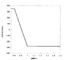
図3に示すように、トルクを350Nmから‐280Nmに急変動させた場合を考える。図3では0.2秒で変動させている。この変動時間を、0.1秒から0.5秒まで段階的に変えて解析を行った。
図4に示すように、本実施形態のように0.2秒以上でトルク変動を行った場合には、安定した結果が得られている。しかしながら、0.1秒でトルク変動を行うと、オーバーシュートが発生し、小さなハンチングが発生し制御的に不安定となる。この図4は、入力回転数が2000回転でほぼ一定の条件である。
【0030】
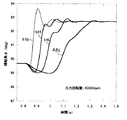
図5に入力回転数が3000回転、図6に入力回転数が4000回転のときの解析結果も示す。これらの図から、回転数が高くなるほど、低速用クラッチ236及び高速用クラッチ237の切り替えをしてモードチェンジをすると有効になる。4000回転では0.2秒でトルク変動をさせると小さなハンチングが見受けられるが、オーバーシュートはない。なお、全ての解析は、変速比をHigh側としている。
【0031】
このように、トルク変動を0.2秒以上、つまり、0.2秒以上で低速用クラッチ236及び高速用クラッチ237の切り替えをしてモードチェンジをすることにより安定した変速結果が得られる。
【0032】
また、クラッチの断続時間が長いと、動力の伝達が断絶された状態となり、車の加速がなくなり、エンジンが吹き上がる。従ってモードチェンジ、またはトルクが断絶している時間は1秒以内に完了するのが望ましい。
【0033】
したがって、0.2〜1秒で低速用クラッチ236及び高速用クラッチ237の切り替えをしてモードチェンジをすることにより安定したトルク変動を得ることができ、変速ショックの発生を抑えて運転者に違和感を与えることがない。
【0034】
次に、図8から図11は、本発明に係る第2実施形態を示している。この無段変速装置は、入力側回転軸(入力軸)11bと、出力軸29aと、トロイダル型無段変速機19aと、遊星歯車装置20aと、第一の動力伝達手段34aと、第二の動力伝達手段40aとを備える。このうちの入力側回転軸11bは、図示しない図8の左側に配置したエンジン等の駆動源につながって、この駆動源により回転駆動される。
【0035】
出力軸29aは、入力側回転軸11bの回転に基づく動力を取り出すためのもので、図示しないデフアレンシャルギヤ等を介して、やはり図示しない車輪駆動軸に接続される。
【0036】
また、トロイダル型無段変速機19aは、ダブルキヤビティ型で、且つ、各キヤビティ内にトラニオン7、7及びパワーローラ9、9を3個ずつ、合計6個設けたものである。この様なトロイダル型無段変速機19aを構成するため、入力側回転軸11bの両端部に1対の入力側ディスク(入力ディスク)2A、2Bを、互いの内側面2a、2a同士を対向させた状態で、入力側回転軸11bと同期した回転自在に支持している。このうち、図8の左側の入力側ディスク2Aは入力側回転軸11bに、ボールスプライン43を介して、軸方向の変位自在に支持している.これに対して、図1の右側の入力側ディスク2Bは、入力側回転軸11bの先端部にスプライン係合させた状態でその背面をローディングナット44で抑える事により、入力側回転軸11bに固定している。なお、このローディングナット44と入力側ディスク2Bとの問にはシム板45を挟持している。
【0037】
そして、入力側回転軸11bの中間部周囲で1対の入力側ディスク2A、2B同士の間に1対の出力側ディスク(出力ディスク)4、4を、それぞれの内側面4a、4aを各入力側ディスク2A、2Bの内側面2a、2aに対向させた状態で、互いに同期した回転自在に支持している。そして、各入力側ディスク2A、2Bと各出力側ディスク4、4との内側面2a、4a同士の問に、それぞれがトラニオン7、7の内側面に回転自在に支持されたパワーローラ9、9を挟持している。パワーローラ9、9の外側面と各トラニオン7、7の中間部内側面との間には、各パワーローラ9、9の外側面の側から順に、各パワーローラ9、9に加わるスラスト方向の荷重を支承しつつ、これら各パワーローラ9、9の回転を許容するスラスト玉軸受14、14と、各パワーローラ9、9から各スラスト玉軸受14、14を構成する外輪16、16に加わるスラスト荷重を支承するスラストニードル軸受15、15とを設けている。
【0038】
各トラニオン7、7を支持するため、ケーシング5aの内面に設けた取付部47にヨーク48を、このヨーク48の外径側端部3個所位置の取付孔49、49に挿通したシャフト50、50と、これら各シャフト50、50に螺合したナット51、51とにより支持固定している。図示の例では、これら各シャフト50、50及びナット51、51により、取付部47とヨーク48との間に、ギヤハウジング52を固定している。このギヤハウジング52の内径側には、上記1対の出力側ディスク4、4をその両端部に凹凸係合させた出力スリーブ53を、1対の転がり軸受54、54により回転自在に支持すると共に、この出力スリーブ53の中間部外周面に設けた出力歯車12bを、上記ギヤハウジング52の内部に収納している。
【0039】
また、ヨーク48は全体を星形に形成すると共に、その径方向中間部乃至は外径側部分を二股に形成して、3個所の保持部55、55を、円周方向等間隔に形成している。そして、これら各保持部55、55の径方向中間部に、それぞれ支持片56、56の中間部を、第二の枢軸57、57により枢支している。これら各支持片56、56はそれぞれ、第二の枢軸57、57の周囲に配置される円筒状の取付部58と、この取付部58の外周面から径方向外方に突出した1対の支持板部59、59とから成る。これら1対の支持板部59、59同士の交差角度は120度である。従って、円周方向に隣り合う支持片56、56の支持板部59、59同士は、互いに平行である。
【0040】
この様な各支持板部59、59には、それぞれ円孔60、60を形成している。各支持片56、56が中立状態にある場合、円周方向に隣り合う支持片56、56の支持板部59、59に形成した円孔60、60同士は互いに同心である。そして、これら各円孔60、60内に、各トラニオン7、7の両端部に設けた枢軸6、6を、ラジアルニードル軸受61、61により支持している。これら各ラジアルニードル軸受61、61を構成する外輪62、62の外周面は、球状凸面としている。この様な外輪62、62は上記各円孔60、60内に、がたつきなく、且つ揺動変位自在に内験している。また、上記各支持板部59、59の一部には、上記各円孔60、60と同心で円弧状の長孔63、63を形成し、これら各長孔63、63に、上記各トラニオン7、7の端面(肩部)に突設した止めねじ64を用いて、各トラニオン7の枢軸方向のすきま量をがたのないように調整している。
【0041】
この様にして前記ケーシング5a内に支持した上記各トラニオン7、7の内側面には、変位軸8を介して前記パワーローラ9、9を支持している。そして、これら各パワーローラ9、9の周面9a、9aと、各ディスク2A、2B、4の内側面2a、4aとを当接させている。又、基端側の入力側ディスク2Aと入力側回転軸11bとの問に、油圧式の押圧装置28aを組み付けて、各面9a、2a、4a同士の当接部(トラクション部)の面圧を確保し、トロイダル型無段変速機19aによる動力の伝達を効率良く行える様にしている。
【0042】
押圧装置28aを構成する為に、入力側回転軸11bの外周面の基端寄り部分に、外向フランジ状の鍔部65を固設すると共に、基端側の入力側ディスク2Aにシリンダ筒66を、この入力側ディスク2Aの外側面(図8、9の左面)から軸方向に突出する状態で、油密に外嵌保持している。シリンダ筒66の内径は、軸方向中間部で小さく、両端部で大きくなっており、入力側ディスク2Aは、このうちの先端側の大径部分に、油密に内嵌している。又、シリンダ筒66の中間部内周面に、内向フランジ状の仕切板部67を設け、更に、このシリンダ筒66の内周面と上記入力側回転軸11bの外周面との間に、第一ピストン部材68を設けている。
【0043】
この第−ピストン部材68は、入力側回転軸11bに外嵌自在な支持筒部69の中間部外周面に、外向フランジ状の隔壁板70を形成したもので、この隔壁板70の外周縁をシリンダ筒66の内周面中間部の小径部分に、油密に且つ軸方向に変位自在に摺接させている。又、この状態で上記仕切板部67の内周縁を、支持筒部69の外周面に、油密に且つ軸方向に変位自在に摺接させている。更に、上記支持筒部69の基端部外周面とシリンダ筒66の基端部内周面との間に、円輪状の第二ピストン部材71を設けている。この第二ピストン部材71は、その基端側側面を鍔部65に当接させる事により軸方向の変位を阻止すると共に、内外両周縁と上記支持筒部69の基端部外周面及びシリンダ筒66の基端部内周面との間の油密を保持している。
【0044】
又、上記仕切板部67を備えたシリンダ筒66は、この仕切板部67と第二ピストン部材71との間に設けた皿板ばね72により、入力側ディスク2Aに向け押圧している。従ってこの入力側ディスク2Aは、少なくとも(押圧装置28a内に圧油を導入していない状態でも)に見合う押圧力により押圧され、前記各面9a、2a、4aの弾力に見合う面圧を付与する。従って、この弾力は、前記トロイダル型無段変速機19aにより極く小さな動力の伝達を行なう際に、各面9a、2a、4aどうしの各当接部で(不可避であるピストンを除く)滑りが生じない程度に規制する。
【0045】
又、駆動軸80から入力側回転軸11bへの回転力の伝達を、鍔部65を介して行なう様にしている。この為に、この鍔部65の外周縁部複数個所に切り欠き83、83を形成すると共に、これら各切り欠き83、83と、駆動軸80の端部に形成した駆動用凸部84、84とを係合させている。この為に本例の場合には、上記駆動軸80の端部に外向フランジ状の連結部85を設け、この連結部85の片面外径寄り端部に、上記各駆動用凸部84、84を突設している。
【0046】
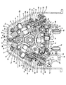
さらに、各トラニオン7、7に油圧式のアクチュエータ17a、17bを設けて、これら各トラニオン7、7を、それぞれの両端部に設けた枢軸6、6の軸方向に変位駆動自在としている。このうち、図10の下側中央部のトラニオン7は、それぞれが(押し出し方向の力のみ得られる)単動型であり押圧方向を互いに反対方向とした1対のアクチュエータ17a、17aにより、それぞれ挺子腕86、86を介して、両端部に設けた枢軸6、6の軸方向に変位駆動自在としている。トラニオン7を変位させる場合には、何れか一方のアクチュエータ17aの油圧室にのみ圧油を送り込み、他方のアクチュエータ17aの油圧室は解放状態とする。これに対して、図10の上部両側のトラニオン7、7は、それぞれ(圧油の給排方向の切り換えに基づいて押し出し方向又は引き込み方向の力を得られる)複動型のアクチュエータ17b、17bにより、それぞれの両端部に設けた枢軸6、6の軸方向に変位駆動自在としている。
【0047】
トロイダル型無段変速機19aに設けた、合計6個のトラニオン7、7の変位は、制御弁により各アクチュエータ17a、17bに等量の圧油を給排する事により、互いに同期して同じ長さずつ行なう。この為に、何れか(図示の例では図3の上部左側)のトラニオン7と共に変位するロツド87の端部にブリセスカム88を固定し、このトラニオン7の姿勢を、リンク89を介して制御弁のスプール90に伝達自在としている。
【0048】
遊星歯車装置20aは、太陽歯車30と、リング歯車21と、遊星歯車組32、32とを備える。このうちの太陽歯車30は、出力軸29aの入力側端部(図8の左端部)に固定している。従ってこの出力軸29aは、太陽歯車30の回転に伴って回転する。この太陽歯車30の周囲にはリング歯車21を、太陽歯車30と同心に、且つ回転自在に支持している。そして、リング歯車21の内周面と太陽歯車30の外周面との間に、それぞれが1対ずつの遊星歯車31a、31bを組み合わせて成る、複数組の遊星歯車組32、32を設けている。そして、これら1対ずつの遊星歯車31a、31bは、互いに噛合すると共に、外径側に配置した遊星歯車31aを上記リング歯車21に噛合させ、内径側に配置した遊星歯車31bを太陽歯車30に噛合させている。この様な遊星歯車組32、32は、キャリア33の片側面(図8の左側面)に回転自在に支持している。又、このキャリア33は、上記出力軸29aの中間部周囲に、回転自在に支持している。
【0049】
又、キャリア33とトロイダル型無段変速機19aを構成する1対の出力側ディスク4、4とを、前記第一の動力伝達手段34aにより、回転力の伝達を可能な状態に接続している。この第一の動力伝達手段34aを構成する為に、入力側回転軸11b及び出力軸29aと平行な伝達軸35aを設け、この伝達軸35aの一端部(図1の左端部)に固定した歯車91を、出力歯車12bと噛合させている。又、出力軸29aの中間部周囲にスリーブ94を回転自在に配置し、このスリーブ94の外周面に支持した歯車95と、伝達軸35aの他端部(図8の右端部)に固設した歯車96とを、図示しないアイドル歯車を介して噛合させている。更に、スリーブ94の周囲にキャリア33を、円環状の結合ブラケット97を介して、スリーブ94と同期した回転自在に支持している。従ってキャリア33は、各出力側ディスク4、4の回転に伴って、これら出力側ディスク4、4と反対方向に、上記各歯車12b、91、95、96の歯数に応じた速度で回転する。尚、結合ブラケット97及び上記キャリア33と上記出力軸29aとの間に、低速用クラッチ41aを設けている。
【0050】
一方、入力側回転軸11bとリング歯車21とは、この入力側回転軸11bの先端部に支持した入力側ディスク2Bと、この入力側回転軸11bと同心に配置された伝達軸23aとを介して、回転力の伝達を可能な状態に接続自在としている。この為に、入力側ディスク2Bの外側面(図8、9の右側面)の一部で、径方向に関してこの外側面の中央部よりも外径寄り半部に、複数の凸部98、98を突設している。本例の場合には、これら各凸部98、98は、それぞれ円弧状で、上記入力側ディスク2Bの中心軸をその中心とする同一円弧上に、間欠的に且つ等間隔に配置している。そして、円周方向に隣り合う凸部98、98の円周方向端面同士の間を、係止切り欠き部99、99としている。
【0051】
一方、伝達軸23aの基端部には、円すい筒状の伝達筒部100を介して伝達フランジ101を設けている。そして、この伝達フランジ101の外周縁部に、各係止切り欠き部99、99と同数の伝達用突片102、102を、円周方向に関して等間隔に形成している。そして、これら各伝達用突片102、102と各係止切り欠き部99、99とを係合させ、入力側ディスク2Bと伝達軸23aとの間でのトルク伝達を可能にしている。各伝達用突片102、102と各係止切り欠き部99、99との係合部の径は十分に大きいので、上記入力側ディスク2Bと伝達軸23aとの間で、十分に大きなトルクを伝達自在である。
この無段変速装置は、高速用クラッチ24a、低速用クラッチ41a及び後退用クラッチ42aとから成るクラッチ機構を備える。これらクラッチ機構は、何れも湿式多板クラッチであって、それぞれに付属した油圧シリンダ内への圧油の給排に基づいて断接させられる。又、何れか1個のクラッチが接続された場合には、残り2個のクラッチの接続が断たれる。
【0052】
先ず、低速走行時には、低速用クラッチ41aを接続すると共に、高速用クラッチ24a及び後退用クラッチ42aの接続を断つ。この状態で入力側回転軸11bを回転させると、トロイダル型無段変速機19aのみが、この入力側回転軸11bから出力軸29aに動力を伝達する。すなわち、この状態では、トロイダル型無段変速機19aの出力歯車12bの回転が、第一の動力伝達手段34aを介してキャリア33に伝わる。低速用クラッチ41aが接続される事により、遊星歯車装置20aは、構成各歯車21、30、31a、31bが相対変位不能な状態となっているので、キャリア33の回転は、そのまま太陽歯車30に伝わり、この太陽歯車30を固設した出力軸29aが回転する。
【0053】
高速走行時には、前記高速用クラッチ24aを接続すると共に、低速用クラッチ41a及び後退用クラッチ42aの接続を断つ。この状態で入力側回転軸11bを同転させると、この入力側回転軸11bから前記出力軸29aには、伝達軸23aを含む第二の動力伝達手段40aと、遊星歯車装置20aとが、動力を伝達する。即ち、高速走行時に入力側回転軸11bが回転すると、この回転は伝達軸23aと結合用ブラケット104と高速用クラッチ24aとを介して、リング歯車21に伝わる。そして、このリング歯車21の回転が複数の遊星歯車組32、32を介して太陽歯車30に伝わり、この太陽歯車30を固定した上記出力軸29aを回転させる。この状態で、トロイダル型無段変速機19aの変速比を変える事により各遊星歯車組32、32の公転速度を変化させれば、無段変速装置全体としての変速比を調節できる。
【0054】
なお、本実施形態のロイダル型無段変速機19aが本発明のバリエータに対応し、遊星歯車装置20aが本発明の遊星歯車機構に対応し、第一の動力伝達手段34aが本発明の第一の動力伝達系に対応し、第二の動力伝達手段40aが本発明の第二の動力伝達系に対応し、低速用クラッチ41aが本発明の第1のモードクラッチに対応し、高速用クラッチ24aが第2のモードクラッチに対応している。
【0055】
ここで、図11に示すように、低速用クラッチ41a及び高速用クラッチ24aの駆動部110は、本発明のモード切り換え手段に相当する制御回路112に電気的に接続されており、制御回路112からの出力信号により、低速用クラッチ41a及び高速用クラッチ24aのクラッチ締結、クラッチ開放の動作が、所定の切り換え動作時間を設けて行われるようになっている。本実施形態の切り換え動作時間は、0.2〜1秒に設定されている。
【0056】
上述の様に構成した本実施形態の無段変速装置の作用は、次の通りである。先ず、低速走行時には、制御回路112の制御により、0.2〜1秒の切り換え動作時間で、低速用クラッチ41a接続すると共に、高速用クラッチ24a及び後退用クラッチ4aの接続を断つ。この状態で図示しない発進クラッチを接続し、前記入力軸11bを回転させると、トロイダル型無段変速機19aのみが、入力軸11bから出力軸29a動力を伝達する。即ち、低速用クラッチ41aの接続に伴って、リング歯車21とキャリア33とが一体的に結合され、遊星歯車機構32を構成する各歯車同士の相対回転が不能になる。また、高速用クラッチ24a及び後退用クラッチ42aの接続が断たれる事で、リング歯車21は、伝達軸23aの回転速度に関係なく回転自在となる。
【0057】
そして、制御回路112が、切り換え動作時間を0.2〜1秒として、低速用クラッチ41a及び高速用クラッチ24aの切り替え(クラッチ締結、クラッチ開放)をしてモードチェンジすると、オーバーシュートが発生せず制御的に不安定となり、安定した変速結果が得られる。
したがって、第1実施形態と同様に、変速ショックの発生を抑えて運転者に違和感を与えることがない。
【0058】
以上、本発明は、特開平10−196759号公報に示すような、低速モードではバリエータのみを経由する動力伝達経路を用い、高速モードでは2つの動力伝達経路を用いる無段変速機構について有効であることを述べてきたが、Geared Neutralシステムのようにトルクの正負が反転するシステムにおいても有効である。さらに、エンジンブレーキのようにトルクの正負が反転する場合においても有効となる。
【0059】
【発明の効果】
以上説明したように、本発明によると、第1のモードクラッチ及び第2のモードクラッチのモードチェンジにおいて安定したトルク変動を得ることで、変速ショックの発生を抑えて運転者に違和感を与えない無段変速装置を提供することができる。
【図面の簡単な説明】
【図1】本発明に係る第1実施形態の無段変速装置を示すスケルトン図である。
【図2】第1実施形態のモード切り換え手段を示すブロック図である。
【図3】第1実施形態においてトルクを急変動させた場合を示す図である。
【図4】第1実施形態において入力回転数が2000回転でクラッチのモード切り換え時間を変化させた場合のトルク変動を示す図である。
【図5】第1実施形態において入力回転数が3000回転でクラッチのモード切り換え時間を変化させた場合のトルク変動を示す図である。
【図6】第1実施形態において入力回転数が4000回転でクラッチのモード切り換え時間を変化させた場合のトルク変動を示す図である。
【図7】第1実施形態においてトルクが負荷されると変速指令を出していないにも関わらず、バリエータが変速してしまう状態を示す図である。
【図8】本発明に係る第2実施形態の無段変速装置を示す要部断面図である。
【図9】図8の左半部拡大図である。
【図10】図8のA−A断面図である。
【図11】第2実施形態のモード切り換え手段を示すブロック図である。
【符号の説明】
2A、2B、202 入力ディスク
4、478a 出力ディスク
9、208 パワーローラ
11b、217 入力軸
15 エンジン(駆動源)
19a トロイダル型無段変速機(バリエータ)
20a、220a 遊星歯車装置
21、223 リング歯車
23a、280 伝達軸(第2の動力伝達系)
24a、237 高速用クラッチ(第2のモードクラッチ)
29a、219 出力軸
30、222 太陽歯車
31a、224 遊星歯車
32 遊星歯車組
34a 第1の動力伝達手段(第1の動力伝達系)
40a 第2の動力伝達手段(第2の動力伝達系)
41a、236 低速用クラッチ(第1のモードクラッチ)
112、252 制御回路(モード切り換え手段)
220 バリエータ
221 遊星歯車機構
228 第1の動力伝達系
231 第2の動力伝達系[0001]
BACKGROUND OF THE INVENTION
The present invention Is an example For example, the present invention relates to an improvement of a continuously variable transmission incorporating a variator used as a transmission for an automobile.
[0002]
[Prior art]
Japanese Patent Laid-Open No. 10-196759 discloses an input shaft that is rotationally driven by a drive source, an output shaft that extracts power based on the rotation of the input shaft, and an input / output disposed between the input shaft and the output shaft A continuously variable transmission including a variator having a disk and a power roller and a planetary gear mechanism is described.
[0003]
This continuously variable transmission has two modes, low speed side and high speed side, when traveling forward. The low speed mode uses a power transmission system that passes only through the variator, and the high speed mode transmits power through the variator. System and variator-free power transmission system, these two power transmission systems input to any two gears of the planetary gear mechanism sun gear, ring gear and planetary gear, the remaining one gear is the output shaft And output as a differential component of the two gears. In this continuously variable transmission, the power flowing through the variator is reduced in the high-speed mode, so that the effect of becoming a highly efficient and long-life device can be achieved.
[0004]
In the continuously variable transmission disclosed in Japanese Patent Laid-Open No. 10-196759, the torque input to the variator at the time of the mode change for switching between the low speed mode and the high speed mode varies greatly from positive to negative (or vice versa). For example, the input torque varies from +350 Nm to −280 Nm at the time of mode change in which the mode is switched from the low speed mode to the high speed mode.
[0005]
In addition, two power transmission systems are used in the low-speed mode, the mode in which only the variator is used in the high-speed mode, and the planetary gear differential component is set to zero rotation in the low-speed mode. In the Geared Neutral system that does not require a clutch, when the two modes are switched, the torque is reversed in the same way. Incidentally, in the Geared Neutral system, the mode change is performed when the variator is on the low speed side.
[0006]
In addition to these systems, there are continuously variable transmissions that create two or more modes by combining a variator and planetary gears, but many layouts reverse the sign of torque when changing modes. . For example, there is a two-mode continuously variable transmission as disclosed in JP-A-2000-220719.
[0007]
[Problems to be solved by the invention]
However, the variator has a characteristic of shifting as shown in FIG. 7 when the torque varies. FIG. 7 shows measurement results when the rotation speed is constant at about 2000 rotations, the oil temperature is controlled at a temperature close to that of actual vehicle travel, and only the torque is changed without issuing a shift command. When the torque is varied in this way, the variator shifts although no shift command is issued.
[0008]
The following reasons are conceivable as reasons for this speed change.
(1) When a load is applied to the variator, traction force is generated in the vertical direction (in the direction of the tilting axis of the trunnion that supports the power roller), and the piston force of the mechanism that moves the trunnion acts in the opposite direction as the reaction force. . Of course, there is a gap in the radial needle bearing that supports the power roller and the radial needle bearing that supports the pivot. For this reason, when a load is applied, the inner ring of the power roller moves up and down the sum of these gaps. As the power roller moves in the vertical direction, a side slip occurs and the power roller shifts.
(2) Further, the gear ratio varies with respect to the torque load due to the deformation of the trunnion shaft due to the elastic deformation of the trunnion. In the traction drive, it is necessary to apply a pressing force to the traction contact point, and the force is supported by the trunnion.
[0009]
The trunnion is supported by two yokes to cancel the force generated between the front, rear, left and right trunnions. Therefore, the trunnion is applied with a load on the beam supported at two points, and naturally deforms elastically. As a result, the trunnion shaft itself does not receive any force and is not elastically deformed. sound The trunnion shaft is tilted. As a result, the contact point between the recess cam and the valve link of the mechanism for moving the trunnion moves, and the spool moves in the axial direction. As a result, the valve is turned off, a differential pressure is generated, and a shift is generated.
[0010]
These factors overlap, and as shown in FIG. 7, when a torque is applied, the variator shifts even though no shift command is issued.
If this shift variation occurs stably, the occurrence of a shift shock can be suppressed by issuing a shift command. However, it must be avoided that the control becomes unstable during the mode change, that is, when the torque fluctuates. Incidentally, at the time of mode switching, the driver does not intend to change the mode, and the mode change occurs unconsciously by the driver. Therefore, if the clutch engagement / disconnection time is long in the mode change, power is not generated, and the driver feels uncomfortable because the engine blows up.
[0011]
From the above, the mode change must be performed stably, and at the same time, the mode change needs to be completed by instantaneously changing the clutch in a short time.
The present invention has been made in view of the above circumstances, and provides a continuously variable transmission that suppresses the occurrence of a shift shock and does not give the driver a sense of incongruity by obtaining a stable torque fluctuation in a mode change. Objective.
[0012]
[Means for Solving the Problems]
In order to achieve the object, the continuously variable transmission according to
[0013]
DETAILED DESCRIPTION OF THE INVENTION
Hereinafter, embodiments according to the present invention will be described with reference to the drawings.
FIG. 1 shows a first embodiment according to the present invention. The continuously variable transmission according to this embodiment includes an
[0014]
The
[0015]
A plurality (usually 2 to 3) of
[0016]
The
[0017]
The
Further, the
[0018]
On the other hand, the
[0019]
The continuously variable transmission according to this embodiment includes a clutch mechanism. This clutch mechanism connects only one of the
[0020]
Here, as shown in FIG. 2, the driving
[0021]
Further, as shown in FIG. 1, a
[0022]
In the illustrated example, the
[0023]
The operation of the continuously variable transmission according to the present embodiment configured as described above is as follows. First, during low-speed running, the
[0024]
Therefore, when the
[0025]
The action itself when changing the gear ratio between the input side and
[0026]
On the other hand, during high speed running, the
[0027]
That is, when the
[0028]
Next, the reason why the control circuit changed the mode by switching the clutch for
The inventors conducted analysis using a program for analyzing a continuously variable transmission, in which torque suddenly fluctuates, that is, when the
[0029]
Consider a case where the torque is suddenly changed from 350 Nm to -280 Nm as shown in FIG. In FIG. 3, it is changed in 0.2 seconds. The variation time was changed stepwise from 0.1 seconds to 0.5 seconds, and the analysis was performed.
As shown in FIG. 4, when the torque fluctuation is performed in 0.2 seconds or more as in this embodiment, a stable result is obtained. However, if torque fluctuation is performed in 0.1 seconds, overshoot occurs, small hunting occurs, and control becomes unstable. FIG. 4 shows a condition where the input rotational speed is 2000 and almost constant.
[0030]
FIG. 5 also shows an analysis result when the input rotation speed is 3000 rotations and FIG. 6 is an input rotation speed of 4000 rotations. From these figures, it is effective to change the mode by switching the low-
[0031]
As described above, a stable speed change result can be obtained by switching between the
[0032]
Also, if the clutch is disconnected for a long time, the transmission of power is cut off, the vehicle is no longer accelerated, and the engine blows up. Therefore, it is desirable to complete the mode change or the time when the torque is cut off within one second.
[0033]
Therefore, stable torque fluctuation can be obtained by switching between the
[0034]
Next, FIGS. 8 to 11 show a second embodiment according to the present invention. This continuously variable transmission includes an input side rotating shaft (input shaft) 11b, an output shaft 29a, a toroidal continuously variable transmission 19a, a planetary gear device 20a, a first power transmission means 34a, a second power transmission means 34a, Power transmission means 40a. Among these, the input side rotating shaft 11b is connected to a driving source such as an engine arranged on the left side of FIG. 8 (not shown), and is rotationally driven by this driving source.
[0035]
The output shaft 29a is for taking out power based on the rotation of the input side rotating shaft 11b, and is connected to a wheel drive shaft (not shown) via a differential gear (not shown).
[0036]
The toroidal-type continuously variable transmission 19a is a double-cavity type and includes six
[0037]
Then, a pair of output side disks (output disks) 4 and 4 are inserted between the pair of input side disks 2A and 2B around the intermediate portion of the input side rotating shaft 11b, and the inner side surfaces 4a and 4a are respectively input. The side disks 2A and 2B are rotatably supported in synchronization with each other while facing the inner side surfaces 2a and 2a. The power rollers 9, 9 are rotatably supported on the inner side surfaces of the
[0038]
In order to support each
[0039]
Further, the
[0040]
Circular holes 60 and 60 are formed in the
[0041]
In this way, the power rollers 9 and 9 are supported on the inner side surfaces of the
[0042]
In order to constitute the pressing device 28a, an outward flange-
[0043]
The first piston member 68 is formed by forming an outward flange-shaped partition plate 70 on the outer peripheral surface of the intermediate portion of the
[0044]
Further, the
[0045]
Further, the rotational force is transmitted from the
[0046]
In addition, each
[0047]
The total displacement of the six
[0048]
The planetary gear device 20 a includes a sun gear 30, a ring gear 21, and planetary gear sets 32 and 32. Of these, the sun gear 30 is fixed to the input side end (left end in FIG. 8) of the output shaft 29a. Therefore, the output shaft 29 a rotates as the sun gear 30 rotates. Around the sun gear 30, a ring gear 21 is supported concentrically with the sun gear 30 and rotatably. Between the inner peripheral surface of the ring gear 21 and the outer peripheral surface of the sun gear 30, there are provided a plurality of planetary gear sets 32, 32 each formed by combining a pair of planetary gears 31a, 31b. . The planetary gears 31a and 31b of each pair are meshed with each other, and the planetary gear 31a disposed on the outer diameter side is meshed with the ring gear 21 to Diameter The planetary gear 31b arranged on the side is meshed with the sun gear 30. Such planetary gear sets 32 and 32 are rotatably supported on one side surface (left side surface in FIG. 8) of the carrier 33. The carrier 33 is rotatably supported around the intermediate portion of the output shaft 29a.
[0049]
Further, the carrier 33 and the pair of output side disks 4 and 4 constituting the toroidal-type continuously variable transmission 19a are connected to each other in a state in which the rotational force can be transmitted by the first power transmission means 34a. . In order to constitute the first power transmission means 34a, a
[0050]
On the other hand, the input side rotating shaft 11b and the ring gear 21 are connected via an input side disk 2B supported at the tip of the input side rotating shaft 11b and a transmission shaft 23a disposed concentrically with the input side rotating shaft 11b. Thus, it is possible to connect to a state where transmission of rotational force is possible. For this reason, a plurality of
[0051]
On the other hand, a transmission flange 101 is provided at a proximal end portion of the transmission shaft 23a via a conical cylindrical
The continuously variable transmission includes a clutch mechanism including a high speed clutch 24a, a low speed clutch 41a, and a reverse clutch 42a. Each of these clutch mechanisms is a wet multi-plate clutch, and is connected / disconnected based on supply / discharge of pressure oil to / from a hydraulic cylinder attached to each clutch mechanism. When any one of the clutches is connected, the remaining two clutches are disconnected.
[0052]
First, during low-speed running, the low-speed clutch 41a is connected and the high-speed clutch 24a And disconnecting the reverse clutch 42a. When the input side rotating shaft 11b is rotated in this state, only the toroidal type continuously variable transmission 19a transmits power from the input side rotating shaft 11b to the output shaft 29a. That is, in this state, the rotation of the
[0053]
During high speed running, the high speed clutch 24a is connected and the low speed clutch 41a and the reverse clutch 42a are disconnected. When the input side rotating shaft 11b rotates in this state, the second power transmission means 40a including the transmission shaft 23a and the planetary gear device 20a are connected to the output shaft 29a from the input side rotating shaft 11b. To communicate. In other words, input side rotation during high-speed driving axis When 11b rotates, this rotation is transmitted axis It is transmitted to the ring gear 21 through 23a, the coupling bracket 104 and the high speed clutch 24a. Then, the rotation of the ring gear 21 is transmitted to the sun gear 30 via the plurality of planetary gear sets 32, 32, and the output shaft 29a to which the sun gear 30 is fixed is rotated. In this state, if the revolution speed of each planetary gear set 32, 32 is changed by changing the speed ratio of the toroidal type continuously variable transmission 19a, the speed ratio of the continuously variable transmission as a whole can be adjusted.
[0054]
The toroidal continuously variable transmission 19a of the present embodiment corresponds to the variator of the present invention, the planetary gear device 20a corresponds to the planetary gear mechanism of the present invention, and the first power transmission means 34a corresponds to the first of the present invention. The second power transmission means 40a corresponds to the second power transmission system of the present invention, the low speed clutch 41a corresponds to the first mode clutch of the present invention, and the high speed clutch 24a. Corresponds to the second mode clutch.
[0055]
Here, as shown in FIG. 11, the driving
[0056]
The operation of the continuously variable transmission according to the present embodiment configured as described above is as follows. First, during low speed running, the
[0057]
When the
Therefore, as in the first embodiment, the occurrence of a shift shock is suppressed and the driver does not feel uncomfortable.
[0058]
As described above, the present invention is effective for a continuously variable transmission mechanism that uses a power transmission path that passes only through a variator in the low speed mode and uses two power transmission paths in the high speed mode, as disclosed in JP-A-10-196759. As described above, the present invention is also effective in a system in which the sign of torque is reversed, such as the Geared Neutral system. Furthermore, this is effective even when the sign of torque is reversed, such as in engine braking.
[0059]
【The invention's effect】
As described above, according to the present invention, stable torque fluctuation is obtained in the mode change of the first mode clutch and the second mode clutch, so that the occurrence of shift shock is suppressed and the driver does not feel uncomfortable. A step transmission can be provided.
[Brief description of the drawings]
FIG. 1 is a skeleton diagram showing a continuously variable transmission according to a first embodiment of the present invention.
FIG. 2 is a block diagram showing mode switching means of the first embodiment.
FIG. 3 is a diagram showing a case where torque is suddenly changed in the first embodiment.
FIG. 4 is a diagram showing torque fluctuation when the input rotation speed is 2000 rotations and the clutch mode switching time is changed in the first embodiment.
FIG. 5 is a diagram showing torque fluctuation when the input rotation speed is 3000 rotations and the clutch mode switching time is changed in the first embodiment.
FIG. 6 is a diagram showing torque fluctuation when the input rotation speed is 4000 rotations and the clutch mode switching time is changed in the first embodiment.
FIG. 7 is a diagram showing a state where the variator shifts when torque is applied in the first embodiment even though no shift command is issued.
FIG. 8 is a cross-sectional view of an essential part showing a continuously variable transmission according to a second embodiment of the present invention.
FIG. 9 is an enlarged view of the left half part of FIG. 8;
10 is a cross-sectional view taken along the line AA in FIG.
FIG. 11 is a block diagram showing mode switching means of the second embodiment.
[Explanation of symbols]
2A, 2B, 202 Input disk
4, 478a Output disk
9, 208 Power roller
11b, 217 Input shaft
15 Engine (drive source)
19a Toroidal continuously variable transmission (variator)
20a, 220a Planetary gear device
21, 223 Ring gear
23a, 280 Transmission shaft (second power transmission system)
24a, 237 High speed clutch (second mode clutch)
29a, 219 Output shaft
30, 222 Sun gear
31a, 224 planetary gear
32 planetary gear set
34a First power transmission means (first power transmission system)
40a Second power transmission means (second power transmission system)
41a, 236 Low speed clutch (first mode clutch)
112, 252 Control circuit (mode switching means)
220 Variator
221 Planetary gear mechanism
228 First power transmission system
231 Second power transmission system
Claims (1)
前記第1のモード及び前記第2のモードの切り換え動作に際して、前記第1のモードクラッチと前記第2のモードクラッチのうち、締結する側のモードクラッチがトルクを伝達し始めてから開放する側のモードクラッチがトルクを伝達しなくなるまでを、0.2〜1秒で行わせるモード切り換え手段を備えたことを特徴とする無段変速装置。An input shaft that is rotationally driven by a drive source, an output shaft that extracts power based on the rotation of the input shaft, and a variator that includes an input / output disk and a power roller disposed between the input shaft and the output shaft; A planetary gear mechanism, a first power transmission system that transmits the power of the drive source to the planetary gear mechanism via the variator, and a second power transmission system that transmits the power to the planetary gear mechanism without passing through the variator. The power transmitted by two of the power transmission systems and the power transmitted to the first and second power transmission systems is selected from the three types of gears of the sun gear, the ring gear, and the planetary gear that constitute the planetary gear mechanism. A first mode that is one of the low-speed side and the high- speed side during the forward movement and a second mode that is the other when the two gears are joined and a gear other than the two gears is connected to the output shaft. Have These first and second by switching the mode inverted positive and negative torque input to the variator, these switching the first and second mode, one of the first mode clutch and the second mode clutch In a continuously variable transmission that is performed by opening and fastening the other ,
In the switching operation between the first mode and the second mode, the mode that is released after the engaging mode clutch of the first mode clutch and the second mode clutch starts transmitting torque. A continuously variable transmission comprising a mode switching means for performing until the clutch no longer transmits torque in 0.2 to 1 second.
Priority Applications (3)
| Application Number | Priority Date | Filing Date | Title |
|---|---|---|---|
| JP2001309844A JP3758546B2 (en) | 2001-10-05 | 2001-10-05 | Continuously variable transmission |
| DE10246352A DE10246352B4 (en) | 2001-10-05 | 2002-10-04 | Stepless transmission |
| US10/263,725 US7077777B2 (en) | 2001-10-05 | 2002-10-04 | Continuously variable transmission |
Applications Claiming Priority (1)
| Application Number | Priority Date | Filing Date | Title |
|---|---|---|---|
| JP2001309844A JP3758546B2 (en) | 2001-10-05 | 2001-10-05 | Continuously variable transmission |
Publications (3)
| Publication Number | Publication Date |
|---|---|
| JP2003113935A JP2003113935A (en) | 2003-04-18 |
| JP2003113935A5 JP2003113935A5 (en) | 2005-06-09 |
| JP3758546B2 true JP3758546B2 (en) | 2006-03-22 |
Family
ID=19128925
Family Applications (1)
| Application Number | Title | Priority Date | Filing Date |
|---|---|---|---|
| JP2001309844A Expired - Fee Related JP3758546B2 (en) | 2001-10-05 | 2001-10-05 | Continuously variable transmission |
Country Status (3)
| Country | Link |
|---|---|
| US (1) | US7077777B2 (en) |
| JP (1) | JP3758546B2 (en) |
| DE (1) | DE10246352B4 (en) |
Families Citing this family (44)
| Publication number | Priority date | Publication date | Assignee | Title |
|---|---|---|---|---|
| US6932739B2 (en) * | 2001-12-25 | 2005-08-23 | Nsk Ltd. | Continuously variable transmission apparatus |
| CN1578890B (en) * | 2002-09-30 | 2010-05-26 | 乌尔里克·罗斯 | Transmission mechanism |
| ES2528176T3 (en) * | 2002-09-30 | 2015-02-05 | Ulrich Rohs | Rotary transmission |
| US7011600B2 (en) | 2003-02-28 | 2006-03-14 | Fallbrook Technologies Inc. | Continuously variable transmission |
| DE102004003691B4 (en) * | 2004-01-24 | 2018-10-31 | Zf Friedrichshafen Ag | Cone Ring Transmission |
| JP4974896B2 (en) | 2004-10-05 | 2012-07-11 | フォールブルック テクノロジーズ インコーポレイテッド | Continuously variable transmission |
| EP1945490B1 (en) | 2005-10-28 | 2018-12-05 | Fallbrook Intellectual Property Company LLC | Electromotive drives |
| EP1954959B1 (en) | 2005-11-22 | 2013-05-15 | Fallbrook Intellectual Property Company LLC | Continuously variable transmission |
| CA2930483C (en) | 2005-12-09 | 2017-11-07 | Fallbrook Intellectual Property Company Llc | Continuously variable transmission |
| EP1811202A1 (en) | 2005-12-30 | 2007-07-25 | Fallbrook Technologies, Inc. | A continuously variable gear transmission |
| US7882762B2 (en) | 2006-01-30 | 2011-02-08 | Fallbrook Technologies Inc. | System for manipulating a continuously variable transmission |
| CN102269056B (en) | 2006-06-26 | 2013-10-23 | 福博科技术公司 | Continuously variable transmission |
| WO2008057507A1 (en) | 2006-11-08 | 2008-05-15 | Fallbrook Technologies Inc. | Clamping force generator |
| US8738255B2 (en) | 2007-02-01 | 2014-05-27 | Fallbrook Intellectual Property Company Llc | Systems and methods for control of transmission and/or prime mover |
| CN104121345B (en) | 2007-02-12 | 2017-01-11 | 福博科知识产权有限责任公司 | Continuously variable transmission and method therefor |
| CN103438207B (en) | 2007-02-16 | 2016-08-31 | 福博科技术公司 | Unlimited speed changing type buncher, buncher and method, assembly, sub-component and parts |
| CN105626801B (en) | 2007-04-24 | 2019-05-28 | 福博科知识产权有限责任公司 | Electric traction drives |
| US8641577B2 (en) | 2007-06-11 | 2014-02-04 | Fallbrook Intellectual Property Company Llc | Continuously variable transmission |
| CA2692476C (en) | 2007-07-05 | 2017-11-21 | Fallbrook Technologies Inc. | Continuously variable transmission |
| US8996263B2 (en) | 2007-11-16 | 2015-03-31 | Fallbrook Intellectual Property Company Llc | Controller for variable transmission |
| WO2009085773A1 (en) | 2007-12-21 | 2009-07-09 | Fallbrook Technologies Inc. | Automatic transmissions and methods therefor |
| US8313405B2 (en) | 2008-02-29 | 2012-11-20 | Fallbrook Intellectual Property Company Llc | Continuously and/or infinitely variable transmissions and methods therefor |
| US8317651B2 (en) | 2008-05-07 | 2012-11-27 | Fallbrook Intellectual Property Company Llc | Assemblies and methods for clamping force generation |
| US8535199B2 (en) | 2008-06-06 | 2013-09-17 | Fallbrook Intellectual Property Company Llc | Infinitely variable transmissions, continuously variable transmissions, methods, assemblies, subassemblies, and components therefor |
| EP2304272B1 (en) | 2008-06-23 | 2017-03-08 | Fallbrook Intellectual Property Company LLC | Continuously variable transmission |
| WO2010017242A1 (en) | 2008-08-05 | 2010-02-11 | Fallbrook Technologies Inc. | Methods for control of transmission and prime mover |
| US8469856B2 (en) | 2008-08-26 | 2013-06-25 | Fallbrook Intellectual Property Company Llc | Continuously variable transmission |
| US8167759B2 (en) | 2008-10-14 | 2012-05-01 | Fallbrook Technologies Inc. | Continuously variable transmission |
| CA2756273C (en) | 2009-04-16 | 2017-06-27 | Fallbrook Technologies Inc. | Stator assembly and shifting mechanism for a continuously variable transmission |
| US8512195B2 (en) | 2010-03-03 | 2013-08-20 | Fallbrook Intellectual Property Company Llc | Infinitely variable transmissions, continuously variable transmissions, methods, assemblies, subassemblies, and components therefor |
| US20110165986A1 (en) * | 2010-07-19 | 2011-07-07 | Ford Global Technologies, Llc | Transmission Producing Continuously Speed Ratios |
| US8888643B2 (en) | 2010-11-10 | 2014-11-18 | Fallbrook Intellectual Property Company Llc | Continuously variable transmission |
| WO2012138610A1 (en) | 2011-04-04 | 2012-10-11 | Fallbrook Intellectual Property Company Llc | Auxiliary power unit having a continuously variable transmission |
| WO2013112408A1 (en) | 2012-01-23 | 2013-08-01 | Fallbrook Intellectual Property Company Llc | Infinitely variable transmissions, continuously variable transmissions methods, assemblies, subassemblies, and components therefor |
| WO2014117167A1 (en) | 2013-01-28 | 2014-07-31 | Robert Hornblower Meyer | Continuously variable drive mechanism |
| CA2909565A1 (en) | 2013-04-19 | 2014-10-23 | Fallbrook Intellectual Property Company Llc | Continuously variable transmission |
| US20150031501A1 (en) * | 2013-07-24 | 2015-01-29 | GM Global Technology Operations LLC | Hybrid-electric vehicle with continuously variable transmission |
| US9625019B2 (en) * | 2015-08-21 | 2017-04-18 | Ford Global Technologies, Llc | Infinitely variable transmission |
| US10047861B2 (en) | 2016-01-15 | 2018-08-14 | Fallbrook Intellectual Property Company Llc | Systems and methods for controlling rollback in continuously variable transmissions |
| CN109154368B (en) | 2016-03-18 | 2022-04-01 | 福博科知识产权有限责任公司 | Continuously variable transmission, system and method |
| US10023266B2 (en) | 2016-05-11 | 2018-07-17 | Fallbrook Intellectual Property Company Llc | Systems and methods for automatic configuration and automatic calibration of continuously variable transmissions and bicycles having continuously variable transmissions |
| CN108825773B (en) * | 2018-05-18 | 2019-07-05 | 吉林大学 | A kind of metal band type stepless speed variator target gear with odd-side structure and belt wheel goals ratio decision-making technique |
| US11215268B2 (en) | 2018-11-06 | 2022-01-04 | Fallbrook Intellectual Property Company Llc | Continuously variable transmissions, synchronous shifting, twin countershafts and methods for control of same |
| US11174922B2 (en) | 2019-02-26 | 2021-11-16 | Fallbrook Intellectual Property Company Llc | Reversible variable drives and systems and methods for control in forward and reverse directions |
Family Cites Families (11)
| Publication number | Priority date | Publication date | Assignee | Title |
|---|---|---|---|---|
| JP3744153B2 (en) | 1996-11-13 | 2006-02-08 | 日本精工株式会社 | Continuously variable transmission |
| US5888160A (en) | 1996-11-13 | 1999-03-30 | Nsk Ltd. | Continuously variable transmission |
| JP3716569B2 (en) * | 1997-08-25 | 2005-11-16 | マツダ株式会社 | Control device for continuously variable transmission |
| JPH11108147A (en) | 1997-10-02 | 1999-04-20 | Nippon Seiko Kk | Continuously variable transmission |
| JP2000120822A (en) * | 1998-10-21 | 2000-04-28 | Nsk Ltd | Continuously variable transmission device |
| US6306059B1 (en) * | 1999-01-27 | 2001-10-23 | Nissan Motor Co., Ltd. | Infinite speed ratio transmission device |
| JP4062809B2 (en) | 1999-02-03 | 2008-03-19 | 日本精工株式会社 | Continuously variable transmission |
| EP1114952B1 (en) * | 2000-01-07 | 2003-07-02 | Nissan Motor Co., Ltd. | Infinite speed ratio continuously variable transmission |
| JP3458830B2 (en) * | 2000-07-21 | 2003-10-20 | 日産自動車株式会社 | Control device for infinitely variable speed ratio transmission |
| JP2002181185A (en) * | 2000-12-14 | 2002-06-26 | Honda Motor Co Ltd | Clutch controller in continuously variable transmission for vehicle |
| JP4492016B2 (en) | 2001-02-09 | 2010-06-30 | 日本精工株式会社 | Continuously variable transmission |
-
2001
- 2001-10-05 JP JP2001309844A patent/JP3758546B2/en not_active Expired - Fee Related
-
2002
- 2002-10-04 US US10/263,725 patent/US7077777B2/en not_active Expired - Fee Related
- 2002-10-04 DE DE10246352A patent/DE10246352B4/en not_active Expired - Fee Related
Also Published As
| Publication number | Publication date |
|---|---|
| US20030069106A1 (en) | 2003-04-10 |
| DE10246352A1 (en) | 2003-04-30 |
| JP2003113935A (en) | 2003-04-18 |
| US7077777B2 (en) | 2006-07-18 |
| DE10246352B4 (en) | 2011-02-03 |
Similar Documents
| Publication | Publication Date | Title |
|---|---|---|
| JP3758546B2 (en) | Continuously variable transmission | |
| KR101323161B1 (en) | Drive mechanism for infinitely variable transmission | |
| KR101433848B1 (en) | Drive mechanism for infinitely variable transmission | |
| US6932739B2 (en) | Continuously variable transmission apparatus | |
| JP2003113935A5 (en) | ||
| US20060234823A1 (en) | Continuously variable transmission appartus | |
| US5217418A (en) | Drivelines for wheeled vehicles | |
| JP2001317601A (en) | Troidal type continuously variable transmission | |
| JP2004019778A (en) | Planetary gear device for vehicle | |
| JP4281370B2 (en) | Continuously variable transmission | |
| JPH11257458A (en) | Toroidal type continuously variable transmission | |
| JP4492016B2 (en) | Continuously variable transmission | |
| JP2001116097A (en) | Toroidal type continuously variable transmission | |
| JP4066920B2 (en) | Testing equipment for toroidal type continuously variable transmissions | |
| JP3702598B2 (en) | Half toroidal continuously variable transmission | |
| JP2003207042A (en) | Continuously valiable transmission | |
| JP4492007B2 (en) | Toroidal continuously variable transmission and continuously variable transmission | |
| JP2004125119A (en) | Continuously-variable transmission | |
| JP4158320B2 (en) | Continuously variable transmission | |
| JP4815785B2 (en) | Toroidal continuously variable transmission | |
| JP2002147559A (en) | Toroidal type continuously variable transmission | |
| JP2002357259A (en) | Variable-speed drive | |
| JP2003207010A (en) | Continuously variable transmission | |
| JPH11230292A (en) | Toroidal continuously variable transmission | |
| JP2003021209A (en) | Continuously variable transmission |
Legal Events
| Date | Code | Title | Description |
|---|---|---|---|
| A521 | Request for written amendment filed |
Free format text: JAPANESE INTERMEDIATE CODE: A523 Effective date: 20040906 |
|
| A621 | Written request for application examination |
Free format text: JAPANESE INTERMEDIATE CODE: A621 Effective date: 20040906 |
|
| A131 | Notification of reasons for refusal |
Free format text: JAPANESE INTERMEDIATE CODE: A131 Effective date: 20050930 |
|
| A521 | Request for written amendment filed |
Free format text: JAPANESE INTERMEDIATE CODE: A523 Effective date: 20051128 |
|
| TRDD | Decision of grant or rejection written | ||
| A01 | Written decision to grant a patent or to grant a registration (utility model) |
Free format text: JAPANESE INTERMEDIATE CODE: A01 Effective date: 20051213 |
|
| A61 | First payment of annual fees (during grant procedure) |
Free format text: JAPANESE INTERMEDIATE CODE: A61 Effective date: 20051226 |
|
| R150 | Certificate of patent or registration of utility model |
Free format text: JAPANESE INTERMEDIATE CODE: R150 |
|
| FPAY | Renewal fee payment (event date is renewal date of database) |
Free format text: PAYMENT UNTIL: 20100113 Year of fee payment: 4 |
|
| FPAY | Renewal fee payment (event date is renewal date of database) |
Free format text: PAYMENT UNTIL: 20100113 Year of fee payment: 4 |
|
| FPAY | Renewal fee payment (event date is renewal date of database) |
Free format text: PAYMENT UNTIL: 20110113 Year of fee payment: 5 |
|
| FPAY | Renewal fee payment (event date is renewal date of database) |
Free format text: PAYMENT UNTIL: 20120113 Year of fee payment: 6 |
|
| FPAY | Renewal fee payment (event date is renewal date of database) |
Free format text: PAYMENT UNTIL: 20130113 Year of fee payment: 7 |
|
| FPAY | Renewal fee payment (event date is renewal date of database) |
Free format text: PAYMENT UNTIL: 20130113 Year of fee payment: 7 |
|
| FPAY | Renewal fee payment (event date is renewal date of database) |
Free format text: PAYMENT UNTIL: 20140113 Year of fee payment: 8 |
|
| LAPS | Cancellation because of no payment of annual fees |