Hintergrund der ErfindungBackground of the invention
1. Gebiet der Erfindung1. Field of the invention
Die
vorliegende Erfindung betrifft Verbesserungen an einem stufenlosen
Getriebe, welches ein stufenloses Toroidalgetriebe enthält, das
beispielsweise als Getriebe für
ein Auto verwendet wird.The
The present invention relates to improvements to a continuously variable
Transmission containing a toroidal continuously variable transmission that
for example, as a transmission for
a car is used.
2. Beschreibung des Standes
der Technik2. Description of the state
of the technique
Das U.S. Patent Nr. 5,888,160 offenbart
ein stufenloses Getriebe, welches eine Eingangswelle, die durch
eine Antriebsquelle drehbar angetrieben wird, eine Ausgangswelle
zum Herausnehmen von Kraft auf der Grundlage der Drehung dieser
Eingangswelle, ein stufenloses Toroidalgetriebe mit einer Eingangs-
und einer Ausgangsscheibe und einer Kraftrolle, welche zwischen
der Eingangswelle und Ausgangswelle angeordnet sind, und eine Planetenzahnradvorrichtung
umfasst.The U.S. Patent No. 5,888,160 discloses a continuously variable transmission having an input shaft rotatably driven by a drive source, an output shaft for extracting power based on the rotation of this input shaft, a toroidal continuously variable transmission having input and output disks, and a power roller connected between the input and output shafts Output shaft are arranged, and comprises a Planetenenzahnradvorrichtung.
Das
stufenlose Toroidalgetriebe hat zwei Modi für eine Niedrigdrehzahlseite
und eine Hochdrehzahlseite während
einer Vorwärtsbewegung,
wobei der Modus für
die Niedrigdrehzahlseite ein lediglich durch das stufenlose Toroidalgetriebe
geleitetes Kraftübertragungssystem
verwendet und der Modus für
die Hochdrehzahlseite ein durch das stufenlose Toroidalgetriebe
geleitetes Kraftübertragungssystem und
ein nicht durch das stufenlose Toroidalgetriebe geleitetes Kraftübertragungssystem
verwendet. Die vorgesehene Anordnung ist derart beschaffen, dass diese
beiden Kraftübertragungssysteme
eingegeben werden in beliebige Zweizahnräder eines Sonnenrads, eines
Tellerrads und von Planetenrädern
einer Planetenradvorrichtung, wobei das verbleibende Rad verbunden
ist mit der Ausgangswelle, und ein Ausgang erhalten wird als die
Differenzkomponente der beiden Räder.
Da die durch das stufenlose Toroidalgetriebe übertragene Kraft im Modus für die Hochdrehzahlseite
klein wird, liefert dieses stufenlose Getriebe die Vorteile, dass
es hoch effizient wird und eine lange Lebensdauer aufweist.The
stepless Toroidalgetriebe has two modes for a low speed side
and a high speed side during
a forward movement,
the mode for
the low speed side only by the stepless Toroidalgetriebe
guided power transmission system
used and the mode for
the high speed side on through the stepless toroidal transmission
directed power transmission system and
a not through the toroidal continuously variable transmission power transmission system
used. The proposed arrangement is such that this
two power transmission systems
be entered into any two-gear wheels of a sun gear, one
Ring gear and planetary gears
a planetary gear device, wherein the remaining wheel connected
is with the output shaft, and an output is obtained as the
Difference component of the two wheels.
Since the transmitted through the toroidal continuously variable transmission power in the mode for the high speed side
small, this continuously variable transmission provides the benefits of that
it becomes highly efficient and has a long life.
Die
gattungsgemäße DE 197 50 166 A1 beschreibt
ein stufenlos verstellbares Getriebe mit einem Toroidgetriebe und
einem Planetengetriebe. Dabei lassen sich gemäß einem ersten Modus niedrige Drehzahlen
für das
stufenlos verstellbare Getriebe über
einen ersten Kräfteübertragungsmechanismus beziehungsweise
hohe Drehzahlen gemäß einem zweiten
Modus über
einen zweiten Kräfteübertragungsmechanismus
einstellen. Der erste Kräfteübertragungsmechanismus
ist mit einer ersten Kupplung für
einen ersten Modus assoziiert, und der zweite Kräfteübertragungsmechanismus ist
mit einer zweiten Kupplung für
einen zweiten Modus assoziiert. Nachteilig daran ist, dass eine
ruckartige Drehmomentenänderung
beziehungsweise Drehzahländerung
auftreten kann.The generic DE 197 50 166 A1 describes a continuously variable transmission with a toroidal transmission and a planetary gear. In this case, according to a first mode, low rotational speeds for the continuously variable transmission can be set via a first force transmission mechanism or high rotational speeds according to a second mode via a second force transmission mechanism. The first force transmission mechanism is associated with a first clutch for a first mode, and the second force transmission mechanism is associated with a second clutch for a second mode. The disadvantage of this is that a sudden change in torque or speed change can occur.
Die DE 198 45 546 A1 betrifft
ein stufenloses Getriebe, das ein Toroidgetriebe und ein Planetengetriebe
umfasst. Mittels Drehzahlerfassungssensoren kann ein Zeitpunkt bestimmt
werden, an welchem ein Moduswechsel geschaltet werden kann.The DE 198 45 546 A1 relates to a continuously variable transmission comprising a toroidal transmission and a planetary gear. By means of speed detection sensors, a time can be determined at which a mode change can be switched.
Bei
dem im U.S. Patent Nr. 5,888,160 offenbarten
stufenlosen Getriebe erfolgt eine starke Änderung des in das stufenlose
Toroidalgetriebe während einer
Modusänderung
zum Durchführen
einer Umschaltung zwischen dem Niedrigdrehzahlmodus und dem Hochdrehzahlmodus
eingegebenen Drehmoments von der Plusseite zur Minusseite (oder
umgekehrt). Beispielsweise ändert
sich das eingegebene Drehmoment während einer Modusänderung,
bei welcher der Modus für
die Niedrigdrehzahlseite umgeschaltet wird auf den Modus für die Hochdrehzahlseite,
von +350 Nm auf –280
Nm.In the im U.S. Patent No. 5,888,160 In the continuously variable transmission, a large change in the torque inputted to the toroidal continuously variable transmission during a mode change for performing switching between the low-speed mode and the high-speed mode is made from the plus side to the minus side (or vice versa). For example, during a mode change in which the low-speed-side mode is switched to the high-speed-side mode, the input torque changes from +350 Nm to -280 Nm.
Ferner
tritt in dem Getriebeneutralsystem, bei welchem zwei Kraftübertragungssysteme
verwendet werden im Modus für
die Niedrigdrehzahlseite, und ein Modus, bei welchem lediglich das
stufenlose Toroidalgetriebe durchgeleitet wird, verwendet wird im
Modus für die
Hochdrehzahlseite, und bei welchem im Modus für die Niedrigdrehzahlseite
die Differenzkomponente der Planetenräder festgelegt ist auf eine
0-Drehung, um eine Startkupplung unnötig zu machen, eine Umkehrung
der positiven und negativen Seiten des Drehmoments in ähnlicher
Weise auf, wenn die beiden Modi umgeschaltet werden. Ferner wird
im Getriebeneutralsystem die Modusänderung durchgeführt, wenn
das stufenlose Toroidalgetriebe sich auf der Niedrigdrehzahlseite
befindet.Further
occurs in the transmission neutral system, in which two power transmission systems
be used in mode for
the low-speed side, and a mode in which only the
stepless Toroidalgetriebe is passed, is used in the
Mode for the
High speed side, and in which mode for the low speed side
the difference component of the planet gears is set to one
0 turn to make a starting clutch unnecessary, a reversal
the positive and negative sides of the torque in similar
Way, if the two modes are switched. Furthermore, will
in gearbox neutral system the mode change is performed when
the stepless Toroidalgetriebe on the low speed side
located.
Zusätzlich zu
diesen Systemen existiert ein stufenloses Getriebe zum Erzeugen
zweier Modi durch Kombinieren des stufenlosen Toroidalgetriebes
und der Planetenräder,
jedoch werden die positiven und negativen Seiten des Drehmoments
bei vielen Gestaltungen zum Zeitpunkt einer Modusänderung
umgekehrt. Beispielsweise existiert ein stufenloses Zwei-Modus-Getriebe,
wie etwa im U.S. Patent Nr. 6,251,039 offenbart.In addition to these systems, a continuously variable transmission exists for generating two modes by combining the toroidal continuously variable transmission and the planetary gears, however, the positive and negative sides of the torque are reversed in many configurations at the time of mode change. For example, there is a two-mode continuously variable transmission, such as in the U.S. Patent No. 6,251,039 disclosed.
Jedoch
hat das stufenlose Toroidalgetriebe eine Charakteristik, dass, wenn
das Drehmoment geändert
wird, sich die Drehzahl ändert,
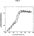
wie in 7 dargestellt. 7 zeigt
die Ergebnisse einer Messung zu einem Zeitpunkt, zu welchem die
Drehzahl auf bzw. um 2000 Umdrehungen festgelegt wurde, die Öltemperatur
und ähnliches
auf eine Temperatur nahe der Temperatur während einer tatsächlichen Fahrzeugfahrt
gesteuert wurden und keine Gangwechselbefehle ausgegeben wurden,
sondern lediglich das Drehmoment geändert wurde. Wenn das Drehmoment
in dieser Weise geändert
wird, erfährt das
stufenlose Toroidalgetriebe eine Drehzahländerung trotz der Tatsache,
dass keine Drehzahländerung
ausgegeben wurde.However, the toroidal continuously variable transmission has a characteristic that when the torque is changed, the rotational speed changes as in 7 shown. 7 FIG. 14 shows the results of a measurement at a time when the engine speed was set at 2000 rpm, the oil temperature and the like were controlled to a temperature close to the temperature during actual vehicle travel, and no gear change commands were issued but only the torque was changed , If that Torque is changed in this way, learns the continuously variable Toroidalgetriebe a speed change despite the fact that no speed change has been issued.
Die
folgenden Gründe
werden als die Ursachen für
diese Drehzahländerung
angesehen.
- (1) Wenn eine Last angewandt wird
auf das stufenlose Toroidalgetriebe, treten Traktionskräfte in der
Vertikalrichtung (der Richtung der Neigungsachse des die Kraftrolle
tragenden Zapfens) auf, die Kraft des Kolbens einer Vorrichtung
zum Bewegen des Zapfens wirkt in der entgegengesetzten Richtung
als Reaktionskraft davon. Selbstverständlich existieren Zwischenräume in einem
Radialnadelrollenlager, welches die Kraftrolle trägt, und
einem Radialnadelrollenlager, welches den Drehzapfen trägt. Aus
diesem Grund bewegt sich, wenn eine Last angewandt wird, der Innenring
der Kraftrolle in der Vertikalrichtung um den Gesamtsummenabschnitt
dieser Zwischenräume.
Mit einer Bewegung dieser Kraftrolle in der Vertikalrichtung tritt
ein Seitwärtsrutschen
auf, mit dem Ergebnis, dass die Kraftrolle eine Drehzahländerung erfährt.
- (2) Außerdem ändert sich
das Übersetzungsverhältnis bezüglich der
Last des Drehmoments infolge der Wirkung der Ablenkung einer Zapfenwelle, bewirkt
durch die elastische Verformung des Zapfens. In einem Traktionsantrieb
ist es erforderlich zu bewirken, dass eine Druckkraft auf den Traktionskontaktpunkt
wirkt, und diese Kraft wird durch den Zapfen getragen.
The following reasons are considered as the causes of this speed change. - (1) When a load is applied to the toroidal continuously variable transmission, traction forces occur in the vertical direction (the direction of the pitch axis of the pin carrying the power roller), the force of the piston of a pin moving device acts in the opposite direction as the reaction force thereof. Of course, there are spaces in a radial needle roller bearing, which carries the power roller, and a radial needle roller bearing, which carries the pivot. For this reason, when a load is applied, the inner ring of the power roller in the vertical direction moves around the sum total portion of these gaps. With a movement of this power roller in the vertical direction, a sideways slide occurs, with the result that the power roller undergoes a speed change.
- (2) In addition, the gear ratio changes with respect to the load of the torque due to the action of the deflection of a trunnion shaft caused by the elastic deformation of the trunnion. In a traction drive, it is necessary to cause a compressive force to act on the traction contact point, and this force is carried by the pin.
Außerdem wird
der Zapfen getragen durch zwei Joche, und die Kräfte, welche zwischen den beiden
Abschnitten des Zapfens in der Rückwärts- und Vorwärtsrichtung
und der Links- und Rechtsrichtung auftreten, werden aufgehoben.
Dementsprechend nimmt der Zapfen einen Zustand an, in welchem eine Last
angewandt wird auf einen an zwei Punkten getragenen Träger, so
dass der Zapfen natürlich
eine elastische Verformung erfährt.
Folglich wird, obwohl eine Zapfenwelle selbst nicht elastisch verformt
wird, da sie keinen Kräften
ausgesetzt ist, die Zapfenwelle berührt von der elastischen Verformung
des Zapfens, mit dem Ergebnis, dass die Zapfenwelle sich neigt. Folglich
bewegt sich der Kontaktpunkt zwischen einem Präzessionsnocken einer Vorrichtung
zum Bewegen des Zapfens und einer Ventilverbindung, so dass der
Steuerschieber sich in der Axialrichtung bewegt. Folglich wird das
Ventil geschnitten, und der Differenzdruck tritt auf, was zum Auftreten
der Drehzahländerung
führt.
Infolge der Kombination dieser Faktoren erfährt, wie in 7 dargestellt,
bei Anwendung des Drehmoments das stufenlose Toroidalgetriebe eine
Drehzahländerung
trotz der Tatsache, dass kein Drehzahländerungsbefehl ausgegeben wurde.In addition, the pin is supported by two yokes, and the forces which occur between the two portions of the pin in the backward and forward direction and the left and right direction are canceled. Accordingly, the pin assumes a state in which a load is applied to a support carried at two points, so that the pin naturally undergoes elastic deformation. Consequently, although a trunnion shaft itself is not elastically deformed because it is not subjected to forces, the trunnion shaft is touched by the elastic deformation of the trunnion, with the result that the trunnion shaft inclines. As a result, the contact point moves between a precess cam of a pin moving device and a valve joint, so that the spool moves in the axial direction. Consequently, the valve is cut, and the differential pressure occurs, resulting in the occurrence of the speed change. As a result of the combination of these factors, as in 7 As shown, when the torque is applied, the toroidal continuously variable transmission undergoes a speed change despite the fact that no speed change command has been issued.
Wenn
die Änderung
der Drehzahländerung derart
ist, dass sie stabil auftritt, ist es möglich, das Auftreten eines
Rucks bei einer Drehzahländerung durch
Ausgeben eines Drehzahländerungsbefehls
zu unterdrücken.
Jedoch muss die Situation vermieden werden, bei welcher eine Steuerung
zum Zeitpunkt der Modusänderung
instabil wird, das heißt,
wenn sich ein Drehmoment geändert
hat. Ferner versucht zum Zeitpunkt der Modusumschaltung der Fahrer nicht,
die Modusänderung
durchzuführen,
und die Modusänderung
findet statt, während
sich der Fahrer dessen nicht bewusst ist. Dementsprechend wird, wenn
die Zeitdauer einer Verbindung und Trennung der Kupplung in dieser
Modusänderung
lang ist, der Zustand derart, dass keine Kraft erzeugt wird, so dass
der Fahrer ein Gefühl
von Unbehaglichkeit infolge eines derartigen Hochdrehens des Motors
verspürt.If
the change
the speed change such
is that it occurs stably, it is possible the occurrence of a
Rucks through at a speed change
Output a speed change command
to suppress.
However, the situation where a controller needs to be avoided must be avoided
at the time of the mode change
becomes unstable, that is,
when a torque changes
Has. Further, at the time of mode switching, the driver does not try
the mode change
perform,
and the mode change
takes place while
the driver is unaware of it. Accordingly, if
the duration of a connection and disconnection of the coupling in this
mode change
is long, the state such that no force is generated, so that
the driver a feeling
discomfort due to such high revving of the engine
felt.
Daraus
geht deutlich hervor, dass die Modusänderung stabil durchgeführt werden
muss, und gleichzeitig, dass die Modusänderung durch ein momentanes
Verschieben der Kupplung in kurzer Zeit abgeschlossen werden muss.from that
it is clear that the mode change is stable
must, and at the same time, that the mode change by a momentary
Move the clutch in a short time must be completed.
Zusammenfassung der ErfindungSummary of the invention
Die
Erfindung wurde gemacht vor dem Hintergrund der oben beschriebenen
Umstände,
und es ist deren Aufgabe, ein stufenloses Getriebe zu schaffen,
welches dem Fahrer kein unbehagliches Gefühl vermittelt, in dem es das
Auftreten eines Drehzahländerungsrucks
unterdrückt
durch Erhalten stabiler Drehmomentänderungen bei der Modusänderung.The
The invention was made against the background of the above-described
Circumstances,
and its job is to create a continuously variable transmission
which gives the driver no uncomfortable feeling in which it
Occurrence of a speed change pressure
repressed
by obtaining stable torque changes in the mode change.
Um
die obige Aufgabe zu lösen,
ist erfindungsgemäß ein stufenloses
Toroidalgetriebe vorgesehen, umfassend:
eine durch eine Antriebsquelle
drehbar angetriebene Eingangswelle;
eine Ausgangswelle zum
Herausnehmen von Leistung auf der Grundlage der Drehung der Eingangswelle;
ein
stufenloses Toroidalgetriebe;
eine Planetenradvorrichtung,
umfassend:
ein Sonnenrad;
ein Tellerrad, angeordnet um
das Sonnenrad; und
ein Planetenrad, vorgesehen zwischen dem
Sonnenrad und dem Tellerrad,
wobei die beiden Übertragungspfade
vorgesehen sind zum Übertragen
der Kraft von der Antriebsquelle zur Ausgangswelle und
wobei
die zum ersten und zweiten Kraftübertragungssystem übertragene
Kraft zur Konvergenz zu den beiden Rädern des Sonnenrads, des Tellerrads und
des Planetenrads gebracht wird und ein verbleibendes Rad, welches
von den beiden Rädern
verschieden ist, mit der Ausgangswelle verbunden ist; und
eine
Modusumschaltvorrichtung, welche ein Umschalten während einer
Vorwärtsbewegung
durchführt
zwischen einem ersten Modus für
eine Niedrigdrehzahlseite und einem zweiten Modus für eine Hochdrehzahlseite,
wobei die Umschaltung durchgeführt
wird zwischen dem ersten und dem zweiten Modus durch die Betätigung eines
Verbindens und Trennens einer ersten Moduskupplung und einer zweiten Moduskupplung,
wobei
die Betätigung
eines Durchführens
der Umschaltung zwischen dem ersten Modus und dem zweiten Modus
in 0,2 bis 1 Sekunde durchgeführt wird.In order to achieve the above object, according to the present invention, there is provided a toroidal continuously variable transmission comprising:
an input shaft rotatably driven by a drive source;
an output shaft for taking out power based on the rotation of the input shaft;
a continuously variable toroidal transmission;
a planetary gear device comprising:
a sun wheel;
a ring gear, arranged around the sun gear; and
a planet gear provided between the sun gear and the ring gear,
wherein the two transmission paths are provided for transmitting the power from the drive source to the output shaft and
wherein the power transmitted to the first and second power transmission systems is converged to the two wheels of the sun gear, the ring gear and the planetary gear and a remaining wheel different from the two wheels is connected to the output shaft; and
a mode switching device which is a Um switching during a forward movement between a first mode for a low speed side and a second mode for a high speed side, wherein the switching is performed between the first and second modes by the operation of connecting and disconnecting a first mode clutch and a second mode clutch;
wherein the operation of performing the switching between the first mode and the second mode is performed in 0.2 to 1 second.
Ferner
können
beim stufenlosen Getriebe die beiden Kraftübertragungspfade das erste
Kraftübertragungssystem
zum Übertragen
der Kraft zu der Planetenradvorrichtung über das stufenlose Toroidalgetriebe
und das zweite Kraftübertragungssystem zum Übertragen
der Kraft zu der Planetenradvorrichtung, ohne durch das stufenlose
Toroidalgetriebe geleitet zu werden, sein.Further
can
in the continuously variable transmission, the two power transmission paths the first
Power transmission system
to transfer
the force to the Planetenradvorrichtung via the stepless Toroidalgetriebe
and the second power transmission system for transmitting
the force to the planetary gear device without passing through the stepless
Toroidal transmission to be passed.
Ferner
kann beim stufenlosen Getriebe die Modusumschaltvorrichtung eine
Steuerschaltung sein, welche die Betätigung eines Verbindens und Trennens
der ersten Moduskupplung und der zweiten Moduskupplung durchführt in Reaktion
auf ein Ausgangssignal der Steuerschaltung.Further
can with the continuously variable transmission, the mode switching device a
Control circuit, which is the operation of a connecting and disconnecting
the first mode clutch and the second mode clutch perform in response
to an output signal of the control circuit.
Außerdem kann
beim stufenlosen Getriebe das stufenlose Toroidalgetriebe von einem
Einfachhohlraumtyp sein.In addition, can
in the continuously variable transmission, the continuously variable toroidal transmission of one
Be single cavity type.
Ferner
kann beim stufenlosen Getriebe das stufenlose Toroidalgetriebe von
einem Doppelhohlraumtyp sein.Further
can the continuously variable transmission of the toroidal continuously variable transmission from
a double cavity type.
Kurze Beschreibung der ZeichnungShort description of the drawing
1 ist
ein Skelettdiagramm eines stufenlosen Getriebes gemäß einem
ersten Ausführungsbeispiel
der Erfindung; 1 is a skeleton diagram of a continuously variable transmission according to a first embodiment of the invention;
2 ist
ein Blockdiagramm einer Modusumschaltvorrichtung gemäß dem ersten
Ausführungsbeispiel. 2 FIG. 10 is a block diagram of a mode switching device according to the first embodiment. FIG.
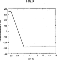
3 ist
ein Diagramm, welches einen Fall darstellt, bei welchem das Drehmoment
beim ersten Ausführungsbeispiel
plötzlich
geändert
wird. 3 FIG. 15 is a diagram illustrating a case where the torque is suddenly changed in the first embodiment.
4 ist
ein Diagramm, welches die Drehmomentänderung in einem Fall darstellt,
bei welchem die Modusumschaltzeit für Kupplungen geändert wird,
wobei die Anzahl einer Eingangsumdrehung auf 2000 Umdrehungen beim
ersten Ausführungsbeispiel
festgelegt ist; 4 Fig. 12 is a diagram illustrating the torque change in a case where the mode switching time for clutches is changed, the number of input revolution being set to be 2000 rpm in the first embodiment;
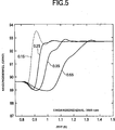
5 ist
ein Diagramm, welches die Drehmomentänderung in einem Fall darstellt,
in welchem die Kupplungsmodusumschaltzeit geändert wurde, wobei die Anzahl
der Eingangsumdrehung auf 3000 Umdrehungen beim ersten Ausführungsbeispiel
festgelegt ist; 5 Fig. 15 is a diagram illustrating the torque change in a case where the clutch mode switching time has been changed, the number of input revolution being set to 3000 rpm in the first embodiment;
6 ist
ein Diagramm, welches die Drehmomentänderung in einem Fall darstellt,
in welchem die Kupplungsmodusumschaltzeit geändert wurde, wobei die Anzahl
einer Eingangsumdrehung auf 4000 Umdrehungen beim ersten Ausführungsbeispiel
festgelegt ist. 6 FIG. 12 is a diagram illustrating the torque change in a case where the clutch mode switching time has been changed, wherein the number of one input revolution is set to 4000 rpm in the first embodiment.
7 ist
ein Diagramm, welches einen Zustand darstellt, in welchem bei Anwendung
des Drehmoments ein stufenlose Toroidalgetriebe eine Drehzahländerung
trotz der Tatsache erfährt,
dass kein Drehzahländerungsbefehl
beim ersten Ausführungsbeispiel
ausgegeben wurde; 7 Fig. 10 is a diagram illustrating a state in which, when the torque is applied, a toroidal continuously variable transmission undergoes a speed change in spite of the fact that no speed change command has been issued in the first embodiment;
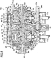
8 ist
eine Querschnittsansicht von wesentlichen Abschnitten, welche ein
stufenloses Getriebe gemäß einem
zweiten Ausführungsbeispiel
der Erfindung darstellt; 8th Fig. 15 is a cross-sectional view of essential portions showing a continuously variable transmission according to a second embodiment of the invention;
9 ist
eine vergrößerte Ansicht
eines linksseitigen Abschnitts von 8; 9 is an enlarged view of a left-side portion of 8th ;
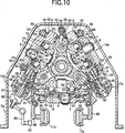
10 ist
eine Querschnittsansicht längs
einer Linie A-A in 8; und 10 is a cross-sectional view along a line AA in 8th ; and
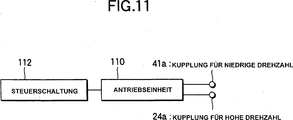
11 ist
ein Blockdiagramm, welches eine Modusumschalteinrichtung gemäß dem zweiten
Ausführungsbeispiel
darstellt. 11 FIG. 10 is a block diagram illustrating a mode switching device according to the second embodiment. FIG.
Genaue Beschreibung der bevorzugten
AusführungsbeispieleDetailed description of the preferred
embodiments
Unter
Bezugnahme auf die beiliegende Zeichnung werden die Ausführungsbeispiele
der Erfindung beschrieben.Under
Referring to the accompanying drawings, the embodiments
of the invention.
1 zeigt
ein erstes Ausführungsbeispiel der
Erfindung. Ein stufenloses Getriebe gemäß diesem Ausführungsbeispiel
ist ausgestattet mit einer Eingangswelle 217, verbunden
mit der Kurbelwelle 216 eines Motors 215, welcher
eine Antriebsquelle ist, und durch diesen Motor 215 drehbar
angetrieben wird. Eine Startkupplung 218 ist vorgesehen
zwischen dem eingangsseitigen Endabschnitt (dem linken Endabschnitt
in 1) der Eingangswelle 217 und dem ausgangsseitigen
Endabschnitt (dem rechten Endabschnitt in 1) der Kurbelwelle 216 in Reihe
mit der Kurbelwelle 216 und der Eingangswelle 217.
Dementsprechend sind im Falle des vorliegenden Ausführungsbeispiels
die Kurbelwelle 216 und die Eingangswelle 217 konzentrisch
zueinander angeordnet. Hingegen ist eine Ausgangswelle 219 zum Herausnehmen
von Kraft auf der Grundlage der Drehung der Eingangswelle 217 parallel
zur Eingangswelle 217 angeordnet. Ein stufenloses Toroidalgetriebe
eines Einfachhohlraumtyps 220 ist vorgesehen um die Eingangswelle 217,
und eine Planetenradvorrichtung 221 ist vorgesehen um die
Ausgangswelle 219. 1 shows a first embodiment of the invention. A continuously variable transmission according to this embodiment is provided with an input shaft 217 , connected to the crankshaft 216 an engine 215 , which is a driving source, and by this motor 215 is rotatably driven. A starting clutch 218 is provided between the input side end portion (the left end portion in 1 ) of the input shaft 217 and the output side end portion (the right end portion in FIG 1 ) of the crankshaft 216 in series with the crankshaft 216 and the input shaft 217 , Accordingly, in the case of the present embodiment, the crankshaft 216 and the input shaft 217 arranged concentrically with each other. On the other hand is an output shaft 219 for removing force based on the rotation of the input shaft 217 parallel to the input shaft 217 arranged. A stepless Toroidalgetrie be a single cavity type 220 is provided around the input shaft 217 , and a planetary gear device 221 is provided around the output shaft 219 ,
Eine
Nockenscheibe 210, welche das stufenlose Toroidalgetriebe 220 bildet,
ist befestigt am Zwischenabschnitt hin zum ausgangsseitigen Endabschnitt
(nach rechts in 1) der Eingangswelle 217.
Ferner werden eine Eingangsseitenscheibe 202 und eine Ausgangsseitenscheibe 204 getragen
um die Eingangswelle 217 zur unabhängigen Drehung relativ zur
Eingangswelle 217 durch Lager, nicht dargestellt, wie etwa
Nadellager. Rollen 212 sind angeordnet zwischen einer Nockenfläche 213,
ausgebildet auf einer Fläche
(der linken Fläche
bei Betrachtung in 1) der Nockenscheibe 210 und
einer Nockenfläche 214,
ausgebildet auf der außenseitigen Fläche der
Eingangsseitenscheibe 202, um dadurch eine Druckvorrichtung 209 zu
bilden. Dementsprechend wird die Eingangsseitenscheibe 202 mit
der Drehung der Eingangswelle 217, während sie hin zur Ausgangsseitenscheibe 204 gedrückt wird,
gedreht.A cam disc 210 , which the stepless Toroidalgetriebe 220 is attached to the intermediate portion toward the output side end portion (to the right in 1 ) of the input shaft 217 , Further, an input page disk 202 and an exit side pane 204 carried around the input shaft 217 for independent rotation relative to the input shaft 217 by bearings, not shown, such as needle roller bearings. roll 212 are arranged between a cam surface 213 , formed on a surface (the left surface when viewed in 1 ) of the cam disc 210 and a cam surface 214 formed on the outside surface of the input side disk 202 to thereby produce a printing device 209 to build. Accordingly, the input side disk becomes 202 with the rotation of the input shaft 217 while heading to the home page disk 204 is pressed, turned.
Eine
Vielzahl (gewöhnlich
zwei bis drei) von Kraftrollen 208 sind angeordnet zwischen
der Innenfläche 202a der
Eingangsseitenscheibe 202 und der Innenseite 204a der
Ausgangsseitenscheibe 204, und die Umfangsflächen 208a dieser
Kraftrollen 208 werden in Kontakt gebracht mit den oben
erwähnten Innenflächen 202a und 204a.
Diese Kraftrollen 208 werden drehbar getragen durch nicht
dargestellte Zapfen und Verschiebungswellen. Das stufenlose Toroidalgetriebe 220 ändert, wie
das bis jetzt gut bekannte stufenlose Toroidalgetriebe, das Übersetzungsverhältnis zwischen
der Eingangsseitenscheibe 202 und der Ausgangsseitenscheibe 204 durch Schwenken
der Zapfen und Ändern
des Neigungswinkels der Verschiebungswellen, welche die Kraftrollen 208 tragen.A variety (usually two to three) of power rollers 208 are arranged between the inner surface 202a the entrance side pane 202 and the inside 204a the output side pane 204 , and the peripheral surfaces 208a these power roles 208 are brought into contact with the above-mentioned inner surfaces 202a and 204a , These power rollers 208 are rotatably supported by pins and shafts, not shown. The stepless Toroidalgetriebe 220 changes, like the well-known stepless Toroidalgetriebe, the gear ratio between the input side disc 202 and the home page disk 204 by pivoting the pins and changing the angle of inclination of the displacement shafts which the power rollers 208 wear.
Ein
Sonnenrad 222, welches die Planetenradvorrichtung 221 bildet,
ist befestigt am eingangsseitigen Endabschnitt (dem rechten Endabschnitt
bei Betrachtung in 1) der Ausgangswelle 219.
Dementsprechend wird diese Ausgangswelle 219 mit der Drehung
des Sonnenrads 222 gedreht. Ein Tellerrad 223 ist
drehbar gelagert um das Sonnenrad 222, um konzentrisch
mit dem Sonnenrad 222 zu sein. Eine Vielzahl (gewöhnlich drei)
von Planetenradsätzen 224 sind
vorgesehen zwischen der Innenumfangsfläche des Tellerrads 223 und
der Außenumfangsfläche des
Sonnenrads 222. Bei dem dargestellten Ausführungsbeispiel
umfassen diese Planetenradsätze 224 jeweils
eine Kombination aus einem Paar von Planetenrädern 225a und 225b.
Diese Paare von Planetenrädern 225a und 225b greifen
ineinander, und das Planetenrad 225a, angeordnet auf der
Außendurchmesserseite,
wird in Eingriff mit dem Tellerrad 223 gebracht, während das
Planetenrad 225b, angeordnet auf der Innendurchmesserseite,
in Eingriff mit dem Sonnenrad 222 gebracht wird. Wie oben
beschrieben, bringt jeder Planetenradsatz 224, gebildet durch
ein Paar von Planetenrädern 225a und 225b, die
Drehrichtungen des Tellerrads 223 und des Sonnenrads 222 in Übereinstimmung
miteinander. Dementsprechend kann, wenn es im Hinblick auf die Beziehung
mit anderen Bestandteilen nicht erforderlich ist, die Drehrichtungen
des Tellerrads 223 und des Sonnenrads 222 in Übereinstimmung
miteinander zu bringen, ein einzelnes Planetenrad in Eingriff sowohl mit
dem Tellerrad 223 als auch mit dem Sonnenrad 222 gebracht
werden.A sun wheel 222 The planetary gear device 221 is attached to the input side end portion (the right end portion when viewed in FIG 1 ) of the output shaft 219 , Accordingly, this output shaft 219 with the rotation of the sun gear 222 turned. A crown wheel 223 is rotatably mounted around the sun gear 222 to be concentric with the sun gear 222 to be. A variety (usually three) of planetary gear sets 224 are provided between the inner peripheral surface of the ring gear 223 and the outer peripheral surface of the sun gear 222 , In the illustrated embodiment, these planetary gear sets 224 each a combination of a pair of planetary gears 225a and 225b , These pairs of planet wheels 225a and 225b interlock, and the planetary gear 225a , disposed on the outer diameter side, is engaged with the ring gear 223 brought while the planetary gear 225b located on the inner diameter side, in engagement with the sun gear 222 is brought. As described above, each planetary gearset brings 224 formed by a pair of planet gears 225a and 225b , the directions of rotation of the ring gear 223 and the sun wheel 222 in harmony with each other. Accordingly, when it is not required in view of the relationship with other components, the rotational directions of the ring gear 223 and the sun wheel 222 in correspondence with each other, a single planetary gear meshing with both the ring gear 223 as well as with the sun wheel 222 to be brought.
Die
Planetenradsätze 224,
wie oben beschrieben, werden drehbar getragen auf einer Seitenfläche (der
rechten Seitenfläche
bei Betrachtung in 1) eines Trägers 226 durch Drehwellen 227a und 227b parallel
zur Ausgangswelle 219. Der Träger 226 wird drehbar
getragen auf dem Zwischenabschnitt der Ausgangswelle 219 durch
ein nicht dargestelltes Lager, wie etwa ein Nadellager.The planetary gear sets 224 As described above, are rotatably supported on a side surface (the right side surface when viewed in FIG 1 ) of a carrier 226 through rotary shafts 227a and 227b parallel to the output shaft 219 , The carrier 226 is rotatably supported on the intermediate portion of the output shaft 219 by an unillustrated bearing, such as a needle bearing.
Ferner
sind der Träger 226 und
die Ausgangsseitenscheibe 204 miteinander verbunden, um in
der Lage zu sein, eine Drehkraft zu übertragen durch eine erste
Kraftübertragungsvorrichtung 228. Diese
erste Kraftübertragungsvorrichtung 228 umfasst
ein erstes und ein zweites Rad 229 und 230, welche
ineinander greifen. Das heißt,
das erste Rad 229 ist befestigt am Außenflächenabschnitt (der linken Seitenfläche bei
Betrachtung in 1) der Ausgangsseitenscheibe 204,
konzentrisch mit der Ausgangsseitenscheibe 204, während das
zweite Rad 230 befestigt ist an einem Seitenflächenabschnitt (der
linken Seitenfläche
bei Betrachtung in 1) des Trägers 226, konzentrisch
mit dem Träger 226. Dementsprechend
wird der Träger 226 mit
einer Drehzahl entsprechend der Anzahl von Zähnen des ersten und des zweiten
Rads 229 und 230 in einer Richtung entgegengesetzt
zur Richtung einer Drehung der Ausgangsseitenscheibe 204 mit
der Drehung dieser Ausgangsseitenscheibe 204 gedreht.Further, the carrier 226 and the exit side pane 204 interconnected to be able to transmit a rotational force by a first power transmission device 228 , This first power transmission device 228 includes a first and a second wheel 229 and 230 which mesh. That is, the first wheel 229 is attached to the outer surface portion (the left side surface when viewed in FIG 1 ) of the output page disc 204 , concentric with the output side disc 204 while the second wheel 230 is attached to a side surface portion (the left side surface when viewed in FIG 1 ) of the carrier 226 , concentric with the carrier 226 , Accordingly, the carrier becomes 226 at a speed corresponding to the number of teeth of the first and second wheels 229 and 230 in a direction opposite to the direction of rotation of the output side disk 204 with the rotation of this output page disk 204 turned.
Hingegen
können
die Eingangswelle 217 und das Tellerrad 223 miteinander
verbunden sein, um in der Lage zu sein, eine Drehkraft zu übertragen durch
eine zweite Kraftübertragungsvorrichtung 231. Diese
zweite Kraftübertragungsvorrichtung 231 umfasst
ein erstes und ein zweites Kettenrad 232 und 233 und
eine Kette 234, welche sich zwischen diesen beiden Kettenrädern 232 und 233 erstreckt.
Das heißt,
das erste Kettenrad 232 ist befestigt am ausgangsseitigen
Endabschnitt (dem rechten Endabschnitt bei Betrachtung in 1)
der Eingangswelle 217, welche aus der Nockenscheibe 210 vorsteht,
während
das zweite Kettenrad 233 befestigt ist am eingangsseitigen
Endabschnitt (dem rechten Endabschnitt bei Betrachtung in 1)
einer Übertragungswelle 235.
Diese Übertragungswelle 235 ist konzentrisch
mit der Ausgangswelle 219 angeordnet und drehbar gelagert
durch ein nicht dargestelltes Lager, wie etwa ein Wälzlager.
Dementsprechend wird die Übertragungswelle 235 mit
einer Drehzahl entsprechend den Anzahlen von Zähnen des ersten und des zweiten
Kettenrads 232 und 233 in derselben Richtung wie
die Eingangswelle 217 mit der Drehung dieser Eingangswelle 217 gedreht.On the other hand, the input shaft 217 and the crown wheel 223 be connected to each other in order to be able to transmit a rotational force by a second power transmission device 231 , This second power transmission device 231 includes a first and a second sprocket 232 and 233 and a chain 234 which is between these two sprockets 232 and 233 extends. That is, the first sprocket 232 is attached to the output side end portion (the right end portion when viewed in FIG 1 ) of the input shaft 217 , which from the cam disk 210 protrudes while the second sprocket 233 is attached to the input side end portion (the right end portion when viewed in FIG 1 ) of a transmission shaft 235 , This transmission wave 235 is concentric with the output shaft 219 arranged and rotatably supported by a bearing, not shown, such as a rolling bearing. Accordingly, the transmission wave becomes 235 at a speed corresponding to the numbers of teeth of the first and second sprockets 232 and 233 in the same direction as the input shaft 217 with the rotation of this input shaft 217 turned.
Das
stufenlose Getriebe gemäß dem vorliegenden
Ausführungsbeispiel
ist ausgestattet mit einer Kupplungsvorrichtung. Diese Kupplungsvorrichtung
verbindet lediglich den Träger 226 oder
die Übertragungswelle 235,
welche ein Bestandteil der zweiten Kraftübertragungsvorrichtung 231 darstellen, mit
dem Tellerrad 223. Im Falle des vorliegenden Ausführungsbeispiels
umfasst diese Kupplungsvorrichtung eine Kupplung 236 für eine niedrige
Drehzahl entsprechend einer ersten Moduskupplung der Erfindung und
eine Kupplung 237 für
eine hohe Drehzahl entsprechend einer zweiten Moduskupplung der Erfindung.
Die Kupplung 236 für
niedrige Drehzahl ist vorgesehen zwischen dem Außenumfangskantenabschnitt des
Trägers 226 und
einem Axialendabschnitt (dem linken Endabschnitt bei Betrachtung
in 1) des Tellerrads 223. Die Kupplung 236 für niedrige Drehzahl
verhindert zum Zeitpunkt einer Verbindung die Relativdrehung des
Sonnenrads 222, des Tellerrads 223 und der Planetenradsätze 224,
welche die Planetenradvorrichtung 221 bilden, so dass das
Sonnenrad 222 und das Tellerrad 223 einstückig verbunden
sind. Ferner ist die Kupplung 237 für hohe Drehzahl vorgesehen
zwischen der Übertragungswelle 235 und
einer Mittelwelle 239, befestigt am Tellerrad 223 durch
eine Tragplatte 238.The continuously variable transmission according to the present embodiment is equipped with a clutch device. This coupling device merely connects the carrier 226 or the transmission wave 235 , which is a part of the second power transmission device 231 represent, with the ring gear 223 , In the case of the present embodiment, this coupling device comprises a coupling 236 for a low speed according to a first mode clutch of the invention and a clutch 237 for a high speed according to a second mode clutch of the invention. The coupling 236 for low speed is provided between the outer peripheral edge portion of the carrier 226 and an axial end portion (the left end portion when viewed in FIG 1 ) of the ring gear 223 , The coupling 236 for low speed prevents the relative rotation of the sun gear at the time of connection 222 , the ring gear 223 and the planetary gear sets 224 which the planetary gear device 221 form so that the sun gear 222 and the crown wheel 223 are integrally connected. Further, the clutch 237 designed for high speed between the transmission shaft 235 and a medium wave 239 , attached to the ring gear 223 through a support plate 238 ,
Wie
in 2 dargestellt, ist eine Antriebseinheit 250 zum
Antreiben der Kupplung 236 für niedrige Drehzahl und der
Kupplung 237 für
hohe Drehzahl elektrisch verbunden mit einer Steuerschaltung 252 entsprechend
der Modusumschaltvorrichtung der Erfindung, und die Betätigung einer
Verbindung und Trennung der Kupplung 236 für niedrige
Drehzahl und der Kupplung 237 für hohe Drehzahl wird durchgeführt in Reaktion
auf Ausgangssignale von der Steuerschaltung 252, wobei
eine vorbestimmte Umschaltbetätigungszeit
vorgesehen ist. Hier ist die Umschaltbetätigungszeit beim vorliegenden
Ausführungsbeispiel
auf 0,2 bis 1 Sekunde festgelegt.As in 2 is a drive unit 250 for driving the clutch 236 for low speed and the clutch 237 for high speed electrically connected to a control circuit 252 according to the mode switching device of the invention, and the operation of connection and disconnection of the clutch 236 for low speed and the clutch 237 for high speed is performed in response to output signals from the control circuit 252 wherein a predetermined switching actuation time is provided. Here, the switching operation time in the present embodiment is set to 0.2 to 1 second.
Ferner
ist, wie in 1 dargestellt, eine Kupplung 240 zur
Rückwärtsbewegung
vorgesehen zwischen dem Tellerrad 223 und einem festen
Abschnitt, wie etwa einem (nicht dargestellten) Gehäuse des
stufenlosen Getriebes. Diese Kupplung 240 zur Rückwärtsbewegung
ist vorgesehen zum Drehen der Ausgangswelle 219 in der
entgegengesetzten Richtung, um ein Auto rückwärts zu bewegen. Diese Kupplung 240 zur
Rückwärtsbewegung
wird getrennt, wenn die Kupplung 236 für niedrige Drehzahl oder die
Kupplung 237 für
hohe Drehzahl verbunden wird. Währenddessen
werden, wenn diese Kupplung 240 zur Rückwärtsbewegung verbunden ist,
sowohl die Kupplung 236 für niedrige Drehzahl als auch
die Kupplung 237 für
hohe Drehzahl getrennt. Das heißt, abgesehen
von der Startkupplung 218, sind die verbleibenden drei
Kupplungen 236, 237 und 240 derart angeordnet,
dass, wenn eine von diesen verbunden wird, die übrigen beiden Kupplungen getrennt
werden.Furthermore, as in 1 shown a coupling 240 provided for backward movement between the ring gear 223 and a fixed portion, such as a case (not shown) of the continuously variable transmission. This clutch 240 for backward movement is provided for rotating the output shaft 219 in the opposite direction to move a car backwards. This clutch 240 to the backward movement is disconnected when the clutch 236 for low speed or the clutch 237 connected for high speed. Meanwhile, when this clutch 240 connected to the backward movement, both the clutch 236 for low speed as well as the clutch 237 separated for high speed. That is, apart from the starting clutch 218 , the remaining three are couplings 236 . 237 and 240 arranged such that when one of them is connected, the remaining two clutches are separated.
Ferner
werden bei dem dargestellten Ausführungsbeispiel die Ausgangswelle 219 und
ein Differentialgetriebe 241 miteinander verbunden durch eine
dritte Kraftübertragungsvorrichtung 245,
welche ein drittes bis fünftes
Rad 242 bis 244 umfasst. Dementsprechend wird,
wenn die Ausgangswelle 219 gedreht wird, ein Paar aus einer
rechten und einer linken Antriebswelle 246 durch die dritte
Kraftübertragungsvorrichtung 245 und
das Differentialgetriebe 241 gedreht, um dadurch die Antriebsräder des
Autos drehbar anzutreiben.Furthermore, in the illustrated embodiment, the output shaft 219 and a differential gear 241 interconnected by a third power transmission device 245 which is a third to fifth wheel 242 to 244 includes. Accordingly, when the output shaft 219 is rotated, a pair of right and left drive shaft 246 by the third power transmission device 245 and the differential gear 241 rotated, thereby rotatably driving the drive wheels of the car.
Die
Wirkung des stufenlosen Getriebes gemäß dem vorliegenden Ausführungsbeispiel,
aufgebaut wie oben beschrieben, ist wie folgt. Zuerst wird während einer
Niedrigdrehzahlfahrt unter der Steuerung durch die Steuerschaltung 252 die
Kupplung 236 für
niedrige Drehzahl verbunden, während
die Kupplung 237 für
hohe Drehzahl und die Kupplung 240 zur Rückwärtsbewegung
getrennt werden, wobei die Umschaltbetätigungszeit auf 0,2 bis 1 Sekunde festgelegt
ist. Wenn in diesem Zustand die Starkupplung 218 verbunden
und die Eingangswelle 217 gedreht wird, überträgt lediglich
das stufenlose Toroidalgetriebe 220 Kraft von der Eingangswelle 217 auf die
Ausgangswelle 219. Das heißt, mit der Verbindung der
Kupplung 236 für
niedrige Drehzahl werden das Tellerrad 223 und der Träger 226 einstückig miteinander
verbunden, und die Relativdrehung der Räder 222, 223, 225a und 225b,
welche die Planetenradvorrichtung 221 bilden, wird unmöglich. Ferner wird,
wenn die Kupplung 237 für
hohe Drehzahl und die Kupplung 240 zur Rückwärtsbewegung
getrennt werden, das Tellerrad 223 drehbar, unabhängig von der
Drehzahl der Übertragungswelle 235.The effect of the continuously variable transmission according to the present embodiment constructed as described above is as follows. First, during low-speed travel under the control of the control circuit 252 the coupling 236 connected for low speed while the clutch 237 for high speed and the clutch 240 be separated to the backward movement, wherein the switching operation time is set to 0.2 to 1 second. If in this state the Starkupplung 218 connected and the input shaft 217 is rotated, transmits only the continuously variable Toroidalgetriebe 220 Force from the input shaft 217 on the output shaft 219 , That is, with the connection of the clutch 236 for low speed, the ring gear 223 and the carrier 226 integral with each other, and the relative rotation of the wheels 222 . 223 . 225a and 225b which the planetary gear device 221 make it impossible. Further, when the clutch 237 for high speed and the clutch 240 to be separated for backward movement, the ring gear 223 rotatable, regardless of the speed of the transmission shaft 235 ,
Dementsprechend
wird, wenn in diesem Zustand die Eingangswelle 217 gedreht
wird, diese Drehung übertragen
auf die Eingangsseitenscheibe 202 durch die Druckvorrichtung 209 und
wird weiter übertragen
zur Ausgangsseitenscheibe 204 durch die Vielzahl von Kraftrollen 208.
Die Drehung dieser Ausgangsseitenscheibe 204 wird übertragen
auf den Träger 226 und
das Tellerrad 223 durch das erste und das zweite Rad 229 und 230,
welche die erste Kraftübertragungsvorrichtung 228 bilden.
Wie oben beschrieben, ist in diesem Zustand die Relativdrehung der
Räder 222, 223, 225a und 225b,
welche die Planetenradvorrichtung 221 bilden, unmöglich, so
dass die Ausgangswelle 219 mit der selben Drehzahl wie der
Träger 226 und
das Tellerrad 223 gedreht wird.Accordingly, when in this state, the input shaft 217 is rotated, this rotation transmitted to the input side disc 202 through the printing device 209 and will continue to transfer to the output page disc 204 through the multitude of power rollers 208 , The rotation of this exit side disc 204 is transferred to the carrier 226 and the crown wheel 223 through the first and the second wheel 229 and 230 that the first power transmission device 228 form. As described above, in this state, the relative rotation of the wheels 222 . 223 . 225a and 225b which the planetary gear device 221 form, impossible, so that the output shaft 219 at the same speed as the carrier 226 and the crown wheel 223 is turned.
Die
Wirkung selbst ist, wenn das Übersetzungsverhältnis zwischen
der Eingangsseiten- und der
Ausgangsseitenscheibe 202 und 204 sich während einer
Niedrigdrehzahlfahrt ändert, ähnlich der Wirkung
im Falle des bekannten stufenlosen Toroidalgetriebes. Selbstverständlich ist
in diesem Zustand das Übersetzungsverhältnis zwischen
der Eingangswelle 217 und der Ausgangswelle 219,
das heißt,
das Übersetzungsverhältnis als
das stufenlose Gesamtgetriebe, proportional zum Übersetzungsverhältnis des
stufenlosen Toroidalgetriebes 220. Ferner wird in diesem
Zustand ein in dieses stufenlose Toroidalgetriebe 220 eingegebenes
Drehmoment gleich einem auf die Eingangswelle 217 angewandten Drehmoment.
Während
einer Niedrigdrehzahlfahrt drehen das erste und das zweite Kettenrad 232 und 233 und
die Kette 234, welche die zweite Kraftübertragungsvorrichtung 231 bilden,
lediglich leer.The effect itself is when the gear ratio between the input side and the output side plate 202 and 204 changes during a low-speed running, similar to the effect in the case of the known continuously variable Toroidalgetriebes. Of course, in this state, the gear ratio between the input shaft 217 and the output shaft 219 that is, the gear ratio as the continuously variable transmission, proportional to the gear ratio of the continuously variable Toroidalgetriebes 220 , Further, in this state, a stepless Toroidalgetriebe in this 220 input torque equal to one on the input shaft 217 applied torque. During low-speed driving, the first and second sprockets rotate 232 and 233 and the chain 234 that the second power transmission device 231 form, only empty.
Hingegen
wird während
der Hochdrehzahlfahrt und der Steuerung durch die Steuerschaltung 252 die
Kupplung 237 für
hohe Drehzahl verbunden, während
die Kupplung 236 für
niedrige Drehzahl und die Kupplung 240 zur Rückwärtsbewegung
getrennt werden, wobei die Umschaltbetätigungszeit zwischen 0,2 und
1 Sekunde festgelegt ist. Wenn in diesem Zustand die Startkupplung 218 verbunden
und die Eingangswelle 217 gedreht wird, übertragen
das erste und das zweite Kettenrad 232 und 233 und
die Kette 234, welche die zweite Kraftübertragungsvorrichtung 231 bilden,
sowie die Planetenradvorrichtung 221 Kraft von dieser Eingangswelle 217 auf
die Ausgangswelle 219.On the other hand, during the high-speed running and the control by the control circuit 252 the coupling 237 connected for high speed while the clutch 236 for low speed and the clutch 240 be separated to the backward movement, wherein the switching operation time is set between 0.2 and 1 second. If in this state the starting clutch 218 connected and the input shaft 217 is rotated, transmit the first and the second sprocket 232 and 233 and the chain 234 that the second power transmission device 231 form, as well as the planetary gear device 221 Force from this input shaft 217 on the output shaft 219 ,
Das
heißt,
wenn die Eingangswelle 217 während der Hochdrehzahlfahrt
gedreht wird, wird diese Drehung übertragen auf die Mittelwelle 239 durch
die zweite Kraftübertragungsvorrichtung 231 und
die Kupplung 237 für
hohe Drehzahl, um dadurch das Tellerrad 223 zu drehen,
woran die Mittelwelle 239 befestigt ist. Die Drehung dieses
Tellerrads 223 wird wiederum übertragen auf das Sonnenrad 222 durch die
Vielzahl von Planetenradsätzen 224,
um dadurch die Ausgangswelle 219 zu drehen, woran das Sonnenrad 222 befestigt
ist. Unter der Annahme, dass, wenn das Tellerrad 223 die
Eingangsseite geworden ist, die Planetenradsätze 224 gestoppt werden
(nicht um das Sonnenrad 222 drehen), führt die Planetenradvorrichtung 221 eine
Drehzahlerhöhung
bei einem Übersetzungsverhältnis entsprechend
dem Verhältnis
zwischen den Anzahlen von Zähnen
des Tellerrads 223 und des Sonnenrads 222 durch.
Jedoch dreht jeder der Planetenradsätze 224 um das Sonnenrad 222,
und das Übersetzungsverhältnis als
das stufenlose Gesamtgetriebe ändert
sich in Übereinstimmung
mit der Drehzahl dieser Planetenradsätze 224. Daher kann,
wenn das Übersetzungsverhältnis des
stufenlosen Toroidalgetriebes 220 geändert wird, um dadurch die
Drehzahl der Planetenradsätze 224 zu ändern, das Übersetzungsverhältnis als
das stufenlose Gesamtgetriebe eingestellt werden.That is, when the input shaft 217 during the high speed running, this rotation is transmitted to the center shaft 239 by the second power transmission device 231 and the clutch 237 for high speed, thereby turning the ring gear 223 to turn, to which the medium wave 239 is attached. The rotation of this ring gear 223 is in turn transmitted to the sun gear 222 through the multitude of planetary gear sets 224 to thereby the output shaft 219 to turn, whereupon the sun wheel 222 is attached. Assuming that if the ring gear 223 the input side has become, the planetary gear sets 224 stopped (not around the sun gear 222 turn) guides the planetary gear device 221 a speed increase at a gear ratio corresponding to the ratio between the numbers of teeth of the ring gear 223 and the sun wheel 222 by. However, each of the planetary gears turns 224 around the sun wheel 222 , and the gear ratio as the continuously variable transmission changes in accordance with the rotational speed of these planetary gear sets 224 , Therefore, when the gear ratio of the continuously variable Toroidalgetriebes 220 is changed, thereby the speed of the planetary gear sets 224 to change the gear ratio as the continuously variable transmission.
Als
nächstes
wird der Grund für
die Betätigung
beschrieben, bei welcher die Steuerschaltung eine Modusänderung
durchführt
durch Umschalten der Kupplung 236 für niedrige Drehzahl und der Kupplung 237 für hohe Drehzahl
(Kupplungsverbindung und -trennung), wobei die Umschaltbetätigungszeit
auf 0,2 bis 1 Sekunde festgelegt ist.Next, the reason for the operation in which the control circuit makes a mode change by switching the clutch will be described 236 for low speed and the clutch 237 for high speed (clutch connection and disconnection), wherein the switching operation time is set to 0.2 to 1 second.
Unter
Verwendung eines Analyseprogramms für das stufenlose Getriebe haben
die Erfinder der vorliegenden Erfindung eine Analyse anhand einer plötzlichen Änderung
des Drehmoments durchgeführt,
das heißt,
an dem Fall, in welchem eine Modusänderung durch ein momentanes
Umschalten der Kupplung 236 für niedrige Drehzahl und der
Kupplung 237 für
hohe Drehzahl erfolgt. Es sei darauf hingewiesen, dass ein Analyseprogramm
verwendet wurde, bei welchem die Gültigkeit des Programms bestätigt wurde
durch Durchführen
einer Verifizierung nach Durchführen
eines Vergleichs mit den Ergebnissen eines Experiments (z. B. 7)
in dem Fall, in welchem das Drehmoment statisch geändert wurde.Using an analysis program for the continuously variable transmission, the inventors of the present invention conducted an analysis based on a sudden change in torque, that is, in the case where a mode change by a momentary shift of the clutch 236 for low speed and the clutch 237 for high speed. It should be noted that an analysis program was used in which the validity of the program was confirmed by performing a verification after making a comparison with the results of an experiment (eg. 7 ) in the case where the torque has been statically changed.
Es
wird ein Fall betrachtet, in welchem das Drehmoment plötzlich von
350 Nm auf –280
Nm geändert
wird, wie in 3 dargestellt. In 3 wurde das
Drehmoment in 0,2 Sekunden geändert.
Eine Analyse wurde durchgeführt
durch Ändern
der Differenzzeit in Schritten von 0,1 bis 0,5 Sekunden.A case is considered in which the torque is suddenly changed from 350 Nm to -280 Nm as in 3 shown. In 3 the torque was changed in 0.2 seconds. An analysis was performed by changing the difference time in 0.1 to 0.5 second increments.
Stabile
Ergebnisse wurden erhalten in dem Fall, in welchem die Drehmomentänderung
in 0,2 Sekunden oder mehr, wie beim vorliegenden Ausführungsbeispiel,
durchgeführt
wurde, wie in 4 dargestellt. Jedoch trat,
wenn die Drehmomentänderung in
0,1 Sekunden erfolgte, ein Überschwingen
und ein kleines Sägen
auf, mit dem Ergebnis, dass eine Steuerung instabil wurde. In 4 wurde
die Eingangsumdrehungszahl festgelegt auf 2000 Umdrehungen unter
einer im Wesentlichen feststehenden Bedingung.Stable results were obtained in the case where the torque change was performed in 0.2 seconds or more as in the present embodiment, as in FIG 4 shown. However, when the torque change occurred in 0.1 seconds, overshoot and small sawing occurred, with the result that control became unstable. In 4 For example, the input revolution number was set to 2,000 revolutions under a substantially fixed condition.
5 zeigt
die Ergebnisse einer Analyse, bei welcher die Eingangsumdrehungszahl
3000 Umdrehungen betrug, und 6 zeigt
die Ergebnisse einer Analyse, bei welcher die Eingangsumdrehungszahl
4000 Umdrehungen betrug. Diese Figuren zeigen, dass, je höher die
Drehzahl, desto höher
die Wirksamkeit, wenn die Modusänderung
durch Umschalten der Kupplung 236 für niedrige Drehzahl und der
Kupplung 237 für
hohe Drehzahl erfolgt. Bei 4000 Umdrehungen wird, obwohl ein kleines
Sägen beobachtet
wurde, wenn die Drehmomentänderung
in 0,2 Sekunden ausgeführt wurde,
tritt kein Überschwingen
auf. Es sei darauf hingewiesen, dass in sämtlichen Analysen das Übersetzungsverhältnis auf
die hohe Seite eingestellt war. 5 shows the results of an analysis in which the input revolution number was 3000 revolutions, and 6 shows the results of an analysis in which the input revolution number was 4000 rpm. These figures show that the higher the speed, the higher the efficiency when the mode change by switching the clutch 236 for low speed and the clutch 237 for high speed. At 4000 revolutions, although a small sawing was observed, when the torque change was made in 0.2 seconds, no overshoot occurs on. It should be noted that in all analyzes the gear ratio was set to the high side.
Dadurch
können
stabile Ergebnisse einer Drehzahländerung erhalten werden, wenn
die Modusänderung
durchgeführt
wird durch Ausführen
der Drehmomentänderung
in 0,2 oder mehr Sekunden, das heißt, durch Umschalten der Kupplung 236 für niedrige
Drehzahl und der Kupplung 237 für hohe Drehzahl in 0,2 Sekunden
oder mehr.Thereby, stable results of a speed change can be obtained when the mode change is performed by performing the torque change in 0.2 or more seconds, that is, by switching the clutch 236 for low speed and the clutch 237 for high speed in 0.2 seconds or more.
Außerdem wird,
wenn die Zeit zum Verbinden bzw. Trennen der Kupplung lang ist,
der Zustand derartig, dass die Übertragung
von Kraft unterbrochen wird, so dass die Beschleunigung des Autos verloren
geht und der Motor hochdreht. Dementsprechend ist es bevorzugt,
dass die Zeitdauer der Modusänderung
bzw. die Trennung des Drehmoments innerhalb einer Sekunde abgeschlossen
ist.In addition,
if the time to connect or disconnect the coupling is long,
the state such that the transmission
is interrupted by force, so that the acceleration of the car lost
goes and the engine turns up. Accordingly, it is preferable
that the duration of the mode change
or the separation of the torque within one second completed
is.
Daher
kann durch Ausführen
der Modusänderung
durch Umschalten der Kupplung 236 für niedrige Drehzahl und der
Kupplung 237 für
hohe Drehzahl in 0,2 bis 1 Sekunden eine stabile Drehmomentänderung
erhalten werden, und das Auftreten eines Rucks bei einer Drehzahländerung
wird unterdrückt, wodurch
dem Fahrer kein unangenehmes Gefühl vermittelt
wird.Therefore, by performing the mode change by switching the clutch 236 for low speed and the clutch 237 for high speed in 0.2 to 1 second, a stable torque change can be obtained, and the occurrence of a jerk at a speed change is suppressed, whereby the driver is not given an uncomfortable feeling.
Als
nächstes
zeigen 8 bis 11 ein zweites Ausführungsbeispiel
der Erfindung. Dieses stufenlose Getriebe umfasst eine eingangsseitige Drehwelle
(Eingangswelle) 11b, eine Ausgangswelle 29a, ein
stufenloses Toroidalgetriebe 19a, eine Planetenradvorrichtung 20a,
eine erste Kraftübertragungseinrichtung 34a und
eine zweite Kraftübertragungseinrichtung 40a.
Die eingangsseitige Drehwelle 11b dieser Elemente ist verbunden
mit einer Antriebswelle, wie etwa einem nicht dargestellten Motor, angeordnet
auf der linken Seite in 8, und wird durch diese Antriebswelle
drehbar angetrieben.Next show 8th to 11 A second embodiment of the invention. This continuously variable transmission comprises an input-side rotary shaft (input shaft) 11b , an output shaft 29a , a continuously variable toroidal transmission 19a , a planetary gear device 20a , a first power transmission device 34a and a second power transmission device 40a , The input rotary shaft 11b of these elements is connected to a drive shaft, such as a motor, not shown, arranged on the left side in FIG 8th , and is rotatably driven by this drive shaft.
Die
Ausgangswelle 29a dient zum Herausnehmen von Kraft auf
der Grundlage der Drehung der eingangsseitigen Drehwelle 11b und
ist verbunden mit einer nicht dargestellten Fahrzeugradantriebswelle über ein
nicht dargestelltes Differentialgetriebe und ähnliches.The output shaft 29a serves to remove force on the basis of the rotation of the input side rotary shaft 11b and is connected to a not shown Fahrzeugradantriebswelle via a differential gear, not shown, and the like.
Das
stufenlose Toroidalgetriebe 19a ist vom Doppelhohlraumtyp
und ist ausgestattet mit drei Zapfen 7 und drei Kraftrollen 9 in
jedem Hohlraum bzw. sechs Zapfen 7 und sechs Kraftrollen 9 insgesamt. Zum
Aufbau eines derartigen stufenlosen Toroidalgetriebes 19a werden
ein Paar von Eingangsseitenscheiben (Eingangsscheiben) 2A und 2B gelagert auf
beiden Endabschnitten der eingangsseitigen Drehwelle 11b,
um synchron mit der eingangsseitigen Drehwelle 11b drehbar
zu sein, wobei die Innenflächen 2a davon
einander gegenüberliegen.
Von diesen Scheiben wird die Eingangsseitenscheibe 2A auf
der linken Seite bei Betrachtung in 8 gelagert auf
der eingangsseitigen Drehwelle 11b durch eine Kugel-Keilnut 43,
um in Axialrichtung versetzbar zu sein. Hingegen ist die Eingangsseitenscheibe 2B auf der
rechten Seite bei Betrachtung in 8 befestigt an
der eingangsseitigen Drehwelle 11b als Rückfläche davon
und wird gehalten durch eine Lastmutter 44 in einem Zustand,
in welchem die Eingangsseitenscheibe 2B kerbverzahnt ist
mit dem Spitzenabschnitt der eingangsseitigen Drehwelle 11b.
Es sei darauf hingewiesen, dass eine Beilageplatte 45 zwischen
dieser Lastmutter 44 und der Eingangsseitenscheibe 2B angeordnet
ist.The stepless Toroidalgetriebe 19a is of double cavity type and is equipped with three pins 7 and three power roles 9 in each cavity or six pins 7 and six power rollers 9 all in all. To build such a continuous Toroidalgetriebes 19a become a pair of entrance side disks (input disks) 2A and 2 B mounted on both end portions of the input side rotary shaft 11b to synchronously with the input rotary shaft 11b to be rotatable, with the inner surfaces 2a of which are opposite each other. From these disks becomes the entrance side disk 2A on the left when viewed in 8th mounted on the input side rotary shaft 11b through a ball keyway 43 to be displaceable in the axial direction. On the other hand, the entrance page disk 2 B on the right when viewed in 8th attached to the input side rotary shaft 11b as the back surface thereof and held by a load nut 44 in a state in which the input page disk 2 B serrated with the tip portion of the input rotary shaft 11b , It should be noted that a side dish 45 between this load mother 44 and the entrance side screen 2 B is arranged.
Ferner
werden ein Paar von Ausgangsseitenscheiben (Ausgangsscheiben) 4 derart
gelagert, dass sie synchron miteinander zwischen dem Paar von Eingangsseitenscheiben 2A und 2B um
den Zwischenabschnitt der eingangsseitigen Drehwelle 11b in
einem Zustand drehbar sind, in welchem die jeweiligen Innenflächen 4a davon
den Innenflächen 2a der jeweiligen
eingangsseitigen Scheiben 2A und 2B gegenüberliegen.
Ferner sind die Kraftrollen 9, jeweils drehbar gelagert
auf der Innenfläche
des Zapfens 7, angeordnet zwischen den Innenflächen 2a und 4a jeder
der Eingangsseitenscheiben 2A und 2B und jeder
der Ausgangsseitenscheiben 4. Druckkugellager 14 zum
Ermöglichen
der Drehung der Kraftrollen 9 während eines Tragens der Last
in der Druckrichtung, angewandt auf die Kraftrollen 9,
sowie Drucknadelrollenlager 15 zum Tragen der Drucklast,
angewandt von den Kraftrollen 9 auf Außenringe 16, welche
die Druckkugellager 14 bilden, sind in dieser Reihenfolge
vorgesehen ausgehend von den Seiten der Außenflächen der jeweiligen Kraftrollen 9 und
zwischen den Außenflächen der
jeweiligen Kraftrollen 9 und den Innenflächen der
Zwischenabschnitte der jeweiligen Zapfen 7.Further, a pair of output side disks (output disks) 4 such that they are synchronous with each other between the pair of input side discs 2A and 2 B around the intermediate portion of the input rotary shaft 11b are rotatable in a state in which the respective inner surfaces 4a of which the inner surfaces 2a the respective input-side discs 2A and 2 B are opposite. Furthermore, the power rollers 9 , each rotatably mounted on the inner surface of the pin 7 , arranged between the inner surfaces 2a and 4a each of the entrance side windows 2A and 2 B and each of the output side slices 4 , Thrust ball bearings 14 for enabling the rotation of the power rollers 9 during carrying the load in the compression direction, applied to the power rollers 9 , as well as pressure needle roller bearings 15 to carry the pressure load applied by the power rollers 9 on outer rings 16 which are the thrust ball bearings 14 are provided in this order from the sides of the outer surfaces of the respective power rollers 9 and between the outer surfaces of the respective power rollers 9 and the inner surfaces of the intermediate portions of the respective pins 7 ,
Zum
Lagern der Zapfen 7 ist ein Joch 48 gelagert und
befestigt an einem Anbringungsabschnitt 47, vorgesehen
auf der Innenfläche
eines Gehäuses 5a,
mittels Wellen 50, welche in Anbringungslöchern 49 in
drei Positionen eines Außendurchmesser-seitigen
Endabschnitts dieses Jochs 48 eingesetzt sind, und Muttern 51,
welche sich in Gewindeeingriff auf diesen Wellen 50 befinden.
Bei dem dargestellten Beispiel ist ein Getriebegehäuse 52 befestigt
zwischen dem Anbringungsabschnitt 47 und dem Joch 48 durch
die Weilen 50 und die Muttern 51. Auf der Innendurchmesserseite
dieses Getriebegehäuses 52 ist
eine Ausgangshülse 53,
womit das oben erwähnte Paar
von Ausgangsseitenscheiben 4 mit den beiden Endabschnitten
davon in Eingriff ist durch eine konkave/konvexe Anordnung, drehbar
gelagert durch ein Paar von Rollenlagern 54, und ein Ausgangszahnrad 12b,
vorgesehen auf einer Außenumfangsfläche der Zwischenfläche dieser
Ausgangshülse 53,
ist untergebracht in dem oben erwähnten Getriebegehäuse 52.For storing the pins 7 is a yoke 48 stored and attached to a mounting portion 47 provided on the inner surface of a housing 5a , by means of waves 50 which are in mounting holes 49 in three positions of an outer diameter side end portion of this yoke 48 are inserted, and nuts 51 , which engage in threaded engagement on these shafts 50 are located. In the example shown is a transmission housing 52 attached between the mounting portion 47 and the yoke 48 through the ages 50 and the nuts 51 , On the inside diameter side of this gearbox 52 is an output sleeve 53 , bringing the above-mentioned pair of output side windows 4 with the two end portions thereof engaged by a concave / convex arrangement rotatably supported by a pair of roller bearings 54 , and an output gear 12b provided on an outer peripheral surface of the intermediate surface of this output sleeve 53 , is under brought in the above-mentioned gear housing 52 ,
Außerdem ist
das Joch 48 als ganzes ausgebildet in einer Sternform,
und der in Radialrichtung dazwischen liegende Abschnitt davon bzw.
der Außendurchmesserseitenabschnitt
ist ausgebildet in einer gegabelten Weise, wodurch drei Halteabschnitte 55 in
gleichen Abständen
in der Umfangsrichtung ausgebildet sind. Ein Zwischenabschnitt jedes
Tragstücks 56 ist
drehbar gelagert durch jede zweite Drehwelle 57 in dem
in Radialrichtung dazwischen liegenden Abschnitt jedes dieser Halteabschnitte 55. Jedes
dieser Tragstücke 56 ist
gebildet durch einen zylindrischen Anbringungsabschnitt 58,
angeordnet um jede zweite Drehwelle 57, und ein Paar von
Tragplattenabschnitten 59, welche in Radialrichtung nach außen ausgehend
von der Außenumfangsfläche dieses
Anbringungsabschnitts 58 vorstehen. Der Schnittwinkel des
Paars von tragbaren Abschnitten 59 beträgt 120°. Dementsprechend sind die Tragplattenabschnitte 59 der
in Umfangsrichtung benachbarten Tragstücke 56 parallel zueinander.Besides, the yoke is 48 formed as a whole in a star shape, and the radially intermediate portion thereof or the outer diameter side portion is formed in a forked manner, whereby three holding portions 55 are formed at equal intervals in the circumferential direction. An intermediate portion of each support piece 56 is rotatably supported by each second rotary shaft 57 in the radially intermediate portion of each of these holding portions 55 , Each of these support pieces 56 is formed by a cylindrical attachment portion 58 , arranged around every second rotary shaft 57 , and a pair of support plate sections 59 radially outward from the outer peripheral surface of this attachment portion 58 protrude. The intersection angle of the pair of portable sections 59 is 120 °. Accordingly, the support plate sections 59 the circumferentially adjacent support pieces 56 parallel to each other.
Kreislöcher 60 sind
jeweils ausgebildet in den Tragplattenabschnitten 59, welche
derart aufgebaut sind. In einem Fall, in welchem jedes der Tragstücke 56 sich
in einem Neutralzustand befindet, sind die Kreislöcher 60,
gebildet in den Tragplattenabschnitten 59 der in Umfangsrichtung
benachbarten Tragstücke 56,
konzentrisch zueinander. Ferner sind in den jeweiligen Kreislöchern 60 Drehwellen 6,
vorgesehen auf beiden Endabschnitten jedes Zapfens 7, durch
Radialnadelrollenlager 61 gelagert. Die Außenumfangsflächen von
Außenringen 62,
welche diese Radialnadelrollenlager 61 bilden, sind zu
kugelartigen konvexen Flächen
ausgebildet. Die so aufgebauten Außenringe 62 sind ohne
Spiel in die Kreislöcher 60 in
einer derartigen Weise eingesetzt, dass sie schwenkbar und verschiebbar
sind. Außerdem sind
kreisartige bogenförmige
Langlöcher 63,
konzentrisch mit den oben erwähnten
Kreislöchern 60, ausgebildet
in Abschnitten der Tragplattenabschnitte 59, und der Betrag
eines Zwischenraums in der Richtung der Drehwelle jedes Zapfens 7 ist
angrenzend, so dass kein Spiel existiert, durch Verwenden in jedem
dieser Langlöcher 63 einer
Stellschraube 64, welche vorstehend vorgesehen ist auf
einer Endfläche
(Schulterabschnitt) jedes Zapfens 7.circular holes 60 are each formed in the support plate sections 59 which are constructed in this way. In a case where each of the support pieces 56 is in a neutral state, are the circular holes 60 , formed in the bearing plate sections 59 the circumferentially adjacent support pieces 56 , concentric with each other. Further, in the respective circular holes 60 rotating shafts 6 provided on both end portions of each pin 7 , by radial needle roller bearings 61 stored. The outer peripheral surfaces of outer rings 62 which these radial needle roller bearings 61 form, are formed into spherical convex surfaces. The outer rings thus constructed 62 are without play in the circular holes 60 used in such a way that they are pivotable and displaceable. In addition, circular arcuate slots are 63 , concentric with the above-mentioned circular holes 60 , formed in sections of the support plate sections 59 , and the amount of clearance in the direction of the rotational shaft of each pin 7 is adjacent, so there is no play, by using in each of these slots 63 a set screw 64 which is provided above on an end face (shoulder portion) of each pin 7 ,
Jede
der Kraftrollen 9 ist gelagert durch eine Verschiebungswelle 8 auf
der Innenfläche
jedes der Zapfen 7, welche derart im Gehäuse 5 gelagert
sind. Ferner werden Umfangsflächen 9a der
Kraftrollen 9 und die Innenflächen 2a und 4a der
jeweiligen Scheiben 2A, 2B und 4 zum
Anschlag gegeneinander gebracht. Eine hydraulische Druckvorrichtung 28a ist vorgesehen
zwischen der Innenseitenscheibe 2A und der eingangsseitigen
Drehwelle 11b auf der proximalen Endseite zum Sicherstellen
des Flächendrucks
der Anschlagabschnitte (Traktionsabschnitte) der jeweiligen Flächen 9a, 2a und 4a,
wodurch gewährleistet
wird, dass die Übertragung
von Kraft durch das stufenlose Toroidalgetriebe 19a wirksam ausgeführt werden
kann.Each of the power rollers 9 is supported by a displacement shaft 8th on the inner surface of each of the tenons 7 which are in the housing 5 are stored. Furthermore, peripheral surfaces 9a the power rollers 9 and the inner surfaces 2a and 4a the respective discs 2A . 2 B and 4 brought to the stop against each other. A hydraulic pressure device 28a is provided between the inner side window 2A and the input side rotary shaft 11b on the proximal end side for ensuring the surface pressure of the stopper portions (traction portions) of the respective surfaces 9a . 2a and 4a , which ensures that the transmission of power through the toroidal continuously variable transmission 19a can be carried out effectively.
Zum
Bilden der Druckvorrichtung 28a ist ein nach außen weisender
Flanschabschnitt 65 fest vorgesehen auf einem Abschnitt
nahe dem proximalen Ende der Außenfläche der
eingangsseitigen Drehwelle 11b, und eine Zylindertrommel 66 ist
extern eingesetzt und öldicht
gehalten auf der Innenseitenscheibe 2A auf der proximalen
Endseite in einer derartigen Weise, dass sie in Axialrichtung ausgehend von
der Außenfläche (ausgehend
von der linken Fläche
bei Betrachtung in 8 und 9) dieser
Eingangsseitenscheibe 2A vorsteht. Der Innendurchmesser
der Zylindertrommel 66 ist klein im Axialzwischenabschnitt
davon und groß an
den beiden Endabschnitten davon, und die Eingangsseitenscheibe 2A ist
intern und öldicht
eingesetzt in den Großdurchmesserabschnitt
auf der distalen Endseite dieser Abschnitte. Außerdem ist ein einwärts weisender
geflanschter Trennplattenabschnitt 67 vorgesehen auf der
Innenumfangsfläche
des Zwischenabschnitts der Zylindertrommel 66, und ein
erstes Kolbenelement 68 ist vorgesehen zwischen der Innenumfangsfläche der
Zylindertrommel 66 und der Außenumfangsfläche der
eingangsseitigen Drehwelle 11b.To form the printing device 28a is an outwardly facing flange section 65 fixedly provided on a portion near the proximal end of the outer surface of the input side rotating shaft 11b , and a cylinder drum 66 is used externally and held oil-tight on the inner side window 2A on the proximal end side in such a manner as to extend in the axial direction from the outer surface (starting from the left surface when viewed in FIG 8th and 9 ) of this input page disk 2A protrudes. The inside diameter of the cylinder drum 66 is small in the axial intermediate portion thereof and large at both end portions thereof, and the input side disk 2A is internally and oil-tightly inserted into the large diameter section on the distal end side of these sections. Also, an inwardly facing flanged divider plate section 67 provided on the inner peripheral surface of the intermediate portion of the cylinder barrel 66 , and a first piston member 68 is provided between the inner peripheral surface of the cylinder barrel 66 and the outer peripheral surface of the input side rotating shaft 11b ,
Dieses
erste Kolbenelement 68 hat eine auswärts weisende geflanschte Trennplatte 70,
ausgebildet, auf der Außenumfangsfläche des
Zwischenabschnitts eines Tragzylinderabschnitts 69, welcher
in der Lage ist, extern auf die eingangsseitige Drehwelle 11b gesetzt
zu werden. Die Außenumfangskante dieser
Trennplatte 70 wird in Gleitkontakt mit dem Kleindurchmesserabschnitt
des Zwischenabschnitts der Innenumfangsfläche der Zylindertrommel 66 öldicht in
einer derartigen Weise gebracht, dass sie in Axialrichtung verschiebbar
ist. Außerdem
wird in diesem Zustand die Innenumfangskante des oben erwähnten Trennplattenabschnitts 67 in
Gleitkontakt gebracht mit der Außenumfangsfläche des
Tragzylinderabschnitts 69 öldicht in einer derartigen
Weise, dass sie in Axialrichtung verschiebbar ist. Ferner ist ein
ringartiges zweites Kolbenelement 71 vorgesehen zwischen
der Außenumfangsfläche des
proximalen Endabschnitts des Tragzylinderabschnitts 69 und der
Innenumfangsfläche
des proximalen Endabschnitts der Zylindertrommel 66. Dieses
zweite Kolbenelement 71 hat eine proximale Endseitenfläche, welche
gegen den Flanschabschnitt 65 anschlägt, um dadurch eine Axialverschiebung
davon zu verhindern, und erhält
die Öldichtheit
unter den Innen- und Außenumfangskanten
davon, der Außenumfangsfläche des
proximalen Endabschnitts des Tragzylinderabschnitts 69 und
der Innenumfangsfläche
des proximalen Endabschnitts der Zylindertrommel 66 aufrecht.This first piston element 68 has an outwardly facing flanged partition plate 70 , formed on the outer peripheral surface of the intermediate portion of a support cylinder portion 69 which is capable of externally to the input side rotary shaft 11b to be set. The outer peripheral edge of this partition plate 70 becomes in sliding contact with the small-diameter portion of the intermediate portion of the inner circumferential surface of the cylinder barrel 66 Oil-tight brought in such a way that it is displaceable in the axial direction. In addition, in this state, the inner peripheral edge of the above-mentioned partition plate portion 67 brought into sliding contact with the outer peripheral surface of the support cylinder portion 69 Oil-tight in such a way that it is displaceable in the axial direction. Further, a ring-like second piston element 71 provided between the outer peripheral surface of the proximal end portion of the support cylinder portion 69 and the inner circumferential surface of the proximal end portion of the cylinder barrel 66 , This second piston element 71 has a proximal end side surface which abuts against the flange portion 65 thereby preventing an axial displacement thereof, and maintains the oil-tightness under the inner and outer peripheral edges thereof, the outer peripheral surface of the proximal end portion of the support cylinder portion 69 and the inner circumferential surface of the proximal end portion of the cylinder barrel 66 upright.
Außerdem wird
die Zylindertrommel 66 mit dem Trennplattenabschnitt 67 durch
eine konusartige Scheibenfeder 72, welche zwischen diesem
Trennplattenabschnitt 67 und dem zweiten Kolbenelement 71 angeordnet
ist, hin zur Eingangsseitenscheibe 2A gedrückt. Dementsprechend
wird diese Eingangsseitenscheibe 2A durch eine Druckkraft
gedrückt,
so dass sie eine Druckkraft ausübt,
welche mindestens so groß ist
wie die Elastizität
der jeweiligen Flächen 9a, 2a und 4a (selbst
in dem Zustand, in welchem Drucköl
in die Druckvorrichtung 28a eingeführt wird). Dementsprechend
ist diese Elastizität
in einem derartigen Grad begrenzt, dass ein Rutschen an den Anschlagabschnitten
der jeweiligen Flächen 9a, 2a und 4a nicht
auftritt (ausschließlich
des Kolbens, für
welchen ein Rutschen unvermeidbar ist), wenn die Übertragung
von sehr kleiner Kraft durchgeführt
durch das stufenlose Toroidalgetriebe 19a.In addition, the cylinder drum 66 with the separator plate section 67 through a cone-shaped disc spring 72 which is between this partition plate section 67 and the second piston member 71 is arranged, towards the entrance side pane 2A pressed. Accordingly, this input page disk becomes 2A pressed by a compressive force, so that it exerts a compressive force which is at least as great as the elasticity of the respective surfaces 9a . 2a and 4a (Even in the state in which pressure oil in the printing device 28a is introduced). Accordingly, this elasticity is limited to such a degree that slipping at the abutment portions of the respective surfaces 9a . 2a and 4a does not occur (excluding the piston for which slipping is unavoidable) when the transmission of very small force is performed by the toroidal continuously variable transmission 19a ,
Außerdem wird
die Übertragung
der Drehkraft von einer Antriebswelle 80 auf die eingangsseitige
Drehwelle 11b durchgeführt
durch den Flanschabschnitt 65. Aus diesem Grund sind Kerben 83 ausgebildet
an einer Vielzahl von Abschnitten des Außenumfangskantenabschnitts
dieses Flanschabschnitts 65, und diese Kerben 83 und
Antriebsvorsprünge 84,
ausgebildet an den Endabschnitten der Antriebswelle 80,
werden in Eingriff miteinander gebracht. Folglich ist im Falle des
vorliegenden Ausführungsbeispiels
ein auswärts
weisender geflanschter Verbindungsabschnitt 85 vorgesehen
an dem Endabschnitt der Antriebswelle 80, und die Antriebsvorsprünge 84 sind
vorstehend vorgesehen auf Endabschnitten nahe dem Außendurchmesser
einer Fläche
dieses Verbindungsabschnitts 85.In addition, the transmission of the rotational force from a drive shaft 80 on the input side rotary shaft 11b performed by the flange portion 65 , That's why there are notches 83 formed on a plurality of portions of the outer peripheral edge portion of this flange portion 65 , and these scores 83 and drive projections 84 formed at the end portions of the drive shaft 80 , are brought into engagement with each other. Consequently, in the case of the present embodiment, an outwardly facing flanged connection portion 85 provided at the end portion of the drive shaft 80 , and the drive projections 84 are provided above on end portions near the outer diameter of a surface of this connecting portion 85 ,
Ferner
ist jeder der Zapfen 7 ausgestattet mit einem Paar von
hydraulischen Aktuatoren 17a und 17b, um jeden
Zapfen 7 verschiebbar und antriebsfähig in der Axialrichtung der
Drehwellen 6, vorgesehen an beiden Endabschnitten davon,
zu machen. Von diesen Zapfen 7 ist der Zapfen 7 im
unteren Mittelabschnitt in 10 verschiebbar
und antriebsfähig
in der Axialrichtung der Drehwellen 6, vorgesehen auf beiden
Endabschnitten davon, über
Hebelarme 86 durch das Paar von Aktuatoren 17a gemacht,
welche jeweils vom Einfachwirktyp sind (lediglich eine Kraft in
der Ausdehnungsrichtung wird erhalten), und die Druckrichtungen
davon sind einander entgegengesetzt. In dem Fall, in welchem der
Zapfen 7 zu verschieben ist, wird ein Öldruck zugeführt in die
Hydraulikkammer jedes der Aktuatoren 17a, und die Hydraulikkammer
des anderen Aktuators 17a wird in einen Freigabezustand
versetzt. Hingegen wird jeder der Zapfen 7 auf beiden Seiten
des oberen Abschnitts in 10 verschiebbar
und antriebsfähig
in der Axialrichtung der Drehwellen 6, vorgesehen auf beiden
Endabschnitten davon, durch ein Paar von Doppelwirkaktuatoren 17b ausgeführt (eine
Kraft in der Ausdehnungsrichtung bzw. der Zurückziehwirkung wird erhalten
auf der Grundlage des Umschaltens der Zufuhr bzw. Entladerichtung
des Drucköls).Further, each is the pin 7 equipped with a pair of hydraulic actuators 17a and 17b to every pin 7 displaceable and capable of driving in the axial direction of the rotary shafts 6 provided at both end portions thereof. From these cones 7 is the pin 7 in the lower middle section in 10 displaceable and capable of driving in the axial direction of the rotary shafts 6 provided on both end portions thereof via lever arms 86 through the pair of actuators 17a are made, which are each of the single action type (only a force in the extension direction is obtained), and the printing directions thereof are opposite to each other. In the case in which the pin 7 is to be shifted, an oil pressure is supplied into the hydraulic chamber of each of the actuators 17a , and the hydraulic chamber of the other actuator 17a is put into a release state. On the other hand, each of the cones 7 on both sides of the upper section in 10 displaceable and capable of driving in the axial direction of the rotary shafts 6 provided on both end portions thereof by a pair of double-acting actuators 17b (A force in the expansion direction or the retreating action is obtained on the basis of the switching of the supply or discharge direction of the pressurized oil).
Die
Verschiebung der insgesamt sechs Zapfen 7, vorgesehen im
stufenlosen Toroidalgetriebe 19a, wird durchgeführt für jeweils
dieselbe Länge
und synchron miteinander durch Zuführen bzw. Entladen gleicher
Mengen von Drucköl
zu den jeweiligen Aktuatoren 17a und 17b durch
Steuerventile. Aus diesem Grund ist ein Präzessionsnocken 88 befestigt
an einem Endabschnitt einer Stange 87, welche zusammen
mit einem der Zapfen 7 (beim dargestellten Beispiel der
obere linke bei Betrachtung in 10) verschoben
wird, so dass die Stellung des Zapfens 7 übertragbar
ist auf einen Steuerschieber 90 des Steuerventils über eine
Verbindung 89.The displacement of the total of six tenons 7 , provided in stepless Toroidalgetriebe 19a , is performed for each same length and synchronously with each other by supplying or discharging equal amounts of pressurized oil to the respective actuators 17a and 17b through control valves. That's why a precessional cam 88 attached to an end section of a pole 87 , which together with one of the cones 7 (in the example shown, the upper left as viewed in 10 ), so that the position of the pin 7 is transferable to a spool valve 90 of the control valve via a connection 89 ,
Die
Planetenradvorrichtung 20a umfasst ein Sonnenrad 30,
ein Tellerrad 21 und Planetenradsätze 32. Von diesen
Elementen ist das Sonnenrad 30 befestigt am eingangsseitigen
Endabschnitt (dem linken Endabschnitt bei Betrachtung in 8)
der Ausgangswelle 29a. Dementsprechend dreht diese Ausgangswelle 29a mit
der Drehung des Sonnenrads 30. Das Tellerrad 21 ist
konzentrisch und drehbar mit dem Sonnenrad 30 um dieses
Sonnenrad 30 gelagert. Ferner sind die Vielzahl von Planetenradsätzen 32,
welche jeweils ein Paar von Planetenrädern 31a und 31b kombinieren,
vorgesehen zwischen der Innenumfangsfläche des Tellerrads 21 und
der Außenumfangsfläche des
Sonnenrads 30. Jedes Paar von Planetenrädern 31a und 31b wird
in Eingriff miteinander gebracht, und das Planetenrad 31a,
angeordnet auf der Außendurchmesserseite,
wird in Eingriff mit dem Tellerrad 21 gebracht, während das
Planetenrad 31b, angeordnet auf der Innendurchmesserseite,
in Eingriff mit dem Sonnenrad 30 gebracht wird. Diese Planetenradsätze 32 sind
drehbar gelagert auf einer Seitenfläche (der linken Seitenfläche bei
Betrachtung in 8) eines Trägers 33. Außerdem ist
dieser Träger 33 drehbar
gelagert um den Zwischenabschnitt der oben erwähnten Ausgangswelle 29a.The planetary gear device 20a includes a sun wheel 30 , a crown wheel 21 and planetary gear sets 32 , Of these elements is the sun wheel 30 fixed to the input side end portion (the left end portion when viewed in FIG 8th ) of the output shaft 29a , Accordingly, this output shaft rotates 29a with the rotation of the sun gear 30 , The ring gear 21 is concentric and rotatable with the sun gear 30 around this sun wheel 30 stored. Further, the plurality of planetary gear sets 32 which each have a pair of planetary gears 31a and 31b combine, provided between the inner peripheral surface of the ring gear 21 and the outer peripheral surface of the sun gear 30 , Every pair of planet wheels 31a and 31b is brought into engagement with each other, and the planetary gear 31a , disposed on the outer diameter side, is engaged with the ring gear 21 brought while the planetary gear 31b located on the inner diameter side, in engagement with the sun gear 30 is brought. These planetary gear sets 32 are rotatably mounted on a side surface (the left side surface when viewed in FIG 8th ) of a carrier 33 , Besides, this carrier is 33 rotatably supported about the intermediate portion of the above-mentioned output shaft 29a ,
Außerdem sind
der Träger 33 und
das Paar von Ausgangsseitenscheiben 4 zum Bilden des stufenlosen
Toroidalgetriebes 19a durch die erste Kraftübertragungseinrichtung 34a in
einem derartigen Zustand verbunden, dass es möglich ist, die Drehkraft zu übertragen.
Zum Bilden dieser ersten Kraftübertragungseinrichtung 34a ist
eine Drehwelle 35a parallel zur eingangsseitigen Drehwelle 11b und
der Ausgangswelle 29a vorgesehen, und ein Zahnrad 91,
befestigt an einem Endabschnitt (dem linken Endabschnitt bei Betrachtung
in 8) dieser Übertragungswelle 35a ist
in Kontakt gebracht mit dem Außenzahnrad 12b.
Außerdem
ist eine Hülse 94 drehbar
angeordnet um den Zwischenabschnitt der Ausgangswelle 29a,
und ein Zahnrad 95, gelagert auf der Außenumfangsfläche dieser
Hülse 94,
und ein Zahnrad 96, fest vorgesehen auf dem anderen Endabschnitt
(dem rechten Endabschnitt bei Betrachtung in 8) der Übertragungswelle 35a,
sind über ein
(nicht dargestelltes) Leerlaufzahnrad in Eingriff miteinander gebracht.
Ferner ist der Träger 33 gelagert
um die Hülse 94 über eine
ringartige Verbindungsvorrichtung 97, um synchron mit der
Hülse 94 drehbar
zu sein. Dementsprechend dreht bei Drehung der Ausgangsseitenscheiben 4 der
Träger 33 mit
einer Drehzahl entsprechend der Anzahl von Zähnen der oben erwähnten Zahnräder 12b, 91, 95 und 96 in
einer Richtung entgegengesetzt zu der Richtung der Ausgangsseitenscheiben 4.
Es sei darauf hingewiesen, dass eine Kupplung 41a für niedrige Drehzahl
vorgesehen ist zwischen der Verbindungsvorrichtung 97 und
dem Träger 33 einerseits
und der Ausgangswelle 29a.In addition, the carrier 33 and the pair of exit side discs 4 for forming the stepless Toroidalgetriebes 19a by the first power transmission device 34a connected in such a state that it is possible to transmit the rotational force. To form this first power transmission device 34a is a rotary shaft 35a parallel to the input side rotary shaft 11b and the output shaft 29a provided, and a gear 91 attached to an end portion (the left end portion when viewed in FIG 8th ) of this transmission wave 35a is brought into contact with the external gear 12b , There is also a sleeve 94 rotatably disposed about the intermediate portion of the output shaft 29a , and a gear 95 mounted on the outer peripheral surface of this sleeve 94 , and a gear 96 , firmly envisaged on the other En dabschnitt (the right end portion when viewed in 8th ) of the transmission shaft 35a , are brought into engagement with each other via an idle gear (not shown). Further, the carrier 33 stored around the sleeve 94 via an annular connecting device 97 to synchronize with the sleeve 94 to be rotatable. Accordingly rotates upon rotation of the output side discs 4 the carrier 33 at a speed corresponding to the number of teeth of the above-mentioned gears 12b . 91 . 95 and 96 in a direction opposite to the direction of the exit side disks 4 , It should be noted that a clutch 41a is provided for low speed between the connecting device 97 and the carrier 33 on the one hand and the output shaft 29a ,
Hingegen
sind die eingangsseitige Drehwelle 11b und das Tellerrad 21 verbindungsfähig in einem
Zustand ausgeführt,
welcher die Übertragung eines
Drehmoments mittels der Eingangsseitenscheibe 2B, gelagert
auf dem distalen Endabschnitt der eingangsseitigen Drehwelle 11b,
und einer Übertragungswelle 23a,
konzentrisch mit dieser eingangsseitigen Drehwelle 11b angeordnet,
ermöglicht.
Aus diesem Grund sind eine Vielzahl von vorstehenden Abschnitten 98 vorstehend
vorgesehen auf Abschnitten der Außenfläche (der rechten Seitenfläche bei Betrachtung
in 8 und 9) der Eingangsseitenscheibe 2B,
welche halbe Abschnitte nahe am Außendurchmesser als der Mittelabschnitt
der Außenfläche bezüglich der
Radialrichtung sind. im Falle dieses Ausführungsbeispiels sind diese
vorstehenden Abschnitte 98 jeweils kreisbogenförmig und
sind aussetzend in gleichen Abständen
auf denselben Kreisbögen
mit der Mittelachse der Eingangsseitenscheibe 2B als Mitte
davon angeordnet. Ferner sind gekerbte Halteabschnitte 99 zwischen
den Umfangsendflächen
der in Umfangsrichtung benachbarten vorstehenden Abschnitte 98 vorgesehen.On the other hand, the input side rotary shaft 11b and the crown wheel 21 connectable executed in a state which the transmission of torque by means of the input side disk 2 B supported on the distal end portion of the input rotary shaft 11b , and a transmission wave 23a , concentric with this input rotary shaft 11b arranged allows. Because of this, there are a lot of protruding sections 98 provided above on portions of the outer surface (the right side surface when viewed in FIG 8th and 9 ) of the entrance side screen 2 B which are half portions close to the outer diameter than the middle portion of the outer surface with respect to the radial direction. in the case of this embodiment, these protruding portions 98 each circular arc-shaped and are intermittent at equal intervals on the same circular arcs with the central axis of the input side disc 2 B arranged as the middle of it. Further, notched holding portions 99 between the circumferential end surfaces of the circumferentially adjacent protruding portions 98 intended.
Hingegen
ist ein Übertragungsflansch 101 vorgesehen
an einem proximalen Endabschnitt der Übertragungswelle 23a über einen
konischen rohrartigen Übertragungszylinderabschnitt 100.
Ferner sind Übertragungsvorsprünge 102 in
einer Anzahl gleich derjenigen gekerbten Halteabschnitte 99 ausgebildet auf
dem Außenumfangskantenabschnitt
dieses Übertragungsflanschs 101 in
gleichen Abständen
in der Umfangsrichtung. Ferner sind diese Übertragungsvorsprünge 102 und
die gekerbten Halteabschnitte 99 in Eingriff miteinander,
um die Übertragung
des Drehmoments zwischen der Eingangsseitenscheibe 2B und
der Übertragungswelle 23a zu
ermöglichen.
Da die Durchmesser von Eingriffsabschnitten dieser Übertragungsvorsprünge 102 und der
gekerbten Halteabschnitte 99 ausreichend groß sind,
kann ein ausreichend. großes
Drehmoment zwischen der Eingangsseitenscheibe 2B und der Übertragungswelle 23a übertragen
werden.On the other hand is a transmission flange 101 provided at a proximal end portion of the transmission shaft 23a via a conical tubular transfer cylinder section 100 , Further, transfer protrusions 102 in a number equal to those notched holding portions 99 formed on the outer peripheral edge portion of this transmission flange 101 at equal intervals in the circumferential direction. Further, these transfer protrusions 102 and the notched holding sections 99 engaged with each other to transfer the torque between the input side disk 2 B and the transmission wave 23a to enable. Since the diameters of engagement portions of these transfer protrusions 102 and the notched holding portions 99 are sufficiently large, one can be sufficient. big torque between the input side disc 2 B and the transmission wave 23a be transmitted.
Dieses
stufenlose Getriebe hat eine Kupplungsvorrichtung, umfassend eine
Kupplung 24a für hohe
Drehzahl, die Kupplung 41a für niedrige Drehzahl und eine
Kupplung 42a für
Rückwärtsbewegung.
Diese Kupplungsvorrichtung umfasst Mehrscheibenkupplungen des Nasstyps,
welche verbunden oder getrennt werden auf der Grundlage der Zuführung bzw.
Entladung von Drucköl
in daran angebrachte Hydraulikzylinder. In einem Fall, in welchem eine
Kupplung verbunden wird, werden die verbleibenden Kupplungen getrennt.This continuously variable transmission has a clutch device comprising a clutch 24a for high speed, the clutch 41a for low speed and a clutch 42a for backward movement. This coupling device includes multi-disk clutches of the wet type, which are connected or disconnected based on the supply of discharge oil to hydraulic cylinders mounted thereon. In a case where a clutch is connected, the remaining clutches are disconnected.
Zuerst
wird während
einer Niedrigdrehzahlfahrt die Kupplung 41a für niedrige
Drehzahl verbunden, während
die Kupplung 24a für
hohe Drehzahl und die Kupplung 42a für Rückwärtsbewegung getrennt werden.
Wenn in diesem Zustand die eingangsseitige Drehwelle 11b dreht, überträgt lediglich das
stufenlose Toroidalgetriebe 19a Kraft von der eingangsseitigen
Drehwelle 11b zur Ausgangswelle 29a. Das heißt, in diesem
Zustand wird die Drehung des Ausgangszahnrads 12b des stufenlosen
Toroidalgetriebes 19a übertragen
auf den Träger 33 durch die
erste Kraftübertragungseinrichtung 34a.
Wenn die Kupplung 41a für
niedrige Drehzahl verbunden wird, ist die Planetenradvorrichtung 20a derart
beschaffen, dass die einen Bestandteil davon bildenden Zahnräder 21, 30, 31a und 31b sich
in einem relativ unverschiebbaren Zustand befinden, so dass die Drehung
des Trägers 33,
so wie sie ist, zum Sonnenrad 30 übertragen wird, wodurch die
Ausgangswelle 29a dreht, auf welcher dieses Sonnenrad 30 fest
vorgesehen ist.First, during a low-speed ride, the clutch becomes 41a connected for low speed while the clutch 24a for high speed and the clutch 42a be separated for backward movement. When in this state, the input side rotary shaft 11b rotates, transmits only the stepless Toroidalgetriebe 19a Force from the input rotary shaft 11b to the output shaft 29a , That is, in this state, the rotation of the output gear becomes 12b of stepless Toroidalgetriebes 19a transferred to the carrier 33 by the first power transmission device 34a , When the clutch 41a is connected for low speed, is the planetary gear device 20a such that the gears forming part of it 21 . 30 . 31a and 31b are in a relatively immovable state, so that the rotation of the wearer 33 as it is, to the sun 30 is transmitted, causing the output shaft 29a turns on which this sun wheel 30 is provided firmly.
Während einer
Hochdrehzahlfahrt wird die Kupplung 24a für hohe Drehzahl
verbunden, während
die Kupplung 41a für
niedrige Drehzahl und die Kupplung 42a für Rückwärtsbewegung
mit einer Umschaltbetätigungszeit
von 0,2 bis 1 Sekunde getrennt werden. Wenn in diesem Zustand die
eingangsseitige Drehwelle 11b gedreht wird, übertragen
die zweite Kraftübertragungseinrichtung 40a mit
der Übertragungswelle 23a sowie
die Planetenradvorrichtung 20a Kraft von dieser eingangsseitigen
Drehwelle 11b zur Ausgangswelle 29a. Das heißt, wenn
die eingangsseitige Drehwelle 11b während der Hochdrehzahlfahrt
gedreht wird, wird diese Drehung übertragen zum Tellerrad 21 über die Übertragungswelle 23a,
eine Verbindungsvorrichtung 104 und die Kupplung 24a für hohe Drehzahl.
Ferner wird die Drehung dieses Tellerrads 21 wiederum übertragen
zum Sonnenrad 30 über
die Vielzahl von Planetenradsätzen 32,
um dadurch die Ausgangswelle 29a, an welcher das Sonnenrad 30 befestigt
ist, zu drehen. Daher kann, wenn das Übersetzungsverhältnis des
stufenlosen Toroidalgetriebes 19a geändert wird, um dadurch die
Drehzahl der Planetenradsätze 32 zu ändern, das Übersetzungsverhältnis als
das stufenlose Toroidalgetriebe eingestellt werden.During a high-speed drive, the clutch becomes 24a connected for high speed while the clutch 41a for low speed and the clutch 42a be separated for backward movement with a switching actuation time of 0.2 to 1 second. When in this state, the input side rotary shaft 11b is rotated, transmit the second power transmission device 40a with the transmission shaft 23a as well as the planetary gear device 20a Force from this input side rotary shaft 11b to the output shaft 29a , That is, when the input side rotary shaft 11b while the high-speed drive is being rotated, this rotation is transmitted to the ring gear 21 over the transmission shaft 23a , a connection device 104 and the clutch 24a for high speed. Further, the rotation of this ring gear 21 in turn transferred to the sun gear 30 about the variety of planetary gear sets 32 to thereby the output shaft 29a at which the sun wheel 30 is fixed to turn. Therefore, when the gear ratio of the continuously variable Toroidalgetriebes 19a is changed, thereby the speed of the planetary gear sets 32 To change the gear ratio as the stepless Toroidalgetriebe.
Es
sei darauf hingewiesen, dass die Planetenradvorrichtung 20a gemäß diesem
Ausführungsbeispiel
der Planetenradvorrichtung der Erfindung entspricht, die erste Kraftübertragungseinrichtung 34a dem
ersten Kraftübertragungssystem
der Erfindung entspricht, die zweite Kraftübertragungseinrichtung 40a dem
zweiten Kraftübertragungssystem
der Erfindung entspricht, die Kupplung 41a für niedrige Drehzahl
der ersten Moduskupplung der Erfindung entspricht und die Kupplung 24a für hohe Drehzahl der
Moduskupplung entspricht.It should be noted that the planetary gear device 20a According to this embodiment of the planetary gear device according to the invention, the first power transmission device 34a corresponds to the first power transmission system of the invention, the second power transmission device 40a the second power transmission system of the invention, the clutch 41a corresponds to low speed of the first mode clutch of the invention and the clutch 24a for high speed mode clutch corresponds.
Hier
ist, wie in 11 dargestellt, eine Antriebseinheit 110 zum
Antreiben der Kupplung 41a für niedrige Drehzahl und der
Kupplung 24a für
hohe Drehzahl elektrisch verbunden mit einer Steuerschaltung 112 entsprechend
der Modusumschaltvorrichtung der Erfindung, und die Betätigung einer
Verbindung und Trennung der Kupplung 41a für niedrige Drehzahl
und der Kupplung 24a für
hohe Drehzahl wird ausgeführt
in Reaktion auf Ausgangssignale von der Steuerschaltung 112,
wobei eine vorbestimmte Umschaltbetätigungszeit vorgesehen ist.
Die Umschaltbetätigungszeit
beim vorliegenden Ausführungsbeispiel
ist auf 0,2 bis 1 Sekunde festgelegt.Here is how in 11 shown, a drive unit 110 for driving the clutch 41a for low speed and the clutch 24a for high speed electrically connected to a control circuit 112 according to the mode switching device of the invention, and the operation of connection and disconnection of the clutch 41a for low speed and the clutch 24a for high speed is executed in response to output signals from the control circuit 112 wherein a predetermined switching actuation time is provided. The switching operation time in the present embodiment is set to 0.2 to 1 second.
Die
Wirkung des stufenlosen Getriebes gemäß dem vorliegenden Ausführungsbeispiel,
aufgebaut wie oben beschrieben, ist wie folgt: zuerst wird während der
Niedrigdrehzahlfahrt unter der Steuerung durch die Steuerschaltung 112 die
Kupplung 41a für
niedrige Drehzahl verbunden, während
die Kupplung 24a für
hohe Drehzahl und die Kupplung 42a für Rückwärtsbewegung getrennt werden,
wobei die Umschaltbetätigungszeit
0,2 bis 1 Sekunde beträgt.
Wenn in diesem Zustand die Startkupplung verbunden wird und die
eingangsseitige Drehwelle 11b gedreht wird, überträgt lediglich
das stufenlose Toroidalgetriebe 19a Kraft von der eingangsseitigen Drehwelle 11b zur
Ausgangswelle 29a. Das heißt, mit der Verbindung der
Kupplung 41a für
niedrige Drehzahl werden das Tellerrad 21 und der Träger 33 einstückig miteinander
verbunden und die Relativdrehung der Zahnräder, welche die Planetenradvorrichtung 32 bilden,
wird unmöglich.
Ferner wird mit Trennung der Kupplung 24a für hohe Drehzahl
und der Kupplung 42a für
Rückwärtsbewegung
das Tellerrad 21 unabhängig
von der Drehzahl der Übertragungswelle 23a drehbar.The effect of the continuously variable transmission according to the present embodiment constructed as described above is as follows: first, during the low-speed running under the control of the control circuit 112 the coupling 41a connected for low speed while the clutch 24a for high speed and the clutch 42a for reverse movement, wherein the switching operation time is 0.2 to 1 second. In this state, when the starting clutch is connected and the input side rotating shaft 11b is rotated, transmits only the continuously variable Toroidalgetriebe 19a Force from the input rotary shaft 11b to the output shaft 29a , That is, with the connection of the clutch 41a for low speed, the ring gear 21 and the carrier 33 integral with each other and the relative rotation of the gears, which the Planetenradvorrichtung 32 make it impossible. Further, with separation of the clutch 24a for high speed and the clutch 42a for backward movement the ring gear 21 regardless of the speed of the transmission shaft 23a rotatable.
Ferner
tritt, wenn die Steuerschaltung 112 eine Modusänderung
durchführt
durch Umschalten der Kupplung 41a für niedrige Drehzahl und der Kupplung 24a für hohe Drehzahl
(Kupplungsverbindung und -trennung) mit der auf 0,2 bis 1 Sekunde festgelegten
Umschaltbetätigungszeit,
kein Überschwingen
auf, und die Steuerung wird stabil, so dass Ergebnisse einer stabilen
Drehzahländerung erhalten
werden.Further, when the control circuit occurs 112 a mode change is performed by switching the clutch 41a for low speed and the clutch 24a for high speed (clutch connection and disconnection) with the switching operation time set to 0.2 to 1 second, no overshoot, and the control becomes stable, so that results of a stable speed change are obtained.
Dementsprechend
wird das Auftreten eines Rucks bei einem Drehzahlwechsel unterdrückt, und dem
Fahrer wird in derselben Weise wie beim ersten Ausführungsbeispiel
kein unangenehmes Gefühl
vermittelt.Accordingly
the occurrence of a jerk at a speed change is suppressed, and the
Driver becomes in the same manner as in the first embodiment
no unpleasant feeling
taught.
Wie
oben beschrieben ist, obwohl beschrieben wurde, dass die Erfindung
wirksam ist für
das stufenlose Getriebe, welches während des Niedrigdrehzahlmodus
einen lediglich durch das stufenlose Toroidalgetriebe geleiteten
Kraftübertragungspfad verwendet
und während
des Hochdrehzahlmodus zwei Kraftübertragungspfade
verwendet, wie im U.S. Patent
Nr. 5,888,160 offenbart, die Erfindung ebenfalls wirksam
für ein
System, bei welchem die positive und die negative Seite des Drehmoments
wie beim Getriebeneutralzustand umgekehrt werden. Ferner wird die
Erfindung auch ausgeführt
für einen
Fall, bei welchem die positive und die negative Seite des Drehmoments
wie bei einer Motorbremse umgekehrt werden.As described above, although it has been described that the invention is effective for the continuously variable transmission, which uses a power transmission path guided only by the toroidal continuously variable transmission during the low speed mode and uses two power transmission paths during the high speed mode, as in FIG U.S. Patent No. 5,888,160 discloses the invention also effective for a system in which the positive and the negative side of the torque are reversed as in the gear neutral state. Further, the invention is also carried out for a case in which the positive and the negative side of the torque are reversed as in a motor brake.
Wie
oben beschrieben, ist es erfindungsgemäß möglich, ein stufenloses Getriebe
vorzusehen, welches dem Fahrer kein unangenehmes Gefühl vermittelt,
in dem es das Auftreten eines Drehzahländerungsrucks unterdrückt durch
Erhalten stabiler Änderungen
eines Drehmoments beim Moduswechsel zwischen der ersten Moduskupplung
und der zweiten Moduskupplung.As
described above, it is possible according to the invention, a continuously variable transmission
which does not give the driver an unpleasant feeling,
in that it suppresses the occurrence of a speed change pressure by
Get stable changes
a torque in the mode change between the first mode clutch
and the second mode clutch.