JP2004245326A - Continuously variable transmission - Google Patents
Continuously variable transmission Download PDFInfo
- Publication number
- JP2004245326A JP2004245326A JP2003035877A JP2003035877A JP2004245326A JP 2004245326 A JP2004245326 A JP 2004245326A JP 2003035877 A JP2003035877 A JP 2003035877A JP 2003035877 A JP2003035877 A JP 2003035877A JP 2004245326 A JP2004245326 A JP 2004245326A
- Authority
- JP
- Japan
- Prior art keywords
- continuously variable
- variable transmission
- speed
- rotation
- input
- Prior art date
- Legal status (The legal status is an assumption and is not a legal conclusion. Google has not performed a legal analysis and makes no representation as to the accuracy of the status listed.)
- Pending
Links
Images


Classifications
-
- F—MECHANICAL ENGINEERING; LIGHTING; HEATING; WEAPONS; BLASTING
- F16—ENGINEERING ELEMENTS AND UNITS; GENERAL MEASURES FOR PRODUCING AND MAINTAINING EFFECTIVE FUNCTIONING OF MACHINES OR INSTALLATIONS; THERMAL INSULATION IN GENERAL
- F16H—GEARING
- F16H61/00—Control functions within control units of change-speed- or reversing-gearings for conveying rotary motion ; Control of exclusively fluid gearing, friction gearing, gearings with endless flexible members or other particular types of gearing
- F16H61/66—Control functions within control units of change-speed- or reversing-gearings for conveying rotary motion ; Control of exclusively fluid gearing, friction gearing, gearings with endless flexible members or other particular types of gearing specially adapted for continuously variable gearings
- F16H61/664—Friction gearings
- F16H61/6648—Friction gearings controlling of shifting being influenced by a signal derived from the engine and the main coupling
-
- F—MECHANICAL ENGINEERING; LIGHTING; HEATING; WEAPONS; BLASTING
- F16—ENGINEERING ELEMENTS AND UNITS; GENERAL MEASURES FOR PRODUCING AND MAINTAINING EFFECTIVE FUNCTIONING OF MACHINES OR INSTALLATIONS; THERMAL INSULATION IN GENERAL
- F16H—GEARING
- F16H37/00—Combinations of mechanical gearings, not provided for in groups F16H1/00 - F16H35/00
- F16H37/02—Combinations of mechanical gearings, not provided for in groups F16H1/00 - F16H35/00 comprising essentially only toothed or friction gearings
- F16H37/06—Combinations of mechanical gearings, not provided for in groups F16H1/00 - F16H35/00 comprising essentially only toothed or friction gearings with a plurality of driving or driven shafts; with arrangements for dividing torque between two or more intermediate shafts
- F16H37/08—Combinations of mechanical gearings, not provided for in groups F16H1/00 - F16H35/00 comprising essentially only toothed or friction gearings with a plurality of driving or driven shafts; with arrangements for dividing torque between two or more intermediate shafts with differential gearing
- F16H37/0833—Combinations of mechanical gearings, not provided for in groups F16H1/00 - F16H35/00 comprising essentially only toothed or friction gearings with a plurality of driving or driven shafts; with arrangements for dividing torque between two or more intermediate shafts with differential gearing with arrangements for dividing torque between two or more intermediate shafts, i.e. with two or more internal power paths
- F16H37/084—Combinations of mechanical gearings, not provided for in groups F16H1/00 - F16H35/00 comprising essentially only toothed or friction gearings with a plurality of driving or driven shafts; with arrangements for dividing torque between two or more intermediate shafts with differential gearing with arrangements for dividing torque between two or more intermediate shafts, i.e. with two or more internal power paths at least one power path being a continuously variable transmission, i.e. CVT
- F16H37/086—CVT using two coaxial friction members cooperating with at least one intermediate friction member
-
- F—MECHANICAL ENGINEERING; LIGHTING; HEATING; WEAPONS; BLASTING
- F16—ENGINEERING ELEMENTS AND UNITS; GENERAL MEASURES FOR PRODUCING AND MAINTAINING EFFECTIVE FUNCTIONING OF MACHINES OR INSTALLATIONS; THERMAL INSULATION IN GENERAL
- F16H—GEARING
- F16H37/00—Combinations of mechanical gearings, not provided for in groups F16H1/00 - F16H35/00
- F16H37/02—Combinations of mechanical gearings, not provided for in groups F16H1/00 - F16H35/00 comprising essentially only toothed or friction gearings
- F16H37/06—Combinations of mechanical gearings, not provided for in groups F16H1/00 - F16H35/00 comprising essentially only toothed or friction gearings with a plurality of driving or driven shafts; with arrangements for dividing torque between two or more intermediate shafts
- F16H37/08—Combinations of mechanical gearings, not provided for in groups F16H1/00 - F16H35/00 comprising essentially only toothed or friction gearings with a plurality of driving or driven shafts; with arrangements for dividing torque between two or more intermediate shafts with differential gearing
- F16H37/0833—Combinations of mechanical gearings, not provided for in groups F16H1/00 - F16H35/00 comprising essentially only toothed or friction gearings with a plurality of driving or driven shafts; with arrangements for dividing torque between two or more intermediate shafts with differential gearing with arrangements for dividing torque between two or more intermediate shafts, i.e. with two or more internal power paths
- F16H37/084—Combinations of mechanical gearings, not provided for in groups F16H1/00 - F16H35/00 comprising essentially only toothed or friction gearings with a plurality of driving or driven shafts; with arrangements for dividing torque between two or more intermediate shafts with differential gearing with arrangements for dividing torque between two or more intermediate shafts, i.e. with two or more internal power paths at least one power path being a continuously variable transmission, i.e. CVT
- F16H2037/088—Power split variators with summing differentials, with the input of the CVT connected or connectable to the input shaft
- F16H2037/0886—Power split variators with summing differentials, with the input of the CVT connected or connectable to the input shaft with switching means, e.g. to change ranges
-
- F—MECHANICAL ENGINEERING; LIGHTING; HEATING; WEAPONS; BLASTING
- F16—ENGINEERING ELEMENTS AND UNITS; GENERAL MEASURES FOR PRODUCING AND MAINTAINING EFFECTIVE FUNCTIONING OF MACHINES OR INSTALLATIONS; THERMAL INSULATION IN GENERAL
- F16H—GEARING
- F16H61/00—Control functions within control units of change-speed- or reversing-gearings for conveying rotary motion ; Control of exclusively fluid gearing, friction gearing, gearings with endless flexible members or other particular types of gearing
- F16H61/12—Detecting malfunction or potential malfunction, e.g. fail safe; Circumventing or fixing failures
Abstract
Description
【0001】
【発明の属する技術分野】
この発明は、車両(自動車)用自動変速装置として利用する、トロイダル型無段変速機を組み込んだ無段変速装置の改良に関し、停車時若しくは極低速での特性を向上させるものである。
【0002】
【従来の技術】
自動車用自動変速装置として、図4〜6に示す様なトロイダル型無段変速機を使用する事が研究され、一部で実施されている。このトロイダル型無段変速機は、ダブルキャビティ型と呼ばれるもので、入力軸1の両端部周囲に入力側ディスク2、2を、ボールスプライン3、3を介して支持している。従ってこれら両入力側ディスク2、2は、互いに同心に、且つ、同期した回転を自在に支持されている。又、上記入力軸1の中間部周囲に出力歯車4を、この入力軸1に対する相対回転を自在として支持している。そして、この出力歯車4の中心部に設けた円筒部の両端部に出力側ディスク5、5を、それぞれスプライン係合させている。従ってこれら両出力側ディスク5、5は、上記出力歯車4と共に、同期して回転する。
【0003】
又、上記各入力側ディスク2、2と上記各出力側ディスク5、5との間には、それぞれ複数個ずつ(通常2〜3個ずつ)のパワーローラ6、6を挟持している。これら各パワーローラ6、6は、それぞれトラニオン7、7の内側面に、支持軸8、8及び複数の転がり軸受を介して、回転自在に支持されている。上記各トラニオン7、7は、それぞれの長さ方向(図4、6の上下方向、図5の表裏方向)両端部に、これら各トラニオン7、7毎に互いに同心に設けられた枢軸9、9を中心として揺動変位自在である。これら各トラニオン7、7を傾斜させる動作は、油圧式のアクチュエータ10、10により、これら各トラニオン7、7を上記枢軸9、9の軸方向に変位させる事で行なうが、総てのトラニオン7、7の傾斜角度は、油圧式及び機械式に互いに同期させる。
【0004】
即ち、前記入力軸1と出力歯車4との間の変速比を変えるべく、上記各トラニオン7、7の傾斜角度を変える場合には、上記各アクチュエータ10、10により上記各トラニオン7、7を、それぞれ逆方向に、例えば、図6の右側のパワーローラ6を同図の下側に、同図の左側のパワーローラ6を同図の上側に、それぞれ変位させる。この結果、これら各パワーローラ6、6の周面と上記各入力側ディスク2、2及び各出力側ディスク5、5の内側面との当接部に作用する、接線方向の力の向きが変化(当接部にサイドスリップが発生)する。そして、この力の向きの変化に伴って上記各トラニオン7、7が、支持板11、11に枢支された枢軸9、9を中心として、互いに逆方向に揺動(傾斜)する。この結果、上記各パワーローラ6、6の周面と上記入力側、出力側各ディスク2、5の内側面との当接位置が変化し、上記入力軸1と出力歯車4との間の回転変速比が変化する。
【0005】
上記各アクチュエータ10、10への圧油の給排状態は、これら各アクチュエータ10、10の数に関係なく1個の制御弁12により行ない、何れか1個のトラニオン7の動きをこの制御弁12にフィードバックする様にしている。この制御弁12は、ステッピングモータ13により軸方向(図6の左右方向、図4の表裏方向)に変位させられるスリーブ14と、このスリーブ14の内径側に軸方向の変位自在に嵌装されたスプール15とを有する。又、上記各トラニオン7、7と上記各アクチュエータ10、10のピストン16、16とを連結するロッド17、17のうち、何れか1個のトラニオン7に付属のロッド17の端部にプリセスカム18を固定しており、このプリセスカム18とリンク腕19とを介して、上記ロッド17の動き、即ち、軸方向の変位量と回転方向の変位量との合成値を上記スプール15に伝達する、フィードバック機構を構成している。又、上記各トラニオン7、7同士の間には同期ケーブル20を掛け渡して、油圧系の故障時にも、これら各トラニオン7、7の傾斜角度を、機械的に同期させられる様にしている。
【0006】
変速状態を切り換える際には、上記ステッピングモータ13により上記スリーブ14を、得ようとする変速比に見合う所定位置にまで変位させて、上記制御弁12の所定方向の流路を開く。この結果、上記各アクチュエータ10、10に圧油が、所定方向に送り込まれて、これら各アクチュエータ10、10が上記各トラニオン7、7を所定方向に変位させる。即ち、上記圧油の送り込みに伴ってこれら各トラニオン7、7が、前記各枢軸9、9の軸方向に変位しつつ、これら各枢軸9、9を中心に揺動する。そして、上記何れか1個のトラニオン7の動き(軸方向及び揺動変位)が、上記ロッド17の端部に固定したプリセスカム18とリンク腕19とを介して上記スプール15に伝達され、このスプール15を軸方向に変位させる。この結果、上記トラニオン7が所定量変位した状態で、上記制御弁12の流路が閉じられ、上記各アクチュエータ10、10への圧油の給排が停止される。
【0007】
この際の上記トラニオン7及び上記プリセスカム18のカム面21の変位に基づく上記制御弁12の動きは、次の通りである。先ず、上記制御弁12の流路が開かれる事に伴って上記トラニオン7が軸方向に変位すると、前述した様に、パワーローラ6の周面と入力側ディスク2及び出力側ディスク5の内側面との当接部に発生するサイドスリップにより、上記トラニオン7が上記各枢軸9、9を中心とする揺動変位を開始する。又、上記トラニオン7の軸方向変位に伴って上記カム面21の変位が、上記リンク腕19を介して上記スプール15に伝わり、このスプール15が軸方向に変位して、上記制御弁12の切り換え状態を変更する。具体的には、上記アクチュエータ10により上記トラニオン7を中立位置に戻す方向に、上記制御弁12が切り換わる。
【0008】
従って上記トラニオン7は、軸方向に変位した直後から、中立位置に向け、逆方向に変位し始める。但し、上記トラニオン7は、中立位置からの変位が存在する限り、上記各枢軸9、9を中心とする揺動を継続する。この結果、上記プリセスカム18のカム面21の円周方向に関する変位が、上記リンク腕19を介して上記スプール15に伝わり、このスプール15が軸方向に変位する。そして、上記トラニオン7の傾斜角度が、得ようとする変速比に見合う所定角度に達した状態で、このトラニオン7が中立位置に復帰すると同時に、上記制御弁12が閉じられて、上記アクチュエータ10への圧油の給排が停止される。この結果上記トラニオン7の傾斜角度が、前記ステッピングモータ13により前記スリーブ14を軸方向に変位させた量に見合う角度になる。
【0009】
上述の様なトロイダル型無段変速機の運転時には、エンジン等の動力源に繋がる駆動軸22により一方(図4、5の左方)の入力側ディスク2を、図示の様なローディングカム式の押圧装置23を介して回転駆動する。この結果、前記入力軸1の両端部に支持された1対の入力側ディスク2、2が、互いに近づく方向に押圧されつつ同期して回転する。そして、この回転が、上記各パワーローラ6、6を介して上記各出力側ディスク5、5に伝わり、前記出力歯車4から取り出される。
【0010】
この様に上記各入力側ディスク2、2から上記各出力側ディスク5、5に動力を伝達する際に、上記各トラニオン7、7には、それぞれの内側面に支持した上記各パワーローラ6、6の周面と上記各ディスク2、5の内側面との転がり接触部(トラクション部)での摩擦に伴って、それぞれの両端部に設けた枢軸9、9の軸方向の力が加わる。この力は、所謂2Ftと呼ばれるもので、その大きさは、上記各入力側ディスク2、2から上記各出力側ディスク5、5(或は出力側ディスク5、5から入力側ディスク2、2)に伝達するトルクに比例する。そして、この様な力2Ftは、前記各アクチュエータ10、10により支承する。従って、トロイダル型無段変速機の運転時に、これら各アクチュエータ10、10を構成するピストン16、16の両側に存在する1対の油圧室24a、24b同士の間の圧力差は、上記力2Ftの大きさに比例する。
【0011】
上記入力軸1と出力歯車4との回転速度を変える場合で、先ず入力軸1と出力歯車4との間で減速を行なう場合には、上記各アクチュエータ10、10により上記各トラニオン7、7を上記各枢軸9、9の軸方向に移動させ、これら各トラニオン7、7を図5に示す位置に揺動させる。そして、上記各パワーローラ6、6の周面をこの図5に示す様に、上記各入力側ディスク2、2の内側面の中心寄り部分と上記各出力側ディスク5、5の内側面の外周寄り部分とにそれぞれ当接させる。反対に、増速を行なう場合には、上記各トラニオン7、7を図5と反対方向に揺動させ、上各パワーローラ6、6の周面を、この図5に示した状態とは逆に、上記各入力側ディスク2、2の内側面の外周寄り部分と上記各出力側ディスク5、5の内側面の中心寄り部分とに、それぞれ当接する様に、上記各トラニオン7、7を傾斜させる。これら各トラニオン7、7の傾斜角度を中間にすれば、入力軸1と出力歯車4との間で、中間の変速比(速度比)を得られる。
【0012】
更に、上述の様に構成され作用するトロイダル型無段変速機を実際の自動車用の無段変速機に組み込む場合、遊星歯車機構等の歯車式の差動ユニットと組み合わせて無段変速装置を構成する事が、従来から提案されている。例えば特許文献1には、所謂ギヤード・ニュートラルと呼ばれ、入力軸を一方向に回転させたまま、出力軸の回転状態を、停止状態を挟んで正転、逆転に切り換えられる無段変速装置が記載されている。図7は、この様な特許文献1に記載された無段変速装置を示している。この無段変速装置は、トロイダル型無段変速機25と遊星歯車式変速機26とを組み合わせて成る。このうちのトロイダル型無段変速機25は、入力軸1と、1対の入力側ディスク2、2と、出力側ディスク5aと、複数のパワーローラ6、6とを備える。図示の例では、この出力側ディスク5aは、1対の出力側ディスクの外側面同士を突き合わせて一体とした如き構造を有する。
【0013】
又、上記遊星歯車式変速機26は、上記入力軸1及び一方(図7の右方)の入力側ディスク2に結合固定されたキャリア27を備える。このキャリア27の径方向中間部に、その両端部にそれぞれ遊星歯車素子28a、28bを固設した第一の伝達軸29を、回転自在に支持している。又、上記キャリア27を挟んで上記入力軸1と反対側に、その両端部に太陽歯車30a、30bを固設した第二の伝達軸31を、上記入力軸1と同心に、回転自在に支持している。そして、上記各遊星歯車素子28a、28bと、上記出力側ディスク5aにその基端部(図7の左端部)を結合した中空回転軸32の先端部(図7の右端部)に固設した太陽歯車33又は上記第二の伝達軸31の一端部(図7の左端部)に固設した太陽歯車30aとを、それぞれ噛合させている。又、一方(図7の左方)の遊星歯車素子28aを、別の遊星歯車素子34を介して、上記キャリア27の周囲に回転自在に設けたリング歯車35に噛合させている。
【0014】
一方、上記第二の伝達軸31の他端部(図7の右端部)に固設した太陽歯車30bの周囲に設けた第二のキャリア36に遊星歯車素子37a、37bを、回転自在に支持している。尚、この第二のキャリア36は、上記入力軸1及び第二の伝達軸31と同心に配置された、出力軸38の基端部(図7の左端部)に固設されている。又、上記各遊星歯車素子37a、37bは、互いに噛合すると共に、一方の遊星歯車素子37aが上記太陽歯車30bに、他方の遊星歯車素子37bが、上記第二のキャリア36の周囲に回転自在に設けた第二のリング歯車39に、それぞれ噛合している。又、上記リング歯車35と上記第二のキャリア36とを低速用クラッチ40により係脱自在とすると共に、上記第二のリング歯車39とハウジング等の固定の部分とを、高速用クラッチ41により係脱自在としている。
【0015】
上述の様な、図7に示した無段変速装置の場合、上記低速用クラッチ40を接続すると共に上記高速用クラッチ41の接続を断った、所謂低速モード状態では、上記入力軸1の動力が上記リング歯車35を介して上記出力軸38に伝えられる。そして、前記トロイダル型無段変速機25の変速比を変える事により、無段変速装置全体としての変速比、即ち、上記入力軸1と上記出力軸38との間の変速比が変化する。この様な低速モード状態では、無段変速装置全体としての変速比は、無限大に変化する。即ち、上記トロイダル型無段変速機25の変速比を調節する事により、上記入力軸1を一方向に回転させた状態のまま上記出力軸38の回転状態を、停止状態を挟んで、正転、逆転の変換自在となる。
【0016】
尚、この様な低速モード状態での加速若しくは定速走行時に、上記トロイダル型無段変速機25を通過するトルク(通過トルク)は、上記入力軸1から、キャリヤ27及び第一の伝達軸29と太陽歯車33と中空回転軸32とを介して出力側ディスク5aに加わり、更にこの出力側ディスク5aから各パワーローラ6、6を介して各入力側ディスク2、2に加わる。即ち、加速若しくは定速走行時に上記トロイダル型無段変速機25を通過するトルクは、上記各入力側ディスク2、2が上記各パワーローラ6、6からトルクを受ける方向に循環する。
【0017】
これに対して、上記低速用クラッチ40の接続を断ち、上記高速用クラッチ41を接続した、所謂高速モード状態では、上記入力軸1の動力が上記第一、第二の伝達軸29、31を介して上記出力軸38に伝えられる。そして、上記トロイダル型無段変速機25の変速比を変える事により、無段変速装置全体としての変速比が変化する。この場合には、上記トロイダル型無段変速機25の変速比を大きくする程、無段変速装置全体としての変速比が大きくなる。
尚、この様な高速モード状態での加速若しくは定速走行時に、上記トロイダル型無段変速機25を通過するトルクは、各入力側ディスク2、2が各パワーローラ6、6にトルクを付加する方向に加わる。
【0018】
例えば図7に示す様な構造を有し、入力軸1を回転させた状態のまま出力軸38を停止させる、所謂無限大の変速比を実現できる無段変速装置の場合、この出力軸38を停止させた状態を含み、変速比を極端に大きくした状態で、上記トロイダル型無段変速機25に加わるトルクを適正値に維持する事が、このトロイダル型無段変速機25の耐久性確保と、運転操作の容易性確保との面から重要である。何となれば、「回転駆動力=回転速度×トルク」の関係から明らかな通り、変速比が極端に大きく、上記入力軸1が回転したまま上記出力軸38が停止又は極低速で回転する状態では、上記トロイダル型無段変速機25を通過するトルク(通過トルク)が、上記入力軸1に加わるトルクに比べて大きくなる。この為、上記トロイダル型無段変速機25の耐久性を、このトロイダル型無段変速機25を大型化する事なく確保する為には、上述の様にトルクを適正値に納める為に厳密な制御を行なう必要が生じる。具体的には、上記入力軸1に入力するトルクをできるだけ小さくしつつ、上記出力軸38を停止させる為、駆動源を含めた制御が必要になる。
【0019】
又、上記変速比が極端に大きな状態では、上記トロイダル型無段変速機25の変速比が僅かに変化した場合にも、上記出力軸38に加わるトルクが大きく変化する。この為、上記トロイダル型無段変速機25の変速比調節が厳密に行なわれないと、運転者に違和感を与えたり、運転操作を行ないにくくする可能性がある。例えば、自動車用の自動変速装置の場合、停止時には運転者がブレーキを踏んだままで、停止状態を維持する事が行なわれる。この様な場合に、上記トロイダル型無段変速機25の変速比調節が厳密に行なわれず、上記出力軸38に大きなトルクが加わると、停車時に上記ブレーキペダルを踏み込む為に要する力が大きくなり、運転者の疲労を増大させる。逆に、発進時に上記トロイダル型無段変速機25の変速比調節が厳密に行なわれず、上記出力軸38に加わるトルクが小さ過ぎると、滑らかな発進が行なわれなくなったり、上り坂での発進時に車両が後退する可能性がある。従って、停止時若しくは極低速走行時には、駆動源から上記入力軸1に伝達するトルクを制御する他、上記トロイダル型無段変速機25の変速比調節を厳密に行なう必要がある。
【0020】
この様な点を考慮して、特許文献2には、トラニオンを変位させる為の油圧式のアクチュエータ部分の圧力差を直接制御する事により、トロイダル型無段変速機を通過するトルク(通過トルク)を規制する構造が記載されている。
但し、上記特許文献2に記載されている様な構造の場合には、上記圧力差のみで制御を行なう為、上記通過トルクが目標値に一致した瞬間にトラニオンの姿勢を停止させる事が難しい。具体的には、トルク制御の為に上記トラニオンを変位させる量が大きくなる為、上記通過トルクが目標値に一致した瞬間にトラニオンが停止せずにそのまま変位を継続する、所謂オーバシュート(更にはこれに伴うハンチング)が生じ易く、上記通過トルクの制御が安定しない。
【0021】
特に、図4〜6に示した一般的なハーフトロイダル型無段変速機の様に、トラニオン7、7の両端部に設けた各枢軸9、9の方向と、入力側、出力側各ディスク2、5の中心軸の方向とが互いに直角方向である、所謂キャストアングルを持たないトロイダル型無段変速機25の場合に、上記オーバシュートが生じ易い。これに対して、一般的なフルトロイダル型無段変速機の様に、キャストアングルを持った構造の場合には、オーバシュートを収束させる方向の力が作用する為、上記特許文献2に記載されている様な構造でも、十分なトルク制御を行なえるものと考えられる。
【0022】
【特許文献1】
特開2000−220719号公報
【特許文献2】
特開平10−103461号公報
【0023】
【先発明の説明】
この様な事情に鑑みて、本発明者は先に、一般的なハーフトロイダル型無段変速機の様に、キャストアングルを持たないトロイダル型無段変速機を組み込んだ無段変速装置でも、このトロイダル型無段変速機を通過するトルク(通過トルク)の制御を厳密に行なえる方法及び装置を発明した(特願2002−116185号)。
図8は、この様な先発明の制御方法及び装置の対象となる、無段変速装置の構造の1例を示している。この図8に示した無段変速装置は、前述の図7に示した従来から知られている無段変速装置と同様の機能を有するものであるが、遊星歯車式変速機26a部分の構造を工夫する事により、この遊星歯車式変速機26a部分の組立性を向上させている。
【0024】
入力軸1及び1対の入力側ディスク2、2と共に回転するキャリア27aの両側面に、それぞれがダブルピニオン型である、第一、第二の遊星歯車42、43を支持している。即ち、これら第一、第二の遊星歯車42、43は、それぞれ1対ずつの遊星歯車素子44a、44b、45a、45bにより構成している。そして、これら各遊星歯車素子44a、44b、45a、45bを、互いに噛合させると共に、内径側の遊星歯車素子44a、45aを、出力側ディスク5aにその基端部(図8の左端部)を結合した中空回転軸32aの先端部(図8の右端部)及び伝達軸46の一端部(図8の左端部)にそれぞれ固設した第一、第二の太陽歯車47、48に、外径側の遊星歯車素子44b、45bをリング歯車49に、それぞれ噛合させている。
【0025】
一方、上記伝達軸46の他端部(図8の右端部)に固設した第三の太陽歯車50の周囲に設けた第二のキャリア36aに遊星歯車素子51a、51bを、回転自在に支持している。尚、この第二のキャリア36aは、上記入力軸1と同心に配置された出力軸38aの基端部(図8の左端部)に固設されている。又、上記各遊星歯車素子51a、51bは、互いに噛合すると共に、内径側の遊星歯車素子51aを上記第三の太陽歯車50に、外径側の遊星歯車素子51bを、上記第二のキャリア36aの周囲に回転自在に設けた第二のリング歯車39aに、それぞれ噛合させている。又、上記リング歯車49と上記第二のキャリア36aとを低速用クラッチ40aにより係脱自在とすると共に、上記第二のリング歯車39aとハウジング等の固定の部分とを、高速用クラッチ41aにより係脱自在としている。
【0026】
この様に構成する改良された無段変速装置の場合、上記低速用クラッチ40aを接続し、上記高速用クラッチ41aの接続を断った状態では、上記入力軸1の動力が上記リング歯車49を介して上記出力軸38aに伝えられる。そして、トロイダル型無段変速機25の変速比を変える事により、無段変速装置全体としての速度比eCVT 、即ち、上記入力軸1と上記出力軸38aとの間の速度比が変化する。この際のトロイダル型無段変速機25の速度比eCVU と無段変速装置全体としての速度比eCVT との関係は、上記リング歯車49の歯数m49と前記第一の太陽歯車47の歯数m47との比をi1 (=m49/m47)とした場合に、次の(1)式で表される。
eCVT =(eCVU +i1 −1)/i1 −−− (1)
そして、例えば上記歯数同士の比i1 が2である場合に、上記両速度比eCVU 、eCVT 同士の関係が、図9に線分αで示す様に変化する。
【0027】
これに対して、上記低速用クラッチ40aの接続を断ち、上記高速用クラッチ41aを接続した状態では、上記入力軸1の動力が前記第一の遊星歯車42、上記リング歯車49、前記第二の遊星歯車43、前記伝達軸46、前記各遊星歯車素子51a、51b、上記第二のキャリア36aを介して、上記出力軸38aに伝えられる。そして、上記トロイダル型無段変速機25の速度比eCVU を変える事により、無段変速装置全体としての速度比eCVT が変化する。この際のトロイダル型無段変速機25の速度比eCVU と無段変速装置全体としての速度比eCVT との関係は、次の(2)式の様になる。尚、この(2)式中、i1 は上記リング歯車49の歯数m49と前記第一太陽歯車47の歯数m47との比(m49/m47)を、i2 は上記リング歯車49の歯数m49と前記第二の太陽歯車48の歯数m48との比(m49/m48)を、i3 は前記第二のリング歯車39aの歯数m39と前記第三の太陽歯車50の歯数m50との比(m39/m50)を、それぞれ表している。
eCVT ={1/(1−i3 )}・{1+(i2 /i1 )(eCVU −1)}−−− (2)
そして、上記各比のうち、i1 が2、i2 が2.2、i3 が2.8である場合に、上記両速度比eCVU 、eCVT 同士の関係が、図9に線分βで示す様に変化する。
【0028】
上述の様に構成し作用する無段変速装置の場合、図9の線分αから明らかな通り、前記入力軸1を回転させた状態のまま上記出力軸38aを停止させる、所謂変速比無限大の状態を造り出せる。但し、この様に入力軸1を回転させた状態のまま上記出力軸38aを停止させたり、或は極く低速で回転させる状態では、前述した通り、上記トロイダル型無段変速機25を通過するトルク(通過トルク)が、駆動源であるエンジンから上記入力軸1に加えられるトルクよりも大きくなる。この為、車両の停止時又は微速運行時には、上記通過トルクが過大(或は過小に)にならない様にする為、駆動源から上記入力軸1に入力されるトルクを適正に規制する必要がある。
【0029】
又、上記微速運行時、出力軸38aを停止させる状態に近い状態、即ち、上記無段変速装置の変速比が非常に大きく、上記入力軸1の回転速度に比べて上記出力軸38aの回転速度が大幅に遅い状態では、この出力軸38aに加わるトルクが、上記無段変速装置の変速比の僅かな変動により、大幅に変動する。この為、円滑な運転操作を確保する為に、やはり駆動源から上記入力軸1に入力されるトルクを適正に規制する必要がある。
【0030】
尚、この様な低速モード状態での加速若しくは定速走行時に、上記通過トルクは、前述の図7に示す従来構造と同様に、入力軸1からキャリヤ27a及び第一の遊星歯車42と第一の太陽歯車47と中空回転軸32aとを介して出力側ディスク5aに加わり、更にこの出力側ディスク5aから各パワーローラ6、6(図7参照)を介して各入力側ディスク2、2に加わる。即ち、加速若しくは定速走行時に上記通過トルクは、上記各入力側ディスク2、2が上記各パワーローラ6、6からトルクを受ける方向に循環する。
【0031】
この為に、先発明による変速比の制御方法及び装置の場合には、図10に示す様にして、上記駆動源から上記入力軸1に入力されるトルクを適正に規制する様にしている。先ず、上記駆動源であるエンジンの回転速度を大まかに制御する。即ち、このエンジンの回転速度を、図10のw範囲内の点aに規制する。これと共に、この制御されたエンジンの回転速度に上記無段変速装置の入力軸1の回転速度を一致させる為に必要とされる、上記トロイダル型無段変速機25の変速比を設定する。この設定作業は、前述の(1)式に基づいて行なう。即ち、先発明の方法によりエンジンから上記入力軸1に伝達するトルクを厳密に規制する必要があるのは、前記低速用クラッチ40aを接続し、前記高速用クラッチ41aの接続を断った、所謂低速モード時である。従って、上記入力軸1の回転速度を、必要とする出力軸38aの回転速度に対応した値とすべく、上記(1)式により、上記トロイダル型無段変速機25の変速比を設定する。
【0032】
又、上記トロイダル型無段変速機25に組み込んだトラニオン7、7を枢軸9、9の軸方向に変位させる為の油圧式のアクチュエータ10、10を構成する1対の油圧室24a、24b(図6、12参照)同士の間の圧力差を、油圧センサ52(後述する図2参照)により測定する。この油圧測定作業は、上記エンジンの回転速度を大まか(但し回転速度を一定に保つ状態)に制御し、これに対応して、上述の様に、(1)式により上記トロイダル型無段変速機25の変速比を設定した状態で行なう。そして、測定作業に基づいて求めた上記圧力差により、上記トロイダル型無段変速機25を通過するトルク(通過トルク)TCVU を算出する。
【0033】
即ち、上記圧力差は、上記トロイダル型無段変速機25の変速比が一定である限り、このトロイダル型無段変速機25を通過するトルクTCVU に比例する為、上記圧力差により、このトルクTCVU を求める事ができる。この理由は、前述した様に、上記各アクチュエータ10、10が、入力側ディスク2、2から上記出力側ディスク5a(或は出力側ディスク5aから入力側ディスク2、2)に伝達されるトルク(=トロイダル型無段変速機25を通過するトルクTCVU )に比例する大きさを有する、2Ftなる力を支承する為である。
【0034】
一方、上記トルクTCVU は、次の(3)式によっても求められる。
TCVU =eCVU ・TIN/{eCVU +(i1 −1)ηCVU } −−− (3) この(3)式中、eCVU は上記トロイダル型無段変速機25の速度比を、TINは上記エンジンから前記入力軸1に入力されるトルクを、i1 は第一の遊星歯車42に関する遊星歯車変速機の歯数比(リング歯車49の歯数m49と第一の太陽歯車47の歯数m47との比)を、ηCVU は上記トロイダル型無段変速機25の効率を、それぞれ表している。
【0035】
そこで、上記圧力差から求めた、実際にトロイダル型無段変速機25を通過するトルクTCVU1と、上記(3)式から求めた、目標とする通過トルクTCVU2とに基づいて、この実際に通過するトルクTCVU1と目標値TCVU2との偏差△T(=TCVU1−TCVU2)を求める。そして、この偏差△Tを解消する(△T=0とする)方向に、上記トロイダル型無段変速機25の速度比を調節する。尚、上記トルクの偏差△Tと、上記圧力差の偏差とは比例関係にあるので、上記変速比の調節作業は、トルクの偏差によっても、圧力差の偏差によっても行なえる。即ち、トルクの偏差による変速比制御と、圧力差の偏差による変速比制御とは、技術的に見て同じ事である。
【0036】
例えば、図10に示す様に、上記トロイダル型無段変速機25を実際に通過するトルクTCVU1(測定値)を目標値TCVU2に規制する領域で、前記エンジンが前記入力軸1を駆動するトルクTINが、この入力軸1の回転速度が高くなる程急激に低くなる方向に変化する場合に就いて考える。この様なエンジンの特性は、電子制御されたエンジンであれば、低速回転域でも容易に得られる。この様なエンジン特性を有する場合で、上記トルクの測定値TCVU1が同じく目標値TCVU2に比べて、各入力側ディスク2、2が各パワーローラ6、6(図5〜7参照)からトルクを受ける方向の偏差を有する場合には、上記入力軸1を駆動するトルクTINを小さくする為にエンジンの回転速度を増大すべく、無段変速装置全体としての変速比を減速側に変位させる。この為に、上記トロイダル型無段変速機25の速度比を、増速側に変速する。
【0037】
但し、ブレーキペダルを踏んで停止した状態(出力軸の回転速度=0)では、上記トロイダル型無段変速機25の内部で生じる滑り、即ち、入力側、出力側各ディスク2、5aの内側面と各パワーローラ6、6の周面(図5〜7参照)との当接部(トラクション部)で生じる滑り(クリープ)により吸収できる範囲内で、上記トロイダル型無段変速機25の速度比の制御を行なう。従って、この速度比を調節できる許容範囲は、上記当接部に無理な力が加わらない範囲に止まり、低速走行時の場合に比べて限られたものとなる。
【0038】
例えば、図10で、上記目標値TCVU2がa点に存在する場合に、上記測定値TCVU1が同図のb点に存在する場合には、上記各入力側ディスク2、2が上記パワーローラ6、6からトルクを受ける方向の偏差を有する状態となる。そこで、上記トロイダル型無段変速機25の速度比eCVU を増速側に変更して、無段変速装置(T/M)全体としての速度比eCVT を減速側に変更する。これに合わせてエンジンの回転速度を増速し、トルクを下げる。反対に、上記測定値TCVU1が同図のc点に存在する場合には、上記各入力側ディスク2、2が上記パワーローラ6、6にトルクを付加する方向の偏差を有する状態となる。この場合には、上述した場合とは逆に、上記トロイダル型無段変速機25の速度比eCVU を減速側に変更して、無段変速装置(T/M)全体としての速度比eCVT を増速側に変更する。これに合わせて、エンジンの回転速度を減速してトルクを上昇させる。
【0039】
以下、上記圧力差から求めた、実際にトロイダル型無段変速機25を通過するトルクTCVU1が目標値に一致するまで、上述した動作を繰り返し行なう。即ち、1回のトロイダル型無段変速機25の変速制御だけでは、このトロイダル型無段変速機25を通過するトルクTCVU1を目標値TCVU2に一致させられない場合には、上述した動作を繰り返し行なう。この結果、前記エンジンが前記入力軸1を回転駆動するトルクTINを、このトロイダル型無段変速機25を通過するトルクTCVU を目標値TCVU2にする値に近付ける事ができる。尚、この様な動作は、無段変速装置の制御器に組み込んだマイクロコンピュータからの指令により、自動的に、且つ、短時間の間に行なわれる。
【0040】
尚、図11は、上記トロイダル型無段変速機25を通過するトルクTCVU と上記エンジンが上記入力軸1を回転駆動するトルクTINとの比(左側縦軸)と、無段変速装置全体としての速度比eCVT (横軸)と、上記トロイダル型無段変速機25の速度比eCVU (右側縦軸)との関係を示している。実線aが上記通過トルクTCVU と駆動トルクTINとの比と、無段変速装置全体としての速度比eCVT との関係を、破線bが上記両速度比eCVT 、eCVU 同士の関係を、それぞれ示している。先発明は、上記無段変速装置全体としての速度比eCVT を所定値に規制した状態で、上記トロイダル型無段変速機25を実際に通過するトルクTCVU1を上記実線a上の点で表される目標値(TCVU2)に規制すべく、上記トロイダル型無段変速機25の速度比eCVU を規制するものである。
【0041】
先発明の場合、この様に上記トロイダル型無段変速機25を実際に通過するトルクTCVU1を前記目標値TCVU2である上記実線a上の点に規制する為の制御を2段階に分けて、即ち、エンジンの回転速度を大まかに、即ち、上記目標値TCVU2を得られるであろうと考えられる回転速度に制御した後、この回転速度に合わせてトロイダル型無段変速機25の変速比制御を行なう。この為、従来方法の様なオーバシュート(及びそれに伴うハンチング)を生じさせる事なく、或は仮に生じたとしても実用上問題ない程度に低く抑えて、上記トロイダル型無段変速機25を実際に通過するトルクTCVU1を上記目標値TCVU2に規制できる。
【0042】
尚、前述の様に、ブレーキペダルを踏んで停止した状態で前記出力軸38a(図8)には、上記トロイダル型無段変速機25の内部で生じる滑りに基づいて、駆動力(トルク)が加わる。このトルクの大きさは、従来から普及している、トルクコンバータを備えた一般的な自動変速装置で生じるクリープ力に見合う値に設定する事が考えられる。この理由は、一般的な自動変速装置の操作に慣れた運転者に違和感を与えない為である。又、上記トルクの方向は、運転席に設けた操作レバーの操作位置により決定する。この操作レバーが前進方向位置(Dレンジ)を選択された場合には、上記出力軸38aに前進方向にトルクを付与し、後退方向位置(Rレンジ)を選択された場合には、後退方向にトルクを付与する。
【0043】
次に、上述の様にトロイダル型無段変速機25を実際に通過するトルクTCVU1を目標値TCVU2に一致させるべく、このトロイダル型無段変速機25の速度比を制御する部分の回路に就いて、図12により説明する。トラニオン7を枢軸9、9(図6参照)の軸方向(図12の上下方向)に変位させる為の油圧式のアクチュエータ10を構成する1対の油圧室24a、24bに、制御弁12を通じて、圧油を給排自在としている。この制御弁12を構成するスリーブ14は、ステッピングモータ13により、ロッド53とリンク腕54とを介して軸方向に変位自在としている。又、上記制御弁12を構成するスプール15は、リンク腕19とプリセスカム18とロッド17とを介して上記トラニオン7と係合させ、このトラニオン7の軸方向変位及び揺動変位に伴って、軸方向に変位自在としている。以上の構成は、従来から知られている、トロイダル型無段変速機の変速比制御機構と、基本的に同じである。
【0044】
特に先発明の場合には、上記スリーブ14を、上記ステッピングモータ13により駆動するのに加えて、油圧式の差圧シリンダ55によっても駆動する様にしている。即ち、上記スリーブ14に基端部を結合した上記ロッド53の先端部を上記リンク腕54の中間部に枢支すると共に、このリンク腕54の両端部に設けた長孔に、上記ステッピングモータ13或は上記差圧シリンダ55の出力部に設けたピンを係合させている。上記リンク腕54の一端部に設けた長孔内のピンが押し引きされる場合、他端部の長孔内のピンは支点となる。この様な構成により、上記スリーブ14を、上記ステッピングモータ13による他、上記差圧シリンダ55によっても軸方向に変位させられる様にしている。先発明の場合、この差圧シリンダ55による上記スリーブ14の変位により、上記トロイダル型無段変速機25を通過するトルクTCVU に応じてこのトロイダル型無段変速機25の速度比eCVU を調節する様にしている。
【0045】
この為に先発明の場合には、上記差圧シリンダ55に設けた1対の油圧室56a、56b内に、補正用制御弁57を通じて、互いに異なる油圧を導入自在としている。これら各油圧室56a、56bに導入される油圧は、前記アクチュエータ10を構成する1対の油圧室24a、24b内に作用する油圧PDOWN、PUPの差圧△Pと、上記補正用制御弁57の開度調節用の1対の電磁弁58a、58bの出力圧の差圧△P0 とに基づいて決定される。即ち、これら両電磁弁58a、58bの開閉は、これら両電磁弁58a、58bの出力圧の差圧△P0 が前記トロイダル型無段変速機25の目標トルクTCVU2に対応する目標差圧となる様に、図示しない制御器(コントローラ)により演算され、この制御器から出力される出力信号に基づいて制御される。従って、上記補正用制御弁57を構成するスプール59には、上記アクチュエータ10の油圧室24a、24b内に作用する油圧の差圧△Pに応じた力と、これに対抗する力となる、上記目標トルクTCVU2に対応する目標差圧である上記電磁弁58a、58bの出力圧の差圧△P0 とが作用する。
【0046】
上記トロイダル型無段変速機25を実際に通過するトルクTCVU1と上記目標トルクTCVU2とが一致する場合、即ち、これら通過トルクTCVU1と目標トルクTCVU2との差△Tが0の場合には、上記アクチュエータ10の油圧室24a、24b内に作用する油圧の差圧△Pに応じた力と、上記電磁弁58a、58bの出力圧の差圧△P0 に応じた力とが釣り合う。この為、上記補正用制御弁57を構成するスプール59は中立位置となり、上記差圧シリンダ55の油圧室56a、56bに作用する圧力も等しくなる。この状態では、この差圧シリンダ55のスプール60は中立位置となり、上記トロイダル型無段変速機25の速度比は変わらない(補正されない)。
【0047】
一方、上記トロイダル型無段変速機25を実際に通過するトルクTCVU1と上記目標トルクTCVU2とに差が生じると、上記アクチュエータ10の油圧室24a、24b内に作用する油圧の差圧△Pに応じた力と、上記電磁弁58a、58bの出力圧の差圧△P0 に応じた力との釣り合いが崩れる。そして、上記通過トルクTCVU1と目標トルクTCVU2との差△Tの大きさ及び方向に応じて上記補正用制御弁57を構成するスプール59が軸方向に変位し、上記差圧シリンダ55の油圧室56a、56b内に、上記△Tの大きさ及び方向に応じた適切な油圧が導入される。そして、上記差圧シリンダ55のスプール60が軸方向に変位し、これに伴って、前記制御弁12を構成するスリーブ14が軸方向に変位する。この結果、前記トラニオン7が枢軸9、9の軸方向に変位して、上記トロイダル型無段変速機25の速度比が変わる(補正される)。尚、この様にして変速比が変化する方向、及び変化する量は、前述の図10〜11により説明した通りである。又、この様にトロイダル型無段変速機25の速度比が変位する量、即ち補正される量(速度比の補正量)は、このトロイダル型無段変速機25の速度比幅に対して十分小さいものである。この為に、上記差圧シリンダ55のスプール60のストロークは、前記ステッピングンモータ13の出力部のストロークよりも十分に小さくしている。
【0048】
【発明が解決しようとする課題】
上述した先発明に係る無段変速装置の場合、停車時若しくは極低速走行時に、この無段変速装置に組み込んだトロイダル型無段変速機の速度比調節を厳密に行なえる可能性がある。但し、運転者に違和感を与えない走行状態を実現する為の高精度の制御を低コストで行なう為には、出力軸38、38aの回転速度を、安価なセンサにより求められる様にする必要がある。例えば、アクセル、ブレーキ両ペダルから足を話した状態で自動車を微速走行させる、所謂クリープ走行時に駆動輪に加えるトルクは、停止状態で大きく(最大に)し、車速が上昇するに従って急激に小さくする事が好ましい。更に、登坂路での停車時に、上記駆動輪に加えられたトルクが不足して車両が後退する様な状態では、上記出力軸38、38aの逆方向への低速回転を関知して、この出力軸38、38aから上記駆動輪に伝達するトルクを増大させる事が好ましい。
【0049】
上記先発明に係る無段変速装置は、この様な要求に応えられるものではあるが、その為には、上記出力軸38、38aの極低速回転時の回転速度乃至は停止状態を正確に把握する必要がある。但し、極低速回転時の回転速度乃至は停止状態を正確に把握する事ができる回転センサはコストが嵩む。この様な回転センサとしては、例えば、ホール素子、磁気抵抗素子等の磁気検出素子と永久磁石とを組み合わせた、所謂アクティブ型の回転センサが知られているが、比較的高価である。又、回転速度が極端に低い場合の応答性が悪くなる事は避けられない。これに対して、永久磁石から出た磁束を流すポールピースの周囲に巻回したコイルにサインカーブ的に変化する電流を惹起させる、所謂パッシブ型の回転センサは、上記アクティブ型の回転センサに比べて安価である為、上記無段変速装置に使用する事で、その低コスト化を図れる。但し、上記パッシブ型の回転センサは、被検出部の回転速度が遅いと、上記コイルに惹起される電流の電圧が低くなり、この回転速度を検出できなくなる。
【0050】
従って、上記無段変速装置の出力軸38、38aの回転速度検出用のセンサとして、上記パッシブ型の回転センサは不向きである。又、このパッシブ型は勿論、上記アクティブ型の回転センサの場合も、単独では被検出部の回転方向を知る事ができない。この為、前述した様な、登坂路で自動車が後退する状態を知る事はできない。複数の回転センサを組み合わせて回転方向を知る事はできるが、コスト並びに設置スペースが嵩む事は避けられない。
本発明の無段変速装置は、この様な事情に鑑みて発明したものである。
【0051】
【課題を解決するための手段】
本発明の無段変速装置は、前述の図7に示した従来から知られている、或は図8に示した先発明に係る無段変速装置と同様に、入力軸と、出力軸と、トロイダル型無段変速機と、複数の歯車を組み合わせて成る歯車式の差動ユニットと、このトロイダル型無段変速機の変速比の変更を制御する為の制御器とを備える。
又、上記トロイダル型無段変速機は、上記差動ユニットの第一の入力部と共に上記入力軸により回転駆動される入力側ディスクと、この入力側ディスクと同心に、且つ、この入力側ディスクに対する相対回転を自在として支持され、上記差動ユニットの第二の入力部に接続された出力側ディスクと、これら両ディスク同士の間に挟持された複数個のパワーローラと、上記入力側ディスクの回転速度を測定する為の入力側回転センサと、上記出力側ディスクの回転速度を測定する為の出力側回転センサとを備えたものである。
又、上記差動ユニットは、上記第一、第二の入力部同士の間の速度差に応じた回転を取り出して、上記出力軸に伝達するものである。
【0052】
更に、上記制御器は、次の▲1▼▲2▼の機能を有するものである。
▲1▼ 上記トロイダル型無段変速機の変速比を調節して上記差動ユニットを構成する複数の歯車の相対的変位速度を変化させる事により、上記入力軸を一方向に回転させた状態のまま上記出力軸の回転状態を、停止状態を挟んで正転及び逆転に変換する機能。
▲2▼ 上記入力側回転センサにより求められる上記入力側ディスクの回転速度及び上記出力側回転センサにより求められる上記出力側ディスクの回転速度と、上記差動ユニットの変速比とに基づいて、上記出力軸の回転速度を算出する機能。
【0053】
尚、好ましくは、請求項2に記載した様に、上記制御器に、上記▲1▼▲2▼の機能に加えて、次の▲3▼の機能を持たせる。
▲3▼ トロイダル型無段変速機の変速比を変える事により、このトロイダル型無段変速機を通過して出力軸に伝わるトルクを、▲2▼の機能に基づいて求めた出力軸の回転速度に対応して調節する機能。
【0054】
【作用】
上述の様に構成する本発明の無段変速装置の場合、比較的安価な回転センサを使用した場合でも、低速で回転する、若しくは停止状態にある出力軸の回転速度及び回転方向を知る事ができる。即ち、この出力軸の回転速度及び回転方向は、トロイダル型無段変速機の入力側、出力側両ディスクの回転速度と、差動ユニットの変速比(歯数の比)とから、計算により求められる。又、上記出力軸が低速回転若しくは停止している状態でも、上記入力側、出力側両ディスクは、上記出力軸よりも遥かに高速で回転している。従って、比較的安価な回転センサによっても、上記入力側、出力側両ディスクの回転速度を正確に測定し、上記出力軸の回転速度及び回転方向を正確に知る事ができる。
【0055】
【発明の実施の形態】
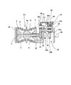
図1〜3は、本発明の実施の形態の1例を示している。図1は、トロイダル型無段変速機25aと、差動ユニットである遊星歯車式変速機26bとを組み合わせて成る、無段変速装置の1例を示している。この無段変速装置の構成は、基本的には、前述の図7に示した従来の、或は図8に示した先発明に係る無段変速装置と同様である。特に、本例の無段変速装置の場合には、上記遊星歯車式変速機26bの第一、第二の遊星歯車42、43を構成する各遊星歯車素子のうち、径方向外側に設ける遊星歯車素子61として、軸方向に長いものを使用している。そして、この遊星歯車素子61を、径方向内側に設けた各遊星歯車素子44a、45aに噛合させている。又、上記遊星歯車素子61と噛合するリング歯車49aとして、幅寸法の小さなものを使用している。この様な図1に示した構造によれば、直径が大きなリング歯車49aの軸方向寸法を短縮してその容積を小さくする事で、無段変速装置の軽量化を図れる。無段変速装置の機能は、上記図7に示した従来の、或は図8に示した先発明に係る無段変速装置と同じである。
【0056】
次いで、上記図1を前提としつつ、図2のブロック図により、本例の無段変速装置に就いて説明する。この図2中、太矢印は動力の伝達経路を、実線は油圧回路を、破線は電気回路を、それぞれ示している。エンジン62の出力は、ダンパ63を介して、入力軸1に入力される。このうちのダンパ63は、上記エンジン62の回転を平滑化して上記入力軸1に伝達する、弾性継手としての役目を有する。尚、本発明の特徴は、トロイダル型無段変速機25aを通過して出力軸38aに付与されるトルクの制御を厳密に行なうべく、車両の極低速走行時若しくは停止時に出力軸38aの回転速度及び回転方向を正確に測定する点にある。無段変速装置自体の構造は上述の図1に示した通りであるから、上記図2で、この図1と同等部分に関しては、できる限り、この図1に使用した符号を付して説明する。
【0057】
上記入力軸1に伝達された動力は、上記トロイダル型無段変速機25aを構成する油圧式の押圧装置23aから入力側ディスク2に伝達され、更にパワーローラ6を介して出力側ディスク5aに伝達される。これら両ディスク2、5aのうち、入力側ディスク2の回転速度は入力側回転センサ64により、出力側ディスク5aの回転速度は出力側回転センサ65により、それぞれ測定して、制御器66に入力し、上記両ディスク2、5a間の(トロイダル型無段変速機25aの)変速比(速度比)を算出自在としている。又、上記入力軸1に伝達された動力は、直接又は上記トロイダル型無段変速機25aを介して、差動ユニットである遊星歯車式変速機26bに伝達される。そして、この遊星歯車式変速機26bの構成部材の差動成分が、クラッチ装置67を介して、上記出力軸38aに取り出される。尚、このクラッチ装置67は、上記図1及び後述する図3に示した低速用クラッチ40a及び高速用クラッチ41aを表すものである。又、本例の場合には、出力軸回転センサ68によっても、上記出力軸38aの回転速度を検出自在としている。但し、この出力軸回転センサ68は、上記入力側回転センサ64及び出力側回転センサ65の故障の有無を判定する為のフェールセーフ用に設置したもので、本発明を実施する場合に必須ではない。
【0058】
一方、前記ダンパ63部分から取り出した動力によりオイルポンプ69を駆動し、このオイルポンプ69から吐出した圧油を、上記押圧装置23aと、上記パワーローラ6を支持したトラニオン7を変位させるアクチュエータ10(例えば図12参照)の変位量を制御する為の制御弁装置70とに、送り込み自在としている。尚、この制御弁装置70とは、前述の図12に示した制御弁12と、差圧シリンダ55と、補正用制御弁57と、後述する図3に記載した、高速用切換弁71及び低速用切換弁72とを合わせたものである。又、上記アクチュエータ10に設けた1対の油圧室24a、24b(図3、6、12参照)内の油圧を(実際には1対の)油圧センサ52により検出して、その検出信号を、上記制御器66に入力している。この制御器66は、上記油圧センサ52からの信号に基づいて、上記トロイダル型無段変速機25aの通過トルクを算出する。
【0059】
又、上記制御弁装置70は、ステッピングモータ13と、ライン圧制御用電磁開閉弁73と、上記補正用制御弁57を切り換える為の電磁弁58a(58b)と、上記高速用切換弁71及び低速用切換弁72を切り換える為のシフト用電磁弁74とにより、その作動状態を切り換えられる。そして、これらステッピングモータ13と、ライン圧制御用電磁開閉弁73と、電磁弁58a(58b)と、シフト用電磁弁74とは、何れも上記制御器66からの制御信号に基づいて切り換えられる。
【0060】
又、この制御器66には、前記各回転センサ64、65、68及び上記油圧センサ52からの信号の他、油温センサ75の検出信号と、ポジションスイッチ76の位置信号と、アクセルセンサ77の検出信号と、ブレーキスイッチ78の信号とを入力している。このうちの油温センサ75は、無段変速装置を納めたケーシング内の潤滑油(トラクションオイル)の温度を検出するものである。又、上記ポジションスイッチ76は、後述する図3に記載した手動油圧切換弁79を切り換える為に運転席に設けられたシフトレバーの操作位置を表す信号を出す為のものである。又、上記アクセルセンサ77は、アクセルペダルの開度を検出する為のものである。更に、上記ブレーキスイッチ78は、ブレーキペダルが踏まれた事、或はパーキングブレーキが操作された事を検出して、その事を表す信号を発するものである。
【0061】
上記制御器66は、上記各スイッチ76、78及びセンサ52、64、65、68、75、77からの信号に基づいて、上記ステッピングモータ13と、ライン圧制御用電磁開閉弁73と、電磁弁58a(58b)と、シフト用電磁弁74とに上記制御信号を送る他、前記エンジン62を制御する為のエンジンコントローラ80に制御信号を送る。そして、前述した先発明の場合と同様にして、入力軸1と出力軸38aとの間の速度比を変えたり、或は停止時若しくは極低速走行時に前記トロイダル型無段変速機25aを通過して上記出力軸38aに加えられるトルク(通過トルク)を制御する。
【0062】
特に本例の場合には、前記入力側回転センサ64及び前記出力側回転センサ65の検出信号に基づいて、上記出力軸38aの回転速度及び回転方向を算出し、上記通過トルクの制御を行なう様にしている。即ち、上記入力側、出力側両回転センサ64、65の検出信号を入力した上記制御器66は、これら両回転センサ64、65の検出信号に基づいて、各入力側ディスク2、2の回転速度NIDと出力側ディスク5aの回転速度NODを求める。前記エンジン62により前記入力軸1が回転している限り、上記各入力側ディスク2、2及び出力側ディスク5aは、何れも十分な速度で回転する。従って、上記両センサ64、65として、安価なパッシブ型のものを使用しても(アクティブ型のものを使用する事は自由である)、上記検出信号の電圧を十分に確保でき、上記各ディスク2、5aの回転速度を確実に求められる。
【0063】
そして、上記各入力側ディスク2、2の回転速度NIDと出力側ディスク5aの回転速度NODとから求められる、上記トロイダル型無段変速機25aの変速比NOD/NID(速度比eCVU とは正負逆)と、前記低速用クラッチ40aを接続しての低速モード状態時の、前記遊星歯車式変速機26bの変速比i1 とから、下記の(4)式により、上記出力軸38aの回転速度NOUT を、上記各入力側ディスク2、2の回転速度に対する比として求める。尚、上記遊星歯車式変速機26bの変速比i1 は、前記リング歯車49aの歯数m49と第一の太陽歯車47の歯数m47との比である(i1 =m49/m47)。
NOUT =(i1 −1−NOD/NID)/i1 −−− (4)
【0064】
従って、上記出力軸38aの回転速度の絶対値は、NOUT ×NIDとなる。又、上記(4)式から明らかな通り、NOD/NID=i1 −1であれば上記出力軸38aは停止し、NOD/NID>i1 −1であれば自動車を後退させる方向に回転し、NOD/NID<i1 −1であれば同じく前進させる方向に回転する。従って、本例の構造によれば、上記出力軸38aの停止状態及び極低速状態の回転速度の他、回転方向も確実に、且つ、十分な応答性(変化した事実を知るまでの時間の短かさ)を確保した状態で知る事ができる。
【0065】
又、本例の無段変速装置の場合には、前記出力軸回転センサ68、上記ポジションスイッチ76、上記アクセルセンサ77からの信号に基づいて、車両が停止若しくは極低速走行時に、前記押圧装置23aが発生する押圧力を、通常走行時に発生する押圧力に比べて小さくする。即ち、上記ポジションスイッチ76からの信号に基づき、上記シフトレバーが前進位置(Dレンジ又はLレンジ)か後退位置(Rレンジ)に位置し、車速が0若しくは極低速(例えば1km/h以下)であり、しかも上記アクセルセンサ77からの信号により、運転者がアクセルペダルを踏み込んでいないと判断される場合に、上記押圧装置23aに導入する油圧を下げて、トラクション部のクリープ率(滑り率)を高くする。
【0066】
この為本例の構造によれば、外乱により前記トロイダル型無段変速機25aの変速比が多少変動した場合でも、このトロイダル型無段変速機25aを通過するトルクの変動を小さく抑えられる。この結果、車両を停止若しくは極低速で走行させる際に、外乱により上記トロイダル型無段変速機25aの変速比が多少変動した場合でも、ブレーキペダルを踏み込む為に要する踏力の変動を低く抑えられる。そして、運転者に違和感を与えたり、運転者が疲労する事を防止できる。又、上記押圧装置23aに供給する油圧を低く抑える事で、給油ポンプの駆動トルクを低減し、燃費改善にも寄与できる。これに対して、車両を通常走行させる際には、上記押圧装置23aが発生する押圧力が十分に大きくなる。この状態では、上記トラクション部のクリープ量が少なくなり、このトラクション部での伝達効率を確保できる。
【0067】
更に本例の無段変速装置の場合には、前記出力軸回転センサ68並びに入力側、出力側回転センサ64、65、前記ポジションスイッチ76、前記ブレーキスイッチ78からの信号に基づいて、上記トロイダル型無段変速機25aの通過トルクの目標値(前述の図10の縦軸に関する、同図のa点の位置)を変える。即ち、上記ポジションスイッチ76からの信号に基づき、前記シフトレバーが前進位置(Dレンジ又はLレンジ)か後退位置(Rレンジ)に切り換えられている場合で、車速が0若しくは極低速(例えば1km/h以下)であり、ブレーキペダルが踏まれるか、或はパーキングブレーキが作動状態にある場合に、上記通過トルクの目標値を下げる(図10のa点を縦軸の下方にずらせる)。この結果、上記出力軸38aに加わるトルクは低くなり、車両が不用意に発進する事はなくなる。又、ブレーキペダルを踏んだ状態で車両を停止させる場合にも、踏力が小さくて済み、運転者の疲労を抑えられる。更に、前記エンジン62の出力トルクを抑えられる分、このエンジン62が消費する燃料を少なくして、省資源化を図れる。
【0068】
これに対して、上記シフトレバーが前進位置(Dレンジ又はLレンジ)か後退位置(Rレンジ)に位置する場合で、車速が0若しくは極低速(例えば1km/h以下)であっても、ブレーキペダルが踏まれず、しかもパーキングブレーキが非作動状態の場合には、上記通過トルクの目標値を比較的高く設定する。この結果、運転者が発進動作を行なえば、車両をもたつきなく発進させる事ができる。特に、登り坂で発進をする場合にアクセルペダルの操作が多少遅れても、車両を後退させずに発進させる事ができる。又、車両の走行速度が極低速でない限り(例えば1km/hを越える限り)、アクセルペダルを踏まずにブレーキペダルを操作するのみで、車両を低速走行させる事が可能になる。この結果、車庫入れや縦列駐車を容易に行なえる。尚、本例の場合、上記シフトレバーが非走行状態、即ち、パーキング位置(Pレンジ)かニュートラル位置(Nレンジ)に位置する場合には、前記クラッチ装置67(低速用、高速用両クラッチ40a、41a)の接続を断ち、上記出力軸38aに駆動力が伝わる事を防止する。この場合には、前記エンジンコントローラ80が上記エンジン62を、可及的に低トルクで、アイドリング回転させる。
【0069】
次に、上述の様な本発明の無段装置の制御に好適な制御回路に就いて、図3により簡単に説明する。尚、制御弁12と、ステッピングモータ13と、プリセスカム18と、リンク腕19と、差圧シリンダ55とにより、アクチュエータ10のストロークを制御し、トロイダル型無段変速機の変速比を調節する部分の構造に就いては、前述の図12に示した先発明に係る構造と同じであるから、重複する説明を省略する。
【0070】
図3に示した油圧回路では、油溜81から吸引されてオイルポンプ69a、69bにより吐出された圧油を、調圧弁82a、82bにより所定圧に調整自在としている。上記オイルポンプ69a、69bが、前述の図1に記載したオイルポンプ69に相当する。又、上記両調圧弁82a、82bのうち、次述する手動油圧切換弁79側に送る油圧を調整する為の調圧弁82aによる調整圧を、ライン圧制御用電磁開閉弁73の開閉に基づいて調節自在としている。そして、上記両調圧弁82a、82bにより圧力を調整された圧油を、上記制御弁12を介して上記アクチュエータ10に送り込み自在とする他、上記差圧シリンダ55のストロークを調節する為の補正用制御弁57に、電磁弁58a、58bの開閉に基づいて送り込み自在としている。
【0071】
又、上記圧油を、前記油圧式の押圧装置23aに送り込む様にしている。又、この圧油は、手動油圧切換弁79と、高速用切換弁71又は低速用切換弁72とを介して、低速用クラッチ40a(40)又は高速用クラッチ41a(41)の油圧室内に送り込み自在としている。上記各切換弁79、71、72のうち、上記手動油圧切換弁79は、運転席に設けられて運転者により操作される操作レバー(シフトレバー)により操作されて、駐車レンジ(P)、リバース(後退)レンジ(R)、ニュートラルレンジ(N)、ドライブ(通常前進)レンジ(D)、高駆動力前進レンジ(L)を選択する。これら各レンジを選択した場合に於ける、上記手動油圧切換弁79の切り換え状態は、図示の通りである。尚、この手動油圧切換弁79を含め、各弁の構造及び機能の表示は、油圧機器に関する機械製図の一般的な手法によっている。
【0072】
又、上記高速用、低速用両切換弁71、72はそれぞれ、シフト用電磁弁74により切り換えられるシフト用切換弁83の切り換えに基づく圧油の給排により、それぞれの連通状態を切り換えられるもので、一方の切換弁71(又は72)が高速用クラッチ41a(又は低速用クラッチ40a)の油圧室に圧油を送り込む際には、他方の切換弁72(又は71)が低速用クラッチ40a(又は高速用クラッチ41a)の油圧室から圧油を排出する。
【0073】
上述の様に構成する油圧回路を備え、前述の図1〜2に示す様に構成した無段変速装置に組み込まれる制御器は、次の(1) 〜(6) の機能を有する。
(1) 低速モード時、即ち、上記低速用クラッチ40aを接続し、上記高速用クラッチ41aの接続を断った状態での運転時に、上記トロイダル型無段変速機25aの変速比を調節して前記遊星歯車式変速機26bを構成する複数の歯車の相対的変位速度を変化させると共に、駆動源であるエンジン62により入力軸1を一方向に回転させた状態のまま、出力軸38aの回転状態を、停止状態を挟んで正転及び逆転に変換自在とする機能(請求項1の▲1▼の機能)。
この機能に関しては、前述の図7に示した従来から知られている、或は図8に示した先発明に係る無段変速装置と同様である。
【0074】
(2) 高速モード時、即ち、上記低速用クラッチ40aの接続を断ち、上記高速用クラッチ41aを接続した状態での運転時に、上記トロイダル型無段変速機25aの変速比を変える事により、上記入力軸1と上記出力軸38aとの間の変速比を変更する機能。
この機能に関しても、前述の図7に示した従来から知られている、或は図8に示した先発明に係る無段変速装置と同様である。
【0075】
(3) 低速モード時、即ち、上記低速用クラッチ40aを接続し、上記高速用クラッチ41aの接続を断った状態での運転時に、前記入力側、出力側両回転センサ64、65の測定値に基づいて上記出力軸38aの回転速度及び回転方向を求め(請求項1の▲2▼の機能)、更に、上記トロイダル型無段変速機25aの変速比を変える事により、このトロイダル型無段変速機25aを通過するトルクを調節する機能(請求項2の▲3▼の機能)。
【0076】
(4) 上記操作レバーにより非走行状態、即ち、パーキングレンジ又はニュートラルレンジが選択された状態で、上記低速用クラッチ40a及び上記高速用クラッチ41aの接続を総て断つ機能。
(5) 車両が停止若しくは極低速走行時に前記押圧装置23aが発生する押圧力を、通常走行時に発生する押圧力に比べて小さくする機能。
(6) 車両が停止若しくは極低速走行時で、この車両を停止させる為に使用する制動手段が操作された場合に、上記トロイダル型無段変速機25aを通過するトルクを、この制動手段が操作されていない場合に比べて低くする機能。
【0077】
尚、図示の例では、上記無段変速装置の速度比を無限大近傍に規制すべく、前記トロイダル型無段変速機25aの変速比を微調節する為の差圧シリンダ55のストロークを小さな範囲に抑えて、この変速比が過度に調節されない様にしている。又、上記差圧シリンダ55を、前記アクチュエータ10の油圧室24a、24b内の差圧により切り換える様にしている。従って、上記変速比を微調節する為の構造部分を故障しにくくして、信頼性の高い無段変速装置を実現できる。
【0078】
【発明の効果】
本発明は、以上に述べた通り構成され作用するので、特に高価な回転センサを使用しなくても、車両の停止時若しくは極低速走行時に、出力軸の回転速度及び回転方向を正確に知る事ができる。この為、無限大の変速比を得られる無段変速装置の実現に寄与できる。
【図面の簡単な説明】
【図1】本発明の実施の形態の1例を示す、無段変速装置の半部略断面図。
【図2】同じく変速制御装置のブロック図。
【図3】無段変速装置に組み込むトロイダル型無段変速機の変速比を調節する為の機構を示す油圧回路図。
【図4】従来から知られているトロイダル型無段変速機の1例を示す断面図。
【図5】図4のA−A断面図。
【図6】同B−B断面図。
【図7】従来から知られている無段変速装置の1例を示す略断面図。
【図8】先発明に係る制御装置により変速比を制御する無段変速装置の1例を示す略断面図。
【図9】この無段変速装置に組み込んだトロイダル型無段変速機(CVU)の速度比と、この無段変速装置(T/M)全体としての速度比との関係を示す線図。
【図10】先発明に係る制御装置で変速比を制御する状態を説明する為、エンジンの回転速度とトルクとの関係を示す線図。
【図11】トロイダル型無段変速機を通過するトルク及び変速比と、無段変速装置全体としての変速比との関係を示す線図。
【図12】先発明の無段変速装置を構成するトロイダル型無段変速機の変速比を調節する為の機構を示す油圧回路図。
【符号の説明】
1 入力軸
2 入力側ディスク
3 ボールスプライン
4 出力歯車
5、5a 出力側ディスク
6 パワーローラ
7 トラニオン
8 支持軸
9 枢軸
10 アクチュエータ
11 支持板
12 制御弁
13 ステッピングモータ
14 スリーブ
15 スプール
16 ピストン
17 ロッド
18 プリセスカム
19 リンク腕
20 同期ケーブル
21 カム面
22 駆動軸
23、23a 押圧装置
24a、24b 油圧室
25、25a トロイダル型無段変速機
26、26a、26b 遊星歯車式変速機
27、27a キャリア
28a、28b 遊星歯車素子
29 第一の伝達軸
30a、30b 太陽歯車
31 第二の伝達軸
32、32a 中空回転軸
33 太陽歯車
34 遊星歯車素子
35 リング歯車
36、36a 第二のキャリア
37a、37b 遊星歯車素子
38、38a 出力軸
39、39a 第二のリング歯車
40、40a 低速用クラッチ
41、41a 高速用クラッチ
42 第一の遊星歯車
43 第二の遊星歯車
44a、44b 遊星歯車素子
45a、45b 遊星歯車素子
46 伝達軸
47 第一の太陽歯車
48 第二の太陽歯車
49、49a リング歯車
50 第三の太陽歯車
51a、51b 遊星歯車素子
52 油圧センサ
53 ロッド
54 リンク腕
55 差圧シリンダ
56a、56b 油圧室
57 補正用制御弁
58a、58b 電磁弁
59 スプール
60 スプール
61 遊星歯車素子
62 エンジン
63 ダンパ
64 入力側回転センサ
65 出力側回転センサ
66 制御器
67 クラッチ装置
68 出力軸回転センサ
69、69a、69b オイルポンプ
70 制御弁装置
71 高速用切換弁
72 低速用切換弁
73 ライン圧制御用電磁弁
74 シフト用電磁弁
75 油温センサ
76 ポジションスイッチ
77 アクセルセンサ
78 ブレーキスイッチ
79 手動油圧切換弁
80 エンジンコントローラ
81 油溜
82a、82b 調圧弁
83 シフト用切換弁[0001]
TECHNICAL FIELD OF THE INVENTION
The present invention relates to an improvement of a continuously variable transmission incorporating a toroidal-type continuously variable transmission, which is used as an automatic transmission for a vehicle (automobile), and to improve characteristics at a stop or at extremely low speeds.
[0002]
[Prior art]
The use of a toroidal-type continuously variable transmission as shown in FIGS. 4 to 6 has been studied as an automatic transmission for an automobile, and has been partially implemented. This toroidal-type continuously variable transmission is a so-called double-cavity type, and supports
[0003]
A plurality of (normally two to three)
[0004]
That is, when the inclination angle of each of the
[0005]
The supply / discharge state of the pressure oil to / from each of the
[0006]
When the gearshift state is switched, the
[0007]
At this time, the movement of the
[0008]
Therefore, immediately after the
[0009]
During operation of the toroidal-type continuously variable transmission as described above, one (the left side of FIGS. 4 and 5)
[0010]
When power is transmitted from the
[0011]
When the rotational speed of the
[0012]
Further, when the toroidal-type continuously variable transmission configured and operated as described above is incorporated into an actual vehicle continuously variable transmission, the continuously variable transmission is configured by combining with a gear-type differential unit such as a planetary gear mechanism. Has been proposed in the past. For example,
[0013]
The planetary
[0014]
On the other hand, the
[0015]
In the case of the continuously variable transmission shown in FIG. 7 as described above, in the so-called low-speed mode in which the low-
[0016]
During acceleration or constant-speed running in such a low-speed mode, the torque (passing torque) passing through the toroidal-type continuously
[0017]
On the other hand, in a so-called high-speed mode state in which the low-
The torque passing through the toroidal-type continuously
[0018]
For example, in the case of a continuously variable transmission having a structure as shown in FIG. 7 and stopping the
[0019]
Further, when the speed ratio is extremely large, even when the speed ratio of the toroidal-type continuously
[0020]
In consideration of such points,
However, in the case of the structure described in
[0021]
In particular, like the general half toroidal type continuously variable transmission shown in FIGS. 4 to 6, the directions of the
[0022]
[Patent Document 1]
JP 2000-220719 A
[Patent Document 2]
JP-A-10-103461
[0023]
[Description of Prior Invention]
In view of such circumstances, the present inventor has previously described this type of continuously variable transmission that incorporates a toroidal type continuously variable transmission that does not have a cast angle, like a general half toroidal type continuously variable transmission. A method and a device capable of strictly controlling the torque (passing torque) passing through a toroidal type continuously variable transmission have been invented (Japanese Patent Application No. 2002-116185).
FIG. 8 shows an example of the structure of a continuously variable transmission to which such a control method and device of the present invention are applied. The continuously variable transmission shown in FIG. 8 has a function similar to that of the conventionally known continuously variable transmission shown in FIG. 7 described above. By devising, the assemblability of the planetary
[0024]
First and second
[0025]
On the other hand, the
[0026]
In the case of the improved continuously variable transmission configured as described above, when the low speed clutch 40a is connected and the high speed clutch 41a is disconnected, the power of the
e CVT = (E CVU + I 1 -1) / i 1 −−− (1)
And, for example, the ratio i of the number of teeth 1 Is 2, the above two speed ratios e CVU , E CVT The relationship between them changes as shown by the line segment α in FIG.
[0027]
On the other hand, when the low speed clutch 40a is disconnected and the high speed clutch 41a is connected, the power of the
e CVT = {1 / (1-i 3 )} ・ {1+ (i 2 / I 1 ) (E CVU -1)} ---- (2)
Then, among the above ratios, i 1 Is 2, i 2 Is 2.2, i 3 Is 2.8, the above two speed ratios e CVU , E CVT The relationship between them changes as shown by the line segment β in FIG.
[0028]
In the case of the continuously variable transmission configured and operated as described above, the
[0029]
Also, at the time of the low speed operation, a state close to a state where the
[0030]
When the vehicle is accelerated or driven at a constant speed in such a low-speed mode, the passing torque is transmitted from the
[0031]
For this reason, in the case of the speed ratio control method and apparatus according to the prior invention, the torque input from the drive source to the
[0032]
Also, a pair of
[0033]
That is, as long as the speed ratio of the toroidal-type continuously
[0034]
On the other hand, the torque T CVU Is also obtained by the following equation (3).
T CVU = E CVU ・ T IN / {E CVU + (I 1 -1) η CVU } −−− (3) In the equation (3), e CVU Represents the speed ratio of the toroidal type continuously
[0035]
Therefore, the torque T actually passing through the toroidal type continuously
[0036]
For example, as shown in FIG. 10, the torque T that actually passes through the toroidal type continuously
[0037]
However, when the brake pedal is depressed and stopped (rotational speed of the output shaft = 0), the slip generated inside the toroidal-type continuously
[0038]
For example, in FIG. CVU2 Is present at point a, the measured value T CVU1 Is present at point b in the drawing, the
[0039]
Hereinafter, the torque T actually passing through the toroidal-type continuously
[0040]
FIG. 11 shows the torque T passing through the toroidal type continuously
[0041]
In the case of the prior invention, the torque T actually passing through the toroidal-type continuously
[0042]
As described above, when the brake pedal is depressed and stopped, the driving force (torque) is applied to the
[0043]
Next, as described above, the torque T actually passing through the toroidal type continuously
[0044]
Particularly in the case of the prior invention, the
[0045]
Therefore, in the case of the prior invention, mutually different hydraulic pressures can be introduced into the pair of
[0046]
The torque T actually passing through the toroidal type continuously
[0047]
On the other hand, the torque T actually passing through the toroidal-type continuously
[0048]
[Problems to be solved by the invention]
In the case of the above-described continuously variable transmission according to the invention, there is a possibility that the speed ratio of the toroidal-type continuously variable transmission incorporated in the continuously variable transmission can be strictly adjusted when the vehicle is stopped or traveling at an extremely low speed. However, in order to perform high-precision control at low cost for realizing a driving state that does not give a driver a sense of incongruity, it is necessary to make the rotational speeds of the
[0049]
The continuously variable transmission according to the above-mentioned invention can meet such a demand, but for that purpose, it is necessary to accurately grasp the rotational speed or the stop state of the
[0050]
Therefore, the passive type rotation sensor is not suitable as a sensor for detecting the rotation speed of the
The continuously variable transmission according to the present invention has been made in view of such circumstances.
[0051]
[Means for Solving the Problems]
The continuously variable transmission according to the present invention includes an input shaft, an output shaft, and the like, similarly to the conventionally known continuously variable transmission illustrated in FIG. 7 described above or according to the prior invention illustrated in FIG. A toroidal type continuously variable transmission, a gear type differential unit formed by combining a plurality of gears, and a controller for controlling a change in a gear ratio of the toroidal type continuously variable transmission are provided.
The toroidal-type continuously variable transmission may further include an input disk that is driven to rotate by the input shaft together with the first input portion of the differential unit, a concentric with the input disk, and An output-side disk supported so as to be capable of relative rotation and connected to a second input section of the differential unit, a plurality of power rollers sandwiched between the two disks, and rotation of the input-side disk An input-side rotation sensor for measuring the speed and an output-side rotation sensor for measuring the rotation speed of the output-side disk are provided.
The differential unit extracts rotation corresponding to a speed difference between the first and second input units and transmits the rotation to the output shaft.
[0052]
Further, the controller has the following functions (1) and (2).
{Circle around (1)} The input shaft is rotated in one direction by adjusting the speed ratio of the toroidal type continuously variable transmission to change the relative displacement speed of the plurality of gears constituting the differential unit. A function that converts the rotation state of the output shaft into normal rotation and reverse rotation with the stop state in between.
(2) The output based on the rotation speed of the input disk determined by the input rotation sensor, the rotation speed of the output disk determined by the output rotation sensor, and the speed ratio of the differential unit. Function to calculate shaft rotation speed.
[0053]
Preferably, the controller has the following function (3) in addition to the functions (1) and (2).
(3) By changing the speed ratio of the toroidal type continuously variable transmission, the torque transmitted to the output shaft through the toroidal type continuously variable transmission is calculated based on the function of (2), and the rotation speed of the output shaft is obtained. Function to adjust according to.
[0054]
[Action]
In the case of the continuously variable transmission of the present invention configured as described above, even when a relatively inexpensive rotation sensor is used, it is possible to know the rotation speed and the rotation direction of the output shaft rotating at a low speed or in a stopped state. it can. That is, the rotational speed and the rotational direction of the output shaft are obtained by calculation from the rotational speeds of both the input and output disks of the toroidal type continuously variable transmission and the gear ratio (ratio of the number of teeth) of the differential unit. It is. Even when the output shaft is rotating at a low speed or stopped, both the input and output disks are rotating at a much higher speed than the output shaft. Therefore, even with a relatively inexpensive rotation sensor, the rotation speeds of both the input and output disks can be accurately measured, and the rotation speed and rotation direction of the output shaft can be accurately known.
[0055]
BEST MODE FOR CARRYING OUT THE INVENTION
1 to 3 show an example of an embodiment of the present invention. FIG. 1 shows an example of a continuously variable transmission, which is a combination of a toroidal type continuously
[0056]
Next, the continuously variable transmission of this embodiment will be described with reference to the block diagram of FIG. In FIG. 2, a thick arrow indicates a power transmission path, a solid line indicates a hydraulic circuit, and a broken line indicates an electric circuit. The output of the engine 62 is input to the
[0057]
The power transmitted to the
[0058]
On the other hand, the oil pump 69 is driven by the power taken out from the
[0059]
The
[0060]
In addition to the signals from the
[0061]
Based on the signals from the
[0062]
In particular, in the case of the present example, the rotation speed and the rotation direction of the
[0063]
Then, the rotation speed N of each of the
N OUT = (I 1 -1-N OD / N ID ) / I 1 −−− (4)
[0064]
Therefore, the absolute value of the rotation speed of the
[0065]
Further, in the case of the continuously variable transmission of the present embodiment, based on signals from the output
[0066]
Therefore, according to the structure of this embodiment, even when the speed ratio of the toroidal-type continuously
[0067]
Further, in the case of the continuously variable transmission according to the present embodiment, the toroidal type is controlled based on signals from the output
[0068]
On the other hand, when the shift lever is located at the forward position (D range or L range) or the reverse position (R range) and the vehicle speed is 0 or extremely low speed (for example, 1 km / h or less), the brake When the pedal is not depressed and the parking brake is not operated, the target value of the passing torque is set relatively high. As a result, if the driver performs the starting operation, the vehicle can be started without any backlash. In particular, when starting on an uphill, even if the operation of the accelerator pedal is slightly delayed, the vehicle can be started without retreating. In addition, as long as the traveling speed of the vehicle is not extremely low (for example, as long as it exceeds 1 km / h), the vehicle can be driven at low speed only by operating the brake pedal without depressing the accelerator pedal. As a result, parking in a garage or parallel parking can be easily performed. In the case of this embodiment, when the shift lever is in a non-traveling state, that is, when the shift lever is located at the parking position (P range) or the neutral position (N range), the clutch device 67 (the low-speed and high-
[0069]
Next, a control circuit suitable for controlling the continuously variable device of the present invention as described above will be briefly described with reference to FIG. The
[0070]
In the hydraulic circuit shown in FIG. 3, the pressure oil sucked from the
[0071]
The pressure oil is sent to the hydraulic
[0072]
Each of the high-speed and low-
[0073]
The controller provided with the hydraulic circuit configured as described above and incorporated in the continuously variable transmission configured as illustrated in FIGS. 1 and 2 has the following functions (1) to (6).
(1) In a low-speed mode, that is, during operation in a state in which the low-
This function is the same as that of the conventionally known continuously variable transmission shown in FIG. 7 or the prior art shown in FIG.
[0074]
(2) In the high-speed mode, that is, when the low-
This function is also the same as that of the conventionally known continuously variable transmission shown in FIG. 7 or the prior art shown in FIG.
[0075]
(3) In the low-speed mode, that is, during operation in a state in which the low-
[0076]
(4) A function of disconnecting all of the low-
(5) A function of making the pressing force generated by the
(6) When the braking means used to stop the vehicle is operated when the vehicle is stopped or traveling at extremely low speed, the braking means operates the torque passing through the toroidal-type continuously
[0077]
In the illustrated example, in order to regulate the speed ratio of the continuously variable transmission to near infinity, the stroke of the differential pressure cylinder 55 for finely adjusting the speed ratio of the toroidal type continuously
[0078]
【The invention's effect】
Since the present invention is configured and operates as described above, it is possible to accurately know the rotation speed and the rotation direction of the output shaft when the vehicle is stopped or traveling at extremely low speed without using an expensive rotation sensor. Can be. For this reason, it can contribute to the realization of a continuously variable transmission that can obtain an infinite speed ratio.
[Brief description of the drawings]
FIG. 1 is a schematic half sectional view of a continuously variable transmission, showing an example of an embodiment of the present invention.
FIG. 2 is a block diagram of a transmission control device.
FIG. 3 is a hydraulic circuit diagram showing a mechanism for adjusting a speed ratio of a toroidal type continuously variable transmission incorporated in the continuously variable transmission.
FIG. 4 is a sectional view showing an example of a conventionally known toroidal-type continuously variable transmission.
FIG. 5 is a sectional view taken along line AA of FIG. 4;
FIG. 6 is a sectional view taken along the line BB in FIG.
FIG. 7 is a schematic sectional view showing an example of a conventionally known continuously variable transmission.
FIG. 8 is a schematic cross-sectional view showing an example of a continuously variable transmission that controls a gear ratio by a control device according to the invention.
FIG. 9 is a diagram showing a relationship between a speed ratio of a toroidal type continuously variable transmission (CVU) incorporated in the continuously variable transmission and a speed ratio of the continuously variable transmission (T / M) as a whole.
FIG. 10 is a diagram showing the relationship between the rotational speed of the engine and the torque in order to explain a state where the gear ratio is controlled by the control device according to the prior invention.
FIG. 11 is a diagram illustrating a relationship between a torque and a gear ratio passing through a toroidal-type continuously variable transmission and a gear ratio of the entire continuously variable transmission.
FIG. 12 is a hydraulic circuit diagram showing a mechanism for adjusting a speed ratio of a toroidal-type continuously variable transmission that forms the continuously variable transmission according to the invention.
[Explanation of symbols]
1 input shaft
2 Input side disk
3 Ball spline
4 Output gear
5, 5a Output side disk
6 Power roller
7 trunnion
8 Support shaft
9 Axis
10 Actuator
11 Support plate
12 Control valve
13 Stepper motor
14 sleeve
15 spool
16 piston
17 Rod
18 Precess Cam
19 Link Arm
20 Synchronous cable
21 Cam surface
22 Drive shaft
23, 23a pressing device
24a, 24b hydraulic chamber
25, 25a Toroidal-type continuously variable transmission
26, 26a, 26b planetary gear type transmission
27, 27a carrier
28a, 28b planetary gear elements
29 First transmission shaft
30a, 30b sun gear
31 Second transmission shaft
32, 32a hollow rotary shaft
33 Sun Gear
34 planetary gear element
35 ring gear
36, 36a Second carrier
37a, 37b planetary gear elements
38, 38a Output shaft
39, 39a Second ring gear
40, 40a Low speed clutch
41, 41a High speed clutch
42 First Planetary Gear
43 Second Planetary Gear
44a, 44b planetary gear element
45a, 45b planetary gear elements
46 Transmission shaft
47 First Sun Gear
48 Second Sun Gear
49, 49a Ring gear
50 Third Sun Gear
51a, 51b planetary gear elements
52 Oil pressure sensor
53 rod
54 link arm
55 differential pressure cylinder
56a, 56b Hydraulic chamber
57 Correction control valve
58a, 58b Solenoid valve
59 spool
60 spool
61 planetary gear element
62 engine
63 Damper
64 Input rotation sensor
65 Output side rotation sensor
66 Controller
67 Clutch device
68 Output shaft rotation sensor
69, 69a, 69b Oil pump
70 Control valve device
71 High-speed switching valve
72 Low-speed switching valve
73 Solenoid valve for line pressure control
74 Shift solenoid valve
75 Oil temperature sensor
76 Position switch
77 Accelerator sensor
78 Brake switch
79 Manual hydraulic switching valve
80 Engine controller
81 sump
82a, 82b Pressure regulating valve
83 Shift switching valve
Claims (2)
このトロイダル型無段変速機は、上記差動ユニットの第一の入力部と共に上記入力軸により回転駆動される入力側ディスクと、この入力側ディスクと同心に、且つ、この入力側ディスクに対する相対回転を自在として支持され、上記差動ユニットの第二の入力部に接続された出力側ディスクと、これら両ディスク同士の間に挟持された複数個のパワーローラと、上記入力側ディスクの回転速度を測定する為の入力側回転センサと、上記出力側ディスクの回転速度を測定する為の出力側回転センサとを備えたものであり、
上記差動ユニットは、上記第一、第二の入力部同士の間の速度差に応じた回転を取り出して上記出力軸に伝達するものであり、
上記制御器は、次の▲1▼▲2▼の機能を有するものである無段変速装置。
▲1▼ 上記トロイダル型無段変速機の変速比を調節して上記差動ユニットを構成する複数の歯車の相対的変位速度を変化させる事により、上記入力軸を一方向に回転させた状態のまま上記出力軸の回転状態を、停止状態を挟んで正転及び逆転に変換する機能。
▲2▼ 上記入力側回転センサにより求められる上記入力側ディスクの回転速度及び上記出力側回転センサにより求められる上記出力側ディスクの回転速度と、上記差動ユニットの変速比とに基づいて、上記出力軸の回転速度を算出する機能。An input shaft, an output shaft, a toroidal type continuously variable transmission, a gear type differential unit formed by combining a plurality of gears, and a controller for controlling a change in a gear ratio of the toroidal type continuously variable transmission With
The toroidal-type continuously variable transmission includes an input-side disk that is rotationally driven by the input shaft together with the first input portion of the differential unit, a concentric rotation with the input-side disk, and a relative rotation with respect to the input-side disk. And the output side disk connected to the second input portion of the differential unit, a plurality of power rollers sandwiched between the two disks, and the rotation speed of the input side disk. An input-side rotation sensor for measuring, and an output-side rotation sensor for measuring the rotation speed of the output-side disk,
The differential unit is for extracting rotation corresponding to a speed difference between the first and second input units and transmitting the rotation to the output shaft,
The controller is a continuously variable transmission having the following functions (1) and (2).
{Circle around (1)} The input shaft is rotated in one direction by adjusting the speed ratio of the toroidal type continuously variable transmission to change the relative displacement speed of the plurality of gears constituting the differential unit. A function that converts the rotation state of the output shaft into normal rotation and reverse rotation with the stop state in between.
(2) The output based on the rotation speed of the input disk determined by the input rotation sensor, the rotation speed of the output disk determined by the output rotation sensor, and the speed ratio of the differential unit. Function to calculate shaft rotation speed.
▲3▼ トロイダル型無段変速機の変速比を変える事により、このトロイダル型無段変速機を通過して出力軸に伝わるトルクを、▲2▼の機能に基づいて求めた出力軸の回転速度に対応して調節する機能。2. The continuously variable transmission according to claim 1, wherein the controller has the following function (3) in addition to the functions (1) and (2).
(3) By changing the speed ratio of the toroidal type continuously variable transmission, the torque transmitted to the output shaft through the toroidal type continuously variable transmission is calculated based on the function of (2), and the rotation speed of the output shaft is obtained. Function to adjust according to.
Priority Applications (2)
| Application Number | Priority Date | Filing Date | Title |
|---|---|---|---|
| JP2003035877A JP2004245326A (en) | 2003-02-14 | 2003-02-14 | Continuously variable transmission |
| US10/777,970 US6991575B2 (en) | 2003-02-14 | 2004-02-13 | Continuously variable transmission apparatus |
Applications Claiming Priority (1)
| Application Number | Priority Date | Filing Date | Title |
|---|---|---|---|
| JP2003035877A JP2004245326A (en) | 2003-02-14 | 2003-02-14 | Continuously variable transmission |
Publications (2)
| Publication Number | Publication Date |
|---|---|
| JP2004245326A true JP2004245326A (en) | 2004-09-02 |
| JP2004245326A5 JP2004245326A5 (en) | 2006-02-09 |
Family
ID=33021141
Family Applications (1)
| Application Number | Title | Priority Date | Filing Date |
|---|---|---|---|
| JP2003035877A Pending JP2004245326A (en) | 2003-02-14 | 2003-02-14 | Continuously variable transmission |
Country Status (2)
| Country | Link |
|---|---|
| US (1) | US6991575B2 (en) |
| JP (1) | JP2004245326A (en) |
Cited By (4)
| Publication number | Priority date | Publication date | Assignee | Title |
|---|---|---|---|---|
| JP2002174330A (en) * | 2000-09-26 | 2002-06-21 | Deere & Co | Device and method for determine output speed of hydraulic unit of hydro-mechanical transmission |
| JP2008057982A (en) * | 2006-08-29 | 2008-03-13 | Honda Motor Co Ltd | Belt damage detector of continuously variable transmission |
| US7618341B2 (en) | 2006-05-19 | 2009-11-17 | Nsk Ltd. | Transmission control device for continuously variable transmission apparatus for vehicles |
| WO2012111364A1 (en) * | 2011-02-15 | 2012-08-23 | 日本精工株式会社 | Continuously variable transmission for vehicle |
Families Citing this family (49)
| Publication number | Priority date | Publication date | Assignee | Title |
|---|---|---|---|---|
| US6551210B2 (en) * | 2000-10-24 | 2003-04-22 | Motion Technologies, Llc. | Continuously variable transmission |
| AU2002303524B2 (en) | 2001-04-26 | 2008-03-06 | Fallbrook Intellectual Property Company Llc | Continuously variable transmission |
| US7011600B2 (en) | 2003-02-28 | 2006-03-14 | Fallbrook Technologies Inc. | Continuously variable transmission |
| US7166052B2 (en) * | 2003-08-11 | 2007-01-23 | Fallbrook Technologies Inc. | Continuously variable planetary gear set |
| ATE550573T1 (en) | 2004-10-05 | 2012-04-15 | Fallbrook Technologies Inc | CONTINUOUSLY ADJUSTABLE GEARBOX |
| JP4323461B2 (en) * | 2005-05-25 | 2009-09-02 | ジヤトコ株式会社 | Automatic transmission |
| ES2439236T3 (en) | 2005-08-24 | 2014-01-22 | Fallbrook Intellectual Property Company Llc | Wind turbine |
| CN102425649B (en) | 2005-10-28 | 2014-09-24 | 福博科知识产权有限责任公司 | Electromotive drives |
| DK1954959T3 (en) | 2005-11-22 | 2013-08-26 | Fallbrook Ip Co Llc | Continuously variable transmission |
| CN101454596B (en) | 2005-12-09 | 2011-06-29 | 瀑溪技术公司 | Continuously variable transmission |
| EP1811202A1 (en) | 2005-12-30 | 2007-07-25 | Fallbrook Technologies, Inc. | A continuously variable gear transmission |
| US7882762B2 (en) | 2006-01-30 | 2011-02-08 | Fallbrook Technologies Inc. | System for manipulating a continuously variable transmission |
| WO2007106874A2 (en) | 2006-03-14 | 2007-09-20 | Autocraft Industries, Inc. | Improved wheelchair |
| US7924780B2 (en) * | 2006-04-12 | 2011-04-12 | Fon Wireless Limited | System and method for linking existing Wi-Fi access points into a single unified network |
| CN102269056B (en) | 2006-06-26 | 2013-10-23 | 福博科技术公司 | Continuously variable transmission |
| PL2089642T3 (en) | 2006-11-08 | 2013-09-30 | Fallbrook Ip Co Llc | Clamping force generator |
| US8738255B2 (en) | 2007-02-01 | 2014-05-27 | Fallbrook Intellectual Property Company Llc | Systems and methods for control of transmission and/or prime mover |
| US20100093479A1 (en) | 2007-02-12 | 2010-04-15 | Fallbrook Technologies Inc. | Continuously variable transmissions and methods therefor |
| EP2700843A3 (en) | 2007-02-16 | 2017-11-08 | Fallbrook Intellectual Property Company LLC | Infinitely variable transmissions, continuously variable transmissions, methods, assemblies, subassemblies, and components therefor |
| CN102943855B (en) | 2007-04-24 | 2016-01-27 | 福博科技术公司 | Electric traction drives |
| WO2008154437A1 (en) | 2007-06-11 | 2008-12-18 | Fallbrook Technologies Inc. | Continuously variable transmission |
| CA2692476C (en) | 2007-07-05 | 2017-11-21 | Fallbrook Technologies Inc. | Continuously variable transmission |
| CN101861482B (en) | 2007-11-16 | 2014-05-07 | 福博科知识产权有限责任公司 | Controller for variable transmission |
| CN102317146B (en) | 2007-12-21 | 2015-11-25 | 福博科知识产权有限责任公司 | Automatic transmission and for its method |
| CA2942806C (en) | 2008-02-29 | 2018-10-23 | Fallbrook Intellectual Property Company Llc | Continuously and/or infinitely variable transmissions and methods therefor |
| US8317651B2 (en) | 2008-05-07 | 2012-11-27 | Fallbrook Intellectual Property Company Llc | Assemblies and methods for clamping force generation |
| JP5457438B2 (en) | 2008-06-06 | 2014-04-02 | フォールブルック インテレクチュアル プロパティー カンパニー エルエルシー | Infinitely variable transmission and control system for infinitely variable transmission |
| CN107246463A (en) | 2008-06-23 | 2017-10-13 | 福博科知识产权有限责任公司 | Buncher |
| WO2010017242A1 (en) | 2008-08-05 | 2010-02-11 | Fallbrook Technologies Inc. | Methods for control of transmission and prime mover |
| US8469856B2 (en) | 2008-08-26 | 2013-06-25 | Fallbrook Intellectual Property Company Llc | Continuously variable transmission |
| US8167759B2 (en) | 2008-10-14 | 2012-05-01 | Fallbrook Technologies Inc. | Continuously variable transmission |
| CA2964358A1 (en) | 2009-04-16 | 2010-10-21 | Fallbrook Intellectual Property Company Llc | Stator assembly and shifting mechanism for a continuously variable transmission |
| US8512195B2 (en) | 2010-03-03 | 2013-08-20 | Fallbrook Intellectual Property Company Llc | Infinitely variable transmissions, continuously variable transmissions, methods, assemblies, subassemblies, and components therefor |
| US8888643B2 (en) | 2010-11-10 | 2014-11-18 | Fallbrook Intellectual Property Company Llc | Continuously variable transmission |
| CA2830929A1 (en) | 2011-04-04 | 2012-10-11 | Fallbrook Intellectual Property Company Llc | Auxiliary power unit having a continuously variable transmission |
| EP3234407B1 (en) * | 2011-04-18 | 2020-05-06 | Transmission CVT Corp Inc. | Continuously variable transmission provided with a roller parking zone |
| CA2861889A1 (en) | 2012-01-23 | 2013-08-01 | Fallbrook Intellectual Property Company Llc | Infinitely variable transmissions, continuously variable transmissions, methods, assemblies, subassemblies, and components therefor |
| CN109018173B (en) | 2013-04-19 | 2021-05-28 | 福博科知识产权有限责任公司 | Continuously variable transmission |
| JP6331449B2 (en) * | 2014-02-17 | 2018-05-30 | 日本精工株式会社 | Toroidal continuously variable transmission |
| US10047861B2 (en) | 2016-01-15 | 2018-08-14 | Fallbrook Intellectual Property Company Llc | Systems and methods for controlling rollback in continuously variable transmissions |
| US9970521B1 (en) * | 2016-02-26 | 2018-05-15 | Rodney J. Cook and successors in trust | Infinitely variable transmission |
| CN109154368B (en) | 2016-03-18 | 2022-04-01 | 福博科知识产权有限责任公司 | Continuously variable transmission, system and method |
| US10023266B2 (en) | 2016-05-11 | 2018-07-17 | Fallbrook Intellectual Property Company Llc | Systems and methods for automatic configuration and automatic calibration of continuously variable transmissions and bicycles having continuously variable transmissions |
| US20180094723A1 (en) * | 2016-10-05 | 2018-04-05 | GM Global Technology Operations LLC | System for rationalizing measured gear ratio values in a vehicle propulsion control system |
| CN110392796B (en) * | 2017-04-03 | 2023-01-10 | Sri国际公司 | Gear shifting mechanism of split belt pulley variable speed transmission device |
| KR102352414B1 (en) * | 2017-06-27 | 2022-01-18 | 현대모비스 주식회사 | Braking apparatus and braking control method of vehicle |
| DE112019002576T5 (en) * | 2018-05-21 | 2021-03-11 | Sri International | CONTINUOUSLY VARIABLE TRANSMISSION WITH NESTED PULLEY |
| US11215268B2 (en) | 2018-11-06 | 2022-01-04 | Fallbrook Intellectual Property Company Llc | Continuously variable transmissions, synchronous shifting, twin countershafts and methods for control of same |
| US11174922B2 (en) | 2019-02-26 | 2021-11-16 | Fallbrook Intellectual Property Company Llc | Reversible variable drives and systems and methods for control in forward and reverse directions |
Family Cites Families (5)
| Publication number | Priority date | Publication date | Assignee | Title |
|---|---|---|---|---|
| JPH10103461A (en) | 1996-09-25 | 1998-04-21 | Nissan Motor Co Ltd | Torque transmission force controller of gear ratio infinite continuously variable transmission |
| JP4062809B2 (en) | 1999-02-03 | 2008-03-19 | 日本精工株式会社 | Continuously variable transmission |
| JP3458830B2 (en) * | 2000-07-21 | 2003-10-20 | 日産自動車株式会社 | Control device for infinitely variable speed ratio transmission |
| JP4284905B2 (en) * | 2001-12-04 | 2009-06-24 | 日産自動車株式会社 | Shift control device for continuously variable transmission |
| JP4168785B2 (en) | 2002-04-18 | 2008-10-22 | 日本精工株式会社 | Method and apparatus for controlling gear ratio of toroidal continuously variable transmission unit for continuously variable transmission |
-
2003
- 2003-02-14 JP JP2003035877A patent/JP2004245326A/en active Pending
-
2004
- 2004-02-13 US US10/777,970 patent/US6991575B2/en not_active Expired - Fee Related
Cited By (9)
| Publication number | Priority date | Publication date | Assignee | Title |
|---|---|---|---|---|
| JP2002174330A (en) * | 2000-09-26 | 2002-06-21 | Deere & Co | Device and method for determine output speed of hydraulic unit of hydro-mechanical transmission |
| JP4588273B2 (en) * | 2000-09-26 | 2010-11-24 | ディーア・アンド・カンパニー | Apparatus and method for determining the output speed of a hydraulic unit of a hydromechanical transmission |
| US7618341B2 (en) | 2006-05-19 | 2009-11-17 | Nsk Ltd. | Transmission control device for continuously variable transmission apparatus for vehicles |
| DE102007023254B4 (en) | 2006-05-19 | 2020-07-09 | Nsk Ltd. | Transmission control device for a continuously variable transmission in a vehicle |
| JP2008057982A (en) * | 2006-08-29 | 2008-03-13 | Honda Motor Co Ltd | Belt damage detector of continuously variable transmission |
| WO2012111364A1 (en) * | 2011-02-15 | 2012-08-23 | 日本精工株式会社 | Continuously variable transmission for vehicle |
| CN103261753A (en) * | 2011-02-15 | 2013-08-21 | 日本精工株式会社 | Continuously variable transmission for vehicle |
| JP5463425B2 (en) * | 2011-02-15 | 2014-04-09 | 日本精工株式会社 | Continuously variable transmission for vehicle |
| US8926472B2 (en) | 2011-02-15 | 2015-01-06 | Nsk Ltd. | Continuously variable transmission for vehicle |
Also Published As
| Publication number | Publication date |
|---|---|
| US6991575B2 (en) | 2006-01-31 |
| US20040204283A1 (en) | 2004-10-14 |
Similar Documents
| Publication | Publication Date | Title |
|---|---|---|
| JP2004245326A (en) | Continuously variable transmission | |
| JP4370842B2 (en) | Continuously variable transmission | |
| JP4378991B2 (en) | Continuously variable transmission | |
| US6830533B2 (en) | Apparatus and method for controlling transmission ratio of toroidal-type continuously variable transmission unit for continuously variable transmission apparatus | |
| JP2003194207A (en) | Toroidal type continuously variable transmission | |
| JP2004169719A (en) | Toroidal type continuously variable transmission, and continuously variable transmission device | |
| JP4066920B2 (en) | Testing equipment for toroidal type continuously variable transmissions | |
| JP2003194208A (en) | Toroidal type continuously variable transmission and continuously variable transmission | |
| JP4078981B2 (en) | Continuously variable transmission | |
| JP4696472B2 (en) | Continuously variable transmission | |
| JP3960182B2 (en) | Continuously variable transmission | |
| JP2004197934A (en) | Continuously variable transmission | |
| JP4379065B2 (en) | Continuously variable transmission | |
| JP4010222B2 (en) | Continuously variable transmission | |
| JP4285195B2 (en) | Continuously variable transmission | |
| JP4273927B2 (en) | Continuously variable transmission | |
| JP2000179674A (en) | Control device of power train | |
| JP4192495B2 (en) | Continuously variable transmission | |
| JP2000179669A (en) | Control device of power train | |
| JP4016745B2 (en) | Continuously variable transmission | |
| JP2002013621A (en) | Controller of power train | |
| JP2000179673A (en) | Control device of power train | |
| JP4534726B2 (en) | Toroidal continuously variable transmission and continuously variable transmission | |
| JPH10274301A (en) | Toroidal continuously variable transmission | |
| JP4534596B2 (en) | Continuously variable transmission |
Legal Events
| Date | Code | Title | Description |
|---|---|---|---|
| A521 | Request for written amendment filed |
Free format text: JAPANESE INTERMEDIATE CODE: A523 Effective date: 20051216 |
|
| A621 | Written request for application examination |
Free format text: JAPANESE INTERMEDIATE CODE: A621 Effective date: 20051216 |
|
| RD04 | Notification of resignation of power of attorney |
Free format text: JAPANESE INTERMEDIATE CODE: A7424 Effective date: 20060714 |
|
| A977 | Report on retrieval |
Free format text: JAPANESE INTERMEDIATE CODE: A971007 Effective date: 20080303 |
|
| A131 | Notification of reasons for refusal |
Free format text: JAPANESE INTERMEDIATE CODE: A131 Effective date: 20080318 |
|
| A02 | Decision of refusal |
Free format text: JAPANESE INTERMEDIATE CODE: A02 Effective date: 20080729 |