EP3801673B1 - Motorgehäusemodul für ein herzunterstützungssystem sowie herzunterstützungssystem und verfahren zum montieren eines herzunterstützungssystems - Google Patents
Motorgehäusemodul für ein herzunterstützungssystem sowie herzunterstützungssystem und verfahren zum montieren eines herzunterstützungssystems Download PDFInfo
- Publication number
- EP3801673B1 EP3801673B1 EP19729209.7A EP19729209A EP3801673B1 EP 3801673 B1 EP3801673 B1 EP 3801673B1 EP 19729209 A EP19729209 A EP 19729209A EP 3801673 B1 EP3801673 B1 EP 3801673B1
- Authority
- EP
- European Patent Office
- Prior art keywords
- sensor
- motor housing
- housing module
- motor
- feedthrough
- Prior art date
- Legal status (The legal status is an assumption and is not a legal conclusion. Google has not performed a legal analysis and makes no representation as to the accuracy of the status listed.)
- Active
Links
Images


Classifications
-
- A—HUMAN NECESSITIES
- A61—MEDICAL OR VETERINARY SCIENCE; HYGIENE
- A61M—DEVICES FOR INTRODUCING MEDIA INTO, OR ONTO, THE BODY; DEVICES FOR TRANSDUCING BODY MEDIA OR FOR TAKING MEDIA FROM THE BODY; DEVICES FOR PRODUCING OR ENDING SLEEP OR STUPOR
- A61M60/00—Blood pumps; Devices for mechanical circulatory actuation; Balloon pumps for circulatory assistance
- A61M60/10—Location thereof with respect to the patient's body
- A61M60/122—Implantable pumps or pumping devices, i.e. the blood being pumped inside the patient's body
- A61M60/126—Implantable pumps or pumping devices, i.e. the blood being pumped inside the patient's body implantable via, into, inside, in line, branching on, or around a blood vessel
- A61M60/13—Implantable pumps or pumping devices, i.e. the blood being pumped inside the patient's body implantable via, into, inside, in line, branching on, or around a blood vessel by means of a catheter allowing explantation, e.g. catheter pumps temporarily introduced via the vascular system
-
- A—HUMAN NECESSITIES
- A61—MEDICAL OR VETERINARY SCIENCE; HYGIENE
- A61M—DEVICES FOR INTRODUCING MEDIA INTO, OR ONTO, THE BODY; DEVICES FOR TRANSDUCING BODY MEDIA OR FOR TAKING MEDIA FROM THE BODY; DEVICES FOR PRODUCING OR ENDING SLEEP OR STUPOR
- A61M60/00—Blood pumps; Devices for mechanical circulatory actuation; Balloon pumps for circulatory assistance
- A61M60/20—Type thereof
- A61M60/205—Non-positive displacement blood pumps
- A61M60/216—Non-positive displacement blood pumps including a rotating member acting on the blood, e.g. impeller
- A61M60/237—Non-positive displacement blood pumps including a rotating member acting on the blood, e.g. impeller the blood flow through the rotating member having mainly axial components, e.g. axial flow pumps
-
- A—HUMAN NECESSITIES
- A61—MEDICAL OR VETERINARY SCIENCE; HYGIENE
- A61M—DEVICES FOR INTRODUCING MEDIA INTO, OR ONTO, THE BODY; DEVICES FOR TRANSDUCING BODY MEDIA OR FOR TAKING MEDIA FROM THE BODY; DEVICES FOR PRODUCING OR ENDING SLEEP OR STUPOR
- A61M60/00—Blood pumps; Devices for mechanical circulatory actuation; Balloon pumps for circulatory assistance
- A61M60/80—Constructional details other than related to driving
- A61M60/802—Constructional details other than related to driving of non-positive displacement blood pumps
- A61M60/81—Pump housings
- A61M60/816—Sensors arranged on or in the housing, e.g. ultrasonic flow sensors
-
- A—HUMAN NECESSITIES
- A61—MEDICAL OR VETERINARY SCIENCE; HYGIENE
- A61M—DEVICES FOR INTRODUCING MEDIA INTO, OR ONTO, THE BODY; DEVICES FOR TRANSDUCING BODY MEDIA OR FOR TAKING MEDIA FROM THE BODY; DEVICES FOR PRODUCING OR ENDING SLEEP OR STUPOR
- A61M60/00—Blood pumps; Devices for mechanical circulatory actuation; Balloon pumps for circulatory assistance
- A61M60/80—Constructional details other than related to driving
- A61M60/855—Constructional details other than related to driving of implantable pumps or pumping devices
- A61M60/871—Energy supply devices; Converters therefor
- A61M60/878—Electrical connections within the patient's body
-
- A—HUMAN NECESSITIES
- A61—MEDICAL OR VETERINARY SCIENCE; HYGIENE
- A61M—DEVICES FOR INTRODUCING MEDIA INTO, OR ONTO, THE BODY; DEVICES FOR TRANSDUCING BODY MEDIA OR FOR TAKING MEDIA FROM THE BODY; DEVICES FOR PRODUCING OR ENDING SLEEP OR STUPOR
- A61M2205/00—General characteristics of the apparatus
- A61M2205/33—Controlling, regulating or measuring
- A61M2205/3331—Pressure; Flow
- A61M2205/3334—Measuring or controlling the flow rate
-
- A—HUMAN NECESSITIES
- A61—MEDICAL OR VETERINARY SCIENCE; HYGIENE
- A61M—DEVICES FOR INTRODUCING MEDIA INTO, OR ONTO, THE BODY; DEVICES FOR TRANSDUCING BODY MEDIA OR FOR TAKING MEDIA FROM THE BODY; DEVICES FOR PRODUCING OR ENDING SLEEP OR STUPOR
- A61M2205/00—General characteristics of the apparatus
- A61M2205/82—Internal energy supply devices
- A61M2205/8262—Internal energy supply devices connectable to external power source, e.g. connecting to automobile battery through the cigarette lighter
Definitions
- the invention relates to a motor housing module for sealing an engine compartment of a motor of a heart assist system and a heart assist system as well as a method for assembling a heart assist system.
- a heart support system with a motor housing module with a motor arranged in a sealed motor compartment is known.
- the motor housing module has a feedthrough section for establishing an electrical connection between the heart support system and a connecting cable for externally contacting the heart support system.
- the motor housing module has a feedthrough line which is embedded in the feedthrough section and extends through the feedthrough section, wherein the feedthrough line can be connected to the motor and to the connecting cable.
- Heart support systems such as a left ventricular heart support system
- a left ventricular heart support system can be implanted in a heart chamber and have integrated electronic components, such as sensors.
- the integration of electronic components into the heart support system is usually carried out in the traditional way on substrates, such as circuit boards or printed circuit boards (PCBs), and integrated into correspondingly large cavities of the heart support system.
- PCBs printed circuit boards
- These heart support systems can be implanted using a sternotomy, for example. It is also possible to implant more compact heart support systems, such as left ventricular heart support systems, in a minimally invasive manner into a blood vessel. These more compact Due to size requirements, cardiac assist systems do not currently have integrated electronic components with implanted processing electronics.
- the US 9,474,840 B2 describes the integration of an optical pressure sensor into the tip of a compact cardiac support system for minimally invasive implantation.
- the optical feed line is implemented in a complex manner using a fiber optic cable in a channel.
- the entire evaluation electronics are placed in an extracorporeal control console separated by the fiber optic cable. For fully implanted systems, however, it is necessary to also place the processing electronics implanted.
- the object of the invention is to provide an improved heart support system.
- it is an object of the invention to create electrical connection options in a heart support system in a small installation space both for a motor for driving a blood pump that supports the heart function and for sensors.
- the approach presented here provides a motor housing module for sealing an engine compartment of a motor of a heart assist system, a heart assist system and a method for assembling a heart assist system according to the main claims presented.
- the measures listed in the dependent claims enable advantageous further developments and improvements of the device specified in the independent claim.
- the motor housing module can seal the motor compartment of the cardiac assist system in a fluid-tight manner and connect the motor of the cardiac assist system to a connecting cable through which the motor can be supplied with power.
- sensor signals can be combined, processed and forwarded via the connecting cable using the motor housing module.
- the motor housing module and the Heart support systems can advantageously be designed to be so compact that they can be used, for example, for a left ventricular heart support system (LVAD) for minimally invasive implantation as a fully implanted system.
- LVAD left ventricular heart support system
- the heart support system can be designed in such a way that it can be introduced into a ventricle or the aorta using a catheter.
- a motor housing module for sealing an engine compartment of a motor of a cardiac assist system has a feedthrough section, at least one feedthrough line and at least one contact pin.
- the feedthrough section is designed to establish an electrical connection between the cardiac assist system and a connecting cable for externally contacting the cardiac assist system.
- the at least one feedthrough line is embedded in the feedthrough section and extends through the feedthrough section.
- the feedthrough line can be connected to the motor and to the connecting cable.
- a first end of the at least one contact pin is embedded in the feedthrough section and a second end protrudes from the feedthrough section on a side facing away from the engine compartment.
- the second end of the contact pin can be connected to a sensor line to at least one sensor of the cardiac assist system and to the connecting cable.
- the motor housing module can be designed in one or two parts, for example.
- the motor housing module can have titanium components or glass components.
- the heart assist system can be, for example, a left ventricular heart assist system that has a heart pump with a motor.
- the motor compartment can be, for example, a section of the heart assist system, for example, also a housing section.
- the motor compartment can advantageously be sealed hermetically, i.e. fluid-tight, by means of the housing presented here.
- the motor housing module can, for example, consist of a material that enables a welded connection between the motor or the motor compartment and the motor housing module in order to seal the motor compartment.
- the feedthrough section for establishing an electrical connection between the heart support system and the connecting cable can, for example, be designed in one piece.
- the feedthrough section can, for example, comprise a milled part and a glass component that are hermetically connected to one another, for example by laser welding or sintering.
- the feedthrough line and the contact pin can, for example, consist of an electrically conductive material, for example a metal such as an iron-nickel-cobalt alloy with a low thermal expansion coefficient or stainless steel.
- the connecting cable for external contacting of the heart support system can, for example, establish an electrical connection to another implanted component, for example a power source and/or control unit of the heart support system.
- the sensor line can, for example, comprise a group of lines and be designed to transmit sensor signals from a sensor in the pump head of the heart support system and/or sensor signals from multiple sensors.
- the sensor line can, for example, be implemented as an applied flexible thin-film substrate.
- the feedthrough section can have at least one through-opening filled with an electrically insulating material for embedding the at least one feedthrough line and at least one blind hole filled with an electrically insulating material for embedding the at least one contact pin.
- the feedthrough section can thus advantageously be made of glass, for example, and both the feedthrough line and the contact pin can be embedded. This embodiment advantageously enables particularly cost-effective production.
- the at least one feedthrough line and additionally or alternatively the at least one contact pin are cylindrical or cup-shaped. If the at least one feedthrough line and the at least one contact pin are cylindrical, i.e. designed as straight pins, the connection of the connecting cable can be made, for example, by directly soldering, gluing, crimping or welding the connecting cable strands to the pin or using a sleeve or a plug.
- connection to the connecting cable can be made, for example, by inserting the strands of the connecting cable into the cup of the feedthrough line or the contact pin, whereby the fixing can be achieved by means of soldering, gluing, crimping or welding.
- various application forms can be realized according to this embodiment, which is advantageous in terms of the simplest possible design.
- additional mechanical stabilization of the connection can be made, for example, by a plug as part of the connection.
- the motor housing module can comprise a body.
- the body can have a sensor groove for receiving at least one electronic component, in particular a sensor and additionally or alternatively a sensor hub.
- a sensor can thus be placed on the body of the motor housing module, which enables a compact design.
- the electrical contacting of an electronic component received in the sensor groove with the feedthrough section can be carried out, for example, by means of an electrically conductive substrate, for example a flexible thin-film substrate.
- the sensor groove can also be shaped, for example, as a depression or as a cavity.
- the body can, for example, be a milled part made of titanium.
- the body can, for example, be shaped to enclose the feedthrough section.
- the feedthrough section which may comprise glass, for example, can then be hermetically combined with the milled part by laser welding, sintering or overmolding. Integrating the feedthrough section into the body can be advantageous in terms of construction, since the body of the motor housing module can be particularly easily welded to another section of the heart support system, for example the engine compartment or the engine.
- the motor housing module can additionally have a sensor cap for covering the at least one electronic component accommodated in the sensor groove.
- the sensor cap can, for example, comprise a metal and be fixed by gluing.
- an accommodated electronic component can thus be protected by the sensor cap.
- the motor housing can have a sensor line section of the sensor line.
- the sensor line section can form a sensor carrier in the region of the sensor groove for connecting the at least one electronic component.
- the sensor line section represents part of the sensor line of the heart support system; the sensor line can be designed to be modular for this purpose, for example.
- the sensor line can widen, for example, in the region of the sensor line section.
- a connection to the sensor line and an integration of an electronic component, such as another sensor is possible in a particularly space-saving and simple manner.
- the electronic component can have a sensor hub.
- the sensor hub can be designed to process at least one sensor signal from the at least one sensor of the heart support system. Additionally or alternatively, the sensor hub can be designed to transmit the sensor signal via the at least one contact pin to the Connecting cables are provided.
- the sensor hub can be understood, for example, as a device that connects network nodes of several sensors to one another, for example in a star shape.
- the sensor hub can be a computer network.
- the sensor hub can be referred to as a coupling element of several sensors.
- the sensor hub can, for example, connect the sensor on the pump head to a sensor accommodated in the sensor groove of the motor housing module. Connecting several sensors using a sensor hub can be advantageous in order to increase reliability compared to a physical bus network.
- the sensor hub can, for example, include calibration and identification information from the pump and the sensors of the cardiac assist system and can be read by a central control unit of the cardiac assist system via a communication bus in the connecting cable. In this way, the control unit can be parameterized with motor data, for example.
- the sensor hub can also be used to pre-process sensor data from the pump's sensors, e.g. to aggregate, filter or calibrate it, and to translate the communication protocol of the sensors to a more robust communication protocol and add artificial redundancy or checksums.
- the sensor line section can advantageously have a contact section.
- the contact section can be arranged on a side of the feedthrough section facing away from the engine compartment.
- the contact section can be O-shaped or U-shaped.
- the contact section can advantageously be used to electrically contact the sensor line with the feedthrough section, with this embodiment being particularly space-saving.
- the contact section can be formed, for example, as an end section of the sensor line section and can be folded over onto the feedthrough section, with the O-shape or U-shape making it possible, for example, to contact the connection cable with the at least one contact pin without the contact section coming into contact with the feedthrough line.
- the contact section can have at least one contact surface for connection to the at least one contact pin.
- the contact surface can be shaped to at least partially enclose the at least one contact pin.
- the contact surface can be semicircular or elliptical for this purpose, for example.
- the contact surface can have an exposed electrically contactable area, for example, wherein the electrical contact between the sensor line section and the contact pin can be established, for example, by solder or adhesive.
- the motor housing module can have a connection point cap for covering a connection point between the feedthrough section and the connection cable. This is advantageous for protecting the connection point.
- the connection point cap can also be part of the sensor cap, for example.
- the connection point cap like the sensor cap, can be filled with a potting compound, for example a silicone or epoxy resin, to protect sensors and contact points from corrosion and conductive liquids.
- the connection point cap can be flexibly shaped in order to be able to provide kink protection and strain relief in addition to mechanical protection.
- the motor housing module can have a coupling device for coupling an insertion device for inserting the cardiac support system to the motor housing module, in particular wherein the coupling device can have at least one fixing element.
- the coupling device can have at least one fixing element.
- a cardiac assist system is also presented.
- the cardiac assist system has a housing with a motor compartment, a motor arranged in the motor compartment, at least one sensor, a sensor line electrically connected to the at least one sensor, a connection cable for externally contacting the cardiac assist system and an embodiment of the aforementioned motor housing module as part of the housing.
- the motor and the at least one sensor are electrically connected to the connection cable by means of the motor housing module.
- the heart support system can be a ventricular heart support system, in particular a left ventricular heart support system.
- the heart support system can, for example, have an electric motor or an electrically operated motor-coupling-pump unit.
- the sensor can, for example, be arranged on the pump head and additionally or alternatively on the motor housing module.
- the sensor can, for example, be a pressure sensor or a sensor for measuring the direction of blood flow.
- the heart support system can, for example, be cylindrical for minimally invasive insertion and have a diameter that is smaller than the human aorta, for example 5 to 12 millimeters.
- the heart support system has a motor, an engine compartment, at least one sensor, a sensor line electrically connected to the at least one sensor and a connection cable for externally contacting the heart support system.
- the method comprises a step of providing, a step of producing, a step of contacting and a step of producing.
- a step of providing an embodiment of the aforementioned motor housing module is provided.
- an electrically conductive connection is made between the at least one feedthrough line of the motor housing module and the motor of the heart support system.
- a material connection is made between the motor housing module and the heart support system in order to seal the motor compartment of the heart support system.
- the at least one contact pin of the motor housing module is contacted with the sensor line of the heart support system.
- the material connection can be created by welding, for example. After welding, a sensor cap and, additionally or alternatively, a connection point cap can also be mounted to cover and protect an electronic component or an electrically conductive interface of a component of the heart support system.
- the method can also comprise a step of connecting the connection cable of the heart support system to the at least one feedthrough line and the at least one contact pin of the motor housing module.
- the connecting step can take place before or after the producing step. If the connecting step takes place after the producing step, the motor housing module can have a passage opening for the connection cable.
- Fig. 1 shows a schematic representation of a heart assist system 100 according to an embodiment.
- a side view of the heart assist system 100 is shown, which is designed here as a left ventricular heart assist system 100 by way of example.
- the heart assist system 100 has a housing 105.
- the heart assist system 100 comprises a motor housing module 110.
- a motor compartment 112 is enclosed by the housing 105 and the motor housing module 110.
- a motor 115 is arranged in the motor compartment 112.
- At least one sensor 120 is arranged in a sensor assembly on a head side of the heart assist system 100.
- the sensor 120 is electrically connected to a sensor line 125.
- the sensor line 125 is guided here, for example, via the housing 105 to the motor housing module 110; it can also run at least partially within the housing 105 or be guided spirally over the housing 105.
- the sensor 120 can be, for example, a pressure sensor or a flow sensor for measuring blood flow, for example by means of ultrasound or laser.
- the cardiac support system 100 On the side of the motor housing module 110 facing away from the motor compartment 112, the cardiac support system 100 has a connection cable 130 for external contact with the cardiac support system 100.
- the motor housing module 110 can be referred to as an electrical connection element: The motor 115 and the at least one sensor 120 is electrically connected to the connection cable 130 by means of the motor housing module 110.
- the motor housing module 110 also called the motor backend, is designed to hermetically close the motor compartment 112 and thus seal it fluid-tight.
- the motor housing module 110 is designed to establish an electrical connection between the hermetically sealed motor interior of the motor 115 and the environment of the heart support system 100:
- the motor housing module 110 takes on the task of merging the sensor line 125, which carries electrical signals from a pump head 135 of the heart support system 100 to the motor housing module 110, with the connection cable 130, which carries the sensor signals and supplies the motor with electrical energy.
- electrical conductors from the interior of the motor 115 can be brought together with the sensor cable 125 routed on the outside of the motor 115 and the connection cable 130, also called the supply cable. In this way, a mechanically secure connection of the connection cable 130 to the motor housing module 110 can be established.
- the heart support system 100 can be connected to another component via the connection cable 130, such as an energy source, a data processing device or a control device.
- the heart support system 100 has a cylindrical, elongated structure with a substantially constant outer diameter and rounded, tapered ends for easy placement by means of a catheter in a blood vessel, such as the aorta.
- the motor housing module 110 has the shape of a truncated cone. It is conical in shape, with a base area in the direction of the motor compartment 112 that corresponds to the outer diameter of the heart support system 100, and with a smaller cover area as a transition to the connection cable 130.
- Fig. 2 shows a schematic representation of a motor housing module 110 for sealing a motor compartment of a motor of a heart assist system according to an embodiment.
- the motor housing module 110 corresponds or is similar to the motor housing module 110 from Fig. 1 . Shown is a cross-section of a side view of the motor housing module 110.
- the motor housing module 110 has at least one feedthrough section 205 for establishing an electrical connection between the cardiac support system and a connecting cable for externally contacting the cardiac support system.
- the motor housing module 110 has at least one feedthrough line 210 which is embedded in the feedthrough section 205 and which extends through the feedthrough section 205.
- the feedthrough line 210 can be connected to the motor and to the connecting cable of the cardiac support system.
- the motor housing module 110 also has at least one contact pin 215.
- Two differently shaped contact pins 215 are shown here as an example.
- a first end of the contact pin 215 is embedded in the feedthrough section 205 and a second end protrudes from the feedthrough section 205 on a side facing away from the engine compartment.
- the second end of the contact pin 215 can be connected to a sensor line to at least one sensor of the cardiac assist system and to the connecting cable.
- the feedthrough section 205 can have at least one through-opening 225 filled with an electrically insulating material for embedding the at least one feedthrough line 210 and at least one blind hole 230 filled with an electrically insulating material for embedding the at least one contact pin 215.
- One of the blind holes can also be filled with conductive material, for example with electrically conductive adhesive, in order to establish an electrical connection between the motor housing and a conductor of the connection cable. This can serve, for example, to electrically shield the motor and the connection cable.
- the feedthrough section 205 is formed from titanium, for example.
- the through-opening 225 and the two blind holes 230 shown are formed in the feedthrough section 205 and filled, for example, with glass as an electrically insulating material.
- the blind holes 230 can accordingly also be referred to as blind glass feedthroughs, since they are not into the interior of the hermetically sealed motor.
- the feedthrough line 210 which can be implemented as a feedthrough pin or pin, is used to electrically contact the motor.
- the contact pins 215, also called blind pins, are used to rewire the sensor line.
- the feedthrough line 210 and the at least one contact pin 215 are formed from an electrically conductive material, for example from a metal such as an iron-nickel-cobalt alloy with a low thermal expansion coefficient or such as stainless steel.
- the at least one feedthrough line 210 and/or the at least one contact pin 215 can be cylindrically shaped, as shown here by way of example with the feedthrough line 210 and the upper of the two contact pins 215, i.e. as straight pins.
- the feedthrough line 210 and/or the at least one contact pin 215 can alternatively also be cup-shaped, as shown by way of example with the lower of the two contact pins 215.
- the connection of the connecting cable can be made, for example, by directly soldering, gluing, crimping or welding the connecting cable strands to the feedthrough line 210 and/or the contact pin 215 or using a sleeve or a plug. If the feedthrough line 210 and/or the at least one contact pin 215 are cup-shaped, the cable connection to the connecting cable can be realized by inserting the strands into the cup. Fixing can be done by soldering, gluing, crimping or welding.
- the motor housing module 110 is designed in accordance with Fig. 2
- the illustrated embodiment is designed in two parts, with a body 220 and the feedthrough section 205, which is formed, for example, as a so-called glass feedthrough component.
- the two-part design of the motor housing module 110 is advantageous in terms of production technology.
- the electrical contacting of the motor and the sensor line with the feedthrough section 205 can in this case be inside the motor housing module 110, hereinafter also
- the advantage of the two-part design of the motor housing module 110 is that a standard glass feedthrough can be used for the feedthrough section 205, which can then be hermetically combined with the body 220 designed as a milled part, for example by laser welding, sintering or overmolding, whereby the body can have further features, such as the integration of clamps as a fixing element of the coupling device and a sensor recess in the form of the sensor groove, as can be seen for example from Fig.
- the two-part design of the motor housing module 110 is also advantageous in terms of assembly, since, for example, the following production sequence can be implemented: contacting the feedthrough section 205 with the motor interior, connecting the feedthrough section 205 with the body 220, for example by sliding the body 220 over the feedthrough section 205, welding the body 220 with the motor housing 112, welding the body 220 with the feedthrough section 205, establishing an electrical connection of the sensor cable to the contact pins 215 and contacting the connection cable with the feedthrough line 210 and the contact pins 215.
- the assembly of a cap element can then be carried out as in Fig. 6 shown as protective cap with potting.
- the two-part design of the motor housing module 110 can be realized by a combination of a milled part as a body 220 for producing the corresponding geometry with advantageous mechanical robustness and strength and by a feedthrough section 205 with classic glass feedthroughs.
- the body 220 as a milled part can advantageously be formed from titanium in order to be able to weld the motor housing module 110 particularly easily and efficiently to a motor housing 112 of the motor 115, which can also be made of titanium, for example. In this way, a hermetically sealed connection can be created between the body 220 and the motor housing 112 in order to make the engine compartment fluid-tight.
- the design of the contact pins 215 as glass blind pins, i.e.
- Fig. 2 thus shows a backend or motor housing module 110 with blind pins for rewiring in the form of the two exemplary contact pins 215 in the blind holes 230.
- Fig. 3 shows a schematic representation of a motor housing module 110 according to an embodiment.
- a side view of the motor housing module 110 with the body 220 and the feedthrough section 205 is shown, wherein the feedthrough section 205 is formed for embedding the feedthrough line and the at least one contact pin and has exemplary recesses for this purpose.
- the motor housing module 110 also called the pump backend, has a cylindrical shape with a stepped plane in the direction of the feedthrough section 205.
- a sensor can be placed on this stepped plane, for example.
- the stepped plane can be shaped as a depression or as a cavity or as a groove.
- the body 220 accordingly has a sensor groove 305, in the shape of the stepped plane, for receiving at least one electronic component, in particular a sensor and/or a sensor hub.
- An electrically conductive substrate can be arranged in the sensor groove 305 in order to realize an electrical contact with an electronic component accommodated in the sensor groove 305.
- the substrate can, for example, be shaped in order to connect the electronic component accommodated in the sensor groove 305 to electrically conductive pins of the backend, i.e. to the at least one contact pin embedded in the feedthrough section 205.
- the substrate is, for example, a flexible Thin film substrate. According to the following Fig. 4 In the embodiment shown, the substrate can also be part of the sensor line or a sensor line section.
- the motor housing module 110 may comprise a coupling device for coupling an insertion device to the heart assist system, as in Fig. 8
- the motor housing module 110 can optionally have a fitting for connecting a Fig. 6 shown cap element as a protective cap or as a kink protection sleeve.
- the cap element can, for example, be shaped to cover the sensor groove 305 and the feedthrough section 205.
- the body 220 can be formed from the same material as the motor of the heart support system in order to be able to create a hermetic welded connection between the motor and the backend in the form of the motor housing module 110.
- a fixed connection for example by ultrasonic welding or injection molding of a polymer, is also possible, as are sintering processes and glazing processes of ceramic components if the motor housing module 110 has ceramic components, for example.
- the feedthrough section 205 is important, which can realize both an electrical feedthrough into the hermetically sealed interior and a rewiring for the sensor line. Manufacturing the motor housing module 110 from one part dispenses with a weld seam and requires correspondingly shaped glass feedthroughs for the feedthrough section 205.
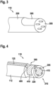
- Fig. 4 shows a schematic representation of a motor housing module 110 according to an embodiment.
- a side view of the motor housing module 110 connected to the motor compartment 112 of the heart assist system is shown, wherein only a proximal section of the cylindrical heart assist system, which Motor compartment 112 is shown.
- the motor housing module 110 has the same diameter and the same material as the motor compartment 112 on the side facing the motor compartment 112.
- the motor housing module 110 can taper in a conical shape in order to create space for placing sensors.
- the sensor line 125 is guided here, for example, along the longitudinal axis of the heart support system 100 in a band-like manner on the housing of the heart support system via the motor compartment 112 to the motor housing module 110.
- the sensor line section 405 has a contact section 415.
- the contact section 415 is arranged on a side of the feedthrough section 205 facing away from the engine compartment 112.
- the contact section 415 is arranged at least partially on the feedthrough section 205.
- the contact section 415 can be O-shaped or U-shaped.
- the contact section 415 extends, for example, over a large part of the cross-sectional area of the feedthrough section 205.
- the contact section 415 has recesses in the area of the through-opening and/or the blind holes.
- Fig. 5 shows a schematic representation of a sensor line section 405 of a motor housing module according to an embodiment.
- the sensor line section 405 is here exemplary as a thin-film substrate for contacting the blind pins in the form of the contact pins and for integrating additional sensors of the heart support system on the motor housing module and shown in a plan view as a fold-out.
- the shape of the sensor line section 405 shown here is suitable for contacting the sensor line to the motor housing module and enables sensor integration on the sensor line section 405.
- the shape of the sensor line section 405 essentially corresponds to the Fig. 4 described sensor line section 405, with the expansion of the sensor line section 405 into a section that runs around the motor housing module and corresponds to the sensor groove.
- the contact section 415 here also has an O-shaped recess 505 through which the feed-through line can be passed when the contact section 415 rests on the feed-through section 205.
- the contact section 415 has at least one contact surface 510 for connection to the at least one contact pin.
- the at least one contact surface 510 is shaped to at least partially enclose the at least one contact pin.
- the contact surface 510 can also be referred to as a contact pad.
- the contact section 415 has, for example, four contact surfaces 510 in order to electrically connect four contact pins embedded in the feedthrough section to the sensor line section 405.
- the contact surfaces 510 can be semicircular or elliptical in shape in order to at least partially enclose a contact pin for electrical contact with the sensor line section 405.
- the shape of the motor housing module and the sensor line are coordinated with one another, for example by the shape of the sensor line section 405, so that the contact pads 510 enclose the contact pins of the motor housing module.
- the contact pads 510 have an exposed electrically contactable area.
- An electrical contact can be made, for example, by solder or adhesive.
- the contacting of the The feedthrough cable for connecting the motor can be made in the same way as the contact pins are made to the sensors, or the contact section 415 has the recess 505 in an O or U shape, as shown here, so that the feedthrough cable can be connected to the connection cable without contact with the contact section 415 of the sensor cable section 405.
- the arrangement of the contact section 415 on the feedthrough section, and thus the contacting of the sensor cable to the blind pins of the motor housing module, can be carried out in the production process, for example, by folding the sensor cable section 405 over onto the feedthrough section and then establishing the electrical connections.
- Additional recesses in the sensor groove of the motor housing module can create additional installation space for accommodating electronic components such as sensors in the sensor groove, particularly if the sensor line section 405 has several sensor carriers 410 as shown here. Components accommodated in the sensor groove can be or will be additionally mechanically protected by a cap element.
- an electronic component accommodated on the sensor line section 405 in the sensor groove of the motor housing module can have a sensor hub.
- the sensor hub is designed to process at least one sensor signal of the at least one sensor of the cardiac support system. Additionally or alternatively, the sensor hub is designed to provide the at least one sensor signal to the connection cable via the at least one contact pin.
- the integration of a sensor hub enables the preprocessing of sensor data and the translation of the data interfaces.
- calibration and operating parameters such as identification information of the cardiac support system or accommodated sensors can be stored on the cardiac support system by means of the sensor hub and provided to a connected control unit by means of the connection cable, for example via a communication bus in the connection cable. In this way, the The control unit can be parameterized with engine data, for example.
- the sensor hub can be used to pre-process sensor data from sensors in the heart support system pump, e.g. to aggregate, filter or calibrate it, and to translate the communication protocol of the sensors to a more robust communication protocol (transceiver) and add artificial redundancy or checksums.
- Fig. 6 shows a schematic representation of a cap element 605 for a motor housing module according to an embodiment.
- the cap element 605 is intended for use with the motor housing module from one of the figures shown here.
- the cap element 605 is shaped to cover electronic components of a motor housing module, as can be seen from Fig. 3 described.
- the cap element 605 can thus be used as mechanical protection of the motor housing module.
- a side view of the cap element 605 in a one-piece design is shown.
- the cap element 605 has at least one recess 610 in the direction of the engine compartment as a sensitive measuring window for one of the sensors 120/410/710.
- the sensor can be a pressure sensor, for example, so that the measuring window 610 is to be placed above the pressure-sensitive membrane of the pressure sensor, so that the blood pressure of the surrounding blood can act unhindered on the pressure sensor.
- Adjacent to the recess 610, the cap element has the sensor cap 615.
- the sensor cap is shaped to have a sensor groove, e.g. the one in Fig. 3 described sensor groove, which is formed as a stepped plane of the cylindrical body of the engine housing module.
- the sensor cap can be shaped accordingly to cover this area.
- the sensor cap 615 is adjoined by a connection point cap 620 which is conically shaped in the manner of an arrowhead and has an opening 625 for the connection cable to pass through.
- the cap element 605 thus has the sensor cap 615 for covering the at least one electronic component accommodated in the sensor groove.
- the cap element 605 also has the optional connection point cap 620 for covering a connection point between the feedthrough section and the connection cable.
- the sensor cap 615 and the connection point cap 620 can be designed as a one-piece component combined as the cap element 605, as shown here.
- the sensor cap 615 and the connection point cap 620 can also be designed separately as separate components.
- the sensor cap 615 can be a metal cap that is fixed by gluing, for example.
- the connection point cap 620 can be flexibly shaped, for example, to provide kink protection and strain relief in addition to mechanical protection.
- the cap element 605 can be filled with a potting compound, for example with a silicone or epoxy resin, to protect sensors and contact points from corrosion and conductive liquids.
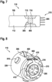
- Fig. 7 shows a schematic representation of a motor housing module 110 according to an embodiment.
- the motor housing module 110 corresponds to or is similar to the motor housing module from one of the figures described above.
- the side view shows the motor compartment 112 with a motor compartment housing 705 as a section of the assembled cylindrical heart support system.
- the motor housing module 110 is connected to the motor compartment housing 705 and has a circumferential recess in the direction of the motor compartment 112 as a sensor groove 305.
- a sensor 710 is integrated as an electronic component on the sensor line section 405.
- the correspondingly filled area 715 is shown here as an example.
- the motor housing module 110 has the feedthrough section 205 on the side facing away from the motor compartment 112, from which four contact pins 215 protrude, for example.
- Fig. 8 shows a schematic representation of a motor housing module 110 according to an embodiment.
- the motor housing module 110 is shown here in a top view.
- the body 220 is realized as a titanium part.
- the sensor line section 405 is led into the sensor groove 305 from the direction of the engine compartment.
- the sensor line section 405 is formed here as a thin-film substrate, for example.
- the body 220 in the form of a milled part made of titanium has a stepped plane as the sensor groove 305.
- the sensor line section 405 expands in the area of the sensor groove 305 and, as a thin layer, almost completely fills a lower area of the base area of the sensor groove 305.
- the motor housing module 110 has a coupling device for coupling an insertion device for introducing the heart support system to the motor housing module 110, in particular wherein the coupling device has at least one fixing element 810.
- the fixing element 810 can serve for the positive coupling of a clamp element, a so-called clamp.
- the body 220 as a titanium part here has, for example, three round fixing elements 810 as a coupling device.
- the fixing elements 810 can additionally or alternatively also be used to fix a cap element for covering an electronic component 805 or an electrical connection point of the motor housing module 110, the fixing elements 810 then serve as a fit for attaching the cap element.
- the embodiment of the motor housing module 110 shown here has the body 220 and the feedthrough section 205, implemented as a so-called glass feedthrough.
- Three feedthrough lines 210 for electrically connecting the motor of the heart support system to the connection cable are embedded in the feedthrough section 205, for example.
- eight U-shaped contact pins 215 are embedded in the feedthrough section 205, for example.
- the contact pins 215 are arranged essentially evenly spaced apart.
- the sensor line section 405 is tapered in the direction of the feedthrough section 205 out of the sensor groove 305 and forms the O-shaped contact section 415.
- the contact section 415 has a semicircular contact surface adjacent to the contact pins 215 for electrically connecting the contact pins 215 to the sensor line section 405.
- the connection cable can be connected to the feed-through line 210 and to the contact pins 215 for external contacting of the cardiac assist system by means of the motor housing module 110.
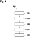
- Fig. 9 shows a flow chart of a method 900 for assembling a heart assist system according to an embodiment.
- the heart assist system has a motor, a motor compartment, at least one sensor, a sensor line electrically connected to the at least one sensor and a connection cable for externally contacting the heart assist system.
- the method 900 comprises a step 901 of providing, a step 903 of producing, a step 905 of contacting and a step 907 of producing.
- a motor housing module is provided in step 901 of providing.
- the motor housing module corresponds to or is similar to the motor housing module from one of the figures described above.
- an electrically conductive connection is made between the at least one feedthrough line of the motor housing module and the motor of the heart assist system.
- step 905 of producing a material connection is made between the motor housing module and the heart assist system in order to to seal the motor compartment of the heart support system.
- step 907 of contacting the at least one contact pin of the motor housing module is contacted with the sensor line of the heart support system.
- a sensor cap and/or a connection point cap for covering and protecting an electronic component or an electrically conductive interface of a component of the heart support system can also be mounted.
- the method 900 optionally comprises a step 909 of connecting the connection cable of the heart assist system to the at least one feedthrough line and the at least one contact pin of the motor housing module.
- the step 909 of connecting can be carried out before or after the step 907 of generating.
- an embodiment includes an "and/or" connection between a first feature and a second feature, this is to be read as the embodiment according to one embodiment has both the first feature and the second feature and according to a further embodiment has either only the first feature or only the second feature.
Landscapes
- Health & Medical Sciences (AREA)
- Heart & Thoracic Surgery (AREA)
- Engineering & Computer Science (AREA)
- Life Sciences & Earth Sciences (AREA)
- Mechanical Engineering (AREA)
- Anesthesiology (AREA)
- Biomedical Technology (AREA)
- Hematology (AREA)
- Cardiology (AREA)
- Animal Behavior & Ethology (AREA)
- General Health & Medical Sciences (AREA)
- Public Health (AREA)
- Veterinary Medicine (AREA)
- Vascular Medicine (AREA)
- External Artificial Organs (AREA)
- Motor Or Generator Frames (AREA)
Description
- Die Erfindung betrifft ein Motorgehäusemodul zum Abdichten eines Motorraums eines Motors eines Herzunterstützungssystems und ein Herzunterstützungssystem sowie ein Verfahren zum Montieren eines Herzunterstützungssystems.
- Aus der
WO 99/49912 A1 - Herzunterstützungssysteme, wie beispielsweise ein linksventrikuläres Herzunterstützungssystem, können in eine Herzkammer implantiert werden und integrierte elektronische Komponenten, beispielsweise Sensoren, aufweisen. Die Integration elektronischer Komponenten in das Herzunterstützungssystem erfolgt meist klassisch auf Substraten, z. B. Leiterplatten oder gedruckten Leiterplatten (PCBs, printed circuit boards), aufgebaut und in entsprechend große Kavitäten des Herzunterstützungssystems integriert. Diese Herzunterstützungssysteme können beispielsweise mittels einer Sternotomie implantiert werden. Zudem ist es möglich, kompakter gebaute Herzunterstützungssysteme, beispielsweise auch linksventrikuläre Herzunterstützungssysteme, minimalinvasiv in ein Blutgefäß zu implantieren. Diese kompakter gebauten Herzunterstützungssysteme weisen aufgrund der Anforderungen an die Baugröße bisher keine integrierten elektronischen Komponenten mit implantiert platzierter Verarbeitungselektronik auf.
- Die
US 9,474,840 B2 - Aufgabe der Erfindung ist es, ein verbessertes Herzunterstützungssystem bereitzustellen. Insbesondere ist es eine Aufgabe der Erfindung, in einem Herzunterstützungssystem auf kleinem Bauraum sowohl für einen Motor zum Antreiben einer die Herzfunktion unterstützenden Blutpumpe als auch für Sensoren elektrische Anschlussmöglichkeiten zu schaffen.
- Diese Aufgabe wird durch ein Motorgehäusemodul mit den in Anspruch 1 angegebenen Merkmalen sowie ein Herzunterstützungssystem nach Anspruch 13 und das in Anspruch 14 angegebene Verfahren zum Montieren eines Herzunterstützungssystems gelöst.
- Vorteilhafte Ausführungsformen der Erfindung sind in den abhängigen Ansprüchen angegeben.
- Vor diesem Hintergrund werden mit dem hier vorgestellten Ansatz ein Motorgehäusemodul zum Abdichten eines Motorraums eines Motors eines Herzunterstützungssystems, ein Herzunterstützungssystem sowie ein Verfahren zum Montieren eines Herzunterstützungssystems gemäß den Hauptansprüchen vorgestellt. Durch die in den abhängigen Ansprüchen aufgeführten Maßnahmen sind vorteilhafte Weiterbildungen und Verbesserungen der im unabhängigen Anspruch angegebenen Vorrichtung möglich.
- Mit diesem Ansatz wird ein Motorgehäusemodul für ein Herzunterstützungssystem vorgestellt. Das Motorgehäusemodul kann den Motorraum des Herzunterstützungssystems fluiddicht abdichten und den Motor des Herzunterstützungssystems mit einem Anschlusskabel verbinden, über das der Motor mit Strom versorgt werden kann. Zudem können mittels dem Motorgehäusemodul Sensorsignale zusammengeführt, verarbeitet und über das Anschlusskabel weitergeleitet werden. Das Motorgehäusemodul und das Herzunterstützungssystem können dabei vorteilhafterweise so kompakt gestaltet sein, das sie beispielsweise für ein linksventrikuläres Herzunterstützungssystem (LVAD, left ventricular assist device) zum minimalinvasiven Implantieren als vollimplantiertes System verwendet werden können. Insbesondere kann das Herzunterstützungssystem so ausgebildet sein, dass es sich mittels Katheter in eine Herzkammer oder die Aorta einführen lässt.
- Vorteilhafterweise ist es somit möglich, auch in einem kompakt gebauten Herzunterstützungssystem elektronische Bauelemente zu integrieren.
- Es wird ein Motorgehäusemodul zum Abdichten eines Motorraums eines Motors eines Herzunterstützungssystems vorgestellt. Das Motorgehäusemodul weist einen Durchführungsabschnitt, zumindest eine Durchführleitung und zumindest einen Kontaktstift auf. Der Durchführungsabschnitt ist ausgebildet, eine elektrische Verbindung zwischen dem Herzunterstützungssystem und einem Anschlusskabel zum externen Kontaktieren des Herzunterstützungssystems herzustellen. Die zumindest eine Durchführleitung ist in dem Durchführungsabschnitt eingebettet und erstreckt sich durch den Durchführungsabschnitt hindurch. Die Durchführleitung ist an den Motor und an das Anschlusskabel anschließbar. Ein erstes Ende des zumindest einen Kontaktstifts ist in den Durchführungsabschnitt eingebettet und ein zweites Ende ragt auf einer von dem Motorraum abgewandten Seite aus dem Durchführungsabschnitt heraus. Das zweite Ende des Kontaktstifts ist an eine Sensorleitung zu zumindest einem Sensor des Herzunterstützungssystems und an das Anschlusskabel anschließbar.
- Das Motorgehäusemodul kann beispielsweise einteilig oder zweiteilig ausgeführt sein. Beispielsweise kann das Motorgehäusemodul Titankomponenten oder Glaskomponenten aufweisen. Das Herzunterstützungssystem kann beispielsweise ein linksventrikuläres Herzunterstützungssystem sein, das eine Herzpumpe mit einem Motor aufweist. Bei dem Motorraum kann es sich beispielsweise um einen Abschnitt des Herzunterstützungssystems handeln, beispielsweise auch um einen Gehäuseabschnitt. Der Motorraum kann mittels des hier vorgestellten Gehäuses vorteilhafterweise hermetisch, also fluiddicht, abgedichtet werden. Das Motorgehäusemodul kann beispielsweise aus einem Material bestehen, das eine Schweißverbindung zwischen dem Motor oder dem Motorraum und dem Motorgehäusemodul ermöglicht, um den Motorraum abzudichten. Der Durchführungsabschnitt zum Herstellen einer elektrischen Verbindung zwischen dem Herzunterstützungssystem und dem Anschlusskabel kann beispielsweise einteilig ausgeführt sein. Alternativ kann der Durchführungsabschnitt beispielsweise einen Frästeil und eine Glaskomponente umfassen, die beispielsweise durch Laserschweißen oder Sintern hermetisch miteinander verbunden sind. Die Durchführleitung und der Kontaktstift können beispielsweise aus einem elektrisch leitfähigen Material, beispielsweise einem Metall wie einer Eisen-Nickel-Kobalt-Legierung mit einem geringen Wärmeausdehnungskoeffizienten oder Edelstahl bestehen. Das Anschlusskabel zum externen Kontaktieren des Herzunterstützungssystems kann beispielsweise eine elektrische Verbindung zu einer weiteren implantierten Komponente herstellen, beispielsweise einer Stromquelle und/oder Steuereinheit des Herzunterstützungssystems. Die Sensorleitung kann beispielsweise eine Gruppe von Leitungen umfassen und ausgebildet sein, um Sensorsignale eines Sensors im Pumpenkopf des Herzunterstützungssystems und/oder Sensorsignale mehrerer Sensoren weiterzuleiten. Die Sensorleitung kann beispielsweise als ein aufgebrachtes flexibles Dünnschichtsubstrat realisiert sein.
- Der Durchführungsabschnitt kann gemäß einer Ausführungsform zumindest eine mit einem elektrisch isolierenden Material verfüllte Durchgangsöffnung zum Einbetten der zumindest einen Durchführleitung und zumindest ein mit einem elektrisch isolierenden Material verfülltes Sackloch zum Einbetten des zumindest einen Kontaktstifts aufweisen. Vorteilhafterweise kann der Durchführungsabschnitt somit beispielsweise aus Glas hergestellt sein oder werden, und sowohl die Durchführleitung als auch der Kontaktstift können eingebettet werden. Diese Ausführungsform ermöglicht vorteilhafterweise eine besonders kostensparende Herstellung.
- Von Vorteil ist es zudem gemäß einer Ausführungsform, wenn die zumindest eine Durchführleitung und zusätzlich oder alternativ der zumindest eine Kontaktstift zylinderförmig oder kelchförmig ausgeformt sind. Wenn die zumindest eine Durchführleitung und der zumindest eine Kontaktstift zylinderförmig, also als gerade Pins, ausgeführt sind, kann die Anbindung des Anschlusskabels beispielsweise durch direktes Löten, Kleben, Crimpen oder Schweißen der Anschlusskabellitzen an den Pin oder unter Verwendung einer Hülse oder eines Steckers erfolgen. Bei einer kelchförmig oder tulpenförmigen Ausformung der zumindest einen Durchführleitung und zusätzlich oder alternativ des zumindest einen Kontaktstifts kann das Anbinden an das Anschlusskabel beispielsweise durch ein Einführen der Litzen des Anschlusskabels in den Kelch der Durchleitung oder des Kontaktstifts erfolgen, wobei das Fixieren mittels Löten, Kleben, Crimpen oder Schweißen realisiert werden kann. Vorteilhafterweise lassen sich gemäß dieser Ausführungsform verschiedene Anwendungsformen realisieren, was in Bezug auf eine möglichst einfache Bauweise von Vorteil ist. Zudem kann beispielsweise eine zusätzliche mechanische Stabilisierung der Anbindung erfolgen, beispielsweise durch einen Stecker als Teil der Anbindung.
- Gemäß einer Ausführungsform kann das Motorgehäusemodul einen Korpus umfassen. Der Korpus kann eine Sensornut zum Aufnehmen zumindest eines elektronischen Bauteils, insbesondere eines Sensors und zusätzlich oder alternativ eines Sensor-Hubs, aufweisen. Vorteilhafterweise kann somit ein Sensor auf dem Korpus des Motorgehäusemoduls platziert werden, was eine kompakte Bauweise ermöglicht. Die elektrische Kontaktierung eines in der Sensornut aufgenommenen elektronischen Bauteils mit dem Durchführungsabschnitt kann beispielsweise mittels eines elektrisch leitfähigen Substrats, beispielsweise eines flexiblen Dünnschichtsubstrats, erfolgen. Die Sensornut kann beispielsweise auch als Mulde oder als Kavität ausgeformt sein. Der Korpus kann beispielsweise ein Frästeil aus Titan sein. Der Korpus kann beispielsweise ausgeformt sein, um den Durchführungsabschnitt zu umschließen. Der Durchführungsabschnitt, der beispielsweise Glas aufweisen kann, kann dann durch Laserschweißen, Sintern oder Umspritzen hermetisch mit dem Frästeil kombiniert werden. Eine Integration des Durchführungsabschnitts in den Korpus kann in Bezug auf die Bauweise vorteilhaft sein, da der Korpus des Motorgehäusemoduls besonders einfach mit einem anderen Abschnitt des Herzunterstützungssystems, beispielsweise dem Motorraum oder dem Motor, verschweißt werden kann.
- Wenn das Motorgehäusemodul gemäß einer Ausführungsform eine Sensornut aufweist, kann das Motorgehäusemodul zusätzlich eine Sensorkappe zum Abdecken des zumindest einen in der Sensornut aufgenommenen elektronischen Bauteils aufweisen. Die Sensorkappe kann beispielsweise ein Metall aufweisen und durch Kleben fixiert werden. Vorteilhafterweise kann so ein aufgenommenes elektronisches Bauteil durch die Sensorkappe geschützt werden.
- Zudem kann das Motorgehäuse gemäß dieser Ausführungsform einen Sensorleitungsabschnitt der Sensorleitung aufweisen. Der Sensorleitungsabschnitt kann im Bereich der Sensornut einen Sensorträger zum Anschließen des zumindest einen elektronischen Bauteils ausformen. Der Sensorleitungsabschnitt repräsentiert einen Teil der Sensorleitung des Herzunterstützungssystems, die Sensorleitung kann dazu beispielsweise modular ausgeführt sein. Zum Ausformen des Sensorträgers kann sich die Sensorleitung beispielsweise im Bereich des Sensorleitungsabschnitts aufweiten. Vorteilhafterweise ist gemäß dieser Ausführungsform eine Verbindung mit der Sensorleitung und eine Integration eines elektronischen Bauteils, wie beispielsweise eines weiteren Sensors, besonders platzsparend und einfach möglich.
- Das elektronische Bauteil kann gemäß einer Ausführungsform einen Sensor-Hub aufweisen. Der Sensor-Hub kann ausgebildet sein, zumindest ein Sensorsignal des zumindest einen Sensors des Herzunterstützungssystems zu verarbeiten. Zusätzlich oder alternativ kann der Sensor-Hub dazu ausgebildet sein, das Sensorsignal über den zumindest einen Kontaktstift an das Anschlusskabel bereitzustellen. Unter dem Sensor-Hub kann beispielsweise ein Gerät verstanden werden, das Netzknoten mehrerer Sensoren beispielsweise sternförmig miteinander verbindet. Der Sensor-Hub kann ein Rechnernetz sein. Der Sensor-Hub kann als Kopplungselement mehrerer Sensoren bezeichnet werden. Der Sensor-Hub kann beispielsweise den Sensor am Pumpenkopf mit einem in der Sensornut des Motorgehäusemoduls aufgenommenen Sensor verbinden. Die Verbindung mehrerer Sensoren mittels eines Sensor-Hubs kann vorteilhaft sein, um eine Ausfallsicherheit gegenüber einem physikalischen Bus-Netz zu erhöhen. Der Sensor-Hub kann beispielsweise Kalibrier- und Identifikationsinformationen von der Pumpe und den Sensoren des Herzunterstützungssystems umfassen und über einen Kommunikationsbus im Anschlusskabel von einem zentralen Steuergerät des Herzunterstützungssystems auslesbar sein. Auf diese Weise kann das Steuergerät beispielsweise mit Motordaten parametriert werden. Der Sensor-Hub kann zudem dazu genutzt werden, Sensordaten der Sensoren der Pumpe vorzuverarbeiten, z. B. zu aggregieren, zu filtern, oder zu kalibrieren und das Kommunikationsprotokoll der Sensoren auf ein robusteres Kommunikationsprotokoll zu übersetzen und künstliche Redundanz oder Prüfsummen hinzuzufügen.
- Vorteilhafterweise kann der Sensorleitungsabschnitt gemäß einer Ausführungsform einen Kontaktabschnitt aufweisen. Der Kontaktabschnitt kann an einer von dem Motorraum abgewandten Seite des Durchführungsabschnitts angeordnet sein. Zudem kann der Kontaktabschnitt O-förmig oder U-förmig ausgeformt sein. Vorteilhafterweise kann der Kontaktabschnitt zum elektrischen Kontaktieren der Sensorleitung mit dem Durchführungsabschnitt verwendet werden, wobei diese Ausführungsform besonders platzsparend ist. Der Kontaktabschnitt kann dazu beispielsweise als ein Endabschnitt des Sensorleitungsabschnitts ausgeformt sein und auf den Durchführungsabschnitt umgeklappt sein oder werden, wobei durch die O-Form oder U-Form beispielsweise das Kontaktieren des Anschlusskabels mit dem zumindest einen Kontaktstift ohne einen Kontakt des Kontaktabschnitts zur Durchführleitung realisiert werden kann.
- Der Kontaktabschnitt kann gemäß einer Ausführungsform zumindest eine Kontaktfläche zum Anschließen an den zumindest einen Kontaktstift aufweisen. Die Kontaktfläche kann ausgeformt sein, um den zumindest einen Kontaktstift zumindest teilweise zu umschließen. Die Kontaktfläche kann dazu beispielsweise halbkreis- oder ellipsenförmig sein. Die Kontaktfläche kann beispielsweise einen offenliegenden elektrisch kontaktierbaren Bereich aufweisen, wobei der elektrische Kontakt zwischen dem Sensorleitungsabschnitt und dem Kontaktstift beispielsweise durch Lot oder Kleber hergestellt werden kann.
- Gemäß einer Ausführungsform kann das Motorgehäusemodul eine Anschlussstellenkappe zum Abdecken einer Anschlussstelle zwischen dem Durchführungsabschnitt und dem Anschlusskabel aufweisen. Dies ist von Vorteil, um die Anschlussstelle zu schützen. Die Anschlussstellenkappe kann beispielsweise auch ein Teil der Sensorkappe sein. Die Anschlussstellenkappe kann, wie auch die Sensorkappe, mit einer Vergussmasse ausgefüllt werden, beispielsweise einem Silikon oder Epoxidharz, um Sensoren und Kontaktstellen vor Korrosion und leitfähigen Flüssigkeiten zu schützen. Die Anschlussstellenkappe kann flexibel ausgeformt sein, um neben einem mechanischen Schutz einen Knickschutz und eine Zugentlastung realisieren zu können.
- Zudem kann das Motorgehäusemodul gemäß einer Ausführungsform eine Koppeleinrichtung zum Ankoppeln einer Einführeinrichtung zum Einführen des Herzunterstützungssystems an das Motorgehäusemodul aufweisen, insbesondere wobei die Koppeleinrichtung zumindest ein Fixierelement aufweisen kann. Dies ist von Vorteil, um das Motorgehäusemodul beispielsweise formschlüssig und/oder kraftschlüssig an die Einführeinrichtung fixieren zu können, beispielsweise um das Herzunterstützungssystem, welches das Motorgehäusemodul umfasst, minimalinvasiv einbringen zu können, und nach erfolgtem Implantieren der Einführeinrichtung abkoppeln zu können, um das Herzunterstützungssystem am Bestimmungsort freizusetzen. Das Fixierelement kann beispielsweise eine Klammer, auch Clamp genannt, oder dergleichen aufweisen. Die Koppeleinrichtung kann gemäß einer Ausführungsform auf dem Korpus des Motorgehäusemoduls realisiert sein.
- Es wird zudem ein Herzunterstützungssystem vorgestellt. Das Herzunterstützungssystem weist ein Gehäuse mit einem Motorraum, einen Motor, der in dem Motorraum angeordnet ist, zumindest einen Sensor, eine mit dem zumindest einen Sensor elektrisch verbundene Sensorleitung, ein Anschlusskabel zum externen Kontaktieren des Herzunterstützungssystems und eine Ausführungsform des vorstehend genannten Motorgehäusemoduls als Teil des Gehäuses auf. Der Motor und der zumindest eine Sensor sind mittels des Motorgehäusemoduls elektrisch mit dem Anschlusskabel verbunden.
- Bei dem Herzunterstützungssystem kann es sich um ein ventrikuläres Herzunterstützungssystem, insbesondere ein linksventrikuläres Herzunterstützungssystem handeln. Das Herzunterstützungssystem kann beispielsweise einen Elektromotor oder eine elektrisch betriebene Motor-Kupplung-Pumpeneinheit aufweisen. Der Sensor kann beispielsweise am Pumpenkopf und zusätzlich oder alternativ an dem Motorgehäusemodul angeordnet sein. Der Sensor kann beispielsweise ein Drucksensor sein oder ein Sensor zum Messen der Blutflussrichtung. Das Herzunterstützungssystem kann beispielsweise zum minimalinvasiven Einführen zylinderförmig sein und einen Durchmesser aufweisen, der geringer als die menschliche Aorta ist, beispielsweise 5 bis 12 Millimeter.
- Zudem wird ein Verfahren zum Montieren eines Herzunterstützungssystems vorgestellt. Das Herzunterstützungssystem weist einen Motor, einen Motorraum, zumindest einen Sensor, eine mit dem zumindest einen Sensor elektrisch verbundene Sensorleitung und ein Anschlusskabel zum externen Kontaktieren des Herzunterstützungssystems auf. Das Verfahren umfasst einen Schritt des Bereitstellens, einen Schritt des Herstellens, einen Schritt des Kontaktierens und einen Schritt des Erzeugens. Im Schritt des Bereitstellens wird eine Ausführungsform des vorstehend genannten Motorgehäusemoduls bereitgestellt. Im Schritt des Herstellens wird eine elektrisch leitfähige Verbindung zwischen der zumindest einen Durchführleitung des Motorgehäusemoduls und dem Motor des Herzunterstützungssystems hergestellt. Im Schritt des Erzeugens wird eine stoffschlüssige Verbindung zwischen dem Motorgehäusemodul und dem Herzunterstützungssystem erzeugt, um den Motorraum des Herzunterstützungssystems abzudichten. Im Schritt des Kontaktierens wird der zumindest eine Kontaktstift des Motorgehäusemoduls mit der Sensorleitung des Herzunterstützungssystems kontaktiert.
- Die stoffschlüssige Verbindung kann beispielsweise mittels Schweißen erzeugt werden. Optional kann nach dem Verschweißen zudem noch eine Sensorkappe und zusätzlich oder alternativ eine Anschlussstellenkappe zum Abdecken und Schützen eines elektronischen Bauteils oder einer elektrisch leitfähigen Schnittstelle einer Komponente des Herzunterstützungssystems montiert werden.
- Das Verfahren kann gemäß einer Ausführungsform zudem einen Schritt des Anschließens des Anschlusskabels des Herzunterstützungssystems an die zumindest eine Durchführleitung und den zumindest einen Kontaktstift des Motorgehäusemoduls umfassen. Der Schritt des Anschließens kann vor oder nach dem Schritt des Erzeugens erfolgen. Wenn der Schritt des Anschließens nach dem Schritt des Erzeugens erfolgt, kann das Motorgehäusemodul eine Durchlassöffnung für das Anschlusskabel aufweisen.
- Vorteilhafte Ausführungsbeispiele des hier vorgestellten Ansatzes sind in den Zeichnungen dargestellt und in der nachfolgenden Beschreibung näher erläutert. Es zeigt:
- Fig. 1
- eine schematische Darstellung eines Herzunterstützungssystems gemäß einem Ausführungsbeispiel;
- Fig. 2
- eine schematische Darstellung eines Motorgehäusemoduls gemäß einem Ausführungsbeispiel;
- Fig. 3
- eine schematische Darstellung eines Motorgehäusemoduls gemäß einem Ausführungsbeispiel;
- Fig. 4
- eine schematische Darstellung eines Motorgehäusemoduls gemäß einem Ausführungsbeispiel;
- Fig. 5
- eine schematische Darstellung eines Sensorleitungsabschnitts eines Motorgehäusemoduls gemäß einem Ausführungsbeispiel;
- Fig. 6
- eine schematische Darstellung eines Kappenelements für ein Motorgehäusemodul gemäß einem Ausführungsbeispiel;
- Fig. 7
- eine schematische Darstellung eines Motorgehäusemoduls gemäß einem Ausführungsbeispiel;
- Fig. 8
- eine schematische Darstellung eines Motorgehäusemoduls gemäß einem Ausführungsbeispiel; und
- Fig. 9
- ein Ablaufdiagramm eines Verfahrens zum Montieren eines Herzunterstützungssystems gemäß einem Ausführungsbeispiel.
- In der nachfolgenden Beschreibung günstiger Ausführungsbeispiele der vorliegenden Erfindung werden für die in den verschiedenen Figuren dargestellten und ähnlich wirkenden Elemente gleiche oder ähnliche Bezugszeichen verwendet, wobei auf eine wiederholte Beschreibung dieser Elemente verzichtet wird.
-
Fig. 1 zeigt eine schematische Darstellung eines Herzunterstützungssystems 100 gemäß einem Ausführungsbeispiel. Es ist eine Seitenansicht des Herzunterstützungssystems 100 gezeigt, das hier beispielhaft als linksventrikuläres Herzunterstützungssystems 100 ausgeführt ist. Das Herzunterstützungssystem 100 weist ein Gehäuse 105 auf. Als Teil des Gehäuses 105 umfasst das Herzunterstützungssystem 100 ein Motorgehäusemodul 110. Von dem Gehäuse 105 und dem Motorgehäusemodul 110 ist ein Motorraum 112 umschlossen. In dem Motorraum 112 ist ein Motor 115 angeordnet. An einer Kopfseite des Herzunterstützungssystems 100 ist in einer Sensorbaugruppe zumindest ein Sensor 120 angeordnet. Der Sensor 120 ist elektrisch mit einer Sensorleitung 125 verbunden. Die Sensorleitung 125 ist hier beispielhaft über das Gehäuse 105 zu dem Motorgehäusemodul 110 geführt, sie kann auch zumindest abschnittsweise innerhalb des Gehäuses 105 verlaufen oder spiralförmig über das Gehäuse 105 geführt sein. Der Sensor 120 kann beispielsweise ein Drucksensor oder ein Flusssensor zum Blutflussmessen sein, beispielsweise mittels Ultraschall oder Laser. An der dem Motorraum 112 abgewandten Seite des Motorgehäusemoduls 110 weist das Herzunterstützungssystem 100 ein Anschlusskabel 130 zum externen Kontaktieren des Herzunterstützungssystems 100 auf. Das Motorgehäusemodul 110 kann als elektrisches Verbindungselement bezeichnet werden: Der Motor 115 und der zumindest eine Sensor 120 sind mittels des Motorgehäusemoduls 110 elektrisch mit dem Anschlusskabel 130 verbunden. Das Motorgehäusemodul 110, auch Motor-Backend genannt, ist dazu ausgeformt, den Motorraum 112 hermetisch zu verschließen und somit fluiddicht abzudichten. Zudem ist das Motorgehäusemodul 110 dazu ausgebildet, eine elektrische Verbindung zwischen dem hermetisch verschlossenen Motorinneren des Motors 115 und der Umgebung des Herzunterstützungssystems 100 herzustellen: Das Motorgehäusemodul 110 übernimmt die Aufgaben der Zusammenführung der Sensorleitung 125, die elektrische Signale aus einem Pumpenkopf 135 des Herzunterstützungssystems 100 zum Motorgehäusemodul 110 führt, mit dem Anschlusskabel 130, das die Sensorsignale weiterführt und den Motor mit elektrischer Energie versorgt. Dazu können elektrische Leiter aus dem Inneren des Motors 115 mit dem auf der Außenseite des Motors 115 geführten Sensorkabel 125 und dem Anschlusskabel 130, auch Zuleitungskabel genannt, zusammengeführt werden. Auf diese Weise kann eine mechanisch sichere Verbindung des Anschlusskabels 130 mit dem Motorgehäusemodul 110 hergestellt werden. Über das Anschlusskabel 130 kann das Herzunterstützungssystem 100 an eine weitere Komponente angeschlossen sein oder werden, wie eine Energiequelle, eine Datenverarbeitungseinrichtung oder ein Steuergerät. - Das Herzunterstützungssystem 100 weist einen zylinderförmigen, länglichen Aufbau mit im Wesentlichen konstantem Außendurchmesser und abgerundeten, sich verjüngenden Enden zur einfachen Platzierung mittels eines Katheters in einem Blutgefäß, etwa der Aorta, auf. Das Motorgehäusemodul 110 hat die Form eines kegelstumpfs. Es ist konusförmig ausgeformt, mit einer Grundfläche in Richtung des Motorraums 112, die dem Außendurchmesser des Herzunterstützungssystems 100 entspricht, und mit einer kleineren Deckfläche als Übergang zum Anschlusskabel 130.
-
Fig. 2 zeigt eine schematische Darstellung eines Motorgehäusemoduls 110 zum Abdichten eines Motorraums eines Motors eines Herzunterstützungssystems gemäß einem Ausführungsbeispiel. Das Motorgehäusemodul 110 entspricht oder ähnelt hierbei dem Motorgehäusemodul 110 ausFig. 1 . Gezeigt ist ein Querschnitt einer Seitenansicht des Motorgehäusemoduls 110. Das Motorgehäusemodul 110 weist zumindest einen Durchführungsabschnitt 205 zum Herstellen einer elektrischen Verbindung zwischen dem Herzunterstützungssystem und einem Anschlusskabel zum externen Kontaktieren des Herzunterstützungssystems auf. Zudem weist das Motorgehäusemodul 110 zumindest eine Durchführleitung 210 auf, die in dem Durchführungsabschnitt 205 eingebettet ist und die sich durch den Durchführungsabschnitt 205 hindurch erstreckt. Die Durchführleitung 210 ist an den Motor und an das Anschlusskabel des Herzunterstützungssystems anschließbar. Das Motorgehäusemodul 110 weist ferner zumindest einen Kontaktstift 215 auf. Beispielhaft sind hier zwei unterschiedlich ausgeformte Kontaktstifte 215 gezeigt. Ein erstes Ende des Kontaktstifts 215 ist in dem Durchführungsabschnitt 205 eingebettet und ein zweites Ende ragt auf einer von dem Motorraum abgewandten Seite aus dem Durchführungsabschnitt 205 heraus. Das zweite Ende des Kontaktstifts 215 ist an eine Sensorleitung zu zumindest einem Sensor des Herzunterstützungssystems und an das Anschlusskabel anschließbar. - Der Durchführungsabschnitt 205 kann wie in dem hier gezeigten Ausführungsbeispiel zumindest eine mit einem elektrisch isolierenden Material verfüllte Durchgangsöffnung 225 zum Einbetten der zumindest einen Durchführleitung 210 und zumindest ein mit einem elektrisch isolierenden Material verfülltes Sackloch 230 zum Einbetten des zumindest einen Kontaktstifts 215 aufweisen. Eines der Sacklöcher kann auch leitfähig, beispielsweise mit elektrisch leitfähigem Kleber verfüllt sein, um eine elektrische Verbindung zwischen Motorgehäuse und einem Leiter des Anschlusskabels herzustellen. Dies kann beispielsweise der elektrischen Schirmung von Motor und Anschlusskabel dienen. Der Durchführungsabschnitt 205 ist beispielsweise aus Titan ausgeformt. Die Durchgangsöffnung 225 und die beiden gezeigten Sacklöcher 230 sind in dem Durchführungsabschnitt 205 ausgeformt und beispielsweise mit Glas als elektrisch isolierendes Material verfüllt. Die Sacklöcher 230 können entsprechend auch als blinde Glasdurchführungen bezeichnet werden, da sie nicht bis in das Innere des hermetisch verschlossenen Motors geführt sind. Die Durchführleitung 210, die als Durchführstift oder Pin realisiert sein kann, wird zur elektrischen Kontaktierung des Motors genutzt. Die Kontaktstifte 215, auch Blindpins genannt, werden zur Umverdrahtung der Sensorleitung genutzt. Die Durchführleitung 210 sowie der zumindest eine Kontaktstift 215 sind aus einem elektrisch leitfähigen Material ausgeformt, beispielsweise aus einem Metall wie einer Eisen-Nickel-Cobalt-Legierung mit einem geringen Wärmeausdehnungskoeffizienten oder wie Edelstahl.
- Die zumindest eine Durchführleitung 210 und/oder der zumindest eine Kontaktstift 215 können zylinderförmig ausgeformt sein, wie hier beispielhaft bei der Durchführleitung 210 und dem oberen der beiden Kontaktstifte 215 gezeigt, also als gerade Pins. Die Durchführleitung 210 und/oder der zumindest eine Kontaktstift 215 können alternativ auch kelchförmig ausgeformt sein, wie beispielhaft bei dem unteren der beiden Kontaktstifte 215 gezeigt. Wenn die Durchführleitung 210 und/oder der zumindest eine Kontaktstift 215 zylinderförmig ausgeformt sind, kann die Anbindung des Anschlusskabels beispielsweise durch direktes Löten, Kleben, Crimpen oder Schweißen der Anschlusskabellitzen an die Durchführleitung 210 und/oder den Kontaktstift 215 oder unter Verwendung einer Hülse oder eines Steckers erfolgen. Wenn die Durchführleitung 210 und/oder der zumindest eine Kontaktstift 215 kelchförmig ausgeformt sind, kann die Kabelverbindung mit dem Anschlusskabel durch Einführen der Litzen in den Kelch realisiert werden. Eine Fixierung kann durch Löten, Kleben, Crimpen oder Schweißen erfolgen.
- Das Motorgehäusemodul 110 ist gemäß dem in
Fig. 2 dargestellten Ausführungsbeispiel zweiteilig ausgeführt, mit einem Korpus 220 und dem Durchführungsabschnitt 205, der beispielsweise als sogenannte Glas-Feedthrough-Komponente ausgeformt ist. Die zweiteilige Ausführung des Motorgehäusemoduls 110 ist produktionstechnisch vorteilhaft. Die elektrische Kontaktierung des Motors und der Sensorleitung mit dem Durchführungsabschnitt 205 kann in diesem Fall im Inneren des Motorgehäusemoduls 110, im Folgenden auch Backend genannt, ermöglicht werden, wobei Motorlitzen beispielsweise an den Durchführungsabschnitt 205 angelötet werden können. Von Vorteil bei der zweiteiligen Ausführung des Motorgehäusemoduls 110 ist, dass für den Durchführungsabschnitt 205 auf eine Standard-Glas-Durchführung, ein Standard-Glas-Feedthrough, zurückgegriffen werden kann, das dann beispielsweise durch Laserschweißen, Sintern oder Umspritzen hermetisch mit dem als Frästeil ausgeführten Korpus 220 kombiniert werden kann, wobei der Korpus weitere Merkmale, wie die Integration von Clamps als Fixierlement der Koppeleinrichtung und eine Sensormulde in Form der Sensornut aufweisen kann, wie beispielsweise anhand vonFig. 8 beschrieben. Die zweiteilige Ausführung des Motorgehäusemoduls 110 ist zudem in Bezug auf die Montage vorteilhaft, da beispielsweise folgender Produktionsablauf realisiert werden kann: Kontaktieren des Durchführungsabschnitts 205 mit dem Motorinneren, Verbinden des Durchführungsabschnitts 205 mit dem Korpus 220, beispielsweise durch Aufschieben des Korpus 220 über den Durchführungsabschnitt 205, Verschweißen des Korpus 220 mit dem Motorgehäuse 112, Verschweißen des Korpus 220 mit dem Durchführungsabschnitt 205, Herstellen einer elektrischen Verbindung des Sensorkabels an die Kontaktstifte 215 und Kontaktieren des Anschlusskabels mit der Durchführleitung 210 und den Kontaktstiften 215. Optional kann anschließend die Montage eines Kappenelements wie inFig. 6 gezeigt als Schutzkappe mit Verguss-erfolgen. - Die zweiteilige Ausführung des Motorgehäusemoduls 110 kann durch eine Kombination aus einem Frästeil als Korpus 220 zur Herstellung der entsprechenden Geometrie mit vorteilhafter mechanischer Robustheit und Festigkeit und durch einen Durchführungsabschnitt 205 mit klassischen Glas-Durchführungen realisiert werden. Der Korpus 220 als Frästeil kann vorteilhafterweise aus Titan ausgeformt sein, um das Motorgehäusemodul 110 besonders einfach und effizient an ein Motorgehäuse 112 des Motors 115 anschweißen zu können, das beispielsweise auch aus Titan bestehen kann. Auf diese Weise kann eine hermetisch dichte Verbindung zwischen dem Korpus 220 und dem Motorgehäuse 112 hergestellt werden, um den Motorraum fluiddicht abzudichten. Die Ausformung der Kontaktstifte 215 als Glas-Blindstifte, also als blind endende Glasdurchführung, ermöglicht eine robuste Umverdrahtung der flexiblen Sensorleitung auf das Anschlusskabel auf Basis der Glas-Feedthrough-Technik, durch die Möglichkeit, die Kontaktstifte 215 an die Sensorleitung und an das Anschlusskabel anzuschließen.
Fig. 2 zeigt somit ein Backend oder Motorgehäusemodul 110 mit Blind-Pins zur Umverdrahtung in Form der beiden beispielhaft gezeigten Kontaktstifte 215 in den Sacklöchern 230. -
Fig. 3 zeigt eine schematische Darstellung eines Motorgehäusemoduls 110 gemäß einem Ausführungsbeispiel. Gezeigt ist eine Seitenansicht auf das Motorgehäusemodul 110 mit dem Korpus 220 und dem Durchführungsabschnitt 205, wobei der Durchführungsabschnitt 205 zum Einbetten der Durchführleitung und des zumindest einen Kontaktstifts ausgeformt ist und dazu beispielhafte Aussparungen aufweist. - Das Motorgehäusemodul 110, auch Pumpen-Backend genannt, weist eine zylinderförmige Form mit einer abgesetzten Ebene in Richtung des Durchführungsabschnitts 205 auf. Auf dieser abgesetzten Ebene kann beispielweise ein Sensor platziert werden. Die abgesetzte Ebene kann als Mulde oder als Kavität oder als Nut ausgeformt sein. Gemäß dem hier gezeigten Ausführungsbeispiel weist der Korpus 220 entsprechend eine Sensornut 305, in Form der abgesetzten Ebene, zum Aufnehmen zumindest eines elektronischen Bauteils, insbesondere eines Sensors und/oder eines Sensor-Hubs, auf.
- In der Sensornut 305 kann ein elektrisch leitfähiges Substrat angeordnet werden, um eine elektrische Kontaktierung eines in der Sensornut 305 aufgenommenen elektronischen Bauteils zu realisieren. Das Substrat kann beispielsweise ausgeformt sein, um das in der Sensornut 305 aufgenommene elektronische Bauteil an elektrisch leitfähigen Pins des Backends, also an den zumindest einen in den Durchführungsabschnitt 205 eingebetteten Kontaktstift, anzuschließen. Das Substrat ist beispielsweise ein flexibles Dünnschichtsubstrat. Gemäß dem in der folgenden
Fig. 4 gezeigten Ausführungsbeispiel kann das Substrat auch Teil der Sensorleitung oder eines Sensorleitungsabschnitts sein. - Optional kann das Motorgehäusemodul 110 eine Koppeleinrichtung zum Ankoppeln einer Einführeinrichtung an das Herzunterstützungssystem aufweisen, wie in
Fig. 8 gezeigt. Zudem kann das Motorgehäusemodul 110 optional eine Passung zum Anbinden eines wie inFig. 6 gezeigten Kappenelements als Schutzkappe oder als Knickschutztülle aufweisen. Das Kappenelement kann beispielweise ausgeformt sein, um die Sensornut 305 und den Durchführungsabschnitt 205 abzudecken. - Der Korpus 220 kann aus demselben Material wie der Motor des Herzunterstützungssystems ausgeformt sein, um eine hermetische Schweißverbindung zwischen dem Motor und dem Backend in Form des Motorgehäusemoduls 110 herstellen zu können. Eine feste Verbindung beispielsweise durch Ultraschallschweißen oder Anspritzen eines Polymers ist ebenfalls möglich, ebenso wie Sinterprozesse und Verglasungsprozesse von Keramikbauteilen, wenn das Motorgehäusemodul 110 beispielsweise Keramikkomponenten aufweist. Für die Verwendung des Motorgehäusemoduls 110 als elektrisches Verbindungselement ist der Durchführungsabschnitt 205 bedeutsam, der sowohl eine elektrische Durchführung in das hermetisch verschlossene Innere, als auch eine Umverdrahtung für die Sensorleitung realisieren kann. Eine Fertigung des Motorgehäusemoduls 110 aus einem Teil verzichtet auf eine Schweißnaht und erfordert entsprechend ausgeformte Glas-Durchführungen für den Durchführungsabschnitt 205.
-
Fig. 4 zeigt eine schematische Darstellung eines Motorgehäusemoduls 110 gemäß einem Ausführungsbeispiel. Es ist eine Seitenansicht des mit dem Motorraum 112 des Herzunterstützungssystems verbundenen Motorgehäusemoduls 110 gezeigt, wobei von dem Herzunterstützungssystem nur ein proximaler Abschnitt des zylinderförmigen Herzunterstützungssystems, das den Motorraum 112 umfasst, dargestellt ist. Das Motorgehäusemodul 110 weist auf der dem Motorraum 112 zugewandten Seite den gleichen Durchmesser und das gleiche Material auf, wie der Motorraum 112. Zur Ausbildung einer Sensornut kann sich das Motorgehäusemodul 110 konusförmig verjüngen, um Bauraum zur Platzierung von Sensoren zu schaffen. Die Sensorleitung 125 ist hier beispielhaft entlang der Längsachse des Herzunterstützungssystems 100 bandförmig auf dem Gehäuse des Herzunterstützungssystems über den Motorraum 112 zum Motorgehäusemodul 110 geführt. - Das Motorgehäusemodul 110 umfasst gemäß dem hier gezeigten Ausführungsbeispiel einen Sensorleitungsabschnitt 405 der Sensorleitung 125. Der Sensorleitungsabschnitt 405 weist im Bereich der Sensornut 305 einen Sensorträger 410 zum Anschließen des zumindest einen elektronischen Bauteils auf. Der Sensorträger 410 kann auch als ein Abschnitt, beispielsweise ein planarer Bereich des Motorgehäusemoduls 110 verstanden werden. Der Sensorleitungsabschnitt 405 ist beispielsweise zum Integrieren eines Sensors in der Sensornut 305 ausgeformt.
- Die Sensorleitung 125 und der Sensorleitungsabschnitt 405 können aus einem elektrisch leitfähigen flexiblen Dünnschichtsubstrat ausgeformt sein. Die Sensornut 305 ist hier bandförmig um das Motorgehäusemodul 110 umlaufend ausgeformt. Der Sensorleitungsabschnitt 405 ist mit der Sensorleitung 125 verbunden, und verläuft zu einem Teil entlang der Sensornut 305 um einen Abschnitt der Mantelfläche des Motorgehäusemoduls 110, wobei der Sensorleitungsabschnitt 405 dazu in diesem Bereich ausgeweitet ist, um ein Ausformen mehrerer Sensorträger 410 zum Anschließen mehrerer elektronischer Bauteile auf dem Sensorleitungsabschnitt 405 entlang der Sensornut 305 zu ermöglichen, wie in der folgenden
Fig. 5 gezeigt. Die Formgebung der Sensornut 305 kann entsprechend dem hier gezeigten Ausführungsbeispiel ausgeführt sein, um sowohl die Kabelführung der Sensorleitung 125 in dem beschriebenen Abschnitt des Sensorleitungsabschnitts 405 zu ermöglichen, als auch die Sensorintegration auf dem Sensorleitungsabschnitt 405 in der Sensornut 305 zu ermöglichen. Zu einem anderen Teil verläuft der Sensorleitungsabschnitt 405 in Richtung des Durchführungsabschnitts 205 von der Sensornut 305 aus auf die Querschnittsfläche des Durchführungsabschnitts 205. - Gemäß dem hier gezeigten Ausführungsbeispiel weist der Sensorleitungsabschnitt 405 einen Kontaktabschnitt 415 auf. Der Kontaktabschnitt 415 ist an einer von dem Motorraum 112 abgewandten Seite des Durchführungsabschnitts 205 angeordnet. Der Kontaktabschnitt 415 ist zumindest teilweise auf dem Durchführungsabschnitt 205 angeordnet. Der Kontaktabschnitt 415 kann O-förmig oder U-förmig ausgeformt sein. Hier erstreckt sich der Kontaktabschnitt 415 beispielhaft über einen Großteil der Querschnittsfläche des Durchführungsabschnitts 205. Der Kontaktabschnitt 415 weist gemäß dem hier gezeigten Ausführungsbeispiel im Bereich der Durchgangsöffnung und/oder der Sacklöcher Aussparungen auf. Zum Kontaktieren des zumindest einen Kontaktstifts 215 mit der Sensorleitung 125 kann der Sensorleitungsabschnitt 405 einen offenliegenden elektrisch kontaktierbaren Bereich in Form einer elektrisch leitfähigen Kontaktfläche 510 aufweisen, die an den in den Durchführungsbereich 205 eingebetteten zumindest einen Kontaktstifts 215 anschließt. Beispielhaft sind hier vier Kontaktstifte 215 gezeigt. Der Kontaktabschnitt 415 weist angrenzend an die Kontaktstifte je Kontaktstift 215 eine halbkreisförmige Aussparung 510 auf. Der Sensorleitungsabschnitt 405, und damit die Sensorleitung 125, ist über den Kontaktabschnitt 415 elektrisch mit den Kontaktstiften 215 im Druckführungsabschnitt 205 des Motormodulgehäuses 110 verbunden. Diese Ausführung der Verbindung kann auch als Anbindung der auch Sensor-Flex genannten flexiblen Sensorleitung 125 an die Blindpins in Form der Kontaktstifte 215 bezeichnet werden.
-
Fig. 5 zeigt eine schematische Darstellung eines Sensorleitungsabschnitts 405 eines Motorgehäusemoduls gemäß einem Ausführungsbeispiel. Der Sensorleitungsabschnitt 405 ist hier beispielhaft als Dünnschichtsubstrat zur Kontaktierung der Blindpins in Form der Kontaktstifte und zur Integration zusätzlicher Sensoren des Herzunterstützungssystems auf dem Motorgehäusemodul ausgeführt und in einer Aufsicht als Auffaltung gezeigt. Die hier gezeigte Ausformung des Sensorleitungsabschnitts 405 ist zur Kontaktierung der Sensorleitung an das Motorgehäusemodul geeignet und ermöglicht eine Sensorintegration auf dem Sensorleitungsabschnitt 405. Die Ausformung des Sensorleitungsabschnitts 405 entspricht im Wesentlichen dem inFig. 4 beschriebenen Sensorleitungsabschnitt 405, mit der Ausweitung des Sensorleitungsabschnitts 405 in einen um das Motorgehäusemodul umlaufenden Anschnitt, der der Sensornut entspricht. In diesem Bereich der Ausweitung des Sensorleitungsabschnitts 405 sind in dem hier gezeigten Ausführungsbeispiel beispielhaft drei Sensorträger 410 ausgeformt. Auf diesen Sensorträgern 410 können elektronische Bauteile, beispielsweise Sensoren, integriert sein. Der Kontaktabschnitt 415 weist hier zusätzlich eine O-förmige Aussparung 505 auf, durch die die Durchführleitung durchgeführt werden kann, wenn der Kontaktabschnitt 415 auf dem Durchführungsabschnitt 205 aufliegt. - Der Kontaktabschnitt 415 weist zumindest eine Kontaktfläche 510 zum Anschließen an den zumindest einen Kontaktstift auf. Die zumindest eine Kontaktfläche 510 ist ausgeformt, um den zumindest einen Kontaktstift zumindest teilweise zu umschließen. Die Kontaktfläche 510 kann auch als Kontaktpad bezeichnet werden. Gemäß dem hier gezeigten Ausführungsbeispiel weist der Kontaktabschnitt 415 beispielhaft vier Kontaktflächen 510 auf, um vier in den Durchführungsabschnitt eingebettete Kontaktstifte elektrisch mit dem Sensorleitungsabschnitt 405 zu verbinden. Die Kontaktflächen 510 können je nach Ausformung des Kontaktabschnitts 415 halbkreisförmig oder ellipsenförmig ausgeformt sein, um je einen Kontaktstift zum elektrischen Kontaktieren mit dem Sensorleitungsabschnitt 405 zumindest teilweise zu umschließen. Die Form des Motorgehäusemoduls und der Sensorleitung sind beispielsweise durch die Ausformung des Sensorleitungsabschnitts 405 so aufeinander abgestimmt, dass die Kontaktpads 510 die Kontaktstifte des Motorgehäusemoduls umschließen. Die Kontaktpads 510 weisen dazu einen offenliegenden elektrisch kontaktierbaren Bereich auf. Ein elektrischer Kontakt kann beispielsweise durch Lot oder Kleber hergestellt werden. Die Kontaktierung der Durchführleitung zum Anschluss des Motors kann gleichartig wie die Kontaktierung der Kontaktstifte mit den Sensoren erfolgen, oder der Kontaktabschnitt 415 weist, wie hier gezeigt, die Aussparung 505 in O- oder U-Form auf, sodass eine Verbindung der Durchführleitung mit dem Anschlusskabel ohne Kontakt zum Kontaktabschnitt 415 des Sensorleitungsabschnitts 405 möglich ist. Die Anordnung des Kontaktabschnitts 415 auf dem Durchführungsabschnitt, und damit die Kontaktierung der Sensorleitung an die Blindpins des Motorgehäusemoduls, kann im Produktionsprozess beispielsweise durch ein Umklappen des Sensorleitungsabschnitts 405 auf den Durchführungsabschnitt und eine anschließende Herstellung der elektrischen Verbindungen erfolgen.
- Durch zusätzliche Mulden in der Sensornut des Motorgehäusemoduls kann zusätzlicher Bauraum für die Aufnahme elektronischer Bauteile wie Sensoren in der Sensornut geschaffen werden, insbesondere wenn der Sensorleitungsabschnitt 405 wie hier gezeigt mehrere Sensorträger 410 aufweist. In der Sensornut aufgenommene Bauteile können zusätzlich durch ein Kappenelement mechanisch geschützt sein oder werden.
- Ein auf dem Sensorleitungsabschnitt 405 in der Sensornut des Motorgehäusemoduls aufgenommenes elektronisches Bauteil kann gemäß einem Ausführungsbeispiel einen Sensor-Hub aufweisen. Der Sensor-Hub ist ausgebildet, zumindest ein Sensorsignal des zumindest einen Sensors des Herzunterstützungssystems zu verarbeiten. Zusätzlich oder alternativ ist der Sensor-Hub ausgebildet, das zumindest eine Sensorsignal über den zumindest einen Kontaktstift an das Anschlusskabel bereitzustellen. Die Integration eines Sensor-Hubs ermöglicht die Vorverarbeitung von Sensordaten sowie die Übersetzung der Datenschnittstellen. Darüber hinaus können Kalibrier- und Betriebsparameter wie eine Identifikationsinformation des Herzunterstützungssystems oder aufgenommener Sensoren mittels des Sensor-Hubs auf dem Herzunterstützungssystem gespeichert sein und mittels des Anschlusskabels an ein angeschlossenes Steuergerät bereitgestellt werden, beispielsweise über einen Kommunikationsbus im Anschlusskabel. Auf diese Weise kann das Steuergerät beispielsweise mit Motordaten parametriert werden. Der Sensor-Hub kann dazu genutzt werden, Sensordaten von Sensoren des Herzunterstützungssystems Pumpe vorzuverarbeiten, z. B. zu aggregieren, zu filtern, oder zu kalibrieren und das Kommunikationsprotokoll der Sensoren auf ein robusteres Kommunikationsprotokoll zu übersetzen (Transceiver) und künstliche Redundanz oder Prüfsummen hinzuzufügen.
-
Fig. 6 zeigt eine schematische Darstellung eines Kappenelements 605 für ein Motorgehäusemodul gemäß einem Ausführungsbeispiel. Das Kappenelement 605 ist zur Verwendung mit dem Motorgehäusemodul aus einer der hier gezeigten Figuren vorgesehen. Das Kappenelement 605 ist dazu ausgeformt, elektronische Bauteile eines Motorgehäusemoduls, wie es anhand vonFig. 3 beschrieben ist, abzudecken. Das Kappenelement 605 kann somit als mechanischer Schutz des Motorgehäusemoduls verwendet werden. Es ist eine Seitenansicht des Kappenelements 605 in einer einteiligen Ausführung gezeigt. - Das Kappenelement 605 weist in Richtung des Motorraums mindestens eine Aussparung 610 als sensitives Messfenster für einen der Sensoren 120/410/710 auf. Bei dem Sensor kann es sich beispielsweise um einen Drucksensor handeln, sodass das Messfenster 610 über der druckempfindlichen Membran des Drucksensors zu platzieren ist, sodass der Blutdruck des umgebenden Blutes ungehindert auf den Drucksensor einwirken kann. Angrenzend an die Aussparung 610 weist das Kappenelement die Sensorkappe 615 auf. Die Sensorkappe ist ausgeformt, um eine Sensornut, z. B. die in
Fig. 3 beschriebene Sensornut, die beispielhaft als abgesetzte Ebene des zylinderförmigen Korpus des Motorgehäusemoduls ausgeformt ist, abzudecken. Wenn die Sensornut beispielsweise gemäß den in denFiguren 4 und5 beschriebenen Ausführungsbeispielen als umlaufende Mulde ausgeformt ist, kann die Sensorkappe entsprechend zum Abdecken dieses Bereichs ausgeformt sein. An die Sensorkappe 615 schließt eine konusförmig in der Art einer Pfeilspitze ausgeformte Anschlussstellenkappe 620 an, die eine Öffnung 625 zum Durchführen des Anschlusskabels aufweist. - Das Kappenelement 605 weist gemäß dem hier gezeigten Ausführungsbeispiel somit die Sensorkappe 615 zum Abdecken des zumindest einen in der Sensornut aufgenommenen elektronischen Bauteils auf. Ferner weist das Kappenelement 605 die optionale Anschlussstellenkappe 620 zum Abdecken einer Anschlussstelle zwischen dem Durchführungsabschnitt und dem Anschlusskabel auf. Die Sensorkappe 615 und die Anschlussstellenkappe 620 können wie hier gezeigt als einteiliges Bauteil kombiniert als Kappenelement 605 ausgeführt sein.
- Alternativ können die Sensorkappe 615 und die Anschlussstellenkappe 620 auch je als eigene Komponente getrennt ausgeführt sein. Die Sensorkappe 615 kann in diesem Fall beispielsweise eine metallische Kappe sein, die durch Kleben fixiert wird. Die Anschlussstellenkappe 620 kann beispielsweise flexibel ausgeformt sein, um neben einem mechanischen Schutz einen Knickschutz und eine Zugentlastung zu ermöglichen. Das Kappenelement 605 kann beispielsweise mit einer Vergussmasse ausgefüllt werden, beispielsweise mit einem Silikon oder Epoxidharz, um Sensoren und Kontaktstellen vor Korrosion und leitfähigen Flüssigkeiten zu schützen.
-
Fig. 7 zeigt eine schematische Darstellung eines Motorgehäusemoduls 110 gemäß einem Ausführungsbeispiel. Dabei entspricht oder ähnelt das Motorgehäusemodul 110 dem Motorgehäusemodul aus einer der vorstehend beschriebenen Figuren. Die Seitenansicht zeigt als Abschnitt des montierten zylinderförmigen Herzunterstützungssystems den Motorraum 112 mit einem Motorraumgehäuse 705. Das Motorgehäusemodul 110 ist mit dem Motorraumgehäuse 705 verbunden und weist in Richtung des Motorraums 112 eine umlaufende Mulde als Sensornut 305 auf. Im Bereich der Sensornut 305 ist auf dem Sensorleitungsabschnitt 405 als elektronisches Bauteil beispielhaft ein Sensor 710 integriert. Zur Veranschaulichung der Möglichkeit, den Sensor 710 unter Verwendung der Sensorkappe und/oder des Kappenelements mit einer Vergussmasse auszufüllen, wie anhand der vorhergehendenFig. 6 beschrieben, ist der entsprechend ausgefüllte Bereich 715 hier beispielhaft gezeigt. Das Motorgehäusemodul 110 weist an der dem Motorraum 112 abgewandten Seite den Durchführungsabschnitt 205 auf, aus dem beispielhaft vier Kontaktstifte 215 herausragen. -
Fig. 8 zeigt eine schematische Darstellung eines Motorgehäusemoduls 110 gemäß einem Ausführungsbeispiel. Das Motorgehäusemodul 110 ist hier in einer Aufsicht gezeigt. Der Korpus 220 ist als Titanteil realisiert. Zur elektrischen Funktionalisierung des Motorgehäusemoduls 110 als elektrisches Verbindungselement ist der Sensorleitungsabschnitt 405 aus der Richtung des Motorraums in die Sensornut 305 hineingeführt. Der Sensorleitungsabschnitt 405 ist hier beispielhaft als Dünnschichtsubstrat ausgeformt. Der Korpus 220 in Form eines Frästeils aus Titan weist als Sensornut 305 eine abgesetzte Ebene auf. Der Sensorleitungsabschnitt 405 weitet sich im Bereich der Sensornut 305 aus und füllt als dünne Schicht einen unteren Bereich der Grundfläche der Sensornut 305 fast vollständig aus. In der Sensornut 305 befindet sich auf dem Sensorleitungsabschnitt 405 ein Sensorträger 410, auf dem beispielhaft ein elektronisches Bauteil 805 aufgenommen ist. - Das Motorgehäusemodul 110 weist gemäß einem Ausführungsbeispiel eine Koppeleinrichtung zum Ankoppeln einer Einführeinrichtung zum Einführen des Herzunterstützungssystems an das Motorgehäusemodul 110 auf, insbesondere wobei die Koppeleinrichtung zumindest ein Fixierelement 810 aufweist. Das Fixierelement 810 kann der formschlüssigen Ankopplung eines Klammerelements, eines sogenannten Clamp, dienen. Der Korpus 220 als Titanteil weist hier beispielhaft drei runde Fixierelemente 810 als Koppeleinrichtung auf. Die Fixierelemente 810 können zusätzlich oder alternativ auch zum Fixieren eines Kappenelements zum Abdecken eines elektronischen Bauteils 805 oder einer elektrischen Anschlussstelle des Motorgehäusemoduls 110 verwendet werden, die Fixierelemente 810 dienen dann als Passung zum Anbringen des Kappenelements.
- Das hier gezeigte Ausführungsbeispiel des Motorgehäusemoduls 110 weist den Korpus 220 und den Durchführungsabschnitt 205, realisiert als sogenanntes Glas-Feedthrough, auf. In dem Durchführungsabschnitt 205 sind beispielhaft drei Durchführleitungen 210 zum elektrischen Verbinden des Motors des Herzunterstützungssystems mit dem Anschlusskabel eingebettet. Zudem sind in dem Durchführungsabschnitt 205 beispielhaft acht U-förmig angeordnete Kontaktstifte 215 eingebettet. Die Kontaktstifte 215 sind im Wesentlichen gleichmäßig beabstandet angeordnet. Der Sensorleitungsabschnitt 405 ist bandförmig verjüngt in Richtung des Durchführungsabschnitts 205 aus der Sensornut 305 herausgeführt und bildet den O-förmigen Kontaktabschnitt 415 aus. Der Kontaktabschnitt 415 weist angrenzend an die Kontaktstifte 215 jeweils eine halbkreisförmige Kontaktfläche zum elektrischen Verbinden der Kontaktstifte 215 mit dem Sensorleitungsabschnitt 405 auf. Das Anschlusskabel kann zum externen Kontaktieren des Herzunterstützungssystems mittels des Motorgehäusemoduls 110 an die Durchführleitung 210 und an die Kontaktstifte 215 angeschlossen werden.
-
Fig. 9 zeigt ein Ablaufdiagramm eines Verfahrens 900 zum Montieren eines Herzunterstützungssystems gemäß einem Ausführungsbeispiel. Das Herzunterstützungssystem weist einen Motor, einen Motorraum, zumindest einen Sensor, eine mit dem zumindest einen Sensor elektrisch verbundene Sensorleitung und ein Anschlusskabel zum externen Kontaktieren des Herzunterstützungssystems auf. Das Verfahren 900 umfasst einen Schritt 901 des Bereitstellens, einen Schritt 903 des Herstellens, einen Schritt 905 des Kontaktierens und einen Schritt 907 des Erzeugens. Im Schritt 901 des Bereitstellens wird ein Motorgehäusemodul bereitgestellt. Dabei entspricht oder ähnelt das Motorgehäusemodul dem Motorgehäusemodul aus einer der vorstehend beschriebenen Figuren. Im Schritt 903 des Herstellens wird eine elektrisch leitfähige Verbindung zwischen der zumindest einen Durchführleitung des Motorgehäusemoduls und dem Motor des Herzunterstützungssystems hergestellt. Im Schritt 905 des Erzeugens wird eine stoffschlüssige Verbindung zwischen dem Motorgehäusemodul und dem Herzunterstützungssystem erzeugt, um den Motorraum des Herzunterstützungssystems abzudichten. Im Schritt 907 des Kontaktierens wird der zumindest eine Kontaktstift des Motorgehäusemoduls mit der Sensorleitung des Herzunterstützungssystems kontaktiert. Optional kann zudem im Schritt 907 des Erzeugens eine Sensorkappe und/oder eine Anschlussstellenkappe zum Abdecken und Schützen eines elektronischen Bauteils oder einer elektrisch leitfähigen Schnittstelle einer Komponente des Herzunterstützungssystems montiert werden. - Auch kann eine Reihenfolge der Schritte des hier vorgestellten Verfahrens in einem speziellen Ausführungsbeispiel wie folgt vorgesehen sein:
- 1. Durchführpin an Motorinneres anbinden
- 2. Korpus 220 aufführen
- 3. Korpus mit Motorgehäuse dicht verschweißen, damit die auf diese Weise hergestellte Verbindung mechanisch hält
- 4. Kontaktierelement in Korpus dicht verschweißen
- 5. Sensorleitung 125 aufkleben, Kontaktabschnitt 415 auf Durchführungsabschnitt 205 klappen, Kontaktfläche 510 an Kontaktstift 215 kontaktieren
- 6. Hülsen an Adern des Anschlusskabel 130 kontaktieren
- 7. Kontaktierte Hülsen auf Kontaktstift 215 und Durchführleitung 210 schieben und festschweißen
- 8. Verguss und Aufsetzen der Sensorkappe 615 und Anschlussstellenkappe 620
- Das Verfahren 900 weist gemäß einem Ausführungsbeispiel optional einen Schritt 909 des Anschließens des Anschlusskabels des Herzunterstützungssystems an die zumindest eine Durchführleitung und den zumindest einen Kontaktstift des Motorgehäusemoduls auf. Der Schritt 909 des Anschließens ist vor oder nach dem Schritt 907 des Erzeugens ausführbar.
- Umfasst ein Ausführungsbeispiel eine "und/oder"-Verknüpfung zwischen einem ersten Merkmal und einem zweiten Merkmal, so ist dies so zu lesen, dass das Ausführungsbeispiel gemäß einer Ausführungsform sowohl das erste Merkmal als auch das zweite Merkmal und gemäß einer weiteren Ausführungsform entweder nur das erste Merkmal oder nur das zweite Merkmal aufweist.
Claims (15)
- Motorgehäusemodul (110) zum Abdichten eines Motorraums (112) eines Motors (115) eines Herzunterstützungssystems (100),mit einem Durchführungsabschnitt (205) zum Herstellen einer elektrischen Verbindung zwischen dem Herzunterstützungssystem (100) und einem Anschlusskabel (130) zum externen Kontaktieren des Herzunterstützungssystems (100);mit zumindest einer Durchführleitung (210), die in dem Durchführungsabschnitt (205) eingebettet ist und sich durch den Durchführungsabschnitt (205) hindurch erstreckt, wobei die Durchführleitung (210) an den Motor (115) und an das Anschlusskabel (130) anschließbar ist;gekennzeichnet durchzumindest einen Kontaktstift (215), wobei ein erstes Ende des Kontaktstifts (215) in dem Durchführungsabschnitt (205) eingebettet ist und ein zweites Ende auf einer von dem Motorraum (112) abgewandten Seite aus dem Durchführungsabschnitt (205) herausragt, und wobei das zweite Ende des Kontaktstifts (215) an eine Sensorleitung (125) zu zumindest einem Sensor (120) des Herzunterstützungssystems (100) und an das Anschlusskabel (130) anschließbar ist.
- Motorgehäusemodul (110) gemäß Anspruch 1, dadurch gekennzeichnet, dass der Durchführungsabschnitt (205) zumindest eine mit einem elektrisch isolierenden Material verfüllte Durchgangsöffnung (225) zum Einbetten der zumindest einen Durchführleitung (210) und zumindest ein mit einem elektrisch isolierenden Material verfülltes Sackloch (230) zum Einbetten des zumindest einen Kontaktstifts (215) aufweist, und/oder dadurch gekennzeichnet, dass die zumindest eine Durchführleitung (210) und/oder der zumindest eine Kontaktstift (215) zylinderförmig oder kelchförmig ausgeformt ist.
- Motorgehäusemodul (110) gemäß einem der vorangegangenen Ansprüche, gekennzeichnet durch einen Korpus (220), wobei der Korpus (220) eine Sensornut (305) zum Aufnehmen zumindest eines elektronischen Bauteils (805), insbesondere eines Sensors (120) und/oder eines Sensor-Hubs, aufweist.
- Motorgehäusemodul (110) gemäß Anspruch 3, gekennzeichnet durch eine Sensorkappe (615) zum Abdecken des zumindest einen in der Sensornut (305) aufgenommenen elektronischen Bauteils (805).
- Motorgehäusemodul (110) gemäß Anspruch 3 oder 4, gekennzeichnet durch einen Sensorleitungsabschnitt (405) der Sensorleitung (125), wobei der Sensorleitungsabschnitt (405) im Bereich der Sensornut (305) einen Sensorträger (410) zum Anschließen des zumindest einen elektronischen Bauteils (805) aufweist.
- Motorgehäusemodul (110) gemäß Anspruch 5, dadurch gekennzeichnet, dass das elektronische Bauteil (805) einen Sensor-Hub aufweist, und wobei der Sensor-Hub ausgebildet ist, zumindest ein Sensorsignal des zumindest einen Sensors (120) des Herzunterstützungssystems (100) zu verarbeiten und/oder über den zumindest einen Kontaktstift (215) an das Anschlusskabel (130) bereitzustellen.
- Motorgehäusemodul (110) gemäß einem der Ansprüche 5 oder 6,
dadurch gekennzeichnet, dass der Sensorleitungsabschnitt (405) einen Kontaktabschnitt (415) aufweist, wobei der Kontaktabschnitt (415) an einer von dem Motorraum (112) abgewandten Seite des Durchführungsabschnitts (205) angeordnet ist. - Motorgehäusemodul nach Anspruch 7, dadurch gekennzeichnet, dass der Kontaktabschnitt (415) O-förmig oder U-förmig ausgeformt ist; und/oder dadurch gekennzeichnet, dass der Kontaktabschnitt (415) zumindest eine Kontaktfläche (510) zum Anschließen an den zumindest einen Kontaktstift (215) aufweist, und wobei die zumindest eine Kontaktfläche (510) ausgeformt ist, den zumindest einen Kontaktstift (215) zumindest teilweise zu umschließen.
- Motorgehäusemodul (110) gemäß einem der vorangegangenen Ansprüche gekennzeichnet durch eine Anschlussstellenkappe (620) zum Abdecken einer Anschlussstelle zwischen dem Durchführungsabschnitt (205) und dem Anschlusskabel (130).
- Motorgehäusemodul (110) gemäß einem der vorangegangenen Ansprüche, gekennzeichnet durch eine Koppeleinrichtung zum Ankoppeln einer Einführeinrichtung zum Einführen des Herzunterstützungssystems (100) an das Motorgehäusemodul (110).
- Motorgehäusemodul (110) gemäß Anspruch 10, dadurch gekennzeichnet, dass die Koppeleinrichtung zumindest ein Fixierelement (810) aufweist.
- Motorgehäusemodul nach einem der Ansprüche 1 bis 11, dadurch gekennzeichnet, dass das Herzunterstützungssystem (100) mittels Katheter in eine Herzkammer oder die Aorta einführbar ist.
- Herzunterstützungssystem (100), wobei das Herzunterstützungssystem (100) folgende Merkmale aufweist:ein Gehäuse (105) mit einem Motorraum (112);einen Motor (115), der in dem Motorraum (112) angeordnet ist;zumindest einen Sensor (120);eine Sensorleitung (125), wobei die Sensorleitung (125) mit dem zumindest einen Sensor (120) elektrisch verbunden ist;ein Anschlusskabel (130) zum externen Kontaktieren des Herzunterstützungssystems (100); undein Motorgehäusemodul (110) gemäß einem der vorangegangenen Ansprüche als Teil des Gehäuses (105), wobei der Motor (115) und der zumindest eine Sensor (120) mittels des Motorgehäusemoduls (110) elektrisch mit dem Anschlusskabel (130) verbunden sind.
- Verfahren (900) zum Montieren eines Herzunterstützungssystems (100), wobei das Herzunterstützungssystem (100) einen Motor (115), einen Motorraum (112), zumindest einen Sensor (120), eine mit dem zumindest einen Sensor (120) elektrisch verbundene Sensorleitung (125) und ein Anschlusskabel (130) zum externen Kontaktieren des Herzunterstützungssystems (100) aufweist, wobei das Verfahren (900) folgende Schritte umfasst:Bereitstellen (901) eines Motorgehäusemoduls (110) gemäß einem der Ansprüche 1 bis 12;Herstellen (903) einer elektrisch leitfähigen Verbindung zwischen der zumindest einen Durchführleitung (210) des Motorgehäusemoduls (110) und dem Motor (115) des Herzunterstützungssystems (100);Erzeugen (905) einer stoffschlüssigen Verbindung zwischen dem Motorgehäusemodul (110) und dem Herzunterstützungssystem (100), um den Motorraum (112) des Herzunterstützungssystems (100) abzudichten; undKontaktieren (907) des zumindest einen Kontaktstifts (215) des Motorgehäusemoduls (110) mit der Sensorleitung (125) des Herzunterstützungssystems (100).
- Verfahren (900) gemäß Anspruch 14, mit einem Schritt (909) des Anschließen des Anschlusskabels (130) des Herzunterstützungssystems (100) an die zumindest eine Durchführleitung (210) und den zumindest einen Kontaktstift (215) des Motorgehäusemoduls (110).
Applications Claiming Priority (2)
| Application Number | Priority Date | Filing Date | Title |
|---|---|---|---|
| DE102018208539.0A DE102018208539A1 (de) | 2018-05-30 | 2018-05-30 | Motorgehäusemodul zum Abdichten eines Motorraums eines Motors eines Herzunterstützungssystems und Herzunterstützungssystem und Verfahren zum Montieren eines Herzunterstützungssystems |
| PCT/EP2019/064156 WO2019229222A1 (de) | 2018-05-30 | 2019-05-30 | Motorgehäusemodul für ein herzunterstützungssystem sowie herzunterstützungssystem und verfahren zum montieren eines herzunterstützungssystems |
Publications (2)
| Publication Number | Publication Date |
|---|---|
| EP3801673A1 EP3801673A1 (de) | 2021-04-14 |
| EP3801673B1 true EP3801673B1 (de) | 2024-10-16 |
Family
ID=66793961
Family Applications (1)
| Application Number | Title | Priority Date | Filing Date |
|---|---|---|---|
| EP19729209.7A Active EP3801673B1 (de) | 2018-05-30 | 2019-05-30 | Motorgehäusemodul für ein herzunterstützungssystem sowie herzunterstützungssystem und verfahren zum montieren eines herzunterstützungssystems |
Country Status (6)
| Country | Link |
|---|---|
| US (2) | US12383727B2 (de) |
| EP (1) | EP3801673B1 (de) |
| JP (1) | JP7650504B2 (de) |
| DE (1) | DE102018208539A1 (de) |
| ES (1) | ES2997283T3 (de) |
| WO (1) | WO2019229222A1 (de) |
Families Citing this family (30)
| Publication number | Priority date | Publication date | Assignee | Title |
|---|---|---|---|---|
| DE102018201030B4 (de) | 2018-01-24 | 2025-10-16 | Kardion Gmbh | Magnetkuppelelement mit magnetischer Lagerungsfunktion |
| EP3746149B1 (de) | 2018-02-01 | 2025-08-06 | Shifamed Holdings, LLC | Intravaskuläre blutpumpen |
| DE102018207594A1 (de) | 2018-05-16 | 2019-11-21 | Kardion Gmbh | Rotor, Magnetkupplungsvorrichtung, Elektromotor für ein Herzunterstützungssystem, Pumpeneinheit für ein Herzunterstützungssystem sowie Verfahren zum Herstellen eines Rotors |
| DE102018207611A1 (de) | 2018-05-16 | 2019-11-21 | Kardion Gmbh | Rotorlagerungssystem |
| DE102018207575A1 (de) | 2018-05-16 | 2019-11-21 | Kardion Gmbh | Magnetische Stirndreh-Kupplung zur Übertragung von Drehmomenten |
| DE102018208539A1 (de) | 2018-05-30 | 2019-12-05 | Kardion Gmbh | Motorgehäusemodul zum Abdichten eines Motorraums eines Motors eines Herzunterstützungssystems und Herzunterstützungssystem und Verfahren zum Montieren eines Herzunterstützungssystems |
| DE102018208538A1 (de) | 2018-05-30 | 2019-12-05 | Kardion Gmbh | Intravasale Blutpumpe und Verfahren zur Herstellung von elektrischen Leiterbahnen |
| DE102018208541A1 (de) | 2018-05-30 | 2019-12-05 | Kardion Gmbh | Axialpumpe für ein Herzunterstützungssystem und Verfahren zum Herstellen einer Axialpumpe für ein Herzunterstützungssystem |
| DE102018208550A1 (de) | 2018-05-30 | 2019-12-05 | Kardion Gmbh | Leitungsvorrichtung zum Leiten eines Blutstroms für ein Herzunterstützungssystem, Herzunterstützungssystem und Verfahren zum Herstellen einer Leitungsvorrichtung |
| DE102018208549A1 (de) * | 2018-05-30 | 2019-12-05 | Kardion Gmbh | Elektronikmodul für ein Herzunterstützungssystem und Verfahren zum Herstellen eines Elektronikmoduls für ein Herzunterstützungssystem |
| DE102018210076A1 (de) | 2018-06-21 | 2019-12-24 | Kardion Gmbh | Verfahren und Vorrichtung zum Erkennen eines Verschleißzustands eines Herzunterstützungssystems, Verfahren und Vorrichtung zum Betreiben eines Herzunterstützungssystems und Herzunterstützungssystem |
| DE102018210058A1 (de) | 2018-06-21 | 2019-12-24 | Kardion Gmbh | Statorschaufelvorrichtung zur Strömungsführung eines aus einer Austrittsöffnung eines Herzunterstützungssystems ausströmenden Fluids, Herzunterstützungssystem mit Statorschaufelvorrichtung, Verfahren zum Betreiben einer Statorschaufelvorrichtung und Herstellverfahren |
| DE102018211297A1 (de) | 2018-07-09 | 2020-01-09 | Kardion Gmbh | Herzunterstützungssystem und Verfahren zur Überwachung der Integrität einer Haltestruktur eines Herzunterstützungssystems |
| DE102018211328A1 (de) | 2018-07-10 | 2020-01-16 | Kardion Gmbh | Laufradgehäuse für ein implantierbares, vaskuläres Unterstützungssystem |
| DE102018211327A1 (de) | 2018-07-10 | 2020-01-16 | Kardion Gmbh | Laufrad für ein implantierbares, vaskuläres Unterstützungssystem |
| DE102018212153A1 (de) | 2018-07-20 | 2020-01-23 | Kardion Gmbh | Zulaufleitung für eine Pumpeneinheit eines Herzunterstützungssystems, Herzunterstützungssystem und Verfahren zum Herstellen einer Zulaufleitung für eine Pumpeneinheit eines Herzunterstützungssystems |
| WO2020028537A1 (en) | 2018-07-31 | 2020-02-06 | Shifamed Holdings, Llc | Intravascaular blood pumps and methods of use |
| ES3055124T3 (en) | 2018-08-07 | 2026-02-10 | Kardion Gmbh | Bearing device for a heart support system, and method for rinsing a space in a bearing device for a heart support system |
| WO2020073047A1 (en) | 2018-10-05 | 2020-04-09 | Shifamed Holdings, Llc | Intravascular blood pumps and methods of use |
| WO2021011473A1 (en) * | 2019-07-12 | 2021-01-21 | Shifamed Holdings, Llc | Intravascular blood pumps and methods of manufacture and use |
| US12465748B2 (en) | 2019-08-07 | 2025-11-11 | Supira Medical, Inc. | Catheter blood pumps and collapsible pump housings |
| EP4501393A3 (de) | 2019-09-25 | 2025-04-09 | Shifamed Holdings, LLC | Katheterblutpumpen und zusammenklappbare pumpengehäuse |
| WO2021062260A1 (en) | 2019-09-25 | 2021-04-01 | Shifamed Holdings, Llc | Catheter blood pumps and collapsible blood conduits |
| EP4072650A4 (de) | 2019-12-11 | 2024-01-10 | Shifamed Holdings, LLC | Absteigende aorten- und hohlvenenblutpumpen |
| EP4077947A4 (de) | 2019-12-19 | 2024-01-10 | Shifamed Holdings, LLC | Intravaskuläre blutpumpen, motoren und fluidsteuerung |
| DE102020102474A1 (de) | 2020-01-31 | 2021-08-05 | Kardion Gmbh | Pumpe zum Fördern eines Fluids und Verfahren zum Herstellen einer Pumpe |
| EP4287419A3 (de) * | 2020-07-07 | 2024-02-14 | Maxon International AG | Elektrische verbindung für eine aktuatoreinheit |
| JP7744043B2 (ja) | 2020-09-14 | 2025-09-25 | カルディオン ゲーエムベーハー | 可変流れ領域を備えたインペラを有する心血管補助ポンプ |
| US12589237B2 (en) | 2020-11-20 | 2026-03-31 | Kardion Gmbh | Mechanical circulatory support system with guidewire aid |
| JP7834203B2 (ja) * | 2022-06-10 | 2026-03-23 | シェンジェン コア メディカル テクノロジー カンパニー リミテッド | 駆動装置及び血液ポンプ |
Family Cites Families (953)
| Publication number | Priority date | Publication date | Assignee | Title |
|---|---|---|---|---|
| US2254698A (en) | 1940-10-04 | 1941-09-02 | Gen Electric | Magnetic system |
| US2310923A (en) | 1941-10-02 | 1943-02-16 | Charles L Bean | Shaft bearing |
| GB648739A (en) | 1947-04-08 | 1951-01-10 | Pioneer Oil Sealing And Mouldi | Sealing means between relatively rotating parts |
| DE1001642B (de) | 1955-04-21 | 1957-01-24 | Kloeckner Humboldt Deutz Ag | Schwingmaschine mit Schubkurbeltrieb, insbesondere zum Foerdern, Klauben oder Sieben von Schuettgut |
| DE1165144B (de) | 1961-01-12 | 1964-03-12 | Siemens Ag | Antriebsaggregat |
| NL278086A (de) | 1961-08-14 | 1900-01-01 | ||
| US3085407A (en) | 1962-03-20 | 1963-04-16 | Sprague Engineering Corp | Coupling means |
| FR1458525A (fr) | 1965-09-27 | 1966-03-04 | Pompe sanguine | |
| US3505987A (en) | 1967-03-17 | 1970-04-14 | Medrad Inc | Intra-aortic heart pump |
| US3568659A (en) | 1968-09-24 | 1971-03-09 | James N Karnegis | Disposable percutaneous intracardiac pump and method of pumping blood |
| US3614181A (en) | 1970-07-02 | 1971-10-19 | Us Air Force | Magnetic bearing for combined radial and thrust loads |
| DE2108590A1 (de) | 1971-02-23 | 1972-09-07 | Siemens Ag | Anordnung zur Lagerung einer hochtourig, insbesondere elektromotorisch angetriebenen Welle |
| US3995617A (en) | 1972-05-31 | 1976-12-07 | Watkins David H | Heart assist method and catheter |
| US4080958A (en) | 1976-02-27 | 1978-03-28 | Datascope Corporation | Apparatus for aiding and improving the blood flow in patients |
| DE2624058C2 (de) | 1976-05-28 | 1984-11-15 | Franz Klaus-Union, 4630 Bochum | Permanentmagnetpumpe |
| US4245622A (en) | 1978-06-16 | 1981-01-20 | Hutchins Iv Thomas B | Inflatable/deflatable device for a heart-assist pump |
| JPS5775555A (en) | 1980-10-24 | 1982-05-12 | Fanuc Ltd | Dc motor |
| US4471252A (en) | 1981-11-27 | 1984-09-11 | Lucas Industries Limited Company | Rotary dynamo electric machine with protection against demagnetization of low flux portion of permanent magnet poles |
| JPS59119788A (ja) | 1982-12-27 | 1984-07-11 | 株式会社日立製作所 | 印刷回路基板 |
| US4522194A (en) | 1983-02-18 | 1985-06-11 | Baylor College Of Medicine | Method and an apparatus for intra-aortic balloon monitoring and leak detection |
| US4625712A (en) | 1983-09-28 | 1986-12-02 | Nimbus, Inc. | High-capacity intravascular blood pump utilizing percutaneous access |
| US4643641A (en) | 1984-09-10 | 1987-02-17 | Mici Limited Partnership Iv | Method and apparatus for sterilization of a centrifugal pump |
| DE3545214A1 (de) | 1984-12-28 | 1986-07-03 | Královopolská strojírna, N.P., Brünn/Brno | Stopfbuchsenlose hermetische magnetkupplung |
| US4785795A (en) | 1985-07-15 | 1988-11-22 | Abiomed Cardiovascular, Inc. | High-frequency intra-arterial cardiac support system |
| JPS62113555A (ja) | 1985-11-13 | 1987-05-25 | Canon Inc | インクジエツト記録装置 |
| US4753221A (en) | 1986-10-22 | 1988-06-28 | Intravascular Surgical Instruments, Inc. | Blood pumping catheter and method of use |
| US4779614A (en) | 1987-04-09 | 1988-10-25 | Nimbus Medical, Inc. | Magnetically suspended rotor axial flow blood pump |
| US4902272A (en) | 1987-06-17 | 1990-02-20 | Abiomed Cardiovascular, Inc. | Intra-arterial cardiac support system |
| JPS6468236A (en) | 1987-09-07 | 1989-03-14 | Aisin Seiki | Cannula equipped with detection electrode |
| US4971768A (en) | 1987-11-23 | 1990-11-20 | United Technologies Corporation | Diffuser with convoluted vortex generator |
| US4817586A (en) | 1987-11-24 | 1989-04-04 | Nimbus Medical, Inc. | Percutaneous bloom pump with mixed-flow output |
| US4846152A (en) | 1987-11-24 | 1989-07-11 | Nimbus Medical, Inc. | Single-stage axial flow blood pump |
| US4889131A (en) | 1987-12-03 | 1989-12-26 | American Health Products, Inc. | Portable belt monitor of physiological functions and sensors therefor |
| US5061256A (en) | 1987-12-07 | 1991-10-29 | Johnson & Johnson | Inflow cannula for intravascular blood pumps |
| US4895557A (en) | 1987-12-07 | 1990-01-23 | Nimbus Medical, Inc. | Drive mechanism for powering intravascular blood pumps |
| GB2213541B (en) | 1987-12-10 | 1991-12-11 | Sundstrand Corp | Mechanical shaft seal |
| US4888011A (en) | 1988-07-07 | 1989-12-19 | Abiomed, Inc. | Artificial heart |
| US4908012A (en) | 1988-08-08 | 1990-03-13 | Nimbus Medical, Inc. | Chronic ventricular assist system |
| US4965713A (en) | 1988-08-15 | 1990-10-23 | Viking Pump Inc. | Terminal element |
| US4896754A (en) | 1988-08-25 | 1990-01-30 | Lord Corporation | Electrorheological fluid force transmission and conversion device |
| JPH0279738A (ja) | 1988-09-12 | 1990-03-20 | Mitsubishi Electric Corp | 同期式acサーボモータの回転子 |
| US4964864A (en) | 1988-09-27 | 1990-10-23 | American Biomed, Inc. | Heart assist pump |
| US4968300A (en) | 1988-10-05 | 1990-11-06 | Abiomed Limited Partnership | Balloon stretch mechanism |
| US4943275A (en) | 1988-10-14 | 1990-07-24 | Abiomed Limited Partnership | Insertable balloon with curved support |
| US5090957A (en) | 1988-10-05 | 1992-02-25 | Abiomed, Inc. | Intraaortic balloon insertion |
| US5112292A (en) | 1989-01-09 | 1992-05-12 | American Biomed, Inc. | Helifoil pump |
| US4944722A (en) | 1989-02-23 | 1990-07-31 | Nimbus Medical, Inc. | Percutaneous axial flow blood pump |
| US5089016A (en) | 1989-06-15 | 1992-02-18 | Abiomed Cardiovascular, Inc. | Blood pump |
| US4927407A (en) | 1989-06-19 | 1990-05-22 | Regents Of The University Of Minnesota | Cardiac assist pump with steady rate supply of fluid lubricant |
| US5044897A (en) | 1989-07-10 | 1991-09-03 | Regents Of The University Of Minnesota | Radial drive for implantable centrifugal cardiac assist pump |
| US4985014A (en) | 1989-07-11 | 1991-01-15 | Orejola Wilmo C | Ventricular venting loop |
| US5116305A (en) | 1990-02-01 | 1992-05-26 | Abiomed, Inc. | Curved intra aortic balloon with non-folding inflated balloon membrane |
| JP2888609B2 (ja) | 1990-06-07 | 1999-05-10 | テルモ株式会社 | 血液補助循環装置 |
| JP3262789B2 (ja) | 1990-08-27 | 2002-03-04 | 科学技術振興事業団 | 遺伝子クローニング方法 |
| CA2026693A1 (en) | 1990-10-02 | 1992-04-03 | David P. Summers | Helifoil pump |
| CA2026692A1 (en) | 1990-10-02 | 1992-04-03 | David P. Summers | Heart assist pump |
| US5195877A (en) | 1990-10-05 | 1993-03-23 | Kletschka Harold D | Fluid pump with magnetically levitated impeller |
| JPH04176471A (ja) | 1990-11-06 | 1992-06-24 | American Biomed Inc | 循環補助ポンプ |
| JP2889384B2 (ja) | 1991-02-08 | 1999-05-10 | ティーディーケイ株式会社 | 磁気カップリング装置 |
| DE4105278C2 (de) * | 1991-02-20 | 1995-04-20 | Rau Guenter | Blutpumpe als Kreiselpumpe |
| RU2051695C1 (ru) | 1991-02-20 | 1996-01-10 | Научно-Исследовательский Институт Трансплантологии И Искусственных Органов | Осевой лопаточный насос для вспомогательного кровообращения |
| US5313765A (en) | 1991-11-04 | 1994-05-24 | Anderson-Martin Machine Company | Capping machine head with magnetic clutch |
| US6336939B1 (en) | 1992-06-23 | 2002-01-08 | Sun Medical Technology Research Corporation | Auxiliary artificial heart of an embedded type |
| US5300112A (en) | 1992-07-14 | 1994-04-05 | Aai Corporation | Articulated heart pump |
| US5676651A (en) | 1992-08-06 | 1997-10-14 | Electric Boat Corporation | Surgically implantable pump arrangement and method for pumping body fluids |
| JPH0669492B2 (ja) | 1992-08-20 | 1994-09-07 | 日機装株式会社 | 血液ポンプ |
| SE501215C2 (sv) | 1992-09-02 | 1994-12-12 | Oeyvind Reitan | Kateterpump |
| US5344443A (en) | 1992-09-17 | 1994-09-06 | Rem Technologies, Inc. | Heart pump |
| US5376114A (en) | 1992-10-30 | 1994-12-27 | Jarvik; Robert | Cannula pumps for temporary cardiac support and methods of their application and use |
| US5297940A (en) | 1992-12-28 | 1994-03-29 | Ingersoll-Dresser Pump Company | Sealless pump corrosion detector |
| JP2569419B2 (ja) | 1993-02-18 | 1997-01-08 | 工業技術院長 | 人工心臓用ポンプ |
| US5456715A (en) | 1993-05-21 | 1995-10-10 | Liotta; Domingo S. | Implantable mechanical system for assisting blood circulation |
| JPH06346917A (ja) | 1993-06-03 | 1994-12-20 | Shicoh Eng Co Ltd | 一方向性動圧軸受を用いた耐圧防水シ−ル機構 |
| US5354271A (en) | 1993-08-05 | 1994-10-11 | Voda Jan K | Vascular sheath |
| US5527159A (en) | 1993-11-10 | 1996-06-18 | The United States Of America As Represented By The Administrator Of The National Aeronautics And Space Administration | Rotary blood pump |
| FR2715011B1 (fr) | 1994-01-13 | 1996-03-29 | Schlumberger Ind Sa | Système d'entraînement en rotation de deux organes mécaniques par accouplement magnétique et compteur de fluide comportant un tel système. |
| US5511958A (en) | 1994-02-10 | 1996-04-30 | Baxter International, Inc. | Blood pump system |
| GB9404321D0 (en) | 1994-03-04 | 1994-04-20 | Thoratec Lab Corp | Driver and method for driving pneumatic ventricular assist devices |
| JPH0857042A (ja) | 1994-08-24 | 1996-03-05 | Terumo Corp | 医療用ポンプ |
| US5613935A (en) | 1994-12-16 | 1997-03-25 | Jarvik; Robert | High reliability cardiac assist system |
| WO1999015212A1 (en) | 1997-09-24 | 1999-04-01 | The Cleveland Clinic Foundation | Flow controlled blood pump system |
| US5713954A (en) | 1995-06-13 | 1998-02-03 | Abiomed R&D, Inc. | Extra cardiac ventricular assist device |
| US5752976A (en) | 1995-06-23 | 1998-05-19 | Medtronic, Inc. | World wide patient location and data telemetry system for implantable medical devices |
| US5691589A (en) | 1995-06-30 | 1997-11-25 | Kaman Electromagnetics Corporation | Detachable magnet carrier for permanent magnet motor |
| US5720771A (en) | 1995-08-02 | 1998-02-24 | Pacesetter, Inc. | Method and apparatus for monitoring physiological data from an implantable medical device |
| ES2202405T3 (es) | 1995-09-22 | 2004-04-01 | United States Surgical Corporation | Dispositivo de soporte cardiaco. |
| DE19546336A1 (de) | 1995-11-17 | 1997-05-22 | Klein Schanzlin & Becker Ag | Magnetkupplung für eine Kreiselpumpe |
| AU730235C (en) | 1996-02-20 | 2001-10-18 | Kriton Medical, Inc. | Sealless rotary blood pump |
| US5695471A (en) | 1996-02-20 | 1997-12-09 | Kriton Medical, Inc. | Sealless rotary blood pump with passive magnetic radial bearings and blood immersed axial bearings |
| AU2298997A (en) | 1996-03-29 | 1997-10-22 | Urenco (Capenhurst) Limited | A method of magnetising a cylindrical body |
| DE19613565C1 (de) | 1996-04-04 | 1997-07-24 | Guenter Prof Dr Rau | Intravasale Blutpumpe |
| DE19613564C1 (de) | 1996-04-04 | 1998-01-08 | Guenter Prof Dr Rau | Intravasale Blutpumpe |
| US5911685A (en) | 1996-04-03 | 1999-06-15 | Guidant Corporation | Method and apparatus for cardiac blood flow assistance |
| US5746709A (en) | 1996-04-25 | 1998-05-05 | Medtronic, Inc. | Intravascular pump and bypass assembly and method for using the same |
| US5814011A (en) | 1996-04-25 | 1998-09-29 | Medtronic, Inc. | Active intravascular lung |
| US6254359B1 (en) | 1996-05-10 | 2001-07-03 | The United States Of America As Represented By The Administrator Of The National Aeronautics And Space Administration | Method for providing a jewel bearing for supporting a pump rotor shaft |
| DE19625300A1 (de) | 1996-06-25 | 1998-01-02 | Guenter Prof Dr Rau | Blutpumpe |
| US6244835B1 (en) | 1996-06-26 | 2001-06-12 | James F. Antaki | Blood pump having a magnetically suspended rotor |
| AT404318B (de) | 1996-07-29 | 1998-10-27 | Heinrich Dr Schima | Zentrifugalpumpe bestehend aus einem pumpenkopf und einem scheibenläuferantrieb zur förderung von blut und anderen scherempfindlichen flüssigkeiten |
| JPH1052489A (ja) | 1996-08-12 | 1998-02-24 | Buaayu:Kk | カニューレ及び補助循環装置 |
| JP4016441B2 (ja) | 1996-10-02 | 2007-12-05 | 株式会社ジェイ・エム・エス | ターボ式血液ポンプ |
| US5965089A (en) | 1996-10-04 | 1999-10-12 | United States Surgical Corporation | Circulatory support system |
| US6071093A (en) | 1996-10-18 | 2000-06-06 | Abiomed, Inc. | Bearingless blood pump and electronic drive system |
| US5888242A (en) | 1996-11-01 | 1999-03-30 | Nimbus, Inc. | Speed control system for implanted blood pumps |
| EP0855515B1 (de) | 1997-01-22 | 2002-12-18 | Eugen Dr. Schmidt | Regelbare Kühlmittelpumpe für Kraftfahrzeuge |
| US5957861A (en) | 1997-01-31 | 1999-09-28 | Medtronic, Inc. | Impedance monitor for discerning edema through evaluation of respiratory rate |
| US5971023A (en) | 1997-02-12 | 1999-10-26 | Medtronic, Inc. | Junction for shear sensitive biological fluid paths |
| US5964694A (en) | 1997-04-02 | 1999-10-12 | Guidant Corporation | Method and apparatus for cardiac blood flow assistance |
| CN1222862A (zh) | 1997-04-02 | 1999-07-14 | 激励心脏技术有限公司 | 心内泵装置 |
| CA2292432A1 (en) | 1997-05-30 | 1998-12-03 | Rosaire Mongrain | Ventricular assist device comprising an enclosed-impeller axial flow blood pump |
| JP3985051B2 (ja) | 1997-07-28 | 2007-10-03 | 独立行政法人 日本原子力研究開発機構 | ダブルラップドライスクロール真空ポンプ |
| US6264645B1 (en) | 1997-08-14 | 2001-07-24 | Medtronic, Inc. | Method of pressurizing the right ventricle of the heart |
| US6731976B2 (en) | 1997-09-03 | 2004-05-04 | Medtronic, Inc. | Device and method to measure and communicate body parameters |
| US5904646A (en) | 1997-09-08 | 1999-05-18 | Jarvik; Robert | Infection resistant power cable system for medically implanted electric motors |
| FR2768056A1 (fr) | 1997-09-10 | 1999-03-12 | Jean Francois Fournial | Pompe cardiaque implantable |
| DE59710092D1 (de) | 1997-09-25 | 2003-06-18 | Levitronix Llc Waltham | Zentrifugalpumpe und Zentrifugalpumpenanordnung |
| US6889082B2 (en) | 1997-10-09 | 2005-05-03 | Orqis Medical Corporation | Implantable heart assist system and method of applying same |
| US6387037B1 (en) | 1997-10-09 | 2002-05-14 | Orqis Medical Corporation | Implantable heart assist system and method of applying same |
| US6007478A (en) | 1997-11-13 | 1999-12-28 | Impella Cardiotechnik Aktiengesellschaft | Cannula having constant wall thickness with increasing distal flexibility and method of making |
| US5928131A (en) | 1997-11-26 | 1999-07-27 | Vascor, Inc. | Magnetically suspended fluid pump and control system |
| DE29804046U1 (de) | 1998-03-07 | 1998-04-30 | Günther, Rolf W., Prof. Dr.med., 52074 Aachen | Perkutan implantierbare selbstentfaltbare Axialpumpe zur temporären Herzunterstützung |
| US6050572A (en) | 1998-03-09 | 2000-04-18 | Bal Seal Engineering Company, Inc. | Rotary cartridge seals with retainer |
| GB2335242A (en) | 1998-03-12 | 1999-09-15 | Copal Electronics | Rotor support with one or two pairs of permanent magnetic bearings and a pivot |
| WO1999049912A1 (en) | 1998-03-30 | 1999-10-07 | Nimbus, Inc. | Sealed motor stator assembly for implantable blood pump |
| KR20010071171A (ko) | 1998-04-22 | 2001-07-28 | 톰 메이져 | 하이브리드 자기 베어링을 갖춘 이식가능한 원심 혈액펌프 |
| US6023641A (en) | 1998-04-29 | 2000-02-08 | Medtronic, Inc. | Power consumption reduction in medical devices employing multiple digital signal processors |
| DE19821307C1 (de) | 1998-05-13 | 1999-10-21 | Impella Cardiotech Gmbh | Intrakardiale Blutpumpe |
| US7083588B1 (en) | 1998-05-26 | 2006-08-01 | Medtronic Vascular, Inc. | Apparatus for providing coronary retroperfusion and methods of use |
| US8489200B2 (en) | 1998-07-06 | 2013-07-16 | Abiomed, Inc. | Transcutaneous energy transfer module with integrated conversion circuitry |
| US6324431B1 (en) | 1998-07-06 | 2001-11-27 | Abiomed, Inc. | Transcutaneous energy transfer device with magnetic field protected components in secondary coil |
| US6324430B1 (en) | 1998-07-06 | 2001-11-27 | Abiomed, Inc. | Magnetic shield for primary coil of transcutaneous energy transfer device |
| US6149683A (en) | 1998-10-05 | 2000-11-21 | Kriton Medical, Inc. | Power system for an implantable heart pump |
| US6001056A (en) | 1998-11-13 | 1999-12-14 | Baxter International Inc. | Smooth ventricular assist device conduit |
| GB2345387A (en) | 1998-11-18 | 2000-07-05 | Schlumberger Holdings | Submersible electromechanical actuator |
| DE29821565U1 (de) | 1998-12-02 | 2000-06-15 | Impella Cardiotechnik AG, 52074 Aachen | Lagerlose Blutpumpe |
| DE29821564U1 (de) | 1998-12-02 | 2000-07-13 | Impella Cardiotechnik AG, 52074 Aachen | Fluidgekühlter Elektromotor mit hoher Leistungsdichte |
| DE29821563U1 (de) | 1998-12-02 | 2000-07-13 | Impella Cardiotechnik AG, 52074 Aachen | Drucksensor |
| EP1013294B1 (de) | 1998-12-16 | 2007-04-18 | Levitronix LLC | Diagonalflusspumpe |
| TW374317U (en) | 1998-12-17 | 1999-11-11 | Nat Science Council | Ventricular assist device |
| US6158984A (en) | 1998-12-28 | 2000-12-12 | Kriton Medical, Inc. | Rotary blood pump with ceramic members |
| US6217541B1 (en) | 1999-01-19 | 2001-04-17 | Kriton Medical, Inc. | Blood pump using cross-flow principles |
| US6018208A (en) | 1999-01-26 | 2000-01-25 | Nimbus, Inc. | Articulated motor stator assembly for a pump |
| US6186665B1 (en) | 1999-01-26 | 2001-02-13 | Nimbus, Inc. | Motor rotor bearing assembly for a blood pump |
| US6123659A (en) | 1999-01-26 | 2000-09-26 | Nimbus Inc. | Blood pump with profiled outflow region |
| US6245007B1 (en) | 1999-01-28 | 2001-06-12 | Terumo Cardiovascular Systems Corporation | Blood pump |
| US6050975A (en) | 1999-02-25 | 2000-04-18 | Thermo Cardiosystems, Inc. | Control of tissue growth in textured blood-contacting surfaces |
| US6210318B1 (en) | 1999-03-09 | 2001-04-03 | Abiomed, Inc. | Stented balloon pump system and method for using same |
| US6264601B1 (en) | 1999-04-02 | 2001-07-24 | World Heart Corporation | Implantable ventricular assist device |
| AU4553300A (en) | 1999-04-20 | 2000-11-02 | Berlin Heart Ag | Device for the axial transport of fluid media |
| DE60021554T2 (de) | 1999-04-23 | 2006-03-30 | Ventrassist Pty Ltd., Brisbane | Rotationsblutpumpe sowie kontrollsystem dafür |
| US6190324B1 (en) | 1999-04-28 | 2001-02-20 | Medtronic, Inc. | Implantable medical device for tracking patient cardiac status |
| US6212430B1 (en) | 1999-05-03 | 2001-04-03 | Abiomed, Inc. | Electromagnetic field source with detection of position of secondary coil in relation to multiple primary coils |
| AUPQ090499A0 (en) | 1999-06-10 | 1999-07-01 | Peters, William S | Heart assist device and system |
| US6890329B2 (en) | 1999-06-15 | 2005-05-10 | Cryocath Technologies Inc. | Defined deflection structure |
| EP1063753B1 (de) | 1999-06-22 | 2009-07-22 | Levitronix LLC | Elektrischer Drehantrieb mit einem magnetisch gelagerten Rotor |
| US6231498B1 (en) | 1999-06-23 | 2001-05-15 | Pulsion Medical Systems Ag | Combined catheter system for IABP and determination of thermodilution cardiac output |
| US6512949B1 (en) | 1999-07-12 | 2003-01-28 | Medtronic, Inc. | Implantable medical device for measuring time varying physiologic conditions especially edema and for responding thereto |
| US6595743B1 (en) | 1999-07-26 | 2003-07-22 | Impsa International Inc. | Hydraulic seal for rotary pumps |
| US6136025A (en) | 1999-07-27 | 2000-10-24 | Barbut; Denise R. | Endoscopic arterial pumps for treatment of cardiac insufficiency and venous pumps for right-sided cardiac support |
| US7022100B1 (en) | 1999-09-03 | 2006-04-04 | A-Med Systems, Inc. | Guidable intravascular blood pump and related methods |
| US6579257B1 (en) | 1999-09-21 | 2003-06-17 | Medtronic, Inc. | Automated occlusion clamp for centrifugal blood pumps |
| US6227820B1 (en) | 1999-10-05 | 2001-05-08 | Robert Jarvik | Axial force null position magnetic bearing and rotary blood pumps which use them |
| US6445956B1 (en) | 1999-10-18 | 2002-09-03 | Abiomed, Inc. | Implantable medical device |
| US6442434B1 (en) | 1999-10-19 | 2002-08-27 | Abiomed, Inc. | Methods and apparatus for providing a sufficiently stable power to a load in an energy transfer system |
| DE19956380C1 (de) | 1999-11-24 | 2001-01-04 | Bosch Gmbh Robert | Flüssigkeitspumpe mit einem Motorgehäuse und Verfahren zur Herstellung eines Motorgehäuses |
| DE29921352U1 (de) | 1999-12-04 | 2001-04-12 | Impella Cardiotechnik AG, 52074 Aachen | Intravasale Blutpumpe |
| CN1254598A (zh) | 1999-12-21 | 2000-05-31 | 马惠生 | 介入式动脉内微型心室辅助循环装置 |
| CN1118304C (zh) | 1999-12-21 | 2003-08-20 | 马惠生 | 心室辅助循环的装置 |
| JP2001207988A (ja) | 2000-01-26 | 2001-08-03 | Nipro Corp | 磁気駆動型軸流ポンプ |
| JP4717312B2 (ja) * | 2000-02-29 | 2011-07-06 | ジェン−プローブ・インコーポレイテッド | 流体搬送プローブ |
| DE10016422B4 (de) | 2000-04-01 | 2013-10-31 | Impella Cardiosystems Ag | Parakardiale Blutpumpe |
| US6361292B1 (en) | 2000-04-12 | 2002-03-26 | Sheldon S. L. Chang | Linear flow blood pump |
| US6530876B1 (en) | 2000-04-25 | 2003-03-11 | Paul A. Spence | Supplemental heart pump methods and systems for supplementing blood through the heart |
| US6432136B1 (en) | 2000-04-25 | 2002-08-13 | The Penn State Research Foundation | Apparatus and method for removing a pocket of air from a blood pump |
| US6540658B1 (en) | 2000-05-30 | 2003-04-01 | Abiomed, Inc. | Left-right flow control algorithm in a two chamber cardiac prosthesis |
| US6527698B1 (en) | 2000-05-30 | 2003-03-04 | Abiomed, Inc. | Active left-right flow control in a two chamber cardiac prosthesis |
| DE20013876U1 (de) | 2000-08-03 | 2001-09-06 | Alt, Michael, 36275 Kirchheim | Gerät zur Geräuschreduktion, insbesondere von künstlichen Herzklappen und intrakorporalen Herzunterstützungssystemen |
| DE10040403A1 (de) | 2000-08-18 | 2002-02-28 | Impella Cardiotech Ag | Intrakardiale Blutpumpe |
| IT1318836B1 (it) | 2000-09-08 | 2003-09-10 | Marco Cipriani | Dispositivo ad accoppiamento magnetico per la trasmissione e lamisurazione di coppia. |
| US6808508B1 (en) | 2000-09-13 | 2004-10-26 | Cardiacassist, Inc. | Method and system for closed chest blood flow support |
| JP3582467B2 (ja) | 2000-09-14 | 2004-10-27 | 株式会社ジェイ・エム・エス | ターボ式血液ポンプ |
| DE10058669B4 (de) | 2000-11-25 | 2004-05-06 | Impella Cardiotechnik Ag | Mikromotor |
| US6540659B1 (en) | 2000-11-28 | 2003-04-01 | Abiomed, Inc. | Cardiac assistance systems having bi-directional pumping elements |
| US6602182B1 (en) | 2000-11-28 | 2003-08-05 | Abiomed, Inc. | Cardiac assistance systems having multiple fluid plenums |
| DE10059714C1 (de) | 2000-12-01 | 2002-05-08 | Impella Cardiotech Ag | Intravasale Pumpe |
| US6912423B2 (en) | 2000-12-15 | 2005-06-28 | Cardiac Pacemakers, Inc. | Terminal connector assembly for a medical device and method therefor |
| US6736403B2 (en) | 2000-12-22 | 2004-05-18 | Vr Dichtungen Gmbh | Rotary shaft seal with two sealing lips |
| DE10108815B4 (de) | 2001-02-16 | 2006-03-16 | Berlin Heart Ag | Vorrichtung zur axialen Förderung von Körperflüssigkeiten |
| DE10108810A1 (de) | 2001-02-16 | 2002-08-29 | Berlin Heart Ag | Vorrichtung zur axialen Förderung von Flüssigkeiten |
| WO2002070039A2 (en) | 2001-03-01 | 2002-09-12 | Three Arch Partners | Intravascular device for treatment of hypertension |
| CN1376523A (zh) | 2001-03-26 | 2002-10-30 | 张大幕 | 新的旋转磁场驱动辅助循环装置 |
| WO2002079676A2 (en) | 2001-03-28 | 2002-10-10 | Balseal Engineering Co., Inc. | Media isolation seal system |
| US20020147495A1 (en) | 2001-04-09 | 2002-10-10 | Christopher Petroff | Reduced-size replacement heart |
| DE10123139B4 (de) | 2001-04-30 | 2005-08-11 | Berlin Heart Ag | Verfahren zur Regelung einer Unterstützungspumpe für Fluidfördersysteme mit pulsatilem Druck |
| AU2002308409B2 (en) | 2001-05-21 | 2005-12-01 | Thoratec Corporation | Staged implantation of ventricular assist devices |
| US6879126B2 (en) | 2001-06-29 | 2005-04-12 | Medquest Products, Inc | Method and system for positioning a movable body in a magnetic bearing system |
| JP3882069B2 (ja) | 2001-07-06 | 2007-02-14 | 独立行政法人産業技術総合研究所 | 人工心臓用ポンプの異常判定方法及び異常判定装置 |
| US7338441B2 (en) | 2001-09-06 | 2008-03-04 | Houser Russell A | Superelastic/shape memory tissue stabilizers and surgical instruments |
| DE10155011B4 (de) | 2001-11-02 | 2005-11-24 | Impella Cardiosystems Ag | Intra-aortale Pumpe |
| US6607368B1 (en) | 2001-11-03 | 2003-08-19 | Anthony Ross | Linear pump and method |
| US6641378B2 (en) | 2001-11-13 | 2003-11-04 | William D. Davis | Pump with electrodynamically supported impeller |
| GB2383540B (en) | 2001-12-28 | 2004-12-08 | Michael Henein | Intravascular pump |
| DK2298370T3 (da) | 2002-02-21 | 2014-01-27 | Design Mentor Inc | Fluidpumpe |
| US7238151B2 (en) | 2002-02-26 | 2007-07-03 | Frazier O Howard | Permanent heart assist system |
| CA2374989A1 (en) | 2002-03-08 | 2003-09-08 | Andre Garon | Ventricular assist device comprising a dual inlet hybrid flow blood pump |
| US6669624B2 (en) | 2002-03-26 | 2003-12-30 | O. Howard Frazier | Temporary heart-assist system |
| US10155082B2 (en) | 2002-04-10 | 2018-12-18 | Baxter International Inc. | Enhanced signal detection for access disconnection systems |
| CN2535055Y (zh) | 2002-04-12 | 2003-02-12 | 许立庆 | 经皮心脏辅助装置 |
| US6991595B2 (en) | 2002-04-19 | 2006-01-31 | Thoratec Corporation | Adaptive speed control for blood pump |
| WO2003103745A2 (en) | 2002-06-11 | 2003-12-18 | Walid Aboul-Hosn | Expandable blood pump and related methods |
| AU2003273612A1 (en) | 2002-06-11 | 2003-12-22 | Walid Aboul-Hosn | Percutaneously introduced blood pump and related methods |
| JP4107886B2 (ja) | 2002-06-12 | 2008-06-25 | 三菱重工業株式会社 | 軸流ポンプ |
| DE10226305C1 (de) | 2002-06-13 | 2003-10-30 | Infratec Gmbh Infrarotsensorik | Durchstimmbares, schmalbandiges Bandpassfilter für die Infrarot-Messtechnik |
| US7998190B2 (en) | 2002-06-17 | 2011-08-16 | California Institute Of Technology | Intravascular miniature stent pump |
| US7241257B1 (en) | 2002-06-28 | 2007-07-10 | Abbott Cardiovascular Systems, Inc. | Devices and methods to perform minimally invasive surgeries |
| US6949066B2 (en) | 2002-08-21 | 2005-09-27 | World Heart Corporation | Rotary blood pump diagnostics and cardiac output controller |
| US6841910B2 (en) | 2002-10-02 | 2005-01-11 | Quadrant Technology Corp. | Magnetic coupling using halbach type magnet array |
| US20040102674A1 (en) | 2002-11-26 | 2004-05-27 | Zadini Filiberto P. | Minimally invasive percutaneous ventricular assist device |
| JP2006508767A (ja) | 2002-12-06 | 2006-03-16 | ワールド・ハート・コーポレイション | 小型拍動性移植可能心室補助デバイスおよび心室補助デバイスを制御する方法 |
| WO2004066825A2 (en) | 2003-01-31 | 2004-08-12 | The Board Of Trustees Of The Leland Stanford Junior University | Detection of apex motion for monitoring cardiac dysfunction |
| JP2004278375A (ja) | 2003-03-14 | 2004-10-07 | Yasuhiro Fukui | 軸流ポンプ |
| CN2616217Y (zh) | 2003-04-11 | 2004-05-19 | 田步升 | 一种全植入式心脏辅助泵 |
| CN1202871C (zh) | 2003-04-18 | 2005-05-25 | 清华大学 | 微型轴流式血泵的优化非恒速控制方法 |
| JP4108054B2 (ja) | 2003-04-30 | 2008-06-25 | 三菱重工業株式会社 | 人工心臓ポンプ |
| US7014620B2 (en) | 2003-05-05 | 2006-03-21 | Hakjin Kim | Lie-down massager |
| GB0310639D0 (en) | 2003-05-08 | 2003-06-11 | Corac Group Plc | Rotary electric machine |
| CA2428741A1 (en) | 2003-05-13 | 2004-11-13 | Cardianove Inc. | Dual inlet mixed-flow blood pump |
| US7052253B2 (en) | 2003-05-19 | 2006-05-30 | Advanced Bionics, Inc. | Seal and bearing-free fluid pump incorporating a passively suspended self-positioning impeller |
| US20040241019A1 (en) | 2003-05-28 | 2004-12-02 | Michael Goldowsky | Passive non-contacting smart bearing suspension for turbo blood-pumps |
| US20080262289A1 (en) | 2003-05-28 | 2008-10-23 | Goldowsky Michael P | Blood Pump Having A Passive Non-Contacting Bearing Suspension |
| TWI257543B (en) | 2003-07-02 | 2006-07-01 | Delta Electronics Inc | Equalizing temperature device |
| US7128538B2 (en) | 2003-07-07 | 2006-10-31 | Terumo Corporation | Centrifugal fluid pump apparatus |
| US7074018B2 (en) | 2003-07-10 | 2006-07-11 | Sheldon Chang | Direct drive linear flow blood pump |
| DE10336902C5 (de) | 2003-08-08 | 2019-04-25 | Abiomed Europe Gmbh | Intrakardiale Pumpvorrichtung |
| WO2005020848A2 (en) | 2003-08-28 | 2005-03-10 | Advanced Research And Technology Institute, Inc. | Cavopulmonary assist device and associated method |
| DE20314393U1 (de) | 2003-09-16 | 2004-03-04 | Campus Medizin & Technik Gmbh | Vorrichtung zum Einführen in Körperorgane mit Markierung der Lagekontrolle |
| WO2005030296A2 (en) | 2003-09-25 | 2005-04-07 | Medforte Research Foundation | Axial-flow blood pump with magnetically suspended, radially and axially stabilized impeller |
| US7070398B2 (en) | 2003-09-25 | 2006-07-04 | Medforte Research Foundation | Axial-flow blood pump with magnetically suspended, radially and axially stabilized impeller |
| DE10345694A1 (de) | 2003-10-01 | 2005-04-21 | Korfmacher Georg | Verfahren und Vorrichtung zum Fördern von Medien |
| US20050137614A1 (en) | 2003-10-08 | 2005-06-23 | Porter Christopher H. | System and method for connecting implanted conduits |
| EP1670524A4 (de) | 2003-10-09 | 2012-12-26 | Thoratec Corp | Laufrad |
| US20050085683A1 (en) | 2003-10-15 | 2005-04-21 | Bolling Steven F. | Implantable heart assist system and method of applying same |
| WO2005037345A2 (en) | 2003-10-17 | 2005-04-28 | Vanderbilt University | Percutaneously-inserted ventricular assist devices and related methods |
| US20050113631A1 (en) | 2003-11-12 | 2005-05-26 | Bolling Steven F. | Cannulae having a redirecting tip |
| DE102004019721A1 (de) | 2004-03-18 | 2005-10-06 | Medos Medizintechnik Ag | Pumpe |
| US7160243B2 (en) | 2004-03-25 | 2007-01-09 | Terumo Corporation | Method and system for controlling blood pump flow |
| US20060030809A1 (en) | 2004-07-12 | 2006-02-09 | Amir Barzilay | Apparatus and method for multiple organ assist |
| US7824358B2 (en) | 2004-07-22 | 2010-11-02 | Thoratec Corporation | Heart pump connector |
| CA2577051C (en) | 2004-08-13 | 2014-05-20 | Reynolds M. Delgado, Iii | Method and apparatus for long-term assisting a left ventricle to pump blood |
| US7393181B2 (en) | 2004-09-17 | 2008-07-01 | The Penn State Research Foundation | Expandable impeller pump |
| DE102004049986A1 (de) | 2004-10-14 | 2006-04-20 | Impella Cardiosystems Gmbh | Intrakardiale Blutpumpe |
| EP1827573B1 (de) | 2004-11-02 | 2013-04-24 | St. Jude Medical AB | Vorrichtung zur beurteilung der positionen eines implantierbaren medizinprodukts |
| DE102004054714A1 (de) | 2004-11-12 | 2006-05-24 | Impella Cardiosystems Gmbh | Faltbare intravasal einführbare Blutpumpe |
| US8419609B2 (en) | 2005-10-05 | 2013-04-16 | Heartware Inc. | Impeller for a rotary ventricular assist device |
| DE102005003632A1 (de) | 2005-01-20 | 2006-08-17 | Fraunhofer-Gesellschaft zur Förderung der angewandten Forschung e.V. | Katheter für die transvaskuläre Implantation von Herzklappenprothesen |
| US7479102B2 (en) | 2005-02-28 | 2009-01-20 | Robert Jarvik | Minimally invasive transvalvular ventricular assist device |
| CN1833736A (zh) | 2005-03-17 | 2006-09-20 | 张杰民 | 搏动轴流血泵 |
| US20060224110A1 (en) | 2005-03-17 | 2006-10-05 | Scott Michael J | Methods for minimally invasive vascular access |
| DE102005017546A1 (de) | 2005-04-16 | 2006-10-19 | Impella Cardiosystems Gmbh | Verfahren zur Steuerung einer Blutpumpe |
| EP2666508B1 (de) | 2005-05-13 | 2019-07-24 | Boston Scientific Limited | Integrierte stent-repositionierungs- und rückholschleife |
| CA2611313A1 (en) | 2005-06-06 | 2006-12-14 | The Cleveland Clinic Foundation | Blood pump |
| US20130209292A1 (en) | 2005-07-01 | 2013-08-15 | Doan Baykut | Axial flow blood pump with hollow rotor |
| EP1738783A1 (de) | 2005-07-01 | 2007-01-03 | Universitätsspital Basel | Axialpumpe mit spiralförmiger Schaufel |
| DE102005045597B4 (de) | 2005-09-23 | 2017-05-18 | Siemens Healthcare Gmbh | In den menschlichen oder tierischen Körper implantierbare Pumpvorrichtung sowie Pumpeinrichtung umfassend eine solche Pumpvorrichtung |
| US8657875B2 (en) | 2005-09-26 | 2014-02-25 | Abiomed, Inc. | Method and apparatus for pumping blood |
| US20070073352A1 (en) | 2005-09-28 | 2007-03-29 | Euler David E | Method and apparatus for regulating a cardiac stimulation therapy |
| WO2007040663A1 (en) | 2005-10-05 | 2007-04-12 | Heartware, Inc. | Axial flow pump with multi-grooved rotor |
| US7878967B1 (en) | 2005-10-06 | 2011-02-01 | Sanjaya Khanal | Heart failure/hemodynamic device |
| US20070142696A1 (en) | 2005-12-08 | 2007-06-21 | Ventrassist Pty Ltd | Implantable medical devices |
| DE202005020288U1 (de) | 2005-12-23 | 2007-05-03 | H. Wernert & Co. Ohg | Permanentmagnetische berührungsfreie Radialdrehkupplung |
| EP1801420A3 (de) | 2005-12-23 | 2009-10-21 | H. Wernert & Co. oHG | Kreiselpumpe mit permanentmagnetischer berührungsfreier Radialdrehkupplung |
| US8550973B2 (en) | 2006-01-09 | 2013-10-08 | Cardiacassist, Inc. | Percutaneous right ventricular assist apparatus and method |
| AU2012261669B2 (en) | 2006-01-13 | 2015-05-21 | Heartware, Inc. | Rotary blood pump |
| EP1825873A3 (de) | 2006-02-23 | 2007-09-26 | Levitronix LLC | Drainagekanule, Perfusionskanüle und Blut-Managementsystem |
| US7758531B2 (en) | 2006-03-02 | 2010-07-20 | Vinod Patel | Method and apparatus for treatment of congestive heart disease |
| WO2007105842A1 (en) | 2006-03-15 | 2007-09-20 | Korea University Industrial & Academic Collaboration Foundation | Rotary blood pump |
| JP2009530041A (ja) | 2006-03-23 | 2009-08-27 | ザ・ペン・ステート・リサーチ・ファンデーション | 拡張可能なインペラポンプを有する心臓補助装置 |
| EP1839600A1 (de) | 2006-03-30 | 2007-10-03 | Levitronix LLC | Expandierbarer Führungstubus |
| EP1839601A1 (de) | 2006-03-30 | 2007-10-03 | Levitronix LLC | Selbstexpandierende Kanüle |
| DE102006019206B4 (de) | 2006-04-21 | 2009-04-09 | Windhorst Beteiligungsgesellschaft Mbh | Verfahren, Anordnung und Spritzgusswerkzeug zum Verbinden eines thermoplastischen Magnetwerkstoffs mit einem nicht-magnetischen Trägerstoff |
| US7850594B2 (en) | 2006-05-09 | 2010-12-14 | Thoratec Corporation | Pulsatile control system for a rotary blood pump |
| AU2013203301B2 (en) | 2006-05-31 | 2015-10-29 | Star Bp, Inc. | Heart Assist Device |
| US7914436B1 (en) | 2006-06-12 | 2011-03-29 | Abiomed, Inc. | Method and apparatus for pumping blood |
| DE102006032583A1 (de) | 2006-07-13 | 2008-01-17 | Biotronik Crm Patent Ag | Einführvorrichtung |
| DE102006035548B4 (de) | 2006-07-27 | 2009-02-12 | Deutsches Zentrum für Luft- und Raumfahrt e.V. | Kunstherz |
| US20080058925A1 (en) | 2006-08-02 | 2008-03-06 | Gordon Cohen | Bifurcated flow device for cardio-pulmonary assist or support and associated methods |
| DE102006036948A1 (de) | 2006-08-06 | 2008-02-07 | Akdis, Mustafa, Dipl.-Ing. | Blutpumpe |
| EP2061531B1 (de) | 2006-09-14 | 2016-04-13 | CircuLite, Inc. | Intravaskuläre blutpumpe und katheter |
| US7963905B2 (en) | 2006-10-11 | 2011-06-21 | Thoratec Corporation | Control system for a blood pump |
| CN200977306Y (zh) | 2006-11-30 | 2007-11-21 | 中国医学科学院阜外心血管病医院 | 微型可植入轴流式心脏辅助血泵 |
| CN101112628A (zh) | 2006-11-30 | 2008-01-30 | 中国医学科学院阜外心血管病医院 | 微型可植入轴流式心脏辅助血泵 |
| US9028392B2 (en) | 2006-12-01 | 2015-05-12 | NuCardia, Inc. | Medical device |
| JP5094111B2 (ja) | 2006-12-28 | 2012-12-12 | 日立オートモティブシステムズ株式会社 | 永久磁石回転電機とその製造方法及び永久磁石式回転電機を備えた自動車 |
| AU2013273663B2 (en) | 2007-02-26 | 2015-07-30 | Heartware, Inc. | Intravascular ventricular assist device |
| AU2008219653B2 (en) | 2007-02-26 | 2014-01-16 | Heartware, Inc. | Intravascular ventricular assist device |
| AT504990B1 (de) | 2007-02-27 | 2008-12-15 | Miracor Medizintechnik Handels | Katheter zur unterstützung der leistung eines herzens |
| DE102007012817A1 (de) | 2007-03-16 | 2008-09-18 | Mwf Consult Ltd. | Vorrichtung zur Unterstützung des Herzens und des Kreislaufs |
| US8216233B2 (en) * | 2007-03-23 | 2012-07-10 | Salient Surgical Technologies, Inc. | Surgical devices and methods of use thereof |
| DE102007014224A1 (de) | 2007-03-24 | 2008-09-25 | Abiomed Europe Gmbh | Blutpumpe mit Mikromotor |
| US7762941B2 (en) | 2007-04-25 | 2010-07-27 | Robert Jarvik | Blood pump bearings with separated contact surfaces |
| WO2008135988A2 (en) | 2007-05-03 | 2008-11-13 | Leviticus-Cardio Ltd. | Permanent ventricular assist device for treating heart failure |
| US7828710B2 (en) | 2007-06-05 | 2010-11-09 | Medical Value Partners, Llc | Apparatus comprising a drive cable for a medical device |
| US8382830B2 (en) | 2007-06-06 | 2013-02-26 | World Heart Corporation | Implantable VAD with replaceable percutaneous cable |
| EP2000159A1 (de) | 2007-06-07 | 2008-12-10 | NewCorTec S.p.A. | Leitung für eine ventrikuläre Hilfsvorrichtung |
| EP2167158B1 (de) | 2007-06-14 | 2016-03-16 | Calon Cardio Technology Ltd | Axiale rotationspumpe mit verringertem durchmesser zur herzunterstützung |
| JP4994971B2 (ja) | 2007-06-29 | 2012-08-08 | アネスト岩田株式会社 | 磁気軸受及び磁気カップリング装置並びにこれらを用いたスクロール型流体機械 |
| EP2016961B1 (de) | 2007-07-18 | 2010-02-17 | Surgery in Motion Ltd. | Vorrichtung zur Unterstützung bei der Herzbehandlung |
| GB0714124D0 (en) | 2007-07-20 | 2007-08-29 | Foster Graham | Cardiac pumps |
| EP3492043B1 (de) | 2007-08-21 | 2025-09-24 | Boston Scientific Medical Device Limited | Ersatzklappe |
| US8079948B2 (en) | 2007-08-29 | 2011-12-20 | NuCardia, Inc. | Article comprising an impeller |
| US20160166747A1 (en) | 2007-10-01 | 2016-06-16 | Oscar H. Frazier | Intraatrial ventricular assist device |
| EP2047873B1 (de) | 2007-10-08 | 2010-12-15 | Ais Gmbh Aachen Innovative Solutions | Katheter-Vorrichtung |
| US8439859B2 (en) | 2007-10-08 | 2013-05-14 | Ais Gmbh Aachen Innovative Solutions | Catheter device |
| US8489190B2 (en) | 2007-10-08 | 2013-07-16 | Ais Gmbh Aachen Innovative Solutions | Catheter device |
| EP2047872B1 (de) | 2007-10-08 | 2010-09-08 | Ais Gmbh Aachen Innovative Solutions | Katheter-Vorrichtung |
| US9199020B2 (en) | 2007-11-01 | 2015-12-01 | Abiomed, Inc. | Purge-free miniature rotary pump |
| US8376926B2 (en) | 2007-11-29 | 2013-02-19 | Micromed Technology, Inc. | Rotary blood pump |
| EP2231222B1 (de) | 2007-12-07 | 2014-02-12 | NuCardia, Inc. | Medizinische vorrichtung |
| CN201150675Y (zh) | 2007-12-29 | 2008-11-19 | 同济大学附属东方医院 | 泵机合一可植入式轴流血泵流道结构 |
| US10117981B2 (en) | 2008-02-08 | 2018-11-06 | Heartware, Inc. | Platinum-cobalt-boron blood pump element |
| EP2249746B1 (de) | 2008-02-08 | 2018-10-03 | Heartware, Inc. | Ventrikuläres unterstützungssystem zur intraventrikulären platzierung |
| CN101951973A (zh) | 2008-02-08 | 2011-01-19 | 哈特威尔公司 | 铂-钴-硼血泵元件 |
| JP4681625B2 (ja) | 2008-02-22 | 2011-05-11 | 三菱重工業株式会社 | 血液ポンプおよびポンプユニット |
| DE102008011858B4 (de) | 2008-02-29 | 2009-12-24 | Gebrüder Frei GmbH & Co. KG | Vorrichtung zur Dämpfung einer Drehbewegung |
| US20090264820A1 (en) | 2008-04-16 | 2009-10-22 | Abiomed, Inc. | Method and apparatus for implanting an endoluminal prosthesis such as a prosthetic valve |
| US8540616B2 (en) | 2008-05-05 | 2013-09-24 | Coherex Medical, Inc. | Ventricular assist device and related methods |
| US8641604B2 (en) | 2008-05-13 | 2014-02-04 | Boston Scientific Scimed, Inc. | Steering system with locking mechanism |
| CN102912510A (zh) | 2008-05-28 | 2013-02-06 | 瑟尔瑞株式会社 | 导电垫及其制造方法 |
| DE202009018145U1 (de) | 2008-06-23 | 2011-05-05 | Cardiobridge Gmbh | Katheterpumpe für die Unterstützung des Kreislaufs |
| WO2010014066A1 (en) | 2008-07-31 | 2010-02-04 | Medtronic, Inc. | Using multiple diagnostic parameters for predicting heart failure events |
| US20110152600A1 (en) | 2008-08-28 | 2011-06-23 | Thoratec Corporation | Implantable heart assist system |
| CA2734775C (en) | 2008-09-10 | 2015-02-03 | Heartware, Inc. | Tet system for implanted medical device |
| WO2010036815A2 (en) | 2008-09-26 | 2010-04-01 | Launchpoint Technologies, Inc. | Magnetically-levitated blood pump with optimization method enabling miniaturization |
| JP2012504454A (ja) | 2008-10-01 | 2012-02-23 | 株式会社イルメディ | 心血管分析装置 |
| JP5665748B2 (ja) | 2008-10-06 | 2015-02-04 | インディアナ・ユニバーシティ・リサーチ・アンド・テクノロジー・コーポレーション | 能動的又は受動的補助のための装置 |
| CA3126252A1 (en) | 2008-10-10 | 2010-04-15 | Medicaltree Patent Ltd. | Heart help pump, system, and method |
| US8550974B2 (en) | 2008-11-13 | 2013-10-08 | Robert Jarvik | Sub-miniature electromechanical medical implants with integrated hermetic feedthroughs |
| DE102008060357A1 (de) | 2008-12-03 | 2010-06-10 | Audi Ag | Steuergerät zum Ansteuern einer elektrischen Maschine in einem Kraftwagen und Kraftwagen mit Steuergerät |
| EP2194278A1 (de) | 2008-12-05 | 2010-06-09 | ECP Entwicklungsgesellschaft mbH | Fluidpumpe mit einem rotor |
| US7993259B2 (en) | 2009-01-23 | 2011-08-09 | Wei-Chang Kang | Percutaneous intra-aortic ventricular assist device |
| EP2218469B1 (de) | 2009-02-12 | 2012-10-31 | ECP Entwicklungsgesellschaft mbH | Gehäuse für ein Funktionselement |
| CN201437016U (zh) | 2009-03-26 | 2010-04-14 | 同济大学附属东方医院 | 植入式心室辅助装置 |
| GB0906642D0 (en) | 2009-04-17 | 2009-06-03 | Calon Cardio Technology Ltd | Cardiac pump |
| JP5506234B2 (ja) | 2009-04-24 | 2014-05-28 | 三菱電機株式会社 | 異方性磁石、モータ、及び異方性磁石の製造方法 |
| EP2246078A1 (de) | 2009-04-29 | 2010-11-03 | ECP Entwicklungsgesellschaft mbH | Wellenanordnung mit einer Welle, die innerhalb einer fluidgefüllten Hülle verläuft |
| EP2248544A1 (de) | 2009-05-05 | 2010-11-10 | ECP Entwicklungsgesellschaft mbH | Im Durchmesser veränderbare Fluidpumpe, insbesondere für die medizinische Verwendung |
| DE202009018416U1 (de) | 2009-05-05 | 2011-08-11 | Ecp Entwicklungsgesellschaft Mbh | Im Durchmesser veränderbare Fluidpumpe |
| EP2432515B1 (de) | 2009-05-18 | 2014-05-07 | Cardiobridge GmbH | Katheterpumpe |
| US8231519B2 (en) | 2009-05-20 | 2012-07-31 | Thoratec Corporation | Multi-lumen cannula |
| US9782527B2 (en) | 2009-05-27 | 2017-10-10 | Tc1 Llc | Monitoring of redundant conductors |
| EP2266640A1 (de) | 2009-06-25 | 2010-12-29 | ECP Entwicklungsgesellschaft mbH | Komprimierbares und expandierbares Schaufelblatt für eine Fluidpumpe |
| AU2010266166B2 (en) | 2009-07-01 | 2015-09-03 | The Penn State Research Foundation | Blood pump with expandable cannula |
| JP5656835B2 (ja) | 2009-07-29 | 2015-01-21 | ソーラテック コーポレイション | 回転駆動装置およびそれを用いた遠心式ポンプ装置 |
| EP2282070B1 (de) | 2009-08-06 | 2012-10-17 | ECP Entwicklungsgesellschaft mbH | Kathetereinrichtung mit einer Ankopplungseinrichtung für eine Antriebseinrichtung |
| US20160008531A1 (en) | 2009-08-11 | 2016-01-14 | W-Z Biotech, Llc | Dual lumen cannula for artificial lung and right ventricular assist device |
| US8684362B2 (en) | 2009-08-12 | 2014-04-01 | Bal Seal Engineering, Inc. | Cartridge seal assemblies and associated methods |
| DE102009039658B4 (de) | 2009-09-02 | 2016-08-04 | Ringfeder Power-Transmission Gmbh | Permanentmagnetkupplung für die synchrone Übertragung von Drehbewegungen |
| JP5736374B2 (ja) | 2009-09-09 | 2015-06-17 | アビオメド インコーポレイテッド | 単一の流体供給源で流体を二重管腔カテーテルへ同時に送達するための方法 |
| EP3441616B1 (de) | 2009-09-22 | 2023-04-19 | ECP Entwicklungsgesellschaft mbH | Komprimierbarer rotor für eine fluidpumpe |
| EP2298372A1 (de) | 2009-09-22 | 2011-03-23 | ECP Entwicklungsgesellschaft mbH | Rotor für eine Axialpumpe zur Förderung eines Fluids |
| EP2298371A1 (de) | 2009-09-22 | 2011-03-23 | ECP Entwicklungsgesellschaft mbH | Funktionselement, insbesondere Fluidpumpe, mit einem Gehäuse und einem Förderelement |
| EP2298373A1 (de) | 2009-09-22 | 2011-03-23 | ECP Entwicklungsgesellschaft mbH | Fluidpumpe mit wenigstens einem Schaufelblatt und einer Stützeinrichtung |
| DE102009047844A1 (de) | 2009-09-30 | 2011-03-31 | Abiomed Europe Gmbh | Verriegelbare Schnellkupplung |
| DE102009043795B4 (de) | 2009-09-30 | 2017-10-19 | AdjuCor GmbH | Herzunterstützungsvorrichtung und Verfahren zu ihrer Steuerung |
| US8690749B1 (en) | 2009-11-02 | 2014-04-08 | Anthony Nunez | Wireless compressible heart pump |
| AU2010315175A1 (en) | 2009-11-04 | 2012-05-17 | Vadovations, Inc. | Methods and devices for treating heart failure |
| EP2319552B1 (de) | 2009-11-06 | 2014-01-08 | Berlin Heart GmbH | Blutpumpe |
| US9682180B2 (en) | 2009-11-15 | 2017-06-20 | Thoratec Corporation | Attachment system, device and method |
| CN201658687U (zh) | 2009-11-17 | 2010-12-01 | 陈洵 | 一种微型螺杆式血泵 |
| BRPI0904483A2 (pt) | 2009-11-25 | 2011-07-12 | Alessandro Verona | dispositivo de assistência ventricular e método para suplementar o fluxo sanguìneo |
| EP2333514A1 (de) | 2009-11-30 | 2011-06-15 | Berlin Heart GmbH | Einrichtung und Verfahren zur Messung von strömungsmechanisch wirksamen Materialparametern eines Fluids |
| EP2330724B1 (de) | 2009-12-02 | 2012-08-29 | Ringfeder Power-Transmission GmbH | Permanentmagnetkupplung |
| US8734508B2 (en) | 2009-12-21 | 2014-05-27 | Boston Scientific Scimed, Inc. | Systems and methods for making and using percutaneously-delivered pumping systems for providing hemodynamic support |
| EP2338539A1 (de) | 2009-12-23 | 2011-06-29 | ECP Entwicklungsgesellschaft mbH | Pumpeneinrichtung mit einer Detektionseinrichtung |
| EP2338541A1 (de) | 2009-12-23 | 2011-06-29 | ECP Entwicklungsgesellschaft mbH | Radial komprimierbarer und expandierbarer Rotor für eine Fluidpumpe |
| EP2338540A1 (de) | 2009-12-23 | 2011-06-29 | ECP Entwicklungsgesellschaft mbH | Förderschaufel für einen komprimierbaren Rotor |
| EP2519274B1 (de) | 2009-12-30 | 2016-04-20 | Thoratec Corporation | Blutpumpensystem mit erweiterter mobilität |
| US8152845B2 (en) | 2009-12-30 | 2012-04-10 | Thoratec Corporation | Blood pump system with mounting cuff |
| EP2519273B1 (de) | 2009-12-30 | 2015-08-05 | Thoratec Corporation | Blutpumpensystem mit montagemanschette |
| US8562508B2 (en) | 2009-12-30 | 2013-10-22 | Thoratec Corporation | Mobility-enhancing blood pump system |
| EP2525870B1 (de) | 2010-01-19 | 2019-03-13 | Heartware, Inc. | Physiologisch reagierendes ventrikuläres unterstützungssystem |
| EP2347778A1 (de) | 2010-01-25 | 2011-07-27 | ECP Entwicklungsgesellschaft mbH | Fluidpumpe mit einem radial komprimierbaren Rotor |
| FR2955499B1 (fr) | 2010-01-28 | 2013-06-14 | Fineheart | " pompe cardiaque autonome, et procede mis en oeuvre dans une telle pompe". |
| US9155827B2 (en) * | 2010-02-17 | 2015-10-13 | Flow Forward Medical, Inc. | System and method to increase the overall diameter of veins |
| KR20110098192A (ko) | 2010-02-26 | 2011-09-01 | 강원대학교산학협력단 | 혈액펌프 |
| EP2363157A1 (de) | 2010-03-05 | 2011-09-07 | ECP Entwicklungsgesellschaft mbH | Vorrichtung zur mechanischen Einwirkung auf ein Medium, insbesondere Fluidpumpe |
| RS20100326A2 (sr) | 2010-03-20 | 2012-04-30 | Uroš BABIĆ | Ručna naprava za kardio-cirkulatorno oživljavanje |
| SE535140C2 (sv) | 2010-03-25 | 2012-04-24 | Jan Otto Solem | En implanterbar anordning, kit och system för förbättring av hjärtfunktionen, innefattande medel för generering av longitudinell rörelse av mitralisklaffen |
| CN201618200U (zh) | 2010-03-29 | 2010-11-03 | 赵菁 | 血管内置微型补血泵 |
| US10512537B2 (en) | 2010-04-16 | 2019-12-24 | Abiomed, Inc. | Flow optimized polymeric heart valve |
| EP2388029A1 (de) | 2010-05-17 | 2011-11-23 | ECP Entwicklungsgesellschaft mbH | Pumpenanordnung |
| DK3586887T3 (da) | 2010-05-26 | 2022-06-13 | Abiomed Inc | Anatomisk tilpasning af en perkutan vad til højre hjertestøtte |
| WO2011156391A2 (en) | 2010-06-07 | 2011-12-15 | Thoratec Corporation | Bi-ventricular percutaneous cable |
| CN201710717U (zh) | 2010-06-08 | 2011-01-19 | 中山哈特人工心脏实验室有限公司 | 一种微型螺杆式血泵 |
| US8894387B2 (en) | 2010-06-18 | 2014-11-25 | Heartware, Inc. | Hydrodynamic chamfer thrust bearing |
| CA2802217A1 (en) | 2010-06-22 | 2011-12-29 | Thoratec Corporation | Fluid delivery system and method for monitoring fluid delivery system |
| EP2399639A1 (de) | 2010-06-25 | 2011-12-28 | ECP Entwicklungsgesellschaft mbH | System zum einführen einer pumpe |
| EP2403109A3 (de) | 2010-06-29 | 2016-12-14 | Schaeffler Technologies AG & Co. KG | Magnetische Baugruppe, insbesondere für eine elektrische Maschine und Verfahren zur Herstellung einer Baugruppe |
| EP2407186A1 (de) | 2010-07-15 | 2012-01-18 | ECP Entwicklungsgesellschaft mbH | Rotor für eine Pumpe, hergestellt mit einem ersten, elastischen Werkstoff |
| EP2407187A3 (de) | 2010-07-15 | 2012-06-20 | ECP Entwicklungsgesellschaft mbH | Blutpumpe für die invasive Anwendung innerhalb eines Körpers eines Patienten |
| EP2407185A1 (de) | 2010-07-15 | 2012-01-18 | ECP Entwicklungsgesellschaft mbH | Radial komprimierbarer und expandierbarer Rotor für eine Pumpe mit einem Schaufelblatt |
| WO2012012552A1 (en) | 2010-07-22 | 2012-01-26 | Thoratec Corporation | Controlling implanted blood pumps |
| WO2012018917A1 (en) | 2010-08-03 | 2012-02-09 | World Heart Corporation | Conformal cannula device and related methods |
| US20120035645A1 (en) | 2010-08-05 | 2012-02-09 | Rainbow Medical Ltd. | Dynamic and static blood filters |
| US9091271B2 (en) | 2010-08-20 | 2015-07-28 | Thoratec Corporation | Implantable blood pump |
| EP3020426B1 (de) | 2010-09-24 | 2017-12-27 | Tc1 Llc | Erzeugung eines künstlichen pulses |
| DE102010041995A1 (de) | 2010-10-05 | 2012-04-05 | Robert Bosch Gmbh | Innenzahnradpumpe |
| US9227001B2 (en) | 2010-10-07 | 2016-01-05 | Everheart Systems Inc. | High efficiency blood pump |
| WO2012051454A2 (en) | 2010-10-13 | 2012-04-19 | Thoratec Corporation | Pumping blood |
| WO2012054435A1 (en) | 2010-10-18 | 2012-04-26 | World Heart Corporation | Blood pump with separate mixed-flow and axial-flow impeller stages, components therefor and related methods |
| UA97202C2 (en) | 2010-11-05 | 2012-01-10 | Константин Витальевич Паливода | Magnetic clutch |
| JP2014501554A (ja) | 2010-11-05 | 2014-01-23 | タフツ メディカル センター インコーポレイテッド | 心臓の補助装置用の分岐したチップを備えたカニューレ |
| CN102475923A (zh) | 2010-11-22 | 2012-05-30 | 大连创达技术交易市场有限公司 | 一种新型介入型辅助循环装置 |
| ES2786754T3 (es) | 2010-12-01 | 2020-10-13 | Abiomed Inc | Lumen de guía de carga |
| CN201894758U (zh) | 2010-12-03 | 2011-07-13 | 中山哈特人工心脏实验室有限公司 | 一种微型轴流血泵 |
| US8794989B2 (en) | 2010-12-08 | 2014-08-05 | Thoratec Corporation | Modular driveline |
| AT510914B1 (de) | 2011-01-03 | 2012-10-15 | Lang Leonh | Medizinische elektrode mit gedruckter zuleitung und verfahren zu ihrer herstellung |
| US8485961B2 (en) | 2011-01-05 | 2013-07-16 | Thoratec Corporation | Impeller housing for percutaneous heart pump |
| US8597170B2 (en) | 2011-01-05 | 2013-12-03 | Thoratec Corporation | Catheter pump |
| WO2012094535A2 (en) | 2011-01-06 | 2012-07-12 | Thoratec Corporation | Percutaneous heart pump |
| US9138518B2 (en) | 2011-01-06 | 2015-09-22 | Thoratec Corporation | Percutaneous heart pump |
| GB201100826D0 (en) | 2011-01-18 | 2011-03-02 | Bremner Christopher P J | Improvements in magnetic couplings |
| US9492601B2 (en) | 2011-01-21 | 2016-11-15 | Heartware, Inc. | Suction detection on an axial blood pump using BEMF data |
| TR201101396A1 (tr) | 2011-02-15 | 2012-09-21 | Toptop Koral | Eksenel akım kalp pompası. |
| EP2693609B1 (de) | 2011-03-28 | 2017-05-03 | Thoratec Corporation | Dreh- und antriebsvorrichtung und zentrifugalpumpvorrichtung damit |
| EP2505847B1 (de) | 2011-03-29 | 2019-09-18 | ABB Schweiz AG | Verfahren zum erkennen des verschleisses in einer mit einem frequenzumrichter angetriebenen pumpe |
| US8818478B2 (en) | 2011-03-31 | 2014-08-26 | Adidas Ag | Sensor garment |
| CN102743801A (zh) | 2011-04-19 | 2012-10-24 | 薛恒春 | 无轴端磁液悬浮轴流血泵 |
| US9050089B2 (en) * | 2011-05-31 | 2015-06-09 | Covidien Lp | Electrosurgical apparatus with tissue site sensing and feedback control |
| EP2723416B1 (de) | 2011-06-27 | 2019-07-31 | Heartware, Inc. | Strömungsmessung in einer blutpumpe |
| JP5849343B2 (ja) | 2011-06-29 | 2016-01-27 | 株式会社プロスパイン | 磁気カップリング及び撹拌装置 |
| EP2736552B1 (de) | 2011-07-28 | 2015-09-23 | Fineheart | Abnehmbare herzpumpe und verfahren für eine solche pumpe |
| EP2739347B1 (de) | 2011-08-05 | 2016-07-06 | CircuLite, Inc. | Mit einem gewebeeinwachsmaterial verkleidete kanüle und verwendungsverfahren dafür |
| US20140187853A1 (en) | 2011-08-11 | 2014-07-03 | Paul A. Spence | Devices, methods and systems for counterpulsation and blood flow conduit connection |
| US8961698B2 (en) | 2011-08-21 | 2015-02-24 | Reliant Heart, Inc. | Pump clean-out system |
| US8734331B2 (en) | 2011-08-29 | 2014-05-27 | Minnetronix, Inc. | Expandable blood pumps and methods of their deployment and use |
| US9162017B2 (en) | 2011-08-29 | 2015-10-20 | Minnetronix, Inc. | Expandable vascular pump |
| US8849398B2 (en) | 2011-08-29 | 2014-09-30 | Minnetronix, Inc. | Expandable blood pump for cardiac support |
| WO2013037380A1 (en) | 2011-09-14 | 2013-03-21 | Ihab Daoud Hanna | Intracardiac implant-total artificial heart |
| WO2013056131A1 (en) | 2011-10-13 | 2013-04-18 | Reichenbach Steven H | Pump and method for mixed flow blood pumping |
| CN202314596U (zh) | 2011-11-12 | 2012-07-11 | 陈丽华 | 经皮心脏辅助器 |
| US9079043B2 (en) | 2011-11-21 | 2015-07-14 | Thoratec Corporation | Transcutaneous power transmission utilizing non-planar resonators |
| CA2856400C (en) | 2011-11-23 | 2018-03-06 | Abiomed, Inc. | Use of a counterpulsation device and counterpulsation |
| CN104168932B (zh) | 2011-11-28 | 2016-03-23 | Mi-Vad公司 | 心室辅助装置和方法 |
| EP2607712B1 (de) | 2011-12-22 | 2016-07-13 | ECP Entwicklungsgesellschaft mbH | Pumpengehäuse mit einem Innenraum zur Aufnahme eines Pumpenrotors |
| EP2617443B1 (de) | 2012-01-17 | 2015-10-21 | PulseCath B.V. | Druckbetätigte Einzellumen-Blutpumpvorrichtung |
| US11389638B2 (en) | 2012-02-07 | 2022-07-19 | Hridaya, Inc. | Hemodynamic assist device |
| EP2812044B1 (de) | 2012-02-07 | 2021-04-07 | Hridaya, Inc. | Hämodynamische hilfsvorrichtung |
| DE102012202411B4 (de) | 2012-02-16 | 2018-07-05 | Abiomed Europe Gmbh | Intravasale blutpumpe |
| CN102545538A (zh) | 2012-02-20 | 2012-07-04 | 上海电机学院 | Halbach盘式磁力耦合器 |
| US9981076B2 (en) | 2012-03-02 | 2018-05-29 | Tc1 Llc | Ventricular cuff |
| WO2013148697A1 (en) | 2012-03-26 | 2013-10-03 | Procyrion, Inc. | Systems and methods for fluid flows and/or pressures for circulation and perfusion enhancement |
| DE102012207049A1 (de) | 2012-04-27 | 2015-08-13 | Abiomed Europe Gmbh | Intravasale rotationsblutpumpe |
| DE102012207056B4 (de) | 2012-04-27 | 2021-11-11 | Abiomed Europe Gmbh | Kathethersystem und intravasale blutpumpe mit diesem kathetersystem |
| DE102012207042B4 (de) | 2012-04-27 | 2017-09-07 | Abiomed Europe Gmbh | Pulsationsblutpumpe |
| DE102012207053A1 (de) | 2012-04-27 | 2013-10-31 | Abiomed Europe Gmbh | Intravasale rotationsblutpumpe |
| EP2662099B1 (de) | 2012-05-09 | 2014-09-10 | Abiomed Europe GmbH | Intravaskuläre Blutpumpe |
| US9849223B2 (en) | 2012-05-11 | 2017-12-26 | Heartware, Inc. | Silver motor stator for implantable blood pump |
| US9446179B2 (en) | 2012-05-14 | 2016-09-20 | Thoratec Corporation | Distal bearing support |
| DE102013008168A1 (de) | 2012-05-14 | 2013-11-14 | Thoratec Corporation | Laufrad für Katheterpumpe |
| US9872947B2 (en) | 2012-05-14 | 2018-01-23 | Tc1 Llc | Sheath system for catheter pump |
| US8721517B2 (en) | 2012-05-14 | 2014-05-13 | Thoratec Corporation | Impeller for catheter pump |
| US9327067B2 (en) | 2012-05-14 | 2016-05-03 | Thoratec Corporation | Impeller for catheter pump |
| WO2013173751A1 (en) | 2012-05-17 | 2013-11-21 | Heartware, Inc. | Magnetically suspended pump |
| TR201207222A2 (tr) | 2012-06-21 | 2012-11-21 | Oran B�Lent | Damar içi kalp destek cihazı. |
| JP2014004303A (ja) | 2012-06-21 | 2014-01-16 | iMed Japan株式会社 | 血液用再生ポンプ |
| US9421311B2 (en) | 2012-07-03 | 2016-08-23 | Thoratec Corporation | Motor assembly for catheter pump |
| EP4186557A1 (de) | 2012-07-03 | 2023-05-31 | Tc1 Llc | Motoranordnung für katheterpumpe |
| US9358329B2 (en) | 2012-07-03 | 2016-06-07 | Thoratec Corporation | Catheter pump |
| JP5660737B2 (ja) | 2012-07-20 | 2015-01-28 | 日本ライフライン株式会社 | 電極カテーテルおよびその製造方法 |
| US9592397B2 (en) | 2012-07-27 | 2017-03-14 | Thoratec Corporation | Thermal management for implantable wireless power transfer systems |
| EP2692369B1 (de) | 2012-07-31 | 2015-04-15 | Rheinisch-Westfälische Technische Hochschule Aachen | Blutpumpenvorrichtung mit axialem Durchfluss |
| EP2890419B1 (de) | 2012-08-31 | 2019-07-31 | Tc1 Llc | Startalgorithmus für eine implantierbare blutpumpe |
| CN104768589B (zh) | 2012-09-05 | 2017-04-19 | 哈特威尔公司 | 集成流传感器的vad |
| HK1210062A1 (en) * | 2012-09-13 | 2016-04-15 | Circulite, Inc. | Blood flow system with variable speed control |
| EP2719403B1 (de) | 2012-10-12 | 2016-09-28 | Abiomed Europe GmbH | Zentrifugal-Blutpumpe |
| EP2908880B1 (de) | 2012-10-16 | 2018-12-05 | Paul A. Spence | Vorrichtung zur erleichterung des flusses vom herzen zu einer blutpumpe |
| WO2014066470A1 (en) | 2012-10-24 | 2014-05-01 | Evergreen Medical Technologies, Inc. | Flex circuit ribbon based elongated members and attachments |
| US10857274B2 (en) | 2012-11-06 | 2020-12-08 | Queen Mary University Of London | Mechanical circulatory support device with centrifugal impeller designed for implantation in the descending aorta |
| DE102012022456A1 (de) | 2012-11-15 | 2014-05-15 | Volkswagen Aktiengesellschaft | Planetengetriebe, Drehmomentübertragungsvorrichtung und Verwendung derselben |
| US10124102B2 (en) | 2012-12-20 | 2018-11-13 | Oran Bulent | Endovascular permanent heart assist device |
| EP2745869A1 (de) | 2012-12-21 | 2014-06-25 | ECP Entwicklungsgesellschaft mbH | Schleusenanordnung für die Einführung eines strangförmigen Körpers, insbesondere eines Katheters, in einen Patientenkörper |
| CN103143072B (zh) | 2012-12-21 | 2015-06-17 | 北京工业大学 | 一种串联手术方式的辅助循环血泵及安装方法 |
| US9220824B2 (en) | 2013-01-08 | 2015-12-29 | AdjuCor GmbH | Implanting cardiac devices |
| DE102013200154A1 (de) | 2013-01-08 | 2014-07-10 | AdjuCor GmbH | Herzunterstützungsvorrichtung mit einer Schale und einer ersten und einer zweiten Hülle |
| US8968174B2 (en) | 2013-01-16 | 2015-03-03 | Thoratec Corporation | Motor fault monitor for implantable blood pump |
| WO2014116671A1 (en) | 2013-01-23 | 2014-07-31 | Thoratec Corporation | Cable system for implantable blood pump with accidental disconnection prevention |
| US9371826B2 (en) | 2013-01-24 | 2016-06-21 | Thoratec Corporation | Impeller position compensation using field oriented control |
| US9876407B2 (en) | 2013-02-20 | 2018-01-23 | Raymond James Walsh | Halbach motor and generator |
| US9556873B2 (en) | 2013-02-27 | 2017-01-31 | Tc1 Llc | Startup sequence for centrifugal pump with levitated impeller |
| US11033728B2 (en) | 2013-03-13 | 2021-06-15 | Tc1 Llc | Fluid handling system |
| US9108019B2 (en) | 2013-03-13 | 2015-08-18 | Boston Scientific Limited | Catheter system |
| JP6530367B2 (ja) | 2013-03-13 | 2019-06-12 | ティーシーワン エルエルシー | 流体導出入システム |
| US10583231B2 (en) | 2013-03-13 | 2020-03-10 | Magenta Medical Ltd. | Blood pump |
| EP4233702A3 (de) | 2013-03-13 | 2023-12-20 | Magenta Medical Ltd. | Herstellung eines laufrads |
| US8882477B2 (en) | 2013-03-14 | 2014-11-11 | Circulite, Inc. | Magnetically levitated and driven blood pump and method for using the same |
| US20140275721A1 (en) | 2013-03-14 | 2014-09-18 | Thoratec Corporation | Centrifugal Blood Pump With Partitioned Implantable Device |
| US9144638B2 (en) | 2013-03-14 | 2015-09-29 | Thoratec Corporation | Blood pump rotor bearings |
| EP3797810B1 (de) | 2013-03-15 | 2025-09-03 | Tc1 Llc | Katheterpumpenanordnung mit einem stator |
| DE112014001418T5 (de) | 2013-03-15 | 2015-12-17 | Minnetronix, Inc. | Expandierbare Blutpumpe zur Herzunterstützung |
| CN105246522B (zh) | 2013-03-15 | 2017-10-20 | 华思科公司 | 胸主动脉心室辅助系统 |
| WO2014144085A1 (en) | 2013-03-15 | 2014-09-18 | Apk Advanced Medical Technologies, Inc. | Devices, systems, and methods for implanting and using a connnector in a tissue wall |
| US9192705B2 (en) | 2013-03-25 | 2015-11-24 | Thoratec Corporation | Percutaneous cable with redundant conductors for implantable blood pump |
| DE102013013700A1 (de) | 2013-04-05 | 2014-10-09 | CircuLite GmbH | Implantierbare Blutpumpe, Blutpumpensystem und Verfahren zur Datenübertragung in einem Blutpumpensystem |
| US10420869B2 (en) | 2013-04-08 | 2019-09-24 | Systol Dynamics | Left ventricular cardiac assist pump and methods therefor |
| US9713663B2 (en) | 2013-04-30 | 2017-07-25 | Tc1 Llc | Cardiac pump with speed adapted for ventricle unloading |
| DE102013007562A1 (de) | 2013-05-02 | 2014-11-06 | Minebea Co., Ltd. | Rotor für eine elektrische Maschine |
| US10111994B2 (en) | 2013-05-14 | 2018-10-30 | Heartware, Inc. | Blood pump with separate mixed-flow and axial-flow impeller stages and multi-stage stators |
| US20160045654A1 (en) | 2014-08-14 | 2016-02-18 | Medibotics Llc | Implanted Extracardiac Device for Circulatory Assistance |
| US9427508B2 (en) | 2013-06-04 | 2016-08-30 | Heartware, Inc. | Axial flow pump pressure algorithm |
| DE102013106352A1 (de) | 2013-06-18 | 2014-12-18 | Universität Zu Lübeck | Herzunterstützungssystem sowie Herzunterstützungsverfahren |
| US9968719B2 (en) | 2013-07-30 | 2018-05-15 | Heartware, Inc. | Wire scaffold device for ventricular assist device |
| KR20160044492A (ko) | 2013-08-14 | 2016-04-25 | 하트웨어, 인코포레이티드 | 축방향 유동 펌프용 임펠러 |
| AU2014306398B2 (en) | 2013-08-16 | 2019-01-31 | Cardiobionic Pty Ltd | Heart assist system and/or device |
| WO2015031630A1 (en) | 2013-08-28 | 2015-03-05 | Heartware, Inc. | Pass-through assembly |
| CN104436338B (zh) | 2013-09-17 | 2020-06-19 | 上海微创医疗器械(集团)有限公司 | 植入式自悬浮轴流血泵 |
| EP2851100A1 (de) | 2013-09-20 | 2015-03-25 | Berlin Heart GmbH | Blutpumpensteuerungssystem und Verfahren zur Steuerung einer Blutpumpe |
| EP2860849B1 (de) | 2013-10-11 | 2016-09-14 | ECP Entwicklungsgesellschaft mbH | Komprimierbarer Motor, Implantieranordnung sowie Verfahren zum Positionieren des Motors |
| EP2860399A1 (de) | 2013-10-14 | 2015-04-15 | ECP Entwicklungsgesellschaft mbH | Verfahren zum Betrieb einer Versorgungseinrichtung, die einen Kanal mit einer Flüssigkeit beaufschlagt, sowie Versorgungseinrichtung |
| EP2868345A1 (de) * | 2013-10-31 | 2015-05-06 | Berlin Heart GmbH | Elektrische Anordnung mit einem implantierbaren Kabelelement |
| EP2868289A1 (de) | 2013-11-01 | 2015-05-06 | ECP Entwicklungsgesellschaft mbH | Flexibler Katheter mit einer Antriebswelle |
| EP2868331B1 (de) | 2013-11-01 | 2016-07-13 | ECP Entwicklungsgesellschaft mbH | Pumpe, insbesondere Blutpumpe |
| JP6521993B2 (ja) | 2013-11-11 | 2019-05-29 | ティーシー1 エルエルシー | 通信を有する共振電力伝送システム |
| EP3077018B1 (de) | 2013-12-04 | 2021-10-27 | Heartware, Inc. | Geformtes ventrikuläres unterstützungssystem |
| US9713717B2 (en) | 2013-12-09 | 2017-07-25 | Boston Scientific Neuromodulation Corporation | Implantable stimulator device having components embedded in a circuit board |
| JP2015122448A (ja) | 2013-12-24 | 2015-07-02 | 住友電工プリントサーキット株式会社 | フッ素樹脂基材、プリント配線板、生体情報測定デバイス及び人工臓器 |
| US20150365738A1 (en) | 2014-01-09 | 2015-12-17 | Rick Purvis | Telemetry arrangements for implantable devices |
| WO2015109028A1 (en) | 2014-01-14 | 2015-07-23 | Kaiser Daniel Walter | Apparatus and methods for optimizing intra cardiac filling pressures, heart rate, and cardiac output |
| US10426880B2 (en) | 2014-02-25 | 2019-10-01 | MI-VAD, Inc. | Ventricular assist device and method |
| DE102014003153B4 (de) | 2014-03-03 | 2015-10-08 | Novapump Gmbh | Katheter zum gerichteten Leiten eines Fluids, insbesondere einer Körperflüssigkeit |
| US11583670B2 (en) | 2014-03-03 | 2023-02-21 | Novapump Gmbh | Catheter for the directional conveyance of a fluid, particularly a body fluid |
| DE102014012850A1 (de) | 2014-09-03 | 2016-03-03 | Novapump Gmbh | Katheter |
| CN103845766B (zh) | 2014-03-07 | 2016-06-22 | 上海市杨浦区市东医院 | 非接触性电磁耦合圆筒型液体泵系统 |
| GB2527075A (en) | 2014-03-17 | 2015-12-16 | Daassist As | Percutaneous system, devices and methods |
| CN103861162B (zh) | 2014-03-28 | 2016-02-24 | 北京工业大学 | 一种受力自平衡式的人工心脏泵外壳 |
| CN103915980A (zh) | 2014-04-11 | 2014-07-09 | 青岛斯普瑞能源科技有限公司 | 一种盘形转盘永磁耦合器 |
| WO2015160806A2 (en) | 2014-04-15 | 2015-10-22 | Heartware, Inc. | Improvements in transcutaneous energy transfer systems |
| CN203842087U (zh) | 2014-04-15 | 2014-09-24 | 长治市久安人工心脏科技开发有限公司 | 轴向磁力卸载式轴流泵心脏辅助装置 |
| WO2015160980A1 (en) | 2014-04-15 | 2015-10-22 | Thoratec Corporation | Heart pump providing adjustable out flow |
| EP3131615B1 (de) | 2014-04-15 | 2021-06-09 | Tc1 Llc | Sensoren für katheterpumpen |
| US10583232B2 (en) | 2014-04-15 | 2020-03-10 | Tc1 Llc | Catheter pump with off-set motor position |
| EP3131597B1 (de) | 2014-04-15 | 2020-12-02 | Tc1 Llc | Katheterpumpeneinführersysteme |
| US9827356B2 (en) | 2014-04-15 | 2017-11-28 | Tc1 Llc | Catheter pump with access ports |
| CN103877630B (zh) | 2014-04-15 | 2016-02-24 | 长治市久安人工心脏科技开发有限公司 | 轴向磁力卸载式轴流泵心脏辅助装置 |
| US10293090B2 (en) | 2014-04-25 | 2019-05-21 | Yale University | Percutaneous device and method for promoting movement of a bodily fluid |
| US20170343043A1 (en) | 2014-05-12 | 2017-11-30 | Raymond James Walsh | Radial-loading Magnetic Reluctance Device |
| EP4647108A3 (de) | 2014-05-13 | 2026-02-18 | Abiomed, Inc. | Kanülenanordnung |
| WO2015175711A1 (en) | 2014-05-13 | 2015-11-19 | Abiomed, Inc. | Blood pump housing component |
| AT515555B1 (de) | 2014-05-15 | 2015-10-15 | Univ Wien Tech | Magnetkupplung |
| JP6652933B2 (ja) | 2014-05-19 | 2020-02-26 | マジェンタ・メディカル・リミテッド | 血液ポンプ |
| EP3145558B1 (de) | 2014-05-20 | 2021-12-15 | CircuLite, Inc. | Herzassistenzsysteme und -verfahren |
| DE102014210299A1 (de) | 2014-05-30 | 2015-12-03 | Mahle International Gmbh | Magnetkupplung |
| CN103977464B (zh) | 2014-06-06 | 2016-08-17 | 清华大学 | 一种出口处渐变流动区域的可植入微型轴流血泵 |
| GB2527059A (en) | 2014-06-10 | 2015-12-16 | Calon Cardio Technology Ltd | Cardiac pump |
| DE102014211216A1 (de) | 2014-06-12 | 2015-12-17 | Universität Duisburg-Essen | Pumpe zur Implantierung in ein Gefäß |
| US20190167878A1 (en) | 2014-06-17 | 2019-06-06 | Stanton J. Rowe | Catheter-based pump for improving organ function |
| DE102014108530A1 (de) | 2014-06-17 | 2015-12-17 | B. Braun Avitum Ag | Verfahren zur Sterilisierung eines Hohlfaserfiltermoduls, Hohlfaserfiltermodul mit Verschluss und Sauerstoff absorbierender Verschluss |
| CN107073183A (zh) | 2014-06-18 | 2017-08-18 | 心脏器械股份有限公司 | 用于识别抽吸事件的方法和设备 |
| US9308305B2 (en) | 2014-06-18 | 2016-04-12 | Ch Biomedical (Usa) Inc. | Implantable blood pump with integrated controller |
| CN203971004U (zh) | 2014-06-20 | 2014-12-03 | 冯森铭 | 一种结构紧密且间隙小的轴流血泵 |
| EP2960515B1 (de) | 2014-06-24 | 2018-10-31 | Grundfos Holding A/S | Magnetische Kupplung |
| DE102014212323A1 (de) | 2014-06-26 | 2015-12-31 | Cortronik GmbH | Ultraschallvorrichtung und Verfahren zum Untersuchen eines besichteten Substrats |
| ES2734216T3 (es) | 2014-07-04 | 2019-12-04 | Abiomed Europe Gmbh | Funda para acceso estanco a un vaso |
| DK3789054T3 (da) | 2014-07-04 | 2024-11-18 | Abiomed Europe Gmbh | Hylster til forseglet adgang til et kar |
| US9345824B2 (en) | 2014-07-07 | 2016-05-24 | Assistocor Gmbh & Co Kg | Ventricular assist device |
| US10556050B2 (en) | 2014-07-10 | 2020-02-11 | Thorvascular Pty Ltd | Low cost ventricular device and system thereof |
| US10744255B2 (en) | 2014-07-22 | 2020-08-18 | Heartware, Inc. | Cardiac support system and methods |
| US10029040B2 (en) | 2014-08-08 | 2018-07-24 | Heartware, Inc. | Implantable pump with tapered diffuser region |
| WO2016028644A1 (en) | 2014-08-18 | 2016-02-25 | Thoratec Corporation | Guide features for percutaneous catheter pump |
| EP3189526B1 (de) | 2014-09-03 | 2019-07-31 | Tc1 Llc | Dreifach verdrilltes antriebsstrangkabel sowie verfahren zur montage und verwendung |
| CN104225696B (zh) | 2014-09-04 | 2017-06-27 | 江苏大学 | 一种折叠式微创植入的心室内轴流血泵 |
| CN104162192B (zh) | 2014-09-05 | 2016-09-28 | 长治市久安人工心脏科技开发有限公司 | 一种液磁悬浮轴流式血泵 |
| CN104208763B (zh) | 2014-09-15 | 2016-09-14 | 长治市久安人工心脏科技开发有限公司 | 一种磁悬浮轴流式血泵 |
| CN104208764B (zh) | 2014-09-26 | 2016-08-17 | 长治市久安人工心脏科技开发有限公司 | 一种磁液悬浮式轴流泵心脏辅助装置 |
| CN204219479U (zh) | 2014-09-26 | 2015-03-25 | 长治市久安人工心脏科技开发有限公司 | 一种磁液悬浮式轴流泵心脏辅助装置 |
| CN104274873A (zh) | 2014-10-13 | 2015-01-14 | 长治市久安人工心脏科技开发有限公司 | 一种微型心尖轴流式血泵及植入方法 |
| CN204106671U (zh) | 2014-10-13 | 2015-01-21 | 长治市久安人工心脏科技开发有限公司 | 一种微型心尖轴流式血泵 |
| US11007345B2 (en) | 2016-10-05 | 2021-05-18 | Orbusneich Medical Pte. Ltd. | Modular vascular catheter |
| US9623162B2 (en) | 2014-11-05 | 2017-04-18 | Reliantheart Inc. | Implantable blood pump |
| US20160144166A1 (en) | 2014-11-25 | 2016-05-26 | Medtronic Bakken Research Center B.V. | Medical lead with thin film |
| US10724534B2 (en) | 2014-11-26 | 2020-07-28 | Tc1 Llc | Pump and method for mixed flow blood pumping |
| DE102014224151A1 (de) | 2014-11-26 | 2016-06-02 | Mahle International Gmbh | Vorrichtung zur berührungslosen Übertragung von Drehbewegungen |
| WO2016097976A1 (en) | 2014-12-16 | 2016-06-23 | Tamburino Corrado | Pumping system, endoluminal device and system for creating a two-way blood flow |
| US9717832B2 (en) | 2015-01-06 | 2017-08-01 | HeartWave, Inc. | Axial flow rotor with downstream bearing wash flow |
| WO2016118777A1 (en) | 2015-01-22 | 2016-07-28 | Thoratec Corporation | Reduced rotational mass motor assembly for catheter pump |
| US9675738B2 (en) | 2015-01-22 | 2017-06-13 | Tc1 Llc | Attachment mechanisms for motor of catheter pump |
| WO2016118781A2 (en) | 2015-01-22 | 2016-07-28 | Thoratec Corporation | Motor assembly with heat exchanger for catheter pump |
| US10184564B2 (en) | 2015-02-02 | 2019-01-22 | Bal Seal Engineering, Inc. | Seal assemblies and related methods |
| WO2016128840A1 (en) | 2015-02-09 | 2016-08-18 | Coraflo Ltd. | A flow and delivery apparatus |
| US10371152B2 (en) | 2015-02-12 | 2019-08-06 | Tc1 Llc | Alternating pump gaps |
| CN107405489B (zh) | 2015-02-24 | 2021-03-12 | 心脏器械股份有限公司 | 用于心动过缓治疗的血泵 |
| US9919085B2 (en) | 2015-03-03 | 2018-03-20 | Drexel University | Dual-pump continuous-flow total artificial heart |
| EP3069741A1 (de) | 2015-03-17 | 2016-09-21 | Berlin Heart GmbH | Herzpumpeneinrichtung und Verfahren zu ihrem Betrieb |
| ES2964493T3 (es) | 2015-03-18 | 2024-04-08 | Abiomed Europe Gmbh | Bomba de sangre |
| ES2842584T3 (es) | 2015-03-18 | 2021-07-14 | Abiomed Europe Gmbh | Bomba de sangre |
| EP4559505A3 (de) | 2015-03-18 | 2025-08-06 | Abiomed Europe GmbH | Pompe sanguine |
| US9726195B2 (en) | 2015-03-25 | 2017-08-08 | Renzo Cecere | Axial flow blood pump |
| CN104707194B (zh) | 2015-03-30 | 2017-11-17 | 武汉理工大学 | 一种基于血流动压和Pivot支承的可植入轴流式血泵 |
| US9907890B2 (en) | 2015-04-16 | 2018-03-06 | Tc1 Llc | Catheter pump with positioning brace |
| CN104888293B (zh) | 2015-04-28 | 2017-03-22 | 武汉理工大学 | 基于光纤光栅的可植入轴流式血泵温度检测系统和方法 |
| US10801511B2 (en) | 2015-04-30 | 2020-10-13 | Ecp Entwicklungsgesellschaft Mbh | Rotor for a fluid pump and method and mold for the production thereof |
| AU2016259860B2 (en) | 2015-05-11 | 2020-05-07 | White Swell Medical Ltd | Systems and methods for reducing pressure at an outflow of a duct |
| EP3294367A4 (de) | 2015-05-15 | 2019-01-16 | Tc1 Llc | Blutpumpe mit verbessertem axialfluss |
| WO2016185473A1 (en) | 2015-05-18 | 2016-11-24 | Magenta Medical Ltd. | Blood pump |
| DE202015009422U1 (de) | 2015-06-16 | 2017-07-12 | Berlin Heart Gmbh | Implantierbare Herzpumpe |
| EP3106187A1 (de) | 2015-06-16 | 2016-12-21 | Berlin Heart GmbH | Implantierbare herzpumpe |
| EP4364787A3 (de) | 2015-06-23 | 2024-07-10 | Abiomed Europe GmbH | Blutpumpe |
| WO2017004175A1 (en) | 2015-06-29 | 2017-01-05 | Thoratec Corporation | Ventricular assist devices having a hollow rotor and methods of use |
| JP6937299B2 (ja) | 2015-07-20 | 2021-09-22 | エル.アイ.エフ.イー. コーポレーション エス.エー.L.I.F.E. Corporation S.A. | センサ及び電子機器を有する衣類用の可撓性織物リボンコネクタ |
| WO2017015268A1 (en) | 2015-07-20 | 2017-01-26 | Thoratec Corporation | Flow estimation using hall-effect sensors |
| EP3324840A4 (de) | 2015-07-20 | 2019-03-20 | Tc1 Llc | Dehnungsmessstreifen zur flussschätzung |
| EP3120880A1 (de) | 2015-07-20 | 2017-01-25 | Berlin Heart GmbH | Implantierbares pumpensystem sowie verfahren zum einbringen eines pumpensystems an einen einsatzort |
| US10029038B2 (en) | 2015-07-21 | 2018-07-24 | Tc1 Llc | Cantilevered rotor pump and methods for axial flow blood pumping |
| EP3329237A4 (de) | 2015-07-29 | 2019-04-10 | Hydro-Québec | Statisch ausgeglichener mechanismus mit halbach-zylindern |
| US10758953B2 (en) | 2015-07-31 | 2020-09-01 | Heartware, Inc. | Connection system with cleaning |
| DK3808404T3 (da) | 2015-08-04 | 2025-05-19 | Abiomed Europe Gmbh | Blodpumpe med selvspulende leje |
| JP6572056B2 (ja) | 2015-08-11 | 2019-09-04 | 株式会社イワキ | 潅流ポンプ |
| US10737008B2 (en) | 2015-08-17 | 2020-08-11 | Abiomed, Inc. | Dual lumen sheath for arterial access |
| DE102015216050A1 (de) | 2015-08-21 | 2017-02-23 | Robert Bosch Gmbh | Pumpe für ein Fluid und Herzunterstützungssystem |
| EP3135325A1 (de) | 2015-08-24 | 2017-03-01 | Berlin Heart GmbH | Regeleinrichtung und verfahren für eine herzpumpe |
| FR3040304B1 (fr) | 2015-08-25 | 2020-11-13 | Fineheart | Pompe de flux sanguin pour assistance ventriculaire |
| WO2017040218A1 (en) | 2015-08-28 | 2017-03-09 | Sunshine Heart Company Pty Ltd. | Restoring autonomic balance |
| US9821146B2 (en) | 2015-09-22 | 2017-11-21 | Abiomed, Inc. | Guidewire for cannula placement |
| WO2017053988A1 (en) | 2015-09-25 | 2017-03-30 | Procyrion, Inc. | Non-occluding intravascular blood pump providing reduced hemolysis |
| DE102015219263A1 (de) | 2015-10-06 | 2017-04-06 | Robert Bosch Gmbh | Pumpe für ein ventrikuläres Unterstützungssystem mit tribologischem Beanspruchungssensor und Verwendung |
| EP3153191A1 (de) | 2015-10-09 | 2017-04-12 | ECP Entwicklungsgesellschaft mbH | Blutpumpe |
| EP3153190A1 (de) | 2015-10-09 | 2017-04-12 | ECP Entwicklungsgesellschaft mbH | Pumpe, insbesondere blutpumpe |
| US10709827B2 (en) | 2015-10-14 | 2020-07-14 | Technische Universität Wien | Membrane catheter |
| DE102015222199A1 (de) | 2015-11-11 | 2017-05-11 | Robert Bosch Gmbh | Herzunterstützungspumpe, Verfahren zum Betreiben einer Herzunterstützungspumpe und Steuergerät |
| US10117983B2 (en) | 2015-11-16 | 2018-11-06 | Tc1 Llc | Pressure/flow characteristic modification of a centrifugal pump in a ventricular assist device |
| WO2017087717A1 (en) | 2015-11-20 | 2017-05-26 | Tc1 Llc | Blood pump controllers having daisy-chained batteries |
| EP3377136B1 (de) | 2015-11-20 | 2020-05-06 | Tc1 Llc | Energieverwaltung von blutpumpensteuergeräten |
| EP3173107A1 (de) | 2015-11-25 | 2017-05-31 | Berlin Heart GmbH | Anschlusseinrichtung |
| CN205215814U (zh) | 2015-11-26 | 2016-05-11 | 曾宪林 | 一种心室辅助循环器 |
| GB2558436B (en) | 2015-12-04 | 2019-12-18 | Halliburton Energy Services Inc | A Method of Bootstrapping a Magnetic coupling for downhole applications |
| EP3181163A1 (de) | 2015-12-14 | 2017-06-21 | Berlin Heart GmbH | Blutpumpe zur herzunterstützung und verfahren zu ihrem betrieb |
| EP3393541B1 (de) | 2015-12-21 | 2023-01-25 | Heartware, Inc. | Implantierbare mechanische kreislaufunterstützungsvorrichtungen |
| CN108541223A (zh) | 2015-12-21 | 2018-09-14 | 心脏器械股份有限公司 | 具有出口蜗壳的轴流式可植入机械循环支持设备 |
| CN106902404B (zh) | 2015-12-23 | 2019-08-02 | 丰凯医疗器械(上海)有限公司 | 经皮辅助泵血装置 |
| CN105498002B (zh) | 2015-12-23 | 2018-06-15 | 丰凯医疗器械(上海)有限公司 | 泵血叶轮 |
| GB2545750A (en) | 2015-12-25 | 2017-06-28 | Cambridge Reactor Design Ltd | An implantable blood pump |
| JP6887958B2 (ja) | 2016-01-15 | 2021-06-16 | テルモ株式会社 | 経皮カテーテル、経皮カテーテルの使用方法 |
| US10849653B2 (en) | 2016-01-29 | 2020-12-01 | Abiomed, Inc. | Thermoform cannula with variable cannula body stiffness |
| CN107019824A (zh) | 2016-01-29 | 2017-08-08 | 林春妮 | 一种预防导管血栓循环泵 |
| EP3202433A1 (de) | 2016-02-04 | 2017-08-09 | Berlin Heart GmbH | Auslassgraft sowie system umfassend eine blutpumpe und einen auslassgraft |
| DE112017000664A5 (de) | 2016-02-05 | 2018-10-25 | Berlin Heart Gmbh | Passiv magnetisch gelagerte blutpumpe |
| EP3205359B1 (de) | 2016-02-11 | 2018-08-29 | Abiomed Europe GmbH | Blutpumpensystem |
| EP3205360B1 (de) | 2016-02-11 | 2018-08-29 | Abiomed Europe GmbH | Blutpumpe |
| US9623163B1 (en) | 2016-02-11 | 2017-04-18 | Michael Fischi | Left ventricle heart-assist device |
| EP3419688A4 (de) | 2016-02-24 | 2019-08-14 | Oscar H. Frazier | Vorrichtung zur intraatrialen ventrikulären unterstützung |
| US10327858B2 (en) | 2016-03-08 | 2019-06-25 | Custom Design and Development, Inc. | Water-resistant ventricular assist device bag |
| JP2019080594A (ja) | 2016-03-18 | 2019-05-30 | テルモ株式会社 | カテーテルポンプおよび処置方法 |
| US12064614B2 (en) | 2016-03-21 | 2024-08-20 | Ramtin Agah | Methods and systems for deployment, charging and retrieval of intracardiac pumps |
| EP3222302B1 (de) | 2016-03-23 | 2018-05-16 | Abiomed Europe GmbH | Blutpumpe mit filter |
| EP3222301B1 (de) | 2016-03-23 | 2018-05-09 | Abiomed Europe GmbH | Blutpumpe |
| EP3436104B1 (de) | 2016-03-31 | 2021-04-28 | Heartware, Inc. | Zinnenförmige einströmkanüle |
| EP3228336A1 (de) | 2016-04-08 | 2017-10-11 | Berlin Heart GmbH | Kanülenanordnung und blutpumpenanordnung sowie deren verwendung |
| US10238782B2 (en) | 2016-04-11 | 2019-03-26 | Abiomed, Inc. | Magnetic fixation apparatus for percutaneous catheter |
| US10426563B2 (en) | 2016-04-26 | 2019-10-01 | Custom Design and Development, Inc. | Lifestyle weatherproof wearable bag for ventricular assist device |
| TW202233270A (zh) | 2016-04-29 | 2022-09-01 | 美商亞提歐醫藥公司 | 用於運輸血液至血泵系統之導管及血泵系統 |
| CN109414533B (zh) | 2016-05-02 | 2021-07-06 | 韦德威申思有限公司 | 心脏辅助装置 |
| US10722625B2 (en) | 2016-05-17 | 2020-07-28 | Abiomed, Inc. | Corkscrew shape for right-sided cardiac device |
| US20170340789A1 (en) | 2016-05-27 | 2017-11-30 | Yale University | Cavo-arterial pump |
| US11986602B2 (en) | 2016-05-31 | 2024-05-21 | Abiomed, Inc. | Catheter of a heart pump shaped for anatomic fit |
| US20190224394A1 (en) | 2016-06-01 | 2019-07-25 | Peter Ayre | Ventricle assist device |
| EP3463505B1 (de) | 2016-06-06 | 2021-09-01 | Abiomed, Inc. | Blutpumpenanordnung mit einem sensor und einer sensorabdeckung |
| US10376621B2 (en) | 2016-07-01 | 2019-08-13 | Heartware, Inc. | Systems and methods for maintaining fluid balance |
| EP3266475A1 (de) | 2016-07-07 | 2018-01-10 | Berlin Heart GmbH | Blutpumpe zur herzunterstützung |
| EP3808402A1 (de) | 2016-07-21 | 2021-04-21 | Tc1 Llc | Gasgefüllte kammer für eine katheterpumpenmotoranordnung |
| WO2018017716A1 (en) | 2016-07-21 | 2018-01-25 | Tc1 Llc | Rotary seal for cantilevered rotor pump and methods for axial flow blood pumping |
| US11160970B2 (en) | 2016-07-21 | 2021-11-02 | Tc1 Llc | Fluid seals for catheter pump motor assembly |
| CN106310410B (zh) | 2016-08-12 | 2018-07-17 | 常俊 | 一种脉动自适应人工心脏 |
| US10660998B2 (en) | 2016-08-12 | 2020-05-26 | Tci Llc | Devices and methods for monitoring bearing and seal performance |
| US10894116B2 (en) | 2016-08-22 | 2021-01-19 | Tc1 Llc | Heart pump cuff |
| ES2754405T3 (es) | 2016-08-23 | 2020-04-17 | Abiomed Europe Gmbh | Dispositivo de asistencia ventricular |
| WO2018039479A1 (en) * | 2016-08-26 | 2018-03-01 | Tc1 Llc | Prosthetic rib with integrated percutaneous connector for ventricular assist devices |
| JP7108603B2 (ja) | 2016-09-01 | 2022-07-28 | アビオメド インコーポレイテッド | 吸い付き防止血液ポンプ入口 |
| DK3290066T3 (da) | 2016-09-01 | 2019-11-18 | Abiomed Europe Gmbh | Blodpumpe med flowkanyle |
| CN109641092B (zh) | 2016-09-06 | 2021-03-12 | 心脏器械股份有限公司 | 用于心室内vad的集成传感器 |
| CN110267692B (zh) | 2016-09-19 | 2022-11-01 | 伊娃哈特股份有限公司 | 心脏套管 |
| EP3848088B1 (de) | 2016-09-19 | 2025-08-06 | Abiomed, Inc. | Kardiovaskuläres unterstützungssystem zur quantifizierung der herzfunktion und zur ermöglichung der herzerholung |
| EP3497775B1 (de) | 2016-09-21 | 2022-07-13 | Tc1 Llc | Systeme und verfahren zur ortung von implantierten vorrichtungen zur drahtlosen stromübertragung |
| RO131676B1 (ro) | 2016-09-29 | 2021-06-30 | Grigore Tinică | Dispozitiv pentru asistarea circulaţiei sangvine |
| US10537672B2 (en) | 2016-10-07 | 2020-01-21 | Nuheart As | Transcatheter device and system for the delivery of intracorporeal devices |
| CN106512117B (zh) | 2016-10-09 | 2023-08-04 | 丰凯利医疗器械(上海)有限公司 | 柔性传动系统、经皮辅助泵血装置及血管内血栓抽吸系统 |
| CN206443963U (zh) | 2016-10-09 | 2017-08-29 | 丰凯医疗器械(上海)有限公司 | 柔性传动系统、经皮辅助泵血装置及血管内血栓抽吸系统 |
| CN106421947B (zh) | 2016-10-13 | 2018-10-09 | 苏州大学 | 一种心室内搏动血泵 |
| DK3311859T3 (da) | 2016-10-19 | 2020-02-03 | Abiomed Europe Gmbh | Ventrikulær hjælpeindretningsstyring |
| EP3528864B1 (de) | 2016-10-20 | 2020-12-30 | Heartware, Inc. | Einströmkanüle |
| WO2018081040A1 (en) | 2016-10-24 | 2018-05-03 | Heartware, Inc. | Blood pump with in-situ attaching motor stators |
| CN115040776B (zh) | 2016-10-25 | 2026-03-20 | 马真塔医药有限公司 | 心室辅助装置 |
| IL266273B (en) | 2016-11-01 | 2022-09-01 | White Swell Medical Ltd | Systems and methods for treating excess fluids |
| EP3319098A1 (de) | 2016-11-02 | 2018-05-09 | Abiomed Europe GmbH | Intravaskuläre blutpumpe mit korrosionsbeständigem dauermagneten |
| RU2637605C1 (ru) | 2016-11-09 | 2017-12-05 | Алексей Васильевич Коротеев | Микроаксиальный насос поддержки кровообращения (варианты) |
| DE102016013334B3 (de) | 2016-11-10 | 2018-04-05 | Fresenius Medical Care Deutschland Gmbh | Medizinisches Gerät mit einem Verbindungsstück für die Herstellung einer Flüssigkeitsverbindung zwischen flüssigkeitsführenden Leitungen |
| EP3538173B1 (de) | 2016-11-14 | 2023-03-08 | Tc1 Llc | Hülsenanordnung für katheterpumpe |
| US10179197B2 (en) | 2016-11-21 | 2019-01-15 | Cardiobridge Gmbh | Catheter pump with a pump head for insertion into the aorta |
| US11033727B2 (en) | 2016-11-23 | 2021-06-15 | Magenta Medical Ltd. | Blood pumps |
| US9839734B1 (en) | 2016-12-02 | 2017-12-12 | Berlin Heart Gmbh | Aortic pump devices and methods |
| EP3335741A1 (de) | 2016-12-14 | 2018-06-20 | Berlin Heart GmbH | Steuervorrichtung für eine implantierbare herzpumpe mit zwei implantierbaren steuereinheiten und mit einem mit diesen verbundenen implantierbaren schalter |
| ES2966086T3 (es) | 2016-12-19 | 2024-04-18 | Abiomed Inc | Bomba cardíaca con sistema de purga pasiva |
| JP7150616B2 (ja) | 2017-01-18 | 2022-10-11 | テルモ株式会社 | ポンプ |
| JP7150615B2 (ja) | 2017-01-18 | 2022-10-11 | テルモ株式会社 | 血液ポンプ |
| WO2018139508A1 (ja) | 2017-01-27 | 2018-08-02 | テルモ株式会社 | インペラ及び血液ポンプ |
| ES2856975T3 (es) | 2017-02-07 | 2021-09-28 | Abiomed Europe Gmbh | Bomba de sangre |
| DE102017102828A1 (de) | 2017-02-13 | 2018-08-16 | Cardiobridge Gmbh | Katheterpumpe mit einem Pumpenkopf zum Einführen in das arterielle Gefäßsystem |
| DE102017102824A1 (de) | 2017-02-13 | 2018-08-16 | Cardiobridge Gmbh | Katheterpumpe mit Antriebseinheit und Katheter |
| DE102017102825A1 (de) | 2017-02-13 | 2018-08-16 | Cardiobridge Gmbh | Katheterpumpe mit Antriebseinheit und Katheter |
| DE102017102823A1 (de) | 2017-02-13 | 2018-08-16 | Cardiobridge Gmbh | Katheterpumpe mit einem Pumpenkopf zum Einsetzen in das arterielle Gefäßsystem |
| WO2018158636A1 (en) | 2017-03-02 | 2018-09-07 | White Swell Medical Ltd | Systems and methods for reducing pressure at outflow of a duct |
| US10478542B2 (en) | 2017-03-20 | 2019-11-19 | Abiomed, Inc. | Cannula having nitinol reinforced inflow region |
| AU2018239421B2 (en) | 2017-03-21 | 2023-03-16 | Abiomed, Inc. | System and method for determining native cardiac output while continuing support to the heart with a catheter-mounted intracardiac blood pump having an imbedded thermistor |
| WO2018183565A1 (en) | 2017-03-29 | 2018-10-04 | Harjes Daniel I | Adjusting protocol based on irregular heart rhythm |
| WO2018183568A1 (en) | 2017-03-29 | 2018-10-04 | Tc1 Llc | Pressure sensing ventricular assist devices and methods of use |
| US11065436B2 (en) | 2017-03-29 | 2021-07-20 | Tc1 Llc | Communication methods and architecture for heart treatment systems |
| DE202017001760U1 (de) | 2017-03-29 | 2017-05-31 | Anas Aboud | Defibrillator - Herzpumpe |
| AU2018242620B2 (en) | 2017-03-31 | 2023-11-16 | CorWave SA | Implantable pump system having a rectangular membrane |
| US10926013B2 (en) | 2017-04-07 | 2021-02-23 | Ecp Entwicklungsgesellschaft Mbh | Methods and systems for an external drive unit for an implantable heart assist pump |
| IL318031A (en) | 2017-04-07 | 2025-02-01 | Ecp Entw Mbh | External drive unit for implantable heart assist pump |
| US10863915B2 (en) | 2017-04-18 | 2020-12-15 | Boston Scientific Scimed Inc | Annotation histogram |
| EP3615103B1 (de) | 2017-04-25 | 2021-03-24 | Heartware, Inc. | Antithrombus-oberflächenpotenzial-keramikelement |
| CA3061644A1 (en) | 2017-04-28 | 2018-11-01 | Nuheart As | Ventricular assist device and method |
| US10537670B2 (en) | 2017-04-28 | 2020-01-21 | Nuheart As | Ventricular assist device and method |
| EP3398625A1 (de) | 2017-05-04 | 2018-11-07 | Abiomed Europe GmbH | Blutpumpe mit verstärktem katheter |
| EP3398624A1 (de) | 2017-05-04 | 2018-11-07 | Abiomed Europe GmbH | Blutpumpe mit verstärktem katheter |
| EP3398626B1 (de) | 2017-05-04 | 2021-02-24 | Abiomed Europe GmbH | Intravaskuläre blutpumpe mit ballon |
| EP4295895A3 (de) | 2017-05-11 | 2024-03-27 | Tc1 Llc | Thermische verbindung für implantierbare blutpumpe |
| US20180326132A1 (en) | 2017-05-12 | 2018-11-15 | Edwards Lifesciences Corporation | Pump for treating congestive heart failure |
| CN110650756B (zh) | 2017-05-16 | 2022-12-27 | 心脏器械股份有限公司 | 心室内流动可植入pv环路系统 |
| EP3624868B1 (de) | 2017-05-19 | 2022-11-09 | Heartware, Inc. | Kolbenstangenmagnet |
| EP3634528B1 (de) | 2017-06-07 | 2023-06-07 | Shifamed Holdings, LLC | Intravaskuläre fluidbewegungsvorrichtungen, systeme und verwendungsverfahren |
| DK3634526T3 (da) | 2017-06-09 | 2024-03-11 | Abiomed Inc | Bestemmelse af hjerteparametre til modulation af blodpumpestøtte |
| DE102017209917A1 (de) | 2017-06-13 | 2018-12-13 | Robert Bosch Gmbh | Biokompatibles magnetisches Bauteil und Herstellungsverfahren dafür |
| EP3437668A1 (de) | 2017-06-21 | 2019-02-06 | Abiomed Europe GmbH | Kanüle für intravaskuläre blutpumpe |
| SG11201908865WA (en) | 2017-06-29 | 2019-10-30 | Quanticision Diagnostics Inc | Apparatus and method for absolute quantification of biomarkers for solid tumor diagnosis |
| WO2019013088A1 (ja) | 2017-07-10 | 2019-01-17 | テルモ株式会社 | 圧力検知装置および体外循環装置 |
| DE102017212193A1 (de) | 2017-07-17 | 2019-01-17 | Robert Bosch Gmbh | Rotoreinheit für ein Herzunterstützungssystem und Verfahren zum Herstellen einer Rotoreinheit für ein Herzunterstützungssystem |
| CN107281567A (zh) | 2017-07-27 | 2017-10-24 | 胡春雷 | 左心室辅助泵 |
| US10780206B2 (en) | 2017-08-14 | 2020-09-22 | Heartware, Inc. | Pump to motor connection system |
| CN111032108B (zh) | 2017-08-14 | 2023-07-04 | 心脏器械股份有限公司 | 泵至马达的连接系统 |
| ES3063470T3 (en) | 2017-08-15 | 2026-04-16 | Univ Maryland | Dual chamber gas exchanger |
| EP3443993A1 (de) | 2017-08-17 | 2019-02-20 | Berlin Heart GmbH | Pumpe mit einem rotorsensor zur erfassung von physiologischen parametern, strömungs- und bewegungsparametern |
| CN110997032A (zh) | 2017-08-18 | 2020-04-10 | 心脏器械股份有限公司 | 使用柔性电子传感器和发射器的血栓检测和去除 |
| ES2896901T3 (es) | 2017-08-23 | 2022-02-28 | Ecp Entw Mbh | Cubierta del eje de accionamiento con una parte termoconductora |
| IL273141B2 (en) | 2017-09-14 | 2023-03-01 | Abiomed Inc | Integrated scalable access for a medical device conductor |
| EP3456367A1 (de) | 2017-09-19 | 2019-03-20 | Abiomed Europe GmbH | Blutpumpe |
| EP3684296B1 (de) | 2017-09-19 | 2024-02-14 | Boston Scientific Scimed, Inc. | Perkutane reparatur eines mitralprolapses |
| WO2019067233A1 (en) | 2017-09-26 | 2019-04-04 | Heartware, Inc. | PREVENTING TRANSMISSION INFECTION USING A ULTRAVIOLET (UV) LIGHT EMITTER ON A FLEXIBLE ARTIFICIAL SKIN |
| CN111132707B (zh) | 2017-09-26 | 2023-05-30 | 心脏器械股份有限公司 | 使用柔性人造皮肤传感阵列的仪器化传动系 |
| WO2019070500A1 (en) | 2017-10-04 | 2019-04-11 | Heartware, Inc. | CIRCULATORY ASSISTANCE DEVICE WITH MAGNETIC SUSPENSION BLOOD DRIVE PISTON |
| US11351355B2 (en) | 2017-10-19 | 2022-06-07 | Datascope Corporation | Devices for pumping blood, related systems, and related methods |
| EP3473279B1 (de) | 2017-10-20 | 2020-07-08 | PulseCath B.V. | Katheterpumpensystem |
| WO2019089373A1 (en) | 2017-11-06 | 2019-05-09 | Heartware, Inc. | Vad with intra-housing fluid access ports |
| US11511103B2 (en) | 2017-11-13 | 2022-11-29 | Shifamed Holdings, Llc | Intravascular fluid movement devices, systems, and methods of use |
| EP3485926A1 (de) | 2017-11-16 | 2019-05-22 | Berlin Heart GmbH | Einlasskanüle für eine fluidpumpe |
| US20190167122A1 (en) | 2017-12-01 | 2019-06-06 | Cook Medical Technologies Llc | Sensor system for endovascular pulsation balloon |
| CN111491677B (zh) | 2017-12-05 | 2023-12-01 | 心脏器械股份有限公司 | 具有叶轮洗涤操作的血泵 |
| JP7013591B2 (ja) | 2017-12-18 | 2022-01-31 | ボストン サイエンティフィック サイムド,インコーポレイテッド | 拡張可能部材を備えた閉塞装置 |
| EP3727492B1 (de) | 2017-12-19 | 2025-01-29 | Boston Scientific Scimed, Inc. | Herzfrequenzmessung unter verwendung der blutpumpenlaufradposition |
| DK3729449T3 (da) | 2017-12-21 | 2024-08-19 | Abiomed Inc | Systemer og fremgangsmåder til forudsigelse af patientsundhedsstatus |
| US11191947B2 (en) | 2018-01-02 | 2021-12-07 | Tc1 Llc | Fluid treatment system for a driveline cable and methods of assembly and use |
| WO2019135890A1 (en) | 2018-01-04 | 2019-07-11 | Tc1 Llc | Systems and methods for elastic wireless power transmission devices |
| US10962028B2 (en) | 2018-01-05 | 2021-03-30 | Hamilton Sundstrand Corporation | Additively manufactured ejector pump |
| CN118304566A (zh) | 2018-01-08 | 2024-07-09 | 星辰Bp有限公司 | 心脏辅助装置 |
| EP3508230A1 (de) | 2018-01-09 | 2019-07-10 | Abiomed Europe GmbH | Verfahren und vorrichtung zur kalibrierung und verwendung bei der schätzung des blutflusses in einer intravaskulären blutpumpe |
| EP4039321B1 (de) | 2018-01-10 | 2026-03-25 | Magenta Medical Ltd. | Ventrikelunterstützungsvorrichtung |
| EP4275737B1 (de) | 2018-01-10 | 2026-04-15 | Tc1 Llc | Lagerlose implantierbare blutpumpe |
| EP3737310B1 (de) | 2018-01-10 | 2022-07-27 | Boston Scientific Scimed, Inc. | Medizinische drehvorrichtung |
| DE102018201030B4 (de) | 2018-01-24 | 2025-10-16 | Kardion Gmbh | Magnetkuppelelement mit magnetischer Lagerungsfunktion |
| CN111655307B (zh) | 2018-01-31 | 2023-12-12 | 心脏器械股份有限公司 | 具有叶轮冲洗操作的轴向血泵 |
| EP3746149B1 (de) | 2018-02-01 | 2025-08-06 | Shifamed Holdings, LLC | Intravaskuläre blutpumpen |
| US12144977B2 (en) | 2018-02-13 | 2024-11-19 | White Swell Medical Ltd | Intravascular catheters |
| SG11202007428TA (en) | 2018-02-15 | 2020-09-29 | Abiomed Inc | Expandable introducer sheath for medical device |
| EP3536955A1 (de) | 2018-03-08 | 2019-09-11 | Berlin Heart GmbH | Antriebsvorrichtung für eine membranfluidpumpe und betriebsverfahren |
| WO2019173596A1 (en) | 2018-03-09 | 2019-09-12 | Boston Scientific Scimed, Inc. | Magnetic coupler for hemostatic rotor sealing |
| EP3765110B1 (de) | 2018-03-13 | 2022-04-06 | Boston Scientific Scimed, Inc. | Kreislaufunterstützungsvorrichtung |
| US11517740B2 (en) | 2018-03-15 | 2022-12-06 | Tc1 Llc | Methods for controlling a left ventricular assist device |
| IL277236B2 (en) | 2018-03-16 | 2024-12-01 | Abiomed Inc | Systems and methods for assessing the position of a heart pump |
| US10940251B2 (en) | 2018-03-20 | 2021-03-09 | Tc1 Llc | Mechanical gauge for estimating inductance changes in resonant power transfer systems with flexible coils for use with implanted medical devices |
| JP2021518249A (ja) | 2018-03-20 | 2021-08-02 | セカンド・ハート・アシスト・インコーポレイテッド | 循環補助ポンプ |
| US11389641B2 (en) | 2018-03-21 | 2022-07-19 | Tc1 Llc | Modular flying lead cable and methods for use with heart pump controllers |
| US10953145B2 (en) | 2018-03-21 | 2021-03-23 | Tci Llc | Driveline connectors and methods for use with heart pump controllers |
| ES2819923T3 (es) | 2018-03-23 | 2021-04-19 | Abiomed Europe Gmbh | Bomba intravascular para sangre |
| EP3542836A1 (de) | 2018-03-23 | 2019-09-25 | Abiomed Europe GmbH | Intravaskuläre blutpumpe mit keramischer innenhülse |
| SG11202007916XA (en) | 2018-03-23 | 2020-10-29 | Abiomed Europe Gmbh | Method of manufacturing a blood pump |
| EP3542835A1 (de) | 2018-03-23 | 2019-09-25 | Abiomed Europe GmbH | Verfahren zur herstellung einer blutpumpe |
| US10918773B2 (en) | 2018-03-26 | 2021-02-16 | Tci Llc | Collapsible and self-expanding cannula for a percutaneous heart pump and method of manufacturing |
| JP7254773B2 (ja) | 2018-03-29 | 2023-04-10 | テルモ株式会社 | 撮像デバイス |
| JP7566724B2 (ja) | 2018-04-04 | 2024-10-15 | セオドシオス・アレクサンダー | 短期の使用のための除去可能な機械的循環支援部 |
| KR102823520B1 (ko) | 2018-04-09 | 2025-06-20 | 보스톤 싸이엔티픽 싸이메드 인코포레이티드 | 스텐트 |
| US11020582B2 (en) | 2018-04-20 | 2021-06-01 | Cardiovascular Systems, Inc. | Intravascular pump with expandable region |
| US11331467B2 (en) | 2018-04-24 | 2022-05-17 | Tc1 Llc | Percutaneous heart pump transitionable between separated and operational configurations |
| EP4299104B1 (de) | 2018-04-30 | 2026-03-04 | Tc1 Llc | Verbesserte blutpumpenverbinder |
| DE102018206750A1 (de) | 2018-05-02 | 2019-11-07 | Kardion Gmbh | Vorrichtung zur induktiven Energieübertragung in einen menschlichen Körper und deren Verwendung |
| DK3567619T3 (da) | 2018-05-08 | 2021-01-04 | Abiomed Europe Gmbh | Korrosionsresistent permanent magnet og intravaskulær blodpumpe omfattende magneten |
| US11298519B2 (en) | 2018-05-08 | 2022-04-12 | Abiomed, Inc. | Use of cardiac assist device to improve kidney function |
| EP3790606B1 (de) | 2018-05-10 | 2024-02-21 | Heartware, Inc. | Algorithmus für axialpumpendruck mit feldorientierter steuerung |
| USD923798S1 (en) | 2018-05-15 | 2021-06-29 | Galil Medical Inc. | Medical device console |
| US11167121B2 (en) | 2018-05-15 | 2021-11-09 | Cardiovascular Systems, Inc. | Intravascular pump with integrated isolated conductor(s) and methods thereof |
| US11141580B2 (en) | 2018-05-15 | 2021-10-12 | Cardiovascular Systems, Inc. | Intravascular blood pump system with integrated conductor(s) in housing and methods thereof |
| USD923797S1 (en) | 2018-05-15 | 2021-06-29 | Galil Medical Inc. | Medical device console |
| DE102018207591A1 (de) | 2018-05-16 | 2019-11-21 | Kardion Gmbh | Montagevorrichtung und Verfahren zum Anbringen zumindest eines Magnetsegments an einen Zylinderkörper für ein Herzunterstützungssystem |
| DE102018207594A1 (de) | 2018-05-16 | 2019-11-21 | Kardion Gmbh | Rotor, Magnetkupplungsvorrichtung, Elektromotor für ein Herzunterstützungssystem, Pumpeneinheit für ein Herzunterstützungssystem sowie Verfahren zum Herstellen eines Rotors |
| DE102018207578A1 (de) | 2018-05-16 | 2019-11-21 | Kardion Gmbh | Verfahren zur Herstellung eines zylinderförmigen Permanentmagneten sowie Verfahren zur Herstellung von Radialkupplungen |
| DE102018207611A1 (de) | 2018-05-16 | 2019-11-21 | Kardion Gmbh | Rotorlagerungssystem |
| DE102018207575A1 (de) | 2018-05-16 | 2019-11-21 | Kardion Gmbh | Magnetische Stirndreh-Kupplung zur Übertragung von Drehmomenten |
| DE102018207608A1 (de) | 2018-05-16 | 2019-11-21 | Kardion Gmbh | Permanentmagnetische Radialdrehkupplung |
| DE102018207624A1 (de) | 2018-05-16 | 2020-01-16 | Kardion Gmbh | Permanentmagnetische Radialdrehkupplung, Permanentmagnet für eine permanentmagnetische Radialdrehkupplung, Segment für einen Permanentmagneten und Pumpe mit einer solchen Radialdrehkupplung, einem solchen Permanentmagneten und/oder einem solchen Segment |
| DE102018207622A1 (de) | 2018-05-16 | 2019-11-21 | Kardion Gmbh | Permanentmagnetische Radialdrehkupplung sowie Mikropumpe mit einer solchen Radialdrehkupplung |
| DE102018207564A1 (de) | 2018-05-16 | 2019-11-21 | Kardion Gmbh | Magnetkupplung zur kontaktlosen Drehmomentübertragung entlang einer Drehachse und Verfahren zur Herstellung einer Magnetkupplung |
| DE102018207585A1 (de) | 2018-05-16 | 2019-11-21 | Kardion Gmbh | Magnetkupplung zur kontaktlosen Drehmomentübertragung und Verfahren zur Herstellung einer Magnetkupplung |
| EP3574932A1 (de) | 2018-05-28 | 2019-12-04 | Berlin Heart GmbH | Blutpumpe |
| DE102018208538A1 (de) | 2018-05-30 | 2019-12-05 | Kardion Gmbh | Intravasale Blutpumpe und Verfahren zur Herstellung von elektrischen Leiterbahnen |
| DE102018208539A1 (de) | 2018-05-30 | 2019-12-05 | Kardion Gmbh | Motorgehäusemodul zum Abdichten eines Motorraums eines Motors eines Herzunterstützungssystems und Herzunterstützungssystem und Verfahren zum Montieren eines Herzunterstützungssystems |
| DE102018208541A1 (de) | 2018-05-30 | 2019-12-05 | Kardion Gmbh | Axialpumpe für ein Herzunterstützungssystem und Verfahren zum Herstellen einer Axialpumpe für ein Herzunterstützungssystem |
| DE102018208550A1 (de) | 2018-05-30 | 2019-12-05 | Kardion Gmbh | Leitungsvorrichtung zum Leiten eines Blutstroms für ein Herzunterstützungssystem, Herzunterstützungssystem und Verfahren zum Herstellen einer Leitungsvorrichtung |
| DE102018208549A1 (de) | 2018-05-30 | 2019-12-05 | Kardion Gmbh | Elektronikmodul für ein Herzunterstützungssystem und Verfahren zum Herstellen eines Elektronikmoduls für ein Herzunterstützungssystem |
| DE102018208536A1 (de) | 2018-05-30 | 2019-12-05 | Kardion Gmbh | Leitungsvorrichtung zum Leiten eines Blutstroms für ein Herzunterstützungssystem, Verfahren zum Herstellen einer Leitungsvorrichtung und Verfahren zum Montieren eines Herzunterstützungssystems |
| DE102018208540A1 (de) | 2018-05-30 | 2019-12-05 | Kardion Gmbh | Pumpengehäusevorrichtung und Verfahren zum Herstellen einer Pumpengehäusevorrichtung und Pumpe mit einer Pumpengehäusevorrichtung |
| US11224736B2 (en) | 2018-05-31 | 2022-01-18 | Tc1 Llc | Blood pump controllers |
| EP3801671B1 (de) | 2018-06-01 | 2022-08-03 | FBR Medical, Inc. | Katheterpumpe mit laufrad mit festem durchmesser |
| DE102018208911A1 (de) | 2018-06-06 | 2019-12-12 | Kardion Gmbh | Leitungsvorrichtung für ein Herzunterstützungssystem und Verfahren zum Herstellen einer Leitungsvorrichtung |
| DE102018208945A1 (de) | 2018-06-06 | 2019-12-12 | Kardion Gmbh | Analysevorrichtung und Verfahren zum Analysieren einer Viskosität eines Fluids |
| WO2019239259A1 (en) | 2018-06-12 | 2019-12-19 | Venstramedical Pty Limited | Intracardiac percutaneous pump for circulatory support and related systems and methods |
| CN112566689A (zh) | 2018-06-13 | 2021-03-26 | 耶鲁大学 | 心内装置 |
| NZ771868A (en) | 2018-06-19 | 2025-08-29 | Massachusetts Inst Technology | Systems and methods for system identification |
| DE102018210058A1 (de) | 2018-06-21 | 2019-12-24 | Kardion Gmbh | Statorschaufelvorrichtung zur Strömungsführung eines aus einer Austrittsöffnung eines Herzunterstützungssystems ausströmenden Fluids, Herzunterstützungssystem mit Statorschaufelvorrichtung, Verfahren zum Betreiben einer Statorschaufelvorrichtung und Herstellverfahren |
| DE102018210076A1 (de) | 2018-06-21 | 2019-12-24 | Kardion Gmbh | Verfahren und Vorrichtung zum Erkennen eines Verschleißzustands eines Herzunterstützungssystems, Verfahren und Vorrichtung zum Betreiben eines Herzunterstützungssystems und Herzunterstützungssystem |
| WO2020003110A2 (en) | 2018-06-25 | 2020-01-02 | Modeus Inc. | Percutaneous blood pump and introducer system |
| DE102018211297A1 (de) | 2018-07-09 | 2020-01-09 | Kardion Gmbh | Herzunterstützungssystem und Verfahren zur Überwachung der Integrität einer Haltestruktur eines Herzunterstützungssystems |
| DE102018211328A1 (de) | 2018-07-10 | 2020-01-16 | Kardion Gmbh | Laufradgehäuse für ein implantierbares, vaskuläres Unterstützungssystem |
| DE102018211327A1 (de) | 2018-07-10 | 2020-01-16 | Kardion Gmbh | Laufrad für ein implantierbares, vaskuläres Unterstützungssystem |
| US11241570B2 (en) | 2018-07-17 | 2022-02-08 | Tc1 Llc | Systems and methods for inertial sensing for VAD diagnostics and closed loop control |
| WO2020018742A1 (en) | 2018-07-19 | 2020-01-23 | Abiomed, Inc. | Systems and methods for reducing leaks from a catheter |
| DE102018212153A1 (de) | 2018-07-20 | 2020-01-23 | Kardion Gmbh | Zulaufleitung für eine Pumpeneinheit eines Herzunterstützungssystems, Herzunterstützungssystem und Verfahren zum Herstellen einer Zulaufleitung für eine Pumpeneinheit eines Herzunterstützungssystems |
| USD929576S1 (en) | 2018-07-24 | 2021-08-31 | Evaheart, Inc. | Cannula |
| US11219753B2 (en) | 2018-07-30 | 2022-01-11 | Cardiovascular Systems, Inc. | Intravascular pump with expandable and collapsible inlet region and methods thereof |
| US11541224B2 (en) | 2018-07-30 | 2023-01-03 | Cardiovascular Systems, Inc. | Intravascular pump without inducer and centrifugal force-driven expansion of impeller blades and/or expandable and collapsible impeller housing |
| US11013904B2 (en) | 2018-07-30 | 2021-05-25 | Cardiovascular Systems, Inc. | Intravascular pump with proximal and distal pressure or flow sensors and distal sensor tracking |
| US10729833B2 (en) | 2018-07-30 | 2020-08-04 | Cardiovascular Systems, Inc. | Intravascular pump with expandable region at least partially collapsible into recesses defined between impeller blades |
| US11202900B2 (en) | 2018-07-31 | 2021-12-21 | Cardiovascular Systems, Inc. | Intravascular pump with controls and display screen on handle |
| WO2020028537A1 (en) | 2018-07-31 | 2020-02-06 | Shifamed Holdings, Llc | Intravascaular blood pumps and methods of use |
| ES3055124T3 (en) | 2018-08-07 | 2026-02-10 | Kardion Gmbh | Bearing device for a heart support system, and method for rinsing a space in a bearing device for a heart support system |
| DE102018213350A1 (de) | 2018-08-08 | 2020-02-13 | Kardion Gmbh | Vorrichtung und Verfahren zur Überwachung eines Gesundheitszustands des Patienten |
| US11632015B2 (en) | 2018-08-28 | 2023-04-18 | Boston Scientific Scimed, Inc. | Axial flux motor for percutaneous circulatory support device |
| CN112703032B (zh) | 2018-09-21 | 2024-06-11 | 阿比奥梅德公司 | 使用光纤传感器作为基于导管的医疗设备中的诊断工具 |
| CN113164271B (zh) | 2018-09-24 | 2025-01-21 | 波士顿科学国际有限公司 | 可重新定位且可移除的支架 |
| DE102018216695A1 (de) | 2018-09-28 | 2020-04-02 | Kardion Gmbh | Gekapselte Mikropumpe |
| WO2020073047A1 (en) | 2018-10-05 | 2020-04-09 | Shifamed Holdings, Llc | Intravascular blood pumps and methods of use |
| CN112689716B (zh) | 2018-10-18 | 2023-06-30 | 波士顿科学国际有限公司 | 血泵轴轴承 |
| SG11202103244YA (en) | 2018-10-18 | 2021-04-29 | Abiomed Inc | Systems and methods for minimizing leaks during insertion of pumps |
| EP3843805A1 (de) | 2018-10-19 | 2021-07-07 | Tc1 Llc | Implantierbare blutpumpenanordnung mit einem clip zur fixierung eines ausflussimplantats |
| CN111166948A (zh) | 2018-11-09 | 2020-05-19 | 上海微创医疗器械(集团)有限公司 | 经皮血泵及其网篮 |
| CN111166949A (zh) | 2018-11-13 | 2020-05-19 | 上海微创医疗器械(集团)有限公司 | 叶轮、叶轮的制造方法以及经皮血泵 |
| CN209790495U (zh) | 2018-11-15 | 2019-12-17 | 安徽通灵仿生科技有限公司 | 一种辅助左心室功能的搏动式导管装置 |
| EP3656411A1 (de) | 2018-11-26 | 2020-05-27 | Berlin Heart GmbH | Blutpumpe zum unterstützen einer herzfunktion und verfahren zur herstellung eines pumpengehäuses einer blutpumpe |
| DE102018220658A1 (de) | 2018-11-30 | 2020-06-04 | Kardion Gmbh | Herzunterstützungssystem und Verfahren zur optischen Spektroskopie unter Verwendung eines Herzunterstützungssystems |
| EP3666303A1 (de) | 2018-12-11 | 2020-06-17 | Abiomed Europe GmbH | Katheter für intravaskuläre blutpumpe |
| AU2019404039B2 (en) | 2018-12-19 | 2022-07-07 | Boston Scientific Scimed, Inc. | Dampening element for fluid management system |
| US11484698B2 (en) | 2019-07-09 | 2022-11-01 | Boston Scientific Scimed, Inc. | Circulatory support device |
| CN113226436B (zh) | 2018-12-19 | 2024-12-31 | 波士顿科学国际有限公司 | 循环支撑装置 |
| US11925570B2 (en) | 2018-12-19 | 2024-03-12 | Boston Scientific Scimed, Inc. | Stent including anti-migration capabilities |
| DE102018222505A1 (de) | 2018-12-20 | 2020-06-25 | Kardion Gmbh | Dehnbares Textil und Tragesystem zur Anwendung an einem Körper eines Patienten sowie Herzunterstützungssystem |
| EP3873554B1 (de) | 2018-12-21 | 2024-11-20 | Tc1 Llc | Implantierbare blutpumpe mit drucksensor und verfahren zur montage davon |
| US20210170081A1 (en) | 2019-01-21 | 2021-06-10 | William R. Kanz | Percutaneous Blood Pump Systems and Related Methods |
| CN115040778B (zh) | 2019-01-24 | 2025-07-25 | 马真塔医药有限公司 | 心室辅助装置 |
| EP4699637A3 (de) | 2019-01-28 | 2026-04-22 | Abiomed, Inc. | Ballon-innenhülle |
| CN111561519B (zh) | 2019-02-14 | 2021-06-25 | 苏州心擎医疗技术有限公司 | 用于磁悬浮轴承的刚度增益机构、磁悬浮轴承和血泵 |
| EP3698820A1 (de) | 2019-02-22 | 2020-08-26 | ECP Entwicklungsgesellschaft mbH | Kathetervorrichtung mit einer antriebswellenabdeckung |
| JP7527300B2 (ja) | 2019-02-28 | 2024-08-02 | ティーシーワン エルエルシー | 拡張可能なスリーブを含む流入カニューレ、及びそれを植え込むための方法 |
| US11318295B2 (en) | 2019-02-28 | 2022-05-03 | Heartware, Inc. | HVAD rinse via a non-uniform thrust bearing gap |
| US11590336B2 (en) | 2019-03-05 | 2023-02-28 | Tc1 Llc | Systems and methods for evaluating blood behavior when flowing through implantable medical devices |
| US12097016B2 (en) | 2019-03-14 | 2024-09-24 | Abiomed, Inc. | Blood flow rate measurement system |
| EP3711786A1 (de) | 2019-03-19 | 2020-09-23 | Abiomed Europe GmbH | Blutpumpe |
| EP3711787A1 (de) | 2019-03-19 | 2020-09-23 | Abiomed Europe GmbH | Blutpumpe |
| EP3711784A1 (de) | 2019-03-19 | 2020-09-23 | Abiomed Europe GmbH | Blutpumpe |
| EP3711785A1 (de) | 2019-03-19 | 2020-09-23 | Abiomed Europe GmbH | Blutpumpe |
| US11179557B2 (en) | 2019-03-26 | 2021-11-23 | Puzzle Medical Devices Inc. | Modular mammalian body implantable fluid flow influencing device and related methods |
| WO2020205547A1 (en) | 2019-03-29 | 2020-10-08 | Abiomed, Inc. | Systems and methods for left ventricular unloading in biologic therapy or vectored gene therapy |
| WO2020215032A1 (en) | 2019-04-19 | 2020-10-22 | Abiomed, Inc. | Cooled mechanical circulatory support system and method of operation |
| EP4582131A3 (de) | 2019-04-22 | 2026-02-04 | Abiomed, Inc. | Neupositionierungshülle mit variabler grösse |
| CN210020563U (zh) | 2019-04-23 | 2020-02-07 | 四川大学 | 一种经皮左心辅助循环系统 |
| US11690606B2 (en) | 2019-05-01 | 2023-07-04 | Tc1 Llc | Introducer sheath assembly for catheter systems and methods of using same |
| EP3972661B1 (de) | 2019-05-23 | 2024-09-11 | Magenta Medical Ltd. | Blutpumpen |
| ES3034013T3 (en) | 2019-05-29 | 2025-08-12 | Abiomed Inc | Coil winding pattern for enhanced motor efficiency |
| WO2020251948A1 (en) | 2019-06-10 | 2020-12-17 | Boston Scientific Scimed, Inc. | Medical cleaning valve |
| JP7352630B2 (ja) | 2019-06-19 | 2023-09-28 | テルモ株式会社 | ポンプ装置 |
| US12097315B2 (en) | 2019-06-26 | 2024-09-24 | Berlin Heart Gmbh | Cardiac drainage cannula and related methods and systems |
| CA3143988A1 (en) | 2019-06-28 | 2020-12-30 | Abiomed, Inc. | Double thermoform cannula |
| IL289207B1 (en) | 2019-06-28 | 2026-04-01 | Abiomed Inc | Intravascular blood pump with multi-layered coreless coils |
| KR20220030255A (ko) | 2019-06-28 | 2022-03-10 | 아비오메드, 인크. | 심전도(ekg) 기능이 있는 혈액 펌프, 및 혈액 펌프의 모니터링, 제세동 및 페이싱 방법 |
| US11527322B2 (en) | 2019-06-30 | 2022-12-13 | Abiomed, Inc. | Context-based user interface to medical database |
| US11654275B2 (en) | 2019-07-22 | 2023-05-23 | Shifamed Holdings, Llc | Intravascular blood pumps with struts and methods of use and manufacture |
| CN110665079B (zh) | 2019-08-20 | 2022-03-15 | 安徽通灵仿生科技有限公司 | 一种经皮介入的左心室辅助装置 |
| US11517737B2 (en) | 2019-08-21 | 2022-12-06 | Boston Scientific Scimed, Inc. | Circulatory support pump centering anchoring and centering device |
| US11583672B2 (en) | 2019-08-30 | 2023-02-21 | Boston Scientific Scimed, Inc. | Glass impeller for a blood pump |
| US11666748B2 (en) | 2019-08-30 | 2023-06-06 | Boston Scientific Scimed, Inc. | Hybrid bearing seal for use in blood pump |
| EP3785745A1 (de) | 2019-09-02 | 2021-03-03 | Abiomed Europe GmbH | Blutpumpe |
| CN114340718B (zh) | 2019-09-05 | 2024-07-30 | 波士顿科学国际有限公司 | 带一体化插管的循环支持装置 |
| JP7411075B2 (ja) | 2019-09-24 | 2024-01-10 | ティーシー1 エルエルシー | 流出カニューレのための回転防止機構を含む埋込型血液ポンプアセンブリ、及び、その製造方法 |
| EP4501393A3 (de) | 2019-09-25 | 2025-04-09 | Shifamed Holdings, LLC | Katheterblutpumpen und zusammenklappbare pumpengehäuse |
| WO2021062260A1 (en) | 2019-09-25 | 2021-04-01 | Shifamed Holdings, Llc | Catheter blood pumps and collapsible blood conduits |
| US11724089B2 (en) | 2019-09-25 | 2023-08-15 | Shifamed Holdings, Llc | Intravascular blood pump systems and methods of use and control thereof |
| CN114450057B (zh) | 2019-10-03 | 2024-10-15 | 波士顿科学国际有限公司 | 减少血栓形成血液泵 |
| EP3822996A1 (de) | 2019-11-12 | 2021-05-19 | Abiomed Europe GmbH | Korrosionsbeständiger dauermagnet für eine intravaskuläre blutpumpe |
| US11707617B2 (en) | 2019-11-22 | 2023-07-25 | Heartware, Inc. | Method to extract and quantify the cardiac end diastolic point/mitral valve closing point from the HVAD estimated flow waveform |
| WO2021113389A1 (en) | 2019-12-03 | 2021-06-10 | Procyrion, Inc. | Blood pumps |
| EP4072650A4 (de) | 2019-12-11 | 2024-01-10 | Shifamed Holdings, LLC | Absteigende aorten- und hohlvenenblutpumpen |
| CA3160964A1 (en) | 2019-12-13 | 2021-06-17 | Procyrion, Inc. | Support structures for intravascular blood pumps |
| US11534596B2 (en) | 2020-01-09 | 2022-12-27 | Heartware, Inc. | Pulsatile blood pump via contraction with smart material |
| EP4087641B1 (de) | 2020-01-10 | 2024-11-06 | Abiomed, Inc. | Blutpumpe mit verbesserter leckkontrolle und verfahren zu seiner herstellung |
| US11806518B2 (en) | 2020-01-10 | 2023-11-07 | Heartware, Inc. | Passive thrust bearing angle |
| EP4093480A1 (de) | 2020-01-21 | 2022-11-30 | Boston Scientific Scimed Inc. | Elektromagnetisch angetriebene blutpumpe |
| DE102020102474A1 (de) | 2020-01-31 | 2021-08-05 | Kardion Gmbh | Pumpe zum Fördern eines Fluids und Verfahren zum Herstellen einer Pumpe |
| EP3858397A1 (de) | 2020-01-31 | 2021-08-04 | Abiomed Europe GmbH | Intravaskuläre blutpumpe |
| EP3858399A1 (de) | 2020-01-31 | 2021-08-04 | ECP Entwicklungsgesellschaft mbH | Intravaskuläre blutpumpe |
| DE102020102473A1 (de) | 2020-01-31 | 2021-08-05 | Kardion Gmbh | Pumpe zum Fördern eines Fluids und Verfahren zum Herstellen einer Pumpe |
| IL294964B2 (en) | 2020-02-04 | 2026-04-01 | Abiomed Inc | Intravascular blood pump with inlet filter |
| EP3862035A1 (de) | 2020-02-06 | 2021-08-11 | Abiomed Europe GmbH | Platzierung einer blutpumpe und intravaskuläre blutpumpe |
| US11648393B2 (en) | 2020-03-17 | 2023-05-16 | Heartware, Inc. | Implantable blood pump with thrombus diverter |
| EP3884968A1 (de) | 2020-03-27 | 2021-09-29 | Abiomed Europe GmbH | Blutpumpe |
| EP3884969A1 (de) | 2020-03-27 | 2021-09-29 | Abiomed Europe GmbH | Blutpumpe |
| EP4039320B1 (de) | 2020-04-07 | 2025-03-19 | Magenta Medical Ltd. | Seitliche bluteinlassöffnungen |
| JP7744043B2 (ja) | 2020-09-14 | 2025-09-25 | カルディオン ゲーエムベーハー | 可変流れ領域を備えたインペラを有する心血管補助ポンプ |
| TW202218705A (zh) | 2020-09-22 | 2022-05-16 | 德商阿比奥梅德歐洲有限公司 | 血泵 |
| WO2022067301A1 (en) | 2020-09-25 | 2022-03-31 | Boston Scientific Scimed, Inc. | Medical imaging device |
| WO2022072944A1 (en) | 2020-10-02 | 2022-04-07 | Shifamed Holdings, Llc | Intravascular blood pumps and methods of use |
| JP7783267B2 (ja) | 2020-10-07 | 2025-12-09 | アビオメド オイローパ ゲーエムベーハー | コンダクタンスおよびアドミタンス測定のための電極アセンブリパッチ |
| EP4225423A4 (de) | 2020-10-08 | 2024-10-09 | Shifamed Holdings, LLC | Intravaskuläre blutpumpen und verfahren zur verwendung |
| US20230390544A1 (en) | 2020-10-09 | 2023-12-07 | Shifamed Holdings, Llc | Intravascular blood pumps |
| US12589237B2 (en) | 2020-11-20 | 2026-03-31 | Kardion Gmbh | Mechanical circulatory support system with guidewire aid |
| US20230293878A1 (en) | 2020-11-20 | 2023-09-21 | Kardion Gmbh | Heart pump tips and delivery system couplings for mechanical circulatory support systems |
| US20220161021A1 (en) | 2020-11-20 | 2022-05-26 | Kardion Gmbh | Mechanical circulatory support system with insertion tool |
| EP4247476A1 (de) | 2020-11-20 | 2023-09-27 | Kardion GmbH | Spülfreies mechanisches kreislaufunterstützungssystem mit magnetantrieb |
| US11918496B2 (en) | 2020-12-02 | 2024-03-05 | Boston Scientific Scimed, Inc. | Stent with improved deployment characteristics |
| EP4291286A4 (de) | 2021-02-10 | 2025-01-22 | Shifamed Holdings, LLC | Katheterblutpumpen mit zusammenklappbarem pumpengehäuse und sensorsystem |
| US11980385B2 (en) | 2021-02-11 | 2024-05-14 | Cardiovascular Systems, Inc. | Drive shaft design, conditioning and stabilization methods for rotational medical devices |
| US20230226342A1 (en) | 2021-03-09 | 2023-07-20 | Magenta Medical Ltd | Ventricular assist device |
| CA3214395A1 (en) | 2021-04-08 | 2022-10-13 | Marius Grauwinkel | Intravascular blood pump rotor |
| CN117580611A (zh) | 2021-07-01 | 2024-02-20 | 阿比奥梅德公司 | 具有被配置成增加血液流量的血液入口的心脏泵组件 |
| JP2024523648A (ja) | 2021-07-02 | 2024-06-28 | カルディオン ゲーエムベーハー | フローガイドノズルを有する心臓補助システム |
| AU2022325057A1 (en) | 2021-08-04 | 2024-02-08 | Kardion Gmbh | Seal for a mechanical circulatory support device |
| US20240245902A1 (en) | 2021-09-23 | 2024-07-25 | Kardion Gmbh | Method and apparatus for manufacturing a cardiac support system |
| US20230191141A1 (en) | 2021-10-07 | 2023-06-22 | Kardion Gmbh | Transcutaneous energy transfer |
| EP4252826B1 (de) | 2021-10-11 | 2026-02-25 | Magenta Medical Ltd. | Ventrikuläre hilfsvorrichtung |
| EP4422740A1 (de) | 2021-10-26 | 2024-09-04 | Kardion GmbH | Herzpumpenimplantatsystem mit befestigungs- und lösevorrichtungen |
| US20230277836A1 (en) | 2022-03-03 | 2023-09-07 | Kardion Gmbh | Sensor device for sensing at least one functional value of a medical device and a method for operating the sensor device |
| AU2023229264B2 (en) | 2022-03-03 | 2025-05-29 | Boston Scientific Medical Device Limited | Tuohy valve tightening port for percutaneous circulatory support device repositioning and axial locking |
| EP4531985A1 (de) | 2022-05-24 | 2025-04-09 | Kardion GmbH | Einführkatheter für einen kreislaufunterstützungskatheter |
| DE102023123778A1 (de) | 2022-09-06 | 2024-03-07 | Kardion Gmbh | Halte- und montagesystem für medizinische vorrichtungen |
| DE102023123779A1 (de) | 2022-09-09 | 2024-03-14 | Kardion Gmbh | Einlässe und verbindungsvorrichtungen für ein herzunterstützungssystem |
| US11746906B1 (en) | 2022-11-01 | 2023-09-05 | Bal Seal Engineering, Llc | Lip seals and related methods |
| WO2024243154A1 (en) | 2023-05-25 | 2024-11-28 | Kardion Gmbh | Heart pump tips and delivery system couplings for mechanical circulatory support systems |
-
2018
- 2018-05-30 DE DE102018208539.0A patent/DE102018208539A1/de active Pending
-
2019
- 2019-05-30 JP JP2021517525A patent/JP7650504B2/ja active Active
- 2019-05-30 ES ES19729209T patent/ES2997283T3/es active Active
- 2019-05-30 US US17/057,243 patent/US12383727B2/en active Active
- 2019-05-30 EP EP19729209.7A patent/EP3801673B1/de active Active
- 2019-05-30 WO PCT/EP2019/064156 patent/WO2019229222A1/de not_active Ceased
-
2025
- 2025-08-11 US US19/296,716 patent/US20260069857A1/en active Pending
Also Published As
| Publication number | Publication date |
|---|---|
| EP3801673A1 (de) | 2021-04-14 |
| JP7650504B2 (ja) | 2025-03-25 |
| US20260069857A1 (en) | 2026-03-12 |
| US12383727B2 (en) | 2025-08-12 |
| ES2997283T3 (en) | 2025-02-17 |
| DE102018208539A1 (de) | 2019-12-05 |
| JP2021526070A (ja) | 2021-09-30 |
| US20210316133A1 (en) | 2021-10-14 |
| WO2019229222A1 (de) | 2019-12-05 |
Similar Documents
| Publication | Publication Date | Title |
|---|---|---|
| WO2019229222A1 (de) | Motorgehäusemodul für ein herzunterstützungssystem sowie herzunterstützungssystem und verfahren zum montieren eines herzunterstützungssystems | |
| EP3804098B1 (de) | Elektronikmodul und anordnung für ein herzunterstützungssystem sowie verfahren zum herstellen eines herzunterstützungssystems | |
| EP2329860B1 (de) | Anschlussgehäuse und dessen Herstellung | |
| EP3801670B1 (de) | Leitungsvorrichtung für ein herzunterstützungssystem und verfahren zum herstellen einer leitungsvorrichtung | |
| EP2111895B1 (de) | Anschlussgehäuse für ein elektromedizinisches Implantat | |
| EP1109596B1 (de) | Vorrichtung in verbindung mit schrittmachern | |
| US6327502B1 (en) | Implantable stimulator housing with electrode connector | |
| DE3400191A1 (de) | Verbindung fuer eine schnecken-prothesenanordnung | |
| DE69100677T2 (de) | Elektrischer Tastkopf mit integraler Zugentlastung und Erdverbindung. | |
| WO2000024462A1 (en) | A housing, with a tubular connector, for a heart stimulator | |
| CN109524863B (zh) | 可植入引导件组件 | |
| EP3881750B1 (de) | Steckverbindung für ein videoendoskop, videoendoskop und verfahren zur herstellung einer steckverbindung | |
| EP3936186B1 (de) | Elektrische verbindung für eine aktuatoreinheit | |
| EP1501599B1 (de) | Vorrichtung in verbindung mit schrittmachern | |
| EP3020449B1 (de) | Elektronisches gerät bzw. elektrisches bauteil | |
| DE102017209519B4 (de) | Elektronisches Bauteil und Verfahren zu dessen Herstellung | |
| DE102012101374A1 (de) | Katheterspitzenvorrichtung und Verfahren zu deren Herstellung | |
| DE102014201331A1 (de) | Anordnung zum Verbinden von elektrischen Baugruppen, Verfahren zur Herstellung einer solchen Verbindungsanordnung und Steuergerät | |
| EP1832311A2 (de) | Implantierbarer Pulsgenerator | |
| DE102005031083A1 (de) | Sensoranordnung | |
| DE19753366B4 (de) | Klemmenanschlussstück für den zugriffsgeschützten Anschluss eines in einem Gehäuse einer isoliergasgefüllten elektrischen Schaltanlage, insbesondere einer Mittelspannungsschaltanlage, angeordneten Wandlers | |
| DE102020213718A1 (de) | Medizinisches Implantat | |
| DE102019106639A1 (de) | Leitung, insbesondere Elektrodenleitung, mit einer Kontaktierungseinrichtung | |
| DE10339484A1 (de) | Optoelektronisches Modul |
Legal Events
| Date | Code | Title | Description |
|---|---|---|---|
| STAA | Information on the status of an ep patent application or granted ep patent |
Free format text: STATUS: UNKNOWN |
|
| STAA | Information on the status of an ep patent application or granted ep patent |
Free format text: STATUS: THE INTERNATIONAL PUBLICATION HAS BEEN MADE |
|
| PUAI | Public reference made under article 153(3) epc to a published international application that has entered the european phase |
Free format text: ORIGINAL CODE: 0009012 |
|
| STAA | Information on the status of an ep patent application or granted ep patent |
Free format text: STATUS: REQUEST FOR EXAMINATION WAS MADE |
|
| 17P | Request for examination filed |
Effective date: 20200907 |
|
| AK | Designated contracting states |
Kind code of ref document: A1 Designated state(s): AL AT BE BG CH CY CZ DE DK EE ES FI FR GB GR HR HU IE IS IT LI LT LU LV MC MK MT NL NO PL PT RO RS SE SI SK SM TR |
|
| AX | Request for extension of the european patent |
Extension state: BA ME |
|
| DAV | Request for validation of the european patent (deleted) | ||
| DAX | Request for extension of the european patent (deleted) | ||
| REG | Reference to a national code |
Ref legal event code: R079 Ipc: A61M0060130000 Ref country code: DE Ref legal event code: R079 Ref document number: 502019012311 Country of ref document: DE Free format text: PREVIOUS MAIN CLASS: A61M0001120000 Ipc: A61M0060130000 |
|
| GRAP | Despatch of communication of intention to grant a patent |
Free format text: ORIGINAL CODE: EPIDOSNIGR1 |
|
| STAA | Information on the status of an ep patent application or granted ep patent |
Free format text: STATUS: GRANT OF PATENT IS INTENDED |
|
| RIC1 | Information provided on ipc code assigned before grant |
Ipc: A61M 60/237 20210101ALI20240426BHEP Ipc: A61M 60/816 20210101ALI20240426BHEP Ipc: A61M 60/878 20210101ALI20240426BHEP Ipc: A61M 60/13 20210101AFI20240426BHEP |
|
| INTG | Intention to grant announced |
Effective date: 20240515 |
|
| GRAS | Grant fee paid |
Free format text: ORIGINAL CODE: EPIDOSNIGR3 |
|
| GRAA | (expected) grant |
Free format text: ORIGINAL CODE: 0009210 |
|
| STAA | Information on the status of an ep patent application or granted ep patent |
Free format text: STATUS: THE PATENT HAS BEEN GRANTED |
|
| AK | Designated contracting states |
Kind code of ref document: B1 Designated state(s): AL AT BE BG CH CY CZ DE DK EE ES FI FR GB GR HR HU IE IS IT LI LT LU LV MC MK MT NL NO PL PT RO RS SE SI SK SM TR |
|
| REG | Reference to a national code |
Ref country code: GB Ref legal event code: FG4D Free format text: NOT ENGLISH |
|
| REG | Reference to a national code |
Ref country code: DE Ref legal event code: R096 Ref document number: 502019012311 Country of ref document: DE Ref country code: CH Ref legal event code: EP |
|
| REG | Reference to a national code |
Ref country code: IE Ref legal event code: FG4D Free format text: LANGUAGE OF EP DOCUMENT: GERMAN |
|
| P01 | Opt-out of the competence of the unified patent court (upc) registered |
Free format text: CASE NUMBER: APP_58661/2024 Effective date: 20241029 |
|
| REG | Reference to a national code |
Ref country code: LT Ref legal event code: MG9D |
|
| REG | Reference to a national code |
Ref country code: ES Ref legal event code: FG2A Ref document number: 2997283 Country of ref document: ES Kind code of ref document: T3 Effective date: 20250217 |
|
| REG | Reference to a national code |
Ref country code: NL Ref legal event code: MP Effective date: 20241016 |
|
| PG25 | Lapsed in a contracting state [announced via postgrant information from national office to epo] |
Ref country code: NL Free format text: LAPSE BECAUSE OF FAILURE TO SUBMIT A TRANSLATION OF THE DESCRIPTION OR TO PAY THE FEE WITHIN THE PRESCRIBED TIME-LIMIT Effective date: 20241016 |
|
| PG25 | Lapsed in a contracting state [announced via postgrant information from national office to epo] |
Ref country code: NL Free format text: LAPSE BECAUSE OF FAILURE TO SUBMIT A TRANSLATION OF THE DESCRIPTION OR TO PAY THE FEE WITHIN THE PRESCRIBED TIME-LIMIT Effective date: 20241016 |
|
| PG25 | Lapsed in a contracting state [announced via postgrant information from national office to epo] |
Ref country code: PT Free format text: LAPSE BECAUSE OF FAILURE TO SUBMIT A TRANSLATION OF THE DESCRIPTION OR TO PAY THE FEE WITHIN THE PRESCRIBED TIME-LIMIT Effective date: 20250217 Ref country code: IS Free format text: LAPSE BECAUSE OF FAILURE TO SUBMIT A TRANSLATION OF THE DESCRIPTION OR TO PAY THE FEE WITHIN THE PRESCRIBED TIME-LIMIT Effective date: 20250216 Ref country code: HR Free format text: LAPSE BECAUSE OF FAILURE TO SUBMIT A TRANSLATION OF THE DESCRIPTION OR TO PAY THE FEE WITHIN THE PRESCRIBED TIME-LIMIT Effective date: 20241016 |
|
| PG25 | Lapsed in a contracting state [announced via postgrant information from national office to epo] |
Ref country code: FI Free format text: LAPSE BECAUSE OF FAILURE TO SUBMIT A TRANSLATION OF THE DESCRIPTION OR TO PAY THE FEE WITHIN THE PRESCRIBED TIME-LIMIT Effective date: 20241016 |
|
| PG25 | Lapsed in a contracting state [announced via postgrant information from national office to epo] |
Ref country code: BG Free format text: LAPSE BECAUSE OF FAILURE TO SUBMIT A TRANSLATION OF THE DESCRIPTION OR TO PAY THE FEE WITHIN THE PRESCRIBED TIME-LIMIT Effective date: 20241016 |
|
| PG25 | Lapsed in a contracting state [announced via postgrant information from national office to epo] |
Ref country code: NO Free format text: LAPSE BECAUSE OF FAILURE TO SUBMIT A TRANSLATION OF THE DESCRIPTION OR TO PAY THE FEE WITHIN THE PRESCRIBED TIME-LIMIT Effective date: 20250116 |
|
| PG25 | Lapsed in a contracting state [announced via postgrant information from national office to epo] |
Ref country code: LV Free format text: LAPSE BECAUSE OF FAILURE TO SUBMIT A TRANSLATION OF THE DESCRIPTION OR TO PAY THE FEE WITHIN THE PRESCRIBED TIME-LIMIT Effective date: 20241016 Ref country code: GR Free format text: LAPSE BECAUSE OF FAILURE TO SUBMIT A TRANSLATION OF THE DESCRIPTION OR TO PAY THE FEE WITHIN THE PRESCRIBED TIME-LIMIT Effective date: 20250117 |
|
| PG25 | Lapsed in a contracting state [announced via postgrant information from national office to epo] |
Ref country code: PL Free format text: LAPSE BECAUSE OF FAILURE TO SUBMIT A TRANSLATION OF THE DESCRIPTION OR TO PAY THE FEE WITHIN THE PRESCRIBED TIME-LIMIT Effective date: 20241016 |
|
| PG25 | Lapsed in a contracting state [announced via postgrant information from national office to epo] |
Ref country code: RS Free format text: LAPSE BECAUSE OF FAILURE TO SUBMIT A TRANSLATION OF THE DESCRIPTION OR TO PAY THE FEE WITHIN THE PRESCRIBED TIME-LIMIT Effective date: 20250116 |
|
| PG25 | Lapsed in a contracting state [announced via postgrant information from national office to epo] |
Ref country code: SM Free format text: LAPSE BECAUSE OF FAILURE TO SUBMIT A TRANSLATION OF THE DESCRIPTION OR TO PAY THE FEE WITHIN THE PRESCRIBED TIME-LIMIT Effective date: 20241016 |
|
| PGFP | Annual fee paid to national office [announced via postgrant information from national office to epo] |
Ref country code: DE Payment date: 20250521 Year of fee payment: 7 |
|
| PG25 | Lapsed in a contracting state [announced via postgrant information from national office to epo] |
Ref country code: DK Free format text: LAPSE BECAUSE OF FAILURE TO SUBMIT A TRANSLATION OF THE DESCRIPTION OR TO PAY THE FEE WITHIN THE PRESCRIBED TIME-LIMIT Effective date: 20241016 |
|
| PGFP | Annual fee paid to national office [announced via postgrant information from national office to epo] |
Ref country code: GB Payment date: 20250527 Year of fee payment: 7 |
|
| PGFP | Annual fee paid to national office [announced via postgrant information from national office to epo] |
Ref country code: IT Payment date: 20250521 Year of fee payment: 7 |
|
| REG | Reference to a national code |
Ref country code: DE Ref legal event code: R097 Ref document number: 502019012311 Country of ref document: DE |
|
| PG25 | Lapsed in a contracting state [announced via postgrant information from national office to epo] |
Ref country code: EE Free format text: LAPSE BECAUSE OF FAILURE TO SUBMIT A TRANSLATION OF THE DESCRIPTION OR TO PAY THE FEE WITHIN THE PRESCRIBED TIME-LIMIT Effective date: 20241016 |
|
| PGFP | Annual fee paid to national office [announced via postgrant information from national office to epo] |
Ref country code: FR Payment date: 20250528 Year of fee payment: 7 |
|
| PGFP | Annual fee paid to national office [announced via postgrant information from national office to epo] |
Ref country code: CH Payment date: 20250601 Year of fee payment: 7 |
|
| PG25 | Lapsed in a contracting state [announced via postgrant information from national office to epo] |
Ref country code: RO Free format text: LAPSE BECAUSE OF FAILURE TO SUBMIT A TRANSLATION OF THE DESCRIPTION OR TO PAY THE FEE WITHIN THE PRESCRIBED TIME-LIMIT Effective date: 20241016 |
|
| PG25 | Lapsed in a contracting state [announced via postgrant information from national office to epo] |
Ref country code: SK Free format text: LAPSE BECAUSE OF FAILURE TO SUBMIT A TRANSLATION OF THE DESCRIPTION OR TO PAY THE FEE WITHIN THE PRESCRIBED TIME-LIMIT Effective date: 20241016 |
|
| PG25 | Lapsed in a contracting state [announced via postgrant information from national office to epo] |
Ref country code: CZ Free format text: LAPSE BECAUSE OF FAILURE TO SUBMIT A TRANSLATION OF THE DESCRIPTION OR TO PAY THE FEE WITHIN THE PRESCRIBED TIME-LIMIT Effective date: 20241016 |
|
| PGFP | Annual fee paid to national office [announced via postgrant information from national office to epo] |
Ref country code: IE Payment date: 20250521 Year of fee payment: 7 |
|
| PLBE | No opposition filed within time limit |
Free format text: ORIGINAL CODE: 0009261 |
|
| STAA | Information on the status of an ep patent application or granted ep patent |
Free format text: STATUS: NO OPPOSITION FILED WITHIN TIME LIMIT |
|
| PG25 | Lapsed in a contracting state [announced via postgrant information from national office to epo] |
Ref country code: SE Free format text: LAPSE BECAUSE OF FAILURE TO SUBMIT A TRANSLATION OF THE DESCRIPTION OR TO PAY THE FEE WITHIN THE PRESCRIBED TIME-LIMIT Effective date: 20241016 |
|
| 26N | No opposition filed |
Effective date: 20250717 |
|
| PGFP | Annual fee paid to national office [announced via postgrant information from national office to epo] |
Ref country code: ES Payment date: 20250630 Year of fee payment: 7 |
|
| PG25 | Lapsed in a contracting state [announced via postgrant information from national office to epo] |
Ref country code: LU Free format text: LAPSE BECAUSE OF NON-PAYMENT OF DUE FEES Effective date: 20250530 |
|
| REG | Reference to a national code |
Ref country code: BE Ref legal event code: MM Effective date: 20250531 |
|
| PG25 | Lapsed in a contracting state [announced via postgrant information from national office to epo] |
Ref country code: MC Free format text: LAPSE BECAUSE OF FAILURE TO SUBMIT A TRANSLATION OF THE DESCRIPTION OR TO PAY THE FEE WITHIN THE PRESCRIBED TIME-LIMIT Effective date: 20241016 |
|
| PG25 | Lapsed in a contracting state [announced via postgrant information from national office to epo] |
Ref country code: BE Free format text: LAPSE BECAUSE OF NON-PAYMENT OF DUE FEES Effective date: 20250531 |