EP2319552B1 - Blutpumpe - Google Patents
Blutpumpe Download PDFInfo
- Publication number
- EP2319552B1 EP2319552B1 EP09075495.3A EP09075495A EP2319552B1 EP 2319552 B1 EP2319552 B1 EP 2319552B1 EP 09075495 A EP09075495 A EP 09075495A EP 2319552 B1 EP2319552 B1 EP 2319552B1
- Authority
- EP
- European Patent Office
- Prior art keywords
- impeller
- blood
- hollow body
- blood pump
- outlet
- Prior art date
- Legal status (The legal status is an assumption and is not a legal conclusion. Google has not performed a legal analysis and makes no representation as to the accuracy of the status listed.)
- Not-in-force
Links
Images


Classifications
-
- A—HUMAN NECESSITIES
- A61—MEDICAL OR VETERINARY SCIENCE; HYGIENE
- A61M—DEVICES FOR INTRODUCING MEDIA INTO, OR ONTO, THE BODY; DEVICES FOR TRANSDUCING BODY MEDIA OR FOR TAKING MEDIA FROM THE BODY; DEVICES FOR PRODUCING OR ENDING SLEEP OR STUPOR
- A61M60/00—Blood pumps; Devices for mechanical circulatory actuation; Balloon pumps for circulatory assistance
- A61M60/10—Location thereof with respect to the patient's body
- A61M60/122—Implantable pumps or pumping devices, i.e. the blood being pumped inside the patient's body
- A61M60/126—Implantable pumps or pumping devices, i.e. the blood being pumped inside the patient's body implantable via, into, inside, in line, branching on, or around a blood vessel
- A61M60/148—Implantable pumps or pumping devices, i.e. the blood being pumped inside the patient's body implantable via, into, inside, in line, branching on, or around a blood vessel in line with a blood vessel using resection or like techniques, e.g. permanent endovascular heart assist devices
-
- A—HUMAN NECESSITIES
- A61—MEDICAL OR VETERINARY SCIENCE; HYGIENE
- A61M—DEVICES FOR INTRODUCING MEDIA INTO, OR ONTO, THE BODY; DEVICES FOR TRANSDUCING BODY MEDIA OR FOR TAKING MEDIA FROM THE BODY; DEVICES FOR PRODUCING OR ENDING SLEEP OR STUPOR
- A61M60/00—Blood pumps; Devices for mechanical circulatory actuation; Balloon pumps for circulatory assistance
- A61M60/10—Location thereof with respect to the patient's body
- A61M60/122—Implantable pumps or pumping devices, i.e. the blood being pumped inside the patient's body
- A61M60/196—Implantable pumps or pumping devices, i.e. the blood being pumped inside the patient's body replacing the entire heart, e.g. total artificial hearts [TAH]
-
- A—HUMAN NECESSITIES
- A61—MEDICAL OR VETERINARY SCIENCE; HYGIENE
- A61M—DEVICES FOR INTRODUCING MEDIA INTO, OR ONTO, THE BODY; DEVICES FOR TRANSDUCING BODY MEDIA OR FOR TAKING MEDIA FROM THE BODY; DEVICES FOR PRODUCING OR ENDING SLEEP OR STUPOR
- A61M60/00—Blood pumps; Devices for mechanical circulatory actuation; Balloon pumps for circulatory assistance
- A61M60/20—Type thereof
- A61M60/205—Non-positive displacement blood pumps
- A61M60/216—Non-positive displacement blood pumps including a rotating member acting on the blood, e.g. impeller
- A61M60/237—Non-positive displacement blood pumps including a rotating member acting on the blood, e.g. impeller the blood flow through the rotating member having mainly axial components, e.g. axial flow pumps
-
- A—HUMAN NECESSITIES
- A61—MEDICAL OR VETERINARY SCIENCE; HYGIENE
- A61M—DEVICES FOR INTRODUCING MEDIA INTO, OR ONTO, THE BODY; DEVICES FOR TRANSDUCING BODY MEDIA OR FOR TAKING MEDIA FROM THE BODY; DEVICES FOR PRODUCING OR ENDING SLEEP OR STUPOR
- A61M60/00—Blood pumps; Devices for mechanical circulatory actuation; Balloon pumps for circulatory assistance
- A61M60/40—Details relating to driving
- A61M60/403—Details relating to driving for non-positive displacement blood pumps
- A61M60/419—Details relating to driving for non-positive displacement blood pumps the force acting on the blood contacting member being permanent magnetic, e.g. from a rotating magnetic coupling between driving and driven magnets
-
- A—HUMAN NECESSITIES
- A61—MEDICAL OR VETERINARY SCIENCE; HYGIENE
- A61M—DEVICES FOR INTRODUCING MEDIA INTO, OR ONTO, THE BODY; DEVICES FOR TRANSDUCING BODY MEDIA OR FOR TAKING MEDIA FROM THE BODY; DEVICES FOR PRODUCING OR ENDING SLEEP OR STUPOR
- A61M60/00—Blood pumps; Devices for mechanical circulatory actuation; Balloon pumps for circulatory assistance
- A61M60/40—Details relating to driving
- A61M60/403—Details relating to driving for non-positive displacement blood pumps
- A61M60/422—Details relating to driving for non-positive displacement blood pumps the force acting on the blood contacting member being electromagnetic, e.g. using canned motor pumps
-
- A—HUMAN NECESSITIES
- A61—MEDICAL OR VETERINARY SCIENCE; HYGIENE
- A61M—DEVICES FOR INTRODUCING MEDIA INTO, OR ONTO, THE BODY; DEVICES FOR TRANSDUCING BODY MEDIA OR FOR TAKING MEDIA FROM THE BODY; DEVICES FOR PRODUCING OR ENDING SLEEP OR STUPOR
- A61M60/00—Blood pumps; Devices for mechanical circulatory actuation; Balloon pumps for circulatory assistance
- A61M60/50—Details relating to control
- A61M60/508—Electronic control means, e.g. for feedback regulation
- A61M60/538—Regulation using real-time blood pump operational parameter data, e.g. motor current
-
- A—HUMAN NECESSITIES
- A61—MEDICAL OR VETERINARY SCIENCE; HYGIENE
- A61M—DEVICES FOR INTRODUCING MEDIA INTO, OR ONTO, THE BODY; DEVICES FOR TRANSDUCING BODY MEDIA OR FOR TAKING MEDIA FROM THE BODY; DEVICES FOR PRODUCING OR ENDING SLEEP OR STUPOR
- A61M60/00—Blood pumps; Devices for mechanical circulatory actuation; Balloon pumps for circulatory assistance
- A61M60/80—Constructional details other than related to driving
- A61M60/802—Constructional details other than related to driving of non-positive displacement blood pumps
- A61M60/804—Impellers
- A61M60/806—Vanes or blades
-
- A—HUMAN NECESSITIES
- A61—MEDICAL OR VETERINARY SCIENCE; HYGIENE
- A61M—DEVICES FOR INTRODUCING MEDIA INTO, OR ONTO, THE BODY; DEVICES FOR TRANSDUCING BODY MEDIA OR FOR TAKING MEDIA FROM THE BODY; DEVICES FOR PRODUCING OR ENDING SLEEP OR STUPOR
- A61M60/00—Blood pumps; Devices for mechanical circulatory actuation; Balloon pumps for circulatory assistance
- A61M60/80—Constructional details other than related to driving
- A61M60/802—Constructional details other than related to driving of non-positive displacement blood pumps
- A61M60/81—Pump housings
- A61M60/812—Vanes or blades, e.g. static flow guides
-
- A—HUMAN NECESSITIES
- A61—MEDICAL OR VETERINARY SCIENCE; HYGIENE
- A61M—DEVICES FOR INTRODUCING MEDIA INTO, OR ONTO, THE BODY; DEVICES FOR TRANSDUCING BODY MEDIA OR FOR TAKING MEDIA FROM THE BODY; DEVICES FOR PRODUCING OR ENDING SLEEP OR STUPOR
- A61M60/00—Blood pumps; Devices for mechanical circulatory actuation; Balloon pumps for circulatory assistance
- A61M60/80—Constructional details other than related to driving
- A61M60/802—Constructional details other than related to driving of non-positive displacement blood pumps
- A61M60/81—Pump housings
- A61M60/814—Volutes
-
- A—HUMAN NECESSITIES
- A61—MEDICAL OR VETERINARY SCIENCE; HYGIENE
- A61M—DEVICES FOR INTRODUCING MEDIA INTO, OR ONTO, THE BODY; DEVICES FOR TRANSDUCING BODY MEDIA OR FOR TAKING MEDIA FROM THE BODY; DEVICES FOR PRODUCING OR ENDING SLEEP OR STUPOR
- A61M60/00—Blood pumps; Devices for mechanical circulatory actuation; Balloon pumps for circulatory assistance
- A61M60/80—Constructional details other than related to driving
- A61M60/802—Constructional details other than related to driving of non-positive displacement blood pumps
- A61M60/818—Bearings
- A61M60/82—Magnetic bearings
- A61M60/822—Magnetic bearings specially adapted for being actively controlled
-
- A—HUMAN NECESSITIES
- A61—MEDICAL OR VETERINARY SCIENCE; HYGIENE
- A61M—DEVICES FOR INTRODUCING MEDIA INTO, OR ONTO, THE BODY; DEVICES FOR TRANSDUCING BODY MEDIA OR FOR TAKING MEDIA FROM THE BODY; DEVICES FOR PRODUCING OR ENDING SLEEP OR STUPOR
- A61M60/00—Blood pumps; Devices for mechanical circulatory actuation; Balloon pumps for circulatory assistance
- A61M60/80—Constructional details other than related to driving
- A61M60/802—Constructional details other than related to driving of non-positive displacement blood pumps
- A61M60/818—Bearings
- A61M60/824—Hydrodynamic or fluid film bearings
-
- A—HUMAN NECESSITIES
- A61—MEDICAL OR VETERINARY SCIENCE; HYGIENE
- A61M—DEVICES FOR INTRODUCING MEDIA INTO, OR ONTO, THE BODY; DEVICES FOR TRANSDUCING BODY MEDIA OR FOR TAKING MEDIA FROM THE BODY; DEVICES FOR PRODUCING OR ENDING SLEEP OR STUPOR
- A61M2205/00—General characteristics of the apparatus
- A61M2205/04—General characteristics of the apparatus implanted
-
- A—HUMAN NECESSITIES
- A61—MEDICAL OR VETERINARY SCIENCE; HYGIENE
- A61M—DEVICES FOR INTRODUCING MEDIA INTO, OR ONTO, THE BODY; DEVICES FOR TRANSDUCING BODY MEDIA OR FOR TAKING MEDIA FROM THE BODY; DEVICES FOR PRODUCING OR ENDING SLEEP OR STUPOR
- A61M2205/00—General characteristics of the apparatus
- A61M2205/33—Controlling, regulating or measuring
Definitions
- the invention relates to the field of blood pumps.
- a blood pump is understood here and below to mean a pump which serves to support or produce a bloodstream within a human or animal body and is suitable for implantation in the chest cavity of a human or animal outside the heart.
- LVAD left ventricular assist devices
- RVAD right ventricular blood pumps
- RVAD right ventricular blood pumps
- the blood is passed through a hollow body, which is part of a pump housing or is arranged in such a pump housing.
- a rotating impeller is provided with a blading for generating a pressure and a resulting flow of the blood.
- TAH total artificial heart pumps
- connection between the blood pump and the heart or blood vessels connecting hoses or pipes and possibly flow manifolds are used.
- at least one cable harness is required for power supply and possibly for controlling the blood pump, which connects the blood pump with an energy store and possibly a control unit.
- Another difficulty lies in the risk of destruction of blood cells (hemolysis) by the blood pump, in particular on mechanical bearings of the impeller, bottlenecks or abrupt changes in the direction of blood flow through the blood pump and by strong pressure gradients within the blood pump.
- mechanical bearings of the impeller replaced by a magnetic and / or hydrodynamic bearing device.
- a radial pump with partially active magnetic bearing is in the DE 10 2006 036 948 shown.
- An additional problem is that for the pulmonary circulation, a much smaller blood pressure must be produced than for the systemic circulation, but the same blood volume per time must be transported through both blood circuits.
- the blood pressure generated by the blood pump depends on the speed of the impeller of the blood pump. It turns out to be difficult to construct a pump which can be used to set very different values of blood pressure within a range of about 5 mmHg to about 150 mmHg with a stable, constant physiological volume flow of between 0 l / min to 20 l / min is suitable and can be used in this way both as RVAD and as LVAD or is suitable for the construction of a total heart pump.
- a corresponding blood pump or total heart pump should therefore have the smallest possible space requirement and be suitable for the blood as gently as possible support or production of blood pressure. In addition, it should be suitable for covering a wide range of blood pressure with a constant volume flow as possible.
- a blood pump comprises a hollow body, in which an impeller with a blading is provided for generating an axial propulsion of the blood along the impeller, and an at least partially actively stabilized magnetic bearing device and a hydrodynamic bearing device for the impeller, wherein the impeller with a motor stator located outside of the hollow body in a rotation a rotational axis of the impeller is displaceable and wherein the hollow body has an inlet for inflowing blood into the hollow body in an inflow direction substantially parallel to the axis of rotation and an outlet for discharging the blood from the hollow body in an outflow direction, wherein the outlet against the axis of rotation of the impeller is arranged offset to generate a non-zero outflow angle between the inflow and the outflow.
- the outlet is understood as meaning an opening in a wall of the hollow body, wherein the outlet is generally continued to the outside through a connecting piece.
- the invention is based on the idea to achieve the smallest possible space requirement of the blood pump including the necessary connecting tubes by the non-zero angle between the inflow of the blood and the outflow of the blood, with a suitable choice of this angle, the outlet of the implanted blood pump in the direction can be aligned with the blood vessel to which the blood pump to be connected, so for example, the aorta, the pulmonary trunk or other blood vessel.
- a particularly short connection tube can be selected for this connection between blood pump and blood vessel be because the connection tube as straight as possible and can be performed directly to the blood vessel and not along a detour forming arc.
- the use of flow bends for deflecting a flow direction of the blood is thus generally superfluous.
- This angle is preferably in a range between about 30 ° and about 150 °, more preferably in a range between about 75 ° and about 105 °, wherein at an angle of 90 °, the blood leaves the blood pump at a right angle to the axis of rotation and at an angle of 0 °, the outflow takes place in the axial direction.
- the basic principle of an axial propulsion of the blood through the impeller is maintained by the blood pump according to the invention.
- blood pumps also referred to as axial pumps, which mainly exert an axial force on the blood and thus accelerate it mainly axially, ie in the direction of the axis of rotation along the impeller, promote the blood in a particularly gentle manner.
- so-called radial pumps accelerate the blood mainly radially to the axis of rotation of the impeller.
- radial pumps usually have a radial outlet, which often has the advantage of particularly short connections to blood vessels.
- the blood pump according to the invention proposed here thus combines both the advantage of gentle blood delivery of an axial pump and the advantage of short connecting tubes between the blood pump and blood vessels of a radial pump and thus a smaller space requirement and better rotor dynamics.
- the blood pump according to the invention is also distinguished by the elimination of a downstream of the impeller in the flow direction of the stator.
- Such Nachleitrad used in ordinary axial pumps with axial outlet for the conversion of rotational movements of the blood in an additional axial pressure build-up and thus an increase in efficiency of the axial promotion of the blood.
- the rotational movement of the blood at least partially also contributes to the blood pressure generated by the blood pump, which can advantageously be shared by omitting the guide wheel.
- the omission of the Nachleitrades the mechanical stress on the blood is avoided by a deflection of the blood through the Nachleitrad, whereby the risk of blood damage is further reduced.
- Another significant advantage which is achieved by saving the Nachleitrades, consists in a smaller axial length of the blood pump and thus a reduced space requirement of the blood pump.
- the Nachleitrad eliminates the problem of unfavorable flow angles of the Nachleitrads at certain operating points of the blood pump. If the Nachleitrad namely flows at an unfavorable angle, even through the Nachleitrad pressure losses arise. In addition, local pressure fluctuations on the Nachleitrad can form, which also have an unfavorable effect on the flow of the blood on the impeller and can complicate a stable mounting of the impeller, especially at low speeds.
- the blading of the impeller is designed as a helix.
- a helix which may be one or more continuous, is preferably continuous and / or runs over an entire length of the impeller and is thus particularly well suited for producing a gentle, low turbulence axial thrust of the blood.
- the conveying effect of the helix on the slope of the helix can be modified particularly easily.
- an outer contour of the helix is cylindrical.
- an at least partially actively stabilized magnetic bearing device for the impeller is suitable for non-contact recording radial as well as axial forces.
- an active stabilization of the axial bearing (active axial stabilization) has proven to be particularly advantageous at all speeds.
- the magnetic bearing device may comprise permanent magnetic elements integrated in the impeller (the impeller generally also includes permanent magnetic elements for functionality as a motor rotor of an electric motor).
- the magnetic bearing system for active axial stabilization may comprise toroidal coils, which allow an axial stabilization of the axial position of the impeller by means of an axial magnetic flux.
- the magnetic bearing device may include a sensor system for measuring a position of the impeller, in particular for detecting a deviation from an axial target position, as well as a control unit connected to the sensor system and the ring magnet, which generated by the ring magnet Magnetic flux adjusted in accordance with the measured axial position of the impeller for correcting a possible deviation of the impeller from the target position. Further details can be found, for example, the above-mentioned document or the description of specific embodiments of the invention below.
- the magnetic storage device of the blood pump also includes permanent magnetic bearing elements for passive radial support (passive radial stabilization) of the impeller.
- These permanent-magnetic bearing elements can be arranged, for example, within the hollow body in the immediate vicinity of an inflow side and an outflow side of the impeller, for example in a hub of the impeller, a stator or an end plate of the hollow body. Further details in turn can be found in the above-mentioned document or the description of specific embodiments of the invention below.
- the hydrodynamic bearing device of the impeller is provided as in FIG WO 02/66837 to realize by a support ring connected to the impeller or more such support rings and in this way to form an annular gap (or more annular gaps) between the support ring and an inner wall of the hollow body for a radial bearing of the impeller.
- a support ring preferably formed as a rotationally symmetrical hollow cylinder, can be carried out in different widths and attach at any point on the impeller, for optimal stabilization of the impeller, in particular with respect to an axial tilting of the impeller to achieve. In this way, hydrodynamic and mechanical imbalances of the impeller can be compensated particularly effective. This is particularly advantageous if, as will be described below, the impeller is partially circulated through a (spiral) drainage channel. In this case, a corresponding support ring directly in the flow direction before the outflow channel contribute to a stabilization of the impeller.
- a further development of the invention provides that the outlet of the hollow body is arranged between an inflow side of the impeller facing the inlet and an outflow side of the impeller facing away from the inlet.
- the outlet is arranged in the immediate vicinity of the outflow side of the impeller in order to fully exploit the axial advance through the blading of the impeller, which is preferably bladed over an entire length of its lateral surface.
- the blading of the impeller preferably also extends along the outlet, i. at a height of the outlet.
- the blood pump has a return plate, which is arranged substantially perpendicular to the axis of rotation of the impeller to complete the hollow body.
- this end flap is preferably arranged in immediate proximity to the downstream side of the impeller, so as to avoid flow-free dead spaces between the impeller and the return plate.
- Such dead spaces generally entail an increased risk of the formation of blood clots and should therefore be excluded as far as possible.
- the return plate is designed as an easy-open closure for easy axial access into the hollow body, for example for easier assembly or adjustment of the blood pump during the assembly process.
- an inner radius of the hollow body is increased in order to form a drainage channel which tangentially revolves and opens into the outlet (spiral housing).
- a drainage channel allows a substantially tangential to the impeller (more precisely tangential to a mantle surface of the impeller) flowing out of the blood through the outlet from the hollow body.
- a corresponding tangential flow component of the blood and the associated kinetic energy of the blood as it flows out of the hollow body can be retained particularly well and with low losses and utilized for the efficient production of the blood pressure.
- the blading of the impeller also extends along the drainage channel, i. at a height of the drainage channel.
- outflow channel expands towards the outlet and thus is configured spirally like a spiral housing.
- a continuous reduction of the flow rate (at a constant volume flow) towards the outlet and a reduction of vortices is achieved and thus ensures a particularly gentle flow of blood from the hollow body.
- the pressure increase generated by the blood pump at the outlet in the transition to the outlet cannula can also be transferred particularly effectively.
- Typical flow rates at the outlet of the blood pump are in this embodiment on a size scale below 1 m / s.
- a lateral surface of the impeller which the blading of the impeller between the supply and the Downstream carries, is substantially cylindrical, frusto-conical or conical designed to produce a uniform as possible and vortex-free propulsion.
- a mainly axial and thus gentle for the blood drive can be ensured.
- a Vorleitrad may be provided which is arranged on the inflow side of the impeller.
- This Vorleitrad serves for a possible vortex-free and thus the blood-sparing and energy losses as free flow of the impeller through the blood and may also have a stationary blading to reduce a rotational movement of the blood about the axis of rotation of the impeller and convert it into an axial propulsion to further increase the delivery rate of the blood pump.
- the Vorleitrad is disposed in an immediate vicinity of the inflow side of the impeller to avoid or reduce a flow-free dead space between the Vorderleitrad and the impeller.
- the precursor wheel may include permanent magnetic bearing elements which are components of the magnetic bearing device.
- the blood pump comprises a control unit which is set up to set speeds of the impeller in a range between 3000 rpm and 35000 rpm for generating a blood pressure at the outlet in a range between 5 mmHg and 150 mmHg at a volume flow of blood adapted to the need.
- a volume flow between 0 l / min and 20 l / min can be set.
- An alternative blood pump comprises a hollow body in which an impeller with a blading is provided for generating an axial propulsion of the blood along the impeller, wherein the impeller is displaceable with a motor stator located outside the hollow body in a rotation about an axis of rotation of the impeller and wherein Hollow body having an inlet for the flow of blood into the hollow body in a direction substantially parallel to the axis of rotation Einströmraum and an outlet for the outflow of blood from the hollow body in a discharge direction, wherein the outlet is arranged offset from the axis of rotation of the impeller to generate a non-zero Outflow angle between the inflow direction and the outflow direction, wherein an inner radius of the hollow body is increased to form a tangentially surrounding the impeller and opening into the outlet, spiral outflow channel for a substantially tangential to the impeller running out of blood from the hollow body, wherein the outlet of the hollow body between a The inlet side facing the inflow side of the impeller and a side facing away from the in
- Such a blood pump may contain a mechanical, hydrodynamic, magnetic, or hybrid storage device for supporting the impeller.
- a shell surface of the impeller carrying the blading is preferably designed substantially cylindrical in shape for an axial propulsion of the blood.
- the hydrodynamic bearing device of the impeller may be formed as a support ring connected to the support ring for forming an annular gap between the support ring and an inner wall of the hollow body for a radial mounting of the impeller.
- the outlet of the hollow body may be arranged between an inlet side of the impeller facing the inlet and a downstream side of the impeller facing away from the inlet.
- an inner radius of the hollow body is increased to form a tangentially circulating and opening into the outlet drainage channel for a substantially tangential to the impeller running out of blood flowing out of the hollow body. Furthermore, it is possible that this outflow channel widens towards the outlet.
- the magnetic bearing device comprises an actively stabilized axial bearing.
- a shell surface of the impeller bearing the blading prefferably configured substantially cylindrical, conical or frusto-conical.
- the blading of the impeller is designed as a helix.
- Vorleitrad may be provided.
- the blood pump may include a control unit configured to adjust rotational speeds of the impeller in a range between 3000 rpm and 35000 rpm for generating a blood pressure at the outlet in a range between 5 mmHg and 150 mmHg at a physiological one Conditions adapted flow rate.
- a total heart pump it is provided that two blood pumps of the type proposed here are present, a first blood pump preferably being used as LVAD and a second blood pump being used as RVAD.
- a first blood pump preferably being used as LVAD
- a second blood pump being used as RVAD.
- the wheels of the two blood pumps of the total heart pump are arranged on a common axis of rotation, whereby a particularly simple construction and assembly is possible. Furthermore, this allows an advantageously slim shape of the total heart pump, whereby an implantation in the chest cavity is facilitated.
- the wheels of the two blood pumps are firmly connected to a single, common impeller, wherein the cavities of the two blood pumps are combined to form a common hollow body (housing).
- This allows a particularly short axial construction of the total heart pump.
- a simpler storage is possible in this way, since the common impeller has fewer degrees of freedom than two individual wheels.
- a bearing block is present between the impeller of the first blood pump and the impeller of the second blood pump, in which at least parts of the bearing device of the first and / or the second blood pump are integrated.
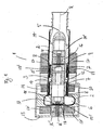
- FIG. 1 is a schematic representation of a longitudinal section through a blood pump 1 of the kind proposed here shown schematically.
- the blood pump 1 comprises a hollow body 2 (shown as a solid thick line) in which an impeller 3 with a blading 4 is provided.
- the hollow body 2 has an inlet 5 for the inflow of blood in an inflow direction parallel to an axis of rotation R (shown in dashed lines) and an outlet 6 for the outflow of the blood in an outflow direction which is perpendicular to the sectional plane.
- the outlet 6 of the hollow body 2 is arranged between an inlet side 9 of the impeller 3 facing the inlet and an outflow side 10 of the impeller 3 facing away from the inlet.
- An inner radius of the hollow body 2 is used to form a tangentially circulating the impeller 3 and opening into the outlet 6 discharge channel 11 for a substantially to the impeller 3 extending outflow of blood from the hollow body. 2
- a hydrodynamic bearing device which is designed as two support rings 7 connected to the impeller 3, for the formation of two annular gaps 8 between the support rings 7 and an inner wall of the hollow body 2 for a radial bearing of the impeller.
- a shell surface 12 of the impeller 3 carrying the blading 4 has a cylindrical shape, but could just as easily be frusto-conical or cone-shaped.
- An axial dimension (length) L of the impeller is set larger than a diameter D of the impeller on the downstream side of the impeller.
- the blading of the impeller is characterized by a slope which increases toward the outlet 6. In this way, a particularly gentle for the blood axial propulsion to the drainage channel 11 is made possible.
- the blading 4 extends axially completely (in other embodiments in part) into the discharge channel 11 and the outflow 6.
- Vorleitrad 14 is provided, which is equipped with a blading 14 '.
- the blood pump further includes a partially actively stabilized storage device that includes an actively stabilized magnetic thrust bearing and a passive magnetic radial bearing.
- the magnetic bearing device initially comprises two permanent magnets 15, 15 'arranged in the impeller on the inflow side and on the outflow side. Furthermore, serve two more, opposite to these (attractive) poled permanent bearing magnets 16, 16 'of the formation of the passive magnetic radial bearing, which ensures that the impeller 3 is held in a radial desired position between the Vorleitrad 14 and the return plate 13.
- two annular coils 17, 17 'outside of the hollow body 2 in front of and behind the impeller 3 are arranged so that they rotate around the hollow body 2 annularly to generate an axial magnetic flux.
- the magnetic bearing device comprises a sensor system, which in the Vorleitrad 14 and / or the return plate 13 and in the impeller 3 integrated distance sensors 18, 18 'for measuring gap widths between the impeller 3 and the Vorleitrad 14 and the return plate 13, and a control unit (not shown) connected to the distance sensors 18, 18 'and the ring magnets which adjusts the magnetic flux generated by the ring magnets according to the measured axial position of the impeller to correct for any deviation of the impeller from an axial target position.
- a sensor system which in the Vorleitrad 14 and / or the return plate 13 and in the impeller 3 integrated distance sensors 18, 18 'for measuring gap widths between the impeller 3 and the Vorleitrad 14 and the return plate 13, and a control unit (not shown) connected to the distance sensors 18, 18 'and the ring magnets which adjusts the magnetic flux generated by the ring magnets according to the measured axial position of the impeller to correct for any deviation of the impeller from an axial target position.
- a motor winding 19 surrounding the hollow body and a motor magnet 20 integrated in the impeller, which magnetizes alternately radially, are used to drive the impeller 3.
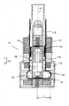
- FIG. 2 is a schematic representation of a longitudinal section through a blood pump 1 shown here proposed type, which differs from the basis FIG. 1 described blood pump only by a modified hydrodynamic storage device differs.
- this is designed as a single connected to the impeller 3 support ring 7 for forming a single annular gap 8 between the support ring 7 and an inner wall of the hollow body 2 for a radial bearing of the impeller.
- a radius r of the hollow body 2 is shown at a level of the discharge channel 11, wherein this radius increases towards the outlet for forming a spiral discharge channel 11, which widens towards the outlet.
- a radius of the impeller blading is designated as r '. It is r ' ⁇ r.
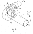
- FIG. 3 shows a schematic representation of a cross section through a hollow body 2 of a blood pump 1 according to FIG. 1 or FIG. 2 ,
- the cross section is perpendicular to the axis of rotation R through the drainage channel 11 of the hollow body 2 of the blood pump 1.
- the hollow body 2 has a radius r, which is increased in comparison to a radius r 'of the hollow body at a level of the inflow side 3 of the impeller 3, Formation of the discharge channel 11.
- the discharge channel 11 expands in its course to the outflow 6 towards spiral and forms in this way a spiral housing.
- the drain 6 is continued outwards into a connecting piece 21, which widens further outwards in order to reduce the flow velocity of the blood.
- FIG. 4 shows a schematic representation of a partially cut hollow body 2 of a blood pump 1 according to FIG. 3 , Recognizable in turn is the hollow body 2 with the inlet 5 for the inflow of blood in an inflow direction, which is marked by the arrow marked E, a tangent to an outlet 21 extended tangential outlet 6 for the outflow of blood in an outflow direction, which is characterized by the arrow designated A and which extends at a right angle to the inflow direction E.
- the cylindrical axial impeller 3 is arranged, wherein Figure additionally shows an example of the overlap of a part of the impeller by the spiral outlet channel.
- the spiral-shaped outlet channel 11 extends tangentially to the impeller 3, opens into the outlet 6 and thus forms a spiral chamber (volute).
- FIG. 5 An embodiment of a total heart pump 22 of the type proposed here is shown schematically. It comprises two blood pumps 1, 1 'of the type proposed here, whose hollow bodies 2, 2' are connected axially to a common hollow body. This has at its two ends two inlets 5, 5 'to the inflow of blood from the pulmonary circulation or the systemic circulation, so that the right blood pump 1 is provided as RVAD and the left blood pump 1' LVAD.
- the two wheels 3, 3 'of the two blood pumps 1, 1' are connected to one another in common with a common impeller.
- the blood can be driven axially by a corresponding configuration of the blading 4, 4 'of the common impeller 3, 3' towards a center of the common hollow body 2, 2 ', on which two spiral outlet channels 11, 11' (spiral chambers) are formed in each case into an outlet 6, 6 'lead to the tangential (right-angled) outflow of the blood from the common hollow body 2, 2'.
- the blading 4, 4 'of the impeller is designed to generate two different values of the blood pressure at the two outlets 6, 6'. To this Purpose is the slope of the helical blading adapted accordingly.
- the connecting gap 23 can be made as narrow as possible in order to reduce as far as possible a leakage flow of the blood between the hollow bodies 3, 3 'of the first and the second blood pump 1, 1'.
- the total heart pump 22 at the two inlets in each case an olive 24, 24 '(connector) for connecting a connecting hose.
- FIG. 6 An embodiment of a total heart pump 22 of the type proposed here is shown schematically. It comprises two blood pumps 1, 1 'of the type proposed here, the hollow bodies 2, 2' of which are aligned axially relative to one another and firmly connected to one another via a bearing block 25.
- the bearing block includes parts of the storage devices (eg, permanent magnetic bearing magnets for axial bearing) of the two blood pumps 1, 1 'to support the two wheels 3, 3'. These are mechanically not connected to each other and thus independently rotatable about the common axis of rotation R.
- the two inlets 5, 5 ' are provided for the inflow of blood from the pulmonary circulation or the systemic circulation, so that, as in the previous embodiment, the right-hand blood pump 1 is designated as RVAD and the left-hand blood pump 1' LVAD.
- the blood can be driven axially by an appropriate choice of the rotational speed and / or by a different embodiment of the blading 4, 4 'of the two wheels 3, 3' in the direction of the bearing block 25.
- both impellers 3, 3 'helical outlet channels 11, 11' are provided, which each open into an outlet 6, 6 'for tangential (right angle) outflow of blood from the hollow bodies 2, 2'.
Landscapes
- Health & Medical Sciences (AREA)
- Heart & Thoracic Surgery (AREA)
- Engineering & Computer Science (AREA)
- Cardiology (AREA)
- Life Sciences & Earth Sciences (AREA)
- Public Health (AREA)
- Biomedical Technology (AREA)
- Hematology (AREA)
- Mechanical Engineering (AREA)
- Animal Behavior & Ethology (AREA)
- General Health & Medical Sciences (AREA)
- Anesthesiology (AREA)
- Veterinary Medicine (AREA)
- Vascular Medicine (AREA)
- Physics & Mathematics (AREA)
- Fluid Mechanics (AREA)
- External Artificial Organs (AREA)
- Structures Of Non-Positive Displacement Pumps (AREA)
Description
- Die Erfindung bezieht sich auf das Gebiet der Blutpumpen.
- Unter einer Blutpumpe wird hier und im Folgenden eine Pumpe verstanden, die der Unterstützung oder Herstellung eines Blutstromes innerhalb eines menschlichen oder tierischen Körpers dient und sich zur Implantation im Brustraum eines Menschen oder Tieres außerhalb des Herzens eignet. Bei linksventrikularen Blutpumpen (left ventricular assist devices, LVAD) besteht eine Verbindung zwischen der linken Herzhälfte und einem Einlass der Blutpumpe sowie zwischen einem Auslass der Blutpumpe und der vom Herz abgehenden Aorta zur Unterstützung oder Herstellung des Blutkreislaufs durch den Körper (Körperkreislauf). Bei rechtsventrikularen Blutpumpen (RVAD) besteht eine Verbindung zwischen der rechten Herzhälfte und dem Lungenstamm, welcher zur linken und rechten Lungenarterie führt, (oder eine direkte Verbindung zwischen dem RVAD und der linken und/oder rechten Lungenarterie) zur Unterstützung oder Herstellung des Blutkreislaufs durch die Lunge (Lungenkreislauf). Innerhalb der Blutpumpe wird das Blut durch einen Hohlkörper geleitet, welcher Teil eines Pumpengehäuses ist oder in einem solchen Pumpengehäuse angeordnet ist. In dem Hohlkörper ist ein rotierendes Laufrad mit einer Beschaufelung zur Erzeugung eines Drucks und einer daraus resultierenden Strömung des Bluts vorgesehen. Sogenannte Totalherzpumpen (total artificial heart, TAH) beinhalten eine links- und eine rechtsventrikulare Blutpumpe zur Unterstützung oder Herstellung des gesamten Blutkreislaufs. Zur Herstellung der genannten Verbindungen zwischen der Blutpumpe und dem Herzen bzw. Blutgefäßen werden Verbindungsschläuche oder -rohre sowie ggf. Strömungskrümmer eingesetzt. Außerdem ist zur Energieversorgung und ggf. zur Steuerung der Blutpumpe wenigstens ein Kabelstrang erforderlich, der die Blutpumpe mit einem Energiespeicher und ggf. einer Steuerungseinheit verbindet.
- Ein Hauptproblem bei der Implantation und der Verwendung solcher Blutpumpen, insbesondere von Totalherzpumpen, ist der Raumbedarf solcher Blutpumpen und der Verbindungsschläuche sowie des Kabelstrangs im Brustraum in der Nähe des Herzens.
- Eine weitere Schwierigkeit liegt in der Gefahr der Zerstörung von Blutkörperchen (Hämolyse) durch die Blutpumpe, insbesondere an mechanischen Lagern des Laufrads, Engführungen oder abrupten Richtungsänderungen der Blutströmung durch die Blutpumpe sowie durch starke Druckgradienten innerhalb der Blutpumpe. Bei der Konstruktion von Blutpumpen werden zu diesem Zweck häufig mechanische Lager des Laufrads durch eine magnetische und/oder hydrodynamische Lagerungsvorrichtung ersetzt. Eine Radialpumpe mit teilweise aktiver magnetischer Lagerung ist in der
DE 10 2006 036 948 gezeigt. - Ein zusätzliches Problem liegt darin, dass für den Lungenkreislauf ein wesentlich kleinerer Blutdruck hergestellt werden muss als für den Körperkreislauf, wobei aber durch beide Blutkreisläufe das gleiche Blutvolumen pro Zeit transportiert werden muss. Der von der Blutpumpe erzeugte Blutdruck hängt von der Drehzahl des Laufrads der Blutpumpe ab. Es stellt sich als schwierig heraus, eine Pumpe zu konstruieren, die sich zur Einstellung sehr unterschiedlicher Werte des Blutdrucks innerhalb eines Bereichs von etwa 5 mmHg bis etwa 150 mmHg bei einem stabilen konstanten, den physiologischen Bedingungen angepassten Volumenstrom zwischen 0 l/min bis 20 l/min eignet und sich auf diese Weise sowohl als RVAD als auch als LVAD einsetzen lässt bzw. sich zur Konstruktion einer Totalherzpumpe eignet.
- Es ist somit Aufgabe der vorliegenden Erfindung, eine Blutpumpe sowie eine Totalherzpumpe vorzuschlagen, welche die oben genannten Probleme löst oder zumindest abmildert. Eine entsprechende Blutpumpe bzw. Totalherzpumpe soll also einen möglichst geringen Raumbedarf aufweisen und sich zu einer das Blut möglichst schonenden Unterstützung oder Herstellung eines Blutdrucks eignen. Außerdem soll sie sich zur Abdeckung eines breiten Bereichs des Blutdrucks bei einem möglichst konstanten Volumenfluss eignen.
- Diese Aufgabe wird erfindungsgemäß gelöst durch Blutpumpen gemäß den unabhängigen Patentansprüchen.
- Eine erfindungsgemäße Blutpumpe umfasst einen Hohlkörper, in dem ein Laufrad mit einer Beschaufelung vorgesehen ist zur Erzeugung eines axialen Vortriebs des Bluts entlang des Laufrads, sowie eine zumindest teilweise aktiv stabilisierte magnetische Lagerungsvorrichtung und eine hydrodynamische Lagerungsvorrichtung für das Laufrad, wobei das Laufrad mit einem außerhalb des Hohlkörpers befindlichen Motorstator in eine Rotation um eine Rotationsachse des Laufrads versetzbar ist und wobei der Hohlkörper einen Einlass zum Einströmen von Blut in den Hohlkörper in einer zur Rotationsachse im Wesentlichen parallelen Einströmrichtung und einen Auslass zum Ausströmen des Bluts aus dem Hohlkörper in einer Ausströmrichtung aufweist, wobei der Auslass gegen die Rotationsachse des Laufrads versetzt angeordnet ist zur Erzeugung eines von Null verschiedenen Ausströmwinkels zwischen der Einströmrichtung und der Ausströmrichtung.
- Dabei wird unter dem Auslass eine Öffnung in einer Wandung des Hohlkörpers verstanden, wobei der Auslass in der Regel durch einen Anschlussstutzen nach außen weitergeführt wird.
- Der Erfindung liegt der Gedanke zugrunde, durch den von Null verschiedenen Winkel zwischen der Einströmrichtung des Blutes und der Ausströmrichtung des Bluts einen möglichst geringen Raumbedarf der Blutpumpe einschließlich der notwendigen Verbindungsschläuche zu erzielen, wobei durch eine geeignete Wahl dieses Winkels der Auslass der implantierten Blutpumpe in Richtung des Blutgefäßes ausgerichtet werden kann, mit dem die Blutpumpe verbunden werden soll, also beispielsweise der Aorta, des Lungenstamms oder eines anderen Blutgefäßes. Auf diese Weise kann für diese Verbindung zwischen Blutpumpe und Blutgefäß eine besonders kurzer Verbindungsschlauch gewählt werden, da der Verbindungsschlauch möglichst geradlinig und auf direktem Wege zu dem Blutgefäß geführt werden kann und nicht entlang eines einen Umweg bildenden Bogens. Ferner wird der Einsatz von Strömungskrümmern zum Umlenken einer Strömungsrichtung des Blutes damit in der Regel überflüssig. Dieser Winkel liegt vorzugsweise in einem Bereich zwischen etwa 30° und etwa 150°, besonders bevorzugt in einem Bereich zwischen etwa 75° und etwa 105°, wobei bei einem Winkel von 90° das Blut die Blutpumpe in einem rechten Winkel zur Rotationsachse verlässt und bei einem Winkel von 0° die Ausströmung in axialer Richtung erfolgt.
- Beim Einsatz von herkömmlichen axialen Blutpumpen sind in der Regel stark gekrümmte Verbindungsschläuche notwendig, da herkömmliche axiale Blutpumpen immer einen axialen Auslass aufweisen (d.h. der Winkel zwischen der Einströmrichtung und der Ausströmrichtung des Blutes beträgt etwa 0°).
- Das Grundprinzip eines axialen Vortriebs des Bluts durch das Laufrad wird durch die erfindungsgemäße Blutpumpe beibehalten. Dies ist vorteilhaft, weil sich solche auch als Axialpumpen bezeichnete Blutpumpen, welche hauptsächlich eine axiale Krafteinwirkung auf das Blut ausüben und dieses somit hauptsächlich axial, also in Richtung der Rotationsachse entlang des Laufrads beschleunigen, das Blut besonders schonend fördern. Im Vergleich hierzu beschleunigen sogenannte Radialpumpen das Blut hauptsächlich radial zur Rotationsachse des Laufrads. Radialpumpen haben darüber hinaus meistens einen radialen Auslass, welcher häufig den Vorteil besonders kurzer Verbindungen zu Blutgefäßen mit sich bringt.
- Die hier vorgeschlagene erfindungsgemäße Blutpumpe vereinigt in sich also sowohl den Vorteil einer schonenden Blutförderung einer Axialpumpe wie auch den Vorteil kurzer Verbindungsschläuche zwischen Blutpumpe und Blutgefäßen einer Radialpumpe und somit eines geringeren Platzbedarf sowie einer besseren Rotordynamik.
- Die erfindungsgemäße Blutpumpe zeichnet sich außerdem durch den Wegfall eines dem Laufrad in Strömungsrichtung nachgelagerten Leitrads aus. Ein solches Nachleitrad dient in gewöhnlichen Axialpumpen mit axialem Auslass zur Umwandlung von Rotationsbewegungen des Blutes in einen zusätzlichen axialen Druckaufbau und somit einer Effizienzsteigerung der axialen Förderung des Blutes. Bei dem erfindungsgemäßen nicht-axialen Auslass trägt die Rotationsbewegung des Bluts zumindest teilweise auch zum durch die Blutpumpe erzeugten Blutdruck bei, welche durch das Weglassen des Nachleitrads vorteilhafterweise mitgenutzt werden kann. Außerdem wird durch das Weglassen des Nachleitrades die mechanische Belastung des Blutes durch eine Umlenkung des Bluts durch das Nachleitrad vermieden, wodurch die Gefahr der Blutschädigung weiter verringert wird.
- Ein weiterer wesentlicher Vorteil, der durch das Einsparen des Nachleitrades erzielt wird, besteht in einer kleineren axialen Länge der Blutpumpe und somit einem reduzierten Raumbedarf der Blutpumpe.
- Außerdem entfällt mit dem Nachleitrad das Problem von ungünstigen Anströmwinkeln des Nachleitrads bei bestimmten Arbeitspunkten der Blutpumpe. Wird das Nachleitrad nämlich unter einem ungünstigen Winkel angeströmt, können sogar durch das Nachleitrad Druckverluste entstehen. Zudem können sich lokale Druckschwankungen am Nachleitrad ausbilden, welche sich auch auf den Strömungsverlauf des Blutes am Laufrad ungünstig auswirken und eine stabile Lagerung des Laufrads insbesondere bei geringen Drehzahlen erschweren können.
- Weiterhin ist vorgesehen, dass die Beschaufelung des Laufrads als Wendel ausgestaltet ist. Eine solche Wendel, welche ein- oder mehrgängig sein kann, ist vorzugsweise durchgängig und/oder verläuft über eine gesamte Länge des Laufrads und eignet sich auf diese Weise besonders gut zur Erzeugung eines schonenden, verwirbelungsarmen axialen Vortriebs des Blutes. Zudem lässt sich die Förderwirkung der Wendel über die Steigung der Wendel besonders leicht modifizieren. Selbstverständlich lassen sich aber auch andere Arten der Beschaufelung des Laufrads mit unterschiedlichen Steigungen realisieren. Vorzugsweise ist eine Außenkontur der Wendel zylinderförmig ausgestaltet.
- Eine zumindest teilweise aktiv stabilisierte magnetische Lagerungsvorrichtung für das Laufrad, wie sie beispielsweise in
WO 00/64030 - In einer Weiterentwicklung umfasst die magnetische Lagerungsvorrichtung der Blutpumpe außerdem permanentmagnetische Lagerelemente für eine passive radiale Lagerung (passive Radialstabilisierung) des Laufrads. Diese permanentmagnetischen Lagerelemente können beispielsweise innerhalb des Hohlkörpers in unmittelbarer Nähe zu einer Zuströmseite und einer Abströmseite des Laufrads angeordnet sein, beispielsweise in einer Nabe des Laufrads, einem Leitrad oder einer Endschlussplatte des Hohlkörpers. Weitere Details sind wiederum der oben genannten Druckschrift oder der Beschreibung spezieller Ausführungsformen der Erfindung weiter unten zu entnehmen.
- Die hydrodynamische Lagerung von Laufrädern in Blutpumpen ist prinzipiell bekannt. In einer Ausführungsform der Erfindung ist vorgesehen, die hydrodynamische Lagerungsvorrichtung des Laufrads wie in
WO 02/66837 - Eine Weiterentwicklung der Erfindung sieht vor, dass der Auslass des Hohlkörpers zwischen einer dem Einlass zugewandten Zuströmseite des Laufrads und einer dem Einlass abgewandten Abströmseite des Laufrads angeordnet ist. Auf diese Weise lassen sich besonders kompakte Ausführungsformen mit einer reduzierten Baulänge verwirklichen. Ferner stellt sich heraus, dass dies zu besonders guten Strömungseigenschaften der Blutpumpe und somit auch zu einer Stabilisierung des Laufrads beiträgt, wodurch sich der durch die Blutpumpe abdeckbare Druckbereich vergrößert. Vorzugsweise ist der Auslass in einer unmittelbaren Umgebung der Abströmseite des Laufrads angeordnet, um den axialen Vortrieb durch die Beschaufelung des Laufrads, welches vorzugsweise über eine Gesamtlänge seiner Mantelfläche hinweg beschaufelt ist, möglichst vollständig auszunutzen. Um dies zu steigern, erstreckt sich die Beschauflung des Laufrads vorzugsweise auch entlang des Auslasses, d.h. auf einer Höhe des Auslasses.
- In einer Weiterentwicklung weist die Blutpumpe eine Rückschlussplatte auf, welche im Wesentlichen senkrecht zur Rotationsachse des Laufrads angeordnet ist zum Abschließen des Hohlkörpers. Im Fall, dass der Auslass, wie oben beschrieben, zwischen der Zuströmseite und der Abströmseite des Laufrads angeordnet ist, ist diese Abschlussklappe vorzugsweise in einer unmittelbaren Nähe zur Abströmseite des Laufrads angeordnet, um so strömungsfreie Toträume zwischen Laufrad und der Rückschlussplatte zu vermeiden. Solche Toträume bergen im Allgemeinen ein erhöhtes Risiko der Bildung von Blutgerinnseln und sind daher möglichst auszuschließen. In einer Weiterentwicklung ist die Rückschlussplatte als leicht zu öffnender Verschluss ausgestaltet zum einfachen Herstellen eines axialen Zugriffs in den Hohlkörper, etwa für einen leichteren Zusammenbau oder eine Justierung der Blutpumpe während des Montageprozesses.
- In einer Ausführungsform ist vorgesehen, dass ein Innenradius des Hohlkörpers vergrößert ist zur Ausbildung eines das Laufrad tangential umlaufenden und in den Auslass mündenden Abflusskanals (Spiralgehäuse). Ein solcher Abflusskanal ermöglicht ein im Wesentlichen tangential zum Laufrad (genauer tangential zu einer Manteloberfläche des Laufrads) verlaufendes Abfließen des Bluts durch den Auslass aus dem Hohlkörper. Auf diese Weise können eine entsprechende tangentiale Strömungskomponente des Bluts und die dazugehörige kinetische Energie des Bluts beim Ausfließen aus dem Hohlkörper besonders gut und verlustarm erhalten bleiben und zur effizienten Erzeugung des Blutdrucks ausgenutzt werden. Eine tangential zur Manteloberfläche aber senkrecht zur Rotationsachse verlaufende Strömungskomponente des Bluts entsteht prinzipiell immer auch bei Axialpumpen, da der durch das Laufrad erzeugte Vortrieb neben der axialen Komponente auch eine Komponente senkrecht zur Rotationsachse aufweist. Insbesondere können durch einen solchen Abflusskanal Verwirbelungen mit entsprechenden Energieverlusten, wie sie bei einem einfachen radialen Auslass auftreten können, vermieden werden. Zudem verbessern sich auf diese Weise weiterhin die Strömungseigenschaften der Blutpumpe und somit auch die Stabilität des Laufrads, wodurch sich der durch die Blutpumpe abdeckbare Druckbereich weiter vergrößert. Außerdem kann gleichzeitig die mit den genannten Verwirbelungen einhergehende mechanische Belastung des Blutes weitestgehend vermieden werden.
- Um eine möglichst hohe Effizienz der Blutförderung bei einer möglichst kompakten Bauform zu erzielen, erstreckt sich die Beschaufelung des Laufrads auch entlang des Abflusskanals, d.h. auf einer Höhe des Abflusskanals.
- Eine Weiterentwicklung sieht vor, dass sich der Abflusskanal zum Auslass hin aufweitet und somit spiralförmig wie ein Spiralgehäuse ausgestaltet ist. Auf diese Weise wird eine kontinuierliche Reduktion der Strömungsgeschwindigkeit (bei gleich bleibendem Volumenstrom) zum Auslass hin und eine Reduktion von Wirbelbildungen erzielt und somit ein besonders schonendes Ausfließen des Blutes aus dem Hohlkörper gewährleistet. Durch die reduzierte Strömungsgeschwindigkeit des Blutes lässt sich zudem die durch die Blutpumpe erzeugte Druckerhöhung am Auslass im Übergang zur Auslasskanüle besonders wirkungsvoll übertragen. Typische Strömungsgeschwindigkeiten am Auslass der Blutpumpe liegen bei diesem Ausführungsbeispiel auf eine Größenskala unter 1 m/s.
- In einer weiteren Ausführungsform ist vorgesehen, dass eine Mantelfläche des Laufrads, welche die Beschaufelung des Laufrads zwischen der Zu- und der Abströmseite trägt, im Wesentlichen zylinderförmig, kegelstumpfförmig oder kegelförmig ausgestaltet ist zur Erzeugung eines möglichst gleichmäßigen und wirbelfreien Vortriebs. Auf diese Weise lässt sich ein hauptsächlich axialer und somit für das Blut schonender Vortrieb gewährleisten. Es lässt sich aber auch durch einen zur Abströmseite des Laufrads hin zunehmenden Durchmesser des Laufrads eine radiale Beschleunigungskomponente erzielen.
- Insbesondere in Kombination mit einer zylinderförmigen oder kegelstumpfförmigen Ausführung des Laufrads kann ein Vorleitrad vorgesehen sein, das auf der Zuströmseite des Laufrads angeordnet ist. Dieses Vorleitrad dient zum einen einer möglichst wirbelfreien und somit das Blut schonenden und von Energieverlusten möglichst freien Anströmung des Laufrads durch das Blut und kann außerdem eine stationäre Beschaufelung aufweisen, um eine Rotationsbewegung des Bluts um die Rotationsachse des Laufrads zu reduzieren und in einen axialen Vortrieb umzuwandeln zur weiteren Steigerung der Förderungsleistung der Blutpumpe. Vorzugsweise ist das Vorleitrad in einer unmittelbaren Nähe zur Zuströmseite des Laufrads angeordnet zur Vermeidung oder Reduzierung eines strömungsfreien Totraums zwischen dem Vorderleitrad und dem Laufrad. Ferner kann das Vorleitrad, wie oben bereits beschrieben, permanentmagnetische Lagerungselemente beinhalten, welche Bestandteile der magnetischen Lagerungsvorrichtung sind.
- In einer Weiterentwicklung ist vorgesehen, dass die Blutpumpe eine Steuereinheit umfasst, die dazu eingerichtet ist, Drehzahlen des Laufrades einzustellen in einem Bereich zwischen 3000 U/min und 35000 U/min zur Erzeugung eines Blutdrucks am Auslass in einem Bereich zwischen 5 mmHg und 150 mmHg bei einem dem Bedarf angepassten Volumenstrom des Bluts. Auf diese Weise lässt sich je nach Strömungswiderstand des Lungen- bzw. Körperkreislauf ein Volumenstrom zwischen 0 I/min und 20 I/min einstellen.
- Eine alternative Blutpumpe umfasst einen Hohlkörper, in dem ein Laufrad mit einer Beschaufelung vorgesehen ist zur Erzeugung eines axialen Vortriebs des Bluts entlang des Laufrads, wobei das Laufrad mit einem außerhalb des Hohlkörpers befindlichen Motorstator in eine Rotation um eine Rotationsachse des Laufrads versetzbar ist und wobei der Hohlkörper einen Einlass zum Einströmen von Blut in den Hohlkörper in einer zur Rotationsachse im Wesentlichen parallelen Einströmrichtung und einen Auslass zum Ausströmen des Bluts aus dem Hohlkörper in einer Ausströmrichtung aufweist, wobei der Auslass gegen die Rotationsachse des Laufrads versetzt angeordnet ist zur Erzeugung eines von Null verschiedenen Ausströmwinkels zwischen der Einströmrichtung und der Ausströmrichtung, wobei ein Innenradius des Hohlkörpers vergrößert ist zur Ausbildung eines das Laufrad tangential umlaufenden und in den Auslass mündenden, spiralförmigen Abflusskanals für ein im Wesentlichen tangential zum Laufrad verlaufendes Abfließen des Bluts aus dem Hohlkörper, wobei der Auslass des Hohlkörpers zwischen einer dem Einlass zugewandten Zuströmseite des Laufrads und einer dem Einlass abgewandten Abströmseite des Laufrads angeordnet ist.
- Eine solche Blutpumpe kann zur Lagerung des Laufrads eine mechanische, hydrodynamische, eine magnetische, oder eine hybride Lagerungsvorrichtung enthalten. Ferner ist vorzugsweise eine die Beschaufelung tragende Mantelfläche des Laufrads im Wesentlichen zylinderförmig ausgestaltet für einen axialen Vortrieb des Blutes.
- Zur Weiterentwicklung dieser alternativen Blutpumpe kommen alle oben aufgeführten und beschriebenen technischen Merkmale in Frage. Es ergeben sich die jeweils genannten Vorteile. Der Vollständigkeit halber seien die Merkmale hier noch einmal kurz aufgeführt. Für eine nähere Erläuterung sei auf die Ausführungen weiter oben verwiesen.
- So kann die hydrodynamische Lagerungsvorrichtung des Laufrads als ein mit dem Laufrad verbundener Stützring ausgebildet sein zur Ausformung eines Ringspalts zwischen dem Stützring und einer Innenwandung des Hohlkörpers für eine radiale Lagerung des Laufrads. Es ist auch möglich, dass der Auslass des Hohlkörpers zwischen einer dem Einlass zugewandten Zuströmseite des Laufrads und einer dem Einlass abgewandten Abströmseite des Laufrads angeordnet ist. Es kann auch vorgesehen sein, dass ein Innenradius des Hohlkörpers vergrößert ist zur Ausbildung eines das Laufrad tangential umlaufenden und in den Auslass mündenden Abflusskanals für ein im Wesentlichen tangential zum Laufrad verlaufendes Abfließen des Bluts aus dem Hohlkörper. Ferner ist es möglich, dass sich dieser Abflusskanal zum Auslass hin aufweitet.
- Ferner kann vorgesehen sein, dass die magnetische Lagerungsvorrichtung eine aktiv stabilisierte Axiallagerung umfasst.
- Zudem ist es möglich, dass eine die Beschaufelung tragende Mantelfläche des Laufrads im Wesentlichen zylinderförmig, kegelförmig oder kegelstumpfförmig ausgestaltet ist. Die Beschaufelung des Laufrads ist als Wendel ausgestaltet.
- Ferner kann ein Vorleitrad vorgesehen sein.
- Schließlich kann die Blutpumpe eine Steuereinheit umfassen, die dazu eingerichtet ist, Drehzahlen des Laufrades einzustellen in einem Bereich zwischen 3000 U/min und 35000 U/min zur Erzeugung eines Blutdrucks an dem Auslass in einem Bereich zwischen 5 mmHg und 150 mmHg bei einem den physiologischen Bedingungen angepassten Volumenstrom.
- In einer erfindungsgemäßen Totalherzpumpe ist vorgesehen, dass zwei Blutpumpen hier vorgeschlagener Art vorhanden sind, wobei eine erste Blutpumpe vorzugsweise als LVAD und eine zweite Blutpumpe als RVAD verwendet wird. Durch den Einsatz der hier beschriebenen Blutpumpen ist die Totalherzpumpe besonders raumsparend und lässt sich somit besonders leicht im Brustraum am Herz anordnen.
- In einer Ausführungsform ist vorgesehen, dass die Laufräder der beiden Blutpumpen der Totalherzpumpe auf einer gemeinsamen Rotationsachse angeordnet sind, wodurch eine besonders einfache Konstruktion und Montage ermöglicht wird. Ferner erlaubt dies eine vorteilhaft schlanke Form der Totalherzpumpe, wodurch eine Implantation in den Brustraum erleichtert wird.
- In einem Ausführungsbeispiel sind die Laufräder der beiden Blutpumpen zu einem einzigen, gemeinsamen Laufrad fest miteinander verbunden, wobei die Hohlräume der beiden Blutpumpen zu einem gemeinsamen Hohlkörper (Gehäuse) zusammengefasst sind. Dies erlaubt einen axial besonders kurzen Aufbau der Totalherzpumpe. Außerdem ist auf diese Weise ein einfachere Lagerung möglich, da das gemeinsame Laufrad weniger Freiheitsgrade aufweist als zwei einzelne Laufräder.
- In einem weiteren Ausführungsbeispiel ist vorgesehen, dass zwischen dem Laufrad der ersten Blutpumpe und dem Laufrad der zweiten Blutpumpe ein Lagerbock vorhanden ist, in dem zumindest Teile der Lagervorrichtung der ersten und/oder der zweiten Blutpumpe integriert sind.
- Im Folgenden werden spezielle Ausführungsformen der Erfindung anhand von
Figuren 1 bis 4 näher beschrieben. Gleiche Bezugszeichen bezeichnen gleiche gegenständliche Merkmale. Es zeigt: - Figur 1
- eine schematische Darstellung eines Längs- schnitts durch eine Blutpumpe hier vorge- schlagener Art,
- Figur 2
- eine schematische Darstellung eines Längs- schnitts durch eine Blutpumpe hier vorge- schlagener Art,
- Figur 3
- eine schematische Darstellung eines Quer- schnitts durch einen Hohlkörper einer Blut- pumpe hier vorgeschlagener Art,
- Figur 4
- eine schematische Darstellung eines teil- weise aufgeschnittenen Hohlkörpers einer Blutpumpe hier vorgeschlagener Art,
- Figur 5
- eine schematische Darstellung einer Total- herzpumpe hier vorgeschlagener Art mit ei- nem einzigen Laufrad und
- Figur 6
- eine schematische Darstellung einer Total- herzpumpe hier vorgeschlagener Art mit zwei einzelnen Laufrädern.
- In
Figur 1 ist eine schematische Darstellung eines Längsschnitts durch eine Blutpumpe 1 hier vorgeschlagener Art schematisch dargestellt. Die Blutpumpe 1 umfasst einen Hohlkörper 2 (als durchgezogene dicke Linie dargestellt), in dem ein Laufrad 3 mit einer Beschaufelung 4 vorgesehen ist. Ferner weist der Hohlkörper 2 einen Einlass 5 zum Einströmen von Blut in einer zu einer Rotationsachse R (gestrichelt dargestellt) parallelen Einströmrichtung und einen Auslass 6 zum Ausströmen des Bluts in einer Ausströmrichtung, welche senkrecht zur Schnittebene verläuft. Demnach ist in diesem Ausführungsbeispiel der Auslass relativ zur Rotationsachse R in einem rechten Winkel versetzt angeordnet zur Erzeugung eines von Null verschiedenen Ausströmwinkels α von α = 90° zwischen der Einströmrichtung und der Ausströmrichtung. - Der Auslass 6 des Hohlkörpers 2 ist zwischen einer dem Einlass zugewandten Zuströmseite 9 des Laufrads 3 und einer dem Einlass abgewandten Abströmseite 10 des Laufrads 3 angeordnet. Ein Innenradius des Hohlkörpers 2 dient zur Ausbildung eines das Laufrad 3 tangential umlaufenden und in den Auslass 6 mündenden Abflusskanals 11 für ein im Wesentlichen tangential zum Laufrad 3 verlaufendes Abfließen des Bluts aus dem Hohlkörper 2.
- Ferner ist eine hydrodynamische Lagerungsvorrichtung vorgesehen, welche als zwei mit dem Laufrad 3 verbundene Stützringe 7 ausgestaltet ist, zur Ausformung von zwei Ringspalten 8 zwischen den Stützringen 7 und einer Innenwandung des Hohlkörpers 2 für eine radiale Lagerung des Laufrads 3.
- Eine die Beschaufelung 4 tragende Mantelfläche 12 des Laufrads 3 ist zylinderförmig ausgeformt, könnte aber genauso gut kegelstumpfförmig oder kegelförmig ausgestaltet sein. Eine axiale Abmessung (Länge) L des Laufrads ist größer gewählt als ein Durchmesser D des Laufrads auf der Abströmseite des Laufrads. Die Beschaufelung des Laufrads ist durch eine Steigung gekennzeichnet, die zum Auslass 6 hin zunimmt. Auf diese Weise wird ein für das Blut besonders schonender axialer Vortrieb bis zum Abflusskanal 11 hin ermöglicht. Die Beschaufelung 4 erstreckt sich axial ganz (in anderen Ausführungsformen teilweise) in den Abflusskanal 11 und den Ausfluss 6.
- In unmittelbarer Nähe zur Zuströmseite 9 des Laufrads 3 ist ein Vorleitrad 14 vorgesehen, welches mit einer Beschaufelung 14' ausgestattet ist.
- Die Blutpumpe umfasst ferner eine teilweise aktiv stabilisierte Lagerungsvorrichtung, welche eine aktiv stabilisierte magnetischen Axiallagerung sowie eine passive magnetische Radiallagerung beinhaltet. Die magnetische Lagerungsvorrichtung umfasst zunächst zwei in dem Laufrad an der Zuströmseite und an der Abströmseite angeordnete Permanentmagnete 15, 15'. Ferner dienen zwei weitere, zu diesen entgegengesetzt (anziehend) gepolte permanente Lagermagnete 16, 16' der Ausbildung des passiven magnetischen Radiallagers, welches dafür sorgt, dass das Laufrad 3 in einer radialen Sollposition zwischen dem Vorleitrad 14 und der Rückschlussplatte 13 gehalten wird. Ferner sind für die aktiv stabilisierte magnetische Axiallagerung zwei Ringspulen 17, 17' außerhalb des Hohlkörper 2 vor und hinter dem Laufrad 3 so angeordnet, dass sie den Hohlkörper 2 ringförmig umlaufen zur Erzeugung eines axialen Magnetflusses. Ferner umfasst die magnetische Lagerungsvorrichtung ein Sensorsystem, welches in dem Vorleitrad 14 und/oder der Rückschlussplatte 13 sowie in dem Laufrad 3 integrierte Abstandssensoren 18, 18' umfasst zur Messung von Spaltbreiten zwischen dem Laufrad 3 und dem Vorleitrad 14 bzw. der Rückschlussplatte 13, sowie eine mit den Abstandssensoren 18, 18' und den Ringmagneten verbundene Regeleinheit (hier nicht dargestellt), welche den von den Ringmagneten erzeugten Magnetfluss gemäß der gemessenen axialen Position des Laufrads einstellt zum Korrigieren einer eventueller Abweichung des Laufrads von einer axialen Sollposition.
- Schließlich sind eine den Hohlkörper umlaufende Motorwicklung 19 und ein im Laufrad integrierter Motormagnet 20 vorgesehen, welcher alternierend radial magnetisiert ist, zum Antreiben des Laufrads 3.
- In
Figur 2 ist eine schematische Darstellung eines Längsschnitts durch eine Blutpumpe 1 hier vorgeschlagener Art gezeigt, welche sich von der anhandFigur 1 beschriebenen Blutpumpe nur durch eine veränderte hydrodynamische Lagerungsvorrichtung unterscheidet. In dem inFigur 2 gezeigten Beispiel ist diese als ein einzelner mit dem Laufrad 3 verbundener Stützring 7 ausgestaltet zur Ausformung eines einzelnen Ringspaltes 8 zwischen dem Stützring 7 und einer Innenwandung des Hohlkörpers 2 für eine radiale Lagerung des Laufrads 3. - Außerdem ist ein Radius r des Hohlkörpers 2 auf einer Höhe des Abflusskanals 11 dargestellt, wobei sich dieser Radius zum Auslass hin vergrößert zur Ausformung eines spiralförmigen Abflusskanals 11, welcher sich zum Auslass hin erweitert. Ein Radius der Laufradbeschaufelung ist als r' bezeichnet. Es gilt r' < r.
-
Figur 3 zeigt eine schematische Darstellung eines Querschnitts durch einen Hohlkörper 2 einer Blutpumpe 1 gemäßFigur 1 oderFigur 2 . Der Querschnitt verläuft senkrecht zur Rotationsachse R durch den Abflusskanal 11 des Hohlkörpers 2 der Blutpumpe 1. Der Hohlkörper 2 weist einen Radius r auf, der im Vergleich zu einem Radius r' des Hohlkörpers auf einer Höhe der Zuströmseite 3 des Laufrads 3 vergrößert ist, zur Ausbildung des Abflusskanals 11. Der Abflusskanal 11 weitet sich in seinem Verlauf zum Abfluss 6 hin spiralförmig auf und bildet auf diese Weise ein Spiralgehäuse aus. Der Abfluss 6 ist in einen Anschlussstutzen 21 nach außen fortgesetzt, der sich nach außen weiter aufweitet zur Verkleinerung der Strömungsgeschwindigkeit des Bluts. -
Figur 4 zeigt eine schematische Darstellung eines teilweise aufgeschnittenen Hohlkörpers 2 einer Blutpumpe 1 gemäßFigur 3 . Zu erkennen ist wiederum der Hohlkörper 2 mit dem Einlass 5 zum Einströmen von Blut in einer Einströmrichtung, die durch den mit E bezeichneten Pfeil gekennzeichnet ist, einem zu einem Auslassstutzen 21 verlängerten tangentialen Auslass 6 zum Ausströmen des Bluts in einer Ausströmrichtung, die durch den mit A bezeichneten Pfeil gekennzeichnet ist und die in einem rechten Winkel zur Einströmrichtung E verläuft. - In dem Hohlkörper ist das zylinderförmige axiale Laufrad 3 angeordnet, wobei Figur zusätzlich beispielhaft die Überdeckung eines Teils des Laufrads durch den spiralförmigen Auslasskanal zeigt. Der spiralförmige Auslasskanal 11 verläuft tangential zum Laufrad 3, mündet in dem Auslass 6 und bildet auf diese Weise eine Spiralkammer (Spiralgehäuse) aus.
- In
Figur 5 ist eine Ausführungsform einer Totalherzpumpe 22 hier vorgeschlagener Art schematisch dargestellt. Sie umfasst zwei Blutpumpen 1, 1' hier vorgeschlagener Art, deren Hohlkörper 2, 2' axial zu einem gemeinsamen Hohlkörper verbunden sind. Dieser weist an seinen beiden Enden zwei Einlässe 5, 5' auf zum Einströmen von Blut aus dem Lungenkreislauf bzw. dem Körperkreislauf, so dass die rechte Blutpumpe 1 als RVAD und die linke Blutpumpe 1' LVAD vorgesehen ist. Die beiden Laufräder 3, 3' der beiden Blutpumpen 1, 1' sind axial zu einem gemeinsamen Laufrad fest miteinander verbunden. Das Blut ist durch eine entsprechende Ausgestaltung der Beschaufelung 4, 4' des gemeinsame Laufrads 3, 3' zu einer Mitte des gemeinsamen Hohlkörpers 2, 2' hin axial antreibbar, an welchem zwei spiralförmige Auslasskanäle 11, 11' (Spiralkammern) ausgeformt sind, welche jeweils in einen Auslass 6, 6' münden zum tangentialen (rechtwinkligen) Ausströmen des Bluts aus dem gemeinsamen Hohlkörper 2, 2'. - Die Beschaufelung 4, 4' des Laufrads ist zur Erzeugung zweier unterschiedlicher Werte des Blutdrucks an den beiden Auslässen 6, 6' ausgestaltet. Zu diesem Zweck ist die Steigung der wendelförmigen Beschaufelung entsprechend angepasst.
- Zwischen den beiden Auslasskanälen 11, 11' besteht ein Verbindungsspalt 23 zwischen dem gemeinsamen Hohlkörper 2, 2' und dem gemeinsamen Laufrad 3, 3'. Der Verbindungsspalt 23 kann möglichst eng ausgestaltet werden, um eine Leckströmung des Blutes zwischen den Hohlkörpern 3, 3' der ersten und der zweiten Blutpumpe 1, 1' möglichst zu reduzieren.
- Ferner weist die Totalherzpumpe 22 an den beiden Einlässen jeweils eine Olive 24, 24' (Verbindungsstück) auf zum Anschließen eines Verbindungsschlauches.
- In
Figur 6 ist eine Ausführungsform einer Totalherzpumpe 22 hier vorgeschlagener Art schematisch dargestellt. Sie umfasst zwei Blutpumpen 1, 1' hier vorgeschlagener Art, deren Hohlkörper 2, 2' axial zueinander ausgerichtet und über einen Lagerbock 25 fest miteinander verbunden sind. Der Lagerbock beinhaltet Teile der Lagerungsvorrichtungen (z.B. permanentmagnetische Lagermagnete zur Axiallagerung) der beiden Blutpumpen 1, 1' zu Lagerung der beiden Laufräder 3, 3'. Diese sind mechanisch nicht miteinander verbunden und somit unabhängig voneinander um die gemeinsame Rotationsachse R drehbar. Die beiden Einlässe 5, 5' sind zum Einströmen von Blut aus dem Lungenkreislauf bzw. dem Körperkreislauf vorgesehen, so dass wie im vorherigen Ausführungsbeispiel die rechte Blutpumpe 1 als RVAD und die linke Blutpumpe 1' LVAD bestimmt ist. Das Blut ist durch eine entsprechende Wahl der Drehzahl und/oder durch eine unterschiedliche Ausgestaltung der Beschaufelung 4, 4' der beiden Laufräder 3, 3' in Richtung des Lagerbocks 25 axial antreibbar. Ferner sind jeweils an den Abströmseiten 10, 10' der beiden Laufräder 3, 3' spiralförmige Auslasskanäle 11, 11' (Spiralkammern) vorgesehen, welche jeweils in einen Auslass 6, 6' münden zum tangentialen (rechtwinkligen) Ausströmen des Bluts aus den Hohlkörpern 2, 2'.
Claims (14)
- Blutpumpe (1), umfassend einen Hohlkörper (2), in dem ein Laufrad (3) mit einer Beschaufelung (4) vorgesehen ist zur Erzeugung eines axialen Vortriebs des Bluts entlang des Laufrads (3), sowie eine zumindest teilweise aktiv stabilisierte magnetische Lagerungsvorrichtung (15, 15', 16, 16', 17, 17', 18, 18') und eine hydrodynamische Lagerungsvorrichtung (7) für das Laufrad, wobei das Laufrad mit einem außerhalb des Hohlkörpers befindlichen Motorstator (19) in eine Rotation um eine Rotationsachse (R) des Laufrads (3) versetzbar ist und wobei der Hohlkörper (2) einen Einlass (5) zum Einströmen von Blut in den Hohlkörper (2) in einer zur Rotationsachse (R) im Wesentlichen parallelen Einströmrichtung (E) und einen Auslass (6) zum Ausströmen des Bluts aus dem Hohlkörper (2) in einer Ausströmrichtung (A) aufweist, wobei der Auslass (6) gegen die Rotationsachse (R) des Laufrads (3) versetzt angeordnet ist zur Erzeugung eines von Null verschiedenen Ausströmwinkels (α) zwischen der Einströmrichtung (E) und der Ausströmrichtung (A), dadurch gekennzeichnet, dass die Beschaufelung (4) des Laufrads (3) als Wendel ausgestaltet ist.
- Blutpumpe (1) aus Anspruch 1, dadurch gekennzeichnet, dass die hydrodynamische Lagerungsvorrichtung (7) des Laufrads als ein mit dem Laufrad verbundener Stützring ausgebildet ist zur Ausformung eines Ringspalts (8) zwischen dem Stützring (7) und einer Innenwandung des Hohlkörpers für eine radiale Lagerung des Laufrads (3).
- Blutpumpe (1) nach einem der Ansprüche 1 oder 2, dadurch gekennzeichnet, dass der Auslass (6) des Hohlkörpers (2) zwischen einer dem Einlass (5) zugewandten Zuströmseite (9) des Laufrads (3) und einer dem Einlass (5) abgewandten Abströmseite (10) des Laufrads (3) angeordnet ist.
- Blutpumpe (1) nach einem der vorangehenden Ansprüche, dadurch gekennzeichnet, dass ein Innenradius (r) des Hohlkörpers (2) vergrößert ist zur Ausbildung eines das Laufrad tangential umlaufenden und in den Auslass (6) mündenden Abflusskanals (11) für ein im Wesentlichen tangential zum Laufrad verlaufendes Abfließen des Bluts aus dem Hohlkörper (2).
- Blutpumpe (1) nach dem vorangehenden Anspruch, dadurch gekennzeichnet, dass sich der Abflusskanal (11) zum Auslass (6) hin aufweitet.
- Blutpumpe nach einem der vorangehenden Ansprüche 4 oder 5, dadurch gekennzeichnet, dass sich die Beschaufelung (4) des Laufrads (3) auch entlang des Abflusskanals (11) erstreckt.
- Blutpumpe (1) nach einem der vorangehenden Ansprüche, dadurch gekennzeichnet, dass eine die Beschaufelung tragende Mantelfläche (12) des Laufrads im Wesentlichen zylinderförmig, kegelförmig oder kegelstumpfförmig ausgestaltet ist.
- Blutpumpe (1) nach einem der vorangehenden Ansprüche, dadurch gekennzeichnet, dass sich die Beschaufelung (4) des Laufrads (3) über eine Gesamtlänge des Laufrads (3) hinweg erstreckt.
- Blutpumpe (1) nach einem der vorangehenden Ansprüche, dadurch gekennzeichnet, dass die magnetische Lagerungsvorrichtung eine aktiv stabilisierte Axiallagerung (15, 15', 17, 17', 18, 18') umfasst.
- Blutpumpe (1) nach Anspruch 9, dadurch gekennzeichnet, dass die Axiallagerung (15, 15', 17, 17', 18, 18') Ringspulen umfasst, welche den Hohlkörper (2) ringförmig umlaufen und von einer Motorwicklung der Blutpumpe (1) unabhängig sind, zur Erzeugung eines axialen Magnetflusses für die aktiv stabilisierte Axiallagerung des Laufrads (3).
- Blutpumpe (1) nach einem der vorangehenden Ansprüche, dadurch gekennzeichnet, dass ein Vorleitrad (14) vorgesehen ist.
- Totalherzpumpe (22), umfassend zwei Blutpumpen (1) nach mindestens einem der vorangehenden Ansprüche.
- Totalherzpumpe (22) aus Anspruch 12, dadurch gekennzeichnet, dass die Laufräder (3) der beiden Blutpumpen (1) auf einer gemeinsame Rotationsachse (R) angeordnet sind.
- Totalherzpumpe (22) nach einem der Ansprüche 12 oder 13, dadurch gekennzeichnet, dass die Laufräder (3, 3') der beiden Blutpumpen (1, 1') fest miteinander verbunden sind zur Ausbildung eines gemeinsamen Laufrads, wobei die Hohlkörper (2, 2') der beiden Blutpumpen (1, 1') zu einem gemeinsamen Hohlkörper zusammengefasst sind.
Priority Applications (9)
| Application Number | Priority Date | Filing Date | Title |
|---|---|---|---|
| EP09075495.3A EP2319552B1 (de) | 2009-11-06 | 2009-11-06 | Blutpumpe |
| EP10778873.9A EP2496280B1 (de) | 2009-11-06 | 2010-11-08 | Blutpumpe |
| CN201510783687.5A CN105214153B (zh) | 2009-11-06 | 2010-11-08 | 血泵及包括其的全人工心脏 |
| EP16156265.7A EP3037118B1 (de) | 2009-11-06 | 2010-11-08 | Blutpumpe |
| CN201080055324.5A CN102711862B (zh) | 2009-11-06 | 2010-11-08 | 血泵 |
| US13/505,368 US9393355B2 (en) | 2009-11-06 | 2010-11-08 | Blood pump |
| PCT/EP2010/006863 WO2011054545A1 (en) | 2009-11-06 | 2010-11-08 | Blood pump |
| US15/192,285 US9731056B2 (en) | 2009-11-06 | 2016-06-24 | Blood pump |
| US15/639,442 US10232099B2 (en) | 2009-11-06 | 2017-06-30 | Blood pump |
Applications Claiming Priority (1)
| Application Number | Priority Date | Filing Date | Title |
|---|---|---|---|
| EP09075495.3A EP2319552B1 (de) | 2009-11-06 | 2009-11-06 | Blutpumpe |
Publications (2)
| Publication Number | Publication Date |
|---|---|
| EP2319552A1 EP2319552A1 (de) | 2011-05-11 |
| EP2319552B1 true EP2319552B1 (de) | 2014-01-08 |
Family
ID=41818783
Family Applications (3)
| Application Number | Title | Priority Date | Filing Date |
|---|---|---|---|
| EP09075495.3A Not-in-force EP2319552B1 (de) | 2009-11-06 | 2009-11-06 | Blutpumpe |
| EP16156265.7A Active EP3037118B1 (de) | 2009-11-06 | 2010-11-08 | Blutpumpe |
| EP10778873.9A Not-in-force EP2496280B1 (de) | 2009-11-06 | 2010-11-08 | Blutpumpe |
Family Applications After (2)
| Application Number | Title | Priority Date | Filing Date |
|---|---|---|---|
| EP16156265.7A Active EP3037118B1 (de) | 2009-11-06 | 2010-11-08 | Blutpumpe |
| EP10778873.9A Not-in-force EP2496280B1 (de) | 2009-11-06 | 2010-11-08 | Blutpumpe |
Country Status (4)
| Country | Link |
|---|---|
| US (3) | US9393355B2 (de) |
| EP (3) | EP2319552B1 (de) |
| CN (2) | CN102711862B (de) |
| WO (1) | WO2011054545A1 (de) |
Families Citing this family (89)
| Publication number | Priority date | Publication date | Assignee | Title |
|---|---|---|---|---|
| EP2319552B1 (de) | 2009-11-06 | 2014-01-08 | Berlin Heart GmbH | Blutpumpe |
| EP3248628B1 (de) | 2010-08-20 | 2019-01-02 | Tc1 Llc | Implantierbare blutpumpe |
| TW201221161A (en) | 2010-10-13 | 2012-06-01 | Thoratec Corp | Pumping blood |
| WO2012149946A1 (en) | 2011-05-05 | 2012-11-08 | Berlin Heart Gmbh | Blood pump |
| WO2013056131A1 (en) | 2011-10-13 | 2013-04-18 | Reichenbach Steven H | Pump and method for mixed flow blood pumping |
| EP3159023B1 (de) | 2012-03-05 | 2017-11-29 | Tc1 Llc | Methode zur kalibrierung implantierbarer medizinischer pumpen |
| GB2517609B (en) * | 2012-06-08 | 2017-05-31 | Cameron Int Corp | Artificial heart system |
| US9492599B2 (en) | 2012-08-31 | 2016-11-15 | Thoratec Corporation | Hall sensor mounting in an implantable blood pump |
| WO2014036410A1 (en) | 2012-08-31 | 2014-03-06 | Thoratec Corporation | Start-up algorithm for an implantable blood pump |
| US12151092B2 (en) | 2012-11-06 | 2024-11-26 | Procardia Llc | Mechanical circulatory support device with centrifugal impeller designed for implantation in the descending aorta |
| US10857274B2 (en) * | 2012-11-06 | 2020-12-08 | Queen Mary University Of London | Mechanical circulatory support device with centrifugal impeller designed for implantation in the descending aorta |
| WO2014120101A2 (en) * | 2013-01-29 | 2014-08-07 | Bulent Oran | Permanent total artificial heart device |
| CN103599573B (zh) * | 2013-10-15 | 2016-02-03 | 上海理工大学 | 一种医用离心式血泵磁力驱动装置 |
| EP2865397A1 (de) * | 2013-10-22 | 2015-04-29 | Berlin Heart GmbH | Verfahren zum Betrieb einer Pumpeneinrichtung sowie Pumpeneinrichtung |
| EP2962710A1 (de) | 2014-07-03 | 2016-01-06 | Berlin Heart GmbH | Verfahren und Herzunterstützungssystem zur Bestimmung eines Auslassdrucks |
| WO2016053688A1 (en) | 2014-10-01 | 2016-04-07 | Heartware, Inc. | Backup controller system with updating |
| WO2016086137A1 (en) | 2014-11-26 | 2016-06-02 | Thoratec Corporation | Pump and method for mixed flow blood pumping |
| EP3157145A1 (de) * | 2015-10-13 | 2017-04-19 | Berlin Heart GmbH | Rotor für eine pumpe sowie pumpe und verfahren zur montage |
| WO2017087728A1 (en) | 2015-11-20 | 2017-05-26 | Tc1 Llc | Improved connectors and cables for use with ventricle assist systems |
| CN108541223A (zh) * | 2015-12-21 | 2018-09-14 | 心脏器械股份有限公司 | 具有出口蜗壳的轴流式可植入机械循环支持设备 |
| WO2017120453A1 (en) | 2016-01-06 | 2017-07-13 | Bivacor Inc. | Heart pump with impeller axial position control |
| EP3222301B1 (de) * | 2016-03-23 | 2018-05-09 | Abiomed Europe GmbH | Blutpumpe |
| EP3266475A1 (de) | 2016-07-07 | 2018-01-10 | Berlin Heart GmbH | Blutpumpe zur herzunterstützung |
| WO2018017716A1 (en) | 2016-07-21 | 2018-01-25 | Tc1 Llc | Rotary seal for cantilevered rotor pump and methods for axial flow blood pumping |
| WO2018031741A1 (en) | 2016-08-12 | 2018-02-15 | Tc1 Llc | Devices and methods for monitoring bearing and seal performance |
| CN109789253B (zh) * | 2016-09-23 | 2021-08-27 | 心脏器械股份有限公司 | 传感器位于壳体表面上的血泵 |
| US12090310B2 (en) | 2016-10-03 | 2024-09-17 | Procardia Llc | Mechanical circulatory support device with axial flow turbomachine optimized for heart failure and cardio-renal syndrome by implantation in the descending aorta |
| US11524153B2 (en) | 2016-10-03 | 2022-12-13 | Queen Mary University Of London | Mechanical circulatory support device with axial flow turbomachine optimized for heart failure and cardio-renal syndrome by implantation in the descending aorta |
| US10549019B2 (en) * | 2016-10-28 | 2020-02-04 | Heartware, Inc. | Single-piece volute |
| AU2018250273B2 (en) * | 2017-04-05 | 2023-06-08 | Bivacor Inc. | Heart pump drive and bearing |
| EP4732889A2 (de) | 2017-06-07 | 2026-04-29 | Supira Medical, Inc. | Vorrichtungen, systeme und verfahren zur bewegung intravaskulärer flüssigkeiten |
| EP3443993A1 (de) | 2017-08-17 | 2019-02-20 | Berlin Heart GmbH | Pumpe mit einem rotorsensor zur erfassung von physiologischen parametern, strömungs- und bewegungsparametern |
| US11511103B2 (en) | 2017-11-13 | 2022-11-29 | Shifamed Holdings, Llc | Intravascular fluid movement devices, systems, and methods of use |
| CN111770765B (zh) * | 2018-01-08 | 2024-05-14 | 星辰Bp有限公司 | 心脏辅助装置 |
| US10973967B2 (en) | 2018-01-10 | 2021-04-13 | Tc1 Llc | Bearingless implantable blood pump |
| CN115025386B (zh) * | 2018-01-10 | 2025-07-25 | 马真塔医药有限公司 | 心室辅助装置 |
| DE102018201030B4 (de) | 2018-01-24 | 2025-10-16 | Kardion Gmbh | Magnetkuppelelement mit magnetischer Lagerungsfunktion |
| JP7410034B2 (ja) | 2018-02-01 | 2024-01-09 | シファメド・ホールディングス・エルエルシー | 血管内血液ポンプならびに使用および製造の方法 |
| EP3542837B1 (de) * | 2018-03-23 | 2020-09-02 | Abiomed Europe GmbH | Intravaskuläre blutpumpe |
| WO2019195480A1 (en) | 2018-04-04 | 2019-10-10 | Theodosios Korakianitis | Removable mechanical circulatory support for short term use |
| US11690997B2 (en) | 2018-04-06 | 2023-07-04 | Puzzle Medical Devices Inc. | Mammalian body conduit intralumenal device and lumen wall anchor assembly, components thereof and methods of implantation and explanation thereof |
| DE102018207611A1 (de) | 2018-05-16 | 2019-11-21 | Kardion Gmbh | Rotorlagerungssystem |
| DE102018207575A1 (de) | 2018-05-16 | 2019-11-21 | Kardion Gmbh | Magnetische Stirndreh-Kupplung zur Übertragung von Drehmomenten |
| DE102018207594A1 (de) | 2018-05-16 | 2019-11-21 | Kardion Gmbh | Rotor, Magnetkupplungsvorrichtung, Elektromotor für ein Herzunterstützungssystem, Pumpeneinheit für ein Herzunterstützungssystem sowie Verfahren zum Herstellen eines Rotors |
| EP3574932A1 (de) * | 2018-05-28 | 2019-12-04 | Berlin Heart GmbH | Blutpumpe |
| DE102018208541A1 (de) * | 2018-05-30 | 2019-12-05 | Kardion Gmbh | Axialpumpe für ein Herzunterstützungssystem und Verfahren zum Herstellen einer Axialpumpe für ein Herzunterstützungssystem |
| DE102018208549A1 (de) | 2018-05-30 | 2019-12-05 | Kardion Gmbh | Elektronikmodul für ein Herzunterstützungssystem und Verfahren zum Herstellen eines Elektronikmoduls für ein Herzunterstützungssystem |
| DE102018208539A1 (de) | 2018-05-30 | 2019-12-05 | Kardion Gmbh | Motorgehäusemodul zum Abdichten eines Motorraums eines Motors eines Herzunterstützungssystems und Herzunterstützungssystem und Verfahren zum Montieren eines Herzunterstützungssystems |
| DE102018208538A1 (de) | 2018-05-30 | 2019-12-05 | Kardion Gmbh | Intravasale Blutpumpe und Verfahren zur Herstellung von elektrischen Leiterbahnen |
| DE102018208550A1 (de) | 2018-05-30 | 2019-12-05 | Kardion Gmbh | Leitungsvorrichtung zum Leiten eines Blutstroms für ein Herzunterstützungssystem, Herzunterstützungssystem und Verfahren zum Herstellen einer Leitungsvorrichtung |
| EP3581216A1 (de) * | 2018-06-11 | 2019-12-18 | Universität Zürich | Blutpumpe für mechanische kreislaufunterstützung für fontan-patienten |
| DE102018210076A1 (de) | 2018-06-21 | 2019-12-24 | Kardion Gmbh | Verfahren und Vorrichtung zum Erkennen eines Verschleißzustands eines Herzunterstützungssystems, Verfahren und Vorrichtung zum Betreiben eines Herzunterstützungssystems und Herzunterstützungssystem |
| DE102018210058A1 (de) | 2018-06-21 | 2019-12-24 | Kardion Gmbh | Statorschaufelvorrichtung zur Strömungsführung eines aus einer Austrittsöffnung eines Herzunterstützungssystems ausströmenden Fluids, Herzunterstützungssystem mit Statorschaufelvorrichtung, Verfahren zum Betreiben einer Statorschaufelvorrichtung und Herstellverfahren |
| DE102018211297A1 (de) | 2018-07-09 | 2020-01-09 | Kardion Gmbh | Herzunterstützungssystem und Verfahren zur Überwachung der Integrität einer Haltestruktur eines Herzunterstützungssystems |
| DE102018211328A1 (de) | 2018-07-10 | 2020-01-16 | Kardion Gmbh | Laufradgehäuse für ein implantierbares, vaskuläres Unterstützungssystem |
| DE102018211327A1 (de) | 2018-07-10 | 2020-01-16 | Kardion Gmbh | Laufrad für ein implantierbares, vaskuläres Unterstützungssystem |
| DE102018212153A1 (de) | 2018-07-20 | 2020-01-23 | Kardion Gmbh | Zulaufleitung für eine Pumpeneinheit eines Herzunterstützungssystems, Herzunterstützungssystem und Verfahren zum Herstellen einer Zulaufleitung für eine Pumpeneinheit eines Herzunterstützungssystems |
| WO2020028537A1 (en) | 2018-07-31 | 2020-02-06 | Shifamed Holdings, Llc | Intravascaular blood pumps and methods of use |
| AU2019320533B2 (en) | 2018-08-07 | 2024-11-21 | Kardion Gmbh | Bearing device for a cardiac support system, and method for flushing an intermediate space in a bearing device for a cardiac support system |
| WO2020073047A1 (en) | 2018-10-05 | 2020-04-09 | Shifamed Holdings, Llc | Intravascular blood pumps and methods of use |
| CN109821084B (zh) * | 2019-03-22 | 2019-10-29 | 河海大学 | 一种基于流道渐变的可植入无轴心脏泵 |
| CN119113374A (zh) | 2019-03-26 | 2024-12-13 | 益智医疗器械股份有限公司 | 模块化哺乳动物身体可植入流体流动影响装置和相关方法 |
| EP3990095A4 (de) | 2019-06-28 | 2023-07-12 | Theodosios Alexander | Abnehmbarer mechanischer kreislaufunterstützer für kurzzeitgebrauch |
| WO2021011473A1 (en) | 2019-07-12 | 2021-01-21 | Shifamed Holdings, Llc | Intravascular blood pumps and methods of manufacture and use |
| US11654275B2 (en) | 2019-07-22 | 2023-05-23 | Shifamed Holdings, Llc | Intravascular blood pumps with struts and methods of use and manufacture |
| EP4010046A4 (de) | 2019-08-07 | 2023-08-30 | Calomeni, Michael | Katheterblutpumpen und zusammenklappbare pumpengehäuse |
| US11730946B2 (en) | 2019-08-12 | 2023-08-22 | Boston Scientific Scimed, Inc. | Flow enhancement for circulatory support device |
| US12171994B2 (en) | 2019-09-11 | 2024-12-24 | Boston Scientific Scimed, Inc. | Reduced thrombosis blood pump with washout bearing |
| EP4034192B1 (de) | 2019-09-25 | 2025-12-24 | Supira Medical, Inc. | Intravaskuläre blutpumpensysteme und verfahren zur verwendung und steuerung davon |
| EP4034221B1 (de) | 2019-09-25 | 2024-11-13 | Shifamed Holdings, LLC | Katheterblutpumpen und zusammenklappbare pumpengehäuse |
| WO2021062260A1 (en) | 2019-09-25 | 2021-04-01 | Shifamed Holdings, Llc | Catheter blood pumps and collapsible blood conduits |
| WO2021062565A2 (en) * | 2019-10-04 | 2021-04-08 | Puzzle Medical Devices Inc. | Fluid kinetic energy redistribution system for use as hemodynamic support |
| US12383723B2 (en) | 2019-10-05 | 2025-08-12 | Puzzle Medical Devices Inc. | Mammalian body implantable fluid flow influencing device |
| EP4072650A4 (de) | 2019-12-11 | 2024-01-10 | Shifamed Holdings, LLC | Absteigende aorten- und hohlvenenblutpumpen |
| US12599758B2 (en) | 2019-12-19 | 2026-04-14 | Shifamed Holdings, Llc | Intravascular blood pumps, motors, and fluid control |
| DE102020102474A1 (de) | 2020-01-31 | 2021-08-05 | Kardion Gmbh | Pumpe zum Fördern eines Fluids und Verfahren zum Herstellen einer Pumpe |
| US11199192B1 (en) * | 2020-07-30 | 2021-12-14 | Hewlett Packard Enterprise Development Lp | Pump assembly having performance enhancing hose connection ports |
| CA3192451A1 (en) | 2020-09-14 | 2022-03-17 | Johannes Bette | Cardiovascular support pump having an impeller with a variable flow area |
| JP2023550938A (ja) | 2020-11-20 | 2023-12-06 | カルディオン ゲーエムベーハー | ガイドワイヤ補助具付き機械的循環支持システム |
| CN117157122A (zh) | 2021-02-10 | 2023-12-01 | 波士顿科学国际有限公司 | 用于血液动力学支持泵的磁性推进器和轴承 |
| CN116549833B (zh) | 2021-03-09 | 2025-08-29 | 马真塔医药有限公司 | 心室辅助装置 |
| WO2022221512A1 (en) | 2021-04-14 | 2022-10-20 | Boston Scientific Scimed Inc. | Flexible tip for transvalvular circulatory support device |
| CN118215524A (zh) | 2021-11-16 | 2024-06-18 | 波士顿科学国际有限公司 | 有利于减少溶血的经皮循环支持系统 |
| AU2022389899B2 (en) | 2021-11-16 | 2025-02-06 | Boston Scientific Scimed Inc. | Percutaneous circulatory support device including proximal pressure sensor |
| JP7693114B2 (ja) | 2021-11-17 | 2025-06-16 | ボストン サイエンティフィック サイムド,インコーポレイテッド | 損傷なくガイドワイヤを並進することを容易にするためのデバイスハウジング形態 |
| US12133976B2 (en) | 2021-11-23 | 2024-11-05 | Boston Scientific Scimed, Inc. | Percutaneous circulatory support device facilitating reduced hemolysis class |
| CN114712701B (zh) * | 2022-04-29 | 2025-03-28 | 中国科学院电工研究所 | 一种人工心脏泵叶轮结构 |
| EP4429754B1 (de) | 2022-09-14 | 2025-02-12 | Magenta Medical Ltd. | Pumpenkopfteil einer ventrikulären unterstützungsvorrichtung |
| IL320366A (en) | 2022-11-01 | 2025-06-01 | Puzzle Medical Devices Inc | Missile medical devices and methods related thereto |
Family Cites Families (34)
| Publication number | Priority date | Publication date | Assignee | Title |
|---|---|---|---|---|
| DE2919236C2 (de) | 1979-05-12 | 1982-08-12 | Kernforschungsanlage Jülich GmbH, 5170 Jülich | Magnetisches Schwebelager für einen Rotor |
| US4688998A (en) | 1981-03-18 | 1987-08-25 | Olsen Don B | Magnetically suspended and rotated impellor pump apparatus and method |
| DE3280274D1 (de) | 1981-03-18 | 1991-01-31 | Guenther Walter Otto Bramm | Vorrichtung zum pumpen mit einem magnetisch aufgehaengten und angetriebenen rotor. |
| US4944748A (en) | 1986-10-12 | 1990-07-31 | Bramm Gunter W | Magnetically suspended and rotated rotor |
| DE3343186A1 (de) | 1983-11-29 | 1985-06-05 | Fraunhofer-Gesellschaft zur Förderung der angewandten Forschung e.V., 8000 München | Magnetische rotorlagerung |
| US5049134A (en) * | 1989-05-08 | 1991-09-17 | The Cleveland Clinic Foundation | Sealless heart pump |
| US5324177A (en) * | 1989-05-08 | 1994-06-28 | The Cleveland Clinic Foundation | Sealless rotodynamic pump with radially offset rotor |
| US5947892A (en) * | 1993-11-10 | 1999-09-07 | Micromed Technology, Inc. | Rotary blood pump |
| US5527159A (en) | 1993-11-10 | 1996-06-18 | The United States Of America As Represented By The Administrator Of The National Aeronautics And Space Administration | Rotary blood pump |
| EP0819330B1 (de) | 1995-04-03 | 2001-06-06 | Levitronix LLC | Rotationsmaschine mit elektromagnetischem drehantrieb |
| US5840070A (en) * | 1996-02-20 | 1998-11-24 | Kriton Medical, Inc. | Sealless rotary blood pump |
| DE19625300A1 (de) * | 1996-06-25 | 1998-01-02 | Guenter Prof Dr Rau | Blutpumpe |
| US6093001A (en) * | 1997-05-02 | 2000-07-25 | University Of Pittsburgh | Rotary pump having a bearing which dissipates heat |
| US6123659A (en) * | 1999-01-26 | 2000-09-26 | Nimbus Inc. | Blood pump with profiled outflow region |
| DE19944863A1 (de) | 1999-09-18 | 2001-04-19 | Forschungszentrum Juelich Gmbh | Magnetlager |
| CA2369955C (en) | 1999-04-20 | 2005-10-18 | Berlin Heart Ag | Device for delivering single-phase or multiphase fluids without altering the properties thereof |
| ATE300322T1 (de) * | 1999-04-23 | 2005-08-15 | Ventrassist Pty Ltd | Rotationsblutpumpe sowie kontrollsystem dafür |
| AUPP995999A0 (en) * | 1999-04-23 | 1999-05-20 | University Of Technology, Sydney | Non-contact estimation and control system |
| US6234772B1 (en) * | 1999-04-28 | 2001-05-22 | Kriton Medical, Inc. | Rotary blood pump |
| US6227820B1 (en) * | 1999-10-05 | 2001-05-08 | Robert Jarvik | Axial force null position magnetic bearing and rotary blood pumps which use them |
| US6527699B1 (en) | 2000-06-02 | 2003-03-04 | Michael P. Goldowsky | Magnetic suspension blood pump |
| DE10108810A1 (de) | 2001-02-16 | 2002-08-29 | Berlin Heart Ag | Vorrichtung zur axialen Förderung von Flüssigkeiten |
| US7070398B2 (en) | 2003-09-25 | 2006-07-04 | Medforte Research Foundation | Axial-flow blood pump with magnetically suspended, radially and axially stabilized impeller |
| WO2005030296A2 (en) | 2003-09-25 | 2005-04-07 | Medforte Research Foundation | Axial-flow blood pump with magnetically suspended, radially and axially stabilized impeller |
| DE102004019721A1 (de) * | 2004-03-18 | 2005-10-06 | Medos Medizintechnik Ag | Pumpe |
| WO2006053384A1 (en) | 2004-11-17 | 2006-05-26 | Queensland University Of Technology | Fluid pump |
| US8419609B2 (en) | 2005-10-05 | 2013-04-16 | Heartware Inc. | Impeller for a rotary ventricular assist device |
| EP1738783A1 (de) | 2005-07-01 | 2007-01-03 | Universitätsspital Basel | Axialpumpe mit spiralförmiger Schaufel |
| WO2007040663A1 (en) | 2005-10-05 | 2007-04-12 | Heartware, Inc. | Axial flow pump with multi-grooved rotor |
| DE102006036948A1 (de) * | 2006-08-06 | 2008-02-07 | Akdis, Mustafa, Dipl.-Ing. | Blutpumpe |
| US9199020B2 (en) | 2007-11-01 | 2015-12-01 | Abiomed, Inc. | Purge-free miniature rotary pump |
| EP2319552B1 (de) | 2009-11-06 | 2014-01-08 | Berlin Heart GmbH | Blutpumpe |
| TW201221161A (en) | 2010-10-13 | 2012-06-01 | Thoratec Corp | Pumping blood |
| WO2012149946A1 (en) | 2011-05-05 | 2012-11-08 | Berlin Heart Gmbh | Blood pump |
-
2009
- 2009-11-06 EP EP09075495.3A patent/EP2319552B1/de not_active Not-in-force
-
2010
- 2010-11-08 WO PCT/EP2010/006863 patent/WO2011054545A1/en not_active Ceased
- 2010-11-08 EP EP16156265.7A patent/EP3037118B1/de active Active
- 2010-11-08 CN CN201080055324.5A patent/CN102711862B/zh not_active Expired - Fee Related
- 2010-11-08 CN CN201510783687.5A patent/CN105214153B/zh not_active Expired - Fee Related
- 2010-11-08 US US13/505,368 patent/US9393355B2/en active Active
- 2010-11-08 EP EP10778873.9A patent/EP2496280B1/de not_active Not-in-force
-
2016
- 2016-06-24 US US15/192,285 patent/US9731056B2/en active Active
-
2017
- 2017-06-30 US US15/639,442 patent/US10232099B2/en active Active
Also Published As
| Publication number | Publication date |
|---|---|
| WO2011054545A1 (en) | 2011-05-12 |
| US10232099B2 (en) | 2019-03-19 |
| US9731056B2 (en) | 2017-08-15 |
| CN105214153B (zh) | 2018-04-27 |
| US20170296725A1 (en) | 2017-10-19 |
| EP2319552A1 (de) | 2011-05-11 |
| US9393355B2 (en) | 2016-07-19 |
| CN105214153A (zh) | 2016-01-06 |
| EP3037118A1 (de) | 2016-06-29 |
| EP2496280B1 (de) | 2016-06-22 |
| EP2496280A1 (de) | 2012-09-12 |
| CN102711862A (zh) | 2012-10-03 |
| CN102711862B (zh) | 2015-12-16 |
| US20120310036A1 (en) | 2012-12-06 |
| EP3037118B1 (de) | 2020-01-08 |
| US20160303300A1 (en) | 2016-10-20 |
Similar Documents
| Publication | Publication Date | Title |
|---|---|---|
| EP2319552B1 (de) | Blutpumpe | |
| EP3833410B1 (de) | Lagervorrichtung für ein herzunterstützungssystem und verfahren zum spülen eines zwischenraums in einer lagervorrichtung für ein herzunterstützungssystem | |
| EP2520317B1 (de) | Blutpumpe | |
| EP3856276B1 (de) | Gekapselte mikropumpe | |
| EP2051751B1 (de) | Blutpumpe | |
| EP1261385B1 (de) | Blutpumpe | |
| EP3359215B1 (de) | Pumpe, insbesondere blutpumpe | |
| DE112012005415B4 (de) | Pumpengehäuse mit einem Innenraum zur Aufnahme eines Pumpenrotors | |
| EP3628344B1 (de) | Blutpumpe | |
| EP2298374B1 (de) | Katheter-Vorrichtung | |
| WO2017042377A1 (de) | Blutpumpe, vorzugsweise zur unterstützung eines herzens | |
| EP2047872B1 (de) | Katheter-Vorrichtung | |
| DE69111664T2 (de) | Blutpumpe und Apparat für die extracorporale Blutzirkulation. | |
| WO2017042378A1 (de) | Blutpumpe, vorzugsweise zur unterstützung eines herzens | |
| WO1997049439A1 (de) | Blutpumpe | |
| DE29907332U1 (de) | Vorrichtung zur schonenden Förderung von ein- oder mehrphasigen Fluiden | |
| WO1998028543A2 (de) | Vorrichtung zur schonenden förderung von ein- und mehrphasigen fluiden |
Legal Events
| Date | Code | Title | Description |
|---|---|---|---|
| PUAI | Public reference made under article 153(3) epc to a published international application that has entered the european phase |
Free format text: ORIGINAL CODE: 0009012 |
|
| AK | Designated contracting states |
Kind code of ref document: A1 Designated state(s): AT BE BG CH CY CZ DE DK EE ES FI FR GB GR HR HU IE IS IT LI LT LU LV MC MK MT NL NO PL PT RO SE SI SK SM TR |
|
| AX | Request for extension of the european patent |
Extension state: AL BA RS |
|
| 17P | Request for examination filed |
Effective date: 20111109 |
|
| 17Q | First examination report despatched |
Effective date: 20111205 |
|
| RIC1 | Information provided on ipc code assigned before grant |
Ipc: A61M 1/10 20060101AFI20130606BHEP Ipc: A61M 1/12 20060101ALN20130606BHEP |
|
| GRAP | Despatch of communication of intention to grant a patent |
Free format text: ORIGINAL CODE: EPIDOSNIGR1 |
|
| INTG | Intention to grant announced |
Effective date: 20130724 |
|
| RIC1 | Information provided on ipc code assigned before grant |
Ipc: A61M 1/12 20060101ALN20130715BHEP Ipc: A61M 1/10 20060101AFI20130715BHEP |
|
| GRAS | Grant fee paid |
Free format text: ORIGINAL CODE: EPIDOSNIGR3 |
|
| GRAA | (expected) grant |
Free format text: ORIGINAL CODE: 0009210 |
|
| AK | Designated contracting states |
Kind code of ref document: B1 Designated state(s): AT BE BG CH CY CZ DE DK EE ES FI FR GB GR HR HU IE IS IT LI LT LU LV MC MK MT NL NO PL PT RO SE SI SK SM TR |
|
| REG | Reference to a national code |
Ref country code: GB Ref legal event code: FG4D Free format text: NOT ENGLISH |
|
| REG | Reference to a national code |
Ref country code: CH Ref legal event code: EP |
|
| REG | Reference to a national code |
Ref country code: IE Ref legal event code: FG4D Free format text: LANGUAGE OF EP DOCUMENT: GERMAN |
|
| REG | Reference to a national code |
Ref country code: AT Ref legal event code: REF Ref document number: 648257 Country of ref document: AT Kind code of ref document: T Effective date: 20140215 |
|
| REG | Reference to a national code |
Ref country code: DE Ref legal event code: R096 Ref document number: 502009008629 Country of ref document: DE Effective date: 20140220 |
|
| REG | Reference to a national code |
Ref country code: NL Ref legal event code: VDEP Effective date: 20140108 |
|
| REG | Reference to a national code |
Ref country code: LT Ref legal event code: MG4D |
|
| PG25 | Lapsed in a contracting state [announced via postgrant information from national office to epo] |
Ref country code: NO Free format text: LAPSE BECAUSE OF FAILURE TO SUBMIT A TRANSLATION OF THE DESCRIPTION OR TO PAY THE FEE WITHIN THE PRESCRIBED TIME-LIMIT Effective date: 20140408 Ref country code: IS Free format text: LAPSE BECAUSE OF FAILURE TO SUBMIT A TRANSLATION OF THE DESCRIPTION OR TO PAY THE FEE WITHIN THE PRESCRIBED TIME-LIMIT Effective date: 20140508 Ref country code: LT Free format text: LAPSE BECAUSE OF FAILURE TO SUBMIT A TRANSLATION OF THE DESCRIPTION OR TO PAY THE FEE WITHIN THE PRESCRIBED TIME-LIMIT Effective date: 20140108 |
|
| PG25 | Lapsed in a contracting state [announced via postgrant information from national office to epo] |
Ref country code: FI Free format text: LAPSE BECAUSE OF FAILURE TO SUBMIT A TRANSLATION OF THE DESCRIPTION OR TO PAY THE FEE WITHIN THE PRESCRIBED TIME-LIMIT Effective date: 20140108 Ref country code: CY Free format text: LAPSE BECAUSE OF FAILURE TO SUBMIT A TRANSLATION OF THE DESCRIPTION OR TO PAY THE FEE WITHIN THE PRESCRIBED TIME-LIMIT Effective date: 20140108 Ref country code: PT Free format text: LAPSE BECAUSE OF FAILURE TO SUBMIT A TRANSLATION OF THE DESCRIPTION OR TO PAY THE FEE WITHIN THE PRESCRIBED TIME-LIMIT Effective date: 20140508 Ref country code: SE Free format text: LAPSE BECAUSE OF FAILURE TO SUBMIT A TRANSLATION OF THE DESCRIPTION OR TO PAY THE FEE WITHIN THE PRESCRIBED TIME-LIMIT Effective date: 20140108 Ref country code: NL Free format text: LAPSE BECAUSE OF FAILURE TO SUBMIT A TRANSLATION OF THE DESCRIPTION OR TO PAY THE FEE WITHIN THE PRESCRIBED TIME-LIMIT Effective date: 20140108 Ref country code: ES Free format text: LAPSE BECAUSE OF FAILURE TO SUBMIT A TRANSLATION OF THE DESCRIPTION OR TO PAY THE FEE WITHIN THE PRESCRIBED TIME-LIMIT Effective date: 20140108 |
|
| PG25 | Lapsed in a contracting state [announced via postgrant information from national office to epo] |
Ref country code: HR Free format text: LAPSE BECAUSE OF FAILURE TO SUBMIT A TRANSLATION OF THE DESCRIPTION OR TO PAY THE FEE WITHIN THE PRESCRIBED TIME-LIMIT Effective date: 20140108 Ref country code: LV Free format text: LAPSE BECAUSE OF FAILURE TO SUBMIT A TRANSLATION OF THE DESCRIPTION OR TO PAY THE FEE WITHIN THE PRESCRIBED TIME-LIMIT Effective date: 20140108 |
|
| REG | Reference to a national code |
Ref country code: DE Ref legal event code: R097 Ref document number: 502009008629 Country of ref document: DE |
|
| PG25 | Lapsed in a contracting state [announced via postgrant information from national office to epo] |
Ref country code: CZ Free format text: LAPSE BECAUSE OF FAILURE TO SUBMIT A TRANSLATION OF THE DESCRIPTION OR TO PAY THE FEE WITHIN THE PRESCRIBED TIME-LIMIT Effective date: 20140108 Ref country code: DK Free format text: LAPSE BECAUSE OF FAILURE TO SUBMIT A TRANSLATION OF THE DESCRIPTION OR TO PAY THE FEE WITHIN THE PRESCRIBED TIME-LIMIT Effective date: 20140108 Ref country code: EE Free format text: LAPSE BECAUSE OF FAILURE TO SUBMIT A TRANSLATION OF THE DESCRIPTION OR TO PAY THE FEE WITHIN THE PRESCRIBED TIME-LIMIT Effective date: 20140108 Ref country code: RO Free format text: LAPSE BECAUSE OF FAILURE TO SUBMIT A TRANSLATION OF THE DESCRIPTION OR TO PAY THE FEE WITHIN THE PRESCRIBED TIME-LIMIT Effective date: 20140108 |
|
| PLBE | No opposition filed within time limit |
Free format text: ORIGINAL CODE: 0009261 |
|
| STAA | Information on the status of an ep patent application or granted ep patent |
Free format text: STATUS: NO OPPOSITION FILED WITHIN TIME LIMIT |
|
| PG25 | Lapsed in a contracting state [announced via postgrant information from national office to epo] |
Ref country code: PL Free format text: LAPSE BECAUSE OF FAILURE TO SUBMIT A TRANSLATION OF THE DESCRIPTION OR TO PAY THE FEE WITHIN THE PRESCRIBED TIME-LIMIT Effective date: 20140108 Ref country code: SK Free format text: LAPSE BECAUSE OF FAILURE TO SUBMIT A TRANSLATION OF THE DESCRIPTION OR TO PAY THE FEE WITHIN THE PRESCRIBED TIME-LIMIT Effective date: 20140108 |
|
| 26N | No opposition filed |
Effective date: 20141009 |
|
| REG | Reference to a national code |
Ref country code: DE Ref legal event code: R097 Ref document number: 502009008629 Country of ref document: DE Effective date: 20141009 |
|
| PG25 | Lapsed in a contracting state [announced via postgrant information from national office to epo] |
Ref country code: SI Free format text: LAPSE BECAUSE OF FAILURE TO SUBMIT A TRANSLATION OF THE DESCRIPTION OR TO PAY THE FEE WITHIN THE PRESCRIBED TIME-LIMIT Effective date: 20140108 |
|
| PG25 | Lapsed in a contracting state [announced via postgrant information from national office to epo] |
Ref country code: MC Free format text: LAPSE BECAUSE OF FAILURE TO SUBMIT A TRANSLATION OF THE DESCRIPTION OR TO PAY THE FEE WITHIN THE PRESCRIBED TIME-LIMIT Effective date: 20140108 Ref country code: LU Free format text: LAPSE BECAUSE OF FAILURE TO SUBMIT A TRANSLATION OF THE DESCRIPTION OR TO PAY THE FEE WITHIN THE PRESCRIBED TIME-LIMIT Effective date: 20141106 Ref country code: BE Free format text: LAPSE BECAUSE OF NON-PAYMENT OF DUE FEES Effective date: 20141130 |
|
| REG | Reference to a national code |
Ref country code: CH Ref legal event code: PL |
|
| PG25 | Lapsed in a contracting state [announced via postgrant information from national office to epo] |
Ref country code: CH Free format text: LAPSE BECAUSE OF NON-PAYMENT OF DUE FEES Effective date: 20141130 Ref country code: LI Free format text: LAPSE BECAUSE OF NON-PAYMENT OF DUE FEES Effective date: 20141130 |
|
| REG | Reference to a national code |
Ref country code: IE Ref legal event code: MM4A |
|
| PG25 | Lapsed in a contracting state [announced via postgrant information from national office to epo] |
Ref country code: IE Free format text: LAPSE BECAUSE OF NON-PAYMENT OF DUE FEES Effective date: 20141106 |
|
| REG | Reference to a national code |
Ref country code: FR Ref legal event code: PLFP Year of fee payment: 7 |
|
| REG | Reference to a national code |
Ref country code: AT Ref legal event code: MM01 Ref document number: 648257 Country of ref document: AT Kind code of ref document: T Effective date: 20141106 |
|
| PG25 | Lapsed in a contracting state [announced via postgrant information from national office to epo] |
Ref country code: AT Free format text: LAPSE BECAUSE OF NON-PAYMENT OF DUE FEES Effective date: 20141106 |
|
| PG25 | Lapsed in a contracting state [announced via postgrant information from national office to epo] |
Ref country code: SM Free format text: LAPSE BECAUSE OF FAILURE TO SUBMIT A TRANSLATION OF THE DESCRIPTION OR TO PAY THE FEE WITHIN THE PRESCRIBED TIME-LIMIT Effective date: 20140108 |
|
| PG25 | Lapsed in a contracting state [announced via postgrant information from national office to epo] |
Ref country code: GR Free format text: LAPSE BECAUSE OF FAILURE TO SUBMIT A TRANSLATION OF THE DESCRIPTION OR TO PAY THE FEE WITHIN THE PRESCRIBED TIME-LIMIT Effective date: 20140409 Ref country code: BG Free format text: LAPSE BECAUSE OF FAILURE TO SUBMIT A TRANSLATION OF THE DESCRIPTION OR TO PAY THE FEE WITHIN THE PRESCRIBED TIME-LIMIT Effective date: 20140108 Ref country code: IT Free format text: LAPSE BECAUSE OF FAILURE TO SUBMIT A TRANSLATION OF THE DESCRIPTION OR TO PAY THE FEE WITHIN THE PRESCRIBED TIME-LIMIT Effective date: 20140108 |
|
| PG25 | Lapsed in a contracting state [announced via postgrant information from national office to epo] |
Ref country code: TR Free format text: LAPSE BECAUSE OF FAILURE TO SUBMIT A TRANSLATION OF THE DESCRIPTION OR TO PAY THE FEE WITHIN THE PRESCRIBED TIME-LIMIT Effective date: 20140108 Ref country code: MT Free format text: LAPSE BECAUSE OF FAILURE TO SUBMIT A TRANSLATION OF THE DESCRIPTION OR TO PAY THE FEE WITHIN THE PRESCRIBED TIME-LIMIT Effective date: 20140108 Ref country code: HU Free format text: LAPSE BECAUSE OF FAILURE TO SUBMIT A TRANSLATION OF THE DESCRIPTION OR TO PAY THE FEE WITHIN THE PRESCRIBED TIME-LIMIT; INVALID AB INITIO Effective date: 20091106 |
|
| REG | Reference to a national code |
Ref country code: FR Ref legal event code: PLFP Year of fee payment: 8 |
|
| PGFP | Annual fee paid to national office [announced via postgrant information from national office to epo] |
Ref country code: FR Payment date: 20161118 Year of fee payment: 8 Ref country code: GB Payment date: 20161122 Year of fee payment: 8 |
|
| PG25 | Lapsed in a contracting state [announced via postgrant information from national office to epo] |
Ref country code: MK Free format text: LAPSE BECAUSE OF FAILURE TO SUBMIT A TRANSLATION OF THE DESCRIPTION OR TO PAY THE FEE WITHIN THE PRESCRIBED TIME-LIMIT Effective date: 20140108 |
|
| GBPC | Gb: european patent ceased through non-payment of renewal fee |
Effective date: 20171106 |
|
| REG | Reference to a national code |
Ref country code: FR Ref legal event code: ST Effective date: 20180731 |
|
| PG25 | Lapsed in a contracting state [announced via postgrant information from national office to epo] |
Ref country code: FR Free format text: LAPSE BECAUSE OF NON-PAYMENT OF DUE FEES Effective date: 20171130 |
|
| PG25 | Lapsed in a contracting state [announced via postgrant information from national office to epo] |
Ref country code: GB Free format text: LAPSE BECAUSE OF NON-PAYMENT OF DUE FEES Effective date: 20171106 |
|
| REG | Reference to a national code |
Ref country code: DE Ref legal event code: R079 Ref document number: 502009008629 Country of ref document: DE Free format text: PREVIOUS MAIN CLASS: A61M0001100000 Ipc: A61M0060000000 |
|
| PGFP | Annual fee paid to national office [announced via postgrant information from national office to epo] |
Ref country code: DE Payment date: 20201126 Year of fee payment: 12 |
|
| REG | Reference to a national code |
Ref country code: DE Ref legal event code: R119 Ref document number: 502009008629 Country of ref document: DE |
|
| PG25 | Lapsed in a contracting state [announced via postgrant information from national office to epo] |
Ref country code: DE Free format text: LAPSE BECAUSE OF NON-PAYMENT OF DUE FEES Effective date: 20220601 |