EP2000159A1 - Leitung für eine ventrikuläre Hilfsvorrichtung - Google Patents
Leitung für eine ventrikuläre Hilfsvorrichtung Download PDFInfo
- Publication number
- EP2000159A1 EP2000159A1 EP07425359A EP07425359A EP2000159A1 EP 2000159 A1 EP2000159 A1 EP 2000159A1 EP 07425359 A EP07425359 A EP 07425359A EP 07425359 A EP07425359 A EP 07425359A EP 2000159 A1 EP2000159 A1 EP 2000159A1
- Authority
- EP
- European Patent Office
- Prior art keywords
- duct
- valve
- tubular body
- duct according
- annular
- Prior art date
- Legal status (The legal status is an assumption and is not a legal conclusion. Google has not performed a legal analysis and makes no representation as to the accuracy of the status listed.)
- Withdrawn
Links
Images


Classifications
-
- A—HUMAN NECESSITIES
- A61—MEDICAL OR VETERINARY SCIENCE; HYGIENE
- A61M—DEVICES FOR INTRODUCING MEDIA INTO, OR ONTO, THE BODY; DEVICES FOR TRANSDUCING BODY MEDIA OR FOR TAKING MEDIA FROM THE BODY; DEVICES FOR PRODUCING OR ENDING SLEEP OR STUPOR
- A61M60/00—Blood pumps; Devices for mechanical circulatory actuation; Balloon pumps for circulatory assistance
- A61M60/80—Constructional details other than related to driving
- A61M60/855—Constructional details other than related to driving of implantable pumps or pumping devices
- A61M60/89—Valves
- A61M60/892—Active valves, i.e. actuated by an external force
-
- A—HUMAN NECESSITIES
- A61—MEDICAL OR VETERINARY SCIENCE; HYGIENE
- A61M—DEVICES FOR INTRODUCING MEDIA INTO, OR ONTO, THE BODY; DEVICES FOR TRANSDUCING BODY MEDIA OR FOR TAKING MEDIA FROM THE BODY; DEVICES FOR PRODUCING OR ENDING SLEEP OR STUPOR
- A61M60/00—Blood pumps; Devices for mechanical circulatory actuation; Balloon pumps for circulatory assistance
- A61M60/10—Location thereof with respect to the patient's body
- A61M60/122—Implantable pumps or pumping devices, i.e. the blood being pumped inside the patient's body
- A61M60/165—Implantable pumps or pumping devices, i.e. the blood being pumped inside the patient's body implantable in, on, or around the heart
- A61M60/17—Implantable pumps or pumping devices, i.e. the blood being pumped inside the patient's body implantable in, on, or around the heart inside a ventricle, e.g. intraventricular balloon pumps
- A61M60/174—Implantable pumps or pumping devices, i.e. the blood being pumped inside the patient's body implantable in, on, or around the heart inside a ventricle, e.g. intraventricular balloon pumps discharging the blood to the ventricle or arterial system via a cannula internal to the ventricle or arterial system
-
- A—HUMAN NECESSITIES
- A61—MEDICAL OR VETERINARY SCIENCE; HYGIENE
- A61M—DEVICES FOR INTRODUCING MEDIA INTO, OR ONTO, THE BODY; DEVICES FOR TRANSDUCING BODY MEDIA OR FOR TAKING MEDIA FROM THE BODY; DEVICES FOR PRODUCING OR ENDING SLEEP OR STUPOR
- A61M60/00—Blood pumps; Devices for mechanical circulatory actuation; Balloon pumps for circulatory assistance
- A61M60/80—Constructional details other than related to driving
- A61M60/855—Constructional details other than related to driving of implantable pumps or pumping devices
- A61M60/857—Implantable blood tubes
-
- A—HUMAN NECESSITIES
- A61—MEDICAL OR VETERINARY SCIENCE; HYGIENE
- A61M—DEVICES FOR INTRODUCING MEDIA INTO, OR ONTO, THE BODY; DEVICES FOR TRANSDUCING BODY MEDIA OR FOR TAKING MEDIA FROM THE BODY; DEVICES FOR PRODUCING OR ENDING SLEEP OR STUPOR
- A61M60/00—Blood pumps; Devices for mechanical circulatory actuation; Balloon pumps for circulatory assistance
- A61M60/80—Constructional details other than related to driving
- A61M60/855—Constructional details other than related to driving of implantable pumps or pumping devices
- A61M60/89—Valves
- A61M60/894—Passive valves, i.e. valves actuated by the blood
-
- A—HUMAN NECESSITIES
- A61—MEDICAL OR VETERINARY SCIENCE; HYGIENE
- A61M—DEVICES FOR INTRODUCING MEDIA INTO, OR ONTO, THE BODY; DEVICES FOR TRANSDUCING BODY MEDIA OR FOR TAKING MEDIA FROM THE BODY; DEVICES FOR PRODUCING OR ENDING SLEEP OR STUPOR
- A61M60/00—Blood pumps; Devices for mechanical circulatory actuation; Balloon pumps for circulatory assistance
- A61M60/10—Location thereof with respect to the patient's body
- A61M60/122—Implantable pumps or pumping devices, i.e. the blood being pumped inside the patient's body
- A61M60/126—Implantable pumps or pumping devices, i.e. the blood being pumped inside the patient's body implantable via, into, inside, in line, branching on, or around a blood vessel
- A61M60/148—Implantable pumps or pumping devices, i.e. the blood being pumped inside the patient's body implantable via, into, inside, in line, branching on, or around a blood vessel in line with a blood vessel using resection or like techniques, e.g. permanent endovascular heart assist devices
Definitions
- the invention relates to cardiac ventricular-assistance devices, commonly referred to as VADs.
- Cardiac ventricular-assistance devices are well known in the art and are used for replacing or helping one of the ventricles of the heart, usually the left one, in its function of pumping the blood, thus reducing the work thereof. VADs are then pumps for the blood.
- the action of the VAD can generate a pulsatile flow of blood similar to that of the natural heart (pulsatile VADs) or substantially continuous (continuous-flow VADs).
- the pump of the VAD which takes the blood from a ventricle of the heart and pushes it into the peripheral or pulmonary circulation, is formed by a deformable chamber, provided with inlet and outlet ducts and one-way valves, which is cyclically compressed and expanded; in the latter case, the pump is of a centrifugal or axial type (turbine).
- the pumping element of the VAD can moreover be implanted in the body of the patient or kept on the outside and connected to the cardiocirculatory system by means of ducts that traverse the skin; in this connection, the terms of "implantable VADs” and “paracorporeal VADs” are respectively used.
- the present invention relates to VADs of a pulsatile type, which are preferentially, but not exclusively, implantable, in particular in the version comprising a pumping element with pulsatile sac.
- Devices of this type are known, for example, from the documents Nos. EP-A-0 728 488 , EP-A-0 728 489 , EP-A-1 066 840 , EP-A-1 466 635 , and again by the European patent application No. 06425592.0 .
- the ventricular-assistance device comprises two ducts or cannulae, designed:
- cardiac valve prostheses are used, both of a mechanical type (for example, with tilting disk) and of a biological type.
- connection of the cannulae to the pumping element of the ventricular-assistance device is usually entrusted to the surgeon. It is thus necessary for the cannulae (and the valves associated thereto) to be connectable to the pumping element of the VAD in a relatively easy way, implementable in a safe and reliable way; this also as regards the need to prevent undesirable inclusion of air in the blood circuit.
- the ventricular-assistance device including the cannulae, should present excellent qualities of haemocompatibility.
- vascular grafts there is on the other hand known the solution of integrating a cardiac valve prosthesis directly in a vascular graft, for example so as to provide a composite implantation device that is usable, for example, for the surgical replacement of the aortic valve and of a stretch of the aorta, for example the ascending one or the entire aortic arch.
- the action of the pumping element of the device can be particularly energetic (it being obtained, for example, via a pumping element with electrical actuation), so that the end stretch of the cannula, which carries associated thereto the valve, may be exposed to mechanical stresses of a certain magnitude, particularly in the case of the duct that carries the blood from the heart to the pumping element.
- valved ducts that are able to meet in an excellent way all the needs - frequently contrasting with one another - outlined previously.
- the object of the present invention is to meet that need.
- valved duct or cannula
- the reference number 10 designates as a whole a duct or cannula that can be used in association with a ventricular-assistance device (VAD) of the pulsatile type, such as the ones described in any of the European patent documents originally cited in the introductory part of the present description.
- VAD ventricular-assistance device
- the duct 10 can then be any one of the ducts coming under the pumping element of the device.
- the duct 10 has:
- the solution described herein relates specifically to the first end, designated by 12. It follows that the solution described herein may be applied indifferently either to the cannula that carries the blood of the patient (coming from the left ventricle) to the device or to the cannula that carries the blood from the ventricular-assistance device to the aorta of the patient. More in general, the solution described herein is suited to being used also in the case of ducts/cannulae that are to be implanted in conditions different from the ones described previously purely by way of example.
- the characteristics of the pumping element of the ventricular-assistance device do not have in itself any specific importance for the purposes of the solution described herein. It will thus be merely assumed that the end 12 of the duct 10 is to be connected to a connector carried by the casing of the pumping element of the device.
- said connector comprises an externally threaded tubular shank C so as to enable connection of the duct 10 through an internally threaded annular ring nut 16 so as to enable it to be screwed on the shank C.
- the internal surface and also the end edge of the tubular connector C have a coating made of haemocompatible material C1.
- Said material is constituted typically by a haemocompatible polymer, such as a polyurethane.
- the aforesaid haemocompatible coating C1 can be advantageously constituted by an integral extension of the pumping sac (not illustrated in the drawings, but of a type in itself known) of the ventricular-assistance device.
- valve 18 Associated to the end 12 of the duct 10 is a valve 18 constituted typically by a cardiac valve prosthesis.
- the annexed drawing refers to a valve prosthesis of a mechanical type, for example of the type with tilting disk. Of course, a choice of this sort is by no means imperative.
- valve 18 will be mounted with different orientations, opposite to one another, according to the function of the duct 10.
- valve 18 In the case of a duct 10, through which the blood of the patient flows to the pumping element of the device, the valve 18 will be oriented so as to enable flow of blood from the end 14 to the end 12 and to prevent flow in the opposite direction.
- valve 18 In the case of a duct 10 that is to carry the blood from the pumping element of the device to the vascular system of the patient, the valve 18 will instead be oriented in such a way as to enable flow from the end 12 to the end 14 and to prevent flow in the opposite direction.
- valve 18 Since it is a cardiac valve prosthesis, the valve 18 will usually have an annular reinforcement 20 with an outer peripheral groove 20a normally designed to house the suture ring of the valve; said suture ring has no reason to be present in the case of the condition of use illustrated herein.
- the reference numbers 22 and 24 designate two, as a whole annular, bodies designed to constitute the basic structure of the end 12 of the duct. These are preferably shaped bodies made of plastic material (for example, a thermoplastic polyurethane, such as Tecoplast or else polyethylene terephthalate or PTFE), provided with an external coating of haemocompatible material, constituted typically by a haemocompatible polymer, such as a polyurethane.
- plastic material for example, a thermoplastic polyurethane, such as Tecoplast or else polyethylene terephthalate or PTFE
- haemocompatible material constituted typically by a haemocompatible polymer, such as a polyurethane.
- the bodies 22 and 24 can be connected to one another in a relationship of grafting and have mutually facing grooved parts 22a, 24a, designed to perform a relationship of gripping and of shape fit with the reinforcement 20 of the prostheses 18.
- the grooves 22a and 24a hence jointly define an annular slot designed to receive within it the reinforcement 20 of the valve 18, at the same time causing the reinforcement 20 to be in a retracted position in the aforesaid slot, i.e., the rim of the internal orifice of the valve of which, as a whole, projects slightly (in an internal radial direction) and, in general, radiused without formations of discontinuity of section with the adjacent areas of the elements 22 and 24.
- the reference 26 designates a further annular body, which has a central orifice 26a that is generally flared according to a pattern diverging towards the bodies 22 and 24 (and hence towards the valve 18).
- the reference 28 designates the body of the duct 10, constituted, for example, by a tubular element made of plastic material, such as for example foamed polytetrafluoroethylene (ePTFE, GoretexTM).
- ePTFE polytetrafluoroethylene
- the body 28 as a whole has a smooth surface except for the corrugations given by the presence of an outer reinforcement structure 30 (for example, a helical metal-wire structure) designed to protect the body 28 of the duct from undesirable phenomena of squeezing, for example in the stretch that, in the position of implantation, is designed to extend in the proximity of the thoracic cage of the patient.
- an outer reinforcement structure 30 for example, a helical metal-wire structure
- the end of the body 28, which is to face the valve 18, is also slightly flared, hence divaricated, as a result of the connection (usually obtained adhesively) with the diverging internal wall of the central orifice 26a of the element 26.
- the end of the body 28 received within the element 26 undergo an operation of cutting designed to form a front contrast surface 28a, designed to rest precisely against the homologous edge of the body 24.
- the ensemble constituted by the bodies 22 and 24 with the valve 18 and the ensemble of the element 26 with the body 28 are joined to one another precisely by means of a tubular element 29, usually glued on the outside of the elements 26 and 24.
- a further tubular element 31 withholds the end of the outer reinforcement structure 30 in a purposely provided groove of the element 26.
- the reference number 32 designates a ring that functions as spacer for carrying the ensemble constituted by the elements 22-20-24-26-31-32 to a precisely determined axial length.
- the spacer ring 32 is designed to co-operate in a relationship of thrust between the ensemble 22-20-24-26-31, on the one hand, and a tubular sleeve 34, on the other, fitted around the end 12 of the duct 10 and which has within it an annular flange 36.
- the flange 36 forms a contrast surface, designed to co-operate in a relationship of thrust against the spacer ring 32.
- the ring 32 has been represented at a certain distance from the elements 26 and 31 facing it.
- the ring 32 is brought, instead, into a position of contrast against said elements, as schematically represented by a dashed line in the same Figure 4 .
- the tubular sleeve 34 has, on its outer surface, at the opposite end with respect to the flange 36, hence at the end facing the valve 18, an annular relief 38 (with conical profile, with self-centring function), designed to constitute a contrast element for the ring nut 16.
- the ring nut 16 is designed to ensure firm sealed connection of the duct 10 to the aforesaid pumping element.
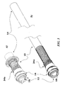
- the sleeve body 34 is made of flexible material, for example polyethylene terephthalate (PTFE) or acetal resin (Delrin TM ) and preferably has an appendage 34a (see Figure 3 ) with flexible structure, for example thanks to the construction according to a general slitted structure with Cardan-joint connections.
- the appendage 34a extends to cover at least partially the "reinforced" stretch of the duct 28 facing the valve 16 and is designed to function as "strain reliever" for the purpose of preventing build-up of undesired stresses between the sleeve body 34 and the duct 28.
- the two parts a) and b) of Figure 3 are precisely designed to highlight how, according to the different operating needs that can be inferred from observation of Figures 1 and 2 , the two ends 12 and 14 of the duct can either be at a certain distance from one another (with the body of the duct that is in itself able to absorb at least some stresses, such as those deriving from a different spatial orientation of the ends 12 and 14) or at a distance closer to one another, in conditions in which the aforesaid function of "strain reliever" becomes important.
- the ensemble of the elements 22 and 24 that supports the valve 16 is "floating", in so far as it is isolated elastically, on the one hand, by the coating C1 set between the threaded shank C and the annular body 22 and, on the other, by the ensemble of the sleeve body 34 and the annular elements 26, 31 and 32.
- This floating-assembly arrangement is able to prevent the valve 18 from possibly being exposed to impact stresses that are too violent as a result of the energetic action of pumping performed by the pumping element of the ventricular-assistance device.
- the entire internal surface of the duct 28 is provided with a coating 39 of haemocompatible material constituted typically by a haemocompatible polymer, such as a polyurethane.
- upstream and downstream with respect to the annular reinforcement 20 of the valve 18 is evidently intended to refer to the direction of flow of blood (which, as explained at the start of this description, is different, according to the function of the duct 10 and the orientation of the valve 18).
- the end 12 and the tubular body 28 of the duct are provided with a internal coating 39, 40 of haemocompatible material that is continuous, with the sole exception of the annular reinforcement 20 of the valve 18.
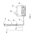
- the coating with haemocompatible material of the internal surface of the ducts, which comes into contact with the blood can be made, for example, using an apparatus like the one represented schematically in Figure 5 and following the process briefly illustrated in what follows.
- the duct 10 is set in a vertical position with the end 12, proximal to the pumping element of the VAD, facing upwards. Introduced from beneath is a piston 60 having a diameter such as to enter the duct, thanks to its elasticity, but at the same time as to occlude its lumen. Said piston 60 is traversed, at the centre, by a tube 62, connected, at the other end, to a tank 64 containing an adequate volume of solution 66 of the haemocompatible material to be used for the coating, for example a solution of polyurethane in tetrahydrofuran. The tank 64 is hermetically sealed and is connected to a second duct 68, through which it is possible to pump air into it and so pressurize it, or sucking air out to obtain a negative pressure therein.
- the duct 10 is filled with the solution 66 in the desired stretch, for example between the levels h1 and h2 indicated in Figure 5 .
- the solution 66 is removed from the lumen of the duct 10, the surface of which remains, in the desired stretch, moistened by a film of solution.
- evaporation of the solvent and deposit of an adherent layer of the biocompatible material is obtained on the desired stretch of the internal surface of the duct.
- the thickness of said layer depends, not only upon the nature of the materials, but also upon the concentration of the solution used.
- the duct 10 is coated with a film of polyurethane with a thickness greater in the stretch of the duct 10 closer to the end for connection to the pumping element of the device, where it is necessary for the duct 10 to have a certain greater stiffness in regard to squeezing.
- the coating film made of haemocompatible material can be instead thinner in the areas more distant from the end connected to the pumping element of the ventricular-assistance device. Said characteristic facilitates the suture of the end of the duct to the artery, in the case of the outlet duct of the VAD, and enhances the qualities of flexibility, and hence of "compliance", of the duct 26.
- the end 12 and the tubular body 28 of the duct are provided with an internal coating 39, 40 of haemocompatible material that is continuous, with the sole exception of the annular reinforcement 20 of the valve 18.
- an outer sleeve i.e., the element designated by 34 in the drawings
- the end 12 of the duct is constituted by: the ensemble of the elements 22 and 24 with the valve 18; the annular body 26 connected to the preceding ones by the sleeve 29; and, if present, by the spiral 30 anchored by means of the sleeve 31.
- the outer sleeve 34, with the ring 32, co-operates with the ring nut 16 for assembling the duct to the body of the pumping element.
- the outer surface of the duct 10 is coated with an adherent film of biocompatible material.
Priority Applications (2)
| Application Number | Priority Date | Filing Date | Title |
|---|---|---|---|
| EP07425359A EP2000159A1 (de) | 2007-06-07 | 2007-06-07 | Leitung für eine ventrikuläre Hilfsvorrichtung |
| US12/128,723 US20080306328A1 (en) | 2007-06-07 | 2008-05-29 | Duct for ventricular-assistance device |
Applications Claiming Priority (1)
| Application Number | Priority Date | Filing Date | Title |
|---|---|---|---|
| EP07425359A EP2000159A1 (de) | 2007-06-07 | 2007-06-07 | Leitung für eine ventrikuläre Hilfsvorrichtung |
Publications (1)
| Publication Number | Publication Date |
|---|---|
| EP2000159A1 true EP2000159A1 (de) | 2008-12-10 |
Family
ID=38657880
Family Applications (1)
| Application Number | Title | Priority Date | Filing Date |
|---|---|---|---|
| EP07425359A Withdrawn EP2000159A1 (de) | 2007-06-07 | 2007-06-07 | Leitung für eine ventrikuläre Hilfsvorrichtung |
Country Status (2)
| Country | Link |
|---|---|
| US (1) | US20080306328A1 (de) |
| EP (1) | EP2000159A1 (de) |
Cited By (2)
| Publication number | Priority date | Publication date | Assignee | Title |
|---|---|---|---|---|
| CN101543647B (zh) * | 2009-05-14 | 2011-09-07 | 天津大学 | 一种脉冲式心室辅助泵 |
| EP3329950A1 (de) * | 2016-12-01 | 2018-06-06 | Berlin Heart GmbH | Kanüle, kanülensystem und blutpumpensystem |
Families Citing this family (6)
| Publication number | Priority date | Publication date | Assignee | Title |
|---|---|---|---|---|
| US9981078B2 (en) | 2014-09-15 | 2018-05-29 | Lijun Jin | Left ventricular assist device |
| US10806581B2 (en) | 2017-05-23 | 2020-10-20 | Harmony Development Group, Inc. | Tethered implantable device having an apical base plate with a hydraulic intracardiac adjusting mechanism |
| WO2018222894A1 (en) * | 2017-05-31 | 2018-12-06 | Harmony Development Group, Inc. | Vortex transduction implant and inflatable sensor harboring platform |
| US10940002B2 (en) | 2017-06-28 | 2021-03-09 | Harmony Development Group, Inc. | Force transducting inflatable implant system including a dual force annular transduction implant |
| WO2019173385A1 (en) | 2018-03-05 | 2019-09-12 | Harmony Development Group, Inc. | A force transducting implant system for the mitigation of atrioventricular pressure gradient loss and the restoration of healthy ventricular geometry |
| DE102018208536A1 (de) * | 2018-05-30 | 2019-12-05 | Kardion Gmbh | Leitungsvorrichtung zum Leiten eines Blutstroms für ein Herzunterstützungssystem, Verfahren zum Herstellen einer Leitungsvorrichtung und Verfahren zum Montieren eines Herzunterstützungssystems |
Citations (4)
| Publication number | Priority date | Publication date | Assignee | Title |
|---|---|---|---|---|
| EP0092927A1 (de) * | 1982-04-10 | 1983-11-02 | Nippon Zeon Co., Ltd. | Kanüle |
| US5089014A (en) * | 1987-05-18 | 1992-02-18 | Holfert John W | Tubular interconnect device for use within the circulatory system |
| US20020095210A1 (en) * | 2001-01-16 | 2002-07-18 | Finnegan Michael T. | Heart pump graft connector and system |
| US20070055357A1 (en) * | 2005-09-02 | 2007-03-08 | Pokorney James L | Prosthetic heart valve housing |
Family Cites Families (10)
| Publication number | Priority date | Publication date | Assignee | Title |
|---|---|---|---|---|
| US4118806A (en) * | 1976-02-04 | 1978-10-10 | Thermo Electron Corporation | Prosthetic blood vessel |
| US4086665A (en) * | 1976-12-16 | 1978-05-02 | Thermo Electron Corporation | Artificial blood conduit |
| JPH0411715Y2 (de) * | 1985-08-30 | 1992-03-24 | ||
| US5609626A (en) * | 1989-05-31 | 1997-03-11 | Baxter International Inc. | Stent devices and support/restrictor assemblies for use in conjunction with prosthetic vascular grafts |
| US5676651A (en) * | 1992-08-06 | 1997-10-14 | Electric Boat Corporation | Surgically implantable pump arrangement and method for pumping body fluids |
| JP3383009B2 (ja) * | 1993-06-29 | 2003-03-04 | テルモ株式会社 | 血管カテーテル |
| US6102845A (en) * | 1994-02-07 | 2000-08-15 | Baxter International Inc. | Ventricular assist device with minimal blood contacting surfaces |
| US5843050A (en) * | 1995-11-13 | 1998-12-01 | Micro Therapeutics, Inc. | Microcatheter |
| US7762977B2 (en) * | 2003-10-08 | 2010-07-27 | Hemosphere, Inc. | Device and method for vascular access |
| US7824358B2 (en) * | 2004-07-22 | 2010-11-02 | Thoratec Corporation | Heart pump connector |
-
2007
- 2007-06-07 EP EP07425359A patent/EP2000159A1/de not_active Withdrawn
-
2008
- 2008-05-29 US US12/128,723 patent/US20080306328A1/en not_active Abandoned
Patent Citations (4)
| Publication number | Priority date | Publication date | Assignee | Title |
|---|---|---|---|---|
| EP0092927A1 (de) * | 1982-04-10 | 1983-11-02 | Nippon Zeon Co., Ltd. | Kanüle |
| US5089014A (en) * | 1987-05-18 | 1992-02-18 | Holfert John W | Tubular interconnect device for use within the circulatory system |
| US20020095210A1 (en) * | 2001-01-16 | 2002-07-18 | Finnegan Michael T. | Heart pump graft connector and system |
| US20070055357A1 (en) * | 2005-09-02 | 2007-03-08 | Pokorney James L | Prosthetic heart valve housing |
Cited By (2)
| Publication number | Priority date | Publication date | Assignee | Title |
|---|---|---|---|---|
| CN101543647B (zh) * | 2009-05-14 | 2011-09-07 | 天津大学 | 一种脉冲式心室辅助泵 |
| EP3329950A1 (de) * | 2016-12-01 | 2018-06-06 | Berlin Heart GmbH | Kanüle, kanülensystem und blutpumpensystem |
Also Published As
| Publication number | Publication date |
|---|---|
| US20080306328A1 (en) | 2008-12-11 |
Similar Documents
| Publication | Publication Date | Title |
|---|---|---|
| EP2000159A1 (de) | Leitung für eine ventrikuläre Hilfsvorrichtung | |
| US4240409A (en) | Apparatus for assisting circulation of blood | |
| CN101878049B (zh) | 博动血泵 | |
| US20020183584A1 (en) | Non-porous smooth ventricular assist device conduit | |
| US8444545B2 (en) | Dual-pulsation bi-ventricular assist device | |
| US6666814B2 (en) | Enhanced intra-aortic balloon assist device | |
| JP4365708B2 (ja) | 人工心臓に関する流入導管システム | |
| US7993259B2 (en) | Percutaneous intra-aortic ventricular assist device | |
| EP1128786B1 (de) | Glattes gefäss für kammerunterstützungsvorrichtung | |
| EP0291476A2 (de) | Vorrichtung zum Berühren von Blutströmungen | |
| US8226712B1 (en) | Total artificial heart system for auto-regulating flow and pressure | |
| CN106714862B (zh) | 经心尖心室辅助装置的植入及其套件 | |
| EP1839600A1 (de) | Expandierbarer Führungstubus | |
| JPH11514251A (ja) | 心臓補助システム | |
| JP2001506898A (ja) | 心臓補助装置の弁 | |
| JP2024511386A (ja) | 大動脈傍血液ポンプ装置 | |
| US20080058925A1 (en) | Bifurcated flow device for cardio-pulmonary assist or support and associated methods | |
| US20100094077A1 (en) | Method for substantially non-delaminable smooth ventricular assist device conduit and product from same | |
| US20210031011A1 (en) | Cannula system and method for discharging the volume of a heart | |
| US20230158288A1 (en) | Pressure sensor arrangement and method | |
| KR101479669B1 (ko) | 심실 보조 장치 | |
| Gibbons | Cardiac assist devices | |
| KR101037077B1 (ko) | 심실보조장치의 착탈이 가능한 연결관 및 그 사용방법 | |
| JP2024517235A (ja) | 漏れのない大動脈アダプターアセンブリを有する血液ポンプ装置及び装置の埋め込み方法 | |
| JPH07265409A (ja) | 大動脈内用バルーンカテーテルおよび血液補助循環装置 |
Legal Events
| Date | Code | Title | Description |
|---|---|---|---|
| PUAI | Public reference made under article 153(3) epc to a published international application that has entered the european phase |
Free format text: ORIGINAL CODE: 0009012 |
|
| AK | Designated contracting states |
Kind code of ref document: A1 Designated state(s): AT BE BG CH CY CZ DE DK EE ES FI FR GB GR HU IE IS IT LI LT LU LV MC MT NL PL PT RO SE SI SK TR |
|
| AX | Request for extension of the european patent |
Extension state: AL BA HR MK RS |
|
| AKX | Designation fees paid | ||
| REG | Reference to a national code |
Ref country code: DE Ref legal event code: 8566 |
|
| STAA | Information on the status of an ep patent application or granted ep patent |
Free format text: STATUS: THE APPLICATION IS DEEMED TO BE WITHDRAWN |
|
| 18D | Application deemed to be withdrawn |
Effective date: 20090611 |