EP3801672B1 - Vorrichtung zum verankern eines herzunterstützungssystems in einem blutgefäss, herstellverfahren zum herstellen einer vorrichtung und herzunterstützungssystem - Google Patents
Vorrichtung zum verankern eines herzunterstützungssystems in einem blutgefäss, herstellverfahren zum herstellen einer vorrichtung und herzunterstützungssystem Download PDFInfo
- Publication number
- EP3801672B1 EP3801672B1 EP19728638.8A EP19728638A EP3801672B1 EP 3801672 B1 EP3801672 B1 EP 3801672B1 EP 19728638 A EP19728638 A EP 19728638A EP 3801672 B1 EP3801672 B1 EP 3801672B1
- Authority
- EP
- European Patent Office
- Prior art keywords
- crown
- anchoring
- state
- support system
- blood vessel
- Prior art date
- Legal status (The legal status is an assumption and is not a legal conclusion. Google has not performed a legal analysis and makes no representation as to the accuracy of the status listed.)
- Active
Links
Images




Classifications
-
- A—HUMAN NECESSITIES
- A61—MEDICAL OR VETERINARY SCIENCE; HYGIENE
- A61M—DEVICES FOR INTRODUCING MEDIA INTO, OR ONTO, THE BODY; DEVICES FOR TRANSDUCING BODY MEDIA OR FOR TAKING MEDIA FROM THE BODY; DEVICES FOR PRODUCING OR ENDING SLEEP OR STUPOR
- A61M60/00—Blood pumps; Devices for mechanical circulatory actuation; Balloon pumps for circulatory assistance
- A61M60/10—Location thereof with respect to the patient's body
- A61M60/122—Implantable pumps or pumping devices, i.e. the blood being pumped inside the patient's body
- A61M60/165—Implantable pumps or pumping devices, i.e. the blood being pumped inside the patient's body implantable in, on, or around the heart
-
- A—HUMAN NECESSITIES
- A61—MEDICAL OR VETERINARY SCIENCE; HYGIENE
- A61M—DEVICES FOR INTRODUCING MEDIA INTO, OR ONTO, THE BODY; DEVICES FOR TRANSDUCING BODY MEDIA OR FOR TAKING MEDIA FROM THE BODY; DEVICES FOR PRODUCING OR ENDING SLEEP OR STUPOR
- A61M60/00—Blood pumps; Devices for mechanical circulatory actuation; Balloon pumps for circulatory assistance
- A61M60/20—Type thereof
- A61M60/205—Non-positive displacement blood pumps
- A61M60/216—Non-positive displacement blood pumps including a rotating member acting on the blood, e.g. impeller
-
- A—HUMAN NECESSITIES
- A61—MEDICAL OR VETERINARY SCIENCE; HYGIENE
- A61M—DEVICES FOR INTRODUCING MEDIA INTO, OR ONTO, THE BODY; DEVICES FOR TRANSDUCING BODY MEDIA OR FOR TAKING MEDIA FROM THE BODY; DEVICES FOR PRODUCING OR ENDING SLEEP OR STUPOR
- A61M60/00—Blood pumps; Devices for mechanical circulatory actuation; Balloon pumps for circulatory assistance
- A61M60/10—Location thereof with respect to the patient's body
- A61M60/122—Implantable pumps or pumping devices, i.e. the blood being pumped inside the patient's body
- A61M60/126—Implantable pumps or pumping devices, i.e. the blood being pumped inside the patient's body implantable via, into, inside, in line, branching on, or around a blood vessel
- A61M60/135—Implantable pumps or pumping devices, i.e. the blood being pumped inside the patient's body implantable via, into, inside, in line, branching on, or around a blood vessel inside a blood vessel, e.g. using grafting
-
- A—HUMAN NECESSITIES
- A61—MEDICAL OR VETERINARY SCIENCE; HYGIENE
- A61M—DEVICES FOR INTRODUCING MEDIA INTO, OR ONTO, THE BODY; DEVICES FOR TRANSDUCING BODY MEDIA OR FOR TAKING MEDIA FROM THE BODY; DEVICES FOR PRODUCING OR ENDING SLEEP OR STUPOR
- A61M60/00—Blood pumps; Devices for mechanical circulatory actuation; Balloon pumps for circulatory assistance
- A61M60/10—Location thereof with respect to the patient's body
- A61M60/122—Implantable pumps or pumping devices, i.e. the blood being pumped inside the patient's body
- A61M60/126—Implantable pumps or pumping devices, i.e. the blood being pumped inside the patient's body implantable via, into, inside, in line, branching on, or around a blood vessel
- A61M60/135—Implantable pumps or pumping devices, i.e. the blood being pumped inside the patient's body implantable via, into, inside, in line, branching on, or around a blood vessel inside a blood vessel, e.g. using grafting
- A61M60/139—Implantable pumps or pumping devices, i.e. the blood being pumped inside the patient's body implantable via, into, inside, in line, branching on, or around a blood vessel inside a blood vessel, e.g. using grafting inside the aorta, e.g. intra-aortic balloon pumps
-
- A—HUMAN NECESSITIES
- A61—MEDICAL OR VETERINARY SCIENCE; HYGIENE
- A61M—DEVICES FOR INTRODUCING MEDIA INTO, OR ONTO, THE BODY; DEVICES FOR TRANSDUCING BODY MEDIA OR FOR TAKING MEDIA FROM THE BODY; DEVICES FOR PRODUCING OR ENDING SLEEP OR STUPOR
- A61M60/00—Blood pumps; Devices for mechanical circulatory actuation; Balloon pumps for circulatory assistance
- A61M60/10—Location thereof with respect to the patient's body
- A61M60/122—Implantable pumps or pumping devices, i.e. the blood being pumped inside the patient's body
- A61M60/126—Implantable pumps or pumping devices, i.e. the blood being pumped inside the patient's body implantable via, into, inside, in line, branching on, or around a blood vessel
- A61M60/148—Implantable pumps or pumping devices, i.e. the blood being pumped inside the patient's body implantable via, into, inside, in line, branching on, or around a blood vessel in line with a blood vessel using resection or like techniques, e.g. permanent endovascular heart assist devices
-
- A—HUMAN NECESSITIES
- A61—MEDICAL OR VETERINARY SCIENCE; HYGIENE
- A61M—DEVICES FOR INTRODUCING MEDIA INTO, OR ONTO, THE BODY; DEVICES FOR TRANSDUCING BODY MEDIA OR FOR TAKING MEDIA FROM THE BODY; DEVICES FOR PRODUCING OR ENDING SLEEP OR STUPOR
- A61M60/00—Blood pumps; Devices for mechanical circulatory actuation; Balloon pumps for circulatory assistance
- A61M60/10—Location thereof with respect to the patient's body
- A61M60/122—Implantable pumps or pumping devices, i.e. the blood being pumped inside the patient's body
- A61M60/165—Implantable pumps or pumping devices, i.e. the blood being pumped inside the patient's body implantable in, on, or around the heart
- A61M60/178—Implantable pumps or pumping devices, i.e. the blood being pumped inside the patient's body implantable in, on, or around the heart drawing blood from a ventricle and returning the blood to the arterial system via a cannula external to the ventricle, e.g. left or right ventricular assist devices
-
- A—HUMAN NECESSITIES
- A61—MEDICAL OR VETERINARY SCIENCE; HYGIENE
- A61M—DEVICES FOR INTRODUCING MEDIA INTO, OR ONTO, THE BODY; DEVICES FOR TRANSDUCING BODY MEDIA OR FOR TAKING MEDIA FROM THE BODY; DEVICES FOR PRODUCING OR ENDING SLEEP OR STUPOR
- A61M60/00—Blood pumps; Devices for mechanical circulatory actuation; Balloon pumps for circulatory assistance
- A61M60/10—Location thereof with respect to the patient's body
- A61M60/122—Implantable pumps or pumping devices, i.e. the blood being pumped inside the patient's body
- A61M60/165—Implantable pumps or pumping devices, i.e. the blood being pumped inside the patient's body implantable in, on, or around the heart
- A61M60/178—Implantable pumps or pumping devices, i.e. the blood being pumped inside the patient's body implantable in, on, or around the heart drawing blood from a ventricle and returning the blood to the arterial system via a cannula external to the ventricle, e.g. left or right ventricular assist devices
- A61M60/183—Implantable pumps or pumping devices, i.e. the blood being pumped inside the patient's body implantable in, on, or around the heart drawing blood from a ventricle and returning the blood to the arterial system via a cannula external to the ventricle, e.g. left or right ventricular assist devices drawing blood from both ventricles, e.g. bi-ventricular assist devices [BiVAD]
-
- A—HUMAN NECESSITIES
- A61—MEDICAL OR VETERINARY SCIENCE; HYGIENE
- A61M—DEVICES FOR INTRODUCING MEDIA INTO, OR ONTO, THE BODY; DEVICES FOR TRANSDUCING BODY MEDIA OR FOR TAKING MEDIA FROM THE BODY; DEVICES FOR PRODUCING OR ENDING SLEEP OR STUPOR
- A61M60/00—Blood pumps; Devices for mechanical circulatory actuation; Balloon pumps for circulatory assistance
- A61M60/80—Constructional details other than related to driving
- A61M60/855—Constructional details other than related to driving of implantable pumps or pumping devices
- A61M60/861—Connections or anchorings for connecting or anchoring pumps or pumping devices to parts of the patient's body
-
- A—HUMAN NECESSITIES
- A61—MEDICAL OR VETERINARY SCIENCE; HYGIENE
- A61M—DEVICES FOR INTRODUCING MEDIA INTO, OR ONTO, THE BODY; DEVICES FOR TRANSDUCING BODY MEDIA OR FOR TAKING MEDIA FROM THE BODY; DEVICES FOR PRODUCING OR ENDING SLEEP OR STUPOR
- A61M60/00—Blood pumps; Devices for mechanical circulatory actuation; Balloon pumps for circulatory assistance
- A61M60/80—Constructional details other than related to driving
- A61M60/855—Constructional details other than related to driving of implantable pumps or pumping devices
- A61M60/865—Devices for guiding or inserting pumps or pumping devices into the patient's body
-
- A—HUMAN NECESSITIES
- A61—MEDICAL OR VETERINARY SCIENCE; HYGIENE
- A61M—DEVICES FOR INTRODUCING MEDIA INTO, OR ONTO, THE BODY; DEVICES FOR TRANSDUCING BODY MEDIA OR FOR TAKING MEDIA FROM THE BODY; DEVICES FOR PRODUCING OR ENDING SLEEP OR STUPOR
- A61M2205/00—General characteristics of the apparatus
- A61M2205/02—General characteristics of the apparatus characterised by a particular materials
- A61M2205/0266—Shape memory materials
-
- A—HUMAN NECESSITIES
- A61—MEDICAL OR VETERINARY SCIENCE; HYGIENE
- A61M—DEVICES FOR INTRODUCING MEDIA INTO, OR ONTO, THE BODY; DEVICES FOR TRANSDUCING BODY MEDIA OR FOR TAKING MEDIA FROM THE BODY; DEVICES FOR PRODUCING OR ENDING SLEEP OR STUPOR
- A61M2209/00—Ancillary equipment
- A61M2209/08—Supports for equipment
- A61M2209/088—Supports for equipment on the body
Definitions
- the invention relates to a device for anchoring a heart support system in a blood vessel, a manufacturing method for producing such a device and a heart support system.
- Cardiac support systems for long-term therapy are typically implanted via a complete or partial opening of the sternum, whereby a heart-lung machine can be used to enable extracorporeal blood circulation. This often involves punching a hole into the structural integrity of the heart muscle tissue and the body's main artery, the aorta.
- Short-term intravascular cardiac support systems are delivered either percutaneously, i.e. through the skin, or surgically via various arterial accesses, for example via the femoral artery. The final positioning of the cardiac support systems can be visually supported intraoperatively, for example using ultrasound or radiological fluoroscopy.
- the implanted cardiac support systems have a high risk of dislocation because there is no local fixation of the cardiac support system.
- the ventricular support system can therefore slip after implantation because it is not anchored at the implantation site, which can lead to a malfunction of the pump or to discontinuation of therapy with the ventricular support system.
- the CA 3 000 581 A1 shows a pump for pumping blood with an impeller connected in a distal area and a housing surrounding the impeller.
- the impeller and housing are designed to self-inflate after forced compression.
- the WO 2008/106103 A2 discloses an implantable blood pump.
- the WO 2017/118738 A1 describes a connector for fluid connection between two anatomical compartments through at least one anatomical wall.
- the US 2013/0303970 A1 shows a catheter pump.
- the catheter pump may include an elongated catheter body with a distal portion that includes an expandable cannula with an inlet and an outlet.
- the object of the invention is to create a device that makes it possible to arrange a medical system, for example a cardiac support system but also an implant, in particular in a blood vessel, for example within the aorta, in such a way that it relates to a section of the human or animal Body, for example the blood vessel or the aorta, has a fundamentally constant spatial position even over longer periods of time, ie hours, days, weeks, months or possibly even years.
- the device for anchoring a cardiac support system in a blood vessel and the arrangement and manufacturing method for producing a corresponding device are presented below.
- the measures listed in the dependent claims make advantageous developments and improvements of the device specified in the independent claim possible.
- an implant for example a heart support system
- a device in the blood vessel, in particular within the aorta, with or without a spatial relationship to the aortic valve.
- the device can be attached to a heart pump.
- the device can advantageously be folded for minimally invasive insertion of the ventricular assist system, and the device is shaped so that it can unfold at the destination for positioning and anchoring the ventricular assist system.
- the heart support system can be aligned at the destination and placed in a targeted manner.
- the position of the heart support system advantageously remains unchanged in the long term due to the anchoring by means of the device, which means that slipping or dislocation of the heart support system can be avoided.
- a device for anchoring a heart support system in a blood vessel can assume an insertion state for introducing the cardiac support system into the blood vessel.
- the device can assume an anchoring state in order to anchor the heart support system in the blood vessel.
- the device comprises at least one fixing device for fixing the device to the heart support system, a crown and a connecting device which is designed to connect the crown to the fixing device.
- the crown is formed from at least one unfolding element.
- the deployment member is configured to deploy during a transition from the insertion state to the anchoring state to increase the diameter of the crown to anchor the device in the blood vessel.
- the device can be formed from a biocompatible material in order to enable the device to grow together with the blood vessel, for example the aorta, during long-term use of the device.
- the device can be made from an elastic material that also has a certain rigidity, for example from Nitinol.
- the cardiac support system can be, for example, one Heart pump such as a right ventricular support system, a left ventricular support system, a biventricular support system or a vascular or valve prosthesis.
- the device can also be used to position another component in a blood vessel and anchor it at its destination, for example another vascular or intracavitary implant such as a gastrointestinal, intrathecal, or intravesical implant.
- the insertion state can be understood, for example, as the state in which the device can be for inserting or when inserting the heart support system into the blood vessel.
- the device can, for example, be fixed to the heart pump and folded together in such a way that the device can be inserted into a catheter with the heart support system for minimally invasive insertion.
- the device and the heart support system can, for example, be introduced minimally invasively through the leg artery, the fermoral artery.
- the device When inserted, the device can have a diameter that is less than the diameter of a human aorta.
- the anchoring state can be understood as meaning a state in which the device, after insertion and alignment at the destination, is unfolded to increase the diameter of the crown in order to non-positively anchor the heart support system at the destination and in this way advantageously prevent slipping or dislocation of the heart support system to prevent.
- the device or a component of the device, for example the crown can have an inside diameter that is slightly larger than the inside diameter of the blood vessel in which it is anchored, for example a total inside diameter in the range of 20 - 30 mm, for example 23 mm, for anchoring to or behind a human aortic valve.
- the outer contour of at least part of the device, for example the crown, in the anchoring state can have a shape corresponding to the not exactly circular aortic anatomy of a human aorta. In this way, the device can be held at the destination in the anchoring state via a radial force connection.
- the fixing device can be designed to fix the device on an implant, for example the heart support system.
- the fixing device can have at least one fixing element for forming a positive and/or non-positive connection with a counter-fixing element arranged on the implant.
- the crown is ring-shaped.
- a single deployment element can be formed in a ring shape or several deployment elements can be lined up in a ring shape.
- the connecting device can comprise at least one elongated, for example wire-shaped, strut which is attached to both the crown and the fixing device.
- the connecting device can be shaped flexibly to enable the diameter of the crown to be increased.
- At least the deployment element of the crown of the device can be formed from shape memory material.
- the unfolding element can consist, for example, of a biocompatible shape memory polymer, or of a biocompatible shape memory alloy, such as Nitinol.
- the entire device can also be made from a shape memory alloy, for example Nitionol. Due to its shape memory properties, the use of a shape memory material such as Nitinol enables a particularly elegant and simple realization of the insertion state and the unfolding of the unfolding element during the transition to the anchoring state.
- Nitinol as a shape memory material is advantageous because the Nitinol material is a proven material in medicine, especially in the field of cardiovascular medicine, for example for heart valve prostheses, stents and vascular prostheses, due to its biocompatibility and the shape memory property, which enables even complex structures to deliver and drop off at the destination in a small installation space, like the device presented here.
- the device can also include an arch device with at least one foot.
- the arch device is designed to unfold during the transition from the insertion state to the anchoring state in order to position the at least one foot in the blood vessel. By positioning the at least one foot in the blood vessel, the device can be aligned and positioned in the blood vessel, for example before anchoring.
- the arch device can be connected to the crown.
- the arch device can have an arch fixation device for fixing the arch device to the heart support system.
- the device can accordingly be formed in one piece, in that the fixation device, the crown, the connecting device and the arch device are coupled to one another, or the device can be in two parts, if the arch device is fixed to the heart support system with its own arch fixation device, and the other components of the device to one another are coupled.
- the one-part embodiment can be advantageous with regard to folding the device for the insertion state; the two-part embodiment can be advantageous depending on the design of the heart support system.
- a two-part embodiment can enable more flexibility with regard to the installation space of the heart support system, for example in that the arch device can be fixed at one end of a motor-coupling-pump unit of the heart support system, and the second part of the device can be fixed to the other end of the motor-coupling-pump unit of the cardiac support system.
- the device can advantageously be aligned and positioned at the destination by unfolding the at least one foot.
- the foot can, for example, have an atraumatic shape in order not to injure the blood vessel when unfolding and in the anchoring state.
- the arch device can be designed to enable the device to be aligned for the anchoring state when positioning the at least one foot by shaping the arch device and the at least one foot.
- the arch device can have three feet, in particular the feet for positioning the feet are each formed in a case of a heart valve.
- This embodiment is advantageous in order to be able to position the device and thus the heart support system particularly precisely, especially if the heart support system is positioned and anchored behind the aortic valve using the device, for example.
- the three feet can, for example, have a shape adapted to the peanut shape of the shells in order to advantageously achieve a particularly advantageous ratio of contact surface and torsional rigidity of the three feet.
- the device is cylindrical in the inserted state.
- the device can, for example, be folded up.
- the device is formed from Nitinol, the device can be cut free from a tube, then a shape corresponding to the anchoring state can be impressed by means of a heat treatment.
- the device can be folded up according to the originally cylindrical tube geometry.
- the deployment element has an inclined position in the anchoring state.
- the inclination can be understood as meaning a certain angle of the deployment element relative to the longitudinal axis of the device.
- the unfolding element can be positioned at an angle in the anchoring state in order to support a force-fitting connection between the crown and the blood vessel in the anchoring state.
- the angle can be, for example, between 20° and 30°, in particular 25°, with respect to the longitudinal axis of the device.
- the crown may have a plurality of deployment elements coupled to one another.
- Each of the deployment elements may have two deployment bars connected at their ends, and the two deployment bars may be at a closer distance from each other in the inserted state than in the anchoring state.
- the deployment elements may be coupled together by a connection to one of the deployment rods of an adjacent deployment element.
- the two deployment rods can be connected to one another in such a way that, when the device is anchored, each deployment element forms a diamond with rounded corners in the axial direction to the longitudinal axis of the device.
- Such a formation of a plurality of diamond-shaped deployment elements coupled together can correspond to a standard cut of a vascular stent, which can be advantageous when producing the device.
- the unfolding element can have a plurality of loops arranged in a meandering manner, the loops being at a smaller distance from one another in the insertion state than in the anchoring state.
- This embodiment offers a particularly space-saving folding of the device for the insertion state.
- the connecting device has at least one bending strut.
- the bending strut is designed to unfold during the transition from the insertion state to the anchoring state in order to enable the crown to be unfolded.
- the bending strut enables a particularly elegant and space-saving connection between the fixing device and the crown.
- the bending strut can, for example, be made of an elastic material, for example Nitinol.
- a first end of the bending strut can be attached to the fixing device according to a further embodiment.
- a second end of the bending strut may be attached to a connection between two adjacent deployment elements, or the second end of the bending strut may be attached to a be attached to the end of the crown facing away from the fixing device.
- the bending strut can therefore be designed according to the shape of the unfolding element of the crown in order to enable efficient unfolding of the crown depending on the embodiment and, depending on the embodiment of the unfolding element, to enable compact folding for the insertion state with regard to the axial length of the device.
- the fixing device can be designed to fix the device to the heart support system in a form-fitting and/or force-fitting manner.
- the device can thus be stably connected to the heart support system in order to absorb forces occurring during implantation or during the life of the heart support system, for example.
- the fixing device can, for example, have an element for positive engagement, or a recess for positive reception of an element, which is applied, for example, to the housing of the heart support system.
- the element for positive fixing can, for example, have different cross sections and the element or the corresponding recess can be shaped, for example, round, oval, triangular, polygonal or star-shaped.
- Both the fixing device and the heart support system can have elements that enable the fixation device to snap into place or be anchored to the heart support system.
- the fixing device can have, for example, a bayonet connection or a clip connection or a hook.
- the fixing device can also be implemented by means of a cohesive connection.
- the fixing device can, for example, be designed to enable a rotational movement between the device and the heart support system.
- the device can also have a sleeve.
- the sleeve can be movable relative to the crown.
- the sleeve can be shaped to at least close the crown in the inserted state enclose and release the crown to initiate the transition to the anchoring state.
- the sleeve can also be movable relative to the arch device and can also be shaped to enclose the arch device in the insertion state and to release the arch device to initiate the transition to the anchoring state.
- the sleeve can also be shaped to enclose and release all other components of the device.
- the sleeve can, for example, be cylindrical and designed in such a way that the device with the sleeve can be inserted into a commercially available catheter in the inserted state.
- the sleeve can advantageously be used, for example, to hold down the other components of the device in the folded state of the device and thereby provide additional stability in the inserted state, for example also when components of the device or the entire device are formed from a shape memory material.
- the sleeve can be removed gradually during the transition from the insertion state to the anchoring state, for example via a controlled mechanism, which can be controlled electrically, for example, or by manually retracting the sleeve.
- the device can, for example, be unfolded step by step in order to advantageously unfold the device in a controlled manner and position it before anchoring, or the sleeve can be moved forward again in order to align the device differently or to correct the positioning of the device.
- the method has at least one unfolding step.
- the unfolding element becomes the crown of the device in the transition from the insertion state unfolded into the anchoring state to increase the diameter of the crown.
- the unfolding step may also be performed to increase the diameter of the crown for anchoring the device in the blood vessel.
- the method can be carried out both when the device is arranged inside a blood vessel and when the device is outside a blood vessel, for example to connect the device to a component of an implant by increasing the diameter of the crown.
- a manufacturing method for manufacturing a device for anchoring a heart support system in a blood vessel is also presented.
- the device may assume an insertion state for inserting the ventricular assist system into the blood vessel, and further, the device may assume an anchoring state to anchor the ventricular assist system in the blood vessel.
- the manufacturing method has at least a step of providing, a step of molding and a step of heat treating.
- a semi-finished product made of a shape memory material is provided.
- a fixing device for fixing the device to the cardiac support system is formed.
- a crown is formed from at least one unfolding element, the unfolding element being designed to unfold during a transition from the insertion state to the anchoring state to increase the diameter of the crown in order to anchor the device in the blood vessel.
- a connecting device is formed to to connect the crown to the connection device.
- the fixation device, the crown and the connecting device are formed from the semi-finished product.
- the fixation device, the crown and the connection device are heat treated to imprint the shape of the anchoring state.
- a cardiac support system with a device is also presented.
- the device can, for example, be fixed to the heart support system.
- the cardiac support system can, for example, include a heart pump with a motor-clutch-pump unit.
- the cardiac support system can have a housing that is shaped to be connected to the device in a form-fitting and/or force-fitting manner, for example by means of the fixing device of the device.
- the size of the cardiac support system and/or the dimensions of the device can be selected or changed in a patient-specific manner.
- Fig. 1 shows a schematic representation of a device 100 for anchoring a heart support system in a blood vessel according to an exemplary embodiment. Even if the device 100 is described here and below in connection with a cardiac support system, the device 100 can also be used to anchor other implants in a blood vessel.
- the device 100 can assume an insertion state for inserting the heart support system into the blood vessel.
- the device 100 can do the in Fig. 1 assume the anchoring state shown in order to anchor the heart support system in the blood vessel.
- the device 100 has at least one fixing device 105 for fixing the device 100 to the heart support system, a crown 110 and a connecting device 115.
- the crown 110 is formed from at least one deployment element 120.
- the deployment member 120 is configured to deploy during a transition from the insertion state to the anchoring state to increase the diameter of the crown 110 to anchor the device 100 in the blood vessel.
- the crown 110 comprises a plurality of unfolding elements 120.
- the connecting device 115 is designed to connect the crown 110 to the fixing device 105.
- the device 100 can be used to prevent the cardiac support system from slipping or moving, since the crown 110 can be used for anchoring at the implantation site.
- a defined positioning of the heart support system also referred to below, is possible by means of the device 100.
- the device may be at least partially formed from a shape memory material such as Nitinol.
- the device 100 is designed as a nitinol frame for anchoring and positioning a cardiac support system in a blood vessel.
- the device 100 can have a design for both long-term use and short-term implantation have a retrievable design, for example by a controlled transfer of the implanted and anchored device 100 from the anchoring state to the insertion state.
- the crown 110 and the fixation device 105 of the device 100 are extended along a longitudinal axis of the device 100, which may correspond to the axis of a catheter in which the cardiac support system is introduced minimally invasively through the leg artery.
- the unfolding element 120 and thus the crown 110 is unfolded according to the anchoring state.
- the unfolding element 120 can have an inclined position in the anchoring state with respect to the longitudinal axis of the device 100.
- the unfolding element 120 can be positioned at a certain angle, for example at an angle of 25°, in order to generate an increased contact force of the crown 110 for non-positively anchoring the device 100 in the blood vessel.
- the crown 110 can, as in the exemplary embodiment shown here, have a plurality of unfolding elements 120 coupled to one another, each of the unfolding elements 120 having two unfolding rods 125 connected at their ends. Central sections of the two deployment rods 125 of each deployment element 120 are at a smaller distance from one another in the inserted state than in the anchoring state. According to this exemplary embodiment, the central sections of all unfolding elements 120 are arranged on a circular path. When deployed, each deployment member 120 may have a diamond shape with rounded corners, the diamond shape being formed by removing the two deployment bars 125 connected at their ends. The unfolding elements 120 coupled together form a lattice-shaped ring. The deployment elements 120 can be shaped identically.
- the connecting device 115 optionally has at least one bending strut 130.
- the bending strut 130 is designed to be at the transition from that Insertion state into the anchoring state to unfold to enable the crown 110 to be unfolded.
- the connecting device 115 can also have several bending struts 130, for example to enable a particularly uniform unfolding of the unfolding element 120 and thus the crown 110.
- the device 100 has, for example, four equally spaced bending struts 130.
- a first end of the bending strut 130 is attached to the fixing device 105 and a second end of the bending strut 130 is attached to a connection between two adjacent deployment elements 120 as shown here.
- the second end of the bending strut 130 can be attached to an end of the crown 110 facing away from the fixing device 105.
- the fixing device 105 is designed to fix the device 100 to the heart support system in a form-fitting and/or force-fitting manner.
- the fixing device 105 can, for example, as shown here, have a recess for positively receiving an applying element, wherein the corresponding element can be formed in a component of the heart support system to be fixed.
- the fixing device 105 is formed as a ring which has a plurality of recesses.
- the annular crown 110 In the unfolded state of the crown 110, the annular crown 110 has a larger diameter than the fixing device 105, which is shaped as a ring.
- the crown 110 and the fixing device 105 have no or only a slight overlap.
- a longitudinal axis of the device 100 runs centrally through the crown 110 and the fixing device 105.
- the unfolding elements 120 have an inclined position in the unfolded state, with the fixing device 105 facing Ends of the unfolding elements 120 have a greater distance from the longitudinal axis of the device 100 than the ends of the unfolding elements 120 facing away from the fixing device 105.
- Fig. 2 shows a schematic representation of part of a heart support system 205 with a device 100 for anchoring the heart support system 205 in a blood vessel according to an exemplary embodiment.
- a section of a heart pump is shown as an example with tubular components that include a motor and an impeller of the heart pump.
- the device 100 is fixed to a housing section of the heart support system 205.
- the deployment element 120 may be formed from a shape memory material.
- several components or the entire device 100 can also be formed from a shape memory material, for example from Nitinol as shown here.
- the device 100 comprises an arch device 210 with at least one foot 215.
- the arch device 210 is designed to unfold during the transition from the insertion state to the anchoring state and thus position the at least one foot 215 in the blood vessel make possible.
- the arch device 210 is connected to the crown 110 here.
- the arch device 210 can also have an arch fixation device for fixing the arch device 210 to the cardiac support system 205, this is in the following Figure 3 shown.
- the arch device 210 can have three feet 215, as shown here.
- the feet 215 can be formed in a case of a heart valve for positioning the feet 215, for example when the cardiac support system 205 fixed by the device 100 is positioned and anchored within a human aorta directly behind an aortic valve.
- the fixing device 105 can fix the device 100 to the heart support system by means of a positive, non-positive or material connection mechanism.
- the heart support system 205 can, for example, as shown here, have a connecting element for positive engagement of the fixing device 105, and the fixing device 105 can have a corresponding material recess for engaging, or a correspondingly shaped connecting element for engaging, such as the clip connection shown here.
- the cardiac support system 205 can be fixed to the device 100 to anchor the cardiac support system 205 in the blood vessel, for example in the aorta.
- the crown 110 ensures that the heart support system 205 is held in the aorta by a radial frictional connection of the device with a wall section of the aorta.
- Fig. 3 shows a schematic representation of a cardiac support system 205 with a device 100 for anchoring a cardiac support system 205 in a blood vessel according to an exemplary embodiment. Shown is a side view of the heart support system 205 with the device 100, the device 100 being designed in two parts. One part of the device 100 comprises the crown 110 connected to the fixing device 105 by means of the connecting device 115, and another part of the device 100 consists of the arch device 210. The device 100 is in an unfolded state corresponding to the anchoring state.
- the arch device 210 has an arch fixation device 305 for fixing the arch device 210 to the heart support system 205 and is not connected to the crown 110.
- the arch fixation device 305 can fix the arch device 210 to the heart support system 205 by means of a positive and non-positive connection, as shown here by way of example.
- the introduction of the heart support system 205 can preferably be carried out minimally invasively through a human leg artery, the femoral artery.
- a limited insertion diameter can be available, which is the maximum diameter of the femoral artery in the area of the implantation site or other arteries in the course (for example the iliac artery, etc.) or z. B. is due to the tortuosity or the degree of calcification of the arterial pathway.
- the heart support system 205 and the device 100 which can be brought into the body in this way, can therefore be limited in diameter and length.
- a high speed of the motor and the pump wheel of the heart pump can be set in order to still achieve significant support for the heart.
- the miniaturization of these components of the heart pump in combination with the high speed can result in the efficiency of the electric motor decreasing and the surface temperature increasing due to the small heat-dissipating surface.
- the device 100 has a sheet device 120 and, according to one embodiment, is made in one piece, as in the previous one Figure 2 shown, the device can fit tightly against the tubular components of the heart support system 205 in the inserted state in order to keep the diameter as small as possible.
- the folded one-piece device 100 can extend over the entire length of the motor-coupling-pump unit of the cardiac support system 205.
- a two-part device like the one in the present one Figure 3 Embodiment shown is advantageous: Through a two-part design of the device 100 and thus also two-part anchoring of the heart support system 205 in the body, radial installation space can be saved in the area of the motor and impeller of the heart pump, for example in the area 310 of the heart support system 205 marked here Installation space in area 310 can be used, for example, to enlarge the pump rotor of the cardiac support system 205 and thus reduce the speed in order to improve efficiency.
- the diameter of the coupling between the motor and the pump rotor can be in the area 310
- Heart support system 205 can be enlarged in order to be able to transmit a higher torque, or to save an overall length of the coupling of the heart support system 205.
- the area 310 can be used to attach flow guiding geometries, for example guide vanes, to the housing of the cardiac support system 205, thereby increasing the efficiency and calming the blood flow.
- Fig. 4 shows a schematic representation of an insertion state of a device 100 for anchoring a heart support system 205 in a blood vessel according to an exemplary embodiment, shown in a side view.
- the device 100 here comprises a sleeve 405 into which the cardiac support system 205 is inserted.
- the heart support system 205 is also connected to the device 100 by means of the fixing device 105, and the connecting device 115 connects the crown 110 to the fixing device 105.
- the crown 110 is connected to the arch device 210.
- the device 100 is cylindrical in the inserted state.
- the connecting device 115, the crown 110 and the arch device 210 are folded together in a cylindrical shape, all components of the device lie against the heart support system 205 and/or another component of the device 100.
- the deployment element from which the crown 110 is formed is optionally formed from a shape memory material, for example Nitinol.
- other components of the device such as the arch device 210 and the connecting device 115, can also consist of a shape memory material.
- the crown 110, the connecting device 115 and the arch device 210 are cut free from a nitinol tube, these components can be folded to their original cylindrical shape, the tube geometry, for the implantation procedure, due to the pseudoelastic properties of the shape memory material. In this way, catheter-supported minimally invasive implantation can be made possible due to the small installation space.
- the can Connecting device 115, the crown 110 and the arch device 210 are held down by the sleeve 405 and are thereby additionally or alternatively prevented from unfolding.
- the mentioned components of the device 100, the crown 110, the connecting device 115 and the arch device 210 are shown in the folded state within the sleeve 405.
- the sleeve 405 is movable relative to the crown 110.
- the sleeve 405 is designed to enclose at least the crown 110 in the insertion state and to release at least the crown 110 to initiate the transition to the anchoring state.
- the sleeve 405 can thus be used to hold down, in particular, the crown 110 and the arch device 210 during the implantation process so that these components do not unfold and therefore do not stand up.
- the sleeve 405, also called the release sheath is pushed into a catheter over the other components of the device 100 when the heart support system 205 connected to the fixing device 105 of the device 100 is loaded.
- the sleeve 405 is retracted so that the crown 110 and the arch device 210 can unfold. Until then, the surgeon can reversibly determine both the axial position and the rotational orientation, the position of the suction tube of the heart support system 205 in the ventricle. Furthermore, the sleeve 405 can be retracted gradually, so that a slow, gradual release of the arch device 210 and the crown 110 occurs during the transition from the insertion state to the anchoring state.
- Fig. 5 shows a schematic representation of an insertion state of a device 100 for anchoring a heart support system 205 in a blood vessel according to an exemplary embodiment. It is a sectional view of the one in the previous one Fig. 4 shown side view shown. Accordingly, the arch device 210 and the crown 110 are in the loaded state and are together with the connecting device and the fixing device 105 enclosed by the sleeve 405, into which the cardiac support system 205 fixed to the device 100 is inserted. Due to the charged state shown here, the components of the device 100 within the sleeve 405 are difficult to distinguish from the ventricular support system 205 because they fit closely to the ventricular support system 205. This illustrates the possibility of folding the device 100 in such a way that the cardiac support system 205 fixed to the device 100 can be introduced and implanted in a minimally invasive manner.
- Fig. 6 shows a schematic representation of a device 100 for anchoring a heart support system in a blood vessel with an arch device 210 according to an exemplary embodiment.
- a side view of the device 100 is shown in the unfolded state in a one-piece design.
- the fixing device 105 has the shape and recesses for positive engagement in an element applied to the heart support system by means of a clip connection.
- the connecting device 115 here consists of four bending struts 130, each connected at one end to the fixing device 105.
- the crown 110 consists of a plurality of unfolding elements 120 coupled to one another, the unfolding rods of which each form diamonds. The other end of the four bending struts 130 of the connecting device 115 is connected to a connection between two adjacent deployment elements 120.
- the arch device 210 is connected to the crown 110 at the end of the crown 110 opposite the fixing device 105.
- the arch device 210 has three feet 215 here.
- the feet 215 are each initially bent in a valley shape in the direction of the longitudinal axis of the device 100 in one of their sections adjacent to the connection with the crown 110, and then form a semicircular arc in a section longer than half the length of each foot 215.
- the crown 110 shown here when unfolded to anchor the heart support system, can have an outer diameter that is slightly larger than a human aorta in order to enable a uniform force connection with the blood vessel in the form of the aorta.
- the outer diameter can be, for example, 20 30 mm.
- the contact pressure of the crown 110 and thus also of the device 100 is generated by the webs in the form of the unfolding elements 120, which are set at an angle of 20°-30°, in particular approximately 25°.
- the crown 110 advantageously has a conical shape with a 5°-10° angle, which can provide a continuous tangential connection to the release sheath in the form of the sleeve during the release process, i.e. during the transition from the insertion state to the anchoring state, and thereby a controlled release -Behavior, i.e. ensure controlled unfolding of the crown 110 and the arch device 210.
- the crown 110 has a length of 10-15 mm, in particular 13 mm.
- the fixing device 105 enables a connection to the heart support system, for example to a heart pump, through a connection to the motor housing of the heart support system.
- the diamond shape of the deployment elements 120 shown here represents a standard cut for vascular stents and enables a laser cut from a tube.
- the feet 215 of the arch device 210 each have an axial length of 20-30 mm, in particular 24 mm. At the front, i.e. at the end of the feet 215 opposite the crown, the arch device 210 has a rotation diameter of 20 -30 mm, in particular 23 mm, adapted to a human aortic valve.
- the feet 215 have an atraumatic shape so that the aortic wall is not injured when the feet 215 are inserted or unfolded and the feet 215 can automatically slip into the housings of the aortic valve.
- This anchoring shape of the feet 215 is advantageous because the peanut shape of the shells offers a particularly advantageous ratio of contact surface and torsional rigidity.
- the indentation of the arch device 210 at the beginning of the feet 215, i.e. at the distal end connected to the crown 110, is designed so that in the event of a partial release during the transition from the insertion state to the anchoring state, i.e. when the crown 110 is still in the crimped state, the target outside diameter of the sheet device 210, which corresponds to the rotation diameter, has already been reached.
- the frame of the device 100 which consists of the fixing device 105, the connecting device 115, the crown 110 and the arch device 210, can be manufactured, for example, using the method presented here Manufacturing process using a shape memory material.
- An elastic material preferably Nitinol or another shape memory alloy, is used for the frame.
- a pipe geometry that has the desired wall thickness of the later construction elements, the crown 110, the feet 215 of the arch device 210, the connecting device 115 and the fixing device 105 is suitable as a semi-finished product for processing.
- the construction elements are realized using a material removal process, preferably laser cutting, in which the pipe volume is removed in the areas not required. Alternatively, punching and eroding processes or machining are also possible.
- the laser-cut contour can now be brought into the desired shape, for example the shape shown here, during a heat treatment, for example with a temperature above 500 ° C.
- the imprinting process describes a plastic deformation without material failure occurring.
- the shape imprinted in this way now appears automatically as soon as the transformation temperature is exceeded. This can be adjusted via the alloy ratio and, in the application described, can be below body temperature, preferably between 0°C and 10°C.
- the nitinol frame of the device 100 formed in this way can be made available in different sizes; the device 100 can be fixed with the cardiac support system, for example, only shortly before loading the implantation device with which the device 100 connected heart support system can be introduced.
- the nitinol structure of the frame supports growth with the aorta by covering the biocompatible material with the body's own tissue.
- Fig. 7 shows a schematic representation of a foot 215 of a bow device according to an exemplary embodiment. Shown is a top view of the foot 215 of the arch device of the device. The foot shown here corresponds to the top foot 215 in the previous one Fig. 6 , with the described arcuate short indentation with a subsequent semicircular bulge, the bulge not representing an exact semicircle, but a flatter semicircular arc section.
- the arch shape of the foot can correspond to the shape of a section of a human heart valve, for example a cup of the aortic valve. When the device transitions from the insertion state to the anchoring state, the foot 215 can first unfold.
- the foot 215 can then be positioned in the blood vessel to align the heart support system, for example behind the heart valve in the housings of the aortic valve. If the desired positioning is not immediately successful, the feet 215 can also be folded together again, even repeatedly, for example using the sleeve, by pushing the sleeve forward again, i.e. over the feet 215, and then pushed back to reposition the feet 215 is, whereby the feet 215 can unfold.
- Fig. 8 shows a schematic representation of part of a crown 110 of a device for anchoring a heart support system in a blood vessel according to an exemplary embodiment.
- a top view of three diamond-shaped unfolding elements 120 of the crown 110 in the conical shape of the crown 110 is shown.
- the sectional contour of the crown 110 shown here corresponds to the not optimally circular aortic anatomy of the human aorta.
- the arch device When the device transitions from the insertion state to the anchoring state, for example, the arch device can first be unfolded and then the crown 110 can be unfolded.
- the shape of the crown in the unfolded state as shown here can be shaped in such a way that a uniform, force-fitting connection is created between the crown 110 and the aorta. Through this connection, the heart support system can be held in position, and dislocation of the heart support system during operation can be prevented by the resulting anchoring of the heart support system in the blood vessel.
- This includes the outside diameter of the crown 110 in the unfolded state of the crown 110 is shaped slightly larger than the inner diameter of the aorta.
- Fig. 9 shows a schematic representation of a fixation device 105 of a device for anchoring a heart support system 205 in a blood vessel according to an exemplary embodiment.
- the top view shows the section of the heart support system 205 connected to the fixation device 105.
- the fixation device 105 is shaped according to an exemplary embodiment in order to fix the device to the heart support system 205 in a positive and/or non-positive manner.
- the fixation can also be realized in a materially bonded manner.
- the fixation by means of the fixation device 105 can be designed in such a way that the device cannot be detached from the heart support system 205 during operation of the heart support system 205; the fixation can remain stable over the life of the heart support system 205.
- the fixing device 105 can be designed to absorb forces occurring during operation of the cardiac support system 205 or during the operation.
- the fixation device 105 can be shaped to assist in positioning the cardiac assist system in the blood vessel.
- the position between the heart support system 205 and the fixation device can be adjustable in both directions via a rotational movement and can be designed to be gradually variable over 360 °; the fixation device 105 and the heart support system 205 can accordingly be movable relative to one another before the positive fixation.
- the fixing device 105 and the heart support system 205 can thus have features that enable the heart support system to snap into place in the device and thus anchor the heart support system 205 to the device.
- the heart support system 205 and/or the fixation device 105 can have at least one applied element 905 for positively connecting the device and the heart support system 205 by means of the fixation device 105.
- the element is applied, for example, to the heart support system, is round and has an undercut in cross section, for engaging the clip connection of the fixing device 105, which is shaped in accordance with the element 905 and shown here.
- the clip connection here has two securing springs 910 in order to easily connect the fixation device to the heart support system to be able to connect, and after the engagement of the positive element to achieve additional fixation by securing springs 910. Regardless of the rotational offset of the applied element 905 relative to the corresponding recess, the fixing device can be locked with the heart support system 205, which is designed here in the form of the securing springs 910.
- Fig. 10 shows a schematic representation of a fixing device 105 of a device for anchoring a heart support system 205 in a blood vessel according to an exemplary embodiment.
- a section of the cardiac support system 205 connected to a section of the fixing device 105 is shown in the top view.
- a round element 905 is applied to the heart support system, and a portion of the fixation alignment has a recess corresponding to the element 905 for positive engagement of the fixation device 105 to securely fix the heart support system 205 to the device.
- FIG. 11a to 11j each show a schematic representation of a form of a positive fixation of a device for anchoring a heart support system in a blood vessel according to an exemplary embodiment.
- a possible embodiment of the one in the previous two is shown Figures 9 and 10 shown applied element for positively connecting the heart support system to the device by means of the interlocking of the applied element and a corresponding recess or formation as a counterpart.
- such an applying element can be implemented for positive fixation both on the heart support system, for example the housing of the pump, and on the connection mechanism of the device, i.e. on the fixing device.
- the Figures 11a to 11e show the different shapes that the element can take for positive fixation through the shape in a schematic top view, and the Figures 11f to 11j show different cross sections that such an element can have.
- the element can be used according to the in Fig. 11a
- the shape shown can be formed as a circle, or according to the in Fig. 11b shown have an oval shape, according to Fig. 11c
- the element can be a triangle, or a polygon as in Fig. 11d shown.
- the element can be as in Fig. 11e shown to be shaped as a star.
- the element may have a cross-section in the shape of a rectangle as in Fig. 11f have shown, or those in Fig.
- FIG. 11g shown flattening of the cross section, which is in Fig. 11h shown rounding of the cross section in Fig. 11i shown semicircle of the cross section, or the one in Fig. 11j have the undercut of the cross section shown. Combinations of the shapes shown can also be used to shape the element.
- Fig. 12 shows a schematic representation of a non-positive fixation of a device 100 for anchoring a heart support system 205 in a blood vessel to a heart support system 205 according to an exemplary embodiment.
- the top view shows a section of the heart support system 205 and the fixed device 100.
- the device 100 has a fixation device with a plurality of diamond-shaped fixation elements which are shaped to prevent the heart support system 205 and the device 100 from moving relative to one another.
- the fixing elements rest on a section of the heart support system 205 and clamp the device against the heart support system 205 in order to secure the device to the heart support system 205 in a non-positive manner.
- Fig. 13 shows a schematic representation of part of a fixing device 105 of a device for anchoring a cardiac support system in a blood vessel according to one embodiment.
- a top view of a positively realized connection of the device to the heart support system is shown, which is realized in the form of a bayonet connection.
- the fixing device 105 includes a bayonet connection in the form of a hook.
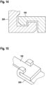
- Fig. 14 shows a schematic representation of part of a fixing device of a device for anchoring a heart support system 205 in a blood vessel according to an exemplary embodiment as a cross section.
- the fixing device 105 is designed here for positive fixing; the heart support system has a corresponding shape.
- the fixing device and the heart support system each have a groove for fixing.
- Fig. 15 shows a schematic representation of part of a fixing device 105 of a device for anchoring a heart support system 205 in a blood vessel according to an exemplary embodiment.
- a section of the fixing device 105 and the heart support system 205 are shown, the sections interlocking with one another in a form-fitting manner.
- the top view shows the positive connection of the fixing device 105 to the heart support system by engaging the fixation device 105 in two hooks of the heart support system 205.
- Fig. 16 shows a schematic representation of part of a fixing device of a device for anchoring a cardiac support system 205 in a blood vessel according to an exemplary embodiment. Shown is a cross section of a non-positive connection of the heart support system 205 with the fixation device 105, which is realized here by a spring connection by means of two springs 1605 between the heart support system 205 and the fixation device 105 as a spring clamp.
- Fig. 17 shows a schematic representation of part of a fixing device of a device for anchoring a cardiac support system 205 in a blood vessel according to an exemplary embodiment. It is the cross section of one Press connection is shown as a non-positive connection of the heart support system 205 with the fixing device 105.
- the assembly of the press connection shown here can be generated by means of a press-in force, or by means of a temperature difference between the heart support system 205 and the fixing device 105, i.e. by press joining using a temperature difference between the fixation device 105 and the heart support system 205 and the pressure that occurs during the subsequent temperature compensation.
- Fig. 18a to 18c each show a schematic representation of a device 100 for anchoring a heart support system in a blood vessel according to an exemplary embodiment, with different situations of the device 100 being shown.
- Fig. 18a shows a top view of the unfolded device 100, as already shown in FIG Fig. 1 is described.
- Fig. 18b shows a section of the in Fig. 18a shown device in the sleeve 405 in the insertion state, as already shown with reference to Fig. 4 is described.
- Fig. 18c shows a side view of the device 100.
- the situations shown here represent, by way of example, the space required by the device 100 in the insertion state, depending on the shape of the device 100.
- the following Figures 19a to 19c show the situations described here corresponding to an alternative shape of the crown 110 of the device 100 according to an exemplary embodiment.
- Fig. 18a shows a side view of the device 100 according to an exemplary embodiment.
- the device 100 includes the fixing device 105, the connecting device 115 and the crown 110, the crown 110 being formed from a plurality of unfolding elements 120 coupled to one another.
- Each of the deployment elements 120 has two deployment rods connected at their ends, which are diamond-shaped in the deployment state shown here.
- the connecting device 115 consists of four bending struts 130, with a first end of each bending strut 130 being attached to the fixing device 105 and with a second end of each bending strut 130 being attached to a connection between two adjacent deployment elements 120.
- Fig. 18b shows the in Fig. 18a described device 100 in the inserted state.
- the crown 110 is folded here for insertion and inserted into the sleeve 405.
- the device 100 also called an anchor, has a comparatively high axial space requirement, for example in comparison to that in Fig. 19b shown embodiment of the device 100.
- the bending struts 130 are not folded completely below or between the unfolding elements of the crown 110, but require a certain axial space in the inserted state, which in this figure is due to the distance between the loaded crown 110 and the fixing device 105 is shown.
- Fig. 18c shows a schematic representation of the device 100 in the unrolled state.
- the device 100 accordingly does not have the cylindrical shape of the insertion state or the unfolded shape of the anchoring state; the unfolded state shown here shows, by way of example, the space required by the connection and formation of the crown 110 and the bending struts 130 of the connecting device.
- Fig. 19a to 19c each show a schematic representation of a device 100 for anchoring a heart support system in a blood vessel according to an exemplary embodiment.
- the ones in the Fig. 19a to 19c The situations shown each show the device 100 as shown on the basis of Fig. 19a is described. Shown is a shape of the crown 110 and the connecting device 115, with which the device 100 in the loaded state, as in the folded state corresponding to the insertion state, has a comparatively small axial space requirement, which can be advantageous, for example, if the device is used in conjunction with a cardiac support system for which additional installation space is advantageous in this area, for example for operating a motor of a heart pump.
- the saving in axial space can be achieved by a modified geometry of the crown 110 and the connecting device 115.
- the crown 110 By shaping the crown 110, attaching the bending struts 130, as well as long bending struts 130 and changing their direction, it is possible to a large extent It can be avoided that the anchor, i.e. the device 100, takes up unnecessary axial space when loading.
- the crown 110 unfolds at the point where it is also in the loaded state.
- Fig. 19a shows the device 100 in a side view in the unfolded state, the device 100 according to this exemplary embodiment having a small axial space requirement.
- the crown 110 is formed from the at least one unfolding element with a plurality of loops arranged in a meandering manner, as in Fig. 19c shown.
- the crown 110 is attached to the fixing device 105.
- Fig. 19b shows the in Fig. 19a described device 100 in the inserted state.
- the crown 110 is crimped here for insertion and inserted into the sleeve 405.
- the device 100 also called an anchor, has a comparatively small axial space requirement, for example in comparison to the one in Fig. 18b shown embodiment of the device 100.
- the bending struts 130 are folded between the unfolding elements of the crown 110; in the inserted state they only require a very small axial space, which is shown in this figure by the small distance between the crimped crown 110 and the fixing device 105 is.
- Fig. 19c shows schematically a representation of the device 100 in the unrolled state as a further situation.
- the described shapes of the unfolding element 120 with a plurality of meandering loops and the described connection of the bending struts 130 to the crown 110 are clearly shown in this figure.
- the crown 110 can be formed from only a single deployment element 120.
- the bending struts 130 of the connecting device are arranged within the meandering loops, with a first end of each bending strut 130 being attached to the fixing device 105 and a second end of the bending strut 130 being attached to an end of the crown 110 facing away from the fixing device 105.
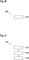
- Fig. 20 shows a flowchart of a method 2000 for operating a device for anchoring a heart support system in a blood vessel (not claimed).
- the method 2000 includes at least a step 2001 of deploying the deployment member of the crown of the device in the transition from the insertion state to the anchoring state to increase the diameter of the crown.
- Fig. 21 shows a flowchart of a manufacturing method 2100 for manufacturing a device for anchoring a heart support system in a blood vessel according to an exemplary embodiment.
- the device may assume an insertion state for inserting the ventricular assist system into the blood vessel, and the device may assume an anchoring state to anchor the ventricular assist system in the blood vessel.
- the manufacturing method 2100 of the device has at least a step 2101 of providing, a step 2103 of molding and a step 2105 of heat treating.
- step 2101 of providing a semi-finished product made of a shape memory material is provided.
- step 2103 of molding a fixing device for fixing the device to the heart support system is formed.
- a crown is formed from at least one deployment element, the deployment element being designed to deploy during a transition from the insertion state to the anchoring state to increase the diameter of the crown in order to anchor the device in the blood vessel.
- a connecting device is formed to connect the crown to the connecting device.
- the fixation device, the crown and the connecting device are formed from the semi-finished product provided in step 2101. In step 2105 of heat treatment, the fixation device, the crown and the connection device are heat treated to imprint the shape of the anchoring state.
- an exemplary embodiment includes an "and/or" link between a first feature and a second feature, this should be read as meaning that the exemplary embodiment has both the first feature and the second feature according to one embodiment and either only that according to a further embodiment first feature or only the second feature.
- a device 100 for anchoring a heart support system in a blood vessel can assume an insertion state for inserting the heart support system into the blood vessel and an anchoring state to anchor the heart support system in the blood vessel.
- the device 100 has at least one fixing device 105 for fixing the device 100 to the heart support system 205, a crown 110 and a connecting device 115.
- the crown 110 is formed from at least one deployment element 120.
- the deployment member 120 is configured to deploy during a transition from the insertion state to the anchoring state to increase the diameter of the crown 110 to anchor the device 100 in the blood vessel.
- the connecting device 115 is designed to connect the crown 110 to the fixing device 105.
Landscapes
- Health & Medical Sciences (AREA)
- Heart & Thoracic Surgery (AREA)
- Engineering & Computer Science (AREA)
- Cardiology (AREA)
- Life Sciences & Earth Sciences (AREA)
- Anesthesiology (AREA)
- Biomedical Technology (AREA)
- Hematology (AREA)
- Mechanical Engineering (AREA)
- Animal Behavior & Ethology (AREA)
- General Health & Medical Sciences (AREA)
- Public Health (AREA)
- Veterinary Medicine (AREA)
- Vascular Medicine (AREA)
- Transplantation (AREA)
- External Artificial Organs (AREA)
- Prostheses (AREA)
Description
- Die Erfindung betrifft eine Vorrichtung zum Verankern eines Herzunterstützungssystems in einem Blutgefäß, ein Herstellverfahren zum Herstellen einer derartigen Vorrichtung und ein Herzunterstützungssystem.
- Herzunterstützungssysteme zur Langzeittherapie werden typischerweise über eine komplette oder teilweise Eröffnung des Brustbeins implantiert, wobei eine Herzlungenmaschine zum Ermöglichen eines extrakorporalen Blutkreislaufs zum Einsatz kommen kann. Häufig wird hierbei durch das Stanzen eines Lochs in die strukturelle Integrität des Herzmuskelgewebes und der Körperhauptschlagader, der Aorta eingegriffen. Kurzfristige intravaskuläre Herzunterstützungssysteme werden entweder perkutan, also durch die Haut, oder chirurgisch über verschiedene arterielle Zugänge, beispielsweise über die Oberschenkelschlagader, angeliefert. Die endgültige Positionierung der Herzunterstützungssysteme kann intraoperativ visuell unterstützt werden, beispielsweise mittels Ultraschall oder radiologische Durchleuchtung. Die implantierten Herzunterstützungssysteme haben allerdings ein hohes Risiko für eine Dislokation, da keine lokale Fixierung des Herzunterstützungssystems vorhanden ist. Das Herzunterstützungssystem kann also nach der Implantation verrutschen, da es nicht am Implantationsort verankert ist, was zu einer Fehlfunktion der Pumpe oder zu einem Abbruch der Therapie mit dem Herzunterstützungssystem führen kann.
- Die
CA 3 000 581 A1 zeigt eine Pumpe zum Pumpen von Blut mit in einem distalen Bereich verbundenen Laufrad und ein das Laufrad umgebendes Gehäuse. Das Laufrad und das Gehäuse sind so ausgebildet, dass sie sich nach einer Zwangskompression selbstentfalten. - Die
WO 2008/106103 A2 offenbart eine implantierbare Blutpumpe. - Die
WO 2017/118738 A1 beschreibt einen Verbinder zur Fluidverbindung zwischen zwei anatomischen Kompartimenten durch mindestens eine anatomische Wand. - Die
US 2013/0303970 A1 zeigt eine Katheterpumpe. Die Katheterpumpe kann einen länglichen Katheterkörper mit einem distalen Abschnitt umfassen, der eine expandierbare Kanüle mit einem Einlass und einem Auslass umfasst. Aufgabe der Erfindung ist es, eine Vorrichtung zu schaffen, die es ermöglicht, ein medizinisches System, z.B. ein Herzunterstützungssystem aber auch ein Implantat insbesondere in einem Blutgefäß, z.B. innerhalb der Aorta so anzuordnen, dass dieses in Bezug auf einen Abschnitt des menschlichen oder auch tierischen Körpers, z.B. das Blutgefäß oder die Aorta eine auch über längere Zeiträume hinweg, d.h. Stunden, Tage, Wochen, Monate oder gegebenenfalls auch Jahre eine grundsätzlich gleichbleibende räumliche Lage hat. - Diese Aufgabe wird durch die in Anspruch 1 und 3 angegebene Vorrichtung zum Verankern eines Herzunterstützungssystems in einem Blutgefäß, die in Anspruch 10 angegebene Anordnung und das in Anspruch 11 definierte Herstellungsverfahren für eine Vorrichtung zum Verankern eines Herzunterstützungssystems in einem Blutgefäß gelöst. Vorteilhafte Ausführungsformen der Erfindung sind in den abhängigen Ansprüchen angegeben.
- Nachfolgend werden hier die Vorrichtung zum Verankern eines Herzunterstützungssystems in einem Blutgefäß und die Anordnung sowie das Herstellverfahren zum Herstellen einer entsprechenden Vorrichtung vorgestellt. Durch die in den abhängigen Ansprüchen aufgeführten Maßnahmen sind vorteilhafte Weiterbildungen und Verbesserungen der im unabhängigen Anspruch angegebenen Vorrichtung möglich.
- Mit dem hier vorgestellten Ansatz kann ein Implantat, beispielsweise ein Herzunterstützungssystem mittels einer Vorrichtung im Blutgefäß, insbesondere innerhalb der Aorta, mit oder ohne räumliche Beziehung zur Aortenklappe, positioniert und verankert werden. Die Vorrichtung kann dazu an einer Herzpumpe fixiert werden. Die Vorrichtung kann vorteilhafterweise zum minimalinvasiven Einführen des Herzunterstützungssystems zusammengefaltet werden, und die Vorrichtung ist so ausgeformt, dass sie sich am Bestimmungsort zum Positionieren und Verankern des Herzunterstützungssystems entfalten kann. Mittels der Vorrichtung kann das Herzunterstützungssystem am Bestimmungsort ausgerichtet und gezielt abgesetzt werden. Die Position des Herzunterstützungssystem bleibt durch die Verankerung mittels der Vorrichtung vorteilhafterweise auch langfristig unverändert, wodurch ein Verrutschen oder eine Dislokation des Herzunterstützungssystems vermieden werden kann.
- Es wird eine Vorrichtung zum Verankern eines Herzunterstützungssystems in einem Blutgefäß vorgestellt. Die Vorrichtung kann zum Einführen des Herzunterstützungssystems in das Blutgefäß einen Einführzustand einnehmen. Zudem kann die Vorrichtung einen Verankerungszustand einnehmen, um das Herzunterstützungssystems in dem Blutgefäß zu verankern. Die Vorrichtung umfasst zumindest eine Fixiereinrichtung zum Fixieren der Vorrichtung an das Herzunterstützungssystem, eine Krone und eine Verbindungseinrichtung, die dazu ausgeformt ist, die Krone mit der Fixiereinrichtung zu verbinden. Die Krone ist aus zumindest einem Entfaltungselement ausgeformt. Das Entfaltungselement ist dazu ausgebildet, um sich bei einem Übergang von dem Einführzustand in den Verankerungszustand zu entfalten zum Vergrößern des Durchmessers der Krone, um die Vorrichtung in dem Blutgefäß zu verankern.
- Die Vorrichtung kann aus einem biokompatiblen Material ausgeformt sein, um bei einem langfristigen Einsatz der Vorrichtung ein Verwachsen der Vorrichtung mit dem Blutgefäß, beispielsweise der Aorta, zu ermöglichen. Zudem kann die Vorrichtung aus einem elastischen Material realisiert werden, das gleichzeitig eine bestimmte Steifigkeit aufweist, beispielsweise aus Nitinol. Bei dem Herzunterstützungssystem kann es sich beispielsweise um eine Herzpumpe wie ein rechtsventrikuläres Unterstützungssystem, ein linksventrikuläres Unterstützungssystem, ein biventrikuläres Unterstützungssystem oder um eine Gefäß- oder Klappenprothese handeln. Zudem kann die Vorrichtung auch verwendet werden, um eine andere Komponente in einem Blutgefäß zu positionieren und an seinem Bestimmungsort zu verankern, beispielsweise ein anderes vaskuläres oder intrakavitäres Implantat wie beispielsweise ein gastrointestinales, intrathekales, oder intravesikales Implantat. Unter dem Einführzustand kann beispielsweise der Zustand verstanden werden, in dem sich die Vorrichtung zum Einführen oder beim Einführen des Herzunterstützungssystems in das Blutgefäß befinden kann. Die Vorrichtung kann dazu beispielsweise an die Herzpumpe fixiert und so zusammengefaltet sein, dass die Vorrichtung mit dem Herzunterstützungssystem zum minimalinvasiven Einbringen in einen Katheter eingeführt werden kann. Die Vorrichtung und das Herzunterstützungssystem können beispielsweise minimalinvasiv durch die Beinarterie, die arteria fermoralis, eingeführt werden. Im Einführzustand kann die Vorrichtung entsprechend einen Durchmesser aufweisen, der unter dem Durchmesser einer menschlichen Aorta liegt. Unter dem Verankerungszustand kann ein Zustand verstanden werden, in dem die Vorrichtung, nach dem Einführen und Ausrichten am Bestimmungsort zum Vergrößern des Durchmessers der Krone entfaltet ist, um das Herzunterstützungssystem kraftschlüssig am Bestimmungsort zu verankern und auf diese Weise vorteilhafterweise ein Verrutschen oder eine Dislokation des Herzunterstützungssystems zu verhindern. Im Verankerungszustand, also im entfalteten Zustand, kann die Vorrichtung oder eine Komponente der Vorrichtung, beispielsweise die Krone, einen Innendurchmesser aufweisen, der geringfügig größer als der Innendurchmesser des Blutgefäßes ist, in dem es verankert wird, beispielsweise einen gesamten Innendurchmesser im Bereich von 20-30 mm, beispielsweise 23 mm, zum Verankern an oder hinter einer menschlichen Aortenklappe. Zudem kann die Außenkontur zumindest eines Teils der Vorrichtung, beispielsweise der Krone, im Verankerungszustand eine der nicht exakt kreisrunden Aorten-Anatomie einer menschlichen Aorta entsprechende Form aufweisen. Auf diese Weise kann die Vorrichtung im Verankerungszustand über einen radialen Kraftschluss am Bestimmungsort gehalten werden.
- Die Fixiereinrichtung kann ausgebildet sein, um die Vorrichtung an einem Implantat, beispielsweise dem Herzunterstützungssystem, zu fixieren. Dazu kann die Fixiereinrichtung zumindest ein Fixierelement zum Bilden einer form-und/oder kraftschlüssigen Verbindung mit einem an dem Implantat angeordneten Gegenfixierelement aufweisen. Die Krone ist ringförmig ausgeformt. Je nach Ausführungsform kann ein einziges Entfaltungselement ringförmig ausgeformt sein oder es können mehrere Entfaltungselemente ringförmig aneinandergereiht sein. Beim Entfalten kann sich das zumindest eine Entfaltungselement ausdehnen. Die Verbindungseinrichtung kann zumindest eine längliche, beispielsweise drahtförmige, Strebe umfassen, die sowohl an der Krone als auch an der Fixiereinrichtung befestigt ist. Die Verbindungseinrichtung kann flexibel ausgeformt sein, um das Vergrößern des Durchmessers der Krone zu ermöglichen.
- Einer vorteilhaften Ausführungsform gemäß kann zumindest das Entfaltungselement der Krone der Vorrichtung aus Formgedächtnismaterial ausgeformt sein. Das Entfaltungselement kann beispielsweise aus einem biokompatiblen Formgedächtnispolymer bestehen, oder aus einer biokompatiblen Formgedächtnislegierung, wie beispielsweise Nitinol. Zudem kann auch die gesamte Vorrichtung aus einer Formgedächtnislegierung, beispielsweise aus Nitionol gefertigt werden. Die Verwendung eines Formgedächtnismaterials wie Nitinol ermöglicht aufgrund seiner Formgedächtniseigenschaften eine besonders elegante und einfache Realisierung des Einführzustands und des Entfaltens des Entfaltungselements beim Übergang in den Verankerungszustand. Die Verwendung von Nitinol als Formgedächtnismaterial ist vorteilhaft, da der Nitinolwerkstoff in der Medizin, insbesondere im Bereich der kardiovaskulären Medizin, ein bewährtes Material darstellt, beispielsweise für Herzklappenprothesen, Stents und Gefäßprothesen, aufgrund seiner Biokompatibilität und der Formgedächtniseigenschaft, die es ermöglicht auch komplexe Strukturen auf kleinem Bauraum an den Bestimmungsort zu liefern und abzusetzen, wie die hier vorgestellte Vorrichtung.
- Die Vorrichtung kann gemäß einer Ausführungsform zudem eine Bogeneinrichtung mit zumindest einem Füßchen umfassen. Die Bogeneinrichtung ist dazu ausgebildet, um sich bei dem Übergang von dem Einführzustand in den Verankerungszustand zu entfalten zum Positionieren des zumindest einen Füßchens im Blutgefäß. Mittels des Positionierens des zumindest einen Füßchens im Blutgefäß kann die Vorrichtung im Blutgefäß beispielsweise vor dem Verankern ausgerichtet und positioniert werden. Die Bogeneinrichtung kann mit der Krone verbunden sein. Alternativ kann die Bogeneinrichtung eine Bogenfixierungseinrichtung zum Fixieren der Bogeneinrichtung an das Herzunterstützungssystem aufweisen. Die Vorrichtung kann entsprechend einteilig ausgeformt sein, indem die Fixierungseinrichtung, die Krone, die Verbindungseinrichtung und die Bogeneinrichtung miteinander gekoppelt sind, oder die Vorrichtung kann zweiteilig sein, wenn die Bogeneinrichtung mit eigener Bogenfixiereinrichtung an dem Herzunterstützungssystem fixiert ist, und die anderen Komponenten der Vorrichtung miteinander gekoppelt sind. Die einteilige Ausführungsform kann im Hinblick auf das Zusammenfalten der Vorrichtung für den Einführzustand vorteilhaft sein, die zweiteilige Ausführungsform kann je nach Bauweise des Herzunterstützungssystems von Vorteil sein. Wenn das Herzunterstützungssystem beispielsweise eine Pumpe mit Motor umfasst, kann eine zweiteilige Ausführungsform mehr Flexibilität im Hinblick auf den Bauraum des Herzunterstützungssystems ermöglichen, beispielsweise indem die Bogeneinrichtung an einem Ende einer Motor-Kupplung-Pumpeneinheit des Herzunterstützungssystems fixiert werden kann, und der zweite Teil der Vorrichtung an dem anderen Ender der Motor-Kupplung-Pumpeneinheit des Herzunterstützungssystems fixiert werden kann. Mittels der Bogeneinrichtung kann die Vorrichtung vorteilhafterweise durch das Entfalten des zumindest einen Füßchens am Bestimmungsort ausgerichtet und positioniert werden. Das Füßchen kann beispielsweise eine atraumatische Form aufweisen, um das Blutgefäß beim Entfalten und im Verankerungszustand nicht zu verletzen. Vorteilhafterweise kann die Bogeneinrichtung dazu ausgebildet sein, beim Positionieren des zumindest einen Füßchens durch die Ausformung der Bogeneinrichtung und des zumindest einen Füßchens ein Ausrichten der Vorrichtung für den Verankerungszustand zu ermöglichen.
- Die Bogeneinrichtung kann gemäß einer weiteren Ausführungsform drei Füßchen aufweisen, insbesondere wobei die Füßchen zum Positionieren der Füßchen in je einer Kuspe einer Herzklappe ausgeformt sind. Diese Ausführungsform ist von Vorteil, um die Vorrichtung und damit das Herzunterstützungssystem besonders exakt positionieren zu können, insbesondere wenn das Herzunterstützungssystem mittels der Vorrichtung beispielsweise hinter der Aortenklappe positioniert und verankert wird. Die drei Füßchen können beispielsweise eine im Hinblick auf eine Erdnuss-Form der Kuspen angepasste Form aufweisen, um so vorteilhafterweise ein besonders vorteilhaftes Verhältnis aus Anlagefläche und Drehsteifigkeit der drei Füßchen zu erreichen.
- Für eine kathetergestütze minimalinvasive Implantation des mit der Vorrichtung verbundenen Herzunterstützungssystems ist es von Vorteil, wenn die Vorrichtung gemäß einer Ausführungsform im Einführzustand zylinderförmig ist. Die Vorrichtung kann dazu beispielsweise zusammengefaltet werden. Wenn die Vorrichtung beispielsweise aus Nitinol ausgeformt ist, kann die Vorrichtung aus einem Rohr freigeschnitten werden, anschließend kann eine dem Verankerungszustand entsprechende Form mittels einer Wärmebehandlung eingeprägt werden. Für den Einführzustand kann die Vorrichtung entsprechend der ursprünglich zylinderförmigen Rohrgeometrie zusammengefaltet werden.
- Zudem kann es vorteilhaft sein, wenn das Entfaltungselement gemäß einer Ausführungsform im Verankerungszustand eine Schrägstellung aufweist. Unter der Schrägstellung kann ein bestimmter Winkel des Entfaltungselements gegenüber der Längsachse der Vorrichtung verstanden werden. Das Entfaltungselement kann im Verankerungszustand in einem Winkel angestellt sein, um im Verankerungszustand eine kraftschlüssige Verbindung zwischen der Krone und dem Blutgefäß zu unterstützen. Der Winkel kann in Bezug auf die Längsachse der Vorrichtung beispielsweise zwischen 20° und 30° betragen, insbesondere 25°. Durch die Schrägstellung des Entfaltungselements kann die Anpresskraft der Krone an das Blutgefäß vorteilhafterweise erhöht werden.
- Die Krone kann gemäß einer Ausführungsform eine Mehrzahl an miteinander gekoppelten Entfaltungselementen aufweisen. Jedes der Entfaltungselemente kann zwei an ihren Enden verbundene Entfaltungsstäbe aufweisen und die zwei Entfaltungsstäbe können im Einführzustand eine geringere Entfernung zueinander aufweisen als im Verankerungszustand. Die Entfaltungselemente können durch eine Verbindung mit einem der Entfaltungsstäbe eines benachbarten Entfaltungselements miteinander gekoppelt sein. Die zwei Entfaltungsstäbe können so miteinander verbunden sein, dass jedes Entfaltungselement im Verankerungszustand der Vorrichtung in axialer Richtung zur Längsachse der Vorrichtung eine Raute mit abgerundeten Ecken ausbildet. Eine solche Ausformung einer Mehrzahl an miteinander gekoppelten rautenförmigen Entfaltungselementen kann einen Standardschnitt eines Gefäß-Stents entsprechen, was beim Herstellen der Vorrichtung vorteilhaft sein kann.
- Alternativ kann das Entfaltungselement gemäß einer Ausführungsform eine Mehrzahl an mäanderartig angeordneten Schlaufen aufweisen, wobei die Schlaufen im Einführzustand eine geringere Entfernung zueinander aufweisen als im Verankerungszustand. Diese Ausführungsform bietet ein besonders platzsparendes Zusammenfalten der Vorrichtung für den Einführzustand.
- Die Verbindungseinrichtung weist zumindest eine Biegestrebe auf. Die Biegestrebe ist dazu ausgebildet, bei dem Übergang von dem Einführzustand in den Verankerungszustand aufzuklappen, um ein Entfalten der Krone zu ermöglichen. Die Biegestrebe ermöglicht eine besonders elegante und platzsparende Verbindung zwischen der Fixiereinrichtung und der Krone. Die Biegestrebe kann beispielsweise aus einem elastischen Material sein, beispielsweise auch aus Nitinol.
- Zudem kann ein erstes Ende der Biegestrebe gemäß einer weiteren Ausführungsform an der Fixiereinrichtung befestigt sein. Ein zweites Ende der Biegestrebe kann an einer Verbindung zwischen zwei benachbarten Entfaltungselementen befestigt sein, oder das zweite Ende der Biegestrebe kann an einem der Fixiereinrichtung abgewandten Ende der Krone befestigt sein. Die Biegestrebe kann also entsprechend der Ausformung des Entfaltungselements der Krone gestaltet werden, um ein effizientes Entfalten der Krone je nach Ausführungsform zu ermöglichen, und um je nach Ausführungsform des Entfaltungselements ein kompaktes Zusammenfalten für den Einführzustand im Hinblick auf die axiale Länge der Vorrichtung zu ermöglichen.
- Die Fixiereinrichtung kann gemäß einer Ausführungsform ausgeformt sein, um die Vorrichtung formschlüssig und/oder kraftschlüssig an das Herzunterstützungssystem zu fixieren. Die Vorrichtung kann somit stabil mit dem Herzunterstützungssystem verbunden werden, um beispielsweise während der Implantation oder während der Laufzeit des Herzunterstützungssystems auftretende Kräfte aufzunehmen. Dazu kann die Fixiereinrichtung beispielsweise ein Element zum formschlüssigen Eingreifen aufweisen, oder eine Aussparung zum formschlüssigen Aufnehmen eines Elements, das beispielsweise auf dem Gehäuse des Herzunterstützungssystems aufgetragen ist. Das Element zum formschlüssigen Fixieren kann beispielsweise unterschiedliche Querschnitte aufweisen und das Element oder die entsprechende Aussparung können beispielsweise rund, oval, dreieckig, vieleckig oder sternförmig ausgeformt sein. Sowohl die Fixiereinrichtung als auch das Herzunterstützungssystem, beispielsweise das Gehäuse des Herzunterstützungssystems, können dazu Elemente aufweisen, die ein Einrasten oder Verankern der Fixiereinrichtung mit dem Herzunterstützungssystem ermöglichen. Zusätzlich oder alternativ kann die Fixiereinrichtung beispielsweise eine Bajonettverbindung oder eine Klippverbindung oder einen Haken aufweisen. Zusätzlich oder alternativ kann die Fixiereinrichtung zudem mittels einer stoffschlüssigen Verbindung realisiert werden. Die Fixiereinrichtung kann beispielsweise ausgebildet sein, um eine rotatorische Bewegung zwischen der Vorrichtung und dem Herzunterstützungssystem zu ermöglichen.
- Gemäß einer Ausführungsform kann die Vorrichtung zudem eine Hülse aufweisen. Die Hülse kann gegenüber der Krone beweglich sein. Zudem kann die Hülse dazu ausgeformt sein, um im Einführzustand zumindest die Krone zu umschließen und die Krone zum Einleiten des Übergangs in den Verankerungszustand freizugeben. Wenn die Vorrichtung gemäß einer Ausführungsform die Bogeneinrichtung umfasst, kann die Hülse auch gegenüber der Bogeneinrichtung beweglich sein und zudem dazu ausgeformt sein im Einführzustand auch die Bogeneinrichtung zu umschließen und die Bogeneinrichtung zum Einleiten des Übergangs in den Verankerungszustand freizugeben. Die Hülse kann auch dazu ausgeformt sein, alle anderen Komponenten der Vorrichtung zu umschließen und wieder freizugeben. Die Hülse kann beispielsweise zylinderförmig ausgeformt und so ausgeführt sein, dass die Vorrichtung mit der Hülse im Einführzustand in einen handelsüblichen Katheter eingeführt werden kann. Die Hülse kann vorteilhafterweise beispielsweise verwendet werden, um die anderen Komponenten der Vorrichtung im zusammengefalteten Zustand der Vorrichtung niederzuhalten und dadurch im Einführzustand zusätzlich zu stabilisieren, beispielsweise auch, wenn Komponenten der Vorrichtung oder die gesamte Vorrichtung aus einem Formgedächtnismaterial ausgeformt sind. Zudem kann die Hülse beim Übergang vom Einführzustand in den Verankerungszustand schrittweise entfernt werden, beispielsweise über einen gesteuerten Mechanismus, der beispielsweise elektrisch gesteuert werden kann, oder durch ein manuelles Zurückziehen der Hülse. Auf diese Weise kann die Vorrichtung beispielsweise schrittweise entfaltet werden, um die Vorrichtung vorteilhafterweise kontrolliert zu entfalten und vor dem Verankern zu positionieren oder die Hülse kann wieder nach vorne verschoben werden, um die Vorrichtung anders auszurichten oder das Positionieren der Vorrichtung zu korrigieren.
- Mit diesem Ansatz wird zudem ein Verfahren (nicht beansprucht) zum Betreiben der Vorrichtung vorgestellt. Das Verfahren weist zumindest einen Schritt des Entfaltens auf. Im Schritt des Entfaltens wird das Entfaltungselement der Krone der Vorrichtung bei dem Übergang von dem Einführzustand in den Verankerungszustand zum Vergrößern des Durchmessers der Krone entfaltet. Der Schritt des Entfaltens kann beispielsweise auch durchgeführt werden, um den Durchmesser der Krone zum Verankern der Vorrichtung in dem Blutgefäß zu vergrößern. Das Verfahren kann sowohl ausgeführt werden, wenn die Vorrichtung innerhalb eines Blutgefäßes angeordnet ist, als auch wenn sich die Vorrichtung außerhalb eines Blutgefäßes befindet, beispielsweise um durch ein Vergrößern des Durchmessers der Krone die Vorrichtung mit einer Komponente eines Implantats zu verbinden.
- Es wird zudem ein Herstellverfahren zum Herstellen einer Vorrichtung zum Verankern eines Herzunterstützungssystems in einem Blutgefäß vorgestellt. Die Vorrichtung kann einen Einführzustand zum Einführen des Herzunterstützungssystems in das Blutgefäß einnehmen, und ferner kann die Vorrichtung einen Verankerungszustand einnehmen, um das Herzunterstützungssystems in dem Blutgefäß zu verankern. Das Herstellverfahren weist zumindest einen Schritt des Bereitstellens, einen Schritt des Ausformens und einen Schritt des Wärmebehandelns auf. Im Schritt des Bereitstellens wird ein Halbzeug aus einem Formgedächtnismaterial bereitgestellt. Im Schritt des Ausformens wird eine Fixiereinrichtung zum Fixieren der Vorrichtung an das Herzunterstützungssystem ausgeformt. Zudem wird im Schritt des Ausformens eine Krone aus zumindest einem Entfaltungselement ausgeformt, wobei das Entfaltungselement dazu ausgebildet ist, um sich bei einem Übergang von dem Einführzustand in den Verankerungszustand zu entfalten zum Vergrößern des Durchmessers der Krone, um die Vorrichtung in dem Blutgefäß zu verankern. Ferner wird im Schritt des Ausformens eine Verbindungseinrichtung dazu ausgeformt, die Krone mit der Anbindungseinrichtung zu verbinden. Die Fixierungseinrichtung, die Krone und die Verbindungseinrichtung werden aus dem Halbzeug ausgeformt. Im Schritt des Wärmebehandelns werden Fixierungseinrichtung, die Krone und die Verbindungseinrichtung wärmebehandelt, um die Form des Verankerungszustands einzuprägen.
- Es wird außerdem ein Herzunterstützungssystem mit einer Vorrichtung gemäß einer Ausführungsform vorgestellt. Die Vorrichtung kann beispielsweise an dem Herzunterstützungssystem fixiert sein. Das Herzunterstützungssystem kann beispielsweise eine Herzpumpe mit einer Motor-Kupplung-Pumpeneinheit umfassen. Zudem kann das Herzunterstützungssystem ein Gehäuse aufweisen, das ausgeformt ist, um mit der Vorrichtung, beispielsweise mittels der Fixiereinrichtung der Vorrichtung, formschlüssig und/oder kraftschlüssig verbunden zu sein. Vorteilhafterweise können gemäß dieser Ausführungsform die Größe des Herzunterstützungssystem und/oder die Abmessungen der Vorrichtung patientenspezifisch ausgewählt oder verändert werden.
- Ausführungsbeispiele des hier vorgestellten Ansatzes sind in den Zeichnungen dargestellt und in der nachfolgenden Beschreibung näher erläutert. Es zeigt:
- Fig. 1
- eine schematische Darstellung einer Vorrichtung zum Verankern eines Herzunterstützungssystems in einem Blutgefäß gemäß einem Ausführungsbeispiel;
- Fig. 2
- eine schematische Darstellung eines Teils eines Herzunterstützungssystems mit einer Vorrichtung zum Verankern eines Herzunterstützungssystems in einem Blutgefäß gemäß einem Ausführungsbeispiel;
- Fig. 3
- eine schematische Darstellung eines Herzunterstützungssystems mit einer Vorrichtung zum Verankern eines Herzunterstützungssystems in einem Blutgefäß gemäß einem Ausführungsbeispiel;
- Fig. 4 und 5
- eine schematische Darstellung eines Einführzustandes einer Vorrichtung zum Verankern eines Herzunterstützungssystems in einem Blutgefäß gemäß einem Ausführungsbeispiel;
- Fig. 6
- eine schematische Darstellung einer Vorrichtung zum Verankern eines Herzunterstützungssystems in einem Blutgefäß mit einer Bogeneinrichtung gemäß einem Ausführungsbeispiel;
- Fig. 7
- eine schematische Darstellung eines Füßchens einer Vorrichtung zum Verankern eines Herzunterstützungssystems in einem Blutgefäß gemäß einem Ausführungsbeispiel;
- Fig. 8
- eine schematische Darstellung eines Teils einer Krone einer Vorrichtung zum Verankern eines Herzunterstützungssystems in einem Blutgefäß gemäß einem Ausführungsbeispiel;
- Fig. 9 und 10
- eine schematische Darstellung einer Fixiereinrichtung einer Vorrichtung zum Verankern eines Herzunterstützungssystems in einem Blutgefäß gemäß einem Ausführungsbeispiel;
- Fig. 11a bis 11j
- eine schematische Darstellung einer Ausformung einer formschlüssigen Fixierung einer Vorrichtung zum Verankern eines Herzunterstützungssystems in einem Blutgefäß gemäß einem Ausführungsbeispiel;
- Fig. 12
- eine schematische Darstellung einer kraftschlüssigen Fixierung einer Vorrichtung zum Verankern eines Herzunterstützungssystems in einem Blutgefäß an ein Herzunterstützungssystem gemäß einem Ausführungsbeispiel;
- Fig. 13 bis 17
- eine schematische Darstellung eines Teils einer Fixiereinrichtung einer Vorrichtung zum Verankern eines Herzunterstützungssystems in einem Blutgefäß gemäß einem Ausführungsbeispiel;
- Fig. 18a bis 18c
- eine schematische Darstellung einer Vorrichtung zum Verankern eines Herzunterstützungssystems in einem Blutgefäß gemäß einem Ausführungsbeispiel;
- Fig. 19a bis 19c
- eine schematische Darstellung einer Vorrichtung zum Verankern eines Herzunterstützungssystems in einem Blutgefäß gemäß einem Ausführungsbeispiel;
- Fig. 20
- ein Ablaufdiagramm eines Verfahrens zum Betreiben einer Vorrichtung zum Verankern eines Herzunterstützungssystems in einem Blutgefäß gemäß einem Ausführungsbeispiel; und
- Fig. 21
- ein Ablaufdiagramm eines Herstellverfahrens zum Herstellen einer Vorrichtung zum Verankern eines Herzunterstützungssystems in einem Blutgefäß gemäß einem Ausführungsbeispiel.
- In der nachfolgenden Beschreibung günstiger Ausführungsbeispiele der vorliegenden Erfindung werden für die in den verschiedenen Figuren dargestellten und ähnlich wirkenden Elemente gleiche oder ähnliche Bezugszeichen verwendet, wobei auf eine wiederholte Beschreibung dieser Elemente verzichtet wird.
-
Fig. 1 zeigt eine schematische Darstellung einer Vorrichtung 100 zum Verankern eines Herzunterstützungssystems in einem Blutgefäß gemäß einem Ausführungsbeispiel. Auch wenn die Vorrichtung 100 hier und im Folgenden im Zusammenhang mit einem Herzunterstützungssystem beschrieben ist, so kann die Vorrichtung 100 auch zum Verankern anderer Implantate in einem Blutgefäß eingesetzt werden. - Gezeigt ist eine Seitenansicht der entfalteten Vorrichtung 100. Die Vorrichtung 100 kann einen Einführzustand zum Einführen des Herzunterstützungssystems in das Blutgefäß einnehmen. Zudem kann die Vorrichtung 100 den in
Fig. 1 gezeigten Verankerungszustand einnehmen, um das Herzunterstützungssystems in dem Blutgefäß zu verankern. - Die Vorrichtung 100 weist zumindest eine Fixiereinrichtung 105 zum Fixieren der Vorrichtung 100 an das Herzunterstützungssystem, eine Krone 110 und eine Verbindungseinrichtung 115 auf. Die Krone 110 ist aus zumindest einem Entfaltungselement 120 ausgeformt. Das Entfaltungselement 120 ist dazu ausgebildet, um sich bei einem Übergang von dem Einführzustand in den Verankerungszustand zu entfalten zum Vergrößern des Durchmessers der Krone 110, um die Vorrichtung 100 in dem Blutgefäß zu verankern. Gemäß dem gezeigten Ausführungsbeispiel umfasst die Krone 110 eine Mehrzahl von Entfaltungselementen 120. Die Verbindungseinrichtung 115 ist dazu ausgeformt, die Krone 110 mit der Fixiereinrichtung 105 zu verbinden.
- Vorteilhafterweise kann mittels der Vorrichtung 100 ein Verrutschen oder Bewegen des Herzunterstützungssystems verhindert werden, da mittels der Krone 110 eine Verankerung am Implantationsort stattfinden kann. Zudem ist mittels der Vorrichtung 100 eine definierte Positionierung des Herzunterstützungssystems, im Folgenden auch genannt, möglich. Die Vorrichtung kann zumindest teilweise aus einem Formgedächtnismaterial wie Nitinol ausgeformt sein. In der hier gezeigten
Figur 1 ist die Vorrichtung 100 als Nitinolrahmen zur Verankerung und Positionierung eines Herzunterstützungssystems in einem Blutgefäß ausgeformt. Die Vorrichtung 100 kann sowohl ein Design für den Langzeiteinsatz aufweisen, als auch für kurzzeitige Implantationen ein rückholbares Design aufweisen, beispielsweise durch ein gesteuertes Überführen der implantierten und verankerten Vorrichtung 100 vom Verankerungszustand in den Einführzustand. - Die die Krone 110 und die Fixiereinrichtung 105 der Vorrichtung 100 sind entlang einer Längsachse der Vorrichtung 100 erstreckt, die der Achse eines Katheters entsprechen kann, in dem das Herzunterstützungssystem minimalinvasiv durch die Beinarterie eingeführt wird.
- In der hier gezeigten Darstellung ist das Entfaltungselement 120 und damit die Krone 110 entsprechend dem Verankerungszustand entfaltet. Das Entfaltungselement 120 kann gemäß dem gezeigten Ausführungsbeispiel im Verankerungszustand eine Schrägstellung in Bezug auf die Längsachse der Vorrichtung 100 aufweisen. Dazu kann das Entfaltungselement 120 in einen bestimmten Winkel angestellt sein, beispielsweise in einem Winkel von 25°, um eine erhöhte Anpresskraft der Krone 110 zum kraftschlüssigen Verankern der Vorrichtung 100 in dem Blutgefäß zu erzeugen.
- Die Krone 110 kann wie in dem hier gezeigten Ausführungsbeispiel eine Mehrzahl an miteinander gekoppelten Entfaltungselementen 120 aufweisen, wobei jedes der Entfaltungselemente 120 zwei an ihren Enden verbundene Entfaltungsstäbe 125 aufweist. Mittige Abschnitte der zwei Entfaltungsstäbe 125 jedes Entfaltungselements 120 weisen im Einführzustand eine geringere Entfernung zueinander auf als im Verankerungszustand. Die mittigen Abschnitte aller Entfaltungselemente 120 sind gemäß diesem Ausführungsbeispiel auf einer Kreisbahn angeordnet. Im entfalteten Zustand kann jedes Entfaltungselement 120 eine Rauten-Form mit abgerundeten Ecken aufweisen, wobei die Rauten-Form durch die Entfernung der zwei an ihren Enden verbundenen Entfaltungsstäbe 125 ausgebildet wird. Die miteinander gekoppelten Entfaltungselemente 120 bilden einen gitterförmigen Ring. Die Entfaltungselemente 120 können identisch ausgeformt sein.
- Die Verbindungseinrichtung 115 weist optional zumindest eine Biegestrebe 130 auf. Die Biegestrebe 130 ist dazu ausgebildet, bei dem Übergang von dem Einführzustand in den Verankerungszustand aufzuklappen, um ein Entfalten der Krone 110 zu ermöglichen. Die Verbindungseinrichtung 115 kann auch mehrere Biegestreben 130, beispielsweise um ein besonders gleichmäßiges Entfalten des Entfaltungselements 120 und damit der Krone 110 zu ermöglichen. In dem hier gezeigten Ausführungsbeispiel weist die Vorrichtung 100 beispielhaft vier gleich beabstandete Biegestreben 130 auf.
- Gemäß einem Ausführungsbeispiel ist ein erstes Ende der Biegestrebe 130 an der Fixiereinrichtung 105 befestigt ist und ein zweites Ende der Biegestrebe 130 ist wie hier gezeigt an einer Verbindung zwischen zwei benachbarten Entfaltungselementen 120 befestigt. Alternativ kann das zweite Ende der Biegestrebe 130 an einem der Fixiereinrichtung 105 abgewandten Ende der Krone 110 befestigt sein.
- Die Fixiereinrichtung 105 ist gemäß einem Ausführungsbeispiel dazu ausgeformt, die Vorrichtung 100 formschlüssig und/oder kraftschlüssig an das Herzunterstützungssystem zu fixieren. Die Fixiereinrichtung 105 kann dazu beispielsweise wie hier gezeigt eine Aussparung zum formschlüssigen Aufnehmen eines auftragenden Elements aufweisen, wobei das entsprechende Element in einer Komponente des zu fixierenden Herzunterstützungssystems ausgeformt sein kann.
- Gemäß einem Ausführungsbeispiel ist die Fixiereinrichtung 105 als ein Ring ausgeformt, der eine Mehrzahl von Aussparungen aufweist. Im entfalteten Zustand der Krone 110 weist die ringförmige Krone 110 einen größeren Durchmesser als die als Ring ausgeformte Fixiereinrichtung 105 auf.
- Die Krone 110 und die Fixiereinrichtung 105 weisen gemäß einem Ausführungsbeispiel keine oder nur eine geringe Überlappung auf.
- Eine Längsachse der Vorrichtung 100 verläuft gemäß einem Ausführungsbeispiel mittig durch die Krone 110 und die Fixiereinrichtung 105. Gemäß einem Ausführungsbeispiel weisen die Entfaltungselemente 120 im entfalteten Zustand eine Schrägstellung auf, wobei der Fixiereinrichtung 105 zugewandte Enden der Entfaltungselemente 120 einen größeren Abstand zur Längsachse der Vorrichtung 100 als der Fixiereinrichtung 105 abgewandte Enden der Entfaltungselemente 120 aufweisen.
-
Fig. 2 zeigt eine schematische Darstellung eines Teils eines Herzunterstützungssystems 205 mit einer Vorrichtung 100 zum Verankern des Herzunterstützungssystems 205 in einem Blutgefäß gemäß einem Ausführungsbeispiel. Als Teils des Herzunterstützungssystems 205 ist beispielhaft ein Abschnitt einer Herzpumpe mit rohrförmigen Komponenten gezeigt, die einen Motor und ein Laufrad der Herzpumpe umfassen. In der hier gezeigten Aufsicht ist die Vorrichtung 100 an einem Gehäuseabschnitt des Herzunterstützungssystems 205 fixiert. - Das Entfaltungselement 120 kann gemäß einem Ausführungsbeispiel aus einem Formgedächtnismaterial ausgeformt sein. Optional können auch mehrere Komponenten oder die gesamte Vorrichtung 100 aus einem Formgedächtnismaterial ausgeformt sein, beispielsweise wie hier gezeigt aus Nitinol.
- Gemäß dem hier gezeigten Ausführungsbeispiel umfasst die Vorrichtung 100 eine Bogeneinrichtung 210 mit zumindest einem Füßchen 215. Die Bogeneinrichtung 210 ist dazu ausgebildet, um sich bei dem Übergang von dem Einführzustand in den Verankerungszustand zu entfalten und so ein Positionieren des zumindest einen Füßchens 215 im Blutgefäß zu ermöglichen. Die Bogeneinrichtung 210 ist hier mit der Krone 110 verbunden. Alternativ kann die Bogeneinrichtung 210 auch eine Bogenfixierungseinrichtung zum Fixieren der Bogeneinrichtung 210 an das Herzunterstützungssystem 205 aufweisen, dies ist in der folgenden
Figur 3 gezeigt. - Die Bogeneinrichtung 210 kann, wie hier gezeigt, drei Füßchen 215 aufweisen. Insbesondere können die Füßchen 215 zum Positionieren der Füßchen 215 in je einer Kuspe einer Herzklappe ausgeformt sein, beispielsweise wenn das durch die Vorrichtung 100 fixierte Herzunterstützungssystem 205 innerhalb einer menschlichen Aorta direkt hinter einer Aortenklappe positioniert und verankert wird.
- Die Fixiereinrichtung 105 kann die Vorrichtung 100 mittels eines formschlüssigen, kraftschlüssigen oder stoffschlüssigen Anbindungsmechanismus an das Herzunterstützungssystem fixieren. Dazu kann das Herzunterstützungssystem 205 beispielsweise wie hier gezeigt ein Verbindungselement zum formschlüssigen Eingreifen der Fixiereinrichtung 105 aufweisen, und die Fixiereinrichtung 105 kann eine entsprechenden Materialaussparung zum Eingreifen aufweisen, oder ein entsprechend ausgeformtes Verbindungselement zum Eingreifen, wie die hier gezeigte Klippverbindung. Auf diese Weise kann das Herzunterstützungssystem 205 an die Vorrichtung 100 fixiert werden, zum Verankern des Herzunterstützungssystems 205 in dem Blutgefäß, beispielsweise in der Aorta. Die Krone 110 sorgt dafür, dass das Herzunterstützungssystems 205 durch einen radialen Kraftschluss der Vorrichtung mit einem Wandabschnitt der Aorta in der Aorta gehalten wird.
-
Fig. 3 zeigt eine schematische Darstellung eines Herzunterstützungssystems 205 mit einer Vorrichtung 100 zum Verankern eines Herzunterstützungssystems 205 in einem Blutgefäß gemäß einem Ausführungsbeispiel. Gezeigt ist eine Seitenansicht des Herzunterstützungssystems 205 mit der Vorrichtung 100, wobei die Vorrichtung 100 zweiteilig ausgeführt ist. Ein Teil der Vorrichtung 100 umfasst dabei die mittels der Verbindungseinrichtung 115 mit der Fixiereinrichtung 105 verbundene Krone 110, und ein anderer Teil der Vorrichtung 100 besteht aus der Bogeneinrichtung 210. Die Vorrichtung 100 befindet sich in einem dem Verankerungszustand entsprechenden entfaltetem Zustand. - Die Bogeneinrichtung 210 weist gemäß dem hier gezeigten Ausführungsbeispiel eine Bogenfixierungseinrichtung 305 zum Fixieren der Bogeneinrichtung 210 an das Herzunterstützungssystem 205 auf und ist nicht mit der Krone 110 verbunden. Die Bogenfixierungseinrichtung 305 kann die Bogeneinrichtung 210 wie hier beispielhaft gezeigt mittels einer formschlüssigen und kraftschlüssigen Verbindung an das Herzunterstützungssystem 205 fixieren.
- Das Einbringen des Herzunterstützungssystems 205 wie der hier beispielhaft gezeigten Herzpumpe kann bevorzugt minimalinvasiv durch eine menschliche Beinarterie, die Arteria femoralis, erfolgen. Für die Komponenten der Vorrichtung 100 kann entsprechend ein begrenzter Einführdurchmesser zur Verfügung stehen, der im maximalen Durchmesser der Arteria femoralis im Bereich der Implantationsstelle oder anderer Arterien im Verlauf (beispielsweise der arteria iliaca etc.) oder aber z. B. der Gewundenheit oder den Verkalkungsgraden der arteriellen Strombahn begründet ist. Das Herzunterstützungssystem 205 sowie die Vorrichtung 100, die auf diesem Weg in den Körper gebracht werden können, können somit im Durchmesser sowie in der Baulänge limitiert sein. Bei einer Herzpumpe als Herzunterstützungssystem 205 kann eine hohe Drehzahl des Motors sowie des Pumpenrades der Herzpumpe eingestellt werden, um trotzdem eine signifikante Unterstützung des Herzens zu erzielen. Die Miniaturisierung dieser Komponenten der Herzpumpe in Kombination mit der hohen Drehzahl kann zur Folge haben, dass der Wirkungsgrad des Elektromotors sinkt, und dass durch die kleine wärmeabführende Oberfläche die Oberflächentemperatur ansteigt. Wenn die Vorrichtung 100 eine Bogeneinrichtung 120 aufweist und gemäß einer Ausführungsform einteilig ausgeführt ist, wie in der vorhergehenden
Figur 2 gezeigt, kann die Vorrichtung im Einführzustand eng an den rohrförmigen Komponenten des Herzunterstützungssystems 205 anliegen, um den Durchmesser möglichst klein zu halten. Die zusammengefaltete einteilige Vorrichtung 100 kann sich dabei über die gesamte Länge der Motor-Kupplung-Pumpeneinheit des Herzunterstützungssystems 205 erstrecken. In diesem Fall ist eine zweiteilig ausgeführte Vorrichtung wie das in der vorliegendenFigur 3 gezeigte Ausführungsbeispiel vorteilhaft: Durch eine zweiteilige Ausführung der Vorrichtung 100 und somit auch zweiteilige Verankerung des Herzunterstützungssystems 205 im Körper kann sich im Bereich des Motors und Laufrades der Herzpumpe radial Bauraum einsparen lassen, beispielsweise in dem hier gekennzeichneten Bereich 310 des Herzunterstützungssystems 205. Ein derart gewonnener Bauraum im Bereich 310 kann beispielsweise genutzt werden, um den Pumpenrotor des Herzunterstützungssystems 205 zu vergrößern und damit die Drehzahl abzusenken, um den Wirkungsgrad zu verbessern. Oder es kann im Bereich 310 der Durchmesser der Kupplung zwischen Motor und Pumpenrotor des Herzunterstützungssystems 205 vergrößert werden, um ein höheres Drehmoment übertragen zu können, oder um eine Baulänge der Kupplung des Herzunterstützungssystems 205 einzusparen. Zudem kann der Bereich 310 genutzt werden, um Strömungsleitgeometrien, beispielsweise Leitschaufeln, am Gehäuse des Herzunterstützungssystems 205 anzubringen, um dadurch den Wirkungsgrad zu erhöhen und die Blutströmung zu beruhigen. -
Fig. 4 zeigt eine schematische Darstellung eines Einführzustandes einer Vorrichtung 100 zum Verankern eines Herzunterstützungssystems 205 in einem Blutgefäß gemäß einem Ausführungsbeispiel, gezeigt in einer Seitenansicht. Die Vorrichtung 100 umfasst hier eine Hülse 405, in die das Herzunterstützungssystem 205 eingeführt ist. Das Herzunterstützungssystem 205 ist zudem mittels der Fixiereinrichtung 105 mit der Vorrichtung 100 verbunden, und die Verbindungseinrichtung 115 verbindet die Krone 110 mit der Fixiereinrichtung 105. Die Krone 110 ist mit der Bogeneinrichtung 210 verbunden. - Gemäß dem hier gezeigten Ausführungsbeispiel ist die Vorrichtung 100 im Einführzustand zylinderförmig. Dazu sind die Verbindungseinrichtung 115, die Krone 110 und die Bogeneinrichtung 210 zylinderförmig zusammengefaltet, alle Komponenten der Vorrichtung liegen an das Herzunterstützungssystem 205 und/oder einer je anderen Komponente der Vorrichtung 100 an.
- Das Entfaltungselement, aus dem die Krone 110 ausgeformt ist, ist optional aus einem Formgedächtnismaterial, beispielsweise Nitinol, ausgeformt. Zudem können auch weitere Komponenten der Vorrichtung, wie beispielsweise die Bogeneinrichtung 210 sowie die Verbindungseinrichtung 115 aus einem Formgedächtnismaterial bestehen. Wenn beispielsweise die Krone 110, die Verbindungseinrichtung 115 und die Bogeneinrichtung 210 aus einem Nitinolrohr freigeschnitten werden, können diese Komponenten, aufgrund der pseudoelastischen Eigenschaften des Formgedächtnismaterials, für den Implantationsvorgang auf ihre ursprüngliche zylindrische Form, die Rohrgeometrie, zusammengefaltet werden. Auf diese Weise kann durch den geringen Bauraum eine kathetergestützte minimalinvasive Implantation ermöglicht werden. Wenn die Vorrichtung 100 wie hier eine Hülse 405 aufweist, können die Verbindungseinrichtung 115, die Krone 110 und die Bogeneinrichtung 210 von der Hülse 405 niedergehalten und dadurch zusätzlich oder alternativ am Entfalten gehindert werden. In der hier gezeigten Darstellung werden entsprechend die genannten Komponenten der Vorrichtung 100, die Krone 110, die Verbindungseinrichtung 115 und die Bogeneinrichtung 210, im zusammengefalteten Zustand innerhalb der Hülse 405 gezeigt.
- Wenn die Vorrichtung 100 gemäß einem Ausführungsbeispiel die Hülse 405 aufweist, ist die Hülse 405 gegenüber der Krone 110 beweglich. Zudem ist die Hülse 405 dazu ausgeformt, um im Einführzustand zumindest die Krone 110 zu umschließen und zumindest die Krone 110 zum Einleiten des Übergangs in den Verankerungszustand freizugeben. Die Hülse 405 kann somit verwendet werden, um insbesondere die Krone 110 und die Bogeneinrichtung 210 während des Implantationsvorgangs niederzuhalten, damit sich diese Komponenten nicht entfalten und somit nicht aufstellen. Dazu wird die Hülse 405, auch Release Sheath genannt, beim Laden des mit der Fixiereinrichtung 105 der Vorrichtung 100 verbundenen Herzunterstützungssystems 205 in einen Katheter über die anderen Komponenten der Vorrichtung 100 geschoben. Sobald die endgültige Position des Herzunterstützungssystems 205, beispielsweise vor der Herzklappe, erreicht ist, wird die Hülse 405 zurückgezogen, sodass sich die Krone 110 und die Bogeneinrichtung 210 entfalten können. Bis dahin kann der Operateur sowohl die axiale Position, als auch die rotatorische Ausrichtung, die Position des Ansaugschlauchs des Herzunterstützungssystems 205 im Ventrikel reversibel bestimmen. Weiterhin kann die Hülse 405 schrittweise zurückgezogen werden, sodass es beim Übergang vom Einführzustand in den Verankerungszustand zu einer langsamen, stufenweisen Freisetzung der Bogeneinrichtung 210 und der Krone 110 kommt.
-
Fig. 5 zeigt eine schematische Darstellung eines Einführzustandes einer Vorrichtung 100 zum Verankern eines Herzunterstützungssystems 205 in einem Blutgefäß gemäß einem Ausführungsbeispiel. Es ist eine Schnittansicht der in der vorhergehendenFig. 4 dargestellten Seitenansicht gezeigt. Entsprechend sind die Bogeneinrichtung 210 und die Krone 110 im geladenen Zustand und werden zusammen mit der Verbindungseinrichtung und der Fixiereinrichtung 105 von der Hülse 405 umschlossen, in die das an die Vorrichtung 100 fixierte Herzunterstützungssystem 205 eingeführt ist. Durch den hier gezeigten geladenen Zustand sind die Komponenten der Vorrichtung 100 innerhalb der Hülse 405 nur schwer von dem Herzunterstützungssystem 205 unterscheidbar, da sie eng an das Herzunterstützungssystem 205 anliegen. Dies illustriert die Möglichkeit, die Vorrichtung 100 so zusammenzufalten, dass das an die Vorrichtung 100 fixierte Herzunterstützungssystems 205 minimalinvasiv eingeführt und implantiert werden kann. -
Fig. 6 zeigt eine schematische Darstellung einer Vorrichtung 100 zum Verankern eines Herzunterstützungssystems in einem Blutgefäß mit einer Bogeneinrichtung 210 gemäß einem Ausführungsbeispiel. Es ist eine Seitenansicht der Vorrichtung 100 im entfalteten Zustand in einteiliger Ausführung gezeigt. Die Fixiereinrichtung 105 weist die Ausformung und Aussparungen zum formschlüssigen Eingreifen in ein auf dem Herzunterstützungssystem aufgetragenes Element mittels einer Klippverbindung auf. Die Verbindungseinrichtung 115 besteht hier aus vier je an einem Ende mit der Fixiereinrichtung 105 verbundenen Biegestreben 130. Die Krone 110 besteht aus einer Mehrzahl an miteinander gekoppelten Entfaltungselementen 120, deren Entfaltungsstäbe jeweils Rauten ausbilden. Das je andere Ende der vier Biegestreben 130 der Verbindungseinrichtung 115 ist mit einer Verbindung zweier benachbarter Entfaltungselemente 120 verbunden. Die Bogeneinrichtung 210 ist am der Fixiereinrichtung 105 gegenüberliegenden Ende der Krone 110 mit der Krone 110 verbunden. Die Bogeneinrichtung 210 weist hier drei Füßchen 215 auf. Die Füßchen 215 sind je in einem ihrer Abschnitte angrenzend an die Verbindung mit der Krone 110 zunächst talförmig in Richtung der Längsachse der Vorrichtung 100 gebogen, und bilden anschließend in einem Abschnitt länger als die Hälfte der Länge jedes Füßchen 215 einen halbkreisförmigen Bogen aus. - Die hier gezeigte Krone 110 kann beispielsweise im zum Verankern des Herzunterstützungssystems entfalteten Zustand einen Außendurchmesser aufweisen, der etwas größer als eine menschliche Aorta ist, um einen gleichmäßigen Kraftschluss mit dem Blutgefäß in Form der Aorta zu ermöglichen, der Außendurchmesser kann in diesem Fall beispielsweise 20- 30 mm, betragen.
- Die Anpresskraft der Krone 110 und damit auch der Vorrichtung 100wird durch die Stege in Form der Entfaltungselemente 120 erzeugt, die mit einem Winkel von 20°-30°, insbesondere ca. 25°, angestellt sind. Die Krone 110 weist vorteilhafterweise eine konische Form mit 5°-10° Winkel auf, dies kann beim Release-Vorgang, also beim Übergang vom Einführzustand in den Verankerungszustand, eine durchgehende tangentiale Verbindung zum Release-Sheath in Form der Hülse und dadurch ein kontrolliertes Release-Verhalten, also ein kontrolliertes Entfalten der Krone 110 und der Bogeneinrichtung 210 gewährleisten. Die Krone 110 weist eine Länge von 10-15mm, insbesondere 13 mm auf. Die Fixiereinrichtung 105 ermöglicht eine Verbindung zum Herzunterstützungssystem, beispielsweise zu einer Herzpumpe, durch eine Verbindung mit dem Motorgehäuse des Herzunterstützungssystems. Die hier gezeigte Rauten-Form der Entfaltungselemente 120 stellt einen Standard-Schnitt bei Gefäß-Stents dar und ermöglicht einen Laserschnitt aus einem Rohr. Die Füßchen 215 der Bogeneinrichtung 210 weisen je eine axiale Länge von 20-30 mm, insbesondere 24 mm auf. Vorne, also an dem der Krone gegenüberliegenden Ende der Füßchen 215, weist die Bogeneinrichtung 210 einen Rotations-Durchmesservon 20 -30mm, insbesondere 23 mm auf, angepasst an eine menschliche Aortenklappe. Zudem weisen die Füßchen 215 eine atraumatische Form auf, damit beim Einführen oder Entfalten der Füßchen 215 die Aortenwand nicht verletzt wird und die Füßchen 215 automatisch in die Kuspen der Aortenklappe rutschen können. Diese Verankerungsform der Füßchen 215 ist vorteilhaft, da die Erdnuss-Form der Kuspen ein besonders vorteilhaftes Verhältnis aus Anlagefläche und Drehsteifigkeit bietet. Die Einbuchtung der Bogeneinrichtung 210 am Anfang der Füßchen 215, also am mit der Krone 110 verbundenen distalen Ende, ist so ausgelegt, dass bei einem Teil-Release beim Übergang des Einführzustands in den Verankerungszustand, also wenn die Krone 110 noch in gecrimptem Zustand ist, der Ziel-Außendurchmesser der Bogeneinrichtung 210, der dem Rotationsdurchmesser entspricht, bereits erreicht wird.
- Die Herstellung des aus der Fixiereinrichtung 105, der Vebindungseinrichtung 115, der Krone 110 und der Bogeneinrichtung 210 bestehenden Rahmens der Vorrichtung 100 kann beispielsweise mittels des hier vorgestellten Herstellverfahrens unter Verwendung eines Formgedächtnismaterials erfolgen. Für den Rahmen wird dazu ein elastisches Material, vorzugsweise Nitinol oder eine andere Formgedächtnislegierung, verwendet. Als Halbzeug für die Bearbeitung bietet sich eine Rohrgeometrie an, welche die gewünschte Wandstärke der späteren Konstruktionselemente, der Krone 110, der Füßchen 215 der Bogeneinrichtung 210, der Verbindungseinrichtung 115 und der Fixiereinrichtung 105 aufweist. Die Konstruktionselemente werden durch ein Verfahren zur Materialwegnahme, vorzugsweise Laserschneiden, realisiert, indem das Rohrvolumen an den nicht benötigten Stellen abgetragen wird. Alternativ sind auch Stanz- und Erodierverfahren oder eine spanende Bearbeitung möglich. Die lasergeschnittene Kontur kann nun im Rahmen einer Wärmebehandlung, beispielsweise mit einer Temperatur über 500°C, in die gewünschte Form, beispielsweise der hier gezeigten Form, gebracht werden. Der Einprägevorgang beschreibt dabei eine plastische Verformung, ohne das Materialversagen auftritt. Die auf diese Weise eingeprägte Form stellt sich nun automatisch ein, sobald die Transformationstemperatur überschritten wird. Diese lässt sich über das Legierungsverhältnis einstellen, und kann im beschriebenen Anwendungsfall unterhalb der Körpertemperatur, vorzugsweise zwischen 0°C und 10°C, liegen. Um Patientengruppen mit unterschiedlichen Größen zu versorgen, kann der so ausgeformte Nitinolrahmen der Vorrichtung 100 in verschiedene Größen zur Verfügung gestellt werden, das Fixieren der Vorrichtung 100 mit dem Herzunterstützungssystem kann dazu beispielsweise erst kurz vor dem Beladen der Implantationsvorrichtung, mit der das mit der Vorrichtung 100 verbundene Herzunterstützungssystem eingeführt werden kann, erfolgen. Dadurch kann die richtige, patientenspezifische Größe der Krone 110 und der Füßchen 215 noch kurz vor der Implantation ausgewählt werden. Bei längeren Einsatzzeiten des Herzunterstützungssystems unterstützt die Nitinolstruktur des Rahmens ein Verwachsen mit der Aorta, indem körpereignes Gewebe das biokompatible Material überzieht.
-
Fig. 7 zeigt eine schematische Darstellung eines Füßchens 215 einer Bogeneinrichtung gemäß einem Ausführungsbeispiel. Gezeigt ist eine Aufsicht auf das Füßchen 215 der Bogeneinrichtung der Vorrichtung. Das hier gezeigte Füßchen entspricht dem obersten Füßchen 215 in der vorhergehendenFig. 6 , mit der beschriebenen bogenförmigen kurzen Einbuchtung mit einer drauffolgenden halbkreisförmigen Ausbeulung, wobei die Ausbeulung keinen exakten Halbkreis darstellt, sondern eine flacheren Halbkreisbogenabschnitt. Die Bogenform des Füßchens kann der Ausformung eines Abschnitts einer menschlichen Herzklappe entsprechen, beispielsweise einer Kuspe der Aortenklappe. Beim Übergang der Vorrichtung vom Einführzustand in den Verankerungszustand kann sich zunächst das Füßchen 215 entfalten. Das Füßchen 215 kann dann zum Ausrichten des Herzunterstützungssystems im Blutgefäß positioniert werden, beispielsweise hinter der Herzklappe in den Kuspen der Aortenklappe. Sollte die gewünschte Positionierung nicht direkt gelingen, können die Füßchen 215 auch erneut zusammengefaltet werden, auch wiederholt, beispielsweise unter Verwendung der Hülse, indem die Hülse wieder nach vorne, also über die Füßchen 215 geschoben wird, und anschließend zum erneuten Positionieren der Füßchen 215 zurückgeschoben wird, wodurch sich die Füßchen 215 entfalten können. -
Fig. 8 zeigt eine schematische Darstellung eines Teils einer Krone 110 einer Vorrichtung zum Verankern eines Herzunterstützungssystems in einem Blutgefäß gemäß einem Ausführungsbeispiel. Als Ausschnitt der Krone 110 ist eine Aufsicht auf drei rautenförmig entfaltete Entfaltungselemente 120 der Krone 110 in konischer Form der Krone 110 gezeigt. Die hier gezeigte Schnittkontur der Krone 110 entspricht der nicht optimal kreisrunden Aorten-Anatomie der menschlichen Aorta. - Beim Übergang der Vorrichtung vom Einführzustand in den Verankerungszustand kann beispielsweise zuerst die Bogeneinrichtung und im Anschluss daran die Krone 110 entfaltet werden. Die Form der Krone im entfalteten Zustand wie hier gezeigt kann so ausgeformt sein, dass eine gleichmäßige kraftschlüssige Verbindung zwischen der Krone 110 und der Aorta entsteht. Durch diese Verbindung kann das Herzunterstützungssystem in Position gehalten werden, und eine Dislokation des Herzunterstützungssystems während des Betriebs kann durch die so entstehende Verankerung des Herzunterstützungssystems im Blutgefäß verhindert werden. Dazu ist der Außendurchmesser der Krone 110 im entfalteten Zustand der Krone 110 etwas größer als der Innendurchmesser der Aorta ausgeformt.
-
Fig. 9 zeigt eine schematische Darstellung einer Fixiereinrichtung 105 einer Vorrichtung zum Verankern eines Herzunterstützungssystems 205 in einem Blutgefäß gemäß einem Ausführungsbeispiel. Die Aufsicht zeigt den mit der Fixiereinrichtung 105 verbundenen Abschnitt des Herzunterstützungssystems 205. Die Fixiereinrichtung 105 ist gemäß einem Ausführungsbeispiel ausgeformt, um die Vorrichtung formschlüssig und/oder kraftschlüssig an das Herzunterstützungssystem 205 zu fixieren. Die Fixierung kann auch stoffschlüssig realisiert werden. Das Fixieren mittels der Fixiereinrichtung 105 kann so ausgebildet sein, dass die Vorrichtung nicht während des Betriebs des Herzunterstützungssystems 205 vom Herzunterstützungssystem 205 gelöst werden kann, die Fixierung kann über die Laufzeit des Herzunterstützungssystems 205 stabil bleiben. Zudem kann die Fixiereinrichtung 105 ausgebildet sein, um während des Betriebs des Herzunterstützungssystems 205 oder während der Operation auftretenden Kräfte aufzunehmen. Die Fixiereinrichtung 105 kann ausgeformt werden, um das Positionieren des Herzunterstützungssystems im Blutgefäß zu unterstützen. Die Position zwischen dem Herzunterstützungssystem 205 und der Fixiereinrichtung kann über eine rotatorische Bewegung in beide Richtung justierbar und über 360° schrittweise variabel gestaltet sein, die Fixiereinrichtung 105 und das Herzunterstützungssystem 205 können entsprechend vor dem formschlüssigen Fixieren gegenüber einander beweglich sein. - Zum formschlüssigen und/oder kraftschlüssigen Fixieren des Herzunterstützungssystems 205 gemäß einem Ausführungsbeispiel können die Fixiereinrichtung 105 und das Herzunterstützungssystem 205 somit Merkmale aufweisen, die ein Einrasten des Herzunterstützungssystems in der Vorrichtung und damit ein Verankern des Herzunterstützungssystems 205 an der Vorrichtung ermöglichen. Dazu können das Herzunterstützungssystem 205 und/oder die Fixiereinrichtung 105 zumindest ein aufgetragenes Element 905 zum formschlüssigen Verbinden der Vorrichtung und des Herzunterstützungssystems 205 mittels der Fixiereinrichtung 105 aufweisen. In der vorliegenden
Fig. 9 ist das Element beispielhaft auf dem Herzunterstützungssystem aufgetragen, rund ausgeführt und weist im Querschnitt einen Hinterschnitt auf, zum Eingreifen der entsprechend des Elements 905 ausgeformten und hier gezeigten Klippverbindung der Fixiereinrichtung 105. Die Klippverbindung weist hier zwei Sicherungsfedern 910 auf, um die Fixiereinrichtung einfach mit dem Herzunterstützungssystem verbinden zu können, und nach dem Eingreifen des formschlüssigen Elements eine zusätzliche Fixierung durch dir Sicherungsfedern 910 zu erreichen. Unabhängig vom rotatorischen Versatz des aufgetragenen Elements 905 gegenüber der entsprechenden Aussparung kann ein Verrasten der Fixiereinrichtung mit dem Herzunterstützungssystem 205 realisiert werden, das hier in Form der Sicherungsfedern 910 ausgeführt ist. - In den folgenden
Figuren 10 bis 17 sind je verschiedene Ausführungsbeispiele zum formschlüssigen und/oder kraftschlüssigen Fixieren des Herzunterstützungssystems 205 mit der Vorrichtung gezeigt. -
Fig. 10 zeigt eine schematische Darstellung einer Fixiereinrichtung 105 einer Vorrichtung zum Verankern eines Herzunterstützungssystems 205 in einem Blutgefäß gemäß einem Ausführungsbeispiel. In der Aufsicht ist ein mit einem Abschnitt der Fixiereinrichtung 105 verbundene Abschnitt des Herzunterstützungssystems 205 gezeigt. Auf dem Herzunterstützungssystem ist ein rundes Element 905 aufgetragen, und ein Abschnitt der Fixierausrichtung weist eine dem Element 905 entsprechende Aussparung auf, zum forschlüssigen Eingreifen der Fixiereinrichtung 105, um das Herzunterstützungssystem 205 sicher an die Vorrichtung zu fixieren. -
Fig. 11a bis 11j zeigen je eine schematische Darstellung einer Ausformung einer formschlüssigen Fixierung einer Vorrichtung zum Verankern eines Herzunterstützungssystems in einem Blutgefäß gemäß einem Ausführungsbeispiel. Gezeigt ist jeweils eine mögliche Ausformung des in den beiden vorhergehendenFiguren 9 und10 gezeigten aufgetragenen Elements zum formschlüssigen Verbinden des Herzunterstützungssystems mit der Vorrichtung mittels des Ineinandergreifens des aufgetragenen Elements und einer entsprechenden Aussparung oder Ausformung als Gegenpart. In der Art einer Positiv-und Negativausführung kann ein solches auftragendes Elemente zum formschlüssigen Fixieren sowohl auf dem Herzunterstützungsystem, beispielsweise dem Gehäuse der Pumpe, als auch auf dem Anbindungsmechanismus der Vorrichtung, also auf der Fixiereinrichtung realisiert werden. DieFiguren 11a bis 11e zeigen die verschiedenen Formen, die das Element zum formschlüssigen Fixieren durch die Ausformung annehmen kann in einer schematischen Draufsicht, und dieFiguren 11f bis 11j zeigen verschiedene Querschnitte, die ein solches Element aufweisen kann. Das Element kann gemäß der inFig. 11a gezeigten Form als Kreis ausgeformt sein, oder gemäß der inFig. 11b gezeigten Form eine ovale Form aufweisen, gemäßFig. 11c kann das Element ein Dreieck sein, oder ein Vieleck wie inFig. 11d gezeigt. Zudem kann das Element wie inFig. 11 e gezeigt als Stern ausgeformt sein. Das Element kann einen Querschnitt in der Form eines Rechtecks wie inFig. 11f gezeigt aufweisen, oder die inFig. 11g gezeigte Abflachung des Querschnitts, die inFig. 11 h gezeigte Abrundung des Querschnitts, den inFig. 11i gezeigten Halbkreis des Querschnitts, oder den inFig. 11j gezeigten Hinterschnitt des Querschnitts aufweisen. Auch Kombinationen der gezeigten Ausformungen können zum Ausformen des Elements verwendet werden. -
Fig. 12 zeigt eine schematische Darstellung einer kraftschlüssigen Fixierung einer Vorrichtung 100 zum Verankern eines Herzunterstützungssystems 205 in einem Blutgefäß an ein Herzunterstützungssystem 205 gemäß einem Ausführungsbeispiel. Die Aufsicht zeigt einen Abschnitt des Herzunterstützungssystems 205 und die fixierte Vorrichtung 100. Die Vorrichtung 100 weist dazu eine Fixierungseinrichtung mit mehreren rautenförmigen Fixierungselementen auf, die ausgeformt sind, um ein gegeneinander Verschieben des Herzunterstützungssystems 205 und der Vorrichtung 100 zu verhindern. Die Fixierungselemente liegen dazu gemäß dem hier gezeigten Ausführungsbeispiel auf einem Abschnitt des Herzunterstützungssystems 205 auf und klemmen die Vorrichtung gegen das Herzunterstützungssystems 205, um die Vorrichtung kraftschlüssig an das Herzunterstützungssystem 205 zu fixieren. -
Fig. 13 zeigt eine schematische Darstellung eines Teils einer Fixiereinrichtung 105 einer Vorrichtung zum Verankern eines Herzunterstützungssystems in einem Blutgefäß gemäß einem Ausführungsbeispiel. Es ist eine Aufsicht auf eine formschlüssig realisierte Verbindung der Vorrichtung mit dem Herzunterstützungssystem gezeigt, die in Form einer Bajonettverbindung realisiert ist. Die Fixiereinrichtung 105 umfasst dazu hier einen Bajonettanschluss in der Form eines Hakens. -
Fig. 14 zeigt eine schematische Darstellung eines Teils einer Fixiereinrichtung einer Vorrichtung zum Verankern eines Herzunterstützungssystems 205 in einem Blutgefäß gemäß einem Ausführungsbeispiel als Querschnitt. Die Fixiereinrichtung 105 ist hier zum formschlüssigen Fixieren ausgeformt, das Herzunterstützungssystem weist eine entsprechende Ausformung auf. Die Fixiereinrichtung und das Herzunterstützungssystem weisen dazu jeweils eine Nut zum Fixieren auf. -
Fig. 15 zeigt eine schematische Darstellung eines Teils einer Fixiereinrichtung 105 einer Vorrichtung zum Verankern eines Herzunterstützungssystems 205 in einem Blutgefäß gemäß einem Ausführungsbeispiel. Es ist beispielhaft je ein Abschnitt der Fixiereinrichtung 105 und des Herzunterstützungssystems 205 gezeigt, wobei die Abschnitte formschlüssig ineinander aufgreifen. Die Aufsicht zeigt, die formschlüssige Verbindung der Fixiereinrichtung 105 mit dem Herzunterstützungssystem durch ein Eingreifen der Fixiereinrichtung 105 in zwei Haken des Herzunterstützungssystems 205. -
Fig. 16 zeigt eine schematische Darstellung eines Teils einer Fixiereinrichtung einer Vorrichtung zum Verankern eines Herzunterstützungssystems 205 in einem Blutgefäß gemäß einem Ausführungsbeispiel. Gezeigt ist ein Querschnitt einer kraftschlüssigen Verbindung des Herzunterstützungssystems 205 mit der Fixiereinrichtung 105, die hier durch eine Federverbindung mittels zweier Federn 1605 zwischen dem Herzunterstützungssystem 205 und der Fixiereinrichtung 105 als Federklemme realisiert wird. -
Fig. 17 zeigt eine schematische Darstellung eines Teils einer Fixiereinrichtung einer Vorrichtung zum Verankern eines Herzunterstützungssystems 205 in einem Blutgefäß gemäß einem Ausführungsbeispiel. Es ist der Querschnitt einer Pressverbindung als kraftschlüssige Verbindung des Herzunterstützungssystems 205 mit der Fixiereinrichtung 105 gezeigt. Die hier gezeigte Montage der Pressverbindung kann mittels Einpresskraft erzeugt werden, oder mittels eines Temperaturunterschieds zwischen dem Herzunterstützungssystem 205 und der Fixiereinrichtung 105, also durch ein Pressfügen mittels eines Temperaturunterschiedes zwischen der Fixiereinrichtung 105 und dem Herzunterstützungssystem 205 und der sich bei dem anschließenden Temperaturausgleich einstellenden Pressung. -
Fig. 18a bis 18c zeigen je eine schematische Darstellung einer Vorrichtung 100 zum Verankern eines Herzunterstützungssystems in einem Blutgefäß gemäß einem Ausführungsbeispiel, wobei je unterschiedliche Situationen der Vorrichtung 100 gezeigt sind.Fig. 18a zeigt eine Aufsicht auf die entfaltete Vorrichtung 100, wie es bereits anhand vonFig. 1 beschrieben ist.Fig. 18b zeigt einen Ausschnitt der inFig. 18a gezeigten Vorrichtung in der Hülse 405 im Einführzustand, wie es bereits anhand vonFig. 4 beschrieben ist.Fig. 18c zeigt eine Seitenansicht der Vorrichtung 100. Die hier gezeigten Situationen stellen beispielhaft den im Einführzustand erforderlichen Platzbedarf der Vorrichtung 100 je nach Ausformung der Vorrichtung 100 dar. Die nachfolgendenFiguren 19a bis 19c zeigen die hier beschriebenen Situationen entsprechend einer alternativen Ausformung der Krone 110 der Vorrichtung 100 gemäß einem Ausführungsbeispiel. -
Fig. 18a zeigt eine Seitenansicht der Vorrichtung 100 gemäß einem Ausführungsbeispiel. Die Vorrichtung 100 umfasst die Fixiereinrichtung 105, die Verbindungseinrichtung 115 und die Krone 110, wobei die Krone 110 aus einer Mehrzahl an miteinander gekoppelten Entfaltungselementen 120 ausgeformt ist. Jedes der Entfaltungselemente 120 weist zwei an ihren Enden verbundene Entfaltungsstäbe auf, die im hier gezeigten Entfaltungszustand rautenförmig sind. Die Verbindungseinrichtung 115 besteht aus vier Biegestreben 130, wobei ein erstes Ende jeder Biegestrebe 130 an der Fixiereinrichtung 105 befestigt ist und wobei ein zweites Ende jeder Biegestrebe 130 an einer Verbindung zwischen zwei benachbarten Entfaltungselementen 120 befestigt ist. -
Fig. 18b zeigt die inFig. 18a beschrieben Vorrichtung 100 im Einführzustand. Die Krone 110 ist hier zum Einführen zusammengefaltet und in die Hülse 405 eingeführt. Durch die beschriebene Ausformung der Krone 110 und die Befestigungsart der Biegestreben 130 weist die Vorrichtung 100, auch Anker genannt, einen vergleichsweise hohen axialen Platzbedarf auf, beispielsweise im Vergleich zu dem inFig. 19b gezeigten Ausführungsbeispiel der Vorrichtung 100. Die Biegestreben 130 sind gemäß diesem Ausführungsbeispiel nicht vollständig unterhalb oder zwischen den Entfaltungselementen der Krone 110 eingefaltet, sondern benötigen im Einführzustand einen bestimmten axialen Platz, der in dieser Figur durch den Abstand zwischen der geladenen Krone 110 und der Fixiereinrichtung 105 gezeigt ist. -
Fig. 18c zeigt schematisch eine Darstellung der Vorrichtung 100 im abgewickelten Zustand. Die Vorrichtung 100 weist entsprechend nicht die zylinderförmige Ausformung des Einführzustandes oder die entfaltete Ausformung des Verankerungszustands auf, der hier gezeigte abgewickelte Zustand zeigt beispielhaft den Platzbedarf durch die Verbindung und Ausformung der Krone 110 und der Biegestreben 130 der Verbindungseinrichtung. -
Fig. 19a bis 19c zeigen je eine schematische Darstellung einer Vorrichtung 100 zum Verankern eines Herzunterstützungssystems in einem Blutgefäß gemäß einem Ausführungsbeispiel. Die in denFig. 19a bis 19c gezeigten Situationen zeigen je die Vorrichtung 100, wie sie anhand vonFig. 19a beschrieben wird. Gezeigt ist eine Ausformung der Krone 110 und der Verbindungseinrichtung 115, mit der die Vorrichtung 100 im geladenen Zustand, als im dem Einführzustand entsprechenden zusammengefalteten Zustand einen vergleichsweise geringen axialen Platzbedarf aufweist, was beispielsweise vorteilhaft sein kann, wenn die Vorrichtung in Verbindung mit einem Herzunterstützungssystem verwendet wird, für das in diesem Bereich zusätzlicher Bauraum vorteilhaft ist, beispielsweise zum Betreiben eines Motors einer Herzpumpe. Die Einsparung im axialen Platz kann durch eine modifizierte Geometrie der Krone 110 und der Verbindungseinrichtung 115 erreicht werden. Durch die Ausformung der Krone 110, die Befestigung der Biegestreben 130, sowie durch lange Biegestreben 130 und deren Richtungsänderung kann weitgehend vermieden werden, dass der Anker, also die Vorrichtung 100, beim Laden unnötig axialen Bauraum beansprucht. Zudem entfaltet sich die Krone 110 gemäß dem hier gezeigten Ausführungsbeispiel an der Stelle, an der sie sich auch im geladenen Zustand befindet. -
Fig. 19a zeigt die Vorrichtung 100 in der Seitenansicht im entfalteten Zustand, wobei die Vorrichtung 100 gemäß diesem Ausführungsbeispiel einen geringen axialen Platzbedarf aufweist. Die Krone 110 ist aus dem zumindest einen Entfaltungselement mit einer Mehrzahl an mäanderartig angeordneten Schlaufen ausgeformt, wie inFig. 19c gezeigt. Die Krone 110 ist an der Fixiereinrichtung 105 befestigt. -
Fig. 19b zeigt die inFig. 19a beschrieben Vorrichtung 100 im Einführzustand. Die Krone 110 ist hier zum Einführen gecrimpt, und in die Hülse 405 eingeführt. Durch die Ausformung der Krone 110 und die Befestigungsart der Biegestreben 130 weist die Vorrichtung 100, auch Anker genannt, einen vergleichsweise geringen axialen Platzbedarf auf, beispielsweise im Vergleich zu dem inFig. 18b gezeigten Ausführungsbeispiel der Vorrichtung 100. Die Biegestreben 130 sind gemäß diesem Ausführungsbeispiel zwischen den Entfaltungselementen der Krone 110 eingefaltet, sie benötigen im Einführzustand nur einen sehr geringen axialen Platz, der in dieser Figur durch den geringen Abstand zwischen der gecrimpten Krone 110 und der Fixiereinrichtung 105 gezeigt ist. -
Fig. 19c zeigt schematisch eine Darstellung der Vorrichtung 100 im abgewickelten Zustand als weitere Situation. Die beschriebene Ausformungen des Entfaltungselements 120 mit einer Mehrzahl mäanderartiger Schlaufen und die beschriebene Verbindung der Biegestreben 130 mit der Krone 110 sind in dieser Figur deutlich gezeigt. Somit kann die Krone 110 aus nur einem einzigen Entfaltungselement 120 ausgeformt sein. Die Biegestreben 130 der Verbindungseinrichtung sind innerhalb der mäanderartigen Schlaufen angeordnet, wobei ein erstes Ende jeder Biegestrebe 130 an der Fixiereinrichtung 105 befestigt ist und wobei ein zweites Ende der Biegestrebe 130 an einem der Fixiereinrichtung 105 abgewandten Ende der Krone 110 befestigt ist. Diese Verbindung der Biegestreben 130 mit der Krone 110 ist besonders im Hinblick auf den axialen Platzbedarf der Vorrichtung 100 im Einführzustand vorteilhaft, wie in der vorhergehenden Situation der Vorrichtung 100 inFig. 19b gezeigt.Fig. 20 zeigt ein Ablaufdiagramm eines Verfahrens 2000 zum Betreiben einer Vorrichtung zum Verankern eines Herzunterstützungssystems in einem Blutgefäß (nicht beansprucht). Das Verfahren 2000 weist zumindest einen Schritt 2001 des Entfaltens des Entfaltungselements der Krone der Vorrichtung bei dem Übergang von dem Einführzustand in den Verankerungszustand zum Vergrößern des Durchmessers der Krone auf. -
Fig. 21 zeigt ein Ablaufdiagramm eines Herstellverfahrens 2100 zum Herstellen einer Vorrichtung zum Verankern eines Herzunterstützungssystems in einem Blutgefäß gemäß einem Ausführungsbeispiel. Die Vorrichtung kann einen Einführzustand zum Einführen des Herzunterstützungssystems in das Blutgefäß einnehmen, und die Vorrichtung kann einen Verankerungszustand einnehmen, um das Herzunterstützungssystems in dem Blutgefäß zu verankern. Das Herstellverfahren 2100 der Vorrichtung weist zumindest einen Schritt 2101 des Bereitstellens, einen Schritt 2103 des Ausformens und einen Schritt 2105 des Wärmebehandelns auf. Im Schritt 2101 des Bereitstellens wird ein Halbzeug aus einem Formgedächtnismaterial bereitgestellt. Im Schritt 2103 des Ausformens wird eine Fixiereinrichtung zum Fixieren der Vorrichtung an das Herzunterstützungssystem ausgeformt. Zudem wird eine Krone aus zumindest einem Entfaltungselement ausgeformt, wobei das Entfaltungselement dazu ausgebildet ist, um sich bei einem Übergang von dem Einführzustand in den Verankerungszustand zu entfalten zum Vergrößern des Durchmessers der Krone, um die Vorrichtung in dem Blutgefäß zu verankern. Ferner wird eine Verbindungseinrichtung dazu ausgeformt, die Krone mit der Anbindungseinrichtung zu verbinden. Die Fixierungseinrichtung, die Krone und die Verbindungseinrichtung werden aus dem im Schritt 2101 bereitgestellten Halbzeug ausgeformt. Im Schritt 2105 des Wärmebehandelns werden die Fixierungseinrichtung, die Krone und die Verbindungseinrichtung wärmebehandelt, um die Form des Verankerungszustands einzuprägen. - Umfasst ein Ausführungsbeispiel eine "und/oder"-Verknüpfung zwischen einem ersten Merkmal und einem zweiten Merkmal, so ist dies so zu lesen, dass das Ausführungsbeispiel gemäß einer Ausführungsform sowohl das erste Merkmal als auch das zweite Merkmal und gemäß einer weiteren Ausführungsform entweder nur das erste Merkmal oder nur das zweite Merkmal aufweist.
- Zusammenfassend sind insbesondere die folgenden bevorzugten Merkmale der Erfindung festzuhalten: Eine Vorrichtung 100 zum Verankern eines Herzunterstützungssystems in einem Blutgefäß kann einen Einführzustand zum Einführen des Herzunterstützungssystems in das Blutgefäß und einen Verankerungszustand einnehmen, um das Herzunterstützungssystems in dem Blutgefäß zu verankern. Die Vorrichtung 100 weist zumindest eine Fixiereinrichtung 105 zum Fixieren der Vorrichtung 100 an das Herzunterstützungssystem 205, eine Krone 110 und eine Verbindungseinrichtung 115 auf. Die Krone 110 ist aus zumindest einem Entfaltungselement 120 ausgeformt. Das Entfaltungselement 120 ist dazu ausgebildet ist, um sich bei einem Übergang von dem Einführzustand in den Verankerungszustand zu entfalten zum Vergrößern des Durchmessers der Krone 110, um die Vorrichtung 100 in dem Blutgefäß zu verankern. Die Verbindungseinrichtung 115 ist dazu ausgeformt, die Krone 110 mit der Fixiereinrichtung 105 zu verbinden.
Claims (11)
- Vorrichtung (100) zum Verankern eines Herzunterstützungssystems (205) in einem Blutgefäß, die einen Einführzustand zum Einführen des Herzunterstützungssystems (205) in das Blutgefäß und einen Verankerungszustand zum Verankern des Herzunterstützungssystems (205) in dem Blutgefäß einnehmen kann und die eine Fixiereinrichtung (105) zum Fixieren an das Herzunterstützungssystem (205) sowie eine ringförmige Krone (110) aufweist, deren Durchmesser bei einem Übergang der Vorrichtung (100) von dem Einführzustand in den Verankerungszustand vergrößert wird, um das Herzunterstützungssystem (205) in dem Blutgefäß zu verankern, wobei die Vorrichtung (100) zum Verankern des Herzunterstützungssystems (205) eine Verbindungseinrichtung (115) hat, die dazu ausgeformt ist, die Krone (110) mit der Fixiereinrichtung (105) zu verbinden und die mehrere Biegestreben (130) enthält, die dazu ausgebildet sind, durch Bewegen einer in dem Katheter relativ zu der Krone (110) beweglich verlagerbar angeordneten Hülse (405) bei einem Übergang von dem Einführzustand in den Verankerungszustand aufzuklappen, um ein Entfalten der Krone (110) zu ermöglichen, wobei die Biegestreben (130) jeweils ein erstes Ende haben, das an der Fixiereinrichtung befestigt ist,
dadurch gekennzeichnet, dassdie ringförmige Krone (110) mehrere Entfaltungselemente (120) aufweist, die für das Entfalten bei einem Übergang der Vorrichtung (100) von dem Einführzustand in den Verankerungszustand zum Vergrößern des Durchmessers der Krone (110) ausgebildet sind,wobei ein jedes Entfaltungselement (120) zwei an ihren Enden verbundene Entfaltungsstäbe (125) aufweist,wobei die Entfaltungsstäbe (125) eines jeden Entfaltungselements (120) in einem auf einer Kreisbahn liegenden mittigen Abschnitt jeweils mit einem Entfaltungsstab (125) eines zu dem Entfaltungselement (120) benachbart angeordneten Entfaltungselement (120) in einem auf einer Kreisbahn liegenden mittigen Abschnitt verbunden sind,wobei jeweils zwei zueinander benachbart angeordnete Entfaltungsstäbe (125) im Einführzustand der Vorrichtung (100) eine geringere Entfernung zueinander aufweisen als im Verankerungszustand der Vorrichtung (100), wobei die Biegestreben (130) jeweils ein zweites Ende aufweisen, das an eine Verbindungsstelle zweier zueinander benachbart angeordneter Entfaltungsstäbe (125) oder an ein der Fixiereinrichtung (105) abgewandtes Ende zweier an diesem Ende miteinander verbundener Entfaltungsstäbe (125) der Krone (110) angeschlossen ist, und wobeidie in dem Katheter relativ zu der Krone (110) beweglich verlagerbar angeordnete Hülse (405) dazu ausgeformt ist, in dem Einführzustand der Vorrichtung (100) zum Verankern des Herzunterstützungssystems (205) die Krone (110) zu umschließen und diese zum Einleiten des Übergangs in den Verankerungszustand freizugeben. - Vorrichtung gemäß Anspruch 1, dadurch gekennzeichnet, dass die Entfaltungselemente (120) aus einem Formgedächtnismaterial ausgeformt sind.
- Vorrichtung (100) zum Verankern eines Herzunterstützungssystems (205) in einem Blutgefäß, die einen Einführzustand zum Einführen des Herzunterstützungssystems (205) in das Blutgefäß und einen Verankerungszustand zum Verankern des Herzunterstützungssystems (205) in dem Blutgefäß einnehmen kann und die eine Fixiereinrichtung (105) zum Fixieren an das Herzunterstützungssystem (205) sowie eine ringförmige Krone (110) aufweist, deren Durchmesser bei einem Übergang der Vorrichtung (100) von dem Einführzustand in den Verankerungszustand vergrößert wird, um das Herzunterstützungssystem (205) in dem Blutgefäß zu verankern, wobei die Vorrichtung (100) zum Verankern des Herzunterstützungssystems (205) eine Verbindungseinrichtung (115) hat, die dazu ausgeformt ist, die Krone (110) mit der Fixiereinrichtung (105) zu verbinden und die mehrere Biegestreben (130) enthält, die dazu ausgebildet sind, durch Bewegen einer in dem Katheter relativ zu der Krone (110) beweglich verlagerbar angeordneten Hülse (405) bei einem Übergang von dem Einführzustand in den Verankerungszustand aufzuklappen, um ein Entfalten der Krone (110) zu ermöglichen, wobei die Biegestreben (130) jeweils ein erstes Ende haben, das an der Fixiereinrichtung befestigt ist,
dadurch gekennzeichnet, dassdie ringförmige Krone (110) aus einem Entfaltungselement (120) besteht, das mehrere mäanderförmige Schlaufen aufweist, die für das Entfalten bei einem Übergang der Vorrichtung (100) von dem Einführzustand in den Verankerungszustand zum Vergrößern des Durchmessers der Krone (110) ausgebildet sind,wobei die Schlaufen im Einführzustand eine geringere Entfernung zueinander aufweisen als im Verankerungszustand,wobei die Verbindungseinrichtung (115) mehrere innerhalb der mäanderförmigen Schlaufen angeordnete Biegestreben (130) enthält, die jeweils ein erstes Ende haben, das an der Fixiereinrichtung befestigt ist, und ein zweites Ende aufweisen, das an ein der Fixiereinrichtung (105) abgewandtes Ende der Krone (110) angeschlossen ist, und wobeidie in dem Katheter relativ zu der Krone (110) beweglich verlagerbar angeordnete Hülse (405) dazu ausgeformt ist, in dem Einführzustand der Vorrichtung (100) zum Verankern des Herzunterstützungssystems (205) die Krone (110) zu umschließen und diese zum Einleiten des Übergangs in den Verankerungszustand freizugeben. - Vorrichtung gemäß Anspruch 3, dadurch gekennzeichnet, dass das Entfaltungselement (120) aus einem Formgedächtnismaterial ausgeformt ist.
- Vorrichtung gemäß einem der vorangegangenen Ansprüche, gekennzeichnet durch eine Bogeneinrichtung (210) mit zumindest einem Füßchen (215), wobei die Bogeneinrichtung (210) dazu ausgebildet ist, sich bei dem Übergang von dem Einführzustand in den Verankerungszustand zum Positionieren des zumindest einen Füßchens (215) im Blutgefäß zu entfalten, und wobei die Bogeneinrichtung (210) mit der Krone (110) verbunden ist oder wobei die Bogeneinrichtung (210) eine Bogenfixierungseinrichtung (305) zum Fixieren der Bogeneinrichtung (210) an das Herzunterstützungssystem (205) aufweist.
- Vorrichtung gemäß Anspruch 5, dadurch gekennzeichnet, dass die Bogeneinrichtung (210) drei Füßchen (215) aufweist, insbesondere wobei die Füßchen (215) zum Positionieren der Füßchen (215) in je einer Kuspe einer Herzklappe ausgeformt sind.
- Vorrichtung gemäß einem der vorangegangenen Ansprüche, dadurch gekennzeichnet, dass die Vorrichtung (100) im Einführzustand zylinderförmig ist.
- Vorrichtung gemäß einem der vorangegangenen Ansprüche, dadurch gekennzeichnet, dass die Krone (110) und die Fixiereinrichtung (105) entlang einer Längsachse erstreckt sind, die der Achse eines Katheters entsprechen kann, und das Entfaltungselement (120) im Verankerungszustand eine Schrägstellung gegenüber dieser Längsachse der Vorrichtung (100) aufweist.
- Vorrichtung gemäß einem der vorangegangenen Ansprüche, dadurch gekennzeichnet, dass die Fixiereinrichtung (105) ausgeformt ist, um die Vorrichtung (100) formschlüssig und/oder kraftschlüssig an das Herzunterstützungssystem (205) zu fixieren.
- Anordnung mit einem Herzunterstützungssystem (205), das eine in einen Katheter einführbare Herzpumpe mit einem Pumpenrad und mit einem Ansaugschlauch aufweist, und mit einer nach einem der Ansprüche 1 bis 9 ausgebildeten Vorrichtung (100).
- Herstellverfahren (2100) zum Herstellen einer nach einem der Ansprüche 1 bis 10 ausgebildeten Vorrichtung (100), wobei das Herstellverfahren zumindest folgende Schritte aufweist:Bereitstellen (2101) eines Halbzeugs aus einem Formgedächtnismaterial;Ausformen (2103) der Fixiereinrichtung (105) und Ausformen der Krone (110) sowie Ausformen der Verbindungseinrichtung (115) aus dem Halbzeug; undWärmebehandeln (2105) der Fixierungseinrichtung, der Krone (110) und der Verbindungseinrichtung (115), um die Form des Verankerungszustands einzuprägen.
Applications Claiming Priority (2)
| Application Number | Priority Date | Filing Date | Title |
|---|---|---|---|
| DE102018208555.2A DE102018208555A1 (de) | 2018-05-30 | 2018-05-30 | Vorrichtung zum Verankern eines Herzunterstützungssystems in einem Blutgefäß, Verfahren zum Betreiben und Herstellverfahren zum Herstellen einer Vorrichtung und Herzunterstützungssystem |
| PCT/EP2019/064158 WO2019229224A1 (de) | 2018-05-30 | 2019-05-30 | Vorrichtung zum verankern eines herzunterstützungssystems in einem blutgefäss, verfahren zum betreiben und herstellverfahren zum herstellen einer vorrichtung und herzunterstützungssystem |
Publications (2)
| Publication Number | Publication Date |
|---|---|
| EP3801672A1 EP3801672A1 (de) | 2021-04-14 |
| EP3801672B1 true EP3801672B1 (de) | 2024-02-28 |
Family
ID=66770459
Family Applications (1)
| Application Number | Title | Priority Date | Filing Date |
|---|---|---|---|
| EP19728638.8A Active EP3801672B1 (de) | 2018-05-30 | 2019-05-30 | Vorrichtung zum verankern eines herzunterstützungssystems in einem blutgefäss, herstellverfahren zum herstellen einer vorrichtung und herzunterstützungssystem |
Country Status (6)
| Country | Link |
|---|---|
| US (1) | US12403296B2 (de) |
| EP (1) | EP3801672B1 (de) |
| JP (1) | JP7382658B2 (de) |
| DE (1) | DE102018208555A1 (de) |
| ES (1) | ES2978285T3 (de) |
| WO (1) | WO2019229224A1 (de) |
Families Citing this family (22)
| Publication number | Priority date | Publication date | Assignee | Title |
|---|---|---|---|---|
| WO2017053988A1 (en) | 2015-09-25 | 2017-03-30 | Procyrion, Inc. | Non-occluding intravascular blood pump providing reduced hemolysis |
| DE102016209871A1 (de) | 2016-06-06 | 2017-12-07 | Robert Bosch Gmbh | Stanzvorrichtung und Verfahren zum Stanzen eines Lumens und Implantieren einer Implantateinrichtung |
| DE102018201030B4 (de) | 2018-01-24 | 2025-10-16 | Kardion Gmbh | Magnetkuppelelement mit magnetischer Lagerungsfunktion |
| DE102018206731A1 (de) | 2018-05-02 | 2019-11-07 | Kardion Gmbh | Vorrichtung zur induktiven Energieübertragung in einen menschlichen Körper und Verwendung der Vorrichtung |
| DE102018206724A1 (de) | 2018-05-02 | 2019-11-07 | Kardion Gmbh | Energieübertragungssystem und Verfahren zur drahtlosen Energieübertragung |
| DE102018206727A1 (de) | 2018-05-02 | 2019-11-07 | Kardion Gmbh | Energieübertragungssystem und Empfangseinheit zur drahtlosen transkutanen Energieübertragung |
| DE102018206725A1 (de) | 2018-05-02 | 2019-11-07 | Kardion Gmbh | Empfangseinheit, Sendeeinheit, Energieübertragungssystem und Verfahren zur drahtlosen Energieübertragung |
| DE102018206754A1 (de) | 2018-05-02 | 2019-11-07 | Kardion Gmbh | Verfahren und Vorrichtung zur Bestimmung der Temperatur an einer Oberfläche sowie Verwendung des Verfahrens |
| DE102018206750A1 (de) | 2018-05-02 | 2019-11-07 | Kardion Gmbh | Vorrichtung zur induktiven Energieübertragung in einen menschlichen Körper und deren Verwendung |
| DE102018207594A1 (de) | 2018-05-16 | 2019-11-21 | Kardion Gmbh | Rotor, Magnetkupplungsvorrichtung, Elektromotor für ein Herzunterstützungssystem, Pumpeneinheit für ein Herzunterstützungssystem sowie Verfahren zum Herstellen eines Rotors |
| DE102018208555A1 (de) | 2018-05-30 | 2019-12-05 | Kardion Gmbh | Vorrichtung zum Verankern eines Herzunterstützungssystems in einem Blutgefäß, Verfahren zum Betreiben und Herstellverfahren zum Herstellen einer Vorrichtung und Herzunterstützungssystem |
| DE102018208564A1 (de) | 2018-05-30 | 2019-12-05 | Kardion Gmbh | Steuerbare Einführungshülse |
| DE102018208537A1 (de) | 2018-05-30 | 2019-12-05 | Kardion Gmbh | Vorrichtung zum Anbinden eines Herzunterstützungssystems an eine Einführeinrichtung und Verfahren zum Herstellen einer Vorrichtung zum Anbinden eines Herzunterstützungssystems an eine Einführeinrichtung |
| DE102018211297A1 (de) | 2018-07-09 | 2020-01-09 | Kardion Gmbh | Herzunterstützungssystem und Verfahren zur Überwachung der Integrität einer Haltestruktur eines Herzunterstützungssystems |
| DE102018211327A1 (de) | 2018-07-10 | 2020-01-16 | Kardion Gmbh | Laufrad für ein implantierbares, vaskuläres Unterstützungssystem |
| WO2021113389A1 (en) | 2019-12-03 | 2021-06-10 | Procyrion, Inc. | Blood pumps |
| CA3160964A1 (en) * | 2019-12-13 | 2021-06-17 | Procyrion, Inc. | Support structures for intravascular blood pumps |
| US11699551B2 (en) | 2020-11-05 | 2023-07-11 | Kardion Gmbh | Device for inductive energy transmission in a human body and use of the device |
| US12589237B2 (en) | 2020-11-20 | 2026-03-31 | Kardion Gmbh | Mechanical circulatory support system with guidewire aid |
| US20230149697A1 (en) * | 2021-11-17 | 2023-05-18 | Boston Scientific Scimed Inc. | Variable stiffness cannula |
| CN116159237A (zh) * | 2021-11-25 | 2023-05-26 | 北京新尖科技有限公司 | 主动脉泵血装置固定系统 |
| CN119327023B (zh) * | 2023-07-20 | 2025-11-18 | 上海心恒睿医疗科技有限公司 | 锚固装置及血泵系统 |
Family Cites Families (889)
| Publication number | Priority date | Publication date | Assignee | Title |
|---|---|---|---|---|
| US2254698A (en) | 1940-10-04 | 1941-09-02 | Gen Electric | Magnetic system |
| NL278086A (de) | 1961-08-14 | 1900-01-01 | ||
| US3085407A (en) | 1962-03-20 | 1963-04-16 | Sprague Engineering Corp | Coupling means |
| US3568659A (en) | 1968-09-24 | 1971-03-09 | James N Karnegis | Disposable percutaneous intracardiac pump and method of pumping blood |
| US3645268A (en) | 1969-12-10 | 1972-02-29 | Dagoberto Capote | Disposable, presterilized, self-locating and piercing evacuator with ejector tube |
| US3614181A (en) | 1970-07-02 | 1971-10-19 | Us Air Force | Magnetic bearing for combined radial and thrust loads |
| DE2108590A1 (de) | 1971-02-23 | 1972-09-07 | Siemens Ag | Anordnung zur Lagerung einer hochtourig, insbesondere elektromotorisch angetriebenen Welle |
| US3790878A (en) | 1971-12-22 | 1974-02-05 | Keithley Instruments | Switching regulator having improved control circuiting |
| DE3117802A1 (de) | 1981-05-06 | 1982-11-25 | Max Dr. 8520 Erlangen Hubmann | Katheterbesteck |
| US4441210A (en) | 1981-09-18 | 1984-04-03 | Hochmair Erwin S | Transcutaneous signal transmission system and methods |
| JPS5976463A (ja) | 1982-10-25 | 1984-05-01 | Toshiba Corp | 固体イメ−ジセンサ |
| US4522194A (en) | 1983-02-18 | 1985-06-11 | Baylor College Of Medicine | Method and an apparatus for intra-aortic balloon monitoring and leak detection |
| US4888009A (en) | 1985-04-05 | 1989-12-19 | Abiomed, Inc. | Prosthetic heart valve |
| US4902272A (en) | 1987-06-17 | 1990-02-20 | Abiomed Cardiovascular, Inc. | Intra-arterial cardiac support system |
| US4802650A (en) | 1987-06-29 | 1989-02-07 | Abiomed, Inc. | Intravenous drug mixing and flow device |
| US5061256A (en) | 1987-12-07 | 1991-10-29 | Johnson & Johnson | Inflow cannula for intravascular blood pumps |
| EP0398932A1 (de) | 1988-01-25 | 1990-11-28 | Baylor College Of Medicine | Implantierbarer und wieder entfernbarer biologischer sensor |
| US4888011A (en) | 1988-07-07 | 1989-12-19 | Abiomed, Inc. | Artificial heart |
| US4896754A (en) | 1988-08-25 | 1990-01-30 | Lord Corporation | Electrorheological fluid force transmission and conversion device |
| US5090957A (en) | 1988-10-05 | 1992-02-25 | Abiomed, Inc. | Intraaortic balloon insertion |
| US4943275A (en) | 1988-10-14 | 1990-07-24 | Abiomed Limited Partnership | Insertable balloon with curved support |
| US4968300A (en) | 1988-10-05 | 1990-11-06 | Abiomed Limited Partnership | Balloon stretch mechanism |
| US4919647A (en) | 1988-10-13 | 1990-04-24 | Kensey Nash Corporation | Aortically located blood pumping catheter and method of use |
| US5112292A (en) | 1989-01-09 | 1992-05-12 | American Biomed, Inc. | Helifoil pump |
| US5084064A (en) | 1989-06-15 | 1992-01-28 | Abiomed Cardiovascular, Inc. | Surgical cuff |
| US4985014A (en) | 1989-07-11 | 1991-01-15 | Orejola Wilmo C | Ventricular venting loop |
| DE69019886T2 (de) | 1989-08-04 | 1995-11-16 | Terumo Corp | Katheter und Instrumentarium zur extrakorporalen Zirkulation. |
| US5000177A (en) | 1990-01-29 | 1991-03-19 | Cardiac Pacemakers, Inc. | Bipolar lead adapter with resilient housing and rigid retainers for plug seals |
| US5116305A (en) | 1990-02-01 | 1992-05-26 | Abiomed, Inc. | Curved intra aortic balloon with non-folding inflated balloon membrane |
| US5195877A (en) | 1990-10-05 | 1993-03-23 | Kletschka Harold D | Fluid pump with magnetically levitated impeller |
| JPH04176471A (ja) | 1990-11-06 | 1992-06-24 | American Biomed Inc | 循環補助ポンプ |
| US5814900A (en) | 1991-07-30 | 1998-09-29 | Ulrich Schwan | Device for combined transmission of energy and electric signals |
| AU4401593A (en) | 1992-06-05 | 1994-01-04 | Thomas Medical Products, Inc. | Catheter introducer with lubrication means |
| US5676651A (en) | 1992-08-06 | 1997-10-14 | Electric Boat Corporation | Surgically implantable pump arrangement and method for pumping body fluids |
| US5330460A (en) | 1992-11-27 | 1994-07-19 | Medamicus, Inc. | Universal slitter having a slider |
| US5322509A (en) | 1993-01-06 | 1994-06-21 | Iowa Methodist Medical Center | Cardiac catheter |
| JP2569419B2 (ja) | 1993-02-18 | 1997-01-08 | 工業技術院長 | 人工心臓用ポンプ |
| JPH06346917A (ja) | 1993-06-03 | 1994-12-20 | Shicoh Eng Co Ltd | 一方向性動圧軸受を用いた耐圧防水シ−ル機構 |
| US5289821A (en) | 1993-06-30 | 1994-03-01 | Swartz William M | Method of ultrasonic Doppler monitoring of blood flow in a blood vessel |
| US5354271A (en) | 1993-08-05 | 1994-10-11 | Voda Jan K | Vascular sheath |
| US5647127A (en) | 1993-12-07 | 1997-07-15 | Asahi Intell Co. Ltd. | Manufacturing process of coil |
| US5511958A (en) | 1994-02-10 | 1996-04-30 | Baxter International, Inc. | Blood pump system |
| GB9404321D0 (en) | 1994-03-04 | 1994-04-20 | Thoratec Lab Corp | Driver and method for driving pneumatic ventricular assist devices |
| US5613935A (en) | 1994-12-16 | 1997-03-25 | Jarvik; Robert | High reliability cardiac assist system |
| JP3064853B2 (ja) | 1995-02-03 | 2000-07-12 | 株式会社村田製作所 | チョークコイル |
| US5800528A (en) | 1995-06-13 | 1998-09-01 | Abiomed R & D, Inc. | Passive girdle for heart ventricle for therapeutic aid to patients having ventricular dilatation |
| US5713954A (en) | 1995-06-13 | 1998-02-03 | Abiomed R&D, Inc. | Extra cardiac ventricular assist device |
| JP3628385B2 (ja) | 1995-07-14 | 2005-03-09 | テルモ株式会社 | カテーテルチューブ |
| DE19613564C1 (de) | 1996-04-04 | 1998-01-08 | Guenter Prof Dr Rau | Intravasale Blutpumpe |
| DE19613565C1 (de) | 1996-04-04 | 1997-07-24 | Guenter Prof Dr Rau | Intravasale Blutpumpe |
| US5911685A (en) | 1996-04-03 | 1999-06-15 | Guidant Corporation | Method and apparatus for cardiac blood flow assistance |
| US5713867A (en) | 1996-04-29 | 1998-02-03 | Medtronic, Inc. | Introducer system having kink resistant splittable sheath |
| US6254359B1 (en) | 1996-05-10 | 2001-07-03 | The United States Of America As Represented By The Administrator Of The National Aeronautics And Space Administration | Method for providing a jewel bearing for supporting a pump rotor shaft |
| US6152909A (en) | 1996-05-20 | 2000-11-28 | Percusurge, Inc. | Aspiration system and method |
| US6270477B1 (en) | 1996-05-20 | 2001-08-07 | Percusurge, Inc. | Catheter for emboli containment |
| US5690674A (en) | 1996-07-02 | 1997-11-25 | Cordis Corporation | Wound closure with plug |
| US5888242A (en) | 1996-11-01 | 1999-03-30 | Nimbus, Inc. | Speed control system for implanted blood pumps |
| ES2208963T3 (es) | 1997-01-03 | 2004-06-16 | Biosense, Inc. | Endoprotesis vascular sensible a la presion. |
| JPH10257681A (ja) | 1997-03-13 | 1998-09-25 | Sony Corp | 充電装置及び充電方法、並びに2次電池装置 |
| US5843141A (en) | 1997-04-25 | 1998-12-01 | Medronic, Inc. | Medical lead connector system |
| US5752937A (en) | 1997-04-30 | 1998-05-19 | Medtronic Inc. | Reinforced splittable medical introducer cannula |
| JP3985051B2 (ja) | 1997-07-28 | 2007-10-03 | 独立行政法人 日本原子力研究開発機構 | ダブルラップドライスクロール真空ポンプ |
| US6889082B2 (en) | 1997-10-09 | 2005-05-03 | Orqis Medical Corporation | Implantable heart assist system and method of applying same |
| US6398734B1 (en) | 1997-10-14 | 2002-06-04 | Vascusense, Inc. | Ultrasonic sensors for monitoring the condition of flow through a cardiac valve |
| JP3247328B2 (ja) | 1997-12-09 | 2002-01-15 | 浩 坂本 | 非接触電力伝達装置 |
| EP0930086A1 (de) | 1998-01-15 | 1999-07-21 | Dew Engineering and Development Limited | Vorrichtung zur Transkutanen Energieübertragung |
| US5928132A (en) | 1998-03-31 | 1999-07-27 | Datascope Investment Corp. | Closed chest intra-aortic balloon based ventricular assist device |
| US6979338B1 (en) | 1998-05-29 | 2005-12-27 | By-Pass Inc. | Low profile anastomosis connector |
| US6324431B1 (en) | 1998-07-06 | 2001-11-27 | Abiomed, Inc. | Transcutaneous energy transfer device with magnetic field protected components in secondary coil |
| US6324430B1 (en) | 1998-07-06 | 2001-11-27 | Abiomed, Inc. | Magnetic shield for primary coil of transcutaneous energy transfer device |
| US6389318B1 (en) | 1998-07-06 | 2002-05-14 | Abiomed, Inc. | Magnetic shield for primary coil of transcutaneous energy transfer device |
| US8489200B2 (en) | 1998-07-06 | 2013-07-16 | Abiomed, Inc. | Transcutaneous energy transfer module with integrated conversion circuitry |
| US6159198A (en) | 1998-07-16 | 2000-12-12 | Medtronic, Inc. | Introducer system |
| ES2216556T3 (es) | 1998-08-19 | 2004-10-16 | Cook Incorporated | Guia de alambre preformada. |
| US6149683A (en) | 1998-10-05 | 2000-11-21 | Kriton Medical, Inc. | Power system for an implantable heart pump |
| US6058958A (en) | 1998-11-05 | 2000-05-09 | Micromed Technology, Inc. | Pulsatile flow system and method |
| DE19904975A1 (de) | 1999-02-06 | 2000-09-14 | Impella Cardiotech Ag | Vorrichtung zur intravasalen Herzklappenoperation |
| US6264601B1 (en) | 1999-04-02 | 2001-07-24 | World Heart Corporation | Implantable ventricular assist device |
| US6212430B1 (en) | 1999-05-03 | 2001-04-03 | Abiomed, Inc. | Electromagnetic field source with detection of position of secondary coil in relation to multiple primary coils |
| US6516227B1 (en) | 1999-07-27 | 2003-02-04 | Advanced Bionics Corporation | Rechargeable spinal cord stimulator system |
| US6553263B1 (en) | 1999-07-30 | 2003-04-22 | Advanced Bionics Corporation | Implantable pulse generators using rechargeable zero-volt technology lithium-ion batteries |
| US7022100B1 (en) | 1999-09-03 | 2006-04-04 | A-Med Systems, Inc. | Guidable intravascular blood pump and related methods |
| US6445956B1 (en) | 1999-10-18 | 2002-09-03 | Abiomed, Inc. | Implantable medical device |
| US6442434B1 (en) | 1999-10-19 | 2002-08-27 | Abiomed, Inc. | Methods and apparatus for providing a sufficiently stable power to a load in an energy transfer system |
| US20050154370A1 (en) | 1999-10-29 | 2005-07-14 | Medtronic, Inc. | Methods and systems for providing therapies into the pericardial space |
| US6450948B1 (en) | 1999-11-02 | 2002-09-17 | Vista Medical Technologies, Inc. | Deflecting tip for surgical cannula |
| US8579966B2 (en) | 1999-11-17 | 2013-11-12 | Medtronic Corevalve Llc | Prosthetic valve for transluminal delivery |
| US6547806B1 (en) | 2000-02-04 | 2003-04-15 | Ni Ding | Vascular sealing device and method of use |
| EP1123687A3 (de) | 2000-02-10 | 2004-02-04 | Aloka Co., Ltd. | Diagnostisches Ultraschallgerät |
| US6361292B1 (en) | 2000-04-12 | 2002-03-26 | Sheldon S. L. Chang | Linear flow blood pump |
| US6561975B1 (en) | 2000-04-19 | 2003-05-13 | Medtronic, Inc. | Method and apparatus for communicating with medical device systems |
| US6530876B1 (en) | 2000-04-25 | 2003-03-11 | Paul A. Spence | Supplemental heart pump methods and systems for supplementing blood through the heart |
| US6743239B1 (en) | 2000-05-25 | 2004-06-01 | St. Jude Medical, Inc. | Devices with a bendable tip for medical procedures |
| US6527698B1 (en) | 2000-05-30 | 2003-03-04 | Abiomed, Inc. | Active left-right flow control in a two chamber cardiac prosthesis |
| US6540658B1 (en) | 2000-05-30 | 2003-04-01 | Abiomed, Inc. | Left-right flow control algorithm in a two chamber cardiac prosthesis |
| US6497681B1 (en) | 2000-06-02 | 2002-12-24 | Thomas Medical Products, Inc. | Device and method for holding and maintaining the position of a medical device such as a cardiac pacing lead or other intravascular instrument and for facilitating removal of a peelable or splittable introducer sheath |
| GB0023412D0 (en) | 2000-09-23 | 2000-11-08 | Khaghani Asghar | Aortic counterpulsator |
| US6471713B1 (en) | 2000-11-13 | 2002-10-29 | Cardica, Inc. | System for deploying an anastomosis device and method of performing anastomosis |
| DE10058669B4 (de) | 2000-11-25 | 2004-05-06 | Impella Cardiotechnik Ag | Mikromotor |
| DE10059714C1 (de) | 2000-12-01 | 2002-05-08 | Impella Cardiotech Ag | Intravasale Pumpe |
| US6488662B2 (en) | 2000-12-19 | 2002-12-03 | Laksen Sirimanne | Percutaneous catheter assembly |
| US7357794B2 (en) | 2002-01-17 | 2008-04-15 | Medtronic Vascular, Inc. | Devices, systems and methods for acute or chronic delivery of substances or apparatus to extravascular treatment sites |
| US6537921B2 (en) | 2001-05-23 | 2003-03-25 | Vram Technologies, Llc | Vertical metal oxide silicon field effect semiconductor diodes |
| US6879126B2 (en) | 2001-06-29 | 2005-04-12 | Medquest Products, Inc | Method and system for positioning a movable body in a magnetic bearing system |
| US8292908B2 (en) | 2001-06-29 | 2012-10-23 | World Heart Corporation | Endoscopic cannulation apparatus and method |
| US20030032941A1 (en) | 2001-08-13 | 2003-02-13 | Boyle William J. | Convertible delivery systems for medical devices |
| US6863677B2 (en) | 2001-08-23 | 2005-03-08 | Eugene Michael Breznock | Method and apparatus for trephinating body vessels and hollow organ walls |
| US6666826B2 (en) | 2002-01-04 | 2003-12-23 | Cardiac Pacemakers, Inc. | Method and apparatus for measuring left ventricular pressure |
| US20060004423A1 (en) | 2002-05-09 | 2006-01-05 | Boveja Birinder R | Methods and systems to provide therapy or alleviate symptoms of chronic headache, transformed migraine, and occipital neuralgia by providing rectangular and/or complex electrical pulses to occipital nerves |
| AU2003273612A1 (en) | 2002-06-11 | 2003-12-22 | Walid Aboul-Hosn | Percutaneously introduced blood pump and related methods |
| US7338521B2 (en) | 2002-06-13 | 2008-03-04 | World Heart, Inc. | Low profile inlet for an implantable blood pump |
| US7241257B1 (en) | 2002-06-28 | 2007-07-10 | Abbott Cardiovascular Systems, Inc. | Devices and methods to perform minimally invasive surgeries |
| DE60328343D1 (de) | 2002-07-15 | 2009-08-27 | Terumo Corp | Blutstillende Vorrichtung mit aufblasbarem Ballon |
| US7041132B2 (en) * | 2002-08-16 | 2006-05-09 | 3F Therapeutics, Inc, | Percutaneously delivered heart valve and delivery means thereof |
| US20040102674A1 (en) | 2002-11-26 | 2004-05-27 | Zadini Filiberto P. | Minimally invasive percutaneous ventricular assist device |
| US7289029B2 (en) | 2002-12-31 | 2007-10-30 | Medtronic Physio-Control Corp. | Communication between emergency medical device and safety agency |
| DE10302550B3 (de) | 2003-01-22 | 2004-08-12 | Forschungszentrum Karlsruhe Gmbh | Gürtelspule als Sende-/Empfangsantenne in einer Transpondereinrichtung |
| US7166088B2 (en) | 2003-01-27 | 2007-01-23 | Heuser Richard R | Catheter introducer system |
| US6887207B2 (en) | 2003-02-26 | 2005-05-03 | Medtronic, Inc. | Methods and apparatus for estimation of ventricular afterload based on ventricular pressure measurements |
| US7250041B2 (en) | 2003-03-12 | 2007-07-31 | Abbott Cardiovascular Systems Inc. | Retrograde pressure regulated infusion |
| US8262671B2 (en) | 2003-03-14 | 2012-09-11 | Oscor Inc. | Vascular introducer having hemostatic valve with integral seal |
| DE20304533U1 (de) | 2003-03-21 | 2004-08-05 | Impella Cardiosystems Ag | Einführvorrichtung zum Einführen eines Gegenstandes in ein Körpergefäß |
| TWI257543B (en) | 2003-07-02 | 2006-07-01 | Delta Electronics Inc | Equalizing temperature device |
| US7985232B2 (en) | 2003-07-08 | 2011-07-26 | St. Jude Medical, Atrial Fibrillation Division, Inc. | Detachable hemostasis valve and splittable sheath assembly |
| DE10335648A1 (de) | 2003-07-30 | 2005-03-03 | Eberhard-Karls-Universität Tübingen | Verschlussstopfen für eine Öffnung in einer Wand eines Gefäßes oder Hohlorgans |
| EP1660164B1 (de) | 2003-07-31 | 2009-04-29 | Wilson-Cook Medical Inc. | System zur Einführung von mehreren Medizinprodukten |
| DE10336902C5 (de) | 2003-08-08 | 2019-04-25 | Abiomed Europe Gmbh | Intrakardiale Pumpvorrichtung |
| US7245117B1 (en) | 2004-11-01 | 2007-07-17 | Cardiomems, Inc. | Communicating with implanted wireless sensor |
| DE20314393U1 (de) | 2003-09-16 | 2004-03-04 | Campus Medizin & Technik Gmbh | Vorrichtung zum Einführen in Körperorgane mit Markierung der Lagekontrolle |
| US7070398B2 (en) | 2003-09-25 | 2006-07-04 | Medforte Research Foundation | Axial-flow blood pump with magnetically suspended, radially and axially stabilized impeller |
| EP1670365B1 (de) | 2003-09-30 | 2018-12-05 | Boston Scientific Scimed, Inc. | Vorrichtung zum setzen eines hämostase-clips |
| DE10353943B4 (de) | 2003-11-18 | 2013-01-03 | Deutsches Zentrum für Luft- und Raumfahrt e.V. | Anordnung zur drahtlosen Energieübertragung an eine implantierte Einrichtung |
| WO2005051838A2 (en) | 2003-11-19 | 2005-06-09 | Transoma Medical, Inc. | Feedback control of ventricular assist devices |
| EP3492042B1 (de) | 2003-12-23 | 2024-03-20 | Boston Scientific Scimed, Inc. | Umpositionierbare herzklappe |
| US7615057B2 (en) | 2004-02-12 | 2009-11-10 | Cardiac Pacemakers, Inc. | Notched cutter for guide catheter removal from lead |
| AU2005228956B2 (en) | 2004-03-23 | 2011-08-18 | Boston Scientific Limited | In-vivo visualization system |
| US11832793B2 (en) | 2004-03-23 | 2023-12-05 | Boston Scientific Scimed, Inc. | Vivo visualization system |
| US7160243B2 (en) | 2004-03-25 | 2007-01-09 | Terumo Corporation | Method and system for controlling blood pump flow |
| US7513864B2 (en) | 2004-07-09 | 2009-04-07 | Kantrowitz Allen B | Synchronization system between aortic valve and cardiac assist device |
| CA2577051C (en) | 2004-08-13 | 2014-05-20 | Reynolds M. Delgado, Iii | Method and apparatus for long-term assisting a left ventricle to pump blood |
| US20060135981A1 (en) | 2004-09-09 | 2006-06-22 | Jay Lenker | Expandable transluminal sheath |
| DE102004049986A1 (de) | 2004-10-14 | 2006-04-20 | Impella Cardiosystems Gmbh | Intrakardiale Blutpumpe |
| US20080269822A1 (en) | 2004-11-02 | 2008-10-30 | Karin Ljungstrom | Device for Evaluating Positions of an Implantable Medical Device |
| WO2006048689A2 (en) | 2004-11-08 | 2006-05-11 | Encesys Limited | Integrated circuits and power supplies |
| US8926564B2 (en) | 2004-11-29 | 2015-01-06 | C. R. Bard, Inc. | Catheter introducer including a valve and valve actuator |
| US7632242B2 (en) | 2004-12-09 | 2009-12-15 | Boston Scientific Scimed, Inc. | Catheter including a compliant balloon |
| US20060224110A1 (en) | 2005-03-17 | 2006-10-05 | Scott Michael J | Methods for minimally invasive vascular access |
| US7565204B2 (en) | 2005-03-24 | 2009-07-21 | Alfred E. Mann Foundation For Scientific Research | Implantable device for controlling received power by a power receiving unit therein |
| US20080015481A1 (en) | 2005-05-04 | 2008-01-17 | Bergin Patrick J | Hemostatic bandage and method of use |
| US8728055B2 (en) | 2005-06-14 | 2014-05-20 | St. Jude Medical, Atrial Fibrillation Division, Inc. | Braided peelable sheath |
| US7419486B2 (en) | 2005-06-15 | 2008-09-02 | St. Jude Medical, Atrial Fibrillation Division, Inc. | Treatment and diagnostic catheters with hydrogel electrodes |
| US8440122B2 (en) | 2005-06-30 | 2013-05-14 | Abbott Vascular Inc. | Introducer sheath and methods of making |
| US9597063B2 (en) | 2006-06-28 | 2017-03-21 | Abbott Laboratories | Expandable introducer sheath to preserve guidewire access |
| DE602006005674D1 (de) | 2005-07-06 | 2009-04-23 | Vascular Pathways Inc | Gerät zur intravenösen kathetereinführung und verwendungsverfahren |
| KR100792311B1 (ko) | 2005-07-30 | 2008-01-07 | 엘에스전선 주식회사 | 충전전력 공급장치, 충전 장치, 배터리 장치, 무접점 충전 시스템 및 무접점 충전 방법 |
| US9026211B2 (en) | 2005-08-30 | 2015-05-05 | Boston Scientific Neuromodulation Corporation | Battery charger circuit for battery powered implantable neurostimulation systems |
| US8083727B2 (en) | 2005-09-12 | 2011-12-27 | Bridgepoint Medical, Inc. | Endovascular devices and methods for exploiting intramural space |
| US9283314B2 (en) | 2005-09-21 | 2016-03-15 | Abiomed, Inc. | Cannula systems |
| US8088145B2 (en) | 2005-10-05 | 2012-01-03 | Loma Linda University Medical Center | Vascular wound closure device and method |
| US7878967B1 (en) | 2005-10-06 | 2011-02-01 | Sanjaya Khanal | Heart failure/hemodynamic device |
| US8343028B2 (en) | 2005-10-19 | 2013-01-01 | Thoratec Corporation | Ventricular pump coupling |
| US9144669B2 (en) | 2005-11-16 | 2015-09-29 | Heartware, Inc. | Implantation procedure for blood pumps |
| US7650192B2 (en) | 2005-12-02 | 2010-01-19 | Medtronic, Inc. | Passive charge of implantable medical device utilizing external power source and method |
| US9744279B2 (en) | 2005-12-08 | 2017-08-29 | Heartware, Inc. | Implant connector |
| US11201500B2 (en) | 2006-01-31 | 2021-12-14 | Mojo Mobility, Inc. | Efficiencies and flexibilities in inductive (wireless) charging |
| CN101421000B (zh) | 2006-03-20 | 2013-01-30 | 麦德托尼克公司 | 可断裂的或可去除的阀和器械 |
| JP2009530041A (ja) | 2006-03-23 | 2009-08-27 | ザ・ペン・ステート・リサーチ・ファンデーション | 拡張可能なインペラポンプを有する心臓補助装置 |
| EP1839601A1 (de) | 2006-03-30 | 2007-10-03 | Levitronix LLC | Selbstexpandierende Kanüle |
| EP1839600A1 (de) | 2006-03-30 | 2007-10-03 | Levitronix LLC | Expandierbarer Führungstubus |
| AT503628B1 (de) | 2006-04-25 | 2008-06-15 | Vc Trust Holding Gmbh | Verfahren zur überwachung der maximalentfernung zweier objekte |
| US7753843B2 (en) | 2006-05-09 | 2010-07-13 | Boston Scientific Scimed, Inc. | Medical device positioning system |
| US7948208B2 (en) | 2006-06-01 | 2011-05-24 | Mojo Mobility, Inc. | Power source, charging system, and inductive receiver for mobile devices |
| EP2023807B1 (de) | 2006-06-02 | 2013-08-14 | Cook Medical Technologies LLC | Druckverstellbare manschette |
| US9889275B2 (en) | 2006-06-28 | 2018-02-13 | Abbott Laboratories | Expandable introducer sheath to preserve guidewire access |
| US7909770B2 (en) | 2006-07-05 | 2011-03-22 | Cardiomems, Inc. | Method for using a wireless pressure sensor to monitor pressure inside the human heart |
| DE102006035547A1 (de) | 2006-07-27 | 2008-02-21 | Deutsches Zentrum für Luft- und Raumfahrt e.V. | Übertragungs-Anordnung |
| US8747350B2 (en) | 2006-09-11 | 2014-06-10 | Boston Scientific Scimed, Inc. | Steerable catheter with rapid exchange lumen |
| EP2061531B1 (de) | 2006-09-14 | 2016-04-13 | CircuLite, Inc. | Intravaskuläre blutpumpe und katheter |
| US12161390B2 (en) | 2006-09-29 | 2024-12-10 | Boston Scientific Medical Device Limited | Connector system for electrosurgical device |
| US8004235B2 (en) | 2006-09-29 | 2011-08-23 | Access Business Group International Llc | System and method for inductively charging a battery |
| US9060802B2 (en) | 2006-11-21 | 2015-06-23 | Bridgepoint Medical, Inc. | Endovascular devices and methods for exploiting intramural space |
| US7722568B2 (en) | 2007-01-29 | 2010-05-25 | Onset Medical Corporation | Expandable intra-aortic balloon pump sheath |
| WO2008098124A1 (en) | 2007-02-07 | 2008-08-14 | Boston Scientific Scimed, Inc. | Attachment clamp |
| AU2008219653B2 (en) | 2007-02-26 | 2014-01-16 | Heartware, Inc. | Intravascular ventricular assist device |
| DE102007012817A1 (de) | 2007-03-16 | 2008-09-18 | Mwf Consult Ltd. | Vorrichtung zur Unterstützung des Herzens und des Kreislaufs |
| US8088154B2 (en) | 2007-03-31 | 2012-01-03 | Cook Medical Technologies Llc | Medical device delivery system with sheath separation |
| US7602142B2 (en) | 2007-04-02 | 2009-10-13 | Visteon Global Technologies, Inc. | System for inductive power transfer |
| CN101678160A (zh) | 2007-04-05 | 2010-03-24 | 麦克罗美德技术公司 | 血泵系统 |
| US7762941B2 (en) | 2007-04-25 | 2010-07-27 | Robert Jarvik | Blood pump bearings with separated contact surfaces |
| WO2008135988A2 (en) | 2007-05-03 | 2008-11-13 | Leviticus-Cardio Ltd. | Permanent ventricular assist device for treating heart failure |
| US8162959B2 (en) | 2007-05-03 | 2012-04-24 | Boston Scientific Scimed, Inc. | Single stage hemostasis clipping device |
| US7932696B2 (en) | 2007-05-14 | 2011-04-26 | Boston Scientific Neuromodulation Corporation | Charger alignment indicator with adjustable threshold |
| US8382830B2 (en) | 2007-06-06 | 2013-02-26 | World Heart Corporation | Implantable VAD with replaceable percutaneous cable |
| JP5201887B2 (ja) | 2007-06-20 | 2013-06-05 | テルモ株式会社 | 人工心臓用血液ポンプシステムおよび機器監視システム |
| JP5613560B2 (ja) | 2007-06-22 | 2014-10-22 | メディカル コンポーネンツ,インコーポレイテッド | 剥ぎ取り式シース・アセンブリおよび該アセンブリ用のハブ |
| US20090010462A1 (en) | 2007-07-02 | 2009-01-08 | Front Edge Technology, Inc. | Compact rechargeable thin film battery system for hearing aid |
| US20090024042A1 (en) | 2007-07-03 | 2009-01-22 | Endotronix, Inc. | Method and system for monitoring ventricular function of a heart |
| GB0714124D0 (en) | 2007-07-20 | 2007-08-29 | Foster Graham | Cardiac pumps |
| WO2009023905A1 (en) | 2007-08-17 | 2009-02-26 | Ventrassist Pty Ltd | Transcutaneous energy transfer coil assemblies and systems |
| EP3492043B1 (de) | 2007-08-21 | 2025-09-24 | Boston Scientific Medical Device Limited | Ersatzklappe |
| US8042273B2 (en) | 2007-08-24 | 2011-10-25 | Medtronic, Inc. | Slitter with mechanical holding finger |
| WO2009029977A1 (en) | 2007-09-03 | 2009-03-12 | Ventrassist Pty Ltd | Transcutaneous energy transfer coil assembly |
| US8808367B2 (en) | 2007-09-07 | 2014-08-19 | Sorin Group Italia S.R.L. | Prosthetic valve delivery system including retrograde/antegrade approach |
| US8461817B2 (en) | 2007-09-11 | 2013-06-11 | Powercast Corporation | Method and apparatus for providing wireless power to a load device |
| ATE487509T1 (de) | 2007-09-18 | 2010-11-15 | Ela Medical Sa | Schneidewerkzeug für hüllrohr eines führungskatheters bei gleichzeitiger anwesenheit einer sonde in diesem hüllrohr |
| GB0718943D0 (en) | 2007-09-28 | 2007-11-07 | Univ Nottingham | Mechanical support |
| EP2047873B1 (de) | 2007-10-08 | 2010-12-15 | Ais Gmbh Aachen Innovative Solutions | Katheter-Vorrichtung |
| US8439859B2 (en) | 2007-10-08 | 2013-05-14 | Ais Gmbh Aachen Innovative Solutions | Catheter device |
| US8923968B2 (en) | 2007-10-30 | 2014-12-30 | Cochlear Limited | Power link for implantable devices |
| US9199020B2 (en) | 2007-11-01 | 2015-12-01 | Abiomed, Inc. | Purge-free miniature rotary pump |
| WO2009070195A1 (en) | 2007-11-27 | 2009-06-04 | Extremely Ingenious Engineering, Llc | Methods and systems for wireless energy and data transmission |
| JP5377944B2 (ja) | 2007-11-30 | 2013-12-25 | 住友ベークライト株式会社 | 胃瘻用シース、シース付きダイレータ、挿入補助具付き胃瘻用シース、胃瘻カテーテルキット |
| US7794384B2 (en) | 2007-12-07 | 2010-09-14 | Terumo Heart, Inc. | Dual communication interface for artificial heart system |
| US7942805B2 (en) | 2007-12-27 | 2011-05-17 | Heartware, Inc. | VAD connector plug |
| JP5639896B2 (ja) | 2008-01-14 | 2014-12-10 | ボストン サイエンティフィック サイムド,インコーポレイテッドBoston Scientific Scimed,Inc. | 医療装置 |
| US20110106115A1 (en) | 2008-01-18 | 2011-05-05 | Med Institute, Inc. | Intravascular device attachment system having struts |
| US8391982B2 (en) | 2008-01-31 | 2013-03-05 | Boston Scientific Neuromodulation Corporation | Lead with lead stiffener for implantable electrical stimulation systems and methods of making and using |
| US8337425B2 (en) | 2008-02-05 | 2012-12-25 | Bridgepoint Medical, Inc. | Endovascular device with a tissue piercing distal probe and associated methods |
| US8301262B2 (en) | 2008-02-06 | 2012-10-30 | Cardiac Pacemakers, Inc. | Direct inductive/acoustic converter for implantable medical device |
| EP2249746B1 (de) | 2008-02-08 | 2018-10-03 | Heartware, Inc. | Ventrikuläres unterstützungssystem zur intraventrikulären platzierung |
| JP4681625B2 (ja) | 2008-02-22 | 2011-05-11 | 三菱重工業株式会社 | 血液ポンプおよびポンプユニット |
| CA2711454C (en) | 2008-03-14 | 2016-11-29 | Medical Components, Inc. | Tearaway introducer sheath with hemostasis valve |
| US20090264820A1 (en) | 2008-04-16 | 2009-10-22 | Abiomed, Inc. | Method and apparatus for implanting an endoluminal prosthesis such as a prosthetic valve |
| US8229567B2 (en) | 2008-04-30 | 2012-07-24 | Medtronic, Inc. | Concentric primary coils for inductively charging an implantable medical device, external power source and method |
| US8540616B2 (en) | 2008-05-05 | 2013-09-24 | Coherex Medical, Inc. | Ventricular assist device and related methods |
| EP2282664A4 (de) | 2008-06-03 | 2013-07-31 | Virtual Ports Ltd | Mehrkomponentenvorrichtung, system und verfahren zur unterstützung minimal invasiver verfahren |
| US20090312650A1 (en) | 2008-06-12 | 2009-12-17 | Cardiac Pacemakers, Inc. | Implantable pressure sensor with automatic measurement and storage capabilities |
| US11812951B2 (en) | 2008-06-17 | 2023-11-14 | Apollo Endosurgery Us, Inc. | Endoscopic needle assembly |
| DE202009018145U1 (de) * | 2008-06-23 | 2011-05-05 | Cardiobridge Gmbh | Katheterpumpe für die Unterstützung des Kreislaufs |
| EP2334373A1 (de) | 2008-07-11 | 2011-06-22 | Boston Scientific Neuromodulation Corporation | Medizinisches system und verfahren zur einstellung von programmierbaren wärmegrenzen |
| US8475431B2 (en) | 2008-07-18 | 2013-07-02 | Cook Medical Technologies Llc | Introducer sheath having a braided member and methods of manufacture |
| US8257312B2 (en) | 2008-07-30 | 2012-09-04 | Medtronic, Inc. | Integrated slitter for medical instrument inserter |
| US9713701B2 (en) | 2008-07-31 | 2017-07-25 | Medtronic, Inc. | Using multiple diagnostic parameters for predicting heart failure events |
| CA2734775C (en) | 2008-09-10 | 2015-02-03 | Heartware, Inc. | Tet system for implanted medical device |
| US8901778B2 (en) | 2008-09-27 | 2014-12-02 | Witricity Corporation | Wireless energy transfer with variable size resonators for implanted medical devices |
| US7824375B2 (en) | 2008-10-09 | 2010-11-02 | Pacesetter, Inc. | Slittable delivery device for the delivery of a cardiac surgical device |
| US8043263B2 (en) | 2008-10-09 | 2011-10-25 | Pacesetter, Inc. | Slittable delivery device assembly for the delivery of a cardiac surgical device |
| EP2349473B1 (de) | 2008-10-10 | 2016-12-14 | Kirk Promotion LTD. | Vorrichtung zur energieversorgung eines implantats |
| WO2010042054A1 (en) | 2008-10-10 | 2010-04-15 | Milux Holding S.A. | Charger for implant |
| AU2009302900B2 (en) | 2008-10-10 | 2016-03-03 | Implantica Patent Ltd. | Charger for implant |
| WO2010080717A1 (en) | 2009-01-12 | 2010-07-15 | The Board Of Trustees Of The Leland Stanford Junior University | Drainage device and method |
| US7993259B2 (en) | 2009-01-23 | 2011-08-09 | Wei-Chang Kang | Percutaneous intra-aortic ventricular assist device |
| EP2216059A1 (de) | 2009-02-04 | 2010-08-11 | ECP Entwicklungsgesellschaft mbH | Kathetereinrichtung mit einem Katheter und einer Betätigungseinrichtung |
| GB0902339D0 (en) | 2009-02-12 | 2009-04-01 | St Georges Healthcare Nhs Trus | Percutaneous guidewire |
| DE102009011726A1 (de) | 2009-03-04 | 2010-09-09 | Siemens Aktiengesellschaft | Medizintechnische Vorrichtung und Verfahren zur Kontrolle der Lage einer Blutpumpe |
| CN102438552A (zh) | 2009-03-19 | 2012-05-02 | 米利佩德有限责任公司 | 重构心脏特征 |
| US20100249491A1 (en) | 2009-03-27 | 2010-09-30 | Circulite, Inc. | Two-piece transseptal cannula, delivery system, and method of delivery |
| US20110137394A1 (en) | 2009-05-29 | 2011-06-09 | Xlumena, Inc. | Methods and systems for penetrating adjacent tissue layers |
| US8357193B2 (en) | 2009-05-29 | 2013-01-22 | Xlumena, Inc. | Apparatus and method for deploying stent across adjacent tissue layers |
| US20100280568A1 (en) | 2009-04-30 | 2010-11-04 | Cherik Bulkes | Implantable High Efficiency Energy Transfer Module With Near-Field Inductive Coupling |
| US8231519B2 (en) | 2009-05-20 | 2012-07-31 | Thoratec Corporation | Multi-lumen cannula |
| US9782527B2 (en) | 2009-05-27 | 2017-10-10 | Tc1 Llc | Monitoring of redundant conductors |
| US20100331918A1 (en) | 2009-06-30 | 2010-12-30 | Boston Scientific Neuromodulation Corporation | Moldable charger with curable material for charging an implantable pulse generator |
| US8260432B2 (en) | 2009-06-30 | 2012-09-04 | Boston Scientific Neuromodulation Corporation | Moldable charger with shape-sensing means for an implantable pulse generator |
| AU2010266166B2 (en) | 2009-07-01 | 2015-09-03 | The Penn State Research Foundation | Blood pump with expandable cannula |
| US8473066B2 (en) | 2009-07-06 | 2013-06-25 | Boston Scientific Neuromodulation Company | External charger for a medical implantable device using field sensing coils to improve coupling |
| BR112012000665B1 (pt) | 2009-07-13 | 2019-10-29 | Koninklijke Philips N.V. | transmissor para transmitir energia elétrica para um receptor indutivamente, receptor para receber energia elétrica de um transmissor indutivamente, sistema para transmitir energia indutivamente de um transmissor para um receptor e método para transmitir energia indutivamente de um transmissor para um receptor |
| US11870270B2 (en) | 2009-07-17 | 2024-01-09 | Peter Forsell | Medical system comprising implants |
| CA2764453C (en) | 2009-07-30 | 2017-06-27 | Boston Scientific Scimed, Inc. | Reconstrainment band with reduced removal interference |
| JP5736374B2 (ja) | 2009-09-09 | 2015-06-17 | アビオメド インコーポレイテッド | 単一の流体供給源で流体を二重管腔カテーテルへ同時に送達するための方法 |
| CA2768567C (en) | 2009-09-14 | 2017-03-21 | Circulite, Inc. | Endovascular anastomotic connector device, delivery system, and methods of delivery and use |
| US8628460B2 (en) | 2009-09-21 | 2014-01-14 | Heartware, Inc. | Hard-wired implanted controller system |
| US8579789B1 (en) | 2009-09-23 | 2013-11-12 | Leviticus Cardio Ltd. | Endovascular ventricular assist device, using the mathematical objective and principle of superposition |
| ES2524544T3 (es) | 2009-09-25 | 2014-12-10 | Boston Scientific Scimed, Inc. | Dispositivos para aproximar tejido |
| US9339631B2 (en) | 2009-09-25 | 2016-05-17 | Boston Scientific Scimed, Inc. | Locking mechanism for a medical device |
| DE102009047845A1 (de) | 2009-09-30 | 2011-03-31 | Abiomed Europe Gmbh | Herzunterstützungssystem |
| DE102009047844A1 (de) | 2009-09-30 | 2011-03-31 | Abiomed Europe Gmbh | Verriegelbare Schnellkupplung |
| EP2314331B1 (de) | 2009-10-23 | 2013-12-11 | ECP Entwicklungsgesellschaft mbH | Katheterpumpenanordnung und flexible Wellenanordnung mit einer Seele |
| EP2498839B1 (de) | 2009-11-09 | 2020-09-23 | L*Vad Technology, Inc. | Vorrichtung zur herzunterstützung und system |
| US9682180B2 (en) | 2009-11-15 | 2017-06-20 | Thoratec Corporation | Attachment system, device and method |
| US10595711B2 (en) | 2009-12-16 | 2020-03-24 | Boston Scientific Scimed, Inc. | System for a minimally-invasive, operative gastrointestinal treatment |
| EP2515996B1 (de) | 2009-12-23 | 2019-09-18 | Setpoint Medical Corporation | Nervenstimulatoren und systeme zur behandlung von chronischer entzündung |
| CA2784637A1 (en) | 2009-12-27 | 2011-06-30 | Tyco Healthcare Group Lp | Splittable sealing access port |
| US8152845B2 (en) | 2009-12-30 | 2012-04-10 | Thoratec Corporation | Blood pump system with mounting cuff |
| EP2519273B1 (de) | 2009-12-30 | 2015-08-05 | Thoratec Corporation | Blutpumpensystem mit montagemanschette |
| US20110190697A1 (en) | 2010-02-03 | 2011-08-04 | Circulite, Inc. | Vascular introducers having an expandable section |
| WO2011112463A1 (en) | 2010-03-06 | 2011-09-15 | Fulton Richard Eustis Iii | Recovery catheter assembly |
| US20110224720A1 (en) | 2010-03-11 | 2011-09-15 | Cvdevices, Llc | Devices, systems, and methods for closing a hole in cardiac tissue |
| RS20100326A2 (sr) | 2010-03-20 | 2012-04-30 | Uroš BABIĆ | Ručna naprava za kardio-cirkulatorno oživljavanje |
| SE535140C2 (sv) | 2010-03-25 | 2012-04-24 | Jan Otto Solem | En implanterbar anordning, kit och system för förbättring av hjärtfunktionen, innefattande medel för generering av longitudinell rörelse av mitralisklaffen |
| US9833314B2 (en) | 2010-04-16 | 2017-12-05 | Abiomed, Inc. | Percutaneous valve deployment |
| DK3586887T3 (da) | 2010-05-26 | 2022-06-13 | Abiomed Inc | Anatomisk tilpasning af en perkutan vad til højre hjertestøtte |
| JP4706886B1 (ja) | 2010-06-08 | 2011-06-22 | 住友電気工業株式会社 | 電力伝達用絶縁回路および電力変換装置 |
| EP2399639A1 (de) | 2010-06-25 | 2011-12-28 | ECP Entwicklungsgesellschaft mbH | System zum einführen einer pumpe |
| WO2012012552A1 (en) | 2010-07-22 | 2012-01-26 | Thoratec Corporation | Controlling implanted blood pumps |
| US20120035645A1 (en) | 2010-08-05 | 2012-02-09 | Rainbow Medical Ltd. | Dynamic and static blood filters |
| EP2600918B1 (de) | 2010-08-06 | 2021-10-13 | Heartware, Inc. | Leitvorrichtung zur verwendung mit einem herzunterstützungssystem |
| EP2422735A1 (de) | 2010-08-27 | 2012-02-29 | ECP Entwicklungsgesellschaft mbH | Implantierbare Blutfördereinrichtung, Manipulationseinrichtung sowie Koppeleinrichtung |
| US8830637B2 (en) | 2010-08-31 | 2014-09-09 | Texas Instruments Incorporated | Methods and apparatus to clamp overvoltages for alternating current systems |
| US8981763B2 (en) | 2010-09-22 | 2015-03-17 | Infineon Technologies Ag | Di/dt current sensing |
| US8262619B2 (en) | 2010-09-30 | 2012-09-11 | Tyco Healthcare Group Lp | Introducer sheath for catheters |
| US8901775B2 (en) | 2010-12-10 | 2014-12-02 | Everheart Systems, Inc. | Implantable wireless power system |
| US9807860B2 (en) | 2010-10-20 | 2017-10-31 | Medtronic Navigation, Inc. | Gated image acquisition and patient model construction |
| US9769912B2 (en) | 2010-10-20 | 2017-09-19 | Medtronic Navigation, Inc. | Gated image acquisition and patient model construction |
| EP2640463B1 (de) | 2010-11-19 | 2017-05-10 | Cardiac Pacemakers, Inc. | Ablösbares is-4 df-4-elektrodenimplantationswerkzeug mit elektrischen kontakten |
| ES2786754T3 (es) | 2010-12-01 | 2020-10-13 | Abiomed Inc | Lumen de guía de carga |
| US8794989B2 (en) | 2010-12-08 | 2014-08-05 | Thoratec Corporation | Modular driveline |
| US9801702B2 (en) | 2010-12-16 | 2017-10-31 | Boston Scientific Scimed, Inc. | Artificial sphincter system and method |
| US20120158074A1 (en) | 2010-12-20 | 2012-06-21 | Medicine Hall Of America, Inc. | Fitted garment comprising heart monitoring with defibrillation capability |
| US9002469B2 (en) | 2010-12-20 | 2015-04-07 | Abiomed, Inc. | Transcutaneous energy transfer system with multiple secondary coils |
| EP4112115B1 (de) | 2010-12-20 | 2026-02-11 | Abiomed, Inc. | Verfahren und system zum genauen verfolgen der verfügbaren last in einem transkutanen energieübertragungssystem |
| WO2012087819A2 (en) | 2010-12-20 | 2012-06-28 | Abiomed, Inc. | Transcutaneous energy transfer system with vibration inducing warning circuitry |
| US8597170B2 (en) | 2011-01-05 | 2013-12-03 | Thoratec Corporation | Catheter pump |
| US8485961B2 (en) | 2011-01-05 | 2013-07-16 | Thoratec Corporation | Impeller housing for percutaneous heart pump |
| US9138518B2 (en) | 2011-01-06 | 2015-09-22 | Thoratec Corporation | Percutaneous heart pump |
| EP3636312B1 (de) | 2011-01-11 | 2022-06-22 | Boston Scientific Limited | Vorrichtung für transkatheter-aortenklappenimplantation |
| US8690833B2 (en) | 2011-01-31 | 2014-04-08 | Vascular Pathways, Inc. | Intravenous catheter and insertion device with reduced blood spatter |
| KR101243587B1 (ko) | 2011-02-17 | 2013-03-20 | 주식회사 팬택 | 무접점 충전 장치, 무접점 충전 시스템 및 무접점 충전 방법 |
| GB2488531B (en) | 2011-02-18 | 2013-04-10 | Cook Medical Technologies Llc | Introducer and deployment handle for splittable sheath |
| EP2678002A2 (de) | 2011-02-25 | 2014-01-01 | Medtronic, Inc. | Therapie für nierenerkrankungen und/oder herzinsuffizienz |
| JP6039586B2 (ja) | 2011-03-02 | 2016-12-07 | ソーラテック コーポレイション | 心室用カフ |
| EP4119184B1 (de) | 2011-04-14 | 2025-09-03 | Abiomed, Inc. | Transkutane energieübertragungsspule mit integrierter funkfrequenzantenne |
| GB201106982D0 (en) | 2011-04-27 | 2011-06-08 | Univ Ulster | Defobrillator apparatus and method |
| CN103533970B (zh) | 2011-05-13 | 2017-03-15 | 海德威公司 | 血管内血泵和植入方法 |
| EP2524709A1 (de) | 2011-05-16 | 2012-11-21 | Berlin Heart GmbH | Verbindungssystem zum lösbaren Fixieren eines hohlzylindrischen Bauteils an einer Ausnehmung |
| US20120296313A1 (en) | 2011-05-20 | 2012-11-22 | Abbott Cardiovascular Systems Inc. | Drug Coated Balloon Hemostatic Valve Insertion/Balloon Sheath |
| CN102793577A (zh) | 2011-05-27 | 2012-11-28 | 心诺普医疗技术(北京)有限公司 | 一种心包穿刺针组件 |
| KR101185112B1 (ko) | 2011-05-27 | 2012-09-21 | 주식회사 엠아이텍 | 무선 충전용 의료기기 및 그 전원 제어 방법 |
| JP5849343B2 (ja) | 2011-06-29 | 2016-01-27 | 株式会社プロスパイン | 磁気カップリング及び撹拌装置 |
| US8764621B2 (en) | 2011-07-11 | 2014-07-01 | Vascor, Inc. | Transcutaneous power transmission and communication for implanted heart assist and other devices |
| WO2013013248A2 (en) | 2011-07-20 | 2013-01-24 | Retrovascular, Inc. | Energy facilitated composition delivery |
| US10010412B2 (en) * | 2011-07-27 | 2018-07-03 | Edwards Lifesciences Corporation | Conical crimper |
| US20140187853A1 (en) | 2011-08-11 | 2014-07-03 | Paul A. Spence | Devices, methods and systems for counterpulsation and blood flow conduit connection |
| EP2560017A3 (de) | 2011-08-18 | 2013-04-17 | Agron Lumiani | Lokale MRT-Spulenvorrichtung für Diagnose, Eingriffe und Therapie |
| US20180126053A1 (en) | 2011-08-19 | 2018-05-10 | Leviticus Cardio Ltd. | Wristwatch for monitoring operation of an implanted ventricular assist device |
| US8961698B2 (en) | 2011-08-21 | 2015-02-24 | Reliant Heart, Inc. | Pump clean-out system |
| US8734331B2 (en) | 2011-08-29 | 2014-05-27 | Minnetronix, Inc. | Expandable blood pumps and methods of their deployment and use |
| US9162017B2 (en) | 2011-08-29 | 2015-10-20 | Minnetronix, Inc. | Expandable vascular pump |
| US8849398B2 (en) | 2011-08-29 | 2014-09-30 | Minnetronix, Inc. | Expandable blood pump for cardiac support |
| WO2013056131A1 (en) | 2011-10-13 | 2013-04-18 | Reichenbach Steven H | Pump and method for mixed flow blood pumping |
| US9508487B2 (en) | 2011-10-21 | 2016-11-29 | Qualcomm Incorporated | Systems and methods for limiting voltage in wireless power receivers |
| US20130116575A1 (en) | 2011-11-04 | 2013-05-09 | Marlin Mickle | Implantable doppler blood flow monitor and doppler probe |
| US9079043B2 (en) | 2011-11-21 | 2015-07-14 | Thoratec Corporation | Transcutaneous power transmission utilizing non-planar resonators |
| CA2856400C (en) | 2011-11-23 | 2018-03-06 | Abiomed, Inc. | Use of a counterpulsation device and counterpulsation |
| CN104168932B (zh) | 2011-11-28 | 2016-03-23 | Mi-Vad公司 | 心室辅助装置和方法 |
| US9149606B2 (en) | 2011-12-09 | 2015-10-06 | Teleflex Medical Incorporated | Enhanced introducer assembly |
| US9002468B2 (en) | 2011-12-16 | 2015-04-07 | Abiomed, Inc. | Automatic power regulation for transcutaneous energy transfer charging system |
| EP2606920A1 (de) | 2011-12-22 | 2013-06-26 | ECP Entwicklungsgesellschaft mbH | Schleuseneinrichtung zum Einführen eines Katheters |
| EP2606919A1 (de) | 2011-12-22 | 2013-06-26 | ECP Entwicklungsgesellschaft mbH | Schleuseneinrichtung zum Einführen eines Katheters |
| EP2793750B1 (de) | 2011-12-23 | 2024-01-24 | Abiomed, Inc. | Herzklappenprothese mit offenem stent |
| US20130178915A1 (en) | 2012-01-10 | 2013-07-11 | Piezo Energy Technologies, LLC | High power ultrasound wireless transcutaneous energy transfer (us-tet) source |
| KR102042498B1 (ko) | 2012-01-11 | 2019-11-11 | 삼성전자주식회사 | 공진 방식 무선 전력 수신 장치용 과전압 보호 장치 및 그 제어 방법 |
| US11005285B2 (en) | 2012-03-21 | 2021-05-11 | Mojo Mobility, Inc. | Wireless power transfer |
| DE102012200912B4 (de) | 2012-01-23 | 2015-05-07 | Dualis Medtech Gmbh | Tragevorrichtung zum Tragen einer Sendespule |
| JPWO2013111700A1 (ja) | 2012-01-23 | 2015-05-11 | テルモ株式会社 | 医療用チューブ、カテーテルおよび医療用チューブの製造方法 |
| US10265056B2 (en) | 2012-01-31 | 2019-04-23 | Boston Scientific Scimed, Inc. | Medical device having a tensionable coupling |
| US9272128B2 (en) | 2012-01-31 | 2016-03-01 | Boston Scientific Scimed, Inc. | Methods and systems for attaching medical device sections |
| US11389638B2 (en) | 2012-02-07 | 2022-07-19 | Hridaya, Inc. | Hemodynamic assist device |
| DE102012202411B4 (de) | 2012-02-16 | 2018-07-05 | Abiomed Europe Gmbh | Intravasale blutpumpe |
| US9981076B2 (en) | 2012-03-02 | 2018-05-29 | Tc1 Llc | Ventricular cuff |
| JP5370519B2 (ja) | 2012-03-15 | 2013-12-18 | 富士電機株式会社 | 電力変換装置 |
| CN104254970B (zh) | 2012-04-27 | 2017-03-08 | 三菱电机株式会社 | Dc/dc转换器、车载设备及充电装置 |
| DE102012207056B4 (de) | 2012-04-27 | 2021-11-11 | Abiomed Europe Gmbh | Kathethersystem und intravasale blutpumpe mit diesem kathetersystem |
| WO2013164831A1 (en) | 2012-05-03 | 2013-11-07 | Powermat Technologies Ltd. | System and method for triggering power transfer across an inductive power coupling and non resonant transmission |
| US9569985B2 (en) | 2012-05-07 | 2017-02-14 | St. Jude Medical, Cardiology Division, Inc. | Transcatheter heart valve delivery deployment simulator |
| US9849223B2 (en) | 2012-05-11 | 2017-12-26 | Heartware, Inc. | Silver motor stator for implantable blood pump |
| US8721517B2 (en) | 2012-05-14 | 2014-05-13 | Thoratec Corporation | Impeller for catheter pump |
| US9446179B2 (en) | 2012-05-14 | 2016-09-20 | Thoratec Corporation | Distal bearing support |
| US8827890B2 (en) | 2012-05-17 | 2014-09-09 | Thoratec Corporation | Touch screen interface and infrared communication system integrated into a battery |
| EP2852429A4 (de) | 2012-05-22 | 2016-03-09 | Sunshine Heart Co Pty Ltd | Verfahren, systeme und vorrichtungen im zusammenhang mit einer entfernbaren perkutanen schnittstellenleitung |
| KR20150028262A (ko) | 2012-06-11 | 2015-03-13 | 하트웨어, 인코포레이티드 | 정렬 특성부가 구비된 접착식 tet 코일 홀더 |
| EP3566636B1 (de) | 2012-06-13 | 2024-02-21 | Boston Scientific Scimed, Inc. | Visualisierungssystem für medizinische vorrichtung |
| EP4186557A1 (de) | 2012-07-03 | 2023-05-31 | Tc1 Llc | Motoranordnung für katheterpumpe |
| US9421311B2 (en) | 2012-07-03 | 2016-08-23 | Thoratec Corporation | Motor assembly for catheter pump |
| US9907699B2 (en) | 2012-07-05 | 2018-03-06 | Domestic Legacy Limited Partnership | One step tympanostomy tube and method of inserting same |
| KR101931256B1 (ko) | 2012-07-25 | 2018-12-20 | 삼성전자주식회사 | 무선 전력 수신 장치 및 방법 |
| US9592397B2 (en) | 2012-07-27 | 2017-03-14 | Thoratec Corporation | Thermal management for implantable wireless power transfer systems |
| US8897891B2 (en) | 2012-08-03 | 2014-11-25 | Boston Scientific Neuromodulation Corporation | Leads with electrode carrier for segmented electrodes and methods of making and using |
| DK4011325T3 (da) | 2012-08-10 | 2025-02-03 | Abiomed Inc | Indretning til forankring af transplantat |
| US9130369B2 (en) | 2012-08-29 | 2015-09-08 | Qualcomm Incorporated | Wireless power overvoltage protection circuit with reduced power dissipation |
| CN104768589B (zh) | 2012-09-05 | 2017-04-19 | 哈特威尔公司 | 集成流传感器的vad |
| JP5638043B2 (ja) | 2012-09-07 | 2014-12-10 | ファナック株式会社 | アラームレベル設定部を有するモータ駆動装置 |
| US9636481B2 (en) | 2012-09-27 | 2017-05-02 | Boston Scientific Scimed, Inc. | Steerable catheter with brake assembly |
| US9438062B2 (en) | 2012-10-12 | 2016-09-06 | Samsung Electronics Co., Ltd | Wireless electric power receiver for wirelessly regulating electric power using switch |
| EP2908880B1 (de) | 2012-10-16 | 2018-12-05 | Paul A. Spence | Vorrichtung zur erleichterung des flusses vom herzen zu einer blutpumpe |
| US9079020B2 (en) | 2012-10-17 | 2015-07-14 | Cardiac Pacemakers, Inc. | Terminal ring configuration to prevent improper IS4 lead connector electrical contact with DF4 connector port |
| KR102080096B1 (ko) | 2012-10-19 | 2020-04-14 | 삼성전자주식회사 | 무선 전력 송신기, 무선 전력 수신기 및 무선 충전 네트워크에서 응급 정보 전송 방법 |
| US9675233B2 (en) | 2012-10-23 | 2017-06-13 | Boston Scientific Scimed, Inc. | Signal transmission components for use with medical devices |
| US9636441B2 (en) | 2012-11-05 | 2017-05-02 | Robert Jarvik | Support stent for transvalvular conduit |
| WO2014081942A1 (en) | 2012-11-21 | 2014-05-30 | Concert Medical, Llc | Preformed guidewire |
| EP2745869A1 (de) | 2012-12-21 | 2014-06-25 | ECP Entwicklungsgesellschaft mbH | Schleusenanordnung für die Einführung eines strangförmigen Körpers, insbesondere eines Katheters, in einen Patientenkörper |
| CN103143072B (zh) | 2012-12-21 | 2015-06-17 | 北京工业大学 | 一种串联手术方式的辅助循环血泵及安装方法 |
| DE102013200152A1 (de) | 2013-01-08 | 2014-07-10 | AdjuCor GmbH | Herzunterstützungsvorrichtung mit einer selbst-expandierenden Schale |
| US9220824B2 (en) | 2013-01-08 | 2015-12-29 | AdjuCor GmbH | Implanting cardiac devices |
| CN103942511A (zh) | 2013-01-18 | 2014-07-23 | 陆婷 | 一种简易无线识别装置的设计与实现方法 |
| US11793636B2 (en) * | 2013-02-06 | 2023-10-24 | Symetis Sa | Prosthetic valve. delivery apparatus and delivery method |
| EP3231395B1 (de) | 2013-02-06 | 2022-08-24 | Boston Scientific Limited | Klappenprothese und abgabevorrichtung |
| US9537344B2 (en) | 2013-02-21 | 2017-01-03 | Cyberonics, Inc. | Phase change material as a dynamic heat sink for trancutaneous energy transmission systems |
| US9539094B2 (en) | 2013-03-13 | 2017-01-10 | St. Jude Medical, Cardiology Division, Inc. | Simulated environment for transcatheter heart valve repair |
| EP4233702A3 (de) | 2013-03-13 | 2023-12-20 | Magenta Medical Ltd. | Herstellung eines laufrads |
| US9108019B2 (en) | 2013-03-13 | 2015-08-18 | Boston Scientific Limited | Catheter system |
| JP6530367B2 (ja) | 2013-03-13 | 2019-06-12 | ティーシーワン エルエルシー | 流体導出入システム |
| US9919088B2 (en) | 2013-03-14 | 2018-03-20 | Yale University | Implantable heart pump controller |
| US9848899B2 (en) | 2013-03-15 | 2017-12-26 | St. Jude Medical, Atrial Fibrillation Division, Inc. | Pressure sensing of irrigant backpressure for aligning directional medical devices with target tissue |
| WO2014144085A1 (en) | 2013-03-15 | 2014-09-18 | Apk Advanced Medical Technologies, Inc. | Devices, systems, and methods for implanting and using a connnector in a tissue wall |
| EP2984731B8 (de) | 2013-03-15 | 2019-06-26 | Tc1 Llc | Verformbare tets-spule mit verbesserter anatomischer passform |
| WO2014148839A1 (en) | 2013-03-21 | 2014-09-25 | Samsung Electronics Co., Ltd. | Wireless power transmitting unit, wireless power receiving unit, and control methods thereof |
| DE102013104948A1 (de) | 2013-05-14 | 2014-11-20 | Acandis Gmbh & Co. Kg | Medizinischer Katheter zur hypothermischen Behandlung, Behandlungssystem mit einem derartigen Katheter und Herstellungsverfahren |
| US9427508B2 (en) | 2013-06-04 | 2016-08-30 | Heartware, Inc. | Axial flow pump pressure algorithm |
| JP6110236B2 (ja) | 2013-07-02 | 2017-04-05 | ルネサスエレクトロニクス株式会社 | 受電装置及び非接触給電システム |
| US9504842B2 (en) | 2013-07-23 | 2016-11-29 | Ado Holding Sa | Electronic medical system with implantable medical device, having wireless power supply transfer |
| WO2015013666A1 (en) | 2013-07-26 | 2015-01-29 | Cardiaq Valve Technologies, Inc. | Systems and methods for sealing openings in an anatomical wall |
| US20150028805A1 (en) | 2013-07-29 | 2015-01-29 | Alfred E. Mann Foundation For Scientific Research | Implant charging field control through radio link |
| CN105407959B (zh) | 2013-07-31 | 2019-07-26 | 泰尔茂株式会社 | 连接器和输液组件 |
| WO2015019132A1 (en) | 2013-08-07 | 2015-02-12 | Baylis Medical Company Inc. | Methods and devices for puncturing tissue |
| US20150045696A1 (en) | 2013-08-09 | 2015-02-12 | Oscor Inc. | Steerable dilator |
| DE202013007408U1 (de) * | 2013-08-16 | 2014-11-19 | Ruprecht-Karls-Universität Heidelberg | Perkutan implantierbare Kreislaufpumpe zur Unterstützung des Herzens |
| CA2922126A1 (en) | 2013-08-30 | 2015-03-05 | Bioventrix, Inc. | Cardiac tissue anchoring devices, methods, and systems for treatment of congestive heart failure and other conditions |
| KR102152691B1 (ko) | 2013-09-13 | 2020-09-08 | 엘지이노텍 주식회사 | 충전 제어 장치, 충전 제어 방법 및 이를 구비한 무선전력 수신장치 |
| US20150090372A1 (en) | 2013-10-02 | 2015-04-02 | The Nanosteel Company, Inc. | Recrystallization, Refinement, and Strengthening Mechanisms For Production Of Advanced High Strength Metal Alloys |
| EP2859911A1 (de) | 2013-10-11 | 2015-04-15 | qSTAR Medical SAS | Portvorrichtungen für vaskulären Zugang mit integrierten Sensoren |
| EP3398562B2 (de) | 2013-10-28 | 2025-10-08 | Boston Scientific Medical Device Limited | Stentklappe, einführungsvorrichtung und verfahren zur verwendung |
| EP2868289A1 (de) | 2013-11-01 | 2015-05-06 | ECP Entwicklungsgesellschaft mbH | Flexibler Katheter mit einer Antriebswelle |
| US10695476B2 (en) | 2013-11-11 | 2020-06-30 | Tc1 Llc | Resonant power transfer systems with communications |
| EP3077018B1 (de) | 2013-12-04 | 2021-10-27 | Heartware, Inc. | Geformtes ventrikuläres unterstützungssystem |
| US9974938B2 (en) | 2013-12-05 | 2018-05-22 | Cardiac Pacemakers, Inc. | Cuttable catheter hub with integrated hemostasis valve |
| CN105792878A (zh) | 2013-12-06 | 2016-07-20 | 施菲姆德控股有限责任公司 | 可转向医疗装置、系统和使用方法 |
| WO2015097804A1 (ja) | 2013-12-26 | 2015-07-02 | 三菱電機エンジニアリング株式会社 | 高周波電源用自動整合回路 |
| US20150196076A1 (en) | 2014-01-15 | 2015-07-16 | Janice Althea Gregg Billingslea | Medical Equipment Garment T-Shirt |
| US10426880B2 (en) | 2014-02-25 | 2019-10-01 | MI-VAD, Inc. | Ventricular assist device and method |
| US9608434B2 (en) | 2014-02-26 | 2017-03-28 | Fsp Technology Inc. | Inverter apparatus having primary-side and secondary-side driver circuits driven by respective DC/DC converters and control method thereof |
| US11583670B2 (en) | 2014-03-03 | 2023-02-21 | Novapump Gmbh | Catheter for the directional conveyance of a fluid, particularly a body fluid |
| US10499908B2 (en) | 2014-03-04 | 2019-12-10 | Maquet Cardiovascular Llc | Surgical implant and method and instrument for installing the same |
| CN104901429A (zh) | 2014-03-05 | 2015-09-09 | 库珀工业控股(爱尔兰)公司 | 磁耦合谐振式无线能量传输接收电路 |
| US9616159B2 (en) | 2014-03-05 | 2017-04-11 | Medtronic Vascular Galway | Modular implantable ventricular assist device |
| WO2015139031A1 (en) | 2014-03-14 | 2015-09-17 | Cardiac Assist, Inc. | Image-guided transseptal puncture device |
| GB2527075A (en) | 2014-03-17 | 2015-12-16 | Daassist As | Percutaneous system, devices and methods |
| WO2015148413A1 (en) | 2014-03-24 | 2015-10-01 | Boston Scientific Scimed, Inc. | Self-expanding stent delivery system |
| CN106163608B (zh) | 2014-03-26 | 2019-07-26 | 泰尔茂株式会社 | 连接器以及输液组件 |
| US20170025901A1 (en) | 2014-04-02 | 2017-01-26 | Powerbyproxi Limited | Low power inductive power receiver |
| EP3131600B1 (de) | 2014-04-15 | 2021-06-16 | Tc1 Llc | Verfahren und systeme zur bereitstellung von batteriefeedback an patienten |
| WO2015160806A2 (en) | 2014-04-15 | 2015-10-22 | Heartware, Inc. | Improvements in transcutaneous energy transfer systems |
| EP3131623B1 (de) | 2014-04-15 | 2018-06-06 | Heartware, Inc. | Verbesserungen an transkutanen energieübertragungssystemen |
| EP3131615B1 (de) | 2014-04-15 | 2021-06-09 | Tc1 Llc | Sensoren für katheterpumpen |
| EP3131597B1 (de) | 2014-04-15 | 2020-12-02 | Tc1 Llc | Katheterpumpeneinführersysteme |
| US10583232B2 (en) | 2014-04-15 | 2020-03-10 | Tc1 Llc | Catheter pump with off-set motor position |
| WO2015160980A1 (en) | 2014-04-15 | 2015-10-22 | Thoratec Corporation | Heart pump providing adjustable out flow |
| US9827356B2 (en) | 2014-04-15 | 2017-11-28 | Tc1 Llc | Catheter pump with access ports |
| US10293090B2 (en) | 2014-04-25 | 2019-05-21 | Yale University | Percutaneous device and method for promoting movement of a bodily fluid |
| US9800172B1 (en) | 2014-05-07 | 2017-10-24 | Energous Corporation | Integrated rectifier and boost converter for boosting voltage received from wireless power transmission waves |
| EP4647108A3 (de) | 2014-05-13 | 2026-02-18 | Abiomed, Inc. | Kanülenanordnung |
| US9936964B2 (en) | 2014-05-15 | 2018-04-10 | Boston Scientific Scimed, Inc. | Retrieval devices and related methods of use |
| US9831685B2 (en) | 2014-05-16 | 2017-11-28 | Samsung Electro-Mechanics Co., Ltd. | Wireless power transmitter |
| JP6652933B2 (ja) | 2014-05-19 | 2020-02-26 | マジェンタ・メディカル・リミテッド | 血液ポンプ |
| DE102014211216A1 (de) | 2014-06-12 | 2015-12-17 | Universität Duisburg-Essen | Pumpe zur Implantierung in ein Gefäß |
| US10245360B2 (en) | 2014-06-17 | 2019-04-02 | Heartware, Inc. | Connector ring clamp and associated methods of use |
| US9308305B2 (en) | 2014-06-18 | 2016-04-12 | Ch Biomedical (Usa) Inc. | Implantable blood pump with integrated controller |
| DE102014212323A1 (de) | 2014-06-26 | 2015-12-31 | Cortronik GmbH | Ultraschallvorrichtung und Verfahren zum Untersuchen eines besichteten Substrats |
| US11103715B2 (en) | 2014-06-27 | 2021-08-31 | Cochlear Limited | Devices and methods for charging medical devices |
| DK3789054T3 (da) | 2014-07-04 | 2024-11-18 | Abiomed Europe Gmbh | Hylster til forseglet adgang til et kar |
| ES2734216T3 (es) | 2014-07-04 | 2019-12-04 | Abiomed Europe Gmbh | Funda para acceso estanco a un vaso |
| CN106659394A (zh) | 2014-07-13 | 2017-05-10 | 三河城心血管系统有限公司 | 用于介入性心脏病学的包括多传感器导丝的系统和装置 |
| CN106714862B (zh) | 2014-07-16 | 2019-08-09 | 心脏器械股份有限公司 | 经心尖心室辅助装置的植入及其套件 |
| US9180005B1 (en) | 2014-07-17 | 2015-11-10 | Millipede, Inc. | Adjustable endolumenal mitral valve ring |
| US10149933B2 (en) | 2014-07-25 | 2018-12-11 | Minnetronix, Inc. | Coil parameters and control |
| AU2014402333A1 (en) | 2014-08-01 | 2017-02-16 | Vadovations, Inc. | Coring dilator for defining an aperture in a tissue wall |
| CA2957504C (en) | 2014-08-15 | 2019-04-02 | Ibrahim Rashid AL-RASHDAN | Expandable sheath and system for intravascular insertion of a medical implement using the same |
| WO2016028644A1 (en) | 2014-08-18 | 2016-02-25 | Thoratec Corporation | Guide features for percutaneous catheter pump |
| WO2016028486A1 (en) | 2014-08-21 | 2016-02-25 | Boston Scientific Scimed, Inc. | Medical device with support member |
| EP3189526B1 (de) | 2014-09-03 | 2019-07-31 | Tc1 Llc | Dreifach verdrilltes antriebsstrangkabel sowie verfahren zur montage und verwendung |
| US20170303375A1 (en) | 2014-09-12 | 2017-10-19 | Tru-Test Limited | An electric fence energiser system and methods of operation and components thereof |
| US9795366B2 (en) | 2014-09-18 | 2017-10-24 | Edwards Lifesciences Corporation | Bio-absorbable wound closure device and method |
| JP6193831B2 (ja) | 2014-09-19 | 2017-09-06 | ファナック株式会社 | 機械の保護動作開始判定機能を有するモータ制御装置 |
| EP3826104B1 (de) | 2014-09-22 | 2023-05-03 | Tc1 Llc | Antennenentwürfe zur kommunikation zwischen einem drahtlos betriebenen implantat mit einer externen vorrichtung ausserhalb des körpers |
| EP3197335B1 (de) | 2014-09-26 | 2021-04-07 | Boston Scientific Scimed, Inc. | Medizinische vorrichtungen |
| WO2016047364A1 (ja) | 2014-09-26 | 2016-03-31 | テルモ株式会社 | ガイドワイヤ |
| WO2016053688A1 (en) | 2014-10-01 | 2016-04-07 | Heartware, Inc. | Backup controller system with updating |
| EP3006072B1 (de) | 2014-10-07 | 2021-09-01 | Abiomed Europe GmbH | Gefäßzugang |
| CN204106671U (zh) | 2014-10-13 | 2015-01-21 | 长治市久安人工心脏科技开发有限公司 | 一种微型心尖轴流式血泵 |
| CN104274873A (zh) | 2014-10-13 | 2015-01-14 | 长治市久安人工心脏科技开发有限公司 | 一种微型心尖轴流式血泵及植入方法 |
| US9561362B2 (en) | 2014-11-10 | 2017-02-07 | Boston Scientific Neuromodulation Corporation | Systems and methods for making and using improved contact arrays for electrical stimulation systems |
| EP3020373A1 (de) | 2014-11-17 | 2016-05-18 | Painer Zotz | Vorrichtung und System zur Erweiterung eines Herzens |
| US10583022B2 (en) | 2014-11-19 | 2020-03-10 | Boston Scientific Scimed, Inc. | Stent delivery systems with a reconstraining member |
| JP6623170B2 (ja) | 2014-12-02 | 2019-12-18 | テルモ株式会社 | カテーテル保持具、およびカテーテルセット |
| US9821101B2 (en) | 2014-12-10 | 2017-11-21 | Heartware, Inc. | Cardiac pump implantation device and method |
| WO2016100334A1 (en) | 2014-12-19 | 2016-06-23 | Heartware, Inc. | Guidewire system and method of pump installation using same |
| DK3643350T3 (da) | 2015-01-07 | 2025-01-27 | Abiomed Europe Gmbh | Indføringskappe |
| EP3042684B1 (de) | 2015-01-07 | 2026-04-29 | Abiomed Europe GmbH | Einführschleusen-Set |
| US10194927B2 (en) | 2015-01-09 | 2019-02-05 | Boston Scientific Scimed, Inc. | Retrieval devices and related methods of use |
| US10918829B2 (en) | 2015-01-22 | 2021-02-16 | Boston Scientific Scimed, Inc. | Fully compliant large bore expandable sheath |
| WO2016118777A1 (en) | 2015-01-22 | 2016-07-28 | Thoratec Corporation | Reduced rotational mass motor assembly for catheter pump |
| CA2974144A1 (en) | 2015-01-23 | 2016-07-28 | Boston Scientific Scimed, Inc. | Balloon catheter visualization systems, methods, and devices having pledgets |
| EP4275623A3 (de) | 2015-02-05 | 2024-01-24 | Boston Scientific Scimed, Inc. | Abnehmbare implantierbare vorrichtungen |
| US11123204B2 (en) | 2015-02-06 | 2021-09-21 | Boston Scientific Scimed, Inc. | Anti-migration stent |
| WO2016128840A1 (en) | 2015-02-09 | 2016-08-18 | Coraflo Ltd. | A flow and delivery apparatus |
| AT516898A1 (de) | 2015-03-11 | 2016-09-15 | Klepetko Walter Prof Dr | Kanülenanordnung |
| WO2016149272A1 (en) | 2015-03-19 | 2016-09-22 | Boston Scientific Scimed, Inc. | Subintimal re-entry balloon catheter |
| US10350341B2 (en) | 2015-03-20 | 2019-07-16 | Drexel University | Impellers, blood pumps, and methods of treating a subject |
| WO2016152379A1 (ja) | 2015-03-25 | 2016-09-29 | テルモ株式会社 | カテーテル組立体 |
| US10265078B2 (en) | 2015-04-01 | 2019-04-23 | Boston Scientific Scimed, Inc. | Systems and methods for delivery of gel embolics |
| US10327896B2 (en) | 2015-04-10 | 2019-06-25 | Edwards Lifesciences Corporation | Expandable sheath with elastomeric cross sectional portions |
| WO2016164361A1 (en) | 2015-04-10 | 2016-10-13 | Boston Scientific Neuromodulation Corporation | Systems and methods for making and using improved contact arrays for electrical stimulation systems |
| DE102016106683A1 (de) | 2015-04-14 | 2016-10-20 | Minnetronix, Inc | Implantierbares Stromversorgungsteil |
| CN104888293B (zh) | 2015-04-28 | 2017-03-22 | 武汉理工大学 | 基于光纤光栅的可植入轴流式血泵温度检测系统和方法 |
| AU2016259860B2 (en) | 2015-05-11 | 2020-05-07 | White Swell Medical Ltd | Systems and methods for reducing pressure at an outflow of a duct |
| EP3093044B1 (de) | 2015-05-12 | 2019-01-02 | Newpace Ltd. | Wiederaufladbarer implantierbarer kardioverter-defibrillator |
| WO2016185909A1 (ja) | 2015-05-15 | 2016-11-24 | テルモ株式会社 | カテーテル組立体 |
| TWI591952B (zh) | 2015-05-15 | 2017-07-11 | 立錡科技股份有限公司 | 諧振式無線電源接收電路及其控制電路與無線電源轉換方法 |
| JP6554317B2 (ja) | 2015-05-18 | 2019-07-31 | ローム株式会社 | 同期整流回路、その制御回路、ワイヤレス受電装置および電子機器 |
| WO2016189662A1 (ja) | 2015-05-26 | 2016-12-01 | テルモ・クリニカルサプライ株式会社 | 分岐血管挿入用カテーテル |
| EP3118963B1 (de) | 2015-07-13 | 2019-06-12 | Nxp B.V. | Drahtloser leistungsempfänger |
| GB201513596D0 (en) | 2015-07-31 | 2015-09-16 | Univ Ulster The | Transcutaneous energy transfer systems and methods |
| EP3334354B1 (de) | 2015-08-11 | 2021-03-03 | Terumo Corporation | System zur implantatfreisetzung |
| US20170047781A1 (en) | 2015-08-12 | 2017-02-16 | Qualcomm Incorporated | Method and apparatus for in-band signaling using parasitic resistances |
| US10737008B2 (en) | 2015-08-17 | 2020-08-11 | Abiomed, Inc. | Dual lumen sheath for arterial access |
| BR112018003737B1 (pt) | 2015-08-24 | 2022-11-22 | Abiomed, Inc | Válvula hemostática para introdutor de dispositivo médico |
| WO2017040264A1 (en) | 2015-08-28 | 2017-03-09 | Heartware, Inc. | Dilation delivery system for a medical device |
| EP3340925B1 (de) | 2015-08-28 | 2020-09-23 | Tc1 Llc | Blutpumpensteuergeräte und verfahren zur verwendung für verbesserte energieeffizienz |
| US10148126B2 (en) | 2015-08-31 | 2018-12-04 | Tc1 Llc | Wireless energy transfer system and wearables |
| WO2017049144A1 (en) | 2015-09-18 | 2017-03-23 | Abiomed, Inc. | Hemostatic valve for heart pump introducer |
| CN108156803B (zh) | 2015-09-18 | 2021-05-04 | 泰尔茂株式会社 | 可推动的植入物传送系统 |
| US10441771B2 (en) | 2015-09-18 | 2019-10-15 | Merit Medical Systems, Inc. | Hemostasis valves and related components and methods |
| US9821146B2 (en) | 2015-09-22 | 2017-11-21 | Abiomed, Inc. | Guidewire for cannula placement |
| WO2017053988A1 (en) | 2015-09-25 | 2017-03-30 | Procyrion, Inc. | Non-occluding intravascular blood pump providing reduced hemolysis |
| EP3153191A1 (de) | 2015-10-09 | 2017-04-12 | ECP Entwicklungsgesellschaft mbH | Blutpumpe |
| EP3153190A1 (de) * | 2015-10-09 | 2017-04-12 | ECP Entwicklungsgesellschaft mbH | Pumpe, insbesondere blutpumpe |
| WO2017066257A1 (en) | 2015-10-14 | 2017-04-20 | St. Jude Medical, Cardiology Division, Inc. | Vascular sensor implantation devices and methods |
| WO2017085668A1 (en) | 2015-11-17 | 2017-05-26 | Yeatts Dale J | Wireless diagnostic system for indirect flow measurement in artificial heart pumps |
| WO2017087380A1 (en) | 2015-11-20 | 2017-05-26 | Tc1 Llc | System architecture that allows patient replacement of vad controller/interface module without disconnection of old module |
| WO2017087717A1 (en) | 2015-11-20 | 2017-05-26 | Tc1 Llc | Blood pump controllers having daisy-chained batteries |
| EP3377136B1 (de) | 2015-11-20 | 2020-05-06 | Tc1 Llc | Energieverwaltung von blutpumpensteuergeräten |
| EP3693057B1 (de) | 2015-11-23 | 2022-10-12 | Zoll Medical Corporation | Kleidung für medizinische wearable-vorrichtungen |
| US10716915B2 (en) | 2015-11-23 | 2020-07-21 | Mivi Neuroscience, Inc. | Catheter systems for applying effective suction in remote vessels and thrombectomy procedures facilitated by catheter systems |
| EP3173107A1 (de) | 2015-11-25 | 2017-05-31 | Berlin Heart GmbH | Anschlusseinrichtung |
| JP6751292B2 (ja) | 2015-11-26 | 2020-09-02 | テルモ株式会社 | カテーテル |
| DE102015223541A1 (de) | 2015-11-27 | 2017-06-01 | Albert-Ludwigs-Universität Freiburg | Implantierbares Fluidpumpensystem |
| JP6783862B2 (ja) | 2015-12-18 | 2020-11-11 | ボストン サイエンティフィック サイムド,インコーポレイテッドBoston Scientific Scimed,Inc. | 血液漏出を低減するための血管導入器ハブ及び血管導入器装置 |
| CN108430365B (zh) | 2015-12-20 | 2021-07-02 | 波士顿科学医学有限公司 | 微型电感式位置传感器 |
| DE102016225862A1 (de) | 2015-12-22 | 2017-06-22 | Robert Bosch Gmbh | Induktives Übertragungssystem zum Übertragen von Energie an ein Gerät, insbesondere induktive Ladeeinheit zum Aufladen eines implantierbaren Geräts, Verfahren und Vorrichtung zum Betreiben eines induktiven Übertragungssystems und medizinisches System |
| CN106902404B (zh) | 2015-12-23 | 2019-08-02 | 丰凯医疗器械(上海)有限公司 | 经皮辅助泵血装置 |
| GB2545750A (en) | 2015-12-25 | 2017-06-28 | Cambridge Reactor Design Ltd | An implantable blood pump |
| EP3397147B1 (de) | 2015-12-28 | 2024-03-27 | Boston Scientific Scimed, Inc. | Medizinprodukte mit antithrombotischen beschichtungen |
| WO2017117185A1 (en) | 2015-12-28 | 2017-07-06 | Heartware, Inc. | Pump motor control with adaptive startup |
| JP2019500133A (ja) | 2015-12-30 | 2019-01-10 | ヌハート エーエスNuheart As | 経カテーテル挿入システム |
| EP3187222B1 (de) | 2016-01-04 | 2019-09-25 | 510 Kardiac Devices, Inc. | Lenkbare einführhülsenanordnung |
| CN108697424A (zh) * | 2016-01-08 | 2018-10-23 | 纽哈特股份公司 | 用于耦接解剖壁的连接器及方法 |
| WO2017120434A2 (en) | 2016-01-08 | 2017-07-13 | Boston Scientific Scimed, Inc., | Devices and methods for guiding a surgical instrument |
| US10342983B2 (en) | 2016-01-14 | 2019-07-09 | Boston Scientific Neuromodulation Corporation | Systems and methods for making and using connector contact arrays for electrical stimulation systems |
| JP6887958B2 (ja) | 2016-01-15 | 2021-06-16 | テルモ株式会社 | 経皮カテーテル、経皮カテーテルの使用方法 |
| US20170203076A1 (en) | 2016-01-15 | 2017-07-20 | Boston Scientific Scimed, Inc. | Slotted tube with planar steering |
| US11006941B2 (en) | 2016-01-29 | 2021-05-18 | Boston Scientific Limited | Access device having an anchoring feature and methods of using the same |
| US10849653B2 (en) | 2016-01-29 | 2020-12-01 | Abiomed, Inc. | Thermoform cannula with variable cannula body stiffness |
| CN108883215A (zh) | 2016-02-03 | 2018-11-23 | 努普拉斯Cv公司 | 导引器装配及其使用方法 |
| EP3202433A1 (de) | 2016-02-04 | 2017-08-09 | Berlin Heart GmbH | Auslassgraft sowie system umfassend eine blutpumpe und einen auslassgraft |
| WO2017135131A1 (ja) | 2016-02-05 | 2017-08-10 | テルモ株式会社 | カテーテル |
| EP3205359B1 (de) | 2016-02-11 | 2018-08-29 | Abiomed Europe GmbH | Blutpumpensystem |
| CN107080871B (zh) | 2016-02-16 | 2020-11-13 | 上海微创医疗器械(集团)有限公司 | 导管鞘和心室辅助循环装置 |
| CN107412892B (zh) | 2016-02-16 | 2021-04-16 | 上海微创医疗器械(集团)有限公司 | 导管鞘和心室辅助循环装置 |
| EP3851151B1 (de) | 2016-02-22 | 2025-03-26 | Abiomed, Inc. | Einführungshülse mit einer mehrschichtigen nabe |
| EP3424551B1 (de) | 2016-02-29 | 2024-03-06 | Terumo Kabushiki Kaisha | Führungsdraht |
| DE102016203172A1 (de) | 2016-02-29 | 2017-08-31 | Robert Bosch Gmbh | Vorrichtung zum Laden eines elektrischen Energiespeichers und Verfahren zum Initialisieren eines Ladevorgangs für einen elektrischen Energiespeicher |
| WO2017151779A1 (en) | 2016-03-02 | 2017-09-08 | Heartware, Inc. | Skin button with flat cable |
| US10548631B2 (en) | 2016-03-04 | 2020-02-04 | Boston Scientific Scimed Inc. | Introducer with expandable capabilities |
| WO2017157884A1 (en) | 2016-03-14 | 2017-09-21 | Université Catholique de Louvain | Device for clean excision of a heart valve |
| EP3220505B8 (de) | 2016-03-16 | 2018-10-31 | Blue Inductive GmbH | Steuerung einer induktiven stromübertragung |
| US12064614B2 (en) | 2016-03-21 | 2024-08-20 | Ramtin Agah | Methods and systems for deployment, charging and retrieval of intracardiac pumps |
| EP3432945B1 (de) | 2016-03-21 | 2025-07-16 | Ramtin Agah | Verfahren und system zum einsetzen, laden und rückholen von intrakardialen pumpen |
| US20170271919A1 (en) | 2016-03-21 | 2017-09-21 | Qualcomm Incorporated | Wireless implant powering via subcutaneous power relay |
| US10563332B2 (en) | 2016-03-28 | 2020-02-18 | Hsuan-Tai CHEN | Closed-loop control device of a mechanical sewing machine and method for controlling the same |
| EP3436105B1 (de) | 2016-03-30 | 2021-04-28 | Heartware, Inc. | Geflanschter herzgewebeblocker |
| US10806904B2 (en) | 2016-03-31 | 2020-10-20 | Surmodics, Inc. | Two-part insertion tool and methods |
| EP3436106B1 (de) | 2016-04-01 | 2021-03-17 | Heartware, Inc. | Axialflussblutpumpe mit radial versetztem rotor |
| EP3226431B1 (de) | 2016-04-01 | 2019-09-04 | Intel IP Corporation | Drahtlose aufladbare vorrichtung, vorrichtung zur steuerung des drahtlosen ladens einer drahtlosen aufladbaren vorrichtung und verfahren zur steuerung des drahtlosen ladens einer drahtlosen aufladbaren vorrichtung |
| US10238782B2 (en) | 2016-04-11 | 2019-03-26 | Abiomed, Inc. | Magnetic fixation apparatus for percutaneous catheter |
| TW202233270A (zh) | 2016-04-29 | 2022-09-01 | 美商亞提歐醫藥公司 | 用於運輸血液至血泵系統之導管及血泵系統 |
| WO2017192351A1 (en) | 2016-05-06 | 2017-11-09 | Boston Scientific Scimed, Inc. | Medical systems, devices, and related methods |
| JP6620253B2 (ja) | 2016-05-09 | 2019-12-11 | ボストン サイエンティフィック サイムド,インコーポレイテッドBoston Scientific Scimed,Inc. | 固定されたジョーフックを有する閉鎖装置 |
| EP3243485A1 (de) | 2016-05-11 | 2017-11-15 | Berlin Heart GmbH | Haltevorrichtung für einen nahtring |
| WO2017205662A1 (en) | 2016-05-26 | 2017-11-30 | Boston Scientific Scimed, Inc. | Articulating devices |
| US11986602B2 (en) | 2016-05-31 | 2024-05-21 | Abiomed, Inc. | Catheter of a heart pump shaped for anatomic fit |
| WO2017213032A1 (ja) | 2016-06-06 | 2017-12-14 | 株式会社村田製作所 | ワイヤレス給電システム、ワイヤレス電力送電装置およびワイヤレス電力受電装置 |
| EP3463505B1 (de) | 2016-06-06 | 2021-09-01 | Abiomed, Inc. | Blutpumpenanordnung mit einem sensor und einer sensorabdeckung |
| DE102016209871A1 (de) | 2016-06-06 | 2017-12-07 | Robert Bosch Gmbh | Stanzvorrichtung und Verfahren zum Stanzen eines Lumens und Implantieren einer Implantateinrichtung |
| US10483804B2 (en) | 2016-06-07 | 2019-11-19 | Mediatek Inc. | Monotonic wireless power transfer |
| US10543006B2 (en) | 2016-06-09 | 2020-01-28 | Boston Scientific Scimed, Inc. | Infusion catheter |
| US11471692B2 (en) | 2016-06-15 | 2022-10-18 | Boston Scientific Neuromodulation Corporation | External charger for an implantable medical device for adjusting charging power based on determined position using at least one sense coil |
| US10603501B2 (en) | 2016-06-15 | 2020-03-31 | Boston Scientific Neuromodulation Corporation | External charger for an implantable medical device having at least one sense coil concentric with a charging coil for determining position |
| US11129996B2 (en) | 2016-06-15 | 2021-09-28 | Boston Scientific Neuromodulation Corporation | External charger for an implantable medical device for determining position and optimizing power transmission using resonant frequency as determined from at least one sense coil |
| US10363426B2 (en) | 2016-06-15 | 2019-07-30 | Boston Scientific Neuromodulation Corporation | External charger for an implantable medical device for determining position using phase angle or a plurality of parameters as determined from at least one sense coil |
| EP3266486B1 (de) | 2016-07-06 | 2019-01-30 | Abiomed Europe GmbH | Einführschleuse für gefässzugang |
| EP3266495A1 (de) | 2016-07-07 | 2018-01-10 | Berlin Heart GmbH | Einrichtung zur durchführung einer leitung durch die haut eines patienten |
| KR20180007117A (ko) | 2016-07-12 | 2018-01-22 | 삼성전자주식회사 | 무선 전력 송신기 및 무선 전력 수신기와 그 동작 방법 |
| EP3808402A1 (de) | 2016-07-21 | 2021-04-21 | Tc1 Llc | Gasgefüllte kammer für eine katheterpumpenmotoranordnung |
| US11160970B2 (en) | 2016-07-21 | 2021-11-02 | Tc1 Llc | Fluid seals for catheter pump motor assembly |
| WO2018017716A1 (en) | 2016-07-21 | 2018-01-25 | Tc1 Llc | Rotary seal for cantilevered rotor pump and methods for axial flow blood pumping |
| US10258724B2 (en) | 2016-08-01 | 2019-04-16 | Heartware, Inc. | VAD with aortic valve opening detection |
| US11511084B2 (en) | 2016-08-11 | 2022-11-29 | Boston Scientific Scimed, Inc. | Introducer sheath |
| WO2018033799A1 (en) | 2016-08-19 | 2018-02-22 | Thalman Health Ltd. | Method and system for determination of core body temperature |
| US11071857B2 (en) | 2016-08-22 | 2021-07-27 | William Marsh Rice University | Systems and methods for wireless treatment of arrhythmias |
| US10894116B2 (en) | 2016-08-22 | 2021-01-19 | Tc1 Llc | Heart pump cuff |
| ES2754405T3 (es) | 2016-08-23 | 2020-04-17 | Abiomed Europe Gmbh | Dispositivo de asistencia ventricular |
| AU2017317423B2 (en) | 2016-08-25 | 2019-08-15 | Terumo Kabushiki Kaisha | Hydrophilic copolymer and medical device |
| WO2018043427A1 (ja) | 2016-09-01 | 2018-03-08 | テルモ株式会社 | イントロデューサー用シース |
| DK3290066T3 (da) | 2016-09-01 | 2019-11-18 | Abiomed Europe Gmbh | Blodpumpe med flowkanyle |
| WO2018043554A1 (ja) | 2016-09-05 | 2018-03-08 | テルモ株式会社 | カテーテル |
| CN110167457B (zh) | 2016-09-09 | 2022-05-24 | 特鲁莫医疗公司 | 用于缝合线修剪的系统 |
| JP6612201B2 (ja) | 2016-09-16 | 2019-11-27 | 株式会社東芝 | 電源回路および電源装置 |
| EP3848088B1 (de) | 2016-09-19 | 2025-08-06 | Abiomed, Inc. | Kardiovaskuläres unterstützungssystem zur quantifizierung der herzfunktion und zur ermöglichung der herzerholung |
| CN110267692B (zh) | 2016-09-19 | 2022-11-01 | 伊娃哈特股份有限公司 | 心脏套管 |
| EP3497775B1 (de) | 2016-09-21 | 2022-07-13 | Tc1 Llc | Systeme und verfahren zur ortung von implantierten vorrichtungen zur drahtlosen stromübertragung |
| EP3520705B1 (de) | 2016-09-29 | 2024-11-06 | Terumo Kabushiki Kaisha | Steuerungsvorrichtung und programm |
| EP3519033A1 (de) | 2016-09-30 | 2019-08-07 | Boston Scientific Limited | Beutelformender katheter |
| US10537672B2 (en) | 2016-10-07 | 2020-01-21 | Nuheart As | Transcatheter device and system for the delivery of intracorporeal devices |
| EP3522947B1 (de) | 2016-10-07 | 2025-02-19 | Nuheart AS | Transkathetervorrichtung zur abgabe von intrakorporalen vorrichtungen |
| CN106512117B (zh) | 2016-10-09 | 2023-08-04 | 丰凯利医疗器械(上海)有限公司 | 柔性传动系统、经皮辅助泵血装置及血管内血栓抽吸系统 |
| CN206443963U (zh) | 2016-10-09 | 2017-08-29 | 丰凯医疗器械(上海)有限公司 | 柔性传动系统、经皮辅助泵血装置及血管内血栓抽吸系统 |
| EP4356947A3 (de) | 2016-10-18 | 2024-08-14 | Boston Scientific Scimed, Inc. | Führungserweiterungskatheter |
| DK3311859T3 (da) | 2016-10-19 | 2020-02-03 | Abiomed Europe Gmbh | Ventrikulær hjælpeindretningsstyring |
| WO2018081040A1 (en) | 2016-10-24 | 2018-05-03 | Heartware, Inc. | Blood pump with in-situ attaching motor stators |
| CN115040776B (zh) * | 2016-10-25 | 2026-03-20 | 马真塔医药有限公司 | 心室辅助装置 |
| IL266273B (en) | 2016-11-01 | 2022-09-01 | White Swell Medical Ltd | Systems and methods for treating excess fluids |
| KR102630656B1 (ko) | 2016-11-01 | 2024-01-30 | 삼성전자주식회사 | 무선 충전을 수행하는 전자 장치 및 방법 |
| CA3032053C (en) | 2016-11-03 | 2021-07-13 | Boston Scientific Scimed, Inc. | User actuated reloadable clip cartridge |
| CN110446524B (zh) | 2016-11-09 | 2021-10-26 | 波士顿科学有限公司 | 用于止血阀的低压密封件设计 |
| US10531941B2 (en) | 2016-11-09 | 2020-01-14 | Boston Scientific Scimed, Inc. | Stent including anti-migration capabilities |
| CN110167492B (zh) | 2016-11-09 | 2021-10-12 | 波士顿科学国际有限公司 | 支架锚固系统 |
| EP3538191A1 (de) | 2016-11-09 | 2019-09-18 | Boston Scientific Limited | Hämostaseventildesign für eine einführhülse |
| WO2018089419A1 (en) | 2016-11-09 | 2018-05-17 | Boston Scientific Scimed, Inc. | Deployable sleeves and related methods |
| EP3538173B1 (de) | 2016-11-14 | 2023-03-08 | Tc1 Llc | Hülsenanordnung für katheterpumpe |
| US11304747B2 (en) | 2016-11-16 | 2022-04-19 | Boston Scientific Scimed, Inc. | Rotatable snares and related methods |
| JP6759069B2 (ja) | 2016-11-18 | 2020-09-23 | テルモ株式会社 | ガイドワイヤ |
| DE102016122268B4 (de) | 2016-11-18 | 2021-12-30 | Cardiobridge Gmbh | Katheterpumpe mit einem Pumpenkopf zum Einsetzen in die Aorta |
| CN109922743B (zh) | 2016-11-22 | 2021-12-14 | 波士顿科学有限公司 | 止血可重新加载的夹子释放机构 |
| CN106776441A (zh) | 2016-11-25 | 2017-05-31 | 合肥海亚信息科技有限公司 | 一种基于nfc标签线缆槽内线路识别系统统 |
| US9839734B1 (en) | 2016-12-02 | 2017-12-12 | Berlin Heart Gmbh | Aortic pump devices and methods |
| DK3551271T3 (da) | 2016-12-08 | 2023-10-02 | Abiomed Inc | Overstøbningsteknik til udformning af peel-away introducer |
| WO2018111758A1 (en) | 2016-12-12 | 2018-06-21 | Boston Scientific Scimed, Inc. | Stent trimming devices |
| US10835401B2 (en) | 2016-12-29 | 2020-11-17 | Boston Scientific Scimed, Inc. | Hydration delivery system for stents |
| US20180193543A1 (en) | 2017-01-09 | 2018-07-12 | Benjamin Sun | Implantable intravascular ventricular assist device |
| WO2018132708A1 (en) | 2017-01-12 | 2018-07-19 | Tc1 Llc | Percutaneous driveline anchor devices and methods of use |
| US10919401B2 (en) | 2017-01-12 | 2021-02-16 | Ford Global Technologies, Llc | Integrated wireless power transfer system |
| WO2018136589A2 (en) | 2017-01-18 | 2018-07-26 | Boston Scientific Scimed, Inc. | Introducer with expandable capabilities |
| DK3570739T3 (da) | 2017-01-19 | 2025-03-24 | HighDim GmbH | Indretninger og fremgangsmåder til at bestemme hjertefunktionen hos en levende person |
| WO2018136383A1 (en) | 2017-01-23 | 2018-07-26 | Boston Scientific Scimed, Inc. | Medical device handles and related methods |
| DE102017000940A1 (de) | 2017-02-02 | 2018-08-02 | Xenios Ag | Anordnung mit einer Blutpumpe, einer Steuereinheit und einem Gerät zur Übermittlung der Messwerte |
| ES2856975T3 (es) | 2017-02-07 | 2021-09-28 | Abiomed Europe Gmbh | Bomba de sangre |
| JP2020507396A (ja) | 2017-02-09 | 2020-03-12 | ボストン サイエンティフィック サイムド,インコーポレイテッドBoston Scientific Scimed,Inc. | 拡張性を備えるイントロデューサー |
| JP7084324B2 (ja) | 2017-02-10 | 2022-06-14 | テルモ株式会社 | 医療用長尺体および医療用長尺体セット |
| DE102017102825A1 (de) | 2017-02-13 | 2018-08-16 | Cardiobridge Gmbh | Katheterpumpe mit Antriebseinheit und Katheter |
| DE102017102824A1 (de) | 2017-02-13 | 2018-08-16 | Cardiobridge Gmbh | Katheterpumpe mit Antriebseinheit und Katheter |
| DE102017102828A1 (de) * | 2017-02-13 | 2018-08-16 | Cardiobridge Gmbh | Katheterpumpe mit einem Pumpenkopf zum Einführen in das arterielle Gefäßsystem |
| US11129969B2 (en) | 2017-02-23 | 2021-09-28 | Boston Scientific Scimed, Inc. | Loading tools for use with medical devices |
| JP6350699B1 (ja) | 2017-03-02 | 2018-07-04 | オムロン株式会社 | 非接触給電装置 |
| KR102711176B1 (ko) | 2017-03-03 | 2024-09-26 | 보스톤 싸이엔티픽 싸이메드 인코포레이티드 | 장치 팁 |
| DK3592411T3 (da) | 2017-03-10 | 2022-01-10 | Abiomed Inc | Udvideligt indførselshylster til medicinsk indretning |
| US10737086B2 (en) | 2017-03-13 | 2020-08-11 | Boston Scientific Limited | Hemostasis valves and methods for making and using hemostasis valves |
| US11291821B2 (en) | 2017-03-13 | 2022-04-05 | Boston Scientific Limited | Hemostasis valves and methods for making and using hemostasis valves |
| JP7049315B2 (ja) | 2017-03-16 | 2022-04-06 | テルモ株式会社 | カテーテル組立体 |
| US10630109B2 (en) | 2017-03-17 | 2020-04-21 | Integrated Device Technology, Inc. | Rx headroom adjustment for stability improvement in wireless power systems |
| JP7126491B2 (ja) | 2017-03-17 | 2022-08-26 | テルモ株式会社 | カテーテル |
| US10478542B2 (en) | 2017-03-20 | 2019-11-19 | Abiomed, Inc. | Cannula having nitinol reinforced inflow region |
| WO2018174251A1 (ja) | 2017-03-23 | 2018-09-27 | テルモ株式会社 | カテーテル及びカテーテルの製造方法 |
| KR102380348B1 (ko) | 2017-03-24 | 2022-03-31 | 삼성전자주식회사 | 무선 전력 송신 장치 및 거치 형태에 따른 무선 전력 송신 방법 |
| EP3378421A1 (de) | 2017-03-24 | 2018-09-26 | Koninklijke Philips N.V. | Navigation von endovaskulären vorrichtungen |
| US10790691B2 (en) | 2017-03-28 | 2020-09-29 | Qualcomm Incorporated | In system reconfigurable rectifier/power converters for wired and wireless charging |
| CN110198755B (zh) | 2017-03-29 | 2021-07-23 | 泰尔茂株式会社 | 导丝 |
| US11065436B2 (en) | 2017-03-29 | 2021-07-20 | Tc1 Llc | Communication methods and architecture for heart treatment systems |
| CN110461381B (zh) | 2017-03-30 | 2022-03-22 | 泰尔茂株式会社 | 医疗用具 |
| EP3603727B1 (de) | 2017-03-31 | 2023-10-04 | Terumo Kabushiki Kaisha | Führungsdraht, medizinische vorrichtung |
| US11096568B2 (en) | 2017-04-06 | 2021-08-24 | Boston Scientific Scimed, Inc. | Access device methods of using the same |
| CN207708250U (zh) | 2017-04-13 | 2018-08-10 | 北京大学深圳医院 | 用于心衰的辅助血液循环装置 |
| US10404093B2 (en) | 2017-04-26 | 2019-09-03 | Biosense Webster (Israel) Ltd. | Using location transmission signals for charging a wireless medical tool of an electromagnetic navigation system |
| EP3398625A1 (de) | 2017-05-04 | 2018-11-07 | Abiomed Europe GmbH | Blutpumpe mit verstärktem katheter |
| EP3398624A1 (de) | 2017-05-04 | 2018-11-07 | Abiomed Europe GmbH | Blutpumpe mit verstärktem katheter |
| JP2018187229A (ja) | 2017-05-10 | 2018-11-29 | テルモ株式会社 | 医療用長尺体 |
| CN110650756B (zh) | 2017-05-16 | 2022-12-27 | 心脏器械股份有限公司 | 心室内流动可植入pv环路系统 |
| WO2018221683A1 (ja) | 2017-05-31 | 2018-12-06 | テルモ株式会社 | 医療デバイス |
| WO2018225538A1 (ja) | 2017-06-05 | 2018-12-13 | テルモ株式会社 | 医療機器駆動装置及び力情報の算出方法 |
| WO2018234454A1 (en) | 2017-06-21 | 2018-12-27 | Abiomed Europe Gmbh | CANNULA FOR AN INTRAVASCULAR BLOOD PUMP |
| EP3437668A1 (de) | 2017-06-21 | 2019-02-06 | Abiomed Europe GmbH | Kanüle für intravaskuläre blutpumpe |
| AU2018294227B2 (en) | 2017-06-28 | 2024-05-02 | Abiomed, Inc. | Guidewire access sleeve |
| SG11201908865WA (en) | 2017-06-29 | 2019-10-30 | Quanticision Diagnostics Inc | Apparatus and method for absolute quantification of biomarkers for solid tumor diagnosis |
| US11191927B2 (en) | 2017-07-31 | 2021-12-07 | Boston Scientific Scimed, Inc. | Dilator with engagement region |
| EP4085853B1 (de) | 2017-07-31 | 2024-07-24 | Boston Scientific Scimed, Inc. | Einführsystem mit erweiterbaren fähigkeiten |
| DE102017213469A1 (de) | 2017-08-03 | 2019-02-07 | Robert Bosch Gmbh | Vorrichtung zur Verbindung mit einem Kabel eines Implantats sowie zugehöriges System |
| DE102017213477A1 (de) | 2017-08-03 | 2019-02-07 | Robert Bosch Gmbh | Dichtung zum Abdichten eines Lochs eines Blutgefäßes |
| DE102017213475A1 (de) | 2017-08-03 | 2019-02-07 | Robert Bosch Gmbh | Dichtung zum Abdichten eines Lochs eines Blutgefäßes |
| CN111032108B (zh) | 2017-08-14 | 2023-07-04 | 心脏器械股份有限公司 | 泵至马达的连接系统 |
| EP3446731A1 (de) | 2017-08-23 | 2019-02-27 | ECP Entwicklungsgesellschaft mbH | Vorrichtung zum komprimieren einen komprimierbaren teils einer katheterpumpe |
| ES2896901T3 (es) | 2017-08-23 | 2022-02-28 | Ecp Entw Mbh | Cubierta del eje de accionamiento con una parte termoconductora |
| US11108277B2 (en) | 2017-08-25 | 2021-08-31 | Apple Inc. | Wireless power transfer control based on required and received power error |
| US11452575B2 (en) | 2017-08-28 | 2022-09-27 | Boston Scientific Scimed, Inc. | Devices and methods to access a target within the body |
| IL273141B2 (en) | 2017-09-14 | 2023-03-01 | Abiomed Inc | Integrated scalable access for a medical device conductor |
| EP3684296B1 (de) | 2017-09-19 | 2024-02-14 | Boston Scientific Scimed, Inc. | Perkutane reparatur eines mitralprolapses |
| US20190083083A1 (en) | 2017-09-21 | 2019-03-21 | Boston Scientific Scimed, Inc. | Introducer with expandable capabilities |
| WO2019067233A1 (en) | 2017-09-26 | 2019-04-04 | Heartware, Inc. | PREVENTING TRANSMISSION INFECTION USING A ULTRAVIOLET (UV) LIGHT EMITTER ON A FLEXIBLE ARTIFICIAL SKIN |
| EP3694596A1 (de) | 2017-10-11 | 2020-08-19 | Heartware, Inc. | Trockentrennungs-/blasenfreie kupplung zur blutübertragung |
| US10389163B2 (en) | 2017-10-20 | 2019-08-20 | Qualcomm Incorporated | Enhanced reverse boosting detection in a wireless charging scheme |
| WO2019084541A1 (en) | 2017-10-27 | 2019-05-02 | Claret Medical, Inc. | SYSTEMS AND METHODS FOR PROTECTING THE CEREBRAL VASCULAR SYSTEM |
| US11110265B2 (en) | 2017-11-03 | 2021-09-07 | Heartware, Inc. | Updating a VAD system without stopping the pump |
| IL301505B2 (en) | 2017-11-06 | 2024-08-01 | Abiomed Inc | A bleeding stop valve is peeling off |
| EP3485926A1 (de) | 2017-11-16 | 2019-05-22 | Berlin Heart GmbH | Einlasskanüle für eine fluidpumpe |
| DE102017220777A1 (de) | 2017-11-21 | 2019-05-23 | Robert Bosch Gmbh | Kabel mit Dichtung für ein Implantat |
| CN111372642B (zh) | 2017-11-21 | 2022-06-24 | 波士顿科学医学有限公司 | 医疗装置和相关方法 |
| US20190167122A1 (en) | 2017-12-01 | 2019-06-06 | Cook Medical Technologies Llc | Sensor system for endovascular pulsation balloon |
| US11224725B2 (en) | 2017-12-05 | 2022-01-18 | Baylis Medical Company Inc. | Transseptal guide wire puncture system |
| US10881320B2 (en) | 2017-12-05 | 2021-01-05 | Boston Scientific Scimed, Inc. | Implantable medical sensors and related methods of use |
| CN111801070B (zh) * | 2017-12-11 | 2024-09-27 | 加州理工学院 | 与血管内可植入人工瓣膜的制造有关的系统、装置和方法 |
| US20190175808A1 (en) | 2017-12-12 | 2019-06-13 | Leviticus Cardio Ltd. | Hybrid powering system for an implanted medical device |
| EP4039321B1 (de) | 2018-01-10 | 2026-03-25 | Magenta Medical Ltd. | Ventrikelunterstützungsvorrichtung |
| CN110034539B (zh) | 2018-01-12 | 2021-06-25 | 泰达电子股份有限公司 | 故障保护方法及其适用的无线电能传输装置 |
| DE102018201030B4 (de) | 2018-01-24 | 2025-10-16 | Kardion Gmbh | Magnetkuppelelement mit magnetischer Lagerungsfunktion |
| US12144977B2 (en) | 2018-02-13 | 2024-11-19 | White Swell Medical Ltd | Intravascular catheters |
| WO2019161175A1 (en) | 2018-02-15 | 2019-08-22 | Boston Scientific Scimed, Inc. | Introducer with expandable capabilities |
| SG11202007428TA (en) | 2018-02-15 | 2020-09-29 | Abiomed Inc | Expandable introducer sheath for medical device |
| JP7050185B2 (ja) | 2018-02-20 | 2022-04-07 | ボストン サイエンティフィック サイムド,インコーポレイテッド | 医療機器離脱システム |
| CN110171101B (zh) | 2018-02-20 | 2023-04-28 | 泰尔茂株式会社 | 导管的制造方法及由该制造方法制造的导管 |
| JP6997007B2 (ja) | 2018-02-26 | 2022-01-17 | テルモ株式会社 | ガイドワイヤ |
| KR102022977B1 (ko) | 2018-02-26 | 2019-09-19 | 엘에스산전 주식회사 | 인버터 제어장치 및 방법 |
| US10893882B2 (en) | 2018-02-27 | 2021-01-19 | Boston Scientific Scimed, Inc. | Atherectomy motor control system with tactile feedback |
| US11529508B2 (en) | 2018-03-02 | 2022-12-20 | Tc1 Llc | Wearable accessory for ventricular assist system |
| US11517740B2 (en) | 2018-03-15 | 2022-12-06 | Tc1 Llc | Methods for controlling a left ventricular assist device |
| JP2021518249A (ja) | 2018-03-20 | 2021-08-02 | セカンド・ハート・アシスト・インコーポレイテッド | 循環補助ポンプ |
| US10940251B2 (en) | 2018-03-20 | 2021-03-09 | Tc1 Llc | Mechanical gauge for estimating inductance changes in resonant power transfer systems with flexible coils for use with implanted medical devices |
| US11389641B2 (en) | 2018-03-21 | 2022-07-19 | Tc1 Llc | Modular flying lead cable and methods for use with heart pump controllers |
| EP3542836A1 (de) | 2018-03-23 | 2019-09-25 | Abiomed Europe GmbH | Intravaskuläre blutpumpe mit keramischer innenhülse |
| ES2819923T3 (es) | 2018-03-23 | 2021-04-19 | Abiomed Europe Gmbh | Bomba intravascular para sangre |
| US10918773B2 (en) | 2018-03-26 | 2021-02-16 | Tci Llc | Collapsible and self-expanding cannula for a percutaneous heart pump and method of manufacturing |
| DE102018204604A1 (de) | 2018-03-27 | 2019-10-02 | Kardion Gmbh | Stecker und Steckersystem zur Kontaktierung eines Kabels mit einem implantierbaren Gerät sowie Verfahren zur Kontaktierung |
| DE102018204610A1 (de) | 2018-03-27 | 2019-10-02 | Kardion Gmbh | Stecker zur Kontaktierung eines Kabels mit einem implantierbaren Gerät sowie Kabel mit Stecker und Herstellungsverfahren |
| JP7254773B2 (ja) | 2018-03-29 | 2023-04-10 | テルモ株式会社 | 撮像デバイス |
| JP6977654B2 (ja) | 2018-03-30 | 2021-12-08 | Tdk株式会社 | ワイヤレス受電装置、及びワイヤレス電力伝送システム |
| CA3094105A1 (en) | 2018-03-30 | 2019-10-03 | Advansix Resins & Chemicals Llc | A method of cleaning and use of a composition for cleaning or stripping a material from a substrate |
| EP3773245B1 (de) | 2018-04-06 | 2026-04-29 | Singru, Kanha Vijay | Ventrikuläre dekompression und unterstützungsvorrichtung |
| US11690997B2 (en) | 2018-04-06 | 2023-07-04 | Puzzle Medical Devices Inc. | Mammalian body conduit intralumenal device and lumen wall anchor assembly, components thereof and methods of implantation and explanation thereof |
| EP3773363B1 (de) | 2018-04-09 | 2023-11-29 | Boston Scientific Scimed, Inc. | Stenteinführungssystem mit reduzierter auslösekraft |
| CN117942016A (zh) | 2018-04-11 | 2024-04-30 | 波士顿科学国际有限公司 | 具有可调节的有效工作轴长度的设备 |
| EP3773129B1 (de) | 2018-04-11 | 2023-10-25 | Boston Scientific Scimed Inc. | Vorrichtungen zur erweiterung eines arbeitskanals |
| US11304755B2 (en) | 2018-04-18 | 2022-04-19 | Boston Scientific Scimed, Inc. | Microwave tissue ablation probe with non-metallic introducer set |
| US11331467B2 (en) | 2018-04-24 | 2022-05-17 | Tc1 Llc | Percutaneous heart pump transitionable between separated and operational configurations |
| WO2019210165A1 (en) | 2018-04-26 | 2019-10-31 | Boston Scientific Scimed, Inc. | Medical device with coupling member |
| DE102018206724A1 (de) | 2018-05-02 | 2019-11-07 | Kardion Gmbh | Energieübertragungssystem und Verfahren zur drahtlosen Energieübertragung |
| DE102018206731A1 (de) | 2018-05-02 | 2019-11-07 | Kardion Gmbh | Vorrichtung zur induktiven Energieübertragung in einen menschlichen Körper und Verwendung der Vorrichtung |
| DE102018206727A1 (de) | 2018-05-02 | 2019-11-07 | Kardion Gmbh | Energieübertragungssystem und Empfangseinheit zur drahtlosen transkutanen Energieübertragung |
| DE102018206725A1 (de) | 2018-05-02 | 2019-11-07 | Kardion Gmbh | Empfangseinheit, Sendeeinheit, Energieübertragungssystem und Verfahren zur drahtlosen Energieübertragung |
| DE102018206754A1 (de) | 2018-05-02 | 2019-11-07 | Kardion Gmbh | Verfahren und Vorrichtung zur Bestimmung der Temperatur an einer Oberfläche sowie Verwendung des Verfahrens |
| DE102018206750A1 (de) | 2018-05-02 | 2019-11-07 | Kardion Gmbh | Vorrichtung zur induktiven Energieübertragung in einen menschlichen Körper und deren Verwendung |
| DE102018206714A1 (de) | 2018-05-02 | 2019-11-07 | Kardion Gmbh | Empfangseinheit und Energieübertragungssystem zur drahtlosen Energieübertragung |
| DE102018206758A1 (de) | 2018-05-02 | 2019-11-07 | Kardion Gmbh | Vorrichtung zur induktiven Energieübertragung in einen menschlichen Körper und Verwendung der Vorrichtung |
| SG11202011175QA (en) | 2018-05-16 | 2020-12-30 | Abiomed Inc | Peel-away sheath assembly |
| DE102018207611A1 (de) | 2018-05-16 | 2019-11-21 | Kardion Gmbh | Rotorlagerungssystem |
| DE102018208555A1 (de) | 2018-05-30 | 2019-12-05 | Kardion Gmbh | Vorrichtung zum Verankern eines Herzunterstützungssystems in einem Blutgefäß, Verfahren zum Betreiben und Herstellverfahren zum Herstellen einer Vorrichtung und Herzunterstützungssystem |
| DE102018208564A1 (de) | 2018-05-30 | 2019-12-05 | Kardion Gmbh | Steuerbare Einführungshülse |
| DE102018208537A1 (de) | 2018-05-30 | 2019-12-05 | Kardion Gmbh | Vorrichtung zum Anbinden eines Herzunterstützungssystems an eine Einführeinrichtung und Verfahren zum Herstellen einer Vorrichtung zum Anbinden eines Herzunterstützungssystems an eine Einführeinrichtung |
| DE102018208927A1 (de) | 2018-06-06 | 2019-12-12 | Kardion Gmbh | Implantierbare Einrichtung zum Ermitteln eines Fluid-Volumenstroms durch ein Blutgefäß |
| CN112566689A (zh) | 2018-06-13 | 2021-03-26 | 耶鲁大学 | 心内装置 |
| WO2019244031A1 (en) | 2018-06-18 | 2019-12-26 | Werner Mohl | Stent pump |
| WO2020003110A2 (en) | 2018-06-25 | 2020-01-02 | Modeus Inc. | Percutaneous blood pump and introducer system |
| DE102018211297A1 (de) | 2018-07-09 | 2020-01-09 | Kardion Gmbh | Herzunterstützungssystem und Verfahren zur Überwachung der Integrität einer Haltestruktur eines Herzunterstützungssystems |
| EP3820412B1 (de) | 2018-07-11 | 2024-02-14 | Boston Scientific Scimed, Inc. | Motorisiertes teleskopisches system zur einführung von medizinischer vorrichtung mit funktion für mechanischen bailout |
| US11241570B2 (en) | 2018-07-17 | 2022-02-08 | Tc1 Llc | Systems and methods for inertial sensing for VAD diagnostics and closed loop control |
| US11523905B2 (en) * | 2018-07-18 | 2022-12-13 | Boston Scientific Scimed, Inc. | Deployment restraint and delivery system for implantable cardiac device |
| WO2020018742A1 (en) | 2018-07-19 | 2020-01-23 | Abiomed, Inc. | Systems and methods for reducing leaks from a catheter |
| EP4501255A3 (de) | 2018-07-31 | 2025-04-30 | Boston Scientific Scimed, Inc. | Medizinischer handgriff |
| WO2020028537A1 (en) | 2018-07-31 | 2020-02-06 | Shifamed Holdings, Llc | Intravascaular blood pumps and methods of use |
| DE102018213350A1 (de) | 2018-08-08 | 2020-02-13 | Kardion Gmbh | Vorrichtung und Verfahren zur Überwachung eines Gesundheitszustands des Patienten |
| WO2020037063A1 (en) | 2018-08-14 | 2020-02-20 | Abiomed, Inc. | Expandable introducer sheath for medical device |
| CN112714632B (zh) | 2018-08-21 | 2024-08-30 | 波士顿科学医学有限公司 | 用于心血管设备的带有倒钩的突出构件 |
| IL281028B2 (en) | 2018-08-23 | 2024-02-01 | Nuvera Medical Inc | Standards, systems and methods of use and production for the guidance of medical devices |
| US11464963B1 (en) | 2018-08-27 | 2022-10-11 | Abiomed, Inc. | Nitinol braid processing procedure |
| EP4129382B1 (de) | 2018-09-10 | 2025-10-29 | Boston Scientific Scimed, Inc. | Einführer mit erweiterbaren fähigkeiten |
| US11318290B2 (en) | 2018-09-18 | 2022-05-03 | Boston Scientific Scimed, Inc. | Ribbed dilator tip |
| US11503993B2 (en) | 2018-09-24 | 2022-11-22 | Boston Scientific Scimed, Inc. | Multiple channel flexible ureteroscope |
| EP3856275B1 (de) | 2018-09-27 | 2023-01-18 | Heartware, Inc. | Mad-schätzung an vad-patienten |
| SG11202103244YA (en) | 2018-10-18 | 2021-04-29 | Abiomed Inc | Systems and methods for minimizing leaks during insertion of pumps |
| EP3843805A1 (de) | 2018-10-19 | 2021-07-07 | Tc1 Llc | Implantierbare blutpumpenanordnung mit einem clip zur fixierung eines ausflussimplantats |
| KR102588522B1 (ko) | 2018-10-26 | 2023-10-13 | 삼성전자주식회사 | 배터리의 충전을 제어하기 위한 전자 장치 및 방법 |
| EP3873552B1 (de) | 2018-11-02 | 2024-10-30 | W. L. Gore & Associates, Inc. | Implantierbare ventrikuläre unterstützungsvorrichtungen und verfahren |
| DE102018218770A1 (de) | 2018-11-02 | 2020-05-07 | Kardion Gmbh | System und Verfahren zur Steuerung eines Herzunterstützungssystems |
| CN209790495U (zh) | 2018-11-15 | 2019-12-17 | 安徽通灵仿生科技有限公司 | 一种辅助左心室功能的搏动式导管装置 |
| WO2020123333A1 (en) | 2018-12-10 | 2020-06-18 | Abiomed, Inc. | Kink resistant peel away medical sheath |
| US11241312B2 (en) | 2018-12-10 | 2022-02-08 | Boston Scientific Scimed, Inc. | Medical device delivery system including a resistance member |
| EP3666303A1 (de) | 2018-12-11 | 2020-06-17 | Abiomed Europe GmbH | Katheter für intravaskuläre blutpumpe |
| US11484698B2 (en) | 2019-07-09 | 2022-11-01 | Boston Scientific Scimed, Inc. | Circulatory support device |
| CN113226436B (zh) | 2018-12-19 | 2024-12-31 | 波士顿科学国际有限公司 | 循环支撑装置 |
| DE102018222505A1 (de) | 2018-12-20 | 2020-06-25 | Kardion Gmbh | Dehnbares Textil und Tragesystem zur Anwendung an einem Körper eines Patienten sowie Herzunterstützungssystem |
| US11497894B2 (en) | 2018-12-21 | 2022-11-15 | Abiomed, Inc. | Persistent perfusion sheath |
| JPWO2020137708A1 (ja) | 2018-12-25 | 2021-11-04 | テルモ株式会社 | カテーテル組立体 |
| US11070098B2 (en) | 2019-01-16 | 2021-07-20 | Google Llc | Wireless charger with adaptive alignment assistance |
| US20210170081A1 (en) | 2019-01-21 | 2021-06-10 | William R. Kanz | Percutaneous Blood Pump Systems and Related Methods |
| CN115040778B (zh) | 2019-01-24 | 2025-07-25 | 马真塔医药有限公司 | 心室辅助装置 |
| EP4699637A3 (de) | 2019-01-28 | 2026-04-22 | Abiomed, Inc. | Ballon-innenhülle |
| CN113365693B (zh) | 2019-01-29 | 2026-01-13 | 威里利生命科学有限责任公司 | 用于无线充电和对准的控制系统 |
| US11529510B2 (en) | 2019-02-19 | 2022-12-20 | Boston Scientific Neuromodulation Corporation | Lead introducers and systems and methods including the lead introducers |
| CN111668941A (zh) | 2019-03-05 | 2020-09-15 | 恩智浦美国有限公司 | 用于无线电力接收器的过电压保护电路系统 |
| US10946170B2 (en) | 2019-03-19 | 2021-03-16 | Terumo Kabushiki Kaisha | Catheter and method of engaging catheter |
| US11179557B2 (en) | 2019-03-26 | 2021-11-23 | Puzzle Medical Devices Inc. | Modular mammalian body implantable fluid flow influencing device and related methods |
| EP4582131A3 (de) | 2019-04-22 | 2026-02-04 | Abiomed, Inc. | Neupositionierungshülle mit variabler grösse |
| EP3958778A1 (de) | 2019-04-23 | 2022-03-02 | Boston Scientific Scimed, Inc. | Flexibles ureteroskop mit schnellem zugang und austausch von medizinprodukten |
| WO2020223427A1 (en) | 2019-05-01 | 2020-11-05 | Boston Scientific Scimed, Inc. | Chambered handle for a medical device |
| US11690606B2 (en) | 2019-05-01 | 2023-07-04 | Tc1 Llc | Introducer sheath assembly for catheter systems and methods of using same |
| US11095146B2 (en) | 2019-05-15 | 2021-08-17 | Stmicroelectronics Asia Pacific Pte Ltd. | HW and methods for improving safety protocol in wireless chargers |
| EP4582011A3 (de) | 2019-05-16 | 2025-08-20 | Boston Scientific Scimed, Inc. | Verschlussvorrichtung auf nahtbasis zur verwendung mit einem endoskop |
| US11931073B2 (en) | 2019-05-17 | 2024-03-19 | Boston Scientific Scimed, Inc. | Medical imaging devices, systems, and methods |
| USD974561S1 (en) | 2019-05-17 | 2023-01-03 | Boston Scientific Scimed Inc. | Radial ultrasound needle biopsy device |
| US11918187B2 (en) | 2019-05-17 | 2024-03-05 | Boston Scientific Scimed, Inc. | Systems and devices for an endoscope tubeless working channel |
| KR102847683B1 (ko) | 2019-05-24 | 2025-08-20 | 위트리시티 코포레이션 | 무선 전력 수신기용 보호 회로 |
| EP3979940A1 (de) | 2019-06-07 | 2022-04-13 | Boston Scientific Scimed Inc. | Nullkraftkatheter |
| CN110237327A (zh) | 2019-06-14 | 2019-09-17 | 湖南埃普特医疗器械有限公司 | 一种驱动外置型轴流心室辅助装置 |
| KR20220030255A (ko) | 2019-06-28 | 2022-03-10 | 아비오메드, 인크. | 심전도(ekg) 기능이 있는 혈액 펌프, 및 혈액 펌프의 모니터링, 제세동 및 페이싱 방법 |
| US11903831B2 (en) | 2019-07-03 | 2024-02-20 | Boston Scientific Scimed, Inc. | Devices, systems, and methods for anchoring an artificial chordae tendineae to a papillary muscle or heart wall |
| CN114072036B (zh) | 2019-07-08 | 2026-03-20 | 波士顿科学国际有限公司 | 用于限制控制机构的移动的系统 |
| CN121015108A (zh) | 2019-07-15 | 2025-11-28 | 波士顿科学国际有限公司 | 医疗系统、装置及相关方法 |
| WO2021011751A1 (en) | 2019-07-17 | 2021-01-21 | Boston Scientific Scimed, Inc. | Devices, systems, and methods for accessing a body lumen |
| WO2021021397A1 (en) | 2019-07-29 | 2021-02-04 | Boston Scientific Scimed, Inc. | Tissue clipping device |
| CN110665079B (zh) | 2019-08-20 | 2022-03-15 | 安徽通灵仿生科技有限公司 | 一种经皮介入的左心室辅助装置 |
| US11517737B2 (en) | 2019-08-21 | 2022-12-06 | Boston Scientific Scimed, Inc. | Circulatory support pump centering anchoring and centering device |
| WO2021061627A1 (en) | 2019-09-24 | 2021-04-01 | Boston Scientific Scimed, Inc. | Medical device release system |
| CN120323894A (zh) | 2019-09-24 | 2025-07-18 | 波士顿科学医学有限公司 | 医疗系统 |
| US11724089B2 (en) | 2019-09-25 | 2023-08-15 | Shifamed Holdings, Llc | Intravascular blood pump systems and methods of use and control thereof |
| EP4501393A3 (de) | 2019-09-25 | 2025-04-09 | Shifamed Holdings, LLC | Katheterblutpumpen und zusammenklappbare pumpengehäuse |
| CN114761062B (zh) | 2019-09-30 | 2026-02-13 | 阿比奥梅德公司 | 可塌缩导管 |
| US11394251B2 (en) | 2019-11-11 | 2022-07-19 | Renesas Electronics America Inc. | Wireless power system |
| DE112020005548T5 (de) | 2019-11-14 | 2022-08-25 | Abiomed, Inc. | Hämostase-ventil für schleusenbaugruppe |
| AU2020396932B2 (en) | 2019-12-03 | 2025-11-20 | Boston Scientific Scimed, Inc. | Medical devices for agent delivery and related methods of use |
| EP4578478A3 (de) | 2019-12-03 | 2025-12-31 | Boston Scientific Scimed Inc. | Medizinische vorrichtung zur verabreichung eines mittels |
| KR20250114436A (ko) | 2019-12-06 | 2025-07-29 | 보스톤 싸이엔티픽 싸이메드 인코포레이티드 | 내시경 초음파 유도 접근 니들 |
| CA3160964A1 (en) | 2019-12-13 | 2021-06-17 | Procyrion, Inc. | Support structures for intravascular blood pumps |
| CN114980945B (zh) | 2019-12-18 | 2026-02-17 | 泰尔茂株式会社 | 用于最小化过量药物输送的方法和装置 |
| JP7457137B2 (ja) | 2020-01-27 | 2024-03-27 | ボストン サイエンティフィック サイムド,インコーポレイテッド | ステント展開システム |
| US11832868B2 (en) | 2020-01-28 | 2023-12-05 | Boston Scientific Scimed, Inc. | Measuring the presence time of a catheter in a patient during a medical procedure |
| EP4096762A1 (de) | 2020-01-30 | 2022-12-07 | Boston Scientific Scimed, Inc. | Medizinische vorrichtung mit führungsdrahtbremse |
| EP4096591A1 (de) | 2020-01-31 | 2022-12-07 | Boston Scientific Scimed Inc. | Atraumatisches abgabesystem |
| WO2021159139A2 (en) | 2020-02-03 | 2021-08-12 | Abiomed, Inc. | Expandable sheath with interlock dilator |
| JP7756647B2 (ja) | 2020-02-04 | 2025-10-20 | ボストン サイエンティフィック サイムド,インコーポレイテッド | 医療装置回転アセンブリ及びその使用方法 |
| IL294964B2 (en) | 2020-02-04 | 2026-04-01 | Abiomed Inc | Intravascular blood pump with inlet filter |
| EP3862035A1 (de) | 2020-02-06 | 2021-08-11 | Abiomed Europe GmbH | Platzierung einer blutpumpe und intravaskuläre blutpumpe |
| US11857159B2 (en) | 2020-02-18 | 2024-01-02 | Boston Scientific Scimed, Inc. | Endoscope lumen accessory and methods of use |
| JP2023514595A (ja) | 2020-02-18 | 2023-04-06 | ボストン サイエンティフィック サイムド,インコーポレイテッド | 内視鏡とともに使用するための縫合をベースとする閉鎖装置 |
| US11931098B2 (en) | 2020-02-19 | 2024-03-19 | Boston Scientific Medical Device Limited | System and method for carrying out a medical procedure |
| US11918764B2 (en) | 2020-02-21 | 2024-03-05 | Boston Scientific Scimed, Inc. | Directional enhancement feature for articulation catheter |
| US11871962B2 (en) | 2020-03-10 | 2024-01-16 | Boston Scientific Scimed, Inc. | Device, a system, and a method for access cannula advancement |
| CN115768509A (zh) | 2020-03-23 | 2023-03-07 | 波士顿科学国际有限公司 | 具有加强构件的引导导管 |
| WO2021195085A1 (en) | 2020-03-24 | 2021-09-30 | Boston Scientific Scimed, Inc. | Medical system for treating a left atrial appendage |
| EP4039320B1 (de) | 2020-04-07 | 2025-03-19 | Magenta Medical Ltd. | Seitliche bluteinlassöffnungen |
| EP4132385A1 (de) | 2020-04-08 | 2023-02-15 | Boston Scientific Scimed, Inc. | Medizinisches instrument mit einem ballon und einem extraktionsglied |
| AU2021251111B2 (en) | 2020-04-08 | 2026-03-12 | Boston Scientific Scimed, Inc. | Locking mechanisms for endoscopic devices |
| US11896814B2 (en) | 2020-05-04 | 2024-02-13 | Heartware, Inc. | Toolless quick connect sewing ring |
| JP7834661B2 (ja) | 2020-06-08 | 2026-03-24 | ティーシー1 エルエルシー | コアキャビティを有する無線電力共振器のためのシステム及び方法 |
| US11938285B2 (en) | 2020-06-17 | 2024-03-26 | Boston Scientific Medical Device Limited | Stop-movement device for elongated medical assembly |
| US20220008052A1 (en) | 2020-07-09 | 2022-01-13 | Tc1 Llc | Catheter system for introducing expandable medical device and methods of using same |
| US20230398330A1 (en) | 2020-08-07 | 2023-12-14 | Kardion Gmbh | Peel-away introducer sheath having an adjustable diameter and method of use |
| US11616397B2 (en) | 2020-08-12 | 2023-03-28 | Medtronic, Inc. | Magnetic alignment of transcutaneous energy transfer coils |
| US11642512B2 (en) | 2020-08-25 | 2023-05-09 | Medtronic, Inc. | Managing the electric field exposure in a fully implanted LVAD system |
| JP1701218S (de) | 2020-09-04 | 2021-11-29 | ||
| WO2022091784A1 (ja) | 2020-10-26 | 2022-05-05 | 朝日インテック株式会社 | カテーテル |
| CN112168427A (zh) * | 2020-11-02 | 2021-01-05 | 上海竑宇医疗科技有限公司 | 一种心尖植入尖瓣夹合装置及心尖植入尖瓣夹合方法 |
| US11699551B2 (en) | 2020-11-05 | 2023-07-11 | Kardion Gmbh | Device for inductive energy transmission in a human body and use of the device |
| EP4243915A4 (de) | 2020-11-12 | 2024-08-07 | Shifamed Holdings, LLC | Einstellbare implantierbare vorrichtungen und zugehörige verfahren |
| EP4247476A1 (de) | 2020-11-20 | 2023-09-27 | Kardion GmbH | Spülfreies mechanisches kreislaufunterstützungssystem mit magnetantrieb |
| US12589237B2 (en) | 2020-11-20 | 2026-03-31 | Kardion Gmbh | Mechanical circulatory support system with guidewire aid |
| US20220161021A1 (en) | 2020-11-20 | 2022-05-26 | Kardion Gmbh | Mechanical circulatory support system with insertion tool |
| US20230293878A1 (en) | 2020-11-20 | 2023-09-21 | Kardion Gmbh | Heart pump tips and delivery system couplings for mechanical circulatory support systems |
| US11266502B1 (en) * | 2020-12-14 | 2022-03-08 | Versa Vascular Inc. | System and method for cardiac valve repair |
| EP4267017A1 (de) | 2020-12-28 | 2023-11-01 | Boston Scientific Scimed, Inc. | Steuermechanismus für endeffektoren |
| EP4240219B1 (de) | 2020-12-31 | 2025-06-04 | Boston Scientific Scimed, Inc. | Schlösser für den aktuator einer medizinischen vorrichtung |
| CN116963677A (zh) | 2021-01-14 | 2023-10-27 | 波士顿科学国际有限公司 | 柔性且抗拉伸的细长轴 |
| US20230226342A1 (en) | 2021-03-09 | 2023-07-20 | Magenta Medical Ltd | Ventricular assist device |
| EP4338704A4 (de) * | 2021-05-13 | 2025-05-14 | Lifetech Scientific (Shenzhen) Co., Ltd. | Embolieschutzvorrichtung |
| DE102021206657A1 (de) | 2021-06-28 | 2022-12-29 | Sivantos Pte. Ltd. | Verfahren, Gerät und Ladegerät |
| US11864746B2 (en) | 2021-07-21 | 2024-01-09 | Terumo Cardiovascular Systems Corporation | Articulating stabilizer arm with disposable and reusable subassemblies |
| WO2023003937A1 (en) | 2021-07-21 | 2023-01-26 | Kardion Gmbh | Guidewire |
| CN113413544A (zh) | 2021-07-27 | 2021-09-21 | 苏州心岭迈德医疗科技有限公司 | 器械输送器及医疗设备 |
| CN215691046U (zh) | 2021-07-27 | 2022-02-01 | 苏州心岭迈德医疗科技有限公司 | 器械输送器及医疗设备 |
| CN113769260B (zh) * | 2021-09-16 | 2024-09-27 | 苏州心岭迈德医疗科技有限公司 | 一种辅助泵血系统 |
| US20230191141A1 (en) | 2021-10-07 | 2023-06-22 | Kardion Gmbh | Transcutaneous energy transfer |
| EP4252826B1 (de) | 2021-10-11 | 2026-02-25 | Magenta Medical Ltd. | Ventrikuläre hilfsvorrichtung |
| EP4422740A1 (de) | 2021-10-26 | 2024-09-04 | Kardion GmbH | Herzpumpenimplantatsystem mit befestigungs- und lösevorrichtungen |
| USD1028246S1 (en) | 2021-11-02 | 2024-05-21 | Abiomed, Inc. | Hub for a medical device |
| FR3128885B1 (fr) * | 2021-11-10 | 2024-12-13 | Fineheart | Dispositif de fixation et de positionnement d’une pompe cardiaque |
| US12502524B2 (en) | 2021-12-03 | 2025-12-23 | Kardion Gmbh | Cardiac pump with optical fiber for laser doppler |
| EP4391972A4 (de) * | 2021-12-17 | 2025-09-10 | Meril Life Sciences Pvt Ltd | Konisch expandierbare mitralklappenreparaturvorrichtung |
| US11892484B2 (en) | 2022-02-11 | 2024-02-06 | Cypress Semiconductor Corporation | Psuedo digital ASK demodulator with integrated buck boost and USB-PD for wireless charging |
| AU2023229264B2 (en) | 2022-03-03 | 2025-05-29 | Boston Scientific Medical Device Limited | Tuohy valve tightening port for percutaneous circulatory support device repositioning and axial locking |
| CN114886614B (zh) * | 2022-05-09 | 2025-08-26 | 上海纽脉医疗科技股份有限公司 | 人工瓣膜及经导管人工瓣膜递送系统 |
| EP4531985A1 (de) | 2022-05-24 | 2025-04-09 | Kardion GmbH | Einführkatheter für einen kreislaufunterstützungskatheter |
| DE102023123778A1 (de) | 2022-09-06 | 2024-03-07 | Kardion Gmbh | Halte- und montagesystem für medizinische vorrichtungen |
| JP2025530821A (ja) | 2022-09-14 | 2025-09-17 | マジェンタ・メディカル・リミテッド | シャフトと駆動ケーブルとの連結 |
| CN117959584A (zh) * | 2022-10-25 | 2024-05-03 | 杭州晟视天辰科技有限公司 | 一种锚固装置和介入式循环辅助系统 |
| CN120187488A (zh) | 2022-11-18 | 2025-06-20 | 波士顿科学国际有限公司 | 用于经皮循环支持装置的导丝插入辅助装置 |
| CN116077106A (zh) | 2022-12-15 | 2023-05-09 | 苏州心岭迈德医疗科技有限公司 | 一种器械导引装置、血泵系统及其使用方法 |
| CN218922664U (zh) | 2022-12-15 | 2023-04-28 | 苏州心岭迈德医疗科技有限公司 | 一种器械导引装置及血泵系统 |
| CN118717356B (zh) * | 2023-03-28 | 2025-09-12 | 宁波健世科技股份有限公司 | 一种可自动对中的植入器械输送系统 |
| CN116271502B (zh) * | 2023-04-26 | 2024-04-23 | 心擎医疗(苏州)股份有限公司 | 导管泵 |
| WO2024243154A1 (en) | 2023-05-25 | 2024-11-28 | Kardion Gmbh | Heart pump tips and delivery system couplings for mechanical circulatory support systems |
| CN119033506B (zh) * | 2023-05-29 | 2025-09-23 | 科凯(南通)生命科学有限公司 | 心脏瓣膜修复组件及修复系统 |
| CN116688321B (zh) | 2023-08-07 | 2023-10-13 | 苏州心岭迈德医疗科技有限公司 | 一种可撕鞘 |
| WO2025075927A1 (en) | 2023-10-02 | 2025-04-10 | Kardion Gmbh | Sheath cutter with feeding mechanism |
| US20250134652A1 (en) * | 2023-10-27 | 2025-05-01 | Medtronic, Inc. | Prosthetic heart valves |
-
2018
- 2018-05-30 DE DE102018208555.2A patent/DE102018208555A1/de active Pending
-
2019
- 2019-05-30 EP EP19728638.8A patent/EP3801672B1/de active Active
- 2019-05-30 JP JP2021517527A patent/JP7382658B2/ja active Active
- 2019-05-30 WO PCT/EP2019/064158 patent/WO2019229224A1/de not_active Ceased
- 2019-05-30 ES ES19728638T patent/ES2978285T3/es active Active
- 2019-05-30 US US17/057,420 patent/US12403296B2/en active Active
Also Published As
| Publication number | Publication date |
|---|---|
| JP2021535813A (ja) | 2021-12-23 |
| DE102018208555A1 (de) | 2019-12-05 |
| US20210290931A1 (en) | 2021-09-23 |
| EP3801672A1 (de) | 2021-04-14 |
| US12403296B2 (en) | 2025-09-02 |
| WO2019229224A1 (de) | 2019-12-05 |
| JP7382658B2 (ja) | 2023-11-17 |
| ES2978285T3 (es) | 2024-09-10 |
Similar Documents
| Publication | Publication Date | Title |
|---|---|---|
| WO2019229224A1 (de) | Vorrichtung zum verankern eines herzunterstützungssystems in einem blutgefäss, verfahren zum betreiben und herstellverfahren zum herstellen einer vorrichtung und herzunterstützungssystem | |
| DE60309843T2 (de) | Vorrichtung zur verankerung von endoluminalprothesen | |
| DE69924400T2 (de) | Endoluminales gewebe mit kontinuierlich kurvenlinearen drahtformen | |
| DE60114165T2 (de) | Minimalinvasive einführbare herzklappenprothese | |
| EP1940321B1 (de) | Vorrichtung zur implantation und befestigung von herzklappenprothesen | |
| DE69629590T2 (de) | Intraluminales verbundimplantat | |
| EP3897454B1 (de) | Vorrichtung zum zuführen und setzen eines implantats in ein blutgefäss | |
| DE602004010347T2 (de) | Stent mit unabhängigen, bei der Aufweitung entkuppelbaren Segmenten | |
| DE69629871T2 (de) | Prothetisches Implantat | |
| EP2752209B1 (de) | Herzunterstützungsvorrichtung mit einer selbst-expandierenden Schale | |
| DE69530159T2 (de) | Intravaskulärer Stent zur Befestigung einer Prothese | |
| DE60225303T2 (de) | Vorrichtung für eine herzklappenreperatur | |
| DE60224950T2 (de) | Aus mehreren segmenten bestehender modularer stent und verfahren zur herstellung von stents | |
| EP1667608B1 (de) | Stent mit endständigen verankerungselementen | |
| DE60019009T2 (de) | Intraluminale aufweitbare Endoprothese | |
| DE69902805T2 (de) | Stent transplantat | |
| DE60221461T3 (de) | Intravaskuläre Stentvorrichtung | |
| DE69828220T2 (de) | Expandierbare intraluminale Endoprothese | |
| DE69839051T2 (de) | Systeme zur perkutanen knochen und wirbelstabilisirung,befestigung und reparatur | |
| EP2987513B1 (de) | Herzunterstützungsvorrichtung mit einer selbst-expandierenden schale | |
| EP2422748B1 (de) | Medizinisches Implantat, insbesondere Klappenimplantat, zur Implantation in einen tierischen und/oder menschlichen Körper sowie Verfahren, insbesondere Herstellungsverfahren, zur Herstellung einer Implantationsvorrichtung für das medizinische Implantat | |
| EP3203931B1 (de) | Gefässprothesen-system | |
| DE102017212193A1 (de) | Rotoreinheit für ein Herzunterstützungssystem und Verfahren zum Herstellen einer Rotoreinheit für ein Herzunterstützungssystem | |
| EP3678589B1 (de) | Intraluminales gefässprothesensystem | |
| EP0481365A1 (de) | Vorrichtung zum Aufweiten einer Stenose in einer Körperröhre |
Legal Events
| Date | Code | Title | Description |
|---|---|---|---|
| STAA | Information on the status of an ep patent application or granted ep patent |
Free format text: STATUS: UNKNOWN |
|
| STAA | Information on the status of an ep patent application or granted ep patent |
Free format text: STATUS: THE INTERNATIONAL PUBLICATION HAS BEEN MADE |
|
| PUAI | Public reference made under article 153(3) epc to a published international application that has entered the european phase |
Free format text: ORIGINAL CODE: 0009012 |
|
| STAA | Information on the status of an ep patent application or granted ep patent |
Free format text: STATUS: REQUEST FOR EXAMINATION WAS MADE |
|
| 17P | Request for examination filed |
Effective date: 20201016 |
|
| AK | Designated contracting states |
Kind code of ref document: A1 Designated state(s): AL AT BE BG CH CY CZ DE DK EE ES FI FR GB GR HR HU IE IS IT LI LT LU LV MC MK MT NL NO PL PT RO RS SE SI SK SM TR |
|
| AX | Request for extension of the european patent |
Extension state: BA ME |
|
| DAV | Request for validation of the european patent (deleted) | ||
| DAX | Request for extension of the european patent (deleted) | ||
| REG | Reference to a national code |
Ref country code: DE Ref legal event code: R079 Ipc: A61M0060135000 Ref country code: DE Ref legal event code: R079 Ref document number: 502019010680 Country of ref document: DE Free format text: PREVIOUS MAIN CLASS: A61M0001120000 Ipc: A61M0060135000 |
|
| GRAP | Despatch of communication of intention to grant a patent |
Free format text: ORIGINAL CODE: EPIDOSNIGR1 |
|
| STAA | Information on the status of an ep patent application or granted ep patent |
Free format text: STATUS: GRANT OF PATENT IS INTENDED |
|
| RIC1 | Information provided on ipc code assigned before grant |
Ipc: A61M 60/865 20210101ALI20230907BHEP Ipc: A61M 60/861 20210101ALI20230907BHEP Ipc: A61M 60/216 20210101ALI20230907BHEP Ipc: A61M 60/139 20210101ALI20230907BHEP Ipc: A61M 60/135 20210101AFI20230907BHEP |
|
| INTG | Intention to grant announced |
Effective date: 20230920 |
|
| GRAS | Grant fee paid |
Free format text: ORIGINAL CODE: EPIDOSNIGR3 |
|
| GRAA | (expected) grant |
Free format text: ORIGINAL CODE: 0009210 |
|
| STAA | Information on the status of an ep patent application or granted ep patent |
Free format text: STATUS: THE PATENT HAS BEEN GRANTED |
|
| AK | Designated contracting states |
Kind code of ref document: B1 Designated state(s): AL AT BE BG CH CY CZ DE DK EE ES FI FR GB GR HR HU IE IS IT LI LT LU LV MC MK MT NL NO PL PT RO RS SE SI SK SM TR |
|
| REG | Reference to a national code |
Ref country code: GB Ref legal event code: FG4D Free format text: NOT ENGLISH |
|
| REG | Reference to a national code |
Ref country code: CH Ref legal event code: EP |
|
| REG | Reference to a national code |
Ref country code: DE Ref legal event code: R096 Ref document number: 502019010680 Country of ref document: DE |
|
| REG | Reference to a national code |
Ref country code: IE Ref legal event code: FG4D Free format text: LANGUAGE OF EP DOCUMENT: GERMAN |
|
| REG | Reference to a national code |
Ref country code: LT Ref legal event code: MG9D |
|
| PG25 | Lapsed in a contracting state [announced via postgrant information from national office to epo] |
Ref country code: IS Free format text: LAPSE BECAUSE OF FAILURE TO SUBMIT A TRANSLATION OF THE DESCRIPTION OR TO PAY THE FEE WITHIN THE PRESCRIBED TIME-LIMIT Effective date: 20240628 |
|
| REG | Reference to a national code |
Ref country code: NL Ref legal event code: MP Effective date: 20240228 |
|
| PG25 | Lapsed in a contracting state [announced via postgrant information from national office to epo] |
Ref country code: LT Free format text: LAPSE BECAUSE OF FAILURE TO SUBMIT A TRANSLATION OF THE DESCRIPTION OR TO PAY THE FEE WITHIN THE PRESCRIBED TIME-LIMIT Effective date: 20240228 |
|
| PG25 | Lapsed in a contracting state [announced via postgrant information from national office to epo] |
Ref country code: GR Free format text: LAPSE BECAUSE OF FAILURE TO SUBMIT A TRANSLATION OF THE DESCRIPTION OR TO PAY THE FEE WITHIN THE PRESCRIBED TIME-LIMIT Effective date: 20240529 |
|
| PG25 | Lapsed in a contracting state [announced via postgrant information from national office to epo] |
Ref country code: RS Free format text: LAPSE BECAUSE OF FAILURE TO SUBMIT A TRANSLATION OF THE DESCRIPTION OR TO PAY THE FEE WITHIN THE PRESCRIBED TIME-LIMIT Effective date: 20240528 Ref country code: NL Free format text: LAPSE BECAUSE OF FAILURE TO SUBMIT A TRANSLATION OF THE DESCRIPTION OR TO PAY THE FEE WITHIN THE PRESCRIBED TIME-LIMIT Effective date: 20240228 Ref country code: HR Free format text: LAPSE BECAUSE OF FAILURE TO SUBMIT A TRANSLATION OF THE DESCRIPTION OR TO PAY THE FEE WITHIN THE PRESCRIBED TIME-LIMIT Effective date: 20240228 |
|
| PG25 | Lapsed in a contracting state [announced via postgrant information from national office to epo] |
Ref country code: RS Free format text: LAPSE BECAUSE OF FAILURE TO SUBMIT A TRANSLATION OF THE DESCRIPTION OR TO PAY THE FEE WITHIN THE PRESCRIBED TIME-LIMIT Effective date: 20240528 Ref country code: NO Free format text: LAPSE BECAUSE OF FAILURE TO SUBMIT A TRANSLATION OF THE DESCRIPTION OR TO PAY THE FEE WITHIN THE PRESCRIBED TIME-LIMIT Effective date: 20240528 Ref country code: NL Free format text: LAPSE BECAUSE OF FAILURE TO SUBMIT A TRANSLATION OF THE DESCRIPTION OR TO PAY THE FEE WITHIN THE PRESCRIBED TIME-LIMIT Effective date: 20240228 Ref country code: LT Free format text: LAPSE BECAUSE OF FAILURE TO SUBMIT A TRANSLATION OF THE DESCRIPTION OR TO PAY THE FEE WITHIN THE PRESCRIBED TIME-LIMIT Effective date: 20240228 Ref country code: IS Free format text: LAPSE BECAUSE OF FAILURE TO SUBMIT A TRANSLATION OF THE DESCRIPTION OR TO PAY THE FEE WITHIN THE PRESCRIBED TIME-LIMIT Effective date: 20240628 Ref country code: HR Free format text: LAPSE BECAUSE OF FAILURE TO SUBMIT A TRANSLATION OF THE DESCRIPTION OR TO PAY THE FEE WITHIN THE PRESCRIBED TIME-LIMIT Effective date: 20240228 Ref country code: GR Free format text: LAPSE BECAUSE OF FAILURE TO SUBMIT A TRANSLATION OF THE DESCRIPTION OR TO PAY THE FEE WITHIN THE PRESCRIBED TIME-LIMIT Effective date: 20240529 Ref country code: FI Free format text: LAPSE BECAUSE OF FAILURE TO SUBMIT A TRANSLATION OF THE DESCRIPTION OR TO PAY THE FEE WITHIN THE PRESCRIBED TIME-LIMIT Effective date: 20240228 Ref country code: BG Free format text: LAPSE BECAUSE OF FAILURE TO SUBMIT A TRANSLATION OF THE DESCRIPTION OR TO PAY THE FEE WITHIN THE PRESCRIBED TIME-LIMIT Effective date: 20240228 |
|
| PG25 | Lapsed in a contracting state [announced via postgrant information from national office to epo] |
Ref country code: PT Free format text: LAPSE BECAUSE OF FAILURE TO SUBMIT A TRANSLATION OF THE DESCRIPTION OR TO PAY THE FEE WITHIN THE PRESCRIBED TIME-LIMIT Effective date: 20240628 Ref country code: PL Free format text: LAPSE BECAUSE OF FAILURE TO SUBMIT A TRANSLATION OF THE DESCRIPTION OR TO PAY THE FEE WITHIN THE PRESCRIBED TIME-LIMIT Effective date: 20240228 |
|
| PG25 | Lapsed in a contracting state [announced via postgrant information from national office to epo] |
Ref country code: SE Free format text: LAPSE BECAUSE OF FAILURE TO SUBMIT A TRANSLATION OF THE DESCRIPTION OR TO PAY THE FEE WITHIN THE PRESCRIBED TIME-LIMIT Effective date: 20240228 Ref country code: PT Free format text: LAPSE BECAUSE OF FAILURE TO SUBMIT A TRANSLATION OF THE DESCRIPTION OR TO PAY THE FEE WITHIN THE PRESCRIBED TIME-LIMIT Effective date: 20240628 Ref country code: PL Free format text: LAPSE BECAUSE OF FAILURE TO SUBMIT A TRANSLATION OF THE DESCRIPTION OR TO PAY THE FEE WITHIN THE PRESCRIBED TIME-LIMIT Effective date: 20240228 Ref country code: LV Free format text: LAPSE BECAUSE OF FAILURE TO SUBMIT A TRANSLATION OF THE DESCRIPTION OR TO PAY THE FEE WITHIN THE PRESCRIBED TIME-LIMIT Effective date: 20240228 |
|
| REG | Reference to a national code |
Ref country code: ES Ref legal event code: FG2A Ref document number: 2978285 Country of ref document: ES Kind code of ref document: T3 Effective date: 20240910 |
|
| PG25 | Lapsed in a contracting state [announced via postgrant information from national office to epo] |
Ref country code: DK Free format text: LAPSE BECAUSE OF FAILURE TO SUBMIT A TRANSLATION OF THE DESCRIPTION OR TO PAY THE FEE WITHIN THE PRESCRIBED TIME-LIMIT Effective date: 20240228 |
|
| PG25 | Lapsed in a contracting state [announced via postgrant information from national office to epo] |
Ref country code: SM Free format text: LAPSE BECAUSE OF FAILURE TO SUBMIT A TRANSLATION OF THE DESCRIPTION OR TO PAY THE FEE WITHIN THE PRESCRIBED TIME-LIMIT Effective date: 20240228 |
|
| PG25 | Lapsed in a contracting state [announced via postgrant information from national office to epo] |
Ref country code: CZ Free format text: LAPSE BECAUSE OF FAILURE TO SUBMIT A TRANSLATION OF THE DESCRIPTION OR TO PAY THE FEE WITHIN THE PRESCRIBED TIME-LIMIT Effective date: 20240228 Ref country code: EE Free format text: LAPSE BECAUSE OF FAILURE TO SUBMIT A TRANSLATION OF THE DESCRIPTION OR TO PAY THE FEE WITHIN THE PRESCRIBED TIME-LIMIT Effective date: 20240228 |
|
| PG25 | Lapsed in a contracting state [announced via postgrant information from national office to epo] |
Ref country code: SK Free format text: LAPSE BECAUSE OF FAILURE TO SUBMIT A TRANSLATION OF THE DESCRIPTION OR TO PAY THE FEE WITHIN THE PRESCRIBED TIME-LIMIT Effective date: 20240228 |
|
| PG25 | Lapsed in a contracting state [announced via postgrant information from national office to epo] |
Ref country code: SM Free format text: LAPSE BECAUSE OF FAILURE TO SUBMIT A TRANSLATION OF THE DESCRIPTION OR TO PAY THE FEE WITHIN THE PRESCRIBED TIME-LIMIT Effective date: 20240228 Ref country code: SK Free format text: LAPSE BECAUSE OF FAILURE TO SUBMIT A TRANSLATION OF THE DESCRIPTION OR TO PAY THE FEE WITHIN THE PRESCRIBED TIME-LIMIT Effective date: 20240228 Ref country code: RO Free format text: LAPSE BECAUSE OF FAILURE TO SUBMIT A TRANSLATION OF THE DESCRIPTION OR TO PAY THE FEE WITHIN THE PRESCRIBED TIME-LIMIT Effective date: 20240228 Ref country code: EE Free format text: LAPSE BECAUSE OF FAILURE TO SUBMIT A TRANSLATION OF THE DESCRIPTION OR TO PAY THE FEE WITHIN THE PRESCRIBED TIME-LIMIT Effective date: 20240228 Ref country code: DK Free format text: LAPSE BECAUSE OF FAILURE TO SUBMIT A TRANSLATION OF THE DESCRIPTION OR TO PAY THE FEE WITHIN THE PRESCRIBED TIME-LIMIT Effective date: 20240228 Ref country code: CZ Free format text: LAPSE BECAUSE OF FAILURE TO SUBMIT A TRANSLATION OF THE DESCRIPTION OR TO PAY THE FEE WITHIN THE PRESCRIBED TIME-LIMIT Effective date: 20240228 |
|
| REG | Reference to a national code |
Ref country code: DE Ref legal event code: R097 Ref document number: 502019010680 Country of ref document: DE |
|
| PLBE | No opposition filed within time limit |
Free format text: ORIGINAL CODE: 0009261 |
|
| STAA | Information on the status of an ep patent application or granted ep patent |
Free format text: STATUS: NO OPPOSITION FILED WITHIN TIME LIMIT |
|
| PG25 | Lapsed in a contracting state [announced via postgrant information from national office to epo] |
Ref country code: MC Free format text: LAPSE BECAUSE OF FAILURE TO SUBMIT A TRANSLATION OF THE DESCRIPTION OR TO PAY THE FEE WITHIN THE PRESCRIBED TIME-LIMIT Effective date: 20240228 |
|
| PG25 | Lapsed in a contracting state [announced via postgrant information from national office to epo] |
Ref country code: LU Free format text: LAPSE BECAUSE OF NON-PAYMENT OF DUE FEES Effective date: 20240530 |
|
| PG25 | Lapsed in a contracting state [announced via postgrant information from national office to epo] |
Ref country code: MC Free format text: LAPSE BECAUSE OF FAILURE TO SUBMIT A TRANSLATION OF THE DESCRIPTION OR TO PAY THE FEE WITHIN THE PRESCRIBED TIME-LIMIT Effective date: 20240228 Ref country code: LU Free format text: LAPSE BECAUSE OF NON-PAYMENT OF DUE FEES Effective date: 20240530 |
|
| 26N | No opposition filed |
Effective date: 20241129 |
|
| REG | Reference to a national code |
Ref country code: BE Ref legal event code: MM Effective date: 20240531 |
|
| PG25 | Lapsed in a contracting state [announced via postgrant information from national office to epo] |
Ref country code: SI Free format text: LAPSE BECAUSE OF FAILURE TO SUBMIT A TRANSLATION OF THE DESCRIPTION OR TO PAY THE FEE WITHIN THE PRESCRIBED TIME-LIMIT Effective date: 20240228 Ref country code: BE Free format text: LAPSE BECAUSE OF NON-PAYMENT OF DUE FEES Effective date: 20240531 |
|
| PGFP | Annual fee paid to national office [announced via postgrant information from national office to epo] |
Ref country code: DE Payment date: 20250521 Year of fee payment: 7 |
|
| PGFP | Annual fee paid to national office [announced via postgrant information from national office to epo] |
Ref country code: GB Payment date: 20250527 Year of fee payment: 7 |
|
| PGFP | Annual fee paid to national office [announced via postgrant information from national office to epo] |
Ref country code: IT Payment date: 20250521 Year of fee payment: 7 |
|
| REG | Reference to a national code |
Ref country code: AT Ref legal event code: MM01 Ref document number: 1660673 Country of ref document: AT Kind code of ref document: T Effective date: 20240530 |
|
| PGFP | Annual fee paid to national office [announced via postgrant information from national office to epo] |
Ref country code: FR Payment date: 20250528 Year of fee payment: 7 |
|
| PGFP | Annual fee paid to national office [announced via postgrant information from national office to epo] |
Ref country code: CH Payment date: 20250601 Year of fee payment: 7 |
|
| PG25 | Lapsed in a contracting state [announced via postgrant information from national office to epo] |
Ref country code: AT Free format text: LAPSE BECAUSE OF NON-PAYMENT OF DUE FEES Effective date: 20240530 |
|
| PGFP | Annual fee paid to national office [announced via postgrant information from national office to epo] |
Ref country code: IE Payment date: 20250521 Year of fee payment: 7 |
|
| PG25 | Lapsed in a contracting state [announced via postgrant information from national office to epo] |
Ref country code: CY Free format text: LAPSE BECAUSE OF FAILURE TO SUBMIT A TRANSLATION OF THE DESCRIPTION OR TO PAY THE FEE WITHIN THE PRESCRIBED TIME-LIMIT; INVALID AB INITIO Effective date: 20190530 |
|
| PGFP | Annual fee paid to national office [announced via postgrant information from national office to epo] |
Ref country code: ES Payment date: 20250630 Year of fee payment: 7 |
|
| PG25 | Lapsed in a contracting state [announced via postgrant information from national office to epo] |
Ref country code: HU Free format text: LAPSE BECAUSE OF FAILURE TO SUBMIT A TRANSLATION OF THE DESCRIPTION OR TO PAY THE FEE WITHIN THE PRESCRIBED TIME-LIMIT; INVALID AB INITIO Effective date: 20190530 |