EP3801672B1 - Apparatus for anchoring a ventricular assist system in a blood vessel, production method for producing an apparatus and ventricular assist system - Google Patents
Apparatus for anchoring a ventricular assist system in a blood vessel, production method for producing an apparatus and ventricular assist system Download PDFInfo
- Publication number
- EP3801672B1 EP3801672B1 EP19728638.8A EP19728638A EP3801672B1 EP 3801672 B1 EP3801672 B1 EP 3801672B1 EP 19728638 A EP19728638 A EP 19728638A EP 3801672 B1 EP3801672 B1 EP 3801672B1
- Authority
- EP
- European Patent Office
- Prior art keywords
- crown
- anchoring
- state
- support system
- blood vessel
- Prior art date
- Legal status (The legal status is an assumption and is not a legal conclusion. Google has not performed a legal analysis and makes no representation as to the accuracy of the status listed.)
- Active
Links
- 238000004873 anchoring Methods 0.000 title claims description 124
- 210000004204 blood vessel Anatomy 0.000 title claims description 92
- 230000002861 ventricular Effects 0.000 title claims description 31
- 238000004519 manufacturing process Methods 0.000 title claims description 15
- 238000003780 insertion Methods 0.000 claims description 60
- 230000037431 insertion Effects 0.000 claims description 60
- 238000005452 bending Methods 0.000 claims description 39
- 230000007704 transition Effects 0.000 claims description 30
- 239000012781 shape memory material Substances 0.000 claims description 16
- 210000003709 heart valve Anatomy 0.000 claims description 7
- 239000011265 semifinished product Substances 0.000 claims description 7
- 230000000747 cardiac effect Effects 0.000 description 40
- 210000000709 aorta Anatomy 0.000 description 17
- HLXZNVUGXRDIFK-UHFFFAOYSA-N nickel titanium Chemical compound [Ti].[Ti].[Ti].[Ti].[Ti].[Ti].[Ti].[Ti].[Ti].[Ti].[Ti].[Ni].[Ni].[Ni].[Ni].[Ni].[Ni].[Ni].[Ni].[Ni].[Ni].[Ni].[Ni].[Ni].[Ni] HLXZNVUGXRDIFK-UHFFFAOYSA-N 0.000 description 15
- 229910001000 nickel titanium Inorganic materials 0.000 description 14
- 238000000034 method Methods 0.000 description 13
- 238000002513 implantation Methods 0.000 description 12
- 210000001765 aortic valve Anatomy 0.000 description 8
- 239000007943 implant Substances 0.000 description 8
- 210000001367 artery Anatomy 0.000 description 6
- 238000009434 installation Methods 0.000 description 6
- 239000000463 material Substances 0.000 description 6
- 238000013461 design Methods 0.000 description 5
- 239000010432 diamond Substances 0.000 description 5
- 238000000465 moulding Methods 0.000 description 5
- 230000008569 process Effects 0.000 description 5
- 230000002792 vascular Effects 0.000 description 5
- 229910003460 diamond Inorganic materials 0.000 description 4
- 238000013459 approach Methods 0.000 description 3
- 230000015572 biosynthetic process Effects 0.000 description 3
- 239000013013 elastic material Substances 0.000 description 3
- 210000001105 femoral artery Anatomy 0.000 description 3
- 238000010438 heat treatment Methods 0.000 description 3
- 230000007774 longterm Effects 0.000 description 3
- 230000007246 mechanism Effects 0.000 description 3
- 229910001285 shape-memory alloy Inorganic materials 0.000 description 3
- 235000017060 Arachis glabrata Nutrition 0.000 description 2
- 241001553178 Arachis glabrata Species 0.000 description 2
- 235000010777 Arachis hypogaea Nutrition 0.000 description 2
- 235000018262 Arachis monticola Nutrition 0.000 description 2
- 210000003484 anatomy Anatomy 0.000 description 2
- 230000004323 axial length Effects 0.000 description 2
- 239000000560 biocompatible material Substances 0.000 description 2
- 239000008280 blood Substances 0.000 description 2
- 210000004369 blood Anatomy 0.000 description 2
- 230000017531 blood circulation Effects 0.000 description 2
- 238000010276 construction Methods 0.000 description 2
- 230000008878 coupling Effects 0.000 description 2
- 238000010168 coupling process Methods 0.000 description 2
- 238000005859 coupling reaction Methods 0.000 description 2
- 230000001419 dependent effect Effects 0.000 description 2
- 239000003814 drug Substances 0.000 description 2
- 238000007373 indentation Methods 0.000 description 2
- 235000020232 peanut Nutrition 0.000 description 2
- 238000004080 punching Methods 0.000 description 2
- 238000007493 shaping process Methods 0.000 description 2
- 210000001519 tissue Anatomy 0.000 description 2
- 241001465754 Metazoa Species 0.000 description 1
- 229910045601 alloy Inorganic materials 0.000 description 1
- 239000000956 alloy Substances 0.000 description 1
- 230000036760 body temperature Effects 0.000 description 1
- 230000002308 calcification Effects 0.000 description 1
- 230000001914 calming effect Effects 0.000 description 1
- 230000006835 compression Effects 0.000 description 1
- 238000007906 compression Methods 0.000 description 1
- 238000013270 controlled release Methods 0.000 description 1
- 230000003247 decreasing effect Effects 0.000 description 1
- 238000011161 development Methods 0.000 description 1
- 230000018109 developmental process Effects 0.000 description 1
- 230000002526 effect on cardiovascular system Effects 0.000 description 1
- 230000000694 effects Effects 0.000 description 1
- 230000003628 erosive effect Effects 0.000 description 1
- 230000002349 favourable effect Effects 0.000 description 1
- 239000012530 fluid Substances 0.000 description 1
- 238000002594 fluoroscopy Methods 0.000 description 1
- 230000002496 gastric effect Effects 0.000 description 1
- 210000003090 iliac artery Anatomy 0.000 description 1
- 238000007913 intrathecal administration Methods 0.000 description 1
- 238000005304 joining Methods 0.000 description 1
- 238000003698 laser cutting Methods 0.000 description 1
- 238000012153 long-term therapy Methods 0.000 description 1
- 238000003754 machining Methods 0.000 description 1
- 230000007257 malfunction Effects 0.000 description 1
- 210000004165 myocardium Anatomy 0.000 description 1
- 230000037361 pathway Effects 0.000 description 1
- 238000012545 processing Methods 0.000 description 1
- 238000005086 pumping Methods 0.000 description 1
- 229920000431 shape-memory polymer Polymers 0.000 description 1
- 210000001562 sternum Anatomy 0.000 description 1
- 238000002560 therapeutic procedure Methods 0.000 description 1
- 238000012546 transfer Methods 0.000 description 1
- 230000009466 transformation Effects 0.000 description 1
- 238000002604 ultrasonography Methods 0.000 description 1
Images


Classifications
-
- A—HUMAN NECESSITIES
- A61—MEDICAL OR VETERINARY SCIENCE; HYGIENE
- A61M—DEVICES FOR INTRODUCING MEDIA INTO, OR ONTO, THE BODY; DEVICES FOR TRANSDUCING BODY MEDIA OR FOR TAKING MEDIA FROM THE BODY; DEVICES FOR PRODUCING OR ENDING SLEEP OR STUPOR
- A61M60/00—Blood pumps; Devices for mechanical circulatory actuation; Balloon pumps for circulatory assistance
- A61M60/10—Location thereof with respect to the patient's body
- A61M60/122—Implantable pumps or pumping devices, i.e. the blood being pumped inside the patient's body
- A61M60/165—Implantable pumps or pumping devices, i.e. the blood being pumped inside the patient's body implantable in, on, or around the heart
-
- A—HUMAN NECESSITIES
- A61—MEDICAL OR VETERINARY SCIENCE; HYGIENE
- A61M—DEVICES FOR INTRODUCING MEDIA INTO, OR ONTO, THE BODY; DEVICES FOR TRANSDUCING BODY MEDIA OR FOR TAKING MEDIA FROM THE BODY; DEVICES FOR PRODUCING OR ENDING SLEEP OR STUPOR
- A61M60/00—Blood pumps; Devices for mechanical circulatory actuation; Balloon pumps for circulatory assistance
- A61M60/20—Type thereof
- A61M60/205—Non-positive displacement blood pumps
- A61M60/216—Non-positive displacement blood pumps including a rotating member acting on the blood, e.g. impeller
-
- A—HUMAN NECESSITIES
- A61—MEDICAL OR VETERINARY SCIENCE; HYGIENE
- A61M—DEVICES FOR INTRODUCING MEDIA INTO, OR ONTO, THE BODY; DEVICES FOR TRANSDUCING BODY MEDIA OR FOR TAKING MEDIA FROM THE BODY; DEVICES FOR PRODUCING OR ENDING SLEEP OR STUPOR
- A61M60/00—Blood pumps; Devices for mechanical circulatory actuation; Balloon pumps for circulatory assistance
- A61M60/10—Location thereof with respect to the patient's body
- A61M60/122—Implantable pumps or pumping devices, i.e. the blood being pumped inside the patient's body
- A61M60/126—Implantable pumps or pumping devices, i.e. the blood being pumped inside the patient's body implantable via, into, inside, in line, branching on, or around a blood vessel
- A61M60/135—Implantable pumps or pumping devices, i.e. the blood being pumped inside the patient's body implantable via, into, inside, in line, branching on, or around a blood vessel inside a blood vessel, e.g. using grafting
- A61M60/139—Implantable pumps or pumping devices, i.e. the blood being pumped inside the patient's body implantable via, into, inside, in line, branching on, or around a blood vessel inside a blood vessel, e.g. using grafting inside the aorta, e.g. intra-aortic balloon pumps
-
- A—HUMAN NECESSITIES
- A61—MEDICAL OR VETERINARY SCIENCE; HYGIENE
- A61M—DEVICES FOR INTRODUCING MEDIA INTO, OR ONTO, THE BODY; DEVICES FOR TRANSDUCING BODY MEDIA OR FOR TAKING MEDIA FROM THE BODY; DEVICES FOR PRODUCING OR ENDING SLEEP OR STUPOR
- A61M60/00—Blood pumps; Devices for mechanical circulatory actuation; Balloon pumps for circulatory assistance
- A61M60/10—Location thereof with respect to the patient's body
- A61M60/122—Implantable pumps or pumping devices, i.e. the blood being pumped inside the patient's body
- A61M60/126—Implantable pumps or pumping devices, i.e. the blood being pumped inside the patient's body implantable via, into, inside, in line, branching on, or around a blood vessel
- A61M60/148—Implantable pumps or pumping devices, i.e. the blood being pumped inside the patient's body implantable via, into, inside, in line, branching on, or around a blood vessel in line with a blood vessel using resection or like techniques, e.g. permanent endovascular heart assist devices
-
- A—HUMAN NECESSITIES
- A61—MEDICAL OR VETERINARY SCIENCE; HYGIENE
- A61M—DEVICES FOR INTRODUCING MEDIA INTO, OR ONTO, THE BODY; DEVICES FOR TRANSDUCING BODY MEDIA OR FOR TAKING MEDIA FROM THE BODY; DEVICES FOR PRODUCING OR ENDING SLEEP OR STUPOR
- A61M60/00—Blood pumps; Devices for mechanical circulatory actuation; Balloon pumps for circulatory assistance
- A61M60/10—Location thereof with respect to the patient's body
- A61M60/122—Implantable pumps or pumping devices, i.e. the blood being pumped inside the patient's body
- A61M60/165—Implantable pumps or pumping devices, i.e. the blood being pumped inside the patient's body implantable in, on, or around the heart
- A61M60/178—Implantable pumps or pumping devices, i.e. the blood being pumped inside the patient's body implantable in, on, or around the heart drawing blood from a ventricle and returning the blood to the arterial system via a cannula external to the ventricle, e.g. left or right ventricular assist devices
- A61M60/183—Implantable pumps or pumping devices, i.e. the blood being pumped inside the patient's body implantable in, on, or around the heart drawing blood from a ventricle and returning the blood to the arterial system via a cannula external to the ventricle, e.g. left or right ventricular assist devices drawing blood from both ventricles, e.g. bi-ventricular assist devices [BiVAD]
-
- A—HUMAN NECESSITIES
- A61—MEDICAL OR VETERINARY SCIENCE; HYGIENE
- A61M—DEVICES FOR INTRODUCING MEDIA INTO, OR ONTO, THE BODY; DEVICES FOR TRANSDUCING BODY MEDIA OR FOR TAKING MEDIA FROM THE BODY; DEVICES FOR PRODUCING OR ENDING SLEEP OR STUPOR
- A61M60/00—Blood pumps; Devices for mechanical circulatory actuation; Balloon pumps for circulatory assistance
- A61M60/80—Constructional details other than related to driving
- A61M60/855—Constructional details other than related to driving of implantable pumps or pumping devices
- A61M60/861—Connections or anchorings for connecting or anchoring pumps or pumping devices to parts of the patient's body
-
- A—HUMAN NECESSITIES
- A61—MEDICAL OR VETERINARY SCIENCE; HYGIENE
- A61M—DEVICES FOR INTRODUCING MEDIA INTO, OR ONTO, THE BODY; DEVICES FOR TRANSDUCING BODY MEDIA OR FOR TAKING MEDIA FROM THE BODY; DEVICES FOR PRODUCING OR ENDING SLEEP OR STUPOR
- A61M60/00—Blood pumps; Devices for mechanical circulatory actuation; Balloon pumps for circulatory assistance
- A61M60/80—Constructional details other than related to driving
- A61M60/855—Constructional details other than related to driving of implantable pumps or pumping devices
- A61M60/865—Devices for guiding or inserting pumps or pumping devices into the patient's body
-
- A—HUMAN NECESSITIES
- A61—MEDICAL OR VETERINARY SCIENCE; HYGIENE
- A61M—DEVICES FOR INTRODUCING MEDIA INTO, OR ONTO, THE BODY; DEVICES FOR TRANSDUCING BODY MEDIA OR FOR TAKING MEDIA FROM THE BODY; DEVICES FOR PRODUCING OR ENDING SLEEP OR STUPOR
- A61M2205/00—General characteristics of the apparatus
- A61M2205/02—General characteristics of the apparatus characterised by a particular materials
- A61M2205/0266—Shape memory materials
-
- A—HUMAN NECESSITIES
- A61—MEDICAL OR VETERINARY SCIENCE; HYGIENE
- A61M—DEVICES FOR INTRODUCING MEDIA INTO, OR ONTO, THE BODY; DEVICES FOR TRANSDUCING BODY MEDIA OR FOR TAKING MEDIA FROM THE BODY; DEVICES FOR PRODUCING OR ENDING SLEEP OR STUPOR
- A61M2209/00—Ancillary equipment
- A61M2209/08—Supports for equipment
- A61M2209/088—Supports for equipment on the body
Definitions
- the invention relates to a device for anchoring a heart support system in a blood vessel, a manufacturing method for producing such a device and a heart support system.
- Cardiac support systems for long-term therapy are typically implanted via a complete or partial opening of the sternum, whereby a heart-lung machine can be used to enable extracorporeal blood circulation. This often involves punching a hole into the structural integrity of the heart muscle tissue and the body's main artery, the aorta.
- Short-term intravascular cardiac support systems are delivered either percutaneously, i.e. through the skin, or surgically via various arterial accesses, for example via the femoral artery. The final positioning of the cardiac support systems can be visually supported intraoperatively, for example using ultrasound or radiological fluoroscopy.
- the implanted cardiac support systems have a high risk of dislocation because there is no local fixation of the cardiac support system.
- the ventricular support system can therefore slip after implantation because it is not anchored at the implantation site, which can lead to a malfunction of the pump or to discontinuation of therapy with the ventricular support system.
- the CA 3 000 581 A1 shows a pump for pumping blood with an impeller connected in a distal area and a housing surrounding the impeller.
- the impeller and housing are designed to self-inflate after forced compression.
- the WO 2008/106103 A2 discloses an implantable blood pump.
- the WO 2017/118738 A1 describes a connector for fluid connection between two anatomical compartments through at least one anatomical wall.
- the US 2013/0303970 A1 shows a catheter pump.
- the catheter pump may include an elongated catheter body with a distal portion that includes an expandable cannula with an inlet and an outlet.
- the object of the invention is to create a device that makes it possible to arrange a medical system, for example a cardiac support system but also an implant, in particular in a blood vessel, for example within the aorta, in such a way that it relates to a section of the human or animal Body, for example the blood vessel or the aorta, has a fundamentally constant spatial position even over longer periods of time, ie hours, days, weeks, months or possibly even years.
- the device for anchoring a cardiac support system in a blood vessel and the arrangement and manufacturing method for producing a corresponding device are presented below.
- the measures listed in the dependent claims make advantageous developments and improvements of the device specified in the independent claim possible.
- an implant for example a heart support system
- a device in the blood vessel, in particular within the aorta, with or without a spatial relationship to the aortic valve.
- the device can be attached to a heart pump.
- the device can advantageously be folded for minimally invasive insertion of the ventricular assist system, and the device is shaped so that it can unfold at the destination for positioning and anchoring the ventricular assist system.
- the heart support system can be aligned at the destination and placed in a targeted manner.
- the position of the heart support system advantageously remains unchanged in the long term due to the anchoring by means of the device, which means that slipping or dislocation of the heart support system can be avoided.
- a device for anchoring a heart support system in a blood vessel can assume an insertion state for introducing the cardiac support system into the blood vessel.
- the device can assume an anchoring state in order to anchor the heart support system in the blood vessel.
- the device comprises at least one fixing device for fixing the device to the heart support system, a crown and a connecting device which is designed to connect the crown to the fixing device.
- the crown is formed from at least one unfolding element.
- the deployment member is configured to deploy during a transition from the insertion state to the anchoring state to increase the diameter of the crown to anchor the device in the blood vessel.
- the device can be formed from a biocompatible material in order to enable the device to grow together with the blood vessel, for example the aorta, during long-term use of the device.
- the device can be made from an elastic material that also has a certain rigidity, for example from Nitinol.
- the cardiac support system can be, for example, one Heart pump such as a right ventricular support system, a left ventricular support system, a biventricular support system or a vascular or valve prosthesis.
- the device can also be used to position another component in a blood vessel and anchor it at its destination, for example another vascular or intracavitary implant such as a gastrointestinal, intrathecal, or intravesical implant.
- the insertion state can be understood, for example, as the state in which the device can be for inserting or when inserting the heart support system into the blood vessel.
- the device can, for example, be fixed to the heart pump and folded together in such a way that the device can be inserted into a catheter with the heart support system for minimally invasive insertion.
- the device and the heart support system can, for example, be introduced minimally invasively through the leg artery, the fermoral artery.
- the device When inserted, the device can have a diameter that is less than the diameter of a human aorta.
- the anchoring state can be understood as meaning a state in which the device, after insertion and alignment at the destination, is unfolded to increase the diameter of the crown in order to non-positively anchor the heart support system at the destination and in this way advantageously prevent slipping or dislocation of the heart support system to prevent.
- the device or a component of the device, for example the crown can have an inside diameter that is slightly larger than the inside diameter of the blood vessel in which it is anchored, for example a total inside diameter in the range of 20 - 30 mm, for example 23 mm, for anchoring to or behind a human aortic valve.
- the outer contour of at least part of the device, for example the crown, in the anchoring state can have a shape corresponding to the not exactly circular aortic anatomy of a human aorta. In this way, the device can be held at the destination in the anchoring state via a radial force connection.
- the fixing device can be designed to fix the device on an implant, for example the heart support system.
- the fixing device can have at least one fixing element for forming a positive and/or non-positive connection with a counter-fixing element arranged on the implant.
- the crown is ring-shaped.
- a single deployment element can be formed in a ring shape or several deployment elements can be lined up in a ring shape.
- the connecting device can comprise at least one elongated, for example wire-shaped, strut which is attached to both the crown and the fixing device.
- the connecting device can be shaped flexibly to enable the diameter of the crown to be increased.
- At least the deployment element of the crown of the device can be formed from shape memory material.
- the unfolding element can consist, for example, of a biocompatible shape memory polymer, or of a biocompatible shape memory alloy, such as Nitinol.
- the entire device can also be made from a shape memory alloy, for example Nitionol. Due to its shape memory properties, the use of a shape memory material such as Nitinol enables a particularly elegant and simple realization of the insertion state and the unfolding of the unfolding element during the transition to the anchoring state.
- Nitinol as a shape memory material is advantageous because the Nitinol material is a proven material in medicine, especially in the field of cardiovascular medicine, for example for heart valve prostheses, stents and vascular prostheses, due to its biocompatibility and the shape memory property, which enables even complex structures to deliver and drop off at the destination in a small installation space, like the device presented here.
- the device can also include an arch device with at least one foot.
- the arch device is designed to unfold during the transition from the insertion state to the anchoring state in order to position the at least one foot in the blood vessel. By positioning the at least one foot in the blood vessel, the device can be aligned and positioned in the blood vessel, for example before anchoring.
- the arch device can be connected to the crown.
- the arch device can have an arch fixation device for fixing the arch device to the heart support system.
- the device can accordingly be formed in one piece, in that the fixation device, the crown, the connecting device and the arch device are coupled to one another, or the device can be in two parts, if the arch device is fixed to the heart support system with its own arch fixation device, and the other components of the device to one another are coupled.
- the one-part embodiment can be advantageous with regard to folding the device for the insertion state; the two-part embodiment can be advantageous depending on the design of the heart support system.
- a two-part embodiment can enable more flexibility with regard to the installation space of the heart support system, for example in that the arch device can be fixed at one end of a motor-coupling-pump unit of the heart support system, and the second part of the device can be fixed to the other end of the motor-coupling-pump unit of the cardiac support system.
- the device can advantageously be aligned and positioned at the destination by unfolding the at least one foot.
- the foot can, for example, have an atraumatic shape in order not to injure the blood vessel when unfolding and in the anchoring state.
- the arch device can be designed to enable the device to be aligned for the anchoring state when positioning the at least one foot by shaping the arch device and the at least one foot.
- the arch device can have three feet, in particular the feet for positioning the feet are each formed in a case of a heart valve.
- This embodiment is advantageous in order to be able to position the device and thus the heart support system particularly precisely, especially if the heart support system is positioned and anchored behind the aortic valve using the device, for example.
- the three feet can, for example, have a shape adapted to the peanut shape of the shells in order to advantageously achieve a particularly advantageous ratio of contact surface and torsional rigidity of the three feet.
- the device is cylindrical in the inserted state.
- the device can, for example, be folded up.
- the device is formed from Nitinol, the device can be cut free from a tube, then a shape corresponding to the anchoring state can be impressed by means of a heat treatment.
- the device can be folded up according to the originally cylindrical tube geometry.
- the deployment element has an inclined position in the anchoring state.
- the inclination can be understood as meaning a certain angle of the deployment element relative to the longitudinal axis of the device.
- the unfolding element can be positioned at an angle in the anchoring state in order to support a force-fitting connection between the crown and the blood vessel in the anchoring state.
- the angle can be, for example, between 20° and 30°, in particular 25°, with respect to the longitudinal axis of the device.
- the crown may have a plurality of deployment elements coupled to one another.
- Each of the deployment elements may have two deployment bars connected at their ends, and the two deployment bars may be at a closer distance from each other in the inserted state than in the anchoring state.
- the deployment elements may be coupled together by a connection to one of the deployment rods of an adjacent deployment element.
- the two deployment rods can be connected to one another in such a way that, when the device is anchored, each deployment element forms a diamond with rounded corners in the axial direction to the longitudinal axis of the device.
- Such a formation of a plurality of diamond-shaped deployment elements coupled together can correspond to a standard cut of a vascular stent, which can be advantageous when producing the device.
- the unfolding element can have a plurality of loops arranged in a meandering manner, the loops being at a smaller distance from one another in the insertion state than in the anchoring state.
- This embodiment offers a particularly space-saving folding of the device for the insertion state.
- the connecting device has at least one bending strut.
- the bending strut is designed to unfold during the transition from the insertion state to the anchoring state in order to enable the crown to be unfolded.
- the bending strut enables a particularly elegant and space-saving connection between the fixing device and the crown.
- the bending strut can, for example, be made of an elastic material, for example Nitinol.
- a first end of the bending strut can be attached to the fixing device according to a further embodiment.
- a second end of the bending strut may be attached to a connection between two adjacent deployment elements, or the second end of the bending strut may be attached to a be attached to the end of the crown facing away from the fixing device.
- the bending strut can therefore be designed according to the shape of the unfolding element of the crown in order to enable efficient unfolding of the crown depending on the embodiment and, depending on the embodiment of the unfolding element, to enable compact folding for the insertion state with regard to the axial length of the device.
- the fixing device can be designed to fix the device to the heart support system in a form-fitting and/or force-fitting manner.
- the device can thus be stably connected to the heart support system in order to absorb forces occurring during implantation or during the life of the heart support system, for example.
- the fixing device can, for example, have an element for positive engagement, or a recess for positive reception of an element, which is applied, for example, to the housing of the heart support system.
- the element for positive fixing can, for example, have different cross sections and the element or the corresponding recess can be shaped, for example, round, oval, triangular, polygonal or star-shaped.
- Both the fixing device and the heart support system can have elements that enable the fixation device to snap into place or be anchored to the heart support system.
- the fixing device can have, for example, a bayonet connection or a clip connection or a hook.
- the fixing device can also be implemented by means of a cohesive connection.
- the fixing device can, for example, be designed to enable a rotational movement between the device and the heart support system.
- the device can also have a sleeve.
- the sleeve can be movable relative to the crown.
- the sleeve can be shaped to at least close the crown in the inserted state enclose and release the crown to initiate the transition to the anchoring state.
- the sleeve can also be movable relative to the arch device and can also be shaped to enclose the arch device in the insertion state and to release the arch device to initiate the transition to the anchoring state.
- the sleeve can also be shaped to enclose and release all other components of the device.
- the sleeve can, for example, be cylindrical and designed in such a way that the device with the sleeve can be inserted into a commercially available catheter in the inserted state.
- the sleeve can advantageously be used, for example, to hold down the other components of the device in the folded state of the device and thereby provide additional stability in the inserted state, for example also when components of the device or the entire device are formed from a shape memory material.
- the sleeve can be removed gradually during the transition from the insertion state to the anchoring state, for example via a controlled mechanism, which can be controlled electrically, for example, or by manually retracting the sleeve.
- the device can, for example, be unfolded step by step in order to advantageously unfold the device in a controlled manner and position it before anchoring, or the sleeve can be moved forward again in order to align the device differently or to correct the positioning of the device.
- the method has at least one unfolding step.
- the unfolding element becomes the crown of the device in the transition from the insertion state unfolded into the anchoring state to increase the diameter of the crown.
- the unfolding step may also be performed to increase the diameter of the crown for anchoring the device in the blood vessel.
- the method can be carried out both when the device is arranged inside a blood vessel and when the device is outside a blood vessel, for example to connect the device to a component of an implant by increasing the diameter of the crown.
- a manufacturing method for manufacturing a device for anchoring a heart support system in a blood vessel is also presented.
- the device may assume an insertion state for inserting the ventricular assist system into the blood vessel, and further, the device may assume an anchoring state to anchor the ventricular assist system in the blood vessel.
- the manufacturing method has at least a step of providing, a step of molding and a step of heat treating.
- a semi-finished product made of a shape memory material is provided.
- a fixing device for fixing the device to the cardiac support system is formed.
- a crown is formed from at least one unfolding element, the unfolding element being designed to unfold during a transition from the insertion state to the anchoring state to increase the diameter of the crown in order to anchor the device in the blood vessel.
- a connecting device is formed to to connect the crown to the connection device.
- the fixation device, the crown and the connecting device are formed from the semi-finished product.
- the fixation device, the crown and the connection device are heat treated to imprint the shape of the anchoring state.
- a cardiac support system with a device is also presented.
- the device can, for example, be fixed to the heart support system.
- the cardiac support system can, for example, include a heart pump with a motor-clutch-pump unit.
- the cardiac support system can have a housing that is shaped to be connected to the device in a form-fitting and/or force-fitting manner, for example by means of the fixing device of the device.
- the size of the cardiac support system and/or the dimensions of the device can be selected or changed in a patient-specific manner.
- Fig. 1 shows a schematic representation of a device 100 for anchoring a heart support system in a blood vessel according to an exemplary embodiment. Even if the device 100 is described here and below in connection with a cardiac support system, the device 100 can also be used to anchor other implants in a blood vessel.
- the device 100 can assume an insertion state for inserting the heart support system into the blood vessel.
- the device 100 can do the in Fig. 1 assume the anchoring state shown in order to anchor the heart support system in the blood vessel.
- the device 100 has at least one fixing device 105 for fixing the device 100 to the heart support system, a crown 110 and a connecting device 115.
- the crown 110 is formed from at least one deployment element 120.
- the deployment member 120 is configured to deploy during a transition from the insertion state to the anchoring state to increase the diameter of the crown 110 to anchor the device 100 in the blood vessel.
- the crown 110 comprises a plurality of unfolding elements 120.
- the connecting device 115 is designed to connect the crown 110 to the fixing device 105.
- the device 100 can be used to prevent the cardiac support system from slipping or moving, since the crown 110 can be used for anchoring at the implantation site.
- a defined positioning of the heart support system also referred to below, is possible by means of the device 100.
- the device may be at least partially formed from a shape memory material such as Nitinol.
- the device 100 is designed as a nitinol frame for anchoring and positioning a cardiac support system in a blood vessel.
- the device 100 can have a design for both long-term use and short-term implantation have a retrievable design, for example by a controlled transfer of the implanted and anchored device 100 from the anchoring state to the insertion state.
- the crown 110 and the fixation device 105 of the device 100 are extended along a longitudinal axis of the device 100, which may correspond to the axis of a catheter in which the cardiac support system is introduced minimally invasively through the leg artery.
- the unfolding element 120 and thus the crown 110 is unfolded according to the anchoring state.
- the unfolding element 120 can have an inclined position in the anchoring state with respect to the longitudinal axis of the device 100.
- the unfolding element 120 can be positioned at a certain angle, for example at an angle of 25°, in order to generate an increased contact force of the crown 110 for non-positively anchoring the device 100 in the blood vessel.
- the crown 110 can, as in the exemplary embodiment shown here, have a plurality of unfolding elements 120 coupled to one another, each of the unfolding elements 120 having two unfolding rods 125 connected at their ends. Central sections of the two deployment rods 125 of each deployment element 120 are at a smaller distance from one another in the inserted state than in the anchoring state. According to this exemplary embodiment, the central sections of all unfolding elements 120 are arranged on a circular path. When deployed, each deployment member 120 may have a diamond shape with rounded corners, the diamond shape being formed by removing the two deployment bars 125 connected at their ends. The unfolding elements 120 coupled together form a lattice-shaped ring. The deployment elements 120 can be shaped identically.
- the connecting device 115 optionally has at least one bending strut 130.
- the bending strut 130 is designed to be at the transition from that Insertion state into the anchoring state to unfold to enable the crown 110 to be unfolded.
- the connecting device 115 can also have several bending struts 130, for example to enable a particularly uniform unfolding of the unfolding element 120 and thus the crown 110.
- the device 100 has, for example, four equally spaced bending struts 130.
- a first end of the bending strut 130 is attached to the fixing device 105 and a second end of the bending strut 130 is attached to a connection between two adjacent deployment elements 120 as shown here.
- the second end of the bending strut 130 can be attached to an end of the crown 110 facing away from the fixing device 105.
- the fixing device 105 is designed to fix the device 100 to the heart support system in a form-fitting and/or force-fitting manner.
- the fixing device 105 can, for example, as shown here, have a recess for positively receiving an applying element, wherein the corresponding element can be formed in a component of the heart support system to be fixed.
- the fixing device 105 is formed as a ring which has a plurality of recesses.
- the annular crown 110 In the unfolded state of the crown 110, the annular crown 110 has a larger diameter than the fixing device 105, which is shaped as a ring.
- the crown 110 and the fixing device 105 have no or only a slight overlap.
- a longitudinal axis of the device 100 runs centrally through the crown 110 and the fixing device 105.
- the unfolding elements 120 have an inclined position in the unfolded state, with the fixing device 105 facing Ends of the unfolding elements 120 have a greater distance from the longitudinal axis of the device 100 than the ends of the unfolding elements 120 facing away from the fixing device 105.
- Fig. 2 shows a schematic representation of part of a heart support system 205 with a device 100 for anchoring the heart support system 205 in a blood vessel according to an exemplary embodiment.
- a section of a heart pump is shown as an example with tubular components that include a motor and an impeller of the heart pump.
- the device 100 is fixed to a housing section of the heart support system 205.
- the deployment element 120 may be formed from a shape memory material.
- several components or the entire device 100 can also be formed from a shape memory material, for example from Nitinol as shown here.
- the device 100 comprises an arch device 210 with at least one foot 215.
- the arch device 210 is designed to unfold during the transition from the insertion state to the anchoring state and thus position the at least one foot 215 in the blood vessel make possible.
- the arch device 210 is connected to the crown 110 here.
- the arch device 210 can also have an arch fixation device for fixing the arch device 210 to the cardiac support system 205, this is in the following Figure 3 shown.
- the arch device 210 can have three feet 215, as shown here.
- the feet 215 can be formed in a case of a heart valve for positioning the feet 215, for example when the cardiac support system 205 fixed by the device 100 is positioned and anchored within a human aorta directly behind an aortic valve.
- the fixing device 105 can fix the device 100 to the heart support system by means of a positive, non-positive or material connection mechanism.
- the heart support system 205 can, for example, as shown here, have a connecting element for positive engagement of the fixing device 105, and the fixing device 105 can have a corresponding material recess for engaging, or a correspondingly shaped connecting element for engaging, such as the clip connection shown here.
- the cardiac support system 205 can be fixed to the device 100 to anchor the cardiac support system 205 in the blood vessel, for example in the aorta.
- the crown 110 ensures that the heart support system 205 is held in the aorta by a radial frictional connection of the device with a wall section of the aorta.
- Fig. 3 shows a schematic representation of a cardiac support system 205 with a device 100 for anchoring a cardiac support system 205 in a blood vessel according to an exemplary embodiment. Shown is a side view of the heart support system 205 with the device 100, the device 100 being designed in two parts. One part of the device 100 comprises the crown 110 connected to the fixing device 105 by means of the connecting device 115, and another part of the device 100 consists of the arch device 210. The device 100 is in an unfolded state corresponding to the anchoring state.
- the arch device 210 has an arch fixation device 305 for fixing the arch device 210 to the heart support system 205 and is not connected to the crown 110.
- the arch fixation device 305 can fix the arch device 210 to the heart support system 205 by means of a positive and non-positive connection, as shown here by way of example.
- the introduction of the heart support system 205 can preferably be carried out minimally invasively through a human leg artery, the femoral artery.
- a limited insertion diameter can be available, which is the maximum diameter of the femoral artery in the area of the implantation site or other arteries in the course (for example the iliac artery, etc.) or z. B. is due to the tortuosity or the degree of calcification of the arterial pathway.
- the heart support system 205 and the device 100 which can be brought into the body in this way, can therefore be limited in diameter and length.
- a high speed of the motor and the pump wheel of the heart pump can be set in order to still achieve significant support for the heart.
- the miniaturization of these components of the heart pump in combination with the high speed can result in the efficiency of the electric motor decreasing and the surface temperature increasing due to the small heat-dissipating surface.
- the device 100 has a sheet device 120 and, according to one embodiment, is made in one piece, as in the previous one Figure 2 shown, the device can fit tightly against the tubular components of the heart support system 205 in the inserted state in order to keep the diameter as small as possible.
- the folded one-piece device 100 can extend over the entire length of the motor-coupling-pump unit of the cardiac support system 205.
- a two-part device like the one in the present one Figure 3 Embodiment shown is advantageous: Through a two-part design of the device 100 and thus also two-part anchoring of the heart support system 205 in the body, radial installation space can be saved in the area of the motor and impeller of the heart pump, for example in the area 310 of the heart support system 205 marked here Installation space in area 310 can be used, for example, to enlarge the pump rotor of the cardiac support system 205 and thus reduce the speed in order to improve efficiency.
- the diameter of the coupling between the motor and the pump rotor can be in the area 310
- Heart support system 205 can be enlarged in order to be able to transmit a higher torque, or to save an overall length of the coupling of the heart support system 205.
- the area 310 can be used to attach flow guiding geometries, for example guide vanes, to the housing of the cardiac support system 205, thereby increasing the efficiency and calming the blood flow.
- Fig. 4 shows a schematic representation of an insertion state of a device 100 for anchoring a heart support system 205 in a blood vessel according to an exemplary embodiment, shown in a side view.
- the device 100 here comprises a sleeve 405 into which the cardiac support system 205 is inserted.
- the heart support system 205 is also connected to the device 100 by means of the fixing device 105, and the connecting device 115 connects the crown 110 to the fixing device 105.
- the crown 110 is connected to the arch device 210.
- the device 100 is cylindrical in the inserted state.
- the connecting device 115, the crown 110 and the arch device 210 are folded together in a cylindrical shape, all components of the device lie against the heart support system 205 and/or another component of the device 100.
- the deployment element from which the crown 110 is formed is optionally formed from a shape memory material, for example Nitinol.
- other components of the device such as the arch device 210 and the connecting device 115, can also consist of a shape memory material.
- the crown 110, the connecting device 115 and the arch device 210 are cut free from a nitinol tube, these components can be folded to their original cylindrical shape, the tube geometry, for the implantation procedure, due to the pseudoelastic properties of the shape memory material. In this way, catheter-supported minimally invasive implantation can be made possible due to the small installation space.
- the can Connecting device 115, the crown 110 and the arch device 210 are held down by the sleeve 405 and are thereby additionally or alternatively prevented from unfolding.
- the mentioned components of the device 100, the crown 110, the connecting device 115 and the arch device 210 are shown in the folded state within the sleeve 405.
- the sleeve 405 is movable relative to the crown 110.
- the sleeve 405 is designed to enclose at least the crown 110 in the insertion state and to release at least the crown 110 to initiate the transition to the anchoring state.
- the sleeve 405 can thus be used to hold down, in particular, the crown 110 and the arch device 210 during the implantation process so that these components do not unfold and therefore do not stand up.
- the sleeve 405, also called the release sheath is pushed into a catheter over the other components of the device 100 when the heart support system 205 connected to the fixing device 105 of the device 100 is loaded.
- the sleeve 405 is retracted so that the crown 110 and the arch device 210 can unfold. Until then, the surgeon can reversibly determine both the axial position and the rotational orientation, the position of the suction tube of the heart support system 205 in the ventricle. Furthermore, the sleeve 405 can be retracted gradually, so that a slow, gradual release of the arch device 210 and the crown 110 occurs during the transition from the insertion state to the anchoring state.
- Fig. 5 shows a schematic representation of an insertion state of a device 100 for anchoring a heart support system 205 in a blood vessel according to an exemplary embodiment. It is a sectional view of the one in the previous one Fig. 4 shown side view shown. Accordingly, the arch device 210 and the crown 110 are in the loaded state and are together with the connecting device and the fixing device 105 enclosed by the sleeve 405, into which the cardiac support system 205 fixed to the device 100 is inserted. Due to the charged state shown here, the components of the device 100 within the sleeve 405 are difficult to distinguish from the ventricular support system 205 because they fit closely to the ventricular support system 205. This illustrates the possibility of folding the device 100 in such a way that the cardiac support system 205 fixed to the device 100 can be introduced and implanted in a minimally invasive manner.
- Fig. 6 shows a schematic representation of a device 100 for anchoring a heart support system in a blood vessel with an arch device 210 according to an exemplary embodiment.
- a side view of the device 100 is shown in the unfolded state in a one-piece design.
- the fixing device 105 has the shape and recesses for positive engagement in an element applied to the heart support system by means of a clip connection.
- the connecting device 115 here consists of four bending struts 130, each connected at one end to the fixing device 105.
- the crown 110 consists of a plurality of unfolding elements 120 coupled to one another, the unfolding rods of which each form diamonds. The other end of the four bending struts 130 of the connecting device 115 is connected to a connection between two adjacent deployment elements 120.
- the arch device 210 is connected to the crown 110 at the end of the crown 110 opposite the fixing device 105.
- the arch device 210 has three feet 215 here.
- the feet 215 are each initially bent in a valley shape in the direction of the longitudinal axis of the device 100 in one of their sections adjacent to the connection with the crown 110, and then form a semicircular arc in a section longer than half the length of each foot 215.
- the crown 110 shown here when unfolded to anchor the heart support system, can have an outer diameter that is slightly larger than a human aorta in order to enable a uniform force connection with the blood vessel in the form of the aorta.
- the outer diameter can be, for example, 20 30 mm.
- the contact pressure of the crown 110 and thus also of the device 100 is generated by the webs in the form of the unfolding elements 120, which are set at an angle of 20°-30°, in particular approximately 25°.
- the crown 110 advantageously has a conical shape with a 5°-10° angle, which can provide a continuous tangential connection to the release sheath in the form of the sleeve during the release process, i.e. during the transition from the insertion state to the anchoring state, and thereby a controlled release -Behavior, i.e. ensure controlled unfolding of the crown 110 and the arch device 210.
- the crown 110 has a length of 10-15 mm, in particular 13 mm.
- the fixing device 105 enables a connection to the heart support system, for example to a heart pump, through a connection to the motor housing of the heart support system.
- the diamond shape of the deployment elements 120 shown here represents a standard cut for vascular stents and enables a laser cut from a tube.
- the feet 215 of the arch device 210 each have an axial length of 20-30 mm, in particular 24 mm. At the front, i.e. at the end of the feet 215 opposite the crown, the arch device 210 has a rotation diameter of 20 -30 mm, in particular 23 mm, adapted to a human aortic valve.
- the feet 215 have an atraumatic shape so that the aortic wall is not injured when the feet 215 are inserted or unfolded and the feet 215 can automatically slip into the housings of the aortic valve.
- This anchoring shape of the feet 215 is advantageous because the peanut shape of the shells offers a particularly advantageous ratio of contact surface and torsional rigidity.
- the indentation of the arch device 210 at the beginning of the feet 215, i.e. at the distal end connected to the crown 110, is designed so that in the event of a partial release during the transition from the insertion state to the anchoring state, i.e. when the crown 110 is still in the crimped state, the target outside diameter of the sheet device 210, which corresponds to the rotation diameter, has already been reached.
- the frame of the device 100 which consists of the fixing device 105, the connecting device 115, the crown 110 and the arch device 210, can be manufactured, for example, using the method presented here Manufacturing process using a shape memory material.
- An elastic material preferably Nitinol or another shape memory alloy, is used for the frame.
- a pipe geometry that has the desired wall thickness of the later construction elements, the crown 110, the feet 215 of the arch device 210, the connecting device 115 and the fixing device 105 is suitable as a semi-finished product for processing.
- the construction elements are realized using a material removal process, preferably laser cutting, in which the pipe volume is removed in the areas not required. Alternatively, punching and eroding processes or machining are also possible.
- the laser-cut contour can now be brought into the desired shape, for example the shape shown here, during a heat treatment, for example with a temperature above 500 ° C.
- the imprinting process describes a plastic deformation without material failure occurring.
- the shape imprinted in this way now appears automatically as soon as the transformation temperature is exceeded. This can be adjusted via the alloy ratio and, in the application described, can be below body temperature, preferably between 0°C and 10°C.
- the nitinol frame of the device 100 formed in this way can be made available in different sizes; the device 100 can be fixed with the cardiac support system, for example, only shortly before loading the implantation device with which the device 100 connected heart support system can be introduced.
- the nitinol structure of the frame supports growth with the aorta by covering the biocompatible material with the body's own tissue.
- Fig. 7 shows a schematic representation of a foot 215 of a bow device according to an exemplary embodiment. Shown is a top view of the foot 215 of the arch device of the device. The foot shown here corresponds to the top foot 215 in the previous one Fig. 6 , with the described arcuate short indentation with a subsequent semicircular bulge, the bulge not representing an exact semicircle, but a flatter semicircular arc section.
- the arch shape of the foot can correspond to the shape of a section of a human heart valve, for example a cup of the aortic valve. When the device transitions from the insertion state to the anchoring state, the foot 215 can first unfold.
- the foot 215 can then be positioned in the blood vessel to align the heart support system, for example behind the heart valve in the housings of the aortic valve. If the desired positioning is not immediately successful, the feet 215 can also be folded together again, even repeatedly, for example using the sleeve, by pushing the sleeve forward again, i.e. over the feet 215, and then pushed back to reposition the feet 215 is, whereby the feet 215 can unfold.
- Fig. 8 shows a schematic representation of part of a crown 110 of a device for anchoring a heart support system in a blood vessel according to an exemplary embodiment.
- a top view of three diamond-shaped unfolding elements 120 of the crown 110 in the conical shape of the crown 110 is shown.
- the sectional contour of the crown 110 shown here corresponds to the not optimally circular aortic anatomy of the human aorta.
- the arch device When the device transitions from the insertion state to the anchoring state, for example, the arch device can first be unfolded and then the crown 110 can be unfolded.
- the shape of the crown in the unfolded state as shown here can be shaped in such a way that a uniform, force-fitting connection is created between the crown 110 and the aorta. Through this connection, the heart support system can be held in position, and dislocation of the heart support system during operation can be prevented by the resulting anchoring of the heart support system in the blood vessel.
- This includes the outside diameter of the crown 110 in the unfolded state of the crown 110 is shaped slightly larger than the inner diameter of the aorta.
- Fig. 9 shows a schematic representation of a fixation device 105 of a device for anchoring a heart support system 205 in a blood vessel according to an exemplary embodiment.
- the top view shows the section of the heart support system 205 connected to the fixation device 105.
- the fixation device 105 is shaped according to an exemplary embodiment in order to fix the device to the heart support system 205 in a positive and/or non-positive manner.
- the fixation can also be realized in a materially bonded manner.
- the fixation by means of the fixation device 105 can be designed in such a way that the device cannot be detached from the heart support system 205 during operation of the heart support system 205; the fixation can remain stable over the life of the heart support system 205.
- the fixing device 105 can be designed to absorb forces occurring during operation of the cardiac support system 205 or during the operation.
- the fixation device 105 can be shaped to assist in positioning the cardiac assist system in the blood vessel.
- the position between the heart support system 205 and the fixation device can be adjustable in both directions via a rotational movement and can be designed to be gradually variable over 360 °; the fixation device 105 and the heart support system 205 can accordingly be movable relative to one another before the positive fixation.
- the fixing device 105 and the heart support system 205 can thus have features that enable the heart support system to snap into place in the device and thus anchor the heart support system 205 to the device.
- the heart support system 205 and/or the fixation device 105 can have at least one applied element 905 for positively connecting the device and the heart support system 205 by means of the fixation device 105.
- the element is applied, for example, to the heart support system, is round and has an undercut in cross section, for engaging the clip connection of the fixing device 105, which is shaped in accordance with the element 905 and shown here.
- the clip connection here has two securing springs 910 in order to easily connect the fixation device to the heart support system to be able to connect, and after the engagement of the positive element to achieve additional fixation by securing springs 910. Regardless of the rotational offset of the applied element 905 relative to the corresponding recess, the fixing device can be locked with the heart support system 205, which is designed here in the form of the securing springs 910.
- Fig. 10 shows a schematic representation of a fixing device 105 of a device for anchoring a heart support system 205 in a blood vessel according to an exemplary embodiment.
- a section of the cardiac support system 205 connected to a section of the fixing device 105 is shown in the top view.
- a round element 905 is applied to the heart support system, and a portion of the fixation alignment has a recess corresponding to the element 905 for positive engagement of the fixation device 105 to securely fix the heart support system 205 to the device.
- FIG. 11a to 11j each show a schematic representation of a form of a positive fixation of a device for anchoring a heart support system in a blood vessel according to an exemplary embodiment.
- a possible embodiment of the one in the previous two is shown Figures 9 and 10 shown applied element for positively connecting the heart support system to the device by means of the interlocking of the applied element and a corresponding recess or formation as a counterpart.
- such an applying element can be implemented for positive fixation both on the heart support system, for example the housing of the pump, and on the connection mechanism of the device, i.e. on the fixing device.
- the Figures 11a to 11e show the different shapes that the element can take for positive fixation through the shape in a schematic top view, and the Figures 11f to 11j show different cross sections that such an element can have.
- the element can be used according to the in Fig. 11a
- the shape shown can be formed as a circle, or according to the in Fig. 11b shown have an oval shape, according to Fig. 11c
- the element can be a triangle, or a polygon as in Fig. 11d shown.
- the element can be as in Fig. 11e shown to be shaped as a star.
- the element may have a cross-section in the shape of a rectangle as in Fig. 11f have shown, or those in Fig.
- FIG. 11g shown flattening of the cross section, which is in Fig. 11h shown rounding of the cross section in Fig. 11i shown semicircle of the cross section, or the one in Fig. 11j have the undercut of the cross section shown. Combinations of the shapes shown can also be used to shape the element.
- Fig. 12 shows a schematic representation of a non-positive fixation of a device 100 for anchoring a heart support system 205 in a blood vessel to a heart support system 205 according to an exemplary embodiment.
- the top view shows a section of the heart support system 205 and the fixed device 100.
- the device 100 has a fixation device with a plurality of diamond-shaped fixation elements which are shaped to prevent the heart support system 205 and the device 100 from moving relative to one another.
- the fixing elements rest on a section of the heart support system 205 and clamp the device against the heart support system 205 in order to secure the device to the heart support system 205 in a non-positive manner.
- Fig. 13 shows a schematic representation of part of a fixing device 105 of a device for anchoring a cardiac support system in a blood vessel according to one embodiment.
- a top view of a positively realized connection of the device to the heart support system is shown, which is realized in the form of a bayonet connection.
- the fixing device 105 includes a bayonet connection in the form of a hook.
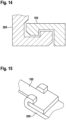
- Fig. 14 shows a schematic representation of part of a fixing device of a device for anchoring a heart support system 205 in a blood vessel according to an exemplary embodiment as a cross section.
- the fixing device 105 is designed here for positive fixing; the heart support system has a corresponding shape.
- the fixing device and the heart support system each have a groove for fixing.
- Fig. 15 shows a schematic representation of part of a fixing device 105 of a device for anchoring a heart support system 205 in a blood vessel according to an exemplary embodiment.
- a section of the fixing device 105 and the heart support system 205 are shown, the sections interlocking with one another in a form-fitting manner.
- the top view shows the positive connection of the fixing device 105 to the heart support system by engaging the fixation device 105 in two hooks of the heart support system 205.
- Fig. 16 shows a schematic representation of part of a fixing device of a device for anchoring a cardiac support system 205 in a blood vessel according to an exemplary embodiment. Shown is a cross section of a non-positive connection of the heart support system 205 with the fixation device 105, which is realized here by a spring connection by means of two springs 1605 between the heart support system 205 and the fixation device 105 as a spring clamp.
- Fig. 17 shows a schematic representation of part of a fixing device of a device for anchoring a cardiac support system 205 in a blood vessel according to an exemplary embodiment. It is the cross section of one Press connection is shown as a non-positive connection of the heart support system 205 with the fixing device 105.
- the assembly of the press connection shown here can be generated by means of a press-in force, or by means of a temperature difference between the heart support system 205 and the fixing device 105, i.e. by press joining using a temperature difference between the fixation device 105 and the heart support system 205 and the pressure that occurs during the subsequent temperature compensation.
- Fig. 18a to 18c each show a schematic representation of a device 100 for anchoring a heart support system in a blood vessel according to an exemplary embodiment, with different situations of the device 100 being shown.
- Fig. 18a shows a top view of the unfolded device 100, as already shown in FIG Fig. 1 is described.
- Fig. 18b shows a section of the in Fig. 18a shown device in the sleeve 405 in the insertion state, as already shown with reference to Fig. 4 is described.
- Fig. 18c shows a side view of the device 100.
- the situations shown here represent, by way of example, the space required by the device 100 in the insertion state, depending on the shape of the device 100.
- the following Figures 19a to 19c show the situations described here corresponding to an alternative shape of the crown 110 of the device 100 according to an exemplary embodiment.
- Fig. 18a shows a side view of the device 100 according to an exemplary embodiment.
- the device 100 includes the fixing device 105, the connecting device 115 and the crown 110, the crown 110 being formed from a plurality of unfolding elements 120 coupled to one another.
- Each of the deployment elements 120 has two deployment rods connected at their ends, which are diamond-shaped in the deployment state shown here.
- the connecting device 115 consists of four bending struts 130, with a first end of each bending strut 130 being attached to the fixing device 105 and with a second end of each bending strut 130 being attached to a connection between two adjacent deployment elements 120.
- Fig. 18b shows the in Fig. 18a described device 100 in the inserted state.
- the crown 110 is folded here for insertion and inserted into the sleeve 405.
- the device 100 also called an anchor, has a comparatively high axial space requirement, for example in comparison to that in Fig. 19b shown embodiment of the device 100.
- the bending struts 130 are not folded completely below or between the unfolding elements of the crown 110, but require a certain axial space in the inserted state, which in this figure is due to the distance between the loaded crown 110 and the fixing device 105 is shown.
- Fig. 18c shows a schematic representation of the device 100 in the unrolled state.
- the device 100 accordingly does not have the cylindrical shape of the insertion state or the unfolded shape of the anchoring state; the unfolded state shown here shows, by way of example, the space required by the connection and formation of the crown 110 and the bending struts 130 of the connecting device.
- Fig. 19a to 19c each show a schematic representation of a device 100 for anchoring a heart support system in a blood vessel according to an exemplary embodiment.
- the ones in the Fig. 19a to 19c The situations shown each show the device 100 as shown on the basis of Fig. 19a is described. Shown is a shape of the crown 110 and the connecting device 115, with which the device 100 in the loaded state, as in the folded state corresponding to the insertion state, has a comparatively small axial space requirement, which can be advantageous, for example, if the device is used in conjunction with a cardiac support system for which additional installation space is advantageous in this area, for example for operating a motor of a heart pump.
- the saving in axial space can be achieved by a modified geometry of the crown 110 and the connecting device 115.
- the crown 110 By shaping the crown 110, attaching the bending struts 130, as well as long bending struts 130 and changing their direction, it is possible to a large extent It can be avoided that the anchor, i.e. the device 100, takes up unnecessary axial space when loading.
- the crown 110 unfolds at the point where it is also in the loaded state.
- Fig. 19a shows the device 100 in a side view in the unfolded state, the device 100 according to this exemplary embodiment having a small axial space requirement.
- the crown 110 is formed from the at least one unfolding element with a plurality of loops arranged in a meandering manner, as in Fig. 19c shown.
- the crown 110 is attached to the fixing device 105.
- Fig. 19b shows the in Fig. 19a described device 100 in the inserted state.
- the crown 110 is crimped here for insertion and inserted into the sleeve 405.
- the device 100 also called an anchor, has a comparatively small axial space requirement, for example in comparison to the one in Fig. 18b shown embodiment of the device 100.
- the bending struts 130 are folded between the unfolding elements of the crown 110; in the inserted state they only require a very small axial space, which is shown in this figure by the small distance between the crimped crown 110 and the fixing device 105 is.
- Fig. 19c shows schematically a representation of the device 100 in the unrolled state as a further situation.
- the described shapes of the unfolding element 120 with a plurality of meandering loops and the described connection of the bending struts 130 to the crown 110 are clearly shown in this figure.
- the crown 110 can be formed from only a single deployment element 120.
- the bending struts 130 of the connecting device are arranged within the meandering loops, with a first end of each bending strut 130 being attached to the fixing device 105 and a second end of the bending strut 130 being attached to an end of the crown 110 facing away from the fixing device 105.
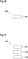
- Fig. 20 shows a flowchart of a method 2000 for operating a device for anchoring a heart support system in a blood vessel (not claimed).
- the method 2000 includes at least a step 2001 of deploying the deployment member of the crown of the device in the transition from the insertion state to the anchoring state to increase the diameter of the crown.
- Fig. 21 shows a flowchart of a manufacturing method 2100 for manufacturing a device for anchoring a heart support system in a blood vessel according to an exemplary embodiment.
- the device may assume an insertion state for inserting the ventricular assist system into the blood vessel, and the device may assume an anchoring state to anchor the ventricular assist system in the blood vessel.
- the manufacturing method 2100 of the device has at least a step 2101 of providing, a step 2103 of molding and a step 2105 of heat treating.
- step 2101 of providing a semi-finished product made of a shape memory material is provided.
- step 2103 of molding a fixing device for fixing the device to the heart support system is formed.
- a crown is formed from at least one deployment element, the deployment element being designed to deploy during a transition from the insertion state to the anchoring state to increase the diameter of the crown in order to anchor the device in the blood vessel.
- a connecting device is formed to connect the crown to the connecting device.
- the fixation device, the crown and the connecting device are formed from the semi-finished product provided in step 2101. In step 2105 of heat treatment, the fixation device, the crown and the connection device are heat treated to imprint the shape of the anchoring state.
- an exemplary embodiment includes an "and/or" link between a first feature and a second feature, this should be read as meaning that the exemplary embodiment has both the first feature and the second feature according to one embodiment and either only that according to a further embodiment first feature or only the second feature.
- a device 100 for anchoring a heart support system in a blood vessel can assume an insertion state for inserting the heart support system into the blood vessel and an anchoring state to anchor the heart support system in the blood vessel.
- the device 100 has at least one fixing device 105 for fixing the device 100 to the heart support system 205, a crown 110 and a connecting device 115.
- the crown 110 is formed from at least one deployment element 120.
- the deployment member 120 is configured to deploy during a transition from the insertion state to the anchoring state to increase the diameter of the crown 110 to anchor the device 100 in the blood vessel.
- the connecting device 115 is designed to connect the crown 110 to the fixing device 105.
Description
Die Erfindung betrifft eine Vorrichtung zum Verankern eines Herzunterstützungssystems in einem Blutgefäß, ein Herstellverfahren zum Herstellen einer derartigen Vorrichtung und ein Herzunterstützungssystem.The invention relates to a device for anchoring a heart support system in a blood vessel, a manufacturing method for producing such a device and a heart support system.
Herzunterstützungssysteme zur Langzeittherapie werden typischerweise über eine komplette oder teilweise Eröffnung des Brustbeins implantiert, wobei eine Herzlungenmaschine zum Ermöglichen eines extrakorporalen Blutkreislaufs zum Einsatz kommen kann. Häufig wird hierbei durch das Stanzen eines Lochs in die strukturelle Integrität des Herzmuskelgewebes und der Körperhauptschlagader, der Aorta eingegriffen. Kurzfristige intravaskuläre Herzunterstützungssysteme werden entweder perkutan, also durch die Haut, oder chirurgisch über verschiedene arterielle Zugänge, beispielsweise über die Oberschenkelschlagader, angeliefert. Die endgültige Positionierung der Herzunterstützungssysteme kann intraoperativ visuell unterstützt werden, beispielsweise mittels Ultraschall oder radiologische Durchleuchtung. Die implantierten Herzunterstützungssysteme haben allerdings ein hohes Risiko für eine Dislokation, da keine lokale Fixierung des Herzunterstützungssystems vorhanden ist. Das Herzunterstützungssystem kann also nach der Implantation verrutschen, da es nicht am Implantationsort verankert ist, was zu einer Fehlfunktion der Pumpe oder zu einem Abbruch der Therapie mit dem Herzunterstützungssystem führen kann.Cardiac support systems for long-term therapy are typically implanted via a complete or partial opening of the sternum, whereby a heart-lung machine can be used to enable extracorporeal blood circulation. This often involves punching a hole into the structural integrity of the heart muscle tissue and the body's main artery, the aorta. Short-term intravascular cardiac support systems are delivered either percutaneously, i.e. through the skin, or surgically via various arterial accesses, for example via the femoral artery. The final positioning of the cardiac support systems can be visually supported intraoperatively, for example using ultrasound or radiological fluoroscopy. However, the implanted cardiac support systems have a high risk of dislocation because there is no local fixation of the cardiac support system. The ventricular support system can therefore slip after implantation because it is not anchored at the implantation site, which can lead to a malfunction of the pump or to discontinuation of therapy with the ventricular support system.
Die
Die
Die
Die
Diese Aufgabe wird durch die in Anspruch 1 und 3 angegebene Vorrichtung zum Verankern eines Herzunterstützungssystems in einem Blutgefäß, die in Anspruch 10 angegebene Anordnung und das in Anspruch 11 definierte Herstellungsverfahren für eine Vorrichtung zum Verankern eines Herzunterstützungssystems in einem Blutgefäß gelöst. Vorteilhafte Ausführungsformen der Erfindung sind in den abhängigen Ansprüchen angegeben.This object is achieved by the device specified in claims 1 and 3 for anchoring a heart support system in a blood vessel, the arrangement specified in claim 10 and the manufacturing method defined in claim 11 for a device for anchoring a heart support system in a blood vessel. Advantageous embodiments of the invention are specified in the dependent claims.
Nachfolgend werden hier die Vorrichtung zum Verankern eines Herzunterstützungssystems in einem Blutgefäß und die Anordnung sowie das Herstellverfahren zum Herstellen einer entsprechenden Vorrichtung vorgestellt. Durch die in den abhängigen Ansprüchen aufgeführten Maßnahmen sind vorteilhafte Weiterbildungen und Verbesserungen der im unabhängigen Anspruch angegebenen Vorrichtung möglich.The device for anchoring a cardiac support system in a blood vessel and the arrangement and manufacturing method for producing a corresponding device are presented below. The measures listed in the dependent claims make advantageous developments and improvements of the device specified in the independent claim possible.
Mit dem hier vorgestellten Ansatz kann ein Implantat, beispielsweise ein Herzunterstützungssystem mittels einer Vorrichtung im Blutgefäß, insbesondere innerhalb der Aorta, mit oder ohne räumliche Beziehung zur Aortenklappe, positioniert und verankert werden. Die Vorrichtung kann dazu an einer Herzpumpe fixiert werden. Die Vorrichtung kann vorteilhafterweise zum minimalinvasiven Einführen des Herzunterstützungssystems zusammengefaltet werden, und die Vorrichtung ist so ausgeformt, dass sie sich am Bestimmungsort zum Positionieren und Verankern des Herzunterstützungssystems entfalten kann. Mittels der Vorrichtung kann das Herzunterstützungssystem am Bestimmungsort ausgerichtet und gezielt abgesetzt werden. Die Position des Herzunterstützungssystem bleibt durch die Verankerung mittels der Vorrichtung vorteilhafterweise auch langfristig unverändert, wodurch ein Verrutschen oder eine Dislokation des Herzunterstützungssystems vermieden werden kann.With the approach presented here, an implant, for example a heart support system, can be positioned and anchored by means of a device in the blood vessel, in particular within the aorta, with or without a spatial relationship to the aortic valve. For this purpose, the device can be attached to a heart pump. The device can advantageously be folded for minimally invasive insertion of the ventricular assist system, and the device is shaped so that it can unfold at the destination for positioning and anchoring the ventricular assist system. Using the device, the heart support system can be aligned at the destination and placed in a targeted manner. The position of the heart support system advantageously remains unchanged in the long term due to the anchoring by means of the device, which means that slipping or dislocation of the heart support system can be avoided.
Es wird eine Vorrichtung zum Verankern eines Herzunterstützungssystems in einem Blutgefäß vorgestellt. Die Vorrichtung kann zum Einführen des Herzunterstützungssystems in das Blutgefäß einen Einführzustand einnehmen. Zudem kann die Vorrichtung einen Verankerungszustand einnehmen, um das Herzunterstützungssystems in dem Blutgefäß zu verankern. Die Vorrichtung umfasst zumindest eine Fixiereinrichtung zum Fixieren der Vorrichtung an das Herzunterstützungssystem, eine Krone und eine Verbindungseinrichtung, die dazu ausgeformt ist, die Krone mit der Fixiereinrichtung zu verbinden. Die Krone ist aus zumindest einem Entfaltungselement ausgeformt. Das Entfaltungselement ist dazu ausgebildet, um sich bei einem Übergang von dem Einführzustand in den Verankerungszustand zu entfalten zum Vergrößern des Durchmessers der Krone, um die Vorrichtung in dem Blutgefäß zu verankern.A device for anchoring a heart support system in a blood vessel is presented. The device can assume an insertion state for introducing the cardiac support system into the blood vessel. In addition, the device can assume an anchoring state in order to anchor the heart support system in the blood vessel. The device comprises at least one fixing device for fixing the device to the heart support system, a crown and a connecting device which is designed to connect the crown to the fixing device. The crown is formed from at least one unfolding element. The deployment member is configured to deploy during a transition from the insertion state to the anchoring state to increase the diameter of the crown to anchor the device in the blood vessel.
Die Vorrichtung kann aus einem biokompatiblen Material ausgeformt sein, um bei einem langfristigen Einsatz der Vorrichtung ein Verwachsen der Vorrichtung mit dem Blutgefäß, beispielsweise der Aorta, zu ermöglichen. Zudem kann die Vorrichtung aus einem elastischen Material realisiert werden, das gleichzeitig eine bestimmte Steifigkeit aufweist, beispielsweise aus Nitinol. Bei dem Herzunterstützungssystem kann es sich beispielsweise um eine Herzpumpe wie ein rechtsventrikuläres Unterstützungssystem, ein linksventrikuläres Unterstützungssystem, ein biventrikuläres Unterstützungssystem oder um eine Gefäß- oder Klappenprothese handeln. Zudem kann die Vorrichtung auch verwendet werden, um eine andere Komponente in einem Blutgefäß zu positionieren und an seinem Bestimmungsort zu verankern, beispielsweise ein anderes vaskuläres oder intrakavitäres Implantat wie beispielsweise ein gastrointestinales, intrathekales, oder intravesikales Implantat. Unter dem Einführzustand kann beispielsweise der Zustand verstanden werden, in dem sich die Vorrichtung zum Einführen oder beim Einführen des Herzunterstützungssystems in das Blutgefäß befinden kann. Die Vorrichtung kann dazu beispielsweise an die Herzpumpe fixiert und so zusammengefaltet sein, dass die Vorrichtung mit dem Herzunterstützungssystem zum minimalinvasiven Einbringen in einen Katheter eingeführt werden kann. Die Vorrichtung und das Herzunterstützungssystem können beispielsweise minimalinvasiv durch die Beinarterie, die arteria fermoralis, eingeführt werden. Im Einführzustand kann die Vorrichtung entsprechend einen Durchmesser aufweisen, der unter dem Durchmesser einer menschlichen Aorta liegt. Unter dem Verankerungszustand kann ein Zustand verstanden werden, in dem die Vorrichtung, nach dem Einführen und Ausrichten am Bestimmungsort zum Vergrößern des Durchmessers der Krone entfaltet ist, um das Herzunterstützungssystem kraftschlüssig am Bestimmungsort zu verankern und auf diese Weise vorteilhafterweise ein Verrutschen oder eine Dislokation des Herzunterstützungssystems zu verhindern. Im Verankerungszustand, also im entfalteten Zustand, kann die Vorrichtung oder eine Komponente der Vorrichtung, beispielsweise die Krone, einen Innendurchmesser aufweisen, der geringfügig größer als der Innendurchmesser des Blutgefäßes ist, in dem es verankert wird, beispielsweise einen gesamten Innendurchmesser im Bereich von 20-30 mm, beispielsweise 23 mm, zum Verankern an oder hinter einer menschlichen Aortenklappe. Zudem kann die Außenkontur zumindest eines Teils der Vorrichtung, beispielsweise der Krone, im Verankerungszustand eine der nicht exakt kreisrunden Aorten-Anatomie einer menschlichen Aorta entsprechende Form aufweisen. Auf diese Weise kann die Vorrichtung im Verankerungszustand über einen radialen Kraftschluss am Bestimmungsort gehalten werden.The device can be formed from a biocompatible material in order to enable the device to grow together with the blood vessel, for example the aorta, during long-term use of the device. In addition, the device can be made from an elastic material that also has a certain rigidity, for example from Nitinol. The cardiac support system can be, for example, one Heart pump such as a right ventricular support system, a left ventricular support system, a biventricular support system or a vascular or valve prosthesis. In addition, the device can also be used to position another component in a blood vessel and anchor it at its destination, for example another vascular or intracavitary implant such as a gastrointestinal, intrathecal, or intravesical implant. The insertion state can be understood, for example, as the state in which the device can be for inserting or when inserting the heart support system into the blood vessel. For this purpose, the device can, for example, be fixed to the heart pump and folded together in such a way that the device can be inserted into a catheter with the heart support system for minimally invasive insertion. The device and the heart support system can, for example, be introduced minimally invasively through the leg artery, the fermoral artery. When inserted, the device can have a diameter that is less than the diameter of a human aorta. The anchoring state can be understood as meaning a state in which the device, after insertion and alignment at the destination, is unfolded to increase the diameter of the crown in order to non-positively anchor the heart support system at the destination and in this way advantageously prevent slipping or dislocation of the heart support system to prevent. In the anchoring state, i.e. in the unfolded state, the device or a component of the device, for example the crown, can have an inside diameter that is slightly larger than the inside diameter of the blood vessel in which it is anchored, for example a total inside diameter in the range of 20 - 30 mm, for example 23 mm, for anchoring to or behind a human aortic valve. In addition, the outer contour of at least part of the device, for example the crown, in the anchoring state can have a shape corresponding to the not exactly circular aortic anatomy of a human aorta. In this way, the device can be held at the destination in the anchoring state via a radial force connection.
Die Fixiereinrichtung kann ausgebildet sein, um die Vorrichtung an einem Implantat, beispielsweise dem Herzunterstützungssystem, zu fixieren. Dazu kann die Fixiereinrichtung zumindest ein Fixierelement zum Bilden einer form-und/oder kraftschlüssigen Verbindung mit einem an dem Implantat angeordneten Gegenfixierelement aufweisen. Die Krone ist ringförmig ausgeformt. Je nach Ausführungsform kann ein einziges Entfaltungselement ringförmig ausgeformt sein oder es können mehrere Entfaltungselemente ringförmig aneinandergereiht sein. Beim Entfalten kann sich das zumindest eine Entfaltungselement ausdehnen. Die Verbindungseinrichtung kann zumindest eine längliche, beispielsweise drahtförmige, Strebe umfassen, die sowohl an der Krone als auch an der Fixiereinrichtung befestigt ist. Die Verbindungseinrichtung kann flexibel ausgeformt sein, um das Vergrößern des Durchmessers der Krone zu ermöglichen.The fixing device can be designed to fix the device on an implant, for example the heart support system. For this purpose, the fixing device can have at least one fixing element for forming a positive and/or non-positive connection with a counter-fixing element arranged on the implant. The crown is ring-shaped. Depending on the embodiment, a single deployment element can be formed in a ring shape or several deployment elements can be lined up in a ring shape. When unfolding, the at least one unfolding element can expand. The connecting device can comprise at least one elongated, for example wire-shaped, strut which is attached to both the crown and the fixing device. The connecting device can be shaped flexibly to enable the diameter of the crown to be increased.
Einer vorteilhaften Ausführungsform gemäß kann zumindest das Entfaltungselement der Krone der Vorrichtung aus Formgedächtnismaterial ausgeformt sein. Das Entfaltungselement kann beispielsweise aus einem biokompatiblen Formgedächtnispolymer bestehen, oder aus einer biokompatiblen Formgedächtnislegierung, wie beispielsweise Nitinol. Zudem kann auch die gesamte Vorrichtung aus einer Formgedächtnislegierung, beispielsweise aus Nitionol gefertigt werden. Die Verwendung eines Formgedächtnismaterials wie Nitinol ermöglicht aufgrund seiner Formgedächtniseigenschaften eine besonders elegante und einfache Realisierung des Einführzustands und des Entfaltens des Entfaltungselements beim Übergang in den Verankerungszustand. Die Verwendung von Nitinol als Formgedächtnismaterial ist vorteilhaft, da der Nitinolwerkstoff in der Medizin, insbesondere im Bereich der kardiovaskulären Medizin, ein bewährtes Material darstellt, beispielsweise für Herzklappenprothesen, Stents und Gefäßprothesen, aufgrund seiner Biokompatibilität und der Formgedächtniseigenschaft, die es ermöglicht auch komplexe Strukturen auf kleinem Bauraum an den Bestimmungsort zu liefern und abzusetzen, wie die hier vorgestellte Vorrichtung.According to an advantageous embodiment, at least the deployment element of the crown of the device can be formed from shape memory material. The unfolding element can consist, for example, of a biocompatible shape memory polymer, or of a biocompatible shape memory alloy, such as Nitinol. In addition, the entire device can also be made from a shape memory alloy, for example Nitionol. Due to its shape memory properties, the use of a shape memory material such as Nitinol enables a particularly elegant and simple realization of the insertion state and the unfolding of the unfolding element during the transition to the anchoring state. The use of Nitinol as a shape memory material is advantageous because the Nitinol material is a proven material in medicine, especially in the field of cardiovascular medicine, for example for heart valve prostheses, stents and vascular prostheses, due to its biocompatibility and the shape memory property, which enables even complex structures to deliver and drop off at the destination in a small installation space, like the device presented here.
Die Vorrichtung kann gemäß einer Ausführungsform zudem eine Bogeneinrichtung mit zumindest einem Füßchen umfassen. Die Bogeneinrichtung ist dazu ausgebildet, um sich bei dem Übergang von dem Einführzustand in den Verankerungszustand zu entfalten zum Positionieren des zumindest einen Füßchens im Blutgefäß. Mittels des Positionierens des zumindest einen Füßchens im Blutgefäß kann die Vorrichtung im Blutgefäß beispielsweise vor dem Verankern ausgerichtet und positioniert werden. Die Bogeneinrichtung kann mit der Krone verbunden sein. Alternativ kann die Bogeneinrichtung eine Bogenfixierungseinrichtung zum Fixieren der Bogeneinrichtung an das Herzunterstützungssystem aufweisen. Die Vorrichtung kann entsprechend einteilig ausgeformt sein, indem die Fixierungseinrichtung, die Krone, die Verbindungseinrichtung und die Bogeneinrichtung miteinander gekoppelt sind, oder die Vorrichtung kann zweiteilig sein, wenn die Bogeneinrichtung mit eigener Bogenfixiereinrichtung an dem Herzunterstützungssystem fixiert ist, und die anderen Komponenten der Vorrichtung miteinander gekoppelt sind. Die einteilige Ausführungsform kann im Hinblick auf das Zusammenfalten der Vorrichtung für den Einführzustand vorteilhaft sein, die zweiteilige Ausführungsform kann je nach Bauweise des Herzunterstützungssystems von Vorteil sein. Wenn das Herzunterstützungssystem beispielsweise eine Pumpe mit Motor umfasst, kann eine zweiteilige Ausführungsform mehr Flexibilität im Hinblick auf den Bauraum des Herzunterstützungssystems ermöglichen, beispielsweise indem die Bogeneinrichtung an einem Ende einer Motor-Kupplung-Pumpeneinheit des Herzunterstützungssystems fixiert werden kann, und der zweite Teil der Vorrichtung an dem anderen Ender der Motor-Kupplung-Pumpeneinheit des Herzunterstützungssystems fixiert werden kann. Mittels der Bogeneinrichtung kann die Vorrichtung vorteilhafterweise durch das Entfalten des zumindest einen Füßchens am Bestimmungsort ausgerichtet und positioniert werden. Das Füßchen kann beispielsweise eine atraumatische Form aufweisen, um das Blutgefäß beim Entfalten und im Verankerungszustand nicht zu verletzen. Vorteilhafterweise kann die Bogeneinrichtung dazu ausgebildet sein, beim Positionieren des zumindest einen Füßchens durch die Ausformung der Bogeneinrichtung und des zumindest einen Füßchens ein Ausrichten der Vorrichtung für den Verankerungszustand zu ermöglichen.According to one embodiment, the device can also include an arch device with at least one foot. The arch device is designed to unfold during the transition from the insertion state to the anchoring state in order to position the at least one foot in the blood vessel. By positioning the at least one foot in the blood vessel, the device can be aligned and positioned in the blood vessel, for example before anchoring. The arch device can be connected to the crown. Alternatively, the arch device can have an arch fixation device for fixing the arch device to the heart support system. The device can accordingly be formed in one piece, in that the fixation device, the crown, the connecting device and the arch device are coupled to one another, or the device can be in two parts, if the arch device is fixed to the heart support system with its own arch fixation device, and the other components of the device to one another are coupled. The one-part embodiment can be advantageous with regard to folding the device for the insertion state; the two-part embodiment can be advantageous depending on the design of the heart support system. If the heart support system includes, for example, a pump with a motor, a two-part embodiment can enable more flexibility with regard to the installation space of the heart support system, for example in that the arch device can be fixed at one end of a motor-coupling-pump unit of the heart support system, and the second part of the device can be fixed to the other end of the motor-coupling-pump unit of the cardiac support system. By means of the arch device, the device can advantageously be aligned and positioned at the destination by unfolding the at least one foot. The foot can, for example, have an atraumatic shape in order not to injure the blood vessel when unfolding and in the anchoring state. Advantageously, the arch device can be designed to enable the device to be aligned for the anchoring state when positioning the at least one foot by shaping the arch device and the at least one foot.
Die Bogeneinrichtung kann gemäß einer weiteren Ausführungsform drei Füßchen aufweisen, insbesondere wobei die Füßchen zum Positionieren der Füßchen in je einer Kuspe einer Herzklappe ausgeformt sind. Diese Ausführungsform ist von Vorteil, um die Vorrichtung und damit das Herzunterstützungssystem besonders exakt positionieren zu können, insbesondere wenn das Herzunterstützungssystem mittels der Vorrichtung beispielsweise hinter der Aortenklappe positioniert und verankert wird. Die drei Füßchen können beispielsweise eine im Hinblick auf eine Erdnuss-Form der Kuspen angepasste Form aufweisen, um so vorteilhafterweise ein besonders vorteilhaftes Verhältnis aus Anlagefläche und Drehsteifigkeit der drei Füßchen zu erreichen.According to a further embodiment, the arch device can have three feet, in particular the feet for positioning the feet are each formed in a case of a heart valve. This embodiment is advantageous in order to be able to position the device and thus the heart support system particularly precisely, especially if the heart support system is positioned and anchored behind the aortic valve using the device, for example. The three feet can, for example, have a shape adapted to the peanut shape of the shells in order to advantageously achieve a particularly advantageous ratio of contact surface and torsional rigidity of the three feet.
Für eine kathetergestütze minimalinvasive Implantation des mit der Vorrichtung verbundenen Herzunterstützungssystems ist es von Vorteil, wenn die Vorrichtung gemäß einer Ausführungsform im Einführzustand zylinderförmig ist. Die Vorrichtung kann dazu beispielsweise zusammengefaltet werden. Wenn die Vorrichtung beispielsweise aus Nitinol ausgeformt ist, kann die Vorrichtung aus einem Rohr freigeschnitten werden, anschließend kann eine dem Verankerungszustand entsprechende Form mittels einer Wärmebehandlung eingeprägt werden. Für den Einführzustand kann die Vorrichtung entsprechend der ursprünglich zylinderförmigen Rohrgeometrie zusammengefaltet werden.For a catheter-supported minimally invasive implantation of the heart support system connected to the device, it is advantageous if the device according to one embodiment is cylindrical in the inserted state. For this purpose, the device can, for example, be folded up. For example, if the device is formed from Nitinol, the device can be cut free from a tube, then a shape corresponding to the anchoring state can be impressed by means of a heat treatment. For the insertion state, the device can be folded up according to the originally cylindrical tube geometry.
Zudem kann es vorteilhaft sein, wenn das Entfaltungselement gemäß einer Ausführungsform im Verankerungszustand eine Schrägstellung aufweist. Unter der Schrägstellung kann ein bestimmter Winkel des Entfaltungselements gegenüber der Längsachse der Vorrichtung verstanden werden. Das Entfaltungselement kann im Verankerungszustand in einem Winkel angestellt sein, um im Verankerungszustand eine kraftschlüssige Verbindung zwischen der Krone und dem Blutgefäß zu unterstützen. Der Winkel kann in Bezug auf die Längsachse der Vorrichtung beispielsweise zwischen 20° und 30° betragen, insbesondere 25°. Durch die Schrägstellung des Entfaltungselements kann die Anpresskraft der Krone an das Blutgefäß vorteilhafterweise erhöht werden.In addition, it can be advantageous if the deployment element, according to one embodiment, has an inclined position in the anchoring state. The inclination can be understood as meaning a certain angle of the deployment element relative to the longitudinal axis of the device. The unfolding element can be positioned at an angle in the anchoring state in order to support a force-fitting connection between the crown and the blood vessel in the anchoring state. The angle can be, for example, between 20° and 30°, in particular 25°, with respect to the longitudinal axis of the device. By tilting the unfolding element, the contact force of the crown against the blood vessel can advantageously be increased.
Die Krone kann gemäß einer Ausführungsform eine Mehrzahl an miteinander gekoppelten Entfaltungselementen aufweisen. Jedes der Entfaltungselemente kann zwei an ihren Enden verbundene Entfaltungsstäbe aufweisen und die zwei Entfaltungsstäbe können im Einführzustand eine geringere Entfernung zueinander aufweisen als im Verankerungszustand. Die Entfaltungselemente können durch eine Verbindung mit einem der Entfaltungsstäbe eines benachbarten Entfaltungselements miteinander gekoppelt sein. Die zwei Entfaltungsstäbe können so miteinander verbunden sein, dass jedes Entfaltungselement im Verankerungszustand der Vorrichtung in axialer Richtung zur Längsachse der Vorrichtung eine Raute mit abgerundeten Ecken ausbildet. Eine solche Ausformung einer Mehrzahl an miteinander gekoppelten rautenförmigen Entfaltungselementen kann einen Standardschnitt eines Gefäß-Stents entsprechen, was beim Herstellen der Vorrichtung vorteilhaft sein kann.According to one embodiment, the crown may have a plurality of deployment elements coupled to one another. Each of the deployment elements may have two deployment bars connected at their ends, and the two deployment bars may be at a closer distance from each other in the inserted state than in the anchoring state. The deployment elements may be coupled together by a connection to one of the deployment rods of an adjacent deployment element. The two deployment rods can be connected to one another in such a way that, when the device is anchored, each deployment element forms a diamond with rounded corners in the axial direction to the longitudinal axis of the device. Such a formation of a plurality of diamond-shaped deployment elements coupled together can correspond to a standard cut of a vascular stent, which can be advantageous when producing the device.
Alternativ kann das Entfaltungselement gemäß einer Ausführungsform eine Mehrzahl an mäanderartig angeordneten Schlaufen aufweisen, wobei die Schlaufen im Einführzustand eine geringere Entfernung zueinander aufweisen als im Verankerungszustand. Diese Ausführungsform bietet ein besonders platzsparendes Zusammenfalten der Vorrichtung für den Einführzustand.Alternatively, according to one embodiment, the unfolding element can have a plurality of loops arranged in a meandering manner, the loops being at a smaller distance from one another in the insertion state than in the anchoring state. This embodiment offers a particularly space-saving folding of the device for the insertion state.
Die Verbindungseinrichtung weist zumindest eine Biegestrebe auf. Die Biegestrebe ist dazu ausgebildet, bei dem Übergang von dem Einführzustand in den Verankerungszustand aufzuklappen, um ein Entfalten der Krone zu ermöglichen. Die Biegestrebe ermöglicht eine besonders elegante und platzsparende Verbindung zwischen der Fixiereinrichtung und der Krone. Die Biegestrebe kann beispielsweise aus einem elastischen Material sein, beispielsweise auch aus Nitinol.The connecting device has at least one bending strut. The bending strut is designed to unfold during the transition from the insertion state to the anchoring state in order to enable the crown to be unfolded. The bending strut enables a particularly elegant and space-saving connection between the fixing device and the crown. The bending strut can, for example, be made of an elastic material, for example Nitinol.
Zudem kann ein erstes Ende der Biegestrebe gemäß einer weiteren Ausführungsform an der Fixiereinrichtung befestigt sein. Ein zweites Ende der Biegestrebe kann an einer Verbindung zwischen zwei benachbarten Entfaltungselementen befestigt sein, oder das zweite Ende der Biegestrebe kann an einem der Fixiereinrichtung abgewandten Ende der Krone befestigt sein. Die Biegestrebe kann also entsprechend der Ausformung des Entfaltungselements der Krone gestaltet werden, um ein effizientes Entfalten der Krone je nach Ausführungsform zu ermöglichen, und um je nach Ausführungsform des Entfaltungselements ein kompaktes Zusammenfalten für den Einführzustand im Hinblick auf die axiale Länge der Vorrichtung zu ermöglichen.In addition, a first end of the bending strut can be attached to the fixing device according to a further embodiment. A second end of the bending strut may be attached to a connection between two adjacent deployment elements, or the second end of the bending strut may be attached to a be attached to the end of the crown facing away from the fixing device. The bending strut can therefore be designed according to the shape of the unfolding element of the crown in order to enable efficient unfolding of the crown depending on the embodiment and, depending on the embodiment of the unfolding element, to enable compact folding for the insertion state with regard to the axial length of the device.
Die Fixiereinrichtung kann gemäß einer Ausführungsform ausgeformt sein, um die Vorrichtung formschlüssig und/oder kraftschlüssig an das Herzunterstützungssystem zu fixieren. Die Vorrichtung kann somit stabil mit dem Herzunterstützungssystem verbunden werden, um beispielsweise während der Implantation oder während der Laufzeit des Herzunterstützungssystems auftretende Kräfte aufzunehmen. Dazu kann die Fixiereinrichtung beispielsweise ein Element zum formschlüssigen Eingreifen aufweisen, oder eine Aussparung zum formschlüssigen Aufnehmen eines Elements, das beispielsweise auf dem Gehäuse des Herzunterstützungssystems aufgetragen ist. Das Element zum formschlüssigen Fixieren kann beispielsweise unterschiedliche Querschnitte aufweisen und das Element oder die entsprechende Aussparung können beispielsweise rund, oval, dreieckig, vieleckig oder sternförmig ausgeformt sein. Sowohl die Fixiereinrichtung als auch das Herzunterstützungssystem, beispielsweise das Gehäuse des Herzunterstützungssystems, können dazu Elemente aufweisen, die ein Einrasten oder Verankern der Fixiereinrichtung mit dem Herzunterstützungssystem ermöglichen. Zusätzlich oder alternativ kann die Fixiereinrichtung beispielsweise eine Bajonettverbindung oder eine Klippverbindung oder einen Haken aufweisen. Zusätzlich oder alternativ kann die Fixiereinrichtung zudem mittels einer stoffschlüssigen Verbindung realisiert werden. Die Fixiereinrichtung kann beispielsweise ausgebildet sein, um eine rotatorische Bewegung zwischen der Vorrichtung und dem Herzunterstützungssystem zu ermöglichen.According to one embodiment, the fixing device can be designed to fix the device to the heart support system in a form-fitting and/or force-fitting manner. The device can thus be stably connected to the heart support system in order to absorb forces occurring during implantation or during the life of the heart support system, for example. For this purpose, the fixing device can, for example, have an element for positive engagement, or a recess for positive reception of an element, which is applied, for example, to the housing of the heart support system. The element for positive fixing can, for example, have different cross sections and the element or the corresponding recess can be shaped, for example, round, oval, triangular, polygonal or star-shaped. Both the fixing device and the heart support system, for example the housing of the heart support system, can have elements that enable the fixation device to snap into place or be anchored to the heart support system. Additionally or alternatively, the fixing device can have, for example, a bayonet connection or a clip connection or a hook. Additionally or alternatively, the fixing device can also be implemented by means of a cohesive connection. The fixing device can, for example, be designed to enable a rotational movement between the device and the heart support system.
Gemäß einer Ausführungsform kann die Vorrichtung zudem eine Hülse aufweisen. Die Hülse kann gegenüber der Krone beweglich sein. Zudem kann die Hülse dazu ausgeformt sein, um im Einführzustand zumindest die Krone zu umschließen und die Krone zum Einleiten des Übergangs in den Verankerungszustand freizugeben. Wenn die Vorrichtung gemäß einer Ausführungsform die Bogeneinrichtung umfasst, kann die Hülse auch gegenüber der Bogeneinrichtung beweglich sein und zudem dazu ausgeformt sein im Einführzustand auch die Bogeneinrichtung zu umschließen und die Bogeneinrichtung zum Einleiten des Übergangs in den Verankerungszustand freizugeben. Die Hülse kann auch dazu ausgeformt sein, alle anderen Komponenten der Vorrichtung zu umschließen und wieder freizugeben. Die Hülse kann beispielsweise zylinderförmig ausgeformt und so ausgeführt sein, dass die Vorrichtung mit der Hülse im Einführzustand in einen handelsüblichen Katheter eingeführt werden kann. Die Hülse kann vorteilhafterweise beispielsweise verwendet werden, um die anderen Komponenten der Vorrichtung im zusammengefalteten Zustand der Vorrichtung niederzuhalten und dadurch im Einführzustand zusätzlich zu stabilisieren, beispielsweise auch, wenn Komponenten der Vorrichtung oder die gesamte Vorrichtung aus einem Formgedächtnismaterial ausgeformt sind. Zudem kann die Hülse beim Übergang vom Einführzustand in den Verankerungszustand schrittweise entfernt werden, beispielsweise über einen gesteuerten Mechanismus, der beispielsweise elektrisch gesteuert werden kann, oder durch ein manuelles Zurückziehen der Hülse. Auf diese Weise kann die Vorrichtung beispielsweise schrittweise entfaltet werden, um die Vorrichtung vorteilhafterweise kontrolliert zu entfalten und vor dem Verankern zu positionieren oder die Hülse kann wieder nach vorne verschoben werden, um die Vorrichtung anders auszurichten oder das Positionieren der Vorrichtung zu korrigieren.According to one embodiment, the device can also have a sleeve. The sleeve can be movable relative to the crown. In addition, the sleeve can be shaped to at least close the crown in the inserted state enclose and release the crown to initiate the transition to the anchoring state. If the device according to one embodiment comprises the arch device, the sleeve can also be movable relative to the arch device and can also be shaped to enclose the arch device in the insertion state and to release the arch device to initiate the transition to the anchoring state. The sleeve can also be shaped to enclose and release all other components of the device. The sleeve can, for example, be cylindrical and designed in such a way that the device with the sleeve can be inserted into a commercially available catheter in the inserted state. The sleeve can advantageously be used, for example, to hold down the other components of the device in the folded state of the device and thereby provide additional stability in the inserted state, for example also when components of the device or the entire device are formed from a shape memory material. In addition, the sleeve can be removed gradually during the transition from the insertion state to the anchoring state, for example via a controlled mechanism, which can be controlled electrically, for example, or by manually retracting the sleeve. In this way, the device can, for example, be unfolded step by step in order to advantageously unfold the device in a controlled manner and position it before anchoring, or the sleeve can be moved forward again in order to align the device differently or to correct the positioning of the device.
Mit diesem Ansatz wird zudem ein Verfahren (nicht beansprucht) zum Betreiben der Vorrichtung vorgestellt. Das Verfahren weist zumindest einen Schritt des Entfaltens auf. Im Schritt des Entfaltens wird das Entfaltungselement der Krone der Vorrichtung bei dem Übergang von dem Einführzustand in den Verankerungszustand zum Vergrößern des Durchmessers der Krone entfaltet. Der Schritt des Entfaltens kann beispielsweise auch durchgeführt werden, um den Durchmesser der Krone zum Verankern der Vorrichtung in dem Blutgefäß zu vergrößern. Das Verfahren kann sowohl ausgeführt werden, wenn die Vorrichtung innerhalb eines Blutgefäßes angeordnet ist, als auch wenn sich die Vorrichtung außerhalb eines Blutgefäßes befindet, beispielsweise um durch ein Vergrößern des Durchmessers der Krone die Vorrichtung mit einer Komponente eines Implantats zu verbinden.With this approach, a method (not claimed) for operating the device is also presented. The method has at least one unfolding step. In the unfolding step, the unfolding element becomes the crown of the device in the transition from the insertion state unfolded into the anchoring state to increase the diameter of the crown. For example, the unfolding step may also be performed to increase the diameter of the crown for anchoring the device in the blood vessel. The method can be carried out both when the device is arranged inside a blood vessel and when the device is outside a blood vessel, for example to connect the device to a component of an implant by increasing the diameter of the crown.
Es wird zudem ein Herstellverfahren zum Herstellen einer Vorrichtung zum Verankern eines Herzunterstützungssystems in einem Blutgefäß vorgestellt. Die Vorrichtung kann einen Einführzustand zum Einführen des Herzunterstützungssystems in das Blutgefäß einnehmen, und ferner kann die Vorrichtung einen Verankerungszustand einnehmen, um das Herzunterstützungssystems in dem Blutgefäß zu verankern. Das Herstellverfahren weist zumindest einen Schritt des Bereitstellens, einen Schritt des Ausformens und einen Schritt des Wärmebehandelns auf. Im Schritt des Bereitstellens wird ein Halbzeug aus einem Formgedächtnismaterial bereitgestellt. Im Schritt des Ausformens wird eine Fixiereinrichtung zum Fixieren der Vorrichtung an das Herzunterstützungssystem ausgeformt. Zudem wird im Schritt des Ausformens eine Krone aus zumindest einem Entfaltungselement ausgeformt, wobei das Entfaltungselement dazu ausgebildet ist, um sich bei einem Übergang von dem Einführzustand in den Verankerungszustand zu entfalten zum Vergrößern des Durchmessers der Krone, um die Vorrichtung in dem Blutgefäß zu verankern. Ferner wird im Schritt des Ausformens eine Verbindungseinrichtung dazu ausgeformt, die Krone mit der Anbindungseinrichtung zu verbinden. Die Fixierungseinrichtung, die Krone und die Verbindungseinrichtung werden aus dem Halbzeug ausgeformt. Im Schritt des Wärmebehandelns werden Fixierungseinrichtung, die Krone und die Verbindungseinrichtung wärmebehandelt, um die Form des Verankerungszustands einzuprägen.A manufacturing method for manufacturing a device for anchoring a heart support system in a blood vessel is also presented. The device may assume an insertion state for inserting the ventricular assist system into the blood vessel, and further, the device may assume an anchoring state to anchor the ventricular assist system in the blood vessel. The manufacturing method has at least a step of providing, a step of molding and a step of heat treating. In the providing step, a semi-finished product made of a shape memory material is provided. In the molding step, a fixing device for fixing the device to the cardiac support system is formed. In addition, in the molding step, a crown is formed from at least one unfolding element, the unfolding element being designed to unfold during a transition from the insertion state to the anchoring state to increase the diameter of the crown in order to anchor the device in the blood vessel. Furthermore, in the forming step, a connecting device is formed to to connect the crown to the connection device. The fixation device, the crown and the connecting device are formed from the semi-finished product. In the heat treating step, the fixation device, the crown and the connection device are heat treated to imprint the shape of the anchoring state.
Es wird außerdem ein Herzunterstützungssystem mit einer Vorrichtung gemäß einer Ausführungsform vorgestellt. Die Vorrichtung kann beispielsweise an dem Herzunterstützungssystem fixiert sein. Das Herzunterstützungssystem kann beispielsweise eine Herzpumpe mit einer Motor-Kupplung-Pumpeneinheit umfassen. Zudem kann das Herzunterstützungssystem ein Gehäuse aufweisen, das ausgeformt ist, um mit der Vorrichtung, beispielsweise mittels der Fixiereinrichtung der Vorrichtung, formschlüssig und/oder kraftschlüssig verbunden zu sein. Vorteilhafterweise können gemäß dieser Ausführungsform die Größe des Herzunterstützungssystem und/oder die Abmessungen der Vorrichtung patientenspezifisch ausgewählt oder verändert werden.A cardiac support system with a device according to one embodiment is also presented. The device can, for example, be fixed to the heart support system. The cardiac support system can, for example, include a heart pump with a motor-clutch-pump unit. In addition, the cardiac support system can have a housing that is shaped to be connected to the device in a form-fitting and/or force-fitting manner, for example by means of the fixing device of the device. Advantageously, according to this embodiment, the size of the cardiac support system and/or the dimensions of the device can be selected or changed in a patient-specific manner.
Ausführungsbeispiele des hier vorgestellten Ansatzes sind in den Zeichnungen dargestellt und in der nachfolgenden Beschreibung näher erläutert. Es zeigt:
- Fig. 1
- eine schematische Darstellung einer Vorrichtung zum Verankern eines Herzunterstützungssystems in einem Blutgefäß gemäß einem Ausführungsbeispiel;
- Fig. 2
- eine schematische Darstellung eines Teils eines Herzunterstützungssystems mit einer Vorrichtung zum Verankern eines Herzunterstützungssystems in einem Blutgefäß gemäß einem Ausführungsbeispiel;
- Fig. 3
- eine schematische Darstellung eines Herzunterstützungssystems mit einer Vorrichtung zum Verankern eines Herzunterstützungssystems in einem Blutgefäß gemäß einem Ausführungsbeispiel;
- Fig. 4 und 5
- eine schematische Darstellung eines Einführzustandes einer Vorrichtung zum Verankern eines Herzunterstützungssystems in einem Blutgefäß gemäß einem Ausführungsbeispiel;
- Fig. 6
- eine schematische Darstellung einer Vorrichtung zum Verankern eines Herzunterstützungssystems in einem Blutgefäß mit einer Bogeneinrichtung gemäß einem Ausführungsbeispiel;
- Fig. 7
- eine schematische Darstellung eines Füßchens einer Vorrichtung zum Verankern eines Herzunterstützungssystems in einem Blutgefäß gemäß einem Ausführungsbeispiel;
- Fig. 8
- eine schematische Darstellung eines Teils einer Krone einer Vorrichtung zum Verankern eines Herzunterstützungssystems in einem Blutgefäß gemäß einem Ausführungsbeispiel;
- Fig. 9 und 10
- eine schematische Darstellung einer Fixiereinrichtung einer Vorrichtung zum Verankern eines Herzunterstützungssystems in einem Blutgefäß gemäß einem Ausführungsbeispiel;
- Fig. 11a bis 11j
- eine schematische Darstellung einer Ausformung einer formschlüssigen Fixierung einer Vorrichtung zum Verankern eines Herzunterstützungssystems in einem Blutgefäß gemäß einem Ausführungsbeispiel;
- Fig. 12
- eine schematische Darstellung einer kraftschlüssigen Fixierung einer Vorrichtung zum Verankern eines Herzunterstützungssystems in einem Blutgefäß an ein Herzunterstützungssystem gemäß einem Ausführungsbeispiel;
- Fig. 13 bis 17
- eine schematische Darstellung eines Teils einer Fixiereinrichtung einer Vorrichtung zum Verankern eines Herzunterstützungssystems in einem Blutgefäß gemäß einem Ausführungsbeispiel;
- Fig. 18a bis 18c
- eine schematische Darstellung einer Vorrichtung zum Verankern eines Herzunterstützungssystems in einem Blutgefäß gemäß einem Ausführungsbeispiel;
- Fig. 19a bis 19c
- eine schematische Darstellung einer Vorrichtung zum Verankern eines Herzunterstützungssystems in einem Blutgefäß gemäß einem Ausführungsbeispiel;
- Fig. 20
- ein Ablaufdiagramm eines Verfahrens zum Betreiben einer Vorrichtung zum Verankern eines Herzunterstützungssystems in einem Blutgefäß gemäß einem Ausführungsbeispiel; und
- Fig. 21
- ein Ablaufdiagramm eines Herstellverfahrens zum Herstellen einer Vorrichtung zum Verankern eines Herzunterstützungssystems in einem Blutgefäß gemäß einem Ausführungsbeispiel.
- Fig. 1
- a schematic representation of a device for anchoring a heart support system in a blood vessel according to an exemplary embodiment;
- Fig. 2
- a schematic representation of part of a heart support system with a device for anchoring a heart support system in a blood vessel according to an exemplary embodiment;
- Fig. 3
- a schematic representation of a heart support system with a device for anchoring a heart support system in a blood vessel according to an exemplary embodiment;
- Figs. 4 and 5
- a schematic representation of an insertion state of a device for anchoring a heart support system in a blood vessel according to an exemplary embodiment;
- Fig. 6
- a schematic representation of a device for anchoring a heart support system in a blood vessel with an arch device according to an exemplary embodiment;
- Fig. 7
- a schematic representation of a foot of a device for anchoring a heart support system in a blood vessel according to an exemplary embodiment;
- Fig. 8
- a schematic representation of part of a crown of a device for anchoring a heart support system in a blood vessel according to an exemplary embodiment;
- 9 and 10
- a schematic representation of a fixing device of a device for anchoring a heart support system in a blood vessel according to an exemplary embodiment;
- Fig. 11a to 11j
- a schematic representation of a form of a positive fixation of a device for anchoring a heart support system in a blood vessel according to an exemplary embodiment;
- Fig. 12
- a schematic representation of a non-positive fixation of a device for anchoring a Heart support system in a blood vessel to a heart support system according to an embodiment;
- Fig. 13 to 17
- a schematic representation of part of a fixing device of a device for anchoring a heart support system in a blood vessel according to an exemplary embodiment;
- Fig. 18a to 18c
- a schematic representation of a device for anchoring a heart support system in a blood vessel according to an exemplary embodiment;
- Fig. 19a to 19c
- a schematic representation of a device for anchoring a heart support system in a blood vessel according to an exemplary embodiment;
- Fig. 20
- a flowchart of a method for operating a device for anchoring a heart support system in a blood vessel according to an exemplary embodiment; and
- Fig. 21
- a flowchart of a manufacturing method for manufacturing a device for anchoring a heart support system in a blood vessel according to an exemplary embodiment.
In der nachfolgenden Beschreibung günstiger Ausführungsbeispiele der vorliegenden Erfindung werden für die in den verschiedenen Figuren dargestellten und ähnlich wirkenden Elemente gleiche oder ähnliche Bezugszeichen verwendet, wobei auf eine wiederholte Beschreibung dieser Elemente verzichtet wird.In the following description of favorable exemplary embodiments of the present invention, the same or similar reference numerals are used for the elements shown in the various figures and having a similar effect, with a repeated description of these elements being omitted.
Gezeigt ist eine Seitenansicht der entfalteten Vorrichtung 100. Die Vorrichtung 100 kann einen Einführzustand zum Einführen des Herzunterstützungssystems in das Blutgefäß einnehmen. Zudem kann die Vorrichtung 100 den in
Die Vorrichtung 100 weist zumindest eine Fixiereinrichtung 105 zum Fixieren der Vorrichtung 100 an das Herzunterstützungssystem, eine Krone 110 und eine Verbindungseinrichtung 115 auf. Die Krone 110 ist aus zumindest einem Entfaltungselement 120 ausgeformt. Das Entfaltungselement 120 ist dazu ausgebildet, um sich bei einem Übergang von dem Einführzustand in den Verankerungszustand zu entfalten zum Vergrößern des Durchmessers der Krone 110, um die Vorrichtung 100 in dem Blutgefäß zu verankern. Gemäß dem gezeigten Ausführungsbeispiel umfasst die Krone 110 eine Mehrzahl von Entfaltungselementen 120. Die Verbindungseinrichtung 115 ist dazu ausgeformt, die Krone 110 mit der Fixiereinrichtung 105 zu verbinden.The
Vorteilhafterweise kann mittels der Vorrichtung 100 ein Verrutschen oder Bewegen des Herzunterstützungssystems verhindert werden, da mittels der Krone 110 eine Verankerung am Implantationsort stattfinden kann. Zudem ist mittels der Vorrichtung 100 eine definierte Positionierung des Herzunterstützungssystems, im Folgenden auch genannt, möglich. Die Vorrichtung kann zumindest teilweise aus einem Formgedächtnismaterial wie Nitinol ausgeformt sein. In der hier gezeigten
Die die Krone 110 und die Fixiereinrichtung 105 der Vorrichtung 100 sind entlang einer Längsachse der Vorrichtung 100 erstreckt, die der Achse eines Katheters entsprechen kann, in dem das Herzunterstützungssystem minimalinvasiv durch die Beinarterie eingeführt wird.The
In der hier gezeigten Darstellung ist das Entfaltungselement 120 und damit die Krone 110 entsprechend dem Verankerungszustand entfaltet. Das Entfaltungselement 120 kann gemäß dem gezeigten Ausführungsbeispiel im Verankerungszustand eine Schrägstellung in Bezug auf die Längsachse der Vorrichtung 100 aufweisen. Dazu kann das Entfaltungselement 120 in einen bestimmten Winkel angestellt sein, beispielsweise in einem Winkel von 25°, um eine erhöhte Anpresskraft der Krone 110 zum kraftschlüssigen Verankern der Vorrichtung 100 in dem Blutgefäß zu erzeugen.In the illustration shown here, the unfolding
Die Krone 110 kann wie in dem hier gezeigten Ausführungsbeispiel eine Mehrzahl an miteinander gekoppelten Entfaltungselementen 120 aufweisen, wobei jedes der Entfaltungselemente 120 zwei an ihren Enden verbundene Entfaltungsstäbe 125 aufweist. Mittige Abschnitte der zwei Entfaltungsstäbe 125 jedes Entfaltungselements 120 weisen im Einführzustand eine geringere Entfernung zueinander auf als im Verankerungszustand. Die mittigen Abschnitte aller Entfaltungselemente 120 sind gemäß diesem Ausführungsbeispiel auf einer Kreisbahn angeordnet. Im entfalteten Zustand kann jedes Entfaltungselement 120 eine Rauten-Form mit abgerundeten Ecken aufweisen, wobei die Rauten-Form durch die Entfernung der zwei an ihren Enden verbundenen Entfaltungsstäbe 125 ausgebildet wird. Die miteinander gekoppelten Entfaltungselemente 120 bilden einen gitterförmigen Ring. Die Entfaltungselemente 120 können identisch ausgeformt sein.The
Die Verbindungseinrichtung 115 weist optional zumindest eine Biegestrebe 130 auf. Die Biegestrebe 130 ist dazu ausgebildet, bei dem Übergang von dem Einführzustand in den Verankerungszustand aufzuklappen, um ein Entfalten der Krone 110 zu ermöglichen. Die Verbindungseinrichtung 115 kann auch mehrere Biegestreben 130, beispielsweise um ein besonders gleichmäßiges Entfalten des Entfaltungselements 120 und damit der Krone 110 zu ermöglichen. In dem hier gezeigten Ausführungsbeispiel weist die Vorrichtung 100 beispielhaft vier gleich beabstandete Biegestreben 130 auf.The connecting
Gemäß einem Ausführungsbeispiel ist ein erstes Ende der Biegestrebe 130 an der Fixiereinrichtung 105 befestigt ist und ein zweites Ende der Biegestrebe 130 ist wie hier gezeigt an einer Verbindung zwischen zwei benachbarten Entfaltungselementen 120 befestigt. Alternativ kann das zweite Ende der Biegestrebe 130 an einem der Fixiereinrichtung 105 abgewandten Ende der Krone 110 befestigt sein.According to one embodiment, a first end of the bending
Die Fixiereinrichtung 105 ist gemäß einem Ausführungsbeispiel dazu ausgeformt, die Vorrichtung 100 formschlüssig und/oder kraftschlüssig an das Herzunterstützungssystem zu fixieren. Die Fixiereinrichtung 105 kann dazu beispielsweise wie hier gezeigt eine Aussparung zum formschlüssigen Aufnehmen eines auftragenden Elements aufweisen, wobei das entsprechende Element in einer Komponente des zu fixierenden Herzunterstützungssystems ausgeformt sein kann.According to one exemplary embodiment, the fixing
Gemäß einem Ausführungsbeispiel ist die Fixiereinrichtung 105 als ein Ring ausgeformt, der eine Mehrzahl von Aussparungen aufweist. Im entfalteten Zustand der Krone 110 weist die ringförmige Krone 110 einen größeren Durchmesser als die als Ring ausgeformte Fixiereinrichtung 105 auf.According to an exemplary embodiment, the fixing
Die Krone 110 und die Fixiereinrichtung 105 weisen gemäß einem Ausführungsbeispiel keine oder nur eine geringe Überlappung auf.According to one exemplary embodiment, the
Eine Längsachse der Vorrichtung 100 verläuft gemäß einem Ausführungsbeispiel mittig durch die Krone 110 und die Fixiereinrichtung 105. Gemäß einem Ausführungsbeispiel weisen die Entfaltungselemente 120 im entfalteten Zustand eine Schrägstellung auf, wobei der Fixiereinrichtung 105 zugewandte Enden der Entfaltungselemente 120 einen größeren Abstand zur Längsachse der Vorrichtung 100 als der Fixiereinrichtung 105 abgewandte Enden der Entfaltungselemente 120 aufweisen.According to one exemplary embodiment, a longitudinal axis of the
Das Entfaltungselement 120 kann gemäß einem Ausführungsbeispiel aus einem Formgedächtnismaterial ausgeformt sein. Optional können auch mehrere Komponenten oder die gesamte Vorrichtung 100 aus einem Formgedächtnismaterial ausgeformt sein, beispielsweise wie hier gezeigt aus Nitinol.According to one embodiment, the
Gemäß dem hier gezeigten Ausführungsbeispiel umfasst die Vorrichtung 100 eine Bogeneinrichtung 210 mit zumindest einem Füßchen 215. Die Bogeneinrichtung 210 ist dazu ausgebildet, um sich bei dem Übergang von dem Einführzustand in den Verankerungszustand zu entfalten und so ein Positionieren des zumindest einen Füßchens 215 im Blutgefäß zu ermöglichen. Die Bogeneinrichtung 210 ist hier mit der Krone 110 verbunden. Alternativ kann die Bogeneinrichtung 210 auch eine Bogenfixierungseinrichtung zum Fixieren der Bogeneinrichtung 210 an das Herzunterstützungssystem 205 aufweisen, dies ist in der folgenden
Die Bogeneinrichtung 210 kann, wie hier gezeigt, drei Füßchen 215 aufweisen. Insbesondere können die Füßchen 215 zum Positionieren der Füßchen 215 in je einer Kuspe einer Herzklappe ausgeformt sein, beispielsweise wenn das durch die Vorrichtung 100 fixierte Herzunterstützungssystem 205 innerhalb einer menschlichen Aorta direkt hinter einer Aortenklappe positioniert und verankert wird.The
Die Fixiereinrichtung 105 kann die Vorrichtung 100 mittels eines formschlüssigen, kraftschlüssigen oder stoffschlüssigen Anbindungsmechanismus an das Herzunterstützungssystem fixieren. Dazu kann das Herzunterstützungssystem 205 beispielsweise wie hier gezeigt ein Verbindungselement zum formschlüssigen Eingreifen der Fixiereinrichtung 105 aufweisen, und die Fixiereinrichtung 105 kann eine entsprechenden Materialaussparung zum Eingreifen aufweisen, oder ein entsprechend ausgeformtes Verbindungselement zum Eingreifen, wie die hier gezeigte Klippverbindung. Auf diese Weise kann das Herzunterstützungssystem 205 an die Vorrichtung 100 fixiert werden, zum Verankern des Herzunterstützungssystems 205 in dem Blutgefäß, beispielsweise in der Aorta. Die Krone 110 sorgt dafür, dass das Herzunterstützungssystems 205 durch einen radialen Kraftschluss der Vorrichtung mit einem Wandabschnitt der Aorta in der Aorta gehalten wird.The fixing
Die Bogeneinrichtung 210 weist gemäß dem hier gezeigten Ausführungsbeispiel eine Bogenfixierungseinrichtung 305 zum Fixieren der Bogeneinrichtung 210 an das Herzunterstützungssystem 205 auf und ist nicht mit der Krone 110 verbunden. Die Bogenfixierungseinrichtung 305 kann die Bogeneinrichtung 210 wie hier beispielhaft gezeigt mittels einer formschlüssigen und kraftschlüssigen Verbindung an das Herzunterstützungssystem 205 fixieren.According to the exemplary embodiment shown here, the
Das Einbringen des Herzunterstützungssystems 205 wie der hier beispielhaft gezeigten Herzpumpe kann bevorzugt minimalinvasiv durch eine menschliche Beinarterie, die Arteria femoralis, erfolgen. Für die Komponenten der Vorrichtung 100 kann entsprechend ein begrenzter Einführdurchmesser zur Verfügung stehen, der im maximalen Durchmesser der Arteria femoralis im Bereich der Implantationsstelle oder anderer Arterien im Verlauf (beispielsweise der arteria iliaca etc.) oder aber z. B. der Gewundenheit oder den Verkalkungsgraden der arteriellen Strombahn begründet ist. Das Herzunterstützungssystem 205 sowie die Vorrichtung 100, die auf diesem Weg in den Körper gebracht werden können, können somit im Durchmesser sowie in der Baulänge limitiert sein. Bei einer Herzpumpe als Herzunterstützungssystem 205 kann eine hohe Drehzahl des Motors sowie des Pumpenrades der Herzpumpe eingestellt werden, um trotzdem eine signifikante Unterstützung des Herzens zu erzielen. Die Miniaturisierung dieser Komponenten der Herzpumpe in Kombination mit der hohen Drehzahl kann zur Folge haben, dass der Wirkungsgrad des Elektromotors sinkt, und dass durch die kleine wärmeabführende Oberfläche die Oberflächentemperatur ansteigt. Wenn die Vorrichtung 100 eine Bogeneinrichtung 120 aufweist und gemäß einer Ausführungsform einteilig ausgeführt ist, wie in der vorhergehenden
Gemäß dem hier gezeigten Ausführungsbeispiel ist die Vorrichtung 100 im Einführzustand zylinderförmig. Dazu sind die Verbindungseinrichtung 115, die Krone 110 und die Bogeneinrichtung 210 zylinderförmig zusammengefaltet, alle Komponenten der Vorrichtung liegen an das Herzunterstützungssystem 205 und/oder einer je anderen Komponente der Vorrichtung 100 an.According to the exemplary embodiment shown here, the
Das Entfaltungselement, aus dem die Krone 110 ausgeformt ist, ist optional aus einem Formgedächtnismaterial, beispielsweise Nitinol, ausgeformt. Zudem können auch weitere Komponenten der Vorrichtung, wie beispielsweise die Bogeneinrichtung 210 sowie die Verbindungseinrichtung 115 aus einem Formgedächtnismaterial bestehen. Wenn beispielsweise die Krone 110, die Verbindungseinrichtung 115 und die Bogeneinrichtung 210 aus einem Nitinolrohr freigeschnitten werden, können diese Komponenten, aufgrund der pseudoelastischen Eigenschaften des Formgedächtnismaterials, für den Implantationsvorgang auf ihre ursprüngliche zylindrische Form, die Rohrgeometrie, zusammengefaltet werden. Auf diese Weise kann durch den geringen Bauraum eine kathetergestützte minimalinvasive Implantation ermöglicht werden. Wenn die Vorrichtung 100 wie hier eine Hülse 405 aufweist, können die Verbindungseinrichtung 115, die Krone 110 und die Bogeneinrichtung 210 von der Hülse 405 niedergehalten und dadurch zusätzlich oder alternativ am Entfalten gehindert werden. In der hier gezeigten Darstellung werden entsprechend die genannten Komponenten der Vorrichtung 100, die Krone 110, die Verbindungseinrichtung 115 und die Bogeneinrichtung 210, im zusammengefalteten Zustand innerhalb der Hülse 405 gezeigt.The deployment element from which the
Wenn die Vorrichtung 100 gemäß einem Ausführungsbeispiel die Hülse 405 aufweist, ist die Hülse 405 gegenüber der Krone 110 beweglich. Zudem ist die Hülse 405 dazu ausgeformt, um im Einführzustand zumindest die Krone 110 zu umschließen und zumindest die Krone 110 zum Einleiten des Übergangs in den Verankerungszustand freizugeben. Die Hülse 405 kann somit verwendet werden, um insbesondere die Krone 110 und die Bogeneinrichtung 210 während des Implantationsvorgangs niederzuhalten, damit sich diese Komponenten nicht entfalten und somit nicht aufstellen. Dazu wird die Hülse 405, auch Release Sheath genannt, beim Laden des mit der Fixiereinrichtung 105 der Vorrichtung 100 verbundenen Herzunterstützungssystems 205 in einen Katheter über die anderen Komponenten der Vorrichtung 100 geschoben. Sobald die endgültige Position des Herzunterstützungssystems 205, beispielsweise vor der Herzklappe, erreicht ist, wird die Hülse 405 zurückgezogen, sodass sich die Krone 110 und die Bogeneinrichtung 210 entfalten können. Bis dahin kann der Operateur sowohl die axiale Position, als auch die rotatorische Ausrichtung, die Position des Ansaugschlauchs des Herzunterstützungssystems 205 im Ventrikel reversibel bestimmen. Weiterhin kann die Hülse 405 schrittweise zurückgezogen werden, sodass es beim Übergang vom Einführzustand in den Verankerungszustand zu einer langsamen, stufenweisen Freisetzung der Bogeneinrichtung 210 und der Krone 110 kommt.If the
Die hier gezeigte Krone 110 kann beispielsweise im zum Verankern des Herzunterstützungssystems entfalteten Zustand einen Außendurchmesser aufweisen, der etwas größer als eine menschliche Aorta ist, um einen gleichmäßigen Kraftschluss mit dem Blutgefäß in Form der Aorta zu ermöglichen, der Außendurchmesser kann in diesem Fall beispielsweise 20- 30 mm, betragen.The
Die Anpresskraft der Krone 110 und damit auch der Vorrichtung 100wird durch die Stege in Form der Entfaltungselemente 120 erzeugt, die mit einem Winkel von 20°-30°, insbesondere ca. 25°, angestellt sind. Die Krone 110 weist vorteilhafterweise eine konische Form mit 5°-10° Winkel auf, dies kann beim Release-Vorgang, also beim Übergang vom Einführzustand in den Verankerungszustand, eine durchgehende tangentiale Verbindung zum Release-Sheath in Form der Hülse und dadurch ein kontrolliertes Release-Verhalten, also ein kontrolliertes Entfalten der Krone 110 und der Bogeneinrichtung 210 gewährleisten. Die Krone 110 weist eine Länge von 10-15mm, insbesondere 13 mm auf. Die Fixiereinrichtung 105 ermöglicht eine Verbindung zum Herzunterstützungssystem, beispielsweise zu einer Herzpumpe, durch eine Verbindung mit dem Motorgehäuse des Herzunterstützungssystems. Die hier gezeigte Rauten-Form der Entfaltungselemente 120 stellt einen Standard-Schnitt bei Gefäß-Stents dar und ermöglicht einen Laserschnitt aus einem Rohr. Die Füßchen 215 der Bogeneinrichtung 210 weisen je eine axiale Länge von 20-30 mm, insbesondere 24 mm auf. Vorne, also an dem der Krone gegenüberliegenden Ende der Füßchen 215, weist die Bogeneinrichtung 210 einen Rotations-Durchmesservon 20 -30mm, insbesondere 23 mm auf, angepasst an eine menschliche Aortenklappe. Zudem weisen die Füßchen 215 eine atraumatische Form auf, damit beim Einführen oder Entfalten der Füßchen 215 die Aortenwand nicht verletzt wird und die Füßchen 215 automatisch in die Kuspen der Aortenklappe rutschen können. Diese Verankerungsform der Füßchen 215 ist vorteilhaft, da die Erdnuss-Form der Kuspen ein besonders vorteilhaftes Verhältnis aus Anlagefläche und Drehsteifigkeit bietet. Die Einbuchtung der Bogeneinrichtung 210 am Anfang der Füßchen 215, also am mit der Krone 110 verbundenen distalen Ende, ist so ausgelegt, dass bei einem Teil-Release beim Übergang des Einführzustands in den Verankerungszustand, also wenn die Krone 110 noch in gecrimptem Zustand ist, der Ziel-Außendurchmesser der Bogeneinrichtung 210, der dem Rotationsdurchmesser entspricht, bereits erreicht wird.The contact pressure of the
Die Herstellung des aus der Fixiereinrichtung 105, der Vebindungseinrichtung 115, der Krone 110 und der Bogeneinrichtung 210 bestehenden Rahmens der Vorrichtung 100 kann beispielsweise mittels des hier vorgestellten Herstellverfahrens unter Verwendung eines Formgedächtnismaterials erfolgen. Für den Rahmen wird dazu ein elastisches Material, vorzugsweise Nitinol oder eine andere Formgedächtnislegierung, verwendet. Als Halbzeug für die Bearbeitung bietet sich eine Rohrgeometrie an, welche die gewünschte Wandstärke der späteren Konstruktionselemente, der Krone 110, der Füßchen 215 der Bogeneinrichtung 210, der Verbindungseinrichtung 115 und der Fixiereinrichtung 105 aufweist. Die Konstruktionselemente werden durch ein Verfahren zur Materialwegnahme, vorzugsweise Laserschneiden, realisiert, indem das Rohrvolumen an den nicht benötigten Stellen abgetragen wird. Alternativ sind auch Stanz- und Erodierverfahren oder eine spanende Bearbeitung möglich. Die lasergeschnittene Kontur kann nun im Rahmen einer Wärmebehandlung, beispielsweise mit einer Temperatur über 500°C, in die gewünschte Form, beispielsweise der hier gezeigten Form, gebracht werden. Der Einprägevorgang beschreibt dabei eine plastische Verformung, ohne das Materialversagen auftritt. Die auf diese Weise eingeprägte Form stellt sich nun automatisch ein, sobald die Transformationstemperatur überschritten wird. Diese lässt sich über das Legierungsverhältnis einstellen, und kann im beschriebenen Anwendungsfall unterhalb der Körpertemperatur, vorzugsweise zwischen 0°C und 10°C, liegen. Um Patientengruppen mit unterschiedlichen Größen zu versorgen, kann der so ausgeformte Nitinolrahmen der Vorrichtung 100 in verschiedene Größen zur Verfügung gestellt werden, das Fixieren der Vorrichtung 100 mit dem Herzunterstützungssystem kann dazu beispielsweise erst kurz vor dem Beladen der Implantationsvorrichtung, mit der das mit der Vorrichtung 100 verbundene Herzunterstützungssystem eingeführt werden kann, erfolgen. Dadurch kann die richtige, patientenspezifische Größe der Krone 110 und der Füßchen 215 noch kurz vor der Implantation ausgewählt werden. Bei längeren Einsatzzeiten des Herzunterstützungssystems unterstützt die Nitinolstruktur des Rahmens ein Verwachsen mit der Aorta, indem körpereignes Gewebe das biokompatible Material überzieht.The frame of the
Beim Übergang der Vorrichtung vom Einführzustand in den Verankerungszustand kann beispielsweise zuerst die Bogeneinrichtung und im Anschluss daran die Krone 110 entfaltet werden. Die Form der Krone im entfalteten Zustand wie hier gezeigt kann so ausgeformt sein, dass eine gleichmäßige kraftschlüssige Verbindung zwischen der Krone 110 und der Aorta entsteht. Durch diese Verbindung kann das Herzunterstützungssystem in Position gehalten werden, und eine Dislokation des Herzunterstützungssystems während des Betriebs kann durch die so entstehende Verankerung des Herzunterstützungssystems im Blutgefäß verhindert werden. Dazu ist der Außendurchmesser der Krone 110 im entfalteten Zustand der Krone 110 etwas größer als der Innendurchmesser der Aorta ausgeformt.When the device transitions from the insertion state to the anchoring state, for example, the arch device can first be unfolded and then the
Zum formschlüssigen und/oder kraftschlüssigen Fixieren des Herzunterstützungssystems 205 gemäß einem Ausführungsbeispiel können die Fixiereinrichtung 105 und das Herzunterstützungssystem 205 somit Merkmale aufweisen, die ein Einrasten des Herzunterstützungssystems in der Vorrichtung und damit ein Verankern des Herzunterstützungssystems 205 an der Vorrichtung ermöglichen. Dazu können das Herzunterstützungssystem 205 und/oder die Fixiereinrichtung 105 zumindest ein aufgetragenes Element 905 zum formschlüssigen Verbinden der Vorrichtung und des Herzunterstützungssystems 205 mittels der Fixiereinrichtung 105 aufweisen. In der vorliegenden
In den folgenden
Umfasst ein Ausführungsbeispiel eine "und/oder"-Verknüpfung zwischen einem ersten Merkmal und einem zweiten Merkmal, so ist dies so zu lesen, dass das Ausführungsbeispiel gemäß einer Ausführungsform sowohl das erste Merkmal als auch das zweite Merkmal und gemäß einer weiteren Ausführungsform entweder nur das erste Merkmal oder nur das zweite Merkmal aufweist.If an exemplary embodiment includes an "and/or" link between a first feature and a second feature, this should be read as meaning that the exemplary embodiment has both the first feature and the second feature according to one embodiment and either only that according to a further embodiment first feature or only the second feature.
Zusammenfassend sind insbesondere die folgenden bevorzugten Merkmale der Erfindung festzuhalten: Eine Vorrichtung 100 zum Verankern eines Herzunterstützungssystems in einem Blutgefäß kann einen Einführzustand zum Einführen des Herzunterstützungssystems in das Blutgefäß und einen Verankerungszustand einnehmen, um das Herzunterstützungssystems in dem Blutgefäß zu verankern. Die Vorrichtung 100 weist zumindest eine Fixiereinrichtung 105 zum Fixieren der Vorrichtung 100 an das Herzunterstützungssystem 205, eine Krone 110 und eine Verbindungseinrichtung 115 auf. Die Krone 110 ist aus zumindest einem Entfaltungselement 120 ausgeformt. Das Entfaltungselement 120 ist dazu ausgebildet ist, um sich bei einem Übergang von dem Einführzustand in den Verankerungszustand zu entfalten zum Vergrößern des Durchmessers der Krone 110, um die Vorrichtung 100 in dem Blutgefäß zu verankern. Die Verbindungseinrichtung 115 ist dazu ausgeformt, die Krone 110 mit der Fixiereinrichtung 105 zu verbinden.In summary, the following preferred features of the invention should be noted in particular: A
Claims (11)
- Device (100) for anchoring a ventricular assist system (205) in a blood vessel, which device can assume an insertion state for inserting the ventricular assist system (205) into the blood vessel, and an anchoring state for anchoring the ventricular assist system (205) in the blood vessel, and which comprises a securing means (105) for securing to the ventricular assist system (205), as well as an annular crown (110), the diameter of which is increased during a transition of the device (100) from the insertion state to the anchoring state in order to anchor the ventricular assist system (205) in the blood vessel, the device (100) for anchoring the ventricular assist system (205) having a connection means (115) which is designed to connect the crown (110) to the securing means (105), and which contains a plurality of bending struts (130) which are designed to fold out, during a transition from the insertion state to the anchoring state, by movement of a sleeve (405) arranged so as to be movable in the catheter relative to the crown (110), in order to allow the crown (110) to be unfurled, the bending struts (130) each having a first end which is fastened to the securing means,
characterized in thatthe annular crown (110) comprises a plurality of unfurling elements (120) which are designed for unfurling during a transition of the device (100) from the insertion state to the anchoring state in order to increase the diameter of the crown (110),each unfurling element (120) comprising two unfurling rods (125) connected at the ends thereof,the unfurling rods (125) of each unfurling element (120), in a central portion lying on a circular path, each being connected to an unfurling rod (125) of an unfurling element (120) arranged adjacent to the unfurling element (120) in a central portion lying on a circular path,in each case two adjacent unfurling rods (125) having a smaller distance from one another in the insertion state of the device (100) than in the anchoring state of the device (100), the bending struts (130) each having a second end which is connected to a connection point of two adjacent unfurling rods (125) or to an end, remote from the securing means (105), of two unfurling rods (125) of the crown (110) which are interconnected at this end, andthe sleeve (405) arranged so as to be movable in the catheter relative to the crown (110) being designed to enclose the crown (110) in the insertion state of the device (100) for anchoring the ventricular assist system (205) and to release it to initiate the transition into the anchoring state. - Device according to claim 1, characterized in that the unfurling elements (120) are formed from a shape memory material.
- Device (100) for anchoring a ventricular assist system (205) in a blood vessel, which device can assume an insertion state for inserting the ventricular assist system (205) into the blood vessel, and an anchoring state for anchoring the ventricular assist system (205) in the blood vessel, and which comprises a securing means (105) for securing to the ventricular assist system (205), as well as an annular crown (110), the diameter of which is increased during a transition of the device (100) from the insertion state to the anchoring state in order to anchor the ventricular assist system (205) in the blood vessel, the device (100) for anchoring the ventricular assist system (205) having a connection means (115) which is designed to connect the crown (110) to the securing means (105), and which contains a plurality of bending struts (130) which are designed to fold out, during a transition from the insertion state to the anchoring state, by movement of a sleeve (405) arranged so as to be movable in the catheter relative to the crown (110), in order to allow the crown (110) to be unfurled, the bending struts (130) each having a first end which is fastened to the securing means,
characterized in thatthe annular crown (110) consists of an unfurling element (120) which comprises a plurality of meander-shaped loops which are designed for unfurling during a transition of the device (100) from the insertion state to the anchoring state in order to increase the diameter of the crown (110),the loops having a smaller distance from one another in the insertion state than in the anchoring state,the connection means (115) containing a plurality of bending struts (130) arranged within the meander-shaped loops, each bending strut having a first end which is fastened to the securing means, and a second end which is connected to an end of the crown (110) remote from the securing means (105), andthe sleeve (405) arranged so as to be movable in the catheter relative to the crown (110) being designed to enclose the crown (110) in the insertion state of the device (100) for anchoring the ventricular assist system (205) and to release it to initiate the transition into the anchoring state. - Device according to claim 3, characterized in that the unfurling element (120) is formed from a shape memory material.
- Device according to any of the preceding claims, characterized by an arc means (210) having at least one foot (215), the arc means (210) being designed to unfurl during the transition from the insertion state to the anchoring state in order to position the at least one foot (215) in the blood vessel, and the arc means (210) being connected to the crown (110) or the arc means (210) having an arc securing means (305) for securing the arc means (210) to the ventricular assist system (205).
- Device according to claim 5, characterized in that the arc means (210) comprises three feet (215), in particular the feet (215) being formed for positioning the feet (215) in a cusp of a heart valve in each case.
- Device according to any of the preceding claims, characterized in that the device (100) is cylindrical in the insertion state.
- Device according to any of the preceding claims, characterized in that the crown (110) and the securing means (105) extend along a longitudinal axis which can correspond to the axis of a catheter, and the unfurling element (120) has an inclined position relative to this longitudinal axis of the device (100) in the anchoring state.
- Device according to any of the preceding claims, characterized in that the fixing means (105) is designed to secure the device (100) to the ventricular assist system (205) in a form-fitting and/or force-fitting manner.
- Arrangement comprising a ventricular assist system (205) which has a heart pump that can be inserted into a catheter and has a pump wheel and a suction tube, and comprising a device (100) designed according to any of claims 1 to 9.
- Production method (2100) for producing a device (100) designed according to any of claims 1 to 10, the production method comprising at least the following steps:providing (2101) a semi-finished product made of a shape memory material;forming (2103) the securing means (105) and forming the crown (110) and forming the connection means (115) from the semi-finished product; andheat-treating (2105) the securing means, the crown (110) and the connection means (115) in order to emboss the shape of the anchoring state.
Applications Claiming Priority (2)
| Application Number | Priority Date | Filing Date | Title |
|---|---|---|---|
| DE102018208555.2A DE102018208555A1 (en) | 2018-05-30 | 2018-05-30 | Apparatus for anchoring a cardiac assist system in a blood vessel, method of operation, and method of making a device and cardiac assist system |
| PCT/EP2019/064158 WO2019229224A1 (en) | 2018-05-30 | 2019-05-30 | Apparatus for anchoring a ventricular assist system in a blood vessel, operating method, production method for producing an apparatus and ventricular assist system |
Publications (2)
| Publication Number | Publication Date |
|---|---|
| EP3801672A1 EP3801672A1 (en) | 2021-04-14 |
| EP3801672B1 true EP3801672B1 (en) | 2024-02-28 |
Family
ID=66770459
Family Applications (1)
| Application Number | Title | Priority Date | Filing Date |
|---|---|---|---|
| EP19728638.8A Active EP3801672B1 (en) | 2018-05-30 | 2019-05-30 | Apparatus for anchoring a ventricular assist system in a blood vessel, production method for producing an apparatus and ventricular assist system |
Country Status (5)
| Country | Link |
|---|---|
| US (1) | US20210290931A1 (en) |
| EP (1) | EP3801672B1 (en) |
| JP (1) | JP7382658B2 (en) |
| DE (1) | DE102018208555A1 (en) |
| WO (1) | WO2019229224A1 (en) |
Families Citing this family (5)
| Publication number | Priority date | Publication date | Assignee | Title |
|---|---|---|---|---|
| DE102018201030A1 (en) | 2018-01-24 | 2019-07-25 | Kardion Gmbh | Magnetic coupling element with magnetic bearing function |
| DE102018206724A1 (en) | 2018-05-02 | 2019-11-07 | Kardion Gmbh | Energy transmission system and method for wireless energy transmission |
| DE102018206754A1 (en) | 2018-05-02 | 2019-11-07 | Kardion Gmbh | Method and device for determining the temperature at a surface and use of the method |
| CA3160964A1 (en) * | 2019-12-13 | 2021-06-17 | Procyrion, Inc. | Support structures for intravascular blood pumps |
| US11699551B2 (en) | 2020-11-05 | 2023-07-11 | Kardion Gmbh | Device for inductive energy transmission in a human body and use of the device |
Family Cites Families (6)
| Publication number | Priority date | Publication date | Assignee | Title |
|---|---|---|---|---|
| AU2008219653B2 (en) | 2007-02-26 | 2014-01-16 | Heartware, Inc. | Intravascular ventricular assist device |
| US9446179B2 (en) * | 2012-05-14 | 2016-09-20 | Thoratec Corporation | Distal bearing support |
| WO2015160943A1 (en) | 2014-04-15 | 2015-10-22 | Thoratec Corporation | Sensors for catheter pumps |
| US10350341B2 (en) * | 2015-03-20 | 2019-07-16 | Drexel University | Impellers, blood pumps, and methods of treating a subject |
| EP3153190A1 (en) * | 2015-10-09 | 2017-04-12 | ECP Entwicklungsgesellschaft mbH | Pump, in particular blood pump |
| EP3399925A1 (en) | 2016-01-08 | 2018-11-14 | Nuheart AS | Connector for coupling anatomical walls |
-
2018
- 2018-05-30 DE DE102018208555.2A patent/DE102018208555A1/en active Pending
-
2019
- 2019-05-30 EP EP19728638.8A patent/EP3801672B1/en active Active
- 2019-05-30 US US17/057,420 patent/US20210290931A1/en active Pending
- 2019-05-30 JP JP2021517527A patent/JP7382658B2/en active Active
- 2019-05-30 WO PCT/EP2019/064158 patent/WO2019229224A1/en active Search and Examination
Also Published As
| Publication number | Publication date |
|---|---|
| US20210290931A1 (en) | 2021-09-23 |
| DE102018208555A1 (en) | 2019-12-05 |
| EP3801672A1 (en) | 2021-04-14 |
| JP2021535813A (en) | 2021-12-23 |
| WO2019229224A1 (en) | 2019-12-05 |
| JP7382658B2 (en) | 2023-11-17 |
Similar Documents
| Publication | Publication Date | Title |
|---|---|---|
| EP3801672B1 (en) | Apparatus for anchoring a ventricular assist system in a blood vessel, production method for producing an apparatus and ventricular assist system | |
| DE60309843T2 (en) | DEVICE FOR ANCHORING ENDOLUMINAL PROTESTS | |
| DE69924400T2 (en) | ENDOLUMINAL TISSUE WITH CONTINUOUS CURVED LINEAR WIRE SHAPES | |
| DE60114165T2 (en) | MINIMALLY INVASIVE INTRODUCED HEART LAPTOP PROSTHESIS | |
| EP1940321B1 (en) | Device for implanting and fastening heart valve prostheses | |
| DE69629590T2 (en) | INTRALUMINAL COMPOSITE IMPLANT | |
| DE602004010347T2 (en) | Stent with independent segments that can be uncoupled during expansion | |
| DE69629871T2 (en) | Prosthetic implant | |
| DE60225303T2 (en) | DEVICE FOR A HEART LAPSE REPAIR | |
| EP2752208B1 (en) | Cardiac assistance device with a self-expanding shell | |
| EP1667608B1 (en) | Stent comprising terminal anchoring elements | |
| DE60019009T2 (en) | Intraluminal expandable endoprosthesis | |
| DE69902805T2 (en) | STENT TRANSPLANT | |
| DE60221461T3 (en) | Intravascular stent device | |
| DE69828220T2 (en) | Expandable intraluminal endoprosthesis | |
| DE69839051T2 (en) | PERCUT BONE SYSTEMS AND SPINAL STABILIZATION, MOUNTING AND REPAIR | |
| DE60224950T2 (en) | MODULAR STENT COMPRISING MULTIPLE SEGMENTS AND METHOD FOR PRODUCING STENTS | |
| DE60108847T2 (en) | TUBULAR FLAP AND STENT FOR THE TREATMENT OF VASCULAR FLUID | |
| DE69634791T2 (en) | Stent with multiple anchoring | |
| EP2422748B1 (en) | Medical implant, particularly valve implant, for implantation in an animal and/or human body and method, particularly production method, for producing an implantation apparatus for the medical implant | |
| EP3203931B1 (en) | Vascular prosthesis system | |
| EP0481365A1 (en) | Device for expanding a stenosis in a body duct | |
| DE202007005491U1 (en) | Medical device for treating aortic valve insufficiency of patient, has self-expandable endoprosthesis for positioning and fixing heart valve implant in arota of patient, and retaining segment with brackets for receiving implant | |
| DE60117126T2 (en) | INTRALUMINARY PROSTHESIS | |
| EP3215055B1 (en) | Modular stent graft system |
Legal Events
| Date | Code | Title | Description |
|---|---|---|---|
| STAA | Information on the status of an ep patent application or granted ep patent |
Free format text: STATUS: UNKNOWN |
|
| STAA | Information on the status of an ep patent application or granted ep patent |
Free format text: STATUS: THE INTERNATIONAL PUBLICATION HAS BEEN MADE |
|
| STAA | Information on the status of an ep patent application or granted ep patent |
Free format text: STATUS: THE INTERNATIONAL PUBLICATION HAS BEEN MADE |
|
| PUAI | Public reference made under article 153(3) epc to a published international application that has entered the european phase |
Free format text: ORIGINAL CODE: 0009012 |
|
| STAA | Information on the status of an ep patent application or granted ep patent |
Free format text: STATUS: REQUEST FOR EXAMINATION WAS MADE |
|
| 17P | Request for examination filed |
Effective date: 20201016 |
|
| AK | Designated contracting states |
Kind code of ref document: A1 Designated state(s): AL AT BE BG CH CY CZ DE DK EE ES FI FR GB GR HR HU IE IS IT LI LT LU LV MC MK MT NL NO PL PT RO RS SE SI SK SM TR |
|
| AX | Request for extension of the european patent |
Extension state: BA ME |
|
| DAV | Request for validation of the european patent (deleted) | ||
| DAX | Request for extension of the european patent (deleted) | ||
| REG | Reference to a national code |
Ref country code: DE Ref legal event code: R079 Ref document number: 502019010680 Country of ref document: DE Free format text: PREVIOUS MAIN CLASS: A61M0001120000 Ipc: A61M0060135000 Ref country code: DE Free format text: PREVIOUS MAIN CLASS: A61M0001120000 |
|
| GRAP | Despatch of communication of intention to grant a patent |
Free format text: ORIGINAL CODE: EPIDOSNIGR1 |
|
| STAA | Information on the status of an ep patent application or granted ep patent |
Free format text: STATUS: GRANT OF PATENT IS INTENDED |
|
| RIC1 | Information provided on ipc code assigned before grant |
Ipc: A61M 60/865 20210101ALI20230907BHEP Ipc: A61M 60/861 20210101ALI20230907BHEP Ipc: A61M 60/216 20210101ALI20230907BHEP Ipc: A61M 60/139 20210101ALI20230907BHEP Ipc: A61M 60/135 20210101AFI20230907BHEP |
|
| INTG | Intention to grant announced |
Effective date: 20230920 |
|
| GRAS | Grant fee paid |
Free format text: ORIGINAL CODE: EPIDOSNIGR3 |
|
| GRAA | (expected) grant |
Free format text: ORIGINAL CODE: 0009210 |
|
| STAA | Information on the status of an ep patent application or granted ep patent |
Free format text: STATUS: THE PATENT HAS BEEN GRANTED |
|
| AK | Designated contracting states |
Kind code of ref document: B1 Designated state(s): AL AT BE BG CH CY CZ DE DK EE ES FI FR GB GR HR HU IE IS IT LI LT LU LV MC MK MT NL NO PL PT RO RS SE SI SK SM TR |
|
| REG | Reference to a national code |
Ref country code: GB Ref legal event code: FG4D Free format text: NOT ENGLISH |
|
| REG | Reference to a national code |
Ref country code: CH Ref legal event code: EP |
|
| REG | Reference to a national code |
Ref country code: DE Ref legal event code: R096 Ref document number: 502019010680 Country of ref document: DE |
|
| REG | Reference to a national code |
Ref country code: IE Ref legal event code: FG4D Free format text: LANGUAGE OF EP DOCUMENT: GERMAN |