EP3748805A2 - Systèmes et procédés pour remplacement de batterie d'un véhicule aérien sans pilote - Google Patents
Systèmes et procédés pour remplacement de batterie d'un véhicule aérien sans pilote Download PDFInfo
- Publication number
- EP3748805A2 EP3748805A2 EP20184250.7A EP20184250A EP3748805A2 EP 3748805 A2 EP3748805 A2 EP 3748805A2 EP 20184250 A EP20184250 A EP 20184250A EP 3748805 A2 EP3748805 A2 EP 3748805A2
- Authority
- EP
- European Patent Office
- Prior art keywords
- uav
- battery
- station
- landing
- energy provision
- Prior art date
- Legal status (The legal status is an assumption and is not a legal conclusion. Google has not performed a legal analysis and makes no representation as to the accuracy of the status listed.)
- Withdrawn
Links
- 238000000034 method Methods 0.000 title abstract description 62
- 230000002123 temporal effect Effects 0.000 claims description 22
- 230000000284 resting effect Effects 0.000 claims description 13
- 230000005484 gravity Effects 0.000 claims description 8
- 238000004364 calculation method Methods 0.000 claims description 3
- 230000033001 locomotion Effects 0.000 description 51
- 238000004891 communication Methods 0.000 description 42
- 230000007246 mechanism Effects 0.000 description 34
- 239000003550 marker Substances 0.000 description 31
- 238000012545 processing Methods 0.000 description 22
- 230000000694 effects Effects 0.000 description 16
- 238000007373 indentation Methods 0.000 description 13
- 230000013011 mating Effects 0.000 description 10
- 238000013459 approach Methods 0.000 description 7
- 230000008859 change Effects 0.000 description 7
- 230000001133 acceleration Effects 0.000 description 6
- 238000005265 energy consumption Methods 0.000 description 6
- 230000004044 response Effects 0.000 description 6
- 230000032258 transport Effects 0.000 description 5
- 230000008878 coupling Effects 0.000 description 4
- 238000010168 coupling process Methods 0.000 description 4
- 238000005859 coupling reaction Methods 0.000 description 4
- 230000003993 interaction Effects 0.000 description 4
- 230000003466 anti-cipated effect Effects 0.000 description 3
- 230000005540 biological transmission Effects 0.000 description 3
- 230000003247 decreasing effect Effects 0.000 description 3
- 238000001514 detection method Methods 0.000 description 3
- 230000005611 electricity Effects 0.000 description 3
- 230000006870 function Effects 0.000 description 3
- 238000003032 molecular docking Methods 0.000 description 3
- 230000037361 pathway Effects 0.000 description 3
- 230000008569 process Effects 0.000 description 3
- 238000013519 translation Methods 0.000 description 3
- XLYOFNOQVPJJNP-UHFFFAOYSA-N water Substances O XLYOFNOQVPJJNP-UHFFFAOYSA-N 0.000 description 3
- HBBGRARXTFLTSG-UHFFFAOYSA-N Lithium ion Chemical compound [Li+] HBBGRARXTFLTSG-UHFFFAOYSA-N 0.000 description 2
- 241001465754 Metazoa Species 0.000 description 2
- OJIJEKBXJYRIBZ-UHFFFAOYSA-N cadmium nickel Chemical compound [Ni].[Cd] OJIJEKBXJYRIBZ-UHFFFAOYSA-N 0.000 description 2
- 238000010586 diagram Methods 0.000 description 2
- 229910001416 lithium ion Inorganic materials 0.000 description 2
- 239000000126 substance Substances 0.000 description 2
- 230000000007 visual effect Effects 0.000 description 2
- 241000283690 Bos taurus Species 0.000 description 1
- 241000282465 Canis Species 0.000 description 1
- 241000283073 Equus caballus Species 0.000 description 1
- 241000282324 Felis Species 0.000 description 1
- 241000238631 Hexapoda Species 0.000 description 1
- 241000283984 Rodentia Species 0.000 description 1
- 239000002253 acid Substances 0.000 description 1
- 230000009471 action Effects 0.000 description 1
- 230000002411 adverse Effects 0.000 description 1
- 238000013473 artificial intelligence Methods 0.000 description 1
- 230000000712 assembly Effects 0.000 description 1
- 238000000429 assembly Methods 0.000 description 1
- 230000008901 benefit Effects 0.000 description 1
- 239000002131 composite material Substances 0.000 description 1
- 238000012790 confirmation Methods 0.000 description 1
- 238000012937 correction Methods 0.000 description 1
- 230000001419 dependent effect Effects 0.000 description 1
- 239000011521 glass Substances 0.000 description 1
- 238000003384 imaging method Methods 0.000 description 1
- 238000010348 incorporation Methods 0.000 description 1
- 238000009434 installation Methods 0.000 description 1
- 230000006386 memory function Effects 0.000 description 1
- 229910052751 metal Inorganic materials 0.000 description 1
- 239000002184 metal Substances 0.000 description 1
- 229910052987 metal hydride Inorganic materials 0.000 description 1
- 239000000203 mixture Substances 0.000 description 1
- 230000004048 modification Effects 0.000 description 1
- 238000012986 modification Methods 0.000 description 1
- 229910052759 nickel Inorganic materials 0.000 description 1
- PXHVJJICTQNCMI-UHFFFAOYSA-N nickel Substances [Ni] PXHVJJICTQNCMI-UHFFFAOYSA-N 0.000 description 1
- -1 nickel metal hydride Chemical class 0.000 description 1
- 239000004033 plastic Substances 0.000 description 1
- 230000008439 repair process Effects 0.000 description 1
- 238000012552 review Methods 0.000 description 1
- 239000005060 rubber Substances 0.000 description 1
- 239000000523 sample Substances 0.000 description 1
- 230000005236 sound signal Effects 0.000 description 1
- 239000007921 spray Substances 0.000 description 1
- 238000006467 substitution reaction Methods 0.000 description 1
- 238000005303 weighing Methods 0.000 description 1
- 239000002023 wood Substances 0.000 description 1
Images


Classifications
-
- B—PERFORMING OPERATIONS; TRANSPORTING
- B60—VEHICLES IN GENERAL
- B60L—PROPULSION OF ELECTRICALLY-PROPELLED VEHICLES; SUPPLYING ELECTRIC POWER FOR AUXILIARY EQUIPMENT OF ELECTRICALLY-PROPELLED VEHICLES; ELECTRODYNAMIC BRAKE SYSTEMS FOR VEHICLES IN GENERAL; MAGNETIC SUSPENSION OR LEVITATION FOR VEHICLES; MONITORING OPERATING VARIABLES OF ELECTRICALLY-PROPELLED VEHICLES; ELECTRIC SAFETY DEVICES FOR ELECTRICALLY-PROPELLED VEHICLES
- B60L53/00—Methods of charging batteries, specially adapted for electric vehicles; Charging stations or on-board charging equipment therefor; Exchange of energy storage elements in electric vehicles
- B60L53/80—Exchanging energy storage elements, e.g. removable batteries
-
- B—PERFORMING OPERATIONS; TRANSPORTING
- B60—VEHICLES IN GENERAL
- B60L—PROPULSION OF ELECTRICALLY-PROPELLED VEHICLES; SUPPLYING ELECTRIC POWER FOR AUXILIARY EQUIPMENT OF ELECTRICALLY-PROPELLED VEHICLES; ELECTRODYNAMIC BRAKE SYSTEMS FOR VEHICLES IN GENERAL; MAGNETIC SUSPENSION OR LEVITATION FOR VEHICLES; MONITORING OPERATING VARIABLES OF ELECTRICALLY-PROPELLED VEHICLES; ELECTRIC SAFETY DEVICES FOR ELECTRICALLY-PROPELLED VEHICLES
- B60L53/00—Methods of charging batteries, specially adapted for electric vehicles; Charging stations or on-board charging equipment therefor; Exchange of energy storage elements in electric vehicles
- B60L53/10—Methods of charging batteries, specially adapted for electric vehicles; Charging stations or on-board charging equipment therefor; Exchange of energy storage elements in electric vehicles characterised by the energy transfer between the charging station and the vehicle
- B60L53/14—Conductive energy transfer
-
- B—PERFORMING OPERATIONS; TRANSPORTING
- B60—VEHICLES IN GENERAL
- B60L—PROPULSION OF ELECTRICALLY-PROPELLED VEHICLES; SUPPLYING ELECTRIC POWER FOR AUXILIARY EQUIPMENT OF ELECTRICALLY-PROPELLED VEHICLES; ELECTRODYNAMIC BRAKE SYSTEMS FOR VEHICLES IN GENERAL; MAGNETIC SUSPENSION OR LEVITATION FOR VEHICLES; MONITORING OPERATING VARIABLES OF ELECTRICALLY-PROPELLED VEHICLES; ELECTRIC SAFETY DEVICES FOR ELECTRICALLY-PROPELLED VEHICLES
- B60L53/00—Methods of charging batteries, specially adapted for electric vehicles; Charging stations or on-board charging equipment therefor; Exchange of energy storage elements in electric vehicles
- B60L53/30—Constructional details of charging stations
- B60L53/31—Charging columns specially adapted for electric vehicles
-
- B—PERFORMING OPERATIONS; TRANSPORTING
- B60—VEHICLES IN GENERAL
- B60L—PROPULSION OF ELECTRICALLY-PROPELLED VEHICLES; SUPPLYING ELECTRIC POWER FOR AUXILIARY EQUIPMENT OF ELECTRICALLY-PROPELLED VEHICLES; ELECTRODYNAMIC BRAKE SYSTEMS FOR VEHICLES IN GENERAL; MAGNETIC SUSPENSION OR LEVITATION FOR VEHICLES; MONITORING OPERATING VARIABLES OF ELECTRICALLY-PROPELLED VEHICLES; ELECTRIC SAFETY DEVICES FOR ELECTRICALLY-PROPELLED VEHICLES
- B60L58/00—Methods or circuit arrangements for monitoring or controlling batteries or fuel cells, specially adapted for electric vehicles
- B60L58/10—Methods or circuit arrangements for monitoring or controlling batteries or fuel cells, specially adapted for electric vehicles for monitoring or controlling batteries
- B60L58/12—Methods or circuit arrangements for monitoring or controlling batteries or fuel cells, specially adapted for electric vehicles for monitoring or controlling batteries responding to state of charge [SoC]
-
- B—PERFORMING OPERATIONS; TRANSPORTING
- B64—AIRCRAFT; AVIATION; COSMONAUTICS
- B64C—AEROPLANES; HELICOPTERS
- B64C39/00—Aircraft not otherwise provided for
- B64C39/02—Aircraft not otherwise provided for characterised by special use
-
- B—PERFORMING OPERATIONS; TRANSPORTING
- B64—AIRCRAFT; AVIATION; COSMONAUTICS
- B64C—AEROPLANES; HELICOPTERS
- B64C39/00—Aircraft not otherwise provided for
- B64C39/02—Aircraft not otherwise provided for characterised by special use
- B64C39/024—Aircraft not otherwise provided for characterised by special use of the remote controlled vehicle type, i.e. RPV
-
- B—PERFORMING OPERATIONS; TRANSPORTING
- B64—AIRCRAFT; AVIATION; COSMONAUTICS
- B64F—GROUND OR AIRCRAFT-CARRIER-DECK INSTALLATIONS SPECIALLY ADAPTED FOR USE IN CONNECTION WITH AIRCRAFT; DESIGNING, MANUFACTURING, ASSEMBLING, CLEANING, MAINTAINING OR REPAIRING AIRCRAFT, NOT OTHERWISE PROVIDED FOR; HANDLING, TRANSPORTING, TESTING OR INSPECTING AIRCRAFT COMPONENTS, NOT OTHERWISE PROVIDED FOR
- B64F1/00—Ground or aircraft-carrier-deck installations
- B64F1/007—Helicopter portable landing pads
-
- B—PERFORMING OPERATIONS; TRANSPORTING
- B64—AIRCRAFT; AVIATION; COSMONAUTICS
- B64F—GROUND OR AIRCRAFT-CARRIER-DECK INSTALLATIONS SPECIALLY ADAPTED FOR USE IN CONNECTION WITH AIRCRAFT; DESIGNING, MANUFACTURING, ASSEMBLING, CLEANING, MAINTAINING OR REPAIRING AIRCRAFT, NOT OTHERWISE PROVIDED FOR; HANDLING, TRANSPORTING, TESTING OR INSPECTING AIRCRAFT COMPONENTS, NOT OTHERWISE PROVIDED FOR
- B64F1/00—Ground or aircraft-carrier-deck installations
- B64F1/02—Arresting gear; Liquid barriers
- B64F1/0297—Arresting gear; Liquid barriers adjustable to align with aircraft trajectory
-
- B—PERFORMING OPERATIONS; TRANSPORTING
- B64—AIRCRAFT; AVIATION; COSMONAUTICS
- B64F—GROUND OR AIRCRAFT-CARRIER-DECK INSTALLATIONS SPECIALLY ADAPTED FOR USE IN CONNECTION WITH AIRCRAFT; DESIGNING, MANUFACTURING, ASSEMBLING, CLEANING, MAINTAINING OR REPAIRING AIRCRAFT, NOT OTHERWISE PROVIDED FOR; HANDLING, TRANSPORTING, TESTING OR INSPECTING AIRCRAFT COMPONENTS, NOT OTHERWISE PROVIDED FOR
- B64F1/00—Ground or aircraft-carrier-deck installations
- B64F1/18—Visual or acoustic landing aids
- B64F1/20—Arrangement of optical beacons
-
- B—PERFORMING OPERATIONS; TRANSPORTING
- B64—AIRCRAFT; AVIATION; COSMONAUTICS
- B64F—GROUND OR AIRCRAFT-CARRIER-DECK INSTALLATIONS SPECIALLY ADAPTED FOR USE IN CONNECTION WITH AIRCRAFT; DESIGNING, MANUFACTURING, ASSEMBLING, CLEANING, MAINTAINING OR REPAIRING AIRCRAFT, NOT OTHERWISE PROVIDED FOR; HANDLING, TRANSPORTING, TESTING OR INSPECTING AIRCRAFT COMPONENTS, NOT OTHERWISE PROVIDED FOR
- B64F1/00—Ground or aircraft-carrier-deck installations
- B64F1/36—Other airport installations
-
- B—PERFORMING OPERATIONS; TRANSPORTING
- B64—AIRCRAFT; AVIATION; COSMONAUTICS
- B64U—UNMANNED AERIAL VEHICLES [UAV]; EQUIPMENT THEREFOR
- B64U50/00—Propulsion; Power supply
- B64U50/30—Supply or distribution of electrical power
- B64U50/39—Battery swapping
-
- G—PHYSICS
- G05—CONTROLLING; REGULATING
- G05D—SYSTEMS FOR CONTROLLING OR REGULATING NON-ELECTRIC VARIABLES
- G05D1/00—Control of position, course or altitude of land, water, air, or space vehicles, e.g. automatic pilot
- G05D1/0011—Control of position, course or altitude of land, water, air, or space vehicles, e.g. automatic pilot associated with a remote control arrangement
-
- G—PHYSICS
- G05—CONTROLLING; REGULATING
- G05D—SYSTEMS FOR CONTROLLING OR REGULATING NON-ELECTRIC VARIABLES
- G05D1/00—Control of position, course or altitude of land, water, air, or space vehicles, e.g. automatic pilot
- G05D1/10—Simultaneous control of position or course in three dimensions
- G05D1/101—Simultaneous control of position or course in three dimensions specially adapted for aircraft
- G05D1/102—Simultaneous control of position or course in three dimensions specially adapted for aircraft specially adapted for vertical take-off of aircraft
-
- B—PERFORMING OPERATIONS; TRANSPORTING
- B60—VEHICLES IN GENERAL
- B60L—PROPULSION OF ELECTRICALLY-PROPELLED VEHICLES; SUPPLYING ELECTRIC POWER FOR AUXILIARY EQUIPMENT OF ELECTRICALLY-PROPELLED VEHICLES; ELECTRODYNAMIC BRAKE SYSTEMS FOR VEHICLES IN GENERAL; MAGNETIC SUSPENSION OR LEVITATION FOR VEHICLES; MONITORING OPERATING VARIABLES OF ELECTRICALLY-PROPELLED VEHICLES; ELECTRIC SAFETY DEVICES FOR ELECTRICALLY-PROPELLED VEHICLES
- B60L2200/00—Type of vehicles
- B60L2200/10—Air crafts
-
- B—PERFORMING OPERATIONS; TRANSPORTING
- B60—VEHICLES IN GENERAL
- B60L—PROPULSION OF ELECTRICALLY-PROPELLED VEHICLES; SUPPLYING ELECTRIC POWER FOR AUXILIARY EQUIPMENT OF ELECTRICALLY-PROPELLED VEHICLES; ELECTRODYNAMIC BRAKE SYSTEMS FOR VEHICLES IN GENERAL; MAGNETIC SUSPENSION OR LEVITATION FOR VEHICLES; MONITORING OPERATING VARIABLES OF ELECTRICALLY-PROPELLED VEHICLES; ELECTRIC SAFETY DEVICES FOR ELECTRICALLY-PROPELLED VEHICLES
- B60L2220/00—Electrical machine types; Structures or applications thereof
- B60L2220/40—Electrical machine applications
- B60L2220/42—Electrical machine applications with use of more than one motor
-
- B—PERFORMING OPERATIONS; TRANSPORTING
- B60—VEHICLES IN GENERAL
- B60L—PROPULSION OF ELECTRICALLY-PROPELLED VEHICLES; SUPPLYING ELECTRIC POWER FOR AUXILIARY EQUIPMENT OF ELECTRICALLY-PROPELLED VEHICLES; ELECTRODYNAMIC BRAKE SYSTEMS FOR VEHICLES IN GENERAL; MAGNETIC SUSPENSION OR LEVITATION FOR VEHICLES; MONITORING OPERATING VARIABLES OF ELECTRICALLY-PROPELLED VEHICLES; ELECTRIC SAFETY DEVICES FOR ELECTRICALLY-PROPELLED VEHICLES
- B60L2240/00—Control parameters of input or output; Target parameters
- B60L2240/60—Navigation input
- B60L2240/66—Ambient conditions
- B60L2240/667—Precipitation
-
- B—PERFORMING OPERATIONS; TRANSPORTING
- B60—VEHICLES IN GENERAL
- B60L—PROPULSION OF ELECTRICALLY-PROPELLED VEHICLES; SUPPLYING ELECTRIC POWER FOR AUXILIARY EQUIPMENT OF ELECTRICALLY-PROPELLED VEHICLES; ELECTRODYNAMIC BRAKE SYSTEMS FOR VEHICLES IN GENERAL; MAGNETIC SUSPENSION OR LEVITATION FOR VEHICLES; MONITORING OPERATING VARIABLES OF ELECTRICALLY-PROPELLED VEHICLES; ELECTRIC SAFETY DEVICES FOR ELECTRICALLY-PROPELLED VEHICLES
- B60L2250/00—Driver interactions
- B60L2250/16—Driver interactions by display
-
- B—PERFORMING OPERATIONS; TRANSPORTING
- B64—AIRCRAFT; AVIATION; COSMONAUTICS
- B64U—UNMANNED AERIAL VEHICLES [UAV]; EQUIPMENT THEREFOR
- B64U10/00—Type of UAV
- B64U10/10—Rotorcrafts
- B64U10/13—Flying platforms
-
- B—PERFORMING OPERATIONS; TRANSPORTING
- B64—AIRCRAFT; AVIATION; COSMONAUTICS
- B64U—UNMANNED AERIAL VEHICLES [UAV]; EQUIPMENT THEREFOR
- B64U30/00—Means for producing lift; Empennages; Arrangements thereof
- B64U30/20—Rotors; Rotor supports
-
- B—PERFORMING OPERATIONS; TRANSPORTING
- B64—AIRCRAFT; AVIATION; COSMONAUTICS
- B64U—UNMANNED AERIAL VEHICLES [UAV]; EQUIPMENT THEREFOR
- B64U50/00—Propulsion; Power supply
- B64U50/10—Propulsion
- B64U50/19—Propulsion using electrically powered motors
-
- B—PERFORMING OPERATIONS; TRANSPORTING
- B64—AIRCRAFT; AVIATION; COSMONAUTICS
- B64U—UNMANNED AERIAL VEHICLES [UAV]; EQUIPMENT THEREFOR
- B64U50/00—Propulsion; Power supply
- B64U50/30—Supply or distribution of electrical power
- B64U50/34—In-flight charging
-
- B—PERFORMING OPERATIONS; TRANSPORTING
- B64—AIRCRAFT; AVIATION; COSMONAUTICS
- B64U—UNMANNED AERIAL VEHICLES [UAV]; EQUIPMENT THEREFOR
- B64U60/00—Undercarriages
- B64U60/50—Undercarriages with landing legs
-
- B—PERFORMING OPERATIONS; TRANSPORTING
- B64—AIRCRAFT; AVIATION; COSMONAUTICS
- B64U—UNMANNED AERIAL VEHICLES [UAV]; EQUIPMENT THEREFOR
- B64U70/00—Launching, take-off or landing arrangements
- B64U70/90—Launching from or landing on platforms
-
- Y—GENERAL TAGGING OF NEW TECHNOLOGICAL DEVELOPMENTS; GENERAL TAGGING OF CROSS-SECTIONAL TECHNOLOGIES SPANNING OVER SEVERAL SECTIONS OF THE IPC; TECHNICAL SUBJECTS COVERED BY FORMER USPC CROSS-REFERENCE ART COLLECTIONS [XRACs] AND DIGESTS
- Y02—TECHNOLOGIES OR APPLICATIONS FOR MITIGATION OR ADAPTATION AGAINST CLIMATE CHANGE
- Y02T—CLIMATE CHANGE MITIGATION TECHNOLOGIES RELATED TO TRANSPORTATION
- Y02T10/00—Road transport of goods or passengers
- Y02T10/60—Other road transportation technologies with climate change mitigation effect
- Y02T10/64—Electric machine technologies in electromobility
-
- Y—GENERAL TAGGING OF NEW TECHNOLOGICAL DEVELOPMENTS; GENERAL TAGGING OF CROSS-SECTIONAL TECHNOLOGIES SPANNING OVER SEVERAL SECTIONS OF THE IPC; TECHNICAL SUBJECTS COVERED BY FORMER USPC CROSS-REFERENCE ART COLLECTIONS [XRACs] AND DIGESTS
- Y02—TECHNOLOGIES OR APPLICATIONS FOR MITIGATION OR ADAPTATION AGAINST CLIMATE CHANGE
- Y02T—CLIMATE CHANGE MITIGATION TECHNOLOGIES RELATED TO TRANSPORTATION
- Y02T10/00—Road transport of goods or passengers
- Y02T10/60—Other road transportation technologies with climate change mitigation effect
- Y02T10/70—Energy storage systems for electromobility, e.g. batteries
-
- Y—GENERAL TAGGING OF NEW TECHNOLOGICAL DEVELOPMENTS; GENERAL TAGGING OF CROSS-SECTIONAL TECHNOLOGIES SPANNING OVER SEVERAL SECTIONS OF THE IPC; TECHNICAL SUBJECTS COVERED BY FORMER USPC CROSS-REFERENCE ART COLLECTIONS [XRACs] AND DIGESTS
- Y02—TECHNOLOGIES OR APPLICATIONS FOR MITIGATION OR ADAPTATION AGAINST CLIMATE CHANGE
- Y02T—CLIMATE CHANGE MITIGATION TECHNOLOGIES RELATED TO TRANSPORTATION
- Y02T10/00—Road transport of goods or passengers
- Y02T10/60—Other road transportation technologies with climate change mitigation effect
- Y02T10/7072—Electromobility specific charging systems or methods for batteries, ultracapacitors, supercapacitors or double-layer capacitors
-
- Y—GENERAL TAGGING OF NEW TECHNOLOGICAL DEVELOPMENTS; GENERAL TAGGING OF CROSS-SECTIONAL TECHNOLOGIES SPANNING OVER SEVERAL SECTIONS OF THE IPC; TECHNICAL SUBJECTS COVERED BY FORMER USPC CROSS-REFERENCE ART COLLECTIONS [XRACs] AND DIGESTS
- Y02—TECHNOLOGIES OR APPLICATIONS FOR MITIGATION OR ADAPTATION AGAINST CLIMATE CHANGE
- Y02T—CLIMATE CHANGE MITIGATION TECHNOLOGIES RELATED TO TRANSPORTATION
- Y02T10/00—Road transport of goods or passengers
- Y02T10/60—Other road transportation technologies with climate change mitigation effect
- Y02T10/72—Electric energy management in electromobility
-
- Y—GENERAL TAGGING OF NEW TECHNOLOGICAL DEVELOPMENTS; GENERAL TAGGING OF CROSS-SECTIONAL TECHNOLOGIES SPANNING OVER SEVERAL SECTIONS OF THE IPC; TECHNICAL SUBJECTS COVERED BY FORMER USPC CROSS-REFERENCE ART COLLECTIONS [XRACs] AND DIGESTS
- Y02—TECHNOLOGIES OR APPLICATIONS FOR MITIGATION OR ADAPTATION AGAINST CLIMATE CHANGE
- Y02T—CLIMATE CHANGE MITIGATION TECHNOLOGIES RELATED TO TRANSPORTATION
- Y02T90/00—Enabling technologies or technologies with a potential or indirect contribution to GHG emissions mitigation
- Y02T90/10—Technologies relating to charging of electric vehicles
- Y02T90/12—Electric charging stations
-
- Y—GENERAL TAGGING OF NEW TECHNOLOGICAL DEVELOPMENTS; GENERAL TAGGING OF CROSS-SECTIONAL TECHNOLOGIES SPANNING OVER SEVERAL SECTIONS OF THE IPC; TECHNICAL SUBJECTS COVERED BY FORMER USPC CROSS-REFERENCE ART COLLECTIONS [XRACs] AND DIGESTS
- Y02—TECHNOLOGIES OR APPLICATIONS FOR MITIGATION OR ADAPTATION AGAINST CLIMATE CHANGE
- Y02T—CLIMATE CHANGE MITIGATION TECHNOLOGIES RELATED TO TRANSPORTATION
- Y02T90/00—Enabling technologies or technologies with a potential or indirect contribution to GHG emissions mitigation
- Y02T90/10—Technologies relating to charging of electric vehicles
- Y02T90/14—Plug-in electric vehicles
-
- Y—GENERAL TAGGING OF NEW TECHNOLOGICAL DEVELOPMENTS; GENERAL TAGGING OF CROSS-SECTIONAL TECHNOLOGIES SPANNING OVER SEVERAL SECTIONS OF THE IPC; TECHNICAL SUBJECTS COVERED BY FORMER USPC CROSS-REFERENCE ART COLLECTIONS [XRACs] AND DIGESTS
- Y02—TECHNOLOGIES OR APPLICATIONS FOR MITIGATION OR ADAPTATION AGAINST CLIMATE CHANGE
- Y02T—CLIMATE CHANGE MITIGATION TECHNOLOGIES RELATED TO TRANSPORTATION
- Y02T90/00—Enabling technologies or technologies with a potential or indirect contribution to GHG emissions mitigation
- Y02T90/10—Technologies relating to charging of electric vehicles
- Y02T90/16—Information or communication technologies improving the operation of electric vehicles
Definitions
- Aerial vehicles such as unmanned aerial vehicles (UAVs) can be used for performing surveillance, reconnaissance, and exploration tasks for military and civilian applications.
- UAVs unmanned aerial vehicles
- Such aerial vehicles may carry a payload configured to perform a specific function.
- a UAV may be powered by an on-board rechargeable battery. In some instances, a UAV may need to travel a distance that will exceed the available charge on the on-board battery. This may severely limit the range and use of the UAV.
- An automated or semi-automated battery charging station may advantageously permit battery life on a UAV to be reloaded. Battery life may be reloaded on a UAV by recharging the on board battery of the UAV or exchanging the onboard battery for another battery.
- An aspect of the invention is directed to a UAV energy provision station, said station comprising: a UAV landing area configured to support a UAV when the UAV is resting on the station, said UAV coupled to a first battery configured to power the UAV; a second battery capable of powering the UAV upon being coupled to the UAV; a battery charging unit capable of charging the first battery of the UAV; and a processor configured to receive information about a state of charge of the first battery and generate an instruction, depending on the state of charge of the first battery, to: (1) exchange the second battery for the first battery such that the first battery is decoupled from the UAV and the second battery is coupled to the UAV, or (2) charge the first battery with the battery charging unit.
- the UAV may be capable of landing on the UAV energy provision station vertically and/or taking off from the UAV energy provision station vertically.
- the UAV may be a rotorcraft.
- the UAV may have a maximum dimension of no more than 100 cm.
- the UAV may comprise a recessed region into which a first battery is inserted to couple to the UAV and provide power to the UAV.
- a second battery may be configured to be inserted into the recessed region to couple to the UAV and provide power to the UAV.
- the battery charging unit of the energy provision station may be configured to charge the first battery while the first battery is inserted in the recessed region.
- the second battery may have the same form factor as the first battery.
- the landing area of the energy provision station may comprise visible markers configured to aid the UAV in landing.
- the visible markers may comprise images. The images may aid a UAV in landing when a UAV recognizes a particular image indicative that the UAV is to land.
- the visible markers may comprise LED lights. The LED lights may flash in a particular spatial or temporal pattern that a UAV may recognize as a particular spatial or temporal pattern that is indicative that the UAV is to land.
- the UAV may transmit information to the energy provision station about the state of charge of the first battery.
- the information may be transmitted wirelessly to the energy provision station using a transmitter on board the UAV.
- the energy provision station may have a receiver that may be configured to receive the wirelessly transmitted information.
- the energy provision station may comprise a charge measuring component that measures the state of charge of the first battery when the UAV is landed on the station.
- the processor may generate the instructions to exchange the second battery with the first battery when the state of charge of the first battery is beneath a predetermined threshold value.
- the UAV energy provision station may be portable.
- a method of providing energy to a UAV comprising: providing the energy provision station as previously described; and receiving information, at the processor, about the state of charge of the first battery.
- the method may include generating the instruction, with aid of the processor to (1) exchange the second battery for the first battery such that the first battery is decoupled from the UAV and the second battery is coupled to the UAV, or (2) charge the first battery with the battery charging unit.
- the method may further include (1) exchanging the second battery for the first battery such that the first battery is decoupled from the UAV and the second battery is coupled to the UAV, or (2) charging the first battery with the battery charging unit, in accordance with the generated instructions.
- An additional aspect of the invention may be directed to a UAV battery changing station, said station comprising: a UAV landing area configured to support a UAV when the UAV is resting on the station, said UAV coupled to a first battery configured to power the UAV; a movable battery storage unit comprising a plurality of holding stations configured to collectively store a plurality of batteries capable of powering the UAV upon being coupled to the UAV, wherein the movable battery storage section is configured to permit simultaneous movement of the plurality of holding stations relative to the UAV landing area; and a battery replacement member configured to take a second battery from a holding station of the movable battery storage unit, and couple the second battery to the UAV.
- the UAV may be capable of landing on the UAV energy provision station vertically and/or taking off from the UAV energy provision station vertically.
- the UAV may be a rotorcraft.
- the UAV may have a maximum dimension of no more than 100 cm.
- the UAV may include a recessed region into which a first battery is inserted to couple to the UAV and provide power to the UAV.
- a second battery may be configured to be inserted into the recessed region to couple to the UAV and provide power to the UAV.
- the battery charging unit of the energy provision station may be configured to charge the first battery while the first battery is inserted in the recessed region.
- the second battery may have the same form factor as the first battery.
- the landing area of the energy provision station may comprise visible markers configured to aid the UAV in landing.
- the visible markers may comprise images. The images may aid a UAV in landing when a UAV recognizes a particular image indicative that the UAV is to land.
- the visible markers may comprise LED lights. The LED lights may flash in a particular spatial or temporal pattern that a UAV may recognize as a particular spatial or temporal pattern that is indicative that the UAV is to land.
- the movable battery storage unit may comprise a carousel configuration for the plurality of holding stations.
- the carousel may include a plurality of holding stations configured to receive a battery.
- the holding stations may be capable of rotating around an axis of rotation.
- the axis of rotation may be oriented in a horizontal direction.
- the movable battery storage unit may comprise at least four holding stations.
- the at least four holding stations may be configured to rotate about the axis of rotation.
- the movable battery storage unit may include a battery charging unit capable of charging at least one battery in a holding station.
- the movable battery storage unit may be located beneath the UAV landing area.
- the movable battery storage unit may include a battery charging unit capable of charging at least one battery in a holding station.
- the battery replacement member may be a mechanical elevator.
- the mechanical elevator may also be configured to decouple the first battery from the UAV.
- the mechanical elevator may include a robot arm clamp that may grasp the first battery to decouple the first battery from the UAV.
- the mechanical elevator may effect horizontal movement to decouple the first battery from the UAV.
- the mechanical elevator may effect vertical movement to transport the first battery to the movable battery storage unit.
- the mechanical elevator may effect vertical movement of the second battery from the movable battery storage unit to the UAV.
- the mechanical elevator may effect horizontal movement of the second battery to be coupled to the UAV.
- the UAV battery changing station may be portable.
- a method of changing a battery of a UAV may be provided in accordance with an aspect of the invention.
- the method may comprise: providing the UAV battery changing station as described elsewhere herein; landing the UAV on the UAV landing area; and using the battery replacement member to take the second battery and couple the second battery to the UAV.
- the method may further comprise moving the first battery to a holding station of the movable battery storage unit.
- the charging station is a UAV battery changing station, said station comprising: a UAV landing area configured to support a UAV when the UAV is resting on the station, said UAV coupled to a first battery configured to power the UAV; a movable battery storage unit comprising a holding station configured to store a second battery capable of powering the UAV upon being coupled to the UAV, wherein the movable battery storage section is configured to permit rotational movement of the holding station about an axis of rotation; and a battery replacement member configured to take the second battery from the holding station of the movable battery storage unit, and couple the second battery to the UAV.
- the UAV may be capable of landing on the UAV energy provision station vertically and/or taking off from the UAV energy provision station vertically.
- the UAV may be a rotorcraft.
- the UAV may have a maximum dimension of no more than 100 cm.
- the UAV may include a recessed region into which a first battery is inserted to couple to the UAV and provide power to the UAV.
- a second battery may be configured to be inserted into the recessed region to couple to the UAV and provide power to the UAV.
- the battery charging unit of the energy provision station may be configured to charge the first battery while the first battery is inserted in the recessed region.
- the second battery may have the same form factor as the first battery.
- the landing area of the energy provision station may comprise visible markers configured to aid the UAV in landing.
- the visible markers may comprise images. The images may aid a UAV in landing when a UAV recognizes a particular image indicative that the UAV is to land.
- the visible markers may comprise LED lights. The LED lights may flash in a particular spatial or temporal pattern that a UAV may recognize as a particular spatial or temporal pattern that is indicative that the UAV is to land.
- the movable battery storage unit may include a carousel configuration that permits the rotational movement about the axis passing through the center of the carousel.
- the axis of rotation may have a horizontal orientation.
- the movable battery storage unit may include a carousel configuration for the plurality of holding stations.
- the holding stations may rotate about the axis passing through the center of the carousel.
- the movable battery storage unit may comprise at least four holding stations.
- the movable battery storage unit may include a battery charging unit capable of charging at least one battery in a holding station.
- the movable battery storage unit may be located beneath the UAV landing area.
- the movable battery storage unit may include a battery charging unit capable of charging at least one battery in a holding station.
- the battery replacement member may be a mechanical elevator.
- the mechanical elevator may also be configured to decouple the first battery from the UAV.
- the mechanical elevator may include a robot arm clamp that may grasp the first battery to decouple the first battery from the UAV.
- the mechanical elevator may effect horizontal movement to decouple the first battery from the UAV.
- the mechanical elevator may effect vertical movement to transport the first battery to the movable battery storage unit.
- the mechanical elevator may effect vertical movement of the second battery from the movable battery storage unit to the UAV.
- the mechanical elevator may effect horizontal movement of the second battery to be coupled to the UAV.
- the UAV battery changing station may be portable.
- a method of changing a battery on board a UAV may further comprise removing the first battery from the UAV using the battery replacement member.
- the method may further comprise moving the first battery to a holding station of the movable battery storage unit.
- a method for changing a battery of a UAV comprising: supporting a UAV on a UAV landing area of a station, wherein said UAV is coupled to a first battery configured to power the UAV; removing the first battery from the UAV with aid of a battery replacement member; and moving, within a battery storage section, a holding station configured to store a second battery capable of powering the UAV upon being coupled to the UAV, wherein the holding station is moved simultaneously while the first battery is being removed with aid of the battery replacement member.
- the holding station may be moved about an axis of rotation.
- the first battery may be removed via a translational motion without rotation.
- the UAV is a rotorcraft capable of landing on the UAV energy provision station vertically and taking off from the UAV energy provision station vertically.
- the UAV may have a maximum dimension of no more than 100 cm.
- the UAV may include a recessed region into which a first battery is inserted to couple to the UAV and provide power to the UAV.
- a second battery may be configured to be inserted into the recessed region to couple to the UAV and provide power to the UAV.
- the battery charging unit of the energy provision station may be configured to charge the first battery while the first battery is inserted in the recessed region.
- the second battery may have the same form factor as the first battery.
- the landing area of the energy provision station may comprise visible markers configured to aid the UAV in landing.
- the visible markers may comprise images. The images may aid a UAV in landing when a UAV recognizes a particular image indicative that the UAV is to land.
- the visible markers may comprise LED lights. The LED lights may flash in a particular spatial or temporal pattern that a UAV may recognize as a particular spatial or temporal pattern that is indicative that the UAV is to land.
- the method may further comprise placing the first battery within a holding station of the battery storage section with aid of the battery replacement member.
- the method may include removing the second battery from the holding station of the battery storage section with aid of the battery replacement member.
- the battery changing station may be A UAV battery changing station, said station comprising: a UAV landing area configured to support a UAV when the UAV is resting on the station, said UAV coupled to a first battery configured to power the UAV, wherein the UAV landing area includes at least one passive landing guide configured to (1) accept a protruding feature of the UAV when the UAV lands in the landing area, and (2) guide the UAV to a desired landing location in the landing area by utilizing gravity; at least one of (a) battery storage unit comprising a holding station configured to store a second battery capable of powering the UAV upon being coupled to the UAV, or (b) a battery charging unit capable of charging the first battery of the UAV.
- the UAV landing area may include a plurality of passive landing guides.
- the passive landing guide can be an inverted cone.
- the desired landing location may have the protruding feature of the UAV at the center of the inverted cone.
- the passive landing guide may remain stationary relative to the UAV landing area.
- the protruding feature of the UAV may be a landing extension member of the UAV designed to bear weight of the UAV when the UAV is not airborne.
- the UAV is a rotorcraft capable of landing on the UAV energy provision station vertically and taking off from the UAV energy provision station vertically.
- the UAV may have a maximum dimension of no more than 100 cm.
- the UAV may include a recessed region into which a first battery is inserted to couple to the UAV and provide power to the UAV.
- a second battery may be configured to be inserted into the recessed region to couple to the UAV and provide power to the UAV.
- the battery charging unit of the energy provision station may be configured to charge the first battery while the first battery is inserted in the recessed region.
- the second battery may have the same form factor as the first battery.
- the landing area of the energy provision station may comprise visible markers configured to aid the UAV in landing.
- the visible markers may comprise images. The images may aid a UAV in landing when a UAV recognizes a particular image indicative that the UAV is to land.
- the visible markers may comprise LED lights. The LED lights may flash in a particular spatial or temporal pattern that a UAV may recognize as a particular spatial or temporal pattern that is indicative that the UAV is to land.
- the battery storage unit may be positioned beneath the UAV landing area.
- the battery charging unit may be capable of charging the first battery of the UAV while the first battery is coupled to the UAV.
- a robotic arm may be provided on the UAV battery changing station, said robotic arm configured to aid the UAV in landing.
- the UAV battery changing station may also include a GPS unit configured to provide location information about the station.
- the UAV may have a GPS unit configured to provide location information about the UAV.
- a processor on-board the UAV or the UAV battery changing station calculates a relative position of the UAV to the UAV battery changing station. Real time kinematic (RTK) navigation is used in the calculation.
- RTK Real time kinematic
- the systems, devices, and methods of the present invention provide interaction between an energy provision station and an unmanned aerial vehicle (UAV).
- UAV unmanned aerial vehicle
- Description of the UAV may be applied to any other type of unmanned vehicle, or any other type of movable object. Description of the vehicle may apply to land-bound, underground, underwater, water surface, aerial, or space-based vehicles.
- the interaction between the energy provision station and the UAV may include docking between the energy provision station and the UAV. Communications may occur between the UAV and the energy provision station while the UAV is separated from the energy provision station and/or while the UAV is connected to the energy provision station.
- the UAV may be powered by a rechargeable battery which may be recharged while onboard the UAV or removed from the UAV prior to recharging.
- the energy provision station may exchange the battery onboard the UAV for another battery.
- the energy provision station may store batteries.
- the energy provision station may be movable relative to a UAV.
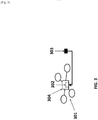
- FIG. 1 shows an example of an unmanned aerial vehicle (UAV) that may be associated with an energy provision station.
- UAV unmanned aerial vehicle
- the UAV may land on or take off from the energy provision station.
- An energy provision system 100 may be provided in accordance with an embodiment of the invention.
- the energy provision system may comprise a UAV 101 and an energy provision station 102.
- the UAV may be adapted to identify and communicate with the energy provision station.
- any description herein of a UAV 101 may apply to any type of movable object.
- the description of a UAV may apply to any type of unmanned movable object (e.g., which may traverse the air, land, water, or space).
- the UAV may be capable of responding to commands from a remote controller.
- the remote controller may be not connected to the UAV, the remote controller may communicate with the UAV wirelessly from a distance.
- the UAV may be capable of operating autonomously or semi-autonomously.
- the UAV may be capable of following a set of pre-programmed instructions.
- the UAV may operate semi-autonomously by responding to one or more commands from a remote controller while otherwise operating autonomously. For instance, one or more commands from a remote controller may initiate a sequence of autonomous or semi-autonomous actions by the UAV in accordance with one or more parameters.
- the UAV 101 may be an aerial vehicle.
- the UAV may have one or more propulsion units that may permit the UAV to move about in the air.
- the one or more propulsion units may enable the UAV to move about one or more, two or more, three or more, four or more, five or more, six or more degrees of freedom.
- the UAV may be able to rotate about one, two, three or more axes of rotation.
- the axes of rotation may be orthogonal to one another.
- the axes of rotation may remain orthogonal to one another throughout the course of the UAV's flight.
- the axes of rotation may include a pitch axis, roll axis, and/or yaw axis.
- the UAV may be able to move along one or more dimensions.
- the UAV may be able to move upwards due to the lift generated by one or more rotors.
- the UAV may be capable of moving along a Z axis (which may be up relative to the UAV orientation), an X axis, and/or a Y axis (which may be lateral).
- the UAV may be capable of moving along one, two, or three axes that may be orthogonal to one another.
- the UAV 101 may be a rotorcraft.
- the UAV may be a multi-rotor craft that may include a plurality of rotors.
- the plurality or rotors may be capable of rotating to generate lift for the UAV.
- the rotors may be propulsion units that may enable the UAV to move about freely through the air.
- the rotors may rotate at the same rate and/or may generate the same amount of lift or thrust.
- the rotors may optionally rotate at varying rates, which may generate different amounts of lift or thrust and/or permit the UAV to rotate.
- one, two, three, four, five, six, seven, eight, nine, ten, or more rotors may be provided on a UAV.
- the rotors may be arranged so that their axes of rotation are parallel to one another. In some instances, the rotors may have axes of rotation that are at any angle relative to one another, which may affect the motion of the UAV.
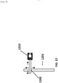
- FIG. 2 shows a detailed view of a possible embodiment of an energy provision system comprising the UAV 201 and the energy provision station 202.
- the UAV 201 shown in FIG. 2 is an example of a UAV that can be part of the energy provision system.
- the UAV shown may have a plurality of rotors 203.
- the rotors 203 may connect to the body of the UAV 204 which may comprise a control unit, inertial measuring unit (IMU), processor, battery, power source, and/or other sensors.
- the rotors may be connected to the body via one or more arms or extensions that may branch from a central portion of the body.
- one or more arms may extend radially from a central body of the UAV, and may have rotors at or near the ends of the arms.
- the UAV may be situated on a surface of the energy provision station by a landing stand 205.
- the landing stand may be configured to support the weight of the UAV when the UAV is not airborne.
- the landing stand may include one or more extension members that may extend from the UAV.
- the extension members of the landing stand may extend from one or more arms of the UAV, or from a central body of the UAV.
- the extension members of the landing stand may extend from beneath one or more rotors, or near one or more rotors.
- the extension members may extend substantially vertically.
- the energy provision station 202 may be a battery station.
- the energy provision station may be a ground station.
- the energy provision station may be a battery changing station or battery exchange station.
- the energy provision station may be a battery recharging station.
- the energy provision station may be portable.
- the energy provision station may be capable of being carried by a human.
- the energy provision station may be capable of being lifted by a human in one or two hands.
- the energy provision station may be reconfigurable or folded in on itself to become more portable.
- the energy provision station 202 may have a landing area for a UAV 206. Any surface of the energy provision station may be adapted to comprise the landing area. For example, a top surface of the energy provision station may form a landing area.
- one or more platforms may be provided as a landing area for the UAV. The platforms may or may not include any sides, ceilings, or covers.
- the energy provision station 202 may further comprise a battery storage system.
- the battery storage system may be configured to store one or more batteries.
- the battery storage system may charge the one or more stored batteries.
- the battery storage system 207 is shown below the landing area 206.
- Another component of an energy provision station may be a mechanism configured to remove a battery from a UAV and to replace the removed battery with a fully or partially charged battery from the battery storage system.
- a vertical position and/or velocity of the UAV may be controlled by maintaining and/or adjusting output to one or more propulsion units of the UAV. For example, increasing the speed of rotation of one or more rotors of the UAV may aid in causing the UAV to increase in altitude or increase in altitude at a faster rate. Increasing the speed of rotation of the one or more rotors may increase the thrust of the rotors. Decreasing the speed of rotation of one or more rotors of the UAV may aid in causing the UAV to decrease in altitude or decrease in altitude at a faster rate. Decreasing the speed of rotation of the one or more rotors may decrease the thrust of the one or more rotors.
- the output When a UAV is taking off, such as from an energy provision station, the output may be provided to the propulsion units may be increased from its previous landed state. When the UAV is landing, such as on a vehicle, the output provided to the propulsion units may be decreased from its previous flight state.
- the UAV may be configured to take off and/or land on an energy provision station in a substantially vertical manner.
- a lateral position and/or velocity of the UAV may be controlled by maintaining and/ or adjusting output to one or more propulsion units of the UAV.
- the altitude of the UAV and the speed of rotation of one or more rotors of the UAV may affect the lateral movement of the UAV.
- the UAV may be tilted in a particular direction to move in that direction, and the speed of the rotors of the UAV may affect the speed of the lateral movement and/or trajectory of movement.
- Lateral position and/or velocity of the UAV may be controlled by varying or maintaining the speed of rotation of one or more rotors of the UAV.
- the UAV 101 may be of small dimensions.
- the UAV may be capable of being lifted and/or carried by a human.
- the UAV may be capable of being carried by a human in one hand.
- the energy provision station may have a landing area configured to provide a space for the UAV to land.
- the UAV dimensions may optionally not exceed the width of the energy provision station landing area.
- the UAV dimensions may optionally not exceed the length of the energy provision station landing area.
- the UAV 101 may have a greatest dimension (e.g., length, width, height, diagonal, diameter) of no more than 100 cm.
- the greatest dimension may be less than or equal to 1 mm, 5 mm, 1 cm, 3 cm, 5 cm, 10 cm, 12 cm, 15 cm, 20 cm, 25 cm, 30 cm, 35 cm, 40 cm, 45 cm, 50 cm, 55 cm, 60 cm, 65 cm, 70 cm, 75 cm, 80 cm, 85 cm, 90 cm, 95 cm, 100 cm, 110 cm, 120 cm, 130 cm, 140 cm, 150 cm, 160 cm, 170 cm, 180 cm, 190 cm, 200 cm, 220 cm, 250 cm, or 300 cm.
- the greatest dimension of the UAV may be greater than or equal to any of the values described herein.
- the UAV may have a greatest dimension falling within a range between any two of the values described herein.
- the UAV 101 may be lightweight.
- the UAV may weigh less than or equal to 1 mg, 5 mg, 10 mg, 50 mg, 100 mg, 500 mg, 1 g, 2 g, 3 g, 5 g, 7 g, 10 g, 12 g, 15 g, 20 g, 25 g, 30 g, 35 g, 40 g, 45 g, 50 g, 60 g, 70 g, 80 g, 90 g, 100 g, 120 g, 150 g, 200 g, 250 g, 300 g, 350 g, 400 g, 450 g, 500 g, 600 g, 700 g, 800 g, 900 g, 1 kg, 1.1 kg, 1.2 kg, 1.3 kg, 1.4 kg, 1.5 kg, 1.7 kg, 2 kg, 2.2 kg, 2.5 kg, 3 kg, 3.5 kg, 4 kg, 4.5 kg, 5 kg, 5.5 kg, 6 kg, 6.5 kg, 7 kg, 7.5 kg, 8 kg, 8.5 kg, 9 kg,
- One or more components of the UAV may be powered by a battery.
- the entire UAV may be powered by a battery or only a propulsion unit, controller, communication unit, Inertial Measure Unit (IMU), and/or other sensors may be powered by a battery.
- Battery can refer to a single battery or a pack of two or more batteries.
- An example of a battery may include a lithium ion battery, alkaline battery, nickel cadmium battery, lead acid battery, or nickel metal hydride battery.
- the battery may be a disposable or a rechargeable battery. The life time of the battery (i.e.
- the life time may be at least 1 min, 5 min, 10 min, 15 min, 30 min, 45 min, 1 hr, 2 hrs, 3 hrs, 4hrs, 5 hrs, or 10 hrs.
- the battery life may have a duration greater than or equal to any of the values described herein.
- the battery life may have a duration falling within a range between any two of the values described herein.
- a battery may be coupled to the UAV to provide power to the UAV by an electrical connection. Any description herein of a battery may apply to one or more batteries. Any description of a battery may apply to a battery pack, and vice versa, where a battery pack may include one or more batteries. Batteries may be connected in series, in parallel, or any combination thereof. An electrical connection between a UAV and a battery or a component of a UAV and a battery may be provided. An electrical contact of a battery may contact an electrical contact of the UAV.
- the UAV may have recessed region on its body to house the battery.
- FIG. 3 shows an example of a UAV 301 with a recessed region 302 configured to house a battery 303 in the body of the UAV 304.
- the recessed region may have equal or non-equal length, width and depth. Possible values for the length, width, and depth of the recessed region may be at least 1 mm, 5 mm, 1 cm, 3 cm, 5 cm, 10 cm, 12 cm, 15 cm, 20 cm, 25 cm, 30 cm, 35 cm, 40 cm, 45 cm, 50 cm, 55 cm, 60 cm, 65 cm, 70 cm, 75 cm, 80 cm, 85 cm, 90 cm, 95 cm, or 100 cm.
- the recessed region may be configured to hold one or more batteries.
- the recessed region may contain electrical contacts to connect the battery to the UAV power system. Additionally the recessed region may comprise electrical connections to communicate with a sensor which may dynamically read and record the remaining charge on the battery.
- the recessed region may include one or more electrical contacts that may be in electrical contact with the battery onboard the UAV. The electrical contacts may be coupled to the battery while it is inside of the recessed region, if the battery is removed the contact may be disconnected from the battery.
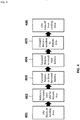
- the method of swapping of a battery on a UAV by an energy provision station may include the steps of landing the UAV at the energy provision station, removing an on-board battery from the UAV using a component of the energy provision station, exchanging the on-board battery for another battery provided at the energy provision station, coupling the other battery to the UAV, and causing the UAV to take off of from the energy provision station. All or any one of these steps may be fully or partially automated.
- the steps described in FIG. 4 may occur in the order shown, or the steps may occur out of order.
- the method of battery exchange may include all of the steps listed or a subset of the steps listed.
- the UAV may land on a landing area on the energy provision station 401.
- the depleted battery may be removed by a mechanism on the energy provision station.
- the energy provision station may employ a robotic arm to remove the depleted battery from the UAV 402.
- the depleted battery may be stored in a battery storage unit.
- the battery storage unit may comprise a container for the battery, the container may include electrical connections configured to provide charge to the battery.
- An example of a battery storage area may be a carousel on board the energy provision station 403.
- the carousel may be configured such that it may rotate to carry away the depleted battery and place a charged battery in line with a mechanism configured to install the charged battery on the UAV.
- a mechanism may be a robotic arm 404.
- the robot arm that transports the charged battery to the UAV may be the same robotic arm that removes the depleted battery from the UAV.
- the robotic arm After rotation of the carousel, the robotic arm may install the charged battery in the UAV 405.
- the final step may be for the UAV to take off from the landing area with a fully charged battery on board 406.
- the UAV may communicate with an energy provision station.
- the UAV may transmit information to the energy provision station regarding the state of the battery on board the UAV, the current flight conditions, time or distance remaining on current mission, distance to the next energy provision station, battery specifications, state of battery charge (e.g. remaining power estimate), battery temperature, UAV specifications, or flight plan (e.g. estimated arrival at the next energy provision station and/or estimated time of arrival at final destination).
- the UAV may also communicate information to the energy provision station describing the state of the UAV.
- the UAV may communicate information describing system failures or descriptions of damaged parts (e.g. broken propeller) to the energy provision station.
- the UAV may carry a payload.
- the UAV may communicate the weight of the pay load. Additionally the UAV may communicate to the energy provision station when in the flight plan the UAV plans to load or unload the payload.
- the energy provision station may communicate information to the UAV.
- the energy provision station may inform the UAV as to whether or not it is available to provide the UAV with a charged battery. For example, the energy provision station may be depleted of charged batteries or the energy provision station may be occupied by another UAV, in these instances the energy provision station may instruct the UAV to continue on to the next closest energy provision station. In another case the energy provision station may instruct the UAV to continue to the next closest energy provision station in the case of adverse weather conditions (e.g. wind, rain, snow) or a mechanical or electrical failure on the energy provision station.
- the energy provision station may transmit updated route instruction to the UAV to direct the UAV to the next energy provision station. Alternatively, when the energy provision station is available for charging, the energy provision station may instruct the UAV to land on the station.
- the UAV may be directed to land at the energy provision station.
- An instruction to land on the energy provision may be transmitted by the energy provision station.
- the UAV may be directed to land at the energy provision station.
- UAV operating parameters such as expected rate of energy consumption, or current rate of energy consumption, may be taken into account. For example, a UAV may be flying in a relatively 'low power' mode where one or more of the sensors are not in operation, but it may be anticipated that the UAV may employ more of the sensors later in flight.
- the anticipated increased rate of energy consumption may affect the anticipated rate of battery charge depletion, which may be taken into account when determining whether the UAV needs to land at the energy provision station.
- the UAV may be directed to land at the energy provision station if the state of charge of the battery falls beneath a predetermined threshold.
- the UAV may be instructed to land on the energy provision station if a mechanical or electrically system on board the UAV is in need of repair (e.g. broken propeller, short in electrical component).
- Landing on an energy provision station may be predetermined by a UAVs flight plan. For example a UAV instructed to travel from point A to point B may have a planned stop at an energy provision station halfway between point A and point B. The decision to land at an energy provision station as part of the flight plan may be contingent on the energy provision station being unoccupied. For example, energy provision station halfway between point A and point B is occupied by another UAV the UAV may alter its flight plan to continue on to the next energy provision station as long as the power remaining on the battery is sufficient to reach the next energy provision station.
- the UAVs may be entered into a queue.
- the UAVs in the queue may wait for access to the energy provision station.
- the UAVs in the queue may be ordered such that UAVs in urgent need of aid from the energy provision station (e.g. those with mechanical failures and/or critically low batteries) may be attended to before UAVs in less need of aid from the energy provisions station.
- the UAVs in the queue may be ranked by layers or they may be ranked based on a system of weighing various factors.
- the primary layer may be the mechanical or electrical status of the UAV
- the secondary layer may be the energy remaining on the UAV's battery
- the tertiary layer may be how long the UAV has been waiting for aid from the energy provision station.
- the layers may be used to rank the UAVs in the queue.
- factors such as the mechanical or electrical status of components of the UAV, the power storage remaining on the battery of the UAV, and how long the UAV has been waiting in the queue may be considered.
- a weighted average (e.g. a score) of the aforementioned factors may be used to determine a UAVs location in the queue.
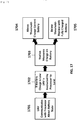
- An interaction between a UAV and an energy provision station may follow the procedure outline in FIG. 21 .
- the interaction may include all the steps shown in FIG. 21 or a subset of these steps, the steps may occur in the order shown or in an alternate order.
- the UAV may detect the energy provision station 2101.
- the detection of the energy provision station by the UAV may be in response to a known GPS signal indicating the location of the energy provision station, a visual detection, or an audio detection.
- the UAV may exchange information with the energy provision station 2102, for example the UAV may communicate information regarding the state of the UAV and/or the battery.
- the energy provision station may provide the UAV with information regarding the state of the energy provision station.
- the UAV may determine if it should land on the energy provision station or continue on its flight path 2103. If the UAV decides to land on the energy provision station it may enter a queue of UAVs waiting to land on the energy provision station 2104. When the UAV is the first UAV in the queue and the energy provision station is unoccupied by another UAV the UAV may land on the energy provision station 2105.
- the UAV may identify an energy provision station landing area by sensing a marking, for example a marking may be a raised pattern, a recessed pattern, an image, a symbol, a decal, a 1-D, 2-D, or 3-D barcode, a QR code, or lights visible on the energy provision station landing area.
- the marking may indicate that the energy provision station has charged batteries available.
- the marking may be a light or pattern of lights, the lights may be turned on only when the energy provision station has charged batteries available.
- the UAV may take off and land on the energy provision station landing area vertically.
- the landing area may comprise recessed mating features to guide the UAV during landing.
- the mating features may decrease the need for accuracy when landing the UAV on the landing area.
- the recessed features may be configured to mate with a wide variety of UAVs, alternatively the mating features may be specific to a single UAV manufacturer, single UAV fleet, or one particular UAV.
- Communication between the UAV and the energy provision station may be used to get the UAV to the general location of the energy provision station. Communication between the UAV and the energy provision station may occur wirelessly.
- the UAV may employ GPS or other locating software to locate the energy provision station. The GPS or other location techniques can be used to get the UAV to the vicinity of the energy provision station.
- the wireless communications may get the UAV within range to sense one or more portions of the energy provision stations. For instance, the UAV may be brought into a line-of-sight of the energy provision station.
- the landing area marker or markers may aid in further pinpointing the location of the energy provision station.
- the marker may serve as a confirmation of the energy provision station on which the UAV may land.
- the markers may also differentiate the energy provision station or a landing area of an energy provision station from other objects or regions.
- the marker may be useful for indicating a landing position of the UAV on the energy provision station.
- the marker may be used as a fiducial marker, which may aid the UAV in navigating to a proper landing position on the energy provision station.
- multiple markers may be provided which may aid the UAV in landing in a desired position.
- it may also be desirable for a UAV to have a particular orientation when docking with the energy provision station.
- the marker may include an asymmetric image or code that may be discernible by the UAV.
- the fiducial may be indicative of the orientation of the energy provision station relative to the UAV. Thus, the UAV may be able to orient itself properly when landing on the energy provision station.
- the marker may also be indicative of the distance of the energy provision station relative to the UAV. This may be used separate from or in combination with one or more other sensors of the UAV to determine the altitude of the UAV. For example, if the size of the fiducial marker is known, the distance from the UAV to the marker may be gauged depending on the size of the marker showing up in the sensors of the UAV.
- the marker may be provided at a particular location relative to a desired landing spot of the UAV on the energy provision station. This may be at a particular location relative to a desired landing spot on a landing area of an energy provision station.
- the UAV may be capable of landing on the landing area with great precision.
- the marker may help guide the UAV to the exact desired spot. For instance, the marker may be located 10 cm in front of the center of the desired landing point of the UAV.
- the UAV may use the marker to guide the UAV to the exact landing spot.
- multiple markers may be provided. The desired landing spot may fall between the multiple markers.
- the UAV may use the markers to help orient the UAV and/or position its landing between the markers. Distance between the markers may aid the UAV in gaging the distance of the UAV to the landing area.
- the marker may be provided anywhere on the energy provision station or landing area.
- the marker may be placed in a location such that it is easily discernable from above.
- the marker may be provided on an exterior surface of the energy provision station.
- the marker may include a wireless signal being emitted by an energy provision station. The origin of the signal may be from outside the energy provision station or inside the energy provision station. Alternatively the energy provision station may emit IR and/or UV light, radio, or audio signals.
- the marker may be positioned near where the UAV may dock with the energy provision station.
- the marker may be positioned less than about 100 cm, 90 cm, 80 cm, 75 cm, 70 cm, 65 cm, 60 cm, 55 cm, 50 cm, 45 cm, 40 cm, 35 cm, 30 cm, 25 cm, 20 cm, 15 cm, 12 cm, 10 cm, 8 cm, 7 cm, 6 cm, 5 cm, 4 cm, 3 cm, 2 cm, or 1 cm from where the UAV lands on the energy provision station.
- Data pertaining to the detected marker may be provided to one or more processors.
- the processors may be on board the UAV. Based on the detected information about the detected marker, the processors may, individually or collectively, generate a command signal.
- the command signal may drive the propulsion units of the UAV.
- the propulsion units may be driven to cause the UAV to land on the energy provision station with the detected marker, when the detected marker is determined to belong to the energy provision station.
- the detected marker may indicate the state of charge of the stored batteries at the energy provision station. For example if the energy provision station has a fully charged battery available the detected marker may result in a command from the processor to land the UAV.
- a UAV may be able to land in an autonomous or semi-autonomous fashion in response to a detected marker.
- the UAV may be capable of landing without receiving any commands or manual input from a user.
- sensors on board the UAV may be used to detect the marker, and processing may occur on-board the UAV.
- the UAV may be capable of landing itself on the energy provision station without requiring further guidance or information from the energy provision station once the UAV has confirmed that the marker belongs to the energy provision station.
- An energy provision station may include a marker, and one or more coupling connection components.
- the energy provision station may send information about its location to a UAV.
- the energy provision station may have a location unit capable of determining positional information.
- An energy provision station may receive information from the UAV about the location of the UAV and the state of the battery on board the UAV. For example, coordinate information, such as GPS coordinates, for the UAV may be provided to the energy provision station. In another example the UAV may communicate the remaining charge percentage of the battery currently in use on the UAV.
- the energy provision station may have a communication unit capable of communicating with the UAV.
- the energy provision station may have a processor capable of identifying and/or calculating a location of the UAV.
- the energy provision station may have a processor capable of identifying and/or calculating a location of the next nearest battery exchange station. For example a UAV may communicate to an energy provision station that the battery currently on board the UAV has a remaining charge percentage of 18%, the processor at the energy provision station may determine the distance to the next battery exchange station in the UAV's flight path to determine if the UAV should stop for recharging or continue to the next energy provision station.
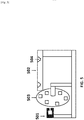
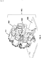
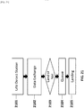
- FIG. 5 shows a possible embodiment of an energy provision station.
- the energy provision station may have three basic components: a battery replacement member 501, a UAV landing area 502, and a battery storage unit 503.
- the battery replacement member may be a mechanical arm 501 that may be configured to remove a battery from a UAV and/or to place a charged battery in the UAV.
- the mechanical arm may both remove the battery from the UAV and place a charged battery in the UAV.
- different mechanical components may be used to remove the battery form the UAV and to place a charged battery in the UAV.
- the mechanical arm may have at least 1, 2, 3, 4, 5, or 6 degrees of freedom.
- the mechanical arm may move autonomously or semi autonomously.
- the UAV landing 502 area may comprise markers that may be uniquely recognized by an approaching UAV.
- the landing area may comprise a passive landing guide 504.
- the passive landing guides may be configured to interact with a component of a UAV as it lands to guide the UAV to a final resting position.
- the UAV may include a landing stand that may fit into a passive landing guide and be guided to the final resting position.
- the UAV may include a surface upon which the UAV may land. The UAV may rest on the surface, or all or a majority of the weight of the UAV may be borne by the passive landing guides.
- the battery storage unit 503 may store a plurality of batteries.
- the battery storage unit may simultaneously store and charge the stored batteries.
- the battery storage unit may move the batteries relative to each other.
- the battery storage unit may move the batteries relative to the UAV landing area and/or a UAV on the landing area. Multiple batteries may be moved simultaneously using the battery storage unit.
- a fully charged battery may be in a location such that the mechanical arm 501 may install the battery on the UAV.
- a mechanical arm may bring a depleted battery from a UAV to a particular location relative to the battery storage unit.
- the battery storage unit may accept the depleted battery.
- the battery storage unit may cause movement of the batteries so that a different battery (e.g., fully charged battery) is moved to the location where the depleted battery was accepted.
- the mechanical arm may receive the different battery.
- the movement may include rotation of the battery storage unit about an axis.
- the UAV landing area of the energy provision station may be configured to comprise a passive landing guide.
- the UAV may have at least one protruding feature which may mate with a corresponding cavity on the landing area of the energy provision station.
- the UAV may have four round conical stoppers which may fit inside of four round conical indentations on the landing area.
- the protruding feature may be a launch stand configured to bear a weight of the UAV.
- FIG. 6 shows an example of a UAV 601 landing on an energy provision station 602 such that the conical stoppers 603 mate with the conical indentations 604 on the landing area.
- the stopper and the indentation may comprise a variety of other mating shapes.
- the stopper may be made from rubber, plastic, metal, wood, or composite.
- the stopper may have a height and width of less than or equal to 1 mm, 5 mm, 1 cm, 3 cm, 5 cm, 10 cm, 12 cm, 15 cm, 20 cm, 25 cm, 30 cm, 35 cm, 40 cm, 45 cm, 50 cm, 55 cm, 60 cm, 65 cm, 70 cm, 75 cm, 80 cm, 85 cm, 90 cm, 95 cm, or 100 cm.
- the indentations may have corresponding dimensions such that they are adapted to fit the stopper.
- the UAV may comprise a protrusion that does not identically mate with an indentation on the landing area.
- the UAV may have a feature protruding from the bottom of the UAV designed such that it is smaller than the indentation on the landing area.
- the protruding feature on the bottom of the UAV may fit into the indentation.
- the UAV may have a protruding rod and the landing area may have a conical indentation. Upon landing, the protruding rod may be funneled into the bottom of the conical indentation.
- FIG. 7 shows a detailed side (left) and top (right) view of a possible embodiment of the landing area 701 with a docked UAV 702 showing a protruding rod fitting inside of a conical indentation 703.
- the protruding rod may be a landing stand of the UAV.
- the protruding rods may bear the weight of the UAV while the UAV is resting on the landing area.
- the indentations may bear the weight of the protruding rods and/or the UAV while the UAV is resting on the landing area.
- the passive landing guide may reduce the need for high precision control of the UAV landing procedure.
- the passive landing guide may be configured such that the UAV may corrected if it approaches the station in such a way that it is off set from the desired landing location.
- the passive landing guide may bring the UAV into the desired location with the aid of gravity.
- FIG. 8 shows an example of how the passive landing guide may correct the UAV if it approaches the landing location with an off set.
- the UAV approaches the landing guide off set to the right (1).
- the UAV partially mates with the passive landing guide, after contact with the landing guide the UAV may slide downward into the correct location (2). This process of correcting the UAV to the correct landing location may rely on gravity and may not introduce a need for a moving part or additional mechanism.
- the UAV may locate the energy provision station using real time kinematics (RTK).
- RTK location methods may require both the UAV and the energy provision station to emit a satellite signal, for example a GPS signal.
- RTK may allow the UAV to locate the correct docking location on the energy provision station with accuracy within 10 cm, 9 cm, 8 cm, 7 cm, 6 cm, 5 cm, 4 cm, 3 cm, 2 cm, 1 cm, or less than 1 cm.
- the energy provision station may comprise a battery storage system.
- the battery storage system may be a carousel.
- the batteries in the battery storage system may be fully charged, partially charged, or depleted of charge.
- the batteries may be connected to a source of electrical power to restore them from a depleted or partially charged state to a state of full charge.
- the batteries may be identical in size, shape, and battery type (e.g. lithium ion, nickel cadmium). Alternatively, different battery sizes, shapes or types may be accommodated.
- the battery storage system may be configured to store at least 2, 3, 4, 5, 6, 7, 8, 9, 10, 15, 20, 25, 30, 35, 40, 45, or 50 batteries. In some embodiments, the battery system may store less than any of the number of batteries described.
- the battery system may store a number of batteries falling within a range between any two of the values described.
- the battery storage system may comprise individual ports for each battery.
- the ports may be movable relative to each other. Multiple ports may move simultaneously.
- the ports may rotate about an axis clockwise, counterclockwise, or in both rotational directions.
- the axis of rotation may be horizontally oriented (e.g., parallel to an underlying surface or ground, perpendicular to the direction of gravity), or vertically oriented (e.g., perpendicular to an underlying surface or ground, parallel to the direction of gravity).
- the ports may translate in any direction. Optionally, they may translate and rotate simultaneously.
- the ports may have electrical connections which may connect to the processor to meter the charge available on the battery or they may connect to an electricity source to charge the battery.
- the electricity source may be on board or off board the energy provision station.
- the electricity source may be an electric generator, a rechargeable battery, a disposable battery, or a connection to a distributed power line.
- the ports may charge the batteries inductively (wirelessly).
- Multiple charging interfaces may be accommodated by the energy provision station such that the station can charge a variety of battery types and voltages.
- the energy provision station may be permanently installed or it may be temporary. In the case of a temporary energy provision station, the station may be configured to be portable and may be carried away by a user.
- the stored batteries may move relative to each other.
- the batteries may move relative to each other in a carousel.
- FIG. 9 shows an example of a possible battery carousel 901 for use in the battery storage system.
- the carousel shown in FIG. 9 can hold 8 batteries 902.
- a carousel may be chosen such that it can hold at least 4, 5, 6, 7, 8, 9, 10, 15, 20, 25, 30, 35, 40, 45, or 50 batteries.
- the carousel may be configured to hold fewer batteries than values described herein or the carousel may be configured to hold a number of batteries within a range between any two of the values described herein.
- the batteries in the carousel may be identical in size, shape, voltage, and composition. Each battery may be stored in a compartment 903.
- the battery may slide in and out of the compartment during installation and removal from a UAV. For instance, the battery may slide and out laterally via a side opening of the compartment. The battery may be able to lock into the compartment during storage.
- a battery may be charged on board the UAV or a battery may be charged in the storage compartment in the battery storage system.
- the battery storage compartment may be configured to provide electrical charge to the battery through electrical contacts.
- FIG. 10 shows an example of a possible battery storage compartment 1001 with electrical contacts configured 1002 to provide charge to a battery.
- the electrical contacts may be connected to a power source 1003 off board the battery.
- the battery may be simultaneously connected to a meter to determine when the battery charge is complete.
- the container may provide only enough electrical power to charge or partially charge the stored battery.
- the battery storage compartment may be part of a carousel or other battery storage unit.
- the battery storage compartment may be movable relative to other portions of an energy provision station.
- the battery carousel 901 may rotate about a shaft 904.
- the carousel may rotate counter-clockwise or clockwise.
- the carousel may be able to rotate in either both directions or only one direction.
- the rotation may be driven by an actuator, such as a motor.
- the actuator may receive a command signal from a controller on-board or off-board the energy provision station that controls movement of the battery storage system.
- the carousel may be configured perpendicular to the base of the energy provision station 905.
- the length of the shaft may be parallel to the base of the energy provision station.
- the carousel may be oriented parallel to the base of the base of the energy provision station or at any other angle relative to the base of the energy provision station.
- FIG. 11 shows a possible embodiment of the complete energy provision station.
- FIG. 11 shows that the landing area 1101 may be placed on top of the carousel 1102.
- the battery carousel may be partially or completely enclosed by a housing.
- the battery storage system may be driven by an actuator to rotate.
- the battery storage system may include a steering lock, so that the battery storage can be locked when needed to prevent it from rotating and fix it at the desired position.
- the steering lock may be located at the bottom of the carousel, the top, or along the sides.
- the energy provision station may comprise a mechanism configured to move the batteries.
- the mechanism may be an automated battery replacement member.
- the mechanism may be a robotic arm, actuator, or a pulley.
- the mechanism may be a mechanical elevator.
- the mechanism configured to move the batteries may be a robotic arm.
- the robotic arm may have at least 2 degrees of freedom.
- a robotic arm having 2 degrees of freedom may be able to move (1) horizontally and (2) vertically.
- the up and down motion may be achieved by a linear actuator, or any other type of actuator.
- the horizontal motion may be achieved by a rack and pinion mechanism driven by an actuator.
- the horizontal motion may be a linear motion.
- the horizontal actuator may be installed on a vertical motion actuator such that the robotic arm may vertically and then horizontally.
- the robotic arm may permit a battery to move vertically and/or horizontally without causing any rotation of the battery.
- the battery may be translated without being rotated by the robotic arm.
- the robotic arm may permit rotation or change in orientation of the
- the mechanism configured to move the batteries may comprise an end member adapted to attach to the battery to be removed from the UAV.
- the end member may be a magnet, a hook, or a suction device.
- the end member may be a clamp.
- the clamp may be installed on the forward and back module such that the robotic arm may move forward or back and then clamp or release a battery.
- the clamping motion may be driven by a steering gear and linkage system.
- the clamp may attach to the battery by compressing the battery between two sides of the clamp with sufficient pressure to hold the battery, alternatively the battery and the clamp may comprise complimentary mating features.
- An example of a complimentary mating feature may be a peg and a hole. Similar mating features may be used to hold the batteries in the battery storage unit.
- FIG. 12 shows a schematic of a possible robotic arm.
- the robotic arm may be raised from the base of the energy provision station by a post 1201.
- the robotic arm may be configured to move up and down along the post.
- the robotic arm may move up and down autonomously or semi autonomously.
- the robotic arm may be attached to the post via a second rail 1202 on which it may be configured to move forward and back.
- the robotic arm may move forward and back autonomously or semi autonomously.
- the third feature of the robotic arm may be a terminal clamp 1203.
- the terminal clamp may have a c shaped opening which may open towards the recessed battery of a docked UAV.
- the terminal clamp may open and close, it may be able to attach to a battery.
- FIG. 13 shows a detailed view of an embodiment of a robotic arm.
- the example shown in FIG. 13 depicts a clamp 1301 mounted on a rack and pinion mechanism 1302.
- the clamp may be oriented horizontally, so that ends of the clamp grid onto the sides of the battery.
- the clamp may include a portion in the rear 1303 that may rotate, thereby causing the ends of the clamp 1304 to move closer together or further apart.
- the rear control portion may rotate with aid of an actuator, that may operate in response to a command signal from a controller on-board or off-board the energy provision station.
- FIG. 14 provides a complete view of the robotic arm including the clamp 1401 mounted on a rack and pinion mechanism 1402.
- the assembly comprising the clamp and rack and pinion supported on an actuator 1403 configured to move the assembly in a vertical up and down path.
- the entire assembly may also be rotated clockwise or counterclockwise about a pivot point 1404.
- the pivot point may be oriented so that the entire assembly may rotate about a vertical axis of rotation. This may permit the assembly to change orientation.
- the assembly may rotate about a limited range.
- the robotic arm may not rotate about an axis, it may be fixed rotationally.
- the robotic arm may be employed in the landing of the UAV on the energy provision station instead of or in addition to swapping the battery on board the UAV.
- the UAV may approach the energy provision station, when the UAV is sufficiently close to the energy provision station the robotic arm may attach to the UAV and place the UAV in a preferred location for battery swapping on board the energy provision station.
- the robotic arm may detect the UAV using a sensor on the robotic arm, for example, the sensor may be a vision sensor, a motion sensor, an audio sensor, or any other sensor configured to detect a UAV in proximity to the robotic arm.
- the robotic arm may attach to the body of the detected UAV, the robotic arm may attach to the UAV using the terminal c shaped clamp. Alternatively the robotic arm may attach to the UAV magnetically, with Velcro, or by achieving positive mating between complimentary mating features on the UAV and the robotic arm.
- the UAV may turn off its rotors after being sized or grasped by the robotic arm.
- the robotic arm may be specifically configured to seize the UAV from the air to place the UAV on the energy provision station.
- the robotic arm may telescope vertically from the energy provision station such that it may be in the proximity of a UAV approaching the energy provision station.
- the robotic arm may be raised at least 6 inches, 12 inches, 24 inches, 36 inches, 48 inches or 60 inches above the landing area of the energy provision station.
- the robotic arm may be raised above the energy provision station to detect an approaching UAV using a visual sensor. Additionally the robotic arm may rotate about an axis such that it can turn to face an incoming UAV.
- the robotic arm may move vertically, horizontally, and rotationally about a vertical and/or horizontal axis.
- the robotic arm may be raised above the energy provision station after the GPS or RTK system on the energy provision station has detected a UAV in proximity of the energy provision station. Once the robotic arm is raised it may grasp an incoming UAV and then lower to the level of the landing area to place the UAV on the landing area of the energy provision station.
- FIG. 15 shows the complete energy provision station assembly including the landing area 1501, battery storage system 1502, and the robotic arm 1503.
- the battery storage system is below the landing area and the robotic arm is adjacent to the battery storage system and landing area such that it is adapted to access both regions of the energy provision station.
- the robotic arm may move vertically between the UAV landing area and the battery storage system while performing a battery switching procedure.
- a notch or opening 1504 may be provided on the UAV landing area that may permit the robotic arm and/or battery to traverse the region between the UAV landing area and the battery storage system.
- the energy provision station may provide charge to the battery onboard the UAV.
- the energy provision station may provide charge to battery on board the UAV without removing the battery from the recessed region in the body of the UAV. Charge may be provided to the battery on board the UAV from a power source on board or off board the energy provision station.
- FIG. 16 shows an example of a battery 1601 on board a UAV 1602 receiving charge from an energy provision station 1603.
- a power source 1604 which may be located on board or off board the energy provision station 1603, provides power to the battery 1601 by means of an electrical pathway 1605.
- the electrical pathway may include an electrical connection 1606 on the landing area 1607. Alternatively, the electrical pathway may take any path between a battery on-board the UAV and the power source.
- the electrical connection 1606 may be recessed in the landing area 1607.
- the electrical connection 1606 may be configured to move out of the recession and mate with a battery when instructed by a processor to provide charge to the battery on board the UAV.
- the electrical connection may be provided separately from the landing area and may or may not contact the landing area.
- the UAV may include an electrical contact that may connect with a corresponding electrical contact for a charging apparatus that connects the power source to the battery.
- a UAV may locate an energy provision station from the air. Upon locating the energy provision station the UAV may communicate with the energy provision station to determine if the UAV should approach and land on the energy provision station to initiate a battery switching procedure.
- a battery life reloading procedure may initiate when a UAV docks on the landing area of an energy provision station. Reloading battery life on a UAV may include increasing the overall battery state of charge for the UAV.
- This may include (1) recharging the existing battery while the battery is on-board the UAV, (2) removing the existing battery from the UAV, recharging the existing battery off-board the UAV, and coupling the existing battery back with the UAV, or (3) removing the existing battery from the UAV, taking a new battery with a higher state of charge, and coupling the new battery with the UAV.
- the UAV docked on the landing area may communicate with a processor on board the energy provision station.
- the UAV may communicate remotely with a processor off board the energy provision station.
- the processor may determine the remaining charge on the battery currently in use on the UAV by communicating with a sensor in contact with the battery. The remaining charge on the battery may be sensed by a voltmeter.
- the processor may initiate a response which may include swapping the battery for a fully charged battery from the storage system or charging the current battery.
- the decision to charge or swap the battery onboard the UAV may be based on a threshold percentage of remaining charge.
- the threshold value may be 50%, 40%, 30%, 20%, 10%, or 5% remaining charge.
- the threshold may be fixed, or it may be variable as a function of battery age, battery type, flight conditions, ambient temperature, or distance to the next energy provision station. After determining an optimal response the battery swap or charge may take place at the energy provision station.
- the processor may indicate that the UAV may take off from the landing area.
- FIG. 17 shows a flow chart outlining a decision process carried out by one or more processors, individually or collectively, when a UAV approaches a landing area.
- the UAV may communicate with energy provision station.
- the UAV may communicate variables such as flight time, flight distance, time since last charge, or distance remaining on mission to the energy provision station 1701.
- the processors which may be on-board or off-board the energy provision station, may instruct the UAV to land on the energy provision station for further assessment 1702.
- the energy provision station may measure the remaining charge on the battery 1703. If the charge is above a pre-determined threshold the energy provision station may provide a charge to the battery currently on board the UAV 1704. If the battery is below a threshold charge percentage the energy provision station may initiate a battery switching procedure 1705 to replace the battery on board the UAV with a fully or partially charged battery from the battery storage system.
- Instruction to swap or charge the battery on board the UAV may be based entirely on the remaining charge on the battery relative to a pre-determined threshold value or the instructions may be based on one or more other factors.
- the current charge on the batteries in the battery storage system may influence the instructions.
- the number of available batteries in the battery storage may influence the instructions. If no batteries are available, then the battery may be charged on-board, regardless of state of charge. If only a single battery is available, the state of charge of the on-board battery may be compared with the single battery provided by the battery storage system.
- the battery storage battery charge may affect the instruction to swap or charge the battery such that if the energy provision station has only partially charged batteries in the storage system the processor may give the instruction to charge the battery on board the UAV rather than replacing the battery with a partially charged battery.
- the time required to swap the battery may be considered in comparison to the time required to charge the battery.
- a decision to swap the battery or charge the battery may be chosen such that the required time is optimized.
- Other factors that may influence the outcome of the instruction from the processor may include the number of other UAV's detected in the vicinity by the energy provision station, the mission of the UAV landed on the energy provision station, and/ or the current flight conditions (e.g. head wind, tail wind, temperature).
- the battery switching procedure may employ the robotic arm mechanism.
- the first step in the procedure may be for the robotic arm to move vertically so that is may be in line with a recessed battery receptacle which may be the location of the battery to be removed from the UAV.
- the robotic arm may move horizontally to approach the battery to be removed from the UAV.
- the clamp may open and close to attach to the battery.
- the arm may retreat horizontally from the UAV and move vertically to be in line with an empty storage receptacle in the battery storage system.
- the robotic arm may place the depleted battery removed from the UAV into the empty storage receptacle in the battery storage system.
- the battery storage system may rotate so that a charged or partially charged battery is in line with the robotic arm.
- the robotic arm may repeat the steps used to remove the battery from the UAV in order to remove the charged or partially charged battery from the battery storage system.
- the robotic arm may move vertically to be in line with the UAV recessed battery receptacle.
- the robotic arm may then move horizontally to push the charged or partially charged battery into the recessed battery onboard the UAV.
- the robotic arm may then release the clamp on the battery and retreat from the UAV. After the robotic arm retreats the UAV may take off vertically from the landing area and continue its mission.
- any description herein of an aerial vehicle such as a UAV, may apply to and be used for any movable object.
- Any description herein of an aerial vehicle may apply specifically to UAVs.
- a movable object of the present invention can be configured to move within any suitable environment, such as in air (e.g., a fixed-wing aircraft, a rotary-wing aircraft, or an aircraft having neither fixed wings nor rotary wings), in water (e.g., a ship or a submarine), on ground (e.g., a motor vehicle, such as a car, truck, bus, van, motorcycle, bicycle; a movable structure or frame such as a stick, fishing pole; or a train), under the ground (e.g., a subway), in space (e.g., a spaceplane, a satellite, or a probe), or any combination of these environments.
- the movable object can be a vehicle, such as a vehicle described elsewhere herein.
- the movable object can be carried by a living subject, or take off from a living subject, such as a human or an animal.
- Suitable animals can include avines, canines, felines, equines, bovines, ovines, porcines, delphines, rodents, or insects.
- the movable object may be capable of moving freely within the environment with respect to six degrees of freedom (e.g., three degrees of freedom in translation and three degrees of freedom in rotation). Alternatively, the movement of the movable object can be constrained with respect to one or more degrees of freedom, such as by a predetermined path, track, or orientation.
- the movement can be actuated by any suitable actuation mechanism, such as an engine or a motor.
- the actuation mechanism of the movable object can be powered by any suitable energy source, such as electrical energy, magnetic energy, solar energy, wind energy, gravitational energy, chemical energy, nuclear energy, or any suitable combination thereof.
- the movable object may be self-propelled via a propulsion system, as described elsewhere herein.
- the propulsion system may optionally run on an energy source, such as electrical energy, magnetic energy, solar energy, wind energy, gravitational energy, chemical energy, nuclear energy, or any suitable combination thereof.
- the movable object may be carried by a living being.
- the movable object can be an aerial vehicle.
- aerial vehicles may be fixed-wing aircraft (e.g., airplane, gliders), rotary-wing aircraft (e.g., helicopters, rotorcraft), aircraft having both fixed wings and rotary wings, or aircraft having neither (e.g., blimps, hot air balloons).
- An aerial vehicle can be self-propelled, such as self-propelled through the air.
- a self-propelled aerial vehicle can utilize a propulsion system, such as a propulsion system including one or more engines, motors, wheels, axles, magnets, rotors, propellers, blades, nozzles, or any suitable combination thereof.
- the propulsion system can be used to enable the movable object to take off from a surface, land on a surface, maintain its current position and/or orientation (e.g., hover), change orientation, and/or change position.
- the movable object can be controlled remotely by a user or controlled locally by an occupant within or on the movable object.
- the movable object may be controlled remotely via an occupant within a separate vehicle.
- the movable object is an unmanned movable object, such as a UAV.
- An unmanned movable object, such as a UAV may not have an occupant onboard the movable object.
- the movable object can be controlled by a human or an autonomous control system (e.g., a computer control system), or any suitable combination thereof.
- the movable object can be an autonomous or semi-autonomous robot, such as a robot configured with an artificial intelligence.
- the movable object can have any suitable size and/or dimensions.
- the movable object may be of a size and/or dimensions to have a human occupant within or on the vehicle.
- the movable object may be of size and/or dimensions smaller than that capable of having a human occupant within or on the vehicle.
- the movable object may be of a size and/or dimensions suitable for being lifted or carried by a human.
- the movable object may be larger than a size and/or dimensions suitable for being lifted or carried by a human.
- the movable object may have a maximum dimension (e.g., length, width, height, diameter, diagonal) of less than or equal to about: 2 cm, 5 cm, 10 cm, 50 cm, 1 m, 2 m, 5 m, or 10 m.
- the maximum dimension may be greater than or equal to about: 2 cm, 5 cm, 10 cm, 50 cm, 1 m, 2 m, 5 m, or 10 m.
- the distance between shafts of opposite rotors of the movable object may be less than or equal to about: 2 cm, 5 cm, 10 cm, 50 cm, 1 m, 2 m, 5 m, or 10 m.
- the distance between shafts of opposite rotors may be greater than or equal to about: 2 cm, 5 cm, 10 cm, 50 cm, 1 m, 2 m, 5 m, or 10 m.
- the movable object may have a volume of less than 100 cm x 100 cm x 100 cm, less than 50 cm x 50 cm x 30 cm, or less than 5 cm x 5 cm x 3 cm.
- the total volume of the movable object may be less than or equal to about: 1 cm 3 , 2 cm 3 , 5 cm 3 , 10 cm 3 , 20 cm 3 , 30 cm 3 , 40 cm 3 , 50 cm 3 , 60 cm 3 , 70 cm 3 , 80 cm 3 , 90 cm 3 , 100 cm 3 , 150 cm 3 , 200 cm 3 , 300 cm 3 , 500 cm 3 , 750 cm 3 , 1000 cm 3 , 5000 cm 3 , 10,000 cm 3 , 100,000 cm 3 3, 1 m 3 , or 10 m 3 .
- the total volume of the movable object may be greater than or equal to about: 1 cm 3 , 2 cm 3 , 5 cm 3 , 10 cm 3 , 20 cm 3 , 30 cm 3 , 40 cm 3 , 50 cm 3 , 60 cm 3 , 70 cm 3 , 80 cm 3 , 90 cm 3 , 100 cm 3 , 150 cm 3 , 200 cm 3 , 300 cm 3 , 500 cm 3 , 750 cm 3 , 1000 cm 3 , 5000 cm 3 , 10,000 cm 3 , 100,000 cm 3 , 1 m 3 , or 10 m 3 .
- the movable object may have a footprint (which may refer to the lateral cross-sectional area encompassed by the movable object) less than or equal to about: 32,000 cm 2 , 20,000 cm 2 , 10,000 cm 2 , 1,000 cm 2 , 500 cm 2 , 100 cm 2 , 50 cm 2 , 10 cm 2 , or 5 cm 2 .
- the footprint may be greater than or equal to about: 32,000 cm 2 , 20,000 cm 2 , 10,000 cm 2 , 1,000 cm 2 , 500 cm 2 , 100 cm 2 , 50 cm 2 , 10 cm 2 , or 5 cm 2 .
- the movable object may weigh no more than 1000 kg.
- the weight of the movable object may be less than or equal to about: 1000 kg, 750 kg, 500 kg, 200 kg, 150 kg, 100 kg, 80 kg, 70 kg, 60 kg, 50 kg, 45 kg, 40 kg, 35 kg, 30 kg, 25 kg, 20 kg, 15 kg, 12 kg, 10 kg, 9 kg, 8 kg, 7 kg, 6 kg, 5 kg, 4 kg, 3 kg, 2 kg, 1 kg, 0.5 kg, 0.1 kg, 0.05 kg, or 0.01 kg.
- the weight may be greater than or equal to about: 1000 kg, 750 kg, 500 kg, 200 kg, 150 kg, 100 kg, 80 kg, 70 kg, 60 kg, 50 kg, 45 kg, 40 kg, 35 kg, 30 kg, 25 kg, 20 kg, 15 kg, 12 kg, 10 kg, 9 kg, 8 kg, 7 kg, 6 kg, 5 kg, 4 kg, 3 kg, 2 kg, 1 kg, 0.5 kg, 0.1 kg, 0.05 kg, or 0.01 kg.
- a movable object may be small relative to a load carried by the movable object.
- the load may include a payload and/or a carrier, as described in further detail elsewhere herein.
- a ratio of a movable object weight to a load weight may be greater than, less than, or equal to about 1:1.
- a ratio of a movable object weight to a load weight may be greater than, less than, or equal to about 1:1.
- a ratio of a carrier weight to a load weight may be greater than, less than, or equal to about 1:1.
- the ratio of an movable object weight to a load weight may be less than or equal to: 1:2, 1:3, 1:4, 1:5, 1:10, or even less.
- the ratio of a movable object weight to a load weight can also be greater than or equal to: 2:1, 3:1, 4:1, 5:1, 10:1, or even greater.
- the movable object may have low energy consumption.
- the movable object may use less than about: 5 W/h, 4 W/h, 3 W/h, 2 W/h, 1 W/h, or less.
- a carrier of the movable object may have low energy consumption.
- the carrier may use less than about: 5 W/h, 4 W/h, 3 W/h, 2 W/h, 1 W/h, or less.
- a payload of the movable object may have low energy consumption, such as less than about: 5 W/h, 4 W/h, 3 W/h, 2 W/h, 1 W/h, or less.
- FIG. 18 illustrates an unmanned aerial vehicle (UAV) 1800, in accordance with embodiments of the present invention.
- the UAV may be an example of a movable object as described herein.
- the UAV 1800 can include a propulsion system having four rotors 1802, 1804, 1806, and 1808. Any number of rotors may be provided (e.g., one, two, three, four, five, six, or more).
- the rotors, rotor assemblies, or other propulsion systems of the unmanned aerial vehicle may enable the unmanned aerial vehicle to hover/maintain position, change orientation, and/or change location.
- the distance between shafts of opposite rotors can be any suitable length 410.
- the length 1810 can be less than or equal to 2 m, or less than equal to 5 m. In some embodiments, the length 1810 can be within a range from 40 cm to 1 m, from 10 cm to 2 m, or from 5 cm to 5 m. Any description herein of a UAV may apply to a movable object, such as a movable object of a different type, and vice versa. The UAV may use an assisted takeoff system or method as described herein.
- the movable object can be configured to carry a load.
- the load can include one or more of passengers, cargo, equipment, instruments, and the like.
- the load can be provided within a housing.
- the housing may be separate from a housing of the movable object, or be part of a housing for a movable object.
- the load can be provided with a housing while the movable object does not have a housing.
- portions of the load or the entire load can be provided without a housing.
- the load can be rigidly fixed relative to the movable object.
- the load can be movable relative to the movable object (e.g., translatable or rotatable relative to the movable object).
- the load can include a payload and/or a carrier, as described elsewhere herein.
- the movement of the movable object, carrier, and payload relative to a fixed reference frame (e.g., the surrounding environment) and/or to each other, can be controlled by a terminal.
- the terminal can be a remote control device at a location distant from the movable object, carrier, and/or payload.
- the terminal can be disposed on or affixed to a support platform.
- the terminal can be a handheld or wearable device.
- the terminal can include a smartphone, tablet, laptop, computer, glasses, gloves, helmet, microphone, or suitable combinations thereof.
- the terminal can include a user interface, such as a keyboard, mouse, joystick, touchscreen, or display. Any suitable user input can be used to interact with the terminal, such as manually entered commands, voice control, gesture control, or position control (e.g., via a movement, location or tilt of the terminal).
- the terminal can be used to control any suitable state of the movable object, carrier, and/or payload.
- the terminal can be used to control the position and/or orientation of the movable object, carrier, and/or payload relative to a fixed reference from and/or to each other.
- the terminal can be used to control individual elements of the movable object, carrier, and/or payload, such as the actuation assembly of the carrier, a sensor of the payload, or an emitter of the payload.
- the terminal can include a wireless communication device adapted to communicate with one or more of the movable object, carrier, or payload.
- the terminal can include a suitable display unit for viewing information of the movable object, carrier, and/or payload.
- the terminal can be configured to display information of the movable object, carrier, and/or payload with respect to position, translational velocity, translational acceleration, orientation, angular velocity, angular acceleration, or any suitable combinations thereof.
- the terminal can display information provided by the payload, such as data provided by a functional payload (e.g., images recorded by a camera or other image capturing device).
- the same terminal may both control the movable object, carrier, and/or payload, or a state of the movable object, carrier and/or payload, as well as receive and/or display information from the movable object, carrier and/or payload.
- a terminal may control the positioning of the payload relative to an environment, while displaying image data captured by the payload, or information about the position of the payload.
- different terminals may be used for different functions. For example, a first terminal may control movement or a state of the movable object, carrier, and/or payload while a second terminal may receive and/or display information from the movable object, carrier, and/or payload.
- a first terminal may be used to control the positioning of the payload relative to an environment while a second terminal displays image data captured by the payload.
- Various communication modes may be utilized between a movable object and an integrated terminal that both controls the movable object and receives data, or between the movable object and multiple terminals that both control the movable object and receives data.
- at least two different communication modes may be formed between the movable object and the terminal that both controls the movable object and receives data from the movable object.
- FIG. 19 illustrates a movable object 1900 including a carrier 1902 and a payload 1904, in accordance with embodiments.
- the movable object 1900 is depicted as an aircraft, this depiction is not intended to be limiting, and any suitable type of movable object can be used, as previously described herein.
- the payload 1904 may be provided on the movable object 1900 without requiring the carrier 1902.
- the movable object 1900 may include propulsion mechanisms 1906, a sensing system 1908, and a communication system 1910.
- the propulsion mechanisms 1906 can include one or more of rotors, propellers, blades, engines, motors, wheels, axles, magnets, or nozzles, as previously described.
- the movable object may have one or more, two or more, three or more, or four or more propulsion mechanisms.
- the propulsion mechanisms may all be of the same type. Alternatively, one or more propulsion mechanisms can be different types of propulsion mechanisms.
- the propulsion mechanisms 1906 can be mounted on the movable object 1900 using any suitable means, such as a support element (e.g., a drive shaft) as described elsewhere herein.
- the propulsion mechanisms 1906 can be mounted on any suitable portion of the movable object 1900, such on the top, bottom, front, back, sides, or suitable combinations thereof.
- the propulsion mechanisms 1906 can enable the movable object 1800 to take off vertically from a surface or land vertically on a surface without requiring any horizontal movement of the movable object 1900 (e.g., without traveling down a runway).
- the propulsion mechanisms 1906 can be operable to permit the movable object 1900 to hover in the air at a specified position and/or orientation.
- One or more of the propulsion mechanisms 1900 may be controlled independently of the other propulsion mechanisms.
- the propulsion mechanisms 1900 can be configured to be controlled simultaneously.
- the movable object 1900 can have multiple horizontally oriented rotors that can provide lift and/or thrust to the movable object.
- the multiple horizontally oriented rotors can be actuated to provide vertical takeoff, vertical landing, and hovering capabilities to the movable object 1900.
- one or more of the horizontally oriented rotors may spin in a clockwise direction, while one or more of the horizontally rotors may spin in a counterclockwise direction.
- the number of clockwise rotors may be equal to the number of counterclockwise rotors.
- the rotation rate of each of the horizontally oriented rotors can be varied independently in order to control the lift and/ or thrust produced by each rotor, and thereby adjust the spatial disposition, velocity, and/or acceleration of the movable object 1800 (e.g., with respect to up to three degrees of translation and up to three degrees of rotation).
- the sensing system 1908 can include one or more sensors that may sense the spatial disposition, velocity, and/or acceleration of the movable object 1900 (e.g., with respect to up to three degrees of translation and up to three degrees of rotation).
- the one or more sensors can include global positioning system (GPS) sensors, motion sensors, inertial sensors, proximity sensors, or image sensors.
- GPS global positioning system
- the sensing data provided by the sensing system 1908 can be used to control the spatial disposition, velocity, and/or orientation of the movable object 1900 (e.g., using a suitable processing unit and/or control module, as described below).
- the sensing system 1908 can be used to provide data regarding the environment surrounding the movable object, such as weather conditions, proximity to potential obstacles, location of geographical features, location of manmade structures, and the like.
- the communication system 1910 enables communication with terminal 1912 having a communication system 1914 via wireless signals 1916.
- the communication systems 1910, 1914 may include any number of transmitters, receivers, and/or transceivers suitable for wireless communication.
- the communication may be one-way communication, such that data can be transmitted in only one direction.
- one-way communication may involve only the movable object 1900 transmitting data to the terminal 1912, or vice-versa.
- the data may be transmitted from one or more transmitters of the communication system 1910 to one or more receivers of the communication system 1912, or vice-versa.
- the communication may be two-way communication, such that data can be transmitted in both directions between the movable object 1900 and the terminal 1912.
- the two-way communication can involve transmitting data from one or more transmitters of the communication system 1910 to one or more receivers of the communication system 1914, and vice-versa.
- the terminal 1912 can provide control data to one or more of the movable object 1900, carrier 1902, and payload 1904 and receive information from one or more of the movable object 1900, carrier 1902, and payload 1904 (e.g., position and/or motion information of the movable object, carrier or payload; data sensed by the payload such as image data captured by a payload camera).
- control data from the terminal may include instructions for relative positions, movements, actuations, or controls of the movable object, carrier and/or payload.
- control data may result in a modification of the location and/or orientation of the movable object (e.g., via control of the propulsion mechanisms 1906), or a movement of the payload with respect to the movable object (e.g., via control of the carrier 1902).
- the control data from the terminal may result in control of the payload, such as control of the operation of a camera or other image capturing device (e.g., taking still or moving pictures, zooming in or out, turning on or off, switching imaging modes, change image resolution, changing focus, changing depth of field, changing exposure time, changing viewing angle or field of view).
- the communications from the movable object, carrier and/or payload may include information from one or more sensors (e.g., of the sensing system 1908 or of the payload 1904).
- the communications may include sensed information from one or more different types of sensors (e.g., GPS sensors, motion sensors, inertial sensor, proximity sensors, or image sensors). Such information may pertain to the position (e.g., location, orientation), movement, or acceleration of the movable object, carrier and/or payload.
- Such information from a payload may include data captured by the payload or a sensed state of the payload.
- the control data provided transmitted by the terminal 1912 can be configured to control a state of one or more of the movable object 1900, carrier 1902, or payload 1904.
- the carrier 1902 and payload 1904 can also each include a communication module configured to communicate with terminal 1912, such that the terminal can communicate with and control each of the movable object 1900, carrier 1902, and payload 1904 independently.
- the movable object 1900 can be configured to communicate with another remote device in addition to the terminal 1912, or instead of the terminal 1912.
- the terminal 1912 may also be configured to communicate with another remote device as well as the movable object 1900.
- the movable object 1900 and/ or terminal 1912 may communicate with another movable object, or a carrier or payload of another movable object.
- the remote device may be a second terminal or other computing device (e.g., computer, laptop, tablet, smartphone, or other mobile device).
- the remote device can be configured to transmit data to the movable object 1900, receive data from the movable object 1900, transmit data to the terminal 1912, and/or receive data from the terminal 1912.
- the remote device can be connected to the Internet or other telecommunications network, such that data received from the movable object 1900 and/or terminal 1912 can be uploaded to a website or server.
- FIG. 19 is a schematic illustration by way of block diagram of a system 2000 for controlling a movable object, in accordance with embodiments.
- the system 2000 can be used in combination with any suitable embodiment of the systems, devices, and methods disclosed herein.
- the system 2000 can include a sensing module 2002, processing unit 2004, non-transitory computer readable medium 2006, control module 2008, and communication module 2010.
- the sensing module 2002 can utilize different types of sensors that collect information relating to the movable objects in different ways. Different types of sensors may sense different types of signals or signals from different sources.
- the sensors can include inertial sensors, GPS sensors, proximity sensors (e.g., lidar), or vision/image sensors (e.g., a camera).
- the sensing module 2002 can be operatively coupled to a processing unit 2004 having a plurality of processors.
- the sensing module can be operatively coupled to a transmission module 2012 (e.g., a Wi-Fi image transmission module) configured to directly transmit sensing data to a suitable external device or system.
- the transmission module 2012 can be used to transmit images captured by a camera of the sensing module 2002 to a remote terminal.
- the processing unit 2004 can have one or more processors, such as a programmable processor (e.g., a central processing unit (CPU)).
- the processing unit 2004 can be operatively coupled to a non-transitory computer readable medium 2006.
- the non-transitory computer readable medium 2006 can store logic, code, and/or program instructions executable by the processing unit 2004 for performing one or more steps.
- the non-transitory computer readable medium can include one or more memory units (e.g., removable media or external storage such as an SD card or random access memory (RAM)).
- data from the sensing module 2002 can be directly conveyed to and stored within the memory units of the non-transitory computer readable medium 2006.
- the memory units of the non-transitory computer readable medium 2006 can store logic, code and/or program instructions executable by the processing unit 2004 to perform any suitable embodiment of the methods described herein.
- the processing unit 2004 can be configured to execute instructions causing one or more processors of the processing unit 2004 to analyze sensing data produced by the sensing module.
- the memory units can store sensing data from the sensing module to be processed by the processing unit 2004.
- the memory units of the non-transitory computer readable medium 2006 can be used to store the processing results produced by the processing unit 2004.
- the processing unit 2004 can be operatively coupled to a control module 2008 configured to control a state of the movable object.
- the control module 2008 can be configured to control the propulsion mechanisms of the movable object to adjust the spatial disposition, velocity, and/or acceleration of the movable object with respect to six degrees of freedom.
- the control module 2008 can control one or more of a state of a carrier, payload, or sensing module.
- the processing unit 2004 can be operatively coupled to a communication module 2010 configured to transmit and/or receive data from one or more external devices (e.g., a terminal, display device, or other remote controller). Any suitable means of communication can be used, such as wired communication or wireless communication.
- the communication module 2010 can utilize one or more of local area networks (LAN), wide area networks (WAN), infrared, radio, WiFi, point-to-point (P2P) networks, telecommunication networks, cloud communication, and the like.
- relay stations such as towers, satellites, or mobile stations, can be used.
- Wireless communications can be proximity dependent or proximity independent. In some embodiments, line-of-sight may or may not be required for communications.
- the communication module 2010 can transmit and/or receive one or more of sensing data from the sensing module 2002, processing results produced by the processing unit 2004, predetermined control data, user commands from a terminal or remote controller, and the like.
- the components of the system 2000 can be arranged in any suitable configuration.
- one or more of the components of the system 2000 can be located on the movable object, carrier, payload, terminal, sensing system, or an additional external device in communication with one or more of the above.
- FIG. 20 depicts a single processing unit 2004 and a single non-transitory computer readable medium 2006, one of skill in the art would appreciate that this is not intended to be limiting, and that the system 2000 can include a plurality of processing units and/or non-transitory computer readable media.
- one or more of the plurality of processing units and/or non-transitory computer readable media can be situated at different locations, such as on the movable object, carrier, payload, terminal, sensing module, additional external device in communication with one or more of the above, or suitable combinations thereof, such that any suitable aspect of the processing and/or memory functions performed by the system 2000 can occur at one or more of the aforementioned locations.
Priority Applications (1)
| Application Number | Priority Date | Filing Date | Title |
|---|---|---|---|
| EP20184250.7A EP3748805A3 (fr) | 2014-08-08 | 2014-08-08 | Systèmes et procédés pour remplacement de batterie d'un véhicule aérien sans pilote |
Applications Claiming Priority (3)
| Application Number | Priority Date | Filing Date | Title |
|---|---|---|---|
| PCT/CN2014/083968 WO2016019567A1 (fr) | 2014-08-08 | 2014-08-08 | Systèmes et procédés pour remplacement de batterie d'un véhicule aérien sans pilote |
| EP20184250.7A EP3748805A3 (fr) | 2014-08-08 | 2014-08-08 | Systèmes et procédés pour remplacement de batterie d'un véhicule aérien sans pilote |
| EP14899445.2A EP3167535B1 (fr) | 2014-08-08 | 2014-08-08 | Systèmes et procédés pour remplacement de batterie d'un véhicule aérien sans pilote |
Related Parent Applications (2)
| Application Number | Title | Priority Date | Filing Date |
|---|---|---|---|
| EP14899445.2A Division EP3167535B1 (fr) | 2014-08-08 | 2014-08-08 | Systèmes et procédés pour remplacement de batterie d'un véhicule aérien sans pilote |
| EP14899445.2A Division-Into EP3167535B1 (fr) | 2014-08-08 | 2014-08-08 | Systèmes et procédés pour remplacement de batterie d'un véhicule aérien sans pilote |
Publications (2)
| Publication Number | Publication Date |
|---|---|
| EP3748805A2 true EP3748805A2 (fr) | 2020-12-09 |
| EP3748805A3 EP3748805A3 (fr) | 2021-03-03 |
Family
ID=54106948
Family Applications (2)
| Application Number | Title | Priority Date | Filing Date |
|---|---|---|---|
| EP20184250.7A Withdrawn EP3748805A3 (fr) | 2014-08-08 | 2014-08-08 | Systèmes et procédés pour remplacement de batterie d'un véhicule aérien sans pilote |
| EP14899445.2A Active EP3167535B1 (fr) | 2014-08-08 | 2014-08-08 | Systèmes et procédés pour remplacement de batterie d'un véhicule aérien sans pilote |
Family Applications After (1)
| Application Number | Title | Priority Date | Filing Date |
|---|---|---|---|
| EP14899445.2A Active EP3167535B1 (fr) | 2014-08-08 | 2014-08-08 | Systèmes et procédés pour remplacement de batterie d'un véhicule aérien sans pilote |
Country Status (5)
| Country | Link |
|---|---|
| US (5) | US9139310B1 (fr) |
| EP (2) | EP3748805A3 (fr) |
| JP (1) | JP6268659B2 (fr) |
| CN (2) | CN113232547B (fr) |
| WO (1) | WO2016019567A1 (fr) |
Families Citing this family (443)
| Publication number | Priority date | Publication date | Assignee | Title |
|---|---|---|---|---|
| US9384668B2 (en) | 2012-05-09 | 2016-07-05 | Singularity University | Transportation using network of unmanned aerial vehicles |
| US9113347B2 (en) | 2012-12-05 | 2015-08-18 | At&T Intellectual Property I, Lp | Backhaul link for distributed antenna system |
| US10009065B2 (en) | 2012-12-05 | 2018-06-26 | At&T Intellectual Property I, L.P. | Backhaul link for distributed antenna system |
| US9527392B2 (en) * | 2013-03-14 | 2016-12-27 | Aurora Flight Sciences Corporation | Aerial system and vehicle for continuous operation |
| AU2014293617A1 (en) | 2013-05-03 | 2015-12-03 | Aerovironment, Inc. | Vertical takeoff and landing (VTOL) air vehicle |
| US9525524B2 (en) | 2013-05-31 | 2016-12-20 | At&T Intellectual Property I, L.P. | Remote distributed antenna system |
| US9999038B2 (en) | 2013-05-31 | 2018-06-12 | At&T Intellectual Property I, L.P. | Remote distributed antenna system |
| US8897697B1 (en) | 2013-11-06 | 2014-11-25 | At&T Intellectual Property I, Lp | Millimeter-wave surface-wave communications |
| US9209902B2 (en) | 2013-12-10 | 2015-12-08 | At&T Intellectual Property I, L.P. | Quasi-optical coupler |
| US9561871B2 (en) * | 2014-05-07 | 2017-02-07 | Deere & Company | UAV docking system and method |
| US10239638B1 (en) | 2014-05-10 | 2019-03-26 | Wing Aviation Llc | Home station for unmanned aerial vehicle |
| US9499265B2 (en) * | 2014-07-02 | 2016-11-22 | Skycatch, Inc. | Unmanned aerial vehicle landing interface |
| CN113232547B (zh) | 2014-08-08 | 2023-07-18 | 深圳市大疆创新科技有限公司 | 无人飞行器电池更换系统及方法 |
| CN105981258A (zh) * | 2014-08-08 | 2016-09-28 | 深圳市大疆创新科技有限公司 | 用于无人飞行器电池能源备用的系统及方法 |
| WO2016019564A1 (fr) | 2014-08-08 | 2016-02-11 | SZ DJI Technology Co., Ltd. | Système multizone d'échange de batteries |
| US10099783B1 (en) * | 2014-08-11 | 2018-10-16 | Fpv Manuals Llc | Accessory mounting for rotary wing aircraft |
| US9692101B2 (en) | 2014-08-26 | 2017-06-27 | At&T Intellectual Property I, L.P. | Guided wave couplers for coupling electromagnetic waves between a waveguide surface and a surface of a wire |
| US9768833B2 (en) | 2014-09-15 | 2017-09-19 | At&T Intellectual Property I, L.P. | Method and apparatus for sensing a condition in a transmission medium of electromagnetic waves |
| US10063280B2 (en) | 2014-09-17 | 2018-08-28 | At&T Intellectual Property I, L.P. | Monitoring and mitigating conditions in a communication network |
| US10909628B1 (en) | 2014-09-22 | 2021-02-02 | State Farm Mutual Automobile Insurance Company | Accident fault determination implementing unmanned aerial vehicles (UAVS) |
| US9615269B2 (en) | 2014-10-02 | 2017-04-04 | At&T Intellectual Property I, L.P. | Method and apparatus that provides fault tolerance in a communication network |
| US9685992B2 (en) | 2014-10-03 | 2017-06-20 | At&T Intellectual Property I, L.P. | Circuit panel network and methods thereof |
| US9503189B2 (en) | 2014-10-10 | 2016-11-22 | At&T Intellectual Property I, L.P. | Method and apparatus for arranging communication sessions in a communication system |
| US9762289B2 (en) | 2014-10-14 | 2017-09-12 | At&T Intellectual Property I, L.P. | Method and apparatus for transmitting or receiving signals in a transportation system |
| US9973299B2 (en) | 2014-10-14 | 2018-05-15 | At&T Intellectual Property I, L.P. | Method and apparatus for adjusting a mode of communication in a communication network |
| US9312919B1 (en) | 2014-10-21 | 2016-04-12 | At&T Intellectual Property I, Lp | Transmission device with impairment compensation and methods for use therewith |
| US9769020B2 (en) | 2014-10-21 | 2017-09-19 | At&T Intellectual Property I, L.P. | Method and apparatus for responding to events affecting communications in a communication network |
| US9627768B2 (en) | 2014-10-21 | 2017-04-18 | At&T Intellectual Property I, L.P. | Guided-wave transmission device with non-fundamental mode propagation and methods for use therewith |
| US9520945B2 (en) | 2014-10-21 | 2016-12-13 | At&T Intellectual Property I, L.P. | Apparatus for providing communication services and methods thereof |
| US9577306B2 (en) | 2014-10-21 | 2017-02-21 | At&T Intellectual Property I, L.P. | Guided-wave transmission device and methods for use therewith |
| US9780834B2 (en) | 2014-10-21 | 2017-10-03 | At&T Intellectual Property I, L.P. | Method and apparatus for transmitting electromagnetic waves |
| US9653770B2 (en) | 2014-10-21 | 2017-05-16 | At&T Intellectual Property I, L.P. | Guided wave coupler, coupling module and methods for use therewith |
| CN112859899A (zh) * | 2014-10-31 | 2021-05-28 | 深圳市大疆创新科技有限公司 | 用于利用视觉标记进行监视的系统和方法 |
| US9764837B2 (en) | 2014-11-14 | 2017-09-19 | Top Flight Technologies, Inc. | Micro hybrid generator system drone |
| US9742462B2 (en) | 2014-12-04 | 2017-08-22 | At&T Intellectual Property I, L.P. | Transmission medium and communication interfaces and methods for use therewith |
| US9461706B1 (en) | 2015-07-31 | 2016-10-04 | At&T Intellectual Property I, Lp | Method and apparatus for exchanging communication signals |
| US10009067B2 (en) | 2014-12-04 | 2018-06-26 | At&T Intellectual Property I, L.P. | Method and apparatus for configuring a communication interface |
| US10243784B2 (en) | 2014-11-20 | 2019-03-26 | At&T Intellectual Property I, L.P. | System for generating topology information and methods thereof |
| US9954287B2 (en) | 2014-11-20 | 2018-04-24 | At&T Intellectual Property I, L.P. | Apparatus for converting wireless signals and electromagnetic waves and methods thereof |
| US10340573B2 (en) | 2016-10-26 | 2019-07-02 | At&T Intellectual Property I, L.P. | Launcher with cylindrical coupling device and methods for use therewith |
| US9997819B2 (en) | 2015-06-09 | 2018-06-12 | At&T Intellectual Property I, L.P. | Transmission medium and method for facilitating propagation of electromagnetic waves via a core |
| US9680670B2 (en) | 2014-11-20 | 2017-06-13 | At&T Intellectual Property I, L.P. | Transmission device with channel equalization and control and methods for use therewith |
| US9800327B2 (en) | 2014-11-20 | 2017-10-24 | At&T Intellectual Property I, L.P. | Apparatus for controlling operations of a communication device and methods thereof |
| US9654173B2 (en) | 2014-11-20 | 2017-05-16 | At&T Intellectual Property I, L.P. | Apparatus for powering a communication device and methods thereof |
| US9544006B2 (en) | 2014-11-20 | 2017-01-10 | At&T Intellectual Property I, L.P. | Transmission device with mode division multiplexing and methods for use therewith |
| CN109733629B (zh) | 2014-11-21 | 2021-05-25 | 深圳市大疆创新科技有限公司 | 用于具有有效载荷的移动平台的基站 |
| US9840340B2 (en) * | 2014-12-09 | 2017-12-12 | Dan O'Toole | Drone docking station and delivery system |
| US9928474B1 (en) | 2014-12-12 | 2018-03-27 | Amazon Technologies, Inc. | Mobile base utilizing transportation units for delivering items |
| US9387928B1 (en) | 2014-12-18 | 2016-07-12 | Amazon Technologies, Inc. | Multi-use UAV docking station systems and methods |
| US9527605B1 (en) * | 2014-12-18 | 2016-12-27 | Amazon Technologies, Inc. | Multi-use unmanned aerial vehicle docking station |
| US9873495B2 (en) * | 2014-12-19 | 2018-01-23 | Stone Aerospace, Inc. | System and method for automated rendezvous, docking and capture of autonomous underwater vehicles |
| US9984347B2 (en) * | 2014-12-30 | 2018-05-29 | Frank Dreano, JR. | System and method for enhancing distribution logistics and increasing surveillance ranges with unmanned aerial vehicles and a dock network |
| US9529359B1 (en) * | 2015-01-08 | 2016-12-27 | Spring Communications Company L.P. | Interactive behavior engagement and management in subordinate airborne robots |
| KR101571161B1 (ko) * | 2015-01-13 | 2015-11-23 | 국방기술품질원 | 무인 항공기, 충전 스테이션 및 이를 포함하는 무인 항공기 자동 충전 시스템 |
| CN105848531B (zh) * | 2015-01-15 | 2018-06-12 | 深圳市大疆创新科技有限公司 | 物品展示台 |
| US10144036B2 (en) | 2015-01-30 | 2018-12-04 | At&T Intellectual Property I, L.P. | Method and apparatus for mitigating interference affecting a propagation of electromagnetic waves guided by a transmission medium |
| US10336470B2 (en) | 2015-02-11 | 2019-07-02 | Aerovironment, Inc. | Pod launch and landing system for vertical take-off and landing (VTOL)unmanned aerial vehicles (UAVs) |
| WO2016130716A2 (fr) | 2015-02-11 | 2016-08-18 | Aerovironment, Inc. | Système de relevé géographique pour véhicules aériens sans pilotes à décollage et atterrissage vertical |
| US9977435B2 (en) | 2015-02-11 | 2018-05-22 | Aeroviroment, Inc. | Survey migration system for vertical take-off and landing (VTOL) unmanned aerial vehicles (UAVS) |
| US11021266B2 (en) * | 2015-02-11 | 2021-06-01 | Aerovironment, Inc. | Pod operating system for a vertical take-off and landing (VTOL) unmanned aerial vehicle (UAV) |
| US10850866B2 (en) | 2015-02-11 | 2020-12-01 | Aerovironment, Inc. | Pod cover system for a vertical take-off and landing (VTOL) unmanned aerial vehicle (UAV) |
| US9650133B2 (en) | 2015-02-12 | 2017-05-16 | Aerovironment, Inc. | Power and communication interface for vertical take-off and landing (VTOL) unmanned aerial vehicles (UAVs) |
| US9876570B2 (en) | 2015-02-20 | 2018-01-23 | At&T Intellectual Property I, Lp | Guided-wave transmission device with non-fundamental mode propagation and methods for use therewith |
| US9540121B2 (en) * | 2015-02-25 | 2017-01-10 | Cisco Technology, Inc. | Pre-flight self test for unmanned aerial vehicles (UAVs) |
| US9749013B2 (en) | 2015-03-17 | 2017-08-29 | At&T Intellectual Property I, L.P. | Method and apparatus for reducing attenuation of electromagnetic waves guided by a transmission medium |
| US10144527B2 (en) * | 2015-03-25 | 2018-12-04 | Skyfront Corp. | Flight controller with generator control |
| US10081421B2 (en) * | 2015-03-26 | 2018-09-25 | University Of North Dakota | Perching attachment for unmanned aircraft |
| US9764838B2 (en) * | 2015-04-14 | 2017-09-19 | ETAK Systems, LLC | Unmanned aerial vehicle-based systems and methods associated with cell sites and cell towers with robotic arms for performing operations |
| US9654984B2 (en) * | 2015-04-14 | 2017-05-16 | ETAK Systems, LLC | Cell tower installation systems and methods with unmanned aerial vehicles |
| JP5857326B1 (ja) * | 2015-04-18 | 2016-02-10 | 株式会社アドテックス | 無人飛翔体及びそのための制御装置 |
| US9705561B2 (en) | 2015-04-24 | 2017-07-11 | At&T Intellectual Property I, L.P. | Directional coupling device and methods for use therewith |
| US10224981B2 (en) | 2015-04-24 | 2019-03-05 | At&T Intellectual Property I, Lp | Passive electrical coupling device and methods for use therewith |
| US9948354B2 (en) | 2015-04-28 | 2018-04-17 | At&T Intellectual Property I, L.P. | Magnetic coupling device with reflective plate and methods for use therewith |
| US9793954B2 (en) | 2015-04-28 | 2017-10-17 | At&T Intellectual Property I, L.P. | Magnetic coupling device and methods for use therewith |
| US9871282B2 (en) | 2015-05-14 | 2018-01-16 | At&T Intellectual Property I, L.P. | At least one transmission medium having a dielectric surface that is covered at least in part by a second dielectric |
| US9490869B1 (en) | 2015-05-14 | 2016-11-08 | At&T Intellectual Property I, L.P. | Transmission medium having multiple cores and methods for use therewith |
| US9748626B2 (en) | 2015-05-14 | 2017-08-29 | At&T Intellectual Property I, L.P. | Plurality of cables having different cross-sectional shapes which are bundled together to form a transmission medium |
| US10650940B2 (en) | 2015-05-15 | 2020-05-12 | At&T Intellectual Property I, L.P. | Transmission medium having a conductive material and methods for use therewith |
| US9917341B2 (en) | 2015-05-27 | 2018-03-13 | At&T Intellectual Property I, L.P. | Apparatus and method for launching electromagnetic waves and for modifying radial dimensions of the propagating electromagnetic waves |
| US9912381B2 (en) | 2015-06-03 | 2018-03-06 | At&T Intellectual Property I, Lp | Network termination and methods for use therewith |
| US10812174B2 (en) | 2015-06-03 | 2020-10-20 | At&T Intellectual Property I, L.P. | Client node device and methods for use therewith |
| US9866309B2 (en) | 2015-06-03 | 2018-01-09 | At&T Intellectual Property I, Lp | Host node device and methods for use therewith |
| US10103801B2 (en) | 2015-06-03 | 2018-10-16 | At&T Intellectual Property I, L.P. | Host node device and methods for use therewith |
| US9913139B2 (en) | 2015-06-09 | 2018-03-06 | At&T Intellectual Property I, L.P. | Signal fingerprinting for authentication of communicating devices |
| US9764836B1 (en) * | 2015-06-09 | 2017-09-19 | Amazon Technologies, Inc. | Unmanned aerial vehicle secure egress and ingress |
| US9608692B2 (en) | 2015-06-11 | 2017-03-28 | At&T Intellectual Property I, L.P. | Repeater and methods for use therewith |
| US10142086B2 (en) | 2015-06-11 | 2018-11-27 | At&T Intellectual Property I, L.P. | Repeater and methods for use therewith |
| US9820146B2 (en) | 2015-06-12 | 2017-11-14 | At&T Intellectual Property I, L.P. | Method and apparatus for authentication and identity management of communicating devices |
| CZ309628B6 (cs) * | 2015-06-15 | 2023-05-31 | České vysoké učení technické v Praze | Systém zahrnující startovací a přistávací plošinu a členy bezpilotního létajícího prostředku pro kontakt s touto startovací a přistávací plošinou |
| WO2016205415A1 (fr) | 2015-06-15 | 2016-12-22 | ImageKeeper LLC | Gestion de véhicule aérien sans pilote |
| US9667317B2 (en) | 2015-06-15 | 2017-05-30 | At&T Intellectual Property I, L.P. | Method and apparatus for providing security using network traffic adjustments |
| US9865911B2 (en) | 2015-06-25 | 2018-01-09 | At&T Intellectual Property I, L.P. | Waveguide system for slot radiating first electromagnetic waves that are combined into a non-fundamental wave mode second electromagnetic wave on a transmission medium |
| US9640850B2 (en) | 2015-06-25 | 2017-05-02 | At&T Intellectual Property I, L.P. | Methods and apparatus for inducing a non-fundamental wave mode on a transmission medium |
| US9509415B1 (en) | 2015-06-25 | 2016-11-29 | At&T Intellectual Property I, L.P. | Methods and apparatus for inducing a fundamental wave mode on a transmission medium |
| ITUB20151955A1 (it) * | 2015-07-03 | 2017-01-03 | Topview S R L Start Up Innovativa | Aeromobile drone e stazione di cambio batteria per tale aeromobile |
| US10033108B2 (en) | 2015-07-14 | 2018-07-24 | At&T Intellectual Property I, L.P. | Apparatus and methods for generating an electromagnetic wave having a wave mode that mitigates interference |
| US9628116B2 (en) | 2015-07-14 | 2017-04-18 | At&T Intellectual Property I, L.P. | Apparatus and methods for transmitting wireless signals |
| US9853342B2 (en) | 2015-07-14 | 2017-12-26 | At&T Intellectual Property I, L.P. | Dielectric transmission medium connector and methods for use therewith |
| US10033107B2 (en) | 2015-07-14 | 2018-07-24 | At&T Intellectual Property I, L.P. | Method and apparatus for coupling an antenna to a device |
| US10341142B2 (en) | 2015-07-14 | 2019-07-02 | At&T Intellectual Property I, L.P. | Apparatus and methods for generating non-interfering electromagnetic waves on an uninsulated conductor |
| US10148016B2 (en) | 2015-07-14 | 2018-12-04 | At&T Intellectual Property I, L.P. | Apparatus and methods for communicating utilizing an antenna array |
| US10320586B2 (en) | 2015-07-14 | 2019-06-11 | At&T Intellectual Property I, L.P. | Apparatus and methods for generating non-interfering electromagnetic waves on an insulated transmission medium |
| US9722318B2 (en) | 2015-07-14 | 2017-08-01 | At&T Intellectual Property I, L.P. | Method and apparatus for coupling an antenna to a device |
| US10205655B2 (en) | 2015-07-14 | 2019-02-12 | At&T Intellectual Property I, L.P. | Apparatus and methods for communicating utilizing an antenna array and multiple communication paths |
| US10044409B2 (en) | 2015-07-14 | 2018-08-07 | At&T Intellectual Property I, L.P. | Transmission medium and methods for use therewith |
| US9882257B2 (en) | 2015-07-14 | 2018-01-30 | At&T Intellectual Property I, L.P. | Method and apparatus for launching a wave mode that mitigates interference |
| US10170840B2 (en) | 2015-07-14 | 2019-01-01 | At&T Intellectual Property I, L.P. | Apparatus and methods for sending or receiving electromagnetic signals |
| US9847566B2 (en) | 2015-07-14 | 2017-12-19 | At&T Intellectual Property I, L.P. | Method and apparatus for adjusting a field of a signal to mitigate interference |
| US9793951B2 (en) | 2015-07-15 | 2017-10-17 | At&T Intellectual Property I, L.P. | Method and apparatus for launching a wave mode that mitigates interference |
| US9608740B2 (en) | 2015-07-15 | 2017-03-28 | At&T Intellectual Property I, L.P. | Method and apparatus for launching a wave mode that mitigates interference |
| US10090606B2 (en) | 2015-07-15 | 2018-10-02 | At&T Intellectual Property I, L.P. | Antenna system with dielectric array and methods for use therewith |
| US9871283B2 (en) | 2015-07-23 | 2018-01-16 | At&T Intellectual Property I, Lp | Transmission medium having a dielectric core comprised of plural members connected by a ball and socket configuration |
| US9948333B2 (en) | 2015-07-23 | 2018-04-17 | At&T Intellectual Property I, L.P. | Method and apparatus for wireless communications to mitigate interference |
| US9912027B2 (en) | 2015-07-23 | 2018-03-06 | At&T Intellectual Property I, L.P. | Method and apparatus for exchanging communication signals |
| US9749053B2 (en) | 2015-07-23 | 2017-08-29 | At&T Intellectual Property I, L.P. | Node device, repeater and methods for use therewith |
| US10586464B2 (en) | 2015-07-29 | 2020-03-10 | Warren F. LeBlanc | Unmanned aerial vehicles |
| US9735833B2 (en) | 2015-07-31 | 2017-08-15 | At&T Intellectual Property I, L.P. | Method and apparatus for communications management in a neighborhood network |
| US9967173B2 (en) | 2015-07-31 | 2018-05-08 | At&T Intellectual Property I, L.P. | Method and apparatus for authentication and identity management of communicating devices |
| US10761533B2 (en) * | 2015-08-14 | 2020-09-01 | Sony Corporation | Mobile body, information processor, mobile body system, information processing method, and information processing program |
| IL257520B (en) * | 2015-08-17 | 2022-08-01 | H3 Dynamics Holdings Pte Ltd | A lucky box |
| US9448562B1 (en) * | 2015-08-18 | 2016-09-20 | Skycatch, Inc. | Utilizing acceleration information for precision landing of unmanned aerial vehicles |
| US10167092B2 (en) * | 2015-08-19 | 2019-01-01 | Cisco Technology, Inc. | Perch for screening drones |
| US9429953B1 (en) * | 2015-08-25 | 2016-08-30 | Skycatch, Inc. | Autonomously landing an unmanned aerial vehicle |
| BR112018004732B1 (pt) * | 2015-09-11 | 2023-03-07 | Reese Alexander Mozer | Estação de docagem |
| US9904535B2 (en) | 2015-09-14 | 2018-02-27 | At&T Intellectual Property I, L.P. | Method and apparatus for distributing software |
| US10079661B2 (en) | 2015-09-16 | 2018-09-18 | At&T Intellectual Property I, L.P. | Method and apparatus for use with a radio distributed antenna system having a clock reference |
| US10009901B2 (en) | 2015-09-16 | 2018-06-26 | At&T Intellectual Property I, L.P. | Method, apparatus, and computer-readable storage medium for managing utilization of wireless resources between base stations |
| US10136434B2 (en) | 2015-09-16 | 2018-11-20 | At&T Intellectual Property I, L.P. | Method and apparatus for use with a radio distributed antenna system having an ultra-wideband control channel |
| US10009063B2 (en) | 2015-09-16 | 2018-06-26 | At&T Intellectual Property I, L.P. | Method and apparatus for use with a radio distributed antenna system having an out-of-band reference signal |
| US10099561B1 (en) | 2015-09-25 | 2018-10-16 | Amazon Technologies, Inc. | Airborne unmanned aerial vehicle charging |
| US9421869B1 (en) * | 2015-09-25 | 2016-08-23 | Amazon Technologies, Inc. | Deployment and adjustment of airborne unmanned aerial vehicles |
| US9769128B2 (en) | 2015-09-28 | 2017-09-19 | At&T Intellectual Property I, L.P. | Method and apparatus for encryption of communications over a network |
| US9729197B2 (en) | 2015-10-01 | 2017-08-08 | At&T Intellectual Property I, L.P. | Method and apparatus for communicating network management traffic over a network |
| US9876264B2 (en) | 2015-10-02 | 2018-01-23 | At&T Intellectual Property I, Lp | Communication system, guided wave switch and methods for use therewith |
| US9882277B2 (en) | 2015-10-02 | 2018-01-30 | At&T Intellectual Property I, Lp | Communication device and antenna assembly with actuated gimbal mount |
| US9969285B2 (en) | 2015-10-05 | 2018-05-15 | Asylon, Inc. | Methods and apparatus for reconfigurable power exchange for multiple UAV types |
| US10355367B2 (en) | 2015-10-16 | 2019-07-16 | At&T Intellectual Property I, L.P. | Antenna structure for exchanging wireless signals |
| US10665942B2 (en) | 2015-10-16 | 2020-05-26 | At&T Intellectual Property I, L.P. | Method and apparatus for adjusting wireless communications |
| DE102015119544B4 (de) * | 2015-10-29 | 2019-08-14 | Deutsche Post Ag | Verfahren zum Beladen und/oder Entladen einer Transporteinrichtung an einem Aufnahmebehälter |
| CA3004475A1 (fr) * | 2015-11-05 | 2017-05-11 | Hossein Rahnama | Accessoire de vol stationnaire pour dispositif mobile |
| WO2017083406A1 (fr) * | 2015-11-10 | 2017-05-18 | Matternet, Inc. | Procédés et systèmes de transport utilisant des véhicules aériens sans pilote |
| AU2016359607A1 (en) | 2015-11-24 | 2018-06-14 | Drone Go Home, LLC | Drone defense system |
| CN105511488B (zh) * | 2015-12-03 | 2018-05-04 | 北京奇虎科技有限公司 | 一种基于无人飞行器的续拍方法和无人飞行器 |
| DE102015225409A1 (de) * | 2015-12-16 | 2017-06-22 | Bayerische Motoren Werke Aktiengesellschaft | Steuereinheit und Verfahren zur Abgrenzung von Bewegungsbereichen |
| US9777502B2 (en) * | 2015-12-18 | 2017-10-03 | Amazon Technologies, Inc. | Multi-level fulfillment center for unmanned aerial vehicles |
| CN108431713B (zh) * | 2015-12-30 | 2022-08-26 | 意大利电信股份公司 | 用于给移动机器人充电的对接系统和方法 |
| KR101883196B1 (ko) * | 2016-01-11 | 2018-07-31 | 드림스페이스월드주식회사 | 수직이착륙 드론 및 도킹 스테이션 |
| US10351240B1 (en) | 2016-01-21 | 2019-07-16 | Wing Aviation Llc | Methods and systems for cooperative operation and configuration of aerially-mobile devices |
| US9714012B1 (en) | 2016-01-22 | 2017-07-25 | International Business Machines Corporation | Power source element replacement during vehicle operation |
| US9764703B2 (en) * | 2016-01-22 | 2017-09-19 | International Business Machines Corporation | Power source element detection and monitoring |
| DE112016006214T5 (de) | 2016-02-09 | 2018-09-27 | Ford Global Technologies, Llc | Rollen von unbesetzten Luftfahrzeugen während Paketzustellung |
| US10301022B1 (en) * | 2016-02-10 | 2019-05-28 | United Services Automobile Association (Usaa) | Self-charging unmanned vehicle |
| WO2017147188A1 (fr) * | 2016-02-23 | 2017-08-31 | Culver Matthew | Systèmes et procédés pour véhicules aériens sans pilote |
| US10040578B2 (en) * | 2016-02-26 | 2018-08-07 | Skycatch, Inc. | Battery arm sensor assembly |
| JP6691794B2 (ja) | 2016-02-26 | 2020-05-13 | 三菱重工業株式会社 | 飛行体の離着陸支援装置及び飛行装置 |
| CN109075591B (zh) * | 2016-02-29 | 2022-09-06 | 维里蒂工作室股份公司 | 用于对飞行器进行充电、运输和操作的系统和方法 |
| US20190112048A1 (en) * | 2016-03-30 | 2019-04-18 | Matthew CULVER | Systems and methods for unmanned aerial vehicles |
| CN105857630A (zh) * | 2016-03-30 | 2016-08-17 | 乐视控股(北京)有限公司 | 停机坪装置、飞行器及飞行器停机系统 |
| US20170282734A1 (en) * | 2016-04-04 | 2017-10-05 | Skycatch, Inc. | Unmanned aerial vehicle self-aligning battery assembly |
| USD805018S1 (en) * | 2016-04-19 | 2017-12-12 | Cristian A. Sobota Rodriguez | Landing platform for an unmanned aerial vehicle |
| US9969495B2 (en) | 2016-04-29 | 2018-05-15 | United Parcel Service Of America, Inc. | Unmanned aerial vehicle pick-up and delivery systems |
| US10730626B2 (en) | 2016-04-29 | 2020-08-04 | United Parcel Service Of America, Inc. | Methods of photo matching and photo confirmation for parcel pickup and delivery |
| WO2017197602A1 (fr) * | 2016-05-18 | 2017-11-23 | 深圳市创客工场科技有限公司 | Aéronef à rotors multiples |
| US9857791B2 (en) | 2016-05-27 | 2018-01-02 | Qualcomm Incorporated | Unmanned aerial vehicle charging station management |
| CN109562829B (zh) | 2016-06-14 | 2022-11-08 | 深圳市大疆创新科技有限公司 | 一种无人机的设备、控制设备、配置方法和计算机实施方法 |
| FR3052748A1 (fr) * | 2016-06-17 | 2017-12-22 | Remotely - Piloted Aircraft Systems Professional Man | Ensemble de decollage et atterrissage de drone |
| WO2017219295A1 (fr) * | 2016-06-22 | 2017-12-28 | SZ DJI Technology Co., Ltd. | Systèmes et procédés de systèmes de marche d'aéronef |
| CN106093330B (zh) * | 2016-06-28 | 2018-07-10 | 张四玉 | 一种水利环境监测飞行器充电桩 |
| US10216188B2 (en) | 2016-07-25 | 2019-02-26 | Amazon Technologies, Inc. | Autonomous ground vehicles based at delivery locations |
| CN106081163B (zh) * | 2016-08-23 | 2019-04-16 | 成都翼高九天科技有限公司 | 一种无人机自动更换动力源系统 |
| US9912419B1 (en) | 2016-08-24 | 2018-03-06 | At&T Intellectual Property I, L.P. | Method and apparatus for managing a fault in a distributed antenna system |
| US9860075B1 (en) | 2016-08-26 | 2018-01-02 | At&T Intellectual Property I, L.P. | Method and communication node for broadband distribution |
| US10176722B1 (en) * | 2016-08-29 | 2019-01-08 | Amazon Technologies, Inc. | Location marker with lights |
| US10032384B1 (en) | 2016-08-29 | 2018-07-24 | Amazon Technologies, Inc. | Location marker with retroreflectors |
| DE102016010685A1 (de) * | 2016-09-06 | 2018-03-08 | Daimler Ag | Vorrichtung zur automatisierten Be- und Entladung einer freifliegenden autonom gesteuerten Drohne |
| GB2573228B (en) | 2016-09-09 | 2020-04-29 | Walmart Apollo Llc | Systems and methods to interchangeably couple tool systems with unmanned vehicles |
| GB2568191A (en) | 2016-09-09 | 2019-05-08 | Walmart Apollo Llc | Geographic area monitoring systems and methods through interchanging tool systems between unmanned vehicles |
| WO2018057315A2 (fr) | 2016-09-09 | 2018-03-29 | Wal-Mart Stores, Inc. | Systèmes et procédés de surveillance de zone géographique mettant en oeuvre le partage informatique entre des véhicules sans pilote multiples |
| CA3035456A1 (fr) * | 2016-09-09 | 2018-07-05 | Walmart Apollo, Llc | Systemes et procedes de surveillance de zone geographique utilisant des systemes d'outils interchangeables |
| CA3035762A1 (fr) | 2016-09-09 | 2018-03-15 | Walmart Apollo, Llc | Systemes et procedes de surveillance de zone geographique qui equilibrent l'utilisation de puissance entre de multiples vehicules sans pilote |
| US10291311B2 (en) | 2016-09-09 | 2019-05-14 | At&T Intellectual Property I, L.P. | Method and apparatus for mitigating a fault in a distributed antenna system |
| US10650621B1 (en) | 2016-09-13 | 2020-05-12 | Iocurrents, Inc. | Interfacing with a vehicular controller area network |
| US11032819B2 (en) | 2016-09-15 | 2021-06-08 | At&T Intellectual Property I, L.P. | Method and apparatus for use with a radio distributed antenna system having a control channel reference signal |
| KR102338271B1 (ko) * | 2016-09-21 | 2021-12-14 | 한국전력공사 | 무인항공기용 충전장치 및 제어방법 |
| EP3515819B1 (fr) * | 2016-09-21 | 2023-03-15 | Zipline International Inc. | Système de récupération automatisé pour aéronefs sans pilote |
| US10222798B1 (en) | 2016-09-29 | 2019-03-05 | Amazon Technologies, Inc. | Autonomous ground vehicles congregating in meeting areas |
| US10245993B1 (en) | 2016-09-29 | 2019-04-02 | Amazon Technologies, Inc. | Modular autonomous ground vehicles |
| US10241516B1 (en) | 2016-09-29 | 2019-03-26 | Amazon Technologies, Inc. | Autonomous ground vehicles deployed from facilities |
| US10303171B1 (en) | 2016-09-29 | 2019-05-28 | Amazon Technologies, Inc. | Autonomous ground vehicles providing ordered items in pickup areas |
| CN106364685A (zh) * | 2016-09-30 | 2017-02-01 | 安徽翼讯飞行安全技术有限公司 | 一种无人机电源结构 |
| KR101851596B1 (ko) | 2016-10-07 | 2018-04-24 | 주식회사 진흥테크 | 무인항공기 및 무인항공기 자동충전장치 |
| US10135147B2 (en) | 2016-10-18 | 2018-11-20 | At&T Intellectual Property I, L.P. | Apparatus and methods for launching guided waves via an antenna |
| US10340600B2 (en) | 2016-10-18 | 2019-07-02 | At&T Intellectual Property I, L.P. | Apparatus and methods for launching guided waves via plural waveguide systems |
| US10135146B2 (en) | 2016-10-18 | 2018-11-20 | At&T Intellectual Property I, L.P. | Apparatus and methods for launching guided waves via circuits |
| US10374316B2 (en) | 2016-10-21 | 2019-08-06 | At&T Intellectual Property I, L.P. | System and dielectric antenna with non-uniform dielectric |
| US10811767B2 (en) | 2016-10-21 | 2020-10-20 | At&T Intellectual Property I, L.P. | System and dielectric antenna with convex dielectric radome |
| US9991580B2 (en) | 2016-10-21 | 2018-06-05 | At&T Intellectual Property I, L.P. | Launcher and coupling system for guided wave mode cancellation |
| US9876605B1 (en) | 2016-10-21 | 2018-01-23 | At&T Intellectual Property I, L.P. | Launcher and coupling system to support desired guided wave mode |
| US10312567B2 (en) | 2016-10-26 | 2019-06-04 | At&T Intellectual Property I, L.P. | Launcher with planar strip antenna and methods for use therewith |
| US10233021B1 (en) | 2016-11-02 | 2019-03-19 | Amazon Technologies, Inc. | Autonomous vehicles for delivery and safety |
| US10291334B2 (en) | 2016-11-03 | 2019-05-14 | At&T Intellectual Property I, L.P. | System for detecting a fault in a communication system |
| US10224634B2 (en) | 2016-11-03 | 2019-03-05 | At&T Intellectual Property I, L.P. | Methods and apparatus for adjusting an operational characteristic of an antenna |
| US10225025B2 (en) | 2016-11-03 | 2019-03-05 | At&T Intellectual Property I, L.P. | Method and apparatus for detecting a fault in a communication system |
| US10498044B2 (en) | 2016-11-03 | 2019-12-03 | At&T Intellectual Property I, L.P. | Apparatus for configuring a surface of an antenna |
| CN106542109A (zh) * | 2016-11-04 | 2017-03-29 | 上海云犀智能系统有限公司 | 一种无人机自主充电平台 |
| CN206218238U (zh) * | 2016-11-09 | 2017-06-06 | 深圳市大疆创新科技有限公司 | 无人机 |
| US10514690B1 (en) | 2016-11-15 | 2019-12-24 | Amazon Technologies, Inc. | Cooperative autonomous aerial and ground vehicles for item delivery |
| CN106516138B (zh) * | 2016-11-16 | 2018-12-11 | 华南理工大学广州学院 | 一种四旋翼飞行器电池自动更换装置 |
| US10562398B2 (en) * | 2016-11-22 | 2020-02-18 | Walmart Apollo, Llc | System and method for autonomous battery replacement |
| US10178445B2 (en) | 2016-11-23 | 2019-01-08 | At&T Intellectual Property I, L.P. | Methods, devices, and systems for load balancing between a plurality of waveguides |
| US10535928B2 (en) | 2016-11-23 | 2020-01-14 | At&T Intellectual Property I, L.P. | Antenna system and methods for use therewith |
| US10340603B2 (en) | 2016-11-23 | 2019-07-02 | At&T Intellectual Property I, L.P. | Antenna system having shielded structural configurations for assembly |
| CN106374589B (zh) * | 2016-11-23 | 2023-08-11 | 吴华锋 | 电池充换电站系统 |
| US10090594B2 (en) | 2016-11-23 | 2018-10-02 | At&T Intellectual Property I, L.P. | Antenna system having structural configurations for assembly |
| US10340601B2 (en) | 2016-11-23 | 2019-07-02 | At&T Intellectual Property I, L.P. | Multi-antenna system and methods for use therewith |
| CN106586017B (zh) * | 2016-11-24 | 2023-09-08 | 丰翼科技(深圳)有限公司 | 电池更换存储设备及无人机的基站 |
| DE112016007402T5 (de) * | 2016-11-30 | 2019-07-18 | Ford Motor Company | Verfahren und gerät für fahrzeugbasiertes aufladen von drohnen |
| US10305190B2 (en) | 2016-12-01 | 2019-05-28 | At&T Intellectual Property I, L.P. | Reflecting dielectric antenna system and methods for use therewith |
| US10361489B2 (en) | 2016-12-01 | 2019-07-23 | At&T Intellectual Property I, L.P. | Dielectric dish antenna system and methods for use therewith |
| FR3059647B1 (fr) | 2016-12-02 | 2021-11-12 | Elistair | Systeme comportant un drone, un fil, et une station d'accueil, permettant des atterrissages autonomes du drone en condition degradee. |
| CN108146404B (zh) * | 2016-12-02 | 2024-04-02 | 成都天府新区光启未来技术研究院 | 无人机电池的更换系统和方法及无人机 |
| US11263579B1 (en) | 2016-12-05 | 2022-03-01 | Amazon Technologies, Inc. | Autonomous vehicle networks |
| US10637149B2 (en) | 2016-12-06 | 2020-04-28 | At&T Intellectual Property I, L.P. | Injection molded dielectric antenna and methods for use therewith |
| US10326494B2 (en) | 2016-12-06 | 2019-06-18 | At&T Intellectual Property I, L.P. | Apparatus for measurement de-embedding and methods for use therewith |
| US10694379B2 (en) | 2016-12-06 | 2020-06-23 | At&T Intellectual Property I, L.P. | Waveguide system with device-based authentication and methods for use therewith |
| US10020844B2 (en) | 2016-12-06 | 2018-07-10 | T&T Intellectual Property I, L.P. | Method and apparatus for broadcast communication via guided waves |
| US10755542B2 (en) | 2016-12-06 | 2020-08-25 | At&T Intellectual Property I, L.P. | Method and apparatus for surveillance via guided wave communication |
| US10135145B2 (en) | 2016-12-06 | 2018-11-20 | At&T Intellectual Property I, L.P. | Apparatus and methods for generating an electromagnetic wave along a transmission medium |
| US10382976B2 (en) | 2016-12-06 | 2019-08-13 | At&T Intellectual Property I, L.P. | Method and apparatus for managing wireless communications based on communication paths and network device positions |
| US9927517B1 (en) | 2016-12-06 | 2018-03-27 | At&T Intellectual Property I, L.P. | Apparatus and methods for sensing rainfall |
| US10819035B2 (en) | 2016-12-06 | 2020-10-27 | At&T Intellectual Property I, L.P. | Launcher with helical antenna and methods for use therewith |
| US10439675B2 (en) | 2016-12-06 | 2019-10-08 | At&T Intellectual Property I, L.P. | Method and apparatus for repeating guided wave communication signals |
| US10727599B2 (en) | 2016-12-06 | 2020-07-28 | At&T Intellectual Property I, L.P. | Launcher with slot antenna and methods for use therewith |
| US10139820B2 (en) | 2016-12-07 | 2018-11-27 | At&T Intellectual Property I, L.P. | Method and apparatus for deploying equipment of a communication system |
| US10168695B2 (en) | 2016-12-07 | 2019-01-01 | At&T Intellectual Property I, L.P. | Method and apparatus for controlling an unmanned aircraft |
| US10389029B2 (en) | 2016-12-07 | 2019-08-20 | At&T Intellectual Property I, L.P. | Multi-feed dielectric antenna system with core selection and methods for use therewith |
| US10243270B2 (en) | 2016-12-07 | 2019-03-26 | At&T Intellectual Property I, L.P. | Beam adaptive multi-feed dielectric antenna system and methods for use therewith |
| US10027397B2 (en) | 2016-12-07 | 2018-07-17 | At&T Intellectual Property I, L.P. | Distributed antenna system and methods for use therewith |
| US10446936B2 (en) | 2016-12-07 | 2019-10-15 | At&T Intellectual Property I, L.P. | Multi-feed dielectric antenna system and methods for use therewith |
| US10359749B2 (en) | 2016-12-07 | 2019-07-23 | At&T Intellectual Property I, L.P. | Method and apparatus for utilities management via guided wave communication |
| US10547348B2 (en) | 2016-12-07 | 2020-01-28 | At&T Intellectual Property I, L.P. | Method and apparatus for switching transmission mediums in a communication system |
| US9893795B1 (en) | 2016-12-07 | 2018-02-13 | At&T Intellectual Property I, Lp | Method and repeater for broadband distribution |
| US9998870B1 (en) | 2016-12-08 | 2018-06-12 | At&T Intellectual Property I, L.P. | Method and apparatus for proximity sensing |
| US10530505B2 (en) | 2016-12-08 | 2020-01-07 | At&T Intellectual Property I, L.P. | Apparatus and methods for launching electromagnetic waves along a transmission medium |
| US10411356B2 (en) | 2016-12-08 | 2019-09-10 | At&T Intellectual Property I, L.P. | Apparatus and methods for selectively targeting communication devices with an antenna array |
| US10938108B2 (en) | 2016-12-08 | 2021-03-02 | At&T Intellectual Property I, L.P. | Frequency selective multi-feed dielectric antenna system and methods for use therewith |
| US10777873B2 (en) | 2016-12-08 | 2020-09-15 | At&T Intellectual Property I, L.P. | Method and apparatus for mounting network devices |
| US10601494B2 (en) | 2016-12-08 | 2020-03-24 | At&T Intellectual Property I, L.P. | Dual-band communication device and method for use therewith |
| US10326689B2 (en) | 2016-12-08 | 2019-06-18 | At&T Intellectual Property I, L.P. | Method and system for providing alternative communication paths |
| US10069535B2 (en) | 2016-12-08 | 2018-09-04 | At&T Intellectual Property I, L.P. | Apparatus and methods for launching electromagnetic waves having a certain electric field structure |
| US10103422B2 (en) | 2016-12-08 | 2018-10-16 | At&T Intellectual Property I, L.P. | Method and apparatus for mounting network devices |
| US10916969B2 (en) | 2016-12-08 | 2021-02-09 | At&T Intellectual Property I, L.P. | Method and apparatus for providing power using an inductive coupling |
| US10389037B2 (en) | 2016-12-08 | 2019-08-20 | At&T Intellectual Property I, L.P. | Apparatus and methods for selecting sections of an antenna array and use therewith |
| US9911020B1 (en) | 2016-12-08 | 2018-03-06 | At&T Intellectual Property I, L.P. | Method and apparatus for tracking via a radio frequency identification device |
| US10340983B2 (en) | 2016-12-09 | 2019-07-02 | At&T Intellectual Property I, L.P. | Method and apparatus for surveying remote sites via guided wave communications |
| US10264586B2 (en) | 2016-12-09 | 2019-04-16 | At&T Mobility Ii Llc | Cloud-based packet controller and methods for use therewith |
| US9838896B1 (en) | 2016-12-09 | 2017-12-05 | At&T Intellectual Property I, L.P. | Method and apparatus for assessing network coverage |
| CN106483979A (zh) * | 2016-12-19 | 2017-03-08 | 重庆信首科技有限公司 | 一种用于大田驱鸟的无人机控制系统 |
| US20180170491A1 (en) * | 2016-12-21 | 2018-06-21 | X Development Llc | Offshore Wind Kite with Separate Perch and Tether Platforms |
| DE102016015857B3 (de) | 2016-12-21 | 2022-11-24 | Wilhelm Heinrich Enders | System zum Be- und/oder Entladen von selbstfliegenden Lasttransportvorrichtungen |
| US10518876B2 (en) * | 2016-12-21 | 2019-12-31 | Makani Technologies Llc | Offshore wind kite with seafloor mooring |
| US10308430B1 (en) | 2016-12-23 | 2019-06-04 | Amazon Technologies, Inc. | Distribution and retrieval of inventory and materials using autonomous vehicles |
| US10310499B1 (en) | 2016-12-23 | 2019-06-04 | Amazon Technologies, Inc. | Distributed production of items from locally sourced materials using autonomous vehicles |
| US10310500B1 (en) | 2016-12-23 | 2019-06-04 | Amazon Technologies, Inc. | Automated access to secure facilities using autonomous vehicles |
| CN108237934B (zh) | 2016-12-27 | 2021-02-26 | 财团法人工业技术研究院 | 充电站与充电站模块 |
| US20180186473A1 (en) * | 2017-01-03 | 2018-07-05 | International Business Machines Corporation | Drone hotel and system, method and computer program product for a drone hotel |
| CN106774415A (zh) * | 2017-01-11 | 2017-05-31 | 深圳市元征科技股份有限公司 | 无人机、无人机电池更换方法、装置及无人机系统 |
| CN110475689A (zh) * | 2017-01-19 | 2019-11-19 | 维趣斯有限公司 | 用于无人驾驶飞行器的包括充电和更换的自动电池维护及相关的系统和方法 |
| WO2018136753A1 (fr) | 2017-01-19 | 2018-07-26 | Vtrus Inc. | Cartographie d'intérieur et commande modulaire pour uav et autres véhicules autonomes, et systèmes et procédés associés |
| JP6884941B2 (ja) * | 2017-02-02 | 2021-06-09 | 国立大学法人大阪大学 | マルチコプタの飛行中におけるバッテリ交換方法、供給側マルチコプタ、及び被供給側マルチコプタ |
| CN110475716B (zh) * | 2017-02-03 | 2023-04-07 | 福特全球技术公司 | 跨接起动无人机 |
| US10310501B2 (en) | 2017-02-15 | 2019-06-04 | International Business Machines Corporation | Managing available energy among multiple drones |
| KR101909893B1 (ko) * | 2017-02-20 | 2018-10-19 | 한국항공대학교산학협력단 | 무인기 도킹스테이션 |
| DE102017127027B4 (de) | 2017-02-21 | 2024-02-01 | Thomas Weimer | Bodenstation für ein batteriebetriebenes unbemanntes Fluggerät und batteriebetriebenes unbemanntes Fluggerät |
| US9973940B1 (en) | 2017-02-27 | 2018-05-15 | At&T Intellectual Property I, L.P. | Apparatus and methods for dynamic impedance matching of a guided wave launcher |
| JP6583311B2 (ja) * | 2017-02-28 | 2019-10-02 | 東京電力ホールディングス株式会社 | 無人飛翔体、飛行制御方法、およびプログラム |
| US10124688B2 (en) | 2017-03-08 | 2018-11-13 | Toyota Research Institute, Inc. | Systems and methods for rendezvousing with an autonomous modular vehicle to provide energy |
| US10298293B2 (en) | 2017-03-13 | 2019-05-21 | At&T Intellectual Property I, L.P. | Apparatus of communication utilizing wireless network devices |
| US10384692B2 (en) | 2017-03-16 | 2019-08-20 | Amazon Technologies, Inc. | Demand-based distribution of items using intermodal carriers and unmanned aerial vehicles |
| US10421542B2 (en) | 2017-03-16 | 2019-09-24 | Amazon Technologies, Inc. | Mobile fulfillment centers with intermodal carriers and unmanned aerial vehicles |
| US9718564B1 (en) * | 2017-03-16 | 2017-08-01 | Amazon Technologies, Inc. | Ground-based mobile maintenance facilities for unmanned aerial vehicles |
| US10147249B1 (en) | 2017-03-22 | 2018-12-04 | Amazon Technologies, Inc. | Personal intermediary communication device |
| US10573106B1 (en) | 2017-03-22 | 2020-02-25 | Amazon Technologies, Inc. | Personal intermediary access device |
| US10538340B1 (en) | 2017-03-23 | 2020-01-21 | Rockwell Collins, Inc. | Mobile UAV launch and retrieval system for operation within a transportation system |
| EP3601040B1 (fr) * | 2017-03-31 | 2022-08-03 | Telefonaktiebolaget LM Ericsson (PUBL) | Diffusion d'informations de géolocalisation dans une trame radio transmise à partir d'un véhicule aérien sans pilote |
| EP3602520A1 (fr) * | 2017-03-31 | 2020-02-05 | Telefonaktiebolaget LM Ericsson (PUBL) | Plan de vol amélioré destiné à des systèmes de trafic aérien sans pilote |
| US20180312069A1 (en) * | 2017-04-26 | 2018-11-01 | Miasolé Hi-Tech Corp. | Battery exchange systems for unmanned aerial vehicles |
| CN107187586B (zh) * | 2017-04-28 | 2023-09-15 | 北京远度互联科技有限公司 | 无人飞行器机体及无人飞行器 |
| CN107128504A (zh) * | 2017-05-09 | 2017-09-05 | 广东容祺智能科技有限公司 | 电力巡检无人机自动更换电池平台 |
| CN107176047A (zh) * | 2017-05-27 | 2017-09-19 | 先测电子科技(上海)有限公司 | 一种无人机停机库 |
| US10584975B2 (en) * | 2017-05-31 | 2020-03-10 | Panasonic Intellectual Property Corporation Of America | Information processing apparatus and information processing method |
| CN107150807A (zh) * | 2017-06-02 | 2017-09-12 | 南京金快快无人机有限公司 | 一种用于植保无人机的电池和农药补给系统 |
| US10775792B2 (en) | 2017-06-13 | 2020-09-15 | United Parcel Service Of America, Inc. | Autonomously delivering items to corresponding delivery locations proximate a delivery route |
| US11086337B2 (en) * | 2017-06-20 | 2021-08-10 | Planck Aerosystems Inc. | Systems and methods for charging unmanned aerial vehicles on a moving platform |
| CN108248435B (zh) * | 2017-06-23 | 2019-10-15 | 杭州力谱科技有限公司 | 一种电动汽车电能共享系统 |
| US10440544B2 (en) * | 2017-07-03 | 2019-10-08 | Essential Products, Inc. | High-frequency motion sensor modules for electronic devices |
| US11445510B2 (en) | 2017-07-10 | 2022-09-13 | Telefonaktiebolaget Lm Ericsson (Publ) | Optimization of radio resource allocation based on unmanned aerial vehicle flight path information |
| CN107161481A (zh) * | 2017-07-17 | 2017-09-15 | 国网天津市电力公司 | 10kV带电作业用绝缘毯夹转取、收纳一体机 |
| CN107357247B (zh) * | 2017-07-18 | 2019-08-16 | 国家电网公司 | 用于电力巡检的无人机自动更换电池装置及其控制方法 |
| US10882410B2 (en) * | 2017-07-19 | 2021-01-05 | Wing Aviation Llc | Systems for charging aerial vehicles |
| US11111016B1 (en) * | 2017-08-01 | 2021-09-07 | Sunflower Labs Inc. | Multicopter three-phase precision auto-landing |
| CN107472062B (zh) * | 2017-08-06 | 2018-07-10 | 温州睿楚科技有限公司 | 一种充电桩系统 |
| CN109383799A (zh) * | 2017-08-07 | 2019-02-26 | 菜鸟智能物流控股有限公司 | 一种飞行器充电方法及相关装置 |
| CN107554341B (zh) * | 2017-09-11 | 2020-09-08 | 福州恒术信息科技有限公司 | 一种基于无人机的智能充电系统及其控制方法 |
| CN107453441B (zh) * | 2017-09-13 | 2020-07-24 | 国网重庆市电力公司电力科学研究院 | 一种移动充电设备及其为静止电动汽车充电的方法 |
| US10526094B2 (en) * | 2017-09-29 | 2020-01-07 | Coretronic Intelligent Robotics Corporation | Platform |
| RU181757U1 (ru) * | 2017-10-05 | 2018-07-26 | федеральное государственное бюджетное образовательное учреждение высшего образования "Нижегородский государственный технический университет им. Р.Е. Алексеева" (НГТУ) | Станция автоматической замены аккумуляторных батарей для беспилотных летательных аппаратов |
| JP2019073056A (ja) * | 2017-10-12 | 2019-05-16 | 株式会社トプコン | 無人航空機制御装置、無人航空機、データ処理装置、無人航空機制御方法および無人航空機制御処理用プログラム |
| US11389357B2 (en) * | 2017-10-24 | 2022-07-19 | Stryker Corporation | Energy storage device management for a patient support apparatus |
| US11086315B2 (en) | 2017-10-26 | 2021-08-10 | 2KR Systems, LLC | Building rooftop intelligence gathering, decision-support and snow load removal system for protecting buildings from excessive snow load conditions, and automated methods for carrying out the same |
| US10969521B2 (en) | 2017-10-26 | 2021-04-06 | 2KR Systems, LLC | Flexible networked array for measuring snow water equivalent (SWE) and system network for providing environmental monitoring services using the same |
| WO2019089052A1 (fr) * | 2017-11-06 | 2019-05-09 | Ford Global Technologies, Llc | Procédé et appareil destiné au ravitaillement économique de drones |
| NO344326B1 (en) * | 2017-11-07 | 2019-11-04 | Autostore Tech As | Storage system comprising a charging station Assembly and a method for exchanging a power source of a vehicle operating in a storage system. |
| CN109747849B (zh) * | 2017-11-07 | 2021-10-01 | 中国科学院沈阳自动化研究所 | 一种小型巡检无人机动平台释放回收系统 |
| US10429838B2 (en) * | 2017-11-08 | 2019-10-01 | The Boeing Company | Unmanned aerial vehicle (UAV) landing systems and methods |
| CN107817815A (zh) * | 2017-11-13 | 2018-03-20 | 苏州微站通信科技有限公司 | 一种无人机充电方法 |
| US10953984B2 (en) | 2017-12-20 | 2021-03-23 | Wing Aviation Llc | Methods and systems for using an unmanned aerial vehicle (UAV) dedicated to deployment of operational infrastructure |
| US10894601B2 (en) | 2017-12-20 | 2021-01-19 | Wing Aviation Llc | Methods and systems for self-deployment of operational infrastructure by an unmanned aerial vehicle (UAV) |
| CN107943086A (zh) * | 2017-12-21 | 2018-04-20 | 合肥灵猫传媒有限公司 | 一种无人机集群返航控制系统 |
| WO2019127105A1 (fr) * | 2017-12-27 | 2019-07-04 | 深圳市大疆创新科技有限公司 | Appareil de démontage et de montage de source d'alimentation de véhicule aérien sans pilote |
| CN108054453B (zh) * | 2017-12-28 | 2020-05-05 | 南京工程学院 | 一种电力巡线无人机充电方法 |
| CN109071038A (zh) * | 2017-12-29 | 2018-12-21 | 深圳市大疆创新科技有限公司 | 拆装无人飞行器电源的动作组件、拆装部及设备 |
| WO2019130280A2 (fr) * | 2017-12-31 | 2019-07-04 | Iatas (Automatic Air Traffic Control) Ltd | Appareils, systèmes et procédés de commande et de placement autonomes d'objets volants autonomes et d'objets de transport autonomes |
| CN110291361A (zh) * | 2018-01-05 | 2019-09-27 | 深圳市大疆创新科技有限公司 | 电路板及采用该电路板的无人飞行器 |
| US10737783B2 (en) * | 2018-01-16 | 2020-08-11 | RSQ-Systems SPRL | Control systems for unmanned aerial vehicles |
| CN108297950B (zh) * | 2018-01-17 | 2024-03-22 | 西安工业大学 | 搭载无人机的履带式越野车及其方法 |
| DE102018101315A1 (de) * | 2018-01-22 | 2019-07-25 | Deutsche Post Ag | Anordnung und Verfahren mit einer flugfähigen unbemannten Transporteinrichtung |
| CN110089982A (zh) * | 2018-01-31 | 2019-08-06 | 光宝电子(广州)有限公司 | 清洁机器人系统及其运作方法 |
| CN108363409A (zh) * | 2018-02-01 | 2018-08-03 | 沈阳无距科技有限公司 | 无人机巡检控制方法、装置及系统 |
| US11413978B2 (en) | 2018-02-22 | 2022-08-16 | Michigan Aerospace Corporation | Battery charging system for drones |
| US20210034837A1 (en) * | 2018-02-27 | 2021-02-04 | Homo Mimicus Co., Ltd | Remote control system and method to support separate operation of an animal, and animal wearable multi-use module platform system |
| KR102111432B1 (ko) * | 2018-02-27 | 2020-05-15 | (주)호모미미쿠스 | 동물의 독립 태스크 수행을 지원하는 원격 제어 시스템 및 방법 |
| US10696396B2 (en) | 2018-03-05 | 2020-06-30 | Rsq-Systems Us Llc | Stability systems for tethered unmanned aerial vehicles |
| US10351261B1 (en) * | 2018-03-05 | 2019-07-16 | Carolyn Bryant | Autonomous drone based package reception and surveillance system |
| CN109494324B (zh) * | 2018-03-09 | 2021-01-29 | 蔚来(安徽)控股有限公司 | 旋转式电池仓、充换电系统、电池操作平台及位置调整方法 |
| GB2572549A (en) * | 2018-03-28 | 2019-10-09 | Sony Corp | Unmanned aerial vehicle |
| CN108515866B (zh) * | 2018-04-04 | 2020-01-21 | 江南大学 | 一种可拆卸电池换接充电装置 |
| US11148805B2 (en) * | 2018-04-10 | 2021-10-19 | Government Of The United States, As Represented By The Secretary Of The Army | Enclosure for an unmanned aerial system |
| US10860953B2 (en) | 2018-04-27 | 2020-12-08 | DISH Technologies L.L.C. | IoT drone fleet |
| PT3790799T (pt) * | 2018-05-10 | 2022-05-11 | Dronus S P A | Base de estacionamento e gestão automática para drones |
| PL244937B1 (pl) * | 2018-05-21 | 2024-04-02 | Adam Wachowski | Urządzenie do osadzania bezzałogowego statku powietrznego zwłaszcza na stacji dokującej |
| US11133684B1 (en) | 2018-05-23 | 2021-09-28 | Alarm.Com Incorporated | Battery drone |
| US10703480B1 (en) * | 2018-06-14 | 2020-07-07 | Kitty Hawk Corporation | Modular personal transportation system |
| US10493863B1 (en) | 2018-06-14 | 2019-12-03 | Kitty Hawk Corporation | Charge related processing for a personal transportation system with removable battery |
| US11898368B2 (en) | 2018-06-14 | 2024-02-13 | Wing Aviation Llc | Unmanned aerial vehicle housing including deployable landing pads |
| US10532815B1 (en) | 2018-06-14 | 2020-01-14 | Kitty Hawk Corporation | Two vehicle transportation system |
| US10850840B2 (en) | 2018-06-14 | 2020-12-01 | Florida Power & Light Company | Drone and rover preplacement for remote autonomous inspection of utility system components |
| CN108639330A (zh) * | 2018-06-20 | 2018-10-12 | 智飞智能装备科技东台有限公司 | 一种空中交通航路勘察无人机 |
| CN109484372B (zh) * | 2018-06-29 | 2022-05-03 | 蔚来(安徽)控股有限公司 | 在换电系统中控制动力电池流转的方法、控制器 |
| CN109515397B (zh) * | 2018-06-29 | 2023-01-13 | 蔚来(安徽)控股有限公司 | 旋转架组件、电池仓、充换电系统和换电站 |
| CN109484371A (zh) * | 2018-06-29 | 2019-03-19 | 蔚来汽车有限公司 | 电池包卡紧装置、电池包存储仓以及换电站 |
| CN109501765A (zh) * | 2018-06-29 | 2019-03-22 | 蔚来汽车有限公司 | 电池包旋转架以及充换电系统 |
| CN108891597B (zh) * | 2018-07-04 | 2021-06-25 | 孙意如 | 一种无人机救援方法 |
| CN109018355B (zh) * | 2018-07-04 | 2022-01-07 | 上海哲匠交通科技有限公司 | 一种高速公路救援方法 |
| US10843819B2 (en) * | 2018-07-24 | 2020-11-24 | Beam Global | Recharging network for drones |
| US10773800B2 (en) | 2018-07-26 | 2020-09-15 | RSQ-Systems SPRL | Vehicle-based deployment of a tethered surveillance drone |
| US11453498B2 (en) * | 2018-07-27 | 2022-09-27 | The Boeing Company | Payload engagement systems and related methods |
| US11174027B2 (en) * | 2018-07-27 | 2021-11-16 | The Boeing Company | Vehicle docking systems, payload transfer systems, and related methods |
| CN109017379A (zh) * | 2018-07-28 | 2018-12-18 | 深圳市旭发智能科技有限公司 | 一种无人机进入充电基站进行充电的方法 |
| KR102095555B1 (ko) * | 2018-08-01 | 2020-03-31 | 문영실 | 필드양식장 불법행위감시가 가능한 무인비행체 및 인공지능 딥러닝을 이용한 불법행위 분석과 인식에 따른 감시 방법 |
| RU2696632C1 (ru) * | 2018-08-09 | 2019-08-05 | Александр Георгиевич Семенов | Станция автоматической замены аккумуляторов для беспилотных летательных аппаратов (БПЛА) и способ ее использования |
| DE102018120198A1 (de) * | 2018-08-20 | 2020-02-20 | Dr. Ing. H.C. F. Porsche Aktiengesellschaft | Luftfahrzeug |
| US10597157B1 (en) | 2018-09-17 | 2020-03-24 | Wing Aviation Llc | Unmanned aerial vehicle fleet management |
| US10671064B2 (en) | 2018-09-17 | 2020-06-02 | Wing Aviation Llc | Unmanned aerial vehicle fleet management |
| JP2020048363A (ja) * | 2018-09-20 | 2020-03-26 | 本田技研工業株式会社 | 電気自動車の充電支援装置 |
| CN109484375B (zh) * | 2018-09-28 | 2022-05-10 | 蔚来(安徽)控股有限公司 | 车辆换电系统 |
| RU2698963C1 (ru) * | 2018-10-05 | 2019-09-02 | Илья Владимирович Редкокашин | Способ автоматической замены батарей для транспортных устройств и устройство для его осуществления |
| TWI682573B (zh) * | 2018-11-08 | 2020-01-11 | 瑞軒科技股份有限公司 | 電池組合、電池裝拆系統及方法 |
| CN110785721A (zh) * | 2018-11-30 | 2020-02-11 | 深圳市大疆创新科技有限公司 | 一种无人设备的控制方法及无人车 |
| US11392130B1 (en) | 2018-12-12 | 2022-07-19 | Amazon Technologies, Inc. | Selecting delivery modes and delivery areas using autonomous ground vehicles |
| EP3894975A1 (fr) * | 2018-12-13 | 2021-10-20 | 10757969 Canada Corporation | Système de commande permettant de commander des systèmes d'aéronef sans pilote |
| US11353870B2 (en) * | 2018-12-31 | 2022-06-07 | Baidu Usa Llc | Autonomous driving computing and storage expansion device with flexible host and client configuration |
| CN111422369B (zh) * | 2019-01-09 | 2023-09-19 | 复亚智能技术发展(江苏)有限公司 | 一种无人机自动机场及控制方法 |
| CN111439380B (zh) * | 2019-01-17 | 2023-04-18 | 南台学校财团法人南台科技大学 | 无人机电池置换方法 |
| LT6769B (lt) | 2019-02-28 | 2020-10-12 | Robotopia, UAB | Energijos šaltinių tiekimo nepilotuojamiems įrenginiams būdas ir šio būdo įgyvendinimo sistema |
| WO2020181329A1 (fr) * | 2019-03-12 | 2020-09-17 | Lamb Ian Conway | Station d'accueil active destinée à l'atterrissage et au stockage à haute fiabilité d'uav |
| CN109941433B (zh) * | 2019-03-12 | 2020-12-11 | 嘉兴觅特电子商务有限公司 | 一种用于海上巡逻的具有紧急降落功能的无人飞行装置 |
| JP6928023B2 (ja) * | 2019-03-19 | 2021-09-01 | ソフトバンク株式会社 | 管理装置、システム、プログラム及び管理方法 |
| FR3094349B1 (fr) | 2019-03-27 | 2021-04-09 | New R Drone | Station de recharge pour drone |
| US20220185472A1 (en) * | 2019-03-27 | 2022-06-16 | Sony Group Corporation | Information processing apparatus and method, and program |
| DE102019109127B4 (de) * | 2019-04-08 | 2023-09-21 | Thomas Weimer | Drohnenbasiertes Luft- und Kollisionsüberwachungssystem |
| US11590858B2 (en) * | 2019-04-25 | 2023-02-28 | Gogoro Inc. | Systems and methods for managing information in vehicles |
| CN110104139B (zh) * | 2019-04-28 | 2023-11-21 | 南京信息工程大学 | 一种无人船搭载无人机的海上巡逻设备及其使用方法 |
| RU2721048C1 (ru) * | 2019-04-29 | 2020-05-15 | Автономная некоммерческая организация высшего образования "Университет Иннополис" | Автоматическая станция зарядки и обслуживания беспилотных летательных аппаратов и беспилотный летательный аппарат, работающий совместно с ней |
| US11591076B2 (en) * | 2019-06-26 | 2023-02-28 | Toyota Motor Engineering & Manufacturing North America, Inc. | Inflatable drone with shape memory alloy wires |
| US20210018935A1 (en) * | 2019-07-15 | 2021-01-21 | Geosat Aerospace & Technology Inc. | Unmanned aerial vehicle and method for launching unmanned aerial vehicle |
| RU2723267C1 (ru) * | 2019-08-27 | 2020-06-09 | Александр Георгиевич Семенов | Станция автоматической замены аккумуляторов для беспилотных летательных аппаратов (БПЛА) |
| CN110435455A (zh) * | 2019-08-28 | 2019-11-12 | 李良杰 | 电动汽车应急充电系统 |
| US11636771B2 (en) | 2019-09-08 | 2023-04-25 | Deere & Company | Stackable housing containers and related systems |
| US11618563B2 (en) | 2019-09-08 | 2023-04-04 | Deere & Company | Self-aligning liquid coupler systems and related methods |
| US11740670B2 (en) * | 2019-09-17 | 2023-08-29 | Dish Network L.L.C. | Systems and methods for automated battery replacement |
| US11958183B2 (en) | 2019-09-19 | 2024-04-16 | The Research Foundation For The State University Of New York | Negotiation-based human-robot collaboration via augmented reality |
| CN114734864A (zh) * | 2019-09-25 | 2022-07-12 | 奥动新能源汽车科技有限公司 | 云端和换电站自动换电的处理方法及处理系统 |
| US10796562B1 (en) | 2019-09-26 | 2020-10-06 | Amazon Technologies, Inc. | Autonomous home security devices |
| US11260970B2 (en) | 2019-09-26 | 2022-03-01 | Amazon Technologies, Inc. | Autonomous home security devices |
| US11597291B1 (en) * | 2019-10-17 | 2023-03-07 | Dell Products L.P. | Transferring power between a drone and a device during delivery |
| CN111422081A (zh) * | 2020-04-02 | 2020-07-17 | 北京京东乾石科技有限公司 | 无人机巡航系统 |
| CN112874782B (zh) * | 2019-11-29 | 2022-09-20 | 北京二郎神科技有限公司 | 无人机、能量供应站和换电系统 |
| KR102359091B1 (ko) * | 2019-12-03 | 2022-02-08 | 에스아이오티 주식회사 | 드론 유지 보수 서비스 시스템 |
| KR102341590B1 (ko) * | 2019-12-19 | 2021-12-20 | 경성대학교 산학협력단 | 충전 스테이션 장치 |
| CN110979091B (zh) * | 2019-12-24 | 2023-03-31 | 江南大学 | 一种无人机电池更换系统 |
| CN111292561B (zh) * | 2019-12-30 | 2021-07-06 | 中电科芜湖通用航空产业技术研究院有限公司 | 一种集装箱模块化空中侦讯系统 |
| CN111056032B (zh) * | 2020-01-20 | 2021-07-20 | 上海交通大学 | 一种无人船载的无人机充电升降系统及实现方法 |
| CN111267790B (zh) * | 2020-02-11 | 2021-07-27 | 江南大学 | 一种无人机电池快换系统 |
| CN111392050B (zh) * | 2020-03-25 | 2021-07-27 | 江南大学 | 一种无人机外定位系统 |
| EP3994060A4 (fr) | 2020-04-06 | 2022-11-09 | Workhorse Group Inc. | Systèmes et procédés pour véhicules volants |
| CN111452646B (zh) * | 2020-04-18 | 2021-10-01 | 江苏小布科技发展有限公司 | 一种电动车电池充电柜 |
| CN113928164A (zh) | 2020-06-29 | 2022-01-14 | 中光电智能机器人股份有限公司 | 电池更换机构、电池更换系统与电池更换方法 |
| US11845351B2 (en) * | 2020-07-07 | 2023-12-19 | Honeywell International Inc. | System and method for a mission-based battery status display for electric vehicles |
| CN111942604A (zh) * | 2020-07-13 | 2020-11-17 | 李隆锦 | 一种无人机电池更换系统 |
| CN112009295A (zh) * | 2020-08-14 | 2020-12-01 | 五邑大学 | 一种无人机自主充电及更换电池装置 |
| US11667402B2 (en) | 2020-09-08 | 2023-06-06 | Wing Aviation Llc | Landing pad with charging and loading functionality for unmanned aerial vehicle |
| US11934981B2 (en) | 2020-10-06 | 2024-03-19 | Dish Network L.L.C. | Systems and methods for drones as a service |
| US11905014B2 (en) | 2020-10-21 | 2024-02-20 | Wing Aviation Llc | Terminal area operation of UAVs for package delivery system |
| CN112428846B (zh) * | 2020-10-22 | 2022-04-19 | 浙江晨泰科技股份有限公司 | 一种防充电头脱落的充电桩 |
| US11440679B2 (en) * | 2020-10-27 | 2022-09-13 | Cowden Technologies, Inc. | Drone docking station and docking module |
| US11782167B2 (en) | 2020-11-03 | 2023-10-10 | 2KR Systems, LLC | Methods of and systems, networks and devices for remotely detecting and monitoring the displacement, deflection and/or distortion of stationary and mobile systems using GNSS-based technologies |
| CN112172599B (zh) * | 2020-11-04 | 2022-07-19 | 福建中维动力科技股份有限公司 | 一种重卡换电侧的锁止机构 |
| CN112406583B (zh) * | 2020-11-12 | 2022-05-31 | 观典防务技术股份有限公司 | 一种无人机专用充电设备及使用方法 |
| FR3116663A1 (fr) * | 2020-11-26 | 2022-05-27 | Intent | Interface électromécanique pour gérer automatiquement une batterie d'un drone |
| WO2022155268A1 (fr) * | 2021-01-15 | 2022-07-21 | Green Cubes Technology, Llc | Système de batterie pouvant être remplacé de véhicules alimentés par batterie |
| CN112977148B (zh) * | 2021-02-20 | 2022-09-30 | 北京京东乾石科技有限公司 | 对象更换系统、方法、装置及存储介质 |
| US20220289395A1 (en) * | 2021-03-09 | 2022-09-15 | Honda Motor Co., Ltd. | Propulsion system for aircraft and method of manufacturing aircraft |
| KR102286449B1 (ko) * | 2021-04-13 | 2021-08-04 | 세종대학교산학협력단 | 착륙 플랫폼 상의 융기 부재의 테이퍼링된 상단부 상으로의 착륙을 위한 하부 구조체가 결합된 무인 비행체 |
| US20220363412A1 (en) * | 2021-05-17 | 2022-11-17 | Pratt & Whitney Canada Corp. | Hybrid-electric and all-electric aircraft power systems |
| RU207973U1 (ru) * | 2021-05-28 | 2021-11-29 | Общество с ограниченной ответственностью "ЭвоКарго" | Тяговая аккумуляторная батарея для беспилотных высокоавтоматизированных транспортных средств |
| DE202022102511U1 (de) * | 2021-05-28 | 2022-06-27 | Evocargo Llc | Traktionsbatterie für ein Fahrzeug |
| CN113320710B (zh) * | 2021-05-28 | 2022-09-09 | 重庆师范大学 | 一种航拍云台全自动电池更换基站 |
| US11273724B1 (en) | 2021-06-29 | 2022-03-15 | Beta Air, Llc | Recharging station for electric aircrafts and a method of its use |
| US11465529B1 (en) | 2021-06-29 | 2022-10-11 | Beta Air, Llc | Methods and systems for optimizing battery recharge management for use with an electric vertical take-off and landing aircraft |
| CN113655806B (zh) * | 2021-07-01 | 2023-08-08 | 中国人民解放军战略支援部队信息工程大学 | 一种无人机群辅助降落方法 |
| CN113320424B (zh) * | 2021-08-02 | 2021-11-09 | 深圳市小樱桃实业有限公司 | 一种新能源汽车充电桩 |
| CN113500944B (zh) * | 2021-08-05 | 2022-11-01 | 池州市金城工程管理服务有限责任公司 | 一种无人机值守仓 |
| CN113716054B (zh) * | 2021-09-14 | 2023-06-27 | 上海峰飞航空科技有限公司 | 动力系统控制方法及无人机控制方法 |
| US11813955B2 (en) | 2021-10-30 | 2023-11-14 | Beta Air, Llc | Systems and methods for a safety feature for charging an electric aircraft |
| DE102022106805A1 (de) | 2022-03-23 | 2023-09-28 | Nicolas Goldberg | Anordnung zum automatisierten Be- und Entladen von Fahrzeugen |
| US20230302955A1 (en) * | 2022-03-24 | 2023-09-28 | Ge Aviation Systems Limited | Method of operating an energy management system for a fleet of aircraft |
| US20230303257A1 (en) * | 2022-03-24 | 2023-09-28 | Ge Aviation Systems Limited | Aircraft and method of operating an aircraft power system module |
| US20230348104A1 (en) * | 2022-04-27 | 2023-11-02 | Skydio, Inc. | Base Stations For Unmanned Aerial Vehicles (UAVs) |
| US11639230B1 (en) * | 2022-04-30 | 2023-05-02 | Beta Air, Llc | System for an integral hybrid electric aircraft |
| US11794922B1 (en) | 2022-08-04 | 2023-10-24 | Wing Aviation Llc | Mobile UAV nest |
| CN115258180B (zh) * | 2022-09-30 | 2023-01-31 | 复亚智能科技(太仓)有限公司 | 一种联动抬升型单侧开盖式无人机收纳装置 |
| CN115783334B (zh) * | 2022-12-05 | 2023-05-26 | 众芯汉创(北京)科技有限公司 | 一种移动式无人机作业航母装备 |
Family Cites Families (98)
| Publication number | Priority date | Publication date | Assignee | Title |
|---|---|---|---|---|
| FR2518733B1 (fr) | 1981-12-22 | 1985-06-14 | France Etat | Systeme de defense de zone a plate-forme d'observation |
| US4700912A (en) | 1986-04-24 | 1987-10-20 | Grumman Aerospace Corporation | Laser illumination system for aircraft launch and landing system |
| US4795957A (en) | 1987-09-03 | 1989-01-03 | Polaroid Corporation, Patent Department | Robot arm having motion-limiting tether |
| JPH0382346A (ja) | 1989-08-23 | 1991-04-08 | Matsushita Electric Ind Co Ltd | 電源切替装置 |
| JPH03147116A (ja) | 1989-11-02 | 1991-06-24 | Mitsubishi Electric Corp | 所持携帯型半導体記憶装置 |
| JPH0594236A (ja) | 1991-09-30 | 1993-04-16 | Toshiba Corp | 電源制御装置 |
| JPH05184008A (ja) * | 1992-01-07 | 1993-07-23 | Toyota Autom Loom Works Ltd | バッテリ交換装置 |
| JPH05189095A (ja) | 1992-01-10 | 1993-07-30 | Fujitsu Ltd | 電子装置 |
| JPH0627369U (ja) | 1992-09-10 | 1994-04-12 | 株式会社小松製作所 | 車両用電子装置のバックアップ電源回路 |
| JPH0594236U (ja) | 1992-11-12 | 1993-12-24 | 三菱化工機株式会社 | 小型改質炉 |
| JP3044978B2 (ja) | 1993-07-14 | 2000-05-22 | 三菱電機株式会社 | 航空機駐機位置検出装置 |
| JPH07200108A (ja) | 1993-12-28 | 1995-08-04 | Ricoh Co Ltd | 電子機器 |
| JPH09315139A (ja) | 1996-05-31 | 1997-12-09 | Hitachi Ltd | 電気自動車用エアコン |
| US5936184A (en) | 1997-11-21 | 1999-08-10 | Tracor Aerospace, Inc. | Devices and methods for clearance of mines or ordnance |
| US6688755B2 (en) | 1997-12-17 | 2004-02-10 | O'meara James C. | Laser lighting system |
| US6604706B1 (en) * | 1998-08-27 | 2003-08-12 | Nicolae Bostan | Gyrostabilized self propelled aircraft |
| US6193190B1 (en) | 1999-01-08 | 2001-02-27 | C. Kirk Nance | Aircraft vertical landing guidance method and system |
| JP3182689B2 (ja) | 1999-05-18 | 2001-07-03 | 矢崎化工株式会社 | 無人走行車のバッテリー自動交換装置 |
| RU2164881C1 (ru) | 1999-12-15 | 2001-04-10 | Государственный научно-производственный ракетно-космический центр "ЦСКБ-Прогресс" | Космический аппарат |
| US6840480B2 (en) * | 2001-09-27 | 2005-01-11 | Ernest A. Carroll | Miniature, unmanned aircraft with interchangeable data module |
| US6898484B2 (en) | 2002-05-01 | 2005-05-24 | Dorothy Lemelson | Robotic manufacturing and assembly with relative radio positioning using radio based location determination |
| US20040211862A1 (en) | 2003-04-25 | 2004-10-28 | Elam Daryl B. | Unmanned aerial vehicle with integrated wing battery |
| JP4279211B2 (ja) | 2004-06-28 | 2009-06-17 | ヤマハ発動機株式会社 | 船舶の電源装置 |
| US7398946B1 (en) * | 2004-10-04 | 2008-07-15 | United States Of America As Represented By The Secretary Of The Air Force | Power line sentry charging |
| US7318564B1 (en) * | 2004-10-04 | 2008-01-15 | The United States Of America As Represented By The Secretary Of The Air Force | Power line sentry charging |
| JP2006193027A (ja) | 2005-01-12 | 2006-07-27 | Seiko Epson Corp | 飛行体 |
| KR100645814B1 (ko) | 2005-06-07 | 2006-11-23 | 엘지전자 주식회사 | 이동로봇의 자동충전 복귀 시스템 및 그 복귀 방법 |
| US7948208B2 (en) | 2006-06-01 | 2011-05-24 | Mojo Mobility, Inc. | Power source, charging system, and inductive receiver for mobile devices |
| EP2046637B1 (fr) * | 2006-07-27 | 2014-06-04 | Sikorsky Aircraft Corporation | Intégration aérodynamique d'un contenant de cargaison à un aéronef à décollage et atterrissage vertical |
| DE102007003458A1 (de) * | 2007-01-24 | 2008-07-31 | Diehl Bgt Defence Gmbh & Co. Kg | Einrichtung zur Energieversorgung eines batteriebetriebenen Kleinfluggerätes |
| US7714536B1 (en) * | 2007-04-05 | 2010-05-11 | The United States Of America As Represented By The Secretary Of The Navy | Battery charging arrangement for unmanned aerial vehicle utilizing the electromagnetic field associated with utility power lines to generate power to inductively charge energy supplies |
| US8931732B2 (en) * | 2007-11-30 | 2015-01-13 | Sikorsky Aircraft Corporation | Electric powered rotary-wing aircraft |
| US8006793B2 (en) | 2008-09-19 | 2011-08-30 | Better Place GmbH | Electric vehicle battery system |
| KR101262968B1 (ko) | 2009-09-02 | 2013-05-09 | 부산대학교 산학협력단 | 구형 탑재부를 구비한 무인항공기 및 무인항공기 탑재를 위한 무인지상차량을 포함하는 무인 항공 장치 |
| US8296036B2 (en) | 2009-09-23 | 2012-10-23 | Aerovironment, Inc. | Aircraft power management |
| US20110106294A1 (en) | 2009-10-30 | 2011-05-05 | John Bean Technologies Corporation | Automatic battery exchange system for mobile vehicles |
| US8511606B1 (en) * | 2009-12-09 | 2013-08-20 | The Boeing Company | Unmanned aerial vehicle base station |
| CN101797978B (zh) | 2009-12-23 | 2014-04-16 | 中国航空工业集团公司第六三一研究所 | 一种无人机刹车综合控制器 |
| CN102044889A (zh) * | 2010-01-19 | 2011-05-04 | 王春生 | 一种电动车辆配套充电网络系统及基于该系统的充电方法 |
| US8862288B2 (en) * | 2010-05-18 | 2014-10-14 | The Boeing Company | Vehicle base station |
| WO2011149544A1 (fr) | 2010-05-26 | 2011-12-01 | Aerovironment Inc. | Système de véhicule reconfigurable fonctionnant sur batterie |
| US8725330B2 (en) * | 2010-06-02 | 2014-05-13 | Bryan Marc Failing | Increasing vehicle security |
| JP2012056462A (ja) | 2010-09-09 | 2012-03-22 | Furukawa Electric Co Ltd:The | 制御装置、制御方法、および、車両電源システム |
| EP2621811A2 (fr) | 2010-09-29 | 2013-08-07 | Aerobotics, Inc. | Nouveaux systèmes et procédés pour l'inspection non destructrice d'avions |
| CN101976731B (zh) * | 2010-09-30 | 2012-11-07 | 国家电网公司 | 电动乘用车电池更换装置及换电系统 |
| WO2012064891A2 (fr) | 2010-11-09 | 2012-05-18 | Colorado Seminary, Which Owns And Operates The University Of Denver | Système d'amarrage de niveau automatique intelligent |
| CN102064578B (zh) * | 2010-12-20 | 2014-03-12 | 中国电力科学研究院 | 一种电动汽车充换电站 |
| TW201227586A (en) * | 2010-12-23 | 2012-07-01 | Electric Energy Express Corp | Mini-type battery exchange system and method |
| CN102730189B (zh) | 2011-03-29 | 2018-02-23 | 郑鹏 | 船用飞吊救生设备及其控制方法 |
| JP5775354B2 (ja) * | 2011-04-28 | 2015-09-09 | 株式会社トプコン | 離着陸ターゲット装置及び自動離着陸システム |
| CN202089043U (zh) | 2011-05-26 | 2011-12-28 | 山东电力研究院 | 电动公交车电池快换系统 |
| CN202271897U (zh) | 2011-07-06 | 2012-06-13 | 珠海银通新能源有限公司 | 电动无人直升机田间作业服务保障车 |
| JP5901906B2 (ja) | 2011-07-26 | 2016-04-13 | 三菱重工業株式会社 | 充電インフラ管理システム、制御方法、及びプログラム |
| CN202190096U (zh) | 2011-07-29 | 2012-04-11 | 北京安翔动力科技有限公司 | 一种无人机机载智能电池装置及其系统 |
| EP2766260A4 (fr) * | 2011-10-12 | 2015-07-01 | Saab Ab | Système et procédé de lancement et d'atterrissage de véhicules aériens sans pilote (uav) |
| JP3173255U (ja) * | 2011-10-31 | 2012-02-02 | 日本システムバンク株式会社 | 充電装置を有するパーキング場の充電可能表示装置 |
| DE102011119979A1 (de) * | 2011-12-02 | 2013-06-06 | Datanion Gmbh | Verfahren zum Landen eines Luftschiffs auf einer am Boden platzierten Landevorrichtung |
| JP6180765B2 (ja) * | 2012-03-29 | 2017-08-16 | ザ・ボーイング・カンパニーThe Boeing Company | 輸送手段ベースステーション |
| US9384668B2 (en) * | 2012-05-09 | 2016-07-05 | Singularity University | Transportation using network of unmanned aerial vehicles |
| CN202642094U (zh) * | 2012-05-15 | 2013-01-02 | 南京信息工程大学 | 一种无人机用起落架 |
| EP2664539B1 (fr) * | 2012-05-17 | 2018-07-18 | The Boeing Company | Procédé et appareil pour prolonger le fonctionnement d'un véhicule aérien sans pilote |
| CN102738890B (zh) | 2012-06-18 | 2014-12-03 | 浙江大学 | 一种无人机遥感平台的供电系统 |
| CN202651882U (zh) | 2012-06-18 | 2013-01-02 | 浙江大学 | 一种无人机遥感平台的供电系统 |
| JPWO2014020644A1 (ja) | 2012-07-31 | 2016-07-11 | パナソニックIpマネジメント株式会社 | 電力供給システム、マスタ蓄電システム及びスレーブ蓄電システム |
| JP2014031118A (ja) * | 2012-08-03 | 2014-02-20 | Tsubakimoto Chain Co | 飛行体及び飛行体システム |
| KR101337940B1 (ko) | 2012-08-16 | 2013-12-09 | 현대자동차주식회사 | 차량의 트립 데이터 소실 방지 방법 |
| CN202929383U (zh) * | 2012-09-11 | 2013-05-08 | 深圳一电科技有限公司 | 无人机及其自动充电系统 |
| KR101709812B1 (ko) | 2012-09-13 | 2017-02-23 | 한국전자통신연구원 | 수직이착륙기의 착륙을 지원하는 지능형 헬리패드, 상기 지능형 헬리패드를 포함하는 시스템 및 방법 |
| CN102909540B (zh) * | 2012-10-19 | 2014-12-10 | 南京信息工程大学 | 小型多旋翼无人机的电池自动更换系统 |
| CN202922160U (zh) | 2012-10-19 | 2013-05-08 | 南京信息工程大学 | 小型多旋翼无人机的电池自动更换系统 |
| WO2014068982A1 (fr) | 2012-10-31 | 2014-05-08 | 国立大学法人徳島大学 | Dispositif de transport et procédé de commande pour un véhicule volant |
| JP6085153B2 (ja) * | 2012-11-26 | 2017-02-22 | 日立Geニュークリア・エナジー株式会社 | 建屋内調査システム |
| US9405296B2 (en) | 2012-12-19 | 2016-08-02 | Elwah LLC | Collision targeting for hazard handling |
| US8880241B2 (en) * | 2013-02-20 | 2014-11-04 | Farrokh Mohamadi | Vertical takeoff and landing (VTOL) small unmanned aerial system for monitoring oil and gas pipelines |
| US9513371B2 (en) | 2013-02-28 | 2016-12-06 | Identified Technologies Corporation | Ground survey and obstacle detection system |
| WO2014160589A1 (fr) * | 2013-03-24 | 2014-10-02 | Bee Robotics Corporation | Système de robot agricole aérien pour épandage, plantation, fertilisation de cultures et autres travaux agricoles |
| CN103219763B (zh) * | 2013-04-02 | 2015-04-15 | 国家电网公司 | 电动汽车充换电监控系统 |
| EP2799336B1 (fr) | 2013-04-29 | 2020-03-18 | The Boeing Company | Dispositif et procédé pour une utilisation avec des véhicules aériens sans pilote |
| CN203491696U (zh) | 2013-06-17 | 2014-03-19 | 中国直升机设计研究所 | 一种无人直升机电源系统 |
| CN103359283A (zh) | 2013-06-29 | 2013-10-23 | 天津大学 | 一种高可靠性倾转旋翼无人飞行器 |
| CN203434741U (zh) | 2013-08-20 | 2014-02-12 | 百富计算机技术(深圳)有限公司 | 数据存储设备的双备用电源电路 |
| KR101524936B1 (ko) | 2013-10-21 | 2015-06-10 | 한국항공우주연구원 | 수직무인이착륙 비행체의 충전 및 격납을 위한 운송체 및 그 방법 |
| CN103738503B (zh) | 2013-12-06 | 2015-11-18 | 天津全华时代航天科技发展有限公司 | 一种无人机机载发电设备 |
| CN203698671U (zh) | 2014-01-23 | 2014-07-09 | 桂林鑫鹰电子科技有限公司 | 一种无人机冗余电源装置 |
| CN103872795B (zh) * | 2014-03-17 | 2016-06-01 | 王洋 | 用于无人飞机的充电系统 |
| CN203845022U (zh) | 2014-04-28 | 2014-09-24 | 赵子滨 | 一种为巡检无人机提供服务的自动化平台 |
| US9611038B2 (en) | 2014-06-03 | 2017-04-04 | Working Drones, Inc. | Mobile computing device-based guidance navigation and control for unmanned aerial vehicles and robotic systems |
| EP3689742B1 (fr) * | 2014-07-31 | 2022-04-13 | SZ DJI Technology Co., Ltd. | Système et procédé de station de base de véhicule aérien sans équipage |
| US9573701B2 (en) | 2014-08-06 | 2017-02-21 | Disney Enterprises, Inc. | Robust and autonomous docking and recharging of quadrotors |
| WO2016019564A1 (fr) | 2014-08-08 | 2016-02-11 | SZ DJI Technology Co., Ltd. | Système multizone d'échange de batteries |
| CN113232547B (zh) | 2014-08-08 | 2023-07-18 | 深圳市大疆创新科技有限公司 | 无人飞行器电池更换系统及方法 |
| CN105981258A (zh) | 2014-08-08 | 2016-09-28 | 深圳市大疆创新科技有限公司 | 用于无人飞行器电池能源备用的系统及方法 |
| US9440351B2 (en) | 2014-10-30 | 2016-09-13 | International Business Machines Corporation | Controlling the operations of a robotic device |
| CN109733629B (zh) * | 2014-11-21 | 2021-05-25 | 深圳市大疆创新科技有限公司 | 用于具有有效载荷的移动平台的基站 |
| CN107000849B (zh) * | 2015-09-06 | 2019-02-19 | 深圳市大疆创新科技有限公司 | 无人机及其空中补给方法、以及浮空平台及其控制方法 |
| WO2017083406A1 (fr) * | 2015-11-10 | 2017-05-18 | Matternet, Inc. | Procédés et systèmes de transport utilisant des véhicules aériens sans pilote |
| US11065976B2 (en) * | 2016-02-24 | 2021-07-20 | Archon Technologies S.R.L. | Docking and recharging station for unmanned aerial vehicles capable of ground movement |
| US20180312069A1 (en) * | 2017-04-26 | 2018-11-01 | Miasolé Hi-Tech Corp. | Battery exchange systems for unmanned aerial vehicles |
-
2014
- 2014-08-08 CN CN202110595141.2A patent/CN113232547B/zh active Active
- 2014-08-08 EP EP20184250.7A patent/EP3748805A3/fr not_active Withdrawn
- 2014-08-08 CN CN201480076768.5A patent/CN106068592B/zh active Active
- 2014-08-08 WO PCT/CN2014/083968 patent/WO2016019567A1/fr active Application Filing
- 2014-08-08 EP EP14899445.2A patent/EP3167535B1/fr active Active
- 2014-08-08 JP JP2016571039A patent/JP6268659B2/ja active Active
- 2014-09-24 US US14/495,696 patent/US9139310B1/en active Active
-
2015
- 2015-08-21 US US14/832,808 patent/US9346560B2/en active Active
-
2016
- 2016-02-29 US US15/056,957 patent/US9440545B2/en active Active
- 2016-09-09 US US15/261,716 patent/US10363826B2/en active Active
-
2019
- 2019-07-03 US US16/502,896 patent/US11332033B2/en active Active
Also Published As
| Publication number | Publication date |
|---|---|
| WO2016019567A1 (fr) | 2016-02-11 |
| CN106068592A (zh) | 2016-11-02 |
| CN113232547A (zh) | 2021-08-10 |
| US20180178663A9 (en) | 2018-06-28 |
| EP3748805A3 (fr) | 2021-03-03 |
| CN113232547B (zh) | 2023-07-18 |
| EP3167535A1 (fr) | 2017-05-17 |
| US9440545B2 (en) | 2016-09-13 |
| US20160236582A1 (en) | 2016-08-18 |
| JP6268659B2 (ja) | 2018-01-31 |
| US20160039540A1 (en) | 2016-02-11 |
| EP3167535B1 (fr) | 2020-09-23 |
| US9346560B2 (en) | 2016-05-24 |
| US20160375779A1 (en) | 2016-12-29 |
| CN106068592B (zh) | 2021-06-11 |
| US9139310B1 (en) | 2015-09-22 |
| US10363826B2 (en) | 2019-07-30 |
| US20190337407A1 (en) | 2019-11-07 |
| JP2017528354A (ja) | 2017-09-28 |
| EP3167535A4 (fr) | 2018-01-10 |
| US11332033B2 (en) | 2022-05-17 |
Similar Documents
| Publication | Publication Date | Title |
|---|---|---|
| US11332033B2 (en) | Systems and methods for UAV battery exchange | |
| US10611252B2 (en) | Systems and methods for UAV battery power backup | |
| US11091043B2 (en) | Multi-zone battery exchange system | |
| JP6538214B2 (ja) | Uavにエネルギーを供給する方法、及びuav | |
| US20220388681A1 (en) | Systems and methods for uav docking | |
| JP6791561B2 (ja) | Uavにエネルギーを供給する方法、及び装置 |
Legal Events
| Date | Code | Title | Description |
|---|---|---|---|
| PUAI | Public reference made under article 153(3) epc to a published international application that has entered the european phase |
Free format text: ORIGINAL CODE: 0009012 |
|
| STAA | Information on the status of an ep patent application or granted ep patent |
Free format text: STATUS: THE APPLICATION HAS BEEN PUBLISHED |
|
| AC | Divisional application: reference to earlier application |
Ref document number: 3167535 Country of ref document: EP Kind code of ref document: P |
|
| AK | Designated contracting states |
Kind code of ref document: A2 Designated state(s): AL AT BE BG CH CY CZ DE DK EE ES FI FR GB GR HR HU IE IS IT LI LT LU LV MC MK MT NL NO PL PT RO RS SE SI SK SM TR |
|
| PUAL | Search report despatched |
Free format text: ORIGINAL CODE: 0009013 |
|
| AK | Designated contracting states |
Kind code of ref document: A3 Designated state(s): AL AT BE BG CH CY CZ DE DK EE ES FI FR GB GR HR HU IE IS IT LI LT LU LV MC MK MT NL NO PL PT RO RS SE SI SK SM TR |
|
| RIC1 | Information provided on ipc code assigned before grant |
Ipc: B60L 53/14 20190101ALI20210127BHEP Ipc: B60L 53/80 20190101ALI20210127BHEP Ipc: H02J 7/00 20060101AFI20210127BHEP Ipc: B60L 53/31 20190101ALI20210127BHEP Ipc: B64F 1/00 20060101ALI20210127BHEP |
|
| STAA | Information on the status of an ep patent application or granted ep patent |
Free format text: STATUS: REQUEST FOR EXAMINATION WAS MADE |
|
| 17P | Request for examination filed |
Effective date: 20210825 |
|
| RBV | Designated contracting states (corrected) |
Designated state(s): AL AT BE BG CH CY CZ DE DK EE ES FI FR GB GR HR HU IE IS IT LI LT LU LV MC MK MT NL NO PL PT RO RS SE SI SK SM TR |
|
| STAA | Information on the status of an ep patent application or granted ep patent |
Free format text: STATUS: THE APPLICATION HAS BEEN WITHDRAWN |
|
| 18W | Application withdrawn |
Effective date: 20220531 |