US11782167B2 - Methods of and systems, networks and devices for remotely detecting and monitoring the displacement, deflection and/or distortion of stationary and mobile systems using GNSS-based technologies - Google Patents
Methods of and systems, networks and devices for remotely detecting and monitoring the displacement, deflection and/or distortion of stationary and mobile systems using GNSS-based technologies Download PDFInfo
- Publication number
- US11782167B2 US11782167B2 US17/087,629 US202017087629A US11782167B2 US 11782167 B2 US11782167 B2 US 11782167B2 US 202017087629 A US202017087629 A US 202017087629A US 11782167 B2 US11782167 B2 US 11782167B2
- Authority
- US
- United States
- Prior art keywords
- gnss
- rooftop
- monitoring
- building
- system network
- Prior art date
- Legal status (The legal status is an assumption and is not a legal conclusion. Google has not performed a legal analysis and makes no representation as to the accuracy of the status listed.)
- Active, expires
Links
Images


Classifications
-
- G—PHYSICS
- G01—MEASURING; TESTING
- G01S—RADIO DIRECTION-FINDING; RADIO NAVIGATION; DETERMINING DISTANCE OR VELOCITY BY USE OF RADIO WAVES; LOCATING OR PRESENCE-DETECTING BY USE OF THE REFLECTION OR RERADIATION OF RADIO WAVES; ANALOGOUS ARRANGEMENTS USING OTHER WAVES
- G01S19/00—Satellite radio beacon positioning systems; Determining position, velocity or attitude using signals transmitted by such systems
- G01S19/01—Satellite radio beacon positioning systems transmitting time-stamped messages, e.g. GPS [Global Positioning System], GLONASS [Global Orbiting Navigation Satellite System] or GALILEO
- G01S19/13—Receivers
- G01S19/24—Acquisition or tracking or demodulation of signals transmitted by the system
- G01S19/243—Demodulation of navigation message
-
- G—PHYSICS
- G01—MEASURING; TESTING
- G01M—TESTING STATIC OR DYNAMIC BALANCE OF MACHINES OR STRUCTURES; TESTING OF STRUCTURES OR APPARATUS, NOT OTHERWISE PROVIDED FOR
- G01M5/00—Investigating the elasticity of structures, e.g. deflection of bridges or air-craft wings
- G01M5/0041—Investigating the elasticity of structures, e.g. deflection of bridges or air-craft wings by determining deflection or stress
-
- G—PHYSICS
- G01—MEASURING; TESTING
- G01S—RADIO DIRECTION-FINDING; RADIO NAVIGATION; DETERMINING DISTANCE OR VELOCITY BY USE OF RADIO WAVES; LOCATING OR PRESENCE-DETECTING BY USE OF THE REFLECTION OR RERADIATION OF RADIO WAVES; ANALOGOUS ARRANGEMENTS USING OTHER WAVES
- G01S19/00—Satellite radio beacon positioning systems; Determining position, velocity or attitude using signals transmitted by such systems
- G01S19/01—Satellite radio beacon positioning systems transmitting time-stamped messages, e.g. GPS [Global Positioning System], GLONASS [Global Orbiting Navigation Satellite System] or GALILEO
- G01S19/02—Details of the space or ground control segments
-
- G—PHYSICS
- G01—MEASURING; TESTING
- G01S—RADIO DIRECTION-FINDING; RADIO NAVIGATION; DETERMINING DISTANCE OR VELOCITY BY USE OF RADIO WAVES; LOCATING OR PRESENCE-DETECTING BY USE OF THE REFLECTION OR RERADIATION OF RADIO WAVES; ANALOGOUS ARRANGEMENTS USING OTHER WAVES
- G01S19/00—Satellite radio beacon positioning systems; Determining position, velocity or attitude using signals transmitted by such systems
- G01S19/01—Satellite radio beacon positioning systems transmitting time-stamped messages, e.g. GPS [Global Positioning System], GLONASS [Global Orbiting Navigation Satellite System] or GALILEO
- G01S19/03—Cooperating elements; Interaction or communication between different cooperating elements or between cooperating elements and receivers
- G01S19/04—Cooperating elements; Interaction or communication between different cooperating elements or between cooperating elements and receivers providing carrier phase data
-
- G—PHYSICS
- G01—MEASURING; TESTING
- G01S—RADIO DIRECTION-FINDING; RADIO NAVIGATION; DETERMINING DISTANCE OR VELOCITY BY USE OF RADIO WAVES; LOCATING OR PRESENCE-DETECTING BY USE OF THE REFLECTION OR RERADIATION OF RADIO WAVES; ANALOGOUS ARRANGEMENTS USING OTHER WAVES
- G01S19/00—Satellite radio beacon positioning systems; Determining position, velocity or attitude using signals transmitted by such systems
- G01S19/01—Satellite radio beacon positioning systems transmitting time-stamped messages, e.g. GPS [Global Positioning System], GLONASS [Global Orbiting Navigation Satellite System] or GALILEO
- G01S19/13—Receivers
- G01S19/14—Receivers specially adapted for specific applications
-
- G—PHYSICS
- G01—MEASURING; TESTING
- G01S—RADIO DIRECTION-FINDING; RADIO NAVIGATION; DETERMINING DISTANCE OR VELOCITY BY USE OF RADIO WAVES; LOCATING OR PRESENCE-DETECTING BY USE OF THE REFLECTION OR RERADIATION OF RADIO WAVES; ANALOGOUS ARRANGEMENTS USING OTHER WAVES
- G01S19/00—Satellite radio beacon positioning systems; Determining position, velocity or attitude using signals transmitted by such systems
- G01S19/01—Satellite radio beacon positioning systems transmitting time-stamped messages, e.g. GPS [Global Positioning System], GLONASS [Global Orbiting Navigation Satellite System] or GALILEO
- G01S19/13—Receivers
- G01S19/33—Multimode operation in different systems which transmit time stamped messages, e.g. GPS/GLONASS
-
- G—PHYSICS
- G01—MEASURING; TESTING
- G01S—RADIO DIRECTION-FINDING; RADIO NAVIGATION; DETERMINING DISTANCE OR VELOCITY BY USE OF RADIO WAVES; LOCATING OR PRESENCE-DETECTING BY USE OF THE REFLECTION OR RERADIATION OF RADIO WAVES; ANALOGOUS ARRANGEMENTS USING OTHER WAVES
- G01S19/00—Satellite radio beacon positioning systems; Determining position, velocity or attitude using signals transmitted by such systems
- G01S19/38—Determining a navigation solution using signals transmitted by a satellite radio beacon positioning system
- G01S19/39—Determining a navigation solution using signals transmitted by a satellite radio beacon positioning system the satellite radio beacon positioning system transmitting time-stamped messages, e.g. GPS [Global Positioning System], GLONASS [Global Orbiting Navigation Satellite System] or GALILEO
- G01S19/40—Correcting position, velocity or attitude
- G01S19/41—Differential correction, e.g. DGPS [differential GPS]
-
- G—PHYSICS
- G01—MEASURING; TESTING
- G01S—RADIO DIRECTION-FINDING; RADIO NAVIGATION; DETERMINING DISTANCE OR VELOCITY BY USE OF RADIO WAVES; LOCATING OR PRESENCE-DETECTING BY USE OF THE REFLECTION OR RERADIATION OF RADIO WAVES; ANALOGOUS ARRANGEMENTS USING OTHER WAVES
- G01S19/00—Satellite radio beacon positioning systems; Determining position, velocity or attitude using signals transmitted by such systems
- G01S19/38—Determining a navigation solution using signals transmitted by a satellite radio beacon positioning system
- G01S19/39—Determining a navigation solution using signals transmitted by a satellite radio beacon positioning system the satellite radio beacon positioning system transmitting time-stamped messages, e.g. GPS [Global Positioning System], GLONASS [Global Orbiting Navigation Satellite System] or GALILEO
- G01S19/42—Determining position
- G01S19/43—Determining position using carrier phase measurements, e.g. kinematic positioning; using long or short baseline interferometry
-
- G—PHYSICS
- G01—MEASURING; TESTING
- G01S—RADIO DIRECTION-FINDING; RADIO NAVIGATION; DETERMINING DISTANCE OR VELOCITY BY USE OF RADIO WAVES; LOCATING OR PRESENCE-DETECTING BY USE OF THE REFLECTION OR RERADIATION OF RADIO WAVES; ANALOGOUS ARRANGEMENTS USING OTHER WAVES
- G01S19/00—Satellite radio beacon positioning systems; Determining position, velocity or attitude using signals transmitted by such systems
- G01S19/38—Determining a navigation solution using signals transmitted by a satellite radio beacon positioning system
- G01S19/39—Determining a navigation solution using signals transmitted by a satellite radio beacon positioning system the satellite radio beacon positioning system transmitting time-stamped messages, e.g. GPS [Global Positioning System], GLONASS [Global Orbiting Navigation Satellite System] or GALILEO
- G01S19/42—Determining position
- G01S19/51—Relative positioning
-
- G—PHYSICS
- G01—MEASURING; TESTING
- G01S—RADIO DIRECTION-FINDING; RADIO NAVIGATION; DETERMINING DISTANCE OR VELOCITY BY USE OF RADIO WAVES; LOCATING OR PRESENCE-DETECTING BY USE OF THE REFLECTION OR RERADIATION OF RADIO WAVES; ANALOGOUS ARRANGEMENTS USING OTHER WAVES
- G01S19/00—Satellite radio beacon positioning systems; Determining position, velocity or attitude using signals transmitted by such systems
- G01S19/01—Satellite radio beacon positioning systems transmitting time-stamped messages, e.g. GPS [Global Positioning System], GLONASS [Global Orbiting Navigation Satellite System] or GALILEO
- G01S19/13—Receivers
- G01S19/35—Constructional details or hardware or software details of the signal processing chain
-
- G—PHYSICS
- G01—MEASURING; TESTING
- G01S—RADIO DIRECTION-FINDING; RADIO NAVIGATION; DETERMINING DISTANCE OR VELOCITY BY USE OF RADIO WAVES; LOCATING OR PRESENCE-DETECTING BY USE OF THE REFLECTION OR RERADIATION OF RADIO WAVES; ANALOGOUS ARRANGEMENTS USING OTHER WAVES
- G01S19/00—Satellite radio beacon positioning systems; Determining position, velocity or attitude using signals transmitted by such systems
- G01S19/38—Determining a navigation solution using signals transmitted by a satellite radio beacon positioning system
- G01S19/39—Determining a navigation solution using signals transmitted by a satellite radio beacon positioning system the satellite radio beacon positioning system transmitting time-stamped messages, e.g. GPS [Global Positioning System], GLONASS [Global Orbiting Navigation Satellite System] or GALILEO
- G01S19/42—Determining position
- G01S19/43—Determining position using carrier phase measurements, e.g. kinematic positioning; using long or short baseline interferometry
- G01S19/44—Carrier phase ambiguity resolution; Floating ambiguity; LAMBDA [Least-squares AMBiguity Decorrelation Adjustment] method
Definitions
- the present invention relates to new and improved methods of and apparatus for detecting and measuring movement, deflection, displacement and/or distortion of stationary and mobile systems alike using remote sensing technologies.
- these stationary and mobile structures include, but are not limited to, office buildings, factories, homes, civil structures such as bridges, roads and tunnels, as well as earth formations such as hillsides and valleys, as well as mobile systems and vehicles such as aircrafts, ocean vessels, ground vehicles and the like.
- GNSS global navigation satellite systems
- RTK real-time kinematic
- a primary object of the present invention is to provide new and improved methods of and apparatus for remotely monitoring the spatial displacement, distortion and/or deformation of both stationary and mobile systems, having diverse structures, in response to internally and/or externally generated forces.
- Another object of the present invention is to provide such new and improved methods of remotely monitoring the spatial displacement, distortion and/or deformation of both stationary and mobile systems, having diverse structures, in response to internally and/or externally generated forces, using new and improved GNSS signal processing methods that enable automated detection of displacement, distortion and/or deformation exceeding predetermined thresholds.
- Another object of the present invention is to provide a GNSS network configured for remote monitoring of the spatial displacement, distortion and/or deformation of a stationary and/or mobile system being tracked by the GNSS network, comprising a cloud-based TCP/IP network architecture supporting (i) a plurality of GNSS satellites transmitting GNSS signals towards the earth and objects below, (ii) a plurality of GNSS rovers of the present invention mounted on the rooftop surfaces of buildings for receiving and processing transmitted GNSS signals during monitoring using time averaging seismic data extraction processing, (iii) an internet gateway providing the GNSS rovers access to the Internet communication infrastructure, (iv) one or more GNSS base stations to support RTK correction of the GNSS signals, (v) one or more client computing systems for transmitting instructions and receiving alerts and notifications and supporting diverse administration, operation and management functions on the system network, (vi) a cell tower for supporting cellular data communications across the system network, and (vii) a data center supporting web servers, application servers, database and datastore servers,
- Another object of the present invention is to provide a new and improved a GNSS system network supported by a constellation of GNSS satellites orbiting around the Earth, and deployed for precise remote monitoring of the spatial displacement, distortion and/or deformation of stationary and/or mobile systems, using methods involving the (i) embodying of multiple GNSS rovers within the boundary of the stationary and/or mobile system being monitored by the GNSS system network, (ii) receiving GNSS signals transmitted from GNSS satellites orbiting the Earth, and (iii) determining the geo-location (GPS coordinates) and time-stamp of each GNSS rover while the stationary and/or mobile system is being monitored for spatial displacement, distortion and/or deformation, using GNSS-based rover data processing methods practiced aboard the system, or remotely within the application and database servers of the data center of the GNSS system network.
- Another object of the present invention is to provide a new and improved method of implementing a GNSS system network enabling high-resolution monitoring of spatial displacement, distortion and/or deformation of a stationary and/or mobile system using a spatial measurement engine accordance with the principles of the present invention, wherein the spatial measurement engine comprises (i) GNSS receivers embedded within the boundary of a stationary and/or mobile system to be monitored, (ii) the GNSS receivers receiving GNSS signals transmitted from GNSS satellites orbiting the Earth, and (iii) a rover data processing module aboard the system for monitoring of spatial displacement, distortion and/or deformation of a stationary and/or mobile system, using a preprocessing module, a bank of data samplers controlled by data sample controllers, a time averaging module controlled by a time averaging controller, a data buffer memory for buffering data from the time averaging module, and an I/O Interface module for receiving module configuration data to configure the mode of the multi-mode data processing module, time-averaging control data for
- Another object of the present invention is to provide a new and improved method of implementing a GNSS system network enabling high-resolution monitoring of spatial displacement, distortion and/or deformation of a stationary and/or mobile system using a spatial measurement engine accordance with the principles of the present invention, wherein the spatial measurement engine comprises (i) GNSS receivers embedded within the boundary of a stationary and/or mobile system to be monitored, (ii) the GNSS receivers receiving GNSS signals transmitted from GNSS satellites orbiting the Earth, and (iii) a rover data processing module aboard the application and database servers of a data center, for monitoring of spatial displacement, distortion and/or deformation of a stationary and/or mobile system, using a preprocessing module, a bank of data samplers controlled by data sample controllers, a time averaging module controlled by a time averaging controller, a data buffer memory for buffering data from the time averaging module, and an I/O Interface module for receiving module configuration data to configure the mode of the multi-mode data processing
- Another object of the present invention is to provide a new and improved GNSS system network that can be deployed and supported by (i) a plurality of GNSS constellations including the GPS (USA) satellite system, the GLONASS ( Russia) satellite system, GALILEO (EU) satellite system, the BEIDOU (China) satellite system, and the QZSS (Japan) satellite system, (ii) GNSS rovers having GNSS receivers with L band antennas mounted on the building site and employing onboard time-averaging data extraction processing principles, and (iii) data centers supporting the functions of the present invention.
- GNSS constellations including the GPS (USA) satellite system, the GLONASS (USD) satellite system, GALILEO (EU) satellite system, the BEIDOU (China) satellite system, and the QZSS (Japan) satellite system
- GNSS rovers having GNSS receivers with L band antennas mounted on the building site and employing onboard time-averaging data extraction processing principles
- Another object of the present invention is to provide a new and improved GNSS system network that can be deployed and supported by (i) a plurality of GNSS constellations including the GPS (USA) satellite system, the GLONASS ( Russia) satellite system, GALILEO (EU) satellite system, the BEIDOU (China) satellite system, and the QZSS (Japan) satellite system, (ii) GNSS rovers having GNSS receivers with L band antennas mounted on the building site, (iii) data centers supporting remote time-averaging data extraction processing principles according to the present invention illustrated.
- Another object of the present invention is to provide a new and improved method of remotely monitoring the spatial displacement, distortion and/or deformation of the stationary and/or mobile systems, involving the processing of GNSS signals received locally at a point on the system surface, automatically determining the occurrence of spatial displacement, distortion and/or deformation of the system being spatially monitored over time, and if and when structural movement thresholds are met or exceeded by the system being monitored, automatically sending email and/or SMS alerts and/or notifications to registered users over the GNSS system network.
- Another object of the present invention is to provide a new and improved GNSS-based system network comprising (i) a plurality of GNSS satellites transmitting GNSS signals towards the earth and objects below, (ii) a cloud-based TCP/IP network architecture, (iii) a plurality of GNSS rovers mounted on the rooftop surfaces of buildings having an internet gateway and building LAN, for receiving and processing transmitted GNSS signals during monitoring using time averaging seismic data extraction processing, (iv) an internet gateway providing the GNSS rovers access to the Internet communication infrastructure, (v) one or more GNSS base stations to support RTK correction of the GNSS signals, (vi) one or more client computing systems for transmitting instructions and receiving alerts and notifications and supporting diverse administration, operation and management functions on the system network, (vii) a cell tower for supporting cellular data communications across the system network, and (viii) a data center supporting web servers, application servers, database and datastore servers, and SMS/text and email servers.
- Another object of the present invention is to provide a new and improved GNSS system network supporting pole-mounted GNSS rovers mounted near roof drains and scuppers and equipped with GNSS sensors for spatial monitoring a building system structure, and also pressure sensors configured for sensing and measuring the pooling of water on its rooftop surface which can cause great structural damage if roof drains or scuppers are obstructed and prevented from draining the flow of water.
- Another object of the present invention is to provide a new and improved GNSS rover unit for use in a GNSS system network, and mounting on a building rooftop surface using either pole-mounted or surface-mounted mechanisms, wherein the GNSS rover unit comprises (i) radio signal subsystems supporting (a) internet data flow using a cellular transceiver (XCVR) with antenna and an internet gateway transceiver (XCVR), (b) RTK position correction data flow using base to rover radio signal transceivers, and (c) GNSS signal reception using multiband GNSS transceivers, (ii) a programmed microprocessor and supporting memory architecture for supporting all control and operating functions, provided with a user I/O interface, battery power module, solar PV panel and charge controller, and (iii) an array of ancillary sensors including, but not limited to, snow pressure sensors, snow depth sensor, wind-speed sensor, digital cameras, roof-surface liquid pressures sensor, atmospheric pressure sensors, drain freeze sensors, temperature and humidity sensors, 3-axis acceler
- Another object of the present invention is to provide a new and improved GNSS rover unit for use in a GNSS system network, employing variable time-averaging based displacement data extraction processing methods, wherein at least 1 CM spatial displacement resolution is enabled when using a 1 second RTK-corrected data sampling rate and 1 hour of time-averaging based displacement data extraction processing.
- Another object of the present invention is to provide a new and improved GNSS rover unit for use in a GNSS system network, employing variable time-averaging based displacement data extraction processing methods, wherein at least 1 CM spatial displacement resolution is enabled when using a 5 minute RTK-corrected data sampling rate and 1 hour of time-averaging based displacement data extraction processing.
- Another object of the present invention is to provide a new and improved GNSS rover unit for use in a GNSS system network, employing variable time-averaging based displacement data extraction processing methods, wherein at least 1 CM spatial displacement resolution is enabled when using a 15 minute RTK-corrected data sampling rate and 3 hours of time-averaging based displacement data extraction processing.
- Another object of the present invention is to provide a new and improved GNSS system network supporting pole-mounted GNSS rovers having ponding sensors mounted near roof drains and scuppers, and specially adapted for monitoring the pooling of water on the rooftop surface which can cause great structural damage if and when the roof drains or scuppers should happened to become obstructed and water flow and drainage prevented.
- Another object of the present invention is to provide a new and improved GNSS system network supporting a pole mounted GNSS rover unit with integrated Pond-Depth Sensor employed in the GNSS system network installed near a rooftop drain cover.
- Another object of the present invention is to provide a new and improved GNSS system network supporting a pole-mounted GNSS rover unit with integrated Pond-Depth Sensor, and snow pressure and windspeed sensors as well for deployment in the GNSS system network installation.
- Another object of the present invention is to provide a new and improved GNSS system network supporting a surface-mounted GNSS rover with an integrated pond-depth sensor, mounted near roof drains and scuppers, also adapted for automated monitoring and measuring the pooling of water on the rooftop surface and communication over the wireless GNSS system network, shown comprising a base stand portion weight for stable support on a rooftop surface for sensing the pooling of water of the rooftop surface, and an upper controller portion containing electronics and radio communication equipment, supported above the stand portion by a hollow pole or otherwise tubular structure.
- Another object of the present invention is to provide a new and improved GNSS system network supporting a surface-mounted GNSS rover with an integrated pond-depth sensor, mounted near roof drains and scuppers, also adapted for automated monitoring and measuring the pooling of water on the rooftop surface and communication over the wireless GNSS system network, shown comprising a base stand portion weight for stable support on a rooftop surface for sensing the pooling of water of the rooftop surface, and an upper controller portion containing electronics and radio communication equipment, supported above the stand portion by a hollow pole or otherwise tubular structure.
- Another object of the present invention is to provide a new and improved GNSS system network supporting a pond-depth sensing GNSS rover unit provided with a second portable weighted base component adapted to sense the development of a water pond on a rooftop surface.
- Another object of the present invention is to provide a new and improved GNSS system network supporting a pond-depth sensing GNSS rover unit provided with a portable weighted base component adapted to sense the development of a water pond on a rooftop surface.
- Another object of the present invention is to provide a new and improved GNSS system network supporting a pond-depth sensing GNSS rover unit provided with a permanently-mounted roof mount (i.e. base component) design enabling the sensing of water pond developing on a rooftop surface.
- a roof mount i.e. base component
- Another object of the present invention is to provide a new and improved GNSS system network supporting a pond-depth sensing GNSS rover unit provided with an external pond-depth sensor.
- Another object of the present invention is to provide a new and improved GNSS rover system for deployed on a GNSS system network, comprising within a GNSS rover controller housing the following components, namely: (i) radio signal subsystems supporting (a) internet data flow using a cellular transceiver (XCVR) with antenna and an internet gateway transceiver (XCVR), (b) RTK position correction data flow using base to rover radio signal transceivers, and (c) GNSS signal reception using multiband GNSS transceivers, (ii) a programmed microprocessor and supporting a memory architecture for supporting the functions of the system, and also provided with a user I/O interface, battery power module, solar PV panel and charge controller, and (iii) an array of ancillary sensors including, but not limited to, snow pressure sensors, snow depth sensors, wind-speed sensors, digital cameras, roof-surface liquid pressures sensors, atmospheric pressure sensors, drain freeze sensors, temperature and humidity sensors, 3-axis accelerometers, electronic com
- Another object of the present invention is to provide a new and improved pond-depth sensing instrument system for integration within a GNSS rover system, and measuring the depth of ponding on a rooftop or like surface using a first method of pressure measurement (M1) employing (i) a first “local” absolute pressure sensor (reference) for measuring the atmospheric pressure as a pressure reference using a first strain gauge sensor mounted on a first sensing membrane within pressure test measurement chamber and producing an output voltage (V atm ), and (ii) a second absolute pressure sensor for measuring the pressure of the liquid and the atmosphere using as second strain gauge (i.e.
- M1 first method of pressure measurement
- M1 employing (i) a first “local” absolute pressure sensor (reference) for measuring the atmospheric pressure as a pressure reference using a first strain gauge sensor mounted on a first sensing membrane within pressure test measurement chamber and producing an output voltage (V atm ), and (ii) a second absolute pressure sensor for measuring the pressure of the liquid and the atmosphere using as second strain gauge (i.e.
- Another object of the present invention is to provide a new and improved pond-depth sensing instrument system for integration within a GNSS rover system, and measuring the depth of water ponding on a rooftop or like surface using a first method of pressure measurement (M 1 ) employing (i) a first “remote” pressure reference (e.g.
- Another object of the present invention is to provide a new and improved GNSS rover system with an integrated in-pole pond-depth sensing instrument comprising a GNSS controller portion having a base housing, a PC board with antenna element, an upper housing with antenna cover, and a hollow support pole mounted to the base housing supporting the PC board and its onboard absolute pressure sensors.
- Another object of the present invention is to provide a new and improved GNSS rover system comprising a base housing plate supporting a PC board with antenna element, an upper housing with antenna cover, and a hollow support pole connected to the base housing support plate providing fluid/air communication between the absolute pressure sensor and the bottom of the hollow support pole.
- Another object of the present invention is to provide a new and improved GNSS rover system comprising a base housing mounting plate, a PC board with antenna element supported within the mounting plate and solid-state pressure sensors, and a hollow support pole for connection to the sensing port formed in the base housing mounting plate.
- Another object of the present invention is to provide a new and improved GNSS rover system provided with an integrated in-pole pond-depth sensing instrument comprising a GNSS controller portion having a base housing, a PC board with an antenna element and solid-state pressure sensors, an upper housing with an antenna cover, and a hollow support pole having a cable mounted therealong and extending to the bottom of the support tube and terminating in a pair of absolute pressuring sensors mounted at the cable end, for sensing the depth of ponding of water on a rooftop surface near the bottom of the support tube orthogonal to the support base typically located near a rooftop rain drain.
- Another object of the present invention is to provide a new and improved method of measuring absolute roof surface pressure and atmospheric pressure by absolute pressure sensors employed in a pond-depth sensing instrument system, wherein the pond-depth is measured and calculated (in inches) by the pond-depth sensing instrument system over the passage of time, including the occurrence of a rain event, steady or variable atmospheric pressure, and with or without rooftop drain clogging.
- Another object of the present invention is to provide a new and improved GNSS rover system provided with an integrated in-pole pond-depth sensing instrument comprising a GNSS controller portion having a base housing, a PC board with an antenna element and solid-state pressure sensors, an upper housing with an antenna cover, and a hollow support pole mounted to the base housing.
- Another object of the present invention is to provide a new and improved GNSS rover system provided with an integrated in-pole pond-depth sensing instrument comprising a GNSS controller portion having a base housing, a PC board with an antenna element and solid-state pressure sensors, upper housing with an antenna cover, and a hollow support pole connected to a support base structure for sensing the pond-depth of water pooling on the rooftop surface of a building.
- Another object of the present invention is to provide a new and improved GNSS rover system provided with an integrated in-pole pond-depth sensing instrument comprising a GNSS controller portion having a base housing, a PC board with an antenna element and solid-state pressure sensors, an upper housing with an antenna cover, and a hollow support pole connected to a support base structure for sensing the pond-depth of water pooling on the rooftop surface of a building.
- Another object of the present invention is to provide a new and improved GNSS rover system provided with an integrated in-pole pond-depth sensing instrument comprising a GNSS controller portion having a base housing, a PC board with antenna element and solid-state pressure sensors, an upper housing with antenna cover, and a hollow support pole connected to a weighted block-like support base structure for sensing pond-depth of water pooling at the bottom surface of the base structure.
- Another object of the present invention is to provide a new and improved building structure having a roof surface upon which the GNSS system network is deployed and operating, wherein each GNSS rover system is realized as a surface-mounted rover device and employs an integrated pond-depth sensing instrument using absolute pressure sensors mounted nearby a roof drain to automatically and continuously or periodically monitor the rooftop drain region for possible pooling of rainwater.
- Another object of the present invention is to provide a new and improved GNSS surface-mounted rover device shown mounted in the vicinity of a rooftop drain and capable of monitoring and measuring the pond-depth of rainwater collected in the monitoring range of the rover device.
- Another object of the present invention is to provide a new and improved GNSS surface-mounted rover system deployed using an externally generated atmospheric pressure measurement (e.g. transmitted from NOAA) and received by the surface-mounted GNSS rover system and used with a locally sensed absolute pressure for measuring the pond surface pressure level, for use in pond-depth measurement calculations.
- an externally generated atmospheric pressure measurement e.g. transmitted from NOAA
- Another object of the present invention is to provide a new and improved surface-mounted GNSS rover device employing a pond-depth sensing instrument subsystem using an external atmospheric pressure obtained from a remote source such as NOAA.
- Another object of the present invention is to provide a new and improved surface-mounted GNSS rover device comprising a base housing portion, a PC board equipped with an integrated color video/still-frame camera system on chip (SOC), a solar modules, an RTK antenna, an optically-transparent cover housing portion, a waterproof sealing ring, a set of fastening screws, and an atmospheric air pressure sensing tube.
- SOC color video/still-frame camera system on chip
- Another object of the present invention is to provide a new and improved GNSS surface-mounted rover system employing an integrated pond-depth sensing instrument system using a pair of local absolute pressure sensors for measuring local atmospheric and pond surface pressure levels for use in pond-depth measurement calculations.
- Another object of the present invention is to provide a new and improved surface-mounted GNSS rover system deployed on a GNSS system network and containing, within a GNSS rover controller housing, the following components: (i) radio signal subsystems supporting (a) internet data flow using a cellular transceiver (XCVR) with antenna and an internet gateway transceiver (XCVR), (b) RTK position correction data flow using base to rover radio signal transceivers, and (c) GNSS signal reception using multiband GNSS transceivers, (ii) a programmed microprocessor and supporting memory architecture, provided with a user I/O interface, battery power module, solar PV panel and charge controller, and (iii) an array of ancillary sensors including, but not limited to, snow pressure sensors, snow depth sensors, wind-speed sensors, digital cameras, roof-surface liquid pressures sensors, atmospheric pressure sensors, drain freeze sensors, temperature and humidity sensors, 3-axis accelerometers, electronic compass instrument, configured and arranged for receiving corrected
- Another object of the present invention is to provide a new and improved pond-depth sensing instrument system for measuring pond-depth (in inches) using the absolute atmospheric pressure and the absolute roof surface pressure measured by a pair of absolute pressure sensors employed in the pond-depth sensing instrument system, over the passage of time including the occurrence of a rain event, steady and variable atmospheric pressure and with and without draining.
- Another object of the present invention is to provide a new and improved GNSS base station comprising a GNSS controller portion having a base housing, a PC board with an antenna element, an upper housing with an antenna cover, and a hollow support pole mounted to a base housing.
- Another object of the present invention is to provide a new and improved GNSS system network for monitoring deflection and/or displacement of a building rooftop, wherein a GNSS base station is shown mounted external to the building on a stationary region of the building, in capable of movement or deflection, while a plurality of GNSS rover units are mounted on the rooftop for detecting displacement and/or deflection.
- Another object of the present invention is to provide a new and improved GNSS base station system for deployment on a GNSS system network, and comprising (i) a GNSS base controller housing equipped with radio signal subsystems supporting (a) internet data flow using a cellular transceiver (XCVR) with antenna and an internet gateway transceiver (XCVR), (b) RTK position correction data flow using base to rover radio signal transceivers, and (c) GNSS signal reception using multiband GNSS transceivers, (ii) a programmed microprocessor and supporting memory architecture, provided with a user I/O interface, battery power module, solar PV panel and charge controller, and (iii) an array of ancillary sensors including, but not limited to, snow pressure sensors, snow depth sensor, wind-speed sensor, digital cameras, roof-surface liquid pressure sensor, atmospheric pressure sensor, drain freeze sensor, temperature and humidity sensors, 3-axis accelerometers, and electronic compass instrument, configured and arranged for computing corrected GNSS signals and determining the position
- Another object of the present invention is to provide a new and improved GNSS system network, wherein a set of GNSS rover units are deployed on the building rooftop, with one GNSS base unit being assigned as an active primary base unit communicating with other active GNSS rover units, and wherein one active GNSS rover unit is assigned as a GNSS rover and an inactive secondary GNSS base (backup) unit.
- Another object of the present invention is to provide a new and improved GNSS system network, wherein the set of GNSS rover units are deployed on the building rooftop, and wherein the first GNSS base unit has been disabled, and the backup GNSS rover unit has been assigned as an active secondary GNSS base unit, communicating with the active GNSS rover units.
- Another object of the present invention is to provide a new and improved method of communication and information processing carried out by an active GNSS base station, generating and transmitting LAT, LONG and ALT Correction offsets to a plurality of GNSS rovers units mounted on a building structure being remotely monitored.
- Another object of the present invention is to provide a new and improved mobile client system for deployment on the system network, comprising: a processor(s); a memory interface; memory for storing operating system instructions, an electronic messaging instructions, communication instructions, GUI instructions, sensor processing instructions, phone instructions, web browsing instructions, media processing instructions, GPS/navigation instructions, camera instructions, other software instructions, and GUI adjustment instructions; peripherals interface; touch-screen controller; other input controller(s); touch screen displays; other input/control devices; i/o subsystem; other sensor(s); motion sensors; light sensors; proximity sensors; camera subsystem; wireless communication subsystem(s); and an audio subsystem.
- Another object of the present invention is to provide a new and improved method of communication and information processing supported on a GNSS system platform, wherein the method comprises the steps of (i) processing GNSS signals received locally at a point on or behind the surface of the stationary and/or mobile system, and (ii) automatically determining the occurrence of spatial displacement, distortion and/or deformation of the system being spatially monitored over time, and (iii) when spatial displacement, distortion and/or deformation thresholds are met or exceeded, automatically sending email and/or SMS alerts and/or notifications to registered Users over the GNSS system network.
- Another object of the present invention is to provide a new and improved GNSS-based system network deploying a plurality of GNSS rover stations and an onsite base station on a building being monitored by the GNSS system network, wherein the GNSS system network comprises (i) a cloud-based TCP/IP network architecture with a plurality of GNSS satellites transmitting GNSS signals towards the earth and objects below, (ii) a plurality of GNSS rovers mounted on the rooftop surface of building for receiving and processing transmitted GNSS signals during monitoring using time averaging data extraction and spatial derivative processing techniques performed locally or remotely, (iii) one or more GNSS base stations to support RTK correction of the GNSS signals, (iv) one or more client computing systems for transmitting instructions and receiving alerts and notifications and supporting diverse administration, operation and management functions on the GNSS system network, (v) a cell tower for supporting cellular data communications across the GNSS system network, and (vi) a data center supporting web servers, application servers, database and datastore
- Another object of the present invention is to provide a new and improved GNSS system network deployed for purposes of monitoring the building rooftop, while using RTK correction data supplied by the onsite GNSS base station and RTK correction processing within each deployed GNSS rover station for high-spatial resolution accuracy.
- Another object of the present invention is to provide a new and improved GNSS system network deployed for purposes of monitoring the building rooftop, wherein an onsite GNSS base station is mounted on the exterior of the building in a highly stationary manner.
- Another object of the present invention is to provide a new and improved method of communication and information processing supported on a GNSS system platform, comprising the steps of (i) processing GNSS signals received locally at a point on or behind the surface of the stationary and/or mobile system, and (ii) automatically determining the occurrence of spatial displacement, distortion and/or deformation of the system being spatially monitored over time, and (iii) when spatial displacement, distortion and/or deformation thresholds are met or exceeded, automatically sending alerts and/or notifications to registered users over the GNSS system network.
- Another object of the present invention is to provide a new and improved GNSS-based object monitoring system network employing GNSS rover stations and an onsite base station using cellular-based internet access for carrying out RTK correction of object positioning being tracked by the system network
- the GNSS system network comprises (i) a cloud-based TCP/IP network architecture with a plurality of GNSS satellites transmitting GNSS signals towards the earth and objects below, (ii) a plurality of GNSS rovers mounted on the rooftop surface of building for receiving and processing transmitted GNSS signals during monitoring using time averaging displacement/deflection data extraction processing, (iii) one or more GNSS base stations to support RTK correction of the GNSS signals, (iv) one or more client computing systems for transmitting instructions and receiving alerts and notifications and supporting diverse administration, operation and management functions on the GNSS system network, (v) a cell tower for supporting cellular data communications across the system network, and (vi) a data center supporting web servers, application servers, database and datastore servers
- Another object of the present invention is to provide a new and improved method of monitoring a stationary and/or mobile system by processing GNSS signals received locally at a point on or behind the surface of the stationary and/or mobile system to automatically determine the occurrence of spatial displacement, distortion and/or deformation of the building system being spatially monitored over time, and when spatial displacement, distortion and/or deformation thresholds are met or exceeded, automatically sending alerts and/or notifications to registered users upon detecting such conditions.
- Another object of the present invention is to provide a new and improved GNSS-based system network comprising: (i) a cloud-based TCP/IP network architecture with a plurality of GNSS satellites transmitting GNSS signals towards the earth and objects below, (ii) a plurality of GNSS rovers mounted on the rooftop surface of building for receiving and processing transmitted GNSS signals during monitoring using time averaging displacement/deflection data extraction processing, (iii) one or more GNSS base stations to support RTK correction of the GNSS signals, (iv) one or more client computing systems for transmitting instructions and receiving alerts and notifications and supporting diverse administration, operation and management functions on the GNSS system network, (v) a cell tower for supporting cellular data communications across the system network, and (vi) a data center supporting web servers, application servers, database and datastore servers, and SMS/text and email servers for communicating with mobile computing systems used in monitoring the deployed GNSS rover stations.
- Another object of the present invention is to provide a new and improved GNSS system network of installed and deployed for real-time building roof beam and surface displacement and deflection monitoring in response to loads created by snow, rain ponding, and/or seismic activity, wherein GNSS rovers are mounted on the rooftop surface and continuously operating reference station (CORS) base stations are mounted on and/or around the building, and wherein RTK correction takes place within the roof-mounted rover devices.
- CORS continuously operating reference station
- Another object of the present invention is to provide a new and improved GNSS-based object tracking network comprising of rover stations using cellular-based internet access and continuously operating reference stations (CORS) base(s) for carrying out RTK position correction at the server/web app of object positioning being tracked by the GNSS system network, comprising: (i) a cloud-based TCP/IP network architecture with a plurality of GNSS satellites transmitting GNSS signals towards the earth and objects below, (ii) a plurality of GNSS rovers mounted on the rooftop surface of building for receiving and processing transmitted GNSS signals during monitoring using time averaging displacement/deflection data extraction processing, (iii) one or more CORS base stations to support RTK correction of the GNSS signals, (iv) one or more client computing systems for transmitting instructions and receiving alerts and notifications and supporting diverse administration, operation and management functions on the system network, (v) a cell tower for supporting cellular data communications across the system network, and (vi) a data center supporting web servers, application servers,
- Another object of the present invention is to provide a new and improved building with a relatively flat roof surface, on which a GNSS system network installed and deployed for real-time roof beam and surface displacement and deflection monitoring in response to loads created by snow, rain ponding, and/or seismic activity, wherein rovers and base stations are mounted on the rooftop surface for monitoring rooftop deflection by collecting and processing GNSS signals transmitted from the GNSS satellite constellations.
- Another object of the present invention is to provide a new and improved a building having a rooftop, upon which GNSS rovers are mounted for monitoring rooftop deflection by collecting and processing GNSS signals transmitted from the GNSS satellite constellations orbiting the Earth, wherein during snow loading on the roof surface, the phase center location (PCL) of each antenna of the GNSS rover is displaced and detected by time-averaging of GNSS signals processed over the GNSS system network.
- PCL phase center location
- Another object of the present invention is to provide a new and improved GNSS system network installed and configured for monitoring snow and/or rain load driven structural deflection and displacement of buildings, comprising (i) a cloud-based TCP/IP network architecture with a plurality of GNSS satellites transmitting GNSS signals towards the earth and objects below, (ii) a plurality of GNSS rovers mounted on the rooftop surface of building for receiving and processing transmitted GNSS signals during monitoring using time averaging displacement data extraction processing, (iii) one or more GNSS base stations to support RTK correction of the GNSS signals, (iv) one or more client computing systems for transmitting instructions and receiving alerts and notifications and supporting diverse administration, operation and management functions on the GNSS system network, (v) a cell tower for supporting cellular data communications across the system network, and (vi) a data center supporting web servers, application servers, database and datastore servers, and SMS/text and email servers for communicating with mobile computing systems used in monitoring the deployed GNSS rovers.
- Another object of the present invention is to provide a new and improved GNSS rover unit for deployment on a GNSS system network, and comprising a cellular XCVR with an antenna, an Internet gateway XCVR with an antenna, a base to rover radio with an antenna, a multiband GNSS RCVR with antennas, a micro-processor with a memory architecture and a user I/O, a battery, a solar (PV) panel, a charge controller, a wind speed sensor, a compass, a 3 axis accelerometer, a snow pressure sensors, camera(s), temp & humidity sensors, a roof surface liquid pressure sensor, an atmospheric pressure sensor, a drain freeze sensor, a snow depth sensor, auxiliary sensors, and a compass.
- Another object of the present invention is to provide a new and improved method of real-time monitoring of structural displacement response using a GNSS system network operating in its snow load monitoring and alert mode, with automated generation of structural deflection alerts.
- Another object of the present invention is to provide a new and improved method of communication and information processing supported by a GNSS system platform deployed to a building rooftop for monitoring snow load driven structural deflection and displacement, comprising the steps of (i) processing GNSS signals received locally at a point on or behind the surface of the stationary and/or mobile system, and (ii) automatically determining the occurrence of spatial displacement, distortion and/or deformation of the system being spatially monitored over time, and (iii) when spatial displacement, distortion and/or deformation thresholds are met or exceeded, and automatically sending email and/or SMS alerts and/or notifications to registered users over the GNSS system network.
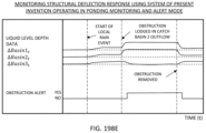
- Another object of the present invention is to provide a new and improved method of communication and information processing supported by a GNSS system platform deployed to a building rooftop for monitoring ponding and water load driven structural deflection and displacement, comprising the steps of (i) processing GNSS signals received locally at a point on or behind the surface of the stationary and/or mobile system, (ii) automatically determining the occurrence of spatial displacement, distortion and/or deformation of the system being spatially monitored over time, and (iii) when spatial displacement, distortion and/or deformation thresholds are met or exceeded, and/or pond-depth thresholds are met or exceeded, automatically sending email and/or SMS alerts and/or notifications to registered users over the GNSS system network.
- Another object of the present invention is to provide a new and improved GNSS system network installed and deployed for real-time wind-driven roof structural damage monitoring in response to loads created by winds on rooftops, wherein rovers and base stations are mounted on the rooftop surface for monitoring rooftop deflection by collecting and processing GNSS signals transmitted from the GNSS satellite constellations.
- Another object of the present invention is to provide a new and improved GNSS system network installed and deployed for real-time roof membrane (i.e. surface) displacement and deflection monitoring in response to wind-driven loads created by winds on rooftops, wherein rovers and base stations are mounted on the rooftop surface for monitoring rooftop deflection by collecting and processing GNSS signals transmitted from the GNSS satellite constellations, wherein there is shown some serious wind-driven damage caused to the rooftop surface.
- roof membrane i.e. surface
- Another object of the present invention is to provide a new and improved GNSS system network installed and configured for monitoring wind-driven roof membrane displacement on buildings, comprising (i) a cloud-based TCP/IP network architecture with a plurality of GNSS satellites transmitting GNSS signals towards the earth and objects below, (ii) a plurality of GNSS rovers of the present invention mounted on the rooftop surface of building for receiving and processing transmitted GNSS signals during monitoring using time averaging displacement data extraction processing, (iii) one or more GNSS base stations to support RTK correction of the GNSS signals, (iv) one or more client computing systems for transmitting instructions and receiving alerts and notifications and supporting diverse administration, operation and management functions on the system network, and (v) a cell tower for supporting cellular data communications across the system network, and (vi) a data center supporting web servers, application servers, database and datastore servers, and SMS/text and email servers for communicating with mobile computing systems used in monitoring the deployed GNSS rovers.
- Another object of the present invention is to provide a new and improved GNSS rover unit for deployment in a GNSS system network comprising: a cellular XCVR with antenna, an Internet gateway XCVR with antenna, a base to rover radio with antenna, a multiband GNSS RCVR with antennas, a micro-processor with a memory architecture and a user I/O, a battery, a solar (PV) panel, a charge controller, a wind speed sensor, a compass, a 3-axis accelerometer, a snow pressure sensor, camera(s), temp & humidity sensors, a roof surface liquid pressure sensor, an atmospheric pressure sensor, a drain freeze sensor, a snow depth sensor, auxiliary sensors, and a compass instrument.
- Another object of the present invention is to provide a new and improved method of real-time monitoring of roof membrane displacement using a GNSS system network operating in its roof membrane monitoring and alert mode, with and automated generation of displaced (rover) station alerts, rooftop windspeed, windspeed alerts and regional windspeed.
- Another object of the present invention is to provide a new and improved method of communication and information processing supported by a GNSS system platform deployed for monitoring wind-driven roof membrane displacement, involving (i) the processing GNSS signals received locally at a point on or behind the surface of the stationary and/or mobile system, (ii) automatically determining the occurrence of spatial displacement, distortion and/or deformation of the system being spatially monitored over time, and (iii) when spatial displacement, distortion and/or deformation thresholds are met or exceeded, or windspeed thresholds have been exceeded, automatically sending email and/or SMS alerts and/or notifications to registered users over the system network.
- Another object of the present invention is to provide a new and improved GNSS system network installed and deployed for real-time foundation settling monitoring in response to whatever forces may act upon a building foundation, wherein rovers and base stations are mounted on the rooftop surface for monitoring rooftop displacement (due to foundation settling) by collecting and processing GNSS signals transmitted from the GNSS satellite constellations.
- Another object of the present invention is to provide a new and improved GNSS system network installed and deployed for real-time structural failure monitoring in response to whatever forces may act upon a building, wherein rovers and base stations are mounted on the rooftop surface for monitoring structural failure in the building by collecting and processing GNSS signals transmitted from the GNSS satellite constellations.
- Another object of the present invention is to provide a new and improved GNSS system network installed and configured for monitoring structural failure in buildings, comprising (i) a cloud-based TCP/IP network architecture with a plurality of GNSS satellites transmitting GNSS signals towards the earth and objects below, (ii) a plurality of GNSS rovers of the present invention mounted on the rooftop surface of building for receiving and processing transmitted GNSS signals during monitoring using time averaging displacement/deflection data extraction processing, (iii) one or more GNSS base stations to support RTK correction of the GNSS signals, (iv) one or more client computing systems for transmitting instructions and receiving alerts and notifications and supporting diverse administration, operation and management functions on the GNSS system network, (v) a cell tower for supporting cellular data communications across the system network, and (vi) a data center supporting web servers, application servers, database and datastore servers, and SMS/text and email servers.
- Another object of the present invention is to provide a new and improved GNSS rover unit deployed on the GNSS system network, comprising: a cellular XCVR with antenna, an Internet gateway XCVR with an antenna, a base to rover radio with an antenna, a multiband GNSS RCVR with a antennas, a micro-processor with a memory architecture and a user I/O, a battery, a solar (PV) panel, a charge controller, a wind speed sensor, a compass, a 3-axis accelerometer, a snow pressure sensor, camera(s), temp & humidity sensors, a roof surface liquid pressure sensor, an atmospheric pressure sensor, a drain freeze sensor, a snow depth sensor, auxiliary sensors, and a compass.
- Another object of the present invention is to provide a new and improved method of monitoring structural displacement response using a GNSS system network operating in a foundation settling and structural failure monitoring and alert mode, involving the processing of GNSS signals received locally at a point on or behind the surface of the stationary and/or mobile system to automatically determine the occurrence of spatial displacement, distortion and/or deformation of the system being spatially monitored over time, and when spatial displacement, distortion and/or deformation thresholds are met or exceeded, or windspeed thresholds have been exceeded, automatically sending alerts and/or notifications to registered users over the system network.
- Another object of the present invention is to provide a new and improved building with a relatively flat roof surface, on which a GNSS system network is installed and deployed for real-time seismic activity monitoring in response to seismic activity in the vicinity of the building, wherein GNSS rovers are mounted on the rooftop surface for monitoring rooftop deflection by collecting and processing GNSS signals transmitted from the GNSS satellite constellations.
- Another object of the present invention is to provide a new and improved GNSS system network installed and configured for monitoring seismic activity around a building and its response to a fault in the earth and/or shock waves generated within the earth during an earth quake, wherein said GNSS system network comprises (i) a cloud-based TCP/IP network architecture with a plurality of GNSS satellites transmitting GNSS signals towards the earth and objects below, (ii) a plurality of GNSS rovers of the present invention mounted on the rooftop surface of building for receiving and processing transmitted GNSS signals during monitoring using time averaging seismic data extraction processing, (iii) one or more GNSS base stations to support RTK correction of the GNSS signals, (iv) one or more client computing systems for transmitting instructions and receiving alerts and notifications and supporting diverse administration, operation and management functions on the system network, (v) a cell tower for supporting cellular data communications across the system network, (v) a data center supporting web servers, application servers, database and datastore servers, and SMS/text and email servers
- Another object of the present invention is to provide a new and improved GNSS rover unit for deployment on a GNSS system network, and comprising a cellular XCVR with antenna, an Internet gateway XCVR with antenna, a base to rover radio with antenna, a multiband GNSS RCVR with antennas, a micro-processor with a memory architecture and a user I/O, a battery, a solar (PV) panel, a charge controller, a wind speed sensor, a compass, a 3-axis accelerometer, a snow pressure sensor, camera(s), temp & humidity sensors, a roof surface liquid pressure sensor, an atmospheric pressure sensor, a drain freeze sensor, a snow depth sensor, auxiliary sensors, and a compass.
- Another object of the present invention is to provide a new and improved method of monitoring of structural displacement of a building in response using a GNSS system network operating in its rain ponding monitoring and alert mode, employing time-averaged displacement data extraction processing, and automated generation of structural displacement alerts, remote USGS accelerometer data and USGS earthquake alerts.
- Another object of the present invention is to provide a new and improved method for monitoring seismic activity and seismic-driven structural displacement response of a building or civil structure using a GNSS system network operating in an early warning seismic monitoring and alert mode, and employing (i) the processing of GNSS signals received locally at a point on or behind the surface of the stationary and/or mobile system, (ii) automatically determining the occurrence of spatial displacement, distortion and/or deformation of the system being spatially monitored over time, and when spatial displacement, distortion and/or deformation thresholds are met or exceeded and vibration (linear accelerations) thresholds are met or exceeded, and (iii) automatically sending email and/or SMS alerts and/or notifications to registered users over the GNSS system network.
- Another object of the present invention is to provide a new and improved GNSS system network installed and deployed for real-time bridge monitoring in response to seismic and other activity in the vicinity of the bridge, wherein GNSS rovers are mounted on the bridge surface for collecting and processing GNSS signals transmitted from the GNSS satellite constellations, for monitoring any deflection and/or displacement the bridge structure may experience over time due to seismic or other activity.
- Another object of the present invention is to provide a new and improved GNSS system network installed and configured for monitoring vertical and lateral bridge span displacement in response to roadway loading and/or shock waves generated within the earth during an earth quake, comprising (i) a cloud-based TCP/IP network architecture with a plurality of GNSS satellites transmitting GNSS signals towards the earth and objects below, (ii) a plurality of GNSS rovers of the present invention mounted on the rooftop surface of building for receiving and processing transmitted GNSS signals during monitoring using time averaging seismic data extraction processing, (iii) one or more GNSS base stations to support RTK correction of the GNSS signals, (iv) one or more client computing systems for transmitting instructions and receiving alerts and notifications and supporting diverse administration, operation and management functions on the system network, (v) a cell tower for supporting cellular data communications across the system network, (vi) a data center supporting web servers, application servers, database and datastore servers, and SMS/text and email servers for communicating with mobile computing systems used in monitoring the deployed
- Another object of the present invention is to provide a new and improved GNSS rover unit deployed on a GNSS system network, and comprising: a cellular XCVR with antenna, an Internet gateway XCVR with antenna, a base to rover radio with antenna, a multiband GNSS RCVR with antennas, a micro-processor with a memory architecture and a user I/O, a battery, a solar (PV) panel, a charge controller, a wind speed sensor, a compass, a 3 axis accelerometer, a snow pressure sensor, camera(s), temp & humidity sensors, a roof surface liquid pressure sensor, an atmospheric pressure sensor, a drain freeze sensor, a snow depth sensor, auxiliary sensors, and a compass.
- Another object of the present invention is to provide a new and improved method of monitoring bridge displacement and vibrational response using a GNSS system network operating in a displacement and vibrational-response monitoring and alert mode, employing (i) the processing of GNSS signals received locally at a point on or behind the surface of the stationary and/or mobile system, (ii) automatically determining the occurrence of spatial displacement, distortion and/or deformation of the system being spatially monitored over time, and when spatial displacement, distortion and/or deformation thresholds are met or exceeded and vibration (linear accelerations) thresholds are met or exceeded, and (iii) automatically sending email and/or SMS alerts and/or notifications to registered Users over the GNSS system network.
- Another object of the present invention is to provide a new and improved GNSS system network installed in a region of the earth's surface and deployed for real-time monitoring of soil movement in response to seismic activity, and rainfall, wherein at least one or more base station is mounted in the vicinity of a region of earth to be monitored by the GNSS system network of the present invention, and a plurality of rovers are mounted in the ground surface over the spatial extent of the regions as illustrated for purposes of monitoring the region of earth by collecting and processing GNSS signals transmitted from the GNSS satellite constellations, wherein the GNSS base unit provides RTK corrected GNSS signals.
- Another object of the present invention is to provide a new and improved GNSS rover secured in the ground surface by way of a stake-like base component, enabling the secure mounting of the GNSS rover unit in the earth surface so that GNSS signal reception and position monitoring of the phase center location of its antenna, during monitoring operations performed by a GNSS system network.
- Another object of the present invention is to provide a new and improved GNSS rover secured in the ground surface by way of the screw-like base component, enabling the secure mounting of the rover unit in the earth surface so that GNSS signal reception and corresponding “antenna phase center” displacement monitoring is supported during the remote monitoring operations performed by a GNSS system network.
- Another object of the present invention is to provide a new and improved GNSS system network installed and configured for monitoring soil and earth movement in response to shock waves generated within the earth during an earth quake and/or heavy rainfall, comprising (i) a cloud-based TCP/IP network architecture with a plurality of GNSS satellites transmitting GNSS signals towards the earth and objects below, (ii) a plurality of GNSS rovers of the present invention mounted on the rooftop surface of building for receiving and processing transmitted GNSS signals during monitoring using time-averaging displacement data extraction processing, (iii) one or more GNSS base stations to support RTK correction of the GNSS signals, (iv) one or more client computing systems for transmitting instructions and receiving alerts and notifications and supporting diverse administration, operation and management functions on the system network, (v) a cell tower for supporting cellular data communications across the system network, (vi) a data center supporting web servers, application servers, database and datastore servers, and SMS/text and email servers, and (vii) a USGS seismic detection server and data
- Another object of the present invention is to provide a new and improved GNSS rover unit deployed on a GNSS system network, and comprising a cellular XCVR with antenna, an Internet gateway XCVR with antenna, a base to rover radio with antenna, a multiband GNSS RCVR with antennas, a micro-processor with a memory architecture and a user I/O, a battery, a solar (PV) panel, a charge controller, a wind speed sensor, a compass, a 3 axis accelerometer, a snow pressure sensor, camera(s), temp & humidity sensors, a roof surface liquid pressure sensor, an atmospheric pressure sensor, a drain freeze sensor, a snow depth sensor, auxiliary sensors, and a compass.
- Another object of the present invention is to provide a new and improved method of real-time monitoring of structural displacement response using a GNSS system network operating in its rain ponding monitoring and alert mode, employing time-averaged displacement data extraction processing, and automated generation of seismic vibration, displacement notifications and/or alerts.
- Another object of the present invention is to provide a new and improved GNSS system network installed in a region of the earth's surface and deployed for real-time monitoring of the movement of a (gas or liquid transport) pipeline after settling in response to seismic activity and/or rainfall, wherein at least one or more GNSS base station is mounted in the vicinity of a region of earth to be monitored by the GNSS system network, and a plurality of rovers are mounted on the pipeline for purposes of monitoring the region of the pipeline by collecting and processing GNSS signals transmitted from the GNSS satellite constellations.
- Another object of the present invention is to provide a new and improved GNSS system network installed and configured for monitoring pipeline movement in response to shock waves generated within the earth during an earth quake and/or heavy rainfall, comprising (i) a cloud-based TCP/IP network architecture with a plurality of GNSS satellites transmitting GNSS signals towards the earth and objects below, (ii) a plurality of GNSS rovers of the present invention mounted on the rooftop surface of building for receiving and processing transmitted GNSS signals during monitoring using time-averaging displacement data extraction processing, (iii) one or more GNSS base stations to support RTK correction of the GNSS signals, (iv) one or more client computing systems for transmitting instructions and receiving alerts and notifications and supporting diverse administration, operation and management functions on the system network, (v) a cell tower for supporting cellular data communications across the GNSS system network, (vi) a data center supporting web servers, application servers, database and datastore servers, and SMS/text and email servers, and (vii) a USGS seismic detection server and
- Another object of the present invention is to provide a new and improved GNSS rover unit deployed on a GNSS system network, and comprising a cellular XCVR with antenna, an Internet gateway XCVR with antenna, a base to rover radio with antenna, a multiband GNSS RCVR with antennas, a micro-processor with a memory architecture and a user I/O, a battery, a solar (PV) panel, a charge controller, a wind speed sensor, a compass, a 3 axis accelerometer, a snow pressure sensor, camera(s), temp & humidity sensors, an atmospheric pressure sensor, a snow depth sensor, auxiliary sensors, and a compass.
- Another object of the present invention is to provide a new and improved GNSS system network installed in the hull of a ship and deployed for real-time monitoring of distortion or deformation of the ship's hull in response to loading and/or environmental forces (e.g. iceberg), wherein a plurality of rovers are mounted on the ship's hull as illustrated for purposes of monitoring the ship's hull by collecting and processing GNSS signals transmitted from the GNSS satellite constellations, and automatically determining spatial deformation and/or deflection with respect to its locally embedded coordinate reference system.
- a new and improved GNSS system network installed in the hull of a ship and deployed for real-time monitoring of distortion or deformation of the ship's hull in response to loading and/or environmental forces (e.g. iceberg), wherein a plurality of rovers are mounted on the ship's hull as illustrated for purposes of monitoring the ship's hull by collecting and processing GNSS signals transmitted from the GNSS satellite constellations, and automatically determining spatial deformation and/or
- Another object of the present invention is to provide a new and improved GNSS system network installed in the ship's hull deployed for real-time monitoring of the ship's hull in response to internal and/or external loading, wherein a plurality of GNSS rovers are mounted in the ship's hull for purposes of monitoring the ship's hull by collecting and processing GNSS signals transmitted from the GNSS satellite constellations, and a controller and radio transceiver for transmitting GNSS signals to local or remote signal processors to automatically determine spatial deformation.
- Another object of the present invention is to provide a new and improved GNSS system network installed in the aircraft's fuselage and deployed for real-time monitoring of distortion or deformation of the aircraft in response to loading and/or environmental force, wherein a plurality of rovers are mounted on the aircraft for purposes of monitoring the region of the aircraft by collecting and processing GNSS signals transmitted from the GNSS satellite constellations, and automatically determining spatial deformation and/or deflection with respect to its locally embedded coordinate reference system.
- Another object of the present invention is to provide a new and improved GNSS system network installed in the aircraft and deployed for real-time monitoring of the aircraft in response to internal and/or external loading, wherein a plurality of rovers are mounted on the aircraft as illustrated for purposes of monitoring the aircraft by collecting and processing GNSS signals transmitted from the GNSS satellite constellations, and a controller and radio transceiver for transmitting GNSS signals to local or remote signal processors to automatically determine spatial deformation.
- Another object of the present invention is to provide a new and improved GNSS system network installed in the railcar and deployed for real-time monitoring of distortion or deformation of the railcar in response to loading and/or environmental forces, wherein a plurality of rovers are mounted on the pipeline as illustrated for purposes of monitoring the region of the railcar by collecting and processing GNSS signals transmitted from the GNSS satellite constellations, to automatically determine spatial deformation and/or deflection with respect to its locally embedded coordinate reference system.
- Another object of the present invention is to provide a new and improved GNSS system network installed in the railcar and deployed for real-time monitoring of the railcar in response to internal and/or external loading, wherein a plurality of rovers are mounted in the railcar as illustrated for purposes of monitoring the railcar by collecting and processing GNSS signals transmitted from the GNSS satellite constellations, and a controller and radio transceiver for transmitting GNSS signals to local or remote signal processors to automatically determine spatial deformation.
- Another object of the present invention is to provide a new and improved GNSS system network installed in the tractor and trailer and deployed for real-time monitoring of distortion or deformation of the tractor and trailer in response to loading and/or environmental forces, wherein a plurality of rovers are mounted on the tractor trailer as illustrated for purposes of monitoring the same by collecting and processing GNSS signals transmitted from the GNSS satellite constellations, to automatically determine spatial deformation and/or deflection with respect to its locally embedded coordinate reference system.
- Another object of the present invention is to provide a new and improved GNSS system network in the ship's hull and deployed for real-time monitoring of the tractor trailer in response to internal and/or external loading, wherein a plurality of rovers are mounted in the tractor trailer as illustrated for purposes of monitoring the tractor trailer by collecting and processing GNSS signals transmitted from the GNSS satellite constellations and a controller and radio transceiver for transmitting GNSS signals to local or remote signal processors to automatically determine spatial deformation.
- Another object of the present invention is to provide a new and improved GNSS system network comprising a plurality of GNSS pond-depth sensing rovers with an integrated pond-depth sensor, mounted near roof drains and scuppers, also adapted for automated sensing, monitoring and measuring the depth of water pooling on the rooftop surface and communication of measured pond-depth to mobile and stationary users over the wireless GNSS system network.
- FIG. 1 is a schematic representation of a GNSS network of the present invention in the form of a generic system block diagram, configured for remote monitoring of the displacement, distortion and/or deformation of a stationary and/or mobile system being tracked by the GNSS network, shown comprising a cloud-based TCP/IP network architecture supporting (i) a plurality of GNSS satellites transmitting GNSS signals towards the earth and objects below, (ii) a plurality of GNSS rovers of the present invention mounted on the rooftop surfaces of buildings for receiving and processing transmitted GNSS signals during monitoring using time averaging seismic data extraction processing, (iii) an internet gateway providing the GNSS rovers access to the Internet communication infrastructure, (iv) one or more GNSS base stations to support RTK correction of the GNSS signals, (v) one or more client computing systems for transmitting instructions and receiving alerts and notifications and supporting diverse administration, operation and management functions on the system network, (vi) a cell tower for supporting cellular data communications across the system network, and (vii) a
- FIG. 2 is a system block diagram for each global navigation satellite system (GNSS) satellite deployed within the GNSS system network of the present invention of FIG. 1 , showing each GNSS satellite as comprising a propulsion system, solar panels, L band antennas, radio transmitters and receivers, and atomic clocks;
- GNSS global navigation satellite system
- FIG. 3 is a system block diagram for the internet gateway deployed in the GNSS system network of the present invention of FIG. 1 , shown comprising a micro-processor with a supporting a memory architecture, a LAN transceiver, a GUI-based user display, a LAN port, an RF transceiver with an antenna, a manager, and a viewer;
- FIG. 4 is a Table Defining User Groups and Members supported by the GNSS system network of the present invention depicted in FIG. 1 , namely: (i) Administrators including Building Owners, Property Managers, General Managers, Facility Directors, Rental Managers, IT Managers, and Admin Staff Members; (ii) Managers including Building Owners; Property Managers, General Managers, Facility Directors, Rental Managers, IT Managers, and Admin Staff Members; (iii) Responders including Workers, General Managers, Property Managers, Facility Directors, roofing Contractors, and Commercial Contractors (e.g. SERVICE PRO); and (iv) Viewers including Workers, General Staff, Accounting, roofing Contractors, Commercial Contractors (e.g. SERVICE PRO), IT Managers, and Admin Staff Members;
- Administrators including Building Owners, Property Managers, General Managers, Facility Directors, Rental Managers, IT Managers, and Admin Staff Members
- Managers including Building Owners; Property Managers, General Managers, Facility Directors, Rental Managers, IT Managers, and Admin Staff Members
- FIGS. 5 A and 5 B shows perspective and elevated views of the Earth, along with a constellation of GNSS satellites orbiting around the Earth, and the GNSS system network of the present invention deployed for precise measurement of positioning and displacement of objects and surfaces (e.g. building and civil structures) relative to the geographic coordinate reference system G, embedded within the Earth, tracking (i) latitude coordinates measuring the number of degrees north or south of the equator, longitude coordinates measuring the number of degrees east or west of the prime meridian, and altitude coordinates measuring the height above ocean sea level;
- objects and surfaces e.g. building and civil structures
- FIG. 6 A is a schematic illustration of the GNSS system network of the present invention, supporting multiple GNSS rovers (ii) embodied within the boundary of a stationary and/or mobile system being monitored by the GNSS system network of the present invention, (ii) receiving GNSS signals transmitted from GNSS satellites orbiting the Earth, and (iii) determining the geo-location (GPS coordinates) and time-stamp of each GNSS rover while the stationary and/or mobile system is being monitored for spatial displacement, distortion and/or deformation using GNSS-based rover data processing methods practiced aboard the system as illustrated in FIG. 6 B , or remotely within the application and database servers of the data center of the GNSS system network as illustrated in FIG. 6 C ;
- FIG. 6 B is a block system diagram illustrating a first method of implementing the GNSS system network of the present invention enabling high-resolution monitoring of spatial displacement, distortion and/or deformation of a stationary and/or mobile system using a spatial measurement engine accordance with the principles of the present invention, wherein the spatial measurement engine comprises (i) GNSS receivers embedded within the boundary of a stationary and/or mobile system to be monitored, (ii) the GNSS receivers receiving GNSS signals transmitted from GNSS satellites orbiting the Earth, and (iii) a rover data processing module aboard the system for monitoring of spatial displacement, distortion and/or deformation of a stationary and/or mobile system, using a preprocessing module, a bank of data samplers controlled by data sample controllers, a time averaging module controlled by a time averaging controller, a data buffer memory for buffering data from the time averaging module, and an I/O Interface module for receiving module configuration data to configure the mode of the multi-mode data processing module, time-a
- FIG. 6 C is a block system diagram illustrating a second method of implementing the GNSS system network of the present invention enabling high-resolution monitoring of spatial displacement, distortion and/or deformation of a stationary and/or mobile system using a spatial measurement engine accordance with the principles of the present invention, wherein the spatial measurement engine comprises (i) GNSS receivers embedded within the boundary of a stationary and/or mobile system to be monitored, (ii) the GNSS receivers receiving GNSS signals transmitted from GNSS satellites orbiting the Earth, and (iii) a rover data processing module aboard the application and database servers of a data center, for monitoring of spatial displacement, distortion and/or deformation of a stationary and/or mobile system, using a preprocessing module, a bank of data samplers controlled by data sample controllers, a time averaging module controlled by a time averaging controller, a data buffer memory for buffering data from the time averaging module, and an I/O Interface module for receiving module configuration data to configure the mode of the multi
- FIG. 7 A is a schematic system block diagram of the GNSS system network of the present invention shown installed and deployed across one or more building sites (e.g. housing systems) comprising: (i) a plurality of GNSS constellations including the GPS (USA) satellite system, the GLONASS ( Russia) satellite system, GALILEO (EU) satellite system, the BEIDOU (China) satellite system, and the QZSS (Japan) satellite system, (ii) GNSS rovers having GNSS receivers with L band antennas mounted on the building site and employing onboard time-averaging data extraction processing principles according to the present invention as illustrated in FIGS.
- building sites e.g. housing systems
- GNSS constellations including the GPS (USA) satellite system, the GLONASS (Russia) satellite system, GALILEO (EU) satellite system, the BEIDOU (China) satellite system, and the QZSS (Japan) satellite system
- GNSS rovers having GNSS receivers with L band antennas mounted on the building site and
- GNSS base station or CORS station having a GNSS receiver with L band antennas supporting RTK correction, and standalone Pond-Depth Sensors with L band antennas, and (iv) data centers supporting the functions of the present invention
- FIG. 7 B is a schematic system block diagram of the GNSS system network of the present invention shown installed and deployed across one or more building sites (e.g. housing systems) comprising: (i) a plurality of GNSS constellations including the GPS (USA) satellite system, the GLONASS ( Russia) satellite system, GALILEO (EU) satellite system, the BEIDOU (China) satellite system, and the QZSS (Japan) satellite system, (ii) GNSS rovers having GNSS receivers with L band antennas mounted on the building site, (iii) at least one GNSS base station (or CORS station) having a GNSS receiver with L band antennas supporting RTK correction, and standalone Pond-Depth Sensors with L band antennas, and (iv) data centers supporting remote time-averaging data extraction processing principles according to the present invention illustrated in FIGS. 6 A and 6 C ;
- FIGS. 8 A, 8 B and 8 C taken together, provide a flow chart describing the primary steps of the communication and information processing method supported on the generalized embodiment of the system platform of the present invention, involving the processing of received GNSS signals locally or remotely to automatically determine the occurrence of spatial displacement, distortion and/or deformation of the system being spatially monitored over time if and when structural movement thresholds are met or exceeded by the system being monitored, the Application Server automatically sends email and/or SMS alerts and/or notifications to registered users over the GNSS system network;
- FIG. 9 shows a system schematic block diagram of the first embodiment of the GNSS-based system network of the present invention comprising GNSS rover stations and onsite GNSS base station using internet gateway and LAN-based internet access for carrying out RTK position correction over a cloud-based TCP/IP network architecture supporting (i) a plurality of GNSS satellites transmitting GNSS signals towards the earth and objects below, (ii) a plurality of GNSS rovers of the present invention mounted on the rooftop surfaces of buildings having an internet gateway and building LAN, for receiving and processing transmitted GNSS signals during monitoring using time averaging seismic data extraction processing, (iii) an internet gateway providing the GNSS rovers access to the Internet communication infrastructure, (iv) one or more GNSS base stations to support RTK correction of the GNSS signals, (v) one or more client computing systems for transmitting instructions and receiving alerts and notifications and supporting diverse administration, operation and management functions on the system network, (vi) a cell tower for supporting cellular data communications across the system network,
- FIG. 10 shows a schematic representation of a building system, in which the GNSS system network of the present invention illustrated in FIGS. 1 through 8 is installed and deployed for spatial monitoring, wherein its GNSS rovers are installed on the building roof (i.e. embedded within the system boundaries) and an onsite GNSS base unit/station is mounted on the premises of the building shown in FIG. 10 ;
- FIG. 11 shows the building system being spatially monitored by the GNSS system network of FIG. 9 , with the onsite RTK-correcting GNSS base unit mounted on the premises thereof;
- FIG. 12 shows a building system being spatially monitored by the GNSS system network of the present invention depicted in FIGS. 1 through 8 , supporting pole-mounted GNSS rovers shown in FIGS. 13 , 14 A and 14 B mounted near roof drains and equipped with snow pressure and windspeed sensors, for spatial monitoring the building system structure, and also the pooling of water on its rooftop surface which can cause great structural damage if roof drains or scuppers are obstructed and prevented from draining the flow of water;
- FIG. 13 show a close up view of a pole mounted GNSS rover unit employed in the GNSS system network and installation illustrated in FIG. 12 , shown installed near a rooftop drain cover;
- FIG. 14 A shows a close up view of the pole-mounted GNSS rover unit of FIG. 12 with snow pressure and windspeed sensors employed in the GNSS system network and installation illustrated in FIG. 12 , and also laser-based snow depth measurement instrumentation for measuring the depth of snow on the rooftop surface using a LADAR-based laser beam measuring distance by time of flight of the light beam;
- FIG. 14 B shows an exploded diagram of the pole-mounted GNSS rover unit shown in FIGS. 13 and 14 A , wherein its base component is shown comprising a base platform for support on a roof or planar surface, mounting an array of electronic load-cells supporting a snow load weight plate or surface, for measuring the weight of the snow load thereon, and sending electrical signals along the mounting pole (or via a Bluetooth wireless link) to the controller component;
- FIG. 15 shows a building system being monitored by the GNSS system network of the present invention and depicted in FIGS. 1 through 9 , supporting surface-mounted GNSS rovers shown in FIGS. 12 and 13 mounted near roof drains, for spatial monitoring the building system and also the pooling of water on its rooftop surface which can obstruct drains, prevent water flow and drainage and cause great property damage;
- FIG. 16 shows a close up view of a surface-mounted GNSS rover unit employed in the GNSS system network installation illustrated in FIG. 12 , shown installed near a rooftop drain cover;
- FIG. 17 shows a first perspective view of a pole-mounted GNSS rover unit employed in the GNSS system network installation illustrated in FIG. 12 , shown installed near a rooftop drain cover, and illustrating the scope and projection of its integrated high-density digital camera system with still and video capture modes, supported by broad field of views (FOVs) overlooking the rooftop surface;
- FOVs broad field of views
- FIG. 18 shows a second perspective view of a surface-mounted GNSS rover unit employed in the GNSS system network installation illustrated in FIG. 12 , shown installed near a rooftop drain cover and detecting motion and changes in the digital images captured by the digital camera system operating in its video capture mode;
- FIG. 19 shows a second perspective view of a pole-mounted GNSS rover unit employed in the GNSS system network installation illustrated in FIGS. 12 and 15 , shown installed near a rooftop drain cover, and illustrating the scope and projection of its integrated high-density digital camera system with still and video capture modes, supported by broad field of views (FOVs) overlooking the rooftop surface;
- FOVs broad field of views
- FIG. 20 shows a second perspective view of a pole-mounted GNSS rover unit employed in the GNSS system network installation illustrated in FIGS. 12 and 15 , shown installed near a rooftop drain cove, and detecting motion and changes in the digital images captured by the digital camera system operating in its video capture mode;
- FIG. 21 shows a system block diagram for GNSS rover system/unit deployed on the GNSS system network of FIGS. 1 , 12 and 15 , shown comprising (i) radio signal subsystems supporting (a) internet data flow using a cellular transceiver (XCVR) with antenna and an internet gateway transceiver (XCVR), (b) RTK position correction data flow using base to rover radio signal transceivers, and (c) GNSS signal reception using multiband GNSS transceivers, (ii) a programmed microprocessor and supporting memory architecture for supporting all control and operating functions, provided with a user I/O interface, battery power module, solar PV panel and charge controller, and (iii) an array of ancillary sensors including, but not limited to, snow pressure sensors, snow depth sensor, wind-speed sensor, digital cameras, roof-surface liquid pressures sensor, atmospheric pressure sensor, drain freeze sensor, temperature and humidity sensors, 3-axis accelerometers, and electronic compass instrument, configured and arranged for receiving corrected GNSS
- FIG. 22 is a graphical data characteristic representation for a stationary GNSS rover antenna altitude data test conducted when operating the GNSS rover at a 1 second GNSS RTK-corrected sampling rate and 2 running time-based averages (i.e. 1 hour average and 3 hour average) plotted against time, to illustrate the operation of the method of time-averaging based displacement data extraction processing carried out according to the principles of the present invention (@) enabling at least 1 CM spatial displacement resolution using this method at a 5 minute RTK-corrected data sampling rate and 1 hour time-averaging based displacement data extraction processing;
- FIG. 23 is a graphical data characteristic representation for a stationary GNSS rover antenna altitude data test conducted when operating the GNSS rover at a 5 minute GNSS RTK-corrected sampling rate and 2 running time-based averages (i.e. 1 hour average and 3 hour average) plotted against time, to illustrate the operation of the method of time-averaging based displacement data extraction processing carried out according to the principles of the present invention (@) enabling at least 1 CM spatial displacement resolution using this method at a 5 minute s RTK-corrected data sampling rate and 1 hour time-averaging based displacement data extraction processing;
- FIG. 24 is a graphical data characteristic representation for a stationary GNSS rover antenna altitude data test conducted when operating the GNSS rover at a 15 minute GNSS RTK-corrected sampling rate and 2 running time-based averages (i.e. 1 hour average and 3 hour average) plotted against time, to illustrate the operation of the method of time-averaging based displacement data extraction processing carried out according to the principles of the present invention (@) enabling at least 1 CM spatial displacement resolution using this method at a 5 minute s RTK-corrected data sampling rate and 1 hour time-averaging based displacement data extraction processing;
- FIG. 25 is a graphical representation of a computer simulation of a GNSS Rover Antenna supported on a building roof beam undergoing displacement and deflection under the weight of a snow load, conducted using a 5 minute GNSS RTK-corrected sampling rate and 1 hour running time-based data averaging process, plotted against time to illustrate the operation of the method of time-averaging based displacement data extraction processing carried out according to the principles of the present invention (@) enabling at least 1 CM spatial displacement resolution using this method;
- FIG. 26 shows a building system being monitored by the GNSS system network of the present invention depicted in FIGS. 1 through 8 , supporting pole-mounted GNSS rovers having ponding sensors shown in FIGS. 27 and 28 , respectively, mounted near roof drains, specially adapted for monitoring the pooling of water on the rooftop surface which can cause great structural damage if and when the roof drains or scuppers should happened to become obstructed and prevent water flow and drainage;
- FIG. 27 show a close up view of a pole mounted GNSS rover unit with integrated Pond-Depth Sensor employed in the GNSS system network installation illustrated in FIG. 26 , shown installed near a rooftop drain cover;
- FIG. 28 shows a close up view of a pole-mounted GNSS rover unit with integrated Pond-Depth Sensor, and snow pressure and windspeed sensors as well for deployment in the GNSS system network installation illustrated in FIG. 26 ;
- FIG. 29 A shows a perspective view of a pole-mounted GNSS rover with an integrated pond-depth sensor, as shown in FIGS. 26 and 27 mounted near roof drains, also adapted for automated monitoring the pooling of water on the rooftop surface and communication over the wireless GNSS system network, shown comprising a base stand portion weight for stable support on a rooftop surface for sensing the pooling of water of the rooftop surface, and an upper controller portion containing electronics and radio communication equipment, supported above the stand portion by a hollow pole or otherwise tubular structure;
- FIG. 29 B shows an exploded view of the pole-mounted GNSS rover of FIG. 29 A with an integrated pond-depth sensor, as shown in FIGS. 26 and 27 mounted near roof drains, also adapted for automated monitoring the pooling of water on the rooftop surface and communication over the wireless GNSS system network, shown comprising a base stand portion weight for stable support on a rooftop surface for sensing the pooling of water of the rooftop surface, and an upper controller portion containing electronics and radio communication equipment, supported above the stand portion by a hollow pole or otherwise tubular structure;
- FIG. 30 A shows a close up first perspective view showing the upper surfaces of the controller portion of the pond-depth sensing GNSS rover unit deployed in FIGS. 29 A and 29 B , and revealing its compact water-proof housing, support pole, and antennas;
- FIG. 30 B shows an exploded perspective view showing the pond-depth sensing GNSS rover unit deployed in FIGS. 29 A and 29 B , and revealing its internal printed circuit (PC) board, support plate, compact water-proof housing, support pole, and antennas;
- PC printed circuit
- FIG. 31 shows a close up second perspective view showing the under surfaces of the controller portion of the pond-depth sensing GNSS rover unit deployed in FIGS. 29 A and 29 B , and revealing its compact water-proof housing, support pole, and antennas;
- FIG. 32 is a cross-sectional view of the controller portion of the GNSS rover unit of the FIGS. 29 A, 29 B, 30 A, 30 B and 31 , showing the precise location of (i) the Antenna Reference Point (ARP) embedded within the PC board, (ii) the Mechanical Antenna Phase Center, and L1, L2 Phase Centers, and L1 and L2 Vertical and Horizontal Offsets, within the physical controller portion of the GNSS rover unit;
- ARP Antenna Reference Point
- FIG. 33 shows the pond-depth sensing GNSS rover unit in FIGS. 30 A through 32 provided with a first portable weighted base component adapted to sense the development of a water pond on a rooftop surface;
- FIG. 34 shows the pond-depth sensing GNSS rover unit in FIGS. 30 A through 32 provided with a second portable weighted base component adapted to sense the development of a water pond on a rooftop surface;
- FIG. 35 shows the pond-depth sensing GNSS rover unit in FIGS. 30 A through 32 provided with a third portable weighted base component adapted to sense the development of a water pond on a rooftop surface, as shown in FIGS. 30 A, 30 B and 31 ;
- FIG. 36 shows a pond-depth sensing GNSS rover unit of the present invention provided with shows the pond-depth sensing GNSS rover unit in FIGS. 30 A through 32 provided with a permanently-mounted roof mount (i.e. base component) design enabling the sensing of water pond developing on a rooftop surface;
- a permanently-mounted roof mount i.e. base component
- FIG. 37 shows the pond-depth sensing GNSS rover unit of FIG. 36 , with its base component being permanently-mounted on a building roof surface with mounting screws, rubber membrane and adhesive;
- FIG. 38 shows the pond-depth sensing GNSS rover unit of FIG. 36 provided with an external pond-depth sensor
- FIG. 39 shows a cross-sectional view of the pond-depth sensing GNSS rover unit of the present invention of FIGS. 36 through 38 permanently-mounted to the roof surface by its roof mount (component) design enabling the sensing of a water pond developing on a rooftop surface;
- FIG. 40 shows a block system diagram for the GNSS rover system deployed on the GNSS system network of the present invention depicted in FIG. 26 , shown comprising within the GNSS rover controller housing the following components, namely: (i) radio signal subsystems supporting (a) internet data flow using a cellular transceiver (XCVR) with antenna and an internet gateway transceiver (XCVR), (b) RTK position correction data flow using base to rover radio signal transceivers, and (c) GNSS signal reception using multiband GNSS transceivers, (ii) a programmed microprocessor and supporting a memory architecture for supporting the functions of the system, and also provided with a user I/O interface, battery power module, solar PV panel and charge controller, and (iii) an array of ancillary sensors including, but not limited to, snow pressure sensors, snow depth sensor, wind-speed sensor, digital cameras, roof-surface liquid pressures sensor, atmospheric pressure sensor, drain freeze sensor, temperature and humidity sensors, 3-axis
- FIG. 41 shows a flow chart describing the primary steps of a GNSS rover communication and information processing method supported within the GNSS rover system shown in FIGS. 29 A through 40 ;
- FIG. 42 B shows a schematic representation of a pond-depth sensing instrument system of the present invention for integration within a GNSS rover system of the present invention, and measuring the depth of ponding on a rooftop or like surface using a first method of pressure measurement (M1) employing a first “remote” pressure reference (e.g.
- FIG. 44 B shows a schematic representation of the rooftop pond-depth sensing instrument system of FIG. 42 , employing an absolute pressure sensor and Method M 1 , and shown operating with liquid in its pond-depth sensing chamber, and producing a non-zero pond-depth value H;
- FIG. 45 A shows a schematic representation of the rooftop pond-depth sensing instrument system of FIG. 43 , employing a differential pressure sensor and Method M 2 , and shown operating without liquid in its pond-depth sensing chamber, and producing zero pond-depth value H;
- FIG. 45 B shows a schematic representation of the rooftop pond-depth sensing instrument system employing a differential pressure sensor and Method M 2 , and shown operating with liquid in its pond-depth sensing chamber, and producing a non-zero pond-depth value H;
- FIG. 46 shows an exploded view of a GNSS rover system with an integrated in-pole pond-depth sensing instrument as shown in FIG. 42 , using method M 1 , comprising a GNSS controller portion having a base housing, the PC board with antenna element, upper housing with antenna cover, and a hollow support pole mounted to the base housing supporting the PC board and its onboard absolute pressure sensors;
- FIG. 47 shows a close-up exploded view of the GNSS rover system shown in FIG. 46 , showing the base housing, the PC board with antenna element for mounting on the base housing plate, an upper housing with antenna cover, and the hollow support pole connecting to the bottom of the base housing support plate;
- FIG. 48 shows an elevated cross-sectional side view of the GNSS rover system depicted in FIGS. 46 and 47 , and showing the base housing plate supporting the PC board with antenna element, the upper housing with antenna cover, and the hollow support pole connected to the base housing support plate providing fluid/air communication between the absolute pressure sensor and the bottom of the hollow support pole;
- FIG. 49 A shows a view of a GNSS rover system with an integrated in-pole pond-depth sensing instrument as shown in FIG. 42 , using method M 1 , comprising a GNSS controller portion having a base housing with support plate, the PC board with antenna element mounted in the support plate, an upper housing with antenna cover, and a hollow support pole having a pressure sensing tube mounted therealong and connected to a sensing port in the base plate and a funnel at the bottom end of the support tube for sensing the depth of ponding of water on a rooftop surface, above which the bottom end of the support tube is supported via a support base structure on roof deck next to a roof deck drain;
- FIG. 49 B shows a closeup view of a GNSS rover system of FIG. 49 A provided with an integrated in-pole pond-depth sensing instrument as shown in FIG. 42 , using method M 1 , and comprising a GNSS controller portion having a base housing with support plate, the PC board with antenna element mounted in the support plate, an upper housing with antenna cover, and a hollow support pole having a pressure sensing tube mounted therealong and connected to a sensing port in the base plate and a funnel at the bottom end of the support tube for sensing the depth of ponding of water on a rooftop surface, above which the bottom end of the support tube is removed from the support base structure on a roof deck;
- FIG. 50 A shows an elevated cross-sectional side view of the GNSS rover system depicted in FIGS. 49 A and 49 B , comprising a controller housing, a hollow support pole, a pressure sensing tube mounted therealong and connected to a sensing port in the base plate and a funnel at the bottom end of the support tube for sensing the depth of water ponding on a rooftop surface, above which the bottom end of the support tube is inserted in the support base structure;
- FIG. 50 B shows a close-up cross-sectional side view of the GNSS rover system depicted in FIG. 50 A , comprising a controller housing, hollow a support pole, a pressure sensing tube mounted therealong and connected to a sensing port in the base plate, a PC board, an absolute pressure sensor for use in measuring local atmospheric pressure, and a pressure port vent;
- FIG. 50 C shows an elevated cross-sectional side view of the GNSS rover system depicted in FIGS. 50 A and 50 B , comprising the hollow support pole, the funnel at the bottom end of the support tube for sensing the depth of ponding of water on a rooftop surface, the filter screen cover the input port of the funnel, and the bottom end of the support tube that is inserted in the support base structure;
- FIG. 50 D shows an exploded view of the GNSS rover system shown in FIGS. 49 A, 49 B, 50 A, 50 B and 50 C showing its upper and lower housing portions, its PC board supported therebetween, its antennas, its battery power storage module, its photovoltaic (PV) panel, the funnel, and the hollow support tube inserted into the base support structure;
- PV photovoltaic
- FIG. 51 A shows a perspective view of the GNSS rover system shown in FIGS. 49 A through 50 D showing its upper unit and support tube removed from the support base structure that is fastened to the roof surface, alongside of which is a roof drain and a bucket of water to be used for testing;
- FIG. 51 B shows a perspective view of the GNSS rover system shown in FIGS. 49 A through 50 D , showing the upper unit and support tube removed from the support base structure and placed in the bucket of water to be used for testing, a roof drain and support base structure on the roof deck.
- FIG. 51 C shows a side cross-sectional view of the GNSS rover system of the present invention illustrated in FIGS. 49 A through 50 D , showing the upper unit and support tube removed from the support base structure and placed in the bucket of water during testing, located alongside a roof drain and the support base structure on the roof deck;
- FIG. 52 shows an exploded view of an alternative embodiment of the GNSS rover system of the present invention provided with an integrated in-pole pond-depth sensing instrument as shown in FIG. 42 , using the method M 1 , and comprising a GNSS controller portion having a base housing, the PC board with antenna element and a pressure sensor, an upper housing with antenna cover, and a hollow support pole having a pressure sensing tube mounted therealong and connected to a fixed pressure measurement chamber at the bottom end of the support tube for sensing the depth of ponding of water on a rooftop surface, above which the bottom end of the support tube is supported via a support base structure;
- FIG. 53 shows a close-up exploded view of the GNSS rover system shown in FIG. 52 , showing the base housing, the PC board with antenna element, upper housing with antenna cover, and the hollow support pole;
- FIG. 54 shows an elevated cross-sectional side view of the GNSS rover system depicted in FIGS. 52 and 53 , and showing the base portion, the PC board with antenna element, the upper housing with antenna cover, and the broken and cut-away hollow support pole;
- FIG. 55 shows an exploded view of another embodiment of the GNSS rover system of the present invention provided with an integrated in-pole pond-depth sensing instrument as shown in FIG. 42 , using the method M 1 , and comprising a GNSS controller portion having a base housing, the PC board with antenna element, an upper housing with antenna cover, and a hollow support pole having a cable mounted therealong and extending outside the support tube and terminating in two absolute pressuring sensors mounted at the cable end, for sensing the depth of ponding of water near a drain on a rooftop surface;
- FIG. 56 shows an exploded view of the GNSS rover system of FIG. 55 , showing its controller portion, its absolute pressure sensors at end of cable passed through the hollow support tube;
- FIG. 57 is an exploded view of the controller portion of the GNSS rover system in FIG. 55 showing its controller top housing portion and controller base housing portion, with a PC board mounted therebetween, and a windspeed measuring instrument mounted on the top of the housing and connected to the PC board;
- FIG. 58 shows a perspective view of the absolute pressure sensor mounted at the end of a cable passed through the support tube of the GNSS rover integrated pond-depth sensing instrument;
- FIG. 59 is an exploded view of the cable end portion of the pond-depth sensing instrument subsystem shown in FIG. 58 , for integration into the GNSS rover system;
- FIG. 60 is a cross-sectional view of the cable end shown in FIG. 59 , showing the absolute pressure sensor mounted in a pressure sensing cage protecting the pressure sensor;
- FIG. 61 shows a perspective view of another embodiment of the GNSS rover system of the present invention provided with an integrated in-pole pond-depth sensing instrument as shown in FIG. 42 , using the method M 1 , comprising a GNSS controller portion having a base housing, a PC board with antenna element, an upper housing with antenna cover, and a hollow support pole having a cable mounted therealong and extending to the bottom of the support tube and terminating in a pair of absolute pressuring sensors mounted at the cable end, for sensing the depth of ponding of water on a rooftop surface near the bottom of the support tube, shown in FIG. 63 , as being orthogonal to the support base typically located near a rooftop rain drain;
- FIG. 62 is an exploded view of the bottom pole section of the GNSS rover system shown in FIG. 61 , showing one of its pressure sensors mounted to the end of a cable mounted at the bottom end of the hollow support tube, immediately above the bottom of the base support plate where water is allowed to pool on a roof-top surface;
- FIG. 63 is a cross-section view of the bottom portion of the hollow support tube employed in the GNSS rover system shown in FIG. 61 ;
- FIG. 64 shows a method of communication and information processing used by the GNSS rover system of the present invention when measuring pond-depth on a planar surface using two independent absolute pressure sensors arranged according to the first method M 1 ;
- FIG. 65 is a graphical representation plotting the absolute roof surface pressure and atmospheric pressure measured by both absolute pressure sensors employed in the pond-depth sensing instrument system of FIGS. 42 A and 42 B (supporting Method M 1 ), and the pond-depth measured and calculated (in inches) by the pond-depth sensing instrument system over the passage of time, including the occurrence of a rain event, steady atmospheric pressure, and no drain clogging;
- FIG. 66 is a graphical representation plotting the absolute roof surface pressure and atmospheric pressure measured by both absolute pressure sensors employed in the pond-depth sensing instrument system of FIGS. 42 and 42 B , and the pond-depth measured and calculated by the instrument system over the passage of time, including the occurrence of a rain event, steady atmospheric pressure and slow draining;
- FIG. 67 is a graphical representation plotting the absolute roof surface pressure and atmospheric pressure measured by both absolute pressure sensors employed in the pond-depth sensing instrument system of FIGS. 42 A and 42 B , and the pond-depth measured and calculated (in inches) by the instrument system over the passage of time including the occurrence of a rain event, a dip in atmospheric pressure and slow draining;
- FIG. 68 is a graphical representation plotting the absolute roof surface pressure and atmospheric pressure (PSIA) measured by both absolute pressure sensors employed in the pond-depth sensing instrument system of FIGS. 42 A and 42 B , and the pond-depth measured and calculated (in inches) by the instrument system over the passage of time including the occurrence of a rain event, a dip in atmospheric pressure and slow draining;
- PSIA roof surface pressure and atmospheric pressure
- FIG. 69 is a graphical data representation characterizing an empirical test of the pond-depth sensing instrument system according to the design shown in FIGS. 42 A and 42 B , showing (i) pressure measurements at the building roof deck surface and at atmospheric reference measured by two absolute pressure sensors, and (ii) water-depth/pond-depth observed and water/pond depth calculated, plotted against moments or points in time;
- FIG. 70 shows an exploded view of a GNSS rover system of the present invention provided with an integrated in-pole pond-depth sensing instrument as shown in FIG. 43 using method M 2 , and comprising a GNSS controller portion having a base housing, the PC board with antenna element, upper housing with antenna cover, and a hollow support pole mounted to the base housing;
- FIG. 71 shows a close-up exploded view of the GNSS rover system shown in FIG. 70 , showing the base housing and support plate, the PC board with antenna element, the upper housing with antenna cover, and the hollow support pole;
- FIG. 72 shows an elevated cross-sectional side view of the GNSS rover system depicted in FIGS. 70 and 71 , and showing the base housing and support plate, the PC board with antenna element, the upper housing with antenna cover, and the hollow support pole;
- FIG. 73 shows a perspective view of the GNSS rover system provided with an integrated in-pole pond-depth sensing instrument as shown in FIG. 42 using method M 1 , or as shown in FIG. 43 using method M 2 , comprising a GNSS controller portion having a base housing, the PC board with antenna element, upper housing with antenna cover, and a hollow support pole connected to a support base structure for sensing pond-depth;
- FIG. 74 shows an exploded perspective view of the GNSS rover system shown in FIG. 73 with an integrated in-pole pond-depth sensing instrument as shown in FIG. 42 using method M 1 , or as shown in FIG. 43 using method M 2 , comprising a GNSS controller portion having a base housing, the PC board with antenna element, upper housing with antenna cover, and a hollow support pole connected to a support base structure for sensing pond-depth;
- FIG. 75 A shows a perspective view of the GNSS rover system provided with an integrated in-pole pond-depth sensing instrument as shown in FIG. 42 using method M 1 , or as shown in FIG. 43 using method M 2 , comprising a GNSS controller portion having a base housing, the PC board with antenna element, upper housing with antenna cover, and a hollow support pole connected to a weighted block-like support base structure for sensing pond-depth at the bottom surface of the base structure;
- FIG. 75 B shows an exploded perspective view of the GNSS rover system shown in FIG. 75 A provided with an integrated in-pole pond-depth sensing instrument as shown in FIG. 42 using method M 1 , or as shown in FIG. 43 using method M 2 , comprising a GNSS controller portion having a base housing, the PC board with antenna element, upper housing with antenna cover, and a hollow support pole connected to a support base structure for sensing pond-depth at the bottom surface of the base structure;
- FIG. 76 A shows a perspective view of the GNSS rover system provided with an integrated in-pole pond-depth sensing instrument as shown in FIG. 42 using method M 1 , or as shown in FIG. 43 using method M 2 , comprising a GNSS controller portion having a base housing, the PC board with antenna element, upper housing with antenna cover, and a hollow support pole connected to a plate-like support base structure bonded to the roof for sensing pond-depth at the bottom surface of the base structure;
- FIG. 76 B shows an exploded perspective view of the GNSS rover system shown in FIG. 76 A provided with an integrated in-pole pond-depth sensing instrument as shown in FIG. 42 using method M 1 , or as shown in FIG. 9
- a GNSS controller portion having a base housing, the PC board with antenna element, upper housing with antenna cover, and a hollow support pole connected to a plate-like support base structure and adhesive to bond the base structure to the roof for sensing pond-depth at the bottom surface of the base structure;
- FIG. 77 shows a perspective view of the GNSS rover system provided with an integrated in-pole pond-depth sensing instrument as shown in FIG. 42 using method M 1 , or as shown in FIG. 43 using method M 2 , comprising a GNSS controller portion having a base housing, the PC board with antenna element, upper housing with antenna cover, and a hollow support pole connected to a support base structure for sensing pond-depth;
- FIG. 78 shows an exploded perspective view of the GNSS rover system shown in FIG. 77 with an integrated in-pole pond-depth sensing instrument as shown in FIG. 42 using method M 1 , or as shown in FIG. 43 using method M 2 , comprising a GNSS controller portion having a base housing, the PC board with antenna element, upper housing with antenna cover, and a hollow support pole connected to a support base structure for sensing pond-depth;
- FIG. 79 shows a flow chart describing the steps of a communication and information processing method subset used during pond-depth measurement when using differential pressure sensor and method M 2 ;
- FIG. 80 is a graphical representation plotting the roof surface pressured measured by the differential pressure sensor employed in the pond-depth sensing instrument system of FIG. 43 , and the pond-depth measured and calculated (in inches) by the instrument system over the passage of time, including the occurrence of a rain event and no drain clogging;
- FIG. 81 is a graphical representation plotting the roof surface pressure measured by the differential pressure sensor employed in the pond-depth sensing instrument system of FIG. 43 , and the pond-depth measured and calculated by the instrument system over the passage of time, including the occurrence of a rain event, and slow draining;
- FIG. 82 is a perspective view of a building structure having a roof surface upon which the GNSS system network of the present invention is deployed and operating, wherein each GNSS rover system is realized as a surface-mounted rover device and employs an integrated pond-depth sensing instrument using absolute pressure sensors as shown in FIGS. 42 A and/or 42 B , and typically mounted nearby a roof drain to automatically and continuously or periodically monitor the rooftop drain region for possible pooling of rainwater;
- FIG. 83 is a perspective view of one GNSS surface-mounted rover device shown in deployed in FIG. 82 , mounted in the vicinity of a rooftop drain and capable of monitoring and measuring the pond-depth of rainwater collected in the monitoring range of the surface-mounted rover device;
- FIG. 84 shows an elevated perspective view of the GNSS surface-mounted rover system shown deployed in FIGS. 82 and 83 , using an externally generated atmospheric pressure measurement (e.g. transmitted from NOAA) and received by the surface-mounted GNSS rover system and a local absolute pressure sensor for measuring the pond surface pressure level for use in computing pond-depth measurements;
- an externally generated atmospheric pressure measurement e.g. transmitted from NOAA
- FIG. 85 is a cross-sectional view of the surface-mounted GNSS rover device of FIG. 84 , employing a pond-depth sensing instrument subsystem as shown in FIG. 42 A , using an external atmospheric pressure sensor from a remote source such as NOAA servers;
- FIG. 86 shows a first exploded view of the surface-mounted GNSS rover device of FIG. 84 , showing its base housing portion, its PC board equipped with an integrated color video/still-frame camera system on chip (SOC), a set of solar modules, an RTK antenna, an optically-transparent cover housing portion, a waterproof sealing ring, a set of fastening screws, and an atmospheric air pressure sensing tube;
- SOC integrated color video/still-frame camera system on chip
- FIG. 87 shows a second close-up exploded view of the surface-mounted GNSS rover device of FIG. 84 , showing its base housing portion, its PC board with integrated color video/still-frame camera system on chip (SOC), its solar modules, its RTK antenna, its optically-transparent cover housing portion, its waterproof sealing ring, a set of fastening screws, and an atmospheric air pressure sensing tube;
- SOC color video/still-frame camera system on chip
- FIG. 88 shows an elevated perspective view of the GNSS surface-mounted rover system shown deployed in FIGS. 82 and 83 , employing an integrated pond-depth sensing instrument system as shown in FIG. 42 B using a pair of local absolute pressure sensors for measuring local atmospheric and pond surface pressure levels for use in pond-depth calculations;
- FIG. 89 is a cross-sectional view of the surface-mounted GNSS rover device of FIG. 88 , employing a pond-depth sensing instrument subsystem as shown in FIG. 42 B ;
- FIG. 90 A shows a first exploded view of the surface-mounted GNSS rover device of FIG. 84 , showing its base housing portion, its PC board with integrated color video/still-frame camera system on chip (SOC), its solar modules, its RTK antenna, its optically-transparent cover housing portion, its waterproof sealing ring, an set of fastening screws, and an atmospheric air pressure sensing tube;
- SOC color video/still-frame camera system on chip
- FIG. 90 B is an exploded view of an absolute pressure sensor for use in measuring local atmospheric pressure in the pond-depth sensing instrument of the present invention employed in the GNSS surface-mounted rover system shown in FIGS. 88 and 89 ;
- FIG. 90 C shows a second close-up exploded view of the surface-mounted GNSS rover device of FIGS. 88 and 89 , showing its base housing portion, its PC board with integrated color video/still-frame camera system on chip (SOC), its solar modules, its RTK antenna, its optically-transparent cover housing portion, its waterproof sealing ring, a set of fastening screws, and an atmospheric air pressure sensing tube;
- SOC color video/still-frame camera system on chip
- FIG. 91 shows an elevated view of the GNSS surface-mounted rover system shown deployed in FIGS. 82 and 83 , employing an integrated pond-depth sensing instrument system as shown in FIG. 43 using a single differential pressure sensor;
- FIG. 92 is a cross-sectional view of the surface-mounted GNSS rover device of FIG. 91 , employing a pond-depth sensing instrument subsystem as shown in FIG. 43 ;
- FIG. 93 A shows a first exploded view of the surface-mounted GNSS rover device of FIG. 93 , showing its base housing portion, its PC board with integrated color video/still-frame camera system on chip (SOC), its solar modules, its RTK antenna, its optically-transparent cover housing portion, its waterproof sealing ring, a set of fastening screws, and an atmospheric air pressure sensing tube;
- SOC color video/still-frame camera system on chip
- FIG. 93 B shows a second close-up exploded view of the surface-mounted GNSS rover device of FIG. 91 , showing its base housing portion, its PC board with integrated color video/still-frame camera system on chip (SOC), its solar modules, its RTK antenna, its optically-transparent cover housing portion, its waterproof sealing ring, a set of fastening screws, and an atmospheric air pressure sensing tube;
- SOC color video/still-frame camera system on chip
- FIG. 94 A shows an elevated perspective view of the GNSS surface-mounted rover system shown fastened to a surface-mounted holding cradle 1301 ;
- FIG. 94 B shows an exploded perspective view of the GNSS surface-mounted rover system shown removed from a surface-mounted holding cradle 1301 .
- the cradle is secured to a surface using adhesive strips 1302 , adhesive or fasteners;
- FIG. 95 shows a system block diagram for the surface-mounted GNSS rover system deployed on the GNSS system network of the present invention depicted in FIGS. 82 through 96 , shown containing within the GNSS rover controller housing, the following components: (i) radio signal subsystems supporting (a) internet data flow using a cellular transceiver (XCVR) with antenna and an internet gateway transceiver (XCVR), (b) RTK position correction data flow using base to rover radio signal transceivers, and (c) GNSS signal reception using multiband GNSS transceivers, (ii) a programmed microprocessor and supporting memory architecture, provided with a user I/O interface, a battery power module, solar PV panel and charge controller, and (iii) an array of ancillary sensors including, but not limited to, snow pressure sensors, snow depth sensor, wind-speed sensors, digital cameras, roof-surface liquid pressures sensors, atmospheric pressure sensors, drain freeze sensor, temperature and humidity sensors, 3-axis accelerometers
- FIG. 96 shows a flow chart describing the steps of communication and information processing method when making pond-depth measurements using the method M 1 illustrated in FIGS. 42 A and/or 42 B using two absolute pressure sensors;
- FIG. 97 shows a graphical representation plotting the absolute atmospheric pressure and the roof surface pressure measured by a pair of absolute pressure sensors employed in the pond-depth sensing instrument system of FIG. 95 and operated according to FIG. 96 , and the pond-depth measured and calculated (in inches) by the instrument system over the passage of time, including the occurrence of a rain event, steady atmospheric pressure and no draining;
- FIG. 98 shows a graphical representation plotting the absolute atmospheric pressure and the roof surface pressure measured by a pair of absolute pressure sensors employed in the pond-depth sensing instrument system of FIG. 95 and operated according to FIG. 96 , and the pond-depth measured and calculated (in inches) by the instrument system over the passage of time, including the occurrence of a rain event, steady atmospheric and slow drain;
- FIG. 99 shows a graphical representation plotting the absolute atmospheric pressure and the roof surface pressure measured by a pair of absolute pressure sensors employed in the pond-depth sensing instrument system of FIG. 95 and operated according to FIG. 96 , and the pond-depth measured and calculated (in inches) by the instrument system over the passage of time, including the occurrence of a rain event, dip in atmospheric pressure and no draining;
- FIG. 100 shows a graphical representation plotting the absolute atmospheric pressure and the roof surface pressure measured by a pair of absolute pressure sensors employed in the pond-depth sensing instrument system of FIG. 95 and operated according to FIG. 96 , and the pond-depth measured and calculated (in inches) by the instrument system over the passage of time, including the occurrence of a rain event, dip in atmospheric pressure and slow draining;
- FIG. 101 shows a flow chart describing the steps of a method for pond-depth measurement according to Method 2 illustrated in FIG. 43 using a single differential pressure sensor;
- FIG. 102 shows a flow chart describing the steps of a rover communication and information processing method used in the system network of FIG. 82 ;
- FIGS. 103 A and 103 B shows perspective views of a building structure having a roof surface, upon which the GNSS system network of the present invention is deployed and operating, wherein each GNSS rover system is realized as a surface-mounted rover device and employs an integrated pond-depth sensing instrument using absolute pressure sensors as shown in FIGS. 42 A and/or 42 B , and typically mounted nearby a roof drain or scupper to automatically and continuously or periodically monitor the rooftop drain or scupper region for possible pooling of rainwater;
- FIG. 103 C is a perspective view of one GNSS surface-mounted rover device shown deployed in FIGS. 103 A and 103 B , mounted in the vicinity of a rooftop drain or scupper and capable of monitoring and measuring the pond-depth of rainwater collected in the monitoring range of the surface-mounted rover device;
- FIG. 103 D is a perspective view of one GNSS surface-mounted rover device shown in FIG. 103 C removed from its mounting cradle in the vicinity of a rooftop drain or scupper and capable of monitoring and measuring the pond-depth of rainwater collected in the monitoring range of the surface-mounted rover device;
- FIG. 104 A shows a perspective view of a GNSS rover system provided with an integrated in housing pond-depth sensing instrument as shown in FIG. 42 , using the method M 1 , comprising a GNSS controller portion having a waterproof lower housing, a PC board, an antenna element, an antenna cover and marker flag;
- FIG. 104 B is an exploded view of the GNSS rover system shown in FIG. 104 A provided with an integrated in housing pond-depth sensing instrument, its antenna tube, a dipole antenna and marker flag;
- FIG. 104 C is an exploded lower view of the GNSS rover system shown in FIG. 104 A provided with an integrated in housing pond-depth sensing instrument, its circuit board, a solar panel, a user display, a pressure membrane, an upper and lower housing and rooftop connection base;
- FIG. 104 D is a perspective lower view of the GNSS rover system shown in FIG. 104 A provided with an integrated in housing pond-depth sensing instrument, its power and menu selection buttons, a solar panel and user display;
- FIG. 104 E is a perspective lower bottom view of the GNSS rover system shown in FIG. 104 A provided with an integrated in housing pond-depth sensing instrument, its connection base and groves and other passages allowing the free flow movement of liquid;
- FIG. 104 F is an exploded lower view of the GNSS rover system shown in FIG. 104 A provided with an integrated in housing pond-depth sensing instrument, its circuit board, a pressure membrane, upper and lower housing and rooftop connection base;
- FIG. 104 G is an exploded lower bottom view of the GNSS rover system shown in FIGS. 104 A through 104 F provided with an integrated in housing pond-depth sensing instrument, its circuit board, pressure membrane, an upper and lower housing and rooftop connection base;
- FIGS. 104 H, 104 I and 104 J show cross sectional views of the GNSS rover system shown in FIG. 104 A provided with an integrated in housing pond-depth sensing instrument;
- FIG. 105 A shows a perspective view of a GNSS rover system provided with an integrated in housing pond-depth sensing instrument as shown in FIG. 42 , using the method M 1 , comprising a GNSS controller portion having a waterproof lower housing, a PC board supporting solid-state pressure sensors, an antenna element, an antenna cover, an upper camera housing mounted on top of the antenna tube and a marker flag;
- FIG. 105 B shows a lower bottom perspective view of a GNSS rover system provided with an integrated in housing pond-depth sensing instrument as shown in FIG. 42 , using the method M 1 , comprising a GNSS controller portion having a waterproof lower housing, a PC board supporting solid-state pressure sensors, an antenna element, an antenna cover, and an upper camera housing mounted on top of the antenna tube;
- FIG. 105 C shows a perspective view of the upper camera housing mounted on top of the antenna tube and camera view ports
- FIG. 105 D shows an exploded perspective view of the GNSS rover system with an upper camera housing mounted on top of the antenna tube and marker flag;
- FIG. 105 E shows an exploded perspective view of the GNSS rover system with an upper camera housing mounted on top of the antenna tube and marker flag;
- FIG. 105 F shows a close up exploded perspective view of the upper camera housing mounted on top of the antenna tube and camera view ports;
- FIG. 105 G shows a close up exploded bottom perspective view of the upper camera housing mounted on top of the antenna tube and camera view ports;
- FIG. 106 A shows a perspective view of the GNSS rover system provided with an integrated in housing pond-depth sensing instrument as shown in FIG. 42 , using the method M 1 , comprising a GNSS controller portion having a waterproof lower housing, a PC board supporting solid-state pressure sensors, an antenna element, an antenna cover and marker flag being lifted from the roof surface connection base next to bucket of water to be used for testing system performance and operation;
- FIG. 106 B shows a perspective view of the GNSS rover system placed in the bucket for testing
- FIG. 106 C shows a cross section view of the GNSS rover system placed in a bucket with water for testing
- FIG. 106 D is a perspective view of one GNSS surface-mounted rover device shown deployed in FIGS. 105 A and 105 B , mounted to its support base that is mounted to base plate held to the roof using an object such as a brick when it is not possible to directly affix the support base to the roof deck;
- FIG. 106 E is an exploded perspective view of one GNSS surface-mounted rover device shown deployed in FIGS. 105 A and 105 B , a support base, a base plate brick and roof deck;
- FIG. 106 F is an exploded perspective view of one GNSS surface-mounted rover device shown deployed in FIGS. 105 A and 105 B , has been removed from the support base for testing or replacement;
- FIG. 107 shows a system block diagram of the GNSS-based system network of the present invention deploying a plurality of rover stations on a building being monitored by the GNSS system network depicted in FIGS. 105 A through 106 F , wherein the GNSS system network comprises (i) a cloud-based TCP/IP network architecture with a plurality of GNSS satellites transmitting GNSS signals towards the earth and objects below, (ii) a plurality of GNSS rovers of the present invention mounted on the rooftop surface of building for receiving and processing transmitted GNSS signals during monitoring, sampling water pressure to determine ponding depth and sampling air pressure locally or remotely for making corrections due to changes to atmospheric pressure, (iii) one or more client computing systems for transmitting instructions and receiving alerts and notifications and supporting diverse administration, operation and management functions on the system network, (iv) a cell tower for supporting cellular data communications across the system network, and (v) a data center supporting web servers, application servers, database and datastore servers, and SMS/text
- FIGS. 108 A and 108 B show a flow chart describing the steps of a method for testing accurate operation of the pond-depth measurement Rover. according to Methods 1 and 2 illustrated in FIG. 43 , FIGS. 42 A and 42 B ;
- FIG. 109 A shows a graphical representation of the pond-depth measured and calculated (in inches) in the pond-depth sensing instrument system of FIG. 109 B and operated according to FIG. 109 D by the instrument system over the passage of time, including the occurrence of a rain event, values below the safe water depth limit, inactive ponding depth alert status and inactive slow draining alert status;
- FIG. 109 B shows a graphical representation of the pond-depth measured and calculated (in inches) in the pond-depth sensing instrument system of FIG. 109 B and operated according to FIG. 109 D by the instrument system over the passage of time, including the occurrence of a rain event, values above the safe water depth limit, active ponding depth alert status and inactive slow draining alert;
- FIG. 109 C shows a graphical representation of the pond-depth measured and calculated (in inches) in the pond-depth sensing instrument system of FIG. 109 B and operated according to FIG. 109 D by the instrument system over the passage of time, including the occurrence of a rain event, values below the safe water depth limit, inactive ponding depth alert status and active slow draining alert;
- FIG. 110 A shows a first perspective view of a GNSS base station deployed in FIGS. 1 and 8 , shown comprising a GNSS controller portion having a base housing, the PC board with antenna element, upper housing with antenna cover, and a hollow support pole mounted to a base housing;
- FIG. 110 B shows a second perspective view of the GNSS base station shown in FIGS. 1 and 8 , showing the base housing, the PC board with antenna element, an upper housing with antenna cover, and the hollow support pole mounted to a base housing;
- FIG. 110 C shows an exploded view of a GNSS base station shown in FIGS. 105 and 106 , comprising a GNSS base controller portion having a base housing, the PC board with antenna element and GNSS module, upper housing with antenna cover, and a hollow support structure;
- FIG. 111 A shows a building structure in which the GNSS system network of the present invention is deployed for monitoring deflection and/or displacement, wherein the GNSS base station is shown mounted external to the building on a stationary region of the building, in capable of movement or deflection;
- FIG. 111 B shows a building structure in which the GNSS system network of the present invention is deployed for monitoring deflection and/or displacement, wherein the GNSS base station is shown mounted external to the building on a stationary region of the building, using a set of deep threaded mounting bolts driven into the stationary region, to prevent movement or deflection;
- FIG. 111 C shows a system block diagram for the GNSS base station system deployed on the GNSS system network of the present invention depicted in FIG. 82 shown comprising, within the GNSS base controller housing, (i) radio signal subsystems supporting (a) Internet data flow using a cellular transceiver (XCVR) with antenna and an Internet gateway transceiver (XCVR), (b) RTK position correction data flow using base to rover radio signal transceivers, and (c) GNSS signal reception using multiband GNSS transceivers, (ii) a programmed microprocessor and supporting memory architecture, provided with a user I/O interface, battery power module, solar PV panel and charge controller, and (iii) an array of ancillary sensors including, but not limited to, snow pressure sensors, snow depth sensor, wind-speed sensor, digital cameras, roof-surface liquid pressure sensor, atmospheric pressure sensor, drain freeze sensor, temperature and humidity sensors, 3-axis accelerometers, and electronic compass instrument, configured and arranged for computing corrected
- FIG. 112 A shows a schematic representation of the GNSS system network of the present invention, wherein a set of GNSS rover units are deployed on the building rooftop, with one GNSS base unit being assigned as active primary base unit communicating with the other GNSS rover units, and wherein one GNSS rover unit is assigned as a GNSS rover and a secondary inactive GNSS base (backup) unit in accordance with the principles of the present invention;
- FIG. 112 B shows a schematic representation of the GNSS system network of the present invention illustrated in FIG. 11 , wherein the set of GNSS rover units are deployed on the building rooftop, and wherein the first GNSS base unit has been disabled, and the backup GNSS rover unit has been assigned as an active secondary GNSS base unit, communicating with the GNSS rover units, in accordance with the principles of the present invention;
- FIG. 113 shows a flow chart describing the primary steps of the method of base communication and information processing carried out by an active GNSS base station according to the principles of the present invention, generating and transmitting LAT, LONG and ALT Correction offsets to the GNSS rovers units mounted on the building;
- FIG. 114 shows a tablet-type client computer system deployed on each GNSS system network of the present invention, comprising a touch-screen GUI screen;
- FIG. 115 shows a mobile phone type client computer system deployed on each GNSS system network of the present invention, comprising a touch-screen GUI screen;
- FIG. 116 shows a laptop-type client computer system deployed on each GNSS system network of the present invention, comprising a keyboard interface and GUI display screen;
- FIG. 117 shows a schematic representation of the general system architecture of a mobile client system deployed on the system network of the present invention, comprising: a Processor(s); a Memory Interface; Memory for storing Operating System Instructions, Electronic Messaging Instructions, Communication Instructions, GUI Instructions, Sensor Processing Instructions, Phone Instructions, Web Browsing Instructions, Media Processing Instructions, GPS/Navigation Instructions, Camera Instructions, Other Software Instructions, and GUI Adjustment Instructions; Peripherals Interface; Touch-Screen Controller; Other Input Controller(s); Touch Screen; Other Input/Control Devices; I/O Subsystem; Other Sensor(s); Motion Sensor; Light Sensor; Proximity Sensor; Camera Subsystem; Wireless Communication Subsystem(s); and Audio Subsystem;
- FIG. 118 shows a table listing the Specification of Services for Specific User Groups enabled on the System Network of the present invention, comprising: services available to administrators, managers, responders, and viewers, selected from the group of services consisting of (i) setup system, (ii) manage stations, (iii) initiate system test, (iv) enable system, (v) initiate communications, (vi) view station status and monitor data for: ponding, rooftop and ground-based imaging, deflection and displacement measurements, snow pressure, wind speed, temperature and structural vibrations, (vii) receive alerts and notifications, respond and report, (viii) define administrator;
- FIG. 119 is a flow chart describing the primary steps involving in a preferred method of setting up the system network of the present invention in any given deployment environment, comprising the steps of: graphical icons and objects supporting various end-user functions including, for example, setup system, managing stations, testing system, enabling systems/communications, viewing conditions/status, setting alerts/responses, and managing company/class/location, data parameters and zones;
- FIG. 120 shows a graphical user interface (GUI) used during the method of system set-up for Company/Class/Location, as depicted in FIG. 119 , and illustrating various graphical icons and objects supporting various end-user function including, for example, set up system, managing stations, testing system, enabling systems/communications, viewing conditions/status, setting alerts/responses, and managing company/class/location, data parameters and zones;
- GUI graphical user interface
- FIG. 121 shows a graphical user interface (GUI) used during the method of system set-up for Zones, as depicted in FIG. 119 , and illustrating various graphical icons and objects supporting various end-user function including, for example, set up system, managing stations, testing system, enabling systems/communications, viewing conditions/status, setting alerts/responses, and managing company/class/location, data parameters and zones;
- GUI graphical user interface
- FIG. 122 shows a graphical user interface (GUI) used during the method of system setup for Zones as depicted in FIG. 121 , and illustrating various graphical icons and objects supporting various end-user function including, for example, setup system, managing stations, testing system, enabling systems/communications, viewing conditions/status, setting alerts/responses, and managing company/class/location, data parameters and zones;
- GUI graphical user interface
- FIG. 123 shows a graphical user interface (GUI) used during the method of system set-up for Users, as depicted in FIG. 119 , and illustrating various graphical icons and objects supporting various end-user function including, for example, setup system, managing stations, testing system, enabling systems/communications, viewing conditions/status, setting alerts/responses, and managing company/class/location, data parameters and zones;
- GUI graphical user interface
- FIG. 124 shows a graphical user interface (GUI) used during the method of system set-up for Data Parameters as illustrated in FIG. 119 , and illustrating various graphical icons and objects supporting various end-user function including, for example, setup system, managing stations, testing system, enabling systems/communications, viewing conditions/status, setting alerts/responses, and managing company/class/location, data parameters and zones;
- GUI graphical user interface
- FIG. 125 is a flow chart describing the method of managing stations deployed on the system network of the present invention, comprising the steps of (a) Assigning a Base or Rover, (b) Defining Operating Parameters (e.g. Sample Rate, RF Power Levels, Health Thresholds), (c) Initiating Firmware Updates, and (d) Initiating Resets;
- Operating Parameters e.g. Sample Rate, RF Power Levels, Health Thresholds
- Initiating Firmware Updates e.g. Sample Rate, RF Power Levels, Health Thresholds
- Initiating Resets e.g. Sample Rate, RF Power Levels, Health Thresholds
- FIG. 126 shows a graphical user interface (GUI) used during the method of managing stations, involving assignment of stations, as illustrated in FIG. 125 , and illustrating various graphical icons and objects supporting various end-user function including, for example, setup system, managing stations, testing system, enabling systems/communications, viewing conditions/status, setting alerts/responses, and managing company/class/location, data parameters and zones;
- GUI graphical user interface
- FIG. 127 shows a graphical user interface (GUI) used during the method of managing stations, involving defining parameters/updates and resets, as illustrated in FIG. 125 , and illustrating various graphical icons and objects supporting various end-user function including, for example, setup system, managing stations, testing system, enabling systems/communications, viewing conditions/status, setting alerts/responses, and managing company/class/location, data parameters and zones;
- GUI graphical user interface
- FIG. 128 shows a flow chart describing the steps carried out the method of initiate system testing on the system network of the present invention, comprising the steps of (a) Calibrating and Test Deflection and Displacement Sensor, (b) Calibrating and Test Pond-Depth Sensor, (c) Testing the Alert, Response and Reporting System, and (d) Testing the User Messaging System;
- FIG. 129 shows a graphical user interface (GUI) used during the method of set-up for system test involving calibrate and test as illustrated in FIG. 128 , and illustrating various graphical icons and objects supporting various end-user function including, for example a graphical user interface (GUI) used during the method of set-up illustrated in FIG. 128 , illustrating various graphical icons and objects supporting various end-user function including, for example, setup system, managing stations, testing system, enabling systems/communications, viewing conditions/status, setting alerts/responses, and managing company/class/location, data parameters and zones;
- GUI graphical user interface
- FIG. 130 shows a graphical user interface (GUI) used during the method of system test involving alert and reporting test as illustrated in FIG. 128 , and illustrating various graphical icons and objects supporting various end-user function including, for example, setup system, managing stations, testing system, enabling systems/communications, viewing conditions/status, setting alerts/responses, and managing company/class/location, data parameters and zones;
- GUI graphical user interface
- FIG. 131 shows a flow chart describing a method of enabling system and initiating communications on the system network of the present invention, comprising the steps of (a) Enabling/Disabling System, and (b) Messaging Users (email, text, web and mobile apps)
- FIG. 132 shows a graphical user interface (GUI) used during the method of enabling systems and communications as illustrated in FIG. 131 , illustrating various graphical icons and objects supporting various end-user function including, for example, setup system, managing stations, testing system, enabling systems/communications, viewing conditions/status, setting alerts/responses, and managing company/class/location, data parameters and zones;
- GUI graphical user interface
- FIG. 133 shows a flow chart describing a method of view structural conditions and station status on the system network of the present invention, comprising the steps of (a) Viewing Current Values Table, (b) Viewing Location-wide Heat Map (e.g. Choose parameters to display such as: deflection or displacement (X,Y,Z), snow pressure, snow depth, ponding depth, vibrations, etc. for a building, bridge or natural structure), (c) Viewing Data Graphs (e.g. Choose parameter and time/date range), (d) Viewing Still Images and Video, (e) Viewing Station Status, and (f) Exporting Data;
- a) Viewing Current Values Table e.g. Choose parameters to display such as: deflection or displacement (X,Y,Z), snow pressure, snow depth, ponding depth, vibrations, etc. for a building, bridge or natural structure
- Viewing Data Graphs e.g. Choose parameter and time/date range
- Viewing Still Images and Video e.g. Viewing Station Status
- FIG. 134 shows a graphical user interface (GUI) used during the method of viewing conditions and status using tables, as illustrated using various graphical icons and objects supporting various end-user functions;
- GUI graphical user interface
- FIGS. 135 A , 135 B 1 , 135 B 2 and 135 B 3 show a series of graphical user interfaces (GUIS) that are used during the method of viewing conditions and status using heat map as illustrated;
- GUIIS graphical user interfaces
- FIG. 136 shows a graphical user interface (GUI) used during the method of viewing conditions and status using heat map as illustrated;
- GUI graphical user interface
- FIG. 137 shows a graphical user interface (GUI) used during the method of viewing conditions and status using heat map illustrated
- FIG. 138 shows a graphical user interface (GUI) used during the method of viewing conditions and status using heat map illustrated
- FIG. 139 shows a graphical user interface (GUI) used during the method of viewing conditions and status using a graph illustrated
- FIG. 140 shows a graphical user interface (GUI) used during the method of viewing conditions and status using images/video as illustrated;
- GUI graphical user interface
- FIG. 141 shows a graphical user interface (GUI) used during the method of viewing conditions and status using images/video as illustrated;
- GUI graphical user interface
- FIG. 142 is a flow chart describing the steps of the method of receiving alerts and notifications, responding and reporting on the system network of the present invention, comprising the steps of (a) Enabling Alerts of monitoring rooftop events where thresholds have been exceeded and define required Responses, (b) Viewing Alert and Response Status, (c) Creating and Submit Plans and Reports, and (d) Receiving and Respond to Alerts and Notifications;
- FIG. 143 shows a graphical user interface (GUI) used during the method of alerts/response setup/enable as illustrated;
- GUI graphical user interface
- FIG. 144 shows a graphical user interface (GUI) used during the method of alerts/response status as illustrated;
- GUI graphical user interface
- FIG. 145 shows a graphical user interface (GUI) used during the method of alerts/response in plans and reports as illustrated;
- GUI graphical user interface
- FIG. 146 shows a graphical user interface (GUI) used when the system sends out a notification to an end-user that a system alert has been generated and requires a user response to specific rooftop snow loading condition at a particular location on a specific building rooftop;
- GUI graphical user interface
- FIG. 147 shows a graphical user interface (GUI) used when the system sends out a notification to an end-user that a system alert has been generated and requires a user response to specific rooftop ponding condition at a particular location on a specific building rooftop;
- GUI graphical user interface
- FIG. 148 shows a graphical user interface (GUI) used when the system sends out a notification to an end-user that a system alert has been generated and requires a user response to specific seismic activity condition at a particular location;
- GUI graphical user interface
- FIG. 149 shows a graphical user interface (GUI) used during the method of system setup of users illustrating various graphical icons and objects;
- GUI graphical user interface
- FIGS. 150 A, 150 B and 150 C show a flow chart describing a method of communication and information processing supported on the first illustrated embodiment of the system platform of the present invention, involving the processing of GNSS signals received locally at a point on or behind the surface of the stationary and/or mobile system to automatically determine the occurrence of spatial displacement, distortion and/or deformation of the system being spatially monitored over time, and when spatial displacement, distortion and/or deformation thresholds are met or exceeded, the Application Server automatically sends email and/or SMS alerts and/or notifications to registered Users over the GNSS system network;
- FIG. 151 shows a system block diagram of the second embodiment of the GNSS-based system network of the present invention deploying a plurality of rover stations and an onsite base station on a building being monitored by the GNSS system network
- the GNSS system network comprises (i) a cloud-based TCP/IP network architecture with a plurality of GNSS satellites transmitting GNSS signals towards the earth and objects below, (ii) a plurality of GNSS rovers of the present invention mounted on the rooftop surface of building for receiving and processing transmitted GNSS signals during monitoring using time averaging data extraction and spatial derivative processing techniques performed locally or remotely, (iii) one or more GNSS base stations to support RTK correction of the GNSS signals, (iv) one or more client computing systems for transmitting instructions and receiving alerts and notifications and supporting diverse administration, operation and management functions on the system network, (v) a cell tower for supporting cellular data communications across the system network, and (vi) a data center supporting web servers, application servers, database and datastore
- FIG. 152 shows a perspective view of a building on which the GNSS system network of FIG. 151 is deployed for purposes of monitoring the building rooftop, while using RTK correction data supplied by the onsite GNSS base station and RTK correction processing within each deployed rover station for high-spatial resolution accuracy;
- FIG. 153 shows a perspective view of the building of FIG. 152 , wherein the onsite GNSS base station is shown mounted on the exterior of the building in a highly stationary manner;
- FIGS. 154 A, 154 B and 154 C taken together, set forth a flow chart describing the communication and information processing method supported on the second illustrated embodiment of the system platform of the present invention, involving the processing of GNSS signals received locally at a point on or behind the surface of the stationary and/or mobile system to automatically determine the occurrence of spatial displacement, distortion and/or deformation of the system being spatially monitored over time, and when spatial displacement, distortion and/or deformation thresholds are met or exceeded, the Application Server automatically sends email and/or SMS alerts and/or notifications to registered Users over the GNSS system network;
- FIG. 155 is a system block diagram of the third embodiment of the GNSS-based object tracking system network of the present invention employing rover stations and onsite base station using cellular-based internet access for carrying out RTK correction of object positioning being tracked by the GNSS system network of the present invention
- the GNSS system network comprises (i) a cloud-based TCP/IP network architecture with a plurality of GNSS satellites transmitting GNSS signals towards the earth and objects below, (ii) a plurality of GNSS rovers of the present invention mounted on the rooftop surface of building for receiving and processing transmitted GNSS signals during monitoring using time averaging displacement/deflection data extraction processing, (iii) one or more GNSS base stations to support RTK correction of the GNSS signals, (iv) one or more client computing systems for transmitting instructions and receiving alerts and notifications and supporting diverse administration, operation and management functions on the system network, (v) a cell tower for supporting cellular data communications across the system network, and (vi) a data center supporting web
- FIG. 156 shows a perspective view of a building on which the GNSS system network of FIG. 155 is deployed for purposes of monitoring the building rooftop, while using RTK correction data supplied by the onsite GNSS base station and RTK correction processing within each deployed rover station for high-spatial resolution accuracy;
- FIG. 157 shows a perspective view of the building of FIG. 156 , wherein the onsite GNSS base station is shown mounted on the exterior of the building in a highly stationary manner;
- FIGS. 158 A, 158 B and 158 C taken together, provide a communication and information processing method supported on the third illustrated embodiment of the system platform of the present invention, involving the processing of GNSS signals received locally at a point on or behind the surface of the stationary and/or mobile system to automatically determine the occurrence of spatial displacement, distortion and/or deformation of the building system being spatially monitored over time, and when spatial displacement, distortion and/o deformation thresholds are met or exceeded, the Application Server automatically sends email and/or SMS alerts and/or notifications to registered Users over the GNSS system network;
- FIG. 159 shows a system block diagram of the fourth embodiment of the GNSS-based object tracking network of the present invention deploying rover stations and offsite base station using cellular-based internet access for carrying out RTK position correction of objects being tracked by the GNSS system network of the present invention, comprising (i) a cloud-based TCP/IP network architecture with a plurality of GNSS satellites transmitting GNSS signals towards the earth and objects below, (ii) a plurality of GNSS rovers of the present invention mounted on the rooftop surface of building for receiving and processing transmitted GNSS signals during monitoring using time averaging displacement/deflection data extraction processing, (iii) one or more GNSS base stations to support RTK correction of the GNSS signals, (iv) one or more client computing systems for transmitting instructions and receiving alerts and notifications and supporting diverse administration, operation and management functions on the system network, (v) a cell tower for supporting cellular data communications across the system network, and (vi) a data center supporting web servers, application servers, database and
- FIG. 160 is a perspective view of a building with a relatively flat roof surface, on which the GNSS system network of the present invention is installed and deployed for real-time roof beam and surface displacement and deflection monitoring in response to loads created by snow, rain ponding, and/or seismic activity, wherein RTK position correction processing occurs within the roof-mounted GNSS rover devices;
- FIGS. 161 A, 161 B and 161 C taken together, set forth a communication and information processing method supported on the fourth illustrated embodiment of the system platform of the present invention, involving the processing of GNSS signals received locally at a point on or behind the surface of the stationary and/or mobile system to automatically determine the occurrence of spatial displacement, distortion and/or deformation of the system being spatially monitored over time, and when spatial displacement, distortion and/o deformation thresholds are met or exceeded, the Application Server automatically sends email and/or SMS alerts and/or notifications to registered Users over the GNSS system network;
- FIG. 162 shows a system block diagram of the fifth embodiment of the GNSS-based object tracking network of the present invention comprising of rover stations and CORS base stations using internet access for carrying out RTK position correction of objects being tracked by the GNSS system network of the present invention, comprising: (i) a cloud-based TCP/IP network architecture with a plurality of GNSS satellites transmitting GNSS signals towards the earth and objects below, (ii) a plurality of GNSS rovers of the present invention mounted on the rooftop surface of building for receiving and processing transmitted GNSS signals during monitoring using time averaging displacement/deflection data extraction processing, (iii) one or more GNSS base stations to support RTK correction of the GNSS signals, (iv) one or more client computing systems for transmitting instructions and receiving alerts and notifications and supporting diverse administration, operation and management functions on the system network, (v) a cell tower for supporting cellular data communications across the system network, and (vi) a data center supporting web servers, application servers, database and datastore
- FIG. 163 is a perspective view of a building with a relatively flat roof surface, on which a system network of the present invention is installed and deployed for real-time roof beam and surface displacement and deflection monitoring in response to loads created by snow, rain ponding, and/or seismic activity, wherein rovers are mounted on the rooftop surface and continuously operating reference station (CORS) base stations are mounted on and/or around the building, and wherein RTK correction takes place within the roof-mounted rover devices;
- CORS continuously operating reference station
- FIG. 164 is a perspective view of the building shown in FIG. 163 , showing the continuously operating reference station (CORS) base stations mounted on the building roof surface;
- CORS continuously operating reference station
- FIG. 165 is a perspective view of the building shown in FIG. 163 , showing the continuously operating reference station (CORS) base stations mounted around the building perimeter;
- CORS continuously operating reference station
- FIGS. 166 A, 166 B and 166 C taken together, set forth a flow chart set forth a communication and information processing method supported on the fifth illustrated embodiment of the system platform of the present invention, involving the processing of GNSS signals received locally at a point on or behind the surface of the stationary and/or mobile system to automatically determine the occurrence of spatial displacement, distortion and/or deformation of the system being spatially monitored over time, and when spatial displacement, distortion and/o deformation thresholds are met or exceeded, the Application Server automatically sends email and/or SMS alerts and/or notifications to registered Users over the GNSS system network;
- FIG. 167 shows a system block diagram of the fourth embodiment of the GNSS-based object tracking network of the present invention comprising of rover stations using cellular-based internet access and continuously operating reference stations (CORS) base(s) for carrying out RTK position correction at the server/web app of object positioning being tracked by the GNSS system network of the present invention, comprising: (i) a cloud-based TCP/IP network architecture with a plurality of GNSS satellites transmitting GNSS signals towards the earth and objects below, (ii) a plurality of GNSS rovers of the present invention mounted on the rooftop surface of building for receiving and processing transmitted GNSS signals during monitoring using time averaging displacement/deflection data extraction processing, (iii) one or more CORS base stations to support RTK correction of the GNSS signals, (iv) one or more client computing systems for transmitting instructions and receiving alerts and notifications and supporting diverse administration, operation and management functions on the system network, (v) a cell tower for supporting cellular data communications across the system network, and
- FIG. 168 is a perspective view of a building with a relatively flat roof surface, on which a system network of the present invention is installed and deployed for real-time roof beam and surface displacement and deflection monitoring in response to loads created by snow, rain ponding, and/or seismic activity, wherein rovers are mounted on the rooftop surface and continuously operating reference station (CORS) base units or stations are mounted on and/or around the building, and wherein RTK position correction takes place within the roof-mounted rover devices;
- CORS continuously operating reference station
- FIG. 169 is a perspective view of the building shown in FIG. 168 , showing the continuously operating reference station (CORS) base stations mounted on the building roof surface;
- CORS continuously operating reference station
- FIG. 170 is a perspective view of the building shown in FIG. 168 , showing the continuously operating reference station (CORS) base stations mounted around the building perimeter;
- CORS continuously operating reference station
- FIGS. 171 A, 171 B and 171 C taken together, set forth a flow chart describing the steps of a communication and information processing method supported on the sixth illustrated embodiment of the system platform of the present invention, involving the processing of GNSS signals received locally at a point on or behind the surface of the stationary and/or mobile system to automatically determine the occurrence of spatial displacement, distortion and/or deformation of the system being spatially monitored over time, and when spatial displacement, distortion and/o deformation thresholds are met or exceeded, the Application Server automatically sends email and/or SMS alerts and/or notifications to registered Users over the GNSS system network;
- FIG. 173 is an elevation view of the building shown and illustrated in FIG. 172 ;
- FIGS. 174 and 175 show cross-sectional views of the pole-mounted GNSS rover arranged in its operational position and deflection test position, respectively, attained by sliding the telescopic pole sections relative to each other and locking the upper pole section into its deflection test position placing the upper pole section at an extended D test height above the roof surface;
- FIG. 176 shows the pole-mounted GNSS rover of FIGS. 174 and 175 arranged and configured in its operational position;
- FIGS. 178 A and 178 B taken together, set forth a flow chart describing the steps involved in practicing the method of design, installation and operating the system network of the present invention on a particular building structure to be monitored;
- FIG. 179 is a flow chart describing the steps carried out when performing the method of receiving alerts and notifications, and responding and reporting high snow load events and the like using the system network of the present invention deployed on one or more buildings and/or structures under management;
- FIG. 180 is a perspective view of a building with a relatively flat roof surface, on which a GNSS system network of the present invention is installed and deployed for real-time roof beam and surface displacement and deflection monitoring in response to loads created by snow, rain ponding, and/or seismic activity, wherein rovers and base stations are mounted on the rooftop surface for monitoring rooftop deflection by collecting and processing GPS signals transmitted from the GNSS satellite constellations;
- FIG. 181 A is a perspective view of a building with a relatively flat roof surface, on which a GNSS system network of the present invention is installed and deployed for real-time roof beam and surface displacement and deflection monitoring in response to loads created by snow, rain ponding, and/or seismic activity, wherein rovers and base stations are mounted on the rooftop surface for monitoring rooftop deflection by collecting and processing GPS signals transmitted from the GNSS satellite constellations, and when there is no loading on the rooftop to be monitored by the system network;
- FIG. 181 B is a perspective view of a building with a relatively flat roof surface, on which a GNSS system network of the present invention is installed and deployed for real-time roof beam and surface displacement and deflection monitoring in response to loads created by snow, rain ponding, and/or seismic activity, wherein rovers and base stations are mounted on the rooftop surface for monitoring rooftop deflection by collecting and processing GPS signals transmitted from the GNSS satellite constellations, and when there is snow loading on the rooftop to be monitored by the GNSS system network;
- FIG. 182 is a partially cut-away perspective view of a building shown in FIGS. 181 A and 181 B , revealing structural beams (i.e. trusses) supporting the roof surface skin, upon which GNSS rovers and GNSS base stations are mounted on the rooftop surface for monitoring rooftop deflection by collecting and processing GPS signals transmitted from the GNSS satellite constellations;
- structural beams i.e. trusses
- FIG. 183 is a cross-section view of the building illustrated in FIGS. 181 A, 181 B and 182 , showing the structural roof support trusses, yielding to the snow load imposed on the building roof surface;
- FIG. 184 is a close-up expanded view of one of the GPS-tracking rovers with antenna mounted on the roof surface of the building shown in FIGS. 181 A, 181 B, 182 and 183 , without snow loading;
- FIG. 185 is a close-up expanded view of one of the GPS-tracking rovers with antenna mounted on the roof surface of the building shown in FIGS. 181 A, 181 B, 182 and 183 , with snow loading causing the roof support truss deflecting downward, causing the “phase center location (PCL)” of each antenna to be displaced and detected by time-averaging of GNSS signals processed over the GNSS system network of the present invention, as illustrated in FIG. 24 ;
- PCL phase center location
- FIG. 186 is a side elevated view of a structural ceiling joist (i.e. roof support truss) employed within the building shown in FIG. 181 A through 185 , with rovers mounted above the structural joist, and illustrating the deflection limit established by the measure L/240 being monitored in real-time by the GNSS system network of the present invention, when live loading create 0 deflection conditions;
- a structural ceiling joist i.e. roof support truss
- FIG. 187 is a side elevated view of a structural ceiling joist (i.e. roof support truss) employed within the building shown in FIG. 181 A through 185 , with rovers mounted above the structural joist, and illustrating the deflection limit established by the measure L/240 being monitored in real-time by the GNSS system network of the present invention, when live loading create ⁇ L/240 deflection conditions;
- a structural ceiling joist i.e. roof support truss
- FIG. 188 is a side elevated view of a structural ceiling joist (i.e. roof support truss) employed within the building shown in FIG. 181 A through 185 , with rovers mounted above the structural joist, and illustrating the deflection limit established by the measure L/240 being monitored in real-time by the GNSS system network of the present invention, when live loading create >L/240 deflection conditions;
- a structural ceiling joist i.e. roof support truss
- FIG. 189 is a system block diagram of the GNSS system network of the present invention installed and configured for monitoring snow and/or rain load driven structural deflection and displacement of buildings, comprising (i) a cloud-based TCP/IP network architecture with a plurality of GNSS satellites transmitting GNSS signals towards the earth and objects below, (ii) a plurality of GNSS rovers of the present invention mounted on the rooftop surface of building for receiving and processing transmitted GNSS signals during monitoring using time averaging displacement data extraction processing, (iii) one or more GNSS base stations to support RTK correction of the GNSS signals, (iv) one or more client computing systems for transmitting instructions and receiving alerts and notifications and supporting diverse administration, operation and management functions on the GNSS system network, (v) a cell tower for supporting cellular data communications across the system network, and (vi) a data center supporting web servers, application servers, database and datastore servers, and SMS/text and email servers;
- FIG. 190 is a system block type schematic diagram for each GNSS rover unit deployed on the GNSS system network of the present invention as depicted in FIG. 189 , shown comprising a cellular XCVR with antenna, an Internet gateway XCVR with antenna, a base to rover radio with antenna, a multiband GNSS RCVR with antennas, a micro-processor with a memory architecture and a user I/O, a battery, a solar (PV) panel, a charge controller, a wind speed sensor, a compass, a 3 axis accelerometer, a snow pressure sensor, camera(s), temp & humidity sensors, a roof surface liquid pressure sensor, an atmospheric pressure sensor, a drain freeze sensor, a snow depth sensor, auxiliary sensors, and a compass;
- PV solar
- FIG. 191 shows a chart illustrating the real-time monitoring of structural displacement response using the GNSS system network of present invention operating in its snow load monitoring and alert mode, illustrating, along a common timeline, RTK-corrected GNSS deflection data stream, moving averaged GNSS deflection data streams with time averaging displacement data extraction processing, and automated generation of structural deflection alerts using the method of the present invention;
- FIGS. 192 A, 192 B and 192 C taken together, sets forth a flow chart describing the steps of communication and information processing method supported by the system platform of the present invention applied to rooftop application for monitoring snow load driven structural deflection and displacement, involving the processing of GNSS signals received locally at a point on or behind the surface of the stationary and/or mobile system to automatically determine the occurrence of spatial displacement, distortion and/or deformation of the system being spatially monitored over time, and when spatial displacement, distortion and/or deformation thresholds are met or exceeded, the Application Server automatically sends email and/or SMS alerts and/or notifications to registered Users over the GNSS system network;
- FIG. 193 is a perspective view of a building with a relatively flat roof surface, on which a GNSS system network of the present invention is installed and deployed for real-time roof beam and surface displacement and deflection monitoring in response to loads created by rain ponding on rooftops, wherein GNSS rovers and GNSS base stations are mounted on the rooftop surface for monitoring rooftop deflection by collecting and processing GPS signals transmitted from the GNSS satellite constellations;
- FIG. 194 is a cross-section view of the building illustrated in FIG. 193 , showing the structural roof support trusses, yielding to the rain ponding load imposed on the building roof surface;
- FIG. 195 A is a system block diagram of the GNSS system network of the present invention installed and configured for monitoring rain ponding (load) driven structural deflection and displacement of buildings, comprising (i) a cloud-based TCP/IP network architecture with a plurality of GNSS satellites transmitting GNSS signals towards the earth and objects below, (ii) a plurality of GNSS rovers of the present invention mounted on the rooftop surface of building for receiving and processing transmitted GNSS signals during monitoring using time averaging displacement/deflection data extraction processing, (iii) one or more GNSS base stations to support RTK correction of the GNSS signals, (iv) one or more client computing systems for transmitting instructions and receiving alerts and notifications and supporting diverse administration, operation and management functions on the system network, (v) a cell tower for supporting cellular data communications across the system network, and (vi) a data center supporting web servers, application servers, database and datastore servers, and SMS/text and email servers;
- FIG. 195 B is a system block type schematic diagram for each GNSS rover unit deployed on the GNSS system network of the present invention as depicted in FIG. 195 A , shown comprising a cellular XCVR with antenna, an Internet gateway XCVR with antenna, a base to rover radio with antenna, a multiband GNSS RCVR with antennas, a micro-processor with a memory architecture and a user I/O, a battery, a solar (PV) panel, a charge controller, a wind speed sensor, a compass, a 3 axis accelerometer, a snow pressure sensor, camera(s), temp & humidity sensors, a roof surface liquid pressure sensor, an atmospheric pressure sensor, a drain freeze sensor, a snow depth sensor, auxiliary sensors, a compass;
- PV solar
- FIG. 196 shows a schematic representation illustrating the real-time monitoring of structural displacement response using the system network of present invention operating in its rain ponding monitoring and alert mode, illustrating, along a common timeline, RTK-corrected GNSS deflection data stream, moving averaged GNSS deflection data streams with time averaging displacement data extraction processing, and automated generation of structural deflection alerts and ponding depth alerts, using the method of the present invention;
- FIGS. 197 A, 197 B and 197 C taken together, show a flow chart describing communication and information processing method supported by the system platform of the present invention applied to rooftop application for monitoring ponding and water load driven structural deflection and displacement;
- FIG. 198 A 1 is a perspective view of a municipal storm water collection and drain system installed in a roadside surface, showing the GNSS system network of the present invention installed and deployed in this particular system, with its GNSS rover units installed in catch basins and around grates to monitor structural deflection, displacement and/or distortion as well as the depth of water in the catch basins;
- FIG. 198 A 2 is a cut-away perspective view of the municipal storm water collection and drain system shown in FIG. 198 A 1 , further illustrating the installation of GNSS rover units below the drain grates within the catch basins connected to the drain pipes deployed in the system, so as to monitor structural deflection, displacement and/or distortion as well as the depth of water in these drain pipes;
- FIG. 198 A 3 is an enlarged view of a catch basin region shown in FIG. 198 A 2 , illustrating the mounting of the GNSS rover controller in the roadside surface above the drain grate, with a pressing sensing tube extending though the catch basin and into the drain pipe so as to monitor the depth of water developing in the drain pipe and catch basis at any particular moment in time, while the GPS coordinates of the GNSS rover with integrated pond-depth sensing is being tracked and recorded on GNSS system network servers back at a data center;
- FIG. 198 B 1 is an enlarged cut-away perspective view of the municipal storm water collection and drain system shown in FIG. 198 A 2 , illustrating unobstructed pathways along the pipe drain shown therein, which the water level sensing instrumentation automatically senses during monitoring by the system network of the present invention;
- FIG. 198 B 2 is an enlarged cut-away perspective view of the municipal storm water collection and drain system shown in FIG. 198 A 2 , illustrating an obstruction existing a catch basin along the drain pathway, causing backed-up fluid in a downstream catch basin, which the water level sensing instrumentation automatically senses during monitoring by the system network of the present invention;
- FIG. 198 C is a system block diagram of the GNSS system network of the present invention installed and configured for monitoring rain ponding (load) driven structural deflection and displacement of buildings, comprising (i) a cloud-based TCP/IP network architecture with a plurality of GNSS satellites transmitting GNSS signals towards the earth and objects below, (ii) a plurality of GNSS rovers of the present invention mounted in the catch basins of a storm drain system installed along streets, for receiving and processing transmitted GNSS signals during monitoring using time averaging displacement/deflection data extraction processing, (iii) one or more GNSS base stations to support RTK correction of the GNSS signals, (iv) one or more client computing systems for transmitting instructions and receiving alerts and notifications and supporting diverse administration, operation and management functions on the system network, (v) a cell tower for supporting cellular data communications across the system network, and (vi) a data center supporting web servers, application servers, database and datastore servers, and SMS/text and email servers;
- FIG. 198 D is a system block type schematic diagram for each GNSS rover unit deployed on the GNSS system network of the present invention as depicted in FIG. 195 , shown comprising a cellular XCVR with antenna, an Internet gateway XCVR with antenna, a base to rover radio with antenna, a multiband GNSS RCVR with antennas, a micro-processor with a memory architecture and a user I/O, a battery, a solar (PV) panel, a charge controller, a wind speed sensor, a compass, a 3 axis accelerometer, a snow pressure sensor, camera(s), temp & humidity sensors, a roof surface liquid pressure sensor, an atmospheric pressure sensor, a drain freeze sensor, a snow depth sensor, auxiliary sensors, a compass;
- PV solar
- FIG. 198 E shows a schematic representation, in chart form, illustrating the real-time monitoring of structural displacement response using the system network of present invention operating in its rain ponding monitoring and alert mode, illustrating, along a common timeline, RTK-corrected GNSS deflection data stream, moving averaged GNSS deflection data streams with time averaging displacement data extraction processing, and automated generation of structural deflection alerts and ponding depth alerts, using the method of the present invention;
- FIGS. 198 F 1 , 198 F 2 and 198 F 3 taken together, show the steps carried out in the communication and information processing method supported by the system platform of the present invention applied to rooftop application for monitoring ponding and water load driven structural deflection and displacement, involving the processing of GNSS signals received locally at a point on or behind the surface of the stationary and/or mobile system to automatically determine the occurrence of spatial displacement, distortion and/or deformation of the system being spatially monitored over time, and when spatial displacement, distortion and/o deformation thresholds are met or exceeded, and/or pond-depth thresholds are met or exceeded, the Application Server automatically sends email and/or SMS alerts and/or notifications to registered Users over the GNSS system network;
- FIG. 199 is a perspective view of a building with a relatively flat roof surface, on which a system network of the present invention is installed and deployed for real-time wind-driven roof structural damage monitoring in response to loads created by winds on rooftops, wherein rovers and base stations are mounted on the rooftop surface for monitoring rooftop deflection by collecting and processing GPS signals transmitted from the GNSS satellite constellations, and there is no wind-driven structural damage experienced by the building;
- FIG. 200 is an elevated side view of the building illustrated in FIG. 199 , showing the positioning of rovers on the structural roof support trusses of the building roof surface;
- FIG. 201 is a perspective view of a building with a relatively flat roof surface, on which a system network of the present invention is installed and deployed for real-time wind-driven structural roof damage monitoring in response to loads created by winds on rooftops, wherein rovers and base stations are mounted on the rooftop surface for monitoring rooftop deflection by collecting and processing GPS signals transmitted from the GNSS satellite constellations, wherein there is shown some serious wind-driven structural damage caused to the rooftop surface;
- FIG. 202 is an elevated side view of the building illustrated in FIG. 201 , showing the positioning on the rovers structural roof support trusses, yielding to the rain ponding load imposed on the building roof surface, and the wind-driven rooftop structural surface damaged reflected in FIG. 201 ;
- FIG. 203 is a system block diagram of the system network of the present invention installed and configured for monitoring rain ponding (load) driven structural deflection and displacement of buildings, comprising (i) a cloud-based TCP/IP network architecture with a plurality of GNSS satellites transmitting GNSS signals towards the earth and objects below, (ii) a plurality of GNSS rovers of the present invention mounted on the rooftop surface of building for receiving and processing transmitted GNSS signals during monitoring using time averaging displacement/deflection data extraction processing, (iii) one or more GNSS base stations to support RTK correction of the GNSS signals, (iv) one or more client computing systems for transmitting instructions and receiving alerts and notifications and supporting diverse administration, operation and management functions on the system network, (v) a cell tower for supporting cellular data communications across the system network, and (v) a data center supporting web servers, application servers, database and datastore servers, and SMS/text and email servers;
- FIG. 204 is a system block type schematic diagram for each GNSS rover unit deployed on the system network of the present invention as depicted in FIG. 203195 , shown comprising a cellular XCVR with antenna, an Internet gateway XCVR with antenna, a base to rover radio with antenna, a multiband GNSS RCVR with antennas, a micro-processor with a memory architecture and a user I/O, a battery, a solar (PV) panel, a charge controller, a wind speed sensor, a compass, a 3 axis accelerometer, a snow pressure sensor, camera(s), temp & humidity sensors, a roof surface liquid pressure sensor, an atmospheric pressure sensor, a drain freeze sensor, a snow depth sensor, auxiliary sensors, a compass;
- PV solar
- FIG. 205 shows a chart illustrating the real-time monitoring of structural displacement response using the system network of present invention operating in its rain ponding monitoring and alert mode, illustrating, along a common timeline, RTK-corrected GNSS deflection data stream, moving averaged GNSS deflection data streams with time averaging displacement data extraction processing, and automated generation of structural displacement alerts, rooftop windspeed, windspeed alerts and regional windspeed, using the method of the present invention;
- FIGS. 206 A, 206 B and 206 C taken together, show the steps carried out in the communication and information processing method supported by the system platform of the present invention applied to rooftop application for monitoring wind activity and structural displacement response using system of present invention operating in wind monitoring and alert mode, involving the processing of GNSS signals received locally at a point on or behind the surface of the stationary and/or mobile system to automatically determine the occurrence of spatial displacement, distortion and/or deformation of the system being spatially monitored over time, and when spatial displacement, distortion and/or deformation thresholds are met or exceeded, or windspeed thresholds have been exceeded, the Application Server automatically sends email and/or SMS alerts and/or notifications to registered Users over the GNSS system network;
- FIG. 207 is a perspective view of a building with a relatively flat roof surface, on which a GNSS system network of the present invention is installed and deployed for real-time wind-driven roof membrane (i.e. surface) displacement and deflection monitoring in response to loads created by winds on rooftops, wherein GNSS rovers and base stations are mounted on the rooftop surface for monitoring rooftop deflection by collecting and processing GNSS signals transmitted from the GNSS satellite constellations, shown while there is no wind-driven damage;
- GNSS rovers and base stations are mounted on the rooftop surface for monitoring rooftop deflection by collecting and processing GNSS signals transmitted from the GNSS satellite constellations, shown while there is no wind-driven damage;
- FIG. 208 is an elevated side view of the building illustrated in FIG. 199 , showing the positioning on the rover's structural roof support trusses of the building;
- FIG. 209 is a perspective view of a building with a relatively flat roof surface, on which a GNSS system network of the present invention is installed and deployed for real-time roof membrane (i.e. surface) displacement and deflection monitoring in response to wind-driven loads created by winds on rooftops, wherein rovers and base stations are mounted on the rooftop surface for monitoring rooftop deflection by collecting and processing GNSS signals transmitted from the GNSS satellite constellations, wherein there is shown some serious wind-driven damage caused to the rooftop surface;
- roof membrane i.e. surface
- FIG. 210 is an elevated side view of the building illustrated in FIG. 209 , showing the repositioning of the GNSS rovers on structural roof support trusses, when yielding to the wind driven load imposed on the building roof membrane, and the wind-driven rooftop surface damaged as reflected in FIG. 209 ;
- FIG. 211 is a system block diagram of the GNSS system network of the present invention installed and configured for monitoring wind-driven roof membrane displacement on buildings, comprising (i) a cloud-based TCP/IP network architecture with a plurality of GNSS satellites transmitting GNSS signals towards the earth and objects below, (ii) a plurality of GNSS rovers of the present invention mounted on the rooftop surface of building for receiving and processing transmitted GNSS signals during monitoring using time averaging displacement data extraction processing, (iii) one or more GNSS base stations to support RTK correction of the GNSS signals, (iv) one or more client computing systems for transmitting instructions and receiving alerts and notifications and supporting diverse administration, operation and management functions on the system network, and (v) a cell tower for supporting cellular data communications across the system network, and (vi) a data center supporting web servers, application servers, database and datastore servers, and SMS/text and email servers;
- FIG. 212 is a system block type schematic diagram for each GNSS rover unit deployed on the GNSS system network of the present invention as depicted in FIG. 211 , shown comprising a cellular XCVR with antenna, an Internet gateway XCVR with antenna, a base to rover radio with antenna, a multiband GNSS RCVR with antennas, a micro-processor with a memory architecture and a user I/O, a battery, a solar (PV) panel, a charge controller, a wind speed sensor, a compass, a 3 axis accelerometer, a snow pressure sensor, camera(s), temp & humidity sensors, a roof surface liquid pressure sensor, an atmospheric pressure sensor, a drain freeze sensor, a snow depth sensor, auxiliary sensors, and a compass instrument;
- PV solar
- FIG. 213 shows a chart illustrating the real-time monitoring of roof membrane displacement using the GNSS system network of present invention operating in its roof membrane monitoring and alert mode, illustrating along a common timeline, a RTK-corrected GNSS deflection data stream, moving averaged GNSS displacement data streams with time averaging displacement data extraction processing, station attitude (e.g. pitch angle, roll angle and heading), and automated generation of displaced (rover) station alerts, rooftop windspeed, windspeed alerts and regional windspeed, using the methods of the present invention;
- station attitude e.g. pitch angle, roll angle and heading
- automated generation of displaced (rover) station alerts e.g. pitch angle, roll angle and heading
- FIGS. 214 A, 214 B and 214 C taken together, show the steps carried out in the communication and information processing method supported by the GNSS system platform of the present invention applied to rooftop application for monitoring wind-driven roof membrane displacement, involving the processing of GNSS signals received locally at a point on or behind the surface of the stationary and/or mobile system to automatically determine the occurrence of spatial displacement, distortion and/or deformation of the system being spatially monitored over time, and when spatial displacement, distortion and/or deformation thresholds are met or exceeded, or windspeed thresholds have been exceeded, the Application Server automatically sends email and/or SMS alerts and/or notifications to registered Users over the GNSS system network;
- FIG. 215 is a first elevated side view of a building with a relatively flat roof surface, on which a GNSS system network of the present invention is installed and deployed for real-time foundation settling monitoring in response to whatever forces may act upon the building foundation, wherein rovers and base stations are mounted on the rooftop surface for monitoring rooftop displacement (due to foundation settling) by collecting and processing GNSS signals transmitted from the GNSS satellite constellations;
- FIG. 216 is a second elevated side view of the building shown in FIG. 215 , illustrating the settling of the building foundation building and displacement of the rovers within the GNSS system network;
- FIG. 217 is a third elevated side view of the building shown in FIG. 215 , on which the GNSS system network of the present invention is installed and deployed for real-time structural failure monitoring in response to whatever forces may act upon the building, wherein rovers and base stations are mounted on the rooftop surface for monitoring structural failure in the building by collecting and processing GNSS signals transmitted from the GNSS satellite constellations;
- FIG. 218 is a fourth elevated side view of the building illustrated in FIG. 215 , showing the positioning on the rovers over the structural roof support trusses, and the roof trusses showing structural failure in response to loading imposed on the building;
- FIG. 219 is a system block diagram of the GNSS system network of the present invention installed and configured for monitoring structural failure in buildings, comprising (i) a cloud-based TCP/IP network architecture with a plurality of GNSS satellites transmitting GNSS signals towards the earth and objects below, (ii) a plurality of GNSS rovers of the present invention mounted on the rooftop surface of building for receiving and processing transmitted GNSS signals during monitoring using time averaging displacement/deflection data extraction processing, (iii) one or more GNSS base stations to support RTK correction of the GNSS signals, (iv) one or more client computing systems for transmitting instructions and receiving alerts and notifications and supporting diverse administration, operation and management functions on the system network, (v) a cell tower for supporting cellular data communications across the system network, and (vi) a data center supporting web servers, application servers, database and datastore servers, and SMS/text and email servers;
- FIG. 220 is a system block type schematic diagram for each GNSS rover unit deployed on the GNSS system network of the present invention as depicted in FIG. 215 , shown comprising a cellular XCVR with antenna, an Internet gateway XCVR with antenna, a base to rover radio with antenna, a multiband GNSS RCVR with antennas, a micro-processor with a memory architecture and a user I/O, a battery, a solar (PV) panel, a charge controller, a wind speed sensor, a compass, a 3 axis accelerometer, a snow pressure sensor, camera(s), temp & humidity sensors, a roof surface liquid pressure sensor, an atmospheric pressure sensor, a drain freeze sensor, a snow depth sensor, auxiliary sensors, a compass;
- PV solar
- FIG. 221 shows a chart illustrating the real-time monitoring of structural failure using the GNSS system network of present invention operating in its roof membrane monitoring and alert mode, illustrating, along a common timeline, a RTK-corrected GNSS deflection data stream, moving averaged GNSS displacement data streams with time averaging displacement data extraction processing, station attitude (e.g. pitch angle, roll angle and heading), and automated generation of structural failure or foundation settling alerts, using the method of the present invention;
- station attitude e.g. pitch angle, roll angle and heading
- FIGS. 222 A, 222 B and 222 C taken together, show the steps carried out in the method of monitoring structural displacement response using the GNSS system network of present invention operating in foundation settling and structural failure monitoring and alert mode, involving the processing of GNSS signals received locally at a point on or behind the surface of the stationary and/or mobile system to automatically determine the occurrence of spatial displacement, distortion and/or deformation of the system being spatially monitored over time, and when spatial displacement, distortion and/or deformation thresholds are met or exceeded, or windspeed thresholds have been exceeded, the Application Server automatically sends email and/or SMS alerts and/or notifications to registered Users over the GNSS system network;
- FIG. 223 is a perspective view of a building with a relatively flat roof surface, on which a GNSS system network of the present invention is installed and deployed for real-time seismic activity monitoring in response to seismic activity in the vicinity of the building, wherein GNSS rovers and base stations are mounted on the rooftop surface for monitoring rooftop deflection by collecting and processing GNSS signals transmitted from the GNSS satellite constellations;
- FIGS. 224 and 225 provide perspective views of the building illustrated in FIG. 223 , showing the positioning on a bracket-mounted controller on the exterior surface of the building;
- FIG. 226 is a system block diagram of the GNSS system network of the present invention installed and configured for monitoring seismic activity around a building and its response to a fault in the earth and/or shock waves generated within the earth during an earth quake, comprising (i) a cloud-based TCP/IP network architecture with a plurality of GNSS satellites transmitting GNSS signals towards the earth and objects below, (ii) a plurality of GNSS rovers of the present invention mounted on the rooftop surface of building for receiving and processing transmitted GNSS signals during monitoring using time averaging seismic data extraction processing, (iii) one or more GNSS base stations to support RTK correction of the GNSS signals, (iv) one or more client computing systems for transmitting instructions and receiving alerts and notifications and supporting diverse administration, operation and management functions on the system network, (v) a cell tower for supporting cellular data communications across the system network, (v) a data center supporting web servers, application servers, database and datastore servers, and SMS/text and email servers, and (vi)
- FIG. 227 is a system block type schematic diagram for each GNSS rover unit deployed on the GNSS system network of the present invention as depicted in FIG. 226 , shown comprising a cellular XCVR with antenna, an Internet gateway XCVR with antenna, a base to rover radio with antenna, a multiband GNSS RCVR with antennas, a micro-processor with a memory architecture and a user I/O, a battery, a solar (PV) panel, a charge controller, a wind speed sensor, a compass, a 3 axis accelerometer, a snow pressure sensor, camera(s), temp & humidity sensors, a roof surface liquid pressure sensor, an atmospheric pressure sensor, a drain freeze sensor, a snow depth sensor, auxiliary sensors, a compass;
- PV solar
- FIG. 228 shows a chart illustrating the real-time monitoring of structural displacement response using the GNSS system network of present invention operating in its rain ponding monitoring and alert mode, illustrating, along a common timeline, RTK-corrected GNSS deflection data stream, moving averaged GNSS displacement data streams with time averaging displacement data extraction processing, and automated generation of structural displacement alerts, remote USGS accelerometer data and USGS earthquake alerts, using the method of the present invention;
- FIGS. 229 A, 229 B and 229 C taken together, show the steps carried out in the communication and information processing method supported by the system platform of the present invention applied to rooftop application for monitoring seismic activity and seismic-driven structural displacement response using system of present invention operating in early warning seismic monitoring and alert mode, involving the processing of GNSS signals received locally at a point on or behind the surface of the stationary and/or mobile system to automatically determine the occurrence of spatial displacement, distortion and/or deformation of the system being spatially monitored over time, and when spatial displacement, distortion and/or deformation thresholds are met or exceeded and vibration (linear accelerations) thresholds are met or exceeded, the Application Server automatically sends email and/or SMS alerts and/or notifications to registered Users over the GNSS system network;
- FIG. 230 is a perspective view of a bridge over a road or waterway, on which a GNSS system network of the present invention is installed and deployed for real-time bridge monitoring in response to seismic and other activity in the vicinity of the bridge, wherein GNSS rovers and base stations are mounted on the bridge surface for collecting and processing GNSS signals transmitted from the GNSS satellite constellations, for monitoring any deflection and/or displacement the bridge structure may experience over time due to seismic or other activity;
- FIGS. 231 and 232 provide perspective views of the close-up view of the bridge structure illustrated in FIG. 230 , showing the mounting of GNSS rovers on various structures of the bridge and the GNSS base station on the exterior surface of one of the concrete support foundations of the bridge, operating within the GNSS system network of the present invention;
- FIG. 233 is an elevated side view of the bridge structure depicted in FIGS. 230 through 232 , shown when not experiencing or demonstrating vertical deflection due to roadway loading and/or surrounding activity;
- FIG. 234 is an elevated side view of the bridge structure depicted in FIGS. 230 through 232 , shown when experiencing vertical deflection between foundations due to excessive roadway loading;
- FIG. 235 is a plan view of the bridge shown in FIGS. 230 through 233 , when not experiencing or demonstrating lateral bridge span or member displacement;
- FIG. 236 is a plan view of the bridge shown in FIGS. 230 through 233 , when experiencing and/or demonstrating lateral bridge span or member displacement;
- FIG. 237 is a system block diagram of the GNSS system network of the present invention installed and configured for monitoring vertical and lateral bridge span displacement in response to bridge roadway loading and/or shock waves generated within the earth during an earth quake, comprising (i) a cloud-based TCP/IP network architecture with a plurality of GNSS satellites transmitting GNSS signals towards the earth and objects below, (ii) a plurality of GNSS rovers of the present invention mounted on the surfaces of the bridge structure for receiving and processing transmitted GNSS signals during monitoring using time averaging seismic data extraction processing, (iii) one or more GNSS base stations to support RTK correction of the GNSS signals, (iv) one or more client computing systems for transmitting instructions and receiving alerts and notifications and supporting diverse administration, operation and management functions on the system network, (v) a cell tower for supporting cellular data communications across the system network, (vi) a data center supporting web servers, application servers, database and datastore servers, and SMS/text and email servers, and (vii) a
- FIG. 238 is a system block type schematic diagram for each GNSS rover unit deployed on the GNSS system network of the present invention as depicted in FIG. 237 , shown comprising a cellular XCVR with antenna, an Internet gateway XCVR with antenna, a base to rover radio with antenna, a multiband GNSS RCVR with antennas, a micro-processor with a memory architecture and a user I/O, a battery, a solar (PV) panel, a charge controller, a wind speed sensor, a compass, a 3 axis accelerometer, a snow pressure sensor, camera(s), temp & humidity sensors, a roof surface liquid pressure sensor, an atmospheric pressure sensor, a drain freeze sensor, a snow depth sensor, auxiliary sensors, and a compass;
- PV solar
- FIG. 239 shows a chart illustrating the real-time monitoring of structural displacement response using the system network of present invention operating in its bridge displacement and vibration monitoring and alert mode, illustrating, along a common timeline, RTK-corrected GNSS deflection data stream, moving averaged GNSS displacement data streams with time averaging displacement data extraction processing, and automated generation of structural displacement alerts, remote USGS accelerometer data and USGS earthquake alerts, using the method of the present invention;
- FIGS. 240 A, 240 B and 240 C taken together, show the steps carried out in the communication and information processing method supported by the GNSS system network of the present invention applied to monitoring bridge displacement and vibrational response using system of present invention operating in displacement and vibrational-response monitoring and alert mode, involving the processing of GNSS signals received locally at a point on or behind the surface of the stationary and/or mobile system to automatically determine the occurrence of spatial displacement, distortion and/or deformation of the system being spatially monitored over time, and when spatial displacement, distortion and/or deformation thresholds are met or exceeded and vibration (linear accelerations) thresholds are met or exceeded, the Application Server automatically sends email and/or SMS alerts and/or notifications to registered Users over the GNSS system network;
- FIG. 241 is a perspective view of a GNSS system network of the present invention installed in a region of the earth's surface and deployed for real-time monitoring of soil movement in response to seismic activity, and rainfall, wherein at least one or more base station is mounted in the vicinity of a region of earth to be monitored by the GNSS system network of the present invention, and a plurality of rovers are mounted in the ground surface over the spatial extent of the regions as illustrated for purposes of monitoring the region of earth by collecting and processing GNSS signals transmitted from the GNSS satellite constellations, wherein the GNSS base unit provides RTK corrected GNSS signals;
- FIG. 242 provides a close-up cross-sectional view of a GNSS rover secured in the ground surface by way of a stake-like base component shown in FIG. 243 , enabling the secure mounting of the GNSS rover unit in the earth surface so that GNSS signal reception and position monitoring of the phase center location of its antenna, during monitoring operations performed by the GNSS system network of the present invention;
- FIG. 243 provides a perspective view of a GNSS rover secured in the ground surface by way of the stake-like base component, enabling the secure mounting of the rover unit in the earth surface so that GNSS signal reception and antenna phase center position monitoring is supported during monitoring operations performed by the GNSS system network of the present invention
- FIG. 244 provides a close-up cross-sectional view of a GNSS rover secured in the ground surface by way of a screw-like base component shown in FIG. 245 , enabling the secure mounting of the rover unit in the earth surface so that GNSS signal reception and position monitoring of the phase center location of its antenna, during monitoring operations performed by the GNSS system network of the present invention;
- FIG. 245 provides a perspective view of a GNSS rover secured in the ground surface by way of the screw-like base component, enabling the secure mounting of the rover unit in the earth surface so that GNSS signal reception and corresponding “antenna phase center” displacement monitoring is supported during the remote monitoring operations performed by the GNSS system network of the present invention
- FIG. 246 A 1 is a perspective view of the GNSS system network of the present invention installed in a region of the earth's surface as shown in FIG. 241 , where the soil has not yet moved in response to seismic activity and/or rainfall;
- FIG. 246 A 2 is a cross-section view of the land region above a roadway being remotely monitored using the GNSS system network of the present invention
- FIG. 246 B 1 is a perspective view of the GNSS system network of the present invention installed in a region of the earth's surface as shown in FIG. 246 A 1 , where the soil has started moving toward the roadway below in response to seismic activity and/or rainfall;
- FIG. 246 B 2 is the cross-section view of the moving land region of FIG. 246 B 1 being remotely monitored using the GNSS system network of the present invention
- FIG. 247 A is a perspective view of a body of water impounded within an Earth embankment being monitored by the GNSS water impoundment movement monitoring system of the present invention installed within the water impoundment;
- FIG. 247 B is a perspective view of an end portion of the water impoundment illustrated in FIG. 247 A showing the GNSS rovers installed in the top rim region of the embankment, and function as GNSS measurement stations intact within the Earth soil;
- FIG. 248 A is a perspective view of the body of water impounded within the Earth embankment shown in FIGS. 247 A and 246 B , being monitored by the GNSS water impoundment movement monitoring system of the present invention, showing an embankment breach monitored by the GNSS system network of the present invention;
- FIG. 248 B is a perspective view of the body of water impounded within the Earth embankment shown in FIG. 248 A , being monitored by the GNSS water impoundment movement monitoring system of the present invention, showing the embankment breach monitored by displaced GNSS measurement stations;
- FIG. 249 A is a perspective view of a body of water impounded within the Earth embankment and dam embankment, being monitored by the GNSS system network with its GNSS rover stations installed at measurement stations around embankment;
- FIG. 249 B is a perspective view of the body of water impounded within the Earth embankment and dam embankment shown in FIG. 249 A , being monitored by the GNSS system network, showing an embankment breach and both intact measurement stations (GNSS rovers), and displaced measurement stations (GNSS rovers) caused by the embankment breach;
- GNSS rovers both intact measurement stations
- GNSS rovers displaced measurement stations
- FIG. 250 is a system block diagram of the GNSS system network of the present invention installed and configured for monitoring soil and earth movement in response to shock waves generated within the earth during an earth quake and/or heavy rainfall, or embankment breaches as shown in FIGS. 246 A through 249 B , wherein the GNSS system network comprises (i) a cloud-based TCP/IP network architecture with a plurality of GNSS satellites transmitting GNSS signals towards the earth and objects below, (ii) a plurality of GNSS rovers 6 mounted in the Earth soil, the embankments and/or dam structures, for receiving and processing transmitted GNSS signals during monitoring using time-averaging displacement data extraction processing, (iii) one or more GNSS base stations to support RTK correction of the GNSS signals, (iv) one or more client computing systems for transmitting instructions and receiving alerts and notifications and supporting diverse administration, operation and management functions on the system network, (v) a cell tower for supporting cellular data communications across the system network, (vi) a data center
- FIG. 251 is a system block type schematic diagram for each GNSS rover unit deployed on the GNSS system network of the present invention as depicted in FIG. 250 , shown comprising a cellular XCVR with antenna, an Internet gateway XCVR with antenna, a base to rover radio with antenna, a multiband GNSS RCVR with antennas, a micro-processor with a memory architecture and a user I/O, a battery, a solar (PV) panel, a charge controller, a wind speed sensor, a compass, a 3 axis accelerometer, a snow pressure sensor, camera(s), temp & humidity sensors, a roof surface liquid pressure sensor, an atmospheric pressure sensor, a drain freeze sensor, a snow depth sensor, auxiliary sensors, and a compass;
- PV solar
- FIG. 252 shows a chart illustrating the real-time monitoring of structural displacement response using the GNSS system network of present invention operating in its soil movement/displacement monitoring and alert mode, illustrating, along a common timeline, a RTK-corrected GNSS deflection data stream, moving averaged GNSS displacement data streams with time averaging displacement data extraction processing, accelerometer data, and automated generation of seismic vibration, displacement and or alerts, remote USGS accelerometer data and USGS earthquake alerts, using the method of the present invention;
- FIGS. 253 A, 253 B and 253 C taken together, show the steps carried out in the communication and information processing method supported by the GNSS system platform of the present invention applied to monitoring soil displacement and response monitoring using system of present invention operating in displacement response monitoring and alert mode, involving the processing of GNSS signals received locally at a point on or behind the surface of the stationary and/or mobile system to automatically determine the occurrence of spatial displacement, distortion and/or deformation of the system being spatially monitored over time, and when spatial displacement, distortion and/or deformation thresholds are met or exceeded, the Application Server automatically sends email and/or SMS alerts and/or notifications to registered Users over the GNSS system network;
- FIG. 254 is a perspective view of a GNSS system network of the present invention installed in a region of the earth's surface and deployed for real-time monitoring of the movement of a (gas or liquid transport) pipeline before settling in response to seismic activity and/or rainfall, wherein at least one or more GNSS base station is mounted in the vicinity of a region of earth to be monitored by the GNSS system network of the present invention, and a plurality of rovers are mounted on the pipeline as illustrated for purposes of monitoring the region of the pipeline by collecting and processing GNSS signals transmitted from the GNSS satellite constellations, wherein the GNSS base unit provides RTK corrected GNSS signals;
- FIG. 255 is a perspective view of a GNSS system network of the present invention installed in a region of the earth's surface and deployed for real-time monitoring of the movement of a (gas or liquid transport) pipeline after settling in response to seismic activity and/or rainfall;
- FIG. 256 is a perspective view of a portion of the pipeline before the pipeline settling shown in FIG. 254 ;
- FIG. 257 is a perspective view of a portion of the pipeline after the pipeline settling shown in FIG. 255 ;
- FIG. 258 is a system block diagram of the GNSS system network of the present invention installed and configured for monitoring pipeline movement in response to shock waves generated within the earth during an earth quake and/or heavy rainfall, comprising (i) a cloud-based TCP/IP network architecture with a plurality of GNSS satellites transmitting GNSS signals towards the earth and objects below, (ii) a plurality of GNSS rovers of the present invention mounted on the rooftop surface of building for receiving and processing transmitted GNSS signals during monitoring using time-averaging displacement data extraction processing, (iii) one or more GNSS base stations to support RTK correction of the GNSS signals, (iv) one or more client computing systems for transmitting instructions and receiving alerts and notifications and supporting diverse administration, operation and management functions on the system network, (v) a cell tower for supporting cellular data communications across the system network, (vi) a data center supporting web servers, application servers, database and datastore servers, and SMS/text and email servers, and (vii) a USGS seismic detection server and data
- FIG. 259 is a system block type schematic diagram for each GNSS rover unit deployed on the GNSS system network of the present invention as depicted in FIG. 258 , shown comprising a cellular XCVR with antenna, an Internet gateway XCVR with antenna, a base to rover radio with antenna, a multiband GNSS RCVR with antennas, a micro-processor with a memory architecture and a user I/O, a battery, a solar (PV) panel, a charge controller, a wind speed sensor, a compass, a 3 axis accelerometer, a snow pressure sensor, camera(s), temp & humidity sensors, an atmospheric pressure sensor, a snow depth sensor, auxiliary sensors, and a compass;
- PV solar
- FIG. 260 is a perspective view of a GNSS system network of the present invention installed in the hull of a ship and deployed for real-time monitoring of distortion or deformation of the ship's hull in response to loading and/or environmental forces (e.g. iceberg), wherein a plurality of rovers are mounted on the ship's hull as illustrated for purposes of monitoring the ship's hull by collecting and processing GNSS signals transmitted from the GNSS satellite constellations, to automatically determine spatial deformation and/or deflection with respect to its locally embedded coordinate reference system;
- a GNSS system network of the present invention installed in the hull of a ship and deployed for real-time monitoring of distortion or deformation of the ship's hull in response to loading and/or environmental forces (e.g. iceberg), wherein a plurality of rovers are mounted on the ship's hull as illustrated for purposes of monitoring the ship's hull by collecting and processing GNSS signals transmitted from the GNSS satellite constellations, to automatically determine spatial deformation and/
- FIG. 261 is a perspective view of the ship's hull shown in FIG. 260 ;
- FIG. 262 is a plan view of the ship's hull shown in FIG. 260 ;
- FIG. 263 is an elevated side view of the ship's hull shown in FIG. 260
- FIG. 264 is an elevated side view of the ship's hull shown in FIG. 260 , after responding to forces created by internal and/or external loads;
- FIG. 265 is a perspective view of a GNSS system network of the present invention installed in the ship's hull of FIG. 260 and deployed for real-time monitoring of the ship's hull in response to internal and/or external loading, wherein a plurality of rovers are mounted in the ship's hull as illustrated for purposes of monitoring the ship's hull by collecting and processing GNSS signals transmitted from the GNSS satellite constellations, and a controller and radio transceiver for transmitting GNSS signals to local or remote signal processors to automatically determine spatial deformation;
- FIG. 266 is a system block type schematic diagram for each GNSS rover unit deployed on the GNSS system network of the present invention as depicted in FIG. 265 , shown comprising a cellular XCVR with antenna, an Internet gateway XCVR with antenna, a rover to rover radio with antenna, a multiband GNSS RCVR with antennas, a micro-processor with a memory architecture and a user I/O, a battery, a solar (PV) panel, a charge controller, a 3 axis accelerometer, camera(s), temp & humidity sensors, an atmospheric pressure sensor, auxiliary sensors, and a compass;
- PV solar
- FIG. 267 is a perspective view of a GNSS system network of the present invention installed in the aircraft's fuselage and deployed for real-time monitoring of distortion or deformation of the aircraft in response to loading and/or environmental force, wherein a plurality of rovers are mounted on the aircraft as illustrated for purposes of monitoring the region of the aircraft by collecting and processing GNSS signals transmitted from the GNSS satellite constellations, to automatically determine spatial deformation and/or deflection with respect to its locally embedded coordinate reference system;
- FIG. 268 is a perspective view of the aircraft wing shown in FIG. 267 ;
- FIG. 269 is a perspective view of the aircraft wing shown in FIG. 267 , with at least one GNSS rover mounted thereon;
- FIG. 270 is an elevated front view of the aircraft shown in FIG. 267 ;
- FIG. 271 is an elevated front view of the aircraft shown in FIG. 267 , after responding to forces created by internal and/or external loads;
- FIG. 272 is a perspective view of a GNSS system network of the present invention installed in the aircraft of FIG. 267 and deployed for real-time monitoring of the aircraft in response to internal and/or external loading, wherein a plurality of rovers are mounted on the aircraft as illustrated for purposes of monitoring the aircraft by collecting and processing GNSS signals transmitted from the GNSS satellite constellations, and a controller and radio transceiver for transmitting GNSS signals to local or remote signal processors to automatically determine spatial deformation;
- FIG. 273 is a system block type schematic diagram for each GNSS rover unit deployed on the GNSS system network of the present invention as depicted in FIG. 267 , shown comprising a cellular XCVR with antenna, an Internet gateway XCVR with antenna, a rover to rover radio with antenna, a multiband GNSS RCVR with antennas, a micro-processor with a memory architecture and a user I/O, a battery, a solar (PV) panel, a charge controller, a 3 axis accelerometer, camera(s), temp & humidity sensors, an atmospheric pressure sensor, auxiliary sensors, and a compass;
- PV solar
- FIG. 274 is a perspective view of a GNSS system network of the present invention installed in the railcar and deployed for real-time monitoring of distortion or deformation of the railcar in response to loading and/or environmental forces, wherein a plurality of rovers are mounted on the railcar as illustrated for purposes of monitoring the railcar by collecting and processing GNSS signals transmitted from the GNSS satellite constellations, to automatically determine spatial deformation and/or deflection with respect to its locally embedded coordinate reference system;
- FIG. 275 is a perspective view of the railcar shown in FIG. 274 ;
- FIG. 276 is an elevated side view of the railcar shown in FIG. 274 ;
- FIG. 277 is an elevated side view of the railcar shown in FIG. 274 , after responding to forces created by internal and/or external loads;
- FIG. 278 is a perspective view of a GNSS system network of the present invention installed in the railcar of FIG. 260 and deployed for real-time monitoring of the railcar in response to internal and/or external loading, wherein a plurality of rovers are mounted in the railcar as illustrated for purposes of monitoring the railcar by collecting and processing GNSS signals transmitted from the GNSS satellite constellations, and a controller and radio transceiver for transmitting GNSS signals to local or remote signal processors to automatically determine spatial deformation;
- FIG. 279 is a system block type schematic diagram for each GNSS rover unit deployed on the GNSS system network of the present invention as depicted in FIG. 275 , shown comprising a cellular XCVR with antenna, an Internet gateway XCVR with antenna, a rover to rover radio with antenna, a multiband GNSS RCVR with antennas, a micro-processor with a memory architecture and a user I/O, a battery, a solar (PV) panel, a charge controller, a compass, a 3-axis accelerometer, camera(s), temp & humidity sensors, an atmospheric pressure sensor, auxiliary sensors, and a compass;
- PV solar
- FIG. 280 is a perspective view of a GNSS system network of the present invention installed in the tractor and trailer and deployed for real-time monitoring of distortion or deformation of the tractor and trailer in response to loading and/or environmental forces, wherein a plurality of rovers are mounted on and/or in the tractor trailer as illustrated for purposes of monitoring the same by collecting and processing GNSS signals transmitted from the GNSS satellite constellations, to automatically determine spatial deformation and/or deflection with respect to its locally embedded coordinate reference system;
- FIG. 281 is a perspective view of the tractor trailer shown in FIG. 280 ;
- FIG. 282 is a plan view of the tractor trailer shown in FIG. 280 ;
- FIG. 283 is an elevated side view of the tractor trailer shown in FIG. 280 , after responding to forces created by internal and/or external loads;
- FIG. 284 is a perspective view of a GNSS system network of the present invention installed in the tractor trailer of FIG. 280 and deployed for real-time monitoring of the tractor trailer in response to internal and/or external loading, wherein a plurality of rovers are mounted on and/or in the tractor trailer as illustrated for purposes of monitoring the tractor trailer by collecting and processing GNSS signals transmitted from the GNSS satellite constellations and a controller and radio transceiver for transmitting GNSS signals to local or remote signal processors to automatically determine spatial deformation; and
- FIG. 285 is a system block type schematic diagram for each GNSS rover unit deployed on the GNSS system network of the present invention as depicted in FIG. 280 , shown comprising a cellular XCVR with antenna, an Internet gateway XCVR with antenna, a rover to rover radio with antenna, a multiband GNSS RCVR with antennas, a micro-processor with a memory architecture and a user I/O, a battery, a solar (PV) panel, a charge controller, a compass, a 3 axis accelerometer, camera(s), temp & humidity sensors, an atmospheric pressure sensor, auxiliary sensors, and a compass.
- PV solar
- FIG. 1 shows a GNSS network of the present invention 1 configured for remotely monitoring of the displacement, distortion and/or deformation of virtually any type of stationary and/or mobile system 2 having a physical embodiment with boundary conditions, and being tracked by the GNSS network.
- the GNSS system network 1 comprises: (i) a cloud-based TCP/IP network architecture 3 supporting a plurality of GNSS satellites 4 ( 4 A, 4 B, . . .
- GNSS rovers of the present invention 6 mounted on the rooftop surfaces of buildings 2 for receiving and processing transmitted GNSS signals during monitoring using time averaging seismic data extraction processing;
- an Internet Gateway 7 providing the GNSS rovers 6 access to the Internet communication infrastructure 3 ;
- one or more GNSS base stations 8 to support RTK correction of the GNSS signals;
- one or more client computing systems 9 for transmitting instructions and receiving alerts and notifications and supporting diverse administration, operation and management functions on the system network 1 ;
- a cell tower 10 for supporting cellular data communications across the system network 1 ;
- a data center 11 supporting web servers 12 A, application servers 12 B, database and datastore servers 12 C, and SMS/text and email servers 12 D; and
- a local weather station 13 e.g. including NOAA, and other national and state weather services.
- FIG. 2 shows the system architecture for each global navigation satellite system (GNSS) satellite 4 that is deployed within the GNSS system network of the present invention of FIG. 1 .
- each GNSS satellite 4 A comprises: a propulsion system 4 A 1 ; solar panels 4 A 2 ; L band antennas 4 A 3 ; radio transmitters and receivers 4 A 4 ; and atomic clocks 4 A 5 .
- FIG. 3 shows the system architecture for the internet gateway 7 deployed in the GNSS system network of the present invention of FIG. 1 .
- the internet gateway 7 comprises: a micro-processor 7 A with a supporting a memory architecture; a LAN transceiver 7 B; a GUI-based user display 7 C; a LAN port 7 D; an RF transceiver 7 E with an antenna 7 F; a manager 7 G; and a viewer 7 H.
- FIG. 1 illustrates the network architecture of the GNSS system network 1 for the case where the system network is implemented as a stand-alone platform designed to work independent from, but alongside of one or more networks deployed on the Internet.
- the GNSS system network 1 is shown comprising various system components, including a cellular phone and SMS messaging systems 12 D, and one or more industrial-strength data centers 12 , preferably mirrored with each other and running Border Gateway Protocol (BGP) between its router gateways, in a manner well known in the data center art.
- Border Gateway Protocol BGP
- each data center 12 comprising: a cluster of communication servers 12 A for supporting http and other TCP/IP based communication protocols on the Internet; cluster of application servers 12 B; a cluster of email processing servers 12 D; cluster of SMS servers 12 D; and a cluster of RDBMS servers 18 configured within an distributed file storage and retrieval ecosystem/system, and interfaced around the TCP/IP infrastructure of the Internet 3 well known in the art.
- cluster of communication servers 12 A for supporting http and other TCP/IP based communication protocols on the Internet
- cluster of application servers 12 B for supporting http and other TCP/IP based communication protocols on the Internet
- cluster of email processing servers 12 D cluster of SMS servers 12 D
- RDBMS servers 18 configured within an distributed file storage and retrieval ecosystem/system, and interfaced around the TCP/IP infrastructure of the Internet 3 well known in the art.
- the system network architecture also comprises: a plurality of Web-enabled client machines 9 (e.g. desktop computers, mobile computers such as iPad, and other Internet-enabled computing devices with graphics display capabilities, etc.) running native mobile applications and mobile web browser applications supported modules supporting client-side and server-side processes on the system network of the present invention; and numerous media servers 13 (e.g. Google, Facebook, NOAA, etc.) operably connected to the infrastructure of the Internet.
- the network of mobile computing systems 9 will run enterprise-level mobile application software 15 , operably connected to the TCP/IP infrastructure of the Internet.
- Each mobile computing system is provided with GPS-tracking and having wireless internet connectivity with the TCP/IP infrastructure of the Internet 3 , using various communication technologies (e.g. GSM, Bluetooth and other wireless networking protocols well known in the wireless communications arts).
- system network of the present invention 1 will be in almost all instances, realized as an industrial-strength, carrier-class Internet-based network of object-oriented system design. Also, the system network will be deployed over a global data packet-switched communication network comprising numerous computing systems and networking components, as shown. As such, the information network of the present invention is often referred to herein as the “system” or “system network”.
- the system network 1 would be designed according to object-oriented systems engineering (DOSE) methods using UML-based modeling tools such as ROSE by Rational Software, Inc. using an industry-standard Rational Unified Process (RUP) or Enterprise Unified Process (EUP), both well known in the art.
- DOSE object-oriented systems engineering
- UML-based modeling tools such as ROSE by Rational Software, Inc. using an industry-standard Rational Unified Process (RUP) or Enterprise Unified Process (EUP), both well known in the art.
- ROSE Rational Unified Process
- EUP Enterprise Unified Process
- Implementation programming languages can include C, Objective C, C, Java, PHP, Python, Google's GO, and other computer programming languages known in the art.
- the Internet-based system network can be implemented using any object-oriented integrated development environment (IDE) such as for example: the Java Platform, Enterprise Edition, or Java EE (formerly J2EE); Websphere IDE by IBM; Weblogic IDE by BEA; a non-Java IDE such as Microsoft's .NET IDE; or other suitably configured development and deployment environment well known in the art.
- IDE object-oriented integrated development environment
- the system network is deployed as a three-tier server architecture with a double-firewall, and appropriate network switching and routing technologies well known in the art.
- private/public/hybrid cloud service providers such Amazon Web Services (AWS) may be used to deploy Kubernetes, an open-source software container/cluster management/orchestration system, for automating deployment, scaling, and management of containerized software applications, such as the mobile enterprise-level application described above.
- AWS Amazon Web Services
- Such practices are well known in the computer programming, networking and digital communication arts.
- a data schema will be created for the object-oriented system-engineered (DOSE) software component thereof, for execution on a client-server architecture.
- the software component of the system network will consist of classes, and these classes can be organized into frameworks or libraries that support the generation of graphical interface objects within GUI screens, control objects within the application or middle layer of the enterprise-level application, and enterprise or database objects represented within the system database (RDBMS) 12 C.
- the RDBMS will be structured according to a database schema comprising enterprise objects, represented within the system database (e.g.
- RDBMS RDBMS
- building owner building manager
- building insurer system user ID
- building ID building location
- building property value client workstation ID for computer workstation deployed on the system network
- client workstation ID for computer workstation deployed on the system network
- Each software module contains classes (written in an object-oriented programming language) supporting the system network of the present invention including, for example, the user registration module, GNSS rover registration module, GNSS base station registration module, mobile client computer registration module, user account management module, log-in module, settings module, contacts module, search module, data synchronization module, help module, and many other modules supporting the selection, delivery and monitoring of system monitoring related services supported on the system network of the present invention.
- classes written in an object-oriented programming language supporting the system network of the present invention including, for example, the user registration module, GNSS rover registration module, GNSS base station registration module, mobile client computer registration module, user account management module, log-in module, settings module, contacts module, search module, data synchronization module, help module, and many other modules supporting the selection, delivery and monitoring of system monitoring related services supported on the system network of the present invention.
- the enterprise-level system network of the present invention is supported by a robust suite of hosted services delivered to (i) Web-based client subsystems 9 using an application service provider (ASP) model, and also to (ii) remote monitoring services deployed for various kinds of stationary and/or mobile systems to be monitored, as described above and below.
- ASP application service provider
- the Web-enabled mobile clients 9 can be realized using a web-browser application running on the operating system (OS) of a computing device 9 (e.g. Linux, Application IOS, etc.) to support online modes of system operation.
- OS operating system
- computing device 9 e.g. Linux, Application IOS, etc.
- system network can be accessed using Java clients, or a native client application, 15 running on the operating system (OS) of a client computing device 9 , to support both online and limited off-line modes of system operation.
- OS operating system
- FIG. 117 illustrates the system architecture of an exemplary mobile computing system (e.g. system component) 9 deployed on the GNSS system network 1 and supporting the many services offered by system network servers.
- the mobile computing device 9 can include a memory interface 52 , one or more data processors, image processors and/or central processing units 54 , and a peripherals interface 56 .
- the memory interface 52 , the one or more processors 54 and/or the peripherals interface 56 can be separate components or can be integrated in one or more integrated circuits.
- One or more communication buses or signal lines can couple the various components in the mobile device. Sensors, devices, and subsystems can be coupled to the peripherals interface 56 to facilitate multiple functionalities.
- a motion sensor 60 can be coupled to the peripherals interface 56 to facilitate the orientation, lighting, and proximity functions.
- Other sensors 66 can also be connected to the peripherals interface 56 , such as a positioning system (e.g., GPS receiver), a temperature sensor, a biometric sensor, a gyroscope, or other sensing device, to facilitate related functionalities.
- a camera subsystem 70 and an optical sensor 72 e.g., a charged coupled device (CCD) or a complementary metal-oxide semiconductor (CMOS) optical sensor, can be utilized to facilitate camera functions, such as recording photographs and video clips.
- CCD charged coupled device
- CMOS complementary metal-oxide semiconductor
- Communication functions can be facilitated through one or more wireless communication subsystems 74 , which can include radio frequency receivers and transmitters and/or optical (e.g., infrared) receivers and transmitters.
- the specific design and implementation of the communication subsystem 74 can depend on the communication network(s) over which the mobile computing device 9 is intended to operate.
- a mobile device 100 may include communication subsystems 224 designed to operate over a GSM network, a GPRS network, an EDGE network, a Wi-Fi or WiMax network, and a BluetoothTM network.
- the wireless communication subsystems 74 may include hosting protocols such that the mobile computing device 9 may be configured as a base station for other wireless devices.
- An audio subsystem 76 can be coupled to a speaker 78 and a microphone 80 to facilitate voice-enabled functions, such as voice recognition, voice replication, digital recording, and telephony functions.
- the I/O subsystem 90 can include a touch screen controller 92 and/or other input controller(s) 94 .
- the touch-screen controller 92 can be coupled to a touch screen 96 .
- the touch screen 96 and touch screen controller 92 can, for example, detect contact and movement or break thereof using any of a plurality of touch sensitivity technologies, including but not limited to capacitive, resistive, infrared, and surface acoustic wave technologies, as well as other proximity sensor arrays or other elements for determining one or more points of contact with the touch screen 96 .
- the other input controller(s) 94 can be coupled to other input/control devices 98 , such as one or more buttons, rocker switches, thumb-wheel, infrared port, USB port, and/or a pointer device such as a stylus.
- the one or more buttons can include an up/down button for volume control of the speaker 78 and/or the microphone 80 .
- Such buttons and controls can be implemented as a hardware objects, or touch-screen graphical interface objects, touched and controlled by the system user. Additional features of mobile computing device 9 can be found in U.S. Pat. No. 8,631,358 incorporated herein by reference in its entirety.
- FIG. 4 there is shown a Table Defining User Groups and Members supported by the GNSS system network of the present invention depicted in FIG. 1 .
- these User Groups and Members might include: (i) Administrators including Building Owners, Property Managers, General Managers, Facility Directors, Rental Managers, IT Managers, and Admin Staff Members; (ii) Managers including Building Owners; Property Managers, General Managers, Facility Directors, Rental Managers, IT Managers, and Admin Staff Members; (iii) Responders including Workers, General Managers, Property Managers, Facility Directors, roofing Contractors, and Commercial Contractors (e.g. SERVICE PRO); and (iv) Viewers including Workers, General Staff, Accounting, roofing Contractors, Commercial Contractors (e.g. SERVICE PRO), IT Managers, and Admin Staff Members.
- Administrators including Building Owners, Property Managers, General Managers, Facility Directors, Rental Managers, IT Managers, and Admin Staff Members
- Managers including Building Owners
- FIGS. 5 A and 5 B there is shown perspective and elevated views of the Earth, along with a constellation of GNSS satellites 4 orbiting around the Earth 5 .
- the GNSS system network 1 is deployed for precise measurement of positioning and displacement of objects and surfaces (e.g. building and civil structures) relative to the geographic coordinate reference system G, embedded within the Earth 5 .
- This involves tracking (i) latitude coordinates measuring the number of degrees north or south of the equator, (ii) longitude coordinates measuring the number of degrees east or west of the prime meridian, and (iii) altitude coordinates measuring the height above ocean sea level.
- latitude coordinates measuring the number of degrees north or south of the equator
- longitude coordinates measuring the number of degrees east or west of the prime meridian
- altitude coordinates measuring the height above ocean sea level.
- coordinates can be transformed into coordinates locally specified in any other coordinate reference system that may be defined and embedded somewhere on the Earth.
- Such coordinate transforms will typically involve using homogenous transformations, and other mathematical techniques that consider relative coordinate frame translations and rotations, to achieve the required transformations to carry out the coordinate transformations.
- coordinate transformation reference should be made to Coordinates and Transformations, MIT ECCS 6.837 Wojciech Matusik, https://ocw.mit.edu/course/electrical-engineering-and-computer-science/6-837-computer-graphics-fall-2012/lecture-notes/MIT6_837F12_Lec03.pdf, incorporated herein by reference.
- GNSS System Network Employed to Remotely Monitor the Displacement, Distortion and/or Deformation of Stationary and/or Mobile Systems in which a Set of GNSS Rover Units are Embedded and Operated to Collect and Process GNSS Signals from a Constellations of GNSS Satellites
- FIG. 6 A shows the GNSS system network of the present invention 1 supporting multiple GNSS rovers 6 embodied within the boundary of a stationary and/or mobile system 2 being monitored by the GNSS system network of the present invention 1 .
- Each GNSS rover unit 6 receives GNSS signals transmitted from GNSS satellites 4 orbiting the Earth.
- the received GNSS signals are processed locally and/or remotely to determine the geo-location (GPS coordinates) and time-stamp of each GNSS rover 6 , while monitoring for spatial displacement, distortion and/or deformation using GNSS-based rover data processing methods.
- GPS coordinates GPS coordinates
- time-stamp time-stamp of each GNSS rover 6
- these data processing methods can be locally practiced aboard the system 2 as illustrated in FIG. 6 B , or remotely practiced within the application and database servers 12 B of the data center 12 of the GNSS system network 1 , as illustrated in FIG. 6 C .
- FIG. 6 B illustrates a first method of implementing the GNSS system network of the present invention enabling high-resolution monitoring of spatial displacement, distortion and/or deformation of a stationary and/or mobile system using a spatial measurement engine 20 accordance with the principles of the present invention.
- the spatial measurement engine 20 comprises: (i) GNSS receivers 6 A embedded within the boundary of a stationary and/or mobile system 2 to be monitored; (ii) the GNSS receivers 6 A receiving GNSS signals transmitted from GNSS satellites orbiting the Earth 5 ; and (iii) a rover data processing module 6 B aboard the system for monitoring of spatial displacement, distortion and/or deformation of a stationary and/or mobile system 2 .
- each rover data processing module 6 B comprises: a preprocessing module 21 , a bank of data samplers 22 controlled by data sample controllers 26 , a time averaging module 23 controlled by a time averaging controller 27 , a spatial derivative processing module 24 connected to the I/O interface module, a data buffer memory 25 for buffering data from the spatial derivative processing module 24 , and an I/O Interface module 28 for receiving data from data buffer memory 25 and transferring same to system controller module 29 , and receiving module configuration data to configure the mode of the multi-mode data processing module, time averaging control data for controlling the time averaging controller, and sample rate control data for controlling the data sample controller.
- FIG. 6 C illustrates a second method of implementing the GNSS system network of the present invention 1 enabling high-resolution monitoring of spatial displacement, distortion and/or deformation of a stationary and/or mobile system using a spatial measurement engine 20 accordance with the principles of the present invention.
- the spatial measurement engine 20 comprises: (i) GNSS receivers 6 embedded within the boundary of a stationary and/or mobile system 2 to be monitored; (ii) the GNSS receivers 6 A′ receiving GNSS signals transmitted from GNSS satellites 4 orbiting the Earth 5 ; and (iii) a rover data processing module 6 B′ aboard the application and database servers 12 C of a data center 12 for monitoring of spatial displacement, distortion and/or deformation of a stationary and/or mobile system.
- the rover data processing module 6 B′ hosted at the data center 12 comprises: a preprocessing module 21 ′′, a bank of data samplers 22 ′ controlled by data sample controllers 26 ′, a time averaging module 23 ′ controlled by a time averaging controller 26 ′, a data buffer memory 25 ′ for buffering data from the time averaging module 23 ′, and an I/O Interface module 28 ′ for receiving module configuration data to configure the mode of the multi-mode data processing module, time averaging control data for controlling the time averaging controller 23 ′, and sample rate control data for controlling the data sample controller 26 ′, and a spatial derivative processing module 24 ′ connected to the data buffer memory 25 ′ which is connected to the I/O interface module 28 for storage in the datastore server 12 C.
- FIG. 7 A shows the GNSS system network of the present invention 1 shown installed and deployed across one or more building sites (e.g. housing systems) 2 comprising: (i) a plurality of GNSS constellations 4 including the GPS (USA) satellite system, the GLONASS ( Russia) satellite system, GALILEO (EU) satellite system, the BEIDOU (China) satellite system, and the QZSS (Japan) satellite system; (ii) GNSS rovers 6 having GNSS receivers 6 A with L band antennas 29 A mounted on the building site and employing onboard time-averaging data extraction processing principles according to the present invention as illustrated in FIGS.
- GNSS constellations 4 including the GPS (USA) satellite system, the GLONASS (Russia) satellite system, GALILEO (EU) satellite system, the BEIDOU (China) satellite system, and the QZSS (Japan) satellite system
- GNSS rovers 6 having GNSS receivers 6 A with L band antennas 29 A mounted on the building site and employing onboard
- GNSS base station (or CORS station) 8 having a GNSS receiver 8 A with L band antennas 29 B supporting RTK correction, and standalone Pond-Depth Sensors 30 with L band antennas 29 C; and (iv) data centers 12 supporting the functions of the present invention.
- FIG. 7 B shows the GNSS system network of the present invention 1 shown installed and deployed across one or more building sites (e.g. housing systems) 2 comprising: (i) a plurality of GNSS constellations 4 including the GPS (USA) satellite system, the GLONASS ( Russia) satellite system, GALILEO (EU) satellite system, the BEIDOU (China) satellite system, and the QZSS (Japan) satellite system; (ii) GNSS rovers 6 having GNSS receivers 6 A with L band antennas 29 A mounted on the building site 2 ; (iii) at least one GNSS base station (or CORS station) 8 having a GNSS receiver 8 A with L band antennas 29 B supporting RTK correction, and standalone Pond-Depth Sensors 30 with L band antennas 29 A; and (iv) data centers 12 supporting remote time-averaging data extraction processing principles according to the present invention illustrated in FIGS. 6 A, 6 B and 6 C .
- GNSS constellations 4 including the GPS (USA) satellite system, the
- FIGS. 8 A, 8 B and 8 C provide a flow chart describing the primary steps of the communication and information processing method supported on the generalized embodiment of the GNSS system platform of the present invention.
- the Administrator registers stationary and/or mobile systems 2 (e.g. buildings, bridges, hillsides, ground vehicles, aircrafts, watercrafts, etc.) to be automatically spatially monitored for structural displacement, distortion and/or deformation beyond predetermined thresholds, and generating notifications and/or alarms to administrators and/or managers of the spatially-monitored system.
- stationary and/or mobile systems 2 e.g. buildings, bridges, hillsides, ground vehicles, aircrafts, watercrafts, etc.
- the GNSS system network 1 comprises: (i) a plurality of GNSS Rover Units embedded within the boundary of the monitored system 4 , for receiving GNSS signals from GNSS satellites 4 and processing the received GNSS signals locally or remotely to automatically determine the occurrence of spatial displacement, distortion and/or deformation of the monitored system over time; (ii) one or more mobile computing systems 9 operably connected to the system network, and each supporting a Web Application; and (iii) a remote data center 12 supporting Web, Application and Database Servers 12 A, 12 B, 12 C operably connected to the system network to provide a remote web user interface, and read/write and process data regarding the spatial monitoring functions supported by the GNSS system network.
- Step 2 of FIG. 8 A the Administrator creates deflection, deformation and/or displacement limits and thresholds for the monitored system and registers limits and thresholds in the Database.
- Administrator registers alert thresholds in the Database 12 C for each virtual zone based upon acceptable structural deflection and/or displacement.
- GNSS Rover Receivers 6 A embedded within the system being monitored receiving GNSS signals transmitted from constellations of GNSS satellites orbiting the Earth.
- the GNSS Base Receivers 8 B automatically acquire multi-band GNSS signals from available GNSS constellations 4 and creates a dataset of: Latitude (Lat), Longitude (Long) and Altitude (Alt) known as: Lat Base Uncorrected , Long Base Uncorrected , Alt Base Uncorrected over a period of time (t) and are also known as LLAT Base Uncorrected .
- the process continues for hours or days.
- the GNSS Base Receivers 8 B use the dataset to calculate a precise Latitude, Longitude and Altitude.
- the GNSS Base Receivers 8 B compare to newly acquired Latitude, Longitude and Altitude positions and create correction offsets known as Lat Correction, Long Correction and Alt Correction also known as LLA Correction.
- the GNSS Base Receivers 8 B make the LLA Correction available to the GNSS Rover Receivers 6 A or the Application Server through (i) an IP Gateway 7 followed by a cellular modem or LAN, (ii) directly through a cellular network, (iii) RF Data Link or (iv) other pathway.
- the GNSS Rover Receivers 6 A automatically acquire multi-band GNSS signals from available GNSS constellations 4 and calculate: Latitude (Lat), Longitude (Long) and Altitude (Alt).
- GNSS Rover Receivers 6 A when requested by the Application Server 12 B, GNSS Rover Receivers 6 A send through (i) an IP Gateway 7 followed by a cellular modem or LAN, (ii) directly through a cellular network, (iii) RF Data Link or (iv) other pathway.
- the GNSS Rover Receivers 6 A or the Application Server 12 B request and receive LLA Correction from the Base GNSS Receivers 8 B through (i) an IP Gateway 7 followed by a cellular modem or LAN, (ii) directly through a cellular network 10 , (iii) RF Data Link or (iv) other pathway.
- the LLA Rover Corrected data processed in the GNSS Rover Receivers 6 A is saved to memory then transmitted to the Application Server 12 B through (i) an IP Gateway 7 followed by a cellular modem or LAN, (ii) directly through a cellular network, (iii) RF Data Link or (iv) other pathway and processing the received GNSS signals locally or remotely to automatically determine the occurrence of spatial displacement, distortion and/or deformation of the system being spatially monitored over time.
- the Rovers 6 and Bases 8 save and send Auxiliary Sensor Data including: snow and ponding depth, wind speed, solar panel heading/current, station pitch/roll, temperature and camera images, shown in FIG. 20 , to the Application Server 12 B through (i) an IP Gateway 7 followed by a cellular modem or LAN, (ii) directly through a cellular network, (iii) RF Data Link or (iv) other pathway.
- Auxiliary Sensor Data including: snow and ponding depth, wind speed, solar panel heading/current, station pitch/roll, temperature and camera images, shown in FIG. 20 , to the Application Server 12 B through (i) an IP Gateway 7 followed by a cellular modem or LAN, (ii) directly through a cellular network, (iii) RF Data Link or (iv) other pathway.
- the Application Server 12 B saves the LLA Rover Corrected data and Auxiliary Sensor Data to the Database.
- the Application Server 12 B accesses the data from the Database 12 and processes the data using a simple moving average (SMA) method to further improve each Rover's latitudinal, longitudinal and altitudinal positional accuracy using the following equations:
- SMA simple moving average
- Lat SMAt L ⁇ a ⁇ t t - 1 + L ⁇ a ⁇ t t - 2 + L ⁇ a ⁇ t t - 3 + L ⁇ a ⁇ t t - n n L ⁇ o ⁇ n ⁇ g S ⁇ M ⁇
- a ⁇ t L ⁇ o ⁇ n ⁇ g t - 1 + L ⁇ o ⁇ n ⁇ g t - 2 + L ⁇ o ⁇ n ⁇ g t - 3 + L ⁇ o ⁇ n ⁇ g t - n n
- the Application Server 12 B sends and Auxiliary Sensor Data to the Web App 15 for display on mobile and/or desktop computing devices.
- the received GNSS signals are locally or remotely processed to automatically determine the occurrence of spatial displacement, distortion and/or deformation of the system being spatially monitored over time If and when structural movement thresholds are met or exceeded by the system being monitored, the Application Server 12 B automatically sends email and/or SMS alerts and/or notifications to registered Users over the GNSS system network.
- Step 18 of FIG. 8 C if and when the structural movements of the system being monitored have returned to below alert thresholds, then the Application Server 12 B automatically sends email and SMS alerts and/or notifications to registered users.
- RTK Real-Time Kinematic
- the geo-positioning technique is commonly referred to as code-based positioning, because the GNSS receiver correlates with and uses the GNSS signals transmitted by four or more GNSS satellites 4 to determine the ranges to the satellites. From these ranges and satellites, the GNSS receiver can establish its position to within a few meters.
- RTK Real-Time Kinematic
- RTK Real-Time Kinematic
- the basic concept of RTK is to reduce and remove errors common to a base station and rover. RTK is used for applications that require higher accuracies, such as centimeter-level positioning, up Range Calculation.
- the range is calculated by determining the number of carrier cycles at the rover station, then multiplying this number by the carrier wavelength.
- the calculated ranges still include errors from such sources as satellite clock and ephemerides, and delays.
- To eliminate these errors and to take advantage of the precision of carrier-based measurements, requires measurements to be transmitted from the GNSS base station 8 to the GNSS rover station 6 .
- a complicated process called “ambiguity resolution” is needed to determine the number of whole cycles. Using a complex process, high precision GNSS receivers can resolve the ambiguities almost instantaneously.
- GNSS rovers 6 determine their position using algorithms that incorporate ambiguity resolution and differential corrections.
- the position accuracy achievable by the rover depends on, among other things, its distance from the “baseline” and the accuracy of the differential corrections. Corrections are as accurate as the known station and the quality of the GNSS base station's satellite observations. Site selection is important for minimizing environmental effects such as interference and multipath, as is the quality of the GNSS base station 8 and rover Network RTK.
- the GNSS system network RTK is based on the use of several widely spaced permanent stations.
- data from the permanent stations is regularly communicated to a central processing station.
- the central station calculates information or corrected position to the RTK user terminal.
- the benefit of this approach is an overall RTK base station 8 is required.
- data may be transmitted over cellular medium.
- Source of Positional Errors in GNSS-based positioning systems are due to a variety of factors such as GNSS satellite atomic position error, ionosphere and troposphere effects and receiver clock error among other sources.
- FIG. 9 shows a system schematic block diagram of the first embodiment of the GNSS-based system network of the present invention 100 comprising GNSS rover stations 6 and onsite GNSS base station 8 using internet gateway 7 and LAN-based internet access 32 for carrying out RTK position correction over a cloud-based TCP/IP network architecture 3 .
- FIG. 9 shows a system schematic block diagram of the first embodiment of the GNSS-based system network of the present invention 100 comprising GNSS rover stations 6 and onsite GNSS base station 8 using internet gateway 7 and LAN-based internet access 32 for carrying out RTK position correction over a cloud-based TCP/IP network architecture 3 .
- FIG. 9 shows a system schematic block diagram of the first embodiment of the GNSS-based system network of the present invention 100 comprising GNSS rover stations 6 and onsite GNSS base station 8 using internet gateway 7 and LAN-based internet access 32 for carrying out RTK position correction over a cloud-based TCP/IP network architecture 3 .
- the GNSS system network 100 comprises: (i) a plurality of GNSS satellites 4 transmitting GNSS signals towards the earth and objects below; (ii) a plurality of GNSS rovers of the present invention 6 mounted on the rooftop surfaces of buildings 2 having an internet gateway 7 and building LAN 32 , for receiving and processing transmitted GNSS signals during monitoring using time averaging seismic data extraction processing; (iii) an internet gateway 7 providing the GNSS rovers 6 access to the Internet communication infrastructure 3 ; (iv) one or more GNSS base stations 8 to support RTK correction of the GNSS signals; (v) one or more client computing systems 9 for transmitting instructions and receiving alerts and notifications and supporting diverse administration, operation and management functions on the system network; (vi) a cell tower 10 for supporting cellular data communications across the system network 100 ; and (vii) a data center 12 supporting web servers 12 A, application servers 12 B, database and datastore servers 12 C, and SMS/text and email servers 12 D; (viii) a local weather station servers
- FIG. 10 shows a building system, in which the GNSS system network 10 illustrated in FIGS. 1 through 8 is installed and deployed for spatial monitoring, wherein its GNSS rovers 6 are installed on the building roof 8 A (i.e. embedded within the system boundaries) and an onsite GNSS base unit/station 8 is mounted on the premises of the building 8 shown in FIG. 10 .
- FIG. 11 shows the building system 2 being spatially monitored by the GNSS system network of FIG. 9 , with the onsite RTK-correcting GNSS base unit 8 mounted on the premises thereof.
- FIG. 12 shows a building system 8 being spatially monitored by the GNSS system network 100 depicted in FIGS. 1 through 8 , supporting pole-mounted GNSS rovers 6 ′ shown in FIGS. 13 and 14 mounted near roof drains and equipped with snow pressure and windspeed sensors 112 , for spatial monitoring (i) the building system structure 2 , and also (ii) the pooling of water 35 on its rooftop surface which can cause great structural damage if roof drains or scuppers are obstructed and prevented from draining the flow of water.
- FIG. 13 show a close up view of a pole mounted GNSS rover unit 6 ′ employed in the GNSS system network and installation illustrated in FIG. 12 , shown installed near a rooftop drain cover 34 .
- FIG. 14 A shows the pole-mounted GNSS rover unit 6 ′ of FIG. 12 with snow pressure and windspeed sensors 105 employed in the GNSS system network and installation illustrated in FIG. 12 , and also laser-based snow depth measurement instrumentation 107 for measuring the depth of snow on the rooftop surface using an integrated LADAR-based laser beam system 17 configured for measuring distance by time of flight of the light beam over an extended period of time.
- FIG. 14 B shows the pole-mounted GNSS rover unit 6 ′ shown in FIGS. 13 and 14 A , wherein its base component 101 comprises: a base platform 102 supportable on a roof or planar surface 8 A; an array of electronic load-cells 103 mounted within the base platform 102 and supporting a snow load weight plate or surface 104 , for (i) measuring the weight of the snow load thereon, and (ii) transmitting electrical signals along the mounting pole (or via a Bluetooth wireless link) 105 to the controller component 106 supported thereby.
- FIG. 15 shows a building system 2 being monitored by the GNSS system network 100 depicted in FIGS. 1 through 9 , supporting surface-mounted GNSS rovers 6 ′ shown in FIGS. 12 and 13 mounted near roof drains 34 , for spatial monitoring the building system and also the pooling of water on its rooftop surface which can obstruct drains, prevent water flow and drainage and cause great property damage.
- FIG. 16 shows the surface-mounted GNSS rover unit 6 ′ employed in the GNSS system network installation illustrated in FIGS. 12 and 15 , shown installed near a rooftop drain cover 34
- FIG. 17 shows a pole-mounted GNSS rover unit 6 ′ employed in the GNSS system network installation illustrated in FIG. 12 , shown installed near a rooftop drain cover 34 .
- FIG. 17 illustrates the scope and projection of its integrated high-density digital camera system 115 ′ with still and video capture modes, supported by broad field of views (FOVs) overlooking the rooftop surface 8 A.
- FOVs broad field of views
- FIG. 18 shows a second perspective view of a surface-mounted GNSS rover unit 6 ′′ employed in the GNSS system network installation illustrated in FIG. 12 , shown installed near a rooftop drain cover 34 .
- the digital camera system is detecting motion and changes in the digital images captured by the digital camera system 115 ′′ operating in its video capture mode.
- FIG. 19 shows a second perspective view of a pole-mounted GNSS rover unit 6 ′ employed in the GNSS system network installation illustrated in FIGS. 12 and 15 , shown installed near a rooftop drain cover 34 .
- FIG. 19 illustrates the scope and projection of its integrated high-density digital camera system 115 ′ with still and video capture modes, supported by broad field of views (FOVs) overlooking the rooftop surface 8 A.
- FOVs broad field of views
- FIG. 20 shows a second perspective view of a pole-mounted GNSS rover unit 6 ′ employed in the GNSS system network installation illustrated in FIGS. 12 and 15 , and installed near a rooftop drain cove.
- the digital camera system 115 ′ is detecting motion and changes in the digital images captured by the digital camera system 115 ′ operating in its video capture mode.
- FIG. 21 shows the GNSS rover system/unit 6 ( 6 ′, 6 ′′) deployed on the GNSS system network 1 of FIGS. 1 , 12 and 15 , as comprising: (i) radio signal subsystems 120 supporting (a) internet data flow using a cellular transceiver (XCVR) 121 A with antenna 121 B and an internet gateway transceiver (XCVR) 122 A and antenna 122 B, (b) RTK position correction data flow using base to rover radio signal transceivers 123 A and antennas 123 B, and (c) GNSS signal reception using multiband GNSS transceivers 124 A and antennas 124 B; (ii) a programmed microprocessor 125 and supporting memory architecture 126 for supporting all control and operating functions, provided with a user I/O interface 127 , battery power module 128 , solar PV panel 129 and charge controller 130 ; and (iii) an array of ancillary sensors 131 including, but not limited to the following: snow pressure
- Each GNSS rover unit 6 ( 6 ′, 6 ′′) is configured and arranged for receiving corrected GNSS signals transmitted from the GNSS satellites 4 , and determining (i) the position of the GNSS rover relative to a global reference system, and (ii) differential displacement of the GNSS rover 6 , relative to other GNSS rovers embedded within the system 2 , over time, as determined by the by the spatial measurement engine of the present invention 20 , as schematically depicted in FIGS. 6 A, 6 B and 6 C .
- FIG. 22 shows a graphical data characteristic representation for a stationary GNSS rover antenna altitude data test which is conducted when operating the GNSS rover at a 1 second GNSS RTK-corrected sampling rate and 2 running time-based averages (i.e. 1 hour average and 3 hour average) plotted against time.
- This graphical representation illustrates the operation of the method of time-averaging based displacement data extraction processing carried out according to the principles of the present invention (@). This method has been empirically tested and shown to enable at least 1 CM spatial displacement resolution when using a 5 minute RTK-corrected data sampling rate and 1 hour time-averaging based displacement data extraction processing.
- FIG. 23 shows a graphical data characteristic representation for a stationary GNSS rover antenna altitude data test which is conducted when operating the GNSS rover at a 5 minute GNSS RTK-corrected sampling rate and 2 running time-based averages (i.e. 1 hour average and 3 hour average) plotted against time.
- This graphical representation illustrates the operation of the method of time-averaging based displacement data extraction processing carried out according to the principles of the present invention (@). This method has been empirically tested and shown to enable at least 1 CM spatial displacement resolution when using a 5 minute s RTK-corrected data sampling rate and 1 hour time-averaging based displacement data extraction processing.
- FIG. 24 shows a graphical data characteristic representation for a stationary GNSS rover antenna altitude data test which is conducted when operating the GNSS rover at a 15 minute GNSS RTK-corrected sampling rate and 2 running time-based averages (i.e. 1 hour average and 3 hour average) plotted against time.
- This method illustrates the operation of the method of time-averaging based displacement data extraction processing carried out according to the principles of the present invention (@). This method has been empirically tested and shown to enable at least 1 CM spatial displacement resolution when using a 5 minute s RTK-corrected data sampling rate and 1 hour time-averaging based displacement data extraction processing.
- FIG. 25 shows a graphical representation of a computer simulation of a GNSS Rover Antenna supported on a building roof beam undergoing displacement and deflection under the weight of a snow load, conducted using a 5 minute GNSS RTK-corrected sampling rate and 1 hour running time-based data averaging process, plotted against time.
- This graphical representation illustrates the operation of the method of time-averaging based displacement data extraction processing carried out according to the principles of the present invention (@) and enabling at least 1 CM spatial displacement resolution.
- FIG. 26 shows a building system being monitored by the GNSS system network of the present invention depicted in FIGS. 1 through 8 , supporting pole-mounted GNSS rovers having ponding sensors shown in FIGS. 27 and 28 , respectively, mounted near roof drains, specially adapted for monitoring the pooling of water on the rooftop surface which can cause great structural damage if and when the roof drains or scuppers should happened to become obstructed and prevent water flow and drainage.
- FIG. 27 shows a pole mounted GNSS rover unit 6 with integrated pond-depth sensor 30 employed in the GNSS system network installation 1 illustrated in FIG. 26 , installed near a rooftop drain cover 34 .
- FIG. 28 shows a pole-mounted GNSS rover unit 61 with integrated pond-depth sensor 30 , and snow pressure sensor 132 and windspeed sensors 134 as well for deployment in the GNSS system network installation illustrated in FIG. 26 .
- FIGS. 29 A and 29 B shows a pole-mounted GNSS rover 6 ′ with an integrated pond-depth sensor, as shown in FIGS. 26 and 27 mounted near roof drains 34 , also adapted for automated monitoring the pooling of water on the rooftop surface and communication over the wireless GNSS system network.
- the GNSS rover unit 6 ′ comprises: a base stand portion weight 101 for stable support on a rooftop surface for sensing the pooling of water of the rooftop surface 2 A; and an upper controller portion 106 containing electronics and radio communication equipment, supported above the stand portion 101 by a hollow pole or otherwise tubular structure 105 .
- FIG. 30 A shows the upper surfaces of the controller portion 106 of the pond-depth sensing GNSS rover unit deployed in FIGS. 29 A and 29 B , and revealing its compact water-proof housing, support pole, and antennas.
- FIG. 30 B also shows the pond-depth sensing GNSS rover unit 106 deployed in FIGS. 29 A and 29 B , and its internal printed circuit (PC) board 108 , support plate 107 , water sealing gasket 107 A, compact water-proof housing 110 , support pole 105 , antenna module 124 B with L1 and L2, and solar panel 111 .
- PC printed circuit
- FIG. 31 shows the under surfaces of the controller portion 106 of the pond-depth sensing GNSS rover unit 6 ′ deployed in FIGS. 29 A and 29 B , and revealing its compact water-proof housing, support pole, and antennas.
- FIG. 32 shows the controller portion of the GNSS rover unit 6 ′ of the FIGS. 29 A, 29 B, 30 A, 30 B and 31 , and illustrates particularly the precise location of (i) the Antenna Reference Point (ARP) embedded within the PC board, (ii) the Mechanical Antenna Phase Center, and L1, L2 Phase Centers, and L1 and L2 Vertical and Horizontal Offsets, within the physical controller portion 106 of the GNSS rover unit 6 ′.
- ARP Antenna Reference Point
- FIG. 33 shows the pond-depth sensing GNSS rover unit 6 ′ in FIGS. 30 A through 32 provided with a first portable weighted base component 101 ′ adapted to sense the development (e.g. pooling) of a water pond on a rooftop surface 8 A.
- a first portable weighted base component 101 ′ adapted to sense the development (e.g. pooling) of a water pond on a rooftop surface 8 A.
- FIG. 34 shows the pond-depth sensing GNSS rover unit 6 ′ in FIGS. 30 A through 32 provided with a second portable weighted base component 101 , shown in FIG. 29 A , adapted to sense the development (e.g. pooling) of a water pond on a rooftop surface 2 A.
- FIG. 35 shows the pond-depth sensing GNSS rover unit 6 ′ in FIGS. 30 A through 32 provided with a third portable weighted base component 101 ′′ adapted to sense the development of a water pond on a rooftop surface, as shown in FIGS. 30 A, 30 B and 31 .
- FIG. 36 shows a pond-depth sensing GNSS rover unit 6 ′ provided with shows the pond-depth sensing GNSS rover unit in FIGS. 30 A through 32 employing a permanently-mounted roof mount (i.e. base component) design 101 ′′′ enabling the sensing of water ponding on a rooftop surface 2 A.
- a permanently-mounted roof mount i.e. base component
- FIG. 37 shows the pond-depth sensing GNSS rover unit 6 ′ of FIG. 36 , with its base component 101 ′′′ being permanently-mounted on a building roof surface with mounting screws 197 . adhesive and capped with a rubber membrane 198 and adhesive.
- FIG. 38 shows the pond-depth sensing GNSS rover unit 6 ′ of FIG. 36 provided with an external pond-depth sensor 145
- FIG. 39 shows the pond-depth sensing GNSS rover unit 6 ′ of FIGS. 36 through 38 permanently-mounted to the roof surface 2 A by its roof mount (component) design enabling the sensing of water ponding on a rooftop surface 2 A.
- FIG. 40 shows the GNSS rover system 6 ′ deployed on the GNSS system network 1 depicted in FIG. 26 , as comprising within its controller housing the following components, namely: (i) radio signal subsystems 120 supporting (a) internet data flow using a cellular transceiver (XCVR) 121 A with antenna 121 B and an internet gateway transceiver (XCVR) 122 A with antenna 122 B, (b) RTK position correction data flow using base to rover radio signal transceivers 123 A with antenna 123 B, and (c) GNSS signal reception using multiband GNSS transceivers 124 A and antenna 124 B; (ii) a programmed microprocessor 125 and supporting a memory architecture 126 for supporting the functions of the system, and also provided with a user I/O interface 127 , battery power module 128 , solar PV panel 129 and charge controller 130 ; and (iii) an array of integrated ancillary sensors 131 A including, but not limited to, temperature and
- the unit 6 further includes external sensors including a snow pressure sensor 132 and a drain freeze sensor 138 . As described herein, these components are configured and arranged for receiving corrected GNSS signals and determining the position of the GNSS rover relative to a global reference system, and local or remote signal processing to determine spatial displacement, distortion and/or deformation of the system being monitored by the spatial measurement engine of the present invention 120 schematically depicted in FIGS. 6 A, 6 B and 6 C .
- FIG. 41 describing the primary steps of a GNSS rover communication and information processing method supported within the GNSS rover system 6 in FIGS. 29 A through 40 .
- the GNSS Rover Receivers 6 A automatically acquire multi-band GNSS signals from available GNSS constellations 4 and calculate: Latitude (Lat), Longitude (Long) and Altitude (Alt), as described.
- GNSS Rover Receivers 6 A when requested by the Application Server 12 B, GNSS Rover Receivers 6 A send LLA Rover Uncorrected through (i) an IP Gateway followed by a cellular modem or LAN, (ii) directly through a cellular network, (iii) RF Data Link or (iv) other pathway.
- the GNSS Rover Receivers 6 A or the Application Server 12 B request and receive LLA Correction from the Base GNSS Receivers through (i) an IP Gateway followed by a cellular modem or LAN, (ii) directly through a cellular network, (iii) RF Data Link or (iv) other pathway.
- the data processed in the GNSS Rover Receivers is saved to memory, then transmitted to the Application Server through (i) an IP Gateway followed by a cellular modem or LAN, (ii) directly through a cellular network, (iii) RF Data Link or (iv) other pathway, for processing and automatically determine spatial displacement, distortion and/or deformation within the system being monitored by the spatial measurement engine of the present invention;
- the GNSS Rovers and Bases save and send Auxiliary Sensor Data including snow and ponding depth, wind speed, solar panel heading/current, station pitch/roll, temperature and camera images, shown in FIG. 40 , to the Application Server through (i) an IP Gateway followed by a cellular modem or LAN, (ii) directly through a cellular network, (iii) RF Data Link or (iv) other pathway, for processing and automated determination of rooftop windspeed, and other atmospheric disturbances in the region of the GNSS Rover and/or Base Units.
- Auxiliary Sensor Data including snow and ponding depth, wind speed, solar panel heading/current, station pitch/roll, temperature and camera images, shown in FIG. 40 , to the Application Server through (i) an IP Gateway followed by a cellular modem or LAN, (ii) directly through a cellular network, (iii) RF Data Link or (iv) other pathway, for processing and automated determination of rooftop windspeed, and other atmospheric disturbances in the region of the GNSS Rover and
- the first method and instrument design employs providing a pressure tube 105 between the GNSS rover controller housing 106 and the building roof surface 2 A (on which water ponding occurs). Then, a first single-port absolute pressure sensor is mounted in the controller housing 106 for sensing the roof surface liquid pressure, and a second single-port absolute pressure sensor is mounted in the controller housing (or elsewhere) for sensing an atmospheric pressure reference.
- This first instrument design is illustrated in the embodiments set forth in FIGS.
- a variation of the first method and instrument design employs providing a pressure tube 154 between the GNSS rover controller housing 106 and the building roof surface 2 A (on which water ponding occurs). Then, a single dual-port differential pressure sensor is mounted in the controller housing 106 having a first port for sensing the roof surface liquid pressure and a second port for sensing the atmospheric pressure reference.
- This second instrument design is illustrated in the embodiments set forth in FIGS. 43 , 70 , 71 , 72 , 73 , 93 , 94 , 95 , and 96 .
- the second method and instrument design employs providing an electrical cable 1 between the GNSS rover controller housing 106 and the building roof surface 2 A (on which water ponding occurs). Then, a first single port absolute pressure sensor is connected to the electrical cable for sensing the liquid roof surface pressure, and a second absolute pressure sensor mounted in the controller housing (or elsewhere) for sensing the atmospheric pressure reference.
- This third instrument design is illustrated in the embodiments set forth in FIGS. 42 A and 42 B .
- FIG. 42 A shows a pond-depth sensing instrument system for integration within a GNSS rover system of the present invention.
- the purpose of the pond-depth sensing instrument is to measure the depth of water ponding on a rooftop or like surface using a first method of pressure measurement (M 1 ) described below.
- FIG. 42 B shows a schematic representation of a pond-depth sensing instrument system of the present invention for integration within a GNSS rover system of the present invention, and measuring the depth of ponding on a rooftop or like surface using a first method of pressure measurement (M 1 ).
- a variation of the first method comprises the steps of: (a) employing a first “remote” pressure reference (e.g. NOAA, NMS, etc.) or other remote sensing station 155 , for measuring the atmospheric reference; (b) employing a second absolute pressure sensor 156 for measuring the pressure of the liquid and the atmosphere using as second strain gauge sensor mounted on a sensing membrane within pressure test measurement chamber and producing an output voltage (V atm ); and (c) using a signal processor 157 for computing the difference between these pressure measurements to provide the pressure of the liquid and then scaling this measure with a conversion factor k1 to compute the depth of liquid (i.e.
- FIG. 43 shows a pond-depth sensing instrument system 130 for integration within the GNSS rover system of the present invention.
- the purpose of the pond-depth sensing instrument 130 is to measure the depth of water ponding on a rooftop or like surface using a second method of pressure measurement (M 2 ).
- FIG. 44 B shows the rooftop pond-depth sensing instrument system of FIG. 42 , employing an absolute pressure sensor 152 and Method M 1 , and shown operating with liquid in its pond-depth sensing chamber, and producing a non-zero pond-depth value H.
- FIG. 45 A shows the rooftop pond-depth sensing instrument system of FIG. 43 , employing a differential pressure sensor 158 and Method M 2 , and shown operating without liquid in its pond-depth sensing chamber, and producing zero pond-depth value H.
- FIG. 45 B shows the rooftop pond-depth sensing instrument system employing a differential pressure sensor 158 and Method M 2 , and shown operating with liquid in its pond-depth sensing chamber, and producing a non-zero pond-depth value H.
- FIGS. 46 , 47 and 48 show a GNSS rover system 6 ′ with an integrated in-pole pond-depth sensing instrument 130 illustrated in FIGS. 422 and 42 B using method M 1 .
- the GNSS rover system 6 ′ comprises: a GNSS controller portion 106 having a base housing, the PC board 108 with antenna element, upper housing with antenna cover 110 , and a hollow support pole 105 mounted to the base housing 107 supporting the PC board 108 and its onboard absolute pressure sensors 151 and 152 .
- FIG. 47 shows the GNSS rover system shown in FIG.
- FIG. 46 shows the base housing 110 , the PC board with antenna element 108 A for mounting on the base housing plate 107 , an upper housing with antenna cover 110 , and the hollow support pole 105 connecting to the bottom of the base housing support plate 107 .
- FIG. 48 shows the GNSS rover system depicted in FIGS. 46 and 47 , with the base housing plate 107 supporting the PC board 108 with antenna element, the upper housing with antenna cover 110 , and the hollow support pole 105 connected to the base housing support plate providing fluid/air communication between the absolute pressure sensor 152 and the bottom of the hollow support pole 105 where the ponding of water develops and is available for sensing and monitoring.
- FIG. 48 shows the GNSS rover system depicted in FIGS. 46 and 47 , with the base housing plate 107 supporting the PC board 108 with antenna element, the upper housing with antenna cover 110 , and the hollow support pole 105 connected to the base housing support plate providing fluid/air communication between the absolute pressure sensor 152 and the bottom of the hollow support pole 105
- atmospheric pressure sensor 151 mounted on PC board 108 senses the atmospheric pressure which factors into the water ponding height measurement illustrated in FIGS. 42 A, 44 A and 44 B .
- the atmospheric pressure sensor 151 can be realized by a remote pressure sensor reference 155 illustrated in FIG. 42 B and transmitted to microprocessor 157 , and factored with the liquid pressure sensed by pressure sensor 156 .
- FIGS. 49 A and 49 B show a GNSS rover system 6 ′ with an integrated in-pole pond-depth sensing instrument as shown in FIG. 42 , using method M 1 .
- the GNSS rover system 6 ′′ comprises: a GNSS controller portion 6 A′ having a base housing 107 with PC board 108 and 124 B antenna element; an upper housing 110 , and a hollow support pole 105 having a pressure sensing tube 160 mounted therealong and connected to a sensing port in the base plate 204 ; and a funnel 162 at the bottom end of the support tube 105 for sensing the depth of ponding of water on a rooftop surface 2 A, above which the bottom end of the support tube 210 is supported via a support base structure 204 on roof deck 2 A next to a roof deck drain 34 .
- FIGS. 50 A, 50 B and 50 C show the GNSS rover system 6 ′ depicted in FIGS. 49 A and 49 B , comprising: a controller housing 107 , 110 ; a hollow support pole 105 ; a pressure sensing tube 106 mounted therealong and connected to a sensing port in the base plate; and funnel 162 at the bottom end of the support tube 160 for sensing the depth of water ponding on a rooftop surface, above which the bottom end of the support tube is inserted in the support base structure.
- FIG. 50 D shows the GNSS rover system 6 ′ in FIGS. 49 A, 49 B, 50 A, 50 B and 50 C comprising: four CMOS cameras 135 with image formation optics, mounted on PC board 108 with a microprocessor and memory architecture 124 A and Bluetooth transceiver chip; an OLED display panel 1314 and supporting interface and driver; the GNSS chip 124 A and its antenna strips 121 A, 121 B, 121 B and 121 C; a rubber gasket seal 107 A for sealing the housing halves 110 and 107 ; a photo-voltaic (PV) polar panel 1313 for collecting photonic energy from the Sun and generating electrical power at an output voltage with an output current; a battery power storage module 128 for storing electrical power produced from the PV panel 1313 and supporting power conditioning electronics; a set of screws 1318 for fastening the housing halves 110 and 107 ; an LED power indicator 1323 ′; solid-state pressure sensing transducers (i.e.
- a solid-state pressure sensor 203 B ( 151 ) for sensing local atmospheric pressure required for pressure measurement method M 1 illustrated in FIG. 42 A ; a pressure sensing tube 160 coupled to the pressure sensor 203 A and a funnel structure 162 with screen cover 208 mounted at the bottom of the base 207 as shown in FIGS.
- FIGS. 51 A and 51 B show the GNSS rover system in FIG. 49 A , with its upper unit 6 ′ and pressure sensing tube 160 removed from the support base structure 207 .
- the upper unit 6 ′ and pressure sensing tube 160 is placed in the bucket of water 1332 to be used for testing, near a roof drain 34 and support base structure on the roof deck 2 A.
- FIG. 51 C shows a side cross-sectional view of the GNSS rover system shown in FIGS. 49 A and 51 B , showing the upper unit 6 ′ and pressure sensing tube 160 removed from the support base structure 207 and placed in the bucket of water 1332 during testing, located alongside a roof drain 34 and the support base structure 207 on the roof deck 2 A.
- FIGS. 108 A and 108 B the steps of a test procedure is disclosed for use with GNSS rover system in FIG. 49 and other pond sending rovers disclosed throughout herein.
- Step 1 in FIG. 108 A the User presses the Power button on the Rover to wake up the unit from Sleep Mode.
- Step 2 in FIG. 108 A the User presses the Mode button on the Rover to enter the unit into Test Mode.
- Step 3 in FIG. 108 A the User removes the Rover from its support base structure.
- the User lowers the Rover into a 1 ⁇ 2 full bucket of water, and adjusts the water until it reaches a predetermined height (e.g. 4 inches) indicated by the Test Depth Mark on the Antenna Tube or Support Mast of the Rover.
- a predetermined height e.g. 4 inches
- Step 5 in FIG. 108 A the User presses the Mode Button on the Rover to initiate sampling the water depth pressure sensor known as P PRES SENSOR .
- the Rover obtains the atmospheric pressure known as P ATM by one of the following (i) sampling the Rover's atmospheric pressure sensor (ii) requesting the atmospheric pressure from the Data Center.
- the Rover calculates the ponding Water Depth known as H using the formula:
- the Rover outputs the calculated Water Depth on the Rover's display for the User.
- the Rover sends the calculated Water Depth data to the Application Server 12 B.
- the Application Server 12 B compares calculated Water Depth to predetermined minimum and maximum values to determines if the Rover's operation has passed or failed.
- the Application Server (i) records the Pass/Fail status, date and time of the test in the Database 12 C, (ii) indicates the Pass/Fail status of the sensor on the Web App Server 12 A.
- the Application Server 12 B sends the Pass/Fail status to the Rover.
- the Rover outputs the Pass/Fail status on the Rover's display.
- Step 14 in FIG. 108 B if the Rover passes the test, then User returns the Rover to the Structural Support Base.
- Step 15 in FIG. 108 B if the Rover fails the test, then the User takes further action to resolve the problem.
- FIGS. 52 , 53 and 54 show a GNSS rover system 6 ′ with an integrated in-pole pond-depth sensing instrument 130 as shown in FIG. 42 , using the method M 1 .
- the GNSS rover system comprises: a GNSS controller portion 106 having a base housing 107 , a PC board 108 with antenna element 108 A, an upper housing 110 with antenna cover 110 A; and a hollow support pole 105 having a pressure sensing tube 160 mounted therealong and connected to a fixed pressure measurement chamber 105 A at the bottom end of the support tube 105 for sensing the depth of ponding of water on a rooftop surface 2 A, above which the bottom end of the support tube 105 is supported via a support base structure 101 .
- FIG. 53 shows the GNSS rover system 6 ′ shown in FIG. 52 , with its base housing, the PC board 108 with pressure sensor 152 , an antenna element 108 A, upper housing 110 with antenna cover, and the hollow support pole 105 .
- FIG. 54 shows a the GNSS rover system depicted in FIGS. 52 and 53 , with its base portion, the PC board 108 with antenna element 108 A, the upper housing 110 with antenna cover 110 A, and the broken and cut-away hollow support pole 105 .
- one end of the pressure sensing tube 160 is connected to the pressure sensor 152 on the PC board 108 , while the other end of the pressure sensing tube is configured in the hollow support pole 105 for sensing the pressure of water ponding at the end of the support tube 105 B, and in turn, measuring the height of water ponding in inches or other units of height measurement.
- the reference pressure sensor 151 is also mounted on the PC board 108 for measuring the local reference pressure, required to practice the method of atmospheric pressure and water ponding depth measurement illustrated in FIGS. 44 A and 44 B .
- FIG. 55 shows a GNSS rover system 6 ′ with an integrated in-pole pond-depth sensing instrument 130 as shown in FIG. 42 , using the method M 1 .
- the GNSS rover system 6 ′ comprises: a GNSS controller portion 106 having a base housing, a PC board 108 with antenna element, an upper housing with antenna cover; and a hollow support pole 105 having a cable 170 mounted therealong and extending outside the support tube 105 and terminating in one absolute pressuring sensor 152 mounted at the cable end, for sensing the depth of ponding of water near a drain on a rooftop surface 2 A.
- FIG. 56 shows the GNSS rover system of FIG.
- FIG. 55 showing its controller portion 106 , its absolute pressure sensor 172 (i.e. 152 in FIGS. 44 A and 44 B ) at end of cable passed through the hollow support tube 170 .
- FIG. 57 shows the controller portion 106 of the GNSS rover system 6 ′ with its controller top housing portion 110 and controller base housing portion 107 , with a PC board 108 mounted therebetween, and a windspeed measuring instrument 173 mounted on the top of the housing 110 A and connected to the PC board 108 .
- FIG. 58 shows the absolute pressure sensor 172 mounted at the end of cable 170 passed through the support tube 105 of the GNSS rover integrated pond-depth sensing instrument 130 .
- FIG. 59 shows the cable end portion 171 of the pond-depth sensing instrument subsystem in FIG. 58 , for integration into the GNSS rover system.
- FIG. 60 shows the cable end 171 shown in FIG. 59 , with the absolute pressure sensor 172 mounted in a pressure sensing cage 172 A, 172 B, within mounting device 176 and threaded cap 175 , protecting the pressure sensor 172 , while the reference pressure sensor 151 is mounted on the PC board 108 as described hereinabove.
- the reference atmospheric pressure sensor 151 is mounted on the PC board 108 , to measure local atmospheric pressure required by method M 1 .
- FIG. 61 shows a GNSS rover system 6 ′ provided with an integrated in-pole pond-depth sensing instrument as shown in FIG. 42 , using the method M 1 .
- the GNSS rover system comprises: a GNSS controller portion 106 having a base housing 107 , a PC board 108 with antenna element 108 A, an upper housing 110 with antenna cover 110 A; and a hollow support pole 105 having a cable 160 mounted therealong and extending to the bottom of the support tube and terminating in an absolute pressuring sensor 152 mounted at the cable end 160 , inside and towards the end of the hollow support tube 105 .
- the reference pressure sensor 151 is mounted on the PC board 108 as described hereinabove, according to Method 1 described in FIGS. 42 A and/or 42 B .
- the pond depth sensing instrument is capable of sensing the depth of ponding of water on a rooftop surface 2 A near the bottom of the support tube 105 orthogonal to the support base 101 ′′′ typically located near a rooftop rain drain 34 .
- FIG. 62 shows the GNSS rover system in FIG. 61 , with one of its pressure sensors 152 mounted to the end of a cable 160 mounted at the bottom end of the hollow support tube 105 , immediately above the bottom of the base support plate 101 ′′, where water is allowed to pool on a roof-top surface 2 A.
- FIG. 63 shows the hollow support tube 105 employed in the GNSS rover system in FIG. 61 , where the pressure sensor 172 ( 152 ) is mounted.
- the atmospheric pressure sensor 151 is mounted within the controller 106 to carry out the method M 1 illustrated in FIGS. 42 A, 44 A and 44 B and described above.
- FIG. 64 describes the primary steps involved in practicing the first communication and information processing method when measuring the pond-depth on a planar surface using two independent absolute pressure sensors 151 and 152 arranged according to the first method M 1 described above.
- the GNSS Rovers 6 ′ equipped with the pond-depth sensing instrument 130 are placed in locations of interest on the roof such as near a roof drain, roof scupper or at other low points in the roof where water might collect.
- the Rover 6 ′′ or Standalone Pond-Depth Sensor pressure sensors 152 and 151 read the Liquid Pressure of the rooftop surface 2 A and the Atmospheric Pressure at the rooftop surface with values known as P Roof Abs t0 and P Atm t0 respectively, where pressure P is measured in pounds per square inch absolute [PSIA] and t is time.
- the Rover 6 ′ or Standalone Pond-Depth Sensor 152 sends P Roof Abs t0 and P Atm t0 through (i) an IP Gateway followed by a cellular modem or LAN, (ii) directly through a cellular network, (iii) RF Data Link or (iv) other pathway.
- Step 4 of FIG. 64 periodically the Rover or Standalone Pond-Depth Sensor pressure sensors read the Rooftop Surface Liquid Pressure and Atmospheric Pressures with values known as P Roof Abs tn and P Atm tn where n is incremented with time.
- the Rover when a nonzero water depth or close to nonzero water depth is detected, the Rover will increase its sampling rate. The sampling rate returns to the normal sampling rate once the water depth has returned to zero or close to zero.
- the Rover or Standalone Pond-Depth Sensor when requested by the Application Server, sends P Roof Abs tn and P Atm tn through (i) an IP Gateway followed by a cellular modem or LAN, (ii) directly through a cellular network, (iii) RF Data Link or (iv) other pathway.
- the Rover 6 ′ or Standalone Pond-Depth Sensor 130 saves water depth in inches (D tn ) and drainage rate in inches/min (DR tn ) to memory.
- the Rover 6 ′ or Standalone Pond-Depth Sensor 130 periodically sends water depth in inches or cm (D tn ) and drainage rate in inches/min or cm/min (DR tn ) to the Application Server or when the Application Server request the data.
- FIG. 65 shows plots of the absolute roof surface pressure and atmospheric pressure measured by both absolute pressure sensors employed in the pond-depth sensing instrument system of FIGS. 42 A and 42 B (supporting Method M 1 ), and the pond-depth measured and calculated (in inches) by the pond-depth sensing instrument system over the passage of time, including the occurrence of a rain event, steady atmospheric pressure, and no drain clogging.
- FIG. 66 shows a plot of the absolute roof surface pressure and atmospheric pressure measured by both absolute pressure sensors employed in the pond-depth sensing instrument system of FIGS. 42 A and 42 B , and the pond-depth measured and calculated by the instrument system over the passage of time, including the occurrence of a rain event, steady atmospheric pressure and slow draining.
- FIG. 67 shows a plot of (i) the absolute roof surface pressure and atmospheric pressure measured by both absolute pressure sensors employed in the pond-depth sensing instrument system of FIGS. 42 A and 42 B (Method M 1 ), and (ii) the pond-depth measured and calculated (in inches) by the instrument system over the passage of time including the occurrence of a rain event, a dip in atmospheric pressure and slow draining.
- FIG. 68 shows a plot of (i) the absolute roof surface pressure and atmospheric pressure (PSIA) measured by both absolute pressure sensors employed in the pond-depth sensing instrument system of FIGS. 42 A and 42 B , and (ii) the pond-depth measured and calculated (in inches) by the instrument system over the passage of time including the occurrence of a rain event, a dip in atmospheric pressure and slow draining.
- PSIA absolute roof surface pressure and atmospheric pressure
- FIG. 69 shows an empirical test of the pond-depth sensing instrument system according to the design shown in FIGS. 42 A and 42 B , showing (i) pressure measurements at the building roof deck surface and at atmospheric reference measured by two absolute pressure sensors, and (ii) water-depth/pond-depth observed and water/pond depth calculated, plotted against moments or points in time.
- FIGS. 70 , 71 and 72 show a GNSS rover system 6 ′ provided with an integrated in-pole pond-depth sensing instrument 130 as shown in FIG. 43 using Method M 2 .
- the GNSS rover system comprises: a GNSS controller portion 106 having a base housing 107 , the PC board 108 with antenna element 108 A, upper housing 110 with antenna cover 110 A, and a hollow support pole 105 mounted to the base housing 107 .
- a solid-state differential-type pressure sensor 153 is mounted on the PC board 107 , and functions within method M 2 as illustrated in FIGS. 43 , 45 A and 45 B .
- FIGS. 73 and 74 show the GNSS rover system 6 ′ provided with the integrated in-pole pond-depth sensing instrument 130 using the Method M 1 illustrated in FIGS. 42 A and 42 B , or using the Method M 2 illustrated in FIG. 43 .
- the GNSS rover system 6 ′ comprises: a GNSS controller portion 106 having a base housing 107 ; a PC board 108 with antenna element 108 A; an upper housing 110 with antenna cover 110 A; a hollow support pole 105 connected to a support base structure 165 ; and solid-state pressure sensor(s) 151 , 152 mounted on PC board 108 for sensing and measuring pond-depth H and displaying such measurements on mobile smartphones and mobile computing systems deployed on the system network of the present invention.
- FIGS. 75 A and 75 B show the GNSS rover system 6 ′ shown in FIG. 73 provided with an integrated in-pole pond-depth sensing instrument of FIG. 43 using Method M 1 , or as shown in FIG. 43 using Method M 2 .
- the GNSS rover system comprises: a GNSS controller portion 106 having a base housing 107 ; a PC board 108 with antenna element 108 A, upper housing 110 with antenna cover 110 A; a hollow support pole 105 connected to a weighted block-like support base structure for sensing pond-depth at the bottom surface of the base structure 165 ; and solid-state pressure sensor(s) 151 , 152 mounted on the PC board 108 for sensing and measuring pond-depth H and displaying such measurements on mobile smartphones and mobile computing systems deployed on the system network of the present invention.
- FIGS. 76 A and 76 B show the GNSS rover system provided with an integrated in-pole pond-depth sensing instrument of FIG. 42 using method M 1 , or as shown in FIG. 43 using Method M 2 .
- the GNSS rover system comprises: a GNSS controller portion 106 having a base housing 107 ; a PC board 108 with antenna element 108 A; an upper housing 110 with antenna cover 110 A; a hollow support pole 105 connected to a flat plat support base structure for sensing pond-depth at the bottom surface of the base structure 101 ′; and solid-state pressure sensor(s) 151 , 152 for sensing and measuring pond-depth H and displaying such measurements on mobile smartphones and mobile computing systems deployed on the system network of the present invention.
- the base structure is bonded to the roof deck 2 A or other surface using adhesive 199 , double sided tape or mastic putty.
- FIGS. 77 and 78 show the GNSS rover system 6 ′ provided with an integrated in-pole pond-depth sensing instrument 130 of FIG. 42 using Method M 1 , or as shown in FIG. 43 using Method M 2 .
- the GNSS rover system 6 ′ comprises: a GNSS controller portion 106 having a base housing 107 , an PC board 108 with antenna element 108 A; an upper housing 110 with antenna cover 110 A; a hollow support pole 105 connected to a support base structure 166 for sensing pond-depth on a planar surface 2 A; and solid-state pressure sensor(s) 151 , 152 for sensing and measuring pond-depth H and displaying such measurements on mobile smartphones and mobile computing systems deployed on the system network of the present invention.
- FIG. 79 describes the steps of a communication and information processing method subset used during pond-depth measurement when using differential pressure sensor 153 and Method M 2 .
- each GNSS Rover 6 ′ is equipped with automated pond-depth sensing instrumentation are placed in locations of interest on the roof, such as near a roof drain 34 , roof scupper or at other low points in the roof where water might collect.
- the GNSS Rover's or Standalone Pond-Depth Sensor's differential pressure sensor 153 reads the Rooftop Surface Liquid Pressure with respect to Atmospheric Pressure with value known as P Roof t0 where pressure P is measured in pounds per square inch (PSI) and t is time.
- PSI pounds per square inch
- the Rover 6 ′ or Standalone Pond-Depth Sensor sends P Roof t0 through (i) an IP Gateway 7 followed by a cellular modem or LAN, (ii) directly through a cellular network 10 , (iii) RF Data Link or (iv) other pathway.
- Step 4 of FIG. 79 periodically the Rover or Standalone Pond-Depth Sensor pressure sensors read the Rooftop Surface Liquid Pressure where P Roof tn is incremented with time.
- the Rover when a nonzero water depth or close to nonzero water depth is detected, the Rover will increase its sampling rate. The sampling rate returns to the normal sampling rate once the water depth has returned to zero or close to zero.
- the Rover or Standalone Pond-Depth Sensor when requested by the Application Server, sends P Roof tn a request (i.e. a digital packet-based request) through (i) the IP Gateway followed by a cellular modem or LAN, (ii) directly through a cellular network, (iii) RF Data Link or (iv) other pathway.
- P Roof tn a request (i.e. a digital packet-based request) through (i) the IP Gateway followed by a cellular modem or LAN, (ii) directly through a cellular network, (iii) RF Data Link or (iv) other pathway.
- the Rover or Standalone Pond-Depth Sensor saves water depth in inches (D tn ) and drainage rate in inches/min (DR tn ) to memory local or remote on Database Server 12 C.
- the Rover or Standalone Pond-Depth Sensor periodically sends water depth in inches or cm (D tn ) and drainage rate in inches/min or cm/min (DR tn ) to the Application Server 12 C or when the Application Server request the data.
- FIG. 80 shows a plot of (i) the roof surface pressured measured by the differential pressure sensor 153 employed in the pond-depth sensing instrument system of FIG. 43 integrated into the GNSS rover system 6 ′, and (ii) the pond-depth measured and calculated (in inches) by the instrument system over the passage of time, including the occurrence of a rain event and no drain clogging.
- FIG. 81 shows a plot of (i) the roof surface pressure measured by the differential pressure sensor 153 employed in the pond-depth sensing instrument system of FIG. 43 integrated into the GNSS rover system 6 ′, and (ii) the pond-depth measured and calculated by the instrument system over the passage of time, including the occurrence of a rain event, and slow draining.
- an external atmospheric pressure reference such as data from a local weather station or a surface mount GNSS rover 6 ′′ operating from a non-submerged location.
- a second method of measuring pond depth as illustrated in FIG. 42 A , using instrumentation in a surface-mounted GNSS rover system 6 ′′ involved using two single-port absolute pressure sensors 151 and 152 for sensing roof deck liquid pressure, and also the atmospheric pressure reference mounted on the antenna tube.
- a third method of measuring pond depth illustrated in FIG. 43 using instrumentation in a surface-mounted GNSS rover system involved using a dual-port differential pressure sensor 158 having a first port for sensing roof deck liquid pressure, and a second port venting near the top of the antenna mast for sensing the atmospheric pressure reference.
- FIG. 82 shows a building structure 2 having a roof surface 2 A, upon which the GNSS system network 1 is deployed and operating.
- each GNSS rover system 6 ′ is realized as a surface-mounted GNSS rover device and employs an integrated pond-depth sensing instrument 130 ′′ using absolute pressure sensors 151 , 152 as shown in FIGS. 42 A and/or 42 B .
- each GNSS rover is mounted nearby a roof drain 34 to automatically, and continuously or periodically, monitor the rooftop drain region for possible pooling of rainwater, generating measurements of measured on pond-depth and sending notifications thereof to individuals having concern for the condition of the building rooftop surface.
- FIG. 83 shows one GNSS surface-mounted rover device 6 ′′ shown in deployed in FIG. 82 , mounted in the vicinity of a rooftop drain 34 and capable of monitoring and measuring the pond-depth of rainwater collected in the monitoring range of the rover device.
- FIG. 84 shows the GNSS surface-mounted rover system of FIGS. 82 and 83 .
- the GNSS surface-mounted rover system 6 ′′ employs (i) an externally generated atmospheric pressure measurement 151 (e.g. transmitted from NOAA 155 and) received by the surface-mounted GNSS rover system 6 ′′, and (ii) a local absolute pressure sensor 152 for measuring the pond surface pressure level for use in computing pond-depth measurements using the method M 1 of FIG. 42 A .
- FIG. 85 shows the surface-mounted GNSS rover device of FIG. 84 , employing a pond-depth sensing instrument subsystem as shown in FIG. 42 A , using an external atmospheric pressure sensor 151 from a remote source such as NOAA server 14 to provide the atmospheric pressure measurement for method M 1 illustrated in FIGS. 42 B, and 44 A and 44 B .
- FIGS. 86 and 87 show the surface-mounted GNSS rover device of FIG. 84 , with its base housing portion 170 , its PC board 172 equipped with an integrated color video/still-frame camera system on chip (SOC) 172 A, a solar modules 129 , an RTK antenna 123 B, an optically-transparent cover housing portion 171 , a waterproof sealing ring 170 B, a set of fastening screws 177 , and an atmospheric air pressure sensing tube 175 .
- SOC system on chip
- FIGS. 88 and 89 show the GNSS surface-mounted rover system 6 ′′ deployed in FIGS. 82 and 83 , as employing an integrated pond-depth sensing instrument system as shown in FIG. 42 B using a pair of local absolute pressure sensors 151 , 152 ( 155 , 156 ) for measuring local atmospheric and pond surface pressure levels for use in pond-depth calculations.
- FIGS. 90 A, 90 B and 90 C show the surface-mounted GNSS rover device of FIG. 84 , showing its base housing portion, its PC board with integrated color video/still-frame camera system on chip (SOC) 135 , its solar modules 129 , its RTK antenna 123 A, its optically-transparent cover housing portion, its waterproof sealing ring 170 B, a set of fastening screws 177 , and an atmospheric air pressure sensing tube 175 .
- SOC color video/still-frame camera system on chip
- FIGS. 91 and 92 shows the GNSS surface-mounted rover system deployed in FIGS. 82 and 83 , as employing an integrated pond-depth sensing instrument system as shown in FIG. 43 using a single differential pressure sensor 158 .
- FIGS. 93 A and 93 B show the surface-mounted GNSS rover device of FIG. 91 , with its base housing portion 170 , its PC board 172 with integrated color video/still-frame camera system on chip (SOC) 135 , its solar modules 129 , its RTK antenna 123 A, its optically-transparent cover housing portion 170 , its waterproof sealing ring 170 B, a set of fastening screws 177 , and an atmospheric air pressure sensing tube 174 .
- SOC color video/still-frame camera system on chip
- FIG. 94 A shows an elevated perspective view of the GNSS surface-mounted rover device 6 ′′ shown fastened to a surface-mounted holding cradle 1301 .
- Flexible arms 1301 ′ extend upward and engage features on the surface-mounted GNSS rover device 6 ′′, holding it in place from the elements especially when submerged in water and buoyant. Ponding water on the roof deck or other surface is free to flow inward toward the pressure sensor via grooves 1339 shaped into the surface mount holding cradle 1301 ;
- FIG. 94 B shows an exploded perspective view of the GNSS surface-mounted rover system shown removed from a surface-mounted holding cradle 1301 .
- the cradle is secured to a roof or other surface to be monitored using double-sided tapes 1302 , mastic putty, adhesives or fasteners.
- Flexible arms 1301 ′ extending upward can be flexed outward to release the surface-mounted GNSS rover 6 ′′ device for maintenance, inspection, replacement or calibration.
- Radially placed grooves 1339 allow ponding water to flow inwards toward the center of the cradle 1301 ;
- FIG. 95 shows the surface-mounted GNSS rover system 6 ′′ depicted in FIGS. 82 through 94 B , as containing within its GNSS rover controller housing 170 , 171 , the following components: (i) radio signal subsystems supporting (a) internet data flow using a cellular transceiver (XCVR) 121 A with antenna 121 B and an internet gateway transceiver (XCVR) 122 A, (b) RTK position correction data flow using base to rover radio signal transceivers 123 A with antenna 122 B, and (c) GNSS signal reception using multiband GNSS transceivers 124 A with antenna 124 B; (ii) a programmed microprocessor and supporting memory architecture, provided with a user I/O interface 127 , battery power module 128 , solar PV panel 129 and charge controller 130 ; and (iii) an array of ancillary sensors including, but not limited to, wind-speed sensor, temperature and humidity sensors 139 , digital cameras 1
- FIG. 96 describing the steps of communication and information processing method when making pond-depth measurements using the Method M 1 illustrated in FIGS. 42 A and/or 42 B using two absolute pressure sensors 151 and 152 .
- the GNSS rovers 6 ′′ equipped with pond-depth sensing instrument are placed in locations of interest on the roof such as near a roof drain or at other low points in the roof where water might collect.
- the Rover or Standalone Pond-Depth Sensor pressure sensors read the Rooftop Surface Liquid Pressure and Atmospheric Pressure with values known as P Roof Abs t0 and P Atm t0 where pressure P is measured in pounds per square inch absolute (PSIA) and t is time.
- PSIA pounds per square inch absolute
- the Rover or Standalone Pond-Depth Sensor when requested by the Application Server, sends P Roof Abs t0 and P Atm t0 through (i) an IP Gateway followed by a cellular modem or LAN, (ii) directly through a cellular network, (iii) RF Data Link or (iv) other pathway.
- Step 4 of FIG. 96 As indicated in Step 4 of FIG. 96 , as indicated in Step 1 of FIG. 96 , periodically the Rover or Standalone Pond-Depth Sensor pressure sensors read the Rooftop Surface Liquid Pressure and Atmospheric Pressures with values known as P Roof Abs tn and P Atm tn and where n is incremented with time.
- the Rover will increase its sampling rate.
- the sampling rate returns to the normal sampling rate once the water depth has returned to zero or close to zero.
- the Rover or Standalone Pond-Depth Sensor when requested by the Application Server, sends P Roof Abs tn and P Atm tn digital packets through (i) an IP Gateway followed by a cellular modem or LAN, (ii) directly through a cellular network, (iii) RF Data Link or (iv) other pathway.
- the Rover or Standalone Pond-Depth Sensor saves water depth in inches (D tn ) and drainage rate in inches/min (DR tn ) to memory.
- the Rover or Standalone Pond-Depth Sensor periodically sends water depth in inches or cm (D tn ) and drainage rate in inches/min or cm/min (DR tn ) to the Application Server or when the Application Server request the data.
- FIG. 97 shows a plot of (i) the absolute atmospheric pressure and the roof surface pressure measured by a pair of absolute pressure sensors 151 and 152 employed in the pond-depth sensing instrument system of FIG. 95 and operated according to FIG. 96 , and (ii) the pond-depth measured and calculated (in inches) by the instrument system over the passage of time, including the occurrence of a rain event, steady atmospheric pressure and no draining.
- FIG. 98 shows a plot of (i) the absolute atmospheric pressure and the roof surface pressure measured by a pair of absolute pressure sensors 151 and 152 employed in the pond-depth sensing instrument system of FIG. 95 and operated according to FIG. 96 , and (ii) the pond-depth measured and calculated (in inches) by the instrument system over the passage of time, including the occurrence of a rain event, steady atmospheric and slow drain.
- FIG. 99 shows a plot of (i) the absolute atmospheric pressure and the roof surface pressure measured by a pair of absolute pressure sensors 151 and 152 employed in the pond-depth sensing instrument system of FIG. 95 and operated according to FIG. 96 , and the pond-depth measured and calculated (in inches) by the instrument system over the passage of time, including the occurrence of a rain event, dip in atmospheric pressure and no draining.
- FIG. 100 shows a plot of (i) the absolute atmospheric pressure and the roof surface pressure measured by a pair of absolute pressure sensors 151 and 152 employed in the pond-depth sensing instrument system of FIG. 95 and operated according to FIG. 96 , and (ii) the pond-depth measured and calculated (in inches) by the instrument system over the passage of time, including the occurrence of a rain event, dip in atmospheric pressure and slow draining.
- FIG. 101 describes the steps of a method for pond-depth measurement according to Method 2 illustrated in FIG. 43 using a single differential pressure sensor 158 .
- the GNSS rovers equipped with Pond-depth sensing instrument are placed in locations of interest on the roof such as near a roof drain, roof scuppers or at other low points in the roof where water might collect.
- the Rover's or Standalone Pond-Depth Sensor's differential pressure sensor 158 reads the Rooftop Surface Liquid Pressure with respect to Atmospheric Pressure with value known as P Roof t0 where pressure P is measured in pounds per square inch (PSI) and t is time.
- PSI pounds per square inch
- the Rover or Standalone Pond-Depth Sensor when requested by the Application Server, sends P Roof t0 through (i) an IP Gateway followed by a cellular modem or LAN, (ii) directly through a cellular network, (iii) RF Data Link or (iv) other pathway.
- Step 4 of FIG. 101 periodically the Rover or Standalone Pond-Depth Sensor pressure sensors read the Rooftop Surface Liquid Pressure P Roof tn where n is incremented with time.
- the Rover will increase its sampling rate.
- the sampling rate returns to the normal sampling rate once the water depth has returned to zero or close to zero.
- the Rover or Standalone Pond-Depth Sensor when requested by the Application Server 12 B, sends P Roof tn through (i) an IP Gateway followed by a cellular modem or LAN, (ii) directly through a cellular network, (iii) RF Data Link or (iv) other pathway.
- the Rover or Standalone Pond-Depth Sensor saves the computed water depth in inches (D tn ) and drainage rate in inches/min (DR tn ) to memory.
- the Rover or Standalone Pond-Depth Sensor periodically sends water depth in inches or cm (D tn ) and drainage rate in inches/min or cm/min (DR tn ) to the Application Server or when the Application Server request the data.
- FIG. 102 shows a flow chart describing the steps of a GNSS rover communication and information processing method.
- the GNSS Rover Receivers automatically acquire multi-band GNSS signals from available GNSS constellations and calculate: Latitude (Lat), Longitude (Long) and Altitude (Alt).
- GNSS Rover Receivers when requested by the Application Server, send LLA Rover Uncorrected through (i) an IP Gateway followed by a cellular modem or LAN, (ii) directly through a cellular network, (iii) RF Data Link or (iv) other pathway.
- the GNSS Rover Receivers or the Application Server 12 B request and receive LLA Correction from the Base GNSS Receivers through (i) an IP Gateway followed by a cellular modem or LAN, (ii) directly through a cellular network, (iii) RF Data Link or (iv) other pathway.
- LLA Rover Corrected data processed in the GNSS Rover Receivers is saved to memory then transmitted to the Application Server through (i) an IP Gateway followed by a cellular modem or LAN, (ii) directly through a cellular network, (iii) RF Data Link or (iv) other pathway and processing the received GNSS signals locally or remotely to automatically determine the occurrence of spatial displacement, distortion and/or deformation of the system being spatially monitored over time.
- the Rovers 6 , 6 ′, 6 ′′ and Bases 8 save and send Auxiliary Sensor Data including: snow and ponding depth, wind speed, solar panel heading/current, station pitch/roll, temperature and camera images, shown in FIG. 95 , to the Application Server 12 B through (i) an IP Gateway followed by a cellular modem or LAN, (ii) directly through a cellular network, (iii) RF Data Link or (iv) other pathway.
- Auxiliary Sensor Data including: snow and ponding depth, wind speed, solar panel heading/current, station pitch/roll, temperature and camera images, shown in FIG. 95 , to the Application Server 12 B through (i) an IP Gateway followed by a cellular modem or LAN, (ii) directly through a cellular network, (iii) RF Data Link or (iv) other pathway.
- Each GNSS Rover System is Realized as a Surface-Mounted Rover Device and Employs an Integrated Pond-Depth Sensing Instrument Using Absolute Pressure Sensors
- FIGS. 103 A, 103 B, 103 C and 103 D show a building structure 2 having a roof surface 2 A upon which the GNSS system network of the present invention is deployed and operating.
- each GNSS rover system (e.g. unit or module) 1301 is realized as a surface-mounted rover device and employs an integrated pond-depth sensing instrument using absolute pressure sensors 152 , 151 as shown in FIGS. 42 A and/or 42 B , and typically mounted nearby a roof drain 34 or scupper 34 A to automatically and continuously or periodically monitor the rooftop drain or scupper region 34 , 34 A for possible pooling of rainwater.
- FIG. 103 C shows one GNSS surface-mounted rover device 1301 deployed in FIGS. 103 A and 103 B , mounted in the vicinity of a rooftop drain or scupper 34 and capable of monitoring and measuring the pond-depth of rainwater collected in the monitoring range of the surface-mounted rover device 1301 .
- FIG. 103 D shows the base component 1301 A of the GNSS surface-mounted rover device 1301 being removed from its snap-type mounting cradle 1302 in the vicinity of a rooftop drain or scupper 34 and capable of monitoring and measuring the pond-depth of rainwater collected in the monitoring range of the surface-mounted rover device. Removal of device 1301 A from its roof-mounted mounting cradle 1302 is to enable simple testing and calibration as shown in FIGS. 106 A, 106 B AND 106 C , or for servicing and/or replacement as the case may be.
- FIGS. 104 A and 104 B show the GNSS rover system 1300 provided with an integrated in housing pond-depth sensing instrument as shown in FIG. 42 , using the method M 1 , comprising: a GNSS controller portion having a waterproof lower housing; a PC board; an antenna element 121 B 122 B; an antenna cover 1319 ; test depth mark 210 ; and marker pole 1321 and marker flag 1322 .
- FIG. 104 C shows the GNSS rover system in FIG. 106 A provided with an integrated in housing pond-depth sensing instrument, its antenna tube 1319 , a dipole antenna 121 B 122 B, marker flag staff bushing 1320 , flexible marker flag staff 1321 made from metal, fiberglass or plastic and marker flag 1322 .
- FIGS. 104 C, 104 F, 104 G and 104 J show the GNSS rover system 1301 as comprising a collection of components, namely: an upper housing portion 1316 having a display aperture and apertures for buttons; a lower housing portion 1304 with a reservoir 1338 for receiving a pressure sensing assembly formed around the solid-state pressure sensor 152 mounted on PC board 1309 and surrounded around antifreeze liquid 1306 enclosed between a double-sided tape disk or adhesive layer 1308 on the PC board 1309 and a pressure membrane 1305 , with a spacer disc 1307 , disposed between the layer 1308 and pressure membrane 1305 ; a sealing gasket 107 A; a solar panel 129 connected to a battery power module 128 for powering components on the PC board 1309 ; a user display 1314 connected to the PC board 1309 for viewing through the aperture formed in the upper housing portion 1316 ; a multiband GNSS antenna 124 B operably connected to a multiband GNSS receiver 124 , data transceivers
- the lower housing 1304 is releasably supported within the base cradle 1302 with its flexible arms engage the upper and lower housing sections of the unit 1301 A.
- the base cradle 1302 is mounted to the roof surface using double side tape, mastic putty or adhesive 1303 to bond the cradle base 1302 to the roof deck 2 A.
- the rubber membrane 1305 keeps dirt and debris from clogging the opening of the pressure sensor 152 .
- Antifreeze fluid 1306 fills the void reservoir bounded by the membrane 1305 , spacer disk 1308 and PC board 1309 .
- the membrane 1305 is “top hat” shaped. The flange of the top hat is sandwiched between the controller housing 1304 and the double sided adhesive tape 1307 .
- the spacer disk 1308 reduces fluid volume and is shaped to help purge air through the center hole 1307 A while antifreeze fluid 1306 is filled from above, before the PC board 1309 is lowered into place onto of the double sided tape strip 1307 . As shown in FIG.
- the presence of water on the roof deck 2 A applies hydrostatic pressure to the bottom of the rubber membrane 1305 , which via the anti-freeze. Since the rubber membrane is inherently flexible, hydrostatic pressure readily transfers to the incompressible antifreeze fluid above and consequently to the pressure sensor 152 .
- the double sided tape blocks water from entering the internal volume of the controller 1301 A.
- the display cycles through outputs such as water depth, battery level, solar charging level, radio signal strength (RSSI), a solar panel and user display.
- RSSI radio signal strength
- grooves 1339 are formed in the support base 1302 to allow the flow of water in and out from beneath the solid-state pressure sensor 152 mounted on the bottom surface of the PC board 1309 .
- grooves 1339 in cradle base 1302 and passages 1338 in lower housing portion 1304 allow the free flow movement of liquid water towards the pressure sensor 152 .
- the GNSS rover system 1301 is provided with a camera housing 1301 B mounted on top of the antenna tube 1319 .
- the camera housing 1301 B comprises: a housing lid 1323 ; a lower housing 1324 ; camera view ports 1325 ; and a marker flag 1321 1322 .
- the test depth mark 210 is used for functional testing of the Rover 1301 .
- PC board 1327 supports CCD or CMOS cameras 1326 with image formation optics that peer through view ports 1325 when the PC board 1327 is mounted in housing 1324 with top housing cover 1323 mounted with its antenna element 1321 through port 1323 ′.
- FIG. 105 F shows the upper camera housing 1301 B being mounted on top of the antenna tube 1319 , with camera view ports 1325 , printed circuit board 1327 supporting cameras 1326 and data communications antenna 121 B 122 B, mounted within the housing 1327 .
- a marker flag socket 1323 ′ and marker flag staff 1321 are mounted on the.
- FIG. 105 G shows the upper camera housing 1301 B mounted on top of the antenna tube 1319 .
- the housing 1324 comprises: camera view ports 1325 ; atmospheric pressure port 1313 ; and a time of flight range finder sensor aperture.
- Inside the housing is a printed circuit board 1327 supporting cameras 1326 , pressure sensor 151 for atmospheric reference, “time of flight” (ToF) IR laser range finder 1328 for measuring the snow depth on the roof surface and an alternative to water depth measurement.
- ToF time of flight
- FIG. 106 A shows a perspective view of the GNSS rover system provided with an integrated in housing pond-depth sensing instrument as shown in FIG. 42 , using the method M 1 , comprising a GNSS controller portion 1301 having a waterproof lower housing, a PC board, an antenna element, an antenna cover and marker flag being lifted from the roof surface 2 A connection base next to bucket of water 1332 to be used for testing system performance and operation.
- FIG. 106 D shows one GNSS surface-mounted rover device 1301 shown deployed in FIGS. 105 A and 105 B , mounted to its support base 1302 that is mounted to base plate 1334 held to the roof using an object, such as a brick 1335 , when it is not possible to directly affix the support base to the roof deck 2 A.
- FIG. 106 E shows one GNSS surface-mounted rover device 1301 deployed in FIGS. 105 A and 105 B , comprising: a support base 1302 , a base plate brick 1335 and roof deck 2 A.
- FIG. 106 F shows one GNSS surface-mounted rover device deployed in FIGS. 105 A and 105 B , while removed from the support base for testing or replacement.
- the GNSS system network 1300 comprises: (i) a cloud-based TCP/IP network architecture with a plurality of GNSS satellites 4 transmitting GNSS signals towards the earth and objects below; (ii) a plurality of GNSS rovers 6 (i.e.
- GNSS 1301 mounted on the rooftop surface of building for receiving and processing transmitted GNSS signals during monitoring, sampling water pressure to determine ponding depth and sampling air pressure locally or remotely for making corrections due to changes to atmospheric pressure;
- client computing systems 9 for transmitting instructions and receiving alerts and notifications and supporting diverse administration, operation and management functions on the system network;
- a cell tower 10 for supporting cellular data communications across the system network 1300 ;
- a Data Center(s) 12 supporting Web Servers 12 A, Application Servers 12 B, Database 12 C and Datastore Servers 12 C, and SMS/text and email servers 12 D.
- FIGS. 106 A and 106 B show the GNSS rover system 1301 , with its base unit 1301 A and pressure sensing tube 210 removed from the roof mounting support base 1302 .
- the base unit 1301 A and pressure sensing tube 1319 is placed in the bucket of water 1332 to be used for testing, near a roof drain 34 and support base structure on the roof deck 2 A.
- FIG. 106 C shows a side cross-sectional view of the GNSS rover system 1301 showing the upper unit 1301 A and pressure sensing tube 1319 removed from the roof mounting base 1302 and placed in the bucket of water 1332 during testing, located alongside a roof drain 34 and the support base structure 207 on the roof deck 2 A.
- FIGS. 108 A and 108 B the steps of a test procedure is disclosed for use with GNSS rover system in FIG. 49 and elsewhere throughout herein.
- Step 1 in FIG. 108 A the User presses the Power Button on the Rover 1301 A to wake up the unit from Sleep Mode.
- Step 2 in FIG. 108 A the User presses the Mode Button on Rover 1301 A to enter the unit into Test Mode.
- the User removes the Rover 1301 A from its support base structure 1302 .
- the User lowers the Rover 1301 A into a 1 ⁇ 2 full bucket of water, and adjusts the water until it reaches a predetermined height (e.g. 4 inches) indicated by the Test Depth Mark 210 on the Antenna Tube 121 A, 121 A or Support Mast 1319 of the Rover 1301 A.
- a predetermined height e.g. 4 inches
- the User presses the Mode button on the Rover 1301 A to initiate sampling the water depth pressure sensor 152 known as P PRES SENSOR .
- the Rover ‘30’ obtains the atmospheric pressure known as P ATM by one of the following (i) sampling the Rover's atmospheric pressure sensor 152 , (ii) requesting the atmospheric pressure from the Data Center.
- the Rover calculates the water depth know as H using:
- the Rover outputs the calculated water depth on the Rover's display for the User.
- the Rover sends the calculated water depth data to the Application and Database Servers.
- the Application Server compares calculated water depth to predetermined minimum and maximum values to determines if the Rover's operation has passed or failed.
- the Application Server (i) records the Pass/Fail status, date and time of the test in the Database, (ii) indicates the Pass/Fail status of the sensor on the Web App.
- the Application Server sends the Pass/Fail status to the Rover.
- the Rover outputs the Pass/Fail status on the Rover's display.
- Step 14 in FIG. 108 B if the Rover passes the test the User returns the Rover 1301 A to the Structural Support Base 1302 .
- Step 15 in FIG. 108 B if the Rover fails the test the User takes further action to resolve the problem.
- FIG. 109 A shows a graphical representation of the pond-depth measured and calculated (in inches) in the pond-depth sensing instrument system of FIGS. 104 A and 105 A and operated by the instrument system over the passage of time, including the occurrence of a rain event, values below the safe water depth limit, inactive ponding depth alert status and inactive slow draining alert status.
- FIG. 109 B shows a graphical representation of the pond-depth measured and calculated (in inches) in the pond-depth sensing instrument system FIGS. 104 A and 105 A and operated by the instrument system over the passage of time, including the occurrence of a rain event, values above the safe water depth limit, active ponding depth alert status and inactive slow draining alert.
- FIG. 109 C shows a graphical representation of the pond-depth measured and calculated (in inches) in the pond-depth sensing instrument system of FIGS. 104 A and 105 A and operated by the instrument system over the passage of time, including the occurrence of a rain event, values below the safe water depth limit, inactive ponding depth alert status and active slow draining alert.
- FIGS. 110 A, 110 B and 110 C shows a GNSS base station 8 as deployed in FIGS. 1 and 8 , comprising: a GNSS controller portion 180 having a base housing; a PC board 183 with antenna element 183 A and pressure sensors 136 , 137 and other components represented in FIG. 111 C ; upper housing with antenna cover 185 A; and a hollow support pole 190 mounted to a base housing 195 .
- FIG. 111 A shows a building structure 2 in which the GNSS system network of the present invention is deployed for monitoring deflection and/or displacement.
- the GNSS base station 2 B is shown mounted external to the building on a stationary region of the building 2 , in capable of movement or deflection.
- FIG. 111 B shows a building structure in which the GNSS system network of the present invention is deployed for monitoring deflection and/or displacement.
- the GNSS base station 8 is shown mounted external to the building on a stationary region of the building 2 , using a set of deep threaded mounting bolts 196 driven into the stationary region 2 B, to prevent movement or deflection.
- FIG. 111 C shows a GNSS base station system 8 deployed on the GNSS system network of the present invention depicted in FIG. 82 .
- the GNSS base station system 8 comprises, within the GNSS base controller housing 180 : (i) radio signal subsystems supporting (a) internet data flow using a cellular transceiver (XCVR) 121 A with antenna 121 B and an internet gateway transceiver (XCVR) 122 A with antenna 122 B, (b) RTK position correction data flow using base to rover radio signal transceivers 123 A and antenna 123 B, and (c) GNSS signal reception using multiband GNSS transceivers 124 A with antenna 124 B; (ii) a programmed microprocessor 125 and supporting memory architecture 126 , provided with a user I/O interface 127 ; battery power module 128 ; a solar PV panel and charge controller 129 ; and (iii) an array of ancillary sensors ( 131 D 0 including, but not
- FIG. 112 A shows a set of GNSS rover units 8 are deployed on the building rooftop 2 A, wherein one GNSS base unit 8 is assigned as active primary base unit communicating with the other GNSS rover units.
- One GNSS rover unit is assigned as a GNSS rover and a secondary inactive GNSS base (backup) unit in accordance with the principles of the present invention.
- FIG. 112 B shows the set of GNSS rover units 8 are deployed on the building rooftop 2 A, wherein the first GNSS base unit 8 has been disabled, and the backup GNSS rover unit 8 has been assigned as an active secondary GNSS base unit, communicating with the GNSS rover units, in accordance with the principles of the present invention.
- FIG. 113 describes the primary steps of the method of base communication and information processing carried out by an active GNSS base station 8 according to the principles of the present invention, generating and transmitting LAT, LONG and ALT Correction offsets to the GNSS rovers units mounted on the building.
- the GNSS Base Receivers automatically acquire multi-band GNSS signals from available GNSS constellations and creates a dataset of: Latitude (Lat), Longitude (Long) and Altitude (Alt). The process continues for hours or days.
- Step 2 As indicated at Step 2 of FIG. 113 , the GNSS Base Receivers 6 A use the LLAT Base Uncorrected dataset to calculate a precise Latitude, Longitude and Altitude.
- the GNSS Base Receivers compare LLA Base Corrected to newly acquired Latitude, Longitude and Altitude positions and create correction offsets known as Lat Correction, Long Correction and Alt Correction also known as LLA Correction.
- the GNSS Base Receivers make the LLA Correction available to the GNSS Rover Receivers or the Application Server through (i) an IP Gateway followed by a cellular modem or LAN, (ii) directly through a cellular network, (iii) RF Data Link or (iv) other pathway.
- the GNSS Rover Receivers or the Application Server 2 B request and receive LLA Correction from the Base GNSS Receivers through (i) an IP Gateway followed by a cellular modem or LAN, (ii) directly through a cellular network, (iii) RF Data Link or (iv) other pathway, and processing the received GNSS signals locally or remotely to automatically determine the occurrence of spatial displacement, distortion and/or deformation of the system being spatially monitored over time.
- the Rovers and Bases save and send Auxiliary Sensor Data including: snow and ponding depth, wind speed, solar panel heading/current, station pitch/roll, temperature and camera images, shown in FIG. 110 , to the Application Server through (i) an IP Gateway followed by a cellular modem or LAN, (ii) directly through a cellular network, (iii) RF Data Link or (iv) other pathway.
- Auxiliary Sensor Data including: snow and ponding depth, wind speed, solar panel heading/current, station pitch/roll, temperature and camera images, shown in FIG. 110 , to the Application Server through (i) an IP Gateway followed by a cellular modem or LAN, (ii) directly through a cellular network, (iii) RF Data Link or (iv) other pathway.
- FIGS. 114 and 115 show a tablet-type client computer system 9 B and a mobile phone type client computer system 9 C, respectively, each having a touch-screen GUI and deployed on each GNSS system network of the present invention disclosed and taught herein.
- the laptop-type client computer system 9 C comprises a keyboard interface and GUI display screen.
- FIG. 117 shows the general system architecture of any mobile client system 9 for use on the system network of the present invention.
- the system 9 comprises: a Processor(s) 54 ; a Memory Interface 52 ; Memory 100 for storing Operating System Instructions, Electronic Messaging Instructions, Communication Instructions, GUI Instructions, Sensor Processing Instructions, Phone Instructions, Web Browsing Instructions, Media Processing Instructions, GPS/Navigation Instructions, Camera Instructions, Other Software Instructions, and GUI Adjustment Instructions; Peripherals Interface 256 ; Touch-Screen Controller 92 ; Other Input Controller(s) 94 ; Touch Screen 96 ; Other Input/Control Devices 98 ; I/O Subsystem 99 ; Other Sensor(s) 66 ; Motion Sensor 60 ; Light Sensor 62 ; Proximity Sensor 64 ; Camera Subsystem 70 ; Wireless Communication Subsystem(s) 74 ; and Audio Subsystem 77 supported by speakers 78 and microphones 80 .
- FIG. 118 lists the Services for Specific User Groups enabled on the System Network of the present invention.
- the list of services comprises: services available to administrators, managers, responders, and viewers, selected from the group of services consisting of (i) setup system, (ii) manage stations, (iii) initiate system test, (iv) enable system, (v) initiate communications, (vi) view station status and monitor data for: ponding, rooftop and ground-based imaging, deflection and displacement measurements, snow pressure, wind speed, temperature and structural vibrations, (vii) receive alerts and notifications, respond and report, (viii) define administrator.
- FIG. 119 describes the primary steps involving in a preferred method of setting up the system network of the present invention in any given deployment environment.
- the method comprising the steps of: (a) defining company (e.g. address, email, phone # and business contact); (b) defining monitoring class (e.g. buildings, bridges, natural structures (e.g. hillsides, glacier, etc.); (c) defining Class Locations (e.g. address, lat/log.); (d) defining Zones (e.g. creating zone regions and deflection/deformation/movement limits; (e) defining users (e.g. names, email, number, access level, privileges, affiliation, roles, alert preferences); (f) defining administrators (e.g. only done by Administrators); and (g) defining data parameters (e.g. units of measure, simple moving averaging (SMA), length, etc.).
- company e.g. address, email, phone # and business contact
- monitoring class e.g. buildings, bridges, natural structures
- FIG. 120 shows a graphical user interface (GUI) used during the method of system set-up for Company/Class/Location, as depicted in FIG. 119 .
- GUI graphical user interface
- the GUI illustrates various graphical icons and objects supporting various end-user functions including, for example, set up system, managing stations, testing system, enabling systems/communications, viewing conditions/status, setting alerts/responses, and managing company/class/location, data parameters and zones.
- an exemplary company “RRG” has been named and its location has been specified along with its class.
- FIG. 121 shows a graphical user interface (GUI) used during the method of system set-up for Zones, as depicted in FIG. 119 .
- GUI graphical user interface
- the GUI illustrates various graphical icons and objects supporting various end-user function including, for example, set up system, managing stations, testing system, enabling systems/communications, viewing conditions/status, setting alerts/responses, and managing company/class/location, data parameters and zones.
- the zone of an exemplary building has been specified using the GUIs tools supported on the platform in the illustrated embodiment the zone is specified in terms of name, region and warning limits however it is understood that other parameters may be used to specify a Zone on the platform.
- FIG. 122 shows a graphical user interface (GUI) used during the method of system setup for Zones as depicted in FIG. 121 .
- GUI graphical user interface
- the GUI illustrates various graphical icons and objects supporting various end-user function including, for example, setup system, managing stations, testing system, enabling systems/communications, viewing conditions/status, setting alerts/responses, and managing company/class/location, data parameters and zones.
- multiple zones can be configured with unique characteristics.
- FIG. 123 shows a graphical user interface (GUI) used during the method of system set-up for Users, as depicted in FIG. 119 .
- GUI graphical user interface
- the GUI illustrates various graphical icons and objects supporting various end-user function including, for example, setup system, managing stations, testing system, enabling systems/communications, viewing conditions/status, setting alerts/responses, and managing company/class/location, data parameters and zones.
- usernames, contact information and alert notifications are entered.
- FIG. 124 shows a graphical user interface (GUI) used during the method of system set-up for Data Parameters as illustrated in FIG. 119 .
- GUI graphical user interface
- the GUI illustrates graphical icons and objects supporting various end-user function including, for example, setup system, managing stations, testing system, enabling systems/communications, viewing conditions/status, setting alerts/responses, and managing company/class/location, data parameters and zones.
- Data Parameters are specified controlling position averaging and sampling and data transmission intervals.
- FIG. 125 describes the method of managing stations deployed on the system network of the present invention. As shown, the method comprises the steps of: (a) Assigning a Base or Rover, (b) Defining Operating Parameters (e.g. Sample Rate, RF Power Levels, Health Thresholds); (c) Initiating Firmware Updates; and (d) Initiating Resets.
- Operating Parameters e.g. Sample Rate, RF Power Levels, Health Thresholds
- Initiating Firmware Updates e.g. Sample Rate, RF Power Levels, Health Thresholds
- Initiating Resets e.g. Sample Rate, RF Power Levels, Health Thresholds
- FIG. 126 shows a graphical user interface (GUI) used during the method of managing stations, involving assignment of stations, as illustrated in FIG. 125 .
- GUI graphical user interface
- the GUI illustrates various graphical icons and objects supporting various end-user function including, for example, setup system, managing stations, testing system, enabling systems/communications, viewing conditions/status, setting alerts/responses, and managing company/class/location, data parameters and zones.
- station names are specified along with Base or Rover assignment.
- FIG. 127 shows a graphical user interface (GUI) used during the method of managing stations, involving defining parameters/updates and resets, as illustrated in FIG. 125 .
- GUI graphical user interface
- the GUI illustrates various graphical icons and objects supporting various end-user function including, for example, setup system, managing stations, testing system, enabling systems/communications, viewing conditions/status, setting alerts/responses, and managing company/class/location, data parameters and zones.
- stations can be marked for reset and firmware updates along with setting other operational parameter.
- FIG. 128 describes the steps carried out the method of initiate system testing on the system network of the present invention. As shown, the method comprises the steps of: (a) Calibrating and Test Deflection and Displacement Sensor; (b) Calibrating and Test Pond-Depth Sensor; (c) Testing the Alert, Response and Reporting System; and (d) Testing the User Messaging System.
- FIG. 129 shows a graphical user interface (GUI) used during the method of set-up for system test involving calibrate and test as illustrated in FIG. 128 .
- GUI graphical user interface
- the GUI illustrates various graphical icons and objects supporting various end-user function including, for example a graphical user interface (GUI) used during the method of set-up illustrated in FIG. 128 , illustrating various graphical icons and objects supporting various end-user function including, for example, setup system, managing stations, testing system, enabling systems/communications, viewing conditions/status, setting alerts/responses, and managing company/class/location, data parameters and zones.
- stations can be put into test mode to confirm a specified movement initiated by the user without triggering accidental alert notifications to users.
- FIG. 130 shows a graphical user interface (GUI) used during the method of system test involving alert and reporting test as illustrated in FIG. 128 .
- GUI graphical user interface
- the GUI illustrates various graphical icons and objects supporting various end-user function including, for example, setup system, managing stations, testing system, enabling systems/communications, viewing conditions/status, setting alerts/responses, and managing company/class/location, data parameters and zones.
- user contact information is displayed, system test messages are composed and message recipients are identified.
- FIG. 131 describes a method of enabling system and initiating communications on the system network of the present invention. As shown, the method comprises the steps of: (a) Enabling/Disabling System; and (b) Messaging Users (email, text, web and mobile apps).
- FIG. 132 shows a graphical user interface (GUI) used during the method of enabling systems and communications as illustrated in FIG. 131 .
- GUI graphical user interface
- the GUI illustrates various graphical icons and objects supporting various end-user function including, for example, setup system, managing stations, testing system, enabling systems/communications, viewing conditions/status, setting alerts/responses, and managing company/class/location, data parameters and zones.
- user contact information is displayed, messages are composed informing users that the system is enabled and they are selected to receive alerts.
- FIG. 133 describes a method of view structural conditions and station status on the system network of the present invention. As shown, the method comprising the steps of: (a) Viewing Current Values Table; (b) Viewing Location-wide Heat Map (Choose parameters to display such as: deflection or displacement (X,Y,Z), snow pressure, snow depth, ponding depth, vibrations, etc. for a building, bridge or natural structure); (c) Viewing Data Graphs (Choose parameter and time/date range); (d) Viewing Still Images and Video; (e) Viewing Station Status; and (f) Exporting Data.
- FIG. 134 shows a graphical user interface (GUI) used during the method of viewing conditions and status using tables, as illustrated using various graphical icons and objects supporting various end-user functions.
- GUI graphical user interface
- tabularized data is displayed and includes Deflection, Alert Level, Zone Location and Deflection Limit assigned to the Zone.
- FIGS. 135 A , 135 B 1 , 135 B 2 and 135 B 3 shows a graphical user interface (GUI) used during the method of viewing conditions and status using heat map as illustrated.
- GUI graphical user interface
- FIG. 135 A data including but not limited to Deflection, Snow and Ponding Depth and Seismic activity is displayed. Deflection is shown in the form of a color indexed heat map. Historical data can be reviewed using the play, stop, cue forward and cue back buttons. Images can be digitally shared, printed or viewed collectively as a video such as the water impoundment failure example shown in FIG. 135 B 1 , FIG. 135 B 2 and FIG. 135 B 2 .
- FIG. 136 shows a graphical user interface (GUI) used during the method of viewing conditions and status using heat map as illustrated.
- GUI graphical user interface
- data including but not limited to Deflection, Snow and Ponding Depth is displayed.
- Snow Depth is shown in the form of a color indexed heat map.
- FIG. 137 shows a graphical user interface (GUI) used during the method of viewing conditions and status using heat map illustrated.
- GUI graphical user interface
- data including but not limited to Deflection, Ponding Depth and Drainage Rate Status is displayed. Ponding Depth and Drainage Rate are shown in the form of a color indexed heat map.
- FIG. 138 shows a graphical user interface (GUI) used during the method of viewing conditions and status using heat map illustrated.
- GUI graphical user interface
- data including but not limited to Deflection, Snow and Ponding Depth is displayed.
- Seismic Vibration is shown in the form of a color indexed heat map.
- FIG. 139 shows a graphical user interface (GUI) used during the method of viewing conditions and status using a graph illustrated.
- GUI graphical user interface
- historical data including but not limited to Deflection, Snow and Ponding Depth and Seismic activity is displayed in graphical form.
- FIG. 140 shows a graphical user interface (GUI) used during the method of viewing conditions and status using images/video as illustrated. As shown in FIG. 140 , an exemplary location “Main Office”, Station “Rover 2 ”, Camera “East” has been selected to display a view of the roof top. Timestamped previously recorded images can be viewed
- FIG. 141 shows a graphical user interface (GUI) used during the method of viewing conditions and status using images/video as illustrated.
- GUI graphical user interface
- FIG. 140 an exemplary location “Main Office”, Station “Rover 2 ”, Camera “East” has been selected to display a video of the roof top. Movements within the camera view can be used to trigger video recording.
- FIG. 142 describes the steps of the method of receiving alerts and notifications, responding and reporting on the system network of the present invention. As shown, the method comprises the steps of: (a) enabling Alerts of monitoring rooftop events where thresholds have been exceeded and define required Responses; (b) viewing Alert and Response Status; (c) creating and Submit Plans and Reports; and (d) receiving and Respond to Alerts and Notifications.
- FIG. 143 shows a graphical user interface (GUI) used during the method of alerts/response setup/enable as illustrated.
- GUI graphical user interface
- Responders can be sent requests for Alert acknowledgement and submissions of a Site Investigation Plan, Risk Mitigation Plan and Risk Mitigation Report. Managers can be sent requests to approve Site Investigation and Risk Mitigation Plans, and to acknowledge project completion.
- FIG. 144 shows a graphical user interface (GUI) used during the method of alerts/response status as illustrated. As shown in FIG. 144 , the real time status of the various stages of the alert, planning and reporting system are displayed. Alerts, plans and reports can be also be accessed from this page.
- GUI graphical user interface
- FIG. 145 shows a graphical user interface (GUI) used during the method of alerts/response in plans and reports as illustrated. As shown in FIG. 145 an exemplary Site Investigation Plan has been composed and is ready for submission.
- GUI graphical user interface
- FIG. 146 shows a graphical user interface (GUI) used when the system sends out a notification to an end-user that a system alert has been generated and requires a user response to specific rooftop snow loading condition at a particular location on a specific building rooftop.
- GUI graphical user interface
- FIG. 147 shows a graphical user interface (GUI) used when the system sends out a notification to an end-user that a system alert has been generated and requires a user response to specific rooftop ponding condition at a particular location on a specific building rooftop.
- GUI graphical user interface
- FIG. 148 shows a graphical user interface (GUI) used when the system sends out a notification to an end-user that a system alert has been generated and requires a user response to specific seismic activity condition at a particular location.
- GUI graphical user interface
- FIGS. 150 A, 150 B and 150 C describe a method of communication and information processing supported on the first illustrated embodiment of the system platform of the present invention.
- the Administrator registers buildings to be monitored in the GNSS system network Database of a System for automatically detecting structural movement and/or displacement beyond predetermined thresholds and generating notifications and/or alarms to administrators and/or managers of the building, where the system comprises (i) a plurality of GNSS Rover Units (GNSS Rovers) installed at locations on the building and operably connected to the TCP/IP infrastructure of an wireless communication network (“Network”) to provide position using GNSS Rover Receivers and auxiliary sensor data.
- GNSS Rovers GNSS Rover Units
- GNSS Base Station installed on or about the measurement site operably connected to the GNSS system network, to provide position error correction data using GNSS Base Receivers
- GNSS Base Receivers one or more mobile computing systems operably connected to the GNSS system network, each supporting Web Application, and
- a remote Data center supporting Web, Application and Database Servers operably connected to the GNSS system network to provide a remote user web interface, perform calculations, and read/write and process data.
- Step 2 of FIG. 150 A the Administrator creates virtual geolocated zones with similar deflection or movement limits and registers them in the Database.
- the Administrator registers alert thresholds in the Database for each virtual zone based upon acceptable structural deflection and/or displacement.
- constellations of GNSS satellites send time and satellite position data continuously.
- the GNSS Base Receivers automatically acquire multi-band GNSS signals from available GNSS constellations and creates a dataset of: Latitude (Lat), Longitude (Long) and Altitude (Alt) over a period of time (t). The process continues for hours or days.
- the GNSS Base Receivers use the LLAT Base Uncorrected dataset to calculate a precise Latitude, Longitude and Altitude.
- the GNSS Base Receivers compare LLA Base Corrected to newly acquired Latitude, Longitude and Altitude positions and create correction offsets known as Lat Correction, Long Correction and Alt Correction also known as LLA Correction.
- the GNSS Base Receivers make the LLA Correction available to the GNSS Rover Receivers through an RF Data Link.
- the GNSS Rover Receivers automatically acquire multi-band GNSS signals from available GNSS constellations and calculate: Latitude (Lat), Longitude (Long) and Altitude (Alt).
- the GNSS Rover Receivers request and receive LLA Correction from the Base GNSS Receivers through an RF Data Link.
- Step 11 of FIG. 150 B the data processed in the GNSS Rover Receivers is saved to memory then transmitted to the Application Server through an IP Gateway followed by the LAN.
- the Rovers and Bases save and send Auxiliary Sensor Data including: snow and ponding depth, wind speed, solar panel heading/current, station pitch/roll, temperature and camera images, shown in FIG. 20 , to the Application Server through an IP Gateway followed by the LAN.
- the Application Server saves the LLA Rover Corrected data and Auxiliary Sensor Data to the Database.
- the Application Server accesses the LLA Rover Corrected data from the Database and processes the data using a simple moving average (SMA) method to further improve each Rover's latitudinal, longitudinal and altitudinal positional accuracy using the following equations:
- SMA simple moving average
- Lat SMAt Lat t - 1 + Lat t - 2 + Lat t - 3 + Lat t - n n
- Long SMAt Long t - 1 + Long t - 2 + Long t - 3 + Long t - n n
- Alt SMAt Alt t - 1 + Alt t - 2 + Alt t - 3 + Alt t - n n
- This averaged dataset is known as LLA SMA t .
- the Application Server sends and Auxiliary Sensor Data to the Web App for display on mobile and/or desktop computing devices.
- Step 16 of FIG. 150 C Processing the received GNSS signals locally or remotely to automatically determine the occurrence of spatial displacement, distortion and/or deformation of the system being spatially monitored over time, and when spatial displacement, distortion and/or deformation thresholds are met or exceeded, the Application Server automatically sends email and/or SMS alerts and/or notifications to registered Users over the GNSS system network.
- the Application Server automatically sends email and SMS alerts and/or notifications to registered users.
- FIG. 151 shows the second embodiment of the GNSS-based system network of the present invention 200 deploying a plurality of rover stations and an onsite base station on a building being monitored by the GNSS system network
- the GNSS system network 200 comprises: (i) a cloud-based TCP/IP network architecture with a plurality of GNSS satellites 4 transmitting GNSS signals towards the earth 5 and objects and systems moving thereabouts; (ii) a plurality of GNSS rovers 6 of the present invention mounted on the rooftop surface 2 A of a building 8 for receiving and processing transmitted GNSS signals during monitoring using time averaging data extraction and spatial derivative processing techniques performed locally or remotely; (iii) one or more GNSS base stations 8 to support RTK correction of the GTSS signals; (iv) one or more client computing systems 9 for transmitting instructions and receiving alerts and notifications and supporting diverse administration, operation and management functions on the system network 200 ; (v) a cell tower 10 for supporting cellular data communications across the system network; and (vi) a data center 12 supporting web servers 12 A, application servers 12 B, database and datastore servers 12 C, and SMS/text and email servers 12 D.
- FIG. 152 shows a building on which the GNSS system network 200 of FIG. 151 is deployed for purposes of monitoring the building rooftop, while using RTK correction data supplied by the onsite GNSS base station 8 and RTK correction processing within each deployed rover station 6 for high-spatial resolution accuracy.
- the onsite GNSS base station 8 is shown mounted on the exterior of the building in a highly stationary manner.
- FIGS. 154 A, 154 B and 154 C describes the communication and information processing method supported on the second illustrative embodiment of the system platform of the present invention 200 .
- the Administrator registers buildings to be monitored in the GNSS system network database of a system network for automatically detecting structural movement and/or displacement beyond predetermined thresholds and generating notifications and/or alarms to administrators and/or managers of the building.
- the system comprises: (i) a plurality of GNSS Rover Units (GNSS Rovers) installed at locations on the building and operably connected to the TCP/IP infrastructure of a wireless communication network (“Network”) to provide position using GNSS Rover Receivers and auxiliary sensor data; (ii) at least one GNSS Base Station installed on or about the measurement site operably connected to the GNSS system network, to provide position error correction data using GNSS Base Receivers; (iii) one or more mobile computing systems 9 operably connected to the GNSS system network, each supporting Web Application; and (iv) a remote data center supporting Web, Application and Database Servers 12 A, 12 B and 12 C operably connected to the GNSS system network 200 to provide a remote user web interface, perform calculations, and read/write and process data.
- Network wireless communication network
- the Administrator creates virtual geolocated zones with similar deflection or movement limits and registers them in the database.
- the Administrator registers alert thresholds in the Database for each virtual zone based upon acceptable structural deflection and/or displacement.
- the constellations of GNSS satellites send time and satellite position data continuously.
- the GNSS Base Receivers automatically acquire multi-band GNSS signals from available GNSS constellations and creates a dataset of: Latitude (Lat), Longitude (Long) and Altitude (Alt), over a period of time (t). The process continues for hours or days.
- the GNSS Base Receivers use the LLAT Base Uncorrected dataset to calculate a precise Latitude, Longitude and Altitude.
- the GNSS Base Receivers compare LLA Base Corrected to newly acquired Latitude, Longitude and Altitude positions and create correction offsets known as Lat Correction, Long Correction and Alt Correction also known as LLA Correction.
- the GNSS Base Receivers make the LLA Correction available to the GNSS Rover Receivers through an IP Gateway followed by a cellular modem.
- the GNSS Rover Receivers automatically acquire multi-band GNSS signals from available GNSS constellations and calculate: Latitude (Lat), Longitude (Long) and Altitude (Alt).
- the GNSS Rover Receivers request and receive LLA Correction from the Base GNSS Receivers through an RF Data Link.
- the data processed in the GNSS Rover Receivers is saved to memory then transmitted to the Application Server through an IP Gateway followed by a cellular modem.
- the Rovers and Bases save and send Auxiliary Sensor Data including: snow and ponding depth, wind speed, solar panel heading/current, station pitch/roll, temperature and camera images, shown in FIG. 40 , to the Application Server through an IP Gateway followed by a cellular modem.
- the Application Server saves the LLA Rover Corrected data and Auxiliary Sensor Data to the Database.
- the Application Server accesses the LLA Rover Corrected data from the Database and processes the data using a simple moving average (SMA) method to further improve each Rover's latitudinal, longitudinal and altitudinal positional accuracy using the following equations:
- SMA simple moving average
- Lat SMAt Lat t - 1 + Lat t - 2 + Lat t - 3 + Lat t - n n
- Long SMAt Long t - 1 + Long t - 2 + Long t - 3 + Long t - n n
- Alt SMAt Alt t - 1 + Alt t - 2 + Alt t - 3 + Alt t - n n
- This averaged dataset is known as LLA SMA t .
- the Application Server sends LLA SMA t and Auxiliary Sensor Data to the Web App for display on mobile and/or desktop computing devices.
- the processing the received GNSS signals locally or remotely to automatically determine the occurrence of spatial displacement, distortion and/or deformation of the system being spatially monitored over time, and when spatial displacement, distortion and/o deformation thresholds are met or exceeded, the Application Server automatically sends email and/or SMS alerts and/or notifications to registered Users over the GNSS system network 200 .
- the Application Server automatically sends email and SMS alerts and/or notifications to registered users.
- FIG. 155 shows the third embodiment of the GNSS-based system network of the present invention 300 employing rover stations and onsite base station using cellular-based internet access for carrying out RTK correction.
- the GNSS system network 300 comprises: (i) a cloud-based TCP/IP network architecture with a plurality of GNSS satellites 4 transmitting GNSS signals towards the earth and objects below; (ii) a plurality of GNSS rovers of the present invention 6 mounted on the rooftop surface 2 A of building 2 for receiving and processing transmitted GNSS signals during monitoring using time averaging displacement/deflection data extraction processing; (iii) one or more GNSS base stations 8 to support RTK correction of the GTSS signals; (iv) one or more client computing systems for transmitting instructions and receiving alerts and notifications and supporting diverse administration, operation and management functions on the system network 300 ; (v) a cell tower 10 for supporting cellular data communications across the system network 300 ; and (vi) a data center 12 supporting web servers, application servers, database and datastore servers, 12 A, 12 B and 12 C and SMS/text and email servers 12 D.
- FIG. 156 shows a building on which the GNSS system network 300 of FIG. 155 is deployed for purposes of monitoring the building rooftop 2 A, while using RTK correction data supplied by the onsite GNSS base station and RTK correction processing within each deployed rover station for high-spatial resolution accuracy.
- FIG. 157 shows the building of FIG. 156 , wherein the onsite GNSS base station 8 is mounted on the exterior of the building in a highly stationary manner.
- FIGS. 158 A, 158 B and 158 C show a communication and information processing method supported on the third illustrated embodiment of the system platform of the present invention.
- the Administrator registers buildings to be monitored in the GNSS system network 300 for automatically detecting structural movement and/or displacement beyond predetermined thresholds and generating notifications and/or alarms to administrators and/or managers of the building.
- the system network 300 comprises (i) a plurality of GNSS Rover Units (GNSS Rovers) 6 installed at locations on the building and operably connected to the TCP/IP infrastructure of a wireless communication network (“Network”) to provide position using GNSS Rover Receivers and auxiliary sensor data; (ii) at least one GNSS Base Station 6 installed on or about the measurement site operably connected to the GNSS system network, to provide position error correction data using GNSS Base Receivers; (iii) one or more mobile computing systems operably connected to the GNSS system network, each supporting Web Application, and (iv) a remote Data center supporting Web, Application and Database Servers operably connected to the GNSS system network 300 to provide a remote user web interface, perform calculations, and read/write and process data
- Step 2 of FIG. 158 A the Administrator creates virtual geolocated zones with similar deflection or movement limits and registers them in the Database.
- the Administrator registers alert thresholds in the Database for each virtual zone based upon acceptable structural deflection and/or displacement.
- the constellations of GNSS satellites send time and satellite position data continuously.
- the GNSS Base Receivers automatically acquire multi-band GNSS signals from available GNSS constellations 4 and creates a dataset of: Latitude (Lat), Longitude (Long) and Altitude (Alt) over a period of time (t). The process continues for hours or days.
- the GNSS Base Receivers use the LLAT Base Uncorrected dataset to calculate a precise Latitude, Longitude and Altitude.
- the GNSS Base Receivers compare LLA Base Corrected to newly acquired Latitude, Longitude and Altitude positions and create correction offsets known as Lat Correction, Long Correction and Alt Correction also known as LLA Correction.
- the GNSS Base Receivers make the LLA Correction available to the GNSS Rover Receivers directly through a cellular network 10 .
- the GNSS Rover Receivers automatically acquire multi-band GNSS signals from available GNSS constellations and calculate: Latitude (Lat), Longitude (Long) and Altitude (Alt).
- the GNSS Rover Receivers request and receive LLA Correction from the Base GNSS Receivers directly through a cellular network 10 .
- LLA Rover Corrected the data processed in the GNSS Rover Receivers is saved to memory then transmitted to the Application Server directly through a cellular network 10 .
- the Rovers and Bases save and send Auxiliary Sensor Data including: snow and ponding depth, wind speed, solar panel heading/current, station pitch/roll, temperature and camera images, disclosed herein, to the Application Server directly through a cellular network 10 .
- Application Server saves the LLA Rover Corrected data and Auxiliary Sensor Data to the Database.
- the Application Server accesses the LLA Rover Corrected data from the Database and processes the data using a simple moving average (SMA) method to further improve each Rover's latitudinal, longitudinal and altitudinal positional accuracy using the following equations:
- SMA simple moving average
- Lat SMAt Lat t - 1 + Lat t - 2 + Lat t - 3 + Lat t - n n
- Long SMAt Long t - 1 + Long t - 2 + Long t - 3 + Long t - n n
- Alt SMAt Alt t - 1 + Alt t - 2 + Alt t - 3 + Alt t - n n
- Application Server sends and Auxiliary Sensor Data to the Web App for display on mobile and/or desktop computing devices.
- the Application Server automatically sends email and SMS alerts and/or notifications to registered users.
- FIG. 159 shows a system block diagram of the fourth embodiment of the GNSS-based system network of the present invention 400 deploying rover stations and offsite base station using cellular-based internet access for carrying out RTK position correction.
- the system network comprises: (i) a cloud-based TCP/IP network architecture with a plurality of GNSS satellites transmitting GNSS signals towards the earth 5 and objects below; (ii) a plurality of GNSS rovers 6 of the present invention mounted on the rooftop surface of building for receiving and processing transmitted GNSS signals during monitoring using time averaging displacement/deflection data extraction processing; (iii) one or more GNSS base stations 8 to support RTK correction of the GNSS signals; (iv) one or more client computing systems for transmitting instructions and receiving alerts and notifications and supporting diverse administration, operation and management functions on the system network 8 ; (v) a cell tower for supporting cellular data communications across the system network; and (vi) a data center 12 supporting web servers, application servers, database and datastore servers 12
- FIG. 160 shows a building with a relatively flat roof surface 2 A, on which the GNSS system network of the present invention 400 is installed and deployed for real-time roof beam and surface displacement and deflection monitoring in response to loads created by snow, rain ponding, and/or seismic activity.
- RTK position correction processing occurs within the roof-mounted GNSS rover devices 6 .
- FIGS. 161 A, 161 B and 161 C shows a communication and information processing method supported on the fourth illustrated embodiment of the system platform of the present invention.
- the Administrator registers buildings to be monitored in the system network database for automatically detecting structural movement and/or displacement beyond predetermined thresholds and generating notifications and/or alarms to administrators and/or managers of the building.
- the system comprises: (i) a plurality of GNSS Rover Units (GNSS Rovers) installed at locations on the building and operably connected to the TCP/IP infrastructure of a wireless communication network (“Network”) to provide position using GNSS Rover Receivers and auxiliary sensor data; (ii) at least one GNSS Base Station installed remote of the measurement site operably connected to the GNSS system network, to provide position error correction data using GNSS Base Receivers; (iii) one or more mobile computing systems operably connected to the GNSS system network, each supporting Web Application; and (iv) a remote data center supporting Web, Application and Database Servers 12 A, 12 B and 12 C operably connected to the GNSS system network 400 to provide a remote user web interface, perform calculations, and read/write and process
- the Administrator creates virtual geolocated zones with similar deflection or movement limits and registers them in the database.
- the Administrator registers alert thresholds in the Database for each virtual zone based upon acceptable structural deflection and/or displacement.
- constellations of GNSS satellites 4 send time and satellite position data continuously.
- the GNSS Base Receivers automatically acquire multi-band GNSS signals from available GNSS constellations and creates a dataset of: Latitude (Lat), Longitude (Long) and Altitude (Alt) over a period of time (t). The process continues for hours or days.
- the GNSS Base Receivers use the LLAT Base Uncorrected dataset to calculate a precise Latitude, Longitude and Altitude.
- the GNSS Base Receivers compare LLA Base Corrected to newly acquired Latitude, Longitude and Altitude positions and create correction offsets known as Lat Correction, Long Correction and Alt Correction also known as LLA Correction.
- the GNSS Base Receivers make the LLA Correction available to the GNSS Rover Receivers through (i) an IP Gateway followed by a cellular modem or LAN, (ii) directly through a cellular network, (iii) RF Data Link or (iv) other pathway.
- the GNSS Rover Receivers automatically acquire multi-band GNSS signals from available GNSS constellations and calculate: Latitude (Lat), Longitude (Long) and Altitude (Alt).
- the GNSS Rover Receivers or the Application Server request and receive LLA Correction from the Base GNSS Receivers through (i) an IP Gateway followed by a cellular modem or LAN, (ii) directly through a cellular network, (iii) RF Data Link or (iv) other pathway.
- the data processed in the GNSS Rover Receivers is saved to memory then transmitted to the Application Server through (i) an IP Gateway followed by a cellular modem or LAN, (ii) directly through a cellular network, (iii) RF Data Link or (iv) other pathway.
- the Rovers and Bases save and send Auxiliary Sensor Data including: snow and ponding depth, wind speed, solar panel heading/current, station pitch/roll, temperature and camera images, disclosed herein, to the Application Server through (i) an IP Gateway followed by a cellular modem or LAN, (ii) directly through a cellular network, (iii) RF Data Link or (iv) other pathway.
- Auxiliary Sensor Data including: snow and ponding depth, wind speed, solar panel heading/current, station pitch/roll, temperature and camera images, disclosed herein, to the Application Server through (i) an IP Gateway followed by a cellular modem or LAN, (ii) directly through a cellular network, (iii) RF Data Link or (iv) other pathway.
- the Application Server saves the LLA Rover Corrected data and Auxiliary Sensor Data to the Database.
- the Application Server accesses the data from the Database and processes the data using a simple moving average (SMA) method to further improve each Rover's latitudinal, longitudinal and altitudinal positional accuracy using the following equations:
- SMA simple moving average
- Lat SMAt Lat t - 1 + Lat t - 2 + Lat t - 3 + Lat t - n n
- Long SMAt Long t - 1 + Long t - 2 + Long t - 3 + Long t - n n
- Alt SMAt Alt t - 1 + Alt t - 2 + Alt t - 3 + Alt t - n n
- Step 15 As indicated at Step 15 of FIG. 161 C , the Application Server sends LLA SMA t and Auxiliary Sensor Data to the Web App for display on mobile and/or desktop computing devices.
- the processing the received GNSS signals locally or remotely to automatically determine the occurrence of spatial displacement, distortion and/or deformation of the system being spatially monitored over time, and when spatial displacement, distortion and/o deformation thresholds are met or exceeded, the Application Server automatically sends email and/or SMS alerts and/or notifications to registered Users over the GNSS system network 400 .
- the Application Server automatically sends email and SMS alerts and/or notifications to registered users.
- NTRIP Protocol Networked Transport of RTCM Via Internet Protocol
- CORS Protocol Continuous Operating Reference Station
- NTRIP and CORS are different things.
- NTRIP Network Transport of RTCM via Internet Protocol
- CORS Continuous Operating Reference Station
- RTK differential correction is forms of RTK differential correction that are done through the use of a cellular modem and base station network. This means that instead of using the traditional base station and radio to send correction data to a rover, data is sent using the internet to a cellular modem with a data plan. In order to use this type of correction you must have a cellular modem, a receiver capable of RTK correction and a cellular data plan. You are also required to register with your local NTRIP provider. This will include creating a username and password as well as obtaining a port and IP address for the cell modem to access the network.
- NTRIP/CORS CMR, CMR+, RTCM 2.x and RTCM 3.x.
- CMR, CMR+ and RTCM 2.x are only capable of using GPS, whereas RTCM 3.x is capable of using GPS and GLONASS.
- HTTP Hypertext Transfer Protocol
- Ntrip which uses HTTP, is implemented in three programs: Ntripsource, NtripServer and NtripCaster. Described below.
- the Ntripsource provide continuous GNSS data (e.g. RTCM-3.2 corrections) as streaming data.
- a single source represents GNSS data referring to a specific location.
- Source description parameters as compiled in the source-table specify the format in use (e.g. RTCM 2.0, RTCM 3, and Raw), the recognized navigation system (e.g. GPS, GPS+GLONASS), location coordinates and other information.
- the Ntrip Server is used to transfer GNSS data of a Ntripsource to the NtripCaster. Before transmitting GNSS data to the NtripCaster using the IP connection, the NtripServer sends an assignment of the mount point. Server passwords and mount points must be defined by the administrator of the NtripCaster and handed over to the administrators of the participating NtripServer.
- An NtripServer in its simplest setup is a computer program running on a PC that sends correction data of an Ntripsource (e.g. as received via the serial communication port from a GNSS receiver) to the NtripCaster.
- the Ntrip protocol may be used for the transport of RTCM data of a virtual reference station following the so-called VRS concept. Based on data from a number of reference stations, RTCM corrections are derived for a virtual point at the user's approximate position. Data for this virtual reference station represent a single Ntripsource that can be transmitted by an NtripServer
- the NtripCaster is basically an HTTP server supporting a subset of HTTP request/response messages and adjusted to low-bandwidth streaming data (from 50 up to 500 Bytes/sec per stream).
- the NtripCaster accepts request-messages on a single port from either the NtripServer or the NtripClient. Depending on these messages, the NtripCaster decides whether there is streaming data to receive or to send.
- FIG. 162 shows the fifth embodiment of the GNSS-based system network of the present invention 500 comprising rover stations 6 and CORS base stations 8 ′ using Internet access for carrying out RTK position correction.
- the GNSS system network 500 comprises: (i) a cloud-based TCP/IP network architecture 3 with a plurality of GNSS satellites 4 transmitting GNSS signals towards the earth and objects below; (ii) a plurality of GNSS rovers of the present invention 6 mounted on the rooftop surface 2 A of building for receiving and processing transmitted GNSS signals during monitoring using time averaging displacement/deflection data extraction processing; (iii) one or more GNSS base stations 8 to support RTK correction of the GNSS signals; (iv) one or more client computing systems 9 for transmitting instructions and receiving alerts and notifications and supporting diverse administration, operation and management functions on the system network; (v) a cell tower 10 for supporting cellular data communications across the system network; and (vi) a data center 12 supporting web servers, application servers, database and datastore servers
- FIG. 163 shows a building with a relatively flat roof surface, on which a system network of the present invention 500 is installed and deployed for real-time roof beam and surface displacement and deflection monitoring in response to loads created by snow, rain ponding, and/or seismic activity.
- rovers 6 are mounted on the rooftop surface and continuously operating reference station (CORS) base stations are mounted on and/or around the building, and wherein RTK correction takes place within the roof-mounted rover devices.
- FIG. 164 shows the continuously operating reference station (CORS) base stations mounted on the building roof surface.
- FIG. 165 shows the continuously operating reference station (CORS) base stations mounted around the building perimeter.
- FIGS. 166 A, 166 B and 166 C show the communication and information processing method supported on the fifth illustrated embodiment of the system platform of the present invention 500 .
- the Administrator registers buildings to be monitored in the GNSS system network Database of a System for automatically detecting structural movement and/or displacement beyond predetermined thresholds and generating notifications and/or alarms to administrators and/or managers of the building.
- the system network 500 comprises: (i) a plurality of GNSS Rover Units (GNSS Rovers) 6 installed at locations on the building and operably connected to the TCP/IP infrastructure of an wireless communication network (“Network”) to provide position using GNSS Rover Receivers and auxiliary sensor data; (ii) at least one GNSS Base Station 8 installed on, or about, or remote of, the measurement site operably connected to the GNSS system network 500 , to provide position error correction data using GNSS Base Receivers; (iii) one or more mobile computing systems 9 operably connected to the GNSS system network 500 , each supporting Web Application; and (iv) a remote data center 12 supporting Web, Application and Database Servers 12 A, 12 B and 12 C operably connected to the GNSS system network 500 to provide a remote user web interface, perform calculations, and read/write and process data.
- Network wireless communication network
- GNSS Base Station 8 installed on, or about, or remote of, the measurement site operably connected to the GNSS system network 500 , to provide position error
- Step 2 of FIG. 166 A the Administrator creates virtual geolocated zones with similar deflection or movement limits and registers them in the Database.
- the Administrator registers alert thresholds in the Database for each virtual zone based upon acceptable structural deflection and/or displacement.
- constellations of GNSS satellites 4 send time and satellite position data continuously.
- the GNSS Base Receivers automatically acquire multi-band GNSS signals from available GNSS constellations and creates a dataset of: Latitude (Lat), Longitude (Long) and Altitude (Alt) over a period of time (t). The process continues for hours or days.
- the GNSS Base Receivers use the LLAT Base Uncorrected dataset to calculate a precise Latitude, Longitude and Altitude.
- the GNSS Base Receivers compare LLA Base Corrected to newly acquired Latitude, Longitude and Altitude positions and create correction offsets known as Lat Correction, Long Correction and Alt Correction also known as LLA Correction.
- the GNSS Base Receivers make the LLA Correction available to the GNSS Rover Receivers through (i) an IP Gateway followed by a cellular modem or LAN, (ii) directly through a cellular network 10 , (iii) RF Data Link or (iv) other pathway.
- the GNSS Rover Receivers automatically acquire multi-band GNSS signals from available GNSS constellations 4 and calculate: Latitude (Lat), Longitude (Long) and Altitude (Alt).
- the GNSS Rover Receivers request and receive LLA Correction from the Base GNSS Receivers directly through a cellular network 10 .
- Step 11 of FIG. 166 B the data processed in the GNSS Rover Receivers is saved to memory then transmitted to the Application Server directly through a cellular network 10 .
- the GNSS Rovers save and send Auxiliary Sensor Data including: snow and ponding depth, wind speed, solar panel heading/current, station pitch/roll, temperature and camera images, disclosed herein, to the Application Server directly through a cellular network 10 .
- Step 13 As indicated at Step 13 of FIG. 166 C , the Application Server saves the LLA Rover Corrected data and Auxiliary Sensor Data to the Database 12 .
- the Application Server accesses the LLA Rover Corrected data from the Database and processes the data using a simple moving average (SMA) method to further improve each Rover's latitudinal, longitudinal and altitudinal positional accuracy using the following equations:
- SMA simple moving average
- Lat SMAt Lat t - 1 + Lat t - 2 + Lat t - 3 + Lat t - n n
- Long SMAt Long t - 1 + Long t - 2 + Long t - 3 + Long t - n n
- Alt SMAt Alt t - 1 + Alt t - 2 + Alt t - 3 + Alt t - n n
- the Application Server sends LLA SMA t and Auxiliary Sensor Data to the Web App for display on mobile and/or desktop computing devices 9 .
- the processing the received GNSS signals locally or remotely to automatically determine the occurrence of spatial displacement, distortion and/or deformation of the system being spatially monitored over time, and when spatial displacement, distortion and/o deformation thresholds are met or exceeded, the Application Server 12 B automatically sends email and/or SMS alerts and/or notifications to registered Users over the GNSS system network 500 .
- the Application Server automatically sends email and SMS alerts and/or notifications to registered users.
- FIG. 167 shows the GNSS-based system network of the sixth embodiment of the present invention 600 comprising of rover stations 6 using cellular-based internet access and continuously operating reference stations (CORS) base(s) 8 ′ for carrying out RTK position correction at the server/web app of the GNSS system network 600 .
- CORS continuously operating reference stations
- the system network 600 comprises: (i) a cloud-based TCP/IP network architecture with a plurality of GNSS satellites 4 transmitting GNSS signals towards the earth and objects below; (ii) a plurality of GNSS rovers of the present invention mounted on the rooftop surface of building for receiving and processing transmitted GNSS signals during monitoring using time averaging displacement/deflection data extraction processing; (iii) one or more CORS base stations 8 ′ to support RTK correction of the GNSS signals; (iv) one or more client computing systems 9 for transmitting instructions and receiving alerts and notifications and supporting diverse administration, operation and management functions on the system network; (v) a cell tower 10 for supporting cellular data communications across the system network; and (vi) a data center 12 supporting web servers, application servers, database and datastore servers 12 A, 12 B and 12 C, and SMS/text and email servers 12 D.
- FIG. 168 shows a building with a relatively flat roof surface 2 A, on which a system network of the present invention 600 is installed and deployed for real-time roof beam and surface displacement and deflection monitoring in response to loads created by snow, rain ponding, and/or seismic activity.
- the GNSS rovers 6 are mounted on the rooftop surface and continuously operating reference station (CORS) base units or stations 8 ′ are mounted on and/or around the building.
- CORS continuously operating reference station
- FIG. 169 shows the continuously operating reference station (CORS) base stations 8 ′ mounted on the building roof surface.
- FIG. 170 shows the continuously operating reference station (CORS) base stations 8 ′ mounted around the building perimeter.
- FIGS. 171 A, 171 B and 171 C describe the steps of a communication and information processing method supported on the sixth illustrated embodiment of the system platform of the present invention.
- the Administrator registers buildings to be monitored in the GNSS system network database 12 C for automatically detecting structural movement and/or displacement beyond predetermined thresholds and generating notifications and/or alarms to administrators and/or managers of the building.
- the system network comprises: (i) a plurality of GNSS Rover Units (GNSS Rovers) installed at locations on the building and operably connected to the TCP/IP infrastructure of a wireless communication network (“Network”) to provide position using GNSS Rover Receivers and auxiliary sensor data; (ii) at least one GNSS Base Station installed on, or about, or remote of, the measurement site operably connected to the GNSS system network, to provide position error correction data using GNSS Base Receivers (iii) one or more mobile computing systems operably connected to the GNSS system network, each supporting Web Application; and (iv) a remote data center 12 supporting Web, Application and Database Servers 12 A, 12 B and 12 C operably connected to the GNSS system network 600 to provide a remote user web interface, perform calculations, and read/write and process data.
- Network wireless communication network
- Step 2 in FIG. 171 A the Administrator creates virtual geolocated zones with similar deflection or movement limits and registers them in the Database.
- Administrator registers alert thresholds in the Database for each virtual zone based upon acceptable structural deflection and/or displacement.
- constellations of GNSS satellites send time and satellite position data continuously.
- the GNSS Base Receivers automatically acquire multi-band GNSS signals from available GNSS constellations and creates a dataset of: Latitude (Lat), Longitude (Long) and Altitude (Alt) over a period of time (t). The process continues for hours or days.
- the GNSS Base Receivers use the LLAT Base Uncorrected dataset to calculate a precise Latitude, Longitude and Altitude.
- the GNSS Base Receivers compare LLA Base Corrected to newly acquired Latitude, Longitude and Altitude positions and create correction offsets known as Lat Correction, Long Correction and Alt Correction also known as LLA Correction.
- the GNSS Base Receivers make the LLA Correction available to the Application Server directly through a cellular network.
- the GNSS Rover Receivers automatically acquire multi-band GNSS signals from available GNSS constellations 4 and calculate: Latitude (Lat), Longitude (Long) and Altitude (Alt).
- GNSS Rover Receivers when requested by the Application Server, or on interval, GNSS Rover Receivers send LLA Rover Uncorrected directly through a cellular network.
- the Application Server requests and receives LLA Correction from the Base GNSS Receivers directly through a cellular network.
- the Rovers save and send Auxiliary Sensor Data including: snow and ponding depth, wind speed, solar panel heading/current, station pitch/roll, temperature and camera images, disclosed herein, to the Application Server directly through a cellular network.
- the Application Server saves the LLA Rover Corrected data and Auxiliary Sensor Data to the Database.
- the Application Server accesses the LLA Rover Corrected data from the database and processes the data using a simple moving average (SMA) method to further improve each Rover's latitudinal, longitudinal and altitudinal positional accuracy using the following equations:
- SMA simple moving average
- Lat SMAt Lat t - 1 + Lat t - 2 + Lat t - 3 + Lat t - n n
- Long SMAt Long t - 1 + Long t - 2 + Long t - 3 + Long t - n n
- Alt SMAt Alt t - 1 + Alt t - 2 + Alt t - 3 + Alt t - n n
- the processing the received GNSS signals locally or remotely to automatically determine the occurrence of spatial displacement, distortion and/or deformation of the system being spatially monitored over time, and when spatial displacement, distortion and/o deformation thresholds are met or exceeded, the Application Server automatically sends email and/or SMS alerts and/or notifications to registered Users over the GNSS system network.
- the Application Server automatically sends email and SMS alerts and/or notifications to registered users.
- FIGS. 172 and 173 show a building on which the GMSS system network of the present invention 600 is installed, configured and deployed in accordance with the principles of the present invention.
- FIGS. 174 and 175 show an exemplary pole-mounted GNSS rover 6 arranged in its operational position and deflection test position, respectively, attained by sliding the telescopic pole sections relative to each other and locking the upper pole section into its deflection test position. As shown FIGS. 174 and 175 , the upper pole section is placed/moved into its deflection test position by placing the upper pole section at an extended D test height above the roof surface 2 A.
- the bottom of the upper pole section 105 is located at a zero reference height, and the GNSS rover 6 is ready and configured for operation.
- FIGS. 178 A and 178 B describe the steps involved in practicing the method of designing, installing and operating the GNSS system network of the present invention (e.g. 1 , 100 , 200 , 300 , 400 , 500 , 600 , 800 , 900 , 1000 , 1100 and 1200 ) on a particular building or civil structure which is to be remotely monitored in accordance with the principles of the present invention disclosed herein.
- the GNSS system network of the present invention e.g. 1 , 100 , 200 , 300 , 400 , 500 , 600 , 800 , 900 , 1000 , 1100 and 1200
- the method involves determining which rooftop spans are sufficiently long to monitor using present invention
- the method involves determining number of joists (beams) to monitor.
- the method involves assigning a GNSS Rover at mid span of selected joists
- Step 4 As indicated at Step 4 in FIG. 178 A , the method involves installing GNSS Rovers using either a ballasted or permanent mount.
- the method involves assigning a GNSS Base to a stationary object (relative to earth) at the building site.
- the method involves installing GNSS Base.
- the method involves initiating GNSS Rovers and GNSS Base.
- the method involves launching Web App on client computer and create/login to user account.
- the method involves assigning GNSS Rovers and GNSS Base to user account.
- the method involves creating other users for the account and add contact information including: email addresses and phone numbers, alert message format and frequency, general rooftop data update format and frequency.
- the method involves adding aforementioned building to be monitored.
- the method involves creating virtual zone(s) for each rooftop joist type (deflection) region.
- the method involves assigning a maximum allowable deflection based upon span to each zone.
- the method involves assigning a warning threshold as a percentage of max. allowable deflection for each zone.
- the method involves initiating high accuracy position acquisition mode for the base.
- the method involves acquiring latitude, longitude and altitude position data from each rover.
- the method involves testing system by adjusting each Rover's mast height by h d for the test period.
- the method involves after test period, returning the mast height to the normal operating position.
- Step 19 As indicated at Step 19 in FIG. 178 B , the method involves reviewing test data and confirming that each station has accurately registered the changes in mast height. When completed the system is now ready for use.
- the method involves receiving alerts as rooftop conditions change and if system errors occur.
- the method involves receiving periodic rooftop condition updates such as weather conditions, images and system status.
- the method lastly involves reviewing “heat map” plots of deflection and/or movements for various time spans.
- FIG. 179 describes the steps carried out when performing the method of receiving alerts and notifications, and responding and reporting high snow load events and the like using the system network of the present invention deployed on one or more buildings and/or structures under remote monitoring and management.
- the method involves setting up and Enabling System.
- the method involves detecting an occurrence of an event when Zone Thresholds are exceeded.
- the method involves the system sending out Notifications.
- the method involves the Responder acknowledging Notification.
- the method involves the Responder submitting Site Investigation Plan.
- the method involves the Manager approving Site Investigation Plan.
Abstract
Description
LatRover Corrected=LatRover Uncorrected+Lat Correction
LongRover Corrected=LongRover Uncorrected+Long Correction
AltRover Corrected=AltRover Uncorrected+Alt Correction
This averaged dataset is known as: LLASMA t
LatRover Corrected=LatRover Uncorrected+Lat Correction
LongRover Corrected=LongRover Uncorrected+Long Correction
AltRover Corrected=AltRover Uncorrected+Alt Correction
P LIQUID ≈P ATM+LIQUID −P ATM
P ATM+LIQUID ≈P PRES SENSOR
As indicated at
LatRover Corrected=LatRover Uncorrected+Lat Correction
LongRover Corrected=LongRover Uncorrected+Long Correction
AltRover Corrected=AltRover Uncorrected+Alt Correction
P LIQUID ≈P ATM+LIQUID −P ATM
P ATM+LIQUID ≈P PRES SENSOR
LatRover Corrected=LatRover Uncorrected+Lat Correction
LongRover Corrected=LongRover Uncorrected+Long Correction
AltRover Corrected=AltRover Uncorrected+Alt Correction
LatRover Corrected=LatRover Uncorrected+Lat Correction
LongRover Corrected=LongRover Uncorrected+Long Correction
AltRover Corrected=AltRover Uncorrected+Alt Correction
LatRover Corrected=LatRover Uncorrected+Lat Correction
LongRover Corrected=LongRover Uncorrected+Long Correction
AltRover Corrected=AltRover Uncorrected+Alt Correction
LatRover Corrected=LatRover Uncorrected+Lat Correction
LongRover Corrected=LongRover Uncorrected+Long Correction
AltRover Corrected=AltRover Uncorrected+Alt Correction
LatRover Corrected=LatRover Uncorrected+Lat Correction
LongRover Corrected=LongRover Uncorrected+Long Correction
AltRover Corrected=AltRover Uncorrected+Alt Correction
LatRover Corrected=LatRover Uncorrected+Lat Correction
LongRover Corrected=LongRover Uncorrected+Long Correction
AltRover Corrected=AltRover Uncorrected+Alt Correction
This averaged dataset is known as: LLASMA t.
LatRover Corrected=LatRover Uncorrected+Lat Correction
LongRover Corrected=LongRover Uncorrected+Long Correction
AltRover Corrected=AltRover Uncorrected+Alt Correction
This averaged dataset is known as: LLASMA t.
LatRover Corrected=LatRover Uncorrected+Lat Correction
LongRover Corrected=LongRover Uncorrected+Long Correction
AltRover Corrected=AltRover Uncorrected+Alt Correction
As indicated at
This averaged dataset is known as: LLASMA t
LatRover Corrected=LatRover Uncorrected+Lat Correction
LongRover Corrected=LongRover Uncorrected+Long Correction
AltRover Corrected=AltRover Uncorrected+Alt Correction
This averaged dataset is known as: LLASMA t.
LatRover Corrected=LatRover Uncorrected+Lat Correction
LongRover Corrected=LongRover Uncorrected+Long Correction
AltRover Corrected=AltRover Uncorrected+Alt Correction
This averaged dataset is known as: LLASMA t.
LatRover Corrected=LatRover Uncorrected+Lat Correction
LongRover Corrected=LongRover Uncorrected+Long Correction
AltRover Corrected=AltRover Uncorrected+Alt Correction
This averaged dataset is known as: LLASMA t.
LatRover Corrected=LatRover Uncorrected+Lat Correction
LongRover Corrected=LongRover Uncorrected+Long Correction
AltRover Corrected=AltRover Uncorrected+Alt Correction
This averaged dataset is known as: LLASMA t.
LatRover Corrected=LatRover Uncorrected+Lat Correction
LongRover Corrected=LongRover Uncorrected+Long Correction
AltRover Corrected=AltRover Uncorrected+Alt Correction
This averaged dataset is known as: LLASMA t
LatRover Corrected=LatRover Uncorrected+Lat Correction
LongRover Corrected=LongRover Uncorrected+Long Correction
AltRover Corrected=AltRover Uncorrected+Alt Correction
This averaged dataset is known as: LLASMA t
Claims (20)
Priority Applications (4)
| Application Number | Priority Date | Filing Date | Title |
|---|---|---|---|
| US17/087,629 US11782167B2 (en) | 2020-11-03 | 2020-11-03 | Methods of and systems, networks and devices for remotely detecting and monitoring the displacement, deflection and/or distortion of stationary and mobile systems using GNSS-based technologies |
| PCT/US2021/057964 WO2022098803A2 (en) | 2020-11-03 | 2021-11-03 | Methods of and systems for remotely monitoring stationary systems using gnss-based technologies |
| PCT/US2021/057933 WO2022098783A1 (en) | 2020-11-03 | 2021-11-03 | Methods of and systems for remotely monitoring mobile systems using gnss-based technologies |
| CA3197211A CA3197211A1 (en) | 2020-11-03 | 2021-11-03 | Methods of and systems for remotely monitoring stationary systems using gnss-based technologies |
Applications Claiming Priority (1)
| Application Number | Priority Date | Filing Date | Title |
|---|---|---|---|
| US17/087,629 US11782167B2 (en) | 2020-11-03 | 2020-11-03 | Methods of and systems, networks and devices for remotely detecting and monitoring the displacement, deflection and/or distortion of stationary and mobile systems using GNSS-based technologies |
Publications (2)
| Publication Number | Publication Date |
|---|---|
| US20220137235A1 US20220137235A1 (en) | 2022-05-05 |
| US11782167B2 true US11782167B2 (en) | 2023-10-10 |
Family
ID=81379897
Family Applications (1)
| Application Number | Title | Priority Date | Filing Date |
|---|---|---|---|
| US17/087,629 Active 2041-04-18 US11782167B2 (en) | 2020-11-03 | 2020-11-03 | Methods of and systems, networks and devices for remotely detecting and monitoring the displacement, deflection and/or distortion of stationary and mobile systems using GNSS-based technologies |
Country Status (3)
| Country | Link |
|---|---|
| US (1) | US11782167B2 (en) |
| CA (1) | CA3197211A1 (en) |
| WO (2) | WO2022098783A1 (en) |
Families Citing this family (5)
| Publication number | Priority date | Publication date | Assignee | Title |
|---|---|---|---|---|
| US11782167B2 (en) | 2020-11-03 | 2023-10-10 | 2KR Systems, LLC | Methods of and systems, networks and devices for remotely detecting and monitoring the displacement, deflection and/or distortion of stationary and mobile systems using GNSS-based technologies |
| CN112887908B (en) * | 2021-03-12 | 2023-02-07 | 真点科技(北京)有限公司 | Method and device for processing positioning information, computer storage medium and terminal |
| CN115628681B (en) * | 2022-12-21 | 2023-02-28 | 中南大学 | Device for monitoring surface deformation of goaf next to high-speed rail coal mine |
| CN116961737B (en) * | 2023-09-21 | 2024-01-30 | 深圳市芯盛智能信息有限公司 | Beidou emergency communication system |
| CN117111178B (en) * | 2023-10-18 | 2024-02-06 | 中国电建集团贵阳勘测设计研究院有限公司 | Dam hidden danger and dangerous situation air-ground water collaborative detection system and method |
Citations (83)
| Publication number | Priority date | Publication date | Assignee | Title |
|---|---|---|---|---|
| GB191420267A (en) | 1914-09-28 | 1915-09-28 | Power Progress Ltd | An Improved Method of and Means for taking Energy from a Source of Natural or Waste Heat into a Closed Cycle of Thermal Operations. |
| GB516444A (en) | 1937-06-26 | 1940-01-02 | Chem Ind Basel | Manufacture of acetylene derivatives of the cyclopentanopolyhydrophenanthrene series |
| GB946087A (en) | 1960-09-28 | 1964-01-08 | Dow Chemical Co | Resins containing urea and method for their production |
| GB1112553A (en) | 1964-10-13 | 1968-05-08 | Nippon Shiryo Kogyo Kk | A process for producing crystallized granules |
| US4047042A (en) | 1974-06-15 | 1977-09-06 | Rikagaku Kenkyusho | Method of determining the water equivalent depth of snowfall using neutrons of cosmic rays |
| US4843372A (en) | 1988-01-21 | 1989-06-27 | Thomas Savino | Bridge sway and deflection detection system |
| US4927232A (en) | 1985-03-18 | 1990-05-22 | G2 Systems Corporation | Structural monitoring system using fiber optics |
| US4936060A (en) | 1988-10-14 | 1990-06-26 | J. W. Welsh & Associates, Inc. | Flexible roof control system |
| US5594250A (en) | 1995-04-03 | 1997-01-14 | Condreva; Kenneth J. | Method for detecting water equivalent of snow using secondary cosmic gamma radiation |
| US5850185A (en) | 1996-04-03 | 1998-12-15 | Canty; Jeffery N. | Deflection monitoring system |
| WO1999033272A1 (en) | 1997-12-19 | 1999-07-01 | Rod Abramson | Apparatus and methods for remote inspection of structure facades |
| WO2000047966A1 (en) | 1999-02-11 | 2000-08-17 | Deha Ankersysteme Gmbh & Co. Kg | Device for determining the bending stress of components |
| US20020194922A1 (en) | 2002-08-05 | 2002-12-26 | Schaefer Garry L. | Detector and system for indicating pressure change and methods of use |
| WO2003068537A1 (en) | 2002-02-12 | 2003-08-21 | Shinichi Nakamura | Tire cover |
| US6727841B1 (en) | 2003-04-03 | 2004-04-27 | The United States Of America As Represented By The Secretary Of The Air Force | Position-adaptive UAV radar for urban environments |
| US6826664B2 (en) | 2003-01-10 | 2004-11-30 | Onset Computer Corporation | Interleaving synchronous data and asynchronous data in a single data storage file |
| US6957166B1 (en) | 1998-04-30 | 2005-10-18 | The United States Of America As Represented By The Department Of Health And Human Services | Method and apparatus for load rate monitoring |
| US6988661B2 (en) | 1999-06-07 | 2006-01-24 | Metrologic Instruments, Inc. | Automated object identification and attribute acquisition system having a multi-compartment housing with optically-isolated light transmission apertures for operation of a planar laser illumination and imaging (pliim) based linear imaging subsystem and a laser-base |
| US20060249622A1 (en) | 2005-05-04 | 2006-11-09 | Lockheed Martin Corporation | Autonomous Environmental Control System and Method For Post-Capture and Pre-Launch Management of an Unmanned Air Vehicle |
| US7139471B1 (en) | 2004-10-12 | 2006-11-21 | Brian Durham | Apparatus for removing snow/ice from a roof |
| US20070135989A1 (en) | 2005-12-08 | 2007-06-14 | Honeywell International Inc. | System and method for controlling vehicular traffic flow |
| EP1806461A1 (en) | 2006-01-06 | 2007-07-11 | Hermanus Johannes Visser | Method and device for monitoring roof loads |
| US20080087837A1 (en) | 2006-10-11 | 2008-04-17 | Darin Desilets | Non-invasive method for measuring soil water content or snow water equivalent depth using cosmic-ray neutrons |
| CA2573711A1 (en) | 2007-01-10 | 2008-07-10 | Hydro Quebec | Gamma monitoring of snow water equivalent and soil moisture content |
| US20080278311A1 (en) | 2006-08-10 | 2008-11-13 | Loma Linda University Medical Center | Advanced Emergency Geographical Information System |
| US7516094B2 (en) | 1996-10-25 | 2009-04-07 | Ipf, Inc. | Internet-based system for managing and delivering consumer product information to consumers at web-based retailer store sites on the world wide web (WWW), using consumer product information (CPI) requesting and graphical user interface (GUI) display subsystems, driven by server-side components embodying universal product numbers (UPNs) and driven by UPN/URL links managed by product manufacturer team members and/or their agents |
| US20090120179A1 (en) | 2005-09-07 | 2009-05-14 | Pauli Nylander | Precipitation Weighing Gauge and a Method for Precipitation Measurement |
| WO2009129496A2 (en) | 2008-04-17 | 2009-10-22 | The Travelers Indemnity Company | A method of and system for determining and processing object structure condition information |
| US20100076624A1 (en) * | 2008-09-25 | 2010-03-25 | Hinnant Jr Harris O | Methods and systems for active wing and lift surface control using integrated aeroelasticity measurements |
| WO2010059125A1 (en) | 2008-11-19 | 2010-05-27 | Nanyang Polytechnic | Automated gutter control system |
| US20110073771A1 (en) | 2009-02-26 | 2011-03-31 | Jeff L Frolik | Distributive, non-destructive real-time system and method for snowpack monitoring |
| US8040273B2 (en) | 2009-07-14 | 2011-10-18 | Raytheon Company | Radar for imaging of buildings |
| US20120044106A1 (en) | 2009-03-04 | 2012-02-23 | Eni S.P.A. | Apparatus and method for measuring spatial movements of plant structures |
| CN103093586A (en) | 2011-10-28 | 2013-05-08 | 上海博泰悦臻网络技术服务有限公司 | Reporting and monitoring method of vehicle state, vehicle-mounted terminal and service center |
| US20130173062A1 (en) | 2009-12-08 | 2013-07-04 | Pamela Koenig-Richardson | Smart building unified managed solutions |
| US8594936B1 (en) | 2008-12-31 | 2013-11-26 | The Weather Channel, Llc | Providing current estimates of precipitation accumulations |
| WO2013186438A1 (en) | 2012-06-13 | 2013-12-19 | Halton Marine Oy | Arrangement for preventing freezing of the air intake in an air conditioning system |
| US20140249693A1 (en) | 2013-02-15 | 2014-09-04 | Disney Enterprises, Inc. | Controlling unmanned aerial vehicles as a flock to synchronize flight in aerial displays |
| WO2014151819A2 (en) | 2013-03-15 | 2014-09-25 | Beldon Technologies, Inc. | Roof monitoring method and system |
| US20140316614A1 (en) | 2012-12-17 | 2014-10-23 | David L. Newman | Drone for collecting images and system for categorizing image data |
| EP2813870A1 (en) | 2013-06-11 | 2014-12-17 | Ceská Zemedelská Univerzita V Praze | Device for measuring of the time course of snow height, air temperature and temperature profile of snow layer |
| US20140366648A1 (en) | 2012-10-25 | 2014-12-18 | Avatech, Inc. | Methods, apparatus and systems for measuring snow structure and stability |
| US20140379179A1 (en) | 2013-06-24 | 2014-12-25 | Honeywell International Inc. | Systems and methods for autonomous landing using a three dimensional evidence grid |
| US8982207B2 (en) | 2010-10-04 | 2015-03-17 | The Boeing Company | Automated visual inspection system |
| US20150120094A1 (en) | 2013-10-26 | 2015-04-30 | Amazon Technologies, Inc. | Unmanned aerial vehicle delivery system |
| JP2015102529A (en) * | 2013-11-28 | 2015-06-04 | 三菱電機株式会社 | Hazard monitoring system, and hazard warning terminal |
| US9057804B2 (en) | 2012-10-25 | 2015-06-16 | Avatech, Inc. | Methods, apparatus and systems for measuring snow structure and stability |
| WO2015102706A2 (en) | 2013-12-13 | 2015-07-09 | Aai Corporation | Payload shroud for air vehicle |
| US9082015B2 (en) | 2013-03-15 | 2015-07-14 | State Farm Mutual Automobile Insurance Company | Automatic building assessment |
| US20150219767A1 (en) | 2014-02-03 | 2015-08-06 | Board Of Regents, The University Of Texas System | System and method for using global navigation satellite system (gnss) navigation and visual navigation to recover absolute position and attitude without any prior association of visual features with known coordinates |
| WO2015123623A1 (en) | 2014-02-17 | 2015-08-20 | Ubiqomm | Broadband access system via drone/uav platforms |
| US20150236779A1 (en) | 2014-02-17 | 2015-08-20 | Ahmad Jalali | Broadband access system via drone/uav platforms |
| US9139310B1 (en) | 2014-08-08 | 2015-09-22 | SZ DJI Technology Co., Ltd | Systems and methods for UAV battery exchange |
| US20150336667A1 (en) | 2014-05-20 | 2015-11-26 | Verizon Patent And Licensing Inc. | Unmanned aerial vehicle platform |
| US20160004795A1 (en) | 2014-07-01 | 2016-01-07 | Scanifly, LLC | Device, method, apparatus, and computer-readable medium for solar site assessment |
| US20160001878A1 (en) | 2013-02-25 | 2016-01-07 | Nes&Tec Co.,Ltd. | Easy landing drone |
| US20160001884A1 (en) | 2013-11-10 | 2016-01-07 | Google Inc. | Methods and Systems for Alerting and Aiding an Emergency Situation |
| US20160033966A1 (en) | 2014-07-31 | 2016-02-04 | Emmett Farris | System and method for controlling drone delivery or pick up during a delivery or pick up phase of drone operation |
| US9262789B1 (en) | 2012-10-08 | 2016-02-16 | State Farm Mutual Automobile Insurance Company | System and method for assessing a claim using an inspection vehicle |
| US9262788B1 (en) | 2013-03-15 | 2016-02-16 | State Farm Mutual Automobile Insurance Company | Methods and systems for capturing the condition of a physical structure via detection of electromagnetic radiation |
| WO2016057098A2 (en) | 2014-07-15 | 2016-04-14 | Richard Postrel | System and method for automated traffic management of intelligent unmanned aerial vehicles |
| US20160115323A1 (en) | 2010-08-12 | 2016-04-28 | Benjamin Lear Belcher | Biodegradable Environmental Marking Material And Method For Marking An Outdoor Environmental Location |
| US20160144978A1 (en) | 2013-06-21 | 2016-05-26 | Airnov | Drone equipped with an imaging device and with means of protecting the imaging device |
| US20160144358A1 (en) | 2016-01-28 | 2016-05-26 | Nilesh Patel | Dynamic Lab on a Chip Based Point-Of-Care Device For Analysis of Pluripotent Stem Cells, Tumor Cells, Drug Metabolites, Immunological Response, Glucose Monitoring, Hospital Based Infectious Diseases, and Drone Delivery Point-of-Care Systems |
| WO2016083897A2 (en) | 2014-11-24 | 2016-06-02 | Kitov Systems Ltd. | Automated inspection |
| US20160159496A1 (en) | 2014-12-09 | 2016-06-09 | Dan O'Toole | Drone Docking Station and Delivery System |
| US20160179096A1 (en) | 2014-05-23 | 2016-06-23 | Lily Robotics, Inc. | Launching unmanned aerial copter from mid-air |
| US9420042B2 (en) | 2012-05-15 | 2016-08-16 | Raymond & Lae Engineering, Inc. | Facilities management system |
| US20160327653A1 (en) | 2014-02-03 | 2016-11-10 | Board Of Regents, The University Of Texas System | System and method for fusion of camera and global navigation satellite system (gnss) carrier-phase measurements for globally-referenced mobile device pose determination |
| FR3038069A1 (en) * | 2015-06-29 | 2016-12-30 | Altran Tech - Altran | METHOD FOR DETECTING A SEISM AND SYSTEM IMPLEMENTING SAID METHOD |
| US20170180460A1 (en) | 2015-12-16 | 2017-06-22 | Wal-Mart Stores, Inc. | Systems and methods of capturing and distributing imaging content captured through unmanned aircraft systems |
| US9784887B1 (en) | 2013-08-12 | 2017-10-10 | Physical Optics Corporation | Meteorological sensing systems and methods |
| US20180092295A1 (en) | 2016-09-30 | 2018-04-05 | Deere & Company | Controlling ground engaging elements based on images |
| CN108398074A (en) * | 2017-12-07 | 2018-08-14 | 北京佳讯飞鸿电气股份有限公司 | A kind of snow depth monitoring system, method and device |
| JP2018179734A (en) * | 2017-04-12 | 2018-11-15 | 清水建設株式会社 | Displacement measurement method and displacement measurement system |
| US20190107646A1 (en) | 2016-04-08 | 2019-04-11 | Board Of Regents Of The Nevada System Of Higher Education, On Behalf Of The Univ. Of Nevada, Reno | Systems and methods for determining snowpack characteristics |
| CA3022235A1 (en) | 2017-10-26 | 2019-04-26 | 2KR Systems, LLC | Building rooftop intelligence gathering, decision-support and snow load removal system for protecting buildings from excessive snow load conditions, and automated methods for carrying out the same |
| JP6602176B2 (en) * | 2015-11-27 | 2019-11-06 | 株式会社熊谷組 | Building damage assessment method |
| US20190383967A1 (en) | 2018-06-15 | 2019-12-19 | Wisys Technology Foundation, Inc. | Spatially Diverse Snowpack Sensing System |
| US10579028B1 (en) | 2015-02-19 | 2020-03-03 | State Farm Mutual Automobile Insurance Company | Systems and methods for monitoring building health |
| CN111736170A (en) | 2020-07-24 | 2020-10-02 | 杭州都市高速公路有限公司 | Device and method for monitoring cutting slope deformation degree |
| US10889989B1 (en) | 2019-01-07 | 2021-01-12 | V2T Ip, Llc | Roof monitoring system |
| US20220137235A1 (en) | 2020-11-03 | 2022-05-05 | 2KR Systems, LLC | Methods of and systems, networks and devices for remotely detecting and monitoring the displacement, deflection and/or distortion of stationary and mobile systems using gnss-based technologies |
-
2020
- 2020-11-03 US US17/087,629 patent/US11782167B2/en active Active
-
2021
- 2021-11-03 CA CA3197211A patent/CA3197211A1/en active Pending
- 2021-11-03 WO PCT/US2021/057933 patent/WO2022098783A1/en active Application Filing
- 2021-11-03 WO PCT/US2021/057964 patent/WO2022098803A2/en active Application Filing
Patent Citations (94)
| Publication number | Priority date | Publication date | Assignee | Title |
|---|---|---|---|---|
| GB191420267A (en) | 1914-09-28 | 1915-09-28 | Power Progress Ltd | An Improved Method of and Means for taking Energy from a Source of Natural or Waste Heat into a Closed Cycle of Thermal Operations. |
| GB516444A (en) | 1937-06-26 | 1940-01-02 | Chem Ind Basel | Manufacture of acetylene derivatives of the cyclopentanopolyhydrophenanthrene series |
| US2267257A (en) | 1937-06-26 | 1941-12-23 | Ciba Pharm Prod Inc | Process for the manufacture of acetylene derivatives of the cyclopentano-polyhydrophenanthrene series |
| GB946087A (en) | 1960-09-28 | 1964-01-08 | Dow Chemical Co | Resins containing urea and method for their production |
| GB1112553A (en) | 1964-10-13 | 1968-05-08 | Nippon Shiryo Kogyo Kk | A process for producing crystallized granules |
| US4047042A (en) | 1974-06-15 | 1977-09-06 | Rikagaku Kenkyusho | Method of determining the water equivalent depth of snowfall using neutrons of cosmic rays |
| US4927232A (en) | 1985-03-18 | 1990-05-22 | G2 Systems Corporation | Structural monitoring system using fiber optics |
| US4843372A (en) | 1988-01-21 | 1989-06-27 | Thomas Savino | Bridge sway and deflection detection system |
| US4936060A (en) | 1988-10-14 | 1990-06-26 | J. W. Welsh & Associates, Inc. | Flexible roof control system |
| US5594250A (en) | 1995-04-03 | 1997-01-14 | Condreva; Kenneth J. | Method for detecting water equivalent of snow using secondary cosmic gamma radiation |
| US5850185A (en) | 1996-04-03 | 1998-12-15 | Canty; Jeffery N. | Deflection monitoring system |
| US7516094B2 (en) | 1996-10-25 | 2009-04-07 | Ipf, Inc. | Internet-based system for managing and delivering consumer product information to consumers at web-based retailer store sites on the world wide web (WWW), using consumer product information (CPI) requesting and graphical user interface (GUI) display subsystems, driven by server-side components embodying universal product numbers (UPNs) and driven by UPN/URL links managed by product manufacturer team members and/or their agents |
| WO1999033272A1 (en) | 1997-12-19 | 1999-07-01 | Rod Abramson | Apparatus and methods for remote inspection of structure facades |
| US6957166B1 (en) | 1998-04-30 | 2005-10-18 | The United States Of America As Represented By The Department Of Health And Human Services | Method and apparatus for load rate monitoring |
| WO2000047966A1 (en) | 1999-02-11 | 2000-08-17 | Deha Ankersysteme Gmbh & Co. Kg | Device for determining the bending stress of components |
| US6988661B2 (en) | 1999-06-07 | 2006-01-24 | Metrologic Instruments, Inc. | Automated object identification and attribute acquisition system having a multi-compartment housing with optically-isolated light transmission apertures for operation of a planar laser illumination and imaging (pliim) based linear imaging subsystem and a laser-base |
| WO2003068537A1 (en) | 2002-02-12 | 2003-08-21 | Shinichi Nakamura | Tire cover |
| US6832522B2 (en) | 2002-08-05 | 2004-12-21 | The United States Of America As Represented By The Secretary Of The Army | Detector and system for indicating pressure change and methods of use |
| US20020194922A1 (en) | 2002-08-05 | 2002-12-26 | Schaefer Garry L. | Detector and system for indicating pressure change and methods of use |
| US6826664B2 (en) | 2003-01-10 | 2004-11-30 | Onset Computer Corporation | Interleaving synchronous data and asynchronous data in a single data storage file |
| US6727841B1 (en) | 2003-04-03 | 2004-04-27 | The United States Of America As Represented By The Secretary Of The Air Force | Position-adaptive UAV radar for urban environments |
| US7139471B1 (en) | 2004-10-12 | 2006-11-21 | Brian Durham | Apparatus for removing snow/ice from a roof |
| US20060249622A1 (en) | 2005-05-04 | 2006-11-09 | Lockheed Martin Corporation | Autonomous Environmental Control System and Method For Post-Capture and Pre-Launch Management of an Unmanned Air Vehicle |
| US20090120179A1 (en) | 2005-09-07 | 2009-05-14 | Pauli Nylander | Precipitation Weighing Gauge and a Method for Precipitation Measurement |
| US20070135989A1 (en) | 2005-12-08 | 2007-06-14 | Honeywell International Inc. | System and method for controlling vehicular traffic flow |
| EP1806461A1 (en) | 2006-01-06 | 2007-07-11 | Hermanus Johannes Visser | Method and device for monitoring roof loads |
| US20070164874A1 (en) | 2006-01-06 | 2007-07-19 | Visser Hermanus J | Method and device for monitoring roof loads |
| US7646309B2 (en) | 2006-01-06 | 2010-01-12 | Hermanus Johannes Visser | Method and device for monitoring roof loads |
| US20080278311A1 (en) | 2006-08-10 | 2008-11-13 | Loma Linda University Medical Center | Advanced Emergency Geographical Information System |
| US20080087837A1 (en) | 2006-10-11 | 2008-04-17 | Darin Desilets | Non-invasive method for measuring soil water content or snow water equivalent depth using cosmic-ray neutrons |
| CA2573711A1 (en) | 2007-01-10 | 2008-07-10 | Hydro Quebec | Gamma monitoring of snow water equivalent and soil moisture content |
| WO2009129496A2 (en) | 2008-04-17 | 2009-10-22 | The Travelers Indemnity Company | A method of and system for determining and processing object structure condition information |
| US20100076624A1 (en) * | 2008-09-25 | 2010-03-25 | Hinnant Jr Harris O | Methods and systems for active wing and lift surface control using integrated aeroelasticity measurements |
| WO2010059125A1 (en) | 2008-11-19 | 2010-05-27 | Nanyang Polytechnic | Automated gutter control system |
| US8594936B1 (en) | 2008-12-31 | 2013-11-26 | The Weather Channel, Llc | Providing current estimates of precipitation accumulations |
| US20110073771A1 (en) | 2009-02-26 | 2011-03-31 | Jeff L Frolik | Distributive, non-destructive real-time system and method for snowpack monitoring |
| US8552396B2 (en) | 2009-02-26 | 2013-10-08 | The University Of Vermont And State Agricultural College | Distributive, non-destructive real-time system and method for snowpack monitoring |
| US20120044106A1 (en) | 2009-03-04 | 2012-02-23 | Eni S.P.A. | Apparatus and method for measuring spatial movements of plant structures |
| US8040273B2 (en) | 2009-07-14 | 2011-10-18 | Raytheon Company | Radar for imaging of buildings |
| US20130173062A1 (en) | 2009-12-08 | 2013-07-04 | Pamela Koenig-Richardson | Smart building unified managed solutions |
| US20160115323A1 (en) | 2010-08-12 | 2016-04-28 | Benjamin Lear Belcher | Biodegradable Environmental Marking Material And Method For Marking An Outdoor Environmental Location |
| US8982207B2 (en) | 2010-10-04 | 2015-03-17 | The Boeing Company | Automated visual inspection system |
| CN103093586A (en) | 2011-10-28 | 2013-05-08 | 上海博泰悦臻网络技术服务有限公司 | Reporting and monitoring method of vehicle state, vehicle-mounted terminal and service center |
| US9420042B2 (en) | 2012-05-15 | 2016-08-16 | Raymond & Lae Engineering, Inc. | Facilities management system |
| WO2013186438A1 (en) | 2012-06-13 | 2013-12-19 | Halton Marine Oy | Arrangement for preventing freezing of the air intake in an air conditioning system |
| US9262789B1 (en) | 2012-10-08 | 2016-02-16 | State Farm Mutual Automobile Insurance Company | System and method for assessing a claim using an inspection vehicle |
| US9057804B2 (en) | 2012-10-25 | 2015-06-16 | Avatech, Inc. | Methods, apparatus and systems for measuring snow structure and stability |
| US20140366648A1 (en) | 2012-10-25 | 2014-12-18 | Avatech, Inc. | Methods, apparatus and systems for measuring snow structure and stability |
| US20140316614A1 (en) | 2012-12-17 | 2014-10-23 | David L. Newman | Drone for collecting images and system for categorizing image data |
| US20140249693A1 (en) | 2013-02-15 | 2014-09-04 | Disney Enterprises, Inc. | Controlling unmanned aerial vehicles as a flock to synchronize flight in aerial displays |
| US20160001878A1 (en) | 2013-02-25 | 2016-01-07 | Nes&Tec Co.,Ltd. | Easy landing drone |
| US9292630B1 (en) | 2013-03-15 | 2016-03-22 | State Farm Mutual Automobile Insurance Company | Methods and systems for capturing the condition of a physical structure via audio-based 3D scanning |
| US9262788B1 (en) | 2013-03-15 | 2016-02-16 | State Farm Mutual Automobile Insurance Company | Methods and systems for capturing the condition of a physical structure via detection of electromagnetic radiation |
| WO2014151819A2 (en) | 2013-03-15 | 2014-09-25 | Beldon Technologies, Inc. | Roof monitoring method and system |
| US9082015B2 (en) | 2013-03-15 | 2015-07-14 | State Farm Mutual Automobile Insurance Company | Automatic building assessment |
| EP2813870A1 (en) | 2013-06-11 | 2014-12-17 | Ceská Zemedelská Univerzita V Praze | Device for measuring of the time course of snow height, air temperature and temperature profile of snow layer |
| US20160144978A1 (en) | 2013-06-21 | 2016-05-26 | Airnov | Drone equipped with an imaging device and with means of protecting the imaging device |
| EP2818957A1 (en) | 2013-06-24 | 2014-12-31 | Honeywell International Inc. | System and method for UAV landing |
| US20140379179A1 (en) | 2013-06-24 | 2014-12-25 | Honeywell International Inc. | Systems and methods for autonomous landing using a three dimensional evidence grid |
| US9784887B1 (en) | 2013-08-12 | 2017-10-10 | Physical Optics Corporation | Meteorological sensing systems and methods |
| US20150120094A1 (en) | 2013-10-26 | 2015-04-30 | Amazon Technologies, Inc. | Unmanned aerial vehicle delivery system |
| US20160001884A1 (en) | 2013-11-10 | 2016-01-07 | Google Inc. | Methods and Systems for Alerting and Aiding an Emergency Situation |
| JP2015102529A (en) * | 2013-11-28 | 2015-06-04 | 三菱電機株式会社 | Hazard monitoring system, and hazard warning terminal |
| WO2015102706A2 (en) | 2013-12-13 | 2015-07-09 | Aai Corporation | Payload shroud for air vehicle |
| US20160327653A1 (en) | 2014-02-03 | 2016-11-10 | Board Of Regents, The University Of Texas System | System and method for fusion of camera and global navigation satellite system (gnss) carrier-phase measurements for globally-referenced mobile device pose determination |
| US20150219767A1 (en) | 2014-02-03 | 2015-08-06 | Board Of Regents, The University Of Texas System | System and method for using global navigation satellite system (gnss) navigation and visual navigation to recover absolute position and attitude without any prior association of visual features with known coordinates |
| US20150236779A1 (en) | 2014-02-17 | 2015-08-20 | Ahmad Jalali | Broadband access system via drone/uav platforms |
| US20160105233A1 (en) | 2014-02-17 | 2016-04-14 | Ubiqomm, LLC | Broadband access system via drone/uav platforms |
| WO2015123623A1 (en) | 2014-02-17 | 2015-08-20 | Ubiqomm | Broadband access system via drone/uav platforms |
| US20150336667A1 (en) | 2014-05-20 | 2015-11-26 | Verizon Patent And Licensing Inc. | Unmanned aerial vehicle platform |
| US20160179096A1 (en) | 2014-05-23 | 2016-06-23 | Lily Robotics, Inc. | Launching unmanned aerial copter from mid-air |
| US20160004795A1 (en) | 2014-07-01 | 2016-01-07 | Scanifly, LLC | Device, method, apparatus, and computer-readable medium for solar site assessment |
| WO2016057098A2 (en) | 2014-07-15 | 2016-04-14 | Richard Postrel | System and method for automated traffic management of intelligent unmanned aerial vehicles |
| US20160033966A1 (en) | 2014-07-31 | 2016-02-04 | Emmett Farris | System and method for controlling drone delivery or pick up during a delivery or pick up phase of drone operation |
| US9139310B1 (en) | 2014-08-08 | 2015-09-22 | SZ DJI Technology Co., Ltd | Systems and methods for UAV battery exchange |
| US9346560B2 (en) | 2014-08-08 | 2016-05-24 | SZ DJI Technology Co., Ltd. | Systems and methods for UAV battery exchange |
| WO2016083897A2 (en) | 2014-11-24 | 2016-06-02 | Kitov Systems Ltd. | Automated inspection |
| US20160159496A1 (en) | 2014-12-09 | 2016-06-09 | Dan O'Toole | Drone Docking Station and Delivery System |
| US10579028B1 (en) | 2015-02-19 | 2020-03-03 | State Farm Mutual Automobile Insurance Company | Systems and methods for monitoring building health |
| US11644805B1 (en) | 2015-02-19 | 2023-05-09 | State Farm Mutual Automobile Insurance Company | Systems and methods for monitoring building health |
| FR3038069A1 (en) * | 2015-06-29 | 2016-12-30 | Altran Tech - Altran | METHOD FOR DETECTING A SEISM AND SYSTEM IMPLEMENTING SAID METHOD |
| JP6602176B2 (en) * | 2015-11-27 | 2019-11-06 | 株式会社熊谷組 | Building damage assessment method |
| US20170180460A1 (en) | 2015-12-16 | 2017-06-22 | Wal-Mart Stores, Inc. | Systems and methods of capturing and distributing imaging content captured through unmanned aircraft systems |
| US20160144358A1 (en) | 2016-01-28 | 2016-05-26 | Nilesh Patel | Dynamic Lab on a Chip Based Point-Of-Care Device For Analysis of Pluripotent Stem Cells, Tumor Cells, Drug Metabolites, Immunological Response, Glucose Monitoring, Hospital Based Infectious Diseases, and Drone Delivery Point-of-Care Systems |
| US20190107646A1 (en) | 2016-04-08 | 2019-04-11 | Board Of Regents Of The Nevada System Of Higher Education, On Behalf Of The Univ. Of Nevada, Reno | Systems and methods for determining snowpack characteristics |
| US20180092295A1 (en) | 2016-09-30 | 2018-04-05 | Deere & Company | Controlling ground engaging elements based on images |
| JP2018179734A (en) * | 2017-04-12 | 2018-11-15 | 清水建設株式会社 | Displacement measurement method and displacement measurement system |
| CA3022235A1 (en) | 2017-10-26 | 2019-04-26 | 2KR Systems, LLC | Building rooftop intelligence gathering, decision-support and snow load removal system for protecting buildings from excessive snow load conditions, and automated methods for carrying out the same |
| US20190127985A1 (en) * | 2017-10-26 | 2019-05-02 | 2KR Systems, LLC | Building rooftop intelligence gathering, decision-support and snow load removal system for protecting buildings from excessive snow load conditions, and automated methods for carrying out the same |
| CN108398074A (en) * | 2017-12-07 | 2018-08-14 | 北京佳讯飞鸿电气股份有限公司 | A kind of snow depth monitoring system, method and device |
| US20190383967A1 (en) | 2018-06-15 | 2019-12-19 | Wisys Technology Foundation, Inc. | Spatially Diverse Snowpack Sensing System |
| US10889989B1 (en) | 2019-01-07 | 2021-01-12 | V2T Ip, Llc | Roof monitoring system |
| CN111736170A (en) | 2020-07-24 | 2020-10-02 | 杭州都市高速公路有限公司 | Device and method for monitoring cutting slope deformation degree |
| US20220137235A1 (en) | 2020-11-03 | 2022-05-05 | 2KR Systems, LLC | Methods of and systems, networks and devices for remotely detecting and monitoring the displacement, deflection and/or distortion of stationary and mobile systems using gnss-based technologies |
Non-Patent Citations (73)
| Title |
|---|
| "Advances in GNSS-RTK for Structural Deformation Monitoring in Regions of High Ionospheric Activity", Chris Rizos, Joël van Cranenbroeck, and Vincent Lui, FIG Congress 2010, Facing The Challenges—Building the Capacity, Apr. 2010 (13 Sheets). |
| "Analytical Computation of the Spatial Resolution in GNSS-R and Experimental Validation at L1 and L5" by Adriano Camps, and Joan Francesc Munoz-Martin, Remote Sensing, 2020, vol. 12, No. 3910, MDPI, Nov. 2020 (15 Sheets). |
| "Automatic Roof Plane Detection and Analysis in Airborne Lidar Point Clouds for Solar Potential Assessment", Andreas Jochem, Bernhard Hofle , Martin Rutzinger and Norbert Pfeifer, Sensors, 2009, vol. 9, Jul. 2019, pp. 5241-5262 (22 Sheets). |
| "Commercial Roof Drains and Drainage Systems" Guide to Commerical Roof Drains, Siphonic Drains for Flat Roofs, IKO Commerical, published Apr. 15, 2019, at https://www.iko.com/comm/blog/commercial-roof-drains/ , captured Dec. 11, 2019 (17 Sheets). |
| "Deep Learning for Detecting Building Defects Using Convolutional Neural Networks", Husein Perez, Joseph H. Tah and Amir Mosavi, Sensors, 2019, vol. 19, 3556, MDPI, Aug. 2019, (22 Sheets). |
| "Geomembrane Linear Failure: Modelling of its Influence on Containment Transfer", by V. Nosko and N. Touze-Foltz, EuroGeo 2—2000, Bologna Italy—vol. 2 2000 (4 Sheets). |
| "GNSS Receiver Architecture for Remote Sensing Applications", Sara J. Hrbek, Phd Thesis, University of Colorado, Department of Aeospace Engineering Sciences, 2019, (164 Sheets). |
| "GNSS/INS Integration with Integrity Monitoring for UAV No-Fly Zone Management" by Rui Sun, Wenyu Zhang, Jiazhu Zheng, and Washington Yotto Ochieng, Remote Sensing, 2020, vol. 12, No. 524, MDPI, Feb. 2020 (22 Sheets). |
| "GPS Accuracy" by GPS.Gov, published at https://www.gps.gov/systems/gps/performance/accuracy/ , captured Jul. 3, 2020 (3 Sheets). |
| "GPS Monitoring of Slow-Moving Landslides", Richard Giraud and Greg McDonald, Utah Geological Surey, Survey Notes, vol. 43, No. 1, Jan. 2011 (2 Pages), also published as text at https://geology.utah.gov/map-pub/survey-notes/gps-monitoring-of-slow-moving-landslides/#:˜:text . . . . |
| "Heat Mapping Drones: An Autonomous Computer Vision-based Procedure for Building Envelope Inspection using Unmanned Aerial Systems (UAS ) " Tarek Rakha, Amanda Linberty, Alice Gorodetsky, Burak Kakillioglu, and Senem Velipasalar, Jan. 2, 2018, Technology|Architecture + Design, vol. 2, Issue 1 (41 Sheets). |
| "Heat Mapping Drones: An Autonomous Computer Vision-based Procedure for Building Envelope Inspection using Unmanned Aerial Systems (UAS )" Tarek Rakha, Amanda Linberty, Alice Gorodetsky, Burak Kakillioglu, and Senem Velipasalar, Sep. 23-26, 2018, International Building Physics Conference (IBPC) 2018, Proceedings, Syracuse, NY, USA, (7 Sheets). |
| "Landslide Mapping on the Wasatch Plateau: Comparision of Methods Including High-Resolution LIDAR" by Greg McDoland, Richard Giraud (Utah Geological Survey) and Karl Boyer (Manti-La Sal National Forest), Utah Geological Survey, Digital Mapping Techniques 2015, presented at DNT' 15—May 17-20, 2015, Utah Geological Survey, Salt Lake City, Utah (34 Sheets). |
| "Methods for Detection of Inapropriate Discharges to Storm Drainage Systems-Background Literature and Summary of Findings", by Robert Pitt, Department of Civil and Environmental Engineering, the University of Alabama, Contract EPA No. X-82907801-0, Nov. 2001, (431 Sheets). |
| "Permanent, autonomous monitoring of landslide movements with GPS", L. Manetti, M. Frapolli, and A. Knecht, by GEODEV Earth Technologies SA, Manno, Switzerland, published in the book titled Landslides, 1st Edition, Published by Routledge, 2002 (6Sheets). |
| "Recent Advances of Structures Monitoring and Evaluation Using GPS-Time Series Monitoring Systems: A Review", Mosbeh R. Kaloop, Emad Elbeltagi , Jong Wan Hu, and Ahmed Elrefai, ISPRS, 2017, vol. 6, No. 682, MDPI, Nov. 2017 (17 Sheets). |
| "Risk Control Bulletin Safe Work Practices on Snow-Covered Roots," CNA Financial Corporation, 2010 (2 Sheets). |
| "Risk Control Bulletin: The Snow Loading and Roof Collapse Preparation Guide", CNA Financial Corporation, RC156M RC Roof FL 120915, 2015 (3 Sheets). |
| "Rooftop Unit Embedded Diagnostics: Automated Fault Detection and Diagnostics (AFDD) Development, Field Testing and Validation", S. Katipamula, W. Kim, R. Lutes, RM Underhill, Prepared for US Department of Energy (DOE), PNNL-2379, Sep. 2015 (126 Sheets). |
| "Vertical Deformation Monitoring of the Suspension Bridge Tower Using GNSS: A Case Study of the Forth Road Bridge in the UK", Qusen Chen , Weiping Jiang , Xiaolin Meng , Peng Jiang, Kaihua Wang, Yilin Xie, and Jun Ye, Remote Sensing, 2018, vol. 10, No. 365, MDPI, (19 Sheets). |
| 2KR Systems, "Snow Sentry Brochure", Jan. 2017, (pp. 1-9). |
| ABS Guide for Hull Condition Monitoring Systems, American Bureau of Shipping, Jul. 2020 (31 Sheets). |
| Alpine Hydromet, "FSP: Fluidless Snow Pillow", Jan. 2017, (pp. 1-2). |
| Applicant's Response to Written Opinion dated Nov. 19, 2022 filed in PCT Application No. PCT/US2021/67933 (8 Sheets). |
| Applicant's Response to Written Opinion dated Nov. 21, 2022 filed in PCT Application No. PCT/US2021/67964 (9 Sheets). |
| Bayern Innovativ, "Snow Patrol", Jan. 2017, (pp. 1-14). |
| C. Inal et al., The Comparison of KOSAGA and CORS-TR in Real Time Kinematic Positioning, International Refereed Journal of Engineering And Sciences, 17 pages, 2015 (Year: 2015). * |
| Campbell Scientific, "CS725 Instruction Manual", Jan. 2012, (pp. 1-48). |
| Campbell Scientific, "CS725 Snow Water Equivalent Sensor", Jan. 2017, (pp. 1-2). |
| CNA, "Risk Control Bulletin: Safe Work Practices on Snow Covered Roofs", Jan. 2010, (pp. 1-2). |
| CNA, "Risk Control Bulletin: The Snow Loading and Roof Collapse Preparation Guide", Dec. 2015, (pp. 1-3). |
| Data Sheet for ADS RAINALERT® III Rainfall Monitoring System, Doc # RAIII—Jul. 11, 2022, by ADS LLC, Jul. 2022 (2 Sheets). |
| Data Sheet for ONSET® RXW-RGF-XXX Sensor—HOBONet Rainfall Sensor, by Onset Computer Corporation, Bourne, MA, 2018 (3 Sheets). |
| Data Sheet for ZED-F9P Module—by U-Bloc For High Precision GNSS Module, Document # UBX-17051259-R05, U-blox AG, 2020 (24 Sheets). |
| Hydrological Systems, "Snow Load Roof Monitor", Nov. 2013, (pp. 1-2). |
| Indiegogo, "Weather Flow: Smart Weather Stations", Dec. 2016, (pp. 1-31). |
| Installation Instructions for Honeywell 24PC Series Pressure Sensors 50047629 (Issue 1), Honeywell Sensing and Control, Honeywell International, Inc. 2009 (4 Sheets). |
| Intellicom Innovation, "NetBiter Case Study: Snow Load Scales", Jan. 2017, (pp. 1-2). |
| International Preliminary Report on Patentability (IPRP—Chapter II) dated Apr. 28, 2023 issued in PCT Application No. PCT/US2021/057933 (8 Sheets). |
| International Preliminary Report on Patentability (IPRP-Chapter II) dated Jan. 19, 2023 issued in PCT Application No. PCT/US2021/057964 (8 Sheets). |
| International Search Report (ISR) and Written Opinion issued in PCT Application No. PCT/US2021/67933 dated Mar. 7, 2022 (56 Sheets). |
| International Search Report (ISR) and Written Opinion issued in PCT Application No. PCT/US2021/67964 dated Apr. 22, 2022 (68 Sheets). |
| J. Yu et al, Global Navigation Satellite System-based positioning technology for structural health monitoring: a review, Struct Control Health Monit. 27 pages, Oct. 2019 (Year: 2019). * |
| Lendzioch et al. "Combined Study of Snow Depth Determination and Winter Leaf Area Index Retrieval by Unmanned Aerial Vehicle Photogrammetry" 19th EGU General Assembly, EGU2017, proceedings from the conference held Apr. 23-28, 2017 in Vienna, Austria., p. 7016 (Year: 2017). |
| Lockton Inc., Lucas Pfannenstiel, "Extending the Life of Your Company's Roof", Sep. 2018, (pp. 1-4). |
| Lockton Inc., Lucas Pfannenstiel, "How Well Will Your Property Weather the Winter Weather?", Nov. 2017, (pp. 1-4). |
| NH Business Review, "N.H. firm may have solution for roof snow loads", Mar. 2015, (pp. 1-7). |
| Notice of Allowance dated Mar. 3, 2021 for U.S. Appl. No. 15/794,263 (pp. 1-9). |
| Notice of Allowance dated Sep. 10, 2020 for U.S. Appl. No. 15/794,283 (pp. 1-5). |
| Office Action dated Feb. 28, 2020 for U.S. Appl. No. 15/794,283 (pp. 1-8). |
| Office Action dated Jun. 22, 2020 for U.S. Appl. No. 15/794,263 (pp. 1-15). |
| Product Brochure for ZED-F9P Module—by U-Bloc For High Precision GNSS Module, Document #UBX-17005151, RO6, U-BLOX AG, 2020 (2 Sheets). |
| Product Specification Sheet for ST LPS33HW MEMS Pressure Sensor, STMicroelectronics NV., Doc. # 030522 Rev 1, Jul. 2017, (50 Sheets). |
| Promicron Inc., "Snow Load Sensor", Jul. 2014, (pp. 1-3). |
| Pro-Micron, "SnowCHECK: Early Warning System for Excessive Roof Loads", Jan. 2015, (pp. 1-3). |
| Pro-Micron, "SnowCheck: Snow Load Sensor", Sep. 2015, (pp. 1-4). |
| Robotex Inc., "Avatar II Brochure", Jun. 2012, (pp. 1-7). |
| Roof Guards Gmbh, "Roof Guard and NetBiter", Nov. 2013, (pp. 1-3). |
| Roof Guards Gmbh, "Roof Guards", Jan. 2015, (pp. 1-3). |
| Ruuki, "Roof Snow Load System", Nov. 2013, (pp. 1). |
| Ruukki, "Ruukki Smart Roof Now Ready", Jan. 2014, (pp. 1-3). |
| Ruukki, "Ruukki's Design Toolbox", Jan. 2014, (pp. 1-4). |
| Ruukki, "Ruukki's Load-Bearing Roof Solution", Jan. 2010, (pp. 1-11). |
| Ruukki, "Smart Roof Sensor", Nov. 2011, (pp. 1). |
| Ruukki, "Smart Roof", Jan. 2014, (pp. 1-3). |
| Safe Roof Systems Inc., "Roof Deflection Monitoring", Jan. 2017, (pp. 1-7). |
| Sommer Messtechnik, "Snow Scale Screenshots", Jan. 2017, (pp. 1-15). |
| Sommer Messtechnik, "Snow Scale SSG", Dec. 2014, (pp. 1-4). |
| Sommer Messtechnik, "Snow Scales SSG", Aug. 2016, (pp. 1-2). |
| Specification Sheet for DIGI XBEE-PRO 900HP RF Module, DIGI International Inc., 2018, Document #91002310 B5/518, 2018 (3 Sheets). |
| Specification Sheet for ST VL53L1X Time of Flight Sensor, STMicroelectronics NV, DocID 0311281, Nov. 2018 (35 Sheets). |
| U-Bloc GNSS Product Overview, Document # UBX-14000426-R14, U-Blox AG, 2021 (4 Pages). |
| Y.J. Morton et al., Position, Navigation, and Timing Technologies in the 21st Century: Integrated Satellite Navigation, Sensor Systems, and Civil Applications, vol. 2, Wiley-IEEE Press, p. 1713-1733, Jan. 2020 (Year: 2020). * |
Also Published As
| Publication number | Publication date |
|---|---|
| WO2022098803A3 (en) | 2022-07-21 |
| WO2022098783A1 (en) | 2022-05-12 |
| US20220137235A1 (en) | 2022-05-05 |
| CA3197211A1 (en) | 2022-05-12 |
| WO2022098803A2 (en) | 2022-05-12 |
Similar Documents
| Publication | Publication Date | Title |
|---|---|---|
| US11782167B2 (en) | Methods of and systems, networks and devices for remotely detecting and monitoring the displacement, deflection and/or distortion of stationary and mobile systems using GNSS-based technologies | |
| US20210397182A1 (en) | Building rooftop intelligence gathering and decision-support system and methods of augmented-reality supported building inspection | |
| Yi et al. | Recent research and applications of GPS‐based monitoring technology for high‐rise structures | |
| Im et al. | Summary review of GPS technology for structural health monitoring | |
| US9854404B2 (en) | Techniques for generating environment and reference data reports for particular environments on behalf of mobile devices | |
| CN103822629B (en) | Positioning system based on multi-directional polarized light navigation sensor and positioning method of positioning system | |
| US20220155484A1 (en) | In situ measurement station for monitoring wind and water properties in extreme hydrodynamic conditions | |
| RU2467298C1 (en) | System of satellite monitoring of engineering facilities displacements using satellite navigation systems glonass/gps | |
| Falck et al. | Near real-time GPS applications for tsunami early warning systems | |
| Karegar et al. | Raspberry Pi Reflector (RPR): A Low‐Cost Water‐Level Monitoring System Based on GNSS Interferometric Reflectometry | |
| KR100515162B1 (en) | System for realtime monitoring of disaster by global positioning system and inertial navigation system and method for management thereof | |
| KR102232918B1 (en) | Subsidence sensor of real-time artificial intelligence based building condition diagnosis system | |
| EP3819589B1 (en) | Three-dimensional tilt detection device and tilt detection method therefor | |
| CN116089406A (en) | Barrier visualization processing system for ocean mapping | |
| CN112461199B (en) | NBIoT-based antenna attitude detection method and terminal | |
| US11481854B1 (en) | Property measurement with automated document production | |
| KR20120069300A (en) | Underwater information collection apparatus capable of moving on the water | |
| KR20050102604A (en) | Structure construction management system using gnss | |
| CN113155149B (en) | Astronomical/inertial integrated navigation semi-physical simulation system | |
| CN215413820U (en) | Multi-parameter tower state detection device | |
| KR100573714B1 (en) | Surveying apparatus for water level at all times using GPS | |
| CN111164460A (en) | Electronic device, method and computer program for determining and using distances from matching constellation information | |
| US20220260441A1 (en) | Electronic hail pad | |
| Kuperus | Wave monitoring using wireless sensor nodes | |
| KR20120067546A (en) | Auto operating method for node movable on the water |
Legal Events
| Date | Code | Title | Description |
|---|---|---|---|
| FEPP | Fee payment procedure |
Free format text: ENTITY STATUS SET TO UNDISCOUNTED (ORIGINAL EVENT CODE: BIG.); ENTITY STATUS OF PATENT OWNER: SMALL ENTITY |
|
| FEPP | Fee payment procedure |
Free format text: ENTITY STATUS SET TO SMALL (ORIGINAL EVENT CODE: SMAL); ENTITY STATUS OF PATENT OWNER: SMALL ENTITY |
|
| AS | Assignment |
Owner name: 2KR SYSTEMS, LLC, NEW HAMPSHIRE Free format text: ASSIGNMENT OF ASSIGNORS INTEREST;ASSIGNORS:MELVIN, PATRICK;DUNDORF, CHRISTOPHER C.;SIGNING DATES FROM 20210224 TO 20210225;REEL/FRAME:055410/0852 |
|
| STPP | Information on status: patent application and granting procedure in general |
Free format text: DOCKETED NEW CASE - READY FOR EXAMINATION |
|
| STPP | Information on status: patent application and granting procedure in general |
Free format text: NON FINAL ACTION MAILED |
|
| STPP | Information on status: patent application and granting procedure in general |
Free format text: NOTICE OF ALLOWANCE MAILED -- APPLICATION RECEIVED IN OFFICE OF PUBLICATIONS |
|
| STPP | Information on status: patent application and granting procedure in general |
Free format text: PUBLICATIONS -- ISSUE FEE PAYMENT VERIFIED |
|
| STCF | Information on status: patent grant |
Free format text: PATENTED CASE |