EP3552903A1 - Vorrichtung und verfahren zur bereitstellung einer sicherheitsstrategie an ein fahrzeug - Google Patents
Vorrichtung und verfahren zur bereitstellung einer sicherheitsstrategie an ein fahrzeug Download PDFInfo
- Publication number
- EP3552903A1 EP3552903A1 EP19167269.0A EP19167269A EP3552903A1 EP 3552903 A1 EP3552903 A1 EP 3552903A1 EP 19167269 A EP19167269 A EP 19167269A EP 3552903 A1 EP3552903 A1 EP 3552903A1
- Authority
- EP
- European Patent Office
- Prior art keywords
- vehicle
- condition
- shoulder
- control circuit
- operational
- Prior art date
- Legal status (The legal status is an assumption and is not a legal conclusion. Google has not performed a legal analysis and makes no representation as to the accuracy of the status listed.)
- Granted
Links
Images


Classifications
-
- G—PHYSICS
- G05—CONTROLLING; REGULATING
- G05D—SYSTEMS FOR CONTROLLING OR REGULATING NON-ELECTRIC VARIABLES
- G05D1/00—Control of position, course, altitude or attitude of land, water, air or space vehicles, e.g. using automatic pilots
- G05D1/0055—Control of position, course, altitude or attitude of land, water, air or space vehicles, e.g. using automatic pilots with safety arrangements
- G05D1/0061—Control of position, course, altitude or attitude of land, water, air or space vehicles, e.g. using automatic pilots with safety arrangements for transition from automatic pilot to manual pilot and vice versa
-
- B—PERFORMING OPERATIONS; TRANSPORTING
- B60—VEHICLES IN GENERAL
- B60W—CONJOINT CONTROL OF VEHICLE SUB-UNITS OF DIFFERENT TYPE OR DIFFERENT FUNCTION; CONTROL SYSTEMS SPECIALLY ADAPTED FOR HYBRID VEHICLES; ROAD VEHICLE DRIVE CONTROL SYSTEMS FOR PURPOSES NOT RELATED TO THE CONTROL OF A PARTICULAR SUB-UNIT
- B60W60/00—Drive control systems specially adapted for autonomous road vehicles
- B60W60/001—Planning or execution of driving tasks
- B60W60/0015—Planning or execution of driving tasks specially adapted for safety
- B60W60/0016—Planning or execution of driving tasks specially adapted for safety of the vehicle or its occupants
-
- B—PERFORMING OPERATIONS; TRANSPORTING
- B60—VEHICLES IN GENERAL
- B60W—CONJOINT CONTROL OF VEHICLE SUB-UNITS OF DIFFERENT TYPE OR DIFFERENT FUNCTION; CONTROL SYSTEMS SPECIALLY ADAPTED FOR HYBRID VEHICLES; ROAD VEHICLE DRIVE CONTROL SYSTEMS FOR PURPOSES NOT RELATED TO THE CONTROL OF A PARTICULAR SUB-UNIT
- B60W30/00—Purposes of road vehicle drive control systems not related to the control of a particular sub-unit, e.g. of systems using conjoint control of vehicle sub-units
- B60W30/18—Propelling the vehicle
- B60W30/18009—Propelling the vehicle related to particular drive situations
- B60W30/18163—Lane change; Overtaking manoeuvres
-
- B—PERFORMING OPERATIONS; TRANSPORTING
- B60—VEHICLES IN GENERAL
- B60W—CONJOINT CONTROL OF VEHICLE SUB-UNITS OF DIFFERENT TYPE OR DIFFERENT FUNCTION; CONTROL SYSTEMS SPECIALLY ADAPTED FOR HYBRID VEHICLES; ROAD VEHICLE DRIVE CONTROL SYSTEMS FOR PURPOSES NOT RELATED TO THE CONTROL OF A PARTICULAR SUB-UNIT
- B60W40/00—Estimation or calculation of non-directly measurable driving parameters for road vehicle drive control systems not related to the control of a particular sub unit, e.g. by using mathematical models
- B60W40/10—Estimation or calculation of non-directly measurable driving parameters for road vehicle drive control systems not related to the control of a particular sub unit, e.g. by using mathematical models related to vehicle motion
- B60W40/105—Speed
-
- B—PERFORMING OPERATIONS; TRANSPORTING
- B60—VEHICLES IN GENERAL
- B60W—CONJOINT CONTROL OF VEHICLE SUB-UNITS OF DIFFERENT TYPE OR DIFFERENT FUNCTION; CONTROL SYSTEMS SPECIALLY ADAPTED FOR HYBRID VEHICLES; ROAD VEHICLE DRIVE CONTROL SYSTEMS FOR PURPOSES NOT RELATED TO THE CONTROL OF A PARTICULAR SUB-UNIT
- B60W50/00—Details of control systems for road vehicle drive control not related to the control of a particular sub-unit, e.g. process diagnostic or vehicle driver interfaces
- B60W50/0098—Details of control systems ensuring comfort, safety or stability not otherwise provided for
-
- B—PERFORMING OPERATIONS; TRANSPORTING
- B60—VEHICLES IN GENERAL
- B60W—CONJOINT CONTROL OF VEHICLE SUB-UNITS OF DIFFERENT TYPE OR DIFFERENT FUNCTION; CONTROL SYSTEMS SPECIALLY ADAPTED FOR HYBRID VEHICLES; ROAD VEHICLE DRIVE CONTROL SYSTEMS FOR PURPOSES NOT RELATED TO THE CONTROL OF A PARTICULAR SUB-UNIT
- B60W50/00—Details of control systems for road vehicle drive control not related to the control of a particular sub-unit, e.g. process diagnostic or vehicle driver interfaces
- B60W50/08—Interaction between the driver and the control system
- B60W50/085—Changing the parameters of the control units, e.g. changing limit values, working points by control input
-
- B—PERFORMING OPERATIONS; TRANSPORTING
- B60—VEHICLES IN GENERAL
- B60W—CONJOINT CONTROL OF VEHICLE SUB-UNITS OF DIFFERENT TYPE OR DIFFERENT FUNCTION; CONTROL SYSTEMS SPECIALLY ADAPTED FOR HYBRID VEHICLES; ROAD VEHICLE DRIVE CONTROL SYSTEMS FOR PURPOSES NOT RELATED TO THE CONTROL OF A PARTICULAR SUB-UNIT
- B60W50/00—Details of control systems for road vehicle drive control not related to the control of a particular sub-unit, e.g. process diagnostic or vehicle driver interfaces
- B60W50/08—Interaction between the driver and the control system
- B60W50/087—Interaction between the driver and the control system where the control system corrects or modifies a request from the driver
-
- B—PERFORMING OPERATIONS; TRANSPORTING
- B60—VEHICLES IN GENERAL
- B60W—CONJOINT CONTROL OF VEHICLE SUB-UNITS OF DIFFERENT TYPE OR DIFFERENT FUNCTION; CONTROL SYSTEMS SPECIALLY ADAPTED FOR HYBRID VEHICLES; ROAD VEHICLE DRIVE CONTROL SYSTEMS FOR PURPOSES NOT RELATED TO THE CONTROL OF A PARTICULAR SUB-UNIT
- B60W40/00—Estimation or calculation of non-directly measurable driving parameters for road vehicle drive control systems not related to the control of a particular sub unit, e.g. by using mathematical models
- B60W40/08—Estimation or calculation of non-directly measurable driving parameters for road vehicle drive control systems not related to the control of a particular sub unit, e.g. by using mathematical models related to drivers or passengers
- B60W2040/0818—Inactivity or incapacity of driver
-
- B—PERFORMING OPERATIONS; TRANSPORTING
- B60—VEHICLES IN GENERAL
- B60W—CONJOINT CONTROL OF VEHICLE SUB-UNITS OF DIFFERENT TYPE OR DIFFERENT FUNCTION; CONTROL SYSTEMS SPECIALLY ADAPTED FOR HYBRID VEHICLES; ROAD VEHICLE DRIVE CONTROL SYSTEMS FOR PURPOSES NOT RELATED TO THE CONTROL OF A PARTICULAR SUB-UNIT
- B60W40/00—Estimation or calculation of non-directly measurable driving parameters for road vehicle drive control systems not related to the control of a particular sub unit, e.g. by using mathematical models
- B60W40/08—Estimation or calculation of non-directly measurable driving parameters for road vehicle drive control systems not related to the control of a particular sub unit, e.g. by using mathematical models related to drivers or passengers
- B60W2040/0872—Driver physiology
-
- B—PERFORMING OPERATIONS; TRANSPORTING
- B60—VEHICLES IN GENERAL
- B60W—CONJOINT CONTROL OF VEHICLE SUB-UNITS OF DIFFERENT TYPE OR DIFFERENT FUNCTION; CONTROL SYSTEMS SPECIALLY ADAPTED FOR HYBRID VEHICLES; ROAD VEHICLE DRIVE CONTROL SYSTEMS FOR PURPOSES NOT RELATED TO THE CONTROL OF A PARTICULAR SUB-UNIT
- B60W50/00—Details of control systems for road vehicle drive control not related to the control of a particular sub-unit, e.g. process diagnostic or vehicle driver interfaces
- B60W2050/0062—Adapting control system settings
- B60W2050/0075—Automatic parameter input, automatic initialising or calibrating means
- B60W2050/0095—Automatic control mode change
-
- B—PERFORMING OPERATIONS; TRANSPORTING
- B60—VEHICLES IN GENERAL
- B60W—CONJOINT CONTROL OF VEHICLE SUB-UNITS OF DIFFERENT TYPE OR DIFFERENT FUNCTION; CONTROL SYSTEMS SPECIALLY ADAPTED FOR HYBRID VEHICLES; ROAD VEHICLE DRIVE CONTROL SYSTEMS FOR PURPOSES NOT RELATED TO THE CONTROL OF A PARTICULAR SUB-UNIT
- B60W2520/00—Input parameters relating to overall vehicle dynamics
- B60W2520/10—Longitudinal speed
-
- B—PERFORMING OPERATIONS; TRANSPORTING
- B60—VEHICLES IN GENERAL
- B60W—CONJOINT CONTROL OF VEHICLE SUB-UNITS OF DIFFERENT TYPE OR DIFFERENT FUNCTION; CONTROL SYSTEMS SPECIALLY ADAPTED FOR HYBRID VEHICLES; ROAD VEHICLE DRIVE CONTROL SYSTEMS FOR PURPOSES NOT RELATED TO THE CONTROL OF A PARTICULAR SUB-UNIT
- B60W2552/00—Input parameters relating to infrastructure
-
- B—PERFORMING OPERATIONS; TRANSPORTING
- B60—VEHICLES IN GENERAL
- B60W—CONJOINT CONTROL OF VEHICLE SUB-UNITS OF DIFFERENT TYPE OR DIFFERENT FUNCTION; CONTROL SYSTEMS SPECIALLY ADAPTED FOR HYBRID VEHICLES; ROAD VEHICLE DRIVE CONTROL SYSTEMS FOR PURPOSES NOT RELATED TO THE CONTROL OF A PARTICULAR SUB-UNIT
- B60W2554/00—Input parameters relating to objects
- B60W2554/80—Spatial relation or speed relative to objects
- B60W2554/801—Lateral distance
-
- B—PERFORMING OPERATIONS; TRANSPORTING
- B60—VEHICLES IN GENERAL
- B60W—CONJOINT CONTROL OF VEHICLE SUB-UNITS OF DIFFERENT TYPE OR DIFFERENT FUNCTION; CONTROL SYSTEMS SPECIALLY ADAPTED FOR HYBRID VEHICLES; ROAD VEHICLE DRIVE CONTROL SYSTEMS FOR PURPOSES NOT RELATED TO THE CONTROL OF A PARTICULAR SUB-UNIT
- B60W2554/00—Input parameters relating to objects
- B60W2554/80—Spatial relation or speed relative to objects
- B60W2554/804—Relative longitudinal speed
Definitions
- the present disclosure relates to an apparatus and method for providing a strategy for the maintenance of safety depending on a state of a driver of a vehicle.
- the autonomous system may provide a variety of functions, for example, setting speed keeping, vehicle-to-vehicle distance keeping, lane keeping, and a lane change.
- the autonomous system may perform autonomous driving using various devices such as a sensor for sensing environments outside the vehicle, a sensor for sensing information about the vehicle, a global positioning system (GPS), a detailed map, a driver state monitoring system, a steering actuator, an acceleration/deceleration actuator, a communication circuit, and a control circuit (e.g., an electronic control unit (ECU)).
- the autonomous system may monitor a state of a driver and may provide a suitable minimum risk maneuver (MRM) depending on the state of the driver.
- MRM minimum risk maneuver
- a system capable of providing an automatic lane change function may provide a strategy capable of increasing the safety of the driver through a lane change.
- a specified operational condition e.g., a speed of the vehicle and a distance between the vehicle and a following vehicle
- An aspect of the present disclosure provides an apparatus and method for providing a safety strategy for providing for the safety of a driver by suitably adjusting an operational condition of an automatic lane change.
- an apparatus for providing a safety strategy in a vehicle may include: a sensor configured to sense information about the outside of the vehicle, a memory storing road information, and a control circuit configured to be electrically connected with the sensor and the memory.
- the control circuit may be configured to generate a route which is toward a shoulder included in a road where the vehicle is traveling, when a transition demand of the vehicle is ignored, adjust an operational condition of an automatic lane change based on at least a portion of a speed of the vehicle, a speed of a following vehicle which is traveling in a target lane of the route, or a distance between the vehicle and the following vehicle, and perform the automatic lane change toward the shoulder along the route, when the adjusted operational condition is satisfied.
- control circuit may be configured to generate the route, when a driver of the vehicle does not respond to the transition demand during a specified time interval after the transition demand occurs.
- control circuit may be configured to determine whether the shoulder is included in the road where the vehicle is traveling, based on the road information and generate the route, when the shoulder is included in the road where the vehicle is traveling.
- control circuit may be configured to control stopping in a lane where the vehicle is traveling, when the shoulder is not included in the road where the vehicle is traveling.
- control circuit may be configured to control stopping in the shoulder, when the vehicle enters the shoulder.
- the operational condition may include a sensor sensing distance condition, an operational distance condition, and an operational speed condition.
- control circuit may be configured to adjust the operational condition to determine that the sensor sensing distance condition is satisfied when the following vehicle is sensed by the sensor.
- the operational distance condition may be adjusted based on a speed of the vehicle and a relative speed between the vehicle and the following vehicle.
- the operational speed condition may be adjusted based on a speed of the following vehicle and a distance between the vehicle and the following vehicle.
- control circuit may be configured to adjust the operational condition, when a predetermined operational condition is not satisfied.
- control circuit may be configured to calculate an expected time taken to enter the shoulder and adjust the operational condition, when the expected time is longer than a specified time.
- a method for providing a safety strategy in a vehicle may include: generating a route which is toward a shoulder included in a road where the vehicle is traveling, when a transition demand of the vehicle is ignored, adjusting an operational condition of an automatic lane change based on at least a portion of a speed of the vehicle, a speed of a following vehicle which is traveling in a target lane of the route, or a distance between the vehicle and the following vehicle, and performing the automatic lane change toward the shoulder along the route, when the adjusted operational condition is satisfied.
- the generating may include generating the route, when a driver of the vehicle does not respond to the transition demand during a specified time interval after the transition demand occurs.
- the generating may include determining whether the shoulder is included in the road where the vehicle is traveling, based on the road information and generating the route, when the shoulder is included in the road where the vehicle is traveling.
- the method may further include controlling stopping in a lane where the vehicle is traveling, when the shoulder is not included in the road where the vehicle is traveling.
- the method may further include controlling stopping in the shoulder, when the vehicle enters the shoulder.
- the operational condition may include a sensor sensing distance condition, an operational distance condition, and an operational speed condition.
- the adjusting may include adjusting the operational condition to determine that the sensor sensing distance condition is satisfied when the following vehicle is sensed by a sensor of the vehicle.
- the operational distance condition may be adjusted based on a speed of the vehicle and a relative speed between the vehicle and the following vehicle.
- the operational speed condition may be adjusted based on a speed of the following vehicle and a distance between the vehicle and the following vehicle.
- the adjusting may include adjusting the operational condition, when a predetermined operational condition is not satisfied.
- the adjusting may include calculating an expected time taken to enter the shoulder and adjusting the operational condition, when the expected time is longer than a specified time.
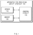
- FIG. 1 is a block diagram illustrating a configuration of an apparatus for providing a safety strategy in a vehicle according to one aspect of the present disclosure.
- an apparatus 100 for providing a safety strategy may include a sensor 110, a memory 120, and a control circuit 130.
- the apparatus 100 for providing the safety strategy in FIG. 1 may be a portion of an autonomous system and may be loaded into the vehicle.
- the sensor 110 may sense information about the outside of the vehicle.
- the sensor 110 may sense information (e.g., a location, a speed, acceleration, and the like) associated with a following vehicle which is traveling on a lane neighboring to a lane where the vehicle is traveling.
- the sensor 110 may sense a speed of the vehicle.
- the memory 120 may store road information.
- the road information may include, for example, a map or the like.
- the road information may include information about whether the road where the vehicle is traveling includes a shoulder.
- the control circuit 140 may be electrically connected with the sensor 110 and the memory 120.
- the control circuit 140 may control the sensor 110 and the memory 120 and may perform a variety of data processing and various arithmetic operations.
- the control circuit 140 may be, for example, an electronic control unit
- ECU electronic unit
- MCU micro controller unit
- sub-controller which is loaded into the vehicle.
- control circuit 140 may provide a transition demand of the vehicle to a driver of the vehicle.
- control circuit 140 may output the transition demand using an output device (not shown).
- the transition demand may be ignored by the driver. For example, when the driver of the vehicle does not respond to the transition demand during a specified time interval after the transition demand occurs, the control circuit 130 may determine that the transition demand is ignored.
- the control circuit 130 may generate a route which is toward a shoulder included in the road where the vehicle is traveling.
- the control circuit 130 may execute a minimum risk maneuver (MRM) for the safety of the driver.
- MRM minimum risk maneuver
- the control circuit 130 may execute a strategy for stopping the vehicle or a strategy for moving the vehicle to a shoulder.
- the control circuit 130 may generate a route which is toward the shoulder.
- the control circuit 130 may determine whether a shoulder is included in a road where the vehicle is traveling, based on road information. When the shoulder is included in the road where the vehicle is traveling, the control circuit 130 may generate a route which is toward the shoulder. The control circuit 130 may determine whether there is a shoulder using the road information stored in the memory 120 and may execute a strategy for moving the vehicle to the shoulder. According to one aspect, when the shoulder is not included in the road where the vehicle is traveling, the control circuit 130 may control stopping in the road where the vehicle is traveling.
- the control circuit 130 may adjust an operational condition of an automatic lane change at least a portion of a speed of the vehicle, a speed of a following vehicle which is traveling in a target lane of a route, or a distance between the vehicle and the following vehicle.
- the operational condition may include, for example, a sensor sensing distance condition, an operational distance condition, and an operational speed condition.
- the operational condition may be preset.
- the predetermined operational condition may be difficult to be satisfied in an MRM situation.
- the control circuit 130 may move the vehicle to the shoulder using an automatic lane change in the MRM situation by adjusting the operational condition. For example, when a distance sensible by the sensor 110 is greater than or equal to 55 m, the predetermined sensor sensing distance condition may be satisfied.
- the control circuit 130 may determine that the sensor sensing distance condition is met when a following vehicle is sensed by the sensor 110 by adjusting the predetermined sensor sensing distance condition.
- the operational distance condition may be adjusted based on, for example, a speed of the vehicle and a relative speed between the vehicle and the following vehicle.
- the operational speed condition may be adjusted based on, for example, a speed of the following vehicle and a distance between the vehicle and the following vehicle. A description will be given in detail of the adjustment of the operational distance condition and the operational speed condition with reference to FIGS. 4 and 5 .
- the control circuit 130 may adjust the operational condition based on the information collected by the sensor 110.
- control circuit 130 may adjust an operational condition.
- the control circuit 130 may mitigate the operational condition to execute the strategy.
- the control circuit 130 may calculate an expected time taken to enter the shoulder and may adjust an operational condition when the expected time is longer than a specified time.
- the control circuit 130 may calculate an expected time taken to enter the shoulder, based on the generated route and the information collected by the sensor 110.
- the control circuit 130 may shorten a time taken to enter the shoulder, by mitigating the operational condition.
- the control circuit 130 may perform an automatic lane change toward the shoulder along the route.
- the control circuit 130 may control stopping in the shoulder.
- the apparatus for providing the safety strategy in the vehicle may effectively execute the MRM by mitigating the operational condition of the automatic lane change when executing the MRM.
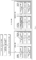
- FIG. 2 is a drawing illustrating an exemplary operation of an apparatus for providing a safety strategy in a vehicle according to one aspect of the present disclosure.
- the vehicle may generate a transition demand such that a driver of the vehicle controls the vehicle.
- the vehicle may activate an MRM.
- the vehicle may search for a shoulder on a road where it is traveling.
- the vehicle may first activate a normal MRM.
- the vehicle may control its stopping. For example, the vehicle may calculate a distance required until stopping and may calculate deceleration, thus controlling its stopping based on the calculated results.
- the vehicle may control its stopping in the shoulder. For example, the vehicle may calculate an expected time T LC taken. For example, the expected time T LC taken may be calculated by multiplying the number of lanes from the lane where the vehicle is currently traveling to the shoulder by 6 seconds and may adding a time margin of 3 seconds to the multiplied value. When the expected time T LC taken is shorter than a specified time T NormalMRM , the vehicle may initiate lane change control.
- the vehicle may activate an emergency MRM.
- the vehicle may change an operational condition of a lane change.
- the vehicle may calculate an expected time T LC taken again based on the changed operational condition.
- the vehicle may initiate lane change control.
- the vehicle may control its stopping.
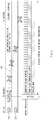
- FIG. 3 is a drawing illustrating an exemplary operation of an apparatus for providing a safety strategy in a vehicle according to one aspect of the present disclosure.
- a vehicle 310 may generate a route 330 which is toward a shoulder.
- the vehicle 310 may generate a driver warning and may turn on/off emergency lights.
- the vehicle 310 may adjust an operational condition of an automatic lane change.
- the vehicle 310 may determine that a sensor sensing distance condition is satisfied.
- a critical distance calculated based on a speed of the vehicle 310 and a relative distance between the vehicle 310 and the following vehicle 320 is less than a distance between the vehicle 310 and the following vehicle 320
- the vehicle 310 may determine that an operational distance condition is satisfied.
- an operational speed calculated based on a speed of the following vehicle 320 and a distance between the vehicle 310 and the following vehicle 320 is slower than a speed of the vehicle 310, the vehicle 310 may determine that an operational speed condition is satisfied.
- the vehicle 310 may perform lane change control toward the shoulder.
- the vehicle 310 may control its stopping.
- FIG. 4 is a drawing illustrating an exemplary operation of an apparatus for providing a safety strategy in a vehicle according to one aspect of the present disclosure.
- a critical distance (an operational distance condition) may be adjusted based on a speed of the vehicle and a relative speed between the vehicle and a following vehicle. As shown in FIG. 4 , the critical distance may be adjusted to increase as a speed of the vehicle increases and increase as a relative speed between the vehicle and the following vehicle increases. For example, when the speed of the vehicle is less than or equal to 60 kph, when the relative speed is less than or equal to 30 kph, and when the distance between the vehicle and the following vehicle is greater than or equal to 40 m, the operational distance condition may be satisfied.
- FIG. 5 is a drawing illustrating an exemplary operation of an apparatus for providing a safety strategy in a vehicle according to one aspect of the present disclosure.
- a reduced or minimum speed (an operational speed condition) may be adjusted based on a speed of a following speed and a distance between the vehicle and the following speed.
- the reduced or minimum speed may be adjusted to increase as the following vehicle increases in speed and decrease as a distance between the vehicle and the following vehicle increases. For example, when the speed of the following vehicle is less than or equal to 40 kph, when the distance between the vehicle and the following vehicle is greater than or equal to 20 m, and when the speed of the vehicle is greater than or equal to 10 kph, the operational speed condition may be satisfied.
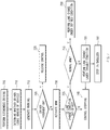
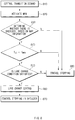
- FIG. 6 is a flowchart illustrating a method for providing a safety strategy in a vehicle according to one aspect of the present disclosure.
- a vehicle including an apparatus 100 for providing a safety strategy in FIG. 1 performs a process of FIG. 6 .
- an operation described as being performed by the vehicle may be understood as being controlled by a control circuit 130 of the apparatus 100 for providing the safety strategy.
- the vehicle may provide a transition demand of the vehicle to its driver.
- the vehicle may output the transition demand to hand over control authority to the driver.
- the vehicle may determine whether the transition demand is ignored. For example, when the driver does not approve the transition demand during a specified time, the vehicle may determine that the transition demand is ignored.
- the vehicle may hand over control authority to the driver.
- the vehicle may release the control by an autonomous system.
- the vehicle may generate a route which is toward a shoulder included in a road where it is traveling. For example, the vehicle may execute a strategy, as one of MRMs, for moving the vehicle to the shoulder.
- the vehicle may adjust an operational condition of an automatic lane change based on at least a portion of a speed of the vehicle, a speed of a following vehicle, or a distance between the vehicle and the following vehicle. For example, a predetermined sensor sensing distance condition may be satisfied when a distance sensible by a sensor of the vehicle is greater than a specified distance. After the vehicle changes the predetermined sensor sensing distance condition, when the following vehicle is sensed by the sensor, the vehicle may determine that the sensor sensing distance condition is satisfied.
- An operational distance condition may be calculated based on a speed of the vehicle and a relative speed between the vehicle and the following vehicle.
- the operational speed condition may be calculated based on a speed of the following vehicle and a distance between the vehicle and the following vehicle.
- the vehicle may determine whether the adjusted operational condition is satisfied. When the adjusted operational condition is satisfied, in operation 670, the vehicle may perform an automatic lane change toward the shoulder along the generated route. When the adjusted operational condition is not satisfied, in operation 680, the vehicle may control its stopping in the lane where the vehicle is traveling.
- FIG. 7 is a flowchart illustrating a method for providing a safety strategy in a vehicle according to one aspect of the present disclosure.
- a vehicle including an apparatus 100 for providing a safety strategy in FIG. 1 performs a process of FIG. 7 .
- an operation described as being performed by the vehicle may be understood as being controlled by a control circuit 130 of the apparatus 100 for providing the safety strategy.
- the vehicle may perform autonomous driving.
- the vehicle may determine whether its driver looks ahead of the vehicle.
- the vehicle may generate a warning.
- the vehicle may determine whether the driver intervenes.
- control authority is handed over to the driver after the driver intervenes, in operation 725, the vehicle may release the autonomous control.
- the vehicle may activate an MRM.
- the vehicle may determine whether an operational condition of a lane change is satisfied.
- the condition is not satisfied, in operation 740, the vehicle may control its stopping.
- the condition is satisfied, in operation 745, the vehicle may determine whether it is able to perform a normal MRM.
- the vehicle may perform a lane change under a defined condition.
- the vehicle may change the operational condition of the lane change and may perform a lane change under the changed operational condition.
- the vehicle may control its stopping in a shoulder.
- FIG. 8 is a flowchart illustrating a method for providing a safety strategy in a vehicle according to one aspect of the present disclosure.
- a vehicle including an apparatus 100 for providing a safety strategy in FIG. 1 performs a process of FIG. 8 .
- an operation described as being performed by the vehicle may be understood as being controlled by a control circuit 130 of the apparatus 100 for providing the safety strategy.
- the vehicle may provide a transition demand to its driver.
- the vehicle may activate an MRM.
- the vehicle may determine whether there is a shoulder, based on map information.
- the vehicle may determine whether an expected time T LC taken to move to the shoulder is shorter than a specified time T MRM .
- the vehicle may determine whether a lane change condition is satisfied.
- the vehicle may perform lane change control.
- the vehicle may control its stopping in the shoulder.
- the vehicle may control its stopping without a lane change.
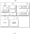
- FIG. 9 is a block diagram illustrating a configuration of a computing system according to one aspect of the present disclosure.
- a computing system 1000 may include at least one processor 1100, a memory 1300, a user interface input device 1400, a user interface output device 1500, a storage 1600, and a network interface 1700, which are connected with each other via a bus 1200.
- the processor 1100 may be a central processing unit (CPU) or a semiconductor device for performing processing of instructions stored in the memory 1300 and/or the storage 1600.
- CPU central processing unit
- Each of the memory 1300 and the storage 1600 may include various types of volatile or non-volatile storage media.
- the memory 1300 may include a read only memory (ROM) and a random access memory (RAM).
- the operations of the methods or algorithms described in connection with the specification may be directly implemented with a hardware module, a software module, or combinations thereof, executed by the processor 1100.
- the software module may reside on a storage medium (i.e., the memory 1300 and/or the storage 1600) such as a RAM, a flash memory, a ROM, an erasable and programmable ROM (EPROM), an electrically EPROM (EEPROM), a register, a hard disc, a removable disc, or a compact disc-ROM (CD-ROM).
- An exemplary storage medium may be coupled to the processor 1100.
- the processor 1100 may read out information from the storage medium and may write information in the storage medium.
- the storage medium may be integrated with the processor 1100.
- the processor and storage medium may reside in an application specific integrated circuit (ASIC).
- the ASIC may reside in a user terminal.
- the processor and storage medium may reside as a separate component of the user terminal.
- the apparatus for providing the safety strategy in the vehicle may provide a safety strategy capable of providing for the safety of the driver in a situation where a predetermined operational condition is not satisfied, by adjusting an operational condition of an automatic lane change in a critical situation.
Landscapes
- Engineering & Computer Science (AREA)
- Automation & Control Theory (AREA)
- Transportation (AREA)
- Mechanical Engineering (AREA)
- Human Computer Interaction (AREA)
- Physics & Mathematics (AREA)
- Mathematical Physics (AREA)
- Aviation & Aerospace Engineering (AREA)
- Radar, Positioning & Navigation (AREA)
- Remote Sensing (AREA)
- General Physics & Mathematics (AREA)
- Control Of Driving Devices And Active Controlling Of Vehicle (AREA)
- Traffic Control Systems (AREA)
Applications Claiming Priority (2)
| Application Number | Priority Date | Filing Date | Title |
|---|---|---|---|
| US201862655831P | 2018-04-11 | 2018-04-11 | |
| KR1020180143881A KR102610742B1 (ko) | 2018-04-11 | 2018-11-20 | 차량의 안전 전략 제공 장치 및 방법 |
Publications (2)
| Publication Number | Publication Date |
|---|---|
| EP3552903A1 true EP3552903A1 (de) | 2019-10-16 |
| EP3552903B1 EP3552903B1 (de) | 2022-03-09 |
Family
ID=66092158
Family Applications (1)
| Application Number | Title | Priority Date | Filing Date |
|---|---|---|---|
| EP19167269.0A Active EP3552903B1 (de) | 2018-04-11 | 2019-04-04 | Vorrichtung und verfahren zur bereitstellung einer sicherheitsstrategie an ein fahrzeug |
Country Status (3)
| Country | Link |
|---|---|
| US (1) | US11084491B2 (de) |
| EP (1) | EP3552903B1 (de) |
| CN (1) | CN110371135B (de) |
Cited By (1)
| Publication number | Priority date | Publication date | Assignee | Title |
|---|---|---|---|---|
| CN112977470A (zh) * | 2019-12-12 | 2021-06-18 | 现代自动车株式会社 | 用于控制车辆的装置及方法 |
Families Citing this family (7)
| Publication number | Priority date | Publication date | Assignee | Title |
|---|---|---|---|---|
| US11199847B2 (en) * | 2018-09-26 | 2021-12-14 | Baidu Usa Llc | Curvature corrected path sampling system for autonomous driving vehicles |
| DE102018220127A1 (de) * | 2018-11-23 | 2020-05-28 | Ford Global Technologies, Llc | Spurwechselassistenzsystem |
| JP7022680B2 (ja) * | 2018-12-27 | 2022-02-18 | 本田技研工業株式会社 | 車両制御装置 |
| KR102764275B1 (ko) * | 2019-12-06 | 2025-02-07 | 현대자동차주식회사 | 갓길 주차 상태 정보를 이용한 경로 탐색 방법 및 시스템 |
| CN112172801B (zh) * | 2020-03-03 | 2021-10-08 | 星空映画(武汉)科技有限公司 | 应用大数据处理的安全距离调整方法 |
| JP7226400B2 (ja) * | 2020-07-01 | 2023-02-21 | トヨタ自動車株式会社 | 運転計画装置及び運転計画用コンピュータプログラム |
| US11872988B2 (en) * | 2020-11-10 | 2024-01-16 | GM Global Technology Operations LLC | Method and system to adapt overtake decision and scheduling based on driver assertions |
Citations (5)
| Publication number | Priority date | Publication date | Assignee | Title |
|---|---|---|---|---|
| US20060009910A1 (en) * | 2004-06-17 | 2006-01-12 | Frank Ewerhart | Lane changing assistant for motor vehicles |
| US8521352B1 (en) * | 2012-05-07 | 2013-08-27 | Google Inc. | Controlling a vehicle having inadequate map data |
| DE102015205131A1 (de) * | 2015-03-20 | 2016-09-22 | Bayerische Motoren Werke Aktiengesellschaft | Verfahren zum Betreiben eines zumindest teilweise automatisiert fahrenden Fahrzeugs innerhalb einer Fahrstrecke |
| US20170108865A1 (en) * | 2015-10-20 | 2017-04-20 | Robert Bosch Gmbh | Method for selecting an optimized trajectory |
| US20180029604A1 (en) * | 2015-02-10 | 2018-02-01 | Denso Corporation | Evacuation control apparatus and evacuation control method |
Family Cites Families (209)
| Publication number | Priority date | Publication date | Assignee | Title |
|---|---|---|---|---|
| DE4313568C1 (de) | 1993-04-26 | 1994-06-16 | Daimler Benz Ag | Verfahren zur Leithilfe für einen Fahrspurwechsel durch ein Kraftfahrzeug |
| DE19632929C1 (de) | 1996-08-16 | 1997-11-27 | Daimler Benz Ag | Vorrichtung zur selbsttätigen Fahrzeugquerführung längs einer Fahrspur |
| DE19821122A1 (de) | 1997-12-15 | 1999-06-17 | Volkswagen Ag | Verfahren zur Regelung von Geschwindigkeit und Abstand bei Überholvorgängen |
| JP2000198458A (ja) | 1999-01-08 | 2000-07-18 | Mazda Motor Corp | 車両の制御装置 |
| JP3529037B2 (ja) | 1999-08-02 | 2004-05-24 | 日産自動車株式会社 | 車線追従装置 |
| DE10114187A1 (de) | 2001-03-23 | 2002-09-26 | Bosch Gmbh Robert | Verfahren und Vorrichtung zur Unterstützung eines Überholvorgangs bei Kraftfahrzeugen |
| JP2003025868A (ja) | 2001-07-16 | 2003-01-29 | Nissan Motor Co Ltd | 車両の車線変更支援装置 |
| DE10218010A1 (de) | 2002-04-23 | 2003-11-06 | Bosch Gmbh Robert | Verfahren und Vorrichtung zur Querführungsunterstützung bei Kraftfahrzeugen |
| CA2531662C (en) | 2003-07-07 | 2016-04-26 | Sensomatix Ltd. | Traffic information system |
| DE602004008541T2 (de) | 2003-07-07 | 2008-04-30 | Nissan Motor Co., Ltd., Yokohama | Steuersystem für ein Fahrzeug zum Halten der Fahrspur |
| DE10350779A1 (de) | 2003-10-30 | 2005-06-02 | Robert Bosch Gmbh | Spurhaltesystem für ein Kraftfahrzeug und Betriebsverfahren |
| JP4032253B2 (ja) | 2003-12-17 | 2008-01-16 | ソニー株式会社 | 光通信装置及び車両制御方法 |
| DE102004005815B3 (de) | 2004-02-06 | 2005-06-09 | Audi Ag | Kraftfahrzeug mit einer Einrichtung zur kombinierten Anzeige des aktuellen Ein- oder Aus-Status mehrerer Systeme zur Unterstützung des Fahrers |
| KR100578573B1 (ko) | 2004-05-06 | 2006-05-12 | 기아자동차주식회사 | 제한속도표시 및 경고장치 |
| JP4379199B2 (ja) | 2004-05-17 | 2009-12-09 | 日産自動車株式会社 | 車線変更支援装置および方法 |
| DE102004048009A1 (de) | 2004-10-01 | 2006-04-06 | Robert Bosch Gmbh | Verfahren und Vorrichtung zur Fahrerunterstützung |
| DE102004048468A1 (de) | 2004-10-05 | 2006-04-13 | Siemens Ag | System und Verfahren zur Einstellung der Geschwindigkeit eines Fahrzeugs auf eine zulässige Höchstgeschwindigkeit |
| JP2008531388A (ja) * | 2005-03-03 | 2008-08-14 | コンティネンタル・テーベス・アクチエンゲゼルシヤフト・ウント・コンパニー・オッフェネ・ハンデルスゲゼルシヤフト | 車両の車線変更時の衝突回避方法及び装置 |
| US7881848B2 (en) | 2006-04-28 | 2011-02-01 | Nissan Motor Co., Ltd. | Lane departure prevention apparatus and method |
| JP4582052B2 (ja) | 2006-06-07 | 2010-11-17 | トヨタ自動車株式会社 | 走行支援装置 |
| JP4449960B2 (ja) | 2006-08-22 | 2010-04-14 | トヨタ自動車株式会社 | 操舵支援装置 |
| JP4525670B2 (ja) | 2006-11-20 | 2010-08-18 | トヨタ自動車株式会社 | 走行制御計画生成システム |
| DE102007005245A1 (de) | 2007-02-02 | 2007-11-22 | Daimlerchrysler Ag | Verfahren zum Betreiben eines Fahrerassistenzsystems und Fahrerassistenzsystem für ein Kraftfahrzeug |
| JP4748122B2 (ja) | 2007-06-28 | 2011-08-17 | 日産自動車株式会社 | 車線逸脱防止装置 |
| JP4366419B2 (ja) | 2007-09-27 | 2009-11-18 | 株式会社日立製作所 | 走行支援装置 |
| US8090516B2 (en) | 2007-11-20 | 2012-01-03 | Nissan Motor Co., Ltd. | Lane deviation prevention device and method |
| DE102008001677A1 (de) | 2008-05-09 | 2009-11-12 | Robert Bosch Gmbh | Assistenzsystem zur Fahrerunterstützung in Fahrzeugen |
| US8392064B2 (en) | 2008-05-27 | 2013-03-05 | The Board Of Trustees Of The Leland Stanford Junior University | Systems, methods and devices for adaptive steering control of automotive vehicles |
| US8170739B2 (en) | 2008-06-20 | 2012-05-01 | GM Global Technology Operations LLC | Path generation algorithm for automated lane centering and lane changing control system |
| US9846049B2 (en) | 2008-07-09 | 2017-12-19 | Microsoft Technology Licensing, Llc | Route prediction |
| DE112010000085A5 (de) | 2009-02-03 | 2012-08-16 | Adc Automotive Distance Control Systems Gmbh | Geschwindigkeitsvoreinstellung für ein Fahrzeug mit automatischer Längsregelung |
| EP2423901B1 (de) | 2009-04-23 | 2017-03-15 | Panasonic Intellectual Property Management Co., Ltd. | Antriebshilfsvorrichtung, antriebshilfsverfahren und programm |
| US8164543B2 (en) | 2009-05-18 | 2012-04-24 | GM Global Technology Operations LLC | Night vision on full windshield head-up display |
| US8384534B2 (en) | 2010-01-14 | 2013-02-26 | Toyota Motor Engineering & Manufacturing North America, Inc. | Combining driver and environment sensing for vehicular safety systems |
| DE102010004625A1 (de) | 2010-01-14 | 2011-07-21 | Ford Global Technologies, LLC, Mich. | Verfahren und Vorrichtung zur Unterstützung eines Fahrers bei einem Überholvorgang |
| CN102378712B (zh) | 2010-03-12 | 2014-12-10 | 丰田自动车株式会社 | 转向辅助装置 |
| US8618922B2 (en) | 2010-03-30 | 2013-12-31 | GM Global Technology Operations LLC | Method and system for ensuring operation of limited-ability autonomous driving vehicles |
| US8977419B2 (en) | 2010-12-23 | 2015-03-10 | GM Global Technology Operations LLC | Driving-based lane offset control for lane centering |
| WO2012131405A1 (en) | 2011-03-29 | 2012-10-04 | Josic Ante | Automatic control of maximum speed and automatic control system thereof |
| DE102011016770B4 (de) | 2011-04-12 | 2021-02-04 | Daimler Ag | Verfahren zur Unterstützung eines Fahrers eines Fahrzeugs bei einem Fahrspurwechsel und Vorrichtung zur Durchführung des Verfahrens |
| DE102011016771A1 (de) | 2011-04-12 | 2012-10-18 | Daimler Ag | Vorrichtung zur Bedienung einer Fahrspurwechselunterstützung in einem Fahrzeug |
| JP2012226392A (ja) | 2011-04-14 | 2012-11-15 | Honda Elesys Co Ltd | 運転支援システム |
| WO2012160591A1 (ja) | 2011-05-20 | 2012-11-29 | 本田技研工業株式会社 | 車線変更支援システム |
| DE102011109618A1 (de) | 2011-08-05 | 2013-02-07 | Daimler Ag | Verfahren und Vorrichtung zum Betrieb eines Fahrzeuges |
| DE102011081892A1 (de) | 2011-08-31 | 2013-02-28 | Robert Bosch Gmbh | Verfahren zur Fahrspur-Überwachung und Fahrspur-Überwachungssystem für ein Fahrzeug |
| US8838325B2 (en) * | 2011-09-12 | 2014-09-16 | Ford Global Technologies | Vehicle shut-down functionality for peps-equipped vehicles |
| DE102011086241B4 (de) | 2011-11-14 | 2018-04-05 | Robert Bosch Gmbh | Verfahren zum sicheren Abstellen eines Fahrzeuges |
| DE102012001405A1 (de) | 2012-01-26 | 2012-11-22 | Daimler Ag | Verfahren zur Durchführung eines Fahrspurwechsels und Vorrichtung zur Durchführung des Verfahrens |
| DE102012002304A1 (de) | 2012-02-06 | 2013-08-08 | Audi Ag | Vorrichtung zum automatisierten Führen eines Kraftwagens und Verfahren zum Betreiben eines Kraftwagens |
| JP5868218B2 (ja) | 2012-02-28 | 2016-02-24 | 株式会社日本自動車部品総合研究所 | 車両制御装置 |
| US8457827B1 (en) | 2012-03-15 | 2013-06-04 | Google Inc. | Modifying behavior of autonomous vehicle based on predicted behavior of other vehicles |
| US9315178B1 (en) * | 2012-04-13 | 2016-04-19 | Google Inc. | Model checking for autonomous vehicles |
| DE102012008090A1 (de) | 2012-04-21 | 2013-10-24 | Volkswagen Aktiengesellschaft | Verfahren und Vorrichtung zum Nothalt eines Kraftfahrzeugs |
| US9505411B2 (en) * | 2012-07-24 | 2016-11-29 | Toyota Jidosha Kabushiki Kaisha | Drive assist device |
| US8798841B1 (en) * | 2013-03-14 | 2014-08-05 | GM Global Technology Operations LLC | System and method for improving sensor visibility of vehicle in autonomous driving mode |
| US9751534B2 (en) | 2013-03-15 | 2017-09-05 | Honda Motor Co., Ltd. | System and method for responding to driver state |
| GB2512317A (en) | 2013-03-26 | 2014-10-01 | Jaguar Land Rover Ltd | Vehicle control system and method |
| US8874301B1 (en) * | 2013-07-09 | 2014-10-28 | Ford Global Technologies, Llc | Autonomous vehicle with driver presence and physiological monitoring |
| US8930060B1 (en) | 2013-07-15 | 2015-01-06 | Ford Global Technologies | Post-impact path assist for vehicles |
| DE102013219887A1 (de) | 2013-10-01 | 2015-04-02 | Volkswagen Aktiengesellschaft | Verfahren für ein Fahrerassistenzsystem eines Fahrzeugs |
| RU2624392C1 (ru) | 2013-10-11 | 2017-07-03 | Ниссан Мотор Ко., Лтд. | Устройство управления движением и способ управления движением |
| KR20150061752A (ko) | 2013-11-28 | 2015-06-05 | 현대모비스 주식회사 | 차량 운행 보조 장치 및 그 장치에 의한 차량 운행 보조 기능의 자동 활성화 방법 |
| US9988047B2 (en) | 2013-12-12 | 2018-06-05 | Magna Electronics Inc. | Vehicle control system with traffic driving control |
| JP6237256B2 (ja) | 2014-01-21 | 2017-11-29 | 日産自動車株式会社 | 車速制御装置 |
| KR20150087619A (ko) | 2014-01-22 | 2015-07-30 | 한국전자통신연구원 | 증강 현실 기반의 차로 변경 안내 장치 및 방법 |
| JP6064946B2 (ja) * | 2014-05-30 | 2017-01-25 | 株式会社デンソー | 退避走行支援装置 |
| KR101551096B1 (ko) | 2014-06-05 | 2015-09-21 | 현대자동차주식회사 | 자율주행차량의 차선변경장치 및 방법 |
| US9457807B2 (en) | 2014-06-05 | 2016-10-04 | GM Global Technology Operations LLC | Unified motion planning algorithm for autonomous driving vehicle in obstacle avoidance maneuver |
| JP2016000602A (ja) | 2014-06-12 | 2016-01-07 | トヨタ自動車株式会社 | 車線変更支援装置 |
| JP6031066B2 (ja) | 2014-06-17 | 2016-11-24 | 富士重工業株式会社 | 車両の走行制御装置 |
| JP6299872B2 (ja) | 2014-08-11 | 2018-03-28 | 日産自動車株式会社 | 車両の走行制御装置及び方法 |
| EP3001272B1 (de) | 2014-09-26 | 2017-04-12 | Volvo Car Corporation | Verfahren zur Bahnplanung bei Fließmanövern |
| US9499197B2 (en) | 2014-10-15 | 2016-11-22 | Hua-Chuang Automobile Information Technical Center Co., Ltd. | System and method for vehicle steering control |
| JP6086106B2 (ja) | 2014-10-16 | 2017-03-01 | トヨタ自動車株式会社 | 運転支援装置 |
| DE102014225680A1 (de) | 2014-12-12 | 2016-06-16 | Volkswagen Aktiengesellschaft | Verfahren und Vorrichtung zur Übernahmeaufforderung einer Fahraufgabe an den Fahrzeugführer eines Fahrzeugs im Rahmen des automatischen Fahrens des Fahrzeugs |
| JP6470039B2 (ja) | 2014-12-26 | 2019-02-13 | 日立オートモティブシステムズ株式会社 | 車両制御システム |
| KR102036050B1 (ko) * | 2014-12-30 | 2019-10-24 | 주식회사 만도 | 차선 변경 장치 및 방법 |
| US10705521B2 (en) | 2014-12-30 | 2020-07-07 | Visteon Global Technologies, Inc. | Autonomous driving interface |
| JP6137212B2 (ja) | 2015-02-02 | 2017-05-31 | トヨタ自動車株式会社 | 運転支援装置 |
| JP2016151815A (ja) | 2015-02-16 | 2016-08-22 | 株式会社デンソー | 運転支援装置 |
| JP6154411B2 (ja) | 2015-02-27 | 2017-06-28 | 本田技研工業株式会社 | 車両の注意喚起装置 |
| JP2016168985A (ja) | 2015-03-16 | 2016-09-23 | トヨタ自動車株式会社 | 走行制御装置 |
| JP6237685B2 (ja) | 2015-04-01 | 2017-11-29 | トヨタ自動車株式会社 | 車両制御装置 |
| JP2016196285A (ja) | 2015-04-03 | 2016-11-24 | 株式会社デンソー | 走行制御装置及び走行制御方法 |
| JP6292218B2 (ja) | 2015-04-03 | 2018-03-14 | 株式会社デンソー | 情報提示装置及び情報提示方法 |
| DE102015206144B4 (de) | 2015-04-07 | 2022-10-06 | Volkswagen Aktiengesellschaft | Verfahren und Vorrichtung zum sicheren Abstellen eines Fahrzeuges |
| JP6511930B2 (ja) * | 2015-04-16 | 2019-05-15 | 株式会社デンソー | 退避走行支援装置 |
| DE102015206969B4 (de) | 2015-04-17 | 2022-02-17 | Bayerische Motoren Werke Aktiengesellschaft | Fahrerassistenzsystem in einem Kraftfahrzeug |
| EP3286058B1 (de) | 2015-04-20 | 2021-07-28 | Bayerische Motoren Werke Aktiengesellschaft | Vorrichtung und verfahren zur steuerung einer benutzersituationsbewusstseinsveränderung eines benutzers eines fahrzeugs und system zur verarbeitung von veränderungen des benutzersituationsbewusstseins |
| WO2016170785A1 (ja) | 2015-04-21 | 2016-10-27 | パナソニックIpマネジメント株式会社 | 情報処理システム、情報処理方法、およびプログラム |
| JP6761967B2 (ja) | 2015-04-21 | 2020-09-30 | パナソニックIpマネジメント株式会社 | 運転支援方法およびそれを利用した運転支援装置、自動運転制御装置、車両、プログラム |
| JP6252548B2 (ja) | 2015-05-22 | 2017-12-27 | トヨタ自動車株式会社 | 車速制限装置及び車速制御装置 |
| DE102015209476A1 (de) | 2015-05-22 | 2016-11-24 | Robert Bosch Gmbh | Systemgrenzen einer automatischen Steuerung |
| KR101750876B1 (ko) | 2015-05-28 | 2017-06-26 | 엘지전자 주식회사 | 차량용 디스플레이 장치 및 차량 |
| WO2016199799A1 (ja) | 2015-06-11 | 2016-12-15 | 日本精工株式会社 | 電動パワーステアリング装置 |
| US9604641B2 (en) | 2015-06-16 | 2017-03-28 | Honda Motor Co., Ltd. | System and method for providing vehicle collision avoidance at an intersection |
| JP6323402B2 (ja) | 2015-07-01 | 2018-05-16 | 株式会社デンソー | 車線内走行制御装置、車線内走行制御方法 |
| JP6332170B2 (ja) | 2015-07-01 | 2018-05-30 | トヨタ自動車株式会社 | 自動運転制御装置 |
| US10259416B2 (en) | 2015-07-28 | 2019-04-16 | Nissan Motor Co., Ltd. | Travel control method and travel control apparatus |
| JP6451851B2 (ja) | 2015-07-28 | 2019-01-16 | 日産自動車株式会社 | 走行制御装置の制御方法および走行制御装置 |
| MY193056A (en) | 2015-07-28 | 2022-09-26 | Nissan Motor | Method for controlling travel control device, and travel control device |
| JP6552316B2 (ja) | 2015-07-29 | 2019-07-31 | 修一 田山 | 車輌の自動運転システム |
| JP5957745B1 (ja) | 2015-07-31 | 2016-07-27 | パナソニックIpマネジメント株式会社 | 運転支援装置、運転支援システム、運転支援方法、運転支援プログラム及び自動運転車両 |
| JP5910904B1 (ja) | 2015-07-31 | 2016-04-27 | パナソニックIpマネジメント株式会社 | 運転支援装置、運転支援システム、運転支援方法、運転支援プログラム及び自動運転車両 |
| JP2017047765A (ja) | 2015-09-01 | 2017-03-09 | 本田技研工業株式会社 | 走行制御装置 |
| JP6568759B2 (ja) | 2015-09-30 | 2019-08-28 | 日立オートモティブシステムズ株式会社 | 車線変更システム |
| DE102015219231A1 (de) | 2015-10-06 | 2017-04-06 | Robert Bosch Gmbh | Ansteuervorrichtung und Verfahren zum Betreiben eines Fahrerassistenzsystems |
| WO2017060978A1 (ja) | 2015-10-06 | 2017-04-13 | 株式会社日立製作所 | 自動運転制御装置および自動運転制御方法 |
| JP6519435B2 (ja) | 2015-10-16 | 2019-05-29 | 株式会社デンソー | 報知管理装置及び報知管理方法 |
| US10217363B2 (en) | 2015-10-29 | 2019-02-26 | Faraday&Future Inc. | Methods and systems for electronically assisted lane entrance |
| JP6447468B2 (ja) | 2015-11-17 | 2019-01-09 | 株式会社デンソー | 運転支援装置 |
| DE102015224244A1 (de) | 2015-12-03 | 2017-06-08 | Bayerische Motoren Werke Aktiengesellschaft | Steuersystem zur Beeinflussung von automatischen Fahrfunktionen eines Fahrzeugs durch einen Fahrer |
| US9699289B1 (en) | 2015-12-09 | 2017-07-04 | Toyota Motor Engineering & Manufacturing North America, Inc. | Dynamic vehicle automation level availability indication system and method |
| DE102016007187A1 (de) | 2015-12-19 | 2017-06-22 | Daimler Ag | Verfahren zum Deaktivieren einer automatisierten Fahrfunktion eines Fahrzeugs und Fahrerassistenzsystem zur Durchführung des Verfahrens |
| JP6787671B2 (ja) | 2016-01-14 | 2020-11-18 | 株式会社デンソー | 合流支援装置 |
| JP6515823B2 (ja) | 2016-01-14 | 2019-05-22 | 株式会社デンソー | 車線変更支援装置 |
| US10324463B1 (en) | 2016-01-22 | 2019-06-18 | State Farm Mutual Automobile Insurance Company | Autonomous vehicle operation adjustment based upon route |
| JP6246844B2 (ja) | 2016-02-18 | 2017-12-13 | 本田技研工業株式会社 | 車両制御システム、車両制御方法、および車両制御プログラム |
| JP6517161B2 (ja) | 2016-02-18 | 2019-05-22 | 本田技研工業株式会社 | 走行制御装置 |
| JP6209232B2 (ja) | 2016-02-19 | 2017-10-04 | 本田技研工業株式会社 | 車線変更支援装置 |
| JP6838248B2 (ja) | 2016-02-22 | 2021-03-03 | 日立Astemo株式会社 | 情報処理装置 |
| DE102016203020A1 (de) | 2016-02-25 | 2017-08-31 | Bayerische Motoren Werke Aktiengesellschaft | Fahrerassistenzsystem mit per Feststellbremse-Bedienelement aktivierbarer Nothaltefunktion |
| JP6308233B2 (ja) | 2016-02-29 | 2018-04-11 | トヨタ自動車株式会社 | 車両制御装置及び車両制御方法 |
| FR3049560B1 (fr) | 2016-04-01 | 2019-08-09 | Valeo Schalter Und Sensoren Gmbh | Procede et systeme d'assistance au changement de voie de roulage pour vehicule automobile |
| JP6460349B2 (ja) * | 2016-04-13 | 2019-01-30 | トヨタ自動車株式会社 | 車両走行制御装置 |
| JP6485399B2 (ja) | 2016-04-15 | 2019-03-20 | 株式会社デンソー | 支援装置 |
| JP6275187B2 (ja) | 2016-04-28 | 2018-02-07 | 本田技研工業株式会社 | 車両制御システム、車両制御方法、および車両制御プログラム |
| JP2017200786A (ja) | 2016-05-02 | 2017-11-09 | 本田技研工業株式会社 | 車両制御システム、車両制御方法、および車両制御プログラム |
| KR101779823B1 (ko) | 2016-05-10 | 2017-10-10 | 재단법인대구경북과학기술원 | 자율주행차량의 제어 모드 전환 방법 및 그 장치 |
| JP6387369B2 (ja) | 2016-05-23 | 2018-09-05 | 本田技研工業株式会社 | 走行制御装置 |
| JP6535634B2 (ja) | 2016-05-26 | 2019-06-26 | 本田技研工業株式会社 | 経路案内装置及び経路案内方法 |
| JP6449195B2 (ja) | 2016-06-02 | 2019-01-09 | 本田技研工業株式会社 | 運転支援装置 |
| JP7031581B2 (ja) | 2016-06-02 | 2022-03-08 | ソニーグループ株式会社 | 情報処理装置と情報処理方法 |
| JP6778872B2 (ja) | 2016-06-28 | 2020-11-04 | パナソニックIpマネジメント株式会社 | 運転支援装置及び運転支援方法 |
| KR101844885B1 (ko) | 2016-07-11 | 2018-05-18 | 엘지전자 주식회사 | 차량 운전 보조장치 및 이를 포함하는 차량 |
| JP6809020B2 (ja) | 2016-07-27 | 2021-01-06 | いすゞ自動車株式会社 | 操舵補助装置及び操舵補助方法 |
| CN107672584B (zh) | 2016-07-29 | 2022-05-03 | 福特环球技术公司 | 超车车道控制的系统和方法 |
| JP6831190B2 (ja) | 2016-08-15 | 2021-02-17 | トヨタ自動車株式会社 | 自動運転車両の制御システム及び制御方法 |
| DE102016215565A1 (de) | 2016-08-19 | 2018-02-22 | Continental Automotive Gmbh | Fahrerassistenzsystem für Überholvorgänge |
| US20180050659A1 (en) | 2016-08-22 | 2018-02-22 | Faraday&Future Inc. | Electric seatbelt notification systems and methods |
| DE102016216134A1 (de) | 2016-08-29 | 2018-03-01 | Bayerische Motoren Werke Aktiengesellschaft | Verschieben der Querposition einer automatisierten Querführung zum Informieren des Fahrers über einen erforderlichen Spurwechsel |
| KR20180024414A (ko) * | 2016-08-30 | 2018-03-08 | 현대자동차주식회사 | 차량 및 그 제어방법 |
| US20180239352A1 (en) | 2016-08-31 | 2018-08-23 | Faraday&Future Inc. | System and method for operating vehicles at different degrees of automation |
| JP6609229B2 (ja) | 2016-09-02 | 2019-11-20 | 株式会社デンソー | 物体検知装置 |
| DE102016117438A1 (de) | 2016-09-16 | 2018-03-22 | Knorr-Bremse Systeme für Nutzfahrzeuge GmbH | Verfahren und Vorrichtung zum Steuern einer Bewegung eines Fahrzeugs und Fahrzeugbewegungssteuersystem |
| US10496090B2 (en) | 2016-09-29 | 2019-12-03 | Magna Electronics Inc. | Handover procedure for driver of autonomous vehicle |
| JP6731619B2 (ja) | 2016-10-26 | 2020-07-29 | パナソニックIpマネジメント株式会社 | 情報処理システム、情報処理方法、およびプログラム |
| WO2018079297A1 (ja) | 2016-10-27 | 2018-05-03 | 日立オートモティブシステムズ株式会社 | 故障検知装置 |
| US9874871B1 (en) | 2016-11-21 | 2018-01-23 | Baidu Usa Llc | Method to dynamically adjusting steering rates of autonomous vehicles |
| WO2018096644A1 (ja) | 2016-11-25 | 2018-05-31 | 本田技研工業株式会社 | 車両用表示制御装置、車両用表示制御方法、および車両用表示制御プログラム |
| JP6466899B2 (ja) | 2016-12-01 | 2019-02-06 | 株式会社Subaru | 車両用表示装置 |
| JP6490044B2 (ja) | 2016-12-09 | 2019-03-27 | 本田技研工業株式会社 | 車両用制御装置 |
| JP6642399B2 (ja) | 2016-12-07 | 2020-02-05 | トヨタ自動車株式会社 | 車両走行制御装置 |
| KR20180070401A (ko) | 2016-12-16 | 2018-06-26 | 현대자동차주식회사 | 자율주행차량의 운전 제어권 이양을 판단하는 시스템 및 방법 |
| JP6895634B2 (ja) | 2016-12-16 | 2021-06-30 | パナソニックIpマネジメント株式会社 | 情報処理システム、情報処理方法、およびプログラム |
| JP6919429B2 (ja) | 2016-12-21 | 2021-08-18 | トヨタ自動車株式会社 | 運転支援装置 |
| JP6547970B2 (ja) | 2016-12-26 | 2019-07-24 | トヨタ自動車株式会社 | 車両の車線変更支援装置 |
| JP6579334B2 (ja) | 2016-12-26 | 2019-09-25 | トヨタ自動車株式会社 | 車両の車線変更支援装置 |
| JP6686871B2 (ja) | 2016-12-26 | 2020-04-22 | トヨタ自動車株式会社 | 自動運転システム |
| JP2018103766A (ja) | 2016-12-26 | 2018-07-05 | トヨタ自動車株式会社 | 車両の車線変更支援装置 |
| JP6635023B2 (ja) | 2016-12-26 | 2020-01-22 | トヨタ自動車株式会社 | 車両の車線変更支援装置 |
| JP6572880B2 (ja) | 2016-12-28 | 2019-09-11 | トヨタ自動車株式会社 | 運転支援装置 |
| US10569782B2 (en) | 2016-12-29 | 2020-02-25 | Automotive Research & Testing Center | Interactive autonomous safe driving system and deciding method thereof |
| US10254121B2 (en) | 2017-01-23 | 2019-04-09 | Uber Technologies, Inc. | Dynamic routing for self-driving vehicles |
| US10220857B2 (en) | 2017-02-23 | 2019-03-05 | Uber Technologies, Inc. | Vehicle control system |
| US10328973B2 (en) | 2017-03-06 | 2019-06-25 | Ford Global Technologies, Llc | Assisting drivers with roadway lane changes |
| US10754029B2 (en) | 2017-03-31 | 2020-08-25 | Ford Global Technologies, Llc | Vehicle human machine interface control |
| JP2018176935A (ja) | 2017-04-10 | 2018-11-15 | トヨタ自動車株式会社 | 自動運転装置 |
| US11142246B2 (en) | 2017-04-12 | 2021-10-12 | Toyota Jidosha Kabushiki Kaisha | Lane change assist apparatus for vehicle |
| US11008039B2 (en) | 2017-04-12 | 2021-05-18 | Toyota Jidosha Kabushiki Kaisha | Lane change assist apparatus for vehicle |
| US10814913B2 (en) | 2017-04-12 | 2020-10-27 | Toyota Jidosha Kabushiki Kaisha | Lane change assist apparatus for vehicle |
| US10710588B2 (en) | 2017-05-23 | 2020-07-14 | Toyota Motor Engineering & Manufacturing North America, Inc. | Merging and lane change acceleration prediction energy management |
| JP6755390B2 (ja) | 2017-05-26 | 2020-09-16 | 本田技研工業株式会社 | 車両制御システムおよび車両制御方法 |
| WO2018220828A1 (ja) | 2017-06-02 | 2018-12-06 | 本田技研工業株式会社 | 車両制御システム、車両制御方法、およびプログラム |
| JP6795457B2 (ja) | 2017-06-02 | 2020-12-02 | 本田技研工業株式会社 | 車両制御システム、車両制御方法、および車両制御プログラム |
| JP6627822B2 (ja) | 2017-06-06 | 2020-01-08 | トヨタ自動車株式会社 | 車線変更支援装置 |
| JP6673299B2 (ja) | 2017-06-06 | 2020-03-25 | トヨタ自動車株式会社 | 操舵支援装置 |
| JP6760204B2 (ja) | 2017-06-06 | 2020-09-23 | トヨタ自動車株式会社 | 操舵支援装置 |
| JP6627821B2 (ja) | 2017-06-06 | 2020-01-08 | トヨタ自動車株式会社 | 車線変更支援装置 |
| JP6642522B2 (ja) | 2017-06-06 | 2020-02-05 | トヨタ自動車株式会社 | 車線変更支援装置 |
| JP2019003234A (ja) | 2017-06-09 | 2019-01-10 | トヨタ自動車株式会社 | 運転支援装置 |
| JP7074432B2 (ja) | 2017-06-26 | 2022-05-24 | 本田技研工業株式会社 | 車両制御システム、車両制御方法、および車両制御プログラム |
| EP3659882B1 (de) | 2017-07-28 | 2021-06-09 | Nissan Motor Co., Ltd. | Anzeigesteuerungsverfahren und anzeigesteuerungsvorrichtung |
| US10551838B2 (en) | 2017-08-08 | 2020-02-04 | Nio Usa, Inc. | Method and system for multiple sensor correlation diagnostic and sensor fusion/DNN monitor for autonomous driving application |
| JP6545760B2 (ja) | 2017-08-14 | 2019-07-17 | 本田技研工業株式会社 | 車両制御システムおよび車両制御方法 |
| JP6638178B2 (ja) | 2017-08-29 | 2020-01-29 | 本田技研工業株式会社 | 車両制御システム、車両制御方法、およびプログラム |
| JP2019043432A (ja) | 2017-09-05 | 2019-03-22 | 本田技研工業株式会社 | 車両制御システム、車両制御方法、およびプログラム |
| JP2019053503A (ja) | 2017-09-14 | 2019-04-04 | 本田技研工業株式会社 | 移動体情報取得システム、移動体情報取得方法、プログラム、及び、移動体 |
| US11453393B2 (en) | 2017-10-09 | 2022-09-27 | Magna Electronics Inc. | Autonomous vehicle with path planning system |
| GB2568060B (en) | 2017-11-02 | 2020-02-12 | Jaguar Land Rover Ltd | Controller for a vehicle |
| US10618519B2 (en) | 2017-11-06 | 2020-04-14 | Uatc Llc | Systems and methods for autonomous vehicle lane change control |
| US11163309B2 (en) | 2017-11-30 | 2021-11-02 | Direct Current Capital LLC | Method for autonomous navigation |
| KR102014262B1 (ko) | 2017-12-11 | 2019-08-26 | 엘지전자 주식회사 | 차량에 구비된 디스플레이 장치 및 디스플레이 장치의 제어방법 |
| US20190197497A1 (en) | 2017-12-22 | 2019-06-27 | Lyft, Inc. | Responses to detected impairments |
| US10761534B2 (en) | 2018-01-30 | 2020-09-01 | Uatc, Llc | Fused sensor view for self-driving truck |
| JP7032170B2 (ja) | 2018-02-23 | 2022-03-08 | 本田技研工業株式会社 | 車両制御装置 |
| WO2019169031A1 (en) | 2018-02-27 | 2019-09-06 | Nauto, Inc. | Method for determining driving policy |
| JP6725568B2 (ja) | 2018-03-13 | 2020-07-22 | 本田技研工業株式会社 | 車両制御装置、車両、車両制御方法およびプログラム |
| EP4570608A3 (de) | 2018-03-20 | 2025-08-20 | Mobileye Vision Technologies Ltd. | Komfortables verantwortlichkeitssensitives sicherheitsmodell |
| US11378956B2 (en) | 2018-04-03 | 2022-07-05 | Baidu Usa Llc | Perception and planning collaboration framework for autonomous driving |
| US11077854B2 (en) | 2018-04-11 | 2021-08-03 | Hyundai Motor Company | Apparatus for controlling lane change of vehicle, system having the same and method thereof |
| ES2889930T3 (es) | 2018-04-11 | 2022-01-14 | Hyundai Motor Co Ltd | Aparato y método para el control para habilitar un sistema autónomo en un vehículo |
| US10618523B1 (en) | 2018-04-19 | 2020-04-14 | State Farm Mutual Automobile Insurance Company | Assessing driver ability to operate an autonomous vehicle |
| US10935974B1 (en) | 2018-04-19 | 2021-03-02 | State Farm Mutual Automobile Insurance Company | Manual control re-engagement in an autonomous vehicle |
| US11260849B2 (en) | 2018-05-23 | 2022-03-01 | Baidu Usa Llc | Method for determining lane changing trajectories for autonomous driving vehicles |
| US10860023B2 (en) | 2018-06-25 | 2020-12-08 | Mitsubishi Electric Research Laboratories, Inc. | Systems and methods for safe decision making of autonomous vehicles |
| US20200312155A1 (en) | 2018-07-31 | 2020-10-01 | Honda Motor Co., Ltd. | Systems and methods for swarm action |
| US11181920B2 (en) | 2018-08-28 | 2021-11-23 | Denso Corporation | Travel assistance method and travel assistance apparatus |
| JP6931370B2 (ja) | 2019-03-25 | 2021-09-01 | 本田技研工業株式会社 | 車両制御装置、車両制御方法、及びプログラム |
-
2019
- 2019-04-02 US US16/372,937 patent/US11084491B2/en active Active
- 2019-04-04 EP EP19167269.0A patent/EP3552903B1/de active Active
- 2019-04-09 CN CN201910279246.XA patent/CN110371135B/zh active Active
Patent Citations (5)
| Publication number | Priority date | Publication date | Assignee | Title |
|---|---|---|---|---|
| US20060009910A1 (en) * | 2004-06-17 | 2006-01-12 | Frank Ewerhart | Lane changing assistant for motor vehicles |
| US8521352B1 (en) * | 2012-05-07 | 2013-08-27 | Google Inc. | Controlling a vehicle having inadequate map data |
| US20180029604A1 (en) * | 2015-02-10 | 2018-02-01 | Denso Corporation | Evacuation control apparatus and evacuation control method |
| DE102015205131A1 (de) * | 2015-03-20 | 2016-09-22 | Bayerische Motoren Werke Aktiengesellschaft | Verfahren zum Betreiben eines zumindest teilweise automatisiert fahrenden Fahrzeugs innerhalb einer Fahrstrecke |
| US20170108865A1 (en) * | 2015-10-20 | 2017-04-20 | Robert Bosch Gmbh | Method for selecting an optimized trajectory |
Cited By (2)
| Publication number | Priority date | Publication date | Assignee | Title |
|---|---|---|---|---|
| CN112977470A (zh) * | 2019-12-12 | 2021-06-18 | 现代自动车株式会社 | 用于控制车辆的装置及方法 |
| CN112977470B (zh) * | 2019-12-12 | 2023-11-03 | 现代自动车株式会社 | 用于控制车辆的装置及方法 |
Also Published As
| Publication number | Publication date |
|---|---|
| US11084491B2 (en) | 2021-08-10 |
| CN110371135B (zh) | 2025-02-14 |
| CN110371135A (zh) | 2019-10-25 |
| US20190315364A1 (en) | 2019-10-17 |
| EP3552903B1 (de) | 2022-03-09 |
Similar Documents
| Publication | Publication Date | Title |
|---|---|---|
| US11084491B2 (en) | Apparatus and method for providing safety strategy in vehicle | |
| US11550317B2 (en) | Apparatus and method for controlling to enable autonomous system in vehicle | |
| US11173912B2 (en) | Apparatus and method for providing safety strategy in vehicle | |
| EP3552897B1 (de) | Vorrichtung und verfahren zur steuerung des antriebs eines fahrzeugs | |
| KR102610742B1 (ko) | 차량의 안전 전략 제공 장치 및 방법 | |
| EP3552902B1 (de) | Vorrichtung und verfahren zur bereitstellung eines fahrwegs an ein fahrzeug | |
| EP3552911B1 (de) | Vorrichtung und verfahren zur bereitstellung einer sicherheitsstrategie in einem fahrzeug | |
| US11332157B2 (en) | Vehicle control apparatus | |
| EP3552909B1 (de) | Vorrichtung und verfahren zur verwaltung des kontrollautoritätsübergangs in einem fahrzeug | |
| US11548509B2 (en) | Apparatus and method for controlling lane change in vehicle | |
| US11529956B2 (en) | Apparatus and method for controlling driving in vehicle | |
| EP3552898B1 (de) | Vorrichtung und verfahren zur steuerung des spurwechsels in einem fahrzeug | |
| US11334067B2 (en) | Apparatus and method for providing safety strategy in vehicle | |
| EP3659883A1 (de) | Fahrsteuerungsvorrichtung | |
| WO2025220235A1 (ja) | 車両制御方法及び車両制御装置 |
Legal Events
| Date | Code | Title | Description |
|---|---|---|---|
| PUAI | Public reference made under article 153(3) epc to a published international application that has entered the european phase |
Free format text: ORIGINAL CODE: 0009012 |
|
| STAA | Information on the status of an ep patent application or granted ep patent |
Free format text: STATUS: THE APPLICATION HAS BEEN PUBLISHED |
|
| AK | Designated contracting states |
Kind code of ref document: A1 Designated state(s): AL AT BE BG CH CY CZ DE DK EE ES FI FR GB GR HR HU IE IS IT LI LT LU LV MC MK MT NL NO PL PT RO RS SE SI SK SM TR |
|
| AX | Request for extension of the european patent |
Extension state: BA ME |
|
| STAA | Information on the status of an ep patent application or granted ep patent |
Free format text: STATUS: REQUEST FOR EXAMINATION WAS MADE |
|
| 17P | Request for examination filed |
Effective date: 20200414 |
|
| RBV | Designated contracting states (corrected) |
Designated state(s): AL AT BE BG CH CY CZ DE DK EE ES FI FR GB GR HR HU IE IS IT LI LT LU LV MC MK MT NL NO PL PT RO RS SE SI SK SM TR |
|
| RAP3 | Party data changed (applicant data changed or rights of an application transferred) |
Owner name: KIA CORPORATION Owner name: HYUNDAI MOTOR COMPANY |
|
| RIC1 | Information provided on ipc code assigned before grant |
Ipc: B60W 40/08 20120101ALN20210805BHEP Ipc: B60W 50/00 20060101ALN20210805BHEP Ipc: B60W 50/08 20200101ALI20210805BHEP Ipc: G05D 1/00 20060101ALI20210805BHEP Ipc: G08G 1/16 20060101ALI20210805BHEP Ipc: B60W 30/14 20060101ALI20210805BHEP Ipc: B60W 50/10 20120101ALI20210805BHEP Ipc: B60W 30/18 20120101AFI20210805BHEP |
|
| RIC1 | Information provided on ipc code assigned before grant |
Ipc: B60W 40/08 20120101ALN20210813BHEP Ipc: B60W 50/00 20060101ALN20210813BHEP Ipc: B60W 50/08 20200101ALI20210813BHEP Ipc: G05D 1/00 20060101ALI20210813BHEP Ipc: G08G 1/16 20060101ALI20210813BHEP Ipc: B60W 30/14 20060101ALI20210813BHEP Ipc: B60W 50/10 20120101ALI20210813BHEP Ipc: B60W 30/18 20120101AFI20210813BHEP |
|
| GRAP | Despatch of communication of intention to grant a patent |
Free format text: ORIGINAL CODE: EPIDOSNIGR1 |
|
| STAA | Information on the status of an ep patent application or granted ep patent |
Free format text: STATUS: GRANT OF PATENT IS INTENDED |
|
| INTG | Intention to grant announced |
Effective date: 20210924 |
|
| GRAS | Grant fee paid |
Free format text: ORIGINAL CODE: EPIDOSNIGR3 |
|
| GRAA | (expected) grant |
Free format text: ORIGINAL CODE: 0009210 |
|
| STAA | Information on the status of an ep patent application or granted ep patent |
Free format text: STATUS: THE PATENT HAS BEEN GRANTED |
|
| AK | Designated contracting states |
Kind code of ref document: B1 Designated state(s): AL AT BE BG CH CY CZ DE DK EE ES FI FR GB GR HR HU IE IS IT LI LT LU LV MC MK MT NL NO PL PT RO RS SE SI SK SM TR |
|
| REG | Reference to a national code |
Ref country code: CH Ref legal event code: EP Ref country code: AT Ref legal event code: REF Ref document number: 1473910 Country of ref document: AT Kind code of ref document: T Effective date: 20220315 |
|
| REG | Reference to a national code |
Ref country code: IE Ref legal event code: FG4D |
|
| REG | Reference to a national code |
Ref country code: DE Ref legal event code: R096 Ref document number: 602019012261 Country of ref document: DE |
|
| REG | Reference to a national code |
Ref country code: LT Ref legal event code: MG9D |
|
| REG | Reference to a national code |
Ref country code: NL Ref legal event code: MP Effective date: 20220309 |
|
| PG25 | Lapsed in a contracting state [announced via postgrant information from national office to epo] |
Ref country code: SE Free format text: LAPSE BECAUSE OF FAILURE TO SUBMIT A TRANSLATION OF THE DESCRIPTION OR TO PAY THE FEE WITHIN THE PRESCRIBED TIME-LIMIT Effective date: 20220309 Ref country code: RS Free format text: LAPSE BECAUSE OF FAILURE TO SUBMIT A TRANSLATION OF THE DESCRIPTION OR TO PAY THE FEE WITHIN THE PRESCRIBED TIME-LIMIT Effective date: 20220309 Ref country code: NO Free format text: LAPSE BECAUSE OF FAILURE TO SUBMIT A TRANSLATION OF THE DESCRIPTION OR TO PAY THE FEE WITHIN THE PRESCRIBED TIME-LIMIT Effective date: 20220609 Ref country code: LT Free format text: LAPSE BECAUSE OF FAILURE TO SUBMIT A TRANSLATION OF THE DESCRIPTION OR TO PAY THE FEE WITHIN THE PRESCRIBED TIME-LIMIT Effective date: 20220309 Ref country code: HR Free format text: LAPSE BECAUSE OF FAILURE TO SUBMIT A TRANSLATION OF THE DESCRIPTION OR TO PAY THE FEE WITHIN THE PRESCRIBED TIME-LIMIT Effective date: 20220309 Ref country code: BG Free format text: LAPSE BECAUSE OF FAILURE TO SUBMIT A TRANSLATION OF THE DESCRIPTION OR TO PAY THE FEE WITHIN THE PRESCRIBED TIME-LIMIT Effective date: 20220609 |
|
| REG | Reference to a national code |
Ref country code: AT Ref legal event code: MK05 Ref document number: 1473910 Country of ref document: AT Kind code of ref document: T Effective date: 20220309 |
|
| PG25 | Lapsed in a contracting state [announced via postgrant information from national office to epo] |
Ref country code: LV Free format text: LAPSE BECAUSE OF FAILURE TO SUBMIT A TRANSLATION OF THE DESCRIPTION OR TO PAY THE FEE WITHIN THE PRESCRIBED TIME-LIMIT Effective date: 20220309 Ref country code: GR Free format text: LAPSE BECAUSE OF FAILURE TO SUBMIT A TRANSLATION OF THE DESCRIPTION OR TO PAY THE FEE WITHIN THE PRESCRIBED TIME-LIMIT Effective date: 20220610 Ref country code: FI Free format text: LAPSE BECAUSE OF FAILURE TO SUBMIT A TRANSLATION OF THE DESCRIPTION OR TO PAY THE FEE WITHIN THE PRESCRIBED TIME-LIMIT Effective date: 20220309 |
|
| PG25 | Lapsed in a contracting state [announced via postgrant information from national office to epo] |
Ref country code: NL Free format text: LAPSE BECAUSE OF FAILURE TO SUBMIT A TRANSLATION OF THE DESCRIPTION OR TO PAY THE FEE WITHIN THE PRESCRIBED TIME-LIMIT Effective date: 20220309 |
|
| PG25 | Lapsed in a contracting state [announced via postgrant information from national office to epo] |
Ref country code: SM Free format text: LAPSE BECAUSE OF FAILURE TO SUBMIT A TRANSLATION OF THE DESCRIPTION OR TO PAY THE FEE WITHIN THE PRESCRIBED TIME-LIMIT Effective date: 20220309 Ref country code: SK Free format text: LAPSE BECAUSE OF FAILURE TO SUBMIT A TRANSLATION OF THE DESCRIPTION OR TO PAY THE FEE WITHIN THE PRESCRIBED TIME-LIMIT Effective date: 20220309 Ref country code: RO Free format text: LAPSE BECAUSE OF FAILURE TO SUBMIT A TRANSLATION OF THE DESCRIPTION OR TO PAY THE FEE WITHIN THE PRESCRIBED TIME-LIMIT Effective date: 20220309 Ref country code: PT Free format text: LAPSE BECAUSE OF FAILURE TO SUBMIT A TRANSLATION OF THE DESCRIPTION OR TO PAY THE FEE WITHIN THE PRESCRIBED TIME-LIMIT Effective date: 20220711 Ref country code: ES Free format text: LAPSE BECAUSE OF FAILURE TO SUBMIT A TRANSLATION OF THE DESCRIPTION OR TO PAY THE FEE WITHIN THE PRESCRIBED TIME-LIMIT Effective date: 20220309 Ref country code: EE Free format text: LAPSE BECAUSE OF FAILURE TO SUBMIT A TRANSLATION OF THE DESCRIPTION OR TO PAY THE FEE WITHIN THE PRESCRIBED TIME-LIMIT Effective date: 20220309 Ref country code: CZ Free format text: LAPSE BECAUSE OF FAILURE TO SUBMIT A TRANSLATION OF THE DESCRIPTION OR TO PAY THE FEE WITHIN THE PRESCRIBED TIME-LIMIT Effective date: 20220309 Ref country code: AT Free format text: LAPSE BECAUSE OF FAILURE TO SUBMIT A TRANSLATION OF THE DESCRIPTION OR TO PAY THE FEE WITHIN THE PRESCRIBED TIME-LIMIT Effective date: 20220309 |
|
| PG25 | Lapsed in a contracting state [announced via postgrant information from national office to epo] |
Ref country code: PL Free format text: LAPSE BECAUSE OF FAILURE TO SUBMIT A TRANSLATION OF THE DESCRIPTION OR TO PAY THE FEE WITHIN THE PRESCRIBED TIME-LIMIT Effective date: 20220309 Ref country code: IS Free format text: LAPSE BECAUSE OF FAILURE TO SUBMIT A TRANSLATION OF THE DESCRIPTION OR TO PAY THE FEE WITHIN THE PRESCRIBED TIME-LIMIT Effective date: 20220709 Ref country code: AL Free format text: LAPSE BECAUSE OF FAILURE TO SUBMIT A TRANSLATION OF THE DESCRIPTION OR TO PAY THE FEE WITHIN THE PRESCRIBED TIME-LIMIT Effective date: 20220309 |
|
| REG | Reference to a national code |
Ref country code: CH Ref legal event code: PL |
|
| REG | Reference to a national code |
Ref country code: DE Ref legal event code: R097 Ref document number: 602019012261 Country of ref document: DE |
|
| REG | Reference to a national code |
Ref country code: BE Ref legal event code: MM Effective date: 20220430 |
|
| PLBE | No opposition filed within time limit |
Free format text: ORIGINAL CODE: 0009261 |
|
| STAA | Information on the status of an ep patent application or granted ep patent |
Free format text: STATUS: NO OPPOSITION FILED WITHIN TIME LIMIT |
|
| PG25 | Lapsed in a contracting state [announced via postgrant information from national office to epo] |
Ref country code: MC Free format text: LAPSE BECAUSE OF FAILURE TO SUBMIT A TRANSLATION OF THE DESCRIPTION OR TO PAY THE FEE WITHIN THE PRESCRIBED TIME-LIMIT Effective date: 20220309 Ref country code: LU Free format text: LAPSE BECAUSE OF NON-PAYMENT OF DUE FEES Effective date: 20220404 Ref country code: LI Free format text: LAPSE BECAUSE OF NON-PAYMENT OF DUE FEES Effective date: 20220430 Ref country code: DK Free format text: LAPSE BECAUSE OF FAILURE TO SUBMIT A TRANSLATION OF THE DESCRIPTION OR TO PAY THE FEE WITHIN THE PRESCRIBED TIME-LIMIT Effective date: 20220309 Ref country code: CH Free format text: LAPSE BECAUSE OF NON-PAYMENT OF DUE FEES Effective date: 20220430 |
|
| 26N | No opposition filed |
Effective date: 20221212 |
|
| PG25 | Lapsed in a contracting state [announced via postgrant information from national office to epo] |
Ref country code: SI Free format text: LAPSE BECAUSE OF FAILURE TO SUBMIT A TRANSLATION OF THE DESCRIPTION OR TO PAY THE FEE WITHIN THE PRESCRIBED TIME-LIMIT Effective date: 20220309 Ref country code: BE Free format text: LAPSE BECAUSE OF NON-PAYMENT OF DUE FEES Effective date: 20220430 |
|
| PG25 | Lapsed in a contracting state [announced via postgrant information from national office to epo] |
Ref country code: IE Free format text: LAPSE BECAUSE OF NON-PAYMENT OF DUE FEES Effective date: 20220404 |
|
| P01 | Opt-out of the competence of the unified patent court (upc) registered |
Effective date: 20230505 |
|
| PG25 | Lapsed in a contracting state [announced via postgrant information from national office to epo] |
Ref country code: IT Free format text: LAPSE BECAUSE OF FAILURE TO SUBMIT A TRANSLATION OF THE DESCRIPTION OR TO PAY THE FEE WITHIN THE PRESCRIBED TIME-LIMIT Effective date: 20220309 |
|
| PG25 | Lapsed in a contracting state [announced via postgrant information from national office to epo] |
Ref country code: HU Free format text: LAPSE BECAUSE OF FAILURE TO SUBMIT A TRANSLATION OF THE DESCRIPTION OR TO PAY THE FEE WITHIN THE PRESCRIBED TIME-LIMIT; INVALID AB INITIO Effective date: 20190404 |
|
| PG25 | Lapsed in a contracting state [announced via postgrant information from national office to epo] |
Ref country code: MK Free format text: LAPSE BECAUSE OF FAILURE TO SUBMIT A TRANSLATION OF THE DESCRIPTION OR TO PAY THE FEE WITHIN THE PRESCRIBED TIME-LIMIT Effective date: 20220309 Ref country code: CY Free format text: LAPSE BECAUSE OF FAILURE TO SUBMIT A TRANSLATION OF THE DESCRIPTION OR TO PAY THE FEE WITHIN THE PRESCRIBED TIME-LIMIT Effective date: 20220309 |
|
| PG25 | Lapsed in a contracting state [announced via postgrant information from national office to epo] |
Ref country code: TR Free format text: LAPSE BECAUSE OF FAILURE TO SUBMIT A TRANSLATION OF THE DESCRIPTION OR TO PAY THE FEE WITHIN THE PRESCRIBED TIME-LIMIT Effective date: 20220309 |
|
| PG25 | Lapsed in a contracting state [announced via postgrant information from national office to epo] |
Ref country code: MT Free format text: LAPSE BECAUSE OF FAILURE TO SUBMIT A TRANSLATION OF THE DESCRIPTION OR TO PAY THE FEE WITHIN THE PRESCRIBED TIME-LIMIT Effective date: 20220309 |
|
| PGFP | Annual fee paid to national office [announced via postgrant information from national office to epo] |
Ref country code: FR Payment date: 20250321 Year of fee payment: 7 |
|
| PGFP | Annual fee paid to national office [announced via postgrant information from national office to epo] |
Ref country code: GB Payment date: 20250320 Year of fee payment: 7 |
|
| PGFP | Annual fee paid to national office [announced via postgrant information from national office to epo] |
Ref country code: DE Payment date: 20250320 Year of fee payment: 7 |