EP3552909B1 - Vorrichtung und verfahren zur verwaltung des kontrollautoritätsübergangs in einem fahrzeug - Google Patents
Vorrichtung und verfahren zur verwaltung des kontrollautoritätsübergangs in einem fahrzeug Download PDFInfo
- Publication number
- EP3552909B1 EP3552909B1 EP19167263.3A EP19167263A EP3552909B1 EP 3552909 B1 EP3552909 B1 EP 3552909B1 EP 19167263 A EP19167263 A EP 19167263A EP 3552909 B1 EP3552909 B1 EP 3552909B1
- Authority
- EP
- European Patent Office
- Prior art keywords
- driver
- control
- input
- vehicle
- control circuit
- Prior art date
- Legal status (The legal status is an assumption and is not a legal conclusion. Google has not performed a legal analysis and makes no representation as to the accuracy of the status listed.)
- Active
Links
Images


Classifications
-
- B—PERFORMING OPERATIONS; TRANSPORTING
- B60—VEHICLES IN GENERAL
- B60W—CONJOINT CONTROL OF VEHICLE SUB-UNITS OF DIFFERENT TYPE OR DIFFERENT FUNCTION; CONTROL SYSTEMS SPECIALLY ADAPTED FOR HYBRID VEHICLES; ROAD VEHICLE DRIVE CONTROL SYSTEMS FOR PURPOSES NOT RELATED TO THE CONTROL OF A PARTICULAR SUB-UNIT
- B60W50/00—Details of control systems for road vehicle drive control not related to the control of a particular sub-unit, e.g. process diagnostic or vehicle driver interfaces
- B60W50/08—Interaction between the driver and the control system
- B60W50/082—Selecting or switching between different modes of propelling
-
- B—PERFORMING OPERATIONS; TRANSPORTING
- B60—VEHICLES IN GENERAL
- B60W—CONJOINT CONTROL OF VEHICLE SUB-UNITS OF DIFFERENT TYPE OR DIFFERENT FUNCTION; CONTROL SYSTEMS SPECIALLY ADAPTED FOR HYBRID VEHICLES; ROAD VEHICLE DRIVE CONTROL SYSTEMS FOR PURPOSES NOT RELATED TO THE CONTROL OF A PARTICULAR SUB-UNIT
- B60W50/00—Details of control systems for road vehicle drive control not related to the control of a particular sub-unit, e.g. process diagnostic or vehicle driver interfaces
- B60W50/0098—Details of control systems ensuring comfort, safety or stability not otherwise provided for
-
- B—PERFORMING OPERATIONS; TRANSPORTING
- B60—VEHICLES IN GENERAL
- B60W—CONJOINT CONTROL OF VEHICLE SUB-UNITS OF DIFFERENT TYPE OR DIFFERENT FUNCTION; CONTROL SYSTEMS SPECIALLY ADAPTED FOR HYBRID VEHICLES; ROAD VEHICLE DRIVE CONTROL SYSTEMS FOR PURPOSES NOT RELATED TO THE CONTROL OF A PARTICULAR SUB-UNIT
- B60W60/00—Drive control systems specially adapted for autonomous road vehicles
- B60W60/005—Handover processes
- B60W60/0059—Estimation of the risk associated with autonomous or manual driving, e.g. situation too complex, sensor failure or driver incapacity
-
- B—PERFORMING OPERATIONS; TRANSPORTING
- B60—VEHICLES IN GENERAL
- B60K—ARRANGEMENT OR MOUNTING OF PROPULSION UNITS OR OF TRANSMISSIONS IN VEHICLES; ARRANGEMENT OR MOUNTING OF PLURAL DIVERSE PRIME-MOVERS IN VEHICLES; AUXILIARY DRIVES FOR VEHICLES; INSTRUMENTATION OR DASHBOARDS FOR VEHICLES; ARRANGEMENTS IN CONNECTION WITH COOLING, AIR INTAKE, GAS EXHAUST OR FUEL SUPPLY OF PROPULSION UNITS IN VEHICLES
- B60K35/00—Instruments specially adapted for vehicles; Arrangement of instruments in or on vehicles
- B60K35/10—Input arrangements, i.e. from user to vehicle, associated with vehicle functions or specially adapted therefor
-
- B—PERFORMING OPERATIONS; TRANSPORTING
- B60—VEHICLES IN GENERAL
- B60W—CONJOINT CONTROL OF VEHICLE SUB-UNITS OF DIFFERENT TYPE OR DIFFERENT FUNCTION; CONTROL SYSTEMS SPECIALLY ADAPTED FOR HYBRID VEHICLES; ROAD VEHICLE DRIVE CONTROL SYSTEMS FOR PURPOSES NOT RELATED TO THE CONTROL OF A PARTICULAR SUB-UNIT
- B60W30/00—Purposes of road vehicle drive control systems not related to the control of a particular sub-unit, e.g. of systems using conjoint control of vehicle sub-units
- B60W30/08—Active safety systems predicting or avoiding probable or impending collision or attempting to minimise its consequences
- B60W30/095—Predicting travel path or likelihood of collision
-
- B—PERFORMING OPERATIONS; TRANSPORTING
- B60—VEHICLES IN GENERAL
- B60W—CONJOINT CONTROL OF VEHICLE SUB-UNITS OF DIFFERENT TYPE OR DIFFERENT FUNCTION; CONTROL SYSTEMS SPECIALLY ADAPTED FOR HYBRID VEHICLES; ROAD VEHICLE DRIVE CONTROL SYSTEMS FOR PURPOSES NOT RELATED TO THE CONTROL OF A PARTICULAR SUB-UNIT
- B60W30/00—Purposes of road vehicle drive control systems not related to the control of a particular sub-unit, e.g. of systems using conjoint control of vehicle sub-units
- B60W30/18—Propelling the vehicle
- B60W30/182—Selecting between different operative modes, e.g. comfort and performance modes
-
- B—PERFORMING OPERATIONS; TRANSPORTING
- B60—VEHICLES IN GENERAL
- B60W—CONJOINT CONTROL OF VEHICLE SUB-UNITS OF DIFFERENT TYPE OR DIFFERENT FUNCTION; CONTROL SYSTEMS SPECIALLY ADAPTED FOR HYBRID VEHICLES; ROAD VEHICLE DRIVE CONTROL SYSTEMS FOR PURPOSES NOT RELATED TO THE CONTROL OF A PARTICULAR SUB-UNIT
- B60W50/00—Details of control systems for road vehicle drive control not related to the control of a particular sub-unit, e.g. process diagnostic or vehicle driver interfaces
- B60W50/08—Interaction between the driver and the control system
- B60W50/10—Interpretation of driver requests or demands
-
- B—PERFORMING OPERATIONS; TRANSPORTING
- B60—VEHICLES IN GENERAL
- B60W—CONJOINT CONTROL OF VEHICLE SUB-UNITS OF DIFFERENT TYPE OR DIFFERENT FUNCTION; CONTROL SYSTEMS SPECIALLY ADAPTED FOR HYBRID VEHICLES; ROAD VEHICLE DRIVE CONTROL SYSTEMS FOR PURPOSES NOT RELATED TO THE CONTROL OF A PARTICULAR SUB-UNIT
- B60W50/00—Details of control systems for road vehicle drive control not related to the control of a particular sub-unit, e.g. process diagnostic or vehicle driver interfaces
- B60W50/08—Interaction between the driver and the control system
- B60W50/12—Limiting control by the driver depending on vehicle state, e.g. interlocking means for the control input for preventing unsafe operation
-
- B—PERFORMING OPERATIONS; TRANSPORTING
- B60—VEHICLES IN GENERAL
- B60W—CONJOINT CONTROL OF VEHICLE SUB-UNITS OF DIFFERENT TYPE OR DIFFERENT FUNCTION; CONTROL SYSTEMS SPECIALLY ADAPTED FOR HYBRID VEHICLES; ROAD VEHICLE DRIVE CONTROL SYSTEMS FOR PURPOSES NOT RELATED TO THE CONTROL OF A PARTICULAR SUB-UNIT
- B60W60/00—Drive control systems specially adapted for autonomous road vehicles
- B60W60/005—Handover processes
- B60W60/0053—Handover processes from vehicle to occupant
-
- G—PHYSICS
- G06—COMPUTING OR CALCULATING; COUNTING
- G06V—IMAGE OR VIDEO RECOGNITION OR UNDERSTANDING
- G06V20/00—Scenes; Scene-specific elements
- G06V20/50—Context or environment of the image
- G06V20/59—Context or environment of the image inside of a vehicle, e.g. relating to seat occupancy, driver state or inner lighting conditions
- G06V20/597—Recognising the driver's state or behaviour, e.g. attention or drowsiness
-
- B—PERFORMING OPERATIONS; TRANSPORTING
- B60—VEHICLES IN GENERAL
- B60K—ARRANGEMENT OR MOUNTING OF PROPULSION UNITS OR OF TRANSMISSIONS IN VEHICLES; ARRANGEMENT OR MOUNTING OF PLURAL DIVERSE PRIME-MOVERS IN VEHICLES; AUXILIARY DRIVES FOR VEHICLES; INSTRUMENTATION OR DASHBOARDS FOR VEHICLES; ARRANGEMENTS IN CONNECTION WITH COOLING, AIR INTAKE, GAS EXHAUST OR FUEL SUPPLY OF PROPULSION UNITS IN VEHICLES
- B60K2360/00—Indexing scheme associated with groups B60K35/00 or B60K37/00 relating to details of instruments or dashboards
- B60K2360/149—Instrument input by detecting viewing direction not otherwise provided for
-
- B—PERFORMING OPERATIONS; TRANSPORTING
- B60—VEHICLES IN GENERAL
- B60W—CONJOINT CONTROL OF VEHICLE SUB-UNITS OF DIFFERENT TYPE OR DIFFERENT FUNCTION; CONTROL SYSTEMS SPECIALLY ADAPTED FOR HYBRID VEHICLES; ROAD VEHICLE DRIVE CONTROL SYSTEMS FOR PURPOSES NOT RELATED TO THE CONTROL OF A PARTICULAR SUB-UNIT
- B60W40/00—Estimation or calculation of non-directly measurable driving parameters for road vehicle drive control systems not related to the control of a particular sub unit, e.g. by using mathematical models
- B60W40/08—Estimation or calculation of non-directly measurable driving parameters for road vehicle drive control systems not related to the control of a particular sub unit, e.g. by using mathematical models related to drivers or passengers
- B60W2040/0881—Seat occupation; Driver or passenger presence
-
- B—PERFORMING OPERATIONS; TRANSPORTING
- B60—VEHICLES IN GENERAL
- B60W—CONJOINT CONTROL OF VEHICLE SUB-UNITS OF DIFFERENT TYPE OR DIFFERENT FUNCTION; CONTROL SYSTEMS SPECIALLY ADAPTED FOR HYBRID VEHICLES; ROAD VEHICLE DRIVE CONTROL SYSTEMS FOR PURPOSES NOT RELATED TO THE CONTROL OF A PARTICULAR SUB-UNIT
- B60W50/00—Details of control systems for road vehicle drive control not related to the control of a particular sub-unit, e.g. process diagnostic or vehicle driver interfaces
- B60W2050/0001—Details of the control system
- B60W2050/0043—Signal treatments, identification of variables or parameters, parameter estimation or state estimation
-
- B—PERFORMING OPERATIONS; TRANSPORTING
- B60—VEHICLES IN GENERAL
- B60W—CONJOINT CONTROL OF VEHICLE SUB-UNITS OF DIFFERENT TYPE OR DIFFERENT FUNCTION; CONTROL SYSTEMS SPECIALLY ADAPTED FOR HYBRID VEHICLES; ROAD VEHICLE DRIVE CONTROL SYSTEMS FOR PURPOSES NOT RELATED TO THE CONTROL OF A PARTICULAR SUB-UNIT
- B60W2540/00—Input parameters relating to occupants
- B60W2540/10—Accelerator pedal position
-
- B—PERFORMING OPERATIONS; TRANSPORTING
- B60—VEHICLES IN GENERAL
- B60W—CONJOINT CONTROL OF VEHICLE SUB-UNITS OF DIFFERENT TYPE OR DIFFERENT FUNCTION; CONTROL SYSTEMS SPECIALLY ADAPTED FOR HYBRID VEHICLES; ROAD VEHICLE DRIVE CONTROL SYSTEMS FOR PURPOSES NOT RELATED TO THE CONTROL OF A PARTICULAR SUB-UNIT
- B60W2540/00—Input parameters relating to occupants
- B60W2540/12—Brake pedal position
-
- B—PERFORMING OPERATIONS; TRANSPORTING
- B60—VEHICLES IN GENERAL
- B60W—CONJOINT CONTROL OF VEHICLE SUB-UNITS OF DIFFERENT TYPE OR DIFFERENT FUNCTION; CONTROL SYSTEMS SPECIALLY ADAPTED FOR HYBRID VEHICLES; ROAD VEHICLE DRIVE CONTROL SYSTEMS FOR PURPOSES NOT RELATED TO THE CONTROL OF A PARTICULAR SUB-UNIT
- B60W2540/00—Input parameters relating to occupants
- B60W2540/18—Steering angle
-
- B—PERFORMING OPERATIONS; TRANSPORTING
- B60—VEHICLES IN GENERAL
- B60W—CONJOINT CONTROL OF VEHICLE SUB-UNITS OF DIFFERENT TYPE OR DIFFERENT FUNCTION; CONTROL SYSTEMS SPECIALLY ADAPTED FOR HYBRID VEHICLES; ROAD VEHICLE DRIVE CONTROL SYSTEMS FOR PURPOSES NOT RELATED TO THE CONTROL OF A PARTICULAR SUB-UNIT
- B60W2540/00—Input parameters relating to occupants
- B60W2540/225—Direction of gaze
-
- B—PERFORMING OPERATIONS; TRANSPORTING
- B60—VEHICLES IN GENERAL
- B60W—CONJOINT CONTROL OF VEHICLE SUB-UNITS OF DIFFERENT TYPE OR DIFFERENT FUNCTION; CONTROL SYSTEMS SPECIALLY ADAPTED FOR HYBRID VEHICLES; ROAD VEHICLE DRIVE CONTROL SYSTEMS FOR PURPOSES NOT RELATED TO THE CONTROL OF A PARTICULAR SUB-UNIT
- B60W2540/00—Input parameters relating to occupants
- B60W2540/229—Attention level, e.g. attentive to driving, reading or sleeping
-
- B—PERFORMING OPERATIONS; TRANSPORTING
- B60—VEHICLES IN GENERAL
- B60W—CONJOINT CONTROL OF VEHICLE SUB-UNITS OF DIFFERENT TYPE OR DIFFERENT FUNCTION; CONTROL SYSTEMS SPECIALLY ADAPTED FOR HYBRID VEHICLES; ROAD VEHICLE DRIVE CONTROL SYSTEMS FOR PURPOSES NOT RELATED TO THE CONTROL OF A PARTICULAR SUB-UNIT
- B60W2540/00—Input parameters relating to occupants
- B60W2540/26—Incapacity
Definitions
- the present invention relates to an apparatus and method for determining whether to hand over control authority depending on a situation in an autonomous vehicle.
- JP 2016 151815 A relates to a driving support device of a vehicle capable of switching between automatic driving and manual driving.
- the driving support device that performs automatic driving includes a driving switching unit and an override detection unit that detects an override by a driver of the vehicle.
- the driving support device switches the driving mode from automatic driving to manual driving based on the override detected by the override detection unit, and sequentially determines whether the driver of the vehicle lacks concentration.
- DE 10 2016 007 187 A1 relates to a method for deactivating an automated driving function of a vehicle and driver assistance system for carrying out the method.
- an automated driving function of a vehicle can be deactivated.
- the driving function is deactivated if a driver of the vehicle makes a steering intervention or pedal intervention over a predetermined deactivation threshold. That is, if the driver intervenes in driving operations to such an extent that a pre-defined deactivation threshold is exceeded, the driving function is deactivated and the driving task is transferred back to the driver.
- the senor may include a camera.
- the control circuit may be configured to obtain the state information by analyzing an image of the driver, the image being obtained by the camera.
- the state information may include information associated with a line of sight of the driver and information associated with driver seating.
- the reliability of the control input includes information about a probability of collision by the control input.
- control circuit may be configured to calculate an expected path of the vehicle based on the control input and determine a probability of collision of the vehicle based on the expected path.
- control circuit may be configured to prohibit the control authority transition, when it is impossible to hand over the control authority.
- the apparatus may further include an input device configured to be electrically connected with the control circuit.
- the control circuit may be configured to immediately hand over the control authority to the driver, when an input for the control authority transition is received via the input device.
- the apparatus may further include an input device configured to be electrically connected with the control circuit.
- the control circuit may be configured to resume performing the autonomous control, after the control authority is handed over, when the control input of the driver is stopped or when an input for the autonomous control is received via the input device.
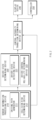
- FIG. 1 is a block diagram illustrating a configuration of an apparatus for managing control authority transition in a vehicle in some forms of the present disclosure.
- an apparatus 100 for managing control authority transition in a vehicle in some forms of the present disclosure may include a steering device 110, an acceleration device 120, a deceleration device 130, a sensor 140, an input device 150, and a control circuit 160.
- the apparatus 100 for managing the control authority transition in FIG. 1 may be a portion of an autonomous system and may be loaded into the vehicle.
- the steering device 110 may be configured to control a steering angle of the vehicle.
- the steering device 110 may include, for example, a steering wheel, an actuator interlocked with the steering wheel, and a controller for controlling the actuator and may be controlled by a driver of the vehicle and/or the autonomous system.
- the acceleration device 120 may be configured to control acceleration of the vehicle.
- the acceleration device 120 may include, for example, a throttle, an actuator interlocked with the throttle, and a controller for controlling the actuator and may be controlled by the driver and/or the autonomous system.
- the deceleration device 130 may be configured to control deceleration of the vehicle.
- the deceleration device 130 may include, for example, a brake, an actuator interlocked with the brake, and a controller for controlling the actuator and may be controlled by the driver and/or the autonomous system.
- the sensor 140 may be configured to sense information about the outside and inside of the vehicle.
- the sensor 140 may sense information about the driver.
- the sensor 140 may include a camera for capturing an image of the driver and may include a sensor for sensing whether the driver sits in the driver's seat.
- the sensor 140 may include a radar, a light detection and ranging (LiDAR), a camera, and the like, for sensing an environment outside the vehicle, and may include a wheel speed sensor, a yaw rate sensor, an acceleration sensor, a torque sensor, and the like, for sensing a state of the vehicle.
- LiDAR light detection and ranging
- the input device 150 may be configured to receive an input from the driver of the vehicle.
- the input device 150 may be implemented as a button, a switch, a lever, a touch sensor, a touch panel, or the like.
- the control circuit 160 may be electrically connected with the steering device 110, the acceleration device 120, the deceleration device 130, the sensor 140, and the input device 150.
- the control circuit 160 may control the steering device 110, the acceleration device 120, the deceleration device 130, the sensor 140, and the input device 150 and may perform a variety of data processing and various arithmetic operations.
- the control circuit 160 may be, for example, an electronic control unit (ECU), a micro controller unit (MCU), or a sub-controller, which is loaded into the vehicle.
- the control circuit 160 may obtain state information about the driver using the sensor 140.
- the state information may include, for example, information associated with a line of sight of the driver and information associated with driver seating.
- the control circuit 160 may obtain an image of the driver using the sensor 140 (e.g., a camera) and may analyze the image of the driver to obtain state information about the driver.
- the control circuit 160 may obtain state information about a line of sight of the driver from the image.
- the control circuit 160 may determine whether the driver sits in the driver's seat, using the sensor 140, and may obtain state information associated with whether the driver sits in the driver's seat.
- the control circuit 160 may determine that the reliability of the control input is low. When the probability of collision is low (or when there is no probability of collision), the control circuit 160 may determine that the reliability of the control input is high.
- the control circuit 160 may determine whether to hand over control authority, based on the state information and the reliability of the control input. When it is determined that the control authority is handed over, the control circuit 160 may hand over the control authority to the driver. When the driver is conscious and when the reliability of the control input is high, the control circuit 160 may determine to hand over the control authority. For example, when pupils of the driver and driver seating are detected and when there is substantially no probability of collision by the control input (or when a probability of collision is low), the control circuit 160 may hand over control authority to the driver.
- the control circuit 160 may prohibit control authority transition.
- the control circuit 160 may prohibit the control authority transition.
- the control circuit 160 may prohibit the control authority transition.
- the control circuit 160 may prohibit the control authority transition.
- the control circuit 160 may perform autonomous control according to a predetermined minimum risk maneuver (MRM).
- MRM minimum risk maneuver
- control circuit 160 when an input for control authority transition is received via the input device 150, the control circuit 160 may immediately hand over control authority to the driver. Independently of determining whether to hand over the control authority, When a transition demand (TD) is received via a separate input device for control authority transition, the control circuit 160 may immediately hand over the control authority to the driver.
- TD transition demand
- the control circuit 160 may resume performing autonomous control.
- the control circuit 160 automatically may initiate autonomous control.
- the control circuit 160 may initiate the autonomous control.
- FIG. 2 is a block diagram illustrating a configuration of an apparatus for managing control authority transition in a vehicle in some forms of the present disclosure.
- the apparatus for managing the control authority transition in the vehicle in some forms of the present disclosure may include a sensor information processing device 210, a driver state determining device 220, a control authority transition determining device 230, a display device 240, and a controller 250.
- the apparatus for managing the control authority transition may detect a state of a driver, may determine reliability of a control input of the vehicle, and may prevent an unintended dangerous operation of the vehicle to ensure stability of the operation.
- the sensor information processing device 210 may generate a driving path and may determine a risk of collision.
- the sensor information processing device 210 may measure dynamic information (e.g., steering, speed, and the like) for predicting a path of the vehicle depending on the purpose of an autonomous system and may recognize a surrounding environment (e.g., a forward lane, a surrounding object, and the like) to determine safety.
- the sensor information processing device 210 may include a driving path generator 211 and a collision risk determining device 212.
- the driver state determining device 220 may monitor a state where the driver sits in the driver's seat and a state where a surrounding situation is recognized to determine whether it is possible for the driver to take over control authority.
- a driver state detecting device 221 may analyze an image to recognize a face of the driver.
- the driver state detecting device 221 may recognize whether a face of the driver is detected, a drowsy state, a line of sight direction, and the like and may monitor a control input for steering, acceleration, deceleration, or the like of the driver, thus determining whether the driver sits in the driver's seat.
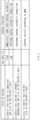
- the driver state detecting device 221 may divide a state of the driver into, for example, four states.
- the control authority transition determining device 230 may determine whether to hand over control authority based on the state information of the driver and the reliability of the control input. A description will be given in detail of a detailed determination method with reference to FIG. 3 .
- the vehicle in some forms of the present disclosure may determine a state of its driver and reliability of a control input by the driver.
- the vehicle may verify whether the driver is conscious and sits in the driver's seat. When it is verified that the driver is conscious and sits in the driver's seat, the vehicle may determine the reliability of the control input. When the reliability of the control input is high, the vehicle may immediately hand over control authority to the driver.
- the vehicle may postpone control authority transition.
- the vehicle may control itself according to a minimum risk maneuver (MRM).
- MRM minimum risk maneuver
- the vehicle may perform deceleration driving, stopping driving, or avoidance driving according to a predetermined MRM.
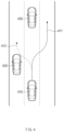
- FIG. 4 is a drawing illustrating an exemplary operation of an apparatus for managing control authority transition in a vehicle in some forms of the present disclosure.
- a vehicle 410 in some forms of the present disclosure may travel on a second lane of a road.
- the vehicle 310 may travel along the center of the second lane.
- a driver of the vehicle 410 may provide a first steering input such that the vehicle 410 is headed toward a right lane.
- the vehicle 410 may calculate a first expected path 411 according to the first steering input. There may be a low probability of collision (or no probability of collision) on the first expected path 411. Thus, reliability of the first steering input may be high.
- the vehicle 410 may hand over control authority to the driver.
- the driver of the vehicle 410 may provide a second steering input such that the vehicle 410 is headed toward a left lane.
- the vehicle 410 may calculate a second expected path 412 according to the second steering input. There may be a high probability (a probability) of collision on the second expected path 412 due to an external object 420. Thus, reliability of the second steering input may be low.
- the vehicle 410 may postpone control authority transition.
- FIG. 5 is a flowchart illustrating a method for managing control authority transition in a vehicle in some forms of the present disclosure.
- a vehicle including an apparatus 100 for managing control authority transition in FIG. 1 performs a process of FIG. 5 .
- an operation described as being performed by the vehicle may be understood as being controlled by a control circuit 160 of the apparatus 100 for managing control authority transition.
- the vehicle may perform autonomous control.
- the vehicle may obtain state information about its driver.
- the vehicle may receive a control input by the driver to at least some of a steering device, an acceleration device, or a deceleration device, which is included in the vehicle.
- the vehicle may determine whether to hand over control authority, based on the state information and reliability of the control input. When it is determined that the control authority is handed over, in operation 550, the vehicle may hand over the control authority to the driver. When it is determined that the control authority is not handed over, in operation 560, the vehicle may prohibit control authority transition.
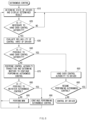
- FIG. 6 is a flowchart illustrating a method for managing control authority transition in a vehicle in some forms of the present disclosure.
- a vehicle including an apparatus 100 for managing control authority transition in FIG. 1 performs a process of FIG. 6 .
- an operation described as being performed by the vehicle may be understood as being controlled by a control circuit 160 of the apparatus 100 for managing control authority transition.
- the vehicle may determine a state of its driver and may display the determined result. For example, the vehicle may determine the state of the driver as a first state, a second state, a third state, or a fourth state, which is described with reference to FIG. 2 .
- the vehicle may determine whether it is necessary to hand over control authority. For example, when a control input by the driver is detected or when a critical situation occurs, the vehicle may determine that it is necessary to hand over the control authority.
- the vehicle may determine whether it is possible to hand over the control authority. For example, the vehicle may consider the state of the driver and the reliability of the control input on an overall basis to determine whether a current situation is a situation capable of handing over the control authority.
- the apparatus and method in some forms of the present disclosure may prevent unintended critical control (e.g., an error input or the like) and may safely hand over control authority to a driver in the situation where the safety of the driver is ensured, by determining whether to hand over the control authority in consideration of a state of the driver and the reliability of a control input by the driver.
- unintended critical control e.g., an error input or the like
Landscapes
- Engineering & Computer Science (AREA)
- Automation & Control Theory (AREA)
- Transportation (AREA)
- Mechanical Engineering (AREA)
- Human Computer Interaction (AREA)
- Physics & Mathematics (AREA)
- General Physics & Mathematics (AREA)
- Combustion & Propulsion (AREA)
- Chemical & Material Sciences (AREA)
- Multimedia (AREA)
- Control Of Driving Devices And Active Controlling Of Vehicle (AREA)
- Traffic Control Systems (AREA)
- Theoretical Computer Science (AREA)
- Aviation & Aerospace Engineering (AREA)
- Remote Sensing (AREA)
- Radar, Positioning & Navigation (AREA)
- Health & Medical Sciences (AREA)
- Game Theory and Decision Science (AREA)
- Medical Informatics (AREA)
- Evolutionary Computation (AREA)
- Artificial Intelligence (AREA)
- Business, Economics & Management (AREA)
Claims (14)
- Einrichtung zur Verwaltung des Kontrollauthoritätsübergangs in einem Fahrzeug, wobei die Einrichtung Folgendes umfasst:eine Lenkvorrichtung (110);eine Beschleunigungsvorrichtung (120);eine Verzögerungsvorrichtung (130);einen Sensor (140), der konfiguriert ist, um Informationen über einen Fahrer des Fahrzeugs zu erfassen; undeine Steuerschaltung (160), die konfiguriert ist, um mit der Lenkvorrichtung (110), der Beschleunigungsvorrichtung (120), der Verzögerungsvorrichtung (130) und dem Sensor (140) elektrisch verbunden zu sein,wobei die Steuerschaltung (160) konfiguriert ist zum:Erhalten von Zustandsinformationen über den Fahrer unter Verwendung des Sensors (140), wenn eine autonome Steuerung durchgeführt wird;Empfangen, vom Fahrer, einer Steuereingabe an mindestens eine aus der Lenkvorrichtung (110), der Beschleunigungsvorrichtung (120) oder der Verzögerungsvorrichtung (130);Berechnen eines erwarteten Pfads des Fahrzeugs basierend auf der Steuereingabe;Bestimmen einer Kollisionswahrscheinlichkeit des Fahrzeugs basierend auf dem erwarteten Pfad und einem Standort eines externen Objekts;Verifizieren, ob der Fahrer bei Bewusstsein ist und auf dem Fahrersitz sitzt;wenn verifiziert wird, dass der Fahrer bei Bewusstsein ist und auf dem Fahrersitz sitzt, Bestimmen einer Zuverlässigkeit der Steuereingabe, wobei die Zuverlässigkeit der Steuereingabe als hoch bestimmt wird, wenn es keine Kollisionswahrscheinlichkeit gibt oder die bestimmte Kollisionswahrscheinlichkeit geringer ist als ein Kollisionsrisiko auf einem Pfad durch die autonome Steuerung;Bestimmen, ob eine Kontrollauthorität übertragen werden soll, basierend auf den Zustandsinformationen und der Zuverlässigkeit der Steuereingabe; undÜbertragen, an den Fahrer, der Kontrollauthorität, wenn bestimmt wird, dass die Kontrollauthorität übertragen werden soll, wenn die Zuverlässigkeit der Steuereingabe hoch ist.
- Einrichtung nach Anspruch 1, wobei der Sensor (140) eine Kamera umfasst, und
wobei die Steuerschaltung (160) konfiguriert ist zum:
Erhalten von den Zustandsinformationen, durch Analysieren eines Bildes des Fahrers, das von der Kamera erhalten wird. - Einrichtung nach Anspruch 1 oder 2, wobei die Zustandsinformationen Informationen betreffend die Sicht des Fahrers und Informationen betreffend einen Sitz des Fahrers umfassen.
- Einrichtung nach Anspruch 1, 2 oder 3, wobei die Zuverlässigkeit der Steuereingabe Informationen betreffend die Kollisionswahrscheinlichkeit durch die Steuereingabe umfasst.
- Einrichtung nach einem der Ansprüche 1 bis 4, wobei die Steuerschaltung (160) konfiguriert ist zum:
nicht Übertragen der Kontrollauthorität, wenn es nicht möglich ist, die Kontrollauthorität zu übertragen. - Einrichtung nach einem der Ansprüche 1 bis 5, wobei die Einrichtung weiter Folgendes umfasst:eine Eingabevorrichtung (150), die konfiguriert ist, um elektrisch mit der Steuerschaltung (160) verbunden zu werden,wobei die Steuerschaltung (160) konfiguriert ist zum:
sofortigen Übertragen, an den Fahrer, der Kontrollauthorität, wenn eine Eingabe zum Übertragen der Kontrollauthorität über die Eingabevorrichtung (150) empfangen wird. - Einrichtung nach einem der Ansprüche 1 bis 6, wobei die Einrichtung weiter Folgendes umfasst:die Eingabevorrichtung (150), die konfiguriert ist, um mit der Steuerschaltung (160) elektrisch verbunden zu werden,wobei die Steuerschaltung (160) konfiguriert ist zum:
wieder Aufnehmen der autonomen Steuerung, nachdem die Kontrollauthorität übertragen wurde, wenn die Steuereingabe des Fahrers gestoppt wird oder wenn eine Eingabe für die autonome Steuerung über die Eingabevorrichtung (150) empfangen wird. - Einrichtung nach einem der Ansprüche 1 bis 7, wobei die Steuerschaltung (160) konfiguriert ist zum:
Übertragen, an den Fahrer, der Kontrollauthorität, wenn Pupillen des Fahrers und der Sitz des sitzenden Fahrers detektiert werden und wenn durch die Steuereingabe keine Kollisionswahrscheinlichkeit besteht. - Einrichtung nach einem der Ansprüche 1 bis 8, wobei die Steuerschaltung (160) konfiguriert ist zum:
nicht Übertragen der Kontrollauthorität, wenn die Pupillen des Fahrers und der Sitz des Fahrers detektiert werden und wenn eine Kollisionswahrscheinlichkeit durch die Steuereingabe besteht. - Einrichtung nach einem der Ansprüche 1 bis 9, wobei die Steuerschaltung (160) konfiguriert ist zum:
nicht Übertragen der Kontrollauthorität, wenn die Pupillen des Fahrers nicht detektiert werden. - Einrichtung nach einem der Ansprüche 1 bis 10, wobei die Steuerschaltung (160) konfiguriert ist zum:
Durchführen der autonomen Steuerung basierend auf einem vorbestimmten Minimum-Risiko-Manöver (MRM), wenn der Sitz des sitzenden Fahrers nicht detektiert wird. - Verfahren zur Verwaltung des Kontrollauthoritätsübergangs in einem Fahrzeug, wobei das Verfahren Folgendes umfasst:Erhalten, mit einer Steuerschaltung (160), von Zustandsinformationen über einen Fahrer des Fahrzeugs, wenn eine autonome Steuerung durchgeführt wird;Empfangen, mit der Steuerschaltung (160), einer Steuereingabe durch den Fahrer an mindestens einer aus einer Lenkvorrichtung (110), einer Beschleunigungsvorrichtung (120) oder einer Verzögerungsvorrichtung (130), wobei die Lenkvorrichtung (110), die Beschleunigungsvorrichtung (120) und die Verzögerungsvorrichtung (130) in das Fahrzeug eingeschlossen sind;Berechnen eines erwarteten Pfads des Fahrzeugs basierend auf der Steuereingabe;Bestimmen einer Kollisionswahrscheinlichkeit des Fahrzeugs basierend auf dem erwarteten Pfad und einem Standort eines externen Objekts;Verifizieren, mit der Steuerschaltung (160), ob der Fahrer bei Bewusstsein ist und auf dem Fahrersitz sitzt;wenn verifiziert wird, dass der Fahrer bei Bewusstsein ist und auf dem Fahrersitz sitzt, Bestimmen, mit der Steuerschaltung (160), einer Zuverlässigkeit der Steuereingabe, wobei die Zuverlässigkeit der Steuereingabe als hoch bestimmt wird, wenn es keine Kollisionswahrscheinlichkeit gibt oder die bestimmte Kollisionswahrscheinlichkeit geringer ist als ein Kollisionsrisiko auf einem Pfad durch die autonome Steuerung;Bestimmen, mit der Steuerschaltung (160), ob eine Kontrollauthorität basierend auf den Zustandsinformationen und der Zuverlässigkeit der Steuereingabe übertragen werden soll; undwenn die Zuverlässigkeit der Steuereingabe hoch ist und bestimmt wird, dass die Kontrollauthorität übertragen werden soll, Übertragen, mit der Steuerschaltung (160), der Kontrollauthorität an den Fahrer.
- Verfahren nach Anspruch 12, wobei die Zustandsinformationen Informationen betreffend die Sicht des Fahrers und Informationen betreffend einen Sitz des Fahrers umfassen.
- Verfahren nach Anspruch 12 oder 13, wobei die Zuverlässigkeit der Steuereingabe Informationen betreffend die Kollisionswahrscheinlichkeit durch die Steuereingabe umfasst.
Applications Claiming Priority (2)
| Application Number | Priority Date | Filing Date | Title |
|---|---|---|---|
| US201862655831P | 2018-04-11 | 2018-04-11 | |
| KR1020190013933A KR20190124131A (ko) | 2018-04-11 | 2019-02-01 | 차량의 제어권 이양 관리 장치 및 방법 |
Publications (2)
| Publication Number | Publication Date |
|---|---|
| EP3552909A1 EP3552909A1 (de) | 2019-10-16 |
| EP3552909B1 true EP3552909B1 (de) | 2025-07-02 |
Family
ID=66092152
Family Applications (1)
| Application Number | Title | Priority Date | Filing Date |
|---|---|---|---|
| EP19167263.3A Active EP3552909B1 (de) | 2018-04-11 | 2019-04-04 | Vorrichtung und verfahren zur verwaltung des kontrollautoritätsübergangs in einem fahrzeug |
Country Status (3)
| Country | Link |
|---|---|
| US (1) | US20190317495A1 (de) |
| EP (1) | EP3552909B1 (de) |
| CN (1) | CN110371137A (de) |
Families Citing this family (8)
| Publication number | Priority date | Publication date | Assignee | Title |
|---|---|---|---|---|
| JP7227106B2 (ja) * | 2019-08-22 | 2023-02-21 | 本田技研工業株式会社 | 操作制御装置、操作制御方法、およびプログラム |
| US11393225B2 (en) * | 2019-12-06 | 2022-07-19 | Robert Bosch Gmbh | System and method for detecting abnormal settling of passengers in a vehicle |
| DE102020000147B4 (de) * | 2020-01-13 | 2024-10-10 | Mercedes-Benz Group AG | Verfahren zur Deaktivierung |
| CN111422253A (zh) * | 2020-04-28 | 2020-07-17 | 九江学院 | 汽车转向控制方法、系统、移动终端及存储介质 |
| KR20210153800A (ko) * | 2020-06-10 | 2021-12-20 | 현대자동차주식회사 | 자율 주행 제어 장치 및 그 방법 |
| KR20220052430A (ko) * | 2020-10-20 | 2022-04-28 | 현대자동차주식회사 | 자율주행차량의 거동 제어 장치 및 그 방법 |
| CN113335300A (zh) * | 2021-07-19 | 2021-09-03 | 中国第一汽车股份有限公司 | 一种人车接管交互的方法、装置、设备和存储介质 |
| CN114715191B (zh) * | 2022-04-14 | 2025-12-02 | 的卢技术有限公司 | 车辆控制方法、装置、电子设备及介质 |
Family Cites Families (7)
| Publication number | Priority date | Publication date | Assignee | Title |
|---|---|---|---|---|
| JP6323318B2 (ja) * | 2014-12-12 | 2018-05-16 | ソニー株式会社 | 車両制御装置および車両制御方法、並びにプログラム |
| JP2016151815A (ja) * | 2015-02-16 | 2016-08-22 | 株式会社デンソー | 運転支援装置 |
| JP6552316B2 (ja) * | 2015-07-29 | 2019-07-31 | 修一 田山 | 車輌の自動運転システム |
| KR101730321B1 (ko) * | 2015-08-03 | 2017-04-27 | 엘지전자 주식회사 | 운전자 보조 장치 및 그 제어방법 |
| KR20170030811A (ko) * | 2015-09-10 | 2017-03-20 | 주식회사 만도 | 운전지원장치 및 운전지원방법 |
| DE102016007187A1 (de) * | 2015-12-19 | 2017-06-22 | Daimler Ag | Verfahren zum Deaktivieren einer automatisierten Fahrfunktion eines Fahrzeugs und Fahrerassistenzsystem zur Durchführung des Verfahrens |
| JP6246844B2 (ja) * | 2016-02-18 | 2017-12-13 | 本田技研工業株式会社 | 車両制御システム、車両制御方法、および車両制御プログラム |
-
2019
- 2019-04-04 EP EP19167263.3A patent/EP3552909B1/de active Active
- 2019-04-08 US US16/378,181 patent/US20190317495A1/en not_active Abandoned
- 2019-04-09 CN CN201910280086.0A patent/CN110371137A/zh active Pending
Also Published As
| Publication number | Publication date |
|---|---|
| CN110371137A (zh) | 2019-10-25 |
| US20190317495A1 (en) | 2019-10-17 |
| EP3552909A1 (de) | 2019-10-16 |
Similar Documents
| Publication | Publication Date | Title |
|---|---|---|
| EP3552909B1 (de) | Vorrichtung und verfahren zur verwaltung des kontrollautoritätsübergangs in einem fahrzeug | |
| US11550317B2 (en) | Apparatus and method for controlling to enable autonomous system in vehicle | |
| KR20190124131A (ko) | 차량의 제어권 이양 관리 장치 및 방법 | |
| US10933883B2 (en) | Driving control apparatus and method for vehicle | |
| EP3552901B1 (de) | Vorrichtung und verfahren zur bereitstellung einer sicherheitsstrategie in einem fahrzeug | |
| CN113561984B (zh) | 自动驾驶控制方法及装置 | |
| EP3552911B1 (de) | Vorrichtung und verfahren zur bereitstellung einer sicherheitsstrategie in einem fahrzeug | |
| US9481374B2 (en) | Method for a driver assistance application | |
| US11332157B2 (en) | Vehicle control apparatus | |
| EP3552903B1 (de) | Vorrichtung und verfahren zur bereitstellung einer sicherheitsstrategie an ein fahrzeug | |
| KR102506871B1 (ko) | 자율 주행 제어 장치 및 그의 전방차량 출발 알림 방법 | |
| EP3552899B1 (de) | Vorrichtung und verfahren zur steuerung des spurwechsels in einem fahrzeug | |
| EP3552898B1 (de) | Vorrichtung und verfahren zur steuerung des spurwechsels in einem fahrzeug | |
| CN107667048A (zh) | 用于控制车辆的行驶功能的方法和系统 | |
| JP7658416B2 (ja) | 制御装置、方法およびプログラム | |
| EP3885227B1 (de) | Vorrichtung zur steuerung des autonomen fahrens eines fahrzeugs, system damit und verfahren dafür | |
| US11292463B2 (en) | Determination of a control signal for an in-part-autonomous vehicle | |
| US12151675B2 (en) | Driving controller for determining a risk level of a vehicle and control method thereof | |
| JP7629531B2 (ja) | 進路推定装置、および、進路推定方法 | |
| US12447967B2 (en) | Vehicle control device, operation method of vehicle control device, and storage medium | |
| CN120817091A (zh) | 用于控制最小风险操纵的方法和设备 | |
| WO2024261892A1 (ja) | 運転権限切替装置および運転権限切替プログラム |
Legal Events
| Date | Code | Title | Description |
|---|---|---|---|
| PUAI | Public reference made under article 153(3) epc to a published international application that has entered the european phase |
Free format text: ORIGINAL CODE: 0009012 |
|
| STAA | Information on the status of an ep patent application or granted ep patent |
Free format text: STATUS: THE APPLICATION HAS BEEN PUBLISHED |
|
| AK | Designated contracting states |
Kind code of ref document: A1 Designated state(s): AL AT BE BG CH CY CZ DE DK EE ES FI FR GB GR HR HU IE IS IT LI LT LU LV MC MK MT NL NO PL PT RO RS SE SI SK SM TR |
|
| AX | Request for extension of the european patent |
Extension state: BA ME |
|
| STAA | Information on the status of an ep patent application or granted ep patent |
Free format text: STATUS: REQUEST FOR EXAMINATION WAS MADE |
|
| 17P | Request for examination filed |
Effective date: 20200414 |
|
| RBV | Designated contracting states (corrected) |
Designated state(s): AL AT BE BG CH CY CZ DE DK EE ES FI FR GB GR HR HU IE IS IT LI LT LU LV MC MK MT NL NO PL PT RO RS SE SI SK SM TR |
|
| RAP3 | Party data changed (applicant data changed or rights of an application transferred) |
Owner name: HYUNDAI MOTOR COMPANY Owner name: KIA CORPORATION |
|
| STAA | Information on the status of an ep patent application or granted ep patent |
Free format text: STATUS: EXAMINATION IS IN PROGRESS |
|
| 17Q | First examination report despatched |
Effective date: 20221130 |
|
| P01 | Opt-out of the competence of the unified patent court (upc) registered |
Effective date: 20230505 |
|
| GRAP | Despatch of communication of intention to grant a patent |
Free format text: ORIGINAL CODE: EPIDOSNIGR1 |
|
| STAA | Information on the status of an ep patent application or granted ep patent |
Free format text: STATUS: GRANT OF PATENT IS INTENDED |
|
| RIC1 | Information provided on ipc code assigned before grant |
Ipc: B60K 35/10 20240101ALI20250207BHEP Ipc: B60W 60/00 20200101ALI20250207BHEP Ipc: B60W 40/08 20120101ALI20250207BHEP Ipc: B60W 30/182 20120101ALI20250207BHEP Ipc: B60W 50/08 20120101AFI20250207BHEP |
|
| INTG | Intention to grant announced |
Effective date: 20250310 |
|
| GRAS | Grant fee paid |
Free format text: ORIGINAL CODE: EPIDOSNIGR3 |
|
| GRAA | (expected) grant |
Free format text: ORIGINAL CODE: 0009210 |
|
| STAA | Information on the status of an ep patent application or granted ep patent |
Free format text: STATUS: THE PATENT HAS BEEN GRANTED |
|
| AK | Designated contracting states |
Kind code of ref document: B1 Designated state(s): AL AT BE BG CH CY CZ DE DK EE ES FI FR GB GR HR HU IE IS IT LI LT LU LV MC MK MT NL NO PL PT RO RS SE SI SK SM TR |
|
| REG | Reference to a national code |
Ref country code: GB Ref legal event code: FG4D |
|
| REG | Reference to a national code |
Ref country code: CH Ref legal event code: EP |
|
| REG | Reference to a national code |
Ref country code: DE Ref legal event code: R096 Ref document number: 602019071847 Country of ref document: DE |
|
| REG | Reference to a national code |
Ref country code: IE Ref legal event code: FG4D |
|
| REG | Reference to a national code |
Ref country code: NL Ref legal event code: MP Effective date: 20250702 |
|
| PG25 | Lapsed in a contracting state [announced via postgrant information from national office to epo] |
Ref country code: PT Free format text: LAPSE BECAUSE OF FAILURE TO SUBMIT A TRANSLATION OF THE DESCRIPTION OR TO PAY THE FEE WITHIN THE PRESCRIBED TIME-LIMIT Effective date: 20251103 |
|
| PG25 | Lapsed in a contracting state [announced via postgrant information from national office to epo] |
Ref country code: NL Free format text: LAPSE BECAUSE OF FAILURE TO SUBMIT A TRANSLATION OF THE DESCRIPTION OR TO PAY THE FEE WITHIN THE PRESCRIBED TIME-LIMIT Effective date: 20250702 |
|
| REG | Reference to a national code |
Ref country code: AT Ref legal event code: MK05 Ref document number: 1808931 Country of ref document: AT Kind code of ref document: T Effective date: 20250702 |
|
| PG25 | Lapsed in a contracting state [announced via postgrant information from national office to epo] |
Ref country code: IS Free format text: LAPSE BECAUSE OF FAILURE TO SUBMIT A TRANSLATION OF THE DESCRIPTION OR TO PAY THE FEE WITHIN THE PRESCRIBED TIME-LIMIT Effective date: 20251102 |
|
| PG25 | Lapsed in a contracting state [announced via postgrant information from national office to epo] |
Ref country code: NO Free format text: LAPSE BECAUSE OF FAILURE TO SUBMIT A TRANSLATION OF THE DESCRIPTION OR TO PAY THE FEE WITHIN THE PRESCRIBED TIME-LIMIT Effective date: 20251002 |
|
| REG | Reference to a national code |
Ref country code: LT Ref legal event code: MG9D |
|
| PG25 | Lapsed in a contracting state [announced via postgrant information from national office to epo] |
Ref country code: AT Free format text: LAPSE BECAUSE OF FAILURE TO SUBMIT A TRANSLATION OF THE DESCRIPTION OR TO PAY THE FEE WITHIN THE PRESCRIBED TIME-LIMIT Effective date: 20250702 |
|
| PG25 | Lapsed in a contracting state [announced via postgrant information from national office to epo] |
Ref country code: FI Free format text: LAPSE BECAUSE OF FAILURE TO SUBMIT A TRANSLATION OF THE DESCRIPTION OR TO PAY THE FEE WITHIN THE PRESCRIBED TIME-LIMIT Effective date: 20250702 |
|
| PG25 | Lapsed in a contracting state [announced via postgrant information from national office to epo] |
Ref country code: HR Free format text: LAPSE BECAUSE OF FAILURE TO SUBMIT A TRANSLATION OF THE DESCRIPTION OR TO PAY THE FEE WITHIN THE PRESCRIBED TIME-LIMIT Effective date: 20250702 |
|
| PG25 | Lapsed in a contracting state [announced via postgrant information from national office to epo] |
Ref country code: GR Free format text: LAPSE BECAUSE OF FAILURE TO SUBMIT A TRANSLATION OF THE DESCRIPTION OR TO PAY THE FEE WITHIN THE PRESCRIBED TIME-LIMIT Effective date: 20251003 |
|
| PG25 | Lapsed in a contracting state [announced via postgrant information from national office to epo] |
Ref country code: SE Free format text: LAPSE BECAUSE OF FAILURE TO SUBMIT A TRANSLATION OF THE DESCRIPTION OR TO PAY THE FEE WITHIN THE PRESCRIBED TIME-LIMIT Effective date: 20250702 Ref country code: CZ Free format text: LAPSE BECAUSE OF FAILURE TO SUBMIT A TRANSLATION OF THE DESCRIPTION OR TO PAY THE FEE WITHIN THE PRESCRIBED TIME-LIMIT Effective date: 20250702 |
|
| PG25 | Lapsed in a contracting state [announced via postgrant information from national office to epo] |
Ref country code: LV Free format text: LAPSE BECAUSE OF FAILURE TO SUBMIT A TRANSLATION OF THE DESCRIPTION OR TO PAY THE FEE WITHIN THE PRESCRIBED TIME-LIMIT Effective date: 20250702 |
|
| PG25 | Lapsed in a contracting state [announced via postgrant information from national office to epo] |
Ref country code: BG Free format text: LAPSE BECAUSE OF FAILURE TO SUBMIT A TRANSLATION OF THE DESCRIPTION OR TO PAY THE FEE WITHIN THE PRESCRIBED TIME-LIMIT Effective date: 20250702 Ref country code: PL Free format text: LAPSE BECAUSE OF FAILURE TO SUBMIT A TRANSLATION OF THE DESCRIPTION OR TO PAY THE FEE WITHIN THE PRESCRIBED TIME-LIMIT Effective date: 20250702 |
|
| PG25 | Lapsed in a contracting state [announced via postgrant information from national office to epo] |
Ref country code: RS Free format text: LAPSE BECAUSE OF FAILURE TO SUBMIT A TRANSLATION OF THE DESCRIPTION OR TO PAY THE FEE WITHIN THE PRESCRIBED TIME-LIMIT Effective date: 20251002 |
|
| PG25 | Lapsed in a contracting state [announced via postgrant information from national office to epo] |
Ref country code: ES Free format text: LAPSE BECAUSE OF FAILURE TO SUBMIT A TRANSLATION OF THE DESCRIPTION OR TO PAY THE FEE WITHIN THE PRESCRIBED TIME-LIMIT Effective date: 20250702 |
|
| PG25 | Lapsed in a contracting state [announced via postgrant information from national office to epo] |
Ref country code: SM Free format text: LAPSE BECAUSE OF FAILURE TO SUBMIT A TRANSLATION OF THE DESCRIPTION OR TO PAY THE FEE WITHIN THE PRESCRIBED TIME-LIMIT Effective date: 20250702 |
|
| PGFP | Annual fee paid to national office [announced via postgrant information from national office to epo] |
Ref country code: GB Payment date: 20260324 Year of fee payment: 8 |
|
| PG25 | Lapsed in a contracting state [announced via postgrant information from national office to epo] |
Ref country code: DK Free format text: LAPSE BECAUSE OF FAILURE TO SUBMIT A TRANSLATION OF THE DESCRIPTION OR TO PAY THE FEE WITHIN THE PRESCRIBED TIME-LIMIT Effective date: 20250702 |
|
| PG25 | Lapsed in a contracting state [announced via postgrant information from national office to epo] |
Ref country code: IT Free format text: LAPSE BECAUSE OF FAILURE TO SUBMIT A TRANSLATION OF THE DESCRIPTION OR TO PAY THE FEE WITHIN THE PRESCRIBED TIME-LIMIT Effective date: 20250702 |
|
| PGFP | Annual fee paid to national office [announced via postgrant information from national office to epo] |
Ref country code: FR Payment date: 20260323 Year of fee payment: 8 |
|
| PG25 | Lapsed in a contracting state [announced via postgrant information from national office to epo] |
Ref country code: SK Free format text: LAPSE BECAUSE OF FAILURE TO SUBMIT A TRANSLATION OF THE DESCRIPTION OR TO PAY THE FEE WITHIN THE PRESCRIBED TIME-LIMIT Effective date: 20250702 Ref country code: EE Free format text: LAPSE BECAUSE OF FAILURE TO SUBMIT A TRANSLATION OF THE DESCRIPTION OR TO PAY THE FEE WITHIN THE PRESCRIBED TIME-LIMIT Effective date: 20250702 |