EP3552898B1 - Vorrichtung und verfahren zur steuerung des spurwechsels in einem fahrzeug - Google Patents
Vorrichtung und verfahren zur steuerung des spurwechsels in einem fahrzeug Download PDFInfo
- Publication number
- EP3552898B1 EP3552898B1 EP18210401.8A EP18210401A EP3552898B1 EP 3552898 B1 EP3552898 B1 EP 3552898B1 EP 18210401 A EP18210401 A EP 18210401A EP 3552898 B1 EP3552898 B1 EP 3552898B1
- Authority
- EP
- European Patent Office
- Prior art keywords
- vehicle
- speed
- lane change
- minimum operation
- control circuit
- Prior art date
- Legal status (The legal status is an assumption and is not a legal conclusion. Google has not performed a legal analysis and makes no representation as to the accuracy of the status listed.)
- Active
Links
Images


Classifications
-
- B—PERFORMING OPERATIONS; TRANSPORTING
- B60—VEHICLES IN GENERAL
- B60W—CONJOINT CONTROL OF VEHICLE SUB-UNITS OF DIFFERENT TYPE OR DIFFERENT FUNCTION; CONTROL SYSTEMS SPECIALLY ADAPTED FOR HYBRID VEHICLES; ROAD VEHICLE DRIVE CONTROL SYSTEMS FOR PURPOSES NOT RELATED TO THE CONTROL OF A PARTICULAR SUB-UNIT
- B60W10/00—Conjoint control of vehicle sub-units of different type or different function
- B60W10/04—Conjoint control of vehicle sub-units of different type or different function including control of propulsion units
- B60W10/06—Conjoint control of vehicle sub-units of different type or different function including control of propulsion units including control of combustion engines
-
- B—PERFORMING OPERATIONS; TRANSPORTING
- B60—VEHICLES IN GENERAL
- B60W—CONJOINT CONTROL OF VEHICLE SUB-UNITS OF DIFFERENT TYPE OR DIFFERENT FUNCTION; CONTROL SYSTEMS SPECIALLY ADAPTED FOR HYBRID VEHICLES; ROAD VEHICLE DRIVE CONTROL SYSTEMS FOR PURPOSES NOT RELATED TO THE CONTROL OF A PARTICULAR SUB-UNIT
- B60W10/00—Conjoint control of vehicle sub-units of different type or different function
- B60W10/18—Conjoint control of vehicle sub-units of different type or different function including control of braking systems
-
- B—PERFORMING OPERATIONS; TRANSPORTING
- B60—VEHICLES IN GENERAL
- B60W—CONJOINT CONTROL OF VEHICLE SUB-UNITS OF DIFFERENT TYPE OR DIFFERENT FUNCTION; CONTROL SYSTEMS SPECIALLY ADAPTED FOR HYBRID VEHICLES; ROAD VEHICLE DRIVE CONTROL SYSTEMS FOR PURPOSES NOT RELATED TO THE CONTROL OF A PARTICULAR SUB-UNIT
- B60W10/00—Conjoint control of vehicle sub-units of different type or different function
- B60W10/20—Conjoint control of vehicle sub-units of different type or different function including control of steering systems
-
- B—PERFORMING OPERATIONS; TRANSPORTING
- B60—VEHICLES IN GENERAL
- B60W—CONJOINT CONTROL OF VEHICLE SUB-UNITS OF DIFFERENT TYPE OR DIFFERENT FUNCTION; CONTROL SYSTEMS SPECIALLY ADAPTED FOR HYBRID VEHICLES; ROAD VEHICLE DRIVE CONTROL SYSTEMS FOR PURPOSES NOT RELATED TO THE CONTROL OF A PARTICULAR SUB-UNIT
- B60W30/00—Purposes of road vehicle drive control systems not related to the control of a particular sub-unit, e.g. of systems using conjoint control of vehicle sub-units
- B60W30/08—Active safety systems predicting or avoiding probable or impending collision or attempting to minimise its consequences
- B60W30/09—Taking automatic action to avoid collision, e.g. braking and steering
-
- B—PERFORMING OPERATIONS; TRANSPORTING
- B60—VEHICLES IN GENERAL
- B60W—CONJOINT CONTROL OF VEHICLE SUB-UNITS OF DIFFERENT TYPE OR DIFFERENT FUNCTION; CONTROL SYSTEMS SPECIALLY ADAPTED FOR HYBRID VEHICLES; ROAD VEHICLE DRIVE CONTROL SYSTEMS FOR PURPOSES NOT RELATED TO THE CONTROL OF A PARTICULAR SUB-UNIT
- B60W30/00—Purposes of road vehicle drive control systems not related to the control of a particular sub-unit, e.g. of systems using conjoint control of vehicle sub-units
- B60W30/08—Active safety systems predicting or avoiding probable or impending collision or attempting to minimise its consequences
- B60W30/095—Predicting travel path or likelihood of collision
- B60W30/0956—Predicting travel path or likelihood of collision the prediction being responsive to traffic or environmental parameters
-
- B—PERFORMING OPERATIONS; TRANSPORTING
- B60—VEHICLES IN GENERAL
- B60W—CONJOINT CONTROL OF VEHICLE SUB-UNITS OF DIFFERENT TYPE OR DIFFERENT FUNCTION; CONTROL SYSTEMS SPECIALLY ADAPTED FOR HYBRID VEHICLES; ROAD VEHICLE DRIVE CONTROL SYSTEMS FOR PURPOSES NOT RELATED TO THE CONTROL OF A PARTICULAR SUB-UNIT
- B60W30/00—Purposes of road vehicle drive control systems not related to the control of a particular sub-unit, e.g. of systems using conjoint control of vehicle sub-units
- B60W30/14—Adaptive cruise control
- B60W30/143—Speed control
-
- B—PERFORMING OPERATIONS; TRANSPORTING
- B60—VEHICLES IN GENERAL
- B60W—CONJOINT CONTROL OF VEHICLE SUB-UNITS OF DIFFERENT TYPE OR DIFFERENT FUNCTION; CONTROL SYSTEMS SPECIALLY ADAPTED FOR HYBRID VEHICLES; ROAD VEHICLE DRIVE CONTROL SYSTEMS FOR PURPOSES NOT RELATED TO THE CONTROL OF A PARTICULAR SUB-UNIT
- B60W30/00—Purposes of road vehicle drive control systems not related to the control of a particular sub-unit, e.g. of systems using conjoint control of vehicle sub-units
- B60W30/18—Propelling the vehicle
- B60W30/18009—Propelling the vehicle related to particular drive situations
- B60W30/18163—Lane change; Overtaking manoeuvres
-
- B—PERFORMING OPERATIONS; TRANSPORTING
- B60—VEHICLES IN GENERAL
- B60W—CONJOINT CONTROL OF VEHICLE SUB-UNITS OF DIFFERENT TYPE OR DIFFERENT FUNCTION; CONTROL SYSTEMS SPECIALLY ADAPTED FOR HYBRID VEHICLES; ROAD VEHICLE DRIVE CONTROL SYSTEMS FOR PURPOSES NOT RELATED TO THE CONTROL OF A PARTICULAR SUB-UNIT
- B60W40/00—Estimation or calculation of non-directly measurable driving parameters for road vehicle drive control systems not related to the control of a particular sub unit, e.g. by using mathematical models
- B60W40/10—Estimation or calculation of non-directly measurable driving parameters for road vehicle drive control systems not related to the control of a particular sub unit, e.g. by using mathematical models related to vehicle motion
- B60W40/105—Speed
-
- B—PERFORMING OPERATIONS; TRANSPORTING
- B60—VEHICLES IN GENERAL
- B60W—CONJOINT CONTROL OF VEHICLE SUB-UNITS OF DIFFERENT TYPE OR DIFFERENT FUNCTION; CONTROL SYSTEMS SPECIALLY ADAPTED FOR HYBRID VEHICLES; ROAD VEHICLE DRIVE CONTROL SYSTEMS FOR PURPOSES NOT RELATED TO THE CONTROL OF A PARTICULAR SUB-UNIT
- B60W50/00—Details of control systems for road vehicle drive control not related to the control of a particular sub-unit, e.g. process diagnostic or vehicle driver interfaces
- B60W50/08—Interaction between the driver and the control system
- B60W50/10—Interpretation of driver requests or demands
-
- B—PERFORMING OPERATIONS; TRANSPORTING
- B60—VEHICLES IN GENERAL
- B60W—CONJOINT CONTROL OF VEHICLE SUB-UNITS OF DIFFERENT TYPE OR DIFFERENT FUNCTION; CONTROL SYSTEMS SPECIALLY ADAPTED FOR HYBRID VEHICLES; ROAD VEHICLE DRIVE CONTROL SYSTEMS FOR PURPOSES NOT RELATED TO THE CONTROL OF A PARTICULAR SUB-UNIT
- B60W50/00—Details of control systems for road vehicle drive control not related to the control of a particular sub-unit, e.g. process diagnostic or vehicle driver interfaces
- B60W50/08—Interaction between the driver and the control system
- B60W50/12—Limiting control by the driver depending on vehicle state, e.g. interlocking means for the control input for preventing unsafe operation
-
- G—PHYSICS
- G08—SIGNALLING
- G08G—TRAFFIC CONTROL SYSTEMS
- G08G1/00—Traffic control systems for road vehicles
- G08G1/16—Anti-collision systems
- G08G1/167—Driving aids for lane monitoring, lane changing, e.g. blind spot detection
-
- B—PERFORMING OPERATIONS; TRANSPORTING
- B60—VEHICLES IN GENERAL
- B60W—CONJOINT CONTROL OF VEHICLE SUB-UNITS OF DIFFERENT TYPE OR DIFFERENT FUNCTION; CONTROL SYSTEMS SPECIALLY ADAPTED FOR HYBRID VEHICLES; ROAD VEHICLE DRIVE CONTROL SYSTEMS FOR PURPOSES NOT RELATED TO THE CONTROL OF A PARTICULAR SUB-UNIT
- B60W50/00—Details of control systems for road vehicle drive control not related to the control of a particular sub-unit, e.g. process diagnostic or vehicle driver interfaces
- B60W2050/0062—Adapting control system settings
- B60W2050/0063—Manual parameter input, manual setting means, manual initialising or calibrating means
- B60W2050/0068—Giving intention of direction, e.g. by indicator lights, steering input
-
- B—PERFORMING OPERATIONS; TRANSPORTING
- B60—VEHICLES IN GENERAL
- B60W—CONJOINT CONTROL OF VEHICLE SUB-UNITS OF DIFFERENT TYPE OR DIFFERENT FUNCTION; CONTROL SYSTEMS SPECIALLY ADAPTED FOR HYBRID VEHICLES; ROAD VEHICLE DRIVE CONTROL SYSTEMS FOR PURPOSES NOT RELATED TO THE CONTROL OF A PARTICULAR SUB-UNIT
- B60W2520/00—Input parameters relating to overall vehicle dynamics
- B60W2520/10—Longitudinal speed
-
- B—PERFORMING OPERATIONS; TRANSPORTING
- B60—VEHICLES IN GENERAL
- B60W—CONJOINT CONTROL OF VEHICLE SUB-UNITS OF DIFFERENT TYPE OR DIFFERENT FUNCTION; CONTROL SYSTEMS SPECIALLY ADAPTED FOR HYBRID VEHICLES; ROAD VEHICLE DRIVE CONTROL SYSTEMS FOR PURPOSES NOT RELATED TO THE CONTROL OF A PARTICULAR SUB-UNIT
- B60W2554/00—Input parameters relating to objects
- B60W2554/80—Spatial relation or speed relative to objects
- B60W2554/801—Lateral distance
-
- B—PERFORMING OPERATIONS; TRANSPORTING
- B60—VEHICLES IN GENERAL
- B60W—CONJOINT CONTROL OF VEHICLE SUB-UNITS OF DIFFERENT TYPE OR DIFFERENT FUNCTION; CONTROL SYSTEMS SPECIALLY ADAPTED FOR HYBRID VEHICLES; ROAD VEHICLE DRIVE CONTROL SYSTEMS FOR PURPOSES NOT RELATED TO THE CONTROL OF A PARTICULAR SUB-UNIT
- B60W2554/00—Input parameters relating to objects
- B60W2554/80—Spatial relation or speed relative to objects
- B60W2554/802—Longitudinal distance
-
- B—PERFORMING OPERATIONS; TRANSPORTING
- B60—VEHICLES IN GENERAL
- B60W—CONJOINT CONTROL OF VEHICLE SUB-UNITS OF DIFFERENT TYPE OR DIFFERENT FUNCTION; CONTROL SYSTEMS SPECIALLY ADAPTED FOR HYBRID VEHICLES; ROAD VEHICLE DRIVE CONTROL SYSTEMS FOR PURPOSES NOT RELATED TO THE CONTROL OF A PARTICULAR SUB-UNIT
- B60W2554/00—Input parameters relating to objects
- B60W2554/80—Spatial relation or speed relative to objects
- B60W2554/804—Relative longitudinal speed
-
- B—PERFORMING OPERATIONS; TRANSPORTING
- B60—VEHICLES IN GENERAL
- B60W—CONJOINT CONTROL OF VEHICLE SUB-UNITS OF DIFFERENT TYPE OR DIFFERENT FUNCTION; CONTROL SYSTEMS SPECIALLY ADAPTED FOR HYBRID VEHICLES; ROAD VEHICLE DRIVE CONTROL SYSTEMS FOR PURPOSES NOT RELATED TO THE CONTROL OF A PARTICULAR SUB-UNIT
- B60W2710/00—Output or target parameters relating to a particular sub-units
- B60W2710/06—Combustion engines, Gas turbines
-
- B—PERFORMING OPERATIONS; TRANSPORTING
- B60—VEHICLES IN GENERAL
- B60W—CONJOINT CONTROL OF VEHICLE SUB-UNITS OF DIFFERENT TYPE OR DIFFERENT FUNCTION; CONTROL SYSTEMS SPECIALLY ADAPTED FOR HYBRID VEHICLES; ROAD VEHICLE DRIVE CONTROL SYSTEMS FOR PURPOSES NOT RELATED TO THE CONTROL OF A PARTICULAR SUB-UNIT
- B60W2710/00—Output or target parameters relating to a particular sub-units
- B60W2710/18—Braking system
-
- B—PERFORMING OPERATIONS; TRANSPORTING
- B60—VEHICLES IN GENERAL
- B60W—CONJOINT CONTROL OF VEHICLE SUB-UNITS OF DIFFERENT TYPE OR DIFFERENT FUNCTION; CONTROL SYSTEMS SPECIALLY ADAPTED FOR HYBRID VEHICLES; ROAD VEHICLE DRIVE CONTROL SYSTEMS FOR PURPOSES NOT RELATED TO THE CONTROL OF A PARTICULAR SUB-UNIT
- B60W2710/00—Output or target parameters relating to a particular sub-units
- B60W2710/20—Steering systems
-
- B—PERFORMING OPERATIONS; TRANSPORTING
- B60—VEHICLES IN GENERAL
- B60W—CONJOINT CONTROL OF VEHICLE SUB-UNITS OF DIFFERENT TYPE OR DIFFERENT FUNCTION; CONTROL SYSTEMS SPECIALLY ADAPTED FOR HYBRID VEHICLES; ROAD VEHICLE DRIVE CONTROL SYSTEMS FOR PURPOSES NOT RELATED TO THE CONTROL OF A PARTICULAR SUB-UNIT
- B60W2720/00—Output or target parameters relating to overall vehicle dynamics
- B60W2720/10—Longitudinal speed
- B60W2720/106—Longitudinal acceleration
Definitions
- the present disclosure relates to an apparatus and method for adjusting a speed of a vehicle to control a lane change.
- lane change control may put a driver in danger, and the driver may set a minimum operation speed capable of performing lane change control.
- the minimum operation speed is set, while the vehicle travels at a speed slower than the minimum operation speed, when a lane change command of the driver is generated, we have discovered that a control strategy is desired to accelerate the vehicle to the minimum operation speed or more.
- DE 198 21 122 A1 describes a method for regulating the speed and/or the distance of a first vehicle in relation to at least one preceding vehicle during a passing maneuver.
- EP 1 607 264 A1 describes that a vehicle has a speed regulating system and a surroundings sensor system for detecting the traffic environment including the traffic on an adjacent lane, a decision device for deciding whether a desire to change lanes can be accommodated and a command device that outputs an acceleration command to the speed regulating signal in the event of a desire to change lanes.
- a detection device uses the data of the sensing arrangement for detecting a window for a safe entry to the adjacent lane and the command device computes an acceleration strategy including a time point for starting acceleration.
- An aspect of the present invention provides an apparatus and method for controlling a lane change in a vehicle to provide a strategy for lane change control when a driving speed of the vehicle is lower than a minimum operation speed.
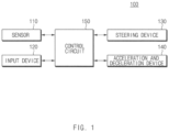
- FIG. 1 is a block diagram illustrating a configuration of an apparatus for controlling a lane change in a vehicle in one form of the present disclosure.
- an apparatus 100 for controlling a lane change in a vehicle may include a sensor 110, an input device 120, a steering device 130, an acceleration and deceleration device 140, and a control circuit 150.
- the apparatus 100 of FIG. 1 may be loaded into the vehicle.
- the sensor 110 may be configured to sense an external vehicle.
- the sensor 110 may include, for example, a forward sensor 110 and a blind spot assist (BSA) sensor (or a rear lateral sensor) 110.
- BSA blind spot assist
- the sensor 110 may sense a preceding vehicle which is traveling on the same lane as the vehicle and a following vehicle which is traveling on a lane adjacent to the vehicle.
- the input device 120 may be configured to receive a lane change command from a driver of the vehicle.
- the input device 120 may be implemented with, for example, a turn signal lever, a switch, a button, or the like capable of receiving an input of the driver.
- the steering device 130 may be configured to control a steering angle of the vehicle.
- the steering device 130 may include, for example, a steering wheel, an actuator interlocked with the steering wheel, and a controller for controlling the actuator.
- the acceleration and deceleration device 140 may be configured to control a speed of the vehicle.
- the acceleration and deceleration device 140 may include, for example, a throttle, a brake, an actuator interlocked with the throttle and the brake, and a controller for controlling the actuator.
- the control circuit 150 may be electrically connected with the sensor 110, the input device 120, the steering device 130, and the acceleration and deceleration device 140.
- the control circuit 150 may control the sensor 110, the input device 120, the steering device 130, and the acceleration and deceleration device 140 and may perform a variety of data processing and various arithmetic operations.
- the control circuit 150 may be, for example, an electronic control unit (ECU) or a sub-controller loaded into the vehicle.
- ECU electronice control unit
- the control circuit 150 receives a lane change command using the input device 120.
- the control circuit 150 may receive a lane change command in a left or right direction via the input device 120 from the driver.
- the control circuit 150 calculates a minimum operation speed for lane change control.
- the control circuit 150 may calculate a minimum operation speed in response to receiving a lane change command or may calculate a minimum operation speed periodically while the vehicle travels.
- the apparatus 100 activates control only when a driving speed of the vehicle is greater than or equal to the minimum operation speed for a safe lane change.
- An exemplary equation for calculating a minimum operation speed V smin may be Equation 1 below.
- V s min a ⁇ t B ⁇ t G + v app ⁇ a 2 ⁇ t B ⁇ t G 2 ⁇ 2 ⁇ a ⁇ v app ⁇ t G ⁇ S rear
- the minimum operation speed V smin may be determined based on S rear , V app , a, t B , and t G .
- each of a, t B , and t G may be a kind of environmental variable indicating a predicted behavior of a following vehicle and may correspond to a predefined constant.
- Each of the distance S rear between the vehicle and the following vehicle and the speed V app of the following vehicle may be a value indicating a motion state of the following vehicle and may be measured by the sensor 110.
- control circuit 150 sets the distance S rear to a maximum sensing distance of the sensor 110 and sets the speed V app to a maximum legal speed of a country where a vehicle is traveling.
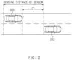
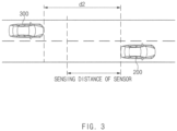
- a description will be given in detail of an exemplary form of calculating the minimum operation speed with reference to FIGS. 2 and 3 .
- the control circuit 150 may determine whether to accelerate the vehicle based on a speed of a preceding vehicle which is traveling on the same lane as the vehicle. In a situation where the vehicle should accelerate its driving speed to reach the minimum operation speed to activate lane change control, the control circuit 150 may divide a surrounding situation into four situations and may provide a control strategy suitable for each of the four situations. The control circuit 150 may suitably accelerate or decelerate the vehicle and may perform lane change control by controlling the steering device 130 and the acceleration and deceleration device 140.
- control circuit 150 may verify whether the minimum operation speed is higher than a driving speed of the vehicle. When the driving speed of the vehicle is higher than the minimum operation speed, the control circuit 150 may immediately initiate a lane change. When the driving speed of the vehicle is lower than the minimum operation speed, the control circuit 150 may perform lane change control depending on the control strategy disclosed in Table 1 above.
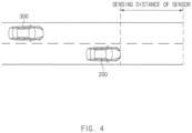
- the control circuit 150 may verify whether there is a preceding vehicle using the sensor 110. When the preceding vehicle is not detected, the control circuit 150 may sufficiently accelerate the vehicle, thus accelerating the vehicle to the minimum operation speed or more to change a lane.
- the vehicle 200 sets the distance S rear to a maximum sensing distance of the sensor and sets the speed V app to a maximum legal speed of a country where the vehicle 200 is traveling.
- the vehicle 200 calculates a minimum operation speed by applying the set S rear and V app to Equation 1 above.
- the vehicle 200 may calculate a minimum operation speed by detecting the following vehicle 300 in a lane to be changed or may calculate a minimum operation speed by detecting the following vehicle 300 in a lane adjacent to the vehicle 200.
- the vehicle 200 may control a driving speed of the vehicle 200 to be higher than a minimum operation speed and may perform lane change control when the driving speed of the vehicle 200 is higher than the minimum operation speed.
- the vehicle 200 may fail to detect the preceding vehicle.
- the preceding vehicle is not located within the sensing distance of the sensor, since the vehicle 200 sufficiently accelerates its driving speed, it may accelerate the driving speed to a minimum operation speed and may change a lane.
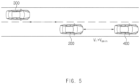
- FIG. 5 is a drawing illustrating an exemplary operation of an apparatus for controlling a lane change in a vehicle according to another exemplary form of the present disclosure.
- a vehicle 200 may control its driving speed to be higher than the minimum operation speed V smin and may perform lane change control when the driving speed of the vehicle 200 is higher than the minimum operation speed V smin .
- the vehicle 200 may detect a speed of the preceding vehicle 400.
- the speed V f of the preceding vehicle 400 is faster than the minimum operation speed V smin , since the vehicle 200 sufficiently accelerates its driving speed, it may accelerate the driving speed to the minimum operation speed V smin and may change a lane.
- FIG. 6 is a drawing illustrating an exemplary operation of an apparatus for controlling a lane change in a vehicle according to another form of the present disclosure.
- a vehicle 200 may determine whether to accelerate based on a speed of the preceding vehicle 400 and a distance between the vehicle 200 and the preceding vehicle 400.
- the vehicle 200 may sense the speed V f of the preceding vehicle 400.
- the speed V f of the preceding vehicle 400 is slower than the minimum operation speed V smin , the vehicle 200 is unable to sufficiently accelerate its driving speed, so it may determine whether to accelerate in consideration of a headway between the vehicle 200 and the preceding vehicle 400.
- the vehicle 200 may determine a probability of collision between the vehicle 200 and the preceding vehicle 400 based on the speed V f of the preceding vehicle 400 and a distance between the vehicle 200 and the preceding vehicle 400.
- the vehicle 200 may control its driving speed to be higher than the minimum operation speed V smin and may perform lane change control when the driving speed of the vehicle 200 is higher than the minimum operation speed V smin .
- the vehicle 200 may predict a driving path of the vehicle 200 and a driving path of the preceding vehicle 400 until a lane change is completed.
- the vehicle 200 may accelerate its driving speed to the minimum operation speed V smin and may change a lane along the predicted driving speed.
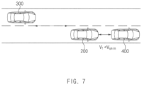
- FIG. 7 is a drawing illustrating an exemplary operation of an apparatus for controlling a lane change in a vehicle according to another aspect of the present disclosure.
- a vehicle 200 may determine a probability of collision between the vehicle 200 and a preceding vehicle 400 based on a speed V f of the preceding vehicle 400 and a distance between the vehicle 200 and the preceding vehicle 400.
- the vehicle 200 may control its driving speed to decelerate.
- the vehicle 200 may predict its driving path and a driving path of the preceding vehicle 400 until a lane change is completed.
- the vehicle 200 may perform deceleration control. After the vehicle 200 decelerates, it may determine the probability of collision again and may calculate a minimum operation speed again.
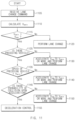
- FIGS. 8 and 9 are drawings illustrating an exemplary operation for determining a probability of collision in an apparatus for controlling a lane change in a vehicle according to an exemplary form of the present disclosure.
- a vehicle may estimate its predicted driving path and a predicted driving path of a preceding vehicle based on a speed of the preceding vehicle and a distance between the vehicle and the preceding vehicle and may determine a probability of collision between the vehicle and the preceding vehicle based on the predicted driving path of the vehicle and the predicted driving path of the preceding vehicle.
- a vehicle 810 may recognize a preceding vehicle 820, a driving lane, and a target lane.
- the vehicle 810 may predict a path where the vehicle 810 accelerates to a minimum operation speed and changes a lane and may predict a path of the preceding vehicle 820.
- the vehicle 810 may verify whether paths are duplicated. When the paths are duplicated, the vehicle 810 may determine that there is a probability of collision between the vehicle 810 and the preceding vehicle 820. When the paths are not duplicated, the vehicle 810 may determine that there is no probability of collision between the vehicle 810 and the preceding vehicle 820.
- a 1 st point 911, a 2 nd point 912, a 3 rd point 913, and a 4 th point 914 may represent expected movement points of a vehicle 910 at intervals of a specified time (e.g., 100 ms).
- a 6 th point 921, a 7 th point 922, a 8 th point 923, and a 9 th point 924 may represent expected movement points of a preceding vehicle 920 at intervals of the same time.
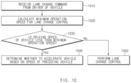
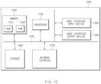
- FIG. 10 is a flowchart illustrating a method for controlling a lane change in a vehicle according to an exemplary form of the present disclosure.
Landscapes
- Engineering & Computer Science (AREA)
- Transportation (AREA)
- Mechanical Engineering (AREA)
- Automation & Control Theory (AREA)
- Chemical & Material Sciences (AREA)
- Combustion & Propulsion (AREA)
- Physics & Mathematics (AREA)
- General Physics & Mathematics (AREA)
- Human Computer Interaction (AREA)
- Mathematical Physics (AREA)
- Control Of Driving Devices And Active Controlling Of Vehicle (AREA)
- Controls For Constant Speed Travelling (AREA)
Claims (14)
- Vorrichtung (100) zur Steuerung eines Spurwechsels eines Fahrzeugs (200), wobei die Vorrichtung Folgendes umfasst:einen Sensor (110), der konfiguriert ist, um ein externes Fahrzeug (300, 400) zu erfassen;eine Eingabevorrichtung (120), die konfiguriert ist, um einen Spurwechselbefehl von einem Fahrer des Fahrzeugs zu empfangen; undeine Steuerschaltung (150), die konfiguriert ist, um elektrisch mit dem Sensor und der Eingabevorrichtung verbunden zu werden,wobei die Steuerschaltung (150) konfiguriert ist zum:Empfangen des Spurwechselbefehls unter Verwendung der Eingabevorrichtung;Berechnen einer minimale Betriebsgeschwindigkeit des Fahrzeugs für eine Spurwechselsteuerung;Bestimmen, ob das Fahrzeug beschleunigt werden soll, basierend auf einer Geschwindigkeit eines vorausfahrenden Fahrzeugs (400), das auf der gleichen Fahrspur wie das Fahrzeug fährt, wenn eine Fahrgeschwindigkeit des Fahrzeugs niedriger als die minimale Betriebsgeschwindigkeit ist; undAktivieren der Spurwechselsteuerung nur, wenn die Fahrgeschwindigkeit des Fahrzeugs größer oder gleich der minimalen Betriebsgeschwindigkeit ist,dadurch gekennzeichnet, dass die Steuerschaltung (150) konfiguriert ist zum:wenn ein nachfolgendes Fahrzeug (300), das auf einer Zielfahrspur fährt, die dem Spurwechselbefehl entspricht, nicht von dem Sensor erfasst wird, Einstellen eines Abstands zwischen dem Fahrzeug (200) und dem nachfolgenden Fahrzeug (300) auf einen maximalen Abstand, der von dem Sensor erfasst wird, und einer Geschwindigkeit des nachfolgenden Fahrzeugs (300) auf eine gesetzliche Höchstgeschwindigkeit eines Landes, in dem das Fahrzeug (200) fährt, undBerechnen der minimalen Betriebsgeschwindigkeit basierend auf dem Abstand und der von der Steuerschaltung (150) eingestellten Geschwindigkeit.
- Vorrichtung (100) nach Anspruch 1, wobei die Steuerschaltung (150) konfiguriert ist zum:
Berechnen der minimale Betriebsgeschwindigkeit des Fahrzeugs als Antwort auf das Empfangen des Spurwechselbefehls. - Vorrichtung (100) nach Anspruch 1, wobei die Steuerschaltung (150) konfiguriert ist zum:
periodischen Berechnen der minimalen Betriebsgeschwindigkeit des Fahrzeugs, während das Fahrzeug fährt. - Vorrichtung (100) nach Anspruch 1, wobei die Steuerschaltung (150) konfiguriert ist zum:
wenn ein nachfolgendes Fahrzeug, das auf einer dem Spurwechselbefehl entsprechenden Zielfahrspur fährt, von dem Sensor erfasst wird, Berechnen der minimalen Betriebsgeschwindigkeit basierend auf einer Geschwindigkeit des nachfolgenden Fahrzeugs und einem Abstand zwischen dem Fahrzeug und dem nachfolgenden Fahrzeug. - Vorrichtung (100) nach Anspruch 1, wobei die Steuerschaltung (150) konfiguriert ist zum:Steuern des Fahrzeugs, sodass die Fahrgeschwindigkeit des Fahrzeugs höher ist als die minimale Betriebsgeschwindigkeit, wenn die minimale Betriebsgeschwindigkeit niedriger ist als die Geschwindigkeit des vorausfahrenden Fahrzeugs; undDurchführen der Spurwechselsteuerung.
- Vorrichtung (100) nach Anspruch 1, wobei die Steuerschaltung (150) konfiguriert ist zum:Steuern des Fahrzeugs, sodass die Fahrgeschwindigkeit des Fahrzeugs höher ist als die minimale Betriebsgeschwindigkeit, wenn das vorausfahrende Fahrzeug nicht von dem Sensor erfasst wird; undDurchführen der Spurwechselsteuerung.
- Vorrichtung (100) nach Anspruch 1, wobei die Steuerschaltung (150) konfiguriert ist zum:
Bestimmen, ob das Fahrzeug beschleunigt werden soll, basierend auf der Geschwindigkeit des vorausfahrenden Fahrzeugs und einem Abstand zwischen dem Fahrzeug und dem vorausfahrenden Fahrzeug zu bestimmen, wenn die minimale Betriebsgeschwindigkeit höher ist als die Geschwindigkeit des vorausfahrenden Fahrzeugs. - Vorrichtung (100) nach Anspruch 7, wobei die Steuerschaltung (150) konfiguriert ist zum:Bestimmen einer Kollisionswahrscheinlichkeit zwischen dem Fahrzeug und dem vorausfahrenden Fahrzeug basierend auf der Geschwindigkeit des vorausfahrenden Fahrzeugs und dem Abstand zwischen dem Fahrzeug und dem vorausfahrenden Fahrzeug;Steuern des Fahrzeugs, sodass die Fahrgeschwindigkeit des Fahrzeugs höher ist als die minimale Betriebsgeschwindigkeit, wenn keine Kollisionswahrscheinlichkeit besteht; undDurchführen der Spurwechselsteuerung.
- Vorrichtung (100) nach Anspruch 8, wobei die Steuerschaltung (150) konfiguriert ist zum:Schätzen eines vorhergesagten Fahrpfads des Fahrzeugs und eines vorhergesagten Fahrpfads des vorausfahrenden Fahrzeugs basierend auf der Geschwindigkeit des vorausfahrenden Fahrzeugs und dem Abstand zwischen dem Fahrzeug und dem vorausfahrenden Fahrzeug; undBestimmen der Kollisionswahrscheinlichkeit zwischen dem Fahrzeug und dem vorausfahrenden Fahrzeug basierend auf dem vorhergesagten Fahrpfad des Fahrzeugs und dem vorhergesagten Fahrpfad des vorausfahrenden Fahrzeugs.
- Vorrichtung (100) nach Anspruch 7, wobei die Steuerschaltung (150) konfiguriert ist zum:Bestimmen einer Kollisionswahrscheinlichkeit zwischen dem Fahrzeug und dem vorausfahrenden Fahrzeug basierend auf der Geschwindigkeit des vorausfahrenden Fahrzeugs und dem Abstand zwischen dem Fahrzeug und dem vorausfahrenden Fahrzeug; undSteuern des Fahrzeugs, sodass es abbremst, wenn die Kollisionswahrscheinlichkeit besteht.
- Vorrichtung (100) nach Anspruch 10, wobei die Steuerschaltung (150) konfiguriert ist zum:
die Kollisionswahrscheinlichkeit zu bestimmen, nachdem das Fahrzeug abgebremst hat. - Vorrichtung (100) nach Anspruch 10, wobei die Steuerschaltung (150) konfiguriert ist zum:
erneuten Berechnen der minimalen Betriebsgeschwindigkeit, nachdem das Fahrzeug abgebremst hat. - Verfahren zum Steurung eines Spurwechsels bei einem Fahrzeug, wobei das Verfahren Folgendes umfasst:Empfangen (910), durch eine Steuerschaltung, eines Spurwechselbefehls von einem Fahrer des Fahrzeugs;Berechnen (920), durch die Steuerschaltung, einer minimalen Betriebsgeschwindigkeit des Fahrzeugs für eine Spurwechselsteuerung;Bestimmen (930), durch die Steuerschaltung, ob das Fahrzeug basierend auf einer Geschwindigkeit eines vorausfahrenden Fahrzeugs, das auf der gleichen Fahrspur wie das Fahrzeug fährt, beschleunigt werden soll, wenn eine Fahrgeschwindigkeit des Fahrzeugs niedriger als die minimale Betriebsgeschwindigkeit ist;Aktivieren der Spurwechselsteuerung (950) nur dann, wenn die Fahrgeschwindigkeit des Fahrzeugs größer oder gleich der minimalen Betriebsgeschwindigkeit ist,dadurch gekennzeichnet, dass das Verfahren weiter Folgendes umfasst:Einstellen, durch die Steuerschaltung (150), eines Abstands zwischen dem Fahrzeug (200) und dem nachfolgenden Fahrzeug (300) auf einen vom Sensor erfassten maximalen Abstand und einer Geschwindigkeit des nachfolgenden Fahrzeugs (300) auf eine gesetzliche Höchstgeschwindigkeit eines Landes, in dem das Fahrzeug (200) fährt, wenn ein nachfolgendes Fahrzeug (300), das auf einer dem Spurwechselbefehl entsprechenden Zielfahrspur fährt, nicht vom Sensor erfasst wird, undBerechnen, durch die Steuerschaltung (150), der minimalen Betriebsgeschwindigkeit basierend auf dem Abstand und der durch die Steuerschaltung (150) eingestellten Geschwindigkeit.
- Verfahren nach Anspruch 13, wobei Berechnen der minimalen Betriebsgeschwindigkeit Folgendes umfasst:
wenn ein nachfolgendes Fahrzeug, das auf einer dem Spurwechselbefehl entsprechenden Zielfahrspur fährt, erfasst wird, Berechnen der minimalen Betriebsgeschwindigkeit basierend auf einer Geschwindigkeit des nachfolgenden Fahrzeugs und einem Abstand zwischen dem Fahrzeug und dem nachfolgenden Fahrzeug.
Applications Claiming Priority (2)
| Application Number | Priority Date | Filing Date | Title |
|---|---|---|---|
| US201862655831P | 2018-04-11 | 2018-04-11 | |
| KR1020180107268A KR102645041B1 (ko) | 2018-04-11 | 2018-09-07 | 차량의 차로 변경 제어 장치 및 방법 |
Publications (2)
| Publication Number | Publication Date |
|---|---|
| EP3552898A1 EP3552898A1 (de) | 2019-10-16 |
| EP3552898B1 true EP3552898B1 (de) | 2025-07-02 |
Family
ID=64604581
Family Applications (1)
| Application Number | Title | Priority Date | Filing Date |
|---|---|---|---|
| EP18210401.8A Active EP3552898B1 (de) | 2018-04-11 | 2018-12-05 | Vorrichtung und verfahren zur steuerung des spurwechsels in einem fahrzeug |
Country Status (3)
| Country | Link |
|---|---|
| US (1) | US20190315361A1 (de) |
| EP (1) | EP3552898B1 (de) |
| CN (1) | CN110371118B (de) |
Families Citing this family (7)
| Publication number | Priority date | Publication date | Assignee | Title |
|---|---|---|---|---|
| KR102942823B1 (ko) * | 2020-06-30 | 2026-03-24 | 현대모비스 주식회사 | 차로 변경 보조 시스템 및 이를 이용한 차로 변경 방법 |
| CN112606805B (zh) * | 2020-12-17 | 2021-12-14 | 东风汽车集团有限公司 | 一种车辆自动紧急制动系统aeb的控制方法 |
| CN113916247B (zh) * | 2021-10-13 | 2023-10-13 | 苏州科技大学 | 智能网联游览车辆道路选择及路径规划装置和方法 |
| CN116229758B (zh) * | 2021-12-03 | 2025-11-07 | 北京万集科技股份有限公司 | 变道引导方法、路侧设备、系统及存储介质 |
| CN116853286A (zh) * | 2023-06-02 | 2023-10-10 | 华能伊敏煤电有限责任公司 | 一种露天矿厂矿车的无人驾驶控制方法 |
| KR20250001260A (ko) * | 2023-06-28 | 2025-01-06 | 현대자동차주식회사 | 차량 경로 생성 장치 및 그 방법 |
| DE102024000335B3 (de) * | 2024-02-02 | 2025-07-10 | Mercedes-Benz Group AG | Sicherheitsprüfung eines Fahrzeug-Spurwechsels mit abgestuften Sensorsichtweiten |
Family Cites Families (27)
| Publication number | Priority date | Publication date | Assignee | Title |
|---|---|---|---|---|
| JP3385921B2 (ja) * | 1997-07-14 | 2003-03-10 | 日産自動車株式会社 | 車両用追従走行制御装置 |
| DE19821122A1 (de) * | 1997-12-15 | 1999-06-17 | Volkswagen Ag | Verfahren zur Regelung von Geschwindigkeit und Abstand bei Überholvorgängen |
| US6353788B1 (en) * | 1997-12-15 | 2002-03-05 | Robert Bosch Gmbh | Method for regulating speed and distance during passing maneuvers |
| DE10114187A1 (de) * | 2001-03-23 | 2002-09-26 | Bosch Gmbh Robert | Verfahren und Vorrichtung zur Unterstützung eines Überholvorgangs bei Kraftfahrzeugen |
| JP2003025868A (ja) * | 2001-07-16 | 2003-01-29 | Nissan Motor Co Ltd | 車両の車線変更支援装置 |
| US7016783B2 (en) * | 2003-03-28 | 2006-03-21 | Delphi Technologies, Inc. | Collision avoidance with active steering and braking |
| DE602004008541T2 (de) * | 2003-07-07 | 2008-04-30 | Nissan Motor Co., Ltd., Yokohama | Steuersystem für ein Fahrzeug zum Halten der Fahrspur |
| JP4379199B2 (ja) * | 2004-05-17 | 2009-12-09 | 日産自動車株式会社 | 車線変更支援装置および方法 |
| DE102004029369B4 (de) * | 2004-06-17 | 2016-09-15 | Robert Bosch Gmbh | Spurwechselassistent für Kraftfahrzeuge |
| JP4689486B2 (ja) * | 2005-08-01 | 2011-05-25 | 本田技研工業株式会社 | 車両用制御装置 |
| JP4366419B2 (ja) * | 2007-09-27 | 2009-11-18 | 株式会社日立製作所 | 走行支援装置 |
| DE102010004625A1 (de) * | 2010-01-14 | 2011-07-21 | Ford Global Technologies, LLC, Mich. | Verfahren und Vorrichtung zur Unterstützung eines Fahrers bei einem Überholvorgang |
| RU2566175C1 (ru) * | 2011-08-31 | 2015-10-20 | Ниссан Мотор Ко., Лтд. | Устройство помощи при вождении транспортного средства |
| KR101399026B1 (ko) * | 2012-11-23 | 2014-05-27 | 현대엠엔소프트 주식회사 | 차선 변경 시 위험 알림 시스템 및 그 방법 |
| DE102014200896A1 (de) * | 2014-01-20 | 2015-07-23 | Volkswagen Aktiengesellschaft | Spurwechselassistenz für ein Kraftfahrzeug |
| DE102014210174B4 (de) * | 2014-05-28 | 2024-05-16 | Volkswagen Aktiengesellschaft | Bestimmen eines kritischen Fahrzeugzustands und einer Fahrzeugmindestentfernung |
| JP6470039B2 (ja) * | 2014-12-26 | 2019-02-13 | 日立オートモティブシステムズ株式会社 | 車両制御システム |
| JP2016149109A (ja) * | 2015-02-10 | 2016-08-18 | 国立大学法人金沢大学 | 車両走行制御装置 |
| JP2016168985A (ja) * | 2015-03-16 | 2016-09-23 | トヨタ自動車株式会社 | 走行制御装置 |
| JP6304504B2 (ja) * | 2015-10-28 | 2018-04-04 | 本田技研工業株式会社 | 車両制御装置、車両制御方法、および車両制御プログラム |
| JP6659379B2 (ja) * | 2016-01-28 | 2020-03-04 | 日立オートモティブシステムズ株式会社 | 道路情報認識システム及び道路情報認識方法 |
| EP3208786B1 (de) * | 2016-02-22 | 2023-06-07 | Volvo Car Corporation | Verfahren und system zur beurteilung von verkehrslücken zwischen fahrzeugen und zeitinstanzen zur durchführung eines spurwechselmanövers |
| JP6485399B2 (ja) * | 2016-04-15 | 2019-03-20 | 株式会社デンソー | 支援装置 |
| JP6310503B2 (ja) * | 2016-06-06 | 2018-04-11 | 本田技研工業株式会社 | 車両及びレーン変更タイミング判定方法 |
| US10625742B2 (en) * | 2016-06-23 | 2020-04-21 | Honda Motor Co., Ltd. | System and method for vehicle control in tailgating situations |
| JP6468261B2 (ja) * | 2016-08-10 | 2019-02-13 | トヨタ自動車株式会社 | 自動運転システム |
| KR20180024414A (ko) * | 2016-08-30 | 2018-03-08 | 현대자동차주식회사 | 차량 및 그 제어방법 |
-
2018
- 2018-11-29 US US16/204,400 patent/US20190315361A1/en not_active Abandoned
- 2018-12-05 EP EP18210401.8A patent/EP3552898B1/de active Active
- 2018-12-05 CN CN201811478859.8A patent/CN110371118B/zh active Active
Also Published As
| Publication number | Publication date |
|---|---|
| US20190315361A1 (en) | 2019-10-17 |
| CN110371118B (zh) | 2024-12-27 |
| EP3552898A1 (de) | 2019-10-16 |
| CN110371118A (zh) | 2019-10-25 |
Similar Documents
| Publication | Publication Date | Title |
|---|---|---|
| EP3552898B1 (de) | Vorrichtung und verfahren zur steuerung des spurwechsels in einem fahrzeug | |
| EP3552899B1 (de) | Vorrichtung und verfahren zur steuerung des spurwechsels in einem fahrzeug | |
| KR102645041B1 (ko) | 차량의 차로 변경 제어 장치 및 방법 | |
| EP3552902B1 (de) | Vorrichtung und verfahren zur bereitstellung eines fahrwegs an ein fahrzeug | |
| EP3552913B1 (de) | Vorrichtung und verfahren zur steuerung für die ermöglichung eines autonomen systems in einem fahrzeug | |
| EP3591638B1 (de) | Fahrassistenzverfahren und fahrassistenzvorrichtung | |
| US9517719B2 (en) | Method and device for automatic direction indication | |
| US11173912B2 (en) | Apparatus and method for providing safety strategy in vehicle | |
| EP3552903B1 (de) | Vorrichtung und verfahren zur bereitstellung einer sicherheitsstrategie an ein fahrzeug | |
| EP3552911B1 (de) | Vorrichtung und verfahren zur bereitstellung einer sicherheitsstrategie in einem fahrzeug | |
| US20130297172A1 (en) | Drive assisting apparatus | |
| EP3552909B1 (de) | Vorrichtung und verfahren zur verwaltung des kontrollautoritätsübergangs in einem fahrzeug | |
| US20190176831A1 (en) | Apparatus and method for controlling lane change in vehicle | |
| EP3569460A1 (de) | Vorrichtung und verfahren zur steuerung des fahrens in einem fahrzeug | |
| EP3552915A1 (de) | Vorrichtung und verfahren zur bereitstellung einer sicherheitsstrategie in einem fahrzeug | |
| US11591021B2 (en) | Method for preparing and/or performing a steering intervention that assists the driver of a vehicle | |
| JP3157986B2 (ja) | 追突防止システムにおける追突危険性判断方法 | |
| KR102932587B1 (ko) | 차량 제어 장치 및 차량 제어 방법 | |
| EP3835824A1 (de) | Adaptives objekt-in-pfad-erkennungsmodell für automatischen oder halbautomatischen fahrzeugbetrieb | |
| JP7631467B2 (ja) | 自車両の後方に位置する検出エリアにおいて対象物を検出するための車両物体検出システムおよび方法 |
Legal Events
| Date | Code | Title | Description |
|---|---|---|---|
| PUAI | Public reference made under article 153(3) epc to a published international application that has entered the european phase |
Free format text: ORIGINAL CODE: 0009012 |
|
| STAA | Information on the status of an ep patent application or granted ep patent |
Free format text: STATUS: THE APPLICATION HAS BEEN PUBLISHED |
|
| AK | Designated contracting states |
Kind code of ref document: A1 Designated state(s): AL AT BE BG CH CY CZ DE DK EE ES FI FR GB GR HR HU IE IS IT LI LT LU LV MC MK MT NL NO PL PT RO RS SE SI SK SM TR |
|
| AX | Request for extension of the european patent |
Extension state: BA ME |
|
| STAA | Information on the status of an ep patent application or granted ep patent |
Free format text: STATUS: REQUEST FOR EXAMINATION WAS MADE |
|
| 17P | Request for examination filed |
Effective date: 20200409 |
|
| RBV | Designated contracting states (corrected) |
Designated state(s): AL AT BE BG CH CY CZ DE DK EE ES FI FR GB GR HR HU IE IS IT LI LT LU LV MC MK MT NL NO PL PT RO RS SE SI SK SM TR |
|
| RAP3 | Party data changed (applicant data changed or rights of an application transferred) |
Owner name: HYUNDAI MOTOR COMPANY Owner name: KIA CORPORATION |
|
| P01 | Opt-out of the competence of the unified patent court (upc) registered |
Effective date: 20230505 |
|
| STAA | Information on the status of an ep patent application or granted ep patent |
Free format text: STATUS: EXAMINATION IS IN PROGRESS |
|
| 17Q | First examination report despatched |
Effective date: 20230713 |
|
| GRAP | Despatch of communication of intention to grant a patent |
Free format text: ORIGINAL CODE: EPIDOSNIGR1 |
|
| STAA | Information on the status of an ep patent application or granted ep patent |
Free format text: STATUS: GRANT OF PATENT IS INTENDED |
|
| RIC1 | Information provided on ipc code assigned before grant |
Ipc: B60W 50/00 20060101ALN20250306BHEP Ipc: G08G 1/16 20060101ALI20250306BHEP Ipc: B60W 30/14 20060101ALI20250306BHEP Ipc: B60W 50/10 20120101ALI20250306BHEP Ipc: B60W 30/18 20120101AFI20250306BHEP |
|
| INTG | Intention to grant announced |
Effective date: 20250321 |
|
| GRAS | Grant fee paid |
Free format text: ORIGINAL CODE: EPIDOSNIGR3 |
|
| GRAA | (expected) grant |
Free format text: ORIGINAL CODE: 0009210 |
|
| STAA | Information on the status of an ep patent application or granted ep patent |
Free format text: STATUS: THE PATENT HAS BEEN GRANTED |
|
| AK | Designated contracting states |
Kind code of ref document: B1 Designated state(s): AL AT BE BG CH CY CZ DE DK EE ES FI FR GB GR HR HU IE IS IT LI LT LU LV MC MK MT NL NO PL PT RO RS SE SI SK SM TR |
|
| REG | Reference to a national code |
Ref country code: GB Ref legal event code: FG4D |
|
| REG | Reference to a national code |
Ref country code: CH Ref legal event code: EP |
|
| REG | Reference to a national code |
Ref country code: DE Ref legal event code: R096 Ref document number: 602018083132 Country of ref document: DE |
|
| REG | Reference to a national code |
Ref country code: IE Ref legal event code: FG4D |
|
| REG | Reference to a national code |
Ref country code: NL Ref legal event code: MP Effective date: 20250702 |
|
| PG25 | Lapsed in a contracting state [announced via postgrant information from national office to epo] |
Ref country code: PT Free format text: LAPSE BECAUSE OF FAILURE TO SUBMIT A TRANSLATION OF THE DESCRIPTION OR TO PAY THE FEE WITHIN THE PRESCRIBED TIME-LIMIT Effective date: 20251103 |
|
| PG25 | Lapsed in a contracting state [announced via postgrant information from national office to epo] |
Ref country code: NL Free format text: LAPSE BECAUSE OF FAILURE TO SUBMIT A TRANSLATION OF THE DESCRIPTION OR TO PAY THE FEE WITHIN THE PRESCRIBED TIME-LIMIT Effective date: 20250702 |
|
| REG | Reference to a national code |
Ref country code: AT Ref legal event code: MK05 Ref document number: 1808925 Country of ref document: AT Kind code of ref document: T Effective date: 20250702 |
|
| PG25 | Lapsed in a contracting state [announced via postgrant information from national office to epo] |
Ref country code: IS Free format text: LAPSE BECAUSE OF FAILURE TO SUBMIT A TRANSLATION OF THE DESCRIPTION OR TO PAY THE FEE WITHIN THE PRESCRIBED TIME-LIMIT Effective date: 20251102 |
|
| PGFP | Annual fee paid to national office [announced via postgrant information from national office to epo] |
Ref country code: DE Payment date: 20251128 Year of fee payment: 8 |
|
| PGFP | Annual fee paid to national office [announced via postgrant information from national office to epo] |
Ref country code: GB Payment date: 20251128 Year of fee payment: 8 |
|
| PG25 | Lapsed in a contracting state [announced via postgrant information from national office to epo] |
Ref country code: NO Free format text: LAPSE BECAUSE OF FAILURE TO SUBMIT A TRANSLATION OF THE DESCRIPTION OR TO PAY THE FEE WITHIN THE PRESCRIBED TIME-LIMIT Effective date: 20251002 |
|
| REG | Reference to a national code |
Ref country code: LT Ref legal event code: MG9D |
|
| PG25 | Lapsed in a contracting state [announced via postgrant information from national office to epo] |
Ref country code: AT Free format text: LAPSE BECAUSE OF FAILURE TO SUBMIT A TRANSLATION OF THE DESCRIPTION OR TO PAY THE FEE WITHIN THE PRESCRIBED TIME-LIMIT Effective date: 20250702 |
|
| PG25 | Lapsed in a contracting state [announced via postgrant information from national office to epo] |
Ref country code: FI Free format text: LAPSE BECAUSE OF FAILURE TO SUBMIT A TRANSLATION OF THE DESCRIPTION OR TO PAY THE FEE WITHIN THE PRESCRIBED TIME-LIMIT Effective date: 20250702 |
|
| PG25 | Lapsed in a contracting state [announced via postgrant information from national office to epo] |
Ref country code: HR Free format text: LAPSE BECAUSE OF FAILURE TO SUBMIT A TRANSLATION OF THE DESCRIPTION OR TO PAY THE FEE WITHIN THE PRESCRIBED TIME-LIMIT Effective date: 20250702 |
|
| PGFP | Annual fee paid to national office [announced via postgrant information from national office to epo] |
Ref country code: FR Payment date: 20251128 Year of fee payment: 8 |
|
| PG25 | Lapsed in a contracting state [announced via postgrant information from national office to epo] |
Ref country code: GR Free format text: LAPSE BECAUSE OF FAILURE TO SUBMIT A TRANSLATION OF THE DESCRIPTION OR TO PAY THE FEE WITHIN THE PRESCRIBED TIME-LIMIT Effective date: 20251003 |
|
| PG25 | Lapsed in a contracting state [announced via postgrant information from national office to epo] |
Ref country code: SE Free format text: LAPSE BECAUSE OF FAILURE TO SUBMIT A TRANSLATION OF THE DESCRIPTION OR TO PAY THE FEE WITHIN THE PRESCRIBED TIME-LIMIT Effective date: 20250702 Ref country code: CZ Free format text: LAPSE BECAUSE OF FAILURE TO SUBMIT A TRANSLATION OF THE DESCRIPTION OR TO PAY THE FEE WITHIN THE PRESCRIBED TIME-LIMIT Effective date: 20250702 |
|
| PG25 | Lapsed in a contracting state [announced via postgrant information from national office to epo] |
Ref country code: LV Free format text: LAPSE BECAUSE OF FAILURE TO SUBMIT A TRANSLATION OF THE DESCRIPTION OR TO PAY THE FEE WITHIN THE PRESCRIBED TIME-LIMIT Effective date: 20250702 |
|
| PG25 | Lapsed in a contracting state [announced via postgrant information from national office to epo] |
Ref country code: BG Free format text: LAPSE BECAUSE OF FAILURE TO SUBMIT A TRANSLATION OF THE DESCRIPTION OR TO PAY THE FEE WITHIN THE PRESCRIBED TIME-LIMIT Effective date: 20250702 Ref country code: PL Free format text: LAPSE BECAUSE OF FAILURE TO SUBMIT A TRANSLATION OF THE DESCRIPTION OR TO PAY THE FEE WITHIN THE PRESCRIBED TIME-LIMIT Effective date: 20250702 |
|
| PG25 | Lapsed in a contracting state [announced via postgrant information from national office to epo] |
Ref country code: RS Free format text: LAPSE BECAUSE OF FAILURE TO SUBMIT A TRANSLATION OF THE DESCRIPTION OR TO PAY THE FEE WITHIN THE PRESCRIBED TIME-LIMIT Effective date: 20251002 |
|
| PG25 | Lapsed in a contracting state [announced via postgrant information from national office to epo] |
Ref country code: ES Free format text: LAPSE BECAUSE OF FAILURE TO SUBMIT A TRANSLATION OF THE DESCRIPTION OR TO PAY THE FEE WITHIN THE PRESCRIBED TIME-LIMIT Effective date: 20250702 |
|
| PG25 | Lapsed in a contracting state [announced via postgrant information from national office to epo] |
Ref country code: RO Free format text: LAPSE BECAUSE OF FAILURE TO SUBMIT A TRANSLATION OF THE DESCRIPTION OR TO PAY THE FEE WITHIN THE PRESCRIBED TIME-LIMIT Effective date: 20250702 |
|
| PG25 | Lapsed in a contracting state [announced via postgrant information from national office to epo] |
Ref country code: SM Free format text: LAPSE BECAUSE OF FAILURE TO SUBMIT A TRANSLATION OF THE DESCRIPTION OR TO PAY THE FEE WITHIN THE PRESCRIBED TIME-LIMIT Effective date: 20250702 |
|
| PG25 | Lapsed in a contracting state [announced via postgrant information from national office to epo] |
Ref country code: DK Free format text: LAPSE BECAUSE OF FAILURE TO SUBMIT A TRANSLATION OF THE DESCRIPTION OR TO PAY THE FEE WITHIN THE PRESCRIBED TIME-LIMIT Effective date: 20250702 |
|
| PG25 | Lapsed in a contracting state [announced via postgrant information from national office to epo] |
Ref country code: IT Free format text: LAPSE BECAUSE OF FAILURE TO SUBMIT A TRANSLATION OF THE DESCRIPTION OR TO PAY THE FEE WITHIN THE PRESCRIBED TIME-LIMIT Effective date: 20250702 |
|
| PG25 | Lapsed in a contracting state [announced via postgrant information from national office to epo] |
Ref country code: SK Free format text: LAPSE BECAUSE OF FAILURE TO SUBMIT A TRANSLATION OF THE DESCRIPTION OR TO PAY THE FEE WITHIN THE PRESCRIBED TIME-LIMIT Effective date: 20250702 Ref country code: EE Free format text: LAPSE BECAUSE OF FAILURE TO SUBMIT A TRANSLATION OF THE DESCRIPTION OR TO PAY THE FEE WITHIN THE PRESCRIBED TIME-LIMIT Effective date: 20250702 |