EP3552911B1 - Vorrichtung und verfahren zur bereitstellung einer sicherheitsstrategie in einem fahrzeug - Google Patents
Vorrichtung und verfahren zur bereitstellung einer sicherheitsstrategie in einem fahrzeug Download PDFInfo
- Publication number
- EP3552911B1 EP3552911B1 EP19167270.8A EP19167270A EP3552911B1 EP 3552911 B1 EP3552911 B1 EP 3552911B1 EP 19167270 A EP19167270 A EP 19167270A EP 3552911 B1 EP3552911 B1 EP 3552911B1
- Authority
- EP
- European Patent Office
- Prior art keywords
- vehicle
- event
- control
- control circuit
- time interval
- Prior art date
- Legal status (The legal status is an assumption and is not a legal conclusion. Google has not performed a legal analysis and makes no representation as to the accuracy of the status listed.)
- Active
Links
Images


Classifications
-
- G—PHYSICS
- G05—CONTROLLING; REGULATING
- G05D—SYSTEMS FOR CONTROLLING OR REGULATING NON-ELECTRIC VARIABLES
- G05D1/00—Control of position, course, altitude or attitude of land, water, air or space vehicles, e.g. using automatic pilots
- G05D1/0055—Control of position, course, altitude or attitude of land, water, air or space vehicles, e.g. using automatic pilots with safety arrangements
-
- B—PERFORMING OPERATIONS; TRANSPORTING
- B60—VEHICLES IN GENERAL
- B60W—CONJOINT CONTROL OF VEHICLE SUB-UNITS OF DIFFERENT TYPE OR DIFFERENT FUNCTION; CONTROL SYSTEMS SPECIALLY ADAPTED FOR HYBRID VEHICLES; ROAD VEHICLE DRIVE CONTROL SYSTEMS FOR PURPOSES NOT RELATED TO THE CONTROL OF A PARTICULAR SUB-UNIT
- B60W50/00—Details of control systems for road vehicle drive control not related to the control of a particular sub-unit, e.g. process diagnostic or vehicle driver interfaces
- B60W50/08—Interaction between the driver and the control system
-
- B—PERFORMING OPERATIONS; TRANSPORTING
- B60—VEHICLES IN GENERAL
- B60W—CONJOINT CONTROL OF VEHICLE SUB-UNITS OF DIFFERENT TYPE OR DIFFERENT FUNCTION; CONTROL SYSTEMS SPECIALLY ADAPTED FOR HYBRID VEHICLES; ROAD VEHICLE DRIVE CONTROL SYSTEMS FOR PURPOSES NOT RELATED TO THE CONTROL OF A PARTICULAR SUB-UNIT
- B60W30/00—Purposes of road vehicle drive control systems not related to the control of a particular sub-unit, e.g. of systems using conjoint control of vehicle sub-units
- B60W30/08—Active safety systems predicting or avoiding probable or impending collision or attempting to minimise its consequences
- B60W30/09—Taking automatic action to avoid collision, e.g. braking and steering
-
- B—PERFORMING OPERATIONS; TRANSPORTING
- B60—VEHICLES IN GENERAL
- B60W—CONJOINT CONTROL OF VEHICLE SUB-UNITS OF DIFFERENT TYPE OR DIFFERENT FUNCTION; CONTROL SYSTEMS SPECIALLY ADAPTED FOR HYBRID VEHICLES; ROAD VEHICLE DRIVE CONTROL SYSTEMS FOR PURPOSES NOT RELATED TO THE CONTROL OF A PARTICULAR SUB-UNIT
- B60W50/00—Details of control systems for road vehicle drive control not related to the control of a particular sub-unit, e.g. process diagnostic or vehicle driver interfaces
- B60W50/0097—Predicting future conditions
-
- B—PERFORMING OPERATIONS; TRANSPORTING
- B60—VEHICLES IN GENERAL
- B60W—CONJOINT CONTROL OF VEHICLE SUB-UNITS OF DIFFERENT TYPE OR DIFFERENT FUNCTION; CONTROL SYSTEMS SPECIALLY ADAPTED FOR HYBRID VEHICLES; ROAD VEHICLE DRIVE CONTROL SYSTEMS FOR PURPOSES NOT RELATED TO THE CONTROL OF A PARTICULAR SUB-UNIT
- B60W50/00—Details of control systems for road vehicle drive control not related to the control of a particular sub-unit, e.g. process diagnostic or vehicle driver interfaces
- B60W50/02—Ensuring safety in case of control system failures, e.g. by diagnosing, circumventing or fixing failures
- B60W50/029—Adapting to failures or work around with other constraints, e.g. circumvention by avoiding use of failed parts
-
- B—PERFORMING OPERATIONS; TRANSPORTING
- B60—VEHICLES IN GENERAL
- B60W—CONJOINT CONTROL OF VEHICLE SUB-UNITS OF DIFFERENT TYPE OR DIFFERENT FUNCTION; CONTROL SYSTEMS SPECIALLY ADAPTED FOR HYBRID VEHICLES; ROAD VEHICLE DRIVE CONTROL SYSTEMS FOR PURPOSES NOT RELATED TO THE CONTROL OF A PARTICULAR SUB-UNIT
- B60W50/00—Details of control systems for road vehicle drive control not related to the control of a particular sub-unit, e.g. process diagnostic or vehicle driver interfaces
- B60W50/08—Interaction between the driver and the control system
- B60W50/082—Selecting or switching between different modes of propelling
-
- B—PERFORMING OPERATIONS; TRANSPORTING
- B60—VEHICLES IN GENERAL
- B60W—CONJOINT CONTROL OF VEHICLE SUB-UNITS OF DIFFERENT TYPE OR DIFFERENT FUNCTION; CONTROL SYSTEMS SPECIALLY ADAPTED FOR HYBRID VEHICLES; ROAD VEHICLE DRIVE CONTROL SYSTEMS FOR PURPOSES NOT RELATED TO THE CONTROL OF A PARTICULAR SUB-UNIT
- B60W50/00—Details of control systems for road vehicle drive control not related to the control of a particular sub-unit, e.g. process diagnostic or vehicle driver interfaces
- B60W50/08—Interaction between the driver and the control system
- B60W50/14—Means for informing the driver, warning the driver or prompting a driver intervention
-
- B—PERFORMING OPERATIONS; TRANSPORTING
- B60—VEHICLES IN GENERAL
- B60W—CONJOINT CONTROL OF VEHICLE SUB-UNITS OF DIFFERENT TYPE OR DIFFERENT FUNCTION; CONTROL SYSTEMS SPECIALLY ADAPTED FOR HYBRID VEHICLES; ROAD VEHICLE DRIVE CONTROL SYSTEMS FOR PURPOSES NOT RELATED TO THE CONTROL OF A PARTICULAR SUB-UNIT
- B60W60/00—Drive control systems specially adapted for autonomous road vehicles
- B60W60/001—Planning or execution of driving tasks
- B60W60/0015—Planning or execution of driving tasks specially adapted for safety
- B60W60/0016—Planning or execution of driving tasks specially adapted for safety of the vehicle or its occupants
-
- B—PERFORMING OPERATIONS; TRANSPORTING
- B60—VEHICLES IN GENERAL
- B60W—CONJOINT CONTROL OF VEHICLE SUB-UNITS OF DIFFERENT TYPE OR DIFFERENT FUNCTION; CONTROL SYSTEMS SPECIALLY ADAPTED FOR HYBRID VEHICLES; ROAD VEHICLE DRIVE CONTROL SYSTEMS FOR PURPOSES NOT RELATED TO THE CONTROL OF A PARTICULAR SUB-UNIT
- B60W60/00—Drive control systems specially adapted for autonomous road vehicles
- B60W60/005—Handover processes
- B60W60/0053—Handover processes from vehicle to occupant
-
- B—PERFORMING OPERATIONS; TRANSPORTING
- B60—VEHICLES IN GENERAL
- B60W—CONJOINT CONTROL OF VEHICLE SUB-UNITS OF DIFFERENT TYPE OR DIFFERENT FUNCTION; CONTROL SYSTEMS SPECIALLY ADAPTED FOR HYBRID VEHICLES; ROAD VEHICLE DRIVE CONTROL SYSTEMS FOR PURPOSES NOT RELATED TO THE CONTROL OF A PARTICULAR SUB-UNIT
- B60W60/00—Drive control systems specially adapted for autonomous road vehicles
- B60W60/005—Handover processes
- B60W60/0059—Estimation of the risk associated with autonomous or manual driving, e.g. situation too complex, sensor failure or driver incapacity
-
- G—PHYSICS
- G05—CONTROLLING; REGULATING
- G05D—SYSTEMS FOR CONTROLLING OR REGULATING NON-ELECTRIC VARIABLES
- G05D1/00—Control of position, course, altitude or attitude of land, water, air or space vehicles, e.g. using automatic pilots
- G05D1/02—Control of position or course in two dimensions
- G05D1/021—Control of position or course in two dimensions specially adapted to land vehicles
- G05D1/0287—Control of position or course in two dimensions specially adapted to land vehicles involving a plurality of land vehicles, e.g. fleet or convoy travelling
- G05D1/0289—Control of position or course in two dimensions specially adapted to land vehicles involving a plurality of land vehicles, e.g. fleet or convoy travelling with means for avoiding collisions between vehicles
-
- G—PHYSICS
- G06—COMPUTING OR CALCULATING; COUNTING
- G06V—IMAGE OR VIDEO RECOGNITION OR UNDERSTANDING
- G06V20/00—Scenes; Scene-specific elements
- G06V20/50—Context or environment of the image
- G06V20/56—Context or environment of the image exterior to a vehicle by using sensors mounted on the vehicle
- G06V20/58—Recognition of moving objects or obstacles, e.g. vehicles or pedestrians; Recognition of traffic objects, e.g. traffic signs, traffic lights or roads
-
- G—PHYSICS
- G06—COMPUTING OR CALCULATING; COUNTING
- G06V—IMAGE OR VIDEO RECOGNITION OR UNDERSTANDING
- G06V20/00—Scenes; Scene-specific elements
- G06V20/50—Context or environment of the image
- G06V20/56—Context or environment of the image exterior to a vehicle by using sensors mounted on the vehicle
- G06V20/588—Recognition of the road, e.g. of lane markings; Recognition of the vehicle driving pattern in relation to the road
-
- B—PERFORMING OPERATIONS; TRANSPORTING
- B60—VEHICLES IN GENERAL
- B60W—CONJOINT CONTROL OF VEHICLE SUB-UNITS OF DIFFERENT TYPE OR DIFFERENT FUNCTION; CONTROL SYSTEMS SPECIALLY ADAPTED FOR HYBRID VEHICLES; ROAD VEHICLE DRIVE CONTROL SYSTEMS FOR PURPOSES NOT RELATED TO THE CONTROL OF A PARTICULAR SUB-UNIT
- B60W50/00—Details of control systems for road vehicle drive control not related to the control of a particular sub-unit, e.g. process diagnostic or vehicle driver interfaces
- B60W2050/0062—Adapting control system settings
- B60W2050/0075—Automatic parameter input, automatic initialising or calibrating means
- B60W2050/0082—Automatic parameter input, automatic initialising or calibrating means for initialising the control system
-
- B—PERFORMING OPERATIONS; TRANSPORTING
- B60—VEHICLES IN GENERAL
- B60W—CONJOINT CONTROL OF VEHICLE SUB-UNITS OF DIFFERENT TYPE OR DIFFERENT FUNCTION; CONTROL SYSTEMS SPECIALLY ADAPTED FOR HYBRID VEHICLES; ROAD VEHICLE DRIVE CONTROL SYSTEMS FOR PURPOSES NOT RELATED TO THE CONTROL OF A PARTICULAR SUB-UNIT
- B60W2552/00—Input parameters relating to infrastructure
- B60W2552/05—Type of road, e.g. motorways, local streets, paved or unpaved roads
-
- B—PERFORMING OPERATIONS; TRANSPORTING
- B60—VEHICLES IN GENERAL
- B60W—CONJOINT CONTROL OF VEHICLE SUB-UNITS OF DIFFERENT TYPE OR DIFFERENT FUNCTION; CONTROL SYSTEMS SPECIALLY ADAPTED FOR HYBRID VEHICLES; ROAD VEHICLE DRIVE CONTROL SYSTEMS FOR PURPOSES NOT RELATED TO THE CONTROL OF A PARTICULAR SUB-UNIT
- B60W2552/00—Input parameters relating to infrastructure
- B60W2552/10—Number of lanes
-
- B—PERFORMING OPERATIONS; TRANSPORTING
- B60—VEHICLES IN GENERAL
- B60W—CONJOINT CONTROL OF VEHICLE SUB-UNITS OF DIFFERENT TYPE OR DIFFERENT FUNCTION; CONTROL SYSTEMS SPECIALLY ADAPTED FOR HYBRID VEHICLES; ROAD VEHICLE DRIVE CONTROL SYSTEMS FOR PURPOSES NOT RELATED TO THE CONTROL OF A PARTICULAR SUB-UNIT
- B60W2554/00—Input parameters relating to objects
Definitions
- the present invention relates to an apparatus and method for providing a strategy for the maintenance of safety depending on the occurrence of an event.
- the autonomous system may provide a variety of functions, for example, setting speed keeping, vehicle-to-vehicle distance keeping, lane keeping, and a lane change.
- the autonomous system may perform autonomous driving using various devices such as a sensor for sensing environments outside the vehicle, a sensor for sensing information about the vehicle, a global positioning system (GPS), a detailed map, a driver state monitoring system, a steering actuator, an acceleration/deceleration actuator, a communication circuit, and a control circuit (e.g., an electronic control unit (ECU)).
- the autonomous system may detect a critical situation and may provide a minimum risk maneuver (MRM) when sensing the critical situation.
- MRM minimum risk maneuver
- the autonomous system may predict or detect a critical situation.
- the critical situation may be predicted or may occur like a bombshell.
- the safety of a driver may be improved.
- US 2018/088574 A1 discloses a control system that is operable to control a vehicle in an autonomous or semi-autonomous mode including a processor that processes data captured by a plurality of exterior sensing sensors.
- the control system determines (i) a total action time until the vehicle encounters the event, (ii) an estimated time for the driver to take over control and (iii) an estimated handling time for the vehicle to be controlled before the vehicle encounters the event. Responsive to the determinations, the control system (i) allows the driver to take over control of the vehicle or (ii) controls the vehicle to slow down and stop the vehicle before the vehicle encounters the event.
- EP 3 284 646 A1 discloses a control system for an autonomous driving vehicle comprising an operation device configured to be operated by a driver; a notification device configured to give notification to the driver; and an electronic control unit. Autonomous driving is performed. When the driver operates the operation device during autonomous driving, autonomous driving is terminated, and vehicle driving is switched to manual driving. Further, when the driver should be requested to terminate autonomous driving during autonomous driving, the notification device is controlled to first notify a request for preparing for manual driving to the driver and then notify a request for terminating autonomous driving to the driver.
- US 2015/0094899 A1 discloses a driver assistance system of a vehicle, which is able to control the vehicle at least partially automatically.
- a method alerts the driver to retake control of the vehicle from the driver assistance system based on the distance between the current location of the vehicle and an end of the autopilot capable route section.
- An end of an autopilot route section in a route planned for the vehicle is determined and distance information is determined between a current position of the vehicle and the end of the autopilot route section.
- the distance information is compared to a first and a second threshold value, and a first or a second indication is output as a function thereof.
- An aspect of the present invention provides an apparatus and method for identifying a critical situation which may occur during autonomous control and providing an MRM suitable for each situation.
- an apparatus for providing a safety strategy in a vehicle includes: a sensor configured to obtain sensing information about the outside of the vehicle, a memory storing road information, an output device configured to output a notification, and a control circuit configured to be electrically connected with the sensor, the memory, and the output device.
- the control circuit is configured to recognize an event associated with a critical situation of the vehicle based on at least a portion of the sensing information or the road information, while performing autonomous control, maintain the autonomous control, output a transition demand using the output device, and control the vehicle according to a predetermined strategy for the critical situation, when the event is a planned event, and immediately output the transition demand and control the vehicle according to the predetermined strategy, when the event is an unplanned event.
- the planned event may be associated with a driving road or a driving lane of the vehicle.
- the unplanned event may be associated with an external object or a failure of an autonomous system of the vehicle.
- control circuit may be configured to calculate an expected remaining time taken until the event occurs, when the event is the planned event, maintain the autonomous control, when the expected remaining time is greater than the sum of a first time interval and a second time interval, output the transition demand, when the expected remaining time is less than or equal to the sum of the first time interval and the second time interval and is greater than the second time interval, and control the vehicle according to the predetermined strategy, when the expected remaining time is less than or equal to the second time interval.
- the first time interval may be preset.
- the second time interval may be calculated based on a speed of the vehicle.
- control circuit may be configured to immediately output the transition demand and calculate an expected remaining time taken until the event occurs, when the event is the unplanned event and control the vehicle according to the predetermined strategy together with outputting the transition demand, when the expected remaining time is less than a specified time interval.
- the specified time interval may be calculated based on a speed of the vehicle.
- control circuit may be configured to immediately control the vehicle according to the predetermined strategy together with outputting the transition demand, when the event is the unplanned event.
- control circuit may be configured to immediately control the vehicle according to the predetermined strategy together with outputting the transition demand, when the event is an event where a surrounding vehicle cuts in.
- control circuit may be configured to immediately control the vehicle according to the predetermined strategy together with outputting the transition demand, when the event is a failure of an autonomous system.
- control circuit may be configured to control the vehicle according to another strategy for the critical situation, when deceleration required to avoid the critical situation is greater in magnitude than a specified value.
- control circuit may be configured to hand over control authority to a driver of the vehicle, when an input by the driver is received after the transition demand is output.
- the predetermined strategy may include stopping in lane, deceleration in lane, or movement toward a shoulder.
- a method for providing a safety strategy in a vehicle includes recognizing an event associated with a critical situation of the vehicle based on at least a portion of sensing information or road information, while performing autonomous control, maintaining the autonomous control, outputting a transition demand, and controlling the vehicle according to a predetermined strategy for the critical situation, when the event is a planned event, and immediately outputting the transition demand and controlling the vehicle according to the predetermined strategy, when the event is an unplanned event.
- the planned event may be associated with a driving road or a driving lane of the vehicle.
- the unplanned event may be associated with an external object or a failure of an autonomous system of the vehicle.
- the controlling of the vehicle when the event is the planned event may include calculating an expected remaining time taken until the event occurs, maintaining the autonomous control, when the expected remaining time is greater than the sum of a first time interval and a second time interval, outputting the transition demand, when the expected remaining time is less than or equal to the sum of the first time interval and the second time interval and is greater than the second time interval, and controlling the vehicle according to the predetermined strategy, when the expected remaining time is less than or equal to the second time interval.
- the controlling of the vehicle when the event is the unplanned event may include immediately outputting the transition demand and calculating an expected remaining time taken until the event occurs and controlling the vehicle according to the predetermined strategy together with outputting the transition demand, when the expected remaining time is less than a specified time interval.
- the controlling of the vehicle when the event is the unplanned event may include immediately controlling the vehicle according to the predetermined strategy together with outputting the transition demand.
- FIG. 1 is a block diagram illustrating a configuration of an apparatus for providing a safety strategy in a vehicle according to one aspect of the present invention.
- an apparatus 100 for providing a safety strategy includes a sensor 110, a memory 120, an output device 130, and a control circuit 140.
- the apparatus 100 for providing a safety strategy in FIG. 1 may be a portion of an autonomous system and may be loaded into the vehicle.
- the sensor 110 senses information associated with the outside of the vehicle.
- the sensor 110 may sense information (e.g., a location, a speed, acceleration, and the like) associated with an external object located in front of, behind, or on either side of the vehicle.
- the sensor 110 may also sense information about the vehicle.
- the sensor 110 may sense the location of the vehicle and motion (e.g., a speed, acceleration, a steering angle, and the like) of the vehicle.
- the memory 120 stores road information.
- the road information may include, for example, a map or the like.
- the road information may include information about, for example, a type (e.g., a limited-access road, a normal road, or the like) of a road, a termination point of the road, a characteristic (e.g., a merging lane or the like) of a lane, and the like.
- the output device 130 is configured to output a notification.
- the output device 130 may provide a notification sensuously recognizable by a driver of the vehicle.
- the output device 130 may include, for example, a display, a speaker, a vibration motor, and/or the like.
- the control circuit 140 is configured to be electrically connected with the sensor 110, the memory 120, and the output device 130.
- the control circuit 140 may control the sensor 110, the memory 120, and the output device 130 and may perform a variety of data processing and various arithmetic operations.
- the control circuit 140 may be, for example, an electronic control unit (ECU), a micro controller unit (MCU), or a sub-controller, which is loaded into the vehicle.
- ECU electronice control unit
- MCU micro controller unit
- sub-controller which is loaded into the vehicle.
- control circuit 140 may perform autonomous control.
- control circuit 140 may perform driving assistance control on a limited-access road.
- the control circuit 140 may recognize an event associated with a critical situation of the vehicle based on at least a portion of sensing information or road information while performing autonomous control.
- the control circuit 140 may continue verifying a probability that a predefined critical situation will occur.
- the event may include, for example, a planned event and an unplanned event.
- the planned event may be associated with a driving road or a driving lane of the vehicle.
- the unplanned event may be associated with an external object or a failure of the autonomous system. A description will be given in detail below of an example of the planned event and the unplanned event with reference to FIGS. 3 and 4 .
- the control circuit 140 may control the vehicle as below in response to the critical situation.
- the control circuit 140 when the event is the planned event, the control circuit 140 is configured to maintain autonomous control and output a transition demand using the output device 130, thus controlling the vehicle according to a predetermined strategy for a critical situation.
- the control circuit 140 may calculate an expected remaining time taken until the event occurs. When the expected remaining time is greater than the sum of a first time interval and a second time interval, the control circuit 140 may maintain autonomous control. When the expected remaining time is less than or equal to the sum of the first time interval and the second time interval and is greater than the second time interval, the control circuit 140 may output the transition demand.
- the transition demand may be referred to as a TD.
- the control circuit 140 may control the vehicle according to a predetermined strategy.
- the predetermined strategy may be an MRM.
- the predetermined strategy may include various strategies, for example, stopping in lane, acceleration in lane, or movement toward a shoulder, or the like. While controlling the vehicle according to the predetermined strategy, the control circuit 140 may continue outputting the transition demand.
- the first time interval may be preset.
- the second time interval may be calculated based on, for example, a speed of the vehicle. A description will be given in detail below of an exemplary control strategy corresponding to the planned event with reference to FIG. 5 .
- the control circuit 140 when the event is the unplanned event, the control circuit 140 is configured to immediately output a transition demand and control the vehicle according to a predetermined strategy. For example, when the event is the unplanned event, the control circuit 140 may immediately output the transition demand and may calculate an expected remaining time taken until the event occurs. When the expected remaining time is less than a specified time interval, the control circuit 140 may control the vehicle according to a predetermined strategy together with outputting the transition demand.
- the specified time interval may be calculated based on, for example, a speed of the vehicle.
- the control circuit 140 may control the vehicle according to a predetermined strategy together with immediately outputting a transition demand.
- the control circuit 140 may control the vehicle according to the predetermined strategy together with immediately outputting the transition demand.
- the control circuit 140 may control the vehicle according to another strategy for the critical situation. Because the speed of the vehicle is fast, when acceleration of greater than or equal to 3.7 m/s 2 is required to avoid the critical situation, the control circuit 140 may control the vehicle according to an emergency control strategy which is more advantageous for avoiding the critical situation than the above-mentioned predetermined strategy.
- the control circuit 140 may hand over control authority to the driver.
- the control circuit 140 may stop executing the above-mentioned control strategy and may immediately hand over control authority to the driver.
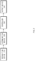
- FIG. 2 is a block diagram illustrating a configuration of an apparatus for providing a safety strategy in a vehicle according to one aspect of the present invention.
- the apparatus for providing the safety strategy in the vehicle may include a recognition device 210, a determination device 220, a controller 230, and an output device 240.
- the recognition device 210 may recognize a location, motion, and the like of the vehicle.
- the recognition device 210 may include a global positioning system (GPS) module, an inertial measurement unit (IMU), and the like.
- GPS global positioning system
- IMU inertial measurement unit
- the recognition device 210 may recognize surrounding circumstances on a road where the vehicle is traveling.
- the recognition device 210 may include a camera, a radar, a light detection and ranging (LiDAR), and the like.
- the determination device 220 may include a logic for precise positioning, which may determine a location of the vehicle.
- the determination device 220 may control the vehicle to travel along a destination or a most probable path (MPP) specified by a driver of the vehicle.
- the determination device 220 may determine whether it is desirable to perform an MRM, based on the recognized information.
- the controller 230 may select a suitable MRM depending on the determined result and may control the vehicle according to the selected strategy.
- the controller 230 may control the vehicle in a manner described with reference to FIG. 1 .
- the output device 240 may notify the driver of a state of the system, a critical situation, and the like.
- the output device 240 may provide a transition demand (TD) to the driver.
- TD transition demand
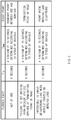
- FIG. 3 is a drawing illustrating a planned event recognized by an apparatus for providing a safety strategy in a vehicle according to one aspect of the present invention.
- the planned event may include when there is out of an operational design domain (ODD), when there is failure to set a driving path because the vehicle arrives at a termination point of a road, when it is impossible to enter a neighboring lane when the vehicle travels on a merging lane, and the like.
- ODD operational design domain
- the planned event may be an event, occurrence of which may be predicted when autonomous control is performed along a set path, irrespective of an external environment which is dynamically changed.
- T TD (a first time interval) may be a predetermined value.
- T TD may be set to 8 seconds in response to when there is out of the ODD and when the vehicle arrives at the termination point of the road.
- T TD may be set to 4 seconds in response to when the vehicle travels on the merging lane.
- T TD may be set to be relatively low.
- T MRM (a second time interval) may be determined based on a speed of the vehicle.
- T MRM may be set to a time when the vehicle may be stopped by specific deceleration. The faster the speed of the vehicle, longer T MRM may be. Although the speed of the vehicle is sufficiently slow, T MRM may be set to a minimum of 10 seconds or more.
- an event point may be set to a boundary point between the ODD (e.g., a limited-access road) and a non-ODD (e.g., a general road, a tollgate, or the like).
- the event point may be set to the termination point of the road.
- the event point may be set a point where the merging lane disappears.
- FIG. 4 is a drawing illustrating an unplanned event recognized by an apparatus for providing a safety strategy in a vehicle according to one aspect of the present invention.
- the unplanned event may include when a forward obstacle is detected, when a vehicle which cuts in at a short range is detected, when a section of road construction is detected, when there is system failure (e.g., failure of hardware such as a sensor and an electronic control unit (ECU) and an error of software), and the like.
- the unplanned event may be an event which occurs by an external environment which is dynamically changed and may be an event which is unable to be predicted.
- the vehicle may immediately generate a transition demand (TD) without considering T TD .
- T MRM (a specified time interval) may be determined based on a speed of the vehicle.
- T MRM may be set to a time when the vehicle may be stopped by specific deceleration. The faster the speed of the vehicle, the longer the T MRM may be. Although the vehicle is sufficiently slow in speed, T MRM may be set to a minimum of 10 seconds or more.
- the vehicle When the vehicle which cuts in at the short range is detected and when there is the system failure, since there is a higher probability that an emergency situation will occur than the other unplanned events, the vehicle may immediately perform an MRM together with providing the TD without considering T MRM .
- an event point may be a point where a collision with the obstacle is predicted.
- the event point may be a point where a collision with the vehicle which cuts in is expected.
- the event point may be a point where it is impossible to travel due to the section of road construction.
- the event point may be a point where the failure is recognized.
- FIG. 5 is a drawing illustrating an exemplary operation of an apparatus for providing a safety strategy in a vehicle according to one aspect of the present invention.
- the vehicle may perform autonomous control at a speed of 60 kph. While performing the autonomous control, the vehicle may recognize a critical situation. When the critical situation is a planned event, the vehicle may maintain the autonomous control until an expected remaining time t EVT is the same as the sum of T TD and T MRM .
- the vehicle may output a TD until the expected remaining time t EVT is the same as T MRM . While outputting the TD, the vehicle may perform lane keeping control and inter-vehicle distance keeping control.
- the vehicle may control itself. For example, the vehicle may control stopping in lane. While performing the MRM, the vehicle may continue outputting the TD.
- the vehicle may stop before an event point and may turn on/off its emergency lights while maintaining the stopping.
- FIG. 6 is a drawing illustrating an exemplary operation of an apparatus for providing a safety strategy in a vehicle according to one aspect of the present invention.
- the vehicle may perform autonomous control at a speed of 60 kph. While performing the autonomous control, the vehicle may recognize a critical situation.
- the vehicle may immediately output a transition demand.
- the vehicle may output the transition demand until an expected remaining time t EVT is the same as T MRM .
- the vehicle may perform lane keeping control and inter-vehicle distance keeping control.
- the vehicle may control itself according to an MRM. For example, the vehicle may control stopping in lane. While performing the MRM, the vehicle may continue outputting the transition demand.
- the vehicle may stop before an event point and may turn on/off its emergency lights while maintaining the stopping.
- FIG. 7 is a drawing illustrating an exemplary operation of an apparatus for providing a safety strategy in a vehicle according to one aspect of the present invention.
- the vehicle may perform autonomous control at a speed of 60 kph. While performing the autonomous control, the vehicle may recognize a critical situation.
- the vehicle may control itself according to an MRM or an emergency control strategy together with immediately outputting a transition demand. Simultaneously, the vehicle may turn on/off its emergency lights. For example, when an expected remaining time t EVT is less than T MRM at a time when the critical situation is recognized, when a vehicle which cuts in at a short range, that is, is during an unplanned event, is detected, when there is an emergency event such as system failure, or when deceleration greater than specified deceleration (e.g., 3.7 m/s 2 ) is required, the vehicle may control itself according to the MRM or the emergency control strategy together with immediately outputting the transition demand.
- an emergency event such as system failure
- specified deceleration e.g., 3.7 m/s 2
- the vehicle may execute the MRM.
- the vehicle may execute the emergency control strategy.
- the vehicle may control, for example, lane departure and stopping. Thus, the vehicle may stop before an event point.
- FIG. 8 is a flowchart illustrating a method for providing a safety strategy in a vehicle according to one aspect of the present invention.
- a vehicle including an apparatus 100 for providing a safety strategy in FIG. 1 performs a process of FIG. 8 .
- an operation described as being performed by the vehicle may be understood as being controlled by a control circuit 140 of the apparatus 100 for providing the safety strategy.
- the vehicle may perform autonomous control.
- the vehicle may detect a critical situation while performing the autonomous control and may provide a strategy corresponding to the critical situation as below.
- the vehicle may recognize an event associated with the critical situation based on at least a portion of sensing information or road information. For example, the vehicle may continue monitoring an event associated with a predefined critical situation.
- the vehicle may determine whether the recognized event corresponds to a planned event. For example, the vehicle may determine whether the recognized event is a planned event associated with a driving road or a driving lane or whether the recognized event is event is an unplanned event associated with an external object or a failure of its autonomous system.
- the vehicle may maintain the autonomous control. For example, the vehicle may maintain the autonomous control until a predetermined transition demand is initiated.
- the vehicle may output a transition demand. For example, when the predetermined transition demand is initiated, the vehicle may output the transition demand to its driver.
- the vehicle may control itself according to a predetermined strategy for the critical situation. For example, when an MRM is initiated, the vehicle may control stopping in lane.
- the vehicle may immediately output a transition demand.
- the vehicle may immediately output the transition demand to the driver without considering the time when the transition demand is initiated.
- the vehicle may control itself according to a predetermined strategy for the critical situation. For example, when the MRM is initiated, the vehicle may control stopping in lane concurrently with outputting the transition demand.
- FIG. 9 is a flowchart illustrating a method for providing a safety strategy in a vehicle according to one aspect of the present invention.
- a vehicle including an apparatus 100 for providing a safety strategy in FIG. 1 performs a process of FIG. 9 .
- an operation described as being performed by the vehicle may be undrstood as being controlled by a control circuit 140 of the apparatus 100 for providing the safety strategy.
- the vehicle may perform autonomous control.
- the vehicle may determine a critical situation.
- the vehicle may determine whether the critical situation corresponds to a planned event.
- the vehicle may calculate an expected remaining time t EVT up to an event point.
- the vehicle may determine whether the expected remaining time t EVT is less than or equal to the sum of a time T TD required for a transition demand (TD) before an MRM and an expected time T MRM taken for the MRM.
- the vehicle may generate a TD.
- the vehicle may determine whether an input for control authority transition by a driver is received.
- the vehicle may determine whether the expected remaining time t EVT is less than or equal to T MRM .
- the vehicle may perform an MRM.
- the vehicle may hand over control authority to the driver.
- the vehicle may calculate an expected remaining time t EVT up to an event point.
- the vehicle may calculate T TD and T MRM based on a current state and a type of the event.
- the vehicle may determine whether deceleration required to avoid risk is greater than a specified value (e.g., 3.7 m/s 2 ).
- the vehicle may generate a TD.
- the vehicle may determine whether an input for control authority transition by the driver is received.
- the vehicle may determine whether the expected remaining time t EVT is less than or equal to T MRM .
- the vehicle may perform an MRM.
- the vehicle may hand over control authority to the driver.
- the vehicle may perform emergency control strategy.
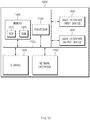
- FIG. 10 is a block diagram illustrating a configuration of a computing system according to one aspect of the present invention.
- a computing system 1000 may include at least one processor 1100, a memory 1300, a user interface input device 1400, a user interface output device 1500, a storage 1600, and a network interface 1700, which are connected with each other via a bus 1200.
- the processor 1100 may be a central processing unit (CPU) or a semiconductor device for performing processing of instructions stored in the memory 1300 and/or the storage 1600.
- CPU central processing unit
- Each of the memory 1300 and the storage 1600 may include various types of volatile or non-volatile storage media.
- the memory 1300 may include a read only memory (ROM) and a random access memory (RAM).
- the operations of the methods or algorithms described in connection with the specification may be directly implemented with a hardware module, a software module, or combinations thereof, executed by the processor 1100.
- the software module may reside on a storage medium (i.e., the memory 1300 and/or the storage 1600) such as a RAM, a flash memory, a ROM, an erasable and programmable ROM (EPROM), an electrically EPROM (EEPROM), a register, a hard disc, a removable disc, or a compact disc-ROM (CD-ROM).
- An exemplary storage medium may be coupled to the processor 1100.
- the processor 1100 may read out information from the storage medium and may write information in the storage medium.
- the storage medium may be integrated with the processor 1100.
- the processor and storage medium may reside in an application specific integrated circuit (ASIC).
- the ASIC may reside in a user terminal.
- the processor and storage medium may reside as a separate component of the user terminal.
- the apparatus for providing the safety strategy in the vehicle may enhance the safety of a driver through a correspondence strategy suitable for a situation by classifying an event associated with the critical situation of an autonomous vehicle as a planned event or an unplanned event and providing the correspondence strategy.
Landscapes
- Engineering & Computer Science (AREA)
- Automation & Control Theory (AREA)
- Transportation (AREA)
- Mechanical Engineering (AREA)
- Human Computer Interaction (AREA)
- Physics & Mathematics (AREA)
- General Physics & Mathematics (AREA)
- Radar, Positioning & Navigation (AREA)
- Remote Sensing (AREA)
- Aviation & Aerospace Engineering (AREA)
- Theoretical Computer Science (AREA)
- Multimedia (AREA)
- Traffic Control Systems (AREA)
- Control Of Driving Devices And Active Controlling Of Vehicle (AREA)
- Business, Economics & Management (AREA)
- Health & Medical Sciences (AREA)
- Artificial Intelligence (AREA)
- Evolutionary Computation (AREA)
- Game Theory and Decision Science (AREA)
- Medical Informatics (AREA)
Claims (15)
- Einrichtung zum Bereitstellen einer Sicherheitsstrategie (100) in einem Fahrzeug, wobei die Einrichtung (100) umfasst:einen Sensor (110), der konfiguriert ist, Erfassungsinformationen über eine Außenseite des Fahrzeugs zu erhalten;einen Speicher (120), der Straßeninformationen speichert;eine Ausgabevorrichtung (130), die konfiguriert ist, eine Benachrichtigung auszugeben; undeine Steuerschaltung (140), die konfiguriert ist, elektrisch mit dem Sensor (110), dem Speicher (120) und der Ausgabevorrichtung (130) verbunden zu sein,wobei die Steuerschaltung (140) konfiguriert ist zum:Erkennen eines Ereignisses, das mit einer kritischen Situation des Fahrzeugs verknüpft ist, basierend auf mindestens einem Teil der Erfassungsinformationen oder der Straßeninformationen, während autonome Steuerung durchgeführt wird; undwenn das Ereignis ein geplantes Ereignis ist, Aufrechterhalten der autonomen Steuerung, Ausgeben einer Übergangsanforderung unter Verwendung der Ausgabevorrichtung (130) und Steuern des Fahrzeugs gemäß einer vorbestimmten Strategie für die kritische Situation; undwenn das Ereignis ein ungeplantes Ereignis ist, Ausgeben der Übergangsanforderung und Steuern des Fahrzeugs gemäß der vorbestimmten Strategie.
- Einrichtung (100) nach Anspruch 1, wobei das geplante Ereignis mit einer Fahrstraße oder einer Fahrspur des Fahrzeugs verknüpft ist.
- Einrichtung (100) nach Anspruch 1 oder 2, wobei das ungeplante Ereignis mit einem externen Objekt oder einem Versagen eines autonomen Systems des Fahrzeugs verknüpft ist.
- Einrichtung (100) nach Anspruch 1, wobei die Steuerschaltung (140) konfiguriert ist zum:Berechnen einer erwarteten verbleibenden Zeit bis zum Eintritt des Ereignisses, wenn das Ereignis das geplante Ereignis ist;Aufrechterhalten der autonomen Steuerung, wenn die erwartete verbleibende Zeit größer als eine Summe eines ersten Zeitintervalls und eines zweiten Zeitintervalls ist;Ausgeben der Übergangsanforderung, wenn die erwartete verbleibende Zeit kleiner als oder gleich der Summe des ersten Zeitintervalls und des zweiten Zeitintervalls und größer als das zweite Zeitintervall ist; undSteuern des Fahrzeugs gemäß der vorbestimmten Strategie, wenn die erwartete verbleibende Zeit kleiner als oder gleich dem zweiten Zeitintervall ist.
- Einrichtung (100) nach Anspruch 4, wobei das erste Zeitintervall vorab eingestellt wird.
- Einrichtung (100) nach Anspruch 4, wobei das zweite Zeitintervall basierend auf einer Geschwindigkeit des Fahrzeugs berechnet wird.
- Einrichtung (100) nach einem der Ansprüche 1 bis 6, wobei die Steuerschaltung (140) konfiguriert ist zum:wenn das Ereignis ein ungeplantes Ereignis ist, unmittelbaren Ausgeben der Übergangsanforderung und Berechnen einer erwarteten verbleibenden Zeit bis zum Eintritt des Ereignisses; undSteuern des Fahrzeugs gemäß der vorbestimmten Strategie gemeinsam mit Ausgeben der Übergangsanforderung, wenn die erwartete verbleibende Zeit kleiner als ein spezifiziertes Zeitintervall ist.
- Einrichtung (100) nach Anspruch 7, wobei das spezifizierte Zeitintervall basierend auf einer Geschwindigkeit des Fahrzeugs berechnet wird.
- Einrichtung (100) nach einem der Ansprüche 1 bis 8, wobei die Steuerschaltung (140) konfiguriert ist zum:
unmittelbaren Steuern des Fahrzeugs gemäß der vorbestimmten Strategie gemeinsam mit Ausgeben der Übergangsanforderung, wenn das Ereignis das ungeplante Ereignis ist. - Einrichtung (100) nach einem der Ansprüche 1 bis 9, wobei die Steuerschaltung (140) konfiguriert ist zum:
unmittelbaren Steuern des Fahrzeugs gemäß der vorbestimmten Strategie gemeinsam mit Ausgeben der Übergangsanforderung, wenn das Ereignis ein Ereignis ist, wo ein Fahrzeug in der Umgebung einschert. - Einrichtung (100) nach einem der Ansprüche 1 bis 10, wobei die Steuerschaltung (140) konfiguriert ist zum:
unmittelbaren Steuern des Fahrzeugs gemäß der vorbestimmten Strategie gemeinsam mit Ausgeben der Übergangsanforderung, wenn das Ereignis ein Versagen eines autonomen Systems ist. - Einrichtung (100) nach einem der Ansprüche 1 bis 11, wobei die Steuerschaltung (140) konfiguriert ist zum:
Steuern des Fahrzeugs gemäß einer anderen Strategie für die kritische Situation, wenn Bremsung, die erforderlich ist, um die kritische Situation zu vermeiden, stärker ist als ein spezifizierter Wert. - Einrichtung (100) nach einem der Ansprüche 1 bis 12, wobei die Steuerschaltung (140) konfiguriert ist zum:
Übergeben von Steuerungsautorität an einen Fahrer des Fahrzeugs, wenn eine Eingabe von dem Fahrer empfangen wird, nachdem die Übergangsanforderung ausgegeben worden ist. - Einrichtung (100) nach einem der Ansprüche 1 bis 13, wobei die vorbestimmte Strategie Stoppen in Spur, Bremsen in Spur oder Bewegung zu einem Seitenstreifen umfasst.
- Verfahren zum Bereitstellen einer Sicherheitsstrategie in einem Fahrzeug, wobei das Verfahren umfasst:Erkennen (820), durch eine Steuerschaltung (140), eines Ereignisses, das mit einer kritischen Situation des Fahrzeugs verknüpft ist, basierend auf mindestens einem Teil von Erfassungsinformationen von einem Sensor (110) in elektrischer Verbindung mit der Steuerschaltung (140) oder Straßeninformationen, die in einem Speicher (120) in elektrischer Verbindung mit der Steuerschaltung (140) gespeichert sind, während autonome Steuerung durchgeführt wird; undwenn das Ereignis ein geplantes Ereignis ist, Aufrechterhalten (840), durch die Steuerschaltung (140), der autonomen Steuerung; Ausgeben (850), durch eine Ausgabevorrichtung (130), einer Übergangsanforderung; und, durch die Steuerschaltung (140), Steuern (860) des Fahrzeugs gemäß einer vorbestimmten Strategie für die kritische Situation; undwenn das Ereignis ein ungeplantes Ereignis ist, Ausgeben (870), durch die Ausgabevorrichtung (130), der Übergangsanforderung; und Steuern (880), durch die Steuerschaltung (140), des Fahrzeugs gemäß der vorbestimmten Strategie.
Applications Claiming Priority (2)
| Application Number | Priority Date | Filing Date | Title |
|---|---|---|---|
| US201862655831P | 2018-04-11 | 2018-04-11 | |
| KR1020180151079A KR20190124119A (ko) | 2018-04-11 | 2018-11-29 | 차량의 안전 전략 제공 장치 및 방법 |
Publications (3)
| Publication Number | Publication Date |
|---|---|
| EP3552911A2 EP3552911A2 (de) | 2019-10-16 |
| EP3552911A3 EP3552911A3 (de) | 2020-05-20 |
| EP3552911B1 true EP3552911B1 (de) | 2021-06-09 |
Family
ID=66092159
Family Applications (1)
| Application Number | Title | Priority Date | Filing Date |
|---|---|---|---|
| EP19167270.8A Active EP3552911B1 (de) | 2018-04-11 | 2019-04-04 | Vorrichtung und verfahren zur bereitstellung einer sicherheitsstrategie in einem fahrzeug |
Country Status (3)
| Country | Link |
|---|---|
| US (1) | US20190317492A1 (de) |
| EP (1) | EP3552911B1 (de) |
| CN (1) | CN110356413B (de) |
Families Citing this family (11)
| Publication number | Priority date | Publication date | Assignee | Title |
|---|---|---|---|---|
| EP3822140B1 (de) * | 2019-11-18 | 2022-06-22 | Zenuity AB | Validierungsabdeckung der betriebsentwurfsdomäne für strassen- und fahrspurart |
| CN115390554A (zh) * | 2019-11-28 | 2022-11-25 | 华为技术有限公司 | 一种设计运行区域odd判断方法、装置及相关设备 |
| EP3838672B1 (de) | 2019-12-18 | 2022-06-08 | Hyundai Motor Company | Autonomes fahrzeug und verfahren zu dessen steuerung |
| KR102909019B1 (ko) * | 2019-12-18 | 2026-01-08 | 현대자동차주식회사 | 자율주행차량 및 그의 표시등 제어 방법 |
| US11292493B2 (en) * | 2020-01-23 | 2022-04-05 | Ford Global Technologies, Llc | Vehicle operation modes |
| KR20210120395A (ko) * | 2020-03-26 | 2021-10-07 | 현대자동차주식회사 | 차량의 자율 주행 제어 장치 및 방법 및 그 방법 |
| JP2021160632A (ja) * | 2020-04-01 | 2021-10-11 | マツダ株式会社 | 自動運転制御システム |
| KR20210124602A (ko) * | 2020-04-06 | 2021-10-15 | 현대자동차주식회사 | 차량의 자율 주행 제어 장치, 그를 포함한 시스템 및 그 방법 |
| CN116529137A (zh) * | 2020-10-27 | 2023-08-01 | 现代自动车株式会社 | 用于执行最小风险操作的车辆和上述车辆的工作方法 |
| KR20230092059A (ko) * | 2021-12-16 | 2023-06-26 | 한국자동차연구원 | 주행 모드 간 전환을 지원하는 차량 내 자율 주행 시스템 |
| CN114325787B (zh) * | 2021-12-24 | 2025-07-25 | 中寰卫星导航通信有限公司 | 车辆的电子围栏的确定方法、装置及计算机可读存储介质 |
Family Cites Families (10)
| Publication number | Priority date | Publication date | Assignee | Title |
|---|---|---|---|---|
| US8126642B2 (en) * | 2008-10-24 | 2012-02-28 | Gray & Company, Inc. | Control and systems for autonomously driven vehicles |
| US8457827B1 (en) * | 2012-03-15 | 2013-06-04 | Google Inc. | Modifying behavior of autonomous vehicle based on predicted behavior of other vehicles |
| DE102013219887A1 (de) * | 2013-10-01 | 2015-04-02 | Volkswagen Aktiengesellschaft | Verfahren für ein Fahrerassistenzsystem eines Fahrzeugs |
| EP2916190B1 (de) * | 2014-03-04 | 2019-05-08 | Volvo Car Corporation | Vorrichtung und Verfahren zur Vorhersage von zum autonomen Fahren verfügbarer Zeit in einem Fahrzeug mit autonomer Fahrfähigkeit |
| JP6508072B2 (ja) * | 2016-01-26 | 2019-05-08 | 株式会社デンソー | 報知制御装置及び報知制御方法 |
| JP6831190B2 (ja) * | 2016-08-15 | 2021-02-17 | トヨタ自動車株式会社 | 自動運転車両の制御システム及び制御方法 |
| US10496090B2 (en) * | 2016-09-29 | 2019-12-03 | Magna Electronics Inc. | Handover procedure for driver of autonomous vehicle |
| JP6469635B2 (ja) * | 2016-12-16 | 2019-02-13 | 本田技研工業株式会社 | 車両制御装置 |
| KR102642239B1 (ko) * | 2016-12-22 | 2024-03-04 | 현대자동차주식회사 | 차량 및 그 제어 방법 |
| US10935974B1 (en) * | 2018-04-19 | 2021-03-02 | State Farm Mutual Automobile Insurance Company | Manual control re-engagement in an autonomous vehicle |
-
2019
- 2019-04-02 US US16/372,966 patent/US20190317492A1/en not_active Abandoned
- 2019-04-04 EP EP19167270.8A patent/EP3552911B1/de active Active
- 2019-04-11 CN CN201910289295.1A patent/CN110356413B/zh active Active
Also Published As
| Publication number | Publication date |
|---|---|
| EP3552911A2 (de) | 2019-10-16 |
| EP3552911A3 (de) | 2020-05-20 |
| US20190317492A1 (en) | 2019-10-17 |
| CN110356413B (zh) | 2024-07-19 |
| CN110356413A (zh) | 2019-10-22 |
Similar Documents
| Publication | Publication Date | Title |
|---|---|---|
| EP3552911B1 (de) | Vorrichtung und verfahren zur bereitstellung einer sicherheitsstrategie in einem fahrzeug | |
| ES2880577T3 (es) | Aparato y método para proporcionar una estrategia de seguridad en un vehículo | |
| EP3552901B1 (de) | Vorrichtung und verfahren zur bereitstellung einer sicherheitsstrategie in einem fahrzeug | |
| EP3552902B1 (de) | Vorrichtung und verfahren zur bereitstellung eines fahrwegs an ein fahrzeug | |
| EP3552913B1 (de) | Vorrichtung und verfahren zur steuerung für die ermöglichung eines autonomen systems in einem fahrzeug | |
| EP3549839B1 (de) | Steuerungsvorrichtung und -verfahren für autonomes fahren | |
| US10940867B2 (en) | Substitution of sensor measurement data | |
| EP4144605B1 (de) | Vorrichtung und verfahren zur bereitstellung benachrichtigungen im hinblick auf die übertragung der kontrolle eines fahrzeugs | |
| US11332157B2 (en) | Vehicle control apparatus | |
| EP3552909B1 (de) | Vorrichtung und verfahren zur verwaltung des kontrollautoritätsübergangs in einem fahrzeug | |
| US11084491B2 (en) | Apparatus and method for providing safety strategy in vehicle | |
| US11794781B2 (en) | Autonomous controller for detecting a low-speed target object in a congested traffic situation, a system including the same, and a method thereof | |
| EP3552915B1 (de) | Vorrichtung und verfahren zur bereitstellung einer sicherheitsstrategie in einem fahrzeug | |
| US20250249901A1 (en) | Autonomous driving control apparatus and method thereof | |
| US10293815B2 (en) | Driver assistance system having controller and controlling method thereof | |
| KR20210057897A (ko) | 자율주행차량의 안전주행 제어 장치 및 그 방법 | |
| US12157462B2 (en) | Vehicle control system and method | |
| CN121420341A (zh) | 车辆控制装置、信息处理装置 |
Legal Events
| Date | Code | Title | Description |
|---|---|---|---|
| PUAI | Public reference made under article 153(3) epc to a published international application that has entered the european phase |
Free format text: ORIGINAL CODE: 0009012 |
|
| STAA | Information on the status of an ep patent application or granted ep patent |
Free format text: STATUS: THE APPLICATION HAS BEEN PUBLISHED |
|
| AK | Designated contracting states |
Kind code of ref document: A2 Designated state(s): AL AT BE BG CH CY CZ DE DK EE ES FI FR GB GR HR HU IE IS IT LI LT LU LV MC MK MT NL NO PL PT RO RS SE SI SK SM TR |
|
| AX | Request for extension of the european patent |
Extension state: BA ME |
|
| PUAL | Search report despatched |
Free format text: ORIGINAL CODE: 0009013 |
|
| AK | Designated contracting states |
Kind code of ref document: A3 Designated state(s): AL AT BE BG CH CY CZ DE DK EE ES FI FR GB GR HR HU IE IS IT LI LT LU LV MC MK MT NL NO PL PT RO RS SE SI SK SM TR |
|
| AX | Request for extension of the european patent |
Extension state: BA ME |
|
| RIC1 | Information provided on ipc code assigned before grant |
Ipc: B60W 50/08 20200101AFI20200415BHEP Ipc: B60W 50/14 20200101ALI20200415BHEP Ipc: B60W 30/09 20120101ALI20200415BHEP Ipc: B60W 50/029 20120101ALI20200415BHEP Ipc: B60W 50/00 20060101ALI20200415BHEP |
|
| STAA | Information on the status of an ep patent application or granted ep patent |
Free format text: STATUS: REQUEST FOR EXAMINATION WAS MADE |
|
| 17P | Request for examination filed |
Effective date: 20200915 |
|
| RBV | Designated contracting states (corrected) |
Designated state(s): AL AT BE BG CH CY CZ DE DK EE ES FI FR GB GR HR HU IE IS IT LI LT LU LV MC MK MT NL NO PL PT RO RS SE SI SK SM TR |
|
| REG | Reference to a national code |
Ref country code: DE Ref legal event code: R079 Ref document number: 602019005164 Country of ref document: DE Free format text: PREVIOUS MAIN CLASS: B60W0050080000 Ipc: B60W0060000000 |
|
| GRAP | Despatch of communication of intention to grant a patent |
Free format text: ORIGINAL CODE: EPIDOSNIGR1 |
|
| STAA | Information on the status of an ep patent application or granted ep patent |
Free format text: STATUS: GRANT OF PATENT IS INTENDED |
|
| RIC1 | Information provided on ipc code assigned before grant |
Ipc: B60W 50/14 20200101ALI20201117BHEP Ipc: B60W 60/00 20200101AFI20201117BHEP Ipc: B60W 50/029 20120101ALI20201117BHEP Ipc: B60W 50/08 20200101ALI20201117BHEP Ipc: B60W 30/09 20120101ALI20201117BHEP Ipc: B60W 50/00 20060101ALI20201117BHEP |
|
| INTG | Intention to grant announced |
Effective date: 20201222 |
|
| GRAS | Grant fee paid |
Free format text: ORIGINAL CODE: EPIDOSNIGR3 |
|
| GRAA | (expected) grant |
Free format text: ORIGINAL CODE: 0009210 |
|
| STAA | Information on the status of an ep patent application or granted ep patent |
Free format text: STATUS: THE PATENT HAS BEEN GRANTED |
|
| AK | Designated contracting states |
Kind code of ref document: B1 Designated state(s): AL AT BE BG CH CY CZ DE DK EE ES FI FR GB GR HR HU IE IS IT LI LT LU LV MC MK MT NL NO PL PT RO RS SE SI SK SM TR |
|
| REG | Reference to a national code |
Ref country code: GB Ref legal event code: FG4D |
|
| REG | Reference to a national code |
Ref country code: CH Ref legal event code: EP Ref country code: AT Ref legal event code: REF Ref document number: 1400236 Country of ref document: AT Kind code of ref document: T Effective date: 20210615 |
|
| REG | Reference to a national code |
Ref country code: DE Ref legal event code: R096 Ref document number: 602019005164 Country of ref document: DE |
|
| REG | Reference to a national code |
Ref country code: IE Ref legal event code: FG4D |
|
| REG | Reference to a national code |
Ref country code: SE Ref legal event code: TRGR |
|
| REG | Reference to a national code |
Ref country code: NL Ref legal event code: FP |
|
| REG | Reference to a national code |
Ref country code: GR Ref legal event code: EP Ref document number: 20210401775 Country of ref document: GR Effective date: 20210813 |
|
| REG | Reference to a national code |
Ref country code: SK Ref legal event code: T3 Ref document number: E 37623 Country of ref document: SK |
|
| REG | Reference to a national code |
Ref country code: LT Ref legal event code: MG9D |
|
| PG25 | Lapsed in a contracting state [announced via postgrant information from national office to epo] |
Ref country code: HR Free format text: LAPSE BECAUSE OF FAILURE TO SUBMIT A TRANSLATION OF THE DESCRIPTION OR TO PAY THE FEE WITHIN THE PRESCRIBED TIME-LIMIT Effective date: 20210609 Ref country code: LT Free format text: LAPSE BECAUSE OF FAILURE TO SUBMIT A TRANSLATION OF THE DESCRIPTION OR TO PAY THE FEE WITHIN THE PRESCRIBED TIME-LIMIT Effective date: 20210609 Ref country code: FI Free format text: LAPSE BECAUSE OF FAILURE TO SUBMIT A TRANSLATION OF THE DESCRIPTION OR TO PAY THE FEE WITHIN THE PRESCRIBED TIME-LIMIT Effective date: 20210609 Ref country code: BG Free format text: LAPSE BECAUSE OF FAILURE TO SUBMIT A TRANSLATION OF THE DESCRIPTION OR TO PAY THE FEE WITHIN THE PRESCRIBED TIME-LIMIT Effective date: 20210909 |
|
| REG | Reference to a national code |
Ref country code: AT Ref legal event code: MK05 Ref document number: 1400236 Country of ref document: AT Kind code of ref document: T Effective date: 20210609 |
|
| REG | Reference to a national code |
Ref country code: ES Ref legal event code: FG2A Ref document number: 2880577 Country of ref document: ES Kind code of ref document: T3 Effective date: 20211124 |
|
| PG25 | Lapsed in a contracting state [announced via postgrant information from national office to epo] |
Ref country code: NO Free format text: LAPSE BECAUSE OF FAILURE TO SUBMIT A TRANSLATION OF THE DESCRIPTION OR TO PAY THE FEE WITHIN THE PRESCRIBED TIME-LIMIT Effective date: 20210909 Ref country code: LV Free format text: LAPSE BECAUSE OF FAILURE TO SUBMIT A TRANSLATION OF THE DESCRIPTION OR TO PAY THE FEE WITHIN THE PRESCRIBED TIME-LIMIT Effective date: 20210609 Ref country code: RS Free format text: LAPSE BECAUSE OF FAILURE TO SUBMIT A TRANSLATION OF THE DESCRIPTION OR TO PAY THE FEE WITHIN THE PRESCRIBED TIME-LIMIT Effective date: 20210609 |
|
| PG25 | Lapsed in a contracting state [announced via postgrant information from national office to epo] |
Ref country code: AT Free format text: LAPSE BECAUSE OF FAILURE TO SUBMIT A TRANSLATION OF THE DESCRIPTION OR TO PAY THE FEE WITHIN THE PRESCRIBED TIME-LIMIT Effective date: 20210609 Ref country code: SM Free format text: LAPSE BECAUSE OF FAILURE TO SUBMIT A TRANSLATION OF THE DESCRIPTION OR TO PAY THE FEE WITHIN THE PRESCRIBED TIME-LIMIT Effective date: 20210609 Ref country code: RO Free format text: LAPSE BECAUSE OF FAILURE TO SUBMIT A TRANSLATION OF THE DESCRIPTION OR TO PAY THE FEE WITHIN THE PRESCRIBED TIME-LIMIT Effective date: 20210609 Ref country code: PT Free format text: LAPSE BECAUSE OF FAILURE TO SUBMIT A TRANSLATION OF THE DESCRIPTION OR TO PAY THE FEE WITHIN THE PRESCRIBED TIME-LIMIT Effective date: 20211011 Ref country code: EE Free format text: LAPSE BECAUSE OF FAILURE TO SUBMIT A TRANSLATION OF THE DESCRIPTION OR TO PAY THE FEE WITHIN THE PRESCRIBED TIME-LIMIT Effective date: 20210609 |
|
| PG25 | Lapsed in a contracting state [announced via postgrant information from national office to epo] |
Ref country code: PL Free format text: LAPSE BECAUSE OF FAILURE TO SUBMIT A TRANSLATION OF THE DESCRIPTION OR TO PAY THE FEE WITHIN THE PRESCRIBED TIME-LIMIT Effective date: 20210609 |
|
| REG | Reference to a national code |
Ref country code: DE Ref legal event code: R097 Ref document number: 602019005164 Country of ref document: DE |
|
| PLBE | No opposition filed within time limit |
Free format text: ORIGINAL CODE: 0009261 |
|
| STAA | Information on the status of an ep patent application or granted ep patent |
Free format text: STATUS: NO OPPOSITION FILED WITHIN TIME LIMIT |
|
| PG25 | Lapsed in a contracting state [announced via postgrant information from national office to epo] |
Ref country code: DK Free format text: LAPSE BECAUSE OF FAILURE TO SUBMIT A TRANSLATION OF THE DESCRIPTION OR TO PAY THE FEE WITHIN THE PRESCRIBED TIME-LIMIT Effective date: 20210609 |
|
| 26N | No opposition filed |
Effective date: 20220310 |
|
| PG25 | Lapsed in a contracting state [announced via postgrant information from national office to epo] |
Ref country code: AL Free format text: LAPSE BECAUSE OF FAILURE TO SUBMIT A TRANSLATION OF THE DESCRIPTION OR TO PAY THE FEE WITHIN THE PRESCRIBED TIME-LIMIT Effective date: 20210609 |
|
| REG | Reference to a national code |
Ref country code: BE Ref legal event code: MM Effective date: 20220430 |
|
| PG25 | Lapsed in a contracting state [announced via postgrant information from national office to epo] |
Ref country code: MC Free format text: LAPSE BECAUSE OF FAILURE TO SUBMIT A TRANSLATION OF THE DESCRIPTION OR TO PAY THE FEE WITHIN THE PRESCRIBED TIME-LIMIT Effective date: 20210609 Ref country code: LU Free format text: LAPSE BECAUSE OF NON-PAYMENT OF DUE FEES Effective date: 20220404 |
|
| PG25 | Lapsed in a contracting state [announced via postgrant information from national office to epo] |
Ref country code: BE Free format text: LAPSE BECAUSE OF NON-PAYMENT OF DUE FEES Effective date: 20220430 |
|
| PG25 | Lapsed in a contracting state [announced via postgrant information from national office to epo] |
Ref country code: IE Free format text: LAPSE BECAUSE OF NON-PAYMENT OF DUE FEES Effective date: 20220404 |
|
| P01 | Opt-out of the competence of the unified patent court (upc) registered |
Effective date: 20230505 |
|
| PG25 | Lapsed in a contracting state [announced via postgrant information from national office to epo] |
Ref country code: HU Free format text: LAPSE BECAUSE OF FAILURE TO SUBMIT A TRANSLATION OF THE DESCRIPTION OR TO PAY THE FEE WITHIN THE PRESCRIBED TIME-LIMIT; INVALID AB INITIO Effective date: 20190404 |
|
| PG25 | Lapsed in a contracting state [announced via postgrant information from national office to epo] |
Ref country code: MK Free format text: LAPSE BECAUSE OF FAILURE TO SUBMIT A TRANSLATION OF THE DESCRIPTION OR TO PAY THE FEE WITHIN THE PRESCRIBED TIME-LIMIT Effective date: 20210609 Ref country code: CY Free format text: LAPSE BECAUSE OF FAILURE TO SUBMIT A TRANSLATION OF THE DESCRIPTION OR TO PAY THE FEE WITHIN THE PRESCRIBED TIME-LIMIT Effective date: 20210609 |
|
| PG25 | Lapsed in a contracting state [announced via postgrant information from national office to epo] |
Ref country code: MT Free format text: LAPSE BECAUSE OF FAILURE TO SUBMIT A TRANSLATION OF THE DESCRIPTION OR TO PAY THE FEE WITHIN THE PRESCRIBED TIME-LIMIT Effective date: 20210609 |
|
| PGFP | Annual fee paid to national office [announced via postgrant information from national office to epo] |
Ref country code: SE Payment date: 20250321 Year of fee payment: 7 |
|
| PGFP | Annual fee paid to national office [announced via postgrant information from national office to epo] |
Ref country code: NL Payment date: 20250321 Year of fee payment: 7 |
|
| PGFP | Annual fee paid to national office [announced via postgrant information from national office to epo] |
Ref country code: GR Payment date: 20250320 Year of fee payment: 7 |
|
| PGFP | Annual fee paid to national office [announced via postgrant information from national office to epo] |
Ref country code: FR Payment date: 20250321 Year of fee payment: 7 Ref country code: CZ Payment date: 20250328 Year of fee payment: 7 |
|
| PGFP | Annual fee paid to national office [announced via postgrant information from national office to epo] |
Ref country code: IT Payment date: 20250321 Year of fee payment: 7 Ref country code: SK Payment date: 20250325 Year of fee payment: 7 Ref country code: GB Payment date: 20250320 Year of fee payment: 7 |
|
| PGFP | Annual fee paid to national office [announced via postgrant information from national office to epo] |
Ref country code: TR Payment date: 20250324 Year of fee payment: 7 |
|
| PGFP | Annual fee paid to national office [announced via postgrant information from national office to epo] |
Ref country code: DE Payment date: 20250320 Year of fee payment: 7 |
|
| PGFP | Annual fee paid to national office [announced via postgrant information from national office to epo] |
Ref country code: ES Payment date: 20250516 Year of fee payment: 7 |
|
| PGFP | Annual fee paid to national office [announced via postgrant information from national office to epo] |
Ref country code: CH Payment date: 20250501 Year of fee payment: 7 |