EP3552902B1 - Vorrichtung und verfahren zur bereitstellung eines fahrwegs an ein fahrzeug - Google Patents
Vorrichtung und verfahren zur bereitstellung eines fahrwegs an ein fahrzeug Download PDFInfo
- Publication number
- EP3552902B1 EP3552902B1 EP19167267.4A EP19167267A EP3552902B1 EP 3552902 B1 EP3552902 B1 EP 3552902B1 EP 19167267 A EP19167267 A EP 19167267A EP 3552902 B1 EP3552902 B1 EP 3552902B1
- Authority
- EP
- European Patent Office
- Prior art keywords
- vehicle
- lane
- path
- deviated
- driving
- Prior art date
- Legal status (The legal status is an assumption and is not a legal conclusion. Google has not performed a legal analysis and makes no representation as to the accuracy of the status listed.)
- Active
Links
Images


Classifications
-
- B—PERFORMING OPERATIONS; TRANSPORTING
- B60—VEHICLES IN GENERAL
- B60W—CONJOINT CONTROL OF VEHICLE SUB-UNITS OF DIFFERENT TYPE OR DIFFERENT FUNCTION; CONTROL SYSTEMS SPECIALLY ADAPTED FOR HYBRID VEHICLES; ROAD VEHICLE DRIVE CONTROL SYSTEMS FOR PURPOSES NOT RELATED TO THE CONTROL OF A PARTICULAR SUB-UNIT
- B60W30/00—Purposes of road vehicle drive control systems not related to the control of a particular sub-unit, e.g. of systems using conjoint control of vehicle sub-units
- B60W30/18—Propelling the vehicle
- B60W30/18009—Propelling the vehicle related to particular drive situations
- B60W30/18163—Lane change; Overtaking manoeuvres
-
- B—PERFORMING OPERATIONS; TRANSPORTING
- B60—VEHICLES IN GENERAL
- B60W—CONJOINT CONTROL OF VEHICLE SUB-UNITS OF DIFFERENT TYPE OR DIFFERENT FUNCTION; CONTROL SYSTEMS SPECIALLY ADAPTED FOR HYBRID VEHICLES; ROAD VEHICLE DRIVE CONTROL SYSTEMS FOR PURPOSES NOT RELATED TO THE CONTROL OF A PARTICULAR SUB-UNIT
- B60W30/00—Purposes of road vehicle drive control systems not related to the control of a particular sub-unit, e.g. of systems using conjoint control of vehicle sub-units
- B60W30/18—Propelling the vehicle
- B60W30/18009—Propelling the vehicle related to particular drive situations
- B60W30/18109—Braking
- B60W30/18118—Hill holding
-
- B—PERFORMING OPERATIONS; TRANSPORTING
- B60—VEHICLES IN GENERAL
- B60W—CONJOINT CONTROL OF VEHICLE SUB-UNITS OF DIFFERENT TYPE OR DIFFERENT FUNCTION; CONTROL SYSTEMS SPECIALLY ADAPTED FOR HYBRID VEHICLES; ROAD VEHICLE DRIVE CONTROL SYSTEMS FOR PURPOSES NOT RELATED TO THE CONTROL OF A PARTICULAR SUB-UNIT
- B60W30/00—Purposes of road vehicle drive control systems not related to the control of a particular sub-unit, e.g. of systems using conjoint control of vehicle sub-units
- B60W30/08—Active safety systems predicting or avoiding probable or impending collision or attempting to minimise its consequences
- B60W30/095—Predicting travel path or likelihood of collision
- B60W30/0956—Predicting travel path or likelihood of collision the prediction being responsive to traffic or environmental parameters
-
- B—PERFORMING OPERATIONS; TRANSPORTING
- B60—VEHICLES IN GENERAL
- B60W—CONJOINT CONTROL OF VEHICLE SUB-UNITS OF DIFFERENT TYPE OR DIFFERENT FUNCTION; CONTROL SYSTEMS SPECIALLY ADAPTED FOR HYBRID VEHICLES; ROAD VEHICLE DRIVE CONTROL SYSTEMS FOR PURPOSES NOT RELATED TO THE CONTROL OF A PARTICULAR SUB-UNIT
- B60W30/00—Purposes of road vehicle drive control systems not related to the control of a particular sub-unit, e.g. of systems using conjoint control of vehicle sub-units
- B60W30/10—Path keeping
- B60W30/12—Lane keeping
-
- B—PERFORMING OPERATIONS; TRANSPORTING
- B60—VEHICLES IN GENERAL
- B60W—CONJOINT CONTROL OF VEHICLE SUB-UNITS OF DIFFERENT TYPE OR DIFFERENT FUNCTION; CONTROL SYSTEMS SPECIALLY ADAPTED FOR HYBRID VEHICLES; ROAD VEHICLE DRIVE CONTROL SYSTEMS FOR PURPOSES NOT RELATED TO THE CONTROL OF A PARTICULAR SUB-UNIT
- B60W50/00—Details of control systems for road vehicle drive control not related to the control of a particular sub-unit, e.g. process diagnostic or vehicle driver interfaces
- B60W50/08—Interaction between the driver and the control system
- B60W50/087—Interaction between the driver and the control system where the control system corrects or modifies a request from the driver
-
- B—PERFORMING OPERATIONS; TRANSPORTING
- B60—VEHICLES IN GENERAL
- B60W—CONJOINT CONTROL OF VEHICLE SUB-UNITS OF DIFFERENT TYPE OR DIFFERENT FUNCTION; CONTROL SYSTEMS SPECIALLY ADAPTED FOR HYBRID VEHICLES; ROAD VEHICLE DRIVE CONTROL SYSTEMS FOR PURPOSES NOT RELATED TO THE CONTROL OF A PARTICULAR SUB-UNIT
- B60W50/00—Details of control systems for road vehicle drive control not related to the control of a particular sub-unit, e.g. process diagnostic or vehicle driver interfaces
- B60W50/08—Interaction between the driver and the control system
- B60W50/10—Interpretation of driver requests or demands
-
- G—PHYSICS
- G08—SIGNALLING
- G08G—TRAFFIC CONTROL SYSTEMS
- G08G1/00—Traffic control systems for road vehicles
- G08G1/16—Anti-collision systems
- G08G1/167—Driving aids for lane monitoring, lane changing, e.g. blind spot detection
-
- B—PERFORMING OPERATIONS; TRANSPORTING
- B60—VEHICLES IN GENERAL
- B60W—CONJOINT CONTROL OF VEHICLE SUB-UNITS OF DIFFERENT TYPE OR DIFFERENT FUNCTION; CONTROL SYSTEMS SPECIALLY ADAPTED FOR HYBRID VEHICLES; ROAD VEHICLE DRIVE CONTROL SYSTEMS FOR PURPOSES NOT RELATED TO THE CONTROL OF A PARTICULAR SUB-UNIT
- B60W50/00—Details of control systems for road vehicle drive control not related to the control of a particular sub-unit, e.g. process diagnostic or vehicle driver interfaces
- B60W2050/0001—Details of the control system
- B60W2050/0043—Signal treatments, identification of variables or parameters, parameter estimation or state estimation
-
- B—PERFORMING OPERATIONS; TRANSPORTING
- B60—VEHICLES IN GENERAL
- B60W—CONJOINT CONTROL OF VEHICLE SUB-UNITS OF DIFFERENT TYPE OR DIFFERENT FUNCTION; CONTROL SYSTEMS SPECIALLY ADAPTED FOR HYBRID VEHICLES; ROAD VEHICLE DRIVE CONTROL SYSTEMS FOR PURPOSES NOT RELATED TO THE CONTROL OF A PARTICULAR SUB-UNIT
- B60W50/00—Details of control systems for road vehicle drive control not related to the control of a particular sub-unit, e.g. process diagnostic or vehicle driver interfaces
- B60W2050/0062—Adapting control system settings
- B60W2050/0063—Manual parameter input, manual setting means, manual initialising or calibrating means
- B60W2050/0068—Giving intention of direction, e.g. by indicator lights, steering input
-
- B—PERFORMING OPERATIONS; TRANSPORTING
- B60—VEHICLES IN GENERAL
- B60W—CONJOINT CONTROL OF VEHICLE SUB-UNITS OF DIFFERENT TYPE OR DIFFERENT FUNCTION; CONTROL SYSTEMS SPECIALLY ADAPTED FOR HYBRID VEHICLES; ROAD VEHICLE DRIVE CONTROL SYSTEMS FOR PURPOSES NOT RELATED TO THE CONTROL OF A PARTICULAR SUB-UNIT
- B60W2510/00—Input parameters relating to a particular sub-units
- B60W2510/20—Steering systems
- B60W2510/202—Steering torque
-
- B—PERFORMING OPERATIONS; TRANSPORTING
- B60—VEHICLES IN GENERAL
- B60W—CONJOINT CONTROL OF VEHICLE SUB-UNITS OF DIFFERENT TYPE OR DIFFERENT FUNCTION; CONTROL SYSTEMS SPECIALLY ADAPTED FOR HYBRID VEHICLES; ROAD VEHICLE DRIVE CONTROL SYSTEMS FOR PURPOSES NOT RELATED TO THE CONTROL OF A PARTICULAR SUB-UNIT
- B60W2510/00—Input parameters relating to a particular sub-units
- B60W2510/20—Steering systems
- B60W2510/205—Steering speed
-
- B—PERFORMING OPERATIONS; TRANSPORTING
- B60—VEHICLES IN GENERAL
- B60W—CONJOINT CONTROL OF VEHICLE SUB-UNITS OF DIFFERENT TYPE OR DIFFERENT FUNCTION; CONTROL SYSTEMS SPECIALLY ADAPTED FOR HYBRID VEHICLES; ROAD VEHICLE DRIVE CONTROL SYSTEMS FOR PURPOSES NOT RELATED TO THE CONTROL OF A PARTICULAR SUB-UNIT
- B60W2520/00—Input parameters relating to overall vehicle dynamics
- B60W2520/12—Lateral speed
- B60W2520/125—Lateral acceleration
-
- B—PERFORMING OPERATIONS; TRANSPORTING
- B60—VEHICLES IN GENERAL
- B60W—CONJOINT CONTROL OF VEHICLE SUB-UNITS OF DIFFERENT TYPE OR DIFFERENT FUNCTION; CONTROL SYSTEMS SPECIALLY ADAPTED FOR HYBRID VEHICLES; ROAD VEHICLE DRIVE CONTROL SYSTEMS FOR PURPOSES NOT RELATED TO THE CONTROL OF A PARTICULAR SUB-UNIT
- B60W2540/00—Input parameters relating to occupants
- B60W2540/18—Steering angle
-
- B—PERFORMING OPERATIONS; TRANSPORTING
- B60—VEHICLES IN GENERAL
- B60W—CONJOINT CONTROL OF VEHICLE SUB-UNITS OF DIFFERENT TYPE OR DIFFERENT FUNCTION; CONTROL SYSTEMS SPECIALLY ADAPTED FOR HYBRID VEHICLES; ROAD VEHICLE DRIVE CONTROL SYSTEMS FOR PURPOSES NOT RELATED TO THE CONTROL OF A PARTICULAR SUB-UNIT
- B60W2540/00—Input parameters relating to occupants
- B60W2540/20—Direction indicator values
-
- B—PERFORMING OPERATIONS; TRANSPORTING
- B60—VEHICLES IN GENERAL
- B60W—CONJOINT CONTROL OF VEHICLE SUB-UNITS OF DIFFERENT TYPE OR DIFFERENT FUNCTION; CONTROL SYSTEMS SPECIALLY ADAPTED FOR HYBRID VEHICLES; ROAD VEHICLE DRIVE CONTROL SYSTEMS FOR PURPOSES NOT RELATED TO THE CONTROL OF A PARTICULAR SUB-UNIT
- B60W2554/00—Input parameters relating to objects
- B60W2554/20—Static objects
Definitions
- the present invention relates to an apparatus and method for providing a driving path of a vehicle upon a lane change of the vehicle.
- the autonomous system may provide a variety of functions, for example, setting speed keeping, vehicle-to-vehicle distance keeping, lane keeping, and a lane change.
- the autonomous system may perform autonomous driving using various devices such as a sensor for sensing environments outside the vehicle, a sensor for sensing information about the vehicle, a global positioning system (GPS), a detailed map, a driver state monitoring system, a steering actuator, an acceleration/deceleration actuator, a communication circuit, and a control circuit (e.g., an electronic control unit (ECU)).
- the autonomous system may generate a path for the autonomous driving and may perform a lane change along the generated path.
- the vehicle While performing the autonomous driving, the vehicle may travel along a path following the center of a lane where it is traveling.
- the vehicle may travel along a deviated path which departs from the lane center in the lane by an intention of its driver.
- the vehicle performs an automatic lane change, in some cases, there is a need for reflecting the above-mentioned deviated driving to generate a path.
- DE 10 2016 216 134 A1 relates to shifting the lateral position of an automated lateral guidance to inform the driver of a necessary lane change.
- the document describes a driver assistance system for at least automated lateral guidance of a motor vehicle.
- the driver assistance system is set up to keep the current transverse position in relation to the lane.
- the driver is informed of the required lane change with the aim of informing the driver that he/she should initiate the lane change.
- the lateral guidance is adapted so that the lateral position of the vehicle in relation to the current lane is to be moved to change lanes.
- the vehicle is kept in the center of the lane or in a position shifted to the center.
- the vehicle changes lanes and depending on the implementation the vehicle's position ends up in the center or shifted thereto before taking an exit lane.
- An aspect of the present invention provides an apparatus and method for performing a lane change and generating and providing a deviated driving path in a target lane of the lane change.
- an apparatus for providing a driving path of a vehicle may include: one or more sensors configured to obtain information about the vehicle and information about an external object, a steering device, an input device configured to receive a lane change command from a driver of the vehicle, and a control circuit configured to be electrically connected with the one or more sensors, the steering device, and the input device.
- the control circuit may be configured to control the vehicle to travel along a deviated path in a driving lane of the vehicle based on at least a portion of the information obtained by the one or more sensors or an operation of the steering device, control the vehicle to complete a lane change and travel along a deviated path in a target lane of the lane change, when the lane change command is received by the input device while the vehicle travels along the deviated path in the driving lane, determine an intention of the driver to perform a deviated driving based on the operation of the steering device, and generate the deviated path in the changed lane in response to the received lane change command when the driver is determined to intend to perform the deviated driving, wherein the deviated driving means the vehicle travels along a deviated path which departs from a lane center path in the driving lane.
- control circuit may be configured to determine that the driver intends to perform the deviated driving, when a steering torque greater than a specified value is generated during a specified time and when the vehicle is away from the center of the driving lane over a specified distance.
- control circuit may be configured to determine an intention of a driver of the vehicle to perform deviated driving, based on the operation of the steering device and generate a lane centering path in the target lane, when the lane change command is received while the driver does not intend to perform the deviated driving.
- control circuit may be configured to determine that the driver does not intend to perform the deviated driving, when a steering torque less than or equal to a specified value is generated during a specified time and the vehicle is away from the center of the driving lane over a specified distance.
- control circuit may be configured to generate the deviated path in the target lane such that the vehicle is away from the external object, when the external object is detected in a specified area of a lane neighboring to the target lane.
- control circuit may be configured to determine whether to generate the deviated path in the target lane, after the vehicle enters the target lane.
- control circuit is configured to control the vehicle to travel along a lane centering path in the target lane, when a lateral position error is greater than a specified value during a specified time.
- control circuit may be configured to control the vehicle to travel along a lane centering path in the target lane, when lateral acceleration of the vehicle is greater than a specified value.
- a method for providing a driving path of a vehicle may include: controlling the vehicle to travel along a deviated path in a driving lane of the vehicle based on at least a portion of information about the vehicle, information about an external object, or an operation of a steering wheel of the vehicle and controlling the vehicle to complete a lane change and travel along a deviated path in a target lane of the lane change, when the lane change command is received from a driver of the vehicle while the vehicle travels along the deviated path in the driving lane.
- the controlling the vehicle to travel along the deviated path in the driving lane may include determining an intention of the driver of the vehicle to perform deviated driving, based on the operation of the steering device.
- the controlling the vehicle to travel along the deviated path in the target lane may include generating the deviated path in the target lane, when the lane change command is received while the driver intends to perform the deviated driving.
- the method may further include generating a lane centering path in the target lane, when the lane change command is received while the driver does not intend to perform the deviated driving.
- controlling the vehicle to travel along the deviated path in the target lane may include generating the deviated path in the target lane such that the vehicle is away from the external object, when the external object is detected in a specified area of a lane neighboring to the target lane.
- the method further includes controlling the vehicle to travel along a lane centering path in the target lane, when a lateral position error is greater than a specified value during a specified time.
- the method may further include controlling the vehicle to travel along a lane centering path in the target lane, when lateral acceleration of the vehicle is greater than a specified value.
- FIG. 1 is a block diagram illustrating a configuration of an apparatus for providing a driving path in a vehicle in some forms of the present disclosure.
- an apparatus 100 for providing a driving path in a vehicle in some forms of the present invention may include a sensor 110, a steering device 120, an input device 130, and a control circuit 140.
- the apparatus 100 for providing a driving path in FIG. 1 may be a portion of an autonomous system and may be loaded into the vehicle.
- the sensor 110 may be configured to sense information about the vehicle loaded with the apparatus 100 for providing the driving path and information about an external object.
- the sensor 110 may sense a preceding vehicle, a following vehicle, a side vehicle, a line on a road, a median strip, a guide rail, another external object, and the like, and may sense a speed, a steering angle, a steering torque, a wheel speed, a yaw rate, and the like of the vehicle.
- the sensor 110 may include, for example, a camera, a radar, a light detection and ranging (LiDAR), a speed sensor, an angle sensor, a torque sensor, a wheel speed sensor, and/or a yaw rate sensor.
- LiDAR light detection and ranging
- the steering device 120 may adjust a driving direction of the vehicle.
- the steering device 120 may include a steering wheel or the like and may be controlled by a driver and/or an autonomous system of the vehicle.
- the input device 130 may be configured to receive a lane change command from the driver of the vehicle.
- the input device 130 may be, for example, a turn signal lever, a switch, and/or a button.
- the control circuit 140 may be electrically connected with the sensor 110, the steering device 120, and the input device 130.
- the control circuit 140 may control the sensor 110, the steering device 120, and the input device 130 and may perform a variety of data processing and various arithmetic operations.
- the control circuit 140 may be, for example, an electronic control unit (ECU), a micro controller unit (MCU), or a sub-controller, which is loaded into the vehicle.
- ECU electronice control unit
- MCU micro controller unit
- sub-controller which is loaded into the vehicle.
- control circuit 140 may control the vehicle to travel along a deviated path in a driving lane of the vehicle, based on at least a portion of the information obtained by the sensor 110 or an operation of the steering device 120.
- the control circuit 140 may determine an intention of the driver to perform deviated driving, based on information of the sensor 110 and/or an operation of the steering device 120.
- the control circuit 140 may perform deviated driving in the driving lane depending to an intention of the driver or a situation outside the vehicle.
- the control circuit 140 may control the vehicle to complete a lane change and travel along a deviated path in a target lane of the lane change. For example, when the vehicle performs the deviated driving before the lane change command is received, the control circuit 140 may control the vehicle to perform the deviated driving after completing the lane change. When the vehicle performs the deviated driving, the control circuit 140 may consider an intention of the driver to perform the deviated driving.
- the control circuit 140 may determine an intention of the driver to perform deviated driving, based on an operation of the steering device 120. While the driver intends to perform the deviated driving, when a lane change command is received, the control circuit 140 may generate a deviated path in a target lane of the lane change. For example, when a steering torque greater than a specified value is generated during a specified time and when the vehicle is away from the center of its driving lane over a specified distance, the control circuit 140 may determine that the driver intends to perform a deviated driving by controlling the steering vehicle 120.
- the control circuit 140 may generate a lane centering path in the target lane. For example, when a steering torque less than or equal to the specified value is generated during the specified time and when the vehicle is away from the center of the driving lane over the specified distance, since the driver does not control the steering device 120 to perform the deviated driving, the control circuit 140 may determine that the driver does not intend to perform the deviated driving.
- the control circuit 140 may generate a deviated path in the target lane such that the vehicle is away from the external object.
- the control circuit 140 may perform a deviated driving in a direction away from the external object. After the vehicle enters the target lane, the control circuit 140 may determine whether to generate a deviated path in the target lane in consideration of the external object located on the lane neighboring to the target lane.
- the control circuit 140 may control vehicle to perform lane centering. For example, when a lateral position error (e.g., a distance between a path generated by the system and a real driving path) is greater than a specified value during a specified time, the control circuit 140 may determine that path following performance of the vehicle is degraded and may control the vehicle to travel along a lane centering path in the target lane.
- a lateral position error e.g., a distance between a path generated by the system and a real driving path
- control circuit 140 may determine that there is a high probability that the path following performance of the vehicle will be degraded and may control the vehicle to travel along the lane centering path in the target lane.
- a specified value e.g., a curvature of a road is small
- the control circuit 140 may control the vehicle to travel along the lane centering path in the target lane until the following vehicle passes the vehicle.
- the control circuit 140 may detect the following vehicle on the lane neighboring to the target lane using the sensor 110.
- the control circuit 140 may determine whether the following vehicle approaches the vehicle, based on a relative speed between the vehicle and the following vehicle.
- the control circuit 140 may control the vehicle to travel along the lane centering path to avoid close proximity to the following vehicle.
- the control circuit 140 may control the vehicle to travel along a deviated path in the target lane after the following vehicle passes the vehicle.
- FIG. 2 is a block diagram illustrating a software module included in an apparatus for providing a driving path in a vehicle in some forms of the present invention.
- the apparatus for providing the driving path in some forms of the present invention may include a deviated path generator 210, a lane change path generator 220, a lane change completion determining device 230, an avoidance object determining device 240, and a conversion path determining device 250.
- the deviated path generator 210 may determine whether an external object exists within a distance capable of giving a driver of the vehicle uneasiness on a lane neighboring to a driving lane of the vehicle. For example, when the external object exists during a specified time in a specified area from the vehicle, the deviated path generator 210 may determine that there is an object to be avoided. The deviated path generator 210 may determine whether a deviation occurs in the driving lane by steering control of the driver, a lateral gradient of a driving road of the vehicle, or a curvature of the road. When there is the object to be avoided or when the deviation occurs in the driving lane, the deviated path generator 210 may generate a deviated path in the driving lane.
- the lane change path generator 220 may generate a path for a lane change.
- the lane change path generator 220 may determine whether there is a probability that collision will occur during the lane change. When there is no possibility of collision, the lane change path generator 220 may generate a lane change path.
- the lane change path generator 220 may determine that it is impossible to perform a lane change and may fail to generate a path for the lane change.
- the lane change path generator 220 may generate a lane change path.
- the lane change completion determining device 230 may determine whether the vehicle enters a target lane and whether a target vehicle is arranged on the center of a lane.
- the avoidance object determining device 240 may determine whether an object to be avoided exists on a lane neighboring to the target lane.
- the conversion path determining device 250 may generate a lane centering path or a deviated path and may control the vehicle to travel along the generated path.
- the conversion path determining device 250 may determine that path following performance is degraded by disturbance and may control the vehicle to follow the lane center.
- the conversion path determining device 250 may determine that there is a high probability that path following performance will be degraded and may control the vehicle to follow the lane center.
- the conversion path determining device 250 may generate a deviated path in a lane in a direction away from the object to be avoided and may control the vehicle to travel along the deviated path.
- the conversion path determining device 250 may control the vehicle to perform the deviated driving by reflecting the intention of the driver.
- FIG. 3 is a drawing illustrating an exemplary operation of an apparatus for providing a driving path in a vehicle in some forms of the present invention.
- a vehicle 310 may perform a lane change toward a target lane from its driving lane.
- the vehicle 310 may turn on/off a left turn signal.
- the vehicle 310 may be traveling along a deviated path.
- the vehicle 310 may perform lane keeping control during a specified time interval after the lane change command is received and may then initiate line approaching control.
- the vehicle 310 may perform the line approaching control toward a line between the driving lane and the target lane.
- the vehicle 310 may move toward the line in a lateral direction.
- the vehicle 310 may complete the line approaching control within a second time interval.
- the vehicle 310 may perform lane keeping control.
- the vehicle 310 may move toward the center of the target lane in the lateral direction.
- the vehicle 310 may turn off the left turn signal.
- the vehicle 310 may generate a deviated path in the lane in consideration of a deviated driving state, a location of an external object, and the like when receiving the lane change command and may travel along the deviated path.
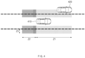
- a vehicle 410 in some forms of the present invention may detect an external object 420 located on a lane neighboring to a lane where the vehicle 410 is traveling.
- the vehicle 410 may determine whether the external object 420 exists within a specified area.
- the vehicle 410 may determine whether the external object 420 exists within a specified distance Z2 (e.g., 5 m) in a longitudinal direction from a front bumper and a rear bumper of the vehicle 410 and within a specified distance Z3 (e.g., 30 cm) in a lateral direction from a line.
- a specified distance Z2 e.g., 5 m
- Z3 e.g. 30 cm
- the vehicle 410 may release the external object 420 from the object to be avoided.
- the vehicle 420 may generate a deviated path in a right direction in the lane and may perform deviated driving along the generated path.
- FIG. 5 is a drawing illustrating an exemplary operation of an apparatus for providing a driving path in a vehicle in some forms of the present invention.
- a vehicle 510 in some forms of the present invention may travel along a centering path 520 in a lane where it is traveling.
- the vehicle 510 may perform deviated driving depending on an operation of a steering wheel of its driver.
- the vehicle 510 may generate a deviated path 530.
- the vehicle 510 may determine that the driver has an intention to perform deviated driving. While the vehicle 510 travels along the deviated path 530, when a lane change command is received, the vehicle 510 may generate a deviated path in a changed lane after the lane change and may travel along the deviated path.
- FIG. 6 is a drawing illustrating an exemplary operation of an apparatus for providing a driving path in a vehicle in some forms of the present invention.
- a vehicle 610 in some forms of the present invention may travel along a centering path 620 in a lane where it is traveling.
- the vehicle 610 may travel in a state where it departs from the centering path 620 by a lateral gradient of a road where it is traveling or a curvature of the road.
- the vehicle 610 may generate a deviated path 630.
- the vehicle 610 may determine that its driver does not have an intention to perform deviated driving.
- the vehicle 610 While the vehicle 610 travels along the deviated path 630, when a lane change command is received, the vehicle 610 may generate a centering path after a lane change and may travel along the centering path. Although the lane change command is received, the vehicle 610 may fail to perform a lane change.
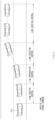
- FIG. 7 is a drawing illustrating an operation of an apparatus for providing a driving path in a vehicle in some forms of the present invention.
- the vehicle in embodiments of the present invention travels along a deviated path 720 in response to an external object or an operation of a steering wheel of its driver.
- the vehicle When a lane change command is received from the driver, the vehicle generates a lane change path 730 including the deviated path 720 and a deviated path 740.
- a distance between the deviated path 740 and a lane centering path 750 is set to correspond to a distance between the deviated path 720 and a lane centering path 710.
- the lane change path 730 is generated in consideration of an intention of the driver to perform deviated driving.
- FIG. 8 is a flowchart illustrating a method for providing a driving path in a vehicle in some forms of the present invention.
- a vehicle including an apparatus 100 for providing a driving path in FIG. 1 performs a process of FIG. 8 .
- an operation described as being by the vehicle may be understood as being controlled by a control circuit 140 of the apparatus 100 for providing the driving path.
- the vehicle may control itself to travel along a deviated path in its driving lane based on at least a portion of information about the vehicle, information about an external object, or an operation of a steering device of the vehicle.
- the vehicle may perform deviated driving depending on lateral acceleration of the vehicle, proximity of the external object, an operation of the steering wheel of the driver, and/or the like.
- the vehicle may receive a lane change command from its driver.
- the vehicle may receive an input of the driver to its turn signal lever.
- the vehicle may control itself to complete a lane change and travel along a deviated path in a target lane of the lane change. For example, when the vehicle performs deviated driving upon the reception of the lane change command, it may perform deviated driving after the lane change. The vehicle may consider an intention of the driver to perform deviated driving and may consider a surrounding object capable of giving the driver uneasiness.
- FIG. 9 is a flowchart illustrating a method for providing a driving path in a vehicle in some forms of the present invention.
- a vehicle including an apparatus 100 for providing a driving path in FIG. 1 performs a process of FIG. 9 .
- an operation described as being by the vehicle may be understood as being controlled by a control circuit 140 of the apparatus 100 for providing the driving path.
- the vehicle may generate a lane centering path.
- the vehicle may travel along the lane centering path.
- the vehicle may determine whether it is necessary to perform deviated driving. For example, the vehicle may determine whether there is an external object capable of giving its driver uneasiness or whether the driver has an intention to perform deviated driving (e.g., an operation of the driver for its steering wheel).
- the vehicle may determine whether path following performance is degraded. For example, the vehicle may determine whether the path following performance is degraded with reference to a lateral gradient of a road where the vehicle is traveling, lateral acceleration of the vehicle, and/or the like.
- the vehicle may generate a deviated path in a lane where the vehicle is traveling.
- the vehicle may travel along the deviated path.
- the vehicle may generate a lane centering path.
- the vehicle may travel along the lane centering path.
- the vehicle may receive a lane change command.
- the vehicle may receive the lane change command from the driver through its turn signal lever.
- the vehicle may determine whether it is possible to perform a lane change. For example, the vehicle may determine whether it is possible to perform the lane change, based on a probability of collision, whether path following performance is degraded, a speed of the vehicle, a curvature of the road, and/or the like.
- the vehicle may generate a lane change path.
- the vehicle may travel along the lane change path.
- the vehicle may determine whether it enters a target lane.
- the vehicle may travel along the lane change path until it enters the target lane.
- the lane change may be ended.
- the vehicle may determine whether it is necessary to perform deviated driving. For example, the vehicle may determine whether an external object capable of giving the driver uneasiness exists within a specified area on the changed lane, whether the driver intends to performs deviated driving before the lane change, or whether the driver currently intends to perform deviated driving.
- the vehicle determines whether path following performance is degraded.
- the vehicle may generate a deviated path in the lane.
- the vehicle may travel along the deviated path.
- the vehicle may generate a lane centering path.
- the vehicle may travel along the lane centering path.
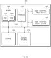
- FIG. 10 is a block diagram illustrating a configuration of a computing system in some forms of the present disclosure.
- a computing system 1000 may include at least one processor 1100, a memory 1300, a user interface input device 1400, a user interface output device 1500, a storage 1600, and a network interface 1700, which are connected with each other via a bus 1200.
- the processor 1100 may be a central processing unit (CPU) or a semiconductor device for performing processing of instructions stored in the memory 1300 and/or the storage 1600.
- CPU central processing unit
- Each of the memory 1300 and the storage 1600 may include various types of volatile or non-volatile storage media.
- the memory 1300 may include a read only memory (ROM) and a random access memory (RAM).
- the operations of the methods or algorithms described in some forms of the present disclosure disclosed in the specification may be directly implemented with a hardware module, a software module, or combinations thereof, executed by the processor 1100.
- the software module may reside on a storage medium (i.e., the memory 1300 and/or the storage 1600) such as a RAM, a flash memory, a ROM, an erasable and programmable ROM (EPROM), an electrically EPROM (EEPROM), a register, a hard disc, a removable disc, or a compact disc-ROM (CD-ROM).
- An exemplary storage medium may be coupled to the processor 1100.
- the processor 1100 may read out information from the storage medium and may write information in the storage medium.
- the storage medium may be integrated with the processor 1100.
- the processor and storage medium may reside in an application specific integrated circuit (ASIC).
- the ASIC may reside in a user terminal.
- the processor and storage medium may reside as a separate component of the user terminal.
- the apparatus for providing the driving path in the vehicle in some forms of the present invention may provide a path in which the intention of the driver is reflected upon an automatic lane change by determining the intention of the driver and providing a deviated driving path.
Landscapes
- Engineering & Computer Science (AREA)
- Automation & Control Theory (AREA)
- Transportation (AREA)
- Mechanical Engineering (AREA)
- Human Computer Interaction (AREA)
- Physics & Mathematics (AREA)
- General Physics & Mathematics (AREA)
- Steering Control In Accordance With Driving Conditions (AREA)
- Control Of Driving Devices And Active Controlling Of Vehicle (AREA)
- Traffic Control Systems (AREA)
Claims (13)
- Einrichtung (100) zur Bereitstellung eines Fahrwegs eines Fahrzeugs, die Einrichtung umfassend:eine Vielzahl von Sensoren (110), die dazu konfiguriert ist, Informationen bezüglich des Fahrzeugs und Informationen bezüglich eines externen Objekts zu erhalten;eine Lenkvorrichtung (120);eine Eingabevorrichtung (130), die dazu konfiguriert ist, einen Spurwechselbefehl von einem Fahrer des Fahrzeugs zu empfangen; undeine Steuerschaltung (140), die elektrisch mit der Vielzahl von Sensoren (110), der Lenkvorrichtung (120) und der Eingabevorrichtung (130) verbunden ist und konfiguriert ist zum:Steuern des Fahrzeugs, sodass es entlang eines abweichenden Wegs (720, 740) in einer Fahrspur des Fahrzeugs fährt, basierend auf mindestens einem von den Informationen bezüglich des Fahrzeugs, den Informationen bezüglich des externen Objekts oder eines Betriebs der Lenkvorrichtung (120); undSteuern des Fahrzeugs, sodass es einen Spurwechsel vollzieht und entlang des abweichenden Wegs (720, 740) in einer Zielspur der gewechselten Spur fährt, als Reaktion auf den empfangenen Spurwechselbefehl, wenn das Fahrzeug entlang des abweichenden Wegs (720, 740) in der Fahrspur fährt;dadurch gekennzeichnet, dassdie Steuerschaltung (140) weiter konfiguriert ist zum:
Steuern des Fahrzeugs, sodass es entlang des Spurmittenwegs (710, 750) in der Zielspur fährt, wenn ein seitlicher Positionsfehler zu einer zweiten vorbestimmten Zeit größer als ein zweiter vorbestimmter Wert ist. - Einrichtung nach Anspruch 1, wobei die Steuerschaltung (140) weiter konfiguriert ist zum:Bestimmen einer Absicht des Fahrers, ein abweichendes Fahren (720) durchzuführen, basierend auf dem Betrieb der Lenkvorrichtung; undErzeugen des abweichenden Wegs (750) in der Zielspur als Reaktion auf den empfangenen Spurwechselbefehl, wenn bestimmt wird, dass der Fahrer beabsichtigt, das abweichende Fahren durchzuführen.
- Einrichtung (100) nach Anspruch 1 oder 2, wobei die Steuerschaltung (140) dazu konfiguriert ist, zu bestimmen, dass der Fahrer beabsichtigt, das abweichende Fahren durchzuführen, wenn:ein Lenkdrehmoment, das größer als ein erster vorbestimmter Wert ist, zu einer ersten vorbestimmten Zeit erzeugt wird; unddas Fahrzeug von einer Mitte der Fahrspur mit einem Abstand entfernt ist, der größer als ein vorbestimmter Abstand ist.
- Einrichtung (100) nach einem der Ansprüche 1 bis 3, wobei die Steuerschaltung (140) weiter konfiguriert ist zum:Bestimmen der Absicht des Fahrers, das abweichende Fahren durchzuführen, basierend auf dem Betrieb der Lenkvorrichtung (120); undErzeugen eines Spurmittenwegs (710, 750) in der Zielspur als Reaktion auf den empfangenen Spurwechselbefehl, wenn bestimmt wird, dass der Fahrer nicht beabsichtigt, das abweichende Fahren durchzuführen.
- Einrichtung (100) nach Anspruch 4, wobei die Steuerschaltung (140) dazu konfiguriert ist, zu bestimmen, dass der Fahrer nicht beabsichtigt, das abweichende Fahren durchzuführen, wenn:das Lenkmoment, das kleiner oder gleich dem ersten vorbestimmten Wert ist, zu der ersten vorbestimmten Zeit erzeugt wird; unddas Fahrzeug von der Mitte der Fahrspur mit einem Abstand entfernt ist, der größer als der vorbestimmte Abstand ist.
- Einrichtung (100) nach einem der Ansprüche 1 bis 5, wobei die Steuerschaltung (140) weiter konfiguriert ist zum:
Erzeugen des abweichenden Wegs (710, 750) in der Zielspur, sodass sich das Fahrzeug von dem externen Objekt weg befindet, wenn das externe Objekt in einem spezifizierten Bereich einer an die Zielspur angrenzenden Spur detektiert wird. - Einrichtung (100) nach Anspruch 6, wobei die Steuerschaltung (140) konfiguriert ist zum:
Bestimmen, ob der abweichende Weg (710, 750) auf der Zielspur zu erzeugen ist, nachdem das Fahrzeug auf die Zielspur eingefahren ist. - Einrichtung (100) nach einem der Ansprüche 1 bis 7, wobei die Steuerschaltung (140) weiter konfiguriert ist zum:
Steuern des Fahrzeugs, sodass es entlang des Spurmittenwegs (710, 750) in der Zielspur fährt, wenn eine Querbeschleunigung des Fahrzeugs größer als ein dritter vorbestimmter Wert ist. - Einrichtung (100) nach einem der Ansprüche 1 bis 8, wobei die Steuerschaltung (140) weiter konfiguriert ist zum:Steuern des Fahrzeugs, sodass es entlang des Spurmittenwegs (710, 750) in der Zielspur fährt, wenn sich ein nachfolgendes Fahrzeug dem Fahrzeug von der an die Zielspur angrenzenden Spur nähert, bis das nachfolgende Fahrzeug das Fahrzeug passiert; undSteuern des Fahrzeugs, sodass es entlang des abweichenden Wegs (720, 740) in der Zielspur fährt, nachdem das nachfolgende Fahrzeug das Fahrzeug passiert hat.
- Verfahren zur Bereitstellung eines Fahrwegs eines Fahrzeugs, das Verfahren umfassend:Steuern des Fahrzeugs mit einer Steuerschaltung (140), sodass es entlang eines abweichenden Wegs (720, 740) in einer Fahrspur des Fahrzeugs fährt, basierend auf mindestens einem von Informationen bezüglich des Fahrzeugs, Informationen bezüglich eines externen Objekts oder eines Betriebs der Lenkvorrichtung (120) des Fahrzeugs; undSteuern des Fahrzeugs mit der Steuerschaltung (140), sodass es einen Spurwechsel vollzieht und entlang des abweichendes Wegs (720, 740) in einer Zielspur der gewechselten Spur fährt, als Reaktion auf einen Spurwechselbefehl, der von einem Fahrer des Fahrzeugs empfangen wird, wenn das Fahrzeug entlang des abweichenden Wegs (720, 740) in der Fahrspur fährt;dadurch gekennzeichnet, dass das Verfahren weiter umfasst:
Steuern des Fahrzeugs mit der Steuerschaltung (140), sodass es entlang des Spurmittenwegs (730, 750) in der Zielspur fährt, wenn ein seitlicher Positionsfehler zu einer ersten vorbestimmten Zeit größer als ein erster vorbestimmter Wert ist. - Verfahren nach Anspruch 10, wobei das Verfahren weiter umfasst:Bestimmen einer Absicht des Fahrers mit der Steuerschaltung (140), ein abweichendes Fahren durchzuführen, basierend auf dem Betrieb der Lenkvorrichtung; undErzeugen des abweichenden Wegs (750) in der Zielspur mit dem Steuerschaltkreis (140) als Reaktion auf den empfangenen Spurwechselbefehl, wenn bestimmt wird, dass der Fahrer beabsichtigt, das abweichende Fahren durchzuführen.
- Verfahren nach Anspruch 10 oder 11, wobei Steuern des Fahrzeugs, sodass es entlang des abweichenden Wegs (720, 740) in der Zielspur fährt, umfasst:
Erzeugen des abweichenden Wegs (720, 740) in der Zielspur mit der Steuerschaltung (140), wenn das externe Objekt in einem spezifizierten Bereich einer an die Zielspur angrenzenden Spur detektiert wird, sodass sich das Fahrzeug von dem externen Objekt entfernt befindet. - Verfahren nach einem der Ansprüche 10 bis 12, wobei das Verfahren weiter umfasst:
Steuern des Fahrzeugs mit der Steuerschaltung (140), sodass es entlang des Spurmittenwegs (730, 750) in der Zielspur fährt, wenn eine Querbeschleunigung des Fahrzeugs größer als ein zweiter vorbestimmter Wert ist.
Applications Claiming Priority (2)
| Application Number | Priority Date | Filing Date | Title |
|---|---|---|---|
| US201862655831P | 2018-04-11 | 2018-04-11 | |
| KR1020180142013A KR102692317B1 (ko) | 2018-04-11 | 2018-11-16 | 차량의 주행 경로 제공 장치 및 방법 |
Publications (2)
| Publication Number | Publication Date |
|---|---|
| EP3552902A1 EP3552902A1 (de) | 2019-10-16 |
| EP3552902B1 true EP3552902B1 (de) | 2025-05-28 |
Family
ID=66092156
Family Applications (1)
| Application Number | Title | Priority Date | Filing Date |
|---|---|---|---|
| EP19167267.4A Active EP3552902B1 (de) | 2018-04-11 | 2019-04-04 | Vorrichtung und verfahren zur bereitstellung eines fahrwegs an ein fahrzeug |
Country Status (3)
| Country | Link |
|---|---|
| US (1) | US11541889B2 (de) |
| EP (1) | EP3552902B1 (de) |
| CN (1) | CN110371125B (de) |
Families Citing this family (14)
| Publication number | Priority date | Publication date | Assignee | Title |
|---|---|---|---|---|
| CN110979305B (zh) * | 2019-03-18 | 2021-06-22 | 毫末智行科技有限公司 | 车辆异常换道控制方法、装置及系统 |
| WO2021005632A1 (ja) * | 2019-07-05 | 2021-01-14 | 三菱電機株式会社 | 車載情報機器及び車載情報機器制御方法 |
| DE102019213185B4 (de) * | 2019-09-02 | 2025-07-10 | Volkswagen Aktiengesellschaft | Querführung eines Fahrzeugs mittels von anderen Fahrzeugen erfassten Umgebungsdaten |
| KR20220082868A (ko) | 2019-10-16 | 2022-06-17 | 로코메이션, 인크. | 자율 팔로워 차량들에 관한 요구를 감소시키는 거동들 |
| US11407419B2 (en) * | 2019-12-30 | 2022-08-09 | Baidu Usa Llc | Central line shifting based pre-change lane path planning |
| US11858509B2 (en) * | 2020-03-02 | 2024-01-02 | GM Global Technology Operations LLC | Driver offset request for automated lane following |
| US10814885B1 (en) * | 2020-05-06 | 2020-10-27 | Southern Taiwan University Of Science And Technology | Car and neighboring vehicle lane departure warning system and method |
| CN113954834A (zh) * | 2020-07-15 | 2022-01-21 | 荷兰移动驱动器公司 | 变道规划方法及车载装置 |
| KR20220128559A (ko) * | 2021-03-12 | 2022-09-21 | 현대자동차주식회사 | 차선 유지 제어 장치, 그를 포함하는 차량 시스템, 및 그 방법 |
| JP7355057B2 (ja) * | 2021-03-24 | 2023-10-03 | 株式会社デンソー | 車両用制御装置及び車両用制御方法 |
| WO2022213373A1 (zh) * | 2021-04-09 | 2022-10-13 | 华为技术有限公司 | 一种轨迹规划方法以及相关设备 |
| US12214785B2 (en) * | 2021-09-13 | 2025-02-04 | Aptiv Technologies AG | Vehicle localization to map data |
| CN115662186B (zh) * | 2022-10-13 | 2023-09-15 | 安徽信息工程学院 | 基于人工智能的车辆避障方法以及系统 |
| FR3142153B1 (fr) * | 2022-11-23 | 2024-10-04 | Psa Automobiles Sa | Procédé et dispositif de contrôle d’une fonction SALC d’un véhicule |
Family Cites Families (259)
| Publication number | Priority date | Publication date | Assignee | Title |
|---|---|---|---|---|
| US4361202A (en) | 1979-06-15 | 1982-11-30 | Michael Minovitch | Automated road transportation system |
| US5314037A (en) | 1993-01-22 | 1994-05-24 | Shaw David C H | Automobile collision avoidance system |
| DE4313568C1 (de) | 1993-04-26 | 1994-06-16 | Daimler Benz Ag | Verfahren zur Leithilfe für einen Fahrspurwechsel durch ein Kraftfahrzeug |
| DE19632929C1 (de) * | 1996-08-16 | 1997-11-27 | Daimler Benz Ag | Vorrichtung zur selbsttätigen Fahrzeugquerführung längs einer Fahrspur |
| DE19821122A1 (de) | 1997-12-15 | 1999-06-17 | Volkswagen Ag | Verfahren zur Regelung von Geschwindigkeit und Abstand bei Überholvorgängen |
| JP3824784B2 (ja) | 1998-06-30 | 2006-09-20 | 富士通株式会社 | 走行支援装置、車線変更可否判断装置、その方法及び記録媒体 |
| JP2000198458A (ja) | 1999-01-08 | 2000-07-18 | Mazda Motor Corp | 車両の制御装置 |
| JP3529037B2 (ja) * | 1999-08-02 | 2004-05-24 | 日産自動車株式会社 | 車線追従装置 |
| DE10114187A1 (de) | 2001-03-23 | 2002-09-26 | Bosch Gmbh Robert | Verfahren und Vorrichtung zur Unterstützung eines Überholvorgangs bei Kraftfahrzeugen |
| JP2003025868A (ja) | 2001-07-16 | 2003-01-29 | Nissan Motor Co Ltd | 車両の車線変更支援装置 |
| DE10218010A1 (de) * | 2002-04-23 | 2003-11-06 | Bosch Gmbh Robert | Verfahren und Vorrichtung zur Querführungsunterstützung bei Kraftfahrzeugen |
| WO2005003885A2 (en) | 2003-07-07 | 2005-01-13 | Sensomatix Ltd. | Traffic information system |
| DE602004008541T2 (de) | 2003-07-07 | 2008-04-30 | Nissan Motor Co., Ltd., Yokohama | Steuersystem für ein Fahrzeug zum Halten der Fahrspur |
| DE10350779A1 (de) * | 2003-10-30 | 2005-06-02 | Robert Bosch Gmbh | Spurhaltesystem für ein Kraftfahrzeug und Betriebsverfahren |
| JP4032253B2 (ja) | 2003-12-17 | 2008-01-16 | ソニー株式会社 | 光通信装置及び車両制御方法 |
| DE102004005815B3 (de) | 2004-02-06 | 2005-06-09 | Audi Ag | Kraftfahrzeug mit einer Einrichtung zur kombinierten Anzeige des aktuellen Ein- oder Aus-Status mehrerer Systeme zur Unterstützung des Fahrers |
| KR100578573B1 (ko) | 2004-05-06 | 2006-05-12 | 기아자동차주식회사 | 제한속도표시 및 경고장치 |
| JP4379199B2 (ja) | 2004-05-17 | 2009-12-09 | 日産自動車株式会社 | 車線変更支援装置および方法 |
| DE102004029369B4 (de) | 2004-06-17 | 2016-09-15 | Robert Bosch Gmbh | Spurwechselassistent für Kraftfahrzeuge |
| DE102004048009A1 (de) | 2004-10-01 | 2006-04-06 | Robert Bosch Gmbh | Verfahren und Vorrichtung zur Fahrerunterstützung |
| DE102004048468A1 (de) | 2004-10-05 | 2006-04-13 | Siemens Ag | System und Verfahren zur Einstellung der Geschwindigkeit eines Fahrzeugs auf eine zulässige Höchstgeschwindigkeit |
| WO2007063397A1 (en) * | 2005-12-01 | 2007-06-07 | Toyota Jidosha Kabushiki Kaisha | Driving assistance system and driving assistance method |
| US7881848B2 (en) | 2006-04-28 | 2011-02-01 | Nissan Motor Co., Ltd. | Lane departure prevention apparatus and method |
| JP4582052B2 (ja) * | 2006-06-07 | 2010-11-17 | トヨタ自動車株式会社 | 走行支援装置 |
| JP4449960B2 (ja) * | 2006-08-22 | 2010-04-14 | トヨタ自動車株式会社 | 操舵支援装置 |
| JP4525670B2 (ja) | 2006-11-20 | 2010-08-18 | トヨタ自動車株式会社 | 走行制御計画生成システム |
| DE102007005245A1 (de) | 2007-02-02 | 2007-11-22 | Daimlerchrysler Ag | Verfahren zum Betreiben eines Fahrerassistenzsystems und Fahrerassistenzsystem für ein Kraftfahrzeug |
| JP4748122B2 (ja) | 2007-06-28 | 2011-08-17 | 日産自動車株式会社 | 車線逸脱防止装置 |
| JP4366419B2 (ja) | 2007-09-27 | 2009-11-18 | 株式会社日立製作所 | 走行支援装置 |
| EP2062796B1 (de) | 2007-11-20 | 2010-08-04 | Nissan Motor Co., Ltd. | Spurabweichungsverhinderungsvorrichtung und -verfahren |
| JP2009184554A (ja) | 2008-02-07 | 2009-08-20 | Denso Corp | 安全走行支援システム |
| DE102008001677A1 (de) | 2008-05-09 | 2009-11-12 | Robert Bosch Gmbh | Assistenzsystem zur Fahrerunterstützung in Fahrzeugen |
| US8392064B2 (en) * | 2008-05-27 | 2013-03-05 | The Board Of Trustees Of The Leland Stanford Junior University | Systems, methods and devices for adaptive steering control of automotive vehicles |
| US8170739B2 (en) * | 2008-06-20 | 2012-05-01 | GM Global Technology Operations LLC | Path generation algorithm for automated lane centering and lane changing control system |
| US9846049B2 (en) | 2008-07-09 | 2017-12-19 | Microsoft Technology Licensing, Llc | Route prediction |
| JP4730406B2 (ja) * | 2008-07-11 | 2011-07-20 | トヨタ自動車株式会社 | 走行支援制御装置 |
| WO2010088869A1 (de) | 2009-02-03 | 2010-08-12 | Adc Automotive Distance Control Systems Gmbh | Geschwindigkeitsvoreinstellung für ein fahrzeug mit automatischer längsregelung |
| WO2010122747A1 (ja) | 2009-04-23 | 2010-10-28 | パナソニック株式会社 | 運転支援装置、運転支援方法及びプログラム |
| US8164543B2 (en) | 2009-05-18 | 2012-04-24 | GM Global Technology Operations LLC | Night vision on full windshield head-up display |
| KR101102144B1 (ko) * | 2009-11-17 | 2012-01-02 | 주식회사 만도 | 차선 유지 제어 방법 및 시스템 |
| KR101286377B1 (ko) | 2009-12-09 | 2013-07-15 | 주식회사 만도 | 차선변경 과도상태 제어 방법 및 장치와 이를 이용한 적응형 순항 제어 시스템 |
| US8384534B2 (en) | 2010-01-14 | 2013-02-26 | Toyota Motor Engineering & Manufacturing North America, Inc. | Combining driver and environment sensing for vehicular safety systems |
| DE102010004625A1 (de) | 2010-01-14 | 2011-07-21 | Ford Global Technologies, LLC, Mich. | Verfahren und Vorrichtung zur Unterstützung eines Fahrers bei einem Überholvorgang |
| WO2011111121A1 (ja) * | 2010-03-12 | 2011-09-15 | トヨタ自動車株式会社 | 操舵支援装置 |
| US8618922B2 (en) | 2010-03-30 | 2013-12-31 | GM Global Technology Operations LLC | Method and system for ensuring operation of limited-ability autonomous driving vehicles |
| DE102010049351A1 (de) | 2010-10-23 | 2012-04-26 | Daimler Ag | Verfahren zum Betreiben einer Bremsassistenzvorrichtung und Bremsassistenzvorrichtung für ein Fahrzeug |
| US8977419B2 (en) * | 2010-12-23 | 2015-03-10 | GM Global Technology Operations LLC | Driving-based lane offset control for lane centering |
| WO2012131405A1 (en) | 2011-03-29 | 2012-10-04 | Josic Ante | Automatic control of maximum speed and automatic control system thereof |
| DE102011016771A1 (de) | 2011-04-12 | 2012-10-18 | Daimler Ag | Vorrichtung zur Bedienung einer Fahrspurwechselunterstützung in einem Fahrzeug |
| DE102011016770B4 (de) | 2011-04-12 | 2021-02-04 | Daimler Ag | Verfahren zur Unterstützung eines Fahrers eines Fahrzeugs bei einem Fahrspurwechsel und Vorrichtung zur Durchführung des Verfahrens |
| JP2012226392A (ja) * | 2011-04-14 | 2012-11-15 | Honda Elesys Co Ltd | 運転支援システム |
| US8935071B2 (en) * | 2011-05-05 | 2015-01-13 | GM Global Technology Operations LLC | Optimal fusion of electric park brake and hydraulic brake sub-system functions to control vehicle direction |
| US8670903B2 (en) * | 2011-05-05 | 2014-03-11 | GM Global Technology Operations LLC | Lane centering fail-safe control using differential braking |
| US20140074356A1 (en) | 2011-05-20 | 2014-03-13 | Honda Motor Co., Ltd. | Lane change assist system |
| DE102011109618A1 (de) | 2011-08-05 | 2013-02-07 | Daimler Ag | Verfahren und Vorrichtung zum Betrieb eines Fahrzeuges |
| DE102011081892A1 (de) | 2011-08-31 | 2013-02-28 | Robert Bosch Gmbh | Verfahren zur Fahrspur-Überwachung und Fahrspur-Überwachungssystem für ein Fahrzeug |
| US8838325B2 (en) | 2011-09-12 | 2014-09-16 | Ford Global Technologies | Vehicle shut-down functionality for peps-equipped vehicles |
| DE102011086241B4 (de) | 2011-11-14 | 2018-04-05 | Robert Bosch Gmbh | Verfahren zum sicheren Abstellen eines Fahrzeuges |
| DE102012001405A1 (de) | 2012-01-26 | 2012-11-22 | Daimler Ag | Verfahren zur Durchführung eines Fahrspurwechsels und Vorrichtung zur Durchführung des Verfahrens |
| DE102012002304A1 (de) | 2012-02-06 | 2013-08-08 | Audi Ag | Vorrichtung zum automatisierten Führen eines Kraftwagens und Verfahren zum Betreiben eines Kraftwagens |
| JP5868218B2 (ja) * | 2012-02-28 | 2016-02-24 | 株式会社日本自動車部品総合研究所 | 車両制御装置 |
| US8457827B1 (en) | 2012-03-15 | 2013-06-04 | Google Inc. | Modifying behavior of autonomous vehicle based on predicted behavior of other vehicles |
| DE112012006077B4 (de) | 2012-03-22 | 2022-02-10 | Toyota Jidosha Kabushiki Kaisha | Bremssteuervorrichtung |
| US9315178B1 (en) | 2012-04-13 | 2016-04-19 | Google Inc. | Model checking for autonomous vehicles |
| DE102012008090A1 (de) | 2012-04-21 | 2013-10-24 | Volkswagen Aktiengesellschaft | Verfahren und Vorrichtung zum Nothalt eines Kraftfahrzeugs |
| US8521352B1 (en) | 2012-05-07 | 2013-08-27 | Google Inc. | Controlling a vehicle having inadequate map data |
| KR101896720B1 (ko) | 2012-12-24 | 2018-09-07 | 현대자동차주식회사 | 자동 차선 변경 제어 시스템 |
| US8798841B1 (en) | 2013-03-14 | 2014-08-05 | GM Global Technology Operations LLC | System and method for improving sensor visibility of vehicle in autonomous driving mode |
| US9751534B2 (en) | 2013-03-15 | 2017-09-05 | Honda Motor Co., Ltd. | System and method for responding to driver state |
| GB2512317A (en) | 2013-03-26 | 2014-10-01 | Jaguar Land Rover Ltd | Vehicle control system and method |
| KR101439017B1 (ko) | 2013-04-11 | 2014-10-30 | 현대자동차주식회사 | 차선 변경 제어 시스템 |
| US20140309855A1 (en) | 2013-04-12 | 2014-10-16 | Bao Tran | Smart car with automatic signalling |
| US8874301B1 (en) | 2013-07-09 | 2014-10-28 | Ford Global Technologies, Llc | Autonomous vehicle with driver presence and physiological monitoring |
| US8930060B1 (en) | 2013-07-15 | 2015-01-06 | Ford Global Technologies | Post-impact path assist for vehicles |
| WO2015026352A1 (en) | 2013-08-22 | 2015-02-26 | Intel Corporation | Locality adapted computerized assisted or autonomous driving of vehicles |
| JP6337435B2 (ja) | 2013-09-26 | 2018-06-06 | 日産自動車株式会社 | 運転支援装置 |
| DE102013219887A1 (de) | 2013-10-01 | 2015-04-02 | Volkswagen Aktiengesellschaft | Verfahren für ein Fahrerassistenzsystem eines Fahrzeugs |
| JP6257989B2 (ja) | 2013-10-08 | 2018-01-10 | 日産自動車株式会社 | 運転支援装置 |
| CN105636849B (zh) | 2013-10-11 | 2018-05-18 | 日产自动车株式会社 | 行驶控制装置以及行驶控制方法 |
| KR20150061752A (ko) | 2013-11-28 | 2015-06-05 | 현대모비스 주식회사 | 차량 운행 보조 장치 및 그 장치에 의한 차량 운행 보조 기능의 자동 활성화 방법 |
| US9988047B2 (en) | 2013-12-12 | 2018-06-05 | Magna Electronics Inc. | Vehicle control system with traffic driving control |
| JP6237256B2 (ja) | 2014-01-21 | 2017-11-29 | 日産自動車株式会社 | 車速制御装置 |
| KR20150087619A (ko) | 2014-01-22 | 2015-07-30 | 한국전자통신연구원 | 증강 현실 기반의 차로 변경 안내 장치 및 방법 |
| KR101551096B1 (ko) * | 2014-06-05 | 2015-09-21 | 현대자동차주식회사 | 자율주행차량의 차선변경장치 및 방법 |
| US9457807B2 (en) | 2014-06-05 | 2016-10-04 | GM Global Technology Operations LLC | Unified motion planning algorithm for autonomous driving vehicle in obstacle avoidance maneuver |
| JP2016000602A (ja) | 2014-06-12 | 2016-01-07 | トヨタ自動車株式会社 | 車線変更支援装置 |
| JP6031066B2 (ja) | 2014-06-17 | 2016-11-24 | 富士重工業株式会社 | 車両の走行制御装置 |
| JP6348785B2 (ja) | 2014-06-27 | 2018-06-27 | 株式会社Subaru | 車両の運転支援装置 |
| KR101611057B1 (ko) | 2014-07-04 | 2016-04-08 | 고려대학교 산학협력단 | 차량 충돌 방지 방법 및 장치 |
| EP3181420B1 (de) | 2014-08-11 | 2018-12-19 | Nissan Motor Co., Ltd | Fahrsteuerungsvorrichtung und -verfahren für fahrzeug |
| EP3001272B1 (de) | 2014-09-26 | 2017-04-12 | Volvo Car Corporation | Verfahren zur Bahnplanung bei Fließmanövern |
| JP5970513B2 (ja) | 2014-09-29 | 2016-08-17 | 富士重工業株式会社 | 運転支援制御装置 |
| US9499197B2 (en) * | 2014-10-15 | 2016-11-22 | Hua-Chuang Automobile Information Technical Center Co., Ltd. | System and method for vehicle steering control |
| JP6086106B2 (ja) * | 2014-10-16 | 2017-03-01 | トヨタ自動車株式会社 | 運転支援装置 |
| DE102014225680A1 (de) | 2014-12-12 | 2016-06-16 | Volkswagen Aktiengesellschaft | Verfahren und Vorrichtung zur Übernahmeaufforderung einer Fahraufgabe an den Fahrzeugführer eines Fahrzeugs im Rahmen des automatischen Fahrens des Fahrzeugs |
| JP6470039B2 (ja) | 2014-12-26 | 2019-02-13 | 日立オートモティブシステムズ株式会社 | 車両制御システム |
| US10705521B2 (en) | 2014-12-30 | 2020-07-07 | Visteon Global Technologies, Inc. | Autonomous driving interface |
| KR102036050B1 (ko) * | 2014-12-30 | 2019-10-24 | 주식회사 만도 | 차선 변경 장치 및 방법 |
| JP6137212B2 (ja) | 2015-02-02 | 2017-05-31 | トヨタ自動車株式会社 | 運転支援装置 |
| JP6528690B2 (ja) | 2015-02-10 | 2019-06-12 | 株式会社デンソー | 退避制御装置、退避制御方法 |
| JP2016151815A (ja) | 2015-02-16 | 2016-08-22 | 株式会社デンソー | 運転支援装置 |
| JP6154411B2 (ja) | 2015-02-27 | 2017-06-28 | 本田技研工業株式会社 | 車両の注意喚起装置 |
| JP2016168985A (ja) | 2015-03-16 | 2016-09-23 | トヨタ自動車株式会社 | 走行制御装置 |
| DE102015205131A1 (de) | 2015-03-20 | 2016-09-22 | Bayerische Motoren Werke Aktiengesellschaft | Verfahren zum Betreiben eines zumindest teilweise automatisiert fahrenden Fahrzeugs innerhalb einer Fahrstrecke |
| JP6491929B2 (ja) * | 2015-03-31 | 2019-03-27 | アイシン・エィ・ダブリュ株式会社 | 自動運転支援システム、自動運転支援方法及びコンピュータプログラム |
| JP6237685B2 (ja) | 2015-04-01 | 2017-11-29 | トヨタ自動車株式会社 | 車両制御装置 |
| JP2016196285A (ja) | 2015-04-03 | 2016-11-24 | 株式会社デンソー | 走行制御装置及び走行制御方法 |
| JP6292218B2 (ja) | 2015-04-03 | 2018-03-14 | 株式会社デンソー | 情報提示装置及び情報提示方法 |
| DE102015206144B4 (de) | 2015-04-07 | 2022-10-06 | Volkswagen Aktiengesellschaft | Verfahren und Vorrichtung zum sicheren Abstellen eines Fahrzeuges |
| DE102015206969B4 (de) | 2015-04-17 | 2022-02-17 | Bayerische Motoren Werke Aktiengesellschaft | Fahrerassistenzsystem in einem Kraftfahrzeug |
| EP3286058B1 (de) | 2015-04-20 | 2021-07-28 | Bayerische Motoren Werke Aktiengesellschaft | Vorrichtung und verfahren zur steuerung einer benutzersituationsbewusstseinsveränderung eines benutzers eines fahrzeugs und system zur verarbeitung von veränderungen des benutzersituationsbewusstseins |
| CN107531245B (zh) | 2015-04-21 | 2020-01-24 | 松下知识产权经营株式会社 | 信息处理系统、信息处理方法、以及程序 |
| JP6598019B2 (ja) | 2015-04-21 | 2019-10-30 | パナソニックIpマネジメント株式会社 | 運転支援方法およびそれを利用した運転支援装置、運転制御装置、車両、運転支援プログラム |
| JP6365390B2 (ja) | 2015-04-27 | 2018-08-01 | トヨタ自動車株式会社 | 車線変更支援装置 |
| DE102015209476A1 (de) | 2015-05-22 | 2016-11-24 | Robert Bosch Gmbh | Systemgrenzen einer automatischen Steuerung |
| JP6252548B2 (ja) | 2015-05-22 | 2017-12-27 | トヨタ自動車株式会社 | 車速制限装置及び車速制御装置 |
| KR101750876B1 (ko) | 2015-05-28 | 2017-06-26 | 엘지전자 주식회사 | 차량용 디스플레이 장치 및 차량 |
| US10710582B2 (en) | 2015-06-11 | 2020-07-14 | Nsk Ltd. | Electric power steering device |
| US9604641B2 (en) | 2015-06-16 | 2017-03-28 | Honda Motor Co., Ltd. | System and method for providing vehicle collision avoidance at an intersection |
| JP6332170B2 (ja) * | 2015-07-01 | 2018-05-30 | トヨタ自動車株式会社 | 自動運転制御装置 |
| JP6323402B2 (ja) | 2015-07-01 | 2018-05-16 | 株式会社デンソー | 車線内走行制御装置、車線内走行制御方法 |
| KR101886019B1 (ko) | 2015-07-28 | 2018-08-06 | 닛산 지도우샤 가부시키가이샤 | 주행 제어 방법 및 주행 제어 장치 |
| WO2017017795A1 (ja) | 2015-07-28 | 2017-02-02 | 日産自動車株式会社 | 走行制御装置の制御方法および走行制御装置 |
| EP4053821B1 (de) | 2015-07-28 | 2025-11-12 | NISSAN MOTOR Co., Ltd. | Verfahren zur steuerung einer fahrsteuerungsvorrichtung sowie fahrsteuerungsvorrichtung |
| MY191084A (en) | 2015-07-28 | 2022-05-30 | Nissan Motor | Method for controlling travel control device, and travel control device |
| BR112018001488B1 (pt) | 2015-07-28 | 2024-01-02 | Nissan Motor Co., Ltd | Método de controle e aparelho de controle de deslocamento |
| JP6552316B2 (ja) | 2015-07-29 | 2019-07-31 | 修一 田山 | 車輌の自動運転システム |
| JP5910904B1 (ja) | 2015-07-31 | 2016-04-27 | パナソニックIpマネジメント株式会社 | 運転支援装置、運転支援システム、運転支援方法、運転支援プログラム及び自動運転車両 |
| JP5957745B1 (ja) | 2015-07-31 | 2016-07-27 | パナソニックIpマネジメント株式会社 | 運転支援装置、運転支援システム、運転支援方法、運転支援プログラム及び自動運転車両 |
| JP2017047765A (ja) * | 2015-09-01 | 2017-03-09 | 本田技研工業株式会社 | 走行制御装置 |
| JP6428546B2 (ja) | 2015-09-25 | 2018-11-28 | トヨタ自動車株式会社 | 運転支援装置 |
| JP6568759B2 (ja) | 2015-09-30 | 2019-08-28 | 日立オートモティブシステムズ株式会社 | 車線変更システム |
| DE102015219231A1 (de) | 2015-10-06 | 2017-04-06 | Robert Bosch Gmbh | Ansteuervorrichtung und Verfahren zum Betreiben eines Fahrerassistenzsystems |
| JP6654641B2 (ja) | 2015-10-06 | 2020-02-26 | 株式会社日立製作所 | 自動運転制御装置および自動運転制御方法 |
| JP6519435B2 (ja) | 2015-10-16 | 2019-05-29 | 株式会社デンソー | 報知管理装置及び報知管理方法 |
| DE102015220360A1 (de) | 2015-10-20 | 2017-04-20 | Robert Bosch Gmbh | Verfahren zur Auswahl einer optimierten Trajektorie |
| US10217363B2 (en) | 2015-10-29 | 2019-02-26 | Faraday&Future Inc. | Methods and systems for electronically assisted lane entrance |
| MX2018004155A (es) | 2015-10-29 | 2018-08-01 | Ford Global Tech Llc | Salida haptica dentro del vehiculo. |
| JP6447468B2 (ja) | 2015-11-17 | 2019-01-09 | 株式会社デンソー | 運転支援装置 |
| KR102433791B1 (ko) * | 2015-11-20 | 2022-08-19 | 주식회사 에이치엘클레무브 | 차선 이탈 경고 장치 및 방법 |
| DE102015224244A1 (de) | 2015-12-03 | 2017-06-08 | Bayerische Motoren Werke Aktiengesellschaft | Steuersystem zur Beeinflussung von automatischen Fahrfunktionen eines Fahrzeugs durch einen Fahrer |
| JP2017100681A (ja) | 2015-12-04 | 2017-06-08 | トヨタ自動車株式会社 | 走行制御装置 |
| US9699289B1 (en) | 2015-12-09 | 2017-07-04 | Toyota Motor Engineering & Manufacturing North America, Inc. | Dynamic vehicle automation level availability indication system and method |
| DE102016007187A1 (de) | 2015-12-19 | 2017-06-22 | Daimler Ag | Verfahren zum Deaktivieren einer automatisierten Fahrfunktion eines Fahrzeugs und Fahrerassistenzsystem zur Durchführung des Verfahrens |
| KR101788183B1 (ko) * | 2015-12-28 | 2017-10-20 | 현대자동차주식회사 | 차량 및 그 제어방법 |
| JP6515823B2 (ja) * | 2016-01-14 | 2019-05-22 | 株式会社デンソー | 車線変更支援装置 |
| JP6787671B2 (ja) | 2016-01-14 | 2020-11-18 | 株式会社デンソー | 合流支援装置 |
| US10324463B1 (en) | 2016-01-22 | 2019-06-18 | State Farm Mutual Automobile Insurance Company | Autonomous vehicle operation adjustment based upon route |
| JP6323470B2 (ja) | 2016-02-05 | 2018-05-16 | トヨタ自動車株式会社 | 車両制御システム |
| JP6246844B2 (ja) | 2016-02-18 | 2017-12-13 | 本田技研工業株式会社 | 車両制御システム、車両制御方法、および車両制御プログラム |
| JP6517161B2 (ja) | 2016-02-18 | 2019-05-22 | 本田技研工業株式会社 | 走行制御装置 |
| JP6209232B2 (ja) | 2016-02-19 | 2017-10-04 | 本田技研工業株式会社 | 車線変更支援装置 |
| JP6838248B2 (ja) | 2016-02-22 | 2021-03-03 | 日立Astemo株式会社 | 情報処理装置 |
| DE102016203020A1 (de) | 2016-02-25 | 2017-08-31 | Bayerische Motoren Werke Aktiengesellschaft | Fahrerassistenzsystem mit per Feststellbremse-Bedienelement aktivierbarer Nothaltefunktion |
| JP6308233B2 (ja) | 2016-02-29 | 2018-04-11 | トヨタ自動車株式会社 | 車両制御装置及び車両制御方法 |
| JP6524943B2 (ja) | 2016-03-17 | 2019-06-05 | 株式会社デンソー | 走行支援装置 |
| FR3049560B1 (fr) | 2016-04-01 | 2019-08-09 | Valeo Schalter Und Sensoren Gmbh | Procede et systeme d'assistance au changement de voie de roulage pour vehicule automobile |
| JP6485399B2 (ja) | 2016-04-15 | 2019-03-20 | 株式会社デンソー | 支援装置 |
| JP6291680B2 (ja) | 2016-04-26 | 2018-03-14 | 本田技研工業株式会社 | 車両制御システム、車両制御方法、および車両制御プログラム |
| JP6275187B2 (ja) | 2016-04-28 | 2018-02-07 | 本田技研工業株式会社 | 車両制御システム、車両制御方法、および車両制御プログラム |
| JP2017200786A (ja) | 2016-05-02 | 2017-11-09 | 本田技研工業株式会社 | 車両制御システム、車両制御方法、および車両制御プログラム |
| KR101795250B1 (ko) * | 2016-05-03 | 2017-11-07 | 현대자동차주식회사 | 자율주행차량의 주행경로 계획장치 및 방법 |
| KR101779823B1 (ko) | 2016-05-10 | 2017-10-10 | 재단법인대구경북과학기술원 | 자율주행차량의 제어 모드 전환 방법 및 그 장치 |
| JP6387369B2 (ja) | 2016-05-23 | 2018-09-05 | 本田技研工業株式会社 | 走行制御装置 |
| JP6535634B2 (ja) | 2016-05-26 | 2019-06-26 | 本田技研工業株式会社 | 経路案内装置及び経路案内方法 |
| JP7031581B2 (ja) | 2016-06-02 | 2022-03-08 | ソニーグループ株式会社 | 情報処理装置と情報処理方法 |
| JP6449195B2 (ja) | 2016-06-02 | 2019-01-09 | 本田技研工業株式会社 | 運転支援装置 |
| JP6310503B2 (ja) | 2016-06-06 | 2018-04-11 | 本田技研工業株式会社 | 車両及びレーン変更タイミング判定方法 |
| JP6778872B2 (ja) | 2016-06-28 | 2020-11-04 | パナソニックIpマネジメント株式会社 | 運転支援装置及び運転支援方法 |
| KR101844885B1 (ko) | 2016-07-11 | 2018-05-18 | 엘지전자 주식회사 | 차량 운전 보조장치 및 이를 포함하는 차량 |
| JP6809020B2 (ja) * | 2016-07-27 | 2021-01-06 | いすゞ自動車株式会社 | 操舵補助装置及び操舵補助方法 |
| CN107672584B (zh) | 2016-07-29 | 2022-05-03 | 福特环球技术公司 | 超车车道控制的系统和方法 |
| JP2018020682A (ja) * | 2016-08-04 | 2018-02-08 | トヨタ自動車株式会社 | 車両制御装置 |
| JP6583183B2 (ja) * | 2016-08-04 | 2019-10-02 | トヨタ自動車株式会社 | 車両制御装置 |
| DE102016009760A1 (de) * | 2016-08-11 | 2018-02-15 | Trw Automotive Gmbh | Steuerungssystem und Steuerungsverfahren zum Führen eines Kraftfahrzeugs entlang eines Pfades |
| JP6831190B2 (ja) | 2016-08-15 | 2021-02-17 | トヨタ自動車株式会社 | 自動運転車両の制御システム及び制御方法 |
| DE102016215565A1 (de) | 2016-08-19 | 2018-02-22 | Continental Automotive Gmbh | Fahrerassistenzsystem für Überholvorgänge |
| US20180050659A1 (en) | 2016-08-22 | 2018-02-22 | Faraday&Future Inc. | Electric seatbelt notification systems and methods |
| DE102016216134A1 (de) * | 2016-08-29 | 2018-03-01 | Bayerische Motoren Werke Aktiengesellschaft | Verschieben der Querposition einer automatisierten Querführung zum Informieren des Fahrers über einen erforderlichen Spurwechsel |
| US20180239352A1 (en) | 2016-08-31 | 2018-08-23 | Faraday&Future Inc. | System and method for operating vehicles at different degrees of automation |
| JP6609229B2 (ja) | 2016-09-02 | 2019-11-20 | 株式会社デンソー | 物体検知装置 |
| DE102016117438A1 (de) | 2016-09-16 | 2018-03-22 | Knorr-Bremse Systeme für Nutzfahrzeuge GmbH | Verfahren und Vorrichtung zum Steuern einer Bewegung eines Fahrzeugs und Fahrzeugbewegungssteuersystem |
| JP6696379B2 (ja) | 2016-09-20 | 2020-05-20 | 日産自動車株式会社 | 運転者意図特定方法及び運転者意図特定装置 |
| US10496090B2 (en) | 2016-09-29 | 2019-12-03 | Magna Electronics Inc. | Handover procedure for driver of autonomous vehicle |
| JP6731619B2 (ja) | 2016-10-26 | 2020-07-29 | パナソニックIpマネジメント株式会社 | 情報処理システム、情報処理方法、およびプログラム |
| EP3534174B1 (de) | 2016-10-27 | 2022-09-28 | Hitachi Astemo, Ltd. | Fehlfunktionsvorrichtung |
| US9874871B1 (en) | 2016-11-21 | 2018-01-23 | Baidu Usa Llc | Method to dynamically adjusting steering rates of autonomous vehicles |
| JPWO2018096644A1 (ja) | 2016-11-25 | 2019-10-17 | 本田技研工業株式会社 | 車両用表示制御装置、車両用表示制御方法、および車両用表示制御プログラム |
| JP6466899B2 (ja) | 2016-12-01 | 2019-02-06 | 株式会社Subaru | 車両用表示装置 |
| JP6490044B2 (ja) | 2016-12-09 | 2019-03-27 | 本田技研工業株式会社 | 車両用制御装置 |
| JP6642399B2 (ja) | 2016-12-07 | 2020-02-05 | トヨタ自動車株式会社 | 車両走行制御装置 |
| JP6895634B2 (ja) | 2016-12-16 | 2021-06-30 | パナソニックIpマネジメント株式会社 | 情報処理システム、情報処理方法、およびプログラム |
| KR20180070401A (ko) | 2016-12-16 | 2018-06-26 | 현대자동차주식회사 | 자율주행차량의 운전 제어권 이양을 판단하는 시스템 및 방법 |
| JP6919429B2 (ja) * | 2016-12-21 | 2021-08-18 | トヨタ自動車株式会社 | 運転支援装置 |
| JP6547970B2 (ja) | 2016-12-26 | 2019-07-24 | トヨタ自動車株式会社 | 車両の車線変更支援装置 |
| JP6635023B2 (ja) | 2016-12-26 | 2020-01-22 | トヨタ自動車株式会社 | 車両の車線変更支援装置 |
| JP2018103766A (ja) | 2016-12-26 | 2018-07-05 | トヨタ自動車株式会社 | 車両の車線変更支援装置 |
| JP6686871B2 (ja) | 2016-12-26 | 2020-04-22 | トヨタ自動車株式会社 | 自動運転システム |
| JP6579334B2 (ja) | 2016-12-26 | 2019-09-25 | トヨタ自動車株式会社 | 車両の車線変更支援装置 |
| JP6572880B2 (ja) | 2016-12-28 | 2019-09-11 | トヨタ自動車株式会社 | 運転支援装置 |
| US10569782B2 (en) | 2016-12-29 | 2020-02-25 | Automotive Research & Testing Center | Interactive autonomous safe driving system and deciding method thereof |
| US10254121B2 (en) | 2017-01-23 | 2019-04-09 | Uber Technologies, Inc. | Dynamic routing for self-driving vehicles |
| KR102406506B1 (ko) | 2017-02-17 | 2022-06-10 | 현대자동차주식회사 | 자율주행 차량 경쟁 제어 장치, 그를 포함한 시스템 및 그 방법 |
| US10220857B2 (en) | 2017-02-23 | 2019-03-05 | Uber Technologies, Inc. | Vehicle control system |
| US10328973B2 (en) | 2017-03-06 | 2019-06-25 | Ford Global Technologies, Llc | Assisting drivers with roadway lane changes |
| US20180281856A1 (en) | 2017-03-31 | 2018-10-04 | Ford Global Technologies, Llc | Real time lane change display |
| JP2018176935A (ja) * | 2017-04-10 | 2018-11-15 | トヨタ自動車株式会社 | 自動運転装置 |
| US11008039B2 (en) | 2017-04-12 | 2021-05-18 | Toyota Jidosha Kabushiki Kaisha | Lane change assist apparatus for vehicle |
| US10814913B2 (en) | 2017-04-12 | 2020-10-27 | Toyota Jidosha Kabushiki Kaisha | Lane change assist apparatus for vehicle |
| US11142246B2 (en) | 2017-04-12 | 2021-10-12 | Toyota Jidosha Kabushiki Kaisha | Lane change assist apparatus for vehicle |
| US10710588B2 (en) | 2017-05-23 | 2020-07-14 | Toyota Motor Engineering & Manufacturing North America, Inc. | Merging and lane change acceleration prediction energy management |
| WO2018216194A1 (ja) | 2017-05-26 | 2018-11-29 | 本田技研工業株式会社 | 車両制御システムおよび車両制御方法 |
| JP6795457B2 (ja) | 2017-06-02 | 2020-12-02 | 本田技研工業株式会社 | 車両制御システム、車両制御方法、および車両制御プログラム |
| WO2018220828A1 (ja) | 2017-06-02 | 2018-12-06 | 本田技研工業株式会社 | 車両制御システム、車両制御方法、およびプログラム |
| JP6627821B2 (ja) * | 2017-06-06 | 2020-01-08 | トヨタ自動車株式会社 | 車線変更支援装置 |
| JP6760204B2 (ja) | 2017-06-06 | 2020-09-23 | トヨタ自動車株式会社 | 操舵支援装置 |
| JP6673299B2 (ja) | 2017-06-06 | 2020-03-25 | トヨタ自動車株式会社 | 操舵支援装置 |
| JP6627822B2 (ja) * | 2017-06-06 | 2020-01-08 | トヨタ自動車株式会社 | 車線変更支援装置 |
| JP6642522B2 (ja) | 2017-06-06 | 2020-02-05 | トヨタ自動車株式会社 | 車線変更支援装置 |
| JP2019003234A (ja) * | 2017-06-09 | 2019-01-10 | トヨタ自動車株式会社 | 運転支援装置 |
| JP7074432B2 (ja) | 2017-06-26 | 2022-05-24 | 本田技研工業株式会社 | 車両制御システム、車両制御方法、および車両制御プログラム |
| CA3071358A1 (en) | 2017-07-28 | 2019-01-31 | Nissan Motor Co., Ltd. | Display control method and display control device |
| US10551838B2 (en) | 2017-08-08 | 2020-02-04 | Nio Usa, Inc. | Method and system for multiple sensor correlation diagnostic and sensor fusion/DNN monitor for autonomous driving application |
| JP6634637B2 (ja) | 2017-08-14 | 2020-01-22 | 本田技研工業株式会社 | 車両制御システムおよび車両制御方法 |
| JP6545760B2 (ja) | 2017-08-14 | 2019-07-17 | 本田技研工業株式会社 | 車両制御システムおよび車両制御方法 |
| JP6638178B2 (ja) | 2017-08-29 | 2020-01-29 | 本田技研工業株式会社 | 車両制御システム、車両制御方法、およびプログラム |
| JP2019043432A (ja) | 2017-09-05 | 2019-03-22 | 本田技研工業株式会社 | 車両制御システム、車両制御方法、およびプログラム |
| CN111065564B (zh) * | 2017-09-07 | 2023-06-13 | 本田技研工业株式会社 | 车辆及其控制装置以及控制方法 |
| JP2019053503A (ja) | 2017-09-14 | 2019-04-04 | 本田技研工業株式会社 | 移動体情報取得システム、移動体情報取得方法、プログラム、及び、移動体 |
| US11453393B2 (en) | 2017-10-09 | 2022-09-27 | Magna Electronics Inc. | Autonomous vehicle with path planning system |
| JP6573223B2 (ja) * | 2017-10-24 | 2019-09-11 | マツダ株式会社 | 車両制御装置 |
| JP6573222B2 (ja) * | 2017-10-24 | 2019-09-11 | マツダ株式会社 | 車両制御装置 |
| JP6573224B2 (ja) * | 2017-10-24 | 2019-09-11 | マツダ株式会社 | 車両制御装置 |
| GB2568060B (en) | 2017-11-02 | 2020-02-12 | Jaguar Land Rover Ltd | Controller for a vehicle |
| JP6926957B2 (ja) | 2017-11-02 | 2021-08-25 | トヨタ自動車株式会社 | 車線変更支援装置 |
| US10618519B2 (en) | 2017-11-06 | 2020-04-14 | Uatc Llc | Systems and methods for autonomous vehicle lane change control |
| US11163309B2 (en) | 2017-11-30 | 2021-11-02 | Direct Current Capital LLC | Method for autonomous navigation |
| US10597033B2 (en) | 2017-12-05 | 2020-03-24 | Ford Global Technologies, Llc | Monitoring and adjustment of gaps between vehicles |
| KR102014262B1 (ko) | 2017-12-11 | 2019-08-26 | 엘지전자 주식회사 | 차량에 구비된 디스플레이 장치 및 디스플레이 장치의 제어방법 |
| US20190197497A1 (en) | 2017-12-22 | 2019-06-27 | Lyft, Inc. | Responses to detected impairments |
| US10761534B2 (en) | 2018-01-30 | 2020-09-01 | Uatc, Llc | Fused sensor view for self-driving truck |
| US10703340B2 (en) | 2018-02-02 | 2020-07-07 | Ford Global Technologies, Llc | Sensor cleaning system |
| US10838421B2 (en) | 2018-02-09 | 2020-11-17 | Denso Corporation | Autonomous drive system |
| JP7032170B2 (ja) * | 2018-02-23 | 2022-03-08 | 本田技研工業株式会社 | 車両制御装置 |
| US11392131B2 (en) | 2018-02-27 | 2022-07-19 | Nauto, Inc. | Method for determining driving policy |
| JP6725568B2 (ja) | 2018-03-13 | 2020-07-22 | 本田技研工業株式会社 | 車両制御装置、車両、車両制御方法およびプログラム |
| CN117022255A (zh) | 2018-03-20 | 2023-11-10 | 御眼视觉技术有限公司 | 用于主车辆的自动驾驶系统、机器可读存储介质和装置 |
| JP6866867B2 (ja) * | 2018-03-27 | 2021-04-28 | トヨタ自動車株式会社 | 車両制御システム |
| US11378956B2 (en) | 2018-04-03 | 2022-07-05 | Baidu Usa Llc | Perception and planning collaboration framework for autonomous driving |
| ES2889930T3 (es) | 2018-04-11 | 2022-01-14 | Hyundai Motor Co Ltd | Aparato y método para el control para habilitar un sistema autónomo en un vehículo |
| US11077854B2 (en) | 2018-04-11 | 2021-08-03 | Hyundai Motor Company | Apparatus for controlling lane change of vehicle, system having the same and method thereof |
| US10935974B1 (en) | 2018-04-19 | 2021-03-02 | State Farm Mutual Automobile Insurance Company | Manual control re-engagement in an autonomous vehicle |
| US10618523B1 (en) | 2018-04-19 | 2020-04-14 | State Farm Mutual Automobile Insurance Company | Assessing driver ability to operate an autonomous vehicle |
| US11260849B2 (en) * | 2018-05-23 | 2022-03-01 | Baidu Usa Llc | Method for determining lane changing trajectories for autonomous driving vehicles |
| US10860023B2 (en) | 2018-06-25 | 2020-12-08 | Mitsubishi Electric Research Laboratories, Inc. | Systems and methods for safe decision making of autonomous vehicles |
| US20200312155A1 (en) | 2018-07-31 | 2020-10-01 | Honda Motor Co., Ltd. | Systems and methods for swarm action |
| US20200049513A1 (en) * | 2018-08-10 | 2020-02-13 | Delphi Technologies, Llc | Positioning system |
| US11181920B2 (en) | 2018-08-28 | 2021-11-23 | Denso Corporation | Travel assistance method and travel assistance apparatus |
| JP6931370B2 (ja) | 2019-03-25 | 2021-09-01 | 本田技研工業株式会社 | 車両制御装置、車両制御方法、及びプログラム |
-
2019
- 2019-04-04 EP EP19167267.4A patent/EP3552902B1/de active Active
- 2019-04-08 US US16/378,203 patent/US11541889B2/en active Active
- 2019-04-09 CN CN201910279596.6A patent/CN110371125B/zh active Active
Also Published As
| Publication number | Publication date |
|---|---|
| EP3552902A1 (de) | 2019-10-16 |
| US20190315367A1 (en) | 2019-10-17 |
| US11541889B2 (en) | 2023-01-03 |
| CN110371125B (zh) | 2024-09-20 |
| CN110371125A (zh) | 2019-10-25 |
Similar Documents
| Publication | Publication Date | Title |
|---|---|---|
| EP3552902B1 (de) | Vorrichtung und verfahren zur bereitstellung eines fahrwegs an ein fahrzeug | |
| KR102692317B1 (ko) | 차량의 주행 경로 제공 장치 및 방법 | |
| EP3552911B1 (de) | Vorrichtung und verfahren zur bereitstellung einer sicherheitsstrategie in einem fahrzeug | |
| CN110371116B (zh) | 用于控制车辆的驾驶的装置和方法 | |
| EP3569460B1 (de) | Vorrichtung und verfahren zur steuerung des fahrens in einem fahrzeug | |
| US10847034B2 (en) | Apparatus and method for controlling lane change for vehicle | |
| EP3552901A2 (de) | Vorrichtung und verfahren zur bereitstellung einer sicherheitsstrategie in einem fahrzeug | |
| EP3552903B1 (de) | Vorrichtung und verfahren zur bereitstellung einer sicherheitsstrategie an ein fahrzeug | |
| EP3552899B1 (de) | Vorrichtung und verfahren zur steuerung des spurwechsels in einem fahrzeug | |
| CN112092808B (zh) | 防止车辆碰撞的装置和方法 | |
| EP3552898B1 (de) | Vorrichtung und verfahren zur steuerung des spurwechsels in einem fahrzeug | |
| EP3982346B1 (de) | Strasseneinfahrtssystem und -verfahren für ein fahrzeug | |
| JP6304011B2 (ja) | 車両用走行制御装置 | |
| US11334067B2 (en) | Apparatus and method for providing safety strategy in vehicle | |
| CN108725316B (zh) | 行驶车道引导系统及其控制方法 | |
| CN112829748B (zh) | 车道变更辅助装置、包括该装置的车辆系统及其方法 | |
| US12420781B2 (en) | Apparatus and method for controlling vehicle | |
| JP2023536349A (ja) | 車両のための回避軌道を決定するための方法 | |
| JP7746903B2 (ja) | 走行制御方法及び走行制御装置 | |
| WO2025253568A1 (ja) | 車両制御方法及び車両制御装置 |
Legal Events
| Date | Code | Title | Description |
|---|---|---|---|
| PUAI | Public reference made under article 153(3) epc to a published international application that has entered the european phase |
Free format text: ORIGINAL CODE: 0009012 |
|
| STAA | Information on the status of an ep patent application or granted ep patent |
Free format text: STATUS: THE APPLICATION HAS BEEN PUBLISHED |
|
| AK | Designated contracting states |
Kind code of ref document: A1 Designated state(s): AL AT BE BG CH CY CZ DE DK EE ES FI FR GB GR HR HU IE IS IT LI LT LU LV MC MK MT NL NO PL PT RO RS SE SI SK SM TR |
|
| AX | Request for extension of the european patent |
Extension state: BA ME |
|
| STAA | Information on the status of an ep patent application or granted ep patent |
Free format text: STATUS: REQUEST FOR EXAMINATION WAS MADE |
|
| 17P | Request for examination filed |
Effective date: 20200407 |
|
| RBV | Designated contracting states (corrected) |
Designated state(s): AL AT BE BG CH CY CZ DE DK EE ES FI FR GB GR HR HU IE IS IT LI LT LU LV MC MK MT NL NO PL PT RO RS SE SI SK SM TR |
|
| STAA | Information on the status of an ep patent application or granted ep patent |
Free format text: STATUS: EXAMINATION IS IN PROGRESS |
|
| RAP3 | Party data changed (applicant data changed or rights of an application transferred) |
Owner name: HYUNDAI MOTOR COMPANY Owner name: KIA CORPORATION |
|
| 17Q | First examination report despatched |
Effective date: 20210803 |
|
| P01 | Opt-out of the competence of the unified patent court (upc) registered |
Effective date: 20230505 |
|
| RIC1 | Information provided on ipc code assigned before grant |
Ipc: B60W 50/00 20060101ALN20241106BHEP Ipc: B60W 30/12 20060101ALI20241106BHEP Ipc: B60W 30/10 20060101ALI20241106BHEP Ipc: G08G 1/16 20060101ALI20241106BHEP Ipc: B60W 30/14 20060101ALI20241106BHEP Ipc: B60W 50/10 20120101ALI20241106BHEP Ipc: B60W 30/18 20120101AFI20241106BHEP |
|
| GRAP | Despatch of communication of intention to grant a patent |
Free format text: ORIGINAL CODE: EPIDOSNIGR1 |
|
| STAA | Information on the status of an ep patent application or granted ep patent |
Free format text: STATUS: GRANT OF PATENT IS INTENDED |
|
| RIC1 | Information provided on ipc code assigned before grant |
Ipc: B60W 50/00 20060101ALN20241202BHEP Ipc: B60W 30/12 20060101ALI20241202BHEP Ipc: B60W 30/10 20060101ALI20241202BHEP Ipc: G08G 1/16 20060101ALI20241202BHEP Ipc: B60W 30/14 20060101ALI20241202BHEP Ipc: B60W 50/10 20120101ALI20241202BHEP Ipc: B60W 30/18 20120101AFI20241202BHEP |
|
| RIC1 | Information provided on ipc code assigned before grant |
Ipc: B60W 50/00 20060101ALN20241211BHEP Ipc: B60W 30/12 20060101ALI20241211BHEP Ipc: B60W 30/10 20060101ALI20241211BHEP Ipc: G08G 1/16 20060101ALI20241211BHEP Ipc: B60W 30/14 20060101ALI20241211BHEP Ipc: B60W 50/10 20120101ALI20241211BHEP Ipc: B60W 30/18 20120101AFI20241211BHEP |
|
| RIN1 | Information on inventor provided before grant (corrected) |
Inventor name: OH, DONG EON Inventor name: JEONG, JIN SU Inventor name: PARK, CHAN IL Inventor name: KIM, DAE-YOUNG Inventor name: KIM, BEOM JUN Inventor name: KIM, HOI WON Inventor name: UM, DOO JIN |
|
| INTG | Intention to grant announced |
Effective date: 20250102 |
|
| GRAS | Grant fee paid |
Free format text: ORIGINAL CODE: EPIDOSNIGR3 |
|
| GRAA | (expected) grant |
Free format text: ORIGINAL CODE: 0009210 |
|
| STAA | Information on the status of an ep patent application or granted ep patent |
Free format text: STATUS: THE PATENT HAS BEEN GRANTED |
|
| AK | Designated contracting states |
Kind code of ref document: B1 Designated state(s): AL AT BE BG CH CY CZ DE DK EE ES FI FR GB GR HR HU IE IS IT LI LT LU LV MC MK MT NL NO PL PT RO RS SE SI SK SM TR |
|
| REG | Reference to a national code |
Ref country code: GB Ref legal event code: FG4D |
|
| REG | Reference to a national code |
Ref country code: CH Ref legal event code: EP |
|
| REG | Reference to a national code |
Ref country code: IE Ref legal event code: FG4D Ref country code: DE Ref legal event code: R096 Ref document number: 602019070480 Country of ref document: DE |
|
| REG | Reference to a national code |
Ref country code: NL Ref legal event code: MP Effective date: 20250528 |
|
| PG25 | Lapsed in a contracting state [announced via postgrant information from national office to epo] |
Ref country code: ES Free format text: LAPSE BECAUSE OF FAILURE TO SUBMIT A TRANSLATION OF THE DESCRIPTION OR TO PAY THE FEE WITHIN THE PRESCRIBED TIME-LIMIT Effective date: 20250528 Ref country code: FI Free format text: LAPSE BECAUSE OF FAILURE TO SUBMIT A TRANSLATION OF THE DESCRIPTION OR TO PAY THE FEE WITHIN THE PRESCRIBED TIME-LIMIT Effective date: 20250528 |
|
| REG | Reference to a national code |
Ref country code: LT Ref legal event code: MG9D |
|
| PG25 | Lapsed in a contracting state [announced via postgrant information from national office to epo] |
Ref country code: GR Free format text: LAPSE BECAUSE OF FAILURE TO SUBMIT A TRANSLATION OF THE DESCRIPTION OR TO PAY THE FEE WITHIN THE PRESCRIBED TIME-LIMIT Effective date: 20250829 Ref country code: NO Free format text: LAPSE BECAUSE OF FAILURE TO SUBMIT A TRANSLATION OF THE DESCRIPTION OR TO PAY THE FEE WITHIN THE PRESCRIBED TIME-LIMIT Effective date: 20250828 |
|
| PG25 | Lapsed in a contracting state [announced via postgrant information from national office to epo] |
Ref country code: NL Free format text: LAPSE BECAUSE OF FAILURE TO SUBMIT A TRANSLATION OF THE DESCRIPTION OR TO PAY THE FEE WITHIN THE PRESCRIBED TIME-LIMIT Effective date: 20250528 Ref country code: PL Free format text: LAPSE BECAUSE OF FAILURE TO SUBMIT A TRANSLATION OF THE DESCRIPTION OR TO PAY THE FEE WITHIN THE PRESCRIBED TIME-LIMIT Effective date: 20250528 |
|
| PG25 | Lapsed in a contracting state [announced via postgrant information from national office to epo] |
Ref country code: BG Free format text: LAPSE BECAUSE OF FAILURE TO SUBMIT A TRANSLATION OF THE DESCRIPTION OR TO PAY THE FEE WITHIN THE PRESCRIBED TIME-LIMIT Effective date: 20250528 |
|
| PG25 | Lapsed in a contracting state [announced via postgrant information from national office to epo] |
Ref country code: HR Free format text: LAPSE BECAUSE OF FAILURE TO SUBMIT A TRANSLATION OF THE DESCRIPTION OR TO PAY THE FEE WITHIN THE PRESCRIBED TIME-LIMIT Effective date: 20250528 |
|
| PG25 | Lapsed in a contracting state [announced via postgrant information from national office to epo] |
Ref country code: RS Free format text: LAPSE BECAUSE OF FAILURE TO SUBMIT A TRANSLATION OF THE DESCRIPTION OR TO PAY THE FEE WITHIN THE PRESCRIBED TIME-LIMIT Effective date: 20250828 |
|
| PG25 | Lapsed in a contracting state [announced via postgrant information from national office to epo] |
Ref country code: IS Free format text: LAPSE BECAUSE OF FAILURE TO SUBMIT A TRANSLATION OF THE DESCRIPTION OR TO PAY THE FEE WITHIN THE PRESCRIBED TIME-LIMIT Effective date: 20250928 |
|
| PG25 | Lapsed in a contracting state [announced via postgrant information from national office to epo] |
Ref country code: LV Free format text: LAPSE BECAUSE OF FAILURE TO SUBMIT A TRANSLATION OF THE DESCRIPTION OR TO PAY THE FEE WITHIN THE PRESCRIBED TIME-LIMIT Effective date: 20250528 |
|
| REG | Reference to a national code |
Ref country code: AT Ref legal event code: MK05 Ref document number: 1798487 Country of ref document: AT Kind code of ref document: T Effective date: 20250528 |
|
| PG25 | Lapsed in a contracting state [announced via postgrant information from national office to epo] |
Ref country code: DK Free format text: LAPSE BECAUSE OF FAILURE TO SUBMIT A TRANSLATION OF THE DESCRIPTION OR TO PAY THE FEE WITHIN THE PRESCRIBED TIME-LIMIT Effective date: 20250528 Ref country code: SM Free format text: LAPSE BECAUSE OF FAILURE TO SUBMIT A TRANSLATION OF THE DESCRIPTION OR TO PAY THE FEE WITHIN THE PRESCRIBED TIME-LIMIT Effective date: 20250528 Ref country code: AT Free format text: LAPSE BECAUSE OF FAILURE TO SUBMIT A TRANSLATION OF THE DESCRIPTION OR TO PAY THE FEE WITHIN THE PRESCRIBED TIME-LIMIT Effective date: 20250528 |
|
| PG25 | Lapsed in a contracting state [announced via postgrant information from national office to epo] |
Ref country code: CZ Free format text: LAPSE BECAUSE OF FAILURE TO SUBMIT A TRANSLATION OF THE DESCRIPTION OR TO PAY THE FEE WITHIN THE PRESCRIBED TIME-LIMIT Effective date: 20250528 |
|
| PG25 | Lapsed in a contracting state [announced via postgrant information from national office to epo] |
Ref country code: EE Free format text: LAPSE BECAUSE OF FAILURE TO SUBMIT A TRANSLATION OF THE DESCRIPTION OR TO PAY THE FEE WITHIN THE PRESCRIBED TIME-LIMIT Effective date: 20250528 |
|
| PG25 | Lapsed in a contracting state [announced via postgrant information from national office to epo] |
Ref country code: RO Free format text: LAPSE BECAUSE OF FAILURE TO SUBMIT A TRANSLATION OF THE DESCRIPTION OR TO PAY THE FEE WITHIN THE PRESCRIBED TIME-LIMIT Effective date: 20250528 Ref country code: SK Free format text: LAPSE BECAUSE OF FAILURE TO SUBMIT A TRANSLATION OF THE DESCRIPTION OR TO PAY THE FEE WITHIN THE PRESCRIBED TIME-LIMIT Effective date: 20250528 |
|
| PG25 | Lapsed in a contracting state [announced via postgrant information from national office to epo] |
Ref country code: IT Free format text: LAPSE BECAUSE OF FAILURE TO SUBMIT A TRANSLATION OF THE DESCRIPTION OR TO PAY THE FEE WITHIN THE PRESCRIBED TIME-LIMIT Effective date: 20250528 |
|
| REG | Reference to a national code |
Ref country code: DE Ref legal event code: R097 Ref document number: 602019070480 Country of ref document: DE |
|
| PLBE | No opposition filed within time limit |
Free format text: ORIGINAL CODE: 0009261 |
|
| STAA | Information on the status of an ep patent application or granted ep patent |
Free format text: STATUS: NO OPPOSITION FILED WITHIN TIME LIMIT |
|
| PGFP | Annual fee paid to national office [announced via postgrant information from national office to epo] |
Ref country code: GB Payment date: 20260324 Year of fee payment: 8 |
|
| REG | Reference to a national code |
Ref country code: CH Ref legal event code: L10 Free format text: ST27 STATUS EVENT CODE: U-0-0-L10-L00 (AS PROVIDED BY THE NATIONAL OFFICE) Effective date: 20260409 |
|
| PGFP | Annual fee paid to national office [announced via postgrant information from national office to epo] |
Ref country code: FR Payment date: 20260323 Year of fee payment: 8 |