EP2600201B1 - Élément électro-photographique photosensible, cartouche de traitement et appareil électro-photographique - Google Patents
Élément électro-photographique photosensible, cartouche de traitement et appareil électro-photographique Download PDFInfo
- Publication number
- EP2600201B1 EP2600201B1 EP20120194617 EP12194617A EP2600201B1 EP 2600201 B1 EP2600201 B1 EP 2600201B1 EP 20120194617 EP20120194617 EP 20120194617 EP 12194617 A EP12194617 A EP 12194617A EP 2600201 B1 EP2600201 B1 EP 2600201B1
- Authority
- EP
- European Patent Office
- Prior art keywords
- group
- substituted
- photosensitive member
- electrophotographic photosensitive
- unsubstituted
- Prior art date
- Legal status (The legal status is an assumption and is not a legal conclusion. Google has not performed a legal analysis and makes no representation as to the accuracy of the status listed.)
- Not-in-force
Links
- 238000000034 method Methods 0.000 title claims description 30
- 230000008569 process Effects 0.000 title claims description 21
- -1 amine compound Chemical class 0.000 claims description 64
- 125000003277 amino group Chemical group 0.000 claims description 50
- 125000000217 alkyl group Chemical group 0.000 claims description 35
- 239000000463 material Substances 0.000 claims description 34
- 125000004122 cyclic group Chemical group 0.000 claims description 26
- 125000003118 aryl group Chemical group 0.000 claims description 17
- 230000005525 hole transport Effects 0.000 claims description 16
- 238000012546 transfer Methods 0.000 claims description 14
- 125000003545 alkoxy group Chemical group 0.000 claims description 10
- 125000002496 methyl group Chemical group [H]C([H])([H])* 0.000 claims description 6
- 238000004140 cleaning Methods 0.000 claims description 5
- 125000004663 dialkyl amino group Chemical group 0.000 claims description 5
- 125000001495 ethyl group Chemical group [H]C([H])([H])C([H])([H])* 0.000 claims description 5
- 125000004435 hydrogen atom Chemical group [H]* 0.000 claims description 5
- 125000002887 hydroxy group Chemical group [H]O* 0.000 claims description 5
- 125000002252 acyl group Chemical group 0.000 claims description 4
- 125000004453 alkoxycarbonyl group Chemical group 0.000 claims description 4
- 125000004104 aryloxy group Chemical group 0.000 claims description 4
- 125000005843 halogen group Chemical group 0.000 claims description 4
- 125000004573 morpholin-4-yl group Chemical group N1(CCOCC1)* 0.000 claims description 4
- 125000005161 aryl oxy carbonyl group Chemical group 0.000 claims description 3
- 125000002915 carbonyl group Chemical group [*:2]C([*:1])=O 0.000 claims description 3
- 125000003178 carboxy group Chemical group [H]OC(*)=O 0.000 claims description 3
- 125000004989 dicarbonyl group Chemical group 0.000 claims description 3
- 125000001664 diethylamino group Chemical group [H]C([H])([H])C([H])([H])N(*)C([H])([H])C([H])([H])[H] 0.000 claims description 3
- 125000002147 dimethylamino group Chemical group [H]C([H])([H])N(*)C([H])([H])[H] 0.000 claims description 3
- 239000010410 layer Substances 0.000 description 164
- 238000000576 coating method Methods 0.000 description 83
- 239000011248 coating agent Substances 0.000 description 79
- 239000007788 liquid Substances 0.000 description 65
- 150000001875 compounds Chemical class 0.000 description 58
- 230000000052 comparative effect Effects 0.000 description 43
- 229920005989 resin Polymers 0.000 description 36
- 239000011347 resin Substances 0.000 description 36
- 239000002245 particle Substances 0.000 description 25
- IEQIEDJGQAUEQZ-UHFFFAOYSA-N phthalocyanine Chemical compound N1C(N=C2C3=CC=CC=C3C(N=C3C4=CC=CC=C4C(=N4)N3)=N2)=C(C=CC=C2)C2=C1N=C1C2=CC=CC=C2C4=N1 IEQIEDJGQAUEQZ-UHFFFAOYSA-N 0.000 description 22
- XEKOWRVHYACXOJ-UHFFFAOYSA-N Ethyl acetate Chemical compound CCOC(C)=O XEKOWRVHYACXOJ-UHFFFAOYSA-N 0.000 description 18
- 239000013078 crystal Substances 0.000 description 16
- 239000000049 pigment Substances 0.000 description 14
- 239000000047 product Substances 0.000 description 14
- OKKJLVBELUTLKV-UHFFFAOYSA-N Methanol Chemical compound OC OKKJLVBELUTLKV-UHFFFAOYSA-N 0.000 description 13
- 238000011156 evaluation Methods 0.000 description 13
- YXFVVABEGXRONW-UHFFFAOYSA-N Toluene Chemical compound CC1=CC=CC=C1 YXFVVABEGXRONW-UHFFFAOYSA-N 0.000 description 12
- JHIVVAPYMSGYDF-UHFFFAOYSA-N cyclohexanone Chemical compound O=C1CCCCC1 JHIVVAPYMSGYDF-UHFFFAOYSA-N 0.000 description 12
- ZWEHNKRNPOVVGH-UHFFFAOYSA-N 2-Butanone Chemical compound CCC(C)=O ZWEHNKRNPOVVGH-UHFFFAOYSA-N 0.000 description 11
- 239000002904 solvent Substances 0.000 description 11
- LRHPLDYGYMQRHN-UHFFFAOYSA-N N-Butanol Chemical compound CCCCO LRHPLDYGYMQRHN-UHFFFAOYSA-N 0.000 description 10
- 239000000126 substance Substances 0.000 description 10
- CSCPPACGZOOCGX-UHFFFAOYSA-N Acetone Chemical compound CC(C)=O CSCPPACGZOOCGX-UHFFFAOYSA-N 0.000 description 9
- YMWUJEATGCHHMB-UHFFFAOYSA-N Dichloromethane Chemical compound ClCCl YMWUJEATGCHHMB-UHFFFAOYSA-N 0.000 description 9
- RTZKZFJDLAIYFH-UHFFFAOYSA-N Diethyl ether Chemical compound CCOCC RTZKZFJDLAIYFH-UHFFFAOYSA-N 0.000 description 9
- LFQSCWFLJHTTHZ-UHFFFAOYSA-N Ethanol Chemical compound CCO LFQSCWFLJHTTHZ-UHFFFAOYSA-N 0.000 description 9
- ZMXDDKWLCZADIW-UHFFFAOYSA-N N,N-Dimethylformamide Chemical compound CN(C)C=O ZMXDDKWLCZADIW-UHFFFAOYSA-N 0.000 description 9
- CXWXQJXEFPUFDZ-UHFFFAOYSA-N tetralin Chemical compound C1=CC=C2CCCCC2=C1 CXWXQJXEFPUFDZ-UHFFFAOYSA-N 0.000 description 9
- 238000002441 X-ray diffraction Methods 0.000 description 8
- 239000012965 benzophenone Substances 0.000 description 8
- 239000011230 binding agent Substances 0.000 description 8
- 238000007598 dipping method Methods 0.000 description 8
- 239000006185 dispersion Substances 0.000 description 8
- 229920002037 poly(vinyl butyral) polymer Polymers 0.000 description 8
- 239000000123 paper Substances 0.000 description 7
- 239000007787 solid Substances 0.000 description 7
- 238000012360 testing method Methods 0.000 description 7
- HEDRZPFGACZZDS-UHFFFAOYSA-N Chloroform Chemical compound ClC(Cl)Cl HEDRZPFGACZZDS-UHFFFAOYSA-N 0.000 description 6
- IAZDPXIOMUYVGZ-UHFFFAOYSA-N Dimethylsulphoxide Chemical compound CS(C)=O IAZDPXIOMUYVGZ-UHFFFAOYSA-N 0.000 description 6
- KFZMGEQAYNKOFK-UHFFFAOYSA-N Isopropanol Chemical compound CC(C)O KFZMGEQAYNKOFK-UHFFFAOYSA-N 0.000 description 6
- XBDQKXXYIPTUBI-UHFFFAOYSA-M Propionate Chemical compound CCC([O-])=O XBDQKXXYIPTUBI-UHFFFAOYSA-M 0.000 description 6
- WYURNTSHIVDZCO-UHFFFAOYSA-N Tetrahydrofuran Chemical compound C1CCOC1 WYURNTSHIVDZCO-UHFFFAOYSA-N 0.000 description 6
- RWCCWEUUXYIKHB-UHFFFAOYSA-N benzophenone Chemical compound C=1C=CC=CC=1C(=O)C1=CC=CC=C1 RWCCWEUUXYIKHB-UHFFFAOYSA-N 0.000 description 6
- MVPPADPHJFYWMZ-UHFFFAOYSA-N chlorobenzene Chemical compound ClC1=CC=CC=C1 MVPPADPHJFYWMZ-UHFFFAOYSA-N 0.000 description 6
- TZIHFWKZFHZASV-UHFFFAOYSA-N methyl formate Chemical compound COC=O TZIHFWKZFHZASV-UHFFFAOYSA-N 0.000 description 6
- 229920000515 polycarbonate Polymers 0.000 description 6
- 239000004417 polycarbonate Substances 0.000 description 6
- BDERNNFJNOPAEC-UHFFFAOYSA-N propan-1-ol Chemical compound CCCO BDERNNFJNOPAEC-UHFFFAOYSA-N 0.000 description 6
- VYPSYNLAJGMNEJ-UHFFFAOYSA-N Silicium dioxide Chemical compound O=[Si]=O VYPSYNLAJGMNEJ-UHFFFAOYSA-N 0.000 description 5
- GWEVSGVZZGPLCZ-UHFFFAOYSA-N Titan oxide Chemical compound O=[Ti]=O GWEVSGVZZGPLCZ-UHFFFAOYSA-N 0.000 description 5
- 239000011324 bead Substances 0.000 description 5
- 238000001035 drying Methods 0.000 description 5
- 239000011241 protective layer Substances 0.000 description 5
- 230000035945 sensitivity Effects 0.000 description 5
- 125000001424 substituent group Chemical group 0.000 description 5
- 239000004925 Acrylic resin Substances 0.000 description 4
- FXHOOIRPVKKKFG-UHFFFAOYSA-N N,N-Dimethylacetamide Chemical compound CN(C)C(C)=O FXHOOIRPVKKKFG-UHFFFAOYSA-N 0.000 description 4
- XLOMVQKBTHCTTD-UHFFFAOYSA-N Zinc monoxide Chemical compound [Zn]=O XLOMVQKBTHCTTD-UHFFFAOYSA-N 0.000 description 4
- 229910052782 aluminium Inorganic materials 0.000 description 4
- XAGFODPZIPBFFR-UHFFFAOYSA-N aluminium Chemical compound [Al] XAGFODPZIPBFFR-UHFFFAOYSA-N 0.000 description 4
- TZCXTZWJZNENPQ-UHFFFAOYSA-L barium sulfate Chemical compound [Ba+2].[O-]S([O-])(=O)=O TZCXTZWJZNENPQ-UHFFFAOYSA-L 0.000 description 4
- 230000015572 biosynthetic process Effects 0.000 description 4
- 230000000694 effects Effects 0.000 description 4
- 239000011521 glass Substances 0.000 description 4
- 229910052751 metal Inorganic materials 0.000 description 4
- 239000002184 metal Substances 0.000 description 4
- 229920006122 polyamide resin Polymers 0.000 description 4
- 239000004576 sand Substances 0.000 description 4
- 238000003786 synthesis reaction Methods 0.000 description 4
- OGIDPMRJRNCKJF-UHFFFAOYSA-N titanium oxide Inorganic materials [Ti]=O OGIDPMRJRNCKJF-UHFFFAOYSA-N 0.000 description 4
- MAOBFOXLCJIFLV-UHFFFAOYSA-N (2-aminophenyl)-phenylmethanone Chemical compound NC1=CC=CC=C1C(=O)C1=CC=CC=C1 MAOBFOXLCJIFLV-UHFFFAOYSA-N 0.000 description 3
- RYHBNJHYFVUHQT-UHFFFAOYSA-N 1,4-Dioxane Chemical compound C1COCCO1 RYHBNJHYFVUHQT-UHFFFAOYSA-N 0.000 description 3
- LHENQXAPVKABON-UHFFFAOYSA-N 1-methoxypropan-1-ol Chemical compound CCC(O)OC LHENQXAPVKABON-UHFFFAOYSA-N 0.000 description 3
- ARXJGSRGQADJSQ-UHFFFAOYSA-N 1-methoxypropan-2-ol Chemical compound COCC(C)O ARXJGSRGQADJSQ-UHFFFAOYSA-N 0.000 description 3
- XNWFRZJHXBZDAG-UHFFFAOYSA-N 2-METHOXYETHANOL Chemical compound COCCO XNWFRZJHXBZDAG-UHFFFAOYSA-N 0.000 description 3
- 229920000178 Acrylic resin Polymers 0.000 description 3
- 229920000936 Agarose Polymers 0.000 description 3
- UHOVQNZJYSORNB-UHFFFAOYSA-N Benzene Chemical compound C1=CC=CC=C1 UHOVQNZJYSORNB-UHFFFAOYSA-N 0.000 description 3
- CTQNGGLPUBDAKN-UHFFFAOYSA-N O-Xylene Chemical compound CC1=CC=CC=C1C CTQNGGLPUBDAKN-UHFFFAOYSA-N 0.000 description 3
- 239000004372 Polyvinyl alcohol Substances 0.000 description 3
- KXKVLQRXCPHEJC-UHFFFAOYSA-N acetic acid trimethyl ester Natural products COC(C)=O KXKVLQRXCPHEJC-UHFFFAOYSA-N 0.000 description 3
- VZGDMQKNWNREIO-UHFFFAOYSA-N carbon tetrachloride Substances ClC(Cl)(Cl)Cl VZGDMQKNWNREIO-UHFFFAOYSA-N 0.000 description 3
- 239000005018 casein Substances 0.000 description 3
- BECPQYXYKAMYBN-UHFFFAOYSA-N casein, tech. Chemical compound NCCCCC(C(O)=O)N=C(O)C(CC(O)=O)N=C(O)C(CCC(O)=N)N=C(O)C(CC(C)C)N=C(O)C(CCC(O)=O)N=C(O)C(CC(O)=O)N=C(O)C(CCC(O)=O)N=C(O)C(C(C)O)N=C(O)C(CCC(O)=N)N=C(O)C(CCC(O)=N)N=C(O)C(CCC(O)=N)N=C(O)C(CCC(O)=O)N=C(O)C(CCC(O)=O)N=C(O)C(COP(O)(O)=O)N=C(O)C(CCC(O)=N)N=C(O)C(N)CC1=CC=CC=C1 BECPQYXYKAMYBN-UHFFFAOYSA-N 0.000 description 3
- 235000021240 caseins Nutrition 0.000 description 3
- 239000012461 cellulose resin Substances 0.000 description 3
- NKDDWNXOKDWJAK-UHFFFAOYSA-N dimethoxymethane Chemical compound COCOC NKDDWNXOKDWJAK-UHFFFAOYSA-N 0.000 description 3
- POLCUAVZOMRGSN-UHFFFAOYSA-N dipropyl ether Chemical compound CCCOCCC POLCUAVZOMRGSN-UHFFFAOYSA-N 0.000 description 3
- 239000003822 epoxy resin Substances 0.000 description 3
- WBJINCZRORDGAQ-UHFFFAOYSA-N formic acid ethyl ester Natural products CCOC=O WBJINCZRORDGAQ-UHFFFAOYSA-N 0.000 description 3
- 229910044991 metal oxide Inorganic materials 0.000 description 3
- 150000004706 metal oxides Chemical class 0.000 description 3
- YKYONYBAUNKHLG-UHFFFAOYSA-N n-Propyl acetate Natural products CCCOC(C)=O YKYONYBAUNKHLG-UHFFFAOYSA-N 0.000 description 3
- 239000005011 phenolic resin Substances 0.000 description 3
- 229920000647 polyepoxide Polymers 0.000 description 3
- 229920000728 polyester Polymers 0.000 description 3
- 229920001296 polysiloxane Polymers 0.000 description 3
- 229920002451 polyvinyl alcohol Polymers 0.000 description 3
- 229940090181 propyl acetate Drugs 0.000 description 3
- 230000001629 suppression Effects 0.000 description 3
- YLQBMQCUIZJEEH-UHFFFAOYSA-N tetrahydrofuran Natural products C=1C=COC=1 YLQBMQCUIZJEEH-UHFFFAOYSA-N 0.000 description 3
- XOLBLPGZBRYERU-UHFFFAOYSA-N tin dioxide Chemical compound O=[Sn]=O XOLBLPGZBRYERU-UHFFFAOYSA-N 0.000 description 3
- 229910001887 tin oxide Inorganic materials 0.000 description 3
- NQPDZGIKBAWPEJ-UHFFFAOYSA-N valeric acid Chemical compound CCCCC(O)=O NQPDZGIKBAWPEJ-UHFFFAOYSA-N 0.000 description 3
- XLYOFNOQVPJJNP-UHFFFAOYSA-N water Substances O XLYOFNOQVPJJNP-UHFFFAOYSA-N 0.000 description 3
- 239000008096 xylene Substances 0.000 description 3
- NAWXUBYGYWOOIX-SFHVURJKSA-N (2s)-2-[[4-[2-(2,4-diaminoquinazolin-6-yl)ethyl]benzoyl]amino]-4-methylidenepentanedioic acid Chemical compound C1=CC2=NC(N)=NC(N)=C2C=C1CCC1=CC=C(C(=O)N[C@@H](CC(=C)C(O)=O)C(O)=O)C=C1 NAWXUBYGYWOOIX-SFHVURJKSA-N 0.000 description 2
- 241000544785 Bromus japonicus Species 0.000 description 2
- GYHNNYVSQQEPJS-UHFFFAOYSA-N Gallium Chemical compound [Ga] GYHNNYVSQQEPJS-UHFFFAOYSA-N 0.000 description 2
- 238000005481 NMR spectroscopy Methods 0.000 description 2
- PXHVJJICTQNCMI-UHFFFAOYSA-N Nickel Chemical compound [Ni] PXHVJJICTQNCMI-UHFFFAOYSA-N 0.000 description 2
- HEDRZPFGACZZDS-MICDWDOJSA-N Trichloro(2H)methane Chemical compound [2H]C(Cl)(Cl)Cl HEDRZPFGACZZDS-MICDWDOJSA-N 0.000 description 2
- 238000000862 absorption spectrum Methods 0.000 description 2
- 229920000180 alkyd Polymers 0.000 description 2
- 230000004888 barrier function Effects 0.000 description 2
- 150000008366 benzophenones Chemical class 0.000 description 2
- 239000001913 cellulose Substances 0.000 description 2
- 229920002678 cellulose Polymers 0.000 description 2
- PBAYDYUZOSNJGU-UHFFFAOYSA-N chelidonic acid Natural products OC(=O)C1=CC(=O)C=C(C(O)=O)O1 PBAYDYUZOSNJGU-UHFFFAOYSA-N 0.000 description 2
- 238000006243 chemical reaction Methods 0.000 description 2
- 239000003086 colorant Substances 0.000 description 2
- 238000005520 cutting process Methods 0.000 description 2
- 230000006866 deterioration Effects 0.000 description 2
- 230000002349 favourable effect Effects 0.000 description 2
- 229910052731 fluorine Inorganic materials 0.000 description 2
- 125000001153 fluoro group Chemical group F* 0.000 description 2
- 229910052733 gallium Inorganic materials 0.000 description 2
- 238000010438 heat treatment Methods 0.000 description 2
- 239000004973 liquid crystal related substance Substances 0.000 description 2
- 238000005259 measurement Methods 0.000 description 2
- PRMHOXAMWFXGCO-UHFFFAOYSA-M molport-000-691-708 Chemical compound N1=C(C2=CC=CC=C2C2=NC=3C4=CC=CC=C4C(=N4)N=3)N2[Ga](Cl)N2C4=C(C=CC=C3)C3=C2N=C2C3=CC=CC=C3C1=N2 PRMHOXAMWFXGCO-UHFFFAOYSA-M 0.000 description 2
- 125000004123 n-propyl group Chemical group [H]C([H])([H])C([H])([H])C([H])([H])* 0.000 description 2
- 150000002894 organic compounds Chemical class 0.000 description 2
- 229920006287 phenoxy resin Polymers 0.000 description 2
- 239000013034 phenoxy resin Substances 0.000 description 2
- 229920002382 photo conductive polymer Polymers 0.000 description 2
- 229920003023 plastic Polymers 0.000 description 2
- 229920003227 poly(N-vinyl carbazole) Polymers 0.000 description 2
- 229920003229 poly(methyl methacrylate) Polymers 0.000 description 2
- 229920002401 polyacrylamide Polymers 0.000 description 2
- 229920000058 polyacrylate Polymers 0.000 description 2
- 229920001721 polyimide Polymers 0.000 description 2
- 239000004926 polymethyl methacrylate Substances 0.000 description 2
- 239000011118 polyvinyl acetate Substances 0.000 description 2
- 229920002689 polyvinyl acetate Polymers 0.000 description 2
- 235000019422 polyvinyl alcohol Nutrition 0.000 description 2
- 229920002717 polyvinylpyridine Polymers 0.000 description 2
- 229920000036 polyvinylpyrrolidone Polymers 0.000 description 2
- 239000001267 polyvinylpyrrolidone Substances 0.000 description 2
- 235000013855 polyvinylpyrrolidone Nutrition 0.000 description 2
- BWHMMNNQKKPAPP-UHFFFAOYSA-L potassium carbonate Chemical compound [K+].[K+].[O-]C([O-])=O BWHMMNNQKKPAPP-UHFFFAOYSA-L 0.000 description 2
- 229920002545 silicone oil Polymers 0.000 description 2
- 229920002050 silicone resin Polymers 0.000 description 2
- 239000000758 substrate Substances 0.000 description 2
- 230000002194 synthesizing effect Effects 0.000 description 2
- 229920002803 thermoplastic polyurethane Polymers 0.000 description 2
- 239000006097 ultraviolet radiation absorber Substances 0.000 description 2
- 239000011787 zinc oxide Substances 0.000 description 2
- RINOYHWVBUKAQE-UHFFFAOYSA-N 1-iodo-2-methylbenzene Chemical compound CC1=CC=CC=C1I RINOYHWVBUKAQE-UHFFFAOYSA-N 0.000 description 1
- 238000005160 1H NMR spectroscopy Methods 0.000 description 1
- YTTFFPATQICAQN-UHFFFAOYSA-N 2-methoxypropan-1-ol Chemical compound COC(C)CO YTTFFPATQICAQN-UHFFFAOYSA-N 0.000 description 1
- 125000003903 2-propenyl group Chemical group [H]C([*])([H])C([H])=C([H])[H] 0.000 description 1
- RZVHIXYEVGDQDX-UHFFFAOYSA-N 9,10-anthraquinone Chemical group C1=CC=C2C(=O)C3=CC=CC=C3C(=O)C2=C1 RZVHIXYEVGDQDX-UHFFFAOYSA-N 0.000 description 1
- WKBOTKDWSSQWDR-UHFFFAOYSA-N Bromine atom Chemical group [Br] WKBOTKDWSSQWDR-UHFFFAOYSA-N 0.000 description 1
- RYGMFSIKBFXOCR-UHFFFAOYSA-N Copper Chemical compound [Cu] RYGMFSIKBFXOCR-UHFFFAOYSA-N 0.000 description 1
- 239000001856 Ethyl cellulose Substances 0.000 description 1
- ZZSNKZQZMQGXPY-UHFFFAOYSA-N Ethyl cellulose Chemical compound CCOCC1OC(OC)C(OCC)C(OCC)C1OC1C(O)C(O)C(OC)C(CO)O1 ZZSNKZQZMQGXPY-UHFFFAOYSA-N 0.000 description 1
- 238000005033 Fourier transform infrared spectroscopy Methods 0.000 description 1
- 108010010803 Gelatin Proteins 0.000 description 1
- 239000004640 Melamine resin Substances 0.000 description 1
- 229920000877 Melamine resin Polymers 0.000 description 1
- 239000004677 Nylon Substances 0.000 description 1
- 229920002292 Nylon 6 Polymers 0.000 description 1
- 229930182556 Polyacetal Natural products 0.000 description 1
- 239000005062 Polybutadiene Substances 0.000 description 1
- 239000004642 Polyimide Substances 0.000 description 1
- 239000004743 Polypropylene Substances 0.000 description 1
- 239000006087 Silane Coupling Agent Substances 0.000 description 1
- PJANXHGTPQOBST-VAWYXSNFSA-N Stilbene Natural products C=1C=CC=CC=1/C=C/C1=CC=CC=C1 PJANXHGTPQOBST-VAWYXSNFSA-N 0.000 description 1
- 229920001807 Urea-formaldehyde Polymers 0.000 description 1
- 239000002253 acid Substances 0.000 description 1
- 239000000853 adhesive Substances 0.000 description 1
- 230000001070 adhesive effect Effects 0.000 description 1
- 229910045601 alloy Inorganic materials 0.000 description 1
- 239000000956 alloy Substances 0.000 description 1
- 238000002048 anodisation reaction Methods 0.000 description 1
- PYKYMHQGRFAEBM-UHFFFAOYSA-N anthraquinone Natural products CCC(=O)c1c(O)c2C(=O)C3C(C=CC=C3O)C(=O)c2cc1CC(=O)OC PYKYMHQGRFAEBM-UHFFFAOYSA-N 0.000 description 1
- 230000008901 benefit Effects 0.000 description 1
- ZLSMCQSGRWNEGX-UHFFFAOYSA-N bis(4-aminophenyl)methanone Chemical compound C1=CC(N)=CC=C1C(=O)C1=CC=C(N)C=C1 ZLSMCQSGRWNEGX-UHFFFAOYSA-N 0.000 description 1
- 125000000484 butyl group Chemical group [H]C([*])([H])C([H])([H])C([H])([H])C([H])([H])[H] 0.000 description 1
- 239000006229 carbon black Substances 0.000 description 1
- 239000000969 carrier Substances 0.000 description 1
- 239000003054 catalyst Substances 0.000 description 1
- 229910052801 chlorine Inorganic materials 0.000 description 1
- 125000001309 chloro group Chemical group Cl* 0.000 description 1
- 239000013065 commercial product Substances 0.000 description 1
- 229920001577 copolymer Polymers 0.000 description 1
- 125000004093 cyano group Chemical group *C#N 0.000 description 1
- 230000007547 defect Effects 0.000 description 1
- 238000011161 development Methods 0.000 description 1
- 125000000664 diazo group Chemical group [N-]=[N+]=[*] 0.000 description 1
- 238000003618 dip coating Methods 0.000 description 1
- 238000010894 electron beam technology Methods 0.000 description 1
- 229920006351 engineering plastic Polymers 0.000 description 1
- 230000002708 enhancing effect Effects 0.000 description 1
- 125000001301 ethoxy group Chemical group [H]C([H])([H])C([H])([H])O* 0.000 description 1
- 125000003754 ethoxycarbonyl group Chemical group C(=O)(OCC)* 0.000 description 1
- 229920001249 ethyl cellulose Polymers 0.000 description 1
- 235000019325 ethyl cellulose Nutrition 0.000 description 1
- 229920006242 ethylene acrylic acid copolymer Polymers 0.000 description 1
- 239000000706 filtrate Substances 0.000 description 1
- 238000001914 filtration Methods 0.000 description 1
- 239000007789 gas Substances 0.000 description 1
- 239000008273 gelatin Substances 0.000 description 1
- 229920000159 gelatin Polymers 0.000 description 1
- 235000019322 gelatine Nutrition 0.000 description 1
- 235000011852 gelatine desserts Nutrition 0.000 description 1
- 150000004820 halides Chemical class 0.000 description 1
- 125000004970 halomethyl group Chemical group 0.000 description 1
- OAKJQQAXSVQMHS-UHFFFAOYSA-N hydrazine Substances NN OAKJQQAXSVQMHS-UHFFFAOYSA-N 0.000 description 1
- 229910003437 indium oxide Inorganic materials 0.000 description 1
- PJXISJQVUVHSOJ-UHFFFAOYSA-N indium(iii) oxide Chemical compound [O-2].[O-2].[O-2].[In+3].[In+3] PJXISJQVUVHSOJ-UHFFFAOYSA-N 0.000 description 1
- 239000012948 isocyanate Substances 0.000 description 1
- 150000002513 isocyanates Chemical class 0.000 description 1
- 239000003446 ligand Substances 0.000 description 1
- 230000001050 lubricating effect Effects 0.000 description 1
- 230000014759 maintenance of location Effects 0.000 description 1
- 239000012528 membrane Substances 0.000 description 1
- 125000000956 methoxy group Chemical group [H]C([H])([H])O* 0.000 description 1
- 125000001160 methoxycarbonyl group Chemical group [H]C([H])([H])OC(*)=O 0.000 description 1
- 238000005065 mining Methods 0.000 description 1
- 239000012046 mixed solvent Substances 0.000 description 1
- 238000012986 modification Methods 0.000 description 1
- 230000004048 modification Effects 0.000 description 1
- MQWFLKHKWJMCEN-UHFFFAOYSA-N n'-[3-[dimethoxy(methyl)silyl]propyl]ethane-1,2-diamine Chemical compound CO[Si](C)(OC)CCCNCCN MQWFLKHKWJMCEN-UHFFFAOYSA-N 0.000 description 1
- 125000001624 naphthyl group Chemical group 0.000 description 1
- 238000006386 neutralization reaction Methods 0.000 description 1
- 229910052759 nickel Inorganic materials 0.000 description 1
- 125000000449 nitro group Chemical group [O-][N+](*)=O 0.000 description 1
- 229910052755 nonmetal Inorganic materials 0.000 description 1
- 229920001778 nylon Polymers 0.000 description 1
- 125000001997 phenyl group Chemical group [H]C1=C([H])C([H])=C(*)C([H])=C1[H] 0.000 description 1
- 239000004033 plastic Substances 0.000 description 1
- 229920002285 poly(styrene-co-acrylonitrile) Polymers 0.000 description 1
- 229920002492 poly(sulfone) Polymers 0.000 description 1
- 229920002312 polyamide-imide Polymers 0.000 description 1
- 229920001230 polyarylate Polymers 0.000 description 1
- 229920002857 polybutadiene Polymers 0.000 description 1
- 229920005668 polycarbonate resin Polymers 0.000 description 1
- 239000004431 polycarbonate resin Substances 0.000 description 1
- 229920001225 polyester resin Polymers 0.000 description 1
- 239000004645 polyester resin Substances 0.000 description 1
- 229920013716 polyethylene resin Polymers 0.000 description 1
- 239000009719 polyimide resin Substances 0.000 description 1
- 229920006324 polyoxymethylene Polymers 0.000 description 1
- 229920001155 polypropylene Polymers 0.000 description 1
- 229920005990 polystyrene resin Polymers 0.000 description 1
- 229920002635 polyurethane Polymers 0.000 description 1
- 239000004814 polyurethane Substances 0.000 description 1
- 229920005749 polyurethane resin Polymers 0.000 description 1
- 239000011148 porous material Substances 0.000 description 1
- 229910000027 potassium carbonate Inorganic materials 0.000 description 1
- 238000002360 preparation method Methods 0.000 description 1
- 125000001436 propyl group Chemical group [H]C([*])([H])C([H])([H])C([H])([H])[H] 0.000 description 1
- 238000000425 proton nuclear magnetic resonance spectrum Methods 0.000 description 1
- 239000002994 raw material Substances 0.000 description 1
- 230000009467 reduction Effects 0.000 description 1
- 238000006722 reduction reaction Methods 0.000 description 1
- 238000006268 reductive amination reaction Methods 0.000 description 1
- 230000002829 reductive effect Effects 0.000 description 1
- 230000004044 response Effects 0.000 description 1
- 238000007788 roughening Methods 0.000 description 1
- 239000000523 sample Substances 0.000 description 1
- 239000000741 silica gel Substances 0.000 description 1
- 229910002027 silica gel Inorganic materials 0.000 description 1
- 230000003595 spectral effect Effects 0.000 description 1
- 238000001228 spectrum Methods 0.000 description 1
- 238000005507 spraying Methods 0.000 description 1
- 239000010935 stainless steel Substances 0.000 description 1
- 229910001220 stainless steel Inorganic materials 0.000 description 1
- 235000021286 stilbenes Nutrition 0.000 description 1
- 229920003048 styrene butadiene rubber Polymers 0.000 description 1
- 238000006467 substitution reaction Methods 0.000 description 1
- 230000003746 surface roughness Effects 0.000 description 1
- 230000001360 synchronised effect Effects 0.000 description 1
Images

Classifications
-
- G—PHYSICS
- G03—PHOTOGRAPHY; CINEMATOGRAPHY; ANALOGOUS TECHNIQUES USING WAVES OTHER THAN OPTICAL WAVES; ELECTROGRAPHY; HOLOGRAPHY
- G03G—ELECTROGRAPHY; ELECTROPHOTOGRAPHY; MAGNETOGRAPHY
- G03G5/00—Recording members for original recording by exposure, e.g. to light, to heat, to electrons; Manufacture thereof; Selection of materials therefor
- G03G5/14—Inert intermediate or cover layers for charge-receiving layers
- G03G5/142—Inert intermediate layers
-
- G—PHYSICS
- G03—PHOTOGRAPHY; CINEMATOGRAPHY; ANALOGOUS TECHNIQUES USING WAVES OTHER THAN OPTICAL WAVES; ELECTROGRAPHY; HOLOGRAPHY
- G03G—ELECTROGRAPHY; ELECTROPHOTOGRAPHY; MAGNETOGRAPHY
- G03G5/00—Recording members for original recording by exposure, e.g. to light, to heat, to electrons; Manufacture thereof; Selection of materials therefor
- G03G5/14—Inert intermediate or cover layers for charge-receiving layers
Definitions
- the present invention relates to an electrophotographic photosensitive member, and a process cartridge and an electrophotographic apparatus having the electrophotographic photosensitive member.
- an electrophotographic photosensitive member (organic electrophotographic photosensitive member) having a photosensitive layer comprising a charge generating material and a hole transporting material (charge transporting material) which are organic compounds has been widely used in an electrophotographic apparatus such as a copier and a laser beam printer.
- a phthalocyanine pigment and an azo pigment are known as a charge generating material having a high sensitivity.
- the electrophotographic photosensitive member using a phthalocyanine pigment or an azo pigment has a problem in that a phenomenon called ghost tends to occur. Specifically, a positive ghost having a high density in only a region irradiated with light at the time of pre-rotation and a negative ghost having a low density in only a region irradiated with light at the time of pre-rotation are observed in an output image.
- Japanese Patent Application Laid-Open No. 2002-091044 discloses a technique in which an undercoat layer provided between a conductive support and a photosensitive layer comprises an electron transporting organic compound and a polyamide resin, thereby reducing variations in exposure potential and residual potential by an environment.
- Japanese Patent Application Laid-Open No. 2007-148293 discloses a technique in which a charge generation layer and an intermediate later provided between a support and the charge generation layer contain an electron transporting material, thereby suppressing a ghost.
- Japanese Patent Application Laid-Open No. H08-095278 discloses a technique in which a photosensitive layer comprises a benzophenone derivative, thereby enhancing gas resistance and suppressing deterioration in sensitivity and reduction in chargeability.
- Japanese Patent Application Laid-Open No. S58-017450 discloses a technique in which a layer comprising a benzophenone derivative is provided between a support and a photosensitive layer, thereby suppressing deterioration in sensitivity after repeated use.
- An object of the present invention is to provide an electrophotographic photosensitive member with which a ghost is suppressed even under a low temperature and low humidity environment, and a process cartridge and an electrophotographic apparatus having the electrophotographic photosensitive member.
- US 2009/035674 A1 is directed at a photoconductor including a substrate, an undercoat layer, a photo-generating layer and at least one charge transport layer and discloses that a benzophenone compound substituted by a hydroxyl group can be included in the undercoat layer as an ultraviolet absorber.
- US 2009/162767 A1 is directed at a photoconductor containing a supporting substrate, a photogenerating layer and at least one charge transport layer which contains a benzophenone and discloses that a benzophenone compound substituted by an amino group can be included in a hole transport layer.
- the present invention provides an electrophotographic photosensitive member having a support, an undercoat layer formed on the support, a charge generation layer formed on the undercoat layer and comprising a charge generating material and a hole transport layer formed on the charge generation layer and comprising a hole transporting material, wherein the undercoat layer comprises an amine compound represented by the following formula (1): where, in the formula (1), R 1 to R 10 each independently represent a hydrogen atom, a halogen atom, a hydroxy group, a carboxyl group, an alkoxycarbonyl group, an aryloxycarbonyl group, a substituted or unsubstituted acyl group, a substituted or unsubstituted alkyl group, a substituted or unsubstituted alkoxy group, a substituted or unsubstituted aryloxy group, a substituted or unsubstituted amino group, or a substituted or unsubstituted cyclic amino group, provided that at least one of R 1 to R 10
- the present invention also provides a process cartridge that integrally supports the electrophotographic photosensitive member and at least one unit selected from the group consisting of a charging unit, a developing unit, a transfer unit and a cleaning unit, and that is detachably mountable to a main body of an electrophotographic apparatus.
- the present invention also provides an electrophotographic apparatus having the electrophotographic photosensitive member, and a charging unit, an image exposure unit, a developing unit and a transfer unit.
- the present invention can provide an electrophotographic photosensitive member with which a ghost is suppressed even under a low temperature and low humidity environment, and a process cartridge and an electrophotographic apparatus having the electrophotographic photosensitive member.
- the electrophotographic photosensitive member of the present invention is an electrophotographic photosensitive member having a support, an undercoat layer (also referred as to intermediate layer or barrier layer) formed on the support, and a photosensitive layer formed on the undercoat layer and comprising a charge generating material and a hole transporting material.
- the undercoat layer comprises an amine compound represented by the following formula (1).
- R 1 to R 10 each independently represent a hydrogen atom, a halogen atom, a hydroxy group, a carboxyl group, an alkoxycarbonyl group, an aryloxycarbonyl group, a substituted or unsubstituted acyl group, a substituted or unsubstituted alkyl group, a substituted or unsubstituted alkoxy group, a substituted or unsubstituted aryloxy group, a substituted or unsubstituted amino group, or a substituted or unsubstituted cyclic amino group, provided that at least one of R 1 to R 10 represents an amino group substituted with a substituted or unsubstituted aryl group, an amino group substituted with a substituted or unsubstituted alkyl group, or a substituted or unsubstituted cyclic amino group; and X 1 represents a carbonyl group or a dicarbonyl group.
- the amine compound represented by the formula (1) can be an amine compound in which at least one of the R 1 to R 10 in the formula (1) is an amino group substituted with a substituted or unsubstituted alkyl group.
- the amino group substituted with a substituted or unsubstituted alkyl group can be an amino group substituted with an alkyl group substituted with an alkoxy group, an amino group substituted with an alkyl group substituted with an aryl group, or an amino group substituted with an unsubstituted alkyl group.
- the amino group substituted with a substituted or unsubstituted alkyl group can be a dialkyl amino group, and the dialkyl amino group can be a dimethylamino group or a diethylamino group.
- the amine compound represented by the formula (1) can be an amine compound in which at least one of the R 1 to R 10 in the formula (1) is a substituted or unsubstituted cyclic amino group.
- the substituted or unsubstituted cyclic amino group can be a morpholino group or a 1-piperidyl group.
- the amine compound represented by the formula (1) can be particularly an amine compound represented by any of the following formulas (2) to (4) from the viewpoint of suppressing a ghost.
- R 11 , R 13 , R 15 , R 17 and R 19 each independently represent a hydrogen atom, a substituted or unsubstituted alkyl group, or a substituted or unsubstituted aryl group.
- R 12 , R 14 , R 16 , R 18 and R 20 each independently represent a substituted or unsubstituted alkyl group, or a substituted or unsubstituted aryl group.
- R 11 and R 12 may be bound to each other to form a substituted or unsubstituted cyclic amino group
- R 13 and R 14 may be bound to each other to form a substituted or unsubstituted cyclic amino group
- R 15 and R 16 may be bound to each other to form a substituted or unsubstituted cyclic amino group
- R 17 and R 18 may be bound to each other to form a substituted or unsubstituted cyclic amino group
- R 19 and R 20 may be bound to each other to form a substituted or unsubstituted cyclic amino group.
- the amine compound represented by any of the formulas (2) to (4) can be an amine compound in which the R 11 to R 20 in any of the formulas (2) to (4) are each an alkyl group substituted with an alkoxy group, an alkyl group substituted with an aryl group or an unsubstituted alkyl group.
- the unsubstituted alkyl group can be a methyl group or an ethyl group.
- the amine compound represented by any of the formulas (2) to (4) can be an amine compound in which the R 11 and R 12 , the R 13 and R 14 , the R 15 and R 16 , the R 17 and R 18 , and the R 19 and R 20 in any of the formulas (2) to (4) are bound to each other to form a substituted or unsubstituted cyclic amino group.
- the substituted or unsubstituted cyclic amino group can be a morpholino group or a 1-piperidyl group.
- Examples of a substituent that may be comprised in each group of the substituted or unsubstituted acyl group, the substituted or unsubstituted alkyl group, the substituted or unsubstituted alkoxy group, the substituted or unsubstituted aryloxy group, the substituted or unsubstituted amino group, the substituted or unsubstituted aryl group and the substituted or unsubstituted cyclic amino group in each of the formulas (1) to (4) include an alkyl group such as a methyl group, an ethyl group, a propyl group and a butyl group, an alkoxy group such as a methoxy group and an ethoxy group, a dialkyl amino group such as a dimethylamino group and a diethylamino group, an alkoxycarbonyl group such as a methoxycarbonyl group and an ethoxycarbonyl group, an aryl group such as a
- the present inventors consider as follows the reason why the electrophotographic photosensitive member of the present invention is excellent in the effect of suppressing a ghost.
- the amine compound represented by the formula (1) comprised in the undercoat layer of the electrophotographic photosensitive member of the present invention is an amine compound having a benzophenone skeleton as a basic skeleton and having at least one of an amino group substituted with a substituted or unsubstituted aryl group, an amino group substituted with a substituted or unsubstituted alkyl group, or a substituted or unsubstituted cyclic amino group.
- the amine compound represented by the formula (1) has a substituent (substituted or unsubstituted aryl group, or substituted or unsubstituted alkyl group) via an amino group or has an amino group having a cyclic structure to thereby deform the space between electron orbits of a benzophenone skeleton which is a basic skeleton, which is considered to have a favorable effect on charge retention properties.
- the benzophenone skeleton as a basic skeleton has a larger dipole moment than, for example, an anthraquinone skeleton, which is also considered to have an advantage for the effect of suppressing a ghost.
- specific exemplary examples of the amine compound represented by the formula (1) (exemplary compounds) will be represented, but the present invention is not limited to the exemplary compounds.
- Me represents a methyl group
- Et represents an ethyl group
- n-Pr represents a n-propyl group.
- the amine compound represented by the formula (1) can also be available as a commercial product and can also be synthesized as follows.
- Amino benzophenone is used as a raw material.
- a substitution reaction of amino benzophenone and a halide enables introducing a substituent into an amino group.
- a reaction of amino benzophenone and an aromatic halide using a metal catalyst is a useful method for synthesizing an amine compound substituted with an aryl group.
- a reaction using reductive amination is a useful method for synthesizing an amine compound substituted with an alkyl group.
- Part(s) in the synthesis example means “part(s) by mass”.
- the IR (infrared) absorption spectrum was measured by a Fourier transform infrared spectrophotometer (trade name: FT/IR-420, manufactured by JASCO Corporation).
- the NMR (nuclear magnetic resonance) spectrum was measured by a nuclear magnetic resonance apparatus (trade name: EX-400, manufactured by JEOL Ltd.).
- the electrophotographic photosensitive member of the present invention is, as descrived above, an electrophotographic photosensitive member having a support, an undercoat layer formed on the support, and a photosensitive layer formed on the undercoat layer.
- the photosensitive layer is a laminated layer-type photosensitive layer in which a charge generation layer comprising a charge generating material and a hole transport layer comprising a hole transporting material are laminated.
- FIG. 1 is a view illustrating one example of a layer structure of an electrophotographic photosensitive member.
- reference numeral 101 denotes a support
- reference numeral 102 denotes an undercoat layer
- reference numeral 103 denotes a charge generation layer
- reference numeral 104 denotes a hole transport layer
- reference numeral 105 denotes a photosensitive layer (laminated layer-type photosensitive layer).
- the support can be a support having conductivity (conductive support), and examples include a support made of a metal (alloy) such as aluminum, stainless steel and nickel, and a support made of a metal, plastic or paper having a conductive film provided on the surface.
- a support made of a metal (alloy) such as aluminum, stainless steel and nickel
- a support made of a metal, plastic or paper having a conductive film provided on the surface examples include a cylindrical shape and a film shape.
- a cylindrical support made of aluminum is excellent in terms of mechanical strength, electrophotographic properties and cost.
- a crude pipe can be used as the support as it is, or a support obtained by subjecting the surface of a crude pipe to a physical treatment such as cutting and honing, an anodization treatment, and/or a chemical treatment using an acid can be used as the support.
- a conductive layer may be provided between the support and the undercoat layer, if necessary.
- the conductive layer can be formed on the crude pipe to thereby provide an interference pattern suppression function by a simple method.
- such a case is very useful in terms of productivity and cost.
- the conductive layer can be formed by applying a coating liquid for a conductive layer on the support and then drying the obtained coating film.
- the coating liquid for a conductive layer can be prepared by subjecting conductive particles, a binder resin and a solvent to a dispersion treatment.
- the conductive particles include tin oxide particles, indium oxide particles, titanium oxide particles, barium sulfate particles and carbon black.
- the binder resin includes a phenol resin. If necessary, roughening particles may also be added to the coating liquid for a conductive layer.
- the thickness of the conductive layer is preferably 5 to 40 ⁇ m and more preferably 10 to 30 ⁇ m from the viewpoints of the interference pattern suppression function and hiding (covering) of defects on the support.
- the undercoat layer is provided on the support or the conductive layer.
- the undercoat layer can be formed by applying on the support or the conductive layer a coating liquid for an undercoat layer prepared by dissolving the amine compound represented by the formula (1) and a resin in a solvent, and drying the obtained coating film.
- the resin for use in the undercoat layer examples include an acrylic resin, an allyl resin, an alkyd resin, an ethylcellulose resin, an ethylene-acrylic acid copolymer, an epoxy resin, a casein resin, a silicone resin, a gelatin resin, a phenol resin, a butyral resin, a polyacrylate resin, a polyacetal resin, a polyamidimide resin, a polyamide resin, a polyallylether resin, a polyimide resin, a polyurethane resin, a polyester resin, a polyethylene resin, a polycarbonate resin, a polystyrene resin, a polysulfone resin, a polyvinyl alcohol resin, a polybutadiene resin, a polypropylene resin, a urea resin, an agarose resin and a cellulose resin.
- the resin can be a polyamide resin from the viewpoints of a barrier function and an adhesive function.
- Examples of the solvent for use in the coating liquid for an undercoat layer include benzene, toluene, xylene, tetralin, chlorobenzene, dichloromethane, chloroform, trichloroethylene, tetrachloroethylene, carbon tetrachloride, methyl acetate, ethyl acetate, propyl acetate, methyl formate, ethyl formate, acetone, methyl ethyl ketone, cyclohexanone, diethyl ether, dipropyl ether, propylene glycol monomethyl ether, dioxane, methylal, tetrahydrofuran, water, methanol, ethanol, n-propanol, isopropanol, butanol, methyl cellosolve, methoxypropanol, dimethylformamide, dimethylacetamide and dimethylsulfoxide.
- the undercoat layer may comprise metal oxide particles.
- the metal oxide particles include zinc oxide particles and titanium oxide particles.
- the thickness of the undercoat layer can be 0.1 to 30.0 ⁇ m.
- the content of the amine compound represented by the formula (1) in the undercoat layer is preferably 0.05% by mass or more and 15% by mass or less, and more preferably 0.1% by mass or more and 10% by mass or less, based on the total mass of the undercoat layer.
- the amine compound represented by the formula (1) comprised in the undercoat layer may be amorphous or crystalline.
- the amine compound represented by the formula (1) can also be used in a combination of two or more types.
- the charge generating material is preferably a phthalocyanine pigment or an azo pigment from the viewpoint of having a high sensitivity and, in particular, more preferably a phthalocyanine pigment.
- the phthalocyanine pigment includes non-metal phthalocyanine and metal phthalocyanine, and the phthalocyanines may have an axial ligand and/or a substituent.
- the phthalocyanine pigment can be an oxytitanium phthalocyanine or a gallium phthalocyanine because the phthalocyanines tend to cause a ghost while having a high sensitivity and thus can enjoy the effect of the present invention.
- the gallium phthalocyanine can be hydroxygallium phthalocyanine or chlorogallium phthalocyanine.
- the phthalocyanine pigment can be a hydroxygallium phthalocyanine crystal in the form of a crystal having strong peaks at Bragg angles 2 ⁇ of 7.4° ⁇ 0.3° and 28.2° ⁇ 0.3° in CuK ⁇ characteristic X-ray diffraction, a chlorogallium phthalocyanine crystal in the form of a crystal having strong peaks at Bragg angles 2 ⁇ ⁇ 0.2° of 7.4°, 16.6°, 25.5° and 28.3° in CuK ⁇ characteristic X-ray diffraction, or an oxytitanium phthalocyanine crystal in the form of a crystal having a strong peak at a Bragg angle 2 ⁇ of 27.2° ⁇ 0.2° in CuK ⁇ characteristic X-ray diffraction.
- the phthalocyanine pigment can be a hydroxygallium phthalocyanine crystal in the form of a crystal having strong peaks at Bragg angles 2 ⁇ ⁇ 0.2° of 7.3°, 24.9° and 28.1° and the strongest peak at a Bragg angle of 28.1° in CuK ⁇ characteristic X-ray diffraction or a hydroxygallium phthalocyanine crystal in the form of a crystal having strong peaks at Bragg angles 2 ⁇ ⁇ 0.2° of 7.5°, 9.9°, 16.3°, 18.6°, 25.1° and 28.3° in CuK ⁇ characteristic X-ray diffraction.
- examples of a binder resin of the charge generation layer include a resin (insulating resin) such as polyvinyl butyral, polyacrylate, polycarbonate, polyester, a phenoxy resin, polyvinyl acetate, an acrylic resin, polyacrylamide, polyvinylpyridine, a cellulose-based resin, a urethane resin, an epoxy resin, an agarose resin, a cellulose resin, casein, polyvinyl alcohol and polyvinylpyrrolidone.
- an organic photoconductive polymer such as poly-N-vinylcarbazole, polyvinylanthracene and polyvinylpyrene can also be used.
- Examples of a solvent for use in a coating liquid for a charge generation layer include toluene, xylene, tetralin, chlorobenzene, dichloromethane, chloroform, trichloroethylene, tetrachloroethylene, carbon tetrachloride, methyl acetate, ethyl acetate, propyl acetate, methyl formate, ethyl formate, acetone, methyl ethyl ketone, cyclohexanone, diethyl ether, dipropyl ether, propylene glycol monomethyl ether, dioxane, methylal, tetrahydrofuran, water, methanol, ethanol, n-propanol, isopropanol, butanol, methyl cellosolve, methoxypropanol, dimethylformamide, dimethylacetamide and dimethylsulfoxide.
- the charge generation layer can be formed by coating a coating liquid for a charge generation layer comprising the charge generating material and if necessary the binder resin, and drying the obtained coating film.
- the coating liquid for a charge generation layer may be prepared by adding only the charge generating material to the solvent, subjecting the resultant to a dispersion treatment and then adding the binder resin, or may be prepared by adding the charge generating material and the binder resin together to the solvent and subjecting the resultant to a dispersion treatment.
- the thickness of the charge generation layer can be 0.05 ⁇ m or more and 5 ⁇ m or less.
- the content of the charge generating material in the charge generation layer is preferably 30% by mass or more and 90% by mass or less, and more preferably 50% by mass or more and 80% by mass or less, based on the total mass of the charge generation layer.
- Examples of the hole transporting material include a triarylamine compound, a hydrazine compound, a stilbene compound, a pyrazoline compound, an oxazole compound, a thiazole compound and a triallylmethane compound.
- examples of a binder resin of the hole transport layer include a resin (insulating resin) such as polyvinyl butyral, polyacrylate, polycarbonate, polyester, phenoxy resin, a polyvinyl acetate, an acrylic resin, a polyacrylamide resin, a polyamide resin, polyvinylpyridine resin, a cellulose-based resin, a urethane resin, an epoxy resin, an agarose resin, a cellulose resin, casein, polyvinyl alcohol and polyvinylpyrrolidone.
- an organic photoconductive polymer such as poly-N-vinylcarbazole, polyvinylanthracene and polyvinylpyrene can also be used.
- Examples of a solvent for use in a coating liquid for a hole transport layer include toluene, xylene, tetralin, monochlorobenzene, dichloromethane, chloroform, trichloroethylene, tetrachloroethylene, carbon tetrachloride, methyl acetate, ethyl acetate, propyl acetate, methyl formate, ethyl formate, acetone, methyl ethyl ketone, cyclohexanone, diethyl ether, dipropyl ether, propylene glycol monomethyl ether, dioxane, methylal, tetrahydrofuran, water, methanol, ethanol, n-propanol, isopropanol, butanol, methyl cellosolve, methoxypropanol, dimethylformamide, dimethylacetamide and dimethylsulfoxide.
- the hole transport layer can be formed by applying a coating liquid for a hole transport layer obtained by dissolving the hole transporting material and if necessary the binder resin in the solvent, and drying the obtained coating film.
- the thickness of the hole transport layer can be 5 ⁇ m or more and 40 ⁇ m or less.
- the content of the hole transporting material is preferably 20% by mass or more and 80% by mass or less, and more preferably 30% by mass or more and 60% by mass or less, based on the total mass of the hole transport layer.
- the amine compound represented by the formula (1) can be comprised in the charge generation layer.
- the amine compound represented by the formula (1) comprised in the charge generation layer may also be amorphous or crystalline.
- the amine compound represented by the formula (1) can also be used in a combination of two or more types.
- the charge generation layer comprises the amine compound represented by the formula (1)
- the amine compound represented by the formula (1) comprised in the charge generation layer can have the same structure as the amine compound represented by the formula (1) comprised in the undercoat layer.
- a protective layer may be provided on the photosensitive layer.
- the protective layer can be formed by applying on the photosensitive layer a coating liquid for a protective layer prepared by dissolving a resin such as polyvinyl butyral, polyester, polycarbonate (polycarbonate Z, modified polycarbonate or the like), nylon, polyimide, polyarylate, polyurethane, a styrene-butadiene copolymer, a styrene-acrylic acid copolymer or a styreneacrylonitrile copolymer in a solvent, and drying/curing the obtained coating film.
- a resin such as polyvinyl butyral, polyester, polycarbonate (polycarbonate Z, modified polycarbonate or the like)
- nylon polyimide
- polyarylate polyurethane
- polyarylate polyurethane
- styrene-butadiene copolymer a styrene-acrylic acid copolymer or a styreneacrylonitrile copolymer
- the thickness of the protective layer can be 0.05 to 20 ⁇ m.
- the protective layer may also comprise conductive particles, an ultraviolet absorber and lubricating particles such as fluorine atom-containing resin particles.
- conductive particles include metal oxide particles such as tin oxide particles.
- a method for applying the coating liquid for each layer includes a dip coating method (dipping method), a spray coating method, a spinner coating method, a bead coating method, a blade coating method and a beam coating method.
- FIG. 2 is a view illustrating one example of a schematic structure of an electrophotographic apparatus provided with a process cartridge having the electrophotographic photosensitive member of the present invention.
- Reference numeral 1 denotes a cylindrical (drum-shaped) electrophotographic photosensitive member, and the member is rotationally driven around an axis 2 in an arrow direction at a predetermined circumferential velocity (process speed).
- the surface of the electrophotographic photosensitive member 1 is charged at a predetermined positive or negative potential by a charging unit 3 in the course of rotation. Then, the surface of the electrophotographic photosensitive member 1 is irradiated with image exposure light 4 from an image exposure unit (not illustrated), and an electrostatic latent image corresponding to target image information is formed on the surface.
- the image exposure light 4 is light whose intensity is modulated in response to the time-series electrical digital image signal of the target image information, and output from an image exposure unit such as a slit exposure unit and a laser beam scanning exposure unit.
- the electrostatic latent image formed on the surface of the electrophotographic photosensitive member 1 is developed (normally developed or reversely developed) by a toner received in a developing unit 5, and a toner image is formed on the surface of the electrophotographic photosensitive member 1.
- the toner image formed on the surface of the electrophotographic photosensitive member 1 is transferred to a transfer material 7 by a transfer unit 6.
- a bias voltage having a reverse polarity to a charge held by a toner is applied to the transfer unit 6 from a bias supply (not illustrated).
- the transfer material 7 is paper
- the transfer material 7 is ejected out of a paper feeding unit (not illustrated), and sent between the electrophotographic photosensitive member 1 and the transfer unit 6 while being synchronous to the rotation of the electrophotographic photosensitive member 1.
- the transfer material 7 on which the toner image is transferred from the electrophotographic photosensitive member 1 is separated from the surface of the electrophotographic photosensitive member 1, conveyed to an image fixing unit 8 and subjected to a fixing treatment of the toner image, and printed out outside an electrophotographic apparatus as an image-formed product (print, copy) .
- the surface of the electrophotographic photosensitive member 1 after the toner image is transferred to the transfer material 7 is cleaned by removing an adhered matter such as a toner (transfer residual toner) by a cleaning unit 9.
- a cleaner system has been recently developed, and thus the system can also be adopted to directly remove the transfer residual toner by a developing device and the like.
- the surface of the electrophotographic photosensitive member 1 is subjected to a neutralization treatment by pre-exposure light 10 from a pre-exposure unit (not illustrated), and then repeatedly used for image forming. It is to be noted that in the case where the charging unit 3 is a contact charging unit using a charging roller, the pre-exposure unit is not necessarily required.
- a plurality of components selected from components such as the electrophotographic photosensitive member 1, the charging unit 3, the developing unit 5 and the cleaning unit 9 are accommodated in a container and integrally supported to form a process cartridge, and the process cartridge can be configured to be detachably mountable to a main body of an electrophotographic apparatus.
- a configuration is, for example, as follows. At least one component selected from the charging unit 3, the developing unit 5 and the cleaning unit 9 is integrally supported with the electrophotographic photosensitive member 1 to form a cartridge.
- the cartridge can be formed into a process cartridge 11 detachably mountable to a main body of an electrophotographic apparatus by using a guide unit 12 such as a rail in the main body of the electrophotographic apparatus.
- the image exposure light 4 may be reflected light or transmitted light from a manuscript in the case where the electrophotographic apparatus is a copier or a printer.
- the image exposure light 4 may be light emitted by reading and signalizing a manuscript by a sensor, and scanning a laser beam, driving an LED array, or driving a liquid crystal shutter array, carried out according to the signal.
- the electrophotographic photosensitive member of the present invention can widely be applied in the electrophotographic application field such as a laser beam printer, a CRT printer, an LED printer, FAX, a liquid crystal printer and laser plate making.
- the present invention will be described in more detail with reference to specific Examples.
- the present invention is not limited to the Examples.
- the thickness of each layer of an electrophotographic photosensitive member in each of Examples and Comparative Examples was measured by an eddy current thickness meter (Fischerscope, manufactured by Fischer Instruments K.K.) or calculated from the mass per unit area in terms of specific weight. "Part(s)" in
- An aluminum cylinder having a diameter of 24 mm and a length of 257 mm was used as a support (cylindrical support).
- the coating liquid for a charge generation layer was applied by dipping on the undercoat layer and the obtained coating film was dried at 100°C for 10 minutes, thereby forming
- the coating films for the conductive layer, the undercoat layer, the charge generation layer and the hole transport layer were dried using an oven set at each temperature. The same will apply hereinafter.
- Example 1 As described above, a cylindrical (drum-shaped) electrophotographic photosensitive member in Example 1 was produced.
- An electrophotographic photosensitive member in Example 2 was produced in the same manner as in Example 1 except that the amount of the exemplary compound (1) used in preparing a coating liquid for an undercoat layer was changed from 0.5 parts to 0.005 parts in Example 1.
- An electrophotographic photosensitive member in Example 3 was produced in the same manner as in Example 1 except that the amount of the exemplary compound (1) used in preparing a coating liquid for an undercoat layer was changed from 0.5 parts to 0.05 parts in Example 1.
- An electrophotographic photosensitive member in Example 4 was produced in the same manner as in Example 1 except that the amount of the exemplary compound (1) used in preparing a coating liquid for an undercoat layer was changed from 0.5 parts to 1.25 parts in Example 1.
- An electrophotographic photosensitive member in Example 5 was produced in the same manner as in Example 1 except that the amount of the exemplary compound (1) used in preparing a coating liquid for an undercoat layer was changed from 0.5 parts to 2.5 parts in Example 1.
- An electrophotographic photosensitive member in Example 6 was produced in the same manner as in Example 1 except that the amount of the exemplary compound (1) used in preparing a coating liquid for an undercoat layer was changed from 0.5 parts to 5 parts in Example 1.
- Example 7 An electrophotographic photosensitive member in Example 7 was produced in the same manner as in Example 1 except that the amount of the exemplary compound (1) used in preparing a coating liquid for an undercoat layer was changed from 0.5 parts to 0.25 parts and the preparation of a coating liquid for a charge generation layer was changed as follows in Example 1.
- An electrophotographic photosensitive member in Example 8 was produced in the same manner as in Example 7 except that 0.25 parts of the exemplary compound (1) used in preparing a coating liquid for an undercoat layer was changed to 0.025 parts of an exemplary compound (2) (product code: B1275, produced by Tokyo Chemical Industry Co., Ltd.) and 2 parts of the exemplary compound (1) used in preparing a coating liquid for a charge generation layer was changed to 0.1 parts of an exemplary compound (2) in Example 7.
- An electrophotographic photosensitive member in Example 9 was produced in the same manner as in Example 8 except that the amount of the exemplary compound (2) used in preparing a coating liquid for an undercoat layer was changed from 0.025 parts to 0.05 parts and the exemplary compound (2) was not used in preparing a coating liquid for a charge generation layer in Example 8.
- An electrophotographic photosensitive member in Example 10 was produced in the same manner as in Example 8 except that the undercoat layer was formed as follows in Example 8.
- An electrophotographic photosensitive member in Example 11 was produced in the same manner as in Example 10 except that the amount of the exemplary compound (2) used in preparing a coating liquid for an undercoat layer was changed from 0.12 parts to 0.24 parts and the exemplary compound (2) was not used in preparing a coating liquid for a charge generation layer in Example 10.
- An aluminum cylinder having a diameter of 30 mm and a length of 357.5 mm was used as a support (cylindrical support).
- a silicone oil (trade name: SH28PA, produced by Dow Corning Toray Silicone Co., Ltd.) and 21 parts of polymethylmethacrylate resin (PMMA) particles (trade name: SSX-102, produced by Sekisui Plastics Co., Ltd., average particle size: 2.5 ⁇ m) were added thereto, thereby preparing a coating liquid for an undercoat layer.
- the coating liquid for an undercoat layer was applied by dipping on the support and the obtained coating film was dried at 160°C for 30 minutes, thereby forming an undercoat layer having a thickness of 16 ⁇ m.
- Example 12 a charge generation layer and a hole transport layer were formed in the same manner as in Example 8, thereby producing an electrophotographic photosensitive member in Example 12.
- An electrophotographic photosensitive member in Example 13 was produced in the same manner as in Example 12 except that the amount of the exemplary compound (2) used in preparing a coating liquid for an undercoat layer was changed from 3 parts to 6 parts and the exemplary compound (2) was not used in preparing a coating liquid for a charge generation layer in Example 12.
- An electrophotographic photosensitive member in Example 14 was produced in the same manner as in Example 7 except that the amount of the exemplary compound (1) used in preparing a coating liquid for an undercoat layer was changed from 0.25 parts to 0.125 parts and 2 parts of the exemplary compound (1) used in preparing a coating liquid for a charge generation layer was changed to 0.1 parts of the exemplary compound (2) in Example 7.
- Example 15 An electrophotographic photosensitive member in Example 15 was produced in the same manner as in Example 1 except that the exemplary compound (1) used in preparing a coating liquid for an undercoat layer was changed to an exemplary compound (3) (product code: B1212, produced by Tokyo Chemical Industry Co., Ltd.) in Example 1.
- Example 16 An electrophotographic photosensitive member in Example 16 was produced in the same manner as in Example 1 except that the exemplary compound (1) used in preparing a coating liquid for an undercoat layer was changed to an exemplary compound (4) (product code: B1433, produced by Tokyo Chemical Industry Co., Ltd.) in Example 1.
- Example 17 An electrophotographic photosensitive member in Example 17 was produced in the same manner as in Example 7 except that the exemplary compound (1) used in preparing a coating liquid for an undercoat layer was changed to an exemplary compound (5) (product code: D2561, produced by Tokyo Chemical Industry Co., Ltd.) in Example 7.
- Example 18 An electrophotographic photosensitive member in Example 18 was produced in the same manner as in Example 1 except that the exemplary compound (1) used in preparing a coating liquid for an undercoat layer was changed to an exemplary compound (9) in Example 1.
- An electrophotographic photosensitive member in Example 19 was produced in the same manner as in Example 1 except that the exemplary compound (1) used in preparing a coating liquid for an undercoat layer was changed to an exemplary compound (12) in Example 1.
- An electrophotographic photosensitive member in Example 20 was produced in the same manner as in Example 1 except that the exemplary compound (1) used in preparing a coating liquid for an undercoat layer was changed to an exemplary compound (14) in Example 1.
- An electrophotographic photosensitive member in Example 21 was produced in the same manner as in Example 7 except that the exemplary compound (1) used in preparing a coating liquid for an undercoat layer was changed to an exemplary compound (18) in Example 7.
- An electrophotographic photosensitive member in Example 22 was produced in the same manner as in Example 1 except that the exemplary compound (1) used in preparing a coating liquid for an undercoat layer was changed to an exemplary compound (27) in Example 1.
- An electrophotographic photosensitive member in Example 23 was produced in the same manner as in Example 1 except that the charge generation layer was formed as follows in Example 1.
- An electrophotographic photosensitive member in Comparative Example 1 was produced in the same manner as in Example 1 except that the exemplary compound (1) was not used in preparing a coating liquid for an undercoat layer in Example 1.
- An electrophotographic photosensitive member in Comparative Example 2 was produced in the same manner as in Example 1 except that the exemplary compound (1) used in preparing a coating liquid for an undercoat layer was changed to a bisazo pigment represented by the following formula (8) in Example 1.
- An electrophotographic photosensitive member in Comparative Example 3 was produced in the same manner as in Example 1 except that the exemplary compound (1) used in preparing a coating liquid for an undercoat layer was changed to a benzophenone compound represented by the following formula (9) (product code: 378259, produced by Sigma-Aldrich) in Example 1.
- An electrophotographic photosensitive member in Comparative Example 4 was produced in the same manner as in Example 7 except that the exemplary compound (1) used in preparing a coating liquid for an undercoat layer was changed to a compound represented by the following formula (10) (product code: B0483, produced by Tokyo Chemical Industry Co., Ltd.) in Example 7.
- a compound represented by the following formula (10) product code: B0483, produced by Tokyo Chemical Industry Co., Ltd.
- Me represents a methyl group.
- An electrophotographic photosensitive member in Comparative Example 5 was produced in the same manner as in Example 1 except that the exemplary compound (1) used in preparing a coating liquid for an undercoat layer was changed to an anthraquinone compound represented by the following formula (11) in Example 1.
- Et represents an ethyl group.
- An electrophotographic photosensitive member in Comparative Example 6 was produced in the same manner as in Example 1 except that the exemplary compound (1) used in preparing a coating liquid for an undercoat layer was changed to a benzophenone compound represented by the following formula (12) (product code: 126217, produced by Sigma-Aldrich) in Example 1.
- a benzophenone compound represented by the following formula (12) product code: 126217, produced by Sigma-Aldrich
- An electrophotographic photosensitive member in Comparative Example 7 was produced in the same manner as in Example 7 except that the exemplary compound (1) used in preparing a coating liquid for an undercoat layer was changed to a benzophenone compound represented by the following formula (13) in Example 7. Where, in the formula (13), Me represents a methyl group.
- An electrophotographic photosensitive member in Comparative Example 8 was produced in the same manner as in Example 11 except that the exemplary compound (2) used in preparing a coating liquid for an undercoat layer was changed to a benzophenone compound represented by the following formula (14) (product code: D1688, produced by Tokyo Chemical Industry Co., Ltd.) in Example 11.
- An electrophotographic photosensitive member in Comparative Example 9 was produced in the same manner as in Example 13 except that the exemplary compound (2) used in preparing a coating liquid for an undercoat layer was changed to benzophenone represented by the following formula (15) (product code: B0083, produced by Tokyo Chemical Industry Co., Ltd.) in Example 13.
- An electrophotographic photosensitive member in Comparative Example 10 was produced in the same manner as in Example 11 except that the exemplary compound (2) was not used in preparing a coating liquid for an undercoat layer in Example 11.
- An electrophotographic photosensitive member in Comparative Example 11 was produced in the same manner as in Example 13 except that the exemplary compound (2) was not used in preparing a coating liquid for an undercoat layer in Example 13.
- An electrophotographic photosensitive member in Comparative Example 12 was produced in the same manner as in Example 23 except that the exemplary compound (1) was not used in preparing a coating liquid for an undercoat layer and in preparing a coating liquid for a charge generation layer in Example 23.
- an altered machine of a laser beam printer manufactured by Hewlett-Packard Development Company, L.P. (trade name: Color Laser Jet CP3525dn) was used with respect to the electrophotographic photosensitive members in Examples 1 to 11, 14 to 23 and Comparative Examples 1 to 8, 10, 12.
- the laser beam printer was altered so that pre-exposure light was not turned on and the altered machine was operated under a variable charging condition and in a variable laser exposure amount, and in addition, the produced electrophotographic photosensitive member was attached to a process cartridge for a cyan color, the resultant was mounted on the station of the process cartridge for a cyan color, and process cartridges for other colors were operated even if being not attached to the main body of the laser beam printer.
- an altered machine of a copier manufactured by Canon Kabushiki Kaisha (trade name: imageRUNNER iR-ADV C5051) was used for the electrophotographic photosensitive members in Examples 12 and 13 and Comparative Examples 9 and 11.
- the copier was altered so that the altered machine was operated under a variable charging condition and in a variable laser exposure amount, and in addition, the produced electrophotographic photosensitive member was attached to a process cartridge for a cyan color, the resultant was mounted on the station of the process cartridge for a cyan color, and process cartridges for other colors were operated even if being not attached to the main body of the copier.
- each electrophotographic photosensitive member was set so that the initial dark area potential was -500V and the light area potential was -150V with respect to Examples 1 to 11, 14 to 23 and Comparative Examples 1 to 8, 10, 12, and on the other hand, the initial dark area potential was -600V and the light area potential was -250V with respect to Examples 12 and 13 and Comparative Examples 9 and 11.
- the surface potential of each electrophotographic photosensitive member was determined by using a potential probe (trade name: model 6000B-8, manufactured by Trek Japan KK) attached at the developing position of the process cartridge and a surface electrometer (trade name: model 344, manufactured by Trek Japan KK), to measure a potential at the center portion in the longitudinal direction of the electrophotographic photosensitive member.
- the electrophotographic photosensitive member was left to stand together with the electrophotographic apparatus for the evaluation under a low temperature and low humidity environment, 15°C/10% RH, for 3 days, and then the evaluation of a ghost was performed. Then, a duration test in which 1,000 sheets of paper were passed was performed under the same environment, and the evaluation of a ghost was performed immediately after the duration test.
- the evaluation results under a low temperature and low humidity environment are shown in Table 1.
- the evaluation criteria are as follows.
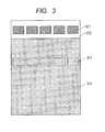
- An image for evaluating a ghost was formed by outputting a square image of solid black 301 on the head of an image and then outputting a halftone image 304 of a 1-dot KEIMA (knight of Japanese chess) pattern as shown FIG. 3 .
- the image was output by first outputting a solid white image on the first sheet, thereafter, continuously outputting an image for evaluating a ghost on 5 sheets, then outputting a solid black image on 1 sheet, and outputting an image for evaluation of a ghost on 5 sheets again, in this order, and such ten images for evaluating a ghost in total were evaluated.
- the evaluation of a ghost was performed by measuring the density difference between the image density of a 1-dot KEIMA (knight of Japanese chess) pattern and the image density of a ghost region (region where a ghost could occur) by a spectral densitometer (trade name: X-Rite 504/508, manufactured by X-Rite, Incorporated). Ten points of one image for evaluating a ghost were measured and the average of such ten points was defined as a result of one image. All the ten images for evaluating a ghost were subjected to the same measurement and then the respective averages were determined and defined as the density differences of the respective Examples. The density difference indicates that the smaller value exhibits a lower degree of ghost and is more favorable.
- the "initial” means the density difference before performing the duration test in which 1,000 sheets of paper were passed under an ordinary temperature and ordinary humidity environment or under a low temperature and low humidity environment
- the “after duration” means the density difference after performing the duration test in which 1,000 sheets of paper were passed under an ordinary temperature and ordinary humidity environment or under a low temperature and low humidity environment.
- Example 1 0.026 0.030 0.029 0.033
- Example 2 0.029 0.036 0.034 0.042
- Example 3 0.028 0.031 0.031 0.036
- Example 4 0.027 0.032 0.030 0.037
- Example 5 0.029 0.034 0.032 0.038
- Example 6 0.031 0.035 0.034 0.040
- Example 7 0.019 0.022 0.021 0.024
- Example 8 0.019 0.025 0.022 0.027
- Example 9 0.025 0.030 0.029 0.035
- Example 10 0.021 0.024 0.024 0.028
- Example 11 0.026 0.029 0.030 0.034
- Example 12 0.021 0.026 0.024 0.029
- Example 13 0.026 0.029 0.029 0.034
- Example 14 0.024 0.028 0.026 0.032
- Example 15 0.025 0.030 0.029 0.034
- Example 16 0.027 0.033 0.032 0.038
- the electrophotographic photosensitive member In order to provide an electrophotographic photosensitive member with which a ghost is suppressed even under a low temperature and low humidity environment, and a process cartridge and an electrophotographic apparatus having the electrophotographic photosensitive member, the electrophotographic photosensitive member is defined according to claim 1.
Landscapes
- Physics & Mathematics (AREA)
- General Physics & Mathematics (AREA)
- Photoreceptors In Electrophotography (AREA)
Claims (15)
- Elément photosensible électrophotographique comprenant un support,
une sous-couche formée sur le support, une couche de production de charge formée sur la sous-couche et qui comprend une matière de production de charge, et
une couche de transport de lacunes formée sur la couche de production de charge et comprenant une matière de transport de lacunes,
dans lequel
la sous-couche comprend une amine représentée par la formule (1) suivante :
- Elément photosensible électrophotographique suivant la revendication 1, dans lequel au moins un des groupes R1 à R10 représente un groupe amino substitué avec un groupe alkyle substitué ou non substitué.
- Elément photosensible électrophotographique suivant la revendication 2, dans lequel le groupe alkyle substitué ou non substitué dans le groupe amino substitué avec un groupe alkyle substitué ou non substitué est un groupe alkyle substitué avec un groupe alkoxy, un groupe alkyle substitué avec un groupe aryle ou un groupe alkyle non substitué.
- Elément photosensible électrophotographique suivant la revendication 2, dans lequel le groupe amino substitué avec un groupe alkyle substitué ou non substitué est un groupe dialkylamino.
- Elément photosensible électrophotographique suivant la revendication 4, dans lequel le groupe dialkylamino est un groupe diméthylamino ou un groupe diéthylamino.
- Elément photosensible électrophotographique suivant la revendication 1, dans lequel au moins un des groupes R1 à R10 est un groupe amino cyclique substitué ou non substitué.
- Elément photosensible électrophotographique suivant la revendication 6, dans lequel le groupe amino cyclique substitué ou non substitué est un groupe morpholino ou un groupe 1-pipéridyle.
- Elément photosensible électrophotographique suivant la revendication 1, dans lequel l'amine représentée par la formule (1) est une amine représentée par l'une quelconque des formules (2) à (4) suivantes :


- Elément photosensible électrophotographique suivant la revendication 8, dans lequel les groupes R11 à R20 représentent chacun un groupe alkyle substitué avec un groupe alkoxy, un groupe alkyle substitué avec un groupe aryle ou un groupe alkyle non substitué.
- Elément photosensible électrophotographique suivant la revendication 9, dans lequel les groupes R11 à R20 représentent chacun un groupe méthyle ou un groupe éthyle.
- Elément photosensible électrophotographique suivant la revendication 8, dans lequel le groupe amino cyclique substitué ou non substitué formé par liaison de R11 à R12, de R13 à R14, de R15 à R16, de R17 à R18 ou de R19 à R20 est autre qu'un groupe morpholino ou un groupe 1-pipéridyle.
- Elément photosensible électrophotographique suivant l'une quelconque des revendications 1 à 11, dans lequel la quantité de l'amine représentée par la formule (1) dans la sous-couche va de 0,05 % en masse ou plus à 15 % en masse ou moins.
- Elément photosensible électrophotographique suivant l'une quelconque des revendications 1 à 12, dans lequel la couche de production de charge comprend la matière de production de charge et une amine représentée par la formule (1), et l'amine représentée par la formule (1) présente dans la sous-couche a la même structure que l'amine représentée par la formule (1) présente dans la couche de production de charge.
- Cartouche de traitement qui porte de manière intégrée l'élément photosensible électrophotographique suivant l'une quelconque des revendications 1 à 13, et au moins une unité choisie dans le groupe consistant en une unité de charge, une unité de développement, une unité de transfert et une unité de nettoyage, et qui peut être montée de manière amovible dans le corps principal d'un appareil électrophotographique.
- Appareil électrophotographique comprenant l'élément photosensible électrophotographique suivant l'une quelconque des revendications 1 à 13 et une unité de charge, une unité d'exposition d'image, une unité de développement et une unité de transfert.
Applications Claiming Priority (2)
| Application Number | Priority Date | Filing Date | Title |
|---|---|---|---|
| JP2011262024 | 2011-11-30 | ||
| JP2012251040A JP5993720B2 (ja) | 2011-11-30 | 2012-11-15 | 電子写真感光体、プロセスカートリッジおよび電子写真装置 |
Publications (2)
| Publication Number | Publication Date |
|---|---|
| EP2600201A1 EP2600201A1 (fr) | 2013-06-05 |
| EP2600201B1 true EP2600201B1 (fr) | 2014-09-10 |
Family
ID=47226050
Family Applications (1)
| Application Number | Title | Priority Date | Filing Date |
|---|---|---|---|
| EP20120194617 Not-in-force EP2600201B1 (fr) | 2011-11-30 | 2012-11-28 | Élément électro-photographique photosensible, cartouche de traitement et appareil électro-photographique |
Country Status (5)
| Country | Link |
|---|---|
| US (2) | US8841052B2 (fr) |
| EP (1) | EP2600201B1 (fr) |
| JP (1) | JP5993720B2 (fr) |
| KR (1) | KR101580711B1 (fr) |
| CN (1) | CN103135372B (fr) |
Families Citing this family (33)
| Publication number | Priority date | Publication date | Assignee | Title |
|---|---|---|---|---|
| JP5993720B2 (ja) * | 2011-11-30 | 2016-09-14 | キヤノン株式会社 | 電子写真感光体、プロセスカートリッジおよび電子写真装置 |
| JP5871775B2 (ja) * | 2011-11-30 | 2016-03-01 | キヤノン株式会社 | 電子写真感光体、プロセスカートリッジおよび電子写真装置 |
| JP6071439B2 (ja) | 2011-11-30 | 2017-02-01 | キヤノン株式会社 | フタロシアニン結晶の製造方法、および電子写真感光体の製造方法 |
| JP6039368B2 (ja) | 2011-11-30 | 2016-12-07 | キヤノン株式会社 | 電子写真感光体、プロセスカートリッジおよび電子写真装置、ならびに、ガリウムフタロシアニン結晶 |
| JP5827612B2 (ja) | 2011-11-30 | 2015-12-02 | キヤノン株式会社 | ガリウムフタロシアニン結晶の製造方法、及び該ガリウムフタロシアニン結晶の製造方法を用いた電子写真感光体の製造方法 |
| JP6105974B2 (ja) | 2012-03-15 | 2017-03-29 | キヤノン株式会社 | 電子写真感光体の製造方法、および電荷輸送層用乳化液 |
| JP6218519B2 (ja) | 2012-10-12 | 2017-10-25 | キヤノン株式会社 | 電子写真感光体、電子写真感光体の製造方法、プロセスカートリッジ及び電子写真装置、並びに化合物を吸着した粒子 |
| JP6188535B2 (ja) * | 2012-11-20 | 2017-08-30 | キヤノン株式会社 | 電子写真感光体、プロセスカートリッジおよび電子写真装置 |
| JP6004930B2 (ja) * | 2012-12-14 | 2016-10-12 | キヤノン株式会社 | 電子写真感光体、プロセスカートリッジおよび電子写真装置 |
| JP6161425B2 (ja) * | 2013-06-19 | 2017-07-12 | キヤノン株式会社 | 電子写真感光体の製造方法 |
| JP6347696B2 (ja) * | 2013-09-30 | 2018-06-27 | キヤノン株式会社 | 電子写真感光体、プロセスカートリッジ及び電子写真装置 |
| JP6555877B2 (ja) | 2013-12-26 | 2019-08-07 | キヤノン株式会社 | 電子写真感光体、及び、該電子写真感光体の製造方法、及び該電子写真感光体を有するプロセスカートリッジ及び電子写真装置 |
| JP6478750B2 (ja) | 2014-04-30 | 2019-03-06 | キヤノン株式会社 | 電子写真感光体、プロセスカートリッジおよび電子写真装置、ならびに、フタロシアニン結晶およびその製造方法 |
| JP6611479B2 (ja) * | 2015-01-26 | 2019-11-27 | キヤノン株式会社 | 電子写真感光体、プロセスカートリッジおよび電子写真装置 |
| JP2017010009A (ja) | 2015-06-24 | 2017-01-12 | キヤノン株式会社 | 電子写真感光体、プロセスカートリッジおよび電子写真装置 |
| JP2017083537A (ja) | 2015-10-23 | 2017-05-18 | キヤノン株式会社 | 電子写真感光体、プロセスカートリッジ及び電子写真装置 |
| US10095137B2 (en) | 2016-04-04 | 2018-10-09 | Canon Kabushiki Kaisha | Electrophotographic photosensitive member, method of producing electrophotographic photosensitive member, process cartridge, and electrophotographic image forming apparatus |
| JP6978858B2 (ja) | 2016-06-21 | 2021-12-08 | キヤノン株式会社 | 電子写真感光体、電子写真感光体の製造方法、該電子写真感光体を有するプロセスカートリッジおよび電子写真装置 |
| JP7417350B2 (ja) * | 2017-03-28 | 2024-01-18 | キヤノン株式会社 | 光学素子、光学材料、光学機器及びトリアリールアミン化合物 |
| JP6887928B2 (ja) * | 2017-09-27 | 2021-06-16 | キヤノン株式会社 | 電子写真感光体、その製造方法、プロセスカートリッジおよび電子写真装置 |
| JP7305458B2 (ja) | 2019-06-25 | 2023-07-10 | キヤノン株式会社 | 電子写真感光体、プロセスカートリッジ及び電子写真装置 |
| US11126097B2 (en) | 2019-06-25 | 2021-09-21 | Canon Kabushiki Kaisha | Electrophotographic photosensitive member, process cartridge, and electrophotographic apparatus |
| JP7353824B2 (ja) | 2019-06-25 | 2023-10-02 | キヤノン株式会社 | 電子写真感光体、プロセスカートリッジおよび電子写真装置 |
| JP7269111B2 (ja) | 2019-06-25 | 2023-05-08 | キヤノン株式会社 | 電子写真感光体、プロセスカートリッジおよび電子写真装置 |
| US11573499B2 (en) | 2019-07-25 | 2023-02-07 | Canon Kabushiki Kaisha | Process cartridge and electrophotographic apparatus |
| US11320754B2 (en) | 2019-07-25 | 2022-05-03 | Canon Kabushiki Kaisha | Process cartridge and electrophotographic apparatus |
| JP7337650B2 (ja) | 2019-10-18 | 2023-09-04 | キヤノン株式会社 | プロセスカートリッジおよび電子写真装置 |
| US11112719B2 (en) | 2019-10-18 | 2021-09-07 | Canon Kabushiki Kaisha | Process cartridge and electrophotographic apparatus capable of suppressing lateral running while maintaining satisfactory potential function |
| JP7337651B2 (ja) | 2019-10-18 | 2023-09-04 | キヤノン株式会社 | プロセスカートリッジ及び電子写真装置 |
| JP7483477B2 (ja) | 2020-04-21 | 2024-05-15 | キヤノン株式会社 | 電子写真感光ドラム、プロセスカートリッジおよび電子写真画像形成装置 |
| JP7444691B2 (ja) | 2020-04-21 | 2024-03-06 | キヤノン株式会社 | 電子写真感光体の製造方法 |
| JP7449151B2 (ja) | 2020-04-21 | 2024-03-13 | キヤノン株式会社 | 電子写真感光ドラム |
| JP2023131675A (ja) | 2022-03-09 | 2023-09-22 | キヤノン株式会社 | 電子写真装置 |
Family Cites Families (84)
| Publication number | Priority date | Publication date | Assignee | Title |
|---|---|---|---|---|
| BE626529A (fr) * | 1961-12-29 | |||
| JPS57125942A (en) * | 1981-01-29 | 1982-08-05 | Konishiroku Photo Ind Co Ltd | Electrophotographic receptor |
| JPS57125941A (en) * | 1981-01-29 | 1982-08-05 | Konishiroku Photo Ind Co Ltd | Electrophotographic receptor |
| JPS57210343A (en) * | 1981-06-20 | 1982-12-23 | Konishiroku Photo Ind Co Ltd | Electrophotographic receptor |
| JPS57212456A (en) * | 1981-06-23 | 1982-12-27 | Konishiroku Photo Ind Co Ltd | Electrophotographic receptor |
| JPS5817450A (ja) | 1981-07-24 | 1983-02-01 | Mitsubishi Paper Mills Ltd | 電子写真用感光体 |
| JPS5858551A (ja) * | 1981-10-01 | 1983-04-07 | Konishiroku Photo Ind Co Ltd | 電子写真感光体 |
| JPS59204045A (ja) * | 1983-05-07 | 1984-11-19 | Sumitomo Chem Co Ltd | 電子写真感光体及びその製造法 |
| JPH01198481A (ja) | 1988-02-01 | 1989-08-10 | Canon Inc | マイクロ波プラズマcvd法による堆積膜形成法 |
| US4908330A (en) | 1988-02-01 | 1990-03-13 | Canon Kabushiki Kaisha | Process for the formation of a functional deposited film containing group IV atoms or silicon atoms and group IV atoms by microwave plasma chemical vapor deposition process |
| JPH0727227B2 (ja) * | 1988-10-05 | 1995-03-29 | 富士ゼロックス株式会社 | 電子写真感光体及び画像形成方法 |
| JP2782109B2 (ja) | 1990-07-30 | 1998-07-30 | キヤノン株式会社 | 電子写真感光体、該電子写真感光体を備えた電子写真装置並びにファクシミリ |
| EP0492618B1 (fr) | 1990-12-26 | 1999-03-17 | Canon Kabushiki Kaisha | Elément électrophotographique photosensible, et appareil électrophotographique, appareillage et appareil fac-similé utilisant cet élément |
| JPH04254862A (ja) * | 1991-01-30 | 1992-09-10 | Canon Inc | 電子写真感光体、該電子写真感光体を備えた電子写真装置並びにファクシミリ |
| EP0510538B1 (fr) | 1991-04-19 | 1999-03-03 | Canon Kabushiki Kaisha | Elément photosensible électrophotographique et procédé pour sa fabrication |
| EP0511588B1 (fr) | 1991-04-24 | 1996-09-25 | Canon Kabushiki Kaisha | Elément électrophotographique photosensible, et appareil électrophotographique, appareillage et appareil fac-similé utilisant cet élément |
| US5246807A (en) | 1991-08-05 | 1993-09-21 | Canon Kabushiki Kaisha | Electrophotographic photosensitive member, and electrophotographic apparatus, device unit, and facsimile machine employing the same |
| JPH05224439A (ja) * | 1992-02-12 | 1993-09-03 | Fuji Electric Co Ltd | 電子写真用感光体 |
| JPH06123981A (ja) * | 1992-10-12 | 1994-05-06 | Ricoh Co Ltd | 単層型電子写真用感光体 |
| EP0655655B1 (fr) | 1993-10-04 | 1998-06-10 | Canon Kabushiki Kaisha | Elément photosensible électrophotographique, unité de traitement et appareil électrophotographique l'utilisant |
| US5407766A (en) * | 1993-12-20 | 1995-04-18 | Xerox Corporation | Hydroxygallium phthalocyanine photoconductive imaging members |
| US5464718A (en) | 1993-12-24 | 1995-11-07 | Canon Kabushiki Kaisha | Electrophotographic photosensitive member, process cartridge including same and electrophotographic apparatus |
| JPH07219251A (ja) * | 1994-01-28 | 1995-08-18 | Ricoh Co Ltd | 電子写真用感光体 |
| US5629116A (en) | 1994-03-07 | 1997-05-13 | Canon Kabushiki Kaisha | Electrophotographic photosensitive member, process cartridge and electrophotographic apparatus having the electrophotographic photosensitive member |
| EP0690357B1 (fr) | 1994-06-30 | 2000-02-09 | Canon Kabushiki Kaisha | Appareil électrographique et méthode pour la formation d'image |
| JPH0895278A (ja) | 1994-09-20 | 1996-04-12 | Ricoh Co Ltd | 電子写真感光体及びこれを用いた電子写真装置 |
| US5818489A (en) | 1994-12-07 | 1998-10-06 | Canon Kabushiki Kaisha | Image forming apparatus and process cartridge having exposure device using light beam having specific spot area |
| JP2992638B2 (ja) | 1995-06-28 | 1999-12-20 | キヤノン株式会社 | 光起電力素子の電極構造及び製造方法並びに太陽電池 |
| DE69610949T2 (de) * | 1995-07-06 | 2001-03-22 | Hewlett-Packard Co., Palo Alto | Copolymere geeignet als Sperrmaterial gegen Ladungsinjektion für Photorezeptoren |
| JPH09288366A (ja) * | 1996-02-20 | 1997-11-04 | Ricoh Co Ltd | 電子写真感光体 |
| DE69708732T2 (de) | 1996-03-27 | 2002-08-08 | Canon K.K., Tokio/Tokyo | Elektrophotographisches photoempfindliches Element, elektrophotographischer Apparat und Prozesskassette unter Verwendung desselben |
| US5811212A (en) | 1996-04-26 | 1998-09-22 | Canon Kabushiki Kaisha | Electrophotographic photosensitive member containing an azocalix n!arene compound and electrophotographic apparatus and process cartridge comprising the photosensitive member |
| US5876888A (en) | 1996-07-04 | 1999-03-02 | Canon Kabushiki Kaisha | Electrophotographic photosensitive member, and apparatus and process cartridge provided with the same |
| DE69708772T2 (de) | 1996-07-09 | 2002-08-08 | Canon K.K., Tokio/Tokyo | Elektrophotographisches, lichtempfindliches Element, sowie ein elektrophotographischer Apparat und Prozesskassette unter Verwendung desselben |
| US6296978B1 (en) | 1997-04-30 | 2001-10-02 | Canon Kabushiki Kaisha | Electrophotographic photosensitive member, a process-cartridge inclusive thereof, and an image forming apparatus |
| JPH1115184A (ja) | 1997-06-23 | 1999-01-22 | Sharp Corp | 電子写真感光体およびその製造方法 |
| US6093515A (en) | 1997-08-29 | 2000-07-25 | Canon Kabushiki Kaisha | Electrophotographic photosensitive member, process cartridge and electrophotographic apparatus |
| US6245472B1 (en) | 1997-09-12 | 2001-06-12 | Canon Kabushiki Kaisha | Phthalocyanine compounds, process for production thereof and electrophotographic photosensitive member using the compounds |
| US6146800A (en) | 1997-10-17 | 2000-11-14 | Canon Kabushiki Kaisha | Electrophotographic photosensitive member, process cartridge, and electrophotographic apparatus |
| EP0940725B1 (fr) | 1998-03-04 | 2003-06-04 | Canon Kabushiki Kaisha | Elément photosensible, électrophotographique, unité de traitement et appareil électrophotographique |
| EP0940726B1 (fr) | 1998-03-06 | 2004-05-26 | Canon Kabushiki Kaisha | Elément photosensible, électrophotographique, unité de traitement et appareil électrophotographique |
| EP0977088B1 (fr) | 1998-07-31 | 2008-08-20 | Canon Kabushiki Kaisha | Utilisation d'un élément photosensible, électrophotographique dans un appareil électrophotographique équippé d'un laser semiconducteur de longueur d'onde de 380nm à 500nm, et appareil électrophotographique |
| EP0977086B1 (fr) | 1998-07-31 | 2007-03-21 | Canon Kabushiki Kaisha | Appareil électrophotographique |
| EP0982632B1 (fr) | 1998-08-25 | 2005-05-11 | Canon Kabushiki Kaisha | Elément photosensible, électrophotographique, unité de traitement et appareil électrophotographique |
| US6218063B1 (en) | 1998-08-26 | 2001-04-17 | Canon Kabushiki Kaisha | Electrophotographic photosensitive member, process cartridge, and electrophotographic apparatus |
| US6248490B1 (en) | 1998-12-01 | 2001-06-19 | Canon Kabushiki Kaisha | Electrophotographic photosensitive member, process cartridge, and electrophotographic apparatus |
| US6258498B1 (en) | 1998-12-25 | 2001-07-10 | Canon Kabushiki Kaisha | Electrophotographic photosensitive member, and process cartridge and electrophotographic photosensitive member |
| US6335132B1 (en) | 1999-06-25 | 2002-01-01 | Canon Kabushiki Kaisha | Electrophotographic photosensitive member, and process cartridge and electrophotographic apparatus including the photosensitive member |
| DE60116550T2 (de) | 2000-08-08 | 2006-08-17 | Canon K.K. | Elektrophotographisches, lichtempfindliches Element, Prozesskartusche und elektrophotographischer Apparat |
| EP1179751B1 (fr) | 2000-08-08 | 2005-11-02 | Canon Kabushiki Kaisha | Elément photosensible électrophotographique, procédé pour sa fabrication, cartouche de traitement et appareil électrophotographique |
| JP2002091044A (ja) | 2000-09-12 | 2002-03-27 | Mitsubishi Chemicals Corp | 電子写真感光体 |
| US6683175B2 (en) | 2001-04-12 | 2004-01-27 | Canon Kabushiki Kaisha | Porphyrin compound, and electrophotographic photosensitive member, process-cartridge and apparatus using the compound |
| JP2003083118A (ja) | 2001-09-10 | 2003-03-19 | Toyota Motor Corp | 2サイクル自着火ガソリンエンジン |
| US6773856B2 (en) | 2001-11-09 | 2004-08-10 | Canon Kabushiki Kaisha | Electrophotographic photosensitive member, process cartridge, and electrophotographic apparatus |
| CN1306342C (zh) | 2002-04-26 | 2007-03-21 | 佳能株式会社 | 电摄影感光体、成像处理盒和电摄影装置 |
| KR100643827B1 (ko) | 2002-06-28 | 2006-11-10 | 캐논 가부시끼가이샤 | 전자사진 감광체, 프로세스 카트리지 및 전자사진 장치 |
| US7001699B2 (en) | 2002-08-30 | 2006-02-21 | Canon Kabushiki Kaisha | Electrophotographic photosensitive member, process cartridge and electrophotographic apparatus |
| JP2004240056A (ja) * | 2003-02-04 | 2004-08-26 | Fuji Denki Gazo Device Kk | 正帯電単層型電子写真用感光体 |
| US7245851B2 (en) | 2003-11-26 | 2007-07-17 | Canon Kabushiki Kaisha | Electrophotographic apparatus |
| US7276318B2 (en) | 2003-11-26 | 2007-10-02 | Canon Kabushiki Kaisha | Electrophotographic photosensitive member, and electrophotographic apparatus and process cartridge which make use of the same |
| JP4456953B2 (ja) | 2004-07-16 | 2010-04-28 | 富士ゼロックス株式会社 | 画像形成装置及びプロセスカートリッジ |
| WO2006028232A1 (fr) | 2004-09-10 | 2006-03-16 | Canon Kabushiki Kaisha | Element photosensible electrophotographique, cartouche de traitement et appareil electrophotographique |
| CN100578371C (zh) | 2005-04-08 | 2010-01-06 | 佳能株式会社 | 电子照相感光构件,以及具有该电子照相感光构件的处理盒和电子照相设备 |
| JP2007065164A (ja) * | 2005-08-30 | 2007-03-15 | Canon Inc | 電子写真感光体、プロセスカートリッジおよび電子写真装置 |
| JP2007148293A (ja) | 2005-11-30 | 2007-06-14 | Canon Inc | 電子写真感光体、プロセスカートリッジ及び電子写真装置 |
| US8088541B2 (en) | 2005-12-07 | 2012-01-03 | Canon Kabushiki Kaisha | Polyvinyl acetal resin, electrophotographic photosensitive member, process cartridge, and electrophotographic apparatus |
| JP4059518B2 (ja) | 2006-01-31 | 2008-03-12 | キヤノン株式会社 | 電子写真感光体の製造方法 |
| JP4101278B2 (ja) | 2006-01-31 | 2008-06-18 | キヤノン株式会社 | 電子写真感光体、プロセスカートリッジおよび電子写真装置 |
| JP4194631B2 (ja) | 2006-01-31 | 2008-12-10 | キヤノン株式会社 | 画像形成方法ならびに該画像形成方法を用いた電子写真装置 |
| JP4183267B2 (ja) | 2006-01-31 | 2008-11-19 | キヤノン株式会社 | 電子写真感光体、プロセスカートリッジ及び電子写真装置 |
| JP4235673B2 (ja) | 2007-07-17 | 2009-03-11 | キヤノン株式会社 | 電子写真感光体の製造方法 |
| US7670737B2 (en) | 2007-07-31 | 2010-03-02 | Xerox Corporation | UV absorbing hole blocking layer containing photoconductors |
| JP4380794B2 (ja) | 2007-12-04 | 2009-12-09 | キヤノン株式会社 | 電子写真感光体、電子写真感光体の製造方法、プロセスカートリッジおよび電子写真装置 |
| US20090162767A1 (en) | 2007-12-20 | 2009-06-25 | Xerox Corporation | Benzophenone containing photoconductors |
| JP4702448B2 (ja) * | 2008-12-26 | 2011-06-15 | 富士ゼロックス株式会社 | 電子写真感光体及びその製造方法、プロセスカートリッジ、並びに画像形成装置。 |
| JP4696174B2 (ja) | 2009-04-23 | 2011-06-08 | キヤノン株式会社 | 電子写真感光体の製造方法 |
| JP5081271B2 (ja) | 2009-04-23 | 2012-11-28 | キヤノン株式会社 | 電子写真感光体、プロセスカートリッジおよび電子写真装置 |
| JP5610907B2 (ja) | 2009-08-18 | 2014-10-22 | キヤノン株式会社 | 電子写真感光体、プロセスカートリッジおよび電子写真装置 |
| JP5734093B2 (ja) | 2010-06-30 | 2015-06-10 | キヤノン株式会社 | 電子写真感光体、プロセスカートリッジおよび電子写真装置 |
| JP5906069B2 (ja) * | 2011-11-30 | 2016-04-20 | キヤノン株式会社 | 電子写真感光体、プロセスカートリッジおよび電子写真装置 |
| JP5993720B2 (ja) * | 2011-11-30 | 2016-09-14 | キヤノン株式会社 | 電子写真感光体、プロセスカートリッジおよび電子写真装置 |
| JP6071439B2 (ja) | 2011-11-30 | 2017-02-01 | キヤノン株式会社 | フタロシアニン結晶の製造方法、および電子写真感光体の製造方法 |
| JP5827612B2 (ja) | 2011-11-30 | 2015-12-02 | キヤノン株式会社 | ガリウムフタロシアニン結晶の製造方法、及び該ガリウムフタロシアニン結晶の製造方法を用いた電子写真感光体の製造方法 |
| JP6188535B2 (ja) * | 2012-11-20 | 2017-08-30 | キヤノン株式会社 | 電子写真感光体、プロセスカートリッジおよび電子写真装置 |
-
2012
- 2012-11-15 JP JP2012251040A patent/JP5993720B2/ja active Active
- 2012-11-21 US US13/683,752 patent/US8841052B2/en active Active
- 2012-11-22 KR KR1020120132730A patent/KR101580711B1/ko active IP Right Grant
- 2012-11-28 EP EP20120194617 patent/EP2600201B1/fr not_active Not-in-force
- 2012-11-29 CN CN201210500984.0A patent/CN103135372B/zh not_active Expired - Fee Related
-
2014
- 2014-08-25 US US14/468,266 patent/US9535347B2/en active Active
Also Published As
| Publication number | Publication date |
|---|---|
| JP5993720B2 (ja) | 2016-09-14 |
| CN103135372A (zh) | 2013-06-05 |
| KR20130061064A (ko) | 2013-06-10 |
| US9535347B2 (en) | 2017-01-03 |
| US20130137023A1 (en) | 2013-05-30 |
| KR101580711B1 (ko) | 2015-12-28 |
| JP2013137523A (ja) | 2013-07-11 |
| US20140363759A1 (en) | 2014-12-11 |
| EP2600201A1 (fr) | 2013-06-05 |
| US8841052B2 (en) | 2014-09-23 |
| CN103135372B (zh) | 2015-02-11 |
Similar Documents
| Publication | Publication Date | Title |
|---|---|---|
| EP2600201B1 (fr) | Élément électro-photographique photosensible, cartouche de traitement et appareil électro-photographique | |
| EP2733539B1 (fr) | Élément électro-photographique photosensible, cartouche de traitement et appareil électro-photographique | |
| JP5827612B2 (ja) | ガリウムフタロシアニン結晶の製造方法、及び該ガリウムフタロシアニン結晶の製造方法を用いた電子写真感光体の製造方法 | |
| JP6039368B2 (ja) | 電子写真感光体、プロセスカートリッジおよび電子写真装置、ならびに、ガリウムフタロシアニン結晶 | |
| JP6005216B2 (ja) | 電子写真感光体、電子写真感光体の製造方法、プロセスカートリッジおよび電子写真装置、ならびに、固溶体および固溶体の製造方法 | |
| US8415078B2 (en) | Electrophotographic photosensitive member, process electrophotographic apparatus | |
| US9223233B2 (en) | Electrophotographic photosensitive member, process cartridge and electrophotographic apparatus | |
| US20110045390A1 (en) | Electrophotographic photosensitive member, process cartridge and electrophotographic apparatus | |
| JP5906069B2 (ja) | 電子写真感光体、プロセスカートリッジおよび電子写真装置 | |
| JP2014134772A (ja) | 電子写真感光体、プロセスカートリッジおよび電子写真装置、ならびにフタロシアニン結晶 | |
| US9746790B2 (en) | Electrophotographic photosensitive member, process cartridge and electrophotographic apparatus, and chlorogallium phthalocyanine crystal and method for producing the same | |
| JP5932607B2 (ja) | 電子写真感光体、プロセスカートリッジおよび電子写真装置 | |
| JP2018091932A (ja) | 電子写真感光体、プロセスカートリッジ及び電子写真装置 |
Legal Events
| Date | Code | Title | Description |
|---|---|---|---|
| PUAI | Public reference made under article 153(3) epc to a published international application that has entered the european phase |
Free format text: ORIGINAL CODE: 0009012 |
|
| AK | Designated contracting states |
Kind code of ref document: A1 Designated state(s): AL AT BE BG CH CY CZ DE DK EE ES FI FR GB GR HR HU IE IS IT LI LT LU LV MC MK MT NL NO PL PT RO RS SE SI SK SM TR |
|
| AX | Request for extension of the european patent |
Extension state: BA ME |
|
| 17P | Request for examination filed |
Effective date: 20131205 |
|
| RBV | Designated contracting states (corrected) |
Designated state(s): AL AT BE BG CH CY CZ DE DK EE ES FI FR GB GR HR HU IE IS IT LI LT LU LV MC MK MT NL NO PL PT RO RS SE SI SK SM TR |
|
| GRAP | Despatch of communication of intention to grant a patent |
Free format text: ORIGINAL CODE: EPIDOSNIGR1 |
|
| INTG | Intention to grant announced |
Effective date: 20140327 |
|
| GRAS | Grant fee paid |
Free format text: ORIGINAL CODE: EPIDOSNIGR3 |
|
| GRAA | (expected) grant |
Free format text: ORIGINAL CODE: 0009210 |
|
| AK | Designated contracting states |
Kind code of ref document: B1 Designated state(s): AL AT BE BG CH CY CZ DE DK EE ES FI FR GB GR HR HU IE IS IT LI LT LU LV MC MK MT NL NO PL PT RO RS SE SI SK SM TR |
|
| REG | Reference to a national code |
Ref country code: GB Ref legal event code: FG4D |
|
| REG | Reference to a national code |
Ref country code: CH Ref legal event code: EP |
|
| REG | Reference to a national code |
Ref country code: IE Ref legal event code: FG4D |
|
| REG | Reference to a national code |
Ref country code: AT Ref legal event code: REF Ref document number: 686988 Country of ref document: AT Kind code of ref document: T Effective date: 20141015 |
|
| REG | Reference to a national code |
Ref country code: DE Ref legal event code: R096 Ref document number: 602012003060 Country of ref document: DE Effective date: 20141023 |
|
| PG25 | Lapsed in a contracting state [announced via postgrant information from national office to epo] |
Ref country code: ES Free format text: LAPSE BECAUSE OF FAILURE TO SUBMIT A TRANSLATION OF THE DESCRIPTION OR TO PAY THE FEE WITHIN THE PRESCRIBED TIME-LIMIT Effective date: 20140910 Ref country code: NO Free format text: LAPSE BECAUSE OF FAILURE TO SUBMIT A TRANSLATION OF THE DESCRIPTION OR TO PAY THE FEE WITHIN THE PRESCRIBED TIME-LIMIT Effective date: 20141210 Ref country code: LT Free format text: LAPSE BECAUSE OF FAILURE TO SUBMIT A TRANSLATION OF THE DESCRIPTION OR TO PAY THE FEE WITHIN THE PRESCRIBED TIME-LIMIT Effective date: 20140910 Ref country code: GR Free format text: LAPSE BECAUSE OF FAILURE TO SUBMIT A TRANSLATION OF THE DESCRIPTION OR TO PAY THE FEE WITHIN THE PRESCRIBED TIME-LIMIT Effective date: 20141211 Ref country code: FI Free format text: LAPSE BECAUSE OF FAILURE TO SUBMIT A TRANSLATION OF THE DESCRIPTION OR TO PAY THE FEE WITHIN THE PRESCRIBED TIME-LIMIT Effective date: 20140910 Ref country code: SE Free format text: LAPSE BECAUSE OF FAILURE TO SUBMIT A TRANSLATION OF THE DESCRIPTION OR TO PAY THE FEE WITHIN THE PRESCRIBED TIME-LIMIT Effective date: 20140910 |
|
| REG | Reference to a national code |
Ref country code: NL Ref legal event code: VDEP Effective date: 20140910 |
|
| REG | Reference to a national code |
Ref country code: LT Ref legal event code: MG4D |
|
| PG25 | Lapsed in a contracting state [announced via postgrant information from national office to epo] |
Ref country code: HR Free format text: LAPSE BECAUSE OF FAILURE TO SUBMIT A TRANSLATION OF THE DESCRIPTION OR TO PAY THE FEE WITHIN THE PRESCRIBED TIME-LIMIT Effective date: 20140910 Ref country code: CY Free format text: LAPSE BECAUSE OF FAILURE TO SUBMIT A TRANSLATION OF THE DESCRIPTION OR TO PAY THE FEE WITHIN THE PRESCRIBED TIME-LIMIT Effective date: 20140910 Ref country code: RS Free format text: LAPSE BECAUSE OF FAILURE TO SUBMIT A TRANSLATION OF THE DESCRIPTION OR TO PAY THE FEE WITHIN THE PRESCRIBED TIME-LIMIT Effective date: 20140910 Ref country code: LV Free format text: LAPSE BECAUSE OF FAILURE TO SUBMIT A TRANSLATION OF THE DESCRIPTION OR TO PAY THE FEE WITHIN THE PRESCRIBED TIME-LIMIT Effective date: 20140910 |
|
| REG | Reference to a national code |
Ref country code: AT Ref legal event code: MK05 Ref document number: 686988 Country of ref document: AT Kind code of ref document: T Effective date: 20140910 |
|
| PG25 | Lapsed in a contracting state [announced via postgrant information from national office to epo] |
Ref country code: NL Free format text: LAPSE BECAUSE OF FAILURE TO SUBMIT A TRANSLATION OF THE DESCRIPTION OR TO PAY THE FEE WITHIN THE PRESCRIBED TIME-LIMIT Effective date: 20140910 |
|
| PG25 | Lapsed in a contracting state [announced via postgrant information from national office to epo] |
Ref country code: EE Free format text: LAPSE BECAUSE OF FAILURE TO SUBMIT A TRANSLATION OF THE DESCRIPTION OR TO PAY THE FEE WITHIN THE PRESCRIBED TIME-LIMIT Effective date: 20140910 Ref country code: SK Free format text: LAPSE BECAUSE OF FAILURE TO SUBMIT A TRANSLATION OF THE DESCRIPTION OR TO PAY THE FEE WITHIN THE PRESCRIBED TIME-LIMIT Effective date: 20140910 Ref country code: IS Free format text: LAPSE BECAUSE OF FAILURE TO SUBMIT A TRANSLATION OF THE DESCRIPTION OR TO PAY THE FEE WITHIN THE PRESCRIBED TIME-LIMIT Effective date: 20150110 Ref country code: PT Free format text: LAPSE BECAUSE OF FAILURE TO SUBMIT A TRANSLATION OF THE DESCRIPTION OR TO PAY THE FEE WITHIN THE PRESCRIBED TIME-LIMIT Effective date: 20150112 Ref country code: RO Free format text: LAPSE BECAUSE OF FAILURE TO SUBMIT A TRANSLATION OF THE DESCRIPTION OR TO PAY THE FEE WITHIN THE PRESCRIBED TIME-LIMIT Effective date: 20140910 Ref country code: CZ Free format text: LAPSE BECAUSE OF FAILURE TO SUBMIT A TRANSLATION OF THE DESCRIPTION OR TO PAY THE FEE WITHIN THE PRESCRIBED TIME-LIMIT Effective date: 20140910 |
|
| PG25 | Lapsed in a contracting state [announced via postgrant information from national office to epo] |
Ref country code: PL Free format text: LAPSE BECAUSE OF FAILURE TO SUBMIT A TRANSLATION OF THE DESCRIPTION OR TO PAY THE FEE WITHIN THE PRESCRIBED TIME-LIMIT Effective date: 20140910 Ref country code: AT Free format text: LAPSE BECAUSE OF FAILURE TO SUBMIT A TRANSLATION OF THE DESCRIPTION OR TO PAY THE FEE WITHIN THE PRESCRIBED TIME-LIMIT Effective date: 20140910 |
|
| REG | Reference to a national code |
Ref country code: DE Ref legal event code: R097 Ref document number: 602012003060 Country of ref document: DE |
|
| PG25 | Lapsed in a contracting state [announced via postgrant information from national office to epo] |
Ref country code: LU Free format text: LAPSE BECAUSE OF FAILURE TO SUBMIT A TRANSLATION OF THE DESCRIPTION OR TO PAY THE FEE WITHIN THE PRESCRIBED TIME-LIMIT Effective date: 20141128 Ref country code: BE Free format text: LAPSE BECAUSE OF NON-PAYMENT OF DUE FEES Effective date: 20141130 Ref country code: MC Free format text: LAPSE BECAUSE OF FAILURE TO SUBMIT A TRANSLATION OF THE DESCRIPTION OR TO PAY THE FEE WITHIN THE PRESCRIBED TIME-LIMIT Effective date: 20140910 |
|
| PLBE | No opposition filed within time limit |
Free format text: ORIGINAL CODE: 0009261 |
|
| STAA | Information on the status of an ep patent application or granted ep patent |
Free format text: STATUS: NO OPPOSITION FILED WITHIN TIME LIMIT |
|
| PG25 | Lapsed in a contracting state [announced via postgrant information from national office to epo] |
Ref country code: DK Free format text: LAPSE BECAUSE OF FAILURE TO SUBMIT A TRANSLATION OF THE DESCRIPTION OR TO PAY THE FEE WITHIN THE PRESCRIBED TIME-LIMIT Effective date: 20140910 |
|
| 26N | No opposition filed |
Effective date: 20150611 |
|
| REG | Reference to a national code |
Ref country code: IE Ref legal event code: MM4A |
|
| PG25 | Lapsed in a contracting state [announced via postgrant information from national office to epo] |
Ref country code: IT Free format text: LAPSE BECAUSE OF FAILURE TO SUBMIT A TRANSLATION OF THE DESCRIPTION OR TO PAY THE FEE WITHIN THE PRESCRIBED TIME-LIMIT Effective date: 20140910 |
|
| PG25 | Lapsed in a contracting state [announced via postgrant information from national office to epo] |
Ref country code: IE Free format text: LAPSE BECAUSE OF NON-PAYMENT OF DUE FEES Effective date: 20141128 |
|
| REG | Reference to a national code |
Ref country code: FR Ref legal event code: PLFP Year of fee payment: 4 |
|
| PG25 | Lapsed in a contracting state [announced via postgrant information from national office to epo] |
Ref country code: SI Free format text: LAPSE BECAUSE OF FAILURE TO SUBMIT A TRANSLATION OF THE DESCRIPTION OR TO PAY THE FEE WITHIN THE PRESCRIBED TIME-LIMIT Effective date: 20140910 |
|
| PG25 | Lapsed in a contracting state [announced via postgrant information from national office to epo] |
Ref country code: BG Free format text: LAPSE BECAUSE OF FAILURE TO SUBMIT A TRANSLATION OF THE DESCRIPTION OR TO PAY THE FEE WITHIN THE PRESCRIBED TIME-LIMIT Effective date: 20140910 |
|
| REG | Reference to a national code |
Ref country code: CH Ref legal event code: PL |
|
| PG25 | Lapsed in a contracting state [announced via postgrant information from national office to epo] |
Ref country code: CH Free format text: LAPSE BECAUSE OF NON-PAYMENT OF DUE FEES Effective date: 20151130 Ref country code: TR Free format text: LAPSE BECAUSE OF FAILURE TO SUBMIT A TRANSLATION OF THE DESCRIPTION OR TO PAY THE FEE WITHIN THE PRESCRIBED TIME-LIMIT Effective date: 20140910 Ref country code: MT Free format text: LAPSE BECAUSE OF FAILURE TO SUBMIT A TRANSLATION OF THE DESCRIPTION OR TO PAY THE FEE WITHIN THE PRESCRIBED TIME-LIMIT Effective date: 20140910 Ref country code: HU Free format text: LAPSE BECAUSE OF FAILURE TO SUBMIT A TRANSLATION OF THE DESCRIPTION OR TO PAY THE FEE WITHIN THE PRESCRIBED TIME-LIMIT; INVALID AB INITIO Effective date: 20121128 Ref country code: LI Free format text: LAPSE BECAUSE OF NON-PAYMENT OF DUE FEES Effective date: 20151130 Ref country code: BE Free format text: LAPSE BECAUSE OF FAILURE TO SUBMIT A TRANSLATION OF THE DESCRIPTION OR TO PAY THE FEE WITHIN THE PRESCRIBED TIME-LIMIT Effective date: 20140910 |
|
| REG | Reference to a national code |
Ref country code: FR Ref legal event code: PLFP Year of fee payment: 5 |
|
| PG25 | Lapsed in a contracting state [announced via postgrant information from national office to epo] |
Ref country code: SM Free format text: LAPSE BECAUSE OF FAILURE TO SUBMIT A TRANSLATION OF THE DESCRIPTION OR TO PAY THE FEE WITHIN THE PRESCRIBED TIME-LIMIT Effective date: 20140910 |
|
| REG | Reference to a national code |
Ref country code: FR Ref legal event code: PLFP Year of fee payment: 6 |
|
| PG25 | Lapsed in a contracting state [announced via postgrant information from national office to epo] |
Ref country code: MK Free format text: LAPSE BECAUSE OF FAILURE TO SUBMIT A TRANSLATION OF THE DESCRIPTION OR TO PAY THE FEE WITHIN THE PRESCRIBED TIME-LIMIT Effective date: 20140910 |
|
| PG25 | Lapsed in a contracting state [announced via postgrant information from national office to epo] |
Ref country code: AL Free format text: LAPSE BECAUSE OF FAILURE TO SUBMIT A TRANSLATION OF THE DESCRIPTION OR TO PAY THE FEE WITHIN THE PRESCRIBED TIME-LIMIT Effective date: 20140910 |
|
| PGFP | Annual fee paid to national office [announced via postgrant information from national office to epo] |
Ref country code: DE Payment date: 20211020 Year of fee payment: 10 Ref country code: GB Payment date: 20211020 Year of fee payment: 10 |
|
| PGFP | Annual fee paid to national office [announced via postgrant information from national office to epo] |
Ref country code: FR Payment date: 20211020 Year of fee payment: 10 |
|
| REG | Reference to a national code |
Ref country code: DE Ref legal event code: R119 Ref document number: 602012003060 Country of ref document: DE |
|
| GBPC | Gb: european patent ceased through non-payment of renewal fee |
Effective date: 20221128 |
|
| PG25 | Lapsed in a contracting state [announced via postgrant information from national office to epo] |
Ref country code: GB Free format text: LAPSE BECAUSE OF NON-PAYMENT OF DUE FEES Effective date: 20221128 Ref country code: DE Free format text: LAPSE BECAUSE OF NON-PAYMENT OF DUE FEES Effective date: 20230601 |
|
| PG25 | Lapsed in a contracting state [announced via postgrant information from national office to epo] |
Ref country code: FR Free format text: LAPSE BECAUSE OF NON-PAYMENT OF DUE FEES Effective date: 20221130 |