EP2392375B1 - Breathable gas apparatus with humidifier - Google Patents
Breathable gas apparatus with humidifier Download PDFInfo
- Publication number
- EP2392375B1 EP2392375B1 EP11175449.5A EP11175449A EP2392375B1 EP 2392375 B1 EP2392375 B1 EP 2392375B1 EP 11175449 A EP11175449 A EP 11175449A EP 2392375 B1 EP2392375 B1 EP 2392375B1
- Authority
- EP
- European Patent Office
- Prior art keywords
- humidifier
- lid
- seal
- water tank
- gas
- Prior art date
- Legal status (The legal status is an assumption and is not a legal conclusion. Google has not performed a legal analysis and makes no representation as to the accuracy of the status listed.)
- Active
Links
- XLYOFNOQVPJJNP-UHFFFAOYSA-N water Substances O XLYOFNOQVPJJNP-UHFFFAOYSA-N 0.000 claims abstract description 122
- 230000029058 respiratory gaseous exchange Effects 0.000 claims abstract description 7
- 238000004891 communication Methods 0.000 claims description 16
- 238000007789 sealing Methods 0.000 claims description 15
- 238000012546 transfer Methods 0.000 claims description 15
- 230000002093 peripheral effect Effects 0.000 claims description 10
- 230000007246 mechanism Effects 0.000 claims description 7
- 230000000295 complement effect Effects 0.000 claims description 5
- 208000001797 obstructive sleep apnea Diseases 0.000 claims description 4
- 230000013011 mating Effects 0.000 claims description 2
- 230000002265 prevention Effects 0.000 claims 2
- 238000010438 heat treatment Methods 0.000 description 21
- 239000000463 material Substances 0.000 description 18
- 239000004033 plastic Substances 0.000 description 14
- 229920003023 plastic Polymers 0.000 description 14
- 238000013016 damping Methods 0.000 description 11
- 230000003287 optical effect Effects 0.000 description 10
- 229920001971 elastomer Polymers 0.000 description 9
- 239000000806 elastomer Substances 0.000 description 9
- 239000002184 metal Substances 0.000 description 9
- 229910052751 metal Inorganic materials 0.000 description 9
- 239000002131 composite material Substances 0.000 description 7
- 238000010168 coupling process Methods 0.000 description 7
- 238000005859 coupling reaction Methods 0.000 description 7
- 230000008901 benefit Effects 0.000 description 6
- 238000010276 construction Methods 0.000 description 6
- 230000008878 coupling Effects 0.000 description 6
- 229910000831 Steel Inorganic materials 0.000 description 5
- 230000005540 biological transmission Effects 0.000 description 5
- 230000033001 locomotion Effects 0.000 description 5
- 238000000034 method Methods 0.000 description 5
- 229920000642 polymer Polymers 0.000 description 5
- 239000010959 steel Substances 0.000 description 5
- 230000015572 biosynthetic process Effects 0.000 description 4
- 239000006260 foam Substances 0.000 description 4
- 238000005755 formation reaction Methods 0.000 description 4
- 230000001976 improved effect Effects 0.000 description 4
- 230000001965 increasing effect Effects 0.000 description 4
- 238000000465 moulding Methods 0.000 description 4
- 101000741885 Homo sapiens Protection of telomeres protein 1 Proteins 0.000 description 3
- 102100038745 Protection of telomeres protein 1 Human genes 0.000 description 3
- 239000003365 glass fiber Substances 0.000 description 3
- 239000012528 membrane Substances 0.000 description 3
- 230000037361 pathway Effects 0.000 description 3
- 239000004065 semiconductor Substances 0.000 description 3
- 210000002105 tongue Anatomy 0.000 description 3
- PXHVJJICTQNCMI-UHFFFAOYSA-N Nickel Chemical compound [Ni] PXHVJJICTQNCMI-UHFFFAOYSA-N 0.000 description 2
- 238000009833 condensation Methods 0.000 description 2
- 230000005494 condensation Effects 0.000 description 2
- 238000001816 cooling Methods 0.000 description 2
- 238000013500 data storage Methods 0.000 description 2
- 238000013461 design Methods 0.000 description 2
- 238000010586 diagram Methods 0.000 description 2
- 230000010354 integration Effects 0.000 description 2
- 230000014759 maintenance of location Effects 0.000 description 2
- 238000004519 manufacturing process Methods 0.000 description 2
- 238000003825 pressing Methods 0.000 description 2
- 230000009467 reduction Effects 0.000 description 2
- 208000023504 respiratory system disease Diseases 0.000 description 2
- 238000005476 soldering Methods 0.000 description 2
- 229910001220 stainless steel Inorganic materials 0.000 description 2
- 239000010935 stainless steel Substances 0.000 description 2
- 238000002560 therapeutic procedure Methods 0.000 description 2
- 229920001169 thermoplastic Polymers 0.000 description 2
- 229920002725 thermoplastic elastomer Polymers 0.000 description 2
- 239000004416 thermosoftening plastic Substances 0.000 description 2
- BHWVLZJTVIYLIV-UHFFFAOYSA-N 3,4,4',5-Tetrachlorobiphenyl Chemical compound C1=CC(Cl)=CC=C1C1=CC(Cl)=C(Cl)C(Cl)=C1 BHWVLZJTVIYLIV-UHFFFAOYSA-N 0.000 description 1
- 229910000906 Bronze Inorganic materials 0.000 description 1
- 206010014561 Emphysema Diseases 0.000 description 1
- 229910001209 Low-carbon steel Inorganic materials 0.000 description 1
- 239000004743 Polypropylene Substances 0.000 description 1
- 208000006011 Stroke Diseases 0.000 description 1
- 238000010521 absorption reaction Methods 0.000 description 1
- 230000004913 activation Effects 0.000 description 1
- 230000001154 acute effect Effects 0.000 description 1
- 230000004888 barrier function Effects 0.000 description 1
- 239000011324 bead Substances 0.000 description 1
- 239000010974 bronze Substances 0.000 description 1
- 238000011088 calibration curve Methods 0.000 description 1
- 239000000919 ceramic Substances 0.000 description 1
- 238000004140 cleaning Methods 0.000 description 1
- KUNSUQLRTQLHQQ-UHFFFAOYSA-N copper tin Chemical compound [Cu].[Sn] KUNSUQLRTQLHQQ-UHFFFAOYSA-N 0.000 description 1
- 238000005260 corrosion Methods 0.000 description 1
- 230000007797 corrosion Effects 0.000 description 1
- 230000000694 effects Effects 0.000 description 1
- 230000008030 elimination Effects 0.000 description 1
- 238000003379 elimination reaction Methods 0.000 description 1
- 210000003414 extremity Anatomy 0.000 description 1
- 230000002349 favourable effect Effects 0.000 description 1
- 239000000835 fiber Substances 0.000 description 1
- 239000000945 filler Substances 0.000 description 1
- 230000006870 function Effects 0.000 description 1
- 239000011521 glass Substances 0.000 description 1
- 230000017525 heat dissipation Effects 0.000 description 1
- 230000006698 induction Effects 0.000 description 1
- 230000001939 inductive effect Effects 0.000 description 1
- 238000003780 insertion Methods 0.000 description 1
- 230000037431 insertion Effects 0.000 description 1
- 230000003434 inspiratory effect Effects 0.000 description 1
- 238000009434 installation Methods 0.000 description 1
- 238000005399 mechanical ventilation Methods 0.000 description 1
- 239000000203 mixture Substances 0.000 description 1
- 229910052759 nickel Inorganic materials 0.000 description 1
- 238000013021 overheating Methods 0.000 description 1
- 238000002496 oximetry Methods 0.000 description 1
- 230000000737 periodic effect Effects 0.000 description 1
- 239000004417 polycarbonate Substances 0.000 description 1
- 229920000515 polycarbonate Polymers 0.000 description 1
- -1 polypropylene Polymers 0.000 description 1
- 229920001155 polypropylene Polymers 0.000 description 1
- 229920001296 polysiloxane Polymers 0.000 description 1
- 230000008569 process Effects 0.000 description 1
- 230000004044 response Effects 0.000 description 1
- 230000000717 retained effect Effects 0.000 description 1
- 229920002379 silicone rubber Polymers 0.000 description 1
- 239000004945 silicone rubber Substances 0.000 description 1
- 238000005549 size reduction Methods 0.000 description 1
- 230000008093 supporting effect Effects 0.000 description 1
- 229920003051 synthetic elastomer Polymers 0.000 description 1
- 239000005061 synthetic rubber Substances 0.000 description 1
- 239000000454 talc Substances 0.000 description 1
- 229910052623 talc Inorganic materials 0.000 description 1
- 238000013519 translation Methods 0.000 description 1
- 210000001364 upper extremity Anatomy 0.000 description 1
- 238000009423 ventilation Methods 0.000 description 1
- 238000013022 venting Methods 0.000 description 1
Images


Classifications
-
- A—HUMAN NECESSITIES
- A61—MEDICAL OR VETERINARY SCIENCE; HYGIENE
- A61M—DEVICES FOR INTRODUCING MEDIA INTO, OR ONTO, THE BODY; DEVICES FOR TRANSDUCING BODY MEDIA OR FOR TAKING MEDIA FROM THE BODY; DEVICES FOR PRODUCING OR ENDING SLEEP OR STUPOR
- A61M16/00—Devices for influencing the respiratory system of patients by gas treatment, e.g. mouth-to-mouth respiration; Tracheal tubes
- A61M16/0057—Pumps therefor
- A61M16/0066—Blowers or centrifugal pumps
-
- A—HUMAN NECESSITIES
- A61—MEDICAL OR VETERINARY SCIENCE; HYGIENE
- A61B—DIAGNOSIS; SURGERY; IDENTIFICATION
- A61B5/00—Measuring for diagnostic purposes; Identification of persons
- A61B5/02—Detecting, measuring or recording pulse, heart rate, blood pressure or blood flow; Combined pulse/heart-rate/blood pressure determination; Evaluating a cardiovascular condition not otherwise provided for, e.g. using combinations of techniques provided for in this group with electrocardiography or electroauscultation; Heart catheters for measuring blood pressure
- A61B5/024—Detecting, measuring or recording pulse rate or heart rate
- A61B5/0245—Detecting, measuring or recording pulse rate or heart rate by using sensing means generating electric signals, i.e. ECG signals
-
- A—HUMAN NECESSITIES
- A61—MEDICAL OR VETERINARY SCIENCE; HYGIENE
- A61B—DIAGNOSIS; SURGERY; IDENTIFICATION
- A61B5/00—Measuring for diagnostic purposes; Identification of persons
- A61B5/145—Measuring characteristics of blood in vivo, e.g. gas concentration, pH value; Measuring characteristics of body fluids or tissues, e.g. interstitial fluid, cerebral tissue
- A61B5/1455—Measuring characteristics of blood in vivo, e.g. gas concentration, pH value; Measuring characteristics of body fluids or tissues, e.g. interstitial fluid, cerebral tissue using optical sensors, e.g. spectral photometrical oximeters
- A61B5/14551—Measuring characteristics of blood in vivo, e.g. gas concentration, pH value; Measuring characteristics of body fluids or tissues, e.g. interstitial fluid, cerebral tissue using optical sensors, e.g. spectral photometrical oximeters for measuring blood gases
-
- A—HUMAN NECESSITIES
- A61—MEDICAL OR VETERINARY SCIENCE; HYGIENE
- A61B—DIAGNOSIS; SURGERY; IDENTIFICATION
- A61B7/00—Instruments for auscultation
-
- A—HUMAN NECESSITIES
- A61—MEDICAL OR VETERINARY SCIENCE; HYGIENE
- A61M—DEVICES FOR INTRODUCING MEDIA INTO, OR ONTO, THE BODY; DEVICES FOR TRANSDUCING BODY MEDIA OR FOR TAKING MEDIA FROM THE BODY; DEVICES FOR PRODUCING OR ENDING SLEEP OR STUPOR
- A61M16/00—Devices for influencing the respiratory system of patients by gas treatment, e.g. mouth-to-mouth respiration; Tracheal tubes
- A61M16/0003—Accessories therefor, e.g. sensors, vibrators, negative pressure
-
- A—HUMAN NECESSITIES
- A61—MEDICAL OR VETERINARY SCIENCE; HYGIENE
- A61M—DEVICES FOR INTRODUCING MEDIA INTO, OR ONTO, THE BODY; DEVICES FOR TRANSDUCING BODY MEDIA OR FOR TAKING MEDIA FROM THE BODY; DEVICES FOR PRODUCING OR ENDING SLEEP OR STUPOR
- A61M16/00—Devices for influencing the respiratory system of patients by gas treatment, e.g. mouth-to-mouth respiration; Tracheal tubes
- A61M16/0051—Devices for influencing the respiratory system of patients by gas treatment, e.g. mouth-to-mouth respiration; Tracheal tubes with alarm devices
-
- A—HUMAN NECESSITIES
- A61—MEDICAL OR VETERINARY SCIENCE; HYGIENE
- A61M—DEVICES FOR INTRODUCING MEDIA INTO, OR ONTO, THE BODY; DEVICES FOR TRANSDUCING BODY MEDIA OR FOR TAKING MEDIA FROM THE BODY; DEVICES FOR PRODUCING OR ENDING SLEEP OR STUPOR
- A61M16/00—Devices for influencing the respiratory system of patients by gas treatment, e.g. mouth-to-mouth respiration; Tracheal tubes
- A61M16/0057—Pumps therefor
-
- A—HUMAN NECESSITIES
- A61—MEDICAL OR VETERINARY SCIENCE; HYGIENE
- A61M—DEVICES FOR INTRODUCING MEDIA INTO, OR ONTO, THE BODY; DEVICES FOR TRANSDUCING BODY MEDIA OR FOR TAKING MEDIA FROM THE BODY; DEVICES FOR PRODUCING OR ENDING SLEEP OR STUPOR
- A61M16/00—Devices for influencing the respiratory system of patients by gas treatment, e.g. mouth-to-mouth respiration; Tracheal tubes
- A61M16/021—Devices for influencing the respiratory system of patients by gas treatment, e.g. mouth-to-mouth respiration; Tracheal tubes operated by electrical means
- A61M16/022—Control means therefor
- A61M16/024—Control means therefor including calculation means, e.g. using a processor
-
- A—HUMAN NECESSITIES
- A61—MEDICAL OR VETERINARY SCIENCE; HYGIENE
- A61M—DEVICES FOR INTRODUCING MEDIA INTO, OR ONTO, THE BODY; DEVICES FOR TRANSDUCING BODY MEDIA OR FOR TAKING MEDIA FROM THE BODY; DEVICES FOR PRODUCING OR ENDING SLEEP OR STUPOR
- A61M16/00—Devices for influencing the respiratory system of patients by gas treatment, e.g. mouth-to-mouth respiration; Tracheal tubes
- A61M16/08—Bellows; Connecting tubes ; Water traps; Patient circuits
- A61M16/0816—Joints or connectors
-
- A—HUMAN NECESSITIES
- A61—MEDICAL OR VETERINARY SCIENCE; HYGIENE
- A61M—DEVICES FOR INTRODUCING MEDIA INTO, OR ONTO, THE BODY; DEVICES FOR TRANSDUCING BODY MEDIA OR FOR TAKING MEDIA FROM THE BODY; DEVICES FOR PRODUCING OR ENDING SLEEP OR STUPOR
- A61M16/00—Devices for influencing the respiratory system of patients by gas treatment, e.g. mouth-to-mouth respiration; Tracheal tubes
- A61M16/08—Bellows; Connecting tubes ; Water traps; Patient circuits
- A61M16/0875—Connecting tubes
-
- A—HUMAN NECESSITIES
- A61—MEDICAL OR VETERINARY SCIENCE; HYGIENE
- A61M—DEVICES FOR INTRODUCING MEDIA INTO, OR ONTO, THE BODY; DEVICES FOR TRANSDUCING BODY MEDIA OR FOR TAKING MEDIA FROM THE BODY; DEVICES FOR PRODUCING OR ENDING SLEEP OR STUPOR
- A61M16/00—Devices for influencing the respiratory system of patients by gas treatment, e.g. mouth-to-mouth respiration; Tracheal tubes
- A61M16/10—Preparation of respiratory gases or vapours
- A61M16/105—Filters
-
- A—HUMAN NECESSITIES
- A61—MEDICAL OR VETERINARY SCIENCE; HYGIENE
- A61M—DEVICES FOR INTRODUCING MEDIA INTO, OR ONTO, THE BODY; DEVICES FOR TRANSDUCING BODY MEDIA OR FOR TAKING MEDIA FROM THE BODY; DEVICES FOR PRODUCING OR ENDING SLEEP OR STUPOR
- A61M16/00—Devices for influencing the respiratory system of patients by gas treatment, e.g. mouth-to-mouth respiration; Tracheal tubes
- A61M16/10—Preparation of respiratory gases or vapours
- A61M16/1075—Preparation of respiratory gases or vapours by influencing the temperature
- A61M16/109—Preparation of respiratory gases or vapours by influencing the temperature the humidifying liquid or the beneficial agent
-
- A—HUMAN NECESSITIES
- A61—MEDICAL OR VETERINARY SCIENCE; HYGIENE
- A61M—DEVICES FOR INTRODUCING MEDIA INTO, OR ONTO, THE BODY; DEVICES FOR TRANSDUCING BODY MEDIA OR FOR TAKING MEDIA FROM THE BODY; DEVICES FOR PRODUCING OR ENDING SLEEP OR STUPOR
- A61M16/00—Devices for influencing the respiratory system of patients by gas treatment, e.g. mouth-to-mouth respiration; Tracheal tubes
- A61M16/10—Preparation of respiratory gases or vapours
- A61M16/14—Preparation of respiratory gases or vapours by mixing different fluids, one of them being in a liquid phase
- A61M16/16—Devices to humidify the respiration air
- A61M16/162—Water-reservoir filling system, e.g. automatic
-
- B—PERFORMING OPERATIONS; TRANSPORTING
- B01—PHYSICAL OR CHEMICAL PROCESSES OR APPARATUS IN GENERAL
- B01F—MIXING, e.g. DISSOLVING, EMULSIFYING OR DISPERSING
- B01F23/00—Mixing according to the phases to be mixed, e.g. dispersing or emulsifying
- B01F23/20—Mixing gases with liquids
- B01F23/23—Mixing gases with liquids by introducing gases into liquid media, e.g. for producing aerated liquids
- B01F23/232—Mixing gases with liquids by introducing gases into liquid media, e.g. for producing aerated liquids using flow-mixing means for introducing the gases, e.g. baffles
-
- F—MECHANICAL ENGINEERING; LIGHTING; HEATING; WEAPONS; BLASTING
- F04—POSITIVE - DISPLACEMENT MACHINES FOR LIQUIDS; PUMPS FOR LIQUIDS OR ELASTIC FLUIDS
- F04D—NON-POSITIVE-DISPLACEMENT PUMPS
- F04D17/00—Radial-flow pumps, e.g. centrifugal pumps; Helico-centrifugal pumps
- F04D17/08—Centrifugal pumps
- F04D17/16—Centrifugal pumps for displacing without appreciable compression
-
- F—MECHANICAL ENGINEERING; LIGHTING; HEATING; WEAPONS; BLASTING
- F04—POSITIVE - DISPLACEMENT MACHINES FOR LIQUIDS; PUMPS FOR LIQUIDS OR ELASTIC FLUIDS
- F04D—NON-POSITIVE-DISPLACEMENT PUMPS
- F04D25/00—Pumping installations or systems
- F04D25/02—Units comprising pumps and their driving means
- F04D25/06—Units comprising pumps and their driving means the pump being electrically driven
- F04D25/0693—Details or arrangements of the wiring
-
- F—MECHANICAL ENGINEERING; LIGHTING; HEATING; WEAPONS; BLASTING
- F04—POSITIVE - DISPLACEMENT MACHINES FOR LIQUIDS; PUMPS FOR LIQUIDS OR ELASTIC FLUIDS
- F04D—NON-POSITIVE-DISPLACEMENT PUMPS
- F04D29/00—Details, component parts, or accessories
- F04D29/40—Casings; Connections of working fluid
- F04D29/42—Casings; Connections of working fluid for radial or helico-centrifugal pumps
- F04D29/4206—Casings; Connections of working fluid for radial or helico-centrifugal pumps especially adapted for elastic fluid pumps
-
- F—MECHANICAL ENGINEERING; LIGHTING; HEATING; WEAPONS; BLASTING
- F04—POSITIVE - DISPLACEMENT MACHINES FOR LIQUIDS; PUMPS FOR LIQUIDS OR ELASTIC FLUIDS
- F04D—NON-POSITIVE-DISPLACEMENT PUMPS
- F04D29/00—Details, component parts, or accessories
- F04D29/66—Combating cavitation, whirls, noise, vibration or the like; Balancing
- F04D29/661—Combating cavitation, whirls, noise, vibration or the like; Balancing especially adapted for elastic fluid pumps
- F04D29/663—Sound attenuation
- F04D29/664—Sound attenuation by means of sound absorbing material
-
- A—HUMAN NECESSITIES
- A61—MEDICAL OR VETERINARY SCIENCE; HYGIENE
- A61B—DIAGNOSIS; SURGERY; IDENTIFICATION
- A61B2560/00—Constructional details of operational features of apparatus; Accessories for medical measuring apparatus
- A61B2560/04—Constructional details of apparatus
- A61B2560/0443—Modular apparatus
-
- A—HUMAN NECESSITIES
- A61—MEDICAL OR VETERINARY SCIENCE; HYGIENE
- A61B—DIAGNOSIS; SURGERY; IDENTIFICATION
- A61B2560/00—Constructional details of operational features of apparatus; Accessories for medical measuring apparatus
- A61B2560/04—Constructional details of apparatus
- A61B2560/0462—Apparatus with built-in sensors
-
- A—HUMAN NECESSITIES
- A61—MEDICAL OR VETERINARY SCIENCE; HYGIENE
- A61B—DIAGNOSIS; SURGERY; IDENTIFICATION
- A61B2560/00—Constructional details of operational features of apparatus; Accessories for medical measuring apparatus
- A61B2560/04—Constructional details of apparatus
- A61B2560/0475—Special features of memory means, e.g. removable memory cards
-
- A—HUMAN NECESSITIES
- A61—MEDICAL OR VETERINARY SCIENCE; HYGIENE
- A61M—DEVICES FOR INTRODUCING MEDIA INTO, OR ONTO, THE BODY; DEVICES FOR TRANSDUCING BODY MEDIA OR FOR TAKING MEDIA FROM THE BODY; DEVICES FOR PRODUCING OR ENDING SLEEP OR STUPOR
- A61M16/00—Devices for influencing the respiratory system of patients by gas treatment, e.g. mouth-to-mouth respiration; Tracheal tubes
- A61M16/10—Preparation of respiratory gases or vapours
- A61M16/105—Filters
- A61M16/106—Filters in a path
- A61M16/107—Filters in a path in the inspiratory path
-
- A—HUMAN NECESSITIES
- A61—MEDICAL OR VETERINARY SCIENCE; HYGIENE
- A61M—DEVICES FOR INTRODUCING MEDIA INTO, OR ONTO, THE BODY; DEVICES FOR TRANSDUCING BODY MEDIA OR FOR TAKING MEDIA FROM THE BODY; DEVICES FOR PRODUCING OR ENDING SLEEP OR STUPOR
- A61M2205/00—General characteristics of the apparatus
- A61M2205/02—General characteristics of the apparatus characterised by a particular materials
- A61M2205/0216—Materials providing elastic properties, e.g. for facilitating deformation and avoid breaking
-
- A—HUMAN NECESSITIES
- A61—MEDICAL OR VETERINARY SCIENCE; HYGIENE
- A61M—DEVICES FOR INTRODUCING MEDIA INTO, OR ONTO, THE BODY; DEVICES FOR TRANSDUCING BODY MEDIA OR FOR TAKING MEDIA FROM THE BODY; DEVICES FOR PRODUCING OR ENDING SLEEP OR STUPOR
- A61M2205/00—General characteristics of the apparatus
- A61M2205/12—General characteristics of the apparatus with interchangeable cassettes forming partially or totally the fluid circuit
- A61M2205/123—General characteristics of the apparatus with interchangeable cassettes forming partially or totally the fluid circuit with incorporated reservoirs
-
- A—HUMAN NECESSITIES
- A61—MEDICAL OR VETERINARY SCIENCE; HYGIENE
- A61M—DEVICES FOR INTRODUCING MEDIA INTO, OR ONTO, THE BODY; DEVICES FOR TRANSDUCING BODY MEDIA OR FOR TAKING MEDIA FROM THE BODY; DEVICES FOR PRODUCING OR ENDING SLEEP OR STUPOR
- A61M2205/00—General characteristics of the apparatus
- A61M2205/14—Detection of the presence or absence of a tube, a connector or a container in an apparatus
-
- A—HUMAN NECESSITIES
- A61—MEDICAL OR VETERINARY SCIENCE; HYGIENE
- A61M—DEVICES FOR INTRODUCING MEDIA INTO, OR ONTO, THE BODY; DEVICES FOR TRANSDUCING BODY MEDIA OR FOR TAKING MEDIA FROM THE BODY; DEVICES FOR PRODUCING OR ENDING SLEEP OR STUPOR
- A61M2205/00—General characteristics of the apparatus
- A61M2205/33—Controlling, regulating or measuring
- A61M2205/3303—Using a biosensor
-
- A—HUMAN NECESSITIES
- A61—MEDICAL OR VETERINARY SCIENCE; HYGIENE
- A61M—DEVICES FOR INTRODUCING MEDIA INTO, OR ONTO, THE BODY; DEVICES FOR TRANSDUCING BODY MEDIA OR FOR TAKING MEDIA FROM THE BODY; DEVICES FOR PRODUCING OR ENDING SLEEP OR STUPOR
- A61M2205/00—General characteristics of the apparatus
- A61M2205/33—Controlling, regulating or measuring
- A61M2205/3306—Optical measuring means
-
- A—HUMAN NECESSITIES
- A61—MEDICAL OR VETERINARY SCIENCE; HYGIENE
- A61M—DEVICES FOR INTRODUCING MEDIA INTO, OR ONTO, THE BODY; DEVICES FOR TRANSDUCING BODY MEDIA OR FOR TAKING MEDIA FROM THE BODY; DEVICES FOR PRODUCING OR ENDING SLEEP OR STUPOR
- A61M2205/00—General characteristics of the apparatus
- A61M2205/33—Controlling, regulating or measuring
- A61M2205/3368—Temperature
-
- A—HUMAN NECESSITIES
- A61—MEDICAL OR VETERINARY SCIENCE; HYGIENE
- A61M—DEVICES FOR INTRODUCING MEDIA INTO, OR ONTO, THE BODY; DEVICES FOR TRANSDUCING BODY MEDIA OR FOR TAKING MEDIA FROM THE BODY; DEVICES FOR PRODUCING OR ENDING SLEEP OR STUPOR
- A61M2205/00—General characteristics of the apparatus
- A61M2205/36—General characteristics of the apparatus related to heating or cooling
-
- A—HUMAN NECESSITIES
- A61—MEDICAL OR VETERINARY SCIENCE; HYGIENE
- A61M—DEVICES FOR INTRODUCING MEDIA INTO, OR ONTO, THE BODY; DEVICES FOR TRANSDUCING BODY MEDIA OR FOR TAKING MEDIA FROM THE BODY; DEVICES FOR PRODUCING OR ENDING SLEEP OR STUPOR
- A61M2205/00—General characteristics of the apparatus
- A61M2205/42—Reducing noise
-
- A—HUMAN NECESSITIES
- A61—MEDICAL OR VETERINARY SCIENCE; HYGIENE
- A61M—DEVICES FOR INTRODUCING MEDIA INTO, OR ONTO, THE BODY; DEVICES FOR TRANSDUCING BODY MEDIA OR FOR TAKING MEDIA FROM THE BODY; DEVICES FOR PRODUCING OR ENDING SLEEP OR STUPOR
- A61M2205/00—General characteristics of the apparatus
- A61M2205/50—General characteristics of the apparatus with microprocessors or computers
- A61M2205/502—User interfaces, e.g. screens or keyboards
-
- A—HUMAN NECESSITIES
- A61—MEDICAL OR VETERINARY SCIENCE; HYGIENE
- A61M—DEVICES FOR INTRODUCING MEDIA INTO, OR ONTO, THE BODY; DEVICES FOR TRANSDUCING BODY MEDIA OR FOR TAKING MEDIA FROM THE BODY; DEVICES FOR PRODUCING OR ENDING SLEEP OR STUPOR
- A61M2205/00—General characteristics of the apparatus
- A61M2205/50—General characteristics of the apparatus with microprocessors or computers
- A61M2205/52—General characteristics of the apparatus with microprocessors or computers with memories providing a history of measured variating parameters of apparatus or patient
-
- A—HUMAN NECESSITIES
- A61—MEDICAL OR VETERINARY SCIENCE; HYGIENE
- A61M—DEVICES FOR INTRODUCING MEDIA INTO, OR ONTO, THE BODY; DEVICES FOR TRANSDUCING BODY MEDIA OR FOR TAKING MEDIA FROM THE BODY; DEVICES FOR PRODUCING OR ENDING SLEEP OR STUPOR
- A61M2205/00—General characteristics of the apparatus
- A61M2205/60—General characteristics of the apparatus with identification means
- A61M2205/6063—Optical identification systems
-
- A—HUMAN NECESSITIES
- A61—MEDICAL OR VETERINARY SCIENCE; HYGIENE
- A61M—DEVICES FOR INTRODUCING MEDIA INTO, OR ONTO, THE BODY; DEVICES FOR TRANSDUCING BODY MEDIA OR FOR TAKING MEDIA FROM THE BODY; DEVICES FOR PRODUCING OR ENDING SLEEP OR STUPOR
- A61M2206/00—Characteristics of a physical parameter; associated device therefor
- A61M2206/10—Flow characteristics
- A61M2206/16—Rotating swirling helical flow, e.g. by tangential inflows
-
- A—HUMAN NECESSITIES
- A61—MEDICAL OR VETERINARY SCIENCE; HYGIENE
- A61M—DEVICES FOR INTRODUCING MEDIA INTO, OR ONTO, THE BODY; DEVICES FOR TRANSDUCING BODY MEDIA OR FOR TAKING MEDIA FROM THE BODY; DEVICES FOR PRODUCING OR ENDING SLEEP OR STUPOR
- A61M2230/00—Measuring parameters of the user
- A61M2230/005—Parameter used as control input for the apparatus
-
- A—HUMAN NECESSITIES
- A61—MEDICAL OR VETERINARY SCIENCE; HYGIENE
- A61M—DEVICES FOR INTRODUCING MEDIA INTO, OR ONTO, THE BODY; DEVICES FOR TRANSDUCING BODY MEDIA OR FOR TAKING MEDIA FROM THE BODY; DEVICES FOR PRODUCING OR ENDING SLEEP OR STUPOR
- A61M2230/00—Measuring parameters of the user
- A61M2230/40—Respiratory characteristics
- A61M2230/46—Resistance or compliance of the lungs
-
- A—HUMAN NECESSITIES
- A62—LIFE-SAVING; FIRE-FIGHTING
- A62B—DEVICES, APPARATUS OR METHODS FOR LIFE-SAVING
- A62B9/00—Component parts for respiratory or breathing apparatus
- A62B9/003—Means for influencing the temperature or humidity of the breathing gas
-
- B—PERFORMING OPERATIONS; TRANSPORTING
- B01—PHYSICAL OR CHEMICAL PROCESSES OR APPARATUS IN GENERAL
- B01F—MIXING, e.g. DISSOLVING, EMULSIFYING OR DISPERSING
- B01F2101/00—Mixing characterised by the nature of the mixed materials or by the application field
- B01F2101/55—Mixing liquid air humidifiers with air
-
- B—PERFORMING OPERATIONS; TRANSPORTING
- B01—PHYSICAL OR CHEMICAL PROCESSES OR APPARATUS IN GENERAL
- B01F—MIXING, e.g. DISSOLVING, EMULSIFYING OR DISPERSING
- B01F23/00—Mixing according to the phases to be mixed, e.g. dispersing or emulsifying
- B01F23/20—Mixing gases with liquids
- B01F23/23—Mixing gases with liquids by introducing gases into liquid media, e.g. for producing aerated liquids
- B01F23/237—Mixing gases with liquids by introducing gases into liquid media, e.g. for producing aerated liquids characterised by the physical or chemical properties of gases or vapours introduced in the liquid media
- B01F23/2376—Mixing gases with liquids by introducing gases into liquid media, e.g. for producing aerated liquids characterised by the physical or chemical properties of gases or vapours introduced in the liquid media characterised by the gas being introduced
- B01F23/23761—Aerating, i.e. introducing oxygen containing gas in liquids
- B01F23/237611—Air
-
- B—PERFORMING OPERATIONS; TRANSPORTING
- B29—WORKING OF PLASTICS; WORKING OF SUBSTANCES IN A PLASTIC STATE IN GENERAL
- B29L—INDEXING SCHEME ASSOCIATED WITH SUBCLASS B29C, RELATING TO PARTICULAR ARTICLES
- B29L2031/00—Other particular articles
- B29L2031/753—Medical equipment; Accessories therefor
Definitions
- This invention relates to breathable gas supply apparatus, and particularly but not exclusively to such apparatus for use in Continuous Positive Airway Pressure (CPAP) treatment of conditions such as Obstructive Sleep Apnea (OSA) and other respiratory disorders and diseases such as emphysema.
- CPAP Continuous Positive Airway Pressure
- OSA Obstructive Sleep Apnea
- emphysema emphysema
- CPAP treatment of OSA involves the delivery of a pressurised breathable gas, usually air, to a patient's airways using a conduit and mask.
- Gas pressures employed for CPAP typically range from 4 cm H 2 O to 28 cm H 2 O, at flow rates of up to 180 L/min (measured at the mask), depending on patient requirements.
- the pressurised gas acts as a pneumatic splint for the patient's airway, preventing airway collapse, especially during the inspiratory phase of respiration.
- GPAP machines comprising an air flow generator for supplying pressurised air to the patient are known, and over recent years there has been commercial imperative for more compact CPAP machines.
- CPAP machines there has been a trade-off between reduced size on the one hand and reduced performance and/or increased noise on the other, for example Malinckrodt/Tyco/Puritan Bennett 'Goodnight' Series.
- CPAP machines which incorporate humidifying devices, either separately from the flow generator or integrated therewith.
- An example of an integrated flow generator/humidifier unit is the ResMed S7, sold by the present Applicant.
- WO 02/066107 disclose a humidifier including a first humidifier part, a second humidifier part connectable with the first humidifier part, and a sealing gasket disposed between the first and second humidifier parts.
- One of the objects of the invention is to provide a simple and compact breathable gas supply apparatus incorporating a humidifier which is simple and economic in its construction, compact, and easy to use.
- the invention is defined by the features of the independent claim 1. Where in the following the word invention is used it should be interpreted in such a way that protection is only sought for the invention as claimed. Other objects and advantages will be described throughout the specification.
- the apparatus described herein incorporates novel aspects of architecture of both the flow generator and the humidifier, and of their integration, which contribute to a reduction in size compared with known units having similar performance. Techniques for noise reduction and damping are described which enable such a smaller machine to have noise performance which is at least as good as known larger machines.
- the apparatus described herein achieves full integration of the humidifier with the flow generator, in the sense that air flow, electrical and, if required, data connection between the flow generator and the humidifier are provided' automatically upon the physical engagement of the two devices, without the need for any other process of interconnection.
- data storage devices such as memory cards, smart cards, communication ports and the like
- Another aspect is to reduce or eliminate the use of foam in the air path.
- the disclosure provides a flow generator unit for delivering breathable gas to a patient, including: a flow generator case; a powered gas flow generator within the case; a power supply unit adapted for drop-in assembly in said case, said power supply unit including a printed circuit board, a power input connector rigidly attached to said printed circuit board and a power output connector, and a power supply unit mounting for mounting said power supply unit in said case such that said power input connector aligns with a power input port of said case.
- a further form provides a blower enclosure for a flow generator used in delivery of breathable gas to a patient, said blower enclosure including a metal container overmoulded with an acoustically damping polymer lining.
- a further form provides a blower enclosure for a flow generator used in delivery of breathable gas to a patient, said blower being adapted to reduce noise from the enclosed blower, said enclosure comprising: a cavity within a chassis of the flow generator, the cavity defined by side walls and base, the enclosure being adapted to receive and mount a blower in said cavity and a lid adapted to be mounted on said chassis so as to form a top surface of the cavity, wherein at least one of the chassis and lid is moulded from a composite comprising a metal and a plastic.
- a further tion provides a blower for a flow generator used in delivery of breathable gas to a patient, said blower comprising an electric motor with a shaft, an impeller adapted to be mounted on the shaft, and a volute having an air-inlet and an air-outlet, the volute defining a chamber in which a flow of air at pressure is developed, the volute being moulded from a composite comprising a first plastic material and a second plastic material, the first plastic material being generally rigid and the second material being generally elastomeric.
- the first plastic material is overmoulded with the second plastic material.
- the volute comprises an upper volute and a lower volute, the lower volute incorporating the air-inlet.
- the lower volute includes feet moulded from the second plastics material.
- the upper volute incorporates the air-outlet.
- the upper volute includes a seal constructed from the second plastic material and which in use is adapted to provide a seal between the upper and lower volutes.
- the upper and lower volutes are adapted to be snap- fitted together.
- a further form provides a flow generator case for a flow generator used in delivery of breathable gas to a patient, said flow generator case comprising a shell of rigid plastics overmoulded with an elastomeric lining.
- said elastomeric lining forms external feet of said flow generator case.
- a further form provides a fan support arrangement for a flow generator used in delivery of breathable gas to a patient, including a fan housing containing a motor and fan, said support arrangement including a plurality of mounting springs, wherein said springs, fan housing, motor and fan form a spring system having a natural resonant frequency less than one tenth of the frequency of a lowest operating speed of said fan.
- a further form provides a flow generator unit for delivering breathable gas to a patient, including a flow generator case having an air outlet, a fan volute contained within said case, further including a flexible tube connecting an outlet of said fan volute to said air outlet, said flexible tube having two or more corrugations therein.
- a further form of the invention provides a flow generator and humidifier combination for continuous positive airway pressure treatment of a patient, including a flow generator and a humidifier removably attached to the flow generator, wherein said flow generator includes a humidifier attachment detector including an optical transmitter and an optical sensor and wherein said humidifier includes an optical path connector which, when said flow generator and humidifier are attached, completes an optical path between said optical transmitter and said optical sensor.
- a further form provides a muffler arrangement in an air flow path of a flow generator used in delivery of breathable gas to a patient, including a first muffler volume, a second muffler volume and a connecting portion linking said first and second muffler portions, wherein said connecting portion is narrow relative to said muffler portions and includes a lead-in portion which narrows in a direction away from said first muffler portion.
- said connecting portion includes a venturi.
- a further form provides a handle assembly for a flow generator used in delivery of breathable gas to a patient, including a flow generator case, a handle including a pair of attachment arms, each attachment arm having a projection received in a respective track of said case, and a handle retention member which attaches to said case to retain said handle projections against travel along said track.
- a further form provides a method of attachment of a handle to a flow generator case, said handle including a pair of attachment arms, each attachment arm having a projection received in a respective track of said case, including the steps of sliding said handle projections along respective of said tracks and attaching a handle retention member to said case to retain said projections against travel along said respective tracks.
- said sliding of said handle projections along said track occurs without substantial distortion of said attachment arms.
- a further form of the invention provides a humidifier for delivering humidified breathable gas to a patient, including a humidifier case, a water container, a heater located in heat transfer communication with said water container, a gas flow path including a gas inlet, a humidified gas outlet and an intermediate gas flow path which contacts the gas with water vapour from said container, further including a drainage opening adjacent said heater allowing drainage of water past the heater to exit said humidifier case.
- a further form of the invention provides a humidifier for delivering humidified breathable gas to a patient, including a humidifier case, a water container, a heater pad located in heat transfer communication with said water container, a gas flow path including a gas inlet, a humidified gas outlet and an intermediate gas flow path which contacts the gas with water vapour from said container, wherein said heater pad has an upper heating surface and a peripheral heating surface which includes a side wall of said heater pad, and wherein a heat transfer surface of said water container is shaped to correspond to said heater pad so as maintain close heat transfer communication with said upper heating surface and peripheral heating surface of said heater pad.
- said water container defines a water volume which extends both above and below a level of said heating pad upper heating surface.
- a further form of the invention provides a humidifier for delivering humidified breathable gas to a patient, including a humidifier case having a hinged lid, a water container adapted for drop-in assembly in said case, a heater in heat transfer communication with said water container, a gas flow path including a gas inlet, a humidified gas outlet and an intermediate gas flow path which contacts the gas with water vapour from said container, wherein said water container has a gas passage inlet communicating with said gas flow path, said humidifier further including a gas passage inlet seal for sealing connection said gas passage inlet to said gas flow path, wherein said sealing connection is actuated by drop-in assembly of said water container and hinged closing of said lid.
- said gas passage inlet is located on a rear face of said water container and aligns with a gas passage aperture on an opposed face of said case.
- a further form of the invention provides, in a humidifier assembly for a flow generator used in delivery of a supply of breathable gas to a patient for treatment of sleep disordered breathing, the humidifier assembly comprising a water tub having an inlet, a base having a blower outlet and a water-tub-receiving-portion, and a hinged lid with an engagable locking mechanism, a method of forming a seal between the water tub inlet and the blower outlet of the base comprising the steps of: placing the water tub in the tub-receiving-portion of the base so as to position the inlet and the outlet adjacent one another; closing the hinged lid; and engaging the locking mechanism.
- the blower outlet includes front-facing seal forming surface
- the step of placing the water tub in the water-tub-receiving portion of the base further includes the step of placing the water tub against the seal forming surface of the blower outlet.
- a further form of the invention provides, in a humidifier assembly for a flow generator used in delivery of a supply of breathable gas to a patient for treatment of sleep disordered breathing, the humidifier assembly comprising a water tub having an air outlet and an hinged lid with an engagable locking mechanism and an air delivery portion adapted to mate with an air delivery conduit so that the supply of breathable gas can be provided to a patient interface, a method of forming a seal between the water tub air outlet and the air delivery portion comprising the steps of: closing the hinged lid; and engaging the locking mechanism.
- the hinged lid has an underside, and the underside includes a seal forming surface comprising a removably attachable gasket.
- a further form provides a humidifier assembly for a flow generator used in delivery of a supply of breathable gas to a patient for treatment of sleep disordered breathing, the humidifier assembly comprising a water tub having an air inlet and an air outlet, a humidifier base having a blower outlet and a water-tub-receiving portion, and a lid having an air delivery portion adapted to mate with an air delivery conduit so that the supply of breathable gas can be provided to a patient interface, wherein said water-tub-receiving portion and water tub have complementary formations adapted to guide drop-in positioning of said water tub to align said air inlet with said blower outlet.
- said complementary formations further guide positioning of said water tub to align said air outlet with a position of said air delivery portion of said lid when said lid is closed.
- a further form of the invention provides a humidifier for delivering humidified breathable gas to a patient, including a humidifier case having a lid, a water container within said case, a heater in heat transfer communication with said water container, a gas flow path including a gas inlet, a humidified gas outlet in said lid and an intermediate gas flow path which contacts the gas with water vapour from said container, and a gas outlet seal operatively associated with said lid whereby closing said lid creates a sealed communication between said humidified gas outlet the seal and a gas space of said water container.
- the humidifier further includes a gas passage seal attached to the underside of said lid cooperating with a surface of said water container to form a sealed gas passage between a gas passage inlet and a gas inlet to said gas space.
- said gas outlet seal and said gas passage seal are integrally formed.
- a further form provides a humidifier for delivering humidified breathable gas to a patient, including a water container, a heater in heat transfer communication with said water container, a gas flow path including a gas inlet, a humidified gas outlet in said lid and an intermediate gas flow path which contacts the gas with water vapour from said container, wherein said intermediate gas flow path includes a gas passage between a gas passage inlet and a gas inlet to said gas space, said gas passage having a floor sloping downwards from said gas passage inlet to said gas inlet.
- said gas passage includes a drainage portion below a level of the gas passage inlet, being a forwardmost portion of said gas passage having a front wall below the level of the gas passage inlet.
- a further form provides a humidifier for delivering humidified breathable gas to a patient, including a water container, a gas flow path including a gas inlet, a humidified gas outlet in said lid and an intermediate gas flow path which contacts the gas with water vapour from said container, wherein said gas flow path is adapted to introduce said gas into a headspace of said water container with a swirling motion.
- said intermediate gas flow path includes a container air inlet adapted to introduce gas generally tangentially into said container headspace.
- said intermediate gas flow path includes an arcuate gas flow path leading to said container air inlet, and further includes a container air outlet positioned generally centrally of said headspace.
- a further form provides a control circuit for a humidifier for delivering humidified breathable gas to a patient, including a user operable control for selecting a desired gas humidity setting and a heater control circuit for determining a target heater temperature corresponding to the humidity setting and controlling a heater to attain said temperature, wherein said user operable control includes an off setting for which said heater control selects a target heater temperature less than a lowest operating temperature of said humidifier.
- a further form provides a control circuit for a humidifier for delivering humidified breathable gas to a patient, including a user operable control for selecting a desired gas humidity setting and a heater control circuit controlling a heater current to a value corresponding to the humidity setting, said user operable control including setting a reference voltage in response to said user operable control and amplifying said voltage to control said heater current.
- a further form provides a flow generator for delivering breathable gas to a patient, including a processor, a timer, user input means and a display, said processor being programmed to receive a reminder request input and to generate a reminder display at a time specified in said reminder request input.
- said processor is adapted to cancel a reminder request upon receiving a cancellation input from said user input means.
- data storage devices such as memory cards, smart cards, communication ports and the like
- a further form provides a modular data or electrical connector arrangement for a flow generator unit for delivering breathable gas to a patient, including: a flow generator case including an aperture; a gas flow generator; a control circuit for said flow generator, said circuit including , a connector positioned to be accessible through said aperture for data or electrical communication with an external device; and a plurality of closure modules each adapted to attach to said case to cover said aperture, at least one of said closure modules including an internal connector adapted to connect with said control circuit connector, an external data or electrical port adapted for connection to said external device and a data or electrical pathway between said internal and external connectors.
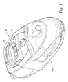
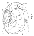
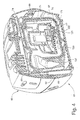
- the illustrated apparatus comprises a flow generator 50 and a humidifier 150, shown in their assembled condition in Fig. 1 , and separately in Figs. 2 and 3 respectively.
- the flow generator engages with the separable humidifier at an engagement face 52, from which protrudes an air connector 53 for the delivery of air from the fan to the humidifier container, electrical connectors 54 for the delivery of power to the humidifier heater and an optical coupling transmitter 200 and sensor 201 described further below.
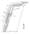
- the face 52 also carries a pair of slots 55 which are engaged by corresponding tongues 156 provided on the humidifier engagement face 157 ( Fig. 15 ) by which the flow generator 50 and humidifier 150 are connected together, as will be described in more detail below.
- the flow generator 50 is also provided with an LCD screen 58 and associated keys 59 by which the user can set the operating parameters of the unit.
- the flow generator 50 has an external case of rigid plastics material moulded in two parts, a top case 60 and a bottom case 61.
- the lower edge of the top case 60 is stepped and flanged at 62 ( Fig 9 ) to mate with the periphery of the bottom case 61.
- the bottom case 61 of flow generator 50 has a shell 120 of rigid plastics material, such polycarbonate/ABS blend, forming the structure of the case, integrally overmoulded with a lining 121 of an elastomer such as a synthetic rubber or thermoplastic elastomer which forms the seal 63 between the top and bottom cases and the chassis 64 and also forms the external feet of the case (see Fig. 6 ).
- a shell 120 of rigid plastics material such polycarbonate/ABS blend
- the lining 121 also covers the internal surface of the chassis-receiving cavity of the bottom case and the dividing wall 123 between the power supply cavity 65 and chassis-receiving cavity, the resulting composite of the rigid shell with elastomeric lining serving to reduce radiated noise levels from the flow generator by damping acoustic resonance of the walls.
- a power supply cavity 65 and a first muffler cavity 134 Formed in the bottom case 61 by walls which join the outer wall of the case are the lower parts and of, respectively, a power supply cavity 65 and a first muffler cavity 134.
- the upper parts of these cavities are formed by the chassis 64, described below.
- the first muffler cavity forms part of the air flow path from the air inlet 85 to the blower, receiving air from an air inlet path defined by the chassis 64, as described below.
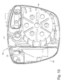
- the chassis 64 forms the blower or fan cavity 70, inlet and outlet air flow paths and the top of the power supply cavity 65.
- the fan cavity 70 includes a metal liner tub 73 insert moulded into the chassis as described below.
- the chassis 64 is formed with a peripheral wall 69 flanged around its lower edge to engage with the inner periphery of the overmoulded sealing flange 63.
- the chassis 64 includes a downwardly extending fan cavity 70 in which is mounted the fan 90 described below.
- This cavity 70 is formed by moulded side walls 71 and base 72, which are formed by moulding inner and outer layers of thermoplastic around an inserted steel liner tub 73.
- the tub may be stainless steel, nickel plated mild steel or other suitable corrosion resistant metal.
- the fan cavity 70 opens to the upper surface of the chassis 64 to enable insertion of the fan 90, this opening being closed by a lid 74.
- the density and stiffness of the steel tub creates a highly effective barrier to transmission of the motor and fan noise, while formation of the cavity 70 by insert moulding from differing materials provides very effective acoustic damping, as does the combination by co-moulding of the hard and soft plastics described already and further described below.
- the use of co-moulding or overmoulding in the combination of materials of different, preferably widely different, stiffness and different, preferably widely different, density has been found to be particularly advantageous in providing acoustic damping.
- Preferred materials for the chassis and liner tub are polypropylene thermoplastic for the chassis and metal, preferably steel (optionally stainless steel), for the liner tub.
- the applicant has found that by forming the fan cavity as a composite of metal and polymer - having a differential in density of greater than 5 times, preferably about 7-8 times, and also significantly different stiffness and damping properties - the resonance peaks of the composite structure are well damped so that noise generated by the fan is well-suppressed by the fan cavity construction.
- the polymer for the chassis 64 be a glass fibre-filled polymer containing from 10-40%, and more preferably about 30%, glass fibre.
- the use of this material as a composite with a steel liner tub 73 gives both effective damping of fan noise and a good match in thermal expansion characteristics so that the composite material chassis performs well over a wide range of operating temperatures. Further, the Applicant has found that the use of glass fibres outperformed talc, bronze, glass bead filler materials for this purpose.
- the top of the fan cavity is formed by the chassis lid 74, which is formed of an embedded steel insert overmoulded with elastomer to provide acoustic damping and sealing of the top of the fan cavity 70
- a preferred polymer lining for the lid is an elastomer, for example of the same type used for the lining 121 of the bottom case.
- the interior is at the same time acoustically sealed from the power supply cavity, which may not be completely sealed from the exterior, due to the necessity of providing mains power input and low voltage power output to the humidifier, via connectors 77 and 79 mounted in apertures 78 and 80 respectively in the rear and front walls of the cavity, and if necessary the venting of the compartment to outside air for cooling. This reduces assembly time and allows the overall device to be smaller.
- a power supply unit 124 is received in the power supply cavity 65, for providing electrical power for operation of the fan, control functions and the humidifier heater pad.
- the power supply comprises a printed circuit board 133, to which are directly attached by soldering or other suitable means a power inlet connector 77, a fan power outlet connector 126 for the fan motor and a humidifier power outlet 79.
- Each end of the power supply cavity 65 has mounting guides 136 for supporting the PCB of the power supply in an upright position so that installation of the power supply is achieved by drop-in assembly.
- the fan 90 and fan housing 93, 94 fit into the fan cavity 70 of the chassis and connect to electrical connector 26 at the top of the power supply PCB. Elastomer overmoulding of the base 94 of the fan housing seals the housing, provides acoustic damping of the fan housing base and forms feet on the bottom of base to act as bump stops protecting the fan in case the unit is bumped or dropped.
- a printed circuit board 81 carrying the electronic control components of the unit.
- the printed circuit board 81 preferably includes an LCD display 58.
- an edge connector 1082 and a sliding connector 1082A may be accessible from a connector aperture in the rear of the case 60, providing for modular connector arrangements to be described in more detail below with reference to Figs 25 to 34 .
- an air inlet 84 is also provided in the rear wall of the top case, and this communicates with an air inlet passage 85 formed in the chassis above the roof of the upper portion of the power supply cavity 65, this passage in turn opening to first muffler cavity 134 surrounding the bottom of the fan cavity of the chassis.
- the top case further defines an air inlet to the flow generator, and has a replaceable filter 129 of any suitable material, such as foam or fibre, and filter cover 130 fitted to the top case 60.
- An inlet wedge 131 serves as an airflow guide.
- a blank cover 132 clips in place over apertures in the case which align with connectors 1082, 1082A to provide ports on the PCB for communications, etc. Further details of the communications and/other electrical ports in the flow generator case will be described later with reference to Figs. 25 to 34 .
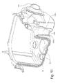
- connection passage 137 ( Fig. 11 ) into a second muffler volume formed by the space between the fan cavity 70 and the fan.
- the fan cavity and the space between the bottom case and the chassis thus form a pair of serially connected volume mufflers, with a restricted diameter passage therebetween.
- Noise attenuation produced by a muffler system is generally proportional to the ratio of a representative diameter of the muffler volume to that of the constriction, and thus an optimal muffler design must balance optimal noise attenuation against the constraints of available muffler volume - especially in a compact machine - and avoiding unacceptable air flow restriction through the constriction.
- the Applicant has found that a favourable adjustment of this balance may be achieved by forming the intermediate connecting passage 137 between the muffler volumes as a venturi, as shown in Figs. 10 and 11 , with a relatively short, smoothly varying diameter lead in portion 137a at the end adjacent the first muffler, an intermediate constriction 137b and a gradually expanding lead out portion 137c at the downstream end.
- the muffler system can achieve the noise attenuation according to the representative diameter of the smallest diameter portion, with better pressure drop characteristics.
- the fan 90 comprises a motor 91, preferably brushless DC motor, provided with a coaxial impeller 92, mounted vertically within a fan housing consisting of a cover 93 and a base 94.
- An air inlet 95 is provided in the floor of the base 94 on the impeller axis, and cavities in the cover and base form a volute 96 which leads from the impeller to an air outlet 97.
- the cover and base 93 and 94 are joined by means of slotted tabs 98 which extend upwardly from the base to snap over stepped ribs 99, the tabs 98 being further located by fitting between parallel ribs on the cover 93.
- the joint between the cover 93 and the base 94 is sealed by an elastomeric over- or co-moulded sealing ring 101.
- the bottom surface of the fan housing base 94 is provided with radial stiffening ribs, and overmoulded to the base 94 is an elastomer damping member 103 which covers that bottom surface between the ribs, and extends around the edge of the base by a flange portion and peripherally spaced tabs.
- an elastomer damping member 103 which covers that bottom surface between the ribs, and extends around the edge of the base by a flange portion and peripherally spaced tabs.
- feet 106 Moulded integrally with the rigid plastics portion of the fan housing base are feet 106 which extend proud of overmoulded elastomer member 103 to receive helical mounting springs 102 ( Fig. 13 ), preferably of metal, by which the fan is mounted on the base 72 of the fan cavity.
- the degree of size reduction which is an objective of the present invention requires great care to be taken to minimise the transmission of noise and vibration, particularly from the motor and the impeller of the fan 90.
- the mounting springs are therefore chosen to ensure minimal transmission of the vibration frequencies encountered during operation. This is achieved by choosing the springs with reference to the mass of the fan 90, such that the natural frequency of the system comprising the springs and the fan is less than approximately one tenth of the shaft speed of the motor when running at its lowest operating speed.
- the air outlet 97 upon the introduction of the fan into the fan cavity, is connected by means of a thermoplastic elastomer or silicone rubber coupling member 108 with an air passage which extends from the side wall of the fan cavity to a connecting nozzle 110 extending through an aperture provided for this purpose in the front face of the flow generator.
- the coupling member 108 includes at least two corrugations which provide flexibility to the connection and improved resistance against transfer of vibration from the fan to the flow generator case.
- the fan 90 therefore floats within its cavity 70 in the chassis 64 with minimum acoustic coupling to the remainder of the flow generator.
- the characteristics of the mounting springs and the coupling member 108 are chosen to minimise the transmission of characteristic vibration frequencies of the fan.
- the illustrated flow generator construction and materials combinations are adapted to result in a compact CPAP flow generator unit of similar performance and noise characteristics to larger units - eg. capable of generating from 4-20cmH20 pressure and a flow rate of 120 L/min and a total radiated noise volume of less than 33dbA, more preferably less than about 30dbA, when operating at 10 cmH20 - in a flow generator unit having a total volume of about 2 litres or less.
- the handle 128 has opposed arms with inwardly projecting pins 140 at their distal ends.
- the top case 60 includes a pair of channel-shaped tracks 141 with one open and one closed end, for receiving respective of the pins. To assemble the handle to the top case, the pins are inserted from the open ends of their respective channels and slid toward the closed ends.
- the facia 127 clips onto the top case 60, and includes projections 142 which trap the pins 140 in the end of their tracks 141.
- the handle attachment configuration thus provides a quick and simple means of assembly without requiring flexing of the handle arms to locate the pins into small recesses as in the prior art.
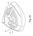
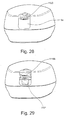
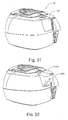
- the humidifier 150 comprises a base unit designed for simple attachment to and detachment from the flow generator 50, which forms a cradle for a water container which is in turn attachable to and detachable from the base unit.
- the general arrangement of the humidifier components includes a base (rear cover 803 and front cover 602) onto which is fitted a heater comprising a heater plate (plate 632 with ceramic heater pad 800) which supports a water tub (tub base 698, seal 699 and tub lid 700) and a hinged humidifier lid 648 which seals against the tub lid 700 to form an air path into the tub through the tub lid.
- a heater comprising a heater plate (plate 632 with ceramic heater pad 800) which supports a water tub (tub base 698, seal 699 and tub lid 700) and a hinged humidifier lid 648 which seals against the tub lid 700 to form an air path into the tub through the tub lid.
- the rear face of the base has a peripheral flange 153 which seats in a corresponding peripheral recess 113 surrounding the front face of the flow generator 50 when the two units are brought together by linear movement towards each other.
- a latch 404 is held in place by latch retainer 404a to be moveable vertically and resiliently urged downwardly by spring 404b, so that the tongues 156 engage in the slots 55 and snap home to engage the two units by means of the downwardly extending fingers 158 at the ends of the tongues.
- the PCB of the flow generator is provided at the end adjacent the humidifier with an optical transmitter 200 which emits a periodic flash of light from the end face of the flow generator case, and an optical sensor 201 to detect the presence or absence of the humidifier.
- the rear face of the humidifier contains a curved reflector 202 which, when the humidifier is attached to the flow generator, completes an optical path from the transmitter to the sensor so that the flow generator PCB detects the presence of the humidifier and may adjust the control algorithms accordingly.
- the rear face of the base unit also carries a connector 162, in this embodiment a pair of flat male blade connectors, for engagement with a mating connector 114 on the front face of the flow generator, to provide power to the humidifier heater from the power supply in the power supply cavity 65.
- the respective faces may also carry further interconnecting devices, where other electrical or data connections are required to be established between the flow generator and the humidifier or downstream devices including the air conduit or the mask. Such devices may take the form of optically coupled devices, or connectors of other suitable kinds.
- an opto-coupling connector enables the implementation of a simple protocol for communications between the flow generator and the humidifier. For example, the current flow levels of the flow generator can be sent to the humidifier controller which then adjusts the operation of the humidifier according to a predetermined algorithm.
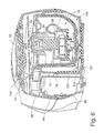
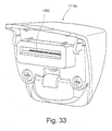
- the back cover 803 which fits to the rear of the front cover 602 provides the air, electrical and communications connections to the flow generator and provide support for a control PCB 804 and the catch assembly.
- the catch assembly includes a latch 404 which is retained by a latch retainer 404a and spring 404b, and operates to attach the humidifier to the flow generator generally as described for the earlier embodiments.
- a control knob 805 on the top of the front cover 602 is connected to the PCB 804 to allow patient control over the degree of humidification.
- an aperture 264 for electrical connections between the humidifier and the flow generator, or for electrical and signal connections to the humidifier.
- the air port 807 in the humidifier rear face mates with the outlet 110 of the flow generator.
- An elastomer airway seal 722 fits between the front and back covers to connect the air port 807 in the back cover 803 to the aperture 626 of the front cover 602.
- the seal (shown in more detail in Figure 16 ) has an inlet connector portion 722a which connects to the flow generator output via the air port 807 formed in the back cover 803, and a peripheral seal portion 722b which extends about the aperture 626 periphery at the front face of the cover 602.
- a wall portion 722c of the seal closes off a lower part of the aperture 626, leaving a smaller aperture 722d defined by the seal.
- the airway seal 722 defines a closed passage from the circular air port 807 to the rectangular aperture 722d in the vertical wall of the front cover.
- the heater pad comprises lower and upper parts 806, 800 and a heater pad cover 632.
- the heater pad cover 632 has an upper heating surface 634, a downwardly extending peripheral wall 636 acting as a further heating surface and a rear flange with a pair of attachment portions 640 for attachment of the heater pad to tubular protrusions 628 on the rear of the front cover 602.
- the heater pad cover 632 is configured to accommodate, below the upper wall 634 and within bounds of the wall 636, a heater pad or other heating means such as an induction heater, for causing heating of the water in the humidifier water container.
- the front of the heater pad cover 632 has a forwardly extending tab 646 of dog-legged shape, which extends to the front of the humidifier cradle front cover 632 to support the heater and also provide a catch for the humidifier lid 648.
- the water container consists of a water tub 698, seal 699 and tub lid 700.
- the floor of the tub 698 is of complementary shape to the heater pad, and is formed of metal or other material suitable to conduct heat from the heater pad to the water in the tub.
- the floor has a generally horizontal portion 900 corresponding to the upper heating surface 634 of the heater pad and a U-shaped portion below the level of the heater pad upper surface, including a generally vertical heat transfer portion 902 below the horizontal portion corresponding to the peripheral heating surface.
- the rear surface of the tub lid has an air inlet aperture 801 leading to an inlet end of the U-shaped air passage 718.
- the tub 698 and tub lid 700 are pressed rearwards so that the peripheral seal 722b abuts the rear surface of the tub lid in a locus surrounding the rear opening of the inlet aperture 801, creating a sealed air path from the flow generator outlet to air passage 718 and into the headspace of the humidifier tub. This allows the humidifier tub to be removed for refilling and replaced without the need for a separate operation to connect the air flow.
- the inside wall of the tub lid 700 has projections 802a, 802b which serve to limit the press fitting of the tub lid onto the tub base 698.
- One projection 802a is provided at the front of the tub, and further projections 802b, or sets of projections, are provided on opposed side walls of the tub lid, forward of the rear of the tub.
- This positioning of the projections 802b allows one-handed disengagement of the tub base and tub lid by squeezing together of the base and lid at their rear end, causing the connection to pivot about the side projections 802b and the tub and lid to separate at the front.
- the ability to separate these components one-handed is a feature of considerable utility, especially for stroke patients or other users with limited dexterity.
- the water container lid 700 has an air passage 718 formed as a U-shaped channel, leading to the humidified air entry aperture 720 into the headspace of the water container.
- the channel floor slopes down in the direction of air flow from the air inlet end to the end at which the air enters the water container.
- the water container lid also has an elliptical humidified air exit aperture 722. These air passages and apertures co-operate with the humidifier lid 648 when closed to define the air flow paths within the humidifier, as will be described below.
- Water may be added to the water container via the air exit aperture 722 while the tub lid is in place, or by removing the tub lid.
- the tank is intended to be filled via the air outlet 722, and the apparatus may be provided with a filling bottle with a spout dimensioned for a convenient fit with that outlet.
- a filling bottle with a spout dimensioned for a convenient fit with that outlet.
- Such a bottle may be provided with a spout of the kind incorporating an air bleed passage which will allow the tank to fill to the correct predetermined height.
- filling arrangements may be employed, for example by removing the tub lid.
- the correct filling height may also indicated by filling level graduations scribed or otherwise marked on the wall of the water tub.
- a microswitch (not shown) or other sensing means may be provided to turn off power to the heater pad when the lid is opened, and/or when the water container is removed.
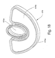
- Figures 17 to 19 show the underside of the humidifier lid 648 and the seal 676 which provides a seal to the tub lid 700 about the U-shaped passage 718 and the humidified air exit aperture 716.
- the seal 676 comprises an edge seal portion 676a and membrane portion 676b, as shown in Figures 18 and 19 .
- the lid 648 has an upper wall 650 and a front wall 652 which extends downwards, and outwardly, from the upper wall.
- the upper wall 650 has a recess at its rear side, such that the part of the upper wall and front wall 652 on each side of the recess constitutes a rearwardly projecting arm 656.
- the hubs 658 are configured to be received in the sockets 622 of the humidifier front cover 602 such that each hub and its corresponding socket constitute a hinge connection, for attaching the lid 648 to the front cover.
- the lid 648 During opening of the lid 648, it may be freely rotated about the hubs through greater than 90° until it reaches a maximum extent of normal travel.
- the lid and front cover are configured such that, if the lid is then rotated further, the hubs pop out of the sockets 622. This may be achieved, as would be understood by a person skilled in the art, by providing suitable chamfers on the hubs and/or sockets, or other suitable formations on the lid or cover, so that the lid flexes to release the hubs from the sockets.
- each arm 656 is shaped complementarily to the shape of the upper portion of the face of the front cover to accommodate that part of the arm when the lid 648 is in a closed position.
- the lid 648 includes a humidified air outlet pipe 662 which passes through the upper wall 650 and extends upwards and forwards at an acute angle from the top of the upper wall, for attachment of a hose to supply humidified air to a patient.
- the pipe 662 continues below the lower surface of the upper wall 650 to define an elliptical rim 664.
- a wall 666 Extending downwards from the lower surface of the upper wall 650 is a wall 666 which is configured to define a closed path and hence a U-shaped enclosed region 668 within the confines of the wall.
- a recessed notch 674 on the rear (inner) surface of that wall, for snap-fit engagement with the tab 646 of the heater pad cover to act as the catch for the lid.
- the lid may be opened by flexing the assembly to release the tab from the notch.
- the edge seal portion 676a of the lid seal includes a channel 676c which fits over the wall 664 and rim 666 on the bottom of the lid 648, and a curved sealing flange 676d which seals against the top surface of the tub lid, so that the space between the U-channel 718 on the tub lid and the seal membrane forms an inlet air passage of the tub, and the air outlet aperture 722 of the tub lid communicates via the elliptical opening 676e in the lid seal to the air outlet pipe 662 of the humidifier lid 648. This is achieved without the need to connect and disconnect air tubes to remove the water container.
- the air from the flow generator passes into the water container, the air then travels across the surface of the water so that the air becomes humidified.
- the heating of the water by the heating pad enhances this humidification.
- the air then exits the water container through the outlet opening 716 to the air outlet pipe 662, which is in turn attached to a suitable hose (not shown) for supplying the humidified air to a patient.
- the air mass within the container is caused to swirl and thus enhance the uptake of water vapour from the water contained in the tub.
- the enhanced uptake of water vapour achieved by inducing the swirling of air as it passes through the tank enables, in an alternative embodiment, the elimination of the heating of the water in the tub.
- the heating element and its controls, and the heat transfer components including the heating plate and the metal tank base are eliminated, and the humidifier becomes a simpler, passive, device.
- a humidifier assembly has a number of advantages over the prior art.
- One advantage relates to convenience of use. Convenience of use is important for all patients, especially those who have poor dexterity.
- the base of the humidifier assembly includes a generally "negative" U-shaped channel.
- the bottom portion of the water tub has a corresponding "positive" U-shape.
- the outer wall of the U-shape is sloping, whereas the inner wall is generally vertical. Because the base and water tubs have complementary configurations, placing the water tub generally in the correct position means that it will to some extent self- align into the correct position, which as described below, is a sealing position.
- a water tub according to the present design can be easily placed in a sealing position without requiring a patient to connect small fiddly tubes such as used in the prior art.
- An aspect of this is that a seal is provided by placing a generally flat surface such as the rear of the water tub, or the top surface of the water tub, against respective silicone gaskets that present a corresponding flat surface. The respective seals are formed when the two flat surfaces contact.
- the humidifier assembly has a very convenient "drop-in" configuration.
- the water tub is held in position by the simple motion of swinging the pivoting lid through approximately 90° from fully open to closed.
- the lid is locked in position via a robust mechanism which provides and audible and reassuring "click"-sound when engaged. Whilst in the preferred embodiment, a pivoting movement is used for the lid, other movements are contemplated including sliding and translation.
- the lid of the humidifier assembly includes an air delivery tube connector, which in a preferred form is generally cylindrical. Connection of the air delivery tube to the lid can be achieved regardless of whether the water tub is in position. This arrangement means that the water tub can be removed and refilled with water if necessary without requiring disengagement of the air delivery tube from the humidifier assembly.
- the illustrated humidifier construction provides a compact humidifier adapted for ease of manufacture and use, and further provides protection against backflow of water into the flow generator when the humidifier and flow generator units are assembled together.
- Backflow protection is provided by the sloping floor of the air passage and the location of the air inlet aperture 801 and the aperture 722d in the seal 722 relative to the air inlet 720 from the air passage 718 into the headspace of the humidifier tub 698.
- the tub is overfilled while in its horizontal position, the water will flow back along the U-shaped air passage 718 only as far as its forwardmost portion, which has a front wall 717 lower than the air inlet aperture 801, and will drain towards the front of the machine.
- the water will be prevented from flowing back along the air passage from the tub to the air inlet 801 as the intermediate portion of the air passage 718 will be above the level of the aperture 720. The water will then flow back into the tub once the machine is righted.
- either the air inlet aperture 720 or the air inlet 801 will be above the water level and thus water should not flow back into the low generator. Again, any water which escapes the tub will flow back into the tub once the machine is righted.
- a non-return valve at an appropriate point, for example a flexible membrane supported in the mouth of the humidifier air inlet.
- the contour of the lid seal is adapted to collect condensation which may form in the lid cavity and the headspace of the water receptacle, preventing backflow of this condensation to the flow generator when the lid is opened.
- the configuration of the front and back covers of the humidifier and of the heater pad is adapted to allow fitting together in a vertical orientation, to minimise the need for reorientation during assembly of the humidifier unit on the production line.
- the resilience of the connection between the lid and the water receptacle, provided by the lid seal is adapted to maintain downwards pressure on the water receptacle when the lid is closed, to maintain good heat-transfer contact between the base of the water receptacle and the heater pad without the added complexity and expense of spring-loaded mounting of the heater pad.
- the humidifier is provided with a control knob allowing adjustment of the humidity of the air supply to the patient.
- the control knob may have a smoothly variable control, or a series of discrete humidity settings, and will have an 'off setting where no power is supplied to the heating pad.
- the correlation between the humidity setting and the power to the heater is controlled by a circuit on the PCB 804.
- Fig. 22 is a sketch of a preferred calibration curve of target water container temperature (y axis) against humidity setting (x axis), including upper and lower tolerances.
- the heater control selects a very low target heater temperature - less than ambient temperature, and preferably lower than the lowest operating temperature of the humidifier. In this way, the heating is turned off when the control knob is in its off position, while allowing use of a less expensive potentiometer without an integral off switch or a separate on/off switch.
- the mounting of the control knob mechanism may provide a tactile 'click' at the off position of the control knob, to confirm to the user that the heater is turned off.
- Fig 23 is a circuit diagram of the humidifier control circuit for controlling the water temperature, including a potentiometer POT1 actuated by the control knob 805 and an operational amplifier OA1 providing power to the heater 800.
- the potentiometer is used in the control path of a semiconductor arrangement to set the operating temperature. This substantially reduces the current through the potentiometer because the potentiometer now only carries a semiconductor control current rather than the load current required to drive the heater element.
- the potentiometer is used in conjunction with a temperature sensing element to control an operational amplifier which drives the heater directly or through a high current semiconductor switch.
- Figure 23 shows an arrangement for controlling temperature via an operational amplifier OA1.
- the operational amplifier n1 has a pair of inputs, V+ being an adding input and V- being a subtracting input.
- the output of the amplifier is proportional to the difference between the voltages on the inputs V+ and V-.
- the temperature of the water is sensed by temperature sensitive resistive element, thermistor TH1, and the operating point is set by potentiometer POT1.
- the operational amplifier input V+ is connected to the junction of R106 and thermistor TH1.
- the operational amplifier switching threshold is determined by the ratio of the resistance of the potentiometer POT1 plus resistor R106 to the resistance of the resistance network formed by thermistor TH1 plus resistor R1 in parallel with resistor R10 plus resistor R10 equals the ratio of resistor R17 to resistor R21. That is, the operational amplifier switches when the junction between the thermistor TH1 and resistor R106 crosses over the potential at V-.
- the operational amplifier is powered from supply points Vss and Vo, so the drive current does not pass through the potentiometer.
- Vss may be the same as Vs
- Vo may be the same as 0v.
- the operational amplifier may drive the heater element directly or it may control a power transistor which drives the heater element.
- This arrangement significantly reduces the dissipation through the potentiometer, allowing a smaller potentiometer, with smaller cooling needs, to be used.
- the arrangement is also well adapted for use in implementing the 'soft' off setting arrangement described above with reference to Fig. 22 .
- Fig. 24 is a flowchart of a Reminder menu to set a number of reminders to alert the patient to specific events; for example, when to replace their mask, when to insert a Data Card (if their device is Data Card enabled) and so on. It can also be used to set special customised reminders.
- a reminder When a reminder is due, a message is displayed on the LCD and remains whenever the device is not delivering therapy.
- the backlight on the LCD flashes when a message is displayed. If more than one reminder for a patient is scheduled for the same date, all scheduled reminders are displayed during that day.
- a patient can clear a message by pressing the LEFT key (or inserting a Data Card, in the case of the Data Card reminder).
- the default setting for all reminders is that they are disabled.
- the patient enters the Reminder Menu from the standby screen by pressing LEFT and DOWN for at least three seconds.
- REPLACE MASK - to set a timed reminder to remind a patient when they need to replace their mask.
- the patient can press the LEFT (clear) key to remove the message from the LCD.
- CALL PROVIDER to set a reminder for the patient to phone the therapist at a certain time; for example,to discuss how their therapy is going.
- the patient can press the LEFT (clear) key to remove the message from the LCD.
- INSERT CARD - if a patient's flow generator is Data Card enabled, the therapist can set a timed reminder on the flow generator to remind them that they need to insert a Data Card to transfer patient data. This enables the therapist to establish compliance. The patient should actually insert the Data Card in order to clear the message from the LCD. (They can also press the LEFT (clear) key to remove the message.)
- REPLACE FILTER - to set a timed reminder to remind the patient when to replace the air filter.
- the patient can press the LEFT (clear) key to remove the message from the LCD.
- Figs. 25 to 32 are rear views of the flow generator, showing various forms of modular data connections foreshadowed earlier, utilising the slot 83 in the rear of the flow generator housing.
- the slot 83 is provided in the wall of a rectangular recess 1115.
- An arcuate depression 1123 is provided in the upper surface of the unit above the recess 1115 to facilitate removal of closure elements from the depression, as described below.
- an edge connector 1082 and a sliding connector 1082A are aligned with and accessible through the connector slot 83 in the rear of the case 60, providing for the modular connector arrangements to be described in more detail below.
- the slot 83 is closed off by a blank closure element 132, shaped to fit into the recess 1115.
- the closure element is shown in more detail in Fig. 27 . This element snaps into the recess by means of lower tabs 1118 and an upper tab 1119 which fit corresponding depressions such as 1122 in the walls of the recess 1115, to close the slot 83 and conform to the contours of the surrounding surface of the unit.
- Complementarily shaped closure elements can be provided for the reception of different kinds of data devices. Shown in Fig. 28 is an element 1116a provided with a slot for the reception of a smart card 1120.
- the element 1116a or the printed circuit board itself may carry the necessary smart card socket.
- a closure element 1116b provided with a DB type data socket.
- the element 1116b is contoured to provide a lower front recess 1121 to facilitate gripping of the associated plug.
- a cross-section of a modified form of this arrangement is shown in Fig. 29A , illustrating the connection between the internal connector 1086 of the element 1116b and the edge connector 1082 of the PCB, and the external DB9 connector 1088.
- element 1116 can be provided to enable the connection of devices such as memory cards and pre-programmed devices as required.
- This facility furthermore enables a wide range of devices to be integrated with the apparatus in modular fashion, for example a clock display which may utilise the system clock contained in the flow generator controller, a voice activation unit, oximetry, ECG and other diagnostic aids, a sound recorder, a light.
- Figs. 30 to 32 are a series of rear perspective views of the flow generator, illustrating one embodiment of the modular data connector arrangement.
- Fig. 33 shows the front, inner surface of the USB closure element module, and
- Fig. 34 is a vertical cross-section of the flow generator.
- Fig. 30 shows the slot 83 open, exposing the edge connector 1082 and sliding connector (not visible in this view) at the rear of the flow generator PCB 81.
- the connectors 1082, 1082A comprise a plurality of electrical contacts for carrying data and/or power between the PCB and an external device.
- Fig 31 shows the arrangement of Fig. 31 where no data connection is required, with the slot covered by a blank closure element 132 generally as described above with reference to Figs 25 to 27 .
- Fig. 32 shows a removable closure element module 1116c carrying a standard universal serial bus (USB) port 1084 on its rear surface.
- the element 1116c incorporates an electrical/data pathway to an electrical connector 1090 at its forward, inner surface ( Figs. 33 and 34 ) adapted to connect with all or selected ones of the contacts of the PCB connector 1082 for electrical and/or data transmission.
- the closure module 1116c has internal electrical components completing a data and/or electrical pathway between its internal and external connectors so that the module acts as an adaptor between the PCB connector and a standard USB port.
- the cost and size of the flow generator unit may be reduced as the unit may be provided with only those connectors which are needed by that patient, and additional connector modules supplied only if the need arises. Furthermore, the arrangement facilitates upgrade of the data connection arrangement of the flow generator to keep up with technological advances or changes in global data connection standards.
Priority Applications (2)
| Application Number | Priority Date | Filing Date | Title |
|---|---|---|---|
| EP20150201.0A EP3695870A1 (en) | 2003-06-20 | 2004-06-21 | Breathable gas apparatus with humidifier |
| EP14200112.2A EP2910271B8 (en) | 2003-06-20 | 2004-06-21 | Breathable gas apparatus with humidifier |
Applications Claiming Priority (4)
| Application Number | Priority Date | Filing Date | Title |
|---|---|---|---|
| AU2003903139A AU2003903139A0 (en) | 2003-06-20 | 2003-06-20 | Breathable gas apparatus with humidifier |
| AU2003905136A AU2003905136A0 (en) | 2003-09-22 | Breathable Gas Apparatus with Humidifier | |
| AU2004901008A AU2004901008A0 (en) | 2004-02-27 | Breathable Gas Apparatus with Humidifier | |
| EP04737434A EP1648544B1 (en) | 2003-06-20 | 2004-06-21 | Breathable gas apparatus with humidifier |
Related Parent Applications (2)
| Application Number | Title | Priority Date | Filing Date |
|---|---|---|---|
| EP04737434.3 Division | 2004-06-21 | ||
| EP04737434A Division EP1648544B1 (en) | 2003-06-20 | 2004-06-21 | Breathable gas apparatus with humidifier |
Related Child Applications (3)
| Application Number | Title | Priority Date | Filing Date |
|---|---|---|---|
| EP14200112.2A Division-Into EP2910271B8 (en) | 2003-06-20 | 2004-06-21 | Breathable gas apparatus with humidifier |
| EP14200112.2A Division EP2910271B8 (en) | 2003-06-20 | 2004-06-21 | Breathable gas apparatus with humidifier |
| EP20150201.0A Division EP3695870A1 (en) | 2003-06-20 | 2004-06-21 | Breathable gas apparatus with humidifier |
Publications (3)
| Publication Number | Publication Date |
|---|---|
| EP2392375A2 EP2392375A2 (en) | 2011-12-07 |
| EP2392375A3 EP2392375A3 (en) | 2013-07-10 |
| EP2392375B1 true EP2392375B1 (en) | 2016-01-06 |
Family
ID=42357983
Family Applications (3)
| Application Number | Title | Priority Date | Filing Date |
|---|---|---|---|
| EP14200112.2A Active EP2910271B8 (en) | 2003-06-20 | 2004-06-21 | Breathable gas apparatus with humidifier |
| EP20150201.0A Withdrawn EP3695870A1 (en) | 2003-06-20 | 2004-06-21 | Breathable gas apparatus with humidifier |
| EP11175449.5A Active EP2392375B1 (en) | 2003-06-20 | 2004-06-21 | Breathable gas apparatus with humidifier |
Family Applications Before (2)
| Application Number | Title | Priority Date | Filing Date |
|---|---|---|---|
| EP14200112.2A Active EP2910271B8 (en) | 2003-06-20 | 2004-06-21 | Breathable gas apparatus with humidifier |
| EP20150201.0A Withdrawn EP3695870A1 (en) | 2003-06-20 | 2004-06-21 | Breathable gas apparatus with humidifier |
Country Status (9)
| Country | Link |
|---|---|
| US (18) | US8020551B2 (ja) |
| EP (3) | EP2910271B8 (ja) |
| JP (17) | JP4865545B2 (ja) |
| CN (6) | CN102784432B (ja) |
| AT (1) | ATE517649T1 (ja) |
| CA (5) | CA2753378C (ja) |
| DE (6) | DE202004021795U1 (ja) |
| ES (1) | ES2559015T3 (ja) |
| NZ (8) | NZ573227A (ja) |
Families Citing this family (178)
| Publication number | Priority date | Publication date | Assignee | Title |
|---|---|---|---|---|
| DE10082260B4 (de) | 1999-08-05 | 2017-09-14 | Resmed R&D Germany Gmbh | System mit einer ersten Vorrichtung zur Zufuhr eines Atemgases und einer Befeuchtungsvorrichtung |
| US7588033B2 (en) | 2003-06-18 | 2009-09-15 | Breathe Technologies, Inc. | Methods, systems and devices for improving ventilation in a lung area |
| DE202004021795U1 (de) | 2003-06-20 | 2011-02-10 | ResMed Ltd., Bella Vista | Atemgasvorrichtung mit Befeuchter |
| AU2003903139A0 (en) | 2003-06-20 | 2003-07-03 | Resmed Limited | Breathable gas apparatus with humidifier |
| EP1660004A4 (en) | 2003-08-18 | 2017-05-31 | Breathe Technologies, Inc. | Method and device for non-invasive ventilation with nasal interface |
| LT3766534T (lt) | 2004-08-20 | 2022-10-25 | Fisher & Paykel Healthcare Limited | Prietaisas pacientui tiekiamų dujų savybėms matuoti |
| DE102006034028A1 (de) * | 2005-08-01 | 2007-02-08 | Weinmann Geräte für Medizin GmbH + Co. KG | Vorrichtung zur Beatmung |
| EP1924311B1 (en) | 2005-08-15 | 2015-09-16 | ResMed Ltd. | Humidifier and/or flow generator for cpap device |
| CA2623756A1 (en) | 2005-09-20 | 2007-03-29 | Lutz Freitag | Systems, methods and apparatus for respiratory support of a patient |
| US8997740B2 (en) * | 2005-09-27 | 2015-04-07 | Ric Investments, Llc | Humidifier with back-flow prevention valve |
| JP5132925B2 (ja) * | 2005-12-21 | 2013-01-30 | レスメド・リミテッド | マスク及び人工呼吸器の構成部品の識別システム及びその方法 |
| US20090199857A1 (en) * | 2006-03-01 | 2009-08-13 | Resmed Limited | Method and Apparatus for Reminding user to Replace and/or Service Cpap Apparatus and/or Component Thereof |
| WO2007142812A2 (en) | 2006-05-18 | 2007-12-13 | Breathe Technologies, Inc. | Tracheotomy method and device |
| WO2008019102A2 (en) | 2006-08-03 | 2008-02-14 | Breathe Technologies, Inc. | Methods and devices for minimally invasive respiratory support |
| EP3884985B1 (en) | 2006-11-06 | 2023-06-07 | Fisher & Paykel Healthcare Limited | Assisted breathing unit |
| WO2008144589A1 (en) | 2007-05-18 | 2008-11-27 | Breathe Technologies, Inc. | Methods and devices for sensing respiration and providing ventilation therapy |
| WO2008148154A1 (en) | 2007-06-05 | 2008-12-11 | Resmed Ltd | Electrical heater with particular application to humidification and fluid warming |
| US8365726B2 (en) | 2007-06-07 | 2013-02-05 | Resmed Limited | Tub for humidifier |
| US8356593B2 (en) | 2007-07-18 | 2013-01-22 | Vapotherm, Inc. | Delivery tube for breathing gas heating and humidification system |
| CA2700878C (en) | 2007-09-26 | 2018-07-24 | Breathe Technologies, Inc. | Methods and devices for providing inspiratory and expiratory flow relief during ventilation therapy |
| JP5513392B2 (ja) | 2007-09-26 | 2014-06-04 | ブリーズ・テクノロジーズ・インコーポレーテッド | 睡眠時無呼吸を治療するための方法及び装置 |
| US8905023B2 (en) | 2007-10-05 | 2014-12-09 | Vapotherm, Inc. | Hyperthermic humidification system |
| US8770193B2 (en) | 2008-04-18 | 2014-07-08 | Breathe Technologies, Inc. | Methods and devices for sensing respiration and controlling ventilator functions |
| WO2009151791A2 (en) | 2008-04-18 | 2009-12-17 | Breathe Technologies, Inc. | Methods and devices for sensing respiration and controlling ventilator functions |
| US9505164B2 (en) | 2009-12-30 | 2016-11-29 | Schauenburg Technology Se | Tapered helically reinforced hose and its manufacture |
| DE102008022663B4 (de) | 2008-05-07 | 2012-10-31 | Schauenburg Hose Technology Gmbh | Stretch-Schlauch |
| USD659235S1 (en) | 2008-06-19 | 2012-05-08 | Resmed Limited | Positive airway pressure delivery device |
| US8677999B2 (en) | 2008-08-22 | 2014-03-25 | Breathe Technologies, Inc. | Methods and devices for providing mechanical ventilation with an open airway interface |
| CN109481813B (zh) * | 2008-09-17 | 2022-01-11 | 瑞思迈私人有限公司 | 用于插入到加湿器腔室中的箱和加湿器 |
| US10252020B2 (en) | 2008-10-01 | 2019-04-09 | Breathe Technologies, Inc. | Ventilator with biofeedback monitoring and control for improving patient activity and health |
| US9964238B2 (en) | 2009-01-15 | 2018-05-08 | Globalmed, Inc. | Stretch hose and hose production method |
| US9132250B2 (en) | 2009-09-03 | 2015-09-15 | Breathe Technologies, Inc. | Methods, systems and devices for non-invasive ventilation including a non-sealing ventilation interface with an entrainment port and/or pressure feature |
| CA2757588C (en) | 2009-04-02 | 2017-01-03 | Breathe Technologies, Inc. | Methods, systems and devices for non-invasive open ventilation with gas delivery nozzles in free space |
| US9962512B2 (en) | 2009-04-02 | 2018-05-08 | Breathe Technologies, Inc. | Methods, systems and devices for non-invasive ventilation including a non-sealing ventilation interface with a free space nozzle feature |
| CN102762250B (zh) | 2009-09-03 | 2017-09-26 | 呼吸科技公司 | 用于包括具有夹带端口和/或压力特征的非密封通气界面的无创通气的方法、系统和装置 |
| US9737682B2 (en) * | 2009-09-17 | 2017-08-22 | Resmed Limited | Humidification of respiratory gases |
| AU2011292111B2 (en) | 2010-08-16 | 2015-03-26 | Breathe Technologies, Inc. | Methods, systems and devices using LOX to provide ventilatory support |
| WO2012045051A1 (en) | 2010-09-30 | 2012-04-05 | Breathe Technologies, Inc. | Methods, systems and devices for humidifying a respiratory tract |
| AU2012220358B2 (en) * | 2011-02-25 | 2014-11-06 | Resmed Motor Technologies Inc. | Blower and PAP system |
| CN103442760B (zh) | 2011-04-05 | 2016-10-26 | 瑞思迈有限公司 | 呼吸设备 |
| US9486602B2 (en) | 2011-06-22 | 2016-11-08 | Breathe Technologies, Inc. | Ventilation mask with integrated piloted exhalation valve and method of ventilating a patient using the same |
| US9038634B2 (en) | 2011-06-22 | 2015-05-26 | Breathe Technologies, Inc. | Ventilation mask with integrated piloted exhalation valve |
| US8839791B2 (en) | 2011-06-22 | 2014-09-23 | Breathe Technologies, Inc. | Ventilation mask with integrated piloted exhalation valve |
| CN113007106B (zh) | 2011-07-13 | 2023-08-11 | 费雪派克医疗保健有限公司 | 叶轮和马达组件 |
| US10137264B2 (en) | 2011-07-13 | 2018-11-27 | Fisher & Paykel Healthcare Limited | Respiratory assistance apparatus |
| AU2012292950B2 (en) * | 2011-08-05 | 2015-10-29 | Resmed Motor Technologies Inc. | Blower |
| SE538414C2 (sv) | 2011-08-10 | 2016-06-21 | Fisher & Paykel Healthcare Ltd | Ledningskonnektor för en andningsanordning för en patient |
| US9649459B2 (en) | 2011-09-26 | 2017-05-16 | Resmed Paris Sas | Ventilator apparatus and method |
| US10213573B2 (en) | 2011-12-22 | 2019-02-26 | Resmed Limited | Humidifiers for respiratory apparatus |
| EP2817518B1 (en) * | 2012-02-02 | 2020-05-20 | imtmedical ag | Sound-proofing housing for a respirator |
| GB2500017B (en) | 2012-03-06 | 2015-07-29 | Dyson Technology Ltd | A Humidifying Apparatus |
| GB2500012B (en) * | 2012-03-06 | 2016-07-06 | Dyson Technology Ltd | A Humidifying Apparatus |
| GB2512192B (en) * | 2012-03-06 | 2015-08-05 | Dyson Technology Ltd | A Humidifying Apparatus |
| GB2541550B (en) * | 2012-03-15 | 2017-06-21 | Fisher & Paykel Healthcare Ltd | Respiratory gas humidification system |
| WO2013135318A1 (en) * | 2012-03-15 | 2013-09-19 | Christian Backhaus | Heating apparatus |
| WO2013147623A1 (en) * | 2012-03-30 | 2013-10-03 | Dexter Chi Lun Cheung | Humidification system |
| US20130284176A1 (en) * | 2012-04-03 | 2013-10-31 | Benjamin D. Dickerson | Force gauged continuous positive airway pressure nasal interface |
| US10357629B2 (en) * | 2012-04-05 | 2019-07-23 | Fisher & Paykel Healthcare Limited | Respiratory assistance apparatus |
| GB2575894A (en) * | 2012-04-27 | 2020-01-29 | Fisher & Paykel Healthcare Ltd | Usability features for respiratory humidification system |
| US9993608B2 (en) * | 2012-05-02 | 2018-06-12 | Fisher & Paykel Healthcare Limited | Respiratory humidifier communication systems and methods |
| WO2013171452A2 (en) * | 2012-05-16 | 2013-11-21 | Dyson Technology Limited | A fan |
| GB2518935B (en) * | 2012-05-16 | 2016-01-27 | Dyson Technology Ltd | A fan |
| DE102013014089A1 (de) * | 2012-08-28 | 2014-03-06 | Weinmann Geräte für Medizin GmbH + Co. KG | Vorrichtung zur Anfeuchtung von Atemgas |
| SG10201801980RA (en) | 2012-09-07 | 2018-05-30 | Fisher & Paykel Healthcare Ltd | Humidification chamber for a respiratory assistance apparatus |
| WO2014051436A1 (en) | 2012-09-25 | 2014-04-03 | Fisher & Paykel Healthcare Limited | Lid construction for breathing apparatus |
| CN104902964A (zh) * | 2012-11-27 | 2015-09-09 | 威廉马歇莱思大学 | 气泡式持续气道正压通气 |
| ES2588707T3 (es) | 2012-12-17 | 2016-11-04 | Ivoclar Vivadent Ag | Procedimiento y sistema para la construcción de una prótesis dental |
| AU2013101734A4 (en) | 2012-12-18 | 2015-09-24 | Fisher & Paykel Healthcare Limited | Impeller and motor assembly |
| USD745137S1 (en) * | 2012-12-20 | 2015-12-08 | Koninklijke Philips N.V. | Nebulizer compressor |
| RU2684043C2 (ru) | 2013-01-29 | 2019-04-03 | Дайсон Текнолоджи Лимитед | Вентилятор в сборе |
| US10653855B2 (en) * | 2013-01-30 | 2020-05-19 | Fisher & Paykel Healthcare Limited | Respiratory assistance apparatus |
| US9878121B2 (en) | 2013-03-13 | 2018-01-30 | Breathe Technologies, Inc. | Ventilation mask with heat and moisture exchange device |
| EP3546004B8 (en) * | 2013-03-14 | 2021-12-22 | Fisher & Paykel Healthcare Limited | Medical components with microstructures for humidification and condensate management |
| US20140261419A1 (en) * | 2013-03-15 | 2014-09-18 | Apex Medical Corp. | Water chamber for a respiratory therapy apparatus and a partition of the water chamber |
| WO2014145812A1 (en) * | 2013-03-15 | 2014-09-18 | Human Design Medical, Llc | Portable positive airway pressure apparatus and method for attenuating the noise emitted therefrom |
| EP3881887B1 (en) * | 2013-03-15 | 2023-11-15 | ResMed Pty Ltd | Respiratory pressure therapy device |
| US9861778B2 (en) | 2013-03-15 | 2018-01-09 | Resmed Limited | Humidifier reservoir |
| JP6189073B2 (ja) * | 2013-04-10 | 2017-08-30 | アトムメディカル株式会社 | 呼吸用ガスの加温加湿器 |
| USD738489S1 (en) * | 2013-05-31 | 2015-09-08 | Resmed Limited | Positive airway pressure delivery console |
| USD738488S1 (en) | 2013-05-31 | 2015-09-08 | Resmed Limited | Positive airway pressure delivery console |
| CN113855976A (zh) * | 2013-06-25 | 2021-12-31 | 瑞思迈私人有限公司 | 出气口连接组件及其制造方法 |
| USD730518S1 (en) | 2013-09-12 | 2015-05-26 | Nordson Corporation | Quick connect fluid connector |
| CN108704213B (zh) * | 2013-09-13 | 2021-06-22 | 费雪派克医疗保健有限公司 | 用于加湿系统的连接 |
| USD749721S1 (en) | 2013-11-25 | 2016-02-16 | Avent, Inc. | Base for enteral feeding device |
| EP4173663A1 (en) * | 2013-12-17 | 2023-05-03 | ResMed Pty Ltd | Apparatus for use in treating a respiratory disorder |
| CA2934235C (en) * | 2013-12-20 | 2023-02-28 | Fisher & Paykel Healthcare Limited | Humidification system connections |
| NL1040590C2 (nl) * | 2014-01-07 | 2015-07-08 | Alcmair Partners B V | Leidingsysteem voor een inrichting voor het beademen van patiënten. |
| CN103800982B (zh) * | 2014-01-08 | 2015-12-23 | 北京怡和嘉业医疗科技有限公司 | 用于呼吸机的加湿器以及呼吸机 |
| EP3099366B1 (en) * | 2014-01-30 | 2019-10-30 | Fisher & Paykel Healthcare Limited | Breathing assistance apparatus with liquid containment |
| US10449319B2 (en) | 2014-02-07 | 2019-10-22 | Fisher & Paykel Healthcare Limited | Respiratory humidification system |
| USD743556S1 (en) | 2014-02-19 | 2015-11-17 | Resmed Limited | Positive airway pressure delivery console |
| USD744108S1 (en) | 2014-02-19 | 2015-11-24 | Resmed Limited | Humidifier reservoir for positive airway pressure delivery console |
| US11278698B2 (en) * | 2014-03-04 | 2022-03-22 | Koninklijke Philips N.V. | Blending gas enriched pressure support system and method |
| TWM481735U (zh) * | 2014-03-14 | 2014-07-11 | Lead Data Inc | 加濕裝置及使用其之呼吸設備 |
| USD762843S1 (en) | 2014-03-18 | 2016-08-02 | Resmed Limited | Air delivery tube |
| CN106535976B (zh) | 2014-05-13 | 2019-04-05 | 费雪派克医疗保健有限公司 | 用于呼吸增湿系统的可用性特征 |
| SG11201609863WA (en) | 2014-05-27 | 2016-12-29 | Fisher & Paykel Healthcare Ltd | Gases mixing and measuring for a medical device |
| USD760258S1 (en) | 2014-05-30 | 2016-06-28 | Resmed Limited | Display screen with graphical user interface |
| CN106535971B (zh) | 2014-06-03 | 2020-12-04 | 费雪派克医疗保健有限公司 | 用于呼吸治疗系统的流动混合器 |
| US9316405B2 (en) * | 2014-07-10 | 2016-04-19 | Dana Electronics Co., Ltd. | Cyclone type humidifier and wet air purifier combination device using centrifugal force |
| TW202313137A (zh) * | 2014-09-03 | 2023-04-01 | 紐西蘭商費雪派克保健有限公司 | 呼吸增濕系統及用於呼吸增濕系統的加熱板 |
| USD809124S1 (en) | 2014-09-12 | 2018-01-30 | Resmed Limited | Pressurized air delivery console |
| US11278689B2 (en) | 2014-11-17 | 2022-03-22 | Fisher & Paykel Healthcare Limited | Humidification of respiratory gases |
| CN107106809B (zh) * | 2014-12-18 | 2020-04-21 | 皇家飞利浦有限公司 | 液体腔室分离系统和方法 |
| USD790683S1 (en) | 2015-03-11 | 2017-06-27 | Resmed Limited | Pressurized air delivery console |
| USD774180S1 (en) | 2015-03-12 | 2016-12-13 | Tecmen Electronics Co., Ltd. | Respirator |
| WO2016150373A1 (zh) * | 2015-03-24 | 2016-09-29 | 湖南明康中锦医疗科技发展有限公司 | 一种便携式呼吸机 |
| AU2016242101B2 (en) * | 2015-03-31 | 2020-12-24 | Fisher & Paykel Healthcare Limited | Apparatus for use in a respiratory support system |
| EP3277351B1 (en) | 2015-04-02 | 2019-06-05 | Hill-Rom Services PTE. LTD. | Manifold for respiratory device |
| CN104815373B (zh) * | 2015-04-16 | 2017-10-20 | 北京怡和嘉业医疗科技股份有限公司 | 呼吸机及其功率控制方法和系统 |
| GB2598220B (en) * | 2015-06-24 | 2022-08-10 | Fisher & Paykel Healthcare Ltd | Breathing assistance apparatus |
| GB2540165B (en) | 2015-07-07 | 2019-09-11 | Dyson Technology Ltd | Humidifying apparatus |
| EP4115930A1 (en) * | 2015-07-07 | 2023-01-11 | ResMed Pty Ltd | Respiratory pressure therapy device |
| GB2540164A (en) * | 2015-07-07 | 2017-01-11 | Dyson Technology Ltd | Humidifying apparatus |
| GB2540166B (en) | 2015-07-07 | 2019-06-12 | Dyson Technology Ltd | Humidifying apparatus |
| WO2017029950A1 (ja) | 2015-08-18 | 2017-02-23 | 株式会社村田製作所 | 送風装置 |
| USD798428S1 (en) | 2015-10-07 | 2017-09-26 | Resmed Limited | Positive airway pressure delivery console |
| US10030961B2 (en) | 2015-11-27 | 2018-07-24 | General Electric Company | Gap measuring device |
| WO2017095241A2 (en) | 2015-12-02 | 2017-06-08 | Fisher & Paykel Healthcare Limited | Flow path sensing for flow therapy apparatus |
| USD844787S1 (en) | 2015-12-28 | 2019-04-02 | Resmed Limited | Pressurized air delivery console |
| USD805630S1 (en) | 2016-02-02 | 2017-12-19 | Resmed Limited | Air delivery tube |
| US11000715B2 (en) * | 2016-02-18 | 2021-05-11 | O2-Matic Products Private Limited | Modular portable oxygen generator |
| USD857189S1 (en) * | 2016-03-11 | 2019-08-20 | ResMed Pty Ltd | Battery pack for an air delivery module |
| WO2017192051A1 (en) * | 2016-05-02 | 2017-11-09 | Fisher & Paykel Healthcare Limited | Humidification chamber and chamber seal for a respiratory assistance apparatus |
| CN105823278A (zh) * | 2016-05-25 | 2016-08-03 | 南京天加空调设备有限公司 | 一种变频空调的变频模块的冷却装置 |
| USD864480S1 (en) * | 2016-07-07 | 2019-10-22 | Calor | Water tank for hair straightening apparatus |
| JP2018078996A (ja) * | 2016-11-15 | 2018-05-24 | 日本電産コパル電子株式会社 | Cpap装置 |
| US11351332B2 (en) | 2016-12-07 | 2022-06-07 | Fisher & Paykel Healthcare Limited | Sensing arrangements for medical devices |
| US11400247B2 (en) | 2016-12-22 | 2022-08-02 | Fisher & Paykel Healthcare Limited | Breathing assistance apparatus |
| US11052214B2 (en) | 2017-01-30 | 2021-07-06 | Globalmed, Inc. | Heated respiratory hose wiring |
| CN115154781A (zh) | 2017-04-10 | 2022-10-11 | 株式会社村田制作所 | 送风装置和流体控制装置 |
| EP3615820A4 (en) | 2017-04-23 | 2021-01-06 | Fisher & Paykel Healthcare Limited | BREATHING ASSISTANCE DEVICE |
| CN110944701A (zh) | 2017-05-26 | 2020-03-31 | 费雪派克医疗保健有限公司 | 为呼吸装置供电 |
| CN107226458B (zh) * | 2017-07-24 | 2019-04-12 | 合肥康居人智能科技有限公司 | 一种用于制氧机加湿的装配机构 |
| CN107572759A (zh) * | 2017-09-25 | 2018-01-12 | 宝鸡市永盛泰钛业有限公司 | 一种用于零件加工的缓冲压力模具 |
| US10792449B2 (en) | 2017-10-03 | 2020-10-06 | Breathe Technologies, Inc. | Patient interface with integrated jet pump |
| CN107696366B (zh) * | 2017-11-16 | 2024-03-08 | 宁波圣宇瑞医疗器械有限公司 | 鼻头浸塑模具 |
| CN109854542A (zh) * | 2017-11-30 | 2019-06-07 | 深圳市美好创亿医疗科技有限公司 | 消音管及具有该消音管的呼吸机 |
| USD917039S1 (en) * | 2018-02-01 | 2021-04-20 | Resvent Medical Technology Co., Ltd | Positive airway pressure assembly |
| CA3091961A1 (en) * | 2018-03-07 | 2019-09-12 | Astrazeneca Ab | Inhaler |
| US11338105B2 (en) | 2018-03-27 | 2022-05-24 | Globalmed, Inc. | Respiratory humidification device |
| CN209107206U (zh) * | 2018-03-31 | 2019-07-16 | 天佑电器(苏州)有限公司 | 箱式组合工具 |
| US11376392B2 (en) * | 2018-04-24 | 2022-07-05 | ResMed Pty Ltd | Tub for use in a humidifier |
| CN108434577B (zh) * | 2018-05-02 | 2020-08-11 | 周晓琪 | 一种医用低噪声氧气湿化瓶 |
| CN108815672B (zh) * | 2018-05-02 | 2020-08-11 | 鹤壁市人民医院 | 一种医用静音氧气湿化瓶 |
| CN108688936A (zh) * | 2018-05-29 | 2018-10-23 | 上海鸿研物流技术有限公司 | 一种载具 |
| EP4249029A3 (en) * | 2018-10-26 | 2023-11-15 | BMC Medical Co., Ltd. | Humidification assembly |
| DE102018008493A1 (de) * | 2018-10-30 | 2020-04-30 | Drägerwerk AG & Co. KGaA | Transfereinheit, Beatmungsvorrichtung, Beatmungssystem sowie Verfahren zum Wechsel einer für einen Beatmungsvorgang eines Patienten verwendeten Beatmungsvorrichtung |
| CN109200414B (zh) * | 2018-11-22 | 2024-02-09 | 广东欧格斯科技有限公司 | 一种降噪呼吸机系统 |
| DE102018129612A1 (de) * | 2018-11-23 | 2020-05-28 | Ebm-Papst St. Georgen Gmbh & Co. Kg | Rotorbaugruppe |
| KR102308884B1 (ko) * | 2018-12-13 | 2021-10-06 | 이해곤 | 에어 커튼을 이용한 미세먼지 차단용 마스크 |
| EP3893973A4 (en) | 2018-12-13 | 2022-09-07 | ResMed Pty Ltd | PNEUMATIC BLOCK FOR RESPIRATORY PRESSURE THERAPY DEVICE |
| USD921900S1 (en) | 2018-12-19 | 2021-06-08 | ResMed Pty Ltd | Humidification tub |
| GB201900018D0 (en) * | 2019-01-02 | 2019-02-13 | Dyson Technology Ltd | Air treatment apparatus |
| EP3679839A1 (en) * | 2019-01-14 | 2020-07-15 | Koninklijke Philips N.V. | Steam cooking apparatus |
| US11745033B2 (en) | 2019-03-17 | 2023-09-05 | Brett Patrick | Process and apparatus to preclude unfiltered atmospheric gases and human respiration products including carbon-dioxide with carbon-14 from entering controlled greenhouse atmospheric gases |
| WO2020206002A1 (en) * | 2019-04-01 | 2020-10-08 | Inogen, Inc. | Compact portable oxygen concentrator |
| EP4186552A1 (en) | 2019-04-17 | 2023-05-31 | ResMed Pty Ltd | Cpap system with resilient sealing for heater plate |
| EP3983039A4 (en) * | 2019-06-14 | 2023-07-05 | Fisher & Paykel Healthcare Limited | APPARATUS FOR ADMINISTERING GAS FLOW |
| JP7275977B2 (ja) * | 2019-08-08 | 2023-05-18 | 株式会社村田製作所 | Cpap装置 |
| USD1006981S1 (en) | 2019-09-06 | 2023-12-05 | Fisher & Paykel Healthcare Limited | Breathing conduit |
| USD948027S1 (en) | 2019-09-10 | 2022-04-05 | Fisher & Paykel Healthcare Limited | Connector for a breathing conduit |
| CN110584607A (zh) * | 2019-09-17 | 2019-12-20 | 广州奥滴尔科技有限公司 | 一种作息调节执行装置及实时作息调节系统 |
| WO2021075178A1 (ja) * | 2019-10-17 | 2021-04-22 | 株式会社村田製作所 | 加湿器 |
| JP6667708B1 (ja) * | 2019-10-24 | 2020-03-18 | 日本たばこ産業株式会社 | エアロゾル吸引器の電源ユニット |
| CN112870518B (zh) * | 2019-11-29 | 2022-09-06 | 深圳市大雅医疗技术有限公司 | 水箱组件及呼吸机 |
| US20220065261A1 (en) * | 2019-12-17 | 2022-03-03 | Zhongshan Broad-Ocean Motor Co., Ltd. | Volute assembly and induced draft fan comprising the same |
| WO2021149348A1 (ja) * | 2020-01-24 | 2021-07-29 | 株式会社村田製作所 | Cpap装置 |
| JP7302505B2 (ja) * | 2020-02-27 | 2023-07-04 | 株式会社デンソー | 送風装置 |
| USD940861S1 (en) | 2020-03-03 | 2022-01-11 | Fisher & Paykel Healthcare Limited | Connector for a respiratory system conduit |
| US20230381444A1 (en) * | 2020-10-29 | 2023-11-30 | ResMed Pty Ltd | Assembly for diverting liquid from a respiratory device |
| US20230398318A1 (en) * | 2020-11-03 | 2023-12-14 | ResMed Pty Ltd | Respiratory pressure therapy device |
| USD974551S1 (en) | 2020-12-09 | 2023-01-03 | Fisher & Paykel Healthcare Limited | Connector assembly and connector |
| CN112755347B (zh) * | 2020-12-31 | 2024-04-05 | 东莞永昇医疗科技有限公司 | 一种呼吸机关机控制方法、呼吸机及计算机可读存储介质 |
| CN112843411B (zh) * | 2021-01-12 | 2022-03-11 | 四川大学华西医院 | 一种自动加温加湿的无创呼吸机 |
| USD995758S1 (en) | 2021-06-11 | 2023-08-15 | Fisher & Paykel Healthcare Limited | Tube assembly and connector |
| CN115111198B (zh) * | 2022-06-24 | 2024-05-07 | 大连海事大学 | 一种多翼离心风机的陷窝结构及多翼离心风机 |
| CN117691798B (zh) * | 2024-02-01 | 2024-04-05 | 爱几度(深圳)科技有限公司 | 一种静音电动马达 |
Citations (2)
| Publication number | Priority date | Publication date | Assignee | Title |
|---|---|---|---|---|
| US5735017A (en) | 1996-03-29 | 1998-04-07 | Bissell Inc. | Compact wet/dry vacuum cleaner with flexible bladder |
| WO2002066106A1 (en) | 2001-02-16 | 2002-08-29 | Resmed Limited | Humidifier with structure to prevent backflow of liquid through the humidifier inlet |
Family Cites Families (342)
| Publication number | Priority date | Publication date | Assignee | Title |
|---|---|---|---|---|
| DE275612C (ja) | ||||
| USRE19826E (en) | 1936-01-21 | aisenstein | ||
| US1085833A (en) | 1913-04-17 | 1914-02-03 | Clay Wilson | Inhaler. |
| US1974843A (en) | 1932-11-05 | 1934-09-25 | Scanlan Morris Company | Gas humidifying device |
| US2220669A (en) | 1936-06-26 | 1940-11-05 | Allen Sherman Hoff Co | Impeller for centrifugal pumps |
| US2598978A (en) | 1950-05-29 | 1952-06-03 | Mary De Martin | Bed lamp with alarm clock |
| US2780708A (en) | 1953-06-23 | 1957-02-05 | Blue Ridge Glass Corp | Electric resistance heater |
| US2945619A (en) | 1954-09-21 | 1960-07-19 | Mclure Carl Ballard | Stage expansion reaction turbines |
| US3171353A (en) | 1962-02-27 | 1965-03-02 | Kenton D Mcmahan | Centrifugal fluid pump |
| US3316910A (en) | 1963-12-20 | 1967-05-02 | Thomas A Davis | Method and apparatus for dissolving renal calculi |
| US3638926A (en) | 1967-09-27 | 1972-02-01 | Alfred W Melville | Humidification |
| US3584401A (en) | 1969-07-01 | 1971-06-15 | Burtek Inc | Educational display device and method |
| US3659604A (en) | 1970-03-30 | 1972-05-02 | Fisher & Paykel | Humidifying means |
| US3612710A (en) | 1970-04-30 | 1971-10-12 | Carrier Corp | Centrifugal refrigerant gas compressor |
| US3620638A (en) | 1970-08-24 | 1971-11-16 | J Arthur Kaye | Liquid propulsion device |
| US3690317A (en) | 1970-10-29 | 1972-09-12 | Bendix Corp | Sonic nebulizer |
| US3864440A (en) | 1972-01-21 | 1975-02-04 | Respiratory Care | Humidifier and heater for delivered gas |
| US3806102A (en) | 1972-06-20 | 1974-04-23 | Arirco Inc | Medical humidifier |
| US4051205A (en) | 1972-09-13 | 1977-09-27 | Graham Cameron Grant | Apparatus for saturated gas delivery |
| US4060576A (en) | 1972-09-13 | 1977-11-29 | Graham Cameron Grant | Method and apparatus for vapor saturated gas delivery |
| US3954920A (en) | 1973-09-04 | 1976-05-04 | Parkland International Inc. | Gas humidification system |
| US4098853A (en) * | 1974-03-25 | 1978-07-04 | Chemetron Corporation | Humidifier and automatic control system therefor |
| US4028444A (en) | 1974-03-25 | 1977-06-07 | Chemetron Corporation | Humidifier and automatic control system therefor |
| JPS5938440B2 (ja) | 1975-01-31 | 1984-09-17 | 株式会社日立製作所 | 流体回転機械 |
| US4037994A (en) | 1975-03-31 | 1977-07-26 | Bird F M | Pressure unloading valve device for compressor |
| AU503578B2 (en) | 1975-09-10 | 1979-09-13 | Grant, Graham Cameron | Task humidifier for respiratory gas |
| US4025590A (en) * | 1976-06-10 | 1977-05-24 | Victor Igich | Self-sealing humidifier for inhalation therapy |
| US4132883A (en) * | 1976-06-14 | 1979-01-02 | Champion Spark Plug Company | Electric steam vaporizer |
| US4171190A (en) | 1976-11-08 | 1979-10-16 | Molded Products Company | Blower motor mounting assembly |
| US4152379A (en) | 1977-05-26 | 1979-05-01 | Airco, Inc. | Anesthesia humidifier |
| US4201737A (en) * | 1977-07-15 | 1980-05-06 | Airco, Inc. | Nebulizing apparatus |
| FR2408739A1 (fr) | 1977-11-10 | 1979-06-08 | Materiel Telephonique | Dispositif de pompage monobloc a fonctionnement ambivalent |
| JPS5836560Y2 (ja) | 1978-06-21 | 1983-08-17 | 河口湖精密株式会社 | 装飾部品 |
| US4222971A (en) | 1978-11-14 | 1980-09-16 | Eilert Richard L | Humidifier liner |
| US4237080A (en) | 1979-01-11 | 1980-12-02 | Skuttle Mfg. Co. | Humidifier assemblies |
| JPS55104925U (ja) | 1979-01-19 | 1980-07-22 | ||
| JPS5820892B2 (ja) | 1979-02-02 | 1983-04-26 | 小名浜堺化学株式会社 | 塩基性硫酸第二鉄の製造法 |
| US4243396A (en) | 1979-04-16 | 1981-01-06 | Becton, Dickinson And Company | Humidifier separator |
| US4261353A (en) * | 1979-08-20 | 1981-04-14 | Bourns Medical Systems, Inc. | Humidifier filler |
| US4311317A (en) * | 1979-08-20 | 1982-01-19 | Bartels Harold U | Lip and radial seal |
| DE3005094C2 (de) | 1980-02-12 | 1983-02-24 | Klein, Schanzlin & Becker Ag, 6710 Frankenthal | Kreiselpumpe mit Doppelspiralgehäuse |
| DE3007755C2 (de) | 1980-02-29 | 1983-01-27 | Drägerwerk AG, 2400 Lübeck | Narkoseeinrichtung |
| US4336798A (en) | 1980-10-06 | 1982-06-29 | Anthony V. Beran | Medical corrugated respiratory tube |
| US4449762A (en) | 1981-03-23 | 1984-05-22 | Turner Jeffrey A | Computer desk |
| JPS5836560A (ja) | 1981-08-27 | 1983-03-03 | 日本ゼオン株式会社 | 血液ポンプ |
| JPS5836560B2 (ja) | 1981-10-28 | 1983-08-10 | 松下電器産業株式会社 | 音声回路装置 |
| FR2528127A1 (fr) | 1982-06-04 | 1983-12-09 | Creusot Loire | Moto-compresseur centrifuge electrique integre a grande vitesse |
| US4576616A (en) | 1982-07-27 | 1986-03-18 | Proto-Med. Inc. | Method and apparatus for concentrating oxygen |
| US4532088A (en) | 1983-05-19 | 1985-07-30 | Inspiron Corporation | Heated respiratory therapy humidifier |
| US4657713A (en) | 1983-05-19 | 1987-04-14 | Intertech Resources Inc. | Heated respiratory therapy humidifier |
| US4753758A (en) | 1983-05-19 | 1988-06-28 | Intertech Resources Inc. | Respiratory humidifier |
| JPS59188465U (ja) | 1983-05-31 | 1984-12-14 | 田辺 潤 | ランニング用スタ−ト器 |
| EP0141399B1 (en) | 1983-11-08 | 1989-07-12 | Bunnell Life Systems, Inc. | Humidifier, particularly for pulmonary assistance systems |
| JPS61179161A (ja) * | 1983-11-10 | 1986-08-11 | シチズン時計株式会社 | 麻酔器用加湿装置 |
| JPS60152611A (ja) | 1984-01-18 | 1985-08-10 | Nippon Steel Corp | スラグ改質方法 |
| US5127800A (en) | 1984-03-20 | 1992-07-07 | Baker Hughes Incorporated | Flow-stabilizing volute pump and liner |
| US4629590A (en) * | 1984-10-15 | 1986-12-16 | Cimco | Nebulizer |
| US4767576A (en) * | 1984-10-15 | 1988-08-30 | Cimco | Nebulizer with auxiliary gas input |
| US4621632A (en) | 1984-11-01 | 1986-11-11 | Bear Medical Systems, Inc. | Humidifier system |
| EP0346566A3 (en) | 1984-12-27 | 1990-05-02 | Teijin Limited | Oxygen enriching apparatus |
| US4676237A (en) | 1985-01-29 | 1987-06-30 | Boutade Worldwide Investments Nv | Inhaler device |
| US4644790A (en) * | 1985-04-01 | 1987-02-24 | Sharp Kabushiki Kaisha | Liquid level indicator for humidifier |
| GB2173274B (en) | 1985-04-04 | 1989-02-01 | Boc Group Plc | Improvements in inhalation apparatus |
| JPH0334373Y2 (ja) | 1985-04-30 | 1991-07-22 | ||
| DE3620066A1 (de) | 1985-06-21 | 1987-01-02 | Kendall & Co | Vorrichtung zum zuleiten von fluessigkeit |
| US4926856A (en) | 1985-06-21 | 1990-05-22 | Hudson Oxygen Therapy Sales Company | Feeding system |
| DD239337A1 (de) | 1985-07-15 | 1986-09-24 | Zittau Kreiskrankenhaus | Beatmungsgeraet mit universeller ventilkombination fuer die neonatologie |
| US4953546A (en) | 1985-07-16 | 1990-09-04 | Transpirator Technologies, Inc. | Method and apparatus for pulmonary and cariovascular conditioning of the young of large animals |
| JPS6222930A (ja) | 1985-07-23 | 1987-01-31 | Matsushita Seiko Co Ltd | 加湿機 |
| DE3611384A1 (de) * | 1986-04-04 | 1987-10-08 | Reinhard Badewien | Geraet fuer die inhalation |
| GB2192136B (en) | 1986-07-04 | 1991-01-02 | Virotherm Lab Ltd | Medical breathing apparatus |
| JPH0737195Y2 (ja) | 1986-09-10 | 1995-08-23 | 矢崎総業株式会社 | ガス警報装置 |
| US4870961A (en) * | 1986-09-22 | 1989-10-03 | Barnard Gordon D | Medical ventilator tube and manifold assembly |
| DE3642637A1 (de) | 1986-12-13 | 1988-06-23 | Ruetgerswerke Ag | Verfahren zur herstellung von verbundteilen |
| IT1200044B (it) | 1986-12-31 | 1989-01-05 | Elmed Ginevri Srl | Respiratore pressumetrico a flusso costante e ventilazione controllata |
| JPH0626894B2 (ja) | 1987-01-12 | 1994-04-13 | 沖電気工業株式会社 | ワイヤドット印字ヘッドの製造方法 |
| US4799287A (en) | 1987-05-04 | 1989-01-24 | Belanger, Inc. | Blower housing construction |
| US5322057A (en) | 1987-07-08 | 1994-06-21 | Vortran Medical Technology, Inc. | Intermittent signal actuated nebulizer synchronized to operate in the exhalation phase, and its method of use |
| US5080093A (en) | 1987-07-08 | 1992-01-14 | Vortran Medical Technology, Inc. | Intermittant signal actuated nebulizer |
| US4807616A (en) * | 1987-07-09 | 1989-02-28 | Carmeli Adahan | Portable ventilator apparatus |
| US4941469A (en) | 1987-11-12 | 1990-07-17 | Carmeli Adahan | Portable ventilator apparatus |
| US4823787A (en) | 1987-07-09 | 1989-04-25 | Carmeli Adahan | Portable ventilator apparatus |
| EP0298367B1 (en) | 1987-07-09 | 1993-10-13 | Carmeli Adahan | Portable ventilator apparatus |
| NZ221689A (en) | 1987-09-07 | 1990-09-26 | Fisher & Paykel | Humidifier: float in gas chamber controls water inlet |
| US4802819A (en) | 1987-09-14 | 1989-02-07 | Mcneil (Ohio) Corporation | Centrifugal pump |
| US4838258A (en) | 1987-10-26 | 1989-06-13 | Gibeck-Dryden Corporation | Gas sampling lumen for breathing system |
| US4819625A (en) | 1987-11-12 | 1989-04-11 | Cimco, Inc. | Nebulizer heater |
| US5259370A (en) | 1987-11-12 | 1993-11-09 | Cimco, Inc. | Nebulizer heater |
| JPH0626894Y2 (ja) | 1987-12-26 | 1994-07-20 | 株式会社精工舎 | モータ駆動の羽根作動装置 |
| US4921642A (en) * | 1987-12-03 | 1990-05-01 | Puritan-Bennett Corporation | Humidifier module for use in a gas humidification assembly |
| US4906417A (en) | 1988-02-08 | 1990-03-06 | Associated Mills Inc. | Humidifier |
| GB8809039D0 (en) * | 1988-04-16 | 1988-05-18 | Virotherm Lab | Medical breathing apparatus |
| DE3823242A1 (de) | 1988-07-08 | 1990-02-22 | Lang Volker | Y-adapter mit integrierter wasserfalle und kondensateliminationsautomatik zum anschliessen von beatmungspatienten an beatmungsschlauchsysteme |
| JPH0219168A (ja) * | 1988-07-08 | 1990-01-23 | Atom Kk | 加湿器 |
| US5014338A (en) | 1988-12-21 | 1991-05-07 | Glucksman Dov Z | Portable air humidifier |
| US4943704A (en) | 1989-02-06 | 1990-07-24 | Ryder International Corporation | Humidifier apparatus |
| US4946348A (en) | 1989-02-14 | 1990-08-07 | Airflow Research & Manufacturing Corporation | Centrifugal fan with airfoil vanes in annular volute envelope |
| JPH073195Y2 (ja) | 1989-04-27 | 1995-01-30 | 防衛庁技術研究本部長 | 機器の操作訓練装置 |
| JPH0737195B2 (ja) | 1989-09-14 | 1995-04-26 | 株式会社アイビーハーツ | 加熱押圧型転写材の製造方法 |
| US4973234A (en) | 1989-10-23 | 1990-11-27 | Davidson Textron Inc. | Shell mold mechanism |
| US5061405A (en) * | 1990-02-12 | 1991-10-29 | Emerson Electric Co. | Constant humidity evaporative wicking filter humidifier |
| US4993411A (en) | 1990-04-06 | 1991-02-19 | Medway | Ultrasonic oxygen humidifier |
| US5237987A (en) | 1990-06-07 | 1993-08-24 | Infrasonics, Inc. | Human lung ventilator system |
| JPH0469434A (ja) | 1990-07-06 | 1992-03-04 | Fujitsu Ltd | 歯車装置 |
| CN2086150U (zh) * | 1990-10-12 | 1991-10-09 | 吴诗德 | 氧气保温湿化装置 |
| DE9014848U1 (ja) | 1990-10-26 | 1991-02-07 | Carl Heyer Gmbh, 5427 Bad Ems, De | |
| JPH0469434U (ja) | 1990-10-30 | 1992-06-19 | ||
| DE4101825A1 (de) * | 1991-01-23 | 1992-07-30 | Peter Kuss | Inhalationsgeraet |
| US5195515A (en) * | 1991-03-06 | 1993-03-23 | Walter Levine | Heated cartridge humidifier and humidification chamber for use therewith |
| US5231981A (en) | 1991-03-20 | 1993-08-03 | N.A.D., Inc. | Display panel with pistol grip for use with anesthesia apparatus |
| FR2674133B1 (fr) | 1991-03-21 | 1993-06-11 | Taema | Installation de fourniture de surpression de gaz respiratoire et procede de commande d'une telle installation. |
| GB9108370D0 (en) | 1991-04-18 | 1991-06-05 | Clement Clarke Int | Measurement apparatus |
| US5199009A (en) | 1991-09-03 | 1993-03-30 | Geno Svast | Reminder clock |
| SE503089C2 (sv) | 1991-09-20 | 1996-03-25 | Gibeck Respiration Ab | Anordning för anslutning av en patient till en respirator innefattande en fuktvärmeväxlare samt användning av en fuktvärmeväxlare i denna anordning |
| EP0535952B1 (en) | 1991-10-04 | 1997-12-29 | FISHER & PAYKEL LIMITED | Humidifier |
| JPH05104681A (ja) | 1991-10-15 | 1993-04-27 | Bridgestone Corp | 制振材 |
| DE4138098C2 (de) | 1991-11-19 | 1996-07-04 | Devilbiss Medizinische Produkt | Vorrichtung zur Bereitstellung warmen befeuchteten Atemgases |
| DE69103014T3 (de) | 1991-12-11 | 1999-04-08 | Hewlett Packard Gmbh | Vorrichtungschassis. |
| US5271391A (en) | 1991-12-20 | 1993-12-21 | Linda Graves | Apparatus for delivering a continuous positive airway pressure to an infant |
| DE4244493A1 (ja) | 1992-01-18 | 1993-07-22 | Eilentropp Hew Kabel | |
| US5231979A (en) | 1992-02-14 | 1993-08-03 | Puritan-Bennett Corporation | Humidifier for CPAP device |
| JPH05285220A (ja) * | 1992-04-13 | 1993-11-02 | Daikin Ind Ltd | 加湿器 |
| JPH0626894A (ja) | 1992-07-06 | 1994-02-04 | Fujitsu Ten Ltd | 異常判定装置 |
| JPH0626894U (ja) * | 1992-09-08 | 1994-04-12 | 山陽電子工業株式会社 | 医療用酸素濃縮気体供給装置 |
| DE69323518T2 (de) | 1992-09-23 | 1999-06-17 | Fisher & Paykel | Befeuchter mit doppelten Schwimmerventilen |
| US5601435A (en) | 1994-11-04 | 1997-02-11 | Intercare | Method and apparatus for interactively monitoring a physiological condition and for interactively providing health related information |
| US5960403A (en) | 1992-11-17 | 1999-09-28 | Health Hero Network | Health management process control system |
| US5985559A (en) | 1997-04-30 | 1999-11-16 | Health Hero Network | System and method for preventing, diagnosing, and treating genetic and pathogen-caused disease |
| US5899855A (en) | 1992-11-17 | 1999-05-04 | Health Hero Network, Inc. | Modular microprocessor-based health monitoring system |
| US6101478A (en) | 1997-04-30 | 2000-08-08 | Health Hero Network | Multi-user remote health monitoring system |
| US5940801A (en) | 1994-04-26 | 1999-08-17 | Health Hero Network, Inc. | Modular microprocessor-based diagnostic measurement apparatus and method for psychological conditions |
| US5887133A (en) | 1997-01-15 | 1999-03-23 | Health Hero Network | System and method for modifying documents sent over a communications network |
| US5794219A (en) | 1996-02-20 | 1998-08-11 | Health Hero Network, Inc. | Method of conducting an on-line auction with bid pooling |
| US5832448A (en) | 1996-10-16 | 1998-11-03 | Health Hero Network | Multiple patient monitoring system for proactive health management |
| US5951300A (en) | 1997-03-10 | 1999-09-14 | Health Hero Network | Online system and method for providing composite entertainment and health information |
| US5879163A (en) | 1996-06-24 | 1999-03-09 | Health Hero Network, Inc. | On-line health education and feedback system using motivational driver profile coding and automated content fulfillment |
| US5956501A (en) | 1997-01-10 | 1999-09-21 | Health Hero Network, Inc. | Disease simulation system and method |
| US5997476A (en) | 1997-03-28 | 1999-12-07 | Health Hero Network, Inc. | Networked system for interactive communication and remote monitoring of individuals |
| US5897493A (en) | 1997-03-28 | 1999-04-27 | Health Hero Network, Inc. | Monitoring system for remotely querying individuals |
| US5913310A (en) | 1994-05-23 | 1999-06-22 | Health Hero Network, Inc. | Method for diagnosis and treatment of psychological and emotional disorders using a microprocessor-based video game |
| US5918603A (en) | 1994-05-23 | 1999-07-06 | Health Hero Network, Inc. | Method for treating medical conditions using a microprocessor-based video game |
| US6023686A (en) | 1996-02-20 | 2000-02-08 | Health Hero Network | Method for conducting an on-line bidding session with bid pooling |
| US5933136A (en) | 1996-12-23 | 1999-08-03 | Health Hero Network, Inc. | Network media access control system for encouraging patient compliance with a treatment plan |
| US5329939A (en) | 1992-12-11 | 1994-07-19 | Cimco, Inc. | Humidifier with liquid level control |
| JP3203846B2 (ja) | 1992-12-25 | 2001-08-27 | 株式会社ブリヂストン | 積層体の製造方法 |
| JP2857005B2 (ja) | 1993-02-19 | 1999-02-10 | 帝人株式会社 | 呼吸用気体供給装置 |
| GB9307733D0 (en) | 1993-04-14 | 1993-06-02 | Msa Britain Ltd | Respiratory protective device |
| US5645531A (en) | 1993-05-26 | 1997-07-08 | Quest Medical, Inc. | Constant pressure blood mixture delivery system and method |
| JPH073195A (ja) | 1993-06-18 | 1995-01-06 | Ricoh Co Ltd | インクジェット記録用インク |
| JP3000826B2 (ja) | 1993-07-19 | 2000-01-17 | 株式会社デンソー | 路車間通信における車載受信装置 |
| CN2161320Y (zh) * | 1993-07-28 | 1994-04-13 | 朱英贵 | 温控式给氧湿化装置 |
| US5637687A (en) * | 1993-08-31 | 1997-06-10 | Wiggins; James C. | Methods and compositions for isolating nucleic acids |
| DE9317450U1 (de) | 1993-11-15 | 1994-06-09 | Metrax Gmbh | Beatmungsgerät |
| JPH07145795A (ja) | 1993-11-22 | 1995-06-06 | Pacific Ind Co Ltd | 流量センサ付遠心式送風機およびその駆動装置 |
| CA2110851C (en) | 1993-12-07 | 2003-04-01 | Technimeca Medic (2002) Inc. | Device for preventing gas-lock during the transfer of a liquid in a closed system, an arrangement containing the same and a method of use |
| JP2606724Y2 (ja) * | 1993-12-21 | 2001-01-09 | 株式会社エー・アンド・デイ | ハンディ型霧化器 |
| FR2714985B1 (fr) | 1994-01-11 | 1996-04-12 | Lenfant Jean Pierre | Procédé de mémorisation et de restitution d'un code secret. |
| JPH07275362A (ja) * | 1994-04-08 | 1995-10-24 | Teijin Ltd | 気道陽圧式呼吸補助装置 |
| US5391063A (en) | 1994-04-25 | 1995-02-21 | General Motors Corporation | Magnet assembly for electric fuel pump |
| WO1995029447A1 (en) | 1994-04-26 | 1995-11-02 | Raya Systems, Inc. | Modular microprocessor-based diagnostic measurement system for psychological conditions |
| DE9409231U1 (de) | 1994-06-07 | 1994-11-03 | Madaus Schwarzer Medtech | Beatmungsgerät für die Schlafmedizin |
| JPH0875197A (ja) | 1994-09-09 | 1996-03-19 | Sanyo Electric Co Ltd | 加湿器 |
| DE19534001B4 (de) * | 1994-09-20 | 2006-05-18 | Fisher & Paykel, East Tamaki | Befeuchterkammer |
| US20020005196A1 (en) * | 1994-11-15 | 2002-01-17 | Pari Gmbh Spezialisten Fur Effektive Inhalation | Portable inhalator compressor device |
| US5551419A (en) | 1994-12-15 | 1996-09-03 | Devilbiss Health Care, Inc. | Control for CPAP apparatus |
| US5483616A (en) * | 1994-12-21 | 1996-01-09 | Duracraft Corporation | Humidifier tank with improved handle |
| JP2563766B2 (ja) * | 1994-12-27 | 1996-12-18 | 株式会社長野計器製作所 | ガス残量計 |
| US5537997A (en) | 1995-01-26 | 1996-07-23 | Respironics, Inc. | Sleep apnea treatment apparatus and passive humidifier for use therewith |
| US5888053A (en) | 1995-02-10 | 1999-03-30 | Ebara Corporation | Pump having first and second outer casing members |
| DE19515739C2 (de) | 1995-05-03 | 1997-09-11 | Holger Krohn | Verfahren und Vorrichtung zur Erzeugung gesundheitsverträglicher Atemluft in nasalen Überdruck - Beatmungsgeräten |
| US5735054A (en) | 1995-06-02 | 1998-04-07 | Cole; Jerry W. | Fixture for a table saw |
| US5598837A (en) | 1995-06-06 | 1997-02-04 | Respironics, Inc. | Passive humidifier for positive airway pressure devices |
| US5573713A (en) * | 1995-06-06 | 1996-11-12 | Emerson Electric Co. | Humidifier having multi-stage fans |
| US5564415A (en) * | 1995-06-07 | 1996-10-15 | Lifecare International, Inc. | Humidifier for a ventilator |
| AUPN344095A0 (en) | 1995-06-08 | 1995-07-06 | Rescare Limited | A humidifier |
| US6338473B1 (en) | 1995-06-08 | 2002-01-15 | Resmed Limited | Humidifier |
| US5676133A (en) * | 1995-06-14 | 1997-10-14 | Apotheus Laboratories, Inc. | Expiratory scavenging method and apparatus and oxygen control system for post anesthesia care patients |
| US5651775A (en) | 1995-07-12 | 1997-07-29 | Walker; Richard Bradley | Medication delivery and monitoring system and methods |
| JP4031062B2 (ja) * | 1995-08-11 | 2008-01-09 | 株式会社荏原製作所 | プラスチック製部品及びその製造方法 |
| US6000396A (en) | 1995-08-17 | 1999-12-14 | University Of Florida | Hybrid microprocessor controlled ventilator unit |
| EP0760247A3 (en) | 1995-08-30 | 1997-04-23 | Devilbiss Health Care Inc | Oxygen concentration system monitoring system |
| US5928177A (en) | 1995-09-15 | 1999-07-27 | Cobe Laboratories, Inc. | Technique for loading a pump header within a peristaltic pump of a dialysis machine |
| US5848592A (en) | 1995-09-25 | 1998-12-15 | Sibley; Nels B. | Air filter |
| CN2239819Y (zh) * | 1995-10-12 | 1996-11-13 | 杨守诠 | 一种高压氧舱用吸氧设备 |
| AUPN616795A0 (en) | 1995-10-23 | 1995-11-16 | Rescare Limited | Ipap duration in bilevel cpap or assisted respiration treatment |
| US6463930B2 (en) * | 1995-12-08 | 2002-10-15 | James W. Biondi | System for automatically weaning a patient from a ventilator, and method thereof |
| US6308706B1 (en) | 1996-03-08 | 2001-10-30 | LAMMERS LéON | Device and process for monitoring the respiration parameters of an artificial respiration system |
| FR2746656B1 (fr) * | 1996-03-26 | 1999-05-28 | System Assistance Medical | Nebuliseur a capteur de pression |
| JPH09269848A (ja) | 1996-03-28 | 1997-10-14 | Internatl Business Mach Corp <Ibm> | 携帯型コンピュータ用ドッキング装置 |
| GB9610814D0 (en) | 1996-05-23 | 1996-07-31 | D H Haden Plc | Apparatus for making beverages |
| US6513526B2 (en) * | 1996-07-26 | 2003-02-04 | Resmed Limited | Full-face mask and mask cushion therefor |
| DE19630466C2 (de) | 1996-07-27 | 1998-05-07 | Nikolaus Netzer | Vorrichtung zur Gaszufuhr bei Schlafapnoe |
| US5878743A (en) | 1996-09-23 | 1999-03-09 | Respironics, Inc. | Pressure sensitive flow control valve |
| JP3060967B2 (ja) | 1996-10-16 | 2000-07-10 | タイガー魔法瓶株式会社 | 加湿器 |
| CA2222830C (en) | 1996-12-02 | 2004-03-30 | Fisher & Paykel Limited | Humidifier sleep apnea treatment apparatus |
| US6032119A (en) | 1997-01-16 | 2000-02-29 | Health Hero Network, Inc. | Personalized display of health information |
| FI101564B1 (fi) | 1997-01-17 | 1998-07-15 | Flaekt Oy | Korkeapainepuhallin |
| WO1998033433A1 (en) | 1997-01-31 | 1998-08-06 | Respironics Georgia, Inc. | Method and apparatus for treating airway disorders |
| US6186140B1 (en) * | 1997-03-14 | 2001-02-13 | 3M Innovative Properties Company | Respiratory filter element having a storage device for keeping track of filter usage and a system for use therewith |
| US6131571A (en) * | 1997-04-30 | 2000-10-17 | University Of Florida | Ventilation apparatus and anesthesia delivery system |
| US5943473A (en) | 1997-05-29 | 1999-08-24 | Levine; Walter | Heated cartridge humidifier |
| JPH11398A (ja) | 1997-06-11 | 1999-01-06 | Fukuda Sangyo:Kk | 酸素療法用酸素濃縮装置 |
| CA2619893C (en) | 1997-06-17 | 2011-11-15 | Fisher & Paykel Healthcare Limited | Respiratory humidification system |
| AUPO742297A0 (en) | 1997-06-18 | 1997-07-10 | Resmed Limited | An apparatus for supplying breathable gas |
| US6189870B1 (en) | 1997-07-01 | 2001-02-20 | Gordon Withall | Dual port medical oxygen humidifier |
| US6371114B1 (en) * | 1998-07-24 | 2002-04-16 | Minnesota Innovative Technologies & Instruments Corporation | Control device for supplying supplemental respiratory oxygen |
| DE19732287A1 (de) | 1997-07-26 | 1999-01-28 | Bayerische Motoren Werke Ag | Multifunktions-Bedieneinrichtung |
| US5916493A (en) | 1997-08-12 | 1999-06-29 | Pegasus Research Corporation | Humidifier system |
| US6049924A (en) * | 1997-09-09 | 2000-04-18 | Hill-Rom, Inc. | Hinged panels for a thermal support apparatus |
| SE9703291L (sv) | 1997-09-11 | 1998-10-05 | Siemens Elema Ab | Inspirationsslang |
| US6543449B1 (en) * | 1997-09-19 | 2003-04-08 | Respironics, Inc. | Medical ventilator |
| AUPP015197A0 (en) | 1997-11-03 | 1997-11-27 | Resmed Limited | A muffler for an apparatus for supplying breathable gas |
| AUPP015097A0 (en) | 1997-11-03 | 1997-11-27 | Resmed Limited | A mounting body |
| ATE420682T1 (de) | 1997-11-07 | 2009-01-15 | Acist Medical Sys Inc | Angiographie-spritze mit mehrfachredundanten prozessoren |
| JPH11137692A (ja) | 1997-11-12 | 1999-05-25 | Sumitomo Bakelite Co Ltd | 医療用酸素濃縮気体供給装置 |
| JP3910703B2 (ja) | 1997-11-14 | 2007-04-25 | 株式会社共立 | 携帯型送風作業機 |
| DE19752672C1 (de) * | 1997-11-28 | 1999-03-04 | Buhler Motor Gmbh | Gehäuse für einen Stellantrieb |
| US6257171B1 (en) | 1998-01-16 | 2001-07-10 | Animal Care Systems, Inc. | Animal caging and biological storage systems |
| US6083007A (en) | 1998-04-02 | 2000-07-04 | Hewlett-Packard Company | Apparatus and method for configuring training for a product and the product |
| WO1999064747A1 (en) | 1998-06-11 | 1999-12-16 | Resmed Limited | A housing for a centrifugal impeller |
| US5844862A (en) | 1998-07-22 | 1998-12-01 | Cocatre-Zilgien; Jan H. | Skin temperature radio telemetry and alarms |
| US6554798B1 (en) | 1998-08-18 | 2003-04-29 | Medtronic Minimed, Inc. | External infusion device with remote programming, bolus estimator and/or vibration alarm capabilities |
| US6158978A (en) | 1998-08-26 | 2000-12-12 | Cary Products Co., Inc. | Blower housing motor mount adapter and gaskets |
| USD419658S (en) | 1998-08-28 | 2000-01-25 | Resmed Limited | Humidifier |
| US6185095B1 (en) | 1998-08-28 | 2001-02-06 | Hewlett-Packard Company | Computer docking station with retractable release lever |
| US20030062045A1 (en) | 1998-09-18 | 2003-04-03 | Respironics, Inc. | Medical ventilator |
| DE29817685U1 (de) | 1998-10-05 | 1999-05-06 | Hoffrichter Helmut | Kopplungsgerät für ein Beatmungsgerät mit Befeuchter |
| WO2000021602A1 (en) | 1998-10-13 | 2000-04-20 | Fisher & Paykel Limited | Respiratory humidification chamber |
| AUPP693398A0 (en) | 1998-11-05 | 1998-12-03 | Resmed Limited | Fault diagnosis in CPAP and NIPPV devices |
| US6210116B1 (en) | 1998-11-05 | 2001-04-03 | John E. Kuczaj | High efficiency pump impeller |
| GB2375715B (en) | 1998-11-18 | 2003-03-26 | Intersurgical Ltd | Medical respiratory apparatus |
| US6161095A (en) | 1998-12-16 | 2000-12-12 | Health Hero Network, Inc. | Treatment regimen compliance and efficacy with feedback |
| US6279574B1 (en) | 1998-12-04 | 2001-08-28 | Bunnell, Incorporated | Variable flow and pressure ventilation system |
| CA2253762A1 (fr) * | 1998-12-04 | 2000-06-04 | Hydro-Quebec | Appareil et methode de commutation pour des lignes de transport d'energie electrique |
| US6129524A (en) | 1998-12-07 | 2000-10-10 | Turbodyne Systems, Inc. | Motor-driven centrifugal air compressor with axial airflow |
| US6052511A (en) * | 1998-12-18 | 2000-04-18 | Honeywell Inc. | Humidifier with removable water supply tank |
| AUPP789698A0 (en) | 1998-12-23 | 1999-01-21 | Resmed Limited | An apparatus for supplying breathable gas |
| DE19901780C1 (de) | 1999-01-18 | 2000-05-25 | Map Gmbh | Gebläseeinrichtung |
| DE19903732B4 (de) | 1999-01-30 | 2007-12-13 | Gottlieb Weinmann - Geräte für Medizin und Arbeitsschutz - GmbH + Co KG | Vorrichtung zur Beatmung sowie Verfahren zur Aufbereitung eines Beatmungsgases |
| US6202991B1 (en) | 1999-02-03 | 2001-03-20 | Nicholas Edward Coniglio | Bubble humidifier with valve inlet for supplying liquid therein |
| JP3895068B2 (ja) * | 1999-02-17 | 2007-03-22 | 帝人株式会社 | 加湿器 |
| DE10021782B4 (de) * | 1999-05-04 | 2018-01-18 | Resmed R&D Germany Gmbh | Vorrichtung zur Zufuhr eines Atemgases unter Überdruck |
| US6398197B1 (en) | 1999-05-10 | 2002-06-04 | Fisher & Paykel Limited | Water chamber |
| FR2793684B1 (fr) | 1999-05-17 | 2001-08-10 | Ethypharm Lab Prod Ethiques | Utilisation de microspheres biodegradables liberant un agent anticancereux pour le traitement du glioblastome, procede de preparation de ces microspheres et suspension les contenant |
| DE29909611U1 (de) * | 1999-06-02 | 1999-09-02 | Hoffrichter Helmut | Anordnung für einen beheizbaren Atemluftbefeuchter |
| WO2000078380A1 (en) | 1999-06-23 | 2000-12-28 | Graham Cameron Grant | Respiration assistor |
| EP1189649B1 (en) * | 1999-06-30 | 2005-06-15 | University Of Florida Research Foundation, Inc. | Ventilator monitor system |
| US6435180B1 (en) * | 1999-07-01 | 2002-08-20 | J&M Distributors Limited | Method and apparatus for delivering humidified air to a face mask |
| US6615831B1 (en) | 1999-07-02 | 2003-09-09 | Respironics, Inc. | Pressure support system and method and a pressure control valve for use in such system and method |
| US6192883B1 (en) | 1999-08-03 | 2001-02-27 | Richard L. Miller, Jr. | Oxygen flow control system and method |
| DE10082260B4 (de) * | 1999-08-05 | 2017-09-14 | Resmed R&D Germany Gmbh | System mit einer ersten Vorrichtung zur Zufuhr eines Atemgases und einer Befeuchtungsvorrichtung |
| DE19936499A1 (de) | 1999-08-05 | 2001-02-08 | Map Gmbh | Vorrichtung zur Atemgasbefeuchtung sowie hierfür vorgesehenes CPAP-Gerät |
| US6275652B1 (en) * | 1999-08-09 | 2001-08-14 | The Holmes Group, Inc. | Heating element for a humidifier |
| JP3634204B2 (ja) | 1999-08-31 | 2005-03-30 | 長野計器株式会社 | 無呼吸検出装置 |
| GB2353904A (en) | 1999-09-02 | 2001-03-07 | Alberice Meters Ltd | Mains supply socket attached to a printed circuit board (PCB) |
| US7063086B2 (en) | 1999-09-23 | 2006-06-20 | Fisher & Paykel Healthcare Limited | Breathing assistance apparatus |
| EP1087322A3 (en) * | 1999-09-23 | 2001-10-10 | RXVP, Inc. | Method and apparatus for monitoring patient activity |
| EP1217942A1 (en) * | 1999-09-24 | 2002-07-03 | Healthetech, Inc. | Physiological monitor and associated computation, display and communication unit |
| AUPQ339099A0 (en) | 1999-10-13 | 1999-11-04 | Resmed Limited | A humidifier |
| DE19949633C2 (de) * | 1999-10-14 | 2003-04-10 | Map Medizin Technologie Gmbh | Vorrichtung zur Zufuhr eines Atemgases unter Überdruck |
| US7225809B1 (en) | 1999-11-01 | 2007-06-05 | Ric Investments, Llc | Method and apparatus for monitoring and controlling a medical device |
| US6837260B1 (en) | 1999-11-02 | 2005-01-04 | Respironics, Inc. | Pressure support system having a two-piece assembly |
| US6678215B1 (en) | 1999-12-28 | 2004-01-13 | G. Victor Treyz | Digital audio devices |
| USD454393S1 (en) | 2000-07-14 | 2002-03-12 | Resmed Limited | Flow generator |
| US6564105B2 (en) | 2000-01-21 | 2003-05-13 | Medtronic Minimed, Inc. | Method and apparatus for communicating between an ambulatory medical device and a control device via telemetry using randomized data |
| JP3475174B2 (ja) | 2000-02-10 | 2003-12-08 | 東芝テック株式会社 | 電動ポンプ |
| SE0000605D0 (sv) | 2000-02-24 | 2000-02-24 | Siemens Elema Ab | Conduit for connecting a fluid transfer device to a patient |
| JP3654125B2 (ja) * | 2000-02-29 | 2005-06-02 | 株式会社日立製作所 | 回転電機 |
| US6918389B2 (en) * | 2000-03-21 | 2005-07-19 | Fisher & Paykel Healthcare Limited | Breathing assistance apparatus |
| US7111624B2 (en) * | 2000-03-21 | 2006-09-26 | Fisher & Paykel Healthcare Limited | Apparatus for delivering humidified gases |
| US20020022973A1 (en) | 2000-03-24 | 2002-02-21 | Jianguo Sun | Medical information management system and patient interface appliance |
| DE10016005B4 (de) * | 2000-03-31 | 2007-11-22 | Map Medizin-Technologie Gmbh | Vorrichtung zur Atemgasbefeuchtung |
| US6314237B1 (en) * | 2000-05-16 | 2001-11-06 | Appliance Development Corporation | Vapor generator |
| US8485862B2 (en) | 2000-05-19 | 2013-07-16 | Applied Materials, Inc. | Polishing pad for endpoint detection and related methods |
| US6622724B1 (en) | 2000-06-19 | 2003-09-23 | Respironics, Inc. | Impeller and a pressure support system and method using such an impeller |
| US6349724B1 (en) | 2000-07-05 | 2002-02-26 | Compumedics Sleep Pty. Ltd. | Dual-pressure blower for positive air pressure device |
| WO2002004736A2 (en) * | 2000-07-12 | 2002-01-17 | Bart Donald Beaumont | Appliance attachable to a dryer and a dryer for use therewith |
| DE10037688A1 (de) | 2000-08-01 | 2002-02-21 | Messer Griesheim Gmbh | Schallgedämmter Sauerstoffkonzentrator |
| WO2002013898A2 (en) | 2000-08-14 | 2002-02-21 | Taga Medical Technologies, Inc. | Cpap humidifier |
| WO2002020075A2 (en) * | 2000-09-04 | 2002-03-14 | Louw Louis Francois | Nebulizer |
| KR100356506B1 (ko) | 2000-09-27 | 2002-10-18 | 엘지전자 주식회사 | 터보 압축기 |
| US6546930B1 (en) | 2000-09-29 | 2003-04-15 | Mallinckrodt Inc. | Bi-level flow generator with manual standard leak adjustment |
| US6718974B1 (en) | 2000-10-06 | 2004-04-13 | Mallinckrodt, Inc. | CPAP humidifier having sliding access door |
| US7056289B2 (en) | 2000-11-06 | 2006-06-06 | The Johns Hopkins University | Method and system for outpatient monitoring |
| DE60142256D1 (de) * | 2000-12-29 | 2010-07-08 | Resmed Ltd | Charakterisierung von maskensystemen |
| DE60136387D1 (de) * | 2000-12-29 | 2008-12-11 | Ares Medical Inc | Risikobewertung von schlafapnoe |
| JP4606601B2 (ja) | 2001-01-10 | 2011-01-05 | 鹿島建設株式会社 | 排気ファン風量制御システム |
| JP2004524088A (ja) | 2001-02-16 | 2004-08-12 | レスメッド・リミテッド | 睡眠時呼吸障害を治療する装置における空気圧信号の監視 |
| AUPR315401A0 (en) * | 2001-02-16 | 2001-03-15 | Resmed Limited | An apparatus for supplying clean breathable gas |
| JP4754078B2 (ja) * | 2001-02-23 | 2011-08-24 | テルモ株式会社 | シリンジポンプ及び送液方法 |
| JP2002253672A (ja) * | 2001-03-06 | 2002-09-10 | Teijin Ltd | 呼吸用気体供給装置情報処理方法 |
| JP4693269B2 (ja) * | 2001-04-10 | 2011-06-01 | 帝人株式会社 | 在宅医療機器保守点検システム |
| US6666660B2 (en) | 2001-04-27 | 2003-12-23 | The Hoover Company | Motor-fan assembly for a floor cleaning machine |
| US6615444B2 (en) | 2001-05-09 | 2003-09-09 | The Hoover Company | Dirt collection system for a vacuum cleaner |
| USD468017S1 (en) | 2001-08-16 | 2002-12-31 | Airsep Corporation | Portable oxygen supply apparatus |
| USD487311S1 (en) | 2001-08-27 | 2004-03-02 | Resmed Limited | Air delivery device |
| AU147335S (en) | 2001-08-27 | 2002-04-17 | Resmed Ltd | An air delivery device |
| AU147283S (en) | 2001-08-27 | 2002-04-05 | Resmed Ltd | An air delivery device |
| FR2830577B1 (fr) | 2001-10-10 | 2004-03-05 | Taema | Compresseur a deux etages notamment pour appareil d'assistan ce respiratoire |
| GB0125132D0 (en) * | 2001-10-19 | 2001-12-12 | Glaxo Group Ltd | Medicament dispenser |
| US6967900B2 (en) | 2001-10-22 | 2005-11-22 | Maverick Industries, Inc. | Combination clock radio, weather station and message organizer |
| US6910483B2 (en) | 2001-12-10 | 2005-06-28 | Resmed Limited | Double-ended blower and volutes therefor |
| CN101450237B (zh) | 2001-12-10 | 2012-03-28 | 雷斯梅德有限公司 | 双头吹气机及其蜗壳 |
| US8517012B2 (en) | 2001-12-10 | 2013-08-27 | Resmed Limited | Multiple stage blowers and volutes therefor |
| JP2003187038A (ja) | 2001-12-13 | 2003-07-04 | Allied Tereshisu Kk | 施設の管理システム及び方法 |
| DE10163800A1 (de) | 2001-12-22 | 2003-07-03 | Heptec Gmbh | Verdampfer für Beatmungsgeräte sowie Verfahren zum Verdampfen |
| US6775882B2 (en) | 2002-01-11 | 2004-08-17 | Royal Appliance Mfg. Co. | Stick vacuum with dirt cup |
| US6604390B1 (en) | 2002-01-24 | 2003-08-12 | Sean Nooner | Device for securing an insulated chest to a stationary member |
| US6850788B2 (en) * | 2002-03-25 | 2005-02-01 | Masimo Corporation | Physiological measurement communications adapter |
| US20030208465A1 (en) | 2002-04-12 | 2003-11-06 | Respironics, Inc. | Method for managing medical information and medical information management system |
| AUPS192602A0 (en) * | 2002-04-23 | 2002-05-30 | Resmed Limited | Nasal mask |
| US6953354B2 (en) * | 2002-06-05 | 2005-10-11 | Fisher & Paykel Healthcare Limited | Connector for breathing conduits |
| SE0201854D0 (sv) | 2002-06-18 | 2002-06-18 | Siemens Elema Ab | Medicinsk ventilation |
| US20030236450A1 (en) | 2002-06-24 | 2003-12-25 | Kocinski Richard J. | System for remotely monitoring and controlling CPAP apparatus |
| US6874771B2 (en) | 2002-08-09 | 2005-04-05 | Kaz, Inc. | Humidifier with a heating disc |
| US7089930B2 (en) | 2002-08-20 | 2006-08-15 | Audiopack Technologies, Inc. | Wireless heads-up display for a self-contained breathing apparatus |
| DE20213232U1 (de) | 2002-08-23 | 2003-03-20 | Euromed Medical Partners Gmbh | Geräuschdämmendes Gehäuse zur Aufnahme einer Turbine |
| JP2006504469A (ja) * | 2002-11-01 | 2006-02-09 | フィッシャー アンド ペイケル ヘルスケア リミテッド | 患者へのガス送出を検出するシステム |
| CN1314192C (zh) | 2002-11-05 | 2007-05-02 | 南京航空航天大学 | 压电行波型环状超声电机 |
| DK1562663T3 (en) | 2002-11-12 | 2016-04-18 | Fisher & Paykel Healthcare Ltd | Respiratory Aid Apparatus |
| US6896478B2 (en) | 2002-12-16 | 2005-05-24 | Visteon Global Technologies, Inc. | Dual fan blower with axial expansion |
| US7849852B2 (en) | 2003-02-04 | 2010-12-14 | Fisher & Paykel Healthcare Limited | Breathing assistance apparatus |
| USD493884S1 (en) | 2003-05-30 | 2004-08-03 | Resmed Limited | Flow generator casing with humidifier |
| USD493520S1 (en) | 2003-05-30 | 2004-07-27 | Resmed Limited | Flow generator casing |
| AU2003903139A0 (en) | 2003-06-20 | 2003-07-03 | Resmed Limited | Breathable gas apparatus with humidifier |
| DE202004021795U1 (de) | 2003-06-20 | 2011-02-10 | ResMed Ltd., Bella Vista | Atemgasvorrichtung mit Befeuchter |
| AU2003903138A0 (en) | 2003-06-20 | 2003-07-03 | Resmed Limited | Method and apparatus for improving the comfort of cpap |
| US8225796B2 (en) | 2003-07-28 | 2012-07-24 | Salter Labs | Respiratory therapy system including a nasal cannula assembly |
| DK1656173T3 (en) | 2003-08-20 | 2016-04-11 | Fisher & Paykel Healthcare Ltd | Humidifier water chamber |
| WO2005079898A2 (de) | 2004-02-20 | 2005-09-01 | Weinmann Geräte für Medizin GmbH & Co. KG | Modulare vorrichtung zur befeuchtung von atemgas |
| US7413173B2 (en) | 2004-09-10 | 2008-08-19 | Ric Investments, Llc | Molded water chamber base plate for use in a humidifier and ventilator assembly |
| US20070036662A1 (en) | 2005-08-05 | 2007-02-15 | C.R.F Societa Consortilla Per Azioni | Multistage motor-compressor for the compression of a fluid |
| WO2007019628A1 (en) | 2005-08-15 | 2007-02-22 | Resmed Ltd | Low cost cpap flow generator and humidifier assembly |
| US7677246B2 (en) | 2005-09-23 | 2010-03-16 | Ric Investments, Llc | Modular pressure support system |
| US9072848B2 (en) | 2007-11-05 | 2015-07-07 | Resmed Limited | Ventilation system and control thereof |
| AU2009263813B2 (en) | 2008-06-27 | 2015-03-19 | Koninklijke Philips Electronics N.V. | Humidifier for a breathing system |
| BRPI1005839B8 (pt) | 2009-02-13 | 2021-06-22 | Koninklijke Philips Electronics Nv | dispositivo de suporte de pressão adaptado para produzir um fluxo de gás respiratório para administrar em um paciente e método para operar o dispositivo de suporte de pressão |
| JP6238002B2 (ja) | 2013-12-17 | 2017-11-29 | 三菱自動車工業株式会社 | 車両のシートベルト装置 |
| EP3440819B1 (en) | 2016-04-06 | 2020-10-21 | Karamba Security | Centralized controller management and anomaly detection |
| FR3058310B1 (fr) | 2016-11-09 | 2019-01-25 | Arioneo | Electrode de cardio-frequencemetre et procede de mesure de la frequence cardiaque |
| PL3855954T3 (pl) | 2018-09-25 | 2023-02-20 | Philip Morris Products S.A. | Indukcyjnie ogrzewany wyrób do wytwarzania aerozolu zawierający substrat do wytwarzania aerozolu i zespół susceptorowy |
| JP2020154568A (ja) * | 2019-03-19 | 2020-09-24 | 株式会社日立製作所 | データ通信に基づいて意思決定を行うシステム |
-
2004
- 2004-06-21 DE DE202004021795U patent/DE202004021795U1/de not_active Expired - Lifetime
- 2004-06-21 CA CA2753378A patent/CA2753378C/en active Active
- 2004-06-21 AT AT04737434T patent/ATE517649T1/de not_active IP Right Cessation
- 2004-06-21 NZ NZ573227A patent/NZ573227A/en unknown
- 2004-06-21 JP JP2006515549A patent/JP4865545B2/ja not_active Expired - Fee Related
- 2004-06-21 NZ NZ596207A patent/NZ596207A/xx unknown
- 2004-06-21 CN CN201210297972.2A patent/CN102784432B/zh active Active
- 2004-06-21 DE DE202004021774U patent/DE202004021774U1/de not_active Expired - Lifetime
- 2004-06-21 NZ NZ748073A patent/NZ748073A/en unknown
- 2004-06-21 NZ NZ710686A patent/NZ710686A/en unknown
- 2004-06-21 DE DE202004021777U patent/DE202004021777U1/de not_active Expired - Lifetime
- 2004-06-21 ES ES11175449.5T patent/ES2559015T3/es active Active
- 2004-06-21 NZ NZ745073A patent/NZ745073A/en unknown
- 2004-06-21 CN CN201010154162.2A patent/CN101947343B/zh active Active
- 2004-06-21 NZ NZ585683A patent/NZ585683A/en unknown
- 2004-06-21 CN CN201810464119.2A patent/CN108837255B/zh active Active
- 2004-06-21 CA CA3081288A patent/CA3081288C/en active Active
- 2004-06-21 CA CA3045674A patent/CA3045674C/en active Active
- 2004-06-21 CN CN201510512418.5A patent/CN105194774B/zh active Active
- 2004-06-21 EP EP14200112.2A patent/EP2910271B8/en active Active
- 2004-06-21 CA CA3146667A patent/CA3146667A1/en active Pending
- 2004-06-21 EP EP20150201.0A patent/EP3695870A1/en not_active Withdrawn
- 2004-06-21 CN CN201410559916.0A patent/CN104353165B/zh active Active
- 2004-06-21 NZ NZ728764A patent/NZ728764A/en unknown
- 2004-06-21 DE DE202004021798U patent/DE202004021798U1/de not_active Expired - Lifetime
- 2004-06-21 CN CN201410017494.4A patent/CN103816592B/zh active Active
- 2004-06-21 DE DE202004021796U patent/DE202004021796U1/de not_active Expired - Lifetime
- 2004-06-21 EP EP11175449.5A patent/EP2392375B1/en active Active
- 2004-06-21 CA CA2912125A patent/CA2912125C/en active Active
- 2004-06-21 DE DE202004021794U patent/DE202004021794U1/de not_active Expired - Lifetime
-
2010
- 2010-07-05 JP JP2010153008A patent/JP5702958B2/ja not_active Expired - Fee Related
- 2010-10-04 JP JP2010224862A patent/JP4932932B2/ja not_active Expired - Fee Related
- 2010-10-04 JP JP2010224861A patent/JP4865899B2/ja active Active
- 2010-10-07 US US12/900,008 patent/US8020551B2/en active Active
- 2010-10-08 US US12/900,781 patent/US8028693B2/en not_active Expired - Fee Related
-
2011
- 2011-01-18 JP JP2011007671A patent/JP4880786B2/ja active Active
- 2011-04-05 US US13/080,300 patent/US8042535B2/en not_active Ceased
- 2011-09-15 JP JP2011201622A patent/JP5666406B2/ja not_active Expired - Fee Related
-
2012
- 2012-12-24 NZ NZ607671A patent/NZ607671A/en not_active Application Discontinuation
-
2014
- 2014-01-17 JP JP2014006622A patent/JP6035256B2/ja active Active
- 2014-07-29 US US14/445,143 patent/US9038631B2/en active Active
- 2014-07-29 US US14/445,190 patent/US9227035B2/en not_active Expired - Fee Related
- 2014-07-29 US US14/445,152 patent/US9038632B2/en active Active
- 2014-09-30 US US14/501,253 patent/US9072860B2/en active Active
- 2014-12-16 JP JP2014253908A patent/JP6113140B2/ja not_active Expired - Fee Related
-
2015
- 2015-03-23 JP JP2015059122A patent/JP6198766B2/ja active Active
- 2015-07-02 US US14/790,693 patent/US9358359B2/en active Active
-
2016
- 2016-01-04 US US14/987,275 patent/US9539409B2/en active Active
- 2016-02-26 US US15/054,820 patent/US9610420B2/en active Active
- 2016-03-24 US US15/079,098 patent/USRE46543E1/en not_active Expired - Fee Related
- 2016-11-30 US US15/364,874 patent/US10881820B2/en active Active
- 2016-11-30 JP JP2016232574A patent/JP6773537B2/ja active Active
-
2017
- 2017-03-09 US US15/454,534 patent/US11260187B2/en active Active
- 2017-03-24 JP JP2017058875A patent/JP6715794B2/ja not_active Expired - Fee Related
-
2018
- 2018-01-12 US US15/869,491 patent/US10201676B2/en active Active
- 2018-05-02 JP JP2018088743A patent/JP6903031B2/ja active Active
- 2018-12-06 JP JP2018228939A patent/JP7132108B2/ja active Active
-
2020
- 2020-02-18 JP JP2020025254A patent/JP6916325B2/ja active Active
- 2020-06-05 US US16/893,663 patent/US10850053B2/en active Active
- 2020-09-15 JP JP2020154568A patent/JP7021315B2/ja active Active
-
2021
- 2021-05-12 US US17/318,393 patent/US11235115B2/en active Active
- 2021-12-17 US US17/554,124 patent/US11413412B2/en active Active
- 2021-12-22 JP JP2021208171A patent/JP2022031372A/ja active Pending
-
2022
- 2022-06-29 US US17/852,962 patent/US20230007968A1/en active Pending
-
2023
- 2023-03-02 JP JP2023031890A patent/JP2023060090A/ja active Pending
Patent Citations (2)
| Publication number | Priority date | Publication date | Assignee | Title |
|---|---|---|---|---|
| US5735017A (en) | 1996-03-29 | 1998-04-07 | Bissell Inc. | Compact wet/dry vacuum cleaner with flexible bladder |
| WO2002066106A1 (en) | 2001-02-16 | 2002-08-29 | Resmed Limited | Humidifier with structure to prevent backflow of liquid through the humidifier inlet |
Also Published As
Similar Documents
| Publication | Publication Date | Title |
|---|---|---|
| US20230007968A1 (en) | Device, system, and/or method for treating and monitoring a patient | |
| AU2022256140A1 (en) | Breathable gas apparatus with humidifier | |
| AU2013201490B2 (en) | Breathable Gas Apparatus with Humidifier | |
| AU2020220049B2 (en) | Breathable gas apparatus with humidifier | |
| NZ763812B2 (en) | Breathable Gas Apparatus with Humidifier |
Legal Events
| Date | Code | Title | Description |
|---|---|---|---|
| AC | Divisional application: reference to earlier application |
Ref document number: 1648544 Country of ref document: EP Kind code of ref document: P |
|
| AK | Designated contracting states |
Kind code of ref document: A2 Designated state(s): AT BE BG CH CY CZ DE DK EE ES FI FR GB GR HU IE IT LI LU MC NL PL PT RO SE SI SK TR |
|
| PUAI | Public reference made under article 153(3) epc to a published international application that has entered the european phase |
Free format text: ORIGINAL CODE: 0009012 |
|
| RIN1 | Information on inventor provided before grant (corrected) |
Inventor name: SNOW, JOHN, MICHAEL Inventor name: RICHMOND, DONALD, ANGUS Inventor name: KAO, DAN Inventor name: JEHA, SIMONE, MARIE Inventor name: VIRR, ALEXANDER Inventor name: LITHGOW, PERRY, DAVID Inventor name: CRUMBLIN, GEOFFREY Inventor name: YEE, ARTHUR, KIN-WAI Inventor name: TREVOR-WILSON, DUNCAN, LOVEL Inventor name: KENYON, BARTON, JOHN Inventor name: JANIAK, MICHAEL THOMAS Inventor name: SAADA, JIM Inventor name: PAYNE, MARK, JOHN Inventor name: SAPULA, MAREK, TOMASZ Inventor name: PRIMROSE, ROHAN, NEIL Inventor name: MURRAY, ANDREW, CHARLES |
|
| RIN1 | Information on inventor provided before grant (corrected) |
Inventor name: RICHMOND, DONALD, ANGUS Inventor name: SAADA, JIM Inventor name: MURRAY, ANDREW, CHARLES Inventor name: TREVOR-WILSON, DUNCAN, LOVEL Inventor name: LITHGOW, PERRY, DAVID Inventor name: KAO, DAN Inventor name: CRUMBLIN, GEOFFREY Inventor name: PAYNE, MARK, JOHN Inventor name: SAPULA, MAREK, TOMASZ Inventor name: YEE, ARTHUR, KIN-WAI Inventor name: VIRR, ALEXANDER Inventor name: KENYON, BARTON, JOHN Inventor name: JEHA, SIMONE, MARIE Inventor name: JANIAK, MICHAEL THOMAS Inventor name: PRIMROSE, ROHAN, NEIL Inventor name: SNOW, JOHN, MICHAEL |
|
| PUAL | Search report despatched |
Free format text: ORIGINAL CODE: 0009013 |
|
| AK | Designated contracting states |
Kind code of ref document: A3 Designated state(s): AT BE BG CH CY CZ DE DK EE ES FI FR GB GR HU IE IT LI LU MC NL PL PT RO SE SI SK TR |
|
| RIC1 | Information provided on ipc code assigned before grant |
Ipc: B29C 43/20 20060101ALI20130531BHEP Ipc: B29C 41/22 20060101ALI20130531BHEP Ipc: B29C 39/12 20060101ALI20130531BHEP Ipc: B29C 45/16 20060101ALI20130531BHEP Ipc: B29C 63/00 20060101ALI20130531BHEP Ipc: A62B 7/00 20060101ALI20130531BHEP Ipc: A61M 16/16 20060101AFI20130531BHEP |
|
| 17P | Request for examination filed |
Effective date: 20140108 |
|
| RBV | Designated contracting states (corrected) |
Designated state(s): AT BE BG CH CY CZ DE DK EE ES FI FR GB GR HU IE IT LI LU MC NL PL PT RO SE SI SK TR |
|
| GRAP | Despatch of communication of intention to grant a patent |
Free format text: ORIGINAL CODE: EPIDOSNIGR1 |
|
| INTG | Intention to grant announced |
Effective date: 20140718 |
|
| GRAS | Grant fee paid |
Free format text: ORIGINAL CODE: EPIDOSNIGR3 |
|
| GRAP | Despatch of communication of intention to grant a patent |
Free format text: ORIGINAL CODE: EPIDOSNIGR1 |
|
| INTG | Intention to grant announced |
Effective date: 20150120 |
|
| GRAP | Despatch of communication of intention to grant a patent |
Free format text: ORIGINAL CODE: EPIDOSNIGR1 |
|
| INTG | Intention to grant announced |
Effective date: 20150605 |
|
| GRAJ | Information related to disapproval of communication of intention to grant by the applicant or resumption of examination proceedings by the epo deleted |
Free format text: ORIGINAL CODE: EPIDOSDIGR1 |
|
| GRAP | Despatch of communication of intention to grant a patent |
Free format text: ORIGINAL CODE: EPIDOSNIGR1 |
|
| INTG | Intention to grant announced |
Effective date: 20150929 |
|
| GRAA | (expected) grant |
Free format text: ORIGINAL CODE: 0009210 |
|
| AC | Divisional application: reference to earlier application |
Ref document number: 1648544 Country of ref document: EP Kind code of ref document: P |
|
| AK | Designated contracting states |
Kind code of ref document: B1 Designated state(s): AT BE BG CH CY CZ DE DK EE ES FI FR GB GR HU IE IT LI LU MC NL PL PT RO SE SI SK TR |
|
| REG | Reference to a national code |
Ref country code: GB Ref legal event code: FG4D |
|
| REG | Reference to a national code |
Ref country code: CH Ref legal event code: EP |
|
| REG | Reference to a national code |
Ref country code: ES Ref legal event code: FG2A Ref document number: 2559015 Country of ref document: ES Kind code of ref document: T3 Effective date: 20160210 Ref country code: IE Ref legal event code: FG4D |
|
| REG | Reference to a national code |
Ref country code: AT Ref legal event code: REF Ref document number: 768321 Country of ref document: AT Kind code of ref document: T Effective date: 20160215 |
|
| REG | Reference to a national code |
Ref country code: DE Ref legal event code: R096 Ref document number: 602004048493 Country of ref document: DE |
|
| REG | Reference to a national code |
Ref country code: SE Ref legal event code: TRGR |
|
| REG | Reference to a national code |
Ref country code: CH Ref legal event code: NV Representative=s name: VOSSIUS AND PARTNER, CH |
|
| REG | Reference to a national code |
Ref country code: NL Ref legal event code: MP Effective date: 20160106 |
|
| REG | Reference to a national code |
Ref country code: AT Ref legal event code: MK05 Ref document number: 768321 Country of ref document: AT Kind code of ref document: T Effective date: 20160106 |
|
| REG | Reference to a national code |
Ref country code: FR Ref legal event code: PLFP Year of fee payment: 13 |
|
| PG25 | Lapsed in a contracting state [announced via postgrant information from national office to epo] |
Ref country code: NL Free format text: LAPSE BECAUSE OF FAILURE TO SUBMIT A TRANSLATION OF THE DESCRIPTION OR TO PAY THE FEE WITHIN THE PRESCRIBED TIME-LIMIT Effective date: 20160106 |
|
| REG | Reference to a national code |
Ref country code: CH Ref legal event code: PFA Owner name: RESMED LTD., AU Free format text: FORMER OWNER: RESMED LTD., AU |
|
| PG25 | Lapsed in a contracting state [announced via postgrant information from national office to epo] |
Ref country code: GR Free format text: LAPSE BECAUSE OF FAILURE TO SUBMIT A TRANSLATION OF THE DESCRIPTION OR TO PAY THE FEE WITHIN THE PRESCRIBED TIME-LIMIT Effective date: 20160407 Ref country code: FI Free format text: LAPSE BECAUSE OF FAILURE TO SUBMIT A TRANSLATION OF THE DESCRIPTION OR TO PAY THE FEE WITHIN THE PRESCRIBED TIME-LIMIT Effective date: 20160106 |
|
| PGFP | Annual fee paid to national office [announced via postgrant information from national office to epo] |
Ref country code: CH Payment date: 20160613 Year of fee payment: 13 |
|
| PG25 | Lapsed in a contracting state [announced via postgrant information from national office to epo] |
Ref country code: PL Free format text: LAPSE BECAUSE OF FAILURE TO SUBMIT A TRANSLATION OF THE DESCRIPTION OR TO PAY THE FEE WITHIN THE PRESCRIBED TIME-LIMIT Effective date: 20160106 Ref country code: AT Free format text: LAPSE BECAUSE OF FAILURE TO SUBMIT A TRANSLATION OF THE DESCRIPTION OR TO PAY THE FEE WITHIN THE PRESCRIBED TIME-LIMIT Effective date: 20160106 Ref country code: PT Free format text: LAPSE BECAUSE OF FAILURE TO SUBMIT A TRANSLATION OF THE DESCRIPTION OR TO PAY THE FEE WITHIN THE PRESCRIBED TIME-LIMIT Effective date: 20160506 |
|
| PGFP | Annual fee paid to national office [announced via postgrant information from national office to epo] |
Ref country code: SE Payment date: 20160613 Year of fee payment: 13 |
|
| REG | Reference to a national code |
Ref country code: DE Ref legal event code: R026 Ref document number: 602004048493 Country of ref document: DE |
|
| PLBI | Opposition filed |
Free format text: ORIGINAL CODE: 0009260 |
|
| PG25 | Lapsed in a contracting state [announced via postgrant information from national office to epo] |
Ref country code: EE Free format text: LAPSE BECAUSE OF FAILURE TO SUBMIT A TRANSLATION OF THE DESCRIPTION OR TO PAY THE FEE WITHIN THE PRESCRIBED TIME-LIMIT Effective date: 20160106 Ref country code: DK Free format text: LAPSE BECAUSE OF FAILURE TO SUBMIT A TRANSLATION OF THE DESCRIPTION OR TO PAY THE FEE WITHIN THE PRESCRIBED TIME-LIMIT Effective date: 20160106 |
|
| PLAX | Notice of opposition and request to file observation + time limit sent |
Free format text: ORIGINAL CODE: EPIDOSNOBS2 |
|
| 26 | Opposition filed |
Opponent name: BMC MEDICAL CO., LTD. Effective date: 20161006 |
|
| PG25 | Lapsed in a contracting state [announced via postgrant information from national office to epo] |
Ref country code: CZ Free format text: LAPSE BECAUSE OF FAILURE TO SUBMIT A TRANSLATION OF THE DESCRIPTION OR TO PAY THE FEE WITHIN THE PRESCRIBED TIME-LIMIT Effective date: 20160106 Ref country code: RO Free format text: LAPSE BECAUSE OF FAILURE TO SUBMIT A TRANSLATION OF THE DESCRIPTION OR TO PAY THE FEE WITHIN THE PRESCRIBED TIME-LIMIT Effective date: 20160106 Ref country code: SK Free format text: LAPSE BECAUSE OF FAILURE TO SUBMIT A TRANSLATION OF THE DESCRIPTION OR TO PAY THE FEE WITHIN THE PRESCRIBED TIME-LIMIT Effective date: 20160106 |
|
| PG25 | Lapsed in a contracting state [announced via postgrant information from national office to epo] |
Ref country code: BE Free format text: LAPSE BECAUSE OF FAILURE TO SUBMIT A TRANSLATION OF THE DESCRIPTION OR TO PAY THE FEE WITHIN THE PRESCRIBED TIME-LIMIT Effective date: 20160106 |
|
| PLBP | Opposition withdrawn |
Free format text: ORIGINAL CODE: 0009264 |
|
| PG25 | Lapsed in a contracting state [announced via postgrant information from national office to epo] |
Ref country code: MC Free format text: LAPSE BECAUSE OF FAILURE TO SUBMIT A TRANSLATION OF THE DESCRIPTION OR TO PAY THE FEE WITHIN THE PRESCRIBED TIME-LIMIT Effective date: 20160106 |
|
| PG25 | Lapsed in a contracting state [announced via postgrant information from national office to epo] |
Ref country code: SI Free format text: LAPSE BECAUSE OF FAILURE TO SUBMIT A TRANSLATION OF THE DESCRIPTION OR TO PAY THE FEE WITHIN THE PRESCRIBED TIME-LIMIT Effective date: 20160106 Ref country code: BG Free format text: LAPSE BECAUSE OF FAILURE TO SUBMIT A TRANSLATION OF THE DESCRIPTION OR TO PAY THE FEE WITHIN THE PRESCRIBED TIME-LIMIT Effective date: 20160406 |
|
| REG | Reference to a national code |
Ref country code: IE Ref legal event code: MM4A |
|
| PLBB | Reply of patent proprietor to notice(s) of opposition received |
Free format text: ORIGINAL CODE: EPIDOSNOBS3 |
|
| REG | Reference to a national code |
Ref country code: FR Ref legal event code: PLFP Year of fee payment: 14 |
|
| PLBD | Termination of opposition procedure: decision despatched |
Free format text: ORIGINAL CODE: EPIDOSNOPC1 |
|
| REG | Reference to a national code |
Ref country code: DE Ref legal event code: R100 Ref document number: 602004048493 Country of ref document: DE |
|
| PG25 | Lapsed in a contracting state [announced via postgrant information from national office to epo] |
Ref country code: IE Free format text: LAPSE BECAUSE OF NON-PAYMENT OF DUE FEES Effective date: 20160621 |
|
| PLBM | Termination of opposition procedure: date of legal effect published |
Free format text: ORIGINAL CODE: 0009276 |
|
| STAA | Information on the status of an ep patent application or granted ep patent |
Free format text: STATUS: OPPOSITION PROCEDURE CLOSED |
|
| PGFP | Annual fee paid to national office [announced via postgrant information from national office to epo] |
Ref country code: TR Payment date: 20170526 Year of fee payment: 14 |
|
| 27C | Opposition proceedings terminated |
Effective date: 20170528 |
|
| REG | Reference to a national code |
Ref country code: SE Ref legal event code: EUG |
|
| REG | Reference to a national code |
Ref country code: CH Ref legal event code: PL |
|
| PG25 | Lapsed in a contracting state [announced via postgrant information from national office to epo] |
Ref country code: SE Free format text: LAPSE BECAUSE OF NON-PAYMENT OF DUE FEES Effective date: 20170622 |
|
| PG25 | Lapsed in a contracting state [announced via postgrant information from national office to epo] |
Ref country code: CH Free format text: LAPSE BECAUSE OF NON-PAYMENT OF DUE FEES Effective date: 20170630 Ref country code: LI Free format text: LAPSE BECAUSE OF NON-PAYMENT OF DUE FEES Effective date: 20170630 |
|
| REG | Reference to a national code |
Ref country code: FR Ref legal event code: PLFP Year of fee payment: 15 |
|
| PG25 | Lapsed in a contracting state [announced via postgrant information from national office to epo] |
Ref country code: CY Free format text: LAPSE BECAUSE OF FAILURE TO SUBMIT A TRANSLATION OF THE DESCRIPTION OR TO PAY THE FEE WITHIN THE PRESCRIBED TIME-LIMIT Effective date: 20160106 Ref country code: HU Free format text: LAPSE BECAUSE OF FAILURE TO SUBMIT A TRANSLATION OF THE DESCRIPTION OR TO PAY THE FEE WITHIN THE PRESCRIBED TIME-LIMIT; INVALID AB INITIO Effective date: 20040621 |
|
| PG25 | Lapsed in a contracting state [announced via postgrant information from national office to epo] |
Ref country code: LU Free format text: LAPSE BECAUSE OF NON-PAYMENT OF DUE FEES Effective date: 20160621 |
|
| REG | Reference to a national code |
Ref country code: DE Ref legal event code: R082 Ref document number: 602004048493 Country of ref document: DE Representative=s name: VOSSIUS & PARTNER PATENTANWAELTE RECHTSANWAELT, DE Ref country code: DE Ref legal event code: R081 Ref document number: 602004048493 Country of ref document: DE Owner name: RES MED PTY LTD, BELLA VISTA, AU Free format text: FORMER OWNER: RESMED LTD., BELLA VISTA, NSW, AU |
|
| REG | Reference to a national code |
Ref country code: ES Ref legal event code: PC2A Owner name: RESMED PTY LTD Effective date: 20190724 |
|
| PG25 | Lapsed in a contracting state [announced via postgrant information from national office to epo] |
Ref country code: TR Free format text: LAPSE BECAUSE OF NON-PAYMENT OF DUE FEES Effective date: 20180621 |
|
| PGFP | Annual fee paid to national office [announced via postgrant information from national office to epo] |
Ref country code: IT Payment date: 20220518 Year of fee payment: 19 Ref country code: GB Payment date: 20220520 Year of fee payment: 19 Ref country code: FR Payment date: 20220519 Year of fee payment: 19 Ref country code: DE Payment date: 20220518 Year of fee payment: 19 |
|
| PGFP | Annual fee paid to national office [announced via postgrant information from national office to epo] |
Ref country code: ES Payment date: 20220701 Year of fee payment: 19 |
|
| REG | Reference to a national code |
Ref country code: DE Ref legal event code: R119 Ref document number: 602004048493 Country of ref document: DE |
|
| GBPC | Gb: european patent ceased through non-payment of renewal fee |
Effective date: 20230621 |
|
| PG25 | Lapsed in a contracting state [announced via postgrant information from national office to epo] |
Ref country code: DE Free format text: LAPSE BECAUSE OF NON-PAYMENT OF DUE FEES Effective date: 20240103 Ref country code: GB Free format text: LAPSE BECAUSE OF NON-PAYMENT OF DUE FEES Effective date: 20230621 |