EP2005489B1 - Lichtemittierende vorrichtung und beleuchtungssystem damit - Google Patents
Lichtemittierende vorrichtung und beleuchtungssystem damit Download PDFInfo
- Publication number
- EP2005489B1 EP2005489B1 EP07745750.5A EP07745750A EP2005489B1 EP 2005489 B1 EP2005489 B1 EP 2005489B1 EP 07745750 A EP07745750 A EP 07745750A EP 2005489 B1 EP2005489 B1 EP 2005489B1
- Authority
- EP
- European Patent Office
- Prior art keywords
- light emitting
- emitting portion
- light
- emitting device
- color temperature
- Prior art date
- Legal status (The legal status is an assumption and is not a legal conclusion. Google has not performed a legal analysis and makes no representation as to the accuracy of the status listed.)
- Active
Links
Images

Classifications
-
- E—FIXED CONSTRUCTIONS
- E04—BUILDING
- E04H—BUILDINGS OR LIKE STRUCTURES FOR PARTICULAR PURPOSES; SWIMMING OR SPLASH BATHS OR POOLS; MASTS; FENCING; TENTS OR CANOPIES, IN GENERAL
- E04H15/00—Tents or canopies, in general
- E04H15/32—Parts, components, construction details, accessories, interior equipment, specially adapted for tents, e.g. guy-line equipment, skirts, thresholds
- E04H15/34—Supporting means, e.g. frames
- E04H15/44—Supporting means, e.g. frames collapsible, e.g. breakdown type
- E04H15/48—Supporting means, e.g. frames collapsible, e.g. breakdown type foldable, i.e. having pivoted or hinged means
- E04H15/50—Supporting means, e.g. frames collapsible, e.g. breakdown type foldable, i.e. having pivoted or hinged means lazy-tongs type
-
- H—ELECTRICITY
- H10—SEMICONDUCTOR DEVICES; ELECTRIC SOLID-STATE DEVICES NOT OTHERWISE PROVIDED FOR
- H10W—GENERIC PACKAGES, INTERCONNECTIONS, CONNECTORS OR OTHER CONSTRUCTIONAL DETAILS OF DEVICES COVERED BY CLASS H10
- H10W90/00—Package configurations
-
- C—CHEMISTRY; METALLURGY
- C09—DYES; PAINTS; POLISHES; NATURAL RESINS; ADHESIVES; COMPOSITIONS NOT OTHERWISE PROVIDED FOR; APPLICATIONS OF MATERIALS NOT OTHERWISE PROVIDED FOR
- C09K—MATERIALS FOR MISCELLANEOUS APPLICATIONS, NOT PROVIDED FOR ELSEWHERE
- C09K11/00—Luminescent materials, e.g. electroluminescent or chemiluminescent
- C09K11/08—Luminescent materials, e.g. electroluminescent or chemiluminescent containing inorganic luminescent materials
- C09K11/77—Luminescent materials, e.g. electroluminescent or chemiluminescent containing inorganic luminescent materials containing rare earth metals
- C09K11/7728—Luminescent materials, e.g. electroluminescent or chemiluminescent containing inorganic luminescent materials containing rare earth metals containing europium
- C09K11/77342—Silicates
-
- C—CHEMISTRY; METALLURGY
- C09—DYES; PAINTS; POLISHES; NATURAL RESINS; ADHESIVES; COMPOSITIONS NOT OTHERWISE PROVIDED FOR; APPLICATIONS OF MATERIALS NOT OTHERWISE PROVIDED FOR
- C09K—MATERIALS FOR MISCELLANEOUS APPLICATIONS, NOT PROVIDED FOR ELSEWHERE
- C09K11/00—Luminescent materials, e.g. electroluminescent or chemiluminescent
- C09K11/08—Luminescent materials, e.g. electroluminescent or chemiluminescent containing inorganic luminescent materials
- C09K11/77—Luminescent materials, e.g. electroluminescent or chemiluminescent containing inorganic luminescent materials containing rare earth metals
- C09K11/7728—Luminescent materials, e.g. electroluminescent or chemiluminescent containing inorganic luminescent materials containing rare earth metals containing europium
- C09K11/7735—Germanates
-
- C—CHEMISTRY; METALLURGY
- C09—DYES; PAINTS; POLISHES; NATURAL RESINS; ADHESIVES; COMPOSITIONS NOT OTHERWISE PROVIDED FOR; APPLICATIONS OF MATERIALS NOT OTHERWISE PROVIDED FOR
- C09K—MATERIALS FOR MISCELLANEOUS APPLICATIONS, NOT PROVIDED FOR ELSEWHERE
- C09K11/00—Luminescent materials, e.g. electroluminescent or chemiluminescent
- C09K11/08—Luminescent materials, e.g. electroluminescent or chemiluminescent containing inorganic luminescent materials
- C09K11/77—Luminescent materials, e.g. electroluminescent or chemiluminescent containing inorganic luminescent materials containing rare earth metals
- C09K11/7728—Luminescent materials, e.g. electroluminescent or chemiluminescent containing inorganic luminescent materials containing rare earth metals containing europium
- C09K11/7737—Phosphates
- C09K11/7738—Phosphates with alkaline earth metals
-
- H—ELECTRICITY
- H05—ELECTRIC TECHNIQUES NOT OTHERWISE PROVIDED FOR
- H05B—ELECTRIC HEATING; ELECTRIC LIGHT SOURCES NOT OTHERWISE PROVIDED FOR; CIRCUIT ARRANGEMENTS FOR ELECTRIC LIGHT SOURCES, IN GENERAL
- H05B33/00—Electroluminescent light sources
- H05B33/12—Light sources with substantially two-dimensional [2D] radiating surfaces
- H05B33/14—Light sources with substantially two-dimensional [2D] radiating surfaces characterised by the chemical or physical composition or the arrangement of the electroluminescent material, or by the simultaneous addition of the electroluminescent material in or onto the light source
-
- H—ELECTRICITY
- H05—ELECTRIC TECHNIQUES NOT OTHERWISE PROVIDED FOR
- H05B—ELECTRIC HEATING; ELECTRIC LIGHT SOURCES NOT OTHERWISE PROVIDED FOR; CIRCUIT ARRANGEMENTS FOR ELECTRIC LIGHT SOURCES, IN GENERAL
- H05B45/00—Circuit arrangements for operating light-emitting diodes [LED]
-
- H—ELECTRICITY
- H05—ELECTRIC TECHNIQUES NOT OTHERWISE PROVIDED FOR
- H05B—ELECTRIC HEATING; ELECTRIC LIGHT SOURCES NOT OTHERWISE PROVIDED FOR; CIRCUIT ARRANGEMENTS FOR ELECTRIC LIGHT SOURCES, IN GENERAL
- H05B45/00—Circuit arrangements for operating light-emitting diodes [LED]
- H05B45/20—Controlling the colour of the light
-
- H—ELECTRICITY
- H05—ELECTRIC TECHNIQUES NOT OTHERWISE PROVIDED FOR
- H05B—ELECTRIC HEATING; ELECTRIC LIGHT SOURCES NOT OTHERWISE PROVIDED FOR; CIRCUIT ARRANGEMENTS FOR ELECTRIC LIGHT SOURCES, IN GENERAL
- H05B45/00—Circuit arrangements for operating light-emitting diodes [LED]
- H05B45/40—Details of LED load circuits
-
- H—ELECTRICITY
- H05—ELECTRIC TECHNIQUES NOT OTHERWISE PROVIDED FOR
- H05B—ELECTRIC HEATING; ELECTRIC LIGHT SOURCES NOT OTHERWISE PROVIDED FOR; CIRCUIT ARRANGEMENTS FOR ELECTRIC LIGHT SOURCES, IN GENERAL
- H05B47/00—Circuit arrangements for operating light sources in general, i.e. where the type of light source is not relevant
- H05B47/10—Controlling the light source
- H05B47/16—Controlling the light source by timing means
-
- H—ELECTRICITY
- H10—SEMICONDUCTOR DEVICES; ELECTRIC SOLID-STATE DEVICES NOT OTHERWISE PROVIDED FOR
- H10H—INORGANIC LIGHT-EMITTING SEMICONDUCTOR DEVICES HAVING POTENTIAL BARRIERS
- H10H20/00—Individual inorganic light-emitting semiconductor devices having potential barriers, e.g. light-emitting diodes [LED]
- H10H20/80—Constructional details
- H10H20/85—Packages
- H10H20/851—Wavelength conversion means
- H10H20/8511—Wavelength conversion means characterised by their material, e.g. binder
- H10H20/8512—Wavelength conversion materials
- H10H20/8513—Wavelength conversion materials having two or more wavelength conversion materials
-
- F—MECHANICAL ENGINEERING; LIGHTING; HEATING; WEAPONS; BLASTING
- F21—LIGHTING
- F21K—NON-ELECTRIC LIGHT SOURCES USING LUMINESCENCE; LIGHT SOURCES USING ELECTROCHEMILUMINESCENCE; LIGHT SOURCES USING CHARGES OF COMBUSTIBLE MATERIAL; LIGHT SOURCES USING SEMICONDUCTOR DEVICES AS LIGHT-GENERATING ELEMENTS; LIGHT SOURCES NOT OTHERWISE PROVIDED FOR
- F21K9/00—Light sources using semiconductor devices as light-generating elements, e.g. using light-emitting diodes [LED] or lasers
-
- H—ELECTRICITY
- H10—SEMICONDUCTOR DEVICES; ELECTRIC SOLID-STATE DEVICES NOT OTHERWISE PROVIDED FOR
- H10H—INORGANIC LIGHT-EMITTING SEMICONDUCTOR DEVICES HAVING POTENTIAL BARRIERS
- H10H20/00—Individual inorganic light-emitting semiconductor devices having potential barriers, e.g. light-emitting diodes [LED]
- H10H20/80—Constructional details
- H10H20/85—Packages
- H10H20/851—Wavelength conversion means
-
- Y—GENERAL TAGGING OF NEW TECHNOLOGICAL DEVELOPMENTS; GENERAL TAGGING OF CROSS-SECTIONAL TECHNOLOGIES SPANNING OVER SEVERAL SECTIONS OF THE IPC; TECHNICAL SUBJECTS COVERED BY FORMER USPC CROSS-REFERENCE ART COLLECTIONS [XRACs] AND DIGESTS
- Y02—TECHNOLOGIES OR APPLICATIONS FOR MITIGATION OR ADAPTATION AGAINST CLIMATE CHANGE
- Y02B—CLIMATE CHANGE MITIGATION TECHNOLOGIES RELATED TO BUILDINGS, e.g. HOUSING, HOUSE APPLIANCES OR RELATED END-USER APPLICATIONS
- Y02B20/00—Energy efficient lighting technologies, e.g. halogen lamps or gas discharge lamps
- Y02B20/40—Control techniques providing energy savings, e.g. smart controller or presence detection
Definitions
- the present invention relates to a light emitting diode, and more particularly, a light emitting diode that can realize different light spectrums and color temperatures by forming a plurality of light emitting portions within a single package.
- a light emitting diode is an electroluminescence device having a structure in which an n-type semiconductor of which major carriers are electrons and a p-type semiconductor of which major carriers are holes are joined together, and emits predetermined light through recombination of these electrons and holes.
- a light emitting diode consumes less electric power and has a longer service life as compared with conventional light bulbs or fluorescent lamps.
- the electric power consumption of a light emitting diode is less than a few tenth to a few hundredth of those of conventional illumination devices, and the life span thereof is several to several ten times, thereby having reduced electric power consumption and excellent durability. Further light emitting diode can be installed in a small space and durable against vibration.
- a light emitting device using such a light emitting diode is used for display and back light, and a study is actively in progress so as to apply to illumination.
- a white light emitting diode as well as a light emitting diode with a single color such as red, blue and green is recently released. It is expected that a demand will increase rapidly as light emitting devices using a white light emitting diode are applied to products for a car and illumination.
- the organism of humans has the circadian rhythm that means the physiological rhythm repeats in a 24 hours cycle.
- the human hormone cortisol known as stress hormone as well as melatonin known as sleep hormone have a big influence of alertness and sleep.
- the cortisol level is increasing as a basis for the day's activities.
- the minimum of cortisol is at midnight.
- the melatonin level drops in the morning. So sleepiness is reduced.
- the day is ending and it becomes dark the melatonin level is increasing and the sleeping hormone is effective and the basis for a healthy sleep.
- the color temperature of the sunlight is higher than 6000K in the morning and getting decreased during the afternoon gradually.
- the color temperature indicates a physical figure with Kelvin (K) for a color of a light source.
- K Kelvin
- the increasing color temperature makes activity and concentration of the brain increased and the decreasing color temperature makes the sensitivity active and the mind comfortable.
- Light provides various feelings according to wavelength or color temperatures and has a great influence on the physiological rhythm of humans. If the physiological rhythm does not adapt properly, many diseases such as digestive trouble and chronic fatigue can be caused. Accordingly, a study on illumination devices with consideration of the circadian rhythm is in progress.
- a common method of making white light is to combine a part of the first light emitted from a light emitting diode chip and the second light which of wavelength is changed by phosphor by applying phosphor around a light emitting diode chip.
- Phosphor substances for making white light can be garnet phosphors, thiogallate phosphors, sulfide phosphors, silicate phosphors, oxynitride phosphors and so forth.
- a light emitting device using such materials has a disadvantage in that a scope of color temperature is narrow, the color rendering index is very low, and the stability of these lamps is unsatisfactory. That is, there is a problem that it is difficult to manufacture a light emitting device providing various light spectrums or color temperatures.
- EP 1 605 030 A2 is described a light emitting device, comprising:
- the object of the present invention is to provide a light emitting device and lighting system having the same capable of realizing various light spectrums or color temperatures by forming a plurality of light emitting portions within a single package.
- Another object of the present invention is to provide a lighting system having the same capable of adjusting light spectrums or color temperatures of light according to the physiological rhythm of humans.
- a light emitting device comprising:
- the light emitting diode chip emits blue or UV light.
- the first and second light emitting portions are formed in one package.
- the light emitting device further comprises a substrate, wherein the light emitting diode chips of the first and second light emitting portions are mounted on the substrate, and the phosphor of the first and second light emitting portions are disposed on the light emitting diode chips.
- the light emitting device further comprises a heat sink for emitting heat generated from the light emitting diode chips, wherein the light emitting diode chips of the first and second light emitting portions are mounted on the heat sink and the phosphor of the first and second light emitting portions are disposed on the light emitting diode chips.
- a groove is formed in the substrate, and the first light emitting portion and the second light emitting are formed on the lower of the groove.
- the groove comprises a plurality of grooves, each groove is positioned apart from each other, and the first light emitting portion or the second light emitting is formed on the lower of the each groove.
- the light emitting device further comprises a molding portion encapsulating the first light emitting portion and the second light emitting in common.
- the invention is further directed to a lighting system as defined in claim 9.
- Such lighting system according to the invention is comprising
- the first light emitting device is disposed on a first region of the base plate, and the second light emitting device is disposed on a second region of the base plate.
- the present invention has an advantage in that a light emitting device can be diversely applied in a desired atmosphere and use by realizing white light with different light spectrums and color temperatures, as a plurality of light emitting portions are formed in a single package. Particularly, the present invention has the effect on health by appropriately adjusting wavelength or a color temperature of light according to the circadian rhythm of humans.
- a light emitting device is characterized by a first light emitting portion that emits white light with a relatively high color temperature within a single package, a second light emitting portion that emits light with a relatively low color temperature, and possibility of operating independently from the first light emitting portion and the second light emitting portion.
- the first light emitting portion emits white light at a color temperature of 6000K or more, which is known as daylight.
- the second light emitting portion emits white light at a color temperature of 3000K or less, which is known as warm white.
- the first and second light emitting portions include a light emitting diode chip and phosphor.
- the white light with a desired light spectrum and color temperature can be realized by combination of blue light or UV light emitted from a light emitting diode chip and wavelength-converted light by phosphor.
- a light emitting diode chip and phosphor forming the first light emitting portion or the second light emitting portion can be diversely comprised.
- the first light emitting portion or the second light emitting portion can include a single blue light emitting diode chip and a phosphor with yellow emission.
- the white light is realized by combination of blue light emitted from a light emitting diode chip and wavelength-converted yellow light by phosphor.
- the first light emitting portion or the second light emitting portion can include a single blue light emitting diode chip, a phosphor with green emission and a phosphor with orange emission.
- the white light is realized by combination of blue light emitted from a light emitting diode chip and wavelength-converted green and orange light by phosphors.
- the color rendering index is more improved than that of the white light realized by combination of blue light emitted from a light emitting diode chip and wavelength-converted yellow light by phosphor.
- the color rendering index can be improved by using a light emitting diode chip and a plurality of phosphor materials with different emission peaks.
- the aforementioned phosphors are characterized by using phosphor materials with different emission peaks, for example silicate phosphor with emission peaks from green to red.
- the white light with various light spectrums and color temperatures can be realized by making a variety of colors out of light emitted from a light emitting diode chip.
- an influence of phosphor materials on each other can be minimized by using the same series of phosphor materials.
- the aforementioned phosphor materials include aluminates, silicates, oxynitrides, antimonates, germanates, or phosphates. Particularly, use of phosphor materials containing Pb or Cu causes the high stability and excellent photoexcitation.
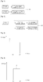
- Fig. 1 is a conceptual block diagram illustrating a light emitting device according to a first embodiment of the present invention.
- a light emitting device includes a first light emitting portion that emits white light at a color temperature of 6000K or more, second light emitting portion that emits white light at a color temperature of 3000K less, and the said first light emitting portion and second light emitting portion are characterized by independent driving.
- the said first light emitting portion and second light emitting portion can be driven independently.
- a light emitting device can realize white light with the high CRI, variable spectrum and color temperature by selective driving of a first light emitting device and a second light emitting device.
- a light emitting device can realize variable spectrum and color temperature of white light, it is advantageous that it can be applied variously in desired atmosphere and uses with only single package (A). For instance, driving a first light emitting portion, which emits white light at a color temperature of 6000K or more(daylight) in the daytime, activity and concentration of human brain can be improved, and driving second light emitting portion, which emits white light at a color temperature of 3000K or less(warm white) in the night time, it helps people to have more peaceful and comfortable rest. Especially, it has effect of improving health by controlling wavelength and color temperature of the light appropriately according to circadian function of effects of human being.
- Fig. 2 is a concept block diagram illustrating a light emitting device according to another embodiment of the present invention.
- a light emitting device comprises a first light emitting portion that emits white light at a color temperature of 6000K or more, a second light emitting portion that emits white light at a color temperature of 3000K or less, a first controller part connected to the said first light emitting portion, and a second controller part connected to the said second light emitting portion.
- the first and second controller parts are characterized by control of input power from the outside to the first and second light emitting portions.
- the said first and second controller part are to control each input voltage to the first and second light emitting portion, for example, the said first and second controller parts control the input voltage from the power by the time and output.
- the said first and second controller parts can include timer and voltage controller circuit. That is, input voltage to the controller part from the power outside is controlled through timer and voltage controller circuit by the time then it is passed to the first and second light emitting portions.
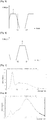
- Figs. 3 and 4 are graphs illustrating an embodiment of the first and second controller parts respectively.
- the first controller part (1) passes the voltage from the power outside for first 14 hours of the day, and blocks the voltage for remaining 12 hours of the day.
- the second controller part (2) blocks the voltage for first 12 hours of the day as shown in the Fig. 4 , and passes the voltage for remaining 12 hours of the day. That is, for 12 hours of a day, power is delivered to only the first light emitting portion for driving, and for remaining 12 hours of a day, power is delivered to only the second light emitting portion for driving.
- white light at a color temperature of 6000K or more(daylight) can be realized by driving only the first light emitting portion in the daytime, and for remaining 12 hours of a day, for example, white light at a color temperature of 3000K or less(warm white) can be realized by driving only the second light emitting portion.
- the aforementioned is showing an example of power on/off to the first and second light emitting portions, but it is not limited to, it can be applied in various ways. For instance, as it is shown in Figs. 5 and 6 , luminous intensity of the first and second light emitting portions can be increased or decreased as the voltage is increased or decreased by the time. Accordingly, a color temperature of white light emitted from a light emitting device can be increased or decreased gradually.
- Such a light emitting device can control the operation of the first and second light emitting devices through the first and second controller parts, it can be applied in various ways as desired.
- a light emitting device of which color temperature is controlled automatically can be produced without a separated input by the time.
- a light emitting device can be formed to realize a relatively high color temperature during the daytime, and a relatively low color temperature during the nighttime.
- it has effect of improving health by controlling wavelength and a color temperature of the light appropriately according to the circadian rhythm of humans.
- the aforementioned embodiment explained a controller part, which controls voltage by the time, but it is not limited to, the said controller part can include an additional separate input part, so that, it can be formed to adjust a color temperature as user's desire.
- the aforementioned embodiment showed that power is impressed to the first and second controller parts at the same time, but it is not limited to, the said first and second controller parts can be connected to separated power, and they can be driven independently.
- they can be formed to include only one controller, which can control the first and second light emitting portions together.
- Such a light emitting device can realize various spectrum and color temperature of white light, it is advantageous that it can be applied variously in desired atmosphere and uses with only single package (A). For instance, driving a first light emitting portion, which emits white light at a color temperature of 6000K or more(daylight) in the daytime, activity and concentration of human brain can be improved, and driving second light emitting portion, which emits white light at a color temperature of 3000K or less(warm white) in the night time, it helps people to have more peaceful and comfortable rest. Especially, it has effect of improving health by controlling wavelength and a color temperature of the light appropriately according to the circadian rhythm of humans.
- a first light emitting portion is comprised of a light emitting diode chip with wavelength of 456nm (blue light), the phosphor consisting of Cu 0,15 Ba 1,82 Sr 0,03 Si 0,99 Ge 0,01 O 4 : Eu with peak emission of 515nm, and the phosphor consisting of Cu 0,05 Sr 1,72 Ca 0,23 Si 0,99 Ge 0,01 O 4 : Eu with peak emission of 593nm.
- a second light emitting portion is comprised of a light emitting diode chip with wavelength of 452nm, the phosphor consisting of Cu 0,15 Ba 1,84 Sr 0,01 Si 0,99 Zr 0,01 O 4 : Eu with peak emission of 508nm, and the phosphor consisting of Cu 0,05 Sr 1,85 Ca 0,10 SiO 4 :Eu with peak emission of 605nm.
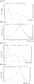
- Fig. 7 shows emission spectrum of the first light emitting portion
- Fig. 8 shows emission spectrum of the second light emitting portion.
- luminous intensity of the first light emitting portion is relatively high in blue emission region
- luminous intensity of the second light emitting portion is relatively high in yellow or red emission region. That is, a color temperature of the first light emitting portion is relatively high and a color temperature of the second light emitting portion is relatively low.
- the first light emitting portion of this embodiment has 9,500K of a color temperature with excellent color rendering index of 88. Moreover, the second light emitting portion has 2,640K of a color temperature with excellent color rendering index of 83.
- a first light emitting portion is comprised of a light emitting diode chip with wavelength of 456nm, the phosphor consisting of Cu 0,15 Ba 1,82 Sr 0,05 Si 0,99 Ge 0,01 O 4 : Eu with peak emission of 515nm, and the phosphor consisting of Cu 0,05 Sr 1,8 Ca 0,15 SiO 4 :Eu with peak emission of 600nm.
- a second light emitting portion is comprised of a light emitting diode chip with wavelength of 456nm, the phosphor consisting of Cu 0,15 Ba 1,82 Sr 0,03 Si 0,99 Ge 0,01 O 4 : Eu, with peak emission of 515nm, and the phosphor consisting of CU 0,05 Sr 1,8 Ca 0,15 SiO 4 :Eu with peak emission of 600nm.
- the phosphors mixing ratio of the first emitting portion is different from the phosphors mixing ratio of the second emitting portion, so that color temperature and color rendering index of the first emitting portion are different from them of the second emitting portion.
- Fig. 9 shows light spectrum of the first light emitting portion and Fig. 10 shows light spectrum of the second light emitting portion. As shown in Figs. 9 and 10 , a color temperature of the first light emitting portion is relatively high and a color temperature of the second light emitting portion is relatively low.
- the first light emitting portion of this embodiment has 8,800K of a color temperature with an excellent color rendering index of 92. Moreover, the second light emitting portion has 2,550K of a color temperature with an excellent color rendering index of 80.
- the white light with an excellent color rendering index and various light spectrum and color temperatures can be realized by selective driving of first light emitting portion and second light emitting portion.
- the white light with a color temperature of 8800K which is relatively high is rendered during the day by driving only the first light emitting portion
- the white light with a color temperature of 2550K which is relatively low is rendered during the night by driving only the second light emitting portion.
- a first light emitting portion is comprised of a light emitting diode chip that emits UV light with wavelength of 405nm, the phosphor consisting of Cu 0,02 Ba 2,8 Sr 0,2 Mg 0,98 Si 2 O 8 : Eu with emission peak of 440nm, the phosphor consisting of Cu 0,15 Ba 1,84 Sr 0,01 Si 0,99 Zr 0,01 O 4 : Eu with emission peak of 508nm, the phosphor consisting of Cu 0,02 Ba 0,98 Sr 0,98 Ca 0,02 SiO 4 : Eu with emission peak of 565nm, and the phosphor consisting of Cu 0,15 Mg 0,85 BaP 2 O 7 : Eu, Mn with emission peak of 630nm.
- a second light emitting portion is comprised of a light emitting diode chip that emits UV light with wavelength of 405nm, the phosphor consisting of Cu 0,02 Ba 2,8 Sr 0,2 Mg 0,98 Si 2 O 8 : Eu with emission peak of 440nm, the phosphor consisting of Cu 0,15 Ba 1,82 Sr 0,03 Si 0,99 Ge 0,01 O 4 : Eu with emission peak of 515nm, the phosphor consisting of Cu 0,05 Sr 1,72 Ca 0,23 Si 0,99 Ge 0,01 O 4 : Eu with emission peak of 593nm, and the phosphor consisting of Cu 0,15 Mg 0,85 BaP 2 O 7 : Eu, Mn with emission peak of 630nm.
- Fig. 11 shows light spectrum of the first light emitting portion
- Fig. 12 shows light spectrum of the second light emitting portion. As shown in Figs. 11 and 12 , a color temperature of the first light emitting portion is relatively high and a color temperature of the second light emitting portion is relatively low.
- the first light emitting portion of this embodiment has 8,800K of a color temperature with an excellent color rendering index of 88. Moreover, the second light emitting portion has 2600K of a color temperature with an excellent color rendering index of 95.
- the white light with an excellent color rendering index and various light spectrum and color temperatures can be realized by selective driving of first light emitting portion and second light emitting portion.
- the white light with a color temperature of 8800K which is relatively high is rendered during the day by driving only the first light emitting portion
- the white light with a color temperature of 2600K which is relatively low is rendered during the night by driving only the second light emitting portion.
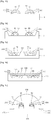
- Figs. 13 to 17 show the light emitting devices applying to different structures according to the present invention.
- a light emitting device comprises a substrate(10), a first light emitting portion(200) and a second light emitting portion(300) mounted on the substrate(10).
- the first light emitting portion(200) comprises a first light emitting diode chip(20) and a first phosphor(30).
- the first phosphor(30) mixed in thermoset resin(50) such as epoxy and silicon is disposed on the first light emitting diode chip(20).
- the first light emitting portion(200) renders white light at a color temperature of 6000K or more (daylight) by combination of light emitted from the first light emitting diode chip(20) and wavelength-converted light by the first phosphor(30).
- the second light emitting portion(300) comprises a second light emitting diode chip(60) and a second phosphor(70).
- the second phosphor(70) mixed in thermoset resin(90) such as epoxy and silicon is disposed on the second light emitting diode chip(60).
- the second light emitting portion(300) renders white light at a color temperature of 3000K or less (warm white) by combination of light emitted from the second light emitting diode chip(60) and wavelength-converted light by the second phosphor(70).
- the substrate(10) can have a predetermined slope on the sidewalls of a cavity by forming a predetermined cavity wherein first and second light emitting portion(200, 300) are formed.
- a light emitting device comprises the substrate(10) with the cavity(100), and the first light emitting portion(200) and the second light emitting portion(300) formed on the bottom of the cavity(100).
- the first light emitting portion(200) comprising the first light emitting diode chip(20) and the first phosphor(30) and the second light emitting portion(300) comprising the second light emitting diode chip(60) and the second phosphor(70) are formed on the bottom of the cavity(100).
- a compound(50, 90) of the first and second phosphor(30, 70) and thermoset resin is disposed on the first and second light emitting diode chips(20, 60).
- a predetermined slope of the sidewalls of the cavity(100) can maximize reflection of light emitted from the light emitting diode chips(20, 60) and increase luminescent efficiency.
- a molding portion(not shown) can be formed by filling the inside of the cavity(100) with transparent thermoset resin in order to protect the first and second light emitting portion(200, 300).
- a cavity corresponding to each of light emitting portions can be formed to separate the first light emitting portion(200) from the second light emitting portion(300).
- a light emitting device comprises a substrate(100) with a plurality of cavities to separate light emitting portions(200, 300), and the first light emitting portion(200) and the second light emitting portion(300) separately formed on the bottom of the cavity.
- the first light emitting portion(200) is formed by mounting the first light emitting diode chip(20) on the bottom of a cavity(110) and filling the inside of the cavity(110) with a compound(50) of the first phosphor(30) and thermoset resin.
- the second light emitting portion(300) can be formed in the same way. At this time, reflection of light emitted from the light emitting diode chips(20, 60) can be maximized and luminescent efficiency can be increased by forming a predetermined slope of the sidewalls of each of the cavities.
- a light emitting device comprises a substrate(10) wherein a cavity(120) is formed with the curved sidewalls, and the first light emitting portion(200) and the second light emitting portion(300) formed on the bottom of the cavity(120). Further, a partition(130) can be formed in a predetermined area of the bottom of the cavity(120) to separate the first light emitting portion(200) from the second light emitting portion(300). The partition(130) can be formed at the same height as the substrate(10) as shown in Fig.
- the partition can be formed at a lower height than the substrate(10) to separate the first light emitting portion(200) from the second light emitting portion(300) and a molding portion(140) filling the first and second light emitting portion(200, 300) together can be formed as shown in Fig. 16 .
- a molding portion(140) filling the first and second light emitting portion(200, 300) together can be formed as shown in Fig. 16 .
- Fig. 17 shows an example of a light emitting device for efficiently emitting heat generated from the light emitting diode chips(20, 60).
- the light emitting device comprises a heat sink(160), the first light emitting portion(200) and the second light emitting portion(300) formed on the heat sink(160), a housing(150) surrounding the heat sink(160) leas frames(170, 180) protruding toward the outside of the housing, and a molding portion(190) filling the first and second light emitting portion(200, 300).
- use of excellent thermal conductive materials such as metal as a heat sink(160) can make it more efficient to emit heat generated from the light emitting diode chips(20, 60).
- the heat sink(160) includes a protruding portion corresponding to each of the light emitting portions(200, 300) to make it easy to dispose a compound(50, 90) of the phosphor(30, 70) and thermoset resin on the light emitting diode chips(20, 60), but is not limited to. Further, a light emitting portion may be formed on a plane of the heat sink or on the bottom of the cavity of a heat sink.
- the first and second light emitting portions consist of a light emitting diode chip each, but is not limited to.
- the first and second light emitting portions may consist of a plurality of light emitting diode chips.
- the present invention can be applied to various products as well as illumination.
- a number of light emitting diodes from 50 to 80 are needed to apply to illumination.
- packages manufactured with different structures may be mounted on a substrate or a number of light emitting diode chips may be mounted directly on a substrate.
- each of dots(500) can comprise the first light emitting portion and the second light emitting portion. That is, each of dots(500) can render daylight and warm white, but is not limited to.
- Each of dots(500) can include either the first light emitting portion or the second light emitting portion.
- a dot including the first light emitting portion and a dot including the second light emitting portion may be arranged alternately with each other, or a group of dots including the first light emitting portion and a group of dots second light emitting portion may be arranged separately from each other. Dots can be arranged in various forms according to convenience of process or a desired purpose.
Landscapes
- Chemical & Material Sciences (AREA)
- Engineering & Computer Science (AREA)
- Inorganic Chemistry (AREA)
- Materials Engineering (AREA)
- Organic Chemistry (AREA)
- Architecture (AREA)
- Civil Engineering (AREA)
- Structural Engineering (AREA)
- Luminescent Compositions (AREA)
- Led Device Packages (AREA)
Claims (10)
- Lichtemittierende Vorrichtung umfassend:- einen ersten lichtemittierenden Abschnitt zum Emittieren von Tageslicht mit einer hohen Farbtemperatur von 6000K oder mehr; und- einen zweiten lichtemittierenden Abschnitt zum Emittieren von warmem weißen Licht bei einer Farbtemperatur 3000K oder weniger,- eine Steuerung zum Steuern einer zumindest an einen von dem ersten lichtemittierenden Abschnitt und dem zweiten lichtemittierenden Abschnitt angelegten Spannung,wobei jeder von dem ersten lichtemittierenden Abschnitt und dem zweiten lichtemittierenden Abschnitt einen lichtemittierenden Dioden-Chip und eine Vielzahl Phosphore umfasst, und der erste lichtemittierende Abschnitt und der zweite lichtemittierende Abschnitt unabhängig angesteuert werden, und
wobei die Phosphore die folgende generelle Formel haben
a(M1O)·e(M3O)·g(MO 5OP)·h(MX 6OY),
wobei 0<a≤2, 0<e≤4, 0≤g≤8, 1≤o≤2, 1≤p≤5, 0<h≤2, 1≤x≤2, 1≤y≤5 and M1 = Cu; M3 = Mg, Ca, Sr, Ba, Mn; M5 = Si, Ge, Zr, Mn; M6 = Eu, und
wobei die Steuerung die Spannungseingabe von außerhalb in Bezug auf die Zeit steuert und die Spannung an zumindest einen von dem ersten lichtemittierenden Abschnitt und dem zweiten lichtemittierenden Abschnitt angelegt, und
wobei die Steuerung die Spannung mit einem 24-Stunden-Zyklus erhöht oder absenkt und die Spannung an zumindest einen von dem ersten lichtemittierenden Abschnitt und dem zweiten lichtemittierenden Abschnitt angelegt. - Lichtemittierende Vorrichtung nach Anspruch 1, wobei der lichtemittierende Dioden-Chip blaues oder UV-Licht emittiert.
- Lichtemittierende Vorrichtung nach Anspruch 1 oder 2, wobei der erste lichtemittierende Abschnitt und der zweite lichtemittiererende Abschnitt in einer Einheit ausgebildet sind.
- Lichtemittierende Vorrichtung nach Anspruch 3, weiter umfassend:
ein Substrat, wobei die lichtemittierenden Dioden-Chips des ersten lichtemittierenden Abschnitts und des zweiten lichtemittierenden Abschnitts auf dem Substrat angebracht sind, und die Phosphore des ersten lichtemittierenden Abschnitts und des zweiten lichtemittierenden Abschnitts auf den lichtemittierenden Dioden-Chips angeordnet sind. - Lichtemittierende Vorrichtung nach Anspruch 3, weiter umfassend:- eine Wärmesenke zum Emittieren von von den lichtemittierenden Dioden-Chips erzeugter Wärme,wobei die lichtemittierenden Dioden-Chips des ersten lichtemittierenden Abschnitts und des zweiten lichtemittierenden Abschnitts auf der Wärmesenke angebracht sind und die Phosphore des ersten lichtemittierenden Abschnitts und des zweiten lichtemittierenden Abschnitts auf den lichtemittierenden Dioden-Chips angeordnet sind.
- Lichtemittierende Vorrichtung nach Anspruch 4, wobei eine Nut in dem Substrat ausgebildet ist, und der erste lichtemittierende Abschnitt und der zweite lichtemittierende Abschnitt an dem unteren Ende der Nut ausgebildet sind.
- Lichtemittierende Vorrichtung nach Anspruch 6, wobei die Nut eine Vielzahl von Nuten umfasst, wobei jede Nut getrennt von jeder anderen angeordnet ist, und der erste lichtemittierende Abschnitt oder der zweite lichtemittierende Abschnitt an dem unteren Ende einer jeden Nut ausgebildet ist.
- Lichtemittierende Vorrichtung nach Anspruch 7, weiter umfassend:- einen Formteilabschnitt, welcher den ersten lichtemittierenden Abschnitt und den zweiten lichtemittierenden Abschnitt gemeinsam einkapselt.
- Beleuchtungssystem umfassend:- eine Grundplatte; und- die lichtemittierende Vorrichtung nach einem der Ansprüche 1 bis 8.
- Beleuchtungssystem noch Anspruch 9, wobei die erste lichtemittierende Vorrichtung an einem ersten Bereich der Grundplatte angeordnet ist, und die zweite lichtemittierende Vorrichtung an einem zweiten Bereich der Grundplatte angeordnet ist.
Priority Applications (2)
| Application Number | Priority Date | Filing Date | Title |
|---|---|---|---|
| EP11182709.3A EP2402415B1 (de) | 2006-03-31 | 2007-03-31 | Lichtemittierende Vorrichtung und Beleuchtungssystem damit |
| EP21159777.8A EP3922697A1 (de) | 2006-03-31 | 2007-03-31 | Lichtemittierende vorrichtung und beleuchtungssystem damit |
Applications Claiming Priority (2)
| Application Number | Priority Date | Filing Date | Title |
|---|---|---|---|
| KR1020060029517A KR100875443B1 (ko) | 2006-03-31 | 2006-03-31 | 발광 장치 |
| PCT/KR2007/001587 WO2007114614A1 (en) | 2006-03-31 | 2007-03-31 | Light emitting device and lighting system having the same |
Related Child Applications (3)
| Application Number | Title | Priority Date | Filing Date |
|---|---|---|---|
| EP21159777.8A Division EP3922697A1 (de) | 2006-03-31 | 2007-03-31 | Lichtemittierende vorrichtung und beleuchtungssystem damit |
| EP11182709.3A Division-Into EP2402415B1 (de) | 2006-03-31 | 2007-03-31 | Lichtemittierende Vorrichtung und Beleuchtungssystem damit |
| EP11182709.3A Division EP2402415B1 (de) | 2006-03-31 | 2007-03-31 | Lichtemittierende Vorrichtung und Beleuchtungssystem damit |
Publications (3)
| Publication Number | Publication Date |
|---|---|
| EP2005489A1 EP2005489A1 (de) | 2008-12-24 |
| EP2005489A4 EP2005489A4 (de) | 2010-11-03 |
| EP2005489B1 true EP2005489B1 (de) | 2019-12-18 |
Family
ID=38563849
Family Applications (3)
| Application Number | Title | Priority Date | Filing Date |
|---|---|---|---|
| EP07745750.5A Active EP2005489B1 (de) | 2006-03-31 | 2007-03-31 | Lichtemittierende vorrichtung und beleuchtungssystem damit |
| EP11182709.3A Active EP2402415B1 (de) | 2006-03-31 | 2007-03-31 | Lichtemittierende Vorrichtung und Beleuchtungssystem damit |
| EP21159777.8A Pending EP3922697A1 (de) | 2006-03-31 | 2007-03-31 | Lichtemittierende vorrichtung und beleuchtungssystem damit |
Family Applications After (2)
| Application Number | Title | Priority Date | Filing Date |
|---|---|---|---|
| EP11182709.3A Active EP2402415B1 (de) | 2006-03-31 | 2007-03-31 | Lichtemittierende Vorrichtung und Beleuchtungssystem damit |
| EP21159777.8A Pending EP3922697A1 (de) | 2006-03-31 | 2007-03-31 | Lichtemittierende vorrichtung und beleuchtungssystem damit |
Country Status (6)
| Country | Link |
|---|---|
| US (4) | US9576939B2 (de) |
| EP (3) | EP2005489B1 (de) |
| JP (1) | JP5430394B2 (de) |
| KR (1) | KR100875443B1 (de) |
| TW (1) | TWI341597B (de) |
| WO (1) | WO2007114614A1 (de) |
Families Citing this family (132)
| Publication number | Priority date | Publication date | Assignee | Title |
|---|---|---|---|---|
| KR100655894B1 (ko) | 2004-05-06 | 2006-12-08 | 서울옵토디바이스주식회사 | 색온도 및 연색성이 우수한 파장변환 발광장치 |
| KR100658700B1 (ko) | 2004-05-13 | 2006-12-15 | 서울옵토디바이스주식회사 | Rgb 발광소자와 형광체를 조합한 발광장치 |
| US8318044B2 (en) | 2004-06-10 | 2012-11-27 | Seoul Semiconductor Co., Ltd. | Light emitting device |
| KR100665298B1 (ko) | 2004-06-10 | 2007-01-04 | 서울반도체 주식회사 | 발광장치 |
| KR100665299B1 (ko) * | 2004-06-10 | 2007-01-04 | 서울반도체 주식회사 | 발광물질 |
| KR101258397B1 (ko) * | 2005-11-11 | 2013-04-30 | 서울반도체 주식회사 | 구리 알칼리토 실리케이트 혼성 결정 형광체 |
| KR101055772B1 (ko) | 2005-12-15 | 2011-08-11 | 서울반도체 주식회사 | 발광장치 |
| US9351355B2 (en) * | 2005-12-30 | 2016-05-24 | Seoul Semiconductor Co., Ltd. | Illumination system having color temperature control and method for controlling the same |
| KR100875443B1 (ko) | 2006-03-31 | 2008-12-23 | 서울반도체 주식회사 | 발광 장치 |
| KR101258227B1 (ko) | 2006-08-29 | 2013-04-25 | 서울반도체 주식회사 | 발광 소자 |
| JP2008283155A (ja) * | 2007-05-14 | 2008-11-20 | Sharp Corp | 発光装置、照明機器および液晶表示装置 |
| KR100951274B1 (ko) * | 2007-07-19 | 2010-05-06 | 삼성엘이디 주식회사 | 백라이트 유닛 |
| RU2467051C2 (ru) | 2007-08-22 | 2012-11-20 | Сеул Семикондактор Ко., Лтд. | Люминофоры на основе нестехиометрических тетрагональных силикатов меди и щелочноземельного металла и способ их получения |
| KR101055769B1 (ko) | 2007-08-28 | 2011-08-11 | 서울반도체 주식회사 | 비화학양론적 정방정계 알칼리 토류 실리케이트 형광체를채택한 발광 장치 |
| US8410714B2 (en) | 2007-11-12 | 2013-04-02 | Mitsubishi Chemical Corporation | Illuminating device |
| DE102008011153B4 (de) | 2007-11-27 | 2023-02-02 | OSRAM Opto Semiconductors Gesellschaft mit beschränkter Haftung | Verfahren zur Herstellung einer Anordnung mit mindestens zwei lichtemittierenden Halbleiterbauelementen |
| JP5437277B2 (ja) * | 2008-02-21 | 2014-03-12 | コーニンクレッカ フィリップス エヌ ヴェ | Gls似のled光源 |
| JPWO2009110285A1 (ja) | 2008-03-03 | 2011-07-14 | シャープ株式会社 | 発光装置 |
| KR100986359B1 (ko) * | 2008-03-14 | 2010-10-08 | 엘지이노텍 주식회사 | 발광 장치 및 이를 구비한 표시 장치 |
| JP2009231525A (ja) * | 2008-03-24 | 2009-10-08 | Mitsubishi Chemicals Corp | 発光モジュール、および照明装置 |
| KR100924912B1 (ko) * | 2008-07-29 | 2009-11-03 | 서울반도체 주식회사 | 웜화이트 발광장치 및 그것을 포함하는 백라이트 모듈 |
| CN101677117B (zh) * | 2008-09-19 | 2012-03-21 | 展晶科技(深圳)有限公司 | 高演色性发光二极管的配置方法与系统 |
| JP5308773B2 (ja) * | 2008-10-30 | 2013-10-09 | スタンレー電気株式会社 | 半導体発光装置 |
| CN101771025A (zh) | 2008-12-26 | 2010-07-07 | 富准精密工业(深圳)有限公司 | 发光二极管 |
| DE102009011688A1 (de) | 2009-03-04 | 2010-09-09 | Ledon Lighting Jennersdorf Gmbh | Lichtmaschine mit variabler Lichtemission nach dem Tageslichtrhythmus |
| US20100244735A1 (en) * | 2009-03-26 | 2010-09-30 | Energy Focus, Inc. | Lighting Device Supplying Temporally Appropriate Light |
| TWI468614B (zh) * | 2009-04-21 | 2015-01-11 | Cheng Hsi Miao | 可調色溫的燈具 |
| KR20120015337A (ko) | 2009-05-05 | 2012-02-21 | 쓰리엠 이노베이티브 프로퍼티즈 컴파니 | Led에서 사용하기 위한 재방출 반도체 캐리어 디바이스 및 제조 방법 |
| KR20120016261A (ko) | 2009-05-05 | 2012-02-23 | 쓰리엠 이노베이티브 프로퍼티즈 컴파니 | 인듐 공핍 메커니즘을 이용하여 인듐-함유 기판 상에 성장된 반도체 디바이스 |
| DE102009030205A1 (de) * | 2009-06-24 | 2010-12-30 | Litec-Lp Gmbh | Leuchtstoffe mit Eu(II)-dotierten silikatischen Luminophore |
| KR101055762B1 (ko) | 2009-09-01 | 2011-08-11 | 서울반도체 주식회사 | 옥시오소실리케이트 발광체를 갖는 발광 물질을 채택한 발광 장치 |
| JP2012532454A (ja) | 2009-06-30 | 2012-12-13 | スリーエム イノベイティブ プロパティズ カンパニー | カドミウム非含有の再発光半導体構成体 |
| CN102474932B (zh) * | 2009-06-30 | 2015-12-16 | 3M创新有限公司 | 具有可调节色温的白光电致发光器件 |
| KR20120055540A (ko) | 2009-06-30 | 2012-05-31 | 쓰리엠 이노베이티브 프로퍼티즈 컴파니 | 전류 집중에 기초한 색 조정을 갖는 전계발광 디바이스 |
| TWI412784B (zh) * | 2009-08-24 | 2013-10-21 | Ind Tech Res Inst | Led光源裝置及其出光方法 |
| FI20095967A7 (fi) * | 2009-09-18 | 2011-03-19 | Valoya Oy | Valaisinsovitelma |
| JP5443959B2 (ja) * | 2009-11-25 | 2014-03-19 | パナソニック株式会社 | 照明装置 |
| KR101081069B1 (ko) * | 2009-12-21 | 2011-11-07 | 엘지이노텍 주식회사 | 발광소자 및 그를 이용한 라이트 유닛 |
| TWI518736B (zh) * | 2010-03-31 | 2016-01-21 | Ats自動模具系統股份有限公司 | 光產生系統及其方法 |
| KR101039994B1 (ko) * | 2010-05-24 | 2011-06-09 | 엘지이노텍 주식회사 | 발광소자 및 이를 구비한 라이트 유닛 |
| KR101103674B1 (ko) * | 2010-06-01 | 2012-01-11 | 엘지이노텍 주식회사 | 발광 소자 |
| US20110309381A1 (en) * | 2010-06-21 | 2011-12-22 | Toshiba Lighting & Technology Corporation | Light-emitting device and lighting apparatus |
| US8702277B2 (en) | 2010-07-12 | 2014-04-22 | Samsung Electronics Co., Ltd. | White light emitting diode and liquid crystal display including the same |
| JP6155189B2 (ja) * | 2010-07-21 | 2017-06-28 | コーニンクレッカ フィリップス エヌ ヴェKoninklijke Philips N.V. | 日周リズムによる動的照明システム |
| US9532423B2 (en) | 2010-07-23 | 2016-12-27 | Lighting Science Group Corporation | System and methods for operating a lighting device |
| US8841864B2 (en) | 2011-12-05 | 2014-09-23 | Biological Illumination, Llc | Tunable LED lamp for producing biologically-adjusted light |
| US9827439B2 (en) | 2010-07-23 | 2017-11-28 | Biological Illumination, Llc | System for dynamically adjusting circadian rhythm responsive to scheduled events and associated methods |
| US8686641B2 (en) | 2011-12-05 | 2014-04-01 | Biological Illumination, Llc | Tunable LED lamp for producing biologically-adjusted light |
| US9681522B2 (en) | 2012-05-06 | 2017-06-13 | Lighting Science Group Corporation | Adaptive light system and associated methods |
| US9024536B2 (en) | 2011-12-05 | 2015-05-05 | Biological Illumination, Llc | Tunable LED lamp for producing biologically-adjusted light and associated methods |
| US8743023B2 (en) | 2010-07-23 | 2014-06-03 | Biological Illumination, Llc | System for generating non-homogenous biologically-adjusted light and associated methods |
| EP2413358A1 (de) * | 2010-07-28 | 2012-02-01 | Civilight Qidong Lighting Technology Co., Ltd. | LED-Lampe mit mehreren Farbtemperaturen |
| US8937324B2 (en) * | 2010-08-30 | 2015-01-20 | Bridgelux, Inc. | Light-emitting device array with individual cells |
| US9373606B2 (en) | 2010-08-30 | 2016-06-21 | Bridgelux, Inc. | Light-emitting device array with individual cells |
| JP2012109532A (ja) * | 2010-09-08 | 2012-06-07 | Mitsubishi Chemicals Corp | 発光装置、照明装置、及びレンズ |
| CN101974331B (zh) * | 2010-10-19 | 2013-05-01 | 同济大学 | 一种蓝光激发的红色荧光材料及制备方法 |
| JP5579042B2 (ja) * | 2010-12-17 | 2014-08-27 | 三菱電機株式会社 | 照明装置 |
| KR20120113419A (ko) * | 2011-04-05 | 2012-10-15 | 삼성전자주식회사 | 발광소자 모듈 및 면광원 장치 |
| CN103493226B (zh) * | 2011-04-22 | 2016-09-28 | 株式会社东芝 | 白光源以及包括所述白光源的白光源系统 |
| US8901850B2 (en) | 2012-05-06 | 2014-12-02 | Lighting Science Group Corporation | Adaptive anti-glare light system and associated methods |
| US8754832B2 (en) | 2011-05-15 | 2014-06-17 | Lighting Science Group Corporation | Lighting system for accenting regions of a layer and associated methods |
| US9173269B2 (en) | 2011-05-15 | 2015-10-27 | Lighting Science Group Corporation | Lighting system for accentuating regions of a layer and associated methods |
| EP2711995B1 (de) * | 2011-05-16 | 2019-06-26 | Nichia Corporation | Lichtemittierende vorrichtung und verfahren zu ihrer herstellung |
| KR101212654B1 (ko) * | 2011-05-20 | 2012-12-14 | (주)라이타이저코리아 | 발광 다이오드 패키지 및 그의 제조 방법 |
| CN103718650A (zh) * | 2011-08-16 | 2014-04-09 | 三星电子株式会社 | 具有可调节的色温的led装置 |
| US20130075769A1 (en) * | 2011-09-22 | 2013-03-28 | Ledengin, Inc. | Selection of phosphors and leds in a multi-chip emitter for a single white color bin |
| JP5893888B2 (ja) * | 2011-10-13 | 2016-03-23 | シチズン電子株式会社 | 半導体発光装置 |
| JP5861083B2 (ja) * | 2011-11-01 | 2016-02-16 | パナソニックIpマネジメント株式会社 | 照明器具 |
| JP5861064B2 (ja) * | 2011-11-01 | 2016-02-16 | パナソニックIpマネジメント株式会社 | 照明器具 |
| US9289574B2 (en) | 2011-12-05 | 2016-03-22 | Biological Illumination, Llc | Three-channel tuned LED lamp for producing biologically-adjusted light |
| US9913341B2 (en) | 2011-12-05 | 2018-03-06 | Biological Illumination, Llc | LED lamp for producing biologically-adjusted light including a cyan LED |
| US9220202B2 (en) | 2011-12-05 | 2015-12-29 | Biological Illumination, Llc | Lighting system to control the circadian rhythm of agricultural products and associated methods |
| US20130170174A1 (en) | 2011-12-29 | 2013-07-04 | Intematix Technology Center Corp. | Multi-cavities light emitting device |
| EP2613354B1 (de) * | 2012-01-03 | 2020-05-06 | Epistar Corporation | Lichtemittierende Vorrichtung mit mehreren Hohlräumen |
| JP5895193B2 (ja) * | 2012-03-02 | 2016-03-30 | パナソニックIpマネジメント株式会社 | 照明制御装置、およびこれを用いた照明装置 |
| US9402294B2 (en) | 2012-05-08 | 2016-07-26 | Lighting Science Group Corporation | Self-calibrating multi-directional security luminaire and associated methods |
| AU2013308871B2 (en) | 2012-08-28 | 2017-04-13 | Delos Living Llc | Systems, methods and articles for enhancing wellness associated with habitable environments |
| EP2896078A4 (de) | 2012-09-13 | 2016-05-25 | 3M Innovative Properties Co | Effizientes beleuchtungssystem mit weitem farbbereich |
| US9174067B2 (en) | 2012-10-15 | 2015-11-03 | Biological Illumination, Llc | System for treating light treatable conditions and associated methods |
| JP6074703B2 (ja) * | 2012-12-20 | 2017-02-08 | パナソニックIpマネジメント株式会社 | Led照明装置及びled発光モジュール |
| TWI576010B (zh) | 2012-12-28 | 2017-03-21 | 財團法人工業技術研究院 | 光源裝置 |
| US9693408B2 (en) | 2012-12-28 | 2017-06-27 | Industrial Technology Research Institute | Light source apparatus |
| US10039169B2 (en) | 2012-12-28 | 2018-07-31 | Industrial Technology Research Institute | Light source apparatus |
| US10485070B2 (en) | 2012-12-28 | 2019-11-19 | Industrial Technology Research Institute | Light source apparatus and display apparatus |
| EP2953174B1 (de) * | 2013-01-31 | 2020-07-01 | Kabushiki Kaisha Toshiba | Lichtemittierende vorrichtung und led-glühlampe |
| US9030103B2 (en) | 2013-02-08 | 2015-05-12 | Cree, Inc. | Solid state light emitting devices including adjustable scotopic / photopic ratio |
| US9039746B2 (en) | 2013-02-08 | 2015-05-26 | Cree, Inc. | Solid state light emitting devices including adjustable melatonin suppression effects |
| TWI618961B (zh) * | 2013-03-05 | 2018-03-21 | 元太科技工業股份有限公司 | 發光模組及電子裝置 |
| US20140268731A1 (en) | 2013-03-15 | 2014-09-18 | Lighting Science Group Corpporation | Low bay lighting system and associated methods |
| US10368798B2 (en) | 2013-06-28 | 2019-08-06 | North Carolina State University | Systems and methods for determining sleep patterns and circadian rhythms |
| KR20150025231A (ko) * | 2013-08-28 | 2015-03-10 | 서울반도체 주식회사 | 광원 모듈 및 그 제조 방법, 및 백라이트 유닛 |
| US9410664B2 (en) * | 2013-08-29 | 2016-08-09 | Soraa, Inc. | Circadian friendly LED light source |
| EP3050403A1 (de) | 2013-09-23 | 2016-08-03 | Philips Lighting Holding B.V. | Beleuchtungssystem mit tagesrhythmus- und dimmlichtdynamik |
| JP2015070866A (ja) * | 2013-10-01 | 2015-04-16 | パナソニックIpマネジメント株式会社 | 光源モジュール及び照明装置 |
| JP6145679B2 (ja) * | 2013-10-28 | 2017-06-14 | パナソニックIpマネジメント株式会社 | 光源モジュール及び照明装置 |
| CA2940766A1 (en) | 2014-02-28 | 2015-09-03 | Delos Living Llc | Systems, methods and articles for enhancing wellness associated with habitable environments |
| JP6156440B2 (ja) * | 2014-05-30 | 2017-07-05 | 日亜化学工業株式会社 | 赤色発光蛍光体及びこれを用いた発光装置 |
| WO2015189112A1 (en) * | 2014-06-10 | 2015-12-17 | Koninklijke Philips N.V. | Light emitting arrangement with adjustable emission spectrum |
| JP6755090B2 (ja) * | 2014-12-11 | 2020-09-16 | シチズン電子株式会社 | 発光装置及び発光装置の製造方法 |
| DK3235342T3 (da) * | 2014-12-16 | 2021-08-16 | Signify Holding Bv | Belysningsindretning, belysningssystem og anvendelse deraf |
| WO2016096387A1 (en) * | 2014-12-16 | 2016-06-23 | Philips Lighting Holding B.V. | Working light, lighting system and use thereof |
| US10424562B2 (en) | 2014-12-16 | 2019-09-24 | Citizen Electronics Co., Ltd. | Light emitting device with phosphors |
| WO2016115230A1 (en) | 2015-01-13 | 2016-07-21 | Delos Living Llc | Systems, methods and articles for monitoring and enhancing human wellness |
| KR102606852B1 (ko) | 2015-01-19 | 2023-11-29 | 쑤저우 레킨 세미컨덕터 컴퍼니 리미티드 | 발광 소자 |
| JP6458991B2 (ja) * | 2015-02-23 | 2019-01-30 | 東芝ライテック株式会社 | 車両用照明装置および車両用灯具 |
| PL3271013T3 (pl) * | 2015-03-19 | 2019-02-28 | Philips Lighting Holding B.V. | Lampa o barwie bio |
| US9974138B2 (en) * | 2015-04-21 | 2018-05-15 | GE Lighting Solutions, LLC | Multi-channel lamp system and method with mixed spectrum |
| US9900957B2 (en) * | 2015-06-11 | 2018-02-20 | Cree, Inc. | Lighting device including solid state emitters with adjustable control |
| JP6667237B2 (ja) * | 2015-09-11 | 2020-03-18 | アルパッド株式会社 | 発光装置 |
| DE102016104875A1 (de) * | 2016-03-16 | 2017-09-21 | Osram Opto Semiconductors Gmbh | Optoelektronisches Bauelement, Verfahren zur Herstellung eines optoelektronischen Bauelements und Blitzlichtbeleuchtung für ein tragbares Gerät |
| DE102016107497B4 (de) * | 2016-03-24 | 2020-01-30 | Tdk Electronics Ag | Multi-LED System und Verfahren zu seiner Herstellung |
| US10143058B2 (en) * | 2016-06-03 | 2018-11-27 | Litegear Inc. | Artificial light compensation system and process |
| WO2018039433A1 (en) | 2016-08-24 | 2018-03-01 | Delos Living Llc | Systems, methods and articles for enhancing wellness associated with habitable environments |
| TWI610457B (zh) * | 2016-10-19 | 2018-01-01 | 隆達電子股份有限公司 | 白光光源裝置 |
| JP6726882B2 (ja) * | 2017-01-25 | 2020-07-22 | パナソニックIpマネジメント株式会社 | 照明装置 |
| US10465869B2 (en) | 2017-01-30 | 2019-11-05 | Ideal Industries Lighting Llc | Skylight fixture |
| CN110612610A (zh) * | 2017-02-27 | 2019-12-24 | 朱伽努有限责任公司 | 可调白光照明系统 |
| EP3376095B1 (de) * | 2017-03-14 | 2019-08-21 | Yamaha Hatsudoki Kabushiki Kaisha | Scheinwerfereinheit mit variabler farbtemperatur bei abblendlicht |
| DK180189B1 (en) | 2017-04-27 | 2020-07-24 | Chromaviso As | Circadian lamp and method of operating such a lamp |
| WO2019046580A1 (en) | 2017-08-30 | 2019-03-07 | Delos Living Llc | SYSTEMS, METHODS AND ARTICLES FOR EVALUATING AND / OR IMPROVING HEALTH AND WELL-BEING |
| US11257990B2 (en) * | 2017-09-29 | 2022-02-22 | Nichia Corporation | Light emitting device |
| CN113178437B (zh) * | 2017-12-21 | 2023-08-11 | 厦门市三安光电科技有限公司 | 一种白光led封装结构以及白光源系统 |
| EP3850458A4 (de) | 2018-09-14 | 2022-06-08 | Delos Living, LLC | Systeme und verfahren zur luftsanierung |
| DK3915360T3 (da) * | 2019-01-24 | 2024-04-29 | Dainippon Printing Co Ltd | Led-belysningsenhed til dyre- og plantevækst, led-belysningsmodul til dyre- og plantevækst, hylde til et dyre- og plantevækstsstativ, dyre- og plantevækstsstativ, dyre- og plantevækstsfabrik |
| US11209129B2 (en) * | 2019-01-29 | 2021-12-28 | Xiamen Eco Lighting Co. Ltd. | Light apparatus |
| US11844163B2 (en) | 2019-02-26 | 2023-12-12 | Delos Living Llc | Method and apparatus for lighting in an office environment |
| US11898898B2 (en) | 2019-03-25 | 2024-02-13 | Delos Living Llc | Systems and methods for acoustic monitoring |
| US11578841B2 (en) | 2019-04-17 | 2023-02-14 | Biological Innovation And Optimization Systems, Llc | Color separation lighting devices |
| CN212115725U (zh) * | 2019-11-11 | 2020-12-08 | 漳州立达信光电子科技有限公司 | Led灯色温控制电路及led灯具 |
| JP7752122B2 (ja) * | 2020-02-12 | 2025-10-09 | ジェイケイ-ホールディング ゲーエムベーハー | 身体照射装置 |
| CN114031400B (zh) * | 2021-11-23 | 2023-01-20 | 松山湖材料实验室 | 单相暖白光荧光陶瓷及其制备方法和应用 |
| KR20240031788A (ko) | 2022-09-01 | 2024-03-08 | 삼성전자주식회사 | 디스플레이용 발광 소자 및 이를 포함하는 백라이트 유닛 |
Family Cites Families (208)
| Publication number | Priority date | Publication date | Assignee | Title |
|---|---|---|---|---|
| US2110162A (en) * | 1938-03-08 | Luminescent material | ||
| US2402760A (en) * | 1942-06-27 | 1946-06-25 | Rca Corp | Luminescent material |
| US2617773A (en) * | 1948-09-10 | 1952-11-11 | Westinghouse Electric Corp | Lead activated calcium tungstate phosphor |
| US2570136A (en) * | 1949-12-22 | 1951-10-02 | Du Pont | Infrared phosphors |
| US2719128A (en) * | 1950-06-21 | 1955-09-27 | Patent Treuhand Ges Fuer Elektrische Gluehlampen Mbh | Luminescent material |
| US2780600A (en) * | 1955-01-24 | 1957-02-05 | Westinghouse Electric Corp | Lead-and manganese-activated cadmium-sodium fluorophosphate phosphor |
| US3143510A (en) * | 1959-06-12 | 1964-08-04 | Philips Corp | Copper and tin activated orthophosphate phosphors |
| US3598752A (en) * | 1967-04-14 | 1971-08-10 | Itt | Ultraviolet emitting cathodoluminescent material |
| JPS476258Y1 (de) | 1968-05-17 | 1972-03-04 | ||
| JPS4938994Y1 (de) | 1970-01-16 | 1974-10-25 | ||
| NL7013516A (de) | 1970-09-12 | 1972-03-14 | ||
| JPS476258U (de) | 1971-02-18 | 1972-09-21 | ||
| US3644212A (en) * | 1971-02-18 | 1972-02-22 | Westinghouse Electric Corp | Zinc-magnesium silico-germanate phosphor composition and method of preparing same |
| JPS4938994A (de) | 1972-08-19 | 1974-04-11 | ||
| US3893939A (en) * | 1973-01-04 | 1975-07-08 | Us Energy | Activated phosphors having matrices of yttrium-transition metal compound |
| US3905911A (en) * | 1974-09-25 | 1975-09-16 | Gte Sylvania Inc | Copper activated hafnium phosphate phosphors and method of making |
| NL7807274A (nl) | 1978-03-10 | 1979-09-12 | Philips Nv | Luminescerende stof, luminescerend scherm voorzien van een dergelijke stof en lagedrukkwikdampontladingslamp voorzien van een dergelijk scherm. |
| JPS55135190U (de) | 1979-03-20 | 1980-09-25 | ||
| JPS55135190A (en) | 1979-04-06 | 1980-10-21 | Dainippon Toryo Co Ltd | Fluorescent substance and its manufacture |
| GB2058117B (en) * | 1979-08-03 | 1983-06-08 | Kasei Optonix | Borate phosphor |
| NL8006223A (nl) | 1980-11-14 | 1982-06-01 | Philips Nv | Luminescerend scherm en lagedrukkwikdampontladingslamp voorzien van een dergelijk scherm. |
| JPS57109886U (de) | 1980-12-26 | 1982-07-07 | ||
| NL8201943A (nl) | 1982-05-12 | 1983-12-01 | Philips Nv | Luminescerend scherm. |
| JPS61258892A (ja) | 1985-05-13 | 1986-11-17 | Matsushita Electronics Corp | 螢光ランプ |
| JPS62197487A (ja) | 1986-02-25 | 1987-09-01 | Hitachi Ltd | 蛍光体の製造方法 |
| JPS62218476A (ja) * | 1986-03-18 | 1987-09-25 | Murata Mfg Co Ltd | 薄膜el素子 |
| JPS62197487U (de) | 1986-06-07 | 1987-12-15 | ||
| US5188763A (en) | 1986-08-29 | 1993-02-23 | Gte Products Corporation | Method for preparing zinc orthosilicate phosphor |
| JPS63196180A (ja) | 1987-02-10 | 1988-08-15 | Canon Inc | 撮像装置 |
| JPH07110941B2 (ja) * | 1987-10-19 | 1995-11-29 | 化成オプトニクス株式会社 | 発光組成物 |
| US4972086A (en) * | 1989-02-03 | 1990-11-20 | Eastman Kodak Company | X-ray intensifying screen including a titanium activated hafnium dioxide phosphor containing erbium to reduce afterglow |
| DE69002470T2 (de) | 1989-02-07 | 1994-03-03 | Agfa Gevaert Nv | Reproduktion von Röntgenbildern mit photostimulierbarem Leuchtstoff. |
| US5060118A (en) * | 1989-04-06 | 1991-10-22 | Frank A. Arone | Apparatus for daylight color duplication |
| JP2995778B2 (ja) | 1990-02-02 | 1999-12-27 | セイコーエプソン株式会社 | 集積回路 |
| JPH0578659A (ja) | 1991-09-18 | 1993-03-30 | Toshiba Corp | 蛍光体および蛍光ランプ |
| JPH05198843A (ja) | 1992-01-23 | 1993-08-06 | Toshiba Lighting & Technol Corp | 発光ダイオードランプおよび発光ダイオード表示装置 |
| JPH0578659U (ja) | 1992-03-31 | 1993-10-26 | 永治 高橋 | リアワイパーオートシステム |
| US5518808A (en) * | 1992-12-18 | 1996-05-21 | E. I. Du Pont De Nemours And Company | Luminescent materials prepared by coating luminescent compositions onto substrate particles |
| KR940019586A (ko) * | 1993-02-04 | 1994-09-14 | 휴고 라이히무트, 한스 블뢰흐레 | 엘리베이터용 표시소자 |
| CA2141646C (en) | 1994-02-04 | 2001-11-06 | Nobuyuki Kuwabara | Leather coloring process, leather coloring apparatus, and colored leather produced by such process |
| TW353678B (en) | 1994-08-17 | 1999-03-01 | Mitsubishi Chem Corp | Aluminate phosphor |
| US5472636A (en) * | 1994-09-14 | 1995-12-05 | Osram Sylvania Inc. | Method of preparing manganese and lead coactivated calcium silicate phosphor |
| JP3759958B2 (ja) | 1995-04-14 | 2006-03-29 | 株式会社東京化学研究所 | 残光特性を有する螢光体 |
| JPH0940946A (ja) | 1995-07-28 | 1997-02-10 | Tokyo Kagaku Kenkyusho:Kk | 残光特性を有する蛍光成形体 |
| DE19539315A1 (de) * | 1995-10-23 | 1997-04-24 | Hoechst Ag | UV-aktive Regeneratcellulosefasern |
| JPH09153644A (ja) | 1995-11-30 | 1997-06-10 | Toyoda Gosei Co Ltd | 3族窒化物半導体表示装置 |
| JP3686159B2 (ja) | 1996-04-09 | 2005-08-24 | 日本放送協会 | 低速電子線励起用蛍光体 |
| DE19638667C2 (de) | 1996-09-20 | 2001-05-17 | Osram Opto Semiconductors Gmbh | Mischfarbiges Licht abstrahlendes Halbleiterbauelement mit Lumineszenzkonversionselement |
| TW383508B (en) | 1996-07-29 | 2000-03-01 | Nichia Kagaku Kogyo Kk | Light emitting device and display |
| US5965192A (en) * | 1996-09-03 | 1999-10-12 | Advanced Vision Technologies, Inc. | Processes for oxide based phosphors |
| DE69627334T2 (de) * | 1996-10-10 | 2003-12-11 | Agfa-Gevaert, Mortsel | Neuer Photostimulierbarer Leuchtstoff |
| US5853614A (en) * | 1996-12-17 | 1998-12-29 | Beijing Hongye Coating Materials Company | Long decay luminescent material |
| JP2000509912A (ja) * | 1997-03-03 | 2000-08-02 | コーニンクレッカ フィリップス エレクトロニクス エヌ ヴィ | 白色光発光ダイオード |
| ATE278749T1 (de) | 1997-03-26 | 2004-10-15 | Zhiguo Xiao | Langnachleuchtender silikatphosphor und verfahren zu dessen herstellung |
| JPH10321914A (ja) | 1997-05-19 | 1998-12-04 | Tec Corp | 発光装置及びこの発光装置を使用した照明装置 |
| JP2992254B2 (ja) | 1997-08-11 | 1999-12-20 | 北京市豊台区宏業塗装輔料廠 | 高速励起・高輝度低減衰性発光材料の製造方法 |
| US7014336B1 (en) * | 1999-11-18 | 2006-03-21 | Color Kinetics Incorporated | Systems and methods for generating and modulating illumination conditions |
| CN1085719C (zh) | 1997-11-21 | 2002-05-29 | 中国科学院长春应用化学研究所 | 镝、铅共掺高压汞灯用荧光粉的制备方法 |
| US5952681A (en) | 1997-11-24 | 1999-09-14 | Chen; Hsing | Light emitting diode emitting red, green and blue light |
| JPH11177143A (ja) | 1997-12-16 | 1999-07-02 | Toshiba Lighting & Technology Corp | 発光ダイオードを用いた照明用光源および照明装置 |
| US6278832B1 (en) | 1998-01-12 | 2001-08-21 | Tasr Limited | Scintillating substance and scintillating wave-guide element |
| US6252254B1 (en) | 1998-02-06 | 2001-06-26 | General Electric Company | Light emitting device with phosphor composition |
| JP3505380B2 (ja) | 1998-02-17 | 2004-03-08 | 新日本製鐵株式会社 | 整流回路 |
| JP2907286B1 (ja) * | 1998-06-26 | 1999-06-21 | サンケン電気株式会社 | 蛍光カバーを有する樹脂封止型半導体発光装置 |
| ES2299260T5 (es) | 1998-09-28 | 2011-12-20 | Koninklijke Philips Electronics N.V. | Sistema de iluminación. |
| JP2000260580A (ja) | 1999-03-09 | 2000-09-22 | Matsushita Electric Ind Co Ltd | 室内照明装置 |
| JP2000294387A (ja) * | 1999-04-09 | 2000-10-20 | Sekisui House Ltd | 照明制御方法および照明システム |
| KR100355456B1 (ko) * | 1999-07-30 | 2002-10-11 | 한국전자통신연구원 | 형광 디스플레이용 적색 형광체와 그것의 제조방법 |
| JP2001144331A (ja) * | 1999-09-02 | 2001-05-25 | Toyoda Gosei Co Ltd | 発光装置 |
| US6686691B1 (en) * | 1999-09-27 | 2004-02-03 | Lumileds Lighting, U.S., Llc | Tri-color, white light LED lamps |
| TWI272299B (en) | 1999-10-06 | 2007-02-01 | Sumitomo Chemical Co | A process for producing aluminate-based phosphor |
| JP2001115157A (ja) | 1999-10-15 | 2001-04-24 | Nippon Sheet Glass Co Ltd | 蛍光体およびその製造方法 |
| US6513949B1 (en) | 1999-12-02 | 2003-02-04 | Koninklijke Philips Electronics N.V. | LED/phosphor-LED hybrid lighting systems |
| JP3809760B2 (ja) | 2000-02-18 | 2006-08-16 | 日亜化学工業株式会社 | 発光ダイオード |
| DE10020465A1 (de) | 2000-04-26 | 2001-11-08 | Osram Opto Semiconductors Gmbh | Strahlungsemittierendes Halbleiterbauelement mit Lumineszenzkonversionselement |
| GB0012377D0 (en) * | 2000-05-22 | 2000-07-12 | Isis Innovation | Oxide based phosphors |
| JP2002057376A (ja) | 2000-05-31 | 2002-02-22 | Matsushita Electric Ind Co Ltd | Ledランプ |
| US6577073B2 (en) * | 2000-05-31 | 2003-06-10 | Matsushita Electric Industrial Co., Ltd. | Led lamp |
| CN100567447C (zh) | 2000-06-27 | 2009-12-09 | 住友化学工业株式会社 | 铝酸盐荧光物质的制法、荧光物质和含荧光物质的装置 |
| US6737801B2 (en) * | 2000-06-28 | 2004-05-18 | The Fox Group, Inc. | Integrated color LED chip |
| JP4432275B2 (ja) | 2000-07-13 | 2010-03-17 | パナソニック電工株式会社 | 光源装置 |
| TW459403B (en) | 2000-07-28 | 2001-10-11 | Lee Jeong Hoon | White light-emitting diode |
| DE10036940A1 (de) | 2000-07-28 | 2002-02-07 | Patent Treuhand Ges Fuer Elektrische Gluehlampen Mbh | Lumineszenz-Konversions-LED |
| JP2002050795A (ja) | 2000-07-31 | 2002-02-15 | Kansai Tlo Kk | InGaN系発光ダイオード |
| JP4396016B2 (ja) | 2000-09-21 | 2010-01-13 | 三菱化学株式会社 | アルミン酸塩蛍光体、蛍光体ペースト組成物及び真空紫外線励起発光装置 |
| JP2002097465A (ja) | 2000-09-25 | 2002-04-02 | Toyo Ink Mfg Co Ltd | 有機エレクトロルミネッセンス素子材料およびそれを使用した有機エレクトロルミネッセンス素子 |
| TWI290907B (en) * | 2000-10-17 | 2007-12-11 | Sharp Kk | Oxide material, method for preparing oxide thin film and element using said material |
| JP2002173677A (ja) | 2000-12-04 | 2002-06-21 | Tokin Corp | 真空紫外線励起蛍光体及びそれを用いた蛍光体ペースト |
| KR100392363B1 (ko) | 2000-12-26 | 2003-07-22 | 한국전자통신연구원 | 형광체 및 그 제조방법 |
| AT410266B (de) * | 2000-12-28 | 2003-03-25 | Tridonic Optoelectronics Gmbh | Lichtquelle mit einem lichtemittierenden element |
| CN1187428C (zh) | 2001-02-12 | 2005-02-02 | 湖南师范大学 | 单基双能转光剂及其制造方法和应用方法 |
| JP2002254273A (ja) | 2001-02-23 | 2002-09-10 | Mori Seiki Co Ltd | 切削工機の制御装置、切削工機及びその切削方法 |
| JP3783572B2 (ja) * | 2001-03-05 | 2006-06-07 | 日亜化学工業株式会社 | 発光装置 |
| US6611000B2 (en) * | 2001-03-14 | 2003-08-26 | Matsushita Electric Industrial Co., Ltd. | Lighting device |
| JP4101468B2 (ja) | 2001-04-09 | 2008-06-18 | 豊田合成株式会社 | 発光装置の製造方法 |
| WO2002089219A1 (en) | 2001-04-17 | 2002-11-07 | Nichia Corporation | Light-emitting apparatus |
| KR100419611B1 (ko) * | 2001-05-24 | 2004-02-25 | 삼성전기주식회사 | 발광다이오드 및 이를 이용한 발광장치와 그 제조방법 |
| JP4055373B2 (ja) | 2001-05-31 | 2008-03-05 | 日亜化学工業株式会社 | 発光装置の製造方法 |
| JP2002368277A (ja) | 2001-06-05 | 2002-12-20 | Rohm Co Ltd | チップ型半導体発光装置 |
| US20030030063A1 (en) * | 2001-07-27 | 2003-02-13 | Krzysztof Sosniak | Mixed color leds for auto vanity mirrors and other applications where color differentiation is critical |
| DE10137042A1 (de) * | 2001-07-31 | 2003-02-20 | Patent Treuhand Ges Fuer Elektrische Gluehlampen Mbh | Planare Lichtquelle auf LED-Basis |
| US6737681B2 (en) | 2001-08-22 | 2004-05-18 | Nichia Corporation | Light emitting device with fluorescent member excited by semiconductor light emitting element |
| US7189340B2 (en) * | 2004-02-12 | 2007-03-13 | Mitsubishi Chemical Corporation | Phosphor, light emitting device using phosphor, and display and lighting system using light emitting device |
| JP4045781B2 (ja) * | 2001-08-28 | 2008-02-13 | 松下電工株式会社 | 発光装置 |
| JP4032682B2 (ja) | 2001-08-28 | 2008-01-16 | 三菱化学株式会社 | 蛍光体 |
| US7023019B2 (en) | 2001-09-03 | 2006-04-04 | Matsushita Electric Industrial Co., Ltd. | Light-emitting semiconductor device, light-emitting system and method for fabricating light-emitting semiconductor device |
| US6770398B1 (en) * | 2001-09-11 | 2004-08-03 | The United States Of America As Represented By The Secretary Of The Army | Potassium stabilized manganese dioxide for lithium rechargeable batteries |
| WO2003030274A1 (en) | 2001-09-27 | 2003-04-10 | Nichia Corporation | Light-emitting device and its manufacturing method |
| ATE525755T1 (de) * | 2001-10-12 | 2011-10-15 | Nichia Corp | Lichtemittierendes bauelement und verfahren zu seiner herstellung |
| JP2003133595A (ja) | 2001-10-24 | 2003-05-09 | Seiwa Electric Mfg Co Ltd | 発光ダイオードランプ、これに用いられる赤色蛍光体及びこれに用いられるフィルタ |
| CN1152114C (zh) | 2001-10-26 | 2004-06-02 | 中国科学院长春应用化学研究所 | 蓝紫色、绿色硅铝锌体系长余辉发光材料的制备方法 |
| JP2003152229A (ja) | 2001-11-16 | 2003-05-23 | Rohm Co Ltd | 半導体発光装置 |
| JP4092911B2 (ja) | 2001-12-21 | 2008-05-28 | 松下電器産業株式会社 | プラズマディスプレイ装置の製造方法 |
| CN1266776C (zh) | 2002-01-21 | 2006-07-26 | 诠兴开发科技股份有限公司 | 白色发光二极管的制造方法 |
| JP2003228366A (ja) | 2002-02-06 | 2003-08-15 | Shinnichi Electronics Kk | スロットマシーン又はパチスロ機の画像表示装置、スロットマシーン又はパチスロ機の画像表示装置に於ける画像表示方法及び画像表示プログラム |
| TWI243339B (en) * | 2002-03-19 | 2005-11-11 | Casio Computer Co Ltd | Image reading apparatus and drive control method |
| JP4280038B2 (ja) | 2002-08-05 | 2009-06-17 | 日亜化学工業株式会社 | 発光装置 |
| JP4868685B2 (ja) | 2002-06-07 | 2012-02-01 | 日亜化学工業株式会社 | 蛍光体 |
| KR100983193B1 (ko) * | 2002-03-22 | 2010-09-20 | 니치아 카가쿠 고교 가부시키가이샤 | 질화물 형광체와 그 제조 방법 및 발광 장치 |
| JP2003321675A (ja) | 2002-04-26 | 2003-11-14 | Nichia Chem Ind Ltd | 窒化物蛍光体及びその製造方法 |
| JP3822545B2 (ja) | 2002-04-12 | 2006-09-20 | 士郎 酒井 | 発光装置 |
| JP2003306674A (ja) * | 2002-04-15 | 2003-10-31 | Sumitomo Chem Co Ltd | 白色led用蛍光体とそれを用いた白色led |
| TW546854B (en) | 2002-05-21 | 2003-08-11 | Harvatek Corp | White light emitting device |
| DE10233050B4 (de) | 2002-07-19 | 2012-06-14 | Osram Opto Semiconductors Gmbh | Lichtquelle auf LED-Basis für die Erzeugung von Licht unter Ausnutzung des Farbmischprinzips |
| JP2004071807A (ja) | 2002-08-06 | 2004-03-04 | Sharp Corp | 照明装置、カメラ装置及び携帯機器 |
| JP4309106B2 (ja) | 2002-08-21 | 2009-08-05 | 士郎 酒井 | InGaN系化合物半導体発光装置の製造方法 |
| JP3978102B2 (ja) | 2002-08-29 | 2007-09-19 | 岡谷電機産業株式会社 | 発光ダイオード |
| US7224000B2 (en) * | 2002-08-30 | 2007-05-29 | Lumination, Llc | Light emitting diode component |
| US7244965B2 (en) * | 2002-09-04 | 2007-07-17 | Cree Inc, | Power surface mount light emitting die package |
| JP4263453B2 (ja) * | 2002-09-25 | 2009-05-13 | パナソニック株式会社 | 無機酸化物及びこれを用いた発光装置 |
| JP2004127988A (ja) | 2002-09-30 | 2004-04-22 | Toyoda Gosei Co Ltd | 白色発光装置 |
| US7061024B2 (en) | 2002-10-14 | 2006-06-13 | Koninklijke Philips Electronics N.V. | Light-emitting device comprising an EU(II)-activated phosphor |
| JP2004134699A (ja) | 2002-10-15 | 2004-04-30 | Toyoda Gosei Co Ltd | 発光装置 |
| MY149573A (en) | 2002-10-16 | 2013-09-13 | Nichia Corp | Oxynitride phosphor and production process thereof, and light-emitting device using oxynitride phosphor |
| US7009199B2 (en) | 2002-10-22 | 2006-03-07 | Cree, Inc. | Electronic devices having a header and antiparallel connected light emitting diodes for producing light from AC current |
| JP4072632B2 (ja) * | 2002-11-29 | 2008-04-09 | 豊田合成株式会社 | 発光装置及び発光方法 |
| JP3929885B2 (ja) | 2002-12-06 | 2007-06-13 | シーケーディ株式会社 | Led照明装置、led照明装置の製造装置、及び、led照明装置の製造方法 |
| DE10259946A1 (de) | 2002-12-20 | 2004-07-15 | Tews, Walter, Dipl.-Chem. Dr.rer.nat.habil. | Leuchtstoffe zur Konversion der ultravioletten oder blauen Emission eines lichtemittierenden Elementes in sichtbare weiße Strahlung mit sehr hoher Farbwiedergabe |
| CN2624578Y (zh) | 2003-01-21 | 2004-07-07 | 夏志清 | 一种交直流两用的led灯 |
| KR100499079B1 (ko) * | 2003-02-10 | 2005-07-01 | 엘지전자 주식회사 | 녹색 산화물 형광체 |
| KR100574546B1 (ko) | 2003-03-28 | 2006-04-27 | 한국화학연구원 | 스트론튬실리케이트계 형광체, 그 제조방법 및 이를이용한 발광다이오드 |
| US7320531B2 (en) | 2003-03-28 | 2008-01-22 | Philips Lumileds Lighting Company, Llc | Multi-colored LED array with improved brightness profile and color uniformity |
| US20040206970A1 (en) | 2003-04-16 | 2004-10-21 | Martin Paul S. | Alternating current light emitting device |
| TW200501456A (en) * | 2003-04-23 | 2005-01-01 | Hoya Corp | Light-emitting diode |
| US7005679B2 (en) * | 2003-05-01 | 2006-02-28 | Cree, Inc. | Multiple component solid state white light |
| US6982045B2 (en) | 2003-05-17 | 2006-01-03 | Phosphortech Corporation | Light emitting device having silicate fluorescent phosphor |
| TWI307945B (en) | 2003-07-15 | 2009-03-21 | Macroblock Inc | A light-emitting semiconductor device packaged with light-emitting diodes and current-driving integrated circuits |
| US6987353B2 (en) * | 2003-08-02 | 2006-01-17 | Phosphortech Corporation | Light emitting device having sulfoselenide fluorescent phosphor |
| US7026755B2 (en) | 2003-08-07 | 2006-04-11 | General Electric Company | Deep red phosphor for general illumination applications |
| CN100395897C (zh) | 2003-08-08 | 2008-06-18 | 厦门三安电子有限公司 | 一种氮化物器件倒装的方法 |
| JP2005063070A (ja) | 2003-08-08 | 2005-03-10 | Tdk Corp | シミュレーションの条件設定画面の表示方法、表示装置、表示実行プログラム及びそのプログラムを記録した記録媒体 |
| US7204607B2 (en) * | 2003-09-16 | 2007-04-17 | Matsushita Electric Industrial Co., Ltd. | LED lamp |
| JP2005101296A (ja) * | 2003-09-25 | 2005-04-14 | Osram-Melco Ltd | 可変色発光ダイオード素子及び可変色発光ダイオードモジュール及び可変色発光ダイオード照明器具 |
| JP2005100799A (ja) * | 2003-09-25 | 2005-04-14 | Osram-Melco Ltd | 可変色発光ダイオードモジュール及び可変色発光ダイオード照明器具 |
| JP2005100800A (ja) * | 2003-09-25 | 2005-04-14 | Matsushita Electric Ind Co Ltd | Led照明光源 |
| US7132060B2 (en) | 2003-11-04 | 2006-11-07 | Zecotek Medical Systems Inc. | Scintillation substances (variants) |
| JP4222192B2 (ja) * | 2003-11-21 | 2009-02-12 | 豊田合成株式会社 | 照明装置 |
| TWI263356B (en) | 2003-11-27 | 2006-10-01 | Kuen-Juei Li | Light-emitting device |
| US7066623B2 (en) * | 2003-12-19 | 2006-06-27 | Soo Ghee Lee | Method and apparatus for producing untainted white light using off-white light emitting diodes |
| KR100586944B1 (ko) * | 2003-12-26 | 2006-06-07 | 삼성전기주식회사 | 고출력 발광다이오드 패키지 및 제조방법 |
| KR20050070349A (ko) * | 2003-12-30 | 2005-07-07 | 서울옵토디바이스주식회사 | 다색 발광 다이오드의 제조 방법 |
| JP2005198843A (ja) | 2004-01-15 | 2005-07-28 | Mitsumi Electric Co Ltd | 画像検出装置 |
| WO2005068584A1 (ja) | 2004-01-16 | 2005-07-28 | Mitsubishi Chemical Corporation | 蛍光体、及びそれを用いた発光装置、照明装置ならびに画像表示装置 |
| CN2690724Y (zh) | 2004-03-05 | 2005-04-06 | 深圳市蓝科电子有限公司 | 高亮度发光二极管照明装置 |
| KR100605211B1 (ko) | 2004-04-07 | 2006-07-31 | 엘지이노텍 주식회사 | 형광체 및 이를 이용한 백색 발광다이오드 |
| KR100655894B1 (ko) * | 2004-05-06 | 2006-12-08 | 서울옵토디바이스주식회사 | 색온도 및 연색성이 우수한 파장변환 발광장치 |
| KR100658700B1 (ko) | 2004-05-13 | 2006-12-15 | 서울옵토디바이스주식회사 | Rgb 발광소자와 형광체를 조합한 발광장치 |
| JP2006012770A (ja) * | 2004-05-27 | 2006-01-12 | Hitachi Ltd | 発光装置及び該発光装置を用いた画像表示装置 |
| CN100397544C (zh) | 2004-05-27 | 2008-06-25 | 株式会社日立制作所 | 发光装置以及使用该发光装置的图像显示装置 |
| KR100665298B1 (ko) | 2004-06-10 | 2007-01-04 | 서울반도체 주식회사 | 발광장치 |
| US8318044B2 (en) | 2004-06-10 | 2012-11-27 | Seoul Semiconductor Co., Ltd. | Light emitting device |
| KR100665299B1 (ko) | 2004-06-10 | 2007-01-04 | 서울반도체 주식회사 | 발광물질 |
| US7601276B2 (en) * | 2004-08-04 | 2009-10-13 | Intematix Corporation | Two-phase silicate-based yellow phosphor |
| JP5081370B2 (ja) * | 2004-08-31 | 2012-11-28 | 日亜化学工業株式会社 | 発光装置 |
| US20070247051A1 (en) * | 2004-09-07 | 2007-10-25 | Sumitomo Chemical Company, Limited | Phosphor, Phosphor Paste and Light-Emitting Device |
| KR20040088418A (ko) | 2004-09-15 | 2004-10-16 | 박재익 | 삼파장 백색 발광다이오드 |
| JP4880892B2 (ja) | 2004-10-18 | 2012-02-22 | 株式会社東芝 | 蛍光体,蛍光体の製造方法およびこれを用いた発光装置 |
| KR100666265B1 (ko) | 2004-10-18 | 2007-01-09 | 엘지이노텍 주식회사 | 형광체 및 이를 이용한 발광소자 |
| JP4836429B2 (ja) | 2004-10-18 | 2011-12-14 | 株式会社東芝 | 蛍光体およびこれを用いた発光装置 |
| CN1289454C (zh) | 2004-11-01 | 2006-12-13 | 厦门大学 | 天然苯甲醛制备方法 |
| JP2006173433A (ja) | 2004-12-17 | 2006-06-29 | Ube Ind Ltd | 光変換用セラミック複合体およびそれを用いた発光装置 |
| RU2359362C2 (ru) | 2004-12-22 | 2009-06-20 | Сеул Семикондактор Ко., Лтд. | Светоизлучающее устройство |
| US20060135026A1 (en) | 2004-12-22 | 2006-06-22 | Kimberly-Clark Worldwide, Inc. | Composite cleaning products having shape resilient layer |
| US7138770B2 (en) * | 2004-12-27 | 2006-11-21 | Top Union Globaltek Inc. | LED driving circuit |
| US7541728B2 (en) * | 2005-01-14 | 2009-06-02 | Intematix Corporation | Display device with aluminate-based green phosphors |
| DE102005005263A1 (de) | 2005-02-04 | 2006-08-10 | Patent-Treuhand-Gesellschaft für elektrische Glühlampen mbH | Gelb emittierender Leuchtstoff und Lichtquelle mit derartigem Leuchtstoff |
| JP4878439B2 (ja) | 2005-03-10 | 2012-02-15 | 東芝ライテック株式会社 | 照明装置 |
| JP4868499B2 (ja) * | 2005-04-08 | 2012-02-01 | 独立行政法人産業技術総合研究所 | 応力発光体とその製造方法およびそれを含む複合材料、並びに応力発光体の母体構造 |
| KR100732913B1 (ko) | 2005-05-13 | 2007-06-29 | 서호전기주식회사 | 정지위치 유도 방법 및 장치 및 그를 갖는 크레인 시스템 |
| KR100697822B1 (ko) | 2005-06-23 | 2007-03-20 | 한국화학연구원 | Uv led용 스트론튬마그네슘실리케이트계 청색 형광체 및 이의 제조방법 |
| KR100927154B1 (ko) * | 2005-08-03 | 2009-11-18 | 인터매틱스 코포레이션 | 실리케이트계 오렌지 형광체 |
| CN1317537C (zh) | 2005-09-08 | 2007-05-23 | 上海交通大学 | 跨临界二氧化碳制冷系统节流短管 |
| KR100666211B1 (ko) | 2005-09-22 | 2007-01-09 | 한국화학연구원 | 자외선 및 장파장 여기용 규산염계 형광체 |
| KR101258397B1 (ko) | 2005-11-11 | 2013-04-30 | 서울반도체 주식회사 | 구리 알칼리토 실리케이트 혼성 결정 형광체 |
| US7585436B2 (en) | 2005-12-14 | 2009-09-08 | Solutia Incorporated | Polymer films comprising stabilized infrared absorbing agents |
| KR101055772B1 (ko) * | 2005-12-15 | 2011-08-11 | 서울반도체 주식회사 | 발광장치 |
| KR100626272B1 (ko) | 2006-01-20 | 2006-09-20 | 씨엠에스테크놀로지(주) | 바륨실리케이트계 형광체, 그의 제조 방법, 및 이를 이용한백색 발광소자 및 발광필름 |
| KR100794005B1 (ko) | 2006-02-21 | 2008-01-10 | 현대자동차주식회사 | 링기어의 동력전달기구 |
| KR100875443B1 (ko) | 2006-03-31 | 2008-12-23 | 서울반도체 주식회사 | 발광 장치 |
| US7820075B2 (en) * | 2006-08-10 | 2010-10-26 | Intematix Corporation | Phosphor composition with self-adjusting chromaticity |
| KR20080046789A (ko) | 2006-11-23 | 2008-05-28 | 인터매틱스 코포레이션 | 2상 실리케이트계 옐로우 형광체 |
| KR101159104B1 (ko) | 2007-02-08 | 2012-06-22 | 주식회사 엘지화학 | 분산성이 우수한 전도성 고분자를 바인더로서 포함하고있는 전극 합제 및 이를 포함하고 있는 리튬 이차전지 |
| KR101396588B1 (ko) * | 2007-03-19 | 2014-05-20 | 서울반도체 주식회사 | 다양한 색온도를 갖는 발광 장치 |
| JP5521273B2 (ja) | 2007-06-01 | 2014-06-11 | 日立化成株式会社 | シンチレータ用単結晶、シンチレータ用単結晶を製造するための熱処理方法、及びシンチレータ用単結晶の製造方法 |
| RU2467051C2 (ru) | 2007-08-22 | 2012-11-20 | Сеул Семикондактор Ко., Лтд. | Люминофоры на основе нестехиометрических тетрагональных силикатов меди и щелочноземельного металла и способ их получения |
| KR101055769B1 (ko) * | 2007-08-28 | 2011-08-11 | 서울반도체 주식회사 | 비화학양론적 정방정계 알칼리 토류 실리케이트 형광체를채택한 발광 장치 |
| WO2009028818A2 (en) | 2007-08-28 | 2009-03-05 | Seoul Semiconductor Co., Ltd. | Light emitting device employing non-stoichiometric tetragonal alkaline earth silicate phosphors |
| JP2011233730A (ja) | 2010-04-28 | 2011-11-17 | Renesas Electronics Corp | 中空モールドパッケージ |
-
2006
- 2006-03-31 KR KR1020060029517A patent/KR100875443B1/ko not_active Expired - Lifetime
-
2007
- 2007-03-31 EP EP07745750.5A patent/EP2005489B1/de active Active
- 2007-03-31 US US12/295,438 patent/US9576939B2/en active Active
- 2007-03-31 JP JP2009502693A patent/JP5430394B2/ja not_active Expired - Fee Related
- 2007-03-31 EP EP11182709.3A patent/EP2402415B1/de active Active
- 2007-03-31 EP EP21159777.8A patent/EP3922697A1/de active Pending
- 2007-03-31 WO PCT/KR2007/001587 patent/WO2007114614A1/en not_active Ceased
- 2007-04-02 TW TW096111579A patent/TWI341597B/zh active
-
2011
- 2011-10-24 US US13/279,878 patent/US9312246B2/en active Active
-
2017
- 2017-02-17 US US15/435,980 patent/US11322484B2/en active Active
-
2022
- 2022-05-02 US US17/735,047 patent/US12009348B2/en active Active
Non-Patent Citations (1)
| Title |
|---|
| None * |
Also Published As
| Publication number | Publication date |
|---|---|
| EP2005489A4 (de) | 2010-11-03 |
| JP5430394B2 (ja) | 2014-02-26 |
| EP2005489A1 (de) | 2008-12-24 |
| US9312246B2 (en) | 2016-04-12 |
| US12009348B2 (en) | 2024-06-11 |
| US20170162548A1 (en) | 2017-06-08 |
| EP3922697A1 (de) | 2021-12-15 |
| US20090303694A1 (en) | 2009-12-10 |
| US9576939B2 (en) | 2017-02-21 |
| WO2007114614A1 (en) | 2007-10-11 |
| US11322484B2 (en) | 2022-05-03 |
| EP2402415A1 (de) | 2012-01-04 |
| US20220262776A1 (en) | 2022-08-18 |
| JP2009532856A (ja) | 2009-09-10 |
| US20120037933A1 (en) | 2012-02-16 |
| TWI341597B (en) | 2011-05-01 |
| TW200807753A (en) | 2008-02-01 |
| EP2402415B1 (de) | 2021-06-09 |
| KR20070098194A (ko) | 2007-10-05 |
| KR100875443B1 (ko) | 2008-12-23 |
Similar Documents
| Publication | Publication Date | Title |
|---|---|---|
| US12009348B2 (en) | Light emitting device and lighting system having the same | |
| JP5442956B2 (ja) | 多様な色温度を有する発光装置 | |
| EP3683494B1 (de) | Weisslichtquelle und weisslichtquellensystem damit | |
| US8847507B2 (en) | Illuminating device | |
| CN114270547B (zh) | 全光谱白色发光装置 | |
| CN110546772B (zh) | 发光装置 | |
| CN102287632A (zh) | 照明装置和照明装置的控制方法 | |
| CN102192424B (zh) | 发光装置以及照明装置 | |
| KR100728134B1 (ko) | 발광 장치 | |
| CN111213006A (zh) | 发光装置 | |
| CN110676247A (zh) | 发光装置 | |
| KR101121731B1 (ko) | 발광 장치 | |
| CN211238288U (zh) | 一种led光源 | |
| CN216624274U (zh) | 蓝绿光可调led人因照明器件 | |
| KR100883991B1 (ko) | 색변환 광대역 발광다이오드와, 이의 제조 방법 | |
| JP2011192472A (ja) | 光源ユニット及び光源装置 | |
| CN110211951B (zh) | 一种基于全光谱的多段色温可调的白光led灯结构 | |
| KR20190085694A (ko) | 발광소자 패키지 | |
| KR20090115991A (ko) | 백색 발광 장치 |
Legal Events
| Date | Code | Title | Description |
|---|---|---|---|
| PUAI | Public reference made under article 153(3) epc to a published international application that has entered the european phase |
Free format text: ORIGINAL CODE: 0009012 |
|
| 17P | Request for examination filed |
Effective date: 20081031 |
|
| AK | Designated contracting states |
Kind code of ref document: A1 Designated state(s): AT BE BG CH CY CZ DE DK EE ES FI FR GB GR HU IE IS IT LI LT LU LV MC MT NL PL PT RO SE SI SK TR |
|
| RIN1 | Information on inventor provided before grant (corrected) |
Inventor name: TEWS, WALTER Inventor name: ROTH, GUNDULA Inventor name: LEE, CHUNG HOON |
|
| A4 | Supplementary search report drawn up and despatched |
Effective date: 20101006 |
|
| RIC1 | Information provided on ipc code assigned before grant |
Ipc: H05B 33/14 20060101ALI20100930BHEP Ipc: C09K 11/77 20060101AFI20100930BHEP Ipc: H01L 33/00 20100101ALI20100930BHEP |
|
| DAX | Request for extension of the european patent (deleted) | ||
| 17Q | First examination report despatched |
Effective date: 20130517 |
|
| STAA | Information on the status of an ep patent application or granted ep patent |
Free format text: STATUS: EXAMINATION IS IN PROGRESS |
|
| GRAP | Despatch of communication of intention to grant a patent |
Free format text: ORIGINAL CODE: EPIDOSNIGR1 |
|
| STAA | Information on the status of an ep patent application or granted ep patent |
Free format text: STATUS: GRANT OF PATENT IS INTENDED |
|
| INTG | Intention to grant announced |
Effective date: 20190703 |
|
| GRAS | Grant fee paid |
Free format text: ORIGINAL CODE: EPIDOSNIGR3 |
|
| GRAA | (expected) grant |
Free format text: ORIGINAL CODE: 0009210 |
|
| STAA | Information on the status of an ep patent application or granted ep patent |
Free format text: STATUS: THE PATENT HAS BEEN GRANTED |
|
| AK | Designated contracting states |
Kind code of ref document: B1 Designated state(s): AT BE BG CH CY CZ DE DK EE ES FI FR GB GR HU IE IS IT LI LT LU LV MC MT NL PL PT RO SE SI SK TR |
|
| REG | Reference to a national code |
Ref country code: GB Ref legal event code: FG4D |
|
| REG | Reference to a national code |
Ref country code: CH Ref legal event code: EP |
|
| REG | Reference to a national code |
Ref country code: DE Ref legal event code: R096 Ref document number: 602007059632 Country of ref document: DE |
|
| REG | Reference to a national code |
Ref country code: IE Ref legal event code: FG4D |
|
| REG | Reference to a national code |
Ref country code: AT Ref legal event code: REF Ref document number: 1214586 Country of ref document: AT Kind code of ref document: T Effective date: 20200115 |
|
| REG | Reference to a national code |
Ref country code: NL Ref legal event code: MP Effective date: 20191218 |
|
| PG25 | Lapsed in a contracting state [announced via postgrant information from national office to epo] |
Ref country code: SE Free format text: LAPSE BECAUSE OF FAILURE TO SUBMIT A TRANSLATION OF THE DESCRIPTION OR TO PAY THE FEE WITHIN THE PRESCRIBED TIME-LIMIT Effective date: 20191218 Ref country code: LV Free format text: LAPSE BECAUSE OF FAILURE TO SUBMIT A TRANSLATION OF THE DESCRIPTION OR TO PAY THE FEE WITHIN THE PRESCRIBED TIME-LIMIT Effective date: 20191218 Ref country code: FI Free format text: LAPSE BECAUSE OF FAILURE TO SUBMIT A TRANSLATION OF THE DESCRIPTION OR TO PAY THE FEE WITHIN THE PRESCRIBED TIME-LIMIT Effective date: 20191218 Ref country code: BG Free format text: LAPSE BECAUSE OF FAILURE TO SUBMIT A TRANSLATION OF THE DESCRIPTION OR TO PAY THE FEE WITHIN THE PRESCRIBED TIME-LIMIT Effective date: 20200318 Ref country code: GR Free format text: LAPSE BECAUSE OF FAILURE TO SUBMIT A TRANSLATION OF THE DESCRIPTION OR TO PAY THE FEE WITHIN THE PRESCRIBED TIME-LIMIT Effective date: 20200319 Ref country code: LT Free format text: LAPSE BECAUSE OF FAILURE TO SUBMIT A TRANSLATION OF THE DESCRIPTION OR TO PAY THE FEE WITHIN THE PRESCRIBED TIME-LIMIT Effective date: 20191218 |
|
| REG | Reference to a national code |
Ref country code: LT Ref legal event code: MG4D |
|
| PG25 | Lapsed in a contracting state [announced via postgrant information from national office to epo] |
Ref country code: EE Free format text: LAPSE BECAUSE OF FAILURE TO SUBMIT A TRANSLATION OF THE DESCRIPTION OR TO PAY THE FEE WITHIN THE PRESCRIBED TIME-LIMIT Effective date: 20191218 Ref country code: CZ Free format text: LAPSE BECAUSE OF FAILURE TO SUBMIT A TRANSLATION OF THE DESCRIPTION OR TO PAY THE FEE WITHIN THE PRESCRIBED TIME-LIMIT Effective date: 20191218 Ref country code: NL Free format text: LAPSE BECAUSE OF FAILURE TO SUBMIT A TRANSLATION OF THE DESCRIPTION OR TO PAY THE FEE WITHIN THE PRESCRIBED TIME-LIMIT Effective date: 20191218 Ref country code: PT Free format text: LAPSE BECAUSE OF FAILURE TO SUBMIT A TRANSLATION OF THE DESCRIPTION OR TO PAY THE FEE WITHIN THE PRESCRIBED TIME-LIMIT Effective date: 20200513 Ref country code: RO Free format text: LAPSE BECAUSE OF FAILURE TO SUBMIT A TRANSLATION OF THE DESCRIPTION OR TO PAY THE FEE WITHIN THE PRESCRIBED TIME-LIMIT Effective date: 20191218 |
|
| PG25 | Lapsed in a contracting state [announced via postgrant information from national office to epo] |
Ref country code: IS Free format text: LAPSE BECAUSE OF FAILURE TO SUBMIT A TRANSLATION OF THE DESCRIPTION OR TO PAY THE FEE WITHIN THE PRESCRIBED TIME-LIMIT Effective date: 20200418 Ref country code: SK Free format text: LAPSE BECAUSE OF FAILURE TO SUBMIT A TRANSLATION OF THE DESCRIPTION OR TO PAY THE FEE WITHIN THE PRESCRIBED TIME-LIMIT Effective date: 20191218 |
|
| REG | Reference to a national code |
Ref country code: DE Ref legal event code: R097 Ref document number: 602007059632 Country of ref document: DE |
|
| REG | Reference to a national code |
Ref country code: AT Ref legal event code: MK05 Ref document number: 1214586 Country of ref document: AT Kind code of ref document: T Effective date: 20191218 |
|
| PLBE | No opposition filed within time limit |
Free format text: ORIGINAL CODE: 0009261 |
|
| STAA | Information on the status of an ep patent application or granted ep patent |
Free format text: STATUS: NO OPPOSITION FILED WITHIN TIME LIMIT |
|
| PG25 | Lapsed in a contracting state [announced via postgrant information from national office to epo] |
Ref country code: DK Free format text: LAPSE BECAUSE OF FAILURE TO SUBMIT A TRANSLATION OF THE DESCRIPTION OR TO PAY THE FEE WITHIN THE PRESCRIBED TIME-LIMIT Effective date: 20191218 Ref country code: MC Free format text: LAPSE BECAUSE OF FAILURE TO SUBMIT A TRANSLATION OF THE DESCRIPTION OR TO PAY THE FEE WITHIN THE PRESCRIBED TIME-LIMIT Effective date: 20191218 Ref country code: ES Free format text: LAPSE BECAUSE OF FAILURE TO SUBMIT A TRANSLATION OF THE DESCRIPTION OR TO PAY THE FEE WITHIN THE PRESCRIBED TIME-LIMIT Effective date: 20191218 |
|
| REG | Reference to a national code |
Ref country code: CH Ref legal event code: PL |
|
| 26N | No opposition filed |
Effective date: 20200921 |
|
| PG25 | Lapsed in a contracting state [announced via postgrant information from national office to epo] |
Ref country code: SI Free format text: LAPSE BECAUSE OF FAILURE TO SUBMIT A TRANSLATION OF THE DESCRIPTION OR TO PAY THE FEE WITHIN THE PRESCRIBED TIME-LIMIT Effective date: 20191218 Ref country code: AT Free format text: LAPSE BECAUSE OF FAILURE TO SUBMIT A TRANSLATION OF THE DESCRIPTION OR TO PAY THE FEE WITHIN THE PRESCRIBED TIME-LIMIT Effective date: 20191218 |
|
| REG | Reference to a national code |
Ref country code: BE Ref legal event code: MM Effective date: 20200331 |
|
| PG25 | Lapsed in a contracting state [announced via postgrant information from national office to epo] |
Ref country code: LU Free format text: LAPSE BECAUSE OF NON-PAYMENT OF DUE FEES Effective date: 20200331 |
|
| PG25 | Lapsed in a contracting state [announced via postgrant information from national office to epo] |
Ref country code: LI Free format text: LAPSE BECAUSE OF NON-PAYMENT OF DUE FEES Effective date: 20200331 Ref country code: IT Free format text: LAPSE BECAUSE OF FAILURE TO SUBMIT A TRANSLATION OF THE DESCRIPTION OR TO PAY THE FEE WITHIN THE PRESCRIBED TIME-LIMIT Effective date: 20191218 Ref country code: CH Free format text: LAPSE BECAUSE OF NON-PAYMENT OF DUE FEES Effective date: 20200331 Ref country code: IE Free format text: LAPSE BECAUSE OF NON-PAYMENT OF DUE FEES Effective date: 20200331 |
|
| PG25 | Lapsed in a contracting state [announced via postgrant information from national office to epo] |
Ref country code: PL Free format text: LAPSE BECAUSE OF FAILURE TO SUBMIT A TRANSLATION OF THE DESCRIPTION OR TO PAY THE FEE WITHIN THE PRESCRIBED TIME-LIMIT Effective date: 20191218 Ref country code: BE Free format text: LAPSE BECAUSE OF NON-PAYMENT OF DUE FEES Effective date: 20200331 |
|
| PGFP | Annual fee paid to national office [announced via postgrant information from national office to epo] |
Ref country code: FR Payment date: 20211208 Year of fee payment: 16 |
|
| PGFP | Annual fee paid to national office [announced via postgrant information from national office to epo] |
Ref country code: GB Payment date: 20220105 Year of fee payment: 16 |
|
| PG25 | Lapsed in a contracting state [announced via postgrant information from national office to epo] |
Ref country code: TR Free format text: LAPSE BECAUSE OF FAILURE TO SUBMIT A TRANSLATION OF THE DESCRIPTION OR TO PAY THE FEE WITHIN THE PRESCRIBED TIME-LIMIT Effective date: 20191218 Ref country code: MT Free format text: LAPSE BECAUSE OF FAILURE TO SUBMIT A TRANSLATION OF THE DESCRIPTION OR TO PAY THE FEE WITHIN THE PRESCRIBED TIME-LIMIT Effective date: 20191218 Ref country code: CY Free format text: LAPSE BECAUSE OF FAILURE TO SUBMIT A TRANSLATION OF THE DESCRIPTION OR TO PAY THE FEE WITHIN THE PRESCRIBED TIME-LIMIT Effective date: 20191218 |
|
| PGFP | Annual fee paid to national office [announced via postgrant information from national office to epo] |
Ref country code: DE Payment date: 20221205 Year of fee payment: 17 |
|
| GBPC | Gb: european patent ceased through non-payment of renewal fee |
Effective date: 20230331 |
|
| PG25 | Lapsed in a contracting state [announced via postgrant information from national office to epo] |
Ref country code: GB Free format text: LAPSE BECAUSE OF NON-PAYMENT OF DUE FEES Effective date: 20230331 |
|
| PG25 | Lapsed in a contracting state [announced via postgrant information from national office to epo] |
Ref country code: GB Free format text: LAPSE BECAUSE OF NON-PAYMENT OF DUE FEES Effective date: 20230331 Ref country code: FR Free format text: LAPSE BECAUSE OF NON-PAYMENT OF DUE FEES Effective date: 20230331 |
|
| REG | Reference to a national code |
Ref country code: DE Ref legal event code: R119 Ref document number: 602007059632 Country of ref document: DE |
|
| PG25 | Lapsed in a contracting state [announced via postgrant information from national office to epo] |
Ref country code: DE Free format text: LAPSE BECAUSE OF NON-PAYMENT OF DUE FEES Effective date: 20241001 |
|
| PG25 | Lapsed in a contracting state [announced via postgrant information from national office to epo] |
Ref country code: DE Free format text: LAPSE BECAUSE OF NON-PAYMENT OF DUE FEES Effective date: 20241001 |