EP1977816B1 - Nanoscale gold catalysts, activating agents, support media, and related methodologies useful for making such catalyst systems especially when the gold is deposited onto the support media using physical vapor deposition - Google Patents
Nanoscale gold catalysts, activating agents, support media, and related methodologies useful for making such catalyst systems especially when the gold is deposited onto the support media using physical vapor deposition Download PDFInfo
- Publication number
- EP1977816B1 EP1977816B1 EP08155693A EP08155693A EP1977816B1 EP 1977816 B1 EP1977816 B1 EP 1977816B1 EP 08155693 A EP08155693 A EP 08155693A EP 08155693 A EP08155693 A EP 08155693A EP 1977816 B1 EP1977816 B1 EP 1977816B1
- Authority
- EP
- European Patent Office
- Prior art keywords
- gold
- particles
- sample
- catalyst
- support
- Prior art date
- Legal status (The legal status is an assumption and is not a legal conclusion. Google has not performed a legal analysis and makes no representation as to the accuracy of the status listed.)
- Expired - Lifetime
Links
Images


Classifications
-
- B—PERFORMING OPERATIONS; TRANSPORTING
- B01—PHYSICAL OR CHEMICAL PROCESSES OR APPARATUS IN GENERAL
- B01J—CHEMICAL OR PHYSICAL PROCESSES, e.g. CATALYSIS OR COLLOID CHEMISTRY; THEIR RELEVANT APPARATUS
- B01J23/00—Catalysts comprising metals or metal oxides or hydroxides, not provided for in group B01J21/00
- B01J23/38—Catalysts comprising metals or metal oxides or hydroxides, not provided for in group B01J21/00 of noble metals
- B01J23/48—Silver or gold
- B01J23/52—Gold
-
- A—HUMAN NECESSITIES
- A62—LIFE-SAVING; FIRE-FIGHTING
- A62D—CHEMICAL MEANS FOR EXTINGUISHING FIRES OR FOR COMBATING OR PROTECTING AGAINST HARMFUL CHEMICAL AGENTS; CHEMICAL MATERIALS FOR USE IN BREATHING APPARATUS
- A62D3/00—Processes for making harmful chemical substances harmless or less harmful, by effecting a chemical change in the substances
- A62D3/30—Processes for making harmful chemical substances harmless or less harmful, by effecting a chemical change in the substances by reacting with chemical agents
- A62D3/38—Processes for making harmful chemical substances harmless or less harmful, by effecting a chemical change in the substances by reacting with chemical agents by oxidation; by combustion
-
- A—HUMAN NECESSITIES
- A62—LIFE-SAVING; FIRE-FIGHTING
- A62D—CHEMICAL MEANS FOR EXTINGUISHING FIRES OR FOR COMBATING OR PROTECTING AGAINST HARMFUL CHEMICAL AGENTS; CHEMICAL MATERIALS FOR USE IN BREATHING APPARATUS
- A62D9/00—Composition of chemical substances for use in breathing apparatus
-
- B—PERFORMING OPERATIONS; TRANSPORTING
- B01—PHYSICAL OR CHEMICAL PROCESSES OR APPARATUS IN GENERAL
- B01D—SEPARATION
- B01D53/00—Separation of gases or vapours; Recovering vapours of volatile solvents from gases; Chemical or biological purification of waste gases, e.g. engine exhaust gases, smoke, fumes, flue gases, aerosols
- B01D53/34—Chemical or biological purification of waste gases
- B01D53/38—Removing components of undefined structure
- B01D53/44—Organic components
-
- B—PERFORMING OPERATIONS; TRANSPORTING
- B01—PHYSICAL OR CHEMICAL PROCESSES OR APPARATUS IN GENERAL
- B01D—SEPARATION
- B01D53/00—Separation of gases or vapours; Recovering vapours of volatile solvents from gases; Chemical or biological purification of waste gases, e.g. engine exhaust gases, smoke, fumes, flue gases, aerosols
- B01D53/34—Chemical or biological purification of waste gases
- B01D53/46—Removing components of defined structure
- B01D53/62—Carbon oxides
-
- B—PERFORMING OPERATIONS; TRANSPORTING
- B01—PHYSICAL OR CHEMICAL PROCESSES OR APPARATUS IN GENERAL
- B01D—SEPARATION
- B01D53/00—Separation of gases or vapours; Recovering vapours of volatile solvents from gases; Chemical or biological purification of waste gases, e.g. engine exhaust gases, smoke, fumes, flue gases, aerosols
- B01D53/34—Chemical or biological purification of waste gases
- B01D53/92—Chemical or biological purification of waste gases of engine exhaust gases
- B01D53/94—Chemical or biological purification of waste gases of engine exhaust gases by catalytic processes
- B01D53/944—Simultaneously removing carbon monoxide, hydrocarbons or carbon making use of oxidation catalysts
-
- B—PERFORMING OPERATIONS; TRANSPORTING
- B01—PHYSICAL OR CHEMICAL PROCESSES OR APPARATUS IN GENERAL
- B01D—SEPARATION
- B01D53/00—Separation of gases or vapours; Recovering vapours of volatile solvents from gases; Chemical or biological purification of waste gases, e.g. engine exhaust gases, smoke, fumes, flue gases, aerosols
- B01D53/34—Chemical or biological purification of waste gases
- B01D53/92—Chemical or biological purification of waste gases of engine exhaust gases
- B01D53/94—Chemical or biological purification of waste gases of engine exhaust gases by catalytic processes
- B01D53/9445—Simultaneously removing carbon monoxide, hydrocarbons or nitrogen oxides making use of three-way catalysts [TWC] or four-way-catalysts [FWC]
- B01D53/945—Simultaneously removing carbon monoxide, hydrocarbons or nitrogen oxides making use of three-way catalysts [TWC] or four-way-catalysts [FWC] characterised by a specific catalyst
-
- B—PERFORMING OPERATIONS; TRANSPORTING
- B01—PHYSICAL OR CHEMICAL PROCESSES OR APPARATUS IN GENERAL
- B01J—CHEMICAL OR PHYSICAL PROCESSES, e.g. CATALYSIS OR COLLOID CHEMISTRY; THEIR RELEVANT APPARATUS
- B01J21/00—Catalysts comprising the elements, oxides, or hydroxides of magnesium, boron, aluminium, carbon, silicon, titanium, zirconium, or hafnium
- B01J21/02—Boron or aluminium; Oxides or hydroxides thereof
-
- B—PERFORMING OPERATIONS; TRANSPORTING
- B01—PHYSICAL OR CHEMICAL PROCESSES OR APPARATUS IN GENERAL
- B01J—CHEMICAL OR PHYSICAL PROCESSES, e.g. CATALYSIS OR COLLOID CHEMISTRY; THEIR RELEVANT APPARATUS
- B01J23/00—Catalysts comprising metals or metal oxides or hydroxides, not provided for in group B01J21/00
- B01J23/38—Catalysts comprising metals or metal oxides or hydroxides, not provided for in group B01J21/00 of noble metals
- B01J23/54—Catalysts comprising metals or metal oxides or hydroxides, not provided for in group B01J21/00 of noble metals combined with metals, oxides or hydroxides provided for in groups B01J23/02 - B01J23/36
- B01J23/66—Silver or gold
-
- B—PERFORMING OPERATIONS; TRANSPORTING
- B01—PHYSICAL OR CHEMICAL PROCESSES OR APPARATUS IN GENERAL
- B01J—CHEMICAL OR PHYSICAL PROCESSES, e.g. CATALYSIS OR COLLOID CHEMISTRY; THEIR RELEVANT APPARATUS
- B01J35/00—Catalysts, in general, characterised by their form or physical properties
- B01J35/30—Catalysts, in general, characterised by their form or physical properties characterised by their physical properties
- B01J35/391—Physical properties of the active metal ingredient
- B01J35/393—Metal or metal oxide crystallite size
-
- B—PERFORMING OPERATIONS; TRANSPORTING
- B01—PHYSICAL OR CHEMICAL PROCESSES OR APPARATUS IN GENERAL
- B01J—CHEMICAL OR PHYSICAL PROCESSES, e.g. CATALYSIS OR COLLOID CHEMISTRY; THEIR RELEVANT APPARATUS
- B01J35/00—Catalysts, in general, characterised by their form or physical properties
- B01J35/40—Catalysts, in general, characterised by their form or physical properties characterised by dimensions, e.g. grain size
- B01J35/45—Nanoparticles
-
- B—PERFORMING OPERATIONS; TRANSPORTING
- B01—PHYSICAL OR CHEMICAL PROCESSES OR APPARATUS IN GENERAL
- B01J—CHEMICAL OR PHYSICAL PROCESSES, e.g. CATALYSIS OR COLLOID CHEMISTRY; THEIR RELEVANT APPARATUS
- B01J37/00—Processes, in general, for preparing catalysts; Processes, in general, for activation of catalysts
- B01J37/02—Impregnation, coating or precipitation
- B01J37/0238—Impregnation, coating or precipitation via the gaseous phase-sublimation
-
- B—PERFORMING OPERATIONS; TRANSPORTING
- B01—PHYSICAL OR CHEMICAL PROCESSES OR APPARATUS IN GENERAL
- B01J—CHEMICAL OR PHYSICAL PROCESSES, e.g. CATALYSIS OR COLLOID CHEMISTRY; THEIR RELEVANT APPARATUS
- B01J37/00—Processes, in general, for preparing catalysts; Processes, in general, for activation of catalysts
- B01J37/34—Irradiation by, or application of, electric, magnetic or wave energy, e.g. ultrasonic waves ; Ionic sputtering; Flame or plasma spraying; Particle radiation
- B01J37/341—Irradiation by, or application of, electric, magnetic or wave energy, e.g. ultrasonic waves ; Ionic sputtering; Flame or plasma spraying; Particle radiation making use of electric or magnetic fields, wave energy or particle radiation
- B01J37/347—Ionic or cathodic spraying; Electric discharge
-
- B—PERFORMING OPERATIONS; TRANSPORTING
- B01—PHYSICAL OR CHEMICAL PROCESSES OR APPARATUS IN GENERAL
- B01J—CHEMICAL OR PHYSICAL PROCESSES, e.g. CATALYSIS OR COLLOID CHEMISTRY; THEIR RELEVANT APPARATUS
- B01J37/00—Processes, in general, for preparing catalysts; Processes, in general, for activation of catalysts
- B01J37/34—Irradiation by, or application of, electric, magnetic or wave energy, e.g. ultrasonic waves ; Ionic sputtering; Flame or plasma spraying; Particle radiation
- B01J37/349—Irradiation by, or application of, electric, magnetic or wave energy, e.g. ultrasonic waves ; Ionic sputtering; Flame or plasma spraying; Particle radiation making use of flames, plasmas or lasers
-
- B—PERFORMING OPERATIONS; TRANSPORTING
- B82—NANOTECHNOLOGY
- B82Y—SPECIFIC USES OR APPLICATIONS OF NANOSTRUCTURES; MEASUREMENT OR ANALYSIS OF NANOSTRUCTURES; MANUFACTURE OR TREATMENT OF NANOSTRUCTURES
- B82Y30/00—Nanotechnology for materials or surface science, e.g. nanocomposites
-
- B—PERFORMING OPERATIONS; TRANSPORTING
- B01—PHYSICAL OR CHEMICAL PROCESSES OR APPARATUS IN GENERAL
- B01D—SEPARATION
- B01D2255/00—Catalysts
- B01D2255/10—Noble metals or compounds thereof
- B01D2255/106—Gold
-
- B—PERFORMING OPERATIONS; TRANSPORTING
- B01—PHYSICAL OR CHEMICAL PROCESSES OR APPARATUS IN GENERAL
- B01D—SEPARATION
- B01D2257/00—Components to be removed
- B01D2257/50—Carbon oxides
- B01D2257/502—Carbon monoxide
-
- B—PERFORMING OPERATIONS; TRANSPORTING
- B01—PHYSICAL OR CHEMICAL PROCESSES OR APPARATUS IN GENERAL
- B01J—CHEMICAL OR PHYSICAL PROCESSES, e.g. CATALYSIS OR COLLOID CHEMISTRY; THEIR RELEVANT APPARATUS
- B01J21/00—Catalysts comprising the elements, oxides, or hydroxides of magnesium, boron, aluminium, carbon, silicon, titanium, zirconium, or hafnium
- B01J21/02—Boron or aluminium; Oxides or hydroxides thereof
- B01J21/04—Alumina
-
- B—PERFORMING OPERATIONS; TRANSPORTING
- B01—PHYSICAL OR CHEMICAL PROCESSES OR APPARATUS IN GENERAL
- B01J—CHEMICAL OR PHYSICAL PROCESSES, e.g. CATALYSIS OR COLLOID CHEMISTRY; THEIR RELEVANT APPARATUS
- B01J21/00—Catalysts comprising the elements, oxides, or hydroxides of magnesium, boron, aluminium, carbon, silicon, titanium, zirconium, or hafnium
- B01J21/18—Carbon
-
- B—PERFORMING OPERATIONS; TRANSPORTING
- B01—PHYSICAL OR CHEMICAL PROCESSES OR APPARATUS IN GENERAL
- B01J—CHEMICAL OR PHYSICAL PROCESSES, e.g. CATALYSIS OR COLLOID CHEMISTRY; THEIR RELEVANT APPARATUS
- B01J2235/00—Indexing scheme associated with group B01J35/00, related to the analysis techniques used to determine the catalysts form or properties
- B01J2235/30—Scanning electron microscopy; Transmission electron microscopy
-
- B—PERFORMING OPERATIONS; TRANSPORTING
- B01—PHYSICAL OR CHEMICAL PROCESSES OR APPARATUS IN GENERAL
- B01J—CHEMICAL OR PHYSICAL PROCESSES, e.g. CATALYSIS OR COLLOID CHEMISTRY; THEIR RELEVANT APPARATUS
- B01J23/00—Catalysts comprising metals or metal oxides or hydroxides, not provided for in group B01J21/00
- B01J23/02—Catalysts comprising metals or metal oxides or hydroxides, not provided for in group B01J21/00 of the alkali- or alkaline earth metals or beryllium
-
- B—PERFORMING OPERATIONS; TRANSPORTING
- B01—PHYSICAL OR CHEMICAL PROCESSES OR APPARATUS IN GENERAL
- B01J—CHEMICAL OR PHYSICAL PROCESSES, e.g. CATALYSIS OR COLLOID CHEMISTRY; THEIR RELEVANT APPARATUS
- B01J37/00—Processes, in general, for preparing catalysts; Processes, in general, for activation of catalysts
- B01J37/02—Impregnation, coating or precipitation
- B01J37/024—Multiple impregnation or coating
- B01J37/0248—Coatings comprising impregnated particles
-
- Y—GENERAL TAGGING OF NEW TECHNOLOGICAL DEVELOPMENTS; GENERAL TAGGING OF CROSS-SECTIONAL TECHNOLOGIES SPANNING OVER SEVERAL SECTIONS OF THE IPC; TECHNICAL SUBJECTS COVERED BY FORMER USPC CROSS-REFERENCE ART COLLECTIONS [XRACs] AND DIGESTS
- Y02—TECHNOLOGIES OR APPLICATIONS FOR MITIGATION OR ADAPTATION AGAINST CLIMATE CHANGE
- Y02A—TECHNOLOGIES FOR ADAPTATION TO CLIMATE CHANGE
- Y02A50/00—TECHNOLOGIES FOR ADAPTATION TO CLIMATE CHANGE in human health protection, e.g. against extreme weather
- Y02A50/20—Air quality improvement or preservation, e.g. vehicle emission control or emission reduction by using catalytic converters
-
- Y—GENERAL TAGGING OF NEW TECHNOLOGICAL DEVELOPMENTS; GENERAL TAGGING OF CROSS-SECTIONAL TECHNOLOGIES SPANNING OVER SEVERAL SECTIONS OF THE IPC; TECHNICAL SUBJECTS COVERED BY FORMER USPC CROSS-REFERENCE ART COLLECTIONS [XRACs] AND DIGESTS
- Y02—TECHNOLOGIES OR APPLICATIONS FOR MITIGATION OR ADAPTATION AGAINST CLIMATE CHANGE
- Y02T—CLIMATE CHANGE MITIGATION TECHNOLOGIES RELATED TO TRANSPORTATION
- Y02T10/00—Road transport of goods or passengers
- Y02T10/10—Internal combustion engine [ICE] based vehicles
- Y02T10/12—Improving ICE efficiencies
-
- Y—GENERAL TAGGING OF NEW TECHNOLOGICAL DEVELOPMENTS; GENERAL TAGGING OF CROSS-SECTIONAL TECHNOLOGIES SPANNING OVER SEVERAL SECTIONS OF THE IPC; TECHNICAL SUBJECTS COVERED BY FORMER USPC CROSS-REFERENCE ART COLLECTIONS [XRACs] AND DIGESTS
- Y10—TECHNICAL SUBJECTS COVERED BY FORMER USPC
- Y10S—TECHNICAL SUBJECTS COVERED BY FORMER USPC CROSS-REFERENCE ART COLLECTIONS [XRACs] AND DIGESTS
- Y10S977/00—Nanotechnology
- Y10S977/84—Manufacture, treatment, or detection of nanostructure
- Y10S977/90—Manufacture, treatment, or detection of nanostructure having step or means utilizing mechanical or thermal property, e.g. pressure, heat
-
- Y—GENERAL TAGGING OF NEW TECHNOLOGICAL DEVELOPMENTS; GENERAL TAGGING OF CROSS-SECTIONAL TECHNOLOGIES SPANNING OVER SEVERAL SECTIONS OF THE IPC; TECHNICAL SUBJECTS COVERED BY FORMER USPC CROSS-REFERENCE ART COLLECTIONS [XRACs] AND DIGESTS
- Y10—TECHNICAL SUBJECTS COVERED BY FORMER USPC
- Y10S—TECHNICAL SUBJECTS COVERED BY FORMER USPC CROSS-REFERENCE ART COLLECTIONS [XRACs] AND DIGESTS
- Y10S977/00—Nanotechnology
- Y10S977/902—Specified use of nanostructure
- Y10S977/903—Specified use of nanostructure for conversion, containment, or destruction of hazardous material
-
- Y—GENERAL TAGGING OF NEW TECHNOLOGICAL DEVELOPMENTS; GENERAL TAGGING OF CROSS-SECTIONAL TECHNOLOGIES SPANNING OVER SEVERAL SECTIONS OF THE IPC; TECHNICAL SUBJECTS COVERED BY FORMER USPC CROSS-REFERENCE ART COLLECTIONS [XRACs] AND DIGESTS
- Y10—TECHNICAL SUBJECTS COVERED BY FORMER USPC
- Y10S—TECHNICAL SUBJECTS COVERED BY FORMER USPC CROSS-REFERENCE ART COLLECTIONS [XRACs] AND DIGESTS
- Y10S977/00—Nanotechnology
- Y10S977/902—Specified use of nanostructure
- Y10S977/904—Specified use of nanostructure for medical, immunological, body treatment, or diagnosis
-
- Y—GENERAL TAGGING OF NEW TECHNOLOGICAL DEVELOPMENTS; GENERAL TAGGING OF CROSS-SECTIONAL TECHNOLOGIES SPANNING OVER SEVERAL SECTIONS OF THE IPC; TECHNICAL SUBJECTS COVERED BY FORMER USPC CROSS-REFERENCE ART COLLECTIONS [XRACs] AND DIGESTS
- Y10—TECHNICAL SUBJECTS COVERED BY FORMER USPC
- Y10S—TECHNICAL SUBJECTS COVERED BY FORMER USPC CROSS-REFERENCE ART COLLECTIONS [XRACs] AND DIGESTS
- Y10S977/00—Nanotechnology
- Y10S977/963—Miscellaneous
Definitions
- the present invention relates to methods using gold-based catalyst systems, and particularly to gold-based catalyst systems in which nanoscale gold particles are immobilized on nanoporous support media.
- ultra-fine, nanoscale gold particles exhibit specific physical and chemical properties different from those of the ordinary coarse gold grains (" Ultra-fine Particles" published by Agne Publishing Center in 1986 ).
- ultrafine gold is catalytically active and can be used as a catalyst for oxidizing carbon monoxide to form carbon dioxide.
- the use of catalytically active gold also has been proposed to catalyze other oxidation reactions such as the oxidation of carbonaceous soot in diesel exhaust streams, oxidation of unsaturated and saturated hydrocarbons, and the like.
- ultra-fine particles of gold are very mobile and possess large surface energies and, therefore, tend to coagulate easily. In fact, it has been difficult to prevent such coagulation from occurring, making ultrafine gold hard to handle. Such mobility is undesirable inasmuch as the catalytic activity of gold tends to fall off as its particle size increases. This problem is relatively unique to gold and is much less of an issue with other noble metals such as Pt and Pd. Therefore, the development of the methods to deposit and immobilize ultra-fine gold particles on a carrier in a uniformly dispersed state has been desired.
- the review article by Haruta covers Au catalysts for various catalytic reactions, predominantly oxidation reactions. It discloses inter alia PVD-methods for depositing Au on a support, in particular by co-sputtering.
- the disclosed supports are known as porous (e.g. ⁇ -Al 2 O 3 , Si, Ti, Fe or Co oxides).
- the article highlights the importance of the particle size of deposited Au (should be below 10 nm for CO oxidation) and the significance of the support (should tightly bind Au and give a maximum perimeter distance of gold-support interface).
- the article further teaches a microscopic equality of deposition-precipitation, CVD and PVD made catalysts, i.e. all display Au predominantly on the catalyst surface in the form of hemispherical particles.
- US4046712 A discloses PVD-deposition (pref. ion beam sputtering) of a Pt group metal onto a low-porosity ceramic or carbon particulate substrate (pref. Al 2 O 3 ), the product being useful as oxidation catalyst, specifically disclosed being CO oxidation.
- An embodi ment described as particularly advantageous (cf. example 3) entails adhering fine (1-5 ⁇ m) alumina particles, which have been Pt-sputtered to larger (100 ⁇ m, i.e. approximately 140 mesh) unsputtered alumina particles.
- Sputtering-PVD is described as better than mere vapour deposition for coating porous or non-porous substrates, additionally porous substrates (inherently less mechanically and thermally stable) are not needed when sputtering is used.
- GB1486108 A discloses composite particles obtainable by sputtering small particles (preferred materials: oxidic supports such as ⁇ -Al 2 O 3 ) with inter alia Au and subsequently coating them onto macroscopic entities, such as fibres, wool or ceramic granules.
- the present invention relates to novel methods using gold-based, heterogeneous catalyst systems comprising nanoscale gold deposited onto a nanoporous support.
- the many aspects of the invention provide significant advances in the performance of catalytic systems.
- the gold-based catalyst systems of the present invention have excellent catalytic performance. These systems would find application in the area of CO abatement in the form of personal, vehicle and building protection, catalysts and catalyst supports for the purification of exhaust gases from internal combustion engines, removal of CO from fuel cell feedstocks, and in catalyzing other oxidation reactions such as the oxidation of carbonaceous soot in diesel exhaust streams and the selective oxidation of organic compounds.
- the gold-based catalyst systems would be suitable as catalyst systems for the catalytic oxidation of unsaturated and saturated hydrocarbons.
- hydrocarbon means unsaturated or saturated hydrocarbons such as olefins or alkanes.
- the hydrocarbon can also contain heteroatoms like N, O, P, S or halogens.
- the organic compounds to be oxidized may be acyclic, monocyclic, bicyclic, or polycyclic and may be mono-olefinic, di-olefinic, or poly-olefinic.
- the double bonds in compounds with two or more double bonds may be conjugated or non-conjugated.
- the invention involves using physical vapor deposition (PVD) methodologies to deposit catalytically active gold optionally together with other catalytically active metals onto a nanoporous support.
- PVD physical vapor deposition
- Some embodiments of nanoporous supports have very high surface area throughout the volume of the support, and conventional methodologies involve impregnating such media as much as possible throughout their volume with catalyst. Indeed, the technical literature reports that such "full volume” impregnation may be required to achieve acceptable catalytic performance.
- PVD tends to be a line of sight coating technique, meaning that PVD deposits catalyst mainly at and very near (some minor surface penetration will occur, such as by diffusion) the surface of the nanoporous support media.
- nanoporous media appears to be underutilized, making it appear as if PVD were an inappropriate technique to be used in this context.
- surface deposition/coating of catalytically active metal onto the nanoscale topography of nanoporous media provides catalyst systems with excellent performance notwithstanding conventional wisdom.
- gold for example, it appears that these nanoscale features help to immobilize the gold, preventing gold accumulation that might otherwise result in a loss of performance.
- the present invention appreciates that nanoporous support media have more to offer catalytically than just high surface area throughout the volume of the media.
- PVD of catalytically active metal to provide a catalyst system for use in the present invention can be carried out in unique ways.
- support media is both tumbled (or otherwise fluidized) and comminuted (e.g., ground or milled) to some degree during at least a portion of the PVD treatment. It has been found that comminuting the media during PVD enhances performance of the resultant catalyst system.
- PVD is used to deposit a catalytically active gold separately from and after the support media has been impregnated with an activating agent.
- preferred modes of practice involve depositing gold via PVD only after the support media has been impregnated with one or more activating agents, dried, and optionally calcined. This greatly expands the range of activating agents that can be used in combination with a catalytically active metal.
- the process of the invention can deposit gold optionally together with other metals onto media comprising very basic or water soluble materials.
- Water soluble salts such as alkali metal salts and/or alkaline earth metal salts are inexpensive, readily available, and easily incorporated into catalytic systems when practicing the present invention.
- these salts are potent activators for gold-based catalysis, especially when used to activate nanoporous carbon support media. Bifurcating PVD deposition of catalytically active gold from earlier activation of the support media was a key to help enable this advance in the use of carbon media supports with activating salts for gold-based catalysis.
- the present invention offers many other features and advantages.
- a catalytically active gold is active right away when deposited via PVD. There is no need to heat treat the system after gold deposition as is the case with some other methodologies. This, of course, does not mean that a heating step, if desired, is not possible. It is within the scope of the present invention to include a subsequent heating step.
- the gold is highly active catalytically for relatively long periods with respect to CO oxidation, even though it tends to be deposited only proximal to the support media surface when using PVD to deposit the gold.
- the catalyst systems also are effective in humid environments and work over a wide temperature range, including room temperature (e.g., about 22°C to about 27°C) and much cooler (e.g., less than 5°C).
- the physical vapor deposition process is very clean in the sense that there are no impurities introduced into the system as in the case of the solution state processes.
- the process may be chloride-free and thus there is no need for washing steps to remove chloride or other undesirable ions, molecules or reaction by-products, as is the case in most solution state deposition processes.
- the catalyst system is robust and consistent. For example, we prepared and tested two identical embodiments of our system about one month apart. Notwithstanding the fact that the two embodiments were separately made, the respective data for each were identical for practical purposes. This kind of consistency is uncommon for gold-based catalyst systems. See the Wolf et al. article.
- This catalyst preparation method can deposit catalyst metals uniformly on nonuniform or non-homogeneous surfaces. This is not true for the solution state deposition processes wherein solution deposition favors deposition on the surfaces having a charge opposite to the depositing metal ion, leaving the other surfaces uncoated or at best weakly coated.
- the PVD process can be used to deposit other metals simultaneously or sequentially or to deposit mixtures of metals by using poly-phasic targets so that catalyst particles can be formed that comprise polyphasic nanoparticles, e.g., nanoparticles comprising atomic mixtures of say M 1 and M 2 (where M 1 and M 2 represent different metals), or that have combinations of metal nanoparticles for multi-function catalysts, e.g., nanoparticle mixtures comprising mixtures of discrete M 1 particles and discrete M 2 particles.
- catalyst particles can be prepared that can catalyze more than one reaction and these functions can be carried out simultaneously in practice.
- a catalyst particle can be prepared that will oxidize CO while at the same time oxidize NOx efficiently.
- This process allows the creation of a new family of active metals on carbon and on other oxidatively sensitive substrates.
- carbon in the presence of an oxidizing environment cannot withstand the elevated temperatures that are often required.
- the carbon particles had to be treated in a reducing atmosphere since they would be attacked by oxygen during this heating step.
- Such a reducing step may undesirably reduce other catalyst constituents (e.g., as in the case of iron oxide supported on carbon or in porous carbon).
- carbon particles and other non-oxide particles can be coated with catalyst nanoparticles and no heating step or post reduction is required. In this manner, high surface area carbon can be rendered catalytic for CO oxidation without losing the adsorptive properties of the porous carbon for the removal of other impurities from a gas steam.
- a heterogeneous catalyst system is used in the context of the present invention as defined in the annexed claims.
- the system comprises a nanoporous support medium.
- the nanoporous support medium may include at least one water soluble salt impregnated onto the support medium.
- the nanoporous support medium also includes catalytically active gold deposited onto the support medium, wherein the catalytically active gold may be deposited at a Penetration Depth Ratio in the range of from about 1 x 10 -9 to about 0.1.
- a heterogeneous catalyst system can be used that comprises a nanoporous support medium as defined in the annexed claims, an alkali metal salt impregnated onto the support medium, and catalytically active gold deposited onto the support medium.
- the method of making a catalyst system which can be used in accordance with an aspect of the present invention includes a step of impregnating a water soluble salt onto a catalyst support medium.
- the method may also include a step of heat treating the impregnated support medium at a temperature greater than about 200°C. Additionally, the method includes a step of physically vapor depositing a catalyst onto the heat treated support medium.
- the method comprises a step of physically vapor depositing the catalyst onto a catalyst support medium and a step of mixing and comminuting the support medium during at least a portion of the physical vapor deposition.
- a further method may include a step of hydrolyzing a metal alkoxide onto a catalyst support medium.
- the method includes a step of depositing catalytically active metal onto the activated support surface and includes gold as the active metal and physical vapor deposition as the method of depositing said metal.
- the method for producing the catalyst system to be used in the context of the invention includes incorporating smaller, nanoporous particles (i.e., guest particles) onto a coarser particle (i.e., host particle).
- the method includes depositing a catalytically active metal onto the enhanced surface area support and includes gold as the active metal and physical vapor deposition as the method of depositing said metal.
- the ratio of the average particle size of the host particles to the guest particles is desirably in the ratio of 10,000:1 to 10:1.
- catalytically active gold is deposited onto the desired support(s) using physical vapor deposition.
- Physical vapor deposition refers to the physical transfer of gold from a gold-containing source or target to the support. Physical vapor deposition may be viewed as involving atom-by-atom deposition although in actual practice, the gold may be transferred as extremely fine bodies constituting more than one atom per body. Once at the surface, the gold may interact with the surface physically, chemically, ionically, and/or otherwise.
- PVD approaches There are different approaches for carrying out physical vapor deposition. Representative approaches include sputter deposition, evaporation, and cathodic arc deposition. Any of these or other PVD approaches may be used, although the nature of the PVD technique used can impact catalytic activity. For instance, the energy of the physical vapor deposition technique used can impact the mobility, and hence tendency to accumulate, of the deposited gold. Higher energy tends to correspond to an increased tendency of the gold to accumulate. Increased accumulation, in turn, tends to reduce catalytic activity.
- the energy of the depositing species is lowest for evaporation, higher for sputter deposition (which may include some ion content in which a small fraction of the impinging metal species are ionized), and highest for cathodic arc (which may be several tens of percents of ion content). Accordingly, if a particular PVD technique yields deposited gold that is more mobile than might be desired, it may be useful to use a PVD technique of lesser energy instead.
- Physical vapor deposition generally is a line of sight/surface coating technique between the gold source and the support. This means that only the exposed, outer surfaces of the support, but not the inner pores well within the substrate, are directly coated. Inner surfaces not in a direct line of sight with the source will tend not to be directly coated with gold.
- the gold atoms can migrate by diffusion or other mechanism some moderate distance into the catalyst surface to provide nano-particles and gold clusters in the substrate pores in the region immediately adjacent to the surface before being immobilized.
- the average penetration into the porous substrates can be up to 50 nanometers in depth or sometimes greater, such as up to about 70 to about 90 nm in depth. In general though, the penetration depth is less than 50 nm and can be less than 30 nm.
- the gold penetration is very shallow compared to the typical support size.
- the total thickness of the gold is equal to the gold penetration depth plus the thickness of the gold that is deposited on the surface of the substrate and that has not penetrated by diffusion. This total thickness is in general less than 50 nm and can often be less than 30 nm or even less than 20 nm. On materials having surface pores whose depth is greater than about 10 nm to 20 nm, the total gold thickness can appear to be greater than 50 nm since the gold layer follows the contours of the surface and the actual surface contour is reflected by the pore structure that it possesses. It is most preferred that the active gold species be collected on the outermost portion of the catalyst particle since this is the surface of the catalyst that interacts most readily with gaseous reactants.
- the underlying support thickness represents the size of the support as measured perpendicular to the catalyst surface and is usually indicative of particle size.
- the underlying support thickness may be determined by microscopic methods including optical microscopy or scanning electron microscopy.
- the value for C t may be determined by transmission electron microscopy in the case of thin films and high resolution scanning electron microscopy in the case of thicker films.
- the total thickness C t is very easily discerned from visual inspection of TEM data.
- PDR is in the range of from about 1 X 10 -9 to 0.1, preferably 1 X 10 -6 to 1 X 10 -4 , indicating that the gold shell region is very thin indeed relative to total support thickness. As noted above, this generally corresponds to a penetration depth on the order of up to about 50 nm, preferably about 30 nm on preferred supports.
- Characterization of the surface region and the gold bodies is accomplished using transmission electron microscopy as is well-known in the catalyst art.
- One method suitable for characterizing the catalytic surfaces is as follows: the catalyst particles are embedded in 3M ScotchcastTM Electrical Resin #5 (epoxy; 3M Company, St. Paul, MN) in disposable embedding capsules; resin is allowed to cure at room temperature for 24 hours.
- a random, embedded granule is trimmed (with a stainless steel razor blade previously cleaned with isopropyl alcohol) down to the middle surface region of the granule such that most of the granule is cut away on one side, leaving epoxy on the on the other side.
- a small trapezoid-shaped face (less than a half millimeter on a side) is selected and trimmed such that the epoxy/granule interface is left intact. The long direction of this interface is also the cutting direction.
- a Leica Ultracut UCT microtome Leica Microsystems Inc., Bannockburn, Il) is used to cross-section the face. The face is first aligned such that the granule surface was perpendicular to the knife edge.
- Sections approximately 70nm thick are cut at a speed of 0.08mm/second. These sections are separated by floating onto deionized water and collected using a microtomy hair tool and picked up using a "Perfect Loop" (loop distributed by Electron Microscopy Sciences, Fort Washington, Pa). Samples are transferred via this loop to a 3mm diameter, 300 mesh copper TEM grid with carbon/formvar lacey substrate. The regions of interest (intact, cleanly cut specimens showing the interfacial region) that lie over the holes in the substrate are imaged and analyzed.
- Images are taken at various magnifications (50.000X and 100,000X) in a Hitachi H-9000 transmission electron microscope (TEM; Hitachi High Technologies America, Pleasanton, Ca) at 300KV accelerating voltage using a Gatan CCD camera (Gatan Inc., Warrenton, Pa) and Digital Micrograph software. Representative regions (regions selected wherein the interface of the catalytic surface is clearly examined in a fashion perpendicular to the surface of the sample) are imaged. Calibrated markers and sample identifications are placed on each image. Numerous (>10) interfacial regions are examined.
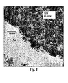
- FIG. 1 An example of a TEM image of a cross-section of a representative catalyst surface of the present invention (material of example 3) is shown in Fig. 1 .
- the gold nanoparticles can be seen to be both on the surface of the support and in the sub-surface region of the support.
- the region containing the gold nanoparticles is very thin and the gold deposition can be seen to follow the contours of the surface of the support.
- the resultant catalytically active material of the invention from one perspective may be viewed as nanoporous catalytic supports having relatively thin shells of discontinuous, catalytic gold on and proximal to their outer surfaces. That is, a resultant catalytically active material comprises a gold-rich shell region proximal to the surface and an interior region comprising negligible gold. In preferred embodiments, this gold-rich shell region comprises small (generally less than 10 nm, most preferably less than 5 nm), discrete gold bodies.
- the present invention overcomes this bias through the combined appreciation that (1) gold mobility is highly restricted on the surface of nanoporous supports, and (2) gold is still catalytically active even at very low weight loadings resulting from the surface coating approach. Consequently, using such supports is highly and uniquely beneficial in the context of depositing gold onto the surface region of a nanoporous support even though full catalytic capacity of the support is not utilized.
- physical vapor deposition preferably is performed while the support to be treated is being well-mixed (e.g., tumbled, fluidized, or the like) to help ensure that particle surfaces are adequately treated.
- Methods of tumbling particles for deposition by PVD are summarized in U.S. Pat. No. 4,618,525 .
- Wise "High Dispersion Platinum Catalyst by RF Sputtering," Journal of Catalysis, Vol. 83, pages 477-479 (1983 ) and Cairns et al U.S. Pat. No. 4,046,712 .
- the support is both tumbled or otherwise fluidized as well as comminuted (e.g., ground or milled to some degree) during at least a portion of the PVD process.
- This provides a degree of mechanical abrasion of the surface of the particles and generation of some fines during gold deposition.
- catalytic performance is enhanced when deposition is carried out with comminution. It is our belief that these processes, i.e., the generation of fines and the mechanical interaction of the grits with each other, increases the activity of the resulting catalyst materials. While not wishing to be bound by theory, we believe that the fines provide higher surface area for higher activity. Fresh surface areas of the support are also exposed, and this might also enhance performance.
- the TEMs reveal the presence of a unique, two phase structure believed to comprise nanoparticles and clusters of gold and carbonaceous material on the surface of the gold-coated particles. It is possible that the mechanical action gives rise to this unique structure as carbonaceous material from one granule is transferred onto the gold-coated surface of another granule by rubbing. This nano-composite of gold/activation agent and carbon seems to possess a very high activity for catalysis of CO oxidation.
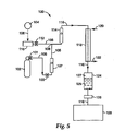
- the apparatus 10 includes a housing 12 defining a vacuum chamber 14 containing a particle agitator 16.
- the housing 12 which may be made from an aluminum alloy if desired, is a vertically oriented hollow cylinder (45 cm high and 50 cm in diameter).
- the base 18 contains a port 20 for a high vacuum gate valve 22 followed by a six-inch diffusion pump 24 as well as a support 26 for the particle agitator 16.
- the chamber 14 is capable of being evacuated to background pressures in the range of 10 -6 torr.
- the top of the housing 12 includes a demountable, rubber L-gasket sealed plate 28 that is fitted with an external mount three-inch diameter dc magnetron sputter deposition source 30 (a US Gun II, US, INC., San Jose, CA). Into the source 30 is fastened a gold sputter target 32 (7.6 cm (3.0 inch) diameter x 0.48 cm (3/16 inch) thick). The sputter source 30 is powered by an MDX-10 Magnetron Drive (Advanced Energy Industries, Inc, Fort Collins, CO) fitted with an arc suppressing Spare-le 20 (Advanced Energy Industries, Inc, Fort Collins, CO).
- MDX-10 Magnetron Drive Advanced Energy Industries, Inc, Fort Collins, CO
- an arc suppressing Spare-le 20 Advanced Energy Industries, Inc, Fort Collins, CO.
- the particle agitator 16 is a hollow cylinder (12 cm long x 9.5 cm diameter horizontal) with a rectangular opening 34 (6.5 cm x 7.5 cm) in the top 36.
- the opening 34 is positioned 7 cm directly below the surface 36 of the gold sputter target 32 so that sputtered gold atoms can enter the agitator volume 38.
- the agitator 16 is fitted with a shaft 40 aligned with its axis.
- the shaft 40 has a rectangular cross section (1 cm x 1 cm) to which are bolted four rectangular blades 42 which form an agitation mechanism or paddle wheel for the support particles being tumbled.
- the blades 42 each contain two holes 44 (2 cm diameter) to promote communication between the particle volumes contained in each of the four quadrants formed by the blades 42 and agitator cylinder 16.
- the dimensions of the blades 42 are selected to give side and end gap distances of either 2.7 mm or 1.7 mm with the agitator walls 48. Preferred modes of use of this apparatus are described below in the examples.
- the gap spacing between the agitator 16 and the walls of the housing 12 affects the performance of the resulting catalyst. As the gap is made smaller, the support particles will have a greater tendency to be ground to some degree. Since such grinding is believed to be beneficial, the gap is set at a suitable distance to ensure that grinding occurs. In one preferred mode the gap was set at about the diameter of the support particles to be coated.
- Physical vapor deposition may be carried out at any desired temperature(s) over a very wide range.
- the deposited gold may be more catalytically active if the gold is deposited at relatively low temperatures, e.g., at a temperature below about 150°C, preferably below about 50°C, more preferably at ambient temperature (e.g., about 20°C to about 27°C) or less. Operating under ambient conditions is preferred as being effective and economical since no heating or chilling requirements are involved during the deposition
- deposition at lower temperatures yields more catalytically active gold for at least two reasons.
- lower temperatures yield gold with more defects in terms of geometrical size and/or shape (angularities, kinks, steps, etc.). Such defects are believed to play a role in many catalytic processes (see Z. P. Liu and P. Hu, J. Am. Chem. Soc., 2003, 125, 1958 ).
- deposition at higher temperatures tends to yield gold that has a more organized and defect-free crystal structure and hence is less active.
- deposition temperature can also impact gold mobility. Gold tends to be more mobile at higher temperatures and hence more likely to accumulate and lose catalytic activity.
- the present invention uses catalytically active gold on the desired support(s) as heterogeneous catalytic systems.
- Gold is widely known as a noble, relatively inert metal with a yellowish color.
- the characteristics of gold change dramatically in nanoscale regimes, where gold becomes highly catalytically active.
- the high reactivity of gold catalyst in comparison with other metal catalysts is illustrated by reactions such as oxidation of CO under ambient conditions and reduction of NO, as well as epoxidation and hydrochlorination of unsaturated hydrocarbons.
- Catalytically active gold may be identified by one or more requisite characteristics including size, color, and/or electrical characteristics. Generally, if a gold sample has one or more of these requisite characteristics, and preferably two or more of these characteristics, it will be deemed to be catalytically active in the practice of the present invention.
- Nanoscale size is a key requisite associated with catalytically active gold in that the catalytic activity of gold to a large degree is a function of whether the gold sample has a thickness dimension in the nanoscale regime (e.g., particle diameter, fiber diameter, film thickness, or the like). Bodies (also referred to as clusters in the literature) having smaller dimensions tend to be more catalytically active. As size increases, catalytic characteristics fall off rapidly.
- catalytically active gold may have a nanoscale size over a wide range, with smaller sizes more preferred when higher activity is desired.
- Catalytically active gold clusters as they are used in the context of the invention have particle or cluster dimensions in the range of from 0.5 nm to 50 nm, preferably 1 nm to 10 nm.
- the gold has a size of no more than 2 nm to 5 nm in any dimension.
- the technical literature reports that catalytic activity may be a maximum at sizes in the range of from 2 nm to about 3 nm.
- the size of the individual gold nanoparticles can be determined by TEM analysis as is well known in the art and as is described herein.
- catalytically active gold is highly active when provided on nanoporous supports in accordance with the practice of the present invention.
- catalytically active gold is highly active when provided on nanoporous supports in accordance with the practice of the present invention.
- gold is expensive.
- nanoscale gold is highly mobile when deposited using PVD, catalytic activity may be compromised if too much gold is used due to accumulation of the gold into large bodies.
- the weight loading of gold on the support preferably is in the range of 0.005 to 10 weight %, preferably 0.005 to 2 weight %, and most preferably from 0.005 to 1.5 weight % based upon the total weight of the support and the gold.
- Depositing catalytically active gold onto a support is very compatible with PVD techniques. Gold naturally sputters to form catalytically active, nanoscale particles and clusters onto the nanoporous support surface. It is believed that the gold is deposited mainly in elemental form, although other oxidation states may be present. Although gold is mobile and will tend to accumulate in low energy sites of the surface, the nanoporous characteristics of the support and the preferred use of activating agents in the practice of the present invention help to immobilize the gold, helping to keep the deposited gold clusters isolated and preferably discontinuous, This helps to preserve catalytic activity that might be otherwise compromised if the gold were to accumulate into larger sized bodies.
- very thin, gold films of nanoscale thickness may also be formed over some or all of the support surface if desired, keeping in mind that catalytic activity decreases with increasing film thickness. Even though such films may be formed with catalytic activity, discontinuous, isolated gold clusters tend to be much more catalytically active and are preferred in most applications.
- the heterogeneous catalyst system may be thermally treated after gold deposition if desired.
- Some conventional methods may require such thermal treatment in order to render the gold catalytically active.
- gold deposited in accordance with the present invention is highly active as deposited without any need for a thermal treatment. Indeed, such gold can very effectively catalytically oxidize CO to form CO 2 at room temperature or even much cooler. Additionally, depending upon factors such as the nature of the support, the activating agents, the amount of gold, or the like, catalytic activity can be compromised to some degree if thermally treated at too high a temperature.
- the heterogeneous catalyst system is intended to be used in a heated environment, e.g., an environment having a temperature higher than about 200°C
- the catalytic activity of the system should be confirmed at those temperatures.
- Embodiments of the invention that perform catalytically well for CO oxidation in such high temperature regimes are described below in the examples. These include systems in which the support includes one or more of alumina, titania, silica, and/or the like.
- low-coordination gold in catalytic nanoparticles is beneficial.
- Low coordination gold refers to Au n for which n on average is in the range of 1 to 100, preferably about 2 to 20.
- the catalytic activity of the very small clusters of gold is associated at least to some degree with low-coordination defects, and that these defects are able to provide sites for storing charges which may be transferred from underlying supports and/or other sources.
- heterogeneous catalysts of the invention include one or more of the following features: (a) The gold and hence the defects are located mainly on the surface of the underlying support; (b) The average value for n is greater than about 2, and (c) As much as is practically possible, gold clusters are isolated but nonetheless close to each other (within a distance of about 1 - 2 nm or less). (d). While such features may be associated with smaller sized gold clusters, it is possible that such characteristics may be found mainly at steps or edges of larger clusters.
- one or more other catalysts could also be provided on the same supports and/or on other supports intermixed with the gold-containing supports. Examples include one or more of silver, palladium, platinum, rhodium, ruthenium, osmium, copper, iridium, or the like. If used, these may be co-deposited onto the support from a target source that is the same or different than the gold source target. Alternatively, such catalysts may be provided on the support either before or after the gold. Other catalysts requiring a thermal treatment for activation advantageously may be applied onto the support and heat treated before the gold is deposited.
- Nanoporous means that the total nanoporous capacity for pores in the size range of 1 to 10 nm is greater than 20% (i.e., greater than about 0.20 using the formula below) of the total pore volume of the support material in the range from 1 to 100 nm as calculated using the following formula.
- NPC CPv 1 - CPv 10 CPv 1 - CPv 100
- the data for calculating the nanoporous capacity as above can be obtained by a technique as described in ASTM Standard Practice D 4641-49 in which nitrogen desorption isotherms are used to calculate the pore size distribution of catalysts and catalyst supports in the range from about 1.5 to 100 nm.
- nanopores can be observed and nanopore size can be measured via transmission electron microscopy (TEM), so that the respective data can also be obtained via TEM.
- TEM transmission electron microscopy
- the nanoporous characteristic of the support helps to immobilize gold clusters on the support surface. This stabilization of the very small gold particles and clusters is evidenced by both the direct observation of smaller particles of gold in TEM studies of materials possessing nanoporous surfaces and in higher catalytic activity as measured by the ability of the catalyst to convert CO to CO 2 in the presence of air.
- the nanoporous characteristic of the support helps to immobilize gold clusters on the support surface. This stabilization of the very small gold particles and clusters is evidenced by both the direct observation of smaller particles of gold in TEM studies of materials possessing nanoporous surfaces and in higher catalytic activity as measured by the ability of the catalyst to convert CO to CO 2 in the presence of air.
- gold is also readily deposited onto nonporous supports using PVD in a catalytically active state without requiring additional thermal or other treatment for activation.
- the substrate particles optionally may further have microporous, mesoporous, and/or macroporous characteristics as such are defined in applicable provisions of IUPAC Compendium of Chemical Technology, 2d edition (1997 ). A typical population of activated carbon or alumina support particles will tend to include a combination of nanoporous, microporous, mesoporous, and macroporous properties.
- the support materials only need be nanoporous in the exterior surface region of the support at a depth equal to or greater than the penetration depth of the gold atoms in the present invention.
- the present invention includes methods whereby normally low surface area, non-nanoporous materials can be made to possess exterior surfaces characterized by nanoporosity.
- These methods include adsorption of nanoporous materials such as gels and nanoparticle size colloids on the surface of a material to form the nanoporous material; hydrolysis of metal alkoxides or metal salts on the surface of a material to form the nanoporous materials; and oxidation of a thin coating of metal, e.g., aluminum, titanium, tin, antimony or the like, on the surface of a material to form a nanoporous material.
- the thin metal films can be deposited by physical vapor methods and the oxidation can be carried out by dry or moist air to produce a nanoparticle film on the substrate.
- hydrolysis with gas phase water is generally more effective in producing activating nanoporous films than hydrolyzing with liquid phase water or water solutions.
- a support is prepared by adsorbing or adhering fine (less than 100 micrometers, preferably less than 50 micrometers and most preferably less than 10 micrometer) nanoporous particles on coarser (greater than 30 mesh) particles.
- This small-particle-supported-on-a-larger-particle composite structure provides dramatically higher total exterior surface area while retaining the desirable gas passing characteristics, i.e., low pressure drop, of a coarser particle.
- inexpensive, non-nanoporous, coarser particles can be used.
- very inexpensive, highly active catalyst particles can be prepared since the bulk of the volume of a catalyst bed is taken up by the inexpensive, underlying, coarser particles.
- nanoporous small particles that can be used in this fashion include sol-gel-derived small particles, and high surface area aerogel particles.
- the small particles can be adhered to the larger particles using partially hydrolyzed alkoxide solutions, basic metal salt solutions, or nanoparticle sized colloidal metal oxides and oxy-hydroxides as an adhesion agent.
- Partially hydrolyzed alkoxide solutions are prepared as is well known in the sol-gel art.
- Useful metal alkoxides include alkoxides of titanium, aluminum, silicon, tin, vanadium and admixtures of these alkoxides.
- Basic metal salts include nitrate and carboxylate salts of titanium and aluminum.
- Nanoparticle size colloidal materials include colloids of oxides and oxy-hydroxides of aluminum, titanium and oxides of silicon, tin, and vanadium.
- the adhesion agent is present in solution and generally is included at an amount of 2 to about 50 oxide weight percent of the nanoporous small particle size material to be adhered.
- the nanoporous, small particle size material is admixed with the selected adhesion agent in solution and then this mixture is combined with the coarser particles. If the coarser particle is porous, the small particle-adhesion agent solution mixture can be introduced by incipient wetting of the porous larger particle. If the larger particle is not porous, the small particle-adhesion agent solution mixture can be admixed with the coarser particles and the solution liquid can be removed either concurrent with the mixing or subsequent to the mixing.
- the mixture is dried and calcined to provide a composite particle having the smaller, nanoporous particles adhered on the surface of a coarser particle.
- the calcining temperature is selected to be below the temperature at which the nanoporous particles lose porosity. Generally the calcining temperature will be in the range of 200°C to 800°C.
- support media of the present invention preferably further include one or more additional characteristics.
- preferred embodiments of the support media are characterized by multiphasic, e.g., biphasic, surfaces.
- Multiphasic means that the surface has more than one phase.
- Our data shows that catalytic activity is enhanced when gold is deposited onto a multiphasic surface. While not wishing to be bound, it is believed that the resultant phase boundaries on the surface appear to help stabilize gold.
- TEM studies as described herein and as is well known in the art can be used to assess whether a surface is biphasic. It is believed that these phase boundaries are very finely dispersed at the nanoscale, helping to make the boundaries effective for immobilizing gold.
- Multiphasic characteristics may be provided by treatment of a support with one or more activating agents.
- Ba(NO 3 ) 2 is one type of activating agent that may be added to a support prior to gold deposition via solution impregnation followed up with a calcining treatment.
- barium nitrate is used as an activating agent for a gamma alumina support.
- an isolated barium phase is not detected. While not wishing to be bound, it is believed that the barium has reacted onto the alumina support surface, thus modifying the surface. Consequently, it is believed that the surface has aluminum rich regions constituting one phase and a barium rich region constituting another phase. Each phase has different properties and different affinity to gold.
- the phase boundaries in one belief, function in a manner analogous to fencing to prevent migration and accumulation of gold.
- Activating agents are described further below.
- a wide variety of materials may serve as suitable supports in the practice of the present invention.
- Representative examples include carbonaceous materials, silicaceous materials (such as silica), metal compounds such as metal oxides or sulfides, combinations of these, and the like.
- Representative metal oxides (or sulfides) include oxides (or sulfides) of one or more of magnesium, aluminum, titanium, vanadium, chromium, manganese, iron, cobalt, nickel, copper, zinc, gallium, germanium, strontium, yttrium, zirconium, niobium, molybdenum, technetium, ruthenium, rhodium, palladium, silver, cadmium, indium, iron, tin, antimony, barium, lanthanum, hafnium, thallium, tungsten, rhenium, osmium, iridium, and platinum.
- carbonaceous substances include activated carbon and graphite.
- Suitable activated carbon particles may be derived from a wide variety of source(s) including coal, coconut, peat, any activated carbon(s) from any source(s), combinations of at least two of these, and/or the like.
- Preferred embodiments of support media may be selected from aluminous oxides, titania, titania-alumina, activated carbon, binary oxides such as hopcalite (CuMnO 2 ), molecular sieves, and/or the like.
- alumina, titania and activated carbon are particularly preferred support materials.
- Activated carbon, titania and alumina are found in forms characterized by nanoporosity and therefore, these forms are preferred support materials.
- Activated carbon is advantageous because in addition to providing a support for catalytic activity, the carbon also functions as an absorbent for noxious gases.
- Activated alumina also is a preferred support material, as it is very robust to aging and heat.
- Heterogeneous catalyst systems are advantageously made from ingredients comprising an alumina support when the catalyst system will be used at elevated temperature and/or where longer service life is desired.
- Heterogeneous catalyst systems of the present invention optionally may incorporate one or more activating agents to enhance catalytic performance of the system.
- an activating agent generally refers to any ingredient that is generally not catalytic by itself yet can enhance the performance of a catalyst when both the activating agent(s) and the catalyst are incorporated into the system.
- One preferred class of activating agents of the present invention includes one or more metal salts.
- a metal salt enhances catalytic performance, but the exact mechanism by which performance is enhanced is not known for certain. Without wishing to be bound, it is believed that the metal cation reacts with the surface of the support in a manner that helps to immobilize gold (e.g., by providing a multiphasic surface) and/or that the metal cation functions as an electron acceptor or participates in some fashion in the catalytic reaction sequence.
- the activating agent comprises at least one alkali metal salt and at least one alkaline earth metal salt, wherein the weight ratio of the alkali metal salt to the alkaline earth metal salt is in the range of about 1:19 to about 19:1, preferably about 1:3 to about 3:1.
- the catalytic performance of a system comprising a potassium salt and a barium salt on a nanoporous alumina support with gold catalyst is astonishing as shown in the examples below. Briefly, this system catalytically oxidized nearly all CO in a test stream containing 1500 ppm CO at ambient temperature for a sustained period of time.
- the metal salts can include any suitable counter anion(s). Examples include nitrate, hydroxide, acetate, carbonate, combinations of these, and the like. Carbonate is an especially preferred anion as it appears independently to have activating characteristics. Carbonate is even more effective when used in combination with an alkali metal or alkaline earth metal. Accordingly, preferred activating agents of the invention comprise a carbonate salt, and more preferably an alkali metal carbonate salt or an alkaline earth metal carbonate salt.
- Potassium carbonate is very effective, for example, especially when used on activated carbon with a gold catalyst, but it is also effective in systems with other types of supports, e.g., alumina, as well.
- the fact that potassium carbonate activates a carbon-gold system is quite surprising. Firstly; depositing gold onto K 2 CO 3 in the absence of the carbon or other nanoporous support provides a system with very low, if any, catalytic activity. Further, depositing gold on activated carbon in the absence of the K 2 CO 3 also provides a system with very low, if any, catalytic activity. Yet, when the three ingredients are combined, a very effective catalyst system results as shown by the examples below.
- potassium carbonate and many of the other salts mentioned herein are very soluble in aqueous solution.
- Depositing the gold onto the substrate via PVD allows systems containing both gold and such activating materials to be easily made.
- Water soluble activators such as K 2 CO 3 cannot be used with conventional aqueous impregnation or precipitation methods. This is because they would dissolve in and be washed from the support medium by the water solvents.
- alkoxide materials especially those described above with respect to forming nanoporous surface features on less porous host particles.
- Preferred alkoxides include alkoxides of Ti and Al.
- Alkoxide materials are advantageously used in combination with one or more of the water soluble salt materials described above. When the two kinds of materials are used together, they can be impregnated onto the support at the same time or sequentially in any order, although it is preferred that the alkoxide material(s) be impregnated onto the support after the impregnation of the salt(s).
- the water soluble salt is impregnated onto the support, and the support is then dried and optionally calcined.
- the alkoxide is impregnated onto the support, the product is hydrolyzed, dried, and optionally calcined.
- gold is then deposited onto the activated support.
- an alkoxide as an impregnant/activating agent appears to change the crystalline structure of the support in our TEM studies. Specifically, the grain structure of the support proximal to the support surface appears to be much finer than the core region and much finer than otherwise identical systems prepared without the alkoxide.
- the structure modification penetrates in most instances further into the support than the gold, e.g., 50 nm or more. In some instances, the boundary between the modified surface region and the unmodified core region is easily observed.
- alkoxides may work in all conditions. For example, Ti and Al alkoxides were found to enhance catalytic performance when incorporated into catalyst systems as shown in the examples. However, substituting a Zr-based alkoxide into these formulations did not demonstrate any enhancement in the ability of the system to oxidize CO.
- Iron salts also are poor candidates for use as the only activating agent when PVD techniques are used to deposit gold This is unexpected, inasmuch as iron salts are effective activators when gold is impregnated onto particles via solution processing. This shows that ingredients that readily work in one context, e.g., solution processing, may not work the same in another context, e.g., PVD processing.
- porous supports are readily activated under the same conditions that work with other support media.
- the amount of activating agent used in the heterogeneous catalyst system can vary over a wide range and will depend upon a variety of factors including the nature of the activating agent, the amount of gold to be incorporated into the system, the nature of the support, and the like. Generally, if too little activating agent is used, the potential benefits of using the activating agent may not be fully attained. On the other hand, beyond some point, using additional activating agent may not provide significant additional benefit and may undermine catalytic performance to some degree. Accordingly, as suggested guidelines, representative embodiments of the invention may include from 0.25 to 15, preferably 1 to 5 weight percent of activating agent based upon the total weight of activating agent and the support.
- the molar ratio of the salt(s) to alkoxide(s) ingredient(s) is in the range of 1:100 to 100:1, preferably 1:5 to 5:1.
- the activating agent may be incorporated into the heterogeneous catalyst system in a variety of different ways.
- the support to be used may inherently include a suitable activating agent.
- activated carbon derived from coconut shell naturally includes potassium carbonate as a constituent. This kind of activated carbon provides an excellent support for gold catalyst without requiring additional activating ingredients.
- Kuraray GC carbon and Kuraray GG carbon are both derived from coconut shells.
- Kuraray GG carbon is the natural, resultant carbon that includes potassium carbonate.
- Kuraray GC carbon is similar except that it has been acid washed and then extensively rinsed with water to remove the potassium carbonate and other acid and water soluble constituents.
- gold is deposited onto these two carbons using PVD, the system derived from Kuraray GG carbon (includes the potassium carbonate) is a very good catalyst for CO oxidation, especially under more humid conditions.
- the system derived from Kuraray GC carbon (essentially no potassium carbonate) has low activity for CO oxidation in dry or humid environments. Further, if the Kuraray GG carbon is washed to remove the potassium salt, catalytic functionality of the resultant system is significantly compromised. Catalytic activity can be recovered again if the washed Kuraray GG carbon is impregnated with an activating agent prior to gold deposition, especially if the impregnated carbon is thermally treated (described further below) prior to gold deposition.
- TEM (transition electron micrograph) examination of the gold deposited on Kuraray GG carbon particles by physical vapor deposition showed the presence of nanoparticles and protodots both on the immediate surface of the support and in pores immediately adjacent to the support surface.
- the gold was present in both nanoparticle and in very small cluster forms.
- the gold particles formed preferentially in small grooves and fissure-like pores in the carbon as evidenced by the orientation of the gold particles in linear, necklace-like patterns on the surface of the carbon.
- the dark field image of the same region showed the gold-enriched striations clearly.
- the uniformity of the gold deposition could be clearly seen on the TEM images.
- the gold clusters that were observed by TEM were as small as 1 nm or less and as large as about 5 nm.
- the gold rich gold grooves or striations were as wide as about 7 nm and as long as about 50 to 100 nm.
- potassium carbonate provides sites where water can adsorb. Indeed, in certain cases we have found that the gold catalysts are more active in the presence of moisture.
- incipient wetness impregnation involves slowly adding a solution comprising the desired activating agent to dry support particles with mixing. The solution generally is added until saturation, and adding an excess of solution is desirably avoided.
- solutions typically are aqueous and the concentration of each species of activating agent in the solution generally is in the range of from about 0.2 M to about 2.5 M. If more than one species of activating agent is to be added, these may be added together, separately, or in overlapping fashion.
- the particles are dried and optionally calcined (thermal treatment).
- Deposition of gold preferably occurs via PVD after impregnation, drying, and optional calcining. Bifurcation of impregnation and gold deposition is a distinct advantage for many reasons.
- the kinds of activating agents that could be used would be limited.
- HAuCl 4 a gold species commonly used in solution methods because of its relatively low cost, is very acidic making it incompatible with basic activating agents such as the preferred alkali and alkaline earth metal salts. In cases where basic gold species are used, the aqueous impregnation would tend to wash away some of the desired activating ions.
- Thermal treatment (calcining) of the activated support prior to gold deposition can be very beneficial.
- an activating agent may not function to the desired degree until after calcining.
- calcining tends to yield demonstrable improvements when the activating agent includes a nitrate salt.
- the performance of an effective activating agent would be further enhanced.
- the performance of generally effective carbonate salts can be enhanced to a degree via calcining.
- salts such as potassium carbonate tend to already be in active form when impregnated, and the resultant activated supports are beneficially dried, e.g., at a temperature up to about 200°C without really needing a calcining treatment.
- thermal treatment involves heating the impregnated support at a temperature in the range of 125°C to about 1000°C for a time period in the range of 1 second to 40 hours, preferably 1 minute to 6 hours, in any suitable atmosphere, such as air; an inert atmosphere such as nitrogen; carbon dioxide; argon; or a reducing atmosphere such as hydrogen; and the like.
- suitable atmosphere such as air; an inert atmosphere such as nitrogen; carbon dioxide; argon; or a reducing atmosphere such as hydrogen; and the like.
- the particular thermal conditions to be used will depend upon factors including the nature of the support and the nature of the impregnants(s).
- thermal treatment should occur below a temperature at which the constituents of the impregnated support would be decomposed, degraded, or otherwise unduly thermally damaged.
- Many calcining treatments of impregnated supports are described in the examples below.
- an activating agent may be supplied as a salt or the like, the resultant form of the salt or its constituent ions after incorporation into the heterogeneous catalyst system is not known with certainty. Analysis by x-ray diffraction shows no distinct oxide or carbonate phase of metal, although some carbonate per se is shown. It is believed, therefore, that the metal ions have reacted with and modified the support surface.
- catalysts of the present invention There is a wide range of applications for catalysts of the present invention. We believe that these catalysts will find application in the areas of treatment of automobile exhaust, as hydrogenation catalysis, as catalysts for the oxidation of hydrocarbons, and as catalysts for the removal of the oxides of nitrogen, and in sensors for detection and measurement of gases and vapors, and CO removal from inhabited areas. Respiratory protection devices such as smoke masks or escape hoods could usefully employ catalysts of the invention for the removal of hazardous CO or other gases from breathing air.
- Test Method 1 CO challenge test procedure
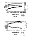
- Fig. 4 shows testing system 50 that was used to subject samples to CO challenges in order to assess catalytic characteristics for oxidizing CO.
- High-pressure compressed air from supply line 52 is reduced in pressure, regulated, and filtered by regulator 54 (3M Model W-2806 Air Filtration and Regulation Panel, 3M Company, St Paul, MN) to remove particulates and oils.
- the regulator is adjusted to give a delivery pressure of between 40 and 60 psi.
- Valve 56 Hoke Inc., Spartanburg, SC
- Valve 56 Hoke Inc., Spartanburg, SC
- the flow meter 58 was calibrated using a Gilibrator® bubble flow meter (Sensidyne, Inc., Clearwater, FL; not shown). Unless otherwise stated an airflow rate of 64 LPM was used for all catalyst testing.
- the main airflow passes through the headspace 60 above a heated distilled water bath 62 of vessel 64 and then passes via lines 57 and 75 into a 1000 ml mixing flask 66.
- Relative humidity in the mixing flask is monitored using a RH sensor 68 (Type 850-252, General Eastern, Wilmington, MA).
- the RH sensor 68 provides an electrical signal to a humidity controller 70 (an Omega Engineering PID controller series CN1200 from Omega Engineering Inc., Stamford, CT) that delivers power via lines 71 to a submerged heater 72 to maintain the RH at the set point. Unless otherwise indicated, the relative humidity is controlled at 85%.
- a cylinder 74 of carbon monoxide equipped with a regulator 76 suitable for CO service provides a regulated flow of CO gas via line 73.
- a stainless steel, very fine angled metering valve 78 (Swagelok Co, Solon, OH) is used to set the desired CO flow rate. Unless otherwise indicated, a CO flow rate of 96 mL/min is used in order to obtain a CO concentration in the air stream of 1500 ppm.
- the metered CO is combined with the humidified air in the mixing flask 66.
- the combined stream then flows into the test chamber 80 having a box 81 such as an inverted, 13-quart, stainless steel bucket closably engaging a support platform 83.
- a test fixture 82 Inside the test chamber 80 is a test fixture 82.
- the test chamber 80 is sealed to support platform 83 using a foam gasket (not shown). Two clamps (not shown) ensure a tight seal to the support platform 83.
- the box 81 can be removed to allow catalyst text fixtures to be placed inside for testing and taken out after testing is complete.
- the support platform 83 is equipped with an inner 29/42 tapered fitting (not shown) onto which the fixture 82 containing the catalyst to be tested is mounted.
- the CO and CO 2 concentrations and the dew point temperature are measured at the outlet of the test chamber using a Brüel & Kj ⁇ r Multi-gas Monitor Type 1302 sensor (Brüel & Kj ⁇ r, N ⁇ rum, Denmark; not shown) equipped with optical filters #982 to detect CO 2 and #984 to detect CO.
- the Multi-gas Monitor was calibrated with 10,000-ppm CO 2 and 3,000-ppm CO gas standards following the manufacturers recommended procedure.
- the Multi-gas Monitor outputs data to a data acquisition device such as a chart recorder or a laptop PC running Hyperterminal Software (Hilgraeve, Monroe, MI). Text files are imported into Microsoft® Excel software (Microsoft Corp., Redmond, WA) for data analysis.
- the system 50 Prior to initiating testing the system 50 is allowed to equilibrate to a constant concentration of nominally 1500-ppm CO. Variability in the initial CO concentration was ⁇ 5% for samples tested at 1500-ppm and ⁇ 3% for samples tested at 3600-ppm CO.
- the temperature of the air stream is monitored downstream of the test fixture using a K-type thermocouple (not shown) and digital readout (not shown) (Fluke 51 K/J Thermometer, Fluke Corporation, Everett, WA).
- Catalyst samples are sieved to remove fines prior to testing. Unless otherwise specified, samples were sieved to remove particles finer than 20 mesh using U.S. Standard Sieves (A.S.T.M. E-11 specification; The Murdock Co., Mundelein, IL).
- a specified catalyst volume typically 100 ml, is loaded into the aluminum test fixture 82 with 8.9 cm (3.5 in) inner diameter and equipped with an outer 29/42 tapered fitting using a loading' column (as described in UK 606,876 with one modification, the removal of the upward facing cone). Typical bed depth is approximately 1.6 cm (0.6 in). Screens mounted inside the test fixture 82 prevent loss of catalyst particles during the testing.
- the tubing 85 carrying the air/CO mixture is disconnected from the top of the test chamber 80 via the tapered fitting (not shown), the box 81 is removed, and the test fixture 82 containing the catalyst is placed on the 29/42 fitting on the support platform 81. The box 81 is replaced and sealed to the support platform 83.
- CO and CO 2 concentration measurements begin when the air/CO tubing 85 is reconnected to the tapered fitting on the top of the test chamber 80. Measurements continue for a specified time period, typically 30 minutes.
- valve 78 was replaced with a stainless steel, fine metering, double pattern valve (Swagelok Co., Solon, OH) to allow for control of higher CO flowraes.
- Test Method 2 Chromatographic Test Procedure and Apparatus
- Fig. 5 shows a system 100 used for chromatographic analysis of catalytic characteristics of samples.
- System 100 includes a high pressure CO in air mixture (1.9% v/v) stored in tank 102 and is also coupled to a source 104 of building compressed air via line 106.
- Pressure regulator and shut off valve 101 and fine needle valve 103 help control the flow of CO in air through line 105.
- the flow of CO in air is measured by rotameter 107 (Alphagaz (Air Liquide) 3502 flow tube, Morrisville, PA).
- the flow of building compressed air through line 106 is reduced in pressure, regulated, and filtered by regulator 110 (3M Model W-2806 Air Filtration and Regulation Panel, 3M Company, St Paul, MN).
- the regulator is adjusted to give a delivery pressure of between 40 and 60 psi.
- Fine needle valve 112 is used to set the desired airflow rate through line 106.
- Rotameter 114 (Aalborg Instruments 112-02 flowtube, Orangeburg, NY) on line 116 measures the total flow of the combined streams.
- the rotameters are calibrated using a Gilibrator® bubble flow meter (not shown) placed at the catalyst bed (no catalyst present).
- the two rotameters 107 and 114 are chosen to obtain concentrations from about 1000 to 20,000 ppm CO at flow rates from about 100 mL/min to about 500 mL/min under lab ambient conditions.
- the diluted CO in air mixture in line 116 is then humidified to the desired RH by passing the air mixture either through the inner tube of a tube in shell Nafion® dryer 118 as shown (Perma Pure MD 110-12P; Toms River, New Jersey) operating as a humidifier or by passing the air mixture through a pressure vessel containing water (not shown).
- Wet air is introduced to dryer 118 through line 120 and exits via line 122. In the latter, process, a RH of about 70% was obtained at a flow rate of 200 ml/min.
- Wet air is passed through the dryer shell to humidify the dry CO in air stream passing through the inner tube.
- the wet air is obtained by bubbling compressed air through a glass frit into a flask of water maintained at a controlled temperature in a refrigerated water bath. If a lower RH is desired, the temperature of the water bath is lowered until the CO in air mixture attains the desired RH. This is measured by a General Eastern Hygro-M1 optical mirror dew point hygrometer (GE General Eastern Instruments, Wilmington MA). Room temperature air saturated with water vapor at about 3 L/min through the dryer shell humidifies a CO/air stream at 100 mL/min to >90% RH
- the catalyst sample (usually about 1-2 cm in depth) is snowflaked into a section of thick walled 4 mm ID polyethylene tubing 124 about 8 cm in length to form a catalyst bed 125.
- a cotton plug 127 seals one end of tubing 124.
- the CO in air mixture passes through the catalyst bed and then through a particulate cartridge filter 126 (Balston DFU sample filter grade BQ, Parker Hannifin Corporation, Tewksbury, MA) into the gas sampling valve of a gas chromatograph 128 (SRI model 8610C gas chromatograph with gas sampling valve and thermal conductivity and helium ionization detectors, Torrance, CA).
- the particulate filter 126 protects the GC valve from damage by particulates escaping the catalyst bed.
- the gas sampling valve periodically injects the exit stream from the catalyst bed onto a 5 ft molecular sieve 5A column. This separates CO from air.
- CO concentration is determined by either a thermal conductivity detector (CO detection limit about 500 ppm) or by a helium ionization detector (CO detection limit ⁇ 10 ppm). The CO concentration is measured approximately every four minutes during the test, displayed, and recorded in a data file.
- detectors are calibrated by diluting a known flow of Scott certified CO (99.3%) with a known flow of air to generate known CO concentrations (flow calibrator: Sensidyne Gilibrator flow calibrator, Clearwater, FL). A calibration curve is generated from these data.
- Gold Application Method Process for deposition of gold nanoparticles onto substrate particles:
- the power is stopped after 60 minutes.
- the chamber 14 is backfilled with air and the gold coated particles are removed from the apparatus 10.
- the gold sputter target 32 is weighed before and after coating to determine the amount of gold deposited. In the case of carbon particles, the amount of gold deposited was determined by ion-coupled plasma elemental analysis on the treated carbon particles to be 0.05% w/w.
- the gap between the blades 42 and the chamber wall were maintained at 1.7 mm (deposition condition 1) or 2.7 mm (deposition condition 2).
- the resulting dried material was crushed using a ⁇ Braun" type UD pulverizer having a 1.1 mm gap between the steel plates.
- the crushed material was screened and the 0.125 mm to about 1 mm screen size material was retained and was fed into the end of a calciner which was a 23 cm diameter 4.3 meter long stainless steel tube having a 2.9 meter hot zone, the tube being inclined at 2.4 degrees with respect to the horizontal, and rotating at 7 rpm, to provide residence time of about 15 - 20 minutes.
- the calciner had a hot zone feed end temperature of about 350°C and exit end temperature of about 800°C.
- the gas above the alumina particles at the hot end of the calciner was measured at about 380°C during the calcinations.
- the pre-fired material was then screened to be greater than 20 mesh but less than 16 mesh in size using U. S. Standard Sieves (A.S.T.M. E-11 specification; The Murdock Co., Mundelein, IL). This size fraction was designated alumina particles "A”.
- An additional sample of the pre-fired material was screened to be greater than about 20 mesh but less than 14 mesh in size using the U. S. Standard Sieves (A.S.T.M. E-11 specification; The Murdock Co., Mundelein, IL).
- the 14 to 20 mesh particle size samples were designated alumina particles "B". These materials were used in the preparation of the following catalyst supports.
- Type A gamma alumina particles were treated with gold by plasma-assisted sputtering as previously described using deposition condition 2.
- the performance of the CO oxidation catalyst of example 1 in oxidizing CO during gas flow through a bed was measured using test method 1.
- the CO challenge was 3600 ppm CO and the total gas flow rate was 64 liters/min.
- the gas was at 85% relative humidity.
- the results are represented in Fig. 6.
- Fig. 6 and other similar graphs in these examples display measured gas concentrations in ppm versus time of testing after test gas mixture is passed through a 100 ml test bed. The elapsed time is represented in minutes:seconds:tenths of seconds.
- Type B gamma alumina particles were treated with gold by plasma-assisted sputtering as previously described using deposition condition 2.
- the performance of the CO oxidation catalyst of example 2 in oxidizing CO during gas flow through a bed was measured using test method 1.
- the CO challenge was 3600 ppm CO and the total gas flow rate was 64 liters/min.
- the gas was at 85% relative humidity. The results are represented in Fig. 7 .
- a solution of the impregnation liquid was prepared by mixing sufficient soluble salt of the impregnation metal with deionized water in sufficient quantity to generate a solution having the desired concentration.
- the particles were impregnated by incipient wetness.
- the incipient wetness technique involves slow addition of the impregnation solution to the dry, gamma alumina particles while stirring the particles with a paddle or spatula, until the pores of the gamma alumina particles are fully saturated with the solution via impregnation of the solution into the pores of the gamma alumina particles. An excess of the impregnation solution, as evidenced by the visual observation of liquid phase on or between the particles was avoided. After the particles were fully saturated, the impregnated particles were dried in a forced air oven at 130°C and were calcined as described for each sample.
- the weight percent gold on this sample was measured by Inductively Coupled Argon Plasma Spectroscopic Analysis (ICP). The results for replicate samples were 0.0486 wt % gold and 0.0521 wt % gold.
- Example 3 A sample from Example 3 was examined by TEM as previously described.
- the approximate size range of Au particles in an undulating region that appeared to be representative of the sample was 2.1 to 6.6 nm.
- the average size of Au particles in this 51 region was 3.0 nm and the approximate range of depth into the substrate was 38 to 60 nm.
- the approximate size range of Au particles was 2.4 to 11.4 am.
- the average size of Au particles in this region was 8.6 nm and the gold particles were found to be entirely on the surface of the particle with little penetration observed.
- the performance of the catalyst of example 3 was examined for its catalytic activity in oxidizing CO during gas flow through a bed using test method 1.
- the CO challenge was 1500 ppm CO and the total gas flow rate was 64 liters/min.
- the gas was at 85% relative humidity.
- the results are represented in Fig. 8 . These results illustrate the improved catalytic properties of the support modified with a potassium source.
- a 300 ml portion of the dried sample from example 3 was calcined to 300°C by heating in air in a box furnace and holding the sample at 300°C for 1 hour. After cooling, this calcined sample was treated with gold (deposition condition 2).
- the performance of the catalyst of example 4 was examined for its catalytic activity in oxidizing CO during gas flow through a bed using test method 1.
- the CO challenge was 1500 ppm CO and the total gas flow rate was 64 liters/min.
- the gas was at 85% relative humidity.
- the results are represented in Fig. 9 .
- a 300 ml portion of the dried sample from example 3 was calcined to 600°C by heating in air in a box furnace and holding the sample at 600°C for 1 hour. After cooling, this calcined sample was treated with gold (deposition condition 2).
- the performance of the catalyst of example 5 was examined for its catalytic activity in oxidizing CO during gas flow through a bed using test method 1.
- the CO challenge was 1500 ppm CO and the total gas flow rate was 64 liters/min.
- the gas was at 85% relative humidity.
- the results are represented in Fig. 10 .
- a solution of potassium carbonate was prepared by dissolving 6.91 g of K 2 CO 3 ((Merck KGAA, Darmstadt, Germany)) in sufficient deionized water to yield a volume of 200 ml
- a sample of gamma alumina particles B (300 ml volume of particles, 224.14 g) was impregnated by the incipient wetness technique using about 150 ml of the 0.4 M K 2 SO 4 . After impregnation, the particles were dried in an oven at 130°C. After drying the impregnated particles were gold treated via plasma-assisted sputtering (deposition condition 2).
- the performance of the catalyst of example 6 was examined for its catalytic activity in oxidizing CO during gas flow through a bed using test method 1.
- the CO challenge was 3600 ppm CO and the total gas flow rate was 64 liters/min.
- the gas was at 85% relative humidity.
- the results are represented in Fig. 11 .
- Potassium carbonate impregnated gamma alumina particles were prepared and tested exactly as described in example 6 with the exception that 13.82 g of potassium carbonate was used in place of the 6.91 g potassium carbonate. The results of testing are represented in Fig. 12 .
- Potassium carbonate impregnated gamma alumina particles were prepared and tested exactly as described in example 6 with the exception that 20.72 g of potassium Carbonate was used in place of the 6.91 g potassium carbonate. The results of testing are represented in Fig. 13 .
- a solution of 0.5 M ammonium carbonate (Fisher Scientific Co., Fair Lawn, NJ) was prepared by dissolving 11.41g of ammonium carbonate hydrate in sufficient deionized water to yield a volume of 200 ml.
- a sample of gamma alumina particles A (300 ml volume of particles, 224.14 g sample) was impregnated by the incipient wetness technique using about 150 ml of the 0.5 M ammonium carbonate solution. After impregnation, the particles were dried in an oven at 100°C. After drying the impregnated particles were gold treated via plasma assisted sputtering (deposition condition 2).
- the performance of the catalyst of example 9 was examined for its catalytic activity in oxidizing CO during gas flow through a bed using test method 1.
- the CO challenge was 1500 ppm CO and the total gas flow rate was 64 liters/min.
- the gas was at 85% relative humidity.
- the results are represented in Fig. 14 .
- a solution of 0.4 M potassium hydroxide was prepared by dissolving 4.49 g of KOH (Merck KgaA, Darmstadt, Germany) in sufficient deionized water to yield a volume of 200 ml.
- KOH Merck KgaA, Darmstadt, Germany
- a sample of gamma alumina particles A 300 ml volume of particles, 224.14 g sample) was impregnated by the incipient wetness technique using about 150 ml of the 0.4 M KOH. After impregnation, the particles were dried in an oven at 100°C. After drying the impregnated particles were gold treated via plasma-assisted sputtering (deposition condition 2).
- the performance of the catalyst of example 10 was examined for its catalytic activity in oxidizing CO during gas flow through a bed using test method 1.
- the CO challenge was 1500 ppm CO and the total gas flow rate was 64 liters/min.
- the gas was at 85% relative humidity.
- the results are represented in Fig. 15 .
- a solution of 0.4 M potassium acetate was prepared by dissolving 7.85 g of KCH 3 O 2 (Fisher Scientific Co., Fair Lawn, NJ) in sufficient deionized water to yield a volume of 200 mL
- KCH 3 O 2 Fisher Scientific Co., Fair Lawn, NJ
- a sample of gamma alumina particles A 300 ml volume of particles, 224.14 g was impregnated by the incipient wetness technique using about 150 ml of the 0.4 M KCH 3 O 2 . After impregnation, the particles were dried in an oven at 100°C. After drying the impregnated particles were gold treated via plasma-assisted sputtering (deposition condition 2).
- the performance of the catalyst of example 11 was examined for its catalytic activity in oxidizing CO during gas flow through a bed using test method 1.
- the CO challenge was 1500 ppm CO and the total gas flow rate was 64 liters/min.
- the gas was at 85% relative humidity.
- the results are represented in Fig. 16 .
- a solution of potassium sulfate was prepared by dissolving 13.94 g of K 2 SO 4 (J.T. Baker Chemical Co., Phillipsburg, NJ) in sufficient deionized water to yield a volume of 200 ml.
- a sample of gamma alumina particles A (300 ml volume of particles, 224.14 g) was impregnated by the incipient wetness technique using about 150 ml of the 0.4 M K 2 SO 4 . After impregnation, the particles were dried in an oven at 100°C. After drying the impregnated particles were gold treated via plasma-assisted sputtering (deposition condition 2).
- the performance of the catalyst of example 12 was examined for its catalytic activity in oxidizing CO during gas flow through a bed using test method 1.
- the CO challenge was 1500 ppm CO and the total gas flow rate was 64 liters/min.
- the gas was at 85% relative humidity.
- the results are represented in Fig. 17 .
- a solution of potassium oxalate was prepared by dissolving 14.74 g of K 2 C 2 O 4 (Mallinkrodt Chemical Works, St. Louis, Mo) in sufficient deionized water to yield a volume of 200 ml.
- a sample of gamma alumina particles A (300 ml volume of particles, 224.14 g) was impregnated by the incipient wetness technique using about 150 ml of the 0.4 M K 2 C 2 O 4 . After impregnation, the particles were dried in an oven at 100°C. After drying the impregnated particles were gold treated via plasma-assisted sputtering (deposition condition 2).
- the performance of the catalyst of example 13 was examined for its catalytic activity in oxidizing CO during gas flow through a bed using test method 1.
- the CO challenge was 1500 ppm CO and the total gas flow rate was 64 liters/min.
- the gas was at 85% relative humidity The results are represented in Fig. 18 .
- a solution of potassium phosphate was prepared by dissolving 13.93 g of K 2 HPO 4 (Aldrich Chemical Co., Milwaukee, WI) in sufficient deionized water to yield a volume of 200 ml.
- a sample of gamma alumina particles A 300 ml volume of particles, 224.14 g was impregnated by the incipient wetness technique using about 150 ml of the 0.4 M K 2 HPO 4 . After impregnation, the particles were dried in an oven at 100°C. After drying the impregnated particles were gold treated via plasma assisted sputtering (deposition condition 2).
- the performance of the catalyst of example 14 was examined for its catalytic activity in oxidizing CO during gas flow through a bed using test method 1.
- the CO challenge was 1500 ppm CO and the total gas flow rate was 64 hters/min.
- the gas was at 85% relative humidity. The results are represented in Fig. 19 .
- the incipient wetness technique was used to impregnate A type gamma alumina particles with 0.4 M barium nitrate (Certified A.C.S., Fisher Scientific Co., Fair Lawn, NJ) solution as the impregnation solution.
- This impregnation involved impregnating 224.1 g of the gamma alumina with 148 ml of a solution prepared by dissolving 20.9 g of barium nitrate in deionized water to yield a final volume of 200 mls. After drying at 130°C the sample was treated with gold via plasma-assisted sputtering (deposition condition 2).
- the performance of the catalyst of example 15 was examined for its catalytic activity in oxidizing CO during gas flow through a bed using test method 1.
- the CO challenge was 1500 ppm CO and the total gas flow rate was 64 liters/min.
- the gas was at 85% relative humidity.
- the results are represented in Fig. 20 .
- the incipient wetness technique was used to impregnate A-type gamma alumina particles with 0.4 M barium nitrate (Certified A.C.S., Fisher Scientific Co., Fair Lawn, NJ) solution as the impregnation solution exactly as described in example 12. After drying at 130°C, a portion of the sample was calcined to 300°C and held at 300°C for 1 hour before allowing to cool with the furnace. After cooling, the sample was treated with gold via plasma-assisted sputtering (deposition condition 2).
- the performance of the catalyst of example 16 was examined for its catalytic activity in oxidizing CO during gas flow through a bed using test method 1.
- the CO challenge was 1500 ppm CO and the total gas flow rate was 64 liters/min.
- the gas was at 85% relative humidity.
- the results are represented in Fig. 21 .
- the incipient wetness technique was used to impregnate A-type gamma Alumina particles with 0.4 M barium nitrate (Certified A.C.S., Fisher Scientific Co., Fair Lawn, NJ) solution as the impregnation solution exactly as describe in example 12. After drying at 130°C, a portion of the sample was calcined to 600°C and held at 600°C for one hour. After cooling, the sample was treated with gold via plasma-assisted sputtering (deposition condition 2).
- the performance of the catalyst of example 17 was examined for its catalytic activity in oxidizing CO during gas flow through a bed using test method 1.
- the CO challenge was 1500 ppm CO and the total gas flow rate was 64 liters/min.
- the gas was at 85% relative humidity.
- the results are represented in Fig. 22 .
- the incipient wetness technique was used to impregnate A-type gamma alumina particles with 0.4 M barium nitrate (Certified A.C.S., Fisher Scientific Co., Fair Lawn, NJ) solution as the impregnation solution exactly as described in example 12. After drying at 130°C, a portion of the sample was calcined to 600°C and held at 600°C for one hour. After cooling, this sample was impregnated with 0.5 M K 2 CO 3 by incipient wetness. The sample was dried at 130°C and treated with gold according to deposition condition 2.
- the performance of the catalyst of example 18 was examined for its catalytic activity in oxidizing CO during gas flow through a bed using test method 1.
- the CO challenge was 1500 ppm CO and the total gas flow rate was 64 liters/min.
- the gas was at 85% relative humidity.
- the results are represented in Fig. 23 .
- Comparison of the results of testing the material of example 18 with the results of testing the material of examples 17 show that improvement in catalytic performance can be attained by using a combination of activating agents.
- the incipient wetness technique was used to impregnate A-type gamma alumina particles with 0.4 M magnesium nitrate hexahydrate (Alfa Aesar, Ward Hill, MA) solution
- the solution for impregnation was prepared by dissolving 20.51 g of the magnesium nitrate hexahydrate in deionized water to yield a final volume of 200 ml. 148 ml of this solution was used to impregnate 224.14 g of the alumina particles. After drying at 130°C the sample was treated with gold via plasma-assisted sputtering (deposition condition 2).
- the performance of the catalyst of example 19 was examined for its catalytic activity in oxidizing CO during gas flow through a bed using test method 1.
- the CO challenge was 1500 ppm CO and the total gas flow rate was 64 liters/min.
- the gas was at 85% relative humidity.
- the results are represented in Fig. 24 .
- the incipient wetness technique was used to impregnate A-type gamma alumina particles with 0.4 M magnesium nitrate (Alfa Aesar, Ward Hill, MA) solution as described in example 16. After drying at 130°C, a portion of the sample was calcined to 300°C and held at 300°C for 1 hour before allowing to cool with the furnace. After cooling, the sample was treated with gold via plasma-assisted sputtering (deposition condition 2).
- the performance of the catalyst of example 20 was examined for its catalytic activity in oxidizing CO during gas flow through a bed using test method 1.
- the CO challenge was 1500 ppm CO and the total gas flow rate was 64 liters/min.
- the gas was at 85% relative humidity.
- the results are represented in Fig. 25 .
- the incipient wetness technique was used to impregnate A-type gamma alumina particles with 0.4 M magnesium nitrate (Alfa Aesar, Ward Hill, MA) solution as described in example 16. After drying at 130°C, a portion of the sample was calcined to 600°C and held at 600°C for one hour. After cooling, the sample was treated with gold via plasma assisted sputtering (deposition condition 2).
- the performance of the catalyst of example 21 was examined for its catalytic activity in oxidizing CO during gas flow through a bed using test method 1.
- the CO challenge was 1500 ppm CO and the total gas flow rate was 64 liters/min.
- the gas was at 85% relative humidity.
- the results are represented in Fig. 26 .
- the incipient wetness technique was used to impregnate A-type gamma alumina particles with a solution of 0.4 M calcium nitrate.
- a solution of 0.4 M calcium nitrate To prepare the impregnation solution, 18.89 g of calcium nitrate tetrahydrate (BAKER ANALYZED ®, J.T. Baker, Co., Phillipsburg, NJ) was dissolved in deionized water to yield a volume of 200 ml. 148 ml of this solution was impregnated into 224.14 g of the gamma alumina particles. After drying at 130°C the sample was treated with gold via plasma assisted sputtering (deposition condition 2).
- the performance of the catalyst of example 22 was examined for its catalytic activity in oxidizing CO during gas flow through a bed using test method 1.
- the CO challenge was 1500 ppm CO and the total gas flow rate was 64 liters/min.
- the gas was at 85% relative humidity.
- the results are represented in Fig. 27 .
- the incipient wetness technique was used to impregnate A-type gamma alumina particles with a solution of 0.4 M calcium nitrate (calcium nitrate tetrahydrate, BAKER ANALYZED ®, J. T. Baker, Co., Phillipsburg, NJ) as described in example 19. After drying at 130°C, a portion of the sample was calcined to 300°C and held at 300°C for 1 hour before allowing to cool with the furnace. After cooling, the sample was treated with gold via plasma-assisted sputtering (deposition condition 2).
- the performance of the catalyst of example 23 was examined for its catalytic activity in oxidizing CO during gas flow through a bed using test method 1.
- the CO challenge was 1500 ppm CO and the total gas flow rate was 64 liters/min.
- the gas was at 85% relative humidity.
- the results are represented in Fig. 28 .
- the incipient wetness technique was used to impregnate A-type gamma alumina particles with a solution of 0.4 M calcium nitrate (calcium nitrate tetrahydrate, BAKER ANALYZED ®, J. T. Baker, Co., Phillipsburg, NJ) as described in example 19. After drying at 130°C, a portion of the sample was calcined to 600°C and held at 600°C for one hour. After cooling, the sample was treated with gold via plasma-assisted sputtering (deposition condition 2).
- the performance of the catalyst of example 24 was examined for its catalytic activity in oxidizing CO during gas flow through a bed using test method 1.
- the CO challenge was 1500 ppm CO and the total gas flow rate was 64 liters/min.
- the gas was at 85% relative humidity.
- the results are represented in Fig. 29 .
- the incipient wetness technique was used to impregnate A-type gamma alumina particles with a solution of 0.4 M calcium nitrate (calcium nitrate tetrahydrate, BAKER ANALYZED ®, J. T. Baker, Co., Phillipsburg, NJ) as described in example 19. After drying at 130°C, a portion of the sample was calcined to 600°C and held at 600°C for one hour. After cooling, the sample was impregnated by incipient wetness using a 0.5 M solution of potassium carbonate. The resulting calcium and potassium treated particles were dried at 135°C overnight and treated with gold via plasma-assisted sputtering (deposition condition 2).
- the performance of the catalyst of example 25 was examined for its catalytic activity in oxidizing CO during gas flow through a bed using test method 1.
- the CO challenge was 1500 ppm CO and the total gas flow rate was 64 liters/min.
- the gas was at 85% relative humidity.
- the results are represented in Fig. 30 .
- the incipient wetness technique was used to impregnate A-type gamma alumina particles with a solution of 0.4 M iron nitrate nonahydrate.
- 32.32 g of Fe(NO 3 ) 3 ⁇ 9H 2 O was dissolved in deionized water to yield a final volume of 200 mL 224.14 g of gamma alumina A particles were impregnated with the iron nitrate solution. After drying at 130°C, the sample was calcined to 600°C and held at 600°C for 1 hour. After calcining the impregnated particles were gold treated via plasma-assisted sputtering (deposition condition 2).
- the performance of the catalyst of example 26 was examined for its catalytic activity in oxidizing CO during gas flow through a bed using test method 1.
- the CO challenge was 1500 ppm CO and the total gas flow rate was 64 liters/min.
- the gas was at 85% relative humidity.
- the results are represented in Fig. 31 .
- the incipient wetness technique was used to impregnate A-type gamma Alumina particles with 148 ml of a solution of 50% manganese nitrate (Fisher Scientific Co., Fair Lawn, NJ). 224.14 g of gamma alumina A particles were impregnated with the manganese nitrate solution. After drying at 130°C, the sample was calcined to 600°C and held at 600°C for 1 hour. After calcining the impregnated particles were gold treated via plasma-assisted sputtering (deposition condition 2).
- the performance of the catalyst of example 27 was examined for its catalytic activity in oxidizing CO during gas flow through a bed using test method 1.
- the CO challenge was 1500 ppm CO and the total gas flow rate was 64 liters/min.
- the gas was at 85 % relative humidity. The results are represented in Fig. 32 .
- the incipient wetness technique was used to impregnate A-type gamma alumina particles with a solution of 0.4 M cobalt nitrate hexahydrate.
- To make the cobalt nitrate solution 23.28 g of Co(NO 3 ) 2 ⁇ 6H 2 O (analytical reagent grade, Mallinkrodt Inc., Paris, Ky) was dissolved in deionized water to yield a final volume of 200 ml. 224.14 g of gamma alumina A particles were impregnated with the cobalt nitrate solution. After drying the impregnated particles at 130°C, a portion of the sample was calcined to 600°C and held at 600°C for 1 hour. After calcining the impregnated particles were gold treated via plasma-assisted sputtering (deposition condition 2).
- the performance of the catalyst of example 28 was examined for its catalytic activity in oxidizing CO during gas flow through a bed using test method 1.
- the CO challenge was 1500 ppm CO and the total gas flow rate was 64 liters/min.
- the gas was at 85% relative humidity.
- the results are represented in Fig. 33 .
- the incipient wetness technique was used to impregnate A-type gamma alumina particles with a solution of 0.4 M copper (II) nitrate 2.5 hydrate.
- copper (II) nitrate 2.5 hydrate To make the copper nitrate solution, 18.61 g of Cu(NO 3 ) 2 ⁇ 2.5H 2 O (BAKER ANALYZED ®, J. T. Baker, Co., Phillipsburg, NJ) was dissolved in deionized water to yield a final volume of 200 ml. 224.14 g of gamma alumina A particles were impregnated with the copper nitrate solution. After drying the impregnated particles at 130°C, a portion of the sample was calcined to 600°C and held at 600°C for 1 hour. After calcining the impregnated particles were gold treated via plasma-assisted sputtering (deposition condition 2).
- the performance of the catalyst of example 29 was examined for its catalytic activity in oxidizing CO during gas flow through a bed using test method 1.
- the CO challenge was 1500 ppm CO and the total gas flow rate was 64 liters/min.
- the gas was at 85% relative humidity.
- the results are represented in Fig. 34 .
- the incipient wetness technique was used to impregnate A-type gamma alumina particles with a solution of 0.4 M nickel nitrate hexahydrate.
- nickel nitrate solution 23.26 g of Ni(NO 3 ) 2 ⁇ 6H 2 O (Cobalt low, certified, Fisher Scientific Company, Fair Lawn, NJ) was dissolved in deionized water to yield a final volume of 200 ml. 224.14 g of gamma alumina A particles were impregnated with the nickel nitrate solution. After drying the impregnated particles at 130°C, a portion of the sample was calcined to 600°C and held at 600°C for 1 hour. After calcining the impregnated particles were gold treated via plasma-assisted sputtering (deposition condition 2).
- the performance of the catalyst of example 30 was examined for its catalytic activity in oxidizing CO during gas flow through a bed using test method 1.
- the CO challenge was 1500 ppm CO and the total gas flow rate was 64 liters/min.
- the gas was at 85% relative humidity.
- the results are represented in Fig. 35 .
- the incipient wetness technique was used to impregnate A-type gamma alumina particles with a solution of 0.4 M chromium nitrate nonahydrate.
- chromium nitrate solution 32.01 g of Cr(NO 3 ) 3 ⁇ 9H 2 O (Reagent grade, Matheson, Coleman and Bell, Norwood, Ohio) was dissolved in deionized water to yield a final volume of 200 mL 224.14 g of gamma alumina A particles were impregnated with the chromium nitrate solution. After drying the impregnated particles at 130°C, a portion of the sample was calcined to 600°C and held at 600°C for 1 hour. After calcining the impregnated particles were gold treated via plasma-assisted sputtering (deposition condition 2).
- the performance of the catalyst of example 31 was examined for its catalytic activity in oxidizing CO during gas flow through a bed using test method 1.
- the CO challenge was 1500 ppm CO and the total gas flow rate was 64 liters/min.
- the gas was at 85% relative humidity.
- the results are represented in Fig. 36 .
- the incipient wetness technique was used to impregnate A-type gamma Alumina particles with a solution or 0.4 M zinc nitrate hexahydrate.
- a solution or 0.4 M zinc nitrate hexahydrate 23.80 g of Zn(NO 3 ) 2 ⁇ 6H 2 O (BAKER ANALYZED Reagent,® Mallinkrodt Baker, Inc., Phillipsburg, NJ) was dissolved in deionized water to yield a final volume of 200 ml 224.14 g of gamma alumina A particles were impregnated with the zinc nitrate solution. After drying the impregnated particles at 130°C, a portion of the sample was calcined to 600°C and held at 600°C for 1 hour. After calcining the impregnated particles were gold treated via plasma-assisted sputtering (deposition condition 2).
- the performance of the catalyst of example 32 was examined for its catalytic activity in oxidizing CO during gas flow through a bed using test method 1.
- the CO challenge was 1500 ppm CO and the total gas flow rate was 64 liters/min.
- the gas was at 85% relative humidity.
- the results are represented in Fig. 37 .
- the incipient wetness technique was used to impregnate A-type gamma alumina particles with a solution of Tyzor LATM titanium lactate solution containing potassium carbonate.
- Tyzor LATM titanium lactate solution containing potassium carbonate.
- To make the titanium lactate/potassium carbonate solution 6.91 g of K 2 CO 3 was dissolved in 200 ml of Tyzor LA titanium lactate (E. I. Du Pont de Nemours Co., Willmington, DE: Tyzor LA is nominally 13.7% by weight TiO 2 equivalent).
- Tyzor LA is nominally 13.7% by weight TiO 2 equivalent.
- 224.14 g of gamma alumina A particles were impregnated with about 148 ml of the Tyzor LA/potassium carbonate solution.
- the sample was examined by TEM as previously described.
- the approximate size range of Au particles in a representative region of the sample was 3.2 to 32 nm.
- the average size of Au particles was 9 nm and the approximate range of depth into the substrate was 33 to 60 nm.
- the performance of the catalyst of example 33 was examined for its catalytic activity in oxidizing CO during gas flow through a bed using test method 1.
- the CO challenge was 3600 ppm CO and the total gas flow rate was 64 liters/min. Then gas was at 85% relative humidity. The results are represented in Fig. 38 .
- TPT tetraisopropyltitanate
- isopropyl alcohol was prepared by mixing 30 ml of tetraisopropyltitanate (Gelest, Inc., Tullytown, PA) with sufficient isopropyl alcohol to yield a final volume of 148 ml.
- This solution was impregnated by incipient wetness into 224.14 g of the B-type alumina particles. After impregnation the particles were spread out onto a 30X21 cm aluminum tray and were allowed to hydrolyze in air for about 2 hours. During this time the particles were gently stirred every 10 minutes using a spatula.
- the performance of the catalyst of example 34 was examined for its catalytic activity in oxidizing CO during gas flow through a bed using test method 1.
- the CO challenge was 3600 ppm CO and the total gas flow rate was 64 liters/min.
- the gas was at 85% relative humidity.
- the results are represented in Fig. 39 .
- the performance of the catalyst of example 35 was examined for its catalytic activity in oxidizing CO during gas flow through a bed using test method 1.
- the CO challenge was 3600 ppm CO and the total gas flow rate was 64 liters/min.
- the gas was at 85% relative humidity.
- the results are represented in Fig. 40 .
- Potassium carbonate-treated alumina particles were prepared by impregnating A-type alumina particles with a solution of 0.5 M K 2 CO 3 (Merck KGaA, Darmstadt, Germany) in deionized water. This material was dried overnight at 135°C in a forced air furnace.
- a solution of tetraisopropyltitanate (TPT) in isopropyl alcohol was prepared by mixing 30 ml of tetraisopropyltitanate (Gelest, Inc., Tullytown, PA) with sufficient isopropyl alcohol to yield a final volume of 148 ml.
- the performance of the catalyst of example 36 was examined for its catalytic activity in oxidizing CO during gas flow through a bed using test method 1.
- the CO challenge was 3600 ppm CO and the total gas flow rate was 64 liters/min.
- the gas was at 85% relative humidity.
- the results are represented in Fig. 41 .
- the results of the testing of the material of example 36 demonstrates the high activity that can be obtained by use of a nanoporous metal oxide coating in combination with an activating agent.
- the performance of the catalyst of example 37 was examined for its catalytic activity in oxidizing CO during gas flow through a bed using test method 1.
- the CO challenge was 3600 ppm CO and the total gas flow rate was 64 liters/min.
- the gas was at 85% relative humidity.
- the results are represented in Fig. 42 .
- Particles of example 37 were placed in a 1/2 mm high, 3 mm diameter copper ring on a microscope slide and immobilized using conductive Buehler epoxy.
- the conductive epoxy was prepared by mixing 5 g Buehler epoxy base (Epoxy Base No. 20-8130-037, Buehler Inc., Lake Bluff, IL), 1 g Buehler Epoxy hardener (No 20-8132-003) and 1 g colloidal carbon glue (Catalog number 16053, Ted Pella, Inc., Reading, CA). The epoxy mix was de-aired at 5 mm vacuum for 2 minutes, poured into the ring and over the particles. The samples were cured for 1 hr.
- the immobilized sample was polished flat on one side with 600 grit carbide sand paper.
- the flat surface was affixed to a SouthBay 515 dimpling machine (South Bay Technology, Inc., San Clemente, CA) and ground using diamond slurry to a thickness of 15 um.
- the Sample was placed in a Gatan ion mill (Gatan Duo Mill Model 600, Gatan, Inc., Warrendale, PA) and milled with dual guns using argon at 5KV and 0.5 mA per gun until the sample was perforated in the correct area.
- the sample/s were viewed in a JEOL JSL 200CX (JEOL USA Inc., Peabody, MA) at 200 Kv.
- the samples were manipulated so as to allow viewing of the outer surface of the gold particle with a viewing angle perpendicular to the catalyst surface.
- the microstructure and the condition of the core-coating interfaced was determined and the crystalline phases of the core-interface determined.
- the core was transition alumina, the coating zirconia, and the Au did not visibly penetrate the core.
- the zirconia phase was discontinuous and the gold was primarily found on the outside edge of the zirconia deposit. Selected area diffraction was used to identify the major crystalline phases present. Crystalline gold, gamma alumina and crystalline zirconia were identified.
- the zirconia phase was identified as monoclinic zirconia.
- the zirconia crystallites were in 0.1 - 0.3 micrometer clusters consisting of primary crystallites of 50-100nm. Although some small gold crystallites were observed in the 30 -100 nm size range, the bulk of the gold was found to be much larger, in the 30 - 100nm range.
- the sample was examined by TEM as previously described.
- the approximate size range of Au particles in a representative region of the sample was 2.6 to 9.7 nm.
- the average length of Au particles in this region was 4.4 nm and the approximate range of depth into the substrate was 40 to 57 nm.
- the performance of the catalyst of example 38 was examined for its catalytic activity in oxidizing CO during gas flow through a bed using test method 1.
- the CO challenge was 1500 ppm CO and the total gas flow rate was 64 liters/min.
- the gas was at 85% relative humidity.
- the results are represented in Fig. 43 .
- results of the testing of the material of example 38 show the high performance of a catalyst utilising a support material whose surface was altered by the hydrolysis of a metal alkoxide (in this case an aluminum alkoxide) on said surface (in this case a nanoporous aluminum oxide).
- a metal alkoxide in this case an aluminum alkoxide
- TPT tetraisopropyltitanate
- isopropyl alcohol was prepared by mixing 30 ml of tetraisopropyltitanate (Gelest, Inc., Tullytown, PA) with sufficient isopropyl alcohol to yield a final volume of 148 ml.
- This solution was impregnated by incipient wetness into 224.14 g of the B-type alumina particles. After impregnation the particles were spread out onto a 30X21 cm aluminum tray and were allowed to hydrolyze in air for about 2 hours. During this time the particles were gently stirred every 20 minutes using a spatula.
- the tray of air hydrolyzed-TPT-treated particles was transferred into an oven and dried at about 150°C overnight.
- these particles were impregnated by incipient wetness technique with a 0.5 M Potassium carbonate (Merck KGaA, Darmstadt, Germany) solution. This material was dried overnight at 135°C in a forced air oven. After drying, the potassium carbonate impregnated-titanium oxide-coated particles were gold treated via sputtering (deposition condition 2).
- the performance of the catalyst of example 40 was examined for its catalytic activity in oxidizing CO during gas flow through a bed using test method 1.
- the CO challenge was 3600 ppm CO and the total gas flow rate was 64 liters/min.
- the gas was at 85% relative humidity The results are represented in Fig. 45 .
- the performance of the catalyst of example 41 was examined for its catalytic activity in oxidizing CO during gas flow through a bed using test method 1.
- the CO challenge was 3600 ppm CO and the total gas flow rate was 64 liters/min.
- the gas was at 85% relative humidity.
- the results are represented in Fig. 46 .
- the performance of the catalyst of example 42 was examined for its catalytic activity in oxidizing CO during gas flow through a bed using test method 1.
- the CO challenge was 1500 ppm CO and the total gas flow rate was 32 liters/min.
- the gas was at 85% relative humidity.
- the results are represented in Fig. 47 .
- the performance of the catalyst of example 43 was examined for its catalytic activity in oxidizing CO during gas flow through a bed using test method 1.
- the CO challenge was 1500 ppm CO and the total gas flow rate was 32 liters/min.
- the gas was at 85% relative humidity.
- the results are represented in Fig. 48 .
- the performance of the catalyst of example 44 was examined for its catalytic activity in oxidizing CO during gas flow through a bed using test method 1.
- the CO challenge was 1500 ppm CO and the total gas flow rate was 32 liters/min.
- the gas was at 85% relative humidity.
- the results are represented in Fig. 49 .
- a 10% boehmite sol was prepared by dispersing 20.0 g of alpha alumina monohydrate (boehmite) powder sold under the trade designation Disperal (Condea Chimie, GMBH) in 188.5 g deionized water using 1.25 ml concentrated nitric acid as a dispersant.
- the boehmite was first added to the deionized water while rapidly stirring with an OMNI GLH lab mixer (Omni International, Warrenton, Virginia). The acid was added dropwise to the dispersion while rapidly mixing to generate uniform dispersion.
- the result of this process was that the finer gamma alumina particles adhered to the surface of the coarser gamma alumina particles.
- the mixture was transferred to a shallow aluminum tray and dried in an oven at 125°C.
- the dried particles were calcined to 600°C according to the schedule: room temperature to 600°C at 4.8°C/min., hold at 600°C for 1 hour, and then cool with the furnace. After the particles were cool, the particles were gold treated according to deposition condition 2.
- the performance of the catalyst of example 46 was examined for its catalytic activity in oxidizing CO during gas flow through a bed using test method 1.
- the CO challenge was 1500 ppm CO and the total gas flow rate was 32 liters/min.
- the gas was at 85% relative humidity.
- the results are represented in Fig. 51 .
- a boehmite sol was prepared by the method described in example 46 using 358.52 g of DisperalTM boehmite, 592 g of deionized water and 13 ml of concentrated nitric acid.
- fine particle size gamma alumina was prepared by calcining a sample of DisperalTM boehmite to 600°C in a fused silica tray (heating rate of 4.8°C/min., held at 600°C for 2 hours). 58.61 g of this fine particle size gamma alumina was added to the boehmite sol with rapid stirring using an OMNI GLH lab mixer. 200 g of this mixture was diluted with 900 g of deionized water.
- the dried particles were calcined to 600°C according to the schedule: room temperature to 600°C at 2.4°C/min., hold at 600°C for 1 hour, cool with the furnace. After the particles were cool, the particles were impregnated with 0.5 M solution of potassium carbonate by incipient wetness. The particles were again dried at 120 C overnight, calcined to 600°C (4.8°C/min. to 600°C, hold at 600°C for 1 hour, cool with the furnace) and, after cooling, the particles were gold treated according to deposition condition 2.
- the performance of the catalyst of example 47 was examined for its catalytic activity in oxidizing CO during gas flow through a bed using test method 1.
- the CO challenge was 3600 ppm CO and the total gas flow rate was 64 liters/min.
- the gas was at 85% relative humidity.
- the results are represented in Fig. 52 .
- the performance of the catalyst of example 48 was examined for its catalytic activity in oxidizing CO during gas flow through a bed using test method 1.
- the CO challenge was 1500 ppm CO and the total gas flow rate was 32 liters/min.
- the gas was at 85% relative humidity.
- the results are represented in Fig. 53 .
- Examples 49 - 54 were prepared by gold treating 300 ml samples of 12X20 mesh Kuraray GG carbon particles using the deposition conditions shown in table 1 below.
- the "power” represents the cathodic power during the gold deposition process;
- current represents the measured current during this process;
- time represents the time of gold treatment;
- pressure represents the chamber pressure during the deposition process;
- revs total is the number of total revolutions of the agitator in the chamber during the deposition time;
- “gap” indicates the gap between the blades and the chamber wall,
- ⁇ 20 mesh indicates the percentage by weight of the sample that was found to pass through a 20 mesh sieve after the gold treatment;
- ⁇ 60 mesh indicates the percentage by weight of the sample that was found to pass through a 60 mesh sieve after the gold treatment; and
- the "% eff.” is a measure of the catalytic activity as measured by the percentage of CO removed during the first 15 minutes of the test versus the amount of CO that was introduced into the catalyst test bed during the test Table 1
- Examples 55 - 60 were prepared by gold treating 300 ml samples of 12X20 mesh Kuraray GG carbon particles using the deposition conditions shown in table 2 below.
- “thickness” represents the relative thickness of the gold coating as measured by the plasma current
- “rotation rate” represents the rotation speed of the particle agitator shaft
- “distance” represents the length between the sample and the target and the other variables are as previously defined.
- Table 3 Example thickness power current time rotation rate gap distance % eff.
- Examples 66 - 70 were prepared by gold treating various chromatography grade silica gel substrates (S2509, S4883, S9258 obtained from Sigma Aldrich Co, St Louis, MO) as described in Table 3 below.
- S2509 consists of 70 to 230 mesh particles (63 to 200 ⁇ m) with average pore diameter of 60 ⁇ .
- S4883 consists of 20 to 200 mesh particles (74 to 840 ⁇ m) with average pore diameter of 22 ⁇ .
- S9258 consists of 15 to 40 ⁇ m particles with average pore diameter of 60 ⁇ .
- the distance between the samples and target was maintained at 4.6 cm.
- the gap was set at 1.7 mm.
- the "catalyst weight” refers to the weight of the material tested for its catalytic activity.
- Drying temp refers to the temperature at which the sample was dried overnight prior to gold treating.
- Table 4 Example Substrate Catalyst Weight Drying Temp Power Current Time Rotation rate mg °C kW Amps hrs rpm 66 S2509 98 200 0.03 0.07 2 4 67 S4883 105 200 0.02 0.06 1 4 68 S9258 98 600 0.02 0.1 6 4 69 S9258 105 - - - - - 70 S2509 214 200 0.03 0.07 2 4
- Example 38 A sample prepared as described in Example 38 was sieved to retain particles smaller than 140-mesh using U. S. Standard Sieves (A.S.T.M. E-11 specification; The Murdock Co., Mundelein, IL). The retained sample was tested as described in Test Method 2 using 18,900 ppm CO in air at greater than 85% RH and a flow rate of 100 mL/min. Catalyst mass tested was 119 mg. The test was continued for 28 hours. Results are indicated in Fig. 58 .
Landscapes
- Chemical & Material Sciences (AREA)
- Engineering & Computer Science (AREA)
- Chemical Kinetics & Catalysis (AREA)
- Materials Engineering (AREA)
- Organic Chemistry (AREA)
- Health & Medical Sciences (AREA)
- Physics & Mathematics (AREA)
- General Chemical & Material Sciences (AREA)
- Oil, Petroleum & Natural Gas (AREA)
- Analytical Chemistry (AREA)
- Environmental & Geological Engineering (AREA)
- Biomedical Technology (AREA)
- Toxicology (AREA)
- Optics & Photonics (AREA)
- Plasma & Fusion (AREA)
- Combustion & Propulsion (AREA)
- Nanotechnology (AREA)
- Emergency Management (AREA)
- Business, Economics & Management (AREA)
- General Health & Medical Sciences (AREA)
- Condensed Matter Physics & Semiconductors (AREA)
- General Physics & Mathematics (AREA)
- Composite Materials (AREA)
- Pulmonology (AREA)
- Crystallography & Structural Chemistry (AREA)
- Catalysts (AREA)
- Carbon And Carbon Compounds (AREA)
- Physical Vapour Deposition (AREA)
- Organic Low-Molecular-Weight Compounds And Preparation Thereof (AREA)
Priority Applications (3)
| Application Number | Priority Date | Filing Date | Title |
|---|---|---|---|
| PL08155693T PL1977816T3 (pl) | 2003-09-26 | 2004-09-23 | Katalizatory, środki aktywujące, środki nośne i związane z nimi metody przydatne przy tworzeniu takich układów katalitycznych zwłaszcza, gdy katalizator jest osadzany na środkach nośnych poprzez fizyczne osadzanie z fazy gazowej |
| PL10179499T PL2316567T3 (pl) | 2003-09-26 | 2004-09-23 | Katalizatory, środki aktywujące, nośniki i metodologie użyteczne do wytwarzania układów katalizatora, w szczególności gdy katalizator jest osadzany na nośnikach z wykorzystaniem fizycznego osadzania z fazy gazowej |
| EP10179499.8A EP2316567B1 (en) | 2003-09-26 | 2004-09-23 | Nanoscale gold catalysts, activating agents, support media, and related methodologies useful for making such catalyst systems especially when the gold is deposited onto the support media using physical vapor deposition |
Applications Claiming Priority (2)
| Application Number | Priority Date | Filing Date | Title |
|---|---|---|---|
| US50662303P | 2003-09-26 | 2003-09-26 | |
| EP04784916A EP1663481B1 (en) | 2003-09-26 | 2004-09-23 | Nanoscale gold catalysts, activating agents, support media, and related methodologies useful for making such catalyst systems especially when the gold is deposited onto the support media using physical vapor deposition |
Related Parent Applications (2)
| Application Number | Title | Priority Date | Filing Date |
|---|---|---|---|
| EP04784916A Division EP1663481B1 (en) | 2003-09-26 | 2004-09-23 | Nanoscale gold catalysts, activating agents, support media, and related methodologies useful for making such catalyst systems especially when the gold is deposited onto the support media using physical vapor deposition |
| EP04784916.1 Division | 2004-09-23 |
Related Child Applications (2)
| Application Number | Title | Priority Date | Filing Date |
|---|---|---|---|
| EP10179499.8A Division EP2316567B1 (en) | 2003-09-26 | 2004-09-23 | Nanoscale gold catalysts, activating agents, support media, and related methodologies useful for making such catalyst systems especially when the gold is deposited onto the support media using physical vapor deposition |
| EP10179499.8 Division-Into | 2010-09-24 |
Publications (3)
| Publication Number | Publication Date |
|---|---|
| EP1977816A2 EP1977816A2 (en) | 2008-10-08 |
| EP1977816A3 EP1977816A3 (en) | 2009-12-09 |
| EP1977816B1 true EP1977816B1 (en) | 2011-08-31 |
Family
ID=34393179
Family Applications (3)
| Application Number | Title | Priority Date | Filing Date |
|---|---|---|---|
| EP08155693A Expired - Lifetime EP1977816B1 (en) | 2003-09-26 | 2004-09-23 | Nanoscale gold catalysts, activating agents, support media, and related methodologies useful for making such catalyst systems especially when the gold is deposited onto the support media using physical vapor deposition |
| EP10179499.8A Expired - Lifetime EP2316567B1 (en) | 2003-09-26 | 2004-09-23 | Nanoscale gold catalysts, activating agents, support media, and related methodologies useful for making such catalyst systems especially when the gold is deposited onto the support media using physical vapor deposition |
| EP04784916A Expired - Lifetime EP1663481B1 (en) | 2003-09-26 | 2004-09-23 | Nanoscale gold catalysts, activating agents, support media, and related methodologies useful for making such catalyst systems especially when the gold is deposited onto the support media using physical vapor deposition |
Family Applications After (2)
| Application Number | Title | Priority Date | Filing Date |
|---|---|---|---|
| EP10179499.8A Expired - Lifetime EP2316567B1 (en) | 2003-09-26 | 2004-09-23 | Nanoscale gold catalysts, activating agents, support media, and related methodologies useful for making such catalyst systems especially when the gold is deposited onto the support media using physical vapor deposition |
| EP04784916A Expired - Lifetime EP1663481B1 (en) | 2003-09-26 | 2004-09-23 | Nanoscale gold catalysts, activating agents, support media, and related methodologies useful for making such catalyst systems especially when the gold is deposited onto the support media using physical vapor deposition |
Country Status (15)
Families Citing this family (134)
| Publication number | Priority date | Publication date | Assignee | Title |
|---|---|---|---|---|
| US7169376B2 (en) * | 2004-06-10 | 2007-01-30 | Chevron U.S.A. Inc. | Method for making hydrogen using a gold containing water-gas shift catalyst |
| DE602004019662D1 (de) * | 2003-09-26 | 2009-04-09 | 3M Innovative Properties Co | Nanoskalige goldkatalysatoren, aktivierungsmittel, trägermedien und verwandte methodologien zur herstellung derartiger katalysatorsysteme, insbesondere bei abscheidung des golds auf den trägermedien mittels pvd |
| JP4426379B2 (ja) * | 2004-05-24 | 2010-03-03 | Tanakaホールディングス株式会社 | 触媒前駆体及び触媒、並びに、触媒前駆体及び触媒の製造方法 |
| US8058202B2 (en) * | 2005-01-04 | 2011-11-15 | 3M Innovative Properties Company | Heterogeneous, composite, carbonaceous catalyst system and methods that use catalytically active gold |
| KR101320387B1 (ko) | 2005-01-25 | 2013-10-22 | 삼성에스디아이 주식회사 | Co 제거 촉매 시스템 및 이를 채용한 연료처리장치 |
| US7867648B2 (en) * | 2005-02-16 | 2011-01-11 | 3M Innovative Properties Company | Fuel cell catalyst |
| US7360581B2 (en) * | 2005-11-07 | 2008-04-22 | 3M Innovative Properties Company | Structured thermal transfer article |
| US7695808B2 (en) * | 2005-11-07 | 2010-04-13 | 3M Innovative Properties Company | Thermal transfer coating |
| US20090011293A1 (en) * | 2006-02-15 | 2009-01-08 | 3M Innovative Properties Company | Selective Oxidation of Carbon Monoxide Relative to Hydrogen Using Catalytically Active Gold |
| US8137750B2 (en) * | 2006-02-15 | 2012-03-20 | 3M Innovative Properties Company | Catalytically active gold supported on thermally treated nanoporous supports |
| WO2007106664A2 (en) * | 2006-02-28 | 2007-09-20 | 3M Innovative Properties Company | Low pressure drop, highly active catalyst systems using catalytically active gold |
| US7740902B2 (en) * | 2006-04-20 | 2010-06-22 | 3M Innovative Properties Company | Method for making oxygen-reducing catalyst layers |
| US7906251B2 (en) * | 2006-04-20 | 2011-03-15 | 3M Innovative Properties Company | Oxygen-reducing catalyst layer |
| WO2007143043A2 (en) * | 2006-06-01 | 2007-12-13 | Carrier Corporation | Air purification system |
| JP4984678B2 (ja) * | 2006-06-28 | 2012-07-25 | 株式会社日立製作所 | Co酸化方法 |
| EP2040815A2 (en) * | 2006-07-17 | 2009-04-01 | The Robert Gordon University | Coating process and coated product |
| AU2007313786B2 (en) * | 2006-10-30 | 2010-08-19 | 3M Innovative Properties Company | Filter media including filtering agent effective for removal of cyano-containing contaminants having improved compatibility with amine sensitive impregnants and amine sensitive substrates |
| WO2008060980A2 (en) * | 2006-11-11 | 2008-05-22 | Uop Llc | Oxidation processes using functional surface catalyst composition |
| BRPI0716682A2 (pt) | 2006-11-17 | 2013-09-24 | Dow Global Technologies Inc | "composiÇço de catalisador, processo para preparar um àxido de olefina e composiÇço de precursor de catalisador." |
| JP2010510082A (ja) * | 2006-11-22 | 2010-04-02 | 本田技研工業株式会社 | 組成物の特性を変化させる方法、触媒物質の性能を調整する方法、および、組成物 |
| US7534738B2 (en) | 2006-11-27 | 2009-05-19 | Nanostellar, Inc. | Engine exhaust catalysts containing palladium-gold |
| US8258070B2 (en) | 2006-11-27 | 2012-09-04 | WGCH Technology Limited | Engine exhaust catalysts containing palladium-gold |
| US7709414B2 (en) | 2006-11-27 | 2010-05-04 | Nanostellar, Inc. | Engine exhaust catalysts containing palladium-gold |
| KR100917495B1 (ko) * | 2006-11-27 | 2009-09-16 | 나노스텔라 인코포레이티드 | 팔라듐-금을 포함하는 엔진 배기가스 촉매 |
| DE102006058800A1 (de) * | 2006-12-13 | 2008-06-19 | Wacker Chemie Ag | Verfahren zur Herstellung von Katalysatoren und deren Verwendung für die Gasphasenoxidation von Olefinen |
| JP4958649B2 (ja) * | 2007-06-14 | 2012-06-20 | 株式会社アルバック | 同軸型真空アーク蒸発源を備えた触媒用ナノ粒子担持装置 |
| US8900420B2 (en) * | 2007-08-20 | 2014-12-02 | 3M Innovative Properties Company | Catalyst production process |
| CN101820766B (zh) * | 2007-10-03 | 2014-04-23 | 3M创新有限公司 | 限制微生物生长的方法 |
| JP5451624B2 (ja) * | 2007-10-03 | 2014-03-26 | スリーエム イノベイティブ プロパティズ カンパニー | 微生物濃縮プロセス及び濃縮剤 |
| BRPI0817422A8 (pt) * | 2007-10-03 | 2019-01-29 | 3M Innovative Properties Co | processo de concentração de microorganismos |
| CN101981177B (zh) | 2007-10-03 | 2013-06-26 | 3M创新有限公司 | 微生物浓集方法 |
| JP5215414B2 (ja) * | 2008-01-14 | 2013-06-19 | スリーエム イノベイティブ プロパティズ カンパニー | 多機能性酸化触媒及び製造方法 |
| CA2714699C (en) | 2008-02-21 | 2016-03-22 | Duane D. Fansler | Adducts of amines and polycarboxylic acids, and filter media comprising such adducts |
| GB0808427D0 (en) | 2008-05-09 | 2008-06-18 | Johnson Matthey Plc | Apparatus |
| WO2009139747A1 (en) * | 2008-05-16 | 2009-11-19 | Utc Power Corporation | A stabilized platinum catalyst |
| US8389175B2 (en) * | 2008-05-16 | 2013-03-05 | Utc Power Corporation | Fuel cell having a stabilized cathode catalyst |
| TWI369246B (en) * | 2008-07-25 | 2012-08-01 | Iner Aec Executive Yuan | High capacity hydrogen sotrage material and method of making the same |
| CN103588646B (zh) * | 2008-10-06 | 2016-04-13 | 陶氏环球技术有限责任公司 | 由环氧乙烷和氨制造乙醇胺类和1,2-亚乙基胺类的方法及相关方法 |
| BRPI0914009A2 (pt) * | 2008-10-06 | 2015-07-28 | Union Carbide Chem Plastic | Método para reparar uma triamina cíclica |
| WO2010042164A2 (en) * | 2008-10-06 | 2010-04-15 | Union Carbide Chemicals & Plastics Technology Llc | Transalkoxylation of nucleophilic compounds |
| EP2346809B1 (en) * | 2008-10-06 | 2016-01-13 | Union Carbide Chemicals & Plastics Technology LLC | Method of manufacturing ethyleneamines |
| BRPI0914040A2 (pt) * | 2008-10-06 | 2015-11-03 | Union Carbide Chem Plastic | composição de catalisador e método para transaminar um composto reagente |
| JP5480276B2 (ja) | 2008-10-06 | 2014-04-23 | ユニオン カーバイド ケミカルズ アンド プラスティックス テクノロジー エルエルシー | 担体として酸性混合金属酸化物を含む低金属(ニッケル及びレニウム)触媒組成物 |
| WO2010042160A1 (en) * | 2008-10-06 | 2010-04-15 | Union Carbide Chemicals & Plastics Technology Llc | A process to selectively manufacture diethylenetriamine (deta) or other desirable ethylenamines via continuous transamination of ethylenediamine (eda), and other ethyleneamines over a heterogeneous catalyst system |
| US20100121100A1 (en) * | 2008-11-12 | 2010-05-13 | Daniel Travis Shay | Supported palladium-gold catalysts and preparation of vinyl acetate therewith |
| US8071504B2 (en) | 2008-12-19 | 2011-12-06 | Caterpillar Inc. | Exhaust system having a gold-platinum group metal catalyst |
| CN105671124A (zh) | 2008-12-31 | 2016-06-15 | 3M创新有限公司 | 大肠菌检测方法以及其中使用的试剂盒 |
| US20100273645A1 (en) * | 2009-04-24 | 2010-10-28 | Bedard Robert L | Functional Surface Catalyst Composition |
| US8309489B2 (en) * | 2009-06-18 | 2012-11-13 | University Of Central Florida Research Foundation, Inc. | Thermally stable nanoparticles on supports |
| EA023812B1 (ru) * | 2009-10-23 | 2016-07-29 | Массачусетс Инститьют Оф Текнолоджи | Каталитический материал |
| JP4901938B2 (ja) * | 2009-10-23 | 2012-03-21 | トヨタ自動車株式会社 | Nox浄化用触媒 |
| US8273682B2 (en) | 2009-12-16 | 2012-09-25 | Lyondell Chemical Technology, L.P. | Preparation of palladium-gold catalyst |
| US8507720B2 (en) * | 2010-01-29 | 2013-08-13 | Lyondell Chemical Technology, L.P. | Titania-alumina supported palladium catalyst |
| US8329611B2 (en) | 2009-12-16 | 2012-12-11 | Lyondell Chemical Technology, L,P. | Titania-containing extrudate |
| CN101804349A (zh) * | 2010-03-18 | 2010-08-18 | 内蒙古师范大学 | 一种高稳定性Au/LaMnO3催化剂的制备方法 |
| JP5912273B2 (ja) * | 2010-03-19 | 2016-04-27 | 株式会社Nbcメッシュテック | 抗ウイルス剤及びその製造方法 |
| CN101837281B (zh) * | 2010-06-04 | 2012-06-20 | 厦门大学 | 一种具有复合吸附功能的甲醛吸附剂的制备方法 |
| CN101890364B (zh) * | 2010-06-25 | 2012-06-27 | 西北农林科技大学 | 一种利用农林废弃物制备固体酸催化剂的方法 |
| US8586501B2 (en) * | 2010-10-04 | 2013-11-19 | General Electric Company | Catalyst and method of manufacture |
| EP2638020B1 (en) | 2010-11-10 | 2016-09-07 | Dow Global Technologies LLC | Transamination of nitrogen-containing compounds to make cyclic and cyclic/acyclic polyamine mixtures |
| WO2012064484A1 (en) | 2010-11-10 | 2012-05-18 | Dow Global Technologies Llc | Transamination of nitrogen-containing compounds to high molecular weight polyalkyleneamines |
| US9084988B2 (en) | 2011-02-07 | 2015-07-21 | Toyota Jidosha Kabushiki Kaisha | NOX purification catalyst |
| US9115621B2 (en) | 2011-03-04 | 2015-08-25 | Toyota Jidosha Kabushiki Kaisha | Metal particles, exhaust gas purifying catalyst comprising metal particles, and methods for producing them |
| RU2468066C1 (ru) * | 2011-07-07 | 2012-11-27 | Федеральное Государственное Бюджетное Образовательное Учреждение Высшего Профессионального Образования "Нижегородский Государственный Университет Им. Н.И. Лобачевского" | Способ получения низших олефиновых углеводородов |
| EP2749352B1 (en) * | 2011-08-23 | 2019-11-06 | Toyota Jidosha Kabushiki Kaisha | Exhaust gas purification catalyst, and method for producing same |
| US9463428B2 (en) * | 2011-12-21 | 2016-10-11 | 3M Innovative Properties Company | Palladium-based catalyst and support systems |
| US9663387B2 (en) | 2011-12-22 | 2017-05-30 | 3M Innovative Properties Company | Filtration medium comprising a metal sulfide |
| KR102079994B1 (ko) | 2011-12-22 | 2020-04-14 | 쓰리엠 이노베이티브 프로퍼티즈 컴파니 | 탄소 옥시칼코게나이드 및 금속 염의 열분해 생성물을 포함하는 여과 장치 및 이 열분해 생성물로 클로라민을 제거하는 방법 |
| AU2012355638B2 (en) | 2011-12-22 | 2016-02-18 | 3M Innovative Properties Company | Filtration medium comprising a metal-containing particulate |
| EP2794089A4 (en) | 2011-12-22 | 2015-09-09 | 3M Innovative Properties Co | ETHYLENE DISTANCE MEDIUM |
| JP6114307B2 (ja) | 2011-12-29 | 2017-04-12 | ダウ グローバル テクノロジーズ エルエルシー | 環式ポリアミン化合物からの高分子量環式ポリアミン化合物の生成 |
| WO2013148140A1 (en) | 2012-03-27 | 2013-10-03 | Dow Global Technologies Llc | Rhenium recovery from used reductive amination catalysts |
| JP5943280B2 (ja) * | 2012-06-12 | 2016-07-05 | 公立大学法人首都大学東京 | 金クラスター触媒及びその製造方法 |
| WO2014010012A1 (ja) * | 2012-07-09 | 2014-01-16 | トヨタ自動車株式会社 | 排ガス浄化用触媒及びその製造方法 |
| JP6249689B2 (ja) | 2012-09-05 | 2017-12-20 | 三菱日立パワーシステムズ株式会社 | 排ガス処理再生触媒及び排ガス処理触媒の再生方法 |
| KR101446116B1 (ko) * | 2012-09-18 | 2014-10-06 | 한화케미칼 주식회사 | 탄소나노튜브 제조용 금속촉매의 제조방법 및 이를 이용한 탄소나노튜브의 제조방법 |
| EP2792410A1 (en) * | 2013-04-15 | 2014-10-22 | Goldemar Solutions, S.L. | Method of manufacturing a catalyst comprising gold nanoparticles, the catalyst and its use |
| EP3077444B1 (en) | 2013-12-02 | 2018-04-25 | Dow Global Technologies LLC | Preparation of high molecular weight, branched, acyclic polyalkyleneamines and mixtures thereof |
| US9272268B2 (en) * | 2014-04-01 | 2016-03-01 | Ut-Battelle, Llc | Catalysts for low temperature oxidation |
| NL2013836B1 (en) | 2014-11-20 | 2016-10-10 | Univ Delft Tech | Production of nanostructured materials. |
| EP3226921B1 (en) | 2014-12-04 | 2020-08-19 | 3M Innovative Properties Company | Antimicrobial compositions comprising bioglass |
| CN104559827B (zh) | 2014-12-29 | 2017-11-21 | 3M创新有限公司 | 可压缩的微米级聚合物颗粒及其用途、可固化组合物及其制备方法、压敏粘合剂、胶带 |
| JP6461663B2 (ja) * | 2015-03-20 | 2019-01-30 | 高知県公立大学法人 | 酸化チタン触媒およびその製造方法 |
| WO2017033185A1 (en) * | 2015-08-24 | 2017-03-02 | Bar-Ilan University | Nanoporous metal-based film supported on aerogel substrate and methods for the preparation thereof |
| DE102015222972A1 (de) | 2015-11-20 | 2017-05-24 | Robert Bosch Gmbh | Katalysator und Verfahren zur Herstellung |
| MX2018008431A (es) * | 2016-01-06 | 2019-02-11 | Basf Corp | Catalizador de oxidacion de diesel que comprende nanoparticulas de metal del grupo de platino. |
| US10724136B2 (en) | 2016-01-20 | 2020-07-28 | Honda Motor Co., Ltd. | Conducting high transparency thin films based on single-walled carbon nanotubes |
| WO2017135136A1 (ja) * | 2016-02-01 | 2017-08-10 | 国立大学法人北海道大学 | 支持体上に単原子が分散した構造体、支持体上に単原子が分散した構造体を製造する方法およびスパッタ装置 |
| US10511019B2 (en) | 2016-03-10 | 2019-12-17 | 3M Innovative Properties Company | Electrode solutions and electrochemical cells and batteries therefrom |
| US10816702B2 (en) | 2016-03-18 | 2020-10-27 | Corning Incorporated | Reflective optical element with high stiffness substrate |
| US20180056758A1 (en) * | 2016-08-31 | 2018-03-01 | Ford Global Technologies, Llc | Vehicle duct with enhanced lighting or cleaning capabilities and related methods |
| CN109890931B (zh) | 2016-10-25 | 2021-03-16 | 3M创新有限公司 | 可磁化磨料颗粒和包含可磁化磨料颗粒的磨料制品 |
| EP3533075A4 (en) | 2016-10-25 | 2020-07-01 | 3M Innovative Properties Company | METHOD FOR MANUFACTURING MAGNETIZABLE ABRASIVE PARTICLES |
| US11484990B2 (en) | 2016-10-25 | 2022-11-01 | 3M Innovative Properties Company | Bonded abrasive wheel and method of making the same |
| EP3532562B1 (en) | 2016-10-25 | 2021-05-19 | 3M Innovative Properties Company | Magnetizable abrasive particle and method of making the same |
| EP3532249B1 (en) | 2016-10-25 | 2025-01-29 | 3M Innovative Properties Company | Structured abrasive articles and methods of making the same |
| JP7088598B2 (ja) | 2016-11-18 | 2022-06-21 | スリーエム イノベイティブ プロパティズ カンパニー | コーティングされたフィラー粒子を有する金属ハイブリッド研削ホイール |
| JP2020514964A (ja) | 2016-12-21 | 2020-05-21 | スリーエム イノベイティブ プロパティズ カンパニー | 導電性粒子、物品、及び方法 |
| CN106731807B (zh) * | 2016-12-29 | 2019-04-19 | 天津大学 | 一种纳米瓶负载催化剂降解汽车内VOCs的方法 |
| US12208491B2 (en) | 2017-01-19 | 2025-01-28 | 3M Innovative Properties Company | Use of magnetics with magnetizable abrasive particles, methods, apparatuses and systems using magnetics to make abrasive articles |
| CN110198810A (zh) | 2017-01-19 | 2019-09-03 | 3M创新有限公司 | 可磁化磨料颗粒的磁性辅助转移及其相关的方法、装置和系统 |
| US11141835B2 (en) | 2017-01-19 | 2021-10-12 | 3M Innovative Properties Company | Manipulation of magnetizable abrasive particles with modulation of magnetic field angle or strength |
| EP3571258A4 (en) | 2017-01-23 | 2020-12-02 | 3M Innovative Properties Company | MAGNETICALLY ASSISTED DISPOSITION OF MAGNETISABLE ABRASIVE PARTICLES |
| CN110337347B (zh) | 2017-02-28 | 2022-07-12 | 3M创新有限公司 | 金属粘结磨料制品及制备金属粘结磨料制品的方法 |
| CN109550388A (zh) * | 2017-09-25 | 2019-04-02 | 重展(上海)实业有限公司 | 车间废气处理装置 |
| US11577977B2 (en) | 2017-09-26 | 2023-02-14 | The Board Of Trustees Of The University Of Arkansas | Composite zero valent iron nanoparticles and applications thereof |
| KR20200125582A (ko) * | 2018-03-02 | 2020-11-04 | 미쯔비시 가스 케미칼 컴파니, 인코포레이티드 | 알루미나의 보호액, 보호방법 및 이것을 이용한 알루미나층을 가지는 반도체 기판의 제조방법 |
| KR102596869B1 (ko) * | 2018-03-06 | 2023-11-02 | 스미토모 세이카 가부시키가이샤 | 미정제 일산화탄소 가스로부터 산소를 제거하는 방법 및 일산화탄소 가스의 정제 방법 |
| US11602822B2 (en) | 2018-04-24 | 2023-03-14 | 3M Innovative Properties Company | Coated abrasive article and method of making the same |
| CN112004642A (zh) | 2018-04-24 | 2020-11-27 | 3M创新有限公司 | 制备带涂层磨料制品的方法 |
| WO2019207415A1 (en) | 2018-04-24 | 2019-10-31 | 3M Innovative Properties Company | Method of making a coated abrasive article |
| US11998947B2 (en) | 2018-07-18 | 2024-06-04 | 3M Innovative Properties Company | Magnetizable particles forming light controlling structures and methods of making such structures |
| WO2020044158A1 (en) | 2018-08-27 | 2020-03-05 | 3M Innovative Properties Company | Embedded electronic circuit in grinding wheels and methods of embedding |
| WO2020089741A1 (en) | 2018-11-01 | 2020-05-07 | 3M Innovative Properties Company | Tetrahedral shaped abrasive particles with predetermined rake angles |
| CN113164121B (zh) | 2018-11-13 | 2024-12-17 | 舒万诺知识产权公司 | 干电极 |
| EP3785825A1 (en) | 2019-08-30 | 2021-03-03 | 3M Innovative Properties Company | Powder blend for use in additive manufacturing |
| EP4077568A1 (en) | 2019-12-17 | 2022-10-26 | 3M Innovative Properties Company | Transfer tape articles for preparing dry electrodes |
| CN113562751B (zh) * | 2020-04-28 | 2023-05-09 | 中国石油化工股份有限公司 | 改性拟薄水铝石及其制备方法和改性氧化铝及加氢催化剂 |
| BR112022024821A2 (pt) * | 2020-06-05 | 2023-03-21 | Ingevity South Carolina Llc | Carvão ativado modificado por deposição de camada atômica e métodos do mesmo |
| CN112275284B (zh) * | 2020-10-20 | 2023-06-20 | 大连海事大学 | 一种等离子体调控金属纳米粒子与载体间相互作用的方法 |
| CN113198418B (zh) * | 2021-04-19 | 2022-08-05 | 贵州民族大学 | 一种利用食用菌菌渣制备高效除磷活性炭的方法 |
| WO2022234357A1 (en) | 2021-05-06 | 2022-11-10 | 3M Innovative Properties Company | Precursor compositions including a curable component and surface coated or modified hollow glass microspheres, articles, additive manufacturing methods, and methods of interfering with electromagnetic radiation |
| US11724245B2 (en) | 2021-08-13 | 2023-08-15 | Amogy Inc. | Integrated heat exchanger reactors for renewable fuel delivery systems |
| US12000333B2 (en) | 2021-05-14 | 2024-06-04 | AMOGY, Inc. | Systems and methods for processing ammonia |
| EP4352008A4 (en) | 2021-06-11 | 2025-07-02 | Amogy Inc | AMMONIA TREATMENT SYSTEMS AND METHODS |
| CN113499803B (zh) * | 2021-07-30 | 2024-07-09 | 内蒙古双欣环保材料股份有限公司 | 一种催化剂配制干燥塔、催化剂配制装置及方法 |
| US11539063B1 (en) | 2021-08-17 | 2022-12-27 | Amogy Inc. | Systems and methods for processing hydrogen |
| DE102022100735A1 (de) | 2022-01-13 | 2023-07-13 | Vaillant Gmbh | Katalytische Ausrüstungen von Adsorptionsmitteln |
| US11912574B1 (en) | 2022-10-06 | 2024-02-27 | Amogy Inc. | Methods for reforming ammonia |
| US11795055B1 (en) | 2022-10-21 | 2023-10-24 | Amogy Inc. | Systems and methods for processing ammonia |
| US11866328B1 (en) | 2022-10-21 | 2024-01-09 | Amogy Inc. | Systems and methods for processing ammonia |
| CN116422338B (zh) * | 2023-04-12 | 2024-09-10 | 华侨大学 | 一种抗过度还原xAl2O3/Ni/In2O3催化剂及其制备方法 |
| CN117000273A (zh) * | 2023-08-04 | 2023-11-07 | 贵州重力科技环保股份有限公司 | 一种超低汞催化剂及制备方法 |
| US20250144601A1 (en) * | 2023-11-03 | 2025-05-08 | Air Products And Chemicals, Inc. | Adsorbent Material, Adsorption System, and Adsorption Process |
Family Cites Families (125)
| Publication number | Priority date | Publication date | Assignee | Title |
|---|---|---|---|---|
| GB606876A (en) | 1938-04-21 | 1940-01-22 | Vickers Armstrongs Ltd | Improvements in or relating to gun-fire control or like apparatus for similar purposes |
| US3386223A (en) | 1966-02-01 | 1968-06-04 | Minnesota Mining & Mfg | Method of joining drywall panels |
| US3873469A (en) * | 1972-04-12 | 1975-03-25 | Corning Glass Works | Support coatings for catalysts |
| US4046712A (en) * | 1972-11-30 | 1977-09-06 | United Kingdom Atomic Energy Authority | Catalysts sputtered on substantially nonporous low surface area particulate supports |
| US3907725A (en) | 1973-02-26 | 1975-09-23 | Nat Gypsum Co | Asbestos-free drywall joint compound utilizing attapulgite clay as asbestos substitute |
| US3966645A (en) * | 1974-02-22 | 1976-06-29 | United Kingdom Atomic Energy Authority | Catalyst |
| JPS514118A (en) * | 1974-06-27 | 1976-01-14 | Kuraray Co | Sakusanbiniruno seizohoho |
| GB1486108A (en) * | 1975-02-27 | 1977-09-21 | Ici Ltd | Reforming and/or isomerisation of hydrocarbon feedstocks using a sputtered catalyst |
| US4283320A (en) | 1979-06-04 | 1981-08-11 | Scm Corporation | Semi-gloss latex paint |
| SU986482A1 (ru) * | 1980-03-31 | 1983-01-07 | Опытное Конструкторско-Технологическое Бюро "Кристалл" С Опытным Производством Ленинградского Ордена Октябрьской Революции И Ордена Трудового Красного Знамени Технологического Института Им.Ленсовета | Катализатор дл очистки газов от окиси углерода |
| US4391647A (en) | 1981-07-06 | 1983-07-05 | Sand And Sea Corporation | Spackeling composition |
| GB8300554D0 (en) * | 1983-01-10 | 1983-02-09 | Atomic Energy Authority Uk | Catalyst preparation |
| US4469640A (en) * | 1983-03-14 | 1984-09-04 | E. I. Du Pont De Nemours And Company | Catalytic conversion of formamides to isocyanates |
| EP0172280B1 (en) * | 1983-03-14 | 1988-03-09 | E.I. Du Pont De Nemours And Company | Catalyst composition |
| GB8316276D0 (en) * | 1983-06-15 | 1983-07-20 | Atomic Energy Authority Uk | Breathing apparatus |
| US4703008A (en) * | 1983-12-13 | 1987-10-27 | Kiren-Amgen, Inc. | DNA sequences encoding erythropoietin |
| DE3513726A1 (de) * | 1985-04-17 | 1986-10-23 | Basf Ag, 6700 Ludwigshafen | Verfahren zur herstellung von katalysatoren fuer die abgasentgiftung |
| US4629751A (en) | 1985-04-18 | 1986-12-16 | Minnesota Mining And Manufacturing Company | Gel-resistant bubble-filled wall repair compound |
| US4618525A (en) | 1985-06-03 | 1986-10-21 | Minnesota Mining And Manufacturing Company | Coated glass microbubbles and article incorporating them |
| JPS62155937A (ja) * | 1985-08-30 | 1987-07-10 | Agency Of Ind Science & Technol | 金および金系複合酸化物を担持した触媒体を製造する方法 |
| DE3625474A1 (de) | 1986-03-26 | 1988-02-04 | Kraftwerk Union Ag | Plattenfoermiger katalysator |
| US4824879A (en) | 1986-06-20 | 1989-04-25 | Minnesota Mining And Manufacturing Company | Low shrinkage tape joint composition containing attapulgite |
| JPS63252908A (ja) * | 1987-04-08 | 1988-10-20 | Agency Of Ind Science & Technol | 金超微粒子固定化酸化物、その製造法、酸化触媒、還元触媒、可燃性ガスセンサ素子、及び電極用触媒 |
| JPH0620559B2 (ja) | 1987-05-14 | 1994-03-23 | 工業技術院長 | 触媒燃焼反応用触媒体とその製造方法 |
| JPS6483513A (en) * | 1987-09-24 | 1989-03-29 | Agency Ind Science Techn | Ultrafine gold particle immobilized alkaline earth metallic compound, production thereof, oxidation catalyst, reduction catalyst and combustible gas sensor element |
| US4904709A (en) | 1988-09-28 | 1990-02-27 | Polymer Plastics Corp. | Textured exterior surface treatment |
| US5058578A (en) * | 1988-10-16 | 1991-10-22 | Weiss Alvin H | Respiratory device |
| US4912082A (en) * | 1989-01-18 | 1990-03-27 | The United States Of America As Represeted By The Administrator Of The National Aeronautics And Space Administration | Catalyst for carbon monoxide oxidation |
| JPH02252610A (ja) * | 1989-03-24 | 1990-10-11 | Agency Of Ind Science & Technol | 金超微粒子固定化酸化物の製造法 |
| DE3914294A1 (de) * | 1989-04-29 | 1990-10-31 | Gutec Gmbh | Traegerkatalysatoren zur oxidation von kohlenmonoxid |
| RU1626495C (ru) | 1989-07-31 | 1995-06-27 | Государственное предприятие Научно-инженерный центр плазмохимических технологий "Плазматех" | Способ получения катализатора для второй ступени окисления аммиака |
| US5029578A (en) * | 1989-09-15 | 1991-07-09 | United States Of America As Represented By The Secretary Of The Navy | Oxygen breathing apparatus simulator |
| US4994422A (en) * | 1990-02-20 | 1991-02-19 | Fuel Conservation Corporation | Microspheres coated with catalyst and methods of producing same |
| US5112400A (en) | 1990-03-06 | 1992-05-12 | Rheox, Inc. | Clay thickener for use in water-based systems and joint compounds containing such compositions |
| CA2065231A1 (en) | 1990-09-17 | 1992-03-18 | Peter M. Attard | Clay-free, asbestos-free and glass microbubble-free joint compounds |
| RU1825654C (ru) | 1991-01-30 | 1993-07-07 | Химический Факультет Мгу Им.М.В. Ломоносова | Способ получени катализатора дл синтеза и разложени аммиака |
| US5258340A (en) | 1991-02-15 | 1993-11-02 | Philip Morris Incorporated | Mixed transition metal oxide catalysts for conversion of carbon monoxide and method for producing the catalysts |
| DE4120492A1 (de) * | 1991-06-21 | 1992-12-24 | Hoechst Ag | Verfahren zur herstellung von vinylacetat |
| JPH0738945B2 (ja) | 1991-08-30 | 1995-05-01 | 工業技術院長 | 金−酸化物複合体、可燃性ガス酸化触媒、可燃性ガスセンサーおよび顔料 |
| JP2516516B2 (ja) | 1991-10-09 | 1996-07-24 | 財団法人石油産業活性化センター | 窒素酸化物接触還元用触媒 |
| JPH05103996A (ja) | 1991-10-16 | 1993-04-27 | Tanaka Kikinzoku Kogyo Kk | 触媒用金属基体への担体層形成方法 |
| US5506273A (en) * | 1991-12-06 | 1996-04-09 | Agency Of Industrial Science And Technology | Catalyst for hydrogenation and method for hydrogenation therewith |
| DE4221011A1 (de) * | 1992-06-26 | 1994-01-05 | Basf Ag | Schalenkatalysatoren |
| JPH0753577B2 (ja) | 1992-10-23 | 1995-06-07 | 工業技術院長 | 金超微粒子固定化チタン系酸化物の製造法 |
| IL108635A (en) * | 1993-02-18 | 1997-09-30 | Grigorova Bojidara | Catalyst for use in an oxidation reaction |
| JP2535763B2 (ja) | 1993-09-28 | 1996-09-18 | 工業技術院長 | 窒素酸化物除去用触媒及び窒素酸化物除去方法 |
| JPH07155618A (ja) * | 1993-12-06 | 1995-06-20 | Hitachi Ltd | 担持金属触媒、及びその製造方法 |
| JP2615418B2 (ja) | 1994-03-10 | 1997-05-28 | 工業技術院長 | 金超微粒子固定化チタン系金属酸化物からなる酸化触媒、還元触媒、可燃性ガスセンサ素子および電極用触媒 |
| ES2078190B1 (es) * | 1994-05-20 | 1996-08-01 | Cusi Lab | Procedimiento para el recubrimiento de goticulas o particulas de tamaño nanometrico. |
| US5492627A (en) * | 1994-06-29 | 1996-02-20 | Minnesota Mining And Manufacturing Company | Method for separating mercury from fluids using composite articles |
| CN1037071C (zh) | 1994-08-29 | 1998-01-21 | 青岛化工学院 | 纳米铜锌合金催化剂的制备方法 |
| DE4432155A1 (de) | 1994-09-09 | 1996-03-14 | Smc Spezialmaterialien Zur Flu | Verfahren und Vorrichtung zum Herstellen eines katalytisch aktiven Substrates und Verwendung eines solchen Substrates |
| US5670247A (en) | 1994-10-03 | 1997-09-23 | Mitsubishi Paper Mills Limited | Photoreactive noxious substance purging agent and photoreactive noxious substance purging material using the agent |
| JP2615432B2 (ja) | 1994-10-28 | 1997-05-28 | 工業技術院長 | 金−酸化チタン含有触媒による炭化水素の部分酸化方法 |
| JPH08295502A (ja) | 1995-04-25 | 1996-11-12 | Agency Of Ind Science & Technol | 金触媒による水素含有ガス中の一酸化炭素除去方法 |
| US5550093A (en) * | 1995-06-14 | 1996-08-27 | National Science Council | Preparation of supported gold catalysts for carbon monoxide oxidation |
| US5863975A (en) | 1995-10-03 | 1999-01-26 | Rheox Inc. | Aqueous construction compositions with improved water retention properties and a process for providing water retention properties to aqueous construction compositions |
| JPH09127036A (ja) | 1995-10-27 | 1997-05-16 | Agency Of Ind Science & Technol | 接触燃焼式ガスセンサ |
| JP2832336B2 (ja) * | 1995-11-07 | 1998-12-09 | 工業技術院長 | 金超微粒子固定化物質及びその製造方法 |
| JP3777437B2 (ja) | 1996-03-21 | 2006-05-24 | 独立行政法人産業技術総合研究所 | 炭化水素の部分酸化方法および部分酸化用触媒 |
| JP4135818B2 (ja) | 1997-03-03 | 2008-08-20 | 株式会社日本触媒 | 炭化水素の部分酸化用触媒および炭化水素の部分酸化方法 |
| KR100255480B1 (ko) * | 1996-03-21 | 2000-05-01 | 사또 다께오 | 탄화수소의 부분산화용촉매 및 탄화수소의 부분산화방법 |
| JP2000510042A (ja) * | 1996-05-14 | 2000-08-08 | イー・アイ・デユポン・ドウ・ヌムール・アンド・カンパニー | 耐火性担体上にナノ微粒子状金属を有する触媒組成物 |
| EP0912231B1 (en) * | 1996-05-28 | 2001-09-12 | Anglo American Research Laboratories (Proprietary) Limited | Oxidation catalyst |
| CN1111525C (zh) | 1996-07-01 | 2003-06-18 | 陶氏化学公司 | 烯烃直接氧化成烯烃氧化物的方法 |
| US5750013A (en) * | 1996-08-07 | 1998-05-12 | Industrial Technology Research Institute | Electrode membrane assembly and method for manufacturing the same |
| WO1998011984A1 (en) | 1996-09-20 | 1998-03-26 | Daiken Chemical Co., Ltd. | Ultrafine metal particle carrying photocatalyst, highly function material loaded with the photocatalyst, and method of manufacturing them |
| DE69731363T2 (de) * | 1996-12-25 | 2005-12-22 | Agency Of Industrial Science And Technology | Verfahren zur Epoxid-Herstellung und Katalysator für die Verwendung darin |
| JPH10237055A (ja) | 1996-12-25 | 1998-09-08 | Agency Of Ind Science & Technol | エポキシドの製造方法およびエポキシド製造用触媒 |
| US5989648A (en) * | 1997-05-06 | 1999-11-23 | The Penn State Research Foundation | Plasma generation of supported metal catalysts |
| JPH10330291A (ja) | 1997-05-28 | 1998-12-15 | Agency Of Ind Science & Technol | ヘテロ元素含有オキシド化合物の製造方法 |
| DE19734974A1 (de) * | 1997-08-13 | 1999-02-25 | Hoechst Ag | Verfahren zur Herstellung von porös geträgerten Metall-Nanopartikel-haltigen Katalysatoren, insbesondere für die Gasphasenoxidation von Ethylen und Essigsäure zu Vinylacetat |
| JP4016121B2 (ja) | 1997-09-05 | 2007-12-05 | 独立行政法人産業技術総合研究所 | 炭化水素部分酸化用触媒及び含酸素有機化合物の製造方法 |
| US6090448A (en) | 1997-10-31 | 2000-07-18 | Alliedsignal Inc. | Polyol-based precursors for producing nanoporous silica thin films |
| JP4000392B2 (ja) * | 1997-11-05 | 2007-10-31 | 独立行政法人産業技術総合研究所 | 炭化水素の部分酸化用触媒及び含酸素有機化合物の製法 |
| DE19804709A1 (de) * | 1998-02-06 | 1999-08-12 | Bayer Ag | Verfahren zur katalytischen Direktoxidation ungesättigter Kohlenwasserstoffe in der Gasphase |
| US6252095B1 (en) * | 1998-02-24 | 2001-06-26 | Director-General Of Agency Of Industrial Science And Technology | Catalyst for partially oxidizing unsaturated hydrocarbon |
| AU6472798A (en) | 1998-03-19 | 1999-10-11 | University Of Florida | Process for depositing atomic to nanometer particle coatings on host particles |
| US6110862A (en) * | 1998-05-07 | 2000-08-29 | Engelhard Corporation | Catalytic material having improved conversion performance |
| DE19836585C1 (de) | 1998-08-12 | 2000-05-11 | Zsw | Au/Fe¶2¶0¶3¶-Katalysatormaterialien, Verfahren zu deren Herstellung und deren Verwendung |
| US6358309B1 (en) | 1998-12-10 | 2002-03-19 | 3M Innovative Properties Company | Low dust wall repair compound |
| KR100284936B1 (ko) * | 1998-12-31 | 2001-04-02 | 김충섭 | 촉매 활성 귀금속 담지 제올라이트계 탈질 촉매의 제조 방법 |
| DE19910151A1 (de) | 1999-02-26 | 2000-09-14 | Inst Angewandte Chemie Berlin | Verfahren zur Abscheidung von diskreten Metallteilchen auf einem Trägermaterial |
| JP2000279809A (ja) * | 1999-03-30 | 2000-10-10 | Nippon Shokubai Co Ltd | エポキシド製造用触媒及びエポキシドの製法 |
| JP4646409B2 (ja) | 1999-04-08 | 2011-03-09 | ダウ グローバル テクノロジーズ インコーポレイティド | 酸化された金触媒を使用してオレフィンをオレフィンオキシドにハイドロ酸化するための方法 |
| JP4521644B2 (ja) | 1999-04-13 | 2010-08-11 | シャープ株式会社 | 光触媒膜の形成方法 |
| CN1277952C (zh) | 1999-04-14 | 2006-10-04 | 联合讯号公司 | 制备基体上的低介电纳米多孔薄膜的方法、一种制品和一种集成电路 |
| US6773771B1 (en) | 1999-04-27 | 2004-08-10 | Mitsubishi Paper Mills Limited | Ink-jet recording sheet |
| JP4395580B2 (ja) | 1999-04-28 | 2010-01-13 | 独立行政法人産業技術総合研究所 | エポキシドの製造方法 |
| EP1125933A1 (en) | 2000-02-07 | 2001-08-22 | Bayer Aktiengesellschaft | Epoxidation catalyst containing metals of the lanthanoide series |
| JP4456230B2 (ja) | 2000-05-29 | 2010-04-28 | 独立行政法人産業技術総合研究所 | 金超微粒子担持触媒の再生方法 |
| US6740143B2 (en) | 2000-06-22 | 2004-05-25 | E. I. Du Pont De Nemours And Company | Mixed matrix nanoporous carbon membranes |
| DE10030637A1 (de) * | 2000-06-29 | 2002-01-10 | Bayer Ag | Katalysatoren auf Basis Erdalkalititanat als Träger für metallisches Gold zur selektiven Oxidation von Kohlenwasserstoffen |
| US6534438B1 (en) * | 2000-07-26 | 2003-03-18 | Bp Chemicals Limited | Catalyst composition |
| US7037865B1 (en) | 2000-08-08 | 2006-05-02 | Moldite, Inc. | Composite materials |
| DE10049625A1 (de) * | 2000-10-05 | 2002-04-11 | Bayer Ag | Verfahren zur katalytischen Direktoxidation ungesättigter Kohlenwasserstoffe in der Gasphase |
| EP1209121A1 (en) * | 2000-11-22 | 2002-05-29 | Haldor Topsoe A/S | Process for the catalytic oxidation of carbon monoxide and/or methanol |
| DE10107777A1 (de) | 2001-02-16 | 2002-09-05 | Bayer Ag | Kontinuierlicher Prozess für die Synthese von nanoskaligen Edelmetallpartikeln |
| EP1236509A1 (en) | 2001-02-23 | 2002-09-04 | Degussa Aktiengesellschaft | Catalytic precious metal-treated carbon black |
| JP4721026B2 (ja) | 2001-03-28 | 2011-07-13 | Toto株式会社 | 大便器装置 |
| US7326806B2 (en) * | 2001-06-04 | 2008-02-05 | Nippon Shokubai Co., Ltd. | Catalyst for the preparation of carboxylic esters and method for producing carboxylic esters |
| US20030092921A1 (en) * | 2001-06-05 | 2003-05-15 | Stangland Eric E. | Method of making gold-titania catalyst for oxidation of hydrocarbons |
| TW574071B (en) * | 2001-06-14 | 2004-02-01 | Rohm & Haas | Mixed metal oxide catalyst |
| JP4035654B2 (ja) * | 2001-06-29 | 2008-01-23 | 株式会社デンソー | 触媒粒子およびその製造方法 |
| EP1288188A1 (en) | 2001-08-28 | 2003-03-05 | Avantium International B.V. | Supported catalyst composition, processes for the preparation thereof and use of the supported catalyst composition |
| US6596187B2 (en) * | 2001-08-29 | 2003-07-22 | Motorola, Inc. | Method of forming a nano-supported sponge catalyst on a substrate for nanotube growth |
| JP2003103174A (ja) | 2001-09-28 | 2003-04-08 | Nippon Shokubai Co Ltd | 金属粒子担持体及び不飽和カルボニル化合物の製造方法 |
| US6800584B2 (en) * | 2001-10-12 | 2004-10-05 | Catalytic Materials Llc | Gold catalysts supported on graphitic carbon nanostructures |
| DE10201241A1 (de) * | 2002-01-15 | 2003-07-24 | Bayer Ag | Katalysator |
| ATE283767T1 (de) | 2002-07-01 | 2004-12-15 | Ilford Imaging Ch Gmbh | Verfahren zur beschichtung eines bewegten trägers |
| EP1437228B1 (de) | 2003-01-10 | 2005-03-30 | ILFORD Imaging Switzerland GmbH | Aufzeichnungsmaterial für den Tintenstrahldruck |
| DE10321273A1 (de) | 2003-05-13 | 2004-12-09 | Degussa Ag | Gold-Trägerkatalysatoren |
| US7243658B2 (en) | 2003-06-13 | 2007-07-17 | Philip Morris Usa Inc. | Nanoscale composite catalyst to reduce carbon monoxide in the mainstream smoke of a cigarette |
| WO2004112958A1 (en) * | 2003-06-19 | 2004-12-29 | Carrier Corporation | Air purification system comprising gold/titanium dioxide photocatalyst |
| ATE309916T1 (de) | 2003-09-08 | 2005-12-15 | Ilford Imaging Ch Gmbh | Aufzeichnungsmaterial für den tintenstrahldruck |
| DE602004019662D1 (de) * | 2003-09-26 | 2009-04-09 | 3M Innovative Properties Co | Nanoskalige goldkatalysatoren, aktivierungsmittel, trägermedien und verwandte methodologien zur herstellung derartiger katalysatorsysteme, insbesondere bei abscheidung des golds auf den trägermedien mittels pvd |
| US7087622B2 (en) * | 2004-05-07 | 2006-08-08 | Janssen Pharmaceutica N.V. | Pyridone compounds as inhibitors of bacterial type III protein secreation systems |
| WO2006003450A1 (en) | 2004-07-06 | 2006-01-12 | University College Cardiff Consultants Limited | Supported gold catalysts |
| US7790796B2 (en) | 2004-11-08 | 2010-09-07 | Elmer's Products Inc. | Spackling composition containing polyaramid fibers and ceramic microparticles, and methods of repair and attachment |
| US8058202B2 (en) | 2005-01-04 | 2011-11-15 | 3M Innovative Properties Company | Heterogeneous, composite, carbonaceous catalyst system and methods that use catalytically active gold |
| US20060168924A1 (en) * | 2005-02-01 | 2006-08-03 | Shin-Ching Sun | Wire gauze filter assembly |
| US7431905B2 (en) | 2005-10-04 | 2008-10-07 | General Electric Company | Catalyst system and method for the reduction of NOx |
| WO2007106664A2 (en) | 2006-02-28 | 2007-09-20 | 3M Innovative Properties Company | Low pressure drop, highly active catalyst systems using catalytically active gold |
| JP5103996B2 (ja) | 2007-04-11 | 2012-12-19 | トヨタ紡織株式会社 | 車両用テーブル装置 |
| JP5154384B2 (ja) | 2008-11-26 | 2013-02-27 | 株式会社フジワラテクノアート | 浸漬装置 |
-
2004
- 2004-09-23 DE DE602004019662T patent/DE602004019662D1/de not_active Expired - Lifetime
- 2004-09-23 PL PL10179499T patent/PL2316567T3/pl unknown
- 2004-09-23 AT AT04784916T patent/ATE423619T1/de not_active IP Right Cessation
- 2004-09-23 CA CA2540036A patent/CA2540036C/en not_active Expired - Fee Related
- 2004-09-23 KR KR1020067005905A patent/KR101120789B1/ko not_active Expired - Fee Related
- 2004-09-23 PL PL04784916T patent/PL1663481T3/pl unknown
- 2004-09-23 MX MXPA06003259A patent/MXPA06003259A/es active IP Right Grant
- 2004-09-23 PL PL08155693T patent/PL1977816T3/pl unknown
- 2004-09-23 CN CN2004800278933A patent/CN1901992B/zh not_active Expired - Fee Related
- 2004-09-23 CN CN2010102447134A patent/CN101973546B/zh not_active Expired - Fee Related
- 2004-09-23 US US10/948,012 patent/US7727931B2/en not_active Expired - Fee Related
- 2004-09-23 RU RU2006109035/04A patent/RU2359754C2/ru not_active IP Right Cessation
- 2004-09-23 EP EP08155693A patent/EP1977816B1/en not_active Expired - Lifetime
- 2004-09-23 EP EP10179499.8A patent/EP2316567B1/en not_active Expired - Lifetime
- 2004-09-23 WO PCT/US2004/031265 patent/WO2005030382A2/en active Search and Examination
- 2004-09-23 JP JP2006528169A patent/JP5202845B2/ja not_active Expired - Fee Related
- 2004-09-23 EP EP04784916A patent/EP1663481B1/en not_active Expired - Lifetime
- 2004-09-23 AU AU2004275787A patent/AU2004275787B2/en not_active Ceased
- 2004-09-23 BR BRPI0414788A patent/BRPI0414788B1/pt not_active IP Right Cessation
-
2006
- 2006-03-21 IL IL174436A patent/IL174436A0/en unknown
-
2010
- 2010-04-08 US US12/756,635 patent/US7989384B2/en not_active Expired - Fee Related
-
2011
- 2011-06-23 US US13/167,293 patent/US8314048B2/en not_active Expired - Fee Related
-
2012
- 2012-10-12 US US13/650,782 patent/US8618020B2/en not_active Expired - Fee Related
-
2013
- 2013-07-24 US US13/949,437 patent/US8664148B2/en not_active Expired - Fee Related
Also Published As
Similar Documents
| Publication | Publication Date | Title |
|---|---|---|
| EP1977816B1 (en) | Nanoscale gold catalysts, activating agents, support media, and related methodologies useful for making such catalyst systems especially when the gold is deposited onto the support media using physical vapor deposition | |
| US8664149B2 (en) | Heterogeneous, composite, carbonaceous catalyst system and methods that use catalytically active gold | |
| US7955570B2 (en) | Low pressure drop, highly active catalyst systems using catalytically active gold |
Legal Events
| Date | Code | Title | Description |
|---|---|---|---|
| PUAI | Public reference made under article 153(3) epc to a published international application that has entered the european phase |
Free format text: ORIGINAL CODE: 0009012 |
|
| AC | Divisional application: reference to earlier application |
Ref document number: 1663481 Country of ref document: EP Kind code of ref document: P |
|
| AK | Designated contracting states |
Kind code of ref document: A2 Designated state(s): AT BE BG CH CY CZ DE DK EE ES FI FR GB GR HU IE IT LI LU MC NL PL PT RO SE SI SK TR |
|
| RIC1 | Information provided on ipc code assigned before grant |
Ipc: B01J 37/34 20060101ALI20090827BHEP Ipc: B01J 23/52 20060101AFI20090827BHEP Ipc: B01J 21/18 20060101ALI20090827BHEP Ipc: B01J 21/06 20060101ALI20090827BHEP Ipc: B01D 53/86 20060101ALI20090827BHEP Ipc: B01J 21/04 20060101ALI20090827BHEP Ipc: B01J 35/02 20060101ALI20090827BHEP Ipc: B01J 23/66 20060101ALI20090827BHEP Ipc: A62D 9/00 20060101ALI20090827BHEP Ipc: B01J 35/10 20060101ALI20090827BHEP Ipc: B01J 37/02 20060101ALI20090827BHEP |
|
| PUAL | Search report despatched |
Free format text: ORIGINAL CODE: 0009013 |
|
| AK | Designated contracting states |
Kind code of ref document: A3 Designated state(s): AT BE BG CH CY CZ DE DK EE ES FI FR GB GR HU IE IT LI LU MC NL PL PT RO SE SI SK TR |
|
| 17P | Request for examination filed |
Effective date: 20100602 |
|
| 17Q | First examination report despatched |
Effective date: 20100630 |
|
| AKX | Designation fees paid |
Designated state(s): DE FR GB IT NL PL |
|
| RIN1 | Information on inventor provided before grant (corrected) |
Inventor name: CHAMBERLAIN, CRAIG, S. Inventor name: BREY, LARRY, A. Inventor name: JONES, MARVIN, E. Inventor name: BUCCELLATO, GINA, M. Inventor name: WOOD, THOMAS E. Inventor name: SIEDLE, ALLEN, R. |
|
| GRAP | Despatch of communication of intention to grant a patent |
Free format text: ORIGINAL CODE: EPIDOSNIGR1 |
|
| RIC1 | Information provided on ipc code assigned before grant |
Ipc: B01J 37/34 20060101ALI20110223BHEP Ipc: B01D 53/86 20060101AFI20110223BHEP Ipc: B01J 37/02 20060101ALI20110223BHEP Ipc: B01J 23/66 20060101ALI20110223BHEP Ipc: B01J 35/02 20060101ALI20110223BHEP Ipc: B01J 21/06 20060101ALI20110223BHEP Ipc: B01J 35/10 20060101ALI20110223BHEP Ipc: A62D 9/00 20060101ALI20110223BHEP Ipc: B01J 21/04 20060101ALI20110223BHEP Ipc: B01J 23/52 20060101ALI20110223BHEP Ipc: B01J 21/18 20060101ALI20110223BHEP |
|
| GRAS | Grant fee paid |
Free format text: ORIGINAL CODE: EPIDOSNIGR3 |
|
| GRAA | (expected) grant |
Free format text: ORIGINAL CODE: 0009210 |
|
| AC | Divisional application: reference to earlier application |
Ref document number: 1663481 Country of ref document: EP Kind code of ref document: P |
|
| AK | Designated contracting states |
Kind code of ref document: B1 Designated state(s): DE FR GB IT NL PL |
|
| REG | Reference to a national code |
Ref country code: GB Ref legal event code: FG4D |
|
| REG | Reference to a national code |
Ref country code: NL Ref legal event code: T3 |
|
| REG | Reference to a national code |
Ref country code: DE Ref legal event code: R096 Ref document number: 602004034279 Country of ref document: DE Effective date: 20111103 |
|
| REG | Reference to a national code |
Ref country code: PL Ref legal event code: T3 |
|
| PG25 | Lapsed in a contracting state [announced via postgrant information from national office to epo] |
Ref country code: IT Free format text: LAPSE BECAUSE OF FAILURE TO SUBMIT A TRANSLATION OF THE DESCRIPTION OR TO PAY THE FEE WITHIN THE PRESCRIBED TIME-LIMIT Effective date: 20110831 |
|
| PLBE | No opposition filed within time limit |
Free format text: ORIGINAL CODE: 0009261 |
|
| STAA | Information on the status of an ep patent application or granted ep patent |
Free format text: STATUS: NO OPPOSITION FILED WITHIN TIME LIMIT |
|
| 26N | No opposition filed |
Effective date: 20120601 |
|
| REG | Reference to a national code |
Ref country code: DE Ref legal event code: R097 Ref document number: 602004034279 Country of ref document: DE Effective date: 20120601 |
|
| PGFP | Annual fee paid to national office [announced via postgrant information from national office to epo] |
Ref country code: NL Payment date: 20130910 Year of fee payment: 10 |
|
| PGFP | Annual fee paid to national office [announced via postgrant information from national office to epo] |
Ref country code: PL Payment date: 20130806 Year of fee payment: 10 |
|
| REG | Reference to a national code |
Ref country code: FR Ref legal event code: PLFP Year of fee payment: 12 |
|
| PG25 | Lapsed in a contracting state [announced via postgrant information from national office to epo] |
Ref country code: NL Free format text: LAPSE BECAUSE OF NON-PAYMENT OF DUE FEES Effective date: 20150401 |
|
| REG | Reference to a national code |
Ref country code: PL Ref legal event code: LAPE |
|
| PG25 | Lapsed in a contracting state [announced via postgrant information from national office to epo] |
Ref country code: PL Free format text: LAPSE BECAUSE OF NON-PAYMENT OF DUE FEES Effective date: 20140923 |
|
| REG | Reference to a national code |
Ref country code: FR Ref legal event code: PLFP Year of fee payment: 13 |
|
| REG | Reference to a national code |
Ref country code: FR Ref legal event code: PLFP Year of fee payment: 14 |
|
| REG | Reference to a national code |
Ref country code: FR Ref legal event code: PLFP Year of fee payment: 15 |
|
| PGFP | Annual fee paid to national office [announced via postgrant information from national office to epo] |
Ref country code: FR Payment date: 20180813 Year of fee payment: 15 Ref country code: DE Payment date: 20180911 Year of fee payment: 15 |
|
| PGFP | Annual fee paid to national office [announced via postgrant information from national office to epo] |
Ref country code: GB Payment date: 20180919 Year of fee payment: 15 |
|
| REG | Reference to a national code |
Ref country code: DE Ref legal event code: R119 Ref document number: 602004034279 Country of ref document: DE |
|
| PG25 | Lapsed in a contracting state [announced via postgrant information from national office to epo] |
Ref country code: DE Free format text: LAPSE BECAUSE OF NON-PAYMENT OF DUE FEES Effective date: 20200401 |
|
| GBPC | Gb: european patent ceased through non-payment of renewal fee |
Effective date: 20190923 |
|
| PG25 | Lapsed in a contracting state [announced via postgrant information from national office to epo] |
Ref country code: GB Free format text: LAPSE BECAUSE OF NON-PAYMENT OF DUE FEES Effective date: 20190923 Ref country code: FR Free format text: LAPSE BECAUSE OF NON-PAYMENT OF DUE FEES Effective date: 20190930 |