EP1947893A1 - Système de gestion de trafic - Google Patents
Système de gestion de trafic Download PDFInfo
- Publication number
- EP1947893A1 EP1947893A1 EP08008021A EP08008021A EP1947893A1 EP 1947893 A1 EP1947893 A1 EP 1947893A1 EP 08008021 A EP08008021 A EP 08008021A EP 08008021 A EP08008021 A EP 08008021A EP 1947893 A1 EP1947893 A1 EP 1947893A1
- Authority
- EP
- European Patent Office
- Prior art keywords
- wireless transmission
- wireless
- information
- terminal
- section
- Prior art date
- Legal status (The legal status is an assumption and is not a legal conclusion. Google has not performed a legal analysis and makes no representation as to the accuracy of the status listed.)
- Withdrawn
Links
- 230000005540 biological transmission Effects 0.000 claims abstract description 545
- 238000004891 communication Methods 0.000 description 201
- 238000000034 method Methods 0.000 description 93
- 238000003860 storage Methods 0.000 description 74
- 238000007726 management method Methods 0.000 description 55
- 230000006870 function Effects 0.000 description 43
- 238000010586 diagram Methods 0.000 description 24
- 238000012545 processing Methods 0.000 description 20
- 230000000694 effects Effects 0.000 description 19
- 230000008901 benefit Effects 0.000 description 18
- 238000001514 detection method Methods 0.000 description 9
- 230000003466 anti-cipated effect Effects 0.000 description 7
- 238000005259 measurement Methods 0.000 description 7
- 230000009467 reduction Effects 0.000 description 6
- 230000004044 response Effects 0.000 description 6
- 239000003795 chemical substances by application Substances 0.000 description 5
- 230000001965 increasing effect Effects 0.000 description 5
- 239000007787 solid Substances 0.000 description 5
- 230000008859 change Effects 0.000 description 3
- 238000004590 computer program Methods 0.000 description 3
- 230000005684 electric field Effects 0.000 description 3
- 230000008569 process Effects 0.000 description 3
- 101150012579 ADSL gene Proteins 0.000 description 2
- 102100020775 Adenylosuccinate lyase Human genes 0.000 description 2
- 108700040193 Adenylosuccinate lyases Proteins 0.000 description 2
- 101100048435 Caenorhabditis elegans unc-18 gene Proteins 0.000 description 2
- 230000004075 alteration Effects 0.000 description 2
- 230000009286 beneficial effect Effects 0.000 description 2
- 238000004364 calculation method Methods 0.000 description 2
- 230000001413 cellular effect Effects 0.000 description 2
- 238000009826 distribution Methods 0.000 description 2
- 238000005516 engineering process Methods 0.000 description 2
- 230000003203 everyday effect Effects 0.000 description 2
- 230000015654 memory Effects 0.000 description 2
- 238000012546 transfer Methods 0.000 description 2
- 238000009825 accumulation Methods 0.000 description 1
- 238000007792 addition Methods 0.000 description 1
- 230000006399 behavior Effects 0.000 description 1
- 230000001276 controlling effect Effects 0.000 description 1
- 238000012937 correction Methods 0.000 description 1
- 238000012217 deletion Methods 0.000 description 1
- 230000037430 deletion Effects 0.000 description 1
- 238000013461 design Methods 0.000 description 1
- 238000009792 diffusion process Methods 0.000 description 1
- 230000003292 diminished effect Effects 0.000 description 1
- 230000002708 enhancing effect Effects 0.000 description 1
- 230000006872 improvement Effects 0.000 description 1
- 238000003780 insertion Methods 0.000 description 1
- 230000037431 insertion Effects 0.000 description 1
- 230000010354 integration Effects 0.000 description 1
- 239000004973 liquid crystal related substance Substances 0.000 description 1
- 238000012986 modification Methods 0.000 description 1
- 230000004048 modification Effects 0.000 description 1
- 230000006855 networking Effects 0.000 description 1
- 238000003825 pressing Methods 0.000 description 1
- 230000001105 regulatory effect Effects 0.000 description 1
- 239000004065 semiconductor Substances 0.000 description 1
- 230000006403 short-term memory Effects 0.000 description 1
- 230000007480 spreading Effects 0.000 description 1
- 238000003892 spreading Methods 0.000 description 1
- 238000006467 substitution reaction Methods 0.000 description 1
- 238000012360 testing method Methods 0.000 description 1
- 238000012795 verification Methods 0.000 description 1
- 230000002747 voluntary effect Effects 0.000 description 1
Images


Classifications
-
- G06Q50/40—
-
- G—PHYSICS
- G08—SIGNALLING
- G08G—TRAFFIC CONTROL SYSTEMS
- G08G1/00—Traffic control systems for road vehicles
- G08G1/005—Traffic control systems for road vehicles including pedestrian guidance indicator
-
- G—PHYSICS
- G08—SIGNALLING
- G08G—TRAFFIC CONTROL SYSTEMS
- G08G1/00—Traffic control systems for road vehicles
- G08G1/123—Traffic control systems for road vehicles indicating the position of vehicles, e.g. scheduled vehicles; Managing passenger vehicles circulating according to a fixed timetable, e.g. buses, trains, trams
-
- H—ELECTRICITY
- H04—ELECTRIC COMMUNICATION TECHNIQUE
- H04W—WIRELESS COMMUNICATION NETWORKS
- H04W12/00—Security arrangements; Authentication; Protecting privacy or anonymity
- H04W12/06—Authentication
- H04W12/068—Authentication using credential vaults, e.g. password manager applications or one time password [OTP] applications
-
- H—ELECTRICITY
- H04—ELECTRIC COMMUNICATION TECHNIQUE
- H04W—WIRELESS COMMUNICATION NETWORKS
- H04W4/00—Services specially adapted for wireless communication networks; Facilities therefor
- H04W4/02—Services making use of location information
- H04W4/024—Guidance services
-
- H—ELECTRICITY
- H04—ELECTRIC COMMUNICATION TECHNIQUE
- H04W—WIRELESS COMMUNICATION NETWORKS
- H04W4/00—Services specially adapted for wireless communication networks; Facilities therefor
- H04W4/30—Services specially adapted for particular environments, situations or purposes
- H04W4/40—Services specially adapted for particular environments, situations or purposes for vehicles, e.g. vehicle-to-pedestrians [V2P]
- H04W4/42—Services specially adapted for particular environments, situations or purposes for vehicles, e.g. vehicle-to-pedestrians [V2P] for mass transport vehicles, e.g. buses, trains or aircraft
-
- H—ELECTRICITY
- H04—ELECTRIC COMMUNICATION TECHNIQUE
- H04W—WIRELESS COMMUNICATION NETWORKS
- H04W88/00—Devices specially adapted for wireless communication networks, e.g. terminals, base stations or access point devices
- H04W88/02—Terminal devices
-
- H—ELECTRICITY
- H04—ELECTRIC COMMUNICATION TECHNIQUE
- H04L—TRANSMISSION OF DIGITAL INFORMATION, e.g. TELEGRAPHIC COMMUNICATION
- H04L63/00—Network architectures or network communication protocols for network security
- H04L63/08—Network architectures or network communication protocols for network security for authentication of entities
-
- H—ELECTRICITY
- H04—ELECTRIC COMMUNICATION TECHNIQUE
- H04W—WIRELESS COMMUNICATION NETWORKS
- H04W4/00—Services specially adapted for wireless communication networks; Facilities therefor
- H04W4/02—Services making use of location information
- H04W4/021—Services related to particular areas, e.g. point of interest [POI] services, venue services or geofences
-
- H—ELECTRICITY
- H04—ELECTRIC COMMUNICATION TECHNIQUE
- H04W—WIRELESS COMMUNICATION NETWORKS
- H04W4/00—Services specially adapted for wireless communication networks; Facilities therefor
- H04W4/02—Services making use of location information
- H04W4/029—Location-based management or tracking services
-
- H—ELECTRICITY
- H04—ELECTRIC COMMUNICATION TECHNIQUE
- H04W—WIRELESS COMMUNICATION NETWORKS
- H04W72/00—Local resource management
- H04W72/20—Control channels or signalling for resource management
- H04W72/23—Control channels or signalling for resource management in the downlink direction of a wireless link, i.e. towards a terminal
-
- H—ELECTRICITY
- H04—ELECTRIC COMMUNICATION TECHNIQUE
- H04W—WIRELESS COMMUNICATION NETWORKS
- H04W72/00—Local resource management
- H04W72/50—Allocation or scheduling criteria for wireless resources
- H04W72/56—Allocation or scheduling criteria for wireless resources based on priority criteria
- H04W72/563—Allocation or scheduling criteria for wireless resources based on priority criteria of the wireless resources
-
- H—ELECTRICITY
- H04—ELECTRIC COMMUNICATION TECHNIQUE
- H04W—WIRELESS COMMUNICATION NETWORKS
- H04W76/00—Connection management
- H04W76/10—Connection setup
-
- H—ELECTRICITY
- H04—ELECTRIC COMMUNICATION TECHNIQUE
- H04W—WIRELESS COMMUNICATION NETWORKS
- H04W84/00—Network topologies
-
- H—ELECTRICITY
- H04—ELECTRIC COMMUNICATION TECHNIQUE
- H04W—WIRELESS COMMUNICATION NETWORKS
- H04W84/00—Network topologies
- H04W84/005—Moving wireless networks
-
- H—ELECTRICITY
- H04—ELECTRIC COMMUNICATION TECHNIQUE
- H04W—WIRELESS COMMUNICATION NETWORKS
- H04W84/00—Network topologies
- H04W84/02—Hierarchically pre-organised networks, e.g. paging networks, cellular networks, WLAN [Wireless Local Area Network] or WLL [Wireless Local Loop]
- H04W84/10—Small scale networks; Flat hierarchical networks
- H04W84/12—WLAN [Wireless Local Area Networks]
-
- H—ELECTRICITY
- H04—ELECTRIC COMMUNICATION TECHNIQUE
- H04W—WIRELESS COMMUNICATION NETWORKS
- H04W92/00—Interfaces specially adapted for wireless communication networks
- H04W92/02—Inter-networking arrangements
-
- Y—GENERAL TAGGING OF NEW TECHNOLOGICAL DEVELOPMENTS; GENERAL TAGGING OF CROSS-SECTIONAL TECHNOLOGIES SPANNING OVER SEVERAL SECTIONS OF THE IPC; TECHNICAL SUBJECTS COVERED BY FORMER USPC CROSS-REFERENCE ART COLLECTIONS [XRACs] AND DIGESTS
- Y02—TECHNOLOGIES OR APPLICATIONS FOR MITIGATION OR ADAPTATION AGAINST CLIMATE CHANGE
- Y02D—CLIMATE CHANGE MITIGATION TECHNOLOGIES IN INFORMATION AND COMMUNICATION TECHNOLOGIES [ICT], I.E. INFORMATION AND COMMUNICATION TECHNOLOGIES AIMING AT THE REDUCTION OF THEIR OWN ENERGY USE
- Y02D30/00—Reducing energy consumption in communication networks
- Y02D30/70—Reducing energy consumption in communication networks in wireless communication networks
Definitions
- the present invention relates to a wireless transmission system.
- the present invention relates to a wireless transmission system, a wireless transmission device, and a wireless transmission terminal with which, when a wireless transmission terminal which is being used by a user and which is connected to a wireless transmission device accesses the internet, the wireless transmission device utilizes the public wireless transmission network.
- the present invention relates to a wireless transmission system and to a moving wireless transmission device with which, when a wireless transmission terminal which is being used by a user and which is connected to a moving wireless transmission device accesses the internet, said moving wireless transmission device utilizes the public wireless transmission network.
- the present invention relates to an authentication method for specifying a device which is the object of communication, and to a wireless transmission device and a wireless terminal device which take advantage of this authentication method.
- the present invention relates to a traffic management system which performs vehicle traffic management by providing information to passengers (hereinafter termed "getting off information") which is related to guiding them for getting off or the like, using a wireless transmission function which has been built into a public transport vehicle such as a bus or a train or the like.
- a household LAN can be easily set up as a wireless LAN, and it is easy to download electronic mail outside the home by using a mobile telephone, and it has become everyday practice to read home pages upon the internet in this manner.
- a wireless LAN is set up by providing a wireless transmission device for the wireless LAN as a wireless base station within the moving vehicle. Furthermore, as an access method to external networks such as the internet or the like, this wireless transmission device is endowed with a function of connection to a mobile telephone network, which is a public wireless transmission network. By doing this, it is possible to connect to the internet from a terminal such as a wireless LAN terminal or the like which is being employed by the user within the moving vehicle, such as a notebook type personal computer or the like, via the wireless transmission device and the public wireless transmission network.
- a cellular system or a PHS system or the like may be considered, but in particular, there is a per se known high speed wireless transmission system according to the cdma2000 lxEV-DO standard; for example, refer to Japanese Patent Laying Open Publication 2002-300644 .
- a wireless LAN which is a wireless transmission system according to the above described prior art. Connection between a wireless transmission device and the public wireless transmission network is performed, according to requirements, when accessing from the wireless LAN terminal to a device upon the exterior, such as a web server upon the internet or the like. Due to this, when for example the wireless LAN terminal makes a request to example a home page, the wireless transmission device first starts a connection to the public wireless transmission network, and, when this connection has been completed, it starts to access the home page which is the objective.
- a long time period is' required for establishing this connection, due to reasons such as variability of the wireless propagation environment and the like.
- PPP Point to Point Protocol
- PHS Personal Handyphone System
- CDMA Code Division Multiple Access
- the wireless transmission device undesirably accesses the wireless transmission network without any dependence upon whether or not a display is being provided to the effect that a timer of the application has timed out so that access to the home page cannot be established, which is useless.
- a wireless transmission device within a moving vehicle connects to a public wireless transmission network
- it is not possible absolutely to guarantee success in establishing a connection because of the fact that the state of wireless communication with the public wireless transmission network changes from moment to moment due to changes in the position of the vehicle.
- a public wireless transmission network which uses the PPP (Point to Point Protocol), such as for example a PHS (Personal Handyphone System) or a CDMA (Code Division Multiple Access) system of the so called cdma2000 lxEV-DO type
- PPP Point to Point Protocol
- PHS Personal Handyphone System
- CDMA Code Division Multiple Access
- the state of wireless communication with the public wireless transmission network and the number of users of the public wireless transmission network are not known to the users within the moving vehicle. Due to this, although a user may be trying indefatigably to establish an internet connection via the public wireless transmission network, if the wireless transmission device is, for example, out of range of the service of the public wireless transmission network, then the wireless transmission terminal of the user is not able to connect to the internet. Furthermore, even if the wireless transmission terminal of the user is able to establish access to the internet, if the traffic upon the public wireless transmission network is congested, then the wireless transmission device of the user experiences an extremely slow response.
- the wireless LAN is set up by providing a mobile wireless transmission device for a wireless LAN as a wireless base station within the moving vehicle. Furthermore, as a method for accessing an exterior network such as the internet or the like, such a mobile wireless transmission device is endowed with a function for connection to a mobile telephone network, which is a public wireless transmission network. By doing this, it is possible to connect to the internet via the mobile wireless transmission device and the public wireless transmission network from a terminal for a wireless LAN or the like, such as a notebook type personal computer or the like, which is being used by a user within the moving vehicle.
- a public wireless transmission network a cellular system or a PHS system or the like may be considered, in particular, as a high speed wireless transmission system, there is a known type of such system which utilizes the cdma2000 lxEV-DO format.
- a cellular system or a PHS system or the like may be considered, in particular, as a high speed wireless transmission system
- there is a known type of such system which utilizes the cdma2000 lxEV-DO format For example, reference may be made to Japanese Patent Laying Open Publication 2002-300644 .
- the communication speed of such a mobile telephone network is insufficient by comparison to that of a wireless LAN or the like, and accordingly it is difficult to provide a comfortable internet access environment.
- the state of wireless communication with the mobile telephone network may be bad due to the position of the vehicle or the like, and, if a large number of mobile telephone users who are utilizing the same base station outside the moving vehicle are present, then the communication speed becomes even slower.
- the cdma2000 1x-EV-DO format (hereinafter termed the EV-DO format) has been developed.
- This EV-DO format is a format according to the cdma2000 1x format which corresponds to an extended third generation cdmaOne format, and is a format which offers a specially increased speed transmission rate for data communications.
- EV means "evolved”
- DO means "data only”.
- the wireless interface structure of the uplink circuit from the wireless transmission terminal to the base station is almost the same as that for the cdma2000 1X format.
- the wireless interface structure of the downlink circuit from the base station wire to the less transmission terminal on the one hand, that for the band which is regulated at 1.23 MHz is identical to that for the cdma2000 1 x format, while that for the modulation method or the multiplexed method is greatly different from that for the cdma2000 1x format.
- the modulation method by contrast to QPSK or HPSK which are used in the cdma2000 1x format, with the EV-DO format, QPSK, 8-PSK, or 16QAM are changed over between according to the reception conditions in the downlink circuit in the wireless transmission terminal.
- the reception conditions are good, the error tolerance is low and moreover a high speed transmission rate is used, while, if the reception conditions are bad, although the speed is low, a transmission rate is used for which the error tolerance is high.
- CDMA Code Division Multiple Access
- TDMA Time Division Multiple Access
- a wireless transmission terminal measures the carrier to interference power ratio of a pilot signal, as a quantity representative of the reception state of the downlink circuit from the base station which is the object of communication, and estimates the state of reception of the next reception timing from changes thereof, and notifies "the highest transmission speed at which it is possible to receive with less than a predetermined error rate" which is anticipated therefrom to the base station as a data rate control bit (hereinafter "DRC").
- DRC data rate control bit
- the base station receives DRCs from a plurality of wireless transmission terminals, and a scheduler function within the base station determines, each time division unit, with which of the wireless transmission terminals to communicate; but, in concrete terms, as high a possible transmission rate is used in communication with each of the wireless transmission terminals, based upon the DRCs from the wireless transmission terminals.
- this transmission rate is the sum, upon a single frequency band, and normally for one among a plurality of sectors thereof, of the data communication rates for the plurality of wireless transmission terminals which are connected to the single base station, and if a plurality of frequency bands are utilized, the transmission rate is also increased.
- wireless LANs are also being developed, and recently wireless LANs which follow the IEEE802.1 1b standard are endowed with a capability of providing a maximum communication speed of 11 Mbps over a communication area of a radius of 50 to 100 m.
- this diffusion is taking place due to the increase in transmission speed, the reduction in the cost of access points and mobile terminals, and the spreading of ADSL within the home environment.
- wireless networks are also being utilized outdoors, and support and service in a street environment is starting within rather limited areas. In other words, with a wireless LAN, by comparison to the EV-DO format, the service area is rather narrow, but it is possible to provide a higher transmission speed.
- a wireless LAN within a vehicle such as a bus or a train or the like in which people ride for comparatively long time periods
- communication devices are being provided which include communication means with a wireless LAN and communication means with mobile telephones, and notebook type PCs and the like within the vehicle are connected via this wireless LAN; and moreover, by connecting to the internet outside the vehicle by taking advantage of the mobile telephone network, it becomes possible for connection to be established from notebook type PCs or the like within the vehicle to the internet outside the vehicle.
- Encryption for such a wireless LAN as described above can only normally be performed with a single encryption key for a single access point. Due to this, each of the users who is connected to a single access point utilizes the same encryption key. The security threshold between the users who are utilizing the same access point is low, and there is a danger that information which is being transferred via wireless transmission can be read out. In order to enhance the level of safety, it is necessary for each of the users to be provided with different encoding information and with different authentication information.
- the user may input encoding information and authentication information such as a user name and a password or the like for the authentication procedure by using an input means such as a keyboard or the like while looking at his terminal screen.
- an input means such as a keyboard or the like
- a wireless LAN of the current type is one which follows the IEEE802.1 1b standard, and at the maximum its transmission speed can be raised to 11 Mbps. It should be understood that, with this type of wireless LAN, the area of a single access point is narrowed down to a radius of about 50 - 100 m, so that a street support service for mobile telephone equipment using this type of wireless LAN is a limited one in a limited area.
- the transmission speed of mobile telephone apparatus has become higher and higher along with the widening of its band, but as yet the transmission speed is still slow in comparison with a wireless LAN.
- the radius of the service area of a single access point has increased to about 2 km.
- a mobile IP technology has become widespread in which a large number of access points are set up, in the same way as with mobile telephone apparatus, and it is possible for a mobile node to access these access points continuously while traveling past them, without changing its IP address.
- a home agent which is a router which has an interface upon a home link of a mobile node
- a foreign agent which is a router which has an interface upon a mobile terminal link of a mobile node
- a mobile node acquires a care-of address upon the mobile terminal link, and registers this care-of address in the home agent as the care-of address of the mobile terminal.
- ITS Intelligent Transport System: a high quality road traffic system
- ITS Intelligent Transport System: a high quality road traffic system
- CD Compact Disk
- DVD Digital Versatile Disk
- the accumulation of road information for car navigation systems upon DVDs or HDDs (Hard Disk Drives) has much progressed recently.
- the implementation of systems which take advantage of wireless as an updating method for such road information is proceeding apace.
- the present invention has been conceived of in the light of this type of problem, and it takes as its objective to provide a wireless transmission system, in which, when a wireless transmission terminal which is connected to a wireless transmission device and which is being utilized by a user accesses the internet, the wireless transmission device uses a public wireless transmission network, with which uncertainty and disquiet on the part of the user when connecting to the public transmission network are alleviated.
- Another objective of the present invention is to provide a wireless transmission device and a wireless transmission terminal which are used in such a wireless transmission system.
- the wireless transmission system is a wireless transmission system in which a wireless transmission terminal which is being employed by a user performs data communication via a wireless transmission device which is connected to a public wireless transmission network
- said wireless transmission device comprises: a first wireless transmission means which performs wireless transmission with said wireless transmission terminal; a second wireless transmission means which performs wireless transmission with said public wireless transmission network; a detection means which detects the state of connection to said public wireless transmission network which is connected via said second wireless transmission means; and a control means which controls transmission to said wireless transmission terminal via said first wireless transmission means of said connection state information which has been detected
- said wireless transmission terminal comprises: a third wireless transmission means which performs wireless transmission with said wireless transmission device; and a notification means which notifies said connection state information which it has received via said third wireless transmission means to the user.
- wireless transmission terminal which is being employed by a user accesses the internet via a wireless transmission device which is connected to a public wireless transmission network
- said wireless transmission device comprises: a first wireless transmission means which performs wireless transmission with said wireless transmission terminal; a second wireless transmission means which performs wireless transmission with said public wireless transmission network; a detection means which detects the state of connection to said public wireless transmission network which is connected via said second wireless transmission means; a storage means which stores a web page; and a control means which, when an access request to said internet has been made from said wireless transmission terminal, if the connection state to said public wireless transmission network is non-connected, controls transmission to said wireless transmission terminal via said first wireless transmission means of a web page which is stored in said storage means; and said wireless transmission terminal comprises: a third wireless transmission means which performs wireless transmission with said wireless transmission device; an access requesting means which makes an access request to the internet via said third wireless transmission means; and a display means which displays said
- the wireless transmission device is a wireless transmission device which, based upon a data communication request from a wireless transmission terminal which is being utilized by a user, is capable of performing said data communication by connecting to a public wireless transmission network, comprising: a first wireless transmission means which performs wireless transmission with said wireless transmission terminal; a second wireless transmission means which performs wireless transmission with said public wireless transmission network; a detection means which detects the connection state to said public wireless transmission network which is connected via said second wireless transmission means; and a control means which controls transmission to said wireless transmission terminal via said first wireless transmission means of said connection state information which has been detected.
- wireless transmission device which makes it possible to access the internet by connecting to a public wireless transmission network, based upon an internet access request from a wireless transmission device which is being employed by a user, comprising: a first wireless transmission means which performs wireless transmission with said wireless transmission terminal; a second wireless transmission means which performs wireless transmission with said public wireless transmission network; a detection means which detects the state of connection to said public wireless transmission network which is connected via said second wireless transmission means; a storage means which stores a web page; and a control means which, when an access request to said internet has been made from said wireless transmission terminal, if the connection state to said public wireless transmission network is non-connected, controls transmission to said wireless transmission terminal via said first wireless transmission means of a web page which is stored in said storage means.
- the wireless transmission terminal is a wireless transmission terminal which performs data communication via a wireless transmission device which has been connected to a public wireless transmission network, comprising: a wireless transmission means which performs wireless transmission with said wireless transmission device; and a notification means which notifies to the user connection state information between said wireless transmission device and the public wireless transmission network which has been received from said wireless transmission device via said wireless transmission means.
- wireless transmission terminal which accesses the internet via a wireless transmission device which has been connected to a public wireless transmission network, comprising: a wireless transmission means which performs wireless transmission with said wireless transmission device; an access requesting means which makes a request for access to the internet via said wireless transmission means; and a display means which displays a web page which has been received via said wireless transmission means; and wherein: if, when said access requesting means has made a request for access to the internet to said wireless transmission means, said wireless transmission means has received from said wireless transmission device a different web page from the web page for which said access request has been made, said display means displays said web page which has been received.
- the present invention has been conceived of in the light of the above type of problem, and it takes as another of its objectives to provide a wireless transmission system, which can decide, when a wireless transmission terminal which is being used by a user and which is connected to a wireless transmission device accesses the internet via the wireless transmission device, whether or not the user is trying to establish access to the public wireless transmission network, and with which, due to this, along with promising an enhancement of the efficiency of use of the processing power and the power consumed by the wireless transmission device by performing access from the user to the public wireless transmission network in an efficient manner, it is also possible to alleviate uncertainty and disquiet on the part of the user when connecting to the public wireless transmission network.
- Another objective of the present invention is to provide a wireless transmission device and a wireless transmission terminal which are used in this wireless transmission system.
- the wireless transmission system is a wireless transmission system in which a wireless transmission terminal which is being employed by a user performs data communication via a wireless transmission device which has been connected to a public wireless transmission network
- said wireless transmission device comprises: a first wireless transmission means which performs wireless transmission with said wireless transmission terminal; a second wireless transmission means which performs wireless transmission with said public wireless transmission network; a detection means which detects the state of wireless communication to said public wireless transmission network which is connected via said second wireless transmission means; and a control means which controls transmission of said information about the state of wireless communication which has been detected to said wireless transmission terminal via said first wireless transmission means
- said wireless transmission terminal comprises: a third wireless transmission means which performs wireless transmission with said wireless transmission device; and a notification means which notifies to the user said information about the state of wireless communication which has been received via said third wireless transmission means.
- wireless transmission device which makes it possible to connect to a public wireless transmission network and to perform data communication, based upon a data communication request from a wireless transmission terminal which is being employed by a user, comprising: a first wireless transmission means which performs wireless transmission with said wireless transmission terminal; a second wireless transmission means which performs wireless transmission with said public wireless transmission network; a detection means which detects the state of wireless communication to said public wireless transmission network which is connected via said second wireless transmission means; and a control means which controls transmission of said information about the state of wireless communication which has been detected to said wireless transmission terminal via said first wireless transmission means.
- the wireless transmission terminal is a wireless transmission terminal which performs data communication via a wireless transmission device which has been connected to a public wireless transmission network, comprising: a wireless transmission means which performs wireless transmission with said wireless transmission device; and a notification means which notifies to a user information about the state of wireless communication between said wireless transmission device and the public wireless transmission network which it has received from said wireless transmission device via said wireless transmission means.
- the wireless transmission system is a wireless transmission system in which a wireless transmission terminal which is being employed by a user performs data communication via a wireless transmission device which has been connected to a public wireless transmission network
- said wireless transmission device comprises: a first wireless transmission means which performs wireless transmission with said wireless transmission terminal; a second wireless transmission means which performs wireless transmission with said public wireless transmission network; a detection means which detects the number of wireless transmission terminals which are performing data communication via said second wireless transmission means; and a control means which controls transmission of said number of terminals which has been detected to said wireless transmission terminal via said first wireless transmission means
- said wireless transmission terminal comprises: a third wireless transmission means which performs wireless transmission with said wireless transmission device; and a notification means which notifies to the user said number of terminals which it has received via said third wireless transmission means.
- the wireless transmission device is a wireless transmission device which makes it possible to connect to a public wireless transmission network and to perform data communication, based upon a data communication request from a wireless transmission terminal which is being employed by a user, comprising: a first wireless transmission means which performs wireless transmission with said wireless transmission terminal; a second wireless transmission means which performs wireless transmission with said public wireless transmission network; a detection means which detects the number of wireless transmission terminals which are performing data communication via said second wireless transmission means; and a control means which controls transmission of said number of terminals which has been detected to said wireless transmission terminal via said first wireless transmission means.
- the wireless transmission terminal according to the present invention is a wireless transmission terminal which performs data communication via a wireless transmission device which is connected to a public wireless transmission network, comprising: a wireless transmission means which performs wireless transmission with said wireless transmission device; and a notification means which notifies the number of wireless transmission terminals that are performing data communication by taking advantage of said public wireless transmission network, which has been received from said wireless transmission device via said wireless transmission means.
- the present invention has been conceived in the light of the above described problems, and another objective thereof is to provide a wireless transmission system which, if a wireless transmission terminal uses a mobile wireless transmission device which accesses the internet by taking advantage of a public wireless transmission network, can alleviate the communication burden which is imposed upon the public wireless transmission network, and can enhance the internet access environment.
- Another objective of the present invention is to provide a mobile wireless transmission device which may be used in this wireless transmission system.
- the mobile wireless transmission device is a mobile wireless transmission device which makes it possible to access the internet by connecting to a public wireless transmission network, based upon an internet access request from a wireless transmission device which is being employed by a user, comprising: a first wireless transmission means which performs wireless transmission with said wireless transmission terminal; a second wireless transmission means which performs wireless transmission with said public wireless transmission network; a first storage means which stores web pages which have been accessed via said second wireless transmission means; and a control means which, when an access request to said internet has been made from said wireless transmission terminal, searches for a web page which complies with said access request from within the web pages which are stored by said first storage means, and, if a compliant web page has been found, controls transmission of said web page to said wireless transmission terminal via said first wireless transmission means.
- the wireless transmission system is a wireless transmission system in which a wireless transmission terminal which is being employed by a user accesses the internet via a mobile wireless transmission device which has been connected to a public wireless transmission network, comprising: a mobile wireless transmission device which comprises: a first wireless transmission means which performs wireless transmission with said wireless transmission terminal; a second wireless transmission means which performs wireless transmission with said public wireless transmission network; a first storage means which stores web pages which have been accessed via said second wireless transmission means; a measurement means which measures the access frequencies to web pages for which access attempts have been made via said second wireless transmission means; a second storage means which stores web pages for which it has been estimated that the access frequency is high; and a control means which, when an access request to said internet has been made from said wireless transmission terminal, searches for a web page which complies with said access request from within the web pages which are stored by said first and said second storage means, and, if a compliant web page has been found, controls transmission of said web page to said wireless transmission terminal via said first wireless
- the present invention has been conceived in the light of recognition of these kind of conditions, and one of its objectives is to provide an authentication method and a communication device and a terminal device which utilize this method, which can ensure a high level of safety with a simple method of actuation.
- Another preferred embodiment of the present invention is a communication device.
- This device comprises: a generating means which generates authentication information for a terminal device; a storage means which stores information related to said communication device; a writing in means which writes said authentication information which has been generated and said information related to said communication device which has been stored into a storage medium; an ejection means which ejects said storage medium to the exterior of said communication device; a communication means which transmits and receives signals to and from a terminal device to which said storage medium has been presented, based upon said information related to said communication device which has been written into said storage medium; an acquiring means which acquires authentication information from said terminal device via said communication means; an authentication means which authenticates said terminal device, based upon said authentication information which has been acquired and said authentication information which has been generated; and a permission means which permits data communication between said terminal device which has been authenticated and said communication means.
- Eject does not only refer to the case of forcible expulsion to the outside, but also includes the case of voluntary removal by the user himself.
- the storage medium upon which the authentication information has been written is ejected to the exterior, and authentication is performed via the wireless network for the terminal device which has acquired the authentication information from said storage medium, accordingly leakage of the authentication information is prevented.
- This terminal device comprises: a presentation reception means which physically receives presentation from an external device of a storage medium into which information related to a communication device which is an object of communication, and authentication information, have been written; an acquisition means which acquires, from said storage medium which has been presented and received, said information related to said communication device which is an object of communication, and said authentication information; a communication means which transmits and receives signals to and from said communication device which is an object of communication, based upon said information related to said communication device which is an object of communication which has been acquired; a generating means which generates, from said authentication information which has been acquired, a signal for an authentication procedure for said communication device which is an object of communication; and a command means which commands transmission of said signal for said authentication procedure which has been generated, and which, when said communication device which is an object of communication has been authenticated, commands data communication with said communication means.
- the storage medium upon which the authentication information has been written is presented from the wireless device which is to be the object of communication, and the authentication information is acquired from said storage medium, and a request is made to the wireless device for authentication via the wireless network, accordingly leakage of the authentication information is prevented.
- Another preferred embodiment of the present invention is an authentication method.
- a communication device before establishing communication with a terminal device, a communication device writes information related to said communication device and authentication information into a storage medium, and said terminal device which has received presentation of said storage medium performs transmission and reception of signals to and from said communication device, based upon said information related to said communication device which has been written into said storage medium, and moreover permits data communication based upon said authentication information which has been written into said storage medium.
- the present invention has been made in the light of the problems described above, and it takes as one of its objects to provide a traffic management system which can perform traffic management appropriately by notifying traffic information to a portable terminal which is being carried by a passenger who is riding within a moving vehicle such as a bus or a train or the like.
- the traffic management system comprises a management center which comprises a management means which manages the traffic states of a plurality of vehicles, and a vehicle which comprises a transmission means which transmits said traffic state via a network to said management center, wherein: said management center comprises an estimation means which, from the traffic states of said plurality of vehicles, estimates the traffic time of each vehicle, and a traffic time transmittal means which transmits the traffic time which has been estimated by said estimation means to each vehicle via said network; and said vehicle comprises a reception means which receives the traffic time that has been estimated by said estimation means, and a notification means which notifies the traffic time which has been received by said reception means.
- a wireless LAN is set up within a vehicle such as a bus or a train or the like, and, via this wireless LAN, a stopping reservation for a station or a stopping point at which a passenger within the vehicle who is carrying a portable terminal wishes to get off the vehicle is registered in advance from the portable terminal upon a sub-computer.
- the sub-computer notifies the getting off reservation information via this portable terminal before the vehicle arrives at the station or stopping point for which the getting off reservation has been made.
- the passenger is able to get off at the station or the stopping point at which he wishes to get off reliably, even if he should miss hearing an audio guide to this station or stopping point at which he wishes to get off.
- a passenger who is riding in the vehicle such as a bus or the like can make a reservation for the stopping point at which he plans to get off before passing the stopping point one before the one for which he wants to make the getting off reservation, accordingly if he does not hear the broadcast within the bus, or if he cannot see a display board upon which the next stopping point is displayed, still he is able reliably to notify the attendant of the moving vehicle of the fact that he wishes to get off.
- the present position of the moving vehicle is determined by a system upon a host computer which is provided upon the ground, using actual position data and actual traffic speed data, and for the journey time instant and/or the required time for passing a specified ground point to be notified to the portable terminal.
- the state of congestion upon the road by calculating the journey time to the next stopping point at the time point of passing the stopping point directly before by taking advantage of the data such as the time period required by the bus which is running one before this bus, and it is possible to estimate the time instant of arrival of the bus at its next stopping point comparatively accurately.
- the sub-computer by registering in advance the stopping point at which a passenger wishes to get off from his portable terminal upon a sub-computer as getting off reservation information, it is possible for the sub-computer to notify the getting off reservation information automatically to the portable terminal of the passenger shortly before the stopping point at which he wants to get off.
- the passenger who is carrying the portable terminal is able reliably to get off at the stopping point for which he has made the getting off reservation.
- a passenger who is waiting at the stopping point for the bus is able to await the bus with a spiritually calm feeling, since a time instant at which it is anticipated that the bus will arrive at the stopping point which reflects the current traffic conditions may be displayed upon his portable terminal.
- a user who is taking advantage of a moving vehicle such as a bus or a train does not need to consult a timetable which is determined upon in advance, and can be informed in real time of traffic information such as where the bus is at the present moment. Furthermore, even if due to traffic conditions or the like a delay in traffic has occurred, the user is able to know in real time what type of influence is being exerted upon the departure time instant from or the arrival time instant at his stopping point such as his desired station or the like.
- FIG. 1 is a block diagram showing the structure of a wireless transmission system 1 which is a preferred embodiment of the present invention.
- the reference symbol 1 denotes a wireless LAN system, which comprises a number of wireless LAN terminals 2 and a wireless transmission device 3.
- This wireless LAN is set up within a moving vehicle such as a bus or a train or the like.
- this wireless LAN for example, there may be utilized one which conforms to the standard "IEEE802.11b"
- the wireless LAN terminals 2 are endowed with the function of acting as wireless transmission terminals for the wireless LAN 1.
- these wireless LAN terminals 2 for example, there may be utilized notebook type personal computers, portable type terminals such as those termed "PDA”s (Personal Digital Assistants: information devices for individual use), or the like.
- PDA Personal Digital Assistants: information devices for individual use
- the wireless transmission device 3 is endowed with the function of serving as a wireless base station and server for the wireless LAN 1.
- Each of the wireless LAN terminals 2 is connected to the wireless transmission device 3 via wireless, and is capable of communicating with that wireless transmission device 3. Furthermore, since each of the wireless LAN terminals 2 is connected via wireless with the wireless transmission device 3, it is capable of accessing the internet and the like via that wireless transmission device 3.
- the wireless transmission device 3 comprises a means for connection to, for example, a mobile telephone network, which is one example of a public wireless transmission network (hereinafter termed an external network).
- the wireless transmission device 3 is connected via wireless to a mobile telephone base station 4, and establishes a wireless transmission circuit 101 for external access between itself and that mobile telephone base station 4.
- This mobile telephone base station 4 is a wireless base station of a mobile telephone network in which, for example, the PPP protocol is used.
- it may be a wireless base station of a TDMA type PHS, or of a CDMA type network of the so called "cdma2000 1xEV-DO" type.
- This wireless transmission circuit 101 for external access is established via PPP.
- the wireless LAN terminal 2 When this wireless transmission circuit 101 for external access is established, the wireless LAN terminal 2 is able to connect to the internet 5 via the wireless LAN 1 and the mobile telephone network. By doing this, the wireless LAN terminal 2 is able to access a web server 6, for example, so that the user is able to read any desired home page.
- FIG 2 is a block diagram showing the structure of a wireless LAN terminal 2 according to a preferred embodiment of the present invention.
- the wireless LAN terminal 2 comprises a wireless LAN access section 21, a control section 22, a storage section 23, a display section 24, and an actuation section 25.
- the wireless LAN access section 21 transmits and receives wireless signals to and from the wireless transmission device 3.
- the storage section 23 is accessed by the control section 22, and stores various types of data.
- the display section 24 comprises a display device such as a LED or a liquid crystal display panel or the like, and a display control circuit.
- the actuation section 25 comprises an input device such as a keyboard or the like.
- the control section 22 is endowed with various types of network service function such as an electronic mail function, a function of reading home pages (a web browser function), and the like. Furthermore, as a means for notifying the user of the wireless transmission connection state, it is endowed with a function of displaying upon the display section 24 the state of the wireless connection with the wireless transmission device 3, and with a function of displaying upon the display section 24 the state of connection from the wireless LAN 1 to the external network (the connection to the wireless transmission circuit 101 for external access).
- network service function such as an electronic mail function, a function of reading home pages (a web browser function), and the like.
- FIG 3 is a block diagram showing the structure of the wireless transmission device 3 according to the first preferred embodiment of the present invention.
- the wireless transmission device 3 comprises a wireless LAN access point section 31, a mobile terminal section 32, a control section 33, a storage section 34, and a web server section 35.
- the wireless LAN access point section 31 sends and receives wireless signals to and from each of the wireless LAN terminals 2, and performs data communication by establishing a wireless transmission circuit with each of the wireless LAN terminals 2.
- the mobile terminal section 32 sends and receives wireless signals to and from the mobile telephone base station 4 of the external network, and performs data communication by establishing the wireless transmission circuit 101 for external access.
- the control section 33 along with processing the data which is send and received by each of the wireless LAN access point section 31 and the mobile terminal section 32, also controls each of the sections of the wireless transmission device 3.
- the storage section 34 is accessed by the control section 33, and stores various items of data.
- the web server section 35 opens home pages in order to provide them to the wireless LAN terminals 2.
- the control section 33 is endowed with the function of relaying communication between the wireless LAN terminals 2 and the exterior of the wireless LAN 1. Furthermore, it is endowed with the function of notifying to the wireless LAN terminals 2 the state of their wireless connections to the external network.
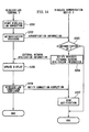
- FIG 4 is a flow chart showing the communication control procedure which is performed by the wireless transmission device 3 of the above described FIG 3 .
- FIGS. 5 and 6 are sequence charts showing the flow of the communication control procedure for the wireless LAN 1 according to the first preferred embodiment of the present invention.
- the wireless transmission device 3 when the wireless transmission device 3 receives an access request (a packet) from a wireless LAN terminal 2, it inspects the destination of the said packet, and makes a decision as to whether or not that destination is the external network (in a step S1). Here, if the destination is not the external network, then (in a step S11) it accesses the appropriate server within the wireless LAN 1 (for example the web server section 35).
- step S 1 If in the step S 1 the result of the decision is that the destination is the external network, then the flow of control proceeds to a step S2, in which the connection state to the external network is decided upon.
- a connection to the external network is already operational, then an access request to the external network is transmitted (in a step S 10) via the mobile terminal section 32 to the external network.
- step S2 If the result of the decision in the step S2 is that there is no connection to the external network, then the flow of control proceeds to a step S3, in which, along with starting a connection to the external network, the access request which has been received from the wireless LAN terminal 2 is stored in the storage section 34 (in a step S4).
- a message is returned to the wireless LAN terminal 2 which is the original transmission source of said access request to the effect that a connection is being established to the external network (in a step S5).
- the wireless LAN terminal 2 displays said message which it has received. By doing this, the user is able to recognize that at the present time a connection is being established to the external network.
- the wireless transmission device 3 reads out from the storage section 34 the access request which is stored (in steps S6 and S7).
- a decision is made as to whether or not the connection to the external network has succeeded or has failed (in a step S8).
- a message is returned to the wireless LAN terminal 2 which is the original transmission source for said access request to the effect that connection with the external network is impossible (in a step S9).
- the wireless LAN terminal 2 which has received this message displays said message which has received. By doing this, the user is able to recognize that the wireless transmission device 3 has not been able to establish a connection to the external network.
- the wireless transmission device 3 transmits said access request via the mobile terminal section 32 to the external network (in a step S 10).
- FIG 5 there is shown a sequence chart for the case in which, in the above described communication control procedure for the wireless LAN 1, the connection to the external network has failed.
- the wireless LAN terminal 2 requests access to the internet 5 to the web server 6 (in a step S21).
- the wireless transmission device 3 along with starting a PPP connection procedure with the mobile telephone base station 4 (in a step S22), also transmits "connecting" as an external network connection state notification to said wireless LAN terminal 2 (in a step S23).
- said PPP connection fails (in a step S24)
- the wireless transmission device 3 transmits "connection failed" as an external network connection state notification to said wireless LAN terminal 2 (in a step S25).
- FIG 6 there is shown a sequence chart for the case in which, in the above described communication control procedure for the wireless LAN 1, the connection to the external network has succeeded.
- the wireless LAN terminal 2 requests access to the internet 5 to the web server 6 (in a step S21).
- the wireless transmission device 3 along with starting a PPP connection procedure with the mobile telephone base station 4 (in a step S22), also transmits "connecting" as an external network connection state notification to said wireless LAN terminal 2 (in a step S23).
- the wireless transmission device 3 transmits the access request to the web server 6 to the mobile telephone network (in a step S32). Due to this, the access request from the wireless LAN terminal 2 to the web server 6 is executed.
- connection completed as an external network connection state notification to the wireless LAN terminal 2 which was the original source of the external access request.
- a message to the effect that connection to the external network has been successful is displayed upon the wireless LAN terminal 2 which was the original source of the external access request, so that the user thereof may be notified of the fact that the connection to the external network has been successful.
- connection state to the external network is notified to the user by notifying it to the wireless LAN terminal 2 which was the original source of the external access request, thereby it is possible for the user to recognize definitely and unambiguously the connection state during external access, and uncertainty and disquiet upon the part of the user when connecting to an external network are alleviated.
- the level of reliability of the wireless transmission service from the point of view of the user is enhanced, and the excellent beneficial result is attained of contribution to the expansion of the wireless transmission service.
- the wireless transmission device 3 when notifying the external network connection state, transmits a web page (for example, an HTML document) which is stored upon the wireless transmission device 3 to the wireless LAN terminal 2, and causes it to be displayed thereon.
- FIG 7 is a block diagram showing the structure of the wireless transmission device 3 according to this second preferred embodiment of the present invention.
- This web page storage section 41 stores a web page (for example, an HTML document).
- the objective of this web page is to prevent a timeout of the browser function of the wireless LAN terminal 2, and it is primarily for showing upon the wireless LAN terminal 2 that the wireless transmission device 3 is attempting to establish a connection to the external network. And, during the notification of the external network connection state in the steps S5 and S9 of FIG 4 described above, the control section 33 transmits said web page to the wireless LAN terminal 2. And, by displaying this web page, it is possible to cause the state of the connection to the external network to be displayed.
- the data of this web page is received by the wireless LAN terminal 2 which was the original source of said access request, and is displayed thereupon. Furthermore, upon said wireless LAN terminal 2, by the data of said web page being received, the occurrence of a timeout when accessing the home page, which is one of the functions of a web browser, is prevented. Due to this, when the wireless transmission device 3 is connecting to an external network, along with it being possible for the user definitely and unambiguously to recognize the connection state during external access, it is also possible for uncertainty and disquiet on the part of the user to be alleviated, since the web browser as well does not perform any timeout display; and, when the connection to the external network has been completed, the web page which has been requested by the wireless LAN terminal 2 is displayed thereupon.
- FIG 8 is a figure showing a constructional example of a web page on which a message to the effect that connection to an external network is in progress has been displayed.
- a web page screen 201 which is stored by the wireless transmission device 3 is being displayed upon the display section 24 of the wireless LAN terminal 2.
- a message is being displayed upon said web page screen 201 for notifying to the user the fact connection to an external network is in progress, and that it will take some time before the connection is completed.
- FIG 9 is a figure showing a structural example of a web page upon which a message has been displayed to the effect that connection to the external network has failed.
- the web page screen 202 is being displayed upon the display section 24 of the wireless LAN terminal 2.
- a message for notifying to the user that the connection to the external network has failed is being displayed upon this web page 202.
- FIG 10 is a block diagram showing the structure of the wireless transmission device 3 according to this third preferred embodiment of the present invention. This figure shows that this wireless transmission device additionally incorporates a cache section 42, in addition to the elements shown in FIG, 3 which were incorporated in a previously described preferred embodiment of the present invention. This cache section 42 is endowed with the function of storing page data which has been accessed.
- the control section 33 transmits said page data in the cache section 42 to the wireless LAN terminal 2 which was the original source of the external access request.
- This page data is received by said wireless LAN terminal 2 which was the original source of the access request, and is displayed thereby. Furthermore, the occurrence of a timeout upon said wireless LAN terminal 2 during the access to the web page is prevented by its receiving this page data. In this manner, along with uncertainty and disquiet upon the part of the user while he is standing by being alleviated since the page screen which is cached is displayed until the connection to the external network is completed, also the newest version of the page is displayed when the connection to the external network is completed.
- This fourth preferred embodiment is different from the above described first through third preferred embodiments, in that it is arranged for an enquiry about the external network connection state to be transmitted from the wireless LAN terminal 2 to the wireless transmission device 3.
- the wireless LAN terminal 2 stores a program which can operate upon the wireless LAN terminal 2.
- This program is an autonomously operating type computer program, and it is for implementing the function of enquiring about the external network connection state from the wireless LAN terminal 2 to the wireless transmission device 3.
- FIG. 11 there is shown a sequence chart which gives the flow of the communication control procedure with the wireless LAN 1 according to this fourth preferred embodiment of the present invention.
- the wireless LAN terminal 2 makes an access request to the web server 6 over the internet (in a step S41).
- the wireless transmission device 3 starting a PPP connection procedure with the mobile telephone base station 4 (in a step S42), it also transmits a stored program to said wireless LAN terminal 2 (in a step S43).
- the wireless LAN terminal which was the source of the external access request executes said program, and periodically transmits an external network connection state request to the wireless transmission device 3 (in a step S44).
- the wireless transmission device 3 receives this external network connection state request, it responds with the current connection state. With the response in the step S45, "connecting" is returned as a response, since as yet the PPP connection is not completed. By doing this, a message to the effect that connection to the external network is still being established is displayed upon the wireless LAN terminal 2 which was the original source of the external access request, and thereby the user is notified that connection to the external network is still being established.
- the wireless transmission device 3 transmits to the external network an access request to the web server 6 (in a step S47). Furthermore, due to the completion of the PPP connection, the wireless transmission device 3 transmits "connection completed" as a response to the external network connection state request (in a step S48). By doing this, a message to the effect that connection to the external network has been successfully established is displayed upon the wireless LAN terminal 2 which was the original source of the external access request, and thereby the user is notified that connection to the external network has succeeded.
- the wireless LAN terminal 2 it would also be acceptable for the wireless LAN terminal 2 to contain the program in advance.
- the wireless LAN terminal 2 stores up the external access request which has been transmitted, and, when a connection completed with the external network has been received, to again transmit this access request, and for the wireless transmission device 3, upon this access request, to transmit said access request to the external network.
- the notification means in the wireless LAN terminal 2 which notifies the state of wireless connection to the external network is not to be considered as being limited to the one which provides the above described screen display. It would be acceptable for the wireless LAN terminal 2 to notify the state of wireless connection to the external network by turning on a display lamp, or the like. Furthermore, it would also be acceptable to notify the state of wireless connection to the external network by emitting a sound such as a beep or the like.
- the wireless LAN 1 may acceptably be one which is set up in a fixed operational environment, such as a LAN within a home or a small office or the like.
- the public wireless transmission network for external access may acceptably be a wireless transmission network which is accessed via a communication connection protocol other than the PPP protocol.
- the wireless transmission terminal which is being used by the user accesses, via a wireless transmission device which is connected to the public wireless transmission network, a network such as the internet or the like which is external to the wireless transmission device, it is possible to alleviate uncertainty and disquiet on the part of the user by notifying the connection state between the wireless transmission device and the public wireless transmission network to the user.
- the beneficial results are obtained that the degree of confidence which the user accords to the wireless transmission service is enhanced, and that thereby a contribution is made to the dissemination of wireless transmission services.
- FIG 12 is a block diagram showing the structure of a wireless transmission system according to another preferred embodiment of the present invention.
- a moving vehicle 210 like a bus or a train or the like is shown with certain of the components of the wireless transmission system mounted therein, the other details are the same as those shown in FIG 1 with reference to the first preferred embodiment of the present invention. Accordingly, the explanation of this FIG 12 will be curtailed.
- FIG 2 A block diagram showing the structure of a wireless LAN terminal 2 according to a preferred embodiment of the present invention is shown in FIG 2 . Since the explanation of this wireless LAN terminal 2 has already been given above, here it will be curtailed.
- the control section 22 is endowed with various network service functions, such as an electronic mail function, a function of reading home pages (a web browser function), and the like. Furthermore, as a means for notifying to the user the state of wireless transmission connection, it is further endowed with a function of displaying upon a display section 24 information about the state of wireless communication which gives the state of wireless communication (the state of the wireless transmission circuit 101 which is used for external access) between the wireless transmission device 3 and the external network, and with a function of displaying the number of users of the external network (the number of terminals currently in use) upon the display section 24.
- various network service functions such as an electronic mail function, a function of reading home pages (a web browser function), and the like.
- a function of displaying upon a display section 24 information about the state of wireless communication which gives the state of wireless communication (the state of the wireless transmission circuit 101 which is used for external access) between the wireless transmission device 3 and the external network, and with a function of displaying the number of users of the external network (the number of terminals
- the information about the state of wireless communication and the number of terminals in use are items of information which are referenced by the user of the wireless LAN terminal 2 when utilizing the external network.
- the information about the state of wireless communication and the number of terminals in use will collectively be referred to as external network utilization information.
- FIG 13 is a block diagram showing the structure of a wireless transmission device 3 according to another preferred embodiment of the present invention.
- the wireless transmission device 3 comprises a wireless LAN access point section 231, a mobile terminal section 232, a control section 233, a storage section 234, a web server section 235, and an external network utilization information updating section 236.
- the wireless LAN access point section 231 transmits and receives wireless signals between itself and each of the wireless LAN terminals 2, and performs data communication by establishing wireless transmission circuits with each of the wireless LAN terminals 2.
- the mobile terminal section 232 transmits and receives wireless signals between itself and a mobile telephone base station 4 of the external network, and performs data communication by establishing a wireless transmission circuit 101 for external access. Furthermore, the mobile terminal section 232 is endowed with a function of measuring information about the state of wireless communication which specifies the state of wireless communication with the external network. As this type of information about the state of wireless communication, for example, there may be suggested the received electric field intensity, the amount of wireless transmission bandwidth which is allocated, or the like. Furthermore, the mobile terminal section 232 detects the number of the wireless LAN terminals 2 which are currently being used for performing data communication with the external network (the number of terminals in use).
- the control section 233 along with processing the data which is transmitted and received by each of the wireless LAN access point section 231 and the mobile terminal section 232, also controls each of the sections of the wireless transmission device 3.
- the storage section 234 stores various types of data which are accessed by the control section 233.
- the web server section 235 opens home pages for provision thereof to the wireless LAN terminals 2.
- the external network utilization information updating section 236 acquires, from the mobile terminal section 232, external network utilization information (the information about the state of wireless communication and the number of terminals in use), and stores this information in the storage section 234. And the external network utilization information updating section 236 periodically acquires said external network utilization information from the mobile terminal section 232, and updates the external network utilization information which is stored in the storage section 234.
- control section 233 is endowed with the function of relaying communication between the wireless LAN terminals 2 and the exterior of this wireless LAN system 1. Furthermore, the control section 233 is endowed with the function of notifying the external network utilization information which is stored in the storage section 234 to the wireless LAN terminals 2.
- FIG 14 is a sequence chart showing the flow, within the communication control procedure of the wireless LAN system 1 according to this fifth preferred embodiment of the present invention, of the processing related to notification of external network utilization information.
- the mobile terminal section 232 detects the external network utilization information (the information about the state of wireless communication and the number of terminals in use) at a predetermined period, for example once per second. Furthermore, the external network utilization information updating section 236 acquires the external network utilization information from the mobile terminal section 232 at a predetermined period, for example at a period (such as 3 seconds) which is greater than the detection period by the mobile terminal section 232, and updates the external network utilization information which is stored in the storage section 234.
- the external network utilization information the information about the state of wireless communication and the number of terminals in use
- the wireless LAN terminal 2 starts wireless LAN connection (in a step S201). And it transmits authentication information to the wireless transmission device 3 and performs an authentication procedure (in a step S202).
- this authentication information there may be utilized individual identification information which is recorded in a vehicle ticket of the vehicle 210, or a control ticket for transportation payment, a prepaid card or the like for transportation payment, or the like.
- it may also take advantage of a card which is specific to the individual, such as for example the card number of a credit card or the like.
- the control section 233 of the wireless transmission device 3 tests that this authentication information is genuine, and if it is genuine it decides that authentication has been performed (in a step S203).
- the control section 233 reads out the external network information which is stored in the storage section 234 in a predetermined cycle, and transmits it to the appropriate one of the wireless LAN terminals 2 (in a step S204).
- the external network utilization information is read out from the storage section 234 and is transmitted to the wireless LAN terminal 2 at a period (for example 3 seconds) which is greater than the updating period of the external network utilization information by the external network utilization information updating section 236.
- the control section 22 of the wireless LAN terminal 2 When it receives the external network utilization information from the wireless transmission device 3, the control section 22 of the wireless LAN terminal 2 displays this external network utilization information which it has received upon the screen of the display section 24. And, upon receiving the external network utilization information, the control section 22 updates the contents of the screen display of the display section 24 with this external network utilization information which it has received (in a step S205). By doing this, the user is able to make a decision as to whether or not to attempt to establish connection to the external network, based upon the state of wireless communication between the wireless transmission device 3, and the number of terminals in use. For example, if the state of wireless communication is bad, he may cease his attempt to establish access to the external network. Or, if the number of terminals in use is great, he may wait to try to establish access to the external network until the number of terminals in use has diminished.
- the external network utilization information (the information about the state of wireless communication between the wireless transmission device 3 and the external network, and the number of terminals in use upon the external network) is notified by being notified to the wireless LAN terminal 2, accordingly it is possible for the user to make a decision as to whether or not to try to access the external network, based upon said external network utilization information.
- the external network utilization information the information about the state of wireless communication between the wireless transmission device 3 and the external network, and the number of terminals in use upon the external network
- the wireless LAN terminal 2 stores a program which can operate upon said wireless LAN terminal 2.
- This program is a computer program of an autonomously operating type, and it is one which implements a function of requesting the external network utilization information from the wireless LAN 2 to the wireless transmission device 3, and a function of performing control for notifying this external network utilization information.
- FIG 15 is a sequence chart showing, in the communication control procedure of the wireless LAN system 1 according to this sixth preferred embodiment of the present invention, the flow of a procedure which is related to notification of the external network utilization information.
- the mobile terminal section 232 periodically detects the external network utilization information, and the external network utilization information updating section 236 periodically acquires the external network utilization information from the mobile terminal section 232 and updates the external network utilization information in the storage section 234.
- the wireless LAN terminal 2 starts the procedure of wireless LAN connection (in a step S211). And it transmits authentication information to the wireless transmission device 3 and performs an authentication procedure (in a step S212).
- the control section 233 of the wireless transmission device 3 verifies that this authentication information is genuine, and if it has been verified to be genuine, it makes the decision that authentication has been successful (in a step S213).
- the control section 233 transmits the program that is stored in the storage section 234 to the wireless LAN terminal 2 (in a step S214).
- the wireless LAN terminal 2 When it receives this program, the wireless LAN terminal 2 starts the operation of the program, and periodically requests the external network utilization information from the wireless transmission device 3 (in steps S215 and S216). When it receives this request, the control section 233 of the wireless transmission device 3 reads out the external network utilization information which is stored in the storage section 234, and transmits it to said wireless LAN terminal 2 (in a step S217).
- the wireless LAN terminal 2 When it receives the external network utilization information from the wireless transmission device 3, the wireless LAN terminal 2 displays this external network utilization information which it has received upon the screen of the display section 24. And, each time it receives the information about the state of wireless transmission and so on, it updates the contents of the screen display of the display section 24 with the external network utilization information which it has received (in a step S218). By doing this, it is possible for the user to make a decision as to whether or not to try to access the external network, based upon the external network utilization information (in other words, based upon the information relating to the state of wireless communication with the external network, and upon the number of terminals of the external network which are in use).
- FIGS. 16 through 19D are figures showing examples of display of such external network utilization information.
- FIG. 16 is a figure showing an example of the structure of a display screen 24a of the display section 24 of the wireless LAN terminal 2.
- an external network utilization information screen 2202 is displayed upon the display screen 24a.
- the external network utilization screen 2202 is a screen upon which the external network utilization information is displayed.
- This external network utilization screen 2202 is set to a size with which the external network utilization information can be recognized by the user. Desirably, it is as small a screen as possible. By doing this, it is possible to display the external network utilization information without interposing any obstacle to other displays upon the display screen 24.
- it may be arranged to call up the external network utilization information screen 2202, and to close it, as required, by a predetermined actuation of the actuation section 25.
- FIG 17 is a figure showing a first example for the structure of the external network utilization information screen 2202.
- the received electric field intensity is utilized in the external network utilization information as the information about the state of wireless communication.
- the received electric field intensity is displayed in a display region 2302 as one of three levels.
- the power level of a received signal is at level 2. Since the power level of the received signal is taken in this manner as being a criterion of the state of wireless communication between the wireless transmission device 3 and the external network, it becomes possible for the user to tell at a glance whether this state of wireless transmission is good or bad, and this is extremely easy for the user to understand.
- FIGS. 18A and 18B are figures showing a second example for the structure of the external network utilization information screen 2202.
- the amount of wireless transmission bandwidth allocated is utilized in the external network utilization information as the information about the state of wireless communication.
- the number of terminals in use is also used in the external network utilization information.
- the amount of wireless transmission bandwidth allocated is displayed as the magnitude of a display bar 2311.
- the number of terminals in use is displayed as a numerical value in a display region 2312.
- FIGS. 19A through 19D are figures showing a third example for the structure of the external network utilization information screen 2202.
- the amount of wireless transmission bandwidth allocated is utilized in the external network utilization information as the information about the state of wireless communication.
- the number of terminals in use is also used in the external network utilization information.
- the amount of wireless transmission bandwidth allocated is displayed as one of three levels by the number of bars 2321 which are displayed. For example, in FIG 19A , one of the display bars 2321 is displayed, which indicates to the user that the amount of wireless transmission bandwidth which is allocated is at level 1.
- FIG 19B two of the display bars 2321 are displayed, which indicates to the user that the amount of wireless transmission bandwidth which is allocated is at level 2. Yet further, in FIGS. 19C and 19D , three of the display bars 2321 are displayed, which indicates to the user that the amount of wireless transmission bandwidth which is allocated is at level 3.
- the projected data communication speed which is anticipated, based upon the amount of wireless transmission bandwidth which is allocated and the number of terminals which are in use, is displayed by the magnitude of the portions highlighted in black of those of the display bars 2321 which are displayed.
- This projected data communication speed may be obtained, for example, by dividing the amount of wireless transmission bandwidth which is allocated by the number of terminals which are in use. For example, in FIGS. 19A and 19C , the entire extents of the display bars 2321 which are displayed are shown as solid, which means that it is possible for one terminal to utilize the entire amount of wireless transmission bandwidth which is allocated.
- FIG 19B about half of the display bars 2321 which are displayed are highlighted shown as solid, which means that it is possible for one terminal to utilize about half of the amount of wireless transmission bandwidth which is allocated.
- FIG 19D about one quarter of the display bars 2321 which are displayed are shown as solid, which means that it is possible for one terminal to utilize about one quarter of the amount of wireless transmission bandwidth which is allocated.
- FIGS. 19A and 19B are compared together, in FIG 19A the entire amount of wireless transmission bandwidth which is allocated can be utilized by a single terminal, while in FIG 19B about half of the amount of wireless transmission bandwidth which is allocated can be utilized by a single terminal; but, by contrast to the situation in FIG 19A in which the amount of wireless transmission bandwidth which is allocated is at level 1, in FIG 19B , the amount of wireless transmission bandwidth which is allocated is at level 2. Due to this, it will be understood that the projected data communication speeds in FIGS. 19A and 19B are approximately of the same order. Furthermore, if FIGS.
- FIGS. 19A and 19C are compared together, although in both these cases the entire amount of wireless transmission bandwidth which is allocated can be utilized by a single terminal, by contrast to the situation in the FIG 19A case in which the amount of wireless transmission bandwidth which is allocated is at level 1, in the FIG 19C case, the amount of wireless transmission bandwidth which is allocated is at level 3; and accordingly it will be easily understood that, in the latter case, the projected data communication speed is higher. Yet further, if FIGS.
- the notification means in the wireless LAN terminal 2 which notifies the state of wireless connection to the external network is not to be considered as being limited to the one which provides the above described screen display. It would be acceptable for the wireless LAN terminal 2 to notify the state of wireless connection to the external network by turning on a display lamp, or the like. Furthermore, it would also be acceptable to notify the state of wireless connection to the external network by emitting a sound such as a beep or the like.
- the wireless LAN 1 may acceptably be one which is set up in a fixed operational environment, such as a LAN within a home or a small office or the like.
- the public wireless transmission network for external access may acceptably be a wireless transmission network which is accessed via a communication connection protocol other than the PPP protocol.
- the wireless transmission terminal which the user is utilizing accesses an external network such as the internet or the like via the wireless transmission device, by notifying the state of wireless communication between the wireless transmission device and the public wireless transmission network to the user, it is possible for the user to make a decision as to whether or not to attempt to access the external network, based upon said state of wireless communication. If this result, for example, is that the state of wireless transmission is bad, then, since it may be expected that the user will refrain from access to the external network, accordingly the access to the external network can be performed efficiently, and it becomes possible to utilize the processing power and the power consumed by the wireless transmission device more effectively. Furthermore, it is possible to alleviate uncertainty and disquiet upon the part of the user when he takes advantage of the external network.
- the present invention by notifying to the user the number of wireless transmission terminals which are performing data communication by taking advantage of the public wireless transmission network, it is possible for the user to make a decision as to whether or not to attempt to access the external network, based upon said number of terminals.
- the access to the external network can be performed efficiently, and it becomes possible to utilize the processing power and the power consumed by the wireless transmission device more effectively.
- FIG 20 is a block diagram showing an example of the structure of a system related to internet access which applies a wireless transmission system according to a preferred embodiment of the present invention.
- FIG 20 is the same as FIG 1 , except for a management device 307, a bus 210 which is used as an example of a moving vehicle, and a bus center 311. Accordingly, only the features of this preferred embodiment in which it differs from the FIG 1 preferred embodiment will be described here, while description of aspects of this preferred embodiment which are the same as ones of the FIG. 1 preferred embodiment will be curtailed.
- the structural element 3 in FIG 1 is simply a wireless transmission device, in FIG 20 it is a mobile wireless transmission device.
- the management device 307 is connected to the internet 5. This management device 307 performs traffic management of the moving vehicle 210, management related to web access from the interior of the moving vehicle 210, and the like.
- a router 312 is provided which is connected to the internet. It is possible to establish a connection between the mobile wireless transmission device 3 within the moving vehicle 210 and the router 312 via a LAN cable 313. By doing this, it is possible to connect the mobile wireless transmission device 3 within the moving vehicle 210 to the internet via the router 312.
- the mobile wireless transmission device 3 and the router 312 are connected via the LAN cable 313, it would also be acceptable to connect them together via a high speed wireless transmission circuit.
- FIG 20 The block diagram showing the structure of the wireless LAN terminal 2 which is shown in FIG 20 is the same as that given in FIG 2 . Since this has already been explained, its description will here be curtailed.
- FIG. 21 is a block diagram showing the structure of the mobile wireless transmission device 3 according to this preferred embodiment of the present invention.
- the wireless LAN access point section 331 transmits and receives wireless signals with each of the wireless LAN terminals 2, and performs data communication by establishing wireless transmission circuits with each of the wireless LAN terminals 2.
- the mobile terminal section 332 transmits and receives wireless signals between itself and the mobile telephone base station 4 of the mobile telephone network, and performs data communication by establishing the wireless transmission circuit 101 for external access.
- the control section 333 along with processing the data which is transmitted and received by the wireless LAN access point section 331 and the mobile terminal section 332, also controls the various portions of the mobile wireless transmission device 3.
- This control section 333 is endowed with the function of acting as a relay for communication between the wireless LAN terminals 2 and elements exterior to the wireless LAN system 1. Furthermore, the control section 333 is endowed with a control function related to internet access.
- the storage section 334 is accessed by the control section 333, and stores various types of data.
- the web server section 335 opens home pages for providing them to the wireless LAN terminals 2.
- the first cache server 336 stores web pages upon the internet 5 which have been accessed via the mobile terminal section 332. And, when a request for a web page occurs, it outputs said web page.
- the second cache server 337 stores web pages upon the internet 5 for which it is estimated that the access frequency is high. And, when a request for a web page occurs, it outputs said web page.
- the cache data base 338 accumulates management information (URLs, dates of updating, and the like) related to the web pages which are stored upon the second cache server 337.
- the cache update control section 339 performs update control for the web pages which are accumulated upon the second cache server 337.
- the web access frequency measurement section 340 measures the access frequency for web pages for which access attempts via the mobile terminal section 332 have been made. In concrete terms, it counts the number of users who have made access requests for each web page upon the internet 5.
- the LAN cable access section 341 accesses the internet 5 via the LAN cable 13 and the router 312 which have been provided in the bus center 311.
- FIG. 22 is a block diagram showing the structure of the management device 307 shown in FIG. 20 .
- the communication section 351 performs data communication via the internet 5. For example, it can transmit and receive data to and from a web server 6 upon the internet 5, the mobile wireless transmission device 3 within the moving vehicle 210 via the mobile telephone network, the mobile wireless transmission device 3 within the moving vehicle 210 via the router 312 of the bus center 311, and the like.
- the cache server 352 stores web pages upon the internet 5 for which it is estimated that the access frequency is high. And, when a request for a web page occurs, it outputs that web page.
- the cache data base 353 accumulates management information (URLs, dates of updating, and the like) related to the web pages which are stored upon the cache server 352.
- the cache update control section 354 performs update control for the web pages which are accumulated upon the cache server 352.
- the moving vehicle cache management section 355 stores the web pages which are supplied to traffic and which have been accumulated upon the second cache server 337 of the moving vehicle 210 (the moving vehicles). And it reflects this stored content upon the cache server 352. In other words, the web pages which have been accumulated upon the second cache server 337 are also accumulated upon the cache server 352.
- the moving vehicle cache updating section 356 performs processing for updating the second cache server 337 of the moving vehicle.
- An opportunity for this updating is when, for a vehicle 210 which is moving in traffic, an update has been performed for the source of provision of a web page, or when, for a mobile vehicle 210 which is standing by in the bus center 311 or the like, an update request has been received from said mobile vehicle 210.
- the web access frequency totalizing data base 357 accumulates information such as journey paths, en route time periods, URL access frequency lists, and so on.
- FIG. 23 is a figure which shows an example of the structure of this web access frequency totalizing data base 357.
- the access frequency for the URL 1 is 100
- the access frequency for the URL 2 is 98
- the access frequency for the URL 3 is 80, and so on.
- This access frequency list is created based upon the results of measuring the access frequencies with the web access frequency measuring section 340 of each of the moving vehicles 10.
- FIG. 24 is a flow chart showing the flow of processing which is performed when the mobile wireless transmission device 3 shown in FIG. 21 receives an access request to a web page.
- a user who is riding in the moving vehicle 210 issues an access request to a web page upon the internet 5 by using his wireless LAN terminal 2.
- the control section 333 of the mobile wireless transmission device 3 commands it to be registered upon the web access frequency measurement section 340.
- the web access frequency measurement section 340 registers, in a measurement table of its own, the requested web page and a recognition code which specifies the wireless LAN terminal 2 which is making this access request (for example, its MAC-ID, or a recognition code or the like which has been distributed by the service provider for the mobile wireless transmission device 3 or the like), and counts up by 1 (in a step S3102) the number of users accessing said web page.
- control section 333 searches upon the second cache server 337, and makes a decision as to whether or not the requested web page has been accumulated thereon (in steps S3103 and S3104). And, if the web page which is being requested is accumulated upon the second cache server 337, then it reads out said web page from the second cache server 337 and transmits it to the wireless LAN terminal 2 which is the original source of the request (in a step S3110).
- the control section 333 searches upon the first cache server 339, and makes a decision as to whether or not the web page which is being requested is accumulated thereon (in steps S3105 and S3106). And, if the web page which is being requested is accumulated upon the first cache server 336, then it reads out said web page from the first cache server 336 and transmits it to the wireless LAN terminal 2 which is the original source of the request (in a step S3111).
- the control section 333 makes a decision about the state of communication upon the mobile telephone network by the mobile terminal section 332. And, if it is not possible to connect to the mobile telephone network, then it transmits (in a step S3109) an "access impossible" message to the wireless LAN terminal 2 which was the original source of the access request, to the effect that it is not possible to access the requested web page, since it is not possible to connect to the mobile telephone network.
- the number of accessing users for each web page which has been measured by the web access frequency measurement section 340 is collected together into the management device at the bus center 311 or the like and is reflected in the web access frequency totalizing data base 357.
- the web pages upon the internet 5 which have been accessed in the past are stored upon the first cache server 336. And, when the same web page is accessed for a second time, the web page on the first cache server 336 is transmitted back to the user. Since the frequency of access to the internet 5 using the mobile telephone network is reduced by doing this, accordingly it is possible to alleviate the communication load which is imposed upon the mobile telephone network, and the accessibility when accessing the internet 5 from within the moving vehicle is accordingly enhanced. Furthermore, it is possible to anticipate a reduction in the cost of communication.
- the web pages upon the internet 5 for which it has been estimated that the access frequency will be high are stored upon the second cache server 337, accordingly, when a request for a web page is received from the user, by searching upon said second cache server 337 with a higher priority than searching upon the first cache server 336, it is possible to anticipate a reduction in the time period which is required for searching.
- FIG. 25 is a flow chart showing the flow of a cache updating procedure performed by the management device 307 shown in FIG. 22 .
- the cache update control section 354 of the management device 307 searches, at a certain cycle period, the update state of the web pages which are registered in the cache data base 53, and makes a decision as to the state of updating of said web server 6 (in steps S3201 and S3202). And, when it has detected an update of a web page, this cache update control section 354 acquires from said web server 6 the updated version of the web page, and updates said web page upon the cache server 352 (in a step S3203). Next, the cache update control section 354 updates the update time of said updated web page in the cache data base 53 (in a step S3204).
- the moving vehicle cache management section 355 makes a decision upon the presence or absence of a vehicle 201 moving in traffic which is using said updated web page, based upon the web access frequency totalizing data base 357 (in a step S3205). And, if such a moving vehicle 210 is present, the moving vehicle cache updating section 356 transmits the updated web page to said moving vehicle 210, in order to update the second cache server 337 of said moving vehicle 210 (in a step S3206).
- the cache update control section 339 of the moving vehicle 210 which has received said updated web page updates said web page upon the second cache server 337 with said updated version thereof (in a step S3301). And, next, it reflects said updated contents in the cache data base 338 (in a step S3302).
- the management device 307 inspects the update state of the web pages, and, if an update has occurred, it reflects said update in the cache server 352. Furthermore, it performs updating of the second cache server 337 only within the moving vehicle(s) 210 in traffic which is/are using the updated web page. By doing this, along with it being possible to update the cache contents within the vehicles 210 which are moving in traffic at high efficiency, it is also possible to alleviate the load of communication using the mobile telephone network, since it is not necessary to inspect the update state of the web pages from the vehicles 210 which are moving in traffic.
- FIG. 26 is a flow chart showing the flow of an update procedure for the second cache server 337 of the moving vehicle 210 before it enters into traffic. Next, the operation related to updating this second cache server 337 of the moving vehicle 210 before it enters into traffic will be explained.
- the cache update control section 339 transmits a second cache server update request message to the management device 307 (in steps S3402 and S3403).
- This update request message includes a vehicle identification code for this particular moving vehicle 210.
- the moving vehicle cache updating section 356 acquires (in steps S3501 and S3502) a traffic path and a traffic time until this moving vehicle 210 next arrives back at the bus center 311 from a journey planning data base (not shown in the figures).
- the traffic path and the traffic time which are acquired are related to the traffic maneuvers which will take place until the next time that updating of the second cache server 337 will be performed.
- the moving vehicle cache updating section 356 refers to the web access frequency totalizing data base 357, and creates (in a step S3503) a web page collection (for example, a list of URLs), based upon said URL access frequency list in traffic path and traffic time which was acquired in the above described step S3502.
- a web page collection for example, a list of URLs
- the web pages are listed in order of increasing access frequency (for example from level 1 to level 3).
- the moving vehicle cache updating section 356 creates the cache data base data for using by said moving vehicle 210, based upon said web page collection which has been created. And this cache data base data which has thus been created is transmitted to the moving vehicle 210 (in a step S3504).
- the cache update control section 339 of the moving vehicle 210 updates the cache data base 338 (in a step S3404).
- the moving vehicle cache updating section 356 of the management device 307 reads out said web page from the cache server 352 based upon the web page collection, and transmits it to said moving vehicle 210 as second cache accumulated data (in a step S3505).
- the cache update control section 339 of the moving vehicle 210 updates the second cache server 337 (in a step S3405).
- the cache update control section 339 transmits an update completed message to the management device 307 (in a step S3406).
- the moving vehicle cache updating section 356 of the management device 307 terminates its processing, since the updating process has been completed (in a step S3506).
- the management device 307 performs an updating procedure for the second cache server 337 upon the moving vehicle 210 while it is standing by in the bus center 311 or the like, based upon the web access frequency totalizing data base 357.
- This updating procedure will now be described in detail.
- a web page which has been accumulated in advance in the second cache server 337 upon the moving vehicle 210 which is standing by in, for example, the bus center 311 or the like is one of which the access frequency within the URL access frequency list of the next traffic path and journey time band is up to level 2.
- the access frequency within the URL access frequency list of the next traffic path and journey time band is up to level 2.
- the time band "6:00 - 10:00" is the time band for going to work or going to school, and the probability is high that during this time band, each day, as targets for information collection at the start of the day, web pages will be repeatedly accessed which provide information such as news, weather or the like.
- the passengers during the time band "10:00 ⁇ 16:00" are mainly housewives or the like, and it may be anticipated that, during this time band, each day, web pages will be repeatedly accessed which provide shopping information or hobby information or the like.
- web pages upon the internet 5 which have been accessed in the past are stored upon the first cache server 336, accordingly, when the same web pages are accessed for a second time, it is possible to take advantage of the web pages which are stored upon said first cache server 336. Due to this, since the frequency of access to the internet 5 over the mobile telephone network is reduced, accordingly it is possible to alleviate the communication burden which is imposed upon the mobile telephone network, and moreover the internet access environment within the moving vehicle is enhanced.
- the web access frequency totalizing data base 357 by reflecting in the web access frequency totalizing data base 357 the number of users who access each web page which have been measured for the moving vehicle 210 for each journey, it is possible to reflect the access frequency measurement results for each journey, in the next vehicle journey and subsequent ones, in the accumulated contents in the second cache server. By doing this, and by caching the most suitable pages, it is possible to enhance the hit ratio in the second cache server 337.
- control section of the mobile wireless transmission device 3 may acceptably be made so as to perform control for displaying upon the wireless LAN terminal 2 a list of web pages which are accumulated upon the first cache server 336 or upon the second cache server 337.
- the user is enabled to become aware of the web pages which are cached, so that the convenience of the system with regard to web page access is enhanced.
- This preferred embodiment of the present invention relates to a communication system which comprises a wireless device which is fitted to a bus.
- this wireless device it is also endowed with the function of serving as a terminal device which is connected to a base station device which is provided externally to the bus.
- the communication system within the bus is a wireless LAN
- the wireless system external to the bus is a system according to the EV-DO format; and, with these unified formats, said wireless device sets up a communication system which relays between the terminal devices which are being employed by the users and the base system device which is established externally.
- said communication system is only used by specified users. In other words, authentication is performed by the terminal devices, in order to prevent utilization of said communication system by users who are not specified.
- the user In order to pay the transportation charge for the bus, the user contacts a payment card, such as for example a prepaid card, to a payment device which is provided within the bus.
- the wireless device writes in information related to the terminal device in the payment card, such as the authentication information, encoding information, the frequency with which it should be used, and the like.
- the payment device ejects the payment card when it has completed the payment for the bus transportation charge.
- the user then takes the payment card out of the terminal device, and the terminal device outputs a connection request to the wireless device, based upon the information related to the terminal device which has been written into the payment card. For example, it generates a signal for making a connection request by using the authentication information and the encoding information, and outputs said signal at a frequency which should be used.
- the wireless device executes an authentication procedure for a terminal device based upon said signal, and, if it is a terminal device which belongs to an authorized user, permits connection thereof. Furthermore, it transmits data between itself and the terminal device with a communication system according to the EV-DO format.
- FIG. 27 is a figure showing a communication system 4100 according to a preferred embodiment of the present invention.
- This communication system comprises a wireless device 410, a payment device 412, a payment card 414, a terminal device 416, a base station device 418, and a network 420.
- the payment device 412 comprises a read out section 442 and a write in section 444;
- the wireless device 410 comprises a first antenna for communication 460, a first communication section 422, a second antenna for communication 462, a second communication section 424, a creation section 426, a communication processing section 428, a control section 430, and a storage section 432;
- the terminal device 416 comprises a terminal antenna 464, a communication section 446, a read out section 448, an authentication section 450, an encoding section 452, and a control section 454.
- the creation section 426 comprises an authentication information creation section 434, an encoding information creation section 436, a communication processing section 428, an authentication section 438, and an encoding section 440.
- the base station device 418 is compatible with the EV-DO format, and is connected to a backbone network 420. Furthermore, there is provided a base station antenna 466 for wireless transmission. This base station antenna 466 may also be made up from a plurality of antennas or sectors.
- the first communication section 422 executes a communication procedure according to the EV-DO format, corresponding to the base section device 418.
- the first communication section 422 corresponds to an EV-DO terminal device.
- a first antenna for communication 460 for wireless transmission there is provided.
- the second communication section 424 executes a communication procedure for a wireless LAN which will be described hereinafter.
- the second communication section 424 corresponds to the base station device of this wireless LAN.
- a second antenna for communication for wireless transmission is provided.
- the payment card 414 is a card for paying for bus transportation, and, as previously described, may be exemplified by a prepaid card.
- the read out section 442 reads out the information within the payment card 414, such as for example the amount of money remaining upon it, and, after having performed a procedure for deducting the cost of the current journey, the write in section 444 writes the final remaining amount of money into the payment card 414. Furthermore, the write in section 444 also writes in the information which is required for communication between the wireless device 410 and the terminal device 416.
- the authentication information creation section 434 creates authentication information for the terminal device 416, for example a password or the like, and outputs it to the write in section 444 for writing into the payment card 414.
- the encoding information creation section 436 creates encoding information for the terminal device 416, for example a secret key or the like, and outputs it to the write in section 444 for writing into the payment card 414.
- the storage section 432 stores this authentication information and this encoding information. It should be understood that it also stores information which is necessary for processing the transportation charge deduction, for example a table of transportation charges.
- FIG. 28 shows the data structure of the information which is related to the terminal devices which has been stored in the storage section 432.
- recognition number is a number which identifies the terminal devices 416 - for example, a recognition number for a user who owns the terminal device 416 may be used.
- these fields are shown as A1 through AN.
- authentication information is a password which has been generated by the authentication information creation section 434, and here, by way of example, these fields are shown as B1 through BN.
- encoding information is a secret key which has been generated by the encoding information creation section 436, and here, by way of example, these fields are shown as Cl through CN.
- frequency information is the frequency which is transmitted by the second communication section 424, and here it is supposed that it is fixed at fl.
- the authentication section 438 authenticates this terminal device 416, based upon the authentication information which has been created by the authentication information creation section 434 in advance and has been stored in the storage section 432. For example, if the password which has been stored in the storage section 432 and the password which is contained in the connection request from the terminal device 416 are the same as one another, then it permits connection of said terminal device 416. And, when a connection request has been performed by the terminal device 416, the encoding section 440 executes an encoding procedure based upon a code which has been generated in advance by the encoding information creation section 436 and has been stored in the storage section 432.
- control section 430 Along with controlling the various timings of the wireless device 410, the control section 430 generates control signals for executing the previously described authentication procedures. Furthermore, it executes the transportation charge payment processing by the payment device 412.
- the communication section 446 executes a wireless LAN communication procedure, in order to communicate with the second communication section 424. Furthermore, it is provided with the terminal antenna 464 for wireless transmission.
- the payment card 414 which has been ejected from the write in section 444 When the payment card 414 which has been ejected from the write in section 444 is inserted into the read out section 448, it reads out the information related to the terminal device which has been written into the payment card 414 which has thus been inserted.
- the payment device 412 is provided with an interface into which, in the same manner, the payment card 414 can be inserted. Furthermore, among the read out information, the authentication information is outputted to the authentication section 450, the encoding information is outputted to the encoding section 452, and the frequency of use information is outputted to the communication section 446. And the read out section 448 sets the frequency to the value which has been inputted, and accesses the wireless device 410.
- the authentication section 450 When performing a connection request for the wireless device 410, the authentication section 450 writes the authentication information into a request packet. Furthermore, if there has been a response relating to authentication from the wireless device 410, it performs a procedure corresponding thereto.
- the encoding section 452 performs a communication encryption procedure, based upon the encoding information which it has received from the read out section 448.
- the control section 454 controls the various timings for the terminal device 416.
- This structure may be implemented in hardware, such as the CPU of some computer and its memory and other LSIs, or may be implemented in software as a program which fulfils a reservation management function and which has been loaded in the memory, but here it is only shown as functional blocks which may be implemented by any of these methods. It will be clear to a person of ordinary skill in the art without undue experimentation that it is possible to implement these functional blocks only by hardware, only by software, or by a combination of both hardware and software, as may be found to be most appropriate and convenient.
- FIG. 29 is a sequence diagram showing the authentication procedure.
- the user contacts the payment card 414 against the payment device 412 (in a step S410).
- the payment device 412 performs the payment procedure (in a step S412).
- the authentication information creation section 434 and the encoding information creation section 4436 create the predetermined information (in a step S414).
- the write in section 444 writes in this predetermined information into the payment card 414 (in a step S416).
- the payment device 412 then ejects the payment card 414 to the outside (in a step S418).
- the next user inserts his payment card 414 into the read out section 448 (in a step S420).
- the read out section 448 reads out the information (in a step S422), and outputs the information which has thus been read out to the authentication section 450, the encoding section 452, the communication section 446, and so on.
- the communication section 446 Based upon the operation of the, the authentication section 450 and the encoding section 452, the communication section 446 generates a packet containing a connection request (in a step S424).
- the second communication section 424 receives this packet, and the authentication section 438 verifies the information which it contains (in a step S426). If the information is valid, the wireless device 410 permits communication with the terminal device 416 (in a step S428). After this, the wireless device 410 relays data for communication with the terminal device 416, and data for communication with the base station device 418.
- FIGS. 30A through 30C are external views of the terminal device 416 of FIG. 27 .
- FIG. 30A shows it as seen from the front at a slight angle
- FIG. 30B shows it as seen from the rear at a slight angle
- FIG. 30C shows it as seen from the rear at a slight angle and moreover with a card housing section lid 470 in the open state.
- this card housing section lid 470 is opened, it becomes possible to remove, or to insert, any type of card such as a payment card 414 or the like, from or into a card housing section 472.
- the card housing section lid 470 is closed, the payment card 414 which has been inserted into the card housing section 472 is fixed inside the terminal device 416, and the encoding information and the authentication information which have been written into the payment card 414 may be read out by wireless transmission.
- the read out section 448 of the terminal device 416 reads out from the payment card 414 the previously written in authentication information and encoding information, and the encoding section 452 encrypts the information to be transmitted to the wireless device 410 based upon said encoding information.
- an authentication procedure with the wireless device 410 is performed using the aforesaid authentication information.
- the terminal device 416 transmits information via the communication section 446 and the terminal antenna 464, receives information via the second antenna for communication 462 of the wireless device 410, decodes the signal via the second communication section 424 with the encoding section 440, performs the authentication procedure with the authentication section 438, makes a decision as to whether or not this authentication information and the encoding information which has been previously stored in the storage section 432 agree with one another, and, if they do so agree, permits communication. By doing this, it becomes impossible for a user who is not riding upon the bus to receive service by taking advantage of the wireless device 410. Furthermore, since encoding information and authentication information which are specific to each terminal are used, it is difficult to impersonate or to decode the wireless information, and accordingly it becomes possible to enhance the level of safety of the personal information of the user of the system.
- the explanation of the details of the distribution of information by the communication system 4100 goes as follows: When a user gets onto the vehicle (the bus), new encoding information is created by the encoding information creation section 436 of the wireless device 410, and new authentication information is created by the authentication information creation section 434, and, along with these being written into the payment card 414, they are also stored in the storage section 432.
- the level of safety is enhanced by preventing leakage of the authentication information, since the authentication of the terminal device is performed according to predetermined authentication information which has been written into the card. Furthermore, since the information about the frequency of use of the wireless device is notified in advance to the terminal device, it is possible for the terminal device to anticipate reliable connection for communication with the wireless device. Yet further, since the card upon which the authentication information has been written is also used for making payment for transportation charges, there is no requirement to ask the user newly to carry an additional card.
- the communication network between the wireless device 410 and the base station device 418 was one which followed the EV-DO standard, this is not to be considered as being limitative of the present invention; it would, alternatively, be perfectly possible to utilize some other type of wireless transmission means for this network, such as a simple type of mobile telephone system or the like. According to such a variant preferred embodiment, it would be possible to apply the present invention in various different ways. In other words, it would be acceptable to be able to access a network which was external to the bus, or the like.
- the explanation was made in terms of a bus which was proffered as an example, it would also be possible to apply the present invention to the provision of a wireless transmission environment within a fixed environment, rather than basing it upon a mobile environment such as a bus or a train or the like.
- the present invention has been explained in terms of a payment card 414 or control ticket or the like being proffered and the authentication information and the encoding information being transferred to it, it would also be acceptable for the information to be transferred to a stamp which was issued in advance, or to another card or to a semiconductor memory or the like which is in the possession of the individual user over a long time period. According to such a variant preferred embodiment of the present invention, it is possible to apply the present invention in various different ways. In other words, with a predetermined card, it will be sufficient only to notify the authentication information to the terminal device 416.
- the distribution of the authentication information and the encoding information which employ a control ticket may be done, for example, as follows.
- the control ticket itself employs an IC tag, and, when the control ticket is issued, the authentication information and the encoding information are written into the control ticket Furthermore, information such as the stopping point at which the passenger will get off the moving vehicle is also written into the control ticket at the same time.
- the user inserts the control ticket into the card housing section 472 of the terminal device 416 in the same manner as with the payment card 414 as described above, and the authentication information and the encoding information which have been written into the control ticket are read out by the read out section 448.
- the amount of money to be paid for transportation is calculated, based upon the stopping point at which the passenger got onto the vehicle which has been read out from the control ticket, and upon the stopping point at which the vehicle is stopped at the current time, and from information input by the driver such as whether the passenger is an adult or a child and for how many passengers payment is to be made and the like, and this cost of transportation is displayed, and then, when the passenger puts cash into a cash payment machine, either change is rendered, or the amount still to be paid is shown, or thanks are given if the exact amount has been paid. Even if, according to the type of the bus card, it is determined that the current bus card is one of the post-payment type, it is possible to execute a procedure which is substantially the same as the one in the case of the previously described control ticket.
- frequency information was carried, it should be understood that the present invention is not to be considered as being limited only to the case of carrying frequency information; it would be possible to carry other types of information related to wireless transmission, such as, for example, the format for modulation between the wireless device and the terminal device, or the communication standard such as IEEE802.1 1a, IEEE802.1 1b, IEEE802.1 1g, HiSWAN, wireless 1394, UWB, or the like.
- the service of the wireless LAN is set up within the public transport vehicle such as a bus or a train or the like onto which a large number of passengers board, and from which a large number of passengers alight.
- a wireless repeater device which comprises a wireless LAN communication means and communication means such as mobile telephones is set up within these public transport vehicles (hereinafter termed "moving vehicles"), and is connected by wireless LAN with portable terminals such as notebook type PCs or the like within the moving vehicle, and is made so that, by utilizing the mobile telephone network for network connection outside the moving vehicle, it is possible to connect from the notebook type PCs within the moving vehicle to the internet network outside the moving vehicle.
- a service which combines a wireless transmission system and a moving vehicle such as a bus or a train
- a system is also set up to transmit information such as the state of traffic or the like, i.e. the current position of the bus and/or the departure time instant from a stopping point, by using the wireless transmission system, and, via a central computer (a host computer) or the like, to display the most recent traffic state at stopping points.
- a service may also be implemented for providing information related to the traffic state of the bus or the train or the like by taking advantage of the web (the internet). By doing this, it becomes possible to provide a feeling of spiritual confidence to the passengers who are waiting for the bus or the like, since it is possible for them to know in advance after approximately what time the bus will arrive at its stopping point or the like at which they are waiting.
- FIG 35 is a structural view showing the communication system in the moving vehicle.
- the wireless repeater device 512' of the moving vehicle 51' is connected to a network 54 via a base station 53 of the 1xEV-DO (1x Evolution Data Only) type, and moreover a WWW server 55 which provides web information is connected to the network 54.
- the wireless repeater device 512' in the interior of the moving vehicle 51' and wireless LAN terminals 513, 514, and 515 which are owned by the various-passengers are present within the area of a local network 52' of a wireless LAN access point section 5126 which is included in the wireless repeater device 512'. Due to this, each of the passengers is able to download from the web server 55 the web information which he desires into his own one of the wireless LAN terminals 513, 514, and 515 via the wireless repeater device 512'.
- each of the wireless LAN terminals 513, 514, and 515 cannot download information or the like related to the stopping points for the vehicle at which the passengers will want to get off the vehicle.
- the communication system technology shown in FIG 35 from the point of view of a person who is riding upon the bus or the like, he is not able to know after approximately what time period the bus will arrive at the stopping point which is his personal objective.
- next stopping point for the bus may be displayed to the passengers by broadcasting an announcement within the bus of the next stopping point, or by displaying an announcement of the next stopping point upon a notice board upon the front of the bus, since various passengers within the moving vehicle such as a bus are all present at the same time and riding in the bus, sometimes it happens that such a broadcast within the bus is not heard (or at least not noticed) due to conversation between the passengers, or that a passenger cannot easily see the notice board because his seat happens to be located in a dead corner of the bus.
- this is a bus which is used every day by the same persons, such as one which carries commuters or school children, then, although it is possible for the persons who are familiar with the route of the bus to know the next stopping point of the bus by watching the external scenery without listening to a broadcast within the vehicle and without watching the notice board or the like, on the other hand, in the case of a person who is riding upon the bus for the first time, he cannot make a decision as to whether or not the next stopping point is the stopping point at which he wishes to get off if he does not know the name of the next stopping point, so that he may undesirably pass his desired alighting point.
- the traffic management system is set up to be very convenient to use from the point of view of the passenger, since the exact traffic information or the exact getting off information is notified to the portable terminal which is being carried by the passenger within the moving vehicle such as a bus or a train or the like.
- the details of this traffic management system according to this preferred embodiment of the present invention will be explained in detail with reference to the drawings.
- FIG 31 is an overall view showing the structure of a traffic management system according to the present invention.
- a wireless repeater device 512 of the moving vehicle 51 is connected to a network 54 via a lxEV-DO base station 53.
- a moving vehicle 516 of an identical structure to the moving vehicle 51 is also connected to the network 54 via a lxEV-DO base station 517.
- a data center 510 which performs integrated management of data related to traffic information
- a WWW server 55 which provides web information (internet information).
- a wireless repeater device 512 is provided within the moving vehicle 51, and also passengers are riding within the moving vehicle 51 who own individual wireless LAN terminals 513, 514, and 515. Yet further, the interior of the moving vehicle 51 constitutes the interior of a local network 52 of a wireless LAN access point section 5125 which is included in the wireless repeater device 512.
- the wireless repeater device 512 comprises a 1xEV-DO mobile terminal section 5120, a control section 5121, a wireless LAN access point section 5125, the WWW server section 5126, a vehicle position information acquisition section 5251, a path information storage section 5252, a getting off reservation information updating section 5253, a getting off reservation information notification section 5254, a getting off reservation information storage section 5255, a display section 5256, and an actuation section 5257.
- the structure of the wireless repeater device for the moving vehicle 516 is exactly the same. Accordingly, in the following explanation, only the wireless repeater device 512 of the moving vehicle 51 will be described.
- the 1xEV-DO mobile terminal section 5120 of the wireless repeater device 512 can connect wirelessly with a 1xEV-DO base station 53 external to the moving vehicle 51. Furthermore, this 1xEV-DO base station 53 is connected to the network 54 via a cable, and thus is capable of communicating with the WWW server 55 which are present upon the network 54 and with the data center 510. Even further, via the antenna 5250, the vehicle position information acquisition section 5251 can specify the position of the vehicle by a GPS or the like which is not shown in the figure. Moreover, it is possible to access a getting off reservation page of the WWW server section 5126 of the wireless repeater device 512 from the wireless LAN terminals 513, 514, and 515.
- the traffic path information and the map information for the moving vehicle 51 are also read out from the path information storage section 5252. And, based upon the traffic path and the map information, a display process is performed according to the present position of the moving vehicle 51, and, for example, the position information for the moving vehicle 51 is displayed upon the wireless LAN terminal 513 which has made access.
- the getting off reservation information updating section 5253 stores a recognition code (for example, an IP address for connection to the internet or a MAC address for identifying the information device which is connected to the LAN, or a recognition code which has been distributed by the wireless repeater device, or the like) which identifies the stopping point at which the passenger plans to get off and his wireless LAN terminal 513 in the getting off reservation information storage section 5255.
- a recognition code for example, an IP address for connection to the internet or a MAC address for identifying the information device which is connected to the LAN, or a recognition code which has been distributed by the wireless repeater device, or the like
- the getting off reservation information updating section 5253 reads out, based upon the next stopping point information which is obtained from the vehicle position information acquisition section 5251 and the path information storage section 5252 of the moving vehicle 51, the getting off reservation information which is stored in the getting off reservation information storage section 5255, and makes a decision as to whether or not there exists a getting off reservation for the next stopping point. And, if indeed there exists such a getting off reservation, it transmits the getting off information as a notification message to the wireless LAN terminal 513 which corresponds to the recognition code which has been set up in association with this next stopping point.
- the wireless LAN terminal 513 having accessed the wireless repeater device 512
- the wireless LAN terminals 514 or 515 access the wireless repeater device using the same method, they can also receive similar getting off information from the wireless repeater device 512 as a notification message.
- FIG 32 is an explanatory figures showing the flow of a procedure which is executed, with the traffic management system of FIG 31 , in the case that any one of the wireless LAN terminals makes a getting off reservation with the wireless repeater device. Accordingly, the flow of this getting off reservation procedure will be explained with reference to FIGS. 31 and 32 .
- a getting off reservation screen for the wireless repeater device 512 is opened by the wireless LAN terminal which is being carried by a passenger who is riding upon the moving vehicle 51, three methods are displayed as methods of specifying a getting off stopping point (in a step S51): "selection from road map”, “selection from map”, and “selection from list of target locations".
- step 51 If in the step 51 the item "selection from road map” has been selected, along with displaying a map of the road upon which the bus is traveling at the present time, the names of stopping points, estimated journey times, and so on, for each stopping point of the bus, there are displayed upon the screen (in a step S52) a "getting off” button for making a getting off reservation, a "map” button for displaying a map of the area which includes the stopping point, and an “information” button for displaying information related to the vicinity of the stopping point.
- a getting off reservation re-verification screen "getting off at XXX ?" is displayed (in a step S57).
- a getting off reservation for the said stopping point is stored in the getting off reservation information storage section 5255 of the wireless repeater device 512, and a reservation completed screen "getting off reservation made for stopping point XXX" is displayed, and the getting off reservation procedure is thereby completed (in a step S58).
- step 51 if in the step 51 the item "selection from map” has been selected, then a map upon which the path has been written based upon the current position of the moving vehicle 51 is displayed (in a step S53).
- the legend "passed” is appended to stopping points which have already been passed.
- the button for the desired stopping point for example "CCC”
- the passenger by selecting the button for the desired stopping point (for example "CCC"), it is possible for the passenger to display an enlarged map which includes this stopping point "CCC" which has been selected (in a step S56).
- the passenger selects the button "make a getting off reservation” then the screen for re-verifying the getting off reservation "getting off at XXX ?" is displayed (in the step S57).
- a getting off reservation for the said stopping point is stored in the getting off reservation information storage section 255 of the wireless repeater device 512, and the reservation completed screen "getting off reservation made for stopping point XXX" is displayed, and the getting off reservation procedure is thereby completed (in the step S58).
- step 51 if in the step 51 the item "selection from list of target locations" has been selected, a screen for input of the name of the target location is displayed (in a step S54).
- the passenger inputs the name of the stopping location which is his objective, and selects the "accept” button, the name of this target location and the name of the closest stopping point (for example "CCC") are displayed (in a step S55).
- the "verify map” button is selected, a map which includes the said stopping point is displayed (in a step S56).
- the position of the target location is shown on the map by a flashing display so as to make it easy to recognize it by eye, and/or it may be displayed in a different color. Yet further, at the same time, it is also possible to draw upon the map a line which shows a path from the stopping point to the objective (the target location). Furthermore, by selecting the button for the desired stopping point (for example "CCC”), it is possible for the passenger to display an enlarged map which includes this stopping point "CCC" which has been selected (in a step S56).
- the button for the desired stopping point for example "CCC”
- the screen for re-verifying the getting off reservation "getting off at XXX ?" is displayed (in the step S57). Furthermore, when the passenger selects the "yes” button, a getting off reservation for the said stopping point is stored in the getting off reservation information storage section 255 of the wireless repeater device 512, and the reservation completed screen "getting off reservation made for stopping point XXX" is displayed, and the getting off reservation procedure is thereby completed (in the step S58).
- each of the moving vehicles transmits the time instants of arrival, departure, and transit for each of the stopping points to the data center 510 via the 1xEX-DO wireless transmission circuit net and the network 54, then, based upon the time instants of arrival, departure, and transit which have been obtained from a moving vehicle which has previously passed along the same road, the data center 510 can estimate the anticipated transit times for this moving vehicle which is passing along the road after said previous vehicle, and can transmit these anticipated transit times from the data center 510 to the moving vehicle 51.
- a getting off reservation is stored in the getting off reservation information storage section 5255, it is supposed that, apart from the stopping point for which this getting off reservation has been made, a recognition code which can identify the wireless LAN terminal which has made the reservation (for example, an IP address, a MAC address, or a recognition code which has been allocated to the wireless repeater device 512 or the like) has been stored at the same time.
- a recognition code which can identify the wireless LAN terminal which has made the reservation for example, an IP address, a MAC address, or a recognition code which has been allocated to the wireless repeater device 512 or the like
- next stopping point is the stopping point at which the passenger plans to get off
- the device with the recognition code for which a getting off reservation has been made for this stopping point in other words, to the wireless LAN terminal from which the reservation was made.
- this notification it would also be possible to arrange for this notification to be performed via an audio message such as a beep or the like.
- the matter is not particularly described herein, apart from making a getting off reservation in the above manner, it would also be possible to provide a change/deletion screen for changing or deleting the reservation stopping point at which the passenger desires to get off.
- FIG. 33 is an example of a flow chart which shows the flow of the reservation notification procedure in the traffic management system of FIG 31 .
- a guide broadcast is started for the next stopping point (in a stop S512).
- the getting off reservation information for the next stopping point is read out from the getting off reservation information storage section 5255 (in a step S513), and the presence or absence of a getting off reservation is decided upon (in a step S514).
- the getting off reservation information notification section 5254 notifies the vehicle attendant to the effect that a getting off reservation is present (in a step S515).
- the getting off button within the vehicle is forcibly pressed, so that this getting off button is illuminated, and the buzzer sounds (in a step S516).
- the attendant is warned to stop the vehicle there.
- a message is notified to the person who made the getting off reservation that the next stopping point is the one for which he made the getting off reservation (in a step S517).
- a guide broadcast is emitted within the vehicle to the effect that the vehicle is going to stop at the next stopping point (in a step S518).
- the moving vehicle 51 continues to be driven while a decision is made as to whether or not to pass the predetermined starting point (in a step S519), and a decision is made as to whether or not the getting off button has been pressed (in a step S520). Furthermore, when each stopping point is passed, the steps of the above procedure are started again from the step S511 for the next stopping point, and the previously described procedure is thereby repeated.
- FIG 34 is a figure showing an example of notification of the next getting off stopping point which has been displayed upon a PDA (Personal Digital Assistant) by the traffic management system.
- a PDA Personal Digital Assistant
- FIG 34 if a passenger has registered upon a PDA 5400 which is endowed with a wireless LAN communication function, as a getting off reservation, that his stopping point is the next stopping point, then a message to this effect is notified via the wireless LAN of the local network 52 from the wireless repeater device 512 of FIG 31 , and this notification message 5401 is displayed upon the screen of this PDA 5400 of the passenger (for example, upon the wireless LAN terminal 51 of FIG. 31 ).
- the wireless repeater device 512 of FIG 31 being accessed in order to acquire information for displaying the antenna bar (the EV-DO antenna 5403 of FIG 34 )
- information is also acquired as to whether or not the next stopping point is the stopping point at which the passenger plans to get off.
- the next stopping point is in fact the stopping point at which the passenger plans to get off, a notification message 5401 to that effect is displayed upon the screen of the PDA 5400, thereby performing the desired notification procedure for the owner of the PDA 5400.
- the software which displays the EV-DO antenna 5403 may also itself keep the stopping point at which the passenger plans to get off, and may make a decision based upon the information about the next stopping point which has been notified from the wireless repeater device 512 of FIG 31 .
- a recognition code for example, a MAC-ID which identifies the wireless transmission terminal which the passenger owns may be combined with his getting off stopping point, and may be registered as normal getting off reservation information for getting off at the same stopping point in the getting off reservation information storage section 5255 of the wireless repeater device 512.
- the recognition code of this wireless transmission terminal and the normal getting off reservation information which is stored in the getting off reservation information storage section 5255 are compared together, and, if the recognition code of this wireless transmission terminal is registered in the getting off reservation information storage section 5255, it is handled as a getting off reservation. In this manner, along with it being made unnecessary for this repeat passenger to set a getting off reservation each time he rides in the vehicle, also it is possible to alleviate the burden of traffic upon the wireless LAN within the vehicle.
- the wireless repeater device 512 which is related to setting getting off reservations and a device which is endowed with the function of acting as an access point for the wireless LAN at each of the stopping points of the vehicle, and to register the getting off reservation in the wireless repeater device which is provided at the stopping point, and, when said moving vehicle 51 has arrived at a stopping point, to transfer the getting off reservation information from the wireless repeater device at that stopping point to the wireless repeater device 512 within the moving vehicle 51.
- the moving vehicle 51 upon which the passenger wishes to ride has arrived at that stopping point, to transmit a notification message to the effect that the moving vehicle upon which the passenger desires to ride has arrived to the wireless transmission terminal at the stopping point at which the getting off reservation has been made, and to display upon this moving vehicle 51 information such as to make it possible to identify the vehicle, such as its destination or the like.
- the structure is such that a computer which is carried upon the vehicle (a sub-computer) fulfils the functions of the vehicle position information acquisition section 5251, the path information storage section 5252, the getting off reservation information updating section 5253, the getting off reservation information notification section 5254, the getting off reservation information storage section 5255, the display section 5256, and the actuation section 5257, it would also be possible, as an alternative, to make a structure in which all of these functions, or some of them, were entrusted to a host computer which was connected via a communication network to said sub-computer.
- this preferred embodiment of the present invention has been explained, by way of example, in terms of a bus being the moving vehicle, this should not be construed as being limitative of the present invention; in fact this preferred embodiment of the present invention may equally well be applied to a moving vehicle which is a vehicle of some other type, such as a train or the like.
- this preferred embodiment of the present invention has been explained, by way of example, in terms of the public communication external to the moving vehicle being a net according to the 1xEV-DO standard, this should not be construed as being limitative of the present invention; it would also be possible to utilize some other type of wireless transmission means, such as a PHS network or a mobile telephone network or the like.
- the management center is able to estimate the time instant that each of the vehicles will arrive at its next stopping point, based upon the arrival time instants at, and the departure time instants from, the various stopping points for the various vehicles. Furthermore, the management center calculates the vehicle stopping times at the stopping points from the time instant information which it has acquired from each of the vehicles, and totals these items of time information according to the stopping points, the time instants, the weather, and the like. At this time, the management center estimates the time instant of arrival at the next stopping point, based upon the journey times for the vehicles which have previously traversed the same path. It should be understood that this estimation of the arrival time instant is performed by considering vehicles which do stop at the stopping point and vehicles which do not stop at the stopping point as traversing different paths.
- FIG 36 is a schematic view showing, for this preferred embodiment of the present invention, how the estimation of the arrival time instant is performed in the case that the vehicle does not stop at the stopping point.
- FIG 37 is a schematic view showing, again for this preferred embodiment of the present invention, how the estimation of the arrival time instant is performed in consideration of the number of passengers for the stopping point and the weather and so on.
- FIG 38 is a schematic view showing, again for this preferred embodiment of the present invention, how the calculation of the arrival time instant at the stopping point is performed.
- the vehicle 2 passes the stopping point S, and the time instant YY2(S+1) that it arrives at the stopping point S+1 is estimated based upon the data for the vehicle 0 and the vehicle 1 which have previously traversed the same path. It should be understood that, if the vehicle 2 stops at the stopping point S, data is used for a vehicle 0 and for a vehicle 1 which also have stopped at the same stopping point S. Furthermore, when estimating the arrival time instant at a stopping point S+n which is further on, this is performed using statistical values which have been accumulated in a data base for the vehicle stopping time (the boarding and alighting time) at each of the stopping points which are present between the stopping point S and the stopping point S+n.
- the arrival time instant at the stopping point is obtained by calculation.
- FIG 39 is a schematic figure showing, for this preferred embodiment of the present invention, the estimation of arrival time instant when traffic conditions in the vicinity of an intersection are considered.
- road conditions are occurring in which the path up to the intersection is congested and, when the intersection is crossed, the congestion disappears; while the opposite road conditions are occurring. Due to this, in the estimation of journey time, an estimate is made by dividing the intersection at this sequence as a branch point. It should be understood that, in order to perform the estimation of the arrival time instant in consideration of this kind of road conditions, it is necessary to upload the time instant at which each of the vehicles enters the intersection and the time instant at which it leaves the intersection to the data center.
- the position at which the accident has occurred is uploaded to the data center as GPS coordinates by the driver of the vehicle who has recognized said accident, and correction processing is performed by adding, to the estimated arrival time instant for the following vehicle or vehicles, an excess time period item which is determined according to the seriousness of the accident and according to its potential to cause ongoing obstruction.
- the present invention should not be considered as being limited by these possibilities, which are only suggestions. Furthermore, with the objective of enhancing the accuracy of the results of estimating the arrival time instants and the departure time instants, it is desirable to separate the distance between the stopping points into shorter intervals, and to perform the uploading of the data in each of those intervals. By doing this, it becomes possible to estimate the arrival time instant more accurately, even if the distance between the stopping points is long, or a longer time period than usual is required because of congestion due to an accident or the like.
- FIG. 40 is a schematic figure showing, for this preferred embodiment of the present invention, the state of a display upon the exterior of the vehicle of estimated arrival time instant at various stopping points. As shown in FIG 40 , by displaying the estimated arrival time instants at stopping points upon the outside of the vehicle, it is possible to inform the approximate arrival times of the bus to the passengers before they mount into the bus. Furthermore, it would be possible to provide the same time instant information from a server over the internet.
- a wireless LAN is set up within a vehicle such as a bus or a train, and, via this wireless LAN, information is provided to the portable terminals which are owned by the passengers within the bus relating to stopping points such as stations or the like at which the passengers may get off from the bus. For example, as information which may be provided upon the portable terminals, the stopping point or station for getting off may be notified, the journey time to pass a stopping point or a station may be notified, or the like. Furthermore, in the case that the moving vehicle is a train, it would also be acceptable to arrange, when a commuter ticket is read in by a portable terminal, to derive the stopping station or the stopping time or the like automatically.
- the stopping points at which the passengers who are riding upon the vehicle and are using portable terminals are registered in advance.
- the host computer performs getting off notification at an appropriate timing to the portable terminal of a passenger who has thus registered after having passed the stopping point one before the one at which he wishes to get off.
- the host computer is provided within the moving vehicle, or that it is provided at a command location on the ground, this makes no difference to its notification function, whichever the case may be. Furthermore, it would also be possible to receive only the position information from a command location on the ground, and for the identification of the portable terminals which have been registered to be processed within the moving vehicle. In other words, in this traffic management system, it would be possible to envisage various methods of subdividing its functions.
- the traffic management system of the present invention is built up from a host computer which is provided upon the ground, a sub-computer which is carried in the moving vehicle, and portable terminals which are owned by the passengers who are traveling in the moving vehicle, the detailed manner in which the various functions of the system are allocated to these various elements is not particularly specified.
- the present position of the moving vehicle is decided upon by a system upon the host computer which is on the ground, and for the time instant at which a specified ground point is passed, and/or the time interval required, to be notified to the portable terminals by using the present position data and the actual traffic speed data. For example, if it is arranged to calculate the time period for passing to the next stopping point by utilizing, at the time point at which the previous stopping point is passed, of data such as the time period required by the bus which is running one before this bus and the like, then it is possible to estimate the time periods for passing the stopping points accurately by reflecting the congestion state of the road and the like.
Applications Claiming Priority (6)
| Application Number | Priority Date | Filing Date | Title |
|---|---|---|---|
| JP2003152685A JP4566524B2 (ja) | 2003-05-29 | 2003-05-29 | 無線通信システム、無線通信装置、無線通信端末 |
| JP2003187111A JP4152817B2 (ja) | 2003-06-30 | 2003-06-30 | 無線通信システム、無線通信装置、無線通信端末 |
| JP2003356499A JP4307211B2 (ja) | 2003-10-16 | 2003-10-16 | 認証方法ならびにそれを利用した通信装置および端末装置 |
| JP2003399451A JP4275515B2 (ja) | 2003-11-28 | 2003-11-28 | 無線通信システム |
| JP2004104292A JP4588346B2 (ja) | 2004-03-31 | 2004-03-31 | 運行管理システム |
| EP04012392A EP1482751B1 (fr) | 2003-05-29 | 2004-05-26 | Système de communication dans lequel un répéteur sans fil transfère des notifications aux terminaux d'un réseau local sans fil |
Related Parent Applications (1)
| Application Number | Title | Priority Date | Filing Date |
|---|---|---|---|
| EP04012392A Division EP1482751B1 (fr) | 2003-05-29 | 2004-05-26 | Système de communication dans lequel un répéteur sans fil transfère des notifications aux terminaux d'un réseau local sans fil |
Publications (1)
| Publication Number | Publication Date |
|---|---|
| EP1947893A1 true EP1947893A1 (fr) | 2008-07-23 |
Family
ID=33136258
Family Applications (5)
| Application Number | Title | Priority Date | Filing Date |
|---|---|---|---|
| EP08008021A Withdrawn EP1947893A1 (fr) | 2003-05-29 | 2004-05-26 | Système de gestion de trafic |
| EP08008017A Withdrawn EP1947892A1 (fr) | 2003-05-29 | 2004-05-26 | Accès à Internet pour des utilisateurs dans un véhicule |
| EP08008020A Withdrawn EP1950995A1 (fr) | 2003-05-29 | 2004-05-26 | Authentification d'un terminal de communication |
| EP04012392A Expired - Fee Related EP1482751B1 (fr) | 2003-05-29 | 2004-05-26 | Système de communication dans lequel un répéteur sans fil transfère des notifications aux terminaux d'un réseau local sans fil |
| EP08008022A Expired - Fee Related EP1947894B1 (fr) | 2003-05-29 | 2004-05-26 | Informer l'utilisateur d'un terminal de communication sans fil de l'état de communication d'un réseau sans fil externe |
Family Applications After (4)
| Application Number | Title | Priority Date | Filing Date |
|---|---|---|---|
| EP08008017A Withdrawn EP1947892A1 (fr) | 2003-05-29 | 2004-05-26 | Accès à Internet pour des utilisateurs dans un véhicule |
| EP08008020A Withdrawn EP1950995A1 (fr) | 2003-05-29 | 2004-05-26 | Authentification d'un terminal de communication |
| EP04012392A Expired - Fee Related EP1482751B1 (fr) | 2003-05-29 | 2004-05-26 | Système de communication dans lequel un répéteur sans fil transfère des notifications aux terminaux d'un réseau local sans fil |
| EP08008022A Expired - Fee Related EP1947894B1 (fr) | 2003-05-29 | 2004-05-26 | Informer l'utilisateur d'un terminal de communication sans fil de l'état de communication d'un réseau sans fil externe |
Country Status (5)
| Country | Link |
|---|---|
| US (5) | US8903385B2 (fr) |
| EP (5) | EP1947893A1 (fr) |
| KR (3) | KR100769741B1 (fr) |
| CN (2) | CN101815246B (fr) |
| DE (1) | DE602004023454D1 (fr) |
Cited By (1)
| Publication number | Priority date | Publication date | Assignee | Title |
|---|---|---|---|---|
| CN108197678A (zh) * | 2017-12-28 | 2018-06-22 | 新开普电子股份有限公司 | 一种交通数据管理系统 |
Families Citing this family (137)
| Publication number | Priority date | Publication date | Assignee | Title |
|---|---|---|---|---|
| JP4386732B2 (ja) | 2002-01-08 | 2009-12-16 | セブン ネットワークス, インコーポレイテッド | モバイルネットワークの接続アーキテクチャ |
| HUE025509T2 (en) * | 2002-04-19 | 2016-02-29 | Linak As | Drive unit, preferably actuator, control unit and design |
| US8468126B2 (en) * | 2005-08-01 | 2013-06-18 | Seven Networks, Inc. | Publishing data in an information community |
| US7917468B2 (en) | 2005-08-01 | 2011-03-29 | Seven Networks, Inc. | Linking of personal information management data |
| US20040235449A1 (en) * | 2003-05-22 | 2004-11-25 | International Business Machines Corporation | Mobile communications network |
| CN100386999C (zh) * | 2003-07-23 | 2008-05-07 | 华为技术有限公司 | 监测用户连接状态的方法 |
| US7113779B1 (en) * | 2004-01-08 | 2006-09-26 | Iwao Fujisaki | Carrier |
| KR100620713B1 (ko) * | 2004-07-28 | 2006-09-19 | 주식회사 팬택앤큐리텔 | 패킷 서비스 설정 제어 방법 및 이동통신 시스템 |
| KR100727932B1 (ko) * | 2005-02-14 | 2007-06-14 | 삼성전자주식회사 | 이동 노드를 등록하는 방법 및 장치 |
| US7408896B2 (en) | 2005-03-02 | 2008-08-05 | Qualcomm Incorporated | Method and system for providing mobile wireless access points |
| US8438633B1 (en) | 2005-04-21 | 2013-05-07 | Seven Networks, Inc. | Flexible real-time inbox access |
| KR100663405B1 (ko) * | 2005-06-03 | 2007-01-02 | 엘지전자 주식회사 | 국가간 이동경로 자동 탐색 방법 및 장치 |
| WO2006136660A1 (fr) | 2005-06-21 | 2006-12-28 | Seven Networks International Oy | Maintien d'une connexion ip dans un reseau mobile |
| US8412804B2 (en) * | 2005-07-29 | 2013-04-02 | Cisco Technology, Inc. | Acquiring information in a communication network relative to a location |
| US20070027997A1 (en) * | 2005-07-29 | 2007-02-01 | Cisco Technology, Inc. | Technique for translating location information |
| US20070025337A1 (en) * | 2005-07-29 | 2007-02-01 | Cisco Technology, Inc. | Technique for providing ancillary information to an entity in a communications network |
| WO2007016452A2 (fr) * | 2005-08-01 | 2007-02-08 | Cisco Technology, Inc. | Technique d'affichage d'informations auxiliaires en rapport avec l'emplacement d'une entite dans un reseau de communication |
| JP2007102390A (ja) * | 2005-10-03 | 2007-04-19 | Hitachi Ltd | 空席予約システム |
| KR100779313B1 (ko) * | 2006-01-04 | 2007-11-23 | 엘에스전선 주식회사 | Uwb 휴대통신단말을 이용한 대중교통 승객 목적지알림시스템 및 그 알림방법 |
| KR101261434B1 (ko) * | 2006-01-19 | 2013-05-10 | 삼성전자주식회사 | 무선 광역 망 내에 무선 지역 망 형성방법 및 이를지원하는 무선통신시스템 |
| US7769395B2 (en) * | 2006-06-20 | 2010-08-03 | Seven Networks, Inc. | Location-based operations and messaging |
| US8893111B2 (en) | 2006-03-31 | 2014-11-18 | The Invention Science Fund I, Llc | Event evaluation using extrinsic state information |
| US8310996B2 (en) * | 2006-08-07 | 2012-11-13 | Qualcomm Incorporated | Conditional scheduling for asynchronous wireless communication |
| US9008002B2 (en) | 2006-08-07 | 2015-04-14 | Qualcomm Incorporated | Conditional requests for asynchronous wireless communication |
| US8416762B2 (en) * | 2006-08-07 | 2013-04-09 | Qualcomm Incorporated | Message exchange scheme for asynchronous wireless communication |
| US8340027B2 (en) * | 2006-08-07 | 2012-12-25 | Qualcomm Incorporated | Monitor period for asynchronous wireless communication |
| US8737313B2 (en) * | 2006-08-07 | 2014-05-27 | Qualcomm Incorporated | Transmit time segments for asynchronous wireless communication |
| GB2441574A (en) | 2006-09-08 | 2008-03-12 | Fujitsu Ltd | Network entry to a multi-hop wireless communication system |
| US20080085688A1 (en) * | 2006-10-06 | 2008-04-10 | Motorola, Inc. | Method and system for data retrieval using push to talk |
| JP2008143669A (ja) * | 2006-12-11 | 2008-06-26 | Brother Ind Ltd | 物品管理システム、無線タグ、及び無線タグ情報読み取り装置 |
| US8391775B2 (en) * | 2007-03-09 | 2013-03-05 | Airbiquity Inc. | Mobile digital radio playlist system |
| KR100824066B1 (ko) * | 2007-04-13 | 2008-04-22 | 한국광기술원 | 차량 간의 통신 장치 및 이를 이용한 차량의 원격 제어방법 |
| US8805425B2 (en) | 2007-06-01 | 2014-08-12 | Seven Networks, Inc. | Integrated messaging |
| JP5217266B2 (ja) * | 2007-06-21 | 2013-06-19 | 富士通セミコンダクター株式会社 | 広帯域無線接続通信装置 |
| ITMO20070227A1 (it) * | 2007-07-06 | 2009-01-07 | Teko Telecom S P A | "apparato e metodo per la copertura radio di un veicolo, impiegabili in particolare nell'ambito dei trasporti ferroviari o simili" |
| KR101387502B1 (ko) * | 2007-08-10 | 2014-04-21 | 엘지전자 주식회사 | 모듈 인식 방법 및, 모듈 인식 장치 |
| KR101387501B1 (ko) * | 2007-08-10 | 2014-04-21 | 엘지전자 주식회사 | 모듈 인식 방법 및, 모듈 인식 장치 |
| WO2009022801A2 (fr) | 2007-08-10 | 2009-02-19 | Lg Electronics Inc. | Procédé de reconnaissance de module et appareil associé à ce procédé |
| US10778417B2 (en) | 2007-09-27 | 2020-09-15 | Clevx, Llc | Self-encrypting module with embedded wireless user authentication |
| CN103458477B (zh) | 2007-09-27 | 2016-06-29 | 松下电器(美国)知识产权公司 | 移动终端、在移动终端中执行的方法和信息服务器 |
| US10181055B2 (en) | 2007-09-27 | 2019-01-15 | Clevx, Llc | Data security system with encryption |
| US11190936B2 (en) | 2007-09-27 | 2021-11-30 | Clevx, Llc | Wireless authentication system |
| US10783232B2 (en) * | 2007-09-27 | 2020-09-22 | Clevx, Llc | Management system for self-encrypting managed devices with embedded wireless user authentication |
| US8000286B1 (en) * | 2007-10-18 | 2011-08-16 | Sprint Spectrum L.P. | Alternate operational-data transmission scheme for low-cost-internet-base-station-(LCIB) systems |
| US8305991B1 (en) | 2007-11-14 | 2012-11-06 | Sprint Spectrum L.P. | Method and system for sector switching during packet transmission |
| US8364181B2 (en) | 2007-12-10 | 2013-01-29 | Seven Networks, Inc. | Electronic-mail filtering for mobile devices |
| US9002828B2 (en) | 2007-12-13 | 2015-04-07 | Seven Networks, Inc. | Predictive content delivery |
| US9154947B2 (en) * | 2007-12-13 | 2015-10-06 | GM Global Technology Operations LLC | Secure home-to-vehicle wireless connectivity |
| US8862657B2 (en) | 2008-01-25 | 2014-10-14 | Seven Networks, Inc. | Policy based content service |
| US20090193338A1 (en) * | 2008-01-28 | 2009-07-30 | Trevor Fiatal | Reducing network and battery consumption during content delivery and playback |
| JP5136891B2 (ja) * | 2008-02-27 | 2013-02-06 | 日本電気株式会社 | 携帯通信端末、該携帯通信端末で用いられるアイコン表示方法及びアイコン表示制御プログラム |
| WO2009121413A1 (fr) * | 2008-04-03 | 2009-10-08 | Telefonaktiebolaget Lm Ericsson (Publ) | Appareil et procédé de fourniture d'accès à des ressources internet dans un réseau de communications sans fil |
| US8787947B2 (en) | 2008-06-18 | 2014-07-22 | Seven Networks, Inc. | Application discovery on mobile devices |
| US8078158B2 (en) | 2008-06-26 | 2011-12-13 | Seven Networks, Inc. | Provisioning applications for a mobile device |
| US8516096B2 (en) * | 2008-07-09 | 2013-08-20 | In Motion Technology Inc. | Cognitive wireless system |
| US8909759B2 (en) | 2008-10-10 | 2014-12-09 | Seven Networks, Inc. | Bandwidth measurement |
| WO2010053803A1 (fr) * | 2008-10-28 | 2010-05-14 | Airbiquity Inc. | Achat d’un morceau de musique lu au même moment sur la radio d’un véhicule |
| JP4767306B2 (ja) | 2008-11-07 | 2011-09-07 | 株式会社エヌ・ティ・ティ・ドコモ | 携帯無線通信端末および無線通信方法 |
| US8103310B1 (en) | 2009-08-07 | 2012-01-24 | Sprint Spectrum L.P. | Methods and systems for using femtocells to address macro-network backhaul congestion |
| US8838332B2 (en) * | 2009-10-15 | 2014-09-16 | Airbiquity Inc. | Centralized management of motor vehicle software applications and services |
| US8831823B2 (en) * | 2009-10-15 | 2014-09-09 | Airbiquity Inc. | Centralized management of motor vehicle software applications and services |
| US9002574B2 (en) | 2009-10-15 | 2015-04-07 | Airbiquity Inc. | Mobile integration platform (MIP) integrated handset application proxy (HAP) |
| US8942888B2 (en) | 2009-10-15 | 2015-01-27 | Airbiquity Inc. | Extensible scheme for operating vehicle head unit as extended interface for mobile device |
| US9370029B2 (en) | 2009-10-15 | 2016-06-14 | Airbiquity Inc. | Efficient headunit communication integration |
| KR100958615B1 (ko) * | 2009-10-19 | 2010-05-19 | (주)한국기술비젼 | 통합형 무선 통신 장치와 그의 동작 방법 |
| DE102009052675A1 (de) * | 2009-11-12 | 2011-05-19 | Deutsche Telekom Ag | Verfahren zur Verteilung von Informationen an mobile Endgeräte |
| JP5230824B2 (ja) | 2010-01-06 | 2013-07-10 | 三菱電機株式会社 | 無線通信装置および無線通信方法 |
| US8838783B2 (en) | 2010-07-26 | 2014-09-16 | Seven Networks, Inc. | Distributed caching for resource and mobile network traffic management |
| EP2599003B1 (fr) | 2010-07-26 | 2018-07-11 | Seven Networks, LLC | Coordination du trafic de réseau mobile entre plusieurs applications |
| US20120039248A1 (en) * | 2010-08-10 | 2012-02-16 | Ford Global Technologies, Llc | Method and system for in-vehicle wireless connectivity |
| WO2012033271A1 (fr) * | 2010-09-07 | 2012-03-15 | 에스케이텔레콤 주식회사 | Système d'affichage de pages web mises en cache, serveur, terminal et procédé correspondants, et support d'enregistrement lisible par ordinateur sur lequel est enregistré le procédé |
| CN102442260A (zh) * | 2010-10-11 | 2012-05-09 | 宏达国际电子股份有限公司 | 车用单元与移动装置间的操作方法及其车用单元系统 |
| US8843153B2 (en) | 2010-11-01 | 2014-09-23 | Seven Networks, Inc. | Mobile traffic categorization and policy for network use optimization while preserving user experience |
| WO2012060995A2 (fr) | 2010-11-01 | 2012-05-10 | Michael Luna | Mise en cache distribuée dans un réseau sans fil d'un contenu fourni par une application mobile sur une requête de longue durée |
| US8484314B2 (en) | 2010-11-01 | 2013-07-09 | Seven Networks, Inc. | Distributed caching in a wireless network of content delivered for a mobile application over a long-held request |
| JP2012109742A (ja) * | 2010-11-16 | 2012-06-07 | Sony Corp | 情報提供装置及び情報提供方法、並びに通信システム |
| CA2798523C (fr) | 2010-11-22 | 2015-02-24 | Seven Networks, Inc. | Alignement de transfert de donnees pour optimiser des connexions etablies pour transmission sur reseau sans fil |
| KR101761811B1 (ko) * | 2010-11-22 | 2017-07-26 | 삼성전자주식회사 | 무선 통신 시스템에서 매크로 기지국과 차량 기지국간의 핸드오버 지원 방법 및 시스템 |
| EP3422775A1 (fr) | 2010-11-22 | 2019-01-02 | Seven Networks, LLC | Optimisation des intervalles d'interrogation de ressources pour répondre à des demandes de dispositif mobile |
| AT12733U1 (de) * | 2010-11-23 | 2012-10-15 | Josef Fischl | Anmeldestation für busse |
| US9325662B2 (en) | 2011-01-07 | 2016-04-26 | Seven Networks, Llc | System and method for reduction of mobile network traffic used for domain name system (DNS) queries |
| GB2505103B (en) | 2011-04-19 | 2014-10-22 | Seven Networks Inc | Social caching for device resource sharing and management cross-reference to related applications |
| US8832228B2 (en) | 2011-04-27 | 2014-09-09 | Seven Networks, Inc. | System and method for making requests on behalf of a mobile device based on atomic processes for mobile network traffic relief |
| US8804619B2 (en) * | 2011-04-27 | 2014-08-12 | Telefonaktiebolaget L M Ericsson (Publ) | Methods for assigning radio resources for mobile devices connected to a mobile communication module and related systems and devices |
| US8621075B2 (en) | 2011-04-27 | 2013-12-31 | Seven Metworks, Inc. | Detecting and preserving state for satisfying application requests in a distributed proxy and cache system |
| US20120289151A1 (en) * | 2011-05-09 | 2012-11-15 | Chih-Hsiang Wu | Method of Handling Attach Procedure and Related Communication Device |
| US8937903B2 (en) * | 2011-06-14 | 2015-01-20 | At&T Intellectual Property I, L.P. | System and method for providing a content delivery network via a motor vehicle |
| US8965430B2 (en) * | 2011-06-30 | 2015-02-24 | Telefonaktiebolaget L M Ericsson (Publ) | Method and apparatus for controlling channel quality reporting modes used by wireless communication network users |
| US9718371B2 (en) * | 2011-06-30 | 2017-08-01 | International Business Machines Corporation | Recharging of battery electric vehicles on a smart electrical grid system |
| EP2737742A4 (fr) | 2011-07-27 | 2015-01-28 | Seven Networks Inc | Génération et distribution automatiques d'informations de politique concernant un trafic mobile malveillant dans un réseau sans fil |
| US9866277B2 (en) * | 2011-08-15 | 2018-01-09 | Adam James Wang | Vehicle wireless hub |
| US8995956B2 (en) * | 2011-09-23 | 2015-03-31 | GM Global Technology Operations LLC | System and method for vehicle based cellular offload |
| WO2013050216A1 (fr) | 2011-10-04 | 2013-04-11 | International Business Machines Corporation | Mise en cache de contenu par anticipation dans des réseaux mobiles |
| US8918503B2 (en) | 2011-12-06 | 2014-12-23 | Seven Networks, Inc. | Optimization of mobile traffic directed to private networks and operator configurability thereof |
| US8977755B2 (en) | 2011-12-06 | 2015-03-10 | Seven Networks, Inc. | Mobile device and method to utilize the failover mechanism for fault tolerance provided for mobile traffic management and network/device resource conservation |
| US9009250B2 (en) | 2011-12-07 | 2015-04-14 | Seven Networks, Inc. | Flexible and dynamic integration schemas of a traffic management system with various network operators for network traffic alleviation |
| US9277443B2 (en) | 2011-12-07 | 2016-03-01 | Seven Networks, Llc | Radio-awareness of mobile device for sending server-side control signals using a wireless network optimized transport protocol |
| US9021021B2 (en) | 2011-12-14 | 2015-04-28 | Seven Networks, Inc. | Mobile network reporting and usage analytics system and method aggregated using a distributed traffic optimization system |
| WO2013103988A1 (fr) | 2012-01-05 | 2013-07-11 | Seven Networks, Inc. | Détection et gestion d'interactions d'utilisateur à l'aide d'applications d'avant-plan sur un dispositif mobile dans une mise en cache distribuée |
| US9203864B2 (en) | 2012-02-02 | 2015-12-01 | Seven Networks, Llc | Dynamic categorization of applications for network access in a mobile network |
| US9326189B2 (en) | 2012-02-03 | 2016-04-26 | Seven Networks, Llc | User as an end point for profiling and optimizing the delivery of content and data in a wireless network |
| US8843158B2 (en) * | 2012-02-22 | 2014-09-23 | Apple Inc. | Delivering content by predicting predetermined routes using wireless networks |
| US8892053B2 (en) | 2012-03-14 | 2014-11-18 | International Business Machines Corporation | Cache hits via a users speed, direction of movement, location, and band within a cellular network |
| US8812695B2 (en) | 2012-04-09 | 2014-08-19 | Seven Networks, Inc. | Method and system for management of a virtual network connection without heartbeat messages |
| WO2013155208A1 (fr) | 2012-04-10 | 2013-10-17 | Seven Networks, Inc. | Service client/services de centre d'appels intelligents améliorés au moyen d'une application mobile en temps réel et historique et des statistiques relatives au trafic collectées par un système de mémoire cache distribué dans un réseau mobile |
| CN103379037A (zh) * | 2012-04-27 | 2013-10-30 | 株式会社Ntt都科摩 | 路由设备及其方法和系统 |
| EP2859464B1 (fr) | 2012-06-08 | 2020-09-16 | Airbiquity, Inc. | Évaluation de données de capteurs électroniques permettant d'identifier à distance un véhicule à moteur et de télésurveiller un comportement d'un conducteur |
| US8775631B2 (en) | 2012-07-13 | 2014-07-08 | Seven Networks, Inc. | Dynamic bandwidth adjustment for browsing or streaming activity in a wireless network based on prediction of user behavior when interacting with mobile applications |
| US11786146B1 (en) | 2012-09-25 | 2023-10-17 | Micro Mobio Corporation | Wireless hub system and method |
| US9161258B2 (en) | 2012-10-24 | 2015-10-13 | Seven Networks, Llc | Optimized and selective management of policy deployment to mobile clients in a congested network to prevent further aggravation of network congestion |
| US20140177497A1 (en) | 2012-12-20 | 2014-06-26 | Seven Networks, Inc. | Management of mobile device radio state promotion and demotion |
| US9271238B2 (en) | 2013-01-23 | 2016-02-23 | Seven Networks, Llc | Application or context aware fast dormancy |
| US8874761B2 (en) | 2013-01-25 | 2014-10-28 | Seven Networks, Inc. | Signaling optimization in a wireless network for traffic utilizing proprietary and non-proprietary protocols |
| US9326185B2 (en) | 2013-03-11 | 2016-04-26 | Seven Networks, Llc | Mobile network congestion recognition for optimization of mobile traffic |
| US9066326B2 (en) * | 2013-03-14 | 2015-06-23 | Google Technology Holdings LLC | Automatic user notification, with quick response (QR) code generation following failed NFC device pairing |
| US9065765B2 (en) | 2013-07-22 | 2015-06-23 | Seven Networks, Inc. | Proxy server associated with a mobile carrier for enhancing mobile traffic management in a mobile network |
| CN103634400B (zh) * | 2013-11-29 | 2017-10-31 | 深圳市航盛电子股份有限公司 | 一种数据接收缓存方法 |
| CN103648091A (zh) * | 2013-11-29 | 2014-03-19 | 北京中勤世帝生物技术有限公司 | 一种收发板、收发器和无线授权系统 |
| US9386462B2 (en) | 2014-03-28 | 2016-07-05 | GM Global Technology Operations LLC | Methods and apparatus for determining and planning wireless network deployment sufficiency when utilizing vehicle-based relay nodes |
| US9386624B2 (en) | 2014-03-28 | 2016-07-05 | GM Global Technology Operations LLC | Systems and methods of facilitating portable device communications |
| CN105594156B (zh) * | 2014-05-08 | 2020-01-21 | 松下电器(美国)知识产权公司 | 车载网络系统、电子控制单元及不正常检测方法 |
| CN104865906A (zh) * | 2014-06-27 | 2015-08-26 | 广东美的环境电器制造有限公司 | 环境调节装置的控制系统和方法、服务器和移动终端 |
| CN105162761B (zh) * | 2015-07-28 | 2018-10-12 | 上海斐讯数据通信技术有限公司 | 一种Portal认证URL的动态选择方法、系统、及无线接入点 |
| WO2017161570A1 (fr) * | 2016-03-25 | 2017-09-28 | 华为技术有限公司 | Procédé, appareil et système de communication |
| CN106231592A (zh) * | 2016-07-21 | 2016-12-14 | 北京谛听机器人科技有限公司 | 一种无需输入密码的无线网络连接系统及方法 |
| CN106157601B (zh) * | 2016-07-21 | 2018-05-18 | 宁波大学 | 一种基于移动通信数据的公交客流需求的调查方法 |
| CN106184290A (zh) * | 2016-07-27 | 2016-12-07 | 中车大连机车车辆有限公司 | 动力集中动车组紧急驾驶控制装置及方法 |
| CN106327905A (zh) * | 2016-08-30 | 2017-01-11 | 无锡卓信信息科技股份有限公司 | 基于无线射频的停车场管理系统的车辆寻找方法 |
| US11068837B2 (en) * | 2016-11-21 | 2021-07-20 | International Business Machines Corporation | System and method of securely sending and receiving packages via drones |
| CN106851770B (zh) * | 2017-02-28 | 2019-10-29 | 电子科技大学 | 基于链路质量的车联网通信方法 |
| US10903894B1 (en) * | 2017-06-27 | 2021-01-26 | Quantenna Communications, Inc. | Mobile wireless repeater |
| CN108924953B (zh) * | 2018-07-05 | 2020-06-26 | 新华三技术有限公司 | 一种ap的管理方法和装置 |
| CN108909777B (zh) * | 2018-07-13 | 2023-07-07 | 洪清喜 | 一种铁路cir基础数据分析验证设备 |
| DE102018221742A1 (de) * | 2018-12-14 | 2020-06-18 | Volkswagen Aktiengesellschaft | Verfahren zum Betreiben eines Datennetzwerks eines Kraftfahrzeugs und Kraftfahrzeug mit einem entsprechend betreibbaren Datennetzwerk |
| US11961310B2 (en) | 2019-04-24 | 2024-04-16 | Harman International Industries, Incorporated | System and cryptographic hardening method for traffic signal verification |
| CN110189452B (zh) * | 2019-06-06 | 2022-07-12 | 广州小鹏汽车科技有限公司 | 车钥匙的接入处理方法、装置、系统及车辆 |
| KR20210056177A (ko) * | 2019-11-08 | 2021-05-18 | 삼성전자주식회사 | 듀얼 커넥티비티를 지원하는 전자 장치 및 그 동작 방법 |
Citations (3)
| Publication number | Priority date | Publication date | Assignee | Title |
|---|---|---|---|---|
| US5736940A (en) * | 1993-04-06 | 1998-04-07 | Burgener; E. C. | Portable transit data information system and apparatus |
| US6374176B1 (en) | 1996-08-13 | 2002-04-16 | Nextbus Information Systems, Inc. | Public transit vehicle arrival information system |
| EP1209928A2 (fr) * | 2000-11-27 | 2002-05-29 | Nokia Corporation | Un serveur et un procédé de fournir des contenus en utilisant un serveur |
Family Cites Families (94)
| Publication number | Priority date | Publication date | Assignee | Title |
|---|---|---|---|---|
| US597537A (en) * | 1898-01-18 | Table-fastener | ||
| JPS5966417U (ja) * | 1982-10-28 | 1984-05-04 | 日本精工株式会社 | バツクル組立体 |
| JPH079666B2 (ja) | 1988-04-30 | 1995-02-01 | 株式会社東芝 | 携帯可能電子装置取扱システム |
| US6278936B1 (en) | 1993-05-18 | 2001-08-21 | Global Research Systems, Inc. | System and method for an advance notification system for monitoring and reporting proximity of a vehicle |
| JP3414843B2 (ja) | 1993-06-22 | 2003-06-09 | 三菱電機株式会社 | 交通手段制御装置 |
| EP0709002B1 (fr) | 1993-07-16 | 1997-04-02 | Ericsson Inc. | Methode et appareil de commande des operations d'un emetteur-recepteur dans un systeme radioelectrique de telecommunication |
| US5682325A (en) * | 1994-09-12 | 1997-10-28 | Bell Atlantic Network Services, Inc. | Level 1 gateway for video tone networks |
| JPH08129699A (ja) | 1994-10-31 | 1996-05-21 | Omron Corp | 乗車情報報知システムおよび乗車情報受信装置 |
| US6074376A (en) * | 1995-01-30 | 2000-06-13 | The Procter & Gamble Company | Absorbent article wrapper comprising side flap fastener cover |
| JP3355627B2 (ja) | 1995-08-09 | 2002-12-09 | トヨタ自動車株式会社 | 旅行計画作成装置 |
| US6132306A (en) * | 1995-09-06 | 2000-10-17 | Cisco Systems, Inc. | Cellular communication system with dedicated repeater channels |
| JPH09146818A (ja) | 1995-11-17 | 1997-06-06 | Matsushita Electric Ind Co Ltd | 情報切替装置及び機械翻訳装置 |
| US5867785A (en) | 1996-01-31 | 1999-02-02 | Motorola, Inc. | Method for providing communication service to communication units located within a common carrier transportation device |
| US5914668A (en) * | 1996-08-30 | 1999-06-22 | Lucent Technologies Inc. | Wireless terminal controlled mobility operational parameters |
| FI103469B1 (fi) | 1996-09-17 | 1999-06-30 | Nokia Telecommunications Oy | Kopioidun tilaajatunnuksen väärinkäytön estäminen matkaviestinjärjestelmässä |
| US6047376A (en) | 1996-10-18 | 2000-04-04 | Toshiba Information Systems (Japan) Corporation | Client-server system, server access authentication method, memory medium stores server-access authentication programs, and issuance device which issues the memory medium contents |
| US6031528A (en) * | 1996-11-25 | 2000-02-29 | Intel Corporation | User based graphical computer network diagnostic tool |
| US5873100A (en) | 1996-12-20 | 1999-02-16 | Intel Corporation | Internet browser that includes an enhanced cache for user-controlled document retention |
| JPH10243015A (ja) | 1997-02-27 | 1998-09-11 | Asuteru Tokyo:Kk | 情報提供システム |
| US6473704B1 (en) | 1997-04-28 | 2002-10-29 | Mitsubishi Precision, Co., Ltd. | Information guidance system |
| EP0890907B1 (fr) | 1997-07-11 | 2000-06-14 | ICO Services Ltd. | Accès au Web pour des utilisateurs dans un véhicule |
| US6680694B1 (en) | 1997-08-19 | 2004-01-20 | Siemens Vdo Automotive Corporation | Vehicle information system |
| JP3450666B2 (ja) | 1997-09-11 | 2003-09-29 | 富士通株式会社 | 乗換又は到着予告通知機能付き情報処理装置,乗換又は到着予告用情報送信装置及び情報処理装置における乗換又は到着予告方法並びにコンピュータ読み取り可能な記録媒体 |
| US6094659A (en) | 1997-09-26 | 2000-07-25 | 3Com Corporation | Web server for use in a LAN modem |
| US6098878A (en) | 1998-04-30 | 2000-08-08 | Ericsson Inc. | Tariff management apparatus and method for communications terminals using smart cards |
| US6212560B1 (en) | 1998-05-08 | 2001-04-03 | Compaq Computer Corporation | Dynamic proxy server |
| AUPP411098A0 (en) | 1998-06-15 | 1998-07-09 | Newcom Technologies Pty Ltd | Communication method and apparatus improvements |
| KR100268237B1 (ko) | 1998-07-24 | 2000-10-16 | 윤종용 | 무선단말기의 통화성공 가능성 표시장치 및방법 |
| JP2000083273A (ja) * | 1998-09-07 | 2000-03-21 | Fujitsu Ltd | ソフトハンドオフ方法及びそれを用いた移動通信システム |
| JP3036635B1 (ja) | 1998-12-15 | 2000-04-24 | 日本電気株式会社 | 交通機関用運行管理システム及び運行管理方法 |
| JP4123621B2 (ja) | 1999-02-16 | 2008-07-23 | 株式会社日立製作所 | 主記憶共有型マルチプロセッサシステム及びその共有領域設定方法 |
| US6272598B1 (en) | 1999-03-22 | 2001-08-07 | Hewlett-Packard Company | Web cache performance by applying different replacement policies to the web cache |
| JP3826613B2 (ja) | 1999-04-09 | 2006-09-27 | 日本電気株式会社 | トラヒック監視機能付き携帯電話機及びそのトラヒック監視方法 |
| US6526131B1 (en) * | 1999-04-30 | 2003-02-25 | Hewlett-Packard Company | Initiation of communication between network service system and customer-premises equipment |
| US20030078880A1 (en) | 1999-10-08 | 2003-04-24 | Nancy Alley | Method and system for electronically signing and processing digital documents |
| JP3842500B2 (ja) | 1999-11-10 | 2006-11-08 | 株式会社東芝 | 無線携帯端末装置 |
| AUPQ412899A0 (en) | 1999-11-18 | 1999-12-09 | Prescient Networks Pty Ltd | A gateway system for interconnecting wireless ad-hoc networks |
| DE69923981T2 (de) | 1999-12-06 | 2006-03-16 | Telefonaktiebolaget Lm Ericsson (Publ) | Verfahren und Anordnung in einem Telekommunikationsnetz |
| JP4101420B2 (ja) | 1999-12-27 | 2008-06-18 | 株式会社日立製作所 | 電子認証方法及びその実施装置 |
| JP2001189722A (ja) | 2000-01-04 | 2001-07-10 | Toshiba Corp | 無線通信システム、無線端末、無線基地局、認証カード、および認証方法 |
| JP2001222795A (ja) | 2000-02-10 | 2001-08-17 | Sanyo Electric Works Ltd | 交通機関の運行情報システム |
| JP4453146B2 (ja) * | 2000-02-23 | 2010-04-21 | セイコーエプソン株式会社 | ウエブページの提供方法とウエブページの提供装置 |
| JP4372300B2 (ja) | 2000-02-25 | 2009-11-25 | 三菱電機株式会社 | 通信システム及び情報端末 |
| TW507196B (en) * | 2000-02-25 | 2002-10-21 | Via Tech Inc | Device and method of signal compensation for high speed disk drive |
| US7127518B2 (en) | 2000-04-17 | 2006-10-24 | Circadence Corporation | System and method for implementing application functionality within a network infrastructure |
| JP4515598B2 (ja) | 2000-05-19 | 2010-08-04 | パナソニック株式会社 | 運行情報提供システム |
| JP3642004B2 (ja) | 2000-05-22 | 2005-04-27 | 日本電気株式会社 | 中継装置、移動体無線通信システム、その障害通知方法、及びその障害通知プログラムを記録した記録媒体 |
| KR100369796B1 (ko) | 2000-05-24 | 2003-01-30 | 삼성전자 주식회사 | 무선이동통신시스템의 이동국 셀 이탈 알림 방법 |
| KR100735406B1 (ko) * | 2000-06-23 | 2007-07-04 | 삼성전자주식회사 | 부호분할 다중접속 시스템의 핸드오프 단말기의 순방향링크 데이터 서비스 장치 및 방법 |
| JP2002109689A (ja) | 2000-09-29 | 2002-04-12 | Nippon Signal Co Ltd:The | バス乗車支援システム |
| JP2002199450A (ja) | 2000-12-26 | 2002-07-12 | Canon Inc | 通信システム |
| JP2002204277A (ja) | 2000-12-28 | 2002-07-19 | Ntt Docomo Kansai Inc | 通信システム、サーバ装置、クライアント装置及び記録媒体 |
| KR20020055891A (ko) * | 2000-12-29 | 2002-07-10 | 윤종용 | 이동단말에서의 정보 서비스 방법 |
| WO2002067541A2 (fr) | 2001-01-09 | 2002-08-29 | T-Telematik Venture Beteiligungsgesellschaft Mbh | Procede et appareil d'echange code d'informations |
| US7035911B2 (en) | 2001-01-12 | 2006-04-25 | Epicrealm, Licensing Llc | Method and system for community data caching |
| US6871236B2 (en) | 2001-01-26 | 2005-03-22 | Microsoft Corporation | Caching transformed content in a mobile gateway |
| JP2002236997A (ja) | 2001-02-07 | 2002-08-23 | Casio Comput Co Ltd | 乗客端末装置、車両運行管理装置、乗車データ処理システム、及びプログラム |
| JP4037061B2 (ja) | 2001-02-16 | 2008-01-23 | 株式会社東芝 | 無線アクセスシステム |
| ES2189626B1 (es) * | 2001-02-21 | 2005-03-16 | Consejo Superior De Investigaciones Cientificas | Procedimiento para aumentar la temperatura de curie en oxidos magnetoresistivos con estructura de doble perovskita. |
| JP2002251313A (ja) | 2001-02-23 | 2002-09-06 | Fujitsu Ltd | キャッシュサーバ及び分散キャッシュサーバシステム |
| KR20020071068A (ko) | 2001-03-02 | 2002-09-12 | 유수경 | 열차 도착지 자동 알림 시스템 |
| US6954934B2 (en) | 2001-03-15 | 2005-10-11 | Intel Corporation | Management of links to data embedded in blocks of data |
| JP2002297486A (ja) | 2001-03-29 | 2002-10-11 | Sanyo Electric Co Ltd | 情報提供サーバおよび情報提供方法 |
| JP4790924B2 (ja) | 2001-03-30 | 2011-10-12 | 京セラ株式会社 | 携帯通信端末 |
| JP4703882B2 (ja) | 2001-04-03 | 2011-06-15 | 本田技研工業株式会社 | 車両共同利用管理装置 |
| US20020146980A1 (en) | 2001-04-04 | 2002-10-10 | Solondz Max Aaron | Wireless architecture using multiple air interface |
| JP2002312439A (ja) | 2001-04-11 | 2002-10-25 | Fujitsu Ten Ltd | 案内システム、携帯端末、車両側装置、受信側携帯端末、送信元携帯端末、乗降所側装置および乗降センター装置 |
| JP2002319094A (ja) | 2001-04-19 | 2002-10-31 | Nissin Electric Co Ltd | バス運行管理方法 |
| JP2002329293A (ja) | 2001-05-07 | 2002-11-15 | Nec Soft Ltd | バス運行情報取得システムおよびバス運行情報取得方法 |
| JP2002334013A (ja) | 2001-05-09 | 2002-11-22 | Sharp Corp | 情報表示装置及び情報表示プログラムを記録した記録媒体 |
| JP2002344478A (ja) | 2001-05-18 | 2002-11-29 | Mitsubishi Electric Corp | 列車内ネットワーク接続システム |
| JP3655575B2 (ja) | 2001-10-30 | 2005-06-02 | 株式会社日立コミュニケーションテクノロジー | ゲートウェイ装置 |
| JP4090711B2 (ja) | 2001-07-10 | 2008-05-28 | 日本電信電話株式会社 | コンテンツ提供方法、コンテンツ提供装置、コンテンツ提供プログラム及びコンテンツ提供プログラムを記録した記録媒体 |
| WO2003007162A1 (fr) | 2001-07-13 | 2003-01-23 | Adalive.Com, Inc. | Systeme interactif de communications couple a des dispositifs informatiques portatifs utilisant des communications a courte distance |
| GB0121492D0 (en) | 2001-09-05 | 2001-10-24 | Cit Alcatel | A multi-channel optical loading channel transmitter |
| JP2003085032A (ja) | 2001-09-10 | 2003-03-20 | Kanazawa Inst Of Technology | 自己組織化キャッシュ方法およびその方法を利用可能なキャッシュサーバ |
| JPWO2003027618A1 (ja) | 2001-09-20 | 2005-01-06 | 松下電器産業株式会社 | 案内システム、案内装置、案内装置と通信する無線装置 |
| JP2003132205A (ja) | 2001-10-26 | 2003-05-09 | Sharp Corp | ネットワーク調理器システム |
| KR20030035245A (ko) | 2001-10-30 | 2003-05-09 | 엘지전자 주식회사 | 부루투스 모듈을 이용한 도착 위치 알림 방법 및 시스템 |
| JP2003179542A (ja) | 2001-12-11 | 2003-06-27 | Nef:Kk | 降車駅案内システム |
| JP2003187111A (ja) | 2001-12-13 | 2003-07-04 | Fuji Electric Co Ltd | 中古部品の価格算出システム |
| JP2003186785A (ja) | 2001-12-14 | 2003-07-04 | Sanyo Electric Co Ltd | ローカルサーバ、情報配信システムおよびユーザ端末装置 |
| JP4166466B2 (ja) | 2001-12-19 | 2008-10-15 | ソニー株式会社 | 無線通信システム及び無線通信方法、無線通信装置及びその制御方法、並びにコンピュータ・プログラム |
| JP2003204540A (ja) | 2002-01-09 | 2003-07-18 | Ntt Docomo Inc | コンテンツサーバ、その制御方法、移動通信端末、その制御方法、プログラムおよび記録媒体 |
| US20030169460A1 (en) * | 2002-03-11 | 2003-09-11 | Siemens Technology-To-Business Center, Llc | On-demand service performance upgrade for wireless network |
| WO2003079642A2 (fr) * | 2002-03-18 | 2003-09-25 | Matsushita Electric Industrial Co., Ltd. | Serveur ddns, terminal client ddns et systeme ddns, et terminal de serveur web, leur systeme de reseau, et procede de controle d'acces |
| US20030179542A1 (en) * | 2002-03-22 | 2003-09-25 | Compal Electronic, Inc | Means for externally connecting battery pack to portable computer |
| JP2003281021A (ja) | 2002-03-25 | 2003-10-03 | Alps System Integration Co Ltd | プロキシキャッシュ又はプロキシログによるurl情報共有システム |
| JP3822126B2 (ja) | 2002-03-27 | 2006-09-13 | 松下電器産業株式会社 | 輸送管理システム |
| US6708893B2 (en) | 2002-04-12 | 2004-03-23 | Lucent Technologies Inc. | Multiple-use smart card with security features and method |
| JP2003319462A (ja) | 2002-04-26 | 2003-11-07 | Toshiba Corp | 無線通信装置および方法 |
| JP2004104292A (ja) | 2002-09-06 | 2004-04-02 | Murata Mach Ltd | 通信装置 |
| US20040204151A1 (en) * | 2002-12-30 | 2004-10-14 | Sivakumar Muthuswamy | Method and apparatus for advising a user of a wireless device as to a connection status thereof |
| US7119716B2 (en) | 2003-05-28 | 2006-10-10 | Legalview Assets, Limited | Response systems and methods for notification systems for modifying future notifications |
-
2004
- 2004-05-25 US US10/853,604 patent/US8903385B2/en not_active Expired - Fee Related
- 2004-05-25 KR KR1020040037502A patent/KR100769741B1/ko not_active IP Right Cessation
- 2004-05-26 CN CN2010101574931A patent/CN101815246B/zh not_active Expired - Fee Related
- 2004-05-26 EP EP08008021A patent/EP1947893A1/fr not_active Withdrawn
- 2004-05-26 CN CNB2004100476955A patent/CN100438378C/zh not_active Expired - Fee Related
- 2004-05-26 EP EP08008017A patent/EP1947892A1/fr not_active Withdrawn
- 2004-05-26 EP EP08008020A patent/EP1950995A1/fr not_active Withdrawn
- 2004-05-26 EP EP04012392A patent/EP1482751B1/fr not_active Expired - Fee Related
- 2004-05-26 EP EP08008022A patent/EP1947894B1/fr not_active Expired - Fee Related
- 2004-05-26 DE DE602004023454T patent/DE602004023454D1/de active Active
-
2006
- 2006-07-20 KR KR1020060067808A patent/KR20060096188A/ko not_active Application Discontinuation
- 2006-07-20 KR KR1020060067851A patent/KR20060093311A/ko not_active Application Discontinuation
-
2007
- 2007-09-27 US US11/863,136 patent/US8639283B2/en not_active Expired - Fee Related
- 2007-09-27 US US11/863,155 patent/US20080103685A1/en not_active Abandoned
- 2007-09-27 US US11/863,146 patent/US8682294B2/en not_active Expired - Fee Related
-
2008
- 2008-09-23 US US12/236,380 patent/US8521216B2/en active Active
Patent Citations (3)
| Publication number | Priority date | Publication date | Assignee | Title |
|---|---|---|---|---|
| US5736940A (en) * | 1993-04-06 | 1998-04-07 | Burgener; E. C. | Portable transit data information system and apparatus |
| US6374176B1 (en) | 1996-08-13 | 2002-04-16 | Nextbus Information Systems, Inc. | Public transit vehicle arrival information system |
| EP1209928A2 (fr) * | 2000-11-27 | 2002-05-29 | Nokia Corporation | Un serveur et un procédé de fournir des contenus en utilisant un serveur |
Cited By (2)
| Publication number | Priority date | Publication date | Assignee | Title |
|---|---|---|---|---|
| CN108197678A (zh) * | 2017-12-28 | 2018-06-22 | 新开普电子股份有限公司 | 一种交通数据管理系统 |
| CN108197678B (zh) * | 2017-12-28 | 2021-06-15 | 新开普电子股份有限公司 | 一种交通数据管理系统 |
Also Published As
| Publication number | Publication date |
|---|---|
| KR20060096188A (ko) | 2006-09-08 |
| EP1482751A2 (fr) | 2004-12-01 |
| US20080103685A1 (en) | 2008-05-01 |
| US20080102796A1 (en) | 2008-05-01 |
| EP1947894A2 (fr) | 2008-07-23 |
| KR20040103321A (ko) | 2004-12-08 |
| EP1950995A1 (fr) | 2008-07-30 |
| US8521216B2 (en) | 2013-08-27 |
| CN101815246A (zh) | 2010-08-25 |
| KR20060093311A (ko) | 2006-08-24 |
| EP1947892A1 (fr) | 2008-07-23 |
| US8682294B2 (en) | 2014-03-25 |
| US20040259545A1 (en) | 2004-12-23 |
| DE602004023454D1 (de) | 2009-11-19 |
| US8903385B2 (en) | 2014-12-02 |
| EP1482751A3 (fr) | 2005-04-13 |
| CN100438378C (zh) | 2008-11-26 |
| EP1947894A3 (fr) | 2009-04-08 |
| CN101815246B (zh) | 2013-01-16 |
| KR100769741B1 (ko) | 2007-10-23 |
| US20080043692A1 (en) | 2008-02-21 |
| EP1482751B1 (fr) | 2009-10-07 |
| CN1574700A (zh) | 2005-02-02 |
| US8639283B2 (en) | 2014-01-28 |
| US20090073946A1 (en) | 2009-03-19 |
| EP1947894B1 (fr) | 2012-12-12 |
Similar Documents
| Publication | Publication Date | Title |
|---|---|---|
| EP1947894B1 (fr) | Informer l'utilisateur d'un terminal de communication sans fil de l'état de communication d'un réseau sans fil externe | |
| Zhao et al. | Vehicular communications: Standardization and open issues | |
| WO2016197622A1 (fr) | Architecture d'internet de véhicule et procédé et dispositif de mise en œuvre de service dans cette dernière | |
| US6782266B2 (en) | Method of wireless communication in restricted wireless zones | |
| KR100400549B1 (ko) | 단거리 무선전용 통신망을 이용한 지리정보 서비스 장치 | |
| JP3351653B2 (ja) | 無線通信システムの再送制御方式および端末装置 | |
| Choi et al. | Survey of spectrum regulation for intelligent transportation systems | |
| CN104702657A (zh) | 提供通信服务的系统和方法以及支持该系统和方法的车辆 | |
| JP3070853B1 (ja) | 光無線融合通信を用いた路車間通信方法 | |
| KR100421364B1 (ko) | 단거리 무선전용 통신망을 이용한 교통신호 제어 장치 | |
| KR101533192B1 (ko) | 차량 통신 네트워크의 패킷 송신 방법 | |
| JP2006186449A (ja) | 移動無線端末装置および無線通信システム | |
| Sai et al. | Current and future ITS | |
| CN101052226B (zh) | 无线电通信系统 | |
| JP2007317117A (ja) | 狭域通信用車載器及びその通信方法 | |
| JP3392825B2 (ja) | データ通信方法及びそのシステム | |
| Hsu et al. | Communication requirements and network design for IVHS | |
| Khalil et al. | Collaborating vehicles for increased traffic safety | |
| KR100393785B1 (ko) | 단거리 무선전용 통신 시스템의 통신 프레임 크기 가변 방법 | |
| Linnartz et al. | Spectrum needs for IVHS | |
| JP2004032083A (ja) | 情報配信システム、情報配信システム用の情報配信装置、基地局側装置及び移動局側装置、並びに情報配信方法 | |
| KR20030075032A (ko) | 지능형 교통망 시스템을 이용한 택시 운행관리 방법 | |
| CHING | Designing information systems' applications for public transport system in Singapore | |
| JP2006345040A (ja) | 情報配信システムおよび情報配信管理装置 | |
| KR20080054654A (ko) | 양방향 dmb 방송에 있어서 자원 할당 방법 |
Legal Events
| Date | Code | Title | Description |
|---|---|---|---|
| PUAI | Public reference made under article 153(3) epc to a published international application that has entered the european phase |
Free format text: ORIGINAL CODE: 0009012 |
|
| 17P | Request for examination filed |
Effective date: 20080425 |
|
| AC | Divisional application: reference to earlier application |
Ref document number: 1482751 Country of ref document: EP Kind code of ref document: P |
|
| AK | Designated contracting states |
Kind code of ref document: A1 Designated state(s): DE GB |
|
| 17Q | First examination report despatched |
Effective date: 20081204 |
|
| AKX | Designation fees paid |
Designated state(s): DE GB |
|
| STAA | Information on the status of an ep patent application or granted ep patent |
Free format text: STATUS: THE APPLICATION IS DEEMED TO BE WITHDRAWN |
|
| 18D | Application deemed to be withdrawn |
Effective date: 20120229 |