EP0458796B1 - Procede pour liberer des moyens de retenue - Google Patents
Procede pour liberer des moyens de retenue Download PDFInfo
- Publication number
- EP0458796B1 EP0458796B1 EP90901757A EP90901757A EP0458796B1 EP 0458796 B1 EP0458796 B1 EP 0458796B1 EP 90901757 A EP90901757 A EP 90901757A EP 90901757 A EP90901757 A EP 90901757A EP 0458796 B1 EP0458796 B1 EP 0458796B1
- Authority
- EP
- European Patent Office
- Prior art keywords
- threshold
- process according
- time
- acceleration
- integrator
- Prior art date
- Legal status (The legal status is an assumption and is not a legal conclusion. Google has not performed a legal analysis and makes no representation as to the accuracy of the status listed.)
- Expired - Lifetime
Links
- 238000000034 method Methods 0.000 title claims abstract description 70
- 230000008569 process Effects 0.000 title claims abstract description 62
- 230000000452 restraining effect Effects 0.000 title claims abstract description 12
- 230000001133 acceleration Effects 0.000 claims abstract description 94
- 230000006870 function Effects 0.000 claims description 46
- 230000010354 integration Effects 0.000 claims description 14
- 230000001419 dependent effect Effects 0.000 claims description 9
- 230000009467 reduction Effects 0.000 claims description 7
- 238000012886 linear function Methods 0.000 claims description 2
- 230000004044 response Effects 0.000 claims description 2
- 230000036962 time dependent Effects 0.000 claims 6
- 239000000654 additive Substances 0.000 claims 1
- 230000000996 additive effect Effects 0.000 claims 1
- 230000001550 time effect Effects 0.000 claims 1
- 238000010586 diagram Methods 0.000 description 15
- 230000008859 change Effects 0.000 description 14
- 230000035945 sensitivity Effects 0.000 description 13
- 230000001960 triggered effect Effects 0.000 description 6
- 238000006243 chemical reaction Methods 0.000 description 5
- 238000011156 evaluation Methods 0.000 description 5
- 230000006872 improvement Effects 0.000 description 3
- 230000004913 activation Effects 0.000 description 2
- 230000008901 benefit Effects 0.000 description 2
- 238000011161 development Methods 0.000 description 2
- 230000018109 developmental process Effects 0.000 description 2
- 230000014509 gene expression Effects 0.000 description 2
- 230000004043 responsiveness Effects 0.000 description 2
- 239000007787 solid Substances 0.000 description 2
- 206010039203 Road traffic accident Diseases 0.000 description 1
- 230000001154 acute effect Effects 0.000 description 1
- 230000006978 adaptation Effects 0.000 description 1
- 238000002485 combustion reaction Methods 0.000 description 1
- 230000001186 cumulative effect Effects 0.000 description 1
- 230000009849 deactivation Effects 0.000 description 1
- 230000003247 decreasing effect Effects 0.000 description 1
- 230000007812 deficiency Effects 0.000 description 1
- 238000001514 detection method Methods 0.000 description 1
- 238000006073 displacement reaction Methods 0.000 description 1
- 230000000694 effects Effects 0.000 description 1
- 230000002349 favourable effect Effects 0.000 description 1
- 230000008571 general function Effects 0.000 description 1
- 238000003909 pattern recognition Methods 0.000 description 1
- 230000010363 phase shift Effects 0.000 description 1
- 230000008092 positive effect Effects 0.000 description 1
- 239000011435 rock Substances 0.000 description 1
- 239000004575 stone Substances 0.000 description 1
Images


Classifications
-
- B—PERFORMING OPERATIONS; TRANSPORTING
- B60—VEHICLES IN GENERAL
- B60R—VEHICLES, VEHICLE FITTINGS, OR VEHICLE PARTS, NOT OTHERWISE PROVIDED FOR
- B60R21/00—Arrangements or fittings on vehicles for protecting or preventing injuries to occupants or pedestrians in case of accidents or other traffic risks
- B60R21/01—Electrical circuits for triggering passive safety arrangements, e.g. airbags, safety belt tighteners, in case of vehicle accidents or impending vehicle accidents
- B60R21/013—Electrical circuits for triggering passive safety arrangements, e.g. airbags, safety belt tighteners, in case of vehicle accidents or impending vehicle accidents including means for detecting collisions, impending collisions or roll-over
- B60R21/0132—Electrical circuits for triggering passive safety arrangements, e.g. airbags, safety belt tighteners, in case of vehicle accidents or impending vehicle accidents including means for detecting collisions, impending collisions or roll-over responsive to vehicle motion parameters, e.g. to vehicle longitudinal or transversal deceleration or speed value
- B60R21/0133—Electrical circuits for triggering passive safety arrangements, e.g. airbags, safety belt tighteners, in case of vehicle accidents or impending vehicle accidents including means for detecting collisions, impending collisions or roll-over responsive to vehicle motion parameters, e.g. to vehicle longitudinal or transversal deceleration or speed value by integrating the amplitude of the input signal
-
- B—PERFORMING OPERATIONS; TRANSPORTING
- B60—VEHICLES IN GENERAL
- B60R—VEHICLES, VEHICLE FITTINGS, OR VEHICLE PARTS, NOT OTHERWISE PROVIDED FOR
- B60R21/00—Arrangements or fittings on vehicles for protecting or preventing injuries to occupants or pedestrians in case of accidents or other traffic risks
- B60R21/01—Electrical circuits for triggering passive safety arrangements, e.g. airbags, safety belt tighteners, in case of vehicle accidents or impending vehicle accidents
- B60R21/013—Electrical circuits for triggering passive safety arrangements, e.g. airbags, safety belt tighteners, in case of vehicle accidents or impending vehicle accidents including means for detecting collisions, impending collisions or roll-over
- B60R21/0132—Electrical circuits for triggering passive safety arrangements, e.g. airbags, safety belt tighteners, in case of vehicle accidents or impending vehicle accidents including means for detecting collisions, impending collisions or roll-over responsive to vehicle motion parameters, e.g. to vehicle longitudinal or transversal deceleration or speed value
- B60R2021/01322—Electrical circuits for triggering passive safety arrangements, e.g. airbags, safety belt tighteners, in case of vehicle accidents or impending vehicle accidents including means for detecting collisions, impending collisions or roll-over responsive to vehicle motion parameters, e.g. to vehicle longitudinal or transversal deceleration or speed value comprising variable thresholds, e.g. depending from other collision parameters
Definitions
- the invention is based on a method for triggering restraint devices according to the preamble of claim 1.
- Such methods are known from 1141 engineers de l'Automobile (1982) no. 6, pp. 69-72.
- Restraint systems with only one, centrally arranged impact sensor do their job excellently in a frontal or rear impact. Problems arise, however, in the collisions with oblique impact angles, which occur relatively frequently in today's city traffic, since here, despite an acute danger for the vehicle occupants, the restraint means are activated too late.
- restraint systems are also known, e.g.
- a safety device for vehicle occupants which comprises an acceleration sensor, an amplifier for the output signal of the acceleration sensor, a first threshold value circuit, an integration circuit and a second threshold value circuit, and an AND logic element whose first input connection has the output signal of the second threshold switch is supplied. Furthermore, the safety device comprises a third threshold circuit, to the input side of which the output signal of the amplifier is fed and whose output signal is in turn connected to the second input terminal of the AND gate. There is no provision for changing the threshold values of the aforementioned threshold switches.
- a device for triggering occupant protection systems which comprises an accelerometer, a high pass, an integrator, a first threshold switch which defines the trigger threshold for the securing means and a second threshold transmitter.
- the input connection of this second threshold value transmitter is connected to the output connection of the integrator, while the output connection of the second threshold value transmitter is led to a summation point located at the input connection of the integrator.
- the second threshold value generator generates an output signal which influences a lower integration threshold of the integrator.
- the method according to the invention with the characterizing features of claim 1 has the advantage that in a restraint system with only one centrally arranged sensor, the vehicle occupants can also be reliably recognized oblique, offset and pole impact situations and the restraining means can be triggered in good time. Further developments of the method are specified in the subclaims.
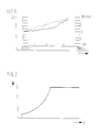
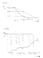
- FIG. 1 shows the speed reduction as a function of time in a diagram
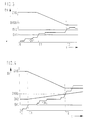
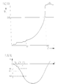
- FIG. 3 shows a diagram of the integration value as a function of the acceleration value
- FIG. 3 to FIG. 8 shows diagrams showing the change in speed as a function of time
- FIG. 9 shows the dependence of a threshold value on a diagram the acceleration
- FIG. 10 to FIG. 13 diagrams with representations of the speed change as a function of time
- FIG. 14 to FIG. 16 diagrams for representing the acceleration as a function of time
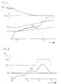
- FIG. 17 an acceleration-time diagram when crossing a railway track
- FIG. 18 and FIG. 19 diagrams showing the change in speed as a function of time.
- FIG. 1 shows in a diagram the speed reduction DV of a vehicle as a function of the time that occurs, for example, in a vehicle collision on the basis of a traffic accident.
- the change in speed is obtained by integrating the acceleration detected by a sensor, for example an acceleration sensor.
- the curve shown in dotted lines in the diagram corresponds to an impact in the longitudinal axis direction of the vehicle, which corresponds to a speed change of approximately 14.3 km per hour in a period of 120 ms after the start of the collision. This accident situation should not yet lead to a trigger because there is no significant danger for the occupants.
- the solid curve which arises in the event of an oblique impact with an impact angle of 30 ° with respect to the longitudinal axis of the vehicle, corresponds to a change in speed of approx. 26 km per hour within 120 ms after the start of the collision and should definitely lead to the deployment of the restraint system.
- a disadvantage of known systems is that, in such collisions with an oblique impact, dangerous situations are recognized too late by the sensor, which is only sensitive in the longitudinal axis direction of the vehicle, with the result that the restraint system is generally triggered too late, so that no effective protection is provided more can be guaranteed.
- an integration device for speed change or acceleration provided in the restraint system does not integrate the acceleration values output by the acceleration sensor, but rather values which, in the manner of a characteristic curve or a characteristic curve field Output signals of the acceleration sensor are assigned.
- FIG. 2 represents the integration value as a function of the acceleration value a in the form of a schematic characteristic curve.
- the invention is based on the knowledge that the disproportionate evaluation of larger acceleration values, e.g. by a quadratic evaluation of a high acceleration, corresponding output values of the acceleration sensor are integrated much more than would be the case with a proportional evaluation (corresponds to a linear characteristic curve).
- the DV integrator can wash up very quickly even in the case of very rapid crash situations due to the large acceleration amplitudes that occur and correspondingly large amplitude values of the output signal of the acceleration sensor.
- a necessarily very quick triggering can thus take place in good time in the case of very fast crash processes.
- Appropriate design of the characteristic curve has no influence on slow crash processes.
- the triggering sensitivity of restraint systems can thus be set differently in a relatively simple manner in fast crash processes and slow crash processes.
- the restraint means are activated when the integrated output signal (acceleration signal) of the acceleration sensor exceeds a predefinable fixed threshold, the so-called DV threshold.
- This integrated acceleration represents the change in speed justified from the beginning of the impact situation.
- the time it takes for this DV integral to reach the DV threshold has so far not been taken into account in conventional restraint systems.
- the invention now shows ways of taking this into account Timing restraint systems for vehicle occupants can be designed even more effectively.
- a first method to include the time in the trigger criterion is to represent the DV threshold as a function of time, with the time running from a certain minimum DV integrator level or from a particular characteristic of the acceleration or its first integral.
- a special function dependency of the triggering criterion on time could be obtained from the observation of the quotient constant / t.
- the DV threshold can be influenced not only as a function of the elapsed time, but also as a function of the cumulative DV integrator status, for example also from the quotient DV integrator / t. The latter quotient represents the average change in speed or the deceleration.
- the DV integral itself can be increased or decreased depending on the elapsed time, the DV threshold remaining constant even in this case.
- the DV threshold is influenced.
- the range or band of the DV integrator value range can be regarded as constant over time in a first exemplary embodiment.
- the range can be viewed as a function of time t, the basic DV threshold and / or the DV integrator. This means that, for example, the bandwidth can remain constant over time, just as it is possible that the width of the band can expand or contract somewhat over time, just as it is possible that both the lower limit and the upper limit the area can be a general function over the time of the DV basic threshold and the DV integrator.
- the above-mentioned influence on the DV threshold within the range just defined can be any function of time, the basic DV threshold and the DV integrator itself. If, for example, the DV integrator is below the lower value that limits the range mentioned, the DV threshold is set to the value of an original DV basic threshold. If, on the other hand, the DV integrator is above the upper value which limits the range mentioned, the DV threshold preferably remains at the value which is the last was discontinued by this measure.
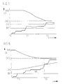
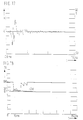
- the range or band of the DV integrator value range has a constant width, namely between the values DV1 to DV2, which is independent of time or other parameters.
- a relatively high DV threshold namely the DV basic threshold DVG
- the DV integrator DVI shown in steps in the diagram starts up with increasing time t and, at time T1, after the lower threshold value DV1 has been exceeded, it enters the range or band of the DV integrator value range in which the DV threshold is to be influenced. If the DV integrator DVI is now within the value range limited by the threshold values DV1, DV2, the DV threshold DV is lowered from the DV basic threshold DVG as a function of time to a predefinable minimum value. In the exemplary embodiment according to FIG. 3, the lowering of the DV threshold takes place with a linear course, which is approximately due to the relationship
- DV threshold DV basic threshold (1 - p t) can be characterized. According to FIG. 3, the DV basic threshold is linearly reduced in accordance with the relationship mentioned above until the DV integrator DVI has left the DV integrator value range by exceeding the upper threshold DV2 or the DV threshold is set to a minimum value. The basic DV threshold then maintains this minimum value DVGU reached at time T2.
- the purpose of the measure explained above is to ensure that DV integrator profiles, which are especially in oblique impact situations (approximately ( ⁇ 10 ° - 30 °) with respect to the longitudinal axis of the vehicle), are within a predefined range of values DV1, DV2 for a relatively long time
- DV integrator profiles are also in the previously defined area DV1, DV2 in comparatively slow frontal impact situations, in which no deployment of the restraint means is desired in such frontal impact situations.
- small and relatively short acceleration processes typically occur, which do not trigger the restraint means in the measures shown here. In this way, the trigger sensitivity for slow frontal impact situations and slow oblique impact situations can be set differently.
- the DV integrator value range DV1, DV2 is not kept constant over time, but is widened with increasing time. This widening takes place in accordance with the exemplary embodiment shown in FIG. 4 in particular by the fact that at time T1, at which the DV integrator enters the DV integrator value range by exceeding the lower threshold value DV1, the upper threshold value DV2 of the DV integrator value range increases . In the exemplary embodiment shown in FIG. 4, this enlargement takes place approximately according to a linear function of time t. Just as in the exemplary embodiment according to FIG.
- the DV threshold DV proceeds from the DV basic threshold DVG with a preferably linear profile to lowered to the minimum value DVGU.
- This minimum value DVGU is reached when the DV integrator leaves the value range DV1, DV2 again (time T2) by exceeding the upper threshold DV2.
- the DV integrator DVI reaches the lower limit value DV1 of the predefinable DV integrator value range at time T1, which causes the DV threshold to be lowered from the relatively high value of the DV basic threshold DVG.
- the lowering of the basic Dv threshold is no longer dependent solely on the time t but also on the current status of the DV integrator DVI, which results in a further refinement of the response behavior of the restraint system.
- the DV threshold is in turn lowered to a predeterminable minimum value DVGU which is reached when the DV integrator leaves the DV integrator value range DV1, DV2 at time T2 by exceeding the upper threshold DV2.
- the DV integrator value range DV1, DV2 expands with increasing time t, since the upper threshold value DV2 increases as a function of time.
- the time dependency of the upper threshold value DV2 begins at time T1 at which the DV integrator DVI exceeds the lower threshold value DV1.
- the DV threshold value is lowered again based on the relatively high DV basic threshold DVG, this reduction being approximately represented by the following expression
- the DV threshold assumes its lowest value, ie DVGU. If the integrator DVI falls below the DV integrator value range DV1, DV2, the DV threshold again assumes the value of the DV basic threshold DVG.
- the DV integrator DVI exceeds the threshold value DV1 at the time T1, but does not drop below it for a longer period of time. If, on the other hand, it is determined that the DV integrator DVI does not reach the threshold DVG1 set for triggering the restraint means within a predetermined time after the DV1 threshold value has been exceeded, the DV basic threshold DVG1 is changed to a less sensitive DV basic threshold DVG2 at time T2 raised.
- the effective time of this increase can be determined by a timer as well as by exceeding or falling below DV thresholds (e.g. DV1) in conjunction with times. This is equivalent to a reduction in the willingness to trigger.
- This timing element has the effect that the reduced readiness to trigger is maintained over a predeterminable period of time, for example from time T2 to time T3, and only at time T3 the sensitivity is reduced again to the lower threshold value DVG1.
- the sensitivity can be raised again to the threshold DVG1 immediately after the timer has expired at time T3; alternatively, the return to the more sensitive threshold DVG1 can optionally also take place with a certain time dependency, for example with a linear course as a function of time.
- the timer can be implemented, for example, by a counter that starts at time T2 and stops when a counter reading corresponding to the desired time delay is reached, that is to say, for example, at time T3.
- this measure in accordance with the exemplary embodiment explained above is to interpret DV integrator curves which have been at a low level for a relatively long time, but above a first DV threshold value, here DV1, in such a way that a continuous one There is a delay, but this is too small to activate the restraint systems. A less sensitive reaction of the restraint means is therefore sought.
- the method according to the embodiment of FIG. 8 can be used expediently when braking is carried out on a rough road. It can happen that the DV integrator slowly swings up without a situation that poses a risk to the occupants.
- This method also has a positive effect in the event of slow crash processes in which the restraint means would be triggered, but the activation of the restraint means would be too late to still be able to contribute to protecting the vehicle occupants. If the release is too late, the maximum possible forward displacement of the vehicle occupants for the sensible use of restraint devices is exceeded. For example, activation of the airbag would no longer make sense if a body part of a vehicle occupant has already hit the steering wheel of the vehicle. By raising the DV threshold to a less sensitive value DVG2, a no longer sensible triggering of restraint devices can be prevented, in order to thereby avoid an additional risk to the vehicle occupants by the restraint devices themselves.
- a further advantageous embodiment of the invention is explained with reference to FIG. 9.
- a further improvement in the triggering behavior of the restraint means is achieved in that the DV threshold is already made dependent on the acceleration values detected by the acceleration sensor. This can be achieved, for example, by assigning a certain DV threshold value to each acceleration value detected by the acceleration sensor using a selectable characteristic curve.
- the DV threshold values can therefore be represented as a function of the acceleration a.
- FIG. 9 shows the representation of the DV threshold curve as a function of Be acceleration a.
- the trigger threshold is kept at a constant value up to an acceleration as, which is reached at time T1 according to FIG. 14, and is lowered for larger accelerations.
- the dashed line represents a straight line, i.e. does not represent a linear drop in the DV threshold value as a function of the acceleration.
- an acceleration value a2 is determined at time T2.
- a DV threshold value DV2 is assigned to this acceleration value a2.
- the DV threshold value can be made dependent on the acceleration value a in a non-linear relationship. This is illustrated by means of the solid curve shown in FIG. 9.
- a lowered DV threshold value DV2 is already achieved here with a relatively low delay a1.
- the measure described above makes it much easier for the large acceleration values a to exceed the DV threshold necessary for the release of the restraint means than for correspondingly smaller acceleration values. A necessarily very quick triggering can thus still take place in time in the case of very fast crash courses. If the characteristic curve is selected appropriately, slow crash processes are not influenced, since the amplitudes of the acceleration values remain comparatively small and do not result in a lowering of the DV threshold. With this measure, the trigger sensitivity can be better adapted to rapid crashes. A different trigger sensitivity for fast and slow crash situations can also be selected.
- the acceleration-time curve is idealized in FIG. In practice, this idealized curve is overlaid with numerous fluctuations in amplitude, which arise, for example, when driving through potholes.
- the amplitude values of the acceleration-time curve are sampled according to FIG. 14 and the sampled amplitude values are used as a decision criterion for lowering the DV threshold according to FIG. 9, it can happen that an extreme value of the amplitude in the case of a temporary one Fluctuation of the acceleration-time curve is detected. Since this may deviate strongly from an average value, there could be a meaningless lowering of the DV threshold according to the characteristic curve shown in FIG. 9.
- a plurality of chronologically successive amplitude values of the acceleration-time curve are recorded in order to form an average.
- the slope of the acceleration-time curve is used as a criterion for lowering the DV threshold value.
- This measure is explained with reference to FIG. 16.
- This curve is characterized by a first relative minimum at time T2, the amplitude value of which, however, does not yet exceed the acceleration limit value as.
- This relative minimum at time T2 is then followed by a relative maximum at time T3 at which there is a comparatively low acceleration value. Following this relative maximum at T3, the acceleration-time curve lowers further, only to reach the acceleration limit value as at time T4.
- Such an acceleration-time curve is characteristic of vehicles with energy-absorbing crumple zones. If, as in the previously mentioned exemplary embodiment, only amplitude values were used as a criterion for lowering the DV threshold, completely unsatisfactory results would be obtained with such a curve profile. A lowering of the DV threshold would only be initiated at the earliest at time T4, since only then does the detected acceleration amplitude exceed the predetermined limit value as. Up to this In contrast, according to FIG. 9, time T4 would keep the DV threshold at a relatively high value DVG. In a disadvantageous manner, dangerous crash situations would not be detected in time. because the course of the crash is hidden by the influence of the crumple zone.
- the slope of the acceleration-time curve is recorded as the triggering criterion for lowering the DV threshold.
- the slope of the acceleration-time curve is recorded at the coordinates T1, a1, which is indicated by the tangent TA1 shown.
- the acceleration value a1 is still so low that there is no reason for lowering the DV threshold if the amplitude is evaluated purely, the slope of the tangent TA1 shows that this is a dangerous crash situation which requires the reaction of the restraint means to react quickly .
- This rapid reaction of the restraint means is achieved by lowering the DV threshold as shown in FIG. 9.
- the slope of the acceleration-time curve can be determined in a simple manner by detecting the amplitude values at two points in quick succession and forming the corresponding difference quotient. If the slope corresponding to this difference quotient exceeds a predefinable limit value, then the DV threshold is lowered according to a predefinable relationship, for example with a linear time dependency.
- decision criteria for lowering the DV threshold were explained using some detailed exemplary embodiment. Further decision criteria can be derived from a frequency analysis of the acceleration-time curve. With this frequency analysis, it is then also possible to recognize natural resonances of the accelerometer system and to suppress them. It is also also possible to avoid interference vibrations with very high amplitude values, which, however, do not originate from a crash situation, such as e.g. B. Recognize impact stresses of the vehicle by falling rocks or when driving through a pothole and to exclude them from an assessment. Furthermore, pattern recognition can also be carried out in that the acceleration-time curve is recorded very precisely and is compared, for example, with a stored ideal pattern. Furthermore, combinations of the measures described above are also possible in order to achieve a particularly optimal adaptation of the evaluation criteria to a specific vehicle in individual cases.
- the decision as to whether the DV threshold is to be lowered or not it is additionally possible to use output signals from further sensors which are arranged locally in the vehicle from the central sensor unit.
- the evaluation criterion can still be made dependent on certain operating states of the vehicle, which the central acceleration sensor alone cannot detect. For example, switching signals of a rear axle switch, the seat belt buckles, the seat contact, the brake switch, a gear switch, a touch switch or mechanical acceleration switch can be detected and combined with the output signal of the central acceleration sensor in order to make a decision criterion for lowering the DV threshold that is particularly suitable for the specific vehicle to derive.
- output signals of other control devices in the vehicle for brake control, for internal combustion engine control or for navigation can also be evaluated.
- the DV threshold was influenced in accordance with a DV integrator value or an acceleration value, preferably also via a predefinable characteristic curve. It is also possible to influence the detected basic values, such as DV integrator values and / or the acceleration value, additively and / or multiplicatively in order to achieve a certain functional dependency for influencing the course of the DV threshold value. If several parameters, for example sensor output signals from other sensors, are to be taken into account, it makes sense to carry out the DV threshold value change in accordance with characteristic values that are stored in a characteristic diagram.
- the DV threshold was lowered when a decision criterion was present, starting from a relatively high value of the DV basic threshold DVG, in order to achieve a more sensitive reaction of the restraint means and to improve the protection of the vehicle occupants.
- the decision criterion ceased to exist, the existence of which is expediently checked periodically after a predeterminable time cycle, the initially lowered DV threshold was raised to the original basic value DVG practically without any time delay.
- FIG. 10 shows the speed change DV as a function of time t.
- the course of the curve of the DV integrator DVI is also entered in the diagram.
- the value of the DV basic threshold DVG is also shown.
- An improvement in the triggering behavior is achieved according to a further embodiment of the invention in that, after the triggering sensitivity of the restraint system has been tightened by lowering the DV threshold from the comparatively high threshold value DVG to a lower threshold value, this reduction takes place as immediately as possible, but the deactivation takes place due to according to newly detected acceleration values, is carried out with a time delay.
- Disarming here means raising an initially lowered DV threshold to, for example, the higher DVG value of the DV basic threshold. This measure is explained with reference to FIG. 11, which essentially corresponds to the illustration in FIG. 10. The lowering of the DV threshold from the high value of the DV basic threshold DVG takes place again at times T1, T2, T3, T4, TA.
- the DV threshold is raised to the original value DVG of the DV basic threshold only with a time delay DT.
- the DV integrator When integrating the occurring acceleration values, the DV integrator has a phase shift with respect to the acceleration amplitudes. This shift can be compensated for by the time delay of the threshold increase described above. Due to the time-delayed withdrawal of the lowered threshold values to the basic DVG value to favorable ones. An earlier triggering of the restraint means or a trigger with a greater triggering safety take place.
- An advantageous further embodiment of the invention improves the trigger behavior by influencing integration values as a function of a DV reference integrator and the time.
- the integration values are only influenced if the DV reference integrator is within a defined range. If the DV reference integrator runs in the area mentioned, a timer is started. The read acceleration values are then multiplied by a factor that is proportional to the time count, or a value is added. The resulting new integration values are integrated by the release integrator, which triggers the restraint device when a specified DV threshold is exceeded.
- FIG. 13 shows the same functional dependency between the speed change and the time as FIG. 12, but with the curve of the trip integrator A1 being shown.
- the reference integrator RI enters the DV integrator value range delimited by the two thresholds, DV1 and DV2, by exceeding the low DV threshold DV1.
- a timer is then started, with the proviso that acceleration values supplied by the acceleration sensor as an output signal, which are to be integrated by the trigger integrator A1, are linked beforehand with a factor corresponding to the elapsed time, preferably multiplicatively or additively.
- the trip integrator AI is in oblique impact situations and in a frontal impact situation for different lengths in the range defined by the limit values DV1 and DV2.
- timing elements are started when the reference integrator RI exceeds a predeterminable lower threshold, for example the threshold DV1 in FIG. 12.
- these timers cause a kind of modulation to set the DV threshold so that either, depending on the type of triggering target hold, the basic threshold is raised or lowered.
- the DV threshold can be reduced as a function of the detected acceleration amplitudes in accordance with an exemplary embodiment already described above, or else additionally on the polarity of the acceleration signals.
- Each of the timing elements influences the lowering of the DV threshold for the duration of its running time in the individual manner assigned to it.
- the number of time elements that can be used can be selected as required, depending on the requirements of the type of DV threshold influencing.
- Timing elements preferably counter circuits.
- a single counter can also be provided, which is queried for different counter readings.
- a time limit for the different types of influencing the DV thresholds is then given by the meter readings.
- the counters or the counter can be reset, for example, as soon as the reference integrator RI has fallen below the above-mentioned lower threshold DV1 again.
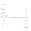
- FIG. 17 shows the output signal of an acceleration sensor when crossing a railroad track in which the vehicle is exposed to a brief impact.
- the acceleration-time curve is shown.
- the curve shows a bipolar signal with initially very high amplitude values up to about 30 g, which, however, decay very quickly. After only about 30 ms, there are only comparatively low amplitude values.
- FIG. 18 again shows a representation of the change in speed OV as a function of time t.
- the course of the DV integrator DVI together with the DV threshold is shown in this diagram, which, however, can be varied here according to the methods described above and runs according to a complex time function.
- the DV threshold begins at time 0 with a relatively high constant value, namely the DV basic threshold DVG, which is lowered to a lower value after about 15 ms to increase the sensitivity of the system, to about this low level, about DV1 for about 15 ms to persist and then again, at least temporarily to rise to the level of the DV basic threshold DVG again.
- the illustration in FIG. 18 shows that the course of the curve of the DV integrator DVI exceeds the lowered DV threshold after approximately 13.5 ms. This would result in the superfluous triggering of the restraint devices.
Abstract
Claims (45)
Applications Claiming Priority (5)
| Application Number | Priority Date | Filing Date | Title |
|---|---|---|---|
| DE3905052 | 1989-02-18 | ||
| DE3905052 | 1989-02-18 | ||
| DE3924507 | 1989-07-25 | ||
| DE3924507A DE3924507A1 (de) | 1989-02-18 | 1989-07-25 | Verfahren zur ausloesung von rueckhaltemitteln |
| PCT/DE1990/000048 WO1990009298A1 (fr) | 1989-02-18 | 1990-01-27 | Procede pour liberer des moyens de retenue |
Publications (3)
| Publication Number | Publication Date |
|---|---|
| EP0458796A1 EP0458796A1 (fr) | 1991-12-04 |
| EP0458796B1 true EP0458796B1 (fr) | 1992-11-11 |
| EP0458796B2 EP0458796B2 (fr) | 1995-05-17 |
Family
ID=25877958
Family Applications (1)
| Application Number | Title | Priority Date | Filing Date |
|---|---|---|---|
| EP90901757A Expired - Lifetime EP0458796B2 (fr) | 1989-02-18 | 1990-01-27 | Procede pour liberer des moyens de retenue |
Country Status (7)
| Country | Link |
|---|---|
| US (1) | US5014810A (fr) |
| EP (1) | EP0458796B2 (fr) |
| JP (2) | JPH0764246B2 (fr) |
| KR (1) | KR0169312B1 (fr) |
| AU (1) | AU638432B2 (fr) |
| DE (2) | DE3924507A1 (fr) |
| WO (1) | WO1990009298A1 (fr) |
Cited By (10)
| Publication number | Priority date | Publication date | Assignee | Title |
|---|---|---|---|---|
| WO1994014638A1 (fr) * | 1992-12-23 | 1994-07-07 | Siemens Aktiengesellschaft | Procede permettant de commander l'unite de commande d'un systeme visant a proteger les passagers d'un vehicule |
| DE4330486A1 (de) * | 1993-09-09 | 1995-03-16 | Daimler Benz Ag | Verfahren zur Auslösung eines Airbags in einem Kraftfahrzeug |
| US5742916A (en) * | 1992-12-23 | 1998-04-21 | Siemens Aktiengesellschaft | Process and circuit for controlling the control unit of a system for protecting vehicle occupants |
| US5790404A (en) * | 1994-12-22 | 1998-08-04 | Morton International, Inc. | Method enabling rapid and reliable triggering of vehicle occupant restraint systems by spectral frequency analysis of the acceleration signal |
| WO2000063045A2 (fr) * | 1999-04-20 | 2000-10-26 | Robert Bosch Gmbh | Procede pour l'etablissement d'un critere de declenchement de moyens de retenue |
| WO2002014113A1 (fr) | 2000-08-17 | 2002-02-21 | Robert Bosch Gmbh | Procede pour etablir une decision de declenchement d'un systeme de retenue |
| US6353783B1 (en) | 1997-11-29 | 2002-03-05 | Robert Bosch Gmbh | Method and device for forming a deployment criterion for a restraint system |
| DE10065518A1 (de) * | 2000-12-28 | 2002-07-11 | Bosch Gmbh Robert | Verfahren zum Auslösen von Rückhaltemitteln in einem Kraftfahrzeug |
| WO2006037680A1 (fr) * | 2004-10-02 | 2006-04-13 | Robert Bosch Gmbh | Procede et dispositif de commande de moyens de protection de personnes |
| DE102006031238B4 (de) * | 2006-07-06 | 2016-07-21 | Robert Bosch Gmbh | Vorrichtung und Verfahren zur Ansteuerung von Personenschutzmitteln |
Families Citing this family (100)
| Publication number | Priority date | Publication date | Assignee | Title |
|---|---|---|---|---|
| WO1990003289A1 (fr) * | 1988-09-17 | 1990-04-05 | Robert Bosch Gmbh | Appareil et procede de declenchement d'un systeme de protection pour les occupants d'un vehicule |
| JP2543839B2 (ja) * | 1990-01-29 | 1996-10-16 | センサー・テクノロジー株式会社 | 衝突センサ |
| GB9005168D0 (en) * | 1990-03-08 | 1990-05-02 | Autoliv Dev | Improvements in or relating to an accelerometer arrangement |
| US5787377A (en) * | 1990-08-24 | 1998-07-28 | Kanto Seiki Co. Ltd. | Air-bag control circuit |
| US6125313A (en) * | 1990-08-24 | 2000-09-26 | Kanto Seiki Co., Ltd. | Air-bag control circuit |
| JP2879613B2 (ja) * | 1991-03-18 | 1999-04-05 | 本田技研工業株式会社 | 乗員保護装置 |
| JP2755502B2 (ja) * | 1991-04-19 | 1998-05-20 | センサー・テクノロジー株式会社 | 衝突センサ |
| DE4116336C1 (en) * | 1991-05-18 | 1992-06-11 | Messerschmitt-Boelkow-Blohm Gmbh, 8012 Ottobrunn, De | Passive safety device release assembly for motor vehicle occupant - has acceleration pick=ups with sensitivity axes directed to detect angle of frontal impact and supplying evaluating circuit |
| DE4117811A1 (de) * | 1991-05-31 | 1992-12-03 | Messerschmitt Boelkow Blohm | Verfahren zur aufprallerkennung bei fahrzeugen |
| US6609053B1 (en) * | 1995-06-07 | 2003-08-19 | Automotive Technologies International, Inc. | Method and apparatus for sensing a vehicle crash |
| US7284769B2 (en) * | 1995-06-07 | 2007-10-23 | Automotive Technologies International, Inc. | Method and apparatus for sensing a vehicle crash |
| US5339242A (en) * | 1991-11-26 | 1994-08-16 | Delco Electronics Corp. | Method and apparatus for vehicle crash discrimination based on oscillation and energy content |
| JPH05221280A (ja) * | 1992-02-10 | 1993-08-31 | Toyoda Gosei Co Ltd | エアバッグ制御装置 |
| DE4212421A1 (de) * | 1992-04-14 | 1993-10-28 | Bosch Gmbh Robert | Verfahren und Einrichtung zum Schutz von Fahrzeuginsassen |
| DE4223562A1 (de) * | 1992-07-17 | 1993-09-23 | Daimler Benz Ag | Verfahren zur einflussnahme auf die ausloesung eines insassenrueckhaltesystems in einem kraftfahrzeug und vorrichtung zur durchfuehrung des verfahrens |
| JPH0640308A (ja) * | 1992-07-21 | 1994-02-15 | Naldec Kk | 車両の安全装置 |
| DE4324753B4 (de) * | 1992-08-25 | 2004-05-06 | Daimlerchrysler Ag | Auslösevorrichtung für eine Sicherheitseinrichtung zum Schutz von Fahrzeuginsassen |
| US5436838A (en) * | 1992-09-21 | 1995-07-25 | Nec Corporation | Crash/non-crash discrimination using frequency components of acceleration uniquely generated upon crash impact |
| WO1994023973A1 (fr) * | 1993-04-15 | 1994-10-27 | Automotive Systems Laboratory, Inc. | Systeme de reperage d'accident a strategies multiples |
| US5446661A (en) * | 1993-04-15 | 1995-08-29 | Automotive Systems Laboratory, Inc. | Adjustable crash discrimination system with occupant position detection |
| JP3324220B2 (ja) * | 1993-09-07 | 2002-09-17 | 日産自動車株式会社 | 乗員拘束装置の制御装置 |
| WO1995012505A1 (fr) * | 1993-11-02 | 1995-05-11 | Sensor Technology Co., Ltd. | Capteur de collision |
| US5430649A (en) * | 1993-11-26 | 1995-07-04 | Delco Electronics Corporation | SIR deployment method based on occupant displacement and crash severity |
| US5498028A (en) * | 1994-01-04 | 1996-03-12 | Trw Inc. | Method and apparatus for controlling an actuatable restraining device |
| US5418722A (en) * | 1994-03-04 | 1995-05-23 | Delco Electronics Corporation | SIR deployment method with rough road immunity |
| US5483449A (en) * | 1994-03-31 | 1996-01-09 | Delco Electronics Corporation | Inflatable restraint system and method of controlling deployment thereof |
| US5668720A (en) * | 1994-04-28 | 1997-09-16 | Toyoda Gosei Co., Ltd. | Air bag controlling apparatus |
| US5538099A (en) * | 1994-05-27 | 1996-07-23 | Trw Vehicle Safety Systems Inc. | Method and apparatus for controlling an air bag restraint system |
| US5587906A (en) * | 1994-06-13 | 1996-12-24 | Trw Inc. | Method and apparatus for sensing a vehicle crash condition using velocity enhanced acceleration crash metrics |
| US5583771A (en) * | 1994-08-04 | 1996-12-10 | Delco Electronics Corp. | Method and apparatus for distinguishing between deployment events and non-deployment events in an SIR system |
| EP0787631B1 (fr) * | 1994-08-26 | 2002-05-02 | Automotive Systems Laboratory Inc. | Filtre apparié pour détection d'accident de véhicule |
| US5504379A (en) * | 1994-09-23 | 1996-04-02 | Trw Vehicle Safety Systems Inc. | Method and apparatus for sensing a vehicle crash using a velocity displacement metric |
| US5508920A (en) * | 1994-10-25 | 1996-04-16 | Automotive Systems Laboratory, Inc. | Crash discriminator responsive to early-crush and multiple-hit scenarios |
| KR970001747B1 (ko) * | 1994-10-31 | 1997-02-15 | 대우전자 주식회사 | 3방향(3축) 감속신호와 가변 기준치를 이용한 자동차용 에어백 제어장치 |
| DE19547830A1 (de) * | 1995-12-21 | 1997-07-03 | Bosch Gmbh Robert | Airbagsystem |
| DE19609077C1 (de) * | 1996-03-08 | 1997-08-28 | Siemens Ag | Anordnung zum Auslösen eines Rückhaltemittels zum Seitenaufprallschutz in einem Kraftfahrzeug |
| US5702124A (en) * | 1996-04-22 | 1997-12-30 | Trw Inc. | Method and apparatus for sensing a vehicle crash using a displacement velocity metric |
| DE19616836C2 (de) * | 1996-04-26 | 1998-04-09 | Siemens Ag | Einrichtung zum Auslösen eines Rückhaltemittels in einem Fahrzeug |
| DE19619412C1 (de) * | 1996-05-14 | 1997-08-28 | Telefunken Microelectron | Auslöseverfahren für passive Sicherheitseinrichtungen in Fahrzeugen |
| DE19619414C1 (de) * | 1996-05-14 | 1997-08-21 | Telefunken Microelectron | Auslöseverfahren für passive Sicherheitseinrichtungen in Fahrzeugen |
| DE19647660B4 (de) * | 1996-11-19 | 2005-09-01 | Daimlerchrysler Ag | Auslösevorrichtung für Insassenrückhaltesysteme in einem Fahrzeug |
| JP3333813B2 (ja) | 1996-11-20 | 2002-10-15 | トヨタ自動車株式会社 | 乗員保護装置の起動制御装置 |
| SE9604671L (sv) * | 1996-12-19 | 1998-06-20 | Volvo Ab | Säkerhetsanordning för fordon |
| US5899948A (en) * | 1997-02-06 | 1999-05-04 | Raphael; Eric Lewis | System and method for the detection and discrimination of vehicle crash events |
| JP3721242B2 (ja) | 1997-03-31 | 2005-11-30 | 日産自動車株式会社 | 乗員拘束安全装置の制御装置 |
| DE19724101A1 (de) * | 1997-06-07 | 1998-12-10 | Bayerische Motoren Werke Ag | Verfahren zur bedarfsgerechten Steuerung von Insassen-Sicherheitseinrichtungen |
| JP3044709B2 (ja) | 1997-09-19 | 2000-05-22 | トヨタ自動車株式会社 | 乗員保護装置の起動制御装置 |
| US6485057B1 (en) * | 1997-12-16 | 2002-11-26 | Nsk Autoliv Co., Ltd. | Automotive passenger restraint and protection apparatus and seatbelt protraction and retraction amount-detecting device |
| US6257363B1 (en) * | 1997-12-16 | 2001-07-10 | Nsk Ltd. | Automotive passenger restraint and protection apparatus |
| JP3063731B2 (ja) * | 1998-04-02 | 2000-07-12 | トヨタ自動車株式会社 | 乗員保護装置の起動制御装置 |
| DE19816989B4 (de) * | 1998-04-17 | 2004-06-17 | Daimlerchrysler Ag | Verfahren zur Auslösung eines zweistufigen Airbag-Gasgenerators |
| JPH11334527A (ja) * | 1998-05-25 | 1999-12-07 | Asuko Kk | 乗員保護装置の起動制御方法及び乗員保護装置の起動制御装置並びに乗員保護装置の起動制御プログラムを記録した記録媒体 |
| DE19840440B4 (de) * | 1998-09-04 | 2004-09-16 | Siemens Ag | Verfahren und Vorrichtung zum Steuern eines Insassenschutzmittels eines Fahrzeugs |
| US6219606B1 (en) * | 1998-11-16 | 2001-04-17 | Delphi Technologies, Inc. | Restraint deployment control method having a delayed adaptable deployment threshold |
| JP3346472B2 (ja) | 1999-02-01 | 2002-11-18 | トヨタ自動車株式会社 | 乗員保護装置の起動制御装置 |
| JP3436185B2 (ja) | 1999-02-09 | 2003-08-11 | トヨタ自動車株式会社 | 乗員保護装置の起動制御装置 |
| DE19905379C2 (de) * | 1999-02-09 | 2001-09-20 | Daimler Chrysler Ag | Verfahren zur Auflösung einer Sicherheitseinrichtung in einem Kraftfahrzeug im Falle eines Überschlages |
| DE19913675B4 (de) * | 1999-03-25 | 2006-05-04 | Volkswagen Ag | Verfahren und Einrichtung zur Steuerung eines Sicherheitssystems bei Kraftfahrzeugen |
| US6236921B1 (en) | 1999-08-04 | 2001-05-22 | Visteon Global Technologies, Inc. | Three speed algorithm for airbag sensor activation |
| DE19957187B4 (de) * | 1999-11-27 | 2007-05-10 | Volkswagen Ag | Verfahren und Vorrichtung zur Crasherkennung |
| DE19962328A1 (de) * | 1999-12-23 | 2001-06-28 | Bosch Gmbh Robert | Verfahren und Einrichtung zum Erkennen einer Kurvenfahrt eines Fahrzeugs |
| DE10108848C2 (de) * | 2000-03-18 | 2002-05-16 | Conti Temic Microelectronic | Verfahren zur Steuerung von Insassenschutzeinrichtungen in einem Fahrzeug |
| DE10015267C2 (de) * | 2000-03-28 | 2003-08-21 | Siemens Ag | Steuervorrichtung für Insassenschutzmittel in einem Kraftfahrzeug |
| DE10033907A1 (de) * | 2000-07-12 | 2002-01-24 | Bosch Gmbh Robert | Verfahren zum Ermitteln der Schwere eines Frontaufpralls |
| DE10036935A1 (de) * | 2000-07-28 | 2002-02-07 | Siemens Ag | Verfahren zum Überwachen der Funktion eines Sensors, der zueinander inverse Ausgangssignale liefert, in einem Kraftfahrzeug |
| DE10050956A1 (de) * | 2000-10-13 | 2002-05-02 | Bayerische Motoren Werke Ag | Verfahren zur Auslösung von wenigstens einem Rückhaltemittel |
| US6662092B2 (en) * | 2000-12-15 | 2003-12-09 | General Motors Corporation | Fuzzy logic control method for deployment of inflatable restraints |
| DE10103661C1 (de) * | 2001-01-27 | 2002-08-08 | Bosch Gmbh Robert | Verfahren zur Seitenaufprallsensierung in einem Fahrzeug |
| DE10116926B4 (de) | 2001-04-05 | 2005-06-16 | Daimlerchrysler Ag | Verfahren zur Ansteuerung eines Gasgenerators für einen Airbag in einem Kraftfahrzeug |
| DE10117220A1 (de) | 2001-04-06 | 2002-10-10 | Conti Temic Microelectronic | Verfahren zur Auflösung eines Insassenschutzsystems in Fahrzeugen |
| DE10117219A1 (de) * | 2001-04-06 | 2002-10-10 | Conti Temic Microelectronic | Verfahren zur Auslösung eines Insassenschutzsystems in Fahrzeugen |
| JP4416961B2 (ja) | 2001-05-11 | 2010-02-17 | 三菱電機株式会社 | 車両用乗員保護システム |
| US6498972B1 (en) * | 2002-02-13 | 2002-12-24 | Ford Global Technologies, Inc. | Method for operating a pre-crash sensing system in a vehicle having a countermeasure system |
| DE10245781A1 (de) * | 2002-10-01 | 2004-04-15 | Robert Bosch Gmbh | Verfahren zur Auslösung eines Rückhaltesystems in einem Fahrzeug |
| US6748307B1 (en) * | 2002-11-25 | 2004-06-08 | General Motors Corporation | Collision sensing system |
| US7321817B2 (en) * | 2002-12-13 | 2008-01-22 | Ford Global Technologies, Llc | Automobile frontal collision location detection for coordinated activation of safety systems |
| DE10309081A1 (de) * | 2003-03-03 | 2004-09-16 | Robert Bosch Gmbh | Vorrichtung zur Ansteuerung von Rückhaltemitteln in einem Fahrzeug |
| JP4449409B2 (ja) * | 2003-10-27 | 2010-04-14 | 日産自動車株式会社 | 車両用乗員保護装置 |
| DE10360893A1 (de) * | 2003-12-19 | 2005-07-21 | Robert Bosch Gmbh | Verfahren zur Ansteuerung von Personenschutzmitteln |
| DE10360769B4 (de) * | 2003-12-23 | 2012-04-12 | Conti Temic Microelectronic Gmbh | Verfahren und Vorrichtung zum Auslösen mindestens einer Insassenschutzeinrichtung in einem Fahrzeug |
| DE102004006603B4 (de) * | 2004-02-11 | 2015-06-03 | Volkswagen Ag | Verfahren und Vorrichtung zur Aufprallerkennung bei Kraftfahrzeugen |
| DE102004029373B4 (de) * | 2004-06-17 | 2012-12-13 | Robert Bosch Gmbh | Verfahren und Vorrichtung zum Unterscheiden von verschiedenen Crashsituationen für die Ansteuerung eines Rückhaltesystems eines Fahrzeugs |
| DE102004029817A1 (de) | 2004-06-19 | 2006-01-05 | Robert Bosch Gmbh | Sicherheitssystem für Fahrzeuginsassen |
| DE102004031010A1 (de) * | 2004-06-26 | 2006-01-12 | Conti Temic Microelectronic Gmbh | Vorrichtung und Verfahren zur Auslösung eines Insassenschutzsystems in einem Fahrzeug |
| DE102004032985A1 (de) | 2004-07-08 | 2006-02-09 | Daimlerchrysler Ag | Kraftfahrzeug mit einem präventiv wirkenden Sicherheitssystem |
| US7477974B2 (en) * | 2004-07-27 | 2009-01-13 | Robert Bosch Gmbh | Vehicle restraint device control method and apparatus using dynamically determined threshold |
| DE102005014782A1 (de) * | 2005-03-31 | 2006-10-05 | Siemens Ag | Verfahren und Vorrichtung zum Übertragen von Daten auf einer Datenleitung zwischen einem Steuergerät und einem dezentralen Datenverarbeitungsgerät |
| WO2007090417A1 (fr) * | 2006-02-07 | 2007-08-16 | Freescale Semiconductor, Inc. | Agencement de capteur d'accélération, agengement de protection pour un système d'activation, système d'activation |
| DE102006042769C5 (de) | 2006-09-12 | 2011-07-28 | Continental Automotive GmbH, 30165 | Verfahren und Vorrichtung zum Auslösen eines Personenschutzmittels für ein Fahrzeug |
| DE102006045682B3 (de) * | 2006-09-27 | 2008-02-07 | Siemens Ag | Verfahren und Vorrichtung zum Auslösen zumindest eines Insassenschutzsystems eines Kraftfahrzeugs, insbesondere bei einer Böschungsfahrt |
| DE102006058878A1 (de) * | 2006-12-13 | 2008-06-26 | Siemens Ag | Verfahren und Vorrichtung zum Auslösen eines Fußgängerschutzsystems |
| US9340188B2 (en) | 2007-05-10 | 2016-05-17 | Mitsubishi Electric Corporation | Occupant protective apparatus and pedestrian protective apparatus |
| WO2008140070A1 (fr) * | 2007-05-11 | 2008-11-20 | Toyota Jidosha Kabushiki Kaisha | Dispositif servant à commander un airbag de collision latérale |
| JP5518520B2 (ja) * | 2010-02-17 | 2014-06-11 | ダイハツ工業株式会社 | 乗員保護装置 |
| DE102012208093A1 (de) | 2011-07-22 | 2013-01-24 | Robert Bosch Gmbh | Verfahren und Steuergerät zur Ansteuerung zumindest eines Personenschutzmittels eines Fahrzeugs |
| DE102013101274A1 (de) * | 2013-02-08 | 2014-08-14 | Continental Automotive Gmbh | Verfahren zum Ermitteln eines Parameters zur Steuerung von Insassenschutzeinrichtungen aus dem Beschleunigungssignal |
| KR101526715B1 (ko) * | 2013-11-26 | 2015-06-05 | 현대자동차주식회사 | 자동차용 측면 에어백 전개 시스템 및 방법 |
| CN110606040B (zh) * | 2019-08-30 | 2021-07-20 | 江苏大学 | 一种适用于车辆事故自动呼救系统速度变化量的校正方法 |
| EP3825966A1 (fr) * | 2019-11-19 | 2021-05-26 | D.S. Raider Ltd | Système et procédé de surveillance et de prédiction de pannes dans des véhicules |
| WO2023285123A1 (fr) * | 2021-07-16 | 2023-01-19 | Continental Automotive Technologies GmbH | Procédé de détection d'impact et d'activation de dispositifs de protection des occupants |
Family Cites Families (19)
| Publication number | Priority date | Publication date | Assignee | Title |
|---|---|---|---|---|
| US3762495A (en) * | 1970-07-04 | 1973-10-02 | Nissan Motor | Method and device for triggering motor vehicle safety mechanisms |
| GB1362759A (en) * | 1971-05-28 | 1974-08-07 | Brueckner Apparatebau Gmbh | Apparatus for textile treatment |
| US3851305A (en) * | 1971-05-28 | 1974-11-26 | Nissan Motor | Collision detecting system for a motor vehicle |
| DE2240389A1 (de) * | 1971-08-27 | 1973-03-01 | Technar Inc | Unfallsicherheits-system fuer fahrzeuginsassen |
| US3889232A (en) * | 1971-08-27 | 1975-06-10 | Technar Inc | Sensor assembly for use in a vehicle equipped with a gas bag restraint system |
| DE2222038C3 (de) * | 1972-05-05 | 1978-07-06 | Messerschmitt-Boelkow-Blohm Gmbh, 8000 Muenchen | Prüfschaltung für die Auslösevorrichtung einer dem Schutz der Insassen eines Fahrzeuges während eines Unfalles dienenden Sicherheitseinrichtung |
| US3963090A (en) * | 1975-01-09 | 1976-06-15 | Hollins J R | Automatic seat belt buckle unlatching mechanism |
| US4189022A (en) * | 1978-09-26 | 1980-02-19 | Cascardo Adolph P | Automatically releasing seat belt anchor |
| FR2504474A1 (fr) * | 1981-04-28 | 1982-10-29 | Renault | Procede et systeme de detection de collision et de commande de dispositifs de securite |
| JPS598574A (ja) * | 1982-07-08 | 1984-01-17 | 鈴木 忠一 | スウイングサイクル |
| JPS5940964A (ja) * | 1982-08-30 | 1984-03-06 | Nippon Soken Inc | シ−トベルト装置 |
| US4638179A (en) * | 1984-03-31 | 1987-01-20 | Robert Bosch Gmbh | Extended response trigger circuit |
| US4742886A (en) * | 1986-02-17 | 1988-05-10 | Nissan Motor Co., Ltd. | Seat belt apparatus |
| DE3609839A1 (de) * | 1986-03-22 | 1987-09-24 | Bosch Gmbh Robert | Vorrichtung zum selbsttaetigen ausloesen von insassenschutzvorrichtungen bei einem unfall |
| DE3621580C2 (de) * | 1986-06-27 | 1995-06-29 | Bosch Gmbh Robert | Vorrichtung zum Auslösen von Insassenschutzsystemen |
| JPS6368440A (ja) * | 1986-09-11 | 1988-03-28 | N S K Warner Kk | パツシブシ−トベルトシステム |
| DE3717427C3 (de) * | 1987-05-23 | 1994-09-01 | Deutsche Aerospace | Aufprallsensor für Kraftfahrzeuge |
| DE3816587A1 (de) * | 1988-05-16 | 1989-11-23 | Messerschmitt Boelkow Blohm | Einrichtung zur ausloesung einer passiven sicherheitseinrichtung |
| DE3816588A1 (de) * | 1988-05-16 | 1989-11-23 | Messerschmitt Boelkow Blohm | Einrichtung zur ausloesung einer passiven sicherheitseinrichtung |
-
1989
- 1989-07-25 DE DE3924507A patent/DE3924507A1/de not_active Ceased
- 1989-12-28 US US07/458,239 patent/US5014810A/en not_active Ceased
-
1990
- 1990-01-27 KR KR1019900702289A patent/KR0169312B1/ko not_active IP Right Cessation
- 1990-01-27 AU AU49467/90A patent/AU638432B2/en not_active Expired
- 1990-01-27 EP EP90901757A patent/EP0458796B2/fr not_active Expired - Lifetime
- 1990-01-27 JP JP2502301A patent/JPH0764246B2/ja not_active Expired - Lifetime
- 1990-01-27 DE DE59000470T patent/DE59000470C5/de not_active Expired - Lifetime
- 1990-01-27 WO PCT/DE1990/000048 patent/WO1990009298A1/fr active IP Right Grant
-
1994
- 1994-12-06 JP JP6301725A patent/JP2657154B2/ja not_active Expired - Lifetime
Cited By (14)
| Publication number | Priority date | Publication date | Assignee | Title |
|---|---|---|---|---|
| WO1994014638A1 (fr) * | 1992-12-23 | 1994-07-07 | Siemens Aktiengesellschaft | Procede permettant de commander l'unite de commande d'un systeme visant a proteger les passagers d'un vehicule |
| US5742916A (en) * | 1992-12-23 | 1998-04-21 | Siemens Aktiengesellschaft | Process and circuit for controlling the control unit of a system for protecting vehicle occupants |
| DE4330486A1 (de) * | 1993-09-09 | 1995-03-16 | Daimler Benz Ag | Verfahren zur Auslösung eines Airbags in einem Kraftfahrzeug |
| US5445413A (en) * | 1993-09-09 | 1995-08-29 | Mercedes-Benz Ag | Method for releasing an airbag in a motor vehicle |
| US5790404A (en) * | 1994-12-22 | 1998-08-04 | Morton International, Inc. | Method enabling rapid and reliable triggering of vehicle occupant restraint systems by spectral frequency analysis of the acceleration signal |
| US6353783B1 (en) | 1997-11-29 | 2002-03-05 | Robert Bosch Gmbh | Method and device for forming a deployment criterion for a restraint system |
| WO2000063045A3 (fr) * | 1999-04-20 | 2001-03-15 | Bosch Gmbh Robert | Procede pour l'etablissement d'un critere de declenchement de moyens de retenue |
| WO2000063045A2 (fr) * | 1999-04-20 | 2000-10-26 | Robert Bosch Gmbh | Procede pour l'etablissement d'un critere de declenchement de moyens de retenue |
| WO2002014113A1 (fr) | 2000-08-17 | 2002-02-21 | Robert Bosch Gmbh | Procede pour etablir une decision de declenchement d'un systeme de retenue |
| DE10065518A1 (de) * | 2000-12-28 | 2002-07-11 | Bosch Gmbh Robert | Verfahren zum Auslösen von Rückhaltemitteln in einem Kraftfahrzeug |
| US6725141B2 (en) | 2000-12-28 | 2004-04-20 | Robert Bosch Gmbh | Method of triggering restraint means in a motor vehicle |
| DE10065518B4 (de) * | 2000-12-28 | 2004-10-14 | Robert Bosch Gmbh | Verfahren zum Auslösen von Rückhaltemitteln in einem Kraftfahrzeug |
| WO2006037680A1 (fr) * | 2004-10-02 | 2006-04-13 | Robert Bosch Gmbh | Procede et dispositif de commande de moyens de protection de personnes |
| DE102006031238B4 (de) * | 2006-07-06 | 2016-07-21 | Robert Bosch Gmbh | Vorrichtung und Verfahren zur Ansteuerung von Personenschutzmitteln |
Also Published As
| Publication number | Publication date |
|---|---|
| JP2657154B2 (ja) | 1997-09-24 |
| KR0169312B1 (ko) | 1999-02-01 |
| DE59000470C5 (de) | 2009-12-17 |
| US5014810A (en) | 1991-05-14 |
| DE3924507A1 (de) | 1990-08-23 |
| JPH0764246B2 (ja) | 1995-07-12 |
| KR910700165A (ko) | 1991-03-14 |
| AU638432B2 (en) | 1993-07-01 |
| WO1990009298A1 (fr) | 1990-08-23 |
| DE59000470D1 (de) | 1992-12-17 |
| AU4946790A (en) | 1990-09-05 |
| EP0458796A1 (fr) | 1991-12-04 |
| JPH07309197A (ja) | 1995-11-28 |
| JPH04503339A (ja) | 1992-06-18 |
| EP0458796B2 (fr) | 1995-05-17 |
Similar Documents
| Publication | Publication Date | Title |
|---|---|---|
| EP0458796B1 (fr) | Procede pour liberer des moyens de retenue | |
| EP1355805B1 (fr) | Procede pour declencher des moyens de retenue dans un vehicule a moteur | |
| DE3644139C2 (fr) | ||
| DE19743009B4 (de) | Verfahren und Vorrichtung zur Einzelpunktabfühlung von vorderen und seitlichen Aufschlagzusammenstoßbedingungen | |
| DE4116336C1 (en) | Passive safety device release assembly for motor vehicle occupant - has acceleration pick=ups with sensitivity axes directed to detect angle of frontal impact and supplying evaluating circuit | |
| DE4034971C2 (de) | Auf einen Fahrzeugruck ansprechende Vorrichtung zur Betätigung eines Fahrzeuginsassenrückhaltesystems in einem Passagierfahrzeug | |
| DE19816989B4 (de) | Verfahren zur Auslösung eines zweistufigen Airbag-Gasgenerators | |
| DE112007002666B4 (de) | Aktivierungsvorrichtung für ein Insassenschutzsystem | |
| DE4212421A1 (de) | Verfahren und Einrichtung zum Schutz von Fahrzeuginsassen | |
| DE19938891B4 (de) | Verfahren und Vorrichtung zur Steuerung der Auslösung eines Kraftfahrzeug-Insassenschutzsystems | |
| DE102012201646B4 (de) | Verfahren und Vorrichtung zur Bestimmung einer Kollisionsgeschwindigkeit bei einer Kollision eines Fahrzeugs | |
| DE10157203B4 (de) | Passives Sicherheitssystem | |
| DE10202908B4 (de) | Verfahren und Anordnung zur Bestimmung eines Detektionsbereiches eines Pre-Crash-Sensorsystems | |
| EP1680311B1 (fr) | Automobile munie d'un systeme de protection des passagers | |
| WO2011117046A1 (fr) | Procédé et dispositif pour la détermination d'au moins un paramètre de déclenchement d'un moyen de protection des personnes d'un véhicule | |
| DE3606567A1 (de) | Pruefverfahren fuer airbag-system-ausloeseschaltungen | |
| DE19806836C1 (de) | Vorrichtung zum Steuern eines Insassenschutzmittels eines Kraftfahrzeugs, insbesondere zum Seitenaufprallschutz | |
| DE10239406A1 (de) | Vorrichtung zur Erkennung eines Fahrzeugüberschlags | |
| DE102005042203B4 (de) | Verfahren und Vorrichtung zum Bestimmen einer Aufprallschwere für ein Sicherheitssystem eines Kraftfahrzeugs | |
| DE19900327A1 (de) | Verfahren zum Steuern der Auslösung mindestens einer Zündpille eines Insassenschutzsystems eines Kraftfahrzeugs, und entsprechend ausgelegtes Inassenschutzsystem | |
| EP0852193A1 (fr) | Procédé pour déclencher un dispositif de sécurité, en particulier un tendeur de ceinture dans un véhicule de transport pour individus | |
| DE19616836C2 (de) | Einrichtung zum Auslösen eines Rückhaltemittels in einem Fahrzeug | |
| EP1227008A2 (fr) | Procédé pour le déclenchement d'un système de retenue | |
| DE19547830A1 (de) | Airbagsystem | |
| DE102005017421A1 (de) | Sicherheitssystem |
Legal Events
| Date | Code | Title | Description |
|---|---|---|---|
| PUAI | Public reference made under article 153(3) epc to a published international application that has entered the european phase |
Free format text: ORIGINAL CODE: 0009012 |
|
| 17P | Request for examination filed |
Effective date: 19910726 |
|
| AK | Designated contracting states |
Kind code of ref document: A1 Designated state(s): DE FR GB IT SE |
|
| RAP3 | Party data changed (applicant data changed or rights of an application transferred) |
Owner name: ROBERT BOSCH GMBH |
|
| 17Q | First examination report despatched |
Effective date: 19920403 |
|
| GRAA | (expected) grant |
Free format text: ORIGINAL CODE: 0009210 |
|
| AK | Designated contracting states |
Kind code of ref document: B1 Designated state(s): DE FR GB IT SE |
|
| REF | Corresponds to: |
Ref document number: 59000470 Country of ref document: DE Date of ref document: 19921217 |
|
| ET | Fr: translation filed | ||
| GBT | Gb: translation of ep patent filed (gb section 77(6)(a)/1977) |
Effective date: 19921202 |
|
| ITF | It: translation for a ep patent filed |
Owner name: STUDIO JAUMANN |
|
| PLBI | Opposition filed |
Free format text: ORIGINAL CODE: 0009260 |
|
| 26 | Opposition filed |
Opponent name: SIEMENS AG Effective date: 19930811 |
|
| EAL | Se: european patent in force in sweden |
Ref document number: 90901757.6 |
|
| PUAH | Patent maintained in amended form |
Free format text: ORIGINAL CODE: 0009272 |
|
| STAA | Information on the status of an ep patent application or granted ep patent |
Free format text: STATUS: PATENT MAINTAINED AS AMENDED |
|
| 27A | Patent maintained in amended form |
Effective date: 19950517 |
|
| AK | Designated contracting states |
Kind code of ref document: B2 Designated state(s): DE FR GB IT SE |
|
| GBTA | Gb: translation of amended ep patent filed (gb section 77(6)(b)/1977) |
Effective date: 19950517 |
|
| ET3 | Fr: translation filed ** decision concerning opposition | ||
| ITF | It: translation for a ep patent filed |
Owner name: STUDIO JAUMANN |
|
| REG | Reference to a national code |
Ref country code: GB Ref legal event code: IF02 |
|
| PG25 | Lapsed in a contracting state [announced via postgrant information from national office to epo] |
Ref country code: IT Free format text: LAPSE BECAUSE OF NON-PAYMENT OF DUE FEES;WARNING: LAPSES OF ITALIAN PATENTS WITH EFFECTIVE DATE BEFORE 2007 MAY HAVE OCCURRED AT ANY TIME BEFORE 2007. THE CORRECT EFFECTIVE DATE MAY BE DIFFERENT FROM THE ONE RECORDED. Effective date: 20050127 |
|
| PGFP | Annual fee paid to national office [announced via postgrant information from national office to epo] |
Ref country code: GB Payment date: 20090123 Year of fee payment: 20 |
|
| PGFP | Annual fee paid to national office [announced via postgrant information from national office to epo] |
Ref country code: SE Payment date: 20090126 Year of fee payment: 20 Ref country code: DE Payment date: 20090327 Year of fee payment: 20 |
|
| PGFP | Annual fee paid to national office [announced via postgrant information from national office to epo] |
Ref country code: FR Payment date: 20090120 Year of fee payment: 20 |
|
| REG | Reference to a national code |
Ref country code: GB Ref legal event code: PE20 Expiry date: 20100126 |
|
| EUG | Se: european patent has lapsed | ||
| PG25 | Lapsed in a contracting state [announced via postgrant information from national office to epo] |
Ref country code: GB Free format text: LAPSE BECAUSE OF EXPIRATION OF PROTECTION Effective date: 20100126 |
|
| PG25 | Lapsed in a contracting state [announced via postgrant information from national office to epo] |
Ref country code: DE Free format text: LAPSE BECAUSE OF EXPIRATION OF PROTECTION Effective date: 20100127 |