EP0458796B1 - Process for releasing restraining means - Google Patents
Process for releasing restraining means Download PDFInfo
- Publication number
- EP0458796B1 EP0458796B1 EP90901757A EP90901757A EP0458796B1 EP 0458796 B1 EP0458796 B1 EP 0458796B1 EP 90901757 A EP90901757 A EP 90901757A EP 90901757 A EP90901757 A EP 90901757A EP 0458796 B1 EP0458796 B1 EP 0458796B1
- Authority
- EP
- European Patent Office
- Prior art keywords
- threshold
- process according
- time
- acceleration
- integrator
- Prior art date
- Legal status (The legal status is an assumption and is not a legal conclusion. Google has not performed a legal analysis and makes no representation as to the accuracy of the status listed.)
- Expired - Lifetime
Links
- 238000000034 method Methods 0.000 title claims abstract description 70
- 230000008569 process Effects 0.000 title claims abstract description 62
- 230000000452 restraining effect Effects 0.000 title claims abstract description 12
- 230000001133 acceleration Effects 0.000 claims abstract description 94
- 230000006870 function Effects 0.000 claims description 46
- 230000010354 integration Effects 0.000 claims description 14
- 230000001419 dependent effect Effects 0.000 claims description 9
- 230000009467 reduction Effects 0.000 claims description 7
- 238000012886 linear function Methods 0.000 claims description 2
- 230000004044 response Effects 0.000 claims description 2
- 230000036962 time dependent Effects 0.000 claims 6
- 239000000654 additive Substances 0.000 claims 1
- 230000000996 additive effect Effects 0.000 claims 1
- 230000001550 time effect Effects 0.000 claims 1
- 238000010586 diagram Methods 0.000 description 15
- 230000008859 change Effects 0.000 description 14
- 230000035945 sensitivity Effects 0.000 description 13
- 230000001960 triggered effect Effects 0.000 description 6
- 238000006243 chemical reaction Methods 0.000 description 5
- 238000011156 evaluation Methods 0.000 description 5
- 230000006872 improvement Effects 0.000 description 3
- 230000004913 activation Effects 0.000 description 2
- 230000008901 benefit Effects 0.000 description 2
- 238000011161 development Methods 0.000 description 2
- 230000018109 developmental process Effects 0.000 description 2
- 230000014509 gene expression Effects 0.000 description 2
- 230000004043 responsiveness Effects 0.000 description 2
- 239000007787 solid Substances 0.000 description 2
- 206010039203 Road traffic accident Diseases 0.000 description 1
- 230000001154 acute effect Effects 0.000 description 1
- 230000006978 adaptation Effects 0.000 description 1
- 238000002485 combustion reaction Methods 0.000 description 1
- 230000001186 cumulative effect Effects 0.000 description 1
- 230000009849 deactivation Effects 0.000 description 1
- 230000003247 decreasing effect Effects 0.000 description 1
- 230000007812 deficiency Effects 0.000 description 1
- 238000001514 detection method Methods 0.000 description 1
- 238000006073 displacement reaction Methods 0.000 description 1
- 230000000694 effects Effects 0.000 description 1
- 230000002349 favourable effect Effects 0.000 description 1
- 230000008571 general function Effects 0.000 description 1
- 238000003909 pattern recognition Methods 0.000 description 1
- 230000010363 phase shift Effects 0.000 description 1
- 230000008092 positive effect Effects 0.000 description 1
- 239000011435 rock Substances 0.000 description 1
- 239000004575 stone Substances 0.000 description 1
Images


Classifications
-
- B—PERFORMING OPERATIONS; TRANSPORTING
- B60—VEHICLES IN GENERAL
- B60R—VEHICLES, VEHICLE FITTINGS, OR VEHICLE PARTS, NOT OTHERWISE PROVIDED FOR
- B60R21/00—Arrangements or fittings on vehicles for protecting or preventing injuries to occupants or pedestrians in case of accidents or other traffic risks
- B60R21/01—Electrical circuits for triggering passive safety arrangements, e.g. airbags, safety belt tighteners, in case of vehicle accidents or impending vehicle accidents
- B60R21/013—Electrical circuits for triggering passive safety arrangements, e.g. airbags, safety belt tighteners, in case of vehicle accidents or impending vehicle accidents including means for detecting collisions, impending collisions or roll-over
- B60R21/0132—Electrical circuits for triggering passive safety arrangements, e.g. airbags, safety belt tighteners, in case of vehicle accidents or impending vehicle accidents including means for detecting collisions, impending collisions or roll-over responsive to vehicle motion parameters, e.g. to vehicle longitudinal or transversal deceleration or speed value
- B60R21/0133—Electrical circuits for triggering passive safety arrangements, e.g. airbags, safety belt tighteners, in case of vehicle accidents or impending vehicle accidents including means for detecting collisions, impending collisions or roll-over responsive to vehicle motion parameters, e.g. to vehicle longitudinal or transversal deceleration or speed value by integrating the amplitude of the input signal
-
- B—PERFORMING OPERATIONS; TRANSPORTING
- B60—VEHICLES IN GENERAL
- B60R—VEHICLES, VEHICLE FITTINGS, OR VEHICLE PARTS, NOT OTHERWISE PROVIDED FOR
- B60R21/00—Arrangements or fittings on vehicles for protecting or preventing injuries to occupants or pedestrians in case of accidents or other traffic risks
- B60R21/01—Electrical circuits for triggering passive safety arrangements, e.g. airbags, safety belt tighteners, in case of vehicle accidents or impending vehicle accidents
- B60R21/013—Electrical circuits for triggering passive safety arrangements, e.g. airbags, safety belt tighteners, in case of vehicle accidents or impending vehicle accidents including means for detecting collisions, impending collisions or roll-over
- B60R21/0132—Electrical circuits for triggering passive safety arrangements, e.g. airbags, safety belt tighteners, in case of vehicle accidents or impending vehicle accidents including means for detecting collisions, impending collisions or roll-over responsive to vehicle motion parameters, e.g. to vehicle longitudinal or transversal deceleration or speed value
- B60R2021/01322—Electrical circuits for triggering passive safety arrangements, e.g. airbags, safety belt tighteners, in case of vehicle accidents or impending vehicle accidents including means for detecting collisions, impending collisions or roll-over responsive to vehicle motion parameters, e.g. to vehicle longitudinal or transversal deceleration or speed value comprising variable thresholds, e.g. depending from other collision parameters
Definitions
- the invention is based on a method for triggering restraint devices according to the preamble of claim 1.
- Such methods are known from 1141 engineers de l'Automobile (1982) no. 6, pp. 69-72.
- Restraint systems with only one, centrally arranged impact sensor do their job excellently in a frontal or rear impact. Problems arise, however, in the collisions with oblique impact angles, which occur relatively frequently in today's city traffic, since here, despite an acute danger for the vehicle occupants, the restraint means are activated too late.
- restraint systems are also known, e.g.
- a safety device for vehicle occupants which comprises an acceleration sensor, an amplifier for the output signal of the acceleration sensor, a first threshold value circuit, an integration circuit and a second threshold value circuit, and an AND logic element whose first input connection has the output signal of the second threshold switch is supplied. Furthermore, the safety device comprises a third threshold circuit, to the input side of which the output signal of the amplifier is fed and whose output signal is in turn connected to the second input terminal of the AND gate. There is no provision for changing the threshold values of the aforementioned threshold switches.
- a device for triggering occupant protection systems which comprises an accelerometer, a high pass, an integrator, a first threshold switch which defines the trigger threshold for the securing means and a second threshold transmitter.
- the input connection of this second threshold value transmitter is connected to the output connection of the integrator, while the output connection of the second threshold value transmitter is led to a summation point located at the input connection of the integrator.
- the second threshold value generator generates an output signal which influences a lower integration threshold of the integrator.
- the method according to the invention with the characterizing features of claim 1 has the advantage that in a restraint system with only one centrally arranged sensor, the vehicle occupants can also be reliably recognized oblique, offset and pole impact situations and the restraining means can be triggered in good time. Further developments of the method are specified in the subclaims.
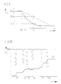
- FIG. 1 shows the speed reduction as a function of time in a diagram
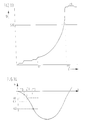
- FIG. 3 shows a diagram of the integration value as a function of the acceleration value
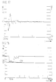
- FIG. 3 to FIG. 8 shows diagrams showing the change in speed as a function of time
- FIG. 9 shows the dependence of a threshold value on a diagram the acceleration
- FIG. 10 to FIG. 13 diagrams with representations of the speed change as a function of time
- FIG. 14 to FIG. 16 diagrams for representing the acceleration as a function of time
- FIG. 17 an acceleration-time diagram when crossing a railway track
- FIG. 18 and FIG. 19 diagrams showing the change in speed as a function of time.
- FIG. 1 shows in a diagram the speed reduction DV of a vehicle as a function of the time that occurs, for example, in a vehicle collision on the basis of a traffic accident.
- the change in speed is obtained by integrating the acceleration detected by a sensor, for example an acceleration sensor.
- the curve shown in dotted lines in the diagram corresponds to an impact in the longitudinal axis direction of the vehicle, which corresponds to a speed change of approximately 14.3 km per hour in a period of 120 ms after the start of the collision. This accident situation should not yet lead to a trigger because there is no significant danger for the occupants.
- the solid curve which arises in the event of an oblique impact with an impact angle of 30 ° with respect to the longitudinal axis of the vehicle, corresponds to a change in speed of approx. 26 km per hour within 120 ms after the start of the collision and should definitely lead to the deployment of the restraint system.
- a disadvantage of known systems is that, in such collisions with an oblique impact, dangerous situations are recognized too late by the sensor, which is only sensitive in the longitudinal axis direction of the vehicle, with the result that the restraint system is generally triggered too late, so that no effective protection is provided more can be guaranteed.
- an integration device for speed change or acceleration provided in the restraint system does not integrate the acceleration values output by the acceleration sensor, but rather values which, in the manner of a characteristic curve or a characteristic curve field Output signals of the acceleration sensor are assigned.
- FIG. 2 represents the integration value as a function of the acceleration value a in the form of a schematic characteristic curve.
- the invention is based on the knowledge that the disproportionate evaluation of larger acceleration values, e.g. by a quadratic evaluation of a high acceleration, corresponding output values of the acceleration sensor are integrated much more than would be the case with a proportional evaluation (corresponds to a linear characteristic curve).
- the DV integrator can wash up very quickly even in the case of very rapid crash situations due to the large acceleration amplitudes that occur and correspondingly large amplitude values of the output signal of the acceleration sensor.
- a necessarily very quick triggering can thus take place in good time in the case of very fast crash processes.
- Appropriate design of the characteristic curve has no influence on slow crash processes.
- the triggering sensitivity of restraint systems can thus be set differently in a relatively simple manner in fast crash processes and slow crash processes.
- the restraint means are activated when the integrated output signal (acceleration signal) of the acceleration sensor exceeds a predefinable fixed threshold, the so-called DV threshold.
- This integrated acceleration represents the change in speed justified from the beginning of the impact situation.
- the time it takes for this DV integral to reach the DV threshold has so far not been taken into account in conventional restraint systems.
- the invention now shows ways of taking this into account Timing restraint systems for vehicle occupants can be designed even more effectively.
- a first method to include the time in the trigger criterion is to represent the DV threshold as a function of time, with the time running from a certain minimum DV integrator level or from a particular characteristic of the acceleration or its first integral.
- a special function dependency of the triggering criterion on time could be obtained from the observation of the quotient constant / t.
- the DV threshold can be influenced not only as a function of the elapsed time, but also as a function of the cumulative DV integrator status, for example also from the quotient DV integrator / t. The latter quotient represents the average change in speed or the deceleration.
- the DV integral itself can be increased or decreased depending on the elapsed time, the DV threshold remaining constant even in this case.
- the DV threshold is influenced.
- the range or band of the DV integrator value range can be regarded as constant over time in a first exemplary embodiment.
- the range can be viewed as a function of time t, the basic DV threshold and / or the DV integrator. This means that, for example, the bandwidth can remain constant over time, just as it is possible that the width of the band can expand or contract somewhat over time, just as it is possible that both the lower limit and the upper limit the area can be a general function over the time of the DV basic threshold and the DV integrator.
- the above-mentioned influence on the DV threshold within the range just defined can be any function of time, the basic DV threshold and the DV integrator itself. If, for example, the DV integrator is below the lower value that limits the range mentioned, the DV threshold is set to the value of an original DV basic threshold. If, on the other hand, the DV integrator is above the upper value which limits the range mentioned, the DV threshold preferably remains at the value which is the last was discontinued by this measure.
- the range or band of the DV integrator value range has a constant width, namely between the values DV1 to DV2, which is independent of time or other parameters.
- a relatively high DV threshold namely the DV basic threshold DVG
- the DV integrator DVI shown in steps in the diagram starts up with increasing time t and, at time T1, after the lower threshold value DV1 has been exceeded, it enters the range or band of the DV integrator value range in which the DV threshold is to be influenced. If the DV integrator DVI is now within the value range limited by the threshold values DV1, DV2, the DV threshold DV is lowered from the DV basic threshold DVG as a function of time to a predefinable minimum value. In the exemplary embodiment according to FIG. 3, the lowering of the DV threshold takes place with a linear course, which is approximately due to the relationship
- DV threshold DV basic threshold (1 - p t) can be characterized. According to FIG. 3, the DV basic threshold is linearly reduced in accordance with the relationship mentioned above until the DV integrator DVI has left the DV integrator value range by exceeding the upper threshold DV2 or the DV threshold is set to a minimum value. The basic DV threshold then maintains this minimum value DVGU reached at time T2.
- the purpose of the measure explained above is to ensure that DV integrator profiles, which are especially in oblique impact situations (approximately ( ⁇ 10 ° - 30 °) with respect to the longitudinal axis of the vehicle), are within a predefined range of values DV1, DV2 for a relatively long time
- DV integrator profiles are also in the previously defined area DV1, DV2 in comparatively slow frontal impact situations, in which no deployment of the restraint means is desired in such frontal impact situations.
- small and relatively short acceleration processes typically occur, which do not trigger the restraint means in the measures shown here. In this way, the trigger sensitivity for slow frontal impact situations and slow oblique impact situations can be set differently.
- the DV integrator value range DV1, DV2 is not kept constant over time, but is widened with increasing time. This widening takes place in accordance with the exemplary embodiment shown in FIG. 4 in particular by the fact that at time T1, at which the DV integrator enters the DV integrator value range by exceeding the lower threshold value DV1, the upper threshold value DV2 of the DV integrator value range increases . In the exemplary embodiment shown in FIG. 4, this enlargement takes place approximately according to a linear function of time t. Just as in the exemplary embodiment according to FIG.
- the DV threshold DV proceeds from the DV basic threshold DVG with a preferably linear profile to lowered to the minimum value DVGU.
- This minimum value DVGU is reached when the DV integrator leaves the value range DV1, DV2 again (time T2) by exceeding the upper threshold DV2.
- the DV integrator DVI reaches the lower limit value DV1 of the predefinable DV integrator value range at time T1, which causes the DV threshold to be lowered from the relatively high value of the DV basic threshold DVG.
- the lowering of the basic Dv threshold is no longer dependent solely on the time t but also on the current status of the DV integrator DVI, which results in a further refinement of the response behavior of the restraint system.
- the DV threshold is in turn lowered to a predeterminable minimum value DVGU which is reached when the DV integrator leaves the DV integrator value range DV1, DV2 at time T2 by exceeding the upper threshold DV2.
- the DV integrator value range DV1, DV2 expands with increasing time t, since the upper threshold value DV2 increases as a function of time.
- the time dependency of the upper threshold value DV2 begins at time T1 at which the DV integrator DVI exceeds the lower threshold value DV1.
- the DV threshold value is lowered again based on the relatively high DV basic threshold DVG, this reduction being approximately represented by the following expression
- the DV threshold assumes its lowest value, ie DVGU. If the integrator DVI falls below the DV integrator value range DV1, DV2, the DV threshold again assumes the value of the DV basic threshold DVG.
- the DV integrator DVI exceeds the threshold value DV1 at the time T1, but does not drop below it for a longer period of time. If, on the other hand, it is determined that the DV integrator DVI does not reach the threshold DVG1 set for triggering the restraint means within a predetermined time after the DV1 threshold value has been exceeded, the DV basic threshold DVG1 is changed to a less sensitive DV basic threshold DVG2 at time T2 raised.
- the effective time of this increase can be determined by a timer as well as by exceeding or falling below DV thresholds (e.g. DV1) in conjunction with times. This is equivalent to a reduction in the willingness to trigger.
- This timing element has the effect that the reduced readiness to trigger is maintained over a predeterminable period of time, for example from time T2 to time T3, and only at time T3 the sensitivity is reduced again to the lower threshold value DVG1.
- the sensitivity can be raised again to the threshold DVG1 immediately after the timer has expired at time T3; alternatively, the return to the more sensitive threshold DVG1 can optionally also take place with a certain time dependency, for example with a linear course as a function of time.
- the timer can be implemented, for example, by a counter that starts at time T2 and stops when a counter reading corresponding to the desired time delay is reached, that is to say, for example, at time T3.
- this measure in accordance with the exemplary embodiment explained above is to interpret DV integrator curves which have been at a low level for a relatively long time, but above a first DV threshold value, here DV1, in such a way that a continuous one There is a delay, but this is too small to activate the restraint systems. A less sensitive reaction of the restraint means is therefore sought.
- the method according to the embodiment of FIG. 8 can be used expediently when braking is carried out on a rough road. It can happen that the DV integrator slowly swings up without a situation that poses a risk to the occupants.
- This method also has a positive effect in the event of slow crash processes in which the restraint means would be triggered, but the activation of the restraint means would be too late to still be able to contribute to protecting the vehicle occupants. If the release is too late, the maximum possible forward displacement of the vehicle occupants for the sensible use of restraint devices is exceeded. For example, activation of the airbag would no longer make sense if a body part of a vehicle occupant has already hit the steering wheel of the vehicle. By raising the DV threshold to a less sensitive value DVG2, a no longer sensible triggering of restraint devices can be prevented, in order to thereby avoid an additional risk to the vehicle occupants by the restraint devices themselves.
- a further advantageous embodiment of the invention is explained with reference to FIG. 9.
- a further improvement in the triggering behavior of the restraint means is achieved in that the DV threshold is already made dependent on the acceleration values detected by the acceleration sensor. This can be achieved, for example, by assigning a certain DV threshold value to each acceleration value detected by the acceleration sensor using a selectable characteristic curve.
- the DV threshold values can therefore be represented as a function of the acceleration a.
- FIG. 9 shows the representation of the DV threshold curve as a function of Be acceleration a.
- the trigger threshold is kept at a constant value up to an acceleration as, which is reached at time T1 according to FIG. 14, and is lowered for larger accelerations.
- the dashed line represents a straight line, i.e. does not represent a linear drop in the DV threshold value as a function of the acceleration.
- an acceleration value a2 is determined at time T2.
- a DV threshold value DV2 is assigned to this acceleration value a2.
- the DV threshold value can be made dependent on the acceleration value a in a non-linear relationship. This is illustrated by means of the solid curve shown in FIG. 9.
- a lowered DV threshold value DV2 is already achieved here with a relatively low delay a1.
- the measure described above makes it much easier for the large acceleration values a to exceed the DV threshold necessary for the release of the restraint means than for correspondingly smaller acceleration values. A necessarily very quick triggering can thus still take place in time in the case of very fast crash courses. If the characteristic curve is selected appropriately, slow crash processes are not influenced, since the amplitudes of the acceleration values remain comparatively small and do not result in a lowering of the DV threshold. With this measure, the trigger sensitivity can be better adapted to rapid crashes. A different trigger sensitivity for fast and slow crash situations can also be selected.
- the acceleration-time curve is idealized in FIG. In practice, this idealized curve is overlaid with numerous fluctuations in amplitude, which arise, for example, when driving through potholes.
- the amplitude values of the acceleration-time curve are sampled according to FIG. 14 and the sampled amplitude values are used as a decision criterion for lowering the DV threshold according to FIG. 9, it can happen that an extreme value of the amplitude in the case of a temporary one Fluctuation of the acceleration-time curve is detected. Since this may deviate strongly from an average value, there could be a meaningless lowering of the DV threshold according to the characteristic curve shown in FIG. 9.
- a plurality of chronologically successive amplitude values of the acceleration-time curve are recorded in order to form an average.
- the slope of the acceleration-time curve is used as a criterion for lowering the DV threshold value.
- This measure is explained with reference to FIG. 16.
- This curve is characterized by a first relative minimum at time T2, the amplitude value of which, however, does not yet exceed the acceleration limit value as.
- This relative minimum at time T2 is then followed by a relative maximum at time T3 at which there is a comparatively low acceleration value. Following this relative maximum at T3, the acceleration-time curve lowers further, only to reach the acceleration limit value as at time T4.
- Such an acceleration-time curve is characteristic of vehicles with energy-absorbing crumple zones. If, as in the previously mentioned exemplary embodiment, only amplitude values were used as a criterion for lowering the DV threshold, completely unsatisfactory results would be obtained with such a curve profile. A lowering of the DV threshold would only be initiated at the earliest at time T4, since only then does the detected acceleration amplitude exceed the predetermined limit value as. Up to this In contrast, according to FIG. 9, time T4 would keep the DV threshold at a relatively high value DVG. In a disadvantageous manner, dangerous crash situations would not be detected in time. because the course of the crash is hidden by the influence of the crumple zone.
- the slope of the acceleration-time curve is recorded as the triggering criterion for lowering the DV threshold.
- the slope of the acceleration-time curve is recorded at the coordinates T1, a1, which is indicated by the tangent TA1 shown.
- the acceleration value a1 is still so low that there is no reason for lowering the DV threshold if the amplitude is evaluated purely, the slope of the tangent TA1 shows that this is a dangerous crash situation which requires the reaction of the restraint means to react quickly .
- This rapid reaction of the restraint means is achieved by lowering the DV threshold as shown in FIG. 9.
- the slope of the acceleration-time curve can be determined in a simple manner by detecting the amplitude values at two points in quick succession and forming the corresponding difference quotient. If the slope corresponding to this difference quotient exceeds a predefinable limit value, then the DV threshold is lowered according to a predefinable relationship, for example with a linear time dependency.
- decision criteria for lowering the DV threshold were explained using some detailed exemplary embodiment. Further decision criteria can be derived from a frequency analysis of the acceleration-time curve. With this frequency analysis, it is then also possible to recognize natural resonances of the accelerometer system and to suppress them. It is also also possible to avoid interference vibrations with very high amplitude values, which, however, do not originate from a crash situation, such as e.g. B. Recognize impact stresses of the vehicle by falling rocks or when driving through a pothole and to exclude them from an assessment. Furthermore, pattern recognition can also be carried out in that the acceleration-time curve is recorded very precisely and is compared, for example, with a stored ideal pattern. Furthermore, combinations of the measures described above are also possible in order to achieve a particularly optimal adaptation of the evaluation criteria to a specific vehicle in individual cases.
- the decision as to whether the DV threshold is to be lowered or not it is additionally possible to use output signals from further sensors which are arranged locally in the vehicle from the central sensor unit.
- the evaluation criterion can still be made dependent on certain operating states of the vehicle, which the central acceleration sensor alone cannot detect. For example, switching signals of a rear axle switch, the seat belt buckles, the seat contact, the brake switch, a gear switch, a touch switch or mechanical acceleration switch can be detected and combined with the output signal of the central acceleration sensor in order to make a decision criterion for lowering the DV threshold that is particularly suitable for the specific vehicle to derive.
- output signals of other control devices in the vehicle for brake control, for internal combustion engine control or for navigation can also be evaluated.
- the DV threshold was influenced in accordance with a DV integrator value or an acceleration value, preferably also via a predefinable characteristic curve. It is also possible to influence the detected basic values, such as DV integrator values and / or the acceleration value, additively and / or multiplicatively in order to achieve a certain functional dependency for influencing the course of the DV threshold value. If several parameters, for example sensor output signals from other sensors, are to be taken into account, it makes sense to carry out the DV threshold value change in accordance with characteristic values that are stored in a characteristic diagram.
- the DV threshold was lowered when a decision criterion was present, starting from a relatively high value of the DV basic threshold DVG, in order to achieve a more sensitive reaction of the restraint means and to improve the protection of the vehicle occupants.
- the decision criterion ceased to exist, the existence of which is expediently checked periodically after a predeterminable time cycle, the initially lowered DV threshold was raised to the original basic value DVG practically without any time delay.
- FIG. 10 shows the speed change DV as a function of time t.
- the course of the curve of the DV integrator DVI is also entered in the diagram.
- the value of the DV basic threshold DVG is also shown.
- An improvement in the triggering behavior is achieved according to a further embodiment of the invention in that, after the triggering sensitivity of the restraint system has been tightened by lowering the DV threshold from the comparatively high threshold value DVG to a lower threshold value, this reduction takes place as immediately as possible, but the deactivation takes place due to according to newly detected acceleration values, is carried out with a time delay.
- Disarming here means raising an initially lowered DV threshold to, for example, the higher DVG value of the DV basic threshold. This measure is explained with reference to FIG. 11, which essentially corresponds to the illustration in FIG. 10. The lowering of the DV threshold from the high value of the DV basic threshold DVG takes place again at times T1, T2, T3, T4, TA.
- the DV threshold is raised to the original value DVG of the DV basic threshold only with a time delay DT.
- the DV integrator When integrating the occurring acceleration values, the DV integrator has a phase shift with respect to the acceleration amplitudes. This shift can be compensated for by the time delay of the threshold increase described above. Due to the time-delayed withdrawal of the lowered threshold values to the basic DVG value to favorable ones. An earlier triggering of the restraint means or a trigger with a greater triggering safety take place.
- An advantageous further embodiment of the invention improves the trigger behavior by influencing integration values as a function of a DV reference integrator and the time.
- the integration values are only influenced if the DV reference integrator is within a defined range. If the DV reference integrator runs in the area mentioned, a timer is started. The read acceleration values are then multiplied by a factor that is proportional to the time count, or a value is added. The resulting new integration values are integrated by the release integrator, which triggers the restraint device when a specified DV threshold is exceeded.
- FIG. 13 shows the same functional dependency between the speed change and the time as FIG. 12, but with the curve of the trip integrator A1 being shown.
- the reference integrator RI enters the DV integrator value range delimited by the two thresholds, DV1 and DV2, by exceeding the low DV threshold DV1.
- a timer is then started, with the proviso that acceleration values supplied by the acceleration sensor as an output signal, which are to be integrated by the trigger integrator A1, are linked beforehand with a factor corresponding to the elapsed time, preferably multiplicatively or additively.
- the trip integrator AI is in oblique impact situations and in a frontal impact situation for different lengths in the range defined by the limit values DV1 and DV2.
- timing elements are started when the reference integrator RI exceeds a predeterminable lower threshold, for example the threshold DV1 in FIG. 12.
- these timers cause a kind of modulation to set the DV threshold so that either, depending on the type of triggering target hold, the basic threshold is raised or lowered.
- the DV threshold can be reduced as a function of the detected acceleration amplitudes in accordance with an exemplary embodiment already described above, or else additionally on the polarity of the acceleration signals.
- Each of the timing elements influences the lowering of the DV threshold for the duration of its running time in the individual manner assigned to it.
- the number of time elements that can be used can be selected as required, depending on the requirements of the type of DV threshold influencing.
- Timing elements preferably counter circuits.
- a single counter can also be provided, which is queried for different counter readings.
- a time limit for the different types of influencing the DV thresholds is then given by the meter readings.
- the counters or the counter can be reset, for example, as soon as the reference integrator RI has fallen below the above-mentioned lower threshold DV1 again.
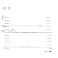
- FIG. 17 shows the output signal of an acceleration sensor when crossing a railroad track in which the vehicle is exposed to a brief impact.
- the acceleration-time curve is shown.
- the curve shows a bipolar signal with initially very high amplitude values up to about 30 g, which, however, decay very quickly. After only about 30 ms, there are only comparatively low amplitude values.
- FIG. 18 again shows a representation of the change in speed OV as a function of time t.
- the course of the DV integrator DVI together with the DV threshold is shown in this diagram, which, however, can be varied here according to the methods described above and runs according to a complex time function.
- the DV threshold begins at time 0 with a relatively high constant value, namely the DV basic threshold DVG, which is lowered to a lower value after about 15 ms to increase the sensitivity of the system, to about this low level, about DV1 for about 15 ms to persist and then again, at least temporarily to rise to the level of the DV basic threshold DVG again.
- the illustration in FIG. 18 shows that the course of the curve of the DV integrator DVI exceeds the lowered DV threshold after approximately 13.5 ms. This would result in the superfluous triggering of the restraint devices.
Abstract
Description
Die Erfindung geht aus von einem Verfahren zur Auslösung von Rückhaltemitteln nach dem Oberbegriff des Anspruchs 1. Solche Verfahren sind aus 1141 Ingenieurs de l'Automobile (1982) No. 6, S. 69-72, bekannt. Rückhaltesysteme mit lediglich einem, zentral angeordneten Aufprallsensor erfüllen ihre Aufgabe hervorragend bei einem Frontal- oder Heckaufprall. Probleme ergeben sich jedoch bei den im heutigen Stadtverkehr relativ häufig auftretenden Kollisionen mit schrägem Aufprallwinkel, da hier trotz einer akuten Gefahr für die Fahrzeuginsassen die Rückhaltemittel zu spät aktiviert werden. Um diesen Mängeln abzuhelfen und die Erkennung von in Schrägrichtung verkaufenden Kollisionen zu verbessern, sind weiterhin Rückhaltesysteme bekannt z.B. (EP-A-0 292 669, DE-OS 22 40 389), die zwei Beschleunigungssensoren umfassen, deren Empfindlichkeitsachsen winklig zur Fahrzeuglängsachse angeordnet sind. Nachteilig ist hierbei der vergleichsweise hohe technische Aufwand zur Verkabelung der Sensoren, der kostensteigernd wirkt. Schließlich sind auch Rückhaltesysteme mit einer Mehrzahl von dezentral im Fahrzeug angeordneten Sensoren bekannt, die ebenfalls einen hohen Verkabelungsaufwand erfordern und zudem im praktischen Betrieb sehr störanfällig sind. Überdies sind bei allen bisher bekannten Systemen mit dezentraler Anordnung zusätzlicher Sensoren lediglich mechanische Schalter verwendet worden, deren Funktionsfähigkeit im praktischen Betrieb des Kraftfahrzeugs nicht ohne weiteres überprüfbar ist.The invention is based on a method for triggering restraint devices according to the preamble of
Aus FR-A-2 184 307 ist eine Sicherheitseinrichtung für Fahrzeuginsassen bekannt, die einen Beschleunigungssensor, einen Verstärker für das Ausgangssignal des Beschleunigungssensors, eine erste Schwellwertschaltung, eine Integrationsschaltung und eine zweite Schwellwertschaltung, sowie eine UND-Verknüpfungsglied umfaßt, dessen ersten Eingangsanschluß das Ausgangssignal des zweiten Schwellwertschalters zugeführt ist. Weiter umfaßt die Sicherheitseinrichtung eine dritte Schwellwertschaltung, der eingangsseitig das Ausgangssignal des Verstärkers zugeführt ist und deren Ausgangssignal wiederum am zweiten Eingangsanschluß des UND-Verknüpfungsgliedes liegt. Eine Änderung der Schwellwerte der vorerwähnten Schwellwertschalter ist nicht vorgesehen.From FR-A-2 184 307 a safety device for vehicle occupants is known which comprises an acceleration sensor, an amplifier for the output signal of the acceleration sensor, a first threshold value circuit, an integration circuit and a second threshold value circuit, and an AND logic element whose first input connection has the output signal of the second threshold switch is supplied. Furthermore, the safety device comprises a third threshold circuit, to the input side of which the output signal of the amplifier is fed and whose output signal is in turn connected to the second input terminal of the AND gate. There is no provision for changing the threshold values of the aforementioned threshold switches.
Aus WO-A-88/00146 ist weiter eine Vorrichtung zum Auslösen von Insassenschutzsystemen bekannt, die einen Beschleunigungsaufnehmer, einen Hochpass, einen Integrator, einen den Auslöseschwellwert für die Sicherungsmittel festlegenden ersten Schwellwertschalter und einen zweiten Schwellwertgeber umfaßt. Der Eingangsanschluß dieses zweiten Schwellwertgebers ist mit dem Ausgangsanschluß des Integrators verbunden, während der Ausgangsanschluß des zweiten Schwellwertgebers an einen am Eingangsanschluß des Integrators liegenden Summationspunkt geführt ist. Der zweite Schwellwertgeber erzeugt ein Ausgangssignal, das eine untere Integrationssschwelle des Integrators beeinflußt.From WO-A-88/00146 a device for triggering occupant protection systems is also known which comprises an accelerometer, a high pass, an integrator, a first threshold switch which defines the trigger threshold for the securing means and a second threshold transmitter. The input connection of this second threshold value transmitter is connected to the output connection of the integrator, while the output connection of the second threshold value transmitter is led to a summation point located at the input connection of the integrator. The second threshold value generator generates an output signal which influences a lower integration threshold of the integrator.
Das erfindungsgemäße Verfahren mit den kennzeichnenden Merkmalen des Anspruchs 1 hat demgegenüber den Vorteil, daß bei einem Rückhaltesystem mit nur einem zentral angeordnet Sensor auch die Fahrzeuginsassen gefährdende Schräg-, Offset-und Polaufprallsituationen zuverlässig erkannt werden und die Rückhaltemittel rechtzeitig ausgelöst werden können. In den Unteransprüchen werden Weiterbildungen des Verfahrens angegeben.The method according to the invention with the characterizing features of
Die Erfindung ist anhand von in der Zeichnung dargestellten Ausführungsbeispielen in der nachfolgenden Beschreibung näher erläutert. Es zeigen Figur 1 in einem Diagramm die Geschwindigkeitsverminderung als Funktion derZeit, Figur in Gestalteiner schematischen Kennlinie den Integrationswert als Funktion des Beschleunigungswertes, Figur 3 bis Figur 8 Diagrame mit Dargestellungen der Geschwindigkeitsänderung als Funktion der Zeit,Figur 9 in einem Diagramm die Abhängigkeit eines Schwellwertes von der Beschleunigung,Figur 10 bis Figur 13 Diagramme mit Dargestellungen der Geschwindigkeitsänderung als Funktion der Zeit, Figur 14 bis Figur 16 Diagramme zur Darstellung der Beschleunigung als Funktion der Zeit, Figur 17 ein Beschleunigungs-ZeitDiagramm beim Überfahren eines Eisenbahngleises und Figur 18 und Figur 19 Diagramme mit Darstellung der Geschwindigkeitsänderung als Funktion der Zeit.The invention is explained in more detail in the following description with reference to exemplary embodiments shown in the drawing. FIG. 1 shows the speed reduction as a function of time in a diagram, FIG. 3 shows a diagram of the integration value as a function of the acceleration value, FIG. 3 to FIG. 8 shows diagrams showing the change in speed as a function of time, FIG. 9 shows the dependence of a threshold value on a diagram the acceleration, FIG. 10 to FIG. 13 diagrams with representations of the speed change as a function of time, FIG. 14 to FIG. 16 diagrams for representing the acceleration as a function of time, FIG. 17 an acceleration-time diagram when crossing a railway track and FIG. 18 and FIG. 19 diagrams showing the change in speed as a function of time.
Figur 1 zeigt in einem Diagramm die Geschwindigkeitsverminderung DV eines Fahrzeugs als Funktion der Zeit, die beispielsweise bei einer Fahrzeugkollision anläßlich eines Verkehrsunfalls auftritt. Die Geschwindigkeitsänderung wird durch Integration der von einem Sensor, beispielsweise einem Beschleunigungsaufnehmer erfaßten Beschleunigung gewonnen. Die in dem Diagramm punktiert dargestellte Kurve entspricht einem Aufprall in Längsachsenrichtung des Fahrzeugs, die einer Geschwindigkeitsänderung von etwa 14,3 km pro Stunde in einem Zeitraum von 120 ms nach Beginn der Kollision entpricht. Diese Unfallsituation soll noch nicht zu einer Auslösung führen, da keine nennenswerte Gefahr für die Insassen besteht. Die ausgezogene Kurve dagegen, die bei einem Schrägaufprall mit Stoßwinkel von 30° in bezug auf die Fahrzeuglängsachse entsteht,entspricht einer Geschwindigkeitsveränderung von ca. 26 km pro Stunde innerhalb einerZeitvon 120 ms nach Kollisionbeginn und sollte unbedingt zu einem Auslösen des Rückhaltesystems führen. Nachteilig bei bekannten Systemen ist, daß gerade bei derartigen Kollisionen mit Schrägaufprall gefährliche Situationen von dem lediglich in Längsachsenrichtung des Fahrzeug empfindlichen Sensor zu spät erkannt werden, mit der Folge, daß einen Auslösung des Rückhaltesystems in der Regel zu spät erfolgt, so daß kein wirksamer Schutz mehr gewährleistet werden kann.FIG. 1 shows in a diagram the speed reduction DV of a vehicle as a function of the time that occurs, for example, in a vehicle collision on the basis of a traffic accident. The change in speed is obtained by integrating the acceleration detected by a sensor, for example an acceleration sensor. The curve shown in dotted lines in the diagram corresponds to an impact in the longitudinal axis direction of the vehicle, which corresponds to a speed change of approximately 14.3 km per hour in a period of 120 ms after the start of the collision. This accident situation should not yet lead to a trigger because there is no significant danger for the occupants. The solid curve, on the other hand, which arises in the event of an oblique impact with an impact angle of 30 ° with respect to the longitudinal axis of the vehicle, corresponds to a change in speed of approx. 26 km per hour within 120 ms after the start of the collision and should definitely lead to the deployment of the restraint system. A disadvantage of known systems is that, in such collisions with an oblique impact, dangerous situations are recognized too late by the sensor, which is only sensitive in the longitudinal axis direction of the vehicle, with the result that the restraint system is generally triggered too late, so that no effective protection is provided more can be guaranteed.
Eine Verbesserung des Auslöseverhaltens kann nun gemäß der Erfindung dadurch erreicht werden, daß eine in dem Rückhaltesystem vorgesehene Integrationseinrichtung für die Geschwindigkeitsänderung bzw. Beschleunigung (DV Integrator) nicht die vom Beschleunigungssensor abgegebenen Beschleunigungswerte integriert, sondern Werte, die nach Art einer Kennlinie oder eines Kennlinienfeldes den Ausgangssignalen des Beschleunigungssensors zugeordnet sind. Ein Musterbeispiel einer solchen Zuordnung geht aus der Darstellung in Figur 2 hervor, die in Gestalt einer schematischen Kennlinie den Integrationswert als Funktion des Beschleunigungswertes a wiedergibt. Die Erfindung geht hierbei von der Erkenntnis aus, daß durch das in der Kennlinie erkennbare überproportionale Bewerten von größeren Beschleunigungswerte, z.B. durch eine quadratische Bewertung einer hohen Beschleunigung, entsprechende Ausgangswerte des Beschleunidungssensors viel stärker integriert werden als dies bei einer proportionalen Bewertung (entspricht einer linearen Kennlinie) der Fall wäre. Dadurch kann auch bei sehr schnell ablaufenden Crashsituationen durch die dabei auftretenden großen Beschleunigungsamplituden und entsprechend große Amplitudenwerte des Ausgangssignals des Beschleunigungssensors der DV-integrator sehr schnell anwaschen. Ein notwendigerweise sehr schnelles Auslösen kann somit bei sehr schnellen Crashvorgängen rechtzeitig erfolgen. Auf langsame Crashvorgänge wird dabei durch entsprechende Gestaltung der Kennlinie kein Einfluß genommen. Somit kann dieAustöseempfindtichkeitvon Rückhaltesystemen auf vergleichsweise einfache Art in schnellen Crashvorgängen und langsamen Crashvorgängen unterschiedlich eingestellt werden.An improvement in the triggering behavior can now be achieved according to the invention in that an integration device for speed change or acceleration (DV integrator) provided in the restraint system does not integrate the acceleration values output by the acceleration sensor, but rather values which, in the manner of a characteristic curve or a characteristic curve field Output signals of the acceleration sensor are assigned. A sample example of such an assignment can be seen in the illustration in FIG. 2, which represents the integration value as a function of the acceleration value a in the form of a schematic characteristic curve. The invention is based on the knowledge that the disproportionate evaluation of larger acceleration values, e.g. by a quadratic evaluation of a high acceleration, corresponding output values of the acceleration sensor are integrated much more than would be the case with a proportional evaluation (corresponds to a linear characteristic curve). As a result, the DV integrator can wash up very quickly even in the case of very rapid crash situations due to the large acceleration amplitudes that occur and correspondingly large amplitude values of the output signal of the acceleration sensor. A necessarily very quick triggering can thus take place in good time in the case of very fast crash processes. Appropriate design of the characteristic curve has no influence on slow crash processes. The triggering sensitivity of restraint systems can thus be set differently in a relatively simple manner in fast crash processes and slow crash processes.
Bei bekannten Rückhaltesystemen werden die Rückhaltemittel aktiviert, wenn das aufintegrierte Ausgangssignal (Beschleunigungssignal) des Beschleunigungssensors eine vorgebbare feste Schwelle, die sogenannte DV-Schwelle, überschreitet. Diese aufintegrierte Beschleunigung stellt die Geschwindigkeitsänderung gerechtet vom Beginn der Aufprallsituation dar. Die Zeit die dieses DV-Integral benötig, um die DV-Schwelle zu erreichen, wurde bisher bei herkömmlichen Rückhaltesystemen nicht berücksichtig.Die Erfindung zeigt nun Wege auf, wie durch Berücksichtigung auch dieses Zeitverhaltens Rückhaltesysteme für Fahrzeuginsassen noch wirksamer gestaltet werden können.In known restraint systems, the restraint means are activated when the integrated output signal (acceleration signal) of the acceleration sensor exceeds a predefinable fixed threshold, the so-called DV threshold. This integrated acceleration represents the change in speed justified from the beginning of the impact situation. The time it takes for this DV integral to reach the DV threshold has so far not been taken into account in conventional restraint systems. The invention now shows ways of taking this into account Timing restraint systems for vehicle occupants can be designed even more effectively.
Eine erste Methode, die Zeit in das Auslösekriterium einzubeziehen, besteht darin, die DV Schwelle als Funktion der Zeit darzustellen, wobei die Zeit ab einem gewissen minimalen DV-Integratorstand oder ab einem besonderen Merkmal der Beschleunigung oder deren erstem Integral läuft. Eine besondere Funktionsabhängigkeit des Auslösekriteriums von der Zeit könnte aus der Beobachtung des Quotienten Konstante/t gewonnen werden. In einem alternativen Ausführungsbeispiel kann die DV-Schwelle nicht nur in Abhängigkeit von der abgelaufenen Zeit, sondern auch in Abhängigkeit von dem kumulierten DV-Integratorstand, beispielsweise auch vom Quotienten DV-Integrator/t beeinflußt werden. Der Letztgenannten Quotient stellt die mittlere Geschwindigkeitsveränderung oder die Verzögerung dar.A first method to include the time in the trigger criterion is to represent the DV threshold as a function of time, with the time running from a certain minimum DV integrator level or from a particular characteristic of the acceleration or its first integral. A special function dependency of the triggering criterion on time could be obtained from the observation of the quotient constant / t. In an alternative exemplary embodiment, the DV threshold can be influenced not only as a function of the elapsed time, but also as a function of the cumulative DV integrator status, for example also from the quotient DV integrator / t. The latter quotient represents the average change in speed or the deceleration.
In einerweiteren Alternative kann stattdervorstehend erwähnten DV Schwelle das DV-Integral selbst in Abhängigkeit von der abgelaufenen Zeit vergrößert oder verkleinert werden, wobei die DV Schwelle selbst in diesem Fall konstant bleibt.In a further alternative, instead of the DV threshold mentioned above, the DV integral itself can be increased or decreased depending on the elapsed time, the DV threshold remaining constant even in this case.
Die vorstehend nur kurz angesprochenen Zusammenhänger werden im Folgenden wieder unter Bezugnahme auf die Zeichningen näher erläutert. Befindet sich der DV-integrator zwischen zwei Integratorwerten, also innerhalb eines Bereiches oder eines Bandes des DV-Integrator-Wertebereichs, so wird auf die DV-Schwelle Einfluß genommen. Der Bereich oder das Band des DV-Integrator-Wertebereichs kann in einem ersten Ausführungsbeispiel über die Zeit als konstant angesehen werden. Alternativ kann der Bereich als Funktion der Zeit t, der DV-Grund-schwelle und/oder des DV-Integrators angesehen werden. Das bedeutet, daß beispielweise die Bandbreite über sie Zeit konstant bleiben kann, ebenso wie es möglich ist, daß sich die Banbreite über die Zeit etwa trompetenförmig aufweiten als auch einengen kann, ebenso wie es möglich ist, daß sowohl die untere Grenze als auch obere Grenze des Bereichs eine allgemeine Funktion über der Zeit der DV-Grundschwelle und des DV-Integrators sein können. Die vorstehend erwähnte Einflußnahme auf die DV-Schwelle innerhalb des soeben definierten Bereiches kann eine beliebige Funktion der Zeit, der DV-Grundschwelle und des DV-Integrators selbst sein. Ist beispielweise der DV-Integrator unterhalb des unteren Wertes, der den genannten Bereich begrenzt, so wird die DV-Schwelle auf den Wert einer ursprünglichen DV-Grundschwelle eingestellt. Ist dagegen der DV Integrator oberhalb des oberen Wertes, der den genannten Bereich begrenzt, so bleibt die DV-Schwelle vorzugsweise auf dem Wert, der als letzter durch diese Maßnahme eingestellt wurde. Ein erstes Ausführungsbeispiel in diesem Zusammenhang wird nun anhand von Figur 3 erläutert. In diesem Ausführungsbeispiel hat der Bereich oder das Band des DV-Integrator-Wertebereichs eine konstante Breite, nämlich zwischen den Werten DV1 bis DV2, die von der Zeit bzw. von anderen Parametern unabhängig ist. Zum Zeitpunkt TO ist eine relativ hohe DV-Schwelle, nämlich die DV Grundschwelle DVG gesetzt. Der im Diagramm treppenförmig dargestellte DV-Integrator DVI läuft mit zunehmender Zeit t hoch und tritt zum Zeitpunkt T1 nach Überschreiten des unteren Schwellwertes DV1 in den Bereich oder das Band des DV-Integrators-Wertebereichs ein, in dem Einfluß auf die DV Schwelle genommen soll. Befindet sich nun der DV-Integrator DVI innerhalb des durch die Schwellwerte DV1, DV2 begrenzten Wertebereichs, wird die DV-Schwelle DV ausgehend von der DV-Grundschwelle DVG als Funktion der Zeit bis zu einem vorgebbaren Minimalwert abgesenkt. In dem Ausführungsbeispiel nach Figur 3 erfolgt das Absenken der DV Schwelle mit einem linearen Verlauf, der etwa durch die BeziehungThe relationships only briefly mentioned above are explained in more detail below with reference to the drawings. If the DV integrator is between two integrator values, ie within a range or a band of the DV integrator value range, the DV threshold is influenced. The range or band of the DV integrator value range can be regarded as constant over time in a first exemplary embodiment. Alternatively, the range can be viewed as a function of time t, the basic DV threshold and / or the DV integrator. This means that, for example, the bandwidth can remain constant over time, just as it is possible that the width of the band can expand or contract somewhat over time, just as it is possible that both the lower limit and the upper limit the area can be a general function over the time of the DV basic threshold and the DV integrator. The above-mentioned influence on the DV threshold within the range just defined can be any function of time, the basic DV threshold and the DV integrator itself. If, for example, the DV integrator is below the lower value that limits the range mentioned, the DV threshold is set to the value of an original DV basic threshold. If, on the other hand, the DV integrator is above the upper value which limits the range mentioned, the DV threshold preferably remains at the value which is the last was discontinued by this measure. A first exemplary embodiment in this connection will now be explained with reference to FIG. 3. In this exemplary embodiment, the range or band of the DV integrator value range has a constant width, namely between the values DV1 to DV2, which is independent of time or other parameters. At time TO, a relatively high DV threshold, namely the DV basic threshold DVG, is set. The DV integrator DVI shown in steps in the diagram starts up with increasing time t and, at time T1, after the lower threshold value DV1 has been exceeded, it enters the range or band of the DV integrator value range in which the DV threshold is to be influenced. If the DV integrator DVI is now within the value range limited by the threshold values DV1, DV2, the DV threshold DV is lowered from the DV basic threshold DVG as a function of time to a predefinable minimum value. In the exemplary embodiment according to FIG. 3, the lowering of the DV threshold takes place with a linear course, which is approximately due to the relationship
DV - Schwelle = DV - Grundschwelle (1 - p t) charakterisiert werden kann. Gemaß Figur 3 wird die DV Grundschwelle entsprechend der vorstehend erwähnten Beziehung solange linearabgesenkt, bis der DV-Integrator DVI den DV-Integrator-Wertebereich durch Überschreiten der oberen Schwelle DV2 wieder verlassen hat oder sich die DV-Schwelle auf einen Minimalwert einstellt. Die DV-Grundschwelle behält dann diesen zum Zeitpunkt T2 erreichten minimalen Wert DVGU bei. Sinn der zuvor erläuterten Maßnahme ist es, DV-Integrator-Verläufe, welche sich speziell bei Schrägaufprallsituationen (etwa (±10° - 30°) in bezug auf die Fahrzeuglängsachse) über eine relativ lange Zeit innerhalb eines vorgebaren Wertebereichs DV1, DV2 befinden, so auszuwerten, daß sich eine Verschärfung der Auslösebereitschaft durch das Absenken der DV Schwelle vom relativ hohen Wert der DV Grundschwelle DVG auf den niedrigeren Wert DVGU ergibt. Dabei stört es nicht, daß sich DV-Integrator-Verläufe ebenso bei vergleichsweise langsamen Frontalaufprallsituationen in dem zuvor definierte Bereich DV1,DV2 befinden, in denen bei derartigen Frontalaufprallsituationen keine Auslösung der Rückhaltemitten gewünscht ist. Bei den letztgenannten Crashsituationen treten typischerweise kleine und relativ kurze Beschleunigungsabläufe auf, die bei den hier aufgezeigten Maßnahmen nicht zu einer Auslösung der Rückhaltemittel führen. Somit kann hierdurch die Auslöseempfindlichkeit für langsame Frontalaufprallsituationen und langsame Schrägaufprallsituationen unterschiedlich eingestellt werden.DV threshold = DV basic threshold (1 - p t) can be characterized. According to FIG. 3, the DV basic threshold is linearly reduced in accordance with the relationship mentioned above until the DV integrator DVI has left the DV integrator value range by exceeding the upper threshold DV2 or the DV threshold is set to a minimum value. The basic DV threshold then maintains this minimum value DVGU reached at time T2. The purpose of the measure explained above is to ensure that DV integrator profiles, which are especially in oblique impact situations (approximately (± 10 ° - 30 °) with respect to the longitudinal axis of the vehicle), are within a predefined range of values DV1, DV2 for a relatively long time To evaluate that the readiness for triggering is increased by lowering the DV threshold from the relatively high value of the DV basic threshold DVG to the lower value DVGU. It is not a problem that DV integrator profiles are also in the previously defined area DV1, DV2 in comparatively slow frontal impact situations, in which no deployment of the restraint means is desired in such frontal impact situations. In the last-mentioned crash situations, small and relatively short acceleration processes typically occur, which do not trigger the restraint means in the measures shown here. In this way, the trigger sensitivity for slow frontal impact situations and slow oblique impact situations can be set differently.
In einem weiteren Ausführungsbeispiel der Erfindung wird gemäß Figur4 der DV-Integrator-Wertebereich DV1, DV2 nicht über der Zeit konstant gehalten, sondern mit zunehmender Zeit verbreitert. Diese Verbreiterung erfolgt gemäß dem in Figur4 dargestellten Ausführungsbeispiel insbesondere dadurch, daß zum Zeitpunkt T1, an dem der DV-Integrator durch Überschreiten des unteren Schwellwertes DV1 in den DV-Integrator-Wertebereich eindringt, sich der obere Schwellwert DV2 des DV-Integrator-Wertebereichs vergrößert. In dem in Figur 4 dargestellten Ausführungbeispiel erfolgt diese Vergrößerung etwa nach einer linearen Funktion der Zeit t. Ebenso wie im Ausführungbeispiel gemäß Figur 3 wird, beginnend zum Zeitpunkt T1, an dem also der DV-Integrator durch Überschreiten derunteren Schwelle DV1 in den Bereich DV1, DV2 eindringt, die DV Schwelle DV ausgehend von der DV Grundschwelle DVG mit einem vorzugsweise linearen Verlauf bis zum Minimalwert DVGU abgesenkt. Dieser Minimalwert DVGU wird dann erreicht, wenn der DV-Intgegrator durch Überschreiten der oberen Schwelle DV2 den Wertebereich DV1, DV2 wieder verläßt (Zeitpunkt T2). Auch durch die zuvor erläuterte Maßnahme wird eine erhebliche Verschärfung der Ansprechempfindlichkeit der Rückhaltemittel erreicht, so daß auch bei schwierigen Schrägaufprallsituationen eine optimale Auslösung der Rückhaltemittel zum Schutz der Fahrzeuginsassen gewährleistet ist.In a further exemplary embodiment of the invention, the DV integrator value range DV1, DV2 is not kept constant over time, but is widened with increasing time. This widening takes place in accordance with the exemplary embodiment shown in FIG. 4 in particular by the fact that at time T1, at which the DV integrator enters the DV integrator value range by exceeding the lower threshold value DV1, the upper threshold value DV2 of the DV integrator value range increases . In the exemplary embodiment shown in FIG. 4, this enlargement takes place approximately according to a linear function of time t. Just as in the exemplary embodiment according to FIG. 3, starting at time T1, at which the DV integrator penetrates into the area DV1, DV2 by exceeding the lower threshold DV1, the DV threshold DV proceeds from the DV basic threshold DVG with a preferably linear profile to lowered to the minimum value DVGU. This minimum value DVGU is reached when the DV integrator leaves the value range DV1, DV2 again (time T2) by exceeding the upper threshold DV2. The measure explained above also considerably increases the responsiveness of the restraint means, so that optimal triggering of the restraint means for protecting the vehicle occupants is ensured even in the case of difficult oblique impact situations.
In dem weiteren Ausführungsbeispiel der Erfindung nach Figur 5 erreicht der DV-Integrator DVI den unteren Grenzwert DV1 des vorgebbaren DV-Integrator-Wertebereichs zum Zeitpunkt T1, wodurch ein Absenken der DV Schwelle vom relativ hohen Wert der Dv-Grundschwelle DVG veranlaßt wird. Allerdings ist in diesem Ausführungsbeispiel die Absenkung der Dv-Grundschwelle nicht mehr ausschließlich von der Zeit t abhängig sondern zusätlich vom jeweils aktuellen Stand des DV-Integrators DVI, wodurch sich eine weitere Verfeinerung des Ansprechverhaltens des Rückhaltesystems ergibt. Die DV-Schwelle wird wiederum bis zu einem vorgebbaren Minimalwert DVGU abgesenkt der dann erreicht wird, wenn der DV-Integrator durch Überschreiten, der oberen Schwelle DV2 zum Zeitpunkt T2 den DV-Integrator-Wertebereich DV1, DV2 verläßt.In the further exemplary embodiment of the invention according to FIG. 5, the DV integrator DVI reaches the lower limit value DV1 of the predefinable DV integrator value range at time T1, which causes the DV threshold to be lowered from the relatively high value of the DV basic threshold DVG. In this exemplary embodiment, however, the lowering of the basic Dv threshold is no longer dependent solely on the time t but also on the current status of the DV integrator DVI, which results in a further refinement of the response behavior of the restraint system. The DV threshold is in turn lowered to a predeterminable minimum value DVGU which is reached when the DV integrator leaves the DV integrator value range DV1, DV2 at time T2 by exceeding the upper threshold DV2.
In einem weiteren Ausführungsbeispiel nach Figur 6 erweitert sich, ähnlich wie in dem Ausführungsbeispiel nach Figur4 der DV-Integrator-Wertebereich DV1, DV2 mit zunehmender Zeit t, da sich der obere Schwellwert DV2 als Funktion der Zeit vergrößert. Die Zeitabhängigkeit des oberen Schwellwertes DV2 beginnt zum Zeitpunkt T1, an dem der DV-Integrator-DVI den unteren Schwellwert DV1 überschreitet. Ebenfalls zu diesem Zeitpunkt wird wiederum der DV-Schwellwert ausgehend von der relativ hohen DV-Grundschwelle DVG abgesenkt, wobei sich diese Absenkung näherungsweise durch folgenden Ausdruck darstellen läßtIn a further exemplary embodiment according to FIG. 6, similar to the exemplary embodiment according to FIG. 4, the DV integrator value range DV1, DV2 expands with increasing time t, since the upper threshold value DV2 increases as a function of time. The time dependency of the upper threshold value DV2 begins at time T1 at which the DV integrator DVI exceeds the lower threshold value DV1. Also at this point in time, the DV threshold value is lowered again based on the relatively high DV basic threshold DVG, this reduction being approximately represented by the following expression
![]()
![]()
Zum Zeitpunkt T2, an dem der DV-Integrator DVI den vorgegebenen DV-Integrator-Wertebereich DV1, DV2 verlassen hat, nimmt die DV Schwelle ihren geringsten Wert, also DVGU, an. Unterschreitet der Integrator DVI den DV-Integrator-Wertebereich DV1, DV2, so nimmt die DV Schwelle wieder den Wert der DV Grundschwelle DVG an.At time T2, at which the DV integrator DVI has left the specified DV integrator value range DV1, DV2, the DV threshold assumes its lowest value, ie DVGU. If the integrator DVI falls below the DV integrator value range DV1, DV2, the DV threshold again assumes the value of the DV basic threshold DVG.
Das Ausführungsbeispiel der Erfindung gemäß Figur 7 unterscheidet sich von den zuvor beschriebenen Ausführungsbeispielen dadurch, daß auch die untere Schwelle DV1 des DV-Integrator-Bereichs DV1, DV2, ebenso wie die obere Schwelle DV2 ab dem Zeitpunkt T1 eine Zeitabhängigkeit zeigt. So kann beispielsweise die untere Schwelle DV1 ab dem Zeitpunkt T1 dargestellt werden als![]()
- während die oberen Schwelle DV2 sich als

- darstellen läßt. Beide Grenzen DV1, DV2 des DV-Integrator-Wertebereichs DV1, DV2 zeigen also eine lineare Zeitabhängigkeit, da ihr Verlauf durch die vorstehend wiedergegebenen Geradengleichungen darstellbar ist. In den vorgenanten Gleichungen sind mit m, n die Steigungen der Geraden bezeichnet, während die Ausdrücke K1, K2 Konstanten darstellen. Wie in dem anhand von Figur 6 beschriebenen Ausführungsbeispiel wird, beginnend mit dem Zeitpunkt T1, d.h. beginnend mit dem Eintritt des DV Integrators DVI in den Vorgegebenen Wertebereich DV1, DV2, die DV-Schwelle ausgehend von der DV-Grundschwelle DVG bis zu einem vorgebbaren Minimalwert DVGU abgesenkt. Auch dieses Ausführungsbeispiel ermöglicht es, die Auslöseempfindlichkeit an die besonderen Probleme des Schrägaufpralls anzupasse, so daß sich ein optimaler Schutz für die Fahrzeuginsassen erreichen läßt.
- while the upper threshold DV2 turns out to be
- represents. Both limits DV1, DV2 of the DV integrator value range DV1, DV2 thus show a linear time dependency, since their course can be represented by the straight line equations given above. In the aforementioned equations, m, n denote the slopes of the straight line, while the expressions K1, K2 represent constants. As in the exemplary embodiment described with reference to FIG. 6, starting from time T1, ie starting with the entry of the DV integrator DVI into the specified value range DV1, DV2, the DV threshold starts from the DV basic threshold DVG up to a predeterminable minimum value DVGU lowered. This exemplary embodiment also makes it possible to adapt the trigger sensitivity to the special problems of the oblique impact, so that optimum protection for the vehicle occupants can be achieved.
In dem weiteren Ausführungbeispiel nach Figur 8 überschreitet der DV-Integrator DVI zum Zeitpunkt T1 den Schwellwert DV1, unterschreitet diesen aber während eines längeren Zeitraums nicht mehr. Wenn jedoch anderseits festgestellt wird, daß der DV-Integrator DVI die für das Auslösen der Rückhaltemittel gesetzte Schwelle DVG1 innerhalb einervorgegebenen Zeit nach Überschreiten des DV1-Schwellwertes nicht erreicht, wird zum Zeitpunkt T2 die DV-Grundschwelle DVG1 auf eine weniger empfindliche DV-Grundschwelle DVG2 angehoben. Die wirksame Zeit dieser Anhebung kann sowohl von einem Zeitglied als auch vom Überschreiten bzw. Unterschreiten von DV-Schwellen (z. B. DV1) in Zusammenwirkung mit Zeiten bestimmt werden. Dies kommt einer Verminderung der Auslösebereitschaft gleich. Dieses Zeitglied bewirkt, daß die verminderte Auslösebereitschaft über einen vorgebbaren Zeitraum etwa vom Zeitpunkt T2 bis zum Zeitpunkt T3 aufrechterhalten und erst zum Zeitpunkt T3 die Empfindlichkeit wieder auf den geringeren Schwellwert DVG1 abgesenkt wird. Das Wiederanheben der Empfindlichkeit auf den SchwellwertDVG1 kann unmittelbar nach Ablauf des Zeitgliedes zum Zeitpunkt T3 erfolgen; alternativ kann die Rückkehr zu der empfindlicheren Schwelle DVG1 gegebenenfalls auch mit einer bestimmten Zeitabhängigkeit, beispielsweise mit einem linearen Verlauf als Funktion der Zeit, erfolgen. Das Zeitglied kann beispielsweise durch einen Zähler realisiert werden, der zum Zeitpunkt T2 gestartet und bei Erreichen eines der Gewünschten Zeitverzögerung entsprechenden Zählerstandes, also beispielweise zum Zeitpunkt T3, gestoppt wird. Sinn dieser Maßnahme entsprechend dem vorstehend erläutert Ausführungbeispiel ist es, DV-Integrator-Verläufe, welche sich über eine relativ lange Zeit auf einem niedrigen Niveau, jedoch oberhalb eines ersten DV-Schwellwertes, hier DV1, befinden, so zu interpretieren, daß zwar eine kontinuierliche Verzögerung anliegt, diese jedoch zu gering ist, zum die Rückhaltesysteme anzusteuern. Angestrebt wird also eine weniger empfindliche Reaktion der Rückhaltemittel. Beispielsweise ist das Verfahren gemäß Ausführungsbeispiel zu Figur 8 dann zweckmäßig einsetzbar, wenn eine Bremsung auf einer Schlechtwegstrecke durchgeführt wird. Dabei kann es vorkommen, daß sich der DV Integrator langsam hochschaukelt, ohne daß jedoch eine die Insassen gefährdende Situation vorliegt. Ebenso wirkt sich dieses Verfahren positiv aus bei langsamen Crashvorgängen, bei welchen zwar eine Auslösung der Rückhaltemittel stattfinden würde, jedoch die Aktivierung der Rückhaltemittel zu spät käme, um noch zum Schutz der Fahrzeuginsassen beitragen zu können. Bei einer zu späten Auslösung ist nähmlich eine für den sinnvollen Einsatz von Rückhaltemitteln maximal zulässig Vorverlagerung der Fahrzeuginsassen bereits überschreiten. Beispielsweise wäre eine Aktivierung des Airbags nicht mehr sinnvoll, wenn ein Körperteil eines Fahrzeuginsassen bereits auf das Lenkrad des Fahrzeug aufgeschlagen ist. Durch das Anheben der DV-Schwelle auf einen weniger empfindlichen Wert DVG2 kann somit eine nicht mehr sinnvolle Auslösung von Rückhaltemitteln verhindert werden, um dadurch eine zusätzliche Gefährdung der Fahrzeuginsassen durch die Rückhaltemittel selbst zu vermeiden.In the further exemplary embodiment according to FIG. 8, the DV integrator DVI exceeds the threshold value DV1 at the time T1, but does not drop below it for a longer period of time. If, on the other hand, it is determined that the DV integrator DVI does not reach the threshold DVG1 set for triggering the restraint means within a predetermined time after the DV1 threshold value has been exceeded, the DV basic threshold DVG1 is changed to a less sensitive DV basic threshold DVG2 at time T2 raised. The effective time of this increase can be determined by a timer as well as by exceeding or falling below DV thresholds (e.g. DV1) in conjunction with times. This is equivalent to a reduction in the willingness to trigger. This timing element has the effect that the reduced readiness to trigger is maintained over a predeterminable period of time, for example from time T2 to time T3, and only at time T3 the sensitivity is reduced again to the lower threshold value DVG1. The sensitivity can be raised again to the threshold DVG1 immediately after the timer has expired at time T3; alternatively, the return to the more sensitive threshold DVG1 can optionally also take place with a certain time dependency, for example with a linear course as a function of time. The timer can be implemented, for example, by a counter that starts at time T2 and stops when a counter reading corresponding to the desired time delay is reached, that is to say, for example, at time T3. The purpose of this measure in accordance with the exemplary embodiment explained above is to interpret DV integrator curves which have been at a low level for a relatively long time, but above a first DV threshold value, here DV1, in such a way that a continuous one There is a delay, but this is too small to activate the restraint systems. A less sensitive reaction of the restraint means is therefore sought. For example, the method according to the embodiment of FIG. 8 can be used expediently when braking is carried out on a rough road. It can happen that the DV integrator slowly swings up without a situation that poses a risk to the occupants. This method also has a positive effect in the event of slow crash processes in which the restraint means would be triggered, but the activation of the restraint means would be too late to still be able to contribute to protecting the vehicle occupants. If the release is too late, the maximum possible forward displacement of the vehicle occupants for the sensible use of restraint devices is exceeded. For example, activation of the airbag would no longer make sense if a body part of a vehicle occupant has already hit the steering wheel of the vehicle. By raising the DV threshold to a less sensitive value DVG2, a no longer sensible triggering of restraint devices can be prevented, in order to thereby avoid an additional risk to the vehicle occupants by the restraint devices themselves.
Eine weitere vorteilhafte Ausgestaltung der Erfindung wird anhand von Figur 9 erläutert. Eine weitere Verbesserung Auslöseverhaltens der Rückhaltemittel wird dadurch erreicht, daß die DV Schwelle schon von den vom Beschleunigungssensor erfaßten Beschleunigungswerten abhängig gemacht wird. Dies kann beispielsweise dadurch erreicht werden, daß jedem vom Beschleunigungssensor erfaßten Bechleunigungswert über eine wählbare Kennlinie ein bestimmter DV Schwellwert zugewiesen wird. Die DV Schwellwerte lassen sich demzufolge also als Funktion der Bechleunigung a darstellen. Zur Erläuterung dieses Sachverhalts zeigt Figur 9 die Darstellung der DV-Schwellen-Kurve als Funktion der Beschleunigung a. Weiter wird zur Erläuterung auch auf Figur 14 verwiesen, die die Beschleunigung der Zeit t darstellt und damit praktisch das Ausgangssignal des Bechleunigungssensors wiedergibt.A further advantageous embodiment of the invention is explained with reference to FIG. 9. A further improvement in the triggering behavior of the restraint means is achieved in that the DV threshold is already made dependent on the acceleration values detected by the acceleration sensor. This can be achieved, for example, by assigning a certain DV threshold value to each acceleration value detected by the acceleration sensor using a selectable characteristic curve. The DV threshold values can therefore be represented as a function of the acceleration a. To explain this fact, FIG. 9 shows the representation of the DV threshold curve as a function of Be acceleration a. For further explanation, reference is also made to FIG. 14, which represents the acceleration of time t and thus practically reproduces the output signal of the acceleration sensor.
In dem Biespiel gemäß Figur 9 wird die Auslöseschwelle bis zu einer Beschleunigung as, welche nach Figur 14 zum Zeitpunkt T1 erreicht wird, auf einem konstanten Wert gehalten und für größere Beschleunigungen abgesenkt.In the example according to FIG. 9, the trigger threshold is kept at a constant value up to an acceleration as, which is reached at time T1 according to FIG. 14, and is lowered for larger accelerations.
Im Ausführungsbeispiel nach Figur 9 sind dazu zwei Alternativen dargestellt. Die gestrichelte Linie stellt eine Gerade dar, repräsentiert also kein lineare Absenkung des DV-Schwellwerts als Funktion der Beschleunigung. Gemäß Figur 14 wird zum Zeitpunkt T2 ein Beschleunigungswert a2 ermittelt. Gemäß der in Figur 9 dargestellten linearen Kurve wird diesem Beschleunigungswert a2 ein DV-Schwellwert DV2 zugeordnet. Als weitere Alternativ kann der DV-Schwellwert in einer nichtlinearen Beziehung vom Beschleunigungswert a abhängig gemacht werden. Das wird anhand der in Figur 9 dargestellten ausgezogenen Kurve bildhaft erläutert. Ein abgesenkter DV Schwellwert DV2 wird hier bereits bei einer relativ niedrigen Verzögerung a1 erreicht. Bei dem Beschleunigungswert a2 liegt eine bereits sehr stark abgesenkte DV-Schwelle DV3 vor.In the exemplary embodiment according to FIG. 9, two alternatives are shown. The dashed line represents a straight line, i.e. does not represent a linear drop in the DV threshold value as a function of the acceleration. According to FIG. 14, an acceleration value a2 is determined at time T2. According to the linear curve shown in FIG. 9, a DV threshold value DV2 is assigned to this acceleration value a2. As a further alternative, the DV threshold value can be made dependent on the acceleration value a in a non-linear relationship. This is illustrated by means of the solid curve shown in FIG. 9. A lowered DV threshold value DV2 is already achieved here with a relatively low delay a1. At the acceleration value a2, there is an already very greatly reduced DV threshold DV3.
Durch die vorbeschriebene Maßnahme wird bei großen Beschleunigungswerten a sehr viel leichter die für die Auslösung der Rückhaltemittel notwendige Überschreitung der DV Schwelle möglich, als bei entsprechend kleineren Bleschleunigungswerten. Ein notwendigerweise sehr schnelles Auslösen kann somit bei sehr schnellen Crashverläufen noch rechtzeitig erfolgen. Auf langsame Crashvorgänge wird bei entsprechender Auswahl der Kennlinie kein Einfluß genommen, da die Amplituden der Beschleunigungswerte vergleichsweise klein bleiben und nicht zu einer Absenkung der DV-Schwelle. Mit dieser Maßnahme kann somit die Auslöseempfindlichkeit an schnelle Crashverläufe besser angepaßt werden. Weiter kann eine unterschiedliche Auslöseempfindlichkeit für schnelle und langsame Crashsituationen gewählt werden. In Figur 14 ist die Beschleunigungs-Zeit-Kurve idealisiert dargestellt. In der Praxis sind dieser idealisierten Kurve zahlreiche Amplitudenschwankungen überlagert, die beispielsweise beim Durchfahren von Schlaglöchern entstehen. Wenn nun, wie zuvor beschrieben, die Amplitudenwerte der Beschleunigungs-Zeit-Kurve gemäß Figur 14 abgetastet und die abgetasteten Amplitudenwerte als Entscheidungskriterium für die Absenkung der DV-Schwelle entsprechend Figur 9 herangezogen werden, kann es vorkommen, daß gerade ein Extremwert derAmplitude bei einer temporären Schwankung der Beschleunigungs-Zeit-Kurve erfaßt wird. Da diese unter Umständen stark von einem Mittelwert abweicht, könnte es zu einer nichtsinnvollen Absenkung der DV-Schwelle gemäß den in Figur 9 dargestellten Kennlinie kommen. Um dieses zu verhindern, werden gemäß einer vorteilhafte Weiterbildung der Erfindung mehrere, zeitlich aufeinanderfolgenden Amplitudenwerte der Beschleunigungs-Zeit-Kurve erfaßt, um einen Mittelwert zu bilden. Erst anhand dieses Mittelwertes wird geprüft, ob eine Absenkung der DV-Schwelle entsprechend den in Figur 9 beispielhaft dargestellten Kennlinienverläufen erforderlich ist. Diese Maßnahme wird anhand von Figur 15 erläutert, in der eine Beschleunigungs-Zeit-Kurve mit einem ähnlichen Verlauf wie in Figur 14 dargestellt ist. Zum Zeitpunkt T1 liegt ein relativ niedriger Beschleunigungswert vor, der noch nicht zu einer Absenkung der DV-Schwelle führt. Zu einem späteren Zeitpunkt wird eine Beschleunigungsschwelle as überschritten, die zu einer Absenkung des DV-Schwellwertes Anlaß geben muß. In aufeinanderfolgenden Zeitpunkten T2 bis T6 werden Amplitudenwerte der Beschleunigungs-Zeit-Kurve erfaßt, die alle oberhalb des Beschleunigungswertes as liegen. Ein Amplitudenmittelwert wird dadurch gebildet,daß die erfaßten Amplitudenwerte addiert werden und die so erhaltene Summe derAmplitudenwerte durch die Anzahl der Meßwerte dividiert wird. Wie bereits erwähnt, wird der auf diese Weise erhaltene Amplitudenmittelwert daraufnin überprüft, ob eine Absenkung der DV Schwelle entsprechenden den in Figur 9 dargestellten Kennlinien erfolgen muß.The measure described above makes it much easier for the large acceleration values a to exceed the DV threshold necessary for the release of the restraint means than for correspondingly smaller acceleration values. A necessarily very quick triggering can thus still take place in time in the case of very fast crash courses. If the characteristic curve is selected appropriately, slow crash processes are not influenced, since the amplitudes of the acceleration values remain comparatively small and do not result in a lowering of the DV threshold. With this measure, the trigger sensitivity can be better adapted to rapid crashes. A different trigger sensitivity for fast and slow crash situations can also be selected. The acceleration-time curve is idealized in FIG. In practice, this idealized curve is overlaid with numerous fluctuations in amplitude, which arise, for example, when driving through potholes. If, as described above, the amplitude values of the acceleration-time curve are sampled according to FIG. 14 and the sampled amplitude values are used as a decision criterion for lowering the DV threshold according to FIG. 9, it can happen that an extreme value of the amplitude in the case of a temporary one Fluctuation of the acceleration-time curve is detected. Since this may deviate strongly from an average value, there could be a meaningless lowering of the DV threshold according to the characteristic curve shown in FIG. 9. In order to prevent this, according to an advantageous development of the invention, a plurality of chronologically successive amplitude values of the acceleration-time curve are recorded in order to form an average. Only on the basis of this mean value is it checked whether a lowering of the DV threshold is necessary in accordance with the characteristic curves shown in FIG. 9. This measure is explained with reference to FIG. 15, in which an acceleration-time curve with a similar course as in FIG. 14 is shown. At time T1 there is a relatively low acceleration value that does not yet lead to a lowering of the DV threshold. At a later point in time, an acceleration threshold as is exceeded, which must give rise to a lowering of the DV threshold value. At successive times T2 to T6, amplitude values of the acceleration-time curve are recorded, which are all above the acceleration value as. An average amplitude value is formed by adding the detected amplitude values and dividing the sum of the amplitude values thus obtained by the number of measured values. As already mentioned, the amplitude mean value obtained in this way is checked to determine whether the DV threshold must be lowered in accordance with the characteristics shown in FIG. 9.
Gemäß einer weiteren vorteilhaften Ausgestaltung dieses Ausführungsbeispiels der Erfindung wird anstelle eines Amplitudenwertes oder eines Amplitudenmittelwertes der Beschleunigungs-Zeit-Kurve die Steigung der Beschleunigungs-Zeit-Kurve als Kriterium für das Absenken des DV-Schwellwertes herangezogen. Diese Maßnahme wird unter bezug auf Figur 16 erläutert. Die ebenfalls eine charakteristische Beschleunigungs-Zeit-Kurve eines bestimmten Fahrzeugtyps darstellt. Diese Kurve zeichnet sich durch ein erstes relatives Minimum zum Zeitpunkt T2 aus, dessen Amplitudenwert allerdings den Beschleunigungsgrenzwert as noch nicht überschreitet. Auf dieses relative Minimum zum Zeitpunkt T2 folgt dann wieder ein relatives Maximum zum Zeitpunkt T3, bei dem ein vergleichsweise niedriger Beschleunigungswert vorliegt. Im Anschluß an dieses relative Maximum bei T3 senkt sich die Beschleunigungs-Zeit-Kurve weiter ab, um erst zum Zeitpunkt T4 den Beschleunigungsgrenzwert as zu erreichen. Eine derartige Beschleunigungs-Zeit-Kurve ist charakteristisch für Fahrzeuge mit energieabsorbierenden Knautschzonen. Wenn, wie bei dem Zuvor erwähnten Ausführungsbeispiel, als Kriterium für das Absenken der DV Schwelle lediglich Amplitudenwerte herangezogen würden, käme man bei einem derartigen Kurvenverlauf zu völlig unbefriedigenden Ergebnissen. Ein Absenken der DV-Schwelle würde nämlich frühestens erst zum Zeitpunkt T4 veranlaßt, da erst dann die erfaßte Beschleunigungsamplitude den vorgegebene Grenzwert as übersteigt. Bis zu diesem Zeitpunkt T4 würde dagegen gemäß Figur 9 die DV-Schwelle auf einem relativ hohen Wert DVG gehalten werden. In nachteiliger Weise würde hier durchaus gefährliche Crashsituationen nicht rechtzeitig erfaßt. da der Crashverlauf, durch die Einflüsse der Knautschzone verdeckt wird. Die notwendige Absenkung der Dv-Schwelle für ein empfindlicheres Reagieren der Rückhaltemittel käme zum Zeitpunkt T4 viel zu spät. Diesem Nachteil kann dadurch abgeholfen werden, daß als Auslösekriterium für das Absenken der DV-Schwelle die Steigung der Beschleunigungs-Zeit-Kurve erfaßt wird. Biespielsweise wird gemäß Figur 16 die Steigung der Beschleunigungs-Zeit-Kurve bei den Koordinaten T1, a1 erfaßt, was durch die eingezeichnete Tangente TA1 angebeutet ist. Obwohl der Beschleunigungswert a1 noch derart gering ist, daß bei reiner Amplitudenauswertung noch kein Anlaß für das Absenken der DV Schwelle bestünde, zeigt doch die Steigung d er Tangente TA1, daß es sich um eine gefährliche Crashsituation handelt, die ein Schnelles Reagieren der Rückhaltemittel erforderlich macht. Dieses Schnelle Reagieren der Rückhaltemittel wird, wie bereits beschrieben, durch Absenken der DV Schwelle gemäß der Darstellung von Figur 9 erreicht. Die Steigung der Beschleunigungs-Zeit-Kurve kann auf einfache Weise dadurch ermittelt werden, daß in zwei kurz aufeinanderfolgenden Zeitpunkten die Amplitudenwerte erfaßt werden und der entsprechende Differenzenquotient gebildet wird. Übersteigt die diesem Differenzquotient entsprechende Steigung einen vorgebbaren Grenzwert, dann wird die DV Schwelle nach einer vorgebbaren Beziehung, biespielsweise mit einer linearen Zeitabhängigkeit, abgesenkt.According to a further advantageous embodiment of this exemplary embodiment of the invention, instead of an amplitude value or an amplitude mean value of the acceleration-time curve, the slope of the acceleration-time curve is used as a criterion for lowering the DV threshold value. This measure is explained with reference to FIG. 16. Which also represents a characteristic acceleration-time curve of a certain vehicle type. This curve is characterized by a first relative minimum at time T2, the amplitude value of which, however, does not yet exceed the acceleration limit value as. This relative minimum at time T2 is then followed by a relative maximum at time T3 at which there is a comparatively low acceleration value. Following this relative maximum at T3, the acceleration-time curve lowers further, only to reach the acceleration limit value as at time T4. Such an acceleration-time curve is characteristic of vehicles with energy-absorbing crumple zones. If, as in the previously mentioned exemplary embodiment, only amplitude values were used as a criterion for lowering the DV threshold, completely unsatisfactory results would be obtained with such a curve profile. A lowering of the DV threshold would only be initiated at the earliest at time T4, since only then does the detected acceleration amplitude exceed the predetermined limit value as. Up to this In contrast, according to FIG. 9, time T4 would keep the DV threshold at a relatively high value DVG. In a disadvantageous manner, dangerous crash situations would not be detected in time. because the course of the crash is hidden by the influence of the crumple zone. The necessary lowering of the Dv threshold for a more sensitive reaction of the restraining means would come much too late at time T4. This disadvantage can be remedied in that the slope of the acceleration-time curve is recorded as the triggering criterion for lowering the DV threshold. For example, according to FIG. 16, the slope of the acceleration-time curve is recorded at the coordinates T1, a1, which is indicated by the tangent TA1 shown. Although the acceleration value a1 is still so low that there is no reason for lowering the DV threshold if the amplitude is evaluated purely, the slope of the tangent TA1 shows that this is a dangerous crash situation which requires the reaction of the restraint means to react quickly . This rapid reaction of the restraint means, as already described, is achieved by lowering the DV threshold as shown in FIG. 9. The slope of the acceleration-time curve can be determined in a simple manner by detecting the amplitude values at two points in quick succession and forming the corresponding difference quotient. If the slope corresponding to this difference quotient exceeds a predefinable limit value, then the DV threshold is lowered according to a predefinable relationship, for example with a linear time dependency.
Zuletzt wurden anhand einiger ausführlicher Ausführungsbeispiel Entscheidungskriterien für das Absenken der DV Schwelle erläutert. Weitere Entscheidungskriterien können aus einer Frequenzanalyse der Beschleunigungs-Zeit-Kurve abgeleitet werden. Bei dieser Frequenzanalyse ist es dann auch möglich, Eigenresonanzen des Beschleunigungsaufnehmersystems zu erkennen und diese zu unterdrücken. Es ist weiter ebenfalls möglich, Störschwingungen mit zum Teil sehr hohen Amplitudenwerten, die allerdings nicht vor einer Crashsituation stammen, wie z. B. Schlagbeanspruchungen des Fahrzeugs durch Steinschlag oder bei Durchfahren eines Schlaglochs, zu erkennen und von einer Bewertung auszunehmen. Weiter kann auch eine Mustererkennung durchgeführt werden, indem die Beschleunigungs-Zeit-Kurve sehr genau erfaßt und beispielweise mit einem abgespeicherten Idealmuster verglichen wird. Des weitern sind auch Kombinationen der zuvor beschriebenen Maßnahmen möglich, um im Einzelfall eine besonders optimale Anpassung der Bewertungskriterien an ein bestimmtes Fahrzeug zu erreichen.Finally, decision criteria for lowering the DV threshold were explained using some detailed exemplary embodiment. Further decision criteria can be derived from a frequency analysis of the acceleration-time curve. With this frequency analysis, it is then also possible to recognize natural resonances of the accelerometer system and to suppress them. It is also also possible to avoid interference vibrations with very high amplitude values, which, however, do not originate from a crash situation, such as e.g. B. Recognize impact stresses of the vehicle by falling rocks or when driving through a pothole and to exclude them from an assessment. Furthermore, pattern recognition can also be carried out in that the acceleration-time curve is recorded very precisely and is compared, for example, with a stored ideal pattern. Furthermore, combinations of the measures described above are also possible in order to achieve a particularly optimal adaptation of the evaluation criteria to a specific vehicle in individual cases.
In weiterer Ausgestaltung der Erfindung können für die Entscheidung, ob die DV Schwelle abzusenken ist oder nicht, zusätlich auch noch Ausgangssgignale weiterer Sensoren herangezogen werden, die im Fahrzeug örtlich getrennt von derzentralen Sensoreinheit angeordnet sind. Auf diese Weise kann das Bewertungskriterium noch von bestimmten Betriebszuständen des Fahrzeug abhängig gemacht werden, die der zentrale Beschleunigungssensorallein nicht erfassen kann. Beispielsweise können Schaltsignale eines Hinterachsschalters, der Gurtschlösser, des Sitzkontakts, des Bremsschalters, eines Getriebeschalters, eines Berührungsschalters oder mechanischen Beschleunigungsschalters erfaßt und mit dem Ausgangssignal des zentralen Beschleunigungssensors kombiniert werden, um ein für das spezielle Fahrzeug besonders geeignetes Entscheidungskriterium für das Absenken der DV-Schwelle abzuleiten. Schließlich können auch Ausgangssignale weiterer im Fahrzeug vorhandener Steuergeräte für die Bremsregelung, für die Brennkraftmaschinensteuerung oder für die Navigation mit ausgewertet werden.In a further embodiment of the invention, for the decision as to whether the DV threshold is to be lowered or not, it is additionally possible to use output signals from further sensors which are arranged locally in the vehicle from the central sensor unit. In this way, the evaluation criterion can still be made dependent on certain operating states of the vehicle, which the central acceleration sensor alone cannot detect. For example, switching signals of a rear axle switch, the seat belt buckles, the seat contact, the brake switch, a gear switch, a touch switch or mechanical acceleration switch can be detected and combined with the output signal of the central acceleration sensor in order to make a decision criterion for lowering the DV threshold that is particularly suitable for the specific vehicle to derive. Finally, output signals of other control devices in the vehicle for brake control, for internal combustion engine control or for navigation can also be evaluated.
In den oben beschriebenen Ausführungsbeispielen wurde die DV-Schwelle nach maßgabe eines DV-Integrator-Wertes oder eines Beschleunigungswertes, vorzugsweise auch über eine vorgebbare Kennlinie, beeinflußt. Es ist ebenfalls möglich, die erfaßten Grundwerte, wie DV Integratorwerte und/oder den Beschleunigungswert, additiv und/oder multiplikativ zu beeinflussen, um eine bestimmte funktionale Abhängigkeit zur Einwirkung auf den Verlauf des DV-Schwellwertes zu erreichen. Sofern mehrere Parameter, beispielsweise auch noch Sensorausgangssignale von anderen Sensoren, berücksichtigt werden sollen, bietet es sich an, die DV-Schwellwertänderung nach Maßgabe von Kennwerten vorzunehmen, die in einem Kennfeld abgespeichert sind.In the exemplary embodiments described above, the DV threshold was influenced in accordance with a DV integrator value or an acceleration value, preferably also via a predefinable characteristic curve. It is also possible to influence the detected basic values, such as DV integrator values and / or the acceleration value, additively and / or multiplicatively in order to achieve a certain functional dependency for influencing the course of the DV threshold value. If several parameters, for example sensor output signals from other sensors, are to be taken into account, it makes sense to carry out the DV threshold value change in accordance with characteristic values that are stored in a characteristic diagram.
Bei den bisher beschriebenen Ausführungsbeispielen wurde die DV-Schwell bei Vorliegen eines Entscheidungskriteriums, ausgehend von einem relativ hohen Wert der DV Grundschwelle DVG, abgesenkt, um eine empfindlichere Reaktion der Rückhaltemittel zu erreichen und den Schutz der Fahrzeuginssasen zu verbessern. Nach Wegfall des Entscheidungskriteriums, dessen Vorhandensein zweckmäßig taktweise nach einem vorgebbaren Zeittakt überprüft wird, wurde die zunächst abgesenkte DV Schwelle praktisch ohne zeitliche Verzögerung wieder auf den ursprünglichen Grundwert DVG angehohen. Diese Situation wird nochmals unter Bezugnahme auf Figur 10 dargestellt. Die Abbildung zeigt die Geschwindigkeitsänderung DV als Funktion der Zeit t. In dem Diagramm ist weiter der Verlauf der Kurve des DV-Integrators DVI eingetragen. Schließlich ist auch der Wert der DV-Grundschwelle DVG eingezeichnet. Zu Zeitpunkten T1, T2, T3, T4, T5 und TAliegen Kriterien vor, die ein Absenken der DV-Grundschwelle vom relativ hohen Wert DVG auf einen vergleichsweise niedrigen Wert zweckmäßig erscheinen lassen, um die Ansprechempfindlichkeit des Rückhaltesystems zu vergrößern. Sofern bei der nächsten Überprüfung dieses Entscheidungskriterium nicht mehr vorliegt, wird die DV-Schwelle, praktisch verzugslos, wieder auf den vergleichsweise hohen Wert DVG angehohen. Dies ist zu den dargestellten Zeitpunkten T1, T2, T3, T4 und T5 der Fall. Erst zum Zeitpunkt TA überschreitet der DV-Integrator DVI den abgesenkten Schwellwert, wodurch eine Auslösung der Rückhaltemittel veranlaßt wird. Eine Verbesserung des Auslöseverhaltens wird gemäß einer weiteren Ausgestaltung der Erfindung dadurch erreicht, daß nach einer Verschärfung der Auslöseempfindlichkeit des Rückhaltesystems durch Absenken der DV-Schwelle von dem vergleichsweise hohen Schwellwert DVG auf einen niedrigeren Schwellwert diese Absenkung zwar möglichst unmittelbar erfolgt, jedoch das Entschärfen aufgrund von entsprechend neu erfaßten Beschleunigungswerten, zeitverzögert durchgeführtwird. Entschärfen bedeuten hierdasAnheben einer zunächst abgesenkten DV-Schwelle auf beispielsweise den höheren Wert DVG der DV-Grundschwelle. Diese Maßnahme wird unter Bezug auf Figur 11 erläutert, die im wesentlichen der Darstellung von Figur 10 entspricht. Die Absenkung der DV Schwelle vom hohen Wert der DV-Grundschwelle DVG findet wiederum zu Zeitpunkten T1, T2, T3, T4, TAstatt. Abweichend zur Darstellung gemäß Figur 10 wird die DV-Schwelle erst mit einer Zeitverzögerung DT wieder auf den ursprünglichen Wert DVG der DV-Grundschwelle angehoben. Beim Integrieren der auftretenden Beschleunigungswerte hat nämlich der DV-Integrator eine Phasenverschiebung gegenüber den Beschleunigungsamplituden. Diese Verschiebung kann durch die vorstehend beschriebene Zeitverzögerung der Schwellenanhebung ausgeglichen werden. Durch die zeitverzögerte Rücknahme der abgesenkten Schwellwerte auf den Grundwert DVG auf günstige. Weise eine frühere Auslösung der Rückhaltemittel bzw. eine Auslösung mit einer größeren Auslösesicherheit stattfinden.In the exemplary embodiments described so far, the DV threshold was lowered when a decision criterion was present, starting from a relatively high value of the DV basic threshold DVG, in order to achieve a more sensitive reaction of the restraint means and to improve the protection of the vehicle occupants. After the decision criterion ceased to exist, the existence of which is expediently checked periodically after a predeterminable time cycle, the initially lowered DV threshold was raised to the original basic value DVG practically without any time delay. This situation is illustrated again with reference to FIG. 10. The figure shows the speed change DV as a function of time t. The course of the curve of the DV integrator DVI is also entered in the diagram. Finally, the value of the DV basic threshold DVG is also shown. At times T1, T2, T3, T4, T5 and TA there are criteria that seem appropriate to lower the basic DV threshold from the relatively high value DVG to a comparatively low value leave to increase the responsiveness of the restraint system. If this decision criterion is no longer available at the next check, the DV threshold is raised again, practically without delay, to the comparatively high value DVG. This is the case at the illustrated times T1, T2, T3, T4 and T5. Only at time TA does the DV integrator DVI exceed the lowered threshold value, which triggers the restraining means to be triggered. An improvement in the triggering behavior is achieved according to a further embodiment of the invention in that, after the triggering sensitivity of the restraint system has been tightened by lowering the DV threshold from the comparatively high threshold value DVG to a lower threshold value, this reduction takes place as immediately as possible, but the deactivation takes place due to according to newly detected acceleration values, is carried out with a time delay. Disarming here means raising an initially lowered DV threshold to, for example, the higher DVG value of the DV basic threshold. This measure is explained with reference to FIG. 11, which essentially corresponds to the illustration in FIG. 10. The lowering of the DV threshold from the high value of the DV basic threshold DVG takes place again at times T1, T2, T3, T4, TA. In a departure from the representation according to FIG. 10, the DV threshold is raised to the original value DVG of the DV basic threshold only with a time delay DT. When integrating the occurring acceleration values, the DV integrator has a phase shift with respect to the acceleration amplitudes. This shift can be compensated for by the time delay of the threshold increase described above. Due to the time-delayed withdrawal of the lowered threshold values to the basic DVG value to favorable ones. An earlier triggering of the restraint means or a trigger with a greater triggering safety take place.
Eine vorteilhafte weitere Ausgestaltung der Erfindung erreicht eine Verbesserung des Auslöserverhaltens dadurch, daß in Abhängigkeit von einem-DV-referenzintegrator und der Zeit Integrationswerte beeinflußt werden. Die Integrationswerte werden nur dann beeinflußt, wenn sich der DV-Referenzintegrator innerhalb eines definierten Bereiches befindet. Läuft der DV-Referenzintegrator in den erwähnten Bereich, so wird ein Zeitglied gestartet. Die eingelesenen Beschleunigungswerte werden sodann mit einem Faktor, der zu der Zeitzählung proportional ist, multipliziert oder es wird ein Wert addiert. Die dadurch entstehenden neuen Integrationswerte werden durch den Auslöseintegrator integriert, bei der Überschreiten einer vorgegebenen DV-Schwelle die Rückhaltemittel auslöst. Diese Maßnahmen werden anhand von Figur 12 und Figur 13 erläutert. Figur 12 zeigt ein Diagramm mit Darstellung der Geschwindigkeitsänderung DV als Funktion der Zeit, in dem zuzätzlich der Verlauf eines Referenzintegrators RI eingetragen ist. Weiter sind die DV Grundschwelle DVG und ein durch niedrigere DV Schwellen DV1 und DV2 abgegrenzter Bereich eingetragen. Figur 13 zeigt die gleiche funktionelle Abhängigkeit zwischen der Geschwindigkeitsänderung und der Zeit wie Figur 12, jedoch mit Darstellung des Kurvenverlaufts des Auslöseintegrators Al. Zum Zeitpunkt T1 tritt in Figur 12 der Referenzintegrator RI durch Überschreiten der niedrigen DV Schwelle DV1 in den von den beiden Schwelle, DV1 und DV2 begrenzten DV Integrator-Wertebereich ein. Zu diesem Zeitpunkt T1 wird sodann ein Zeitglied gestartet, mit der Maßgabe, daß vom Beschleunigungssensor als Ausganssignal gelieferte Beschleunigungswerte, die vom Auslöseintegrator Al aufintegriertwerden sollen, zuvor mit einem der abgelaufenen Zeit entsprechenden Faktor, vorzugsweise multiplikativ bzw. additiv, verknüpft werden. Diese Beeinflussung der vom Auslöseintegrator AI aufzuintegrierenden Beschleunigungswerte dauert solange an, bis der Referenzintegrator RI zum Zeitpunkt T2 durch Überschreiten der oberen Schwelle DV2 gemäß Figur 12 den durch die Schwellwerte DV1, DV2 definierten Bereich wieder verläßt. Etwa zu diesem Zeitpunkt ist aber auch der Befehl zum Auslösen der Rückhaltemittel gegeben worden, da wie aus Figur 13 ersichtlich, der Auslöseintegrator Al den vorgegebenen Schwellwert DVG der DV-Schwelle überschritten hat. Durch diese Maßnahme wird bei Crashsituationen, bei denen der Referenzintegrator RI sich sehr lange in einem vorgebbaren Wertebereich befindet, der Auslöseintegrator AI sehr schnell anwaschen. Da sich ein solches Verhalten typischensweise bei Schrägaufprallsituationen mit Winkeln von etwa 30° in bezug auf die Fahrzeuglängsachse sowie bei Aufprallsituationen wie Offset-Crashs, Pol-Crashs usw. zeigt, ist dadurch ein sehr starkes Anwachsen des Auslöseintegrators AI möglich. dadurch wird die Auslöseschwelle DVG bereits sehr schnell erreicht und die Rückhaltemittel können in einer Gefahr bringenden Situation sehrfrühzeitig aktiviertwerden. Die Referenzintegratorverläufe RI befinden sich bei Schrägaufprallsituationen und bei einer Frontalaufprallsituation unterschiedlich lange in dem durch die Grenzwerte DV1 und DV2 definierte Bereich. Mit der vorbeschriebenen Maßnahme kann somit die Auslöseempfindlichkeit für frontale Crashsituationen gegenüber Schräg-, Offset-, Pol-Crashsituationen unterschiedlich eingestellt werden.An advantageous further embodiment of the invention improves the trigger behavior by influencing integration values as a function of a DV reference integrator and the time. The integration values are only influenced if the DV reference integrator is within a defined range. If the DV reference integrator runs in the area mentioned, a timer is started. The read acceleration values are then multiplied by a factor that is proportional to the time count, or a value is added. The resulting new integration values are integrated by the release integrator, which triggers the restraint device when a specified DV threshold is exceeded. These measures are explained on the basis of FIGS. 12 and 13. FIG. 12 shows a diagram with the change in speed DV as a function of time, in which the course of a reference integrator RI is also entered. The DV basic threshold DVG and a range delimited by lower DV thresholds DV1 and DV2 are also entered. FIG. 13 shows the same functional dependency between the speed change and the time as FIG. 12, but with the curve of the trip integrator A1 being shown. At time T1 in FIG. 12, the reference integrator RI enters the DV integrator value range delimited by the two thresholds, DV1 and DV2, by exceeding the low DV threshold DV1. At this point in time T1, a timer is then started, with the proviso that acceleration values supplied by the acceleration sensor as an output signal, which are to be integrated by the trigger integrator A1, are linked beforehand with a factor corresponding to the elapsed time, preferably multiplicatively or additively. This influencing of the acceleration values to be integrated by the trigger integrator AI continues until the reference integrator RI leaves the area defined by the threshold values DV1, DV2 at time T2 by exceeding the upper threshold DV2 according to FIG. At about this time, however, the command to trigger the restraining means was also given, since, as can be seen from FIG. 13, the trigger integrator A1 has exceeded the predetermined threshold value DVG of the DV threshold. In crash situations in which the reference integrator RI has been in a predeterminable value range for a long time, this measure will cause the trip integrator AI to wash up very quickly. Since such behavior typically occurs in oblique impact situations with angles of approximately 30 ° with respect to the longitudinal axis of the vehicle and in impact situations such as offset crashes, pole crashes, etc., a very large increase in the trip integrator AI is possible. As a result, the DVG triggering threshold is reached very quickly and the restraint devices can be activated very early in a dangerous situation. The reference integrator curves RI are in oblique impact situations and in a frontal impact situation for different lengths in the range defined by the limit values DV1 and DV2. With the measure described above, the trigger sensitivity for frontal crash situations can be set differently than oblique, offset, pole crash situations.
In einerweiteren vorteilhaften Ausgestaltung der Erfindung werden Zeitgliedergestartet, wenn der Referenzintegrator RI eine vorgebbare untere Schwelle, etwa die Schwelle DV1 in Figur 12, überschreitet. Diese Zeitglieder bewirken während ihrer Laufzeit, eine Art Modulation den DV Schwelle dahingehend, daß entweder, je nach Art des angestrebten Auslöseverhaltens, die Grundschwelle angehoben oder abgesenkt wird. Weiterhin kann eine Absenkung der DV-Schwelle in Abhängigkeit von den erfaßten Beschleunigungsamplituden entsprechend einem schon oben beschriebenen Ausführungsbeispiel oder aber auch zusätzlich noch von der Polarität des Beschleunigungssignale durchgeführt werden. Jedes der Zeitglieder bewirkt für die Dauer seiner Laufzeit eine Beinsflussung der Absenkung der DV-Schwelle, auf die ihm zugeordnet individuelle Weise. Die Anzahl der einsetzbaren Zeitglieder ist beliebig wählbar, je nach Erfordernis der Art der DV-Schwellenbeeinflussung. Als Zeitglieder lasse, sich vorzugsweise Zählerschaltungen einsetzen. Anstelle mehrerer getrennter Zählschaltungen kann auch ein einziger Zähler vorgesehen werden, der auf unterschiedliche Zählerstände abgefragt wird. Eine zeitliche Begrenzen für die verschiedenen Arten der Beeinflussung der DV-Schwellen wird dann durch die Zählerstände gegeben. Eine Rücksetzung der Zähler oder des Zählers kann z.B. erfolgen, sobald der Referenzintegrator RI die schon erwähnte vorbeschrieben untere Schwelle DV1 wieder unterschritten hat. Mit den zuvor erwähnten Maßnahmen ist es auf besonders zweckmäßige Art und Weise möglich, Störimpulse relativ hoher Amplitude, die aber nicht von Crashsituationen herrühren, zu unterdrücken. Störimpulse dieser Art treten z.B. bei Hammerschlägen gegen die Karosserie, bei Steinschlag gegen den Fahrzeugunterboden, beim Aufschlagen der Karosserie auf schienen beim Überfahren von Bahngleisen, auf. Eine unzweckmäßige Auslösung von Rückhaltemitteln bei derartigen impulsartigen Beanspruchungen wird sicher vermieden, ohne die Empfindlichkeit des Systems gegenüber den kritischen Schrägaufprallsituationen zu vermindern. Charakteristisch für Beschleunigungssignale, die von harten Schlagbeanspruchungen der zuvor beschriebenen Art herrühren, ist, daß sie mit sehr hohen Amplitudenwerten beginnen, daß diese jedoch schnell wieder auf vergleichsweise geringe Werte fallen. Deshalb kann das von einem Zeitglied beeinflußte Nichtabsenken der DV Schwelle Fehlauslösungen bei den zuvor erwähnten Beanspruchungen verhindern. Dies gilt selbst für höchste, in der Praxis vorkommende Amplitudenwerte des Ausgangssignals des Bescheunigungssensors. Die zuletzt beschriebenen Maßnahmen werden im Folgenden anhand von Figur 17 bis 19 noch etwas ausführlicher beschrieben. Figur 17 zeigt das Ausganssignal eines Beschleunigungssensors beim Überfähren eines Eisenbahngleises, bei dem das Fahrzeug einer kurzzeitigen Schlagbeanspruchung ausgesetzt ist. Dargestellt ist die Beschleunigungs-Zeit-Kurve. Die Kurve zeigt ein bipolares Signal mit anfänglich sehr hohen Amplitudenwerten bis etwa über 30 g, die allerdings sehr rasch wieder abklingen. Schon nach etwa 30 ms liegen nur noch vergleichsweise niedrige Amplitudenwerte vor. Figur 18 zeigt wiederum eine Darstellung Geschwindigkeitsänderung OVals Funktion der Zeit t. Eingezeichnet in diesem Diagramm ist der Verlauf des DV-Integrators DVI zusammen mit der DV-Schwelle, die hier allerdings nach den oben beschriebenen Methoden varänderbar ist und nach einer komplexen Zeitfunktion verläuft. Die DV-Schwelle beginnt zum Zeitpunkt 0 mit einem relativ hohen konstanten Wert nämlich der DV-Grundschwelle DVG, der zur Empfindlichkeitssteigerung des Systems nach etwa 15 ms auf einen niedrigeren Wert abgesenkt ist, um auf diesem niedrigen Niveau, etwa DV1 für ca. 15 ms zu verharren und dann erneut, zumindest zeitweilig auf das Niveau der DV Grundschwelle DVG wieder anzusteigen. Die Darstellung nach Figur 18 zeigt, daß der Kurvenverlauf des DV-Integrators DVI die abgesenkte DV-Schwelle nach etwa 13,5 ms übersteigt. Dies hätte die hier allerdings überflüssige Auslösung der Rückhaltemittel zur Folge.In a further advantageous embodiment of the invention, timing elements are started when the reference integrator RI exceeds a predeterminable lower threshold, for example the threshold DV1 in FIG. 12. During their runtime, these timers cause a kind of modulation to set the DV threshold so that either, depending on the type of triggering target hold, the basic threshold is raised or lowered. Furthermore, the DV threshold can be reduced as a function of the detected acceleration amplitudes in accordance with an exemplary embodiment already described above, or else additionally on the polarity of the acceleration signals. Each of the timing elements influences the lowering of the DV threshold for the duration of its running time in the individual manner assigned to it. The number of time elements that can be used can be selected as required, depending on the requirements of the type of DV threshold influencing. Can be used as timing elements, preferably counter circuits. Instead of several separate counter circuits, a single counter can also be provided, which is queried for different counter readings. A time limit for the different types of influencing the DV thresholds is then given by the meter readings. The counters or the counter can be reset, for example, as soon as the reference integrator RI has fallen below the above-mentioned lower threshold DV1 again. With the measures mentioned above, it is possible in a particularly expedient manner to suppress interference pulses of relatively high amplitude, which, however, do not result from crash situations. Interference impulses of this type occur, for example, with hammer blows against the body, with stone chips against the vehicle underbody, when the body hits rails when driving over railway tracks. Inappropriate triggering of restraint devices in the case of such impulsive stresses is reliably avoided without reducing the sensitivity of the system to the critical oblique impact situations. Characteristic of acceleration signals which result from hard impact stresses of the type described above is that they start with very high amplitude values, but that these rapidly drop back to comparatively low values. Therefore, the non-lowering of the DV threshold, which is influenced by a timing element, can prevent false tripping in the case of the stresses mentioned above. This even applies to the highest amplitude values of the output signal of the acceleration sensor that occur in practice. The measures described last are described in more detail below with reference to FIGS. 17 to 19. FIG. 17 shows the output signal of an acceleration sensor when crossing a railroad track in which the vehicle is exposed to a brief impact. The acceleration-time curve is shown. The curve shows a bipolar signal with initially very high amplitude values up to about 30 g, which, however, decay very quickly. After only about 30 ms, there are only comparatively low amplitude values. FIG. 18 again shows a representation of the change in speed OV as a function of time t. The course of the DV integrator DVI together with the DV threshold is shown in this diagram, which, however, can be varied here according to the methods described above and runs according to a complex time function. The DV threshold begins at
Aus der Darstellung in Figur 19 geht nun hervor, daß keine Auslösung der Rückhaltesysteme stattfindet, da die DV-Schwelle nicht von der Dv-Grundschwelle DVG auf den niedrigeren Wert DV1 hinabgesetzt worden ist. Dies wird durch eine Zählerschaltung bewirkt, die bei Beginn der Stoßbeanspruchung also zum Zeitpunkt 0 gesetzt wird und während einer vorgebbaren Mindestzeit, im Beispielsfall etwa 25 ms, läuft. Während dieser Zählerlaufzeit erreicht zwar der DV-Integrator DVI mit seinem Kurvenverlauf Amplitudenwerte, die das Niveau des reduzierte DV-Schwellwertes DV1 nach Figur 18 überschreiten würden. Da aber die DV-Schwelle nicht auf diesen Wert DV1 herabgesetzt worden ist, findet keine Auslösung des Rückhaltesystems statt. Erst nach der durch die Zählerschaltung bestimmten Zeitverzögerung in der Größenordnung von etwa 25 ms könnte wieder eine Absenkung der DV Schwelle zur Steigerung der Systemempfindlichkeit stattfinden.19 shows that the restraint systems are not triggered because the DV threshold has not been lowered from the DV basic threshold DVG to the lower value DV1. This is brought about by a counter circuit, which is set at
Claims (45)
Applications Claiming Priority (5)
| Application Number | Priority Date | Filing Date | Title |
|---|---|---|---|
| DE3905052 | 1989-02-18 | ||
| DE3905052 | 1989-02-18 | ||
| DE3924507 | 1989-07-25 | ||
| DE3924507A DE3924507A1 (en) | 1989-02-18 | 1989-07-25 | METHOD FOR RELEASING RETENTION AGENTS |
| PCT/DE1990/000048 WO1990009298A1 (en) | 1989-02-18 | 1990-01-27 | Process for releasing restraining means |
Publications (3)
| Publication Number | Publication Date |
|---|---|
| EP0458796A1 EP0458796A1 (en) | 1991-12-04 |
| EP0458796B1 true EP0458796B1 (en) | 1992-11-11 |
| EP0458796B2 EP0458796B2 (en) | 1995-05-17 |
Family
ID=25877958
Family Applications (1)
| Application Number | Title | Priority Date | Filing Date |
|---|---|---|---|
| EP90901757A Expired - Lifetime EP0458796B2 (en) | 1989-02-18 | 1990-01-27 | Process for releasing restraining means |
Country Status (7)
| Country | Link |
|---|---|
| US (1) | US5014810A (en) |
| EP (1) | EP0458796B2 (en) |
| JP (2) | JPH0764246B2 (en) |
| KR (1) | KR0169312B1 (en) |
| AU (1) | AU638432B2 (en) |
| DE (2) | DE3924507A1 (en) |
| WO (1) | WO1990009298A1 (en) |
Cited By (10)
| Publication number | Priority date | Publication date | Assignee | Title |
|---|---|---|---|---|
| WO1994014638A1 (en) * | 1992-12-23 | 1994-07-07 | Siemens Aktiengesellschaft | Process for controlling the control unit in a system for protecting a car occupant |
| DE4330486A1 (en) * | 1993-09-09 | 1995-03-16 | Daimler Benz Ag | Method for deploying an airbag in a motor vehicle |
| US5742916A (en) * | 1992-12-23 | 1998-04-21 | Siemens Aktiengesellschaft | Process and circuit for controlling the control unit of a system for protecting vehicle occupants |
| US5790404A (en) * | 1994-12-22 | 1998-08-04 | Morton International, Inc. | Method enabling rapid and reliable triggering of vehicle occupant restraint systems by spectral frequency analysis of the acceleration signal |
| WO2000063045A2 (en) * | 1999-04-20 | 2000-10-26 | Robert Bosch Gmbh | Method for establishing a release criterion for restraining means |
| WO2002014113A1 (en) | 2000-08-17 | 2002-02-21 | Robert Bosch Gmbh | Method for reaching a release decision for retaining means |
| US6353783B1 (en) | 1997-11-29 | 2002-03-05 | Robert Bosch Gmbh | Method and device for forming a deployment criterion for a restraint system |
| DE10065518A1 (en) * | 2000-12-28 | 2002-07-11 | Bosch Gmbh Robert | Method for triggering restraint devices in a motor vehicle |
| WO2006037680A1 (en) * | 2004-10-02 | 2006-04-13 | Robert Bosch Gmbh | Method and device for controlling personal protection means |
| DE102006031238B4 (en) * | 2006-07-06 | 2016-07-21 | Robert Bosch Gmbh | Device and method for controlling personal protection devices |
Families Citing this family (100)
| Publication number | Priority date | Publication date | Assignee | Title |
|---|---|---|---|---|
| JP2768710B2 (en) * | 1988-09-17 | 1998-06-25 | ローベルト・ボッシュ・ゲゼルシャフト・ミット・ベシュレンクテル・ハフツング | A device that activates a protection device that protects a vehicle occupant |
| JP2543839B2 (en) * | 1990-01-29 | 1996-10-16 | センサー・テクノロジー株式会社 | Collision sensor |
| GB9005168D0 (en) * | 1990-03-08 | 1990-05-02 | Autoliv Dev | Improvements in or relating to an accelerometer arrangement |
| US5787377A (en) * | 1990-08-24 | 1998-07-28 | Kanto Seiki Co. Ltd. | Air-bag control circuit |
| US6125313A (en) * | 1990-08-24 | 2000-09-26 | Kanto Seiki Co., Ltd. | Air-bag control circuit |
| JP2879613B2 (en) * | 1991-03-18 | 1999-04-05 | 本田技研工業株式会社 | Occupant protection device |
| JP2755502B2 (en) * | 1991-04-19 | 1998-05-20 | センサー・テクノロジー株式会社 | Collision sensor |
| DE4116336C1 (en) * | 1991-05-18 | 1992-06-11 | Messerschmitt-Boelkow-Blohm Gmbh, 8012 Ottobrunn, De | Passive safety device release assembly for motor vehicle occupant - has acceleration pick=ups with sensitivity axes directed to detect angle of frontal impact and supplying evaluating circuit |
| DE4117811A1 (en) * | 1991-05-31 | 1992-12-03 | Messerschmitt Boelkow Blohm | Motor vehicle impact detection method for activating occupant safety system - measuring acceleration and deceleration, integrating, subtracting previous speed value and comparing with threshold |
| US7284769B2 (en) * | 1995-06-07 | 2007-10-23 | Automotive Technologies International, Inc. | Method and apparatus for sensing a vehicle crash |
| US6609053B1 (en) * | 1995-06-07 | 2003-08-19 | Automotive Technologies International, Inc. | Method and apparatus for sensing a vehicle crash |
| US5339242A (en) * | 1991-11-26 | 1994-08-16 | Delco Electronics Corp. | Method and apparatus for vehicle crash discrimination based on oscillation and energy content |
| JPH05221280A (en) * | 1992-02-10 | 1993-08-31 | Toyoda Gosei Co Ltd | Air bag control device |
| DE4212421A1 (en) * | 1992-04-14 | 1993-10-28 | Bosch Gmbh Robert | Method and device for protecting vehicle occupants |
| DE4223562A1 (en) * | 1992-07-17 | 1993-09-23 | Daimler Benz Ag | Vehicle passenger safety system acceleration triggering - comparing integrated and discriminated acceleration signal with threshold derived from filtering of discriminated signal. |
| JPH0640308A (en) * | 1992-07-21 | 1994-02-15 | Naldec Kk | Safety device for vehicle |
| DE4324753B4 (en) * | 1992-08-25 | 2004-05-06 | Daimlerchrysler Ag | Tripping device for a safety device for the protection of vehicle occupants |
| US5436838A (en) * | 1992-09-21 | 1995-07-25 | Nec Corporation | Crash/non-crash discrimination using frequency components of acceleration uniquely generated upon crash impact |
| US5446661A (en) * | 1993-04-15 | 1995-08-29 | Automotive Systems Laboratory, Inc. | Adjustable crash discrimination system with occupant position detection |
| WO1994023973A1 (en) * | 1993-04-15 | 1994-10-27 | Automotive Systems Laboratory, Inc. | Multiple-strategy crash discrimination system |
| JP3324220B2 (en) * | 1993-09-07 | 2002-09-17 | 日産自動車株式会社 | Control device for occupant restraint system |
| AU7863494A (en) * | 1993-11-02 | 1995-05-23 | Sensor Technology Co., Ltd. | Collision sensor |
| US5430649A (en) * | 1993-11-26 | 1995-07-04 | Delco Electronics Corporation | SIR deployment method based on occupant displacement and crash severity |
| US5498028A (en) * | 1994-01-04 | 1996-03-12 | Trw Inc. | Method and apparatus for controlling an actuatable restraining device |
| US5418722A (en) * | 1994-03-04 | 1995-05-23 | Delco Electronics Corporation | SIR deployment method with rough road immunity |
| US5483449A (en) * | 1994-03-31 | 1996-01-09 | Delco Electronics Corporation | Inflatable restraint system and method of controlling deployment thereof |
| US5668720A (en) * | 1994-04-28 | 1997-09-16 | Toyoda Gosei Co., Ltd. | Air bag controlling apparatus |
| US5538099A (en) * | 1994-05-27 | 1996-07-23 | Trw Vehicle Safety Systems Inc. | Method and apparatus for controlling an air bag restraint system |
| US5587906A (en) * | 1994-06-13 | 1996-12-24 | Trw Inc. | Method and apparatus for sensing a vehicle crash condition using velocity enhanced acceleration crash metrics |
| US5583771A (en) * | 1994-08-04 | 1996-12-10 | Delco Electronics Corp. | Method and apparatus for distinguishing between deployment events and non-deployment events in an SIR system |
| EP0787631B1 (en) * | 1994-08-26 | 2002-05-02 | Automotive Systems Laboratory Inc. | Matched filter for vehicle crash discrimination |
| US5504379A (en) * | 1994-09-23 | 1996-04-02 | Trw Vehicle Safety Systems Inc. | Method and apparatus for sensing a vehicle crash using a velocity displacement metric |
| US5508920A (en) * | 1994-10-25 | 1996-04-16 | Automotive Systems Laboratory, Inc. | Crash discriminator responsive to early-crush and multiple-hit scenarios |
| KR970001747B1 (en) * | 1994-10-31 | 1997-02-15 | 대우전자 주식회사 | Air-bag device taking advantage of three direction speed reduction signal and variable standard value |
| DE19547830A1 (en) * | 1995-12-21 | 1997-07-03 | Bosch Gmbh Robert | Airbag system for vehicle occupants |
| DE19609077C1 (en) * | 1996-03-08 | 1997-08-28 | Siemens Ag | Arrangement for triggering a restraint device for side impact protection in a motor vehicle |
| US5702124A (en) * | 1996-04-22 | 1997-12-30 | Trw Inc. | Method and apparatus for sensing a vehicle crash using a displacement velocity metric |
| DE19616836C2 (en) * | 1996-04-26 | 1998-04-09 | Siemens Ag | Device for triggering a restraint in a vehicle |
| DE19619414C1 (en) * | 1996-05-14 | 1997-08-21 | Telefunken Microelectron | Passive passenger restraint e.g. airbag release control method for vehicle |
| DE19619412C1 (en) * | 1996-05-14 | 1997-08-28 | Telefunken Microelectron | Triggering passive safety device for occupant of vehicle in crash |
| DE19647660B4 (en) * | 1996-11-19 | 2005-09-01 | Daimlerchrysler Ag | Tripping device for occupant restraint systems in a vehicle |
| JP3333813B2 (en) * | 1996-11-20 | 2002-10-15 | トヨタ自動車株式会社 | Startup control device for occupant protection device |
| SE9604671L (en) * | 1996-12-19 | 1998-06-20 | Volvo Ab | Vehicle safety device |
| US5899948A (en) * | 1997-02-06 | 1999-05-04 | Raphael; Eric Lewis | System and method for the detection and discrimination of vehicle crash events |
| JP3721242B2 (en) | 1997-03-31 | 2005-11-30 | 日産自動車株式会社 | Control device for occupant restraint safety device |
| DE19724101A1 (en) * | 1997-06-07 | 1998-12-10 | Bayerische Motoren Werke Ag | Process for controlling occupant safety devices as required |
| JP3044709B2 (en) | 1997-09-19 | 2000-05-22 | トヨタ自動車株式会社 | Activation control device for occupant protection device |
| US6485057B1 (en) * | 1997-12-16 | 2002-11-26 | Nsk Autoliv Co., Ltd. | Automotive passenger restraint and protection apparatus and seatbelt protraction and retraction amount-detecting device |
| US6257363B1 (en) | 1997-12-16 | 2001-07-10 | Nsk Ltd. | Automotive passenger restraint and protection apparatus |
| JP3063731B2 (en) | 1998-04-02 | 2000-07-12 | トヨタ自動車株式会社 | Activation control device for occupant protection device |
| DE19816989B4 (en) | 1998-04-17 | 2004-06-17 | Daimlerchrysler Ag | Method for triggering a two-stage airbag inflator |
| JPH11334527A (en) * | 1998-05-25 | 1999-12-07 | Asuko Kk | Method and device for starting and controlling occupant protection device as well as recording medium in which starting and control program for occupant protection device is recorded |
| DE19840440B4 (en) * | 1998-09-04 | 2004-09-16 | Siemens Ag | Method and device for controlling a vehicle occupant protection device |
| US6219606B1 (en) * | 1998-11-16 | 2001-04-17 | Delphi Technologies, Inc. | Restraint deployment control method having a delayed adaptable deployment threshold |
| JP3346472B2 (en) | 1999-02-01 | 2002-11-18 | トヨタ自動車株式会社 | Activation control device for occupant protection device |
| JP3436185B2 (en) | 1999-02-09 | 2003-08-11 | トヨタ自動車株式会社 | Activation control device for occupant protection device |
| DE19905379C2 (en) * | 1999-02-09 | 2001-09-20 | Daimler Chrysler Ag | Method for releasing a safety device in a motor vehicle in the event of a rollover |
| DE19913675B4 (en) * | 1999-03-25 | 2006-05-04 | Volkswagen Ag | Method and device for controlling a safety system in motor vehicles |
| US6236921B1 (en) | 1999-08-04 | 2001-05-22 | Visteon Global Technologies, Inc. | Three speed algorithm for airbag sensor activation |
| DE19957187B4 (en) * | 1999-11-27 | 2007-05-10 | Volkswagen Ag | Method and device for crash detection |
| DE19962328A1 (en) * | 1999-12-23 | 2001-06-28 | Bosch Gmbh Robert | Method for precisely indicating the curved path of a vehicle or determining the transverse acceleration of a vehicle for use in ABS, anti-slip or vehicle dynamics systems by measurement of wheel velocities |
| DE10108850C2 (en) * | 2000-03-18 | 2002-05-08 | Conti Temic Microelectronic | Method for controlling occupant protection devices in a vehicle |
| DE10015267C2 (en) * | 2000-03-28 | 2003-08-21 | Siemens Ag | Control device for occupant protection means in a motor vehicle |
| DE10033907A1 (en) * | 2000-07-12 | 2002-01-24 | Bosch Gmbh Robert | Procedure for determining the severity of a front impact |
| DE10036935A1 (en) * | 2000-07-28 | 2002-02-07 | Siemens Ag | Sensor monitoring system for vehicles detects excessive gradient in output sums |
| DE10050956A1 (en) * | 2000-10-13 | 2002-05-02 | Bayerische Motoren Werke Ag | Method for triggering at least one restraint |
| US6662092B2 (en) * | 2000-12-15 | 2003-12-09 | General Motors Corporation | Fuzzy logic control method for deployment of inflatable restraints |
| DE10103661C1 (en) * | 2001-01-27 | 2002-08-08 | Bosch Gmbh Robert | Side impact sensing method in a vehicle |
| DE10116926B4 (en) | 2001-04-05 | 2005-06-16 | Daimlerchrysler Ag | Method for controlling a gas generator for an airbag in a motor vehicle |
| DE10117219A1 (en) * | 2001-04-06 | 2002-10-10 | Conti Temic Microelectronic | Triggering occupant protection system in vehicle involves continuously altering or adapting triggering signal threshold depending on acceleration in direction of vertical axis of vehicle |
| DE10117220A1 (en) | 2001-04-06 | 2002-10-10 | Conti Temic Microelectronic | Procedure for dissolving an occupant protection system in vehicles |
| JP4416961B2 (en) * | 2001-05-11 | 2010-02-17 | 三菱電機株式会社 | Vehicle occupant protection system |
| US6498972B1 (en) * | 2002-02-13 | 2002-12-24 | Ford Global Technologies, Inc. | Method for operating a pre-crash sensing system in a vehicle having a countermeasure system |
| DE10245781A1 (en) * | 2002-10-01 | 2004-04-15 | Robert Bosch Gmbh | Method for triggering a restraint system in a vehicle |
| US6748307B1 (en) * | 2002-11-25 | 2004-06-08 | General Motors Corporation | Collision sensing system |
| US7321817B2 (en) * | 2002-12-13 | 2008-01-22 | Ford Global Technologies, Llc | Automobile frontal collision location detection for coordinated activation of safety systems |
| DE10309081A1 (en) * | 2003-03-03 | 2004-09-16 | Robert Bosch Gmbh | Device for controlling restraint devices in a vehicle |
| JP4449409B2 (en) * | 2003-10-27 | 2010-04-14 | 日産自動車株式会社 | Vehicle occupant protection device |
| DE10360893A1 (en) * | 2003-12-19 | 2005-07-21 | Robert Bosch Gmbh | Method for controlling personal protective equipment |
| DE10360769B4 (en) * | 2003-12-23 | 2012-04-12 | Conti Temic Microelectronic Gmbh | Method and device for triggering at least one occupant protection device in a vehicle |
| DE102004006603B4 (en) * | 2004-02-11 | 2015-06-03 | Volkswagen Ag | Method and device for impact detection in motor vehicles |
| DE102004029373B4 (en) * | 2004-06-17 | 2012-12-13 | Robert Bosch Gmbh | Method and device for distinguishing different crash situations for the control of a restraint system of a vehicle |
| DE102004029817A1 (en) | 2004-06-19 | 2006-01-05 | Robert Bosch Gmbh | Security system for vehicle occupants |
| DE102004031010A1 (en) * | 2004-06-26 | 2006-01-12 | Conti Temic Microelectronic Gmbh | Device and method for triggering an occupant protection system in a vehicle |
| DE102004032985A1 (en) * | 2004-07-08 | 2006-02-09 | Daimlerchrysler Ag | Motor vehicle with a preventive safety system |
| US7477974B2 (en) * | 2004-07-27 | 2009-01-13 | Robert Bosch Gmbh | Vehicle restraint device control method and apparatus using dynamically determined threshold |
| DE102005014782A1 (en) * | 2005-03-31 | 2006-10-05 | Siemens Ag | Method and device for transmitting data on a data line between a control device and a decentralized data processing device |
| US8121761B2 (en) * | 2006-02-07 | 2012-02-21 | Freescale Semiconductor, Inc. | Acceleration sensor arrangement, safing arrangement for an activation system, activation system |
| DE102006042769C5 (en) | 2006-09-12 | 2011-07-28 | Continental Automotive GmbH, 30165 | Method and device for triggering a personal protection device for a vehicle |
| DE102006045682B3 (en) * | 2006-09-27 | 2008-02-07 | Siemens Ag | Passenger protective system releasing method for e.g. minivan, involves raising and lowering criterion during travel on slop on detecting impact in which distance between threshold value and variable is reduced and increased respectively |
| DE102006058878A1 (en) * | 2006-12-13 | 2008-06-26 | Siemens Ag | Method and device for triggering a pedestrian protection system |
| CN101674959B (en) * | 2007-05-10 | 2012-01-25 | 三菱电机株式会社 | Vehicle condition detecting unit and occupant protection apparatus including the unit |
| EP2154032B1 (en) * | 2007-05-11 | 2012-10-24 | Toyota Jidosha Kabushiki Kaisha | Device for controlling side collision airbag |
| JP5518520B2 (en) * | 2010-02-17 | 2014-06-11 | ダイハツ工業株式会社 | Crew protection device |
| DE102012208093A1 (en) | 2011-07-22 | 2013-01-24 | Robert Bosch Gmbh | Method for driving vehicle occupant protection unit of vehicle, involves applying deployment algorithm to sensor signal transformation and obtaining a control signal for controlling and activating the vehicle occupant protection unit |
| DE102013101274A1 (en) * | 2013-02-08 | 2014-08-14 | Continental Automotive Gmbh | Method for determining parameter to control protection device by using acceleration signal in motor car, involves comparing signal with lower and higher thresholds, and detecting exceeding time crossing from lower to higher threshold |
| KR101526715B1 (en) * | 2013-11-26 | 2015-06-05 | 현대자동차주식회사 | System and method for controlling curtain airbag of vehicle |
| CN110606040B (en) * | 2019-08-30 | 2021-07-20 | 江苏大学 | Correction method suitable for speed variation of automatic distress system for vehicle accident |
| JP2021108110A (en) * | 2019-11-19 | 2021-07-29 | ディー.エス.レイダー エルティーディーD.S.Raider Ltd | System and method for monitoring and predicting vehicle damage |
| WO2023285123A1 (en) * | 2021-07-16 | 2023-01-19 | Continental Automotive Technologies GmbH | Method for detecting impact and activating occupant protection devices |
Family Cites Families (19)
| Publication number | Priority date | Publication date | Assignee | Title |
|---|---|---|---|---|
| US3762495A (en) * | 1970-07-04 | 1973-10-02 | Nissan Motor | Method and device for triggering motor vehicle safety mechanisms |
| US3851305A (en) * | 1971-05-28 | 1974-11-26 | Nissan Motor | Collision detecting system for a motor vehicle |
| GB1362759A (en) * | 1971-05-28 | 1974-08-07 | Brueckner Apparatebau Gmbh | Apparatus for textile treatment |
| US3889232A (en) * | 1971-08-27 | 1975-06-10 | Technar Inc | Sensor assembly for use in a vehicle equipped with a gas bag restraint system |
| DE2240389A1 (en) * | 1971-08-27 | 1973-03-01 | Technar Inc | ACCIDENTAL SAFETY SYSTEM FOR VEHICLE OCCUPANTS |
| DE2222038C3 (en) * | 1972-05-05 | 1978-07-06 | Messerschmitt-Boelkow-Blohm Gmbh, 8000 Muenchen | Test circuit for the triggering device of a safety device used to protect the occupants of a vehicle during an accident |
| US3963090A (en) * | 1975-01-09 | 1976-06-15 | Hollins J R | Automatic seat belt buckle unlatching mechanism |
| US4189022A (en) * | 1978-09-26 | 1980-02-19 | Cascardo Adolph P | Automatically releasing seat belt anchor |
| FR2504474A1 (en) * | 1981-04-28 | 1982-10-29 | Renault | METHOD AND SYSTEM FOR COLLISION DETECTION AND CONTROL OF SECURITY DEVICES |
| JPS598574A (en) * | 1982-07-08 | 1984-01-17 | 鈴木 忠一 | Swing cycle |
| JPS5940964A (en) * | 1982-08-30 | 1984-03-06 | Nippon Soken Inc | Seat belt device |
| US4638179A (en) * | 1984-03-31 | 1987-01-20 | Robert Bosch Gmbh | Extended response trigger circuit |
| US4742886A (en) * | 1986-02-17 | 1988-05-10 | Nissan Motor Co., Ltd. | Seat belt apparatus |
| DE3609839A1 (en) * | 1986-03-22 | 1987-09-24 | Bosch Gmbh Robert | DEVICE FOR AUTOMATICALLY TRIGGERING PLANE PROTECTION DEVICES IN AN ACCIDENT |
| DE3621580C2 (en) * | 1986-06-27 | 1995-06-29 | Bosch Gmbh Robert | Device for triggering occupant protection systems |
| JPS6368440A (en) * | 1986-09-11 | 1988-03-28 | N S K Warner Kk | Passive seat belt system |
| DE3717427C3 (en) * | 1987-05-23 | 1994-09-01 | Deutsche Aerospace | Impact sensor for motor vehicles |
| DE3816588A1 (en) * | 1988-05-16 | 1989-11-23 | Messerschmitt Boelkow Blohm | Device for triggering a passive safety device |
| DE3816587A1 (en) * | 1988-05-16 | 1989-11-23 | Messerschmitt Boelkow Blohm | DEVICE FOR TRIGGERING A PASSIVE SAFETY DEVICE |
-
1989
- 1989-07-25 DE DE3924507A patent/DE3924507A1/en not_active Ceased
- 1989-12-28 US US07/458,239 patent/US5014810A/en not_active Ceased
-
1990
- 1990-01-27 DE DE59000470T patent/DE59000470C5/en not_active Expired - Lifetime
- 1990-01-27 EP EP90901757A patent/EP0458796B2/en not_active Expired - Lifetime
- 1990-01-27 JP JP2502301A patent/JPH0764246B2/en not_active Expired - Lifetime
- 1990-01-27 WO PCT/DE1990/000048 patent/WO1990009298A1/en active IP Right Grant
- 1990-01-27 AU AU49467/90A patent/AU638432B2/en not_active Expired
- 1990-01-27 KR KR1019900702289A patent/KR0169312B1/en not_active IP Right Cessation
-
1994
- 1994-12-06 JP JP6301725A patent/JP2657154B2/en not_active Expired - Lifetime
Cited By (14)
| Publication number | Priority date | Publication date | Assignee | Title |
|---|---|---|---|---|
| WO1994014638A1 (en) * | 1992-12-23 | 1994-07-07 | Siemens Aktiengesellschaft | Process for controlling the control unit in a system for protecting a car occupant |
| US5742916A (en) * | 1992-12-23 | 1998-04-21 | Siemens Aktiengesellschaft | Process and circuit for controlling the control unit of a system for protecting vehicle occupants |
| DE4330486A1 (en) * | 1993-09-09 | 1995-03-16 | Daimler Benz Ag | Method for deploying an airbag in a motor vehicle |
| US5445413A (en) * | 1993-09-09 | 1995-08-29 | Mercedes-Benz Ag | Method for releasing an airbag in a motor vehicle |
| US5790404A (en) * | 1994-12-22 | 1998-08-04 | Morton International, Inc. | Method enabling rapid and reliable triggering of vehicle occupant restraint systems by spectral frequency analysis of the acceleration signal |
| US6353783B1 (en) | 1997-11-29 | 2002-03-05 | Robert Bosch Gmbh | Method and device for forming a deployment criterion for a restraint system |
| WO2000063045A3 (en) * | 1999-04-20 | 2001-03-15 | Bosch Gmbh Robert | Method for establishing a release criterion for restraining means |
| WO2000063045A2 (en) * | 1999-04-20 | 2000-10-26 | Robert Bosch Gmbh | Method for establishing a release criterion for restraining means |
| WO2002014113A1 (en) | 2000-08-17 | 2002-02-21 | Robert Bosch Gmbh | Method for reaching a release decision for retaining means |
| DE10065518A1 (en) * | 2000-12-28 | 2002-07-11 | Bosch Gmbh Robert | Method for triggering restraint devices in a motor vehicle |
| US6725141B2 (en) | 2000-12-28 | 2004-04-20 | Robert Bosch Gmbh | Method of triggering restraint means in a motor vehicle |
| DE10065518B4 (en) * | 2000-12-28 | 2004-10-14 | Robert Bosch Gmbh | Method for triggering restraint devices in a motor vehicle |
| WO2006037680A1 (en) * | 2004-10-02 | 2006-04-13 | Robert Bosch Gmbh | Method and device for controlling personal protection means |
| DE102006031238B4 (en) * | 2006-07-06 | 2016-07-21 | Robert Bosch Gmbh | Device and method for controlling personal protection devices |
Also Published As
| Publication number | Publication date |
|---|---|
| KR910700165A (en) | 1991-03-14 |
| AU638432B2 (en) | 1993-07-01 |
| DE3924507A1 (en) | 1990-08-23 |
| JPH04503339A (en) | 1992-06-18 |
| US5014810A (en) | 1991-05-14 |
| WO1990009298A1 (en) | 1990-08-23 |
| AU4946790A (en) | 1990-09-05 |
| JPH0764246B2 (en) | 1995-07-12 |
| KR0169312B1 (en) | 1999-02-01 |
| JPH07309197A (en) | 1995-11-28 |
| DE59000470D1 (en) | 1992-12-17 |
| DE59000470C5 (en) | 2009-12-17 |
| JP2657154B2 (en) | 1997-09-24 |
| EP0458796A1 (en) | 1991-12-04 |
| EP0458796B2 (en) | 1995-05-17 |
Similar Documents
| Publication | Publication Date | Title |
|---|---|---|
| EP0458796B1 (en) | Process for releasing restraining means | |
| EP1355805B1 (en) | Method for triggering means of restraint in a motor vehicle | |
| DE3644139C2 (en) | ||
| DE19743009B4 (en) | Method and apparatus for single point sensing of front and side impact crash conditions | |
| DE4116336C1 (en) | Passive safety device release assembly for motor vehicle occupant - has acceleration pick=ups with sensitivity axes directed to detect angle of frontal impact and supplying evaluating circuit | |
| DE4034971C2 (en) | Device responding to a vehicle jolt for actuating a vehicle occupant restraint system in a passenger vehicle | |
| DE19816989B4 (en) | Method for triggering a two-stage airbag inflator | |
| DE112007002666B4 (en) | Activation device for an occupant protection system | |
| DE4212421A1 (en) | Method and device for protecting vehicle occupants | |
| DE19938891B4 (en) | Method and device for controlling the deployment of a motor vehicle occupant protection system | |
| DE102012201646B4 (en) | Method and device for determining a collision speed in the event of a vehicle collision | |
| DE10157203B4 (en) | Passive security system | |
| DE10202908B4 (en) | Method and arrangement for determining a detection range of a pre-crash sensor system | |
| EP1680311B1 (en) | Motor vehicle equipped with an occupant protection system | |
| WO2011117046A1 (en) | Method and device for determining at least one triggering parameter of a person protection means of a vehicle | |
| DE3606567A1 (en) | TEST METHOD FOR AIRBAG SYSTEM RELEASE CIRCUITS | |
| DE19806836C1 (en) | Device for controlling motor vehicle occupant protection device, esp. for side impact protection, such as head airbag or belt tensioner | |
| DE10239406A1 (en) | Vehicle rollover detection device | |
| DE102005042203B4 (en) | Method and device for determining an impact severity for a safety system of a motor vehicle | |
| DE19900327A1 (en) | Method of controlling the triggering of at least one ignition capsule of vehicle occupant protection system with several accident detection accelerometers | |
| EP0852193A1 (en) | Method for triggering a safety device, particularly a belt tensioner in a passenger transport | |
| DE19616836C2 (en) | Device for triggering a restraint in a vehicle | |
| EP1227008A2 (en) | Method for triggering a restraint system | |
| DE19547830A1 (en) | Airbag system for vehicle occupants | |
| DE102005017421A1 (en) | Safety system for vehicle occupants has function module to form mean values from signal values of input signal, and storage device with stored function values |
Legal Events
| Date | Code | Title | Description |
|---|---|---|---|
| PUAI | Public reference made under article 153(3) epc to a published international application that has entered the european phase |
Free format text: ORIGINAL CODE: 0009012 |
|
| 17P | Request for examination filed |
Effective date: 19910726 |
|
| AK | Designated contracting states |
Kind code of ref document: A1 Designated state(s): DE FR GB IT SE |
|
| RAP3 | Party data changed (applicant data changed or rights of an application transferred) |
Owner name: ROBERT BOSCH GMBH |
|
| 17Q | First examination report despatched |
Effective date: 19920403 |
|
| GRAA | (expected) grant |
Free format text: ORIGINAL CODE: 0009210 |
|
| AK | Designated contracting states |
Kind code of ref document: B1 Designated state(s): DE FR GB IT SE |
|
| REF | Corresponds to: |
Ref document number: 59000470 Country of ref document: DE Date of ref document: 19921217 |
|
| ET | Fr: translation filed | ||
| GBT | Gb: translation of ep patent filed (gb section 77(6)(a)/1977) |
Effective date: 19921202 |
|
| ITF | It: translation for a ep patent filed |
Owner name: STUDIO JAUMANN |
|
| PLBI | Opposition filed |
Free format text: ORIGINAL CODE: 0009260 |
|
| 26 | Opposition filed |
Opponent name: SIEMENS AG Effective date: 19930811 |
|
| EAL | Se: european patent in force in sweden |
Ref document number: 90901757.6 |
|
| PUAH | Patent maintained in amended form |
Free format text: ORIGINAL CODE: 0009272 |
|
| STAA | Information on the status of an ep patent application or granted ep patent |
Free format text: STATUS: PATENT MAINTAINED AS AMENDED |
|
| 27A | Patent maintained in amended form |
Effective date: 19950517 |
|
| AK | Designated contracting states |
Kind code of ref document: B2 Designated state(s): DE FR GB IT SE |
|
| GBTA | Gb: translation of amended ep patent filed (gb section 77(6)(b)/1977) |
Effective date: 19950517 |
|
| ET3 | Fr: translation filed ** decision concerning opposition | ||
| ITF | It: translation for a ep patent filed |
Owner name: STUDIO JAUMANN |
|
| REG | Reference to a national code |
Ref country code: GB Ref legal event code: IF02 |
|
| PG25 | Lapsed in a contracting state [announced via postgrant information from national office to epo] |
Ref country code: IT Free format text: LAPSE BECAUSE OF NON-PAYMENT OF DUE FEES;WARNING: LAPSES OF ITALIAN PATENTS WITH EFFECTIVE DATE BEFORE 2007 MAY HAVE OCCURRED AT ANY TIME BEFORE 2007. THE CORRECT EFFECTIVE DATE MAY BE DIFFERENT FROM THE ONE RECORDED. Effective date: 20050127 |
|
| PGFP | Annual fee paid to national office [announced via postgrant information from national office to epo] |
Ref country code: GB Payment date: 20090123 Year of fee payment: 20 |
|
| PGFP | Annual fee paid to national office [announced via postgrant information from national office to epo] |
Ref country code: SE Payment date: 20090126 Year of fee payment: 20 Ref country code: DE Payment date: 20090327 Year of fee payment: 20 |
|
| PGFP | Annual fee paid to national office [announced via postgrant information from national office to epo] |
Ref country code: FR Payment date: 20090120 Year of fee payment: 20 |
|
| REG | Reference to a national code |
Ref country code: GB Ref legal event code: PE20 Expiry date: 20100126 |
|
| EUG | Se: european patent has lapsed | ||
| PG25 | Lapsed in a contracting state [announced via postgrant information from national office to epo] |
Ref country code: GB Free format text: LAPSE BECAUSE OF EXPIRATION OF PROTECTION Effective date: 20100126 |
|
| PG25 | Lapsed in a contracting state [announced via postgrant information from national office to epo] |
Ref country code: DE Free format text: LAPSE BECAUSE OF EXPIRATION OF PROTECTION Effective date: 20100127 |