WO2013077352A1 - Dérivé hétérocyclique aromatique, matière pour élément électroluminescent organique et élément électroluminescent organique - Google Patents
Dérivé hétérocyclique aromatique, matière pour élément électroluminescent organique et élément électroluminescent organique Download PDFInfo
- Publication number
- WO2013077352A1 WO2013077352A1 PCT/JP2012/080156 JP2012080156W WO2013077352A1 WO 2013077352 A1 WO2013077352 A1 WO 2013077352A1 JP 2012080156 W JP2012080156 W JP 2012080156W WO 2013077352 A1 WO2013077352 A1 WO 2013077352A1
- Authority
- WO
- WIPO (PCT)
- Prior art keywords
- group
- substituted
- carbon atoms
- unsubstituted
- general formula
- Prior art date
Links
- 0 CCc(c(*)c1*(C)C)c(*)c2c1c(N**)c(c(C)c(C*(C)C)c(**)c1*)c1c2** Chemical compound CCc(c(*)c1*(C)C)c(*)c2c1c(N**)c(c(C)c(C*(C)C)c(**)c1*)c1c2** 0.000 description 26
- OHHQXGDCXOBJBM-UHFFFAOYSA-N BrC1=CCC=CCC1 Chemical compound BrC1=CCC=CCC1 OHHQXGDCXOBJBM-UHFFFAOYSA-N 0.000 description 1
- MZOPBFYWYJNYFA-UHFFFAOYSA-N Brc(cc1)ccc1-c1ccc(C2NC(c3ccccc3)=NC(c3ccccc3)=C2)cc1 Chemical compound Brc(cc1)ccc1-c1ccc(C2NC(c3ccccc3)=NC(c3ccccc3)=C2)cc1 MZOPBFYWYJNYFA-UHFFFAOYSA-N 0.000 description 1
- YRZCDYQCTYSGBJ-UHFFFAOYSA-N C(C1)C(C(C2)C=Cc3c2c(cccc2)c2[o]3)C=CC1C1NC(c2ccccc2)NC(C(CC2)=CC=C2C(CC2)Cc3c2[o]c2c3CCC=C2)N1 Chemical compound C(C1)C(C(C2)C=Cc3c2c(cccc2)c2[o]3)C=CC1C1NC(c2ccccc2)NC(C(CC2)=CC=C2C(CC2)Cc3c2[o]c2c3CCC=C2)N1 YRZCDYQCTYSGBJ-UHFFFAOYSA-N 0.000 description 1
- MSYAIULNNHCZIR-UHFFFAOYSA-N C(C1)C2Oc3ccccc3C2CC1C(CC1)=CCC1C(C=C(C1)C(C2)CC(C(CC3)=Cc4c3[o]c3ccccc43)=CC2C(C=C2)=CC3C2OC2C=CC=CC32)NC1C1=CC=CCC1 Chemical compound C(C1)C2Oc3ccccc3C2CC1C(CC1)=CCC1C(C=C(C1)C(C2)CC(C(CC3)=Cc4c3[o]c3ccccc43)=CC2C(C=C2)=CC3C2OC2C=CC=CC32)NC1C1=CC=CCC1 MSYAIULNNHCZIR-UHFFFAOYSA-N 0.000 description 1
- HZFODZHBSNQIBX-UHFFFAOYSA-N C(C1)C=CC(C23)=C1OC2C=CC=C3c1c(C2NC(c3ccccc3)=NC(c3ccccc3)=C2)cccc1 Chemical compound C(C1)C=CC(C23)=C1OC2C=CC=C3c1c(C2NC(c3ccccc3)=NC(c3ccccc3)=C2)cccc1 HZFODZHBSNQIBX-UHFFFAOYSA-N 0.000 description 1
- GWCAIFHMOIFMDM-UHFFFAOYSA-N C(C1)C=CC2=C1C1C=C(C(C3)CC(C(C4)C=C(c5cc(-c6ccc7[o]c(C=CCC8)c8c7c6)cc(C6=CC7C(CCC=C8)=C8OC7C=C6)c5)NC4C4C=CC=CC4)=CC3c3ccc4[o]c(CCC=C5)c5c4c3)C=CC1O2 Chemical compound C(C1)C=CC2=C1C1C=C(C(C3)CC(C(C4)C=C(c5cc(-c6ccc7[o]c(C=CCC8)c8c7c6)cc(C6=CC7C(CCC=C8)=C8OC7C=C6)c5)NC4C4C=CC=CC4)=CC3c3ccc4[o]c(CCC=C5)c5c4c3)C=CC1O2 GWCAIFHMOIFMDM-UHFFFAOYSA-N 0.000 description 1
- NNDVKWKVUYYMOY-UHFFFAOYSA-N C(C1)C=CC=C1C1NC(c2ccccc2)=CC(C(CC=C2)C=C2c2cccc3c2c(cccc2)c2[o]3)N1 Chemical compound C(C1)C=CC=C1C1NC(c2ccccc2)=CC(C(CC=C2)C=C2c2cccc3c2c(cccc2)c2[o]3)N1 NNDVKWKVUYYMOY-UHFFFAOYSA-N 0.000 description 1
- YPXBQIXBISNTBK-UHFFFAOYSA-N C(C1)C=Cc2c1c(cc(cc1)-c(cc3)ccc3C3=NC(C(C=C4)=CCC4C(CC4)=Cc5c4[o]c4c5C=CCC4)NC(C(CC4)=CC=C4C(CC45)C=CC4OC4=C5C=CCC4)N3)c1[o]2 Chemical compound C(C1)C=Cc2c1c(cc(cc1)-c(cc3)ccc3C3=NC(C(C=C4)=CCC4C(CC4)=Cc5c4[o]c4c5C=CCC4)NC(C(CC4)=CC=C4C(CC45)C=CC4OC4=C5C=CCC4)N3)c1[o]2 YPXBQIXBISNTBK-UHFFFAOYSA-N 0.000 description 1
- QTGVHWSOUWIEMT-UHFFFAOYSA-N C(C1)C=Cc2c1c(cccc1-c3cc(C(CC=C4)c5c4c(cccc4)c4[o]5)cc(C4=CC(C(C=C5)=CCC5C(C=C5)=CC6C5OC5C=CC=CC65)NC(c5ccccc5)=C4)c3)c1[o]2 Chemical compound C(C1)C=Cc2c1c(cccc1-c3cc(C(CC=C4)c5c4c(cccc4)c4[o]5)cc(C4=CC(C(C=C5)=CCC5C(C=C5)=CC6C5OC5C=CC=CC65)NC(c5ccccc5)=C4)c3)c1[o]2 QTGVHWSOUWIEMT-UHFFFAOYSA-N 0.000 description 1
- HOZYEKJAZCTDHJ-UHFFFAOYSA-N C(C1)C=Cc2c1c1c(C3NC(c4cc5ccccc5cc4)=NC(C4C=CC=CC4)=C3)cccc1[o]2 Chemical compound C(C1)C=Cc2c1c1c(C3NC(c4cc5ccccc5cc4)=NC(C4C=CC=CC4)=C3)cccc1[o]2 HOZYEKJAZCTDHJ-UHFFFAOYSA-N 0.000 description 1
- GTMWSMQGMSWNOW-UHFFFAOYSA-N C(C1)C=Cc2c1c1cc(C(C3)=CC(C(C4)C=C(C5C=CC=CC5)NC4C4C=CC=CC4)=CC3c3ccc4[o]c5ccccc5c4c3)ccc1[o]2 Chemical compound C(C1)C=Cc2c1c1cc(C(C3)=CC(C(C4)C=C(C5C=CC=CC5)NC4C4C=CC=CC4)=CC3c3ccc4[o]c5ccccc5c4c3)ccc1[o]2 GTMWSMQGMSWNOW-UHFFFAOYSA-N 0.000 description 1
- ZICWNIVNJXLYDR-UHFFFAOYSA-N C(C1)CC=CC1c1cc(C(CC2)=CCC2c2c3[o]c(C=CCC4)c4c3ccc2)cc(-c2ccccc2)n1 Chemical compound C(C1)CC=CC1c1cc(C(CC2)=CCC2c2c3[o]c(C=CCC4)c4c3ccc2)cc(-c2ccccc2)n1 ZICWNIVNJXLYDR-UHFFFAOYSA-N 0.000 description 1
- ZXASLFIJQHNOKM-UHFFFAOYSA-N C(C12)=CC=CC1Oc1c2cc(C2NC(c(cc3)cc4c3[o]c3ccccc43)NC(c(cc3)cc4c3[o]c3ccccc43)=C2)cc1 Chemical compound C(C12)=CC=CC1Oc1c2cc(C2NC(c(cc3)cc4c3[o]c3ccccc43)NC(c(cc3)cc4c3[o]c3ccccc43)=C2)cc1 ZXASLFIJQHNOKM-UHFFFAOYSA-N 0.000 description 1
- NOQNNGDSKKAKPP-UHFFFAOYSA-N C(C1CC(c2ccccc2)NC(c2cc(-c3ccccc3)ccc2)=C2)C12c1cc(C(CC2)=Cc3c2[o]c2c3cccc2)cc(-c2ccc3[o]c(CCC=C4)c4c3c2)c1 Chemical compound C(C1CC(c2ccccc2)NC(c2cc(-c3ccccc3)ccc2)=C2)C12c1cc(C(CC2)=Cc3c2[o]c2c3cccc2)cc(-c2ccc3[o]c(CCC=C4)c4c3c2)c1 NOQNNGDSKKAKPP-UHFFFAOYSA-N 0.000 description 1
- AGLKKXHNXHSWJI-UHFFFAOYSA-N C(CC1)CC(C2)=C1C=CC2C1=CC(c(c(-c2ccc3[o]c4ccccc4c3c2)cc(-c(cc2)cc3c2[o]c2c3cccc2)c2)c2-c(cc2)cc3c2[o]c2ccccc32)=[IH]=CC(C2C=CC=CC2)=N1 Chemical compound C(CC1)CC(C2)=C1C=CC2C1=CC(c(c(-c2ccc3[o]c4ccccc4c3c2)cc(-c(cc2)cc3c2[o]c2c3cccc2)c2)c2-c(cc2)cc3c2[o]c2ccccc32)=[IH]=CC(C2C=CC=CC2)=N1 AGLKKXHNXHSWJI-UHFFFAOYSA-N 0.000 description 1
- YMFUKTLQUNNKNM-UHFFFAOYSA-N C(CC1)CC=C1C(C1)=NC(C2C=CCCC2)=CC1C1=CCCC(c(cc2)cc3c2[o]c2ccccc32)=C1 Chemical compound C(CC1)CC=C1C(C1)=NC(C2C=CCCC2)=CC1C1=CCCC(c(cc2)cc3c2[o]c2ccccc32)=C1 YMFUKTLQUNNKNM-UHFFFAOYSA-N 0.000 description 1
- GDBZIAXQTOBRKF-UHFFFAOYSA-N C(CC1)CC=C1C1NC(C(C2)CC=CC2C2C=CC3Oc4ccccc4C3C2)=NC(C2=CCC(C(CC3)C=CC3C(C=C3)=CC4C3OC3C=CCCC43)C=C2)N1 Chemical compound C(CC1)CC=C1C1NC(C(C2)CC=CC2C2C=CC3Oc4ccccc4C3C2)=NC(C2=CCC(C(CC3)C=CC3C(C=C3)=CC4C3OC3C=CCCC43)C=C2)N1 GDBZIAXQTOBRKF-UHFFFAOYSA-N 0.000 description 1
- VIAULOLFEGPMCK-UHFFFAOYSA-N C(CC1C2C=CC(C3NC(c(cc4)ccc4C4=CC=CC5C4OC4C5C=CCC4)NC(C(CC4)=CC=C4C4=CC=CC5C4OC4C=CC=CC54)N3)=CC2)Cc2c1[o]c1ccccc21 Chemical compound C(CC1C2C=CC(C3NC(c(cc4)ccc4C4=CC=CC5C4OC4C5C=CCC4)NC(C(CC4)=CC=C4C4=CC=CC5C4OC4C=CC=CC54)N3)=CC2)Cc2c1[o]c1ccccc21 VIAULOLFEGPMCK-UHFFFAOYSA-N 0.000 description 1
- AVQMZKJORWFQTB-UHFFFAOYSA-N C(CC=C1)C2C1OC1C=CC(C3C=CC(C4N=C(c5cccc(C6=CC7c(cccc8)c8OC7C=C6)c5)NC(C5=CC=CCC5)N4)=CC3)=CC21 Chemical compound C(CC=C1)C2C1OC1C=CC(C3C=CC(C4N=C(c5cccc(C6=CC7c(cccc8)c8OC7C=C6)c5)NC(C5=CC=CCC5)N4)=CC3)=CC21 AVQMZKJORWFQTB-UHFFFAOYSA-N 0.000 description 1
- WOOHRACQBRUPQI-UHFFFAOYSA-N C(CC=CC1)C1C(C1)NC(c2ccccc2)=CC1c1cc(C(C=CC23)=CC2Oc2c3cccc2)cc(C(C2)C=Cc3c2[o]c2ccccc32)c1 Chemical compound C(CC=CC1)C1C(C1)NC(c2ccccc2)=CC1c1cc(C(C=CC23)=CC2Oc2c3cccc2)cc(C(C2)C=Cc3c2[o]c2ccccc32)c1 WOOHRACQBRUPQI-UHFFFAOYSA-N 0.000 description 1
- VPFUIYHVWFSPPI-UHFFFAOYSA-N C(CC=CC12)C1Oc1c2cc(C2NC(c3ccccc3)NC(C(CC3)=Cc4c3[o]c3c4cccc3)=C2)cc1 Chemical compound C(CC=CC12)C1Oc1c2cc(C2NC(c3ccccc3)NC(C(CC3)=Cc4c3[o]c3c4cccc3)=C2)cc1 VPFUIYHVWFSPPI-UHFFFAOYSA-N 0.000 description 1
- ABTSUFKVXYBOMS-UHFFFAOYSA-N C1=C(c2c(c3ccccc3[o]3)c3ccc2)N=C(c2ccccc2)NC1c1cccc2c1c(cccc1)c1[o]2 Chemical compound C1=C(c2c(c3ccccc3[o]3)c3ccc2)N=C(c2ccccc2)NC1c1cccc2c1c(cccc1)c1[o]2 ABTSUFKVXYBOMS-UHFFFAOYSA-N 0.000 description 1
- KBOFKNJXNXUROJ-UHFFFAOYSA-N C1=C(c2ccccc2)N=C(c2ccccc2)NC1c(cc1)ccc1-c(cc1)ccc1-c1c2[o]c3ccccc3c2ccc1 Chemical compound C1=C(c2ccccc2)N=C(c2ccccc2)NC1c(cc1)ccc1-c(cc1)ccc1-c1c2[o]c3ccccc3c2ccc1 KBOFKNJXNXUROJ-UHFFFAOYSA-N 0.000 description 1
- PHPZVXXPPGSEIN-UHFFFAOYSA-N C1=CC(c2cc(-c(cc3)cc4c3[o]c3ccccc43)cc(-c(cc3)cc4c3[o]c3ccccc43)c2-c2nc(-c3ccccc3)nc(-c3ccccc3)c2)=CC2c3ccccc3OC12 Chemical compound C1=CC(c2cc(-c(cc3)cc4c3[o]c3ccccc43)cc(-c(cc3)cc4c3[o]c3ccccc43)c2-c2nc(-c3ccccc3)nc(-c3ccccc3)c2)=CC2c3ccccc3OC12 PHPZVXXPPGSEIN-UHFFFAOYSA-N 0.000 description 1
- BBKHKZSQIZKEJB-UHFFFAOYSA-N C1=CC(c2cccc(C3NC(c4ccccc4)=NC(c4ccccc4)=C3)c2)=CC2c3ccccc3OC12 Chemical compound C1=CC(c2cccc(C3NC(c4ccccc4)=NC(c4ccccc4)=C3)c2)=CC2c3ccccc3OC12 BBKHKZSQIZKEJB-UHFFFAOYSA-N 0.000 description 1
- PDCOXYZOGPICIO-UHFFFAOYSA-N C1C2OC3C=CC(c4ccc(C5NC(c6ccccc6)NC(c6ccccc6)=C5)cc4)=CC3C2C=CC1 Chemical compound C1C2OC3C=CC(c4ccc(C5NC(c6ccccc6)NC(c6ccccc6)=C5)cc4)=CC3C2C=CC1 PDCOXYZOGPICIO-UHFFFAOYSA-N 0.000 description 1
- XKPZFMNTLQERKW-UHFFFAOYSA-N C1C2c3cccc(C(CC4)CC=C4C4N=C(c5ccc(C6C(OC7C=CCCC77)=C7C=CC6)cc5)NC(c5ccccc5)N4)c3OC2C=CC1 Chemical compound C1C2c3cccc(C(CC4)CC=C4C4N=C(c5ccc(C6C(OC7C=CCCC77)=C7C=CC6)cc5)NC(c5ccccc5)N4)c3OC2C=CC1 XKPZFMNTLQERKW-UHFFFAOYSA-N 0.000 description 1
- LGWFDWNGLDMXFS-UHFFFAOYSA-N C1C=CC(C2NC(C3C=CC=CC3)=CC(c3cc(C(C45)=CC=CC4Oc4c5cccc4)cc(-c4cccc5c4c(cccc4)c4[o]5)c3)N2)=CC1 Chemical compound C1C=CC(C2NC(C3C=CC=CC3)=CC(c3cc(C(C45)=CC=CC4Oc4c5cccc4)cc(-c4cccc5c4c(cccc4)c4[o]5)c3)N2)=CC1 LGWFDWNGLDMXFS-UHFFFAOYSA-N 0.000 description 1
- GGRSZXUJKYPTJO-UHFFFAOYSA-N C1C=CC=CC1C1=CC(c(cc2)cc3c2[o]c2c3cccc2)NC(c2cc3ccccc3cc2)=N1 Chemical compound C1C=CC=CC1C1=CC(c(cc2)cc3c2[o]c2c3cccc2)NC(c2cc3ccccc3cc2)=N1 GGRSZXUJKYPTJO-UHFFFAOYSA-N 0.000 description 1
- DQOIPYVFBXMAKR-UHFFFAOYSA-N C1C=CC=CC1C1=CC(c2cc(-c3ccc4[o]c5ccccc5c4c3)cc(-c3ccc4[o]c(cccc5)c5c4c3)c2)NC(c2ccccc2)N1 Chemical compound C1C=CC=CC1C1=CC(c2cc(-c3ccc4[o]c5ccccc5c4c3)cc(-c3ccc4[o]c(cccc5)c5c4c3)c2)NC(c2ccccc2)N1 DQOIPYVFBXMAKR-UHFFFAOYSA-N 0.000 description 1
- NNPWPXVBEGACGU-UHFFFAOYSA-N CC(C)(C1C=CC=CC11)c2c1ccc(C1=CC(C3C=CC4OC5C=CC=CC5C4C3)NC(c3ccccc3)N1)c2 Chemical compound CC(C)(C1C=CC=CC11)c2c1ccc(C1=CC(C3C=CC4OC5C=CC=CC5C4C3)NC(c3ccccc3)N1)c2 NNPWPXVBEGACGU-UHFFFAOYSA-N 0.000 description 1
- PIBJXCKCPPTUFS-UHFFFAOYSA-N CC(C1)C(C(C2)C=CC(c(cc3)cc4c3[o]c3c4cccc3)=C2c2ccc3[o]c4ccccc4c3c2)C=C(c2ccc(C3C=CC=CC3)cc2)NC1C1=CC=CCC1 Chemical compound CC(C1)C(C(C2)C=CC(c(cc3)cc4c3[o]c3c4cccc3)=C2c2ccc3[o]c4ccccc4c3c2)C=C(c2ccc(C3C=CC=CC3)cc2)NC1C1=CC=CCC1 PIBJXCKCPPTUFS-UHFFFAOYSA-N 0.000 description 1
- UPRIARXVARMTOH-UHFFFAOYSA-N CC1(C)c2ccccc2C(C=C2)=C1CC2C1=CC(c2cccc3c2C(CCC=C2)C2O3)NC(c2ccccc2)=N1 Chemical compound CC1(C)c2ccccc2C(C=C2)=C1CC2C1=CC(c2cccc3c2C(CCC=C2)C2O3)NC(c2ccccc2)=N1 UPRIARXVARMTOH-UHFFFAOYSA-N 0.000 description 1
- BMVPLNHJWPHFDW-UHFFFAOYSA-O CC=CC=CCC(N)N=C(c(cc1)ccc1[BrH+])[NH3+] Chemical compound CC=CC=CCC(N)N=C(c(cc1)ccc1[BrH+])[NH3+] BMVPLNHJWPHFDW-UHFFFAOYSA-O 0.000 description 1
- CXWNXWALCPFYPC-UHFFFAOYSA-N CCC(CC(c1ccccc1)=NC(c(cc1)cc(C2(C)C)c1-c1c2cccc1)=C1)=C1c1cc(-c2ccc3[o]c4ccccc4c3c2)cc(-c2ccc3[o]c4ccccc4c3c2)c1 Chemical compound CCC(CC(c1ccccc1)=NC(c(cc1)cc(C2(C)C)c1-c1c2cccc1)=C1)=C1c1cc(-c2ccc3[o]c4ccccc4c3c2)cc(-c2ccc3[o]c4ccccc4c3c2)c1 CXWNXWALCPFYPC-UHFFFAOYSA-N 0.000 description 1
- SNZLTXARGGGNBW-UHFFFAOYSA-N CCC(CC(c1ccccc1)=NC(c1ccccc1)=C1)=C1c(cc1)cc(-c(cc2)cc3c2[o]c2c3cccc2)c1-c(cc1)cc2c1[o]c1c2cccc1 Chemical compound CCC(CC(c1ccccc1)=NC(c1ccccc1)=C1)=C1c(cc1)cc(-c(cc2)cc3c2[o]c2c3cccc2)c1-c(cc1)cc2c1[o]c1c2cccc1 SNZLTXARGGGNBW-UHFFFAOYSA-N 0.000 description 1
- ATMYEZCKDIOZNW-UHFFFAOYSA-N CCC(CC(c1ccccc1)=NC(c1ccccc1)=C1)=C1c(ccc(-c(cc1)cc2c1[o]c1ccccc21)c1)c1-c(cc1)cc2c1[o]c1ccccc21 Chemical compound CCC(CC(c1ccccc1)=NC(c1ccccc1)=C1)=C1c(ccc(-c(cc1)cc2c1[o]c1ccccc21)c1)c1-c(cc1)cc2c1[o]c1ccccc21 ATMYEZCKDIOZNW-UHFFFAOYSA-N 0.000 description 1
- PNUGYBBQPGFHEI-HYXAFXHYSA-N CCNC(C/C=C\C)N Chemical compound CCNC(C/C=C\C)N PNUGYBBQPGFHEI-HYXAFXHYSA-N 0.000 description 1
- NIAGKOHFKRTNDY-MGRQHWMJSA-N CC[C@H](CCCBr)C(C[C@@H](C)N)N Chemical compound CC[C@H](CCCBr)C(C[C@@H](C)N)N NIAGKOHFKRTNDY-MGRQHWMJSA-N 0.000 description 1
- AAUZZMIAJIYIJT-UHFFFAOYSA-N C[BrH]c(cc1)ccc1-c(cc1)ccc1-c1nc(-c2ccccc2)nc(-c2ccccc2)c1 Chemical compound C[BrH]c(cc1)ccc1-c(cc1)ccc1-c1nc(-c2ccccc2)nc(-c2ccccc2)c1 AAUZZMIAJIYIJT-UHFFFAOYSA-N 0.000 description 1
- LXUNZSDDXMPKLP-UHFFFAOYSA-N Cc1ccccc1S Chemical compound Cc1ccccc1S LXUNZSDDXMPKLP-UHFFFAOYSA-N 0.000 description 1
- JVUHPHOSWURPDM-UHFFFAOYSA-N FC(C(CNC12)=CC1Oc(cc1)c2cc1C(CC1)=CCC1C(C1)C=C(c2ccccc2)N=C1C1C=CCCC1)(F)F Chemical compound FC(C(CNC12)=CC1Oc(cc1)c2cc1C(CC1)=CCC1C(C1)C=C(c2ccccc2)N=C1C1C=CCCC1)(F)F JVUHPHOSWURPDM-UHFFFAOYSA-N 0.000 description 1
- CXDSUPUVOLFGKW-UHFFFAOYSA-N FC1C=CC(C2NC(C3=CC=CCC3)NC(C(CC(C3)C4=CCCc5c4[s]c4ccccc54)C=C3C3=CCCC4C3SC3C4C=CCC3)N2)=CC1 Chemical compound FC1C=CC(C2NC(C3=CC=CCC3)NC(C(CC(C3)C4=CCCc5c4[s]c4ccccc54)C=C3C3=CCCC4C3SC3C4C=CCC3)N2)=CC1 CXDSUPUVOLFGKW-UHFFFAOYSA-N 0.000 description 1
- SYJWCIDTCYXVCT-UHFFFAOYSA-N FC1C=CC(C2NC(C3=CCCC=C3)NC(C(C3)CC(c4ccc5[s]c(cccc6)c6c5c4)=CC3c3ccc4[s]c(C=CCC5)c5c4c3)[N-]2)=CC1 Chemical compound FC1C=CC(C2NC(C3=CCCC=C3)NC(C(C3)CC(c4ccc5[s]c(cccc6)c6c5c4)=CC3c3ccc4[s]c(C=CCC5)c5c4c3)[N-]2)=CC1 SYJWCIDTCYXVCT-UHFFFAOYSA-N 0.000 description 1
- DXRYOEVNRCRMCO-UHFFFAOYSA-N N#CC(C=C1)=CCC1C1=NC(c2cc(-c3ccc4[s]c5ccccc5c4c3)cc(C(C3)C=Cc4c3c(C=CCC3)c3[s]4)c2)NC(C2=CC=CCC2)N1 Chemical compound N#CC(C=C1)=CCC1C1=NC(c2cc(-c3ccc4[s]c5ccccc5c4c3)cc(C(C3)C=Cc4c3c(C=CCC3)c3[s]4)c2)NC(C2=CC=CCC2)N1 DXRYOEVNRCRMCO-UHFFFAOYSA-N 0.000 description 1
- WAPNZUJEBFRLAO-UHFFFAOYSA-N N#CC1=CC=CCC1C1NC(C2=CC=CCC2)NC(C(C=C(C2)C(CC=C3)c4c3c(CCC=C3)c3[s]4)=CC2c2cccc3c2[s]c2c3C=CCC2)[N-]1 Chemical compound N#CC1=CC=CCC1C1NC(C2=CC=CCC2)NC(C(C=C(C2)C(CC=C3)c4c3c(CCC=C3)c3[s]4)=CC2c2cccc3c2[s]c2c3C=CCC2)[N-]1 WAPNZUJEBFRLAO-UHFFFAOYSA-N 0.000 description 1
- XNJXGHKQYGPNHR-UHFFFAOYSA-N N#CC1=CCC(C2N=C(c3ccccc3)NC(c3cc(-c4cccc5c4[s]c4c5cccc4)cc(-c4cccc5c4[s]c4ccccc54)c3)N2)C=C1 Chemical compound N#CC1=CCC(C2N=C(c3ccccc3)NC(c3cc(-c4cccc5c4[s]c4c5cccc4)cc(-c4cccc5c4[s]c4ccccc54)c3)N2)C=C1 XNJXGHKQYGPNHR-UHFFFAOYSA-N 0.000 description 1
- HIKYGFLZCQAMMF-UHFFFAOYSA-N N#Cc1cc(C2=NC(C(C=C(C3)C(CCCC45)C4Sc4c5cccc4)=CC3C(CCC3)C4=C3C3C=CC=CC3S4)NC(c3ccccc3)=N2)ccc1 Chemical compound N#Cc1cc(C2=NC(C(C=C(C3)C(CCCC45)C4Sc4c5cccc4)=CC3C(CCC3)C4=C3C3C=CC=CC3S4)NC(c3ccccc3)=N2)ccc1 HIKYGFLZCQAMMF-UHFFFAOYSA-N 0.000 description 1
- PXXJHWLDUBFPOL-UHFFFAOYSA-N NC(c1ccccc1)=N Chemical compound NC(c1ccccc1)=N PXXJHWLDUBFPOL-UHFFFAOYSA-N 0.000 description 1
Images


Classifications
-
- C—CHEMISTRY; METALLURGY
- C07—ORGANIC CHEMISTRY
- C07D—HETEROCYCLIC COMPOUNDS
- C07D405/00—Heterocyclic compounds containing both one or more hetero rings having oxygen atoms as the only ring hetero atoms, and one or more rings having nitrogen as the only ring hetero atom
- C07D405/02—Heterocyclic compounds containing both one or more hetero rings having oxygen atoms as the only ring hetero atoms, and one or more rings having nitrogen as the only ring hetero atom containing two hetero rings
- C07D405/10—Heterocyclic compounds containing both one or more hetero rings having oxygen atoms as the only ring hetero atoms, and one or more rings having nitrogen as the only ring hetero atom containing two hetero rings linked by a carbon chain containing aromatic rings
-
- C—CHEMISTRY; METALLURGY
- C07—ORGANIC CHEMISTRY
- C07D—HETEROCYCLIC COMPOUNDS
- C07D405/00—Heterocyclic compounds containing both one or more hetero rings having oxygen atoms as the only ring hetero atoms, and one or more rings having nitrogen as the only ring hetero atom
- C07D405/14—Heterocyclic compounds containing both one or more hetero rings having oxygen atoms as the only ring hetero atoms, and one or more rings having nitrogen as the only ring hetero atom containing three or more hetero rings
-
- C—CHEMISTRY; METALLURGY
- C07—ORGANIC CHEMISTRY
- C07D—HETEROCYCLIC COMPOUNDS
- C07D409/00—Heterocyclic compounds containing two or more hetero rings, at least one ring having sulfur atoms as the only ring hetero atoms
- C07D409/02—Heterocyclic compounds containing two or more hetero rings, at least one ring having sulfur atoms as the only ring hetero atoms containing two hetero rings
- C07D409/10—Heterocyclic compounds containing two or more hetero rings, at least one ring having sulfur atoms as the only ring hetero atoms containing two hetero rings linked by a carbon chain containing aromatic rings
-
- C—CHEMISTRY; METALLURGY
- C07—ORGANIC CHEMISTRY
- C07D—HETEROCYCLIC COMPOUNDS
- C07D409/00—Heterocyclic compounds containing two or more hetero rings, at least one ring having sulfur atoms as the only ring hetero atoms
- C07D409/14—Heterocyclic compounds containing two or more hetero rings, at least one ring having sulfur atoms as the only ring hetero atoms containing three or more hetero rings
-
- C—CHEMISTRY; METALLURGY
- C07—ORGANIC CHEMISTRY
- C07D—HETEROCYCLIC COMPOUNDS
- C07D471/00—Heterocyclic compounds containing nitrogen atoms as the only ring hetero atoms in the condensed system, at least one ring being a six-membered ring with one nitrogen atom, not provided for by groups C07D451/00 - C07D463/00
- C07D471/02—Heterocyclic compounds containing nitrogen atoms as the only ring hetero atoms in the condensed system, at least one ring being a six-membered ring with one nitrogen atom, not provided for by groups C07D451/00 - C07D463/00 in which the condensed system contains two hetero rings
- C07D471/04—Ortho-condensed systems
-
- C—CHEMISTRY; METALLURGY
- C07—ORGANIC CHEMISTRY
- C07D—HETEROCYCLIC COMPOUNDS
- C07D491/00—Heterocyclic compounds containing in the condensed ring system both one or more rings having oxygen atoms as the only ring hetero atoms and one or more rings having nitrogen atoms as the only ring hetero atoms, not provided for by groups C07D451/00 - C07D459/00, C07D463/00, C07D477/00 or C07D489/00
- C07D491/02—Heterocyclic compounds containing in the condensed ring system both one or more rings having oxygen atoms as the only ring hetero atoms and one or more rings having nitrogen atoms as the only ring hetero atoms, not provided for by groups C07D451/00 - C07D459/00, C07D463/00, C07D477/00 or C07D489/00 in which the condensed system contains two hetero rings
- C07D491/04—Ortho-condensed systems
- C07D491/044—Ortho-condensed systems with only one oxygen atom as ring hetero atom in the oxygen-containing ring
- C07D491/048—Ortho-condensed systems with only one oxygen atom as ring hetero atom in the oxygen-containing ring the oxygen-containing ring being five-membered
-
- C—CHEMISTRY; METALLURGY
- C07—ORGANIC CHEMISTRY
- C07D—HETEROCYCLIC COMPOUNDS
- C07D519/00—Heterocyclic compounds containing more than one system of two or more relevant hetero rings condensed among themselves or condensed with a common carbocyclic ring system not provided for in groups C07D453/00 or C07D455/00
-
- C—CHEMISTRY; METALLURGY
- C07—ORGANIC CHEMISTRY
- C07F—ACYCLIC, CARBOCYCLIC OR HETEROCYCLIC COMPOUNDS CONTAINING ELEMENTS OTHER THAN CARBON, HYDROGEN, HALOGEN, OXYGEN, NITROGEN, SULFUR, SELENIUM OR TELLURIUM
- C07F7/00—Compounds containing elements of Groups 4 or 14 of the Periodic System
- C07F7/02—Silicon compounds
- C07F7/08—Compounds having one or more C—Si linkages
- C07F7/0803—Compounds with Si-C or Si-Si linkages
- C07F7/081—Compounds with Si-C or Si-Si linkages comprising at least one atom selected from the elements N, O, halogen, S, Se or Te
- C07F7/0812—Compounds with Si-C or Si-Si linkages comprising at least one atom selected from the elements N, O, halogen, S, Se or Te comprising a heterocyclic ring
- C07F7/0816—Compounds with Si-C or Si-Si linkages comprising at least one atom selected from the elements N, O, halogen, S, Se or Te comprising a heterocyclic ring said ring comprising Si as a ring atom
-
- C—CHEMISTRY; METALLURGY
- C09—DYES; PAINTS; POLISHES; NATURAL RESINS; ADHESIVES; COMPOSITIONS NOT OTHERWISE PROVIDED FOR; APPLICATIONS OF MATERIALS NOT OTHERWISE PROVIDED FOR
- C09K—MATERIALS FOR MISCELLANEOUS APPLICATIONS, NOT PROVIDED FOR ELSEWHERE
- C09K11/00—Luminescent, e.g. electroluminescent, chemiluminescent materials
- C09K11/02—Use of particular materials as binders, particle coatings or suspension media therefor
- C09K11/025—Use of particular materials as binders, particle coatings or suspension media therefor non-luminescent particle coatings or suspension media
-
- C—CHEMISTRY; METALLURGY
- C09—DYES; PAINTS; POLISHES; NATURAL RESINS; ADHESIVES; COMPOSITIONS NOT OTHERWISE PROVIDED FOR; APPLICATIONS OF MATERIALS NOT OTHERWISE PROVIDED FOR
- C09K—MATERIALS FOR MISCELLANEOUS APPLICATIONS, NOT PROVIDED FOR ELSEWHERE
- C09K11/00—Luminescent, e.g. electroluminescent, chemiluminescent materials
- C09K11/06—Luminescent, e.g. electroluminescent, chemiluminescent materials containing organic luminescent materials
-
- H—ELECTRICITY
- H10—SEMICONDUCTOR DEVICES; ELECTRIC SOLID-STATE DEVICES NOT OTHERWISE PROVIDED FOR
- H10K—ORGANIC ELECTRIC SOLID-STATE DEVICES
- H10K50/00—Organic light-emitting devices
-
- H—ELECTRICITY
- H10—SEMICONDUCTOR DEVICES; ELECTRIC SOLID-STATE DEVICES NOT OTHERWISE PROVIDED FOR
- H10K—ORGANIC ELECTRIC SOLID-STATE DEVICES
- H10K50/00—Organic light-emitting devices
- H10K50/10—OLEDs or polymer light-emitting diodes [PLED]
- H10K50/11—OLEDs or polymer light-emitting diodes [PLED] characterised by the electroluminescent [EL] layers
-
- H—ELECTRICITY
- H10—SEMICONDUCTOR DEVICES; ELECTRIC SOLID-STATE DEVICES NOT OTHERWISE PROVIDED FOR
- H10K—ORGANIC ELECTRIC SOLID-STATE DEVICES
- H10K50/00—Organic light-emitting devices
- H10K50/10—OLEDs or polymer light-emitting diodes [PLED]
- H10K50/14—Carrier transporting layers
- H10K50/16—Electron transporting layers
-
- H—ELECTRICITY
- H10—SEMICONDUCTOR DEVICES; ELECTRIC SOLID-STATE DEVICES NOT OTHERWISE PROVIDED FOR
- H10K—ORGANIC ELECTRIC SOLID-STATE DEVICES
- H10K85/00—Organic materials used in the body or electrodes of devices covered by this subclass
- H10K85/60—Organic compounds having low molecular weight
- H10K85/615—Polycyclic condensed aromatic hydrocarbons, e.g. anthracene
- H10K85/622—Polycyclic condensed aromatic hydrocarbons, e.g. anthracene containing four rings, e.g. pyrene
-
- H—ELECTRICITY
- H10—SEMICONDUCTOR DEVICES; ELECTRIC SOLID-STATE DEVICES NOT OTHERWISE PROVIDED FOR
- H10K—ORGANIC ELECTRIC SOLID-STATE DEVICES
- H10K85/00—Organic materials used in the body or electrodes of devices covered by this subclass
- H10K85/60—Organic compounds having low molecular weight
- H10K85/615—Polycyclic condensed aromatic hydrocarbons, e.g. anthracene
- H10K85/623—Polycyclic condensed aromatic hydrocarbons, e.g. anthracene containing five rings, e.g. pentacene
-
- H—ELECTRICITY
- H10—SEMICONDUCTOR DEVICES; ELECTRIC SOLID-STATE DEVICES NOT OTHERWISE PROVIDED FOR
- H10K—ORGANIC ELECTRIC SOLID-STATE DEVICES
- H10K85/00—Organic materials used in the body or electrodes of devices covered by this subclass
- H10K85/60—Organic compounds having low molecular weight
- H10K85/649—Aromatic compounds comprising a hetero atom
- H10K85/654—Aromatic compounds comprising a hetero atom comprising only nitrogen as heteroatom
-
- H—ELECTRICITY
- H10—SEMICONDUCTOR DEVICES; ELECTRIC SOLID-STATE DEVICES NOT OTHERWISE PROVIDED FOR
- H10K—ORGANIC ELECTRIC SOLID-STATE DEVICES
- H10K85/00—Organic materials used in the body or electrodes of devices covered by this subclass
- H10K85/60—Organic compounds having low molecular weight
- H10K85/649—Aromatic compounds comprising a hetero atom
- H10K85/657—Polycyclic condensed heteroaromatic hydrocarbons
- H10K85/6572—Polycyclic condensed heteroaromatic hydrocarbons comprising only nitrogen in the heteroaromatic polycondensed ring system, e.g. phenanthroline or carbazole
-
- H—ELECTRICITY
- H10—SEMICONDUCTOR DEVICES; ELECTRIC SOLID-STATE DEVICES NOT OTHERWISE PROVIDED FOR
- H10K—ORGANIC ELECTRIC SOLID-STATE DEVICES
- H10K85/00—Organic materials used in the body or electrodes of devices covered by this subclass
- H10K85/60—Organic compounds having low molecular weight
- H10K85/649—Aromatic compounds comprising a hetero atom
- H10K85/657—Polycyclic condensed heteroaromatic hydrocarbons
- H10K85/6574—Polycyclic condensed heteroaromatic hydrocarbons comprising only oxygen in the heteroaromatic polycondensed ring system, e.g. cumarine dyes
-
- H—ELECTRICITY
- H10—SEMICONDUCTOR DEVICES; ELECTRIC SOLID-STATE DEVICES NOT OTHERWISE PROVIDED FOR
- H10K—ORGANIC ELECTRIC SOLID-STATE DEVICES
- H10K85/00—Organic materials used in the body or electrodes of devices covered by this subclass
- H10K85/60—Organic compounds having low molecular weight
- H10K85/649—Aromatic compounds comprising a hetero atom
- H10K85/657—Polycyclic condensed heteroaromatic hydrocarbons
- H10K85/6576—Polycyclic condensed heteroaromatic hydrocarbons comprising only sulfur in the heteroaromatic polycondensed ring system, e.g. benzothiophene
-
- C—CHEMISTRY; METALLURGY
- C09—DYES; PAINTS; POLISHES; NATURAL RESINS; ADHESIVES; COMPOSITIONS NOT OTHERWISE PROVIDED FOR; APPLICATIONS OF MATERIALS NOT OTHERWISE PROVIDED FOR
- C09K—MATERIALS FOR MISCELLANEOUS APPLICATIONS, NOT PROVIDED FOR ELSEWHERE
- C09K2211/00—Chemical nature of organic luminescent or tenebrescent compounds
- C09K2211/10—Non-macromolecular compounds
- C09K2211/1003—Carbocyclic compounds
- C09K2211/1007—Non-condensed systems
-
- C—CHEMISTRY; METALLURGY
- C09—DYES; PAINTS; POLISHES; NATURAL RESINS; ADHESIVES; COMPOSITIONS NOT OTHERWISE PROVIDED FOR; APPLICATIONS OF MATERIALS NOT OTHERWISE PROVIDED FOR
- C09K—MATERIALS FOR MISCELLANEOUS APPLICATIONS, NOT PROVIDED FOR ELSEWHERE
- C09K2211/00—Chemical nature of organic luminescent or tenebrescent compounds
- C09K2211/10—Non-macromolecular compounds
- C09K2211/1003—Carbocyclic compounds
- C09K2211/1011—Condensed systems
-
- C—CHEMISTRY; METALLURGY
- C09—DYES; PAINTS; POLISHES; NATURAL RESINS; ADHESIVES; COMPOSITIONS NOT OTHERWISE PROVIDED FOR; APPLICATIONS OF MATERIALS NOT OTHERWISE PROVIDED FOR
- C09K—MATERIALS FOR MISCELLANEOUS APPLICATIONS, NOT PROVIDED FOR ELSEWHERE
- C09K2211/00—Chemical nature of organic luminescent or tenebrescent compounds
- C09K2211/10—Non-macromolecular compounds
- C09K2211/1018—Heterocyclic compounds
- C09K2211/1025—Heterocyclic compounds characterised by ligands
- C09K2211/1029—Heterocyclic compounds characterised by ligands containing one nitrogen atom as the heteroatom
-
- C—CHEMISTRY; METALLURGY
- C09—DYES; PAINTS; POLISHES; NATURAL RESINS; ADHESIVES; COMPOSITIONS NOT OTHERWISE PROVIDED FOR; APPLICATIONS OF MATERIALS NOT OTHERWISE PROVIDED FOR
- C09K—MATERIALS FOR MISCELLANEOUS APPLICATIONS, NOT PROVIDED FOR ELSEWHERE
- C09K2211/00—Chemical nature of organic luminescent or tenebrescent compounds
- C09K2211/10—Non-macromolecular compounds
- C09K2211/1018—Heterocyclic compounds
- C09K2211/1025—Heterocyclic compounds characterised by ligands
- C09K2211/1044—Heterocyclic compounds characterised by ligands containing two nitrogen atoms as heteroatoms
-
- C—CHEMISTRY; METALLURGY
- C09—DYES; PAINTS; POLISHES; NATURAL RESINS; ADHESIVES; COMPOSITIONS NOT OTHERWISE PROVIDED FOR; APPLICATIONS OF MATERIALS NOT OTHERWISE PROVIDED FOR
- C09K—MATERIALS FOR MISCELLANEOUS APPLICATIONS, NOT PROVIDED FOR ELSEWHERE
- C09K2211/00—Chemical nature of organic luminescent or tenebrescent compounds
- C09K2211/10—Non-macromolecular compounds
- C09K2211/1018—Heterocyclic compounds
- C09K2211/1025—Heterocyclic compounds characterised by ligands
- C09K2211/1059—Heterocyclic compounds characterised by ligands containing three nitrogen atoms as heteroatoms
-
- C—CHEMISTRY; METALLURGY
- C09—DYES; PAINTS; POLISHES; NATURAL RESINS; ADHESIVES; COMPOSITIONS NOT OTHERWISE PROVIDED FOR; APPLICATIONS OF MATERIALS NOT OTHERWISE PROVIDED FOR
- C09K—MATERIALS FOR MISCELLANEOUS APPLICATIONS, NOT PROVIDED FOR ELSEWHERE
- C09K2211/00—Chemical nature of organic luminescent or tenebrescent compounds
- C09K2211/10—Non-macromolecular compounds
- C09K2211/1018—Heterocyclic compounds
- C09K2211/1025—Heterocyclic compounds characterised by ligands
- C09K2211/1088—Heterocyclic compounds characterised by ligands containing oxygen as the only heteroatom
-
- C—CHEMISTRY; METALLURGY
- C09—DYES; PAINTS; POLISHES; NATURAL RESINS; ADHESIVES; COMPOSITIONS NOT OTHERWISE PROVIDED FOR; APPLICATIONS OF MATERIALS NOT OTHERWISE PROVIDED FOR
- C09K—MATERIALS FOR MISCELLANEOUS APPLICATIONS, NOT PROVIDED FOR ELSEWHERE
- C09K2211/00—Chemical nature of organic luminescent or tenebrescent compounds
- C09K2211/10—Non-macromolecular compounds
- C09K2211/1018—Heterocyclic compounds
- C09K2211/1025—Heterocyclic compounds characterised by ligands
- C09K2211/1092—Heterocyclic compounds characterised by ligands containing sulfur as the only heteroatom
-
- C—CHEMISTRY; METALLURGY
- C09—DYES; PAINTS; POLISHES; NATURAL RESINS; ADHESIVES; COMPOSITIONS NOT OTHERWISE PROVIDED FOR; APPLICATIONS OF MATERIALS NOT OTHERWISE PROVIDED FOR
- C09K—MATERIALS FOR MISCELLANEOUS APPLICATIONS, NOT PROVIDED FOR ELSEWHERE
- C09K2211/00—Chemical nature of organic luminescent or tenebrescent compounds
- C09K2211/10—Non-macromolecular compounds
- C09K2211/1018—Heterocyclic compounds
- C09K2211/1025—Heterocyclic compounds characterised by ligands
- C09K2211/1096—Heterocyclic compounds characterised by ligands containing other heteroatoms
-
- H—ELECTRICITY
- H10—SEMICONDUCTOR DEVICES; ELECTRIC SOLID-STATE DEVICES NOT OTHERWISE PROVIDED FOR
- H10K—ORGANIC ELECTRIC SOLID-STATE DEVICES
- H10K2101/00—Properties of the organic materials covered by group H10K85/00
- H10K2101/10—Triplet emission
-
- H—ELECTRICITY
- H10—SEMICONDUCTOR DEVICES; ELECTRIC SOLID-STATE DEVICES NOT OTHERWISE PROVIDED FOR
- H10K—ORGANIC ELECTRIC SOLID-STATE DEVICES
- H10K2101/00—Properties of the organic materials covered by group H10K85/00
- H10K2101/30—Highest occupied molecular orbital [HOMO], lowest unoccupied molecular orbital [LUMO] or Fermi energy values
-
- H—ELECTRICITY
- H10—SEMICONDUCTOR DEVICES; ELECTRIC SOLID-STATE DEVICES NOT OTHERWISE PROVIDED FOR
- H10K—ORGANIC ELECTRIC SOLID-STATE DEVICES
- H10K2101/00—Properties of the organic materials covered by group H10K85/00
- H10K2101/40—Interrelation of parameters between multiple constituent active layers or sublayers, e.g. HOMO values in adjacent layers
-
- H—ELECTRICITY
- H10—SEMICONDUCTOR DEVICES; ELECTRIC SOLID-STATE DEVICES NOT OTHERWISE PROVIDED FOR
- H10K—ORGANIC ELECTRIC SOLID-STATE DEVICES
- H10K2102/00—Constructional details relating to the organic devices covered by this subclass
- H10K2102/10—Transparent electrodes, e.g. using graphene
- H10K2102/101—Transparent electrodes, e.g. using graphene comprising transparent conductive oxides [TCO]
-
- H—ELECTRICITY
- H10—SEMICONDUCTOR DEVICES; ELECTRIC SOLID-STATE DEVICES NOT OTHERWISE PROVIDED FOR
- H10K—ORGANIC ELECTRIC SOLID-STATE DEVICES
- H10K2102/00—Constructional details relating to the organic devices covered by this subclass
- H10K2102/301—Details of OLEDs
- H10K2102/351—Thickness
-
- H—ELECTRICITY
- H10—SEMICONDUCTOR DEVICES; ELECTRIC SOLID-STATE DEVICES NOT OTHERWISE PROVIDED FOR
- H10K—ORGANIC ELECTRIC SOLID-STATE DEVICES
- H10K50/00—Organic light-emitting devices
- H10K50/10—OLEDs or polymer light-emitting diodes [PLED]
- H10K50/17—Carrier injection layers
- H10K50/171—Electron injection layers
-
- H—ELECTRICITY
- H10—SEMICONDUCTOR DEVICES; ELECTRIC SOLID-STATE DEVICES NOT OTHERWISE PROVIDED FOR
- H10K—ORGANIC ELECTRIC SOLID-STATE DEVICES
- H10K50/00—Organic light-emitting devices
- H10K50/10—OLEDs or polymer light-emitting diodes [PLED]
- H10K50/18—Carrier blocking layers
Definitions
- the present invention relates to an organic electroluminescence device, an aromatic heterocyclic derivative that can be used for the organic electroluminescence device, and a material for an organic electroluminescence device including the aromatic heterocyclic derivative.
- organic electroluminescence elements When organic electroluminescence elements (hereinafter sometimes referred to as organic EL elements) are classified according to their light emission principles, they can be classified into two types, fluorescent and phosphorescent types.
- organic EL elements When a voltage is applied to the organic EL element, holes are injected from the anode and electrons are injected from the cathode, and these recombine in the light emitting layer to form excitons.
- excitons According to the statistical rule of electron spin, singlet excitons and triplet excitons are generated at a ratio of 25%: 75%.
- the fluorescence type since light emission by singlet excitons is used, the internal quantum efficiency was said to be 25%.
- Fluorescent materials using fluorescent materials have recently been developed for long-life technology and are being applied to full-color displays such as mobile phones and TVs. However, higher efficiency compared to phosphorescent devices has been an issue. .
- the triplet excitons are generated by collision fusion of two triplet excitons, that is, a triplet-triplet fusion (TTF) phenomenon, related to a technology for improving the efficiency of fluorescent elements.
- TTF triplet-triplet fusion
- a technique for extracting light emitted from term excitons is disclosed.
- a barrier layer that effectively induces the TTF phenomenon is required to be a compound having a wide gap in order to increase triplet energy and a high electron resistance as a layer for transporting electrons. From such a viewpoint, a compound composed of a hydrocarbon ring has been considered preferable.
- Patent Document 1 a compound having a pyrene skeleton or an anthracene skeleton and a substituent selected from a carbazolyl group, a dibenzofuranyl group, or a dibenzothiophenyl group is used in the electron transport layer adjacent to the fluorescent light emitting layer.
- An organic EL element is disclosed.
- Patent Document 2 discloses an organic EL device using a fluoranthene derivative as a barrier layer in order to effectively induce the TTF phenomenon.
- An object of the present invention is to provide an organic EL element that emits light with high efficiency and is driven at a lower driving voltage, an aromatic heterocyclic derivative that can be used in the organic EL element, and an organic including the aromatic heterocyclic derivative. It is to provide a material for an EL element.
- X 1 to X 3 are a nitrogen atom or CR 1 . However, at least one of X 1 to X 3 is a nitrogen atom.
- Each R 1 is independently Hydrogen atom, A halogen atom, A cyano group, A substituted or unsubstituted aryl group having 6 to 30 ring carbon atoms, A substituted or unsubstituted heterocyclic group having 5 to 30 ring atoms, A substituted or unsubstituted alkyl group having 1 to 30 carbon atoms, A substituted or unsubstituted alkenyl group having 2 to 30 carbon atoms, A substituted or unsubstituted alkynyl group having 2 to 30 carbon atoms, A substituted or unsubstituted alkylsilyl group having 3 to 30 carbon atoms, A substituted or unsubstituted arylsilyl group having 6 to 30 ring carbon atoms, A substituted or unsubstituted alkylsily
- HAr is represented by the following general formula (3).
- a is an integer of 1 to 5.
- L 1 is a single bond or a divalent linking group.
- L 1 is a trivalent or more and hexavalent or less linking group, and HAr is the same or different.
- the linking group is A substituted or unsubstituted aryl group having 6 to 30 ring carbon atoms, A substituted or unsubstituted heterocyclic group having 5 to 30 ring atoms, or These groups are divalent to hexavalent residues derived from either two or three groups bonded to each other. The groups bonded to each other are the same or different from each other.
- X 11 to X 18 are each independently a carbon atom bonded to the nitrogen atom, CR 13 , or L 1 with a single bond.
- Y 1 is an oxygen atom, a sulfur atom, SiR 11 R 12 , or a silicon atom bonded to R 11 and L 1 with a single bond.
- the bond to L 1 is any one of carbon atoms in X 11 to X 18 and R 11 to R 12 and a silicon atom in Y 1 .
- R 11 and R 12 have the same meaning as R 1 in the general formula (1).
- R 11 and R 12 are the same or different.
- Each R 13 is independently Hydrogen atom, A halogen atom, A cyano group, A substituted or unsubstituted aryl group having 6 to 30 ring carbon atoms, A substituted or unsubstituted heterocyclic group having 5 to 30 ring atoms, A substituted or unsubstituted alkyl group having 1 to 30 carbon atoms, A substituted or unsubstituted alkenyl group having 2 to 30 carbon atoms, A substituted or unsubstituted alkynyl group having 2 to 30 carbon atoms, A substituted or unsubstituted alkylsilyl group having 3 to 30 carbon atoms, A substituted or unsubstituted arylsilyl group having 6 to 30 ring carbon atoms, A substituted or unsubstituted alkoxy group having 1 to 30 carbon atoms, A substituted or unsubstituted aralkyl group having 6 to 30 ring carbon atoms or a substituted or un
- a plurality of R 13 may be the same or different from each other. Further, adjacent R 13 may be bonded to each other to form a ring.
- Ar 1 and Ar 2 are each independently Represented by the general formula (2), A substituted or unsubstituted aryl group having 6 to 30 ring carbon atoms, or A substituted or unsubstituted heterocyclic group having 5 to 30 ring atoms.
- the organic electroluminescent device characterized by X 13 or X 16 in the general formula (3) is a carbon atom bonded by a single bond to L 1.
- a in the general formula (2) is an integer of 1 or more and 3 or less.
- a in the general formula (2) is 1,
- L 1 in the general formula (2) is a linking group,
- the linking group includes a divalent residue of a substituted or unsubstituted aryl group having 6 to 30 ring carbon atoms, or a divalent residue of a substituted or unsubstituted heterocyclic group having 5 to 30 ring atoms.
- a in the general formula (2) is 2,
- L 1 in the general formula (2) is a linking group,
- the linking group includes a trivalent residue of a substituted or unsubstituted aryl group having 6 to 30 ring carbon atoms, or a trivalent residue of a substituted or unsubstituted heterocyclic group having 5 to 30 ring atoms.
- Y 1 in the general formula (3) is an oxygen atom or a sulfur atom
- One of X 11 to X 18 is a carbon atom bonded to L 1 with a single bond, and the other is CR 13.
- L 1 in the general formula (2) is a divalent or trivalent residue derived from any of benzene, biphenyl, terphenyl, naphthalene, and phenanthrene.
- the electron transport zone includes a barrier layer, and the barrier layer contains an aromatic heterocyclic derivative represented by the general formula (1).
- At least one of the electron injection layer and the electron transport layer contains at least one of an electron donating dopant material and an organometallic complex.
- the electron donating dopant material includes alkali metal, alkaline earth metal, rare earth metal, alkali metal oxide, alkali metal halide, alkaline earth metal oxide, alkaline earth metal halide, rare earth metal.
- the organometallic complex is one or more selected from the group consisting of an organometallic complex containing an alkali metal, an organometallic complex containing an alkaline earth metal, and an organometallic complex containing a rare earth metal.
- Ar 11 and Ar 12 are each independently A substituted or unsubstituted monocyclic group having 5 to 30 ring atoms; A substituted or unsubstituted condensed ring group having 10 to 30 ring atoms or a combination of the monocyclic group and the condensed ring group.
- R 101 to R 108 are each independently Hydrogen atom, A halogen atom, A cyano group, a substituted or unsubstituted monocyclic group having 5 to 30 ring atoms, A substituted or unsubstituted condensed ring group having 10 to 30 ring-forming atoms, A group composed of a combination of the monocyclic group and the condensed ring group, A substituted or unsubstituted alkyl group having 1 to 30 carbon atoms, A substituted or unsubstituted cycloalkyl group having 3 to 30 ring carbon atoms, A substituted or unsubstituted alkylsilyl group having 3 to 30 carbon atoms, A substituted or unsubstituted arylsilyl group having 8 to 30 ring carbon atoms, A substituted or unsubstituted alkoxy group having 1 to 30 carbon atoms, A substituted or unsubstituted aralkyl group having 7
- the said light emitting layer contains the fluorescent luminescent dopant material whose main peak wavelength is 500 nm or less.
- the organic electroluminescent element characterized by the above-mentioned.
- X 1 to X 3 are a nitrogen atom or CR 1 . However, at least one of X 1 to X 3 is a nitrogen atom.
- Each R 1 is independently Hydrogen atom, A halogen atom, A cyano group, A substituted or unsubstituted aryl group having 6 to 30 ring carbon atoms, A substituted or unsubstituted heterocyclic group having 5 to 30 ring atoms, A substituted or unsubstituted alkyl group having 1 to 30 carbon atoms, A substituted or unsubstituted alkenyl group having 2 to 30 carbon atoms, A substituted or unsubstituted alkynyl group having 2 to 30 carbon atoms, A substituted or unsubstituted alkylsilyl group having 3 to 30 carbon atoms, A substituted or unsubstituted arylsilyl group having 6 to 30 ring carbon atoms, A substituted or unsubstituted
- HAr is represented by the following general formula (6).
- a is an integer of 1 to 5.
- L 1 is a divalent linking group.
- L 1 is a trivalent or more and hexavalent or less linking group, and HAr is the same or different.
- the linking group is A substituted or unsubstituted aryl group having 6 to 30 ring carbon atoms, A substituted or unsubstituted heterocyclic group having 5 to 30 ring atoms, or These groups are divalent to hexavalent residues derived from either two or three groups bonded to each other. The groups bonded to each other are the same or different from each other.
- Y 1 is an oxygen atom or a sulfur atom.
- X 11 and X 18 are a nitrogen atom or CR 13 .
- one of X 12 to X 17 is a carbon atom bonded to L 1 with a single bond, and the other is a nitrogen atom or CR 13 .
- Each R 13 is independently Hydrogen atom, A halogen atom, A cyano group, A substituted or unsubstituted aryl group having 6 to 30 ring carbon atoms, A substituted or unsubstituted heterocyclic group having 5 to 30 ring atoms, A substituted or unsubstituted alkyl group having 1 to 30 carbon atoms, A substituted or unsubstituted alkenyl group having 2 to 30 carbon atoms, A substituted or unsubstituted alkynyl group having 2 to 30 carbon atoms, A substituted or unsubstituted alkylsilyl group having 3 to 30 carbon atoms, A substituted or unsubstituted arylsilyl group having 6 to 30 ring carbon atoms, A substituted or unsubstituted alkoxy group having 1 to 30 carbon atoms, A substituted or unsubstituted aralkyl group having 6 to 30 ring carbon atoms or a substituted or un
- a plurality of R 13 may be the same or different from each other. Further, adjacent R 13 may be bonded to each other to form a ring.
- Ar 1 and Ar 2 are each independently Represented by the general formula (5), A substituted or unsubstituted aryl group having 6 to 30 ring carbon atoms, or A substituted or unsubstituted heterocyclic group having 5 to 30 ring atoms.
- a in the general formula (5) is an integer of 1 or more and 3 or less.
- a in the general formula (5) is 1 or 2.
- a in the general formula (5) is 1,
- L 1 in the general formula (5) is a linking group,
- the linking group includes a divalent residue of a substituted or unsubstituted aryl group having 6 to 30 ring carbon atoms, or a divalent residue of a substituted or unsubstituted heterocyclic group having 5 to 30 ring atoms.
- a in the general formula (5) is 2,
- L 1 in the general formula (5) is a linking group,
- the linking group includes a trivalent residue of a substituted or unsubstituted aryl group having 6 to 30 ring carbon atoms, or a trivalent residue of a substituted or unsubstituted heterocyclic group having 5 to 30 ring atoms.
- Y 1 in the general formula (6) is an oxygen atom
- X 11 and X 18 in the general formula (6) are CR 13
- One of X 12 to X 17 in the general formula (6) is a carbon atom bonded to L 1 with a single bond, and the other is CR 13 .
- L 1 in the general formula (5) is a divalent or trivalent residue derived from any one of benzene, biphenyl, terphenyl, naphthalene, and phenanthrene.
- an organic EL element that emits light with high efficiency and is driven at a lower driving voltage, an aromatic heterocyclic derivative that can be used in the organic EL element, and an organic including the aromatic heterocyclic derivative A material for an EL element can be provided.
- FIG. 6 is an energy band diagram when a dopant material satisfying Ah ⁇ Ad and a dopant material satisfying Ah> Ad coexist.
- aromatic heterocyclic derivatives The aromatic heterocyclic derivative of the present invention is represented by the following general formula (4).
- X 1 to X 3 are a nitrogen atom or CR 1 . However, at least one of X 1 to X 3 is a nitrogen atom.
- Each R 1 is independently Hydrogen atom, A halogen atom, A cyano group, A substituted or unsubstituted aryl group having 6 to 30 ring carbon atoms, A substituted or unsubstituted heterocyclic group having 5 to 30 ring atoms, A substituted or unsubstituted alkyl group having 1 to 30 carbon atoms, A substituted or unsubstituted alkenyl group having 2 to 30 carbon atoms, A substituted or unsubstituted alkynyl group having 2 to 30 carbon atoms, A substituted or unsubstituted alkylsilyl group having 3 to 30 carbon atoms, A substituted or unsubstituted arylsilyl group having 6 to 30 ring carbon atoms, A substituted or unsubstituted
- HAr is represented by the following general formula (6).
- a is an integer of 1 to 5.
- L 1 is a divalent linking group.
- L 1 is a trivalent or more and hexavalent or less linking group, and HAr is the same or different.
- the linking group is A substituted or unsubstituted aryl group having 6 to 30 ring carbon atoms, A substituted or unsubstituted heterocyclic group having 5 to 30 ring atoms, or These groups are divalent to hexavalent residues derived from either two or three groups bonded to each other. The groups bonded to each other are the same or different from each other.
- Y 1 is an oxygen atom or a sulfur atom.
- X 11 and X 18 are a nitrogen atom or CR 13 .
- one of X 12 to X 17 is a carbon atom bonded to L 1 with a single bond, and the other is a nitrogen atom or CR 13 .
- Each R 13 is independently Hydrogen atom, A halogen atom, A cyano group, A substituted or unsubstituted aryl group having 6 to 30 ring carbon atoms, A substituted or unsubstituted heterocyclic group having 5 to 30 ring atoms, A substituted or unsubstituted alkyl group having 1 to 30 carbon atoms, A substituted or unsubstituted alkenyl group having 2 to 30 carbon atoms, A substituted or unsubstituted alkynyl group having 2 to 30 carbon atoms, A substituted or unsubstituted alkylsilyl group having 3 to 30 carbon atoms, A substituted or unsubstituted arylsilyl group having 6 to 30 ring carbon atoms, A substituted or unsubstituted alkoxy group having 1 to 30 carbon atoms, A substituted or unsubstituted aralkyl group having 6 to 30 ring carbon atoms or a substituted or un
- a plurality of R 13 may be the same or different from each other. Further, adjacent R 13 may be bonded to each other to form a ring.
- Ar 1 and Ar 2 are each independently Represented by the general formula (5), A substituted or unsubstituted aryl group having 6 to 30 ring carbon atoms, or A substituted or unsubstituted heterocyclic group having 5 to 30 ring atoms.
- X 13 or X 16 is preferably a carbon atom bonded to L 1 with a single bond.
- a is an integer of 1 or more and 5 or less, more preferably 1 or more and 3 or less, and particularly preferably 1 or 2.
- L 1 is a divalent linking group
- the general formula (5) is represented by the following general formula (5-1).
- L 1 is a trivalent or more and hexavalent or less linking group.
- L 1 is a trivalent linking group
- the general formula (5) is represented by the following general formula (5-2).
- HAr is the same or different.
- the linking group is A substituted or unsubstituted aryl group having 6 to 30 ring carbon atoms, A substituted or unsubstituted heterocyclic group having 5 to 30 ring atoms, or These groups are divalent or trivalent residues derived from either two or three groups linked together.
- L 1 of the general formulas (5), (5-1), and (5-2) a group in which two or three of these groups are bonded to each other is an aryl having 6 to 30 ring carbon atoms.
- a divalent or trivalent residue derived from a group and a heterocyclic group having 5 to 30 ring atoms is a single bond with each other, and is a group in which two or three are bonded.
- groups bonded to each other are the same or different from each other.
- L 1 is a substituted or unsubstituted aryl group having 6 to 30 ring carbon atoms, or a substituted or unsubstituted ring forming atom number. It is preferably a 5-30 heterocyclic group. Further, in the general formulas (5), (5-1), and (5-2), L 1 is a divalent or trivalent derivative derived from any of benzene, biphenyl, terphenyl, naphthalene, and phenanthrene. It is preferably a residue.
- a is 1 and L 1 is a divalent residue of a substituted or unsubstituted aryl group having 6 to 30 ring carbon atoms, or a substituted or unsubstituted ring. It is more preferably a divalent residue of a heterocyclic group having 5 to 30 atoms.
- a is 2, and L 1 is a linking group, and the linking group is a substituted or unsubstituted aryl group having 6 to 30 ring carbon atoms. It is more preferably a valent residue or a trivalent residue of a substituted or unsubstituted heterocyclic group having 5 to 30 ring atoms.
- X 13 or X 16 is preferably a carbon atom bonded to L 1 with a single bond.
- Y 1 is preferably an oxygen atom.
- X 11 and X 18 are CR 13
- one of X 12 to X 17 is a single bond with respect to L 1 . It is a carbon atom to be bonded, and other than that, CR 13 is more preferable.
- any two or three of X 1 to X 3 in the general formula (4) are nitrogen atoms.
- Examples of the aryl group having 6 to 30 ring carbon atoms in the general formulas (4) to (6) and (5-1) to (5-2) include a phenyl group, a 1-naphthyl group, and a 2-naphthyl group.
- the aryl group preferably has 6 to 20 ring carbon atoms, more preferably 6 to 12 carbon atoms. It is preferable.
- a phenyl group, a biphenyl group, a naphthyl group, a phenanthryl group, a terphenyl group, a fluorenyl group, and a triphenylenyl group are particularly preferable.
- the substituted or unsubstituted alkyl group having 1 to 30 carbon atoms in the general formula (4) is present at the 9-position carbon atom. It is preferably substituted.
- Examples of the heterocyclic group having 5 to 30 ring atoms in the general formulas (4) to (6) and (5-1) to (5-2) include a pyrrolyl group, a pyrazinyl group, a pyridinyl group, and an indolyl group.
- the number of ring-forming atoms of the heterocyclic group in the general formulas (4) to (6) and (5-1) to (5-2) is preferably 5 to 20, and more preferably 5 to 14. preferable.
- the alkyl group having 1 to 30 carbon atoms in the general formulas (4) and (6) may be linear, branched or cyclic.
- Examples of the linear or branched alkyl group include a methyl group, ethyl group, propyl group, isopropyl group, n-butyl group, s-butyl group, isobutyl group, t-butyl group, n-pentyl group, n- Hexyl, n-heptyl, n-octyl, n-nonyl, n-decyl, n-undecyl, n-dodecyl, n-tridecyl, n-tetradecyl, n-pentadecyl, n- Hexadecyl, n-heptadecyl, n-octadecyl, neopentyl, 1-methylpentyl,
- cyclic alkyl group examples include a cyclopropyl group, a cyclobutyl group, a cyclopentyl group, a cyclohexyl group, a 4-methylcyclohexyl group, a 1-adamantyl group, a 2-adamantyl group, a 1-norbornyl group, and 2- And norbornyl group.
- the linear or branched alkyl group preferably has 1 to 10 carbon atoms, and more preferably 1 to 6 carbon atoms.
- the linear or branched alkyl groups methyl group, ethyl group, propyl group, isopropyl group, n-butyl group, s-butyl group, isobutyl group, t-butyl group, n-pentyl group, n-hexyl group Is preferred.
- the cycloalkyl group preferably has 3 to 10 ring carbon atoms, and more preferably 5 to 8 carbon atoms.
- cycloalkyl groups a cyclopentyl group and a cyclohexyl group are preferable.
- halogenated alkyl group in which the alkyl group is substituted with a halogen atom include those in which the alkyl group having 1 to 30 carbon atoms is substituted with one or more halogen groups. Specific examples include a fluoromethyl group, a difluoromethyl group, a trifluoromethyl group, a fluoroethyl group, and a trifluoromethylmethyl group.
- the alkenyl group having 2 to 30 carbon atoms in the general formulas (4) and (6) may be linear, branched or cyclic, for example, vinyl, propenyl, butenyl, oleyl, eicosapenta Examples include enyl, docosahexaenyl, styryl, 2,2-diphenylvinyl, 1,2,2-triphenylvinyl, 2-phenyl-2-propenyl and the like.
- a vinyl group is preferable.
- the alkynyl group having 2 to 30 carbon atoms in the general formulas (4) and (6) may be linear, branched or cyclic, and examples thereof include ethynyl, propynyl, 2-phenylethynyl and the like. It is done. Of the alkynyl groups described above, an ethynyl group is preferred.
- alkylsilyl group having 3 to 30 carbon atoms in the general formulas (4) and (6) examples include trialkylsilyl groups having an alkyl group exemplified as the alkyl group having 1 to 30 carbon atoms. Is a trimethylsilyl group, triethylsilyl group, tri-n-butylsilyl group, tri-n-octylsilyl group, triisobutylsilyl group, dimethylethylsilyl group, dimethylisopropylsilyl group, dimethyl-n-propylsilyl group, dimethyl-n- Examples thereof include a butylsilyl group, a dimethyl-t-butylsilyl group, a diethylisopropylsilyl group, a vinyldimethylsilyl group, a propyldimethylsilyl group, and a triisopropylsilyl group.
- the three alkyl groups may be the same or
- Examples of the arylsilyl group having 6 to 30 ring carbon atoms in the general formulas (4) and (6) include a dialkylarylsilyl group, an alkyldiarylsilyl group, and a triarylsilyl group.
- Examples of the dialkylarylsilyl group include a dialkylarylsilyl group having two alkyl groups exemplified as the alkyl group having 1 to 30 carbon atoms and one aryl group having 6 to 30 ring carbon atoms. .
- the carbon number of the dialkylarylsilyl group is preferably 8-30.
- the two alkyl groups may be the same or different.
- alkyldiarylsilyl group examples include an alkyldiarylsilyl group having one alkyl group exemplified for the alkyl group having 1 to 30 carbon atoms and two aryl groups having 6 to 30 ring carbon atoms. .
- the carbon number of the dialkylarylsilyl group is preferably 13-30.
- the two aryl groups may be the same or different.
- Examples of the triarylsilyl group include a triarylsilyl group having three aryl groups having 6 to 30 ring carbon atoms.
- the carbon number of the dialkylarylsilyl group is preferably 18-30.
- the three aryl groups may be the same or different from each other.
- the alkoxy group having 1 to 30 carbon atoms in the general formulas (4) and (6) is represented by —OY.
- Y include the alkyl group having 1 to 30 carbon atoms.
- the alkoxy group include a methoxy group, an ethoxy group, a propoxy group, a butoxy group, a pentyloxy group, and a hexyloxy group.
- the halogenated alkoxy group in which the alkoxy group is substituted with a halogen atom include those in which the alkoxy group having 1 to 30 carbon atoms is substituted with one or more halogen groups.
- the aralkyl group having 6 to 30 ring carbon atoms in the general formulas (4) and (6) is represented by —YZ.
- Y include an alkylene group corresponding to the alkyl group having 1 to 30 carbon atoms.
- Z include the above aryl groups having 6 to 30 ring carbon atoms.
- This aralkyl group has 7 to 30 carbon atoms (the aryl moiety has 6 to 30, preferably 6 to 20, more preferably 6 to 12 carbon atoms), and the alkyl moiety has 1 to 30 carbon atoms (preferably 1 to 20 carbon atoms). More preferably, it is 1 to 10, and more preferably 1 to 6).
- Examples of the aralkyl group include benzyl group, 2-phenylpropan-2-yl group, 1-phenylethyl group, 2-phenylethyl group, 1-phenylisopropyl group, 2-phenylisopropyl group, and phenyl-t-butyl.
- ⁇ -naphthylmethyl group 1- ⁇ -naphthylethyl group, 2- ⁇ -naphthylethyl group, 1- ⁇ -naphthylisopropyl group, 2- ⁇ -naphthylisopropyl group, ⁇ -naphthylmethyl group, 1- ⁇ - Naphthylethyl group, 2- ⁇ -naphthylethyl group, 1- ⁇ -naphthylisopropyl group, 2- ⁇ -naphthylisopropyl group, 1-pyrrolylmethyl group, 2- (1-pyrrolyl) ethyl group, p-methylbenzyl group, m -Methylbenzyl group, o-methylbenzyl group, p-chlorobenzyl group, m-chlorobenzyl group, o-chlorobenzyl group, p-bromine Benzyl group, m
- the aryloxy group having 6 to 30 ring carbon atoms in the general formulas (4) and (6) is represented by —OZ.
- Z include the above aryl group having 6 to 30 ring carbon atoms, or a monocyclic group and a condensed ring group described later.
- Examples of the aryloxy group include a phenoxy group.
- halogen atom in the general formulas (4) and (6) examples include fluorine, chlorine, bromine, iodine, and the like, preferably a fluorine atom.
- ring-forming carbon means a carbon atom constituting a saturated ring, an unsaturated ring, or an aromatic ring.
- Ring-forming atom means a carbon atom and a hetero atom constituting a hetero ring (including a saturated ring, an unsaturated ring, and an aromatic ring).
- examples of the substituent include an aryl group, a heterocyclic group, an alkyl group (a linear or branched alkyl group, a cycloalkyl group, a halogenated alkyl group) as described above,
- alkenyl groups, alkynyl groups, alkylsilyl groups, arylsilyl groups, alkoxy groups, halogenated alkoxy groups, aralkyl groups, aryloxy groups, halogen atoms, cyano groups, hydroxyl groups, nitro groups, carboxy groups, and the like can be given.
- an aryl group, a heterocyclic group, an alkyl group, a halogen atom, an alkylsilyl group, an arylsilyl group, and a cyano group are preferable, and further, specific examples that are preferable in the description of each substituent Are preferred. Moreover, these substituents may be further substituted with the above-mentioned substituents.
- “Unsubstituted” in the case of “substituted or unsubstituted” means that a hydrogen atom is substituted. In the compound described below or a partial structure thereof, the case of “substituted or unsubstituted” is the same as described above.
- the hydrogen atom includes isotopes having different numbers of neutrons, that is, light hydrogen (protium), deuterium (triuterium), and tritium.
- the aromatic heterocyclic derivative of the present invention can be used as a material for an organic EL device.
- the material for an organic EL element may contain the aromatic heterocyclic derivative of the present invention alone or may contain other compounds.
- the organic EL device material containing the aromatic heterocyclic derivative of the present invention can be used, for example, as an electron transport band material, for example, a barrier layer material.
- the electron transport zone means any one of an electron transport layer, an electron injection layer, a barrier layer, or a combination of two or more of these layers.
- the TTF phenomenon is used.
- the TTF phenomenon will be described below. Holes and electrons injected from the anode and cathode recombine in the light emitting layer to generate excitons.
- the spin state has a ratio of 25% singlet excitons and 75% triplet excitons as conventionally known.
- a conventionally known fluorescent element light is emitted when 25% of singlet excitons relax to the ground state, but the remaining 75% of triplet excitons are thermally generated without emitting light. It returns to the ground state through the deactivation process. Therefore, the theoretical limit value of the internal quantum efficiency of the conventional fluorescent element was said to be 25%.
- TTF ratio TTF-derived emission ratio
- FIG. 1 is a schematic configuration diagram of an organic EL element showing an example of the first embodiment of the present invention.
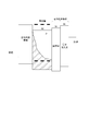
- FIG. 2 is a diagram showing the relationship between the light emitting layer and the triplet energy in the electron transport band of the organic electroluminescence device according to the first embodiment.
- the triplet energy means a difference between the energy in the lowest excited triplet state and the energy in the ground state, and the singlet energy (sometimes referred to as an energy gap) is the energy in the lowest excited singlet state. The difference in energy in the ground state.
- the organic EL element 1 shown in FIG. 1 includes a hole transport zone 60, a light emitting layer 20, an electron transport zone 70, and a cathode 50 in order from the anode 10 side. In the organic EL element 1 of this embodiment, these are adjacent to each other.
- the electron transport zone 70 in the present embodiment is composed of the barrier layer 30 and the electron injection layer 40.
- a hole transport zone 60 is preferably provided between the anode 10 and the light emitting layer 20.
- the hole transport zone includes at least one of a hole injection layer and a hole transport layer.
- the term “barrier layer” refers to a layer having a barrier function against triplet energy. Therefore, the hole barrier layer and the charge barrier layer have different functions.
- the light emitting layer includes a host material and a dopant material.
- a dopant material exhibiting fluorescence emission (hereinafter also referred to as a fluorescence emitting dopant material) is preferable.
- a fluorescent light-emitting dopant material having a main peak wavelength of 550 nm or less is preferable, and a fluorescent light-emitting dopant material having a main peak wavelength of 500 nm or less is more preferable.
- the main peak wavelength refers to the peak wavelength of the emission spectrum that maximizes the emission intensity in the emission spectrum measured in a toluene solution having a concentration of 10 ⁇ 5 mol / liter to 10 ⁇ 6 mol / liter.
- the main peak wavelength of 550 nm corresponds to about green light emission, and in this wavelength region, it is desired to improve the light emission efficiency of the fluorescent light emitting element using the TTF phenomenon. Further, in a fluorescent light emitting device that emits blue light of 480 nm or less, higher luminous efficiency can be expected. For red light emission of 550 nm or more, phosphorescent light emitting elements with high internal quantum efficiency are already in practical use, and thus it is not desired to improve the light emission efficiency as fluorescent elements.
- holes injected from the anode are injected into the light emitting layer through the hole transport zone, and electrons injected from the cathode are injected into the light emitting layer through the electron injection layer and the barrier layer. Thereafter, holes and electrons are recombined in the light emitting layer, and singlet excitons and triplet excitons are generated.
- recombination occurs on the host material molecule and on the dopant material molecule. In this embodiment, as shown in FIG. 2, when the triplet energies of the host material and the dopant material are E T h and E T d , respectively, the relationship of the following formula (2A) is satisfied.
- the barrier layer is adjacent to the light emitting layer.
- the barrier layer prevents the triplet excitons generated in the light-emitting layer from diffusing into the electron transport band, and confines the triplet excitons in the light-emitting layer, thereby increasing the density of the triplet excitons and improving the efficiency of the TTF phenomenon. Has the function to cause well.
- the barrier layer also has a role of efficiently injecting electrons into the light emitting layer. When the electron injecting property to the light emitting layer is lowered, the density of triplet excitons is reduced by reducing the electron-hole recombination in the light emitting layer. When the density of the triplet exciton is reduced, the collision frequency of the triplet exciton decreases, and the TTF phenomenon does not occur efficiently.
- the barrier layer of the organic EL device of this embodiment contains an aromatic heterocyclic derivative represented by the following general formula (1).
- X 1 to X 3 are a nitrogen atom or CR 1 . However, at least one of X 1 to X 3 is a nitrogen atom.
- Each R 1 is independently Hydrogen atom, A halogen atom, A cyano group, A substituted or unsubstituted aryl group having 6 to 30 ring carbon atoms, A substituted or unsubstituted heterocyclic group having 5 to 30 ring atoms, A substituted or unsubstituted alkyl group having 1 to 30 carbon atoms, A substituted or unsubstituted alkenyl group having 2 to 30 carbon atoms, A substituted or unsubstituted alkynyl group having 2 to 30 carbon atoms, A substituted or unsubstituted alkylsilyl group having 3 to 30 carbon atoms, A substituted or unsubstituted arylsilyl group having 6 to 30 ring carbon atoms, A substituted or unsubstituted alkylsily
- HAr is represented by the following general formula (3).
- a is an integer of 1 to 5.
- L 1 is a single bond or a divalent linking group.
- L 1 is a trivalent or more and hexavalent or less linking group, and HAr is the same or different.
- the linking group is A substituted or unsubstituted aryl group having 6 to 30 ring carbon atoms, A substituted or unsubstituted heterocyclic group having 5 to 30 ring atoms, or These groups are divalent to hexavalent residues derived from either two or three groups bonded to each other. The groups bonded to each other are the same or different from each other.
- X 11 to X 18 are each independently a carbon atom bonded to the nitrogen atom, CR 13 , or L 1 with a single bond.
- Y 1 is an oxygen atom, a sulfur atom, SiR 11 R 12 , or a silicon atom bonded to R 11 and L 1 with a single bond.
- the bond to L 1 is any one of carbon atoms in X 11 to X 18 and R 11 to R 12 and a silicon atom in Y 1 .
- R 11 and R 12 have the same meaning as R 1 in the general formula (1).
- R 11 and R 12 are the same or different.
- Each R 13 is independently Hydrogen atom, A halogen atom, A cyano group, A substituted or unsubstituted aryl group having 6 to 30 ring carbon atoms, A substituted or unsubstituted heterocyclic group having 5 to 30 ring atoms, A substituted or unsubstituted alkyl group having 1 to 30 carbon atoms, A substituted or unsubstituted alkenyl group having 2 to 30 carbon atoms, A substituted or unsubstituted alkynyl group having 2 to 30 carbon atoms, A substituted or unsubstituted alkylsilyl group having 3 to 30 carbon atoms, A substituted or unsubstituted arylsilyl group having 6 to 30 ring carbon atoms, A substituted or unsubstituted alkoxy group having 1 to 30 carbon atoms, A substituted or unsubstituted aralkyl group having 6 to 30 ring carbon atoms or a substituted or un
- a plurality of R 13 may be the same or different from each other. Further, adjacent R 13 may be bonded to each other to form a ring.
- Ar 1 and Ar 2 are each independently Represented by the general formula (2), A substituted or unsubstituted aryl group having 6 to 30 ring carbon atoms, or A substituted or unsubstituted heterocyclic group having 5 to 30 ring atoms.
- X 13 or X 16 is preferably a carbon atom bonded to L 1 with a single bond.
- X 11 or X 18 is preferably a carbon atom bonded to L 1 with a single bond.
- a is an integer of 1 or more and 5 or less, more preferably 1 or more and 3 or less, and particularly preferably 1 or 2.
- L 1 is a single bond or a divalent linking group
- the general formula (2) is represented by the following general formula (2-1).
- L 1 is a trivalent or more and hexavalent or less linking group.
- the general formula (2) is represented by the following general formula (2-2). At this time, HAr is the same or different.
- the linking group is A substituted or unsubstituted aryl group having 6 to 30 ring carbon atoms, A substituted or unsubstituted heterocyclic group having 5 to 30 ring atoms, or These groups are divalent or trivalent residues derived from either two or three groups linked together.
- the group in which two or three of these groups are bonded to each other is a divalent or trivalent group derived from the aryl group having 6 to 30 ring carbon atoms and the heterocyclic group having 5 to 30 ring atoms.
- a group in which the residues are single bonds to each other and are bonded to 2 or 3 residues.
- groups bonded to each other are the same or different from each other.
- L 1 is preferably a linking group, and the linking group has 6 substituted or unsubstituted ring-forming carbon atoms.
- the linking group has 6 substituted or unsubstituted ring-forming carbon atoms.
- the linking group is preferably a substituted or unsubstituted aryl group having 6 to 30 ring carbon atoms or a substituted or unsubstituted heterocyclic group having 5 to 30 ring atoms.
- the linking group includes a substituted or unsubstituted ring-forming carbon number of 6 It is preferably a divalent residue of an aryl group of ⁇ 30 or a divalent residue of a substituted or unsubstituted heterocyclic group having 5 to 30 ring atoms. More specifically, L 1 is preferably a divalent residue derived from any of benzene, biphenyl, terphenyl, naphthalene and phenanthrene.
- the linking group includes a substituted or unsubstituted ring-forming carbon number of 6 It is preferably a trivalent residue of an aryl group of ⁇ 30 or a trivalent residue of a substituted or unsubstituted heterocyclic group having 5 to 30 ring atoms. More specifically, L 1 is preferably a divalent residue derived from any of benzene, biphenyl, terphenyl, naphthalene and phenanthrene.
- Y 1 in the general formula (3) is preferably an oxygen atom or a sulfur atom. Further, Y 1 in the general formula (3) is an oxygen atom or a sulfur atom, and one of X 11 to X 18 is a carbon atom bonded to L 1 with a single bond, and the others are CR 13 is preferred. It is more preferable that any two or three of X 1 to X 3 in the general formula (1) are nitrogen atoms.
- L 1 in the general formula (2) is preferably a divalent or trivalent residue derived from any one of benzene, biphenyl, terphenyl, naphthalene, and phenanthrene.
- the structure of the aromatic heterocyclic derivative represented by the general formula (1) included in the barrier layer of the organic EL element of the present embodiment include the following. However, the present embodiment is not limited to the aromatic derivatives having these structures.
- the organic EL element 1 of the present embodiment includes the electron injection layer 40 between the barrier layer 30 and the cathode 50 as described above.
- the electron injection layer 40 preferably contains an aromatic heterocyclic derivative represented by the general formula (1).
- the aromatic heterocyclic derivative contained in the barrier layer 30 and the aromatic heterocyclic derivative contained in the electron injection layer 40 may be the same or different.
- the electron injection layer is for facilitating electron injection from the cathode.
- Specific examples include a laminate of a normal electron transport material and at least one of an electron donating dopant material and an organometallic complex, or a material for forming a barrier layer, at least of an electron donating dopant material and an organometallic complex. What added either in the vicinity of the cathode interface in an electron injection layer can be used.
- Examples of the electron donating dopant material include at least one selected from alkali metals, alkali metal compounds, alkaline earth metals, alkaline earth metal compounds, rare earth metals, rare earth metal compounds, and the like.
- Examples of the organometallic complex include at least one selected from an organometallic complex containing an alkali metal, an organometallic complex containing an alkaline earth metal, an organometallic complex containing a rare earth metal, and the like.
- alkali metal examples include lithium (Li) (work function: 2.93 eV), sodium (Na) (work function: 2.36 eV), potassium (K) (work function: 2.28 eV), rubidium (Rb) (work Function: 2.16 eV), cesium (Cs) (work function: 1.95 eV) and the like, and those having a work function of 2.9 eV or less are particularly preferable.
- K, Rb, and Cs are preferred, Rb or Cs is more preferred, and Cs is most preferred.
- alkaline earth metal examples include calcium (Ca) (work function: 2.9 eV), strontium (Sr) (work function: 2.0 eV to 2.5 eV), barium (Ba) (work function: 2.52 eV).
- a work function of 2.9 eV or less is particularly preferable.
- the rare earth metal examples include scandium (Sc), yttrium (Y), cerium (Ce), terbium (Tb), ytterbium (Yb) and the like, and those having a work function of 2.9 eV or less are particularly preferable.
- preferred metals are particularly high in reducing ability, and by adding a relatively small amount to the electron injection region, it is possible to improve the light emission luminance and extend the life of the organic EL element.
- alkali metal compound examples include lithium oxide (Li 2 O), cesium oxide (Cs 2 O), alkali oxides such as potassium oxide (K 2 O), lithium fluoride (LiF), sodium fluoride (NaF), fluorine.
- alkali halides such as cesium fluoride (CsF) and potassium fluoride (KF), and lithium fluoride (LiF), lithium oxide (Li 2 O), and sodium fluoride (NaF) are preferable.
- alkaline earth metal compound examples include barium oxide (BaO), strontium oxide (SrO), calcium oxide (CaO), and barium strontium oxide (Ba x Sr 1-x O) (0 ⁇ x ⁇ 1), Examples thereof include barium calcium oxide (Ba x Ca 1-x O) (0 ⁇ x ⁇ 1), and BaO, SrO, and CaO are preferable.
- the rare earth metal compound ytterbium fluoride (YbF 3), scandium fluoride (ScF 3), scandium oxide (ScO 3), yttrium oxide (Y 2 O 3), cerium oxide (Ce 2 O 3), gadolinium fluoride (GdF 3), such as terbium fluoride (TbF 3) can be mentioned, YbF 3, ScF 3, TbF 3 are preferable.
- the organometallic complex is not particularly limited as long as it contains at least one of an alkali metal ion, an alkaline earth metal ion, and a rare earth metal ion as a metal ion as described above.
- the ligand includes quinolinol, benzoquinolinol, acridinol, phenanthridinol, hydroxyphenyl oxazole, hydroxyphenyl thiazole, hydroxydiaryl oxadiazole, hydroxydiaryl thiadiazole, hydroxyphenyl pyridine, hydroxyphenyl benzimidazole, hydroxybenzotriazole, Hydroxyfulborane, bipyridyl, phenanthroline, phthalocyanine, porphyrin, cyclopentadiene, ⁇ -diketones, azomethines, and derivatives thereof are preferred, but not limited thereto.
- the addition form of the electron donating dopant material and the organometallic complex is preferably formed in a layered or island shape in the interface region.
- a forming method while depositing at least one of an electron donating dopant material and an organometallic complex by a resistance heating vapor deposition method, an organic material that is a light emitting material or an electron injection material that forms an interface region is simultaneously deposited, and the organic material is deposited in the organic material.
- a method of dispersing at least one of an electron donating dopant material and an organometallic complex reducing dopant material is preferable.
- the electron donating dopant material and the organometallic complex At least one of them is vapor-deposited by resistance heating vapor deposition, preferably with a layer thickness of 0.1 nm to 15 nm.
- the electron emitting dopant material and the organic metal are formed after the light emitting material or the electron injecting material which is the organic layer at the interface is formed in the island shape.
- At least one of the complexes is vapor-deposited by a resistance heating vapor deposition method alone, and is preferably formed with an island thickness of 0.05 nm to 1 nm.
- examples of the compound other than the electron donating dopant material and the organometallic complex used for the electron injection layer include compounds represented by the following general formula (EIL-1).
- HAr 1 is a substituted or unsubstituted nitrogen-containing heterocyclic group, and preferably has a structure represented by the following formula.
- HAr 1 in the general formula (EIL-1) Fluorine atom, A cyano group, A substituted or unsubstituted alkyl group having 1 to 20 carbon atoms, A substituted or unsubstituted cycloalkyl group having 3 to 20 carbon atoms, A substituted or unsubstituted alkylsilyl group having 3 to 20 carbon atoms, A substituted or unsubstituted arylsilyl group having 8 to 30 carbon atoms, A substituted or unsubstituted alkoxy group having 1 to 20 carbon atoms, A substituted or unsubstituted aryloxy group having 6 to 30 carbon atoms, Examples thereof include a substituted or unsubstituted aryl group having 6 to 30 ring carbon atoms, or a substituted or unsubstituted heterocyclic group having 5 to 30 ring atoms.
- Ar 1 is a substituted or unsubstituted condensed ring group having 10 to 30 ring carbon atoms, and preferably has the following condensed ring structure.
- Ar 1 in the general formula (EIL-1) Fluorine atom, A cyano group, A substituted or unsubstituted alkyl group having 1 to 20 carbon atoms, A substituted or unsubstituted cycloalkyl group having 3 to 20 carbon atoms, A substituted or unsubstituted alkylsilyl group having 3 to 20 carbon atoms, A substituted or unsubstituted arylsilyl group having 8 to 30 carbon atoms, A substituted or unsubstituted alkoxy group having 1 to 20 carbon atoms, A substituted or unsubstituted aryloxy group having 6 to 30 carbon atoms, Examples thereof include a substituted or unsubstituted aryl group having 6 to 30 ring carbon atoms, or a substituted or unsubstituted heterocyclic group having 5 to 30 ring atoms.
- L 1 is Single bond, A substituted or unsubstituted a + b valent hydrocarbon ring group having 6 to 30 ring carbon atoms, A substituted or unsubstituted a + b-valent heterocyclic group having 5 to 30 ring atoms; An a + b valent group formed by connecting a plurality of substituted or unsubstituted hydrocarbon ring groups having 6 to 30 ring carbon atoms or substituted or unsubstituted heterocyclic groups having 5 to 30 ring atoms.
- L 1 in formula (EIL-1) Fluorine atom, A cyano group, A substituted or unsubstituted alkylsilyl group having 3 to 20 carbon atoms, A substituted or unsubstituted arylsilyl group having 8 to 30 carbon atoms, Examples thereof include a substituted or unsubstituted aryl group having 6 to 30 ring carbon atoms, or a substituted or unsubstituted heterocyclic group having 5 to 30 ring atoms.
- examples of the compound used for the electron injection layer include compounds represented by the following general formula (EIL-2).
- R 101 to R 108 is bonded to L 2 with a single bond, and the other is a hydrogen atom or a substituent.
- substituent of R 101 to R 108 in the general formula (EIL-2) include the same as those described in the general formula (EIL-1), preferably an alkyl group having 1 to 20 carbon atoms or An aryl group having 6 to 30 ring carbon atoms.
- L 2 represents a single bond or a linking group, and the linking group has a c-valent aromatic hydrocarbon group or a structure represented by the following general formula (EIL-2-1) c-valent group.
- R 109 to R 110 are a hydrogen atom or a substituent.
- d and e are each independently an integer of 1 to 5.
- X is selected from the structures represented by the following formulae.
- c is an integer of 2 to 4, and preferably c is 2.
- a compound represented by the following general formula (EIL-2-2) bonded to L 2 at R 101 is preferable.
- R 102 to R 107 are hydrogen atoms or substituents, preferably hydrogen atoms.
- c and L 2 are the same as those in the general formula (EIL-2).
- c is preferably 2.
- L 2 is preferably a substituted or unsubstituted phenylene group or a substituted or unsubstituted naphthylene group.
- Ar 108 is a hydrogen atom, an alkyl group having 1 to 20 carbon atoms, or a substituted or unsubstituted aryl group having 6 to 30 ring carbon atoms, and more preferably A methyl group, a t-butyl group, a substituted or unsubstituted phenyl group or a substituted or unsubstituted naphthyl group;
- the affinity of the host material is denoted as A h
- the affinity of the dopant material is denoted as A d
- the ionization potential of the host material is denoted as I h
- the ionization potential of the dopant material is denoted as I d .
- the dopant material used in the present embodiment is a fluorescent light-emitting dopant material that exhibits fluorescent light having a main peak wavelength of 550 nm or less, and the energy gap is relatively large. Therefore, when the relationship of A h > A d is satisfied, the relationship of I h > I d is satisfied at the same time. Therefore, the dopant material easily functions as a hole trap.
- FIG. 4 shows an example of the relationship between the host material and the dopant material Ip (ionization potential) -Af (affinity) in the light emitting layer at this time.
- Ip ionization potential
- -Af affinity
- FIG. 4 shows the relationship in the case of A h > A b > A e .
- the dopant material becomes hole trapping, and triplet excitons are generated not only on the host material molecule but also directly on the dopant material molecule. Become. As a result, more triplet excitons are generated directly on the dopant material.
- a hole transport layer is provided adjacent to the light emitting layer in the hole transport zone, and the triplet energy E T ho of the hole transport layer is higher than the triplet energy E T h of the host material. Larger is preferred.
- the dopant material has a hole trapping property, holes injected from the hole transport zone into the light emitting layer are trapped by the dopant material. Therefore, many recombination occurs on the anode side in the light emitting layer.
- the triplet energy of the hole transport material used in the conventionally known hole transport band is often larger than the triplet energy of the host material originally, and diffusion of triplet excitons on the hole side is not a problem. There wasn't.
- the recombination region includes carrier mobility, ionization potential, affinity, and film thickness in the hole transport band and electron transport band.
- the thickness of the electron transport zone is larger than the hole transport zone, the amount of electrons injected into the light emitting layer is relatively small, and as a result, the recombination region is biased toward the electron transport zone.
- the TTF phenomenon can be caused more efficiently.
- the host material is an anthracene derivative, a polycyclic aromatic skeleton-containing compound, preferably an anthracene derivative.
- the dopant material is at least one compound selected from the group consisting of pyrene derivatives, aminoanthracene derivatives, aminochrysene derivatives, and aminopyrene derivatives.
- Preferred examples of the combination of the host material and the dopant material include an anthracene derivative as the host material and at least one selected from the group consisting of pyrene derivatives, aminoanthracene derivatives, aminochrysene derivatives, and aminopyrene derivatives as the dopant material. It is a combination of these compounds.
- aminoanthracene derivatives include compounds represented by the following formula (20A).
- each of A 1 and A 2 independently represents an optionally substituted aliphatic hydrocarbon group having 1 to 6 carbon atoms, and optionally having 6 to 6 ring-forming carbon atoms.
- a 3 independently represents an optionally substituted aliphatic hydrocarbon group having 1 to 6 carbon atoms, an optionally substituted aromatic hydrocarbon group having 6 to 20 ring carbon atoms, and a substituent.
- a heteroaromatic hydrocarbon group having 5 to 19 ring atoms which may have a group or a hydrogen atom. This heteroaromatic hydrocarbon group contains a nitrogen, sulfur or oxygen atom.
- amino chrysene derivative examples include compounds represented by the following formula (20B).
- X 1 to X 10 are each a hydrogen atom or a substituent, and Y 1 and Y 2 are each a substituent.
- X 1 to X 10 are hydrogen atoms.
- Y 1 and Y 2 are aromatic rings having 6 to 30 ring carbon atoms which may have a substituent.
- the aromatic ring substituent is preferably an alkyl group having 1 to 6 carbon atoms.
- the aromatic ring is preferably an aromatic ring having 6 to 10 ring carbon atoms or a phenyl group.
- aminopyrene derivatives include compounds represented by the following formula (20C).
- X 1 to X 10 are each a hydrogen atom or a substituent, provided that X 3 and X 8 or X 2 and X 7 are each —NY 1 Y 2 (Y 1 , Y 2 are Is a substituent).
- X 3 and X 8 are each —NY 1 Y 2 , X 2 , 4, 5, 7 , 9 , and 10 are hydrogen atoms
- X 1 and X 6 are hydrogen atoms, alkyl groups, or A cycloalkyl group
- X 2 and X 7 are each —NY 1 Y 2 , X 1,3-6 and 8-10 are hydrogen atoms.
- Y 1 and Y 2 are aromatic rings that may have a substituent, and are, for example, a phenyl group or a naphthyl group.
- substituent of the aromatic ring include an alkyl group having 1 to 6 carbon atoms.
- the anthracene derivative is preferably a compound represented by the general formula (20D).
- Ar 11 and Ar 12 are each independently a substituted or unsubstituted monocyclic group having 5 to 30 ring atoms, or a substituted or unsubstituted condensed ring having 10 to 30 ring atoms. It is a group composed of a ring group or a combination of the monocyclic group and the condensed ring group.
- the monocyclic group is a group composed only of a ring structure having no condensed structure.
- the number of ring-forming atoms of the monocyclic group is 5 to 30, preferably 5 to 20.
- the monocyclic group include aromatic groups such as phenyl group, biphenyl group, terphenyl group, and quarterphenyl group, and heterocyclic groups such as pyridyl group, pyrazyl group, pyrimidyl group, triazinyl group, furyl group, and thienyl group. Is mentioned. Among these, a phenyl group, a biphenyl group, and a terphenyl group are preferable.
- the condensed ring group is a group in which two or more ring structures are condensed.
- the number of ring-forming atoms of the fused ring group is 10-30, preferably 10-20.
- Examples of the condensed ring group include naphthyl group, phenanthryl group, anthryl group, chrysenyl group, benzoanthryl group, benzophenanthryl group, triphenylenyl group, benzochrysenyl group, indenyl group, fluorenyl group, 9,9-dimethylfluorene group.
- Nyl group benzofluorenyl group, dibenzofluorenyl group, fluoranthenyl group, benzofluoranthenyl group and other condensed aromatic ring groups, benzofuranyl group, benzothiophenyl group, indolyl group, dibenzofuranyl group, Examples thereof include condensed heterocyclic groups such as a dibenzothiophenyl group, a carbazolyl group, a quinolyl group, and a phenanthrolinyl group.
- naphthyl group phenanthryl group, anthryl group, 9,9-dimethylfluorenyl group, fluoranthenyl group, benzoanthryl group, dibenzothiophenyl group, dibenzofuranyl group, and carbazolyl group are preferable.
- examples of the group composed of the combination of the monocyclic group and the condensed ring group include a phenyl group, a naphthyl group, and a phenyl group combined in order from the anthracene ring side. Groups.
- alkyl group silyl group, alkoxy group, aryloxy group, aralkyl group, and halogen atom from R 101 to R 108 in the general formula (20D) are described in R 1 in the general formula (1).
- the cycloalkyl group is the same as that described above. Further, the case of “substituted or unsubstituted” in these substituents is the same as described above.
- Ar 11 and Ar 12 in the general formula (20D), and preferred substituents of “substituted or unsubstituted” from R 101 to R 108 are monocyclic groups, condensed ring groups, alkyl groups, cycloalkyl groups, silyl groups. , An alkoxy group, a cyano group, and a halogen atom (particularly fluorine). Particularly preferred are a monocyclic group and a condensed ring group, and preferred specific substituents are the same as those in the above-mentioned general formula (20D) and the above-mentioned general formula (1).
- the dopant material of this embodiment is a wide gap dopant material that emits fluorescent light having a main peak wavelength of 550 nm or less
- the difference between Ad and Ah is satisfied when the relationship of A h ⁇ Ad is satisfied. Is about 0.2 eV, the difference between the ionization potential of the host material and the ionization potential of the dopant material is reduced. As a result, dopant materials tend not to have significant hole trapping properties.
- FIG. 5 shows the relationship in the case of A h > A b > A e .
- the dopant material in this case tends not to have a remarkable trapping property for both electrons and holes.
- electron-hole recombination occurs mainly on the host material molecules over a wide area in the light emitting layer, and 25% singlet excitons and 75 % Triplet excitons are mainly produced on the host material molecules.
- the energy of singlet excitons generated on the host material is transferred to the dopant material by Forster energy transfer, and contributes to the fluorescence emission of the dopant material molecules.
- the energy of triplet excitons is determined by the relationship between the triplet energies of the host material and the dopant material.
- a barrier layer is provided adjacent to the light emitting layer. Since the triplet energy E T b of the barrier layer is set larger than the triplet energy E T h of the host material, the triplet excitons are prevented from diffusing into the electron transport band, and efficiently in the light emitting layer. It becomes possible to cause a TTF phenomenon.
- triplet excitons are generated not only on the host material molecule but also directly on the dopant material molecule.
- E T h ⁇ E T d triplet excitons generated directly on the dopant material are also collected on the host material by Dexter-type energy transfer.
- the TTF phenomenon often occurs.
- the probability of trapping electrons by the dopant material becomes higher near the interface between the light emitting layer and the barrier layer, and as a result, recombination also occurs near the interface between the light emitting layer and the barrier layer. A lot happens.
- the confinement effect of the triplet exciton by the barrier layer is larger than in the case of [2-1], and the density of the triplet exciton at the interface with the barrier layer is increased.
- FIG. 6 the relationship in the case of A h > A b > A e is shown.
- the above-described host material and the dopant material satisfies the relationship of A h ⁇ A d, for example, be selected from the following compounds (JP 2010-50227 JP (see Japanese Patent Application No. 2008-212102), etc.).
- Examples of the host material include anthracene derivatives and polycyclic aromatic skeleton-containing compounds, preferably anthracene derivatives.
- fluoranthene derivatives As dopant materials, fluoranthene derivatives, pyrene derivatives, arylacetylene derivatives, fluorene derivatives, boron complexes, perylene derivatives, oxadiazole derivatives and anthracene derivatives, preferably fluoranthene derivatives, pyrene derivatives and boron complexes, more preferably fluoranthene derivatives And boron complexes.
- the host material is an anthracene derivative and the dopant material is a fluoranthene derivative or a boron complex.
- Examples of specific fluoranthene derivatives include the following compounds.
- X 1 to X 12 are hydrogen or a substituent.
- X 1 to X 2 , X 4 to X 6 and X 8 to X 11 are hydrogen atoms, and X 3 , X 7 and X 12 may have a substituent, and the number of ring forming atoms is 5 to 50 It is a compound which is an aryl group. More preferably, X 1 to X 2 , X 4 to X 6 and X 8 to X 11 are hydrogen atoms, and X 7 and X 12 are aryls having 5 to 50 ring atoms that may have a substituent.
- X 1 to X 2 , X 4 to X 6 and X 8 to X 11 are hydrogen atoms, and X 7 and X 12 each have 5 to 50 ring-forming atoms which may have a substituent.
- An aryl group a compound in which X 3 is —Ar 1 —Ar 2 —Ar 3 , wherein Ar 1 and Ar 3 are each an arylene group having 5 to 50 ring atoms that may have a substituent, Ar 2 is an aryl group having 5 to 50 ring atoms which may have a substituent.
- Examples of specific boron complex compounds include the following compounds.
- a and A ′ represent an independent azine ring system corresponding to a 6-membered aromatic ring system containing at least one nitrogen
- X a and X b are each independently selected substitutions A group wherein the two are linked to form a fused ring for ring A or ring A ′, respectively, wherein the fused ring contains an aryl or heteroaryl substituent
- m and n Each independently represents 0-4, Z a and Z b each independently represent a halide, and 1, 2, 3, 4, 1 ′, 2 ′, 3 ′ and 4 ′ represent , Each independently represents a carbon atom or a nitrogen atom.
- the azine ring is such that 1, 2, 3, 4, 1 ′, 2 ′, 3 ′ and 4 ′ are all carbon atoms, m and n are 2 or more, and X a and X b are It is a quinolinyl or isoquinolinyl ring which represents a substituent having 2 or more carbon atoms that are linked to form an aromatic ring.
- Z a and Z b are preferably fluorine atoms.
- the anthracene derivative as the host material in the case of [2] is the same as that described in the above “[1] In the case of A h > Ad ”.
- An example of an energy band diagram in the case where both of the dopant materials to be filled is included is shown. In such a case, both electrons and holes are trapped reasonably, and as a result, recombination occurs throughout the light emitting layer. Therefore, a lot of recombination occurs on the cathode side, and the TTF phenomenon is efficiently generated by providing a barrier layer having a large triplet energy.
- FIG. 7 the relationship in the case of A h > A b > A e is shown.
- the exciton density at the interface between the light emitting layer and the barrier layer is large. In this case, the probability that holes that did not contribute to recombination in the light emitting layer are injected into the barrier layer is increased. Therefore, the material used for the barrier layer is preferably a material having excellent oxidation durability among the aromatic heterocyclic derivatives.
- the barrier layer material shows a reversible oxidation process by cyclic voltammetry measurement.
- the light emitting layer can include two or more fluorescent light emitting dopant materials having a main peak wavelength of 550 nm or less.
- the affinity A d of at least one dopant material is greater than or equal to the affinity A h of the host material, and the triplet energy E T d of the dopant material is the triplet energy E of the host material. greater than T h.
- affinity A d of at least one other dopant material is less than the affinity A h of the host material.
- Such two comprise dopant material provide a large barrier layer of A h ⁇ A d OmitasudopantozairyotoA h> it is to include both the dopant material satisfying A d triplet energy as described above This can significantly improve the efficiency.
- the affinity A h is less than the dopant material affinity A d is the host material of the dopant materials, pyrene derivatives, amino anthracene derivative, aminochrysene derivatives, aminopyrene derivatives.
- dibenzofuran compounds described in WO05 / 113431 and JP2005-314239 fluorene compounds described in WO02 / 14244, and benzanthracene compounds described in WO08 / 145239 can also be used.
- a pyrene compound described in JP2004-204238, WO05 / 108348, WO04 / 83162, WO09 / 84512, KR10-2008-79956, KR10-2007-115588, KR10-2010-24894, WO04 / 44088 The described chrysene compounds and the anthracene compounds described in WO07 / 2117 can also be used.
- the host material and the dopant material are preferably a compound in which a cyclic structure or a single atom is bonded to each other (including a cyclic structure and a bond of a single atom), and the bond is a single bond.
- Unpreferable examples include compounds having a carbon-carbon double bond other than a cyclic structure. This is because the triplet exciton energy generated on the host material and the dopant material is not used for the TTF phenomenon and is consumed for the structural change of the double bond.
- Each layer of the organic EL element of this embodiment is formed by any of dry film forming methods such as vacuum deposition, sputtering, plasma, and ion plating, and wet film forming methods such as spin coating, dipping, flow coating, and ink jet. Can be applied.
- dry film forming methods such as vacuum deposition, sputtering, plasma, and ion plating
- wet film forming methods such as spin coating, dipping, flow coating, and ink jet. Can be applied.
- the material for forming each layer is dissolved or dispersed in an appropriate solvent such as ethanol, chloroform, tetrahydrofuran, dioxane or the like to form a thin film, and any solvent may be used.
- an appropriate solvent such as ethanol, chloroform, tetrahydrofuran, dioxane or the like
- any solvent may be used.
- an organic EL material-containing solution containing the aromatic amine derivative of the present invention and a solvent can be used as a material for an organic EL element.
- an appropriate resin or additive may be used for improving the film formability and preventing pinholes in the film.
- the film thickness is not particularly limited, but must be set to an appropriate film thickness. If the film thickness is too thick, a large applied voltage is required to obtain a constant light output, resulting in poor efficiency. If the film thickness is too thin, pinholes and the like are generated, and sufficient light emission luminance cannot be obtained even when an electric field is applied.
- the film thickness of the barrier layer is preferably 20 nm or less.
- the thickness of the other layers is usually in the range of 5 nm to 10 ⁇ m, more preferably in the range of 10 nm to 0.2 ⁇ m.
- FIG. 8 shows an example of the organic EL element 2 according to the second embodiment.
- the organic EL element of this embodiment does not need to be provided with an electron injection layer.
- the organic EL element 2 according to the second embodiment shown in FIG. 8 has an anode 10, a hole transport band 60, and a light emitting layer 20.
- An electron transport zone (in this embodiment, a barrier layer 30) and a cathode 50 are provided in this order.
- these layers are adjacent to each other.
- the barrier layer 30 of the organic EL element 2 includes the aromatic heterocyclic derivative represented by the general formula (1). Further, the other layers constituting the organic EL element 2 are the same as those in the first embodiment.
- FIG. 9 shows an example of the organic EL element 3 according to the third embodiment.
- the organic EL device of the present invention may be provided with an electron injection layer on the cathode side of the electron transport layer.
- the organic EL device 3 according to the third embodiment shown in FIG. A light emitting layer 20, an electron transport zone (in this embodiment, a barrier layer 30, an electron transport layer 41, and an electron injection layer 40), and a cathode 50 are provided in this order. In the present embodiment, these layers are adjacent to each other.
- the electron injection layer 40 and the electron transport layer 41 includes the above-described aromatic heterocyclic derivative of the present invention.
- the materials described in the above electron injection layer or a known electron transport material can be used.
- the electron injection layer 40 and the electron transport layer 41 may be configured to include other materials in addition to the above-described aromatic heterocyclic derivative of the present invention.
- the barrier layer 30 of the organic EL element 3 includes the aromatic heterocyclic derivative represented by the general formula (1).
- the other layers constituting the organic EL element 3 are the same as in the first embodiment.
- the organic EL element of this embodiment can have a tandem element configuration having at least two organic layer units including a light emitting layer.
- An intermediate layer also referred to as an intermediate conductive layer, a charge generation layer, or CGL
- An electron transport zone can be provided for each unit.
- At least one light emitting layer is a fluorescent light emitting layer, and a unit including the light emitting layer satisfies the above requirements.
- FIG. 10 shows an example of an organic EL element according to the fourth embodiment.
- the organic EL element 4 includes an anode 10, light emitting layers 22 and 24, and a cathode 50 in this order, and an intermediate layer 80 is provided between the light emitting layers 22 and 24.
- the barrier layer 32 is adjacent to the light emitting layer 24.
- the electron injection layer 40 is between the barrier layer 32 and the cathode 50.
- the barrier layer 32, the electron injection layer 40, and the light emitting layer 24 are a barrier layer, an electron injection layer, and a fluorescent light emitting layer that satisfy the requirements of the present invention.
- the other light emitting layer may be fluorescent or phosphorescent.
- barrier layer 32 and the electron injection layer 40 correspond to an electron transport zone.
- an electron transport band and a hole transport band may be interposed between the two light emitting layers 22 and 24. Further, there may be three or more light emitting layers and two or more intermediate layers. When there are three or more light emitting layers, there may or may not be an intermediate layer between all the light emitting layers.
- the intermediate layer is a layer including at least one of the intermediate conductive layer and the charge generation layer, or at least one of the intermediate conductive layer and the charge generation layer, and serves as a supply source of electrons or holes injected into the light emitting unit.
- the electric charge supplied from the intermediate layer is injected into the light emitting unit. Therefore, by providing the intermediate layer, the luminous efficiency (current efficiency) with respect to the injected current is increased. improves.
- the intermediate layer include metals, metal oxides, metal oxide mixtures, composite oxides, and electron-accepting organic compounds.
- As the metal a co-deposited film of Mg, Al, Mg or Ag is preferable.
- Examples of the metal oxide include ZnO, WO 3 , MoO 3 , and MoO 2 .
- Examples of the metal oxide mixture include ITO, IZO (registered trademark), and ZnO: Al.
- Examples of the electron-accepting organic compound include organic compounds having a CN group as a substituent.
- a triphenylene derivative, a tetracyanoquinodimethane derivative, an indenofluorene derivative, or the like is preferable.
- As the triphenylene derivative hexacyanohexaazatriphenylene is preferable.
- the electron-accepting substance may be a single substance or a mixture with other organic compounds.
- an electron donating dopant represented by an alkali metal and an organometallic complex is added in the vicinity of the charge generation layer interface in the electron transport layer. To do.
- Examples of the electron donating dopant and the organometallic complex include those described in the first embodiment.
- Specific examples of the compound that can be used for the electron-donating dopant and the organometallic complex include compounds described in Japanese Patent Application Publication No. PCT / JP2010 / 003434 (International Publication No. 2010/134352).
- an anode In the fifth embodiment, an anode, a plurality of light emitting layers, an electron transport zone having a barrier layer adjacent to the light emitting layer, an electron injection layer adjacent to the barrier layer, and a cathode in this order, and a plurality of light emitting layers
- a charge barrier layer is provided between any two of the light emitting layers.
- the light emitting layer in contact with the charge barrier layer is a fluorescent light emitting layer.
- the fluorescent light emitting layer, the barrier layer in the electron transport zone, and the electron injection layer satisfy the above requirements.
- the charge barrier layer is provided with an energy barrier of a HOMO level and a LUMO level between adjacent light emitting layers, thereby adjusting carrier injection into the light emitting layer, so that electrons and holes injected into the light emitting layer are injected.
- This layer has the purpose of adjusting the carrier balance.
- Anode / first light emitting layer / charge barrier layer / second light emitting layer / electron transport zone / cathode anode / first light emitting layer / charge barrier layer / second light emitting layer / third light emitting layer / electron transport zone / cathode
- FIG. 11 shows an example of the organic EL element according to this embodiment.
- the upper diagram of FIG. 11 is a diagram showing the device configuration and the HOMO and LUMO energy levels of each layer.
- the lower diagram of FIG. 11 shows the relationship of the energy gap between the third light emitting layer and the barrier layer.
- This organic EL element includes an anode, a first light emitting layer, a second light emitting layer, a third light emitting layer, an electron transport zone, and a cathode in this order. Between the first light emitting layer and the second light emitting layer, There is a charge barrier layer.
- the electron transport zone consists of a barrier layer.
- the barrier layer and the third light emitting layer are a barrier layer and a fluorescent light emitting layer that satisfy the requirements of the present invention.
- the first light emitting layer and the second light emitting layer may be fluorescent or phosphorescent.
- the element of the present embodiment is suitable as a white light-emitting element, and can be white by adjusting the emission color of the first light-emitting layer, the second light-emitting layer, and the third light-emitting layer.
- the light emitting layer may be only the first light emitting layer and the second light emitting layer, and the light emission color of the two light emitting layers may be adjusted to be white.
- the second light emitting layer is a fluorescent light emitting layer that satisfies the requirements of the present invention.
- the host material of the first light emitting layer is a hole transporting material
- a fluorescent light emitting dopant material having a main peak wavelength larger than 550 nm is added, and the host material of the second light emitting layer (and the third light emitting layer) is transported by electrons.
- the hole transport material is compared with the triplet energy of the hole transport material and the triplet energy of the host material. It is preferable that the triplet energy of the transport material is large.
- ⁇ Sixth embodiment> blue pixels, green pixels, and red pixels are provided side by side on a substrate. Of these three color pixels, at least one of the blue pixel and the green pixel has the configuration of the first embodiment or the second embodiment.
- FIG. 12 shows an example of the organic EL element according to this embodiment.
- a blue pixel B, a green pixel G, and a red pixel R are formed in parallel on a common substrate 100.
- the blue pixel B includes the anode 10, the hole transport zone 60, the blue light emitting layer 20B, the barrier layer 32, the electron injection layer 40, the cathode 50, and the protective layer 90 in this order from the substrate 100 side.
- the green pixel G includes an anode 10, a hole transport zone 60, a green light emitting layer 20G, a barrier layer 32, an electron injection layer 40, a cathode 50, and a protective layer 90 in this order from the substrate 100 side.
- the red pixel R includes an anode 10, a hole transport band 60, a red light emitting layer 20R, a barrier layer 32, an electron injection layer 40, a cathode 50, and a protective layer 90 in this order from the substrate 100 side.
- An insulating film 200 is formed between the anodes of the adjacent pixels to maintain the insulation between the pixels.
- the electron transport zone is composed of the barrier layer 32 and the electron injection layer 40.
- the barrier layer is provided in common for the blue pixel B, the red pixel R, and the green pixel G.
- the effect of the barrier layer is remarkable compared to the light emission efficiency conventionally obtained in the blue fluorescent element.
- the same effect of confining the triplet energy in the light emitting layer can be obtained, and the improvement of the light emission efficiency can be expected.
- the phosphorescent light-emitting layer it is possible to obtain an effect of confining triplet excitons in the light-emitting layer, which prevents diffusion of triplet energy and contributes to improvement of the luminous efficiency of the phosphorescent dopant material .
- Examples of the hole transport zone include those composed of a hole transport layer and those composed of a combination of a hole transport layer and a hole injection layer.
- the hole transport band may be common or different in the blue pixel B, the red pixel R, and the green pixel G.
- each hole transport zone has a configuration suitable for the emission color.
- the organic layer composed of the light emitting layers 20B, G, R and the barrier layer is not limited to the configuration shown in the figure and can be changed as appropriate.
- the green light emitting layer is preferably composed of the following host material and dopant material.
- a condensed aromatic ring derivative is preferable.
- anthracene derivatives, pyrene derivatives, and the like are more preferable in terms of light emission efficiency and light emission lifetime.
- examples of the host material include heterocyclic compounds.
- examples of the heterocyclic compound include carbazole derivatives, dibenzofuran derivatives, ladder-type furan compounds, and pyrimidine derivatives.
- the dopant material is not particularly limited as long as it has the function, but an aromatic amine derivative is preferable in terms of luminous efficiency and the like.
- an aromatic amine derivative a condensed aromatic ring derivative having an optionally substituted arylamino group is preferable. Examples of such a compound include pyrene, anthracene, and chrysene having an arylamino group.
- a styrylamine compound is also preferable as the dopant material.
- the styrylamine compound include styrylamine, styryldiamine, styryltriamine, and styryltetraamine.
- styrylamine is a compound in which at least one arylvinyl group is substituted on an optionally substituted arylamine, and the arylvinyl group may be substituted, and the substituent is an aryl group.
- a silyl group, an alkyl group, a cycloalkyl group and an arylamino group, and these substituents may further have a substituent.
- boron complexes and fluoranthene compounds are also preferable as dopant materials.
- a metal complex is also preferable as the dopant material. Examples of metal complexes include iridium complexes and platinum complexes.
- the red light emitting layer is preferably composed of the following host material and dopant material.
- the host material is preferably a condensed aromatic ring derivative.
- a condensed aromatic ring derivative a naphthacene derivative, a pentacene derivative, or the like is more preferable in terms of light emission efficiency and light emission lifetime.
- examples of the host material include condensed polycyclic aromatic compounds.
- examples of the condensed polycyclic aromatic compound include naphthalene compounds, phenanthrene compounds, and fluoranthene compounds.
- an aromatic amine derivative is preferable.
- the aromatic amine derivative a condensed aromatic ring derivative having an optionally substituted arylamino group is preferable.
- An example of such a compound is periflanten having an arylamino group.
- metal complex is preferable as the dopant material.
- metal complexes include iridium complexes and platinum complexes.
- the organic EL element of the sixth embodiment is manufactured as follows, for example.
- a transparent conductive layer such as an APC (Ag—Pd—Cu) layer (reflection layer), a zinc oxide film (IZO), or a tin oxide film, which is a silver alloy layer, is formed on the substrate in this order.
- this conductive material layer is patterned by etching using a resist pattern as a mask by using a normal lithography technique to form an anode.
- an insulating film made of a photosensitive resin such as polyimide is applied and formed on the anode by spin coating. Thereafter, the blue light emitting region, the green light emitting region, and the red light emitting region are patterned by exposing, developing and curing to expose the anode.
- Electrodes for red pixels, green pixels, and blue pixels which correspond to the blue light emitting region, the green light emitting region, and the red light emitting region, respectively, and correspond to the anode.
- UV ozone washing is performed for 30 minutes.
- a positive hole injection layer and a positive hole transport layer a positive hole injection layer is laminated
- Each light emitting layer is formed so as to be arranged corresponding to each position of the anode for the red pixel, the green pixel, and the blue pixel.
- the blue light emitting layer, the green light emitting layer, and the red light emitting layer are finely patterned using a shadow mask.
- a barrier layer is laminated over the entire surface.
- an electron injection layer is laminated over the entire surface.
- Mg and Ag are vapor-deposited to form a cathode made of a semi-permeable MgAg alloy.
- the hole transport layer contains an aromatic amine derivative represented by any of the following formulas (a-1) to (a-5).
- Ar 1 to Ar 24 are each independently an aryl group having 6 to 50 ring carbon atoms which may have a substituent, or a substituent.
- a heteroaryl group having 5 to 50 ring atoms which may have L 1 to L 9 each independently represents an arylene group having 6 to 50 ring carbon atoms which may have a substituent, or a heteroarylene group having 5 to 50 ring atoms which may have a substituent.
- the substituents that Ar 1 to Ar 24 and L 1 to L 9 may have include a linear or branched alkyl group having 1 to 15 carbon atoms, a cycloalkyl group having 3 to 15 ring carbon atoms, carbon
- An alkylarylsilyl group having an alkyl group and an aryl group having 6 to 14 ring carbon atoms, an aryl group having 6 to 50 ring carbon atoms, a heteroaryl group having 5 to 50 ring atoms, a halogen atom or a cyano group is there.
- a plurality of adjacent substituents may be bonded to each other to form a saturated or unsaturated divalent group forming a ring.
- At least one of Ar 1 to Ar 24 is a substituent represented by any of the following formulas (a-6) or (a-7).
- X represents an oxygen atom, a sulfur atom, or N-Ra
- Ra represents a linear or branched alkyl group having 1 to 15 carbon atoms
- a ring-forming carbon number of 3 to 15 represents a cycloalkyl group
- an aryl group having 6 to 50 ring carbon atoms or a heteroaryl group having 5 to 50 ring atoms.
- L 10 represents a single bond, an arylene group having 6 to 50 ring carbon atoms which may have a substituent, or a heteroarylene group having 5 to 50 ring atoms which may have a substituent.
- L 11 represents an arylene group having 6 to 50 ring carbon atoms which may have a substituent, or a heteroarylene having 5 to 50 ring atoms which may have a substituent.
- R 1 to R 4 each independently represents a linear or branched alkyl group having 1 to 15 carbon atoms or a ring forming carbon number of 3 to 15 A cycloalkyl group having 1 to 15 carbon atoms, a trialkylsilyl group having a linear or branched alkyl group having 1 to 15 carbon atoms, a triarylsilyl group having an aryl group having 6 to 14 ring carbon atoms, and 1 to 15 carbon atoms.
- a plurality of adjacent R 1 to R 4 may be bonded to each other to form a ring.
- a, c and d each represents an integer of 0 to 4;
- b represents an integer of 0 to 3.
- the compound represented by the formula (a-1) is preferably a compound represented by the following formula (a-8).
- Cz represents a carbazolyl group which may have a substituent.
- L 12 represents an arylene group having 6 to 50 ring carbon atoms which may have a substituent, or a heteroarylene group having 5 to 50 ring atoms which may have a substituent.
- Ar 25 and Ar 26 each independently represents an aryl group having 6 to 50 ring carbon atoms which may have a substituent, or a heteroaryl having 5 to 50 ring atoms which may have a substituent. Represents a group.
- the compound represented by the formula (a-8) is preferably a compound represented by the following formula (a-9).
- R 5 and R 6 are each independently a linear or branched alkyl group having 1 to 15 carbon atoms, a cycloalkyl group having 3 to 15 ring carbon atoms, or a carbon atom.
- a plurality of adjacent R 5 and R 6 may be bonded to each other to form a ring.
- e and f each represents an integer of 0 to 4.
- L 12, Ar 25 and Ar 26 are the same meaning as L 12, Ar 25 and Ar 26 in the formula (a-8). )
- the compound represented by the formula (a-9) is preferably a compound represented by the following formula (a-10).
- R 7 and R 8 are each independently a linear or branched alkyl group having 1 to 15 carbon atoms, a cycloalkyl group having 3 to 15 ring carbon atoms, carbon
- R 5 and R 6 may be bonded to each other to form a ring.
- g and h each represents an integer of 0 to 4.
- R 5, R 6, e, f, Ar 25 and Ar 26 are as defined in formula (a-9) R 5, R 6, e, f, and Ar 25 and Ar 26. )
- the organic EL element of this embodiment may be provided with an electron transport layer instead of the barrier layer 30 as an electron transport band in the organic EL element 2 according to the second embodiment shown in FIG.
- the organic EL device according to the seventh embodiment includes the anode 10, the hole transport zone 60, the light emitting layer 20, the electron transport layer, and the cathode 50 in this order, although not shown.
- the electron carrying layer contains the aromatic heterocyclic derivative of this invention, and may contain the other material further.
- the light emitting layer 20 contains the dopant material which shows phosphorescence emission as a dopant material.
- the other layer which comprises the organic EL element in this embodiment it is the same as that of 1st embodiment and 2 embodiment.
- Synthesis Example 2 Synthesis of Compound 9 A synthesis scheme of Compound 9 is shown below.
- Synthesis Example 3 Synthesis of Compound 13 A synthesis scheme of Compound 13 is shown below.
- Synthesis Example 4 Synthesis of Compound 14 A synthesis scheme of Compound 14 is shown below.
- Synthesis Example 5 Synthesis of Compound 16 A synthesis scheme of Compound 16 is shown below.
- Synthesis Example 6 Synthesis of Compound 22 A synthesis scheme of Compound 22 is shown below.
- Synthesis Example 7 Synthesis of Compound 24 A synthesis scheme of Compound 22 is shown below.
- Synthesis Example 8 Synthesis of Compound 28 A synthesis scheme of Compound 28 is shown below.
- Synthesis Example 9 Synthesis of Compound 31 A synthesis scheme of Compound 31 is shown below.
- Synthesis Example 10 Synthesis of Compound 34 A synthesis scheme of Compound 34 is shown below.
- Synthesis Example 11 Synthesis of Compound 38 A synthesis scheme of Compound 38 is shown below.
- Synthesis Example 12 Synthesis of Compound 42 A synthesis scheme of Compound 42 is shown below.
- Synthesis Example 13 Synthesis of Compound 46 A synthesis scheme of Compound 46 is shown below.
- Synthesis Example 14 Synthesis of Compound 50 A synthesis scheme of Compound 50 is shown below.
- Synthesis Example 15 Synthesis of Compound 51 A synthesis scheme of Compound 51 is shown below.
- Synthesis Example 16 Synthesis of Compound 52 A synthesis scheme of Compound 52 is shown below.
- Synthesis Example 17 Synthesis of Compound 53 A synthesis scheme of Compound 53 is shown below.
- Synthesis Example 18 Synthesis of Compound 59 A synthesis scheme of Compound 59 is shown below.
- Synthesis Example 19 Synthesis of Compound 64 A synthesis scheme of Compound 64 is shown below.
- Synthesis Example 20 Synthesis of Compound 65 A synthesis scheme of Compound 65 is shown below.
- Synthesis Example 21 Synthesis of Compound 69 A synthesis scheme of Compound 69 is shown below.
- Synthesis Example 21 Synthesis of Compound 70 A synthesis scheme of Compound 70 is shown below.
- Synthesis Example 23 Synthesis of Compound 71 A synthesis scheme of Compound 71 is shown below.
- Synthesis Example 24 Synthesis of Compound 72 A synthesis scheme of Compound 72 is shown below.
- Synthesis Example 25 Synthesis of Compound 74 A synthesis scheme of Compound 74 is shown below.
- Synthesis Example 26 Synthesis of Compound 78 A synthesis scheme of Compound 78 is shown below.
- Synthesis Example 27 Synthesis of Compound 79 A synthesis scheme of Compound 79 is shown below.
- Synthesis Example 28 Synthesis of Compound 82 A synthesis scheme of Compound 82 is shown below.
- Synthesis Example 29 Synthesis of Compound 83 A synthesis scheme of Compound 83 is shown below.
- Synthesis Example 30 Synthesis of Compound 88 A synthesis scheme of Compound 88 is shown below.
- Example 1 A 25 mm ⁇ 75 mm ⁇ 0.7 mm thick glass substrate with ITO transparent electrode (anode) (manufactured by Geomatic) was subjected to ultrasonic cleaning in isopropyl alcohol for 5 minutes and then UV ozone cleaning for 30 minutes.
- the glass substrate with the transparent electrode line after washing is mounted on the substrate holder of the vacuum deposition apparatus, and first, HI-1 is vapor-deposited so as to cover the transparent electrode on the surface where the transparent electrode line is formed.
- a 5 nm HI-1 film was formed. This HI-1 film functions as a hole injection layer.
- HT-1 was vapor-deposited to form an HT-1 film having a thickness of 80 nm on the HI-1 film.
- This HT-1 film functions as a first hole transport layer.
- the compound HT-2 was vapor-deposited to form a HT-2 film having a thickness of 15 nm on the HT-1 film.
- This HT-2 film functions as a second hole transport layer.
- BH-1 (host material) and BD-1 (dopant material) were co-evaporated at a mass ratio of 20: 1 to form a light emitting layer having a thickness of 25 nm.
- Compound 7 was vapor-deposited on this light emitting layer to form a 20 nm thick barrier layer.
- ET-1 as an electron transport material was vapor-deposited on the barrier layer to form an electron injection layer having a thickness of 5 nm.
- LiF was vapor-deposited on this electron injection layer to form a 1-nm thick LiF film.
- Metal Al was vapor-deposited on this LiF film to form a metal cathode having a thickness of 80 nm.
- the organic EL element of Example 1 was produced.
- Examples 2 to 19 and Comparative Example 1 The organic EL elements of Examples 2 to 19 and Comparative Example 1 were produced in the same manner as the organic EL elements of Example 1 except that the materials shown in Table 1 were used as the material for the barrier layer. The following BCP was used as a material for the barrier layer of the organic EL device of Comparative Example 1.
- ⁇ Element evaluation> The following evaluation was performed about the produced organic EL element. The results are shown in Table 1. -Initial performance The voltage was applied to the organic EL element so that a current density might be 10 mA / cm ⁇ 2 >, and the voltage value (V) at that time was measured. Further, the EL emission spectrum at that time was measured with a spectral radiance meter (CS-1000: manufactured by Konica Minolta). From the obtained spectral radiance spectrum, chromaticity CIEx, CIEy, current efficiency L / J (cd / A), and external quantum efficiency EQE (%) were calculated.
- the TTF-derived emission intensity ratio with respect to the total emission can be set to a high value. High efficiency that could not be achieved with a fluorescent element can be made possible.
- the emission intensity ratio derived from TTF can be measured by a transient EL method.
- the transient EL method is a method for measuring the attenuation behavior (transient characteristic) of EL light emission after the DC voltage applied to the element is removed.
- the EL emission intensity is classified into a light emission component from a singlet exciton generated by the first recombination and a light emission component from a singlet exciton generated via the TTF phenomenon.
- the lifetime of singlet excitons is on the order of nanoseconds and is so short that it decays quickly after removal of the DC voltage.
- the TTF phenomenon gradually attenuates due to light emission from the singlet excitons generated via the long-lived triplet excitons.
- the light emission from the singlet excitons and the light emission from the triplet excitons have a large time difference, and thus the emission intensity derived from TTF can be obtained. Specifically, it can be determined by the following method.
- the transient EL waveform is measured as follows (see FIG. 13).
- a pulse voltage waveform output from the voltage pulse generator (PG) is applied to the EL element.
- the applied voltage waveform is taken into an oscilloscope (OSC).
- OSC oscilloscope
- PMT photomultiplier tube
- the voltage waveform and pulse emission are synchronized and taken into a personal computer (PC).
- the TTF-derived emission intensity ratio is determined as follows by analysis of the transient EL waveform.
- the rate equation of the decay behavior of the triplet exciton is solved to model the decay behavior of the emission intensity based on the TTF phenomenon.
- the time decay of the triplet exciton density n T inside the light emitting layer can be expressed by the following rate equation using the decay rate ⁇ due to the lifetime of the triplet exciton and the decay rate ⁇ due to the collision of the triplet exciton. it can.
- the graph of FIG. 14A is a measurement example when a predetermined DC voltage is applied to the EL element and then the voltage is removed, and shows the change over time in the emission intensity of the EL element.
- the DC voltage was removed at about 3 ⁇ 10 ⁇ 8 seconds.
- the graph represents the luminance when the voltage is removed as 1. Thereafter, after a rapid decay up to about 2 ⁇ 10 ⁇ 7 seconds, a slow decay component appears.
- the graph of FIG. 14B is a graph in which the reciprocal of the square root of the light intensity up to 10 ⁇ 5 seconds after voltage removal is plotted with the time point of voltage removal as the origin, and it can be seen that it can be approximated to a straight line well.
- the value of the intersection A with the vertical axis when the straight line portion is extended to the time origin is 2.41.
- the fitting to a straight line is preferably performed by the least square method. In this case, it is preferable to perform fitting using values up to 10 ⁇ 5 seconds.
- a voltage pulse waveform (pulse width: 500 microseconds, frequency: 20 Hz, voltage: voltage corresponding to 0.1 to 100 mA / cm 2 ) output from a pulse generator (manufactured by Agilent Technologies, 8114A) is applied, and EL emission is photoelectron
- a transient EL waveform was obtained by inputting to a multiplier (R928, manufactured by Hamamatsu Photonics), synchronizing the pulse voltage waveform and EL light emission, and capturing it in an oscilloscope (2440, manufactured by Tektronix). This was analyzed to determine the TTF ratio.
- the organic EL element of Example 1 was energized at room temperature, and the pulse voltage was removed at about 3 ⁇ 10 ⁇ 8 seconds.
- the TTF ratio was obtained from this graph in which the reciprocal of the square root of the light intensity up to 1.5 ⁇ 10 ⁇ 5 seconds was plotted after the voltage was removed, with the time point of voltage removal as the origin. It measured similarly about the other Example and the comparative example. The results are shown in Table 1.
- the TTF ratio is higher than that of the organic EL element of Comparative Example 1, and high current efficiency and external quantum efficiency are obtained. Showed efficiency.
- the driving voltage of the organic EL elements of Examples 1 to 19 was lower than that of the organic EL element of Comparative Example 1.
- the organic EL element of the present invention can be used for displays and lighting devices.
Abstract
Priority Applications (15)
| Application Number | Priority Date | Filing Date | Title |
|---|---|---|---|
| KR1020137017143A KR20140101661A (ko) | 2011-11-22 | 2012-11-21 | 방향족 복소고리 유도체, 유기 일렉트로루미네선스 소자용 재료 및 유기 일렉트로루미네선스 소자 |
| KR1020187012723A KR102025031B1 (ko) | 2011-11-22 | 2012-11-21 | 방향족 복소고리 유도체, 유기 일렉트로루미네선스 소자용 재료 및 유기 일렉트로루미네선스 소자 |
| CN201280007957.8A CN103380508B (zh) | 2011-11-22 | 2012-11-21 | 芳香族杂环衍生物、有机电致发光元件用材料以及有机电致发光元件 |
| JP2013520912A JP6152053B2 (ja) | 2011-11-22 | 2012-11-21 | 芳香族複素環誘導体、および有機エレクトロルミネッセンス素子用材料 |
| KR1020187001341A KR102046775B1 (ko) | 2011-11-22 | 2012-11-21 | 방향족 복소고리 유도체, 유기 일렉트로루미네선스 소자용 재료 및 유기 일렉트로루미네선스 소자 |
| EP17162551.0A EP3211682B1 (fr) | 2011-11-22 | 2012-11-21 | Dérivé hétérocyclique aromatique, matière pour élément électroluminescent organique et élément électroluminescent organique |
| US13/989,698 US9209406B2 (en) | 2011-11-22 | 2012-11-21 | Aromatic heterocyclic derivative, material for organic electroluminescent element, and organic electroluminescent element |
| EP12851292.8A EP2752902B9 (fr) | 2011-11-22 | 2012-11-21 | Dérivé hétérocyclique aromatique, matière pour élément électroluminescent organique et élément électroluminescent organique |
| CN201710706445.5A CN107501244B (zh) | 2011-11-22 | 2012-11-21 | 芳香族杂环衍生物、有机电致发光元件用材料以及有机电致发光元件 |
| US13/964,237 US20140001456A1 (en) | 2011-11-22 | 2013-08-12 | Aromatic heterocyclic derivative, material for organic eletroluminescent element, and organic electroluminescent element |
| US14/918,935 US9893296B2 (en) | 2011-11-22 | 2015-10-21 | Aromatic heterocyclic derivative, material for organic electroluminescent element, and organic electroluminescent element |
| US15/840,848 US10418563B2 (en) | 2011-11-22 | 2017-12-13 | Aromatic heterocyclic derivative, material for organic electroluminescent element, and organic electroluminescent element |
| US16/040,276 US10199580B2 (en) | 2011-11-22 | 2018-07-19 | Aromatic heterocyclic derivative, material for organic electroluminescent element, and organic electroluminescent element |
| US16/523,863 US11374176B2 (en) | 2011-11-22 | 2019-07-26 | Aromatic heterocyclic derivative, material for organic electroluminescent element, and organic electroluminescent element |
| US17/748,108 US20220285627A1 (en) | 2011-11-22 | 2022-05-19 | Aromatic heterocyclic derivative, material for organic electroluminescent element, and organic electroluminescent element |
Applications Claiming Priority (4)
| Application Number | Priority Date | Filing Date | Title |
|---|---|---|---|
| JP2011255472 | 2011-11-22 | ||
| JP2011-255472 | 2011-11-22 | ||
| JP2012-193349 | 2012-09-03 | ||
| JP2012193349 | 2012-09-03 |
Related Child Applications (3)
| Application Number | Title | Priority Date | Filing Date |
|---|---|---|---|
| US13/989,698 A-371-Of-International US9209406B2 (en) | 2011-11-22 | 2012-11-21 | Aromatic heterocyclic derivative, material for organic electroluminescent element, and organic electroluminescent element |
| US13/964,237 Continuation US20140001456A1 (en) | 2011-11-22 | 2013-08-12 | Aromatic heterocyclic derivative, material for organic eletroluminescent element, and organic electroluminescent element |
| US14/918,935 Continuation US9893296B2 (en) | 2011-11-22 | 2015-10-21 | Aromatic heterocyclic derivative, material for organic electroluminescent element, and organic electroluminescent element |
Publications (1)
| Publication Number | Publication Date |
|---|---|
| WO2013077352A1 true WO2013077352A1 (fr) | 2013-05-30 |
Family
ID=48469794
Family Applications (1)
| Application Number | Title | Priority Date | Filing Date |
|---|---|---|---|
| PCT/JP2012/080156 WO2013077352A1 (fr) | 2011-11-22 | 2012-11-21 | Dérivé hétérocyclique aromatique, matière pour élément électroluminescent organique et élément électroluminescent organique |
Country Status (7)
| Country | Link |
|---|---|
| US (7) | US9209406B2 (fr) |
| EP (2) | EP2752902B9 (fr) |
| JP (3) | JP6152053B2 (fr) |
| KR (3) | KR102046775B1 (fr) |
| CN (5) | CN107556298B (fr) |
| TW (1) | TWI606046B (fr) |
| WO (1) | WO2013077352A1 (fr) |
Cited By (38)
| Publication number | Priority date | Publication date | Assignee | Title |
|---|---|---|---|---|
| JP2014045176A (ja) * | 2012-08-03 | 2014-03-13 | Semiconductor Energy Lab Co Ltd | 発光素子、発光装置、電子機器、照明装置及び複素環化合物 |
| US9126943B2 (en) | 2010-01-15 | 2015-09-08 | Idemitsu Kosan Co., Ltd. | Nitrogenated heterocyclic ring derivative and organic electroluminescent element comprising same |
| WO2015169412A1 (fr) | 2014-05-05 | 2015-11-12 | Merck Patent Gmbh | Matières pour des dispositifs organiques électroluminescents |
| WO2015190400A1 (fr) * | 2014-06-11 | 2015-12-17 | 保土谷化学工業株式会社 | Dérivé de pyrimidine et élément électroluminescent organique |
| KR20160006633A (ko) * | 2014-07-09 | 2016-01-19 | 유니버셜 디스플레이 코포레이션 | 유기 전계발광 물질 및 소자 |
| WO2016111515A1 (fr) * | 2015-01-08 | 2016-07-14 | 주식회사 두산 | Élément électroluminescent organique |
| JP2017513224A (ja) * | 2014-04-04 | 2017-05-25 | エルジー・ケム・リミテッド | 有機発光素子 |
| JPWO2016084962A1 (ja) * | 2014-11-28 | 2017-09-07 | 出光興産株式会社 | 化合物、有機エレクトロルミネッセンス素子用材料、有機エレクトロルミネッセンス素子および電子機器 |
| WO2017178311A1 (fr) | 2016-04-11 | 2017-10-19 | Merck Patent Gmbh | Composés hétérocycliques à structures dibenzofuranes et/ou dibenzothiophènes |
| WO2018034340A1 (fr) * | 2016-08-19 | 2018-02-22 | 株式会社Kyulux | Matériau de transport de charge, composé, matériau de fluorescence retardée, et élément luminescent organique |
| JP2018506847A (ja) * | 2014-12-24 | 2018-03-08 | ドゥーサン コーポレイション | 有機電界発光素子 |
| JP2018065798A (ja) * | 2016-10-14 | 2018-04-26 | 株式会社半導体エネルギー研究所 | 有機化合物、発光素子、発光装置、電子機器、および照明装置 |
| JP2018090561A (ja) * | 2016-02-15 | 2018-06-14 | 国立大学法人山形大学 | 新規なトリアジン化合物、それを用いた有機電子素子及び植物栽培用照明 |
| TWI637946B (zh) * | 2013-09-11 | 2018-10-11 | 麥克專利有限公司 | 有機電發光裝置 |
| US10147891B2 (en) | 2014-01-09 | 2018-12-04 | Samsung Sdi Co., Ltd. | Organic compound, organic optoelectronic device, and display device |
| US20190097140A1 (en) * | 2017-09-26 | 2019-03-28 | Samsung Display Co., Ltd. | Organic light-emitting device |
| US10381572B2 (en) | 2014-04-04 | 2019-08-13 | Lg Chem, Ltd. | Heterocyclic compound and organic light-emitting element comprising same |
| JP2019522903A (ja) * | 2016-06-29 | 2019-08-15 | サムスン エスディアイ カンパニー, リミテッドSamsung Sdi Co., Ltd. | 有機光電子素子用化合物、有機光電子素子用組成物、有機光電子素子および表示装置 |
| WO2019181858A1 (fr) * | 2018-03-19 | 2019-09-26 | 出光興産株式会社 | Élément électroluminescent organique et dispositif électronique |
| JP2019186571A (ja) * | 2014-05-23 | 2019-10-24 | 株式会社半導体エネルギー研究所 | 発光素子、発光装置、電子機器、及び照明装置 |
| WO2020116615A1 (fr) * | 2018-12-07 | 2020-06-11 | 出光興産株式会社 | Nouveau composé et élément électroluminescent organique l'utilisant |
| KR20200123105A (ko) | 2018-02-20 | 2020-10-28 | 이데미쓰 고산 가부시키가이샤 | 신규 화합물 및 그것을 이용한 유기 일렉트로루미네센스 소자 |
| WO2021033731A1 (fr) * | 2019-08-19 | 2021-02-25 | 出光興産株式会社 | Composé, matériau pour élément électroluminescent organique, élément électroluminescent organique et dispositif électronique |
| US10964892B2 (en) | 2014-04-04 | 2021-03-30 | Lg Chem, Ltd. | Heterocyclic compound and organic light-emitting device comprising same |
| US11084806B2 (en) | 2016-07-12 | 2021-08-10 | Samsung Sdi Co., Ltd. | Compound for organic optoelectronic device, composition for organic optoelectronic device, organic optoelectronic device, and display device |
| US11158817B2 (en) | 2017-01-05 | 2021-10-26 | Samsung Sdi Co., Ltd. | Compound for organic optoelectronic device, composition for organic optoelectronic device and organic optoelectronic device and display device |
| US11217756B2 (en) | 2018-05-04 | 2022-01-04 | Samsung Sdi Co., Ltd. | Compound for organic optoelectronic device, composition for organic optoelectronic device and organic optoelectronic device and display device |
| US11223019B2 (en) | 2017-06-22 | 2022-01-11 | Samsung Sdi Co., Ltd. | Compound for organic optoelectronic device, composition for organic optoelectronic device and organic optoelectronic device and display device |
| US11264574B2 (en) | 2016-07-29 | 2022-03-01 | Samsung Sdi Co., Ltd. | Composition for organic optoelectronic element, organic optoelectronic element, and display device |
| US11296281B2 (en) | 2017-03-15 | 2022-04-05 | Merck Patent Gmbh | Materials for organic electroluminescent devices |
| WO2022163734A1 (fr) | 2021-01-29 | 2022-08-04 | 出光興産株式会社 | Composé, matériau pour élément électroluminescent organique, élément électroluminescent organique et appareil électronique |
| WO2022163735A1 (fr) * | 2021-01-29 | 2022-08-04 | 出光興産株式会社 | Composé, matériau pour éléments électroluminescents organiques, élément électroluminescent organique et dispositif électronique |
| WO2022168761A1 (fr) * | 2021-02-04 | 2022-08-11 | 出光興産株式会社 | Composé, matériau pour élément électroluminescent organique, élément électroluminescent organique et appareil électronique |
| US11482682B2 (en) | 2017-08-01 | 2022-10-25 | Samsung Sdi Co., Ltd. | Compound for organic optoelectronic diode, organic optoelectronic diode, and display device |
| JP2023501280A (ja) * | 2019-10-31 | 2023-01-18 | ソールブレイン・カンパニー・リミテッド | 有機化合物、それを含む有機発光ダイオード、及び該有機発光ダイオードを含む表示装置 |
| US11678572B2 (en) | 2016-06-29 | 2023-06-13 | Samsung Sdi Co., Ltd. | Compound for organic optoelectronic device, composition for organic optoelectronic device, organic optoelectronic device and display apparatus |
| KR20230129418A (ko) | 2021-01-08 | 2023-09-08 | 이데미쓰 고산 가부시키가이샤 | 화합물, 유기 전기발광 소자용 재료, 유기 전기발광소자 및 전자 기기 |
| US11800794B2 (en) | 2017-06-22 | 2023-10-24 | Samsung Sdi Co., Ltd. | Compound for organic optoelectronic device, composition for organic optoelectronic device and organic optoelectronic device and display device |
Families Citing this family (43)
| Publication number | Priority date | Publication date | Assignee | Title |
|---|---|---|---|---|
| EP2752902B9 (fr) * | 2011-11-22 | 2017-08-30 | Idemitsu Kosan Co., Ltd | Dérivé hétérocyclique aromatique, matière pour élément électroluminescent organique et élément électroluminescent organique |
| KR102261235B1 (ko) | 2011-11-22 | 2021-06-04 | 이데미쓰 고산 가부시키가이샤 | 방향족 복소 고리 유도체, 유기 일렉트로루미네선스 소자용 재료 및 유기 일렉트로루미네선스 소자 |
| WO2013180241A1 (fr) * | 2012-06-01 | 2013-12-05 | 出光興産株式会社 | Élément à électroluminescence organique et matériel pour un élément à électroluminescence organique |
| CN105473569B (zh) | 2013-11-13 | 2021-01-01 | 出光兴产株式会社 | 化合物、有机电致发光元件用材料、有机电致发光元件和电子设备 |
| WO2015140073A1 (fr) | 2014-03-17 | 2015-09-24 | Idemitsu Kosan Co., Ltd. | Nouveau dibenzofuranes et dibenzothiophènes |
| CN103951657A (zh) * | 2014-05-09 | 2014-07-30 | 江西冠能光电材料有限公司 | 一种高电负性有机半导体 |
| WO2016023608A1 (fr) * | 2014-08-13 | 2016-02-18 | Merck Patent Gmbh | Matériaux pour dispositifs électroluminescents organiques |
| US10749113B2 (en) | 2014-09-29 | 2020-08-18 | Universal Display Corporation | Organic electroluminescent materials and devices |
| US10361375B2 (en) | 2014-10-06 | 2019-07-23 | Universal Display Corporation | Organic electroluminescent materials and devices |
| KR101829749B1 (ko) | 2014-10-31 | 2018-02-19 | 삼성에스디아이 주식회사 | 유기 광전자 소자용 화합물, 유기 광전자 소자용 조성물, 유기 광전자 소자 및 표시 장치 |
| KR101560102B1 (ko) * | 2014-11-20 | 2015-10-13 | 주식회사 엘지화학 | 유기 발광 소자 |
| JP6634028B2 (ja) * | 2014-12-24 | 2020-01-22 | 保土谷化学工業株式会社 | 有機エレクトロルミネッセンス素子 |
| WO2016105141A2 (fr) * | 2014-12-24 | 2016-06-30 | 주식회사 두산 | Composé organique et élément électroluminescent organique le comprenant |
| WO2016105050A1 (fr) * | 2014-12-24 | 2016-06-30 | 주식회사 두산 | Élément électroluminescent organique |
| CN107406415B (zh) * | 2015-01-20 | 2021-02-19 | 保土谷化学工业株式会社 | 嘧啶衍生物和有机电致发光器件 |
| US10164194B2 (en) * | 2015-01-26 | 2018-12-25 | Luminescence Technology Corporation | Compound for organic electroluminescent device |
| EP3255692B1 (fr) * | 2015-02-03 | 2023-07-05 | Hodogaya Chemical Co., Ltd. | Élément électroluminescent organique |
| WO2016181705A1 (fr) * | 2015-05-11 | 2016-11-17 | 日本放送協会 | Couche mince organique et procédé de fabrication de couche mince organique, élément électroluminescent organique, dispositif d'affichage, dispositif d'éclairage, cellule solaire à couches minces organiques, transistor à couches minces, et composition de revêtement |
| US11522140B2 (en) | 2015-08-17 | 2022-12-06 | Universal Display Corporation | Organic electroluminescent materials and devices |
| CN108349913B (zh) | 2015-10-27 | 2021-06-29 | 株式会社Lg化学 | 化合物和包含其的有机发光器件 |
| TWI582081B (zh) * | 2016-03-25 | 2017-05-11 | 昱鐳光電科技股份有限公司 | 用於有機電激發光元件之化合物及使用該化合物之有機電激發光元件 |
| JP2017182892A (ja) | 2016-03-28 | 2017-10-05 | セイコーエプソン株式会社 | 発光素子、発光装置、及び電子機器 |
| US11691983B2 (en) | 2016-06-22 | 2023-07-04 | Idemitsu Kosan Co., Ltd. | Specifically substituted benzofuro- and benzothienoquinolines for organic light emitting diodes |
| WO2018038464A1 (fr) * | 2016-08-23 | 2018-03-01 | 주식회사 두산 | Composé organique et dispositif électroluminescent organique le comprenant |
| KR101801003B1 (ko) * | 2016-08-23 | 2017-11-24 | 주식회사 두산 | 유기 화합물 및 이를 포함하는 유기 전계 발광 소자 |
| WO2018043761A1 (fr) | 2016-09-05 | 2018-03-08 | Idemitsu Kosan Co.,Ltd. | Aza-dibenzofuranes et aza-dibenzothiophènes spécifiquement substitués pour dispositifs électroniques organiques |
| KR101939152B1 (ko) * | 2016-09-12 | 2019-01-16 | (주)씨엠디엘 | 플루오렌닐 트리아진 유도체 유기화합물 및 이를 포함하는 유기 전계 발광 소자 |
| KR102037816B1 (ko) * | 2016-11-16 | 2019-10-29 | 삼성에스디아이 주식회사 | 유기 광전자 소자 및 표시 장치 |
| KR102122340B1 (ko) * | 2016-12-02 | 2020-06-12 | 삼성에스디아이 주식회사 | 유기 광전자 소자용 화합물, 유기 광전자 소자용 조성물, 유기 광전자 소자 및 표시 장치 |
| CN108218802B (zh) * | 2016-12-14 | 2021-08-10 | 株式会社Lg化学 | 有机发光元件 |
| KR102032955B1 (ko) * | 2017-06-07 | 2019-10-16 | 주식회사 엘지화학 | 신규한 헤테로 고리 화합물 및 이를 이용한 유기발광 소자 |
| KR102458850B1 (ko) * | 2017-11-13 | 2022-10-26 | 덕산네오룩스 주식회사 | 유기전기 소자용 화합물, 이를 이용한 유기전기소자 및 그 전자 장치 |
| TWI630260B (zh) * | 2017-12-21 | 2018-07-21 | 昱鐳光電科技股份有限公司 | 經喹啉取代之二苯基嘧啶化合物及其有機電激發光元件 |
| KR20190114764A (ko) | 2018-03-29 | 2019-10-10 | 덕산네오룩스 주식회사 | 유기전기소자용 화합물, 이를 이용한 유기전기소자 및 그 전자 장치 |
| WO2019190101A1 (fr) * | 2018-03-29 | 2019-10-03 | 덕산네오룩스 주식회사 | Composé d'élément électrique organique, élément électrique organique l'utilisant et dispositif électronique associé |
| TWI692471B (zh) * | 2018-10-23 | 2020-05-01 | 昱鐳光電科技股份有限公司 | 苯基聯苯嘧啶類化合物及其有機電激發光元件 |
| JP2020184568A (ja) * | 2019-05-07 | 2020-11-12 | キヤノン株式会社 | 有機発光素子、それを有する表示装置、撮像装置、照明装置、移動体 |
| KR102545503B1 (ko) * | 2019-10-31 | 2023-06-21 | 솔브레인 주식회사 | 유기 화합물, 이를 포함하는 유기 발광 다이오드 및 상기 유기 발광 다이오드를 포함하는 표시장치 |
| CN111018843B (zh) * | 2019-11-01 | 2022-01-28 | 陕西莱特光电材料股份有限公司 | 化合物、电子元件及电子装置 |
| US20230123170A1 (en) | 2020-02-14 | 2023-04-20 | Idemitsu Kosan Co.,Ltd. | Compound, material for an organic electroluminescence device and an organic electroluminescence device comprising the compound |
| KR20220089547A (ko) * | 2020-12-21 | 2022-06-28 | 엘티소재주식회사 | 헤테로고리 화합물, 이를 포함하는 유기 발광 소자, 이의 제조 방법 및 유기물층용 조성물 |
| EP4043453A1 (fr) | 2021-02-11 | 2022-08-17 | Idemitsu Kosan Co., Ltd. | Composé, matériau pour dispositif électroluminescent organique et dispositif électroluminescent organique comprenant le composé |
| CN113285038B (zh) * | 2021-04-28 | 2022-12-02 | 陕西莱特光电材料股份有限公司 | 一种有机电致发光器件及电子装置 |
Citations (5)
| Publication number | Priority date | Publication date | Assignee | Title |
|---|---|---|---|---|
| WO2007069569A1 (fr) * | 2005-12-15 | 2007-06-21 | Idemitsu Kosan Co., Ltd. | Materiau pour element a electroluminescence organique et element electroluminescent organique correspondant |
| WO2010044342A1 (fr) * | 2008-10-15 | 2010-04-22 | コニカミノルタホールディングス株式会社 | Élément électroluminescent organique, procédé de fabrication d'élément électroluminescent organique, élément électroluminescent organique blanc, dispositif d'affichage et dispositif d'éclairage |
| WO2010134350A1 (fr) * | 2009-05-22 | 2010-11-25 | 出光興産株式会社 | Élément électroluminescent organique |
| WO2010136109A1 (fr) * | 2009-05-29 | 2010-12-02 | Merck Patent Gmbh | Matériaux pour dispositifs électroluminescents organiques |
| JP2012097006A (ja) * | 2010-10-29 | 2012-05-24 | Mitsubishi Chemicals Corp | ピリミジン化合物、有機電界発光素子用材料、有機電界発光素子用組成物、有機電界発光素子、照明装置及び表示装置 |
Family Cites Families (160)
| Publication number | Priority date | Publication date | Assignee | Title |
|---|---|---|---|---|
| US2014102A (en) | 1934-05-29 | 1935-09-10 | Rca Corp | Direct reading vacuum tube meter |
| JP4514841B2 (ja) * | 1998-02-17 | 2010-07-28 | 淳二 城戸 | 有機エレクトロルミネッセント素子 |
| WO2002014244A1 (fr) | 2000-08-10 | 2002-02-21 | Mitsui Chemicals, Inc. | Compose d'hydrocarbure, materiau pour element organique electroluminescent et element organique electroluminescent |
| JP2003022697A (ja) * | 2001-07-06 | 2003-01-24 | Mitsubishi Electric Corp | 半導体集積回路装置 |
| JP5135657B2 (ja) | 2001-08-01 | 2013-02-06 | コニカミノルタホールディングス株式会社 | 有機エレクトロルミネッセンス素子及び表示装置 |
| KR100948700B1 (ko) | 2002-03-22 | 2010-03-22 | 이데미쓰 고산 가부시키가이샤 | 유기 전기 발광 소자용 재료 및 이를 이용한 유기 전기발광 소자 |
| JP4036041B2 (ja) | 2002-06-24 | 2008-01-23 | コニカミノルタホールディングス株式会社 | 有機エレクトロルミネッセンス素子及び表示装置 |
| US20060004010A1 (en) * | 2002-07-10 | 2006-01-05 | Hiromu Habashita | Ccr4 antagonist and medical use thereof |
| US20060257684A1 (en) | 2002-10-09 | 2006-11-16 | Idemitsu Kosan Co., Ltd. | Organic electroluminescent device |
| KR20050070071A (ko) | 2002-10-21 | 2005-07-05 | 이데미쓰 고산 가부시키가이샤 | 유기 전자발광 소자용 재료 및 이것을 이용한 유기전자발광 소자 |
| EP1556360B1 (fr) | 2002-10-30 | 2008-01-23 | Ciba SC Holding AG | Dispositif electroluminescent |
| DE60333214D1 (de) | 2002-11-12 | 2010-08-12 | Idemitsu Kosan Co | Stoff für organische elektrolumineszenzvorrichtung und darauf basierende organische elektrolumineszenzvorrichtung |
| EP2765174B1 (fr) | 2002-11-26 | 2018-05-30 | Konica Minolta Holdings, Inc. | Élément électroluminescent organique, affichage et illuminateur |
| EP1437395B2 (fr) | 2002-12-24 | 2015-08-26 | LG Display Co., Ltd. | Dispositif électroluminescent organique |
| EP1589789B1 (fr) | 2003-01-24 | 2015-07-01 | Idemitsu Kosan Co., Ltd. | Dispositif electroluminescent organique |
| KR101109561B1 (ko) | 2003-03-20 | 2012-01-31 | 이데미쓰 고산 가부시키가이샤 | 방향족 아민 유도체 및 이를 사용한 유기 전계발광 소자 |
| KR100569187B1 (ko) * | 2003-09-27 | 2006-04-10 | 한국과학기술연구원 | 시클로펜타디엔온으로부터 유도되는 화합물, 이의 제조방법 및 이를 이용한 el 소자 |
| DE10356099A1 (de) | 2003-11-27 | 2005-07-07 | Covion Organic Semiconductors Gmbh | Organisches Elektrolumineszenzelement |
| JPWO2005076668A1 (ja) | 2004-02-06 | 2007-10-18 | 出光興産株式会社 | 有機エレクトロルミネッセンス素子 |
| TWI428053B (zh) | 2004-02-09 | 2014-02-21 | Idemitsu Kosan Co | Organic electroluminescent element |
| TW200541401A (en) | 2004-02-13 | 2005-12-16 | Idemitsu Kosan Co | Organic electroluminescent device |
| US7120732B2 (en) * | 2004-02-24 | 2006-10-10 | International Business Machines Corporation | Content addressable memory structure |
| JP5021299B2 (ja) | 2004-03-02 | 2012-09-05 | 出光興産株式会社 | 有機エレクトロルミネッセンス素子 |
| EP1724323A4 (fr) | 2004-03-08 | 2008-11-05 | Idemitsu Kosan Co | Materiau pour dispositif d'electroluminescence organique et dispositif d'electroluminescence organique utilisant un tel materiau |
| WO2005091684A1 (fr) | 2004-03-19 | 2005-09-29 | Idemitsu Kosan Co., Ltd. | Dispositif electroluminescent organique |
| WO2005112518A1 (fr) | 2004-03-25 | 2005-11-24 | Idemitsu Kosan Co., Ltd. | Dispositif électroluminescent organique |
| US7015324B2 (en) * | 2004-03-25 | 2006-03-21 | Semiconductor Energy Laboratory Co., Ltd. | Triazine derivative and light emitting element and light emitting device including the same |
| CN100553395C (zh) | 2004-04-02 | 2009-10-21 | 出光兴产株式会社 | 隔着电子阻挡层具有两个发光层的有机电致发光元件 |
| JP4384536B2 (ja) | 2004-04-27 | 2009-12-16 | 三井化学株式会社 | アントラセン化合物、および該アントラセン化合物を含有する有機電界発光素子 |
| US20080015399A1 (en) | 2004-05-12 | 2008-01-17 | Idemitsu Kosan Co., Ltd. | 1,6-Substituted 3,8-Dihalogenopyrene And Process For Producing The Same |
| CN1951155A (zh) | 2004-05-14 | 2007-04-18 | 出光兴产株式会社 | 有机电致发光器件 |
| TWI373506B (en) | 2004-05-21 | 2012-10-01 | Toray Industries | Light-emitting element material and light-emitting material |
| GB0417328D0 (en) * | 2004-08-04 | 2004-09-08 | Read Well Services Ltd | Apparatus and method |
| US20060040131A1 (en) * | 2004-08-19 | 2006-02-23 | Eastman Kodak Company | OLEDs with improved operational lifetime |
| CN101128560A (zh) | 2005-02-21 | 2008-02-20 | 三菱化学株式会社 | 有机电致发光元件及其制造 |
| EP1887640A4 (fr) | 2005-05-24 | 2012-04-04 | Pioneer Corp | Dispositif electroluminescent organique |
| US7474048B2 (en) * | 2005-06-01 | 2009-01-06 | The Trustees Of Princeton University | Fluorescent filtered electrophosphorescence |
| KR100788254B1 (ko) | 2005-08-16 | 2007-12-27 | (주)그라쎌 | 녹색 발광 화합물 및 이를 발광재료로서 채용하고 있는발광소자 |
| WO2007029426A1 (fr) | 2005-09-05 | 2007-03-15 | Idemitsu Kosan Co., Ltd. | Élément électroluminescent organique émetteur de lumière bleue |
| WO2007029402A1 (fr) | 2005-09-08 | 2007-03-15 | Idemitsu Kosan Co., Ltd. | Dispositif électroluminescent organique |
| JPWO2007029806A1 (ja) | 2005-09-09 | 2009-03-19 | 出光興産株式会社 | アザフルオランテン骨格を有するアザ芳香族化合物及びそれを用いた有機エレクトロルミネッセンス素子 |
| KR20080080099A (ko) * | 2005-11-28 | 2008-09-02 | 이데미쓰 고산 가부시키가이샤 | 아민계 화합물 및 그것을 이용한 유기 전기발광 소자 |
| US7651791B2 (en) * | 2005-12-15 | 2010-01-26 | Idemitsu Kosan Co., Ltd. | Material for organic electroluminescence device and electroluminescence device employing the same |
| JP4864476B2 (ja) | 2006-02-14 | 2012-02-01 | 出光興産株式会社 | 有機エレクトロルミネッセンス素子 |
| KR100991292B1 (ko) | 2006-05-25 | 2010-11-01 | 이데미쓰 고산 가부시키가이샤 | 유기 전계 발광 소자 및 풀컬러 발광 장치 |
| US7768195B2 (en) | 2006-05-25 | 2010-08-03 | Idemitsu Kosan Co., Ltd. | Organic electroluminescent device with improved luminous efficiency |
| KR100874749B1 (ko) | 2006-06-01 | 2008-12-29 | 에스에프씨 주식회사 | 청색발광화합물 및 이를 이용한 유기전계발광소자 |
| JP5081821B2 (ja) | 2006-06-02 | 2012-11-28 | 出光興産株式会社 | 有機エレクトロルミネッセンス素子用材料及びそれを用いた有機エレクトロルミネッセンス素子 |
| KR20090051163A (ko) | 2006-08-04 | 2009-05-21 | 이데미쓰 고산 가부시키가이샤 | 유기 전계 발광 소자 |
| US20080049413A1 (en) | 2006-08-22 | 2008-02-28 | Idemitsu Kosan Co., Ltd. | Organic electroluminescence device |
| JP2008147424A (ja) | 2006-12-11 | 2008-06-26 | Idemitsu Kosan Co Ltd | 有機エレクトロルミネッセンス素子 |
| JP2008147426A (ja) | 2006-12-11 | 2008-06-26 | Idemitsu Kosan Co Ltd | 有機エレクトロルミネッセンス素子 |
| KR100874472B1 (ko) | 2007-02-28 | 2008-12-18 | 에스에프씨 주식회사 | 청색발광화합물 및 이를 이용한 유기전계발광소자 |
| JP2008212102A (ja) | 2007-03-07 | 2008-09-18 | Mitsubishi Agricult Mach Co Ltd | コンバイン |
| JPWO2008123178A1 (ja) | 2007-03-23 | 2010-07-15 | 出光興産株式会社 | 有機el素子 |
| DE102007024850A1 (de) | 2007-05-29 | 2008-12-04 | Merck Patent Gmbh | Neue Materialien für organische Elektrolumineszenzvorrichtungen |
| WO2009008205A1 (fr) | 2007-07-07 | 2009-01-15 | Idemitsu Kosan Co., Ltd. | Dispositif électroluminescent organique et matériau pour un dispositif électroluminescent organique |
| JP2009016693A (ja) | 2007-07-07 | 2009-01-22 | Idemitsu Kosan Co Ltd | ホスト材料および有機el素子 |
| US8221907B2 (en) | 2007-07-07 | 2012-07-17 | Idemitsu Kosan Co., Ltd. | Chrysene derivative and organic electroluminescent device using the same |
| TW200920813A (en) * | 2007-07-07 | 2009-05-16 | Idemitsu Kosan Co | Organic electroluminescence device |
| EP2166590A4 (fr) * | 2007-07-07 | 2012-04-04 | Idemitsu Kosan Co | Elément électroluminescent organique et solution contenant un matériau électroluminescent organique |
| JP5194596B2 (ja) | 2007-07-11 | 2013-05-08 | コニカミノルタホールディングス株式会社 | 有機エレクトロルミネッセンス素子、表示装置及び照明装置 |
| US8288013B2 (en) | 2007-07-18 | 2012-10-16 | Idemitsu Kosan Co., Ltd. | Material for organic electroluminescence device and organic electroluminescence device |
| US20090102363A1 (en) | 2007-08-03 | 2009-04-23 | Idemitsu Kosan Co., Ltd. | Metal complex compound, material for organic electroluminescence device and organic electroluminescence device using the same |
| KR20090024998A (ko) | 2007-09-05 | 2009-03-10 | 제일모직주식회사 | 분자 내에 정공수송기와 전자수송기를 동시에 가지는바이폴라 유기화합물을 포함하는 유기광전소자용 재료 및이를 이용한 유기광전소자 |
| EP2202818B1 (fr) | 2007-09-28 | 2014-11-12 | Idemitsu Kosan Co., Ltd. | Dispositif électroluminescent organique |
| JP5525702B2 (ja) | 2007-11-28 | 2014-06-18 | 出光興産株式会社 | インデノペリレン誘導体を用いた有機エレクトロルミネッセンス素子 |
| JP5249654B2 (ja) | 2007-11-28 | 2013-07-31 | 出光興産株式会社 | フルオランテン誘導体を用いた有機エレクトロルミネッセンス素子 |
| KR20100088604A (ko) | 2007-11-30 | 2010-08-09 | 이데미쓰 고산 가부시키가이샤 | 아자인데노플루오렌디온 유도체, 유기 전계발광 소자용 재료 및 유기 전계발광 소자 |
| JP5317470B2 (ja) | 2007-12-27 | 2013-10-16 | 出光興産株式会社 | 有機エレクトロルミネッセンス素子用材料及びそれを用いた有機エレクトロルミネッセンス素子 |
| CN101910147B (zh) | 2007-12-28 | 2014-02-19 | 出光兴产株式会社 | 芳胺衍生物及使用该芳胺衍生物的有机电致发光元件 |
| JP5325484B2 (ja) | 2008-02-15 | 2013-10-23 | 出光興産株式会社 | 有機エレクトロルミネッセンス素子 |
| KR101495547B1 (ko) | 2008-04-17 | 2015-02-25 | 롬엔드하스전자재료코리아유한회사 | 신규한 전자 재료용 화합물 및 이를 포함하는 유기 전자소자 |
| US8049411B2 (en) | 2008-06-05 | 2011-11-01 | Idemitsu Kosan Co., Ltd. | Material for organic electroluminescence device and organic electroluminescence device using the same |
| US8057919B2 (en) | 2008-06-05 | 2011-11-15 | Idemitsu Kosan Co., Ltd. | Material for organic electroluminescence device and organic electroluminescence device using the same |
| EP2296204B1 (fr) | 2008-07-01 | 2018-01-31 | Toray Industries, Inc. | Élément électroluminescent |
| JP5609641B2 (ja) | 2008-07-10 | 2014-10-22 | コニカミノルタ株式会社 | 有機エレクトロルミネッセンス素子、表示装置及び照明装置 |
| JP5338184B2 (ja) | 2008-08-06 | 2013-11-13 | コニカミノルタ株式会社 | 有機エレクトロルミネッセンス素子、表示装置、照明装置 |
| KR100958641B1 (ko) | 2008-08-18 | 2010-05-20 | 삼성모바일디스플레이주식회사 | 광효율 개선층을 구비한 유기 발광 소자 |
| JP5432487B2 (ja) | 2008-08-20 | 2014-03-05 | 出光興産株式会社 | 有機エレクトロルミネッセンス素子 |
| KR101174090B1 (ko) | 2008-08-25 | 2012-08-14 | 제일모직주식회사 | 유기광전소자용 재료 및 이를 포함하는 유기광전소자 |
| KR101132635B1 (ko) | 2008-08-26 | 2012-04-03 | 에스에프씨 주식회사 | 피렌계 화합물 및 이를 이용한 유기전계발광소자 |
| US7998299B2 (en) | 2008-10-01 | 2011-08-16 | The Boeing Company | Method for making composite truss panel having a fluted core |
| JP5493333B2 (ja) | 2008-11-05 | 2014-05-14 | コニカミノルタ株式会社 | 有機エレクトロルミネッセンス素子、白色有機エレクトロルミネッセンス素子、表示装置及び照明装置 |
| JP5707665B2 (ja) | 2008-12-03 | 2015-04-30 | コニカミノルタ株式会社 | 有機エレクトロルミネッセンス素子、該素子を備えた照明装置及び表示装置 |
| JP5343089B2 (ja) | 2008-12-03 | 2013-11-13 | 出光興産株式会社 | インデノフルオレンジオン誘導体、有機エレクトロルミネッセンス素子用材料及び有機エレクトロルミネッセンス素子 |
| KR101288557B1 (ko) | 2008-12-24 | 2013-07-22 | 제일모직주식회사 | 신규한 유기광전소자용 화합물 및 이를 포함하는 유기광전소자 |
| JP5549228B2 (ja) | 2009-01-09 | 2014-07-16 | 三菱化学株式会社 | 有機el素子及び有機発光デバイス |
| US9617255B2 (en) * | 2009-02-06 | 2017-04-11 | Konica Minolta, Inc. | Organic electroluminescent element, and illumination device and display device each comprising the element |
| JP5544103B2 (ja) | 2009-03-04 | 2014-07-09 | 出光興産株式会社 | 芳香族化合物、有機電子素子用材料及びそれを用いた有機エレクトロルミネッセンス素子 |
| JP5572968B2 (ja) | 2009-03-06 | 2014-08-20 | 大日本印刷株式会社 | 量子ドット発光材料、及び発光デバイス |
| JP2010244344A (ja) * | 2009-04-07 | 2010-10-28 | Askanet:Kk | 供花用名札の表示システム及び供花用名札の表示方法 |
| KR101741415B1 (ko) | 2009-04-29 | 2017-05-30 | 롬엔드하스전자재료코리아유한회사 | 신규한 유기 발광 화합물 및 이를 채용하고 있는 유기 전계 발광 소자 |
| KR101172052B1 (ko) | 2009-05-08 | 2012-08-07 | 덕산하이메탈(주) | 화합물 및 이를 이용한 유기전기소자, 그 단말 |
| US20100295445A1 (en) | 2009-05-22 | 2010-11-25 | Idemitsu Kosan Co., Ltd. | Organic electroluminescent device |
| US8476823B2 (en) | 2009-05-22 | 2013-07-02 | Idemitsu Kosan Co., Ltd. | Organic electroluminescent device |
| KR101311934B1 (ko) | 2009-06-08 | 2013-09-26 | 제일모직주식회사 | 유기광전소자용 조성물 및 이를 이용한 유기광전소자 |
| US20100314644A1 (en) | 2009-06-12 | 2010-12-16 | Idemitsu Kosan Co., Ltd. | Organic electroluminescent device |
| WO2011013783A1 (fr) | 2009-07-31 | 2011-02-03 | 富士フイルム株式会社 | Élément électroluminescent organique |
| JP4590020B1 (ja) | 2009-07-31 | 2010-12-01 | 富士フイルム株式会社 | 電荷輸送材料及び有機電界発光素子 |
| EP3389110B1 (fr) | 2009-07-31 | 2023-12-27 | UDC Ireland Limited | Élément électroluminescent organique |
| KR101431644B1 (ko) * | 2009-08-10 | 2014-08-21 | 롬엔드하스전자재료코리아유한회사 | 신규한 유기 발광 화합물 및 이를 포함하는 유기 전계 발광 소자 |
| WO2011046182A1 (fr) | 2009-10-16 | 2011-04-21 | 出光興産株式会社 | Composé aromatique contenant du fluorène, matériau pour élément électroluminescent organique, et élément électroluminescent organique utilisant un tel matériau |
| US8771840B2 (en) * | 2009-11-13 | 2014-07-08 | Semiconductor Energy Laboratory Co., Ltd. | Heterocyclic compound, light-emitting element, light-emitting device, electronic device, and lighting device |
| KR20110066494A (ko) * | 2009-12-11 | 2011-06-17 | 다우어드밴스드디스플레이머티리얼 유한회사 | 신규한 유기 발광 화합물 및 이를 채용하고 있는 유기 전계 발광 소자 |
| US9126943B2 (en) * | 2010-01-15 | 2015-09-08 | Idemitsu Kosan Co., Ltd. | Nitrogenated heterocyclic ring derivative and organic electroluminescent element comprising same |
| EP2525425B1 (fr) * | 2010-01-15 | 2014-10-15 | Idemitsu Kosan Co., Ltd. | Élément électroluminescent organique |
| KR101771531B1 (ko) | 2010-03-25 | 2017-08-28 | 에스에프씨 주식회사 | 스피로 화합물 및 이를 포함하는 유기전계발광소자 |
| KR101780699B1 (ko) | 2010-03-25 | 2017-09-22 | 에스에프씨 주식회사 | 스피로 화합물 및 이를 포함하는 유기전계발광소자 |
| KR101867105B1 (ko) | 2010-03-31 | 2018-06-12 | 이데미쓰 고산 가부시키가이샤 | 유기 전기발광 소자용 재료 및 그것을 이용한 유기 전기발광 소자 |
| CN104592206B (zh) | 2010-04-20 | 2019-12-31 | 出光兴产株式会社 | 双咔唑衍生物、有机电致发光元件用材料及使用其的有机电致发光元件 |
| US9040962B2 (en) * | 2010-04-28 | 2015-05-26 | Universal Display Corporation | Depositing premixed materials |
| KR20110120994A (ko) * | 2010-04-30 | 2011-11-07 | 다우어드밴스드디스플레이머티리얼 유한회사 | 신규한 유기 발광 화합물 및 이를 채용하고 있는 유기 전계 발광 소자 |
| KR20110122051A (ko) | 2010-05-03 | 2011-11-09 | 제일모직주식회사 | 유기광전소자용 화합물 및 이를 포함하는 유기광전소자 |
| WO2011148909A1 (fr) | 2010-05-24 | 2011-12-01 | 出光興産株式会社 | Elément électroluminescent organique |
| JP2013201153A (ja) | 2010-06-08 | 2013-10-03 | Idemitsu Kosan Co Ltd | 有機エレクトロルミネッセンス素子 |
| JP2013200939A (ja) | 2010-06-08 | 2013-10-03 | Idemitsu Kosan Co Ltd | 有機エレクトロルミネッセンス素子 |
| JP5990515B2 (ja) | 2010-06-18 | 2016-09-14 | ビーエーエスエフ ソシエタス・ヨーロピアBasf Se | ジベンゾフラン化合物と8−ヒドロキシキノリノラトアルカリ土類金属錯体または8−ヒドロキシキノリノラトアルカリ金属錯体との層を含む、有機電子デバイス |
| US9203037B2 (en) | 2010-06-18 | 2015-12-01 | Basf Se | Organic electronic devices comprising a layer of a dibenzofurane compound and a 8-hydroxypquinolinolato earth alkaline metal, or alkali metal complex |
| US8586206B2 (en) | 2010-06-30 | 2013-11-19 | Idemitsu Kosan Co., Ltd. | Aromatic amine derivative and organic electroluminescence device using the same |
| JP2012033918A (ja) | 2010-07-08 | 2012-02-16 | Mitsubishi Chemicals Corp | 有機電界発光素子、有機電界発光デバイス、有機el表示装置及び有機el照明 |
| JP4741028B1 (ja) | 2010-07-09 | 2011-08-03 | 富士フイルム株式会社 | 有機電界発光素子 |
| JP4751954B1 (ja) | 2010-07-09 | 2011-08-17 | 富士フイルム株式会社 | 有機電界発光素子 |
| JP2012028634A (ja) | 2010-07-26 | 2012-02-09 | Idemitsu Kosan Co Ltd | 有機エレクトロルミネッセンス素子 |
| CN103140564B (zh) | 2010-07-30 | 2015-11-25 | 罗门哈斯电子材料韩国有限公司 | 使用电致发光化合物作为发光材料的电致发光器件 |
| JP2012062450A (ja) | 2010-09-17 | 2012-03-29 | Idemitsu Kosan Co Ltd | 新規重合性単量体と高分子化合物、それを用いた有機デバイス用材料、有機エレクトロルミネッセンス用材料、有機デバイス及び有機エレクトロルミネッセンス素子 |
| US9324950B2 (en) | 2010-11-22 | 2016-04-26 | Idemitsu Kosan Co., Ltd. | Organic electroluminescence device |
| JP5480364B2 (ja) * | 2010-11-22 | 2014-04-23 | 出光興産株式会社 | 有機エレクトロルミネッセンス素子 |
| US20120126205A1 (en) | 2010-11-22 | 2012-05-24 | Idemitsu Kosan Co., Ltd. | Organic electroluminescence device |
| US8883323B2 (en) | 2010-11-22 | 2014-11-11 | Idemitsu Kosan Co., Ltd. | Organic electroluminescence device |
| KR101531612B1 (ko) | 2010-12-02 | 2015-06-25 | 제일모직 주식회사 | 유기광전소자용 화합물 및 이를 포함하는 유기광전소자 |
| TW201231459A (en) | 2010-12-20 | 2012-08-01 | Du Pont | Electroactive compositions for electronic applications |
| JP5727038B2 (ja) | 2010-12-20 | 2015-06-03 | イー・アイ・デュポン・ドウ・ヌムール・アンド・カンパニーE.I.Du Pont De Nemours And Company | 電子技術応用のための組成物 |
| JP2014507401A (ja) | 2010-12-20 | 2014-03-27 | イー・アイ・デュポン・ドウ・ヌムール・アンド・カンパニー | 電子技術応用のためのトリアジン誘導体 |
| JP5926286B2 (ja) | 2010-12-21 | 2016-05-25 | イー・アイ・デュポン・ドウ・ヌムール・アンド・カンパニーE.I.Du Pont De Nemours And Company | ピリミジン化合物を含む電子デバイス |
| EP2665342B1 (fr) | 2011-01-11 | 2021-03-03 | Mitsubishi Chemical Corporation | Composition pour élément électroluminescent organique, élément électroluminesecent organique, dispositif d'affichage et dispositif d'éclairage |
| EP2674418B1 (fr) | 2011-02-07 | 2021-01-06 | Idemitsu Kosan Co., Ltd. | Dérivé de biscarbazole ainsi qu'élément électroluminescent organique utilisant celui-ci |
| EP2674429B1 (fr) | 2011-02-07 | 2020-12-23 | Idemitsu Kosan Co., Ltd. | Dérivé de biscarbazole ainsi qu'élément électroluminescent organique utilisant celui-ci |
| JP5964328B2 (ja) | 2011-02-11 | 2016-08-03 | ユニバーサル ディスプレイ コーポレイション | 有機発光素子及び該有機発光素子に使用されるための材料 |
| KR20140009263A (ko) | 2011-02-11 | 2014-01-22 | 유니버셜 디스플레이 코포레이션 | 유기 발광 디바이스 및 이것에 사용되는 재료 |
| KR101399636B1 (ko) | 2011-03-11 | 2014-05-28 | (주)씨에스엘쏠라 | 유기발광화합물 및 이를 이용한 유기 광소자 |
| KR20120122812A (ko) | 2011-04-29 | 2012-11-07 | 롬엔드하스전자재료코리아유한회사 | 신규한 유기 발광 화합물 및 이를 채용하고 있는 유기 전계 발광 소자 |
| EP2694619A4 (fr) * | 2011-05-03 | 2014-10-22 | Rohm & Haas Elect Mat | Nouveaux composés organiques électroluminescents et dispositif électroluminescent organique les utilisant |
| US10276637B2 (en) | 2011-05-13 | 2019-04-30 | Idemitsu Kosan Co., Ltd. | Organic EL multi-color light-emitting device |
| KR101559431B1 (ko) | 2011-05-20 | 2015-10-15 | 주식회사 엠비케이 | 유기발광화합물 및 이를 이용한 유기 광소자 |
| KR20120129733A (ko) | 2011-05-20 | 2012-11-28 | (주)씨에스엘쏠라 | 유기발광화합물 및 이를 이용한 유기 광소자 |
| US9082986B2 (en) | 2011-05-27 | 2015-07-14 | Idemitsu Kosan Co., Ltd. | Organic electroluminescent element |
| JP5898194B2 (ja) | 2011-06-24 | 2016-04-06 | 出光興産株式会社 | 有機エレクトロルミネッセンス素子 |
| JP5795896B2 (ja) | 2011-07-22 | 2015-10-14 | 出光興産株式会社 | 有機エレクトロルミネッセンス材料およびそれを用いた有機エレクトロルミネッセンス素子 |
| JP5742586B2 (ja) | 2011-08-25 | 2015-07-01 | コニカミノルタ株式会社 | 有機エレクトロルミネッセンス素子、照明装置及び表示装置 |
| TWI727297B (zh) | 2011-08-25 | 2021-05-11 | 日商半導體能源研究所股份有限公司 | 發光元件,發光裝置,電子裝置,照明裝置以及新穎有機化合物 |
| JP5862117B2 (ja) | 2011-08-29 | 2016-02-16 | コニカミノルタ株式会社 | 有機エレクトロルミネッセンス素子、照明装置及び表示装置 |
| JP5788743B2 (ja) | 2011-08-31 | 2015-10-07 | ユー・ディー・シー アイルランド リミテッド | 有機電界発光素子 |
| CN103764650A (zh) | 2011-09-09 | 2014-04-30 | 出光兴产株式会社 | 含氮芳香族杂环化合物 |
| US20140217393A1 (en) | 2011-09-09 | 2014-08-07 | Idemitsu Kosan Co., Ltd. | Organic electroluminescence element |
| TW201326120A (zh) | 2011-10-26 | 2013-07-01 | Idemitsu Kosan Co | 有機電致發光元件及有機電致發光元件用材料 |
| CN103931009B (zh) | 2011-11-11 | 2018-01-19 | 三菱化学株式会社 | 有机电致发光元件和有机电致发光器件 |
| KR102261235B1 (ko) * | 2011-11-22 | 2021-06-04 | 이데미쓰 고산 가부시키가이샤 | 방향족 복소 고리 유도체, 유기 일렉트로루미네선스 소자용 재료 및 유기 일렉트로루미네선스 소자 |
| EP2752902B9 (fr) * | 2011-11-22 | 2017-08-30 | Idemitsu Kosan Co., Ltd | Dérivé hétérocyclique aromatique, matière pour élément électroluminescent organique et élément électroluminescent organique |
| JP6317544B2 (ja) | 2013-02-15 | 2018-04-25 | 出光興産株式会社 | 有機エレクトロルミネッセンス素子および電子機器 |
-
2012
- 2012-11-21 EP EP12851292.8A patent/EP2752902B9/fr active Active
- 2012-11-21 KR KR1020187001341A patent/KR102046775B1/ko active IP Right Grant
- 2012-11-21 CN CN201710707351.XA patent/CN107556298B/zh active Active
- 2012-11-21 WO PCT/JP2012/080156 patent/WO2013077352A1/fr active Application Filing
- 2012-11-21 KR KR1020137017143A patent/KR20140101661A/ko active Application Filing
- 2012-11-21 CN CN201280007957.8A patent/CN103380508B/zh active Active
- 2012-11-21 KR KR1020187012723A patent/KR102025031B1/ko active IP Right Grant
- 2012-11-21 JP JP2013520912A patent/JP6152053B2/ja active Active
- 2012-11-21 US US13/989,698 patent/US9209406B2/en active Active
- 2012-11-21 EP EP17162551.0A patent/EP3211682B1/fr active Active
- 2012-11-21 CN CN201710707389.7A patent/CN107342368B/zh active Active
- 2012-11-21 CN CN201710707335.0A patent/CN107586290B/zh active Active
- 2012-11-21 CN CN201710706445.5A patent/CN107501244B/zh active Active
- 2012-11-22 TW TW101143759A patent/TWI606046B/zh active
-
2013
- 2013-08-12 US US13/964,237 patent/US20140001456A1/en not_active Abandoned
-
2015
- 2015-10-21 US US14/918,935 patent/US9893296B2/en active Active
-
2017
- 2017-03-17 JP JP2017053805A patent/JP6434073B2/ja active Active
- 2017-09-07 JP JP2017172564A patent/JP6523391B2/ja active Active
- 2017-12-13 US US15/840,848 patent/US10418563B2/en active Active
-
2018
- 2018-07-19 US US16/040,276 patent/US10199580B2/en active Active
-
2019
- 2019-07-26 US US16/523,863 patent/US11374176B2/en active Active
-
2022
- 2022-05-19 US US17/748,108 patent/US20220285627A1/en active Pending
Patent Citations (5)
| Publication number | Priority date | Publication date | Assignee | Title |
|---|---|---|---|---|
| WO2007069569A1 (fr) * | 2005-12-15 | 2007-06-21 | Idemitsu Kosan Co., Ltd. | Materiau pour element a electroluminescence organique et element electroluminescent organique correspondant |
| WO2010044342A1 (fr) * | 2008-10-15 | 2010-04-22 | コニカミノルタホールディングス株式会社 | Élément électroluminescent organique, procédé de fabrication d'élément électroluminescent organique, élément électroluminescent organique blanc, dispositif d'affichage et dispositif d'éclairage |
| WO2010134350A1 (fr) * | 2009-05-22 | 2010-11-25 | 出光興産株式会社 | Élément électroluminescent organique |
| WO2010136109A1 (fr) * | 2009-05-29 | 2010-12-02 | Merck Patent Gmbh | Matériaux pour dispositifs électroluminescents organiques |
| JP2012097006A (ja) * | 2010-10-29 | 2012-05-24 | Mitsubishi Chemicals Corp | ピリミジン化合物、有機電界発光素子用材料、有機電界発光素子用組成物、有機電界発光素子、照明装置及び表示装置 |
Non-Patent Citations (1)
| Title |
|---|
| See also references of EP2752902A4 * |
Cited By (70)
| Publication number | Priority date | Publication date | Assignee | Title |
|---|---|---|---|---|
| US9126943B2 (en) | 2010-01-15 | 2015-09-08 | Idemitsu Kosan Co., Ltd. | Nitrogenated heterocyclic ring derivative and organic electroluminescent element comprising same |
| JP2019057734A (ja) * | 2012-08-03 | 2019-04-11 | 株式会社半導体エネルギー研究所 | 発光素子、発光装置、電子機器及び照明装置 |
| JP2018135339A (ja) * | 2012-08-03 | 2018-08-30 | 株式会社半導体エネルギー研究所 | 複素環化合物及び発光素子 |
| US10020451B2 (en) | 2012-08-03 | 2018-07-10 | Semiconductor Energy Laboratory Co., Ltd. | Light-emitting element, light-emitting device, electronic device, lighting device, and heterocyclic compound |
| JP2014045176A (ja) * | 2012-08-03 | 2014-03-13 | Semiconductor Energy Lab Co Ltd | 発光素子、発光装置、電子機器、照明装置及び複素環化合物 |
| TWI637946B (zh) * | 2013-09-11 | 2018-10-11 | 麥克專利有限公司 | 有機電發光裝置 |
| US10147891B2 (en) | 2014-01-09 | 2018-12-04 | Samsung Sdi Co., Ltd. | Organic compound, organic optoelectronic device, and display device |
| US10381572B2 (en) | 2014-04-04 | 2019-08-13 | Lg Chem, Ltd. | Heterocyclic compound and organic light-emitting element comprising same |
| US10964892B2 (en) | 2014-04-04 | 2021-03-30 | Lg Chem, Ltd. | Heterocyclic compound and organic light-emitting device comprising same |
| JP2017513224A (ja) * | 2014-04-04 | 2017-05-25 | エルジー・ケム・リミテッド | 有機発光素子 |
| US11877510B2 (en) | 2014-04-04 | 2024-01-16 | Lg Chem, Ltd. | Heterocyclic compound and organic light-emitting element comprising same |
| US11362280B2 (en) | 2014-04-04 | 2022-06-14 | Lg Chem, Ltd. | Organic light-emitting device |
| US10916710B2 (en) | 2014-04-04 | 2021-02-09 | Lg Chem, Ltd. | Heterocyclic compound and organic light-emitting element comprising same |
| US11342508B2 (en) | 2014-04-04 | 2022-05-24 | Lg Chem, Ltd. | Organic light-emitting device |
| US10510963B2 (en) | 2014-04-04 | 2019-12-17 | Lg Chem, Ltd. | Heterocyclic compound and organic light-emitting element comprising same |
| US11271167B2 (en) | 2014-04-04 | 2022-03-08 | Lg Chem, Ltd. | Organic light-emitting device |
| WO2015169412A1 (fr) | 2014-05-05 | 2015-11-12 | Merck Patent Gmbh | Matières pour des dispositifs organiques électroluminescents |
| JP7035158B2 (ja) | 2014-05-23 | 2022-03-14 | 株式会社半導体エネルギー研究所 | 発光素子、発光装置、電子機器、及び照明装置 |
| JP2021052209A (ja) * | 2014-05-23 | 2021-04-01 | 株式会社半導体エネルギー研究所 | 発光素子、発光装置、電子機器、及び照明装置 |
| JP2019186571A (ja) * | 2014-05-23 | 2019-10-24 | 株式会社半導体エネルギー研究所 | 発光素子、発光装置、電子機器、及び照明装置 |
| JPWO2015190400A1 (ja) * | 2014-06-11 | 2017-04-20 | 保土谷化学工業株式会社 | ピリミジン誘導体および有機エレクトロルミネッセンス素子 |
| CN106573911A (zh) * | 2014-06-11 | 2017-04-19 | 保土谷化学工业株式会社 | 嘧啶衍生物和有机电致发光器件 |
| WO2015190400A1 (fr) * | 2014-06-11 | 2015-12-17 | 保土谷化学工業株式会社 | Dérivé de pyrimidine et élément électroluminescent organique |
| KR102406949B1 (ko) * | 2014-07-09 | 2022-06-10 | 유니버셜 디스플레이 코포레이션 | 유기 전계발광 물질 및 소자 |
| JP2016019002A (ja) * | 2014-07-09 | 2016-02-01 | ユニバーサル ディスプレイ コーポレイション | 有機エレクトロルミネッセンス材料及びデバイス |
| KR20160006633A (ko) * | 2014-07-09 | 2016-01-19 | 유니버셜 디스플레이 코포레이션 | 유기 전계발광 물질 및 소자 |
| JP2019194198A (ja) * | 2014-07-09 | 2019-11-07 | ユニバーサル ディスプレイ コーポレイション | 有機エレクトロルミネッセンス材料及びデバイス |
| JPWO2016084962A1 (ja) * | 2014-11-28 | 2017-09-07 | 出光興産株式会社 | 化合物、有機エレクトロルミネッセンス素子用材料、有機エレクトロルミネッセンス素子および電子機器 |
| US10784446B2 (en) | 2014-11-28 | 2020-09-22 | Idemitsu Kosan Co., Ltd. | Compound, organic electroluminescence element material, organic electroluminescence element and electronic device |
| US10916709B2 (en) | 2014-12-24 | 2021-02-09 | Doosan Solus Co., Ltd. | Organic compound and organic electroluminescent element comprising same |
| US11832514B2 (en) | 2014-12-24 | 2023-11-28 | Solus Advanced Materials Co., Ltd. | Organic compound and organic electroluminescent element comprising same |
| JP2018507174A (ja) * | 2014-12-24 | 2018-03-15 | ドゥーサン コーポレイション | 有機化合物及びこれを含む有機電界発光素子 |
| JP2018506847A (ja) * | 2014-12-24 | 2018-03-08 | ドゥーサン コーポレイション | 有機電界発光素子 |
| WO2016111515A1 (fr) * | 2015-01-08 | 2016-07-14 | 주식회사 두산 | Élément électroluminescent organique |
| JP2018090561A (ja) * | 2016-02-15 | 2018-06-14 | 国立大学法人山形大学 | 新規なトリアジン化合物、それを用いた有機電子素子及び植物栽培用照明 |
| WO2017178311A1 (fr) | 2016-04-11 | 2017-10-19 | Merck Patent Gmbh | Composés hétérocycliques à structures dibenzofuranes et/ou dibenzothiophènes |
| JP2019522903A (ja) * | 2016-06-29 | 2019-08-15 | サムスン エスディアイ カンパニー, リミテッドSamsung Sdi Co., Ltd. | 有機光電子素子用化合物、有機光電子素子用組成物、有機光電子素子および表示装置 |
| US11706975B2 (en) | 2016-06-29 | 2023-07-18 | Samsung Sdi Co., Ltd. | Compound for organic optoelectronic device, composition for organic optoelectronic device, organic optoelectronic device and display apparatus |
| US11678572B2 (en) | 2016-06-29 | 2023-06-13 | Samsung Sdi Co., Ltd. | Compound for organic optoelectronic device, composition for organic optoelectronic device, organic optoelectronic device and display apparatus |
| US11084806B2 (en) | 2016-07-12 | 2021-08-10 | Samsung Sdi Co., Ltd. | Compound for organic optoelectronic device, composition for organic optoelectronic device, organic optoelectronic device, and display device |
| US11264574B2 (en) | 2016-07-29 | 2022-03-01 | Samsung Sdi Co., Ltd. | Composition for organic optoelectronic element, organic optoelectronic element, and display device |
| JP2022140543A (ja) * | 2016-08-19 | 2022-09-26 | 株式会社Kyulux | 有機発光素子 |
| JP7115745B2 (ja) | 2016-08-19 | 2022-08-09 | 株式会社Kyulux | 電荷輸送材料、化合物、遅延蛍光材料および有機発光素子 |
| JP7290374B2 (ja) | 2016-08-19 | 2023-06-13 | 株式会社Kyulux | 有機発光素子 |
| JPWO2018034340A1 (ja) * | 2016-08-19 | 2019-06-20 | 株式会社Kyulux | 電荷輸送材料、化合物、遅延蛍光材料および有機発光素子 |
| WO2018034340A1 (fr) * | 2016-08-19 | 2018-02-22 | 株式会社Kyulux | Matériau de transport de charge, composé, matériau de fluorescence retardée, et élément luminescent organique |
| JP7025881B2 (ja) | 2016-10-14 | 2022-02-25 | 株式会社半導体エネルギー研究所 | 有機化合物、発光素子、発光装置、電子機器、および照明装置 |
| JP2018065798A (ja) * | 2016-10-14 | 2018-04-26 | 株式会社半導体エネルギー研究所 | 有機化合物、発光素子、発光装置、電子機器、および照明装置 |
| US11158817B2 (en) | 2017-01-05 | 2021-10-26 | Samsung Sdi Co., Ltd. | Compound for organic optoelectronic device, composition for organic optoelectronic device and organic optoelectronic device and display device |
| US11296281B2 (en) | 2017-03-15 | 2022-04-05 | Merck Patent Gmbh | Materials for organic electroluminescent devices |
| US11223019B2 (en) | 2017-06-22 | 2022-01-11 | Samsung Sdi Co., Ltd. | Compound for organic optoelectronic device, composition for organic optoelectronic device and organic optoelectronic device and display device |
| US11800794B2 (en) | 2017-06-22 | 2023-10-24 | Samsung Sdi Co., Ltd. | Compound for organic optoelectronic device, composition for organic optoelectronic device and organic optoelectronic device and display device |
| US11696498B2 (en) | 2017-06-22 | 2023-07-04 | Samsung Sdi Co., Ltd. | Compound for an organic optoelectronic device, organic optoelectronic device, and display device using the same |
| US11482682B2 (en) | 2017-08-01 | 2022-10-25 | Samsung Sdi Co., Ltd. | Compound for organic optoelectronic diode, organic optoelectronic diode, and display device |
| US20190097140A1 (en) * | 2017-09-26 | 2019-03-28 | Samsung Display Co., Ltd. | Organic light-emitting device |
| KR20200123105A (ko) | 2018-02-20 | 2020-10-28 | 이데미쓰 고산 가부시키가이샤 | 신규 화합물 및 그것을 이용한 유기 일렉트로루미네센스 소자 |
| US11765972B2 (en) | 2018-02-20 | 2023-09-19 | Idemitsu Kosan Co., Ltd. | Compound and organic electroluminescence device using the same |
| WO2019181858A1 (fr) * | 2018-03-19 | 2019-09-26 | 出光興産株式会社 | Élément électroluminescent organique et dispositif électronique |
| US11217756B2 (en) | 2018-05-04 | 2022-01-04 | Samsung Sdi Co., Ltd. | Compound for organic optoelectronic device, composition for organic optoelectronic device and organic optoelectronic device and display device |
| WO2020116615A1 (fr) * | 2018-12-07 | 2020-06-11 | 出光興産株式会社 | Nouveau composé et élément électroluminescent organique l'utilisant |
| KR20210100103A (ko) | 2018-12-07 | 2021-08-13 | 이데미쓰 고산 가부시키가이샤 | 신규 화합물 및 그것을 이용한 유기 일렉트로루미네센스 소자 |
| WO2021033731A1 (fr) * | 2019-08-19 | 2021-02-25 | 出光興産株式会社 | Composé, matériau pour élément électroluminescent organique, élément électroluminescent organique et dispositif électronique |
| JP2023501280A (ja) * | 2019-10-31 | 2023-01-18 | ソールブレイン・カンパニー・リミテッド | 有機化合物、それを含む有機発光ダイオード、及び該有機発光ダイオードを含む表示装置 |
| KR20230129418A (ko) | 2021-01-08 | 2023-09-08 | 이데미쓰 고산 가부시키가이샤 | 화합물, 유기 전기발광 소자용 재료, 유기 전기발광소자 및 전자 기기 |
| KR20230138466A (ko) | 2021-01-29 | 2023-10-05 | 이데미쓰 고산 가부시키가이샤 | 화합물, 유기 전기발광 소자용 재료, 유기 전기발광소자 및 전자 기기 |
| KR20230137903A (ko) | 2021-01-29 | 2023-10-05 | 이데미쓰 고산 가부시키가이샤 | 화합물, 유기 전기발광 소자용 재료, 유기 전기발광소자 및 전자 기기 |
| WO2022163735A1 (fr) * | 2021-01-29 | 2022-08-04 | 出光興産株式会社 | Composé, matériau pour éléments électroluminescents organiques, élément électroluminescent organique et dispositif électronique |
| WO2022163734A1 (fr) | 2021-01-29 | 2022-08-04 | 出光興産株式会社 | Composé, matériau pour élément électroluminescent organique, élément électroluminescent organique et appareil électronique |
| KR20230142716A (ko) | 2021-02-04 | 2023-10-11 | 이데미쓰 고산 가부시키가이샤 | 화합물, 유기 전기발광 소자용 재료, 유기 전기발광소자 및 전자 기기 |
| WO2022168761A1 (fr) * | 2021-02-04 | 2022-08-11 | 出光興産株式会社 | Composé, matériau pour élément électroluminescent organique, élément électroluminescent organique et appareil électronique |
Also Published As
Similar Documents
| Publication | Publication Date | Title |
|---|---|---|
| JP6434073B2 (ja) | 有機エレクトロルミネッセンス素子 | |
| JP6088979B2 (ja) | 芳香族複素環誘導体、有機エレクトロルミネッセンス素子用材料および有機エレクトロルミネッセンス素子 | |
| JP6148621B2 (ja) | 有機エレクトロルミネッセンス素子及び有機エレクトロルミネッセンス素子用材料 | |
| JP6424002B2 (ja) | 有機エレクトロルミネッセンス素子および有機エレクトロルミネッセンス素子用材料 | |
| JP6101248B2 (ja) | 新規化合物、有機エレクトロルミネッセンス素子用材料および有機エレクトロルミネッセンス素子 | |
| JP6060095B2 (ja) | カルバゾール化合物、有機エレクトロルミネッセンス素子用材料および有機エレクトロルミネッセンス素子 | |
| WO2013147205A1 (fr) | Élément électroluminescent organique et matériau pour éléments électroluminescents organiques |
Legal Events
| Date | Code | Title | Description |
|---|---|---|---|
| ENP | Entry into the national phase |
Ref document number: 2013520912 Country of ref document: JP Kind code of ref document: A |
|
| WWE | Wipo information: entry into national phase |
Ref document number: 13989698 Country of ref document: US |
|
| REEP | Request for entry into the european phase |
Ref document number: 2012851292 Country of ref document: EP |
|
| WWE | Wipo information: entry into national phase |
Ref document number: 2012851292 Country of ref document: EP |
|
| ENP | Entry into the national phase |
Ref document number: 20137017143 Country of ref document: KR Kind code of ref document: A |
|
| 121 | Ep: the epo has been informed by wipo that ep was designated in this application |
Ref document number: 12851292 Country of ref document: EP Kind code of ref document: A1 |
|
| NENP | Non-entry into the national phase |
Ref country code: DE |