WO2012017571A1 - 機能性粒子、機能性粒子群、充填剤、電子部品用樹脂組成物、電子部品および半導体装置 - Google Patents
機能性粒子、機能性粒子群、充填剤、電子部品用樹脂組成物、電子部品および半導体装置 Download PDFInfo
- Publication number
- WO2012017571A1 WO2012017571A1 PCT/JP2011/001215 JP2011001215W WO2012017571A1 WO 2012017571 A1 WO2012017571 A1 WO 2012017571A1 JP 2011001215 W JP2011001215 W JP 2011001215W WO 2012017571 A1 WO2012017571 A1 WO 2012017571A1
- Authority
- WO
- WIPO (PCT)
- Prior art keywords
- layer
- particle
- particles
- resin
- functional
- Prior art date
- Legal status (The legal status is an assumption and is not a legal conclusion. Google has not performed a legal analysis and makes no representation as to the accuracy of the status listed.)
- Ceased
Links
Images


Classifications
-
- C—CHEMISTRY; METALLURGY
- C08—ORGANIC MACROMOLECULAR COMPOUNDS; THEIR PREPARATION OR CHEMICAL WORKING-UP; COMPOSITIONS BASED THEREON
- C08L—COMPOSITIONS OF MACROMOLECULAR COMPOUNDS
- C08L63/00—Compositions of epoxy resins; Compositions of derivatives of epoxy resins
-
- H—ELECTRICITY
- H10—SEMICONDUCTOR DEVICES; ELECTRIC SOLID-STATE DEVICES NOT OTHERWISE PROVIDED FOR
- H10W—GENERIC PACKAGES, INTERCONNECTIONS, CONNECTORS OR OTHER CONSTRUCTIONAL DETAILS OF DEVICES COVERED BY CLASS H10
- H10W74/00—Encapsulations, e.g. protective coatings
- H10W74/40—Encapsulations, e.g. protective coatings characterised by their materials
- H10W74/47—Encapsulations, e.g. protective coatings characterised by their materials comprising organic materials, e.g. plastics or resins
- H10W74/473—Encapsulations, e.g. protective coatings characterised by their materials comprising organic materials, e.g. plastics or resins containing a filler
-
- C—CHEMISTRY; METALLURGY
- C08—ORGANIC MACROMOLECULAR COMPOUNDS; THEIR PREPARATION OR CHEMICAL WORKING-UP; COMPOSITIONS BASED THEREON
- C08K—Use of inorganic or non-macromolecular organic substances as compounding ingredients
- C08K9/00—Use of pretreated ingredients
- C08K9/08—Ingredients agglomerated by treatment with a binding agent
-
- H—ELECTRICITY
- H10—SEMICONDUCTOR DEVICES; ELECTRIC SOLID-STATE DEVICES NOT OTHERWISE PROVIDED FOR
- H10W—GENERIC PACKAGES, INTERCONNECTIONS, CONNECTORS OR OTHER CONSTRUCTIONAL DETAILS OF DEVICES COVERED BY CLASS H10
- H10W72/00—Interconnections or connectors in packages
- H10W72/50—Bond wires
-
- H—ELECTRICITY
- H10—SEMICONDUCTOR DEVICES; ELECTRIC SOLID-STATE DEVICES NOT OTHERWISE PROVIDED FOR
- H10W—GENERIC PACKAGES, INTERCONNECTIONS, CONNECTORS OR OTHER CONSTRUCTIONAL DETAILS OF DEVICES COVERED BY CLASS H10
- H10W72/00—Interconnections or connectors in packages
- H10W72/851—Dispositions of multiple connectors or interconnections
-
- H—ELECTRICITY
- H10—SEMICONDUCTOR DEVICES; ELECTRIC SOLID-STATE DEVICES NOT OTHERWISE PROVIDED FOR
- H10W—GENERIC PACKAGES, INTERCONNECTIONS, CONNECTORS OR OTHER CONSTRUCTIONAL DETAILS OF DEVICES COVERED BY CLASS H10
- H10W72/00—Interconnections or connectors in packages
- H10W72/50—Bond wires
- H10W72/551—Materials of bond wires
- H10W72/552—Materials of bond wires comprising metals or metalloids, e.g. silver
- H10W72/5522—Materials of bond wires comprising metals or metalloids, e.g. silver comprising gold [Au]
-
- H—ELECTRICITY
- H10—SEMICONDUCTOR DEVICES; ELECTRIC SOLID-STATE DEVICES NOT OTHERWISE PROVIDED FOR
- H10W—GENERIC PACKAGES, INTERCONNECTIONS, CONNECTORS OR OTHER CONSTRUCTIONAL DETAILS OF DEVICES COVERED BY CLASS H10
- H10W72/00—Interconnections or connectors in packages
- H10W72/851—Dispositions of multiple connectors or interconnections
- H10W72/874—On different surfaces
- H10W72/884—Die-attach connectors and bond wires
-
- H—ELECTRICITY
- H10—SEMICONDUCTOR DEVICES; ELECTRIC SOLID-STATE DEVICES NOT OTHERWISE PROVIDED FOR
- H10W—GENERIC PACKAGES, INTERCONNECTIONS, CONNECTORS OR OTHER CONSTRUCTIONAL DETAILS OF DEVICES COVERED BY CLASS H10
- H10W74/00—Encapsulations, e.g. protective coatings
-
- H—ELECTRICITY
- H10—SEMICONDUCTOR DEVICES; ELECTRIC SOLID-STATE DEVICES NOT OTHERWISE PROVIDED FOR
- H10W—GENERIC PACKAGES, INTERCONNECTIONS, CONNECTORS OR OTHER CONSTRUCTIONAL DETAILS OF DEVICES COVERED BY CLASS H10
- H10W90/00—Package configurations
- H10W90/701—Package configurations characterised by the relative positions of pads or connectors relative to package parts
- H10W90/731—Package configurations characterised by the relative positions of pads or connectors relative to package parts of die-attach connectors
- H10W90/736—Package configurations characterised by the relative positions of pads or connectors relative to package parts of die-attach connectors between a chip and a stacked lead frame, conducting package substrate or heat sink
-
- H—ELECTRICITY
- H10—SEMICONDUCTOR DEVICES; ELECTRIC SOLID-STATE DEVICES NOT OTHERWISE PROVIDED FOR
- H10W—GENERIC PACKAGES, INTERCONNECTIONS, CONNECTORS OR OTHER CONSTRUCTIONAL DETAILS OF DEVICES COVERED BY CLASS H10
- H10W90/00—Package configurations
- H10W90/701—Package configurations characterised by the relative positions of pads or connectors relative to package parts
- H10W90/751—Package configurations characterised by the relative positions of pads or connectors relative to package parts of bond wires
- H10W90/756—Package configurations characterised by the relative positions of pads or connectors relative to package parts of bond wires between a chip and a stacked lead frame, conducting package substrate or heat sink
Definitions
- the present invention relates to a functional particle, a functional particle group, a filler, a resin composition for electronic components using the same, an electronic component, and a semiconductor device.
- Patent Document 1 the obtained treated silica is mixed with a curing catalyst and kneaded, and the treated silica and the curing catalyst component may be separated in the composition or the composition may be uneven. .
- mixing, kneading may cause a reaction of the resin, the curing agent, and the curing catalyst during storage and the curing may proceed, and there is room for improvement in terms of storage stability.
- a filler comprising the functional particles in the present invention is provided.
- a 1st and 2nd layer is provided on a base particle, and an epoxy resin, its hardening
- the epoxy resin, curing agent, and curing accelerator are blended in the layer on the base particle, and at least one of the above three components is provided as a separate layer so that each component is stable on the particle with a predetermined blending. Retained. For this reason, in the filler containing the functional particles in the present invention, it is possible to effectively suppress the bias and variation of components and the deterioration of storage stability due to the reaction between the components.
- a resin composition for electronic parts for sealing a semiconductor element for example, as a resin composition for electronic parts for sealing a semiconductor element, and the manufacturing stability of the semiconductor element can be improved.
- a composition excellent in tablet moldability can be obtained even when the filler containing the functional particles in the present invention is in the form of a tablet by the resin, the curing agent and the curing accelerator covering the surface of the base particle. You can get things.
- the first and second layers cover the base particles and the first layer, respectively, covering at least a part of the surface of the base particles and the first layer. It means being. For this reason, it is not restricted to the aspect which covers the whole surface, For example, the aspect which covers the whole surface when it sees from a specific cross section, and the aspect which covers the specific area
- first layer and the base particle may be in direct contact, or an intervening layer may be provided between them.
- the second layer and the first layer may also be in direct contact with each other, or an intervening layer may be provided between them.
- a functional particle group in which first coated particles coated with resin on base particles composed of an inorganic material and second coated particles coated with a curing agent for the resin are mixed according to the formulation.
- First coated particles in which base particles composed of an inorganic material are coated with a resin Second coated particles obtained by coating the base material particles with a curing agent of the resin;
- a functional particle group is provided.
- a filler comprising the functional particle group in the present invention is provided.
- a functional particle group consisting of first coated particles in which the material for coating the base particles is a resin, and second coated particles in which the material for coating the base particles is a curing agent for the resin.
- the resin and the curing agent can each have a uniform coating on the base particles.
- each component can be added to the particles in a predetermined formulation even when the resin and the curing agent coexist in the functional particle group. It is held stably.
- the composition excellent in tablet moldability can be obtained by coat
- covers base material particles such as resin and a hardening
- the base particle and the resin or curing agent may be in direct contact, or an intervening layer may be provided between them.
- a material such as a resin, a curing agent for the resin, and other components covers the base particle means that at least a part of the surface of the base particle layer is covered. For this reason, it is not restricted to the aspect which covers the whole surface, For example, the aspect which covers the whole surface when it sees from a specific cross section, and the aspect which covers the specific area
- the resin composition for electronic components containing the filler in the said this invention is provided.
- molding the resin composition for electronic components in the said this invention is provided.
- the semiconductor device formed by sealing a semiconductor element using the resin composition for electronic components in the said this invention is provided.
- the present invention it is possible to stably hold the resin and the curing agent on the base particles with a predetermined composition.
- FIG. 1A is sectional drawing which shows the structure of the functional particle in this embodiment.
- the functional particle 100 shown in FIG. 1A includes base particles (inorganic particles 101) made of an inorganic material, a first layer 103 that covers the inorganic particles 101, and a first layer 103 that covers the first layer 103.
- a second layer 105 is included.
- the first layer 103 is in contact with the surface of the inorganic particles 101 and covers the entire surface of the inorganic particles 101.
- the second layer 105 is in contact with the first layer 103 and covers the entire surface of the first layer 103. Further, the first layer 103 and the second layer 105 are provided with a uniform thickness as a preferred embodiment in a cross-sectional view.
- FIG. 1A shows an example in which the interface between the inorganic particles 101 and the first layer 103 and the interface between the first layer 103 and the second layer 105 are both smooth. These interfaces may have irregularities.
- any one or two components of the epoxy resin, the curing agent, and the curing accelerator are included in the first layer 103, and the other components are included in the second layer 105.
- the 1st layer 103 and the 2nd layer 105 may contain components other than resin, a hardening
- any one of the epoxy resin, the curing agent, and the curing accelerator is included in the first layer 103, and the other two are included in the second layer 105.
- any two of the epoxy resin, the curing agent, and the curing accelerator are included in the first layer 103, and the other one is included in the second layer 105.
- the curing agent and the curing accelerator are included in the same layer, and the epoxy resin is included in another layer.
- One of the first layer 103 and the second layer 105 includes a curing agent and a curing accelerator, and the other includes an epoxy resin, so that the storage stability of the filler composed of the functional particles 100 is improved. Further improvement can be achieved. For example, deterioration over time when stored at 40 ° C. can be effectively suppressed.
- the resin and the curing agent are included in the same layer, and the curing accelerator is included in another layer.
- One of the first layer 103 and the second layer 105 includes a resin and a curing agent, and the other includes a curing accelerator, thereby further improving the storage stability of the filler composed of the functional particles 100. Can be improved. For example, deterioration over time when stored at 40 ° C. can be effectively suppressed.
- the thickness of the layer containing an epoxy resin is not particularly limited as long as it is a blending amount necessary for developing a curing reaction, but for example, 5 nm or more, preferably From the viewpoint of further improving productivity, the thickness is set to 50 nm or more, for example, 50 ⁇ m or less, preferably 5 ⁇ m or less.
- the thickness of the layer containing the curing agent among the first layer 103 and the second layer 105 is not particularly limited as long as it is a blending amount necessary for developing the curing reaction, for example, 5 nm or more,
- the thickness is preferably 50 nm or more, and from the viewpoint of further improving productivity, for example, 50 ⁇ m or less, preferably 5 ⁇ m or less.
- the thickness of the layer containing the curing accelerator among the first layer 103 and the second layer 105 is not particularly limited as long as it is a blending amount necessary for developing the curing reaction.
- the thickness is preferably 5 nm or more, and it is not always necessary to form a uniform layer. However, from the viewpoint of further improving the productivity, for example, it is 50 ⁇ m or less, preferably 5 ⁇ m or less.
- each component one type may be used or a plurality of types may be used in combination.
- Examples of the material of the inorganic particles 101 include silica powder such as fused crushed silica powder, fused spherical silica powder, crystalline silica powder, and secondary agglomerated silica powder; alumina, titanium white, aluminum hydroxide, talc, clay, mica, glass fiber Is mentioned.
- silica powder such as fused crushed silica powder, fused spherical silica powder, crystalline silica powder, and secondary agglomerated silica powder
- alumina titanium white, aluminum hydroxide, talc, clay, mica, glass fiber Is mentioned.
- the inorganic particles 101 are composed of one or more inorganic materials selected from the group consisting of silica, alumina, and silicon nitride. It is preferable to use the spherical particles. Of these inorganic materials, silica is particularly preferable. From the viewpoint of mechanical strength, it is preferable that the inorganic particles 101 be fibrous particles made of a fiber material such as glass fiber. The inorganic particles 101 may be particles obtained by processing a nonwoven fabric such as a glass nonwoven fabric into particles.
- the particle shape of the inorganic particles 101 is not particularly limited, and may be, for example, a crushed shape, a substantially spherical shape, a spherical shape such as a true spherical shape, a fibrous shape, a needle shape, or the like.
- the average particle diameter when the inorganic particles 101 are spherical particles is, for example, 1 ⁇ m or more, preferably 10 ⁇ m or more, from the viewpoint of suppressing aggregation between the particles. From the viewpoint of smoothness, the particle diameter of the inorganic particles 101 is, for example, 100 ⁇ m or less, preferably 50 ⁇ m or less.
- inorganic particles 101 having different particle sizes can be used in combination.
- the flowability can be increased by combining particles having different particle sizes, so that high filler filling is possible and solder heat resistance is achieved.
- the package reliability can be further improved.
- the average particle diameter is, for example, 50 nm or more, preferably 200 nm or more, from the viewpoint of suppressing aggregation of the particles.
- the thickness is, for example, 2.5 ⁇ m or less, preferably 1 ⁇ m or less.
- Epoxy resins are monomers, oligomers, and polymers in general having two or more epoxy groups in one molecule, and their molecular weight and molecular structure are not particularly limited.
- the epoxy resin include bifunctional or crystalline epoxy resins such as biphenyl type epoxy resin, bisphenol A type epoxy resin, bisphenol F type epoxy resin, stilbene type epoxy resin, and hydroquinone type epoxy resin; Novolac type epoxy resins such as cresol novolac type epoxy resin, phenol novolak type epoxy resin, naphthol novolak type epoxy resin; Phenol aralkyl type epoxy resins such as phenylene skeleton-containing phenol aralkyl type epoxy resins, biphenylene skeleton containing phenol aralkyl type epoxy resins, phenylene skeleton containing naphthol aralkyl type epoxy resins; Trifunctional epoxy resins such as triphenolmethane type epoxy resins and alkyl-modified triphenolmethane type epoxy resins; Modified phenol type
- a novolac epoxy resin such as a phenol novolac epoxy resin or a cresol novolac epoxy resin
- Biphenyl type epoxy resin Phenol aralkyl type epoxy resins such as phenylene skeleton-containing phenol aralkyl type epoxy resins, biphenylene skeleton containing phenol aralkyl (ie biphenyl aralkyl) type epoxy resins, phenylene skeleton containing naphthol aralkyl type epoxy resins
- Trifunctional epoxy resins such as triphenolmethane type epoxy resins and alkyl-modified triphenolmethane type epoxy resins
- Modified phenol type epoxy resins such as dicyclopentadiene modified phenol type epoxy resin and terpene modified phenol type epoxy resin
- a heterocyclic ring-containing epoxy resin such as a triazine nucleus-containing epoxy
- the curing agent is not particularly limited as long as it can be cured by reacting with an epoxy resin.
- Specific examples thereof include aliphatics such as diethylenetriamine (DETA), triethylenetetramine (TETA), and metaxylenediamine (MXDA).
- aromatic polyamines such as polyamine, diaminodiphenylmethane (DDM), m-phenylenediamine (MPDA), and diaminodiphenylsulfone (DDS), polyamine compounds including dicyandiamide (DICY), organic acid dihydrazide, and the like; Hexahydrophthalic anhydride (HHPA), methyltetrahydrophthalic anhydride (MTHPA) and other alicyclic acid anhydrides, trimellitic anhydride (TMA), pyromellitic anhydride (PMDA), benzophenone tetracarboxylic acid (BTDA), etc.
- HHPA Hexahydrophthalic anhydride
- MTHPA methyltetrahydrophthalic anhydride
- TMA trimellitic anhydride
- PMDA pyromellitic anhydride
- BTDA benzophenone tetracarboxylic acid
- Acid anhydrides including aromatic acid anhydrides
- Bisphenol compounds such as polyphenol compounds such as novolac type phenol resins, phenol aralkyl resins containing phenylene skeletons, phenol aralkyl resins containing biphenylene skeletons (ie biphenyl aralkyl resins), phenylene skeleton containing naphthol aralkyl resins, and bisphenol A
- Polymercaptan compounds such as polysulfide, thioester, thioether
- Isocyanate compounds such as isocyanate prepolymers, blocked isocyanates
- Organic acids such as carboxylic acid-containing polyester resins
- Tertiary amine compounds such as benzyldimethylamine (BDMA) and 2,4,6-tridimethylaminomethylphenol (DMP-30)
- Imidazole compounds such as 2-methylimidazole, 2-ethyl-4-methylimidazole (EMI24); and Lewis acids such as
- the phenolic resin used in the present embodiment is a monomer, oligomer, or polymer in general having two or more phenolic hydroxyl groups in one molecule, and its molecular weight and molecular structure are not particularly limited.
- a phenol novolak resin Cresol novolac resin, dicyclopentadiene-modified phenol resin, terpene-modified phenol resin, triphenolmethane type resin, phenol aralkyl resin (having a phenylene skeleton, biphenylene skeleton, etc.), etc., and these can be used alone.
- two or more types may be used in combination.
- the hardening accelerator should just be what accelerates
- Specific examples include tertiary phosphines, quaternary phosphonium compounds, organic phosphines, tetra-substituted phosphonium compounds, phosphobetaine compounds, adducts of phosphine compounds and quinone compounds, adducts of phosphonium compounds and silane compounds, and the like.
- Phosphorus atom-containing compounds such as adducts of secondary phosphine and electron-deficient compounds; tertiary amine compounds exemplified by 1,8-diazabicyclo (5,4,0) undecene-7, benzyldimethylamine, 2-methylimidazole, etc.
- nitrogen atom-containing compounds such as cyclic and acyclic amidine compounds.
- a phosphorus atom-containing compound is preferable, and a tetra-substituted phosphonium compound is preferable in view of the fact that the fluidity can be improved by lowering the viscosity of the resin composition for encapsulating a semiconductor, and in addition, in view of the cure start-up speed.
- an adduct of a phosphobetaine compound, a phosphine compound and a quinone compound is preferable, and when considering the latent curability, Adducts of phosphonium compounds and silane compounds are preferred.
- organic phosphine examples include a first phosphine such as ethylphosphine and phenylphosphine; a second phosphine such as dimethylphosphine and diphenylphosphine; and a third phosphine such as trimethylphosphine, triethylphosphine, tributylphosphine, and triphenylphosphine.
- a first phosphine such as ethylphosphine and phenylphosphine
- second phosphine such as dimethylphosphine and diphenylphosphine
- a third phosphine such as trimethylphosphine, triethylphosphine, tributylphosphine, and triphenylphosphine.
- Examples of the tetra-substituted phosphonium compound include compounds represented by the following general formula (4).
- the compound represented by the general formula (4) is obtained as follows, for example, but is not limited thereto. First, a tetra-substituted phosphonium halide, an aromatic organic acid and a base are mixed in an organic solvent and mixed uniformly to generate an aromatic organic acid anion in the solution system. Subsequently, when water is added, the compound represented by the general formula (4) can be precipitated.
- R7, R8, R9 and R10 bonded to the phosphorus atom are phenyl groups
- AH is a compound having a hydroxyl group in an aromatic ring, that is, phenols
- A is preferably an anion of the phenol.
- Examples of the phosphobetaine compound include a compound represented by the following general formula (5).
- the compound represented by the general formula (5) is obtained, for example, as follows. First, it is obtained through a step of bringing a triaromatic substituted phosphine, which is a third phosphine, into contact with a diazonium salt and replacing the triaromatic substituted phosphine with a diazonium group of the diazonium salt.
- a triaromatic substituted phosphine which is a third phosphine
- the present invention is not limited to this.
- Examples of the adduct of a phosphine compound and a quinone compound include compounds represented by the following general formula (6).
- the phosphine compound used as an adduct of a phosphine compound and a quinone compound has no substitution on aromatic rings such as triphenylphosphine, tris (alkylphenyl) phosphine, tris (alkoxyphenyl) phosphine, trinaphthylphosphine, tris (benzyl) phosphine, etc. Or those having a substituent such as an alkyl group or an alkoxyl group are preferable. Examples of the alkyl group and alkoxyl group include those having 1 to 6 carbon atoms. From the viewpoint of availability, triphenylphosphine is preferable.
- examples of the quinone compound used for the adduct of the phosphine compound and the quinone compound include o-benzoquinone, p-benzoquinone and anthraquinones, and among them, p-benzoquinone is preferable from the viewpoint of storage stability.
- the adduct can be obtained by contacting and mixing in a solvent capable of dissolving both organic tertiary phosphine and benzoquinone.
- the solvent is preferably a ketone such as acetone or methyl ethyl ketone, which has low solubility in the adduct.
- the present invention is not limited to this.
- R11, R12 and R13 bonded to the phosphorus atom are phenyl groups, and R14, R15 and R16 are hydrogen atoms, that is, 1,4-benzoquinone and tri
- R11, R12 and R13 bonded to the phosphorus atom are phenyl groups
- R14, R15 and R16 are hydrogen atoms, that is, 1,4-benzoquinone and tri
- a compound to which phenylphosphine has been added is preferable in that it reduces the thermal modulus of the cured resin thermal composition.
- Examples of the adduct of a phosphonium compound and a silane compound include compounds represented by the following general formula (7).
- examples of R17, R18, R19, and R20 include a phenyl group, a methylphenyl group, a methoxyphenyl group, a hydroxyphenyl group, a naphthyl group, a hydroxynaphthyl group, a benzyl group, a methyl group, and an ethyl group. , N-butyl group, n-octyl group, cyclohexyl group and the like.
- an aromatic group having a substituent such as phenyl group, methylphenyl group, methoxyphenyl group, hydroxyphenyl group, hydroxynaphthyl group, or the like
- An unsubstituted aromatic group is more preferable.
- X2 is an organic group that binds to Y2 and Y3.
- X3 is an organic group bonded to the groups Y4 and Y5.
- Y2 and Y3 are groups formed by proton-donating substituents releasing protons, and groups Y2 and Y3 in the same molecule are bonded to a silicon atom to form a chelate structure.
- Y4 and Y5 are groups formed by proton-donating substituents releasing protons, and groups Y4 and Y5 in the same molecule are combined with a silicon atom to form a chelate structure.
- the groups X2 and X3 may be the same or different, and the groups Y2, Y3, Y4, and Y5 may be the same or different.
- the groups represented by -Y2-X2-Y3- and -Y4-X3-Y5- in the general formula (7) are constituted by groups in which the proton donor releases two protons.
- proton donors include catechol, pyrogallol, 1,2-dihydroxynaphthalene, 2,3-dihydroxynaphthalene, 2,2′-biphenol, 1,1′-bi-2-naphthol, Examples include salicylic acid, 1-hydroxy-2-naphthoic acid, 3-hydroxy-2-naphthoic acid, chloranilic acid, tannic acid, 2-hydroxybenzyl alcohol, 1,2-cyclohexanediol, 1,2-propanediol, and glycerin. Among these, catechol, 1,2-dihydroxynaphthalene, and 2,3-dihydroxynaphthalene are more preferable.
- Z1 in the general formula (7) represents an organic group or an aliphatic group having an aromatic ring or a heterocyclic ring, and specific examples thereof include a methyl group, an ethyl group, a propyl group, a butyl group, Aliphatic groups such as hexyl group and octyl group; aromatic groups such as phenyl group, benzyl group, naphthyl group and biphenyl group; reactive substituents such as glycidyloxypropyl group, mercaptopropyl group, aminopropyl group and vinyl group; Among them, a methyl group, an ethyl group, a phenyl group, a naphthyl group, and a biphenyl group are more preferable from the viewpoint of thermal stability.
- a silane compound such as phenyltrimethoxysilane and a proton donor such as 2,3-dihydroxynaphthalene are added to a flask containing methanol, and then dissolved.
- Sodium methoxide-methanol solution is added dropwise with stirring.
- crystals are deposited. The precipitated crystals are filtered, washed with water, and vacuum dried to obtain an adduct of a phosphonium compound and a silane compound.
- Inorganic particles 101 87 parts by mass
- first layer 103 biphenyl type epoxy resin 6.1 parts by mass
- second layer 105 triphenylphosphine 0.15 parts by mass.
- the functional particle 100 may contain resin other than an epoxy resin.
- a curable resin can be used as the other resin.
- the curable resin include the following thermosetting resins. Examples thereof include phenol resin, cyanate ester resin, urea (urea) resin, melamine resin, unsaturated polyester resin, bismaleimide resin, polyurethane resin, diallyl phthalate resin, silicone resin, and resin having a benzoxazine ring.
- novolak type phenol resin such as bisphenol A type novolak resin, methylol type resole resin, dimethylene ether type resole resin, tung oil, linseed oil, walnut oil, etc.
- resol type phenol resins such as phenol resins. These can be used alone or in combination of two or more.
- the cyanate ester resin there can be used one obtained by reacting a cyanogen halide compound with phenols, or one obtained by prepolymerizing it with a method such as heating.
- Specific examples include bisphenol type cyanate resins such as novolac type cyanate resin, bisphenol A type cyanate resin, bisphenol E type cyanate resin, and tetramethyl bisphenol F type cyanate resin. These can be used alone or in combination of two or more.
- the functional particle 100 is obtained, for example, by sequentially performing a step of forming the first layer 103 on the surface of the inorganic particle 101 and a step of forming the second layer 105 on the surface of the first layer 103.
- the inorganic particles 101 and the powder that is a raw material of the material constituting the first layer 103 are put into a mixing container in a mechanical particle composite apparatus, and the stirring in the container is performed. Obtained by rotating the wings. By rotating the stirring blade at high speed, impact, compressive force and shearing force act on the individual inorganic particles 101 and the powder raw material, and the powder is compounded on the surface of the inorganic particles 101 to form the first layer 103. Is done.
- the second layer 105 is formed on the first layer 103 by performing the above-described treatment using the particles on which the first layer 103 is formed and the powder that is the raw material of the second layer 105. Is done.
- first layer 103 or the second layer 105 In forming the first layer 103 or the second layer 105, one or two components of the epoxy resin, its curing agent and curing accelerator are included in the first layer 103, The treatment is performed so that the other components are included in the second layer 105, but the raw materials used for the first layer 103 and the second layer 105 are other than the epoxy resin, its curing agent and curing accelerator, respectively.
- a plurality of raw materials may be mixed in advance, and the first or second layer may be formed using the mixture.
- the rotational speed of the stirring blade is 1 to 50 m / s in peripheral speed, and 7 m / s or more, preferably 10 m / s or more from the viewpoint of the expected treatment effect. Further, from the viewpoint of suppressing heat generation during processing and preventing over-pulverization, the rotation speed of the stirring blade is set to 35 m / s or less, preferably 25 m / s or less, for example.
- the mechanical particle compounding device refers to a raw material such as a plurality of types of powders by applying a mechanical action including a compressive force, a shearing force and an impact force to the raw materials such as a plurality of types of powders. It is an apparatus that can obtain a powder in which they are bonded together.
- a rotating body having one or a plurality of stirring blades and a mixing container having an inner peripheral surface close to a tip portion of the stirring blades, etc., and rotating the stirring blades
- a method of rotating the mixing container while fixing or rotating the stirring blade or the like can be used.
- the shape of the stirring blade is not particularly limited as long as a mechanical action can be applied, and examples thereof include an elliptical shape and a plate shape. Further, the stirring blade or the like may have an angle with respect to the rotation direction. Moreover, you may process a groove
- Examples of the mechanical particle compounding device include hybridization by Nara Machinery Co., Ltd., kryptron by Kawasaki Heavy Industries, Ltd., mechanofusion and nobilta by Hosokawa Micron Co., theta composer by Tokuju Kakujo Co., Ltd., mechano mill by Okada Seiko Co., Ltd., Ube Industries A CF mill manufactured by the company may be mentioned, but not limited thereto.
- the temperature in the container during mixing is set according to the raw material, it is set to, for example, 5 ° C. or more and 50 ° C. or less, and 40 ° C. or less, preferably 25 ° C. or less from the viewpoint of preventing melting of organic matter.
- the mixing time is set according to the raw material, but is set to, for example, 30 seconds or more and 120 minutes or less, 1 minute or more from the viewpoint of the expected treatment effect, preferably 3 minutes or more, and 90 from the viewpoint of productivity.
- Min or less preferably 60 min or less.
- the solid components of the raw materials of the first layer 103 and the second layer 105 are obtained using a jet mill or the like. It is preferable to grind in advance.
- the shape of the pulverized product may be arbitrarily selected from a crushed shape, a substantially spherical shape, a true spherical shape, and the like.
- the average particle diameter of the raw material of each layer of the first layer 103 and the second layer 105 is, for example, that of the inorganic particles 101.
- the average particle size is set to be equal to or smaller than the average particle size.
- the analysis of the layer structure of the obtained functional particle 100 can be performed by a scanning electron microscope, Raman spectroscopy, or the like.
- any one or two components of the epoxy resin, the curing agent, and the curing accelerator are included in the first layer 103, and the remaining components are included in the second layer 105.
- the compounding composition of each functional particle 100 can be homogenized.
- the functional particles 100 in which the compounding composition is homogenized among the particles can be stably obtained with a high yield.
- curing agent (B), and a hardening accelerator (C) can be stably hold
- the compounding composition of each functional particle 100 can be homogenized as described above, the functional particle 100 in which the compounding composition is homogenized among the particles is used as a resin composition for semiconductor encapsulation. As a result, the manufacturing stability of the semiconductor device can be improved.
- FIG.1 (b) is sectional drawing which shows the structure of the functional particle in this embodiment.
- the basic configuration of the functional particle 102 shown in FIG. 1B is the same as that of the functional particle 100 described in the first embodiment (FIG. 1A), but the second layer 105 includes a plurality of layers. The difference is that it has layers.
- the second layer 105 includes a lower layer 105b provided in contact with the upper portion of the first layer 103 and an upper layer 105a provided in contact with the lower layer 105b.
- the first layer 103 includes any one of a resin, a curing agent, and a curing accelerator.
- the lower layer 105b includes one component other than the components included in the first layer 103 among the resin, the curing agent, and the curing accelerator
- the upper layer 105a includes the first layer.
- the component which is not contained in any of 103 and lower layer 105b is included.
- the first layer 103 containing a resin, the lower layer 105b containing a curing agent, and the upper layer 105a containing a curing accelerator can be provided in this order.
- the functional particle 102 in the present embodiment has a configuration in which a resin, a curing agent, and a curing accelerator are laminated on the inorganic particle 101 in a predetermined order as separate layers. Thereby, reaction and quality change of the components during preservation
- one of the first layer 103 and the second layer 105 includes a curing agent and a curing accelerator and the other includes an epoxy resin, or one of the first layer 103 and the second layer 105 is By adopting a configuration that includes an epoxy resin and a curing agent and the other includes a curing accelerator, the functional particles 102 are further excellent in storage stability.
- the basic structure of the functional particle 110 shown in FIG. 2A is the same as that of the functional particle 100 (FIG. 1A), except that it further includes an intervening layer 107.
- the first layer 103 and the second layer 105 are separated by the intervening layer 107.
- the intervening layer 107 By providing the intervening layer 107, it is possible to prevent the first layer 103 and the second layer 105 from coming into contact with each other. Therefore, the reaction between the resin contained in these layers, the curing agent, and the curing accelerator is performed. Furthermore, it can suppress reliably. For this reason, the change of the composition by reaction between resin, a hardening
- the constituent material of the intervening layer 107 For example, 1 or more types selected from the group which consists of a metal hydroxide, a coupling agent, a mold release agent, an ion trap agent, a coloring agent, and a flame retardant are included.
- the intervening layer 107 is composed mainly of a metal hydroxide such as aluminum hydroxide, magnesium hydroxide, calcium hydroxide, or hydrotalcite, the contact between the first layer 103 and the second layer 105 is suppressed. In addition, effects such as improvement of flame retardancy and corrosion resistance are exhibited.
- a metal hydroxide such as aluminum hydroxide, magnesium hydroxide, calcium hydroxide, or hydrotalcite
- the intervening layer 107 is composed mainly of a coupling agent such as an epoxy silane coupling agent or an amino silane coupling agent, it acts efficiently between the first layer 103 and the second layer 105 and is molded. This can contribute to lower viscosity. Further, when coated with a low-stress component, contact between the first layer 103 and the second layer 105 can be suppressed, and the function as a low-stress material can be more easily expressed. Can be further improved.
- a coupling agent such as an epoxy silane coupling agent or an amino silane coupling agent
- the intervening layer 107 may be mainly composed of a low stress component such as silicone oil, silicone rubber such as low melting point silicone rubber, or synthetic rubber such as low melting point synthetic rubber. Accordingly, the first layer 103 and the second layer 105 efficiently operate and easily penetrate between the first layer 103 and the second layer 105. Contact with the second layer 105 can be suppressed, and the function as a low-stress material can be expressed more easily, and the reliability when used as a sealant for a semiconductor device is further improved.
- the intervening layer 107 may be mainly composed of a pigment (colorant) such as carbon black, an ion trapping agent such as hydrotalcite, or the like.
- the intervening layer 107 is made of a flame retardant, for example. As the flame retardant, a phosphorus-based, silicone-based, or organometallic salt-based material may be used in addition to the metal hydroxide.
- the intervening layer 107 may contain a wax-like substance as a main material.
- the wax-like substance include natural wax such as carnauba wax and synthetic wax such as polyethylene wax. Since the intervening layer 107 is made of a wax-like substance, the above-described treatment makes the wax-like substance melt at the time of molding and easily covers the entire surface of the first layer 103. The contact of the second layer 105 can be suppressed, and further effects such as improvement of releasability are exhibited. In addition, the above-described treatment melts the wax-like substance during the treatment and easily covers the entire surface of the first layer 103. Therefore, the first layer 103 is uniformly applied to the entire surface of the second layer 105. It is even easier to form.
- the intervening layer 107 may contain one or more inorganic materials selected from the group consisting of silica, alumina, and silicon nitride, for example. Furthermore, in addition to the above materials, a component that is substantially inert to the component adjacent to the intervening layer may be provided. Thereby, since the linear expansion coefficient when it is set as a semiconductor device can be reduced, the reliability when using as a sealing agent of a semiconductor device further improves.
- FIG. 2B is a cross-sectional view showing the structure of the particles having the third layer 109.
- the basic structure of the functional particle 120 shown in FIG. 2B is the same as that of the functional particle 110 shown in FIG. 2A, but a third layer 109 is further provided in contact with the inorganic particle 101. ing.
- the material of the third layer 109 is not particularly limited, but includes, for example, one or more selected from the group consisting of metal hydroxides, coupling agents, mold release agents, ion trapping agents, colorants, and flame retardants.
- the third layer 109 may use, for example, an inorganic material different from the inorganic particles 101 as a main material.
- inorganic materials different from the inorganic particles 101 include metal hydroxides such as aluminum hydroxide, magnesium hydroxide, calcium hydroxide, and hydrotalcite; Talc; and clay.
- the third layer 109 can exhibit an excellent reinforcing effect by using a coupling agent such as an epoxy silane coupling agent or an aminosilane coupling agent as a main material.
- the third layer 109 is made of, for example, a flame retardant.
- a flame retardant a phosphorus-based, silicone-based, or organometallic salt-based material may be used in addition to the metal hydroxide.
- the material exemplified as the material of the intervening layer 107 in the second embodiment can be used for the third layer 109.
- combination of the inorganic particles 101 and the main material of the third layer 109 include the following.
- any of the functional particles described in the above embodiments is suitably used as a filler, for example.
- the filler in this embodiment consists of the functional particle in this embodiment mentioned above.
- Examples of the configuration of the filler include the following examples.
- Inorganic particles 101 spherical silica, first layer 103: curing agent for epoxy resin, second layer 105: epoxy resin.
- This configuration is suitable for use in electronic parts such as a semiconductor sealing material.
- Inorganic particles 101 spherical silica, first layer 103: curing agent and curing accelerator for epoxy resin, second layer 105: epoxy resin.
- This configuration is suitable for use in electronic parts such as a semiconductor sealing material.
- Inorganic particles 101 glass fiber
- first layer 103 curing agent for phenol resin such as hexamethylenetetramine
- second layer 105 phenol resin such as novolac type phenol resin.
- This configuration is suitable, for example, as an in-vehicle molding material.
- Inorganic particles 101 crystalline silica and aluminum hydroxide
- first layer 103 curing agent for epoxy resin
- second layer 105 epoxy resin.
- This configuration is suitable for an insulating material for electronic parts,
- This embodiment relates to a resin composition containing a filler composed of the functional particles described in the above embodiments.
- the resin composition in the present embodiment is a known component in the resin composition for semiconductor encapsulation, the molding material for in-vehicle use, the insulating material for electronic parts, etc. used as necessary with the functional particles described in the above embodiment including.
- grains as described in the above embodiment are uniformly disperse
- a part of the first layer 103 and the second layer 105 may change in composition or may disappear.
- content of the inorganic particle 101 in a resin composition is not specifically limited, 40 mass% or more and 96 mass% or less of the whole resin composition are preferable, and 50 mass% or more and 92 mass% or less are more preferable. Moreover, in the case of the resin composition for semiconductor sealing, 70 mass% or more and 96 mass% or less are preferable, and 85 mass% or more and 92 mass% or less are preferable. When the content is within the above range, a decrease in solder resistance and a decrease in fluidity can be more effectively suppressed.
- the content of the resin in the resin composition is not particularly limited, but is preferably 2% by mass or more and 50% by mass or less, and more preferably 2.5% by mass or more and 40% by mass or less of the entire resin composition.
- a resin composition for semiconductor encapsulation it is preferably 2% by mass or more and 15% by mass or less, and more preferably 2.5% by mass or more and 8% by mass or less, based on the entire resin composition. preferable. Thereby, a fall of solder resistance and a fall of fluidity can be controlled more effectively.
- the content of the curing agent in the resin composition is not particularly limited, but is preferably 2% by mass or more and 30% by mass or less, and preferably 2% by mass or more and 20% by mass or less of the entire resin composition.
- the content of the curing agent in the resin composition is not particularly limited, but is preferably 2% by mass or more and 30% by mass or less, and preferably 2% by mass or more and 20% by mass or less of the entire resin composition.
- it is preferably 1% by mass or more and 15% by mass or less, more preferably 2% by mass or more and 7% by mass or less of the entire resin composition.
- the content of the curing accelerator in the resin composition is, for example, 0.1% by mass or more based on the entire resin composition. Thereby, the fall of sclerosis
- content of a hardening accelerator shall be 1 mass% or less of the whole resin composition, for example. Thereby, the fall of the fluidity
- a coupling agent in addition to the functional particles in the present invention, a coupling agent, a release agent, an ion trap agent, a colorant, and a difficult agent are used depending on the application.
- Various well-known components can be blended in the semiconductor sealing resin composition such as a flame retardant.
- a curable resin in the composition, a curable resin, a filler other than the functional particles 100, a coupling agent, a colorant such as carbon black and bengara, a low stress component such as silicone oil and silicone rubber, a natural wax, a synthetic Wax, higher fatty acids and release salts such as metal salts thereof or paraffin, inorganic ion exchangers such as hydrates such as bismuth oxide, aluminum hydroxide, magnesium hydroxide, calcium hydroxide, hydrotalcite, antimony oxide, boric acid You may mix
- the shape of the resin composition can be selected according to a molding method for molding the composition.
- the resin composition of the present embodiment may be a granule for compression molding.
- the tablet for transfer molding may be sufficient as the resin composition of this embodiment.
- the resin composition of this embodiment into a granular form composed of the functional particles described in the above embodiments, aggregation of particles is suppressed, so that powder flowability is improved and adhesion is difficult. Therefore, there is no possibility of causing troubles in conveyance without causing adhesion on the conveyance path, and it is possible to reliably suppress troubles such as retention during conveyance of the resin composition of the present embodiment to the molding die. . Moreover, the filling property at the time of shaping
- the proportion of fine powder of less than 1 ⁇ m with respect to the entire resin composition is, for example, 5% by mass or less, preferably 3% by mass or less.
- the particle diameter d10 at which the cumulative frequency measured using a laser diffraction particle size distribution measuring device is 10% is, for example, 3 ⁇ m or more, preferably Is 5 ⁇ m or more.
- the average particle diameter of the base particle etc. which considered the gate size etc. of the shaping die it shall be 10 micrometers or less, for example.
- the resin composition of the present embodiment is suitably used as, for example, a resin composition for electronic parts, an in-vehicle resin composition, and a powder coating.
- the resin composition of the present embodiment can be obtained by mixing the filler composed of the functional particles described in the above embodiment and other additives as necessary at room temperature using a mixer. Further, it may be melt-kneaded with a kneader such as an extruder such as a roll or a kneader within a range not deteriorating the effect of the present invention, and pulverized after cooling.
- a kneader such as an extruder such as a roll or a kneader within a range not deteriorating the effect of the present invention
- a molded product is obtained by molding the obtained resin composition.
- a molding method such as a transfer mold, a compression mold, or an injection mold.
- all or part of the first layer 103 and the second layer 105 may change in composition or form.
- the resin and the curing agent contained in the first layer 103 and the second layer 105 may be cured by molding, and the inorganic particles 101 derived from the filler may remain in the cured product.
- An electronic component can be obtained by molding the resin composition for an electronic component in the present embodiment.
- a semiconductor device is obtained by sealing a semiconductor element using the resin composition for electronic components in the present embodiment.
- the manufacturing method of the semiconductor device in this embodiment includes the process of sealing a semiconductor element, for example by compression molding, transfer molding, or injection molding, using the resin composition for semiconductor sealing.
- FIG. 3 is a cross-sectional view showing a configuration of a semiconductor device using the resin composition for electronic components in the present embodiment.
- the semiconductor element 1 is fixed on the die pad 2 via a die bond material cured product 6.
- the electrode pad of the semiconductor element 1 and the lead frame 4 are connected by a gold wire 3.
- the semiconductor element 1 is sealed with a cured sealant 5.
- the encapsulated material cured product 5 is obtained by curing the above-described resin composition for electronic components of the present embodiment.
- the base particle is provided on the base particle.
- FIG. 4 is a cross-sectional view showing the configuration of the coated particles in the present embodiment.
- the covering particle 130 shown in FIG. 4 includes an inorganic particle 111 that is a base particle made of an inorganic material, and a first layer 113 that covers the inorganic particle 111.
- the first layer 113 can be composed of various raw materials constituting the resin composition for electronic parts, and the minimum necessary components include first coated particles in which the first layer 113 is a resin, One layer is the second coated particles that are the curing agent of the resin, and these constitute a functional particle group. Note that the first layer 113 may include a plurality of components.
- the first layer 113 is in contact with the surface of the inorganic particle 111 and covers the entire surface of the inorganic particle 111.
- the first layer 113 is provided with a uniform thickness in a cross-sectional view.
- FIG. 4 shows an example in which the interface between the inorganic particles 111 and the first layer 113 is smooth, these interfaces may have irregularities.
- FIG. 5 is a cross-sectional view showing the configuration of the functional particle group in the present embodiment.
- the functional particle group 140 shown in FIG. 5 includes first particles (first coated particles) 131 in which the inorganic particles 111 are coated with a resin and second particles (first particles) in which the inorganic particles 111 are coated with a resin curing agent. Second coated particles) 133.
- the resin layer 115 of the first particle 131 and the curing agent layer 117 of the second particle 133 correspond to the first layer 113 of the coated particle 130 shown in FIG.
- the thickness of the layer coated with resin is not particularly limited as long as it is an amount necessary for causing a reaction with the curing agent.
- the thickness is set to 5 nm or more, preferably 50 nm or more, and from the viewpoint of further improving the productivity, for example, 50 ⁇ m or less, preferably 5 ⁇ m or less.
- the thickness of the layer coated with the curing agent is particularly required as long as it is a blending amount necessary for causing a reaction with the resin.
- it is 5 nm or more, preferably 50 nm or more, and from the viewpoint of further improving productivity, for example, 50 ⁇ m or less, preferably 5 ⁇ m or less.
- Examples of the material of the inorganic particles 111 include silica powder such as fused crushed silica powder, fused spherical silica powder, crystalline silica powder, and secondary agglomerated silica powder; alumina, titanium white, aluminum hydroxide, talc, clay, mica, glass fiber Etc.
- silica powder such as fused crushed silica powder, fused spherical silica powder, crystalline silica powder, and secondary agglomerated silica powder
- alumina titanium white, aluminum hydroxide, talc, clay, mica, glass fiber Etc.
- the inorganic particles 111 are spherical particles composed of one or more inorganic materials selected from the group consisting of silica, alumina, and silicon nitride. Is preferred. Of these inorganic materials, silica is particularly preferable. From the viewpoint of mechanical strength, it is preferable that the inorganic particles 111 are fibrous particles made of a fiber material such as glass fiber.
- the inorganic particles 111 may be particles obtained by processing a nonwoven fabric such as a glass nonwoven fabric into particles.
- the particle shape of the inorganic particles 111 is not particularly limited, and may be, for example, a crushed shape, a substantially spherical shape, a spherical shape such as a true spherical shape, a fibrous shape, a needle shape, or the like.
- the average particle diameter when the inorganic particles 111 are spherical particles is, for example, 1 ⁇ m or more, preferably 10 ⁇ m or more, from the viewpoint of suppressing aggregation between the particles. From the viewpoint of smoothness, the particle diameter of the inorganic particles 111 is, for example, 100 ⁇ m or less, preferably 50 ⁇ m or less.
- inorganic particles 111 having different particle sizes can be used in combination.
- the inorganic particles 111 when used as a filler used as a sealant for electronic components, fluidity can be improved by combining particles having different particle sizes.
- Package reliability can be further improved.
- the inorganic particles combined with the inorganic particles having the average particle diameter described above have an average particle diameter of, for example, 50 nm or more, preferably 200 nm or more, from the viewpoint of suppressing aggregation of the particles.
- the thickness is, for example, 2.5 ⁇ m or less, preferably 1 ⁇ m or less.
- the resin and the curing agent constitute the resin layer 115 and the curing agent layer 117, respectively.
- Examples of the material for the resin and the curing agent include the materials exemplified in the first embodiment.
- a curable resin for example, a curable resin can be used.
- the curable resin include the following thermosetting resins. Examples include phenol resins, epoxy resins, cyanate ester resins, urea (urea) resins, melamine resins, unsaturated polyester resins, bismaleimide resins, polyurethane resins, diallyl phthalate resins, silicone resins, and resins having a benzoxazine ring. .
- phenol resins include phenol novolak resins, cresol novolac resins, novolac phenol resins such as bisphenol A type novolak resins, methylol type resole resins, dimethylene ether type resole resins, oils modified with tung oil, linseed oil, walnut oil, etc.
- resol type phenolic resins such as modified resol phenolic resins. These can be used alone or in combination of two or more.
- Epoxy resins are monomers, oligomers, and polymers in general having two or more epoxy groups in one molecule, and their molecular weight and molecular structure are not particularly limited.
- the epoxy resin include bifunctional or crystalline epoxy resins such as biphenyl type epoxy resin, bisphenol A type epoxy resin, bisphenol F type epoxy resin, stilbene type epoxy resin, and hydroquinone type epoxy resin; Novolac type epoxy resins such as cresol novolac type epoxy resin, phenol novolak type epoxy resin, naphthol novolak type epoxy resin; Phenol aralkyl type epoxy resins such as phenylene skeleton-containing phenol aralkyl type epoxy resins, biphenylene skeleton containing phenol aralkyl type epoxy resins, phenylene skeleton containing naphthol aralkyl type epoxy resins; Trifunctional epoxy resins such as triphenolmethane type epoxy resins and alkyl-modified triphenolmethane type epoxy resins; Modified phenol type
- a novolak epoxy resin such as a phenol novolac epoxy resin or a cresol novolac epoxy resin
- Biphenyl type epoxy resin Phenol aralkyl type epoxy resins such as phenylene skeleton-containing phenol aralkyl type epoxy resins, biphenylene skeleton containing phenol aralkyl (ie biphenyl aralkyl) type epoxy resins, phenylene skeleton containing naphthol aralkyl type epoxy resins
- Trifunctional epoxy resins such as triphenolmethane type epoxy resins and alkyl-modified triphenolmethane type epoxy resins
- Modified phenol type epoxy resins such as dicyclopentadiene modified phenol type epoxy resin and terpene modified phenol type epoxy resin
- a heterocyclic ring-containing epoxy resin such as a triazine nucleus-containing
- cyanate ester resin for example, a product obtained by reacting a cyanogen halide and a phenol, a product obtained by prepolymerizing the compound by a method such as heating, or the like can be used.
- Specific examples include bisphenol type cyanate resins such as novolac type cyanate resin, bisphenol A type cyanate resin, bisphenol E type cyanate resin, and tetramethyl bisphenol F type cyanate resin. These can be used alone or in combination of two or more.
- curing agent is suitably selected according to the kind of resin.
- any curing agent may be used as long as it reacts with the epoxy resin and is cured.
- aliphatic polyamines such as diethylenetriamine (DETA), triethylenetetramine (TETA), metaxylenediamine (MXDA), diaminodiphenylmethane (DDM), m-phenylenediamine (MPDA), diaminodiphenylsulfone (
- DETA diethylenetriamine
- TETA triethylenetetramine
- MXDA metaxylenediamine
- DDM diaminodiphenylmethane
- MPDA m-phenylenediamine
- diaminodiphenylsulfone In addition to aromatic polyamines such as DDS), polyamine compounds including dicyandiamide (DICY), organic acid dihydrazide, and the like; Hexahydrophthalic anhydride (HHPA), methyltetrahydrophthalic anhydride (MTHPA) and other alicyclic acid anhydrides, trimellitic anhydride (TMA), pyromellitic anhydride (PM
- Acid anhydrides including aromatic acid anhydrides
- Bisphenol compounds such as polyphenol compounds such as novolac type phenol resins, phenol aralkyl resins containing phenylene skeletons, phenol aralkyl resins containing biphenylene skeletons (ie biphenyl aralkyl resins), phenylene skeleton containing naphthol aralkyl resins, and bisphenol A
- Polymercaptan compounds such as polysulfide, thioester, thioether
- Isocyanate compounds such as isocyanate prepolymers, blocked isocyanates
- Organic acids such as carboxylic acid-containing polyester resins
- Tertiary amine compounds such as benzyldimethylamine (BDMA) and 2,4,6-tridimethylaminomethylphenol (DMP-30)
- Imidazole compounds such as 2-methylimidazole, 2-ethyl-4-methylimidazole (EMI24); and Lewis acids such as
- the phenolic resin used in the present embodiment is a monomer, oligomer, or polymer in general having two or more phenolic hydroxyl groups in one molecule, and its molecular weight and molecular structure are not particularly limited.
- a phenol novolak resin Cresol novolac resin, dicyclopentadiene modified phenol resin, terpene modified phenol resin, triphenolmethane type resin, phenol aralkyl resin (having phenylene skeleton, biphenylene skeleton, etc.), etc., and these are used alone.
- two or more types may be used in combination.
- the coated particles 130 are obtained by performing a step of forming the first layer 113 on the surface of the inorganic particles 111.
- the inorganic particles 111 and the powder that is the raw material of the material constituting the first layer 113 are put into a mixing container in a mechanical particle compounding apparatus, and the stirring blade in the container is rotated. It is done. By rotating the stirring blade at high speed, impact, compressive force and shearing force act on the individual inorganic particles 111 and the powder raw material, and the powder is compounded on the surface of the inorganic particles 111 to form the first layer 113. Is done.
- a plurality of raw materials including at least one of a resin or a curing agent may be mixed in advance, and the first layer 113 may be formed using the mixture.
- the rotational speed of the stirring blade is 1 to 50 m / s in peripheral speed, and 7 m / s or more, preferably 10 m / s or more from the viewpoint of the expected treatment effect. Further, from the viewpoint of suppressing heat generation during processing and preventing over-pulverization, the rotation speed of the stirring blade is set to 35 m / s or less, preferably 25 m / s or less, for example.
- the mechanical particle compounding device refers to a raw material such as a plurality of types of powders by applying a mechanical action including a compressive force, a shearing force and an impact force to the raw materials such as a plurality of types of powders. It is an apparatus that can obtain a powder in which they are bonded together.
- a rotating body having one or a plurality of stirring blades and a mixing container having an inner peripheral surface close to a tip portion of the stirring blades, etc., and rotating the stirring blades
- a method of rotating the mixing container while fixing or rotating the stirring blade or the like can be used.
- the shape of the stirring blade is not particularly limited as long as a mechanical action can be applied, and examples thereof include an elliptical shape and a plate shape. Further, the stirring blade or the like may have an angle with respect to the rotation direction. Moreover, you may process a groove
- Examples of the mechanical particle compounding device include hybridization by Nara Machinery Co., Ltd., kryptron by Kawasaki Heavy Industries, Ltd., mechanofusion and nobilta by Hosokawa Micron Co., theta composer by Tokuju Kakujo Co., Ltd., mechano mill by Okada Seiko Co., Ltd., Ube Industries A CF mill manufactured by the company may be mentioned, but not limited thereto.
- the temperature in the container during mixing is set according to the raw material, it is set to, for example, 5 ° C. or more and 50 ° C. or less, and 40 ° C. or less, preferably 25 ° C. or less from the viewpoint of preventing melting of organic matter.
- the mixing time is set according to the raw material, but is, for example, 30 seconds or more and 120 minutes or less, 1 minute or more from the viewpoint of the expected treatment effect, preferably 3 minutes or more, and 90 minutes or less from the viewpoint of productivity. , Preferably 60 minutes or less.
- the analysis of the layer structure of the obtained coated particles 130 can be performed by a scanning electron microscope, Raman spectroscopy, or the like.
- the solid component of the raw material of the first layer 113 is It is preferable to pulverize in advance using a jet mill or the like.
- the shape may be arbitrarily selected such as a crushed shape, a substantially spherical shape, a true spherical shape, and the like.
- the average particle diameter of the raw material of each layer is, for example, equal to or less than the average particle diameter of the inorganic particles, and preferably 1/2 or less of the average particle diameter of the inorganic particles.
- the coated particles 130 (functional particle group 140 in FIG. 5) of the present embodiment include first particles 131 in which inorganic particles 111 are coated with a resin, and second particles in which inorganic particles 111 are coated with a curing agent of the resin. 133, respectively.
- curing agent and a hardening accelerator can each be stably hold
- each particle blend composition can be homogenized.
- the functional particle group 140 is composed of the first particles 131 and the second particles 133, segregation of each coated particle caused by the size of the particles and the difference in specific gravity is difficult to occur during the mixing operation. can do.
- the segregation of the raw material is unlikely to occur by mixing the coated particles 130 coated with the respective constituent elements as the first layer and having a homogenized composition according to the prescription.
- a functional particle group can be stably obtained with a high yield.
- the functional particle group excellent in storage stability can be obtained by coat
- a plurality of raw materials are mixed in advance in a combination of raw materials that do not impair the effects in the present embodiment, and the mixture is used to include either a resin or a curing agent. It is good also as a 1st layer.
- the first coated particles in which the first layer 113 is a resin, and the second in which the first layer 113 is a curing agent for the resin may include third coated particles that are third components other than the resin and the curing agent.
- the degree of contact between the first coated particles and the second coated particles can be changed.
- the reaction between the resin and the curing agent can be further suppressed or promoted. For this reason, the change of the composition by reaction of resin and a hardening
- the inorganic particles 111 of the third coated particles are made of the same material as the inorganic particles 111 of the first and second coated particles, for example.
- the resin which comprises the 1st layer 113 of a 1st coating particle, and the 1st layer 113 of a 2nd coating particle are comprised. It may also contain a curing accelerator (curing catalyst) that acts on the curing agent of the resin.
- the curing catalyst is appropriately selected according to the type of the resin and the curing agent, and may be any one that acts on the resin and the curing agent to promote curing.
- any curing catalyst may be used as long as it reacts with the epoxy resin and the curing agent to accelerate the curing.
- Examples thereof include 1,8-diazabicyclo (5,4,0) undecene-7 (DBU), triphenylphosphine, 2-methylimidazole, tetraphenylphosphonium tetraphenylborate and the like. These may be used alone or in combination. Moreover, what was illustrated as a hardening accelerator in 1st embodiment as a curing catalyst can also be used.
- the first layer 113 of the third coated particles contains, for example, one or more selected from the group consisting of metal hydroxides, coupling agents, mold release agents, ion trapping agents, colorants, and flame retardants. Also good.
- the first layer 113 of the third coated particles is composed mainly of a metal hydroxide such as aluminum hydroxide, magnesium hydroxide, calcium hydroxide, hydrotalcite, and the like.
- the contact of the particles 121 can be suppressed, and further, effects such as improvement of flame retardancy and corrosion resistance are exhibited.
- the first layer 113 of the third coated particles is mainly composed of a coupling agent such as an epoxy silane coupling agent or an amino silane coupling agent, so that the first particle 131 is interposed between the first particle 131 and the second particle 121. It works efficiently and can contribute to the acceleration of the curing reaction and the reduction in viscosity during molding. Moreover, the outstanding reinforcement effect can be show
- the first layer 113 of the third coated particles may be mainly composed of a low stress component such as silicone oil, silicone rubber such as low melting point silicone rubber, or synthetic rubber such as low melting point synthetic rubber.
- a low stress component such as silicone oil, silicone rubber such as low melting point silicone rubber, or synthetic rubber such as low melting point synthetic rubber.
- the contact can be suppressed, and the function as a low-stress material can be expressed more easily, and the reliability when used as a sealant for a semiconductor device is further improved.
- the first layer 113 of the third coated particles may be mainly composed of a pigment (colorant) such as carbon black, an ion trap agent such as hydrotalcite, or the like.
- the first layer 113 of the third coated particles is made of, for example, a flame retardant.
- a flame retardant a phosphorus-based, silicone-based, or organometallic salt-based material may be used in addition to the metal hydroxide.
- the first layer 113 of the third coated particles may be mainly composed of a wax-like substance.
- the wax-like substance include natural waxes such as carnauba wax and synthetic waxes such as polyethylene wax.
- the wax-like substance in the functional particle group is melted at the time of molding, and the first and second coated particles are between the first and second coated particles. Therefore, it is possible to suppress contact with the first and second coated particles, and further, effects such as improvement of releasability are exhibited.
- the wax-like substance is melted during the treatment by the above-described treatment and the entire surface of the first layer 113 of the third coated particles is easily covered, the first layer 113 of the third coated particles is formed. It becomes easier to uniformly form the entire surface of the inorganic particles 111.
- the first layer 113 of the third coated particles may include one or more inorganic materials selected from the group consisting of silica, alumina, and silicon nitride.
- the first layer 113 of the third coated particles may be formed by coating a component containing a liquid raw material.
- any of the functional particle groups described in the above embodiments is suitably used, for example, as a filler.
- the filler in this embodiment consists of the functional particle group in this invention mentioned above.
- Inorganic particles 111 spherical silica, first layer 113 of first coated particles: curing agent for epoxy resin, first layer 113 of second coated particles: epoxy resin.
- This configuration is suitable for use in electronic parts such as a semiconductor sealing material.
- Inorganic particles 111 Glass fiber, first coated particle first layer 113: curing agent for phenolic resin such as hexamethylenetetramine, second coated particle first layer 113: phenolic resin such as novolac type phenolic resin .
- This configuration is suitable, for example, as an in-vehicle molding material.
- Inorganic particles 111 crystalline silica and aluminum hydroxide, first layer 113 of first coated particles: curing agent for epoxy resin, first layer 113 of second coated particles: epoxy resin.
- This configuration is suitable for an insulating material for electronic parts, for example.
- the present embodiment relates to a resin composition containing a filler composed of the functional particle group described in the above embodiments.
- the resin composition is a composition comprising a functional particle group described in the above embodiment and a known component or the like in the resin composition for semiconductor encapsulation used as necessary.
- the functional particle group described in the above embodiment is dispersed in a product.
- a part of the first layer 113 may change in composition or may disappear.
- the content of the inorganic particles in the composition that is a filler is not particularly limited, but is preferably 40% by mass or more and 96% by mass or less, and more preferably 50% by mass or more and 92% by mass or less of the entire composition.
- the resin composition for semiconductor sealing 70 mass% or more and 96 mass% or less are preferable, and 85 mass% or more and 92 mass% or less are preferable.
- content of curable resin in the composition which is a filler is not specifically limited, It is preferable that it is 2 to 50 mass% of the whole composition, and is 2.5 to 40 mass%. More preferably, particularly in the case of a resin composition for semiconductor encapsulation, it is preferably 2% by mass or more and 15% by mass or less, and preferably 2.5% by mass or more and 8% by mass or less of the entire composition. It is more preferable. Thereby, a fall of solder resistance and a fall of fluidity can be controlled more effectively.
- curing agent in the composition which is a filler is not specifically limited, It is preferable that it is 2 to 50 mass% of the whole composition, and is 2.5 to 40 mass%. More preferably, particularly in the case of a resin composition for encapsulating a semiconductor, it is preferably 2% by mass or more and 15% by mass or less, and 2.5% by mass or more and 8% by mass or less of the entire resin composition. It is more preferable. Thereby, a fall of solder resistance and a fall of fluidity can be controlled more effectively.
- the blending amount of the curing accelerator in the composition as the filler is, for example, 0.1% by mass or more in the whole composition as the filler.
- hardenability of a composition can be suppressed much more effectively.
- the compounding quantity of a hardening accelerator shall be 1 mass% or less in all the compositions, for example. Thereby, the fall of the fluidity
- the composition in addition to the filler composed of the functional particle group described in the above embodiment, various components can be blended depending on the application.
- the composition includes a curable resin, a filler other than the functional particle group in the present invention, a coupling agent, a colorant such as carbon black and bengara, a low-stress component such as silicone oil and silicone rubber, natural Wax, synthetic wax, release material such as higher fatty acid and its metal salts or paraffin, inorganic ion exchanger such as hydrate such as bismuth oxide, aluminum hydroxide, magnesium hydroxide, calcium hydroxide, hydrotalcite, antimony oxide Various additives such as flame retardants such as zinc borate and antioxidants may be appropriately blended.
- the shape of the composition can be selected according to the molding method when the composition is molded.
- the resin composition of this embodiment may be a granule for compression molding.
- the aggregation of the particles is suppressed, so that the powder fluidity is improved and the adhesion is difficult. Therefore, it is possible to reliably prevent troubles such as stagnation during transportation of the resin composition of the present embodiment to the molding die.
- molding molding can be improved. Therefore, the yield at the time of obtaining a molded object by compression molding can be improved.
- the tablet for transfer molding may be sufficient as the resin composition of this embodiment.
- the proportion of fine powder of less than 1 ⁇ m with respect to the entire resin composition is, for example, 5 mass% or less, preferably 3 mass% or less.
- the particle diameter d10 at which the cumulative frequency measured using a laser diffraction particle size distribution measuring device is 10% is, for example, 3 ⁇ m or more, preferably Is 5 ⁇ m or more.
- the average particle diameter of the base particle etc. which considered the gate size etc. of the shaping die it shall be 10 micrometers or less, for example.
- the resin composition of the present embodiment is suitably used as, for example, a resin composition for electronic parts, an in-vehicle resin composition, and a powder coating.
- the resin composition of the present embodiment can be obtained by mixing the filler composed of the functional particle group described in the above embodiments and other additives as necessary at room temperature using a mixer. Further, it may be melt-kneaded with a kneader such as an extruder such as a roll or a kneader within a range not deteriorating the effect of the present invention, and pulverized after cooling.
- a kneader such as an extruder such as a roll or a kneader within a range not deteriorating the effect of the present invention
- a molded product is obtained by molding the obtained resin composition.
- it is cured and molded by a molding method such as a transfer mold, a compression mold, or an injection mold.
- a molding method such as a transfer mold, a compression mold, or an injection mold.
- all or part of the first layer 113 may change in composition or form.
- the resin or curing agent contained in the first layer 113 may be cured by molding, and the filler-derived inorganic particles 111 may remain in the cured product.
- An electronic component can be obtained by molding the resin composition for an electronic component in the present embodiment.
- a semiconductor device is obtained by sealing a semiconductor element using the resin composition for electronic components in the present embodiment.
- FIG. 3 is a cross-sectional view showing a configuration of a semiconductor device using the resin composition for electronic components in the present embodiment.
- the semiconductor element 1 is fixed on the die pad 2 via a die bond material cured product 6.
- the electrode pad of the semiconductor element 1 and the lead frame 4 are connected by a gold wire 3.
- the semiconductor element 1 is sealed with a cured sealant 5.
- the encapsulated material cured product 5 is obtained by curing the above-described resin composition for electronic components of the present embodiment.
- functional particles are formed by separately preparing coated particles for covering base particles composed of an inorganic material with a resin and coated particles for covering with a curing agent for the resin.
- the resin and the curing agent constituting the functional particle group can be stably held with a predetermined blending.
- the present invention also includes the following aspects. [1] It is characterized in that it comprises first coated particles in which base particles composed of an inorganic material are coated with a resin, and second coated particles in which the base particles are coated with a curing agent for the resin.
- Functional particle group [2] The functional particle group according to [1], wherein the inorganic material is silica. [3] The functional group according to [1] or [2], wherein the functional particle group includes third coated particles obtained by coating the base material particles with a third component other than a resin and a resin curing agent. Particle group. [4] The functional particle group according to [3], wherein the third component includes a curing catalyst for the resin.
- Example A1 In the following examples, functional particles having a plurality of layers on the substrate particles were produced. Table 1 shows the composition (mass ratio) of the components of each layer. A Theta composer manufactured by Tokuju Kogakusha Co., Ltd. was used as a mechanical particle composite device.
- Example 1 All the raw materials for the coating layer were previously pulverized by a jet mill. A single-track jet mill manufactured by Seishin Enterprise Co., Ltd. was used as the jet mill. The pulverization conditions were a high pressure gas pressure of 0.6 MPa.
- Fused spherical silica (average particle size 29 ⁇ m and 0.1 ⁇ m) was blended with the formulation shown in Table 1 to obtain an inorganic filler.
- the mixture was stirred for 15 minutes at a peripheral speed of 10 m / s of the stirring blade. The coating process was performed.
- the obtained coated particles and 6.3 parts of the epoxy resin were put into the mechanical particle compounding apparatus and stirred at a peripheral speed of 10 m / s of the stirring blade for 15 minutes to perform the coating treatment.
- the obtained coated particles and 4.3 parts of phenol resin were put into the above apparatus and stirred for 15 minutes at a peripheral speed of a stirring blade of 10 m / s to perform coating treatment.
- the obtained coated particles, a curing accelerator, an ion trapping agent, a coloring agent, and a release agent are added in the formulation shown in Table 1, and stirred for 15 minutes at a peripheral speed of the stirring blade of 10 m / s. Coated.
- a coupling agent layer (third layer 109), an epoxy resin layer (first layer 103), a phenol resin layer (on the inorganic particles 101 (FIG. 1 (b), FIG. 2 (b)) ( Curing agent layer: a lower layer 105b of the second layer 105) is formed in this order, and a coating layer (an upper layer 105a of the second layer 105) further including a curing accelerator, an ion trapping agent, a colorant, and a release agent. ) was formed.
- Example 2 Fused spherical silica (average particle diameters 29 ⁇ m and 0.1 ⁇ m) was blended with the formulation shown in Table 1 to obtain an inorganic filler.
- the obtained inorganic filler (88 parts) and coupling agent (0.3 parts) were charged into a mechanical particle compounding apparatus, and stirred for 15 minutes at a peripheral speed of a stirring blade of 10 m / s to carry out a coating treatment.
- Example 2 the obtained coated particles, ion trapping agent, colorant, and release agent were added to the same apparatus as in Example 1 with the formulation shown in Table 1, and the stirring blade was rotated at a peripheral speed of 10 m / s. The coating was performed by stirring for a minute.
- the obtained coated particles, 4.3 parts of phenol resin, and 0.2 part of a curing accelerator were mixed in advance into the same apparatus as in Example 1 and stirred at a peripheral speed of 10 m / s for 15 minutes. Stirring and coating were performed.
- the obtained coated particles and 6.3 parts of an epoxy resin were added, and the coating treatment was performed by stirring for 15 minutes at a peripheral speed of 10 m / s of a stirring blade.
- a coating layer containing a coupling agent layer (third layer 109), an ion trapping agent, a colorant and a release agent on the inorganic particles 101 (FIGS. 2A and 2B), A functional particle in which a mixed layer (first layer 103) of a phenol resin and a curing accelerator was formed and an epoxy resin layer (second layer 105) was further formed thereon was obtained.
- Example 3 Fused spherical silica (average particle diameters 29 ⁇ m and 0.1 ⁇ m) was blended with the formulation shown in Table 1 to obtain an inorganic filler. 88 parts of the obtained inorganic filler and 0.3 part of the coupling agent were put into the same mechanical particle composite apparatus as in Example 1, and the mixture was stirred for 15 minutes at a peripheral speed of 10 m / s of the stirring blade. Processed.
- the obtained coated particles and 0.3 part of the release agent were put into a mechanical particle composite apparatus similar to that in Example 1, and stirred for 15 minutes at a peripheral speed of the stirring blade of 10 m / s to perform the coating treatment. It was.
- the obtained coated particles, the phenol resin, the curing accelerator, the ion trapping agent, and the colorant were charged into the mechanical particle composite apparatus similar to Example 1 with the composition shown in Table 1, and the stirring blade The coating was performed by stirring for 15 minutes at a peripheral speed of 10 m / s.
- the coupling agent layer (third layer 109), the epoxy resin layer (first layer 103), and the release agent layer (intervening layer 107) are formed on the inorganic particles 101 (FIG. 2B).
- Functional particles formed in this order and further having a coating layer (second layer 105) containing a phenol resin, a curing accelerator, an ion trapping agent, and a colorant formed thereon were obtained.
- Comparative Example 2 The raw materials shown in Table 1 were mixed at room temperature with a mixer (container rotating V-type blender). Mixing conditions were 10 minutes at 30 rpm. The obtained mixture was melt-kneaded with a heating roll at 80 to 100 ° C. for 5 minutes, cooled and pulverized to obtain a resin composition for semiconductor encapsulation of this example.
- a sample made of the resin composition for semiconductor encapsulation obtained in each example was placed on a hot plate having a gel time of 175 ° C., and the time until the sample was cured after kneading with a spatula was measured. The shorter this time, the faster the curing rate.
- Spiral flow Using a low-pressure transfer molding machine (KTS-15, manufactured by Kotaki Seiki Co., Ltd.), a mold for spiral flow measurement conforming to EMMI-1-66, mold temperature 175 ° C., injection pressure 6.9 MPa, maintenance The resin composition for semiconductor encapsulation was injected under a pressure time of 120 seconds, and the flow length was measured. The unit was cm.
- Tablet moldability A sample made of the resin composition for semiconductor encapsulation obtained in each example was tableted into a tablet. The case where the trouble shown below was produced was evaluated as x, and the case where the tablet was obtained satisfactorily without causing the problem was indicated as ⁇ .
- ash content uniformity A sample made of the resin composition for semiconductor encapsulation obtained in each example is mixed with a mixer (container rotation V Mixed at room temperature in a mold blender). Mixing conditions were 10 minutes at 30 rpm. It sampled from five places of the obtained mixture, and measured the mass ratio of the residue after baking at 700 degreeC. The unit is%.
- the sample did not melt
- the sample was uneven and the cured product was not uniform.
- Example B1 a functional particle group including a plurality of types of particles having different coating layer materials was manufactured.
- a Theta composer manufactured by Tokuju Kogakusha Co., Ltd. was used as the mechanical particle composite device.
- the container rotation V-type blender was used as a mixer.
- Table 2 shows the blending (mass ratio) of raw materials in each particle.
- Example 4 a functional particle group including 8 types of coated particles having different coating layer materials was manufactured.
- the raw material to be each coating layer was previously pulverized with a jet mill.
- a single-track jet mill manufactured by Seishin Enterprise Co., Ltd. was used as the jet mill.
- the pulverization conditions were a high pressure gas pressure of 0.6 MPa.
- 88 parts by mass of the inorganic filler and 12 parts by mass of the epoxy resin were put into a mechanical particle compositing apparatus and subjected to coating treatment, whereby coated particles 1 were obtained.
- 88 parts by mass of the inorganic filler and 12 parts by mass of the phenol resin were put into a mechanical particle compounding apparatus to perform a coating process, whereby coated particles 2 were obtained.
- the coated particles 3 to 8 were also produced by putting the raw materials into the mechanical particle compounding apparatus with the formulation shown in Table 2 and performing coating treatment.
- the stirring treatment was performed for 60 minutes at a peripheral speed of the stirring blade of 10 m / s for any particle.
- coated particles 1 to 8 were blended at a mass ratio shown in Table 3 and mixed with a mixer to obtain a functional particle group of this example.
- the blending ratio (part by mass) of each raw material is as shown in Table 4.
- the functional particle group obtained in Example 4 gel time (second), spiral flow (cm), tablet moldability, ash uniformity (%), and storage stability after 40 ° C./7 days (spiral flow remaining rate) The measurement results of (%) are shown in Table 4.
- Example 1 In the functional particles (group) obtained in Examples 1 to 4, the proportion of fine powder of less than 1 ⁇ m was 1% by mass or less. Moreover, in each Example, about the particle diameter d10 from which the cumulative frequency measured using a laser diffraction type particle size distribution measuring apparatus becomes 10%, Example 1 is 9.0 micrometers, Example 2 is 8.8 micrometers, and implementation is carried out. Example 3 was 9.0 ⁇ m, and Example 4 was 9.1.
Landscapes
- Chemical & Material Sciences (AREA)
- Health & Medical Sciences (AREA)
- Chemical Kinetics & Catalysis (AREA)
- Medicinal Chemistry (AREA)
- Polymers & Plastics (AREA)
- Organic Chemistry (AREA)
- Structures Or Materials For Encapsulating Or Coating Semiconductor Devices Or Solid State Devices (AREA)
- Compositions Of Macromolecular Compounds (AREA)
- Epoxy Resins (AREA)
- Processes Of Treating Macromolecular Substances (AREA)
- Silicon Compounds (AREA)
- Pigments, Carbon Blacks, Or Wood Stains (AREA)
Abstract
Description
すなわち、特許文献1においては、得られた処理シリカを硬化触媒と混合し、混練しており、組成物中で処理シリカと硬化触媒成分とが分離したり、組成にむらが生じる場合があった。また、混合、混練することにより樹脂、硬化剤、硬化触媒が保存中に反応を生じ、硬化が進行する恐れがあり、保存安定性の面においても、改善の余地があった。
無機材料により構成された基材粒子と、前記基材粒子を被覆する第一の層と、前記第一の層を被覆する第二の層と、を有する機能性粒子を含み、
エポキシ樹脂、前記エポキシ樹脂の硬化剤および硬化促進剤のうち、いずれか一または二つの成分が前記第一の層に含まれるとともに、他の成分が前記第二の層に含まれる、機能性粒子が提供される。
また、樹脂、硬化剤および硬化促進剤が基材粒子表面を被覆する構成とすることにより、本発明における機能性粒子を含む充填剤がタブレット状である場合にも、タブレット成形性に優れた組成物を得ることができる。
すなわち、本発明によれば、
無機材料により構成された基材粒子を樹脂で被覆した第一の被覆粒子と、
前記基材粒子を前記樹脂の硬化剤で被覆した第二の被覆粒子と、
を含んでなる、機能性粒子群が提供される。
また、第一および第二の被覆粒子において、基材粒子と樹脂または硬化剤とは直接接していてもよいし、これらの間に介在層が設けられていてもよい。
また、本発明によれば、前記本発明における電子部品用樹脂組成物を成形させてなる、電子部品が提供される。
また、本発明によれば、前記本発明における電子部品用樹脂組成物を用いて半導体素子を封止してなる、半導体装置が提供される。
図1(a)は、本実施形態における機能性粒子の構成を示す断面図である。図1(a)に示した機能性粒子100は、無機材料により構成された基材粒子(無機粒子101)、無機粒子101を被覆する第一の層103および第一の層103を被覆する第二の層105を含む。
または、エポキシ樹脂、硬化剤および硬化促進剤のうち、いずれか二つが第一の層103に含まれ、他の一つが第二の層105に含まれている。
また、機械的強度の観点からは、無機粒子101をガラス繊維等の繊維材料により構成された繊維状粒子とすることが好ましい。また、無機粒子101は、ガラス不織布等の不織布を粒子状に加工して得られる粒子であってもよい。
エポキシ樹脂として、たとえば、ビフェニル型エポキシ樹脂、ビスフェノールA型エポキシ樹脂、ビスフェノールF型エポキシ樹脂、スチルベン型エポキシ樹脂、ハイドロキノン型エポキシ樹脂等の2官能性または結晶性エポキシ樹脂;
クレゾールノボラック型エポキシ樹脂、フェノールノボラック型エポキシ樹脂、ナフトールノボラック型エポキシ樹脂等のノボラック型エポキシ樹脂;
フェニレン骨格含有フェノールアラルキル型エポキシ樹脂、ビフェニレン骨格含有フェノールアラルキル型エポキシ樹脂、フェニレン骨格含有ナフトールアラルキル型エポキシ樹脂等のフェノールアラルキル型エポキシ樹脂;
トリフェノールメタン型エポキシ樹脂およびアルキル変性トリフェノールメタン型エポキシ樹脂等の3官能型エポキシ樹脂;
ジシクロペンタジエン変性フェノール型エポキシ樹脂、テルペン変性フェノール型エポキシ樹脂等の変性フェノール型エポキシ樹脂;
トリアジン核含有エポキシ樹脂等の複素環含有エポキシ樹脂等が挙げられる。これらは1種類を単独で用いても2種類以上を組み合わせて用いてもよい。
ビフェニル型エポキシ樹脂;
フェニレン骨格含有フェノールアラルキル型エポキシ樹脂、ビフェニレン骨格含有フェノールアラルキル(すなわちビフェニルアラルキル)型エポキシ樹脂、フェニレン骨格含有ナフトールアラルキル型エポキシ樹脂等のフェノールアラルキル型エポキシ樹脂;
トリフェノールメタン型エポキシ樹脂およびアルキル変性トリフェノールメタン型エポキシ樹脂等の3官能型エポキシ樹脂;
ジシクロペンタジエン変性フェノール型エポキシ樹脂、テルペン変性フェノール型エポキシ樹脂等の変性フェノール型エポキシ樹脂;
トリアジン核含有エポキシ樹脂等の複素環含有エポキシ樹脂、アリールアルキレン型エポキシ樹脂が好適に用いられる。
ヘキサヒドロ無水フタル酸(HHPA)、メチルテトラヒドロ無水フタル酸(MTHPA)などの脂環族酸無水物、無水トリメリット酸(TMA)、無水ピロメリット酸(PMDA)、ベンゾフェノンテトラカルボン酸(BTDA)などの芳香族酸無水物などを含む酸無水物;
ノボラック型フェノール樹脂、フェニレン骨格含有フェノールアラルキル樹脂、ビフェニレン骨格含有フェノールアラルキル(すなわちビフェニルアラルキル)樹脂、フェニレン骨格含有ナフトールアラルキル樹脂等のフェノールアラルキル型エポキシ樹脂などのポリフェノール化合物およびビスフェノールAなどのビスフェノール化合物;
ポリサルファイド、チオエステル、チオエーテルなどのポリメルカプタン化合物;
イソシアネートプレポリマー、ブロック化イソシアネートなどのイソシアネート化合物;
カルボン酸含有ポリエステル樹脂などの有機酸類;
ベンジルジメチルアミン(BDMA)、2,4,6-トリジメチルアミノメチルフェノール(DMP-30)などの3級アミン化合物;
2-メチルイミダゾール、2-エチル-4-メチルイミダゾール(EMI24)などのイミダゾール化合物;およびBF3錯体などのルイス酸;
ノボラック型フェノール樹脂、レゾール型フェノール樹脂などのフェノール樹脂;
メチロール基含有尿素樹脂のような尿素樹脂;および
メチロール基含有メラミン樹脂のようなメラミン樹脂などが挙げられる。
具体例としては、有機ホスフィン、テトラ置換ホスホニウム化合物、ホスホベタイン化合物、ホスフィン化合物とキノン化合物との付加物、ホスホニウム化合物とシラン化合物との付加物等で例示される3級ホスフィン、4級ホスホニウム、3級ホスフィンと電子欠乏性化合物の付加物等のリン原子含有化合物;1,8-ジアザビシクロ(5,4,0)ウンデセン-7、ベンジルジメチルアミン、2-メチルイミダゾール等で例示される3級アミン化合物、環状、非環状のアミジン化合物等の窒素原子含有化合物等が挙げられる。これらの硬化促進剤は、1種類を単独で用いても2種以上を併用しても差し支えない。これらのうち、リン原子含有化合物が好ましく、特に半導体封止用樹脂組成物の粘度を低くすることにより流動性を向上させることができること、さらに硬化立ち上がり速度という点を考慮するとテトラ置換ホスホニウム化合物が好ましく、また半導体封止用樹脂組成物の硬化物の熱時低弾性率という点を考慮するとホスホベタイン化合物、ホスフィン化合物とキノン化合物との付加物が好ましく、また潜伏的硬化性という点を考慮すると、ホスホニウム化合物とシラン化合物との付加物が好ましい。
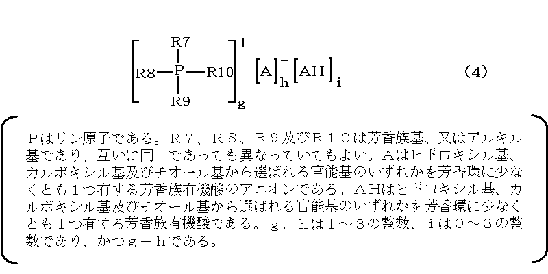
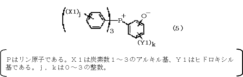
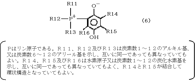
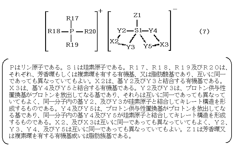
無機粒子101:87質量部、第一の層103:ビフェニル型エポキシ樹脂6.1質量部、フェノールノボラック樹脂4.0質量部、第二の層105:トリフェニルホスフィン0.15質量部。
他の樹脂として、たとえば硬化性樹脂を用いることができる。ここで硬化性樹脂としては、以下のような熱硬化性樹脂が挙げられる。たとえば、フェノール樹脂、シアネートエステル樹脂、ユリア(尿素)樹脂、メラミン樹脂、不飽和ポリエステル樹脂、ビスマレイミド樹脂、ポリウレタン樹脂、ジアリルフタレート樹脂、シリコーン樹脂、ベンゾオキサジン環を有する樹脂等が挙げられる。
機能性粒子100は、たとえば、無機粒子101の表面に第一の層103を形成する工程、および第一の層103の表面に第二の層105を形成する工程を順次行うことにより得られる。
また、混合時間は、原料に応じて設定されるが、たとえば30秒以上120分以下とし、期待する処理効果の観点からは1分以上、好ましくは3分以上とし、生産性の観点からは90分以下、好ましくは60分以下とする。
機能性粒子100においては、エポキシ樹脂、硬化剤および硬化促進剤のうち、いずれか一または二つの成分が第一の層103に含まれるとともに、残りの成分が第二の層105に含まれる。このため、一つ一つの機能性粒子100の配合組成を均質化することができる。また、粒子間で配合組成が均質化された機能性粒子100を高い歩留まりで安定的に得ることができる。このため、エポキシ樹脂(A)、硬化剤(B)および硬化促進剤(C)の各成分を無機粒子101上に安定的に保持させることができる。そして、保存中に成分同士が反応して組成変化することを抑制し、保存安定性を向上させることができる。
図1(b)は、本実施形態における機能性粒子の構成を示す断面図である。図1(b)に示した機能性粒子102の基本構成は、第一の実施形態に記載の機能性粒子100(図1(a))と同様であるが、第二の層105が複数の層を有する点が異なる。
以上の実施形態で用いられる機能性粒子において、第一の層103と第二の層105との間にこれらを離隔する介在層が設けられていてもよい。以下、第一の実施形態の機能性粒子100を例に説明する。
また、介在層107は、カーボンブラック等の顔料(着色剤)、ハイドロタルサイト等のイオントラップ剤などを主材としていてもよい。
また、介在層107は、たとえば難燃剤により構成される。難燃剤として、上記金属水酸化物の他、リン系、シリコーン系、有機金属塩系の物質を用いてもよい。
以上の実施形態で用いられる機能性粒子において、無機粒子101と第一の層103との間に、さらに第三の層を設けてもよい。以下、第三の実施形態の機能性粒子110を例に説明する。
タルク;およびクレーが挙げられる。
また、第三の層109は、たとえば難燃剤により構成される。難燃剤として、上記金属水酸化物の他、リン系、シリコーン系、有機金属塩系の物質を用いてもよい。
さらに、第三の層109には、第二の実施形態にて介在層107の材料として例示した材料を用いることができる。
無機粒子101:シリカ、第三の層109:金属水酸化物の組み合わせ、および
無機粒子101:アルミナ、第三の層109:シリコーンの組み合わせ。
無機粒子101:球状シリカ、第一の層103:エポキシ樹脂に対する硬化剤、第二の層105:エポキシ樹脂。この構成は、たとえば半導体封止材料等の電子部品用途に好適である。
無機粒子101:球状シリカ、第一の層103:エポキシ樹脂に対する硬化剤と硬化促進剤、第二の層105:エポキシ樹脂。この構成は、たとえば半導体封止材料等の電子部品用途に好適である。
無機粒子101:ガラス繊維、第一の層103:ヘキサメチレンテトラミン等のフェノール樹脂に対する硬化剤、第二の層105:ノボラック型フェノール樹脂等のフェノール樹脂。この構成は、たとえば車載用成形材料として好適である。
無機粒子101:結晶シリカおよび水酸化アルミニウム、第一の層103:エポキシ樹脂に対する硬化剤、第二の層105:エポキシ樹脂。この構成は、たとえば電子部品用絶縁材料に好適である。
本実施形態は、以上の実施形態に記載の機能性粒子からなる充填剤を含む樹脂組成物に関する。
本実施形態における樹脂組成物は、以上の実施形態に記載の機能性粒子と必要に応じて使用される半導体封止用樹脂組成物、車載用成形材料、電子部品用絶縁材料において公知の成分等を含む。そして、組成物中に以上の実施形態に記載の機能性粒子が充填剤として均一に分散したものである。組成物中に含まれる充填剤において、第一の層103および第二の層105の一部が組成変化していたり、消失していてもよい。
また半導体封止用樹脂組成物の場合には、70質量%以上96質量%以下が好ましく、85質量%以上92質量%以下が好ましい。含有量が上記範囲内であると、耐半田性の低下や流動性の低下をさらに効果的に抑制することができる。
たとえば、本実施形態の樹脂組成物は、圧縮成形用の顆粒であってもよい。また、本実施形態の樹脂組成物は、トランスファー成形用のタブレットであってもよい。
本実施形態の樹脂組成物は、以上の実施形態に記載の機能性粒子からなる充填剤および必要に応じその他の添加剤を、ミキサーを用いて常温混合して得ることができる。また、本発明の効果を低下させない範囲でロール、ニーダー等の押出機等の混練機で溶融混練し、冷却後粉砕してもよい。
封止材硬化物5は、上述した本実施形態の電子部品用樹脂組成物を硬化させたものである。
図4は、本実施形態における被覆粒子の構成を示す断面図である。図4に示した被覆粒子130は、無機材料により構成された基材粒子である無機粒子111、無機粒子111を被覆する第一の層113からなる。第一の層113は電子部品用樹脂組成物を構成する各種原料で構成することができ、最小限必要な構成要素としては、第一の層113が樹脂である第一の被覆粒子と、第一の層が当該樹脂の硬化剤である第二の被覆粒子とであり、これらにより機能性粒子群が構成される。なお、第一の層113が複数の成分を含んでいてもよい。
また、機械的強度の観点からは、無機粒子111をガラス繊維等の繊維材料により構成された繊維状粒子とすることが好ましい。また、無機粒子111は、ガラス不織布等の不織布を粒子状に加工して得られる粒子であってもよい。
樹脂および硬化剤は、それぞれ、樹脂層115および硬化剤層117を構成する。樹脂および硬化剤の材料として、それぞれ、たとえば、第一の実施形態で例示した材料が挙げられる。
エポキシ樹脂として、たとえば、ビフェニル型エポキシ樹脂、ビスフェノールA型エポキシ樹脂、ビスフェノールF型エポキシ樹脂、スチルベン型エポキシ樹脂、ハイドロキノン型エポキシ樹脂等の2官能性または結晶性エポキシ樹脂;
クレゾールノボラック型エポキシ樹脂、フェノールノボラック型エポキシ樹脂、ナフトールノボラック型エポキシ樹脂等のノボラック型エポキシ樹脂;
フェニレン骨格含有フェノールアラルキル型エポキシ樹脂、ビフェニレン骨格含有フェノールアラルキル型エポキシ樹脂、フェニレン骨格含有ナフトールアラルキル型エポキシ樹脂等のフェノールアラルキル型エポキシ樹脂;
トリフェノールメタン型エポキシ樹脂およびアルキル変性トリフェノールメタン型エポキシ樹脂等の3官能型エポキシ樹脂;
ジシクロペンタジエン変性フェノール型エポキシ樹脂、テルペン変性フェノール型エポキシ樹脂等の変性フェノール型エポキシ樹脂;
トリアジン核含有エポキシ樹脂等の複素環含有エポキシ樹脂等が挙げられる。これらは1種類を単独で用いても2種類以上を組み合わせて用いてもよい。
ビフェニル型エポキシ樹脂;
フェニレン骨格含有フェノールアラルキル型エポキシ樹脂、ビフェニレン骨格含有フェノールアラルキル(すなわちビフェニルアラルキル)型エポキシ樹脂、フェニレン骨格含有ナフトールアラルキル型エポキシ樹脂等のフェノールアラルキル型エポキシ樹脂;
トリフェノールメタン型エポキシ樹脂およびアルキル変性トリフェノールメタン型エポキシ樹脂等の3官能型エポキシ樹脂;
ジシクロペンタジエン変性フェノール型エポキシ樹脂、テルペン変性フェノール型エポキシ樹脂等の変性フェノール型エポキシ樹脂;
トリアジン核含有エポキシ樹脂等の複素環含有エポキシ樹脂、アリールアルキレン型エポキシ樹脂が好適に用いられる。
たとえば、第一の被覆粒子中の第一の層(樹脂層115)がエポキシ樹脂を含む場合、これに対する硬化剤としては、エポキシ樹脂と反応して硬化させるものであればよく、当業者に公知のものが使用でき、たとえば、ジエチレントリアミン(DETA)、トリエチレンテトラミン(TETA)、メタキシレンジアミン(MXDA)などの脂肪族ポリアミン、ジアミノジフェニルメタン(DDM)、m-フェニレンジアミン(MPDA)、ジアミノジフェニルスルホン(DDS)などの芳香族ポリアミンのほか、ジシアンジアミド(DICY)、有機酸ジヒドラジドなどを含むポリアミン化合物;
ヘキサヒドロ無水フタル酸(HHPA)、メチルテトラヒドロ無水フタル酸(MTHPA)などの脂環族酸無水物、無水トリメリット酸(TMA)、無水ピロメリット酸(PMDA)、ベンゾフェノンテトラカルボン酸(BTDA)などの芳香族酸無水物などを含む酸無水物;
ノボラック型フェノール樹脂、フェニレン骨格含有フェノールアラルキル樹脂、ビフェニレン骨格含有フェノールアラルキル(すなわちビフェニルアラルキル)樹脂、フェニレン骨格含有ナフトールアラルキル樹脂等のフェノールアラルキル型エポキシ樹脂などのポリフェノール化合物およびビスフェノールAなどのビスフェノール化合物;
ポリサルファイド、チオエステル、チオエーテルなどのポリメルカプタン化合物;
イソシアネートプレポリマー、ブロック化イソシアネートなどのイソシアネート化合物;
カルボン酸含有ポリエステル樹脂などの有機酸類;
ベンジルジメチルアミン(BDMA)、2,4,6-トリジメチルアミノメチルフェノール(DMP-30)などの3級アミン化合物;
2-メチルイミダゾール、2-エチル-4-メチルイミダゾール(EMI24)などのイミダゾール化合物;およびBF3錯体などのルイス酸;
ノボラック型フェノール樹脂、レゾール型フェノール樹脂などのフェノール樹脂;
メチロール基含有尿素樹脂のような尿素樹脂;および
メチロール基含有メラミン樹脂のようなメラミン樹脂などが挙げられる。
これらの硬化剤の中でも特にフェノール系樹脂を用いることが好ましい。本実施形態で用いられるフェノール系樹脂は、1分子内にフェノール性水酸基を2個以上有するモノマー、オリゴマー、ポリマー全般であり、その分子量、分子構造を特に限定するものではないが、たとえばフェノールノボラック樹脂、クレゾールノボラック樹脂、ジシクロペンタジエン変性フェノール樹脂、テルペン変性フェノール樹脂、トリフェノールメタン型樹脂、フェノールアラルキル樹脂(フェニレン骨格、ビフェニレン骨格等を有する)等が挙げられ、これらは1種類を単独で用いても2種以上を併用しても差し支えない。
混合時間は、原料に応じて設定されるが、たとえば30秒以上120分以下とし、期待する処理効果の観点からは1分以上、好ましくは3分以上とし、生産性の観点からは90分以下、好ましくは60分以下とする。
本実施形態の被覆粒子130(図5では機能性粒子群140)は、無機粒子111を樹脂で被覆した第一の粒子131と、無機粒子111を上記樹脂の硬化剤で被覆した第二の粒子133とから各々構成される。このため、基材粒子上に樹脂または硬化剤および硬化促進剤を、それぞれ、所定の配合で安定的に保持することができる。また、第一の粒子131および第二の粒子133について、一つ一つの粒子配合組成を均質化することができる。また、機能性粒子群140は、第一の粒子131と第二の粒子133とから構成されるため、混合操作中などに粒子の大小や比重の違いによって生じる各々の被覆粒子の偏析を起こり難くすることができる。
図4および5に示した粒子およびそれを用いた機能性粒子群において、第一の層113が樹脂である第一の被覆粒子と、第一の層113が前記樹脂の硬化剤である第二の被覆粒子の他に、第一の層113が前記樹脂および硬化剤以外の第三の成分である第三の被覆粒子を含んでもよい。第一の被覆粒子と第二の被覆粒子の他に第三の被覆粒子が介在することにより、第一の被覆粒子と第二の被覆粒子の接触度合いを変えることができ、さらに前記第三の成分を適宜選択することにより、樹脂と硬化剤との反応をさらに抑制または促進することができる。このため、樹脂と硬化剤とが反応することによる組成の変化をさらに確実に抑制し、より一層保存安定性に優れた構成とすることができる。
また第三の被覆粒子の第一の層113がエポキシシランカップリング剤、アミノシランカップリング剤等のカップリング剤を主材とすることにより、第一の粒子131と第二の粒子121の間で効率的に作用し、硬化反応の促進や成形時低粘度化に寄与できる。また、優れた補強効果を奏することができる。
また、第三の被覆粒子の第一の層113は、カーボンブラック等の顔料(着色剤)、ハイドロタルサイト等のイオントラップ剤などを主材としていてもよい。
また、第三の被覆粒子の第一の層113は、たとえば難燃剤により構成される。難燃剤として、上記金属水酸化物の他、リン系、シリコーン系、有機金属塩系の物質を用いてもよい。
また、第三の被覆粒子の第一の層113は、液状原料を含む成分を被覆することにより形成されてもよい。
無機粒子111:球状シリカ、第一の被覆粒子の第一の層113:エポキシ樹脂に対する硬化剤、第二の被覆粒子の第一の層113:エポキシ樹脂。この構成は、たとえば半導体封止材料等の電子部品用途に好適である。
無機粒子111:ガラス繊維、第一の被覆粒子の第一の層113:ヘキサメチレンテトラミン等のフェノール樹脂に対する硬化剤、第二の被覆粒子の第一の層113:ノボラック型フェノール樹脂等のフェノール樹脂。この構成は、たとえば車載用成形材料として好適である。
無機粒子111:結晶シリカおよび水酸化アルミニウム、第一の被覆粒子の第一の層113:エポキシ樹脂に対する硬化剤、第二の被覆粒子の第一の層113:エポキシ樹脂。この構成は、たとえば電子部品用絶縁材料に好適である。
本実施形態は、以上の実施形態に記載の機能性粒子群からなる充填剤を含む樹脂組成物に関する。
樹脂組成物は、この樹脂組成物は、以上の実施形態に記載の機能性粒子群と必要に応じて使用される半導体封止用樹脂組成物において公知の成分等を含む組成物であり、組成物中に以上の実施形態に記載の機能性粒子群が分散したものである。組成物中に含まれる充填剤において、第一の層113の一部が組成変化していたり、消失していてもよい。
たとえば本実施形態の樹脂組成物は、圧縮成形用の顆粒であってもよい。以上の実施形態に記載の機能性粒子群による顆粒とすることにより、粒子同士の凝集が抑制されるため粉体流動性が向上するとともに付着しにくくなるため、搬送路での付着を生じることがなく搬送に支障をきたす恐れが低くなり、成形金型への本実施形態の樹脂組成物搬送時の滞留などのトラブルを確実に抑制することができる。また、成形時の充填性を向上することができる。よって、圧縮成形により成形体を得る際の歩留まりを向上することができる。
また、本実施形態の樹脂組成物は、トランスファー成形用のタブレットであってもよい。
本実施形態の樹脂組成物は、以上の実施形態に記載の機能性粒子群からなる充填剤および必要に応じその他の添加剤を、ミキサーを用いて常温混合して得ることができる。また、本発明の効果を低下させない範囲でロール、ニーダー等の押出機等の混練機で溶融混練し、冷却後粉砕してもよい。
封止材硬化物5は、上述した本実施形態の電子部品用樹脂組成物を硬化させたものである。
[1]無機材料により構成された基材粒子を樹脂で被覆した第一の被覆粒子及び前記基材粒子を前記樹脂の硬化剤で被覆した第二の被覆粒子を含んでなることを特徴とする機能性粒子群。
[2]前記無機材料がシリカである[1]に記載の機能性粒子群。
[3]機能性粒子群が、前記基材粒子を樹脂、樹脂の硬化剤以外の第三の成分で被覆した第三の被覆粒子を含んでなる[1]または[2]に記載の機能性粒子群。
[4]前記第三の成分が前記樹脂の硬化触媒を含むものである[3]に記載の機能性粒子群。
[5]前記第三の成分が、難燃剤を含むものである[1]~[4]いずれか1項に記載の機能性粒子群。
[6]前記第三の成分が、シリカ、アルミナおよびカーボンブラックからなる群から選択される1種以上の無機材料を含むものである[1]~[5]いずれか1項に記載の機能性粒子群。
[7]前記第三の成分が、ワックス状物質を含むものである[1]~[6]いずれか1項に記載の機能性粒子群。
[8]前記第三の成分が、液状原料を含むものである[1]~[7]いずれか1項に記載の機能性粒子群。
[9][1]乃至[7]いずれか1項に記載の機能性粒子群からなる、充填剤。
[10][9]に記載の充填剤を含む、電子部品用樹脂組成物。
[11][10]に記載の電子部品用樹脂組成物を成形させてなる、電子部品。
[12][10]に記載の電子部品用樹脂組成物を用いて半導体素子を封止してなる、半導体装置。
以下の実施例では、基材粒子上に複数の層を有する機能性粒子を製造した。各層の成分の配合(質量比)を表1に示す。機械的粒子複合化装置として、徳寿工作所社製シータコンポーザを用いた。

被覆層の原料は、いずれも、予めジェットミルで粉砕した。ジェットミルとして、セイシン企業社製シングルトラックジェットミルを用いた。粉砕条件は高圧ガス圧力0.6MPaとした。
溶融球状シリカ(平均粒子径29μmおよび0.1μm)を表1に記載の配合でブレンドし、無機充填剤を得た。得られた無機充填材88部およびカップリング剤0.3部を機械的粒子複合化装置に投入し、攪拌翼の周速10m/sで15分間攪拌することにより、被覆処理をおこなった。
溶融球状シリカ(平均粒子径29μmおよび0.1μm)を表1に記載の配合でブレンドし、無機充填剤を得た。得られた無機充填材88部およびカップリング剤0.3部を実施例1と同様の機械式粒子複合化装置に投入し、攪拌翼の周速10m/sで15分間攪拌することにより、被覆処理をおこなった。
表1に記載の原料をすべてヘンシェルミキサーに投入して粉砕混合し、本例の半導体封止用樹脂組成物を得た。混合条件は、1000rpmで10分間とした。
表1に記載の原料をミキサー(容器回転V型ブレンダー)にて常温混合した。混合条件は、30rpmで10分間とした。得られた混合物を80~100℃の加熱ロールで5分間溶融混練し、冷却後粉砕することにより、本例の半導体封止用樹脂組成物を得た。
スパイラルフロー:低圧トランスファー成形機(コータキ精機社製、KTS-15)を用いて、EMMI-1-66に準じたスパイラルフロー測定用金型に、金型温度175℃、注入圧力6.9MPa、保圧時間120秒の条件で半導体封止用樹脂組成物を注入し、流動長を測定した。単位をcmとした。
タブレット成形性:各例で得られた半導体封止用樹脂組成物からなる試料をタブレットに打錠成型した。下記に示す不具合を生じた場合を×、不具合を生じずに、良好にタブレットが得られたものを○、とした。
タブレット成型工程で、金型内面に樹脂が付着して、タブレットの外観に欠損が生じた場合
灰分均一性:各例で得られた半導体封止用樹脂組成物からなる試料をミキサー(容器回転V型ブレンダー)にて常温混合した。混合条件は、30rpmで10分間とした。得られた混合物の5箇所からサンプリングし、700℃で焼成した後の残渣の質量比を測定した。単位を%とした。得られた測定結果の最大値から最小値を引いた値を算出した。この数値が小さいほど、成分均一性が良いことを示す。
40℃/7日後 保存性(スパイラルフロー残存率):40℃に温度調節した乾燥機中に各例で得られた半導体封止用樹脂組成物からなる試料を7日間保存した後、スパイラルフローを測定し、保存前後のスパイラルフロー測定結果から残存率(保存後の測定値/保存前の測定値)を求めた。この数値が大きいほど、スパイラルフローの低下が少なく、保存性が良いことを示す。
本実施例では、被覆層の材料が異なる複数種の粒子を含む機能性粒子群を製造した。機械式粒子複合化装置として、徳寿工作所社製シータコンポーザを用いた。また、ミキサーとしては容器回転V型ブレンダーを用いた。
表2に、各粒子における原料の配合(質量比)を示す。
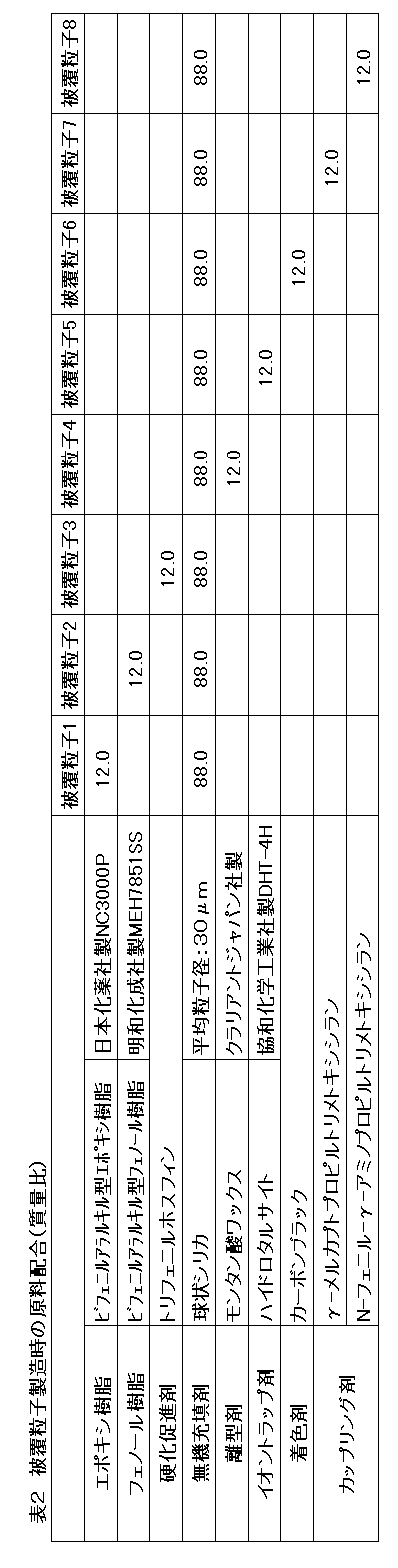
本実施例では、被覆層の構成材料が異なる8種類の被覆粒子を含む機能性粒子群を製造した。
各被覆層となる原料は予めジェットミルで粉砕した。ジェットミルとして、セイシン企業社製シングルトラックジェットミルを用いた。粉砕条件は高圧ガス圧力0.6MPaとした。
無機充填材88質量部とエポキシ樹脂12質量部とを機械式粒子複合化装置に投入して被覆処理をおこない、被覆粒子1を得た。
また、無機充填材88質量部とフェノール樹脂12質量部とを機械式粒子複合化装置に投入して被覆処理をおこない、被覆粒子2を得た。
被覆粒子3~8についても、それぞれ、原料を表2に記載の配合で機械式粒子複合化装置に投入して被覆処理することにより製造した。
攪拌処理条件は、いずれの粒子についても、攪拌翼の周速10m/sで60分間攪拌処理とした。
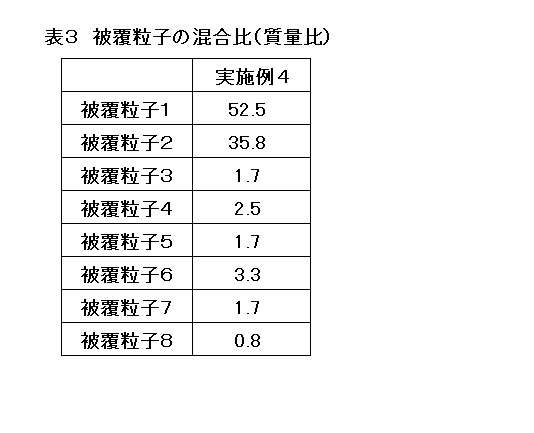
また、実施例4で得られた機能性粒子群について、ゲルタイム(秒)、スパイラルフロー(cm)、タブレット成形性、灰分均一性(%)および40℃/7日後 保存性(スパイラルフロー残存率)(%)の測定結果を表4に示す。
また、各実施例において、レーザー回折式粒度分布測定装置を用いて測定される累積頻度が10%となる粒子径d10については、実施例1は9.0μm、実施例2は8.8μm、実施例3は9.0μm、実施例4は9.1であった。
Claims (26)
- 無機材料により構成された基材粒子と、前記基材粒子を被覆する第一の層と、前記第一の層を被覆する第二の層と、を有する機能性粒子を含み、
エポキシ樹脂、前記エポキシ樹脂の硬化剤および硬化促進剤のうち、いずれか一または二つの成分が前記第一の層に含まれるとともに、他の成分が前記第二の層に含まれる、機能性粒子。 - 請求項1に記載の機能性粒子において、
前記第一の層が、前記エポキシ樹脂、前記硬化剤および前記硬化促進剤のうち、いずれか一つの成分を含み、
前記第二の層が、前記エポキシ樹脂、前記硬化剤および前記硬化促進剤のうち、前記第一の層に含まれる成分以外の一方の成分を含む層と、前記第一の層に含まれる成分以外の他方の成分を含む層と、を備える、機能性粒子。 - 請求項1に記載の機能性粒子において、
前記第一および第二の層のうち、一方が前記硬化剤および前記硬化促進剤を含み、他方が前記エポキシ樹脂を含む、機能性粒子。 - 請求項1に記載の機能性粒子において、
前記第一および第二の層のうち、一方が前記エポキシ樹脂および前記硬化剤を含み、他方が前記硬化促進剤を含む、機能性粒子。 - 請求項1乃至4いずれか1項に記載の機能性粒子において、当該機能性粒子の前記第一および第二の層の間に、これらを離隔する介在層が設けられた、機能性粒子。
- 請求項5に記載の機能性粒子において、前記介在層が、金属水酸化物、カップリング剤、離型剤、イオントラップ剤、着色剤および難燃剤からなる群から選択される一種以上を含む、機能性粒子。
- 請求項5または6に記載の機能性粒子において、前記介在層が、シリカ、アルミナおよび窒化ケイ素からなる群から選択される一または二以上の無機材料を含む、機能性粒子。
- 請求項5乃至7いずれか1項に記載の機能性粒子において、前記介在層が、ワックス状物質を主材とする、機能性粒子。
- 請求項1乃至8いずれか1項に記載の機能性粒子において、前記基材粒子と前記第一の層との間に、前記基材粒子に接して設けられた第三の層を有する、機能性粒子。
- 請求項9に記載の機能性粒子において、前記第三の層が、金属水酸化物、カップリング剤、離型剤、イオントラップ剤、着色剤および難燃剤からなる群から選択される一種以上を含む、機能性粒子。
- 請求項1乃至10いずれか1項に記載の機能性粒子において、前記基材粒子の材料が、シリカ、アルミナおよび窒化ケイ素からなる群から選択される一または二以上の無機材料である、機能性粒子。
- 請求項1乃至11いずれか1項に記載の機能性粒子からなる、充填剤。
- 無機材料により構成された基材粒子を樹脂で被覆した第一の被覆粒子と、
前記基材粒子を前記樹脂の硬化剤で被覆した第二の被覆粒子と、
を含んでなる、機能性粒子群。 - 請求項13に記載の機能性粒子群において、前記無機材料がシリカである、機能性粒子群。
- 請求項13または14に記載の機能性粒子群において、前記基材粒子を前記樹脂、前記樹脂の硬化剤以外の第三の成分で被覆した第三の被覆粒子をさらに含んでなる、機能性粒子群。
- 請求項15に記載の機能性粒子群において、前記第三の成分が前記樹脂の硬化触媒を含むものである、機能性粒子群。
- 請求項15または16に記載の機能性粒子群において、前記第三の成分が、難燃剤を含むものである、機能性粒子群。
- 請求項15乃至17いずれか1項に記載の機能性粒子群において、前記第三の成分が、シリカ、アルミナおよび窒化ケイ素からなる群から選択される1種以上の無機材料を含むものである、機能性粒子群。
- 請求項15乃至18いずれか1項に記載の機能性粒子群において、前記第三の成分が、ワックス状物質を含むものである、機能性粒子群。
- 請求項15乃至19いずれか1項に記載の機能性粒子群において、前記第三の成分が、液状原料を含むものである、機能性粒子群。
- 請求項13乃至20いずれか1項に記載の機能性粒子群からなる、充填剤。
- 請求項12または21に記載の充填剤において、
当該充填剤が顆粒状であり、JIS標準篩を用いて篩分により測定した粒度分布における、当該充填剤全体に対する1μm未満の微粉の割合が5質量%以下である、充填剤。 - 請求項12、21または22いずれか1項に記載の充填剤において、
当該充填剤が顆粒状であり、レーザー回折式粒度分布測定装置を用いて測定される累積頻度が10%となる粒子径d10が3μm以上である、充填剤。 - 請求項12、21乃至23いずれか1項に記載の充填剤を含む、電子部品用樹脂組成物。
- 請求項24に記載の電子部品用樹脂組成物を成形させてなる、電子部品。
- 請求項24に記載の電子部品用樹脂組成物を用いて半導体素子を封止してなる、半導体装置。
Priority Applications (5)
| Application Number | Priority Date | Filing Date | Title |
|---|---|---|---|
| SG2013008586A SG187259A1 (en) | 2010-08-05 | 2011-03-02 | Functional particle, functional particle group, filler, resin composition for electronic component, electronic component and semiconductor device |
| KR1020137005539A KR20130096259A (ko) | 2010-08-05 | 2011-03-02 | 기능성 입자, 기능성 입자군, 충전제, 전자 부품용 수지 조성물, 전자 부품 및 반도체 장치 |
| CN201180038684.9A CN103052687B (zh) | 2010-08-05 | 2011-03-02 | 功能性颗粒、功能性颗粒群、填充剂、电子部件用树脂组合物、电子部件和半导体装置 |
| US13/814,163 US20130134608A1 (en) | 2010-08-05 | 2011-03-02 | Functional particle, functional particle group, filler, resin composition for electronic component, electronic component and semiconductor device |
| JP2012527532A JPWO2012017571A1 (ja) | 2010-08-05 | 2011-03-02 | 機能性粒子、機能性粒子群、充填剤、電子部品用樹脂組成物、電子部品および半導体装置 |
Applications Claiming Priority (2)
| Application Number | Priority Date | Filing Date | Title |
|---|---|---|---|
| JP2010176054 | 2010-08-05 | ||
| JP2010-176054 | 2010-08-05 |
Publications (1)
| Publication Number | Publication Date |
|---|---|
| WO2012017571A1 true WO2012017571A1 (ja) | 2012-02-09 |
Family
ID=45559097
Family Applications (1)
| Application Number | Title | Priority Date | Filing Date |
|---|---|---|---|
| PCT/JP2011/001215 Ceased WO2012017571A1 (ja) | 2010-08-05 | 2011-03-02 | 機能性粒子、機能性粒子群、充填剤、電子部品用樹脂組成物、電子部品および半導体装置 |
Country Status (7)
| Country | Link |
|---|---|
| US (1) | US20130134608A1 (ja) |
| JP (5) | JP5799529B2 (ja) |
| KR (1) | KR20130096259A (ja) |
| CN (1) | CN103052687B (ja) |
| SG (2) | SG10201506094PA (ja) |
| TW (1) | TWI504653B (ja) |
| WO (1) | WO2012017571A1 (ja) |
Cited By (4)
| Publication number | Priority date | Publication date | Assignee | Title |
|---|---|---|---|---|
| CN104136480A (zh) * | 2012-03-16 | 2014-11-05 | 住友电木株式会社 | 封装用树脂组合物和使用该封装用树脂组合物的电子装置 |
| EP2824146A4 (en) * | 2012-03-07 | 2015-10-28 | Sumitomo Bakelite Co | METHOD FOR PRODUCING A RESIN FORMING METHOD, METHOD FOR PRODUCING A RESIN COMPOSITION, RESIN COMPOUNDS, RESIN COMPOSITION, RESIN POWDER WITH LOW DUST EMISSION AND METHOD FOR OBTAINING A RESIN WITH A SMOOTH DUST EMISSION |
| WO2017138268A1 (ja) * | 2016-02-12 | 2017-08-17 | 株式会社ダイセル | 半導体封止用硬化性樹脂組成物、その硬化物、及び半導体装置 |
| JP2018083860A (ja) * | 2016-11-21 | 2018-05-31 | 日本ゼオン株式会社 | 複合粒子を含む粉体組成物およびその製造方法 |
Families Citing this family (21)
| Publication number | Priority date | Publication date | Assignee | Title |
|---|---|---|---|---|
| JP2978133B2 (ja) | 1997-05-21 | 1999-11-15 | 松岡コンクリート工業株式会社 | 型枠の駆動装置 |
| JP5799529B2 (ja) * | 2010-08-05 | 2015-10-28 | 住友ベークライト株式会社 | 機能性粒子、機能性粒子群、充填剤、電子部品用樹脂組成物、電子部品および半導体装置 |
| JP5697048B2 (ja) * | 2012-06-15 | 2015-04-08 | 古河電気工業株式会社 | 有機エレクトロルミネッセンス素子封止用樹脂組成物、有機エレクトロルミネッセンス素子用封止フィルム、有機エレクトロルミネッセンス素子用ガスバリアフィルムおよびこれを用いた有機エレクトロルミネッセンス素子 |
| JP2014197503A (ja) * | 2013-03-29 | 2014-10-16 | 住友ベークライト株式会社 | 複合粒子、半導体封止材料およびリチウムイオン二次電池用電極材料 |
| JP2014196541A (ja) * | 2013-03-29 | 2014-10-16 | 住友ベークライト株式会社 | 複合粒子および半導体封止材料 |
| JP2014195780A (ja) * | 2013-03-29 | 2014-10-16 | 住友ベークライト株式会社 | 複合粒子、半導体封止材料および二次電池用電極材料 |
| JP7154732B2 (ja) * | 2016-03-31 | 2022-10-18 | 味の素株式会社 | 樹脂組成物 |
| CN108246327B (zh) * | 2016-12-28 | 2020-11-10 | 南开大学 | 一种用于固定床乙炔氢氯化反应的氮掺杂碳材料催化剂的制备方法及其使用方法 |
| CN106752750A (zh) * | 2016-12-30 | 2017-05-31 | 安徽真信涂料有限公司 | 一种液压油缸缸体内壁专用粉末涂料 |
| WO2019106812A1 (ja) * | 2017-11-30 | 2019-06-06 | 日立化成株式会社 | コンパウンド粉 |
| CN108359134A (zh) * | 2018-01-17 | 2018-08-03 | 安徽固瑞特新材料科技有限公司 | 一种多组分成膜剂包覆改性促进剂的制备方法 |
| CN108329521A (zh) * | 2018-01-17 | 2018-07-27 | 安徽固瑞特新材料科技有限公司 | 一种多组分包覆改性氧化锌的制备方法 |
| CN108276609A (zh) * | 2018-01-17 | 2018-07-13 | 安徽固瑞特新材料科技有限公司 | 一种双组分成膜剂包覆改性硫磺的制备方法 |
| CN108456330A (zh) * | 2018-01-17 | 2018-08-28 | 安徽固瑞特新材料科技有限公司 | 一种提高橡胶制品加工安全性能的橡胶助剂的制备方法 |
| CN108359147A (zh) * | 2018-01-17 | 2018-08-03 | 安徽固瑞特新材料科技有限公司 | 一种提高橡胶制品加工安全性能的促进剂的制备方法 |
| WO2019186987A1 (ja) * | 2018-03-30 | 2019-10-03 | 互応化学工業株式会社 | 複合粒子 |
| JP2019196462A (ja) * | 2018-05-11 | 2019-11-14 | 住友ベークライト株式会社 | 封止用エポキシ樹脂組成物の構成成分として用いられる粒子の製造方法、封止用エポキシ樹脂組成物の構成成分として用いられるコアシェル粒子、および、封止用エポキシ樹脂組成物 |
| JP2020169314A (ja) * | 2019-04-01 | 2020-10-15 | 住友ベークライト株式会社 | エポキシ樹脂粉体塗料 |
| CN111116991B (zh) * | 2020-02-11 | 2022-03-18 | 江苏艾特克阻燃材料有限公司 | 一种复合氢氧化物抑烟型阻燃剂及其制备方法与应用 |
| JP7501105B2 (ja) * | 2020-05-22 | 2024-06-18 | 住友ベークライト株式会社 | 樹脂被覆無機粒子、熱硬化性樹脂組成物、半導体装置、樹脂被覆無機粒子の製造方法 |
| CN112724867B (zh) * | 2020-12-10 | 2023-01-10 | 深圳先进技术研究院 | 一种绝缘胶膜材料及其制备方法和应用 |
Citations (14)
| Publication number | Priority date | Publication date | Assignee | Title |
|---|---|---|---|---|
| JPS59204614A (ja) * | 1983-05-07 | 1984-11-20 | Hitachi Chem Co Ltd | 電子部品封止用成形材料 |
| JPS6377923A (ja) * | 1986-09-19 | 1988-04-08 | Fujitsu Ltd | 半導体封止用エポキシ樹脂組成物 |
| JPH02175750A (ja) * | 1988-12-28 | 1990-07-09 | Nippon Steel Chem Co Ltd | エポキシ樹脂組成物の製造方法 |
| JPH03211A (ja) * | 1989-05-26 | 1991-01-07 | Matsushita Electric Works Ltd | 半導体封止用エポキシ樹脂成形材料の製造方法 |
| JPH03122114A (ja) * | 1989-10-06 | 1991-05-24 | Somar Corp | 硬化剤組成物、その製造方法及び熱硬化性エポキシ樹脂組成物 |
| JPH03195764A (ja) * | 1989-12-25 | 1991-08-27 | Matsushita Electric Works Ltd | エポキシ樹脂封止材の製造方法 |
| JPH06329765A (ja) * | 1993-05-19 | 1994-11-29 | Toshiba Chem Corp | エポキシ樹脂組成物の製造方法と半導体封止装置 |
| JPH0827361A (ja) * | 1994-07-11 | 1996-01-30 | Shin Etsu Chem Co Ltd | エポキシ樹脂組成物の製造方法及びエポキシ樹脂組成物 |
| JPH1027871A (ja) * | 1996-07-11 | 1998-01-27 | Hitachi Chem Co Ltd | 半導体封止用エポキシ樹脂成形材料の製造方法 |
| JP2000248158A (ja) * | 1999-03-04 | 2000-09-12 | Shin Etsu Chem Co Ltd | 半導体封止用エポキシ樹脂組成物の製造方法 |
| JP2002220475A (ja) * | 2001-01-25 | 2002-08-09 | Sumitomo Bakelite Co Ltd | エポキシ樹脂成形材料の製造方法及び半導体装置 |
| JP2002327044A (ja) * | 2001-05-02 | 2002-11-15 | Sumitomo Bakelite Co Ltd | 半導体封止用エポキシ樹脂組成物の製造方法、半導体封止用エポキシ樹脂組成物及び半導体装置 |
| JP2003105067A (ja) * | 2001-10-01 | 2003-04-09 | Mitsui Chemicals Inc | エポキシ樹脂組成物及びその製造方法 |
| JP2007067164A (ja) * | 2005-08-31 | 2007-03-15 | Sumitomo Bakelite Co Ltd | 半導体封止用エポキシ樹脂組成物及びその製造方法 |
Family Cites Families (24)
| Publication number | Priority date | Publication date | Assignee | Title |
|---|---|---|---|---|
| JPS5744620A (en) * | 1980-08-29 | 1982-03-13 | Nitto Electric Ind Co Ltd | Epoxy resin composition |
| JPH01129035A (ja) * | 1987-11-12 | 1989-05-22 | Nitto Denko Corp | 粉末状エポキシ樹脂組成物の製造方法 |
| JP2566858B2 (ja) * | 1991-10-03 | 1996-12-25 | ソマール株式会社 | 無機質土木建築構造材料の製造方法及びそれに用いる成形材料 |
| JPH06206983A (ja) * | 1993-01-11 | 1994-07-26 | Matsushita Electric Ind Co Ltd | 電子機器用エポキシ樹脂組成物 |
| JP2000198880A (ja) * | 1998-10-27 | 2000-07-18 | Sekisui Chem Co Ltd | 微粒子の被覆方法、被覆微粒子、異方性導電接着剤及び導電接続構造体 |
| JP2001342325A (ja) * | 2000-05-31 | 2001-12-14 | Sumitomo Bakelite Co Ltd | 光半導体封止用エポキシ樹脂組成物及び光半導体装置 |
| JP2004285167A (ja) * | 2003-03-20 | 2004-10-14 | Sumitomo Bakelite Co Ltd | 複合粒子、プリプレグ及び積層板の製造方法 |
| RU2344040C2 (ru) * | 2003-04-15 | 2009-01-20 | Хексион Спешелти Кемикалс, Инк. | Частицы материала, содержащие термопластичный эластомер, и способы их получения и использование |
| JP2006022316A (ja) * | 2004-06-10 | 2006-01-26 | Tokuyama Corp | エポキシ樹脂組成物用充填剤 |
| US8227026B2 (en) * | 2004-09-20 | 2012-07-24 | Momentive Specialty Chemicals Inc. | Particles for use as proppants or in gravel packs, methods for making and using the same |
| DE102004058305B3 (de) * | 2004-12-02 | 2006-05-18 | Infineon Technologies Ag | Halbleiterbauteil mit einem eine Passivierungsschicht aufweisenden Halbleiterchip sowie Verfahren zur Herstellung desselben |
| US7781514B2 (en) * | 2005-07-11 | 2010-08-24 | Illinois Tool Works Inc. | Microspheres as thickening agents for organic peroxides |
| US7332807B2 (en) * | 2005-12-30 | 2008-02-19 | Intel Corporation | Chip package thermal interface materials with dielectric obstructions for body-biasing, methods of using same, and systems containing same |
| JP2007204669A (ja) * | 2006-02-03 | 2007-08-16 | Asahi Kasei Chemicals Corp | 特定小粒径粒度分布エポキシ樹脂用硬化剤およびエポキシ樹脂組成物 |
| US7952212B2 (en) * | 2006-06-30 | 2011-05-31 | Intel Corporation | Applications of smart polymer composites to integrated circuit packaging |
| KR101386373B1 (ko) * | 2006-10-06 | 2014-04-16 | 스미토모 베이클리트 컴퍼니 리미티드 | 수지 조성물, 기재부착 절연 시트, 프리프레그, 다층 프린트 배선판 및 반도체 장치 |
| JP5134824B2 (ja) * | 2007-02-05 | 2013-01-30 | 日東電工株式会社 | 樹脂成形品製造方法 |
| US9096790B2 (en) * | 2007-03-22 | 2015-08-04 | Hexion Inc. | Low temperature coated particles comprising a curable liquid and a reactive powder for use as proppants or in gravel packs, methods for making and using the same |
| JP5010990B2 (ja) * | 2007-06-06 | 2012-08-29 | ソニーケミカル&インフォメーションデバイス株式会社 | 接続方法 |
| JP5526653B2 (ja) * | 2009-08-20 | 2014-06-18 | 住友ベークライト株式会社 | 機能性粒子、充填剤、電子部品用樹脂組成物、電子部品および半導体装置 |
| JP2011252041A (ja) * | 2010-05-31 | 2011-12-15 | Kyocera Chemical Corp | 半導体封止用エポキシ樹脂成形材料の製造方法及び樹脂封止型半導体装置 |
| JP5601034B2 (ja) * | 2010-06-02 | 2014-10-08 | 住友ベークライト株式会社 | 樹脂成形体及びその製造方法、ならびに、電子部品装置 |
| JP5799529B2 (ja) * | 2010-08-05 | 2015-10-28 | 住友ベークライト株式会社 | 機能性粒子、機能性粒子群、充填剤、電子部品用樹脂組成物、電子部品および半導体装置 |
| JP5323284B1 (ja) * | 2012-03-26 | 2013-10-23 | 積水化学工業株式会社 | 導電材料及び接続構造体 |
-
2011
- 2011-03-02 JP JP2011045732A patent/JP5799529B2/ja not_active Expired - Fee Related
- 2011-03-02 KR KR1020137005539A patent/KR20130096259A/ko not_active Ceased
- 2011-03-02 WO PCT/JP2011/001215 patent/WO2012017571A1/ja not_active Ceased
- 2011-03-02 JP JP2012527532A patent/JPWO2012017571A1/ja active Pending
- 2011-03-02 JP JP2011045734A patent/JP5948725B2/ja active Active
- 2011-03-02 CN CN201180038684.9A patent/CN103052687B/zh not_active Expired - Fee Related
- 2011-03-02 SG SG10201506094PA patent/SG10201506094PA/en unknown
- 2011-03-02 JP JP2011045730A patent/JP5626026B2/ja not_active Expired - Fee Related
- 2011-03-02 JP JP2011045731A patent/JP2012052088A/ja active Pending
- 2011-03-02 US US13/814,163 patent/US20130134608A1/en not_active Abandoned
- 2011-03-02 TW TW100106862A patent/TWI504653B/zh not_active IP Right Cessation
- 2011-03-02 SG SG2013008586A patent/SG187259A1/en unknown
Patent Citations (14)
| Publication number | Priority date | Publication date | Assignee | Title |
|---|---|---|---|---|
| JPS59204614A (ja) * | 1983-05-07 | 1984-11-20 | Hitachi Chem Co Ltd | 電子部品封止用成形材料 |
| JPS6377923A (ja) * | 1986-09-19 | 1988-04-08 | Fujitsu Ltd | 半導体封止用エポキシ樹脂組成物 |
| JPH02175750A (ja) * | 1988-12-28 | 1990-07-09 | Nippon Steel Chem Co Ltd | エポキシ樹脂組成物の製造方法 |
| JPH03211A (ja) * | 1989-05-26 | 1991-01-07 | Matsushita Electric Works Ltd | 半導体封止用エポキシ樹脂成形材料の製造方法 |
| JPH03122114A (ja) * | 1989-10-06 | 1991-05-24 | Somar Corp | 硬化剤組成物、その製造方法及び熱硬化性エポキシ樹脂組成物 |
| JPH03195764A (ja) * | 1989-12-25 | 1991-08-27 | Matsushita Electric Works Ltd | エポキシ樹脂封止材の製造方法 |
| JPH06329765A (ja) * | 1993-05-19 | 1994-11-29 | Toshiba Chem Corp | エポキシ樹脂組成物の製造方法と半導体封止装置 |
| JPH0827361A (ja) * | 1994-07-11 | 1996-01-30 | Shin Etsu Chem Co Ltd | エポキシ樹脂組成物の製造方法及びエポキシ樹脂組成物 |
| JPH1027871A (ja) * | 1996-07-11 | 1998-01-27 | Hitachi Chem Co Ltd | 半導体封止用エポキシ樹脂成形材料の製造方法 |
| JP2000248158A (ja) * | 1999-03-04 | 2000-09-12 | Shin Etsu Chem Co Ltd | 半導体封止用エポキシ樹脂組成物の製造方法 |
| JP2002220475A (ja) * | 2001-01-25 | 2002-08-09 | Sumitomo Bakelite Co Ltd | エポキシ樹脂成形材料の製造方法及び半導体装置 |
| JP2002327044A (ja) * | 2001-05-02 | 2002-11-15 | Sumitomo Bakelite Co Ltd | 半導体封止用エポキシ樹脂組成物の製造方法、半導体封止用エポキシ樹脂組成物及び半導体装置 |
| JP2003105067A (ja) * | 2001-10-01 | 2003-04-09 | Mitsui Chemicals Inc | エポキシ樹脂組成物及びその製造方法 |
| JP2007067164A (ja) * | 2005-08-31 | 2007-03-15 | Sumitomo Bakelite Co Ltd | 半導体封止用エポキシ樹脂組成物及びその製造方法 |
Cited By (6)
| Publication number | Priority date | Publication date | Assignee | Title |
|---|---|---|---|---|
| EP2824146A4 (en) * | 2012-03-07 | 2015-10-28 | Sumitomo Bakelite Co | METHOD FOR PRODUCING A RESIN FORMING METHOD, METHOD FOR PRODUCING A RESIN COMPOSITION, RESIN COMPOUNDS, RESIN COMPOSITION, RESIN POWDER WITH LOW DUST EMISSION AND METHOD FOR OBTAINING A RESIN WITH A SMOOTH DUST EMISSION |
| CN104136480A (zh) * | 2012-03-16 | 2014-11-05 | 住友电木株式会社 | 封装用树脂组合物和使用该封装用树脂组合物的电子装置 |
| US20150152258A1 (en) * | 2012-03-16 | 2015-06-04 | Sumitomo Bakelite Co., Ltd. | Resin composition for encapsulation and electronic device using the same |
| CN104136480B (zh) * | 2012-03-16 | 2017-05-31 | 住友电木株式会社 | 封装用树脂组合物和使用该封装用树脂组合物的电子装置 |
| WO2017138268A1 (ja) * | 2016-02-12 | 2017-08-17 | 株式会社ダイセル | 半導体封止用硬化性樹脂組成物、その硬化物、及び半導体装置 |
| JP2018083860A (ja) * | 2016-11-21 | 2018-05-31 | 日本ゼオン株式会社 | 複合粒子を含む粉体組成物およびその製造方法 |
Also Published As
| Publication number | Publication date |
|---|---|
| JP2012052089A (ja) | 2012-03-15 |
| TWI504653B (zh) | 2015-10-21 |
| US20130134608A1 (en) | 2013-05-30 |
| KR20130096259A (ko) | 2013-08-29 |
| CN103052687B (zh) | 2016-01-20 |
| JP5799529B2 (ja) | 2015-10-28 |
| SG187259A1 (en) | 2013-03-28 |
| JP2012052090A (ja) | 2012-03-15 |
| JP5948725B2 (ja) | 2016-07-06 |
| TW201207023A (en) | 2012-02-16 |
| JP2012052088A (ja) | 2012-03-15 |
| JP5626026B2 (ja) | 2014-11-19 |
| JPWO2012017571A1 (ja) | 2013-09-19 |
| JP2012052087A (ja) | 2012-03-15 |
| CN103052687A (zh) | 2013-04-17 |
| SG10201506094PA (en) | 2015-09-29 |
Similar Documents
| Publication | Publication Date | Title |
|---|---|---|
| JP5799529B2 (ja) | 機能性粒子、機能性粒子群、充填剤、電子部品用樹脂組成物、電子部品および半導体装置 | |
| JP6303373B2 (ja) | 圧縮成形用モールドアンダーフィル材料、半導体パッケージ、構造体および半導体パッケージの製造方法 | |
| TWI657128B (zh) | 密封用樹脂組成物及半導體裝置 | |
| WO2012121377A1 (ja) | 半導体装置および半導体装置の製造方法 | |
| JP7255633B2 (ja) | パワーデバイス封止用樹脂組成物およびパワーデバイス | |
| TW201627390A (zh) | 半導體密封用樹脂組成物、半導體裝置及結構體 | |
| JP2017125150A (ja) | 樹脂組成物 | |
| JP7618967B2 (ja) | 熱硬化性樹脂組成物、及び電子装置 | |
| TW201704434A (zh) | 密封用樹脂組成物、電子零件之製造方法、及電子零件 | |
| JP6950299B2 (ja) | 封止材用樹脂組成物及びこれを用いた電子装置 | |
| TW201938388A (zh) | 半導體密封用樹脂組成物、半導體裝置、及半導體密封用樹脂組成物之製造方法 | |
| JP6827210B2 (ja) | 封止用エポキシ樹脂組成物、及び半導体装置の製造方法 | |
| JP6322966B2 (ja) | 封止用樹脂組成物及び電子部品装置 | |
| JP5621663B2 (ja) | 半導体封止用樹脂組成物、半導体装置およびその製造方法 | |
| JP7501105B2 (ja) | 樹脂被覆無機粒子、熱硬化性樹脂組成物、半導体装置、樹脂被覆無機粒子の製造方法 | |
| CN107531982A (zh) | 密封用树脂组合物和电子部件装置 | |
| TWI685535B (zh) | 密封用樹脂組成物及電子零件裝置 | |
| JP6489263B2 (ja) | 封止用樹脂組成物及び電子部品装置 | |
| JP2009203266A (ja) | 一液型エポキシ樹脂組成物 | |
| TWI652284B (zh) | 壓縮成形用模具底部塡充材料、半導體封裝、構造體及半導體封裝之製造方法 | |
| WO2024071234A1 (ja) | 硬化性組成物、硬化物、硬化物の製造方法、半導体パッケージ、及び、半導体パッケージの製造方法 | |
| JP2025080163A (ja) | 封止用樹脂組成物、硬化物および電子装置 | |
| CN107429041A (zh) | 压缩成型用模具底部填充材料、半导体封装、结构体和半导体封装的制造方法 |
Legal Events
| Date | Code | Title | Description |
|---|---|---|---|
| WWE | Wipo information: entry into national phase |
Ref document number: 201180038684.9 Country of ref document: CN |
|
| 121 | Ep: the epo has been informed by wipo that ep was designated in this application |
Ref document number: 11814211 Country of ref document: EP Kind code of ref document: A1 |
|
| WWE | Wipo information: entry into national phase |
Ref document number: 2012527532 Country of ref document: JP |
|
| WWE | Wipo information: entry into national phase |
Ref document number: 13814163 Country of ref document: US |
|
| NENP | Non-entry into the national phase |
Ref country code: DE |
|
| ENP | Entry into the national phase |
Ref document number: 20137005539 Country of ref document: KR Kind code of ref document: A |
|
| 122 | Ep: pct application non-entry in european phase |
Ref document number: 11814211 Country of ref document: EP Kind code of ref document: A1 |