WO2011122622A1 - 圧着端子、接続構造体及びコネクタ - Google Patents
圧着端子、接続構造体及びコネクタ Download PDFInfo
- Publication number
- WO2011122622A1 WO2011122622A1 PCT/JP2011/057809 JP2011057809W WO2011122622A1 WO 2011122622 A1 WO2011122622 A1 WO 2011122622A1 JP 2011057809 W JP2011057809 W JP 2011057809W WO 2011122622 A1 WO2011122622 A1 WO 2011122622A1
- Authority
- WO
- WIPO (PCT)
- Prior art keywords
- crimping
- crimp terminal
- width direction
- crimp
- seal
- Prior art date
Links
Images


Classifications
-
- H—ELECTRICITY
- H01—ELECTRIC ELEMENTS
- H01R—ELECTRICALLY-CONDUCTIVE CONNECTIONS; STRUCTURAL ASSOCIATIONS OF A PLURALITY OF MUTUALLY-INSULATED ELECTRICAL CONNECTING ELEMENTS; COUPLING DEVICES; CURRENT COLLECTORS
- H01R4/00—Electrically-conductive connections between two or more conductive members in direct contact, i.e. touching one another; Means for effecting or maintaining such contact; Electrically-conductive connections having two or more spaced connecting locations for conductors and using contact members penetrating insulation
- H01R4/10—Electrically-conductive connections between two or more conductive members in direct contact, i.e. touching one another; Means for effecting or maintaining such contact; Electrically-conductive connections having two or more spaced connecting locations for conductors and using contact members penetrating insulation effected solely by twisting, wrapping, bending, crimping, or other permanent deformation
- H01R4/18—Electrically-conductive connections between two or more conductive members in direct contact, i.e. touching one another; Means for effecting or maintaining such contact; Electrically-conductive connections having two or more spaced connecting locations for conductors and using contact members penetrating insulation effected solely by twisting, wrapping, bending, crimping, or other permanent deformation by crimping
- H01R4/183—Electrically-conductive connections between two or more conductive members in direct contact, i.e. touching one another; Means for effecting or maintaining such contact; Electrically-conductive connections having two or more spaced connecting locations for conductors and using contact members penetrating insulation effected solely by twisting, wrapping, bending, crimping, or other permanent deformation by crimping for cylindrical elongated bodies, e.g. cables having circular cross-section
- H01R4/184—Electrically-conductive connections between two or more conductive members in direct contact, i.e. touching one another; Means for effecting or maintaining such contact; Electrically-conductive connections having two or more spaced connecting locations for conductors and using contact members penetrating insulation effected solely by twisting, wrapping, bending, crimping, or other permanent deformation by crimping for cylindrical elongated bodies, e.g. cables having circular cross-section comprising a U-shaped wire-receiving portion
-
- H—ELECTRICITY
- H01—ELECTRIC ELEMENTS
- H01R—ELECTRICALLY-CONDUCTIVE CONNECTIONS; STRUCTURAL ASSOCIATIONS OF A PLURALITY OF MUTUALLY-INSULATED ELECTRICAL CONNECTING ELEMENTS; COUPLING DEVICES; CURRENT COLLECTORS
- H01R4/00—Electrically-conductive connections between two or more conductive members in direct contact, i.e. touching one another; Means for effecting or maintaining such contact; Electrically-conductive connections having two or more spaced connecting locations for conductors and using contact members penetrating insulation
- H01R4/58—Electrically-conductive connections between two or more conductive members in direct contact, i.e. touching one another; Means for effecting or maintaining such contact; Electrically-conductive connections having two or more spaced connecting locations for conductors and using contact members penetrating insulation characterised by the form or material of the contacting members
- H01R4/62—Connections between conductors of different materials; Connections between or with aluminium or steel-core aluminium conductors
-
- H—ELECTRICITY
- H01—ELECTRIC ELEMENTS
- H01R—ELECTRICALLY-CONDUCTIVE CONNECTIONS; STRUCTURAL ASSOCIATIONS OF A PLURALITY OF MUTUALLY-INSULATED ELECTRICAL CONNECTING ELEMENTS; COUPLING DEVICES; CURRENT COLLECTORS
- H01R4/00—Electrically-conductive connections between two or more conductive members in direct contact, i.e. touching one another; Means for effecting or maintaining such contact; Electrically-conductive connections having two or more spaced connecting locations for conductors and using contact members penetrating insulation
- H01R4/70—Insulation of connections
-
- H—ELECTRICITY
- H01—ELECTRIC ELEMENTS
- H01R—ELECTRICALLY-CONDUCTIVE CONNECTIONS; STRUCTURAL ASSOCIATIONS OF A PLURALITY OF MUTUALLY-INSULATED ELECTRICAL CONNECTING ELEMENTS; COUPLING DEVICES; CURRENT COLLECTORS
- H01R43/00—Apparatus or processes specially adapted for manufacturing, assembling, maintaining, or repairing of line connectors or current collectors or for joining electric conductors
- H01R43/005—Apparatus or processes specially adapted for manufacturing, assembling, maintaining, or repairing of line connectors or current collectors or for joining electric conductors for making dustproof, splashproof, drip-proof, waterproof, or flameproof connection, coupling, or casing
-
- H—ELECTRICITY
- H01—ELECTRIC ELEMENTS
- H01R—ELECTRICALLY-CONDUCTIVE CONNECTIONS; STRUCTURAL ASSOCIATIONS OF A PLURALITY OF MUTUALLY-INSULATED ELECTRICAL CONNECTING ELEMENTS; COUPLING DEVICES; CURRENT COLLECTORS
- H01R13/00—Details of coupling devices of the kinds covered by groups H01R12/70 or H01R24/00 - H01R33/00
- H01R13/46—Bases; Cases
- H01R13/52—Dustproof, splashproof, drip-proof, waterproof, or flameproof cases
-
- H—ELECTRICITY
- H01—ELECTRIC ELEMENTS
- H01R—ELECTRICALLY-CONDUCTIVE CONNECTIONS; STRUCTURAL ASSOCIATIONS OF A PLURALITY OF MUTUALLY-INSULATED ELECTRICAL CONNECTING ELEMENTS; COUPLING DEVICES; CURRENT COLLECTORS
- H01R2201/00—Connectors or connections adapted for particular applications
- H01R2201/26—Connectors or connections adapted for particular applications for vehicles
-
- H—ELECTRICITY
- H01—ELECTRIC ELEMENTS
- H01R—ELECTRICALLY-CONDUCTIVE CONNECTIONS; STRUCTURAL ASSOCIATIONS OF A PLURALITY OF MUTUALLY-INSULATED ELECTRICAL CONNECTING ELEMENTS; COUPLING DEVICES; CURRENT COLLECTORS
- H01R4/00—Electrically-conductive connections between two or more conductive members in direct contact, i.e. touching one another; Means for effecting or maintaining such contact; Electrically-conductive connections having two or more spaced connecting locations for conductors and using contact members penetrating insulation
- H01R4/10—Electrically-conductive connections between two or more conductive members in direct contact, i.e. touching one another; Means for effecting or maintaining such contact; Electrically-conductive connections having two or more spaced connecting locations for conductors and using contact members penetrating insulation effected solely by twisting, wrapping, bending, crimping, or other permanent deformation
- H01R4/18—Electrically-conductive connections between two or more conductive members in direct contact, i.e. touching one another; Means for effecting or maintaining such contact; Electrically-conductive connections having two or more spaced connecting locations for conductors and using contact members penetrating insulation effected solely by twisting, wrapping, bending, crimping, or other permanent deformation by crimping
- H01R4/188—Electrically-conductive connections between two or more conductive members in direct contact, i.e. touching one another; Means for effecting or maintaining such contact; Electrically-conductive connections having two or more spaced connecting locations for conductors and using contact members penetrating insulation effected solely by twisting, wrapping, bending, crimping, or other permanent deformation by crimping having an uneven wire-receiving surface to improve the contact
Definitions
- the present invention relates to a crimp terminal attached to a connector or the like responsible for connecting an automobile wire harness, a connection structure using the crimp terminal, and a connector equipped with such a connection structure.
- An automobile equipped with various electrical equipments as described above has a wire harness bundled with covered electric wires, and the wire harnesses are connected with a connector to constitute an electric circuit.
- These connectors have a crimp terminal in which a covered electric wire is crimped and connected at a crimping portion, and are configured to fit a male connector and a female connector.
- Patent Document 1 In order to integrally surround from the tip of the covering to the tip of the electric wire conductor, by using a crimp terminal (see Patent Document 1) including a barrel in which a wire barrel and an insulation barrel are integrated, moisture is obtained. It is thought that it is possible to prevent the intrusion. However, in recent complicated electric circuits, it is necessary to ensure more stable conductivity, and the above crimp terminal is not sufficient.
- the present invention provides a barrel piece that constitutes a crimping part for crimping an exposed portion of the wire conductor that is exposed for a predetermined length from the tip of the covering body in a covered electric wire in which the outer periphery of the wire conductor is covered with an insulating covering body, Crimp terminals provided on both sides in the width direction, wherein the barrel piece is formed to have a length in the longitudinal direction longer than the length of the exposed portion of the wire conductor, and water stopping means is provided on at least a part of the surface of the crimp portion.
- the crimping portion is crimped by the barrel piece so as to continuously and integrally surround from the leading end side to the rear end side of the covering body from the leading end side of the wire conductor. .
- compression-bonding part can be used as the crimping
- compression-bonding part can be made into the outer surface and inner surface of the crimping
- the water stop means may be made of resin or rubber, and further, a material in which a resin or rubber sheet having adhesiveness is directly attached to the metal substrate, or a resin or rubber sheet. It can be bonded to a metal substrate via an adhesive, or can be applied and cured on a metal substrate with an uncured resin or rubber having fluidity.
- action can be based on systems, such as a heat
- the barrel piece is formed so that the length in the longitudinal direction is longer than the length of the exposed portion of the wire conductor, and at least a part of the surface of the crimping portion is provided with water stop means, and the crimping portion is at the tip from the tip of the wire conductor.
- the wire conductor or the tip of the sheath that is the boundary between the wire conductor and the sheath can be crimped without exposing from the crimping portion.
- the pressure-bonding portion is provided with the water stop means, it is possible to prevent moisture from entering the pressure-bonding portion that is integrally surrounded. Therefore, it is possible to ensure a certain water stoppage of the crimping part only by the crimping at the crimping part.
- the water stop means can be formed in the width direction in the vicinity of the end portion in the longitudinal direction of the inner surface of the crimping portion.
- the inner surface of the crimping part can be the crimping part bottom surface and the inner surface of the barrel piece.
- the longitudinal direction can be the longitudinal direction of the crimp terminal, that is, the longitudinal direction of the covered electric wire connected to the crimp terminal, and the width direction can be the width direction of the crimp terminal orthogonal to the longitudinal direction. .
- the vicinity of the end in the longitudinal direction of the inner surface of the crimping portion is near the end on the front end side and the end on the rear end side in the longitudinal direction of the bottom surface of the crimping portion, and further near the end on the front end side in the longitudinal direction of the barrel piece. Or near the rear end.
- an end portion of one barrel piece covers an outer end portion of an end portion of the other barrel piece, and an overlapping portion in a longitudinal direction where the end portions overlap each other. Can be formed.
- the open barrel type crimping portion it is possible to suppress the intrusion of moisture from the overlapping portion, which is the matching portion in the longitudinal direction where the barrel pieces in the crimped state are joined together. Therefore, it is possible to more reliably prevent moisture from entering the inside of the crimping portion that integrally surrounds the tip of the wire conductor to the tip of the covering body.
- the water stop means can be formed on at least one of the opposing portions in the vicinity of the end of the barrel piece forming the overlapping portion.
- Each facing portion in the vicinity of the end of the barrel piece forming the overlapping portion is an inner surface of the other barrel piece with respect to the outer surface of the one barrel piece.
- this invention can be set as the structure which the width direction end surfaces of both barrel pieces face each other in the said crimping
- the open barrel-type crimping portion it is possible to suppress the intrusion of moisture from the portion where the end surfaces in the width direction of the barrel pieces in the crimped state abut each other in the longitudinal direction. Therefore, it is possible to more reliably prevent moisture from entering the inside of the crimping portion that integrally surrounds the tip of the wire conductor to the tip of the covering body.
- the water stop means can be formed on at least one of the width direction end faces of the barrels.
- the inner surface of the crimping portion is provided with serrations, and the water stop means is coated in a thin film shape so as to straddle the serrations on the inner surface of the crimping portion, and has been cured. Can be configured.
- the serration can be a serration formed in a groove shape in the width direction, a concave serration arranged in a lattice shape or a staggered shape, or a serration formed in a convex shape.
- the water stoppage can be further improved while ensuring conductivity.
- the waterproof property at the crimping portion for crimping the wire conductor can be improved by covering the serration in a thin film shape and providing a cured curable resin.
- the curable resin coats the inner surface of the crimping portion in a thin film shape, it is difficult to ensure the electrical conductivity between the crimping portion and the electric wire conductor.
- the curable resin since the curable resin is coated across the serrations, the cured curable resin near the serrations peels off due to the crimping pressure of the wire conductor at the crimping part, and the oxide film of the wire conductor becomes the edge of the serration. As a result of this rubbing, metal bonding occurs between the wire conductor and the terminal surface of the crimp terminal, and reliable conductivity can be ensured.
- a cover crimping portion that crimps the sheath of the covered electric wire can be coupled to the crimping portion.
- reliable water stop performance can be ensured.
- a load due to an external force such as bending or pulling with a large swing width
- a gap may be formed between the crimped portion and the surface of the covered body.
- this invention is the connection structure which connected the said covered electric wire and the said crimp terminal by the crimp part in the above-mentioned crimp terminal. According to the present invention, it is possible to configure a connection structure that can ensure reliable water-stopping only by crimping at the crimping portion of the crimping terminal. Therefore, stable conductivity can be ensured.
- the present invention can arrange
- the electric wire conductor in the covered electric wire can be composed of an aluminum electric wire conductor.
- the said aluminum electric wire conductor can be used as the electric wire conductor comprised with an aluminum strand or an aluminum alloy strand.
- the electrolytic corrosion that corrodes the aluminum wire conductor, which is a base metal, compared to the copper alloy constituting the crimp terminal. Can be prevented. Therefore, it is possible to configure a connection state in which stable conductivity is ensured regardless of the metal type constituting the crimp terminal and the wire conductor.
- the present invention is a connector in which the crimp terminal in the connection structure described above is disposed in a connector housing.
- the fitting state which ensured the stable electroconductivity can be comprised irrespective of the metal seed
- a crimp terminal a connection structure, and a connector that can ensure a reliable water-stopping property of the crimping part only by crimping at the crimping part.
- the perspective view of a crimp terminal Explanatory drawing about a crimp terminal. Explanatory drawing about a chain terminal. Explanatory drawing about the crimping
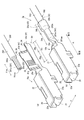
- FIG. 1 shows a perspective view of the female crimp terminal 10
- FIG. 2 shows an explanatory view of the female crimp terminal 10.
- 2A is a side view of the female crimp terminal 10
- FIG. 2B is a longitudinal sectional view in the center in the width direction of the female crimp terminal 10
- FIG. 2C is a female crimp terminal.
- a rear view of the terminal 10 is shown.
- 2D shows a longitudinal sectional view in the center in the width direction of the crimp connection structure 1
- FIG. 2E shows the vicinity of the rear end of the crimp portion 30 in the crimp connection structure 1 in the same state.
- the cross-sectional view in A section is shown.
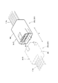
- FIG. 3 shows an explanatory view of the chain terminal 110 constituting the female crimp terminal 10.
- FIG. 3A shows a plan view of the copper alloy strip 100 that forms the chain terminal 110 when the inner surface of the female crimp terminal 10 is placed on the front side
- mold crimp terminal 10 may become the front side is shown.
- FIG. 4 is a perspective view for explaining the crimping of the covered electric wire 200 by the crimping portion 30 in the crimping connection structure 1
- FIG. 4 (a) shows a perspective view of the first caulking state
- FIG. 4 (b) is the final caulking.
- the perspective view of the crimp connection structure 1 comprised in the state is shown.
- the female crimp terminal 10 has a connector box portion 20 that allows insertion tabs to be inserted in a male connector (not shown) from the front, which is the front end side in the longitudinal direction X, to the rear, and behind the connector box portion 20.
- a crimping portion 30 disposed via a transition portion 20a having a predetermined length is integrally formed.
- the longitudinal direction X is a direction that coincides with the longitudinal direction of the covered electric wire 200 to be connected by crimping at the connector box portion 20.
- the covered electric wire 200 to be crimped and connected to the female crimp terminal 10 is configured by covering an aluminum core wire 201 in which aluminum strands are bundled with an insulating coating 202 made of an insulating resin.
- the female crimp terminal 10 is an open barrel type terminal that is three-dimensionally configured by punching and bending a copper alloy strip such as brass whose surface is tin-plated (Sn-plated).
- compression-bonding part 30 of the male crimping terminal provided with the insertion tab inserted in the connector box part 20 is also comprised by the same structure.
- the connector box portion 20 is formed of an inverted hollow rectangular column body, and a dimple 21a that is bent toward the rear in the longitudinal direction X and contacts an insertion tab (not shown) of a male connector to be inserted therein.
- the elastic contact piece 21 is provided.
- the ceiling portion 22 (22a, 22b) of the connector box portion 20 that is a hollow quadrangular prism body is formed by bending the extended portions of the side surface portions 23 (23a, 23b) so as to overlap each other.
- the crimping portion 30 before crimping includes barrel pieces 32 (32a, 32b) that extend obliquely outward and upward from both sides in the width direction Y of the crimping bottom surface 31 and are substantially rectangular in side view.
- the rear view is generally U-shaped.
- the longitudinal length Xb (FIG. 1) of the barrel piece 32 is the longitudinal direction X of the exposed wire portion 201a exposed forward in the longitudinal direction X from the coating distal end 202a which is the distal end in the longitudinal direction X of the insulating coating 202. Longer than the exposed length Xw.
- the crimping portion 30 integrally constitutes a wire crimping range 30a for crimping the wire exposed portion 201a and a coating crimping range 30b for crimping the insulating coating 202.
- the wire crimping range 30a and the coating crimping range 30b are formed in shapes corresponding to the outer diameters of the aluminum core wire 201 and the insulating coating 202 to be crimped, respectively.
- the piece 32 is formed with a longer inner peripheral length than the barrel piece 32 in the electric wire crimping range 30a for crimping the aluminum core wire 201.
- each serration 33 which are grooves in the width direction Y into which the aluminum core wire 201 bites in the state where the aluminum core wire 201 is crimped, are formed in parallel to the longitudinal direction X.
- the serration 33 is formed in a continuous groove shape from the crimping bottom surface 31 and from the both sides of the crimping bottom surface 31 in the width direction Y to the upper part of the barrel piece 32 extending obliquely outward and upward.
- the crimping portion 30 has a widthwise direction band-like seal 41 (41a, 41b) at both longitudinal ends of the longitudinal direction X, and the width direction on the inner surface of the left barrel piece 32a and the outer surface of the right barrel piece 32b.
- a belt-like longitudinal seal 42 (42a, 42b) in the longitudinal direction X is provided at the end of Y.
- the rear width direction seal 41b that is in close contact with the outer peripheral surface of the insulating coating 202 to ensure water-stopping is preferably a material having rubber properties, and among them, as a result of repeated studies from the viewpoint of alkali resistance and heat resistance, Silicone rubber, fluorine rubber, butyl rubber, butadiene rubber, ethylene propyl rubber, nitrile rubber and the like are suitable.
- the thickness of the rear width direction seal 41b is the female crimping in the state before the crimping by the crimping part 30. It is desirable that the thickness of the copper alloy strip 100 (FIG. 3) constituting the terminal 10 is about the plate thickness, and it is preferably 1/3 to 3 times the plate thickness. In each figure, for convenience, the thickness of the female crimp terminal 10 is increased, and the width direction seal 41 and the longitudinal direction seal 42 are illustrated without thickness.
- the front width direction seal 41a on the front side of the crimping portion 30 is preferably made of resin or rubber that has high hardness and is less deformed even when pressed by a barrel piece.
- a sealing material made of resin or rubber having low hardness if excessively attached, excess sealing material flows out toward the connector box portion 20 when the barrel piece 32 is pressed against the crimping bottom surface 31, Since the process of removing this is required, it is not preferable. If the excess sealant that has flowed out is not removed, it is not preferable because it may fall off during use, adhere to the terminal contact, and cause a contact failure.
- the thickness of the sealing material of the front width direction seal 41a may be appropriately selected within the range of 5 ⁇ m or more and the thickness of the copper alloy strip 100 or less in a state before the crimping by the crimping portion 30. Is 10 to 100 ⁇ m.
- sticker 42 (42a, 42b) is formed in the part of the overlapping part D which the barrel pieces 32 contact, as mentioned later, it is comprised with the same material as the front width direction seal
- the female crimp terminal 10 having such a configuration has a water-stop seal 40 (40a) constituting a width direction seal 41 and a longitudinal direction seal 42 (FIGS. 1 and 2) on the front and back surfaces, respectively.
- 40b) is formed by bending a chain terminal 110 formed by punching a copper alloy strip 100 having a predetermined width into a terminal shape.
- a water-stop seal 40a is provided on the surface 100a constituting the inner surface of the female crimp terminal 10 in the reflow tin-plated copper alloy strip 100 at locations corresponding to the width direction seal 41 and the inner surface side longitudinal seal 42a.
- the water stop seal 40b is applied to the corresponding portion of the outer surface side longitudinal seal 42b on the back surface 100b that is provided and constitutes the outer surface of the female crimp terminal 10.
- connection structure 1 is configured (FIGS. 1 and 2). Specifically, the wire exposed portion 201a of the aluminum core wire 201 exposed on the front end side of the insulating coating 202 of the covered wire 200 is positioned from the front width direction seal 41a in the longitudinal direction X of the tip 201aa of the wire exposed portion 201a.
- the covered electric wire 200 is arranged in the crimping part 30 so as to be behind.
- the front end of the barrel piece 32 is in close contact with the crimping bottom face 31 via the front width direction seal 41a
- the electric wire crimping range 30a is in close contact with the electric wire exposed portion 201a
- the covering crimping range 30b is the covering tip 202a.
- the second crimper jig (not shown) is used to intensify the crimping of the barrel piece 32 so as to be in close contact with the outer periphery of the insulating coating 202 via the rear width direction seal 41b.
- 10 and the covered electric wire 200 are connected to form the crimp connection structure 1.
- the front width direction seal 41a can ensure water-stopping on the tip side of the crimping portion 30.
- the overlap portion D is formed so that the end in the width direction Y of the left barrel piece 32a overlaps the Y end of the right barrel piece 32b.
- the inner surface side longitudinal seal 42a formed on the inner surface of the end portion in the width direction Y of the barrel piece 32a and the outer surface side longitudinal seal 42b formed on the outer surface of the Y end portion of the right barrel piece 32b are in close contact. Therefore, it is possible to ensure the water-stopping property of the overlapping portion D in the longitudinal direction in the crimping portion 30.
- the covering crimping range 30b is in close contact with the outer periphery of the insulating coating 202 via the rear width direction seal 41b. It is possible to secure the water-stopping property on the end side.
- the wire exposed portion 201a and the coating tip 202a are not exposed from the crimping portion 30, and moisture enters the inside of the aluminum core wire 201 and the insulating coating 202 in the crimping portion 30. Can be prevented. Therefore, it can be prevented that the surface of the aluminum core wire 201 is corroded and the conductivity between the female crimp terminal 10 and the aluminum core wire 201 is lowered.
- the aluminum core wire 201 is made of aluminum which is a base metal compared to the copper alloy strip 100 constituting the female crimp terminal 10, and moisture is present at the contact portion between the female crimp terminal 10 and the aluminum core wire 201. It is possible to prevent the occurrence of electrolytic corrosion caused by the adhesion. Therefore, the crimp connection structure 1 having a connection state in which stable electrical conductivity is secured in the female crimp terminal 10 and the aluminum core wire 201 can be configured.
- the aluminum core wire 201 is used as the wire conductor, but a copper alloy core wire made of a general copper alloy wire may be used.
- the inner surface side longitudinal seal 42a and the outer surface side longitudinal seal 42b are formed at the width direction end portions of the left barrel piece 32a and the right barrel piece 32b constituting the overlapping portion D, but the inner surface side longitudinal seal 42a. And at least one of the outer surface side longitudinal seals 42b.
- the female crimp terminal 10 a of the second pattern has the barrel piece 32 of the crimp part 30 having substantially the same length as the outer periphery of the electric wire exposed part 201 a and the outer periphery of the insulating coating 202. Is formed. Further, in addition to the width direction seal 41 in the female crimp terminal 10 described above, a side end surface seal 43 is provided on the side end surface 34 in the width direction Y of the barrel piece 32. The side end face seal 43 is made of the same material as the front width direction seal 41a.
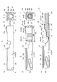
- FIG. 5A is a perspective view of the female crimp terminal 10a of the second pattern
- FIG. 5B is a perspective view of the crimp connection structure 1a configured by caulking the electric wire exposed portion 201a at the crimp portion 30.
- FIG. 6 shows an explanatory view of the female crimp terminal 10a of the second pattern. 6A shows a side view of the female crimp terminal 10a, FIG. 6B shows a longitudinal sectional view in the center in the width direction of the female crimp terminal 10a, and FIG. 6C shows the female crimp terminal. The rear view of the terminal 10a is shown.
- FIG. 6 (d) shows a longitudinal sectional view in the center in the width direction of the crimp connection structure 1a, and
- FIG. 6 (e) shows a portion near the rear end of the crimp portion 30 in the crimp connection structure 1a in the same state.
- the cross-sectional view in a B section is shown.
- the female crimp terminal 10a having such a configuration is similar to the description in FIG. 3, and forms a chain terminal 110 by punching a copper alloy strip 100 having a predetermined width provided with a water stop seal 40 on the surface into a terminal shape, It is configured by performing a bending process and a cutting process.
- the chain terminal 110 is punched out from the copper alloy strip 100 on which the water-stop seal 40 is formed, and the female crimp terminal 10a is formed by bending, and the tip 201aa of the wire exposed portion 201a is formed in the crimp portion 30.
- the covered electric wire 200 is disposed in the crimping portion 30 so that the position in the longitudinal direction X of the crimping portion 30 is behind the front width direction seal 41a in the crimping portion 30, and the coated electric wire 200 is crimped by the crimping portion 30 to be crimped connection structure 1a.
- the front end of the barrel piece 32 is in close contact with the crimping bottom surface 31 via the front width direction seal 41a. it can. Further, as shown in FIG. 6 (e), the lateral end face 34 of the left barrel piece 32a and the lateral end face 34 of the right barrel piece 32b are abutted and adhered to each other. It can be ensured by the side end face seal 43.
- the rear width direction seal 41b is used to It is possible to secure the water-stopping property on the end side. Therefore, in the crimp connection structure 1a configured using the female crimp terminal 10a in this way, a water stop effect similar to that of the crimp connection structure 1 using the female crimp terminal 10 can be obtained.
- sticker 43 was formed in the both-sides end surface 34 of the left barrel piece 32a and the right barrel piece 32b, you may form only in any one.
- the width direction between the longitudinal direction X of the front width direction seal 41 a and the rear width direction seal 41 b is formed on the outer surface of the crimp portion 30.
- a water stop seal may be provided so as to wrap in the longitudinal direction X with the seal 41.
- the length, width, shape or thickness of the width direction seal 41, the longitudinal direction seal 42, or the waterproof seal attached to the outer surface of the crimping portion 30 is the diameter of the female crimp terminal 10 and the covered electric wire 200. It may be set appropriately according to the material.
- the width direction seal 41, the longitudinal direction seal 42, the side end face seal 43, or the material of the water stop seal attached to the outer surface of the crimping portion 30 is also the diameter and material of the female crimp terminal 10 and the covered electric wire 200. What is necessary is just to set suitably according to.
- the connector 3 (3a, 3b) By attaching the crimp connection structure 1 (1a) using such a crimp terminal 10 (10a) to the connector housing 300, the connector 3 (3a, 3b) having reliable conductivity can be configured.
- the connectors 3 (3a, 3b) are connectors of a wire harness is shown, but one may be a connector of a wire harness and the other may be a connector of an auxiliary machine such as a board or a component.
- the crimp connection structure 1 (1a) constituted by the crimp terminals 10 (10a) is a female type.
- the wire harness 301a is mounted on the connector housing 300 and includes the female connector 3a.
- the crimping connection structure 1 (1a) comprised with the male crimp terminal 10 (10a) which is not shown in figure is mounted
- worn with the male connector housing 300, and the wire harness 301b provided with the male connector 3b is comprised.
- the wire harness 301a and the wire harness 301b can be connected by fitting the female connector 3a and the male connector 3b.
- the crimp connection structure 1 (1a) in which the crimp terminal 10 (10a) and the covered electric wire 200 are connected is mounted on the connector housing 300, the wire harness 301 (301a) having reliable conductivity is mounted. , 301b) can be realized.
- the crimp terminal 10 (10a) is inserted into the connector housing 300, but the gap between the crimp terminal 10 (10a) and the inner wall of the connector housing 300 in the connector housing 300 is a very narrow space, Electrolyte aqueous solution, such as salt water, corrodes even the tin plating of the surface of the crimp terminal 10 (10a). Furthermore, it has been found that the liquidity tends to be strongly alkaline due to the narrow space.
- the aluminum core wire 201 is integrally surrounded by the crimping portion 30 and is not exposed, the electrical connection between the aluminum core wire 201 and the crimping terminal 10 (10a) inside the crimping portion 30 even when exposed to alkali in the connector housing 300. Therefore, the electrical conductivity can be reliably maintained.
- a reflow tin-plated copper alloy strip (FAS680H material, manufactured by Furukawa Electric Co., Ltd.) having a thickness of 0.2 mm was used as a copper alloy strip 100 (terminal base material).
- various resins and rubber are attached to the copper alloy strip 100 as the water stop seal 40 as shown in FIG. 3.
- the chain terminal 110 was then bent to produce a male and female crimp terminal 10 (10a) having a tab width of 0.64 mm.
- the resin materials and rubber materials attached to the copper alloy strip 100 are as follows. For butyl rubber, silicone rubber, and urethane rubber, commercially available sheets are used and pressed as necessary to reduce the thickness. It stuck on the copper alloy strip 100.
- epoxy UV curable resin and the urethane UV curable resin were applied with a coater using ThreeBond 3052C and Chemitech U426B, respectively, and then cured by irradiation with ultraviolet rays.
- the crimping portion 30 of the molded crimp terminal 10 (10a) an aluminum wire of conductor cross-sectional area is 0.75 mm 2, length 11cm (Composition of Aluminum wire: ECAl, strand 11 pieces of strand) in
- the aluminum core wire 201 to be constituted was crimped and attached to constitute a crimp connection structure 1 (1a).
- the insulation coating 202 is peeled off by a length of 10 mm on the opposite end side of the covered electric wire 200 crimped to the crimping portion 30 of the crimp terminal 10 (10a), and a solder bath for aluminum (made by Nippon Almit, T235, using flux). And soldered to the surface of the aluminum core wire 201 on the opposite end side. Thereby, the contact resistance with the probe when measuring the electrical resistance is made as small as possible.
- the initial resistance measurement and the corrosion test were carried out for 10 samples of 20 male terminals and 10 female terminals at each level, and the resistance increase value and the corrosion state were measured and observed for all of them. .
- the initial resistance is measured using a resistance measuring instrument (ACm ⁇ HiTESTER 3560, manufactured by Hioki Electric Co., Ltd.) on the inner side surface of the side surface portion 23 of the connector box 20 and the side opposite to the side connected to the crimp terminal 10 (10a) in the covered electric wire 200.
- the aluminum core wire 201 at the end was measured as a positive / negative electrode by a four-terminal method.
- the measured resistance value is considered to be the sum of the resistances between the aluminum core wire 201, the crimp terminal 10 (10a), and the crimped portion 30 / aluminum core wire 201. However, the resistance of the aluminum core wire 201 cannot be ignored. This value was used as the initial resistance between the crimp terminal 10 (10a) and the crimp part 30.
- the joint connector 3 was prepared by inserting the connector housing 300 and the female connector housing 300 and fitting the two connector housings 300 together.
- the connector 3 was tested by the automotive part appearance corrosion test method defined in JASO M610-92. Specifically, after leaving at a high temperature of 120 ° C. for 30 minutes, spraying 25 ° C. and 5% salt water for 2 hours, drying at 60 ° C. and a humidity of 30% RH for 4 hours, and then leaving at 50 ° C. and a humidity of 95% for 2 hours. One cycle was performed up to 30 cycles. After the test, the waterproof treatment is released, the resistance value is measured in the same manner as the initial resistance measurement, and the initial resistance value of the same sample is subtracted to calculate the resistance increase value between the crimped part 30 and the aluminum core wire 201 before and after the exposure. did.
- all the 20 resistance increase values are less than 1 m ⁇ , “ ⁇ ”, less than 3 m ⁇ and less than 3 m ⁇ , and less than 1 m ⁇ , and “ ⁇ ”, less than 1 m ⁇ and less than 3 m ⁇ . “ ⁇ ” indicates that the remainder exceeds 1 m ⁇ , and “ ⁇ ” indicates that there is at least 1 m ⁇ or more and less than 10 m ⁇ , and “ ⁇ ” indicates that there is at least 1 m ⁇ or more. ".
- the degree of corrosion was observed from the cross section. Specifically, a round cross section near the center of the crimped aluminum core wire 201 was polished, and the polished surface was observed and evaluated with an optical microscope. As a result, “ ⁇ ” indicates that the aluminum core wire 201 remains completely for all of the observed items, and “ ⁇ ” indicates that one of the observed aluminum core wires 201 is missing due to corrosion. Of those observed, at least one part of the aluminum core wire 201, or almost the whole, is missing due to corrosion is evaluated as “x”. The results are shown in Table 1.
- the front width direction seal 41a is made of 0.08 mm epoxy UV curable resin
- the longitudinal seal 42 and the side end face seal 43 are made of 0.03 mm epoxy UV curable resin.
- good resistance and corrosion results were obtained by configuring the rear width direction seal 41b with 0.3 mm butyl rubber (Example 1) or 0.3 mm silicone rubber (Example 2).
- the rear width direction seal 41b is made of 0.3 mm urethane rubber (Comparative Example 1) or 0.2 mm epoxy-based UV curable resin (Comparative Example 2)
- good results are obtained in both resistance and corrosion. There wasn't.
- the epoxy UV curable resin is harder than butyl rubber and silicone rubber constituting the rear width direction seal 41b, so that the electric wire is biased excessively during crimping and the electric wire coating is broken, It is thought that it was corroded, and urethane rubber is considered to have been submerged and deteriorated with no resistance to a reaction product (for example, alkali) inside the connector.
- a reaction product for example, alkali
- Example 3 when the longitudinal seal 42 and the side end face seal 43 in Example 1 in which a sufficient water stop effect is obtained are composed of 0.03 mm urethane-based UV curable resin (Comparative Example 3), 0.1 mm When it was composed of butyl rubber (Comparative Example 4), good results could not be obtained. This is presumably because the urethane-based UV curable resin with a thickness of 0.03 mm was not resistant to a reaction product (for example, alkali) inside the connector and deteriorated, so that a sufficient water stop effect could not be obtained. On the contrary, in Comparative Example 4 using butyl rubber, the hardness was low and a sufficient water stop effect could not be obtained, and further, the butyl rubber protruded due to the pressure bonding of the barrel piece 32.
- a reaction product for example, alkali
- the rear width direction seal 41b in Example 1 in which sufficient water-stopping effect was obtained is composed of 0.05 mm butyl rubber (Comparative Example 7) or 1.0 mm butyl rubber (Comparative Example 8). Even good results could not be obtained. Specifically, when the rear width direction seal 41b is made of 0.05 mm butyl rubber (Comparative Example 7), the thickness is too thin to obtain a sufficient water stop effect. On the other hand, when the rear width direction seal 41b was made of 1.0 mm butyl rubber (Comparative Example 8), a sufficient water stop effect could be obtained. However, the thickness was too thick, and the barrel piece 32 was pressed. The butyl rubber protruded. In addition, when the back width direction seal
- Example 4 When the front width direction seal 41a in Example 4 in which a sufficient water-stopping effect has been confirmed is composed of 0.01 mm, 0.02 mm, 0.05 mm, and 0.1 mm epoxy-based UV curable resin (Comparative Example 10, In Example 8, Example 9, Comparative Example 11) and 0.01 mm (Comparative Example 10), the thickness was too thin to obtain a sufficient water-stopping effect, but in other cases a sufficient water-stopping effect was confirmed. I was able to. However, when it was formed with a thickness of 0.1 mm (Comparative Example 11), the thickness was too thick, and the protrusion of the resin due to the pressure bonding of the barrel piece 32 was observed.
- the front width direction seal 41a, the rear width direction seal 41b, the longitudinal direction seal 42, and the side end face seal 43 attached to the crimp terminal 10 (10a) are set to materials and thicknesses according to the attachment locations.
- a certain water-stopping property was secured. It was confirmed that such a reliable water-stopping property can constitute the crimped connection structure 1 (1a) and the connector 3 that do not lower the conductivity.
- the wire conductor and the aluminum wire conductor of the present invention correspond to the aluminum core wire 201
- the covering corresponds to the insulating coating 202
- the tip of the covering corresponds to the covering tip 202a
- the predetermined length corresponds to the exposure length Xw
- the exposed portion of the wire conductor corresponds to the wire exposed portion 201a
- the barrel pieces correspond to the barrel piece 32, the left barrel piece 32a, and the right barrel piece 32b
- the crimp terminal corresponds to the female crimp terminal 10, 10a
- the longitudinal length corresponds to the longitudinal length Xb
- the water stop means corresponds to the width direction seal 41, the front width direction seal 41a, the rear width direction seal 41b, the longitudinal direction seal 42, the inner surface side longitudinal direction seal 42a, the outer surface side longitudinal direction seal 42b, and the side end surface seal 43.
- the overlapping part corresponds to the overlapping part D
- the width direction end face corresponds to the side end face 34
- the connection structure corresponds to the crimp connection structure 1
- the connectors correspond to connector 3, female connector 3a and male connector 3b.
- the present invention is not limited only to the configuration of the above-described embodiment, and many embodiments can be obtained.
- a thin-film curable waterproof seal 40 c made of curable resin may be formed so as to straddle the serration 33.
- a thin-film curable waterproof seal is provided so as to straddle the serration 33 on the surface 100 a constituting the inner surface of the female crimp terminal 10 in the reflow tin-plated copper alloy strip 100. 40c is attached as a band. At this time, the thin-film curable waterproof seal 40c is formed to be thin enough to ensure water-stopping and insulating properties.
- FIG. 8 (b) is an enlarged cross-sectional view of the main part of the crimping part 30 in a crimped state, a cured thin film-like curable waterstop between the aluminum core wire 201 and the inner surface of the crimping part 30.
- the seal 40c is interposed, and the water stoppage at the crimping portion 30 can be improved.
- the thin-film curable waterproof seal 40c covers the inner surface of the crimping portion 30 in a thin film shape, it is difficult to ensure electrical conductivity between the crimping portion 30 and the aluminum core wire 201.
- the thin-film curable waterproof seal 40c covers the inner surface of the crimping portion 30 across the serration 33 and is cured in a thin film shape, the crimping pressure on the aluminum core wire 201 from the barrel piece 32 in the crimping portion 30 As a result, the thin-film curable waterproof seal 40 c on the inner side surface of the serration 33 is peeled off, and the oxide film of the aluminum core wire 201 is removed by rubbing against the edge 33 a of the serration 33, so that the aluminum core wire 201 and the female crimp terminal 10 Metal bonding with the terminal surface occurs, and reliable conductivity can be ensured.
- the serration 33 formed in the groove shape in the width direction has been described.
- serrations arranged in a lattice shape or a zigzag shape may be used, and serrations including not only concave portions but also convex portions may be used.
- an insulation barrel 35 (corresponding to the cover crimping portion) that crimps the outer surface of the insulating coating 202 of the covered electric wire 200 may be connected to the rear side of the crimping portion 30 in the longitudinal direction X.
- the insulation barrel 35 since the load due to external force acts on the insulation barrel 35 by providing the insulation barrel 35 behind the crimping portion 30 in the longitudinal direction X, the gap between the inner surface and the surface of the insulating coating 202 in the coating crimping range 30b. There is no gap and complete water stop can be realized. Therefore, electrolytic corrosion caused by moisture adhering to the contact portion between the aluminum core wire 201 made of aluminum, which is a base metal compared to the copper alloy strip 100 constituting the female crimp terminal 10, and the female crimp terminal 10. Can be prevented.
- the insulation barrel 35 may be provided in the second pattern female crimp terminal 10a.
Landscapes
- Engineering & Computer Science (AREA)
- Manufacturing & Machinery (AREA)
- Connections Effected By Soldering, Adhesion, Or Permanent Deformation (AREA)
- Connector Housings Or Holding Contact Members (AREA)
Abstract
圧着部における圧着だけで確実な止水性を確保することのできる圧着端子、接続構造体およびコネクタを提供することを目的とする。アルミニウム芯線(201)の外周を絶縁性の絶縁被覆(202)で被覆した被覆電線(200)における被覆先端(202a)より露出長さ(Xw)露出させた電線露出部(201a)を、幅方向(Y)の両側に備えたバレル片(32)で圧着する圧着部(30)を備えた雌型圧着端子(10,10a)であって、バレル片(32)を、電線露出部(201a)の露出長さ(Xw)より長手方向(X)の長さを長く形成し、圧着部(30)における表面に幅方向シール(41)及び長手方向シール(42)を備え、圧着部(30)が、電線露出部(201a)より先端側から絶縁被覆(202)の被覆先端(202a)より後端側までを連続して一体的に囲繞するように、バレル片(32)で圧着した。
Description
例えば、自動車用ワイヤーハーネスの接続を担うコネクタ等に装着される圧着端子や、圧着端子を用いた接続構造体、さらには、このような接続構造体を装着したコネクタに関する。
近年の自動車では、様々な電装機器が装備されており、その電気回路はますます複雑化し、安定した電力供給は必要不可欠となっている。このようにさまざまな電装機器が装備された自動車は、被覆電線を束ねたワイヤーハーネスを配索しており、ワイヤーハーネス同士をコネクタで接続し、電気回路を構成している。
これらのコネクタには、被覆電線を圧着部で圧着接続した圧着端子が内部に装着されており、雄型コネクタと、雌型コネクタとを嵌合させる構成である。
これらのコネクタには、被覆電線を圧着部で圧着接続した圧着端子が内部に装着されており、雄型コネクタと、雌型コネクタとを嵌合させる構成である。
このような電気接続によって構成される電気回路において、コネクタ内部に装着した圧着端子と被覆電線との圧着部から水分が侵入すると、被覆電線を構成する電線導体の表面が腐食し、導電性が低下するといった問題があった。
このような問題は、圧着部が被覆電線の被覆体の先端部分を圧着するインシュレーションバレルと、被覆体より先端側で露出する電線導体の露出部分を圧着するワイヤバレルとの間に隙間があり、被覆体の先端部分が露出しているため生じると考えられる。
そこで、被覆体の先端から電線導体の先端までを一体的に囲繞するために、ワイヤバレルとインシュレーションバレルとを一体化したバレルを備えた圧着端子(特許文献1参照)を用いることにより、水分の侵入を防止できると考えられる。しかし、昨今の複雑化された電気回路ではより安定した導電性を確保する必要があり、上記圧着端子では十分ではなかった。
また、自動車からの二酸化炭素排出量の低減が求められている現在において、ガソリン自動車に比べてワイヤーハーネスが多用される電気自動車やハイブリット自動車が用いられてきているような状況の中、ガソリン自動車を含め、すべての自動車において、車両の軽量化は燃費向上に大きな影響を与えるため、ワイヤーハーネスやバッテリーケーブル等に、銅(あるいは銅合金)だけでなくアルミニウム(あるいはアルミニウム合金)製の電線を適用し軽量化を図っている。
このような、アルミニウムやアルミ合金で構成するアルミ電線を銅や銅合金で構成する圧着端子に圧着接続した場合、両者の接触部分に結露や海水等の水分が介在すると電気化学的反応を生じ、端子材料の錫めっき、金めっき、銅合金等の貴な金属種により、卑なアルミニウムやアルミニウム合金が腐食される現象、すなわち異種金属腐食(以下において電食という)が生じるという問題がある。
この電食により、端子の圧着部で圧着したアルミ電線が腐食、溶解、消失し、やがては電気抵抗が上昇し、その結果、十分な導電機能を果たせなくなるおそれがあり、このようなアルミ電線を用いる場合はより確実に水分の浸入を防止する必要性が求められている。
なお、上記特許文献1では、止水性向上のために圧着時にエポキシ塗料を塗布することについても記載されているが、圧着時の塗布は、その工程に時間を要してしまうため、量産に向けては好ましくない。また、圧着する際に、塗布位置及び塗布量を精度良く制御して塗布することも、非常に難しい。したがって、圧着時にエポキシ塗料を塗布する方法は満足のできる方法ではなかった。
この発明は、圧着部における圧着だけで、圧着部における確実な止水性を確保することのできる圧着端子、接続構造体およびコネクタを提供することを目的とする。
この発明は、電線導体の外周を絶縁性の被覆体で被覆した被覆電線における前記被覆体の先端より所定長さ露出させた前記電線導体の露出部分を圧着する圧着部を構成するバレル片を、幅方向両側に備えた圧着端子であって、前記バレル片を、前記電線導体の前記露出部分の長さより長手方向の長さを長く形成し、前記圧着部における表面の少なくとも一部に止水手段を備え、前記圧着部が、前記電線導体の先端より先端側から前記被覆体の先端より後端側までを連続して一体的に囲繞するように、前記バレル片で圧着することを特徴とする。
上記圧着部は、圧着部底面と、その幅方向両側に備えたバレル片とで構成するオープンバレル形式の圧着部とすることができる。
上記圧着部における表面は、圧着部に備えたバレル片の外側表面や内側表面、さらには、バレル片を幅方向両側に備えた圧着部底面の外側表面や内側表面とすることができる。
上記圧着部における表面は、圧着部に備えたバレル片の外側表面や内側表面、さらには、バレル片を幅方向両側に備えた圧着部底面の外側表面や内側表面とすることができる。
上記止水手段は、樹脂またはゴムで構成することができ、さらに、その材料自身に接着性を有する樹脂またはゴムのシートを金属基材上へ直接付けたもの、あるいは、樹脂またはゴムのシートを金属基材上に接着剤を介して接着したもの、あるいは、硬化していない流動性を有した状態の樹脂またはゴムを金属基材上に塗布し硬化させたものとすることができる。なお、その硬化作用は、熱、紫外線、2液、嫌気、湿気等の方式によるとすることができる。
この発明により、圧着部における圧着だけで、圧着部の確実な止水性を確保することができる。
詳しくは、バレル片を、電線導体の露出部分の長さより長手方向の長さを長く形成し、圧着部における表面の少なくとも一部に止水手段を備え、圧着部が、電線導体の先端より先端側から被覆体の先端より後端側までを連続して一体的に囲繞するように、バレル片で圧着するため、電線導体や、電線導体と被覆体との境界部分である被覆体の先端部分を圧着部から露出させずに圧着することができる。また、圧着部に止水手段を備えているため、一体的に囲繞した圧着部内部に水分が浸入することを防止できる。したがって、圧着部における圧着だけで圧着部の確実な止水性を確保することができる。
詳しくは、バレル片を、電線導体の露出部分の長さより長手方向の長さを長く形成し、圧着部における表面の少なくとも一部に止水手段を備え、圧着部が、電線導体の先端より先端側から被覆体の先端より後端側までを連続して一体的に囲繞するように、バレル片で圧着するため、電線導体や、電線導体と被覆体との境界部分である被覆体の先端部分を圧着部から露出させずに圧着することができる。また、圧着部に止水手段を備えているため、一体的に囲繞した圧着部内部に水分が浸入することを防止できる。したがって、圧着部における圧着だけで圧着部の確実な止水性を確保することができる。
この発明の態様として、前記止水手段を、前記圧着部における内側表面の長手方向の端部付近において幅方向に形成することができる。
上記圧着部における内側表面は、上記圧着部底面とバレル片の内側表面とすることができる。さらに、上記長手方向は圧着端子の長手方向、すなわち圧着端子に接続する被覆電線の長手方向とすることができ、幅方向は上記長手方向に対して直交する圧着端子の幅方向とすることができる。
上記圧着部における内側表面は、上記圧着部底面とバレル片の内側表面とすることができる。さらに、上記長手方向は圧着端子の長手方向、すなわち圧着端子に接続する被覆電線の長手方向とすることができ、幅方向は上記長手方向に対して直交する圧着端子の幅方向とすることができる。
また、上記圧着部における内側表面の長手方向の端部付近は、圧着部底面の長手方向における先端側端部付近や後端側端部付近、さらにはバレル片の長手方向における先端側端部付近や後端側端部付近とすることができる。
これにより、電線導体の先端から被覆体の先端までを連続して一体的に囲繞した圧着部内部に水分が浸入することをより確実に防止できる。詳しくは、一体的に囲繞する圧着部の先端側端部付近や後端側端部付近を幅方向の止水手段で止水しているため、圧着部と被覆体との境界面や、圧着部における圧着部底面とバレル片との境界面からの水分の浸入を確実に防止することができる。
また、この発明の態様として、圧着状態の前記圧着部において、一方のバレル片の端部が他方のバレル片の端部の端部外側に被さり、端部同士が重なり合う長手方向の重ね合わせ部分を形成することができる。
これより、オープンバレル形式の圧着部において、圧着状態のバレル片同士が合わさる長手方向のあわせ部分である重ね合わせ部分からの水分の浸入を抑制することができる。したがって、電線導体の先端から被覆体の先端までを連続して一体的に囲繞した圧着部内部に水分が浸入することをさらに確実に防止できる。
また、この発明の態様として、前記重ね合わせ部分を形成する前記バレル片の端部付近における各対向部分の少なくとも一方に前記止水手段を形成することができる。
上記重ね合わせ部分を形成するバレル片の端部付近における各対向部分とは、一方のバレル片の外側表面に対する他方のバレル片の内側表面となる。
これより、圧着状態のバレル片同士が合わさる長手方向のあわせ部分である重ね合わせ部分からの水分の浸入を確実に防止することができる。
これより、圧着状態のバレル片同士が合わさる長手方向のあわせ部分である重ね合わせ部分からの水分の浸入を確実に防止することができる。
また、この発明の態様として、圧着状態の前記圧着部において、両バレル片の幅方向端面同士が突き合わさる構成とすることができる。
これより、オープンバレル形式の圧着部において、圧着状態のバレル片の幅方向の端面同士が長手方向で突き合わさる部分からの水分の浸入を抑制することができる。したがって、電線導体の先端から被覆体の先端までを連続して一体的に囲繞した圧着部内部に水分が浸入することをさらに確実に防止できる。
これより、オープンバレル形式の圧着部において、圧着状態のバレル片の幅方向の端面同士が長手方向で突き合わさる部分からの水分の浸入を抑制することができる。したがって、電線導体の先端から被覆体の先端までを連続して一体的に囲繞した圧着部内部に水分が浸入することをさらに確実に防止できる。
また、この発明の態様として、前記両バレルの前記幅方向端面のうち少なくとも一方の幅方向端面に前記止水手段を形成することができる。
これより、圧着状態のバレル片の長手方向の端面同士が突き合わさる長手方向の突き合わせ部分からの水分の浸入を確実に防止することができる。
これより、圧着状態のバレル片の長手方向の端面同士が突き合わさる長手方向の突き合わせ部分からの水分の浸入を確実に防止することができる。
また、この発明の態様として、前記圧着部の内面に、セレーションを備え、前記止水手段を、圧着部の内面において、前記セレーションを跨ぐように薄膜状に被覆するとともに、硬化済みの硬化型樹脂で構成することができる。
上記セレーションは、幅方向の溝状に形成したセレーションや、格子状や千鳥状に配置した凹状のセレーション、さらには、凸状に形成したセレーションとすることができる。
この発明により、導電性を確保しながら、止水性をより向上することができる。詳しくは、圧着部の内面において、前記セレーションを跨ぐように薄膜状に被覆するとともに、硬化済みの硬化型樹脂を備えたことにより、電線導体を圧着する圧着部における止水性を向上することができる。
その反面、硬化型樹脂が圧着部の内面を薄膜状に被覆するため、圧着部と電線導体との導電性の確保が困難となる。しかしながら、硬化型樹脂はセレーションを跨いで被覆しているため、圧着部における電線導体の圧着圧力により、セレーション近傍の硬化済みである硬化型樹脂は剥離し、電線導体の酸化皮膜がセレーションのエッジとの擦れにより除去され、電線導体と圧着端子の端子表面との金属結合が生じ、確実な導電性を確保することができる。
また、この発明の態様として、前記被覆電線の前記被覆体を圧着する被覆体圧着部を、前記圧着部に連結することができる。
この発明により、曲げ等の外力が作用しても、確実な止水性能を確保することができる。例えば、被覆電線に大きな振り幅での曲げや引っ張り等の外力による負荷が過大に作用すると、圧着部と被覆体表面との間に隙間を生じおそれがあるが、圧着部に連結した被覆体圧着部を備えたことにより、外力による負荷は被覆体圧着部に作用するため、圧着部と被覆体表面との間に隙間が生じることがなく、完全な止水を実現することができる。
この発明により、曲げ等の外力が作用しても、確実な止水性能を確保することができる。例えば、被覆電線に大きな振り幅での曲げや引っ張り等の外力による負荷が過大に作用すると、圧着部と被覆体表面との間に隙間を生じおそれがあるが、圧着部に連結した被覆体圧着部を備えたことにより、外力による負荷は被覆体圧着部に作用するため、圧着部と被覆体表面との間に隙間が生じることがなく、完全な止水を実現することができる。
また、この発明は、上述の圧着端子における圧着部分によって、前記被覆電線と前記圧着端子とを接続した接続構造体であることを特徴とする。
この発明により、圧着端子の圧着部における圧着だけで確実な止水性を確保することのできる接続構造体を構成することができる。したがって、安定した導電性を確保することができる。
この発明により、圧着端子の圧着部における圧着だけで確実な止水性を確保することのできる接続構造体を構成することができる。したがって、安定した導電性を確保することができる。
この発明の態様として、前記電線導体の先端が、前記圧着部における長手方向中間位置となるように配置して接続することができる。
この発明により、電線導体の先端から被覆体の先端までを圧着部で連続して一体的に囲繞し、圧着部内部に水分が浸入することをより確実に防止できる。
この発明により、電線導体の先端から被覆体の先端までを圧着部で連続して一体的に囲繞し、圧着部内部に水分が浸入することをより確実に防止できる。
また、この発明の態様として、前記被覆電線における前記電線導体を、アルミニウム電線導体で構成することができる。
上記アルミニウム電線導体は、アルミニウム製素線あるいはアルミニウム合金製素線で構成する電線導体とすることができる。
上記アルミニウム電線導体は、アルミニウム製素線あるいはアルミニウム合金製素線で構成する電線導体とすることができる。
この発明により、例えば、圧着端子を錫メッキ等を施した銅合金で構成した場合であっても、圧着端子を構成する銅合金に比べて卑な金属であるアルミニウム電線導体が腐食される電食の発生を防止することができる。したがって、圧着端子と電線導体を構成する金属種によらず、安定した導電性を確保した接続状態を構成することができる。
また、この発明は、上述の接続構造体における圧着端子をコネクタハウジング内に配置したコネクタであることを特徴とする。
この発明により、圧着端子と電線導体を構成する金属種によらず、安定した導電性を確保した嵌合状態を構成することができる。
この発明により、圧着端子と電線導体を構成する金属種によらず、安定した導電性を確保した嵌合状態を構成することができる。
この発明によれば、圧着部における圧着だけで、圧着部の確実な止水性を確保することのできる圧着端子、接続構造体およびコネクタを提供することができる。
この発明の一実施形態を以下図面とともに説明する。
図1は雌型圧着端子10の斜視図を示し、図2は雌型圧着端子10についての説明図を示している。なお、図2(a)は雌型圧着端子10の側面図を示し、図2(b)は雌型圧着端子10の幅方向中央における縦断面図を示し、図2(c)は雌型圧着端子10の背面図を示している。また、図2(d)は圧着接続構造体1の幅方向中央における縦断面図を示し、図2(e)は同状態の圧着接続構造体1における圧着部30の後端付近であるA-A断面における横断面図を示している。
図1は雌型圧着端子10の斜視図を示し、図2は雌型圧着端子10についての説明図を示している。なお、図2(a)は雌型圧着端子10の側面図を示し、図2(b)は雌型圧着端子10の幅方向中央における縦断面図を示し、図2(c)は雌型圧着端子10の背面図を示している。また、図2(d)は圧着接続構造体1の幅方向中央における縦断面図を示し、図2(e)は同状態の圧着接続構造体1における圧着部30の後端付近であるA-A断面における横断面図を示している。
図3は、雌型圧着端子10を構成する連鎖端子110についての説明図を示している。詳しくは、図3(a)は雌型圧着端子10の内表面が表側となるように配置した際の連鎖端子110を形成する銅合金条100の平面図を示し、図3(b)は雌型圧着端子10の外表面が表側となるように配置した際の連鎖端子110を形成する銅合金条100の平面図を示している。
図4は圧着接続構造体1における圧着部30による被覆電線200の圧着について説明する斜視図であり、図4(a)は第1かしめ状態の斜視図を示し、図4(b)は最終かしめ状態となって構成された圧着接続構造体1の斜視図を示している。
まずは、雌型圧着端子10について説明する。雌型圧着端子10は、長手方向Xの先端側である前方から後方に向かって、図示省略する雄型コネクタにおける挿入タブの挿入を許容するコネクタボックス部20と、コネクタボックス部20の後方で、所定の長さのトランジション部20aを介して配置された圧着部30とを一体に構成している。なお、長手方向Xとは、コネクタボックス部20で圧着して接続する被覆電線200の長手方向と一致する方向である。
雌型圧着端子10に圧着接続する被覆電線200は、アルミニウム素線を束ねたアルミニウム芯線201を、絶縁樹脂で構成する絶縁被覆202で被覆して構成している。
雌型圧着端子10は、表面が錫メッキ(Snメッキ)された黄銅等の銅合金条に、打ち抜き加工及び折曲加工を施して立体構成したオープンバレル型端子である。
なお、コネクタボックス部20に挿入する挿入タブを備えた雄型圧着端子の圧着部30も同様の構成で構成している。
雌型圧着端子10は、表面が錫メッキ(Snメッキ)された黄銅等の銅合金条に、打ち抜き加工及び折曲加工を施して立体構成したオープンバレル型端子である。
なお、コネクタボックス部20に挿入する挿入タブを備えた雄型圧着端子の圧着部30も同様の構成で構成している。
コネクタボックス部20は、倒位の中空四角柱体で構成され、内部に、長手方向Xの後方に向かって折り曲げられ、挿入される雄型コネクタの挿入タブ(図示省略)に接触するディンプル21aを有する弾性接触片21を備えている。
中空四角柱体であるコネクタボックス部20の天井部22(22a,22b)は、側面部分23(23a,23b)の延長部分を重なるように折り曲げて構成している。
中空四角柱体であるコネクタボックス部20の天井部22(22a,22b)は、側面部分23(23a,23b)の延長部分を重なるように折り曲げて構成している。
圧着前の圧着部30は、図2(b)に示すように、圧着底面31の幅方向Yの両側から斜め外側上方に延出し、側面視略長方形のバレル片32(32a,32b)を備え、後方視略U型に形成している。
なお、バレル片32の長手方向長さXb(図1)は、絶縁被覆202の長手方向X前方側の先端である被覆先端202aから、長手方向X前方で露出する電線露出部201aの長手方向Xの露出長さXwより長く形成している。
なお、バレル片32の長手方向長さXb(図1)は、絶縁被覆202の長手方向X前方側の先端である被覆先端202aから、長手方向X前方で露出する電線露出部201aの長手方向Xの露出長さXwより長く形成している。
より詳しくは、圧着部30は、電線露出部201aを圧着する電線圧着範囲30aと、絶縁被覆202を圧着する被覆圧着範囲30bとを一体で構成している。そして、電線圧着範囲30aと被覆圧着範囲30bとは、それぞれ圧着するアルミニウム芯線201及び絶縁被覆202の外径に応じた形状で形成しているため、絶縁被覆202を圧着する被覆圧着範囲30bのバレル片32は、アルミニウム芯線201を圧着する電線圧着範囲30aのバレル片32より長い内周長さで形成している。
さらに、電線圧着範囲30aの内面には、アルミニウム芯線201を圧着した状態において、アルミニウム芯線201が食い込む、幅方向Yの溝であるセレーション33が、長手方向Xに平行に4本形成している。なお、セレーション33は、圧着底面31と、圧着底面31の幅方向Yの両側から斜め外側上方に延出するバレル片32の上部までを連続する溝形状で形成している。
また、圧着部30には、長手方向Xの前後方向両端部に幅方向Yの帯状の幅方向シール41(41a,41b)と、左バレル片32aの内面と右バレル片32bの外面における幅方向Yの端部に長手方向Xの帯状の長手方向シール42(42a,42b)とを備えている。
なお、絶縁被覆202の外周面と密着して止水性を確保する後方幅方向シール41bは、ゴム物性を備えた材料が好ましく、その中でも、耐アルカリ、耐熱の観点より、検討を重ねた結果、シリコーンゴム、フッ素ゴム、ブチルゴム、ブタジエンゴム、エチレンプロピルゴム、ニトリルゴム等が適する。
さらには、硬度が低く、弾性を備えた材料が好ましい。また、圧着部30で圧着の施工性、及び後述する銅合金条100への付設の容易性の観点より、後方幅方向シール41bの厚みは、圧着部30による圧着前の状態において、雌型圧着端子10を構成する銅合金条100(図3)の板厚程度であることが望ましく、板厚の1/3以上3倍以内がよい。なお、各図中においては、便宜上、雌型圧着端子10の厚みを厚く、幅方向シール41や長手方向シール42を、厚みを持たせずに図示している。
これに対して、圧着部30の前方側の前方幅方向シール41aは、硬度が高く、バレル片によって押し付けられても、変形の少ない樹脂またはゴムが好ましい。硬度が低い樹脂またはゴム製のシール材を付設する場合には、過剰に付設すると、バレル片32を圧着底面31に押さえつけた際に余分なシール材がコネクタボックス部20側へ向かって流出し、これを除去する工程が必要となるため好ましくない。なお、流出した余分なシール材を除去しなければ、使用中、脱落し、端子接点に付着し、接点障害となるおそれがあるので、好ましくない。
よって、前方幅方向シール41aに硬度の低い樹脂またはゴム製のシール材を付設する場合は、過剰とならぬよう適量を付ける必要がある。この場合の前方幅方向シール41aのシール材の厚みは、圧着部30による圧着前の状態において、5μm以上で、且つ銅合金条100の板厚以下の範囲で適宜選定すればよいが、より好ましくは、10~100μmである。
また、長手方向シール42(42a,42b)は、後述するように、バレル片32同士が接触する重ね合い部Dの部分に形成されるため、前方幅方向シール41aと同材料で構成している。
また、長手方向シール42(42a,42b)は、後述するように、バレル片32同士が接触する重ね合い部Dの部分に形成されるため、前方幅方向シール41aと同材料で構成している。
このような構成の雌型圧着端子10は、図3に示すように、表裏面のそれぞれに、幅方向シール41と長手方向シール42(図1,2)とを構成する止水シール40(40a,40b)を付設した所定幅の銅合金条100を端子形状に打ち抜いて形成した連鎖端子110に、折り曲げ加工を施して構成される。
詳しくは、リフロー錫めっき銅合金条100のうち雌型圧着端子10の内側面を構成する表面100aには、幅方向シール41と内面側長手方向シール42aとに対応する箇所に止水シール40aを付設し、雌型圧着端子10の外側面を構成する裏面100bには、外面側長手方向シール42bの該当箇所に止水シール40bを塗布している。
このように、止水シール40が形成された銅合金条100から連鎖端子110を打ち抜いて、折り曲げ加工を施して雌型圧着端子10を構成し、圧着部30に被覆電線200を圧着して圧着接続構造体1を構成する(図1,2)。詳しくは、被覆電線200の絶縁被覆202より先端側で露出するアルミニウム芯線201の電線露出部201aを、電線露出部201aの先端201aaの長手方向Xの位置が圧着部30における前方幅方向シール41aより後方となるように、被覆電線200を圧着部30に配置する。
そして、電線露出部201aの先端201aaから、絶縁被覆202の被覆先端202aより後方までを、図4(a)に示すように、一旦、圧着部30で圧着して一体的に囲繞する。
このとき、図示省略する第1クリンパ治具により、左バレル片32aの幅方向Yの端部を、右バレル片32bのYの端部の上に重ねて重ね合い部Dを形成するように、バレル片32をアルミニウム芯線201の電線露出部201aと絶縁被覆202とに巻きまわして圧着する。
このとき、図示省略する第1クリンパ治具により、左バレル片32aの幅方向Yの端部を、右バレル片32bのYの端部の上に重ねて重ね合い部Dを形成するように、バレル片32をアルミニウム芯線201の電線露出部201aと絶縁被覆202とに巻きまわして圧着する。
さらに、バレル片32の前方側の端部が前方幅方向シール41aを介して圧着底面31に密着するととともに、電線圧着範囲30aが電線露出部201aに密着し、被覆圧着範囲30bが被覆先端202aを跨いで絶縁被覆202の外周に後方幅方向シール41bを介して密着するように、第2クリンパ治具(図示省略)を用い、バレル片32の圧着を強めて、圧着部30による雌型圧着端子10と被覆電線200との接続を行い圧着接続構造体1を構成する。
このとき、バレル片32の前方側の端部が前方幅方向シール41aを介して圧着底面31に密着するため、前方幅方向シール41aにより圧着部30の先端側の止水性を確保することができる。
また、図2(e)に示すように、左バレル片32aの幅方向Yの端部が右バレル片32bのYの端部の上に重なるようにして重ね合い部Dを形成するため、左バレル片32aの幅方向Yの端部内面に形成された内面側長手方向シール42aと、右バレル片32bのYの端部外面に形成された外面側長手方向シール42bとが密着する。したがって、圧着部30における長手方向の重ね合い部Dの止水性を確保することができる。
また、図2(e)に示すように、左バレル片32aの幅方向Yの端部が右バレル片32bのYの端部の上に重なるようにして重ね合い部Dを形成するため、左バレル片32aの幅方向Yの端部内面に形成された内面側長手方向シール42aと、右バレル片32bのYの端部外面に形成された外面側長手方向シール42bとが密着する。したがって、圧着部30における長手方向の重ね合い部Dの止水性を確保することができる。
さらに、図2(d),(e)に示すように、被覆圧着範囲30bが後方幅方向シール41bを介して絶縁被覆202の外周に密着するため、後方幅方向シール41bにより圧着部30の後端側の止水性を確保することができる。
したがって、このように構成された圧着接続構造体1では、圧着部30から電線露出部201aや被覆先端202aが露出せず、圧着部30におけるアルミニウム芯線201や絶縁被覆202内部に水分が浸入することを防止できる。したがって、アルミニウム芯線201の表面が腐食し、雌型圧着端子10とアルミニウム芯線201との導電性が低下することを防止できる。
また、アルミニウム芯線201は、雌型圧着端子10を構成する銅合金条100に比べて卑な金属であるアルミニウムで構成しており、雌型圧着端子10とアルミニウム芯線201との接触部分に水分が付着することで生じる電食の発生を防止することができる。したがって、雌型圧着端子10とアルミニウム芯線201において安定した導電性を確保した接続状態を備えた圧着接続構造体1を構成することができる。
なお、上記説明においては、電線導体としてアルミニウム芯線201を用いたが、一般的な銅合金製素線による銅合金芯線を用いてもよい。
また、重ね合い部Dを構成する左バレル片32aと右バレル片32bのそれぞれの幅方向端部に内面側長手方向シール42a,外面側長手方向シール42bを形成したが、内面側長手方向シール42a及び外面側長手方向シール42bのうち少なくとも一方を備えればよい。
また、重ね合い部Dを構成する左バレル片32aと右バレル片32bのそれぞれの幅方向端部に内面側長手方向シール42a,外面側長手方向シール42bを形成したが、内面側長手方向シール42a及び外面側長手方向シール42bのうち少なくとも一方を備えればよい。
続いて、第2パターンの雌型圧着端子10aについて説明する。第2パターンの雌型圧着端子10aは、図5(a)及び図6に示すように圧着部30のバレル片32が、電線露出部201aの外周及び絶縁被覆202の外周と略同じ長さに形成されている。そして、上述の雌型圧着端子10における幅方向シール41に加えて、バレル片32の幅方向Yの側方端面34に側方端面シール43を備えている。なお、側方端面シール43は、前方幅方向シール41aと同材料で構成している。
なお、図5(a)は第2パターンの雌型圧着端子10aの斜視図を示し、図5(b)は圧着部30で電線露出部201aをかしめて構成した圧着接続構造体1aの斜視図を示している。図6は第2パターンの雌型圧着端子10aについての説明図を示している。なお、図6(a)は雌型圧着端子10aの側面図を示し、図6(b)は雌型圧着端子10aの幅方向中央における縦断面図を示し、図6(c)は雌型圧着端子10aの背面図を示している。また、図6(d)は圧着接続構造体1aの幅方向中央における縦断面図を示し、図6(e)は同状態の圧着接続構造体1aにおける圧着部30の後端付近であるB-B断面における横断面図を示している。
このような構成の雌型圧着端子10aは、図3における説明と同様に、表面に止水シール40を付設した所定幅の銅合金条100を端子形状に打ち抜いて連鎖端子110を形成するとともに、折り曲げ加工を施すとともに、切断処理を行って構成される。
このように、止水シール40が形成された銅合金条100から連鎖端子110を打ち抜いて、折り曲げ加工を施して雌型圧着端子10aを構成し、圧着部30において、電線露出部201aの先端201aaの長手方向Xの位置が圧着部30における前方幅方向シール41aより後方となるように、被覆電線200を圧着部30に配置し、圧着部30で被覆電線200を圧着して圧着接続構造体1aを構成する。
このとき、図示省略するクリンパ治具により、左バレル片32aの側方端面34と、右バレル片32bの側方端面34(図5)とが、電線露出部201aと絶縁被覆202との真上において、突き合わさるような態様で圧着する。
この状態において、バレル片32の前方側の端部が前方幅方向シール41aを介して圧着底面31に密着するため、前方幅方向シール41aにより圧着部30の先端側の止水性を確保することができる。また、図6(e)に示すように、左バレル片32aの側方端面34と右バレル片32bの側方端面34とが突き合わさって密着するため、圧着部30における長手方向の止水性を側方端面シール43によって確保することができる。
さらに、図6(d),(e)に示すように、被覆圧着範囲30bが後方幅方向シール41bを介して絶縁被覆202の外周に密着するため、後方幅方向シール41bにより圧着部30の後端側の止水性を確保することができる。
したがって、このように雌型圧着端子10aを用いて構成された圧着接続構造体1aでは、上述の雌型圧着端子10を用いた圧着接続構造体1と同様の止水効果を得ることができる。
したがって、このように雌型圧着端子10aを用いて構成された圧着接続構造体1aでは、上述の雌型圧着端子10を用いた圧着接続構造体1と同様の止水効果を得ることができる。
なお、左バレル片32aと右バレル片32bの両側方端面34に、側方端面シール43を形成したが、いずれか一方にのみ形成してもよい。
また、別のパターンの雌型圧着端子10として、幅方向シール41に加えて、圧着部30の外側表面において、前方幅方向シール41aと後方幅方向シール41bとの長手方向Xの間を幅方向シール41と長手方向Xにラップするように止水シールを付設させてもよい。
また、別のパターンの雌型圧着端子10として、幅方向シール41に加えて、圧着部30の外側表面において、前方幅方向シール41aと後方幅方向シール41bとの長手方向Xの間を幅方向シール41と長手方向Xにラップするように止水シールを付設させてもよい。
さらには、幅方向シール41、長手方向シール42、あるいは、圧着部30の外側表面に付設する止水シールの長さ、幅、形状或いは厚み等は、雌型圧着端子10と被覆電線200の径や素材に応じて適宜設定すればよい。また、幅方向シール41、長手方向シール42、側方端面シール43、あるいは、圧着部30の外側表面に付設する止水シールの素材も、雌型圧着端子10と被覆電線200の径や素材に応じて適宜設定すればよい。
このような圧着端子10(10a)を用いた圧着接続構造体1(1a)をコネクタハウジング300に装着することによって、確実な導電性を有するコネクタ3(3a,3b)を構成することができる。なお、以下の説明では、コネクタ3(3a,3b)の両方がワイヤーハーネスのコネクタである例を示すが、一方をワイヤーハーネスのコネクタ、他方を基板や部品等の補機のコネクタとしてもよい。
詳しくは、圧着接続構造体1(1a)を装着したコネクタ3の斜視図である図7に示すように、圧着端子10(10a)で構成した圧着接続構造体1(1a)を、雌型のコネクタハウジング300に装着し、雌型コネクタ3aを備えたワイヤーハーネス301aを構成する。そして、図示省略する雄型の圧着端子10(10a)で構成した圧着接続構造体1(1a)を雄型のコネクタハウジング300に装着し、雄型コネクタ3bを備えたワイヤーハーネス301bを構成する。そして、雌型コネクタ3aと雄型コネクタ3bとを嵌合することによって、ワイヤーハーネス301aとワイヤーハーネス301bとを接続することができる。
このとき、コネクタハウジング300には、圧着端子10(10a)と被覆電線200とを接続した圧着接続構造体1(1a)を装着しているため、確実な導電性を備えたワイヤーハーネス301(301a,301b)の接続を実現することができる。
なお、さらに、圧着端子10(10a)はコネクタハウジング300内部に挿入されるが、コネクタハウジング300内部における圧着端子10(10a)とコネクタハウジング300の内壁との隙間は非常に狭い空間であって、塩水等の電解質水溶液は、圧着端子10(10a)の表面の錫メッキまで腐食させる。さらには、隙間空間の狭さも作用して液性は強アルカリ性へ偏ることも判明している。
しかし、アルミニウム芯線201は圧着部30によって一体的に囲繞され、露出しないため、コネクタハウジング300内部においてアルカリ性に曝されても、圧着部30内部におけるアルミニウム芯線201と圧着端子10(10a)との電気的接続状態を維持することができるため、確実に導電性を維持することができる。
このように構成した雌型コネクタ3aと雄型コネクタ3bとを嵌合した状態において実施した腐食試験について以下で説明する。この腐食試験では、導電性の状況を確認するために接続抵抗の劣化、アルミ導体の腐食劣化を評価した。
まず、腐食試験を実施するにあたり、厚み0.2mmのリフロー錫めっき銅合金条(FAS680H材、古河電気工業(株)製)を銅合金条100(端子基材)とした。銅合金条100から端子の形状に応じた連鎖端子110を打ち抜いた後に、図3に示すように、止水シール40として、各種樹脂、およびゴムを銅合金条100へ付設する。そして、連鎖端子110を曲げ成型して、タブ幅0.64mmの雄型と雌型の圧着端子10(10a)とを作製した。
なお、銅合金条100に付設した樹脂材料およびゴム材料は以下のとおりであり、ブチルゴム、シリコーンゴム、ウレタンゴムについては、市販のシートを使用し、必要に応じてプレスして厚みを低減させて銅合金条100に貼り付けた。
また、エポキシ系UV硬化樹脂、ウレタン系UV硬化樹脂については、それぞれ、スリーボンド製3052Cと、ケミテック製U426Bを用い、コータにより塗布した後、紫外線を照射して硬化させた。
そして、成形した圧着端子10(10a)の圧着部30に、導体断面積が0.75mm2、長さ11cmのアルミ素線(アルミ素線の組成:ECAl、素線11本のより線)で構成するアルミニウム芯線201を圧着して取り付けて圧着接続構造体1(1a)を構成した。なお、圧着端子10(10a)の圧着部30に圧着した被覆電線200の逆端側は、長さ10mm分だけ絶縁被覆202を剥ぎ取り、アルミ用はんだ浴(日本アルミット製、T235、フラックス使用)に浸漬して、逆端側のアルミニウム芯線201の表面にはんだを付けた。これにより、電気抵抗を測定する際のプローブとの接点抵抗を可能な限り小さくしている。
なお、初期抵抗測定、および腐食試験は、各水準とも雄型端子10個、雌型端子10個をサンプル数20個について実施し、その全てについて、抵抗上昇値と腐食状況とを測定、観察した。
初期抵抗は、抵抗測定器(ACmΩHiTESTER3560、日置電機株式会社製)を用い、コネクタボックス部20の側面部分23の内側面と、被覆電線200における圧着端子10(10a)と接続した側と反対側の端部のアルミニウム芯線201とを、正・負極として4端子法により測定した。計測した抵抗値は、アルミニウム芯線201、圧着端子10(10a)、圧着部30/アルミニウム芯線201間の各抵抗の足し合わせと考えられるが、アルミニウム芯線201の抵抗は無視できないため、その分を差し引いた値を圧着端子10(10a)と圧着部30との間の初期抵抗とした。
さらに、腐食試験では、上記逆端側の被覆剥ぎ取り部にPTFE性のチューブを被せ、さらにPTFEテープで目止めして防水処理した後、雄型端子、雌型端子5個ずつを、それぞれ雄型のコネクタハウジング300、雌型のコネクタハウジング300に挿入し、両コネクタハウジング300を嵌合することで、ジョイントされたコネクタ3を準備した。
このコネクタ3を、JASO M610-92に定める自動車部品外観腐食試験方法により、試験した。詳しくは、120℃30分の高温放置後、25℃5%塩水を2時間噴霧し、60℃、湿度30%RHにて4時間乾燥後、50℃、湿度95%に2時間放置する工程を1サイクルとして、30サイクルまで実施した。試験後、防水処理を解き、初期抵抗の計測と同様にして抵抗値を測り、同一サンプルの初期の抵抗値を差し引くことにより、曝露前後の圧着部30/アルミニウム芯線201間の抵抗上昇値を算出した。
その結果、20個全ての抵抗上昇値が1mΩ未満のものを「◎」、1mΩ以上3mΩ未満のものが3個以内で残りが1mΩ未満のものを「○」、1mΩ以上3mΩ未満のものが3個を越え残りが1mΩ未満のものを「△」、最大で3mΩ以上10mΩ未満のものが1個でも存在する場合を「▽」、最大で10mΩ以上のものが1個でも存在する場合を「×」と評価している。
さらにまた、腐食の程度を断面より観察した。詳しくは、圧着されたアルミニウム芯線201の中央付近の輪切り断面を研磨して、その研磨面を光学顕微鏡により観察し、評価した。その結果、観察したもの全てについてアルミニウム芯線201が完全に残存しているものを「○」、観察したものの内1個でもアルミニウム芯線201の一部が腐食により欠落しているものを「△」、観察したものの内1個でもアルミニウム芯線201の大部分、あるいはほぼ全体が腐食により欠落しているものを「×」と評価している。
その結果を表1に示す。
その結果を表1に示す。

この表1から分かるように、前方幅方向シール41aを0.08mmのエポキシ系UV硬化樹脂で構成し、長手方向シール42や側方端面シール43を0.03mmのエポキシ系UV硬化樹脂で構成した場合において、後方幅方向シール41bを0.3mmのブチルゴム(実施例1)や0.3mmのシリコーンゴム(実施例2)で構成することにより、抵抗及び腐食とも良好な結果が得られた。これに対し、後方幅方向シール41bを0.3mmのウレタンゴム(比較例1)や0.2mmのエポキシ系UV硬化樹脂で構成すると(比較例2)、抵抗及び腐食とも良好な結果が得られなかった。
これは、後方幅方向シール41bを構成するブチルゴムやシリコーンゴムに比べて、エポキシ系UV硬化樹脂は硬度が高いことにより、圧着時に電線を偏って押し付け過ぎて電線被覆が壊れ、その部位より浸水,腐食したものと考えられ、ウレタンゴムはコネクタ内部での反応物(例えばアルカリ)に対し、耐性が無く劣化してしまい浸水したものと考えられる。
また、十分な止水効果が得られた実施例1における長手方向シール42や側方端面シール43を0.03mmのウレタン系UV硬化樹脂で構成した場合(比較例3)や、0.1mmのブチルゴムで構成した場合(比較例4)も良好な結果を得ることはできなかった。これは、厚み0.03mmに対するウレタン系UV硬化樹脂は、コネクタ内部での反応物(例えばアルカリ)に対し、耐性が無く劣化してしまい十分な止水効果を得ることができなかったと考えられる。逆に、ブチルゴムを用いた比較例4では、硬度が低く、十分な止水効果を得られず、さらには、バレル片32の圧着によってブチルゴムのはみ出しが見られた。
また、十分な止水効果が得られた実施例1における前方幅方向シール41aを0.03mmのウレタン系UV硬化樹脂で構成した場合(比較例5)や、0.1mmのブチルゴムで構成した場合(比較例6)も良好な結果を得ることはできなかった。これも、厚み0.03mmに対するウレタン系UV硬化樹脂は、コネクタ内部での反応物(例えばアルカリ)に対し、耐性が無く劣化してしまい十分な止水効果を得ることができなかったと考えられる。逆に、ブチルゴムを用いた比較例6では、硬度が低く十分な止水効果を得られず、さらには、バレル片32の圧着によってブチルゴムのはみ出しが見られた。
さらに、十分な止水効果が得られた実施例1における後方幅方向シール41bを0.05mmのブチルゴムで構成した場合(比較例7)や1.0mmのブチルゴムで構成した場合(比較例8)も良好な結果を得ることはできなかった。詳しくは、後方幅方向シール41bを0.05mmのブチルゴムで構成した場合(比較例7)は厚みが薄すぎて十分な止水効果が得ることができなかった。これに対し、後方幅方向シール41bを1.0mmのブチルゴムで構成した場合(比較例8)は十分な止水効果を得ることができたが、厚みが厚すぎて、バレル片32の圧着によりブチルゴムのはみ出しがみられた。なお、後方幅方向シール41bを、0.1mm,0.2mm,0.5mmのブチルゴムで構成した場合(実施例3,4,5)は十分な止水効果が確認できた。
十分な止水効果が確認できた実施例4における長手方向シール42,43を、0.005mm,0.01mm,0.05mm,0.1mmのエポキシ系UV硬化樹脂で構成した場合(比較例9,実施例6,実施例7,比較例10)、0.005mm(比較例9)では厚みが薄すぎて十分な止水効果が得られなかったが、その他の場合十分な止水効果を確認することができた。しかし、0.1mmで形成した場合(比較例10)、厚みが厚すぎて、バレル片32の圧着による樹脂のはみ出しが見られた。
十分な止水効果が確認できた実施例4における前方幅方向シール41aを、0.01mm,0.02mm,0.05mm,0.1mmのエポキシ系UV硬化樹脂で構成した場合(比較例10,実施例8,実施例9,比較例11)、0.01mm(比較例10)では厚みが薄すぎて十分な止水効果が得られなかったが、その他の場合十分な止水効果を確認することができた。しかし、0.1mmで形成した場合(比較例11)、厚みが厚すぎて、バレル片32の圧着による樹脂のはみ出しが見られた。
このように、圧着端子10(10a)に付設する前方幅方向シール41a,後方幅方向シール41b,長手方向シール42、側方端面シール43は、その付設箇所に応じた素材や厚みを設定することによって、確実な止水性を確保することが確認できた。このような確実な止水性により、導電性を低下させることのない圧着接続構造体1(1a)及びコネクタ3を構成できることが確認できた。
この発明の構成と、上述の実施例との対応において、この発明の電線導体及びアルミニウム電線導体は、アルミニウム芯線201に対応し、
以下同様に、
被覆体は、絶縁被覆202に対応し、
被覆体の先端は、被覆先端202aに対応し、
所定長さは、露出長さXwに対応し、
記電線導体の露出部は、電線露出部201aに対応し、
バレル片は、バレル片32,左バレル片32a,右バレル片32bに対応し、
圧着端子は、雌型圧着端子10,10aに対応し、
長手方向の長さは、長手方向長さXbに対応し、
止水手段は、幅方向シール41,前方幅方向シール41a,後方幅方向シール41b,長手方向シール42,内面側長手方向シール42a,外面側長手方向シール42b,及び側方端面シール43に対応し、
重ね合わせ部分は、重ね合い部Dに対応し、
幅方向端面は、側方端面34に対応し、
接続構造体は、圧着接続構造体1に対応し、
コネクタは、コネクタ3,雌型コネクタ3a及び雄型コネクタ3bに対応するも、
この発明は、上述の実施形態の構成のみに限定されるものではなく、多くの実施の形態を得ることができる。
例えば、圧着部30における電線圧着範囲30aの内面に、アルミニウム芯線201を圧着した状態において、アルミニウム芯線201が食い込む、幅方向Yの溝であるセレーション33を長手方向Xに平行に複数本形成し、セレーション33を跨ぐように、硬化型樹脂で構成する薄膜状硬化型止水シール40cを形成してもよい。詳しくは、図8(a)に示すように、リフロー錫めっき銅合金条100のうち雌型圧着端子10の内側面を構成する表面100aにおいて、セレーション33を跨ぐように薄膜状硬化型止水シール40cを帯状で付設する。このとき、薄膜状硬化型止水シール40cは止水性及絶縁性が確保できるだけの薄さで形成する。
このようにして、圧着部30の内面に形成された薄膜状硬化型止水シール40cが硬化した後、雌型圧着端子10を構成し、バレル片32で被覆電線200のアルミニウム芯線201を圧着することにより、圧着状態である圧着部30の要部拡大断面図である図8(b)に示すように、アルミニウム芯線201と圧着部30の内面との間に、硬化した薄膜状硬化型止水シール40cが介在することとなり、圧着部30における止水性を向上することができる。
その反面、薄膜状硬化型止水シール40cが圧着部30の内面を薄膜状に被覆するため、圧着部30とアルミニウム芯線201との導電性の確保が困難となる。しかしながら、薄膜状硬化型止水シール40cはセレーション33を跨いで圧着部30の内面を被覆するとともに、薄膜状で硬化しているため、圧着部30におけるバレル片32からのアルミニウム芯線201に対する圧着圧力により、セレーション33の内側側面の薄膜状硬化型止水シール40cは剥離するとともに、アルミニウム芯線201の酸化皮膜がセレーション33のエッジ33aとの擦れにより除去され、アルミニウム芯線201と雌型圧着端子10の端子表面との金属結合が生じ、確実な導電性を確保することができる。
したがって、雌型圧着端子10を構成する銅合金条100に比べて卑な金属であるアルミニウムで構成したアルミニウム芯線201と、雌型圧着端子10との接触部分に水分が付着することで生じる電食の発生を防止することができる。
なお、上述の説明では、幅方向の溝状に形成したセレーション33について説明したが、格子状や千鳥状に配置したセレーションでもよく、また凹部のみならず凸部で構成するセレーションでもよい。
また、圧着部30の長手方向X後方に、被覆電線200の絶縁被覆202の外表面を圧着するインシュレーションバレル35(被覆体圧着部に対応)を連結してもよい。
この場合、曲げ等の外力が被覆電線200に作用しても、確実な止水性能を確保することができる。例えば、大きな振り幅での曲げや引っ張り等の外力による負荷が被覆電線200に過大に作用すると、その応力は、圧着部30の後方際に集中して作用し、被覆圧着範囲30bにおける内面と絶縁被覆202の表面との間に隙間を生じおそれがあり、その場合、圧着部30における止水性が低下するおそれがある。
しかし、圧着部30の長手方向Xの後方にインシュレーションバレル35を備えることにより、外力による負荷はインシュレーションバレル35に作用するため、被覆圧着範囲30bにおける内面と絶縁被覆202の表面との間に隙間が生じることがなく、完全な止水を実現することができる。したがって、雌型圧着端子10を構成する銅合金条100に比べて卑な金属であるアルミニウムで構成したアルミニウム芯線201と、雌型圧着端子10との接触部分に水分が付着することで生じる電食の発生を防止することができる。
なお、インシュレーションバレル35は、第2パターンの雌型圧着端子10aに備えてもよい。
なお、インシュレーションバレル35は、第2パターンの雌型圧着端子10aに備えてもよい。
1,1a…圧着接続構造体
3…コネクタ
3a…雌型コネクタ
3b…雄型コネクタ
10,10a…雌型圧着端子
30…圧着部
32…バレル片
32a…左バレル片
32b…右バレル片
34…側方端面
35…インシュレーションバレル
40c…薄膜状硬化型止水シール
41…幅方向シール
41a…前方幅方向シール
41b…後方幅方向シール
42…長手方向シール
42a…内面側長手方向シール
42b…外面側長手方向シール
43…側方端面シール
201…アルミニウム芯線
201a…電線露出部
202…絶縁被覆
202a…被覆先端
300…コネクタハウジング
D…重ね合い部
Xw…露出長さ
X…長手方向
Xb…長手方向長さ
Y…幅方向
3…コネクタ
3a…雌型コネクタ
3b…雄型コネクタ
10,10a…雌型圧着端子
30…圧着部
32…バレル片
32a…左バレル片
32b…右バレル片
34…側方端面
35…インシュレーションバレル
40c…薄膜状硬化型止水シール
41…幅方向シール
41a…前方幅方向シール
41b…後方幅方向シール
42…長手方向シール
42a…内面側長手方向シール
42b…外面側長手方向シール
43…側方端面シール
201…アルミニウム芯線
201a…電線露出部
202…絶縁被覆
202a…被覆先端
300…コネクタハウジング
D…重ね合い部
Xw…露出長さ
X…長手方向
Xb…長手方向長さ
Y…幅方向
Claims (12)
- 電線導体の外周を絶縁性の被覆体で被覆した被覆電線における前記被覆体の先端より所定長さ露出させた前記電線導体の露出部分を圧着する圧着部を構成するバレル片を、幅方向両側に備えた圧着端子であって、
前記バレル片を、
前記電線導体の前記露出部分の長さより長手方向の長さを長く形成し、
前記圧着部における表面の少なくとも一部に止水手段を備え、
前記圧着部が、
前記電線導体の先端より先端側から前記被覆体の先端より後端側までを連続して一体的に囲繞するように、前記バレル片で圧着する
圧着端子。 - 前記止水手段を、前記圧着部における内側表面の長手方向の端部付近において幅方向に形成した
請求項1に記載の圧着端子。 - 圧着状態の前記圧着部において、一方のバレル片の端部が他方のバレル片の端部の端部外側に被さり、端部同士が重なり合う長手方向の重ね合わせ部分を形成する
請求項1または2に記載の圧着端子。 - 前記重ね合わせ部分を形成する前記バレル片の端部付近における各対向部分の少なくとも一方に前記止水手段を形成した
請求項3に記載の圧着端子。 - 圧着状態の前記圧着部において、両バレル片の幅方向端面同士が突き合わさる構成とした
請求項1または2に記載の圧着端子。 - 前記両バレルの前記幅方向端面のうち少なくとも一方の幅方向端面に前記止水手段を形成した
請求項5に記載の圧着端子。 - 前記圧着部の内面に、セレーションを備え、
前記止水手段を、
圧着部の内面において、前記セレーションを跨ぐように薄膜状に被覆するとともに、硬化済みの硬化型樹脂で構成した
請求項1に記載の圧着端子。 - 前記被覆電線の前記被覆体を圧着する被覆体圧着部を、前記圧着部に連結した
請求項1乃至7のうちいずれかに記載の圧着端子。 - 請求項1乃至8のうちいずれかに記載の圧着端子における圧着部分によって、前記被覆電線と前記圧着端子とを接続した
接続構造体。 - 前記電線導体の先端が、前記圧着部における長手方向中間位置となるように配置して接続した
請求項9に記載の接続構造体。 - 前記被覆電線における前記電線導体を、アルミニウム電線導体で構成した
請求項9または10に記載の接続構造体。 - 請求項9乃至11のうちいずれかに記載の接続構造体における圧着端子をコネクタハウジング内に配置した
コネクタ。
Priority Applications (4)
| Application Number | Priority Date | Filing Date | Title |
|---|---|---|---|
| CN201180016929.8A CN102859795B (zh) | 2010-03-30 | 2011-03-29 | 压接端子、连接构造体和连接器 |
| EP11762846.1A EP2555328A4 (en) | 2010-03-30 | 2011-03-29 | CRIMPING TERMINAL, CONNECTION STRUCTURE BODY, AND CONNECTOR |
| JP2012508343A JP5480368B2 (ja) | 2010-03-30 | 2011-03-29 | 圧着端子、接続構造体及びコネクタ |
| US13/632,801 US8974258B2 (en) | 2010-03-30 | 2012-10-01 | Crimp terminal, connection structural body and connector |
Applications Claiming Priority (2)
| Application Number | Priority Date | Filing Date | Title |
|---|---|---|---|
| JP2010077101 | 2010-03-30 | ||
| JP2010-077101 | 2010-03-30 |
Related Child Applications (1)
| Application Number | Title | Priority Date | Filing Date |
|---|---|---|---|
| US13/632,801 Continuation US8974258B2 (en) | 2010-03-30 | 2012-10-01 | Crimp terminal, connection structural body and connector |
Publications (1)
| Publication Number | Publication Date |
|---|---|
| WO2011122622A1 true WO2011122622A1 (ja) | 2011-10-06 |
Family
ID=44712317
Family Applications (1)
| Application Number | Title | Priority Date | Filing Date |
|---|---|---|---|
| PCT/JP2011/057809 WO2011122622A1 (ja) | 2010-03-30 | 2011-03-29 | 圧着端子、接続構造体及びコネクタ |
Country Status (5)
| Country | Link |
|---|---|
| US (1) | US8974258B2 (ja) |
| EP (1) | EP2555328A4 (ja) |
| JP (1) | JP5480368B2 (ja) |
| CN (1) | CN102859795B (ja) |
| WO (1) | WO2011122622A1 (ja) |
Cited By (36)
| Publication number | Priority date | Publication date | Assignee | Title |
|---|---|---|---|---|
| WO2013069818A1 (en) * | 2011-11-11 | 2013-05-16 | Yazaki Corporation | Connector terminal |
| WO2013145670A1 (en) * | 2012-03-30 | 2013-10-03 | Yazaki Corporation | Terminal crimped wire |
| JP2013211207A (ja) * | 2012-03-30 | 2013-10-10 | Yazaki Corp | 接続端子 |
| JP2014022289A (ja) * | 2012-07-20 | 2014-02-03 | Furukawa Electric Co Ltd:The | 圧着端子及びワイヤハーネス |
| JP2014035792A (ja) * | 2012-08-07 | 2014-02-24 | Furukawa Electric Co Ltd:The | 圧着端子、接続構造体及びコネクタ |
| WO2014038400A1 (ja) * | 2012-09-06 | 2014-03-13 | 矢崎総業株式会社 | 接続構造 |
| JP2014049333A (ja) * | 2012-08-31 | 2014-03-17 | Furukawa Electric Co Ltd:The | 接続構造体の製造方法、接続構造体、コネクタ、ワイヤハーネス |
| JP2014049334A (ja) * | 2012-08-31 | 2014-03-17 | Furukawa Electric Co Ltd:The | 圧着端子の製造方法、圧着端子およびワイヤハーネス |
| WO2014065307A1 (ja) * | 2012-10-23 | 2014-05-01 | 古河電気工業株式会社 | 被覆電線の端子接続構造、ワイヤハーネス及び被覆電線の端子接続方法 |
| JP5546709B1 (ja) * | 2013-02-21 | 2014-07-09 | 古河電気工業株式会社 | 圧着端子、端子付き電線およびワイヤハーネス構造体 |
| WO2014129262A1 (ja) * | 2013-02-20 | 2014-08-28 | 矢崎総業株式会社 | 端子金具付き電線 |
| WO2014129600A1 (ja) * | 2013-02-21 | 2014-08-28 | 古河電気工業株式会社 | ワイヤハーネス、端子と被覆導線の接続方法、ワイヤハーネス構造体 |
| JP2014164932A (ja) * | 2013-02-23 | 2014-09-08 | Furukawa Electric Co Ltd:The | 管構造を有したワイヤハーネス用端子 |
| JP2014164960A (ja) * | 2013-02-24 | 2014-09-08 | Furukawa Electric Co Ltd:The | 端子の製造方法、及び、電線接続構造体の製造方法 |
| WO2014148481A1 (ja) * | 2013-03-19 | 2014-09-25 | 矢崎総業株式会社 | 端子圧着装置と端子金具 |
| WO2014148381A1 (ja) * | 2013-03-19 | 2014-09-25 | 矢崎総業株式会社 | 端子金具及び端子付き電線の製造方法 |
| WO2014148380A1 (ja) * | 2013-03-19 | 2014-09-25 | 矢崎総業株式会社 | 端子金具及び端子付き電線の製造方法 |
| CN104094472A (zh) * | 2012-07-20 | 2014-10-08 | 古河电气工业株式会社 | 压接端子、连接构造体、连接器以及压接端子的压接方法 |
| US20140335745A1 (en) * | 2012-07-20 | 2014-11-13 | Furukawa Electric Co., Ltd. | Crimp terminal, connection structural body and connector |
| JP2014239018A (ja) * | 2013-06-10 | 2014-12-18 | 古河電気工業株式会社 | 圧着端子及び圧着端子の製造方法 |
| WO2015056691A1 (ja) * | 2013-10-15 | 2015-04-23 | 古河As株式会社 | 端子、ワイヤハーネスおよびワイヤハーネス構造体 |
| US20150126078A1 (en) * | 2012-07-09 | 2015-05-07 | Furukawa Electric Co., Ltd. | Crimp terminal, connection structural body and connector |
| JP2015133310A (ja) * | 2013-02-22 | 2015-07-23 | 古河電気工業株式会社 | 圧着端子の製造方法、圧着端子及びワイヤハーネス |
| AT516375B1 (de) * | 2014-12-04 | 2016-05-15 | Gebauer & Griller | Kabel-Kontaktstück-System und Verfahren zur elektrischen Verbindung eines Kabels mit einem Kontaktstück |
| JP2016129149A (ja) * | 2016-03-01 | 2016-07-14 | 古河電気工業株式会社 | 電線接続構造体 |
| JP2017050155A (ja) * | 2015-09-02 | 2017-03-09 | 古河電気工業株式会社 | 端子、端子付き電線、ワイヤハーネス、被覆導線と端子との接続方法およびその圧着管理方法 |
| JP2017050151A (ja) * | 2015-09-02 | 2017-03-09 | 古河電気工業株式会社 | 端子、端子付き電線、ワイヤハーネス、被覆導線と端子との接続方法およびその圧着管理方法 |
| JP2017054835A (ja) * | 2016-12-22 | 2017-03-16 | 古河電気工業株式会社 | 端子及び端子付き電線の製造方法 |
| JP2017084485A (ja) * | 2015-10-23 | 2017-05-18 | 古河電気工業株式会社 | 端子付き電線、ワイヤハーネス |
| WO2017104489A1 (ja) * | 2015-12-16 | 2017-06-22 | 矢崎総業株式会社 | 圧着端子 |
| JP2017111943A (ja) * | 2015-12-16 | 2017-06-22 | 矢崎総業株式会社 | 圧着端子 |
| DE102017218236A1 (de) | 2016-10-13 | 2018-04-19 | Yazaki Corporation | Elektrischer Draht mit einem Anschluss und Verfahren zur Herstellung eines elektrischen Drahtes mit einem Anschluss |
| WO2018123100A1 (ja) * | 2016-12-27 | 2018-07-05 | 矢崎総業株式会社 | 圧着端子および端子製造方法 |
| US10305240B2 (en) | 2014-03-24 | 2019-05-28 | Furukawa Electric Co., Ltd. | Wire harness, connection method between covered conducting wire and terminal, and wire harness structure body |
| US10476177B2 (en) | 2017-06-09 | 2019-11-12 | Yazaki Corporation | Electric wire with terminal and terminal crimping apparatus |
| JP2020031465A (ja) * | 2018-08-21 | 2020-02-27 | 矢崎エナジーシステム株式会社 | 屋内配線用ユニットケーブル |
Families Citing this family (56)
| Publication number | Priority date | Publication date | Assignee | Title |
|---|---|---|---|---|
| WO2011096527A1 (ja) * | 2010-02-05 | 2011-08-11 | 古河電気工業株式会社 | 接続構造体 |
| CN102859795B (zh) * | 2010-03-30 | 2015-08-19 | 古河电气工业株式会社 | 压接端子、连接构造体和连接器 |
| JP5679212B2 (ja) * | 2011-12-12 | 2015-03-04 | 株式会社オートネットワーク技術研究所 | 中継端子 |
| JP5884986B2 (ja) * | 2012-07-31 | 2016-03-15 | 矢崎総業株式会社 | 圧着端子付きアルミ電線 |
| WO2014024938A1 (ja) * | 2012-08-07 | 2014-02-13 | 古河電気工業株式会社 | 圧着端子、接続構造体、コネクタ、ワイヤハーネス、並びに圧着端子の製造方法、接続構造体の製造方法 |
| CN104145374A (zh) * | 2013-02-22 | 2014-11-12 | 古河电气工业株式会社 | 压接端子、压接连接结构体及压接连接结构体的制造方法 |
| CN104170167B (zh) | 2013-02-22 | 2016-01-27 | 古河电气工业株式会社 | 压接端子、压接连接结构体及压接连接结构体的制造方法 |
| KR101817614B1 (ko) * | 2013-02-23 | 2018-01-11 | 후루카와 덴키 고교 가부시키가이샤 | 통 형상체, 압착 단자, 및 이들의 제조 방법, 그리고 압착 단자의 제조 장치 |
| CN104969415B (zh) * | 2013-02-23 | 2018-05-29 | 古河电气工业株式会社 | 压接端子、压接端子的制造方法、电线连接结构体和电线连接结构体的制造方法 |
| WO2014129093A1 (ja) * | 2013-02-23 | 2014-08-28 | 古河電気工業株式会社 | 接続構造体の製造方法、ワイヤーハーネス、及び接続構造体の製造装置 |
| CN105009386B (zh) * | 2013-02-23 | 2017-11-28 | 古河电气工业株式会社 | 连接结构体的制造方法、连接结构体、线束、压接部件和压接装置 |
| JP6454062B2 (ja) | 2013-03-21 | 2019-01-16 | 矢崎総業株式会社 | 圧着端子 |
| DE102013205235A1 (de) * | 2013-03-25 | 2014-09-25 | Tyco Electronics Amp Gmbh | Crimpverbindung |
| US20150027777A1 (en) * | 2013-07-25 | 2015-01-29 | Delphi Technologies, Inc. | Method of connecting an electrical terminal to an electrical wire cable and a wire harness assembly manufactured according to said method |
| JP6074336B2 (ja) | 2013-08-06 | 2017-02-01 | 日新製鋼株式会社 | アルミニウム電線の接続構造 |
| JP2015041509A (ja) * | 2013-08-22 | 2015-03-02 | 住友電装株式会社 | 導電路及び電線 |
| DE112014003899T5 (de) * | 2013-08-26 | 2016-06-09 | Yazaki Corporation | Verbindungsstruktur eines Crimp-Anschlusses in Bezug auf einen Draht |
| JP6020436B2 (ja) * | 2013-12-16 | 2016-11-02 | 住友電装株式会社 | 電線接続用の端子および該端子の電線接続構造 |
| US9937583B2 (en) | 2013-12-24 | 2018-04-10 | Innovative Weld Solutions Ltd. | Welding assembly and method |
| US9649717B2 (en) | 2013-12-24 | 2017-05-16 | Innovative Weld Solutions, Ltd. | Welding assembly and method |
| US9356438B2 (en) | 2014-02-27 | 2016-05-31 | Delphi Technologies, Inc. | Wire cable assembly having a terminal with an encapsulated wire end |
| JP6265804B2 (ja) | 2014-03-19 | 2018-01-24 | 矢崎総業株式会社 | 圧着端子と電線の接続構造 |
| JP6426907B2 (ja) * | 2014-04-04 | 2018-11-21 | 矢崎総業株式会社 | 圧着端子と電線の接続構造 |
| JP6438670B2 (ja) * | 2014-04-04 | 2018-12-19 | 矢崎総業株式会社 | 圧着端子と電線の接続構造 |
| EP3382806B1 (en) * | 2014-08-22 | 2020-12-23 | Furukawa Electric Co., Ltd. | Crimp terminal, connecting structure, manufacturing method of the crimp terminal, and laser welding method |
| JP6147232B2 (ja) | 2014-08-25 | 2017-06-14 | 古河電気工業株式会社 | 端子付き電線の製造方法 |
| JP6172127B2 (ja) * | 2014-11-28 | 2017-08-02 | 株式会社オートネットワーク技術研究所 | ワイヤーハーネス |
| DE102015209855A1 (de) * | 2015-05-28 | 2016-12-01 | Te Connectivity Germany Gmbh | Elektrisches Kontaktierungselement mit einer feinstrukturierten Kontaktierungsfläche |
| JP5940198B2 (ja) * | 2015-06-18 | 2016-06-29 | 古河電気工業株式会社 | 圧着端子、接続構造体及びコネクタ |
| JP6204953B2 (ja) * | 2015-09-18 | 2017-09-27 | 矢崎総業株式会社 | 端子付き電線及びそれを用いたワイヤーハーネス |
| JP6462601B2 (ja) | 2016-01-12 | 2019-01-30 | 株式会社オートネットワーク技術研究所 | コネクタ |
| JP6140337B2 (ja) * | 2016-05-12 | 2017-05-31 | 古河電気工業株式会社 | 接続構造体の製造方法 |
| JP2018037374A (ja) * | 2016-09-02 | 2018-03-08 | 矢崎総業株式会社 | 端子付き電線 |
| JP2018045762A (ja) * | 2016-09-12 | 2018-03-22 | 矢崎総業株式会社 | 圧着端子 |
| JP6506728B2 (ja) * | 2016-10-13 | 2019-04-24 | 矢崎総業株式会社 | 圧着端子および端子圧着装置 |
| JP2018106995A (ja) | 2016-12-27 | 2018-07-05 | 矢崎総業株式会社 | 端子付き電線および端子製造方法 |
| JP6886814B2 (ja) | 2016-12-27 | 2021-06-16 | 矢崎総業株式会社 | 圧着端子 |
| JP6858553B2 (ja) | 2016-12-27 | 2021-04-14 | 矢崎総業株式会社 | 端子接続方法 |
| JP6886813B2 (ja) * | 2016-12-27 | 2021-06-16 | 矢崎総業株式会社 | 圧着端子 |
| JP6858552B2 (ja) | 2016-12-27 | 2021-04-14 | 矢崎総業株式会社 | 圧着端子 |
| WO2018136877A1 (en) | 2017-01-23 | 2018-07-26 | Molex, Llc | Electrical terminal and connector assembly |
| JP6546623B2 (ja) * | 2017-06-26 | 2019-07-17 | 矢崎総業株式会社 | 端子付き電線の製造方法 |
| JP6543304B2 (ja) * | 2017-07-21 | 2019-07-10 | 矢崎総業株式会社 | 端子付き電線、端子圧着装置及び端子付き電線の製造方法 |
| JP6904147B2 (ja) * | 2017-08-01 | 2021-07-14 | 株式会社オートネットワーク技術研究所 | 端子付き電線 |
| USD855574S1 (en) * | 2018-01-30 | 2019-08-06 | Molex, Llc | Connector terminal |
| USD882525S1 (en) * | 2018-01-30 | 2020-04-28 | Molex, Llc | Connector terminal |
| WO2019215949A1 (ja) * | 2018-05-10 | 2019-11-14 | 株式会社オートネットワーク技術研究所 | 端子付き電線 |
| JP6768029B2 (ja) * | 2018-05-21 | 2020-10-14 | 矢崎総業株式会社 | 端子付き電線の製造方法 |
| JP2020017407A (ja) * | 2018-07-25 | 2020-01-30 | 矢崎総業株式会社 | アルミニウム電線圧着端子、圧着装置、および圧着方法 |
| US10957992B2 (en) * | 2018-08-29 | 2021-03-23 | TE Connectivity Services Gmbh | Solderless connection to Litz wire |
| JP6876025B2 (ja) * | 2018-10-22 | 2021-05-26 | 矢崎総業株式会社 | 端子金具 |
| JP6803891B2 (ja) * | 2018-11-05 | 2020-12-23 | 矢崎総業株式会社 | 端子、端子に電線を接続する方法、及び、治具 |
| JP7103204B2 (ja) * | 2018-12-21 | 2022-07-20 | 株式会社オートネットワーク技術研究所 | コネクタ構造体 |
| DE102020105994A1 (de) | 2020-03-05 | 2021-09-09 | Te Connectivity Germany Gmbh | Robustes, hochfrequenz-geeignetes elektrisches Terminal |
| JP2021150235A (ja) * | 2020-03-23 | 2021-09-27 | 矢崎総業株式会社 | 端子付き電線および端子付き電線の製造方法 |
| JP7111784B2 (ja) * | 2020-09-11 | 2022-08-02 | 矢崎総業株式会社 | 雌端子の製造方法 |
Citations (4)
| Publication number | Priority date | Publication date | Assignee | Title |
|---|---|---|---|---|
| JPS5613685A (en) | 1979-07-11 | 1981-02-10 | Sumitomo Electric Industries | Method of mounting terminal of aluminum wire |
| JP2005339850A (ja) * | 2004-05-25 | 2005-12-08 | Furukawa Electric Co Ltd:The | アルミ線ケーブル用端子の防水構造 |
| JP2010165514A (ja) * | 2009-01-14 | 2010-07-29 | Autonetworks Technologies Ltd | 連鎖端子、端子金具、及び端子金具の製造方法 |
| JP2010205583A (ja) * | 2009-03-04 | 2010-09-16 | Autonetworks Technologies Ltd | 圧着端子および端子付き電線 |
Family Cites Families (19)
| Publication number | Priority date | Publication date | Assignee | Title |
|---|---|---|---|---|
| US2735997A (en) * | 1953-11-09 | 1956-02-21 | Electmcal connector | |
| US3417366A (en) * | 1966-08-04 | 1968-12-17 | Advance Transformer Co | Electrical terminal device and method of forming the same |
| US5422438A (en) * | 1991-02-07 | 1995-06-06 | Raychem Sa | Electrical crimp connector |
| US5532433A (en) * | 1991-11-13 | 1996-07-02 | Yazaki Corporation | Waterproof-type terminal connection structure and method of producing same |
| JP2001110464A (ja) * | 1999-10-06 | 2001-04-20 | Auto Network Gijutsu Kenkyusho:Kk | 端子金具と電線との防水接続構造 |
| JP2002216862A (ja) * | 2001-01-19 | 2002-08-02 | Yazaki Corp | 端子と電線の接続部の防水構造及び防水方法 |
| JP4374187B2 (ja) * | 2002-12-20 | 2009-12-02 | 矢崎総業株式会社 | 端子と被覆電線との接続方法 |
| DE202007013957U1 (de) * | 2007-04-23 | 2007-12-20 | Kromberg & Schubert Gmbh & Co. Kg | Leiter mit Kontaktteil |
| JP5320809B2 (ja) * | 2008-05-08 | 2013-10-23 | 住友電装株式会社 | ワイヤハーネスの止水構造および止水部の形成方法 |
| JP5282462B2 (ja) * | 2008-07-07 | 2013-09-04 | 株式会社オートネットワーク技術研究所 | 端子付き電線 |
| JP2010040404A (ja) * | 2008-08-07 | 2010-02-18 | Sumitomo Wiring Syst Ltd | 端子金具及びワイヤーハーネス |
| EP2151893A1 (en) * | 2008-08-07 | 2010-02-10 | Sumitomo Wiring Systems, Ltd. | A terminal fitting and a crimping method |
| JP2010045007A (ja) * | 2008-08-18 | 2010-02-25 | Sumitomo Wiring Syst Ltd | 端子金具 |
| US7722416B2 (en) * | 2008-10-02 | 2010-05-25 | Delphi Technologies, Inc. | Electrical connection system for use on aluminum wires |
| US7905755B1 (en) * | 2009-09-18 | 2011-03-15 | Delphi Technologies, Inc. | Electrical terminal connection with sealed core crimp |
| US7954235B2 (en) * | 2009-09-18 | 2011-06-07 | Delphi Technologies, Inc. | Method of making a seal about a copper-based terminal |
| JP5557378B2 (ja) * | 2010-03-23 | 2014-07-23 | 矢崎総業株式会社 | 圧着端子および圧着端子の電線に対する圧着構造 |
| CN102859795B (zh) * | 2010-03-30 | 2015-08-19 | 古河电气工业株式会社 | 压接端子、连接构造体和连接器 |
| JP2011216253A (ja) * | 2010-03-31 | 2011-10-27 | Yazaki Corp | 圧着端子および圧着端子の電線に対する接続構造 |
-
2011
- 2011-03-29 CN CN201180016929.8A patent/CN102859795B/zh active Active
- 2011-03-29 WO PCT/JP2011/057809 patent/WO2011122622A1/ja active Application Filing
- 2011-03-29 EP EP11762846.1A patent/EP2555328A4/en not_active Withdrawn
- 2011-03-29 JP JP2012508343A patent/JP5480368B2/ja active Active
-
2012
- 2012-10-01 US US13/632,801 patent/US8974258B2/en active Active
Patent Citations (4)
| Publication number | Priority date | Publication date | Assignee | Title |
|---|---|---|---|---|
| JPS5613685A (en) | 1979-07-11 | 1981-02-10 | Sumitomo Electric Industries | Method of mounting terminal of aluminum wire |
| JP2005339850A (ja) * | 2004-05-25 | 2005-12-08 | Furukawa Electric Co Ltd:The | アルミ線ケーブル用端子の防水構造 |
| JP2010165514A (ja) * | 2009-01-14 | 2010-07-29 | Autonetworks Technologies Ltd | 連鎖端子、端子金具、及び端子金具の製造方法 |
| JP2010205583A (ja) * | 2009-03-04 | 2010-09-16 | Autonetworks Technologies Ltd | 圧着端子および端子付き電線 |
Non-Patent Citations (1)
| Title |
|---|
| See also references of EP2555328A4 |
Cited By (69)
| Publication number | Priority date | Publication date | Assignee | Title |
|---|---|---|---|---|
| JP2013105582A (ja) * | 2011-11-11 | 2013-05-30 | Yazaki Corp | コネクタ端子 |
| WO2013069818A1 (en) * | 2011-11-11 | 2013-05-16 | Yazaki Corporation | Connector terminal |
| US9033751B2 (en) | 2011-11-11 | 2015-05-19 | Yazaki Corporation | Connector terminal |
| WO2013145670A1 (en) * | 2012-03-30 | 2013-10-03 | Yazaki Corporation | Terminal crimped wire |
| JP2013211207A (ja) * | 2012-03-30 | 2013-10-10 | Yazaki Corp | 接続端子 |
| US9543689B2 (en) | 2012-03-30 | 2017-01-10 | Yazaki Corporation | Terminal crimped wire |
| CN104205503A (zh) * | 2012-03-30 | 2014-12-10 | 矢崎总业株式会社 | 连接端子 |
| US9397437B2 (en) | 2012-03-30 | 2016-07-19 | Yazaki Corporation | Connection terminal |
| US9391376B2 (en) * | 2012-07-09 | 2016-07-12 | Furukawa Electric Co., Ltd. | Crimp terminal, connection structural body and connector |
| US20150126078A1 (en) * | 2012-07-09 | 2015-05-07 | Furukawa Electric Co., Ltd. | Crimp terminal, connection structural body and connector |
| JP2014022289A (ja) * | 2012-07-20 | 2014-02-03 | Furukawa Electric Co Ltd:The | 圧着端子及びワイヤハーネス |
| US9240635B2 (en) | 2012-07-20 | 2016-01-19 | Furukawa Electric Co., Ltd. | Crimp terminal, connection structural body, connector and pressure-bonding method of crimp terminal |
| US9287634B2 (en) * | 2012-07-20 | 2016-03-15 | Furukawa Electric Co., Ltd. | Crimp terminal, connection structural body and connector |
| CN104094472A (zh) * | 2012-07-20 | 2014-10-08 | 古河电气工业株式会社 | 压接端子、连接构造体、连接器以及压接端子的压接方法 |
| US20140335745A1 (en) * | 2012-07-20 | 2014-11-13 | Furukawa Electric Co., Ltd. | Crimp terminal, connection structural body and connector |
| JP2014035792A (ja) * | 2012-08-07 | 2014-02-24 | Furukawa Electric Co Ltd:The | 圧着端子、接続構造体及びコネクタ |
| JP2014049334A (ja) * | 2012-08-31 | 2014-03-17 | Furukawa Electric Co Ltd:The | 圧着端子の製造方法、圧着端子およびワイヤハーネス |
| JP2014049333A (ja) * | 2012-08-31 | 2014-03-17 | Furukawa Electric Co Ltd:The | 接続構造体の製造方法、接続構造体、コネクタ、ワイヤハーネス |
| JP2014053160A (ja) * | 2012-09-06 | 2014-03-20 | Yazaki Corp | 接続構造 |
| WO2014038400A1 (ja) * | 2012-09-06 | 2014-03-13 | 矢崎総業株式会社 | 接続構造 |
| US9236667B2 (en) | 2012-09-06 | 2016-01-12 | Yazaki Corporation | Connection structure |
| JP2014187024A (ja) * | 2012-10-23 | 2014-10-02 | Furukawa Electric Co Ltd:The | 被覆電線の端子接続構造、ワイヤハーネス及び被覆電線の端子接続方法 |
| JP5554460B1 (ja) * | 2012-10-23 | 2014-07-23 | 古河電気工業株式会社 | 被覆電線の端子接続構造、ワイヤハーネス及び被覆電線の端子接続方法 |
| WO2014065307A1 (ja) * | 2012-10-23 | 2014-05-01 | 古河電気工業株式会社 | 被覆電線の端子接続構造、ワイヤハーネス及び被覆電線の端子接続方法 |
| CN104115334A (zh) * | 2012-10-23 | 2014-10-22 | 古河电气工业株式会社 | 包覆电线的端子连接结构、线束以及包覆电线的端子连接方法 |
| US9680235B2 (en) | 2012-10-23 | 2017-06-13 | Furukawa Electric Co., Ltd. | Insulated wire-terminal connection structure, wire harness, and insulated wire-terminal connection method |
| WO2014129262A1 (ja) * | 2013-02-20 | 2014-08-28 | 矢崎総業株式会社 | 端子金具付き電線 |
| JP2014160591A (ja) * | 2013-02-20 | 2014-09-04 | Yazaki Corp | 端子金具付き電線 |
| US10096913B2 (en) | 2013-02-20 | 2018-10-09 | Yazaki Corporation | Electric wire with terminal metal fitting |
| JP5546709B1 (ja) * | 2013-02-21 | 2014-07-09 | 古河電気工業株式会社 | 圧着端子、端子付き電線およびワイヤハーネス構造体 |
| WO2014129084A1 (ja) * | 2013-02-21 | 2014-08-28 | 古河電気工業株式会社 | 圧着端子、端子付き電線およびワイヤハーネス構造体 |
| WO2014129600A1 (ja) * | 2013-02-21 | 2014-08-28 | 古河電気工業株式会社 | ワイヤハーネス、端子と被覆導線の接続方法、ワイヤハーネス構造体 |
| JP2015133310A (ja) * | 2013-02-22 | 2015-07-23 | 古河電気工業株式会社 | 圧着端子の製造方法、圧着端子及びワイヤハーネス |
| JP2014164932A (ja) * | 2013-02-23 | 2014-09-08 | Furukawa Electric Co Ltd:The | 管構造を有したワイヤハーネス用端子 |
| JP2014164960A (ja) * | 2013-02-24 | 2014-09-08 | Furukawa Electric Co Ltd:The | 端子の製造方法、及び、電線接続構造体の製造方法 |
| WO2014148381A1 (ja) * | 2013-03-19 | 2014-09-25 | 矢崎総業株式会社 | 端子金具及び端子付き電線の製造方法 |
| JP2014182958A (ja) * | 2013-03-19 | 2014-09-29 | Yazaki Corp | 端子金具及び端子付き電線の製造方法 |
| JP2014182953A (ja) * | 2013-03-19 | 2014-09-29 | Yazaki Corp | 端子圧着装置と端子金具 |
| WO2014148481A1 (ja) * | 2013-03-19 | 2014-09-25 | 矢崎総業株式会社 | 端子圧着装置と端子金具 |
| DE112014001526B4 (de) | 2013-03-19 | 2023-05-11 | Yazaki Corporation | Anschlussstück und Verfahren zur Herstellung einer Leitung mit Anschluss |
| JP2014182957A (ja) * | 2013-03-19 | 2014-09-29 | Yazaki Corp | 端子金具及び端子付き電線の製造方法 |
| US9847596B2 (en) | 2013-03-19 | 2017-12-19 | Yazaki Corporation | Terminal fitting and method of manufacturing wire with terminal |
| WO2014148380A1 (ja) * | 2013-03-19 | 2014-09-25 | 矢崎総業株式会社 | 端子金具及び端子付き電線の製造方法 |
| JP2014239018A (ja) * | 2013-06-10 | 2014-12-18 | 古河電気工業株式会社 | 圧着端子及び圧着端子の製造方法 |
| WO2015056691A1 (ja) * | 2013-10-15 | 2015-04-23 | 古河As株式会社 | 端子、ワイヤハーネスおよびワイヤハーネス構造体 |
| JPWO2015056691A1 (ja) * | 2013-10-15 | 2017-03-09 | 古河As株式会社 | 端子、ワイヤハーネスおよびワイヤハーネス構造体 |
| KR20160070747A (ko) * | 2013-10-15 | 2016-06-20 | 후루카와 에이에스 가부시키가이샤 | 단자, 와이어하니스 및 와이어하니스 구조체 |
| KR101869170B1 (ko) * | 2013-10-15 | 2018-06-19 | 후루카와 에이에스 가부시키가이샤 | 단자, 와이어하니스 및 와이어하니스 구조체 |
| US9941601B2 (en) | 2013-10-15 | 2018-04-10 | Furukawa Electric Co., Ltd | Terminal, wire harness, and wire-harness structure |
| US10305240B2 (en) | 2014-03-24 | 2019-05-28 | Furukawa Electric Co., Ltd. | Wire harness, connection method between covered conducting wire and terminal, and wire harness structure body |
| AT516375A4 (de) * | 2014-12-04 | 2016-05-15 | Gebauer & Griller | Kabel-Kontaktstück-System und Verfahren zur elektrischen Verbindung eines Kabels mit einem Kontaktstück |
| AT516375B1 (de) * | 2014-12-04 | 2016-05-15 | Gebauer & Griller | Kabel-Kontaktstück-System und Verfahren zur elektrischen Verbindung eines Kabels mit einem Kontaktstück |
| JP2017050155A (ja) * | 2015-09-02 | 2017-03-09 | 古河電気工業株式会社 | 端子、端子付き電線、ワイヤハーネス、被覆導線と端子との接続方法およびその圧着管理方法 |
| JP2017050151A (ja) * | 2015-09-02 | 2017-03-09 | 古河電気工業株式会社 | 端子、端子付き電線、ワイヤハーネス、被覆導線と端子との接続方法およびその圧着管理方法 |
| JP2017084485A (ja) * | 2015-10-23 | 2017-05-18 | 古河電気工業株式会社 | 端子付き電線、ワイヤハーネス |
| JP2017111943A (ja) * | 2015-12-16 | 2017-06-22 | 矢崎総業株式会社 | 圧着端子 |
| JP2017111948A (ja) * | 2015-12-16 | 2017-06-22 | 矢崎総業株式会社 | 圧着端子 |
| WO2017104489A1 (ja) * | 2015-12-16 | 2017-06-22 | 矢崎総業株式会社 | 圧着端子 |
| US10763597B2 (en) | 2015-12-16 | 2020-09-01 | Yazaki Corporation | Crimp terminal having a groove for facilitating crimping workability and a water stop member |
| JP2016129149A (ja) * | 2016-03-01 | 2016-07-14 | 古河電気工業株式会社 | 電線接続構造体 |
| US10374327B2 (en) | 2016-10-13 | 2019-08-06 | Yazaki Corporation | Electric wire with terminal and manufacturing method of electric wire with terminal |
| DE102017218236A1 (de) | 2016-10-13 | 2018-04-19 | Yazaki Corporation | Elektrischer Draht mit einem Anschluss und Verfahren zur Herstellung eines elektrischen Drahtes mit einem Anschluss |
| DE102017218236B4 (de) | 2016-10-13 | 2022-12-08 | Yazaki Corporation | Elektrischer Draht mit einem Anschluss und Verfahren zur Herstellung eines elektrischen Drahtes mit einem Anschluss |
| JP2017054835A (ja) * | 2016-12-22 | 2017-03-16 | 古河電気工業株式会社 | 端子及び端子付き電線の製造方法 |
| JP2018106992A (ja) * | 2016-12-27 | 2018-07-05 | 矢崎総業株式会社 | 圧着端子および端子製造方法 |
| WO2018123100A1 (ja) * | 2016-12-27 | 2018-07-05 | 矢崎総業株式会社 | 圧着端子および端子製造方法 |
| US10505287B2 (en) | 2016-12-27 | 2019-12-10 | Yazaki Corporation | Crimp terminal and crimp terminal manufacturing method |
| US10476177B2 (en) | 2017-06-09 | 2019-11-12 | Yazaki Corporation | Electric wire with terminal and terminal crimping apparatus |
| JP2020031465A (ja) * | 2018-08-21 | 2020-02-27 | 矢崎エナジーシステム株式会社 | 屋内配線用ユニットケーブル |
Also Published As
| Publication number | Publication date |
|---|---|
| US8974258B2 (en) | 2015-03-10 |
| JPWO2011122622A1 (ja) | 2013-07-08 |
| JP5480368B2 (ja) | 2014-04-23 |
| US20130095708A1 (en) | 2013-04-18 |
| CN102859795B (zh) | 2015-08-19 |
| EP2555328A4 (en) | 2014-05-21 |
| CN102859795A (zh) | 2013-01-02 |
| EP2555328A1 (en) | 2013-02-06 |
Similar Documents
| Publication | Publication Date | Title |
|---|---|---|
| JP5480368B2 (ja) | 圧着端子、接続構造体及びコネクタ | |
| JP5767551B2 (ja) | 圧着端子、接続構造体及びコネクタ | |
| JP5480087B2 (ja) | 圧着端子、接続構造体及びコネクタ | |
| JP5940198B2 (ja) | 圧着端子、接続構造体及びコネクタ | |
| JP5367661B2 (ja) | 接続構造体 | |
| US8266798B2 (en) | Method of making an improved electrical connection with sealed cable core and a terminal | |
| WO2011122302A1 (ja) | 端子金具付き電線及びその製造方法 | |
| JP2010108829A (ja) | 導体と端子の接続部および接続方法 | |
| JP2015181129A5 (ja) | ||
| JP2010108828A (ja) | 導体と端子の接続部および接続方法 | |
| JP5242625B2 (ja) | 接続構造体及び接続構造体の製造方法 | |
| WO2014014104A1 (ja) | 圧着端子、接続構造体及びコネクタ | |
| JP2010165630A (ja) | 端子付き電線 | |
| WO2011115004A1 (ja) | 端子金具付き電線 | |
| WO2011118416A1 (ja) | 端子金具付き電線及びその製造方法 | |
| JP6140337B2 (ja) | 接続構造体の製造方法 | |
| JP2014026905A (ja) | 端子付きアルミ電線 | |
| JP2011238500A (ja) | 接続構造体及び接続構造体の製造方法 | |
| JP2021120959A (ja) | 端子付き電線 | |
| JP2014038836A (ja) | 圧着端子、接続構造体、コネクタ、及び圧着端子の圧着方法 | |
| WO2011115005A1 (ja) | 端子金具付き電線及びその製造方法 | |
| JP2013062205A (ja) | 接続構造体 | |
| JP2010055901A (ja) | 端子金具付き電線及びその製造方法 | |
| JP2017050151A (ja) | 端子、端子付き電線、ワイヤハーネス、被覆導線と端子との接続方法およびその圧着管理方法 | |
| JP2017212089A (ja) | 端子付き電線 |
Legal Events
| Date | Code | Title | Description |
|---|---|---|---|
| WWE | Wipo information: entry into national phase |
Ref document number: 201180016929.8 Country of ref document: CN |
|
| 121 | Ep: the epo has been informed by wipo that ep was designated in this application |
Ref document number: 11762846 Country of ref document: EP Kind code of ref document: A1 |
|
| WWE | Wipo information: entry into national phase |
Ref document number: 2012508343 Country of ref document: JP |
|
| WWE | Wipo information: entry into national phase |
Ref document number: 2011762846 Country of ref document: EP |
|
| NENP | Non-entry into the national phase |
Ref country code: DE |