JP6858552B2 - 圧着端子 - Google Patents
圧着端子 Download PDFInfo
- Publication number
- JP6858552B2 JP6858552B2 JP2016253772A JP2016253772A JP6858552B2 JP 6858552 B2 JP6858552 B2 JP 6858552B2 JP 2016253772 A JP2016253772 A JP 2016253772A JP 2016253772 A JP2016253772 A JP 2016253772A JP 6858552 B2 JP6858552 B2 JP 6858552B2
- Authority
- JP
- Japan
- Prior art keywords
- seal
- barrel
- crimp terminal
- region
- seal member
- Prior art date
- Legal status (The legal status is an assumption and is not a legal conclusion. Google has not performed a legal analysis and makes no representation as to the accuracy of the status listed.)
- Active
Links
Images


Classifications
-
- H—ELECTRICITY
- H01—ELECTRIC ELEMENTS
- H01R—ELECTRICALLY-CONDUCTIVE CONNECTIONS; STRUCTURAL ASSOCIATIONS OF A PLURALITY OF MUTUALLY-INSULATED ELECTRICAL CONNECTING ELEMENTS; COUPLING DEVICES; CURRENT COLLECTORS
- H01R4/00—Electrically-conductive connections between two or more conductive members in direct contact, i.e. touching one another; Means for effecting or maintaining such contact; Electrically-conductive connections having two or more spaced connecting locations for conductors and using contact members penetrating insulation
- H01R4/10—Electrically-conductive connections between two or more conductive members in direct contact, i.e. touching one another; Means for effecting or maintaining such contact; Electrically-conductive connections having two or more spaced connecting locations for conductors and using contact members penetrating insulation effected solely by twisting, wrapping, bending, crimping, or other permanent deformation
- H01R4/18—Electrically-conductive connections between two or more conductive members in direct contact, i.e. touching one another; Means for effecting or maintaining such contact; Electrically-conductive connections having two or more spaced connecting locations for conductors and using contact members penetrating insulation effected solely by twisting, wrapping, bending, crimping, or other permanent deformation by crimping
- H01R4/183—Electrically-conductive connections between two or more conductive members in direct contact, i.e. touching one another; Means for effecting or maintaining such contact; Electrically-conductive connections having two or more spaced connecting locations for conductors and using contact members penetrating insulation effected solely by twisting, wrapping, bending, crimping, or other permanent deformation by crimping for cylindrical elongated bodies, e.g. cables having circular cross-section
- H01R4/184—Electrically-conductive connections between two or more conductive members in direct contact, i.e. touching one another; Means for effecting or maintaining such contact; Electrically-conductive connections having two or more spaced connecting locations for conductors and using contact members penetrating insulation effected solely by twisting, wrapping, bending, crimping, or other permanent deformation by crimping for cylindrical elongated bodies, e.g. cables having circular cross-section comprising a U-shaped wire-receiving portion
- H01R4/185—Electrically-conductive connections between two or more conductive members in direct contact, i.e. touching one another; Means for effecting or maintaining such contact; Electrically-conductive connections having two or more spaced connecting locations for conductors and using contact members penetrating insulation effected solely by twisting, wrapping, bending, crimping, or other permanent deformation by crimping for cylindrical elongated bodies, e.g. cables having circular cross-section comprising a U-shaped wire-receiving portion combined with a U-shaped insulation-receiving portion
-
- H—ELECTRICITY
- H01—ELECTRIC ELEMENTS
- H01R—ELECTRICALLY-CONDUCTIVE CONNECTIONS; STRUCTURAL ASSOCIATIONS OF A PLURALITY OF MUTUALLY-INSULATED ELECTRICAL CONNECTING ELEMENTS; COUPLING DEVICES; CURRENT COLLECTORS
- H01R4/00—Electrically-conductive connections between two or more conductive members in direct contact, i.e. touching one another; Means for effecting or maintaining such contact; Electrically-conductive connections having two or more spaced connecting locations for conductors and using contact members penetrating insulation
- H01R4/58—Electrically-conductive connections between two or more conductive members in direct contact, i.e. touching one another; Means for effecting or maintaining such contact; Electrically-conductive connections having two or more spaced connecting locations for conductors and using contact members penetrating insulation characterised by the form or material of the contacting members
- H01R4/62—Connections between conductors of different materials; Connections between or with aluminium or steel-core aluminium conductors
-
- H—ELECTRICITY
- H01—ELECTRIC ELEMENTS
- H01R—ELECTRICALLY-CONDUCTIVE CONNECTIONS; STRUCTURAL ASSOCIATIONS OF A PLURALITY OF MUTUALLY-INSULATED ELECTRICAL CONNECTING ELEMENTS; COUPLING DEVICES; CURRENT COLLECTORS
- H01R4/00—Electrically-conductive connections between two or more conductive members in direct contact, i.e. touching one another; Means for effecting or maintaining such contact; Electrically-conductive connections having two or more spaced connecting locations for conductors and using contact members penetrating insulation
- H01R4/10—Electrically-conductive connections between two or more conductive members in direct contact, i.e. touching one another; Means for effecting or maintaining such contact; Electrically-conductive connections having two or more spaced connecting locations for conductors and using contact members penetrating insulation effected solely by twisting, wrapping, bending, crimping, or other permanent deformation
- H01R4/18—Electrically-conductive connections between two or more conductive members in direct contact, i.e. touching one another; Means for effecting or maintaining such contact; Electrically-conductive connections having two or more spaced connecting locations for conductors and using contact members penetrating insulation effected solely by twisting, wrapping, bending, crimping, or other permanent deformation by crimping
- H01R4/188—Electrically-conductive connections between two or more conductive members in direct contact, i.e. touching one another; Means for effecting or maintaining such contact; Electrically-conductive connections having two or more spaced connecting locations for conductors and using contact members penetrating insulation effected solely by twisting, wrapping, bending, crimping, or other permanent deformation by crimping having an uneven wire-receiving surface to improve the contact
-
- H—ELECTRICITY
- H01—ELECTRIC ELEMENTS
- H01R—ELECTRICALLY-CONDUCTIVE CONNECTIONS; STRUCTURAL ASSOCIATIONS OF A PLURALITY OF MUTUALLY-INSULATED ELECTRICAL CONNECTING ELEMENTS; COUPLING DEVICES; CURRENT COLLECTORS
- H01R4/00—Electrically-conductive connections between two or more conductive members in direct contact, i.e. touching one another; Means for effecting or maintaining such contact; Electrically-conductive connections having two or more spaced connecting locations for conductors and using contact members penetrating insulation
- H01R4/70—Insulation of connections
-
- H—ELECTRICITY
- H01—ELECTRIC ELEMENTS
- H01R—ELECTRICALLY-CONDUCTIVE CONNECTIONS; STRUCTURAL ASSOCIATIONS OF A PLURALITY OF MUTUALLY-INSULATED ELECTRICAL CONNECTING ELEMENTS; COUPLING DEVICES; CURRENT COLLECTORS
- H01R43/00—Apparatus or processes specially adapted for manufacturing, assembling, maintaining, or repairing of line connectors or current collectors or for joining electric conductors
- H01R43/04—Apparatus or processes specially adapted for manufacturing, assembling, maintaining, or repairing of line connectors or current collectors or for joining electric conductors for forming connections by deformation, e.g. crimping tool
- H01R43/048—Crimping apparatus or processes
-
- H—ELECTRICITY
- H01—ELECTRIC ELEMENTS
- H01R—ELECTRICALLY-CONDUCTIVE CONNECTIONS; STRUCTURAL ASSOCIATIONS OF A PLURALITY OF MUTUALLY-INSULATED ELECTRICAL CONNECTING ELEMENTS; COUPLING DEVICES; CURRENT COLLECTORS
- H01R13/00—Details of coupling devices of the kinds covered by groups H01R12/70 or H01R24/00 - H01R33/00
- H01R13/46—Bases; Cases
- H01R13/52—Dustproof, splashproof, drip-proof, waterproof, or flameproof cases
- H01R13/5216—Dustproof, splashproof, drip-proof, waterproof, or flameproof cases characterised by the sealing material, e.g. gels or resins
Landscapes
- Engineering & Computer Science (AREA)
- Manufacturing & Machinery (AREA)
- Connections Effected By Soldering, Adhesion, Or Permanent Deformation (AREA)
Description
また、本発明の圧着端子において、前記バレル部の前記底板部には、前記被覆電線の前記端部における前記アルミニウム芯線が載せられる位置に凸部が形成されていることが好適である。
また、この構成において、前記複数の凹部のうちの一部は、前記凸部上にも形成されていることが更に好適である。
また、本発明の圧着端子では上述のように、前記粘着ジェルシール部材は、前記第1領域で前記軸方向に帯状に延在する第1シール部分と、前記第2領域で前記交差方向に帯状に延在する第2シール部分と、前記第3領域で前記交差方向に帯状に延在する第3シール部分と、を備えており、前記第2シール部分及び前記第3シール部分それぞれと、前記第1シール部分と、の間には間隙が開いていることも好適である。
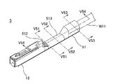
11,51 バレル部
11a,51a 内面
11a−1,51a−1 第1領域
11a−2,51a−2 第2領域
11a−3,51a−3 第3領域
11a−4,51a−4 経路
12 端子部
14 シール部材
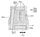
111,511 底板部
112,512 内バレル片
113,513 外バレル片
114,514 凹部
115,515 凸部
116 溝部
141 第1シール部分
142 第2シール部分
143 第3シール部分
D11 軸方向
D12 交差方向
G11 間隙
W1 被覆電線
W1a 端部
W11 アルミニウム芯線
W12 被覆部分
Claims (4)
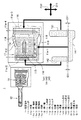
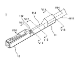
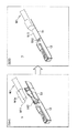
- アルミニウム芯線を有する被覆電線における前記アルミニウム芯線を露出させた端部に巻き付けられて圧着されるバレル部と、接続対象と接続される端子部と、が所定の軸方向に配列された圧着端子であって、
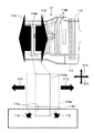
前記バレル部は、前記被覆電線の前記端部が載せられる、前記軸方向に延在する底板部と、当該底板部に対する平面視で前記軸方向と交差する交差方向の両側に前記底板部から延出した内バレル片及び外バレル片と、を有し、圧着時には前記内バレル片を内側にして前記端部に巻き付けられるものであり、
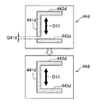
前記外バレル片を前記軸方向に縦断する第1領域、前記アルミニウム芯線よりも前記端子部寄りで前記バレル部の内面を前記交差方向に横断する第2領域、及び前記端部の被覆部分と交差するように前記内面を前記交差方向に横断する第3領域、に亘って設けられ、圧着後に、前記内バレル片と前記外バレル片との間と、筒状となる前記バレル部の前記端子部側の開口と、前記被覆部分と前記バレル部との間と、を密封する粘着ジェルシール部材を備え、
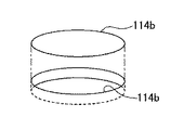
前記バレル部の前記内面には、当該内面に対する平面視で円形又は楕円形の凹部が複数分散して設けられており、
前記粘着ジェルシール部材は、前記第1領域で前記軸方向に帯状に延在する第1シール部分と、前記第2領域で前記交差方向に帯状に延在する第2シール部分と、前記第3領域で前記交差方向に帯状に延在する第3シール部分と、を備えており、
前記第2シール部分及び前記第3シール部分それぞれと、前記第1シール部分と、の間には間隙が開いていることを特徴とする圧着端子。 - 前記バレル部の前記内面には、前記第1領域、前記第2領域、及び前記第3領域に、前記粘着ジェルシール部材と重なるように溝部が形成されており、
複数の前記凹部は、前記溝部を避けて設けられていることを特徴とする請求項1に記載の圧着端子。 - 前記バレル部の前記底板部には、前記被覆電線の前記端部における前記アルミニウム芯線が載せられる位置に凸部が形成されていることを特徴とする請求項1または2に記載の圧着端子。
- 前記複数の凹部のうちの一部は、前記凸部上にも形成されていることを特徴とする請求項3に記載の圧着端子。
Priority Applications (5)
| Application Number | Priority Date | Filing Date | Title |
|---|---|---|---|
| JP2016253772A JP6858552B2 (ja) | 2016-12-27 | 2016-12-27 | 圧着端子 |
| CN201780073008.2A CN110024227B (zh) | 2016-12-27 | 2017-04-26 | 压接端子 |
| PCT/JP2017/016504 WO2018123101A1 (ja) | 2016-12-27 | 2017-04-26 | 圧着端子 |
| EP17887306.3A EP3565061B1 (en) | 2016-12-27 | 2017-04-26 | Crimp terminal |
| US16/420,559 US10756449B2 (en) | 2016-12-27 | 2019-05-23 | Crimp terminal |
Applications Claiming Priority (1)
| Application Number | Priority Date | Filing Date | Title |
|---|---|---|---|
| JP2016253772A JP6858552B2 (ja) | 2016-12-27 | 2016-12-27 | 圧着端子 |
Publications (3)
| Publication Number | Publication Date |
|---|---|
| JP2018106993A JP2018106993A (ja) | 2018-07-05 |
| JP2018106993A5 JP2018106993A5 (ja) | 2019-04-04 |
| JP6858552B2 true JP6858552B2 (ja) | 2021-04-14 |
Family
ID=62710185
Family Applications (1)
| Application Number | Title | Priority Date | Filing Date |
|---|---|---|---|
| JP2016253772A Active JP6858552B2 (ja) | 2016-12-27 | 2016-12-27 | 圧着端子 |
Country Status (5)
| Country | Link |
|---|---|
| US (1) | US10756449B2 (ja) |
| EP (1) | EP3565061B1 (ja) |
| JP (1) | JP6858552B2 (ja) |
| CN (1) | CN110024227B (ja) |
| WO (1) | WO2018123101A1 (ja) |
Families Citing this family (4)
| Publication number | Priority date | Publication date | Assignee | Title |
|---|---|---|---|---|
| JP6803877B2 (ja) * | 2018-07-09 | 2020-12-23 | 矢崎総業株式会社 | 端子付き電線 |
| DE102019109460A1 (de) * | 2019-04-10 | 2020-10-15 | Te Connectivity Germany Gmbh | Crimpkontakt |
| US11264735B1 (en) * | 2020-08-28 | 2022-03-01 | TE Connectivity Services Gmbh | Electrical terminal for terminating a wide size range of magnet wires |
| JP2023057203A (ja) * | 2021-10-11 | 2023-04-21 | 白山商事株式会社 | 圧着接続部材及び圧着接続方法 |
Family Cites Families (30)
| Publication number | Priority date | Publication date | Assignee | Title |
|---|---|---|---|---|
| JPS5940198B2 (ja) | 1977-04-12 | 1984-09-28 | 川研フアインケミカル株式会社 | 改良された固形洗剤 |
| JPS5842951B2 (ja) * | 1979-02-13 | 1983-09-22 | 住友電気工業株式会社 | アルミニウム導体電線の端子圧着法 |
| DE19549174A1 (de) * | 1995-10-28 | 1997-07-03 | Bosch Gmbh Robert | Kontaktelement mit Crimpabschnitt |
| JP3566541B2 (ja) * | 1998-03-31 | 2004-09-15 | 矢崎総業株式会社 | 防水コネクタ及び防水処理方法 |
| JP2009230998A (ja) * | 2008-03-21 | 2009-10-08 | Autonetworks Technologies Ltd | 端子金具付き電線の製造方法及び端子金具付き電線 |
| JP5146187B2 (ja) * | 2008-08-06 | 2013-02-20 | 住友電装株式会社 | 端子金具及びワイヤーハーネス |
| JP2010044913A (ja) * | 2008-08-11 | 2010-02-25 | Mitsubishi Materials Corp | 圧着接続端子 |
| JP2011096452A (ja) | 2009-10-28 | 2011-05-12 | Yazaki Corp | 圧着端子 |
| JP5606115B2 (ja) * | 2010-03-23 | 2014-10-15 | 矢崎総業株式会社 | 圧着端子の電線に対する接続構造 |
| JP5480368B2 (ja) * | 2010-03-30 | 2014-04-23 | 古河電気工業株式会社 | 圧着端子、接続構造体及びコネクタ |
| JP5675205B2 (ja) * | 2010-08-05 | 2015-02-25 | 矢崎総業株式会社 | 圧着端子 |
| JP2012059438A (ja) * | 2010-09-07 | 2012-03-22 | Sumitomo Wiring Syst Ltd | 防水コネクタ |
| JP5953591B2 (ja) * | 2012-04-05 | 2016-07-20 | 矢崎総業株式会社 | 圧着端子を電線に圧着する方法 |
| JP5899593B2 (ja) * | 2012-07-31 | 2016-04-06 | 矢崎総業株式会社 | 圧着端子付きアルミ電線 |
| CN202930577U (zh) * | 2012-11-30 | 2013-05-08 | 浙江荣得利航空部件有限公司 | 一种接线片 |
| CN104137341B (zh) * | 2013-02-21 | 2017-05-24 | 古河电气工业株式会社 | 压接端子、带端子电线及线束结构体 |
| DE102013203796A1 (de) * | 2013-03-06 | 2014-09-11 | Tyco Electronics Amp Gmbh | Elektrische Crimpkontaktvorrichtung |
| JP6063788B2 (ja) * | 2013-03-19 | 2017-01-18 | 矢崎総業株式会社 | 端子金具及び端子付き電線の製造方法 |
| DE102013205235B4 (de) * | 2013-03-25 | 2024-10-17 | Te Connectivity Germany Gmbh | Crimpverbindung sowie Crimpelement, Crimpvorrichtung und Verfahren zum Herstellen einer Crimpverbindung |
| DE112014003899T5 (de) * | 2013-08-26 | 2016-06-09 | Yazaki Corporation | Verbindungsstruktur eines Crimp-Anschlusses in Bezug auf einen Draht |
| JP2015079687A (ja) * | 2013-10-18 | 2015-04-23 | 矢崎総業株式会社 | 圧着端子 |
| JP6426907B2 (ja) * | 2014-04-04 | 2018-11-21 | 矢崎総業株式会社 | 圧着端子と電線の接続構造 |
| US9666956B2 (en) * | 2014-05-19 | 2017-05-30 | Yazaki Corporation | Minute current crimping terminal and minute current wire harness |
| WO2015194640A1 (ja) * | 2014-06-19 | 2015-12-23 | 株式会社フジクラ | 圧着端子 |
| JP5940198B2 (ja) | 2015-06-18 | 2016-06-29 | 古河電気工業株式会社 | 圧着端子、接続構造体及びコネクタ |
| JP6423783B2 (ja) * | 2015-12-16 | 2018-11-14 | 矢崎総業株式会社 | 圧着端子 |
| JP6422851B2 (ja) * | 2015-12-16 | 2018-11-14 | 矢崎総業株式会社 | 圧着端子の製造方法 |
| US9853368B2 (en) * | 2016-05-03 | 2017-12-26 | Te Connectivity Corporation | Electrical crimp terminal |
| JP6822834B2 (ja) * | 2016-12-27 | 2021-01-27 | 矢崎総業株式会社 | 圧着端子および端子製造方法 |
| JP6904147B2 (ja) * | 2017-08-01 | 2021-07-14 | 株式会社オートネットワーク技術研究所 | 端子付き電線 |
-
2016
- 2016-12-27 JP JP2016253772A patent/JP6858552B2/ja active Active
-
2017
- 2017-04-26 EP EP17887306.3A patent/EP3565061B1/en active Active
- 2017-04-26 CN CN201780073008.2A patent/CN110024227B/zh active Active
- 2017-04-26 WO PCT/JP2017/016504 patent/WO2018123101A1/ja not_active Ceased
-
2019
- 2019-05-23 US US16/420,559 patent/US10756449B2/en active Active
Also Published As
| Publication number | Publication date |
|---|---|
| US20190280399A1 (en) | 2019-09-12 |
| EP3565061B1 (en) | 2021-04-07 |
| US10756449B2 (en) | 2020-08-25 |
| WO2018123101A1 (ja) | 2018-07-05 |
| CN110024227B (zh) | 2021-05-25 |
| EP3565061A1 (en) | 2019-11-06 |
| CN110024227A (zh) | 2019-07-16 |
| JP2018106993A (ja) | 2018-07-05 |
| EP3565061A4 (en) | 2019-12-25 |
Similar Documents
| Publication | Publication Date | Title |
|---|---|---|
| JP6858552B2 (ja) | 圧着端子 | |
| JP6822834B2 (ja) | 圧着端子および端子製造方法 | |
| JP6886813B2 (ja) | 圧着端子 | |
| JP6886814B2 (ja) | 圧着端子 | |
| JP6858553B2 (ja) | 端子接続方法 | |
| EP3565062B1 (en) | Terminal-equipped electric wire and terminal production method |
Legal Events
| Date | Code | Title | Description |
|---|---|---|---|
| RD04 | Notification of resignation of power of attorney |
Free format text: JAPANESE INTERMEDIATE CODE: A7424 Effective date: 20180214 |
|
| RD04 | Notification of resignation of power of attorney |
Free format text: JAPANESE INTERMEDIATE CODE: A7424 Effective date: 20180815 |
|
| A521 | Request for written amendment filed |
Free format text: JAPANESE INTERMEDIATE CODE: A523 Effective date: 20190219 |
|
| A621 | Written request for application examination |
Free format text: JAPANESE INTERMEDIATE CODE: A621 Effective date: 20191119 |
|
| A131 | Notification of reasons for refusal |
Free format text: JAPANESE INTERMEDIATE CODE: A131 Effective date: 20201222 |
|
| A521 | Request for written amendment filed |
Free format text: JAPANESE INTERMEDIATE CODE: A523 Effective date: 20210210 |
|
| TRDD | Decision of grant or rejection written | ||
| A01 | Written decision to grant a patent or to grant a registration (utility model) |
Free format text: JAPANESE INTERMEDIATE CODE: A01 Effective date: 20210316 |
|
| A61 | First payment of annual fees (during grant procedure) |
Free format text: JAPANESE INTERMEDIATE CODE: A61 Effective date: 20210324 |
|
| R150 | Certificate of patent or registration of utility model |
Ref document number: 6858552 Country of ref document: JP Free format text: JAPANESE INTERMEDIATE CODE: R150 |
|
| S531 | Written request for registration of change of domicile |
Free format text: JAPANESE INTERMEDIATE CODE: R313531 |
|
| R350 | Written notification of registration of transfer |
Free format text: JAPANESE INTERMEDIATE CODE: R350 |
|
| R250 | Receipt of annual fees |
Free format text: JAPANESE INTERMEDIATE CODE: R250 |
|
| R250 | Receipt of annual fees |
Free format text: JAPANESE INTERMEDIATE CODE: R250 |
|
| R250 | Receipt of annual fees |
Free format text: JAPANESE INTERMEDIATE CODE: R250 |