EP3565061B1 - Crimp terminal - Google Patents
Crimp terminal Download PDFInfo
- Publication number
- EP3565061B1 EP3565061B1 EP17887306.3A EP17887306A EP3565061B1 EP 3565061 B1 EP3565061 B1 EP 3565061B1 EP 17887306 A EP17887306 A EP 17887306A EP 3565061 B1 EP3565061 B1 EP 3565061B1
- Authority
- EP
- European Patent Office
- Prior art keywords
- seal
- seal member
- barrel
- crimp terminal
- region
- Prior art date
- Legal status (The legal status is an assumption and is not a legal conclusion. Google has not performed a legal analysis and makes no representation as to the accuracy of the status listed.)
- Active
Links
- 238000002788 crimping Methods 0.000 claims description 75
- AZDRQVAHHNSJOQ-UHFFFAOYSA-N alumane Chemical group [AlH3] AZDRQVAHHNSJOQ-UHFFFAOYSA-N 0.000 claims description 67
- 239000000853 adhesive Substances 0.000 claims description 18
- 230000001070 adhesive effect Effects 0.000 claims description 18
- 238000004519 manufacturing process Methods 0.000 description 34
- 229910052751 metal Inorganic materials 0.000 description 24
- 239000002184 metal Substances 0.000 description 24
- 238000000034 method Methods 0.000 description 13
- 238000010586 diagram Methods 0.000 description 11
- 238000005452 bending Methods 0.000 description 9
- 230000000052 comparative effect Effects 0.000 description 8
- 230000000694 effects Effects 0.000 description 7
- 238000007789 sealing Methods 0.000 description 7
- 238000002360 preparation method Methods 0.000 description 6
- 230000015572 biosynthetic process Effects 0.000 description 5
- 238000004080 punching Methods 0.000 description 4
- 229910000881 Cu alloy Inorganic materials 0.000 description 3
- 238000003825 pressing Methods 0.000 description 3
- 238000005260 corrosion Methods 0.000 description 2
- 230000007797 corrosion Effects 0.000 description 2
- 150000002739 metals Chemical class 0.000 description 2
- 238000007747 plating Methods 0.000 description 2
- RYGMFSIKBFXOCR-UHFFFAOYSA-N Copper Chemical group [Cu] RYGMFSIKBFXOCR-UHFFFAOYSA-N 0.000 description 1
- ATJFFYVFTNAWJD-UHFFFAOYSA-N Tin Chemical compound [Sn] ATJFFYVFTNAWJD-UHFFFAOYSA-N 0.000 description 1
- NIXOWILDQLNWCW-UHFFFAOYSA-N acrylic acid group Chemical group C(C=C)(=O)O NIXOWILDQLNWCW-UHFFFAOYSA-N 0.000 description 1
- 229910052782 aluminium Inorganic materials 0.000 description 1
- XAGFODPZIPBFFR-UHFFFAOYSA-N aluminium Chemical compound [Al] XAGFODPZIPBFFR-UHFFFAOYSA-N 0.000 description 1
- 239000010953 base metal Substances 0.000 description 1
- PCHJSUWPFVWCPO-UHFFFAOYSA-N gold Chemical compound [Au] PCHJSUWPFVWCPO-UHFFFAOYSA-N 0.000 description 1
- 239000010931 gold Substances 0.000 description 1
- 229910052737 gold Inorganic materials 0.000 description 1
- 239000000463 material Substances 0.000 description 1
- 230000002093 peripheral effect Effects 0.000 description 1
- 239000011347 resin Substances 0.000 description 1
- 229920005989 resin Polymers 0.000 description 1
- 238000004904 shortening Methods 0.000 description 1
- 238000004804 winding Methods 0.000 description 1
Images


Classifications
-
- H—ELECTRICITY
- H01—ELECTRIC ELEMENTS
- H01R—ELECTRICALLY-CONDUCTIVE CONNECTIONS; STRUCTURAL ASSOCIATIONS OF A PLURALITY OF MUTUALLY-INSULATED ELECTRICAL CONNECTING ELEMENTS; COUPLING DEVICES; CURRENT COLLECTORS
- H01R4/00—Electrically-conductive connections between two or more conductive members in direct contact, i.e. touching one another; Means for effecting or maintaining such contact; Electrically-conductive connections having two or more spaced connecting locations for conductors and using contact members penetrating insulation
- H01R4/10—Electrically-conductive connections between two or more conductive members in direct contact, i.e. touching one another; Means for effecting or maintaining such contact; Electrically-conductive connections having two or more spaced connecting locations for conductors and using contact members penetrating insulation effected solely by twisting, wrapping, bending, crimping, or other permanent deformation
- H01R4/18—Electrically-conductive connections between two or more conductive members in direct contact, i.e. touching one another; Means for effecting or maintaining such contact; Electrically-conductive connections having two or more spaced connecting locations for conductors and using contact members penetrating insulation effected solely by twisting, wrapping, bending, crimping, or other permanent deformation by crimping
- H01R4/183—Electrically-conductive connections between two or more conductive members in direct contact, i.e. touching one another; Means for effecting or maintaining such contact; Electrically-conductive connections having two or more spaced connecting locations for conductors and using contact members penetrating insulation effected solely by twisting, wrapping, bending, crimping, or other permanent deformation by crimping for cylindrical elongated bodies, e.g. cables having circular cross-section
- H01R4/184—Electrically-conductive connections between two or more conductive members in direct contact, i.e. touching one another; Means for effecting or maintaining such contact; Electrically-conductive connections having two or more spaced connecting locations for conductors and using contact members penetrating insulation effected solely by twisting, wrapping, bending, crimping, or other permanent deformation by crimping for cylindrical elongated bodies, e.g. cables having circular cross-section comprising a U-shaped wire-receiving portion
- H01R4/185—Electrically-conductive connections between two or more conductive members in direct contact, i.e. touching one another; Means for effecting or maintaining such contact; Electrically-conductive connections having two or more spaced connecting locations for conductors and using contact members penetrating insulation effected solely by twisting, wrapping, bending, crimping, or other permanent deformation by crimping for cylindrical elongated bodies, e.g. cables having circular cross-section comprising a U-shaped wire-receiving portion combined with a U-shaped insulation-receiving portion
-
- H—ELECTRICITY
- H01—ELECTRIC ELEMENTS
- H01R—ELECTRICALLY-CONDUCTIVE CONNECTIONS; STRUCTURAL ASSOCIATIONS OF A PLURALITY OF MUTUALLY-INSULATED ELECTRICAL CONNECTING ELEMENTS; COUPLING DEVICES; CURRENT COLLECTORS
- H01R4/00—Electrically-conductive connections between two or more conductive members in direct contact, i.e. touching one another; Means for effecting or maintaining such contact; Electrically-conductive connections having two or more spaced connecting locations for conductors and using contact members penetrating insulation
- H01R4/58—Electrically-conductive connections between two or more conductive members in direct contact, i.e. touching one another; Means for effecting or maintaining such contact; Electrically-conductive connections having two or more spaced connecting locations for conductors and using contact members penetrating insulation characterised by the form or material of the contacting members
- H01R4/62—Connections between conductors of different materials; Connections between or with aluminium or steel-core aluminium conductors
-
- H—ELECTRICITY
- H01—ELECTRIC ELEMENTS
- H01R—ELECTRICALLY-CONDUCTIVE CONNECTIONS; STRUCTURAL ASSOCIATIONS OF A PLURALITY OF MUTUALLY-INSULATED ELECTRICAL CONNECTING ELEMENTS; COUPLING DEVICES; CURRENT COLLECTORS
- H01R4/00—Electrically-conductive connections between two or more conductive members in direct contact, i.e. touching one another; Means for effecting or maintaining such contact; Electrically-conductive connections having two or more spaced connecting locations for conductors and using contact members penetrating insulation
- H01R4/10—Electrically-conductive connections between two or more conductive members in direct contact, i.e. touching one another; Means for effecting or maintaining such contact; Electrically-conductive connections having two or more spaced connecting locations for conductors and using contact members penetrating insulation effected solely by twisting, wrapping, bending, crimping, or other permanent deformation
- H01R4/18—Electrically-conductive connections between two or more conductive members in direct contact, i.e. touching one another; Means for effecting or maintaining such contact; Electrically-conductive connections having two or more spaced connecting locations for conductors and using contact members penetrating insulation effected solely by twisting, wrapping, bending, crimping, or other permanent deformation by crimping
- H01R4/188—Electrically-conductive connections between two or more conductive members in direct contact, i.e. touching one another; Means for effecting or maintaining such contact; Electrically-conductive connections having two or more spaced connecting locations for conductors and using contact members penetrating insulation effected solely by twisting, wrapping, bending, crimping, or other permanent deformation by crimping having an uneven wire-receiving surface to improve the contact
-
- H—ELECTRICITY
- H01—ELECTRIC ELEMENTS
- H01R—ELECTRICALLY-CONDUCTIVE CONNECTIONS; STRUCTURAL ASSOCIATIONS OF A PLURALITY OF MUTUALLY-INSULATED ELECTRICAL CONNECTING ELEMENTS; COUPLING DEVICES; CURRENT COLLECTORS
- H01R4/00—Electrically-conductive connections between two or more conductive members in direct contact, i.e. touching one another; Means for effecting or maintaining such contact; Electrically-conductive connections having two or more spaced connecting locations for conductors and using contact members penetrating insulation
- H01R4/70—Insulation of connections
-
- H—ELECTRICITY
- H01—ELECTRIC ELEMENTS
- H01R—ELECTRICALLY-CONDUCTIVE CONNECTIONS; STRUCTURAL ASSOCIATIONS OF A PLURALITY OF MUTUALLY-INSULATED ELECTRICAL CONNECTING ELEMENTS; COUPLING DEVICES; CURRENT COLLECTORS
- H01R43/00—Apparatus or processes specially adapted for manufacturing, assembling, maintaining, or repairing of line connectors or current collectors or for joining electric conductors
- H01R43/04—Apparatus or processes specially adapted for manufacturing, assembling, maintaining, or repairing of line connectors or current collectors or for joining electric conductors for forming connections by deformation, e.g. crimping tool
- H01R43/048—Crimping apparatus or processes
-
- H—ELECTRICITY
- H01—ELECTRIC ELEMENTS
- H01R—ELECTRICALLY-CONDUCTIVE CONNECTIONS; STRUCTURAL ASSOCIATIONS OF A PLURALITY OF MUTUALLY-INSULATED ELECTRICAL CONNECTING ELEMENTS; COUPLING DEVICES; CURRENT COLLECTORS
- H01R13/00—Details of coupling devices of the kinds covered by groups H01R12/70 or H01R24/00 - H01R33/00
- H01R13/46—Bases; Cases
- H01R13/52—Dustproof, splashproof, drip-proof, waterproof, or flameproof cases
- H01R13/5216—Dustproof, splashproof, drip-proof, waterproof, or flameproof cases characterised by the sealing material, e.g. gels or resins
Definitions
- the present invention relates to a crimp terminal configured to be crimp-connected to a covered electric wire having an aluminum core wire.
- a covered electric wire having an aluminum core wire has been used for a wire harness in place of a covered electric wire having a copper core wire.
- Some crimp terminals such as connector terminals, for example, are made of a copper alloy or the like and having a surface that is tin-plated or gold-plated.
- the crimp terminal of this type is crimped to an end portion of the covered electric wire where the aluminum core wire is exposed, contact between dissimilar metals occurs between the aluminum core wire and a crimping barrel portion of the crimp terminal. If moisture adheres to such contact portion, the aluminum core wire made of aluminum which is a base metal could be corroded due to so-called dissimilar metal corrosion.
- FIG. 49 shows an example of a conventional crimp terminal having a seal member arranged to surround a contact portion between a barrel portion and an aluminum core wire.
- a crimp terminal 7 shown in FIG. 49 includes a barrel portion 71 and a terminal portion 72 arranged in a predetermined axial direction D71.
- the barrel portion 71 and the terminal portion 72 are produced from a metal plate made of a copper alloy or the like using sheet-metal processing and have a surface that is subjected to tin plating or gold plating.
- the barrel portion 71 is a portion that is wound around and crimped to an end portion W7a of a covered electric wire W7 having an aluminum core wire W71, where the aluminum core wire W71 is exposed.
- the terminal portion 72 is a female terminal configured to be connected to a pin terminal, not shown, as an object to be connected.
- the barrel portion 71 is configured by bending the metal plate so that a cross section thereof intersecting with the axial direction D71 has a substantially U-like shape. After the end portion W7a of the covered electric wire W7 is placed on an inner surface 711 of the barrel portion 71, the barrel portion 71 is wound around and crimped to the end portion W7a. A part of the inner surface 711 of the barrel portion 71 serves as a contact portion 711a with the aluminum core wire W71 at the end portion W7a.
- a seal member 73 is provided so as to surround the contact portion 711a.
- the seal member 73 seals gaps at the respective portions around the contact portion 711a and prevents moisture from entering.
- the contact portion 711a is provided with a serration 74 having a plurality of grooves arranged in rows in the axial direction D71, each groove extending in an intersecting direction D72 that intersects with the axial direction D71 in a plan view with respect to the contact portion 711a.
- a serration 74 having a plurality of grooves arranged in rows in the axial direction D71, each groove extending in an intersecting direction D72 that intersects with the axial direction D71 in a plan view with respect to the contact portion 711a.
- Patent Document 1 JP 5940198 B
- This crimp terminal (1) comprises:
- the above-described conventional crimp terminal as shown as one example in FIG. 49 requires an area of the serration at the inner surface of the barrel portion to be as wide as possible, in order to obtain good electrical continuity between the covered electric wire and the crimp terminal.
- the seal member is provided so as not to hinder sufficient contact between this serration and the aluminum core wire.
- a space for providing the seal member is arranged narrow, frequently causing difficulty of manufacture.
- an object of the present invention is to provide a crimp terminal that can reduce a difficulty of manufacturing while ensuring waterproof property with respect to a contact portion with an aluminum core wire.
- edge of each recess provided on the inner surface of the barrel portion bites into the aluminum core wire, thereby providing good electrical continuity between the covered electric wire and the crimp terminal. That is, the plurality of recesses is dispersedly provided, thereby forming a serration on the inner surface of the barrel portion. Degree of electrical continuity at the serration is determined by sum of lengths of portions which bite into the aluminum core wire per unit area. In the crimp terminal of the present invention, this sum of lengths corresponds to sum of perimeters of the recesses formed into a circular shape or oval shape. In contrast, for example, in the serration 74 shown in FIG.
- an area of the serration required to obtain good electrical continuity between the covered electric wire and the crimp terminal can be reduced compared to, for example, the conventional crimp terminal 7 shown in FIG. 49 .
- the circular or oval recess has a resistance force against a force to expand the recess in an in-plane direction of the inner surface 11a of the barrel portion 11 that is stronger compared to, for example, a groove constituting the serration 74 shown in FIG 49 .
- Pressure applied to the barrel portion during the crimping is force acting in the in-plane direction of the inner surface of the barrel portion, and in the crimp terminal of the present invention, the resistance force at each recess against such pressure is strong. Consequently, according to the crimp terminal of the present invention, the elongation of the barrel portion due to the pressure applied during the crimping can be inhibited. As a result, elongation of the seal member can also be inhibited, thereby ensuring waterproof property at a high level. In this sense also, the crimp terminal of the present invention can reduce difficulty of manufacturing while ensuring waterproof property at a high level.
- a groove is formed on the inner surface of the barrel portion in the first region, the second region and the third region so as to overlap with the seal member, and wherein the plurality of recesses is provided so as to avoid the groove.
- this crimp terminal in the preferable form According to this crimp terminal in the preferable form, movement of the seal member due to the pressure applied during the crimping can be inhibited by the groove overlapping with the seal member. Therefore, the crimp terminal of this crimp terminal in the preferable form can reduce difficulty of manufacturing while ensuring waterproof property at a higher level.
- the crimp terminal that can reduce a difficulty of manufacturing while ensuring waterproof property with respect to the contact portion with the aluminum core wire, can be provided.
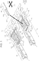
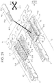
- FIG. 1 illustrates a crimp terminal according to the first embodiment of the present invention.
- a crimp terminal 1 is configured to be crimped to an end portion W1a of a covered electric wire W1 having an aluminum core wire W11, at which the aluminum core wire W11 is exposed.
- the crimp terminal 1 includes a barrel portion 11, a terminal portion 12 and a seal member 14.
- FIG. 1 two crimp terminals 1 are shown, of which one crimp terminal 1 is shown with the seal member 14 removed for the purpose of providing a view of shape of an inner surface of the barrel portion 11.
- the barrel portion 11 and the terminal portion 12 are produced from a metal plate made of a copper alloy or the like using punching and sheet-metal processing, and a surface thereof is tin-plated or gold-plated.
- the barrel portion 11 and the terminal portion 12 are arranged in a predetermined axial direction D11.
- the barrel portions 11 and the terminal portions 12 are collectively formed in a state that a plurality of crimp terminals 1 is connected to each other by a strip-like connecting piece 1a.
- the barrel portion 11 is a plate-like portion that is to be wound around and crimped to the end portion W1a of the covered electric wire W1 so as to circumferentially wrap the aluminum core wire W11 and a covered portion W12.
- the terminal portion 12 is a quadrangular tube-shaped female terminal configured to be connected to a pin terminal, not shown, as an object to be connected.
- the barrel portion 11 includes a bottom plate 111, an inner barrel piece 112 and an outer barrel piece 113.
- the bottom plate 111 is a portion extending in the above-described axial direction D11.
- the inner barrel piece 112 and the outer barrel piece 113 are portions extending from the bottom plate 111 on both sides in an intersecting direction D12 intersecting the axial direction D11 in a plan view with respect to the bottom plate 111.
- a plurality of recesses 114 is dispersedly provided on an inner surface 11a of the barrel portion 11.
- Each recess 114 is formed into a circular shape in a plan view with respect to the inner surface 11a of the barrel portion 11.
- a protrusion 115 is formed on the bottom plate 111 of the barrel portion 11 at a location where the aluminum core wire W11 at the end portion W1a of the covered electric wire W1 is to be placed, and is formed by pressing applied from an outer surface side. Some of the plurality of recesses 114 are also formed on this protrusion 115.
- a seal member 14 formed of an adhesive gel sheet is attached to the inner surface 11a of the barrel portion 11 so as to surround the plurality of recesses 114 from three sides in a plan view.
- the seal member 14 is attached as described below.
- examples of the adhesive gel sheet may include, but not limited to, those using acrylic adhesives.
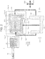
- FIG. 2 illustrates how the seal member shown in FIG. 1 is attached to the inner surface of the barrel portion.
- the seal member 14 is formed of an adhesive gel sheet and is arranged over three regions on the inner surface 11a of the barrel portion 11, namely a first region 11a-1, a second region 11a-2 and a third region 11a-3.
- the first region 11a-1 is a region that traverses the outer barrel piece 113 in the axial direction D11.
- the second region 11a-2 is a region that traverses the inner surface 11a in the intersecting direction D12 on a side closer to the terminal portion 12 than the aluminum core wire W11 when the end portion W1a is placed.
- the third region 11a-3 is a region that traverses the inner surface 11a in the intersecting direction D12 so as to intersect with the covered portion W12 of the end portion W1a.
- the seal member 14 is composed of three portions, namely, a first seal portion 141, a second seal portion 142 and a third seal portion 143.
- the first seal portion 141 is a portion extending in a strip-like shape in the axial direction D11 in the first region 11a-1.
- the second seal portion 142 is a portion extending in a strip-like shape in the intersecting direction D12 in the second region 11a-2.
- the third seal portion 143 is a portion extending in a strip-like shape in the intersecting direction D12 in the third region 11a-3.
- the seal member 14 is attached in a divided manner that the seal member 14 is divided in the partway of a path 11a-4 extending from the second region 11a-2 through the first region 11a-1 to the third region 11a-3. Specifically, the seal member 14 is attached in a manner that both of the second seal portion 142 and the third seal portion 143 are divided from the first seal portion 141. Further, each of the second seal portion 142 and the third seal portion 143 is attached while being divided from the first seal portion 141 in a manner traversing the path 11a-4 in the axial direction D11. Slight gaps G11 are formed between the second seal portion 142 and the first seal portion 141, and between the third seal portion 143 and the first seal portion 141.
- a groove 116 is formed in the first region 11a-1, the second region 11a-2 and the third region 11a-3, so as to overlap with the seal member 14.
- one groove 116 extends in the axial direction D11 while bending in a sawtooth shape in the partway.
- one groove 116 extends linearly in the intersecting direction D12
- three grooves 116 extend linearly in the intersecting direction D12 and are joined on a side of the first region 11a-1.
- the plurality of recesses 114 is provided so as to avoid the grooves 116.
- the first seal portion 141, the second seal portion 142 and the third seal portion 143 are attached so as to overlap the grooves 116 of the first region 11a-1, the second region 11a-2 and the third region 11a-3, respectively.
- the plurality of recesses 114 is provided such that a part thereof overlaps with the seal member 14. Specifically, as shown in FIG. 2 , the recesses 114 located closest to an edge of the outer barrel piece 113 partially overlap with the first region 11a-1, and the recesses 114 located closest to the terminal portion 12 partially overlap with the second region 11a-2. As a result, the part of the recesses 114 will partially overlap with the first seal portion 141 that is attached to the first region 11a-1 and with the second seal portion 142 that is attached to the second region 11a-2.
- the crimp terminal 1 described above is manufactured using a terminal manufacturing method as described below.
- a sheet-metal processing step for forming a structural object prior to the attachment of the seal member 14 is performed.
- the barrel portion 11 is formed together with the terminal portion 12 from the metal plate.
- the barrel portion 11 and the terminal portion 12 are collectively formed with the plurality of crimp terminals 1 connected together by the strip-like connecting piece 1a.
- the formation of the plurality of recesses 114, the formation of the protrusion 115 and the formation of the grooves 116 on the inner surface 11a of the barrel portion 11 are also performed.
- the seal member attaching step is performed in which the seal member 14 is formed from an adhesive gel sheet, and the seal member 14 is attached over the first region 11a-1, the second region 11a-2 and the third region 11a-3.
- This seal member attaching step is a step for attaching the seal member 14 in a manner that the seal member 14 is divided in the partway of the path 11a-4 extending from the second region 11a-2 through the first region lla-1 to the third region 11a-3.
- the first seal portion 141, the second seal portion 142 and the third seal portion 143 are individually attached to the inner surface 11a of the barrel portion 11.
- the first seal portion 141, the second seal portion 142 and the third seal portion 143 are punched out from the adhesive gel sheet and attached to the inner surface 11a of the barrel portion 11.
- the punching out and the attaching are performed at approximately the same time.
- the crimp terminal 1 manufactured as described above is crimped to the end portion W1a of the covered electric wire W1 as follows.
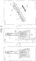
- FIG. 3 illustrates a procedure for completing preparation of the crimp terminal shown in FIGS. 1 and 2 that is ready to be crimped to the end portion of the covered electric wire using the terminal connecting method
- FIG. 4 illustrates a procedure, that follows the procedure shown in FIG. 3 , for crimping the crimp terminal to the end portion of the covered electric wire.
- FIG. 3 also shows the sheet-metal processing step (S11) and the seal member attaching step (S12) in the terminal manufacturing method described above.
- the barrel portion 11 and the terminal portion 12 are formed in the sheet-metal processing step (S11), and the first seal portion 141, the second seal portion 142 and the third seal portion 143 constituting the seal member 14 are attached in the seal member attaching step (S12).
- the crimp terminal 1 to be crimped is detached from the connecting piece 1a shown in FIG. 1 . Then, this barrel portion 11 is subjected to a bending deformation as preparation for placing the end portion W1a of the covered electric wire W1 (S13). This bending deformation is performed such that the inner barrel piece 112 and the outer barrel piece 113 are brought close to each other so that the cross section intersecting with the axial direction D11 is formed into a substantially U-like shape.
- the end portion W1a of the covered electric wire W1 is placed onto the barrel portion 11 after being subjected to the bending deformation (S14) .
- the end portion W1a is placed such that a tip of the aluminum core wire W11 does not overlap with the second seal portion 142.
- a small overlap between the tip of the aluminum core wire W11 and the second seal portion 142 is allowed.
- the barrel portion 11 is wound around and crimped to the end portion W1a such that the inner barrel piece 112 is arranged inside and the outer barrel piece 113 is placed onto the inner barrel piece 112 (S15).
- the seal member 14 seals the respective portions of the crimp terminal 1 as follows.
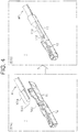
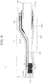
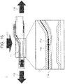
- FIG. 5 shows the crimp terminal after the crimping that is also shown in FIG. 4 .
- FIG. 6 shows changes during the crimping operation in a cross section taken along line V11-V11, a cross section taken along line V12-V12, and a cross section taken along line V13-V13 in FIG. 5 .
- a first step (S151) of the crimping operation bending of the inner barrel piece 112 and the outer barrel piece 113 is started such that the inner barrel piece 112 and the outer barrel piece 113 are wound around the aluminum core wire W11 on the protrusion 115 and around the covered portion W12 in the vicinity thereof.
- the positional relationship is such that, the first seal portion 141 is in contact with the aluminum core wire W11, the third seal portion 143 is in contact with the covered portion W12, and large part of the second seal portion 142 is substantially not in contact with any of the aluminum core wire W11 and the covered portion W12.
- a second step (S152) and a third step (S153) where the winding is slightly advanced, the barrel portion 11 is formed into a tubular shape. Then, the first seal portion 141 is sandwiched between the inner barrel piece 112 and the outer barrel piece 113, and the third seal portion 143 is elongated while being sandwiched between the covered portion W12 and the barrel portion 11.
- the slight gaps G11 are formed between the second seal portion 142 and the first seal portion 141, and between the third seal portion 143 and the first seal portion 141. These gaps G11 are closed by the above-described elongation of the seal member 14 during the crimping.
- FIG. 7 is a schematic view showing how the gaps between the second seal portion and the first seal portion and between the third seal portion and the first seal portion shown in FIG. 2 are closed by the elongation of the seal member during the crimping.
- the second seal portion 142 and the third seal portion 143 are elongated in the intersecting direction D12 which coincides with a length direction thereof. Due to this elongation, the second seal portion 142 and the third seal portion 143 are connected to the first seal portion 141, thereby closing the above-described gaps G11.
- FIG. 8 is a cross sectional view taken along line V14-V14 in FIG. 5 and illustrates how the seal member seals the respective portions of the barrel portion of the crimp terminal after the crimping.
- the space between the inner barrel piece 112 and the outer barrel piece 113 is sealed by the first seal portion 141, and the opening 11b of the barrel part 11 on the side of the terminal portion 12 is sealed by the second seal portion 142.
- the space between the covered portion W12 and the barrel portion 11 is sealed by the third seal portion 143.
- a dimension of the barrel portion 11 after the crimping (hereinafter called, "crimp height CH11") in an up-down direction in FIG. 8 in which pressure is mainly applied, is set to be the following dimension. That is, the dimension is set such that the tubular barrel portion 11 is crushed to an extent that a part of the seal member 14 formed of an adhesive gel sheet having a certain thickness and width projects from the opening 11b of the barrel portion 11.
- the crimp height CH11 By setting the crimp height CH11 to this dimension, the opening 11b of the barrel portion 11 will be sealed at a high level.
- the dimension such as a width of each of the first seal portion 141, the second seal portion 142 and the third seal portion 143 constituting the seal member 14 is set to a dimension necessary and sufficient to achieve the above-described sealing after the crimping.
- each portion of the seal member 14 so as to project from the opening 11b of the barrel portion 11 and from the side of the barrel portion 11 at which the covered electric wire W1 extends out, it is possible to visually check that these portions are securely sealed with the seal member 14 after the crimping.
- FIG. 9 shows a crimp terminal of a first modified example with respect to the crimp terminal of the first embodiment shown in FIGS. 1-8 .
- FIG. 10 shows a cross-sectional view, that is similar to FIG. 8 , of the crimp terminal of the first modified example shown in FIG. 9 .
- elements similar to those shown in FIGS. 1-8 are denoted by the same reference signs as FIGS. 1-8 , and explanation of these similar elements is omitted in the following description.
- a crimp terminal 2 of this first modified example is crimped such that a crimp height CH21 at the terminal portion 12 side of a barrel portion 21 (hereinafter called, "front end portion 211") after the crimping is greater than a crimp height CH22 of a crimp portion 212 of the aluminum core wire W11.
- the crimp height CH21 of the front end portion 211 has a dimension that allows a part of the seal member 14 to project from the opening 11b of the barrel portion 11 and seal at a high level.
- the dimension such as a width of each of the first seal portion 141, the second seal portion 142 and the third seal portion 143 constituting the seal member 14 is set to a dimension necessary and sufficient to achieve the above-described sealing after the crimping.
- the crimping causes the edges of the respective recesses 114 provided on the inner surface 11a of the barrel portion 11 to bite into the aluminum core wire W1a, thereby providing good electrical continuity between the covered electric wire W1 and the crimp terminal 1.
- the seal member 14 formed of an adhesive gel sheet is attached to the inner surface 11a of the barrel portion 11. This seal member 14 seals, after the crimping, the space between the inner barrel piece 112 and the outer barrel piece 113, the opening 11b of the barrel portion 11, that is formed into a tubular shape, on the side of the terminal portion 12, and the space between the covered portion W12 and the barrel portion 11.
- This seal member 14 ensures waterproof property with respect to a contact portion at which a dissimilar metal contact occurs between the aluminum core wire W1a and the inner surface 11a of the barrel portion 11. Further, in this embodiment, the seal member 14 is attached in a divided manner that it is divided in the partway of a path 11a-4 extending from the second region 11a-2 through the first region 11a-1 to the third region 11a-3. That is, the seal member 14, which has a complicated shape to follow the above-described path 11a-4 in order to obtain waterproof property, is divided into individual pieces and attached piece by piece.
- FIG. 11 illustrates a crimp terminal of a second modified example with respect to the crimp terminal of the first embodiment shown in FIGS. 1-8
- FIG. 12 is a schematic diagram illustrating how a seal member shown in FIG. 11 is attached to an inner surface of a barrel portion.
- elements similar to those shown in FIGS. 1-8 are denoted by the same reference signs as FIGS. 1-8 , and explanation of these similar elements is omitted in the following description.
- two crimp terminals 3 are shown, of which one crimp terminal 3 is shown with a seal member 34 removed for the purpose of providing a view of shape of an inner surface of the barrel portion 11.
- the seal member 34 is not divided, and is formed into a C-like shape in a plan view with a second seal portion 342 and a third seal portion 343 extending from and integrally connected with a first seal portion 341 in a two arms fashion.
- This seal member 34 is attached to a region lla-5 having a C-like shape in a plan view, so as to overlap with the grooves 116 on the inner surface 11a of the barrel portion 11 and with a part of the plurality of recesses 114.
- the first seal portion 341 seals a space between the inner barrel piece 112 and the outer barrel piece 113
- the second seal portion 342 seals the opening of the tubular barrel portion 11 on the side of the terminal portion 12
- the third seal portion 343 seals a space between the covered portion W12 and the barrel portion 11.
- the crimp terminal 1 of the first embodiment described above can facilitate the attaching of the seal member 14 which is divided into three pieces and attached piece by piece.
- difficulty of manufacturing can be reduced while ensuring waterproof property with respect to the contact portion with the aluminum core wire W1a.
- the seal member 14 is a sheet made of an adhesive gel having a predetermined thickness, an amount of the gel required to appropriately seal the above-described portions can be adjusted easily and accurately during the manufacture, based on an area of the seal member 14.
- the crimp terminal 1 of this embodiment can reduce difficulty of manufacturing while ensuring waterproof property at a high level, as compared to a case such as applying gel-like resin material for sealing.
- the divided seal member 14 is elongated by the crimping and connected, as explained above with reference to FIG. 7 .
- a rate of elongation by the crimping is greater in the intersecting direction D12 than in the axial direction D11.
- the seal member 14 since the seal member 14 is divided in a manner traversing the above-described path 11a-4 in the axial direction D11, the divided portion will be connected during the crimping due to the elongation in the intersecting direction D12 along which the rate of elongation is greater. Therefore, even more improved waterproof property can be ensured.
- the seal member 14 is attached in a very simple shape that is a shape of a single strip including all of the first seal portion 141, the second seal portion 142 and the third seal portion 143.
- the crimp terminal 1 of this embodiment can further reduce difficulty of manufacturing.
- the grooves 116 are formed on the inner surface 11a of the barrel portion 11 so as to overlap with the seal member 14, and the plurality of recesses 114 is provided so as to avoid the grooves 116. Consequently, movement of the seal member 14 due to the pressure applied during the crimping can be inhibited by the grooves 116 overlapping with the seal member 14. Therefore, the crimp terminal 1 of this embodiment can reduce difficulty of manufacturing while ensuring waterproof property at a higher level.
- the groove 116 provided on the inner surface 11a of the barrel portion 11 contributes to ensure waterproof property at a high level also in the following respect.
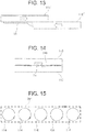
- FIG. 13 is a schematic diagram showing an example in which the groove is not provided on the inner surface of the barrel portion, as a comparative example to explain that the groove provided on the inner surface of the barrel portion contributes to ensure waterproof property at a high level.
- FIG. 14 illustrates that the groove provided on the inner surface of the barrel portion contributes to ensure waterproof property at a high level in comparison with the example of FIG. 13 .
- the seal member 14 attached to an outer barrel piece 113' may be moved to one side by an edge of an inner barrel piece 112' during the crimping.
- the groove 116 provided so as to overlap with the seal member 14 at least a part of the seal member 14 is secured inside the groove 116 even if the seal member 14 is moved to one side.
- the groove 116 provided on the inner surface 11a of the barrel portion 11 contributes to ensure waterproof property at a high level.
- the seal member 14 is attached with the seal member 14 being divided up, thereby reducing difficulty of manufacturing while ensuring waterproof property with respect to the contact portion with the aluminum core wire W1a.
- the seal member 14 is formed of an adhesive gel sheet, difficulty of manufacturing can be reduced while ensuring waterproof property at a high level.
- each recess 114 provided on the inner surface 11a of the barrel portion 11 bites into the aluminum core wire W11, and by which good electrical continuity between the covered electric wire W1 and the crimp terminal 1 is obtained. That is, the plurality of recesses 114 is dispersedly provided, thereby forming a serration on the inner surface 11a of the barrel portion 11. Degree of electrical continuity at the serration is determined by sum of lengths of portions which bite into the aluminum core wire W11 per unit area.
- FIG. 15 is a schematic diagram showing the crimp terminal shown in FIGS. 1-8 and showing that a degree of electrical continuity with the aluminum core wire is determined by the sum of lengths of portions which bite into the aluminum core wire per unit area.
- the sum of lengths of portions that bite into the aluminum core wire W11 corresponds to sum of perimeters of the recesses 114 formed into a circular shape.
- the serration 74 shown in FIG. 49 that is constituted of a groove 741, it is the sum of lengths of edges of the linearly extending groove 741, and, considering this sum in terms of per unit area, the sum of perimeters of the plurality of recesses 114 formed into a circular shape is greater.
- an area of the serration required to obtain good electrical continuity between the covered electric wire W11 and the crimp terminal 1 can be reduced compared to, for example, the conventional crimp terminal 7 shown in FIG.
- the crimp terminal 1 of this embodiment can reduce difficulty of manufacturing while ensuring waterproof property with respect to the contact portion with the aluminum core wire W11.
- the circular recess 114 has a resistance force against a force to expand the recess 114 in an in-plane direction of the inner surface 11a of the barrel portion 11 is stronger compared to, for example, a linear groove.
- Pressure applied to the barrel portion 11 during the crimping is force acting in the in-plane direction of the inner surface 11a of the barrel portion 11, and in the crimp terminal 1 of this embodiment, the resistance force at each recess against such pressure is strong.
- FIG. 16 is a schematic diagram illustrating pressure applied to the barrel portion during the crimping.
- a force F11 to crush the barrel portion 11 of the crimp terminal 1 is applied to the barrel portion 11 by a press machine or the like not shown.
- a force F12 to expand the recess 114 in the in-plane direction of the inner surface 11a is generated at the barrel portion 11.
- FIG. 17 shows a comparative example in which the barrel portion is provided with a linear groove in place of a recess, and illustrates an effect of a force generated on the barrel portion during the crimping.
- elements similar to those shown in FIGS. 1-8 are denoted by the same reference signs as FIGS. 1-8 , and explanation of these similar elements is omitted in the following description.
- a plurality of parallely-arranged linear grooves 114a is provided to serve as the serration, in place of the circular recesses 114 of the crimp terminal 1 of the first embodiment.
- Each groove 114a is provided along the intersecting direction D12 intersecting with the axial direction D11.
- each groove 114a is deformed into a deformed groove 114a' having a broadened width.
- a barrel portion 11' is elongated in the axial direction D11.
- the seal member 14 provided to the barrel portion 11' is correspondingly elongated, and if this elongation is too great, unevenness of the seal member 14 and such is produced for example in the seal member 14 located between the inner barrel piece 112 and the outer barrel piece 113, creating a risk of lowering of waterproof property.
- the crimp terminal 1 of the first embodiment has strong resistance force against the force F12 to expand the recess 114 in the in-plane direction of the inner surface 11a.
- FIG. 18 illustrates that the crimp terminal of the first embodiment has strong resistance force against the force to expand the recess.
- the crimp terminal 1 of this embodiment can reduce difficulty of manufacturing while ensuring waterproof property with respect to the contact portion with the aluminum core wire W1a.
- FIG. 19 shows a recess of a third modified example with respect to the crimp terminal of the first embodiment shown in FIGS. 1-8 .
- FIG. 20 shows a recess of a fourth modified example with respect to the crimp terminal of the first embodiment shown in FIGS. 1-8 .
- FIG. 21 shows a recess of a fifth modified example with respect to the crimp terminal of the first embodiment shown in FIGS. 1-8 .
- a recess 114b in the third modified example shown in FIG. 19 is formed into an oval shape in a plane view.
- a recess 114c in the fourth modified example shown in FIG. 20 is formed into a parallelogram in a plane view.
- a recess 114d in the fifth modified example shown in FIG. 21 is formed into a hexagonal shape in a plane view.
- modified examples of the recess 114 of the crimp terminal 1 of the first embodiment may include those having other shapes such as a triangular shape or other polygonal shapes in a plane view. Any one of these modified examples has the resistance force against the force F12 to expand in the in-plane direction of the inner surface 11a that is strong compared to the linear groove 114a shown in FIG. 17 .
- the oval recess 114b of the third modified example has substantially the same strength as the circular recess 114 of the first embodiment, whereas the parallelogram shaped recess 114c of the fourth modified example and the hexagonal shaped recess 114d of the fifth modified example have a weaker resistance force compared to the circular recess 114 of the first embodiment or the oval recess 114b of the third modified example.
- the crimp terminal 1 of the first embodiment has the following advantageous effects.
- FIG. 22 illustrates an advantageous effect of arranging a part of the plurality of recesses to overlap with the seal member.
- the first seal portion 141 attached to the outer barrel piece 113 side partially overlap with a recess 114-1 located closest to the edge of the outer barrel piece 113.
- the recess 114-1 at a location to be overlapped with the first seal portion 141 can be used as a mark when providing the first seal portion 141 to the inner surface 11a of the barrel portion 11.
- the second seal portion 142 attached to the terminal portion 12 side partially overlap with the recesses 114-1 located closest to the terminal portion 12.
- the recess 114-1 at a location to be overlapped with the second seal portion 142 can be used as a mark when providing the second seal portion 142 to the inner surface 11a of the barrel portion 11.
- the crimp terminal 1 of this embodiment can reduce difficulty of manufacturing.
- the recesses 114-1 overlapped with the first seal portion 141 and the second seal portion 142 inhibit the movement of the first seal portion 141 and the second seal portion 142 due to the pressure applied during the crimping, thereby contributing to ensure waterproof property at a higher level.
- the crimp terminal 1 of this embodiment difficulty of manufacturing can be reduced by utilizing a part of the recesses 114 provided to obtain good electrical continuity between the covered electric wire W1 and the crimp terminal 1, while ensuring waterproof property with respect to the contact portion with the aluminum core wire W11.
- the movement of the seal member 14 due to the pressure applied during the crimping is inhibited also by the groove 116 overlapped with the seal member 14.
- the crimp terminal 1 of the first embodiment can reduce difficulty of manufacturing while ensuring waterproof property at a higher level.
- the groove 116 to be overlapped with the seal member 14 can also be used as a mark when providing the seal member 14 to the inner surface 11a of the barrel portion 11, thereby further reducing difficulty of manufacturing.
- the plurality of recesses 114 forms the serration to ensure high degree of electrical continuity, as described above.
- the effect on the electrical continuity is small. Consequently, when attaching the seal member 14, positioning does not need to be performed so accurately, and in this respect also, difficulty of manufacturing can be reduced even more.
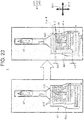
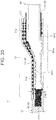
- FIG. 23 shows a sixth modified example with respect to the crimp terminal of the first embodiment shown in FIGS. 1-8 .
- this sixth modified example not only the shape of the seal member but the shape of the recess is also different from that of the crimp terminal 1 of the first embodiment.
- elements similar to those shown in FIGS. 1-8 are denoted by the same reference signs as FIGS. 1-8 , and explanation of these similar elements is omitted in the following description.
- a recess 414 provided on an inner surface 41a of a barrel portion 41 is the recess having a parallelogram shape shown in FIG. 20 as the fourth modified example.
- each of a second seal portion 442 and a third seal portion 443 is divided from a first seal portion 441 in a manner traversing the above-described path 11a-4 in the intersecting direction D12.
- Slight gaps G41 are formed in the axial direction D11 between the second seal portion 442 and the first seal portion 441, and between the third seal portion 443 and the first seal portion 441. These gaps G41 are closed by the above-described elongation of the seal member 44 during the crimping.
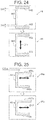
- FIG. 24 is a schematic diagram showing how the gap between the second seal portion and the first seal portion and the gap between the third seal portion and the first seal portion shown in FIG. 23 are closed by the elongation of the seal member during crimping.
- the first seal portion 441 is elongated in the axial direction D11 coincide with a length direction thereof. Due to this elongation, the second seal portion 442 and the third seal portion 443 are connected to the first seal portion 441, thereby closing the above-described gaps G41.
- a rate of elongation in the crimping is greater in the intersecting direction D12 than in the axial direction D11.
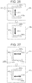
- FIG. 25 shows a seal member of a seventh modified example with respect to the crimp terminal of the first embodiment shown in FIGS. 1-8 .
- FIG. 26 shows a seal member of an eighth modified example with respect to the crimp terminal of the first embodiment shown in FIGS. 1-8 .
- FIG. 27 shows a seal member of a ninth modified example with respect to the crimp terminal of the first embodiment shown in FIGS. 1-8 .
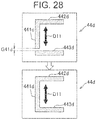
- FIG. 28 shows a seal member of a tenth modified example with respect to the crimp terminal of the first embodiment shown in FIGS. 1-8 .
- a first seal portion 441a and a second seal portion 442a are divided, forming a gap G41a in the intersecting direction D12.
- the first seal portion 441a and a third seal portion 443a are connected to each other so that they are formed into a L-like shape in a plane view. That is, this seal member 44a is divided into two parts.
- the second seal portion 442a is elongated in the intersecting direction D12. Due to this elongation, the second seal portion 442a is connected to the first seal portion 441a, thereby closing the above-described gap G41a.
- a first seal portion 441b and a second seal portion 442b are divided, forming a gap G41b in the axial direction D11.
- the first seal portion 441b and a third seal portion 443b are connected to each other so that they are formed into a L-like shape in a plane view.
- the first seal portion 441b is elongated in the axial direction D11. Due to this elongation, the first seal portion 441b is connected to the second seal portion 442b, thereby closing the above-described gap G41b.
- a first seal portion 441c and a third seal portion 443c are divided, forming a gap G41c in the intersecting direction D12.
- the first seal portion 441c and a second seal portion 442c are connected to each other so that they are formed into an inverse L-like shape in a plane view.
- the third seal portion 443c is elongated in the intersecting direction D12. Due to this elongation, the third seal portion 443c is connected to the first seal portion 441c, thereby closing the above-described gap G41c.
- a first seal portion 441d and a third seal portion 443d are divided, forming a gap G41d in the axial direction D11.
- the first seal portion 441d and a second seal portion 442d are connected to each other so that they are formed into an inverse L-like shape in a plane view.
- the first seal portion 441d is elongated in the axial direction D11. Due to this elongation, the first seal portion 441d is connected to the third seal portion 443d, thereby closing the above-described gap G41d.
- FIG. 29 illustrates a crimp terminal according to a second embodiment of the present invention.
- FIG. 30 illustrates how a seal member shown in FIG. 29 is attached to an inner surface of a barrel portion.
- elements similar to those shown in FIGS. 1-8 are denoted by the same reference signs as FIGS. 1-8 , and explanation of these similar elements is omitted in the following description.
- FIG. 29 two crimp terminals 5 are shown, of which one crimp terminal 5 is shown with a seal member 14 removed for the purpose of providing a view of shape of an inner surface of a barrel portion 51.
- a plurality of recesses 514 is dispersedly provided on an inner surface 51a of the barrel portion 51 over an entire region including a first region 51a-1, a second region 51a-2 and a third region 51a-3.
- a protrusion 515 is formed on the inner surface 51a at a location where the aluminum core wire W11 is to be placed, and is formed by pressing applied from an outer surface side.
- the first region 51a-1 is a region traversing an outer barrel piece 513 in the axial direction D11.
- the second region 51a-2 is a region that traverses, on a side closer to the terminal portion 12 than the aluminum core wire W11, the inner surface 51a of the barrel portion 51 including a bottom plate 511 in the intersecting direction D12 between an inner barrel piece 512 side and the outer barrel piece 513 side.
- the third region 51a-3 is a region that traverses the inner surface 51a in the intersecting direction D12, between the inner barrel piece 512 side and the outer barrel piece 513 side, so as to intersect with the covered portion W12 of the end portion W1a.
- the seal member 14 constituted of the first seal portion 141, the second seal portion 142 and the third seal portion 143 is attached so as to overlap with the recesses 514 at each of the first region 51a-1, the second region 51a-2 and the third region 51a-3.
- Gaps G11 are formed between the second seal portion 142 and the first seal portion 141 and between the third seal portion 143 and the first seal portion 141, the gaps G11 traversing, in the axial direction D11, a path 51a-4 extending from the second region 51a-2 through the first region 51a-1 to the third region 51a-3.
- the crimp terminal 5 described above is manufactured using a terminal manufacturing method as described below.
- a sheet-metal processing step for forming a structural object prior to the attachment of the seal member 14 is performed.
- the barrel portion 51 is formed together with the terminal portion 12 from the metal plate.
- the barrel portion 51 and the terminal portion 12 are collectively formed with the plurality of crimp terminals 5 connected together by the strip-like connecting piece 5a.
- the formation of the plurality of recesses 514 and the formation of the protrusion 515 on the inner surface 51a of the barrel portion 51 are also performed.
- the seal member attaching step is performed in which the seal member 14 is formed from an adhesive gel sheet, and the seal member 14 is attached over the first region 51a-1, the second region 51a-2 and the third region 51a-3.
- This seal member attaching step is a step for attaching the seal member 14 in a manner that the seal member 14 is divided in the partway of the path 51a-4 described above.
- the first seal portion 141, the second seal portion 142 and the third seal portion 143 are individually attached to the inner surface 51a of the barrel portion 51.
- the first seal portion 141, the second seal portion 142 and the third seal portion 143 are punched out from the adhesive gel sheet and attached to the inner surface 51a of the barrel portion 51.
- the crimp terminal 5 manufactured as described above is crimped to the end portion W1a of the covered electric wire W1 as follows.
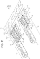
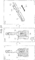
- FIG. 31 illustrates a procedure of completing preparation of the crimp terminal shown in FIGS. 29 and 30 that is ready to be crimped to an end portion of a covered electric wire.
- FIG. 32 illustrates a procedure, that follows the procedure shown in FIG. 31 , of crimping the crimp terminal to the end portion of the covered electric wire.
- FIG. 31 also shows a sheet-metal processing step (S51) and a seal member attaching step (S52) in the terminal manufacturing method described above.
- the barrel portion 51 and the terminal portion 12 are formed in the sheet-metal processing step (S51), and the first seal portion 141, the second seal portion 142 and the third seal portion 143 constituting the seal member 14 are attached in the seal member attaching step (S52).
- the crimp terminal 5 to be crimped is detached from the connecting piece 5a shown in FIG. 29 . Then, this barrel portion 51 is subjected to a bending deformation as preparation for placing the end portion W1a of the covered electric wire W1 (S53). This bending deformation is performed such that the inner barrel piece 512 and the outer barrel piece 513 are brought close to each other so that the cross section intersecting with the axial direction D11 is formed into a substantially U-like shape.
- the end portion W1a of the covered electric wire W1 is placed on the barrel portion 51 that has been subjected to the bending deformation (S54). At this time, the end portion W1a is placed such that a tip of the aluminum core wire W11 does not overlap with the second seal portion 142. However, a small overlap between the tip of the aluminum core wire W11 and the second seal portion 142 is allowed. Subsequently, the barrel portion 51 is wound around and crimped to the end portion W1a such that the inner barrel piece 512 is arranged inside and the outer barrel piece 513 is placed onto the inner barrel piece 512 (S55).
- the seal member 14 seals the respective portions of the crimp terminal 5 as follows.
- FIG. 33 illustrates the crimp terminal after the crimping that is also shown in FIG. 32 .
- FIG. 34 shows a cross-sectional view taken along line V51-V51, a cross-sectional view taken along line V52-V52, and a cross-sectional view taken along line V53-V53 in FIG. 33 .
- FIG. 35 is a cross-sectional view taken along line V54-V54 in FIG. 33 .
- the recess 514 to be overlapped with the seal member 14 assumes a role as the groove 116 of the first embodiment.
- the movement of the seal member 14 due to the pressure applied during the crimping is inhibited by the recess 514 overlapped with the seal member 14.
- the gaps G11 formed between the second seal portion 142 and the first seal portion 141 and between the third seal portion 143 and the first seal portion 141 are closed by the elongation of the second seal portion 142 and the third seal portion 143 in the intersecting direction D11.
- a space between the inner barrel piece 512 and the outer barrel piece 513 is sealed by the first seal portion 141 of the seal member 14.
- an opening 51b of the tubular barrel portion 51 on the terminal portion 12 side is sealed by the second seal portion 142, and a space between the covered portion W12 and the barrel portion 51 is sealed by the third seal portion 143.
- a crimp height CH51 at the barrel portion 51 after crimped is set such that the tubular barrel portion 51 is crushed to an extent that a part of the seal member 14 projects from the opening 51b of the barrel portion 51. As such, the opening 51b of the barrel portion 51 will be sealed at a high level. Furthermore, also at the side of the barrel portion 51 at which the covered electric wire W1 is extending out, a part of the seal member 14 projects out from between the covered portion W12 and the barrel portion 51, thereby sealing this portion at a high level.
- the dimension such as a width of each of the first seal portion 141, the second seal portion 142 and the third seal portion 143 constituting the seal member 14 is set to a dimension necessary and sufficient to achieve the above-described sealing after the crimping.
- the crimping causes edges of the respective recesses 514 provided on the inner surface 51a of the barrel portion 51 to bite into the aluminum core wire W11, thereby providing good electrical continuity between the covered electric wire W1 and the crimp terminal 5. Furthermore, a part of the plurality of recesses 514 provided on the inner surface of the barrel portion 51 overlaps with the seal member 14 for ensuring waterproof property with respect to the contact portion with the aluminum core wire W11. Thus, the recess 514 at a location to be overlapped with the seal member 14 can be used as a mark when providing the seal member 14 to the inner surface 51a of the barrel portion 51, thereby reducing difficulty of manufacturing.
- the recesses 514 overlapped with the seal member 14 inhibit the movement of the seal member 14 due to the pressure applied during the crimping, thereby contributing to ensure waterproof property at a higher level.
- difficulty of manufacturing can be reduced by utilizing a part of the recesses 514 provided to obtain good electrical continuity between the covered electric wire W1 and the crimp terminal 5, while ensuring waterproof property with respect to the contact portion with the aluminum core wire W11.
- the shape of the inner surface of the barrel portion 51 is formed simple with the plurality of recesses 514 dispersedly provided over substantially the entire region, thereby further reducing difficulty of manufacturing regarding forming of the barrel portion 51.
- the seal member 14 can be provided approximately along the outer periphery of the barrel portion 51, and by which the seal member 14 can overlap with the recesses 514 even if the seal member 14 is arranged obliquely and such. That is, when providing the seal member 14, positional accuracy does not need to be so high, and thus in this respect also, difficulty of manufacturing can be further reduced.
- FIG. 36 shows a seal member of a first modified example with respect to the crimp terminal of the second embodiment shown in FIGS. 29-35 .
- FIG. 37 shows a seal member of a second modified example with respect to the crimp terminal of the second embodiment shown in FIGS. 29-35 .
- FIG. 38 shows a seal member of a third modified example with respect to the crimp terminal of the second embodiment shown in FIGS. 29-35 .
- FIG. 39 shows a seal member of a fourth modified example with respect to the crimp terminal of the second embodiment shown in FIGS. 29-35 .
- FIG. 40 shows a seal member of a fifth modified example with respect to the crimp terminal of the second embodiment shown in FIGS. 29-35 .
- FIG. 41 shows a seal member of a sixth modified example with respect to the crimp terminal of the second embodiment shown in FIGS. 29-35 .
- FIG. 42 shows a seal member of a seventh modified example with respect to the crimp terminal of the second embodiment shown in FIGS. 29-35 .
- gaps G51a in the axial direction D11 are formed between a second seal portion 542a and a first seal portion 541a, and between a third seal portion 543a and the first seal portion 541a.
- the first seal portion 541a is elongated in the axial direction D11 during the crimping and closes the gaps G51a, thereby ensuring waterproof property at a high level.
- a first seal portion 541b is formed short, and entire of the seal member 54b is attached at a location biased closer to the terminal portion 12 compared to the first modified example.
- gaps G51b in the axial direction D11 are formed between a second seal portion 542b and a first seal portion 541b, and between a third seal portion 543b and the first seal portion 541b, and the gaps G51b are closed by the elongation during the crimping.
- a region sealed by the seal member 54b is made narrower, but it is premised on that the attachment location of the seal member 54b is set to a location at which waterproof property with respect to the contact portion between the aluminum core wire W11 and the barrel portion 51 is obtained.
- the attachment location of the seal member 54b is then set based on high degree of freedom of the attachment location provided with the recesses 514 formed on substantially the entire surface of the barrel portion 51. According to this second modified example, amount of the adhesive gel sheet used can be reduced by shortening the first seal portion 541b, thereby reducing cost.
- gaps G51c in the intersecting direction D12 are formed between a second seal portion 542c and a first seal portion 541c, and between a third seal portion 543c and the first seal portion 541c.
- the second seal portion 542c and the third seal portion 543c are elongated in the intersecting direction D12 during the crimping and close the gaps G51c.
- the attachment location of the third seal portion 543c is set to a location biased closer to the terminal portion 12, based on high degree of freedom of the attachment location provided with the recesses 514 formed on substantially the entire surface of the barrel portion 51.
- a seal member 54d according to the fourth modified example shown in FIG. 39 is a modified version of the above-described third modified example, in which a first seal portion 541d is made shorter, and a second seal portion 542d and a third seal portion 542d have substantially the same length.
- gaps G51e in the intersecting direction D12 are formed between a second seal portion 542e and a first seal portion 541e, and between a third seal portion 543e and the first seal portion 541e.
- the second seal portion 542e and the third seal portion 543e are elongated in the intersecting direction D12 during the crimping and close the gaps G51e.
- the first seal portion 541e is attached obliquely based on high degree of freedom of the attachment location provided with the recesses 514 formed on substantially the entire surface of the barrel portion 51.
- a seal member 54f according to the sixth modified example shown in FIG. 41 is a modified version of the above-described first modified example shown in FIG. 36 , in which a first seal portion 542f is made shorter. Further, in this sixth modified example, a second seal portion 541f is attached obliquely based on high degree of freedom of the attachment location provided with the recesses 514 formed on substantially the entire surface of the barrel portion 51. A third seal portion 543f is equivalent to that of the first modified example of FIG. 36 .
- a seal member 54g according to the seventh modified example shown in FIG. 42 is also a modified version of the first modified example shown in FIG. 36 .
- a first seal portion 541g is made short, and a second seal portion 542g is made long.
- a third seal portion 543g is formed long and wide.
- the crimp terminal 5 of the second embodiment includes the recesses 514 that are formed on substantially the entire surface of the barrel portion 51. Consequently, regarding the seal member, it is possible to appropriately set way of attachment and shape thereof with high degree of freedom.
- FIG. 43 shows a seal member of an eighth modified example with respect to the crimp terminal of the second embodiment shown in FIGS. 29-35 .
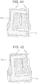
- FIG. 44 shows a seal member of a ninth modified example with respect to the crimp terminal of the second embodiment shown in FIGS. 29-35 .
- FIG. 45 shows a seal member of a tenth modified example with respect to the crimp terminal of the second embodiment shown in FIGS. 29-35 .
- FIG. 46 shows a seal member of an eleventh modified example with respect to the crimp terminal of the second embodiment shown in FIGS. 29-35 .
- FIG. 47 shows a seal member of a twelfth modified example with respect to the crimp terminal of the second embodiment shown in FIGS. 29-35 .
- FIG. 48 shows a seal member of a thirteenth modified example with respect to the crimp terminal of the second embodiment shown in FIGS. 29-35 .
- a seal member 55a of the eighth modified example shown in FIG. 43 is not divided, and is formed into a C-like shape in a plan view with a second seal portion 552a and a third seal portion 553a extending from and integrally connected with a first seal portion 551a in a two arms fashion.
- a seal member 55b of the ninth modified example shown in FIG. 44 is formed into a C-like shape in a plan view with the seal member 55b attached to the barrel portion 51 in a manner oblique in a clockwise fashion in FIG. 44 .
- a seal member 55c of the tenth modified example shown in FIG. 45 is formed into a C-like shape in a plan view with the seal member 55c attached to the barrel portion 51 in a manner oblique in a counterclockwise fashion in FIG. 45 .
- a seal member 55d of the eleventh modified example shown in FIG. 46 includes a second seal portion 552d formed short and a third seal portion 553d which are connected to each other by a first seal portion 551d.
- the entire seal member 55d is attached in a state biased closer to the inner barrel piece 512 of the barrel portion 51.
- a seal member 55e of the twelfth modified example shown in FIG. 47 also includes a second seal portion 552e formed short and a third seal portion 553e which are connected to each other by a first seal portion 551e. However, in this twelfth modified example, the entire seal member 55e is attached in a state biased closer to the outer barrel piece 513 of the barrel portion 51.
- a seal member 55f of the thirteenth modified example shown in FIG. 48 includes a first seal portion 551f formed short and connecting a second seal portion 552f and a third seal portion 553f to each other.
- the entire seal member 55f is attached in a state biased closer to the terminal portion 12 of the barrel portion 51.
- the crimp terminal 5 of the second embodiment even when the integrally-formed seal member is used, it is possible to appropriately set way of attachment and shape of the seal member with high degree of freedom, with the recesses 514 formed on substantially the entire surface of the barrel portion 51.
- the above-described embodiments and various modified examples exemplary show the barrel portion provided with the protrusion formed by applying pressing from the outer surface side.
- the barrel portion is not limited to this, and this protrusion may be omitted.
- the strands of the aluminum core wire can be separated and spread thereby the number of strands contacting the barrel portion can be increased.
- the above-described embodiments and various modified examples exemplary show the crimp terminal provided with the terminal portion 12 as a quadrangular tube-like female terminal, as one example of the terminal portion.
- the terminal portion is not limited to this, and may have other shapes and may involve other connection forms.
Landscapes
- Engineering & Computer Science (AREA)
- Manufacturing & Machinery (AREA)
- Connections Effected By Soldering, Adhesion, Or Permanent Deformation (AREA)
Applications Claiming Priority (2)
| Application Number | Priority Date | Filing Date | Title |
|---|---|---|---|
| JP2016253772A JP6858552B2 (ja) | 2016-12-27 | 2016-12-27 | 圧着端子 |
| PCT/JP2017/016504 WO2018123101A1 (ja) | 2016-12-27 | 2017-04-26 | 圧着端子 |
Publications (3)
| Publication Number | Publication Date |
|---|---|
| EP3565061A1 EP3565061A1 (en) | 2019-11-06 |
| EP3565061A4 EP3565061A4 (en) | 2019-12-25 |
| EP3565061B1 true EP3565061B1 (en) | 2021-04-07 |
Family
ID=62710185
Family Applications (1)
| Application Number | Title | Priority Date | Filing Date |
|---|---|---|---|
| EP17887306.3A Active EP3565061B1 (en) | 2016-12-27 | 2017-04-26 | Crimp terminal |
Country Status (5)
| Country | Link |
|---|---|
| US (1) | US10756449B2 (ja) |
| EP (1) | EP3565061B1 (ja) |
| JP (1) | JP6858552B2 (ja) |
| CN (1) | CN110024227B (ja) |
| WO (1) | WO2018123101A1 (ja) |
Families Citing this family (3)
| Publication number | Priority date | Publication date | Assignee | Title |
|---|---|---|---|---|
| JP6803877B2 (ja) * | 2018-07-09 | 2020-12-23 | 矢崎総業株式会社 | 端子付き電線 |
| DE102019109460A1 (de) * | 2019-04-10 | 2020-10-15 | Te Connectivity Germany Gmbh | Crimpkontakt |
| US11264735B1 (en) * | 2020-08-28 | 2022-03-01 | TE Connectivity Services Gmbh | Electrical terminal for terminating a wide size range of magnet wires |
Family Cites Families (30)
| Publication number | Priority date | Publication date | Assignee | Title |
|---|---|---|---|---|
| JPS5940198B2 (ja) | 1977-04-12 | 1984-09-28 | 川研フアインケミカル株式会社 | 改良された固形洗剤 |
| JPS5842951B2 (ja) * | 1979-02-13 | 1983-09-22 | 住友電気工業株式会社 | アルミニウム導体電線の端子圧着法 |
| DE19549174A1 (de) * | 1995-10-28 | 1997-07-03 | Bosch Gmbh Robert | Kontaktelement mit Crimpabschnitt |
| JP3566541B2 (ja) * | 1998-03-31 | 2004-09-15 | 矢崎総業株式会社 | 防水コネクタ及び防水処理方法 |
| JP2009230998A (ja) * | 2008-03-21 | 2009-10-08 | Autonetworks Technologies Ltd | 端子金具付き電線の製造方法及び端子金具付き電線 |
| JP5146187B2 (ja) * | 2008-08-06 | 2013-02-20 | 住友電装株式会社 | 端子金具及びワイヤーハーネス |
| JP2010044913A (ja) * | 2008-08-11 | 2010-02-25 | Mitsubishi Materials Corp | 圧着接続端子 |
| JP2011096452A (ja) * | 2009-10-28 | 2011-05-12 | Yazaki Corp | 圧着端子 |
| JP5606115B2 (ja) * | 2010-03-23 | 2014-10-15 | 矢崎総業株式会社 | 圧着端子の電線に対する接続構造 |
| CN102859795B (zh) * | 2010-03-30 | 2015-08-19 | 古河电气工业株式会社 | 压接端子、连接构造体和连接器 |
| JP5675205B2 (ja) * | 2010-08-05 | 2015-02-25 | 矢崎総業株式会社 | 圧着端子 |
| JP2012059438A (ja) * | 2010-09-07 | 2012-03-22 | Sumitomo Wiring Syst Ltd | 防水コネクタ |
| JP5953591B2 (ja) * | 2012-04-05 | 2016-07-20 | 矢崎総業株式会社 | 圧着端子を電線に圧着する方法 |
| JP5899593B2 (ja) * | 2012-07-31 | 2016-04-06 | 矢崎総業株式会社 | 圧着端子付きアルミ電線 |
| CN202930577U (zh) * | 2012-11-30 | 2013-05-08 | 浙江荣得利航空部件有限公司 | 一种接线片 |
| CN104137341B (zh) * | 2013-02-21 | 2017-05-24 | 古河电气工业株式会社 | 压接端子、带端子电线及线束结构体 |
| DE102013203796A1 (de) * | 2013-03-06 | 2014-09-11 | Tyco Electronics Amp Gmbh | Elektrische Crimpkontaktvorrichtung |
| JP6063788B2 (ja) * | 2013-03-19 | 2017-01-18 | 矢崎総業株式会社 | 端子金具及び端子付き電線の製造方法 |
| DE102013205235A1 (de) * | 2013-03-25 | 2014-09-25 | Tyco Electronics Amp Gmbh | Crimpverbindung |
| DE112014003899T5 (de) * | 2013-08-26 | 2016-06-09 | Yazaki Corporation | Verbindungsstruktur eines Crimp-Anschlusses in Bezug auf einen Draht |
| JP2015079687A (ja) * | 2013-10-18 | 2015-04-23 | 矢崎総業株式会社 | 圧着端子 |
| JP6426907B2 (ja) * | 2014-04-04 | 2018-11-21 | 矢崎総業株式会社 | 圧着端子と電線の接続構造 |
| CN105098384B (zh) * | 2014-05-19 | 2017-12-15 | 矢崎总业株式会社 | 微电流压接端子和微电流线束 |
| US10128581B2 (en) * | 2014-06-19 | 2018-11-13 | Fujikura Ltd. | Crimp terminal |
| JP5940198B2 (ja) | 2015-06-18 | 2016-06-29 | 古河電気工業株式会社 | 圧着端子、接続構造体及びコネクタ |
| JP6423783B2 (ja) * | 2015-12-16 | 2018-11-14 | 矢崎総業株式会社 | 圧着端子 |
| JP6422851B2 (ja) * | 2015-12-16 | 2018-11-14 | 矢崎総業株式会社 | 圧着端子の製造方法 |
| US9853368B2 (en) * | 2016-05-03 | 2017-12-26 | Te Connectivity Corporation | Electrical crimp terminal |
| JP6822834B2 (ja) * | 2016-12-27 | 2021-01-27 | 矢崎総業株式会社 | 圧着端子および端子製造方法 |
| JP6904147B2 (ja) * | 2017-08-01 | 2021-07-14 | 株式会社オートネットワーク技術研究所 | 端子付き電線 |
-
2016
- 2016-12-27 JP JP2016253772A patent/JP6858552B2/ja active Active
-
2017
- 2017-04-26 WO PCT/JP2017/016504 patent/WO2018123101A1/ja unknown
- 2017-04-26 EP EP17887306.3A patent/EP3565061B1/en active Active
- 2017-04-26 CN CN201780073008.2A patent/CN110024227B/zh active Active
-
2019
- 2019-05-23 US US16/420,559 patent/US10756449B2/en active Active
Non-Patent Citations (1)
| Title |
|---|
| None * |
Also Published As
| Publication number | Publication date |
|---|---|
| JP6858552B2 (ja) | 2021-04-14 |
| US10756449B2 (en) | 2020-08-25 |
| EP3565061A4 (en) | 2019-12-25 |
| EP3565061A1 (en) | 2019-11-06 |
| JP2018106993A (ja) | 2018-07-05 |
| CN110024227A (zh) | 2019-07-16 |
| CN110024227B (zh) | 2021-05-25 |
| US20190280399A1 (en) | 2019-09-12 |
| WO2018123101A1 (ja) | 2018-07-05 |
Similar Documents
| Publication | Publication Date | Title |
|---|---|---|
| EP3565061B1 (en) | Crimp terminal | |
| US10658784B2 (en) | Crimp terminal | |
| CN110140258B (zh) | 压接端子 | |
| CN110088981B (zh) | 压接端子和压接端子的制造方法 | |
| EP3565060B1 (en) | Terminal connection method | |
| EP3565062B1 (en) | Terminal-equipped electric wire and terminal production method |
Legal Events
| Date | Code | Title | Description |
|---|---|---|---|
| STAA | Information on the status of an ep patent application or granted ep patent |
Free format text: STATUS: THE INTERNATIONAL PUBLICATION HAS BEEN MADE |
|
| PUAI | Public reference made under article 153(3) epc to a published international application that has entered the european phase |
Free format text: ORIGINAL CODE: 0009012 |
|
| STAA | Information on the status of an ep patent application or granted ep patent |
Free format text: STATUS: REQUEST FOR EXAMINATION WAS MADE |
|
| 17P | Request for examination filed |
Effective date: 20190522 |
|
| AK | Designated contracting states |
Kind code of ref document: A1 Designated state(s): AL AT BE BG CH CY CZ DE DK EE ES FI FR GB GR HR HU IE IS IT LI LT LU LV MC MK MT NL NO PL PT RO RS SE SI SK SM TR |
|
| AX | Request for extension of the european patent |
Extension state: BA ME |
|
| A4 | Supplementary search report drawn up and despatched |
Effective date: 20191125 |
|
| RIC1 | Information provided on ipc code assigned before grant |
Ipc: H01R 4/70 20060101ALI20191119BHEP Ipc: H01R 4/62 20060101ALI20191119BHEP Ipc: H01R 13/52 20060101ALI20191119BHEP Ipc: H01R 4/18 20060101AFI20191119BHEP |
|
| DAV | Request for validation of the european patent (deleted) | ||
| DAX | Request for extension of the european patent (deleted) | ||
| GRAP | Despatch of communication of intention to grant a patent |
Free format text: ORIGINAL CODE: EPIDOSNIGR1 |
|
| STAA | Information on the status of an ep patent application or granted ep patent |
Free format text: STATUS: GRANT OF PATENT IS INTENDED |
|
| INTG | Intention to grant announced |
Effective date: 20210125 |
|
| GRAS | Grant fee paid |
Free format text: ORIGINAL CODE: EPIDOSNIGR3 |
|
| GRAA | (expected) grant |
Free format text: ORIGINAL CODE: 0009210 |
|
| STAA | Information on the status of an ep patent application or granted ep patent |
Free format text: STATUS: THE PATENT HAS BEEN GRANTED |
|
| AK | Designated contracting states |
Kind code of ref document: B1 Designated state(s): AL AT BE BG CH CY CZ DE DK EE ES FI FR GB GR HR HU IE IS IT LI LT LU LV MC MK MT NL NO PL PT RO RS SE SI SK SM TR |
|
| REG | Reference to a national code |
Ref country code: GB Ref legal event code: FG4D |
|
| REG | Reference to a national code |
Ref country code: AT Ref legal event code: REF Ref document number: 1380883 Country of ref document: AT Kind code of ref document: T Effective date: 20210415 Ref country code: CH Ref legal event code: EP |
|
| REG | Reference to a national code |
Ref country code: DE Ref legal event code: R096 Ref document number: 602017036484 Country of ref document: DE |
|
| REG | Reference to a national code |
Ref country code: IE Ref legal event code: FG4D |
|
| REG | Reference to a national code |
Ref country code: LT Ref legal event code: MG9D |
|
| REG | Reference to a national code |
Ref country code: NL Ref legal event code: MP Effective date: 20210407 Ref country code: AT Ref legal event code: MK05 Ref document number: 1380883 Country of ref document: AT Kind code of ref document: T Effective date: 20210407 |
|
| PG25 | Lapsed in a contracting state [announced via postgrant information from national office to epo] |
Ref country code: HR Free format text: LAPSE BECAUSE OF FAILURE TO SUBMIT A TRANSLATION OF THE DESCRIPTION OR TO PAY THE FEE WITHIN THE PRESCRIBED TIME-LIMIT Effective date: 20210407 Ref country code: BG Free format text: LAPSE BECAUSE OF FAILURE TO SUBMIT A TRANSLATION OF THE DESCRIPTION OR TO PAY THE FEE WITHIN THE PRESCRIBED TIME-LIMIT Effective date: 20210707 Ref country code: AT Free format text: LAPSE BECAUSE OF FAILURE TO SUBMIT A TRANSLATION OF THE DESCRIPTION OR TO PAY THE FEE WITHIN THE PRESCRIBED TIME-LIMIT Effective date: 20210407 Ref country code: NL Free format text: LAPSE BECAUSE OF FAILURE TO SUBMIT A TRANSLATION OF THE DESCRIPTION OR TO PAY THE FEE WITHIN THE PRESCRIBED TIME-LIMIT Effective date: 20210407 Ref country code: LT Free format text: LAPSE BECAUSE OF FAILURE TO SUBMIT A TRANSLATION OF THE DESCRIPTION OR TO PAY THE FEE WITHIN THE PRESCRIBED TIME-LIMIT Effective date: 20210407 Ref country code: FI Free format text: LAPSE BECAUSE OF FAILURE TO SUBMIT A TRANSLATION OF THE DESCRIPTION OR TO PAY THE FEE WITHIN THE PRESCRIBED TIME-LIMIT Effective date: 20210407 |
|
| PG25 | Lapsed in a contracting state [announced via postgrant information from national office to epo] |
Ref country code: GR Free format text: LAPSE BECAUSE OF FAILURE TO SUBMIT A TRANSLATION OF THE DESCRIPTION OR TO PAY THE FEE WITHIN THE PRESCRIBED TIME-LIMIT Effective date: 20210708 Ref country code: IS Free format text: LAPSE BECAUSE OF FAILURE TO SUBMIT A TRANSLATION OF THE DESCRIPTION OR TO PAY THE FEE WITHIN THE PRESCRIBED TIME-LIMIT Effective date: 20210807 Ref country code: RS Free format text: LAPSE BECAUSE OF FAILURE TO SUBMIT A TRANSLATION OF THE DESCRIPTION OR TO PAY THE FEE WITHIN THE PRESCRIBED TIME-LIMIT Effective date: 20210407 Ref country code: SE Free format text: LAPSE BECAUSE OF FAILURE TO SUBMIT A TRANSLATION OF THE DESCRIPTION OR TO PAY THE FEE WITHIN THE PRESCRIBED TIME-LIMIT Effective date: 20210407 Ref country code: PT Free format text: LAPSE BECAUSE OF FAILURE TO SUBMIT A TRANSLATION OF THE DESCRIPTION OR TO PAY THE FEE WITHIN THE PRESCRIBED TIME-LIMIT Effective date: 20210809 Ref country code: NO Free format text: LAPSE BECAUSE OF FAILURE TO SUBMIT A TRANSLATION OF THE DESCRIPTION OR TO PAY THE FEE WITHIN THE PRESCRIBED TIME-LIMIT Effective date: 20210707 Ref country code: PL Free format text: LAPSE BECAUSE OF FAILURE TO SUBMIT A TRANSLATION OF THE DESCRIPTION OR TO PAY THE FEE WITHIN THE PRESCRIBED TIME-LIMIT Effective date: 20210407 Ref country code: LV Free format text: LAPSE BECAUSE OF FAILURE TO SUBMIT A TRANSLATION OF THE DESCRIPTION OR TO PAY THE FEE WITHIN THE PRESCRIBED TIME-LIMIT Effective date: 20210407 |
|
| PG25 | Lapsed in a contracting state [announced via postgrant information from national office to epo] |
Ref country code: LU Free format text: LAPSE BECAUSE OF NON-PAYMENT OF DUE FEES Effective date: 20210426 |
|
| REG | Reference to a national code |
Ref country code: DE Ref legal event code: R097 Ref document number: 602017036484 Country of ref document: DE |
|
| REG | Reference to a national code |
Ref country code: BE Ref legal event code: MM Effective date: 20210430 |
|
| PG25 | Lapsed in a contracting state [announced via postgrant information from national office to epo] |
Ref country code: RO Free format text: LAPSE BECAUSE OF FAILURE TO SUBMIT A TRANSLATION OF THE DESCRIPTION OR TO PAY THE FEE WITHIN THE PRESCRIBED TIME-LIMIT Effective date: 20210407 Ref country code: CZ Free format text: LAPSE BECAUSE OF FAILURE TO SUBMIT A TRANSLATION OF THE DESCRIPTION OR TO PAY THE FEE WITHIN THE PRESCRIBED TIME-LIMIT Effective date: 20210407 Ref country code: CH Free format text: LAPSE BECAUSE OF NON-PAYMENT OF DUE FEES Effective date: 20210430 Ref country code: DK Free format text: LAPSE BECAUSE OF FAILURE TO SUBMIT A TRANSLATION OF THE DESCRIPTION OR TO PAY THE FEE WITHIN THE PRESCRIBED TIME-LIMIT Effective date: 20210407 Ref country code: MC Free format text: LAPSE BECAUSE OF FAILURE TO SUBMIT A TRANSLATION OF THE DESCRIPTION OR TO PAY THE FEE WITHIN THE PRESCRIBED TIME-LIMIT Effective date: 20210407 Ref country code: LI Free format text: LAPSE BECAUSE OF NON-PAYMENT OF DUE FEES Effective date: 20210430 Ref country code: SM Free format text: LAPSE BECAUSE OF FAILURE TO SUBMIT A TRANSLATION OF THE DESCRIPTION OR TO PAY THE FEE WITHIN THE PRESCRIBED TIME-LIMIT Effective date: 20210407 Ref country code: SK Free format text: LAPSE BECAUSE OF FAILURE TO SUBMIT A TRANSLATION OF THE DESCRIPTION OR TO PAY THE FEE WITHIN THE PRESCRIBED TIME-LIMIT Effective date: 20210407 Ref country code: ES Free format text: LAPSE BECAUSE OF FAILURE TO SUBMIT A TRANSLATION OF THE DESCRIPTION OR TO PAY THE FEE WITHIN THE PRESCRIBED TIME-LIMIT Effective date: 20210407 Ref country code: EE Free format text: LAPSE BECAUSE OF FAILURE TO SUBMIT A TRANSLATION OF THE DESCRIPTION OR TO PAY THE FEE WITHIN THE PRESCRIBED TIME-LIMIT Effective date: 20210407 |
|
| PLBE | No opposition filed within time limit |
Free format text: ORIGINAL CODE: 0009261 |
|
| STAA | Information on the status of an ep patent application or granted ep patent |
Free format text: STATUS: NO OPPOSITION FILED WITHIN TIME LIMIT |
|
| 26N | No opposition filed |
Effective date: 20220110 |
|
| GBPC | Gb: european patent ceased through non-payment of renewal fee |
Effective date: 20210707 |
|
| PG25 | Lapsed in a contracting state [announced via postgrant information from national office to epo] |
Ref country code: IE Free format text: LAPSE BECAUSE OF NON-PAYMENT OF DUE FEES Effective date: 20210426 Ref country code: GB Free format text: LAPSE BECAUSE OF NON-PAYMENT OF DUE FEES Effective date: 20210707 |
|
| PG25 | Lapsed in a contracting state [announced via postgrant information from national office to epo] |
Ref country code: IS Free format text: LAPSE BECAUSE OF FAILURE TO SUBMIT A TRANSLATION OF THE DESCRIPTION OR TO PAY THE FEE WITHIN THE PRESCRIBED TIME-LIMIT Effective date: 20210807 Ref country code: FR Free format text: LAPSE BECAUSE OF NON-PAYMENT OF DUE FEES Effective date: 20210607 Ref country code: AL Free format text: LAPSE BECAUSE OF FAILURE TO SUBMIT A TRANSLATION OF THE DESCRIPTION OR TO PAY THE FEE WITHIN THE PRESCRIBED TIME-LIMIT Effective date: 20210407 |
|
| PG25 | Lapsed in a contracting state [announced via postgrant information from national office to epo] |
Ref country code: IT Free format text: LAPSE BECAUSE OF FAILURE TO SUBMIT A TRANSLATION OF THE DESCRIPTION OR TO PAY THE FEE WITHIN THE PRESCRIBED TIME-LIMIT Effective date: 20210407 Ref country code: BE Free format text: LAPSE BECAUSE OF NON-PAYMENT OF DUE FEES Effective date: 20210430 |
|
| PG25 | Lapsed in a contracting state [announced via postgrant information from national office to epo] |
Ref country code: CY Free format text: LAPSE BECAUSE OF FAILURE TO SUBMIT A TRANSLATION OF THE DESCRIPTION OR TO PAY THE FEE WITHIN THE PRESCRIBED TIME-LIMIT Effective date: 20210407 |
|
| PG25 | Lapsed in a contracting state [announced via postgrant information from national office to epo] |
Ref country code: HU Free format text: LAPSE BECAUSE OF FAILURE TO SUBMIT A TRANSLATION OF THE DESCRIPTION OR TO PAY THE FEE WITHIN THE PRESCRIBED TIME-LIMIT; INVALID AB INITIO Effective date: 20170426 |
|
| PGFP | Annual fee paid to national office [announced via postgrant information from national office to epo] |
Ref country code: DE Payment date: 20230228 Year of fee payment: 7 |
|
| PG25 | Lapsed in a contracting state [announced via postgrant information from national office to epo] |
Ref country code: MK Free format text: LAPSE BECAUSE OF FAILURE TO SUBMIT A TRANSLATION OF THE DESCRIPTION OR TO PAY THE FEE WITHIN THE PRESCRIBED TIME-LIMIT Effective date: 20210407 |