WO2009151033A1 - Climatiseur, procédé de fabrication de climatiseur et compresseur - Google Patents
Climatiseur, procédé de fabrication de climatiseur et compresseur Download PDFInfo
- Publication number
- WO2009151033A1 WO2009151033A1 PCT/JP2009/060478 JP2009060478W WO2009151033A1 WO 2009151033 A1 WO2009151033 A1 WO 2009151033A1 JP 2009060478 W JP2009060478 W JP 2009060478W WO 2009151033 A1 WO2009151033 A1 WO 2009151033A1
- Authority
- WO
- WIPO (PCT)
- Prior art keywords
- air conditioner
- rare earth
- motor
- rotor
- stator
- Prior art date
Links
- 238000004519 manufacturing process Methods 0.000 title claims description 14
- 229910052761 rare earth metal Inorganic materials 0.000 claims abstract description 225
- 150000002910 rare earth metals Chemical class 0.000 claims abstract description 224
- 238000004804 winding Methods 0.000 claims abstract description 182
- 238000010438 heat treatment Methods 0.000 claims abstract description 157
- 239000003507 refrigerant Substances 0.000 claims abstract description 112
- 230000004907 flux Effects 0.000 claims abstract description 62
- 238000001816 cooling Methods 0.000 claims abstract description 45
- 239000011162 core material Substances 0.000 claims description 147
- 230000006698 induction Effects 0.000 claims description 60
- 230000006835 compression Effects 0.000 claims description 46
- 238000007906 compression Methods 0.000 claims description 46
- 230000007246 mechanism Effects 0.000 claims description 43
- 238000000034 method Methods 0.000 claims description 38
- 239000000463 material Substances 0.000 claims description 21
- 229910000831 Steel Inorganic materials 0.000 claims description 20
- 239000010959 steel Substances 0.000 claims description 20
- XEEYBQQBJWHFJM-UHFFFAOYSA-N Iron Chemical compound [Fe] XEEYBQQBJWHFJM-UHFFFAOYSA-N 0.000 claims description 19
- 239000012212 insulator Substances 0.000 claims description 18
- 230000002093 peripheral effect Effects 0.000 claims description 18
- 229910052742 iron Inorganic materials 0.000 claims description 9
- 238000007493 shaping process Methods 0.000 claims description 8
- 230000003313 weakening effect Effects 0.000 claims description 7
- 229910000976 Electrical steel Inorganic materials 0.000 claims description 4
- 239000011358 absorbing material Substances 0.000 claims description 3
- 239000002826 coolant Substances 0.000 claims description 3
- 239000000428 dust Substances 0.000 claims description 3
- 239000000835 fiber Substances 0.000 claims description 3
- 239000000945 filler Substances 0.000 claims description 3
- 229920006015 heat resistant resin Polymers 0.000 claims description 3
- 229910000889 permalloy Inorganic materials 0.000 claims description 3
- 229910000859 α-Fe Inorganic materials 0.000 claims description 3
- 230000005855 radiation Effects 0.000 claims description 2
- 230000001965 increasing effect Effects 0.000 abstract description 20
- 230000005347 demagnetization Effects 0.000 description 37
- 230000002427 irreversible effect Effects 0.000 description 30
- 238000010586 diagram Methods 0.000 description 17
- 230000007423 decrease Effects 0.000 description 12
- 239000007788 liquid Substances 0.000 description 11
- 230000002829 reductive effect Effects 0.000 description 8
- 229920005989 resin Polymers 0.000 description 7
- 239000011347 resin Substances 0.000 description 7
- 230000004048 modification Effects 0.000 description 6
- 238000012986 modification Methods 0.000 description 6
- 238000013021 overheating Methods 0.000 description 6
- 238000009413 insulation Methods 0.000 description 5
- 239000000696 magnetic material Substances 0.000 description 5
- RYGMFSIKBFXOCR-UHFFFAOYSA-N Copper Chemical compound [Cu] RYGMFSIKBFXOCR-UHFFFAOYSA-N 0.000 description 4
- 229910052802 copper Inorganic materials 0.000 description 4
- 239000010949 copper Substances 0.000 description 4
- 238000005516 engineering process Methods 0.000 description 4
- 230000008569 process Effects 0.000 description 4
- 238000013459 approach Methods 0.000 description 3
- 239000011248 coating agent Substances 0.000 description 3
- 238000000576 coating method Methods 0.000 description 3
- 239000004020 conductor Substances 0.000 description 3
- 230000000694 effects Effects 0.000 description 3
- 238000003475 lamination Methods 0.000 description 3
- 230000000149 penetrating effect Effects 0.000 description 3
- 238000011084 recovery Methods 0.000 description 3
- 229910052779 Neodymium Inorganic materials 0.000 description 2
- 230000004888 barrier function Effects 0.000 description 2
- 238000005452 bending Methods 0.000 description 2
- 230000008901 benefit Effects 0.000 description 2
- 230000015556 catabolic process Effects 0.000 description 2
- 230000003247 decreasing effect Effects 0.000 description 2
- 238000001514 detection method Methods 0.000 description 2
- 238000004512 die casting Methods 0.000 description 2
- 238000000465 moulding Methods 0.000 description 2
- QEFYFXOXNSNQGX-UHFFFAOYSA-N neodymium atom Chemical compound [Nd] QEFYFXOXNSNQGX-UHFFFAOYSA-N 0.000 description 2
- 239000003921 oil Substances 0.000 description 2
- 230000036961 partial effect Effects 0.000 description 2
- 230000002265 prevention Effects 0.000 description 2
- 230000002441 reversible effect Effects 0.000 description 2
- 238000000926 separation method Methods 0.000 description 2
- 125000006850 spacer group Chemical group 0.000 description 2
- XAGFODPZIPBFFR-BJUDXGSMSA-N Aluminum-26 Chemical compound [26Al] XAGFODPZIPBFFR-BJUDXGSMSA-N 0.000 description 1
- 229910000576 Laminated steel Inorganic materials 0.000 description 1
- XAGFODPZIPBFFR-UHFFFAOYSA-N aluminium Chemical compound [Al] XAGFODPZIPBFFR-UHFFFAOYSA-N 0.000 description 1
- 229910052782 aluminium Inorganic materials 0.000 description 1
- 230000008859 change Effects 0.000 description 1
- 238000012937 correction Methods 0.000 description 1
- 238000013461 design Methods 0.000 description 1
- 238000009792 diffusion process Methods 0.000 description 1
- 230000004927 fusion Effects 0.000 description 1
- 230000001939 inductive effect Effects 0.000 description 1
- 238000005259 measurement Methods 0.000 description 1
- 230000035699 permeability Effects 0.000 description 1
- 239000012256 powdered iron Substances 0.000 description 1
- 239000010726 refrigerant oil Substances 0.000 description 1
- 229920006395 saturated elastomer Polymers 0.000 description 1
- 230000001629 suppression Effects 0.000 description 1
- 238000009423 ventilation Methods 0.000 description 1
Images


Classifications
-
- F—MECHANICAL ENGINEERING; LIGHTING; HEATING; WEAPONS; BLASTING
- F25—REFRIGERATION OR COOLING; COMBINED HEATING AND REFRIGERATION SYSTEMS; HEAT PUMP SYSTEMS; MANUFACTURE OR STORAGE OF ICE; LIQUEFACTION SOLIDIFICATION OF GASES
- F25B—REFRIGERATION MACHINES, PLANTS OR SYSTEMS; COMBINED HEATING AND REFRIGERATION SYSTEMS; HEAT PUMP SYSTEMS
- F25B49/00—Arrangement or mounting of control or safety devices
- F25B49/02—Arrangement or mounting of control or safety devices for compression type machines, plants or systems
- F25B49/025—Motor control arrangements
-
- H—ELECTRICITY
- H02—GENERATION; CONVERSION OR DISTRIBUTION OF ELECTRIC POWER
- H02K—DYNAMO-ELECTRIC MACHINES
- H02K1/00—Details of the magnetic circuit
- H02K1/06—Details of the magnetic circuit characterised by the shape, form or construction
- H02K1/22—Rotating parts of the magnetic circuit
- H02K1/27—Rotor cores with permanent magnets
- H02K1/2706—Inner rotors
- H02K1/272—Inner rotors the magnetisation axis of the magnets being perpendicular to the rotor axis
- H02K1/274—Inner rotors the magnetisation axis of the magnets being perpendicular to the rotor axis the rotor consisting of two or more circumferentially positioned magnets
- H02K1/2753—Inner rotors the magnetisation axis of the magnets being perpendicular to the rotor axis the rotor consisting of two or more circumferentially positioned magnets the rotor consisting of magnets or groups of magnets arranged with alternating polarity
- H02K1/276—Magnets embedded in the magnetic core, e.g. interior permanent magnets [IPM]
- H02K1/2766—Magnets embedded in the magnetic core, e.g. interior permanent magnets [IPM] having a flux concentration effect
-
- H—ELECTRICITY
- H02—GENERATION; CONVERSION OR DISTRIBUTION OF ELECTRIC POWER
- H02K—DYNAMO-ELECTRIC MACHINES
- H02K1/00—Details of the magnetic circuit
- H02K1/06—Details of the magnetic circuit characterised by the shape, form or construction
- H02K1/22—Rotating parts of the magnetic circuit
- H02K1/27—Rotor cores with permanent magnets
- H02K1/2793—Rotors axially facing stators
- H02K1/2795—Rotors axially facing stators the rotor consisting of two or more circumferentially positioned magnets
-
- H—ELECTRICITY
- H02—GENERATION; CONVERSION OR DISTRIBUTION OF ELECTRIC POWER
- H02K—DYNAMO-ELECTRIC MACHINES
- H02K21/00—Synchronous motors having permanent magnets; Synchronous generators having permanent magnets
- H02K21/12—Synchronous motors having permanent magnets; Synchronous generators having permanent magnets with stationary armatures and rotating magnets
- H02K21/14—Synchronous motors having permanent magnets; Synchronous generators having permanent magnets with stationary armatures and rotating magnets with magnets rotating within the armatures
-
- H—ELECTRICITY
- H02—GENERATION; CONVERSION OR DISTRIBUTION OF ELECTRIC POWER
- H02K—DYNAMO-ELECTRIC MACHINES
- H02K21/00—Synchronous motors having permanent magnets; Synchronous generators having permanent magnets
- H02K21/12—Synchronous motors having permanent magnets; Synchronous generators having permanent magnets with stationary armatures and rotating magnets
- H02K21/24—Synchronous motors having permanent magnets; Synchronous generators having permanent magnets with stationary armatures and rotating magnets with magnets axially facing the armatures, e.g. hub-type cycle dynamos
-
- H—ELECTRICITY
- H02—GENERATION; CONVERSION OR DISTRIBUTION OF ELECTRIC POWER
- H02P—CONTROL OR REGULATION OF ELECTRIC MOTORS, ELECTRIC GENERATORS OR DYNAMO-ELECTRIC CONVERTERS; CONTROLLING TRANSFORMERS, REACTORS OR CHOKE COILS
- H02P21/00—Arrangements or methods for the control of electric machines by vector control, e.g. by control of field orientation
- H02P21/0085—Arrangements or methods for the control of electric machines by vector control, e.g. by control of field orientation specially adapted for high speeds, e.g. above nominal speed
- H02P21/0089—Arrangements or methods for the control of electric machines by vector control, e.g. by control of field orientation specially adapted for high speeds, e.g. above nominal speed using field weakening
-
- H—ELECTRICITY
- H02—GENERATION; CONVERSION OR DISTRIBUTION OF ELECTRIC POWER
- H02P—CONTROL OR REGULATION OF ELECTRIC MOTORS, ELECTRIC GENERATORS OR DYNAMO-ELECTRIC CONVERTERS; CONTROLLING TRANSFORMERS, REACTORS OR CHOKE COILS
- H02P21/00—Arrangements or methods for the control of electric machines by vector control, e.g. by control of field orientation
- H02P21/24—Vector control not involving the use of rotor position or rotor speed sensors
- H02P21/26—Rotor flux based control
-
- H—ELECTRICITY
- H02—GENERATION; CONVERSION OR DISTRIBUTION OF ELECTRIC POWER
- H02P—CONTROL OR REGULATION OF ELECTRIC MOTORS, ELECTRIC GENERATORS OR DYNAMO-ELECTRIC CONVERTERS; CONTROLLING TRANSFORMERS, REACTORS OR CHOKE COILS
- H02P27/00—Arrangements or methods for the control of AC motors characterised by the kind of supply voltage
- H02P27/04—Arrangements or methods for the control of AC motors characterised by the kind of supply voltage using variable-frequency supply voltage, e.g. inverter or converter supply voltage
- H02P27/06—Arrangements or methods for the control of AC motors characterised by the kind of supply voltage using variable-frequency supply voltage, e.g. inverter or converter supply voltage using dc to ac converters or inverters
- H02P27/08—Arrangements or methods for the control of AC motors characterised by the kind of supply voltage using variable-frequency supply voltage, e.g. inverter or converter supply voltage using dc to ac converters or inverters with pulse width modulation
-
- H—ELECTRICITY
- H02—GENERATION; CONVERSION OR DISTRIBUTION OF ELECTRIC POWER
- H02P—CONTROL OR REGULATION OF ELECTRIC MOTORS, ELECTRIC GENERATORS OR DYNAMO-ELECTRIC CONVERTERS; CONTROLLING TRANSFORMERS, REACTORS OR CHOKE COILS
- H02P29/00—Arrangements for regulating or controlling electric motors, appropriate for both AC and DC motors
- H02P29/60—Controlling or determining the temperature of the motor or of the drive
- H02P29/62—Controlling or determining the temperature of the motor or of the drive for raising the temperature of the motor
-
- F—MECHANICAL ENGINEERING; LIGHTING; HEATING; WEAPONS; BLASTING
- F25—REFRIGERATION OR COOLING; COMBINED HEATING AND REFRIGERATION SYSTEMS; HEAT PUMP SYSTEMS; MANUFACTURE OR STORAGE OF ICE; LIQUEFACTION SOLIDIFICATION OF GASES
- F25B—REFRIGERATION MACHINES, PLANTS OR SYSTEMS; COMBINED HEATING AND REFRIGERATION SYSTEMS; HEAT PUMP SYSTEMS
- F25B2600/00—Control issues
- F25B2600/02—Compressor control
- F25B2600/021—Inverters therefor
-
- Y—GENERAL TAGGING OF NEW TECHNOLOGICAL DEVELOPMENTS; GENERAL TAGGING OF CROSS-SECTIONAL TECHNOLOGIES SPANNING OVER SEVERAL SECTIONS OF THE IPC; TECHNICAL SUBJECTS COVERED BY FORMER USPC CROSS-REFERENCE ART COLLECTIONS [XRACs] AND DIGESTS
- Y02—TECHNOLOGIES OR APPLICATIONS FOR MITIGATION OR ADAPTATION AGAINST CLIMATE CHANGE
- Y02B—CLIMATE CHANGE MITIGATION TECHNOLOGIES RELATED TO BUILDINGS, e.g. HOUSING, HOUSE APPLIANCES OR RELATED END-USER APPLICATIONS
- Y02B30/00—Energy efficient heating, ventilation or air conditioning [HVAC]
- Y02B30/70—Efficient control or regulation technologies, e.g. for control of refrigerant flow, motor or heating
-
- Y—GENERAL TAGGING OF NEW TECHNOLOGICAL DEVELOPMENTS; GENERAL TAGGING OF CROSS-SECTIONAL TECHNOLOGIES SPANNING OVER SEVERAL SECTIONS OF THE IPC; TECHNICAL SUBJECTS COVERED BY FORMER USPC CROSS-REFERENCE ART COLLECTIONS [XRACs] AND DIGESTS
- Y10—TECHNICAL SUBJECTS COVERED BY FORMER USPC
- Y10T—TECHNICAL SUBJECTS COVERED BY FORMER US CLASSIFICATION
- Y10T29/00—Metal working
- Y10T29/49—Method of mechanical manufacture
- Y10T29/49826—Assembling or joining
Definitions
- the present invention relates to an air conditioner and a compressor that perform a heating operation.
- the air conditioner requires a particularly high heating capacity and is designed to exhibit its maximum capacity at the start of heating operation at low temperatures.
- high heating capacity is usually not necessary.
- cooling it is not necessary to increase the motor capacity when operating for a long time.
- the load in the state of operating for a long time due to high heat insulation of the building tends to decrease year by year. Therefore, if the design is made so as to satisfy the demand for the heating capacity at the time of high load, the operation efficiency during long-time operation is lowered. In other words, it is particularly desirable from the viewpoint of energy saving to improve the motor efficiency of a low load and improve the APF (Annual Performance Factor).
- APF Automatic Performance Factor
- Patent Document 1 a technique that uses magnetic flux control to shift the phase of a motor current
- Patent Document 2 a technique that uses an iron piece that short-circuits the magnetic flux of a magnet
- Patent Document 1 a technique that uses a field adjustment coil
- Patent Document 4 a technique that uses a field adjustment coil
- the circuit becomes complicated, which increases the cost for creating the circuit and increases the production process. Also, if the pressure is too high, the insulation structure must be strengthened.
- an object of the present invention is to provide a technique for realizing a heating operation under a high load.
- the first invention is a rotor (14A, 14A, 14MR) having a plurality of rare earth magnets (14MA, 14MR) that can rotate in the circumferential direction around a shaft (12) extending in the direction of the rotation axis (Q).
- 14R and a compressor (30; 30A) having a motor (10A, 10R) having a stator (16A, 16R) having armature windings (16CA, 16CR) facing the rotor and compressing the refrigerant.
- 30R and an air conditioner (100) capable of heating operation, wherein the heating operation is performed, and the motor operates the compressor at a rotation speed equal to or higher than a predetermined rotation speed.
- a harmonic current flows through the armature winding to inductively heat the rare earth magnet.
- the second invention is the first invention, wherein the air conditioner is further capable of cooling operation, and the induction heating is performed when the motor (10A, 10R) performs the heating and high load operation.
- the cooling operation when the motor performs a cooling high load operation in which the compressor is operated at a rotation speed equal to or higher than a predetermined rotation speed, the flux weakening control by the current phase advance is performed.
- the 3rd invention is 1st invention, Comprising:
- the said air conditioner can further carry out cooling operation,
- the said air conditioner converts the alternating current supplied from a power supply into direct current, (52),
- a PWM inverter (54) that converts a direct current obtained from the converter into an alternating current and supplies it to the armature winding (16CA, 16CR), and a DC link part (56) that connects the converter and the PWM inverter.
- An inverter (50) having the above, and when the motor (10A, 10R) performs the heating and high load operation, the induction heating is performed, and the motor rotates more than a predetermined number of rotations in the cooling operation. In the case of a cooling high load operation that operates the compressor by a number, the voltage of the DC link unit is boosted by the converter.
- the 4th invention is 1st invention, Comprising:
- the said air conditioner can further perform cooling operation,
- the said air conditioner converts the alternating current supplied from a power supply into direct current, (52),
- a PWM inverter (54) that converts a direct current obtained from the converter into an alternating current and supplies it to the armature winding (16CA, 16CR), and a DC link part (56) that connects the converter and the PWM inverter.
- an inverter (50) having a duty ratio of an output signal of the PWM inverter in the heating and high load operation in which the motor operates the compressor at a rotation speed equal to or higher than a predetermined rotation speed in the cooling operation.
- the heating in the high load operation Voltage of the DC link part of the inverter (54) is higher than the voltage of the DC link part in the cooling high-load operation.
- the 5th invention is 1st or 2nd invention, Comprising:
- the said air conditioner converts the alternating current supplied from a power supply into direct current
- the inverter supplies a sine wave current to the motor (10A, 10R) except for the heating and high load operation, and supplies an overmodulated current in the heating and high load operation.
- the 6th invention is 1st or 2nd invention, Comprising:
- the said air conditioner converts the alternating current supplied from a power supply into a direct current (52), and converts the direct current obtained from the said converter into alternating current
- an inverter having a PWM inverter (54) for supplying to the armature winding (16CA, 16CR) and a DC link part (56) for connecting the converter and the PWM inverter,
- the inverter energizes the armature winding with a rectangular wave current in the heating and high load operation, and energizes a sine wave current in other than the heating and high load operation.
- 7th invention is 6th invention, Comprising: In the said heating high load driving
- the 8th invention is 1st or 2nd invention, Comprising:
- the said air conditioner converts the alternating current supplied from a power supply into a direct current (52), and converts the direct current obtained from the said converter into alternating current
- an inverter having a PWM inverter (54) for supplying to the armature winding (16CA, 16CR) and a DC link part (56) for connecting the converter and the PWM inverter,
- the carrier frequency of the inverter in the heating high load operation is higher than the carrier frequency other than in the heating high load operation.
- a ninth invention is any one of the first to sixth and eighth inventions, wherein a non-energized section is provided for power feeding to the motor (10A, 10R), and the motor is provided in the non-energized section.
- the induced voltage is measured, and the main magnetic flux ( ⁇ a) of the motor is estimated based on the induced voltage.
- the 10th invention is 9th invention, Comprising:
- the said non-energization area includes the time when the said induced voltage becomes maximum based on the history of the said induced voltage of the current supplied to the said armature winding beforehand It is provided for a fixed period.
- the 11th invention is 9th invention, Comprising:
- the said motor is a multiphase motor,
- the said non-energization area is the said based on the log
- a twelfth aspect of the invention is any one of the ninth to eleventh aspects of the invention, wherein a coefficient for correcting a decrease in the q-axis inductance (Lq) of the motor based on the estimated field magnetic flux ( ⁇ a). (Kq) is corrected.
- a thirteenth aspect of the invention is any one of the ninth to twelfth aspects of the invention, wherein after the induction heating is started, the induction heating is stopped when a decrease in the induced voltage becomes a predetermined threshold value or more. .
- a fourteenth aspect of the invention is any one of the first to eighth aspects of the invention, wherein the air conditioner further includes a temperature sensor (62) in the vicinity of the refrigerant discharge pipe, and the temperature measured by the temperature sensor is In the case where it is equal to or greater than a predetermined threshold value, the induction heating is not performed.
- a temperature sensor (62) in the vicinity of the refrigerant discharge pipe, and the temperature measured by the temperature sensor is In the case where it is equal to or greater than a predetermined threshold value, the induction heating is not performed.
- the 15th invention is 1st or 2nd invention, Comprising:
- the said air conditioner converts the alternating current supplied from a power supply into a direct current (52), and converts the direct current obtained from the said converter into alternating current
- an inverter having a PWM inverter (54) for supplying to the armature winding (16CA, 16CR) and a DC link part (56) for connecting the converter and the PWM inverter, After the induction heating is started, when the increment of the current supplied to the armature winding corresponding to the torque command value to the motor (10A, 10R) of the inverter is equal to or more than a predetermined threshold value, The induction heating is stopped.
- a sixteenth aspect of the invention is any one of the first to eighth aspects of the invention, wherein the air conditioner includes a winding temperature sensor (64) for detecting a winding temperature of the armature windings (16CA, 16CR). In addition, when the temperature measured by the winding temperature sensor is equal to or higher than a predetermined threshold, the induction heating is not performed.
- the air conditioner includes a winding temperature sensor (64) for detecting a winding temperature of the armature windings (16CA, 16CR).
- a seventeenth aspect of the invention is any one of the first to twelfth aspects of the invention, wherein the air conditioner further includes a timer (66) for measuring a period after the induction heating is started, The induction heating is stopped after measuring a predetermined period.
- the eighteenth aspect of the invention is any one of the first to twelfth aspects of the invention, and the start of the induction heating is reserved after the instantaneous power failure recovery.
- the 19th invention is 1st or 2nd invention, Comprising:
- the said air conditioner converts the alternating current supplied from a power supply into a direct current (52), and converts the direct current obtained from the said converter into alternating current
- an inverter (50) having a PWM inverter (54) for supplying to the armature winding (16CA, 16CR) and a DC link part (56) for connecting the converter and the PWM inverter
- the air conditioner obtains the rotational speed of the rotor (14) from the voltage of the DC link unit and the current flowing through the motors (10A, 10R), and the variation per unit time of the rotational speed is less than a predetermined threshold value. The start of induction heating is withheld until.
- a twentieth invention is any one of the first to nineteenth inventions, wherein the rotor (14) has a rotor core (140A, 140R), and the stator (16A, 16R) is a stator core (160A, 160R).
- the stator core material has a lower iron loss than the rotor core material.
- 21st invention is 20th invention, Comprising:
- the said rotor (14) has a some 1st electromagnetic steel plate extended in the surface which makes the said rotating shaft (Q) a normal line
- the said stator ( 16A, 16R) has a plurality of second electromagnetic steel plates extending in the plane, and the thickness of one of the first electromagnetic steel plates in the rotation axis direction is the rotation axis direction of the one second electromagnetic steel plate. It is larger than the thickness.
- a twenty-second invention is the twentieth or twenty-first invention, wherein a material of the rotor core (140A, 140R) is either a silicon steel plate or a dust core, and a material of the stator core (160A, 160R).
- a material of the rotor core 140A, 140R
- a material of the stator core 160A, 160R
- One of amorphous, ferrite core, and permalloy is used.
- a twenty-third invention is any one of the first to twenty-second inventions, wherein the stator (16A, 16R) is fixed in a container (32) of the compressor (30; 30A, 30R), and the container
- the heat dissipating fin (34) is provided at a position corresponding to the position where the stator is fixed.
- a twenty-fourth aspect of the invention is any one of the first to twenty-second aspects, wherein the motor (10A) is an axial gap type motor, and the compressor (30A) compresses the refrigerant. ),
- the container (32) that houses the compression mechanism part and the motor and presents a high-pressure dome, and the stator (16A) is provided on the compression mechanism part (36) side of the container (32),
- the compressor further includes a low pressure refrigerant jacket (38) that contacts the stator having the armature winding (16CA) around the compression mechanism in the high pressure dome of the container.
- a twenty-fifth aspect of the invention is any one of the first to twenty-second aspects, wherein the motor (10A) is an axial gap type motor, and the armature winding (16CA) is an air-core coil (16CS). Is done.
- 26th invention is 25th invention, Comprising: The said rotor (14A) opposes each other on both sides of the said stator (16A) in the said rotating shaft (Q) direction.
- the twenty-seventh invention is the twenty-sixth invention, wherein the air-core coil (16CS) is formed of a self-bonding rectangular wire.
- the twenty-eighth invention is the twenty-sixth invention, wherein the air-core coil (16CS) is molded from a heat-resistant resin and a fiber filler.
- a twenty-ninth aspect of the invention is any one of the twentieth to twenty-second aspects, wherein an insulator (20) is provided between the armature winding (16CA, 16CR) and the stator core (160A, 160R). A harmonic absorbing material (20A) is disposed.
- a thirtieth aspect of the present invention is any one of the first to twenty-ninth aspects, wherein the rare earth magnet (14MA, 14MR) is disposed on a surface of a rotor core (140A, 140R) included in the rotor (14). .
- a thirty-first invention is any one of the twentieth to twenty-third and twenty-ninth inventions, wherein the motor (10R) is a radial gap type motor, and the armature winding (16CR) is distributed winding or wave winding. And at least one of the coil ends (16CE) of the armature winding protrudes toward the end of the rotor core (140R) in the direction of the rotation axis (Q), and the rare earth magnet (14MR) ) Is opposed to the coil end without passing through the rotor core.
- the thirty-second invention is the thirty-first invention, wherein the armature winding (16CR) is made of a self-bonding material.
- 33rd invention is 32nd invention, Comprising: A rectangular wire is employ
- a thirty-fourth invention is a method for manufacturing any one of the thirty-first to thirty-third inventions, wherein after the rotor core (140R) is disposed, the rotating shaft (Q) of the armature winding (16CR). It is a manufacturing method of an air conditioner provided with the process of shaping the coil end which is an end of a direction.
- a thirty-fifth aspect of the invention is a method of manufacturing the thirty-second or thirty-third aspect of the invention, wherein after the rotor core (140R) is disposed, the coil end of the armature winding (16CR) is shaped, It is a manufacturing method of an air conditioner in which the self-bonding material is fused after shaping a coil end.
- a thirty-sixth aspect of the invention is a method of manufacturing any of the thirty-first to thirty-third aspects of the invention, wherein the stator core (160R) includes a tooth (16T) and a yoke (16Y), and the rotor (14) is disposed.
- a thirty-seventh aspect of the invention is any of the thirty-first to thirty-third aspects of the invention, wherein the coil end (16CE) has only one end portion in the direction of the rotation axis (Q) protruding toward the rotation axis. To do.
- the thirty-eighth aspect is the thirty-seventh aspect, wherein the protruding coil end (16CE) is provided on the compression mechanism (36) side of the compressor (30; 30A, 30R).
- a thirty-ninth aspect of the invention is any one of the thirty-first to thirty-third aspects, wherein the motor (10R) is an inner rotor type motor, and the coil end (16CE) is from the direction of the rotation axis (Q). A line segment is shown in the overhead view.
- 40th invention is 31st invention, Comprising: The said rare earth magnet (14MA, 14MR) protrudes toward the said rotating shaft (Q) direction from the said rotor core (140A, 140R).
- the 41st invention is the 40th invention, wherein an insulator is provided between the coil end (16CE) and the stator core at an end of the stator core (160A, 160R) in the direction of the rotation axis (Q). (20) is provided, and the insulator projects to the rotor side from the stator (16A, 16R).
- the forty-second invention is the forty-fourth invention, wherein the rotor core (140R) is a pair of ends extending in a plane normal to the rotation axis direction at an end portion in the rotation axis (Q) direction.
- the rare earth magnet includes a hole (144) smaller than the maximum area of the cross section of the rare earth magnet (14MR) on the surface where the steel plate is located, and the rare earth magnet exhibits a step that fits with the hole at the end in the rotation axis direction.
- the forty-third invention is the thirty-first invention, wherein the rotor core (140R) is an end plate extending in a plane normal to the rotation axis direction at the end in the rotation axis (Q) direction. 142T, 142B) and a plurality of first electromagnetic steel plates sandwiched between the end plates and stacked in the direction of the rotation axis, and the end plates have a heat capacity of the end plates smaller than that of the rare earth magnets.
- the coil end (16CE) is opposed to the rare earth magnet (14MR) through the end plate.
- a forty-fourth invention is the forty-third invention, wherein a first heat insulator having a larger heat capacity than the rotor core is provided between the rotor core (140R) and the rare earth magnet (14MR), A second heat insulator having a larger heat capacity than the rotor core is provided between the end plates (142T, 142B).
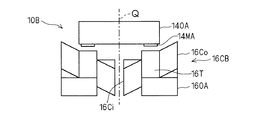
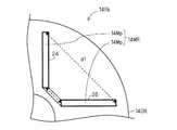
- a forty-fifth aspect of the present invention is any one of the first to twenty-ninth aspects, wherein the motor (10B) is an axial gap type motor, and the armature winding (16CB) is wound by a distributed winding method. The outer peripheral portion of the armature winding is turned toward the outer edge of the rare earth magnet (14MA).
- Forty-sixth invention is the forty-fifth invention, and the armature winding (16CB) is made of a self-bonding material.
- 47th invention is 46th invention, Comprising: A rectangular wire is employ
- a forty-eighth aspect of the invention is a method of manufacturing the forty-sixth or forty-seventh aspect of the invention, in which a first step of forming the armature winding (16CB) and a fusion of the self-bonding material after the first step. It is the manufacturing method of an air conditioner provided with the 2nd process to wear.
- the forty-ninth invention is the forty-fifth invention, wherein the stator (16A) is held in the container (32) of the compressor (30A) on the outer peripheral side thereof, and the coil of the armature winding (16CA) The part on the outer peripheral side of the end (16CE) is bent toward the rotor (14) facing the stator in the direction of the rotation axis (Q).
- the 50th aspect of the present invention is the 49th aspect of the present invention, wherein an inner peripheral portion of the coil end (16CE) is bent toward the direction of the rotation axis (Q).
- the fifty-first invention is the forty-ninth invention, wherein an inner peripheral portion of the coil end (16CE) extends in a plane having the normal direction in the direction of the rotation axis (Q).
- a 52nd aspect of the invention is the 45th aspect of the invention, wherein, on the side facing the armature winding (16C), the rotation axis is centered in a plane normal to the rotation axis (Q) direction. The outer end of the rare earth magnet (14MA, 14MR) in the radial direction is exposed.
- the 53rd invention is the 45th invention, wherein the rare earth magnet (14MA, 14MR) is held by a non-magnetic material holder.
- a fifty-fourth aspect of the present invention is any one of the first to twenty-ninth aspects, wherein the motor (10R) is a radial gap type motor, and the one rare earth magnet (14MR) includes a plurality of magnet bodies (14Mp). Embedded in a rotor core (140R) of the rotor (14), and the coercive force of one of the plurality of magnet bodies is greater than the rotation axis (Q) than the one magnet body. It is higher than the coercive force of the other magnet body disposed on the side close to.
- the motor (10R) is a radial gap type motor
- the one rare earth magnet (14MR) includes a plurality of magnet bodies (14Mp). Embedded in a rotor core (140R) of the rotor (14), and the coercive force of one of the plurality of magnet bodies is greater than the rotation axis (Q) than the one magnet body. It is higher than the coercive force of the other magnet body
- a 55th aspect of the present invention is the 54th aspect of the present invention, wherein the one rare earth magnet (14MA, 14MR) is provided with the plurality of magnet bodies disposed on substantially the same plane parallel to the rotation axis (Q) ( 14 Mp).
- a fifty-sixth invention is the fifty-fourth invention, wherein the rare earth magnet (14MA, 14MR) has the plurality of magnet bodies (14Mp) in a sectional view with the direction of the rotation axis (Q) as a normal line.
- a concave shape opening toward the stator is provided.
- 57th invention is 54th invention, Comprising: Between said one magnet body and another said magnet body among said several magnet bodies (14Mp), heat capacity is larger than the said magnet body.
- a third heat insulator (22; 22S, 22C) is provided.
- the 58th invention is the 57th invention, wherein a resin spacer (22S) is adopted as the third heat insulator (22).
- the 59th invention is the 57th invention, wherein the third heat insulating body (22) employs a resin coating (22C) covering the magnet body (14 Mp).
- the 60th invention is the 57th invention, wherein the third heat insulator (14I) employs a gap (14Ig) provided between the plurality of magnet bodies (14Mp).
- a 61st invention is any one of the 1st to 29th inventions, wherein the motor (10R) is a radial gap type motor, and the one rare earth magnet (14MA, 14MR) is the rotor (14).
- the motor (10R) is a radial gap type motor
- the one rare earth magnet (14MA, 14MR) is the rotor (14).
- a 62nd invention is any of the 1st to 29th inventions, wherein the rare earth magnet (14MA, 14MR) is embedded in a rotor core (140A, 140R) of the rotor (14), and the rare earth magnet And a high thermal conductive resin (24) between the rotor core and the side surface of the rotor core.
- a 63rd invention is any one of the 1st to 29th inventions, wherein the rare earth magnet (14MA, 14MR) is embedded in a rotor core (140A, 140R) of the rotor (14), and the rare earth magnet Aluminum is disposed between the rotor core and the side surface of the rotor core by die casting.
- a 64th aspect of the present invention is any one of the first to 29th aspects of the present invention, wherein a flow line of the refrigerant flowing through the compressor (30; 30A, 30R) is connected to a refrigerant passage (30R) in contact with the rare earth magnet. It is almost parallel.
- a 65th aspect of the present invention is the 64th aspect of the present invention, wherein the motor (10R) is a radial gap type motor, and the rotor (14) embeds the rare earth magnet (14MR) on the rotating shaft (Q).
- the rotor core (140R) extending in parallel is further provided, and the rotor core is provided with a gap (142) exposing a side surface side end portion of the rotor core of the rare earth magnet, and the refrigerant flows through the gap.
- the 66th invention is the 64th invention, wherein the motor (10R) is a radial gap type motor, and the rotor (14R) is a rotor core (140R) in which the rare earth magnet (14MR) is exposed.
- the refrigerant flows through the air gap (10G) of the radial gap motor.
- 67th invention is 65th or 66th invention, Comprising:
- the said compressor (30; 30A, 30R) has a compression mechanism part (36) provided with the discharge port (42), The said rotating shaft (Q)
- the distance from the rotation axis to the discharge port in the plane having the direction normal is not more than the distance from the rotation axis to the refrigerant passage in the plane.
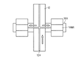
- the 68th invention is any of the 1st to 29th inventions, wherein the shaft (12) exhibits a through hole (12H) extending in the direction of the rotation axis (Q), and the through hole It branches off in the direction penetrating the inside of the rotor (14).
- a 69th aspect of the present invention is a rotor (14C) which can rotate in the circumferential direction around a shaft (12) extending in the direction of the rotation axis (Q) and which exhibits magnetic poles having different polarities alternately in the circumferential direction,
- a rare earth magnet (14N, 14S; 14N1, 14S1) for supplying field magnetic flux to the first stator (16A) having an armature winding (16CA) facing the rotor in the direction of the rotation axis
- the first A motor (10C) provided with a second stator (402) having a magnetic plate facing the rotor from the side opposite to one stator and a field adjusting winding (16F) for adjusting the field magnetic flux is used.
- the air conditioner (100) capable of compressing the refrigerant and capable of heating operation and cooling operation, wherein the motor rotates at a rotation speed equal to or higher than a predetermined rotation speed in the heating operation. Compressing heating In the case of load operation, a harmonic current is passed through the field adjustment winding to inductively heat the rare earth magnet, and in the cooling operation, the motor rotates at a rotation speed equal to or higher than a predetermined rotation speed. In the case of a cooling high load operation for compressing the refrigerant, a current is applied to the field adjusting winding to weaken the field magnetic flux.
- the 70th invention is the 69th invention, wherein a plurality of the rare earth magnets (14N, 14S) are provided on the rotor (14C) with magnetic poles having different polarities alternately in the circumferential direction.
- 71st invention is 69th invention, Comprising:
- the said rotor (14C) received the magnetic field magnetic flux of N pole from the said rare earth magnet (14N), and was provided around the said rotating shaft (Q).
- One magnetic ring (14NR), a second magnetic ring (14SR) provided around the rotation axis by receiving a field magnetic flux of S pole from the rare earth magnet (14S), and the first stator (16A)
- a second magnetic plate (14SB) that is arranged in a plurality of annular shapes in the circumferential direction facing one stator, is magnetically coupled to each other by the second magnetic ring, and is magnetically separated from the first magnetic ring;
- the 72nd invention is the 71st invention, wherein the rare earth magnet exhibits a first magnetic pole surface (14NP) for supplying the N magnetic field magnetic flux to the first magnetic ring (14NR) ( 14N1) and a second magnet (14S1) having a second magnetic pole surface (14SP) for supplying the S magnetic field magnetic flux to the second magnetic ring (14SR), and the rotor (14C) Provided.
- the rare earth magnet exhibits a first magnetic pole surface (14NP) for supplying the N magnetic field magnetic flux to the first magnetic ring (14NR) ( 14N1) and a second magnet (14S1) having a second magnetic pole surface (14SP) for supplying the S magnetic field magnetic flux to the second magnetic ring (14SR), and the rotor (14C) Provided.
- a 73rd invention is the 71st invention, wherein the rare earth magnet (14N1, 14S1) includes a first magnetic pole surface for supplying the N magnetic field magnetic flux to the first magnetic ring, and the second magnetic material. And a second magnetic pole face for supplying the S magnetic field magnetic flux to the ring, and is provided on the second stator (402).
- a harmonic current is passed through the auxiliary winding to inductively heat the rare earth magnet.
- 75th invention is the 74th invention, wherein the motor (10A) is an axial gap type motor, and the auxiliary winding (18) is arranged on the outer peripheral side of the rotor (14A).
- the 76th invention is the 74th invention, wherein the motor (10R) is a radial gap type motor, and the auxiliary winding (18) is arranged in the direction of the rotation axis (Q) of the rotor (14A). The end portion is provided in close proximity to the rare earth magnet (14MA).
- the 77th invention is the 74th invention, wherein the motor (10A) is an axial gap type motor, and the stator (16A) sandwiches the rotor (14A) in the direction of the rotation axis (Q).
- One stator has a stator core (160A) in which an armature winding (16CA) is disposed, and the other stator has the auxiliary winding (18) on the rotor side. Having a stator core.
- the residual magnetic flux density of the rare earth magnet is weakened by induction heating to enable high speed operation, and the refrigerant temperature is raised by flowing the refrigerant in the vicinity of the rare earth magnet. Therefore, it can contribute to heating operation at high load.
- the rotation speed of the motor can be accelerated without excessively increasing the refrigerant temperature.
- the voltage applied to the motor is increased during the cooling high load operation, so that the rotation speed of the motor can be increased without excessively increasing the refrigerant temperature.
- the harmonic component of the current increases, contributing to induction heating.
- the harmonic component of the current flowing through the armature winding is increased, which contributes to induction heating.
- the harmonic component of the current flowing through the armature winding is further increased.
- the frequency of the harmonic current is increased, which contributes to induction heating.
- the field magnetic flux can be estimated from the relationship between the induced voltage and the number of rotations of the motor.
- the non-energized section is provided in the vicinity of the maximum value of the induced voltage, it is possible to avoid or suppress the occurrence of an error in estimating the field magnetic flux.
- the non-energized section can be provided more reliably.
- the temperature of the rare earth magnet can be estimated by measuring the induced voltage. Therefore, irreversible demagnetization can be avoided or suppressed by stopping induction heating when the induced voltage falls below a predetermined threshold value.
- the temperature of the rare earth magnet can be estimated from the temperature of the refrigerant, irreversible demagnetization can be avoided or suppressed.
- the temperature of the rare earth magnet can be estimated from the temperature of the armature winding, irreversible demagnetization can be avoided or suppressed.
- the seventeenth aspect it is possible to avoid or suppress excessive induction heating, thereby avoiding or suppressing irreversible demagnetization.
- the operation of the compressor can be stabilized.
- overheating of the stator can be avoided or suppressed even if induction heating is performed.
- the iron loss of the stator core is small.
- the stator can dissipate heat so that overheating can be avoided or suppressed.
- the stator is cooled, so that overheating can be avoided or suppressed.
- the rotor can be efficiently induction-heated.
- the air-core coil can be easily formed, and the rotor can be efficiently heated.
- the rare earth magnet can be efficiently heated without being obstructed by the rotor core.
- the rare earth magnet provided in the rotor can be efficiently heated.
- the coil end can be shaped easily.
- the manufacture of the motor of the 32nd invention is easy.
- manufacture of the motor of the thirty-first invention is easy.
- the compressor can be easily manufactured.
- the magnet can be efficiently heated.
- the creepage distance of insulation can be extended.
- the rare earth magnet can be efficiently induction-heated while maintaining the lamination of the first electromagnetic steel plates using the end plate.
- the rare earth magnet since the material having a smaller heat capacity than the rare earth magnet is adopted as the end plate of the rotor core, the rare earth magnet can be heated even if the end plate is used.
- the forty-fourth invention it is possible to avoid or suppress the diffusion of heat to the rotor core and to efficiently heat the rare earth magnet.
- the rare earth magnet can be efficiently heated.
- the coil end can be easily shaped.
- the armature winding approaches the rare-earth magnet disposed on the rotor, so that the magnet can be efficiently heated. Moreover, since the stator is held on the outer peripheral side, the heat of the stator can be dissipated if a material having an appropriate heat capacity is adopted as the material of the container.
- the unbalance of the magnetic flux in the radial direction around the rotation axis can be eliminated within a plane having the rotation axis direction as a normal line.
- the rare earth magnet can be efficiently heated.
- the rare earth magnet can be held against the centrifugal force without impairing the heating efficiency.
- irreversible demagnetization of the rare earth magnet can be avoided or suppressed.
- the arrangement of the rare earth magnets is easy.
- the irreversible demagnetization can be avoided or suppressed more effectively.
- heat conduction can be blocked and magnets can be fixed together.
- the magnet body can be cooled by the refrigerant or the ventilation passing through the gap.
- the effect of induction heating is likely to occur in the magnet.
- the thermal conductivity between the rare earth magnet and the rotor core can be increased, and the rare earth magnet can be efficiently heated.
- the thermal conductivity between the rare earth magnet and the rotor core can be increased, and the rare earth magnet can be efficiently heated.
- the heat of the rare earth magnet can be effectively recovered into the refrigerant.
- the air gap functions as a magnetic barrier that prevents the magnetic flux of the rare earth magnet from flowing in a short circuit in the rotor core, and also functions as a passage for the refrigerant to recover the heat of the rare earth magnet.
- the heat of the rare earth magnet can be recovered effectively.
- the refrigerant can be efficiently led to the vicinity of the rare earth magnet, thereby contributing to efficient recovery of the heat of the rare earth magnet.
- the heat of the rare earth magnet can be recovered effectively. It also contributes to oil separation.
- the thrust force can be reduced.
- the field adjustment winding can be used not only for field adjustment but also for induction heating.
- the rare earth magnet can be heated by flowing a harmonic current through the auxiliary winding.
- the force in the direction of the rotating shaft acting between the rotor and the pair of stators is offset. Moreover, since the rotor having the rare earth magnet to be induction heated is interposed between the auxiliary winding and one stator, it is possible to avoid heating one stator unnecessarily.
- IPM rotor It is a top view of an IPM rotor. It is a top view of a SPM rotor. It is a figure which shows an upper end plate when the motor side is seen from the compression mechanism part side. It is sectional drawing of the shaft and rotor in a radial gap type motor. It is sectional drawing of the shaft and rotor in an axial gap type motor. It is sectional drawing of a part of compressor at the time of making a coil end protrude toward a rotating shaft. It is a top view of a radial gap type motor in case a rotor is 2 poles. It is sectional drawing of a radial gap type motor. It is sectional drawing of the rotor of FIG.
- FIG. 35 is a cross-sectional perspective view partially showing the rotor of FIG. 34. It is a figure which shows the modification of FIG. It is a figure which shows the modification of FIG. It is a figure which shows a part of FIG. It is sectional drawing of the rotor of an axial gap type motor. It is sectional drawing of the rotor of a radial gap type motor. It is sectional drawing of the axial gap type motor which has a non-winding stator.
- the basic idea of the present invention uses heating demagnetization of a permanent magnet that generates a field.
- a permanent magnet has a property that a residual magnetic flux density is lowered by receiving heat. By heating the magnet, the residual magnetic flux density is reduced to increase the rotational speed of the motor.
- ⁇ c output limit speed (electrical angular speed)
- Vom: Vam ⁇ Ra ⁇ Iam
- Vam Voltage limit value: Maximum voltage that can be output by the inverter
- Ra Armature winding resistance
- Iam current limit value ... equivalent to the rated current of the motor in continuous operation
- ⁇ e the maximum value of the armature linkage flux by the permanent magnet per phase
- ⁇ e the effective value of the armature flux linkage by the permanent magnet
- Ld d-axis inductance
- the d axis indicates the magnetic pole direction of the rotor of the motor, and the direction orthogonal to this is the q axis.
- the motor operates at high speed, and the refrigerant recovers heat, so the compressor is driven by a motor with a smaller maximum capacity compared to the maximum capacity of the compressor normally required for the required maximum heating capacity. To do.
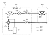
- FIG. 1 is a schematic diagram showing a refrigerant flow in the refrigerant circuit during heating operation of the air conditioner
- FIG. 2 is a schematic diagram showing a refrigerant flow in the refrigerant circuit during cooling operation of the air conditioner.
- a location where the pressure is relatively high in the refrigerant circuit is indicated by a solid line
- a location where the pressure is relatively low is indicated by a one-dot chain line.
- the air conditioner 100 can be roughly divided into an outdoor unit 200 and an indoor unit 300.
- the refrigerant (gas refrigerant) compressed by the compressor 30 included in the outdoor unit 200 is sent to the indoor unit 300 via the four-way valve 202 that switches the refrigerant path and the gas closing valve 204.
- the indoor unit 300 has a heat exchanger 302.
- the heat exchanger 302 during the heating operation functions as a condenser for the refrigerant compressed in the compressor 30, and the condensed refrigerant (liquid refrigerant) is a liquid closing valve 206 and an electric expansion valve 208 provided on the outdoor unit 200 side.
- the condensed refrigerant liquid refrigerant
- the heat exchanger 210 during the heating operation functions as an evaporator of the liquid refrigerant condensed in the heat exchanger 302, and the evaporated refrigerant returns to the compressor 30 via the four-way valve 202.
- the above cycle is repeated during heating operation.
- the high-temperature and high-pressure gas refrigerant is guided to the heat exchanger 302 of the indoor unit 300 to exchange heat with the indoor air.
- the gas refrigerant condenses and raises the indoor air temperature, becomes a condensed refrigerant (liquid refrigerant), adiabatically expands by the electric expansion valve 208 and becomes low temperature and low pressure, and then the refrigerant enters a gas-liquid state.
- the refrigerant becomes a gas refrigerant and is sucked into the compressor 30.
- the gas refrigerant compressed by the compressor 30 is sent to the heat exchanger 210 via the four-way valve 202.
- the heat exchanger 210 during the cooling operation functions as a condenser for the gas refrigerant compressed in the compressor 30, and the condensed liquid refrigerant passes through the electric expansion valve 208 and the liquid closing valve 206 to the heat exchanger 302. Sent.
- the heat exchanger 302 during the cooling operation functions as an evaporator of the liquid refrigerant condensed in the heat exchanger 210, and the evaporated gas refrigerant returns to the compressor 30 via the gas closing valve 204 and the four-way valve 202. .
- the above cycle is repeated during cooling operation.
- the high-temperature and high-pressure gas refrigerant is guided to the heat exchanger 210 of the outdoor unit 200 and is liquefied by exchanging heat with the outside air.
- the liquid refrigerant is adiabatically expanded by the electric expansion valve 208 to become a low temperature and low pressure, and then enters a gas-liquid state.
- the refrigerant is guided to the heat exchanger 302 of the indoor unit 300 and exchanges heat with indoor air, thereby lowering the indoor air temperature. As a result, the refrigerant is vaporized and sucked into the compressor 30.
- the heat exchange sectional area of the heat exchanger 210 of the outdoor unit 200 is larger than the heat exchange sectional area of the heat exchanger 302 of the indoor unit 300. Therefore, a predetermined temperature difference is required between the refrigerant flowing through the outdoor unit 200 and the refrigerant flowing through the indoor unit 300 during the heating operation. In order to secure such a temperature difference, a predetermined pressure difference is required between the refrigerant flowing through the outdoor unit 200 and the refrigerant flowing through the indoor unit 300. Therefore, the load of the motor mounted on the compressor 30 is larger during the heating operation than during the cooling operation. That is, the motor exhibits the maximum rotation speed during the heating operation.
- the compressor 30 is equipped with a motor, and the motor is classified into an axial gap type and a radial gap type.
- FIG. 3 is an exploded perspective view of the axial gap type motor 10 ⁇ / b> A, which is exploded along the rotation axis Q.
- the axial gap motor 10A includes, for example, a rotor 14A as a field element, a stator 16A as an armature, and a magnetic body 400. In an actual configuration, the rotor 14A is sandwiched between the stator 16A and the magnetic body 400 via a slight gap in the rotation axis Q direction.
- the rotor 14A has a rare earth magnet 14MA and a rotor core 140A that covers the stator 16A side of the rare earth magnet 14MA.
- the rare earth magnet 14MA is annularly arranged around the rotation axis Q, and the rotor core 140A has a hole 14HA that holds the shaft 12 (see FIG. 4) via a holding frame (not shown) made of a non-magnetic material in the vicinity of the rotation axis Q. Is provided. Since the rare earth magnet 14MA and the rotor core 140A are independent for each magnetic pole, they need to be integrated with a nonmagnetic material such as resin. This also serves as the above-described holding frame.
- the stator 16A has a stator core 160A, a tooth 16TA held by the stator core 160A, and an armature winding 16CA.
- the stator core 160A extends in a plane whose normal is the direction of the rotation axis Q, and is provided with a hole 16HA through which the shaft 12 held by the rotor 14A passes.
- a bearing may be provided in the hole 16HA to hold the rotor 14A.
- the teeth 16TA are arranged annularly around the rotation axis Q on the main surface facing the rotor 14A, out of the main surfaces having the rotation axis Q of the stator core 160A as a normal line, and the armature winding 16CA is wound around the teeth 16TA. Functions as a wick.
- the armature winding 16CA is wound around the teeth 16TA via an insulator (not shown). Unless otherwise specified in the present application, the armature winding 16CA does not indicate one of the conductive wires constituting the armature winding 16CA, but indicates an aspect in which the conductive wires are wound together. The same applies to the drawings. In addition, the winding start and winding lead lines and their connections are also omitted in the drawings.
- Magnetic body 400 can be grasped as a stator having no windings. For example, a hole 400H that allows the shaft 12 to pass therethrough is provided in the vicinity of the rotation axis Q. Since a magnetic attraction force acts between the rotor 14A and the magnetic body 400, the thrust force acting between the rotor 14A and the stator 16A can be canceled. Since the thrust force acts on a bearing (not shown) that supports the shaft 12, the bearing loss can be reduced by canceling the thrust force.
- the magnetic body 400 may be replaced with the same configuration as the stator 16A, and both the stators may be armatures.
- FIG. 4 is a cross-sectional view of the compressor 30A.
- the compressor 30 ⁇ / b> A includes an axial gap type motor 10 ⁇ / b> A, a container 32, and a compression mechanism unit 36.
- the compression mechanism unit 36 is disposed in the container 32, and the axial gap type motor 10 ⁇ / b> A is disposed in the container 32 and above the compression mechanism unit 36.
- the compression mechanism 36 is driven by the axial gap motor 10 ⁇ / b> A via the shaft 12.
- the suction pipe 41 is connected to the lower side of the container 32, while the discharge pipe 42 is connected to the upper side of the container 32.
- the refrigerant supplied from the suction pipe 41 is guided to the compression mechanism unit 36.
- the suction pipe 41 and the discharge pipe 42 are also shown in the side view in FIG.
- stator core 160A and the outer peripheral side of the magnetic body 400 are fixed inside the container 32, and the axial gap type motor 10A is fixed.
- the lower end side of the shaft 12 is connected to the compression mechanism portion 36.
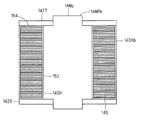
- the compression mechanism 36 includes a cylindrical main body 70, an upper end plate 71T, and a lower end plate 71B.
- the upper end plate 71T and the lower end plate 71B are attached to the upper side and the lower side on the opening side of the main body 70, respectively.
- the shaft 12 passes through the upper end plate 71T and the lower end plate 71B and is inserted into the main body 70.
- the shaft 12 is rotatably supported by a bearing 72T provided on the upper end plate 71T of the compression mechanism portion 36 and a bearing 72B provided on the lower end plate 71B of the compression mechanism portion 36.
- a crank pin 73 is provided on the shaft 12 in the main body 70.
- a piston 74 is fitted to the crank pin 73 and driven.
- the refrigerant is compressed in a compression chamber 75 formed between the piston 74 and the corresponding cylinder.
- the piston performs a rotor or revolving motion in an eccentric state to change the volume of the compression chamber 75.
- the refrigerant is supplied from the suction pipe 41 to the compression mechanism 36, and the refrigerant is compressed by the compression mechanism 36 (particularly the compression chamber 75). .
- the high-pressure refrigerant compressed by the compression mechanism unit 36 is discharged into the container 32 from the discharge port 43 of the compression mechanism unit 36.
- the high-pressure refrigerant includes a groove (not shown) provided around the shaft 12, a hole (not shown) penetrating the inside of the rotor 14A and the stator 16A in the direction of the rotation axis Q, an outer peripheral portion of the stator 16A and the rotor 14A, and a container. 32 is carried to the upper space of the axial gap type motor 10A through the space between the inner surface of 32 and the like. Thereafter, the liquid is discharged to the outside of the container 32 through the discharge pipe 42.
- FIG. 5 is a diagram showing the connection between the power source PS and the motor 10A.
- a current is supplied from the power source PS via the inverter 50 to the motor 10A, particularly the armature winding 16CA, mounted on the compressor 30 included in the air conditioner 100.
- the converter 52 converts the alternating current supplied from the power source PS into a direct current
- the PWM inverter 54 converts the direct current obtained from the converter 52 into an alternating current and supplies it to the armature winding 16CA.
- the converter 52 and the PWM inverter 54 are connected by a DC link unit 56.
- the power supply PS may be three-phase or single-phase.
- the rare earth magnet 14MA is heated and demagnetized in a load region (hereinafter referred to as “heating high load operation”) that is equal to or higher than the maximum number of revolutions during heating operation or a predetermined number of revolutions.
- the voltage applied to the motor 10A is increased.
- the rare earth magnet 14MA is heated, the residual magnetic flux density of the rare earth magnet 14MA is lowered, and the operating point magnetic flux density is also lowered.
- the induced voltage of the axial gap type motor 10A is sufficiently smaller than the voltage of the DC link unit 56, operation at higher speed is possible. In other words, high speed operation is enabled by weakening the residual magnetic flux density of the rare earth magnet 14MA by induction heating.
- Induction heating is known as a method for heating a magnet.
- rare earth sintered magnets particularly neodymium-based sintered magnets
- the rotor core 140A and the stator core 160A are often formed of laminated steel plates or powdered iron cores in order to reduce iron loss, and eddy currents are unlikely to occur. Therefore, the rare earth magnet 14MA tends to generate heat more than the rotor core 140A and the stator core 160A.
- Rare earth sintered magnets cause irreversible demagnetization at high temperatures, but motors are usually designed assuming irreversible demagnetization when locked due to poor start-up or running out of oil. Therefore, when operating stably, there is a relative margin for demagnetization. Conversely, when an unstable advance angle is used for field-weakening control, it becomes susceptible to irreversible demagnetization because it tends to step out.
- the rare earth magnet 14MA is heated by induction heating during heating and high load operation. Furthermore, since the refrigerant temperature is raised by flowing a refrigerant having a temperature lower than that of the rare earth magnet 14MA in the vicinity of the rare earth magnet 14MA, it contributes to the heating operation. For example, if it is going to implement
- cooling high load operation a load region that exceeds the maximum rotation speed of the motor 10A during the cooling operation or a predetermined rotation speed. I do.
- the voltage of the DC link unit 56 may be boosted.
- the current supplied to the armature winding 16CA to heat and demagnetize the rare earth magnet 14MA is preferably as follows.
- Heating demagnetization during heating and high load operation can be realized, for example, by superimposing a harmonic current on the armature winding 16CA.
- a current having a frequency sufficiently higher than the carrier frequency of the PWM inverter may be superimposed.
- the voltage of the DC link unit 56 at the time of heating high load operation May be made higher than the voltage of the DC link unit 56 during the cooling high load operation. That is, the harmonic component of the current flowing through the armature winding 16CA is increased by increasing the voltage of the DC link portion 56 in order to reduce the duty during the heating operation, which contributes to induction heating.
- FIG. 6 is a diagram showing the relationship between the duty of the output signal of the PWM inverter 54 (FIG. 6A) and the current flowing through the armature winding 16CA (FIG. 6B).
- the duty of the output signal of the PWM inverter 54 is large (indicated by the chain line in the figure) and small (indicated by the solid line in the figure)
- the latter case shows the current flowing in the armature winding 16CA.
- a steep peak appears in the current waveform. This indicates that the harmonic component of the current has increased.
- the peak is small when the voltage of the DC link unit 56 remains low, it is desirable to increase the voltage of the DC link unit 56 when reducing the duty of the output signal of the PWM inverter 54 at the time of heating high load.
- the rotor core 140A is on the stator 16A side of the rare earth magnet 14MA.
- the rare earth magnet 14MA may be exposed on the stator 16A side, and in this case, the rare earth magnet 14MA can be induction-heated more efficiently.
- FIG. 7 is a current waveform diagram showing the sine wave current SC1 and the overmodulation current MC1.
- an overmodulation current MC1 that is overmodulated and output by the PWM inverter 54 is supplied to the armature winding 16CA.
- the sine wave current SC1 is supplied to the armature winding 16CA. Since the overmodulation current MC1 approaches a rectangular wave and is greatly distorted, it can be understood that the harmonic current is superimposed on the current flowing through the armature winding 16CA.
- the power supply PS of the axial gap motor 10A is, for example, a U-phase, V-phase, and W-phase three-phase AC power supply. Therefore, the current waveform diagram is different for each phase, but FIG. 7 shows only one phase. ing.
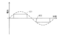
- FIG. 8 is a current waveform diagram showing a sine wave current SC2 and a rectangular wave current BC2. 8 also shows a current waveform diagram for only one phase as in FIG.
- the rectangular wave current BC2 is supplied to the armature winding 16CA.
- a sine wave current SC2 is supplied to the armature winding 16CA.
- the rectangular wave current BC2 has a higher harmonic component than the overmodulation current MC1, and thus is more desirable for induction heating.
- the current control in which a current waveform and a magnetic flux waveform correspond is desirable.
- FIG. 9 is a current waveform diagram showing the rectangular wave current BC3 and the harmonic current HC3.
- the rare earth magnet 14MA can be further induction-heated by flowing the harmonic current HC3 through the non-energized section of the rectangular wave current BC3.
- induction heating can be promoted by increasing the carrier frequency of the inverter 50.
- a rectangular wave exists, but in the present embodiment, it is desirable that the harmonic current HC3 be sufficiently larger than the carrier frequency, and the amplitude or duty ratio may be small.
- the carrier frequency of the inverter 50 may be set higher during heating and high load operation than during steady operation.
- the rotational speed of the axial gap type motor 10A usually increases, so there is an advantage that the sine wave current waveform becomes smooth by increasing the carrier frequency.
- the region that is induction-heated by the current flowing through the armature winding 16CA is a range from the armature winding 16CA to the skin depth ⁇ , and is generally expressed by the following equation.
- ⁇ : angular frequency of current flowing through the armature winding 16CA
- ⁇ : the absolute permeability of the conductor constituting the armature winding 16CA
- ⁇ : conductivity of the conductor constituting the armature winding 16CA
- the skin depth ⁇ is about several millimeters. That is, if the carrier frequency is set to such a frequency, the effect of induction heating can be obtained even if the distance from the armature winding 16CA to the rare earth magnet 14MA is several millimeters.
- the non-energized section is provided when the induced voltage V0 of any one of the U, V, and W phases connected to the axial gap motor 10A takes the maximum value.
- the maximum value is taken every 120 °, so the opportunity to obtain the field magnetic flux ⁇ a is increased, and the measurement accuracy is improved.
- the refrigerant coming out of the discharge pipe 42 can recover the heat of the rare earth magnet 14MA and raise the refrigerant temperature.
- the heat of the rare earth magnet 14MA can be recovered by the refrigerant, and excessive heating can be avoided or suppressed.
- a method of estimating or measuring the temperature of the rare earth magnet 14MA and stopping induction heating when a predetermined temperature threshold value is exceeded can be considered.
- a method is conceivable in which field magnetic flux when irreversible demagnetization occurs is experimentally obtained and stored as a threshold value, and induction heating is stopped by comparing the field magnetic flux ⁇ a obtained during operation with the threshold value.
- a temperature sensor 62 is provided in the vicinity of the discharge pipe 42 of the compressor 30A to detect the refrigerant temperature. Since the refrigerant exchanges heat with the rare earth magnet 14MA, the temperature of the rare earth magnet 14MA can be estimated by detecting the temperature of the refrigerant.
- FIG. 10 is a block diagram illustrating motor control technology.
- the motor control device 80 of the axial gap type motor 10 ⁇ / b> A includes a speed control unit 81, a current command unit 82, a current control unit 83, and a position detection unit 84.
- the speed control unit 81 and the current command unit 82 are combined, and based on the rotational angular velocity ⁇ of the rotor 14A of the axial gap motor 10A and the command value ⁇ *, the d-axis current command value id * and the q-axis current command The value iq * is generated.
- the speed control unit 81 generates a torque command value ⁇ * based on the rotational angular velocity ⁇ and its command value ⁇ *. At this time, even if the command value ⁇ * of the rotational angular velocity ⁇ increases, if either one of the droop commands S2 and S3 for decreasing the rotational angular velocity ⁇ is given from the current command unit 82 and the current control unit 83, the torque command The value ⁇ * is not increased.
- the current command unit 82 generates a d-axis current command value id * and a q-axis current command value iq * based on the torque command value ⁇ * and the current phase command value ⁇ *.
- the relationship of the following equation is maintained between the current phase command value ⁇ * and the d-axis current command value id * and the q-axis current command value iq *.
- an overvoltage detection signal S1 indicating that an overvoltage is detected is supplied from the current control unit 83 to the current command unit 82, and the current phase
- the field weakening control is performed by increasing the command value ⁇ *.
- the current control unit 83 controls the rotation of the axial gap motor 10A based on the d-axis current command value id * and the q-axis current command value iq * obtained from the current command unit 82 and the position angle ⁇ of the rotor 14A.
- Supply ix The current control unit 83 controls the rotation of the axial gap motor 10A based on the d-axis current command value id * and the q-axis current command value iq * obtained from the current command unit 82 and the position angle ⁇ of the rotor 14A.
- the position detector 84 detects the position angle ⁇ based on the current ix and the voltage vx supplied to the axial gap motor 10A, and also obtains the rotational angular velocity ⁇ .
- the current ix and the voltage vx are a generic term for the U phase current iu, the V phase current iv, and the W phase current iw and the U phase voltage vu. , V-phase voltage vv and W-phase voltage vw, respectively.
- Measures to prevent irreversible demagnetization include the following methods in addition to the above.
- the temperature of the rare earth magnet 14MA can be estimated by detecting the temperature of the armature winding 16CA. Therefore, irreversible demagnetization can be prevented by detecting the temperature of the armature winding 16CA before the start of induction heating, for example, and not performing induction heating when the temperature exceeds a predetermined temperature threshold.
- FIG. 11 is a diagram showing the connection between the power source PS and the axial gap type motor 10A.
- the axial gap motor 10A is further provided with a timer 66 for measuring a period from the start of induction heating, and the induction heating is stopped after a predetermined period has elapsed from the start of induction heating. You may do it.
- the axial gap type motor 10A When the axial gap type motor 10A is in sensorless operation, it is desirable for stable operation that the field magnetic flux ⁇ a of the rare earth magnet 14MA at the time of start-up is a certain amount or more. Therefore, the rotational speed of the rotor 14A is measured, and induction heating is not performed until the variation per unit time of the measured rotational speed is equal to or less than a predetermined threshold value. In other words, the start of induction heating is reserved until the operation of the axial gap type motor 10A is stabilized.
- the iron loss of the stator core 160A is made smaller.
- a silicon steel plate or a dust core may be used as the material of the rotor core 140A, and a material with a small iron loss such as an amorphous, ferrite core, or permalloy may be used as the material of the stator 16A.
- a harmonic absorbing material 20A as an insulator may be disposed between the armature winding 16CA and the stator core 160A.
- FIG. 12 is a cross-sectional view of the compressor 30A.
- the third method of suppressing the heating of the stator 16A can be adopted when the motor is an inner rotor type radial gap type motor or an axial gap type motor 10A. If the axial gap type motor 10A is described as an example, the stator 16A is fitted and held on the inner peripheral side of the container 32 of the compressor 30A, and the outside of the container 32 corresponding to the portion holding the stator 16A. Further, a heat radiating mechanism such as a heat radiating fin 34 is provided. The stator 16A is efficiently cooled by the radiation fins 34.
- the radiating fin 34 is extended to a position corresponding to the position of the armature winding 16CA, or provided separately at a position corresponding to the position of the armature winding 16CA, so that the armature winding 16CA is also efficiently cooled. You may do it.
- the aspect in which the compressor 30 (refer FIG. 1, FIG. 2) mounts a radial gap type motor is explained in full detail behind.
- FIG. 13 is a cross-sectional view of the compressor 30 with the axial gap motor removed.
- a fourth method for suppressing the heating of the stator 16A is that the motor mounted on the compressor 30 is an axial gap type motor 10A or an outer rotor type radial gap type motor, and the stator 16A is placed on the compression mechanism section 36 side. Fix it. As a result, heat is radiated from the stator 16 ⁇ / b> A to the container 32 via the compression mechanism 36.
- a low-pressure refrigerant jacket 38 is further provided in the upper part of the compression mechanism 36 in the container 32 having a high-pressure dome, and the refrigerant sucked at a low temperature is brought into close contact with the stator 16A, so that the refrigerant before reaching the vicinity of the rare earth magnet 14MA
- the stator may be actively cooled by exchanging heat with the stator 16A.
- the low-pressure refrigerant jacket 38 is used to temporarily store the suction gas of the compressor and supply the refrigerant to the compression mechanism 36. Compared with the surrounding area of the low-pressure refrigerant jacket 38 only in the high-pressure dome. The temperature is low.
- the method for demagnetizing the rare earth magnet 14MA by induction heating has been described by taking the compressor 30A mounted with the axial gap type motor 10A as an example. However, in realizing the method, the motor mounted on the compressor 30 is described. Depending on the type, the configuration of the apparatus differs. The case where the motor mounted on the compressor 30 is a radial gap type will be described in detail later.
- FIG. 14 is an exploded perspective view of an axial gap type motor 10B employing a coreless stator, which is exploded along the direction of the rotation axis Q.
- a so-called gap winding motor may be adopted by adopting an air-core coil 16CS having no teeth 16TA and a yoke instead of the stator 16A described above.
- the two rotors 14A face each other across the air-core coil 16CS along the rotation axis Q direction.
- the air-core coil 16CS can be easily formed by adopting a rectangular conductive wire having self-bonding properties. Alternatively, it can be easily obtained by molding the air-core coil 16CS with a conductive wire and then molding with a heat-resistant resin and a fiber filler.
- the rare earth magnet 14MA is heated using the armature winding 16CS, it is desirable that the rare earth magnet 14MA and the armature winding 16CS be as close as possible. From this point of view, it is preferable to employ an axial gap type motor in which the rare earth magnet 14MA is usually disposed on the surface of the rotor core 140A.
- FIG. 15 is an exploded perspective view of a part of the radial gap type motor 10R, which is disassembled in the radial direction with the rotation axis Q as the center.
- the radial gap motor 10R includes, for example, a rotor 14R as a field element and a stator 16R as an armature.
- the rotor 14R is opposed to the stator 16R through a slight gap in the radial direction around the rotation axis Q.
- the stator 16R has a yoke 16Y, a tooth 16TR held by the yoke 16Y, and an armature winding 16CR wound around the tooth 16TR. Although only two teeth 16TR are shown here, in the actual motor 10R, the teeth 16TR are arranged in a ring around the rotation axis Q and surround the rotor 14R.
- the armature winding 16CR is wound by, for example, a distributed winding method or a wave winding method straddling a plurality of teeth 16TR.
- the rotor 14R includes a rare earth magnet 14MR and a substantially cylindrical rotor core 140R that holds the rare earth magnet 14MR, and the shaft 12 is inserted through the rotor core 140R along the rotation axis Q direction.
- the rare earth magnet 14MR is formed in a circular columnar body in plan view from the direction of the rotation axis Q, and is disposed on the side surface of the rotor core 140R.
- the rare earth magnet 14MR has an inner diameter that is centered on the rotation axis Q equal to the radius of the circle of the rotor core 140R, and an outer diameter that is a predetermined length.
- the surface which exhibits the said internal diameter is arrange
- SPM Surface Permanent Magnet
- FIG. 16 is a plan view of the rotor 14Ra of the SPM motor.
- the rotor 14Ra has a rotor core 140Ra, a rare earth magnet 14MR, and a holding member 14HR.
- a rotor 14Ra as shown in FIG. 16 may be employed.
- the holding member 14HR is formed in a substantially cylindrical shape with the rotation axis Q as the center, and holds the rotor core 140Ra and the rare earth magnet 14MR inside thereof. Specifically, the rare earth magnets 14MR are evenly arranged along the inner surface of the holding member 14HR, and the rotor core 140Ra is formed to occupy a region surrounded by the holding member 14HR and the rare earth magnet 14MR.
- the holding member 14HR is desirably thin because it functions magnetically as an air gap.
- the rotor core 140Ra has a substantially circular shape in plan view by providing a groove along the direction of the rotation axis Q on the side surface of the substantially cylindrical body and disposing the rare earth magnet 14MR in the groove. Then, by fitting the substantially cylindrical holding member 14HR outside the rotor core 140Ra and the rare earth magnet 14MR, the rare earth magnet 14MR is firmly held against the centrifugal force caused by the rotation of the rotor 14Ra.
- the holding member 14HR is formed of a non-magnetic material so that the rare earth magnet 14MR is not magnetically short-circuited.
- a material with a small eddy current loss is used for the holding member 14HR so as not to prevent induction heating of the rare earth magnet 14MR.
- a material having high thermal conductivity is employed for the holding member 14HR.
- SUS can be adopted for the rare earth magnet 14MR.
- FIG. 17 is a plan view of the rotor 14Rb of the IPM (Interior Permanent Magnet) motor.
- a rotor 14Rb as shown in FIG. 17 may be adopted.
- the rotor 14Rb has a rotor core 140Rb and a rare earth magnet 14MRb.
- the rotor core 140Rb exhibits a hole extending in the direction of the rotation axis Q, and the rare earth magnet 14MRb is embedded in the hole.
- the rare earth magnet 14MRb has its magnetic pole surface extending in a plane whose normal is the radial direction.
- FIG. 18 is a cross-sectional view of a compressor 30R equipped with a radial gap type motor 10R, showing a mode in which a rotor 14Rb is employed. Note that elements having the same functions as those in the first embodiment are denoted by the same reference numerals and description thereof is omitted.
- the compressor 30 ⁇ / b> R includes a radial gap motor 10 ⁇ / b> R and a compression mechanism 36 inside the container 32.
- the armature winding 16CR When the armature winding 16CR is wound by the distributed winding method or the wave winding method, the armature winding 16CR is shaped as a coil and then inserted into the teeth 16TR. Therefore, the coil end 16CE, which is the portion of the armature winding 16CR that protrudes from the end face of the tooth 16TR at the end in the direction of the rotation axis Q, is more flexible than when it is wound by the concentrated winding method.
- the radially outer surface centering on the rotation axis Q is covered with the holding member 14HR like the rotor 14Ra, or the rotor core like the rotor 14Rb.
- the rare earth magnet 14MR is buried in the inside of the magnet, so that it is not exposed.
- the end of the surface of the rare earth magnet 14MR in the direction of the rotation axis Q is exposed on the rotor core surface.
- the rare earth magnets 14MR, 14MRb can be formed without the holding member 14HR and the rotor core 140R.
- Induction heating is possible.
- the armature winding 16CR employs a rectangular conductive wire having self-bonding properties, and the coil end 16CE is molded as described above and then fused.
- the iron loss of the stator core 160R is small when comparing the thickness of one electromagnetic steel sheet constituting the stator core 160R and the thickness of one electromagnetic steel sheet constituting the rotor core 140R.
- the thickness of one electromagnetic steel plate constituting the stator core 160R is thinner than the thickness of one electromagnetic steel plate constituting the rotor core 140R.
- a refrigerant passage 30P substantially parallel to the direction in which the refrigerant flow line extends is secured in the vicinity of the rare earth magnets 14MR and 14MRb. That is, it is desirable that the refrigerant passage 30P is substantially parallel to the flow line of the refrigerant.
- FIG. 19 is a plan view of the IPM rotor 14Rm.
- the rare earth magnet 14MRb is embedded in the rotor core 140R, and gaps 142 are provided at both ends in the longitudinal direction of the rare earth magnet 14MRb in a plan view from the rotation axis Q direction, and a part of the side surface of the rare earth magnet 14MRb is exposed. To do.
- the air gap 142 also functions as a so-called flux barrier that prevents the magnetic flux of the rare earth magnet 14MRb from flowing in a short circuit in the rotor core 140R.
- the air gap 142 as the refrigerant passage 30P, the heat of the rare earth magnet 14MRb can be efficiently recovered.
- FIG. 20 is a plan view of the SPM rotor 14Rn, the stator provided around the SPM rotor 14Rn is omitted, and an air gap 10G formed between the stator and the SPM rotor 14Rn is virtually shown.
- the SPM rotor 14Rn is provided with a rare earth magnet 14MR on the side surface of a substantially cylindrical rotor core 140R, and has an air gap 10G around the magnet.
- the air gap 10G as the refrigerant passage 30P, the heat of the rare earth magnet 14MR can be efficiently recovered.
- FIG. 21 is a view showing the upper end plate 71T when the motor side is viewed from the compression mechanism 36 side. 19 and 20, the distance from the rotation mechanism Q to the discharge port 43 of the compression mechanism 36 is preferably concentric and shorter than the distance to the refrigerant passage 30P. This is because it is difficult for the refrigerant to go from the radially outer side to the radially inner side because centrifugal force acts on the refrigerant.
- FIG. 22 is a sectional view of the shaft 12 and the rotor 14R in the radial gap type motor 10R
- FIG. 23 is a sectional view of the shaft 12 and the rotor 14A in the axial gap type motor 10A.
- the shaft 12 may be provided with a through hole 12H, and the through hole 12H may be communicated as a refrigerant passage 30P.
- the shaft 12 is provided with a through hole 12H, branched at an appropriate position from the rotation axis Q direction to the radially outward direction, passed through the rotor core 140R, and the rare earth magnet. Lead to 14MR.
- a through hole 12H is provided in the shaft 12, and the inside of the rotor core 140A is branched by branching from the rotation axis Q direction to the radially outward direction at a position corresponding to the rotor core 140A holding the rare earth magnet 14MA. It leads to the rare earth magnet 14MA.
- the refrigerant guided to the rare-earth magnets 14MA and 14MR passes through the stators 16A and 16R and travels toward the discharge pipe 42.
- the refrigerant passage 30P is provided in the shaft 12 and guided radially outward by the centrifugal force, it contributes to the separation of the refrigerant oil.
- FIG. 24 is a cross-sectional view of the motor 10R and the compression mechanism portion 36 driven by this when the coil end 16CE protrudes toward the rotation axis Q.
- Each element is simplified.
- At least the coil end 16CE on the compression mechanism portion 36 side of the coil ends 16CE formed at both ends of the teeth 16TR in the rotation axis Q direction is set to the rotation axis Q. It is desirable to protrude toward the side.
- the stator 16R is made into the compressor 30R. It is easy to insert the rotors 14R, 14Ra, 14Rb after being disposed in the container 32.
- the length of the rare earth magnets 14MR, 14MRb in the rotation axis Q direction may be longer than the length of the rotor cores 140R, 140Rb in the same direction, and the rare earth magnets 14MR, 14MRb may be projected from the end faces of the rotor cores 140R, 140Rb.
- the armature winding 16CR is wound around the teeth 16TR (specifically, the armature winding 16CR previously formed in a coil shape is disposed around the teeth 16TR), and the yoke 16Y is attached to the teeth 16TR (FIG. 15). reference).
- the coil end 16CE on either side in the direction of the rotation axis Q, for example, the coil end 16CE on the side facing the compression mechanism 36 (see FIG. 18) when disposed in the compressor 30R is directed toward the rotation axis Q. Project (see FIG. 24).
- the rotor 14R is inserted into the space surrounded by the stator 16R from the other side in the direction of the rotation axis Q, and the shaft 12 and the compression mechanism section 36 are fitted. After that, it is desirable to project the coil end 16CE on the other side in the direction of the rotation axis Q to the rotation axis Q. This is because the coil end 16CE at this position also contributes to induction heating.
- FIG. 25 is a plan view of the radial gap type motor 10R when the stator 16 has two-pole distributed winding, and shows an overhead view from the rotation axis Q direction. Detailed portions such as slots in which the armature winding 16CR is housed are omitted. The armature winding 16CR shows only one phase, and the other phases are omitted.
- the coil end 16CE in the radial gap type motor 10R manufactured as described above, the coil end 16CE preferably exhibits a line segment in a plan view from the direction of the rotation axis Q. With this configuration, the coil end 16CE easily approaches a rare earth magnet (not shown) provided in the rotor 14R (14Rb), and the effect of induction heating is high.
- FIG. 26 is a cross-sectional view of the radial gap type motor 10R. Since a high voltage is applied to the armature winding 16CR, the shorter the electrical distance between the armature winding 16CR and the rotor core 140R, the easier the dielectric breakdown occurs. If the coil end 16CE protrudes toward the rotation axis Q for the purpose of induction heating, the distance is shortened. Therefore, an insulator 20 provided between the armature winding 16CR and the stator core 160R is provided. The insulator 20 preferably projects toward the rotation axis Q along the coil end 16CE that projects toward the rotation axis Q. Thereby, a so-called creepage distance of insulation can be ensured, and insulation breakdown can be avoided or suppressed.
- FIG. 27 is a cross-sectional view of the rotor 14Rb of FIG.
- the rotor core 140Rb has a pair of end plates 142T, 142B extending in a plane normal to the rotation axis Q direction, and a plurality of first electromagnetic waves sandwiched between the end plates 142T, 142B and stacked in the rotation axis Q direction.
- Steel plate 146 The laminated body of the first electromagnetic steel plates 146 has a hole 146H penetrating in the lamination direction, and the rare earth magnet 14MRb is inserted into the hole 146H.
- the length of the rare earth magnet 14MRb in the direction of the rotation axis Q is longer than the length of the laminate in the direction of the rotation axis Q, and the protruding portion 14Mp of the rare earth magnet 14MRb protruding from the laminate exhibits a step.
- the area of the projecting portion 14Mp in the plane with the rotation axis Q direction as the normal line is smaller than the area of the hole 146H in the plane with the rotation axis Q direction as the normal line.
- the end plates 142T and 142B each have a hole 144 aligned with the protruding portion 14Mp, and the step formed by the holes 144 and 146H engages with the step formed by the protruding portion 14Mp.
- the end plates 142T and 142B form a rotor 14Rb sandwiching the laminate and the rare earth magnet 14MRb from both directions of the rotation axis Q direction.
- the coil end 16CE faces the rare earth magnet 14MRb via the end plates 142T and 142B.
- a material having a smaller heat capacity than the rare earth magnet 14MRb as the material of the end plates 142T and 142B, it is avoided that the heating efficiency is greatly reduced even if the end plates 142T and 142B are used.
- the rare earth magnet 14MRb is induction-heated via the end plates 142T and 142B, it is desirable that the rare earth magnet 14MRb and the end plates 142T and 142B are thermally coupled, but heat is radiated from the rare earth magnet 14MRb to the rotor core 140Rb. It needs to be suppressed.
- the first heat insulator 152 having a larger heat capacity than the rotor core 140Rb is disposed between the rotor core 140Rb and the rare earth magnet 14MRb, that is, on the surface of the hole 146H, that is, between the rotor core 140Rb and the end plates 142T and 142B,
- a second heat insulator 154 having a larger heat capacity than the rotor core 140Rb is disposed on the end surface of the laminated body of the first electromagnetic steel plates 146.
- the arrangement of the first heat insulator 152 and the second heat insulator 154 can be realized by attaching a heat insulating film to the laminate of the first electromagnetic steel plates 146 or coating the laminate.
- the rare earth magnet 14MRb can be efficiently induction-heated while maintaining the lamination of the first electromagnetic steel plates 146 by the end plates 142T and 142B.
- ⁇ Axial gap type motor> 28 to 30 are side views of the axial gap type motor 10B.
- one rotor and one stator are opposed to each other.
- the rotor is arranged such that a plurality of rare earth magnets 14MA alternately present magnetic poles in the circumferential direction on the stator side of the rotor core 140A.
- the rotor core 140A serves as a back yoke for the rare earth magnet 14MA.
- the armature winding 16CB is wound by the distributed winding method, and the portion 16Co on the outer peripheral side of the armature winding 16CB is curved toward the outer edge of the rare earth magnet 14MA as shown in FIG. To do.
- the portion 16Ci on the inner peripheral side of the armature winding 16CB is curved to the side opposite to the rotor 14A, so that the radial imbalance of each phase of U, V, and W can be alleviated.
- the inner peripheral portion 16Ci of the armature winding 16CB is curved toward the inner edge of the rare earth magnet 14MA. That is, the plurality of armature windings 16CB disposed on the rotor core 140A may be shaped so as to cover the outer edge and the inner edge of the plurality of rare earth magnets 14MA as a whole.
- the inner peripheral portion 16Ci of the armature winding 16CB may not be curved.
- these aspects can be easily realized by shaping the armature winding 16CB with a rectangular conductor having self-bonding property and fusing it after shaping.
- the rotor 14A holds the rare earth magnet 14MA, for example, if it is held by a nonmagnetic holder such as SUS, the rare earth magnet 14MA can be held against the centrifugal force without impairing the heating efficiency.
- FIG. 31 is an exploded perspective view of the IPM rotor 14Ri.
- the IPM rotor 14Ri is a rotor mounted on the radial gap type motor 10R.
- the rare earth magnet 14MR includes, for example, two first magnet bodies 14Mp1 and a second magnet body 14Mp2, and the two first magnet bodies 14Mp1 are arranged in a straight line on the rotor core 140R with the second magnet body 14Mp2 interposed therebetween. Buried. At this time, the second magnet body 14Mp2 is closer to the rotation axis Q than the first magnet body 14Mp1.
- the irreversible demagnetization of the rare earth magnet 14MR can be avoided or suppressed by making the coercivity of the first magnet body 14Mp1 higher than the coercivity of the second magnet body 14Mp2.
- FIG. 32 is a plan view of the IPM rotor 14Rj.
- the IPM rotor 14Rj is embedded such that the first magnet body 14Mp1 and the second magnet body 14Mp2 have a concave shape that opens to the outer peripheral side (that is, the stator side) of the rotor core 140R in plan view.
- each of the two first magnet bodies 14Mp1 having a relatively high coercive force has a concave shape adjacent to both ends in the extending direction of the second magnet body 14Mp2.
- the second magnet body 14Mp2 is positioned relatively away from the stator (not shown), irreversible demagnetization can be avoided or suppressed.
- a heat insulator (22) having a larger heat capacity than any of the magnet bodies may be provided between the first magnet body 14Mp1 and the second magnet body 14Mp2.
- the resin spacer 22S may be inserted between the first magnet body 14Mp1 and the second magnet body 14Mp2, or the resin coating 22C is applied to the first magnet body 14Mp1 and the second magnet body 14Mp2. Also good.
- a gap may be provided between the first magnet body 14Mp1 and the second magnet body 14Mp2.
- the first magnet body 14Mp1 and the second magnet body 14Mp2 can be cooled by the refrigerant or the air passing through the air gap.
- a magnet having a high residual magnetic flux density can be adopted as the second magnet body 14Mp2 to increase the coercive force of the first magnet body 14Mp1 and perform a weak magnetic flux mainly by induction heating here.
- FIG. 33 is a plan view of the IPM rotor 14Rk.
- the rare earth magnet 14MR disposed in the IPM rotor 14Rk has two magnet bodies 14Mp.
- a distance connecting a point closest to the stator (not shown) in one magnet body 14Mp and a point closest to the stator in the other magnet body 14Mp is a distance d1. Further, if a distance connecting a point farthest from the stator in one magnet body 14Mp and a point farthest from the stator in the other magnet body 14Mp is a distance d2, the distance d1 is longer than the distance d2.
- the two magnet bodies 14Mp have a substantially V shape and are embedded in the rotor core 140R, and the portions corresponding to the opening sides of the two sides constituting the V shape are closest to the stator. Buried.
- the end points are close to the stator, so that the end points can be mainly selectively heated by induction.
- heating may be performed via the rotor core 140R.
- the high thermal conductivity resin 24 may be disposed between the magnet body 14Mp and the rotor core 140R, or the aluminum 26 may be disposed between the magnet body 14Mp and the rotor core 140R by die casting.
- ⁇ Recovering heat from magnets> It is necessary to recover the heat of the induction-heated rare earth magnets 14MA, 14MR, and 14MRb after performing the desired control by heating demagnetization.
- the temperature of the heated rare earth magnets 14MA, 14MR, 14MRb is higher than the refrigerant temperature during the heating operation, that is, the refrigerant temperature is lower than the temperature of the heated rare earth magnets 14MA, 14MR, 14MRb even during the heating operation. . Therefore, in the present invention, a refrigerant passage is provided in the vicinity of the rare earth magnets 14MA, 14MR, and 14MRb.
- FIG. 34 is an exploded perspective view of the axial gap type motor 10C, which is separated along the direction of the rotation axis Q.
- the field adjustment winding 16F is provided on the main surface of the second stator 402 facing the rotor 14C.
- the second stator 402 is made of a magnetic material, and is provided with a circular groove 404 that opens to the rotor 14C side with the rotation axis Q as a central axis with respect to the second stator 400, and the field adjustment winding 16F has a rotation axis in the groove 404. It is wound around Q.
- the field adjustment winding 16F is a winding wound in the circumferential direction, and is provided to generate field magnetic flux interlinking with the armature winding 16CA to perform field weakening control.
- the magnetic flux of the rare earth magnet 14MA can be weakened by the magnetic flux generated by supplying a direct current to the field adjustment winding 16F.
- the rare earth magnet 14MA can be induction-heated by supplying the harmonic current HC to the field adjustment winding 16F. Further, when the axial gap type motor 10C is performing the cooling high load operation, the field weakening control can be performed by supplying a direct current to the field adjusting winding 16F.
- the rotor 14C of the axial gap type motor 10C has the following configuration. That is, the rotor 14C includes a plurality of rare earth magnets 14N and 14S, a first magnetic plate 14NB and a second magnetic plate 14SB, and a first magnetic ring 14NR and a second magnetic ring 14SR.
- a plurality of rare earth magnets 14N having an N-pole magnetic pole surface on the armature winding 16CA side and a plurality of rare earth magnets 14S having an S-pole magnetic pole surface on the armature winding 16CA side are provided on the rotating shaft. They are alternately arranged in the circumferential direction around Q.
- Each of the rare earth magnets 14N is opposite to the armature winding 16CA (S pole side) and has a structure in which each of the plurality of first magnetic plates 14NB is stacked in the rotation axis Q direction. Each of 14NB is magnetically coupled to each other by the first magnetic ring 14NR on the side opposite to the armature winding 16CA. Similarly, each of the rare earth magnets 14S has a structure in which each of the plurality of second magnetic plates 14SB is stacked in the direction of the rotation axis Q on the opposite side (N pole side) to the armature winding 16CA. The two magnetic plates 14SB are magnetically coupled to each other by the second magnetic ring 14SR on the side opposite to the armature winding 16CA. That is, the first magnetic ring 14NR and the second magnetic ring 14SR have a concentric ring with the rotation axis Q as the center, and are connected to the first magnetic plate 14NB or the second magnetic plate 14SB, respectively.
- FIG. 35 is a cross-sectional perspective view partially showing the rotor 14C of FIG. 34.
- the magnetic plates 15NB and 15SB are stacked along the rotation axis Q direction.
- the first magnetic ring 14NR may be disposed on the inner peripheral side or the outer peripheral side of the second magnetic ring 14SR.
- a magnetic plate 15NB is stacked on the magnetic pole surface on the armature winding 16CA side with respect to each of the plurality of rare earth magnets 14N, and a magnetic plate on the magnetic pole surface on the armature winding 16CA side with respect to each of the plurality of rare earth magnets 14S. 15SB may be stacked. If the magnetic plates 15NB and 15SB are provided, the demagnetization applied to the rare earth magnets 14N and 14S by the magnetic field generated by the armature winding 16CA can be suppressed.
- FIG. 36 is an exploded perspective view of the axial gap type motor 10D showing the first modification of FIG. 34, and is shown separated along the rotation axis Q direction.
- the axial gap motor 10D includes annular rare earth magnets 14N1 and 14S1 in the second stator 402 in place of the rare earth magnets 14N and 14S and the magnetic plates 15NB and 15SB shown in the axial gap motor 10C described above. That is, the magnetic rings 14NR and 14SR and the magnetic plates 14NB and 14SB function as a rotor of the axial gap type motor 10D.
- an annular rare earth that has the rotation axis Q as the center is formed on the main surface that faces the rotor. It has magnets 14N1 and 14S1. More specifically, the first magnetic ring 14NR and the rare earth magnet 14N1 constituting the rotor face each other, and the second magnetic ring 14SR and the rare earth magnet 14S1 face each other.
- FIG. 36 illustrates the case where the field winding 16F is disposed between the rare earth magnet 14N1 and the rare earth magnet 14S1, but the outer periphery of the rare earth magnet 14N1 and the inner periphery of the rare earth magnet 14S1 are illustrated. It may be arranged.
- FIG. 37 is an exploded perspective view of an axial gap type motor 10E showing a second modification of FIG. 34, which is shown separated along the rotation axis Q direction.
- FIG. 38 is a perspective view of the second stator 402 shown in FIG. 37 viewed from the armature winding 16CA side.
- the annular rare earth magnets 14N1 and 14S1 are not necessarily provided on the second stator 402, and are provided on the rotor 14E, more specifically, on the magnetic rings 14NR and 14SR from the side opposite to the armature winding 16CA. Also good.
- the rare earth magnet 14N1 is provided on the main surface facing the second stator 402 out of the main surface exhibited by the first magnetic ring 14NR, and the second stator 402 facing the main surface exhibited by the second magnetic ring 14SR.
- a rare earth magnet 14S1 may be provided on the main surface.
- the first magnetic ring 14NR and the second magnetic ring 14SR, and hence the first magnetic plate 14NB and the second magnetic plate 14SB, are each composed of the rare earth magnets 14N and 14S (or the rare earth elements).
- the magnets 14N1, 14S1) receive the magnetic field magnetic flux of N pole and S pole.
- the stator 16A having the armature winding 16CA is fixed to the compression mechanism portion 36 side.
- heat is radiated from the stator 16 ⁇ / b> A to the container 32 via the compression mechanism 36.
- a low-pressure refrigerant jacket 38 is provided in the upper part of the compression mechanism 36 in the container 32 that exhibits a high-pressure dome, and the refrigerant sucked at a low temperature is brought into close contact with the stator 16A, so that the rare-earth magnets 14N, 14S, 14N1, and 14S1 are in the vicinity.
- the stator may be actively cooled by exchanging heat between the refrigerant before reaching the stator 16A. By cooling the stator 16A, the temperature rise of the armature winding 16CA is suppressed, and the copper loss is suppressed.
- FIG. 39 is a cross-sectional view of the rotor 14A of the axial gap motor 10A.
- an auxiliary winding 18 dedicated to induction heating may be provided separately.
- the auxiliary winding 18 is provided in the axial gap type motor 10A, as shown in FIG. 39, the auxiliary winding 18 is further provided around the rotor 14A in the plane in which the rotor 14A extends, and the harmonic current HC is obtained. May be energized.
- FIG. 40 is a cross-sectional view of the rotor 14R of the radial gap type motor 10R.
- the auxiliary winding 18 is provided in the radial gap type motor 10R, as shown in FIG. 40, the auxiliary winding 18 is further provided at the end of the rotor 14R in the direction of the rotation axis Q, and the harmonic current HC is energized. good.
- FIG. 41 is a cross-sectional view of an axial gap motor 10D having a non-winding stator 402.
- FIG. 4 In the case of a motor having a stator 402 that does not have an armature winding, such as the second stator 400 described in FIG. 3, an auxiliary winding 18 is further provided in the second stator 400 and a harmonic current HC is energized. Also good.
Landscapes
- Engineering & Computer Science (AREA)
- Power Engineering (AREA)
- Physics & Mathematics (AREA)
- Mechanical Engineering (AREA)
- Thermal Sciences (AREA)
- General Engineering & Computer Science (AREA)
- Permanent Field Magnets Of Synchronous Machinery (AREA)
- Iron Core Of Rotating Electric Machines (AREA)
- Control Of Motors That Do Not Use Commutators (AREA)
- Permanent Magnet Type Synchronous Machine (AREA)
- Air Conditioning Control Device (AREA)
- Control Of Ac Motors In General (AREA)
Abstract
Priority Applications (5)
| Application Number | Priority Date | Filing Date | Title |
|---|---|---|---|
| EP09762463.9A EP2306105A4 (fr) | 2008-06-09 | 2009-06-08 | Climatiseur, procédé de fabrication de climatiseur et compresseur |
| US12/996,951 US8616016B2 (en) | 2008-06-09 | 2009-06-08 | Air conditioner, air conditioner manufacturing method, and compressor |
| CN2009801208678A CN102057229B (zh) | 2008-06-09 | 2009-06-08 | 空调机、空调机的制造方法以及压缩机 |
| AU2009258615A AU2009258615B2 (en) | 2008-06-09 | 2009-06-08 | Air conditioner, air conditioner manufacturing method, and compressor |
| KR1020107026119A KR101324450B1 (ko) | 2008-06-09 | 2009-06-08 | 공기 조화기, 공기 조화기의 제조 방법 및 압축기 |
Applications Claiming Priority (2)
| Application Number | Priority Date | Filing Date | Title |
|---|---|---|---|
| JP2008-150890 | 2008-06-09 | ||
| JP2008150890A JP5468215B2 (ja) | 2008-06-09 | 2008-06-09 | 空気調和機及び空気調和機の製造方法 |
Publications (1)
| Publication Number | Publication Date |
|---|---|
| WO2009151033A1 true WO2009151033A1 (fr) | 2009-12-17 |
Family
ID=41416740
Family Applications (1)
| Application Number | Title | Priority Date | Filing Date |
|---|---|---|---|
| PCT/JP2009/060478 WO2009151033A1 (fr) | 2008-06-09 | 2009-06-08 | Climatiseur, procédé de fabrication de climatiseur et compresseur |
Country Status (7)
| Country | Link |
|---|---|
| US (1) | US8616016B2 (fr) |
| EP (1) | EP2306105A4 (fr) |
| JP (1) | JP5468215B2 (fr) |
| KR (1) | KR101324450B1 (fr) |
| CN (1) | CN102057229B (fr) |
| AU (1) | AU2009258615B2 (fr) |
| WO (1) | WO2009151033A1 (fr) |
Cited By (6)
| Publication number | Priority date | Publication date | Assignee | Title |
|---|---|---|---|---|
| EP2463992A1 (fr) * | 2010-12-08 | 2012-06-13 | Siemens Aktiengesellschaft | Moteur électrique excité en permanence doté d'un dispositif de chauffage et procédé de fonctionnement |
| WO2011128165A3 (fr) * | 2010-04-16 | 2013-04-11 | Robert Bosch Gmbh | Pompe de refoulement électrique et procédé d'entraînement d'une telle pompe |
| JP5693714B2 (ja) * | 2011-04-28 | 2015-04-01 | 三菱電機株式会社 | ヒートポンプ装置、ヒートポンプシステム及びインバータの制御方法 |
| JP2015084640A (ja) * | 2013-10-25 | 2015-04-30 | ゼネラル・エレクトリック・カンパニイ | 低温用フェライト磁石モーターを加熱するためのシステムおよび方法 |
| US9543887B2 (en) | 2010-10-15 | 2017-01-10 | Mitsubishi Electric Corporation | Heat pump device, heat pump system, and method for controlling three-phase inverter |
| US9618249B2 (en) | 2010-12-21 | 2017-04-11 | Mitsubishi Electric Corporation | Heat pump device, heat pump system, and method for controlling three-phase inverter |
Families Citing this family (43)
| Publication number | Priority date | Publication date | Assignee | Title |
|---|---|---|---|---|
| EP2568597B1 (fr) | 2010-05-06 | 2020-04-15 | Daikin Industries, Ltd. | Appareil de réfrigération |
| EP2434617A1 (fr) * | 2010-09-24 | 2012-03-28 | Siemens Aktiengesellschaft | Générateur pour machine électrique |
| WO2012081078A1 (fr) * | 2010-12-13 | 2012-06-21 | 日立アプライアンス株式会社 | Climatiseur et dispositif d'alimentation en eau chaude |
| CN102287891B (zh) * | 2011-06-16 | 2013-10-09 | 广东美的电器股份有限公司 | 直流变频空调及其控制方法 |
| CN103988030B (zh) * | 2011-12-14 | 2017-07-11 | 三菱电机株式会社 | 热泵装置、具有热泵装置的空调机、热泵热水器、冰箱和制冷机 |
| WO2013094075A1 (fr) * | 2011-12-23 | 2013-06-27 | 三菱電機株式会社 | Moteur à aimant permanent |
| JP2013135542A (ja) * | 2011-12-27 | 2013-07-08 | Hitachi Ltd | 焼結磁石モータ |
| CN104024765B (zh) * | 2012-01-04 | 2016-09-07 | 三菱电机株式会社 | 热泵装置、空调机以及制冷机 |
| JP5836859B2 (ja) * | 2012-03-19 | 2015-12-24 | 日立アプライアンス株式会社 | モータ制御装置、及びこれを用いたモータ駆動装置、圧縮機、冷凍装置、空気調和機、並びにモータ制御方法 |
| EP2645534B1 (fr) * | 2012-03-26 | 2018-01-31 | Siemens Aktiengesellschaft | Composant d'aimant avec une structure d'isolation thermique, ensemble rotor pourvu d'un tel composant d'aimant, transducteur électromécanique et éolienne |
| KR101369262B1 (ko) * | 2012-04-25 | 2014-03-06 | 주식회사 케이에스상사 | 개폐모터구조체 |
| JP5510493B2 (ja) * | 2012-05-11 | 2014-06-04 | セイコーエプソン株式会社 | 電気機械装置 |
| WO2014050154A1 (fr) | 2012-09-28 | 2014-04-03 | ダイキン工業株式会社 | Rotor et machine électrique rotative |
| GB201305787D0 (en) * | 2013-03-28 | 2013-05-15 | Trw Ltd | Motor drive circuit and method of driving a motor |
| JP6342758B2 (ja) * | 2013-10-09 | 2018-06-13 | 株式会社三井ハイテック | 積層鉄心及びその製造方法 |
| JP6285794B2 (ja) * | 2014-05-06 | 2018-02-28 | 株式会社Soken | 空調装置用送風ユニット |
| DE102014217005A1 (de) * | 2014-08-26 | 2016-03-03 | BSH Hausgeräte GmbH | Verfahren zum Bremsen eines Verdichters und Verdichter eines Kältegerätes, Klimageräts oder einer Wärmepumpe sowie Kältegerätes, Klimageräts oder Wärmepumpe damit |
| WO2016079791A1 (fr) * | 2014-11-17 | 2016-05-26 | 株式会社安川電機 | Dispositif et procédé de commande de moteur |
| WO2016162939A1 (fr) * | 2015-04-07 | 2016-10-13 | ジョンソンコントロールズ ヒタチ エア コンディショニング テクノロジー (ホンコン) リミテッド | Climatiseur |
| JP6630195B2 (ja) * | 2016-03-08 | 2020-01-15 | 株式会社東芝 | 誘導加熱装置、接合方法、接合部品およびこれを備える回転電機 |
| JP7152132B2 (ja) | 2016-11-15 | 2022-10-12 | 日産自動車株式会社 | モータの制御方法、及び、モータ制御装置 |
| JP6683116B2 (ja) * | 2016-12-12 | 2020-04-15 | 株式会社デンソー | モータ制御装置 |
| US10320268B2 (en) | 2017-01-31 | 2019-06-11 | Regal Beloit Australia Pty Ltd | Modular stator drive units for axial flux electric machines |
| US10541591B2 (en) | 2017-01-31 | 2020-01-21 | Regal Beloit Australia Pty, Ltd. | Composite stator for axial flux electric machines and methods of assembling the same |
| US10594180B2 (en) * | 2017-01-31 | 2020-03-17 | Regal Beloit America, Inc. | Magnetic flux guides for electric machines |
| US10770940B2 (en) | 2017-01-31 | 2020-09-08 | Regal Beloit Australia Pty Ltd. | Modular rotors for axial flux electric machines |
| US10418889B2 (en) | 2017-01-31 | 2019-09-17 | Regal Beloit Australia Pty Ltd. | Modular stator for axial flux electric machines and methods of assembling the same |
| JP6975886B2 (ja) * | 2017-03-01 | 2021-12-01 | パナソニックIpマネジメント株式会社 | ロボットの制御方法 |
| JP6689449B2 (ja) * | 2017-03-27 | 2020-04-28 | 三菱電機株式会社 | 回転子、電動機、圧縮機、送風機、および空気調和装置 |
| WO2019035195A1 (fr) * | 2017-08-17 | 2019-02-21 | 三菱電機株式会社 | Climatiseur |
| DE102018105129A1 (de) * | 2018-03-06 | 2019-09-12 | Gkn Sinter Metals Engineering Gmbh | Verfahren zum Betreiben eines elektrischen Motors |
| JP6544455B1 (ja) * | 2018-03-30 | 2019-07-17 | 愛知製鋼株式会社 | 電動機および界磁子 |
| CN109059207B (zh) * | 2018-06-14 | 2020-11-27 | 珠海格力电器股份有限公司 | 空调机组的载频控制方法及装置、变频空调器 |
| US11564289B2 (en) * | 2018-07-25 | 2023-01-24 | Heat X, LLC | Magnetic induction style furnace or heat pump with variable blower functionality including retractable magnet arrays |
| US11564290B2 (en) * | 2018-07-25 | 2023-01-24 | Heat X, LLC | Magnetic induction style furnace or heat pump incorporating forced air or fluid blowers |
| JP2020108312A (ja) * | 2018-12-28 | 2020-07-09 | 株式会社マキタ | 電動工具用の分布巻きモータ、電動工具及び芝刈り機 |
| JP7299477B2 (ja) * | 2019-03-27 | 2023-06-28 | ダイキン工業株式会社 | 電動機システム |
| US11012018B2 (en) * | 2019-08-01 | 2021-05-18 | Lennox Industries Inc. | Motor drive operation at light load conditions |
| CN113131644A (zh) * | 2019-12-31 | 2021-07-16 | 日本电产株式会社 | 转子铁芯以及具有该转子铁芯的马达 |
| JP1665116S (fr) * | 2020-02-27 | 2020-08-03 | ||
| CN111384792B (zh) * | 2020-05-29 | 2020-08-28 | 浙江盘毂动力科技有限公司 | 一种轴向电机定子及其生产工艺 |
| CN114811880B (zh) * | 2022-02-28 | 2024-04-05 | 青岛国创智能家电研究院有限公司 | 用于直流空调器除霜的方法及装置、直流空调器 |
| JP7141010B1 (ja) * | 2022-03-31 | 2022-09-22 | ダイキン工業株式会社 | 駆動システム、ターボ圧縮機、冷凍装置 |
Citations (14)
| Publication number | Priority date | Publication date | Assignee | Title |
|---|---|---|---|---|
| JPS63161363A (ja) * | 1986-12-23 | 1988-07-05 | 株式会社東芝 | 空気調和機の圧縮機モ−タの加熱方法 |
| JPH0321947B2 (fr) | 1981-09-25 | 1991-03-25 | Nippon Electric Co | |
| JPH05268740A (ja) * | 1992-03-17 | 1993-10-15 | Seiko Epson Corp | 冷凍サイクル用コンプレッサ |
| JPH06101909A (ja) * | 1992-09-18 | 1994-04-12 | Hitachi Ltd | 圧縮機の冷却装置 |
| JPH11275789A (ja) | 1998-03-23 | 1999-10-08 | Matsushita Electric Ind Co Ltd | 回転子 |
| JP3021947B2 (ja) * | 1992-03-24 | 2000-03-15 | ダイキン工業株式会社 | 能力可変型空気調和装置の制御方法 |
| JP2001178177A (ja) * | 1999-12-17 | 2001-06-29 | Mitsubishi Electric Corp | 電動機駆動装置および空気調和機 |
| WO2003079516A1 (fr) * | 2002-03-20 | 2003-09-25 | Daikin Industries, Ltd. | Moteur de type a aimants permanents et compresseur dote de ce moteur |
| JP2004254421A (ja) * | 2003-02-20 | 2004-09-09 | Daikin Ind Ltd | 電動機およびその製造方法 |
| JP2006141106A (ja) | 2004-11-11 | 2006-06-01 | Nagoya Institute Of Technology | ハイブリッド型モータまたは発電機およびこれを利用したモータまたは発電機駆動システム |
| JP2006313023A (ja) | 2005-05-06 | 2006-11-16 | Hitachi Home & Life Solutions Inc | 空気調和機 |
| JP2007252018A (ja) * | 2006-03-13 | 2007-09-27 | Aichi Elec Co | 永久磁石電動機 |
| WO2007114079A1 (fr) * | 2006-03-27 | 2007-10-11 | Daikin Industries, Ltd. | Noyau d'armature, moteur associe, et son procede de fabrication |
| JP2008131742A (ja) * | 2006-11-21 | 2008-06-05 | Daikin Ind Ltd | モータ |
Family Cites Families (24)
| Publication number | Priority date | Publication date | Assignee | Title |
|---|---|---|---|---|
| GB1451359A (en) * | 1973-11-30 | 1976-09-29 | Citizen Watch Co Ltd | Pulse motor driven circuit |
| US4831828A (en) * | 1987-05-27 | 1989-05-23 | Helix Technology Corporation | Cryogenic refrigerator having a convection system to cool a hermetic compressor |
| CN1103212A (zh) * | 1994-10-28 | 1995-05-31 | 林哲民 | 交流电动机的改进 |
| US6047460A (en) * | 1996-01-23 | 2000-04-11 | Seiko Epson Corporation | Method of producing a permanent magnet rotor |
| AUPO478297A0 (en) * | 1997-01-24 | 1997-02-20 | Commonwealth Scientific And Industrial Research Organisation | Improvements in high speed electric motors |
| JP3484051B2 (ja) * | 1997-09-10 | 2004-01-06 | 株式会社 日立インダストリイズ | 永久磁石式同期電動機及びその製造方法ならびに永久磁石式同期電動機を備えた遠心圧縮機 |
| JPH11103546A (ja) * | 1997-09-29 | 1999-04-13 | Fujitsu General Ltd | 永久磁石電動機 |
| JP3982656B2 (ja) * | 1998-05-19 | 2007-09-26 | 臼井国際産業株式会社 | マグネット式ヒーター |
| JP2000139047A (ja) * | 1998-10-30 | 2000-05-16 | Toyota Motor Corp | 永久磁石形電動機 |
| JP2000350490A (ja) * | 1999-06-02 | 2000-12-15 | Matsushita Electric Ind Co Ltd | ブラシレスモータ制御装置 |
| TW552352B (en) * | 1999-06-29 | 2003-09-11 | Sanyo Electric Co | Sealed rotary compressor |
| JP3629587B2 (ja) * | 2000-02-14 | 2005-03-16 | 株式会社日立製作所 | 空気調和機及び室外機並びに冷凍装置 |
| EP1139549A3 (fr) * | 2000-03-29 | 2002-06-05 | SANYO ELECTRIC Co., Ltd. | Ensemble moteur-compresseur hermétique |
| JP4102177B2 (ja) | 2002-12-10 | 2008-06-18 | トヨタ自動車株式会社 | 永久磁石モータの制御装置および制御方法 |
| JP2004328859A (ja) * | 2003-04-23 | 2004-11-18 | Nissan Motor Co Ltd | 電動機の回転子の製造方法及び電動機の回転子 |
| JP2004346757A (ja) * | 2003-05-20 | 2004-12-09 | Daikin Ind Ltd | 圧縮機および空気調和装置 |
| JP2006121877A (ja) * | 2004-10-25 | 2006-05-11 | Denso Corp | モータ制御装置 |
| JP4667837B2 (ja) * | 2004-11-26 | 2011-04-13 | 本田技研工業株式会社 | 埋め込み磁石型のロータ |
| KR101234824B1 (ko) * | 2005-01-18 | 2013-02-20 | 삼성전자주식회사 | 다단압축식 회전압축기 |
| JP2007174872A (ja) * | 2005-12-26 | 2007-07-05 | Nitto Shinko Kk | モータ磁性部材接着用加熱発泡シート |
| JP2007183395A (ja) * | 2006-01-06 | 2007-07-19 | Seiko Instruments Inc | レンズ駆動モジュール及びカメラモジュール |
| JP4496413B2 (ja) * | 2006-05-24 | 2010-07-07 | 三菱電機株式会社 | 永久磁石形モータの減磁装置、減磁方法 |
| JP4789720B2 (ja) * | 2006-07-07 | 2011-10-12 | 三洋電機株式会社 | モータ制御装置 |
| JP5268740B2 (ja) * | 2009-03-30 | 2013-08-21 | 株式会社日本製鋼所 | 角形基板の4角割れ欠け検出装置 |
-
2008
- 2008-06-09 JP JP2008150890A patent/JP5468215B2/ja active Active
-
2009
- 2009-06-08 US US12/996,951 patent/US8616016B2/en active Active
- 2009-06-08 EP EP09762463.9A patent/EP2306105A4/fr not_active Withdrawn
- 2009-06-08 AU AU2009258615A patent/AU2009258615B2/en active Active
- 2009-06-08 WO PCT/JP2009/060478 patent/WO2009151033A1/fr active Application Filing
- 2009-06-08 KR KR1020107026119A patent/KR101324450B1/ko active IP Right Grant
- 2009-06-08 CN CN2009801208678A patent/CN102057229B/zh active Active
Patent Citations (14)
| Publication number | Priority date | Publication date | Assignee | Title |
|---|---|---|---|---|
| JPH0321947B2 (fr) | 1981-09-25 | 1991-03-25 | Nippon Electric Co | |
| JPS63161363A (ja) * | 1986-12-23 | 1988-07-05 | 株式会社東芝 | 空気調和機の圧縮機モ−タの加熱方法 |
| JPH05268740A (ja) * | 1992-03-17 | 1993-10-15 | Seiko Epson Corp | 冷凍サイクル用コンプレッサ |
| JP3021947B2 (ja) * | 1992-03-24 | 2000-03-15 | ダイキン工業株式会社 | 能力可変型空気調和装置の制御方法 |
| JPH06101909A (ja) * | 1992-09-18 | 1994-04-12 | Hitachi Ltd | 圧縮機の冷却装置 |
| JPH11275789A (ja) | 1998-03-23 | 1999-10-08 | Matsushita Electric Ind Co Ltd | 回転子 |
| JP2001178177A (ja) * | 1999-12-17 | 2001-06-29 | Mitsubishi Electric Corp | 電動機駆動装置および空気調和機 |
| WO2003079516A1 (fr) * | 2002-03-20 | 2003-09-25 | Daikin Industries, Ltd. | Moteur de type a aimants permanents et compresseur dote de ce moteur |
| JP2004254421A (ja) * | 2003-02-20 | 2004-09-09 | Daikin Ind Ltd | 電動機およびその製造方法 |
| JP2006141106A (ja) | 2004-11-11 | 2006-06-01 | Nagoya Institute Of Technology | ハイブリッド型モータまたは発電機およびこれを利用したモータまたは発電機駆動システム |
| JP2006313023A (ja) | 2005-05-06 | 2006-11-16 | Hitachi Home & Life Solutions Inc | 空気調和機 |
| JP2007252018A (ja) * | 2006-03-13 | 2007-09-27 | Aichi Elec Co | 永久磁石電動機 |
| WO2007114079A1 (fr) * | 2006-03-27 | 2007-10-11 | Daikin Industries, Ltd. | Noyau d'armature, moteur associe, et son procede de fabrication |
| JP2008131742A (ja) * | 2006-11-21 | 2008-06-05 | Daikin Ind Ltd | モータ |
Non-Patent Citations (1)
| Title |
|---|
| See also references of EP2306105A4 |
Cited By (15)
| Publication number | Priority date | Publication date | Assignee | Title |
|---|---|---|---|---|
| CN103190073B (zh) * | 2010-04-16 | 2018-01-26 | 罗伯特·博世有限公司 | 电动输送泵和用于驱动电动输送泵的方法 |
| WO2011128165A3 (fr) * | 2010-04-16 | 2013-04-11 | Robert Bosch Gmbh | Pompe de refoulement électrique et procédé d'entraînement d'une telle pompe |
| CN103190073A (zh) * | 2010-04-16 | 2013-07-03 | 罗伯特·博世有限公司 | 电动输送泵和用于驱动电动输送泵的方法 |
| US9543887B2 (en) | 2010-10-15 | 2017-01-10 | Mitsubishi Electric Corporation | Heat pump device, heat pump system, and method for controlling three-phase inverter |
| US9160206B2 (en) | 2010-12-08 | 2015-10-13 | Siemens Aktiengesellschaft | Permanent-magnet-excited electric motor with heating device, and operating method |
| CN103238267B (zh) * | 2010-12-08 | 2015-10-07 | 西门子公司 | 具有加热装置的永磁体励磁的电动机和运行方法 |
| EP2463992A1 (fr) * | 2010-12-08 | 2012-06-13 | Siemens Aktiengesellschaft | Moteur électrique excité en permanence doté d'un dispositif de chauffage et procédé de fonctionnement |
| CN103238267A (zh) * | 2010-12-08 | 2013-08-07 | 西门子公司 | 具有加热装置的永磁体励磁的电动机和运行方法 |
| WO2012076357A3 (fr) * | 2010-12-08 | 2013-01-10 | Siemens Aktiengesellschaft | Moteur électrique à excitation par aimant permanent équipé d'un système de chauffage et procédé pour faire fonctionner un tel moteur électrique |
| US9618249B2 (en) | 2010-12-21 | 2017-04-11 | Mitsubishi Electric Corporation | Heat pump device, heat pump system, and method for controlling three-phase inverter |
| JP5693714B2 (ja) * | 2011-04-28 | 2015-04-01 | 三菱電機株式会社 | ヒートポンプ装置、ヒートポンプシステム及びインバータの制御方法 |
| US9829226B2 (en) | 2011-04-28 | 2017-11-28 | Mitsubishi Electric Corporation | Heat pump device, heat pump system, and method for controlling inverter |
| JP2015084640A (ja) * | 2013-10-25 | 2015-04-30 | ゼネラル・エレクトリック・カンパニイ | 低温用フェライト磁石モーターを加熱するためのシステムおよび方法 |
| KR20150048075A (ko) * | 2013-10-25 | 2015-05-06 | 제네럴 일렉트릭 컴퍼니 | 낮은 온도에서 페라이트 자석 모터를 가열하기 위한 시스템 및 방법 |
| KR102302513B1 (ko) * | 2013-10-25 | 2021-09-17 | 제네럴 일렉트릭 컴퍼니 | 낮은 온도에서 페라이트 자석 모터를 가열하기 위한 시스템 및 방법 |
Also Published As
| Publication number | Publication date |
|---|---|
| EP2306105A1 (fr) | 2011-04-06 |
| KR20110008257A (ko) | 2011-01-26 |
| AU2009258615B2 (en) | 2012-07-26 |
| CN102057229B (zh) | 2013-12-18 |
| AU2009258615A1 (en) | 2009-12-17 |
| KR101324450B1 (ko) | 2013-10-31 |
| JP2009293907A (ja) | 2009-12-17 |
| US8616016B2 (en) | 2013-12-31 |
| EP2306105A4 (fr) | 2016-11-30 |
| US20110083467A1 (en) | 2011-04-14 |
| JP5468215B2 (ja) | 2014-04-09 |
| CN102057229A (zh) | 2011-05-11 |
Similar Documents
| Publication | Publication Date | Title |
|---|---|---|
| WO2009151033A1 (fr) | Climatiseur, procédé de fabrication de climatiseur et compresseur | |
| US8058762B2 (en) | Rotor, axial gap type motor, method of driving motor, and compressor | |
| US10320249B2 (en) | Permanent magnet rotating electric machine and method for manufacturing same | |
| JP6638202B2 (ja) | アキシャルギャップ型の回転電機 | |
| TW565981B (en) | Permanent magnet type rotating electrical machine | |
| US10090793B2 (en) | Electric motor, compressor, and method for controlling electric motor or compressor | |
| US8987967B2 (en) | Claw-pole motor with permanent magnet and electrically exciting parts | |
| AU2006207163B2 (en) | Rotor, axial gap type motor, motor driving method, and compressor | |
| CN103081300B (zh) | 永久磁铁嵌入型电动机的转子、压缩机及制冷空调装置 | |
| US20170256997A1 (en) | Stator of Rotary Electric Machine and Rotary Electric Machine Equipped with the Same | |
| JP2012055119A (ja) | 永久磁石型モータの駆動装置及び圧縮機 | |
| JP2008193877A (ja) | モータ及びモータ駆動制御装置並びに換気扇、液体用ポンプ、冷媒圧縮機、送風機、空気調和機及び冷蔵庫 | |
| JP3828015B2 (ja) | 永久磁石形モータ及び永久磁石形モータの製造方法及び圧縮機及び冷凍サイクル装置 | |
| JP5289415B2 (ja) | 同期電動機の製造方法 | |
| JP2006345692A (ja) | 永久磁石形モータ | |
| JP2008245353A (ja) | モータ及びモータ駆動制御装置並びに換気扇、液体用ポンプ、冷媒圧縮機、送風機、空気調和機及び冷蔵庫 | |
| JP5550583B2 (ja) | 密閉型圧縮機 | |
| WO2019146006A1 (fr) | Moteur électrique, compresseur, et dispositif climatiseur | |
| JP2006034100A (ja) | 永久磁石形モータ | |
| JP2008187863A (ja) | アキシャルギャップ型回転電機及び圧縮機 | |
| JP5151183B2 (ja) | アキシャルギャップ型回転電機及び圧縮機 | |
| Gowtham et al. | Hybrid Ferrite Al-Ni-Co PM Assisted Synchronous Reluctance Motor for Air-Conditioner Compressors | |
| JP2008220128A (ja) | アキシャルギャップ型回転電機及び圧縮機 | |
| JP2001275286A (ja) | 密閉型電動圧縮機 | |
| JP7286019B2 (ja) | 固定子、電動機、圧縮機、冷凍サイクル装置及び空気調和装置 |
Legal Events
| Date | Code | Title | Description |
|---|---|---|---|
| WWE | Wipo information: entry into national phase |
Ref document number: 200980120867.8 Country of ref document: CN |
|
| 121 | Ep: the epo has been informed by wipo that ep was designated in this application |
Ref document number: 09762463 Country of ref document: EP Kind code of ref document: A1 |
|
| ENP | Entry into the national phase |
Ref document number: 20107026119 Country of ref document: KR Kind code of ref document: A |
|
| WWE | Wipo information: entry into national phase |
Ref document number: 2009258615 Country of ref document: AU |
|
| WWE | Wipo information: entry into national phase |
Ref document number: 12996951 Country of ref document: US |
|
| REEP | Request for entry into the european phase |
Ref document number: 2009762463 Country of ref document: EP |
|
| WWE | Wipo information: entry into national phase |
Ref document number: 2009762463 Country of ref document: EP |
|
| NENP | Non-entry into the national phase |
Ref country code: DE |
|
| ENP | Entry into the national phase |
Ref document number: 2009258615 Country of ref document: AU Date of ref document: 20090608 Kind code of ref document: A |