US7749313B2 - Air conditioning system for automotive vehicles - Google Patents
Air conditioning system for automotive vehicles Download PDFInfo
- Publication number
- US7749313B2 US7749313B2 US12/101,067 US10106708A US7749313B2 US 7749313 B2 US7749313 B2 US 7749313B2 US 10106708 A US10106708 A US 10106708A US 7749313 B2 US7749313 B2 US 7749313B2
- Authority
- US
- United States
- Prior art keywords
- discharge electrodes
- air conditioning
- moisture
- conditioning system
- electric short
- Prior art date
- Legal status (The legal status is an assumption and is not a legal conclusion. Google has not performed a legal analysis and makes no representation as to the accuracy of the status listed.)
- Active, expires
Links
Images


Classifications
-
- B—PERFORMING OPERATIONS; TRANSPORTING
- B60—VEHICLES IN GENERAL
- B60H—ARRANGEMENTS OF HEATING, COOLING, VENTILATING OR OTHER AIR-TREATING DEVICES SPECIALLY ADAPTED FOR PASSENGER OR GOODS SPACES OF VEHICLES
- B60H3/00—Other air-treating devices
- B60H3/0071—Electrically conditioning the air, e.g. by ionizing
-
- B—PERFORMING OPERATIONS; TRANSPORTING
- B60—VEHICLES IN GENERAL
- B60H—ARRANGEMENTS OF HEATING, COOLING, VENTILATING OR OTHER AIR-TREATING DEVICES SPECIALLY ADAPTED FOR PASSENGER OR GOODS SPACES OF VEHICLES
- B60H1/00—Heating, cooling or ventilating [HVAC] devices
- B60H1/32—Cooling devices
- B60H1/3233—Cooling devices characterised by condensed liquid drainage means
Definitions
- the present invention relates to an air conditioning system for automotive vehicles and, more particularly, to an air conditioning system for automotive vehicles capable of avoiding electric short between first and second discharge electrodes, which would be caused by moisture, and consequently preventing generation of a spark between the first and second discharge electrodes and an otherwise generated discharge noise.
- An automotive vehicle is provided with an air conditioning system for controlling the temperature of a room air of the vehicle.
- a conventional air conditioning system includes an air conditioning case 10 in which a blower 20 is installed.
- the blower 20 includes a blower fan 22 and a blower motor 24 for driving the blower fan 22 .
- the blower 20 serves to inhale an external air or an internal air through an external air inlet port 12 or an internal air inlet port 14 of the air conditioning case 10 and then to feed the inhaled air to an internal passageway 16 of the air conditioning case 10 .
- the air conditioning system further includes an evaporator 30 arranged inside the internal passageway 16 of the air conditioning case 10 .
- the evaporator 30 includes a coolant tube (not shown) through which coolant can flow.
- the evaporator 30 serves to cool the air passing through the internal passageway 16 and also to introduce the cooled air into a vehicle room, thereby keeping the vehicle room at a pleasant temperature.
- the air conditioning system further includes an ionizer 40 for emitting positive ions and negative ions toward the air flowing through the internal passageway 16 .
- the ionizer 40 is installed on the upstream side of the evaporator 30 and includes a main body 42 attached to a side wall of the air conditioning case 10 , first and second protection pipes 44 and 45 extending from the main body 42 toward the internal passageway 16 in a spaced-apart relationship with each other, and first and second discharge electrodes 46 and 48 extending through the first and second protection pipes 44 and 45 and protruding into the internal passageway 16 .
- the first and second protection pipes 44 and 45 are arranged one above the other in such a manner that they penetrate a through-hole 17 formed in the air conditioning case 10 and extend inwardly from a side wall 16 a of the internal passageway 16 .
- the first and second discharge electrodes 46 and 48 extend through the first and second protection pipes 44 and 45 and protrude into the internal passageway 16 at their tip ends.
- the first and second discharge electrodes 46 and 48 are designed to generate negative ions and positive ions by irradiating high voltage pulses into the air flowing through the internal passageway 16 .
- the negative ions and positive ions generated in the ionizer 40 are introduced into the evaporator 30 to sterilize bacteria and mold living in the evaporator 30 and also to deodorize the air supplied into the vehicle room, thereby enhancing the degree of cleanliness of the air introduced into the vehicle room and creating a comfortable vehicle room environment.
- moisture is condensed in and around the first and second discharge electrodes 46 and 48 of the ionizer 40 if the air introduced into the internal passageway 16 has high humidity.
- the condensed moisture is infiltrated into the first and second discharge electrodes 46 and 48 , thus forming a water film which conducts an electric current between the first and second discharge electrodes 46 and 48 .
- the electrical short through the water film causes a spark between the first and second discharge electrodes 46 and 48 , consequently generating a discharge noise.
- an object of the present invention to provide an air conditioning system for automotive vehicles capable of avoiding electric short between first and second discharge electrodes, which would otherwise be caused by ambient moisture.
- Another object of the present invention is to provide an air conditioning system for automotive vehicles capable of preventing generation of a spark between first and second discharge electrodes and an otherwise generated discharge noise.
- the present invention provides an air conditioning system for automotive vehicles, comprising: an air conditioning case having an internal passageway; an ionizer for emitting positive ions and negative ions into the internal passageway of the air conditioning case, the ionizer including a main body and first and second discharge electrodes extending from the main body into the internal passageway in a spaced-apart relationship with each other; and an electric short preventing means for preventing moisture condensed in and around the first and second discharge electrodes from causing electric short between the first and second discharge electrodes.
- the electric short preventing means may comprise a water drainage rib for draining the moisture condensed in and around the first and second discharge electrodes to prevent the electric short between the first and second discharge electrodes.
- the water drainage rib is adapted to drain the moisture condensed in and around a lower one of the first and second discharge electrodes and is joined to a side wall of the internal passageway so that the condensed moisture can be drained toward the side wall.
- a structure that prevents formation of a water film between the first and second discharge electrodes. This prevents electric short between the first and second discharge electrodes, which would otherwise generate a spark between the first and second discharge electrodes and a discharge noise. As a consequence, it becomes possible to greatly improve the driving comfortableness.
- FIG. 1 is a section view showing a prior art air conditioning system
- FIG. 2 is a section view taken along line II-II in FIG. 1 ;
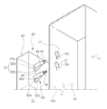
- FIG. 3 is a bottom perspective view showing a first embodiment of a means for preventing electric short between first and second discharge electrodes, which is a characterizing part of an air conditioning system for automotive vehicles in accordance with the present invention
- FIG. 4 is a section view taken along line IV-IV in FIG. 3 ;
- FIGS. 5 to 10 are views illustrating modified examples of a water drainage rib that constitutes the means for preventing electric short between first and second discharge electrodes;
- FIGS. 11 and 12 are section and bottom perspective views showing a second embodiment of a means for preventing electric short between first and second discharge electrodes
- FIGS. 13 and 14 are section and bottom perspective views showing a modified example of an isolation baffle that constitutes the means for preventing electric short between first and second discharge electrodes in accordance with the second embodiment;
- FIGS. 15 and 16 are section and bottom perspective views showing a third embodiment of a means for preventing electric short between first and second discharge electrodes
- FIGS. 17 and 18 are section and bottom perspective views showing a fourth embodiment of a means for preventing electric short between first and second discharge electrodes
- FIGS. 19 and 20 are section and bottom perspective views showing a fifth embodiment of a means for preventing electric short between first and second discharge electrodes.
- FIG. 21 is a bottom perspective view showing a sixth embodiment of a means for preventing electric short between first and second discharge electrodes.
- FIG. 3 is a bottom perspective view showing a characterizing part of an air conditioning system for automotive vehicles in accordance with the present invention.
- FIG. 4 is a section view taken along line IV-IV in FIG. 3 .
- FIGS. 1 , 3 and 4 Prior to describing a characterizing part of an air conditioning system for automotive vehicles in accordance with the present invention, a general aspect of the air conditioning system will be described with reference to FIGS. 1 , 3 and 4 .
- the air conditioning system includes an air conditioning case 10 in which a blower 20 is installed.
- the blower 20 inhales an external air or an internal air through an external air inlet port 12 or an internal air inlet port 14 formed in the air conditioning case 10 and then feed the inhaled air to an internal passageway 16 of the air conditioning case 10 .
- the air conditioning system includes an evaporator 30 installed within the internal passageway 16 of the air conditioning case 10 .
- the evaporator 30 serves to cool the air passing through the internal passageway 16 .
- the cooled air is introduced into a vehicle room, thereby keeping the vehicle room at a pleasant temperature.
- the air conditioning system further includes an ionizer 40 for emitting positive ions and negative ions toward the air flowing through the internal passageway 16 .
- the ionizer 40 is installed on the upstream side of the evaporator 30 and includes a main body 42 attached to an external surface of the air conditioning case 10 , first and second protection pipes 44 and 45 extending from the main body 42 toward the internal passageway 16 in a spaced-apart relationship with each other, and first and second discharge electrodes 46 and 48 extending through the first and second protection pipes 44 and 45 and protruding into the internal passageway 16 .
- the first and second protection pipes 44 and 45 are arranged one above the other in such a manner that they penetrate a through-hole 17 formed in the air conditioning case 10 and extend inwardly from a side wall 16 a of the internal passageway 16 .
- the first and second discharge electrodes 46 and 48 extend through the first and second protection pipes 44 and 45 and protrude into the internal passageway 16 at their tip ends.
- the first and second discharge electrodes 46 and 48 are designed to generate negative ions and positive ions by irradiating high voltage pulses into the air flowing through the internal passageway 16 .
- the air conditioning system of the present invention includes an electric short preventing means 50 for preventing electric short between the first and second discharge electrodes 46 and 48 , which would otherwise be caused by moisture.
- the electric short preventing means 50 includes a water drainage rib 52 designed to drain the moisture existing between the first and second discharge electrodes 46 and 48 .
- the water drainage rib 52 is comprised of a connection portion 52 a connected to a bottom surface 45 a of the second protection pipe 45 , i.e., the lower one of the first and second protection pipes 44 and 45 , and a water drainage portion 52 b extending downwardly from the connection portion 52 a along a gravitational direction.
- the water drainage portion 52 b has a bottom slanting surface inclined toward the side wall 16 a of the internal passageway 16 . Therefore, the bottom slanting surface is joined to the side wall 16 a of the internal passageway 16 .
- a reception groove 16 c for receiving the water drainage rib 52 of the second protection pipe 45 is formed in the side wall 16 a of the internal passageway 16 .
- the water drainage rib 52 serves to rapidly drain the condensed moisture in a downward direction. At this time, the condensed moisture is guided toward and drained along the side wall 16 a of the internal passageway 16 .
- the water drainage rib 52 may be integrally formed with a bottom surface 44 a of the first protection pipe 44 as shown in FIG. 5 .
- the water drainage rib 52 provided in the bottom surface 44 a of the first protection pipe 44 serves to downwardly drain the moisture condensed in and around the first protection pipe 44 .
- the moisture is prevented from infiltrating into the first discharge electrode 46 arranged within the first protection pipe 44 .
- This prevents formation of a water film between the first and second discharge electrodes 46 and 48 . Accordingly, it is possible to prevent electric short between the first and second discharge electrodes 46 and 48 , which would otherwise generate a spark between the first and second discharge electrodes 46 and 48 and a discharge noise.
- the water drainage rib 52 be formed on the bottom surface 45 a of the second protection pipe 45 rather than the first protection pipe 44 . The reason is that, if the water drainage rib 52 is formed in the first protection pipe 44 , the moisture drained from the water drainage rib 52 may flow toward the second protection pipe 45 in a large quantity.
- two water drainage ribs 52 may be formed on the bottom surfaces 44 a and 45 a of the first and second protection pipes 44 and 45 as illustrated in FIG. 6 . In this case, it is possible to drain the moisture condensed in and around the first and second protection pipes 44 and 45 .
- FIGS. 7 and 8 are bottom perspective and section views illustrating a modified example of the water drainage rib 52 .
- the water drainage rib 52 of this modified example is integrally formed with the side wall 16 a of the internal passageway 16 .
- the water drainage rib 52 of this modified example is comprised of a connection portion 52 a that makes contact with the bottom surface 45 a of the second protection pipe 45 and a water drainage portion 52 b extending downwardly from the connection portion 52 a along a gravitational direction.
- the water drainage rib 52 of this modified example serves to downwardly guide and drain the moisture flowing down from the bottom surface 45 a of the second protection pipe 45 .
- the moisture is guided along the water drainage portion 52 b and drained toward the side wall 16 a of the internal passageway 16 .
- the moisture condensed in and around the second protection pipe 45 is prevented from flowing toward the tip end of the second protection pipe 45 and infiltrating into the second discharge electrode 48 . This prevents formation of a water film between the first and second discharge electrodes 46 and 48 .
- the water drainage rib 52 of this modified example may be arranged below the bottom surface 44 a of the first protection pipe 44 as illustrated in FIG. 9 .
- the water drainage rib 52 serves to downwardly drain the moisture condensed in and around the first protection pipe 44 .
- the moisture condensed in and around the first protection pipe 44 is prevented from infiltrating into the first discharge electrode 46 arranged in the first protection pipe 44 . This prevents formation of a water film between the first and second discharge electrodes 46 and 48 .
- two water drainage ribs 52 may be arranged below the bottom surfaces 44 a and 45 a of the first and second protection pipes 44 and 45 as illustrated in FIG. 10 . In this case, it is possible to drain the whole moisture condensed in and around the first and second protection pipes 44 and 45 .
- the electric short preventing means 50 of the second embodiment is useful in case where the ionizer 40 is installed in a ceiling wall 16 b of the internal passageway 16 .
- the electric short preventing means 50 includes an isolation baffle 60 arranged between the first and second discharge electrodes 46 and 48 .
- the isolation baffle 60 is integrally formed with the bottom surface of the main body 42 of the ionizer 40 .
- the isolation baffle 60 is inserted through a through-hole 17 of the air conditioning case 10 together with the first and second discharge electrodes 46 and 48 so that it can protrude into the internal passageway 16 .
- the isolation baffle 60 is formed in parallel with an air flow direction so as not to hinder the flow of air in the internal passageway 16 .
- the isolation baffle 60 extends in a gravitational direction to downwardly guide and drain the moisture which would otherwise flow between the first and second discharge electrodes 46 and 48 .
- the isolation baffle 60 is designed to isolate the first and second discharge electrodes 46 and 48 from each other, it is possible to restrain the condensed moisture from flowing between the first and second discharge electrodes 46 and 48 .
- the isolation baffle 60 is designed to downwardly drain the condensed moisture existing between the first and second discharge electrodes 46 and 48 , it is possible to effectively prevent formation of a water film between the first and second discharge electrodes 46 and 48 , which would otherwise cause electric short between the first and second discharge electrodes 46 and 48 .
- the isolation baffle 60 of the modified example is installed in the air conditioning case 10 so that it can be arranged between the first and second discharge electrodes 46 and 48 .
- the isolation baffle 60 extends from the ceiling of the air conditioning case 10 into the internal passageway 16 .
- the isolation baffle 60 of the modified example restrains the condensed moisture from flowing between the first and second discharge electrodes 46 and 48 . This prevents formation of a water film between the first and second discharge electrodes 46 and 48 . Accordingly, it is possible to prevent electric short between the first and second discharge electrodes 46 and 48 , which would otherwise generate a spark between the first and second discharge electrodes 46 and 48 and a discharge noise.
- the isolation baffle 60 of the modified example is formed in parallel with an air flow direction so as not to hinder the flow of air in the internal passageway 16 .
- the isolation baffle 60 extends in a gravitational direction to downwardly guide and drain the moisture which would otherwise flow between the first and second discharge electrodes 46 and 48 .
- the electric short preventing means 50 of the third embodiment includes a reinforcing rib 70 formed in the reinforcing rib 70 between the first and second discharge electrodes 46 and 48 .
- the reinforcing rib 70 is formed across the internal passageway 16 so as to reinforce the air conditioning case 10 .
- the reinforcing rib 70 is arranged to isolate the first and second discharge electrodes 46 and 48 from each other, thereby restraining the condensed moisture from flowing between the first and second discharge electrodes 46 and 48 .
- the ionizer 40 In order for the reinforcing rib 70 to be used as the electric short preventing means 50 , there is a need to install the ionizer 40 in alignment with the reinforcing rib 70 . In other words, the ionizer 40 needs to be mounted to the air conditioning case 10 in such a manner that the first and second discharge electrodes 46 and 48 are arranged on the opposite sides of the reinforcing rib 70 .
- the electric short preventing means 50 of the third embodiment makes use of the reinforcing rib 70 already formed with the air conditioning case 10 . This eliminates the need to provide an additional component for isolating the first and second discharge electrodes 46 and 48 from each other. Therefore, it is possible to save the costs involved in installing the electric short preventing means 50 .
- the electric short preventing means 50 of the fourth embodiment is useful in case where the ionizer 40 is installed in the ceiling wall 16 b of the internal passageway 16 .
- the electric short preventing means 50 includes a moisture isolation recess 80 formed in the ceiling wall 16 b to surround the first and second discharge electrodes 46 and 48 .
- the moisture isolation recess 80 is formed by upwardly indenting the ceiling wall 16 b around an electrode insertion slot 17 .
- the moisture isolation recess 80 has a bottom surface positioned higher than the surface of the ceiling wall 16 b .
- the moisture isolation recess 80 serves to restrain the moisture from flowing from the remaining region of the ceiling wall 16 b toward the first and second discharge electrodes 46 and 48 .
- the ceiling wall 16 b on which the moisture isolation recess 80 is formed extends along a generally horizontal plane. This is to prevent the condensed moisture existing in an inclined ceiling wall 16 d from flowing toward the ceiling wall 16 b on which the moisture isolation recess 80 is formed. Therefore, it is possible to restrain the condensed moisture from flowing from the inclined ceiling wall 16 d toward the first and second discharge electrodes 46 and 48 .
- the electric short preventing means 50 of the fifth embodiment is useful in cases where the ionizer 40 is installed in the ceiling wall 16 b of the internal passageway 16 .
- the electric short preventing means 50 includes a moisture isolation wall 90 formed around the first and second discharge electrodes 46 and 48 .
- the moisture isolation wall 90 is integrally formed with the air conditioning case 10 in such a fashion that the tip end 92 thereof can face toward the bottom surface of the internal passageway 16 .
- the moisture isolation wall 90 serves to downwardly guide and drain the moisture condensed in the ceiling wall 16 b of the internal passageway 16 . This prevents the moisture from flowing toward the first and second discharge electrodes 46 and 48 , thereby keeping the moisture from infiltrating into the first and second discharge electrodes 46 and 48 .
- the electric short preventing means 50 of the sixth embodiment includes a plurality of water drainage protrusions 100 arranged around the first and second discharge electrodes 46 and 48 . Each of the water drainage protrusions 100 protrudes in a gravitational direction.
- Each of the water drainage protrusions 100 is integrally formed with the air conditioning case 10 in such a fashion that the tip end thereof can face toward the bottom surface of the internal passageway 16 .
- the water drainage protrusions 100 serve to downwardly guide and drain the moisture condensed in the ceiling wall 16 b of the internal passageway 16 . This prevents the moisture from flowing toward the first and second discharge electrodes 46 and 48 , thereby keeping the moisture from infiltrating into the first and second discharge electrodes 46 and 48 .
Landscapes
- Engineering & Computer Science (AREA)
- Mechanical Engineering (AREA)
- Physics & Mathematics (AREA)
- Thermal Sciences (AREA)
- Air-Conditioning For Vehicles (AREA)
- Disinfection, Sterilisation Or Deodorisation Of Air (AREA)
- Air Filters, Heat-Exchange Apparatuses, And Housings Of Air-Conditioning Units (AREA)
Applications Claiming Priority (6)
| Application Number | Priority Date | Filing Date | Title |
|---|---|---|---|
| KR10-2007-0035924 | 2007-04-12 | ||
| KR1020070035924A KR100903312B1 (ko) | 2007-04-12 | 2007-04-12 | 차량용 공조장치 |
| KR10-2007-0036273 | 2007-04-13 | ||
| KR1020070036273A KR100903313B1 (ko) | 2007-04-13 | 2007-04-13 | 차량용 공조시스템의 공조케이스 |
| KR10-2007-0044606 | 2007-05-08 | ||
| KR1020070044606A KR100903314B1 (ko) | 2007-05-08 | 2007-05-08 | 차량용 공조장치 |
Publications (2)
| Publication Number | Publication Date |
|---|---|
| US20080251236A1 US20080251236A1 (en) | 2008-10-16 |
| US7749313B2 true US7749313B2 (en) | 2010-07-06 |
Family
ID=39628751
Family Applications (1)
| Application Number | Title | Priority Date | Filing Date |
|---|---|---|---|
| US12/101,067 Active 2029-01-27 US7749313B2 (en) | 2007-04-12 | 2008-04-10 | Air conditioning system for automotive vehicles |
Country Status (3)
| Country | Link |
|---|---|
| US (1) | US7749313B2 (de) |
| EP (3) | EP1980430B1 (de) |
| JP (3) | JP4743446B2 (de) |
Cited By (5)
| Publication number | Priority date | Publication date | Assignee | Title |
|---|---|---|---|---|
| US20090042502A1 (en) * | 2005-12-30 | 2009-02-12 | Halla Climate Control Corp. | Vehicle Air Purifier with a Negative and Positive Ion Generator and Air Conditioning System Using the Same |
| US8564924B1 (en) | 2008-10-14 | 2013-10-22 | Global Plasma Solutions, Llc | Systems and methods of air treatment using bipolar ionization |
| US9660425B1 (en) | 2015-12-30 | 2017-05-23 | Plasma Air International, Inc | Ion generator device support |
| US9847623B2 (en) | 2014-12-24 | 2017-12-19 | Plasma Air International, Inc | Ion generating device enclosure |
| US11613167B2 (en) * | 2017-11-28 | 2023-03-28 | Hanon Systems | Vehicular air conditioning system |
Families Citing this family (12)
| Publication number | Priority date | Publication date | Assignee | Title |
|---|---|---|---|---|
| CN102668738B (zh) * | 2009-11-25 | 2014-12-03 | 松下电器产业株式会社 | 发热体收纳箱冷却装置 |
| JP5492674B2 (ja) * | 2010-06-25 | 2014-05-14 | 日立アプライアンス株式会社 | 誘導加熱調理器 |
| JP2012067935A (ja) * | 2010-09-21 | 2012-04-05 | Sharp Corp | 冷蔵庫 |
| WO2015111245A1 (ja) * | 2014-01-23 | 2015-07-30 | シャープ株式会社 | 空気調和機 |
| CN104654494A (zh) * | 2014-06-26 | 2015-05-27 | 柳州市安龙机械设备有限公司 | 汽车空调排风机 |
| JP6723682B2 (ja) * | 2014-11-07 | 2020-07-15 | レルテック医療器株式会社 | マイナスイオン発生装置 |
| CN108349351B (zh) | 2015-11-20 | 2021-01-26 | 株式会社电装 | 车辆用空调装置 |
| DE202015106952U1 (de) * | 2015-12-21 | 2017-03-22 | Rehau Ag + Co | Luftführungsanordnung |
| KR101762804B1 (ko) * | 2016-02-15 | 2017-07-28 | 엘지전자 주식회사 | 차량의 공기조화 시스템 |
| DE102017121202A1 (de) | 2017-09-13 | 2019-03-14 | Valeo Klimasysteme Gmbh | Fahrzeugklimaanlagen-Auslasseinheit |
| CN113418325A (zh) * | 2021-07-08 | 2021-09-21 | 平流层复合水离子(深圳)有限公司 | 高压电离水分子自清洁式蒸发器 |
| DE102022202649A1 (de) | 2022-03-17 | 2023-09-21 | Mahle International Gmbh | System für eine Lüftungseinrichtung |
Citations (27)
| Publication number | Priority date | Publication date | Assignee | Title |
|---|---|---|---|---|
| US3957374A (en) * | 1974-02-01 | 1976-05-18 | Carl Zeiss-Stiftung | Apparatus for obtaining samples of dusts for analysis by spectrochemical examination |
| JPS532767A (en) * | 1976-06-30 | 1978-01-11 | Hitachi Plant Eng & Constr Co Ltd | Discharging electrode for electric dust collector |
| JPS6018812U (ja) | 1983-07-19 | 1985-02-08 | カルソニックカンセイ株式会社 | 自動車用空気調和装置 |
| US5065272A (en) * | 1991-01-09 | 1991-11-12 | Elexis Corporation | Air ionizer |
| JPH04114752A (ja) * | 1990-09-04 | 1992-04-15 | Matsushita Electric Ind Co Ltd | 空気清浄器 |
| US5332425A (en) * | 1993-02-22 | 1994-07-26 | Hung Hsing Electric Co., Ltd. | Air purifier |
| US5707429A (en) * | 1996-09-25 | 1998-01-13 | Lewis Lint Trap, Inc. | Ionizing structure for ambient air treatment |
| JP2000247141A (ja) | 1999-03-01 | 2000-09-12 | Zexel Corp | 空調装置の陰イオン発生装置 |
| KR20000067602A (ko) | 1999-04-30 | 2000-11-25 | 구자홍 | 실외기의 파워소자 보호구조 |
| US6294004B1 (en) * | 1999-12-21 | 2001-09-25 | Engineering Dynamics Ltd. | Structures for electrostatic V-bank air filters |
| US6368392B1 (en) * | 1999-05-31 | 2002-04-09 | O-Den Corporation | Electric dust collecting unit |
| US6464754B1 (en) * | 1999-10-07 | 2002-10-15 | Kairos, L.L.C. | Self-cleaning air purification system and process |
| US6506238B1 (en) * | 1999-11-15 | 2003-01-14 | O-Den Corporation | Electric dust collecting unit |
| US6508982B1 (en) * | 1998-04-27 | 2003-01-21 | Kabushiki Kaisha Seisui | Air-cleaning apparatus and air-cleaning method |
| JP2003187945A (ja) | 2001-12-13 | 2003-07-04 | Nippon Gureen Kenkyusho:Kk | 空気イオン発生器および空気イオンの供給方法 |
| US6635105B2 (en) * | 2000-07-11 | 2003-10-21 | Ing. Walter Hengst Gmbh & Co. Kg | Electrostatic precipitator |
| US20040045442A1 (en) * | 2001-02-08 | 2004-03-11 | Karichev Ziya Ramizovich | Method and device for removing inert impurities |
| JP2004105415A (ja) | 2002-09-18 | 2004-04-08 | Sakae Riken Kogyo Co Ltd | 空気清浄フィルタ装置 |
| KR20040073038A (ko) | 2003-02-12 | 2004-08-19 | 한라공조주식회사 | 차량용 공조장치 |
| US20050124286A1 (en) | 2003-12-09 | 2005-06-09 | Valeo Climate Control Corp. | Method and apparatus for decontamination for automotive HVAC systems |
| US6955708B1 (en) * | 2004-08-13 | 2005-10-18 | Shaklee Corporation | Air-treatment apparatus and methods |
| JP2005289177A (ja) | 2004-03-31 | 2005-10-20 | Calsonic Kansei Corp | 空調装置 |
| KR20060102226A (ko) | 2005-03-23 | 2006-09-27 | 한라공조주식회사 | 클러스터 음이온 발생기를 구비한 자동차용 공조장치 |
| US20070034082A1 (en) * | 2005-08-10 | 2007-02-15 | Adair Joel E | Air purifier |
| US7497898B2 (en) * | 2006-10-31 | 2009-03-03 | Smc Corporation | Ionizer |
| US7553354B2 (en) * | 2003-11-17 | 2009-06-30 | Absalut Ecology Establishment | Apparatus and method for reducing and removing airborne oxidized particulates |
| US7601204B2 (en) * | 2006-09-06 | 2009-10-13 | Trane International Inc. | Air conditioning apparatus with integrated air filtration system |
Family Cites Families (27)
| Publication number | Priority date | Publication date | Assignee | Title |
|---|---|---|---|---|
| US3936698A (en) * | 1970-03-20 | 1976-02-03 | Meyer George F | Ion generating apparatus |
| JPS521246Y2 (de) * | 1971-08-24 | 1977-01-12 | ||
| US3942072A (en) * | 1974-10-18 | 1976-03-02 | Burlington Industries, Inc. | Method and system for maintaining an electrically neutral atmosphere |
| JPS6439815A (en) * | 1987-08-05 | 1989-02-10 | Sharp Kk | Noise eliminating circuit |
| JPH03188867A (ja) * | 1989-12-19 | 1991-08-16 | Toto Ltd | オゾン脱臭装置 |
| JPH057857U (ja) * | 1991-07-19 | 1993-02-02 | 積水化学工業株式会社 | 浴室ユニツト |
| JPH0547489A (ja) * | 1991-08-12 | 1993-02-26 | Kitagawa Ind Co Ltd | 帯電防止用イオン発生装置 |
| JP2904328B2 (ja) * | 1992-11-24 | 1999-06-14 | 三菱電機株式会社 | 微生物繁殖防止装置 |
| JPH0834229A (ja) * | 1994-07-21 | 1996-02-06 | Zexel Corp | 空気清浄機 |
| JP3007343U (ja) * | 1994-07-29 | 1995-02-14 | 福島 文雄 | イオン発生装置 |
| FR2794295B1 (fr) * | 1999-05-31 | 2001-09-07 | Joel Mercier | Dispositif generateur d'ions |
| JP4903942B2 (ja) * | 2001-03-15 | 2012-03-28 | 株式会社キーエンス | イオン発生装置 |
| JP2003142228A (ja) * | 2001-11-02 | 2003-05-16 | Yamatake Corp | マイナスイオン発生装置 |
| JP2003229678A (ja) * | 2002-01-31 | 2003-08-15 | Denso Corp | 電子制御装置の筐体構造 |
| JP2004028499A (ja) * | 2002-06-27 | 2004-01-29 | Hitachi Home & Life Solutions Inc | 冷蔵庫 |
| JP2004074859A (ja) * | 2002-08-12 | 2004-03-11 | Denso Corp | 空気浄化機能付き負イオン発生装置 |
| JP4144788B2 (ja) * | 2002-11-19 | 2008-09-03 | 九州日立マクセル株式会社 | 整髪具 |
| JP2004189147A (ja) * | 2002-12-12 | 2004-07-08 | Altia Co Ltd | 車両用マイナスイオン発生装置 |
| JP4239692B2 (ja) * | 2003-06-04 | 2009-03-18 | パナソニック電工株式会社 | 空気清浄機 |
| JP2005014789A (ja) * | 2003-06-26 | 2005-01-20 | Nissan Motor Co Ltd | 静電気防止装置 |
| JP4311631B2 (ja) * | 2003-09-25 | 2009-08-12 | シャープ株式会社 | イオン拡散装置 |
| JP4365201B2 (ja) * | 2003-12-22 | 2009-11-18 | 共立電器産業株式会社 | 空気清浄活性器 |
| JP2006244687A (ja) * | 2005-02-07 | 2006-09-14 | Matsushita Electric Ind Co Ltd | 記録装置 |
| JP4720413B2 (ja) * | 2005-03-07 | 2011-07-13 | パナソニック株式会社 | 空気調和機 |
| WO2006106594A1 (ja) * | 2005-04-04 | 2006-10-12 | Shimizu Corporation | 空気イオン搬送装置および空気イオン搬送システム |
| JP2006290001A (ja) * | 2005-04-05 | 2006-10-26 | Denso Corp | 車両用空気清浄器 |
| FR2888054A1 (fr) * | 2005-07-04 | 2007-01-05 | Genie Et Environnement Sarl | Dispositif de generation d'ions |
-
2008
- 2008-04-08 JP JP2008100371A patent/JP4743446B2/ja active Active
- 2008-04-09 EP EP08007053A patent/EP1980430B1/de active Active
- 2008-04-09 EP EP10195955A patent/EP2289719B1/de active Active
- 2008-04-09 EP EP10195947A patent/EP2289718B1/de active Active
- 2008-04-10 US US12/101,067 patent/US7749313B2/en active Active
-
2011
- 2011-03-30 JP JP2011076218A patent/JP5449244B2/ja active Active
- 2011-03-30 JP JP2011076219A patent/JP5244939B2/ja active Active
Patent Citations (27)
| Publication number | Priority date | Publication date | Assignee | Title |
|---|---|---|---|---|
| US3957374A (en) * | 1974-02-01 | 1976-05-18 | Carl Zeiss-Stiftung | Apparatus for obtaining samples of dusts for analysis by spectrochemical examination |
| JPS532767A (en) * | 1976-06-30 | 1978-01-11 | Hitachi Plant Eng & Constr Co Ltd | Discharging electrode for electric dust collector |
| JPS6018812U (ja) | 1983-07-19 | 1985-02-08 | カルソニックカンセイ株式会社 | 自動車用空気調和装置 |
| JPH04114752A (ja) * | 1990-09-04 | 1992-04-15 | Matsushita Electric Ind Co Ltd | 空気清浄器 |
| US5065272A (en) * | 1991-01-09 | 1991-11-12 | Elexis Corporation | Air ionizer |
| US5332425A (en) * | 1993-02-22 | 1994-07-26 | Hung Hsing Electric Co., Ltd. | Air purifier |
| US5707429A (en) * | 1996-09-25 | 1998-01-13 | Lewis Lint Trap, Inc. | Ionizing structure for ambient air treatment |
| US6508982B1 (en) * | 1998-04-27 | 2003-01-21 | Kabushiki Kaisha Seisui | Air-cleaning apparatus and air-cleaning method |
| JP2000247141A (ja) | 1999-03-01 | 2000-09-12 | Zexel Corp | 空調装置の陰イオン発生装置 |
| KR20000067602A (ko) | 1999-04-30 | 2000-11-25 | 구자홍 | 실외기의 파워소자 보호구조 |
| US6368392B1 (en) * | 1999-05-31 | 2002-04-09 | O-Den Corporation | Electric dust collecting unit |
| US6464754B1 (en) * | 1999-10-07 | 2002-10-15 | Kairos, L.L.C. | Self-cleaning air purification system and process |
| US6506238B1 (en) * | 1999-11-15 | 2003-01-14 | O-Den Corporation | Electric dust collecting unit |
| US6294004B1 (en) * | 1999-12-21 | 2001-09-25 | Engineering Dynamics Ltd. | Structures for electrostatic V-bank air filters |
| US6635105B2 (en) * | 2000-07-11 | 2003-10-21 | Ing. Walter Hengst Gmbh & Co. Kg | Electrostatic precipitator |
| US20040045442A1 (en) * | 2001-02-08 | 2004-03-11 | Karichev Ziya Ramizovich | Method and device for removing inert impurities |
| JP2003187945A (ja) | 2001-12-13 | 2003-07-04 | Nippon Gureen Kenkyusho:Kk | 空気イオン発生器および空気イオンの供給方法 |
| JP2004105415A (ja) | 2002-09-18 | 2004-04-08 | Sakae Riken Kogyo Co Ltd | 空気清浄フィルタ装置 |
| KR20040073038A (ko) | 2003-02-12 | 2004-08-19 | 한라공조주식회사 | 차량용 공조장치 |
| US7553354B2 (en) * | 2003-11-17 | 2009-06-30 | Absalut Ecology Establishment | Apparatus and method for reducing and removing airborne oxidized particulates |
| US20050124286A1 (en) | 2003-12-09 | 2005-06-09 | Valeo Climate Control Corp. | Method and apparatus for decontamination for automotive HVAC systems |
| JP2005289177A (ja) | 2004-03-31 | 2005-10-20 | Calsonic Kansei Corp | 空調装置 |
| US6955708B1 (en) * | 2004-08-13 | 2005-10-18 | Shaklee Corporation | Air-treatment apparatus and methods |
| KR20060102226A (ko) | 2005-03-23 | 2006-09-27 | 한라공조주식회사 | 클러스터 음이온 발생기를 구비한 자동차용 공조장치 |
| US20070034082A1 (en) * | 2005-08-10 | 2007-02-15 | Adair Joel E | Air purifier |
| US7601204B2 (en) * | 2006-09-06 | 2009-10-13 | Trane International Inc. | Air conditioning apparatus with integrated air filtration system |
| US7497898B2 (en) * | 2006-10-31 | 2009-03-03 | Smc Corporation | Ionizer |
Cited By (21)
| Publication number | Priority date | Publication date | Assignee | Title |
|---|---|---|---|---|
| US20090042502A1 (en) * | 2005-12-30 | 2009-02-12 | Halla Climate Control Corp. | Vehicle Air Purifier with a Negative and Positive Ion Generator and Air Conditioning System Using the Same |
| US9925292B2 (en) | 2008-10-14 | 2018-03-27 | Global Plasma Solutions, Llc | Ion generator mounting device |
| US9839714B2 (en) | 2008-10-14 | 2017-12-12 | Global Plasma Solutions, Llc | Ion generator device |
| US9168538B2 (en) | 2008-10-14 | 2015-10-27 | Global Plasma Solutions, Llc | Ion generator mounting device |
| US9289779B2 (en) | 2008-10-14 | 2016-03-22 | Global Plasma Solutions | Ion generator device |
| US9478948B2 (en) | 2008-10-14 | 2016-10-25 | Global Plasma Solutions, Llc | Ion generator mounting device |
| US9509125B2 (en) | 2008-10-14 | 2016-11-29 | Global Plasma Solutions | Ion generator device |
| US8564924B1 (en) | 2008-10-14 | 2013-10-22 | Global Plasma Solutions, Llc | Systems and methods of air treatment using bipolar ionization |
| US10383970B2 (en) | 2008-10-14 | 2019-08-20 | Global Plasma Solutions, Inc. | Ion generator mounting device |
| US10111978B2 (en) | 2008-10-14 | 2018-10-30 | Global Plasma Solutions, Inc. | Ion generator device |
| US8861168B2 (en) | 2008-10-14 | 2014-10-14 | Global Plasma Solutions, Llc | Ion generator device |
| US10978858B2 (en) | 2014-12-24 | 2021-04-13 | Plasma Air International, Inc | Ion generating device enclosure |
| US10297984B2 (en) | 2014-12-24 | 2019-05-21 | Plasma Air International, Inc | Ion generating device enclosure |
| US9847623B2 (en) | 2014-12-24 | 2017-12-19 | Plasma Air International, Inc | Ion generating device enclosure |
| US10014667B2 (en) | 2015-12-30 | 2018-07-03 | Plasma Air International, Inc | Ion generator device support |
| US10153623B2 (en) | 2015-12-30 | 2018-12-11 | Plasma Air International, Inc | Ion generator device support |
| US9985421B2 (en) | 2015-12-30 | 2018-05-29 | Plasma Air International, Inc | Ion generator device support |
| US10439370B2 (en) | 2015-12-30 | 2019-10-08 | Plasma Air International, Inc | Ion generator device support |
| US9660425B1 (en) | 2015-12-30 | 2017-05-23 | Plasma Air International, Inc | Ion generator device support |
| US11018478B2 (en) | 2015-12-30 | 2021-05-25 | Plasma Air International, Inc | Ion generator device support |
| US11613167B2 (en) * | 2017-11-28 | 2023-03-28 | Hanon Systems | Vehicular air conditioning system |
Also Published As
| Publication number | Publication date |
|---|---|
| EP1980430A2 (de) | 2008-10-15 |
| JP2008260520A (ja) | 2008-10-30 |
| EP2289718A1 (de) | 2011-03-02 |
| EP2289719A1 (de) | 2011-03-02 |
| US20080251236A1 (en) | 2008-10-16 |
| JP5449244B2 (ja) | 2014-03-19 |
| EP1980430A3 (de) | 2009-07-15 |
| JP5244939B2 (ja) | 2013-07-24 |
| EP1980430B1 (de) | 2011-09-14 |
| JP2011126540A (ja) | 2011-06-30 |
| EP2289718B1 (de) | 2012-02-15 |
| EP2289719B1 (de) | 2012-02-15 |
| JP2011126541A (ja) | 2011-06-30 |
| JP4743446B2 (ja) | 2011-08-10 |
Similar Documents
| Publication | Publication Date | Title |
|---|---|---|
| US7749313B2 (en) | Air conditioning system for automotive vehicles | |
| US8873215B2 (en) | Ion generator mounting device | |
| US10128075B2 (en) | Ion generation device having attachment devices | |
| CN102904418A (zh) | 开关电源装置 | |
| KR100903314B1 (ko) | 차량용 공조장치 | |
| GB2534013A (en) | Power converter and rolling stock including the same | |
| KR100914416B1 (ko) | 차량용 공조시스템의 이온발생기 | |
| JP3876864B2 (ja) | 空気調和装置の室内ユニット | |
| KR20090022499A (ko) | 센터 마운팅 타입 차량 공조장치의 증발기 파이프 설치구조 | |
| KR100914417B1 (ko) | 차량용 공조장치 | |
| US7604045B2 (en) | Air conditioner for vehicle | |
| JP2004141848A (ja) | イオン発生装置および空気調和機 | |
| KR100903313B1 (ko) | 차량용 공조시스템의 공조케이스 | |
| KR102656055B1 (ko) | 차량용 오버헤드 타입 공조장치 | |
| KR101565406B1 (ko) | 공기조화장치 | |
| JP2004053040A (ja) | 空気調和機 | |
| JP2008117876A (ja) | 冷気循環システム | |
| JP6755404B2 (ja) | 空気調和機の室内機 | |
| CN205425363U (zh) | 一种移动空调侧板的固定连接件 | |
| KR101216998B1 (ko) | 차량 공조시스템용 송풍유닛 | |
| JP2023024436A (ja) | 空調室内機及び空調機 | |
| KR20030000418A (ko) | 공기 조화기의 필터장착구조 | |
| JP2005214596A (ja) | 送風機 | |
| JP2007101110A (ja) | 空気調和機 | |
| JPH10193957A (ja) | 車両用天井置きクーラユニット |
Legal Events
| Date | Code | Title | Description |
|---|---|---|---|
| AS | Assignment |
Owner name: HALLA CLIMATE CONTROL CORP., KOREA, REPUBLIC OF Free format text: ASSIGNMENT OF ASSIGNORS INTEREST;ASSIGNORS:BYON, SANG CHUL;KANG, SUNG HO;SEO, YONG EUN;AND OTHERS;REEL/FRAME:020786/0285 Effective date: 20080410 |
|
| FEPP | Fee payment procedure |
Free format text: PAYOR NUMBER ASSIGNED (ORIGINAL EVENT CODE: ASPN); ENTITY STATUS OF PATENT OWNER: LARGE ENTITY |
|
| STCF | Information on status: patent grant |
Free format text: PATENTED CASE |
|
| CC | Certificate of correction | ||
| AS | Assignment |
Owner name: HALLA VISTEON CLIMATE CONTROL CORPORATION, KOREA, Free format text: CHANGE OF NAME;ASSIGNOR:HALLA CLIMATE CONTROL CORPORATION;REEL/FRAME:030704/0554 Effective date: 20130312 |
|
| FEPP | Fee payment procedure |
Free format text: PAYOR NUMBER ASSIGNED (ORIGINAL EVENT CODE: ASPN); ENTITY STATUS OF PATENT OWNER: LARGE ENTITY Free format text: PAYER NUMBER DE-ASSIGNED (ORIGINAL EVENT CODE: RMPN); ENTITY STATUS OF PATENT OWNER: LARGE ENTITY |
|
| FPAY | Fee payment |
Year of fee payment: 4 |
|
| AS | Assignment |
Owner name: HANON SYSTEMS, KOREA, REPUBLIC OF Free format text: CHANGE OF NAME;ASSIGNOR:HALLA VISTEON CLIMATE CONTROL CORPORATION;REEL/FRAME:037007/0103 Effective date: 20150728 |
|
| MAFP | Maintenance fee payment |
Free format text: PAYMENT OF MAINTENANCE FEE, 8TH YEAR, LARGE ENTITY (ORIGINAL EVENT CODE: M1552) Year of fee payment: 8 |
|
| MAFP | Maintenance fee payment |
Free format text: PAYMENT OF MAINTENANCE FEE, 12TH YEAR, LARGE ENTITY (ORIGINAL EVENT CODE: M1553); ENTITY STATUS OF PATENT OWNER: LARGE ENTITY Year of fee payment: 12 |