EP4483821A1 - System for treating embolism and associated devices and methods - Google Patents
System for treating embolism and associated devices and methods Download PDFInfo
- Publication number
- EP4483821A1 EP4483821A1 EP24198020.0A EP24198020A EP4483821A1 EP 4483821 A1 EP4483821 A1 EP 4483821A1 EP 24198020 A EP24198020 A EP 24198020A EP 4483821 A1 EP4483821 A1 EP 4483821A1
- Authority
- EP
- European Patent Office
- Prior art keywords
- catheter
- syringe
- blood
- clot material
- outlet
- Prior art date
- Legal status (The legal status is an assumption and is not a legal conclusion. Google has not performed a legal analysis and makes no representation as to the accuracy of the status listed.)
- Pending
Links
Images














Classifications
-
- A—HUMAN NECESSITIES
- A61—MEDICAL OR VETERINARY SCIENCE; HYGIENE
- A61B—DIAGNOSIS; SURGERY; IDENTIFICATION
- A61B17/00—Surgical instruments, devices or methods
- A61B17/12—Surgical instruments, devices or methods for ligaturing or otherwise compressing tubular parts of the body, e.g. blood vessels or umbilical cord
- A61B17/12022—Occluding by internal devices, e.g. balloons or releasable wires
- A61B17/12099—Occluding by internal devices, e.g. balloons or releasable wires characterised by the location of the occluder
- A61B17/12109—Occluding by internal devices, e.g. balloons or releasable wires characterised by the location of the occluder in a blood vessel
-
- A—HUMAN NECESSITIES
- A61—MEDICAL OR VETERINARY SCIENCE; HYGIENE
- A61B—DIAGNOSIS; SURGERY; IDENTIFICATION
- A61B17/00—Surgical instruments, devices or methods
- A61B17/22—Implements for squeezing-off ulcers or the like on inner organs of the body; Implements for scraping-out cavities of body organs, e.g. bones; for invasive removal or destruction of calculus using mechanical vibrations; for removing obstructions in blood vessels, not otherwise provided for
-
- A—HUMAN NECESSITIES
- A61—MEDICAL OR VETERINARY SCIENCE; HYGIENE
- A61F—FILTERS IMPLANTABLE INTO BLOOD VESSELS; PROSTHESES; DEVICES PROVIDING PATENCY TO, OR PREVENTING COLLAPSING OF, TUBULAR STRUCTURES OF THE BODY, e.g. STENTS; ORTHOPAEDIC, NURSING OR CONTRACEPTIVE DEVICES; FOMENTATION; TREATMENT OR PROTECTION OF EYES OR EARS; BANDAGES, DRESSINGS OR ABSORBENT PADS; FIRST-AID KITS
- A61F2/00—Filters implantable into blood vessels; Prostheses, i.e. artificial substitutes or replacements for parts of the body; Appliances for connecting them with the body; Devices providing patency to, or preventing collapsing of, tubular structures of the body, e.g. stents
- A61F2/01—Filters implantable into blood vessels
-
- A—HUMAN NECESSITIES
- A61—MEDICAL OR VETERINARY SCIENCE; HYGIENE
- A61M—DEVICES FOR INTRODUCING MEDIA INTO, OR ONTO, THE BODY; DEVICES FOR TRANSDUCING BODY MEDIA OR FOR TAKING MEDIA FROM THE BODY; DEVICES FOR PRODUCING OR ENDING SLEEP OR STUPOR
- A61M1/00—Suction or pumping devices for medical purposes; Devices for carrying-off, for treatment of, or for carrying-over, body-liquids; Drainage systems
- A61M1/64—Containers with integrated suction means
- A61M1/67—Containers incorporating a piston-type member to create suction, e.g. syringes
-
- A—HUMAN NECESSITIES
- A61—MEDICAL OR VETERINARY SCIENCE; HYGIENE
- A61M—DEVICES FOR INTRODUCING MEDIA INTO, OR ONTO, THE BODY; DEVICES FOR TRANSDUCING BODY MEDIA OR FOR TAKING MEDIA FROM THE BODY; DEVICES FOR PRODUCING OR ENDING SLEEP OR STUPOR
- A61M1/00—Suction or pumping devices for medical purposes; Devices for carrying-off, for treatment of, or for carrying-over, body-liquids; Drainage systems
- A61M1/71—Suction drainage systems
- A61M1/79—Filters for solid matter
-
- A—HUMAN NECESSITIES
- A61—MEDICAL OR VETERINARY SCIENCE; HYGIENE
- A61M—DEVICES FOR INTRODUCING MEDIA INTO, OR ONTO, THE BODY; DEVICES FOR TRANSDUCING BODY MEDIA OR FOR TAKING MEDIA FROM THE BODY; DEVICES FOR PRODUCING OR ENDING SLEEP OR STUPOR
- A61M1/00—Suction or pumping devices for medical purposes; Devices for carrying-off, for treatment of, or for carrying-over, body-liquids; Drainage systems
- A61M1/80—Suction pumps
- A61M1/81—Piston pumps, e.g. syringes
- A61M1/815—Piston pumps, e.g. syringes the barrel serving as aspiration container, e.g. in a breast pump
-
- A—HUMAN NECESSITIES
- A61—MEDICAL OR VETERINARY SCIENCE; HYGIENE
- A61M—DEVICES FOR INTRODUCING MEDIA INTO, OR ONTO, THE BODY; DEVICES FOR TRANSDUCING BODY MEDIA OR FOR TAKING MEDIA FROM THE BODY; DEVICES FOR PRODUCING OR ENDING SLEEP OR STUPOR
- A61M1/00—Suction or pumping devices for medical purposes; Devices for carrying-off, for treatment of, or for carrying-over, body-liquids; Drainage systems
- A61M1/84—Drainage tubes; Aspiration tips
-
- A—HUMAN NECESSITIES
- A61—MEDICAL OR VETERINARY SCIENCE; HYGIENE
- A61B—DIAGNOSIS; SURGERY; IDENTIFICATION
- A61B17/00—Surgical instruments, devices or methods
- A61B17/22—Implements for squeezing-off ulcers or the like on inner organs of the body; Implements for scraping-out cavities of body organs, e.g. bones; for invasive removal or destruction of calculus using mechanical vibrations; for removing obstructions in blood vessels, not otherwise provided for
- A61B17/221—Gripping devices in the form of loops or baskets for gripping calculi or similar types of obstructions
-
- A—HUMAN NECESSITIES
- A61—MEDICAL OR VETERINARY SCIENCE; HYGIENE
- A61B—DIAGNOSIS; SURGERY; IDENTIFICATION
- A61B17/00—Surgical instruments, devices or methods
- A61B17/22—Implements for squeezing-off ulcers or the like on inner organs of the body; Implements for scraping-out cavities of body organs, e.g. bones; for invasive removal or destruction of calculus using mechanical vibrations; for removing obstructions in blood vessels, not otherwise provided for
- A61B17/22031—Gripping instruments, e.g. forceps, for removing or smashing calculi
- A61B2017/22034—Gripping instruments, e.g. forceps, for removing or smashing calculi for gripping the obstruction or the tissue part from inside
-
- A—HUMAN NECESSITIES
- A61—MEDICAL OR VETERINARY SCIENCE; HYGIENE
- A61B—DIAGNOSIS; SURGERY; IDENTIFICATION
- A61B17/00—Surgical instruments, devices or methods
- A61B17/22—Implements for squeezing-off ulcers or the like on inner organs of the body; Implements for scraping-out cavities of body organs, e.g. bones; for invasive removal or destruction of calculus using mechanical vibrations; for removing obstructions in blood vessels, not otherwise provided for
- A61B17/22031—Gripping instruments, e.g. forceps, for removing or smashing calculi
- A61B2017/22035—Gripping instruments, e.g. forceps, for removing or smashing calculi for retrieving or repositioning foreign objects
-
- A—HUMAN NECESSITIES
- A61—MEDICAL OR VETERINARY SCIENCE; HYGIENE
- A61B—DIAGNOSIS; SURGERY; IDENTIFICATION
- A61B17/00—Surgical instruments, devices or methods
- A61B17/22—Implements for squeezing-off ulcers or the like on inner organs of the body; Implements for scraping-out cavities of body organs, e.g. bones; for invasive removal or destruction of calculus using mechanical vibrations; for removing obstructions in blood vessels, not otherwise provided for
- A61B2017/22038—Implements for squeezing-off ulcers or the like on inner organs of the body; Implements for scraping-out cavities of body organs, e.g. bones; for invasive removal or destruction of calculus using mechanical vibrations; for removing obstructions in blood vessels, not otherwise provided for with a guide wire
-
- A—HUMAN NECESSITIES
- A61—MEDICAL OR VETERINARY SCIENCE; HYGIENE
- A61B—DIAGNOSIS; SURGERY; IDENTIFICATION
- A61B17/00—Surgical instruments, devices or methods
- A61B17/22—Implements for squeezing-off ulcers or the like on inner organs of the body; Implements for scraping-out cavities of body organs, e.g. bones; for invasive removal or destruction of calculus using mechanical vibrations; for removing obstructions in blood vessels, not otherwise provided for
- A61B2017/22079—Implements for squeezing-off ulcers or the like on inner organs of the body; Implements for scraping-out cavities of body organs, e.g. bones; for invasive removal or destruction of calculus using mechanical vibrations; for removing obstructions in blood vessels, not otherwise provided for with suction of debris
-
- A—HUMAN NECESSITIES
- A61—MEDICAL OR VETERINARY SCIENCE; HYGIENE
- A61B—DIAGNOSIS; SURGERY; IDENTIFICATION
- A61B17/00—Surgical instruments, devices or methods
- A61B17/22—Implements for squeezing-off ulcers or the like on inner organs of the body; Implements for scraping-out cavities of body organs, e.g. bones; for invasive removal or destruction of calculus using mechanical vibrations; for removing obstructions in blood vessels, not otherwise provided for
- A61B17/221—Gripping devices in the form of loops or baskets for gripping calculi or similar types of obstructions
- A61B2017/2212—Gripping devices in the form of loops or baskets for gripping calculi or similar types of obstructions having a closed distal end, e.g. a loop
-
- A—HUMAN NECESSITIES
- A61—MEDICAL OR VETERINARY SCIENCE; HYGIENE
- A61B—DIAGNOSIS; SURGERY; IDENTIFICATION
- A61B2217/00—General characteristics of surgical instruments
- A61B2217/002—Auxiliary appliance
- A61B2217/005—Auxiliary appliance with suction drainage system
-
- A—HUMAN NECESSITIES
- A61—MEDICAL OR VETERINARY SCIENCE; HYGIENE
- A61M—DEVICES FOR INTRODUCING MEDIA INTO, OR ONTO, THE BODY; DEVICES FOR TRANSDUCING BODY MEDIA OR FOR TAKING MEDIA FROM THE BODY; DEVICES FOR PRODUCING OR ENDING SLEEP OR STUPOR
- A61M1/00—Suction or pumping devices for medical purposes; Devices for carrying-off, for treatment of, or for carrying-over, body-liquids; Drainage systems
- A61M1/02—Blood transfusion apparatus
- A61M1/0281—Apparatus for treatment of blood or blood constituents prior to transfusion, e.g. washing, filtering or thawing
-
- A—HUMAN NECESSITIES
- A61—MEDICAL OR VETERINARY SCIENCE; HYGIENE
- A61M—DEVICES FOR INTRODUCING MEDIA INTO, OR ONTO, THE BODY; DEVICES FOR TRANSDUCING BODY MEDIA OR FOR TAKING MEDIA FROM THE BODY; DEVICES FOR PRODUCING OR ENDING SLEEP OR STUPOR
- A61M2205/00—General characteristics of the apparatus
- A61M2205/75—General characteristics of the apparatus with filters
- A61M2205/7545—General characteristics of the apparatus with filters for solid matter, e.g. microaggregates
-
- A—HUMAN NECESSITIES
- A61—MEDICAL OR VETERINARY SCIENCE; HYGIENE
- A61M—DEVICES FOR INTRODUCING MEDIA INTO, OR ONTO, THE BODY; DEVICES FOR TRANSDUCING BODY MEDIA OR FOR TAKING MEDIA FROM THE BODY; DEVICES FOR PRODUCING OR ENDING SLEEP OR STUPOR
- A61M2210/00—Anatomical parts of the body
- A61M2210/12—Blood circulatory system
-
- A—HUMAN NECESSITIES
- A61—MEDICAL OR VETERINARY SCIENCE; HYGIENE
- A61M—DEVICES FOR INTRODUCING MEDIA INTO, OR ONTO, THE BODY; DEVICES FOR TRANSDUCING BODY MEDIA OR FOR TAKING MEDIA FROM THE BODY; DEVICES FOR PRODUCING OR ENDING SLEEP OR STUPOR
- A61M25/00—Catheters; Hollow probes
- A61M25/10—Balloon catheters
Definitions
- the present technology relates generally to systems, methods, and devices for the intravascular treatment of emboli and/or thrombi within a blood vessel of a human patient.
- some embodiments of the present technology relate to systems for releasing stored vacuum pressure to aspirate clot material from a blood vessel.
- Thromboembolic events are characterized by an occlusion of a blood vessel.
- Thromboembolic disorders such as stroke, pulmonary embolism, heart attack, peripheral thrombosis, atherosclerosis, and the like, affect many people. These disorders are a major cause of morbidity and mortality.
- tissue ischemia develops.
- the ischemia will progress to tissue infarction if the occlusion persists.
- infarction does not develop or is greatly limited if the flow of blood is reestablished rapidly. Failure to reestablish blood flow can accordingly lead to the loss of limb, angina pectoris, myocardial infarction, stroke, or even death
- DVT deep venous thrombosis
- DVT commonly occurs where there is a propensity for stagnated blood (e.g., long distance air travel, immobility, etc.) and clotting (e.g., cancer, recent surgery, such as orthopedic surgery, etc.).
- DVT can obstruct drainage of venous blood from the legs leading to swelling, ulcers, pain and infection.
- DVT can also create a reservoir in which blood clots can collect and then travel to other parts of the body including the heart, lungs, brain (stroke), abdominal organs, and/or extremities.
- the undesirable material can cause harm by obstructing pulmonary arteries-a condition known as pulmonary embolism. If the obstruction is upstream, in the main or large branch pulmonary arteries, it can severely compromise total blood flow within the lungs, and therefore the entire body. This can result in low blood pressure and shock. If the obstruction is downstream, in large to medium pulmonary artery branches, it can prevent a significant portion of the lung from participating in the exchange of gases to the blood resulting in low blood oxygen and buildup of blood carbon dioxide.
- Embolectomies are a surgical technique involving incising a blood vessel and placing a balloon-tipped device (such as the Fogarty catheter) at the location of the occlusion.
- the balloon is then inflated at a point beyond the clot and used to withdraw the obstructing material back to the point of incision.
- the obstructing material is then removed by the surgeon.
- a Fogarty catheter may be problematic due to the possible risk of damaging the interior lining of the vessel as the catheter is being withdrawn.
- Percutaneous methods are also utilized for reestablishing blood flow.
- a common percutaneous technique is referred to as balloon angioplasty where a balloon-tipped catheter is introduced to a blood vessel (e.g., typically through an introducing catheter). The balloon-tipped catheter is then advanced to the point of the occlusion and inflated to dilate the stenosis.
- Balloon angioplasty is appropriate for treating vessel stenosis, but it is generally not effective for treating acute thromboembolisms as none of the occlusive material is removed and restenosis regularly occurs after dilation.
- Another percutaneous technique involves placing a catheter near the clot and infusing streptokinase, urokinase, or other thrombolytic agents to dissolve the clot. Unfortunately, thrombolysis typically takes hours to days to be successful. Additionally, thrombolytic agents can cause hemorrhage, and in many patients the thrombolytic agents cannot be used at all.
- a catheter can be intravascularly positioned within a blood vessel such that a distal portion (e.g., a distal opening) of the catheter is positioned proximate to clot material within the blood vessel.
- the catheter can be fluidly coupled to a pressure source via a valve or other fluid control device positioned outside of the patient. With the valve closed, the pressure source can be activated to charge a vacuum chamber of the pressure source with a vacuum. The valve can then be opened to apply the vacuum to the catheter to thereby aspirate at least a portion of the clot material from the blood vessel into the catheter.
- an interventional device can be delivered through the catheter and used to engage the clot material before and/or after the vacuum is applied to the catheter.
- the pressure source is configured to generate a vacuum and store the vacuum before the pressure source is fluidly connected to the catheter. Therefore, opening the fluid control device can instantaneously or nearly instantaneously apply the stored vacuum pressure to the catheter, thereby generating suction throughout the catheter. In particular, the suction is applied at the distal portion of the catheter proximate to the clot material. Pre-charging or storing the vacuum before applying the vacuum to the catheter can generate greater suction forces (and corresponding fluid flow velocities) at and/or near the distal portion of the catheter compared to, for example, simply activating the pressure source while it is fluidly connected to the catheter. The greater suction forces generated by application of the stored vacuum can be used to aspirate or otherwise remove clot material from within a blood vessel of a human patient.
- distal and proximal within this description, unless otherwise specified, the terms can reference a relative position of the portions of a catheter subsystem with reference to an operator and/or a location in the vasculature. Also, as used herein, the designations “rearward,” “forward,” “upward,” “downward,” etc. are not meant to limit the referenced component to use in a specific orientation. It will be appreciated that such designations refer to the orientation of the referenced component as illustrated in the Figures; the systems of the present technology can be used in any orientation suitable to the user.
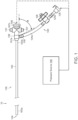
- FIG. 1 is a partially schematic side view of a clot treatment or clot removal system comprising an aspiration assembly 10 ("assembly 10") configured in accordance with an embodiment of the present technology.
- the assembly 10 includes a catheter subsystem 100, a tubing subsystem 120, and a pressure source 140.
- the catheter subsystem 100 includes a catheter 102 (e.g., an aspiration catheter) comprising an elongated shaft defining a lumen 104 and having a distal portion 103a and a proximal portion 103b.
- the catheter subsystem 100 further includes a valve 106 that can be integral with or coupled to the proximal portion 103b of the catheter 102.
- the valve 106 includes a distal portion 107a, a proximal portion 107b, and a lumen 109 extending therethrough from the distal portion 107a to the proximal portion 107b.
- the valve 106 further includes a flow controller (obscured in Figure 1 ) in the lumen 109.
- the valve is a hemostasis valve that is configured to maintain hemostasis during a clot removal procedure by preventing fluid flow in the proximal direction through the valve 106 as various components such as delivery sheaths, pull members, guidewires, interventional devices, other aspiration catheters (e.g., as described in detail with reference to Figures 11-16E ), etc., are inserted through the valve 106 to be delivered through the catheter 102 to a treatment site in a blood vessel.
- the valve 106 further includes a branch or side port 108 positioned distally of the flow controller in the lumen 109 and configured to fluidly couple the lumen 104 of the catheter 102 to the tubing subsystem 120.
- the valve 106 includes buttons 101 that can be actuated (e.g., depressed) to open a conduit within the lumen 109.
- the valve 106 can be a valve of the type disclosed in U.S Patent Application No. 16/117,519, filed August 30, 2018 , and titled "HEMOSTASIS VALVES AND METHODS OF USE,” which is incorporated herein by reference in its entirety.
- the proximal portion 107b of the valve 106 is further configured to be detachably coupled (e.g., via a snap-fit arrangement) to a retraction/aspiration device for aspirating the lumen 104 of the catheter 102 and/or for retracting an interventional device, catheter, delivery sheath, catheter, etc., positioned within the lumen 104.
- a retraction/aspiration device for aspirating the lumen 104 of the catheter 102 and/or for retracting an interventional device, catheter, delivery sheath, catheter, etc., positioned within the lumen 104.
- the tubing subsystem 120 fluidly couples the catheter subsystem 100 to the pressure source 140. More specifically, the tubing subsystem 120 can include one or more tubing sections 124 (individually labeled as a first tubing section 124a and a second tubing section 124b), at least one fluid control device 126 (e.g., a valve), and at least one connector 128 for fluidly coupling the tubing subsystem 120 to the pressure source 140 and/or other suitable components. More specifically, in the illustrated embodiment, the fluid control device 126 is a stopcock that is fluidly coupled to (i) the side port 108 of the valve 106 via the first tubing section 124a and (ii) the connector 128 via the second tubing section 124b.
- the fluid control device 126 is a stopcock that is fluidly coupled to (i) the side port 108 of the valve 106 via the first tubing section 124a and (ii) the connector 128 via the second tubing section 124b.
- the fluid control device 126 can define a lumen having a diameter (or other cross-sectional dimension) that is greater than or equal to a diameter of the lumen 104 of the catheter 102, a diameter of the first tubing section 124a, and/or a diameter of the second tubing section 124b.
- the fluid control device 126 is externally operable by a user to regulate the flow of fluid therethrough and, specifically, from the lumen 104 of the catheter 102 to the pressure source 140.
- the fluid control device 126 can be a clamp that can be actuated (e.g., compressed or squeezed by the hand of a user) to partially or fully restrict fluid flow through the tubing section 124a and/or the tubing section 124b.
- the fluid control device 126 can be omitted and its functionality incorporated into the pressure source 140 (e.g., as described in detail below with reference to Figure 5 ).
- the fluid control device 126 can include a quick-release mechanism (e.g., a spring-loaded apparatus) for rapidly opening, unclamping, etc., the fluid control device 126 to (e.g., instantaneously or nearly instantaneously) fluidly connect the pressure source 140 and the catheter 102.
- the fluid control device 126 can be opened/closed automatically (e.g., by a motor, switch, etc.).
- such a quick-release fluid control device 126 can reduce the time needed for pressure in the assembly 10 to equalize after opening of the fluid control device 126, and can thereby increase suction forces generated at the distal portion 103a of the catheter 102.
- the connector 128 is a quick-release connector (e.g., a quick disconnect fitting) that enables rapid coupling/decoupling of the catheter 102 and the fluid control device 126 to/from the pressure source 140.
- the tubing subsystem 120 can have more or fewer tubing sections, connectors, and/or fluid control devices, and can have other suitable configurations.
- one or more of the components can be permanently connected and/or integrally formed.
- the pressure source 140 is configured to generate (e.g., form, create, charge, build-up, etc.) a vacuum (e.g., negative relative pressure) and store the vacuum for subsequent application to the catheter subsystem 100. Further details of suitable pressure sources are described in detail below with reference to Figures 2-7 .
- a user can first close the fluid control device 126 before activating the pressure source 140 to build up vacuum pressure within the pressure source 140 (e.g., a vacuum chamber of the pressure source 140). In some embodiments, the user can control or select the volume of the generated vacuum. In this manner, a vacuum is charged within the pressure source 140 before the pressure source 140 is fluidly connected to the catheter subsystem 100.
- the user can open the fluid control device 126 to fluidly connect the pressure source 140 to the catheter subsystem 100 and thereby apply or release the vacuum stored in the pressure source 140 to the lumen 104 of the catheter 102. Opening of the fluid control device 126 instantaneously or nearly instantaneously applies the stored vacuum pressure to the tubing subsystem 120 and the catheter 102, thereby generating suction throughout the catheter 102. In particular, the suction is applied at the distal portion 103a of the catheter 102.
- pre-charging or storing the vacuum before applying the vacuum to the lumen 104 of the catheter 102 is expected to generate greater suction forces (and corresponding fluid flow velocities) at and/or near the distal portion 103a of the catheter 102 compared to simply activating the pressure source 140 while it is fluidly connected to the catheter 102.
- the suction forces generated by application of the stored vacuum can be used to aspirate or otherwise remove clot material from within a blood vessel of a human patient.
- the assembly 10 of the present technology includes a pressure source (e.g., a vacuum source, negative pressure source, etc.) configured to charge a vacuum that can be applied to the catheter subsystem 100 to generate suction forces for aspirating clot material from within a blood vessel.
- a pressure source e.g., a vacuum source, negative pressure source, etc.
- the pressure source can be any suitable source or combination of sources for generating and/or storing negative pressure.
- the pressure source can be a pump (e.g., an electric pump coupled to a vacuum chamber) while, in other embodiments, the pressure source can include one or more syringes that can be actuated or otherwise activated by a user of the assembly 10 to generate and store a vacuum therein
- FIG 2 is a side view of a pressure source 240 comprising a vacuum-pressure locking syringe (“syringe 240") configured in accordance with the present technology.
- the syringe 240 can be of the kind sold under the trademark "VacLok” by Merit Medical System, Inc.
- the syringe 240 includes a plunger 242 slidably and rotatably positioned within a chamber or barrel 244.
- the barrel 244 is shown as transparent in Figure 2 for the sake of clarity.
- the plunger 242 includes a seal 243 and a plurality of index members 246 defining slots 248 between adjacent pairs thereof.
- a tab member 245 projects inwardly from the interior surface of the barrel 244 and is configured to be removably positioned in the slots 248 for locking the plunger 242 in position relative to the barrel 244.
- the barrel 244 can be made of a transparent material that permits a user to visualize material (e.g., clot material) within the barrel 244 and to visualize the relative position between the slots 248 and tab member 245 for locking the syringe 240.
- the syringe 240 further includes a tip 247 for coupling the syringe 240 to the tubing subsystem 120.
- the tip 247 is a standard luer connector that can be coupled to the connector 128 via one or more suitable adaptors.
- the tip 247 further defines a lumen or bore 249 having an inner diameter D 1 .
- the diameter D 1 is about 0.103", or about 0.080" to about 0.200", or about 0.100" to about 0.150", or about 0.100" to about 0.110".
- the inner diameter D 1 is about 14 French.
- a user can first close the fluid control device 126 and then grip the plunger 242 and/or the barrel 244 to withdraw (e.g., retract) the plunger 242 at least partially out of the barrel 244 to thereby generate a vacuum in the barrel 244.
- the user can lock the plunger 242 by rotating the plunger 242 relative to the barrel 244 such that the tab member 245 is positioned within a corresponding one of the slots 248.
- the syringe 240 may not be a locking syringe, and the user can instead hold the plunger 242 in position relative to the barrel 244 Moreover, the user can control the volume of the vacuum-by withdrawing the plunger 242 more or less-to provide a desired amount or level of suction/aspiration upon opening of the fluid control device 126. In some embodiments, the syringe has a volume of about 60 cc or less than about 60 cc.
- FIG 3A is a side view of a pressure source 340 comprising a vacuum-pressure locking syringe (“syringe 340") configured in accordance with the present technology.
- the syringe 340 can have some features generally similar to the features of the syringe 240 described above with reference to Figure 2 .
- the syringe 340 includes a plunger 342 slidably and rotatably positioned within a barrel 344, and the plunger 342 includes a plurality of index members 346 defining slots 348 between adjacent pairs thereof.
- the barrel 344 is shown as transparent in Figure 3A (and Figure 3C ) for the sake of clarity.
- the syringe 340 has a maximum volume of about 60 cc or greater than 60 cc.
- the syringe 340 includes a large-bore tip 347. such as a Toomey tip, defining an inner lumen or bore 349.
- the bore 349 can have an inner diameter D 2 that is greater than or equal to the largest inner diameter of the assembly 10 (e.g., of the catheter 102 and tubing subsystem 120).
- the tip 347 can be about 26 French or greater. Accordingly, referring to Figures 2 and 3A together, the diameter D 2 can be greater than the dimension D 1 . For example, the dimension D 2 can be about two, three, four, or more times greater than the diameter D 1 .
- Figure 3B is a side view of an adaptor 350 for connecting the syringe 340 to the catheter subsystem 100 configured in accordance with the present technology
- Figure 3C is a side view of the adaptor 350 coupled to the syringe 340
- Figure 3D is a side view of the syringe 340 coupled to the tubing subsystem 120 via the adaptor 350.
- the adaptor 350 is shown as partially transparent in Figure 3C for the sake of illustration.
- the adaptor 350 includes (i) a first portion 351 defining a first lumen or bore 352 having an inner diameter D 3 , (ii) a second portion 353 defining a second lumen or bore 354. and (iii) a stepped surface or interface 355 between the first and second portions 351, 353.
- the first portion 351 can further include a seal 357 such as an O-Ring around an exterior surface thereof.
- the second bore 354 of the adaptor 350 is configured to removably receive the tip 347 of the syringe 340 therein
- the tip 347 can be snuggly received in the second bore 354 via an interference fit.
- a seal e.g., an O-ring
- the syringe 340 can be permanently coupled or integrally formed with the adaptor 350.
- the first portion 351 of the adaptor 350 is configured to be removably positioned within the connector 128 of the tubing subsystem 120 to fluidly couple the syringe 340 to the tubing subsystem 120.
- the first portion 351 of the adaptor 350 can be pushed into the connector 128 until the interface 355 abuts the connector 128.
- the seal 357 seals the interface between the connector 128 and the adaptor 350.
- the diameter D 3 of the first bore 352 of the adaptor 350 can be selected to be about the same as or greater than the greatest inner diameter of the assembly 10 (e.g., of the catheter 102 and the tubing subsystem 120).
- the catheter 102 can be about 9 French or greater, and the diameter D 3 can be selected to be larger than the size of the catheter 102.
- the continuous lumen between the catheter 102 and the syringe 340 can have a generally constant diameter and/or does not contain any narrowing at the interface between the syringe 340 and the tubing subsystem 120. That is, the adaptor 350 can connect the syringe 340 and the tubing subsystem 120 without any restriction or narrowing of the fluid path.
- a standard luer connector e.g., the syringe 240
- a standard luer connector can only provide a continuous lumen for catheters of about 8 French or smaller. Any narrowing of the fluid pathway between the catheter 102 and the syringe 340 can reduce the volumetric flow rate (e.g., suction forces and fluid velocities) that can be generated when a vacuum stored in the syringe 340 is applied to the catheter 102.
- the syringe 340 and the adaptor 350 can reduce the fluid resistance in the assembly 10 and therefore facilitate a more rapid pressure equalization in the assembly 10 when the fluid control device 126 is opened to apply the charged vacuum to the catheter 102.
- the pressure in the assembly 10 can take about 1-2 seconds to equalize.
- the pressure in the assembly 10 can take less than about 1 second (e.g., about 0.5 seconds) to equalize.
- Table 1 illustrates representative pressure equalization times and associated flow rates when the syringe 240 is coupled to a 20 French catheter (i.e., the catheter 102).
- Table 2 illustrates representative pressure equalization times and associated flow rates when the syringe 340 and the adaptor 350 are coupled to a 20 French catheter (i.e., the catheter 102).
- the syringe 340 provides for relatively faster equalization times and correspondingly greater flow rates. It is expected that the more rapid pressure equalization and flow rates provided by the syringe 340 will provide correspondingly greater suction forces at the distal portion 103a of the catheter 102. That is, in general, it is expected that increasing the bore size of a syringe used to provide vacuum pressure will provide greater suction forces over a smaller period of time (e.g., will provide a larger vacuum impulse). In some embodiments, the greater suction forces can facilitate the removal of clot material from a blood vessel of a patient even where the clot material is strongly lodged or attached within the blood vessel (e.g., a chronic clot).
- the adaptor 350 can couple the syringe 340 to the connector 128 without the need for any intervening tubing sections or additional adaptors.
- This arrangement can minimize the total length, volume, etc., of the components fluidly coupling the catheter 102 to the syringe 340. It is expected that the magnitude of suction forces generated at the distal portion 103a of the catheter 102-e.g., when a vacuum charged in the syringe 340 is applied to the catheter 102 by opening of the fluid control device 126-is proportional to the length of the fluid path between the pressure source 340 and catheter 102.
- the assembly 10 with the syringe 340 and adaptor 350 is expected to increase the suction forces generated at the distal portion 103a of the catheter 102.
- the greater suction forces can facilitate the removal of clot material from a blood vessel of a patient even where the clot material is strongly lodged or attached within the blood vessel (e.g., a chronic clot).
- FIG 4A is a side perspective view a pressure source 400 including the syringe 340 ("primary syringe 340") shown in Figures 3A-3D and a secondary syringe 460 configured in accordance with the present technology.
- the secondary syringe 460 can include a plunger 462 slidably positioned within a chamber or barrel 464.
- the primary and secondary syringes 340, 460 can have the same volume or different volumes.
- a tip 463 of the secondary syringe 460 is coupled to a first one-way valve (e.g., a check valve) 470 via a coupling member 465, such as a tube.
- a first one-way valve e.g., a check valve
- the first one-way valve 470 is configured to fluidly connect the secondary syringe 460 to the ambient environment or another device coupled to the first one-way valve 470.
- a second one-way valve (e.g., a check valve) 472 spans between and is configured to fluidly connect the primary syringe 340 to the secondary syringe 460. More specially, in the illustrated embodiment the second one-way valve 472 is connected between the first portion 351 of the adaptor 350 and the coupling member 465. In other embodiments, the second one-way valve 472 can couple the primary and secondary syringes 340, 460 in different manners. For example, the second one-way valve 472 can span between and directly connect the barrels 344,464.
- the primary and secondary syringes 340, 460 can be coupled or fastened together via one or more connectors 474 that fix the positions of the barrel 344, 464 relative to one another
- the second one-way valve 472 is a normally-open check valve configured to (i) permit fluid (e.g., air) flow from the primary syringe 340 and the adaptor 350 to the secondary syringe 460 and (ii) inhibit fluid flow in the opposite direction from the secondary syringe 460 into the primary syringe 340.
- the second one-way valve 472 has a cracking (e g., opening) pressure of about 0 psi. In one aspect of the present technology, this arrangement maximizes the magnitude of the vacuum that can be charged within the primary syringe 340.
- the cracking pressure of the second one-way valve 472 does not reduce the effective vacuum within the primary syringe 340.
- a normally-closed or other type of valve could be used for the second one-way valve 472.
- the vacuum efficiency of the pressure source 400 would be reduced by the cracking pressure of the second one-way valve 472.
- the first one-way valve 470 can be a check valve configured to (i) permit fluid flow from the secondary syringe 460 to the ambient environment (or other device) and (ii) inhibit fluid flow in the opposite direction from the ambient environment into the secondary syringe 460.
- Figures 4B and 4C are enlarged schematic side views of the pressure source 400 during operation. More specifically, Figures 4B and 4C illustrate fluid flow paths through the first and second one-way valves 470, 472 during retraction and advancement, respectively, of the plunger 462 through the barrel 464 of the secondary syringe 460.
- the first one-way valve 470 is open to permit fluid flow (e.g., fluid expulsion) from the secondary syringe 460 to the ambient environment (or other device) while (ii) the second one-way valve 472 is closed to inhibit fluid flow from the secondary syringe 460 into (e.g., back into) the primary syringe 360, the catheter subsystem 100, and/or the tubing subsystem 120.
- This flow path is indicated by the arrows A in Figure 4C .
- the pressure source 400 can be coupled to the tubing subsystem 120 by coupling the primary syringe 340 to the connector 128 (e.g., as shown in Figure 3D ).
- the pressure source is coupled to the tubing subsystem 120, retraction of the plunger 462 of the secondary syringe 460 evacuates an evacuatable volume of the assembly 10.
- the fluid control device 126 when the fluid control device 126 is closed, retraction of the plunger 462 of the secondary syringe 460 evacuates fluid, through the second one-way valve 472, from (i) the primary syringe 340 (e.g., from the barrel 344, the tip 347, and/or the adaptor 350) and (ii) the portion of the tubing subsystem 120 between the fluid control device 126 and the primary syringe 340.
- This can enable a greater charged/stored vacuum to be generated for subsequent application to the catheter subsystem 100 for aspirating clot material.
- the plunger 462 of the secondary syringe 460 can be withdrawn/advanced (e.g., "cycled") one or more times before withdrawing the plunger 342 of the primary syringe 340 to evacuate air from (i) the tip 347 of the primary syringe 340 and/or (ii) the portion of the tubing subsystem 120 between the fluid control device 126 and the tip 347.
- the plunger 462 of the secondary syringe 460 can alternatively or additionally be withdrawn after withdrawing the plunger 342 of the primary syringe 340 to further evacuate the barrel 344 of the primary syringe 340.
- the plunger 462 can be cycled when the fluid control device 126 is open to, for example, facilitate the removal of clot material stuck or clogged within the catheter subsystem 100. That is, cycling the secondary syringe 460 when the fluid control device 126 is open can generate vacuum pressure and suction in the catheter 102 to aid in the aspiration/removal of clot material.
- the volumes of the primary and secondary syringes 340, 460 can be selected based on one or more desired characteristics of a clot removal procedure using the pressure source 400.
- the secondary syringe 460 can have a larger volume than the primary syringe 340 to permit a high vacuum to be charged within the primary syringe 340 while also limiting blood loss from the patient.
- the pressure source 340 permits a greater vacuum to be generated without increasing the volume of the primary syringe 340.
- the vacuum generated by the primary syringe 340 alone is directly proportional to the volume of the primary syringe 340.
- the volume of the primary syringe 340 must be increased
- inclusion of the secondary syringe 460 in the pressure source 400 and the configuration of the first and second one-way valves 470, 472 allows the (e.g., maximum) generated vacuum to be independent of the volume of the primary syringe 340. Therefore, for example, the generated vacuum can be increased without correspondingly increasing the volume of blood withdrawn from the patient when applying the vacuum to the catheter subsystem 100.
- the primary syringe 340 of the pressure source 400 can be replaced with a simple pressure vessel or other volume, such as a canister, barrel, tube, etc In such embodiments, a vacuum can be generated in the canister simply by cycling the secondary syringe 460 one or more times.
- the secondary syringe 460 can comprise a pump or vacuum source other than a syringe.
- the secondary syringe 460 or other vacuum source can be fluidly coupled to the primary syringe 340 in other manners (e.g., via a different arrangement of check valves) to produce the same or similar flow patterns as shown in Figures 4B and 4C .
- the first and second one-way valves 470, 472 can be other types of flow control devices that are mechanically activated/deactivated (e.g., opened and closed) rather than passively operated via pressure differentials within the pressure source 400.
- the flow control devices 470, 472 can be mechanically coupled to the plunger 462 of the secondary syringe 460 such that cycling the plunger 462 activates/deactivates the flow control devices 470, 472 to operate the pressure source 400 in the manner illustrated in Figures 4B and 4C .
- FIG 5 is a side cross-sectional view of a pressure source 540 comprising an automatic release syringe (“syringe 540") configured in accordance with the present technology.
- the syringe 540 is configured to automatically apply a charged vacuum of a selected volume to the catheter subsystem 100 without requiring the actuation of an intervening fluid control device, such as the fluid control device 126 shown in Figure 1 .
- the syringe 540 can have some features generally similar to the features of the syringes 240, 340 described in detail above with reference to Figures 2 and 3A-3D .
- the syringe 540 includes a first plunger 542 slidably positioned within a chamber or barrel 544.
- the first plunger 542 further includes a first seal 543 that engages an interior surface of the barrel 544 such that a vacuum is formed within the barrel 544 as the first plunger 542 is withdrawn through the barrel 544.
- the syringe 540 includes a tip 547 (e.g., a Toomey tip) for coupling the syringe 540 to the tubing subsystem 120 (e.g., via a Toomey tip adaptor) and defining a bore 549.
- the bore 549 has a relatively large diameter selected to provide rapid pressure equalization in the assembly 10 after a vacuum stored in the syringe 540 is released.
- the first plunger 542 can further include (i) a grip portion 541 configured to be engaged by a user for retracting the first plunger 542 and (ii) a lumen 581 extending lengthwise therethrough.
- a plunger assembly 582 is slidably positioned within and extends through the lumen 581 of the first plunger 542.
- the plunger assembly 582 includes (i) a second plunger 583 and (ii) a release member 584 slidably and/or rotatably positioned within a lumen 585 of the second plunger 583.
- the release member 584 includes an engagement member 586 configured to engage the grip portion 541 of the first plunger 542 when the first plunger 542 is withdrawn from the barrel 544.
- the second plunger 583 includes a second seal 587 configured to engage and seal an interior surface of the bore 549 of the syringe 540 to enable a vacuum to be formed in the barrel 544 as the first plunger 542 is withdrawn through the barrel 544. That is, the second seal 587 can seal (e.g., fluidly disconnect) the barrel 544 of the syringe from the tubing subsystem 120 and the catheter subsystem 100.
- the syringe 540 can further include an O-ring 579 or other suitable component for sealing an interface between the first and second plungers 542, 582 to maintain the vacuum formed within the barrel 544, while also permitting the first plunger 542 to move (e.g., translate) relative to the second plunger 583.
- the plunger assembly 582 further includes a locking mechanism (not shown) configured to permit/inhibit the release member 584 from moving longitudinally relative to the second plunger 583.
- a locking mechanism (not shown) configured to permit/inhibit the release member 584 from moving longitudinally relative to the second plunger 583.
- rotation of the release member 584 in a first direction relative to the second plunger 583 can lock the two components in position, while rotation of the release member 584 in a second direction relative to the second plunger 583 can unlock the two components so that the release member 584 can be withdrawn or pushed into the lumen 585 of the second plunger 583.
- the release member 584 and the second plunger 583 can be integrally formed or permanently locked together.
- the plunger assembly 582 enables (i) a user of the syringe 540 to select a desired volume for a vacuum to be formed in the syringe 540 and (ii) the automatic release or application of a generated vacuum via opening (e.g., unplugging) of the bore 549.
- a user can first unlock the release member 584 and slide the release member 584 to a position corresponding to a desired vacuum volume.
- the release member 584 can have tick marks 588 or other indicia along its length that correspond to a volume of the syringe 540 (e.g., a vacuum chamber volume).
- the user can lock the release member 584 relative to the second plunger 583 (e.g., by rotating the release member 584) to inhibit relative movement of the two components.
- the user can grasp the grip portion 541 to retract the first plunger 542 relative to the barrel 544 and the plunger assembly 582 to generate a vacuum within the barrel 544 between the first and second seals 543, 587.
- the grip portion 541 engages the engagement member 586 of the release member 584 such that further retraction of the first plunger 542 simultaneously retracts the plunger assembly 582.
- the syringe 540 provides for the automatic release of charged vacuum pressure at a specified volume and with a single retraction of the first plunger 542.
- the syringe 540 has a built-in fluid control device and thus eliminates the need for a separate fluid control device 126 and/or an additional step for opening the fluid control device 126.
- FIG 6 is a top perspective view of a pressure source 640 comprising a syringe (“syringe 640") configured in accordance with the present technology.
- the syringe 640 can include some features generally similar to the features of the syringes 240, 340, and 540 described in detail above with reference to Figures 2-3D and 5 .
- the syringe 640 includes a plunger 642 slidably positioned within a barrel 644, and a tip 647 (e.g., a large-bore tip).
- the syringe 640 further includes a lever or handle 690 operably coupled to the plunger 642.
- the handle 690 provides mechanical leverage for withdrawing the plunger 642 to create a vacuum within the barrel 644. More specifically, the handle 690 can be coupled to a crossbar 691 that rotates relative to the plunger 642 via actuation (e.g., rotation) of the handle 690.
- the crossbar 691 can be coupled to a gear (obscured in Figure 6 ) configured to engage a track 692 on the plunger 642. Accordingly, rotation of the handle 690 in a first direction retracts the plunger 642 relative to the barrel 644 to charge a vacuum in the barrel 644. And, rotation of the handle 690 in a second (e.g., opposite) direction advances the plunger 642 into the barrel 644 to, for example, expel fluid, material, etc., from the barrel 644.
- the handle 690 provides additional mechanical leverage relative to a standard syringe, and can thus reduce the force (e.g., strain, energy, etc.) required by a user of the syringe 640 to form a vacuum in the syringe 640. Therefore, use of the syringe 640 can reduce the time needed to remove clot material with the assembly 10.
- the syringe 640 can have a volume greater than 60 cc (e.g., greater than 80 cc, greater than 100 cc, greater than 120 cc, greater than 140 cc, etc.) In a particular embodiment, for example, the syringe 640 can have a volume of about 140 cc.
- the syringe 640 can enable the use of larger volume syringes that can generate correspondingly greater suction forces in the catheter subsystem 100.
- the side port 108 of the valve 106 can be formed to have an angle A that is less than about 90°, less than about 75°, less than about 60°, less than about 45°, less than about 30°, less than about 15° etc.
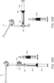
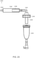
- FIG. 24 is an enlarged isometric view of the assembly 10 showing the pressure source 340 coupled directly to the proximal portion 107b of the valve rather than to the connector 128 of the tubing subsystem 120 and the side port 108 of the valve 106.
- any of the pressure sources described in detail above with reference to Figures 2-6 can be configured to be coupled to the proximal portion 107b of the valve 106 rather than the side port 108.
- the side port 108 can be omitted and the valve 106 and the tubing subsystem 120 can be coupled to the catheter 102 via a Y-connector.
- Figure 25 is an enlarged isometric view of the assembly 10 showing the valve 106 and the tubing subsystem 120 coupled to the catheter 102 via a Y-connector 2590.
- the tubing system 120 is linearly coupled to the catheter 102, and the valve 106 protrudes at an angle from the catheter 102.
- a guidewire or other component is positioned within the valve 106 during the duration of a clot removal procedure (e.g., for delivering interventional devices to a treatment site within a patient).
- the pressure source 140 can be a syringe configured for over-wire delivery.
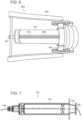
- Figure 7 is a side view of a pressure source 740 comprising a vacuum-pressure locking syringe (“syringe 740") configured in accordance with the present technology for delivery and operation over a guidewire 794
- the syringe 740 can have some features generally similar to the features of the syringe 340 described in detail above with reference to Figure 3 .
- the syringe 740 includes a plunger 742 slidably and rotatably positioned within a barrel 744.
- the barrel 744 is shown as transparent in Figure 7 for the sake of clarity.
- the plunger 742 includes a lumen 796 (shown in broken lines) extending longitudinally therethrough.
- the guidewire 794 can be inserted through the lumen 796 of the plunger 742 such that the syringe 740 can be advanced over the guidewire 794 for attachment to the proximal portion 107b of the valve 106.
- the syringe 740 can further include one or more sealing components (e.g., valves, O-rings, etc.; not shown) for maintaining a seal between the guidewire 794 and the plunger 742 to permit build-up and storage of a vacuum in the barrel 744.
- pressure sources may be combined to, for example, include multiple pressure sources or pressure sources having different components or combinations of components.
- the secondary syringe 460 ( Figures 4A-4C ) can be coupled via one or more one-way valves to the syringes 240, 540. 640 or 740 ( Figures 2 and 5-7 , respectively) to generate additional vacuum.
- multiple pressure sources can be coupled to the catheter 102 via the tubing subsystem 120 and/or via the valve 106.
- the individual pressure sources can be the same or different, and can be coupled to the catheter subsystem 100 via a single fluid control device, such as the fluid control device 126, or can be coupled to the catheter subsystem 100 via separate fluid control devices. Therefore, the profile of the vacuum applied to the catheter 102 can be selected or adjusted by using multiple different pressure sources.
- a specific vacuum profile can depend at least on (i) the individual characteristics of the multiple pressure sources (e.g., volume, bore-size, etc.), (ii) the manner in which the pressure sources are coupled to the catheter subsystem 100 (e.g., via individual valves, via the same valve, etc.), and (iii) the timing of the application or release of the vacuum of each pressure source to the catheter subsystem 100 (e.g., staggered release, simultaneous release, etc.).
- the syringe 240 ( Figure 2 ) and the syringe 340 ( Figure 3 ) can both be coupled to the tubing subsystem 120 via, for example, a Y-connector.
- opening the fluid control device 126 can simultaneously apply the combined vacuum to the catheter 102.
- the larger-bored syringe 340 can provide a short but powerful impulse of vacuum pressure, while the smaller-bored syringe 240 can provide a longer and more sustained vacuum pull. This combination can apply a large, fast-acting suction force to dislodge and capture clot material in the catheter 102, and simultaneously apply a more sustained suction force to capture more clot material.
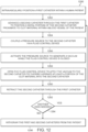
- Figure 8 is a flow diagram of a process or method 800 for operating a clot removal system including the assembly 10 to remove clot material from within a blood vessel (e.g., a pulmonary blood vessel) of a human patient in accordance with the present technology.
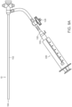
- Figures 9A-9C are side views of a proximal portion of the assembly 10
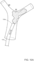
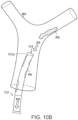
- Figures 10A and 10B are schematic illustrations of a distal portion of the assembly 10, during a clot removal procedure in accordance with embodiments of the present technology.
- Figures 9A-9C are side views of the assembly 10 including the syringe 340 and adaptor 350 ( Figures 3A-3D ), and Figures 10A and 10B are side views of the catheter 102 with the distal portion 103a of the catheter 102 positioned proximate to an embolism or clot material PE within a blood vessel BV (e.g., a pulmonary blood vessel).
- a blood vessel BV e.g., a pulmonary blood vessel.
- the method 800 includes positioning the distal portion 103a of the catheter 102 proximate to clot material within a blood vessel of a human patient (e.g., at a treatment site).
- a distal terminus of the distal portion 103a of the catheter 102 is positioned proximate to a proximal portion of the clot material PE. It is expected that reducing the distance between the distal terminus of the catheter 102 and the proximal portion of the clot material PE-without contacting the clot material PE with the catheter 102-will maximize the suction forces on the clot material PE when the fluid control device 126 is opened.
- the distal terminus of the catheter 102 can be positioned at least partially within the clot material PE, or the distal terminus of the catheter 102 can be positioned distal of the clot material PE.
- the catheter subsystem 100 can include an introducer (e.g., a Y-connector with a hemostasis valve; not shown) that can be partially inserted into the femoral vein.
- a guidewire (not shown) can be guided into the femoral vein through the introducer and navigated through the right atrium, the tricuspid valve, the right ventricle, the pulmonary valve, and into the main pulmonary artery Depending on the location of the embolism, the guidewire can be guided to one or more of the branches of the right pulmonary artery and/or the left pulmonary artery.
- the guidewire can be extended entirely or partially through the clot material PE. In other embodiments, the guidewire can be extended to a location just proximal of the clot material PE.
- the catheter 102 can be placed over the guidewire and advanced (e.g., as indicated by arrow A1) to a position proximate to the clot material PE as illustrated in Figure 10A .
- a contrast agent can be injected through the catheter 102 and viewed using fluoroscopic imaging techniques, as is known in the art.
- the valve 106 can be opened to determine the position of the distal portion 103a of the catheter 102 relative to the clot material PE.
- the activation buttons 101 can be depressed to open the lumen 109 of the valve 106. If there is substantially no back-bleeding through the valve 106, the operator can determine that the distal portion 103a of the catheter 102 is fully engaged with the clot material PE.
- the operator can determine that the distal portion 103a of the catheter is not fully engaged with the clot material PE. Accordingly, to locate the distal portion 103a of the catheter 102 just proximal of the clot material PE, the operator can (i) first determine that distal portion 103a of the catheter is fully engaged with the clot material PE by activating the valve 106 and detecting no back-bleeding and (ii) then reposition the catheter 102 (e.g., by withdrawing the catheter 102 proximally) and activate the valve 106 until back-bleeding is detected-thereby confirming that the distal portion 103a of the catheter 102 is positioned proximal of the clot material PE.
- the valve 106 can be opened during retraction of the catheter 102 until back-bleeding is detected. In other embodiments, the valve 106 can be closed during retraction of the catheter 102, and the catheter 106 can be retracted a set (e.g., predetermined) distance before the valve 106 is opened again. In one aspect of the present technology, determining the position of the distal portion 103a of the catheter 102 via activation of the valve 106 can be used when it is difficult to determine the position of the catheter 102 via radiographic techniques. In contrast, many conventional hemostasis valves cannot be activated in this manner.
- the guidewire can then be withdrawn while, in other embodiments, the guidewire can remain and can be used to guide other catheters (e.g., delivery catheters, additional aspiration catheters, etc.), interventional devices, etc., to the treatment site.
- catheters e.g., delivery catheters, additional aspiration catheters, etc.
- interventional devices etc.
- the user can gain access through the jugular vein, the subclavian vein, the brachial vein, or any other vein that connects or eventually leads to the superior vena cava.
- Use of other vessels that are closer to the right atrium of the patient's heart can also be advantageous as it reduces the length of the instruments needed to reach the pulmonary embolism.
- the method 800 includes coupling a pressure source (e.g., the syringe 340) to the catheter 102 via the fluid control device 126.
- a pressure source e.g., the syringe 340
- the tip 347 shown in Figures 3A and 3C but obscured in Figure 9A
- the syringe 340 can be coupled to the connector 128 via the adaptor 350.
- the method 800 includes activating the syringe 340 to generate a vacuum while the fluid control device 126 is closed.
- the user can first actuate the fluid control device 126 to close the fluid control device 126, and then retract the plunger 342 to generate a vacuum in the barrel 344 of the syringe 340.
- the user can subsequently lock the plunger 342 relative to the barrel 344, as described in detail above, to store or maintain a vacuum of known volume in the syringe 340.
- the syringe 340 can be pre-charged with a vacuum before the vacuum is applied to the catheter 102.
- many conventional aspiration techniques include activating a negative pressure source (e.g., a pump, a syringe, etc.) while the pressure source is fluidly connected to a lumen to be aspirated.
- a negative pressure source e.g., a pump, a syringe, etc.
- the secondary syringe 460 can be cycled one or more times before or after retracting the plunger 342 to increase the vacuum pressure.
- the method 800 includes opening the fluid control device 126 to apply the vacuum to the lumen 104 of the catheter 102.
- the user can actuate (e.g., twist a handle of) the fluid control device 126 to open the fluid control device 126 and apply the vacuum stored in the syringe 340 to the catheter subsystem 100.
- application of the vacuum causes suction at the distal tip 103a of the catheter 102 (e.g., as indicated by arrow A2) that aspirates at least a portion of the clot material PE from the blood vessel BV and into the lumen 104 of the catheter 102.
- opening the fluid control device 126 instantaneously or nearly instantaneously generates suction at the distal portion 103a of the catheter 102.
- application of the vacuum can generate suction for less than about 1 second (e.g., about 0.5 second), substantially less than about 1 second (e.g., about 0 3 second, about 0.1 second, etc.) less than about 2 seconds, or greater than about 2 seconds-until the pressure in the assembly 10 equalizes.
- the clot material PE can be aspirated entirely through the lumen 104 of the catheter 102 and into the barrel 344 of the syringe 340.
- the user can determine whether subsequent steps for treating the clot material PE are necessary or desirable by visualizing the amount of clot material collected in the syringe 340.
- Figure 9C illustrates the syringe 340 and the tubing subsystem 120 after the fluid control device 126 has been opened to apply the vacuum stored in the syringe 340 to the catheter 102.
- some of the clot material PE is visible in the syringe 340.
- the fluid control device 126 or another fluid control device can be intermittently operated to provide discrete bursts of suction.
- the fluid control device 126 can be quickly opened and closed to provide a first burst of suction (e.g., vacuum release) without fully equalizing the pressure in the assembly 10.
- the fluid control device 126 can then be opened again to provide a second burst of suction, or opened and closed repeatedly to provide a desired suction pattern.
- the assembly 10 can be specifically configured to facilitate the application of multiple bursts of suction.
- the fluid control device 126 can be spring-loaded, electronically controlled, etc., to rapidly open and close the valve, and/or (ii) the pressure source 140 can have a large vacuum chamber and/or small bore size to increase the time required for pressure in the assembly 10 to equalize (e.g., to increase a discharge time of the pressure source 140).
- discharging the vacuum stored in the pressure source to aspirate the lumen 104 of the catheter 102 may not remove all of the clot material PE (or a desired amount of the clot material PE) from the blood vessel BV. That is, a single aspiration may not adequately remove the clot material PE from the blood vessel BV.
- the user of the assembly 10 may wish to again apply vacuum pressure (conduct an "aspiration pass") to remove all or a portion of the remaining clot material PE in the blood vessel BV.
- the pressure source can be disconnected from the tubing subsystem 120 and drained (e.g., aspirated clot removal removed) before the method 800 returns to block 802.
- the adaptor 350 and the syringe 340 can be decoupled from the connector 128, and the plunger 342 can be pushed into the barrel 344 to expel the clot material PE and associated fluid from the barrel 344 via the tip 347.
- the pressure source can then be re-coupled to the connector 128 (block 804), primed again (block 806), and the vacuum pressure discharged (block 808) to aspirate all or a portion of the remaining clot material PE.
- Blocks 802-808 can be repeated until a desired amount of clot material is removed from the patient or until the catheter 102 becomes clogged.
- the fluid control device 126 and/or the valve 106 can be opened to check for back bleeding. A lack of back bleeding can indicate that the catheter 102 is likely clogged.
- the barrel 344 of the syringe 340 contains mostly air and relatively little blood and clot material (e.g., less than 5-10 cc) after aspiration of the catheter 102 (block 808), it can indicate that the catheter 102 is likely clogged.
- the method 800 can proceed to block 810 and the catheter 102 can be removed from the patient.
- the catheter 102 can be flushed and cleared prior to reentry into the patient (block 802).
- a different (e.g., new, unused, etc.) catheter can be inserted into the patient and positioned to remove the remaining clot material PE from the patient.
- the syringe 340 can be recharged and used to apply one or more subsequent vacuum pulses to the catheter 102. More specifically, the fluid control device 126 can be closed and the syringe 340 can be removed from the connector 128 and evacuated to remove the clot material and blood therein. Then, blocks 804-808 can be repeated to apply another pulse of vacuum to the catheter 102.
- the syringe 340 can be "cycled” until the vacuum force on the clot material PE overcomes the forces between the clot material PE and the catheter 102 and sucks the clot material PE into the syringe 340.
- the secondary syringe 460 can be cycled one or more times to increase the vacuum in the assembly 10 (e.g., in the catheter 102) and thus increase the suction force exerted against the clot material PE.
- the secondary syringe 460 can be cycled until the vacuum force on the clot material PE overcomes the forces between the clot material PE and the catheter 102 and sucks the clot material PE into the syringe 340.
- a second clot removal assembly can be telescoped through the first assembly 10 to facilitate removal of the clogged clot material PE.
- an interventional device such as a clot removal and/or clot treatment device can be delivered to the treatment site through the catheter 102 for engaging and facilitating clot removal before and/or after application of a stored vacuum to the catheter 102.
- Suitable interventional devices and associated methods are disclosed in U.S. Patent Application No. 9,526,864, filed June 9, 2015 , and titled “RETRACTION AND ASPIRATION DEVICE FOR TREATING EMBOLISM AND ASSOCIATED SYSTEMS AND METHODS," and U.S. Patent Application No. 8,784,434, filed March 15, 2013 , and titled “METHODS AND APPARATUS FOR TREATING EMBOLISM,” both of which are incorporated herein by reference in their entireties.
- the user can first advance an interventional device to the treatment site and at least partially engage the clot material PE with the interventional device to loosen (e.g., scour) the clot material PE.
- loosening of the clot material PE can facilitate the removal of the clot material PE upon a subsequent aspiration pass.
- the user can use an interventional device to engage residual clot material PE ( Figure 10B ) after a first aspiration pass.
- FIG 11 is a partially schematic side view of another clot treatment or clot removal system configured in accordance with the present technology.
- the clot removal system includes a first aspiration assembly 20 and a second aspiration assembly 30.
- the first and second aspiration assemblies 20, 30 (“assemblies 20, 30") can include some features generally similar to the features of the aspiration assembly 10 described in detail above with reference to Figures 1-10B .
- the first aspiration assembly 20 includes (i) a first catheter subsystem 1000 having a first catheter 1002 and a first valve 1006, (ii) a first tubing subsystem 1020 having a first fluid control device 1026 (e.g., a stopcock), and (iii) a first pressure source 1040 that can be fluidly coupled to the first catheter subsystem 1000 via the first tubing subsystem 1020.
- a first catheter subsystem 1000 having a first catheter 1002 and a first valve 1006
- a first tubing subsystem 1020 having a first fluid control device 1026 (e.g., a stopcock)
- a first pressure source 1040 that can be fluidly coupled to the first catheter subsystem 1000 via the first tubing subsystem 1020.
- the second aspiration assembly 30 includes (i) a second catheter subsystem 1100 having a second catheter 1102 and a second valve 1106, (ii) a second tubing subsystem 1120 having a second fluid control device 1126 (e.g., a stopcock), and (iii) a second pressure source 1140 that can be fluidly coupled to the second catheter subsystem 1100 via the second tubing subsystem 1120.
- a second catheter subsystem 1100 having a second catheter 1102 and a second valve 1106,
- a second tubing subsystem 1120 having a second fluid control device 1126 e.g., a stopcock
- a second pressure source 1140 that can be fluidly coupled to the second catheter subsystem 1100 via the second tubing subsystem 1120.
- the first and second catheters 1002, 1102 each comprise an elongated shaft defining a lumen 1004, 1104 and having a distal portion 1003a, 1103a, respectively.
- the first and second valves 1006, 1106 each include (i) a distal portion 1007a, 1107a, (ii) a proximal portion 1007b, 1107b, (iii) a lumen 1009, 1109 extending therethrough, and (iv) a flow controller (obscured in Figure 10 ) in the lumen 1009, 1109, respectively.
- the first fluid control device 1026 is operable to regulate or control fluid flow between (e.g., fluidly connect or disconnect) the first pressure source 1040 and the first catheter subsystem 1000.
- the second fluid control device 1126 is operable to regulate or control fluid flow between (e.g., fluidly connect or disconnect) the second pressure source 1140 and the second catheter subsystem 1100.
- the second catheter 1102 has a smaller cross-sectional dimension (e.g., diameter) than the first catheter 1002 so that the second catheter 1102 can be inserted through the first valve 1006 and into the lumen 1004 of the first catheter 1002.
- the second catheter 1102 can be telescoped through the lumen 1004 of the first catheter 1002 until the distal portion 1103a of the second catheter 1102 extends beyond a distal terminus of the first catheter 1002. Accordingly, the second catheter 1102 can be longer than the first catheter 1002.
- the second catheter 1102 can have a size of 16 French or smaller and the first catheter 1002 can have a size of 20 French or greater.
- the first valve 1006 can provide a hemostatic seal that inhibits fluid flow (e.g., blood flow) through the first valve 1006 and from the first catheter subsystem 1000 when the second catheter 1102 is positioned within the first catheter 1002.
- a sealing member 1499 can be positioned between the first catheter 1002 and the second catheter 1102 for sealing the lumen 1004 of the first catheter 1002 when the second catheter 1102 is advanced distally past the sealing member.
- the first and second pressure sources 1040, 1140 are separate sources each configured to generate and store a vacuum for subsequent application to the first and second catheter subsystems 1000, 1100, respectively, as described in detail above with reference to Figures 1-10B .
- one or both of the pressure sources 1040, 1140 can be configured to provide sustained negative pressure rather than a charge or burst of stored vacuum pressure.
- one of the pressures sources 1040, 1140 can be omitted, or the pressure sources 1040, 1140 can be fluidly coupled and/or integrally formed.
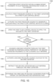
- Figure 12 is a flow diagram of a process or method 1280 for operating a clot removal system including the assemblies 20 and 30 to remove clot material from within a blood vessel (e.g., a pulmonary blood vessel) of a human patient in accordance with the present technology.
- Figures 13A-13C are schematic illustrations of a distal portion of the assemblies 20, 30 during a clot removal procedure in accordance with the present technology.
- Figures 14A-14C are schematic side views of a distal portion of the assemblies 20, 30 during a clot removal procedure and including an optional sealing member in accordance with the present technology.
- the method 1280 includes intravascularly positioning the first catheter 1002 within a human patient.
- Figure 13A illustrates the first catheter 1002 after it has been advanced (e.g., as indicated by arrow A1) to a position within a blood vessel BV (e.g., a pulmonary blood vessel). More specifically, the first catheter 1002 can be advanced within the blood vessel BV until the distal portion 1003a of the first catheter 1002 is positioned proximal to clot material PE within the blood vessel BV.
- a blood vessel BV e.g., a pulmonary blood vessel
- the position of the distal portion 1003a of the first catheter 1002 relative to the clot material PE can be determined by activating the first valve 1006 and determining whether there is back-bleeding through the first valve 1006, as described in detail above.
- the clot material PE is located within a branch (e.g., a reduced diameter portion) of the blood vessel BV.
- access to the blood vessel BV can be achieved using an introducer and guidewire as described in detail above with reference to Figure 8 .
- the method 1280 includes advancing the second catheter 1102 through the first catheter 1002 until the distal portion 1103a of the second catheter 1102 is positioned proximate to the clot material PE within the blood vessel BV (e.g., at a treatment site).
- the user can first insert the distal portion 1103a of the second catheter 1102 through the first valve 1006 before advancing the second catheter 1102 (e.g., as indicated by the arrow A1) through the lumen 1004 of the first catheter 1002.
- the first valve 1006 can be actuated (e.g., by depressing one or more buttons) to open the lumen 1009 of the first valve 1006 so that the second catheter 1102 can be inserted therethrough.
- the position of the distal portion 1103a of the second catheter 1102 relative to the clot material PE can be determined by activating the second valve 1106 and determining whether there is back-bleeding through the second valve 1106, as described in detail above.
- the (smaller) second catheter 1102 can be intravascularly positioned proximate to the clot material PE before intravascularly positioning the (larger) first catheter 1002.
- the second catheter 1102 can act as a guide or rail for guiding the advancement of the first catheter 1002 to the treatment site.
- Figure 13A illustrates the second catheter 1102 after it has been advanced through the first catheter 1002 and past a distal terminus of the first catheter 1002 to position a distal terminus of the second catheter 1102 proximate to a proximal portion of the clot material PE.
- the distal terminus of the second catheter 1102 can be positioned at least partially within the clot material PE, or the distal terminus of the second catheter 1102 can be positioned distal of the clot material PE.
- the second catheter 1102 because the second catheter 1102 has a smaller cross-sectional dimension than the first catheter 1002, the second catheter 1102 can be advanced to narrower (e.g., more distal) treatment sites within the blood vessel BV.
- the first catheter 1002 may be too large to be positioned within the branch of the blood vessel BV, while the second catheter 1102 can be positioned within the branch proximate to or within the clot material PE.
- the method 1280 includes coupling the second pressure source 1140 to the second catheter 1102 via the second fluid control device 1126.
- any one or combination of the pressure sources described in detail above with reference to Figures 2-7 can be coupled to the second catheter 1102 via the second tubing subsystem 1120
- the method 1280 can further include coupling the first pressure source 1040 to the first catheter 1002 (e.g., via the first tubing subsystem 1020).
- the method 1280 includes activating the second pressure source 1140 to generate a vacuum while the second fluid control device 1126 is closed.
- the second pressure source 1140 can be activated to build-up or pre-charge a vacuum for subsequent application to the second catheter 1102.
- the first pressure source 1040 can also be activated to generate and store a vacuum for subsequent application to the first catheter 1002.
- the method 1280 includes opening the second fluid control device 1126 to apply the vacuum stored in second pressure source 1140 to the lumen 1104 of the second catheter 1102.
- application of the vacuum causes suction (e.g., as indicated by arrow A2) that aspirates at least a portion of the clot material PE from the blood vessel BV and into the lumen 1104 of the second catheter 1102.
- suction e.g., as indicated by arrow A2
- opening the second fluid control device 1126 instantaneously or nearly instantaneously generates suction at the distal portion 1103a of the second catheter 1102.
- pre-charging or storing the vacuum before applying the vacuum to the lumen 1104 of the second catheter 1102 is expected to generate greater suction forces (and corresponding fluid flow velocities) at and/or near the distal portion 1103a of the second catheter 1102 compared to simply activating the second pressure source 1140 while it is fluidly connected to the second catheter 1102.
- the method 1280 can further comprise opening the first fluid control device 1026 to generate suction at the distal portion 1003a of the first catheter 1002.
- the suction profile in the blood vessel BV can be selected or modified based on the characteristics of the pressure sources 1040, 1140 (e.g., volume, bore size, etc.) and the timing of the opening of the first and second fluid control devices 1026, 1126.
- the first fluid control device 1026 can be opened at the same time as the second fluid control device 1126 to generate a combined and relatively large suction force in the blood vessel BV.
- the first fluid control device 1026 can be opened after the second fluid control device 1126 to generate staggered or stepped suction forces in the blood vessel BV.
- the first fluid control device 1026 can be opened after the second fluid control device 1126 to aspirate any of the clot material PE (i) remaining in the blood vessel BV after aspiration of the second catheter 1102 and/or (ii) stuck to or extending from the second catheter 1102.
- the first pressure source 1040 can be a pump or other source for providing sustained negative pressure-rather than a built-up charge of negative pressure-and thus can generate sustained (e.g., constant) suction at the distal portion 1003a of the first catheter 1002.
- the first fluid control device 1026 can remain open during the clot removal procedure to provide sustained suction throughout the procedure.
- an interventional device can be delivered through the second catheter 1102 and used to engage the clot material PE before and/or after the vacuum is applied to the second catheter 1102.
- an interventional device can be delivered through the second catheter 1102 and used to engage the clot material PE before and/or after the vacuum is applied to the second catheter 1102.
- the method 1280 includes retracting the second catheter 1102 proximally through the first catheter 1002.
- multiple aspiration passes can be performed with the second catheter 1102 before retracting the second catheter 1102.
- the first pressure source 1040 or another pressure source coupled to the first catheter 1002 can be activated to generate suction (e.g., as indicated by arrow A3) at the distal portion 1003a of the first catheter 1002 during retraction of the second catheter 1102.
- the suction can be constant or provided in one or more bursts, as described in detail above.
- the second catheter 1102 can be fully withdrawn from the patient and disposed of or cleaned (e.g., flushed with a sterile liquid) for reuse
- Figure 14A is an enlarged view of the distal portion of the assemblies 20, 30 shown in Figure 13C and illustrating a portion of the clot material PE stuck to or dangling from the distal portion 1103a of the second catheter 1102.
- an optional seal 1499 is disposed between the first and second catheters 1002, 1102 to facilitate the removal of such dangling clot material PE.
- the seal 1499 (shown in cross-section) can be disposed between an outer surface of the second catheter 1102 and an inner surface of the first catheter 1002
- the seal 1499 can be an O-ring, grommet, or other suitable component that fluidly disconnects the lumen 1004 of the first catheter 1002 from the blood vessel BV when the second catheter 1102 is positioned therethrough (e.g., when the distal terminus of the second catheter 1102 is positioned distally of the seal 1499).
- Figures 14B and 14C are enlarged views of the distal portion of the assemblies 20, 30 and illustrating further retraction of the second catheter 1102 (and the dangling clot material PE) into the lumen 1004 of the first catheter 1002.
- the first pressure source 1040 can be activated to charge a vacuum in the lumen 1004 of the first catheter 1002.
- the operator can open the first fluid control device 1026 and activate the first pressure source 1040 to build up the vacuum in the lumen 1004 of the first catheter 1002.
- the suction acts to separate or otherwise dislodge the clot material PE from the second catheter 1102 and pull the clot material PE proximally through the lumen 1004 of the first catheter 1002.
- a second burst of suction is automatically applied via the first catheter 1002 during retraction of the second catheter 1102.
- the user does not need to take any additional step to release the vacuum stored in the first catheter 1002-as release is automatically triggered by retraction of the second catheter 1102.
- the user can determine whether it is necessary or desirable to redeploy the second catheter 1102 or another catheter through the first catheter 1002 in order to remove any residual clot material PE that was not removed during the first aspiration pass and/or any clot material located elsewhere in the blood vessel BV (e.g., to initiate a second aspiration pass).
- the operator can visualize the amount of clot material PE collected in the first pressure source 1040 and/or the second pressure source 1140 to at least partially determine whether another aspiration pass is needed.
- the operator can rely on imaging (e.g., fluoroscopic imaging) of the blood vessel BV or other techniques known in the art to determine whether an additional aspiration pass is necessary or desirable.
- the user can elect to fully withdraw the assemblies 20, 30 from the patient at block 1296. If clot material PE remains in the vessel, the method can return to block 1284.
- the same second catheter 1102 can be cleaned (e.g., flushed with saline) and advanced again through the first catheter 1002 until the distal portion 1103a of the second catheter 1102 is positioned proximate to the remaining clot material PE within the blood vessel BV.
- a new second catheter 1102 can be used for each pass to reduce the likelihood of contamination (e.g., reintroduction of clot material PE).
- the first catheter 1002 can be aspirated (e.g., via the first pressure source 1040) prior to redeployment of the second catheter 1102 to, for example, remove any clot material PE that may be in the first catheter 1002 to inhibit its reintroduction into the blood vessel BV as the second catheter 1102 is advanced therethrough during another pass.
- the assemblies 20, 30 may be fully withdrawn from the patient (block 1294).
- the method 1280 provides for an aspiration catheter to be deployed multiple times without requiring that the first catheter 1002 be removed after each deployment. Accordingly, the present technology allows for only a single insertion of a guide catheter during a procedure including multiple passes to remove clot material-increasing the speed of the procedure and reducing trauma to the patient since the guide catheter does not need to be reintroduced (e.g., advanced through the vasculature and past the heart) before each pass. Moreover, in certain embodiments, the present technology can enable the first catheter 1002 to be relocated to an alternate treatment site within the patient without removing the first catheter 1002 from the patient and, therefore, without reintroducing the first catheter 1002 through the heart.
- the first catheter 1002 can be relocated to another treatment site within the lungs including a treatment site in the opposite lung. More specifically, (i) a dilator can be reintroduced into the first catheter 1002, (ii) the first catheter 1002 can be withdrawn into the main pulmonary artery, (iii) a guidewire can be redirected to the new treatment site, (iv) the first catheter 1002 can be advanced over the guidewire to the new treatment site, and (v) the dilator can be removed.
- Figure 15 is a flow diagram of another process or method 1580 for operating a clot removal system including the assemblies 20. 30 ( Figure 1 ) to remove clot material from within a blood vessel (e.g., a pulmonary blood vessel) of a human patient in accordance with the present technology.
- Figure 16A is an enlarged side view of a distal portion of the first assembly 20
- Figures 16B-16E are side views of a distal portion of the assemblies 20, 30 during a clot removal procedure in which clot material clogs the first assembly 20 in accordance with the present technology.
- the method 1580 includes intravascularly positioning the first catheter 1002 of the first assembly 20 within a human patient.
- the method 1580 includes coupling the first pressure source 1040 to the first catheter 1002 via the first fluid control device 1026.
- the method 1580 includes activating the first pressure source 1040 to generate a vacuum while the first fluid control device 1026 is closed.
- the first pressure source 1040 can be activated to build-up or pre-charge a vacuum for subsequent application to the first catheter 1002.
- the method 1580 includes opening the first fluid control device 1026 to apply the vacuum stored in the first pressure source 1040 to the lumen 1004 of the first catheter 1002. As described in detail above, opening the first fluid control device 1026 instantaneously or nearly instantaneously generates suction at the distal portion 1003a of the first catheter 1002.
- Figure 16A is an enlarged view of the distal portion of the first assembly 20 illustrating a portion of clot material PE that extends beyond from the distal portion 1003a of the first catheter 1002 and blocks/clogs the lumen 1004 of the first catheter 1002.
- a portion of the clot material PE is not within the first catheter 1002.
- the method 1580 can include determining whether the first catheter 1002 is clogged.
- the operator can determine that the first catheter 1002 is clogged based on the vacuum chamber of the first pressure source 1040 containing little to no clot material PE and blood. For example, since the clot material PE clogs the first catheter 1002, the vacuum chamber of the first pressure source 1040 cavitates when the first fluid control device 1026 is opened. If the first catheter 1002 is not clogged, the method 1580 can proceed to block 1598 and the first catheter 1002 can be withdrawn from the patient or the operator can perform another aspiration pass (e.g., as described in detail above with reference to blocks 808 and 810 of the method 800 shown in Figure 8 ).
- another aspiration pass e.g., as described in detail above with reference to blocks 808 and 810 of the method 800 shown in Figure 8 ).
- the method 1580 can proceed to block 1592 which includes advancing the second catheter 1102 through the first catheter 1002 until the distal portion 1103a of the second catheter 1102 is positioned in or proximate to the clogging clot material PE.
- Figure 16B illustrates the second catheter 1102 after it has been advanced to a position within the first catheter 1002 in which the distal terminus of the second catheter 1102 is at or proximate to the clogging clot material PE.
- the user can first insert the distal portion 1103a of the second catheter 1102 through the first valve 1006 ( Figure 11 ) before advancing the second catheter 1102 through the lumen 1004 of the first catheter 1002.
- the method 1580 includes activating the second pressure source 1140 ( Figure 11 ) coupled to the second catheter 1102. More specifically, the second pressure source 1140 (e.g., any one or combination of the pressure sources described in detail above with reference to Figures 2-7 ) can be coupled to the second catheter 1102 via the second fluid control device 1126 ( Figure 11 ), and the second pressure source 1140 can be activated to build-up or pre-charge a vacuum while the second fluid control device 1126 is closed. The second fluid control device 1126 can then be actuated to apply the vacuum stored in the second pressure source 1140 to the lumen 1104 of the second catheter 1102. In other embodiments, the second pressure source 1140 can simply provide a sustained vacuum rather than an instantaneous release of vacuum That is, in some embodiments the second pressure source 1140 is not pre-charged with a vacuum.
- the second pressure source 1140 can simply provide a sustained vacuum rather than an instantaneous release of vacuum That is, in some embodiments the second pressure source 1140 is not pre-charged with a vacuum.
- Applying the vacuum to second catheter 1102 can aspirate at least a portion of the clogging clot material PE into the second catheter 1102 and/or suck the clot material PE against the distal terminus of the second catheter 1102.
- Figure 16C illustrates a portion of the clot material PE stuck to or extending from the distal portion 1103 a of the second catheter 1102 after aspirating the second catheter 1102.
- the added vacuum pressure generated through the second catheter 1102 is still not enough to break apart the clot material PE such that it can be fully aspirated through the first and/or second catheters 1002, 1102. That is, the clot material PE clogs the lumen 1004 of the first catheter 1002.
- the added vacuum pressure from the second pressure source 1140 is sufficient to break apart the clot material PE such that it is aspirated into, for example, the vacuum chambers of the first and/or second pressure sources 1040, 1140.
- the method can include retracting the second catheter 1102 and the clot material PE through the lumen 1004 of the first catheter 1002.
- Figure 16D illustrates retracting the second catheter 1102, which in turn retracts the attached clot material PE, through the lumen 1004 of the first catheter 1002.
- the second catheter 1102 and clot material PE can be fully withdrawn through the first catheter 1002.
- retracting the clot material PE through the first catheter 1002 causes the clot material PE to break apart and be aspirated into the vacuum chambers of the first and/or second pressure sources 1040, 1140.
- Figure 16E illustrates the clot material PE breaking apart as the vacuum of the first and/or second pressure sources 1040, 1140 is instantaneously or nearly instantaneously released to suck the clot material PE proximally (e.g., as indicated by arrows A5).
- the first and second catheters 1002, 1102 can be withdrawn from the patient or the operator can perform another aspiration pass using one or both of the first and second catheters 1002, 1102.
- the method 1580 removes clot material even when a first aspiration pass clogs the first catheter 1002. More particularly, the second catheter 1102 can be used to remove clogged clot material PE without requiring the first catheter 1002 and the clogged clot material PE to be withdrawn through the blood vessel BV.
- stored vacuum pressure can be used to aspirate or suck clot material from a blood vessel and into a catheter without the need to engage an interventional device with the clot material.
- aspiration devices and techniques disclosed herein can be used in conjunction with any suitable interventional device and/or during a clot removal procedure utilizing an interventional device.
- a clot removal system can be configured to apply stored vacuum pressure to a guide catheter to generate a burst of suction while an interventional device is retracted into and/or through the guide catheter.
- Figure 17 is a partially schematic view of a clot removal system 1700 (“system 1700") configured in accordance with the present technology.
- the system 1700 includes some features generally similar to the features of the clot removal system described in detail above with reference to Figure 1
- the system 1700 includes a catheter or sheath 1702 comprising an elongated shaft, and a valve 1706 coupled to a proximal portion of the sheath 1702.
- the valve 1706 has a side port 1708 that fluidly couples a lumen of the sheath 1702 to a tubing subsystem 1720 and a pressure source 1740 (shown schematically).
- a fluid control device 1726 (e.g., a stopcock or clamp; shown schematically) is operable to fluidly disconnect or connect the pressure source 1740 from/to the lumen of the sheath 1702.
- the pressure source 1740 can be any suitable pressure source for generating and storing vacuum pressure, as described in detail above.
- the system 1700 further includes (i) a self-expanding (e.g., mesh) funnel 1780 coupled to a proximal portion of the sheath 1702 and (ii) an interventional device (e.g., a thrombus extraction device) 1790.
- the interventional device 1790 includes an expandable coring element (e.g., a first portion) 1792 coupled to an expandable cylindrical element (e.g., a second portion) 1794.
- the interventional device 1790 is configured to self-expand from a compressed delivery state to an expanded deployed state. The interventional device 1790 is shown in the deployed state in Figure 17 .
- An elongated shaft 1782 and/or one or more shafts positioned within the elongated shaft 1782 are coupled to the interventional device 1790 and configured to retract, advance, and/or manipulate (e.g., move between the delivery and deployed states) the interventional device 1790.
- the system 1700 can be generally the same as or similar to any of the clot removal systems disclosed in U.S. Patent Application Publication No. 2018/0193043, filed April 26, 2017 , and titled "DEVICES AND METHODS FOR TREATING VASCULAR OCCLUSION.” which is incorporated herein by reference in its entirety.
- the system 1700 is shown intravascularly positioned within a blood vessel BV of a human patient and proximate to clot material DV (e.g., a deep vein thrombus) within the blood vessel BV.
- Figure 17 shows the system 1700 after (i) advancing the sheath 1702 to a position proximate to a proximal portion 1785b of the clot material DV.
- Figures 18A-18H are enlarged views of a distal portion of the system 1700 during a clot removal procedure in accordance with the present technology.
- Figures 18A-18H illustrate the proximal retraction of the interventional device 1790 through the clot material DV to capture at least a portion of the clot material DV, and the subsequent joint retraction of the interventional device 1790 and the captured clot material DV into the funnel 1780 and the sheath 1702.
- charged vacuum pressure generated in the vacuum source 1740 can be applied to the sheath 1702 at one or more times during the illustrated process to generate suction for aspirating the captured clot material DV through the sheath 1702 and/or to inhibit clogging of the sheath 1702.
- proximal retraction of the interventional device 1790 causes the coring element 1792 to separate and/or core the distal end portion 1785a of the clot material DV from the walls W of the blood vessel BV.
- continued proximal retraction of the interventional device 1790 through the clot material DV causes the cylindrical element 1794 to capture the distal end portion 1785a of the clot material therein.
- Figures 18C-18E illustrate further proximal retraction of the interventional device 1790 which causes further separation, coring, and/or capture of the clot material DV.
- proximal end portion 1785b of the clot material DV is cored and captured as the interventional device 1790 is proximally retracted toward the funnel 1780 and the sheath 1702.
- a first radiopaque marker 1887a can be positioned on a distal end portion of the inner shaft 1884 and a second radiopaque marker 1887b can be positioned on a distal end portion of the sheath 1702.
- the interventional device 1790 can be proximally retracted until a portion of the coring element 1792 is contained (e.g., positioned) within the funnel 1780. More specifically, the interventional device 1790 can be proximally retracted until a mouth 1895 of the coring element 1792 is contained within the funnel 1780. In some embodiments, the containment of the mouth 1895 within the funnel 1780 can be fluoroscopically verified by visualization of the radiopaque markers 1887 ( Figure 18E ).
- the mouth 1895 can be determined as wholly contained within the funnel 1780 via fluoroscopic monitoring based on the alignment of the distal end portion of the inner shaft 1884 (e.g., the first radiopaque marker 1885a) relative to the distal end portion of the sheath 1702 (e.g., the second radiopaque marker 1885b).
- the interventional device 1790 can be moved or transformed from the expanded deployed state to the compressed delivery state to compress and secure the clot material DV captured by the interventional device 1790.
- the intermediate shaft 1884 can be unlocked and/or decoupled from the inner shaft 1886 (e.g., via user actuation of a plunger or other device) such that the inner shaft 1886 can be advanced distally relative to the intermediate shaft 1884 to collapse or compress the interventional device 1790.
- the interventional device 1790 can be proximally retracted through the funnel 1780 and into the sheath 1702 as depicted in Figure 18G .
- the interventional device 1790 can continue to be proximally retracted until the interventional device 1790 and the captured clot material DV are fully contained within the sheath 1702.
- the interventional device 1790 and the captured clot material DV can then be withdrawn through the sheath 1702 and the valve 1706 ( Figure 17 ), and from the patient's body.
- the collapse of the interventional device 1790 and/or the retraction of the interventional device 1790 into the funnel 1780 and/or the sheath 1702 can result in one or more portions of the clot material DV breaking away from the clot material DV contained in the interventional device 1790.
- all or a portion of the captured clot material DV can be extruded through pores of the (e.g., mesh) cylindrical element 1794 as the interventional device 1790 collapses.
- any such clot material can be captured by the funnel 1780.
- the pressure source 1740 can be activated to charge a vacuum, and the fluid control device 1726 can subsequently be opened to apply the charged vacuum to the sheath 1702 (as described in detail above).
- the vacuum can be applied to the sheath 1702 at any point during retraction of the interventional device 1790.
- application of the vacuum can generate instantaneous or nearly instantaneous suction (e.g., as indicated by arrows A6) at the distal end portion the sheath 1702 that can aspirate the extruded portions and/or other portions of the clot material DV into and/or through the sheath 1702.
- the generated suction can aspirate some or all of the clot material DV captured by the funnel 1780.
- application of a vacuum from the pressure source 1740 can facilitate smooth retraction of the captured clot material DV through the sheath 1702.
- a burst of suction generated by application of the vacuum can help inhibit clogging of the sheath 1702, and/or help resolve (e.g., break apart) a clog formed in the sheath 1702 during retraction.
- the systems and methods for clot removal described herein can include applying a pre-charged vacuum to generate suction for aspirating clot removal from the blood vessel of a patient.
- aspiration of the clot material also aspirates blood from the patient. It can be advantageous to reintroduce the aspirated blood to the patient to lessen the trauma to the patient-especially where the removal procedure may comprise multiple aspiration passes that can together withdraw a significant amount of blood.
- Figures 19-20E illustrate various devices for filtering aspirated blood from removed clot material to reintroduce the aspirated blood into the patient without reintroducing a significant amount of clot material.
- Figure 19 is a perspective side view of a pressure source 1900 for filtering blood from aspirated clot material during a clot removal procedure configured in accordance with the present technology.
- the pressure source 1900 is generally similar to the pressure source 400 described in detail above with reference to Figures 4A-4C .
- the pressure source 1900 includes the secondary syringe 460 ("syringe 460") and the first and second one-way valves 470 and 472.
- the secondary syringe 460 is coupled to a canister 1940 rather than the primary syringe 340 ( Figures 4A-4C ).
- the canister 1940 includes a tip (obscured) coupled to the adaptor 350 and is configured to be removably positioned within the connector 128 of the tubing subsystem 120 ( Figure 1 ) to fluidly couple the canister 1940 to the tubing subsystem 120. Because the canister 1940 does not include a plunger or other component for changing a volume thereof, the syringe 460 is the only vacuum source for evacuating the canister 1940 (e.g., via repeated cycling of the secondary syringe 460).
- the canister 1940 further includes a filter 1942.
- the canister 1940 is shown as transparent in Figure 19 for the sake of clarity.
- the filter 1942 is coupled to and/or covers a removable end cap 1944 having a blood separation port 1946.
- the filter 1942 separates the blood from the clot material within the canister 1940.
- the filtered blood can be removed via the blood separation port 1946.
- a syringe (not shown) or other device can be fluidly coupled to the blood separation port 1946 and used to draw the blood through the filter 1942 and out of the canister 1940.
- the filtered blood can then be reintroduced to the patient via, for example, the fluid control device 126 and/or the connector 128 of the tubing subsystem 120.
- the end cap 1944 can be removed from the canister 1940 (e.g., by unscrewing the end cap 1944 from the body of the canister 1940) for removing the captured clot material.
- the filter 1942 is attached to the end cap 1944 such that removing the end cap 1944 removes the filter 1942 and permits clot material to be dumped, scooped, or otherwise removed from the canister 1940.
- Figures 20A-20E illustrate a filter device 2050 for filtering blood from aspirated clot material during a clot removal procedure configured in accordance with the present technology.
- the filter device 2050 is configured as an in-line filter for use with, for example, one or more of the pressure sources described in detail above with reference to Figures 2-7 .
- Figure 20A is a partially-exploded side view of the filter device 2050 and the pressure source 340 ( Figures 3A-3D ).
- the filter device 2050 comprises a filter portion 2060 that is removably positionable within a barrel portion 2070.
- the barrel portion 2070 includes a barrel 2072 that defines a chamber 2074, and a large bore tip 2076 configured to fluidly couple the chamber 2074 to external components, such as the tubing subsystem 120 (e.g., as shown in Figure 20C ).
- the filter portion 2060 includes a seal 2062 configured to engage (i) an interior surface of the barrel 2072 when the filter portion 2060 is positioned within the chamber 2074 of the barrel portion 2070 and (ii) an exterior surface of the syringe 340 (e.g., an exterior surface of the barrel 344) when the syringe 340 is inserted into the filter device 2050.
- the filter portion 2060 can be permanently attached to or integrally formed with the barrel portion 2070.
- the filter portion 2060 further includes a filter (e.g., a mesh) 2064 configured (e.g., sized and shaped) to inhibit clot material from passing therethrough.
- a filter e.g., a mesh
- the filter 2064 can be configured to inhibit clots larger than about 100 ⁇ m (e.g., larger than about 110 ⁇ m) from passing therethrough.
- Figure 20B is a perspective side view of the syringe 340 coupled to the filter device 2050.
- the barrel 2072 of the barrel portion 2070 is shown as transparent in Figure 20B (and Figures 20C-20E ) for the sake of clarity.
- the seal 2062 is positioned between the exterior surface of the barrel 344 of the syringe 340 and the interior surface of the barrel 2072 of the barrel portion 2070.
- the filter 2064 is positioned around (e.g., covers) the tip 347 of the syringe 340 to inhibit clot material from entering the barrel 344 of the syringe 340 during operation.
- Figure 20C is a side view of the filter device 2050 and syringe 340 coupled to the tubing subsystem 120 of the assembly 10. More specifically, the tip 2076 can be inserted into the connector 128 of the tubing subsystem 120 as described in detail above.
- the filter device 2050 and the syringe 340 are coupled to the tubing subsystem 120, the filter device 2050 is positioned in-line (e.g., in series) with the syringe 340.
- the plunger 342 of the syringe 340 has been withdrawn to generate negative pressure in the combined volume of the barrels 2072 and 344.
- opening the fluid control device 126 nearly instantaneously applies the negative pressure to the catheter 102 to generate suction therein.
- the filter portion 2060 inhibits the clot material from entering the barrel 344 of the syringe 340.
- aspirated blood is collected in the barrel 344 of the syringe 340 while the aspirated clot material is collected in the barrel 2072 of the barrel portion 2070 of the filter device 2050. In this manner, clot material and blood can be separated during aspiration.
- FIGS 20D and 20E are side views of the syringe 340 coupled to the tubing subsystem 120 of the assembly 10 for reintroducing blood to a patient.
- the syringe 340 can be decoupled from the filter device 2050 and directly coupled to the connector 128. With the fluid control device 126 in an open position, the blood can then be reintroduced to the patient through the assembly 10 by depressing the plunger 342 of the syringe 340.
- the syringe 340 can be decoupled from the filter device 2050 and directly coupled to a port on the fluid control device 126. With the fluid control device 126 in a closed position, the blood can then be reintroduced to the patient through the assembly 10 by depressing the plunger 342 of the syringe 340.
- the filter portion 2060 of the filter device 2050 can be removed from the barrel portion 2070 so that the collected clot material can be removed and the filter device 2050 cleaned.
- the filter device 2050 and a coupled pressure source can be used to filter blood from clot material after-as opposed to during-an aspiration pass.
- the filter device 2050 and coupled pressure source could be used to withdraw blood and clot material collected in the canister 1940 of the pressure source 1900 (e.g., where the canister 1940 does not include the filter 1942).
- FIGS 21A and 21B illustrate a filter device 2150 for filtering blood from aspirated clot material during a clot removal procedure configured in accordance with the present technology.
- the filter device 2150 is configured for use with, for example, one or more of the pressure sources described in detail above with reference to Figures 2-7 .
- Figure 21A is a partially-exploded side view of the filter device 2150 and the pressure source 340 ( Figures 3A-3D )
- the filter device 2150 includes a housing 2152 defining a chamber 2154, a filter 2156 configured to be positioned within the housing 2152, and a cap assembly 2160 configured to be releasably coupled to the housing 2152 (e.g., via a threaded connection, snap-fit connection, etc.).
- the filter 2156 can have a porosity of between about 50-200 microns.
- the housing 2152 can include a port 2153 configured to be removably, fluidly coupled to the pressure source 340 via a tubing subsystem 2120.
- the tubing subsystem 2120 includes tubing sections 2124 (individually labeled as a first tubing section 2124a and a second tubing section 2124b), a fluid control device 2126 (e.g., a valve, stop cock, clamp, etc.), and a connector 2128 (e.g., a large bore connector) for fluidly coupling the tubing subsystem 2120 to the pressure source 340.
- a fluid control device 2126 e.g., a valve, stop cock, clamp, etc.
- a connector 2128 e.g., a large bore connector
- the cap assembly 2160 includes a fluid connector 2162 (e.g., a standard Luer or large bore connector) configured to be connected to a receiving/reinfusion syringe 2170 via, for example, a tubing section 2164.
- the cap assembly 2160 can include a valve (e.g., a one-way valve, a check valve, etc.) that provides for one-way fluid flow through filter assembly 2150.
- the pressure source 340 can be decoupled from the connector 128 ( Figure 1 ) after an aspiration pass and when the pressure source 340 is full of blood and clot material. After connecting the filter device 2150 to the receiving syringe 2170, the pressure source 340 can be coupled to the filter device 2150.
- Figure 21B is a perspective side view of the filter device 2150 coupled to (i) the pressure source 340 via the tubing subsystem 2120 and (ii) the reinfusion syringe 2170 via the tubing section 2164 More specifically, referring to Figures 21A and 21B together, the tip 347 of the pressure source 340 can be coupled to the connector 2128 of the tubing subsystem 2120, and a tip 2172 of the reinfusion syringe 2170 can be coupled to the tubing section 2164.
- the filter device 2150 can be coupled to the pressure source 340 and/or the reinfusion syringe 2170 in other manners (e.g., directly such that the all or part of the tubing subsystem 120 is omitted).
- the filter device 2150 can be directly attached to the side port 108 ( Figure 1 ), an IV line (not shown), or another suitable connection point for reintroducing blood to the patient,
- the fluid control device 2128 can be opened to fluidly connect the pressure source 340 to the filter device 2150. Then, the operator can depress the plunger 342 of the pressure source 340 to drive the blood and clot material from the pressure source 340 into and/or through the filter device 2150.
- the filter 2156 of the filter device 2150 filters the blood from the clot material such that the blood flows into the reinfusion syringe 2170 and the clot material remains in the chamber 2154 of the filter device 2150.
- blood B fills the reinfusion syringe 2170 and clot material PE remains within the chamber 2154 of the filter device 2150 after depressing the plunger 342 of the pressure source 340 in the direction indicated by the arrow H.
- the reinfusion syringe 2170 can be decoupled from the filter device 2150 so that the blood B can be reintroduced to the patient.
- the reinfusion syringe 2170 could be directly coupled to a port on the fluid control device 126 ( Figure 1 ).
- the cap assembly 2160 can be decoupled from the housing 2152 of the filter device 2150 to, for example, permit an operator to remove the clot material PE collected in the housing 2152 and thereby clean and prepare the filter device 2150 for another use.
- FIG 22 is a partially-exploded side view of a filter device 2250 for filtering blood from aspirated clot material during a clot removal procedure configured in accordance with the present technology.
- the filter device 2250 is configured for use with, for example, one or more of the pressure sources described in detail above with reference to Figures 2-7 .
- the filter device 2250 is generally similar to the filter device 2150 described in detail with reference to Figures 21A and 21B .
- the filter device 2250 includes a housing 2252 defining a chamber 2254, a filter 2256 configured to be positioned within the housing 2252, and a cap assembly 2260 configured to be releasably coupled to the housing 2252.
- the filter device 2250 includes a port 2253 that is directly connected to a connector 2228 configured to be coupled to a pressure source (e.g., the pressure source 340 shown in Figures 3A-3D ).
- the cap assembly 2260 includes a fluid connector 2162 (e.g., a standard Luer or large bore connector) configured to be connected to a reinfusion syringe, a sheath, an IV line, etc., (not shown).
- the fluid connector 2262 is angled relative to the filter 2260 and/or the housing 2252.
- the fluid connector 2262 is formed to have an approximately right angle in Figure 22 . In one aspect of the present technology, this arrangement makes the filter device more ergonomic during use.
- FIG 23 is a partially-exploded side view of a filter device 2350 for filtering blood from aspirated clot material during a clot removal procedure configured in accordance with the present technology.
- the filter device 2350 is configured for use with, for example, one or more of the pressure sources described in detail above with reference to Figures 2-7 .
- the filter device 2350 is generally identical to the filter device 2250 described in detail with reference to Figure 22 -including, for example, the housing 2252 ("a first housing 2252"), the filter 2256 ("a first filter 2256”), and the cap assembly 2260 including the fluid connector 2262 ("a first fluid connector 2262").
- a second housing 2382 and a second filter 2386 are fluidly connected to the fluid connector 2262.
- the second housing 2382 includes a second fluid connector 2384 that can be fluidly connected to a reinfusion syringe, a sheath, an IV line, etc., (not shown).
- the second filter 2386 is configured to provide a second stage of filtration.
- the first filter 2256 has a larger porosity than the second filter 2386
- the first filter 2256 can have a porosity of between about 50-200 microns and the second filter 2386 can have a porosity of between about 50-170 microns.
- the various embodiments of filter devices disclosed herein may have different components or combinations of components.
- the filter devices 2050, 2150, 2250, and/or 2350 (“the filter devices") could be utilized with any of several different pressure sources other than the syringe 340 (e.g., those shown in Figures 2 and 4-7 ).
- the filter devices can be formed as a component of the tubing subsystem 120 ( Figure 1 ).
- the filter devices can include any number of filters and/or housings to provide any number of filtration stages.
Landscapes
- Health & Medical Sciences (AREA)
- Heart & Thoracic Surgery (AREA)
- Life Sciences & Earth Sciences (AREA)
- Animal Behavior & Ethology (AREA)
- Biomedical Technology (AREA)
- Engineering & Computer Science (AREA)
- General Health & Medical Sciences (AREA)
- Public Health (AREA)
- Veterinary Medicine (AREA)
- Vascular Medicine (AREA)
- Surgery (AREA)
- Anesthesiology (AREA)
- Hematology (AREA)
- Molecular Biology (AREA)
- Nuclear Medicine, Radiotherapy & Molecular Imaging (AREA)
- Medical Informatics (AREA)
- Oral & Maxillofacial Surgery (AREA)
- Cardiology (AREA)
- Transplantation (AREA)
- Reproductive Health (AREA)
- Orthopedic Medicine & Surgery (AREA)
- Infusion, Injection, And Reservoir Apparatuses (AREA)
- External Artificial Organs (AREA)
- Surgical Instruments (AREA)
- Nitrogen And Oxygen Or Sulfur-Condensed Heterocyclic Ring Systems (AREA)
- Media Introduction/Drainage Providing Device (AREA)
Applications Claiming Priority (4)
| Application Number | Priority Date | Filing Date | Title |
|---|---|---|---|
| US201862718248P | 2018-08-13 | 2018-08-13 | |
| US201862718269P | 2018-08-13 | 2018-08-13 | |
| PCT/US2019/045794 WO2020036809A1 (en) | 2018-08-13 | 2019-08-08 | System for treating embolism and associated devices and methods |
| EP19849303.3A EP3836855B1 (en) | 2018-08-13 | 2019-08-08 | System for treating embolism and associated devices and methods |
Related Parent Applications (1)
| Application Number | Title | Priority Date | Filing Date |
|---|---|---|---|
| EP19849303.3A Division EP3836855B1 (en) | 2018-08-13 | 2019-08-08 | System for treating embolism and associated devices and methods |
Publications (1)
| Publication Number | Publication Date |
|---|---|
| EP4483821A1 true EP4483821A1 (en) | 2025-01-01 |
Family
ID=69405204
Family Applications (2)
| Application Number | Title | Priority Date | Filing Date |
|---|---|---|---|
| EP24198020.0A Pending EP4483821A1 (en) | 2018-08-13 | 2019-08-08 | System for treating embolism and associated devices and methods |
| EP19849303.3A Active EP3836855B1 (en) | 2018-08-13 | 2019-08-08 | System for treating embolism and associated devices and methods |
Family Applications After (1)
| Application Number | Title | Priority Date | Filing Date |
|---|---|---|---|
| EP19849303.3A Active EP3836855B1 (en) | 2018-08-13 | 2019-08-08 | System for treating embolism and associated devices and methods |
Country Status (11)
| Country | Link |
|---|---|
| US (22) | US11559382B2 (cg-RX-API-DMAC7.html) |
| EP (2) | EP4483821A1 (cg-RX-API-DMAC7.html) |
| JP (2) | JP2021534851A (cg-RX-API-DMAC7.html) |
| CN (2) | CN112867455B (cg-RX-API-DMAC7.html) |
| AU (3) | AU2019321256B2 (cg-RX-API-DMAC7.html) |
| CA (1) | CA3114285A1 (cg-RX-API-DMAC7.html) |
| DK (1) | DK3836855T3 (cg-RX-API-DMAC7.html) |
| ES (1) | ES3000010T3 (cg-RX-API-DMAC7.html) |
| FI (1) | FI3836855T3 (cg-RX-API-DMAC7.html) |
| PT (1) | PT3836855T (cg-RX-API-DMAC7.html) |
| WO (1) | WO2020036809A1 (cg-RX-API-DMAC7.html) |
Cited By (1)
| Publication number | Priority date | Publication date | Assignee | Title |
|---|---|---|---|---|
| WO2026156203A1 (en) * | 2025-01-16 | 2026-07-23 | Kite Pharma, Inc. | System for final filtration of cellular products suitable for injection |
Families Citing this family (88)
| Publication number | Priority date | Publication date | Assignee | Title |
|---|---|---|---|---|
| US7686825B2 (en) | 2004-03-25 | 2010-03-30 | Hauser David L | Vascular filter device |
| US10517617B2 (en) | 2007-12-20 | 2019-12-31 | Angiodynamics, Inc. | Systems and methods for removing undesirable material within a circulatory system utilizing a balloon catheter |
| US11589880B2 (en) | 2007-12-20 | 2023-02-28 | Angiodynamics, Inc. | System and methods for removing undesirable material within a circulatory system utilizing during a surgical procedure |
| US20170136158A1 (en) | 2015-10-16 | 2017-05-18 | Angiodynamics, Inc. | Systems and Methods for Removing Undesirable Material Within a Circulatory System |
| US9055964B2 (en) | 2011-03-15 | 2015-06-16 | Angio Dynamics, Inc. | Device and method for removing material from a hollow anatomical structure |
| US12245788B2 (en) | 2011-03-15 | 2025-03-11 | Angiodynamics, Inc. | Device and method for removing material from a hollow anatomical structure |
| PT3821830T (pt) | 2012-09-24 | 2024-10-28 | Inari Medical Inc | Dispositivo para tratar a oclusão vascular |
| US8784434B2 (en) | 2012-11-20 | 2014-07-22 | Inceptus Medical, Inc. | Methods and apparatus for treating embolism |
| CA2901443A1 (en) | 2013-03-15 | 2014-09-25 | Insera Therapeutics, Inc. | Vascular treatment devices and methods |
| WO2015061365A1 (en) | 2013-10-21 | 2015-04-30 | Inceptus Medical, Llc | Methods and apparatus for treating embolism |
| US10342571B2 (en) | 2015-10-23 | 2019-07-09 | Inari Medical, Inc. | Intravascular treatment of vascular occlusion and associated devices, systems, and methods |
| CN108472052B (zh) | 2015-10-23 | 2021-10-01 | 伊纳里医疗公司 | 脉管闭塞的脉管内治疗以及相关的装置、系统和方法 |
| CN109069790A (zh) | 2015-12-18 | 2018-12-21 | 伊纳里医疗公司 | 导管轴及相关装置、系统和方法 |
| CN108135591B (zh) | 2016-02-24 | 2021-05-28 | 禾木(中国)生物工程有限公司 | 柔性增强的神经血管导管 |
| CN110312481B (zh) | 2016-10-24 | 2023-04-11 | 伊纳里医疗有限公司 | 用于治疗血管闭塞的装置和方法 |
| JP7264581B2 (ja) | 2017-01-06 | 2023-04-25 | インセプト、リミテッド、ライアビリティ、カンパニー | 動脈瘤治療装置向けの抗血栓性コーティング |
| ES3008609T3 (en) * | 2017-09-06 | 2025-03-24 | Inari Medical Inc | Hemostasis valves and methods of use |
| US10258357B1 (en) | 2017-10-16 | 2019-04-16 | Michael Bruce Horowitz | Catheter based retrieval device with proximal body having axial freedom of movement |
| WO2022082213A1 (en) | 2017-10-16 | 2022-04-21 | Retriever Medical, Inc. | Clot removal methods and devices with multiple independently controllable elements |
| US12201315B2 (en) | 2017-10-16 | 2025-01-21 | Retriever Medical, Inc. | Clot removal methods and devices with multiple independently controllable elements |
| US11154314B2 (en) | 2018-01-26 | 2021-10-26 | Inari Medical, Inc. | Single insertion delivery system for treating embolism and associated systems and methods |
| US11395665B2 (en) | 2018-05-01 | 2022-07-26 | Incept, Llc | Devices and methods for removing obstructive material, from an intravascular site |
| US10716880B2 (en) | 2018-06-15 | 2020-07-21 | Incuvate, Llc | Systems and methods for aspiration and monitoring |
| US11517335B2 (en) | 2018-07-06 | 2022-12-06 | Incept, Llc | Sealed neurovascular extendable catheter |
| US11471582B2 (en) | 2018-07-06 | 2022-10-18 | Incept, Llc | Vacuum transfer tool for extendable catheter |
| ES3000010T3 (en) | 2018-08-13 | 2025-02-27 | Inari Medical Inc | System for treating embolism and associated devices and methods |
| US12023054B2 (en) | 2018-09-28 | 2024-07-02 | Scp Altis | Catheter apparatus |
| US12285182B2 (en) | 2018-10-10 | 2025-04-29 | Innova Vascular, Inc. | Devices and methods for removing an embolus |
| US11766539B2 (en) | 2019-03-29 | 2023-09-26 | Incept, Llc | Enhanced flexibility neurovascular catheter |
| US12274844B2 (en) | 2019-06-24 | 2025-04-15 | Covidien Lp | Thrombus removal device |
| EP4044906B1 (en) | 2019-10-15 | 2025-03-12 | Kandu Health, Inc. | Systems and methods for multivariate stroke detection |
| CA3157521A1 (en) | 2019-10-16 | 2021-04-22 | Inari Medical, Inc. | Systems, devices, and methods for treating vascular occlusions |
| JP2023507553A (ja) | 2019-12-18 | 2023-02-24 | インパラティブ、ケア、インク. | 静脈血栓塞栓症を治療するための方法及びシステム |
| US20230248498A1 (en) * | 2019-12-18 | 2023-08-10 | Imperative Care, Inc. | Manually rotatable thrombus engagement tool |
| US11457936B2 (en) | 2019-12-18 | 2022-10-04 | Imperative Care, Inc. | Catheter system for treating thromboembolic disease |
| US11633272B2 (en) | 2019-12-18 | 2023-04-25 | Imperative Care, Inc. | Manually rotatable thrombus engagement tool |
| US11648020B2 (en) | 2020-02-07 | 2023-05-16 | Angiodynamics, Inc. | Device and method for manual aspiration and removal of an undesirable material |
| WO2021167614A1 (en) * | 2020-02-20 | 2021-08-26 | First Pass, Llc | Manual clot aspiration and filtration system and method of removing a clot |
| US12311093B2 (en) * | 2020-02-20 | 2025-05-27 | First Pass, Llc | Manual clot aspiration and filtration system and method of removing a clot |
| EP4114285A4 (en) | 2020-03-04 | 2024-03-06 | Shifamed Holdings, LLC | THROMBUS REMOVAL SYSTEMS AND ASSOCIATED METHODS |
| WO2021183444A1 (en) | 2020-03-10 | 2021-09-16 | Imperative Care, Inc. | Enhanced flexibility neurovascular catheter |
| AU2021283979A1 (en) | 2020-06-05 | 2023-01-19 | Stryker Corporation | Recapturable funnel catheters, and associated systems and methods |
| WO2021263033A1 (en) * | 2020-06-26 | 2021-12-30 | Imperative Care, Inc. | Aspiration system with accelerated response |
| CA3190598A1 (en) * | 2020-08-06 | 2022-02-10 | Inari Medical, Inc. | Automatically-locking vacuum syringes, and associated systems and methods |
| US11304723B1 (en) | 2020-12-17 | 2022-04-19 | Avantec Vascular Corporation | Atherectomy devices that are self-driving with controlled deflection |
| USD1048408S1 (en) | 2021-02-04 | 2024-10-22 | Angiodynamics, Inc. | Handle for a manual mechanical aspiration device |
| USD1048407S1 (en) | 2021-02-04 | 2024-10-22 | Angiodynamics, Inc. | Manual mechanical aspiration device |
| USD972720S1 (en) | 2021-02-04 | 2022-12-13 | Angiodynamics, Inc. | Port for aspiration device |
| JP2024508519A (ja) | 2021-03-01 | 2024-02-27 | エンドバスキュラー エンジニアリング,インコーポレイテッド | 拡張可能な遠位端部を含む血栓症の治療のための吸引デバイス、並びにそのシステム及び方法 |
| US12390236B2 (en) | 2021-03-10 | 2025-08-19 | Covidien Lp | Thrombus removal device |
| US12582426B2 (en) | 2021-04-17 | 2026-03-24 | Inquis Medical, Inc. | Apparatuses for removing obstructive material from body lumens |
| US11679195B2 (en) | 2021-04-27 | 2023-06-20 | Contego Medical, Inc. | Thrombus aspiration system and methods for controlling blood loss |
| WO2022246071A2 (en) | 2021-05-19 | 2022-11-24 | Shifamed Holdings, Llc | Thrombus removal systems and associated methods |
| WO2022261043A1 (en) | 2021-06-07 | 2022-12-15 | Avantec Vascular Corporation | Hybrid atherectomy devices |
| EP4362828A4 (en) | 2021-06-28 | 2025-05-14 | Inquis Medical, Inc. | Devices and methods for controlling the removal of obstructive substance |
| US12558175B2 (en) | 2021-08-12 | 2026-02-24 | Imperative Care, Inc. | Multi catheter method of performing a robotic neurovascular procedure |
| USD1077996S1 (en) | 2021-10-18 | 2025-06-03 | Imperative Care, Inc. | Inline fluid filter |
| US12364496B2 (en) | 2022-01-11 | 2025-07-22 | Inari Medical, Inc. | Devices for removing clot material from intravascularly implanted devices, and associated systems and methods |
| US12102782B2 (en) | 2022-01-27 | 2024-10-01 | Contego Medical, Inc. | Thrombectomy and aspiration system and methods of use |
| JP2025503965A (ja) | 2022-02-08 | 2025-02-06 | イナリ メディカル, インコーポレイテッド | 拡張器係止機構を有する凝塊治療システム、並びに関連するデバイス及び方法 |
| US12220139B2 (en) | 2022-03-20 | 2025-02-11 | Von Vascular, Inc. | System, devices and methods for removing obstructions in body lumens |
| US12642543B2 (en) | 2022-03-20 | 2026-06-02 | Von Vascular, Inc. | Sterile field clot catcher device, module and methods |
| WO2025174371A1 (en) * | 2024-02-15 | 2025-08-21 | Von Vascular, Inc. | System, devices and methods for removing obstructions in body lumens |
| US12343024B2 (en) | 2022-03-20 | 2025-07-01 | Von Vascular, Inc. | System, devices and methods for removing obstructions in body lumens |
| US12642542B1 (en) | 2022-03-20 | 2026-06-02 | Von Vascular, Inc. | Adaptive pressure-cyclical aspiration device and methods |
| AU2023244356A1 (en) * | 2022-03-31 | 2024-09-26 | Stryker Corporation | Blood-filtering devices for use with clot treatment systems |
| CN119698258A (zh) | 2022-04-22 | 2025-03-25 | 因奎斯医疗公司 | 用于移除凝块的抽取设备 |
| CN115153752B (zh) * | 2022-08-04 | 2025-10-28 | 上海恩盛医疗科技有限公司 | 连接装置和栓塞物清除系统 |
| US12053192B2 (en) | 2022-09-01 | 2024-08-06 | Endovascular Engineering, Inc. | Systems, devices, and methods for aspiration, including expandable structures and rotatable shafts |
| US12396741B2 (en) * | 2022-09-08 | 2025-08-26 | Siemens Healthineers Endovascular Robotics, Inc. | Systems and methods for thrombus aspiration |
| CN115531714A (zh) * | 2022-10-24 | 2022-12-30 | 深圳市爱博医疗机器人有限公司 | 一种流体控制机构 |
| WO2024145533A2 (en) | 2022-12-28 | 2024-07-04 | Inquis Medical, Inc. | Clot sensing methods and apparatuses |
| AU2024207180A1 (en) | 2023-01-09 | 2025-07-17 | Stryker Corporation | Catheter for use with clot treatment systems |
| US12588925B2 (en) | 2023-01-26 | 2026-03-31 | Acotec Technologies Limited | Deep vein thrombosis thrombectomy device with embolic protection |
| CN116531052A (zh) * | 2023-03-14 | 2023-08-04 | 上海恩盛医疗科技有限公司 | 栓塞物抽吸系统 |
| WO2025038964A1 (en) | 2023-08-16 | 2025-02-20 | Avantec Vascular Corporation | Thrombectomy devices with lateral and vertical bias |
| US12544500B2 (en) | 2023-08-28 | 2026-02-10 | Incuvate, Llc | Systems and methods for injection and aspiration |
| US12280222B2 (en) | 2023-08-28 | 2025-04-22 | Incuvate, Llc | Systems and methods for injection and aspiration |
| US12558486B2 (en) | 2023-11-16 | 2026-02-24 | Inari Medical, Inc. | Automatic locking and unlocking vacuum syringes, and associated systems and methods |
| WO2025117864A1 (en) * | 2023-12-01 | 2025-06-05 | Inari Medical, Inc. | Filtering devices, such as for use with clot treatment systems, and associated systems and methods |
| US20250221721A1 (en) * | 2024-01-08 | 2025-07-10 | Imperative Care, Inc. | Devices for blood capture and reintroduction having a filter |
| US12171917B1 (en) | 2024-01-08 | 2024-12-24 | Imperative Care, Inc. | Devices for blood capture and reintroduction during aspiration procedure |
| WO2025178638A1 (en) * | 2024-02-23 | 2025-08-28 | Imperative Care, Inc. | Catheter system for treating thromboembolic disease having deep pulsatile suction with differential flow and method of using same |
| US12465382B1 (en) | 2024-05-10 | 2025-11-11 | Inari Medical, Inc. | Mechanical thrombectomy assemblies with relief features, and associated devices, systems, and methods |
| WO2026064669A1 (en) * | 2024-09-23 | 2026-03-26 | Inari Medical, Inc. | Clot aspiration and blood reinfusion systems, and associated devices and methods |
| US12440615B1 (en) | 2024-10-28 | 2025-10-14 | Endovascular Engineering, Inc. | Blood transfusion for thrombectomy devices, and systems and methods thereof |
| US12414785B1 (en) | 2025-03-17 | 2025-09-16 | Avantec Vascular Corporation | Cutters with pulsating vacuum control |
| CN121695396B (zh) * | 2026-02-24 | 2026-05-26 | 首都医科大学附属北京天坛医院 | 一种栓塞微导管 |
Citations (8)
| Publication number | Priority date | Publication date | Assignee | Title |
|---|---|---|---|---|
| US20010049486A1 (en) * | 1999-12-31 | 2001-12-06 | Evans Michael A. | Method and system for re-infusing filtered bodily aspirates |
| US20040019310A1 (en) * | 2002-07-29 | 2004-01-29 | Michael Hogendijk | Blood aspiration system and methods of use |
| WO2006124307A2 (en) * | 2005-05-16 | 2006-11-23 | Fox Hollow Technologies, Inc. | Methods and systems for filtering aspirated materials |
| US8784434B2 (en) | 2012-11-20 | 2014-07-22 | Inceptus Medical, Inc. | Methods and apparatus for treating embolism |
| CN103932756B (zh) * | 2014-03-21 | 2016-07-20 | 吴智群 | 一种血栓抽吸系统 |
| US9526864B2 (en) | 2014-06-09 | 2016-12-27 | Inceptus Medical, Llc | Retraction and aspiration device for treating embolism and associated systems and methods |
| US20180042623A1 (en) * | 2016-08-11 | 2018-02-15 | Stanley Batiste | Blood Clot Aspiration Catheter |
| US20180193043A1 (en) | 2017-01-10 | 2018-07-12 | Inari Medical, Inc. | Devices and methods for treating vascular occlusion |
Family Cites Families (1045)
| Publication number | Priority date | Publication date | Assignee | Title |
|---|---|---|---|---|
| US1101890A (en) | 1914-03-31 | 1914-06-30 | Louisa Catherine Tunstead | Garden-shears. |
| US2434835A (en) | 1946-05-04 | 1948-01-20 | Goodrich Co B F | Variable fluid passage |
| US2502639A (en) | 1948-02-16 | 1950-04-04 | American Instr Corp | Hypodermic syringe |
| US2695023A (en) | 1952-01-04 | 1954-11-23 | Pfizer & Co C | Hypodermic syringe |
| US2707954A (en) | 1954-05-05 | 1955-05-10 | Sr John L Kas | Dosing syringe |
| US2784717A (en) | 1954-11-29 | 1957-03-12 | Elbert O Thompson | Evacuative suction apparatus |
| US2955592A (en) | 1955-12-29 | 1960-10-11 | Kenneth S Maclean | Diagnostic instrument |
| US2846179A (en) | 1956-11-16 | 1958-08-05 | Monckton Mary Catherine | Sleeve valve |
| DE1116001B (de) | 1958-07-24 | 1961-10-26 | Ver Armaturen Gmbh | Druckmittelbetaetigtes Schlauchventil, insbesondere fuer Fernbetaetigung |
| US3197173A (en) | 1960-07-12 | 1965-07-27 | John H Van Dyke | Pinch valve |
| US3088363A (en) | 1962-07-17 | 1963-05-07 | Sparks William | Braiding apparatus |
| US3416531A (en) | 1964-01-02 | 1968-12-17 | Edwards Miles Lowell | Catheter |
| US3435826A (en) | 1964-05-27 | 1969-04-01 | Edwards Lab Inc | Embolectomy catheter |
| US3438607A (en) | 1966-03-28 | 1969-04-15 | Omark Air Controls Inc | Valve for evacuator |
| US3383131A (en) | 1966-07-27 | 1968-05-14 | Navy Usa | Core sampler |
| US3515137A (en) | 1966-10-26 | 1970-06-02 | Deseret Pharma | Intravenous catheter unit with inserter means for sequential feeding of catheter |
| DK119221B (da) | 1968-09-17 | 1970-11-30 | Gram H | Udsugningsapparat for legemshulheder. |
| US3675657A (en) | 1969-07-14 | 1972-07-11 | Clebel Inc L Ange Gardien Co R | Tourniquet |
| US3785380A (en) | 1972-02-22 | 1974-01-15 | R Brumfield | Filtering blood sucker |
| DK132690C (da) | 1973-06-15 | 1976-06-21 | H Gram | Aspirationscurette |
| US3860006A (en) | 1973-06-25 | 1975-01-14 | Kendall & Co | Suprapubic catheter system using an internal stylet |
| US3892161A (en) | 1974-06-06 | 1975-07-01 | Vincent Sokol | Braiding machine wire control |
| US3923065A (en) | 1974-09-09 | 1975-12-02 | Jerome Nozick | Embolectomy catheter |
| US4030503A (en) | 1975-11-05 | 1977-06-21 | Clark Iii William T | Embolectomy catheter |
| GB1565509A (en) | 1975-12-10 | 1980-04-23 | Nat Res Dev | Drive mechanism |
| US4036232A (en) * | 1976-04-19 | 1977-07-19 | Abbott Laboratories | Aspiration device |
| US4034642A (en) | 1976-09-27 | 1977-07-12 | Rockwell International Corporation | Braiding machine |
| GB1588072A (en) | 1977-02-11 | 1981-04-15 | Beecher W H | Extracting device for removing objects from human body passages |
| US4222380A (en) | 1977-12-02 | 1980-09-16 | Olympus Optical Co., Ltd. | Celiac injector |
| US4323071A (en) | 1978-04-24 | 1982-04-06 | Advanced Catheter Systems, Inc. | Vascular guiding catheter assembly and vascular dilating catheter assembly and a combination thereof and methods of making the same |
| US4187849A (en) * | 1978-07-28 | 1980-02-12 | Stim Edward M | Suction curettage device with valve control and support means for differing diameter tubes |
| US4324262A (en) | 1979-01-02 | 1982-04-13 | University Of Virginia Alumni Patents Foundation | Aspirating culture catheter and method of use |
| US4243040A (en) | 1979-09-17 | 1981-01-06 | Beecher William H | Extracting device for removing objects from human body passages |
| US4393872A (en) | 1980-05-27 | 1983-07-19 | Eder Instrument Co., Inc. | Aspirating surgical forceps |
| US4523738A (en) | 1982-03-05 | 1985-06-18 | Red Valve Co. Inc. | Deformable sleeve for a pinch valve |
| US4705518A (en) | 1982-04-12 | 1987-11-10 | University Of Utah Research Institute | Artificial sphincter apparatus and method |
| US4401107A (en) | 1982-04-20 | 1983-08-30 | Haber Terry M | Intestinal control valve |
| US4643184A (en) | 1982-09-29 | 1987-02-17 | Mobin Uddin Kazi | Embolus trap |
| US4551862A (en) | 1982-12-15 | 1985-11-12 | Haber Terry M | Prosthetic sphincter |
| US4469100A (en) | 1983-03-14 | 1984-09-04 | Hardwick Charles W | Intussuscepting balloon catheter for stone extraction |
| US6017335A (en) | 1983-12-12 | 2000-01-25 | Burnham; Warren R. | Method for making a tubular product, especially a catheter, and article made thereby |
| US4611594A (en) | 1984-04-11 | 1986-09-16 | Northwestern University | Medical instrument for containment and removal of calculi |
| US5443443A (en) | 1984-05-14 | 1995-08-22 | Surgical Systems & Instruments, Inc. | Atherectomy system |
| US6440148B1 (en) | 1984-05-14 | 2002-08-27 | Samuel Shiber | Stent unclogging system with stepped spiral |
| US4883458A (en) | 1987-02-24 | 1989-11-28 | Surgical Systems & Instruments, Inc. | Atherectomy system and method of using the same |
| US4872579A (en) | 1984-07-23 | 1989-10-10 | Ballard Medical Products | Aspirating/ventilating apparatus and method |
| US4604094A (en) | 1984-09-06 | 1986-08-05 | The United States Of America As Represented By The Secretary Of The Department Of Health And Human Services | Toposcopic catheter and method of fabrication |
| US4646736A (en) | 1984-09-10 | 1987-03-03 | E. R. Squibb & Sons, Inc. | Transluminal thrombectomy apparatus |
| US4634421A (en) | 1985-07-26 | 1987-01-06 | Johnson & Johnson Products Inc. | Valve for incontinent patients |
| US4743230A (en) | 1985-09-05 | 1988-05-10 | Advanced Cardiovascular Systems, Inc. | Inflating and deflating device for balloon dilatation catheters |
| US4650466A (en) | 1985-11-01 | 1987-03-17 | Angiobrade Partners | Angioplasty device |
| US4733665C2 (en) | 1985-11-07 | 2002-01-29 | Expandable Grafts Partnership | Expandable intraluminal graft and method and apparatus for implanting an expandable intraluminal graft |
| US4790812A (en) | 1985-11-15 | 1988-12-13 | Hawkins Jr Irvin F | Apparatus and method for removing a target object from a body passsageway |
| US4863440A (en) | 1985-12-23 | 1989-09-05 | Thomas J. Fogarty | Pressurized manual advancement dilatation catheter |
| US4693257A (en) * | 1986-05-12 | 1987-09-15 | Markham Charles W | Needle aspiration biopsy device with enclosed fluid supply |
| US4723550A (en) | 1986-11-10 | 1988-02-09 | Cordis Corporation | Leakproof hemostasis valve with single valve member |
| US4898575A (en) | 1987-08-31 | 1990-02-06 | Medinnovations, Inc. | Guide wire following tunneling catheter system and method for transluminal arterial atherectomy |
| DE3731242A1 (de) | 1987-09-17 | 1989-03-30 | Joka Kathetertechnik Gmbh | Absperrvorrichtung an einer fluessigkeitsentnahme- oder infusionseinrichtung |
| US4886062A (en) | 1987-10-19 | 1989-12-12 | Medtronic, Inc. | Intravascular radially expandable stent and method of implant |
| US4870953A (en) | 1987-11-13 | 1989-10-03 | Donmicheal T Anthony | Intravascular ultrasonic catheter/probe and method for treating intravascular blockage |
| US4873978A (en) | 1987-12-04 | 1989-10-17 | Robert Ginsburg | Device and method for emboli retrieval |
| US5421824A (en) | 1988-02-10 | 1995-06-06 | Boston Scientific Corporation | Bladder evacuator |
| US5156594A (en) | 1990-08-28 | 1992-10-20 | Scimed Life Systems, Inc. | Balloon catheter with distal guide wire lumen |
| US4890611A (en) | 1988-04-05 | 1990-01-02 | Thomas J. Fogarty | Endarterectomy apparatus and method |
| DE8904025U1 (de) | 1988-04-07 | 1989-05-24 | Schneider (Europe) AG, Zürich | Einführungsschleuse in einem Schlauchverbindungsstück für eine Katheteranordnung |
| US4880408A (en) * | 1988-05-02 | 1989-11-14 | Cumes David M | Medical irrigation device |
| US4826483A (en) | 1988-05-05 | 1989-05-02 | Paul F. Boyd | Non-reusable syringe |
| JPH0255064A (ja) | 1988-08-03 | 1990-02-23 | Toa O | カテーテルを用いた血管内血栓の血栓除去装置 |
| US4981478A (en) | 1988-09-06 | 1991-01-01 | Advanced Cardiovascular Systems | Composite vascular catheter |
| US4946440A (en) | 1988-10-05 | 1990-08-07 | Hall John E | Evertible membrane catheter and method of use |
| US5011488A (en) | 1988-12-07 | 1991-04-30 | Robert Ginsburg | Thrombus extraction system |
| DE8910603U1 (de) | 1989-09-06 | 1989-12-07 | Günther, Rolf W., Prof. Dr. | Vorrichtung zum Ausbringen von Blutgerinnseln aus Arterien und Venen |
| US5127626A (en) | 1989-10-31 | 1992-07-07 | Applied Vascular Devices, Inc. | Apparatus for sealing around members extending therethrough |
| NZ236033A (en) | 1989-11-13 | 1994-11-25 | Davol Inc | Blood pump: filtering with tangential flow separation |
| US5030201A (en) | 1989-11-24 | 1991-07-09 | Aubrey Palestrant | Expandable atherectomy catheter device |
| US5158564A (en) | 1990-02-14 | 1992-10-27 | Angiomed Ag | Atherectomy apparatus |
| US5055198A (en) | 1990-03-07 | 1991-10-08 | Shettigar U Ramakrishna | Autologous blood recovery membrane system and method |
| US5135484A (en) | 1990-05-09 | 1992-08-04 | Pioneering Technologies, Inc. | Method of removing plaque from vessels |
| US5154724A (en) | 1990-05-14 | 1992-10-13 | Andrews Winston A | Atherectomy catheter |
| US5234403A (en) | 1990-05-25 | 1993-08-10 | Sumitomo Bakelite Co., Ltd. | Blood collecting apparatus |
| US5279546A (en) * | 1990-06-27 | 1994-01-18 | Lake Region Manufacturing Company, Inc. | Thrombolysis catheter system |
| US5250025A (en) | 1990-08-15 | 1993-10-05 | Intramed Laboratories | Percutaneous access catheter and method of use |
| US5100423A (en) | 1990-08-21 | 1992-03-31 | Medical Engineering & Development Institute, Inc. | Ablation catheter |
| US5192290A (en) | 1990-08-29 | 1993-03-09 | Applied Medical Resources, Inc. | Embolectomy catheter |
| US5064428A (en) | 1990-09-18 | 1991-11-12 | Cook Incorporated | Medical retrieval basket |
| CA2053471A1 (en) | 1990-10-30 | 1992-05-01 | Ilya Koyfman | Braider apparatus with improved bobbin holder |
| WO1992008513A1 (en) | 1990-11-20 | 1992-05-29 | Interventional Thermodynamics, Inc. | Tension guide and dilator |
| US5053008A (en) * | 1990-11-21 | 1991-10-01 | Sandeep Bajaj | Intracardiac catheter |
| US5329923A (en) | 1991-02-15 | 1994-07-19 | Lundquist Ingemar H | Torquable catheter |
| US5158533A (en) | 1991-03-26 | 1992-10-27 | Gish Biomedical, Inc. | Combined cardiotomy/venous/pleural drainage autotransfusion unit with filter and integral manometer and water seal |
| JPH04300561A (ja) | 1991-03-29 | 1992-10-23 | Aisin Seiki Co Ltd | 大動脈内バルーンポンプ装置 |
| US5244619A (en) | 1991-05-03 | 1993-09-14 | Burnham Warren R | Method of making catheter with irregular inner and/or outer surfaces to reduce travelling friction |
| US5192274A (en) | 1991-05-08 | 1993-03-09 | Bierman Steven F | Anchor pad for catheterization system |
| US5312355A (en) | 1991-07-09 | 1994-05-17 | H L Medical Inventions, Inc. | Splittable hemostatic valve and sheath and the method for using the same |
| US5242461A (en) | 1991-07-22 | 1993-09-07 | Dow Corning Wright | Variable diameter rotating recanalization catheter and surgical method |
| US5192286A (en) | 1991-07-26 | 1993-03-09 | Regents Of The University Of California | Method and device for retrieving materials from body lumens |
| US5129910A (en) | 1991-07-26 | 1992-07-14 | The Regents Of The University Of California | Stone expulsion stent |
| US5197485A (en) | 1991-10-15 | 1993-03-30 | Pilling Co. | Method and apparatus for sampling aortic plaque |
| US5364345A (en) | 1991-10-18 | 1994-11-15 | Imagyn Medical, Inc. | Method of tubal recanalization and catheter system therefor |
| US5389100A (en) | 1991-11-06 | 1995-02-14 | Imagyn Medical, Inc. | Controller for manipulation of instruments within a catheter |
| US5215536A (en) | 1991-11-13 | 1993-06-01 | Merit Medical Systems, Inc. | Self-locking control syringe |
| US5395349A (en) | 1991-12-13 | 1995-03-07 | Endovascular Technologies, Inc. | Dual valve reinforced sheath and method |
| US5246011A (en) | 1992-01-30 | 1993-09-21 | Caillouette James C | Fine needle aspiration syringe |
| WO1993019679A1 (en) | 1992-04-07 | 1993-10-14 | The Johns Hopkins University | A percutaneous mechanical fragmentation catheter system |
| US5337780A (en) | 1992-10-19 | 1994-08-16 | Sherwood Medical Company | Suction control valve |
| CA2093748C (en) | 1992-04-24 | 1996-11-12 | Roy D. Gravener | Valve assembly for introducing instruments into body cavities |
| US5713848A (en) | 1993-05-19 | 1998-02-03 | Dubrul; Will R. | Vibrating catheter |
| JPH0593224U (ja) | 1992-05-20 | 1993-12-21 | 吉田工業株式会社 | 紐締め具 |
| US5974938A (en) | 1992-06-02 | 1999-11-02 | Lloyd; Carter Francis | Braiding machine |
| AU682003B2 (en) | 1992-06-26 | 1997-09-18 | Schneider (Usa) Inc. | Catheter with expandable wire mesh tip |
| US5496365A (en) | 1992-07-02 | 1996-03-05 | Sgro; Jean-Claude | Autoexpandable vascular endoprosthesis |
| JPH06190049A (ja) | 1992-07-22 | 1994-07-12 | Edward Iindo Dewar | 血栓除去カテーテル |
| US5330442A (en) | 1992-10-09 | 1994-07-19 | United States Surgical Corporation | Suture retaining clip |
| US5643297A (en) | 1992-11-09 | 1997-07-01 | Endovascular Instruments, Inc. | Intra-artery obstruction clearing apparatus and methods |
| US5490859A (en) | 1992-11-13 | 1996-02-13 | Scimed Life Systems, Inc. | Expandable intravascular occlusion material removal devices and methods of use |
| FR2699809B1 (fr) | 1992-12-28 | 1995-02-17 | Celsa Lg | Dispositif pouvant constituer sélectivement un filtre sanguin temporaire. |
| US5527326A (en) | 1992-12-29 | 1996-06-18 | Thomas J. Fogarty | Vessel deposit shearing apparatus |
| US5391152A (en) | 1993-03-12 | 1995-02-21 | C. R. Bard, Inc. | Catheter interlock assembly |
| US5456667A (en) | 1993-05-20 | 1995-10-10 | Advanced Cardiovascular Systems, Inc. | Temporary stenting catheter with one-piece expandable segment |
| DE59308956D1 (de) | 1993-06-24 | 1998-10-08 | Schneider Europ Gmbh | Aspirationskatheteranordnung |
| US5419774A (en) | 1993-07-13 | 1995-05-30 | Scimed Life Systems, Inc. | Thrombus extraction device |
| US5370653A (en) | 1993-07-22 | 1994-12-06 | Micro Therapeutics, Inc. | Thrombectomy method and apparatus |
| US5370624A (en) | 1993-09-14 | 1994-12-06 | Becton Dickinson And Company | Catheter with deactivatable side port |
| US5462529A (en) | 1993-09-29 | 1995-10-31 | Technology Development Center | Adjustable treatment chamber catheter |
| US5378230A (en) | 1993-11-01 | 1995-01-03 | Mahurkar; Sakharam D. | Triple-lumen critical care catheter |
| US5476450A (en) * | 1993-11-04 | 1995-12-19 | Ruggio; Joseph M. | Apparatus and method for aspirating intravascular, pulmonary and cardiac obstructions |
| US5376071A (en) * | 1993-11-19 | 1994-12-27 | Henderson; David D. | Intravenous catheter assembly and method of insertion |
| US5429610A (en) | 1993-11-19 | 1995-07-04 | Vaillancourt; Vincent L. | Dual chamber syringe for collecting samples and blood collecting system |
| US5429616A (en) | 1994-05-31 | 1995-07-04 | Schaffer; David I. | Occludable catheter |
| JP3659664B2 (ja) | 1994-05-31 | 2005-06-15 | テルモ株式会社 | 医療用チューブ |
| DE69529338T3 (de) | 1994-07-08 | 2007-05-31 | Ev3 Inc., Plymouth | Intravaskuläre Filtereinrichtung |
| US6123715A (en) | 1994-07-08 | 2000-09-26 | Amplatz; Curtis | Method of forming medical devices; intravascular occlusion devices |
| WO2000053120A1 (en) | 1994-07-08 | 2000-09-14 | Microvena Corporation | Minimally invasive medical device deployment and retrieval system |
| US5639276A (en) | 1994-09-23 | 1997-06-17 | Rapid Development Systems, Inc. | Device for use in right ventricular placement and method for using same |
| US5599305A (en) | 1994-10-24 | 1997-02-04 | Cardiovascular Concepts, Inc. | Large-diameter introducer sheath having hemostasis valve and removable steering mechanism |
| US5549626A (en) | 1994-12-23 | 1996-08-27 | New York Society For The Ruptured And Crippled Maintaining The Hospital For Special Surgery | Vena caval filter |
| US5762995A (en) | 1995-01-13 | 1998-06-09 | Fuji Photo Optical Co., Ltd. | Flexible sheathing tube construction, and method for fabrication thereof |
| US5876414A (en) | 1995-03-28 | 1999-03-02 | Straub Medical Ag | Catheter for detaching abnormal deposits from blood vessels in humans |
| ES2174056T3 (es) | 1995-03-28 | 2002-11-01 | Straub Medical Ag | Cateter para desprender incrustaciones anormales en vasos sanguineos humanos. |
| CA2218072A1 (en) | 1995-04-14 | 1996-10-17 | Schneider (Usa) Inc. | Rolling membrane stent delivery device |
| DE69601437T2 (de) | 1995-04-21 | 1999-09-30 | Bard Inc C R | Ineinandergreifende Kathetereinheit |
| US6824553B1 (en) | 1995-04-28 | 2004-11-30 | Target Therapeutics, Inc. | High performance braided catheter |
| US5938645A (en) | 1995-05-24 | 1999-08-17 | Boston Scientific Corporation Northwest Technology Center Inc. | Percutaneous aspiration catheter system |
| US5827229A (en) | 1995-05-24 | 1998-10-27 | Boston Scientific Corporation Northwest Technology Center, Inc. | Percutaneous aspiration thrombectomy catheter system |
| US5691897A (en) | 1995-05-30 | 1997-11-25 | Roy-G-Biv Corporation | Motion control systems |
| US5591137A (en) | 1995-07-14 | 1997-01-07 | Merit Medical Systems, Inc. | Hemostasis valve with locking seal |
| US6264663B1 (en) | 1995-10-06 | 2001-07-24 | Metamorphic Surgical Devices, Llc | Device for removing solid objects from body canals, cavities and organs including an invertable basket |
| US5741233A (en) | 1995-10-20 | 1998-04-21 | Tfx Medical, Incorporated | Introducer device and methods of use thereof |
| US5782817A (en) | 1995-11-06 | 1998-07-21 | Cordis Corporation | Catheter introducer having toroidal valve |
| US5769816A (en) | 1995-11-07 | 1998-06-23 | Embol-X, Inc. | Cannula with associated filter |
| US5827304A (en) | 1995-11-16 | 1998-10-27 | Applied Medical Resources Corporation | Intraluminal extraction catheter |
| US5769871A (en) | 1995-11-17 | 1998-06-23 | Louisville Laboratories, Inc. | Embolectomy catheter |
| US5895406A (en) | 1996-01-26 | 1999-04-20 | Cordis Corporation | Axially flexible stent |
| US5895398A (en) | 1996-02-02 | 1999-04-20 | The Regents Of The University Of California | Method of using a clot capture coil |
| AR001162A1 (es) | 1996-03-06 | 1997-09-24 | Parodi Juan C | Expansor endovascular de posicionamiento no migratorio |
| US5860938A (en) | 1996-03-07 | 1999-01-19 | Scimed Life Systems, Inc. | Medical pressure sensing guide wire |
| US5814026A (en) | 1996-03-19 | 1998-09-29 | Yoon; Inbae | Endoscopic portal having a universal seal and methods for introducing instruments therethrough |
| US5846251A (en) | 1996-07-22 | 1998-12-08 | Hart; Charles C. | Access device with expandable containment member |
| US5971938A (en) | 1996-04-02 | 1999-10-26 | Hart; Charles C. | Access device with expandable containment member |
| US6254571B1 (en) | 1996-04-18 | 2001-07-03 | Applied Medical Resources Corporation | Remote clot management |
| US6800080B1 (en) | 1996-05-03 | 2004-10-05 | Scimed Life Systems, Inc. | Medical retrieval device |
| CA2254831C (en) | 1996-05-14 | 2006-10-17 | Edwards Lifesciences Corporation | Aortic occluder with associated filter and methods of use during cardiac surgery |
| US20010049517A1 (en) | 1997-03-06 | 2001-12-06 | Gholam-Reza Zadno-Azizi | Method for containing and removing occlusions in the carotid arteries |
| US6152909A (en) * | 1996-05-20 | 2000-11-28 | Percusurge, Inc. | Aspiration system and method |
| US6544276B1 (en) | 1996-05-20 | 2003-04-08 | Medtronic Ave. Inc. | Exchange method for emboli containment |
| US6066158A (en) | 1996-07-25 | 2000-05-23 | Target Therapeutics, Inc. | Mechanical clot encasing and removal wire |
| US5972019A (en) | 1996-07-25 | 1999-10-26 | Target Therapeutics, Inc. | Mechanical clot treatment device |
| US5895376A (en) | 1996-10-23 | 1999-04-20 | Mayo Foundation For Medical Education And Research | Hemostasis valve, system and assembly |
| KR100480402B1 (ko) | 1996-11-26 | 2005-04-06 | 에드워즈 라이프사이언시스 코포레이션 | 다중 내강 접근 장치 |
| AU742712B2 (en) | 1997-02-03 | 2002-01-10 | Angioguard, Inc. | Vascular filter |
| US5827321A (en) | 1997-02-07 | 1998-10-27 | Cornerstone Devices, Inc. | Non-Foreshortening intraluminal prosthesis |
| US5882329A (en) | 1997-02-12 | 1999-03-16 | Prolifix Medical, Inc. | Apparatus and method for removing stenotic material from stents |
| US5800457A (en) | 1997-03-05 | 1998-09-01 | Gelbfish; Gary A. | Intravascular filter and associated methodology |
| WO1998039053A1 (en) | 1997-03-06 | 1998-09-11 | Scimed Life Systems, Inc. | Distal protection device and method |
| US6152946A (en) | 1998-03-05 | 2000-11-28 | Scimed Life Systems, Inc. | Distal protection device and method |
| AU6688398A (en) | 1997-03-06 | 1998-09-22 | Percusurge, Inc. | Intravascular aspiration system |
| US7094249B1 (en) | 1997-03-06 | 2006-08-22 | Boston Scientific Scimed, Inc. | Distal protection device and method |
| US5814064A (en) | 1997-03-06 | 1998-09-29 | Scimed Life Systems, Inc. | Distal protection device |
| JP4083241B2 (ja) | 1997-04-23 | 2008-04-30 | アーテミス・メディカル・インコーポレイテッド | 分岐ステント及び遠位保護システム |
| US5911710A (en) | 1997-05-02 | 1999-06-15 | Schneider/Namic | Medical insertion device with hemostatic valve |
| US5868708A (en) | 1997-05-07 | 1999-02-09 | Applied Medical Resources Corporation | Balloon catheter apparatus and method |
| US5911734A (en) | 1997-05-08 | 1999-06-15 | Embol-X, Inc. | Percutaneous catheter and guidewire having filter and medical device deployment capabilities |
| ES2277388T3 (es) | 1997-05-16 | 2007-07-01 | Jonathan Gertler | Juego de cateter-filtro que posee un sello adaptable. |
| US6059745A (en) | 1997-05-20 | 2000-05-09 | Gelbfish; Gary A. | Thrombectomy device and associated method |
| US5836966A (en) | 1997-05-22 | 1998-11-17 | Scimed Life Systems, Inc. | Variable expansion force stent |
| US6059814A (en) | 1997-06-02 | 2000-05-09 | Medtronic Ave., Inc. | Filter for filtering fluid in a bodily passageway |
| US5951539A (en) | 1997-06-10 | 1999-09-14 | Target Therpeutics, Inc. | Optimized high performance multiple coil spiral-wound vascular catheter |
| ATE286687T1 (de) | 1997-07-17 | 2005-01-15 | Schneider Europ Gmbh | Stent sowie herstellungsverfahren dafür |
| JP3070735B2 (ja) | 1997-07-23 | 2000-07-31 | 株式会社日立製作所 | 摩擦攪拌接合方法 |
| US7037316B2 (en) | 1997-07-24 | 2006-05-02 | Mcguckin Jr James F | Rotational thrombectomy device |
| US6179809B1 (en) | 1997-09-24 | 2001-01-30 | Eclipse Surgical Technologies, Inc. | Drug delivery catheter with tip alignment |
| US6361545B1 (en) | 1997-09-26 | 2002-03-26 | Cardeon Corporation | Perfusion filter catheter |
| ATE236577T1 (de) | 1997-09-26 | 2003-04-15 | Univ Duke | Katheter zur perfusion und okklusion |
| US6066149A (en) | 1997-09-30 | 2000-05-23 | Target Therapeutics, Inc. | Mechanical clot treatment device with distal filter |
| US5908435A (en) | 1997-10-23 | 1999-06-01 | Samuels; Shaun L. W. | Expandable lumen device and method of use |
| CA2450927C (en) | 1997-11-07 | 2007-11-06 | Salviac Limited | An embolic protection device |
| JP2001522631A (ja) | 1997-11-07 | 2001-11-20 | プロリフィックス メディカル, インコーポレイテッド | 身体管腔内の閉塞を治療する方法およびシステム |
| US6156046A (en) | 1997-11-07 | 2000-12-05 | Prolifix Medical, Inc. | Methods and systems for treating obstructions in a body lumen |
| US6530923B1 (en) | 1998-02-10 | 2003-03-11 | Artemis Medical, Inc. | Tissue removal methods and apparatus |
| US20040199202A1 (en) | 1997-11-12 | 2004-10-07 | Genesis Technologies Llc | Biological passageway occlusion removal |
| US6238412B1 (en) | 1997-11-12 | 2001-05-29 | William Dubrul | Biological passageway occlusion removal |
| US20040260333A1 (en) | 1997-11-12 | 2004-12-23 | Dubrul William R. | Medical device and method |
| US6635068B1 (en) | 1998-02-10 | 2003-10-21 | Artemis Medical, Inc. | Occlusion, anchoring, tensioning and flow direction apparatus and methods for use |
| US9498604B2 (en) | 1997-11-12 | 2016-11-22 | Genesis Technologies Llc | Medical device and method |
| US20100030256A1 (en) | 1997-11-12 | 2010-02-04 | Genesis Technologies Llc | Medical Devices and Methods |
| US6221006B1 (en) | 1998-02-10 | 2001-04-24 | Artemis Medical Inc. | Entrapping apparatus and method for use |
| US5947985A (en) | 1997-11-12 | 1999-09-07 | Imran; Mir A. | Apparatus and method for cleaning diseased vein grafts |
| US5911728A (en) | 1997-11-18 | 1999-06-15 | Cardiothoracic Systems, Inc. | Cannula purse string suture clamping device |
| US5954737A (en) | 1997-12-19 | 1999-09-21 | Neurovasx, Inc. | Thrombus macerator catheter |
| US6533770B1 (en) | 1998-01-21 | 2003-03-18 | Heartport, Inc. | Cannula and method of manufacture and use |
| US6295990B1 (en) | 1998-02-03 | 2001-10-02 | Salient Interventional Systems, Inc. | Methods and systems for treating ischemia |
| US9586023B2 (en) * | 1998-02-06 | 2017-03-07 | Boston Scientific Limited | Direct stream hydrodynamic catheter system |
| US6602265B2 (en) | 1998-02-10 | 2003-08-05 | Artemis Medical, Inc. | Tissue separation medical device and method |
| US6824550B1 (en) | 2000-04-06 | 2004-11-30 | Norbon Medical, Inc. | Guidewire for crossing occlusions or stenosis |
| AR017498A1 (es) | 1998-03-13 | 2001-09-12 | Arteria Medical Science Llc | Dispositivo para proteccion contra embolizaciones, en angioplastia de carotida |
| US6960222B2 (en) | 1998-03-13 | 2005-11-01 | Gore Enterprise Holdins, Inc. | Catheter having a funnel-shaped occlusion balloon of uniform thickness and methods of manufacture |
| US6423032B2 (en) | 1998-03-13 | 2002-07-23 | Arteria Medical Science, Inc. | Apparatus and methods for reducing embolization during treatment of carotid artery disease |
| BG102365A (en) | 1998-04-02 | 1999-10-29 | A.I.Stefanov Medical Research Inc. | Canal with alternating length and form |
| US6666874B2 (en) | 1998-04-10 | 2003-12-23 | Endicor Medical, Inc. | Rotational atherectomy system with serrated cutting tip |
| US6450989B2 (en) | 1998-04-27 | 2002-09-17 | Artemis Medical, Inc. | Dilating and support apparatus with disease inhibitors and methods for use |
| US6511492B1 (en) | 1998-05-01 | 2003-01-28 | Microvention, Inc. | Embolectomy catheters and methods for treating stroke and other small vessel thromboembolic disorders |
| US6645222B1 (en) | 1998-05-13 | 2003-11-11 | Arteria Medical Science, Inc. | Puncture resistant branch artery occlusion device and methods of use |
| US5911754A (en) | 1998-07-24 | 1999-06-15 | Uni-Cath Inc. | Flexible stent with effective strut and connector patterns |
| US6306163B1 (en) | 1998-08-04 | 2001-10-23 | Advanced Cardiovascular Systems, Inc. | Assembly for collecting emboli and method of use |
| US6228060B1 (en) | 1998-09-02 | 2001-05-08 | Becton, Dickinson And Company | Blood seal having a spring-biased septum |
| US6458103B1 (en) | 1998-10-23 | 2002-10-01 | Scimed Life Systems, Inc. | Axially activated hemostasis valve with lumen size selection |
| US6152144A (en) | 1998-11-06 | 2000-11-28 | Appriva Medical, Inc. | Method and device for left atrial appendage occlusion |
| US6544278B1 (en) | 1998-11-06 | 2003-04-08 | Scimed Life Systems, Inc. | Rolling membrane stent delivery system |
| US7713282B2 (en) | 1998-11-06 | 2010-05-11 | Atritech, Inc. | Detachable atrial appendage occlusion balloon |
| US7128073B1 (en) | 1998-11-06 | 2006-10-31 | Ev3 Endovascular, Inc. | Method and device for left atrial appendage occlusion |
| US7044134B2 (en) | 1999-11-08 | 2006-05-16 | Ev3 Sunnyvale, Inc | Method of implanting a device in the left atrial appendage |
| AU1405600A (en) | 1998-12-01 | 2000-06-19 | Atropos Limited | A medical device comprising an evertable sleeve |
| US6623460B1 (en) | 1998-12-08 | 2003-09-23 | St. Jude Medical, Daig Division | Partitioned hemostasis valve system |
| US20030069601A1 (en) * | 1998-12-15 | 2003-04-10 | Closys Corporation | Clotting cascade initiating apparatus and methods of use |
| CA2256131A1 (en) | 1998-12-16 | 2000-06-16 | Micro Therapeutics, Inc. | Miniaturized medical brush |
| JP4105313B2 (ja) | 1998-12-21 | 2008-06-25 | ペンタックス株式会社 | 内視鏡用バスケット型回収具 |
| EP1150610A1 (en) | 1999-01-15 | 2001-11-07 | Ventrica Inc. | Methods and devices for forming vascular anastomoses |
| US6767353B1 (en) * | 2002-03-01 | 2004-07-27 | Samuel Shiber | Thrombectomy catheter |
| US6146396A (en) | 1999-03-05 | 2000-11-14 | Board Of Regents, The University Of Texas System | Declotting method and apparatus |
| US20020169474A1 (en) | 1999-03-08 | 2002-11-14 | Microvena Corporation | Minimally invasive medical device deployment and retrieval system |
| US6632236B2 (en) | 1999-03-12 | 2003-10-14 | Arteria Medical Science, Inc. | Catheter having radially expandable main body |
| US6156055A (en) | 1999-03-23 | 2000-12-05 | Nitinol Medical Technologies Inc. | Gripping device for implanting, repositioning or extracting an object within a body vessel |
| JP3533107B2 (ja) | 1999-04-26 | 2004-05-31 | ペンタックス株式会社 | 内視鏡用スネア |
| US6350271B1 (en) | 1999-05-17 | 2002-02-26 | Micrus Corporation | Clot retrieval device |
| US6068645A (en) | 1999-06-07 | 2000-05-30 | Tu; Hosheng | Filter system and methods for removing blood clots and biological material |
| US6458139B1 (en) | 1999-06-21 | 2002-10-01 | Endovascular Technologies, Inc. | Filter/emboli extractor for use in variable sized blood vessels |
| US7637905B2 (en) | 2003-01-15 | 2009-12-29 | Usgi Medical, Inc. | Endoluminal tool deployment system |
| US6179859B1 (en) | 1999-07-16 | 2001-01-30 | Baff Llc | Emboli filtration system and methods of use |
| US6508804B2 (en) | 1999-07-28 | 2003-01-21 | Scimed Life Systems, Inc. | Catheter having continuous lattice and coil reinforcement |
| US7306618B2 (en) | 1999-07-30 | 2007-12-11 | Incept Llc | Vascular device for emboli and thrombi removal and methods of use |
| US6544279B1 (en) | 2000-08-09 | 2003-04-08 | Incept, Llc | Vascular device for emboli, thrombus and foreign body removal and methods of use |
| US6530939B1 (en) | 1999-07-30 | 2003-03-11 | Incept, Llc | Vascular device having articulation region and methods of use |
| US6620182B1 (en) | 1999-07-30 | 2003-09-16 | Incept Llc | Vascular filter having articulation region and methods of use in the ascending aorta |
| US20020026211A1 (en) | 1999-12-23 | 2002-02-28 | Farhad Khosravi | Vascular device having emboli and thrombus removal element and methods of use |
| US6589263B1 (en) | 1999-07-30 | 2003-07-08 | Incept Llc | Vascular device having one or more articulation regions and methods of use |
| US20020022858A1 (en) | 1999-07-30 | 2002-02-21 | Demond Jackson F. | Vascular device for emboli removal having suspension strut and methods of use |
| US6142987A (en) | 1999-08-03 | 2000-11-07 | Scimed Life Systems, Inc. | Guided filter with support wire and methods of use |
| US6168579B1 (en) | 1999-08-04 | 2001-01-02 | Scimed Life Systems, Inc. | Filter flush system and methods of use |
| US6620179B2 (en) | 1999-08-10 | 2003-09-16 | Neurovasx, Inc. | Clot disrupting wire/catheter assembly |
| US6322572B1 (en) | 1999-08-10 | 2001-11-27 | Neurovasx, Inc. | Thrombus macerator catheter |
| DE69913746T2 (de) | 1999-08-27 | 2004-10-07 | Ev3 Inc | Verschiebbarer vaskulärer filter |
| US6702830B1 (en) | 1999-09-17 | 2004-03-09 | Bacchus Vascular, Inc. | Mechanical pump for removal of fragmented matter and methods of manufacture and use |
| US6454775B1 (en) | 1999-12-06 | 2002-09-24 | Bacchus Vascular Inc. | Systems and methods for clot disruption and retrieval |
| US6325815B1 (en) | 1999-09-21 | 2001-12-04 | Microvena Corporation | Temporary vascular filter |
| US6939361B1 (en) | 1999-09-22 | 2005-09-06 | Nmt Medical, Inc. | Guidewire for a free standing intervascular device having an integral stop mechanism |
| US6660013B2 (en) | 1999-10-05 | 2003-12-09 | Omnisonics Medical Technologies, Inc. | Apparatus for removing plaque from blood vessels using ultrasonic energy |
| US6364895B1 (en) | 1999-10-07 | 2002-04-02 | Prodesco, Inc. | Intraluminal filter |
| US6264672B1 (en) | 1999-10-25 | 2001-07-24 | Biopsy Sciences, Llc | Emboli capturing device |
| AU1623201A (en) | 1999-11-18 | 2001-05-30 | Advanced Cardiovascular Systems Inc. | Embolic protection system and method including an emboli-capturing catheter |
| US6402771B1 (en) | 1999-12-23 | 2002-06-11 | Guidant Endovascular Solutions | Snare |
| US6660021B1 (en) | 1999-12-23 | 2003-12-09 | Advanced Cardiovascular Systems, Inc. | Intravascular device and system |
| US6575997B1 (en) | 1999-12-23 | 2003-06-10 | Endovascular Technologies, Inc. | Embolic basket |
| JP3369523B2 (ja) | 1999-12-27 | 2003-01-20 | 日本ピラー工業株式会社 | 逆止弁 |
| US6383206B1 (en) | 1999-12-30 | 2002-05-07 | Advanced Cardiovascular Systems, Inc. | Embolic protection system and method including filtering elements |
| US6540722B1 (en) | 1999-12-30 | 2003-04-01 | Advanced Cardiovascular Systems, Inc. | Embolic protection devices |
| US6645220B1 (en) | 1999-12-30 | 2003-11-11 | Advanced Cardiovascular Systems, Inc. | Embolic protection system and method including and embolic-capturing filter |
| US6663613B1 (en) | 2000-01-25 | 2003-12-16 | Bacchus Vascular, Inc. | System and methods for clot dissolution |
| US7220276B1 (en) | 2000-03-06 | 2007-05-22 | Surmodics, Inc. | Endovascular graft coatings |
| DE60126585T2 (de) | 2000-03-10 | 2007-12-06 | Anthony T. Bakersfield Don Michael | Vorrichtung zur Verhütung von vaskulärer Embolie |
| US20030153873A1 (en) | 2000-03-13 | 2003-08-14 | Luther Ronald B. | Hard tip over-the-needle intravenous catheter |
| US6908455B2 (en) | 2000-03-14 | 2005-06-21 | Mohammed Ali Hajianpour | Surgical suction probe system with an easily cleaned internal filter |
| US6719717B1 (en) * | 2000-03-17 | 2004-04-13 | Advanced Research & Technology Institute, Inc. | Thrombectomy treatment system and method |
| US6695865B2 (en) | 2000-03-20 | 2004-02-24 | Advanced Bio Prosthetic Surfaces, Ltd. | Embolic protection device |
| US6514273B1 (en) | 2000-03-22 | 2003-02-04 | Endovascular Technologies, Inc. | Device for removal of thrombus through physiological adhesion |
| US20040167567A1 (en) | 2001-03-23 | 2004-08-26 | Cano Gerald G. | Method and apparatus for capturing objects beyond an operative site in medical procedures |
| US6836687B2 (en) | 2000-03-31 | 2004-12-28 | Medtronic, Inc. | Method and system for delivery of a medical electrical lead within a venous system |
| US20010031981A1 (en) | 2000-03-31 | 2001-10-18 | Evans Michael A. | Method and device for locating guidewire and treating chronic total occlusions |
| US6592616B1 (en) | 2000-04-28 | 2003-07-15 | Advanced Cardiovascular Systems, Inc. | System and device for minimizing embolic risk during an interventional procedure |
| US6602271B2 (en) | 2000-05-24 | 2003-08-05 | Medtronic Ave, Inc. | Collapsible blood filter with optimal braid geometry |
| US6939362B2 (en) | 2001-11-27 | 2005-09-06 | Advanced Cardiovascular Systems, Inc. | Offset proximal cage for embolic filtering devices |
| US20070208371A1 (en) | 2000-06-29 | 2007-09-06 | Concentric Medical, Inc. | Devices and methods for removing obstructions from a patient and methods for making obstruction removing devices |
| US7285126B2 (en) | 2000-06-29 | 2007-10-23 | Concentric Medical, Inc. | Systems, methods and devices for removing obstructions from a blood vessel |
| US6824545B2 (en) | 2000-06-29 | 2004-11-30 | Concentric Medical, Inc. | Systems, methods and devices for removing obstructions from a blood vessel |
| US8298257B2 (en) | 2000-06-29 | 2012-10-30 | Concentric Medical, Inc. | Systems, methods and devices for removing obstructions from a blood vessel |
| CA2411699A1 (en) | 2000-06-29 | 2002-01-10 | Ivan Sepetka | Systems, methods and devices for removing obstructions from a blood vessel |
| US7766921B2 (en) | 2000-06-29 | 2010-08-03 | Concentric Medical, Inc. | Systems, methods and devices for removing obstructions from a blood vessel |
| US6663650B2 (en) | 2000-06-29 | 2003-12-16 | Concentric Medical, Inc. | Systems, methods and devices for removing obstructions from a blood vessel |
| US7727242B2 (en) | 2000-06-29 | 2010-06-01 | Concentric Medical, Inc. | Systems, methods and devices for removing obstructions from a blood vessel |
| US20040073243A1 (en) | 2000-06-29 | 2004-04-15 | Concentric Medical, Inc., A Delaware Corporation | Systems, methods and devices for removing obstructions from a blood vessel |
| US6656202B2 (en) | 2000-07-14 | 2003-12-02 | Advanced Cardiovascular Systems, Inc. | Embolic protection systems |
| US6575995B1 (en) | 2000-07-14 | 2003-06-10 | Advanced Cardiovascular Systems, Inc. | Expandable cage embolic material filter system and method |
| US6436085B1 (en) * | 2000-08-03 | 2002-08-20 | Mark A. Lauer | Suction catheter system |
| US6558405B1 (en) | 2000-08-29 | 2003-05-06 | Advanced Cardiovascular Systems, Inc. | Embolic filter |
| US20030168068A1 (en) | 2000-09-05 | 2003-09-11 | Poole Anthony George | Body cavity liner |
| US6776770B1 (en) | 2000-09-07 | 2004-08-17 | Advanced Research & Technology Institute | Thromboaspiration valve-filter device and methods |
| US6511496B1 (en) | 2000-09-12 | 2003-01-28 | Advanced Cardiovascular Systems, Inc. | Embolic protection device for use in interventional procedures |
| US6537294B1 (en) | 2000-10-17 | 2003-03-25 | Advanced Cardiovascular Systems, Inc. | Delivery systems for embolic filter devices |
| US6758824B1 (en) | 2000-11-06 | 2004-07-06 | Suros Surgical Systems, Inc. | Biopsy apparatus |
| US6679893B1 (en) | 2000-11-16 | 2004-01-20 | Chestnut Medical Technologies, Inc. | Grasping device and method of use |
| US6506203B1 (en) | 2000-12-19 | 2003-01-14 | Advanced Cardiovascular Systems, Inc. | Low profile sheathless embolic protection system |
| US6569181B1 (en) | 2000-12-20 | 2003-05-27 | Advanced Cardiovascular Systems, Inc. | Stent retrieval system |
| US6582448B1 (en) | 2000-12-21 | 2003-06-24 | Advanced Cardiovascular Systems, Inc. | Vessel occlusion device for embolic protection system |
| IL140780A0 (en) | 2001-01-08 | 2002-02-10 | Gaber Benny | Deflectable guiding apparatus |
| JP5102931B2 (ja) | 2001-01-09 | 2012-12-19 | マイクロベンション インコーポレイテッド | 塞栓摘出用カテーテルおよび該カテーテルを有するシステム |
| US6936059B2 (en) | 2001-01-16 | 2005-08-30 | Scimed Life Systems, Inc. | Endovascular guidewire filter and methods of use |
| US6743237B2 (en) | 2001-01-17 | 2004-06-01 | Innon Holdings, Llc | Endoscopic stone extraction device with improved basket |
| US6610077B1 (en) | 2001-01-23 | 2003-08-26 | Endovascular Technologies, Inc. | Expandable emboli filter and thrombectomy device |
| US6802846B2 (en) | 2001-02-12 | 2004-10-12 | Ams Research Corporation | Foreign body retrieval device and method |
| US6818006B2 (en) | 2001-04-03 | 2004-11-16 | Medtronic Vascular, Inc. | Temporary intraluminal filter guidewire |
| US6800083B2 (en) | 2001-04-09 | 2004-10-05 | Scimed Life Systems, Inc. | Compressible atherectomy burr |
| US6500186B2 (en) | 2001-04-17 | 2002-12-31 | Scimed Life Systems, Inc. | In-stent ablative tool |
| US6645223B2 (en) | 2001-04-30 | 2003-11-11 | Advanced Cardiovascular Systems, Inc. | Deployment and recovery control systems for embolic protection devices |
| ES2202269T3 (es) | 2001-05-03 | 2004-04-01 | Radi Medical Systems Ab | Util de guiado para cierre de heridas. |
| US6635070B2 (en) | 2001-05-21 | 2003-10-21 | Bacchus Vascular, Inc. | Apparatus and methods for capturing particulate material within blood vessels |
| US7041084B2 (en) | 2001-05-24 | 2006-05-09 | Fojtik Shawn P | Hand-held, hand operated power syringe and methods |
| US6929652B1 (en) | 2001-06-01 | 2005-08-16 | Advanced Cardiovascular Systems, Inc. | Delivery and recovery systems having steerability and rapid exchange operating modes for embolic protection systems |
| US6596011B2 (en) | 2001-06-12 | 2003-07-22 | Cordis Corporation | Emboli extraction catheter and vascular filter system |
| US7780693B2 (en) | 2001-06-27 | 2010-08-24 | Salviac Limited | Catheter |
| US6575996B1 (en) | 2001-06-29 | 2003-06-10 | Advanced Cardiovascular Systems, Inc. | Filter device for embolic protection system |
| US7338510B2 (en) | 2001-06-29 | 2008-03-04 | Advanced Cardiovascular Systems, Inc. | Variable thickness embolic filtering devices and method of manufacturing the same |
| US20030010718A1 (en) * | 2001-07-12 | 2003-01-16 | Nxstage Medical, Inc. | Hemodilution cap and methods of use in blood-processing procedures |
| US20050085769A1 (en) | 2001-07-17 | 2005-04-21 | Kerberos Proximal Solutions | Fluid exchange system for controlled and localized irrigation and aspiration |
| US20030023263A1 (en) | 2001-07-24 | 2003-01-30 | Incept Llc | Apparatus and methods for aspirating emboli |
| US6846029B1 (en) | 2001-08-09 | 2005-01-25 | Gary Dean Ragner | Torus-shaped mechanical gripper |
| US6902540B2 (en) | 2001-08-22 | 2005-06-07 | Gerald Dorros | Apparatus and methods for treating stroke and controlling cerebral flow characteristics |
| US6551342B1 (en) | 2001-08-24 | 2003-04-22 | Endovascular Technologies, Inc. | Embolic filter |
| US6656351B2 (en) | 2001-08-31 | 2003-12-02 | Advanced Cardiovascular Systems, Inc. | Embolic protection devices one way porous membrane |
| US7097651B2 (en) | 2001-09-06 | 2006-08-29 | Advanced Cardiovascular Systems, Inc. | Embolic protection basket |
| US8262689B2 (en) | 2001-09-28 | 2012-09-11 | Advanced Cardiovascular Systems, Inc. | Embolic filtering devices |
| US6755847B2 (en) | 2001-10-05 | 2004-06-29 | Scimed Life Systems, Inc. | Emboli capturing device and method of manufacture therefor |
| US7052500B2 (en) | 2001-10-19 | 2006-05-30 | Scimed Life Systems, Inc. | Embolus extractor |
| US20040138692A1 (en) | 2003-01-13 | 2004-07-15 | Scimed Life Systems, Inc. | Embolus extractor |
| US7147656B2 (en) | 2001-12-03 | 2006-12-12 | Xtent, Inc. | Apparatus and methods for delivery of braided prostheses |
| EP1451494B1 (en) | 2001-12-04 | 2006-05-31 | William A. Cook Australia Pty. Ltd. | Access valve |
| US7485125B2 (en) | 2001-12-17 | 2009-02-03 | Smith & Nephew, Inc. | Cutting instrument |
| US7241304B2 (en) | 2001-12-21 | 2007-07-10 | Advanced Cardiovascular Systems, Inc. | Flexible and conformable embolic filtering devices |
| US7195624B2 (en) | 2001-12-26 | 2007-03-27 | Hill-Rom Services, Inc. | Vented vacuum bandage with irrigation for wound healing and method |
| US6913594B2 (en) | 2001-12-31 | 2005-07-05 | Biosense Webster, Inc. | Dual-function catheter handle |
| US7682333B2 (en) | 2002-01-15 | 2010-03-23 | Stryker Corporation | Powered surgical handpiece with precision suction control |
| US7306574B2 (en) | 2002-01-17 | 2007-12-11 | Optivia Medical, Llc | Steerable dilatation system, dilator, and related methods for stepped dilatation |
| US6695834B2 (en) | 2002-01-25 | 2004-02-24 | Scimed Life Systems, Inc. | Apparatus and method for stone removal from a body |
| US7344549B2 (en) | 2002-01-31 | 2008-03-18 | Advanced Cardiovascular Systems, Inc. | Expandable cages for embolic filtering devices |
| US7029494B2 (en) | 2002-02-08 | 2006-04-18 | Scimed Life Systems, Inc. | Braided modular stent with hourglass-shaped interfaces |
| AU2003216359A1 (en) | 2002-02-19 | 2003-09-09 | Medamicus, Inc. | Composite stasis valve |
| AU2003220066A1 (en) | 2002-03-06 | 2003-09-22 | Boston Scientific Limited | Medical retrieval device |
| US6866679B2 (en) | 2002-03-12 | 2005-03-15 | Ev3 Inc. | Everting stent and stent delivery system |
| US20030176884A1 (en) | 2002-03-12 | 2003-09-18 | Marwane Berrada | Everted filter device |
| US6960189B2 (en) | 2002-03-29 | 2005-11-01 | Gore Enterprise Holdings | Proximal catheter assembly allowing for natural and suction-assisted aspiration |
| US7033336B2 (en) | 2002-03-29 | 2006-04-25 | Gore Enterprise Holdings, Inc. | Proximal catheter assembly having a relief valve |
| US20030187495A1 (en) | 2002-04-01 | 2003-10-02 | Cully Edward H. | Endoluminal devices, embolic filters, methods of manufacture and use |
| US6942635B2 (en) | 2002-04-04 | 2005-09-13 | Angiodynamics, Inc. | Blood treatment catheter and method |
| US7052511B2 (en) | 2002-04-04 | 2006-05-30 | Scimed Life Systems, Inc. | Delivery system and method for deployment of foreshortening endoluminal devices |
| US8070769B2 (en) | 2002-05-06 | 2011-12-06 | Boston Scientific Scimed, Inc. | Inverted embolic protection filter |
| US6830561B2 (en) | 2002-05-08 | 2004-12-14 | Scimed Life Systems, Inc. | Catheter with protective sleeve |
| US7585309B2 (en) | 2002-05-16 | 2009-09-08 | Boston Scientific Scimed, Inc. | Aortic filter |
| AUPS280102A0 (en) | 2002-06-07 | 2002-06-27 | Barrett, Graham David | Aspiration tubing |
| US7172614B2 (en) | 2002-06-27 | 2007-02-06 | Advanced Cardiovascular Systems, Inc. | Support structures for embolic filtering devices |
| US7481805B2 (en) | 2002-06-27 | 2009-01-27 | Innoventus Project Ab | Drainage catheter |
| US7232452B2 (en) | 2002-07-12 | 2007-06-19 | Ev3 Inc. | Device to create proximal stasis |
| DE10233085B4 (de) | 2002-07-19 | 2014-02-20 | Dendron Gmbh | Stent mit Führungsdraht |
| US8425549B2 (en) | 2002-07-23 | 2013-04-23 | Reverse Medical Corporation | Systems and methods for removing obstructive matter from body lumens and treating vascular defects |
| JP2004097807A (ja) | 2002-08-20 | 2004-04-02 | Nipro Corp | 血栓捕捉カテーテル |
| EP1402826B1 (en) | 2002-08-20 | 2013-06-12 | Nipro Corporation | Thrombus capture catheter |
| JP4243080B2 (ja) | 2002-08-23 | 2009-03-25 | 旭有機材工業株式会社 | ピンチバルブ |
| DE10242444A1 (de) | 2002-09-11 | 2004-04-01 | pfm Produkte für die Medizin AG | Extraktionsvorrichtung |
| DE10242984B4 (de) | 2002-09-17 | 2010-09-23 | Sanatis Gmbh | Vorrichtung zum Herstellen von Gemischen aus zwei Komponenten |
| US7056328B2 (en) | 2002-09-18 | 2006-06-06 | Arnott Richard J | Apparatus for capturing objects beyond an operative site utilizing a capture device delivered on a medical guide wire |
| US7252675B2 (en) | 2002-09-30 | 2007-08-07 | Advanced Cardiovascular, Inc. | Embolic filtering devices |
| US7331973B2 (en) | 2002-09-30 | 2008-02-19 | Avdanced Cardiovascular Systems, Inc. | Guide wire with embolic filtering attachment |
| US7998163B2 (en) | 2002-10-03 | 2011-08-16 | Boston Scientific Scimed, Inc. | Expandable retrieval device |
| US20040093012A1 (en) | 2002-10-17 | 2004-05-13 | Cully Edward H. | Embolic filter frame having looped support strut elements |
| US20100094320A1 (en) | 2002-10-29 | 2010-04-15 | Microfabrica Inc. | Atherectomy and Thrombectomy Devices, Methods for Making, and Procedures for Using |
| US20040088000A1 (en) | 2002-10-31 | 2004-05-06 | Muller Paul F. | Single-wire expandable cages for embolic filtering devices |
| US20050256452A1 (en) | 2002-11-15 | 2005-11-17 | Demarchi Thomas | Steerable vascular sheath |
| US7322988B2 (en) | 2003-01-17 | 2008-01-29 | Boston Scientific Scimed, Inc. | Methods of forming catheters with soft distal tips |
| US8591540B2 (en) | 2003-02-27 | 2013-11-26 | Abbott Cardiovascular Systems Inc. | Embolic filtering devices |
| US20040199201A1 (en) | 2003-04-02 | 2004-10-07 | Scimed Life Systems, Inc. | Embolectomy devices |
| US8070761B2 (en) | 2003-04-10 | 2011-12-06 | Boston Scientific Scimed, Inc. | Vessel occluding material extractor |
| US7736300B2 (en) | 2003-04-14 | 2010-06-15 | Softscope Medical Technologies, Inc. | Self-propellable apparatus and method |
| US7942892B2 (en) | 2003-05-01 | 2011-05-17 | Abbott Cardiovascular Systems Inc. | Radiopaque nitinol embolic protection frame |
| US7862584B2 (en) | 2003-05-07 | 2011-01-04 | Anpa Medical, Inc. | Suture lock |
| US20040267272A1 (en) | 2003-05-12 | 2004-12-30 | Henniges Bruce D | Bone cement mixing and delivery system |
| US20040260331A1 (en) | 2003-06-20 | 2004-12-23 | D'aquanni Peter | Beta titanium embolic protection frame and guide wire |
| US7722634B2 (en) | 2003-07-03 | 2010-05-25 | Regents Of The University Of Minnesota | Medical device and method of intravenous filtration |
| JP2007503918A (ja) | 2003-09-04 | 2007-03-01 | セカント メディカル エルエルシー | 動脈塞栓を捕捉及び除去するための血管内スネア |
| US7172579B2 (en) | 2003-09-09 | 2007-02-06 | Civco Medical Instruments Co., Inc. | System and method for irrigation and tissue evacuation and collection |
| US8034003B2 (en) | 2003-09-11 | 2011-10-11 | Depuy Mitek, Inc. | Tissue extraction and collection device |
| US8535344B2 (en) | 2003-09-12 | 2013-09-17 | Rubicon Medical, Inc. | Methods, systems, and devices for providing embolic protection and removing embolic material |
| US7377925B2 (en) | 2003-09-16 | 2008-05-27 | Minimally Invasive Devices, Llc | Fragmentation and extraction basket |
| US20050059993A1 (en) | 2003-09-17 | 2005-03-17 | Kamal Ramzipoor | Embolectomy device |
| US8388630B2 (en) | 2003-09-18 | 2013-03-05 | Boston Scientific Scimed, Inc. | Medical retrieval devices and methods |
| JP3660931B2 (ja) | 2003-09-22 | 2005-06-15 | 新 石丸 | 血栓塞栓捕獲装置 |
| US20070255252A1 (en) | 2003-10-07 | 2007-11-01 | Mehta Bharat A | Embolectomy Catheter |
| DE04794558T1 (de) | 2003-10-08 | 2006-11-30 | Medical Components, Inc. | Koaxialer verjüngter katheter |
| US7344550B2 (en) | 2003-10-21 | 2008-03-18 | Boston Scientific Scimed, Inc. | Clot removal device |
| US20050085826A1 (en) | 2003-10-21 | 2005-04-21 | Scimed Life Systems, Inc. | Unfolding balloon catheter for proximal embolus protection |
| US7220269B1 (en) | 2003-11-06 | 2007-05-22 | Possis Medical, Inc. | Thrombectomy catheter system with occluder and method of using same |
| EP2260776A1 (en) | 2003-11-21 | 2010-12-15 | Vnus Medical Technologies, Inc. | Apparatus for treating the carotid artery |
| US7445684B2 (en) | 2003-12-11 | 2008-11-04 | Pursley Matt D | Catheter having fibrous reinforcement and method of making the same |
| JP2005230132A (ja) | 2004-02-18 | 2005-09-02 | Asahi Intecc Co Ltd | 医療用処置具 |
| US7326236B2 (en) | 2003-12-23 | 2008-02-05 | Xtent, Inc. | Devices and methods for controlling and indicating the length of an interventional element |
| NL1027728C2 (nl) | 2003-12-24 | 2005-07-05 | Kedge Holding Bv | Zekeringsinrichting voor een valbeveiliging. |
| US20070179513A1 (en) | 2004-01-09 | 2007-08-02 | Deutsch Harvey L | Method and device for removing an occlusion |
| US7069835B2 (en) | 2004-01-12 | 2006-07-04 | Surpass Medical Ltd. | Striped braided element |
| CA2557583A1 (en) | 2004-01-20 | 2005-08-11 | Massachusetts General Hospital | Permanent thrombus filtering stent |
| US7637903B2 (en) | 2004-02-09 | 2009-12-29 | Cryocor, Inc. | Catheter articulation segment with alternating cuts |
| DE602005011575D1 (de) | 2004-02-19 | 2009-01-22 | Applied Med Resources | Embolektomie-fangschleuse |
| ES2327652T3 (es) | 2004-03-04 | 2009-11-02 | Straub Medical Ag | Cateter para aspirar, fragmentar y retirar material extraible de cuerpos huecos. |
| US20080228209A1 (en) | 2004-03-08 | 2008-09-18 | Demello Richard M | System and method for removal of material from a blood vessel using a small diameter catheter |
| US20070118165A1 (en) | 2004-03-08 | 2007-05-24 | Demello Jonathan R | System and method for removal of material from a blood vessel using a small diameter catheter |
| DE102004012351A1 (de) | 2004-03-11 | 2005-09-29 | pfm Produkte für die Medizin AG | Vorrichtung zur Rekanalisierung eines Hohlraums, Organwegs oder Gefäßes |
| EP1734898A1 (en) | 2004-03-15 | 2006-12-27 | Medtronic Vascular, Inc. | Radially crush-resistant stent |
| US9039724B2 (en) | 2004-03-19 | 2015-05-26 | Aga Medical Corporation | Device for occluding vascular defects |
| US7678129B1 (en) | 2004-03-19 | 2010-03-16 | Advanced Cardiovascular Systems, Inc. | Locking component for an embolic filter assembly |
| US11832793B2 (en) | 2004-03-23 | 2023-12-05 | Boston Scientific Scimed, Inc. | Vivo visualization system |
| US7686825B2 (en) | 2004-03-25 | 2010-03-30 | Hauser David L | Vascular filter device |
| US20160022293A1 (en) | 2004-04-15 | 2016-01-28 | Genesis Technologies Llc | Medical device and method |
| CA2563426C (en) | 2004-05-05 | 2013-12-24 | Direct Flow Medical, Inc. | Unstented heart valve with formed in place support structure |
| JP2005323702A (ja) | 2004-05-13 | 2005-11-24 | Asahi Intecc Co Ltd | 医療用処置具 |
| US7122034B2 (en) | 2004-05-27 | 2006-10-17 | St. Jude Medical, Atrial Fibrillation Division, Inc. | Curved ablation catheter |
| US20050283166A1 (en) | 2004-06-17 | 2005-12-22 | Secant Medical, Llc | Expandible snare |
| US20050283165A1 (en) | 2004-06-17 | 2005-12-22 | Gadberry Donald L | Hemostasis valve and method for assembling same |
| KR100553669B1 (ko) | 2004-06-23 | 2006-02-24 | 메디칸(주) | 지방 흡입 이식용 주사기의 피스턴 |
| US7544202B2 (en) | 2004-06-25 | 2009-06-09 | Angiodynamics, Inc. | Retrievable blood clot filter |
| US20060020286A1 (en) | 2004-07-22 | 2006-01-26 | Volker Niermann | Device for filtering blood in a vessel with helical elements |
| DE102004040868A1 (de) | 2004-08-23 | 2006-03-09 | Miloslavski, Elina | Vorrichtung zur Entfernung von Thromben |
| TWM266026U (en) | 2004-08-27 | 2005-06-01 | Pacific Hospital Supply Co Ltd | Improved structure of orthopedic aspiration sheath |
| US20060047286A1 (en) | 2004-08-31 | 2006-03-02 | Stephen West | Clot retrieval device |
| CN100529637C (zh) | 2004-09-01 | 2009-08-19 | 鸿富锦精密工业(深圳)有限公司 | 热管的制备方法 |
| WO2006029270A1 (en) | 2004-09-07 | 2006-03-16 | Smith & Nephew, Inc. | Methods and devices for sterile field transfer |
| US9655633B2 (en) | 2004-09-10 | 2017-05-23 | Penumbra, Inc. | System and method for treating ischemic stroke |
| US8444668B2 (en) | 2004-09-17 | 2013-05-21 | DePuy Synthes Products, LLC | Expandable vascular occlusion device |
| JP4324535B2 (ja) | 2004-09-28 | 2009-09-02 | 朝日インテック株式会社 | 医療用処置具 |
| US7306585B2 (en) | 2004-09-30 | 2007-12-11 | Engineering Resources Group, Inc. | Guide catheter |
| US20060079787A1 (en) | 2004-09-30 | 2006-04-13 | Whiting James S | Transmembrane access systems and methods |
| JP4496058B2 (ja) | 2004-10-27 | 2010-07-07 | Ykk株式会社 | 保持具 |
| US20060217664A1 (en) | 2004-11-15 | 2006-09-28 | Hattler Brack G | Telescoping vascular dilator |
| US8512350B2 (en) | 2004-12-01 | 2013-08-20 | Boston Scientific Scimed, Inc. | Single operator medical device handles and related methods of use |
| FR2878750B1 (fr) | 2004-12-06 | 2007-02-02 | Claude Mialhe | Valve pour instrument chirurgical ou medical |
| US9545300B2 (en) | 2004-12-22 | 2017-01-17 | W. L. Gore & Associates, Inc. | Filament-wound implantable devices |
| US7691095B2 (en) | 2004-12-28 | 2010-04-06 | St. Jude Medical, Atrial Fibrillation Division, Inc. | Bi-directional steerable catheter control handle |
| US7947030B2 (en) | 2004-12-30 | 2011-05-24 | Reynaldo Calderon | Retrograde perfusion of tumor sites |
| US20060173525A1 (en) | 2005-02-02 | 2006-08-03 | Percutaneous Systems, Inc. | Methods and systems for deploying luminal prostheses |
| US7632296B2 (en) | 2005-03-03 | 2009-12-15 | Boston Scientific Scimed, Inc. | Rolling membrane with hydraulic recapture means for self expanding stent |
| US7244243B2 (en) | 2005-03-10 | 2007-07-17 | Banning Gray Lary | Catheter for treatment of severe pulmonary emboli |
| US8622997B2 (en) | 2005-03-23 | 2014-01-07 | Ronald D. Shippert | Tissue transfer method and apparatus |
| US9581942B1 (en) | 2005-03-23 | 2017-02-28 | Shippert Enterprises, Llc | Tissue transfer method and apparatus |
| US7955344B2 (en) | 2005-04-01 | 2011-06-07 | Nexgen Medical Systems, Inc. | Thrombus removal system and process |
| US8475487B2 (en) | 2005-04-07 | 2013-07-02 | Medrad, Inc. | Cross stream thrombectomy catheter with flexible and expandable cage |
| US20060247586A1 (en) | 2005-04-08 | 2006-11-02 | Voegele James W | Intra-abdominal storage device |
| US20060293696A1 (en) | 2005-04-18 | 2006-12-28 | Salviac Limited | Retrieval catheter |
| US20060264905A1 (en) | 2005-05-02 | 2006-11-23 | Pulsar Vascular, Inc. | Improved Catheters |
| US7645290B2 (en) | 2005-05-05 | 2010-01-12 | Lucas Paul R | Multi-functional thrombectomy device |
| US8663312B2 (en) | 2005-05-27 | 2014-03-04 | Hlt, Inc. | Intravascular cuff |
| WO2006135823A2 (en) | 2005-06-09 | 2006-12-21 | Baylor College Of Medicine | Segmented embolectomy catheter |
| US7780723B2 (en) | 2005-06-13 | 2010-08-24 | Edwards Lifesciences Corporation | Heart valve delivery system |
| US8109962B2 (en) | 2005-06-20 | 2012-02-07 | Cook Medical Technologies Llc | Retrievable device having a reticulation portion with staggered struts |
| US8221348B2 (en) | 2005-07-07 | 2012-07-17 | St. Jude Medical, Cardiology Division, Inc. | Embolic protection device and methods of use |
| US7766934B2 (en) | 2005-07-12 | 2010-08-03 | Cook Incorporated | Embolic protection device with an integral basket and bag |
| US8038704B2 (en) | 2005-07-27 | 2011-10-18 | Paul S. Sherburne | Stent and other objects removal from a body |
| US8123769B2 (en) | 2005-08-12 | 2012-02-28 | Cook Medical Technologies Llc | Thrombus removal device |
| US8343170B2 (en) | 2005-08-12 | 2013-01-01 | Massicotte J Mathieu | Method and device for extracting objects from the body |
| US7938820B2 (en) | 2005-08-18 | 2011-05-10 | Lumen Biomedical, Inc. | Thrombectomy catheter |
| US8021351B2 (en) | 2005-08-18 | 2011-09-20 | Medtronic Vascular, Inc. | Tracking aspiration catheter |
| EP1937348A2 (en) | 2005-09-20 | 2008-07-02 | Emerge Medsystems, LLC | Embolic filter device and related systems and methods |
| US7695458B2 (en) | 2005-10-11 | 2010-04-13 | Tyco Healthcare Group Lp | IV catheter with in-line valve and methods related thereto |
| US20070088382A1 (en) | 2005-10-13 | 2007-04-19 | Bei Nianjiong J | Embolic protection recovery catheter assembly |
| US8252017B2 (en) | 2005-10-18 | 2012-08-28 | Cook Medical Technologies Llc | Invertible filter for embolic protection |
| US8182444B2 (en) | 2005-11-04 | 2012-05-22 | Medrad, Inc. | Delivery of agents such as cells to tissue |
| US20070149996A1 (en) | 2005-12-28 | 2007-06-28 | Medtronic Vascular, Inc. | Low profile filter |
| US20070161963A1 (en) | 2006-01-09 | 2007-07-12 | Smalling Medical Ventures, Llc | Aspiration thrombectomy catheter system, and associated methods |
| DE102006004694B4 (de) | 2006-01-31 | 2011-02-10 | Thyssenkrupp Steel Europe Ag | Verfahren und Vorrichtung zum induktiven Hochfrequenzschweißen von Metallprodukten |
| MX2008009863A (es) | 2006-02-01 | 2008-12-16 | Cleveland Clinic Foundation | Unidad de uso pasivo inflable-desinflable. |
| WO2007092820A2 (en) | 2006-02-03 | 2007-08-16 | Lazarus Effect, Inc. | Methods and devices for restoring blood flow within blocked vasculature |
| ATE452587T1 (de) | 2006-03-06 | 2010-01-15 | Terumo Corp | Atherektomiekatheter |
| EP1991138B1 (en) | 2006-03-08 | 2010-06-16 | Wilson-Cook Medical Inc. | Stent-cleaning assembly |
| US7579550B2 (en) | 2006-03-31 | 2009-08-25 | Boston Scientific Scimed, Inc. | Flexible device shaft with angled spiral wrap |
| US7534234B2 (en) | 2006-05-09 | 2009-05-19 | Fojtik Shawn P | Hand-held aspiration syringe and methods |
| US7993302B2 (en) | 2006-05-09 | 2011-08-09 | Stephen Hebert | Clot retrieval device |
| US7905877B1 (en) | 2006-05-12 | 2011-03-15 | Micrus Design Technology, Inc. | Double helix reinforced catheter |
| DE202006008306U1 (de) | 2006-05-24 | 2006-07-27 | Pacific Hospital Supply Co., Ltd. | Absaugvorrichtung für Knochenstücke bei einer Operation |
| US8092470B2 (en) | 2006-06-08 | 2012-01-10 | Olympus Medical Systems Corp. | Calculus crushing apparatus and medical procedure using endoscope |
| US20070288054A1 (en) | 2006-06-13 | 2007-12-13 | Tanaka Don A | Vascular thrombectomby apparatus and method of use |
| US20080234722A1 (en) | 2006-06-14 | 2008-09-25 | Possis Medical, Inc. | Inferior vena cava filter on guidewire |
| US20090018566A1 (en) | 2006-06-30 | 2009-01-15 | Artheromed, Inc. | Atherectomy devices, systems, and methods |
| NZ574659A (en) | 2006-08-07 | 2012-08-31 | Nsure Holding B V | Quality control of agricultural products based on gene expression |
| EP1897570A1 (en) | 2006-09-08 | 2008-03-12 | Gelanus B.V. | Blood recuperation device and method |
| WO2008039684A2 (en) | 2006-09-20 | 2008-04-03 | Peacock James C | Embolic filter device and related systems and methods |
| US20080097401A1 (en) | 2006-09-22 | 2008-04-24 | Trapp Benjamin M | Cerebral vasculature device |
| DE102006048573B4 (de) | 2006-10-13 | 2011-03-10 | Festo Ag & Co. Kg | Quetschventil |
| US9149609B2 (en) | 2006-10-16 | 2015-10-06 | Embolitech, Llc | Catheter for removal of an organized embolic thrombus |
| US7674247B2 (en) | 2006-10-24 | 2010-03-09 | Control Medical Technology, Llc | Double barrel syringe and handles for use with double barrel syringes |
| US8246641B2 (en) | 2006-11-08 | 2012-08-21 | Cook Medical Technolgies, LLC | Thrombus removal device |
| EP2101859B1 (en) | 2007-01-03 | 2013-11-06 | Cook Medical Technologies LLC | Valve assembly |
| US7914549B2 (en) | 2007-01-05 | 2011-03-29 | Hesham Morsi | Mechanical embolectomy and suction catheter |
| US8784469B2 (en) | 2011-06-30 | 2014-07-22 | Ghassan S. Kassab | Devices, systems, and methods for inverting and closing the left atrial appendage |
| US10772636B2 (en) | 2007-01-23 | 2020-09-15 | Cvdevices, Llc | Atrial appendage occlusion systems and methods of using the same |
| US11166703B2 (en) | 2007-01-23 | 2021-11-09 | Cvdevices, Llc | Devices, systems, and methods for atrial appendage occlusion using light cure |
| WO2008091612A2 (en) | 2007-01-23 | 2008-07-31 | Cvdevices, Llc. | Devices, systems, and methods for percutaneous trans-septal left atrial appendage occlusi0n |
| US7722568B2 (en) | 2007-01-29 | 2010-05-25 | Onset Medical Corporation | Expandable intra-aortic balloon pump sheath |
| RU2463080C2 (ru) * | 2007-02-09 | 2012-10-10 | КейСиАй Лайсензинг Инк. | Система и способ приложения пониженного давления к участку ткани |
| WO2009126747A1 (en) | 2008-04-08 | 2009-10-15 | Reverse Medical Corporation | Occlusion device and method of use |
| EP2124814B1 (en) | 2007-03-20 | 2015-05-20 | Minvasys | Apparatus and methods for stent delivery with embolic protection |
| US7815608B2 (en) | 2007-04-02 | 2010-10-19 | William Cook Australia Pty. Ltd. | High flex introducer assembly |
| US20080243165A1 (en) | 2007-04-02 | 2008-10-02 | Enpath Medical, Inc. | Introducer assembly and method therefor |
| US10064635B2 (en) | 2007-04-17 | 2018-09-04 | Covidien Lp | Articulating retrieval devices |
| US8512352B2 (en) | 2007-04-17 | 2013-08-20 | Lazarus Effect, Inc. | Complex wire formed devices |
| US8496653B2 (en) | 2007-04-23 | 2013-07-30 | Boston Scientific Scimed, Inc. | Thrombus removal |
| US8133174B2 (en) | 2007-05-30 | 2012-03-13 | Tyco Healthcare Group Lp | Self constricting orifice seal |
| US20110022149A1 (en) | 2007-06-04 | 2011-01-27 | Cox Brian J | Methods and devices for treatment of vascular defects |
| US9126020B2 (en) | 2007-06-26 | 2015-09-08 | Roxwood Medical, Inc. | Catheter apparatus with telescoping lumen catheters and its use in methods for treating vasculatures |
| US9125683B2 (en) | 2007-06-26 | 2015-09-08 | Roxwood Medical Inc. | Method and apparatus for placing a catheter within a vasculature |
| US9358037B2 (en) | 2007-06-26 | 2016-06-07 | Roxwood Medical, Inc. | Method and apparatus for centering a microcatheter within a vasculature |
| US7988646B2 (en) | 2007-06-26 | 2011-08-02 | Mark Taber | Catheter apparatus and methods for treating vasculatures |
| JP5290290B2 (ja) * | 2007-07-18 | 2013-09-18 | シルク・ロード・メディカル・インコーポレイテッド | 頚動脈血流の逆流を確立する方法およびシステム |
| US8858490B2 (en) | 2007-07-18 | 2014-10-14 | Silk Road Medical, Inc. | Systems and methods for treating a carotid artery |
| US20090062602A1 (en) | 2007-07-30 | 2009-03-05 | Hansen Medical, Inc. | Apparatus for robotic instrument having variable flexibility and torque transmission |
| WO2009021071A2 (en) | 2007-08-06 | 2009-02-12 | Henson Michael R | Thrombectomy system and method |
| US8821477B2 (en) | 2007-08-06 | 2014-09-02 | Boston Scientific Scimed, Inc. | Alternative micromachined structures |
| US20090076417A1 (en) | 2007-08-08 | 2009-03-19 | Gregory Allen Jones | Glide Clip |
| EP2180907A4 (en) | 2007-08-17 | 2017-07-26 | ConvaTec Technologies Inc. | Aspiration system for removing liquid discharged by the human body, and liquid sensor therefor |
| US8439858B2 (en) | 2007-10-17 | 2013-05-14 | Medtronic, Inc. | Arterial blood filter |
| US8066757B2 (en) | 2007-10-17 | 2011-11-29 | Mindframe, Inc. | Blood flow restoration and thrombus management methods |
| US8088140B2 (en) | 2008-05-19 | 2012-01-03 | Mindframe, Inc. | Blood flow restorative and embolus removal methods |
| US8585713B2 (en) | 2007-10-17 | 2013-11-19 | Covidien Lp | Expandable tip assembly for thrombus management |
| US10123803B2 (en) | 2007-10-17 | 2018-11-13 | Covidien Lp | Methods of managing neurovascular obstructions |
| US11337714B2 (en) | 2007-10-17 | 2022-05-24 | Covidien Lp | Restoring blood flow and clot removal during acute ischemic stroke |
| US8236016B2 (en) | 2007-10-22 | 2012-08-07 | Atheromed, Inc. | Atherectomy devices and methods |
| EP2211972B1 (en) | 2007-10-26 | 2015-12-23 | Embolitech, LLC | Intravascular guidewire filter system for pulmonary embolism protection and embolism removal or maceration |
| US8808259B2 (en) * | 2007-11-21 | 2014-08-19 | T.J. Smith & Nephew Limited | Suction device and dressing |
| EP2234663A1 (en) | 2007-12-19 | 2010-10-06 | Boston Scientific Scimed, Inc. | Structure for use as part of a medical device |
| US8734374B2 (en) * | 2007-12-20 | 2014-05-27 | Angiodynamics, Inc. | Systems and methods for removing undesirable material within a circulatory system during a surgical procedure |
| US8613717B2 (en) | 2007-12-20 | 2013-12-24 | Angiodynamics, Inc. | Systems and methods for removing and fragmenting undesirable material within a circulatory system |
| US20110213290A1 (en) | 2007-12-20 | 2011-09-01 | Vortex Medical | Systems and Methods for Removing Undesirable Material Within a Circulatory System |
| US10517617B2 (en) | 2007-12-20 | 2019-12-31 | Angiodynamics, Inc. | Systems and methods for removing undesirable material within a circulatory system utilizing a balloon catheter |
| US20170136158A1 (en) | 2015-10-16 | 2017-05-18 | Angiodynamics, Inc. | Systems and Methods for Removing Undesirable Material Within a Circulatory System |
| US11589880B2 (en) | 2007-12-20 | 2023-02-28 | Angiodynamics, Inc. | System and methods for removing undesirable material within a circulatory system utilizing during a surgical procedure |
| WO2009082513A1 (en) | 2007-12-20 | 2009-07-02 | Vortex Medical | Systems and methods for removing undesirable material within a circulatory system |
| CN102036611B (zh) | 2007-12-26 | 2015-01-28 | 拉撒路效应公司 | 取回系统及其使用方法 |
| US8021380B2 (en) | 2008-01-11 | 2011-09-20 | Dustin Thompson | Obstruction removal system |
| US9462932B2 (en) | 2008-01-24 | 2016-10-11 | Boston Scientific Scimed, Inc. | Structure for use as part of a medical device |
| CN102014772B (zh) | 2008-02-22 | 2013-11-13 | 泰科保健集团有限合伙公司 | 用于去除血栓的自扩张装置和可去除的结合血栓的装置 |
| US8545433B2 (en) | 2008-04-03 | 2013-10-01 | V.V.T. Med Ltd. | Apparatus and method for treating spider veins |
| JP2011516183A (ja) | 2008-04-04 | 2011-05-26 | リバース メディカル コーポレイション | 多効用マイクロカテーテルシステムおよび使用方法 |
| US7938809B2 (en) | 2008-04-14 | 2011-05-10 | Merit Medical Systems, Inc. | Quick release hemostasis valve |
| US9101748B2 (en) | 2008-05-08 | 2015-08-11 | Becton, Dickinson And Company | Push-button blood control |
| US9061119B2 (en) | 2008-05-09 | 2015-06-23 | Edwards Lifesciences Corporation | Low profile delivery system for transcatheter heart valve |
| US20090292307A1 (en) | 2008-05-22 | 2009-11-26 | Nasser Razack | Mechanical embolectomy device and method |
| US8939991B2 (en) | 2008-06-08 | 2015-01-27 | Hotspur Technologies, Inc. | Apparatus and methods for removing obstructive material from body lumens |
| CA2726851C (en) | 2008-06-08 | 2018-11-27 | Arrow International, Inc. | Apparatus and methods for removing obstructive material from body lumens |
| US20090312786A1 (en) | 2008-06-12 | 2009-12-17 | Terumo Medical Corporation | Guide Sheath Dilator And Method Of Using The Same |
| US20100023034A1 (en) | 2008-06-19 | 2010-01-28 | Coherex Medical, Inc. | Clot retrieval method and device |
| US20110190806A1 (en) | 2008-06-19 | 2011-08-04 | Angiodynamics, Inc. | Thrombectomy catheter and a device comprising the same |
| EP2310079A4 (en) | 2008-06-27 | 2013-12-25 | Singapore Health Serv Pte Ltd | HEMOSTATIC VALVE |
| US9101382B2 (en) | 2009-02-18 | 2015-08-11 | Hotspur Technologies, Inc. | Apparatus and methods for treating obstructions within body lumens |
| CA2729750C (en) | 2008-07-03 | 2017-06-06 | Arrow International, Inc. | Apparatus and method comprising an expandable balloon or member for treating obstructions within body lumens |
| US8070694B2 (en) | 2008-07-14 | 2011-12-06 | Medtronic Vascular, Inc. | Fiber based medical devices and aspiration catheters |
| US8475431B2 (en) | 2008-07-18 | 2013-07-02 | Cook Medical Technologies Llc | Introducer sheath having a braided member and methods of manufacture |
| EP2341845B1 (en) | 2008-07-22 | 2016-01-06 | Neuravi Limited | Clot capture systems |
| US9402707B2 (en) | 2008-07-22 | 2016-08-02 | Neuravi Limited | Clot capture systems and associated methods |
| WO2010019719A2 (en) | 2008-08-13 | 2010-02-18 | Silk Road Medical, Inc. | Suture delivery device |
| DE102008038195A1 (de) | 2008-08-19 | 2010-02-25 | Phenox Gmbh | Vorrichtung zur Eröffnung okkludierter Blutgefäße |
| WO2010023671A2 (en) | 2008-08-29 | 2010-03-04 | Rapid Medical Ltd. | Embolectomy device |
| US8721714B2 (en) | 2008-09-17 | 2014-05-13 | Medtronic Corevalve Llc | Delivery system for deployment of medical devices |
| WO2010034021A2 (en) | 2008-09-22 | 2010-03-25 | Hotspur Technologies, Inc. | Flow restoration systems and methods for use |
| US20100087850A1 (en) | 2008-10-03 | 2010-04-08 | Nasser Razack | Mechanical Embolectomy Device and Method |
| US8057496B2 (en) | 2008-10-06 | 2011-11-15 | Cook Medical Technologies Llc | Mechanical thrombectomy device |
| US9510854B2 (en) | 2008-10-13 | 2016-12-06 | Boston Scientific Scimed, Inc. | Thrombectomy catheter with control box having pressure/vacuum valve for synchronous aspiration and fluid irrigation |
| DE102008053635A1 (de) | 2008-10-29 | 2010-05-12 | Acandis Gmbh & Co. Kg | Medizinische Vorrichtung zur Rekanalisation von Thromben |
| DE102008043541A1 (de) | 2008-11-07 | 2010-05-12 | Biotronik Vi Patent Ag | Katheterschaft |
| US8191457B2 (en) | 2008-11-13 | 2012-06-05 | Atrion Medical Products, Inc. | Actuating mechanism for fluid displacement and pressurizing device |
| CH699981A2 (de) | 2008-11-27 | 2010-05-31 | Straub Medical Ag | Katheter zum Ansaugen, Fragmentieren und Hinausbefördern von entfernbarem Material aus Blutgefässen. |
| WO2010065556A1 (en) | 2008-12-01 | 2010-06-10 | Percutaneous Systems, Inc. | Methods and systems for capturing and removing urinary stones from body cavities |
| CN102245254A (zh) | 2008-12-11 | 2011-11-16 | 株式会社钟化 | 医疗用软管 |
| WO2010075445A1 (en) | 2008-12-23 | 2010-07-01 | Silk Road Medical, Inc. | Methods and systems for treatment of acute ischemic stroke |
| GB0823658D0 (en) | 2008-12-30 | 2009-02-04 | Angiomed Ag | Stent delivery device |
| US8151682B2 (en) | 2009-01-26 | 2012-04-10 | Boston Scientific Scimed, Inc. | Atraumatic stent and method and apparatus for making the same |
| US20100204712A1 (en) * | 2009-02-11 | 2010-08-12 | Mark Mallaby | Neurovascular microcatheter device, system and methods for use thereof |
| US8672835B2 (en) | 2009-02-16 | 2014-03-18 | Fujifilm Corporation | Propellable apparatus and related methods |
| KR101006972B1 (ko) | 2009-02-19 | 2011-01-12 | 신경민 | 음식물 역류방지와 체내 분해가 가능한 스텐트 |
| JP4510125B1 (ja) | 2009-02-20 | 2010-07-21 | 株式会社ウィルファイン | 血管内の血栓捕獲器 |
| WO2010096347A1 (en) | 2009-02-20 | 2010-08-26 | Boston Scientific Scimed, Inc. | Asymmetric dual directional steerable catheter sheath |
| WO2010102307A1 (en) | 2009-03-06 | 2010-09-10 | Lazarus Effect, Inc. | Retrieval systems and methods for use thereof |
| US20100249815A1 (en) | 2009-03-25 | 2010-09-30 | Cook Incorporated | Everted sheath thrombectomy device |
| US9693843B2 (en) | 2009-05-22 | 2017-07-04 | Howard Cohen | Strainer/filter unit for an aspirating filtration system and method thereof |
| US8366694B1 (en) * | 2009-05-22 | 2013-02-05 | Donnell Mark Jordan | Tissue refining device |
| ES2728418T3 (es) | 2009-06-15 | 2019-10-24 | Perflow Medical Ltd | Aparato para permitir flujo sanguíneo a través de un vaso ocluido |
| AU2015210338B2 (en) | 2009-06-24 | 2018-02-01 | Shifamed Holdings, Llc | Steerable medical delivery devices and methods of use |
| CA2764859C (en) | 2009-06-24 | 2018-09-25 | Shifamed, Llc | Steerable medical delivery devices and methods of use |
| US8529596B2 (en) | 2009-07-08 | 2013-09-10 | Concentric Medical, Inc. | Vascular and bodily duct treatment devices and methods |
| US8795317B2 (en) | 2009-07-08 | 2014-08-05 | Concentric Medical, Inc. | Embolic obstruction retrieval devices and methods |
| US8795345B2 (en) | 2009-07-08 | 2014-08-05 | Concentric Medical, Inc. | Vascular and bodily duct treatment devices and methods |
| US8357178B2 (en) | 2009-07-08 | 2013-01-22 | Concentric Medical, Inc. | Vascular and bodily duct treatment devices and methods |
| CA2768506C (en) * | 2009-07-23 | 2018-02-06 | Arrow International, Inc. | Apparatus having a spring element for treating obstructions within body lumens |
| US8057497B1 (en) | 2009-07-28 | 2011-11-15 | Seshadri Raju | Thrombectomy removal device kit |
| WO2011017189A1 (en) | 2009-08-04 | 2011-02-10 | Wilson-Cook Medical Inc. | Roll sleeve mechanism for proximal release stent delivery device |
| CH701695A1 (de) | 2009-08-27 | 2011-02-28 | Straub Medical Ag | Katheter mit Protektionssystem zum Ansaugen, Fragmentieren und Hinausfördern von entfernbarem Material aus Hohlkörpern bzw. Gefässen, insbesondere des menschlichen oder tierischen Körpers. |
| US7967790B2 (en) | 2009-09-01 | 2011-06-28 | Pacesetter, Inc. | Hemostasis valve with iris seal |
| JP2011083596A (ja) | 2009-09-18 | 2011-04-28 | Terumo Corp | 冠動脈用カテーテル及びその係合方法 |
| WO2011032712A1 (de) | 2009-09-21 | 2011-03-24 | Alexandrina Magierka | Medizinische vorrichtung |
| US9339631B2 (en) | 2009-09-25 | 2016-05-17 | Boston Scientific Scimed, Inc. | Locking mechanism for a medical device |
| US20110087173A1 (en) * | 2009-10-12 | 2011-04-14 | Sibbitt Jr Wilmer L | Automatic syringes |
| GB2474866B8 (en) | 2009-10-29 | 2013-04-10 | Xiros Ltd | Knot slip resistant woven cord |
| BR112012010758A2 (pt) | 2009-11-05 | 2019-09-24 | Sequent Medical Inc | dispositivos filamentares de camadas múltiplas para tratamento de defeitos vasculares |
| DE102009052002B4 (de) | 2009-11-05 | 2012-09-27 | Acandis Gmbh & Co. Kg | Medizinische Vorrichtung zum Rekanalisieren von Körperhohlräumen und Set umfassend eine derartige Vorrichtung |
| US20110118817A1 (en) | 2009-11-17 | 2011-05-19 | Boston Scientific Scimed, Inc. | Stent delivery system |
| DE102009056450A1 (de) | 2009-12-01 | 2011-06-09 | Acandis Gmbh & Co. Kg | Medizinische Vorrichtung zur Einfuhr in ein Hohlorgan und Verfahren zur Herstellung einer solchen Vorrichtung |
| WO2011073176A1 (en) | 2009-12-15 | 2011-06-23 | Novartis Ag | Syringe |
| US8771289B2 (en) | 2009-12-21 | 2014-07-08 | Acist Medical Systems, Inc. | Thrombus removal device and system |
| US9468435B2 (en) | 2009-12-23 | 2016-10-18 | Cook Medical Technologies Llc | Wound closure device |
| US8430013B1 (en) | 2009-12-23 | 2013-04-30 | Simon Arden DeYoung | Braiding machine |
| AU2015218421B2 (en) | 2009-12-31 | 2017-08-03 | Covidien Lp | Blood flow restoration and thrombus management |
| US8267897B2 (en) | 2010-01-06 | 2012-09-18 | W. L. Gore & Associates, Inc. | Center twist hemostatic valve |
| WO2011091383A1 (en) | 2010-01-22 | 2011-07-28 | Lazarus Effect, Inc. | Retrieval systems and methods for use thereof |
| EP2531119A1 (en) | 2010-02-05 | 2012-12-12 | Stryker NV Operations Ltd | Multimode occlusion and stenosis treatment apparatus and method of use |
| US20110196309A1 (en) | 2010-02-10 | 2011-08-11 | Wells John F | Multifunctional Device And Methods For Tissue Surgery |
| AU2011217844B2 (en) | 2010-02-18 | 2014-09-25 | BiO2 Medical, Inc. | Vena cava filter catheter and method |
| EP2539012B1 (en) | 2010-02-23 | 2018-01-24 | Covidien LP | Devices for vascular recanalization |
| US20110264133A1 (en) | 2010-03-01 | 2011-10-27 | Tyco Healthcare Group Lp | Introducer sheaths, thrombus collection devices and associated methods |
| US8777893B2 (en) | 2010-04-09 | 2014-07-15 | Medtronic, Inc. | Variable hemostasis valve and method of use |
| WO2011130256A2 (en) | 2010-04-13 | 2011-10-20 | Lumen Biomedical, Inc. | Embolectomy devices and methods for treatment of acute ischemic stroke condition |
| WO2011137437A2 (en) | 2010-04-30 | 2011-11-03 | Bayer Pharma Aktiengesellschaft | Displacement syringe |
| US9126016B2 (en) | 2010-05-19 | 2015-09-08 | Nfusion Vascular Systems Llc | Augmented delivery catheter and method |
| US8864811B2 (en) * | 2010-06-08 | 2014-10-21 | Veniti, Inc. | Bi-directional stent delivery system |
| SG186180A1 (en) | 2010-06-09 | 2013-01-30 | Semprus Biosciences Corp | Non-fouling, anti-microbial, anti-thrombogenic graft-from compositions |
| CA2799786A1 (en) | 2010-06-09 | 2011-12-15 | Semprus Biosciences Corp. | Non-fouling, anti-microbial, anti-thrombogenic graft compositions |
| IT1400495B1 (it) | 2010-06-09 | 2013-06-11 | Cardionova S R L | Dispositivo contenitore di sangue a funzionamento perfezionato. |
| JP4846044B1 (ja) | 2010-06-30 | 2011-12-28 | テルモ株式会社 | 医療用装置 |
| WO2012009675A2 (en) | 2010-07-15 | 2012-01-19 | Lazarus Effect, Inc. | Retrieval systems and methods for use thereof |
| WO2012011097A1 (en) | 2010-07-19 | 2012-01-26 | The Medical Research, Infrastructure and Health Services Fund of the Tel Aviv Medical Center | Device of removing embolisms |
| US8753322B2 (en) * | 2010-08-10 | 2014-06-17 | Spiracur Inc. | Controlled negative pressure apparatus and alarm mechanism |
| US10039900B2 (en) | 2010-09-07 | 2018-08-07 | Angiodynamics, Inc. | Fluid delivery and treatment device and method of use |
| US8858497B2 (en) | 2010-09-07 | 2014-10-14 | Angio Dynamics, Inc. | Device and method for removing material from a hollow anatomical structure |
| US8961533B2 (en) | 2010-09-17 | 2015-02-24 | Hansen Medical, Inc. | Anti-buckling mechanisms and methods |
| US9039749B2 (en) | 2010-10-01 | 2015-05-26 | Covidien Lp | Methods and apparatuses for flow restoration and implanting members in the human body |
| WO2012047803A2 (en) | 2010-10-04 | 2012-04-12 | Reverse Medical Corporation | Distal access aspiration guide catheder |
| US9795408B2 (en) | 2010-10-06 | 2017-10-24 | Cruzar Medsystems, Inc. | Catheter with vessel lining and methods for using same |
| WO2012049652A1 (en) | 2010-10-15 | 2012-04-19 | Endogrowth (Proprietary) Limited | An inversible tubular member and a gripping device including such a member |
| JP2012085816A (ja) | 2010-10-19 | 2012-05-10 | Asahi Intecc Co Ltd | カテーテル組立体 |
| US8845621B2 (en) | 2010-10-19 | 2014-09-30 | Distal Access, Llc | Apparatus for rotating medical devices, systems including the apparatus, and associated methods |
| US20120101480A1 (en) | 2010-10-21 | 2012-04-26 | Boston Scientific Scimed, Inc. | Catheter shaft |
| ES2683943T3 (es) | 2010-10-22 | 2018-09-28 | Neuravi Limited | Sistema de captura y extirpación de coágulos |
| JP5126910B2 (ja) | 2010-10-29 | 2013-01-23 | 朝日インテック株式会社 | 補助ダイレータとこれを用いたカテーテル組立体 |
| DE102010051740A1 (de) | 2010-11-19 | 2012-05-24 | Phenox Gmbh | Thrombektomievorrichtung |
| US8807517B2 (en) | 2010-12-01 | 2014-08-19 | Nelson Irrigation Corporation | Rotary pinch valve |
| US9415187B2 (en) | 2010-12-02 | 2016-08-16 | Cook Medical Technologies Llc | Dialysis catheter |
| JP2014503254A (ja) | 2010-12-03 | 2014-02-13 | アンジオダイナミクス インコーポレイテッド | 血塊の除去装置及び除去方法 |
| US9259306B2 (en) | 2010-12-30 | 2016-02-16 | Claret Medical, Inc. | Aortic embolic protection device |
| WO2012106334A1 (en) | 2011-02-01 | 2012-08-09 | Stinis Curtiss T | Vascular plaque removal systems, devices, ans methods |
| CN103547235B (zh) | 2011-02-04 | 2016-04-27 | 同心医疗公司 | 血管及体内导管的治疗装置及方法 |
| GB2487970B (en) | 2011-02-11 | 2013-07-10 | Cook Medical Technologies Llc | Obstruction capture and removal device |
| WO2012114633A1 (ja) | 2011-02-25 | 2012-08-30 | テルモ株式会社 | 医療用コネクタ |
| US9155619B2 (en) | 2011-02-25 | 2015-10-13 | Edwards Lifesciences Corporation | Prosthetic heart valve delivery apparatus |
| ES3029850T3 (en) | 2011-03-09 | 2025-06-25 | Neuravi Ltd | A clot retrieval device for removing occlusive clot from a blood vessel |
| WO2012132725A1 (ja) | 2011-03-25 | 2012-10-04 | 富士フイルム株式会社 | 自己推進装置 |
| JP2012213478A (ja) | 2011-03-31 | 2012-11-08 | Sumitomo Bakelite Co Ltd | 医療用機器 |
| US9107576B2 (en) | 2011-04-20 | 2015-08-18 | Fujifilm Corporation | Endoscope insertion assisting device |
| US20120271231A1 (en) | 2011-04-25 | 2012-10-25 | Sony Agrawal | Aspiration thrombectomy device |
| BR112013030183A2 (pt) | 2011-05-23 | 2017-12-05 | Lazarus Effect Inc | dispositivo médico intervencional para recuperar e assegurrar uma obstrução dentro de um lúmen de vaso, método de assegurar uma obstrução dentro de um vaso, método de preparação de um dispositivo de recuperação, sistema de recuperação de dispositivo médico, para assegurar uma obstrução dentro de um lúmen de vaso e para uso com um cateter configurado para ser navegado através da vasculatura, dispositivo médico intervencional para assegurar um dispositivo de recuperação tendo uma ou mais obstruções localizadas nele para remoção de um corpo e dispositivo de recuperação do stent para se expandir contra um ou mais corpos oclusivos em uma vasculatura |
| US9345499B2 (en) * | 2011-05-26 | 2016-05-24 | Covidien Lp | Pressure activated foreign body removal system and method of use |
| EP2540338B1 (en) | 2011-06-03 | 2015-09-16 | Cook Medical Technologies LLC | Hemostatic valve with multi-layer valve structure |
| US8641777B2 (en) | 2011-06-03 | 2014-02-04 | Reverse Medical Corporation | Embolic implant and method of use |
| FR2976814B1 (fr) | 2011-06-22 | 2014-05-23 | Perouse Medical | Dispositif de valve hemostatique destine a l'introduction d'un materiel medical dans un patient, et procede associe |
| ITMO20110161A1 (it) | 2011-06-27 | 2012-12-28 | Eurosets Srl | Dispositivo di filtraggio del sangue arterioso |
| US10130789B2 (en) | 2011-06-30 | 2018-11-20 | Covidien Lp | Distal access aspiration guide catheter |
| EP2731493B1 (en) | 2011-07-11 | 2015-07-01 | The Regents of The University of Michigan | Multimodality left atrial appendage occlusion device |
| US11026708B2 (en) | 2011-07-26 | 2021-06-08 | Thrombx Medical, Inc. | Intravascular thromboembolectomy device and method using the same |
| US20130030460A1 (en) | 2011-07-26 | 2013-01-31 | Marks Michael P | Intravascular thromboembolectomy device and method using the same |
| US10779855B2 (en) * | 2011-08-05 | 2020-09-22 | Route 92 Medical, Inc. | Methods and systems for treatment of acute ischemic stroke |
| EP2739217B1 (en) | 2011-08-05 | 2022-07-20 | Route 92 Medical, Inc. | Systems for treatment of acute ischemic stroke |
| US8784442B2 (en) | 2011-08-19 | 2014-07-22 | Empirilon Technology, Llc | Methods and systems for performing thrombectomy procedures |
| US12096951B2 (en) | 2011-10-05 | 2024-09-24 | Penumbra, Inc. | System and method for treating ischemic stroke |
| US8261648B1 (en) | 2011-10-17 | 2012-09-11 | Sequent Medical Inc. | Braiding mechanism and methods of use |
| JP6133307B2 (ja) | 2011-10-17 | 2017-05-24 | シークエント メディカル インコーポレイテッド | 編組機及び使用方法 |
| US10123800B2 (en) | 2011-11-01 | 2018-11-13 | Zipline Medical, Inc. | Surgical incision and closure apparatus with integrated force distribution |
| US9039721B2 (en) | 2011-11-07 | 2015-05-26 | C.R. Bard, Inc. | Instruments for delivering transfascial sutures and methods of transfascial suturing |
| US9561347B2 (en) | 2011-11-16 | 2017-02-07 | W. L. Gore & Associates, Inc. | Introducer sheath assembly having a locking dilator |
| US9149606B2 (en) | 2011-12-09 | 2015-10-06 | Teleflex Medical Incorporated | Enhanced introducer assembly |
| US20160008575A1 (en) | 2011-12-15 | 2016-01-14 | Imricor Medical Systems, Inc. | Slidable valve adaptor for steerable sheath |
| GB2498349B (en) | 2012-01-10 | 2013-12-11 | Cook Medical Technologies Llc | Object capture device |
| EP2804554A1 (en) | 2012-01-17 | 2014-11-26 | Boston Scientific Scimed, Inc. | Renal nerve modulation devices and methods for making and using the same |
| US20130190701A1 (en) | 2012-01-19 | 2013-07-25 | Kirn Medical Design Llc | Medical tube unclogging system and related method |
| US9555217B2 (en) | 2012-01-31 | 2017-01-31 | Terumo Kabushiki Kaisha | Catheter |
| US9408600B2 (en) | 2012-02-07 | 2016-08-09 | Cook Medical Technologies Llc | Releasable suture clamp and suture anchor assembly including same |
| FR2987746B1 (fr) | 2012-03-08 | 2015-04-10 | Adip Sculpt | Seringue pour application medicale |
| US9216277B2 (en) | 2012-03-20 | 2015-12-22 | Cook Medical Technologies, LLC | Hemostasis mechanism and method |
| US9254352B2 (en) | 2012-04-12 | 2016-02-09 | Rajen Nirwal Kumar | Fluid filtering device and method |
| US10195320B2 (en) | 2012-04-12 | 2019-02-05 | Sisu Global Health, Inc. | Blood filtering component, apparatus, and method |
| US9084857B2 (en) | 2012-04-16 | 2015-07-21 | W. L. Gore & Associates, Inc. | Single access flow-reversal catheter devices and methods |
| US10448969B2 (en) | 2012-05-09 | 2019-10-22 | Fusion Medical, Inc. | Clot removal device for blood vessels |
| US20130310765A1 (en) | 2012-05-17 | 2013-11-21 | Medical Components, Inc. | Valve for dilator and sheath assembly |
| US9211132B2 (en) | 2012-06-27 | 2015-12-15 | MicoVention, Inc. | Obstruction removal system |
| US9445828B2 (en) | 2012-07-05 | 2016-09-20 | Cognition Medical Corp. | Methods, devices, and systems for postconditioning with clot removal |
| US9241669B2 (en) | 2012-07-18 | 2016-01-26 | Johnson & Johnson Vision Care, Inc. | Neuromuscular sensing for variable-optic electronic ophthalmic lens |
| US9332998B2 (en) | 2012-08-13 | 2016-05-10 | Covidien Lp | Apparatus and methods for clot disruption and evacuation |
| US9308007B2 (en) | 2012-08-14 | 2016-04-12 | W. L. Gore & Associates, Inc. | Devices and systems for thrombus treatment |
| US9597171B2 (en) | 2012-09-11 | 2017-03-21 | Covidien Lp | Retrieval catheter with expandable tip |
| PT3821830T (pt) | 2012-09-24 | 2024-10-28 | Inari Medical Inc | Dispositivo para tratar a oclusão vascular |
| US20220211400A1 (en) | 2012-09-24 | 2022-07-07 | Inari Medical, Inc. | Device and method for treating vascular occlusion |
| US11419620B2 (en) | 2012-10-03 | 2022-08-23 | The University Of Toledo | Minimally invasive thrombectomy |
| US20150265299A1 (en) | 2012-10-03 | 2015-09-24 | Christopher J. Cooper | Minimally Invasive Thrombectomy |
| US9044575B2 (en) | 2012-10-22 | 2015-06-02 | Medtronic Adrian Luxembourg S.a.r.l. | Catheters with enhanced flexibility and associated devices, systems, and methods |
| JP6381536B2 (ja) | 2012-10-22 | 2018-08-29 | ロックスウッド メディカル, インコーポレイテッド | 血管系内でマイクロカテーテルを心合するための方法および装置 |
| US9456834B2 (en) | 2012-10-31 | 2016-10-04 | Covidien Lp | Thrombectomy device with distal protection |
| DE102012021729B3 (de) | 2012-11-05 | 2013-12-05 | Universitätsklinikum Freiburg | Vorrichtung zum Ablösen wandständiger Thromben aus einem Körpergefäß |
| US9233225B2 (en) | 2012-11-10 | 2016-01-12 | Curvo Medical, Inc. | Coaxial bi-directional catheter |
| US9566057B2 (en) | 2012-12-12 | 2017-02-14 | Cook Medical Technologies Llc | Suture retention mechanism |
| AU2013360028B2 (en) * | 2012-12-14 | 2018-07-26 | Surlutions Pty Ltd | Surgical suction device |
| US10939826B2 (en) | 2012-12-20 | 2021-03-09 | Philips Image Guided Therapy Corporation | Aspirating and removing biological material |
| WO2014105873A1 (en) | 2012-12-26 | 2014-07-03 | Stryker Corporation | Multilayer stent |
| KR101248472B1 (ko) | 2013-01-04 | 2013-04-03 | (주)휴바이오메드 | 지혈 밸브장치 |
| US10850016B2 (en) | 2013-02-01 | 2020-12-01 | Medtronic, Inc. | Modular fluid therapy system having jumpered flow paths and systems and methods for cleaning and disinfection |
| US9308349B2 (en) | 2013-02-08 | 2016-04-12 | Vention Medical Advanced Components, Inc. | Universal catheter handle |
| US20140303658A1 (en) * | 2013-02-13 | 2014-10-09 | Bayer Medical Care Inc. | Thrombectomy Catheter System |
| US9585741B2 (en) | 2013-02-22 | 2017-03-07 | NeuroVasc Technologies, Inc | Embolus removal device with blood flow restriction and related methods |
| US20160256255A9 (en) | 2013-02-22 | 2016-09-08 | Jianlu Ma | Design and methods for a device with blood flow restriction feature for embolus removal in human vasculature |
| US9848882B2 (en) | 2013-03-08 | 2017-12-26 | Scientia Vascular, Llc | Micro-fabricated embolic devices |
| WO2014164541A1 (en) | 2013-03-11 | 2014-10-09 | Boston Scientific Scimed, Inc. | Medical device handles and related methods of use |
| US20140276403A1 (en) | 2013-03-13 | 2014-09-18 | DePuy Synthes Products, LLC | Ischemic stroke device |
| US10406276B2 (en) | 2013-03-14 | 2019-09-10 | The General Hospital Corporation | System and method for guided removal from an in vivo subject |
| EP2967610B1 (en) | 2013-03-14 | 2018-12-05 | Neuravi Limited | A clot retrieval device for removing occlusive clot from a blood vessel |
| AU2014232259A1 (en) | 2013-03-15 | 2015-09-17 | Boston Scientific Scimed, Inc. | Surgical implant system and method |
| EP3202340B1 (en) | 2013-03-15 | 2024-07-17 | Vetex Medical Ltd. | A device suitable for removing matter from inside the lumen and the wall of a body lumen |
| BR112015023602A2 (pt) | 2013-03-15 | 2017-07-18 | Microvention Inc | dispositivo de proteção embólica |
| US9439751B2 (en) | 2013-03-15 | 2016-09-13 | Bolton Medical, Inc. | Hemostasis valve and delivery systems |
| JP6255475B2 (ja) * | 2013-03-15 | 2017-12-27 | メリット・メディカル・システムズ・インコーポレイテッドMerit Medical Systems,Inc. | 固定可能なシリンジアセンブリ、並びに関連する装置及び方法 |
| US8715314B1 (en) | 2013-03-15 | 2014-05-06 | Insera Therapeutics, Inc. | Vascular treatment measurement methods |
| WO2014151209A1 (en) | 2013-03-18 | 2014-09-25 | Virginia Commonwealth Univerisity | Dynamic aspiration methods and systems |
| CN104068910A (zh) | 2013-03-26 | 2014-10-01 | 上海微创医疗器械(集团)有限公司 | 血管取栓系统 |
| WO2014160613A1 (en) | 2013-03-29 | 2014-10-02 | Silk Road Medical, Inc, | Systems and methods for aspirating from a body lumen |
| US9149124B1 (en) | 2013-04-04 | 2015-10-06 | Joseph Savovic | Engineered seating system for use in medical lift chairs |
| US10258455B2 (en) | 2013-04-12 | 2019-04-16 | Don Michael International, Llc | Apparatus and procedure for trapping embolic debris |
| US10130379B2 (en) | 2013-04-23 | 2018-11-20 | Normedix, Inc. | Thrombus extraction catheter |
| US20140330286A1 (en) | 2013-04-25 | 2014-11-06 | Michael P. Wallace | Methods and Devices for Removing Obstructing Material From the Human Body |
| US10016206B1 (en) | 2013-05-17 | 2018-07-10 | Yi Yang | Expandable surgical devices and methods for making and using them |
| US10231751B2 (en) | 2013-05-29 | 2019-03-19 | Thomas A. Sos | Thrombus removal and intravascular distal embolic protection device |
| US9439664B2 (en) | 2013-05-29 | 2016-09-13 | Thomas A. Sos | Thrombus removal and intravascular distal embolic protection device |
| EP3003175B1 (en) * | 2013-05-29 | 2020-08-26 | Sos, Thomas, A. | Thrombus removal and intravascular distal embolic protection device |
| US20140364896A1 (en) | 2013-06-07 | 2014-12-11 | Abott Cardiovascular Systems, Inc. | Device, system, and method for thrombus retrieval |
| US9514490B2 (en) | 2013-06-13 | 2016-12-06 | Elbex Video Ltd. | Method for propagating combination of signals for operating a closed circuit e-commerce |
| US9878125B2 (en) | 2013-06-20 | 2018-01-30 | Zcath Llc | Intermittent urinary catheter |
| WO2014207797A1 (ja) | 2013-06-24 | 2014-12-31 | 住友ベークライト株式会社 | 医療機器の製造方法及び医療機器 |
| US9937321B2 (en) | 2013-06-28 | 2018-04-10 | Normedix, Inc. | Introducer sheath for radial artery access |
| KR101455630B1 (ko) | 2013-06-30 | 2014-10-28 | 안지용 | 수동식 혈전 절제 기구 |
| US9259237B2 (en) | 2013-07-12 | 2016-02-16 | Inceptus Medical, Llc | Methods and apparatus for treating pulmonary embolism |
| EP3019097A4 (en) | 2013-07-12 | 2017-03-08 | Inceptus Medical, LLC | Methods and apparatus for treating pulmonary embolism |
| DE102013011717A1 (de) | 2013-07-15 | 2015-01-15 | Fresenius Medical Care Deutschland Gmbh | Verfahren zum Steuern einer Blutbehandlungsvorrichtung nach Abschluss einer Behandlung und Vorrichtungen |
| US9402708B2 (en) | 2013-07-25 | 2016-08-02 | Covidien Lp | Vascular devices and methods with distal protection |
| DE102013012676A1 (de) | 2013-07-31 | 2015-02-05 | Mann + Hummel Gmbh | Vorrichtung zur Querstromfiltration |
| US9782186B2 (en) | 2013-08-27 | 2017-10-10 | Covidien Lp | Vascular intervention system |
| DE102013109362C5 (de) | 2013-08-29 | 2026-04-30 | Norres Schlauchtechnik Gmbh | Kunststoffschlauch mit Gewebeverstärkung |
| US9814477B2 (en) | 2013-09-24 | 2017-11-14 | Cook Medical Technologies Llc | Clot retrieval system with inverted sleeve |
| US10383644B2 (en) | 2013-10-17 | 2019-08-20 | Covidien Lp | Mechanical thrombectomy with proximal occlusion |
| WO2015061365A1 (en) | 2013-10-21 | 2015-04-30 | Inceptus Medical, Llc | Methods and apparatus for treating embolism |
| US9999748B2 (en) | 2013-10-24 | 2018-06-19 | St. Jude Medical, Cardiology Division, Inc. | Flexible catheter shaft and method of manufacture |
| US9101391B2 (en) | 2013-11-11 | 2015-08-11 | Cross Bay Medical, Inc. | Apparatus and methods for accessing and sealing bodily vessels and cavities |
| WO2015073704A1 (en) * | 2013-11-13 | 2015-05-21 | Covidien Lp | Galvanically assisted attachment of medical devices to thrombus |
| CA2930219A1 (en) | 2013-11-28 | 2015-06-04 | Innoventions Ltd. | Filtration and entrapment apparatus and method of use |
| US10661057B2 (en) | 2013-12-20 | 2020-05-26 | Baylis Medical Company Inc. | Steerable medical device handle |
| US9265512B2 (en) | 2013-12-23 | 2016-02-23 | Silk Road Medical, Inc. | Transcarotid neurovascular catheter |
| US9826998B2 (en) | 2014-01-03 | 2017-11-28 | Legacy Ventures LLC | Clot retrieval system |
| US9173668B2 (en) | 2014-01-03 | 2015-11-03 | Legacy Ventures LLC | Clot retrieval system |
| CN106132356B (zh) | 2014-01-29 | 2018-06-12 | 同心医疗公司 | 血管及体内导管治疗装置和方法 |
| US10029070B2 (en) | 2014-02-03 | 2018-07-24 | Boston Scientific Scimed, Inc. | Crescent channel dye flow enabled guide catheters |
| EP2905366B1 (de) | 2014-02-06 | 2017-03-29 | Airbus Defence and Space GmbH | Modulelement zum Antreiben und Halten von Flechtklöppeln und Flechtvorrichtung |
| FR3017439B1 (fr) | 2014-02-13 | 2016-10-14 | Technip France | Conduite flexible de transport de fluide munie d'un insert en forme de s etendu et procede de fabrication associe |
| CN106413593B (zh) | 2014-03-04 | 2019-10-15 | 莱克马克医学公司 | 具有多个凝块接合元件的血管内血栓栓子切除术装置 |
| US9980803B2 (en) | 2014-03-05 | 2018-05-29 | Cook Medical Technologies Llc | Medical device retrieval system and method |
| US20150374391A1 (en) | 2014-03-07 | 2015-12-31 | Inceptus Medical, Llc | Methods and apparatus for treating small vessel thromboembolisms |
| US10285720B2 (en) | 2014-03-11 | 2019-05-14 | Neuravi Limited | Clot retrieval system for removing occlusive clot from a blood vessel |
| US9427335B2 (en) * | 2014-03-18 | 2016-08-30 | Biomet Biologics, LLC. | Method for rinsing and delivering bone graft |
| US9820761B2 (en) | 2014-03-21 | 2017-11-21 | Route 92 Medical, Inc. | Rapid aspiration thrombectomy system and method |
| US9248221B2 (en) * | 2014-04-08 | 2016-02-02 | Incuvate, Llc | Aspiration monitoring system and method |
| JP2017513685A (ja) | 2014-04-23 | 2017-06-01 | ジャイラス・エーシーエムアイ・インコーポレーテッド | 結石断片吸引デバイス |
| US9980813B2 (en) | 2014-04-28 | 2018-05-29 | Cook Medical Technologies Llc | Selective fluid barrier valve device and method of treatment |
| JP5946866B2 (ja) | 2014-05-09 | 2016-07-06 | キム ホンKim Hong | 高濃縮血漿抽出装置 |
| US9883877B2 (en) | 2014-05-19 | 2018-02-06 | Walk Vascular, Llc | Systems and methods for removal of blood and thrombotic material |
| US10792056B2 (en) | 2014-06-13 | 2020-10-06 | Neuravi Limited | Devices and methods for removal of acute blockages from blood vessels |
| WO2015189354A1 (en) | 2014-06-13 | 2015-12-17 | Neuravi Limited | Devices for removal of acute blockages from blood vessels |
| US20150366690A1 (en) | 2014-06-23 | 2015-12-24 | Abbott Cardiovascular Systems Inc. | Stent delivery system with anchoring guide wire and method for deploying a self-expanding stent |
| US9616213B2 (en) | 2014-07-09 | 2017-04-11 | Freudenberg Medical, Llc | Medical valve with a variable diameter seal |
| US20170202579A1 (en) | 2014-07-24 | 2017-07-20 | Osteomedix, Inc. | Anatomical specimen collection device and system |
| US20160030708A1 (en) | 2014-07-30 | 2016-02-04 | Angiodynamics, Inc. | Rifled catheters and vascular access systems |
| CN205181939U (zh) | 2014-08-08 | 2016-04-27 | 康尔福盛2200公司 | 气道适配器组件 |
| US11273290B2 (en) | 2014-09-10 | 2022-03-15 | Intuitive Surgical Operations, Inc. | Flexible instrument with nested conduits |
| WO2016040550A1 (en) | 2014-09-10 | 2016-03-17 | Vascular Solutions, Inc. | Capture assembly and method |
| US9737688B2 (en) | 2014-09-12 | 2017-08-22 | Freudenberg Medical, Llc | Modular handle assembly for a steerable catheter |
| HK1243663A1 (zh) | 2014-09-15 | 2018-07-20 | 祥丰医疗私人有限公司 | 血管再进入导管 |
| US20160217261A1 (en) | 2014-09-18 | 2016-07-28 | Aetna Inc. | System for analyzing patient out-of-network utilization and improving retention |
| US20160089228A1 (en) | 2014-09-25 | 2016-03-31 | Contego Medical, Llc | Temporary embolic protection device and methods thereof |
| AU2015323899B2 (en) | 2014-09-29 | 2019-09-26 | Centese, Inc | Devices and methods for managing chest drainage |
| EP3200711A4 (en) | 2014-09-30 | 2018-06-27 | Shah, Kaushikkumar Vallabhadas | A sheath assembly and mutihole catheter for different fields of endoscopic surgery involving suction, irrigation and material removal. |
| WO2016061373A1 (en) | 2014-10-17 | 2016-04-21 | Transmed7, Llc | Thrombo-embolic protection and embolectomy/thrombectomy devices and methods |
| DE102014016111B4 (de) | 2014-10-30 | 2016-09-29 | Admedes Schuessler Gmbh | Flechtmaschine zur Herstellung von Geflechten sowie Verfahren zum Führen von Klöppeln |
| EP3017775A1 (en) | 2014-11-07 | 2016-05-11 | National University of Ireland, Galway | A thrombectomy device |
| US20160135829A1 (en) | 2014-11-13 | 2016-05-19 | Angiodynamics, Inc. | Systems and methods for en bloc removal of undesirable material from passageways |
| CN106999196B (zh) | 2014-11-26 | 2020-07-28 | 尼尔拉维有限公司 | 从血管除去阻塞性血栓的取血栓装置 |
| US11253278B2 (en) | 2014-11-26 | 2022-02-22 | Neuravi Limited | Clot retrieval system for removing occlusive clot from a blood vessel |
| US20160166265A1 (en) * | 2014-12-16 | 2016-06-16 | Penumbra Inc. | Methods and Devices for Removal of Thromboembolic Material |
| EP3639768A1 (en) | 2018-10-16 | 2020-04-22 | Anaconda Biomed, S.L. | A device for extraction of thrombus from a blood vessel and a thrombectomy apparatus |
| ES2577288B8 (es) | 2015-01-13 | 2019-01-10 | Anaconda Biomed S L | Dispositivo para trombectomía |
| US11065019B1 (en) | 2015-02-04 | 2021-07-20 | Route 92 Medical, Inc. | Aspiration catheter systems and methods of use |
| EP4137070B1 (en) | 2015-02-04 | 2026-01-28 | Route 92 Medical, Inc. | Rapid aspiration thrombectomy system |
| US9808598B2 (en) | 2015-02-04 | 2017-11-07 | Teleflex Medical Incorporated | Flexible tip dilator |
| US10583245B2 (en) | 2015-02-17 | 2020-03-10 | Amgen Inc. | Drug delivery device with vacuum assisted securement and/or feedback |
| JP6544795B2 (ja) | 2015-03-13 | 2019-07-17 | テルモ株式会社 | 医療用装置 |
| JP6768697B2 (ja) * | 2015-04-10 | 2020-10-14 | シルク・ロード・メディカル・インコーポレイテッドSilk Road Medical, Inc. | 頚動脈血流の逆流を確立する方法およびシステム |
| CN106178227B (zh) | 2015-04-30 | 2022-08-12 | 上海微创龙脉医疗器材有限公司 | 锁定导管鞘和扩张器的装置 |
| WO2016186943A1 (en) | 2015-05-15 | 2016-11-24 | Merit Medical Systems, Inc. | Quick-release hubs for medical devices |
| EP3294400B1 (en) | 2015-05-15 | 2026-07-01 | The U.S.A. as represented by the Secretary, Department of Health and Human Services | THREE-DIMENSIONS CURVED CATHETER FOR RIGHT ATRIAL APPENDIX |
| US9827364B2 (en) | 2015-06-02 | 2017-11-28 | Terumo Cardiovascular Systems, Inc. | Filters with gradient porosities |
| CN112057729A (zh) | 2015-07-13 | 2020-12-11 | Cti血管公司 | 用于治疗血管和非血管疾病的机械驱动且可功能集成的导管系统 |
| US10821212B2 (en) * | 2015-07-13 | 2020-11-03 | Conmed Corporation | Surgical suction device that uses positive pressure gas |
| EP3331458B1 (en) | 2015-08-06 | 2020-05-27 | KP Medcure, Inc. | Axially lengthening thrombus capture system |
| US9999493B2 (en) | 2015-08-06 | 2018-06-19 | Kp Medcure, Inc. | Axial lengthening thrombus capture system |
| US9744024B2 (en) * | 2015-08-06 | 2017-08-29 | Kp Medcure, Inc. | Axial lengthening thrombus capture system |
| US9920462B2 (en) | 2015-08-07 | 2018-03-20 | Nike, Inc. | Braiding machine with multiple rings of spools |
| WO2017027639A1 (en) * | 2015-08-12 | 2017-02-16 | TDL Innovations, LLC | Steerable aspiration catheter system |
| US10179046B2 (en) | 2015-08-14 | 2019-01-15 | Edwards Lifesciences Corporation | Gripping and pushing device for medical instrument |
| US10188777B2 (en) | 2015-08-20 | 2019-01-29 | Aurastem Llc | Liposuction device and system and use thereof |
| CA2994368A1 (en) | 2015-08-23 | 2017-03-02 | Microbot Medical Ltd | Double concentric guidewire |
| US10702292B2 (en) | 2015-08-28 | 2020-07-07 | Incuvate, Llc | Aspiration monitoring system and method |
| US10648268B2 (en) | 2015-08-31 | 2020-05-12 | Cameron International Corporation | Annual blowout preventer with radial actuating member |
| US10561440B2 (en) | 2015-09-03 | 2020-02-18 | Vesatek, Llc | Systems and methods for manipulating medical devices |
| CN108472119B (zh) | 2015-09-07 | 2020-08-07 | 菲尔特莱克斯医药有限公司 | 主动脉内栓子防护过滤器装置 |
| ES2836686T3 (es) | 2015-09-28 | 2021-06-28 | Stryker Corp | Aparatos de trombectomía mecánica |
| US20170100142A1 (en) | 2015-10-09 | 2017-04-13 | Incuvate, Llc | Systems and methods for management of thrombosis |
| ITUB20154668A1 (it) | 2015-10-14 | 2017-04-14 | Mario Goisis | Dispositivo per la filtrazione del grasso estratto con procedure chirurgiche di liposuzione |
| DE102015118011A1 (de) | 2015-10-22 | 2017-04-27 | Human Med Ag | Vorrichtung zur Transplantation von Körperfett |
| US9700332B2 (en) | 2015-10-23 | 2017-07-11 | Inari Medical, Inc. | Intravascular treatment of vascular occlusion and associated devices, systems, and methods |
| CN108472052B (zh) | 2015-10-23 | 2021-10-01 | 伊纳里医疗公司 | 脉管闭塞的脉管内治疗以及相关的装置、系统和方法 |
| US10342571B2 (en) | 2015-10-23 | 2019-07-09 | Inari Medical, Inc. | Intravascular treatment of vascular occlusion and associated devices, systems, and methods |
| EP3373794B1 (en) | 2015-11-09 | 2022-01-05 | Kalila Medical, Inc. | Steering assemblies for medical devices |
| US10716915B2 (en) * | 2015-11-23 | 2020-07-21 | Mivi Neuroscience, Inc. | Catheter systems for applying effective suction in remote vessels and thrombectomy procedures facilitated by catheter systems |
| CN108348266A (zh) | 2015-11-25 | 2018-07-31 | 史密夫和内修有限公司 | 用于软骨自体移植物转移系统的组织捕获器 |
| US10183159B2 (en) | 2015-12-15 | 2019-01-22 | Heartstitch, Inc. | Constriction valve |
| WO2017100902A1 (en) | 2015-12-17 | 2017-06-22 | Kardium Inc. | Medical system |
| CN109069790A (zh) | 2015-12-18 | 2018-12-21 | 伊纳里医疗公司 | 导管轴及相关装置、系统和方法 |
| US10226263B2 (en) * | 2015-12-23 | 2019-03-12 | Incuvate, Llc | Aspiration monitoring system and method |
| US10368884B2 (en) | 2016-01-11 | 2019-08-06 | Boston Scientific Scimed, Inc. | Irrigation devices, methods, and systems |
| WO2017123945A1 (en) | 2016-01-15 | 2017-07-20 | Boston Scientific Scimed, Inc. | Slotted tube with planar steering |
| CN108495594B (zh) | 2016-01-22 | 2021-03-30 | 波士顿科学医学有限公司 | 取回系统 |
| MX2016009360A (es) | 2016-01-27 | 2018-03-06 | Karg Corp | Maquina rotatoria de trenzado. |
| EP3417893B1 (en) | 2016-02-16 | 2023-05-17 | Terumo Kabushiki Kaisha | Blood treatment filter and blood bag system |
| CN105663841A (zh) | 2016-02-18 | 2016-06-15 | 纪凯 | 一种治疗血少板减少紫癜的中药组合物及制备方法 |
| CN108135591B (zh) | 2016-02-24 | 2021-05-28 | 禾木(中国)生物工程有限公司 | 柔性增强的神经血管导管 |
| CN109152586B (zh) | 2016-03-03 | 2022-02-25 | 波士顿科学国际有限公司 | 使用于导管的附属装置 |
| AU2017233547B2 (en) | 2016-03-17 | 2022-03-03 | Tekcyte Limited | Anti-fouling and/or anti-thrombotic medical devices |
| US10799677B2 (en) | 2016-03-21 | 2020-10-13 | Edwards Lifesciences Corporation | Multi-direction steerable handles for steering catheters |
| US10492805B2 (en) | 2016-04-06 | 2019-12-03 | Walk Vascular, Llc | Systems and methods for thrombolysis and delivery of an agent |
| WO2017189591A1 (en) | 2016-04-25 | 2017-11-02 | Stryker Corporation | Inverting mechanical thrombectomy apparatuses and methods of use in the vasculature |
| WO2019010318A1 (en) | 2017-07-06 | 2019-01-10 | Stryker Corporation | APPARATUS AND METHODS FOR INVERSION THROMBECTOMY |
| ES2863415T3 (es) | 2016-04-25 | 2021-10-11 | Stryker Corp | Equipos de trombectomía contra la obstrucción y maceración |
| JP6924256B2 (ja) | 2016-04-25 | 2021-08-25 | ストライカー コーポレイションStryker Corporation | 予め組み込まれた反転トラクタの血栓除去装置および方法 |
| CN109069169B (zh) | 2016-05-06 | 2021-07-20 | 波士顿科学医学有限公司 | 医疗系统、装置和相关方法 |
| US10702656B2 (en) | 2016-05-13 | 2020-07-07 | Black Tie Medical Inc. | Plunger locking assembly for a fat transfer syringe |
| US10653873B2 (en) | 2016-05-26 | 2020-05-19 | Merit Medical Systems, Inc. | Expandable introducer assembly |
| ES2924974T3 (es) | 2016-06-03 | 2022-10-13 | Stryker Corp | Aparatos de trombectomía de inversión |
| US10980555B2 (en) * | 2016-07-12 | 2021-04-20 | Cardioprolific Inc. | Methods and devices for clots and tissue removal |
| US11464528B2 (en) | 2016-07-26 | 2022-10-11 | Neuravi Limited | Clot retrieval system for removing occlusive clot from a blood vessel |
| WO2018019829A1 (en) | 2016-07-26 | 2018-02-01 | Neuravi Limited | A clot retrieval system for removing occlusive clot from a blood vessel |
| WO2018035375A1 (en) | 2016-08-19 | 2018-02-22 | Edwards Lifesciences Corporation | Steerable delivery system for replacement mitral valve and methods of use |
| US10039882B2 (en) | 2016-09-01 | 2018-08-07 | Arthrex, Inc. | Binding syringe |
| US9993257B2 (en) | 2016-09-07 | 2018-06-12 | NeuroVarc Technologies Inc. | Clot retrieval device for ischemic stroke treatment |
| EP3509507A1 (en) | 2016-09-12 | 2019-07-17 | Stryker Corporation | Self-rolling thrombectomy apparatuses and methods |
| US10857301B2 (en) * | 2016-09-20 | 2020-12-08 | Endospace Corporation | Syringe with position locking plunger |
| EP3305306A1 (en) | 2016-10-04 | 2018-04-11 | Dr. Sarah Prinzessin von Isenburg | Compositions comprising adjustable concentrations of growth factors derived from blood serum and clot hypoxia-conditioned medium and methods of their production |
| US11229445B2 (en) * | 2016-10-06 | 2022-01-25 | Mivi Neuroscience, Inc. | Hydraulic displacement and removal of thrombus clots, and catheters for performing hydraulic displacement |
| US10939831B2 (en) | 2016-10-12 | 2021-03-09 | Cygnus Medical, Llc | Pressure-sensing bleed-back control valve with improved sealing |
| US9994980B2 (en) | 2016-10-14 | 2018-06-12 | Inceptus Medical, Llc | Braiding machine and methods of use |
| US10456519B2 (en) | 2016-10-14 | 2019-10-29 | Acclarent, Inc. | Apparatus and method for irrigating sinus cavity |
| USD916281S1 (en) | 2016-10-17 | 2021-04-13 | Angiodynamics, Inc. | Reinforcement arms and collar for a cannula tip |
| JP2019536532A (ja) | 2016-11-01 | 2019-12-19 | ベイリス メディカル カンパニー インコーポレイテッドBaylis Medical Company Inc. | 組織を穿刺する方法およびデバイス |
| JP7169971B2 (ja) | 2016-11-23 | 2022-11-11 | マイクロベンション インコーポレイテッド | 閉塞物除去システム |
| WO2018100445A1 (en) | 2016-12-01 | 2018-06-07 | Sanjar Moussavi Nasser | Negative pressure locked syringe |
| US11826524B2 (en) | 2017-02-07 | 2023-11-28 | Qmax, Llc | Deflectable catheter with compound curve articulation and materials for the same |
| JP7164534B2 (ja) | 2017-02-08 | 2022-11-01 | バスキュラー メドキュア, インコーポレイテッド | 軸線方向伸長式血栓捕獲システム |
| EP4052679B1 (en) | 2017-02-22 | 2025-04-23 | Boston Scientific Scimed, Inc. | Systems for protecting the cerebral vasculature |
| EP3585468A1 (en) | 2017-02-23 | 2020-01-01 | Boston Scientific Scimed, Inc. | Loading tools for use with medical devices |
| US10926060B2 (en) | 2017-03-02 | 2021-02-23 | Covidien Lp | Flexible tip catheter |
| US11607483B2 (en) | 2017-03-24 | 2023-03-21 | Terumo Kabushiki Kaisha | Blood separation method and blood separation filter |
| WO2018195162A1 (en) | 2017-04-18 | 2018-10-25 | St. Jude Medical, Cardiology Division, Inc. | Torqueable steerable sheaths |
| US10537710B2 (en) | 2017-04-20 | 2020-01-21 | Covidien Lp | Catheter including an inner liner with a flexible distal section |
| DE102017004383B3 (de) | 2017-05-06 | 2018-07-12 | Michael Verlage | Armatur und Einbauteil mit Armatur |
| CN110290745B (zh) | 2017-05-10 | 2022-05-24 | 医盟科技股份有限公司 | 可侦测压力变化的注射器 |
| EP3400901A1 (en) | 2017-05-12 | 2018-11-14 | Keystone Heart Ltd. | A device for filtering embolic material in a vascular system |
| KR102374510B1 (ko) * | 2017-05-23 | 2022-03-15 | 아사히 인텍크 가부시키가이샤 | 보조 제트 흡인 혈전 제거 카테터 및 이의 사용 방법 |
| US10478535B2 (en) | 2017-05-24 | 2019-11-19 | Mivi Neuroscience, Inc. | Suction catheter systems for applying effective aspiration in remote vessels, especially cerebral arteries |
| US11432835B2 (en) * | 2017-06-07 | 2022-09-06 | Penumbra, Inc. | Apparatus and methods for clot aspiration |
| WO2018231667A1 (en) | 2017-06-13 | 2018-12-20 | Cook Medical Technologies Llc | Medical devices and kits for stone extraction |
| US11464704B2 (en) | 2017-07-17 | 2022-10-11 | Boston Scientific Scimed, Inc. | Cryotherapeutic delivery device |
| CN110996829B (zh) | 2017-07-21 | 2023-11-21 | 直观外科手术操作公司 | 柔性细长装置系统和方法 |
| ES3008609T3 (en) | 2017-09-06 | 2025-03-24 | Inari Medical Inc | Hemostasis valves and methods of use |
| CN111565653A (zh) | 2017-09-11 | 2020-08-21 | 斯若姆布科思医疗股份有限公司 | 血管内血栓栓塞切除术装置和方法 |
| CN111511296A (zh) | 2017-09-30 | 2020-08-07 | 赛瑞特锐弗有限公司 | 取出系统 |
| JP7429187B2 (ja) | 2017-10-14 | 2024-02-07 | インセプタス メディカル リミテッド ライアビリティ カンパニー | 編組機械および使用方法 |
| WO2022082213A1 (en) | 2017-10-16 | 2022-04-21 | Retriever Medical, Inc. | Clot removal methods and devices with multiple independently controllable elements |
| US11406801B2 (en) | 2017-10-27 | 2022-08-09 | Transit Scientific, LLC | Exoskeleton device with expandable section for scoring |
| EP3706650B1 (en) | 2017-11-09 | 2022-11-30 | Stryker Corporation | Inverting thrombectomy apparatuses having enhanced tracking |
| US11154314B2 (en) | 2018-01-26 | 2021-10-26 | Inari Medical, Inc. | Single insertion delivery system for treating embolism and associated systems and methods |
| CN111491576B (zh) | 2018-01-26 | 2024-06-11 | 史密夫和内修有限公司 | 组织收集和递送装置及其使用方法 |
| CN112040905B (zh) | 2018-03-07 | 2025-03-25 | 创新型心血管解决方案有限责任公司 | 栓塞保护装置 |
| WO2019178165A1 (en) | 2018-03-12 | 2019-09-19 | Xtract Medical | Devices and methods for removing material from a patient |
| CN119405388A (zh) | 2018-05-01 | 2025-02-11 | 因赛普特有限责任公司 | 用于从血管内部位去除闭塞性物质的装置和方法 |
| EP3793457A1 (en) | 2018-05-14 | 2021-03-24 | Stryker Corporation | Inverting thrombectomy apparatuses and methods of use |
| JP7522105B2 (ja) | 2018-05-30 | 2024-07-24 | イーラム テクノロジーズ,インコーポレイテッド | 統合血栓除去術及びフィルタデバイス並びに使用方法 |
| US10953195B2 (en) | 2018-06-01 | 2021-03-23 | Covidien Lp | Flexible tip catheter |
| US11559663B2 (en) | 2018-06-05 | 2023-01-24 | Medtronic Vascular, Inc. | Catheter including slidable push grip |
| US10716880B2 (en) | 2018-06-15 | 2020-07-21 | Incuvate, Llc | Systems and methods for aspiration and monitoring |
| EP3809943A1 (en) | 2018-06-19 | 2021-04-28 | Intuitive Surgical Operations, Inc. | Systems and methods for holding a flexible elongate device in a pose |
| US11471582B2 (en) | 2018-07-06 | 2022-10-18 | Incept, Llc | Vacuum transfer tool for extendable catheter |
| US11678905B2 (en) | 2018-07-19 | 2023-06-20 | Walk Vascular, Llc | Systems and methods for removal of blood and thrombotic material |
| US10531883B1 (en) | 2018-07-20 | 2020-01-14 | Syntheon 2.0, LLC | Aspiration thrombectomy system and methods for thrombus removal with aspiration catheter |
| CA3105728A1 (en) | 2018-07-24 | 2020-01-30 | Penumbra, Inc. | Apparatus and methods for controlled clot aspiration |
| KR102134807B1 (ko) | 2018-07-31 | 2020-07-17 | (주)나눔컴퍼니 | 음압조절수단이 구비된 지방흡입 및 이식용 주사기 |
| ES3000010T3 (en) | 2018-08-13 | 2025-02-27 | Inari Medical Inc | System for treating embolism and associated devices and methods |
| ES3067360T3 (en) | 2018-08-14 | 2026-05-21 | Abiomed Inc | Expandable introducer sheath for medical device |
| WO2020041424A1 (en) | 2018-08-21 | 2020-02-27 | Boston Scientific Scimed, Inc. | Systems for protecting the cerebral vasculature |
| US11304713B2 (en) | 2018-09-07 | 2022-04-19 | Merit Medical Systems, Inc. | Thrombosis macerating and aspiration devices for blood vessels |
| WO2020055908A1 (en) | 2018-09-10 | 2020-03-19 | Stryker Corporation | Inverting thrombectomy apparatuses and methods of use |
| US12023054B2 (en) | 2018-09-28 | 2024-07-02 | Scp Altis | Catheter apparatus |
| EP3636133B1 (en) | 2018-10-12 | 2024-04-03 | Ambu A/S | An articulated tip part for an endoscope |
| NL2021823B1 (en) | 2018-10-16 | 2020-05-13 | Fortimedix Assets Ii B V | Steerable instrument comprising a tube element |
| CN109303588A (zh) | 2018-10-23 | 2019-02-05 | 杭州亿科医疗器械有限公司 | 颅内血栓取出装置 |
| US11357958B2 (en) | 2018-10-25 | 2022-06-14 | Medtronic Vascular, Inc. | Devices and techniques for cardiovascular intervention |
| AU2019380578B2 (en) | 2018-11-13 | 2024-07-25 | Anaconda Biomed, Sl | A thrombectomy system and methods of extracting a thrombus from a thrombus site in a blood vessel of a patient |
| EP3883500B1 (en) | 2018-11-20 | 2024-11-06 | Edwards Lifesciences Corporation | Deployment tools for delivering a device to a native heart valve |
| CA3120076A1 (en) | 2018-11-26 | 2020-06-04 | S.P.M. Flow Control, Inc. | Suction cover assembly for reciprocating pumps |
| EP3894585A2 (en) | 2018-12-10 | 2021-10-20 | 10X Genomics, Inc. | Generating capture probes for spatial analysis |
| US11096449B2 (en) | 2018-12-14 | 2021-08-24 | Iconsky LLC | Clip with side opening |
| US10933226B2 (en) | 2018-12-31 | 2021-03-02 | J.D. Franco & Co., Llc | Intravascular devices, systems, and methods to address eye disorders |
| WO2020160179A1 (en) | 2019-01-31 | 2020-08-06 | Merit Medical Systems, Inc. | Thrombosis macerating devices for blood vessels |
| WO2020162724A1 (ko) | 2019-02-08 | 2020-08-13 | 주식회사 엔벤트릭 | 폐색 혈전 제거 장치 및 폐색 혈전 제거 방법 |
| EP3927284B1 (en) | 2019-02-20 | 2025-07-09 | Edwards Lifesciences Corporation | Counterflexing steerable catheter for transcatheter heart valve therapy |
| CN113747863B (zh) | 2019-03-08 | 2024-11-08 | 内奥瓦斯克迪亚拉公司 | 可取回假体递送系统 |
| US11452841B2 (en) | 2019-04-11 | 2022-09-27 | Covidien Lp | Aspiration catheter system |
| WO2020243571A1 (en) | 2019-05-31 | 2020-12-03 | Microvention, Inc. | Clot retrieval |
| US20200397452A1 (en) | 2019-06-24 | 2020-12-24 | Covidien Lp | Thrombus removal device |
| JP2022540692A (ja) | 2019-07-19 | 2022-09-16 | エリクシアー メディカル コーポレイション | 血栓の吸引のためのデバイスおよび方法 |
| WO2021020767A1 (ko) | 2019-07-29 | 2021-02-04 | 주식회사 엔벤트릭 | 혈전 제거 기기 |
| CN110420046B (zh) | 2019-08-07 | 2020-12-04 | 苏州中天医疗器械科技有限公司 | 一种微创介入血栓取出器械、应用及其使用方法 |
| CN211724332U (zh) | 2019-08-13 | 2020-10-23 | 上海沃比医疗科技有限公司 | 多层导管主体及其导管组件 |
| GB2586874B (en) | 2019-09-09 | 2021-11-17 | Cardiomech As | Steerable introducer for catheter device |
| ES2987037T3 (es) | 2019-09-11 | 2024-11-13 | Neuravi Ltd | Catéter bucal expansible |
| EP4037737A4 (en) | 2019-09-30 | 2023-10-04 | Becton, Dickinson and Company | MEDICATION FILLING SYSTEM |
| CA3157521A1 (en) | 2019-10-16 | 2021-04-22 | Inari Medical, Inc. | Systems, devices, and methods for treating vascular occlusions |
| EP4051140B1 (en) | 2019-11-01 | 2026-07-01 | Reflow Medical, Inc. | Recovery devices with protruding elements for thrombotomy |
| EP4054480A4 (en) | 2019-11-05 | 2024-05-01 | Vascular Medcure, Inc. | Axial lengthening thrombus capture system, tensioning system and expandable funnel catheter |
| US11779364B2 (en) | 2019-11-27 | 2023-10-10 | Neuravi Limited | Actuated expandable mouth thrombectomy catheter |
| US11839725B2 (en) | 2019-11-27 | 2023-12-12 | Neuravi Limited | Clot retrieval device with outer sheath and inner catheter |
| CN114760942A (zh) | 2019-12-05 | 2022-07-15 | 奥林巴斯株式会社 | 医疗用引导护套的弯曲管单元 |
| EP4072613B1 (en) | 2019-12-12 | 2026-05-13 | Stavro Medical, Inc. | Syringe-based manual extracorporeal blood treatment systems and methods employing batch processing |
| CA3161285A1 (en) | 2019-12-17 | 2021-06-24 | Lifetech Scientific (Shenzhen) Co., Ltd. | Sheath |
| US20210178045A1 (en) | 2019-12-17 | 2021-06-17 | Fresenius Medical Care Holdings, Inc. | Flow chamber with helical flow path |
| US20230248498A1 (en) | 2019-12-18 | 2023-08-10 | Imperative Care, Inc. | Manually rotatable thrombus engagement tool |
| CN115151205B (zh) | 2019-12-18 | 2025-11-04 | 伊纳里医疗有限公司 | 用于治疗血管闭塞的装置和方法 |
| US11457936B2 (en) | 2019-12-18 | 2022-10-04 | Imperative Care, Inc. | Catheter system for treating thromboembolic disease |
| US11633272B2 (en) | 2019-12-18 | 2023-04-25 | Imperative Care, Inc. | Manually rotatable thrombus engagement tool |
| JP2023507553A (ja) | 2019-12-18 | 2023-02-24 | インパラティブ、ケア、インク. | 静脈血栓塞栓症を治療するための方法及びシステム |
| DE102020101456A1 (de) | 2020-01-22 | 2021-07-22 | Andramed Gmbh | Valvulotom |
| US11648020B2 (en) | 2020-02-07 | 2023-05-16 | Angiodynamics, Inc. | Device and method for manual aspiration and removal of an undesirable material |
| EP4442212B1 (en) | 2020-02-11 | 2026-07-22 | Stryker Corporation | Anti-locking thrombectomy apparatuses |
| WO2021167614A1 (en) | 2020-02-20 | 2021-08-26 | First Pass, Llc | Manual clot aspiration and filtration system and method of removing a clot |
| US12311093B2 (en) | 2020-02-20 | 2025-05-27 | First Pass, Llc | Manual clot aspiration and filtration system and method of removing a clot |
| US11944327B2 (en) | 2020-03-05 | 2024-04-02 | Neuravi Limited | Expandable mouth aspirating clot retrieval catheter |
| US12036119B2 (en) | 2020-04-20 | 2024-07-16 | Cephea Valve Technologies, Inc. | Delivery system for heart valve replacement |
| US20210338984A1 (en) | 2020-05-01 | 2021-11-04 | Robert Booker | Deflectable catheter systems and methods of use |
| EP4146123A1 (en) | 2020-05-05 | 2023-03-15 | Edwards Lifesciences Corporation | Delivery systems and delivery assemblies for prosthetic heart valves, methods of making and using the same |
| AU2021283979A1 (en) | 2020-06-05 | 2023-01-19 | Stryker Corporation | Recapturable funnel catheters, and associated systems and methods |
| US11737771B2 (en) | 2020-06-18 | 2023-08-29 | Neuravi Limited | Dual channel thrombectomy device |
| US11395669B2 (en) | 2020-06-23 | 2022-07-26 | Neuravi Limited | Clot retrieval device with flexible collapsible frame |
| JP2023532650A (ja) | 2020-06-26 | 2023-07-31 | キューマックス,エルエルシー | カテーテル用のバルブシステムおよび操舵システム並びにその使用方法 |
| US12533148B2 (en) | 2020-07-14 | 2026-01-27 | Bard Peripheral Vascular, Inc. | Apparatus and method for treatment of post thrombotic syndrome |
| CN113949038B (zh) | 2020-07-16 | 2024-07-19 | 施耐德电器工业公司 | 重合闸装置的驱动装置及其驱动方法 |
| CA3190598A1 (en) | 2020-08-06 | 2022-02-10 | Inari Medical, Inc. | Automatically-locking vacuum syringes, and associated systems and methods |
| US11864781B2 (en) | 2020-09-23 | 2024-01-09 | Neuravi Limited | Rotating frame thrombectomy device |
| CN116600723B (zh) | 2020-10-23 | 2026-04-17 | 佳能美国公司 | 用于可操纵设备的强化中心管腔 |
| CN214017710U (zh) | 2020-11-06 | 2021-08-24 | 皖南医学院第一附属医院(皖南医学院弋矶山医院) | 一种颅内动脉血栓取栓一体化装置 |
| US20220142638A1 (en) | 2020-11-10 | 2022-05-12 | Inari Medical, Inc. | Devices for adjustably tensioning sutures, and associated systems and methods |
| CN112168286B (zh) | 2020-11-16 | 2024-06-28 | 杭州德诺脑神经医疗科技有限公司 | 取栓支架、取栓装置及取栓系统 |
| CN112494102B (zh) | 2020-11-17 | 2022-03-22 | 杭州电子科技大学 | 一种应用于血栓清除手术的微小机器人 |
| US20220152355A1 (en) | 2020-11-18 | 2022-05-19 | Inari Medical, Inc. | Catheters having steerable distal portions, and associated systems and methods |
| CA3197631A1 (en) | 2020-11-18 | 2022-05-27 | Inari Medical, Inc. | Catheters having shaped distal portions, and associated systems and methods |
| CN215082793U (zh) | 2020-12-29 | 2021-12-10 | 宁波市北仑区人民医院 | 用于机械通气用的密闭式吸痰管 |
| US11937837B2 (en) | 2020-12-29 | 2024-03-26 | Neuravi Limited | Fibrin rich / soft clot mechanical thrombectomy device |
| USD1048408S1 (en) | 2021-02-04 | 2024-10-22 | Angiodynamics, Inc. | Handle for a manual mechanical aspiration device |
| USD972720S1 (en) | 2021-02-04 | 2022-12-13 | Angiodynamics, Inc. | Port for aspiration device |
| USD1048407S1 (en) | 2021-02-04 | 2024-10-22 | Angiodynamics, Inc. | Manual mechanical aspiration device |
| US11471183B1 (en) | 2021-02-18 | 2022-10-18 | Boston Scientific Scimed, Inc. | Thrombectomy methods |
| US11478262B2 (en) | 2021-03-04 | 2022-10-25 | Nventric Corporation | Thrombectomy device and method |
| US11197684B1 (en) | 2021-03-04 | 2021-12-14 | Nventric Corporation | Thrombectomy device and method |
| USD972723S1 (en) | 2021-03-17 | 2022-12-13 | Angiodynamics, Inc. | Reinforcement arms and collar for an expandable cannula tip |
| CN113729853B (zh) | 2021-04-09 | 2023-11-07 | 杭州唯强医疗科技有限公司 | 碎栓支架、碎栓装置及取栓系统 |
| WO2022220778A1 (en) | 2021-04-14 | 2022-10-20 | Mehmet Hakan Akpinar | A clot retriever and thrombectomy device for massive clot removing from vascular system with adjustable device orifice and retrieve length |
| JP2024514367A (ja) | 2021-04-17 | 2024-04-01 | インクイス メディカル,インコーポレーテッド | 身体内腔から閉塞性物質を除去するためのデバイス、システム、および方法 |
| US11376028B1 (en) | 2021-04-17 | 2022-07-05 | Inquis Medical, Inc. | Devices, systems, and methods for removing obstructive material from body lumens |
| US12629159B2 (en) | 2021-04-19 | 2026-05-19 | Argon Medical Devices, Inc. | Disposable thrombectomy maceration and aspiration system |
| EP4079239B1 (en) | 2021-04-22 | 2025-07-02 | Vetex Medical Ltd. | A thrombectomy device |
| WO2022261448A1 (en) | 2021-06-10 | 2022-12-15 | Shifamed Holdings, Llc | Thrombus removal systems and associated methods |
| EP4362828A4 (en) | 2021-06-28 | 2025-05-14 | Inquis Medical, Inc. | Devices and methods for controlling the removal of obstructive substance |
| CN216148140U (zh) | 2021-07-08 | 2022-04-01 | 常州凯尼特医疗科技有限公司 | 一种两段式取栓支架及装置 |
| CN215349271U (zh) | 2021-07-27 | 2021-12-31 | 苏州铨通医疗科技有限公司 | 一种取栓装置及医用装置 |
| CN113440217B (zh) | 2021-07-27 | 2024-12-27 | 苏州铨通医疗科技有限公司 | 一种取栓装置及医用装置 |
| WO2023018819A1 (en) | 2021-08-11 | 2023-02-16 | Boston Scientific Medical Device Limited | Manual suction device for thrombus capture and reperfusion |
| CN215960137U (zh) | 2021-09-24 | 2022-03-08 | 苏州天鸿盛捷医疗器械有限公司 | 一种溶栓导管装置 |
| EP4419159A4 (en) | 2021-10-18 | 2025-08-20 | Imperative Care Inc | CLOT RETRIEVAL DEVICE |
| EP4721774A3 (en) | 2021-11-17 | 2026-05-13 | RapidPulse, Inc. | Aspiration thrombectomy system |
| WO2023115032A1 (en) | 2021-12-17 | 2023-06-22 | Covidien Lp | Aspiration system including thrombus-disrupting inner member |
| US12364496B2 (en) | 2022-01-11 | 2025-07-22 | Inari Medical, Inc. | Devices for removing clot material from intravascularly implanted devices, and associated systems and methods |
| EP4469101A1 (de) | 2022-01-25 | 2024-12-04 | Tissueflow GmbH | Gewebekollektor für ein chirurgisches absaugsystem |
| WO2023147353A1 (en) | 2022-01-31 | 2023-08-03 | Inari Medical, Inc. | Aspiration catheters having grooved inner surfaces, and associated systems and methods |
| JP2025503965A (ja) | 2022-02-08 | 2025-02-06 | イナリ メディカル, インコーポレイテッド | 拡張器係止機構を有する凝塊治療システム、並びに関連するデバイス及び方法 |
| AU2023244356A1 (en) | 2022-03-31 | 2024-09-26 | Stryker Corporation | Blood-filtering devices for use with clot treatment systems |
| WO2023215779A2 (en) | 2022-05-04 | 2023-11-09 | Inari Medical, Inc. | Dilator for vascular access systems, and associated devices and methods |
| EP4536107A4 (en) | 2022-06-07 | 2026-05-20 | Inari Medical Inc | CLOT REMOVAL SYSTEMS, PARTICULARLY INTENDED FOR USE IN THE REMOVAL OF CLOTS FROM A LEFT ATRIAL APPENDIX (LAA), AND ASSOCIATED DEVICES AND METHODS |
| CN119562793A (zh) | 2022-06-30 | 2025-03-04 | 伊纳里医疗有限公司 | 经皮治疗胆石症的设备、方法及系统 |
| WO2024015735A1 (en) * | 2022-07-12 | 2024-01-18 | Merit Medical Systems, Inc. | Vacuum drainage manifold systems and related methods |
| US20240016505A1 (en) | 2022-07-13 | 2024-01-18 | Retriever Medical, Inc. | Systems, apparatus and methods for removing and filtering vessel occlusions to isolate blood for reinfusion into a patient |
| US20240131235A1 (en) | 2022-07-13 | 2024-04-25 | Retriever Medical, Inc. | Systems, apparatus and methods for processing autologous blood for reinfusion into a patient |
| US20240108366A1 (en) | 2022-07-13 | 2024-04-04 | Retriever Medical, Inc. | Systems, apparatus and methods for processing autologous blood for reinfusion into a patient |
| CN119730905A (zh) | 2022-09-09 | 2025-03-28 | 伊纳里医疗有限公司 | 具有多个线圈层的导管以及相关联的系统和方法 |
| WO2024059695A2 (en) | 2022-09-14 | 2024-03-21 | Inari Medical, Inc. | Recanalization devices and associated systems and methods |
| CN120359060A (zh) | 2022-11-11 | 2025-07-22 | 伊纳里医疗有限公司 | 用于抽吸和冲洗体腔的系统以及相关联的装置和方法 |
| AU2024207180A1 (en) | 2023-01-09 | 2025-07-17 | Stryker Corporation | Catheter for use with clot treatment systems |
| US20250017618A1 (en) | 2023-07-10 | 2025-01-16 | Inari Medical, Inc. | Mechanical thrombectomy assembly with embolic protection, and associated devices, systems, and methods |
| EP4743018A1 (en) | 2023-07-10 | 2026-05-20 | Inari Medical, Inc. | MECHANICAL THROMBECTOMY SYSTEM WITH EMBOLIC PROTECTION, AND ASSOCIATED DEVICES, SYSTEMS AND METHODS |
| US20250064464A1 (en) | 2023-08-23 | 2025-02-27 | Inari Medical, Inc. | Fluid control devices for clot treatment systems, and associated systems and methods |
| EP4731100A1 (en) | 2023-09-14 | 2026-04-29 | Inari Medical, Inc. | Multi-lumen aspiration catheters, and associated systems and methods |
| US12558486B2 (en) | 2023-11-16 | 2026-02-24 | Inari Medical, Inc. | Automatic locking and unlocking vacuum syringes, and associated systems and methods |
| WO2025111572A1 (en) | 2023-11-24 | 2025-05-30 | Inari Medical, Inc. | Apparatuses, methods and systems for intravascular ultrasound circumferential solid-state array dynamic beamforming and methods of use |
| WO2025117864A1 (en) | 2023-12-01 | 2025-06-05 | Inari Medical, Inc. | Filtering devices, such as for use with clot treatment systems, and associated systems and methods |
| WO2025188578A1 (en) | 2024-03-03 | 2025-09-12 | Inari Medical, Inc. | Transcatheter prosthetic venous valve assemblies and associated catheter delivery systems and methods |
| US12465382B1 (en) | 2024-05-10 | 2025-11-11 | Inari Medical, Inc. | Mechanical thrombectomy assemblies with relief features, and associated devices, systems, and methods |
| US20260020841A1 (en) | 2024-07-17 | 2026-01-22 | Inari Medical, Inc. | Vessel contour tracing and blood flow detection in intravascular ultrasound imaging and associated devices, systems, and methods |
| US20260027279A1 (en) | 2024-07-24 | 2026-01-29 | Inari Medical, Inc. | Automated clot aspiration and blood reinfusion systems, and associated devices and methods |
-
2019
- 2019-08-08 ES ES19849303T patent/ES3000010T3/es active Active
- 2019-08-08 CA CA3114285A patent/CA3114285A1/en active Pending
- 2019-08-08 FI FIEP19849303.3T patent/FI3836855T3/fi active
- 2019-08-08 JP JP2021507564A patent/JP2021534851A/ja not_active Withdrawn
- 2019-08-08 CN CN201980067623.1A patent/CN112867455B/zh active Active
- 2019-08-08 US US16/536,185 patent/US11559382B2/en active Active
- 2019-08-08 PT PT198493033T patent/PT3836855T/pt unknown
- 2019-08-08 EP EP24198020.0A patent/EP4483821A1/en active Pending
- 2019-08-08 CN CN202511018707.XA patent/CN120753729A/zh active Pending
- 2019-08-08 WO PCT/US2019/045794 patent/WO2020036809A1/en not_active Ceased
- 2019-08-08 AU AU2019321256A patent/AU2019321256B2/en active Active
- 2019-08-08 DK DK19849303.3T patent/DK3836855T3/da active
- 2019-08-08 EP EP19849303.3A patent/EP3836855B1/en active Active
-
2022
- 2022-07-14 US US17/865,315 patent/US11642209B2/en active Active
- 2022-07-14 US US17/865,280 patent/US11554005B2/en active Active
- 2022-10-28 US US17/976,711 patent/US11969331B2/en active Active
-
2023
- 2023-02-10 US US18/167,757 patent/US11986382B2/en active Active
- 2023-03-07 US US18/180,016 patent/US11744691B2/en active Active
- 2023-04-04 US US18/295,333 patent/US11969332B2/en active Active
- 2023-06-05 US US18/329,450 patent/US11969333B2/en active Active
- 2023-06-05 US US18/329,433 patent/US11974909B2/en active Active
- 2023-06-05 US US18/329,414 patent/US11998436B2/en active Active
- 2023-06-27 US US18/342,480 patent/US11833023B2/en active Active
- 2023-06-27 US US18/342,553 patent/US11974910B2/en active Active
- 2023-07-26 US US18/359,370 patent/US11890180B2/en active Active
- 2023-08-22 US US18/453,793 patent/US11980537B2/en active Active
- 2023-08-25 AU AU2023219946A patent/AU2023219946B2/en active Active
- 2023-10-30 US US18/497,227 patent/US11963861B2/en active Active
-
2024
- 2024-03-06 US US18/597,616 patent/US20240245502A1/en not_active Abandoned
- 2024-03-06 US US18/597,580 patent/US20240245501A1/en active Pending
- 2024-03-27 US US18/619,012 patent/US20240285387A1/en active Pending
- 2024-04-25 US US18/646,438 patent/US20240407905A1/en active Pending
- 2024-04-25 US US18/646,372 patent/US20240307166A1/en active Pending
- 2024-07-01 JP JP2024106083A patent/JP2024114953A/ja active Pending
- 2024-08-27 US US18/816,593 patent/US20240415627A1/en not_active Abandoned
- 2024-08-27 US US18/816,428 patent/US12702538B2/en active Active
- 2024-12-04 AU AU2024272093A patent/AU2024272093A1/en active Pending
Patent Citations (8)
| Publication number | Priority date | Publication date | Assignee | Title |
|---|---|---|---|---|
| US20010049486A1 (en) * | 1999-12-31 | 2001-12-06 | Evans Michael A. | Method and system for re-infusing filtered bodily aspirates |
| US20040019310A1 (en) * | 2002-07-29 | 2004-01-29 | Michael Hogendijk | Blood aspiration system and methods of use |
| WO2006124307A2 (en) * | 2005-05-16 | 2006-11-23 | Fox Hollow Technologies, Inc. | Methods and systems for filtering aspirated materials |
| US8784434B2 (en) | 2012-11-20 | 2014-07-22 | Inceptus Medical, Inc. | Methods and apparatus for treating embolism |
| CN103932756B (zh) * | 2014-03-21 | 2016-07-20 | 吴智群 | 一种血栓抽吸系统 |
| US9526864B2 (en) | 2014-06-09 | 2016-12-27 | Inceptus Medical, Llc | Retraction and aspiration device for treating embolism and associated systems and methods |
| US20180042623A1 (en) * | 2016-08-11 | 2018-02-15 | Stanley Batiste | Blood Clot Aspiration Catheter |
| US20180193043A1 (en) | 2017-01-10 | 2018-07-12 | Inari Medical, Inc. | Devices and methods for treating vascular occlusion |
Cited By (1)
| Publication number | Priority date | Publication date | Assignee | Title |
|---|---|---|---|---|
| WO2026156203A1 (en) * | 2025-01-16 | 2026-07-23 | Kite Pharma, Inc. | System for final filtration of cellular products suitable for injection |
Also Published As
Similar Documents
| Publication | Publication Date | Title |
|---|---|---|
| AU2023219946B2 (en) | System for treating embolism and associated devices and methods | |
| HK40113971A (en) | System for treating embolism and associated devices and methods |
Legal Events
| Date | Code | Title | Description |
|---|---|---|---|
| PUAI | Public reference made under article 153(3) epc to a published international application that has entered the european phase |
Free format text: ORIGINAL CODE: 0009012 |
|
| STAA | Information on the status of an ep patent application or granted ep patent |
Free format text: STATUS: THE APPLICATION HAS BEEN PUBLISHED |
|
| AC | Divisional application: reference to earlier application |
Ref document number: 3836855 Country of ref document: EP Kind code of ref document: P |
|
| AK | Designated contracting states |
Kind code of ref document: A1 Designated state(s): AL AT BE BG CH CY CZ DE DK EE ES FI FR GB GR HR HU IE IS IT LI LT LU LV MC MK MT NL NO PL PT RO RS SE SI SK SM TR |
|
| REG | Reference to a national code |
Ref country code: HK Ref legal event code: DE Ref document number: 40113971 Country of ref document: HK |
|
| STAA | Information on the status of an ep patent application or granted ep patent |
Free format text: STATUS: REQUEST FOR EXAMINATION WAS MADE |
|
| 17P | Request for examination filed |
Effective date: 20250701 |
|
| STAA | Information on the status of an ep patent application or granted ep patent |
Free format text: STATUS: EXAMINATION IS IN PROGRESS |
|
| 17Q | First examination report despatched |
Effective date: 20251002 |
|
| RAP1 | Party data changed (applicant data changed or rights of an application transferred) |
Owner name: STRYKER CORPORATION |