EP4450845A2 - Verbesserungen an einer aktiven fahrzeugaufhängung - Google Patents
Verbesserungen an einer aktiven fahrzeugaufhängung Download PDFInfo
- Publication number
- EP4450845A2 EP4450845A2 EP24178201.0A EP24178201A EP4450845A2 EP 4450845 A2 EP4450845 A2 EP 4450845A2 EP 24178201 A EP24178201 A EP 24178201A EP 4450845 A2 EP4450845 A2 EP 4450845A2
- Authority
- EP
- European Patent Office
- Prior art keywords
- vehicle
- actuator
- hydraulic
- energy
- power
- Prior art date
- Legal status (The legal status is an assumption and is not a legal conclusion. Google has not performed a legal analysis and makes no representation as to the accuracy of the status listed.)
- Pending
Links
Images


Classifications
-
- B—PERFORMING OPERATIONS; TRANSPORTING
- B60—VEHICLES IN GENERAL
- B60G—VEHICLE SUSPENSION ARRANGEMENTS
- B60G17/00—Resilient suspensions having means for adjusting the spring or vibration-damper characteristics, for regulating the distance between a supporting surface and a sprung part of vehicle or for locking suspension during use to meet varying vehicular or surface conditions, e.g. due to speed or load
-
- B—PERFORMING OPERATIONS; TRANSPORTING
- B60—VEHICLES IN GENERAL
- B60G—VEHICLE SUSPENSION ARRANGEMENTS
- B60G11/00—Resilient suspensions characterised by arrangement, location or kind of springs
- B60G11/26—Resilient suspensions characterised by arrangement, location or kind of springs having fluid springs only, e.g. hydropneumatic springs
- B60G11/265—Resilient suspensions characterised by arrangement, location or kind of springs having fluid springs only, e.g. hydropneumatic springs hydraulic springs
-
- B—PERFORMING OPERATIONS; TRANSPORTING
- B60—VEHICLES IN GENERAL
- B60G—VEHICLE SUSPENSION ARRANGEMENTS
- B60G13/00—Resilient suspensions characterised by arrangement, location or type of vibration dampers
- B60G13/14—Resilient suspensions characterised by arrangement, location or type of vibration dampers having dampers accumulating utilisable energy, e.g. compressing air
-
- B—PERFORMING OPERATIONS; TRANSPORTING
- B60—VEHICLES IN GENERAL
- B60G—VEHICLE SUSPENSION ARRANGEMENTS
- B60G17/00—Resilient suspensions having means for adjusting the spring or vibration-damper characteristics, for regulating the distance between a supporting surface and a sprung part of vehicle or for locking suspension during use to meet varying vehicular or surface conditions, e.g. due to speed or load
- B60G17/015—Resilient suspensions having means for adjusting the spring or vibration-damper characteristics, for regulating the distance between a supporting surface and a sprung part of vehicle or for locking suspension during use to meet varying vehicular or surface conditions, e.g. due to speed or load the regulating means comprising electric or electronic elements
- B60G17/0152—Resilient suspensions having means for adjusting the spring or vibration-damper characteristics, for regulating the distance between a supporting surface and a sprung part of vehicle or for locking suspension during use to meet varying vehicular or surface conditions, e.g. due to speed or load the regulating means comprising electric or electronic elements characterised by the action on a particular type of suspension unit
-
- B—PERFORMING OPERATIONS; TRANSPORTING
- B60—VEHICLES IN GENERAL
- B60G—VEHICLE SUSPENSION ARRANGEMENTS
- B60G17/00—Resilient suspensions having means for adjusting the spring or vibration-damper characteristics, for regulating the distance between a supporting surface and a sprung part of vehicle or for locking suspension during use to meet varying vehicular or surface conditions, e.g. due to speed or load
- B60G17/015—Resilient suspensions having means for adjusting the spring or vibration-damper characteristics, for regulating the distance between a supporting surface and a sprung part of vehicle or for locking suspension during use to meet varying vehicular or surface conditions, e.g. due to speed or load the regulating means comprising electric or electronic elements
- B60G17/018—Resilient suspensions having means for adjusting the spring or vibration-damper characteristics, for regulating the distance between a supporting surface and a sprung part of vehicle or for locking suspension during use to meet varying vehicular or surface conditions, e.g. due to speed or load the regulating means comprising electric or electronic elements characterised by the use of a specific signal treatment or control method
-
- B—PERFORMING OPERATIONS; TRANSPORTING
- B60—VEHICLES IN GENERAL
- B60G—VEHICLE SUSPENSION ARRANGEMENTS
- B60G17/00—Resilient suspensions having means for adjusting the spring or vibration-damper characteristics, for regulating the distance between a supporting surface and a sprung part of vehicle or for locking suspension during use to meet varying vehicular or surface conditions, e.g. due to speed or load
- B60G17/015—Resilient suspensions having means for adjusting the spring or vibration-damper characteristics, for regulating the distance between a supporting surface and a sprung part of vehicle or for locking suspension during use to meet varying vehicular or surface conditions, e.g. due to speed or load the regulating means comprising electric or electronic elements
- B60G17/019—Resilient suspensions having means for adjusting the spring or vibration-damper characteristics, for regulating the distance between a supporting surface and a sprung part of vehicle or for locking suspension during use to meet varying vehicular or surface conditions, e.g. due to speed or load the regulating means comprising electric or electronic elements characterised by the type of sensor or the arrangement thereof
-
- B—PERFORMING OPERATIONS; TRANSPORTING
- B60—VEHICLES IN GENERAL
- B60G—VEHICLE SUSPENSION ARRANGEMENTS
- B60G17/00—Resilient suspensions having means for adjusting the spring or vibration-damper characteristics, for regulating the distance between a supporting surface and a sprung part of vehicle or for locking suspension during use to meet varying vehicular or surface conditions, e.g. due to speed or load
- B60G17/015—Resilient suspensions having means for adjusting the spring or vibration-damper characteristics, for regulating the distance between a supporting surface and a sprung part of vehicle or for locking suspension during use to meet varying vehicular or surface conditions, e.g. due to speed or load the regulating means comprising electric or electronic elements
- B60G17/0195—Resilient suspensions having means for adjusting the spring or vibration-damper characteristics, for regulating the distance between a supporting surface and a sprung part of vehicle or for locking suspension during use to meet varying vehicular or surface conditions, e.g. due to speed or load the regulating means comprising electric or electronic elements characterised by the regulation being combined with other vehicle control systems
-
- B—PERFORMING OPERATIONS; TRANSPORTING
- B60—VEHICLES IN GENERAL
- B60G—VEHICLE SUSPENSION ARRANGEMENTS
- B60G17/00—Resilient suspensions having means for adjusting the spring or vibration-damper characteristics, for regulating the distance between a supporting surface and a sprung part of vehicle or for locking suspension during use to meet varying vehicular or surface conditions, e.g. due to speed or load
- B60G17/02—Spring characteristics, e.g. mechanical springs and mechanical adjusting means
- B60G17/04—Spring characteristics, e.g. mechanical springs and mechanical adjusting means fluid spring characteristics
- B60G17/052—Pneumatic spring characteristics
-
- F—MECHANICAL ENGINEERING; LIGHTING; HEATING; WEAPONS; BLASTING
- F03—MACHINES OR ENGINES FOR LIQUIDS; WIND, SPRING, OR WEIGHT MOTORS; PRODUCING MECHANICAL POWER OR A REACTIVE PROPULSIVE THRUST, NOT OTHERWISE PROVIDED FOR
- F03G—SPRING, WEIGHT, INERTIA OR LIKE MOTORS; MECHANICAL-POWER PRODUCING DEVICES OR MECHANISMS, NOT OTHERWISE PROVIDED FOR OR USING ENERGY SOURCES NOT OTHERWISE PROVIDED FOR
- F03G7/00—Mechanical-power-producing mechanisms, not otherwise provided for or using energy sources not otherwise provided for
- F03G7/08—Mechanical-power-producing mechanisms, not otherwise provided for or using energy sources not otherwise provided for recovering energy derived from swinging, rolling, pitching or like movements, e.g. from the vibrations of a machine
-
- F—MECHANICAL ENGINEERING; LIGHTING; HEATING; WEAPONS; BLASTING
- F16—ENGINEERING ELEMENTS AND UNITS; GENERAL MEASURES FOR PRODUCING AND MAINTAINING EFFECTIVE FUNCTIONING OF MACHINES OR INSTALLATIONS; THERMAL INSULATION IN GENERAL
- F16F—SPRINGS; SHOCK-ABSORBERS; MEANS FOR DAMPING VIBRATION
- F16F9/00—Springs, vibration-dampers, shock-absorbers, or similarly-constructed movement-dampers using a fluid or the equivalent as damping medium
- F16F9/06—Springs, vibration-dampers, shock-absorbers, or similarly-constructed movement-dampers using a fluid or the equivalent as damping medium using both gas and liquid
-
- F—MECHANICAL ENGINEERING; LIGHTING; HEATING; WEAPONS; BLASTING
- F16—ENGINEERING ELEMENTS AND UNITS; GENERAL MEASURES FOR PRODUCING AND MAINTAINING EFFECTIVE FUNCTIONING OF MACHINES OR INSTALLATIONS; THERMAL INSULATION IN GENERAL
- F16F—SPRINGS; SHOCK-ABSORBERS; MEANS FOR DAMPING VIBRATION
- F16F9/00—Springs, vibration-dampers, shock-absorbers, or similarly-constructed movement-dampers using a fluid or the equivalent as damping medium
- F16F9/32—Details
- F16F9/50—Special means providing automatic damping adjustment, i.e. self-adjustment of damping by particular sliding movements of a valve element, other than flexions or displacement of valve discs; Special means providing self-adjustment of spring characteristics
- F16F9/512—Means responsive to load action, i.e. static load on the damper or dynamic fluid pressure changes in the damper, e.g. due to changes in velocity
-
- H—ELECTRICITY
- H02—GENERATION; CONVERSION OR DISTRIBUTION OF ELECTRIC POWER
- H02K—DYNAMO-ELECTRIC MACHINES
- H02K11/00—Structural association of dynamo-electric machines with electric components or with devices for shielding, monitoring or protection
- H02K11/30—Structural association with control circuits or drive circuits
- H02K11/33—Drive circuits, e.g. power electronics
-
- H—ELECTRICITY
- H02—GENERATION; CONVERSION OR DISTRIBUTION OF ELECTRIC POWER
- H02K—DYNAMO-ELECTRIC MACHINES
- H02K29/00—Motors or generators having non-mechanical commutating devices, e.g. discharge tubes or semiconductor devices
- H02K29/06—Motors or generators having non-mechanical commutating devices, e.g. discharge tubes or semiconductor devices with position sensing devices
- H02K29/08—Motors or generators having non-mechanical commutating devices, e.g. discharge tubes or semiconductor devices with position sensing devices using magnetic effect devices, e.g. Hall-plates, magneto-resistors
-
- H—ELECTRICITY
- H02—GENERATION; CONVERSION OR DISTRIBUTION OF ELECTRIC POWER
- H02K—DYNAMO-ELECTRIC MACHINES
- H02K5/00—Casings; Enclosures; Supports
- H02K5/04—Casings or enclosures characterised by the shape, form or construction thereof
- H02K5/12—Casings or enclosures characterised by the shape, form or construction thereof specially adapted for operating in liquid or gas
-
- H—ELECTRICITY
- H02—GENERATION; CONVERSION OR DISTRIBUTION OF ELECTRIC POWER
- H02K—DYNAMO-ELECTRIC MACHINES
- H02K7/00—Arrangements for handling mechanical energy structurally associated with dynamo-electric machines, e.g. structural association with mechanical driving motors or auxiliary dynamo-electric machines
- H02K7/14—Structural association with mechanical loads, e.g. with hand-held machine tools or fans
-
- H—ELECTRICITY
- H02—GENERATION; CONVERSION OR DISTRIBUTION OF ELECTRIC POWER
- H02K—DYNAMO-ELECTRIC MACHINES
- H02K7/00—Arrangements for handling mechanical energy structurally associated with dynamo-electric machines, e.g. structural association with mechanical driving motors or auxiliary dynamo-electric machines
- H02K7/18—Structural association of electric generators with mechanical driving motors, e.g. with turbines
- H02K7/1807—Rotary generators
- H02K7/1823—Rotary generators structurally associated with turbines or similar engines
-
- B—PERFORMING OPERATIONS; TRANSPORTING
- B60—VEHICLES IN GENERAL
- B60G—VEHICLE SUSPENSION ARRANGEMENTS
- B60G17/00—Resilient suspensions having means for adjusting the spring or vibration-damper characteristics, for regulating the distance between a supporting surface and a sprung part of vehicle or for locking suspension during use to meet varying vehicular or surface conditions, e.g. due to speed or load
- B60G17/06—Characteristics of dampers, e.g. mechanical dampers
- B60G17/08—Characteristics of fluid dampers
-
- B—PERFORMING OPERATIONS; TRANSPORTING
- B60—VEHICLES IN GENERAL
- B60G—VEHICLE SUSPENSION ARRANGEMENTS
- B60G2202/00—Indexing codes relating to the type of spring, damper or actuator
- B60G2202/40—Type of actuator
- B60G2202/41—Fluid actuator
- B60G2202/413—Hydraulic actuator
-
- B—PERFORMING OPERATIONS; TRANSPORTING
- B60—VEHICLES IN GENERAL
- B60G—VEHICLE SUSPENSION ARRANGEMENTS
- B60G2300/00—Indexing codes relating to the type of vehicle
- B60G2300/06—Cranes
-
- B—PERFORMING OPERATIONS; TRANSPORTING
- B60—VEHICLES IN GENERAL
- B60G—VEHICLE SUSPENSION ARRANGEMENTS
- B60G2300/00—Indexing codes relating to the type of vehicle
- B60G2300/60—Vehicles using regenerative power
-
- B—PERFORMING OPERATIONS; TRANSPORTING
- B60—VEHICLES IN GENERAL
- B60G—VEHICLE SUSPENSION ARRANGEMENTS
- B60G2400/00—Indexing codes relating to detected, measured or calculated conditions or factors
- B60G2400/90—Other conditions or factors
-
- B—PERFORMING OPERATIONS; TRANSPORTING
- B60—VEHICLES IN GENERAL
- B60G—VEHICLE SUSPENSION ARRANGEMENTS
- B60G2600/00—Indexing codes relating to particular elements, systems or processes used on suspension systems or suspension control systems
- B60G2600/18—Automatic control means
- B60G2600/182—Active control means
-
- B—PERFORMING OPERATIONS; TRANSPORTING
- B60—VEHICLES IN GENERAL
- B60G—VEHICLE SUSPENSION ARRANGEMENTS
- B60G2800/00—Indexing codes relating to the type of movement or to the condition of the vehicle and to the end result to be achieved by the control action
- B60G2800/01—Attitude or posture control
- B60G2800/012—Rolling condition
-
- F—MECHANICAL ENGINEERING; LIGHTING; HEATING; WEAPONS; BLASTING
- F16—ENGINEERING ELEMENTS AND UNITS; GENERAL MEASURES FOR PRODUCING AND MAINTAINING EFFECTIVE FUNCTIONING OF MACHINES OR INSTALLATIONS; THERMAL INSULATION IN GENERAL
- F16F—SPRINGS; SHOCK-ABSORBERS; MEANS FOR DAMPING VIBRATION
- F16F9/00—Springs, vibration-dampers, shock-absorbers, or similarly-constructed movement-dampers using a fluid or the equivalent as damping medium
- F16F9/10—Springs, vibration-dampers, shock-absorbers, or similarly-constructed movement-dampers using a fluid or the equivalent as damping medium using liquid only; using a fluid of which the nature is immaterial
- F16F9/14—Devices with one or more members, e.g. pistons, vanes, moving to and fro in chambers and using throttling effect
- F16F9/16—Devices with one or more members, e.g. pistons, vanes, moving to and fro in chambers and using throttling effect involving only straight-line movement of the effective parts
- F16F9/18—Devices with one or more members, e.g. pistons, vanes, moving to and fro in chambers and using throttling effect involving only straight-line movement of the effective parts with a closed cylinder and a piston separating two or more working spaces therein
- F16F9/19—Devices with one or more members, e.g. pistons, vanes, moving to and fro in chambers and using throttling effect involving only straight-line movement of the effective parts with a closed cylinder and a piston separating two or more working spaces therein with a single cylinder and of single-tube type
-
- H—ELECTRICITY
- H02—GENERATION; CONVERSION OR DISTRIBUTION OF ELECTRIC POWER
- H02K—DYNAMO-ELECTRIC MACHINES
- H02K11/00—Structural association of dynamo-electric machines with electric components or with devices for shielding, monitoring or protection
- H02K11/20—Structural association of dynamo-electric machines with electric components or with devices for shielding, monitoring or protection for measuring, monitoring, testing, protecting or switching
- H02K11/21—Devices for sensing speed or position, or actuated thereby
- H02K11/215—Magnetic effect devices, e.g. Hall-effect or magneto-resistive elements
-
- H—ELECTRICITY
- H02—GENERATION; CONVERSION OR DISTRIBUTION OF ELECTRIC POWER
- H02K—DYNAMO-ELECTRIC MACHINES
- H02K11/00—Structural association of dynamo-electric machines with electric components or with devices for shielding, monitoring or protection
- H02K11/20—Structural association of dynamo-electric machines with electric components or with devices for shielding, monitoring or protection for measuring, monitoring, testing, protecting or switching
- H02K11/21—Devices for sensing speed or position, or actuated thereby
- H02K11/22—Optical devices
-
- H—ELECTRICITY
- H02—GENERATION; CONVERSION OR DISTRIBUTION OF ELECTRIC POWER
- H02K—DYNAMO-ELECTRIC MACHINES
- H02K29/00—Motors or generators having non-mechanical commutating devices, e.g. discharge tubes or semiconductor devices
- H02K29/06—Motors or generators having non-mechanical commutating devices, e.g. discharge tubes or semiconductor devices with position sensing devices
- H02K29/10—Motors or generators having non-mechanical commutating devices, e.g. discharge tubes or semiconductor devices with position sensing devices using light effect devices
-
- H—ELECTRICITY
- H02—GENERATION; CONVERSION OR DISTRIBUTION OF ELECTRIC POWER
- H02P—CONTROL OR REGULATION OF ELECTRIC MOTORS, ELECTRIC GENERATORS OR DYNAMO-ELECTRIC CONVERTERS; CONTROLLING TRANSFORMERS, REACTORS OR CHOKE COILS
- H02P6/00—Arrangements for controlling synchronous motors or other dynamo-electric motors using electronic commutation dependent on the rotor position; Electronic commutators therefor
- H02P6/14—Electronic commutators
- H02P6/16—Circuit arrangements for detecting position
Definitions
- the methods and systems described herein relate to improvements in active vehicle suspension.
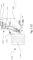
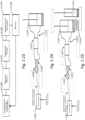
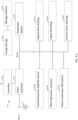
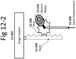
- an active suspension system includes a hydraulic actuator including an extension volume and a compression volume.
- the hydraulic actuator is constructed and arranged to be coupled to a vehicle wheel or suspension member.
- a hydraulic motor is in fluid communication with the extension volume and the compression volume of the hydraulic actuator to control extension and compression of the hydraulic actuator.
- An electric motor is also operatively coupled to the hydraulic motor.
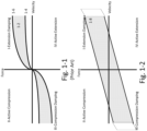
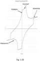
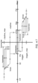
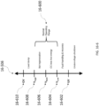
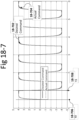
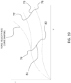
- a controller is electrically coupled to the electric motor, and the controller controls a motor input of the electric motor to operate the hydraulic actuator in at least three of four quadrants of a force velocity domain of the hydraulic actuator.
- a method for controlling an active suspension system includes: controlling a motor input of an electric motor to operate a hydraulic actuator in at least three of four quadrants of a force velocity domain of the hydraulic actuator, wherein the hydraulic actuator is constructed and arranged to be coupled to a vehicle wheel or suspension member, and wherein the electric motor is operatively coupled to a hydraulic motor in fluid communication with an extension volume and a compression volume of the hydraulic actuator to control extension and compression of the hydraulic actuator.
- an active suspension system in yet another embodiment, includes a hydraulic actuator including an extension volume and a compression volume.
- the hydraulic actuator is constructed and arranged to be coupled to a vehicle wheel or suspension member.
- a hydraulic motor-pump is in fluid communication with the extension volume and the compression volume of the hydraulic actuator to control extension and compression of the hydraulic actuator.
- An electric motor is also operatively coupled to the hydraulic motor, and a sensor is configured and arranged to sense wheel events and/or body events.
- a controller is electrically coupled to the electric motor and the sensor. Additionally, in response to a sensed wheel event and/or a sensed body event, the controller applies a motor input to the electric motor to control the hydraulic actuator.
- a method for controlling an active suspension system includes: sensing a wheel event and/or a body event; and applying a motor input to an electric motor in response to the sensed wheel event and/or the body event, wherein the electric motor is operatively coupled to a hydraulic motor-pump in fluid communication with an extension volume and a compression volume of a hydraulic actuator.
- an actuation system in yet another embodiment, includes a hydraulic actuator including an extension volume and a compression volume.
- a hydraulic motor is in fluid communication with the extension volume and the compression volume of the hydraulic actuator to control extension and compression of the hydraulic actuator.
- an electric motor is operatively coupled to the hydraulic motor.
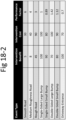
- the actuation system has a reflected system inertia and a system compliance, and a product of the system compliance times the reflected system inertia is less than or equal to about 0.0063 s -2 .
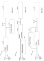
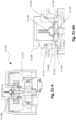
- a device in another embodiment, includes a housing including a first port and a second port.
- a hydraulic motor-pump is disposed within the housing, and the hydraulic motor-pump controls a flow of fluid between the first port and the second port.
- An electric motor is disposed within the housing and operatively coupled to the hydraulic motor. Additionally, a controller electrically coupled to the electric motor and disposed within the housing controls a motor input of the electric motor.
- an active suspension system in yet another embodiment, includes an active suspension housing, and a hydraulic motor-pump disposed within the active suspension housing.
- the hydraulic motor controls a flow of fluid through the active suspension housing.
- An electric motor is disposed within the active suspension housing and operatively coupled to the hydraulic motor.
- a controller is electrically coupled to the electric motor and disposed within the active suspension housing. The controller controls a motor input of the electric motor.
- a vehicle in another embodiment, includes one or more active suspension actuators, where each active suspension actuator includes a hydraulic actuator including an extension volume and a compression volume.
- a hydraulic motor-pump is in fluid communication with the extension volume and the compression volume of the hydraulic actuator to control extension and compression of the hydraulic actuator.
- An electric motor is operatively coupled to the hydraulic motor-pump, and a controller is electrically coupled to the electric motor. The controller controls a motor input of the electric motor to control the hydraulic actuator.
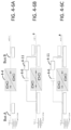
- a device in another embodiment, includes a housing and a pressure-sealed barrier located in the housing disposed between a first portion of the housing and a second portion of the housing.
- the first portion is constructed and arranged to be filled with a fluid subjected to a variable pressure relative to the second portion.
- an electrical feed-through passes from the first portion of the housing to the second portion of the housing through the pressure-sealed barrier.
- a compliant connection is electrically connected to the electrical feed-through and is also electrically connected to a controller disposed on or within the housing.
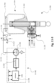
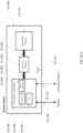
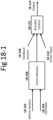
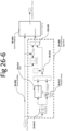
- An on-demand energy hydraulic actuator where motor torque is controlled to directly control actuator response, may be associated with a self-powered architecture where the damping and/or active function is at least partially powered by regenerated energy.
- an active suspension with on demand energy delivery may contain a hydraulic pump that can be backdriven as a hydraulic motor. This can be coupled to an electric motor that may be backdriven as an electric generator.
- An on-demand energy controller may provide for regenerative capability, wherein regenerated energy from the hydraulic machine (pump) is transferred to the electric machine (motor), and delivered to a power bus containing energy storage. By controlling the amount of energy recovered, the effective impedance on the electric motor may be controlled. This can set a given damping force. In this way, damping force can be controlled without consuming energy.
- the on-demand energy controller and other associated power electronics may be optionally run off the power bus such that the regenerated energy is at least partially used to power the control circuit.
- a voltage surge may overcome the reverse biased diode in an H-bridge motor controller, thus conducting energy from the motor to the power bus. If the controller is powered off this bus (either directly or via an intermediate regulated power supply), the controller can wake up and start controlling the active suspension.
- energy storage on the power bus may be sized to accommodate regenerative spikes, and then this energy can be used to actively control the wheel movement (bidirectional energy flow).
- An active suspension may be failure tolerant of a power bus failure, wherein the system can still provide damping, even controlled damping with a bus failure.
- Another advantage is the potential for a retrofittable semi-active or fully active suspension that may be installed OEM or aftermarket on vehicles and not require any wires or power connections. Such a system may communicate with each damper device wirelessly. Energy to power the system may be obtained through recuperating dissipated energy from damping. This has the advantage of being easy to install and lower cost.
- Another advantage is for an energy efficient active suspension. By utilizing the regenerated energy in the active suspension, DC/DC converter losses can be minimized such that recuperated energy is not delivered back to the vehicle, but rather, stored and then used directly in the suspension at a later time.
- An on-demand energy hydraulic actuator where motor torque is controlled to directly control actuator response, may be associated with an energy neutral active suspension control system, wherein the active suspension control system harvests energy during a regenerative cycle by withdrawing energy from the active suspension and storing it for later use by the active suspension.
- a controller can output energy into the motor only when it is needed due to wheel or body movement (on-demand energy delivery), and recover energy during damping, thus achieving roughly energy neutral operation.
- power consumption for the entire active suspension may be energy neutral (e.g. under 100 watts). This may be particularly advantageous in order to make an active suspension that is highly energy efficient.
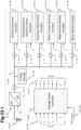
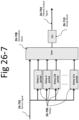
- An on-demand energy hydraulic actuator where motor torque is controlled to directly control actuator response, may be associated with an electronics architecture that uses an energy bus with voltage levels that can be used to signal active suspension system conditions.
- an active suspension with on demand energy delivery may be powered by a loosely regulated DC bus that fluctuates between 40 and 50 volts.
- the active suspension controller for each actuator may reduce its energy consumption by operating in a more efficient state or reducing the amount of force it commands, or for how long it commands force (e.g. during a roll event, the controller allows the vehicle to increasingly lean by relaxing the anti-roll mitigation to save energy).
- a lower voltage may signal the active suspension actuators to bias towards a regenerative mode if the actuator is capable of energy recovery.
- the actuators may reduce energy recovery or dissipate damping energy in the windings of a motor in order to prevent an overvoltage. While this example was described using thresholds, it may also be implemented in a continuous manner wherein the active suspension is simply controlled as some function of the voltage of its power bus.
- Such a system may have several advantages. For example, allowing the voltage to fluctuate increases the usable capacity of certain energy storage mechanisms such as super capacitors on the bus. It may also reduce the number of data connections in the system, or reduce the amount of data that needs to be transmitted over data connections such as CAN.
- the power bus may even be used to transmit data through a variety of communication of power line modulation schemes in order to transmit data such as force commands and sensor values.
- An on-demand energy hydraulic actuator where motor torque is controlled to directly control actuator response, may be associated with an energy storage device such as super capacitors or lithium ion batteries.
- the active suspension may be at least partially during at least one mode powered by energy contained in an energy storage medium. This has the advantage of limiting energy consumption from the vehicle's electrical system during peak power demands from the active suspension. In such cases, the instantaneous energy consumption in the active suspension may be lower than the instantaneous energy draw from the vehicle's electrical system.
- Energy storage can effectively decouple energy usage in the active suspension from energy usage on the vehicle power bus. Likewise, regenerated energy can be buffered and energy storage can be used to reduce the number and size of power spikes on the vehicle electrical system.
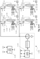
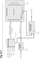
- An on-demand energy hydraulic actuator where motor torque is controlled to directly control actuator response, may be associated with a vehicular high power electrical system that operates at a voltage different from (e.g. higher than) the vehicle's primary electrical system.
- multiple active suspension power units may be energized from a common high power electrical bus operating at a voltage such as 48 volts, with a DC/DC converter between the high power bus and the vehicle's electrical system.
- EPS electric power steering
- This high power bus may be galvanically isolated from the vehicle's primary electrical system using transformer-based DC/DC converter between the two buses.
- the high power electrical system may be loosely regulated, with devices allowing voltage swing within some range.
- the high power electrical system may be operatively connected to energy storage such as capacitors and/or rechargeable batteries. These can be directly controlled to the bus and referenced to ground; connected between the vehicle electrical system and the high power electrical system; or connected via an auxiliary DC/DC converter. Certain other connections exist, such as a split DC/DC converter connecting the vehicle electrical system, the high power bus, and the energy storage.
- energy storage such as capacitors and/or rechargeable batteries.
- the vehicle's electrical system may be isolated from voltage spikes and electrical noise from high power consumers such as suspension actuators.
- the DC/DC converter may be able to employ dynamic energy limits so that too many loads do not overtax the vehicle's electrical system.
- the system may operative more efficiently by reducing current flow in the power cables and the motor windings.
- the active suspension actuators may be able to operate at higher velocities with a given motor winding.
- An on-demand energy hydraulic actuator where motor torque is controlled to directly control actuator response, may be coupled with a rotor position sensor that senses the position and/or velocity of the electric motor.
- This sensor may be operatively coupled to the electric motor directly or indirectly.
- motor position may be sensed without contact using a magnetic or optical encoder.
- rotor position may be measured by measuring the hydraulic pump position, which may be relatively fixed with respect to the electric motor position.
- This rotor position or velocity information may be used by a controller connected to the electric motor.
- the position information may be used for a variety of purposes such as: motor commutation (e.g.
- actuator velocity estimation (which may be a function of rotor velocity for systems with a substantially positive displacement pump); electronic cancellation of pressure fluctuations and ripples; and actuator position estimation (by integrating velocity, and potentially coupling the sensor with an absolute position indicator such as a magnetic switch somewhere in the actuator stroke travel such that activation of the switch implies the actuator position is in a specific location).
- the system may be more accurately and efficiently controlled.
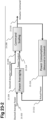
- An on-demand energy hydraulic actuator where an electric motor is moved in lockstep with the active suspension movement (linear travel of the actuator) in at least one mode, may be combined with an algorithm that predicts inertia of the electric motor and controls the motor torque to at least partially reduce the effect of inertia.
- an algorithm that predicts inertia of the electric motor and controls the motor torque to at least partially reduce the effect of inertia.
- a hydraulic active suspension that has a hydraulic pump operatively connected to an electric motor, wherein the pump is substantially positive displacement
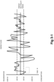
- a fast pothole hit to the wheel will create a surge in hydraulic fluid pressure and accelerate the pump and motor.
- the inertia of the rotary element (the pump and motor in this case) will resist this acceleration, creating a force in the actuator, which will counteract compliance of the wheel. This creates harshness in the ride of the vehicle, and may be undesirable.
- Such a system employing predictive analytic algorithms that factor inertia in the active suspension control may control motor torque at a command torque lower than the desired torque during acceleration events, and at a higher torque that the desired torque during deceleration events.
- the delta between the command torque of the motor and the desired torque is a function of the rotor or actuator acceleration.
- the mass and physical properties of the rotor may be incorporated in the algorithm.
- acceleration is calculated from a rotor velocity sensor (by taking the derivative), or by one or two differential accelerometers on the suspension.
- the controller employing inertia mitigation algorithms may actively accelerate the mass.
- Coupling an active suspension with algorithms that reduce inertia of an electric motor and its connected components may be highly desirable because it can reduce ride harshness on rough roads.
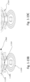
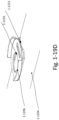
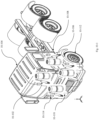
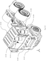
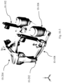
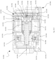
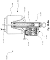
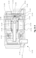
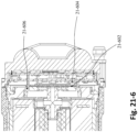
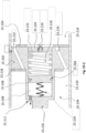
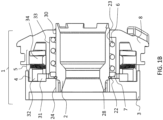
- An on-demand energy hydraulic actuator where motor torque is controlled to directly control actuator response, may be accomplished with a highly integrated power pack.
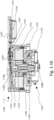
- This may be a single body active suspension actuator comprising an electric motor, an electronic (torque or speed) motor controller, and a sensor in a housing.
- it may be accomplished with a single body actuator comprising an electric motor, a hydraulic pump, and an electronic motor controller in a housing.
- it may be accomplished by a single body valve comprising an electric motor, a hydraulic pump, and an electronic motor controller in a fluid filled housing.
- it may be accomplished with a single body valve comprising a hydraulic pump, an electric motor that controls operation of the hydraulic pump, an electronic motor controller, and one or more sensors, in a housing.
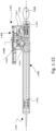
- an actuator comprising an electric motor, a hydraulic pump, and a piston, wherein the actuator facilities communication of fluid through a body of the actuator and into the hydraulic pump.
- a vehicle active suspension system comprising a hydraulic motor disposed proximal to each wheel of the vehicle that produces wheel-specific variable flow / variable pressure, and a controllable electric motor disposed proximal to each hydraulic motor for controlling wheel movement via the hydraulic motor.
- a vehicle wheel-well compatible active suspension actuator comprising a piston rod disposed in an actuator body, a hydraulic motor, an electric motor, an electronic motor controller, and a passive valve disposed in the actuator body or power pack and that operates either in parallel or series with the hydraulic motor, all packaged to fit within or near the vehicle wheel well.
- the ability to package an active suspension with on demand energy delivery into a highly integrated package may be desirable to reduce integration complexity (e.g. eliminates the need to run long hydraulic hoses), improve durability by fully sealing the system, reduce manufacturing cost, improve response time, and reduce loses (electrical, hydraulic, etc.) from shorter distances between components.
- An on-demand energy hydraulic actuator where motor torque is controlled to directly control actuator response, may be associated with power and/or energy optimizing control algorithms, wherein instantaneous power and/or energy over time are tracked and active suspension control is at least partially a function of the energy over time.
- an active suspension may be controlled by an electronic controller that monitors energy consumption in each actuator or energy at the vehicle electrical system interface. If the actuators consume a large amount of energy for an extended period of time, for example, during an extended high lateral acceleration turn, the control algorithm may slowly allow the vehicle to roll, thus reducing the instantaneous power consumption, and over time will reduce the energy consumed (a lower average power). With an on-demand energy suspension, this may be directly utilized to deliver on-demand performance. For example, the electric motor driving the suspension unit may be directly controlled as a consequence of both vehicle dynamics algorithms and an average power consumed over a given window.
- Combining an active suspension capable of adjusting its power consumed with energy optimizing algorithms can particularly enhance the efficiency of an active suspension.
- it may allow an active suspension to be integrated into a vehicle without compromising the current capacity of the alternator.
- the suspension may adjust to reduce its instantaneous energy consumed in order to provide enough vehicle energy for other subsystems such as ABS braking, electric power steering, dynamic stability control, and engine ECUs.
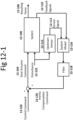
- An on-demand energy hydraulic actuator where motor torque is controlled to directly control actuator response, may be associated with an active chassis power management system for power throttling, wherein a controller responsible for commanding the active suspension responds to energy needs of other devices on the vehicle such as active roll stabilization, electric power steering, etc. and/or energy availability information such as alternator status, battery voltage, and engine RPM.
- an active suspension capable of adjusting its power consumed may reduce its instantaneous and/or time-averaged power consumption if one of the following events occur: vehicle battery voltage drops below a certain threshold; alternator current output is low, engine RPM is low, and battery voltage is dropping at a rate that exceeds a threshold; an controller (e.g. ECU) on the vehicle commands a power consumer device (such as electric power steering) at high power (for example, during a sharp turn at low speed); an economy mode setting for the active suspension is activated, thus limiting the average power consumption over time.
- a power consumer device such as electric power steering
- An on-demand energy hydraulic actuator where motor torque is controlled to directly control actuator response, may receive data from other vehicle control and sensing systems [such as GPS, self-driving parameters, vehicle mode setting (i.e. comfort/sport/eco), driver behavior (e.g. how aggressive is the throttle and steering input), body sensors (accelerometers, IMUs, gyroscopes from other devices on the vehicle), safety system status (ABS braking engaged, ESP status, torque vectoring, airbag deployment, etc.)], and then react based on this data. Reacting may mean changing the force, position, velocity, or power consumption of the actuator in response to the data.
- vehicle control and sensing systems such as GPS, self-driving parameters, vehicle mode setting (i.e. comfort/sport/eco), driver behavior (e.g. how aggressive is the throttle and steering input), body sensors (accelerometers, IMUs, gyroscopes from other devices on the vehicle), safety system status (ABS braking engaged, ESP status, torque vectoring,
- the active suspension may interface with GPS on board the vehicle.
- the vehicle contains (either locally or via a network connection) a map correlating GPS location with road conditions.
- the active suspension may react in an anticipatory fashion to adjust the suspension in response to the location. For example, if the location of a speed bump is known, the actuators can start to lift the wheels immediately before impact. Similarly, topographical features such as hills can be better recognized and the system can respond accordingly. Since civilian GPS is limited in its resolution and accuracy, GPS data can be combined with other vehicle sensors such as an IMU (or accelerometers) using a filter such as a Kalman Filter in order to provide a more accurate position estimate.
- IMU or accelerometers
- the active suspension may not only receive data from other sensors, but may also command other vehicle subsystems.
- the suspension may sense or anticipate rough terrain, and send a command to the self-driving control system to deviate to another road.
- the vehicle may automatically generate the map described above by sensing road conditions using sensors associated with the active suspension and other vehicle devices.
- the ride dynamics may be improved by utilizing predictive and reactive sensor data from a number of sources (including redundant sources, which may be combined and used to provide greater accuracy to the overall system).
- the active suspension may send commands to other systems such as safety systems in order to improve their performance.
- CAN controller area network
- FlexRay Several data networks exist to communicate this data between subsystems such as CAN (controller area network) and FlexRay.
- An on-demand energy hydraulic actuator where motor torque is controlled to directly control actuator response, may be associated with an active safety system, wherein the suspension is controlled to improve the safety of the vehicle during a collision or dangerous vehicle state.
- the active suspension with on-demand energy delivery is controlled to deliver a vehicle height adjustment when an imminent crash is detected in order to ensure the vehicle's bumper collides with the obstacle (for example, a stopped SUV ahead) so as to maximize the crumple zone or minimize the negative impact on the driver and passengers in the vehicle.
- the suspension may adjust to set ride height to optimize in any sort of pre or post-crash scenario.
- the active suspension with on demand energy delivery can adjust wheel force and tire to road dynamics in order to improve traction during ABS braking events or electronic stability program (ESP) events. For example, the wheel can be pushed towards the ground to temporarily increase contact force (by utilizing the vertical inertia of the vehicle), and this can be pulsated.
- ESP electronic stability program
- the on-demand energy capability can be utilized to rapidly throttle up energy in the active suspension on a per event basis in order to respond to the imminent safety threat.
- vehicle dynamics such as height, wheel position, and wheel traction, can be rapidly adjusted and can operate in unison with other safety systems and controllers on the vehicle.
- An on-demand energy hydraulic actuator where motor torque is controlled to directly control actuator response, may be associated with an adaptive controller for hydraulic power packs, wherein the controller instantaneously controls energy in the hydraulic power pack of an active suspension in order to modify the kinematic characteristics of the actuator.
- An on-demand energy hydraulic actuator where motor torque is controlled to directly control actuator response, may be used as an active truck cab stabilization system to improve comfort, among other benefits.
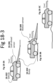
- four active suspension with on demand energy delivery actuators are disposed between the chassis of a heavy truck and the cabin.
- a spring sits in parallel with each actuator (i.e. coil spring, air spring, or leaf spring, etc.), and each assembly is placed roughly at the corner of the cabin.
- Sensors on the cabin and/or the chassis sense movement, and a control loop controlling the active suspension commands the actuators to keep the cabin roughly level.
- two actuators are used at the rear of the cabin, with the front of the cabin hinged on the chassis.
- such a suspension may contain modified hinges and bushings to allow greater compliance in yaw/pitch/roll.
- the actuators may be placed in other locations, such as on an isolated truck bed or trailer to reduce vibration to the truck load.
- a single actuator with on demand energy delivery can be used in a suspended seat.
- the seat such as a truck seat
- the actuator rides on a compliant device such as an air spring, and the actuator is connected in parallel to this complaint device.
- Sensors measure acceleration and control the seat height dynamically to reduce heave input to the individual sitting on the seat.
- the actuator may be placed off the vertical axis in order to affect motion in a different direction. By using a mechanical guide, this motion might not be limited to linear movement.
- multiple actuators may be used to provide more than one degree of freedom.
- a long haul truck containing an active suspension may especially benefit by improving driver comfort and reducing driver fatigue.
- the system can be smaller, easier to integrate, faster response time, and more energy efficient.
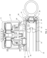
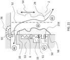
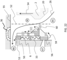
- An on-demand energy hydraulic actuator where motor torque is controlled to directly control actuator response, may be associated with an air spring suspension in which static ride height is nominally provided by a chamber containing compressed air.
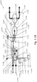
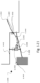
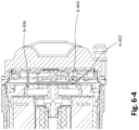
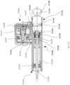
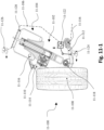
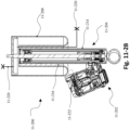
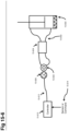
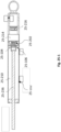
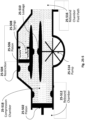
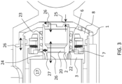
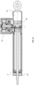
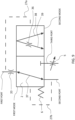
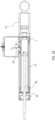
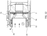
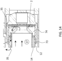
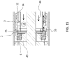
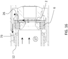
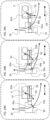
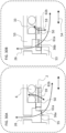
- the active suspension actuator is of a standard hydraulic triple tube damper, with a side-mounted valve that contains a hydraulic pump and an electric motor. The valve porting and location is placed towards the base of the actuator body such that an airbag with folding bellows can fit around the actuator above the valve. With the valve such mounted, a standard air suspension airbag can be placed about the actuator body towards the top of the unit.
- the system just described contains hoses exiting the hydraulic damper near the bottom and leading towards an external power pack containing a hydraulic pump and an electric motor.
- the physical structures of the active suspension actuator and the air spring can be united.
- control systems for the on-demand energy delivery active suspension and the air suspension system can be coupled.
- air pressure in the air suspension may be controlled in conjunction with the commanded force in the active suspension actuator. This may be controlled for the entire air spring system, or on a per-spring (per wheel) basis. The frequency of this control may be on a per event basis, or based on general road conditions.
- the response time of the active suspension actuator is faster than the air spring, but the air spring may be more effective in terms of energy consumption at holding a given ride height or roll force.
- a controller may control the active suspension for rapid events by increasing the energy instantaneously in the on-demand energy system, while simultaneously increasing or decreasing pressure in the air spring system, thus making the air spring effectively an on-demand energy delivery device, albeit at a lower frequency.
- a hydraulic actuator with on demand energy delivery and a rotating element where rotary motor torque is controlled in response to kinematic input into the actuator from an outside element, may utilize a low inertia material in the rotary element to reduce parasitic acceleration dependence.
- the hydraulic pump and/or motor shaft may be produced from an engineered plastic in order to reduce rotary inertia. This has the benefit in an on-demand energy delivery system containing a positive displacement pump of reducing the transmissibility of high frequency input into the actuator (i.e. a graded road at high speed input on the wheel).
- An active suspension with on demand energy delivery where motor torque is controlled in response to road and/or wheel conditions, may be associated with a self-powered architecture where the damping and/or active function is at least partially powered by regenerated energy.
- an active suspension with on demand energy delivery may contain a hydraulic pump that can be backdriven as a hydraulic motor. This can be coupled to an electric motor that may be backdriven as an electric generator.
- An on-demand energy controller may provide for regenerative capability, wherein regenerated energy from the hydraulic machine (pump) is transferred to the electric machine (motor), and delivered to a power bus containing energy storage. By controlling the amount of energy recovered, the effective impedance on the electric motor may be controlled. This can set a given damping force. In this way, damping force can be controlled without consuming energy.
- the on-demand energy controller and other associated power electronics may be optionally run off the power bus such that the regenerated energy is at least partially used to power the control circuit.
- a voltage surge may overcome the reverse biased diode in an H-bridge motor controller, thus conducting energy from the motor to the power bus. If the controller is powered off this bus (either directly or via an intermediate regulated power supply), the controller can wake up and start controlling the active suspension.
- energy storage on the power bus may be sized to accommodate regenerative spikes, and then this energy can be used to actively control the wheel movement (bidirectional energy flow).
- An active suspension may be failure tolerant of a power bus failure, wherein the system can still provide damping, even controlled damping with a bus failure.
- Another advantage is the potential for a retrofittable semi-active or fully active suspension that may be installed OEM or aftermarket on vehicles and not require any wires or power connections. Such a system may communicate with each damper device wirelessly. Energy to power the system may be obtained through recuperating dissipated energy from damping. This has the advantage of being easy to install and lower cost.
- Another advantage is for an energy efficient active suspension. By utilizing the regenerated energy in the active suspension, DC/DC converter losses can be minimized such that recuperated energy is not delivered back to the vehicle, but rather, stored and then used directly in the suspension at a later time.
- An active suspension with on demand energy delivery where motor torque is controlled in response to road and/or wheel conditions, may be associated with an energy neutral active suspension control system, wherein the active suspension control system harvests energy during a regenerative cycle by withdrawing energy from the active suspension and storing it for later use by the active suspension.
- a controller can output energy into the motor only when it is needed due to wheel or body movement (on-demand energy delivery), and recover energy during damping, thus achieving roughly energy neutral operation.
- power consumption for the entire active suspension may be energy neutral (e.g. under 100 watts). This may be particularly advantageous in order to make an active suspension that is highly energy efficient.
- An active suspension with on demand energy delivery where motor torque is controlled in response to road and/or wheel conditions, may be associated with an electronics architecture that uses an energy bus with voltage levels that can be used to signal active suspension system conditions.
- an active suspension with on demand energy delivery may be powered by a loosely regulated DC bus that fluctuates between 40 and 50 volts.
- the active suspension controller for each actuator may reduce its energy consumption by operating in a more efficient state or reducing the amount of force it commands, or for how long it commands force (e.g. during a roll event, the controller allows the vehicle to increasingly lean by relaxing the anti-roll mitigation to save energy).
- a lower voltage may signal the active suspension actuators to bias towards a regenerative mode if the actuator is capable of energy recovery.
- the actuators may reduce energy recovery or dissipate damping energy in the windings of a motor in order to prevent an overvoltage. While this example was described using thresholds, it may also be implemented in a continuous manner wherein the active suspension is simply controlled as some function of the voltage of its power bus.
- Such a system may have several advantages. For example, allowing the voltage to fluctuate increases the usable capacity of certain energy storage mechanisms such as super capacitors on the bus. It may also reduce the number of data connections in the system, or reduce the amount of data that needs to be transmitted over data connections such as CAN.
- the power bus may even be used to transmit data through a variety of communication of power line modulation schemes in order to transmit data such as force commands and sensor values.
- An active suspension with on demand energy delivery where motor torque is controlled in response to road and/or wheel conditions, may be associated with an energy storage device such as super capacitors or lithium ion batteries.
- the active suspension may be at least partially during at least one mode powered by energy contained in an energy storage medium. This has the advantage of limiting energy consumption from the vehicle's electrical system during peak power demands from the active suspension. In such cases, the instantaneous energy consumption in the active suspension may be lower than the instantaneous energy draw from the vehicle's electrical system.
- Energy storage can effectively decouple energy usage in the active suspension from energy usage on the vehicle power bus. Likewise, regenerated energy can be buffered and energy storage can be used to reduce the number and size of power spikes on the vehicle electrical system.
- An active suspension with on demand energy delivery where motor torque is controlled in response to road and/or wheel conditions, may be associated with a vehicular high power electrical system that operates at a voltage different from (e.g. higher than) the vehicle's primary electrical system.
- multiple active suspension power units may be energized from a common high power electrical bus operating at a voltage such as 48 volts, with a DC/DC converter between the high power bus and the vehicle's electrical system.
- EPS electric power steering
- This high power bus may be galvanically isolated from the vehicle's primary electrical system using transformer-based DC/DC converter between the two buses.
- the high power electrical system may be loosely regulated, with devices allowing voltage swing within some range.
- the high power electrical system may be operatively connected to energy storage such as capacitors and/or rechargeable batteries. These can be directly controlled to the bus and referenced to ground; connected between the vehicle electrical system and the high power electrical system; or connected via an auxiliary DC/DC converter. Certain other connections exist, such as a split DC/DC converter connecting the vehicle electrical system, the high power bus, and the energy storage.
- the vehicle's electrical system may be isolated from voltage spikes and electrical noise from high power consumers such as suspension actuators.
- the DC/DC converter may be able to employ dynamic energy limits so that too many loads do not overtax the vehicle's electrical system.
- the system may operative more efficiently by reducing current flow in the power cables and the motor windings.
- the active suspension actuators may be able to operate at higher velocities with a given motor winding.
- An active suspension with on demand energy delivery where motor torque is controlled in response to road and/or wheel conditions, may be coupled with a rotor position sensor that senses the position and/or velocity of the electric motor.
- This sensor may be operatively coupled to the electric motor directly or indirectly.
- motor position may be sensed without contact using a magnetic or optical encoder.
- rotor position may be measured by measuring the hydraulic pump position, which may be relatively fixed with respect to the electric motor position.
- This rotor position or velocity information may be used by a controller connected to the electric motor.
- the position information may be used for a variety of purposes such as: motor commutation (e.g.
- actuator velocity estimation (which may be a function of rotor velocity for systems with a substantially positive displacement pump); electronic cancellation of pressure fluctuations and ripples; and actuator position estimation (by integrating velocity, and potentially coupling the sensor with an absolute position indicator such as a magnetic switch somewhere in the actuator stroke travel such that activation of the switch implies the actuator position is in a specific location).
- the system may be more accurately and efficiently controlled.
- An active suspension with on demand energy delivery where an electric motor is moved in lockstep with the active suspension movement (linear travel of the actuator) in at least one mode, may be combined with an algorithm that predicts inertia of the electric motor and controls the motor torque to at least partially reduce the effect of inertia.
- a hydraulic active suspension that has a hydraulic pump operatively connected to an electric motor, wherein the pump is substantially positive displacement
- a fast pothole hit to the wheel will create a surge in hydraulic fluid pressure and accelerate the pump and motor.
- the inertia of the rotary element (the pump and motor in this case) will resist this acceleration, creating a force in the actuator, which will counteract compliance of the wheel. This creates harshness in the ride of the vehicle, and may be undesirable.
- Such a system employing predictive analytic algorithms that factor inertia in the active suspension control may control motor torque at a command torque lower than the desired torque during acceleration events, and at a higher torque that the desired torque during deceleration events.
- the delta between the command torque of the motor and the desired torque is a function of the rotor or actuator acceleration.
- the mass and physical properties of the rotor may be incorporated in the algorithm.
- acceleration is calculated from a rotor velocity sensor (by taking the derivative), or by one or two differential accelerometers on the suspension.
- the controller employing inertia mitigation algorithms may actively accelerate the mass.
- Coupling an active suspension with algorithms that reduce inertia of an electric motor and its connected components may be highly desirable because it can reduce ride harshness on rough roads.
- An active suspension with on demand energy delivery where motor torque is controlled in response to road and/or wheel conditions, may be accomplished with a highly integrated power pack.
- This may be a single body active suspension actuator comprising an electric motor, an electronic (torque or speed) motor controller, and a sensor in a housing.
- it may be accomplished with a single body actuator comprising an electric motor, a hydraulic pump, and an electronic motor controller in a housing.
- it may be accomplished by a single body valve comprising an electric motor, a hydraulic pump, and an electronic motor controller in a fluid filled housing.
- it may be accomplished with a single body valve comprising a hydraulic pump, an electric motor that controls operation of the hydraulic pump, an electronic motor controller, and one or more sensors, in a housing.
- an actuator comprising an electric motor, a hydraulic pump, and a piston, wherein the actuator facilities communication of fluid through a body of the actuator and into the hydraulic pump.
- a vehicle active suspension system comprising a hydraulic motor disposed proximal to each wheel of the vehicle that produces wheel-specific variable flow / variable pressure, and a controllable electric motor disposed proximal to each hydraulic motor for controlling wheel movement via the hydraulic motor.
- a vehicle wheel-well compatible active suspension actuator comprising a piston rod disposed in an actuator body, a hydraulic motor, an electric motor, an electronic motor controller, and a passive valve disposed in the actuator body or power pack and that operates either in parallel or series with the hydraulic motor, all packaged to fit within or near the vehicle wheel well.
- the ability to package an active suspension with on demand energy delivery into a highly integrated package may be desirable to reduce integration complexity (e.g. eliminates the need to run long hydraulic hoses), improve durability by fully sealing the system, reduce manufacturing cost, improve response time, and reduce loses (electrical, hydraulic, etc.) from shorter distances between components.
- An active suspension with on demand energy delivery where motor torque is controlled in response to road and/or wheel conditions, may be associated with power and/or energy optimizing control algorithms, wherein instantaneous power and/or energy over time are tracked and active suspension control is at least partially a function of the energy over time.
- an active suspension may be controlled by an electronic controller that monitors energy consumption in each actuator or energy at the vehicle electrical system interface. If the actuators consume a large amount of energy for an extended period of time, for example, during an extended high lateral acceleration turn, the control algorithm may slowly allow the vehicle to roll, thus reducing the instantaneous power consumption, and over time will reduce the energy consumed (a lower average power). With an on-demand energy suspension, this may be directly utilized to deliver on-demand performance. For example, the electric motor driving the suspension unit may be directly controlled as a consequence of both vehicle dynamics algorithms and an average power consumed over a given window.
- Combining an active suspension capable of adjusting its power consumed with energy optimizing algorithms can particularly enhance the efficiency of an active suspension.
- it may allow an active suspension to be integrated into a vehicle without compromising the current capacity of the alternator.
- the suspension may adjust to reduce its instantaneous energy consumed in order to provide enough vehicle energy for other subsystems such as ABS braking, electric power steering, dynamic stability control, and engine ECUs.
- An active suspension with on demand energy delivery where motor torque is controlled in response to road and/or wheel conditions, may be associated with an active chassis power management system for power throttling, wherein a controller responsible for commanding the active suspension responds to energy needs of other devices on the vehicle such as active roll stabilization, electric power steering, etc. and/or energy availability information such as alternator status, battery voltage, and engine RPM.
- an active suspension capable of adjusting its power consumed may reduce its instantaneous and/or time-averaged power consumption if one of the following events occur: vehicle battery voltage drops below a certain threshold; alternator current output is low, engine RPM is low, and battery voltage is dropping at a rate that exceeds a threshold; an controller (e.g. ECU) on the vehicle commands a power consumer device (such as electric power steering) at high power (for example, during a sharp turn at low speed); an economy mode setting for the active suspension is activated, thus limiting the average power consumption over time.
- a power consumer device such as electric power steering
- An active suspension with on demand energy delivery where motor torque is controlled in response to road and/or wheel conditions, may receive data from other vehicle control and sensing systems [such as GPS, self-driving parameters, vehicle mode setting (i.e. comfort/sport/eco), driver behavior (e.g. how aggressive is the throttle and steering input), body sensors (accelerometers, IMUs, gyroscopes from other devices on the vehicle), safety system status (ABS braking engaged, ESP status, torque vectoring, airbag deployment, etc.)], and then react based on this data. Reacting may mean changing the force, position, velocity, or power consumption of the actuator in response to the data.
- vehicle control and sensing systems such as GPS, self-driving parameters, vehicle mode setting (i.e. comfort/sport/eco), driver behavior (e.g. how aggressive is the throttle and steering input), body sensors (accelerometers, IMUs, gyroscopes from other devices on the vehicle), safety system status (ABS braking engaged, ESP status
- the active suspension may interface with GPS on board the vehicle.
- the vehicle contains (either locally or via a network connection) a map correlating GPS location with road conditions.
- the active suspension may react in an anticipatory fashion to adjust the suspension in response to the location. For example, if the location of a speed bump is known, the actuators can start to lift the wheels immediately before impact. Similarly, topographical features such as hills can be better recognized and the system can respond accordingly. Since civilian GPS is limited in its resolution and accuracy, GPS data can be combined with other vehicle sensors such as an IMU (or accelerometers) using a filter such as a Kalman Filter in order to provide a more accurate position estimate.
- IMU or accelerometers
- the active suspension may not only receive data from other sensors, but may also command other vehicle subsystems.
- the suspension may sense or anticipate rough terrain, and send a command to the self-driving control system to deviate to another road.
- the vehicle may automatically generate the map described above by sensing road conditions using sensors associated with the active suspension and other vehicle devices.
- the ride dynamics may be improved by utilizing predictive and reactive sensor data from a number of sources (including redundant sources, which may be combined and used to provide greater accuracy to the overall system).
- the active suspension may send commands to other systems such as safety systems in order to improve their performance.
- CAN controller area network
- FlexRay Several data networks exist to communicate this data between subsystems such as CAN (controller area network) and FlexRay.
- An active suspension with on demand energy delivery where motor torque is controlled in response to road and/or wheel conditions, may be associated with an active safety system, wherein the suspension is controlled to improve the safety of the vehicle during a collision or dangerous vehicle state.
- the active suspension with on-demand energy delivery is controlled to deliver a vehicle height adjustment when an imminent crash is detected in order to ensure the vehicle's bumper collides with the obstacle (for example, a stopped SUV ahead) so as to maximize the crumple zone or minimize the negative impact on the driver and passengers in the vehicle.
- the suspension may adjust to set ride height to optimize in any sort of pre or post-crash scenario.
- the active suspension with on demand energy delivery can adjust wheel force and tire to road dynamics in order to improve traction during ABS braking events or electronic stability program (ESP) events.
- the wheel can be pushed towards the ground to temporarily increase contact force (by utilizing the vertical inertia of the vehicle), and this can be pulsated.
- the on-demand energy capability can be utilized to rapidly throttle up energy in the active suspension on a per event basis in order to respond to the imminent safety threat.
- vehicle dynamics such as height, wheel position, and wheel traction, can be rapidly adjusted and can operate in unison with other safety systems and controllers on the vehicle.
- An active suspension with on demand energy delivery where motor torque is controlled in response to road and/or wheel conditions, may be associated with an adaptive controller for hydraulic power packs, wherein the controller instantaneously controls energy in the hydraulic power pack of an active suspension in order to modify the kinematic characteristics of the actuator.
- An active suspension with on demand energy delivery where motor torque is controlled in response to road and/or wheel conditions, may be used as an active truck cab stabilization system to improve comfort, among other benefits.
- four active suspension with on demand energy delivery actuators are disposed between the chassis of a heavy truck and the cabin.
- a spring sits in parallel with each actuator (i.e. coil spring, air spring, or leaf spring, etc.), and each assembly is placed roughly at the corner of the cabin.
- Sensors on the cabin and/or the chassis sense movement, and a control loop controlling the active suspension commands the actuators to keep the cabin roughly level.
- two actuators are used at the rear of the cabin, with the front of the cabin hinged on the chassis.
- such a suspension may contain modified hinges and bushings to allow greater compliance in yaw/pitch/roll.
- the actuators may be placed in other locations, such as on an isolated truck bed or trailer to reduce vibration to the truck load.
- a single actuator with on demand energy delivery can be used in a suspended seat.
- the seat such as a truck seat
- the actuator rides on a compliant device such as an air spring, and the actuator is connected in parallel to this complaint device.
- Sensors measure acceleration and control the seat height dynamically to reduce heave input to the individual sitting on the seat.
- the actuator may be placed off the vertical axis in order to affect motion in a different direction. By using a mechanical guide, this motion might not be limited to linear movement.
- multiple actuators may be used to provide more than one degree of freedom.
- a long haul truck containing an active suspension may especially benefit by improving driver comfort and reducing driver fatigue.
- the system can be smaller, easier to integrate, faster response time, and more energy efficient.
- An active suspension with on demand energy delivery where motor torque is controlled in response to road and/or wheel conditions, may be associated with an air spring suspension in which static ride height is nominally provided by a chamber containing compressed air.
- the active suspension actuator is of a standard hydraulic triple tube damper, with a side-mounted valve that contains a hydraulic pump and an electric motor. The valve porting and location is placed towards the base of the actuator body such that an airbag with folding bellows can fit around the actuator above the valve. With the valve such mounted, a standard air suspension airbag can be placed about the actuator body towards the top of the unit.
- the system just described contains hoses exiting the hydraulic damper near the bottom and leading towards an external power pack containing a hydraulic pump and an electric motor.
- the physical structures of the active suspension actuator and the air spring can be united.
- control systems for the on-demand energy delivery active suspension and the air suspension system can be coupled.
- air pressure in the air suspension may be controlled in conjunction with the commanded force in the active suspension actuator. This may be controlled for the entire air spring system, or on a per-spring (per wheel) basis. The frequency of this control may be on a per event basis, or based on general road conditions.
- the response time of the active suspension actuator is faster than the air spring, but the air spring may be more effective in terms of energy consumption at holding a given ride height or roll force.
- a controller may control the active suspension for rapid events by increasing the energy instantaneously in the on-demand energy system, while simultaneously increasing or decreasing pressure in the air spring system, thus making the air spring effectively an on-demand energy delivery device, albeit at a lower frequency.
- An active suspension with on demand energy delivery and a rotating element where rotary motor torque is controlled in response to road and/or wheel conditions, may utilize a low inertia material in the rotary element to reduce parasitic acceleration dependence.
- the hydraulic pump and/or motor shaft may be produced from an engineered plastic in order to reduce rotary inertia. This has the benefit in an on-demand energy delivery system containing a positive displacement pump of reducing the transmissibility of high frequency input into the actuator (i.e. a graded road at high speed input on the wheel).
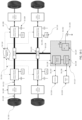
- An active suspension with on demand energy delivery may be coupled with one or more anti-roll bars in a vehicle.
- a standard mechanical anti-roll bar is attached between the two front wheels and a second between the two rear wheels.
- a cross coupled hydraulic roll bar (or actuator) is attached between the front left and the rear right wheels, and then another between the front right and the rear left wheels.
- a downsized anti roll bar is disposed between the wheels, such that there is a large amount of sprung compliance in the bar.
- an anti roll bar with hysteresis is disposed between the two front and/or the two rear wheels. Such a system may be accomplished with a standard roll bar that has a rotation point in the center of the roll bar, wherein between two limits the two ends of the bar can twist freely. When the twist reaches some angle, a limit is reached and the twist becomes stiff.
- the bar is able to move freely. Once the threshold on either side is reached, the twist becomes more difficult.
- Such a system can be further improved by using springs or rotary fluid dampers such that engagement of the limit is gradual (for example, prior to reaching the limit angle a spring engages and twist resistance force increases), and/or it is damped (e.g. using a dynamic mechanical friction or fluid mechanism).
- the active suspension with on-demand energy delivery may be further coupled with an active roll stabilizer system (either hydraulic, electromechanical, or otherwise).
- an active roll stabilizer system either hydraulic, electromechanical, or otherwise.
- anti-roll bar technologies in connection with an active suspension may especially help at high lateral accelerations, where roll force is greatest and where roll force may exceed the maximum force capability of the active suspension actuator. By implementing a solution that primarily operates at the higher accelerations, roll force levels, or roll angles, roll performance can be improved. While several technologies are disclosed that serve the function of assistive roll mitigation to the active suspension, the present invention is not limited in this regard as there are many suitable devices and methods of accomplish anti-roll force to supplement the active suspension.
- Methods and systems for facilitating energy neutral active suspension may include a method of harvesting energy from suspension actuator movement, delivering the harvested energy to an energy source from which the suspension actuator conditionally draws energy to create a force, and consuming energy from the energy source to control movement of the suspension actuator for wheel events that result in actuator movement, wherein energy consumption is regulated and limited so that harvested energy substantially equals consumed energy over a time period that is substantially longer than an average wheel event duration.
- energy may be temporarily consumed so that the actuator complies with at least one of active suspension safety and comfort limits.
- delivered energy may substantially equal consumed energy when consumed energy is less than 100 watts and when generated energy is less than 100 watts averaged over the time period.
- limiting the delivered energy may be effected when average delivered energy is greater than 100 watts over the time period.
- limiting the consumed energy may be effected when average consumed energy is greater than 100 watts over the time period.
- limiting energy consumption may include adjusting active suspension wheel event response parameters to comply with a power consumption reduction protocol. In the method, limiting energy delivery may include diverting harvested energy away from the energy source.
- An energy source of the methods and systems may be at least one of a vehicle electrical system, a lead acid vehicle battery, a super capacitor, a lithium ion battery, a lithium phosphate battery, and another hydraulic actuator.
- the energy source may include an energy storage apparatus coupled with a bi-directional DC-DC converter disposed between a power bus of the suspension actuator and a vehicle primary electrical bus.
- consuming energy may include consuming energy from the energy storage apparatus before consuming energy from the vehicle primary electrical bus.
- Energy from the vehicle primary electrical bus may be sourced through the converter when the energy available in the energy storage apparatus is below a low energy threshold and an anticipated energy need of the suspension actuator would result in the energy available in the energy storage apparatus being below the low energy threshold if the anticipated energy was consumed from the energy storage apparatus.
- energy from the vehicle primary electrical bus may be sourced at any time, including when energy is being sourced from the energy storage apparatus (e.g. energy is simultaneously sourced from both the converter and the energy storage apparatus).
- a method may include harvesting energy from suspension actuator movement, storing the harvested energy in an energy storage facility from which the suspension actuator conditionally draws energy to control the operation of the suspension, consuming energy from the energy storage facility to control movement of the suspension actuator for wheel events that result in actuator movement and adapting control of the suspension actuator to ensure that stored energy substantially equals consumed energy over a time period that is substantially longer than an average wheel event duration.
- the energy source may be at least one of a vehicle electrical system, a lead acid vehicle battery, a super capacitor, a lithium ion battery, a lithium phosphate battery, and another hydraulic actuator.
- adapting control of the suspension actuator may include harvesting substantially more energy than the energy consumed by the suspension actuator during an energy recovery period of time. Also, adapting control of the suspension actuator may comprise shunting harvested energy away from the energy storage facility during an excess energy disposal period of time. Additionally, adapting control of the suspension actuator may include limiting energy consumed by the suspension actuator such that average energy consumed in the actuator is less than 75 watts over a time period substantially longer than an average wheel event duration.
- an electronic suspension system may include a piston disposed in a hydraulic housing, an energy recovery mechanism such that movement of the piston results in energy generation, an energy storage facility to which harvested energy from the energy recovery mechanism is stored and a control system that regulates force on the piston by varying an electrical characteristic of the energy recovery mechanism and that operates from energy stored in the energy storage facility, wherein the control system determines an average net energy exchange over a time period that is substantially longer than an average wheel event duration.
- the electronic suspension may be one of a semi-active and a fully-active suspension. In this embodiment, the average net energy exchange may be determined by subtracting energy used to operate the active suspension system from energy harvested.
- the controller may regulate force on the piston so that stored energy substantially equals energy used to operate the system over a time period that is substantially longer than an average wheel event duration, while temporarily consuming sufficient energy so that the suspension system complies with suspension safety and comfort limits.
- the electric suspension system may also be designed for aftermarket installation on a vehicle as a self-powered fully-active suspension.
- Such a system may include an energy storage apparatus to store energy during certain modes of operation (e.g. while operating in regenerative compression and extension strokes), and to use energy during other modes of operation (e.g. during active extension and active compression). Controller logic may also be powered from this energy storage apparatus. In some embodiments such a system may be completely wireless, requiring no power or data connections.
- control system may be configured with wireless network links that facilitate communication between multiple electronic suspension members in order to coordinate vehicle body control tasks.
- wired communication networks may comprise CAN, FlexRay, Ethernet, data over powerlines, or other suitable means. Such networks may communicate sensor, command, or other data.
- firmware for actuator-specific controllers may be updated (reflashed via a bootloader or similar) over such a network. This may facilitate software upgrades during vehicle servicing.
- a self-powered adaptive suspension system may include a piston disposed in a hydraulic housing and a control system that regulates force on the piston by varying an electrical characteristic of the energy recovery mechanism and that operates from energy stored in the energy storage facility, wherein the control system determines an average net energy exchange over a time period that is substantially longer than an average wheel event duration.
- Other embodiments may include linear motors or ball screw mechanisms connected to rotary electric motors as actuation mechanisms.
- a method of self powered suspension includes measuring energy consumption by an active vehicle suspension system that is capable of operating in at least a passive rebound suspension quadrant, a passive compression suspension quadrant and at least one of a push rebound suspension quadrant (active extension) and a pull compression suspension quadrant (active compression) over a period of time; consuming energy with the active vehicle suspension system during operation in the at least one of a push rebound suspension quadrant and a pull compression suspension quadrant; calculating an average of the measured energy consumption; comparing the calculated average of the measured energy consumption to an energy neutrality target threshold value; and based on the comparison, biasing a control of the active vehicle suspension system to respond to wheel events by operation in the passive rebound and passive compression quadrants until a running average of energy consumed by the active vehicle suspension is lower than the energy neutrality target threshold.
- the running average of energy consumed by the active vehicle suspension may be lower than the energy neutrality target threshold by at least an energy threshold reserve value.
- the power or energy neutrality constraint may comprise an energy neutrality target threshold that may comprise a measure of available power from the vehicle's alternator.
- the energy neutrality target threshold may be lower than an average available power from the vehicle's alternator across an average drive cycle.
- the actuator may be regenerative capable, but in other embodiments the system may operate in only a dissipative semi-active and a consumptive active state.
- the methods and systems described herein may also use power consumption and generation limit means as control mechanisms for achieving substantially neutral average power used by and produced by active vehicle suspension actuators without unduly affecting the performance that such actuators provide.
- At least one controller may dynamically measure power into at least one actuator, and may keep track of running averages over time. Based on time averaged energy use and generation, at least one actuator can be throttled so that at least an average power goal for a vehicle suspension system is substantially met.
- Active vehicle suspension actuators differ from fixed electrical loads such as rear window defrosters, air-conditioning compressors, fans and the like in that that their power requirements are dynamic over time and are not fixed or easily predictable. In most cases, the power consumed by an active vehicle suspension actuator varies on a time basis that is faster than the average power consumption. In addition some active vehicle suspension actuators, can operate as both energy consumers and energy generators, regenerating power in some modes.
- aspects of using power limits for achieving suspension system energy neutrality described herein relate to systems and methods for measuring or estimating power used and generated by at least one active vehicle suspension actuator and controlling the operation of the at least one actuator to achieve overall energy neutrality.
- a plurality of active vehicle suspension actuators is powered off a power bus that is independent from the vehicle's primary electrical system and where the total power on the independent bus can be measured.
- This power measurement is averaged over at least one time constant and the results are compared to at least one average power neutrality constraint.
- the difference between the measured power and average power neutrality constraint is used by the plurality of active vehicle suspension actuator controllers to throttle the actuator commands in such a way that the total power consumed by each of the plurality of active vehicle suspension actuators stays below the at least one average power neutrality constraint.
- the average power neutrality constraint may be a power consumption constraint, a power generation constraint, or both.
- the at least one actuator can be throttled by lowering its control gains, by implementing a command limit or clamp or by a combination thereof.
- Lower control gains reduce the dynamic performance of the actuator, resulting in reduced power consumption.
- the peak as well as the average power consumption is reduced without affecting the performance of the actuator for commands below the limit.
- a throttling limit on the peak regenerative command will limit the peak regeneration as well as the average power regenerated.
- the average power neutrality constraint can be fixed or dynamic and based upon a vehicle power/energy state.
- This state may be determined from a number of vehicle parameters including, but not limited to: engine RPM, alternator load state, vehicle battery voltage, vehicle battery state of charge (SOC), age and state of battery health, and vehicle energy management data.
- the state may also be communicated from a vehicle electronic control unit (ECU) either directly or via a vehicle communications network such as CAN or FlexRay.
- ECU vehicle electronice control unit
- the at least one power neutrality constraint is one of the following: an instantaneous power limit, at least one moving time window average, at least one exponential filter average, or a combination thereof.
- an instantaneous power limit is one of the following: averaging methods, envisioned and the methods and systems described herein are not limited in this regard.
- the at least one power neutrality constraint comprises a maximum average power versus moving time window length table or plot where each point in the table or plot defines a constraint on the maximum power averaged over that time window.
- This power neutrality constraint may be calculated by a suspension controller and communicated in the form of a data structure, table, matrix, array or similar.
- the power consumption or generation of the plurality of active vehicle suspension actuators are individually measured or estimated from their actuator commands.
- Most active vehicle suspension actuators have a relatively simple model for estimating power consumption as a function of actuator command.
- the at least one average power neutrality constraint can be implemented on an actuator by actuator basis.
- a least a portion of the plurality of active vehicle suspension actuators are controlled to ensure that the average power neutrality for the portion of the plurality of active vehicle suspension actuators stays below the at least one average power neutrality constraint.
- the power throttling is implemented in at least one controller or processor, where the at least one processor algorithm uses information from at least one power consumption sensor.
- the power consumption sensor can be a current sensor at a substantially constant voltage actuator connection, a voltage sensor at a substantially constant current actuator connection or a sensor that computes the product of voltage and current at a dynamically varying actuator connection.
- the at least one processor algorithm can be centralized in a suspension controller or distributed to the processors controlling the plurality of active vehicle suspension actuators. Processors may comprise microcontrollers, ASICS, and FPGAs.
- the plurality of active vehicle suspension actuators each have a priority in terms of how much power they are allowed to consume or produce and this prioritization is incorporated into the at least one average power constraints such that actuators with higher priority receive a great portion of the available power.
- This prioritization is dynamically changeable based on the vehicle power/energy state.
- a triage controller (or triage algorithm implemented in a vehicle energy management ECU) allocates more power to certain actuators at key times to improve performance, comfort or safety.
- the triage controller may have a safety mode that allows the power constraints to be overridden during avoidance, hard braking, fast steering and when other safety-critical maneuvers are sensed.
- a simple embodiment of a safety-critical maneuver detection algorithm is a trigger if the brake position or brake pressure measurement exceeds a certain threshold and the derivative of the brake position (the brake depression velocity) or the derivative of the brake pressure also exceeds a threshold.
- An even simpler embodiment may utilize longitudinal or lateral acceleration thresholds.
- Another simple embodiment may utilize steering where a fast control loop compares a steering threshold value to a factor derived by multiplying the steering rate and a value from a lookup table indexed by the current speed of the vehicle.
- the lookup table may contain scalar values that relate maximum regular driving steering rate at each vehicle speed. For example, in a parking lot a quick turn is a conventional maneuver. However, at highway speeds the same quick turn input is likely to be a safety maneuver where the triage controller should disregard power constraints in order to help keep the vehicle stabilized.
- the plurality of active vehicle suspension actuators may have a total allocated power based upon operating modes of the vehicle.
- Operating modes include, but are not limited to: normal driving, highway driving, stopped, sport mode, comfort mode, economy mode, emergency avoidance maneuver, and road condition specific modes.
- the at least one controller regulates the state of charge (SOC) of the at least one energy storage device to prepare for the predicted future power requirements. For example, the knowledge of an impending stop is used to raise the SOC of the energy storage device to make sure that there is enough power available for at least one active suspension actuator to mitigate nose dive of the vehicle.
- SOC state of charge
- At least one integrated active suspension system is disposed to perform vehicle suspension functions at a wheel of the vehicle.
- An independent power bus may power active vehicle suspension actuators, thus allowing regenerative actuators such as those used by an active suspension system to help balance the power consumption of non-regenerative actuators.
- the plurality of active vehicle suspension actuators may each have its own processor and algorithm to facilitate calculating its own average power neutrality constraint and the processors may coordinate this activity via communications over a communications network.
- at least one processor and at least one algorithm may be centralized in a suspension controller.
- the plurality of active vehicle suspension actuators include an active suspension system, at least one sensor that detects future driving conditions, two front active suspension actuators, and two rear active suspension actuators.
- the power drawn by the front active suspension actuators gives a predictive value for the power requirements for the rear active suspension actuators.
- the system reacts by increasing a limit of the generative output of regenerative actuators so that the SOC of the energy storage device can be at least temporarily raised above a normal energy capacity threshold to at least partially compensate for these impending power requirements.
- the power neutrality constraint can be an average power over a long period of time substantially close to zero.
- the plurality of active vehicle suspension actuators includes an active suspension system disposed to perform vehicle suspension functions at at least one wheel
- energy captured via regeneration from small amplitude and/or low frequency wheel events may be stored in the energy storage device.
- the suspension control system requires energy, such as to resist movement of a wheel at very low velocities substantially close to zero velocity, or to encourage movement of a wheel in response to a wheel event, energy may be drawn from the energy storage device. Energy that is consumed to manage various wheel events may be replaced by the regeneration described above.
- the active suspension actuators may be operating in an energy neutral regime.
- Such a regime may allow for net energy consumption up to an energy consumption neutrality limit, such as 100 watts. If energy consumption exceeds such a limit, energy throttling measures may be applied to the suspension system.
- an energy neutral regime may allow for net energy generation up to an energy generation neutrality limit, such as 100 watts. If energy generation exceeds such a limit, energy generation or storage throttling measure may be applied, such as shunting the generated energy away from the energy storage device, changing the suspension actuator regenerative operational profile to generate less energy, and the like.
- the plurality of active vehicle suspension actuators can be throttled indirectly by allowing the voltage on their power bus to droop.
- a DC/DC converter disposed to provide power to the bus implements an at least one average power neutrality constraint.
- the voltage on the bus droops and the actuators react by reducing power consumption.
- One method is to have each actuator implement a bus current limit so as the voltage droops, the power drawn by each actuator decreases in direct proportion to the bus voltage. Alternate methods include, but are not limited to, implementing a gain or lookup table such that the power draw per actuator is a stronger, a weaker or a non-linear function of bus voltage.
- the DC/DC converter may be capable of unidirectional or bidirectional power flow.
- a bidirectional DC/DC converter allows excess regenerative energy to be returned to the vehicle electrical system reducing the amount of power required from the vehicle alternator.
- the electrical system includes a power converter configured to convert a vehicle battery voltage at a first electrical bus into a second voltage at a second electrical bus.
- the second voltage is at least as high as the vehicle battery voltage.
- the electrical system also includes an energy storage apparatus coupled to the second electrical bus.
- At least one load is coupled to the second electrical bus.
- the power converter is configured to provide power to the at least one load from the first electrical bus and to limit a power drawn from the first electrical bus to no higher than a maximum power. When the at least one load draws more power than the maximum power, the at least one load at least partially draws power from the energy storage apparatus.
- the electrical system includes a power converter configured to convert a vehicle battery voltage at a first electrical bus into a second voltage at a second electrical bus.
- the second voltage is at least as high as the vehicle battery voltage.
- the power converter is configured to provide power to the load from the first electrical bus and to limit a power drawn from the first electrical bus to no higher than a maximum power based on an amount of energy drawn from the first electrical bus over a time interval.
- the electrical system includes a power converter configured to convert a vehicle battery voltage at a first electrical bus into a second voltage at a second electrical bus.
- the second voltage is at least as high as the vehicle battery voltage.
- the power converter is configured to receive a signal indicating a state of the vehicle.
- the state of the vehicle represents a measure of energy available from the first electrical bus.
- At least one load is coupled to the second electrical bus.
- the power converter is configured to provide power to the at least one load from the first electrical bus and to limit a power drawn from the first electrical bus based on the state of the vehicle.
- the electrical system includes a power converter configured to convert a vehicle battery voltage at a first electrical bus into a second voltage at a second electrical bus.
- the power converter is configured to allow the second voltage to vary in response to a power source and/or power sink coupled to the second electrical bus.
- the second voltage is allowed to fluctuate between a first threshold and a second threshold.
- the electrical system includes a first electrical bus that operates at a first voltage and drives a drive motor of the electric vehicle.
- the electrical system includes an energy storage apparatus coupled to the first electrical bus.
- the electrical system also includes a second electrical bus that operates at a second voltage lower than the first voltage.
- the electrical system also includes a power converter configured to transfer power between the first electrical bus and the second electrical bus.
- the electrical system further includes at least one electrical load connected to and controlled by an electronic controller. The at least one electrical load is powered from the second electrical bus.
- the at least one electrical load includes an active suspension actuator.
- the electrical system includes an electrical bus configured to deliver power to a plurality of connected loads.
- the electrical system also includes an energy storage apparatus coupled to the electrical bus.
- the energy storage apparatus has a state of charge.
- the energy storage apparatus is configured to deliver power to the plurality of connected loads.
- the electrical system also includes a power converter configured to provide power to the energy storage apparatus and regulate the state of charge of the energy storage apparatus.
- the electrical system further includes at least one device that obtains information regarding an expected future driving condition. The power converter regulates the state of charge of the energy storage apparatus based on the expected future driving condition.
- the electrical system includes a power converter configured to convert a vehicle battery voltage at a first electrical bus into a second voltage at a second electrical bus.
- the second voltage is at least as high as the vehicle battery voltage.
- the electrical system also includes an energy storage apparatus connected across the power converter. A first terminal of the energy storage apparatus is connected to the first electrical bus and a second terminal of the energy storage apparatus is connected to the second electrical bus. At least one load is coupled to the second electrical bus.
- the power converter is configured to provide power to the at least one load and to limit a net power drawn from the first electrical bus to no higher than a maximum power. Net power drawn from the first electrical bus comprises a combination of power through the power converter and the energy storage apparatus.
- Some embodiments relate to electrical system for a vehicle in which a power converter is configured to convert a vehicle battery voltage at a first electrical bus into a second voltage at a second electrical bus.
- the electrical system includes at least one controller configured to control at least one load coupled to the second electrical bus.
- the at least one controller is configured to measure the second voltage and to determine a state of the vehicle based on the second voltage.
- the at least one controller is configured to control the at least one load based on the state of the vehicle.
- Some embodiments relate to an electrical system for a vehicle in which a power converter is configured to convert a vehicle battery voltage at a first electrical bus into a second voltage at a second electrical bus.
- the electrical system includes at least one controller configured to control at least one active suspension actuator coupled to the second electrical bus.
- the at least one controller is configured to measure the second voltage and to determine a state of the vehicle based on the second voltage.
- the at least one controller is configured to control the at least one active suspension actuator based on the state of the vehicle.
- Some embodiments relate to a method of operating at least one load of a vehicle.
- the vehicle has an electrical system in which a power converter is configured to convert a vehicle battery voltage at a first electrical bus into a second voltage at a second electrical bus.
- At least one load is coupled to the second electrical bus.
- the method includes measuring the second voltage, determining a state of the vehicle based on the second voltage and controlling the at least one load based on the state of the vehicle.
- Some embodiments relate to a method, device (e.g., a controller), and/or computer readable storage medium having stored thereon instructions, which, when executed by a processor, perform any of the techniques described herein.
- a system and method for using voltage bus levels to signal system conditions is particularly applicable to voltage busses supported by supercapacitor energy storage.
- a system and method for using voltage bus levels to signal system conditions is can be used to implement predictive energy storage algorithms for the bus.
- the rate of change of the bus voltage allows the system or systems capable of providing power to the bus to predict the future state of the bus and to act accordingly.
- a dropping voltage could signal a DC/DC converter responsible for interfacing the bus to the vehicles 12V electrical system to request more current from the vehicle battery or alternator.
- a rising voltage on the bus could signal the systems on the bus that require variable power that now is a good time to perform tasks that require the highest power.
- the dynamic stability control subsystem could use this opportunity to run its pump to pressurize its brake fluid reservoir.
- this system and method for signaling system conditions provides additional information to predictive energy storage and usage algorithms implemented in one or more subsystems connected to the bus.
- a system and method for using voltage bus levels to signal system conditions can be associated with a vehicular high power electrical system that interconnects a set of high power electrical producers and consumers. By isolating this set of electrical consumers and producers from the vehicle 12V electrical system, the vehicular high power electrical system can distribute power and signal the state of said system while being substantially isolated from the variations on the 12V electrical system due to battery state of charge (SOC), alternator power limits and response time, and dynamic loads of the 12V electrical bus.
- SOC battery state of charge
- Isolating a subset of consumers and producers with a vehicular high power electrical system simplifies the meaning of the bus voltage levels and enables the high power subsystems to use simpler and more robust algorithms to control the energy balance on the bus. For example, an active suspension actuator no longer needs to know the operating state of the vehicle alternator to react appropriately to the voltage on the high power bus.
- a system and method for using voltage bus levels to signal system conditions can be used to implement a power/energy optimizing control system for an active suspension [active damping] system.
- the active suspension system is connected via a medium voltage bus to a DC/DC or similar interface to the vehicle 12V electrical system.
- DC/DC DC/DC or similar interface to the vehicle 12V electrical system.
- An active suspension may operate in a regeneration mode, in an active mode or in a combination thereof depending upon road conditions and the actions of the vehicle operator. Optimal active suspension performance may be achieved when the active suspension system is allowed consume or regenerate as much power as it needs. However, the DC/DC or similar interface to the vehicle 12V electrical system is often limited in peak power and/or average power (energy). By monitoring the voltage on the bus, the active suspension can maximize its use of power in either direction while maintaining the energy balance on the bus within acceptable levels.
- a system and method for using voltage bus levels to signal system conditions can be used as part of a system for power throttling. Any consumer of power on the bus can monitor the bus voltage and use it as an indication of power balance on the bus as well as the energy stored in the system. When the bus voltage drops and or falls below a threshold, consumers of power can implement a power limit to throttle their use of power. Conversely, if the bus voltage rises or exceeds a threshold, producers of power can implement a power limit to throttle their power production or, in the case of an active suspension, their regeneration. These power throttles (limits) implement a non-linear control method for reducing the peak and average power used or regenerated.
- This system and method for using voltage bus levels to signal system conditions is simpler, more robust and more accurate than alternative methods of calculating peak and average power using per system and then communicating these values to all other systems on the bus so that all systems can work in unison to control the power balance on the bus.
- This may also apply to situational active control algorithms wherein the system is controlled with active energy only during events that will have a considerable positive ride impact for the driver and passengers.
- a system and method for using voltage bus levels to signal system conditions can be integrated with other vehicle control and sensing systems to improve the operation of said control systems.
- the state of a voltage bus connected to an active or semi-active suspension system could be used by a vehicle dynamic stability control (DSC) system to help determine the type of road, the road conditions and the driving style of vehicle operator.
- DSC vehicle dynamic stability control
- a dropping bus voltage due to high power consumption by an active suspension could signal a winding secondary road and an aggressive driving style and this information could be used to tailor the response of the DSC system.
- integrating information from other vehicle control/sensing system could improve upon the system state estimation generated by the bus voltage levels alone.
- lateral acceleration measured by a vehicle inertial measurement unit (IMU) or other such sensing system for use by the DSC control system can be used by an active or semi-active suspension system as redundant information for predicting the energy state of the high power voltage bus in the future and react accordingly.
- IMU vehicle inertial measurement unit
- a system and method for using voltage bus levels to signal system conditions can be used to help control a self-powered active suspension and maintain the energy balance on the bus.
- a self-powered active suspension needs to adjust its operating conditions in order to pull zero net energy from the DC bus. If it operates too long in the active power region, the bus voltage will collapse. Conversely, if the active suspension regenerates power for too long, the bus voltage will rise to unacceptable levels.
- a system and method for signaling the energy state of the bus using bus voltage level solves this energy balance requirement by providing a feedback signal to the active suspension system.
- the active suspension can maintain the bus voltage by providing additional regenerative power to the bus to balance an otherwise net load condition or by using more active power to balance an otherwise net excess of power.
- the ability of the active suspension to successfully balance the bus only depends on the availability of suspension power from the road and/or the active suspension ability to spend power on active functions.
- a system and method for using voltage bus levels to signal system conditions can be used to implement an energy neutral active suspension control system where the goal is to balance the active suspension's regeneration with its use of active power such that the average power drawn from the voltage bus over a period of time is substantially zero.
- the active suspension can use the voltage of the bus as feedback to control its operating conditions for energy neutrality such that the bus voltage is held substantially to a setpoint over time.
- the active suspension can be controlled in a similar fashion to balance out any net energy imbalances on the bus.
- the systems on the bus as a whole are operating in an energy neutral fashion.
- the electrical system includes a power converter configured to convert a vehicle battery voltage at a first electrical bus into a second voltage at a second electrical bus.
- the second voltage is at least as high as the vehicle battery voltage.
- the electrical system also includes an energy storage apparatus coupled to the second electrical bus.
- At least one load is coupled to the second electrical bus.
- the power converter is configured to provide power from the first electrical bus to the at least one load and to limit a power drawn from the first electrical bus to no higher than a maximum power. When the at least one load draws more power than the maximum power, the at least one load at least partially draws power from the energy storage apparatus.
- the electrical system includes a power converter configured to convert a vehicle battery voltage at a first electrical bus into a second voltage at a second electrical bus.
- the second voltage is at least as high as the vehicle battery voltage.
- the power converter is configured to provide power from the first electrical bus to a load coupled to the second electrical bus, and to limit a power drawn from the first electrical bus to no higher than a maximum power based on an amount of energy drawn from the first electrical bus over a time interval.
- the electrical system includes a power converter configured to convert a vehicle battery voltage at a first electrical bus into a second voltage at a second electrical bus.
- the second voltage is at least as high as the vehicle battery voltage.
- the power converter is configured to receive a signal indicating a state of the vehicle.
- the state of the vehicle represents a measure of energy available from the first electrical bus.
- At least one load is coupled to the second electrical bus.
- the power converter is configured to provide power from the first electrical bus to the at least one load and to limit a power drawn from the first electrical bus based on the state of the vehicle.
- the electrical system includes a power converter configured to convert a vehicle battery voltage at a first electrical bus into a second voltage at a second electrical bus.
- the power converter is configured to allow the second voltage to vary in response to a power source and/or power sink coupled to the second electrical bus.
- the second voltage is allowed to fluctuate between a first threshold and a second threshold.
- the electrical system includes a first electrical bus that operates at a first voltage and drives a drive motor of the electric vehicle.
- the electrical system includes an energy storage apparatus coupled to the first electrical bus.
- the electrical system also includes a second electrical bus that operates at a second voltage lower than the first voltage.
- the electrical system also includes a power converter configured to transfer power between the first electrical bus and the second electrical bus.
- the electrical system further includes at least one electrical load connected to and controlled by an electronic controller. The at least one electrical load is powered from the second electrical bus.
- the at least one electrical load includes an active suspension actuator.
- the electrical system includes an electrical bus configured to deliver power to a plurality of connected loads.
- the electrical system also includes an energy storage apparatus coupled to the electrical bus.
- the energy storage apparatus has a state of charge.
- the energy storage apparatus is configured to deliver power to the plurality of connected loads.
- the electrical system also includes a power converter configured to provide power to the energy storage apparatus and regulate the state of charge of the energy storage apparatus.
- the electrical system further includes at least one device that obtains information regarding an expected future driving condition. The power converter regulates the state of charge of the energy storage apparatus based on the expected future driving condition.
- the electrical system includes a power converter configured to convert a vehicle battery voltage at a first electrical bus into a second voltage at a second electrical bus.
- the second voltage is at least as high as the vehicle battery voltage.
- the electrical system also includes an energy storage apparatus connected across the power converter. A first terminal of the energy storage apparatus is connected to the first electrical bus and a second terminal of the energy storage apparatus is connected to the second electrical bus. At least one load is coupled to the second electrical bus.
- the power converter is configured to provide power from the first electrical bus to the at least one load and to limit a net power drawn from the first electrical bus to no higher than a maximum power. Net power drawn from the first electrical bus comprises a combination of power through the power converter and the energy storage apparatus.
- Some embodiments relate to electrical system for a vehicle in which a power converter is configured to convert a vehicle battery voltage at a first electrical bus into a second voltage at a second electrical bus.
- the electrical system includes at least one controller configured to control at least one load coupled to the second electrical bus.
- the at least one controller is configured to measure the second voltage and to determine a state of the vehicle based on the second voltage.
- the at least one controller is configured to control the at least one load based on the state of the vehicle.
- Some embodiments relate to an electrical system for a vehicle in which a power converter is configured to convert a vehicle battery voltage at a first electrical bus into a second voltage at a second electrical bus.
- the electrical system includes at least one controller configured to control at least one active suspension actuator coupled to the second electrical bus.
- the at least one controller is configured to measure the second voltage and to determine a state of the vehicle based on the second voltage.
- the at least one controller is configured to control the at least one active suspension actuator based on the state of the vehicle.
- Some embodiments relate to a method of operating at least one load of a vehicle.
- the vehicle has an electrical system in which a power converter is configured to convert a vehicle battery voltage at a first electrical bus into a second voltage at a second electrical bus.
- At least one load is coupled to the second electrical bus.
- the method includes measuring the second voltage, determining a state of the vehicle based on the second voltage and controlling the at least one load based on the state of the vehicle.
- Some embodiments relate to a method, device (e.g., a controller), and/or computer readable storage medium having stored thereon instructions, which, when executed by a processor, perform any of the techniques described herein.
- a vehicular high power electrical system with energy storage may be used to implement a self-powered active suspension and maintain the energy balance on the bus.
- a self-powered active suspension needs to adjust its operating conditions in order to pull zero net energy from the DC bus. If it operates too long in the active power region, the bus voltage will collapse. Conversely, if the active suspension regenerates power for too long, the bus voltage will rise to unacceptable levels. Having adequate energy storage in the high power electrical system makes it feasible to control this energy balance.
- the voltage on the energy storage is a simple feedback signal to the active suspension system that is directly proportional to the energy stored in the system.
- the active suspension can maintain the bus voltage by providing additional regenerative power to the bus to balance an otherwise net load condition or by using more active power to balance an otherwise net excess of power.
- the ability of the active suspension to successfully balance the bus only depends on the availability of suspension power from the road and/or the active suspension ability to spend power on active functions.
- a vehicular high power electrical system may be associated with an energy-neutral active suspension control system where the goal is to balance the active suspension's regeneration with its use of active power such that the average power drawn from the vehicular high power electrical system over a period of time is substantially zero.
- This approach has the advantage of allowing the vehicular high power electrical system to be designed for high peak power without the size or cost required to provide high average power.
- the vehicular high power electrical system may incorporate energy storage, such as supercapacitors or high-performance batteries to provide the peak power and only require a small DC/DC converter to interface with the vehicle 12V electrical system to recharge to energy storage and possibly transfer excess energy back to the vehicle 12V electrical system.
- energy storage such as supercapacitors or high-performance batteries to provide the peak power and only require a small DC/DC converter to interface with the vehicle 12V electrical system to recharge to energy storage and possibly transfer excess energy back to the vehicle 12V electrical system.
- Using supercapacitors for energy storage is especially advantageous as their voltage directly indicates the energy state or state of charge (SOC) of the high power electrical system and the energy neutrality of the active suspension can be achieved over time by controlling the operation of the active suspension so the voltage on the bus stays constant.
- SOC state or state of charge
- a vehicular high power electrical system may incorporate energy storage and predictive energy storage algorithms to meet the power requirements of the systems on the high power bus while minimizing the peak power required from the vehicle 12V electrical system.
- the energy storage must be kept at an adequate state of charge (SOC).
- SOC state of charge
- Either supercapacitors or high performance Lithium batteries can be used for energy storage.
- the DC/DC converter measures the SOC of the energy storage and controls the current to/from the 12V electrical system to keep the energy storage at an SOC setpoint.
- the rate of change of the SOC allows the DC/DC converter to predict the future state of the bus energy and to request more or less current from the vehicle battery or alternator.
- Single body valve comprising an electric motor, a hydraulic pump, and an electronic [torque / speed] electric motor controller, in a [fluid-filled] housing (CV30-3)
- a vehicular high power electrical system may be associated with a highly integrated power pack.
- This may be a single body active suspension actuator comprising an electric motor, an electronic (torque or speed) motor controller, and a sensor in a housing.
- it may be accomplished with a single body actuator comprising an electric motor, a hydraulic pump, and an electronic motor controller in a housing.
- it may be accomplished by a single body valve comprising an electric motor, a hydraulic pump, and an electronic motor controller in a fluid filled housing.
- it may be accomplished with a single body valve comprising a hydraulic pump, an electric motor that controls operation of the hydraulic pump, an electronic motor controller, and one or more sensors, in a housing.
- an actuator comprising an electric motor, a hydraulic pump, and a piston, wherein the actuator facilities communication of fluid through a body of the actuator and into the hydraulic pump.
- a vehicle active suspension system comprising a hydraulic motor disposed proximal to each wheel of the vehicle that produces wheel-specific variable flow / variable pressure, and a controllable electric motor disposed proximal to each hydraulic motor for controlling wheel movement via the hydraulic motor.
- a vehicle wheel-well compatible active suspension actuator comprising a piston rod disposed in an actuator body, a hydraulic motor, an electric motor, an electronic motor controller, and a passive valve disposed in the actuator body or power pack and that operates either in parallel or series with the hydraulic motor, all packaged to fit within or near the vehicle wheel well.
- a vehicular high power electrical system may be associated with a power/energy optimizing control system for an active suspension (active damping.)
- active suspension active damping.
- SOC state of charge
- the high power electrical system incorporates supercapacitors or batteries as energy storage, the voltage on the bus directly represents the SOC of the energy storage.
- energy storage comprising batteries, a different method of estimating energy storage can be used to achieve similar results.
- An active suspension may operate in a regeneration mode, in an active mode or in a combination thereof depending upon road conditions and the actions of the vehicle operator. Optimal active suspension performance may be achieved when the active suspension system is allowed consume or regenerate as much power as it needs. However, the DC/DC or similar interface to the vehicle 12V electrical system is often limited in peak and/or average power (energy). By monitoring the SOC of the energy storage, the active suspension can maximize its use of power in either direction while maintaining the energy balance on the bus within acceptable levels.
- a vehicular high power electrical system may be associated with an open-loop driver input correction active suspension algorithm and with a vehicle model for feed-forward active suspension control.
- the feed-forward signals can be passed through a model of the vehicle to calculate how much power will be required.
- the DC/DC interface to the 12V vehicle electrical system can then temporarily increase its current draw from the 12V electrical system to provide the increased power on the high power bus.
- This open loop (feed-forward) algorithm improves performance by not having to first let the bus voltage droop before increasing the current/power of the DC/DC converter. This temporary increase can be limited in amplitude and time duration to avoid overtaxing the 12V electrical system and causing the alternator to have to ramp up in power.
- a vehicular high power electrical system may be associated with a system for power throttling.
- Any consumer of power on the high power bus can monitor the energy storage state of charge (SOC), either by measuring the bus voltage or by other means, and use it as an indication of power balance on the bus.
- SOC energy storage state of charge
- consumers of power can implement a power limit to throttle their use of power.
- producers of power can implement a power limit to throttle their power production or, in the case of an active suspension, their regeneration.
- a vehicular high power electrical system with energy storage may be associated with a frequency dependant damping algorithm in an active suspension.
- Energy storage such as supercapacitors or lithium phosphate batteries can best absorb the peak power generated by high frequency wheel damping without allowing excessive bus voltage spikes or causing high currents regenerated into the vehicle 12V electrical system.
- Supercapacitors have higher power density than batteries but lower energy density so are best suited to absorb this high frequency regenerated power.
- the energy storage is a rechargeable battery pack, which has high power density as well and can capture and respond to energy needs for lower frequency body events such as roll and heave, the control algorithms for which may operate in a lower frequency regime.
- aspects of this disclosure relate to a method and system for measuring rotor position or velocity in an electric motor disposed in hydraulic fluid.
- the methods and systems disclosed herein may comprise a contactless position sensor that measures electric motor rotor position via magnetic, optical, or other means through a diaphragm that is permeable to the sensing means but impervious to the hydraulic fluid.
- a housing containing hydraulic fluid, an electric motor immersed in the fluid in the housing, wherein the electric motor comprises a rotatable portion that includes a sensor target element, a diaphragm that is impervious to the hydraulic fluid that separates the hydraulic fluid in the housing from a sensing compartment, and a position sensor located in the sensing compartment, wherein the diaphragm permits sensing of the sensor target element by the position sensor.
- the position sensor is a contactless sensor, wherein the position sensor is at least one of an absolute position and a relative position sensor, wherein the position sensor is a contactless magnetic sensor.
- the position sensor may be a Hall effect detector, and the sensor target element may be adapted to be detectable by the position detector and the diaphragm comprises a non-magnetic material.
- the position sensor may be an array of Hall effect sensors and wherein the Hall effect sensors are sensitive to magnetic field in the axial direction with respect to the rotatable portion of the electric motor.
- the sensor target element may be a diametrically magnetized two-pole magnet. In some embodiments of the system the magnet does not need to be aligned in manufacturing.
- the position sensor may be a metal detector, the sensor target element may be adapted to be detectable by the metal detector and the diaphragm comprises a non-magnetic material.
- the position sensor may be an optical detector, the sensor target element may be adapted to be detectable by the optical detector and the diaphragm comprises a translucent region that may be disposed in an optical path between the optical detector and the portion of the rotatable portion that comprises the sensor target element.
- the position sensor may be a radio frequency detector and the sensor target element may be adapted to be detectable by the position detector.
- the position sensor may be tolerant of at least one of variation in air gap between the sensor target element and the position sensor, pressure of the hydraulic fluid, temperature of the hydraulic fluid, and external magnetic fields.
- the system comprises a fluid filled housing wherein the fluid in the housing may be pressurized, wherein the pressure in the fluid filled housing exceeds an operable pressure limit of the position sensor.
- a system of electric motor rotor position sensing comprises an active suspension system in a vehicle between a wheel mount and a vehicle body, wherein the active suspension system comprises an actuator body, a hydraulic pump, and an electric motor coupled to the hydraulic pump immersed in hydraulic fluid.
- the electric motor comprises a rotor with a sensor target element, the rotation of which may be detectable by contactless position sensor, and a diaphragm that isolates the contactless position sensor from the hydraulic fluid while facilitating disposing the contactless position sensor in close proximity to the sensor target element.
- system further comprises of a plurality of sensors, an energy source and a controller that senses wheel and body events through the plurality of sensors, senses the rotor rotational position with the position sensor and in response thereto sources energy from the energy source for use by the electric motor to control the active suspension, wherein the response to the position sensor comprises commutation of an electric BLDC motor to create at least one of a torque and velocity characteristic in the motor.
- creating at least one of a torque and velocity characteristic in the motor creates a force from the active suspension system.
- the response to the position sensor comprises a vehicle dynamics algorithm that uses at least one of rotor velocity, active suspension actuator velocity, actuator position, actuator velocity, wheel velocity, wheel acceleration, and wheel position, wherein such value may be calculated as a function of the rotor rotational position.
- the response to the position sensor comprises a hydraulic ripple cancellation algorithm.
- Electric motor/generator rotor position sensing that in one embodiment may include magnetically sensing the rotary position through a diaphragm and in another embodiment may include magnetically sensing the rotary position of a fluid immersed motor/generator.
- An active suspension may use a rotary position sensor to provide accurate speed and/or torque control of the motor/generator to improve the control feedback and provide superior damper performance.
- a rotary position sensing device that can sense the rotary position a fluid immersed motor/generator through a diaphragm that separates the fluid immersed motor/generator from the senor may be desirable.
- Electric motor/generator rotor position sensing may include magnetically sensing the rotary position of a fluid immersed motor/generator through a diaphragm that in one embodiment is integrated into a single body active suspension actuator comprising of an electric motor/generator, an electronic [torque / speed] electric motor controller, and a sensor, in housing. In another embodiment this may be integrated into a single body active suspension actuator comprising of an electric motor/generator, a hydraulic pump, an electronic [torque / speed] electric motor controller, and a sensor, in a housing.
- the ability to package an active suspension, that incorporates a rotary position sensor to provide accurate speed and/or torque control of the motor/generator to improve the control feedback and provide superior damper performance into a highly integrated package may be desirable to reduce integration complexity (e.g. eliminates the need to run long hydraulic hoses), improve durability by fully sealing the system, reduce manufacturing cost, improve response time, and reduce loses (electrical, hydraulic, etc.) from shorter distances between components.
- Electric motor/generator rotor position sensing in an active valve may include magnetically sensing the rotary position of a fluid immersed motor/generator through a diaphragm that in one embodiment comprises of a single body valve comprising an electric motor, a hydraulic pump, and an electronic [torque / speed] electric motor controller, in a [fluid-filled] housing, and in another embodiment comprises of a single body valve comprising a hydraulic pump, an electric motor that controls operation of the hydraulic pump, an electronic [torque / speed] electric motor controller, and one or more sensors, in a housing.
- Electric motor/generator rotor position sensing may include magnetically sensing the rotary position of a fluid immersed motor/generator through a diaphragm that in one embodiment includes an active suspension actuator comprising an electric motor, a hydraulic pump, and a piston equipped hydraulic actuator that facilitates communication of hydraulic actuator fluid through a body of the actuator with the hydraulic pump.
- the ability to package an active suspension, that incorporates a rotary position sensor to provide accurate speed and/or torque control of the motor/generator to improve the control feedback and provide superior damper performance into a an active damper actuator body where the fluid communication from the hydraulic pump to the piston via fluid channels that are in the actuator body may be desirable to reduce integration complexity by eliminating the need to run external hydraulic hoses, and improve durability by fully sealing the system, reduce manufacturing cost, improve response time, and reduce hydraulic losses by employing larger more direct flow areas.
- Electric motor/generator rotor position sensing that may include magnetically sensing the rotary position of a fluid immersed motor/generator through a diaphragm in one embodiment includes a vehicle active suspension system comprising a hydraulic motor disposed proximal to each wheel of the vehicle that produces wheel-specific [variable flow / variable pressure], and a controllable electric motor disposed proximal to each hydraulic motor for controlling wheel movement via the hydraulic motor.
- a vehicle wheel well compatible active suspension actuator comprising a piston rod disposed in an actuator body, a hydraulic motor, an electric motor, an electronic [torque / speed] electric motor controller, and a passive valve disposed in the actuator body and that operates in [parallel / series] with the hydraulic motor, all packaged to fit within a vehicle wheel well.
- an active suspension that incorporates a rotary position sensor that may include magnetically sensing the rotary position of a fluid immersed motor/generator through a diaphragm to provide accurate speed and/or torque control of the motor/generator to improve the control feedback and provide superior damper performance into a tight integrated package that is disposed proximal to each wheel and is compatible to be disposed into a vehicle wheel well may be desirable to reduce integration complexity (e.g. eliminates the need to run long hydraulic hoses), improve durability by fully sealing the system, reduce manufacturing cost, improve response time, and reduce loses (electrical, hydraulic, etc.) from shorter distances between components.
- integration complexity e.g. eliminates the need to run long hydraulic hoses
- improve durability by fully sealing the system reduce manufacturing cost, improve response time, and reduce loses (electrical, hydraulic, etc.) from shorter distances between components.
- Electric motor/generator rotor position sensing may include magnetically sensing the rotary position of a fluid immersed motor/generator through a diaphragm that in one embodiment includes a multi-aperture diverter valve with a smooth opening/transition.
- Certain applications of an active suspension may require high damper velocities with resulting high hydraulic flow velocities that may produce unacceptably high hydraulic pump speeds. In such applications it may be desirable to limit the speed of the hydraulic pump to acceptable limits when high flow rates exist.
- the use of a multi-aperture diverter valve will allow at least partial fluid flow to bypass the hydraulic pump when a certain flow velocity is achieved. It is desirable to have the fluid bypass transition to act in a smooth manner so as not to produce undesirable ride harshness.
- an active suspension that incorporates a rotary position sensor that may include magnetically sensing the rotary position of a fluid immersed motor/generator through a diaphragm to provide accurate speed and/or torque control of the motor/generator to improve the control feedback and provide superior damper performance that includes with a smooth opening / transition diverter valve may be desirable.
- Electric motor/generator rotor position sensing may include magnetically sensing the rotary position of a motor/generator through a diaphragm, wherein the motor/generator may be fluid immersed that in one embodiment includes a self-calibrating sensor based on detected noise patterns that are filtered out by selective position sensing.
- a self-calibrating sensor based on detected noise patterns that are filtered out by selective position sensing.
- a real-time online no latency [rotational sensor] calibration based on off-line generated calibration curve.
- a high-accuracy calibration method for a low-cost [low-accuracy] position sensor In another embodiment includes a deriving [magnetic] sensor error compensation based on velocity calculation
- position sensors esp. low cost sensors that can operate through a diaphragm
- the non-linearity error in the position data can be detrimental to system performance. This problem is further compounded if the velocity is further differentiated to calculate acceleration.
- redundant sensors which might be used as a reference to correct these errors, are typically not present.
- Typical solutions include low pass or notch filtering the data to reduce signals that match the frequencies of the error signal.
- filters introduce latency or delay in the signal which may be unacceptable to performance sensitive applications. Therefore, method to correct for these errors, without the need for redundant sensing which does not introduce latency in the measured signals may be desirable.
- Electric motor/generator rotor position sensing that may include magnetically sensing the rotary position of a motor/generator through a diaphragm, wherein the motor/generator that may be fluid immersed that in one embodiment uses sensorless data to correct for sensor errors and to improve accuracy.
- position sensors esp. low cost sensors that can operate through a diaphragm
- the non-linearity error in the position data can be detrimental to system performance. This problem is further compounded if the velocity is further differentiated to calculate acceleration.
- redundant sensors which might be used as a reference to correct these errors are typically not present.
- Typical solutions include low pass or notch filtering the data to reduce signals that match the frequencies of the error signal. However, filters introduce a latency or delay in the signal which may be unacceptable to performance sensitive applications.
- the system contains velocity signals that correlate with the errors in the position sensor, then it will not be possible to separate sensor error from system signal for the purpose of creating a calibration table.
- the system is a Brushless DC (BLDC) electric motor then it will include current sensors for at least some of the motor phases.
- BLDC Brushless DC
- Electric motor/generator rotor position sensing may include magnetically sensing the rotary position of a motor/generator through a diaphragm, wherein the motor/generator that may be fluid immersed that in one embodiment the electric motor/generator is controlled by an adaptive controller for hydraulic power packs.
- a tightly integrated hydraulic power pack comprises a compact, high efficiency and low-hydraulic-noise omnidirectional pump that is characterized by very low transport delay and is capable of on-demand rapid reversal of energy flow without the use of external hydraulic accumulators and/or hydraulic control valves while maintaining the desired and rapidly variable force and flow characteristics.
- the controller for the hydraulic power pack system utilizes internal sensors to sense rotor movement as well as external sensor inputs to control desired torque.
- the controller directly controls the dynamics of a hydraulic system by regulating motor torque.
- Electric motor/generator rotor position sensing may include magnetically sensing the rotary position of a fluid immersed motor/generator through a diaphragm that in one embodiment is integrated with a controller that contains active diverter valve smoothing algorithms.
- an active suspension may require high damper velocities with resulting high hydraulic flow velocities that may produce unacceptably high hydraulic pump speeds. In such applications it may be desirable to limit the speed of the hydraulic pump to acceptable limits when high flow rates exist.
- the use of a multi-aperture diverter valve will allow at least partial fluid flow to bypass the hydraulic pump when a certain flow velocity is achieved. It is desirable to have the fluid bypass transition to act in a smooth manner so as not to produce undesirable ride harshness. It is possible through control of the motor torque to smooth this transition.
- Electric motor/generator rotor position sensing that may include magnetically sensing the rotary position of a motor/generator through a diaphragm, wherein the motor/generator that may be fluid immersed that in one embodiment includes active suspension control algorithms to mitigate braking dive, pitch/roll, speed bump response, body heave, head toss, seat bounce, inclined operation, cross slope, large event smoothing that can provide an active safety suspension system.
- the active suspension comprises a compact, high efficiency and low-hydraulic-noise omnidirectional pump that is characterized by very low transport delay and is capable of on-demand rapid reversal of energy flow while maintaining the desired and rapidly variable force and flow characteristics.
- the controller directly controls the dynamics of a hydraulic system by regulating motor torque.
- the controller for the active suspension system may utilize the rotary position sensor to sense rotor movement as well as external sensor inputs to control desired torque. It is desirable to use inputs from these sensors with control algorithms that are designed to improve the vehicle dynamics, road holding and comfort by mitigating braking dive, pitch/roll, speed bump response, body heave, head toss, seat bounce, inclined operation, cross slope and large event smoothing.
- controller can sense when a safety issue may occur so that it can control the active suspension in a manner to improve the vehicle handling so as to help avoid the safety issue, or by rapidly varying the ride height of the vehicle to reduce the effect of an impact.
- Electric motor/generator rotor position sensing that may include magnetically sensing the rotary position of a motor/generator through a diaphragm, wherein the motor/generator that may be fluid immersed that in one embodiment includes an active suspension control algorithms to mitigate braking, pitch/roll, speed bump response, body heave, head toss, seat bounce, inclined operation, cross slope, large event smoothing
- the active suspension comprises a compact, high efficiency and low-hydraulic-noise omnidirectional pump that is characterized by very low transport delay and is capable of on-demand rapid reversal of energy flow while maintaining the desired and rapidly variable force and flow characteristics.
- the controller directly controls the dynamics of a hydraulic system by regulating motor torque.
- the controller for the active suspension system may utilize the rotary position sensor to sense rotor movement as well as external sensor inputs to control desired torque. It is desirable to use inputs from these sensors with control algorithms that are designed to improve the vehicle dynamics, road holding and comfort by mitigating braking dive, pitch/roll, speed bump response, body heave, head toss, seat bounce, inclined operation, cross slope and large event smoothing.
- aspects of the invention relate to a device and methods to electronically control and improve the ripple characteristics of hydraulic pumps/motors.
- Subsequent references to a hydraulic pump will encompass a hydraulic pump and a hydraulic motor except where context indicates otherwise.
- Subsequent references to an electric motor will encompass an electric motor, an electric generator and/or a BLDC motor except where context indicates otherwise.
- References to a rotor and position thereof encompass the entire rotating assembly and therefore with the electric motor position and hydraulic pump position except where context indicates otherwise.
- Subsequent references to ripple torque and ripple velocity encompass a torque signal that is commanded by the controller and/or a velocity signal commanded by the controller respectively except where context indicates otherwise; both are cancellation signals that are added to a nominal command torque or velocity signal.
- Subsequent references to steady state conditions encompass a substantially constant hydraulic pump velocity.
- Subsequent references to displacement flow encompass flow that is transported through the hydraulic pump/motor. This displacement flow may vary with the angular position of the rotor. An operating point may be specified by a combination of pressure differential and pump velocity.
- a hydraulic pump is coupled to the shaft of an electric motor such that torque applied to the shaft of the electric motor results in torque applied to the hydraulic pump.
- a method of electric motor position sensing is provided such that accurate control over motor torque with respect to position is achieved.
- Pressure differential is generated across the hydraulic pump by applying torque to the shaft of the electric motor.
- This torque can be either a retarding torque, in which case shaft power is extracted from the pressure differential, or a driving torque, in which case power is input to the electric motor to cause a pressure differential.
- constant application of torque at steady state will generate non-constant and periodic fluctuations in pressure differential due predominately to the geometric nature of the hydraulic pump and non-constant flow capacity therein; this fact is well known by those trained in the art.
- a non-constant torque, or ripple torque can be carefully applied as a function of rotor position by the electric motor in order to attenuate the magnitude of the generated pressure ripple.
- This torque may fluctuate above and below the nominal mean constant torque to achieve the same mean pressure as the above-mentioned case of constant torque application.
- the mean of the ripple torque may be the same value as the constant torque to achieve the same mean pressure differential.
- one revolution of the hydraulic motor will generate a predetermined and predictable number of periodic fluctuations in pressure and/or flow, which in steady state operation will comprise a periodic waveform with respect to position.
- the ripple torque may result in a ripple velocity to increase velocity and generate increased displacement flow when the displacement flow is lower than the mean flow, and to decrease velocity and generate decreased displacement flow when the displacement flow is higher than the mean flow.
- the ripple torque applied is commanded of the controller by a ripple model that includes rotor position.
- the ripple model specifies the waveform of ripple torque to be applied in order to attenuate pressure ripple at a given operating point.
- the specification of the torque waveform may include the magnitude of one or more periodic waveforms, relative phase angles between each of the plurality of waveforms, as well as the relative phase angle of the resultant waveform with respect to position of the electric motor.
- the summation of one or a plurality of waveforms with predominant frequencies with respect to rotor position at any integer harmonic may produce a resultant waveform that serves to attenuate pressure ripple at multiple harmonic frequencies of the primary rotational frequency.
- the mean ripple torque applied in order to achieve a substantially constant pressure differential value is substantially equal to the constant torque value applied to achieve a mean pressure ripple of the same value.
- the root mean square value of the ripple torque may be higher than the mean ripple torque. In this manner the additional electric power losses associated with this method of ripple cancellation are a result of the electrical resistance losses due to the difference between the root mean square current and the mean current required to produce the tipple current. This may be considered small in comparison with the overall electrical resistance losses and therefore negligible as a loss of the system.
- the ripple model takes as direct inputs any of rotor velocity, electric motor torque, hydraulic flow rate, and hydraulic pressure.
- An operating point may be determined by a combination of rotor velocity or hydraulic flow rate, and motor torque or hydraulic pressure.
- the model may be a function or a series of functions in which the direct inputs serve as independent variables.
- the model may otherwise be a multidimensional array indexed by any combination of the direct inputs.
- the parameters of the ripple model with either of the above detailed formulations are adaptable and or updatable.
- Sensor input from one or a plurality of secondary sensors that are not used to detect rotor position are used as feedback to the ripple model in order to update model parameters that specify the ripple torque waveform.
- the model need not account for all effects of externalities and perturbations but rather, may dynamically update its parameters to account for these factors as they relate to the hydraulic pressure ripple and the corresponding cancellation waveform.
- the ripple model is a feed-forward ripple model of any of torque and velocity.
- the inputs to the model are based on commanded or sensed parameters while the system response is not monitored as a feedback signal. In this manner the model does not have a measure of its performance and does not dynamically adjust its output accordingly to system response in a time scale on the order of the system time constant.
- ripple cancellation is carried out in a closed loop feedback based control system.
- a sensor that correlates with pressure ripple a pressure sensor, a flow sensor, a strain gauge, an accelerometer etc.
- a desired output which may be based on an input parameter (pressure, flow, force etc.), the difference between the desired and actual being considered the error or ripple.
- This signal is then fed into the motor controller, which adjusts the applied torque in order to minimize the magnitude of the ripple signal.
- rotor position may be detected by any of a number of methods including a rotary encoder, a Hall effect sensor, optical sensors, or model-based position estimation that utilize external signals such as phase voltages and phase current signals of the electric motor.
- a rotary encoder a Hall effect sensor
- optical sensors or model-based position estimation that utilize external signals such as phase voltages and phase current signals of the electric motor.
- the latter are known in the field as "sensor-less" algorithms for controlling electric motors.
- Sensor-less methods may include comparing electric motor parameters to a model of motor back EMF.
- the output of the ripple model is a specified ripple velocity as opposed to a ripple torque.
- the displacement flow of the hydraulic pump is non-constant so it may be necessary for the speed to ripple accordingly.
- the motor controller performs closed-loop velocity control in order to achieve the ripple velocity specified by the ripple model.
- No ripple torque specification is necessary and no feedback on torque is performed.
- the output of a ripple velocity has the same attenuation effect on pressure ripple as the model that specifies ripple torque.
- the factors that influence how ripple torque leads to a ripple velocity primarily include hydraulic drag torque and rotational inertia.
- the primary difference of a ripple velocity model over a ripple torque model is that these influences and changes therein are external to the model set parameters and are instead accounted for in the closed loop velocity control. Any changes in torque requirements to achieve a specified ripple velocity will be directly handled by the velocity feedback control.
- the electric motor is immersed in a hydraulic fluid along with the hydraulic pump. In this manner position sensing of the electric motor must be performed inside a pressurized fluid environment.
- the hydraulic pump is preferably located coaxially with the electric motor.
- the electric motor and hydraulic pump are contained in an actuator of a vehicle suspension system. Pressure differential generated across the hydraulic pump results in a force on the piston of the actuator.
- Command torque on the electric motor may be the output of a separate vehicle dynamics model and or feedback control system.
- the ripple torque may be added to the command torque to impart an overall torque applied to the rotor.
- the command torque is used to specify the mean pressure, which may be used as an input to the ripple velocity model.
- operating the electric motor comprises adjusting the current flow through the windings of the electric motor in response to sensed angular position of the rotor.
- Operating the electric motor may also be accomplished by adjusting the voltage in the windings of the electric motor in response to sensed angular position of the rotor.
- the electric motor may be a BLDC motor.
- Adaptive model based feed-forward hydraulic pump/motor pressure ripple cancellation may be associated with active feedback-based hydraulic pump/motor pressure ripple cancellation.
- the torque of a hydraulic pump/motor may be regulated by a controller and a constant torque application will result in fluctuating pressure differential across the hydraulic pump/motor, or pressure ripple.
- a model-based feed-forward method of torque control may apply non-constant torque in a manner so as to attenuate the resulting pressure ripple from the hydraulic device.
- a model may be physical in nature or may be based on empirical data. This feed-forward method may further be associated with a feedback-based control system to dynamically adapt the model to external disturbances or changes in physical parameters such as temperature.
- a single body active suspension actuator comprising an electric motor may include a hydraulic pump/motor, an electronic electric motor controller and a position sensor all contained inside a housing and may be associated with active hydraulic pump/motor pressure ripple cancellation.
- the torque of an electric motor coupled to a hydraulic pump/motor may be regulated by an electronic motor controller and a constant torque application will result in fluctuating pressure differential across the hydraulic pump/motor, or pressure ripple.
- An electric motor controller may include as sensor inputs, a rotational position sensor, pressure sensors, force load cell, accelerometers or any combination therein. These sensors may be used in an active control system to attenuate hydraulic ripple by applying closed-loop feedback torque control on either pressure, acceleration, load cell force or any combination. This system can provide smooth force control of an actuator for a single body active suspension.
- the pressure generated by the hydraulic pump/motor may act directly on a piston and transmit the resulting force through to a suspension.
- a single body active suspension actuator comprising an electric motor may include a hydraulic pump/motor, an electronic electric motor controller and a position sensor all contained inside a housing and may be associated with adaptive model based feed-forward hydraulic pump/motor pressure ripple cancellation.
- the torque of an electric motor coupled to a hydraulic pump/motor may be regulated by an electronic motor controller and a constant torque application will result in fluctuating pressure differential across the hydraulic pump/motor, or pressure ripple.
- An electric motor controller may include as sensor inputs, a rotational position sensor, pressure sensors, force load cell, accelerometers or any combination therein. These sensors may be used in an adaptive control system to attenuate hydraulic ripple by applying model-based feed forward torque control on either pressure, acceleration, load cell force or any combination therein.
- a ripple cancellation model may be based on any number of parameters such as torque applied and sensed speed.
- sensor information such as temperature, acceleration, pressure, or load cell force may be used to update the model parameters using quasi-feedback model updating. This is in contrast to using direct closed loop feedback which can inherently contain latency and be prone to instability.
- a vehicle active suspension system that comprises a hydraulic motor disposed proximal to each wheel of the vehicle that produces wheel specific pressure/flow and a controllable electric motor disposed proximal to each hydraulic motor for controlling wheel movement via the hydraulic motor may be associated with active hydraulic pump/motor pressure ripple cancellation.
- the torque of an electric motor coupled to a hydraulic pump/motor may be regulated by an electronic motor controller and a constant torque application will result in fluctuating pressure differential across the hydraulic pump/motor, or pressure ripple.
- Sensor input to the electric motor controller may be used in feedback torque control to attenuate the hydraulic pressure ripple of the pump/motor and subsequently the force to the suspension and resulting acceleration of the body or wheel.
- ripple attenuation by torque control may be done in an adaptive model-based feed-forward control system, wherein sensor inputs to the controller may be used to adapt the model to changing system conditions or disturbances.
- sensors are not used for closed loop control but are used as feedback for updating the model following control system.
- An adaptive controller for hydraulic power packs may run software employing active hydraulic pump ripple cancellation.
- a controller for hydraulic power packs may be a torque controller and may further be an electric motor with an electric motor torque controller.
- the controller may be adaptive by adjusting its parameters to changing system conditions or disturbances.
- the torque of an electric motor coupled to a hydraulic pump/motor regulated by an electronic motor controller my apply a constant torque and will result in fluctuating pressure differential across the hydraulic pump/motor, or pressure ripple.
- the controller may include as inputs, sensors which may be used in an active control system to attenuate hydraulic ripple by applying closed-loop feedback torque control on pressure.
- the adaptive controller may apply feed-forward control by employing a lookup table or equation, and controlling motor torque with a control signal that equals the command torque offset by the ripple cancellation value at that time step (for example, by applying motor torque plus the amplitude/phase/frequency shifted sine wave that is out of phase with the ripple).
- Active hydraulic pump ripple cancellation may be associated with a control topology of an active suspension including a processor-based controller per wheel.
- a processor-based control method per wheel of a vehicle may be used as the primary control method of an active suspension system.
- the method of control may be torque control of an electric motor coupled to a hydraulic pump/motor.
- the torque may be regulated by the processor-based controller to actively cancel pressure ripple of the hydraulic pump motor. Constant torque application to a hydraulic pump/motor will result in pressure that fluctuates or ripples around a mean value. Using sensor feedback to actively adjust the torque to attenuate this pressure ripple greatly reduces undesirable vibrations and noise in the active suspension system.
- Active hydraulic pump ripple cancellation may be associated with electric motor/generator rotor position sensing in an active suspension.
- a hydraulic pump/motor may be used to control pressure and thereby force in an active suspension system. Torque control of the hydraulic pump/motor may be achieved by coupling to an electric motor/generator. For accurate electric motor torque control it is necessary to include a rotor position sensor. Constant torque application to a hydraulic pump/motor will result in pressure that fluctuates or ripples around a mean value.
- a method of active hydraulic pump ripple cancellation may be implemented by using sensor feedback to the motor torque controller that is based on pump rotary position. Sensors including pressure sensors, accelerometers, load cells etc. may be used along with the rotor position sensor in a closed-loop or semi-closed loop control system to actively attenuate hydraulic pressure ripple and greatly reduce undesirable vibrations and noise in the active suspension system.
- Adaptive feed-forward hydraulic pump ripple cancellation may be associated with electric motor/generator rotor position sensing in an active suspension.
- a hydraulic pump/motor may be used to control pressure and thereby torque in an active suspension system. Torque control of the hydraulic pump/motor may be achieved by coupling to an electric motor/generator. For accurate electric motor torque control it is necessary to include a rotor position sensor. Constant torque application to a hydraulic pump/motor will result in pressure that fluctuates or ripples around a mean value.
- a method of hydraulic pump ripple cancellation may be implemented by using an adaptive model-based feed-forward motor torque control system to attenuate pressure ripple generated by the hydraulic pump/motor.
- Sensor data used for the active suspension such as accelerometer data may be used to update the feed-forward model in order to adapt to external disturbances or changes in physical parameters such as temperature. This association to attenuate hydraulic pressure ripple can greatly reduce undesirable vibrations and noise in the active suspension system.
- Active hydraulic pump ripple cancellation may be associated with magnetically sensing the rotor position of an electric motor/generator through a diaphragm.
- a hydraulic pump/motor may be used to control pressure and thereby torque in a hydraulic system. Torque control of the hydraulic pump/motor may be achieved by coupling to an electric motor/generator. For accurate electric motor torque control it is necessary to include a rotor position sensor. This may drive motor commutation and the ripple cancellation control, which may be a function of hydraulic pump position (which may be proportional to the electric motor position).
- the rotor of the electric motor may be encased in a high pressure fluid environment and it therefore may be necessary to sense rotor position from an external environment through a diaphragm.
- a rotary magnetic sensor couple to the spinning shaft of the electric motor/generator and sensing through a diaphragm constructed of a non-magnetic material. Constant torque application to a hydraulic pump/motor will result in pressure that fluctuates or ripples around a mean value.
- a method of active hydraulic pump ripple cancellation may be implemented by using feedback from this sensor, in addition to other optional sensors such as pressure, accelerometers, load cells etc. to implement active torque control to the hydraulic pump/motor.
- Active hydraulic pump ripple cancellation may be associated with sensing rotor position of a fluid immersed electric generator shaft in an active suspension.
- a hydraulic pump/motor may be used to control pressure and thereby torque in an active suspension system. Torque control of the hydraulic pump/motor may be achieved by coupling to an electric motor/generator.
- the electric motor/generator may be disposed in fluid with the hydraulic pump, coupled on the same shaft.
- An active ripple cancellation algorithm may use feedback from shaft rotary position in order to induce a cancellation signal in the motor by dynamically controlling motor torque.
- a rotor position sensor for accurate electric motor torque control it is sometimes necessary to include a rotor position sensor.
- the rotor of the electric motor may be encased in a high pressure fluid environment and it therefore may be necessary to sense rotor position from an external environment through a diaphragm. This can be achieved by a rotary magnetic sensor couple to the spinning shaft of the electric motor/generator and sensing through a diaphragm constructed of a non-magnetic material. Constant torque application to a hydraulic pump/motor will result in pressure that fluctuates or ripples around a mean value.
- a method of active hydraulic pump ripple cancellation may be implemented by using feedback from sensors such as pressure, accelerometers, load cells etc. to implement active torque control to the hydraulic pump/motor. This cancellation or attenuation of the hydraulic pressure ripple can greatly reduce undesirable vibrations and noise in the active suspension system.
- Active hydraulic pump ripple cancellation may be associated with using sensor-less motor control.
- a hydraulic pump/motor may be used to control pressure and thereby pressure in a hydraulic system. Torque control of the hydraulic pump/motor may be achieved by coupling to an electric motor/generator. In the case of a brushless synchronous motor, position feedback may be necessary in order to provide commutation (driving the phases with current). In addition, position feedback of the rotor may be an input to an active ripple cancellation algorithm that applies a cancellation signal in phase with rotor position. Since a sensor is not always feasible to implement to detect rotary position, it may be desirable to detect rotor position without a position sensor.
- This may be accomplished by measuring current and voltage on the phases of the motor (for example, in the case of a permanent magnet three-phase brushless motor connected to a three phase motor controller bridge, reading phase currents and voltages on at least two of the phases).
- Current may be read as a voltage drop across a shunt resistor, as an analog or digital output from a Hall-effect current sensor, or some other suitable means.
- Voltage may be read in an analog to digital converter (ADC), either directly or via a voltage divider or the like.
- ADC analog to digital converter
- the third phase is left floating.
- Back EMF from the motor creates a voltage on the third phase that can be read by an ADC.
- This voltage crosses zero when the rotor position is half-way through the rotation from the one controlled phase to the other, serving as an indication of absolute rotor position.
- a rotor velocity can be estimated. This angular velocity can be multiplied by time between zero crossings to obtain an estimate on rotor position between floating phase zero crossings.
- This position estimate can then be used by the active hydraulic ripple noise cancellation algorithm by inducing a torque command to the motor that is equal to the command torque plus/minus a ripple cancellation wave (the wave being a function of rotor position). While the above description is one way of conducting sensorless control, multiple such methods exist in the art and the present invention is not limited in this regard.
- sensorless control techniques are used in conjunction with a physical sensor.
- the sensorless technique may provide an a priori estimate of rotor position, which can be used in a filter along with the sensed position in order to eliminate sensor errors from the output.
- This technique of using rotor position estimate data using voltage/current, either alone or in conjunction with a position sensor, may be used with both feed-forward hydraulic pump/motor ripple cancellation
- Adaptive feed-forward hydraulic pump ripple cancellation may be associated with using data to correct for sensor errors and to improve sensor accuracy.
- a hydraulic pump/motor may be used to control pressure and thereby torque in a hydraulic system. Torque control of the hydraulic pump/motor may be achieved by coupling to an electric motor/generator.
- a model for feed-forward pressure ripple cancellation may include as inputs rotational speed and or torque. Using data, or comparison of sensed parameters such as pressure to the model, corrections to other system sensors such as rotor position may be implemented. Certain sensor errors such as dropped counts per revolution may be detected and corrected for by comparing the necessary phase of cancellation torque to the model output of cancellation torque. Detecting and correcting similar sensor errors can help maintain the sensor inaccuracies within certain bounds and control sensor errors from accumulating especially in one direction.
- Adaptive feed-forward hydraulic pump ripple cancellation may be associated with a predictive analytic algorithm that factors in inertia in an active suspension control to arrive at a desired suspension force.
- a hydraulic pump/motor may be used to control pressure and thereby force in a hydraulic system. Torque control of the hydraulic pump/motor may be achieved by coupling to an electric motor/generator.
- a model for feed-forward pressure ripple cancellation may include as inputs rotational speed and or torque.
- a model for inertia of the hydraulic pump/motor rotating assembly may be used in a force control algorithm in an active suspension.
- the force due to hydraulic pressure is produced from torque on the hydraulic motor/pump.
- a dynamic pressure due to the acceleration of the hydraulic motor Under increasing flow conditions or conditions that cause the rotational speed to change there is a dynamic pressure due to the acceleration of the hydraulic motor.
- This additional pressure force due to the inertia of the rotating assembly may be at least partially cancelled by accounting for and summing to the electric motor/generator torque on the hydraulic pump/motor in order to produce the desired force in the active suspension. For example, during acceleration, a lower torque will be applied to the motor to achieve some larger command torque (by helping it accelerate). Similarly, during deceleration, a higher control torque than the command torque will be applied to the motor to slow it down, counteracting inertia.
- Constant torque application to the hydraulic pump/motor will result in pressure that fluctuates or ripples around a mean value at high frequency steady state inputs.
- the torque required from the feed-forward ripple cancellation model must in turn be summed to the torque required from the inertia model to result in the overall pressure force in the active suspension. Therefore, such as system that electronically cancels both pressure ripple from the pump and inertia from accelerating the rotary (and/or linear) mass can be achieved by adding both torque control signals with the command torque (wherein the added value may be positive or negative).
- a single body active suspension actuator comprising an electric motor, an electronic [torque / speed] electric motor controller, and at least one sensor, in a housing, that may include a hydraulic pump that may be in a fluid filled housing, whereby the electric motor may control the hydraulic pump. That in one embodiment is combined with power/energy optimizing control systems for active damping vehicle [roll] dynamics.
- a single body active suspension offers benefits of integration.
- the ability to package an active suspension, that tightly integrates the electric motor/generator with a hydraulic pump that contains the electronic [torque / speed] electric motor controller and sensor in a single body is highly desirable reduced integration complexity (e.g. eliminates the need to run long hydraulic hoses), improved durability by fully sealing the system, reduced manufacturing cost, improved response time, and reduce loses (electrical, hydraulic, etc.) from shorter distances between components.
- the single body active suspension it is desirable to use the single body active suspension to improve roll stability of the vehicle and hence improve the handling dynamics of the vehicle, it also desirable to minimize the amount of energy drawn from the vehicle power bus to power the active suspension (so as to reduce impact on fuel economy and emissions etc.), therefore it may desirable to incorporate a single body active suspension with a control system that can optimize the vehicle dynamics and energy usage.
- a single body active suspension actuator comprising an electric motor, an electronic [torque / speed] electric motor controller, and at least one sensor, in a housing, that may include a hydraulic pump that may be in a fluid filled housing, whereby the electric motor may control the hydraulic pump, that in one embodiment is coupled with an airspring for a vehicle.
- the ability to package an active suspension, that tightly integrates the electric motor/generator with a hydraulic pump that contains the electronic [torque / speed] electric motor controller and sensor in a single body is highly desirable reduced integration complexity (e.g. eliminates the need to run long hydraulic hoses), improved durability by fully sealing the system, reduced manufacturing cost, improved response time, and reduce loses (electrical, hydraulic, etc.) from shorter distances between components.
- reduced integration complexity e.g. eliminates the need to run long hydraulic hoses
- improved durability by fully sealing the system
- reduced manufacturing cost improved response time
- loses electrical, hydraulic, etc.
- By coupling the single body active suspension with airspring further improvements in ride quality can be achieved, as well as the ability to provide ride height adjustability, by dynamically controlling the spring force and the spring rate of the airspring. It may therefore be desirable to couple a single body active suspension with an airspring in order to achieve the benefits of an improved ride quality with tight packaging.
- An active suspension actuator comprising an electric motor, a hydraulic pump, and a piston equipped hydraulic actuator that facilitates communication of hydraulic actuator fluid through a body of the actuator with the hydraulic pump
- a vehicle wheel well compatible active suspension actuator comprising a piston rod disposed in an actuator body, a hydraulic motor, an electric motor, an electronic [torque / speed] electric motor controller, and a passive valve disposed in the actuator body and that operates in [parallel / series] with the hydraulic motor, all packaged to fit within a vehicle wheel well.
- an active suspension that incorporates an active damper actuator body where the fluid communication from the hydraulic pump to the piston via fluid channels that are in the actuator body, that incorporates passive valving to further extend the operation of the active suspension that is all packaged to fit within a vehicle wheel well may be desirable to provide exemplary suspension performance while reducing integration complexity by eliminating the need to run external hydraulic hoses, and improve durability by fully sealing the system, reduce manufacturing cost, improve response time, and reduce hydraulic losses by employing larger more direct flow passages.
- a vehicle active suspension system comprising a hydraulic motor disposed proximal to each wheel of the vehicle that produces wheel-specific [variable flow / variable pressure], and a controllable electric motor disposed proximal to each hydraulic motor for controlling wheel movement via the hydraulic motor
- a vehicle wheel well compatible active suspension actuator comprising a piston rod disposed in an actuator body, a hydraulic motor, an electric motor, an electronic [torque / speed] electric motor controller, and a passive valve disposed in the actuator body and that operates in [parallel / series] with the hydraulic motor, all packaged to fit within a vehicle wheel well.
- an active suspension that incorporates an active damper actuator body where the fluid communication from the hydraulic pump to the piston via fluid channels that are in the actuator body, that incorporates passive valving to further extend the operation of the active suspension that is all packaged to fit within a vehicle wheel well may be desirable to provide exemplary suspension performance while reducing integration complexity by eliminating the need to run external hydraulic hoses, and improve durability by fully sealing the system, reduce manufacturing cost, improve response time, and reduce hydraulic losses by employing larger more direct flow passages.
- An active suspension actuator comprising an electric motor, a hydraulic pump, and a piston equipped hydraulic actuator that facilitates communication of hydraulic actuator fluid through a body of the actuator with the hydraulic pump that in one embodiment is coupled with an airspring.
- the ability to package an active suspension, into a highly integrated package may be desirable to reduce integration complexity (e.g. eliminates the need to run long hydraulic hoses), improve durability by fully sealing the system, reduce manufacturing cost, improve response time, and reduce loses (electrical, hydraulic, etc.) from shorter distances between components while offering improved ride quality and the ability to provide ride height adjustability, by dynamically controlling the spring force and the spring rate of the airspring.
- a vehicle active suspension system comprising a hydraulic motor disposed proximal to each wheel of the vehicle that produces wheel-specific [variable flow / variable pressure], and a controllable electric motor disposed proximal to each hydraulic motor for controlling wheel movement via the hydraulic motor that in one embodiment is coupled with an airspring.
- the ability to package an active suspension, into a highly integrated package that is located proximal to each wheel of the vehicle may be desirable to reduce integration complexity (e.g. eliminates the need to run long hydraulic hoses), improve durability by fully sealing the system, reduce manufacturing cost, improve response time, and reduce loses (electrical, hydraulic, etc.) from shorter distances between components while offering improved ride quality and the ability to provide ride height adjustability, by dynamically controlling the spring force and the spring rate of the airspring.
- a vehicle wheel well compatible active suspension actuator comprising a piston rod disposed in an actuator body, a hydraulic motor, an electric motor, an electronic [torque / speed] electric motor controller, and a passive valve disposed in the actuator body and that operates in [parallel / series] with the hydraulic motor, all packaged to fit within a vehicle wheel well that in one embodiment is coupled with an airspring.
- the ability to incorporate an active suspension that is wheel well compatible that incorporates passive valving to further extend the operation of the active suspension into a tight integrated package that is incorporated with an air spring may be desirable to reduce integration complexity (e.g. eliminates the need to run long hydraulic hoses), improve durability by fully sealing the system, reduce manufacturing cost, improve response time, and reduce loses (electrical, hydraulic, etc.) from shorter distances between components, while offering improved ride quality and the ability to provide ride height adjustability, by dynamically controlling the spring force and the spring rate of the airspring.
- a single body active suspension actuator comprising an electric motor, an electronic [torque / speed] electric motor controller, and at least one sensor, in a housing, that may include a hydraulic pump that may be in a fluid filled housing (i.e. a power pack), whereby the electric motor may control the hydraulic pump, that may comprise a piston equipped hydraulic actuator that facilitates communication of hydraulic actuator fluid through a body of the actuator with the hydraulic pump, whereby the active suspension actuator may be disposed proximal to each wheel of the vehicle that produces wheel-specific [variable flow / variable pressure], and a controllable electric motor disposed proximal to each hydraulic motor for controlling wheel movement via the hydraulic motor that in one embodiment the electric motor/generator is controlled by an adaptive controller for hydraulic power packs.
- the ability to package an active suspension that tightly integrates the electric motor/generator with a hydraulic pump that contains the electronic [torque / speed] electric motor controller and sensor in a single body, whereby all the fluid flow passages may be internal to the single body, is highly desirable for reduced integration complexity (e.g. eliminates the need to run long hydraulic hoses), improved durability by fully sealing the system, reduced manufacturing cost, improved response time, and reduce loses (electrical, hydraulic, etc.) from shorter distances between components.
- the hydraulic power pack of the active suspension comprises a compact, high efficiency and low-hydraulic-noise omnidirectional pump that is characterized by very low transport delay and is capable of on-demand rapid reversal of energy flow without the use of external hydraulic accumulators and/or hydraulic control valves while maintaining the desired and rapidly variable force and flow characteristics.
- the controller for the hydraulic power pack system utilizes internal sensors to sense rotor movement as well as external sensor inputs to control desired torque.
- the controller directly controls the dynamics of a hydraulic system by regulating motor torque.
- To provide superior control of the active suspension delivering accurate and rapid response to inputs to the controller from sensor(s) it is desirable to control the single body active suspension actuator with an adaptive controller for hydraulic power packs.
- a vehicle wheel well compatible active suspension actuator comprising a piston rod disposed in an actuator body, a hydraulic motor, an electric motor, an electronic [torque / speed] electric motor controller (i.e. a power pack), and a passive valve(s) disposed in the actuator body and that operates in [parallel / series] with the hydraulic motor, all packaged to fit within a vehicle wheel well that in one embodiment the electric motor/generator is controlled by an adaptive controller for hydraulic power packs.
- the ability to package an active suspension actuator in a wheel well is highly desirable as it integration into the vehicle will have minimal impact on the vehicle design as the optimum suspension and steering arrangements can still be retained without significant modifications.
- the integration of passive valving into the active suspension actuator is also desirable as it enables the active suspension actuator to operate smoothly over very high velocities (over 6 m/s) without over-speeding components within the power-pack.
- the hydraulic power pack of the active suspension comprises a compact, high efficiency and low-hydraulic-noise omnidirectional pump that is characterized by very low transport delay and is capable of on-demand rapid reversal of energy flow without the use of external hydraulic accumulators and/or hydraulic control valves while maintaining the desired and rapidly variable force and flow characteristics.
- the controller for the hydraulic power pack system utilizes internal sensors to sense rotor movement as well as external sensor inputs to control desired torque.
- the controller directly controls the dynamics of a hydraulic system by regulating motor torque.
- aspects of the invention relate to a commercial vehicle cabin stabilization system that actively responds to external force inputs from the road using sensors to monitor mechanical road input, and at least one or a plurality of controllers to command force outputs to at least one or a plurality of electro-hydraulic actuators to isolate the cabin from these inputs.
- the system is comprised of a plurality of electro-hydraulic actuators, each actuator comprising an electric motor operatively coupled to a hydraulic pump, and a closed hydraulic circuit, wherein each of the plurality of electro-hydraulic actuators is disposed between structural members of the chassis and cabin of the vehicle.
- the system has at least one sensor to sense movement in at least one axis of at least one of the cabin and the chassis.
- the system has a control program executing on at least one controller to activate at least one of the plurality of electro-hydraulic actuators in response to the sensed movement, wherein the activated at least one of the plurality of electro-hydraulic actuators operates to isolate at least a portion of the chassis movement from the cabin.
- control program causes current to flow through the electric motor to at least one of induce rotation of the hydraulic motor thereby inducing hydraulic fluid flow through the actuator and retard rotation of the hydraulic motor thereby reducing movement of the actuator.
- the electro-hydraulic actuator hydraulic pump has a first port and a second port, wherein the first port is in fluid communication with the first side of a hydraulic cylinder, and the second port is in fluid communication with the second side of the hydraulic cylinder, and each actuator further comprises of an accumulator.
- each actuator further comprises a dedicated controller and each dedicated controller executes a version of the control program.
- At least one electro-hydraulic actuator operates to control roll, pitch, and heave of the cabin.
- At least one electro-hydraulic actuator is disposed perpendicular to the vehicle chassis and cabin.
- At least one electro-hydraulic actuator is disposed at a non-perpendicular angle between the chassis and cabin.
- the system can control fore and aft motion of the cabin.
- the plurality of sensors are adapted to detect vehicle acceleration in at least two axes.
- the plurality of sensors are feed-forward sensors and adapted to detect at least one of steering angle, brake application, and throttle.
- the plurality of sensors includes a sensor to detect movement of the operator's seat.
- the cabin is a front hinged cabin and the plurality of electro-hydraulic actuators comprises of two actuators operatively connected to the rear of the cabin.
- the cabin is four-point suspended cabin and the plurality of electro-hydraulic actuators comprises of four actuators operatively connected to each corner of the cabin.
- the system further is comprised of the least of one and a plurality of actuators disposed between a operator's seat and the cabin, wherein the least of one and a plurality of controllers for the least of one and a plurality of seat actuators communicate with the cabin suspension actuators.
- energy in the actuator is consumed in response to a command force.
- the system is a vehicle cabin stabilization system comprising a plurality of electro-hydraulic actuators, each actuator comprising an electric motor operatively coupled to a hydraulic pump, and a closed hydraulic circuit, wherein each of the plurality of electro-hydraulic actuators is disposed between structural members of the chassis and cabin of the vehicle;
- At least one sensor for determining movement of the vehicle in at least two axes.
- control program executing on the controller to activate the plurality of electro-hydraulic actuators in response to the sensed vehicle movement, wherein the activated plurality of electro-hydraulic actuators cooperatively operate to isolate at least a portion of pitch, roll, and heave motions of the cabin from the determined vehicle movement.
- the plurality of sensors disposed to sense movement of the vehicle sense at least one of the chassis, the wheels, a seat, and the cabin.
- control program causes current to flow through the electric motor to at least one of induce rotation of the hydraulic motor thereby inducing hydraulic fluid flow through the actuator and retard rotation of the hydraulic motor thereby reducing movement of the actuator.
- the electro-hydraulic actuator hydraulic pump has a first port and a second port, wherein the first port is in fluid communication with the first side of a hydraulic cylinder, and the second port is in fluid communication with the second side of the hydraulic cylinder, and each actuator further comprises of an accumulator.
- each actuator further comprises a dedicated controller and each dedicated controller executes a version of the control program.
- At least one electro-hydraulic actuator is disposed perpendicular to the vehicle chassis and cabin.
- At least one electro-hydraulic actuator is disposed at a non-perpendicular angle between the chassis and cabin.
- the system can control fore and aft motion of the cabin.
- the plurality of sensors are feed-forward sensors and adapted to detect at least one of steering angle, brake application, and throttle.
- the plurality of sensors includes a sensor to detect movement of the operator's seat.
- the cabin is a front hinged cabin and the plurality of electro-hydraulic actuators comprises of two actuators operatively connected to the rear of the cabin.
- the cabin is four-point suspended cabin and the plurality of electro-hydraulic actuators comprises of four actuators operatively connected to each corner of the cabin.
- the system is further comprised of the least of one and a plurality of actuators disposed between a operator's seat and the cabin, wherein the least of one and a plurality of controllers for the least of one and a plurality of seat actuators communicate with the cabin suspension actuators.
- energy in the actuator is consumed in response to a command force.
- the system is a method of secondary vehicle suspension wherein a plurality of controllable electro-hydraulic actuators are disposed between a structural member of a vehicle chassis and a structural member of a cabin of the vehicle.
- sensed movement information is received on at least one of the plurality of self-controllable electro-hydraulic actuators.
- the plurality of controllable electro-hydraulic actuators are controlled to mitigate the impact of the sensed vehicle movement on the cabin by applying current to at least one electric motor that controls movement of the hydraulic fluid through one of the plurality of actuators by at least one of resisting and assisting rotation of a hydraulic pump that engages the hydraulic fluid.
- the electric motor is immersed in hydraulic fluid with the pump.
- movement of the vehicle is measured the cabin, the chassis, the wheels, or some combination of the three.
- the system is a method of secondary vehicle suspension wherein a plurality of self-controllable electro-hydraulic actuators are disposed between a structural member of a vehicle chassis and a structural member of a cabin of the vehicle.
- sensed movement information is received on at least one of the plurality of self-controllable electro-hydraulic actuators.
- the movement of the cabin is mitigated by controlling rotation of a hydraulic motor of the self-controllable electro-hydraulic actuator that at least partially determines hydraulic fluid pressure within the self-controllable electro-hydraulic actuator in response to the sensed movement.
- each of the plurality of self-controllable electro-hydraulic actuators responds independently to the sensed movement.
- each of the plurality of self-controllable electro-hydraulic actuators comprises at least one local sensor to sense movement of the vehicle.
- each of the plurality of self-controllable electro-hydraulic actuators responds cooperatively to the sensed movement by communicating with at least one other of the plurality of self-controllable electro-hydraulic actuators.
- the system is a method of secondary vehicle suspension, which senses movement of a vehicle chassis.
- a reactive movement of a cabin of the vehicle based on the sensed movement is predicted.
- a plurality of controllable electro-hydraulic actuators disposed between a structural member of the vehicle chassis and a structural member of the cabin are controlled to counteract a portion of the predicted reactive movement that impacts at least one of roll, pitch and heave of the cabin.
- controlling comprises applying current to at least one electric motor that controls movement of the hydraulic fluid through one of the plurality of actuators by at least one of resisting or assisting rotation of a hydraulic pump that engages the hydraulic fluid.
- the system is a method of secondary vehicle suspension wherein movement of a vehicle cabin is sensed using an accelerometer, a gyroscope, a position sensor, or some combination of the three.
- a plurality of controllable electro-hydraulic actuators disposed between a structural member of the vehicle chassis and a structural member of the cabin are controlled to counteract a portion of the cabin movement in the roll, pitch and heave modes of the cabin.
- controlling comprises applying current to at least one electric motor that controls movement of the hydraulic fluid through one of the plurality of actuators by at least one of resisting or assisting rotation of a hydraulic pump that engages the hydraulic fluid.
- An active suspension system for a truck cabin may be coupled with multiple air springs.
- the air springs would assist in the mitigation of mechanical inputs between the chassis and the cab.
- an air spring may be installed in parallel with each actuator to assist with creating a static holding force for the cabin. This air spring can be collocated on the active suspension actuator itself.
- the active suspension actuator can provide short term force changes, while the air spring can provide longer term force changes. This greatly reduces the force outputs required by the actuators in the system and improves overall efficiency.
- the actuators utilized in the active truck cab stabilization system may each be an independent, closed loop electrohydraulic system.
- the mechanical structure within each actuator may contain compression, rebound, or combined diverter valves which assist in the routing of flow within the closed loop actuator.
- the diverter valve could be disposed in the actuator body and operate as follows: in a free flow mode fluid freely flows into the pump. During a diverted bypass mode a fluid-velocity activated valve moves to open a second flow passage that bypasses the pump. In some embodiments during the diverted bypass mode, fluid still flows into the pump, although in some embodiments this flow is limited during the diverted bypass mode. Additionally, in some embodiments the fluid bypass goes through a tuned valve that creates a specific force velocity characteristic. The routing of flow caused by the diverter valves improves the operation range of a pump in the actuator by increasing durability during high velocity impacts and reducing acoustic noise which can negatively impact driver comfort.
- the active truck cab stabilization system may be combined with a self-powered control system, wherein the active truck cab stabilization system can be a self-powered active suspension for a truck cabin.
- the system may utilize a regenerative electrohydraulic actuator, wherein the hydraulic pump can be backdriven, thus turning an operatively coupled motor/generator to generate electricity.
- the controller can regenerate energy during regenerate strokes, and consume active energy during active strokes from the energy storage facility. The amount of energy harvested may be enough to fully rectify the power consumption needs of the suspension system, thereby allowing the system to be self-powered.
- the active truck cab stabilization system When the active truck cab stabilization system is installed on a vehicle and the system is using the self-powered feature, the system will not require any additional power inputs from the vehicle. This allows the system to operate independently of the vehicle electronics which greatly improves the ease of implementation of the system on any vehicle and eliminates the need to divert power from other systems on the truck. This may also facilitate an aftermarket system for cars and trucks for both the primary and secondary suspensions.
- the active truck cab stabilization system may be combined with an energy neutral active suspension control system, wherein energy consumption in at least one controller of the active truck cab stabilization system is monitored and regulated so that the long term average power consumed is substantially energy neutral.
- this might include electrohydraulic or linear electromagnetic actuators that can regenerate energy.
- Control loop gain factors may be continuously modified, or power output thresholds regulated, in order to achieve a target energy consumption level in the system.
- the active truck cab stabilization system may be combined with multiple passive valves which close at high flow velocities within the actuator.
- the closing of these valves prevents the electro-hydro-mechanical pump of the actuator from over-speeding during high acceleration events. This improves the life and durability of the actuators.
- the closing of the valve also provides additional damping to the actuator which improves driver comfort and ride quality.
- the active truck cab stabilization system may comprise of active suspension actuators containing an electric motor, a hydraulic pump, and a hydraulic actuator body and piston that facilitates communication of a hydraulic actuator fluid through the body of the actuator with the hydraulic pump.
- the system may use data gathered from accelerometers located at each actuator to counteract road inputs using software algorithms to calculate the required force output to each actuator.
- the force output is commanded to the electric motor which is linked to the hydraulic pump.
- the pump moves the hydraulic fluid within the actuator to act upon the piston such that it counteracts the road input.
- the actuator body might be a monotube damper body, a twin tube damper body with two concentric tubes, or a triple tube damper body with three concentric tubes.
- the annular areas between the outermost and middle tube, and then the middle tube and the inner tube are used as fluid communication channels between the compression volume and the extension volume of the innermost cavity.
- An active truck cab valve may attach on the side or base of the damper body and connect with these inner tubes so that fluid flows from the tube passages to the valve mechanism.
- the truck cab stabilization system may use a vehicle model for feed-forward active suspension control.
- the system may use data from the truck steering sensor, braking sensors, and throttle sensors in order to counteract disturbances before they create a cabin movement.
- the vehicle model greatly improves the ability of the system to rapidly and correctly respond to driver input induced oscillations and thereby improves driver comfort and ride quality.
- the truck cab stabilization system may be integrated with other vehicle control/sensing systems (GPS, sensing, autonomous driving).
- GPS vehicle control/sensing systems
- the system may consist of multiple actuators with an accelerometer at each actuator.
- the data collected by the accelerometers may be stored and utilized by other vehicle control/sensing systems. For example, if the truck cab stabilization system is linked to the GPS of the vehicle, location data can be stored for road imperfections and the system can respond by creating an actuator force in a predictive manner. This data can later be accessed by the GPS to warn the driver of road hazards.
- the system may respond to various other sensors such as load sensors that detect trailer weight.
- the truck cab stabilization system may use active suspension control algorithms to mitigate braking, pitch/roll, speed bump response, body heave, head toss, seat bounce, inclined operation, cross slope, and large event smoothing and to act as an active safety suspension system.
- the active suspension control algorithms take input from the body accelerometers on the vehicle and command the appropriate force outputs to the actuators. By mitigating these inputs, the active suspension control algorithms may improves the ability of the truck cab stabilization system to affect driver comfort and ride quality.
- the methods and systems described herein incorporate the advantages that are offered by an active suspension actuator with that of an air spring system. It is desirable to provide an active suspension system that is compact in size so as to reduce the installation impact into the vehicle and to facilitate the integration of an air spring. Furthermore it is desirable to link the control systems and to share vehicle sensor inputs for the active suspension with that of the air spring system and to employ novel control strategies to improve the vehicle dynamic behavior and response. Additionally, other desirable features and characteristics of the present methods and systems will become apparent from the subsequent description taken in conjunction with the accompanying drawings and the foregoing technical field and background.
- a vehicle suspension system comprises a controller adapted to control an electric motor that creates a force applied to a hydraulic actuator, wherein the actuator is capable of being controlled in at least three operational quadrants; an air spring operatively coupled in parallel to the hydraulic actuator; and a controller adapted to control at least one of air pressure and air volume of the air spring, wherein at least one of air pressure and air volume, and the actuator force are coordinated among the controllers.
- the system comprises at least one diverter valve capable of diverting hydraulic fluid away from a hydraulic pump operatively connected to the hydraulic actuator in response to the hydraulic fluid flowing at a rate that exceeds a fluid diversion threshold, wherein the diverter creates a damping force during the diverted flow mode, such that wheel motion is damped.
- a method for calculating wheel force in an active suspension on a vehicle comprises a pneumatic air spring disposed between the wheel and the vehicle chassis, an actuator generating force on the air spring, further comprising at least one pressure sensor operatively connected to the air spring; and at least one position sensor measuring at least one of vehicle ride height, air spring displacement, and suspension position.
- a vehicle suspension system comprises an active suspension actuator capable of being controlled in each of four operational quadrants, a controller integrated into a single housing with the active suspension actuator for controlling the actuator and an air spring capable of being controlled via an air compressor and at least one valve, wherein control of the air spring and control of the actuator are coordinated.
- a vehicle suspension system comprises of an air spring that causes low frequency changes to a vehicle ride height in response to commands of a controller and an integrated four-quadrant capable active suspension system having a hydraulic actuator that causes high frequency changes to wheel force via applying at least one of torque commands and velocity commands applied to an electric motor that is coupled to a hydraulic pump that affects fluid flow that changes a position of a piston in a hydraulic actuator, wherein the hydraulic actuator is operatively in parallel to the air spring.
- a method of mitigating impact of wheel events on vehicle occupants comprises identifying a first set of frequency components of a wheel/body event, identifying a second set of frequency components of the wheel/body event, controlling an air spring with a computerized controller to mitigate impact of the first set of frequency components and controlling an active electro-hydraulic actuator with a computerized controller to mitigate impact of the second set of frequency components, wherein the air spring and the actuator are operatively disposed substantially between a vehicle and a wheel of the vehicle such that they are operatively in parallel.
- a vehicle suspension controller for a wheel of a vehicle comprises a first algorithm for determining electric motor commands of an electro-hydraulic suspension actuator a second algorithm for determining commands for the pneumatic valves and air compressor of a suspension air spring and a processor for executing the first algorithm and the second algorithm to control the electro-hydraulic suspension actuator and the air-spring to cooperatively control position and rate of movement of the wheel, wherein the electro-hydraulic suspension actuator and the air spring are operatively disposed in parallel between the wheel and the vehicle.
- a vehicle suspension system comprises a force controllable electro-hydraulic actuator comprising at least one diverter valve capable of at least partially diverting hydraulic fluid away from a hydraulic pump in response to the hydraulic fluid flowing at a rate that exceeds a fluid diversion threshold and at least one of an air pressure and an air volume controllable air spring operatively coupled in parallel with the actuator.
- a ride height adjustment system for a vehicle comprising a linear actuator operatively disposed between a wheel of the vehicle and the chassis of the vehicle, an air spring operatively disposed between a wheel of the vehicle and the chassis of the vehicle, such that it operates in parallel to the linear actuator, a controller adapted to control at least one of air pressure and air volume of the air spring and the force from the linear actuator such that the controller adjusts average ride height of the vehicle, and a command of the controller wherein during a fast ride height increase event, both the air spring air volume is increased and the actuator force is increased in the extension direction.
- an active roll mitigation system for a vehicle having a first side and a second side, comprising at least one linear actuator operatively disposed between at least one first side of the vehicle wheel and the chassis of the vehicle at least one air spring operatively disposed between at least one first side of the vehicle wheel and the chassis of the vehicle, such that it operates in parallel to the linear actuator at least one linear actuator operatively disposed between at least one second side of the vehicle wheel and the chassis of the vehicle at least one air spring operatively disposed between at least one second side of the vehicle wheel and the chassis of the vehicle, such that it operates in parallel to the linear actuator at least one air compressor configured such that static air pressure may be uniquely selected for each of at least one first side air spring and at least one second side air spring at least one sensor to detect vehicle roll; and a controller adapted to control air pressure of the air spring and force from the linear actuator such that during detected vehicle roll, the controller increases air pressure in at least one air spring on the first side and creates an extension force on at least one actuator on the first side, and decreases
- the hydraulic actuator response time is substantially faster than the air spring response time.
- the actuator and the air spring create force in the same direction during a first mode and opposite directions during a second mode, and the controller can command at least one of a first and second mode regardless of input to the wheel from the road.
- the actuator is capable of both providing wheel damping and actively changing wheel position.
- the air pressure in the air spring and force from the actuator is controlled independently in each wheel.
- At least one of air pressure and air volume in the air springs of the two outside wheels to the turn is controlled to be larger than the two inside wheels, and the actuator creates a downward force on the outside wheels, and an upward force on the inside wheels.
- the air spring system and the hydraulic actuator system use at least one common sensor for feedback control.
- the vehicle has at least two modes of operation, wherein stiffness of the air spring and average damping force of the hydraulic actuator change in unison.
- a first mode is a sport mode with stiffer air spring and higher actuator damping
- a second mode is comfort mode with softer air spring rate and lower actuator damping.
- At least one of the hydraulic actuator and air spring are configured to recuperate energy, and a mode is economy mode wherein energy is captured.
- the spring constant of the air spring changes with respect to at least one of air volume and pressure in the air spring.
- at least one of the air spring pressure and air volume is controlled via an air compressor and at least one valve that are controlled by a controller.
- the air spring and the hydraulic actuator are controlled by separate processor-based controllers that coordinate changes to ride height and wheel force to mitigate impact of at least one of wheel events and vehicle events on occupants of the vehicle.
- the air spring and the actuator share a common controller for controlling ride height and wheel force.
- At least one of vehicle ride height actions and wheel force actions taken by the air spring are coordinated with at least one of vehicle ride height actions and wheel force actions taken by the active suspension system.
- the actuator and the air spring create force in the same direction during a first mode and opposite directions during a second mode.
- the actuator force changes at a first frequency
- air spring force/height changes at a lower, second frequency.
- torque changes in the electric motor create force changes in the hydraulic actuator.
- the hydraulic actuator provides wheel damping via a back EMF from the electric motor, which is operatively coupled to a hydraulic pump/motor connected to the actuator.
- system further comprises a compression bump stop internal to the air spring.
- system further comprises a pressure sensor operatively connected to the air spring, wherein the pressure sensor is used by the active suspension system to calculate spring force.
- the response of the active suspension actuator changes based on selected ride height of the air spring.
- a controller for an active suspension system calculates wheel force based on the actuator force, the air spring force, and the inertial force from the unsprung mass.
- the actuator is driven by an electric motor, and the actuator force is a function of measured current in the electric motor.
- the air spring force is calculated by multiplying measured air pressure with the effective area of the air spring at the current displacement, which is calculated based on the position sensor data.
- the inertial force of the unsprung mass is calculated by multiplying the mass of the unsprung mass by the acceleration of the unsprung mass.
- the acceleration of the unsprung mass is measured with one of an accelerometer and at least one of a position sensor by double differentiating the position.
- the wheel force is calculated for low frequencies, and used by the control algorithm for the active suspension actuator.
- a first set of frequency components comprise frequencies that are lower than a second set of frequency components.
- the first set of frequency components are selectable from a range of frequencies that are associated with low frequency vehicle motion and the second set of frequency components are selectable from a range of frequencies that are associated with high frequency wheel motion.
- the electronic controller executes the first algorithm when presented with data indicative of at least one of a wheel event and a vehicle event that is suitable for being mitigated by the air spring.
- the electronic controller executes the second algorithm when presented with data indicative of at least one of a wheel event and a vehicle event that is suitable for being mitigated by the electro-hydraulic suspension actuator.
- the electronic controller adjusts displacement of the air spring when presented with data indicative of at least one of a wheel event and a vehicle event that is suitable for being mitigated by the air spring. In some embodiments of the system the electronic controller adjusts displacement of the electro-hydraulic suspension actuator when presented with data indicative of at least one of a wheel event and a vehicle event that is suitable for being mitigated by the electro-hydraulic suspension actuator. In some embodiments of the system operation of the hydraulic pump is controlled by an electric motor that is operatively coupled with the pump. In some embodiments of the system after a threshold of time the actuator force is decreased and at least one of the air spring pressure and the air spring volume remains constant.
- the threshold is a function of the air spring system response time, such that the actuator provides the dominant vehicle lift force immediately after the fast ride height increase event, and the air spring provides the dominant vehicle lift force at time greater than the response time of the air spring, wherein the air spring system further comprises a range of air spring pressure having a minimum and a maximum pressure limit, such that when the limit is reached the controller does not exceed the maximum pressure limit.
- the pressure is measured using at least one of a pressure sensor and a position height sensor.
- the air spring system further comprises a range of air spring volume having a minimum and a maximum volume limit, such that when the limit is reached the controller does not exceed the maximum volume limit, wherein the volume is measured using at least one of a volume sensor and a position height sensor.
- the linear actuator further comprises a minimum and a maximum force limit, such that when the limit is reached the controller does not exceed the operational force range.
- at least one of the linear actuator and air spring are further controlled by a body/wheel control protocol.
- at least one electronically controlled valve that can set different air pressures in the first side and second side air springs.
- air spring pressure and actuator force are controlled independently in all four corners of a two-axle, four-wheeled vehicle.
- the first side constitutes a left side of the vehicle, and a second side constitutes a right side of the vehicle.
- the system is adapted to create pitch control, wherein the first side constitutes a front axle of the vehicle, and the second side constitutes a rear axle of the vehicle.
- Active suspension coupled with an airspring for a vehicle may incorporate a low inertia material for reduced dependence.
- an airspring in certain vehicular applications it may be desirable to use an airspring as opposed to a mechanical spring to improve ride quality and/or add the function of ride height adjustability.
- To reduce the secondary ride harshness of the system it is important to reduce the inertia of any of the rotating components of the active suspension components that are accelerated in response to damper acceleration.
- it is necessary to reduce the mass of any of the rotating components by close coupling the pump to the motor thereby reducing the size and mass of the coupling.
- An active suspension coupled with an airspring for a vehicle in one embodiment may include a multi-aperture diverter valve with a smooth opening/transition.
- Certain applications active suspension integrated with an airspring may require high damper velocities when a high speed wheel event is witnessed. This may result in high hydraulic flow velocities that may produce unacceptably high hydraulic pump speeds. In such applications it may be desirable to limit the speed of the hydraulic pump to acceptable limits when high flow rates exist.
- the use of a multi-aperture diverter valve will allow at least partial fluid flow to bypass the hydraulic pump when a certain flow velocity is achieved.
- the diverter valve can be adapted to operate and divert fluid in a smooth manner so as not to impart any unwanted harshness on the vehicle when the valve activates. It may therefore be desirable to incorporate the benefits of an airspring suspension with those of an active suspension that includes a diverter valve to allow for high speed operation.
- an active suspension coupled with an airspring that in one embodiment is utilized on a self-powered adaptive suspension where the damping and/or active function is at least partially powered by regenerated energy.
- an active suspension coupled with an airspring may contain a hydraulic pump that can be backdriven as a hydraulic motor. This can be coupled to an electric motor that may be backdriven as an electric generator.
- the active suspension controller may provide for regenerative capability, wherein regenerated energy from the hydraulic machine (pump) is transferred to the electric machine (motor), and delivered to a power bus containing energy storage. By controlling the amount of energy recovered, the effective impedance on the electric motor may be controlled. This can set a given damping force. In this way, damping force can be controlled without consuming energy.
- One advantage of incorporating An active suspension coupled with an airspring with a self-powered adaptive suspension is the energy stored may also be used to control the air pressure/volume that is contained in the air spring to offer self-powered air spring control.
- An active suspension coupled with an airspring that in one embodiment is utilized on an energy neutral suspension control system wherein the hydraulic actuator control system harvests energy during a regenerative cycle by withdrawing energy from the hydraulic actuator and storing it for later use by the hydraulic actuator.
- a controller can output energy into the motor only when it is needed due to wheel or body movement (on-demand energy delivery), and recover energy during damping, thus achieving roughly energy neutral operation.
- power consumption for the entire active suspension may be energy neutral (e.g. under 100 watts). This may be particularly advantageous in order to make an active suspension that is highly energy efficient.
- the present invention describes a method to compensate for the effects of rotary inertia in an actuator.
- the method uses advance information from sensors upstream with respect to a disturbance affecting the actuator to predict the effects of inertia, and to compensate for the disturbance, thus creating the effect of a more ideal actuator.
- the advance information allows for a fast reaction to these events.
- the advance information can come from a multitude of types sensors, that may facilitate sensing information upstream in a disturbance path and thus may sense information about an upcoming disturbance input before that input is felt at the ends of the actuator.
- the advance information is sent to a model, which calculates inertia compensation force commands. These are then added to other force commands, for example those coming from other parts of the control system such as the active control loop designed to isolate the target system from disturbance inputs.
- these external force commands can be null, in which case the desired force output is zero and the inertial forces act as a disturbance on the actuator output that can be cancelled.
- the external forces might be designed to make the target system follow a trajectory.
- a goal of the methods and systems described herein is to allow the actuator to move as freely as possible when the target force command is zero, and as close to ideal as possible when the target force command is non-zero.
- the method and systems may include back-drivable actuators, which may be defined in some embodiments as any actuator where motion at the ends of the actuator creates motion at the actuator itself, and vice-versa motion of the actuator itself creates motion at the ends of the actuator. This is particularly not obvious when the actuator acts through a lever mechanism; for example, ballscrew actuators are backdrivable only if the angle of the screw is inside a range determined by the material of the screw and the friction in the ballcage, which normally is around 10-80 degrees.
- a backdrivable hydraulic actuator may include a property whereby actuation of the actuating element, for example an electric motor, directly creates a pressure differential in the actuator, and whereby a pressure differential at the actuator creates motion of the actuating element, for example through a backdrivable hydraulic pump unit.
- actuation of the actuating element for example an electric motor
- directly creates a pressure differential in the actuator and whereby a pressure differential at the actuator creates motion of the actuating element, for example through a backdrivable hydraulic pump unit.
- An example of a back-drivable actuator could be an hydraulic actuator where the piston is coupled to a bidirectional pump operating in lockstep with the piston, and the pump is operatively coupled with an electric motor used for actuation.
- the moment of inertia of the rotating elements of the actuating element is of concern in this type of application, when the actuator is back-driven by external input and the desire is for the actuator to be easily back-drivable.
- One such moment of inertia that is relevant in this case is the moment of inertia of all rotating components in the electric motor and the pump, as well as any elements coupling the two and any other elements rotating substantially in lockstep with the piston motion.
- the effect of this inertia is felt through the reaction force caused by the moment of inertia multiplied by the angular acceleration of each rotating part, scaled by the square of the motion ratio of angular motion to linear motion of the piston for each element.
- the property thus calculated, which relates relative acceleration to force and has units of [kg], is called inertance.
- the electric motor constituting the actuating element is coupled to the lever mechanism, which could be a pump or a screw mechanism, but also a linear lever, through a shaft, and both are held in place by a multitude of bearing elements.
- the rotating parts of each of these elements contribute to the system inertance as scaled by their respective motion ratios.
- bearing elements typically circulate at a fraction of the rotational speed of the inner or outer race moving with the element constrained by the bearing.
- the inertance can be due to the rotational inertia of a pinion element rotating on a geared rack, or of a rotating hydraulic pump element and motor in an electro-hydraulic active suspension actuator.
- Compensating for inertia is a problem that is challenging from a controls point of view.
- relative acceleration could be measured or calculated with an estimation method to derive it from other measured quantities. Then we could estimate The resulting inertial force could be estimated from the relative acceleration, thereby allowing compensation for it as it is happening.
- the main problem with this approach, as shown in Figure 12-7 is that any real control system has delays associated with the sensing, processing, and sending of information inside the control system, and with delays in the physical actuation system itself. Even a small delay in a simple system like the one shown in Figure 12-3 , and for which Figure 12-7 calculates example control schemes, can immediately make it very hard to obtain performance at the higher end of the frequency spectrum characterizing the actuator, where it is typically most critical.
- This preview information may come from a sensor with upstream information with respect to the disturbance.
- a sensor could be a wheel accelerometer or a tire pressure sensor in a vehicle's active suspension system where the actuator is a back-drivable actuator disposed between the wheel and vehicle body.
- the inputs are mostly coming from the road and the wheel will first sense changes in road elevation.
- the senor might be a sensor with more advance information, such as a laser measuring the road in front of the tire.
- the information could come from a look-ahead sensor like a radar, sonar, lidar or camera-based sensor, or the system could use information from other vehicles having driven the same road at a past time with respect to the target vehicle, or from other information sources such as GPS-based road mapping and texture mapping.
- the next step is to feed the information from the sensor to a model of the actuator that includes linear effects of the inertia, nonlinear effects of inertia, effects of the dynamics of the system surrounding the actuator, delays in the signal propagation and control response, and other useful information.
- the actuator is an electro-hydraulic actuation unit with a rotary pump and electric motor disposed such as to be backdrivable from suspension motion, and disposed between the wheel and the vehicle body.
- the nonlinear effects of the hydraulics should include pump friction and leakage, fluid flow effects in the hydraulic piston and communicating fluid paths, and any passive valving elements that are disposed in series or in parallel with the pump unit.
- the remaining dynamics of the system for this embodiment should include wheel dynamics in the case of a vehicle suspension, sprung or target mass and stiffness, any bushing elements between the disturbance source and the actuator, as well as the actuator and the target system, and any nonlinear effects of the suspension kinematics present in any system where the actuator only constrains one degree of freedom of motion between the disturbance input and the target system.
- the dynamics of the system surrounding the actuator, and the nonlinear effects within the actuator can be carefully modeled according to their importance in the resulting force. For example, backlash and friction in a transmission mechanism such as a ballscrew can be important elements for modeling.
- the model is then used to provide an expected motion of the system, and to calculate the required compensation command to mitigate the effects of the system inertia. This force is then applied with a proper time lag to compensate for the advance knowledge of the event derived from the upstream sensor.
- the compensation command is then added to any external actuator commands to create a single command tasked with both performing the desired actuator response and at the same time mitigating the unwanted effects of inertia resulting from external disturbance inputs.
- the hydraulic actuator will have significant compliance. This compliance can for example be due to the fact that the fluid column between the pressure source (the pump) and the force output (the piston) contains a large enough volume of fluid that it exhibits significant compressibility compared to other compliances in the mechanical assembly.
- the compliance in the hydraulic actuator can also come from flexibility in the mechanical components transporting the pressure fluid, for example flexible hose components.
- the compliance in the hydraulic actuator can also be due to the mechanical compliance of the mounting points of the actuator.
- the active suspension actuator will typically be mounted through a rubber isolator at each end, the top one of which is typically very soft for impact isolation reasons.
- the hydraulic pump will typically exhibit leakage, where fluid can move around the pump without rotating the pump, and vice-versa, where the pump can rotate without creating motion of the piston.
- This leakage may be an important component in any model describing the hydraulic actuator.
- the hydraulic actuator will contain valves to protect the actuator from excessive pressure (pressure blow-off valves), or active or passive valves that divert at least part of the fluid flow created by piston motion, in a parallel fluid path with the pump unit.
- passive valves can serve multiple purposes, but they will in general affect the behavior of the system in a non-linear way that can be accurately modeled in order to facilitate cancelling inertial forces.
- Non-linear behavior of passive valves can include the dependency of pressure to flow rate typical in turbulent or laminar flow, or the behavior of the valves that restrict flow differently at different operating points of the valve.
- a model of the system can be built to accurately reflect any of the system's parameters and behaviors, and can furthermore be built to adapt, through the use for example of Kalman filters or similar adaptation schemes well known in the literature, to changes in the environment, system behavior, or other parameters.
- Kalman filters in general operate by using the difference between model outputs and measured outputs to correct system parameters in order to better predict future states of the system.
- the inertance of the actuator can be calculated based on the rotating inertia of all the components, scaled by the square of the motion ration between linear and rotary motion in the device.
- the inertia model of the system may comprise of a calculation related to this, or it may incorporate other features such as hydraulic leakage. Hydraulic leakage effectively reduces the inertance of the system as a function of leakage, which is a function of fluid pressure, velocity, viscosity, etc.
- the inertia model may dynamically adapt based on at least one parameter. For example, it may adapt based on temperature in the fluid or based on the lifetime durability or age of the active suspension component.
- sensor should be understood, except where context indicates otherwise, to encompass analog and digital sensors, as well as other data collection devices and systems, such as forward-looking cameras, navigation and GPS systems that provide advance information about road conditions, and the like.
- aspects relate broadly to control methodologies of active suspension systems and self-driving vehicles. More specifically, aspects relate to building topographical maps, route planning based on road roughness, regulating energy storage based on planned routes, and mitigating forward and lateral acceleration feel through adaptive pitch and tilt correction.
- an active suspension system comprises a number of active suspension actuators, typically one per wheel for the vehicle.
- Each active suspension actuator may operate in at least three force/velocity operational quadrants such that it may both resist an external motion input and actively push/pull.
- At least one forward-looking sensor is disposed on the vehicle such that it is capable of detecting a road condition the vehicle may encounter in the future.
- the vehicle comprises a location sensor such as a GPS receiver.
- the vehicle may further comprise at least one relative sensor that is capable of detecting relative movement between the vehicle and the ground, or the vehicle and a future road condition.
- Relative sensors may include sensors such as an IMU, accelerometer, speed sensor, etc.
- This may be implemented relative to the vehicle such that the map comprises relative X, Y coordinates from the center of the vehicle and a Z terrain/feature height for the road at each point.
- the topographical map indices may change at each iteration of the control loop.
- the system may also be implemented as an absolute map, wherein the X,Y coordinates relate to absolute positions such as GPS coordinates, and similarly the Z value indicates a terrain/feature height.
- An active suspension controller which may be centralized, distributed among several processor or FPGA-based controllers with one at each actuator, co-located with another vehicle ECU, or any other suitable controller topology, may receive information from the sensor fusion system and the memory system containing the topological map.
- the active suspension controller both controls the active suspension actuators in response to the topographical map and updates the topographical map based on a parameter sensed by either the active suspension actuators or the forward-looking sensor.
- Controlling the active suspension actuators may comprise changing a force, position, or other parameter of the actuators in order to mitigate a detected event in the topographical map.
- Updating the topographical map may comprise recording sensed future events from the forward-looking sensor, recording data from wheel impacts of the front or rear active suspension actuator sensors, or any other suitable data source wherein road data may be extracted and related to a position.
- a self-driving or navigation-guided vehicle performs route planning at least partially based on road roughness.
- a controller on the vehicle receives a driving plan that comprises an anticipated route for the vehicle, such as a GPS-guided route laid onto data from a roadway map database.
- road condition data is collected at a variety of points along the route.
- the controller determines a road roughness impact on the vehicle for at least a portion of the gathered points of road condition data. This may be a calculation based on the road condition data, or it may comprise the road condition data itself, depending on what data is stored.
- the self-driving or navigation-guided vehicle then adjusts the driving plan to reduce road roughness impact on the vehicle. For example, it may avoid a road that is particularly rough.
- an intelligent energy storage system regulates state of charge in a predictive fashion.
- a plurality of electrical loads are connected to an electrical bus.
- Such electrical loads may include active suspension actuators, electric propulsion motors, electric power steering, an electric air compressor, electronically actuated stability control, and the like.
- the electrical bus may comprise an energy storage apparatus such as a rechargeable battery bank, super capacitors, and/or other suitable means of storing electrical energy.
- the energy storage apparatus may be characterized by a state of charge, which is a measure of the energy contained in the apparatus.
- the energy storage apparatus may be disposed to provide energy to at least a portion of the connected electrical loads on the bus.
- a power converter may be configured to provide power to the energy storage, thus changing its state of charge.
- the loads may be electronically connected such that they also regulate the state of charge.
- An electronic controller for a self-driving vehicle calculates a driving plan, which is an anticipated route for the vehicle.
- a computer-based model or algorithm may predict or calculate energy usage by at least a portion of the plurality of loads at a variety of points along the route.
- energy usage may be positive or negative (consumption or regeneration).
- the algorithm or model may then dynamically and predictively set a state of charge of the energy storage apparatus as a function of calculated energy usage for points along the route. In one example, if the algorithm calculates that a large amount of energy will be needed ahead, the power converter may put additional energy into the energy storage apparatus in order to accommodate the future consumption load.
- an active suspension system for a self-driving vehicle mitigates fore/aft and lateral acceleration feel through adaptive pitch and tilt corrections.
- the active suspension system comprises a plurality of active suspension actuators, with an actuator disposed at each wheel of the vehicle. Each actuator is capable of creating an active force between the vehicle chassis and the wheel.
- a self-driving controller which may be a single controller or several controllers distributed in the vehicle, commands steering, acceleration, and deceleration of the vehicle during driving.
- An active suspension controller is in communication with the self-driving controller such that the active suspension controller receives feed-forward command and control information. This feed-forward information may include steering, acceleration, and deceleration signals from the self-driving controller.
- this sensor data may be feedback data, such as measured fore/aft and lateral acceleration.
- An algorithm mitigates passenger disturbance caused by such fore/aft and lateral acceleration by creating a compensation attitude, or a pitch/tilt condition of the vehicle.
- the compensation attitude may be set using the active suspension actuators in response to the feed-forward steering, acceleration, and deceleration signals.
- the compensation attitude is set using feedback data such as measured fore/aft and lateral acceleration.
- the algorithm commands a pitch-up attitude during deceleration (such as braking), a pitch-down attitude during acceleration, and a roll-in attitude during steering.
- a pitch-up attitude comprises lifting the front of the vehicle such that its ride height is higher than the rear
- a pitch-down attitude comprises lowering the front of the vehicle such that its ride height is lower than the rear
- a roll-in attitude comprises lowering the side of the vehicle on the inside radius of the turn such that its ride height is lower than the outside radius side of the vehicle.
- ride height command authority may be limited in comparison to large acceleration events causing large roll or pitch moments, and the control system may not fully achieve such compensation attitude behavior.
- a self-driving vehicle with an active suspension may be associated with predictive energy storage algorithms, wherein the state of charge of an energy storage system is regulated in response to anticipated future energy need.
- This energy storage system may be used to power the active suspension system.
- a vehicle utilizes at least one of the following sensors to command the energy storage system for an active suspension to either charge or discharge: look-ahead vision sensor, LIDAR look-ahead sensor, radar, topographical map (stored or cloud-based), vehicle-to-vehicle data on road surface or other driving conditions, and GPS information.
- GPS can be used in conjunction with the autonomous driving subsystem such that the energy storage can be charged higher if the driving subsystem knows that a high energy need event such as an extended turn is coming up.
- energy storage capacity can be intelligently and efficiently utilized, with the state of charge being regulated in response to a number of sensors that may at least partially predict in a statistically probable fashion the need for energy consumption in an active suspension.
- a self-driving vehicle with an active suspension may be associated with a vehicular high power electrical system comprising an energy storage medium and a loosely regulated DC bus (wherein voltage is allowed to fluctuate depending on energy storage state. Further, one or more high-energy consumers such as an active suspension may be connected to this vehicular high power electrical system.
- a nominally 48 volt DC bus is connected to the main vehicle electrical system running at 12 volts.
- a unidirectional or bidirectional DC/DC converter connects the two buses. Algorithms in the DC/DC converter dynamically limit energy/power transfer in one or more directions (e.g. it executes a maximum average current over a time window).
- multiple vehicle systems may be connected to this bus, such as electric power steering and electric air conditioning compressors.
- an energy storage mechanism is one of a battery (e.g. lithium iron phosphate cell pack), a super capacitor, or a flywheel driven by an electric motor, however, any mechanism capable of storing electrical energy for later use may be suitable.
- the self-driving car can provide sufficient power and loads to high power accessories such as the active suspension without compromising loads on the primary electrical system.
- a self-driving vehicle with an active suspension may be associated with a highly integrated power pack that drives the active suspension actuators.
- This may be a single body active suspension actuator comprising an electric motor, an electronic (torque or speed) motor controller, and a sensor in a housing.
- it may be accomplished with a single body actuator comprising an electric motor, a hydraulic pump, and an electronic motor controller in a housing.
- it may be accomplished by a single body valve comprising an electric motor, a hydraulic pump, and an electronic motor controller in a fluid filled housing.
- it may be accomplished with a single body valve comprising a hydraulic pump, an electric motor that controls operation of the hydraulic pump, an electronic motor controller, and one or more sensors, in a housing.
- an actuator comprising an electric motor, a hydraulic pump, and a piston, wherein the actuator facilities communication of fluid through a body of the actuator and into the hydraulic pump.
- a vehicle active suspension system comprising a hydraulic motor disposed proximal to each wheel of the vehicle that produces wheel-specific variable flow / variable pressure, and a controllable electric motor disposed proximal to each hydraulic motor for controlling wheel movement via the hydraulic motor.
- a vehicle wheel-well compatible active suspension actuator comprising a piston rod disposed in an actuator body, a hydraulic motor, an electric motor, an electronic motor controller, and a passive valve disposed in the actuator body or power pack and that operates either in parallel or series with the hydraulic motor, all packaged to fit within or near the vehicle wheel well of the self-driving vehicle.
- the ability to package an active suspension on a self-driving car into a highly integrated package may be desirable to reduce integration complexity (e.g. eliminates the need to run long hydraulic hoses), improve durability by fully sealing the system, reduce manufacturing cost, improve response time, and reduce loses (electrical, hydraulic, etc.) from shorter distances between components.
- a self-driving vehicle with an active suspension may receive data from other vehicle control and sensing systems [such as GPS, self-driving parameters, vehicle mode setting (i.e. comfort/sport/eco), driver behavior (e.g. how aggressive is the throttle and steering input), body sensors (accelerometers, IMUs, gyroscopes from other devices on the vehicle), safety system status (ABS braking engaged, ESP status, torque vectoring, airbag deployment, etc.)], and then react based on this data. Reacting may mean changing the force, position, velocity, or power consumption of the actuator in response to the data.
- vehicle control and sensing systems such as GPS, self-driving parameters, vehicle mode setting (i.e. comfort/sport/eco), driver behavior (e.g. how aggressive is the throttle and steering input), body sensors (accelerometers, IMUs, gyroscopes from other devices on the vehicle), safety system status (ABS braking engaged, ESP status, torque vectoring, airbag deployment, etc.)
- the active suspension may interface with GPS on board the vehicle.
- the vehicle contains (either locally or via a network connection) a map correlating GPS location with road conditions.
- the active suspension may react in an anticipatory fashion to adjust the suspension in response to the location. For example, if the location of a speed bump is known, the actuators can start to lift the wheels immediately before impact. Similarly, topographical features such as hills can be better recognized and the system can respond accordingly. Since civilian GPS is limited in its resolution and accuracy, GPS data can be combined with other vehicle sensors such as an IMU (or accelerometers) using a filter such as a Kalman Filter in order to provide a more accurate position estimate.
- IMU or accelerometers
- the active suspension may not only receive data from other sensors, but may also command other vehicle subsystems.
- the suspension may sense or anticipate rough terrain, and send a command to the self-driving control system to deviate to another road.
- the vehicle may automatically generate the map described above by sensing road conditions using sensors associated with the active suspension and other vehicle devices.
- a self-driving vehicle with an active suspension may be associated with an active safety suspension system, wherein the suspension reacts to improve the safety of the vehicle during unusual vehicle circumstances.
- the active safety system may benefit from data and advance knowledge of the navigation/driving algorithms, sensor data from a variety of sensors such as vision, LIDAR, etc.
- the self-driving control system can benefit from sensing and control data in order to change the driving behavior in response to a detected unusual vehicle circumstance.
- Unusual vehicle circumstances may include collision events, anticipated or potential collisions (e.g. fast closing speed and short distance between the vehicle and an object in front), loss of traction during braking (e.g. ABS engaged), vehicle slippage (e.g. electronic stability control engaged), etc.
- the overall vehicle safety can be improved. In one direction this is a result of the active safety suspension utilizing information from self-driving sensors and thereby calculating a better estimate of vehicle state. In the other direction, this is a result of the active safety suspension requesting the self-driving vehicle to change course.
- active suspension power handling is characterized by a unique need to produce and absorb large energy spikes while delivering desired performance at acceptable cost.
- suspension is not a stand-alone and independent function, it is rather a vehicle-wide function with each wheel actuated independently while having some interplay with the actual and anticipated motions of other wheels and the vehicle's body.
- the methods and systems disclosed herein are based on an appreciation of the needs dictated by improved vehicle dynamics, safety consideration, vehicle integration complexities and cost of implementation and ownership, as well as the limitations of existing active suspension actuators. To achieve maximum performance from a fully-active suspension actuator, a control system architecture that involves a low-latency communication network between units distributed across the vehicle body is described.
- One objective of the present methods and systems of distributed active suspension control described herein is to improve performance of active suspension systems based on hydraulics, electromagnetics, electro-hydraulics, or other suitable systems by reducing latency and improving response time, reducing central processing requirements, and improving fault-tolerance and reliability.
- aspects relate to distributed, fault-tolerant controllers and distributed processing algorithms for active suspension control technologies.
- a distributed suspension control system comprises a number of active suspension actuators (which, in some embodiments, may be valveless, hydraulic, linear motor, ball screw, valved hydraulic, or other actuators) that are disposed throughout a vehicle such that each active suspension actuator is associated with a single wheel.
- the actuator operates by converting applied energy into motion of a wheel.
- the actuator may comprise a multi-phase electric motor for controlling suspension activity of a wheel, and the actuator may be disposed within a wheel-well of a vehicle between the vehicle's chassis and the vehicle's wheel.
- the vehicle's chassis may be a chassis of any wheeled vehicle, but in at least some embodiments, the vehicle chassis is a car body, a truck chassis, or a truck cabin.
- each actuator comprises an active suspension actuator controller operably coupled to a corresponding actuator (which, in some embodiments, may be to control torque, displacement, or force).
- a corresponding actuator which, in some embodiments, may be to control torque, displacement, or force.
- Each controller has processing capability that executes wheel-specific and vehicle-specific algorithms, and in one embodiment, each controller may run substantially similar control algorithms such that any two distributed actuator-controller pairs may be expected to produce similar actuator outputs given the same controller inputs.
- the active suspension control system comprising a number of actuator-controller pairs disposed throughout the vehicle also forms a network for facilitating communication, control, and sensing information among all of the controllers.
- the system also comprises at least one sensor which, in some embodiments, may be an accelerometer, a displacement sensor, a force sensor, a gyroscope, a temperature sensor, a pressure sensor, etc.
- each controller disposed with each controller to provide vehicle chassis motion and/or vehicle wheel motion related information to the controller.
- the controller acts to process the sensor information and to execute a wheel-specific suspension protocol to control a corresponding wheel's vertical motions.
- the wheel-specific suspension protocol may comprise suspension actions that facilitate keeping the vehicle chassis substantially level during at least one control mode, while maintaining wheel contact with the road surface.
- the wheel-specific suspension protocol may comprise suspension actions that dampen wheel movement while mitigating an impact of road surface on wheel movement and consequently on the vehicle vertical motions.
- the wheel-specific suspension protocol may measure the actuator inertia used in a feedback loop to control the single wheel motion.
- the wheel-specific suspension protocol may comprise two algorithms, one for wheel control and the other for vehicle chassis/body control. Further the controller processes information received over the communication network from any other controller to execute a vehicle-wide suspension protocol to cooperatively control vehicle motion.
- the vehicle-wide suspension protocol may be effected by each controller controlling the single wheel with which it is associated. Also, in one embodiment, the vehicle-wide suspension protocol may facilitate control of vehicle roll, pitch, and vertical acceleration.
- a distributed active valve system comprises a number of active suspension actuators (which, in some embodiments, may be valveless, hydraulic, linear motor, ball screw, valved hydraulic, or other actuators) that are disposed throughout a vehicle such that each active suspension actuator is associated with a single wheel.
- Each actuator comprises an electric motor operatively coupled to a hydraulic pump that communicates with hydraulic fluid that moves a piston of the actuator.
- Each actuator behaves by converting applied energy into a vertical motion of a single wheel in an overall suspension architecture.
- each actuator comprises a separate active suspension actuator controller operably coupled to control torque/velocity to the electric motor thereby causing rotation capable of both resisting and assisting the hydraulic pump.
- the distributed active valve system comprising a number of actuator-controller pairs disposed throughout the vehicle also comprises a communication network for facilitating communication of vehicle control and sensing information among all of the controllers.
- the system also comprises at least one sensor (which, in some embodiments, may be an accelerometer, displacement sensor, force sensor, gyroscope, etc.) disposed with each controller to provide vehicle chassis motion and/or vehicle wheel motion related information to the controller with which the sensor is disposed.
- Each controller executes wheel-specific suspension protocols and vehicle-wide suspension protocols to cooperatively control vehicle motion.
- wheel-specific suspension protocols may perform groundhook control of the wheel to improve damping of an unsprung wheel mass (that is, control that is adapted to maintain contact of the wheel with the ground under conditions that might otherwise results in the wheel losing contact).
- wheel-specific suspension protocols may control the actuator at wheel frequencies.
- vehicle-wide suspension protocols may perform skyhook control (that is, control adapted to maintain a relatively steady position of the vehicle cabin notwithstanding up and down motion of the wheels), active roll control, and/or pitch control. Further, in one embodiment vehicle-wide suspension protocols may control the actuator at body frequencies.
- a distributed active valve system comprises a number of active suspension actuators (which, in some embodiments, may be valveless, hydraulic, linear motor, ball screw, valved hydraulic, or other actuators) that are disposed throughout a vehicle such that each active suspension actuator is associated with a single wheel.
- Each actuator comprises a separate active suspension actuator controller, and in one embodiment, the controller may comprise a motor controller which applies torque to the active suspension system actuator.
- the distributed active valve system comprises a communication network for facilitating communication of vehicle control and sensing information among the actuator controllers.
- the communication network may be a CAN bus, FlexRay, Ethernet, RS-485, or data-over-power-lines communication bus.
- the system also comprises at least one sensor (which, in some embodiments, may be an accelerometer, displacement sensor, force sensor, gyroscope, etc.) disposed with each controller to provide vehicle chassis motion and/or vehicle wheel motion related information to the controller with which the sensor is disposed.
- the active valve system comprises a localized energy storage facility for each active suspension system actuator.
- the localized energy storage facility may be one or more capacitors operatively coupled to the controller to store electrical energy.
- the active suspension system actuators may be capable of both consuming energy and supplying energy to the energy storage facility independently of the other actuators. The energy may be supplied by transferring energy harvested from an electric motor operating in a regenerative mode.
- the system may comprise a centralized energy storage facility. Energy may be able to flow out from the centralized energy storage to the actuators over a power bus and energy may be able to flow into the energy storage from a vehicular high power electrical system, the vehicle primary electrical system, a DC-DC converter, or a regenerative active suspension actuator.
- each controller may be capable of independently detecting and responding to loss of power conditions, which may include providing power to the controller by harvesting power from wheel motion, supplying the harvested power to the controller, and/or applying a preset impedance on the terminals of a motor that controls the active suspension actuator.
- a central vehicle dynamics controller that issues commands to the active suspension actuator controllers.
- the actuator controllers may communicate sensor data to the central vehicle dynamics controller via the communication network, and in one embodiment, external sensors may be connected to the central vehicle dynamics controller to sense wheel movement, body movement, and vehicle state.
- a method of distributed vehicle suspension control comprises controlling a number of vehicle wheels with a number of wheel-specific active suspension actuators disposed in proximity to the wheel and responsible for the wheel's vertical motion.
- the actuators may comprise multi-phase electric motors for controlling suspension activity of the single wheel and the actuator may be disposed within a wheel well of a vehicle between the vehicle body and the vehicle wheel.
- the method further comprises communicating actuator-specific suspension control information over a network that electrically connects the wheel-specific active suspension actuators.
- the communication network may be a private network that contains a gateway to the vehicle's communication network and electronic control units.
- the method further comprises localized sensing of motion (which, in some embodiments, is one of wheel displacement, velocity, and acceleration with respect to the vehicle chassis), and processing of the sensing to execute a wheel-specific suspension protocol to control the single vehicle wheel.
- Wheel velocity may be measured by sensing the velocity of an electric motor that moves in relative lockstep with the active suspension system actuator.
- the wheel-specific suspension protocol may comprise wheel suspension actions that facilitate maintaining wheel compliance with a road surface over which the vehicle is operating while mitigating an impact of road surface based wheel movements on the vehicle.
- the wheel-specific suspension protocol may include a measure of actuator inertia used as feedback to control the actuator.
- a fault-tolerant electronic suspension system comprises a plurality of electronic suspension dampers disposed throughout a vehicle so that each suspension damper is associated with a single wheel.
- the electronic suspension damper is a semi-active damper or a fully active suspension actuator.
- Each damper comprises a separate active suspension controller.
- the fault-tolerant electronic suspension system comprises a communication network for facilitating communication of vehicle chassis control information among the controllers, and at least one sensor disposed with each controller to provide vehicle motion information and controller-specific vehicle wheel motion information to the controller.
- the fault-tolerant electronic suspension system comprises a power distribution bus that provides power to each electronic suspension controller.
- a power distribution fault may include a bus-wide fault or an actuator-specific fault.
- Each electronic suspension controller is capable of independently detecting and responding to power distribution bus fault conditions by self-configuring to provide one of a preset force/velocity dynamic and a semi-active force/velocity dynamic.
- the controller may be able to independently respond to power distribution bus fault conditions by regenerating energy harvested in the electronic suspension damper from wheel motion and facilitating the self-configuring. In one embodiment, the controller may further self-configure to provide a fully-active force/velocity dynamic. In one embodiment, the system may comprise an energy storage device operatively connected and proximal to each electronic suspension controller.
- a distributed suspension control system comprises a number of active suspension actuators (which, in some embodiments, may be valveless, hydraulic, linear motor, ball screw, valved hydraulic, or other actuators) that are disposed throughout a vehicle such that each active suspension actuator is associated with a single wheel. Further the system comprises a number of active suspension actuator controllers disposed so that active suspension actuators on a single vehicle axle share a single controller.
- the distributed suspension control system also comprises a communication network for facilitating communication of vehicle control and sensing information among all of the controllers. Further the system comprises at least one sensor disposed with each controller to provide vehicle chassis motion and/or vehicle wheel motion related information to the controller.
- Each controller processes information provided by its sensors to execute a wheel specific-suspension protocol to control the two or more wheels with which it is associated.
- Each controller also processes information received over the communication network from any of the other controllers to execute a vehicle-wide suspension protocol to cooperatively control vehicle motion.
- a power distribution bus and a communication link between a plurality of controller modules disposed throughout a vehicle body comprise a unified communication over power lines architecture.
- such architecture utilizes a high power impedance matching medium, capable of transmitting/receiving high-speed data via one of many commonly known RF technologies.
- a high power impedance matching medium may comprise a highly flexible coaxial cable with impedance matching terminations and RF baluns disposed at each power feed input to each controller module to separate data from raw DC power.
- An RF transformer extracts/injects data streams into the DC power feed while also attenuating low frequency noise associated with bidirectional DC power flow.
- communication packets are sent over unterminated power lines between a single DC power cable interconnecting all controllers distributed within the vehicle's wheel wells and use the vehicle's chassis as a return path.
- a voltage failure-tolerant smart valve controller may be associated with the control topology of an active suspension system with a processor-based controller located at each wheel.
- An active suspension may include a distributed network of smart valves with one or more controllers per valve powered from a bus and a regenerative source, where a failure of one controller does not adversely impact operation of the other controllers.
- the regenerative source at each wheel allows the controller to create either a preset input force/velocity dynamic in the actuator, or a dynamic (“semi-active") force/velocity dynamic.
- the active suspension system is more robust and guaranteed to provide a safe, reliable handling experience.
- distributed logic and control may provide that the failure of a single node does not compromise the control of the other corners.
- a voltage failure-tolerant smart valve controller may be associated with a vehicular high power 48V electrical system for use in suspension and other vehicle applications.
- the high power 48V electrical system may include a power bus shared by multiple vehicle systems.
- a benefit of a voltage failure-tolerant device, such as a smart valve is that a controller located in the smart valve could create either a preset input force/velocity dynamic in the actuator, or a dynamic ("semi-active") force/velocity dynamic.
- a voltage failure-tolerant smart valve controller may be associated with a single body active suspension actuator comprising an electric motor, a hydraulic pump, and an electronic [torque or speed] electric motor controller, in a housing (which may be fluid filled, or the motor may be in air).
- a single body active suspension actuator comprising an electric motor, a hydraulic pump, and an electronic [torque or speed] electric motor controller, in a housing (which may be fluid filled, or the motor may be in air).
- the single body acts as a node in a failure tolerant distributed network, where the failure of one highly-integrated smart valve does not adversely impact operation of the smart valves.
- Each single body active suspension actuator comprises a complete set of electromechanical components necessary to minimally function if the node loses resources from the distributed network. Therefore the single body active suspension actuator may further comprise an electronic controller that is voltage failure tolerant.
- a voltage failure-tolerant smart valve controller may be associated with a vehicle active suspension system comprising a hydraulic motor and a controllable electric motor disposed proximal to each wheel.
- the smart valve may include a controller, hydraulic motor, and electric motor in a highly-integrated form factor near each wheel, and controlling its respective wheel.
- the integration isolates wheel-specific processing and movement proximal to the wheel and reduces the requirements of a central processing node.
- the integration also enables a failure tolerant distributed network, where the failure of one highly-integrated smart valve does not adversely impact operation of the smart valves.
- a voltage failure-tolerant smart valve controller may be associated with the control method for hydraulic power packs.
- the controller for a voltage failure-tolerant smart valve may implement an adaptive control method that adjusts for different operating conditions during normal operation and failure modes, such as a power bus open-circuit (disconnect) or short-circuit failure.
- the adaptive controller may adjust power control based on a loosely regulated or varying power bus voltage.
- the adaptive nature of the controller allows the hydraulic power packs to continue to operate in the most effective mode possible.
- Such a voltage failure tolerant motor controller may be combined to operate an electric motor that is operatively coupled to a hydraulic pump, which in turn may control a hydraulic actuator.
- a voltage failure-tolerant smart valve controller may be associated with using voltage bus levels to signal active suspension system conditions.
- the smart valve controller may be integrated with a motor mechanically coupled to a hydraulic pump and storage (i.e. capacitor(s)) at each wheel.
- the motor may be capable of being driven or acting as a generator in response to hydraulic flow through the pump.
- the generated energy can be used to maintain a bus voltage across the capacitor(s) to self-power the controller.
- the suspension system can operate independent of a voltage failure on the voltage bus.
- the smart valve controller may be signaled that the failure has occurred by sensing the voltage bus levels.
- the voltage bus levels thus allow the voltage failure-tolerant smart valve controller to sense the active suspension system conditions and adapt its control based on the system conditions.
- a voltage failure-tolerant smart valve controller may be associated with a self-powered semi-active (adaptive) suspension.
- the controller may control a damper that is capable of operating in the reactive quadrants (resisting an input force and velocity) in a controlled manner.
- the semi-active damper may continue to operate in a controlled manner even if an external energy source is lost.
- Such a system may be combined with a damper capable of recuperating energy (translating kinetic input energy into electricity or other potential energy i.e. hydraulic energy storage) and an energy storage apparatus (such as a capacitor).
- the control topology of an active suspension including a processor-based controller per wheel may be associated with a vehicular high power 48V electrical system.
- the processor-based controller per wheel may be powered directly from the high power 48V bus or directly control active suspension components powered from the high power 48V bus. In either case, the control topology will rely on the processor-based controller per wheel knowing the state of the high power 48V electrical system and producing a control output in response to changes in the state of the electrical system or external command signals (over a network such as a CAN bus).
- the control topology at each wheel may choose to operate the active suspension system in a lower power consumption mode with reduced force capability.
- each actuator on the high power bus may contain a processor that is responsible for controlling the actuator, and the multiple controllers may communicate via a communications bus (e.g. CAN, FlexRay, Ethernet, data over powerlines, etc.).
- a communications bus e.g. CAN, FlexRay, Ethernet, data over powerlines, etc.
- the control topology of an active suspension including a processor-based controller per wheel may be associated with electric motor/generator rotor position sensing in an active suspension, and/or a high-accuracy calibration method for a low-cost [low-accuracy] position sensor, and/or self-calibrating a sensor based on detected noise patterns that are filtered out by selective position sensing.
- An active suspension system with an electric motor/generator located proximal to each wheel will benefit from the collocated processor-based controller.
- the processor may interface with a rotor position sensor to provide position, velocity, or acceleration feedback of the electric motor (which may be coupled to a hydraulic pump, ball screw, or other mechanical translation mechanism) to the control topology.
- the active suspension system leverages a distributed architecture.
- the benefits of a distributed architecture include reduced latency and faster response time to localized sensing and events, and reduced processing load requirements of a central node.
- the processor-based controller may implement a high-accuracy calibration method that enables the use of a low-cost [low-accuracy] position sensor.
- the position sensor may exhibit detectable noise patterns that the processor-based controller selectively filters through a calibration process. Both calibration methods would allow a lower cost position sensor to replace a higher cost [higher accuracy] sensor.
- the control topology of an active suspension including a processor-based controller per wheel may be associated with predictive analytic algorithms that factor in inertia in an active suspension control, wherein a torque command signal for an electric motor is dynamically controlled in order to compensate for inertia as the electric motor accelerates.
- Feed-forward control of inertia in a back-drivable actuator where the actuator has linear or rotating inertia such that it reflects back as a force on both ends of the actuator that is proportional to the relative acceleration of the two ends with respect to each other.
- a wheel accelerometer or other sensor may predict the acceleration of the system (e.g. front wheels, look ahead, etc.), and thus be able to counteract what would normally be a marginally stable feedback system.
- the inertial compensation control input that mitigates the effect of inertia is then layered on top of the desired control input signal.
- a processor for the wheel allows sensor data to be fed into this processor, such as rotary or linear position sense, or one or more accelerometers.
- the control topology of an active suspension including a processor-based controller per wheel may be associated with a frequency-dependent damping algorithm, wherein damping and/or actuation are controlled as a function of the frequency of operation.
- a system may include a damper and a smart valve where the damping force is dependent on the frequency of motion and on the input velocity.
- the resulting system can be lightly damped at one frequency, for example the body frequency of the vehicle, while at the same time being highly damped at other frequencies, for example the wheel frequency.
- a system of this type allows for a well-controlled wheel while the body can be actuated, lightly damped, or heavily damped as desired in the particular driving circumstance.
- the presence of a processor for the wheel allows sensor data to be fed into this processor, such as rotary or linear position sense, or one or more accelerometers.
- the control topology of an active suspension including a processor-based controller per wheel may be associated with a vehicle model for feed-forward active suspension control, wherein a model of the vehicle response to all vehicle-impacting inputs (e.g. driver, suspension, road) is used to guide how a suspension system is controlled in response to external inputs (primarily from direct vehicle-impacting sources). Suspension system control actions are based on the inputs and the model in an open-loop control mode.
- a processor for the wheel allows sensor data to be fed into this processor, such as rotary or linear position sense, or one or more accelerometers.
- the control topology of an active suspension including a processor-based controller per wheel may be associated with an open-loop driver input correction algorithm, wherein each processor per wheel receives common vehicle driver input data (a steering sensor, throttle sensor, etc.), and controls a suspension actuator in response to this driver input.
- vehicle driver input data a steering sensor, throttle sensor, etc.
- the control topology of an active suspension including a processor-based controller per wheel may be associated with and/or active hydraulic pump ripple noise cancellation, and/or active suspension control algorithms to mitigate [braking, pitch/roll, speed bump response, body heave, head toss, seat bounce, inclined operation, cross slope, large event smoothing, large event smoothing] in an active safety suspension system.
- the processor-based controller per wheel may implement localized predictive analytic algorithms to arrive at a chosen (desired) suspension force in response to localized or central sensing.
- the processor-based controller per wheel may also implement a damping algorithm that depends on the frequency of localized or central sensing.
- the benefits of running the algorithms that factor in inertia in a processor-based controller per wheel architecture include reduced latency and faster response time to localized sensing and events, and reduced processing load requirements of a central node. High-frequency events will require fast response times to generate damping commands that mitigate the stimulus.
- the control topology of an active suspension including a processor-based controller per wheel may be associated with a self-powered adaptive suspension.
- the processor-based controller may be integrated with a motor mechanically coupled to a hydraulic pump and storage (i.e. capacitor(s)) at each wheel.
- the motor may be capable of being driven or acting as a generator in response to hydraulic flow through the pump.
- the generated energy can be used to maintain a bus voltage across the capacitor(s) to self-power the controller.
- the suspension system can adapt to the varying bus voltage and produce a suspension output.
- the control topology of an active suspension including a processor-based controller per wheel may be associated with using voltage bus levels to signal active suspension system conditions. Due to the high power demand requirements of an active suspension, the voltage bus levels may fluctuate during load conditions.
- the active suspension system may include distributed smart valve controllers that sense the voltage bus levels and adjust force output to the load conditions. For example, during peak loads when the voltage bus drops significantly and the active suspension performance degrades, one or more distributed smart valve controllers may reduce their force output to allow the voltage bus to recover.
- the control topology of an active suspension including a processor-based controller per wheel may be associated with super capacitor use in a vehicle active suspension system. Due to the high power demand requirements of an active suspension during transient events, a low-impedance energy storage buffer may be desirable to provide the active suspension smart valves with the on-demand energy needed to function properly. If the energy storage buffer does not have low enough impedance, the voltage bus powering the active suspension smart valves will drop in response to high-power transient events, reducing suspension damping force capabilities.
- the super capacitor(s) may be centrally located on the active suspension system's voltage bus or the super capacitor(s) may be located per wheel similar to the processor-based controllers.
- the methods and systems may include determining a set of detectable wheel events and vehicle events that cause movement of the vehicle greater than an operator perception threshold; adjusting operation of the vehicle suspension system so that suspension actions taken in response to at least one of wheel events and vehicle events that are not in the set consume power below a first power consumption threshold; and adjusting operation of the vehicle suspension system so that suspension actions taken in response to an event in the set of events consume power sufficient to maintain vehicle movement below the operator perception threshold.
- One novel concept disclosed herein is to consciously and constantly weigh the benefit of an active suspension intervention, and its cost in terms of power consumption, and to intervene continuously in the way to balance those two effects. This approach reduces the requirements for the active suspension.
- the present invention describes methods and systems, including a control protocol, for reducing energy consumption in an active vehicle suspension system comprising an event detector scheme coupled with a cost/benefit analysis of each event.
- This cost/benefit analysis may comprise of any of a number of methods, with power consumption only being one such method.
- the concept relies on detection and classification of discrete wheel events or body events (either as they occur or in a predictive fashion), a method for calculating the expected cost and benefit for each event, and an algorithm for acting on the expected cost and benefit to provide the highest performance at the lowest cost. Once a detectable event is located by the algorithm, a calculation is made to determine the amount of active control performance to apply.
- the expected cost of the intervention is calculated in terms of its power consumption, or in terms of its energy consumption if the event has a finite duration.
- This cost function may comprise of other parameters such as gain factors, force commands, averages of these parameters, or any other control parameter that may have an energy implication on the system.
- sensor should be understood, except where context indicates otherwise, to encompass analog and digital sensors, as well as other data collection devices and systems that are capable of detecting events and other potential inputs, including accelerometers, motion sensors, Hall Effect sensors, forward-looking cameras, navigation and GPS systems and many others that provide information to assist in the control protocols described herein, including, without limitation, advance information about road conditions, and the like.
- the algorithm in response to the event detector, adjusts the actions of the active suspension in a way such that the energy or power consumed over the upcoming detected event is kept as low as possible while the performance meets the desired levels. This may be done using a continuous scale, or it may be done using discrete thresholds on the benefit, the cost, and the settings. These thresholds may also be limited to simple trigger thresholds. Event detection may be a discrete event or a continuous analysis of terrain.
- a smooth road may be detected, and the system may reduce active control output (gain factors, thresholds, etc.) when there is a high cost (in terms of energy, etc.) compared to a small benefit it is creating (vertical acceleration mitigation, other ride metric, etc.), in response to the smooth road.
- active control output gain factors, thresholds, etc.
- the suspension system's operation may be adjusted to consume power below a threshold for power consumption, and the interventions may be sized such that vehicle body movement is kept below a threshold.
- the vehicle body may be a passenger vehicle, such as a car, SUV, or light truck, as well as a heavy industrial or vocational truck. It may also be a superstructure suspended by a suspension from a moving substructure, such as for example a truck cab suspended from the truck frame, a truck bed suspended from the frame, a medical procedure table suspended from an ambulance or vessel, or a seat suspended from a truck, passenger vehicle, bus, or ship, just to name a few.
- the vehicle body may also be a suspended platform for instrumentation, weapons, or video camera equipment where the suspension system is disposed between the platform and the substructure creating the disturbance.
- wheel events seen by a vehicle's suspension are classified into a set of detectable characteristic events.
- wheel events may be defined as inputs into the wheel from the road, including wheel motion at body frequency (in some embodiments approximately 0-5 Hz), causing body motion also, and wheel motion at wheel frequency or higher (in some embodiments approximately 5-25 Hz).
- Wheel motion at body frequency is sometimes referred to as vehicle body events, which may be considered a subclass of wheel events.
- wheel event is used to refer to a specific wheel event that may occur roughly at a wheel frequency.
- Road events may occur on typical average roads, which may be classified according to their roughness, the frequency or number of turns, the speed on which they are typically driven, or specific recognizable input shapes such as speed bumps, driveway entrances, road transitions, and manhole covers.
- Road events may include particular shapes of road that cause discomfort or high power consumption. They may also include specific roads, such as racetracks, which may be either recognized by the event detector scheme, as described further on, or even recognized by the driver and communicated to the algorithm through a user interface.
- roads or events Another way to classify roads or events is by how often they are likely to occur. For example, the driveway leading to one's home is an important event in many ways, because it is a regular, known disturbance and carries an expectation of comfort by the operator of the vehicle. This event may thus be classified through recognition of its recurrence, and qualified as being of high importance for the same reason. Roads may also more generally be classified through analysis of the history of the suspension system, and grouped into similar road profiles using a statistical approach, or they may be grouped according to known road profiles ahead of the car gathered from look-ahead sensors or from stored or cloud based information like road profile maps using GPS.
- the vehicle may be able to use one or more sensors to detect an imminent crash by analyzing driver inputs (e.g. braking), radar, sonar, vision, and other sensors. When an imminent crash event is detected, a signal may be sent to the active suspension system to prepare it for an evasive or braking maneuver.
- driver inputs e.g. braking
- radar e.g. IR
- sonar e.g. IR
- vision e.g. a radar
- other sensors e.g. a signal may be sent to the active suspension system to prepare it for an evasive or braking maneuver.
- one or more of a plurality of settings may be instantiated: stiffen up the suspension to reduce roll and dive, increase power limits to use all necessary energy to keep wheel in uniform contact with the road to reduce wheel bounce, and/or stabilize the vehicle to reduce oscillations.
- the active suspension may instantaneously adjust ride height (e.g. increase ride height) in order to ensure the bumper collides with the vehicle in front. This may similarly be done with the rear of the active suspension vehicle to limit damage if another vehicle hits the active suspension vehicle rear end.
- the adaptive cruise control, collision detection, or parking assistance sensors may be used to detect this imminent collision, and in some cases it may be able to indicate whether the ride height should be increased or decreased.
- the active suspension may adjust the pitch of the vehicle during brake roll-off based on the depression angle or amount the driver has set the brakes at.
- One aspect of the methods and systems disclosed herein is defining ways to recognize a given event as early as possible, and classify it according to the definitions given previously. This is done through the use of a plurality of sensors, on or off the vehicle, and various kinds of analysis to process the sensor data. The classification and characterization of events is important. When transitioning between an energy efficient mode and an active mode, the determination of the expected perceived benefit should be made as early as possible to avoid uncomfortable transitions.
- the event detection algorithm compares the severity of an event, defined in terms of its impact on occupant benefit, to a threshold. If that threshold is exceeded, then an intervention of the active suspension system is warranted; otherwise, the suspension system may concentrate on energy-efficient operation to conserve fuel or electricity (for example, in an electric car). If the event is not expected to produce motion in the vehicle body that exceeds a lower perception threshold for the occupants, then no action should be taken to mitigate it.
- perception thresholds While the notion of perception thresholds is discussed, it is possible that some allowed disturbances may still create a perceptive effect, albeit substantially lower than if the event was not mitigated using the active suspension system.
- Another embodiment of the invention comprises a different approach to the same problem.
- the event detector is replaced by an algorithm classifying the current driving scenario and continuously calculating the projected cost/benefit ratio for each potential future intervention.
- a statistical analysis might allow predicting future events. For example, when driving on a smooth road, slowing down, and turning sharply, there is a high likelihood of a road transition coming up. These road transitions include driveways or road junctures that often cause large motions to the vehicle body, and which often are a significant factor in the perception of a smooth riding vehicle.
- the algorithm reacts to the pre-conditions of such an event (in this case, decreasing speed with a certain pattern, overall smooth road approaching, and high steering angle) by increasing its intervention, for example by increasing the control gains of the active suspension system.
- Another pre-condition that may be detected might be specific driver inputs. If a driver is driving erratically, and thus imparting a pattern of steering, brake, accelerator, or gear shift inputs that may be correlated with poor visibility, bad road conditions, or impaired driving conditions, then the safety of the vehicle should be prioritized at any expense in the power consumption, thus setting a different performance factor than without these pre-conditions. If on the other hand the driver input is easy, but tenses up suddenly, then a bad road segment might be expected.
- Another pre-condition might be derived from purely statistical analysis of existing roads. It is most likely to see large potholes on roads that are driven in a certain speed range, and with a certain steering input. For example, the driver may reduce speed and swerve repeatedly if the road exhibits large holes. In this case, the performance of the active suspension system is more important and should be prioritized.
- road conditions may be at least partially predicted based on a sensed driver input.
- Another pre-condition might be based on a history of the wheel motion in the past period of time driven. If the road has been bad for the last few seconds, it is likely to at the very least remain that way, and thus performance of the active suspension might be adapted to slowly increase if the benefit has been underestimated over the past period of time.
- this scheme may be improved through analysis of all of the past events seen by the suspension.
- the algorithm may look for time periods in the past history of the motion of the vehicle where the occupant comfort levels are poor, and find characteristics in the input profile leading up to these time periods that are repeatable.
- an analysis of wheel motion as measured by accelerometers on the wheel may detect elevated levels of peak wheel acceleration on roads with cracked or damaged road surface.
- road mapping information Another way of characterizing events is based on road mapping information. This may come from cloud-based or stored information such as maps and road profiles, in conjunction with GPS position mapping. It may also come from GPS-based recorded information. For example, the control algorithm may store every event where the level of discomfort exceeds a certain threshold, and the corresponding GPS location is measured. This may then allow preparing for possible large events by detecting an approaching stored "bad event" position.
- the GPS location may also be used in a more sophisticated way by using the mapped road information, along with vehicle speed, driver inputs, and other factors such as for example navigation system commands to pre-determine turns, lane changes, and road transitions, and thus predisposing the control system for those situations.
- Mapped information may include topographical map information, which may be an input to ride comfort, overall vehicle efficiency, and the like.
- Another way to characterize events ahead of the vehicle may be to use look-ahead information from vision-based systems, radar, sonar, lidar, laser or other measurement systems that in conjunction with processing algorithms may detect road profiles ahead.
- the algorithm may detect large road bumps, potholes, and other road unevenness and predict the impact on occupant comfort; it may also detect impending driver inputs or even impacts, as many systems already do, and allow the suspension algorithm to switch to a high active mode for safety or for comfort reasons.
- the benefit to the occupant or system may be defined in many ways. In general, it may represent a measure of the quality of the isolation the active suspension is providing. For human occupants, this measure is determined through a relationship between measured quantities and subjective measures of comfort. In general, it may be based on human interface models developed by the automotive, aerospace, and transportation industries to determine what motions at what frequencies most affect humans. In some implementations, it may be a simple sensor measurement such as an accelerometer reading.
- the expected benefit may be continuously calculated in some embodiments, but in other embodiments may also be calculated only when events are detected, or in yet other embodiments may be calculated in discrete time or space increments for entire sections of road.
- the human perception of comfort in a passenger vehicle is typically not linear with regards to motion of the vehicle. First of all, it depends heavily on the frequency of the motion, which may be more or less emphasized in an active suspension control system. Second, it depends on the direction of motion. For example, roll motions of the vehicle are perceived differently, and with different critical frequencies, than pitch or heave motions. The inventors have discovered that roll motions are particularly critical at the frequencies where the neck has to do a lot of work to hold up the head (normally around 3Hz), while heave motions are particularly critical at the resonant frequencies of the inner organs inside the human body (normally between 4 and 8Hz). In some embodiments roll motion compensation is biased towards higher performance around 3 Hz, whereas vertical heave motion compensation is biased towards higher performance between 4 and 8Hz.
- the benefit might be defined as allowing instrumentation to work, which may depend heavily on the suspended natural frequencies of components of the instrumentation.
- the benefit might be the ability of a surgeon to do his or her work while the superstructure is in motion, which might be particularly difficult if the medical procedure table moves at intermediate frequencies where the surgeon may have to control their hand motions in response, while they may be much less sensitive to low frequency motions or high frequency motions.
- a simple implementation of a benefit calculation represents defining a lower threshold for what the human or non-human occupant of the target system is sensitive to. For example, a measure of vertical acceleration at the occupant's seat in a passenger vehicle crosses a threshold, at a given frequency, if the occupant can sense the motion, or more precisely, if the occupant feels disturbed by the motion. Based on this, the perception threshold may be calculated for any given input, based on its frequency content and time history. In many embodiments the perception threshold is a measure of occupant discomfort, not merely an indicator on whether the disturbance may be felt.
- such an analysis may include a root mean squared acceleration, weighted according to human perception factors at each frequency.
- the perception factors may for example be industry-wide accepted "ride meter" values as used by vehicle manufacturers to quantify a vehicle's comfort performance, or they may rely on the well-known NASA studies for human body vibration sensitivity.
- Another embodiment may include determining the frequency of the input, and characterizing the event by the input frequency alone.
- the expected benefit for the occupant is calculated ahead of time, and for a multitude of interventions from the active suspension system.
- this model may represent a quarter car model with a sprung and unsprung mass, the suspension and tire springs, dampers, and actuators as needed.
- this model may represent a full vehicle, which may include only rigid body degrees of freedom or also include flexibility of the vehicle body, and may include suspension dynamics and kinematics as required to achieve the desired model accuracy.
- the model may also, in other embodiments, be continuously adapted and improved based on measured outputs, in a predictor-corrector type scheme, like for example a Kalman filter.
- the output of this model may then be used to determine the expected benefit to the occupants.
- the output may be calculated for the vehicle in each of a multitude of control modes, and the expected benefit and cost may be calculated for each, based on the model. This may provide sufficient information to preemptively modify suspension behavior to maximize performance and minimize power consumption.
- the cost for the purposes of this calculation may be defined as the amount of power consumed by the active suspension system. Depending on the type of input event, the cost may mean one of a multitude of things. For events that are characterized by short or in general finite duration, or may be predicted in their entirety, it makes more sense to calculate the total amount of energy for the event, while for events that are indeterminate in duration it makes more sense to talk about the average or instantaneous power. The goal is for the system to reduce overall energy consumption.
- a scheme may be applied to determine the course of action to take in the active suspension system.
- a general way of defining the action taken is to define a performance parameter that scales the level of active suspension intervention.
- a lower threshold on the benefit may for example be related to a frequency-weighted perception threshold to the human occupant. If the event is expected to cause discomfort greater than the threshold, and an intervention is thus warranted, then steps are taken to operate in a less fuel-efficient, but more comfortable, mode. As soon as the motion of the vehicle in the more fuel-efficient mode is projected to fall below the mentioned lower threshold for discomfort, the intervention may be discontinued and fuel-efficient operation may resume.
- a lower threshold on benefit allows the control system to ignore small interventions and focus on only the significant ones.
- An upper threshold on power allows to not skew the average power disproportionately through a single event.
- a parameter related to the ratio of benefit to cost may determine the amount of active intervention required for each event.
- the algorithm in one embodiment continuously adjusts its expected benefit/cost ratio for the present or upcoming road events, and sets the performance parameter accordingly.
- the performance parameter For events or interventions where a high benefit/cost ratio is expected, the performance parameter is set high and the active suspension algorithm creates high performance along with typically higher power outputs.
- the performance parameter For events where the benefit/cost ratio is expected to be low, the performance parameter may be low and the active suspension algorithm may maintain a low-energy, low performance status, thus saving overall average energy.
- the performance factor may also be lower than the maximum but higher than the lowest value, and the active suspension system may go into an intermediate mode where comfort is prioritized, but not as much as in high performance mode.
- the benefit/cost ratio may be continuously calculated, or may be limited to a simple threshold or multiple sets of thresholds. These thresholds may also adapt over time as a function of the comparison between expected benefit and cost to actual benefit and cost over each road event.
- the range between high performance and high efficiency operation in the suspension system may be a continuous scale, may have a nonlinear mapping where certain regions are more emphasized than others, or the algorithm may change in discrete steps including at least two operating points.
- the algorithm operates on a purely reactive basis by reading the sensors on the vehicle, including any of acceleration sensors on the vehicle body, rate sensors on the vehicle body, position sensors between the sprung and unsprung mass, sensors correlated with the position or velocity of the unsprung mass with respect to the sprung mass, accelerometers on the unsprung mass, or look-ahead sensors as described above.
- the algorithm may then instantaneously determine the benefit and the cost of the active suspension intervention in course, and may adapt its output to either increase or decrease performance of the system.
- the algorithm in this mode may target maintaining a minimum benefit/cost ratio, so that when the expected benefit is low or below a first threshold, the cost is kept at a maximum or a low cost threshold. If an event occurs and the benefit/cost ratio decreases because the benefit decreases, the performance is raised until the cost increases too and the ratio is again kept at a minimum level.
- the system is implemented with an average filter on the cost to avoid increasing performance after the event is already over. It may also comprise nonlinear schemes such as a fast-attack, slow-decay limit that allows the performance factor to rise quickly but drop slowly after each event.
- such an analysis may include creating perception thresholds at various levels in terms of measured quantities such as for example vertical or lateral acceleration at the occupant's head, and using the crossing of a given threshold as the quantitative value for ride benefit. In this case, events below a certain threshold of perception may be ignored.
- the analysis may include characterizing each event ahead of time at different control settings, and determining the importance to the driver of each change.
- Large single-sided bumps are important to the perception of smoothness during operation of a passenger vehicle. Such bumps may be recognized at the onset if they follow a certain pattern in road slope, often coupled with low speeds and high steering angles.
- the vehicle is driving on a smooth road, in the most energy-efficient mode.
- a single-sided bump is encountered and detected, or maybe is detected ahead of time by a look-ahead system.
- the active suspension is switched into the most high performance mode, and held there during the duration of the event. Once the event is over, or once it is determined that the event was misdiagnosed, the suspension system is again transitioned gently back into the most fuel-efficient mode.
- the overall power consumption in this driving mode may be very low, while the perception to the occupant may be that of a high performance system.
- One aspect of the invention is a method of reducing the power consumed in an active suspension system by reducing the amount of roll control the suspension does. There are multiple ways of doing this.
- the benefits of roll control must be evaluated.
- the lateral acceleration which from a rigid body point of view may be thought of as acting at the center of gravity of the vehicle body, may impart a lateral force on the vehicle body (the centrifugal force).
- Any suspension system with one or more degrees of kinematic freedom may be linearized at any given operating point along its kinematic path (at any given ride height) to reduce the instantaneous path constraints imposed by the kinematics to a single link with rotary joints at each end, called a swing arm.
- This swing arm is a simplified representation of the complex suspension articulation path at that operating point, and allows one to find the instantaneous center around which the vehicle as a whole is allowed to roll in absence of suspension forces from the suspension actuators, including springs (airsprings and coil springs and torsion springs), dampers (linear, nonlinear, and variable dampers) and active elements (actuators of all sorts).
- This lateral force at the vehicle center of gravity may impart a roll moment on the vehicle body that is counterbalanced by the suspension actuator forces.
- the vehicle may roll until the spring force is sufficient to counterbalance the roll moment imparted by the centrifugal force.
- An active suspension may act to lower this roll angle.
- the inventors have discovered that drivers perceive roll rate much more than roll angle.
- Some existing suspension systems mitigate final roll angle. Such systems often do so in a nonlinear way as a function of the input level only, and not as a function of time, such that for example the ratio of roll angle change over lateral acceleration change at higher lateral accelerations is higher than the same ratio at lower lateral accelerations.
- the present invention relates to a method for reducing energy consumption in an active suspension system while still providing the benefit the consumer is looking for.
- the inventors have discovered that a major benefit of an active suspension when it comes to roll control is the fact that the vehicle does not roll at the beginning of a turn, and thus is more stable in emergency maneuvers and responds quickly to sharp steering inputs.
- the energy consumption of an active suspension is heavily driven by its need for controlling the static roll angle of the vehicle.
- the first step is to calculate a desired roll force command as the force that may be required to keep the vehicle level, or at a small angle that is deemed desirable for short periods of time. In a preferred embodiment, this angle may be zero, but in other embodiments it might be non-zero and in general follow a curve such as the one described above and shown in Figure 18-8 .
- the roll force command to maintain the vehicle at zero roll angle is higher than the desired roll force command in this plot, which follows curve 1 18-806.
- the next step is to feed this desired command into a nonlinear algorithm that allows any fast changes in desired command to get through unaltered, much like a high-pass filter.
- the algorithm also provides for an initial period of time after any change in command where the desired command is followed closely without any reduction in the output force, which is unlike a high-pass filter. If the desired roll force command is above a threshold, it may also be saturated to avoid excessive power output by the active suspension system.
- the actual roll force command starts to bleed off from the desired command at a slow rate, such as to be substantially undetectable by the vehicle's occupants. This may let the vehicle roll gently at a rate that is substantially slower than any typical maneuver, and is scaled such that it minimizes energy, but without allowing the driver to perceive the change.
- the actual roll command changes until it reaches a level at which it both keeps energy consumption below a predefined acceptable threshold even for long periods of time, and maintains the roll angle of the vehicle below a threshold deemed acceptable and safe.
- This level might be set by drawing a curve as a function of lateral acceleration that represents the minimum threshold, or it might be adjusted based on the duration of the input and the energy state of the system, while still remaining above or at a predefined minimum acceptable roll angle and below or at a maximum defined energy level.
- Such an algorithm may work in combination with tuned mechanical devices such as one or more anti-roll bars for the vehicle.
- One aspect of this algorithm is how it deals with transitions from one turn into the opposite turn.
- the vehicle may follow the desired roll force command for a period of time that is long enough to allow for no detectable changes in roll force command during a typical slalom or double lane change maneuver.
- the actual roll force again follows any changes in the desired roll force, without removing the already bled roll force command. This allows the vehicle to avoid rapidly changing roll angle as a result of rapid changes in input.
- this algorithm may be modified in such a way that the desired roll force command does not maintain the vehicle flat, but instead allows a certain roll angle that is yet smaller than the final roll angle after bleeding off the actual roll force command. This may also be done adaptively, or in response to a vehicle power state in order to reduce the overall consumption if the vehicle is being driven aggressively for long periods of time.
- the methods described here are particularly well suited for active suspension systems using electro-hydraulic, electromagnetic, and hydraulic actuators, where holding force is expensive in terms of power consumption and thus allowing the vehicle to bleed off roll force after some time is a key enabler for low-energy solutions.
- Such algorithms may be combined with linear motor actuators, hydraulic actuators using electronically controlled valves, hydraulic actuators using controlled pumps and motors, and hydraulic actuators containing a spring in series with the actuator and a damper in parallel with both the actuator and spring.
- the above algorithms are combined with a hydraulic actuator that comprises of a multi-tube damper body that communicates fluid with a hydraulic pump, which is coupled in lockstep with an electric motor.
- aspects of the methods and systems of brushless DC motor rotor position sensing in an active suspension relate to a device to improve the control feedback of an electronically controlled active suspension actuator by sensing the rotational position of a brushless (BLDC) motor, wherein the BLDC motor is operatively connected to a semi- or fully-active suspension system such that the torque from the motor creates force from the actuator.
- BLDC brushless
- a BLDC motor is in operational communication with a hydraulic pump in a vehicle suspension system, the BLDC motor comprises a rotor that includes a sensor target element, sensing the sensor target upon rotation of the rotor using a position sensor, collecting a set of rotor position data, and processing the set of rotor position data along with at least one external sensor in a vehicle dynamics algorithm in order to determine a command torque/velocity for the BLDC motor, optionally further comprising calibrating the rotor position data in real-time by applying a calibration curve.
- an active suspension system comprises an electric motor comprising a rotor that includes a sensor target magnet, a hydraulic pump that is operatively coupled to the electric motor rotor, a hydraulic actuator that is in fluid communication with the hydraulic pump, a contactless position sensor array comprising a plurality of Hall effect sensors, a controller executing a control algorithm for the active suspension system, wherein the control algorithm uses data from the position sensor and at least one external sensor in order to control the active suspension system.
- a method comprises disposing a BLDC motor in operational communication with a hydraulic pump in a vehicle suspension system, wherein the BLDC motor comprises a rotor that includes a sensor target element, sensing the sensor target upon rotation of the rotor using a position sensor, collecting a set of rotor position data, processing the set of rotor position data along with at least one of BLDC command torque/velocity data and sensed BLDC current/voltage data to determine a calibration curve and calibrating rotor position data in real-time by applying the calibration curve, wherein the position sensor may be any of a wide range of sensors.
- the position sensor may be a contactless sensor or a metal detector wherein the sensor target element is adapted to be detectable by the metal detector.
- the position sensor may be an optical detector, and the sensor target element may be adapted to be detectable by the optical detector.
- the position sensor may be a Hall effect detector, and the sensor target element may be adapted to be detectable by the Hall effect detector.
- the position sensor may be a radio frequency detector, and the sensor target element may be adapted to be detectable by the radio frequency detector.
- the position sensor may bean array of Hall effect sensors, or the Hall effect sensors may be sensitive to magnetic field in the axial direction with respect to the rotatable portion of the electric motor.
- the sensor target element may be a diametrically magnetized two-pole magnet, wherein the magnet does not need to be aligned in manufacturing.
- the vehicle suspension system contains pressurized fluid, wherein the pressure exceeds an operable pressure limit of the position sensor.
- a primary axis of the sensor and the target element are coaxial with the rotational axis of rotor.
- a primary axis of the sensor and the target element are off-axis from the rotational axis of the rotor and the target element is of an annular construction.
- the position sensor is located in a sealed sensor compartment that is separated from the fluid in the system by a ferrous material that is held in rigid connection to a housing of the suspension system.
- the sensor target element is assembled onto the rotor. According to yet another aspect, sealing a fluid in the suspension system from the sensing compartment via a diaphragm that is impervious to the hydraulic fluid and disposing the position sensor in the sensing compartment, wherein the diaphragm permits sensing of the sensor target element by the position sensor, wherein the position sensor is disposed on a controller PCB that controls the motor.
- the BLDC motor comprises controlling at least one of torque and rotational speed of the rotatable portion of the BLDC motor by adjusting current flowing through windings of the BLDC motor in response to the sensed sensor target position.
- Another aspect relates to processing a series of sensor target detections with at least one of a derivative and integration filter and an algorithm that uses velocity over time to determine position and acceleration of the rotatable portion.
- Another aspect relates to sealing a fluid in the suspension system to form a dry region in the suspension system via a diaphragm that is impervious to the hydraulic fluid and disposing the position sensor in the dry region, wherein the diaphragm permits sensing of the sensor target element by the position sensor.
- Another aspect relates to a method that comprises disposing a BLDC motor in operational communication with a hydraulic pump in a vehicle suspension system, the BLDC motor comprising a rotor that includes a sensor target element, sensing the sensor target upon rotation of the rotor with a position sensor, processing the sensed rotor position data to determine noise patterns, selecting a subset of sensed rotor positions from the sensed rotor position data; and filtering out the determined noise patterns for the selected subset of sensed rotor positions.
- At least one controller may dynamically measure power into at least one actuator and may keep track of running averages over time. Based on instantaneous and time-averaged energy use, as well as a vehicle state, at least one actuator can be throttled so that at least an average power goal for the plurality of actuators is substantially met.
- Active vehicle actuators differ from fixed electrical loads such as rear window defrosters, air-conditioning compressors, fans and the like in that that their power requirements are dynamic over time and are not fixed or easily predictable. In most cases, the power consumed by an active vehicle actuator varies on a time basis that is rapid compared to variability of other power requirements. In addition some active vehicle actuators, such as those used for active suspension, can operate in different modes, sometimes acting as energy consumers and at other times acting as energy generators.
- aspects of using a power limit for reducing average power consumed described herein relate to systems and methods for measuring or estimating power used by at least one active vehicle actuator and controlling the operation of the at least one actuator to manage (e.g., reduce) overall power consumption.
- a plurality of active vehicle actuators is powered from a power bus that is independent from the vehicle's primary electrical system and where the total power on the independent bus can be measured. This power measurement is averaged over at least one time constant and the results are compared to at least one average power consumption constraint. The difference between the measured power and average power consumption constraint is used by the plurality of active vehicle actuator controllers to throttle the actuator commands in such a way that the total power consumed by the plurality of active vehicle actuators stays below the at least one average power consumption constraint.
- the at least one actuator can be throttled by lowering its control gains, by implementing a command limit or clamp, or by a combination thereof.
- Lower control gains reduce the dynamic performance of the actuator, resulting in reduced power consumption.
- the peak as well as the average power consumption is reduced without affecting the performance of the actuator for commands below the limit.
- a throttling limit on the peak regenerative command will limit the peak regeneration as well as the average power regenerated.
- the average power consumption constraint can be fixed or dynamic and based upon a vehicle power/energy state.
- This state may be determined from a number of vehicle parameters including, but not limited to: engine RPM, alternator load state, vehicle battery voltage, vehicle battery state of charge (SOC), age and state of battery health, vehicle energy management data and anticipated state data, such as based on a look-ahead to anticipated road condition that may impact the likely mode of the actuator (e.g., a certain kind of moderately rough road may provide more opportunities for operating in regenerative mode than a primarily smooth road that has occasional large disturbances).
- the state may also be communicated from a vehicle electronic control unit (ECU) either directly or via a vehicle communications network such as CAN or FlexRay.
- ECU vehicle electronice control unit
- the at least one power consumption constraint is one of the following: an instantaneous power limit, at least one moving time window average, at least one exponential filter average, or a combination thereof.
- an instantaneous power limit is one of the following: averaging methods, envisioned and the methods and systems described herein are not limited in this regard.
- the at least one power consumption constraint comprises a maximum average power versus moving time window length table or plot where each point in the table or plot defines a constraint on the maximum power averaged over that time window.
- This power consumption constraint may be calculated by a vehicle ECU and communicated in the form of a data structure, table, matrix, array or similar.
- a plurality of parameter values that define a model involved in calculating actuator commands may change due to the components aging as well as due to temperature and other variations that affect the performance of an actuator. In such cases an aging and an environment-dependent scaling factor are applied to calculate the scaling factor for actuator commands.
- a non-linear effect of aging is compensated by applying a lookup table, or a piecewise or polynomial approximation, as a multiplication factor to a desired command.
- At least a portion of the plurality of active vehicle actuators are controlled to ensure that the average power consumption for the portion of the plurality of active vehicle actuators stays below the at least one average power consumption constraint.
- the power throttling is implemented in at least one processor, where the at least one processor algorithm uses information from at least one power consumption sensor.
- the power consumption sensor can be a current sensor at a substantially constant voltage actuator connection, a voltage sensor at a substantially constant current actuator connection or a sensor that computes the product of voltage and current at a dynamically varying actuator connection.
- the at least one processor algorithm can be centralized in a vehicle ECU or distributed to the processors controlling the plurality of active vehicle actuators.
- the plurality of active vehicle actuators each have a priority in terms of how much power they are allowed to consume and this prioritization is incorporated into the at least one average power constraints such that actuators with higher priority receive a great portion of the available power.
- This prioritization is dynamically changeable based on the vehicle power/energy state.
- a triage controller (or triage algorithm implemented in a vehicle energy management ECU) allocates more power to certain actuators at key times to improve performance, comfort or safety.
- the triage controller may have a safety mode that allows the power constraints to be overridden during avoidance, hard braking, fast steering and when other safety-critical maneuvers are sensed.
- a simple embodiment of a safety-critical maneuver detection algorithm is a trigger if the brakes are engaged beyond a certain threshold and the derivative of the brake position (the brake depression velocity) also exceeds a threshold.
- An even simpler embodiment may utilize longitudinal acceleration thresholds.
- Another simple embodiment may utilize steering where a fast control loop compares a steering threshold value to a factor derived by multiplying the steering rate and a value from a lookup table indexed by the current speed of the vehicle.
- a piecewise or a polynomial multiplier can be used as for current loop gain adjustments.
- the lookup table may contain scalar values that relate maximum regular driving steering rate at each vehicle speed. For example, in a parking lot a quick turn is a conventional maneuver. However, at highway speeds the same quick turn input is likely to be a safety maneuver where the triage controller should disregard power constraints in order to help keep the vehicle stabilized.
- the plurality of active vehicle actuators may have a total allocated power based upon operating modes of the vehicle.
- Operating modes include, but are not limited to: normal driving, highway driving, stopped, sport mode, comfort mode, economy mode, emergency avoidance maneuver, and road condition specific modes.
- the bus that provides power to the plurality of active vehicle actuators comprises at least one energy storage device where at least one actuator can receive energy from the energy storage device.
- This embodiment also comprises at least one sensor that detects future driving conditions, including but not limited to: a GPS unit to calculate future route, a forward-looking sensor to detect vehicles, pedestrians, stop signs and road conditions, an adaptive speed control system, weather forecasts, driver input such as steering, braking and throttle position. Other sensors and prediction methods are envisioned and the methods and systems described herein are not limited in this regard.
- This system also comprises at least one ECU with at least one algorithm to predict future power flow for at least one of the plurality of active vehicle actuators.
- the at least one ECU regulates the state of charge (SOC) of the at least one energy storage device to prepare for the predicted future power requirements.
- SOC state of charge
- the knowledge of an impending stop is used to raise the SOC of the energy storage device to make sure that there is enough power available for an electronic steering actuator to perform an avoidance maneuver, a dynamic stability control actuator to control skidding, and at least one active suspension actuator to mitigate nose dive of the vehicle.
- the plurality of active vehicle actuators comprises at least one integrated active suspension system disposed to perform vehicle suspension functions at a wheel of the vehicle and at least one active vehicle actuator of a different type.
- An independent power bus may power active vehicle actuators of differing types without limitation, thus allowing regenerative actuators such as those used by an active suspension system to help balance the power consumption of non-regenerative actuators.
- the plurality of active vehicle actuators may each have its own processor and algorithm to facilitate calculating its own average power constraint and the processors may coordinate this activity via communications over a communications network.
- at least one processor and at least one algorithm may be centralized in a vehicle ECU.
- the plurality of active vehicle actuators include an active suspension system disposed to perform vehicle suspension functions, where the at least one sensor that detects future driving conditions comprises the two front active suspension actuators.
- the power drawn by the front active suspension actuators gives a predictive value for the power requirements for the rear active suspension actuators and for other vehicle actuators such as roll stability.
- the system reacts by increasing the SOC of the energy storage device to at least partially compensate for these impending power requirements.
- the power consumption constraint can be an average power over a long period of time substantially close to zero.
- the plurality of active vehicle actuators includes an active suspension system disposed to perform vehicle suspension functions for at least one wheel
- energy captured via regeneration from small amplitude and/or low frequency wheel events may be stored in the energy storage device.
- the suspension control system requires energy, such as to resist movement of a wheel at very low velocities substantially close to zero velocity, or to encourage movement of a wheel in response to a wheel event, energy may be drawn from the energy storage device. Energy that is consumed to manage various wheel events may be replaced by the regeneration described above.
- the active suspension actuators are operating an energy neutral regime.
- the plurality of active vehicle actuators includes a mild hybrid braking system comprising at least one from the following list of active vehicle actuators: the vehicle alternator, the vehicle starter motor, a regenerative braking electrical generator or another motor.
- the energy regenerated during braking may be used to offset the power consumed by other active vehicle actuators and thus reduce the total average power consumption over time.
- Regenerative braking systems typically include an energy storage device to temporarily store the regenerated energy so that it may be used at a later time, reducing the amount of throttling required later, but the methods and systems described herein are not limited in this regard.
- the plurality of active vehicle actuators can be throttled indirectly by allowing the voltage on their power bus to droop.
- a DC/DC converter disposed to provide power to the bus implements an at least one average power consumption constraint. When the total power consumption of the plurality of active vehicle actuators exceeds this constraint the voltage on the bus droops and the actuators react by reducing power consumption.
- One method is to have each actuator implement a bus current limit so when the voltage changes, power drawn by each actuator proportionally follows the bus voltage.
- Alternate methods include, but are not limited to, implementing a gain, a lookup table, a piecewise, or a polynomial scaling, such that the power draw per actuator is a stronger, a weaker or a non-linear function of bus voltage.
- An active chassis power management system for power throttling may be associated with a vehicular high power electrical system incorporating energy storage, such as supercapacitors or high-performance batteries, to provide the peak power required by the actuators. This allows the actuators to have a high instantaneous power limit for high performance and only require throttling to reduce power consumption over longer time periods.
- energy storage such as supercapacitors or high-performance batteries
- supercapacitors for energy storage is especially advantageous as their voltage directly indicates the energy state or state of charge (SOC) of the energy storage device.
- SOC state of charge
- Energy neutrality of the plurality of active vehicle actuators can be achieved over time by throttling so that the voltage on the bus stay substantially constant.
- a similar approach may be taken when using high-performance batteries but may require a different method of estimating SOC, such as coulomb counting, individual cell voltage measurements or a combination thereof.
- An active chassis power management system for power throttling may be associated with an active suspension system comprising on-demand energy electrohydraulic actuators.
- Such an actuator may include a hydraulic actuator operatively coupled to a hydraulic pump.
- the pump is coupled to an electric motor, which is connected to a motor controller that provides on-demand energy, wherein the motor controller provides energy to the motor instantaneously to create a force from the actuator.
- the motor controller provides energy to the motor instantaneously to create a force from the actuator.
- An active chassis power management system for power throttling may be associated with a self-driving vehicle with integrated active suspension.
- Such vehicles have a number of sensors that may be used by the power throttling algorithm to detect and predict future driving conditions.
- a list of such sensors includes, but is not limited to: Radar, Lidar, infrared, long-range ultrasonic, stereo cameras, fisheye cameras, and laser rangefinders. This information may be used to predict future power flow requirements for at least one of the plurality of active vehicle actuators and may also be used to regulate the state of charge (SOC) of an energy storage device to prepare for the future power requirements.
- SOC state of charge
- the knowledge of an impending obstacle avoidance maneuver may be used to raise the SOC of the energy storage device to make sure that there is enough power available for an electronic steering actuator to perform the avoidance maneuver, a dynamic stability control actuator to control skidding, and at least one active suspension actuator to mitigate vehicle body roll.
- An active chassis power management system for power throttling may be associated with a context aware active suspension control system.
- throttling may be implemented by changing the relative weighting given to suspension events that require more or less power. In this way, the overall power consumption of the active suspension system can be reduced without degrading performance.
- An active chassis power management system for power throttling may be associated with an open loop driver inputs correction active suspension algorithm & feed-forward active suspension control using a vehicle model which is used to improve performance of an active suspension system. Feed-forward approaches improve performance by minimizing the gain error of the closed-loop feedback control. The amount of throttle applied to at least one active suspension actuator may be used in the calculation of the acceptable error of the closed-loop system thus avoiding saturation and windup.
- an active suspension device in an aspect of the methods and systems of an inertia migration buffer described herein, includes a housing containing a piston that is operatively disposed to separate a first volume and a second volume and a hydraulic motor operatively connected between the first volume and the second volume.
- the active suspension device further includes a main system accumulator attached to the first volume and an inertia mitigation accumulator in fluid communication with the second volume, such that fluid communication between the second volume and the inertia mitigation accumulator passes through a fluid restriction.
- the inertia mitigation accumulator includes a compressible medium.
- the active suspension device may be a regenerative, semi-active, and fully-active suspension damper.
- the pressure in the inertia mitigation accumulator is greater than the pressure of the main system accumulator when the piston is fully compressed.
- the fluid restriction is a tuned orifice.
- a stiffness of the inertia mitigation accumulator is greater than a stiffness of the main system accumulator. In embodiments, a stiffness of the inertia mitigation accumulator is lower than a stiffness of the main system accumulator.
- the housing includes one of a mono-tube, twin tube, and triple tube damper body.
- the inertia mitigation accumulator includes a chamber that contains a floating piston separating a gas volume from a fluid volume and the fluid volume is in communication with the fluid restriction.
- the compressible medium is at least one of a compressed gas separated by a floating piston, and a mechanical force biasing element acting on a floating piston.
- the main system accumulator is a gas-charged accumulator further comprising a floating piston.
- the piston is connected to a piston rod that is disposed in the second volume.
- the second volume includes a variable pressure side of the hydraulic motor.
- the compressible medium is an air bag.
- the inertia mitigation accumulator is mounted to at least one of on the piston, in the piston rod, in a base of the housing, in a top of the housing near a seal of the piston rod, outside the housing, and inside a housing containing the hydraulic motor.
- the fluid enters the inertia mitigation accumulator and the hydraulic motor provides a high impedance to fluid flow
- a second mode the fluid exits the inertia mitigation accumulator and the hydraulic motor provides a lower impedance to fluid flow.
- the first mode occurs during a high pressure spike in the system.
- the fluid restriction is designed to facilitate dampening resonance of the inertia and compliance of the overall system.
- a method for reducing inertia induced forces in a damper is disclosed.
- An accumulator is disposed in fluid communication with a variable pressure side of a hydraulic motor. Small amplitude, high frequency pulsations in the accumulator are absorbed.
- the fluid is directed between the accumulator and the variable pressure side of the hydraulic motor through a fluid restriction.
- the fluid flows into the accumulator and compresses a compliant medium.
- the variable pressure side of the hydraulic motor includes a side opposite to a main system accumulator.
- the compliant medium is a floating piston separating a gas volume from the fluid.
- an active suspension actuator includes an actuator housing containing a piston that is operatively disposed to separate a first fluid volume and a second fluid volume and a hydraulic motor in fluid connection between the first volume and the second volume.
- the hydraulic motor and electric motor contain rotational elements that have a mass.
- the active suspension actuator further includes a first accumulator attached to the first fluid volume and a second accumulator attached to the second fluid volume and a damping device that provides damping to at least one of the first and second accumulator.
- the first accumulator comprises a floating piston separating compressed gas from the fluid filled first volume and the second accumulator comprises a floating piston separating compressed gas from the fluid filled second volume.
- At least one of the first accumulator and the second accumulator contains a compressible force element that pushes against the accumulator.
- the compressible force element may be a spring disposed to push a floating piston in the accumulator against the gas force.
- At least one of the first accumulator and the second accumulator includes a sealed gas bag.
- the first accumulator and second accumulator may share a common gas volume.
- the damping device includes a fluid restriction orifice between the second fluid volume and the second accumulator.
- the damping device may include a friction seal around a floating piston in at least one of the first accumulator and the second accumulator.
- a separating piston is in direct fluid communication with a first (e.g. compression or rebound and the like) chamber of the hydraulic actuator on a first side of the separating piston, and in direct communication with a second (e.g. rebound or compression and the like) chamber of the hydraulic actuator on a second side of the separating piston that is substantially opposite of the first side of the separating piston.
- a force biasing element such as a mechanical spring
- a separating piston is in direct fluid communication with a first (e.g. compression or rebound and the like) chamber of the hydraulic actuator on a first side of a first separating piston, and in direct communication with a second (e.g. rebound or compression and the like) chamber of the hydraulic actuator on a second side of a second separating piston, wherein a compliant mechanism that creates a force when compressed is disposed between a second side of the first separating piston, and a first side of the second separating piston.
- the compliant mechanism may comprise a gas volume or a spring element disposed between the two separating pistons.
- a force on the first separating piston from a fluid pressure in the first chamber may provide a force on the second separating piston thus creating a force on fluid in the second chamber.
- the present invention describes how to improve the accuracy of a sensor by calibrating it against one of the derivatives of the sensor signal.
- the process allows for the use of a lower accuracy sensor in a high accuracy environment, since the calibrated sensor will perform significantly better than the specified accuracy of the actual sensor.
- Sensor inaccuracy is of many forms.
- Most sensors have a basic resolution of the output signal (often due to the discretized nature of the output, or due to the signal-to-noise ratio of the output signal.
- Some sensors also have a behavior that can be characterized as a nonlinearity or repeatable inaccuracy of the output signal as a function of their basic output.
- many position sensors have a position error that is a function of only the actual position. In an optical encoder for example, this could be due to a poor alignment of the optical screens, such that at a given position, the output reading is always deviating from the actual position.
- In an accelerometer this could be due to the nonlinear behavior of the basic strain signal underlying the accelerometer reading, such that the output at higher accelerations is not proportional to the actual acceleration in the same way as the output at lower accelerations is.
- the present disclosure describes a method whereby the nature of the error signal is used to calibrate the sensor using its own output readings.
- the sensor reading is differentiated with respect to time and filtered to remove all or part of the signal that is periodic with the sensor output.
- the periodicity of this signal corresponds to the harmonics of the actual physical value measured by the sensor; for example, in a rotary position sensor the periodicity corresponds to the multiples of each full revolution of the system, where the sensor is physically in the same position again upon completion of a revolution, and the output should thus repeat itself.
- the filtered signal is then subtracted from the measured signal (accounting as needed for any group delay in the filter to avoid time shifts), and the result is divided by the filtered signal. This value is then multiplied by the incremental sensor reading at the given output and provides a calibration factor for that increment of the sensor's output reading.
- This method can also be applied when using an estimated signal, based on other correlated sensors and a model of the system, to provide a measure of feedback for the signal to be calibrated. This allows for the use of the same technique, but with an added third source for comparison purposes, which might, for example, have higher accuracy over one range of operation of the sensor and lower accuracy over a different range.
- a method of improving accuracy of a sensor comprises using an output from a sensor, calculating a sensor calibration function, and subsequently generating a corrected sensor signal by mapping the output from the sensor with the sensor calibration function.
- the sensor calibration function is generated by performing steps comprising calculating a first intermediate signal by performing one of differentiating and integrating the output from the sensor with respect to time, calculating a second intermediate signal by filtering the first intermediate signal to remove at least a portion of the first intermediate signal that is correlated with the output from the sensor, calculating a third intermediate signal by delaying the first intermediate signal by an amount substantially equal to the group delay in the filter used in the previous step, calculating a fourth intermediate signal by subtracting the second intermediate signal from the third intermediate signal and finally dividing the fourth intermediate signal by the third intermediate signal to obtain an error correction function at a plurality of output values from the sensor.
- the senor may be one of a position linear position, velocity, or acceleration sensor, an angular position, velocity, or acceleration sensor.
- the sensor calibration function is one of a lookup table or a nonlinear mapping function.
- the first intermediate signal may be calculated by integrating or differentiating the output from the sensor multiple times.
- the filter to remove a portion of the sensor signal that is correlated is a notch filter or a string of multiple filters.
- the method described above is equally effective if the steps for generating a sensor calibration table comprise calculating a first intermediate signal by performing one of differentiating and integrating the output from the sensor with respect to time, calculating a second intermediate signal by filtering the first intermediate signal to remove at least a portion of the first intermediate signal that is not correlated with the output from the sensor, calculating a third intermediate signal by delaying the first intermediate signal by an amount substantially equal to the group delay in the filter used in the previous step and finally dividing the second intermediate signal by the third intermediate signal to obtain an error correction function at a plurality of output values from the sensor.
- the sensor calibration may be one of updated in a continuous fashion, updated a finite number of times, updated only during a part of the operating range of the sensor, or updated only during specific times.
- calculating a sensor calibration function further comprises applying a parameter improvement factor derived from a system model to obtain the error correction function.
- applying the parameter improvement factor to update the sensor calibration function is at least one of sensor signal frequency dependent and system model output confidence factor dependent. In other embodiments it comprises applying a parameter improvement factor derived from a system model to the corrected sensor signal to obtain a corrected, filtered position signal.
- a sensor calibration method comprises a controller adapted to control an electric motor, a position sensor disposed to sense the electric motor position, wherein output from the sensor comprises the position sensor output, and an algorithm to improve accuracy of the position sensor, comprising generating a corrected position sense signal by using a calibration table to correct the position sensor output, wherein the calibration table is a correlation between position sensor output and corrected position sensor output.
- the electric motor is at least one of a rotary motor and a linear motor.
- the position sensor is a contactless rotary position sensor such as a Hall effect array magnetic sensor.
- the position sensor output is transmitted from a position sensor via a digital communications bus such as I2C, SPI, UART, CAN, or other communication method.
- the calibration table comprises a lookup table or a function with at least the position sensor output as an input, and the corrected position sense is an output. This may be accomplished in a variety of ways, but one aspect is generating a corrected position sensor output from the raw position sensor output (e.g. from the sensor) without any time step delay.
- the algorithm produces a corrected position sensor output for a given position sensor output without a time-step delay. In some embodiments, the algorithm operates in real-time with no latency.
- the calibration table is generated by processing at least a portion of position sensor output through a filter, and determining a relationship between the filtered position sensor output and a time-correlated position sensor output.
- the time-correlated position sensor output (e.g. raw output) comprises time-delayed position sensor output data.
- the filter is a method that removes periodic content from a signal.
- the filter may comprise at least one of a notch filter, a sync filter, a low-pass filter, a high-pass filter, an FIR filter, and an IIR filter.
- the calibration table is generated periodically during operation of the position sensor; in other embodiments, the calibration table is generated when the sensor is operating in a given operational regime. These may be considered offline, in that processing of the calibration table does not occur on the critical path of calculating a corrected position sensor output from the position sensor output.
- offline may comprise two parallel paths: a real-time sensor correction path to create a corrected position sensor output, and an offline calibration generation path that calculates a calibration table, function, or similar mapping.
- the electric motor is a BLDC motor.
- a linear actuator comprises an electric motor connected to a linear translation device.
- the linear translation device translates a motion of the electric motor into linear motion between a top mount and a bottom mount (top and bottom are used for clarity, but the linear translation device can be mounted in any orientation and the invention is not limited in this regard).
- a motor position sensor detects a position of the motor.
- a controller is electrically connected to the electric motor such that the controller controls the electric motor.
- the electric motor is controlled at least partially as a function of the motor position sensor output, wherein the motor position sensor output is first processed to provide a more accurate position sensor signal.
- the linear translation device may comprise a ball screw mechanism, such as with a thread pitch that allows for it to be backdriveable, connected to a motor such that rotation of the motor creates a linear translation between the two members of the ball screw (wherein each is connected to a top and a bottom mount, respectively).
- a ball screw mechanism such as with a thread pitch that allows for it to be backdriveable
- motor such that rotation of the motor creates a linear translation between the two members of the ball screw (wherein each is connected to a top and a bottom mount, respectively).
- the linear translation device may comprise a hydraulic actuator such as a housing containing a piston separating two volumes (a first volume and a second volume) and a piston rod attached to the piston.
- a hydraulic motor-pump may be operatively connected with a first port in fluid communication with the first volume, and a second port in fluid communication with the second volume. These may be straight connections or through one or more passive or electronically-controlled valves.
- the electric motor may be operatively coupled to the hydraulic motor-pump (either directly or via a mechanical gain linkage such as gears) such that movement of the electric motor creates a linear translation of the hydraulic actuator.
- the linear translation device may comprise a linear electric motor, such as a device that contains coils on a stator and magnets on a piston rod, such that passing current through the coils may provide a force on the piston rod.
- the top mount or bottom mount may comprise a connection with either the stator or the piston rod.
- the senor may be close coupled to a working fluid such as hydraulic fluid in an actuator body (i.e. in the linear translation device housing).
- a magnetic sensor target such as a polarized magnet for a Hall effect sensor may be placed in the working fluid. This may also contribute to sensor errors. For example, fluid temperature may affect sensor accuracy which may be corrected.
- the sensor target flux may change. The position sensor error correction may adapt for such flux changes, which may be non-linear, over the life of the unit.
- the electric motor being controlled at least partially as a function of the motor position sensor output comprises commutation of a BLDC motor using the motor position sensor.
- the motor position sensor output may be corrected and then used as an input to a vehicle dynamics algorithm in an active and/or regenerative suspension system.
- motor velocity may be a parameter that can be used in the vehicle dynamics algorithm, as it may be correlated directly (via a motion ratio) with translation of the linear translation device (between the top mount and the bottom mount).
- Such a system may be considered to operate in lockstep with the electric motor.
- Even hydraulic systems that may contain some leakage through valves and a hydraulic motor-pump should be considered in lockstep when configured in such a way.
- the more accurate position sensor signal may be synonymous with a corrected position sensor output signal.
- the processing to provide a more accurate position sensor signal may comprise using a calibration table or function to correct a position-correlated error.
- the calibration table or function may be generated by processing the motor position sensor output (raw output from the motor position sensor signal) at least periodically in an offline manner. A description of offline is given above.
- the calibration table may adapt based on at least one other parameter such as a temperature reading, a motor velocity, a motor current, and an acceleration of the linear translation device.
- the controller may comprise a motor controller such as a MOSFET or IGBT driven H-bridge or multi-phase bridge. In some embodiments this may further contain current sensors and/or voltage sensors. These sensors may be used to employ "sensorless" model-based techniques to estimate motor position and velocity, which may be used in some embodiments to improve overall corrected position sensor output to generate a filtered signal.
- a motor controller such as a MOSFET or IGBT driven H-bridge or multi-phase bridge.
- this may further contain current sensors and/or voltage sensors. These sensors may be used to employ "sensorless" model-based techniques to estimate motor position and velocity, which may be used in some embodiments to improve overall corrected position sensor output to generate a filtered signal.
- a sensor error correction system uses both a sensor mapping function that uses a calibration table to generate a corrected position sensor output from a position sensor output, and a position estimate using a model based "sensorless" motor position estimator (which may use current sensors and/or voltage measurements, either sensed or predicted based on control, for operation). Both the corrected position sensor output and the sensorless model estimate are fed into a filter to produce a filtered signal.
- This filter may be a Kalman Filter, combination filtering algorithm or similar.
- a parameter estimator portion of the filter may be used as feedback to adapt the model-based motor position estimator model.
- the parameter estimator portion of the filter may also be used as feedback to update parameters or calibration curve of the sensor mapping (i.e. using the calibration table).
- Systems and techniques for improved position sensor accuracy may be combined with algorithms, methods, and systems for reducing ripple (pressure ripple and/or noise) in hydraulic systems.
- an algorithm may operate to control motor torque as a function of rotary position in order to cancel a known ripple that is at least partially a function of rotational position of the pump.
- the use of an accurate rotary sensor allows the system to provide superior performance.
- more accurate sensor readings may be used for algorithms, methods, and systems for reducing the effect of inertia in an actuator.
- a position sensor such as a rotary motor position sensor
- the invention is not limited in this regard and may function with any sensor detecting any parameter.
- some embodiments disclose use in suspension systems (fully active suspensions, semi-active suspensions, regenerative suspensions, etc.), however, the invention is not limited in this regard.
- Many of the techniques can be used in generalized hydraulic actuators for a number of applications, and the like.
- a multi-path fluid diverter valve relate to a device to improve high-speed control of a hydraulic damper and provide tunable high velocity passive damping coefficients, herein called a diverter valve (DV).
- DV diverter valve
- a diverter valve is used with a regenerative active or semi-active damper.
- a high motion ratio is required between damper velocity and motor rotational velocity. Although this may allow for accurate control of the damper at low to medium damper velocities, this ratio can cause overly high motor speeds and unacceptably high damping forces at high velocity damper inputs.
- passive valving can be used in parallel and in series with a hydraulic active or semi-active damper valve.
- a diverter valve may be used to allow fluid to freely rotate a hydraulic pump/motor up to a predetermined rotational velocity and then approximately hold the hydraulic motor at that predetermined rotational velocity, even as fluid flow into the diverter valve increases.
- a diverter valve may be used to allow fluid to freely rotate a hydraulic pump/motor up to a predetermined flow velocity into the hydraulic motor and then approximately hold the fluid flow velocity into the hydraulic motor at that predetermined fluid flow velocity, even as fluid flow into the diverter valve increases.
- the terms fluid velocity and flow velocity in this disclosure shall also include volumetric flow rate, which includes the amount of fluid flowing per unit time, given a fluid flow velocity and passage area.
- a diverter valve for a damper contains an inlet, a first outlet port, and a second outlet port.
- the diverter valve may have two flow modes/stages.
- a free flow mode fluid is able to pass freely from the inlet to the first outlet port of the diverter valve.
- This first outlet port may be operatively coupled to a hydraulic pump or hydraulic motor in an active suspension system.
- a diverted bypass flow stage the free flow is reduced by at least partially closing the first outlet port and at least partially opening the second outlet port that can operate as a bypass.
- this diverted bypass flow stage may allow fluid to flow between the compression and rebound chambers thereby bypassing the hydraulic pump/motor.
- the transition from free flow mode to diverted bypass flow stage is primarily or completely controlled by the flow velocity of fluid from the inlet to the first outlet port (in some embodiments there may be a secondary pressure dependence). That is, in certain embodiments flow is diverted based on a measure of fluid velocity flowing toward the diverter valve independent of a measure of pressure of the fluid proximal (e.g. static pressure outside the diverter valve) to the diverter valve.
- an additional damping valve such as a digressive flexible disk stack is in fluid communication with the second outlet port such that fluid flowing through the second outlet port is then restricted before flowing into the compression or rebound chamber.
- a diverter valve for a damper comprises of a first port acting as a fluid flow inlet, a second port acting as a first outlet, and a third port acting as a second outlet.
- a moveable sealing element such as a valve
- the sealing element moves through at least two positions. In a first position the sealing element provides fluid communication between the first port and the second port, and in a second position the sealing element provides fluid communication between the first port and the third port.
- a force element such as a spring
- the moveable sealing element activates at a predetermined pressure drop generated by a predetermined flow velocity (or volumetric flow rate).
- a fluid restriction such as a small orifice is placed between the first port (high pressure) and the second port (low pressure) such that there is a pressure drop from the first port to the second port.
- the moveable sealing element may move in an axial direction and it contains a first side and an opposite second side that are perpendicular to the direction of travel (e.g. pushing on the first side will move the moveable sealing element into the second position, and pushing on the second side will move the moveable sealing element into the first position).
- the moveable sealing element may be configured such that the higher pressure first port is in fluid communication with the first side of the moveable sealing element, and the lower pressure second port is in fluid communication with the second side of the moveable sealing element. Since the pressure drop from the first port to the second port is a function of the fluid velocity through the diverter valve (such as through the moveable sealing element during the first mode), and with the areas exposed to fluid pressure of the first side and the second side being equal or roughly equal, the net force acting on the moveable sealing element is a function of fluid velocity through the valve which causes a pressure differential on the first and second sides of the moveable sealing element. By selecting a corresponding counteracting force element (such as a spring force), the valve may be tuned to switch modes at a particular fluid flow velocity (or volumetric flow rate).
- a corresponding counteracting force element such as a spring force
- the valve may move into the second position when the pressure differential from the first side to the second side (the net pressure acting on the first side) of the moveable sealing element exceeds a first threshold.
- the moveable sealing element moves into a first mode.
- this diverter valve is used in a damper containing a hydraulic motor, wherein one port of the hydraulic motor is connected to the second port of the diverter valve, with the third port bypassing the hydraulic motor to the opposite port of the hydraulic motor.
- the moveable sealing element may pass through more than two discrete states, such as a linear regime where both the first position and the second position are partially activated, allowing partial fluid flow from the first port to both the second port and the third port generally proportional to the moveable sealing element's position.
- a diverter valve may use several different types of moveable sealing elements including but not limited to sprung discs/washers, spool valves, poppet valves, and the like.
- a diverter valve uses a moveable disc.
- a first (inlet) port and a second and third (outlet) outlet ports communicate fluid with the valve.
- the moveable disc has a first face and a second face and sits within a manifold.
- the manifold is configured such that fluid from the first port (the inlet) is allowed to communicate with the first face of the moveable disc such that a pressure in the first port acts on the first face of the disc.
- the diverter valve moves through at least two modes of operation: a first mode and a second mode.
- the valve In the first mode, the valve is in a free flow mode such that fluid is allowed to communicate from the first (inlet) port through a first restrictive orifice at least partially created by the second face of the disc, and to the second (outlet) port.
- the restrictive orifice creates a pressure drop such that pressure on the second face is less than the pressure on the first face when fluid is flowing through the first restrictive orifice.
- a spring optionally preloaded, creates a counteracting force holding the disc in the first mode unless the pressure differential from sufficient fluid flow velocity is attained to actuate the disc into the second mode.
- the disc In the second mode, the disc at least partially seals the fluid path from the first port to the second port, and opens a fluid path from the first port to the third port.
- an additional second fluid restriction path exists between the first port and the second port to allow restricted fluid communication in both the first and the second modes.
- only part of the second face acts as an orifice or sealing land, with the rest of the second face area open to the pressure of the second port.
- a diverter valve uses a radially-sealed spool valve as the moveable sealing element in a manifold.
- the valve comprises at least three ports: a first port, a second port, and a third port.
- a spool valve moves through at least two modes and contains an orifice through its axis and an annular area on the top and bottom.
- the orifice contains a first region comprising a first fluid restriction such as an hourglass taper in the bore, and may contain a second region with radial openings such as slotted cutouts that communicate fluid from the orifice to the outside diameter of the spool in a restricted fashion (the second restriction).
- This second restriction may be implemented in a number of different ways and is not limited to notches in the spool valve.
- it may be implemented with passages or notches in the manifold.
- the functional purpose of this optional feature is to communicate fluid from the first port to the second port in a restricted manner in either the first or second mode.
- fluid may escape through the orifice and through an annular gap about the valve into the second port (a large opening).
- the spool valve has an outside diameter (OD) in which at least a portion of the OD surface area acts as a sealing land.
- This sealing land may be perpendicular to the axis of travel of the spool, that is, if the spool moves about the z-axis, the sealing land is on a circumference in the xy plane. In some embodiments such a sealing configuration prevents fluid from flowing in the z direction.
- the sealing land on the OD of the spool valve substantially creates a seal that blocks flow from the first port to the third port when in the first mode.
- a force element such as a spring biases the spool valve into the first mode. When in the first mode, fluid may flow through the spool valve orifice, being constricted by the first restriction, and then discharges into the second port through a large opening.
- the pressure differential between the first port acting on the annular area of one side of the spool valve, and the second port acting on the opposite annular area side of the spool valve creates a net force greater than the force element and moves the spool into, or toward, the second mode.
- the radial sealing land may open, allowing fluid flow from the first port to the third port.
- restricted fluid may flow through the second restriction from the first port to the second port.
- an active damper is comprised of separate rebound and compression diverter valves in order to limit high-speed operation of a coupled hydraulic pump.
- These diverter valves may be constructed using a number of different embodiments such as with a face sealing disc, a radially sealing spool valve, or other embodiments that provide diverter valve functionality.
- the active damper may contain one or two diverter valves, and these may be the same or different physical embodiments.
- diverter valves can be used in monotube, twin-tube, or triple-tube damper bodies that have either mono-directional or bidirectional fluid flow.
- the hydraulic pump is in lockstep with the damper movement such that at least one of compression or rebound movement of the damper results in movement of the hydraulic pump.
- the hydraulic pump is further coupled to an electric motor.
- the hydraulic pump and electric motor may be rigidly mounted on the damper, or remote and communicate via devices such as fluid hoses.
- the diverter valve may be integrated into the damper across a variety of locations such as in the active valve, in the base assembly, in the piston rod seal assembly, or in the piston head.
- the damper may be piston rod up or piston rod down when installed in a vehicle.
- the damper may further comprise a floating piston disposed in the damper assembly. In some embodiments the floating piston is between the compression diverter and the bottom mount of the damper assembly.
- a method in an active suspension for transitioning from a free flow mode where fluid flows into a hydraulic motor or pump, to a diverted bypass flow mode where fluid is allowed to at least partially bypass the hydraulic motor or pump is disclosed.
- a sealing element moves to switch from the free flow mode to the diverted bypass flow mode.
- the diverted bypass flow mode contains an additional flow path where some fluid still flows into the hydraulic motor or pump.
- this transition is controlled by fluid flow velocity.
- the multi-path fluid diverter valve methods and systems described herein are not limited in this regard and may be controlled by other parameters such as a hybrid of fluid flow velocity and pressure, digitally using external electronics, or otherwise.
- a method comprising controlling a rotational velocity of a hydraulic motor by diverting fluid driving the motor with a passive diverter valve between the motor and at least one of a compression and a rebound chamber of an active suspension damper based on a measure of fluid velocity flowing toward the diverter valve independent of a measure of pressure of the fluid proximal to the diverter valve.
- aspects of the multi-path fluid diverter valve methods and systems described herein are may be beneficially coupled with a number of features, especially passive valving techniques such as piston-head blowoff valves, flow control check valves, and progressive or digressive valving. Many of the aspects and embodiments discussed may benefit from controlled valving such as flexible or multi-stage valve stacks further restricting fluid exiting the bypass port (herein referred to as the third port).
- a diverter valve for use in improving high-speed control of a hydraulic regenerative active or semi active suspension system that uses an electric motor to regulate hydraulic motor RPM, such as described herein may be combined with progressive valving (e.g. multi-stage valving) with or without flexible discs; a fluid diverter, such as a rebound or compression diverter or blow-off valve; a baffle plate for defining a quieting duct for reducing noise related to fluid flow, and the like; flexible disks; electronic solenoid valves; and the like.
- a diverter valve may be configured as depicted at least in FIGs. 1-18 .
- the active / semi-active suspension system described throughout this disclosure may be combined with amplitude dependent passive damping valving to effect diverter valve functionality, such as a volume variable chamber that varies in volume independently of a direction of motion of a damper piston.
- diverter valve functionality may be configured as a chamber into which fluid can flow through a separating element that separates the variable volume chamber from a primary fluid chamber of the damper.
- the variable volume chamber further includes a restoring spring for delivering an amplitude-dependent damping force adjustment, which facilitates changing the volume of the variable volume chamber independently of the direction of movement of a piston of the suspension system.
- the methods and techniques of diverter valving may be beneficially combined with various damper tube technologies including: dual and triple-tube configurations, McPherson strut; deaeration device for removing air that may be introduced during filling or otherwise without requiring a dedicated air collection region inside the vibration damper; high pressure seals for a damper piston rod / piston head; a low cost low inertia floating piston tube (e.g. monotube); and the like.
- the methods and techniques of diverter valving may be beneficially combined with various accumulator technologies, including: a floating piston internal accumulator that may be constrained to operate between a compression diverter or throttle valve and a damper body bottom; an externally connected accumulator; accumulator placement factors; fluid paths; and the like.
- the methods and techniques of diverter valving may be beneficially combined with various aspects of integration technology including: strut mounting; inverted damper configurations; telescoping hydraulic damper that includes a piston rod axially moveable in a pressure tube which is axially moveable in an intermediate tube; air spring configurations, McPherson strut configurations and damper bodies, self-pumping ride height adjustment configurations, thermally isolating control electronics that are mounted on a damper body to facilitate operating the control electronics as an ambient temperature that is lower than the damper body; airstream mounting of electronics; mounting smart valve (e.g.
- controller hydraulic motor, and the like components on a shock absorber
- flexible cable with optional modular connectors for connecting a smart valve on a standard configuration or inverted damper to a vehicle wiring harness direct wiring of power electronics from externally mounted power switches to an electric motor in the smart valve housing; directly wiring power electronics within the smart valve housing from internally mounted power switches disposed in air to an electric motor/generator disposed in fluid; fastening a smart valve assembly to a damper assembly via bolted connection; and the like.
- An active suspension system such as the system described herein that incorporates electric motor control of a hydraulic pump/motor, may benefit from a diverter valve that may act as a safety or durability feature while providing desirable ride quality during high speed damper events. While an active suspension system may be configured to handle a wide range of wheel events, pressure buildup of hydraulic fluid may exceed a threshold beyond which components of the suspension system may fail or become damaged. Therefore, passive valving, such as a diverter valve or a blow-off valve, and the like may be configured into the hydraulic fluid flow tubes of the suspension system.
- the methods and techniques of diverter valving may be combined with valving techniques and technologies including progressive valving, disk stacks (e.g. piston head valve stacks), amplitude-specific passive damping valve, proportional solenoid valving, adjustable pressure control valve limits, curve shaping, and the like in an active / semi-active suspension system to provide benefits, such as mitigating the effect of inertia, noise reduction, rounding off of damping force curves, gerotor bypass, improved blowoff valve operation, and the like.
- valving techniques and technologies including progressive valving, disk stacks (e.g. piston head valve stacks), amplitude-specific passive damping valve, proportional solenoid valving, adjustable pressure control valve limits, curve shaping, and the like in an active / semi-active suspension system to provide benefits, such as mitigating the effect of inertia, noise reduction, rounding off of damping force curves, gerotor bypass, improved blowoff valve operation, and the like.
- a diverter valve is used in a generic hydraulic system with a back-drivable fluid motor or pump.
- the diverter valve protects the hydraulic motor or pump from rotating faster than specified when an external input on the system would otherwise cause the motor or pump to be back-driven too rapidly.
- a wide band hydraulic ripple noise buffer relate to a device that attenuates ripple in hydraulic systems over a broad range of frequencies and magnitudes, with minimal efficiency penalty, herein referred to as a ripple buffer.
- This device may directly couple the method of attenuation to the origin or source of ripple.
- the source of ripple may be a function of the pump/motor shaft position.
- the ripple buffer is operatively controlled as a function of pump/motor shaft position, thereby allowing the frequency-variant source to present the ripple to the buffer at ripple frequency.
- the ripple frequency may be anywhere from 0 Hz to upwards of 2,500 Hz.
- This buffer may accept and release flow in positions or orientations that correspond to rising system pressure and falling system pressure respectively, accepting a flow volume when the system output flow is above its nominal value, storing this volume, and then re-injecting this flow volume back into the system output flow when the system output flow is below its nominal value, thereby substantially reducing the output flow ripple.
- This attenuator may independently adjust its operating pressure to be similar to that of the nominal hydraulic unit operating pressure so as to offer effective ripple attenuation over the normal operating pressure range of the hydraulic unit with minimal to no pressure dependence.
- a dead band may be configured such that the buffer accepts flow volume when system output flow is above some nominal value plus a first delta, and injects the flow volume when system output flow is below some nominal value minus a second delta.
- the buffer is coupled to a frequency-variant positive displacement source that is a gerotor pump/motor.
- a gerotor pump/motor When presented with flow the gerotor creates an inlet pressure ripple at a frequency equal to the inner rotor rotational frequency multiplied by the number of lobes on the inner rotor.
- each lobe cycle there may exist an orientation of maximum flow capacity and an orientation of minimum flow capacity, whereby, these orientations correspond to orientations of minimum pressure and maximum pressure respectively.
- There exists a wide range of achievable pressure-flow operating points with the unit functioning as a pump in both directions and functioning as a motor in both directions). The knowledge of these orientations can be discovered using computational fluid dynamics by monitoring the inlet port pressure throughout time.
- the buffer may be directly coupled to the inlet port of the gerotor such that the buffer inlet and outlets (one or more communication ports) are exposed to the gerotor port and concealed from the gerotor port by the position of the lobes of the gerotor itself.
- One method to accomplish this is to have communication ports in the gerotor manifold. At certain positions an individual lobe will be directly in line with at least one buffer port such that the lobe effectively seals the buffer port from the main gerotor port. At other positions an individual lobe will be oriented such that at least one buffer communication port is directly exposed to, and in fluid communication with, the main gerotor port with no sealing by the lobe.
- the buffer communication ports can selectively communicate fluid to a buffer chamber containing a volume of compressible medium, which generally compresses to accept flow when being pressurized, and expands to release flow when depressurizing.
- a buffer comprises at least one communication port to the main gerotor port, each of which may act as either a gerotor inlet port or outlet port depending on the operating regime of the hydraulic system.
- the inner element, the outer element or both elements may at certain angular orientations effectively seal at least one of the buffer communication ports from the main gerotor port by presenting its rotating planar face to the inlet of that buffer port. In this orientation the only fluid communication that can exist between the main gerotor port and the said buffer communication port is by way of the axial leakage gap that exists between the gerotor lobe and the buffer communication port surface.
- a buffer comprises at least one communication port to the main gerotor port.
- Flow passages or notches may be incorporated as features in either of the gerotor elements to aid in the filling and evacuation of the buffer chamber via the buffer communication ports.
- the lobe faces may act as a seal to the buffer communication ports at certain angular orientations, at other angular orientations the fluid passages in the rotor elements may create a fluid circuit from the main gerotor port through the rotor element and into the buffer communication port or visa-versa.
- the shape, size and position of these notches can be used to dictate the optimal angular timing of communication between the main gerotor port and at least one buffer communication port.
- a buffer is coupled to the port of a gerotor and contains a compressible medium that is comprised of a gas such as air contained by a sealable barrier (collectively referred to as a diaphragm), which may be accomplished with a multitude of devices such as a floating piston, compliant bladder, folding bellow, etc.
- the buffer comprises at least one communication port to the main gerotor port, each of which may act as either an inlet port or an outlet port depending on the operating regime of the hydraulic system. Rising pressure of the source causes rising pressure force on the diaphragm, which then exerts a force on the gas volume causing it to compress and rise in pressure. Decreasing pressure of the source causes the higher gas pressure to force the diaphragm in the direction of the source such that fluid flows from the buffer volume back into the source volume causing its pressure to rise.
- a buffer uses as its compressible medium a compliant material such as rubber that encloses a gas volume that is nominally at atmospheric pressure.
- the buffer comprises at least one port that is in communication with the main gerotor port, each of which may act as either an inlet port or an outlet port depending on the operating regime of the hydraulic system.
- the compliant material With rising pressure, the compliant material can deform to compress the gas volume thereby causing a certain amount of hydraulic fluid to flow into the buffer chamber. Under decreasing pressure this compliant material can relax allowing the gas volume to expand and hydraulic fluid to be expelled from the buffer chamber.
- a buffer uses as its compressible medium a compliant material such as rubber that encloses a gas volume that is nominally at a pressure greater than atmospheric pressure.
- the nominal gas pressure or gas "pre-charge” pressure allows for tuning of the volumetric compression per unit of increasing pressure or the "volumetric spring rate".
- the buffer comprises at least one port that is in communication with the main gerotor port, each of which may act as either an inlet port or an outlet port depending on the operating regime of the hydraulic system.
- the compliant material may be pre-charged and bound on at least one side by a surface such that its initial volume is predetermined and its nominal pressure is higher than the nominal hydraulic system pressure. This bounding will ensure that the compliant material does not begin to deform under compression inward away from its bounding surface until a certain hydraulic system pressure is achieved. This is a similar notion to the mechanical preloading of a spring to achieve threshold force behavior.
- a buffer uses as its compressible medium a mechanical spring or other deformable solid that supports a piston subjected to the source pressure.
- the side of the piston supported by the mechanical spring may be subjected to the low pressure side of the unit, to gas, or to atmosphere.
- the buffer comprises at least one port that is in communication with the main gerotor port, each of which may act as either an inlet port or an outlet port depending on the operating regime of the hydraulic system. Movement of the piston that acts to compress the spring may result in expansion of the high pressure buffer cavity and compression the low pressure cavity thereby shuttling fluid out of the low pressure cavity.
- the spring may have some mechanical preload to a predetermined force.
- both sides of the piston described in the above paragraph may be subjected to the high pressure side of the unit with different areas of exposure.
- each of which comprises at least one port that is in communication with the main gerotor port, each of which may act as either an inlet port or an outlet port depending on the operating regime of the hydraulic system.
- the communication ports to the main gerotor port may be commonly shared between each of the plurality of buffer chambers such that each port acts as either the inlet to the entire buffer system or the outlet of the entire buffer system.
- the inlet and outlet ports are the same port.
- the arrangement of each buffer chamber and the quantity of such chambers may be determined by mechanical packaging constraints.
- Each buffer may use any compliant medium as described above to achieve the necessary volumetric compliance.
- a buffer system is comprised of a plurality of buffers as described above.
- each individual buffer comprises at least one port that is in communication with the main gerotor port, each of which may act as either an inlet port or an outlet port depending on the operating regime of the hydraulic system.
- Each buffer may use any compliant medium as described above to achieve the necessary volumetric compliance.
- a ripple attenuation device for positive displacement hydraulic pumps/motors contains at least one buffer chamber.
- the buffer chamber has some level of compliance such that the fluid volume can change. This may be accomplished in a variety of ways, for example, through the use of compliant materials (gas bags, rubber membranes sealing a gas volume, floating pistons, actuated pistons, piezo flexures impermeable to fluid, metal, plastic, or rubber bellows, etc.
- the ripple attenuation device may be used to mitigate ripple in a hydraulic system (a ripple fluid region). For example, it may attenuate ripple caused from a positive displacement hydraulic pump/motor.
- steady state pressure In the ripple fluid region of a hydraulic system, there exists a steady state pressure, which may result from pump velocity, pressure, valving, and other devices in the fluid system.
- an additive ripple pressure On top of this steady state pressure is an additive ripple pressure, which is a fluctuating wave that oscillates to make the total system pressure greater than the steady state pressure at the peak of the ripple wave, and less than the steady state pressure at the trough of the ripple wave. While called “steady state pressure,” it should be understood that this ambient system pressure may fluctuate, even rapidly, due to control inputs such as changing pump/motor speed, opening and closing valves, and other parameters in the hydraulic system that cause overall system pressure to change.
- One or more fluid communication ports between the ripple fluid region and the buffer chamber provide fluid flow to and from the buffer chamber.
- ports may contain control valves to dampen and/or completely close fluid flow to and from the buffer chamber at specific periods of each pressure ripple wave.
- ports control fluid flow such that fluid exits the buffer and enters the ripple fluid region when pressure in the ripple fluid region is less than the steady state pressure, and fluid enters the buffer and exits the ripple fluid region when the pressure in the ripple fluid region is more than the steady state pressure.
- the ripple waves are a function of the rotating pump position, and appropriately located ports within the pump can time fluid flow to flow into and out of the buffer at different points in the ripple wave.
- Such pumps may include gerotors, external gear pumps, vane pumps, piston pumps, scroll pumps, etc.
- Buffer chambers may be sized for a variety of characteristics, but often it is desirable to accommodate enough fluid to accept the ripple volume, which is the volume of fluid which, when removed from the system at the buffer, substantially eliminates the pressure ripple. Depending on the system and ripple, this may be the amount of fluid volume required in the ripple fluid region to bring the pressure from the steady state pressure to the steady state pressure plus the peak of the ripple pressure wave. Oftentimes this is sized for a worst-case average scenario in terms of ripple pressure waves. In some systems the ripple volume may be the maximum fluid volume in a hydraulic pump/motor exposed to the variable pressure side of the pump/motor (the side without a large accumulator), minus the minimum fluid volume in the pump/motor exposed to the variable pressure side.
- the coupled hydraulic system may have multiple frequencies of ripple, integer harmonics of dominant ripple frequencies or ripple at multiple equal frequencies that are out of phase with one another.
- Several embodiments describe systems design to cancel the first harmonic, or dominant ripple frequency, but the invention is not limited in this regard and similar methods can be used to cancel higher order harmonics as well.
- This disclosure includes a variety of technologies, methods, systems, applications, use cases, and the like related to electro-hydraulic actuators, such as those used in vehicle suspension systems and the like. Also in this disclosure the reader will find a range of actuator control protocols, architectures, algorithms, and the like to address control, energy management, performance, and many other aspect of actuator uses, including vehicle suspension system uses. Likewise, this disclosure covers a wide range of hydraulic-related elements for managing and facilitating fluid flow to further optimize actuator response and performance, among other things. This disclosure also provides examples of complete suspension actuator systems, including integrated systems, distributed systems, special use systems, and the like. Other examples and embodiments relate to integration with and energy management of vehicle-wide actuators. Yet other examples cover coordination of control of autonomous vehicle suspension systems to manage vehicle motion-related performance, and the like.
- a hydraulic actuator with on-demand energy flow utilizes on demand energy flow to reduce energy consumption and complexity.
- the system comprises a hydraulic actuator body, a hydraulic pump, an electric motor, and an on-demand energy controller.
- the pump is in lockstep with the hydraulic actuator such that energy delivery to the electric motor creates a rapid and direct response in the hydraulic actuator without the need for ancillary electronically controlled valves.
- a self-contained, on-demand hydraulic actuator that can operate in all four quadrants of the force/velocity domain, which has low startup torque and low rotational inertia with a high bandwidth controller, is disclosed.
- a hydraulic actuator operatively coupled to a hydraulic pump, an electric motor, and an on-demand energy motor controller may be in lockstep, at least during certain modes, with actuator.
- the pump may control the actuator over at least three quadrants without valves.
- These embodiment may also include an on demand energy controller that allows the actuator to be controlled in at least three quadrants and facilitates changing torque in the motor in response to an external sensor input to create a force response in the hydraulic actuator.
- Torque control may in lockstep (at least for the majority of operation) with kinematic response of the actuator.
- features may include the pump, motor, controller, and actuator being integrated.
- These embodiments may include torque control occurs at a rate faster than 1Hz and may support bidirectional energy flow.
- hydraulic on-demand energy flow actuators may relate to on demand energy flow mechanisms and schemes for active vehicle suspension.
- An energy-efficient active suspension system that takes advantages of on-demand energy flow may include a hydraulic actuator that is in direct coupling with a pump, which is in direct coupling with an electric motor.
- the electric motor torque may be instantaneously controlled by a controller to create an immediate force change on the hydraulic actuator without the need for electronically controlled valves while only consuming energy when it is needed, thus reducing overall power consumption of the active suspension.
- the concepts of on-demand energy flow of a hydraulic actuator are extended to vehicle wheel and vehicle dynamics control with timely energy demand.
- a further extension of on-demand energy flow concepts for actuators and vehicle suspension may include energy neutral active suspension control.
- An active suspension control system configured for energy neutrality may harvest energy during a regenerative cycle by withdrawing energy from the active suspension and storing it for later use by the active suspension.
- Energy neutrality comes in part from adjusting control parameters of the suspension, within a safety and comfort range to, over time, require no more energy than that harvested by the control system.
- energy generation can be controlled so that overall energy flow in to and out of the suspension system is substantially neutral.
- an active suspension-dedicated energy storage facility may be available, the vehicle electrical system may also be a target storage facility for harvested energy.
- the techniques of energy management for individual actuators, and or for groups of actuators configured as vehicle suspension systems can be extended to facilitate vehicle wide active chassis power throttling.
- Techniques for vehicle active chassis power throttling may use of a power limit (power throttle) as a non-linear control mechanism for reducing the average power used for chassis actuators such as active suspension without unduly affecting the performance increase that such actuators provide.
- One or more controllers may dynamically measure power into each actuator, and keep a running average over time. Based on instantaneous and time averaged energy use as well as vehicle state, each actuator is throttled with a maximum power limit.
- vehicle state and actuator need may be estimated such that particular devices are biased for more energy when critically needed, while targeting overall energy management through various actuator power throttling techniques.
- This cost/benefit analysis may comprise of any of a number of methods, with optimizing power consumption only being one such method.
- These concepts include detection and classification of discrete wheel events or body events (either as they occur or in a predictive fashion), a method for calculating the expected cost and benefit for each event, and an algorithm for acting on the expected cost and benefit to provide the highest performance at the lowest cost. Once a detectable event is located by the algorithm, a calculation is made to determine the amount of active control performance to apply.
- Infrastructure elements that relate to energy management, such on-demand energy flow and energy neutrality include power supply sources and delivery systems, among others.
- a system such as a vehicle suspension system
- systems and methods of using the voltage of a loosely regulated DC bus in a vehicle to signal the state of an active chassis subsystem are also described.
- Energy management by power generators such as a DC-DC converter and regenerative suspension systems, and power consumers such as an active suspension actuators may be able to determine the state of their counterpart energy environment and the system as a whole by measuring voltage on the bus. It is described that by using the natural change in DC bus voltage to indicate system conditions without deliberately changing the bus voltage energy management techniques can be readily accomplished by the actuators, controllers and the like described herein.
- a power bus may also be used more efficiently in high energy demand applications when the bus voltage is raised. Increasing suspension system bus voltage, and for that matter applying a higher voltage to other vehicle system modules, may facilitate better meeting peak power demands.
- Such as system may be configured with the various actuators described herein to facilitate distributing high power in a vehicle by using a uni- or bidirectional DC-DC converter connected between a low voltage vehicle batter bus (e.g. 12V) and a high voltage, high power bus (e.g. 48V).
- a low voltage vehicle batter bus e.g. 12V
- a high voltage, high power bus e.g. 48V.
- Such a system can be configured with multiple sources and sinks and energy storage optimized to meet the peak power and energy capacity requirements of powered devices, such as vehicle suspension systems, while minimizing size and cost.
- electro-hydraulic actuators that are described herein that may benefit energy management, power utilization, efficient operation, improved performance and the like include electric motor-related sensing and control. These include, among other things measuring rotor position or velocity in an electric motor disposed in hydraulic fluid. Through use of a contactless position sensor that measures electric motor rotor position via magnetic, optical, or other means through a diaphragm that is permeable to the sensing means but impervious to the hydraulic fluid, data from the motor rotor position can be collected and used in various control schemes.
- the techniques of contactless position detection described herein may apply to motors, such as brushless DC motors that may be used in high pressure fluid environments such as electro-hydraulic vehicle suspension actuators.
- sensor calibration techniques may effectively improve usefulness of relatively low cost position sensors. Therefore, described herein are techniques for improving accuracy of a sensor by calibrating it against one of the derivatives of the sensor signal. The process allows for the use of a lower accuracy sensor in a high accuracy environment, since the calibrated sensor will effect performance that is significantly better than the specified raw detection accuracy of the actual sensor. Of course these techniques of sensor calibration can be applied to a variety of sensor technologies, environments, applications, and uses.
- hydraulic pumps/motors are used to convert between rotational motion/power and fluid motion/power.
- Pressure differential is achieved across the pump/motor by applying torque to either aid or impede rotation which generally results in either a pressure rise or pressure drop respectively across the unit.
- This torque is often supplied by an electric motor/generator.
- this pressure differential is not a smooth value but rather it contains high frequency fluctuations known as pressure ripple that are largely undesirable.
- a control protocol can be established to create an effect of a more ideal actuator.
- the advance information allows for a fast reaction to these events.
- the advance information can come from a multitude of types sensors, that may facilitate sensing information upstream in a disturbance path and thus may sense information about an upcoming disturbance input before that input is felt at the ends of the actuator.
- the advance information is sent to a model, which calculates inertia compensation force commands. These are then added to other force commands, for example those coming from other parts of the control system such as the active control loop designed to isolate the target system from disturbance inputs.
- Inertia mitigation can be accomplished in other ways, such as through use of fluid accumulators within the hydraulic fluid flow domain of an electro hydraulic actuator. Therefore, described herein is an inertia mitigation accumulator that reduces the effects of undesirable inertial forces to reduce damper harshness during high acceleration, low amplitude events.
- This inertia mitigation accumulator takes in fluid during high acceleration fluid flow, low amplitude pressure spikes to compensate for the hydraulic motor providing high impedance to this fluid flow.
- the inertia mitigation accumulate can also soften an impact of these spikes by outputting the fluid at a time when the hydraulic motor provides lower impedance to fluid flow.
- This economical system reduces the overall undesirable inertial effect on the damper and therefore reduces damper harshness during these high acceleration, low amplitude events.
- valving techniques that conditionally effect fluid flow direction are considered.
- One such consideration has to do with fluid diversion based on fluid flow velocity and the like.
- a high motion ratio is preferred between damper velocity and motor rotational velocity. Although this may allow for accurate control of the damper at low to medium damper velocities, this ratio can cause overly high motor speeds and unacceptably high damping forces at high velocity damper inputs.
- passive valving can be used in parallel and in series with a hydraulic active or semi-active damper valve.
- Such passive valving techniques may include a diverter valve used to allow fluid to freely rotate a hydraulic pump/motor up to a predetermined velocity and then approximately hold the hydraulic motor at the predetermined velocity even as fluid flow into the diverter valve increases.
- a diverter valve may alternatively be used to allow fluid to freely rotate a hydraulic pump/motor up to a predetermined flow velocity into the hydraulic motor and then approximately hold the flow velocity into the hydraulic motor at the predetermined flow velocity even as fluid flow into the diverter valve increases.
- a gerotor and it's accompanying fluid buffer used in an electro-hydraulic actuator system can impact actuator performance, energy efficiency, inertia profile, and the like.
- Configuring aspects of a gerotor, such as lobe shape, fluid port size and location, relative to corresponding fluid buffer ports and the like can have a sizable impact on inertia mitigation due to fluid flow.
- Gerotor features, configuration, buffer interfacing, operational aspects, materials, and the like are described herein.
- An integrated vehicle suspension system can embody any of these innovations in a system configuration that is size and interface compatible with existing vehicle wheel well-based suspension devices.
- a fully integrated suspension actuator and controller has distinct advantages, particularly for active suspension systems that require operation in all four quadrants of a vehicle suspension force-velocity graph (e.g. rebound damping, compression damping, rebound pushing, and compression pulling). Hydraulic energy must be supplied to, or taken from, the wheel damper in order to provide suspension control in all four quadrants of operation.
- This hydraulic energy must be supplied from an energy source such as a hydraulic pump/motor controlled by an electric motor/generator and must be present or provided at an appropriate time in response to a wheel event (e.g. movement of the wheel relative to the vehicle or a force required by the suspension on the wheel that is not correlated with wheel motion, such as what is required during handling maneuvers or changing loads).
- an energy source such as a hydraulic pump/motor controlled by an electric motor/generator
- a wheel event e.g. movement of the wheel relative to the vehicle or a force required by the suspension on the wheel that is not correlated with wheel motion, such as what is required during handling maneuvers or changing loads.
- the integrated hydraulic power source be self-contained whereby the hydraulic pump/motor is close coupled and housed with the electric motor/generator and contains the electric motor controller and any required sensors for motor control.
- the hydraulic pump/motor can apply the required hydraulic energy to the damper to affect the required suspension control directly without the use of valves.
- Such an integrated hydraulic power supply can be termed as a ⁇ Smart Valve' and is disclosed.
- electro-hydraulic actuators including such Smart Valve systems also facilitate deployment in important and valuable applications including active truck cabin stabilization, vehicle suspension with an air spring, self driving vehicles, and distributed vehicle suspension control, each of which is described herein.
- One such application is an active suspension system for a truck cabin, which actively responds to and mitigates mechanical inputs between the truck chassis and the cab.
- the system greatly reduces pitch, roll, and heave motions, which lead to driver discomfort.
- the system can include two or more self-contained actuators that respond to commands from one or more electronic suspension controllers that command the actuators based on feedback from one or more sensors on the cabin and/or chassis.
- an active air suspension system comprising an air spring and an active damper that may be configured with the features and aspects of electro-hydraulic actuators described herein.
- Torque in the electric motor may be instantaneously controlled by a controller to create an immediate force change on the hydraulic actuator.
- This operates in conjunction with an air spring operatively connected in parallel to the active damper, whereby the air spring is actively controlled via an air compressor and valve(s) so as to actively vary the ride height of the suspension system.
- the control of the active damper and the air spring may be coupled such that they operate in a coordinated fashion.
- a self-driving vehicle can be integrated with a fully-active suspension system that utilizes data from one or more sensors typically used for autonomous driving (e.g. vision, lidar, GPS) in order to anticipate road conditions in advance.
- the fully-active suspension pushes and pulls the suspension in three or more suspension operational quadrants in order to deliver superior ride comfort, handling, and/or safety of the vehicle.
- Suspension and road data can also be delivered back to the vehicle in order to change autonomous driving behavior, such as to avoid large road disturbances ahead.
- a distributed controller for active suspension control can be a processor-based subsystem coupled to an electronic suspension actuator.
- the controller can process sensor data at a distributed node, making processing decisions for the wheel actuator it is associated with.
- vehicle-level control such as roll mitigation
- Local processing at the distributed controller has the advantage of reducing latency and response time to localized sensing and events, while also reducing the processing load and cost requirements of a central node.
- the topology of the distributed active suspension controller described herein has been designed to respond to failure modes with fail-safe mechanisms that prevent node-level failure from propagating to system-level failure, as well as preventing system level failure (e.g. failure of the communications network) from preventing each node from operating properly.
- system level failure e.g. failure of the communications network
- Fig 29-1 the methods and systems of energy management 29-102, position sensing 29-104, applications 29-108, electrical infrastructure 29-110, and inertia/fluid management 29-112 can be utilized individually in various combinations, or in total to deliver active vehicle suspension innovations and improvements that are described, depicted, and claimed herein.
- the logical groups depicted in Fig. 29-1 generally indicate various innovations that may have similarities, these groups are merely for reference only and do not indicate any particular or required relationship among the innovations.
- combinations of innovations within or from different logical groups are contemplated and included herein.
- any aspect of an innovation such as a sensor calibration algorithm may be combined with any other aspect of the same innovation or any other innovation such as a super capacitor configured for use in electrical infrastructure. While specific combinations are described and/or claimed herein any other combination of two or more elements, features, algorithms, systems, methods, systems and the like described herein are possible and recognized as included herein even when such combination is not explicitly described in text, depicted in figures, or claimed.
- outputs of one aspect such as fluid flow from a valve may be combined into an operative embodiment with another aspect, such as inertia mitigation algorithms to effect claimable technical implementations implicitly disclosed herein.
- the inventors have recognized several drawbacks associated with typical hydraulic actuator systems and hydraulic suspension systems. More specifically, the costs associated with hydraulic power systems used with typical hydraulic actuators and hydraulic suspension systems can be prohibitively expensive for many applications. Further, the packaging associated with remotely located hydraulic power systems necessitates the use of multiple hydraulic hoses and/or tubing over relatively long lengths which can present installation challenges and reliability issues. Additionally, as noted above applications requiring energy to be constantly available require the use of a continuously running pump. However, the inventors have recognized that requiring a pump to continuously operate requires energy to be applied to the pump even when no hydraulic energy is actually needed thus decreasing system efficiency.
- variable displacement pumps While some systems use variable displacement pumps to increase efficiency of the system, the systems tend to be more expensive and less reliable than corresponding systems using fixed displacement pumps which can limit their use for many applications. Additionally, systems which adjust the speed of the pump also face several technical challenges limiting their use including, for example, startup friction, rotational inertia, and limitations in their electronic control systems.
- a hydraulic power system instead of including a remotely located hydraulic power system, a hydraulic power system, or some portion of a hydraulic power system, may be integrated with, or attached to, a hydraulic actuator. Depending on the particular construction, this may reduce or eliminate the need for external hydraulic connections between the hydraulic power system and the hydraulic actuator. This may both provide increased reliability as well as reduced installation costs and complexity associated with the overall hydraulic system.
- a hydraulic system capable of providing on demand power may include a hydraulic actuator body, a hydraulic motor-pump, an associated electric motor operatively coupled to the hydraulic motor-pump, and a controller. Additionally, the hydraulic motor-pump may be operated in lockstep with the hydraulic actuator such that energy delivery to the electric motor may rapidly and directly control a pressure applied to, and thus response of, the hydraulic actuator without the need for ancillary electronically controlled valves.
- a hydraulic system capable of providing on demand power may also reduce the complexity of a system while providing a desired level of performance.
- a hydraulic system may also provide control within three or more quadrants of a force velocity domain as described in more detail below.
- the hydraulic system may also operate in one, two, or any appropriate number of quadrants of the force velocity domain as the disclosure is not so limited.
- a response time to supply a desired force and/or displacement by the hydraulic system may be limited due to inherent delays associated with compliances and inertias various components in the system. Consequently, in embodiments where it is desired to have a particular response time, the inventors have recognized that it may be desirable to design the compliances and inertias of a hydraulic system to enable a desired level of performance as described in more detail below.
- hydraulic motor-pump may refer to either a hydraulic motor or a hydraulic pump.
- a hydraulic system in one embodiment, includes a hydraulic actuator, a hydraulic motor-pump, an electric motor, and an associated controller.
- the hydraulic actuator includes an extension volume and a compression volume located within the housing of the hydraulic actuator.
- the extension volume and the compression volume are located on either side of a piston constructed and arranged to move through an extension stroke and a compression stroke of the actuator.
- the hydraulic actuator housing may correspond to any appropriate structure including, for example, a hydraulic actuator housing including multiple channels defined by one or more concentric tubes.
- the hydraulic actuator is associated with a hydraulic motor-pump that is in fluid communication with the extension volume and the compression volume of the hydraulic actuator to control actuation of the hydraulic actuator.
- the hydraulic motor-pump when the hydraulic motor-pump is operated in a first direction, fluid flows from the extension volume to the compression volume and the hydraulic actuator undergoes an extension stroke.
- the hydraulic motor-pump when the hydraulic motor-pump is operated in a second direction, fluid flows from the compression volume to the extension volume and the hydraulic actuator undergoes a compression stroke.
- the hydraulic motor-pump may operate in lockstep with the hydraulic actuator to control both extension and compression of the hydraulic actuator.
- any appropriate hydraulic motor-pump might be used including devices capable of providing fixed displacements, variable displacements, fixed speeds, and/or variable speeds as the disclosure is not limited to any particular device.
- the hydraulic motor-pump may correspond to a gerotor.
- the hydraulic system also includes an electric motor which is operatively coupled to the hydraulic motor-pump.
- the electric motor may either be directly or indirectly coupled to the hydraulic motor-pump as the disclosure is not so limited. In either case, the electric motor controls force applied to the hydraulic motor-pump.
- the hydraulic motor-pump may either actively drive the hydraulic actuator or it may act as a generator to provide damping to the hydraulic actuator while also generating energy that may either be stored for future use or dissipated. In instances where the electric motor is back driven as a generator, the hydraulic motor-pump is driven in a particular direction by fluid flowing between the compression volume and the extension volume of a hydraulic actuator in response to an applied force.
- the hydraulic motor-pump drives the electric motor to produce electrical energy.
- the damping force applied to the hydraulic actuator may be electronically controlled to provide a range of forces.
- the hydraulic motor-pump is operated in lockstep with the hydraulic actuator.
- the above-noted controller is electrically coupled to the electric motor and controls a motor input of the electric motor in order to control a force applied to the hydraulic actuator as well as the particular mode of operation.
- the motor input may correspond to any appropriate parameter including, for example, a position, a voltage, a torque, an impedance, a frequency, and/or a motor speed of the electric motor.
- the electric motor may be powered by any appropriate energy source including, for example external energy sources such as an external power supply, a battery on a car, and other appropriate sources as well as internal sources which might be integrated with a controller and/or a hydraulic actuator such as batteries, super capacitors, hydraulic accumulators, flywheels, and other appropriate devices.
- the pressure supplied to the hydraulic actuator may be controlled by the electric motor connected to the hydraulic motor-pump without the need for separately controlled valves.
- the hydraulic motor-pump may also be operated in a bidirectional manner, though embodiments in which the hydraulic motor-pump is only operated in a single direction is also possible through the use of appropriate valving.
- a position of the hydraulic actuator may be determined by a position of the electric motor. Consequently, depending on how the electric motor is controlled, the associated hydraulic actuator may be held still, actively extended, or actively compressed. Alternatively, the hydraulic actuator may be subjected to either compression damping or extension damping as well.
- a hydraulic system constructed and operated as described above may be used to control the hydraulic actuator in either direction without the use of complex valving arrangements and power is only applied to the system when needed as contrasted to a continuously operating pump. For example, in one specific embodiment, over half of the fluid pumped by the hydraulic motor-pump may be used to actuate a hydraulic actuator instead of bypassing the actuator through one or more valves.
- a load holding device is one or more load holding valves. These one or more load holding valves may either be passive in nature, e.g. pilot operated check valves., or they may be active such that they require a control input, e.g. solenoid operated valves.. In other embodiments, the load holding device is a mechanical device constructed and arranged to lock the hydraulic actuator in place.
- the load holding device may be a mechanical brake constructed and arranged to grip the piston rod.
- the mechanical device may be hydraulically, mechanically, and/or electrically deactivated when it is desired to move the hydraulic actuator. While several possible load holding devices are described above, it should be understood that any appropriate device capable of limiting and/or preventing actuation of a hydraulic actuator might be used.
- a hydraulic actuation system and/or a suspension system includes an electric motor, a hydraulic motor-pump (which may be a hydrostatic unit commonly referred to as an HSU), a hydraulic actuator, and a motor controller.
- a hydraulic motor-pump which may be a hydrostatic unit commonly referred to as an HSU
- the various ones of the above-noted components may be disposed in, or integrated with, a single housing.
- the electric motor and the hydraulic motor-pump may be closely coupled to one another.
- the ability to combine the electric motor, hydraulic motor-pump, and motor controller into a compact, self-contained unit, where the electric motor and the hydraulic motor-pump are closely coupled on a common shaft may offer many advantages in terms of size, performance, reliability and durability.
- the motor controller has the ability for bi-directional power flow and has the ability to accurately control the motor by controlling either the motor voltage, current, resistance, a combination of the above, or another appropriate motor input. This may permit the motor controller to accuratelyachieve a desired motor speed, position, and/or torque based upon sensor input (from either internal sensors, external sensors or combination both).
- the above combination of elements may be termed a ⁇ smart valve' as the unit can accurately control hydraulic flow and/or pressure in a bi-directional manner. Additionally, this control may be achieved without the need for separate passive or actively controlled valves. Though embodiments in which additional valves may be used with the smart valve are also contemplated.
- an electric motor and hydraulic motor-pump within the smart valve may be close coupled on a common shaft. Additionally, these components may be disposed in a common fluid-filled housing, thereby eliminating the need for shafts with seals. This may increase the valve's durability and performance. Additionally, some embodiments a smart valve also includes an integrated electronic controller which may combine both power and logic capabilities and may also include sensors, such as a rotary position sensors, accelerometers, or temperature sensors and the like. Integrating the electronic controller into the smart valve minimizes the distance between the controller power board and the electric motor windings, thereby reducing the length of the power connection between the electric motor and the power board section of the integrated electronic controller. This may reduce both power loss in the connection and electromagnetic interference (EMI) disturbances from within the vehicle.
- EMI electromagnetic interference
- a smart valve and a hydraulic actuator into a single body unit may provide a sleek and compact design that offers multiple benefits. For example, such an embodiment reduces integration complexity by eliminating the need to run long hydraulic hoses, improves durability by fully sealing the system, reduces manufacturing cost, improves response time by increasing the system stiffness, and reduces loses both electrical and hydraulic from the shorter distances between components.
- Such a system also allows for easy integration with many suspension architectures, such as monotubes, McPherson struts or air-spring systems.
- suspension architectures such as monotubes, McPherson struts or air-spring systems.
- it is desirable for the integrated active suspension smart valve and hydraulic actuator to fit within the constraints of size and/or shape of typical passive damper-based suspension systems.
- a smart valve is sized and shaped to conform to the size, shape, and form factor constraints of a typical passive damper-based suspension system which may , among other things, permit the smart valve based actuator to be installed in existing vehicle platforms without requiring substantial re-design of those platforms.
- a smart valve may include an electronic control unit or controller, an electric motor operatively coupled to a hydraulic motor-pump, and one or more sensors configured into a single unit.
- the hydraulic motor-pump includes a first port and a second port.
- the first port is in fluid communication with an extension volume of a hydraulic actuator and the second port is in fluid communication with a compression volume of the hydraulic actuator.
- the smart valve may be controlled to create controlled forces in multiple (e.g., typically three or four) quadrants of a vehicle suspension force velocity domain, whereby the four quadrants of the force velocity domain of the hydraulic actuator correspond to compression damping, extension damping, active extension, and active compression.
- a smart valve may optionally include the items identified above including a piston disposed within the hydraulic actuator.
- the piston is movably positioned between the first chamber and a second chamber within the actuator.
- the first chamber may be an extension volume and the second chamber may be a compression volume.
- a smart valve may again include a controller, an electric motor, a hydraulic motor-pump, and one or more sensors.
- the smart valve may be operated by the electronic controller to provide a motor output such as a desired speed or torque of the electric motor by controlling a motor input of the electric motor such as the voltage or current through the motor windings. This may create a torque that resists rotation of the motor.
- the controller may control an electric motor by a motor input of at least one of position, voltage, torque, impedance or frequency.
- the various components of a smart valve may be disposed in or integrated with a single housing or body.
- the controller, electric motor, and sensors may be housed in a housing that can be assembled to a housing for the hydraulic motor-pump to facilitate communication among the active suspension system components.
- a smart valve may include an electric motor, electric motor controller, and hydraulic pump in a housing.
- the housing is fluid filled.
- An alternate configuration of a smart valve may include a hydraulic pump, an electric motor that controls operation of the hydraulic pump, an electric motor controller, and one or more sensors in a single body housing.
- the smart valve may include an electric motor, a hydraulic motor-pump, and a piston equipped hydraulic actuator in fluid communication with the hydraulic motor-pump.
- a smart valve may be sized and shaped to fit in a vehicle wheel well.
- a smart valve may include a piston rod disposed in an actuator body, a hydraulic motor, an electric motor, and an electric controller for controlling the electric motor.
- the smart valve may also include one or more passive valves disposed in the actuator body. The passive valves may either operate in either series or parallel with the hydraulic motor.
- a smart valve incorporated into an active suspension system may be configured so that the electronic controller that controls the electric motor is closely integrated with the smart valve and/or electric motor. This may beneficially minimize the length of a high current path from the control electronics to the electric motor.
- a vehicle active suspension system that controls all wheels of the vehicle.
- a system may include a plurality of smart valves, each being disposed proximal to a vehicle wheel so that each smart valve is capable of producing wheel-specific variable flow and/or pressure for controlling the associated wheels. This may be accomplished by controlling the flow of fluid through the smart valve. Similar to the above, the flow of fluid through the individual smart valves may be controlled using the electric motor associated with the hydraulic motor-pump of each smart valve. Depending on the particular embodiment, it may be desirable for the electric motor to be coaxially disposed with the hydraulic motor-pump.
- a smart valve may be configured in a variety of other ways.
- Some exemplary ways may include: an electronic motor controller integrated with a motor housing so that there are no exposed or flexing wires that carry the motor current to the motor controller; a smart valve's components that are fully integrated with or connected to an actuator body or housing; a smart valve's components that are integrated with our connected to a hydraulic shock absorber body; a smart valve's electronics may be mounted to an actuator; a hydraulic pump and electric motor of a smart valve are disposed on the same shaft; a smart valve that requires no hydraulic hoses; a hydraulic motor that is roughly axially aligned with a piston rod of an actuator; a hydraulic motor that is roughly perpendicular to a piston rod travel direction; as well as a smart valve that is mounted between the top of a strut and a lower control arm of a vehicle wheel assembly to name a few.
- a smart valve may require particular size, shape, and/or orientation limitations. Exemplary smart valve embodiments for various applications are now described.
- a smart valve is incorporated with a suspension and occupies a volume and shape that can fit within a vehicle wheel well and between the actuator top and bottom mounts.
- smart valve integrated with a suspension and occupies a volume and shape such that during full range of motion and articulation of an associated actuator in the suspension system, adequate clearance is maintained between the smart valve and all surrounding components.
- a suspension actuator supports a smart valve co-axially with the actuator body and connects to an actuator top mount.
- a suspension actuator supports a smart valve co-axially with the actuator body and occupies a diameter substantially similar to that of an automotive damper top mount and spring perch.
- An active suspension control of motor-pump may be configured to be less than 8 inches in diameter and 8 inches in depth, and even in some cases, substantially smaller than this footprint.
- a smart valve may be self-contained and may not require externally generated knowledge, sensor input, or other data from a vehicle.
- a smart valve with an integrated processor-based controller may function independently of other systems. This may include functions such as self-calibration regardless of whether there are other smart valves (e.g. corner controllers) operating on other wheels of the vehicle.
- a smart valve may deliver a wide range of suspension performance which may include operating as a passive damper, a semi-active suspension/regenerative actuator, a variable suspension, and/or as a fully active suspension and the like. This functionality is facilitated because it is self-contained and all of the required power, logic control, and all hydraulic connections are contained within the actuator assembly.
- a self-contained smart valve may be combined with a wide range of advanced vehicle capabilities to deliver potentially more value and/or improved performance.
- Combining a smart valve with predictive control, GPS enabled road condition information, radar, look-ahead sensors, and the like may be readily accomplished through use of a vehicle communication bus, such as a CAN bus.
- Algorithms in the smart valve may incorporate this additional information to adjust suspension operation, performance, and the like.
- the suspension system of the rear wheel could be prepared to respond to a wheel event before the wheel experiences the event.
- a flexible membrane, or compliant electrical connections combined with other pressure sealed barriers may be used to mechanically decouple motion of the membrane or barrier from a controller located within a hydraulically pressurized housing.
- the hydraulically pressurized housing may include a separate pressurized fluid filled portion and an air filled portion. Decoupling the movement from the controller may help to prevent the braking of solder joints between the motor connections passing through the membrane or pressure sealed barrier connected to the controller's printed circuit board.
- co-locating a controller electronics within a hydraulically pressurized housing also eliminates the need for complex mechanical feed-throughs and provides a more predictable thermal environment.
- hydraulic pressure ripple from a hydraulic motor-pump is reduced by using a rotary position sensor to supply signals for a hydraulic ripple cancellation algorithm, and/or using a port timed accumulator buffer.
- a hydraulic system may be constructed and arranged to be coupled to an excavator arm, the control surfaces of an aircraft (e.g. flaps, ailerons, elevators, rudders, etc.), forklifts, lift booms, and active suspension systems to name a few. Therefore, while a specific embodiment of a control system directed to an active suspension system as described in more detail below, it should be understood that the noted control methods and systems described below may be integrated into any appropriate system and should not be limited to only an active suspension system.
- an aircraft e.g. flaps, ailerons, elevators, rudders, etc.
- Figs. 1-1 and 1-2 present plots of various ways to control a hydraulic actuator integrated into a suspension system within a force velocity domain.
- the force velocity domain includes a first quadrant I corresponding to extension damping where a force is applied by the hydraulic actuator to counteract extension of hydraulic actuator.
- quadrant III corresponds to compression damping where a force is applied by the hydraulic actuator to counteract compression of the hydraulic actuator a compressive force.
- quadrants II and IV correspond to active compression and active extension of the hydraulic actuator where it is driven to a desired position.
- Fig. 1-1 is a representative plot of the command authority 1-2 of an actuator integrated into a typical semi-active suspension.
- the command authority 1-2 of the semi-active suspension is located within quadrants I and III corresponding to extension and compression damping. Therefore, such a system only applies forces to counteract movement (i.e. reactive forces).
- performance of a semi-active suspension may be varied between damping characteristic curves corresponding to full soft 1-4 and full stiffness 1-6 through opening and closing of a simple electronically controlled valve to regulate fluid flow through the system.
- Systems incorporating electrically controlled valves typically consume energy in order to operate and energy associated with damping of the hydraulic actuator is dissipated as heat.
- the operating range of a semi-active system is limited due to leakage at high forces and would be subject to fluid losses and frictional effects at lower forces.
- a hydraulic actuator as described herein might be operated to emulate the performance of a semi-active system as shown in Fig. 1-1 .
- a hydraulic actuator such as those described herein may generate energy from wheel movement.
- High and low impedance states is a functional description; in some embodiments this may be achieved with a switching power converter such as an H-bridge motor controller, where the switches are controlled to achieve the desired torque characteristic.
- a switching power converter such as an H-bridge motor controller
- the switches are controlled to achieve the desired torque characteristic.
- any appropriate mechanism capable of controlling the applied impedance or other appropriate motor input might be used. In either case, the output torque even in a semi-active mode may be controlled in direct response to a wheel event to create force only when necessary and without the need to continuously provide energy to the system from a continuously operating pump.
- a controller associated with an electric motor controls an input of the electric motor in order to provide controlled forces using the hydraulic actuator in at least three quadrants of the force velocity domain as described in more detail below.
- the hydraulic actuator may be operated to create a controlled force in all four quadrants as the disclosure is not so limited.
- Fig. 1-2 is a representative plot of the command authority 1-8 of a hydraulic actuator incorporated into a full active suspension system.
- the system is able to provide extension damping which might correspond to a reactive force to rebound of a vehicle wheel.
- the system is able to provide compression damping which might correspond to a reactive force to compression of a vehicle wheel.
- a hydraulic system may be adapted to generate energy in at least part of quadrants I and III though embodiments in which this energy is dissipated are also possible.
- the system is also able to create a force in at least one of the two remaining quadrants corresponding to active compression II which might correspond to applying a force to pull a vehicle wheel up and/or active extension IV which may correspond to applying a force to push a wheel down.
- the system may consume energy to apply the desired force.
- This energy may come from any appropriate source including, for example: electrical energy from a vehicle or energy storage device such as a capacitor or battery; hydraulic energy storage from devices such as an accumulator or similar device; and/or mechanical means of energy storage such as a flywheel.
- a full active system operated in at least three of the four quadrants of a force velocity domain provides bidirectional energy flow. More specifically, in quadrants I and III energy is regenerated by the electric motor being driven during compression damping and extension damping, and in quadrants II and IV energy is applied to and consumed by the electric motor to actively extend or compress the hydraulic actuator.
- Such a hydraulic actuation system may be particularly beneficial as compared to previous hydraulic actuation systems integrated with a suspension system because it does not require the use of separate actively controlled valves to control the flow of fluid to and from various portions of the hydraulic actuator body.
- a hydraulic actuator as described herein are capable of operating in all four quadrants of the force velocity domain
- the energy delivered to the hydraulic actuator is controlled by the force, speed and direction of operation of the electric motor and hydraulic motor-pump. More specifically, the electric motor and the hydraulic motor-pump as well, as well as other associated components, continuously reverse operation directions, accelerate from one operation speed to another, and go from a stop to a desired operation speed throughout operation of the hydraulic actuator. Consequently, a response time of the hydraulic actuator will include delays associated with the ability of these various components to quickly transition between one operation state and the next. This is in comparison to systems that simply open and close valves associated with a hydraulic line including a constant flow of fluid and/or pressure to control an associated hydraulic actuator.
- a system including an associated hydraulic actuator, electric motor, and hydraulic motor-pump is designed with a sufficiently fast response time in order to function in an active suspension system.
- the response time may be selected such that the active suspension system is capable of responding to individual events. While these events may correspond to any appropriate control input, in some embodiments, these events are individual body events and/or wheel events.
- a sensor is configured and arranged to sense wheel events and/or body events of a vehicle. The sensor is electrically coupled to the controller of a hydraulic actuator integrated into a suspension system.
- the controller Upon sensing a wheel event and/or a body event, the controller applies a motor input to the electric motor which is coupled to the hydraulic motor-pump. This in turn directly controls the flow of fluid within the hydraulic actuator as the hydraulic motor-pump applies a force to the hydraulic actuator. Therefore, the hydraulic actuator is able to be controlled in response to the individual sensed wheel events and/or body events that result in either wheel or body movement. As described in more detail below, individual body events and/or wheel events typically occur at frequencies greater than 0.5 Hz, 2 Hz, 8 Hz, or any other appropriate frequency. Individual body events and/or wheel events also typically occur at frequencies less than about 20 Hz. Therefore, in one embodiment, a hydraulic actuation system integrated into a suspension system is engineered to respond to individual body events and/or wheel events occurring at frequencies between about 0.5 Hz to 20 Hz inclusively.
- a response time of the hydraulic system be at least equivalent in time to these events. In some embodiments, it may be desirable that the response time is faster than the rate at which individual events occur due to other delays present in the system which may be taken into account when responding to individual events. In view of the above, in some embodiments, a response time of the hydraulic system may be less than about 150 ms, 100 ms, 50 ms, or any other appropriate time period. The response times may also be greater than about 1 ms, 10 ms, 20 ms, 50 ms, or any other appropriate time period.
- a response time of the hydraulic system may be between about 1 ms and 150 ms, 10 ms and 150 ms, 10 ms and 100 ms, or 10 ms and 50 ms. It should be understood that response times greater than or less than those noted above are also possible. Additionally, it should be understood that hydraulic actuators exhibiting fast response times such as those noted above may be used in applications other than a suspension system as the disclosure is not limited to any particular application.
- a natural frequency of the hydraulic actuation system may be greater than about 2 Hz, 5 Hz, 10 Hz, 20 Hz, or any other appropriate frequency. Additionally, the natural frequency may be less than about 100 Hz, 50 Hz, 40 Hz. For example, in one embodiment, the natural frequency of the hydraulic actuation system is between about 2 Hz and 100 Hz inclusively.
- the quantity Jn 2 is the hydraulic actuation system reflected inertia.
- a hydraulic actuation system's reflected inertia Jn 2 includes the rotary moment of inertia J of all the components rotating in lockstep with the motion of the actuator, multiplied by the square of the motion ratio n translating rotation of the electric motor into linear motion of the actuator.
- the reflected inertia can include the moment of inertia of: the rotor; the coupling shaft between the electric motor and hydraulic motor-pump; any bearings coupled with the rotor, shaft, and/or pump; the hydraulic motor-pump; as well as other appropriate components.
- the motion ratio n in a hydraulic actuation system as described herein is characterized by the annular area of the piston around the piston rod in the hydraulic piston, divided by the displacement volume of the hydraulic motor-pump per revolution.
- the motion ratio n as would be known in the art are also contemplated.
- the total reflected inertia may also include the mass of the linearly moving components.
- the total quantity Jn 2 can also be composed of multiple components moving in lockstep with the motion of the piston, each with their own rotating moment of inertia and their own transmission ratio n.
- a bearing system constraining the in-plane motion of the motor shaft has components that rotate at a different angular velocities from that of the motor shaft.
- the bearing system is a roller type bearing
- the rollers will move in lockstep with the shaft but at an angular velocity that is close to half that of the shaft itself.
- the individual rollers move at a much faster angular velocity, while still in lockstep with the shaft.
- each of these components may be accounted for using their own moments of inertia and their own motion ratios.
- the linear mass of the moving components in the motor may also be accounted for through their linear motion ratio n translating motion at the actuator end to motion at the motor end of the lever.
- the expression Jn 2 is intended more generally as the sum of all the rotating moments of inertia and all the moving masses, each multiplied by the square of the motion ratio translating the linear or rotary motion at the actuator into linear or rotary motion of the particular moving element.
- the hydraulic actuation system compliance 1 K is the compliance of all the elements that are in series with the electric motor and located between the electric motor and a force output point of the hydraulic actuator (e.g. the moving shafts of the actuator).
- Various contributions to the hydraulic actuation system compliance can include: a total compressibility of a fluid column between the hydraulic motor-pump and a piston of the hydraulic actuator; a flexibility of the hoses, tubes, or structures connecting the hydraulic motor-pump to the hydraulic actuator; a flexibility of the mounting surfaces of the hydraulic actuator to a force application point; and other appropriate considerations which may contribute to the total compliance of the hydraulic actuation system.
- an inverse of the hydraulic actuation system compliance is the hydraulic actuation system stiffness K.
- a hydraulic actuation system may be designed using the interplay between the compliance and reflected inertia. More specifically, a product of the reflected inertia and the compliance of the hydraulic actuation system Jn 2 /K, which may also be viewed as a ratio of the reflected inertia to the stiffness of hydraulic actuation system, may be designed according to the following design ranges.
- Fig. 1-3 shows a frequency plot relating motor torque updates 1-14 with body control and wheel control frequency bands associated with the typical frequencies of body movement 1-10 and wheel movement 1-12 of a vehicle.
- body movements 1-10 occur between 0 Hz and 4 Hz is, although higher-frequency body movement may occur well beyond this band.
- Wheel movement often occurs between8 Hz and 20 Hz, and is roughly centered around 10 Hertz.
- the body and wheel movement frequencies will differ from vehicle to vehicle and based on road conditions.
- a controller is electrically coupled to an electric motor used to operate the hydraulic actuator, and the controller updates a motor input of the electric motor at a rate that is faster than individual body events and/or wheel events.
- the motor input may be updated with a frequency that is greater than about 0.5 Hz, 2 Hz, 8 Hz, 20 Hz, or any appropriate frequency that the controller and associated electric motor are capable of being operated at.
- the motor input may be updated with a frequency that is less than about 1 kHz, though other frequencies are also possible. Therefore, in one exemplary embodiment, a motor input is controlled with a frequency between about 0.5 Hz and 1 kHz inclusively.
- a control system commands a motor input, such as motor torque, to be updated at 10 Hz, though other frequencies are possible.
- the commanded motor input is set to be the current vertical body velocity (body acceleration put through a software integrator) multiplied by a scaling factor k such that the actuator creates a force opposite to the body velocity.
- the commanded motor input is set to be the current actuator velocity (differential movement between the wheel and body) and multiplied by a factor k in order to counteract movement.
- the system responds much like a damper.
- commanded motor input is updated at slower rates such as 0.5 Hz or faster rates such as 1 kHz.
- More complex control systems may also utilize other sensor data in addition to, or instead of, body acceleration as noted previously, and may include proportional, integral, derivative, and more complex feedback control schemes as the disclosure is not so limited.
- Fig. 1-4 depicts an embodiment of a hydraulic actuator 1-100 capable of being operated in all four-quadrants of the force velocity domain as a fully active actuator.
- a piston including a piston rod 1-104 and piston head 1-106 is disposed in a fluid-filled housing 1-102.
- a piston head 1-106 forces fluid into and out of an extension volume 1-110 located on one side of the piston head and a compression volume 108 located on the opposing side of the piston head through one or more concentric fluid flow tubes 1-122 or other appropriate connection.
- the fluid flow tubes 1-122, or other appropriate connection or port arrangement, are connected to a hydraulic motor-pump 1-114.
- the hydraulic motor-pump 1-114 is in fluid communication with the compression volume 1-108 and the extension volume 1-110 of the hydraulic actuator as indicated by the arrows in the figure.
- the hydraulic motor-pump 1-114 is operatively coupled to an electric motor 1-116 via an appropriate coupling 1-118.
- the electric motor 1-116 and/or the hydraulic motor-pump 1-114 may either be disposed on, integrated with, or remotely located from the hydraulic actuator 1-100 as the disclosure is not so limited.
- the hydraulic motor-pump 1-114, electric motor 1-116, and the coupling 1-118 may be integrated into a single smart valve capable of controlling the flow of fluid between the extension volume in the compression volume of hydraulic actuator without the need for separately operated valves.
- embodiments including separate valves are contemplated.
- the hydraulic motor-pump may be any device capable of functioning as a hydraulic pump or a hydraulic motor including, for example, a gerotor, vane pump, internal or external gear pump, gerolor, high torque/low speed gerotor motor, turbine pump, centrifugal pump, axial piston pump, or bent axis pump.
- the assembly may be configured so that the root and/or tip clearance can be easily adjusted so as to reduce backlash and/or leakage between the inner and outer gerotor elements.
- a gerotor does not include an adjustable root and/or tip clearance are also contemplated.
- the electric motor 1-116 may be any appropriate device including a brushless DC motor such as a three-phase permanent magnet synchronous motor, a brushed DC motor, an induction motor, a dynamo, or any other type of device capable of converting electricity into rotary motion and/or vice-versa.
- the electric motor may be replaced by an engine-driven hydraulic motor-pump.
- it may be desirable to provide an electronically controlled clutch or a pressure bypass in order to reduce engine load while high active actuator forces are not needed.
- the hydraulic motor drive (either through an electronic clutch, an electronically-controlled hydraulic bypass valve, or otherwise), may be rapidly controlled on a per wheel event basis in order to modulate energy usage in the system.
- the coupling 1-118 between the electric motor and the hydraulic-pump motor may be any appropriate coupling.
- a simple shaft might be used, or it may include one or more devices such as a clutch (velocity, electronically, directionally, or otherwise controlled) to alter the kinematic transfer characteristic of the system, a shock-absorbing device such as a spring pin, a cushioning/damping device, a combination of the above, or any other appropriate arrangement capable of coupling the electric motor to the hydraulic motor-pump.
- a clutch velocity, electronically, directionally, or otherwise controlled
- a shock-absorbing device such as a spring pin
- a cushioning/damping device a combination of the above, or any other appropriate arrangement capable of coupling the electric motor to the hydraulic motor-pump.
- a short close-coupled shaft is used to connect the electric motor to the hydraulic motor-pump.
- the coupling of the hydraulic motor-pump to the shaft may also incorporate spring pins and/or drive key features so as to reduce backlash between them.
- the coupling 1-118 transfers the output motion to the hydraulic motor-pump 1-114.
- the hydraulic motor-pump 1-114 and the electric motor 1-116 may also be back driven. Therefore, rotation of the hydraulic motor-pump due to an applied pressure from an associated hydraulic actuator may be transferred via the coupling 1-118 to rotate an output shaft of the electric motor 1-116.
- the electric motor may be used as a generator in which case the rotation of the electric motor by the hydraulic motor-pump may be used to regenerate energy.
- the effective impedance of the electric motor may be controlled using any appropriate method including, for example, pulse width modulation amongst several different loads, in order to control the amount of energy recovered and the damping force provided.
- operation of the electric motor 1-116 and/or the hydraulic motor-pump 1-114 results in movement of fluid between the extension volume and the compression volume through the hydraulic motor-pump which results in movement of the piston rod 1-104 during different modes of operation. More specifically, in a first mode, rotation of the hydraulic motor-pump 1-114 in a first direction forces fluid from the extension volume 1-110 to the compression volume 1-108 through the one or more fluid flow tubes 1-122 and hydraulic motor-pump 1-114. This flow of fluid increases a pressure of the compression volume applied to a first side of the piston head 1-106 and lowers a pressure of the extension volume applied to a second side of the piston head 1-106. This pressure differential applies a force on the piston rod 1-104 to extend the actuator.
- a second mode rotation of the hydraulic motor 1-114 in a second direction such that fluid is moved from the compression volume 1-108 to the extension volume 1-110. Similar to the above, this flow of fluid increases a pressure of the extension volume 1-110 applied to the second side of the piston head 1-106 and lowers a pressure of the compression volume 1-108 applied to the first side of piston head 1-106. This pressure differential applies a force to the piston rod 1-104 to compress, or retract, the actuator.
- the hydraulic motor 1-114 opposes the movement of fluid between the compression volume 1-108 and the extension volume 1-110 such that it provides a damping force to the piston rod 1-104.
- the hydraulic motor-pump is a positive displacement hydraulic motor constructed and arranged to be back driven. While an embodiment including a hydraulic motor-pump and electric motor that may be back driven is described above, embodiments in which the hydraulic actuation system is not back drivable are also contemplated.
- secondary passive or electronic valving is included in the hydraulic actuation system which may in certain modes decouple piston movement from electric motor movement (i.e., movement of the piston head might not create an immediate and correlated movement of the electric motor).
- the embodiment of Fig. 1-3 includes an accumulator 1-112 to accept the piston rod volume.
- the accumulator 1-122 is a nitrogen-filled chamber with a floating piston able to move in the housing and sealed from the hydraulic fluid. While an internal accumulator has been depicted, any appropriate structure, device, or compressible medium capable of accommodating a change in the fluid volume present within the housing 1-102, including an externally located accumulator, might be used as the disclosure is not so limited.
- the embodiment depicted in Fig. 4 may be adapted in order to accommodate a number of different fluid flow paths and should not be limited to any particular arrangement or method of providing fluid flow between various portions of the housing and the hydraulic motor-pump.
- the fluid flow tubes 1-122 may be pipes or hydraulic hoses.
- the fluid flow tubes 1-122 may be the concentric area between the inner and outer tubes of a twin-tube damper or the concentric area between each of the three tubes of a triple-tube damper.
- fluid may flow in both directions through the hydraulic motor-pump.
- a high gas pre-charge for example, greater than 35 bar, may be used to increase the hydraulic fluid stiffness and hence reduce lag and latency. In other embodiments a gas pre-charge around 25 bar, or any other appropriate pressure, may be used.
- the hydraulic actuator may also be beneficially combined with various damper tube technologies including, but not limited to: McPherson strut configurations and damper bodies; de-aeration devices for removing air that may be introduced during filling or otherwise without requiring a dedicated air collection region inside the vibration damper; high pressure seals for a damper piston rod and/or piston head; a low cost low inertia floating piston tube (e.g. monotube); and the like.
- Fig. 1-5 presents one embodiment of a hydraulic actuation system integrated into a suspension system which includes a hydraulic actuator 1-100, hydraulic motor-pump 1-114, and electric motor 1-116 integrated into a suspension system, which may be an active suspension system.
- the suspension system is connected to a wheel 1-128 and located within the wheel-well of a vehicle.
- the actuation system is located where a damper is typically located and is constructed and arranged to be coupled to the suspension system between the lower 1-130 and upper 1-132 suspension members.
- the upper and lower suspension members may be an upper top mount and lower control arm in a suspension system though other configurations are possible.
- the hydraulic actuator housing 1-102 is connected to the lower suspension member 1-130 on one side of the hydraulic actuator and the piston, and the piston rod 1-04 is connected to the upper suspension member 1-132 on an opposing side of the hydraulic actuator.
- the hydraulic actuator could be oriented in the opposite direction as well.
- the connections between the hydraulic actuator and the suspension members might correspond to any appropriate connection including for example, a bushing. In some embodiments, a bushing constructed to reduce noise and resonance vibrations associated with actuator movement might be used.
- the hydraulic actuator 1-100 is also operatively connected to a hydraulic motor-pump 1-114 and electric motor 1-116.
- the hydraulic motor-pump and electric motor may be connected to, or integrated with, the hydraulic actuator.
- the hydraulic motor-pump 1-114 and electric motor 1-116 are located between the suspension members 1-130 and 1-132.
- embodiments in which the hydraulic motor-pump 1-114 and/or electric motor are remotely located from the hydraulic actuator 1-100 are also contemplated.
- a spring 1-124 is disposed coaxially around the piston rod 1-104 and extends between the upper suspension member 1-132 and the hydraulic actuator body 1-102. Therefore, the spring will apply a force to the upper suspension member 1-132 that is dependent on the amount of compression.
- the spring 1-124 is located in parallel to the hydraulic actuator.
- a spring might be located between the piston rod 1-104 and the upper suspension member 1-132 or between the hydraulic actuator housing 1-102 and the lower suspension member 1-130.
- a separate actuator and/or damper may be located in parallel with the spring and in series with the hydraulic actuator.
- a hydraulic actuator may include one or more passive and/or electronically controlled valves 1-126 integrated with the hydraulic actuator housing 1-102, see Fig. 1-5 .
- Types of valves that might be associated with the hydraulic actuator include, but are not limited to, at least one of progressive valving, multi-stage valving, flexible discs, disc stacks, amplitude dependent damping valves, volume variable chamber valving, proportional solenoid valving placed in series or in parallel with the hydraulic pump, electromagnetically adjustable valves for communicating hydraulic fluid between a piston-local chamber and a compensating chamber, and pressure control with adjustable limit valves.
- a baffle plate for defining a quieting duct for reducing noise related to fluid flow might be used.
- a diverter valve constructed and arranged to divert a portion of the fluid flow between the compression volume and the extension volume past the hydraulic motor-pump might also be used to limit either a pressure, flow, and/or amount of energy applied to the hydraulic motor-pump.
- the hydraulic actuator force may be at least partially controlled by the one or more valves 1-126.
- the one or more valves 1-126 may be pressure-operated, inertia-operated, acceleration-operated, and/or electronically controlled.
- the active suspension system may also incorporate any number of other associated components and/or alterations.
- the active suspension system is integrated with at least one of: an inverted actuator, a telescoping actuator, an air spring, a self-pumping ride height adjustable device, and/or other appropriate device.
- the hydraulic actuation system may include various types of thermal management such as: thermal isolation between the actuator body and control/electronics; airstream cooling of electronics; and other appropriate thermal management devices and/or methods.
- the hydraulic actuation system includes an appropriate connection for connecting to either a smart valve including a hydraulic motor-pump and electric motor or to separate hydraulic motor-pump and electric motor combination. While any appropriate connection might be used, in one embodiment the connection corresponds to one of direct wiring, flexible cables, and/or one or more modular connectors for connecting to a vehicle wiring harness, externally mounted power switches, and other appropriate power and/or control sources.
- a hydraulic actuation system is capable of responding on a per wheel and/or body event basis. Therefore, it is desirable that the motor input to an electric motor controlling hydraulic actuation either changes at an update rate greater than or equal to the frequency at which events occur, or that it occurs in direct response to a sensed event.
- Fig. 1-6 demonstrates a generic control architecture for controlling such a hydraulic actuation system. Depending on the particular embodiment, the various components may either be provided separately, or one or more of them may be integrated or attached together as the disclosure is not so limited.
- the hydraulic actuation system includes an electronic controller 1-200. In some embodiments, the controller is a corner controller configured to control an active suspension system associated with a single wheel.
- the controller is electrically coupled to an electric motor 1-116, which is a three-phase electric motor with an encoder in the current embodiment.
- an electric motor 1-116 which is a three-phase electric motor with an encoder in the current embodiment.
- One possible electrical topology of such an embodiment includes a three-phase bridge, with six MOSFET transistors where each motor phase is connected to the junction between two MOSFETs in series.
- the high side MOSFET is connected to the voltage rail and the low side MOSFET is connected to ground and the controller rapidly pulse-width-modulates a control signal to the gate of each MOSFET in order to drive the motor for 1-116.
- other types of electric motors and control methods might also be used including, for example, a sensorless control instead of an encoder.
- the controller 1-200 is configured to receive signals from one or more inputs 1-202 corresponding to various different information sources in order to determine how to control a motor input of the electric motor 1-200 and thus the hydraulic actuator. These sensors may provide information related to sensing individual wheel events, body events, and/or other pertinent information.
- the controller 1-200 may receive inputs from sensors that are external to the hydraulic actuator or from sensors that are integrated with, or disposed on, the hydraulic actuator. Sensors located external to the hydraulic actuator may either be sensors dedicated to the hydraulic actuator, or they may be sensors integrated with the vehicle body as the disclosure is not so limited.
- the above noted sensors correspond to one or more of the following sensor architectures: wheel acceleration sensing; body acceleration sensing, fluid pressure sensing; position sensing; smart valve local sensing; motor position sensing; multi-sensor whole vehicle sensing; centralized inertial measurement unit sensor architecture; the vehicle CAN bus, one or more sensors associated with a wheel (e.g. accelerometers), and one or more sensors associated with an axle (e.g. accelerometers).
- the input received by the controller 1-200 is a signal from a central controller associated with one or more other controllers and hydraulic actuators and may provide information related to other body events, wheel events, or other relevant information sensed by the other controllers, or input to the central controller.
- the inputs received by the controller 1-200 include information from a rotor position sensor that senses the position and/or velocity of the electric motor.
- This sensor may be operatively coupled to the electric motor directly or indirectly.
- motor position may be sensed without contact using a magnetic or optical encoder.
- rotor position may be measured by measuring the hydraulic pump position, which may be relatively fixed with respect to the electric motor position.
- This rotor position or velocity information may be used by a controller connected to the electric motor.
- the position information may be used for a variety of purposes such as: motor commutation (e.g.
- actuator velocity estimation (which may be a function of rotor velocity for systems with a substantially positive displacement pump); electronic cancellation of pressure fluctuations and ripples; and actuator position estimation (by integrating velocity, and potentially coupling the sensor with an absolute position indicator such as a magnetic switch somewhere in the actuator stroke travel such that activation of the switch implies the actuator position is in a specific location).
- actuator position estimation by coupling an active suspension containing an electric motor and/or hydraulic pump with a rotary position sensor coupled to it, the system may be more accurately and efficiently controlled.
- inputs 1-202 include information such as global positioning system (GPS) data, self-driving parameters, vehicle mode setting (i.e. comfort/sport/eco), driver behavior (e.g. how aggressive is the throttle and steering input), body sensors (accelerometers, inertial measurement units, gyroscopes from other devices on the vehicle), safety system status (e.g. ABS braking engaged, electronic stability program status, torque vectoring, airbag deployment), and other appropriate inputs.
- GPS global positioning system
- self-driving parameters i.e. comfort/sport/eco
- driver behavior e.g. how aggressive is the throttle and steering input
- body sensors accelerometers, inertial measurement units, gyroscopes from other devices on the vehicle
- safety system status e.g. ABS braking engaged, electronic stability program status, torque vectoring, airbag deployment
- a suspension system may interface with GPS on board the vehicle and the vehicle may include (either locally or via a network connection) a map correlating GPS location with road conditions
- the active suspension may control hydraulic actuation system within the suspension to react in an anticipatory fashion to adjust the suspension in response to the location of the vehicle. For example, if the location of a speed bump is known, the actuators can start to lift the wheels immediately before impact. Similarly, topographical features such as hills can be better recognized and the system can respond accordingly. Since civilian GPS is limited in its resolution and accuracy, GPS data can be combined with other vehicle sensors such as an inertial measurement unit (or accelerometers) using a filter such as a Kalman Filter in order to provide a more accurate position estimate and/or any other appropriate device.
- GPS data can be combined with other vehicle sensors such as an inertial measurement unit (or accelerometers) using a filter such as a Kalman Filter in order to provide a more accurate position estimate and/or any other appropriate device.
- the ride dynamics may be improved by utilizing predictive and reactive sensor data from a number of sources (including redundant sources, which may be combined and used to provide greater accuracy to the overall system).
- the active suspension may send commands to other systems such as safety systems in order to improve their performance.
- CAN controller area network
- FlexRay Several data networks exist to communicate this data between subsystems such as CAN (controller area network) and FlexRay.
- the inputs 1-202 indicated in Fig. 1-6 may also include information derived from the electric motor including, for example, calculating actuator velocity by measuring electric motor velocity as well as calculating actuator force by measuring electric motor current to name a few.
- the inputs 1-202 include information from look-ahead sensors, such as controllers associated with actuators on the rear axle of a vehicle receiving information from the front wheels to adjust control of the hydraulic actuator before an event occurs.
- the suspension electrical bus 1-204 may be direct current, though embodiments using alternating current are also contemplated. While not shown in Fig. 1-6 , in one embodiment multiple actuators 1-100 and controllers 1-200 share a common suspension electrical bus 1-204. In this way, if one actuator and/or controller pair is regenerating energy, another pair can be consuming this regenerated energy. In some embodiments the voltage of the suspension electrical bus 1-204 is held at a voltage V high higher than that of the vehicle's electrical system, such as 48 volts, 380 volts, or any other appropriate voltage.
- such an embodiment may enable the use of smaller wires with lower currents providing a potential cost, weight, and integration advantage.
- this voltage is substantially similar to the vehicle's electrical system voltage (12, 24 or 48 volts), which may eliminate or reduce the need for a DC-DC converter 1-206.
- V low lower than the vehicle's electrical system to reduce the need for a super capacitor
- the suspension electrical bus 1-204 interfaces with the vehicle's electrical system 1-210 and the vehicle's energy storage 1-212, for example, the main battery, or other appropriate energy storage, through a bidirectional DC-DC converter 1-206.
- Appropriate bidirectional converters include both galvanically isolated and non-galvanically isolated converters.
- other devices capable of converting the electrical signal between the suspension electrical bus 1-204 and the vehicle's electrical system 1-210 might be used.
- a few possible topologies include a synchronous buck converter (where the freewheeling diode is replaced with a transistor), a transformer with fast-switching DC/AC converters on each side, and resonant converters, and other appropriate devices.
- Modern vehicles are typically limited in their capacity to accept regenerative electrical energy from onboard devices, and to deliver large amounts of energy to onboard devices.
- regenerated energy may cause a vehicle's electrical system voltage to rise higher than allowable, and in the latter, large power draws may cause a voltage brownout, or under-voltage condition for the vehicle.
- a form of energy storage associated with the suspension system itself may be used.
- Energy storage may be in the form of batteries such as lithium ion batteries with a charge controller, ultra-capacitors, or other forms of electrical energy storage.
- the negative terminal of one or more ultra-capacitors 1-208 are connected to a positive terminal of a vehicle electrical system 1-212, and the positive terminal is connected to the suspension electrical bus 1-204 running at a voltage higher than the vehicle electrical system voltage.
- the ultra-capacitor, or other appropriate storage device located on the part bus may be sized to accommodate regenerative and/or expected consumption spikes, in order to effectively control wheel movement and regenerate energy during damping (bidirectional energy flow) and limit the impact of such a suspension system on the overall vehicle electrical system.
- the energy storage may be placed directly on the suspension electrical bus or the vehicle electrical system.
- the above described embodiments may be either self-powered or at least partially self-powered by the regenerated energy.
- An active suspension may be failure tolerant of a power bus failure, wherein the system can still provide damping, even controlled damping with a bus failure.
- Another advantage is the potential for a retrofittable semi-active or fully active suspension that may be installed OEM or aftermarket on vehicles and not require any wires or power connections. Such a system may communicate with each actuator device wirelessly or through hard connections such as the vehicle CAN.
- Energy to power the system may be obtained through recuperating dissipated energy from damping. This has the advantage of being easy to install and lower cost. Another advantage is that such a system may function as an energy efficient active suspension. More specifically, by utilizing the regenerated energy in the active suspension, DC/DC converter losses can be minimized such that recuperated energy is not delivered back to the vehicle, but rather, stored and then used directly in the suspension at a later time. Though as noted above, embodiments in which energy is delivered back to the vehicle are also contemplated.
- a hydraulic actuation system incorporated into a suspension system may be a net consumer or producer of energy
- a controller associated with a hydraulic actuation system controls the motor inputs associated with the electric motor in response to road conditions, wheel events, and/or body events such that the energy harvested during regenerative cycles (e.g. during damping) and the energy concerned during active cycles of the suspension system (on-demand energy delivery) are substantially equal over a desired time period.
- the regenerated energy intended for subsequent usage may be stored in any appropriate manner including local energy storage associated with individual hydraulic actuators, or energy might be stored at the vehicle level.
- Appropriate types of energy storage include, but are not limited to, super capacitors, batteries, flywheels, hydraulic accumulators, or any other appropriate mechanism capable of storing the recaptured kinetic energy and subsequently providing it for use by the system for reconversion into kinetic energy in a desired amount and at a desired time.
- the controller 1-200 may control the energy flow such that energy captured via regeneration from small amplitude and/or low frequency wheel and/or body events is stored in the super capacitor 1-208. Once the super capacitor is fully charged, additional regenerated energy is either transferred to the vehicle electrical bus 1-210 to either charge the vehicle energy storage device 1-212, be consumed by loads connected to the vehicle electrical bus 1-210, and/or dissipated as heat on a dissipative resistor.
- the suspension control system When the suspension control system requires energy, such as to resist movement of a wheel or to encourage movement of a wheel in response to a sensed event, energy is drawn from the super capacitor 1-208 and/or from the vehicle electrical bus 1-210 via the bidirectional power converter 1-206. Energy that is consumed to manage various sensed events is replaced during subsequent regenerative events as described above.
- the controller When the relative amounts of regeneration and active actuation are appropriately controlled, the controller provides a substantially energy neutral suspension control over a desired time period. In other embodiments, the controller controls the relative amounts of regeneration over a desired time period to provide an average power with a magnitude that is less than or equal to 75 watts, 50 watts, or any other desired average power. This average power may either be positive corresponding to energy consumption, and/or negative corresponding to energy regeneration.
- Such a control system is not limited to a fully active system including regenerative and practice control. Instead, limiting an average power of the system may also be applied to purely active systems and purely regenerative systems such as might be seen in a hydraulic actuation system and/or a semi-active suspension system.
- Fig. 1-7 illustrates an exemplary implementation of energy neutral control of a suspension system.
- the figure shows power flow 1-300 over time.
- Positive y-axis values 1-302 correspond to regenerated energy during damping and negative y-axis values 1-304 correspond to energy consumed during active actuation.
- a controller regulates the force of a full active suspension and the resulting power flow curve 1-300 such that average power is within a window 306 substantially close to zero such as, for example, 75 W or 50 W of regeneration and/or consumption over an extended period of time.
- Such a control system may be considered an energy neutral control system.
- the control system of an active suspension system such as that shown in Fig. 1-4 may involve a variety of parameters such as wheel and body acceleration, steering input, braking input, and look-ahead sensors such as vision cameras, planar laser scanners, and the like.
- the controller calculates a running average of power (consumed or regenerated) though embodiments in which the power is tracked from ignition might also be used.
- the average powers calculated by taking the total power equal to the integral of the power flow curve 1-300 over the desired time period and dividing it by the time period.
- the controller may then alter a gain parameter in a control algorithm to bias control of the suspension system more towards either the regenerative region if excess power consumption has occurred or the active actuation region if excess power regeneration has occurred in order to keep the average power within the neutral band 1-306, which may also be referred to as an active control demand threshold.
- a control algorithm may slowly allow the vehicle to roll, thus reducing the instantaneous power consumption, and over time will reduce the energy consumed (a lower average power).
- energy neutral system has been described above with regards to an electrical system, embodiments of a control system implementing an active control demand threshold with a mechanical system are also contemplated.
- hydraulic energy may be dissipated using an appropriate element and/or captured using a hydraulic accumulator.
- One such embodiment that may be controlled in such a manner as described above involving the use of two electronically controlled valves and three check valves.
- an average power flow may be taken as the sum of all the hydraulic actuators located within a vehicle or other system. Additionally, the average power flow might be determined for a subset of the hydraulic actuators located within the vehicle or system. The average may also be over all time, between vehicle ignition starts, over a small time window, or over any other appropriate time period.
- a safety maneuver detection algorithm is a trigger if the brake position is depressed beyond a certain threshold, and the derivative of the position (i.e. the brake depression velocity) also exceeds a threshold.
- Other embodiments of a safety maneuver detection algorithm include the use of longitudinal acceleration thresholds, steering thresholds, and/or other appropriate inputs.
- a fast control loop compares a threshold emergency steering threshold to a factor derived by multiplying the steering rate and a value from a lookup table indexed by the current speed of the vehicle.
- the lookup table may contain scalar values that relate maximum regular driving steering rate at each vehicle speed. For example, in a parking lot a quick turn is a conventional maneuver. However, at highway speeds the same quick turn input is likely a safety maneuver where the suspension should disregard energy limits in order to keep the vehicle stabilized.
- a vehicle rollover model for SUVs may be utilized that incorporates a number of sensors such as lateral acceleration to change the suspension dynamics if an imminent rollover condition is detected.
- a number of these heuristics may be fused together (such as by using fuzzy logic) to come to a desired control determination in order to control the suspension system.
- the control determination might not be binary, but rather may be a scaling factor on the power limits.
- a controller of suspension system adjusts how it responds to sensed wheel and/or body events based on the availability of energy reserves within the energy storage, such as a super capacitor, present within the hydraulic actuation system. More specifically, as energy reserves begin to diminish, responses to some wheel events might transition from consuming energy to harvesting energy from the actuator movements.
- energy captured via regeneration from small amplitude and/or low frequency wheel events may be stored in the super capacitor of Fig. 1-6 .
- the suspension control system requires energy, such as to resist movement of a wheel at very low velocities substantially close to zero velocity, or to actively move a wheel, in response to a wheel event, energy may be drawn from the super capacitor.
- the controller biases the system responses towards regeneration and energy conservation until the energy reserves are sufficiently replenished to resume "normal" active suspension operation.
- a suspension capable of adjusting its power consumption over time using energy optimizing algorithms and/or energy neutral algorithms may enhance the efficiency of the suspension.
- it may allow an active suspension to be integrated into a vehicle without compromising the current capacity of the alternator.
- the suspension may adjust to reduce its instantaneous energy consumed in order to provide enough vehicle energy for other subsystems such as an anti-lock braking system (ABS brakes), electric power steering, dynamic stability control, and engine control units (ECUs).
- ABS brakes anti-lock braking system
- ECUs engine control units
- a suspension system as described herein may be associated with an active chassis power management system adapted to control power throttling of the suspension system. More specifically, a controller responsible for commanding the active suspension responds to energy needs of other devices on the vehicle such as active roll stabilization, electric power steering, other appropriate devices, and/or energy availability information such as alternator status, battery voltage, and/or engine RPM. Further, when needed the controller may reduce the power consumption of the suspension system when power is required by other devices and/or when there is low system energy as indicated by the alternator status, battery voltage, and/or engine RPM.
- a controller of a suspension reduces its instantaneous and/or time-averaged power consumption if one of the following events occur: vehicle battery voltage drops below a certain threshold; alternator current output is low, engine RPM is low, the battery voltage is dropping at a rate that exceeds a preset threshold; a controller (e.g. an engine control unit) on the vehicle commands a power consumer device (such as electric power steering) at a relatively high power (for example, during a sharp turn at low speed); an economy mode setting for the active suspension is activated, and/or any other appropriate condition where a reduced power consumption would be desired occurs.
- a controller e.g. an engine control unit
- Fig. 1-7 also provides an example of on-demand energy delivery for an active suspension system.
- an electric motor, or other appropriate associated device, capable of acting as a generator may utilize this energy to generate electricity. This may occur when fluid flows past the hydraulic motor 1-114 in Fig. 1-4 due to wheel rebound action or compression. This flow of fluid is used to turn the electric generator, thereby producing electricity that may be stored for on-demand consumption, or it may be instantaneously consumed by another associated device within a vehicle or another suspension system including a hydraulic actuator.
- an on-demand energy delivery capable suspension system experiences negative energy flow 1-304 (when the graph is below the center line), energy is being consumed as needed (e.g. on-demand).
- the consumed energy may either be used to actively actuate the hydraulic actuator in a desired direction, or it may be used applied as a counter acting current into the generator, thereby resisting the rotation of the hydraulic motor which in turn increases pressure in the actuator causing the wheel movement driving the demand to be mitigated.
- the consumed power may correspond to energy harvested during a previous regeneration cycle.
- the energy can be consumed from a variety of different sources including, for example, energy storage devices associated with the suspension system, a vehicle's 12V or 48V electrical system, and/or any other applicable energy storage system capable of delivering the desired power flow to and from the suspension system.
- energy consumption might be required throughout a wheel event, such as when a vehicle encounters a speed bump.
- Energy may be required to lift the wheel as it goes over a speed bump (that is, reduce distance between the wheel and vehicle) and then push the wheel down as it comes off of the speed bump to keep the vehicle more level throughout.
- rebound action such as the wheel returning to the road surface as it comes down off of the speed bump may, fall into the positive energy flow cycle by harnessing the potential energy in the spring, using extension damping to regenerate energy.
- suspension systems capable of both regeneration and active actuation are described above, embodiments of suspension systems that do not regenerate power, and/or dissipate regenerated power are also contemplated.
- Fig. 1-13 shows an embodiment of asuspension actuator that includes a smart valve.
- the active suspension actuator 1-602 includes an actuator body (housing) 1-604 and a smart valve 1-606.
- the smart valve 1-606 is close coupled to the actuator body 1-604 so that there is a tight integration and short fluid communication between the smart valve and the fluid body, and is sealed so that the integrated active suspension smart valve assembly becomes a single body (or housing) active suspension actuator.
- the smart valve 1-606 is coupled to the actuator body 1-604 so that the axis of the smart valve (i.e. the rotational axis of the integrated hydraulic motor-pump and electric motor) 1-630 is parallel with the axis of actuator body 1-632.
- the integrated smart valve 1-606 includes an electronic controller 1-608, an electric motor 1-610 that is close coupled to hydraulic motor (e.g. an HSU) 1-612.
- the hydraulic motor-pump has a first port 1-614 that is in fluid communication with a first chamber 1-616 in the actuator body 1-604 and a second port 1-618 that is in fluid communication with a second chamber 1-620 in the actuator body 1-604.
- the first port and second port include a hydraulic connection constructed and arranged to place the smart valve in fluid communication with the actuator
- the hydraulic connection includes a first tube inside a second tube.
- the first port corresponds to the first tube
- the second port corresponds to the annular area between the first tube and second tube.
- the hydraulic connection may simply correspond to two adjacent ports.
- Hydraulic seals may be used to contain the fluid within the first and second hydraulic connections as well as to ensure that fluid is sealed within the actuator. It should be understood that many other permutations of hydraulic connection arrangements can be constructed and the disclosure is not limited to only the connection arrangements described herein.
- the first chamber is an extension volume and the second chamber is a compression volume, however, these chambers and volumes may be transposed and the disclosure is not limited in this regard.
- the hydraulic motor-pump 1-612 is in hydraulic communication with the first and second chambers located on opposing sides of a piston 1-622 which is connected to a piston rod 1-624. Therefore, when the piston and piston rod move in a first direction (i.e. an extension stroke) the hydraulic motor-pump rotates in a first direction, and when the piston and piston rod move in a second direction (i.e. a compression stroke) the hydraulic motor rotates in a second rotation.
- the close coupling of the hydraulic motor-pump through the first and second ports with the extension and compression chambers of the actuator may allow for a very stiff hydraulic system which may desirably improve the responsiveness of the actuator.
- a fast response time for the actuator system is highly desirable, especially for active suspension systems where it may need to respond to wheel events acting at 20 Hz and above.
- the response time of a second order system is directly proportional to its natural frequency and the system depicted in Fig. 1-13 , has a natural frequency of about 30 Hz (resulting in a response time of less than 10ms).
- similar systems should be able to readily provide natural frequencies anywhere in the range of about 2 Hz to 100Hz though other frequencies are also possible.
- the active suspension actuator 1-602 may have a high motion ratio from the linear speed of the piston 1-622 and piston rod 1-624 to the rotational speed of the close coupled hydraulic motor-pump and electric motor. Therefore, during high velocity suspension events, extremely high rotational speeds may be achieved by the close coupled hydraulic motor-pump and electric motor. This may cause damage to the hydraulic motor-pump and electric motor.
- passive valving may be incorporated to act hydraulically in either parallel, in series, or a combination of both with the hydraulic motor-pump.
- Such passive valving may include a diverter valve(s) 1-626.
- the diverter valve(s) 1-626 is configured to activate at a preset fluid flow rate (i.e.
- a fluid diversion threshold and will divert hydraulic fluid away from the hydraulic motor-pump 1-612 in response to the hydraulic fluid flowing at a rate that exceeds the fluid diversion threshold.
- the fluid diversion threshold may be selected so that the maximum safe operating speed of the hydraulic motor-pump and motor is never exceeded, even at very high speed suspension events.
- the diverter valve(s) may be located in the extension volume and compression volume as shown in the embodiment of Fig. 1-13 or elsewhere in the hydraulic connection between the actuator body 1-604 and the hydraulic motor-pump 1-612 as the disclosureis not limited in this regard.
- Other forms of passive valving may also be incorporated to act hydraulically in either parallel, in series, or a combination of both, with the hydraulic motor-pump.
- a blow-off valve(s) 1-628 might be used.
- the blow off valve(s) can be adapted so that they can operate when a specific pressure drop across the piston 1-622 is achieved, thereby limiting the maximum pressure in the system.
- the blow off valve(s) 1-628 may be located in the piston as shown in the embodiment of Fig. 1-13 or elsewhere in the hydraulic connection between the actuator body 1-604 and the hydraulic motor-pump 1-612.
- the passive valving used with the active suspension actuator 1-602 can be adapted so as to provide a progressive actuation, thereby minimizing any noise vibration and harshness (NVH) induced by their operation.
- the passive valving that may be incorporated in the active suspension actuator may comprise at least one of progressive valving, multi-stage valving, flexible discs, disc stacks, amplitude dependent damping valves, volume variable chamber valving, and a baffle plate for defining a quieting duct for reducing noise related to fluid flow.
- controlled valving may also be incorporated in the active suspension actuator, such as proportional solenoid valving placed in series or in parallel with the hydraulic motor-pump, electromagnetically adjustable valves for communicating hydraulic fluid between a piston-local chamber and a compensating chamber, and pressure control with adjustable limit valving. While particular arrangements and constructions of passive and controlled valving are disclosed above, other arrangements and constructions are also contemplated.
- the embodiment of Fig. 1-13 includes an accumulator 1-634 to accept the piston rod volume.
- the accumulator is a nitrogen-filled chamber with a floating piston 1-636 able to move in the actuator body and sealed from the hydraulic fluid with a seal 1-638.
- the accumulator is in fluid communication with the compression chamber 1-616.
- the nitrogen in the accumulator is at a pre-charge pressure, the value of which is determined so that it is at a higher value than the maximum working pressure in the compression chamber.
- the floating piston 1-636 rides in the bore of an accumulator body 1-640 that is rigidly connected to the actuator body 1-604.
- a small annular gap 1-642 exists between the outside of the accumulator body 1-640 and the actuator body 1-604 that is in fluid communication with the compression chamber, and hence is at the same pressure (or near same pressure) as the accumulator, thereby negating or reducing the pressure drop between the inside and outside of the accumulator body.
- This arrangement allows for the use a thin wall accumulator body, without the body dilating under pressure from the pre-charged nitrogen.
- the compact nature and size of the integrated smart valve and active suspension actuator of the embodiment of Fig. 1-13 occupies a volume and shape compatible with vehicle suspension damper wheel well clearances. This may enable easy integration into a vehicle wheel well.
- the smart valve occupies a suitable volume and shape such that during full range of motion and articulation of the active suspension actuator, a predetermined minimum clearance is maintained between the smart valve and all surrounding components of a conventional vehicle wheel well.
- the size of the smart valve as disclosed in Fig. 1-13 is less than 8" (203mm) in diameter and is less than 8" (203mm) in length. However, other sizes, dimensions, and orientations are also possible.
- Fig. 1-14 shows one embodiment of a smart valve 1-702.
- a fluid filled housing 1-704 is coupled with the control housing 1-706.
- the control housing is integrated with the smart valve 1-702.
- the smart valve assembly includes a hydraulic motor-pump assembly (HSU) 1-708 closely coupled and operatively connected to a rotor 1-710 of an electric motor/generator.
- the stator 1-712 of the electric motor/generator is rigidly located to the body of the electro-hydraulic valve assembly 1-702.
- the hydraulic motor-pump includes a first port 1-714 that is in fluid communication with a first chamber of the actuator and a second port 1-716 that is in fluid communication with a second chamber of the actuator.
- the second port 1-716 is also in fluid communication with fluid 1-718 that is contained within the volume of the housing 1-704.
- the hydraulic motor-pump and electric motor/generator assembly is contained within and operates within the fluid 1-718 contained in the fluid filled housing 1-704.
- the electric motor/generator may a brushless DC motor and electric commutation may be carried out via the electronic controller and control protocols, as opposed to using mechanical means for commutation (such as brushes for example), which may not remain reliable in an oil filled environment.
- mechanical means for commutation such as brushes for example
- embodiments using brush motors and other types of motors are also contemplated.
- any pressure that is present at the second port of the hydraulic motor-pump will also be present in the fluid 1-718.
- the fluid pressure at the second port may be generated by the pressure drop that exists across the hydraulic motor-pump (and hence across the piston of the actuator of the embodiment of Fig.
- the pressure at the second port may also be present due to a pre-charge pressure that may exist due to a pressurized reservoir (that may exist to account for the rod volume that is introduced or removed from the working volume of the actuator as the piston and piston rod strokes, for example). This pre-charge pressure may fluctuate with stroke position, with temperature or with a combination of both.
- the pressure at the second port may also be generated as a combination of the pressure drop across the hydraulic motor-pump and the pre-charge pressure.
- the control housing 1-706 is integrated with the smart valve body 1-702 and contains a controller cavity 1-720.
- the controller cavity 1-720 is separated from the hydraulic fluid 1-718 that is contained within the housing 1-704 by a bulkhead 1-722, or other pressure sealed barrier.
- the pressure within controller cavity 1-720 is at atmospheric (or near atmospheric) pressure.
- the bulkhead 1-722 contains the fluid 1-718 within the fluid-filled housing 1-704, by a seal(s) 1-724, acting as a pressure barrier between the fluid filled housing and the control cavity.
- the control housing 1-706 contains a controller assembly 1-726 which may be an electronic controller assembly including a logic board 1-728, a power board 1-730, and a capacitor 1-732 among other components.
- the controller assembly is rigidly connected to the control housing 1-706.
- the electric motor/generator stator 1-712 includes winding electrical terminations 1-734 that are electrically connected to a flexible electrical connection (such as a flex PCB for example) 1-736 that is in electrical communication with an electronic connector 1-738.
- the electronic connector 1-738 passes through the bulkhead 1-722 while still isolating the controller cavity from the fluid filled portion of the housing through the use of a sealed pass-through 1-740.
- the bulkhead 1-722 contains the fluid 1-718 within the fluid filled housing 1-704
- the bulkhead is subjected to the pressure variations of the fluid 1-718 due to the pressure from the second port 1-716 of the hydraulic motor-pump.
- the bulkhead is subjected to atmospheric (or near atmospheric) pressure. This may create a pressure differential across the bulkhead which may cause the bulkhead to deflect.
- the bulkhead is constructed from a strong and stiff material (such as steel for example), any change in the pressure differential between the fluid 1-718 and the controller cavity 1-720 may cause a change in the deflection of the bulkhead.
- any change in deflection of the bulkhead may impart a motion to the sealed pass-through, which may in turn impart a motion to the electronic connector 1-738 that is contained within the sealed pass-through.
- the flexible electrical connection 1-736 is adapted so that it can absorb, or otherwise accommodate, motions between the electrical connector 1-738 and the winding electrical terminations 1-734. Therefore, the connections between the winding electrical terminations 1-734 and the flexible electrical connection 1-736 and between the flexible electrical connection 1-736 and the electronic connector 1-738 may be protected from fatigue which could lead to failure.
- the electrical connector 1-738 may be in electrical communication with the power board 1-730 via another compliant electrical member (not shown).
- the compliant electrical member is adapted so that it can absorb any motions that may exist between the electrical connector 1-738 and the power board 1-730 so that the connections between the power board 1-730 and the compliant electrical member and between compliant electrical member 1-742 and the electronic connector 1-738 do not become fatigued over time which may cause these connections to fail as well.
- the control housing 1-706 contains the control assembly 1-726 which may include a logic board, a power board, capacitors and other electronic components such as FETs or IGBTs.
- the control housing 1-706 may act as a heat sink, and may be constructed from a material that offers good thermal conductivity and mass (such as an aluminum or heat dissipating plastic for example).
- the power components of the control assembly 1-726 (such as the FETs or IGBTs) may be mounted flat and in close contact with the inside surface of the control housing 1-706 so that it may utilize this surface as a heat sink.
- the construction of the control housing 1-706 may be such that the heat sink surface may be thermally isolated from the fluid filled housing 1-704, by constructing the housing from various materials and using methods such as overmolding the heat sink surface material with a thermally nonconductive plastic that is in contact with the housing 1-704.
- the control housing 1-706 may be constructed so that the heat sink surface is thermally connected to the fluid filled housing 1-704.
- the heat sink feature of the control housing 1-706 may be adapted and optimized to use any ambient air flow that exists in the wheel well to cool the thermal mass of the heat sink.
- a rotary position sensor 1-742 that measures the rotational position of a source magnet 1-744 that is drivingly connected to the electric motor/generator rotor 1-710, is mounted directly to the logic board 1-728.
- the rotary position sensor may be of a Hall effect type or other type.
- a non-magnetic sensor shield 1-746 is located within the bulkhead and lies in between the source magnet 744 and the rotary position sensor 1-742. Consequently, the sensor shield contains the fluid 1-718 that is in the fluid filled housing while allowing the magnetic flux of the source magnet 1-744 to pass through unimpeded so that it can be detected by the rotary position sensor 1-742 in order to detect the angular position of the rotor 1-710.
- the signal from the rotary position sensor 1-742 may be used by the electronic controller for commutation of the BLDC motor as well as for other functions such as for the use in a hydraulic ripple cancellation algorithm (or protocol).
- all positive displacement hydraulic pumps and motors e.g. HSUs
- HSUs positive displacement hydraulic pumps and motors
- This pressure pulsation is generated because the hydraulic motor-pump does not supply an even flow per revolution.
- the hydraulic motor-pump produces a flow pulsation per revolution, whereby at certain positions the hydraulic motor-pump delivers more flow than its nominal theoretical flow per revolution (i.e.
- the controller Since the profile of the pressure pulsation can be determined relative to the pump position, which may be measured from the rotor position using the source magnet position, it is possible for the controller to use a protocol that can vary the motor current and hence the motor torque based upon the rotor position signal to counteract these pressure pulsations. This may help to mitigate or reduce the pressure pulsations and hence reduce the hydraulic noise and improve the performance of the system.
- Another method of reducing hydraulic ripple from the hydraulic motor-pump may be in the use of a port timed accumulator buffer. In this arrangement the hydraulic motor-pump contains ports that are timed in accordance with the hydraulic motor-pump flow ripple signature so that in positions when the hydraulic motor-pump delivers more flow than its nominal (i.e.
- Fig. 1-15 which shows an embodiment of a suspension system 1-802 including an actuator body (housing) 1-804 and a smart valve 1-806.
- the smart valve 1-806 is close coupled to the actuator body 1-804 so that there is a tight integration and short fluid communication between the smart valve and the fluid body, and is sealed so that the integrated active suspension smart valve assembly either is, or may function as, a single body (or housing) suspension system.
- the integrated smart valve 1-806 includes an electronic controller 1-808 and an electric motor 1-810 that is close coupled to a hydraulic motor-pump (e.g. an HSU) 1-812.
- a hydraulic motor-pump e.g. an HSU
- the hydraulic motor-pump has a first port 1-814 that is in fluid communication with a first chamber 1-816 in the actuator body 1-804 and a second port 1-818 that is in fluid communication with a second chamber 1-820 in the actuator body 1-804.
- the first port and second port include hydraulic connections to the actuator.
- the hydraulic connection may include a first tube inside a second tube such that the first port is the first tube, and the second port is the annular area between the first tube and second tube.
- the hydraulic connection may include two adjacent ports.
- other types and arrangements of connections could also be used.
- Fig. 1-15 is similar to that of the embodiment of Fig. 1-13 with the difference that the smart valve 1-806 is coupled to the actuator body 1-804 so that the axis of the smart valve (i.e. the rotational axis of the integrated hydraulic motor-pump and electric motor) 1-630 is perpendicular, or near perpendicular with the axis of the actuator body 1-632 as opposed to parallel to the axis of the actuator body 1-632. It is of course possible to mount the smart valve with its axis 1-630 at any angle between the parallel and perpendicular with that of the actuator body axis 1-632. Therefore, it should be understood that the hydraulic motor-pump may be coupled to the actuator body in any appropriate orientation and at any appropriate location.
- the axis of the smart valve i.e. the rotational axis of the integrated hydraulic motor-pump and electric motor
- Fig. 1-16 shows an embodiment of a smart valve 1-902 similar to that disclosed in Fig. 1-15 .
- This embodiment shows a smart valve 1-902 including a housing 1-904 coupled with a controller module 1-906.
- the controller module is situated on the top of the smart valve 1-902.
- the smart valve assembly includes a hydraulic motor-pump assembly (e.g. an HSU) 1-908 closely coupled to a rotor 1-910 of an electric motor/generator.
- the stator 1-912 of the electric motor/generator is rigidly connected to the housing 1-904 of the electro-hydraulic valve assembly 1-902.
- the hydraulic motor-pump includes a first port 1-914 that is in fluid communication with a first chamber of the actuator and a second port 1-916 that is in fluid communication with a second chamber of the actuator.
- the second port 1-916 is also in fluid communication with fluid 1-918 that is contained within the volume of the housing 1-904.
- the hydraulic motor-pump and electric motor/generator assembly are contained and operated within the fluid 1-918 contained in the fluid filled housing 1-904.
- the controller module 1-906 is connected to the electric motor/generator via an electronic connection 1-920 and is separated from the hydraulic fluid by a bulkhead 1-922, or other appropriate pressure sealed barrier.
- the electronic connection 1-920 is isolated from the hydraulic fluid via a pass through 1-924.
- Within the controller cavity is a logic subassembly 1-932, a power pack 1-934, and a capacitor 1-936.
- the power pack 1-934 can be mounted to a dedicated heat sink that is thermally decoupled from the hydraulic valve assembly 1-902.
- a power storage unit is mounted on the side of the hydraulic valve assembly 1-902, or it can be integrated with the power pack 1-934.
- the power pack 1-934 is split into three subunits with each subunit housing a single leg (half bridge) of the power pack.
- the logic subassembly may be subdivided into a logic power module, a sensor interface module, and a processor module.
- the logic subassembly 1-932 uses a position sensor 1-938.
- the position sensor may share the same printed circuit board (PCB) that is used for housing FETs (IGBTs) or may be mounted on a flex cable.
- the logic subassembly 1-932 may be completely sensorless.
- a subdivided controller has been described above, it should be understood that all the components of the controller module 1-906 can be integrated into a single assembly and produced on a single PCB.
- a rotary Hall effect position sensor 1-938 that measures the rotational position of a source magnet 1-940 that is drivingly connected to the electric motor/generator rotor 1-910, is mounted directly to the logic board 1-932.
- the Hall effect position sensor may also be protected from the working hydraulic fluid of the electro-hydraulic valve assembly 1-902 by a sensor shield 1-942.
- Fig. 1-17 depicts one embodiment of a controller-valve integration in schematic form.
- a pressure barrier 1-1002 separates a fluid-filled pressurized reservoir 1-1004 from air-filled controller compartment 1-1006 that is exposed to atmospheric pressure.
- the pressure barrier 1-1002 deflects within the boundaries 1-1008 under the influence of variable pressure within volume 1-1004 while motor 1-1010 and a controller board 1-1012 remain stationary.
- a feed-through 1-1014 and a motor connection 1-1016 are electrically connected to opposite ends of a flexible printed circuit board 1-1018.
- a controller board 1-1012 may be rigidly attached to a valve housing 1-1020 and is restricted from motion while feed-through 1-1014 moves in conjunction with the motions of the pressure barrier 1-1002 (e.g. a membrane or other construction).
- Flexible leaves 1-1022 are welded 1-1024 or otherwise electrically connected to feed-through pins 1-1026.
- Flexible leaves 1-1022 may accommodate motions of a feed-through 1-1014 and prevent transfer of reciprocal forces to the controller board 1-2.
- a radially magnetized magnet 1-1033 may transfer angular position of a rotor 1-1028 to a transducer module device 1-1030 via magnetic flux permeable window 1-1032.
- flexible leaves 1-1022 may be solder joined with feed-through pins 1-1026 using a low-temperature solder joint 1-1024. This may enable a self-healing behavior of flexible high current connections. Specifically, when 1-1024 develops micro-cracks, resistance of the corresponding solder joint increases causing a localized temperature rise and re-melting of the low temperature solder. This may be combined with non-wetting plating applied to the surrounding solder and connection pads outside of the solder joint to prevent reflow of the molten solder away from the designated solder area.
- Fig. 1-18 is a schematic of one embodiment of a smart valve architecture.
- the rotor shaft 1-1102 is operatively coupled to the shaft of a hydraulic motor-pump 1-1104 that may be both bidirectional and backdrivable. However, embodiments in which the hydraulic motor-pump is unidirectional and/or pumping only are also contemplated.
- the angular position of a rotor shaft 1-1102 that is rigidly connecting a hydraulic pump 1-1104 to a motor 1-1106 may be used in a motor control loop as described elsewhere.
- the aforementioned position measurement is derived from a radially magnetized permanent magnet inducer 1108 which is rigidly attached to a rotor shaft 1-1102 that is operationally located in fluid-filled reservoir 1-1110.
- the membrane separates the fluid filled reservoir 1-1110 from the electronic enclosure 1-1116 that is exposed to atmospheric pressure. It should be noted that the membrane 1-1114 is exposed to a variable differential pressure between the fluid-filled and air exposed enclosures resulting in a variable membrane deflection.
- Magnetic flux 1-1118 interacts with a field sensitive transducer 1-1120 that translates a strength of the measured magnetic flux 1-1-1118 into an angular position of a rotor shaft 1-1102.
- a controller module 1-1130 includes a processor module 1-1133, a storage capacitor 1134, a three-phase rectifier 1-1131 and a 3-Phase power bridge 1-1132.
- a three-phase rectifier 1131 and a 3-Phase power bridge 1-1132 are operatively connected to a motor 1106 via a bidirectional 3-Phase feed 1-1135.
- a controller 1-1130 is powered by a direct voltage power source via a power feed 1-1141 and may be in communication with at least one other similar controller or a central vehicle suspension controller via a communication bus 1-1140. Though other types of communication including wireless communication might also be used.
- the specifics of the aforementioned architecture, algorithm, and corresponding implementation are described elsewhere.
- a control algorithm implemented on a processor 1-1133 responds to a failure by either closing all switches in the bridge 1-1132 or by modulating the duty cycle of the bridge to maintain a desired current through the windings of a motor 1-1106 and producing a minimum fail-safe torque resulting in a safe damping force.
- the controller rolls-back to a passive damping mode and maintains a desired passive damping characteristic of a suspension system.
- the motor-pump assembly 1-1106, 1-1102, and 1-1104 may spin out of control resulting in voltage rise on a DC bus indicating an unacceptable suspension failure; a shunt relay connected across a DC bus as described elsewhere detects an "above safe voltage level" condition and closes the circuit shorting a DC bus and effectively guaranteeing safe suspension damping.
- a processor module 1-1133 of a controller module 1-1130 may receive a plurality of intrinsic, extrinsic and vehicle related information,.
- the intrinsic information may originate from within the smart valve housing 1-1153 and/or the controller housing 1-1154 forming a complete smart valve 1-1155.
- An intrinsic sensors suite may include, but is not limited to at least two motor current sensors 1-1117, a bus voltage 1-1119 and current 1-1118 sensors, a differential pressure sensor 1-1111, an actuator body accelerometer 1-1145, an ambient 1-1142, fluid 1-1144, and a FET temperature sensor 1-1143.
- An extrinsic sensor suite 1-1150 may also include for example a suspension position sensor 1-1151 and a body acceleration sensor 1-1152, where a suspension position sensor 1-1151 which communicates a longitudinal position of a wheel in reference to the vehicle's body, and a body accelerometer 1-1152 which communicates vehicle body motions in reference to an inertial reference system that may include a body translational and/or rotational motion.
- vehicle related information may include, but is not limited to, steering, throttle, brake inputs, yaw rate, longitudinal acceleration, lateral acceleration, driver preferences, as well as a plurality of inputs such as calculated instantaneous force-velocity requirements.
- These inputs may be communicated to a controller via communication bus 1-1140.
- the specifics of the implementation have been described elsewhere. However, it should be understood that the above signals can be communicated to a controller 1-1130 using any other suitable means including a direct routing of individual signals or utilizing a data over power lines protocol.
- suspension actuators are effectively a link between an independently moving wheel and a vehicle body collectively affected by a plurality of actuator motions.
- the actuator controllers in a vehicle may desirably be connected to a network to enable communicating the desired information.
- the networking can be achieved in a centralized fashion when each actuator uploads all information, including but not limited to time sensitive information like pressure ripples to a central controller, which in turn distributes this information downstream to all actuator controllers in the network to take an appropriate action.
- this may be accomplished in a decentralized manner by homogeneously connecting all controllers in the vehicle using any appropriate connection which may include, but is not limited to, a CAN bus, a Token Ring bus or a Data Over Power Bus interface.
- an electro-hydraulic actuator primarily depends on a hydraulic motor-pump and electric motor performance characteristics as well as on power bus limitations, ambient temperature, electronic components, and hydraulic fluid temperatures.
- Recoverable thermal dependencies and non-recoverable age-related degradations due to mechanical wear-out and chemical changes in fluid composition may be taken into account by a control algorithm or protocol.
- current-to-torque conversion curves may be adjusted based on fluid viscosity change due to temperature variations as well as on power handling capabilities of the electronics due to the rising temperature of electronic components and the amount of available energy stored in the system.
- the adaptive control algorithm may take into account an increased leakage due to mechanical wear out of a hydraulic pump 1-1104 components and/or a long term viscosity change (due to chemical degradation) of a hydraulic fluid.
- the same sensor suites noted above, including, but not limited to a differential pressure sensor 1-1111, temperature sensors 1-1144, 1-1142 and 1-1143 as well as the commanded and actual force-velocity response received from extrinsic sensors may be utilized to adjust both short-term and long-term parameters of the actuator model. Long-term parameter adjustments may be stored in a FLASH memory unit 1137.
- a first input of a differential pressure sensor 1-1111 is connected to a first port of a pump 1-1104, while a second input of a sensor 1-1111 is operatively connected to a second port of a pump 1-1104.
- Power and output leads of a differential pressure sensor 1-1111 penetrate from a fluid-filled reservoir 1-1110 through a hermetically-sealed path-into a controller compartment 1-1116 and conveys a voltage representation of a differential pressure across a pump 1-1104 to a processor module 1-1133.
- a differential pressure value is correlated with a fluid temperature and a plant's (i.e. the object of control) force-velocity to calculate new system parameters that represent short-term and long-term system drift while long-term model changes may be saved in the FLASH memory1-1137.
- a differential pressure variation may be used as an early forward-looking signal to indicate a pending reversal in a plant's motion direction. The latter usually happens when the electric motor/ hydraulic motor-pump assembly is crossing a zero RPM point and rotational speed cannot be calculated based on rotor position sensing alone. Additionally, being a direct indication of a force applied to a plant, a differential pressure provides an unambiguous input to a controller 1-1130 involved in a fast control loop in response to an instantaneous pressure variation.
- Figs. 1-19A , 1-19B , 1-19C , 1-19D , 1-19E, and 1-19F show various embodiments of connection methods for integrating the smart valve with the active suspension actuator body.
- Fig. 11-9A a cross section through a smart valve 1-1202 and actuator body 1-1204 is shown where the actuator body has a protrusion 1206 extending out from the actuator body.
- the protrusion 1-1206 is formed so that it can accept and locate the body of the hydraulic motor-pump 1-1208 such that the hydraulic connection between the first port of the hydraulic motor-pump and first chamber of the actuator body is made via tube 1-1210.
- the protrusion 1-1206 may be constructed by various means such as fixing a separate member to the actuator body (by welding for example), or by constructing the actuator body so that the protrusion is integrally formed with the actuator body (e.g. by utilizing a casting or a sheet metal forming process for example).
- the open cavity 1-1212 created by the protrusion 1-1206 is in fluid communication with the second port of the hydraulic motor-pump and the second chamber of the actuator body when connected thereto and serves to make the hydraulic connection between the two.
- An external member 1-1214 encloses the smart valve assembly 1-1202 and serves to rigidly secure the smart valve assembly to the actuator body and to contain the fluid therein.
- the external member 1-1214 can be assembled and secured after the smart valve assembly is connected to the actuator body by a suitable metal forming process (such as rolling or crimping for example) or by other means such as being secured by fasteners for example.
- Fig. 1-19B shows an alternate embodiment of connecting the smart valve 1-1202 to the actuator body 1-1204.
- the actuator body has a protrusion 1-1206 extending out from the actuator body which is configured to accept and locate the fluid filled housing of the hydraulic motor-pump 1-1216 so that the hydraulic connection between the first port of the hydraulic motor-pump and first chamber of the actuator body is made via an encapsulated connector tube 1-1214.
- the protrusion 1-1206 may be constructed by various means such as fixing a separate member to the actuator body (by welding for example), or by constructing the actuator body so that the protrusion is integrally formed with the actuator body, (by utilizing a casting or a sheet metal forming process for example).
- a second cavity 1-1218 (shown in Fig.
- protrusion 1-1206 is created in the protrusion 1-1206 and is in fluid communication with the second port of the hydraulic motor-pump and the second chamber of the actuator body and serves to make the hydraulic connection between the two.
- the protrusion 1-1206 can be secured after the smart valve assembly is connected to the actuator body by a suitable metal forming process such as a rolling process or crimping for example.
- the unformed state of the protrusion 1-1206 is shown in Fig. 1-19B and is shown in the secured, formed state in Fig. 1-19C .
- the protrusion 1-1206 is formed over tabs 1-1218 that are formed into the fluid filled housing 1-1216.
- the actuator body 1-1204 is shown without the smart valve so that the openings 1-1220 and 1-1222 in the actuator body can be seen as well as to show the protrusion 1-1206 in the unformed state.
- the opening 1-1220 in the actuator body 1-1204 encases the connector tube connector tube 1-1214 and the opening 1-1222 connects to the second port in the hydraulic motor-pump via the fluid filled housing 1-1216.
- the opening 1-1220 is also in fluid communication with the second chamber of the actuator.
- a seal or gasket (not shown) may be placed between the actuator body and the smart valve so as to seal the hydraulic fluid internally from the openings 1-1220and 1-1222 as well as to contain the fluid so that it cannot leak externally.
- FIG. 1-19E and 1-19F An alternate securing shape of the protrusion 1-1206 is shown in Figs. 1-19E and 1-19F .
- the protrusion 1-1206 is formed into a groove 1-1226 that is formed into the fluid filled housing 1-1218.
- the protrusion 1-1206 is shown in the unformed state in Fig. 1-19E and in the secured, formed state in Fig. 1-19F . It is possible to incorporate a thermally insulating member between the actuator body and the smart valve if desired.
- Fig. 1-20 depicts an embodiment of a suspension installation 1-1302 of an active suspension actuator 1-1304 within a wheel well at one corner of a vehicle.
- the suspension system 1-1302 includes an active suspension actuator 1-1304 integrated with a smart valve 1-1306 that is coupled between the chassis 1308 and the wheel 1310.
- the chassis is commonly referred to as a sprung mass
- the wheel and mounting assembly are commonly referred to as an unsprung mass.
- the wheel 1-1310 is coupled to the chassis and actuator 1-1302 by an upper control arm 1-1312, a lower control arm 1-1314 and a mounting member 1-1316 (which is commonly referred to as the knuckle).
- the upper control arm 1-1312 and lower control arm 1-1314 are coupled to the chassis at connection points 1-1318, while the actuator is coupled to the lower control arm 1-1314 via a lower mounting member 1-1320 and to the chassis at an upper mounting member 1-1322.
- the mounting members 1-1320 and 1-1322 may be in the form of elastomeric bushings or other types of suspension mounts, such as hydramounts or active suspension bushings for example, that can be adapted to reduce noise or resonances that may be associated with operation of the active suspension actuator being transmitted to the vehicle or to improve the vehicle NVH characteristics.
- a position sensor 1-1324 may be located between the suspension mounting assembly and the chassis so that wheel position relative to the chassis can be monitored and used for control of the active suspension actuator.
- An accelerometer 1-1326 may be mounted on the unsprung mass so as to monitor wheel acceleration and an accelerometer(s) 1-1328 may be mounted on the sprung mass so as to monitor chassis accelerations.
- An accelerometer, rotary position sensor, and/or pressure sensors may be contained within the active suspension housing and may be combined and adapted with the vehicle sensors to sense a wheel and/or body event. These signals may be used for control of the active suspension actuator. Many combinations of vehicle and actuator based sensors can be constructed and arranged to sense a wheel and/or body event and used for the control of the active suspension actuator.
- appropriate sensor inputs may be related to wheel acceleration sensing, pressure sensing, position sensing, smart valve local sensing, rotary motor position sensing, multi-sensor whole vehicle sensing, a centralized IMU sensor architecture, utilizing combinations of sensors per wheel and axle, as well as other appropriate types of sensors.
- the depicted smart valve is electrically connected to the vehicle electrical power, control, and sensor systems via a connection 1-1330.
- the compact integrated active suspension actuator 1-1304 occupies a similar volume as a typical passive and semi active damper, which facilitates installation of the integrated system into a vehicle wheel well.
- the smart valve 1-1306 is positioned with its axis 1-630 parallel to the axis of the actuator body 1-632.
- other positions and orientations of the smart valve are also contemplated inorder to facilitate installation in other vehicle locations as well as other possible applications.
- Fig. 1-21 shows a schematic implementation of an embodiment of an active suspension actuator 1-1402 with an integrated smart valve 1-1404 with chassis mounted power and signal wire connections.
- the actuator and smart valve are disposed in a vehicle wheel well 1-1406.
- the active suspension actuator with integrated smart valve, 1-1402 and 1-1404 is attached to the unsprung portion of the suspension 1-1408, which connects the wheel 1-1410 to the vehicle chassis 1-1412, such that during operation, there is relative motion between the smart valve 1-1404 and the chassis of the vehicle 1-1412.
- the smart valve's controller is connected to the chassis-mounted wiring harness 1-1414 via one or more flex cable pigtails 1-1416 and mating pair(s) of connectors 1-1418.
- the pigtails exit the controller housing through one or more lead-out glands 1-1420 that provide strain relief as well as environmental sealing. Both sides of the mated pair of connectors are attached to a chassis-mounted bracket 1-1422 and their cables include strain reliefs connected to the same bracket to minimize any motion across the connection, whether it be due to shock, vibration, or cable flexing. The same approach can be used to wire local sensors and other components to the actuator-mounted smart valve controller as well.
- Fig. 1-22 depicts an alternate location of a smart valve on an actuator body.
- the smart valve is located on the side of the actuator body.
- the smart valve may be mounted in other locations on the active suspension actuator as well. One such location may be at the external end of the piston rod where it is fixed to the chassis member.
- the embodiment of Fig. 1-22 depicts the suspension installation 1-1502 of an active suspension actuator 1-1504 within the wheel well at one corner of a vehicle.
- the suspension system 1-1502 includes an active suspension actuator 1-1504 integrated with a smart valve 1-1506 that is coupled between the chassis 1-1508 and the wheel 1-1510.
- Fig. 1-22 depicts an alternate location of a smart valve on an actuator body.
- the smart valve is located on the side of the actuator body.
- the smart valve may be mounted in other locations on the active suspension actuator as well. One such location may be at the external end of the piston rod where it is fixed to the chassis member.
- the embodiment of Fig. 1-22 depicts the suspension installation 1-1502 of an active suspension
- the smart valve 1-1506 is located at the external end of the piston rod 1-1512.
- the axis of the hydraulic motor-pump 1-630 may be co-axial with the axis of the actuator 1-632, and may be fixed to a suspension mount 1-1514 which is connected to the chassis 1-1508.
- the first port and second port of the hydraulic motor-pump contained within the smart valve is in fluid communication with the first chamber and second chamber of the actuator via hydraulic flow passages formed in the piston rod 1-1512.
- the smart valve is electrically connected to the vehicle electrical power, control and sensor systems via a connection 1-1516.
- Fig. 1-22 may be advantageous as the smart valve now occupies the space at the top of the suspension where the top suspension mount normally connects to the chassis, and as such many vehicle chassis construction have adequate clearance in this area. Another advantage is that the smart valve is not connected to the chassis and does not move with the wheel, thereby reducing the unsprung mass of the suspension, as well as mitigating a possible need for flex cables. While an embodiment where the smart valve is located coaxially with, and adjacent the top suspension mount of, the hydraulic actuator, embodiments in which the smart valve is located at or adjacent to a bottom mount of the hydraulic actuator are also contemplated.
- Figs. 1-20 and 1-15 depict a suspension arrangement where an upper and lower suspension member is used to locate the wheel assembly relative to the chassis.
- the active suspension actuator with integrated smart valve may be adapted into a McPherson strut arrangement, not depicted.
- the actuator body and piston rod may become a locating member of the wheel assembly.
- the active suspension actuator to incorporate other arrangements such as an integral air spring, coil spring, torsion spring leaf/beam springs, an inverted actuator, a telescoping actuator, a self-pumping ride height adjustable device, or to incorporate alternate actuator arrangements such as monotube, twin tube, and/or triple tube configurations as the disclosure is not so limited.
- Fig. 1-23 is a schematic representation of one embodiment of a suspension system adapted to provide on demand energy.
- an on-demand energy controller 1-1600 is operatively coupled to an electric motor 1-1602 such that it controls a motor input of the electric motor.
- the electric motor 1-1602 is operatively coupled to a hydraulic motor-pump 1-1604 which is coupled to a hydraulic actuator 1-1606. Actuation of the hydraulic motor-pump 1-1604 controls a fluid flow into and out of the various portions of the actuator 1-1606 to create an actuation force of the actuator.
- the system also includes at least one sensor 1-1608 which is in electrical communication with the on-demand energy controller 1-1600.
- the sensor is adapted to detect one or more system conditions and provide that information to the on-demand energy controller so that the controller can control the overall suspension system to respond to that sensor input. While this system has been described with regards to an on-demand energy suspension system, it should be understood that any hydraulic actuator could also implement an on-demand energy control system as described elsewhere.
- Figs. 21-4 and 1-25 are directed to embodiments of a suspension system that again includes a controller 1-1600, an electric motor 1-1602, a hydraulic motor-pump 1-1604, and a hydraulic actuator 1-1606.
- a fluid connection between the hydraulic actuator 1-1606 and the hydraulic motor-pump 1-1604 may include one or more valves 1-1610 as well as hydraulic tubes or hoses 1-1612.
- the hydraulic motor-pump 1-1604 may still be located near, or be attached to, the hydraulic actuator 1-1606 and include valves 1-1610 within or proximal to the hydraulic actuator 1-1606.
- the hydraulic motor-pump is remotely located from the hydraulic actuator 1-1606 .
- the electric motor 1-1602 may still be controlled in a manner as noted previously in order to dynamically control the system and provide on-demand energy and/or control within three or more quadrants of a force velocity domain.
Landscapes
- Engineering & Computer Science (AREA)
- Mechanical Engineering (AREA)
- Power Engineering (AREA)
- General Engineering & Computer Science (AREA)
- Microelectronics & Electronic Packaging (AREA)
- Chemical & Material Sciences (AREA)
- Combustion & Propulsion (AREA)
- Automation & Control Theory (AREA)
- Physics & Mathematics (AREA)
- Fluid Mechanics (AREA)
- Vehicle Body Suspensions (AREA)
- Control Of Electric Motors In General (AREA)
- Control Of Driving Devices And Active Controlling Of Vehicle (AREA)
Applications Claiming Priority (7)
| Application Number | Priority Date | Filing Date | Title |
|---|---|---|---|
| US201361789600P | 2013-03-15 | 2013-03-15 | |
| US201361815251P | 2013-04-23 | 2013-04-23 | |
| US201361865970P | 2013-08-14 | 2013-08-14 | |
| US201361913644P | 2013-12-09 | 2013-12-09 | |
| PCT/US2014/029654 WO2014145018A2 (en) | 2013-03-15 | 2014-03-14 | Active vehicle suspension improvements |
| EP19200776.3A EP3626485B1 (de) | 2013-03-15 | 2014-03-14 | Verbesserungen an einer aktiven fahrzeugfederung |
| EP14763789.6A EP2968709B1 (de) | 2013-03-15 | 2014-03-14 | Verbesserungen an einer aktiven fahrzeugfederung |
Related Parent Applications (2)
| Application Number | Title | Priority Date | Filing Date |
|---|---|---|---|
| EP19200776.3A Division EP3626485B1 (de) | 2013-03-15 | 2014-03-14 | Verbesserungen an einer aktiven fahrzeugfederung |
| EP14763789.6A Division EP2968709B1 (de) | 2013-03-15 | 2014-03-14 | Verbesserungen an einer aktiven fahrzeugfederung |
Publications (2)
| Publication Number | Publication Date |
|---|---|
| EP4450845A2 true EP4450845A2 (de) | 2024-10-23 |
| EP4450845A3 EP4450845A3 (de) | 2025-01-01 |
Family
ID=51538406
Family Applications (3)
| Application Number | Title | Priority Date | Filing Date |
|---|---|---|---|
| EP24178201.0A Pending EP4450845A3 (de) | 2013-03-15 | 2014-03-14 | Verbesserungen an einer aktiven fahrzeugaufhängung |
| EP14763789.6A Active EP2968709B1 (de) | 2013-03-15 | 2014-03-14 | Verbesserungen an einer aktiven fahrzeugfederung |
| EP19200776.3A Active EP3626485B1 (de) | 2013-03-15 | 2014-03-14 | Verbesserungen an einer aktiven fahrzeugfederung |
Family Applications After (2)
| Application Number | Title | Priority Date | Filing Date |
|---|---|---|---|
| EP14763789.6A Active EP2968709B1 (de) | 2013-03-15 | 2014-03-14 | Verbesserungen an einer aktiven fahrzeugfederung |
| EP19200776.3A Active EP3626485B1 (de) | 2013-03-15 | 2014-03-14 | Verbesserungen an einer aktiven fahrzeugfederung |
Country Status (3)
| Country | Link |
|---|---|
| US (8) | US20140294601A1 (de) |
| EP (3) | EP4450845A3 (de) |
| WO (1) | WO2014145018A2 (de) |
Families Citing this family (318)
| Publication number | Priority date | Publication date | Assignee | Title |
|---|---|---|---|---|
| US7512487B1 (en) * | 2006-11-02 | 2009-03-31 | Google Inc. | Adaptive and personalized navigation system |
| US8839920B2 (en) | 2008-04-17 | 2014-09-23 | Levant Power Corporation | Hydraulic energy transfer |
| US8616351B2 (en) | 2009-10-06 | 2013-12-31 | Tenneco Automotive Operating Company Inc. | Damper with digital valve |
| CN105386951B (zh) | 2010-06-16 | 2021-11-16 | 动态清晰公司 | 整合式能量产生阻尼器 |
| WO2013052540A2 (en) * | 2011-10-04 | 2013-04-11 | Parker-Hannifin Corporation | Method and system for controlling electric actuators |
| DE102012022207B3 (de) * | 2012-11-13 | 2014-01-09 | Audi Ag | Verfahren zum Bereitstellen von Fahrstreckeninformationen mittels zumindest eines Kraftwagens |
| US9884533B2 (en) | 2013-02-28 | 2018-02-06 | Tenneco Automotive Operating Company Inc. | Autonomous control damper |
| JP6346908B2 (ja) | 2013-02-28 | 2018-06-20 | テネコ オートモティブ オペレーティング カンパニー インコーポレイテッドTenneco Automotive Operating Company Inc. | 統合された電子回路を有するダンパ |
| US9217483B2 (en) | 2013-02-28 | 2015-12-22 | Tenneco Automotive Operating Company Inc. | Valve switching controls for adjustable damper |
| US9174508B2 (en) | 2013-03-15 | 2015-11-03 | Levant Power Corporation | Active vehicle suspension |
| EP4450845A3 (de) | 2013-03-15 | 2025-01-01 | ClearMotion, Inc. | Verbesserungen an einer aktiven fahrzeugaufhängung |
| US9879746B2 (en) | 2013-03-15 | 2018-01-30 | Tenneco Automotive Operating Company Inc. | Rod guide system and method with multiple solenoid valve cartridges and multiple pressure regulated valve assemblies |
| US20140265560A1 (en) * | 2013-03-15 | 2014-09-18 | Levant Power Corporation | System and method for using voltage bus levels to signal system conditions |
| US9879748B2 (en) | 2013-03-15 | 2018-01-30 | Tenneco Automotive Operating Company Inc. | Two position valve with face seal and pressure relief port |
| US9702349B2 (en) | 2013-03-15 | 2017-07-11 | ClearMotion, Inc. | Active vehicle suspension system |
| WO2014152254A2 (en) | 2013-03-15 | 2014-09-25 | Carnegie Robotics Llc | Methods, systems, and apparatus for multi-sensory stereo vision for robotics |
| WO2014152482A2 (en) | 2013-03-15 | 2014-09-25 | Levant Power Corporation | Multi-path fluid diverter valve |
| EP3825156A1 (de) | 2013-04-23 | 2021-05-26 | ClearMotion, Inc. | Aktive aufhängung mit strukturellem aktuator |
| US10465925B2 (en) * | 2013-12-17 | 2019-11-05 | Belimo Holding Ag | Systems and methods for fault detection using smart valves |
| US9733643B2 (en) | 2013-12-20 | 2017-08-15 | Agjunction Llc | Hydraulic interrupter safety system and method |
| US10377371B2 (en) | 2014-04-02 | 2019-08-13 | ClearMotion, Inc. | Active safety suspension system |
| DE102015205369B4 (de) * | 2014-04-04 | 2019-08-22 | Ford Global Technologies, Llc | Verfahren zum Betrieb eines Federungssystems |
| US11635075B1 (en) | 2014-06-25 | 2023-04-25 | ClearMotion, Inc. | Gerotor pump with bearing |
| WO2016019091A1 (en) * | 2014-07-31 | 2016-02-04 | Cnh Industrial America Llc | Active force/vibration feedback control method and apparatus for a movable machine |
| US10851816B1 (en) | 2014-08-19 | 2020-12-01 | ClearMotion, Inc. | Apparatus and method for active vehicle suspension |
| JP6482789B2 (ja) * | 2014-08-19 | 2019-03-13 | Kyb株式会社 | サスペンション制御装置 |
| DE102014219977A1 (de) * | 2014-10-01 | 2016-04-07 | Bayerische Motoren Werke Aktiengesellschaft | Verfahren und System zur Ansteuerung eines Aktuators eines aktiven Dämpfersystems |
| US9702424B2 (en) | 2014-10-06 | 2017-07-11 | ClearMotion, Inc. | Hydraulic damper, hydraulic bump-stop and diverter valve |
| US9892296B2 (en) | 2014-11-12 | 2018-02-13 | Joseph E. Kovarik | Method and system for autonomous vehicles |
| US10783781B2 (en) * | 2014-11-17 | 2020-09-22 | Hitachi Automotive Systems, Ltd. | Automatic driving system |
| US9440508B2 (en) * | 2014-11-25 | 2016-09-13 | Seth M. LACHICA | Active vehicle suspension system and method for managing drive energy |
| US10246094B2 (en) * | 2014-12-09 | 2019-04-02 | Ford Global Technologies, Llc | Autonomous vehicle cornering maneuver |
| US10308352B2 (en) * | 2014-12-12 | 2019-06-04 | Borealis Technical Limited | Monitoring system for aircraft drive wheel system |
| WO2016118887A1 (en) | 2015-01-23 | 2016-07-28 | Levant Power Corporation | Method and apparatus for controlling an actuator |
| DE102015101248B4 (de) * | 2015-01-28 | 2024-12-12 | Fraba B.V. | Magnet-basiertes Drehwinkelmesssystem |
| DE102015201411A1 (de) * | 2015-01-28 | 2016-07-28 | Robert Bosch Gmbh | Motor-Pumpen-Aggregat für ein Bremssystem |
| HUE055736T2 (hu) * | 2015-02-06 | 2021-12-28 | Bourns Inc | Jármû alváz szintérzékelõ |
| US10317894B2 (en) | 2015-02-13 | 2019-06-11 | Fluid Handling Llc | No flow detection means for sensorless pumping control applications |
| KR20160117894A (ko) * | 2015-04-01 | 2016-10-11 | 현대자동차주식회사 | 에어 서스펜션 시스템의 제어 장치 및 방법 |
| US9505404B2 (en) * | 2015-04-10 | 2016-11-29 | Jaguar Land Rover Limited | Collision avoidance system |
| US9937765B2 (en) * | 2015-04-28 | 2018-04-10 | Ram Sivaraman | Method of adapting an automobile suspension in real-time |
| DE102015005964A1 (de) * | 2015-05-08 | 2016-11-10 | Man Truck & Bus Ag | Verfahren zur Regelung oder Steuerung der Dämpferkraft verstellbarer Dämpfer in Kraftfahrzeugen, insbesondere in Nutzfahrzeugen |
| DE102015208787B4 (de) * | 2015-05-12 | 2018-10-04 | Zf Friedrichshafen Ag | Verstellbarer Federträger |
| KR102373365B1 (ko) * | 2015-05-29 | 2022-03-11 | 주식회사 만도 | 다단 스위치를 구비한 전자제어 현가장치 및 그의 감쇠력 제어 방법 |
| EP4242054A3 (de) | 2015-06-03 | 2023-11-08 | ClearMotion, Inc. | Verfahren zur reduzierung der reisekrankheit in einem autonomen fahrzeug |
| US10131446B1 (en) * | 2015-07-16 | 2018-11-20 | Near Earth Autonomy, Inc. | Addressing multiple time around (MTA) ambiguities, particularly for lidar systems, and particularly for autonomous aircraft |
| KR20170015114A (ko) | 2015-07-30 | 2017-02-08 | 삼성전자주식회사 | 자율 주행 차량 및 자율 주행 차량 제어 방법 |
| KR20170015115A (ko) | 2015-07-30 | 2017-02-08 | 삼성전자주식회사 | 자율 주행 차량 및 자율 주행 차량 제어 방법 |
| US9869560B2 (en) | 2015-07-31 | 2018-01-16 | International Business Machines Corporation | Self-driving vehicle's response to a proximate emergency vehicle |
| US9785145B2 (en) | 2015-08-07 | 2017-10-10 | International Business Machines Corporation | Controlling driving modes of self-driving vehicles |
| US9483948B1 (en) | 2015-08-07 | 2016-11-01 | International Business Machines Corporation | Automated control of interactions between self-driving vehicles and pedestrians |
| US9721397B2 (en) | 2015-08-11 | 2017-08-01 | International Business Machines Corporation | Automatic toll booth interaction with self-driving vehicles |
| US9718471B2 (en) | 2015-08-18 | 2017-08-01 | International Business Machines Corporation | Automated spatial separation of self-driving vehicles from manually operated vehicles |
| US9481366B1 (en) | 2015-08-19 | 2016-11-01 | International Business Machines Corporation | Automated control of interactions between self-driving vehicles and animals |
| US10564297B2 (en) * | 2015-08-20 | 2020-02-18 | Trimble Inc. | Cordless inertial vehicle navigation with elevation data input |
| US9896100B2 (en) | 2015-08-24 | 2018-02-20 | International Business Machines Corporation | Automated spatial separation of self-driving vehicles from other vehicles based on occupant preferences |
| JP6555474B2 (ja) * | 2015-09-01 | 2019-08-07 | 三菱自動車工業株式会社 | 車載情報処理装置 |
| US10235817B2 (en) | 2015-09-01 | 2019-03-19 | Ford Global Technologies, Llc | Motion compensation for on-board vehicle sensors |
| US9731726B2 (en) | 2015-09-02 | 2017-08-15 | International Business Machines Corporation | Redirecting self-driving vehicles to a product provider based on physiological states of occupants of the self-driving vehicles |
| DE102015011517B3 (de) * | 2015-09-03 | 2016-09-08 | Audi Ag | Verfahren zum Bestimmen einer aktuellen Niveaulage eines Fahrzeugs |
| EP3352402B1 (de) * | 2015-09-15 | 2021-01-20 | LG Electronics Inc. | Ressourcenauswahlverfahren für den v2x-betrieb eines endgeräts in einem drahtloskommunikationssystem und endgerät mit verwendung des verfahrens |
| US9513632B1 (en) | 2015-09-16 | 2016-12-06 | International Business Machines Corporation | Driving mode alerts from self-driving vehicles |
| US9566986B1 (en) | 2015-09-25 | 2017-02-14 | International Business Machines Corporation | Controlling driving modes of self-driving vehicles |
| DE202015105246U1 (de) * | 2015-10-05 | 2017-01-09 | Ebm-Papst St. Georgen Gmbh & Co. Kg | Elektromotor mit einer Steuerelektronik |
| US9723473B2 (en) * | 2015-10-14 | 2017-08-01 | Toyota Jidosha Kabushiki Kaisha | Millimeter wave communication system |
| US9481367B1 (en) | 2015-10-14 | 2016-11-01 | International Business Machines Corporation | Automated control of interactions between self-driving vehicles and animals |
| US9834224B2 (en) | 2015-10-15 | 2017-12-05 | International Business Machines Corporation | Controlling driving modes of self-driving vehicles |
| US9944291B2 (en) | 2015-10-27 | 2018-04-17 | International Business Machines Corporation | Controlling driving modes of self-driving vehicles |
| US9751532B2 (en) | 2015-10-27 | 2017-09-05 | International Business Machines Corporation | Controlling spacing of self-driving vehicles based on social network relationships |
| US10607293B2 (en) | 2015-10-30 | 2020-03-31 | International Business Machines Corporation | Automated insurance toggling for self-driving vehicles |
| US10176525B2 (en) | 2015-11-09 | 2019-01-08 | International Business Machines Corporation | Dynamically adjusting insurance policy parameters for a self-driving vehicle |
| US9791861B2 (en) | 2015-11-12 | 2017-10-17 | International Business Machines Corporation | Autonomously servicing self-driving vehicles |
| US10030961B2 (en) | 2015-11-27 | 2018-07-24 | General Electric Company | Gap measuring device |
| US9681568B1 (en) | 2015-12-02 | 2017-06-13 | Ge Energy Power Conversion Technology Ltd | Compact stacked power modules for minimizing commutating inductance and methods for making the same |
| US10036642B2 (en) | 2015-12-08 | 2018-07-31 | Uber Technologies, Inc. | Automated vehicle communications system |
| US9603158B1 (en) | 2015-12-08 | 2017-03-21 | Uber Technologies, Inc. | Optimizing communication for automated vehicles |
| US10243604B2 (en) | 2015-12-08 | 2019-03-26 | Uber Technologies, Inc. | Autonomous vehicle mesh networking configuration |
| US9879622B2 (en) * | 2015-12-08 | 2018-01-30 | Ford Global Technologies, Llc | Fuel vapor flow based on road conditions |
| US9432929B1 (en) | 2015-12-08 | 2016-08-30 | Uber Technologies, Inc. | Communication configuration system for a fleet of automated vehicles |
| US10050760B2 (en) | 2015-12-08 | 2018-08-14 | Uber Technologies, Inc. | Backend communications system for a fleet of autonomous vehicles |
| US10061326B2 (en) | 2015-12-09 | 2018-08-28 | International Business Machines Corporation | Mishap amelioration based on second-order sensing by a self-driving vehicle |
| GB2545652B (en) * | 2015-12-18 | 2019-06-05 | Jaguar Land Rover Ltd | Control unit for an active suspension system |
| DE102015016555B4 (de) | 2015-12-18 | 2020-06-04 | Audi Ag | Verfahren zum Betreiben eines Dämpfers eines Eigen-Kraftfahrzeugs |
| JP6956722B2 (ja) | 2015-12-24 | 2021-11-02 | クリアモーション,インコーポレイテッド | 統合多重アクチュエータ電子油圧ユニット |
| US10315578B2 (en) * | 2016-01-14 | 2019-06-11 | Faraday&Future Inc. | Modular mirror assembly |
| US9836973B2 (en) | 2016-01-27 | 2017-12-05 | International Business Machines Corporation | Selectively controlling a self-driving vehicle's access to a roadway |
| CA3012975A1 (en) * | 2016-01-29 | 2017-08-03 | Nissan Motor Co., Ltd. | Vehicle travel control method and vehicle travel control device |
| US9902311B2 (en) * | 2016-02-22 | 2018-02-27 | Uber Technologies, Inc. | Lighting device for a vehicle |
| US9969326B2 (en) | 2016-02-22 | 2018-05-15 | Uber Technologies, Inc. | Intention signaling for an autonomous vehicle |
| US10239529B2 (en) | 2016-03-01 | 2019-03-26 | Ford Global Technologies, Llc | Autonomous vehicle operation based on interactive model predictive control |
| LU92990B1 (de) | 2016-03-09 | 2017-09-19 | Ovalo Gmbh | Aktuatorsystem für ein Kraftfahrzeug |
| US10077007B2 (en) * | 2016-03-14 | 2018-09-18 | Uber Technologies, Inc. | Sidepod stereo camera system for an autonomous vehicle |
| US10389202B2 (en) * | 2016-03-22 | 2019-08-20 | American Precision Industries, Inc. | Contaminant-resistant motors for surgical instruments |
| US10987617B2 (en) | 2016-04-05 | 2021-04-27 | Hamilton Sundstrand Corporation | Pressure detection system immune to pressure ripple effects |
| US10954935B2 (en) | 2016-04-19 | 2021-03-23 | ClearMotion, Inc. | Active hydraulic ripple cancellation methods and systems |
| EP4501669A3 (de) | 2016-04-22 | 2025-04-23 | ClearMotion, Inc. | Verfahren zur steuerung in der mitte und schnell reagierendes fahrzeug |
| DE102016207659A1 (de) * | 2016-05-03 | 2017-11-09 | Robert Bosch Gmbh | Aktuatoreinrichtung für ein Fahrzeug, Bremssystem |
| US9849883B2 (en) * | 2016-05-04 | 2017-12-26 | Ford Global Technologies, Llc | Off-road autonomous driving |
| US10685391B2 (en) | 2016-05-24 | 2020-06-16 | International Business Machines Corporation | Directing movement of a self-driving vehicle based on sales activity |
| US11480199B2 (en) | 2016-06-02 | 2022-10-25 | ClearMotion, Inc. | Systems and methods for managing noise in compact high speed and high force hydraulic actuators |
| DE102016009081A1 (de) * | 2016-07-26 | 2018-02-01 | Man Truck & Bus Ag | Verfahren und Vorrichtung zur Steuerung oder Regelung einer Fahrerhaus-Lagerung |
| DE102016116856A1 (de) | 2016-09-08 | 2018-03-08 | Knorr-Bremse Systeme für Nutzfahrzeuge GmbH | System und Verfahren zum Anpassen einer Höhe zumindest eines Teiles eines Nutzfahrzeuges |
| US10093322B2 (en) | 2016-09-15 | 2018-10-09 | International Business Machines Corporation | Automatically providing explanations for actions taken by a self-driving vehicle |
| US10643256B2 (en) | 2016-09-16 | 2020-05-05 | International Business Machines Corporation | Configuring a self-driving vehicle for charitable donations pickup and delivery |
| US20180079272A1 (en) * | 2016-09-20 | 2018-03-22 | Apple Inc. | Motion minimization systems and methods |
| US10191493B2 (en) | 2016-09-27 | 2019-01-29 | Baidu Usa Llc | Vehicle position point forwarding method for autonomous vehicles |
| KR102518534B1 (ko) * | 2016-11-30 | 2023-04-07 | 현대자동차주식회사 | 차량 위치 인식 장치 및 방법 |
| DE102016225253A1 (de) * | 2016-12-16 | 2018-06-21 | Robert Bosch Gmbh | Verfahren zur Feststellung der Zahnstangenposition in einem Lenksystem mit elektrischem Servomotor |
| US10906545B2 (en) * | 2016-12-22 | 2021-02-02 | Blackberry Limited | Adjusting mechanical elements of cargo transportation units |
| EP3339067B1 (de) * | 2016-12-23 | 2022-01-26 | Link MFG., Ltd. | Nutzfahrzeug mit einer kabine und einem kabinenaufhängungssystem |
| US10845820B2 (en) * | 2016-12-30 | 2020-11-24 | DeepMap Inc. | Route generation using high definition maps for autonomous vehicles |
| US10259452B2 (en) | 2017-01-04 | 2019-04-16 | International Business Machines Corporation | Self-driving vehicle collision management system |
| US10529147B2 (en) | 2017-01-05 | 2020-01-07 | International Business Machines Corporation | Self-driving vehicle road safety flare deploying system |
| US10363893B2 (en) | 2017-01-05 | 2019-07-30 | International Business Machines Corporation | Self-driving vehicle contextual lock control system |
| US10958139B2 (en) * | 2017-01-13 | 2021-03-23 | Nidec Corporation | Sensor magnet assembly and motor |
| JP2018114819A (ja) * | 2017-01-18 | 2018-07-26 | Ntn株式会社 | 車両用サスペンション装置 |
| US10480552B2 (en) | 2017-01-27 | 2019-11-19 | ClearMotion, Inc. | Accumulator with secondary gas chamber |
| US10703359B2 (en) * | 2017-01-27 | 2020-07-07 | Ford Global Technologies, Llc | Controlling vehicle orientation |
| EP3580075A4 (de) | 2017-02-12 | 2021-01-20 | Clearmotion, Inc. | Hydraulischer aktuator mit einem frequenzabhängigen relativen druckverhältnis |
| US10293818B2 (en) | 2017-03-07 | 2019-05-21 | Uber Technologies, Inc. | Teleassistance data prioritization for self-driving vehicles |
| US10202126B2 (en) | 2017-03-07 | 2019-02-12 | Uber Technologies, Inc. | Teleassistance data encoding for self-driving vehicles |
| US10152060B2 (en) | 2017-03-08 | 2018-12-11 | International Business Machines Corporation | Protecting contents of a smart vault being transported by a self-driving vehicle |
| US11009875B2 (en) | 2017-03-09 | 2021-05-18 | Waymo Llc | Preparing autonomous vehicles for turns |
| US10465612B2 (en) | 2017-04-03 | 2019-11-05 | Hamilton Sundstrand Corporation | Aircraft fluid control system having a pressure sensor |
| WO2018187580A1 (en) * | 2017-04-05 | 2018-10-11 | ClearMotion, Inc. | Active force cancellation at structural interfaces |
| US11077876B2 (en) | 2017-04-06 | 2021-08-03 | Kongsberg Inc. | Power steering system and a method of operating same |
| US11491841B2 (en) | 2017-05-05 | 2022-11-08 | Fox Factory, Inc. | System for minimizing data transmission latency between a sensor and a suspension controller of a vehicle |
| US10543836B2 (en) * | 2017-05-22 | 2020-01-28 | Ford Global Technologies, Llc | Torque converter control for a variable displacement engine |
| EP3630507A4 (de) | 2017-05-31 | 2021-01-27 | ClearMotion, Inc. | Vorgesteuerte abblaseventile für hydraulische aktuatoren |
| US10479160B2 (en) | 2017-06-06 | 2019-11-19 | Tenneco Automotive Operating Company Inc. | Damper with printed circuit board carrier |
| US10588233B2 (en) | 2017-06-06 | 2020-03-10 | Tenneco Automotive Operating Company Inc. | Damper with printed circuit board carrier |
| DE102017210426B4 (de) | 2017-06-21 | 2024-06-27 | Vitesco Technologies Germany Gmbh | Pumpe, insbesondere Getriebeölpumpe |
| WO2019006361A1 (en) * | 2017-06-30 | 2019-01-03 | Hyperloop Technologies, Inc. | ACTIVE CONTROL SYSTEM |
| US10493622B2 (en) | 2017-07-14 | 2019-12-03 | Uatc, Llc | Systems and methods for communicating future vehicle actions to be performed by an autonomous vehicle |
| US10737544B2 (en) | 2017-07-24 | 2020-08-11 | Ford Global Technologies, Llc | Systems and methods to control a suspension of a vehicle |
| IT201700101028A1 (it) * | 2017-09-08 | 2019-03-08 | Magneti Marelli Spa | Apparato di conversione bidirezionale dell'energia di tipo dc-dc operante fra un sistema di bassa tensione e un sistema di alta tensione di un veicolo comprendente uno stadio di recupero dell'energia e relativo procedimento |
| IT201700101020A1 (it) * | 2017-09-08 | 2019-03-08 | Magneti Marelli Spa | Apparato di conversione dell'energia di tipo dc-dc operante fra un sistema di bassa tensione e un sistema di alta tensione di un veicolo comprendente uno stadio di recupero dell'energia e relativo procedimento |
| EP4191202A1 (de) | 2017-09-13 | 2023-06-07 | ClearMotion, Inc. | Fahrbahnoberflächenbasierte fahrzeugsteuerung |
| RU175985U1 (ru) * | 2017-09-27 | 2017-12-26 | Акционерное общество "Электромашиностроительный завод "ЛЕПСЕ" | Бесконтактная электрическая машина |
| US10933710B2 (en) | 2017-09-29 | 2021-03-02 | Fox Factory, Inc. | Modular electronic damping control |
| US10692377B1 (en) * | 2017-10-06 | 2020-06-23 | Zoox, Inc. | Enhanced travel modes for vehicles |
| DE102017218648A1 (de) * | 2017-10-19 | 2019-04-25 | Robert Bosch Gmbh | Antriebsaggregat, insbesondere Hydraulikaggregat einer elektronisch schlupfregelbaren Fahrzeugbremsanlage |
| DE102017219585A1 (de) * | 2017-11-03 | 2019-05-09 | Zf Friedrichshafen Ag | Verfahren zur Anpassung eines Komforts eines Fahrzeugs, Regelvorrichtung und Fahrzeug |
| US10967862B2 (en) | 2017-11-07 | 2021-04-06 | Uatc, Llc | Road anomaly detection for autonomous vehicle |
| US10802932B2 (en) | 2017-12-04 | 2020-10-13 | Nxp Usa, Inc. | Data processing system having lockstep operation |
| US10493990B2 (en) * | 2017-12-15 | 2019-12-03 | Tenneco Automotive Operating Company Inc. | Systems and methods for ride control blending in electric vehicles |
| DE102017223331A1 (de) * | 2017-12-20 | 2019-06-27 | Audi Ag | Steuerung einer Fahrwerkkomponente eines Fahrzeugs |
| GB2571100A (en) * | 2018-02-15 | 2019-08-21 | Airbus Operations Ltd | Controller for an aircraft braking system |
| EP3759373A4 (de) | 2018-02-27 | 2022-03-16 | ClearMotion, Inc. | Durch eine röhre gehende aktiver aufhängungsvorrichtung |
| US10757340B2 (en) | 2018-03-09 | 2020-08-25 | Pony Ai Inc. | Adaptive filter system for self-driving vehicle |
| GB201803947D0 (en) * | 2018-03-12 | 2018-04-25 | Evectek Ltd | Electric vehicle with an electro-hydraulic propulsion system |
| US11104345B2 (en) * | 2018-04-18 | 2021-08-31 | Rivian Ip Holdings, Llc | Methods, systems, and media for determining characteristics of roads |
| US10800403B2 (en) * | 2018-05-14 | 2020-10-13 | GM Global Technology Operations LLC | Autonomous ride dynamics comfort controller |
| JP2021528300A (ja) | 2018-06-14 | 2021-10-21 | クリアモーション,インコーポレイテッド | 分散型アクティブサスペンションシステム用のアキュムレータ |
| US20190389270A1 (en) * | 2018-06-20 | 2019-12-26 | Volvo Car Corporation | Chassis-based force nullification systems and methods for seated and standing vehicle occupants |
| US20200001914A1 (en) * | 2018-06-27 | 2020-01-02 | GM Global Technology Operations LLC | Test method and metrics to evaluate quality of road feedback to driver in a steer-by-wire system |
| CN108832760B (zh) * | 2018-07-09 | 2024-01-23 | 天津市拓达车辆配件有限公司 | 一种无刷直流电机用可微调减震设备 |
| US11535159B2 (en) | 2018-07-18 | 2022-12-27 | Faraday & Future Inc. | System and methods for mounting a peripheral vehicular device |
| US10907631B2 (en) * | 2018-08-01 | 2021-02-02 | Rolls-Royce Corporation | Pump ripple pressure monitoring for incompressible fluid systems |
| EP3626490A1 (de) | 2018-09-19 | 2020-03-25 | Thermo King Corporation | Verfahren und systeme zur leistungs- und lastverwaltung einer klimaanlage für den transport |
| EP3626489A1 (de) | 2018-09-19 | 2020-03-25 | Thermo King Corporation | Verfahren und systeme zur energieverwaltung einer klimaanlage für transportfahrzeuge |
| US11034213B2 (en) | 2018-09-29 | 2021-06-15 | Thermo King Corporation | Methods and systems for monitoring and displaying energy use and energy cost of a transport vehicle climate control system or a fleet of transport vehicle climate control systems |
| US11273684B2 (en) | 2018-09-29 | 2022-03-15 | Thermo King Corporation | Methods and systems for autonomous climate control optimization of a transport vehicle |
| US11440366B1 (en) | 2018-10-03 | 2022-09-13 | ClearMotion, Inc. | Frequency dependent pressure and/or flow fluctuation mitigation in hydraulic systems |
| US10843700B2 (en) * | 2018-10-17 | 2020-11-24 | Aptiv Technologies Limited | Vehicle system and method for steep slope site avoidance |
| US11186273B2 (en) * | 2018-10-30 | 2021-11-30 | Toyota Motor North America, Inc. | Vehicle data processing systems and methods using one or more local processors |
| US10926610B2 (en) | 2018-10-31 | 2021-02-23 | Thermo King Corporation | Methods and systems for controlling a mild hybrid system that powers a transport climate control system |
| US11059352B2 (en) | 2018-10-31 | 2021-07-13 | Thermo King Corporation | Methods and systems for augmenting a vehicle powered transport climate control system |
| US10875497B2 (en) | 2018-10-31 | 2020-12-29 | Thermo King Corporation | Drive off protection system and method for preventing drive off |
| US11022451B2 (en) | 2018-11-01 | 2021-06-01 | Thermo King Corporation | Methods and systems for generation and utilization of supplemental stored energy for use in transport climate control |
| CN112840127B (zh) * | 2018-11-09 | 2023-02-21 | Kyb株式会社 | 电动泵 |
| US10432127B1 (en) | 2018-11-15 | 2019-10-01 | Goodrich Corporation | Method of dissipating regenerative energy in cargo handling systems |
| WO2020142829A1 (en) * | 2018-11-29 | 2020-07-16 | Isabrem Ltd. | Fuel efficiency optimization apparatus and method for hybrid tractor trailer vehicles |
| US11428536B2 (en) * | 2018-12-19 | 2022-08-30 | Nvidia Corporation | Navigable boundary generation for autonomous vehicles |
| US11709231B2 (en) * | 2018-12-21 | 2023-07-25 | Infineon Technologies Ag | Real time gating and signal routing in laser and detector arrays for LIDAR application |
| US11554638B2 (en) | 2018-12-28 | 2023-01-17 | Thermo King Llc | Methods and systems for preserving autonomous operation of a transport climate control system |
| WO2020142065A1 (en) | 2018-12-31 | 2020-07-09 | Thermo King Corporation | Methods and systems for providing feedback for a transport climate control system |
| US11072321B2 (en) | 2018-12-31 | 2021-07-27 | Thermo King Corporation | Systems and methods for smart load shedding of a transport vehicle while in transit |
| WO2020142066A1 (en) | 2018-12-31 | 2020-07-09 | Thermo King Corporation | Methods and systems for providing predictive energy consumption feedback for powering a transport climate control system using external data |
| US12072193B2 (en) | 2018-12-31 | 2024-08-27 | Thermo King Llc | Methods and systems for notifying and mitigating a suboptimal event occurring in a transport climate control system |
| US12097751B2 (en) | 2018-12-31 | 2024-09-24 | Thermo King Llc | Methods and systems for providing predictive energy consumption feedback for powering a transport climate control system |
| US11421656B2 (en) * | 2019-01-03 | 2022-08-23 | Lucomm Technologies, Inc. | Generative system |
| WO2020142668A1 (en) | 2019-01-03 | 2020-07-09 | ClearMotion, Inc. | Slip control via active suspension for optimization of braking and accelerating of a vehicle |
| US11635734B2 (en) * | 2019-01-10 | 2023-04-25 | Dalian University Of Technology | Interval error observer-based aircraft engine active fault tolerant control method |
| FR3092010B1 (fr) * | 2019-01-25 | 2021-01-22 | Zodiac Fluid Equipment | Tête magnétique pour détecteur magnétique de particules métalliques et détecteur magnétique pourvu d'une telle tête. |
| US11285844B2 (en) | 2019-01-31 | 2022-03-29 | Toyota Motor Engineering & Manufacturing North America, Inc. | Vehicle seat with morphing portions |
| US11084349B2 (en) | 2019-01-31 | 2021-08-10 | Tenneco Automotive Operating Company Inc. | Leaf spring and actuator control systems and methods |
| CN113811701B (zh) | 2019-03-11 | 2024-01-19 | 动态清晰公司 | 压力补偿的主动悬架致动器系统 |
| US11370330B2 (en) * | 2019-03-22 | 2022-06-28 | Toyota Motor Engineering & Manufacturing North America, Inc. | Vehicle seat with morphing portions |
| FI129942B (en) * | 2019-03-25 | 2022-11-15 | Eee Innovations Oy | Improvement of map data |
| FI129919B (en) | 2019-03-25 | 2022-10-31 | Eee Innovations Oy | Condition monitoring of a vehicle |
| FI129920B (en) * | 2019-03-25 | 2022-10-31 | Eee Innovations Oy | Positioning of a vehicle |
| KR102587419B1 (ko) * | 2019-03-27 | 2023-10-10 | 히다치 아스테모 가부시키가이샤 | 서스펜션 제어 장치 |
| US11752901B2 (en) | 2019-03-28 | 2023-09-12 | Toyota Motor Engineering & Manufacturing North America, Inc. | Vehicle seat with tilting seat portion |
| AU2020202306B2 (en) * | 2019-04-02 | 2025-05-15 | The Raymond Corporation | Systems and methods for an arbitration controller to arbitrate multiple automation requests on a material handling device |
| US11560185B2 (en) * | 2019-04-12 | 2023-01-24 | Honda Motor Co., Ltd. | System and method for controlling deployment of a vehicle air dam |
| US11286925B2 (en) * | 2019-04-23 | 2022-03-29 | Peopleflo Manufacturing, Inc. | Electronic apparatus and method for optimizing the use of motor-driven equipment in a control loop system |
| CN110138246B (zh) * | 2019-05-30 | 2020-11-13 | 东北电力大学 | 基于三电平Dual-Buck型电路的阻抗重塑方法 |
| DE102019116086A1 (de) * | 2019-06-13 | 2020-12-17 | WABCO Global GmbH | Einrichtung und Verfahren zur Abbremsung eines Fahrzeugs mit einer Frontlastaufnahmevorrichtung |
| US20200408533A1 (en) * | 2019-06-28 | 2020-12-31 | DeepMap Inc. | Deep learning-based detection of ground features using a high definition map |
| DE102019118384A1 (de) * | 2019-07-08 | 2021-01-14 | Rapa Automotive Gmbh & Co. Kg | Mpe-achssatz mit gemeinsamer ecu |
| US20210031760A1 (en) * | 2019-07-31 | 2021-02-04 | Nissan North America, Inc. | Contingency Planning and Safety Assurance |
| US11001267B2 (en) | 2019-08-01 | 2021-05-11 | Lear Corporation | Method and system for proactively adjusting vehicle occupant biometric monitor in view of upcoming road conditions |
| DE102019122907A1 (de) * | 2019-08-27 | 2021-03-04 | Bayerische Motoren Werke Aktiengesellschaft | Betriebsassistenzverfahren für ein Fahrzeug, Steuereinheit und Fahrzeug |
| US11214118B2 (en) | 2019-09-09 | 2022-01-04 | Thermo King Corporation | Demand-side power distribution management for a plurality of transport climate control systems |
| US11458802B2 (en) | 2019-09-09 | 2022-10-04 | Thermo King Corporation | Optimized power management for a transport climate control energy source |
| US11376922B2 (en) | 2019-09-09 | 2022-07-05 | Thermo King Corporation | Transport climate control system with a self-configuring matrix power converter |
| US11135894B2 (en) | 2019-09-09 | 2021-10-05 | Thermo King Corporation | System and method for managing power and efficiently sourcing a variable voltage for a transport climate control system |
| US11794551B2 (en) | 2019-09-09 | 2023-10-24 | Thermo King Llc | Optimized power distribution to transport climate control systems amongst one or more electric supply equipment stations |
| US11203262B2 (en) | 2019-09-09 | 2021-12-21 | Thermo King Corporation | Transport climate control system with an accessory power distribution unit for managing transport climate control loads |
| ES2992855T3 (en) | 2019-09-09 | 2024-12-19 | Thermo King Llc | Prioritized power delivery for facilitating transport climate control |
| US11420495B2 (en) | 2019-09-09 | 2022-08-23 | Thermo King Corporation | Interface system for connecting a vehicle and a transport climate control system |
| US10985511B2 (en) | 2019-09-09 | 2021-04-20 | Thermo King Corporation | Optimized power cord for transferring power to a transport climate control system |
| US11541882B2 (en) * | 2019-09-24 | 2023-01-03 | Volvo Car Corporation | Low-impact collision detection |
| US20210107650A1 (en) * | 2019-10-15 | 2021-04-15 | Mike Elias Bandak | Aerial firefighting system |
| US11619560B2 (en) | 2019-10-18 | 2023-04-04 | Hamilton Sundstrand Corporation | Pressure ripple mitigation in pressure sensors |
| WO2021086374A1 (en) * | 2019-10-31 | 2021-05-06 | Cummins Inc. | Method and system for controlling a pole switch in an electric motor |
| TWI716175B (zh) * | 2019-10-31 | 2021-01-11 | 東元電機股份有限公司 | 電流響應補償系統及其方法 |
| US11305602B2 (en) * | 2019-11-04 | 2022-04-19 | GM Global Technology Operations LLC | Vehicle detection and isolation system for detecting spring and stabilizing bar associated degradation and failures |
| DE102019130087A1 (de) * | 2019-11-07 | 2021-05-12 | Wabco Europe Bvba | Luftfedersteuerungssystem und Luftfedersystem sowie Fahrzeug damit und Verfahren dafür |
| US11207937B2 (en) | 2019-11-20 | 2021-12-28 | DRiV Automotive Inc. | Suspension system for a vehicle |
| EP4061650A1 (de) * | 2019-11-21 | 2022-09-28 | Tesla, Inc. | Verstellbare fahrzeugaufhängung |
| CN110962519B (zh) * | 2019-11-25 | 2022-11-25 | 福建省汽车工业集团云度新能源汽车股份有限公司 | 一种电动汽车智能调节功能的主动悬架控制方法 |
| CN110861462B (zh) * | 2019-12-02 | 2022-10-04 | 西安科技大学 | 一种基于图像识别的整车智能混合悬架协调控制系统 |
| KR102727133B1 (ko) * | 2019-12-13 | 2024-11-07 | 현대자동차주식회사 | 전자제어현가장치 제어 방법 및 장치 |
| EP3842277A1 (de) * | 2019-12-24 | 2021-06-30 | Vito NV | Elektrische maschine mit hybridenergiespeichervorrichtungen |
| CN111016567A (zh) * | 2019-12-30 | 2020-04-17 | 东风小康汽车有限公司重庆分公司 | 一种汽车驾驶模式的自动切换方法及装置 |
| US11489431B2 (en) | 2019-12-30 | 2022-11-01 | Thermo King Corporation | Transport climate control system power architecture |
| US20210206430A1 (en) * | 2020-01-05 | 2021-07-08 | Eva, Llc | Automated Steering Control Mechanism and System for Wheeled Vehicles |
| JP7298515B2 (ja) * | 2020-03-04 | 2023-06-27 | トヨタ自動車株式会社 | 車両用プレビュー制振制御装置及び車両のプレビュー制振制御方法 |
| DE102020106642B4 (de) | 2020-03-11 | 2022-12-22 | Ford Global Technologies, Llc | Verfahren zum Steuern einer vertikalen Schwingungsdämpfung mindestens eines Rades eines Fahrzeugs und Fahrzeug mit vertikaler Schwingungsdämpfung mindestens eines Rades |
| US11830302B2 (en) | 2020-03-24 | 2023-11-28 | Uatc, Llc | Computer system for utilizing ultrasonic signals to implement operations for autonomous vehicles |
| DE102021105566A1 (de) | 2020-03-24 | 2021-09-30 | Honeywell International Inc. | Drehgeber |
| US20210309063A1 (en) * | 2020-04-02 | 2021-10-07 | Fox Factory, Inc. | Vehicle suspension management via an in-vehicle infotainment (ivi) system |
| JP7247948B2 (ja) | 2020-04-28 | 2023-03-29 | トヨタ自動車株式会社 | 車両の制振制御装置、制振制御方法 |
| JP7354916B2 (ja) | 2020-04-28 | 2023-10-03 | トヨタ自動車株式会社 | 車両の制振制御装置、制振制御システム、制振制御方法及びデータ提供装置。 |
| US11529953B2 (en) | 2020-04-30 | 2022-12-20 | Ford Global Technologies, Llc | Adjust operational parameters based on identified roadway irregularities |
| JP7188413B2 (ja) | 2020-06-04 | 2022-12-13 | トヨタ自動車株式会社 | 車両用制振制御装置及び方法 |
| JP7180638B2 (ja) | 2020-06-08 | 2022-11-30 | トヨタ自動車株式会社 | 車両の走行状態制御装置及び方法 |
| JP7180640B2 (ja) * | 2020-06-10 | 2022-11-30 | トヨタ自動車株式会社 | 車両の制振制御装置、及び制振制御方法 |
| KR20210156885A (ko) * | 2020-06-17 | 2021-12-28 | 현대자동차주식회사 | Bbw 장치의 제어 시스템 |
| JP7314869B2 (ja) | 2020-06-24 | 2023-07-26 | トヨタ自動車株式会社 | 車両用制振制御装置及び方法 |
| JP7252521B2 (ja) * | 2020-06-29 | 2023-04-05 | トヨタ自動車株式会社 | 車両用制振制御装置及び方法 |
| GB2597460B (en) * | 2020-07-21 | 2023-03-29 | Jaguar Land Rover Ltd | Vehicle active suspension control system and method |
| GB2597457B (en) * | 2020-07-21 | 2023-02-01 | Jaguar Land Rover Ltd | Vehicle active suspension control system and method |
| GB2598147B (en) * | 2020-08-21 | 2023-03-22 | Jaguar Land Rover Ltd | Vehicle suspension control system |
| US11772496B2 (en) * | 2020-08-26 | 2023-10-03 | Anusheel Nahar | Regenerative braking system of an automobile and a method to operate |
| US11605249B2 (en) | 2020-09-14 | 2023-03-14 | Dish Wireless L.L.C. | Using automatic road hazard detection to categorize automobile collision |
| JP7307404B2 (ja) * | 2020-10-07 | 2023-07-12 | トヨタ自動車株式会社 | 制振制御装置及びデータ管理装置 |
| JP7367652B2 (ja) | 2020-10-07 | 2023-10-24 | トヨタ自動車株式会社 | 車両用プレビュー制振制御装置及び方法 |
| JP7314897B2 (ja) * | 2020-10-07 | 2023-07-26 | トヨタ自動車株式会社 | 車両用プレビュー制振制御装置及び方法 |
| JP7314899B2 (ja) | 2020-10-14 | 2023-07-26 | トヨタ自動車株式会社 | 制振制御装置 |
| JP7251538B2 (ja) * | 2020-10-19 | 2023-04-04 | トヨタ自動車株式会社 | 車両の制御方法及び制御装置 |
| JP7306362B2 (ja) | 2020-10-19 | 2023-07-11 | トヨタ自動車株式会社 | 車両のプレビュー制振制御用データベース作成方法 |
| JP7322855B2 (ja) * | 2020-10-23 | 2023-08-08 | トヨタ自動車株式会社 | 路面情報作成装置及び車両制御システム |
| US20220212678A1 (en) * | 2020-10-27 | 2022-07-07 | ClearMotion, Inc. | Systems and methods for vehicle control using terrain-based localization |
| JP7314902B2 (ja) | 2020-10-29 | 2023-07-26 | トヨタ自動車株式会社 | 車両の制御方法及び制御装置 |
| JP7328626B2 (ja) | 2020-10-30 | 2023-08-17 | トヨタ自動車株式会社 | 車両の制振制御システム |
| JP7314904B2 (ja) | 2020-10-30 | 2023-07-26 | トヨタ自動車株式会社 | 制振制御装置 |
| CN112417619B (zh) * | 2020-11-23 | 2021-10-08 | 江苏大学 | 一种基于数字孪生的泵机组优化运行调节系统及方法 |
| GB2601349B (en) * | 2020-11-27 | 2023-05-24 | Jaguar Land Rover Ltd | Wheel-to-surface contact patch force variation |
| JP7406182B2 (ja) | 2020-12-11 | 2023-12-27 | トヨタ自動車株式会社 | 関連値情報の更新システム及び関連値情報の更新方法 |
| CN113014462A (zh) * | 2021-02-22 | 2021-06-22 | 上海节卡机器人科技有限公司 | 一种数据转换方法、装置、控制器及其电路 |
| US11932072B2 (en) * | 2021-03-08 | 2024-03-19 | DRiV Automotive Inc. | Suspension control system and method with event detection based on unsprung mass acceleration data and pre-emptive road data |
| DE202021101206U1 (de) | 2021-03-10 | 2022-06-15 | Dana Italia S.R.L. | Baugruppe für eine hydraulisch aufgehängte Fahrzeugachse und Fahrzeugachse, die diese Baugruppe enthält |
| CN117015491B (zh) * | 2021-03-22 | 2024-06-28 | 日产自动车株式会社 | 驱动力控制方法及驱动力控制装置 |
| JP2022147002A (ja) * | 2021-03-23 | 2022-10-06 | 本田技研工業株式会社 | ダンパ制御装置 |
| US12388321B2 (en) * | 2021-03-25 | 2025-08-12 | General Electric Company | Gas turbine engine equipped with a control system for management of rotor modes using an electric machine |
| CN115520193A (zh) * | 2021-06-10 | 2022-12-27 | 罗伯特·博世有限公司 | 用于运行车辆的方法、设备和计算机程序产品 |
| DE102021116460B4 (de) * | 2021-06-25 | 2025-10-02 | Bühler Motor GmbH | Lageranordnung für einen Pumpenmotor |
| FR3124437B1 (fr) * | 2021-06-25 | 2023-10-13 | Renault Sas | Procédé de commande d’un véhicule muni d’au moins une suspension commandée par apprentissage. |
| US12071127B2 (en) | 2021-07-16 | 2024-08-27 | Nissan North America, Inc. | Proactive risk mitigation |
| US11859571B2 (en) | 2021-07-21 | 2024-01-02 | Ford Global Technologies, Llc | Methods for a road surface metric |
| JP7655157B2 (ja) | 2021-09-03 | 2025-04-02 | トヨタ自動車株式会社 | 車両、及び車両用サスペンションの制御方法 |
| DE102021123306B3 (de) * | 2021-09-09 | 2023-01-05 | Audi Ag | Fahrzeug mit einer Kurvenneigefunktion |
| DE102021210043A1 (de) * | 2021-09-10 | 2023-03-16 | Vitesco Technologies Germany Gmbh | Pumpe, insbesondere Getriebeölpumpe mit modularem Aufbau |
| JP7544009B2 (ja) * | 2021-09-14 | 2024-09-03 | トヨタ自動車株式会社 | マップデータ、マップ更新方法、車両制御方法、及び車両制御システム |
| JP7544010B2 (ja) * | 2021-09-14 | 2024-09-03 | トヨタ自動車株式会社 | マップデータ、マップ更新方法、車両制御方法、及び車両制御システム |
| JP7666261B2 (ja) * | 2021-09-17 | 2025-04-22 | トヨタ自動車株式会社 | マップデータ、マップ更新方法、車両制御方法、及び車両制御システム |
| JP7655173B2 (ja) * | 2021-09-24 | 2025-04-02 | トヨタ自動車株式会社 | 車両、及び車両用サスペンションの制御方法 |
| JP7635692B2 (ja) * | 2021-10-05 | 2025-02-26 | トヨタ自動車株式会社 | 車両用サスペンション制御装置 |
| CN118369224A (zh) * | 2021-10-18 | 2024-07-19 | 捷豹路虎有限公司 | 用于主动悬架系统的启动和关闭 |
| US20250262905A1 (en) * | 2021-10-18 | 2025-08-21 | Jaguar Land Rover Limited | Torque control in an active roll control system |
| US11897379B2 (en) | 2021-10-20 | 2024-02-13 | Toyota Motor Engineering & Manufacturing North America, Inc. | Seat with shape memory material member actuation |
| JP7501491B2 (ja) * | 2021-10-22 | 2024-06-18 | トヨタ自動車株式会社 | 車両用サスペンション制御装置、及び車両用サスペンション制御方法 |
| DE102021211978A1 (de) | 2021-10-25 | 2023-04-27 | Continental Automotive Technologies GmbH | System und verfahren zum stabilisieren eines oder mehrerer sensoren an einem fahrzeug |
| IT202100031739A1 (it) * | 2021-12-20 | 2023-06-20 | Way Assauto S R L | Sospensione attiva per veicolo |
| US11959448B2 (en) | 2022-02-04 | 2024-04-16 | Toyota Motor Engineering & Manufacturing North America, Inc. | Trail driving engine start-stop judgment systems and methods |
| GB2632583A (en) * | 2022-04-22 | 2025-02-12 | Hitachi Astemo Ltd | Damping force variable shock absorber |
| US12383066B2 (en) | 2022-04-26 | 2025-08-12 | Toyota Motor Engineering & Manufacturing North America, Inc. | Chair with shape memory material-based movement synchronized with visual content |
| US12097735B2 (en) * | 2022-05-13 | 2024-09-24 | Ford Global Technologies, Llc | Suspension system with dynamic weight balancing control |
| JP7655274B2 (ja) * | 2022-05-25 | 2025-04-02 | トヨタ自動車株式会社 | 機電一体ユニット |
| US20230417572A1 (en) * | 2022-06-24 | 2023-12-28 | Gm Cruise Holdings Llc | Mapping Road Conditions in an Environment |
| DE102022206540B3 (de) * | 2022-06-28 | 2023-10-12 | Robert Bosch Gesellschaft mit beschränkter Haftung | Verfahren zur Regelung von drehzahlvariablen Fluidpumpen |
| US12179538B2 (en) * | 2022-09-01 | 2024-12-31 | Ford Global Technologies, Llc | Methods and apparatus to calibrate a suspension sensor |
| JP2025530280A (ja) * | 2022-09-12 | 2025-09-11 | クリアモーション,インコーポレイテッド | 能動的懸架システムを使用する車両における動的グランドフック制御 |
| EP4594115A1 (de) * | 2022-09-28 | 2025-08-06 | LiquidSpring Technologies, Inc. | Flüssigkeitsfederaufhängungssystem mit variabler rate und geringer varianz der aufhängungsfrequenz |
| US12160196B2 (en) * | 2022-10-26 | 2024-12-03 | Alpha And Omega Semiconductor International Lp | SENSEFET for motor control |
| KR102726647B1 (ko) * | 2022-11-11 | 2024-11-05 | 세메스 주식회사 | 주행장치 및 그 운용방법 |
| JP2024071937A (ja) * | 2022-11-15 | 2024-05-27 | トヨタ自動車株式会社 | 車両制御装置 |
| US12296839B2 (en) * | 2022-11-30 | 2025-05-13 | GM Global Technology Operations LLC | Learning-model predictive control with multi-step prediction for vehicle motion control |
| US20240198751A1 (en) * | 2022-12-20 | 2024-06-20 | Guident Ltd. | System, apparatus, and method for a regenerative device |
| US12270386B2 (en) | 2023-02-16 | 2025-04-08 | Toyota Motor Engineering & Manufacturing North America, Inc. | Shape memory material member-based actuator |
| US12241458B2 (en) | 2023-02-16 | 2025-03-04 | Toyota Motor Engineering & Manufacturing North America, Inc. | Actuator with contracting member |
| US12152570B2 (en) | 2023-02-22 | 2024-11-26 | Toyota Motor Engineering & Manufacturing North America, Inc. | Shape memory material member-based actuator with electrostatic clutch preliminary class |
| US12163507B2 (en) | 2023-02-22 | 2024-12-10 | Toyota Motor Engineering & Manufacturing North America, Inc. | Contracting member-based actuator with clutch |
| US20240294048A1 (en) * | 2023-03-01 | 2024-09-05 | Tesla, Inc. | Vehicle suspension control system |
| DE102023108631A1 (de) | 2023-04-04 | 2024-10-10 | Dr. Ing. H.C. F. Porsche Aktiengesellschaft | Dämpfungsanordnung für eine Achse eines Kraftfahrzeugs und Kraftfahrzeug |
| KR102616457B1 (ko) * | 2023-06-16 | 2023-12-21 | 에이디어스 주식회사 | 자율 주행 차량의 에어서스펜션 작동 플래닝 생성 장치 |
| CN116653525B (zh) * | 2023-06-29 | 2025-11-18 | 重庆长安汽车股份有限公司 | 一种车辆减震器的优化控制方法、装置、车载终端及车辆 |
| US12382848B2 (en) * | 2023-07-26 | 2025-08-12 | Deere & Company | Pressure to hold or raise the head for a work implement |
| US12234811B1 (en) | 2023-08-21 | 2025-02-25 | Toyota Motor Engineering & Manufacturing North America, Inc. | Monitoring a state of a shape memory material member |
| US20250119029A1 (en) * | 2023-10-04 | 2025-04-10 | GM Global Technology Operations LLC | Method and system for sensing component position in an electric drive unit |
| GB2638984A (en) * | 2024-03-05 | 2025-09-10 | Mercedes Benz Group Ag | Vehicle and method |
| US20250340127A1 (en) * | 2024-05-06 | 2025-11-06 | Caterpillar Inc. | Motor fluxing activation |
| US20250353347A1 (en) * | 2024-05-15 | 2025-11-20 | Fox Factory, Inc. | Damper with integrated roll control system |
| CN119084519B (zh) * | 2024-11-08 | 2025-03-11 | 浙江戈尔德智能悬架股份有限公司 | 一种主动液压悬架减振器 |
| US12384212B1 (en) * | 2024-12-03 | 2025-08-12 | Fox Factory, Inc. | Integrated damper ride height system |
Family Cites Families (311)
| Publication number | Priority date | Publication date | Assignee | Title |
|---|---|---|---|---|
| US998128A (en) | 1910-02-03 | 1911-07-18 | Thomas C Neal | Combined air pump and cushion. |
| US1116293A (en) | 1914-02-02 | 1914-11-03 | Joseph G Waters | Apparatus for transforming energy. |
| US1290293A (en) | 1918-04-15 | 1919-01-07 | American Motor Spring Patents Company | Shock-absorber and suspension for vehicles. |
| US2194530A (en) | 1938-01-05 | 1940-03-26 | Servel Inc | Vehicle refrigeration |
| GB652732A (en) | 1943-04-16 | 1951-05-02 | British Thomson Houston Co Ltd | Improvements relating to regulators for dynamo electric machines |
| FR1089112A (fr) | 1952-12-08 | 1955-03-15 | Siegener Eisenbahnbedarf Ag | Suspension de véhicules |
| US2958292A (en) | 1956-10-22 | 1960-11-01 | Allis Chalmers Mfg Co | Canned motor |
| US2942581A (en) | 1958-03-12 | 1960-06-28 | Fisher Governor Co | Hydraulic operator |
| GB1070783A (en) | 1963-06-17 | 1967-06-01 | Ass Elect Ind | Improvements relating to power transfer circuit arrangements |
| US3507580A (en) | 1967-05-12 | 1970-04-21 | Landon H Howard | Energy generator |
| US3515889A (en) | 1967-08-14 | 1970-06-02 | Lamphere Jean K | Power generation apparatus |
| US3540482A (en) | 1967-09-25 | 1970-11-17 | Bendix Corp | Accumulator inlet fitting |
| US3559027A (en) | 1967-09-27 | 1971-01-26 | Harold B Arsem | Electric shock absorber |
| US3610611A (en) * | 1970-03-13 | 1971-10-05 | Gen Motors Corp | Automatic vehicle leveling system with electronic time delay |
| US3688859A (en) | 1970-10-08 | 1972-09-05 | Fma Inc | Vehicular air compression system |
| US3805833A (en) | 1971-10-20 | 1974-04-23 | G Teed | Back-suction diverter valve |
| DE2217536C2 (de) | 1972-04-12 | 1974-05-09 | Carl Schenck Maschinenfabrik Gmbh, 6100 Darmstadt | Anordnung zur Regelung einer dynamischen Prüfanlage, insbesondere für eine hydraulisch angetriebene |
| US3800202A (en) | 1972-04-24 | 1974-03-26 | J Oswald | Cemf dependent regenerative braking for dc motor |
| FR2152111A6 (de) | 1972-09-05 | 1973-04-20 | Ferrara Guy | |
| US3921746A (en) | 1972-12-28 | 1975-11-25 | Alexander J Lewus | Auxiliary power system for automotive vehicle |
| US4295538A (en) | 1974-03-21 | 1981-10-20 | Lewus Alexander J | Auxiliary power system for automotive vehicle |
| US3947004A (en) | 1974-12-23 | 1976-03-30 | Tayco Developments, Inc. | Liquid spring, vehicle suspension system and method for producing a low variance in natural frequency over a predetermined load range |
| US4032829A (en) | 1975-08-22 | 1977-06-28 | Schenavar Harold E | Road shock energy converter for charging vehicle batteries |
| FR2346176A1 (fr) | 1975-10-31 | 1977-10-28 | Milleret Michel | Moteur a recuperation d'energie |
| US4033580A (en) | 1976-01-15 | 1977-07-05 | Paris Irwin S | Elastic type exercising |
| FR2380664A1 (fr) | 1977-02-11 | 1978-09-08 | Cableform Ltd | Dispositif de commande de moteur par impulsions |
| JPS586364B2 (ja) | 1977-08-10 | 1983-02-04 | 株式会社日立製作所 | チョッパ式電気車の制動制御方式 |
| US5794439A (en) | 1981-11-05 | 1998-08-18 | Lisniansky; Robert Moshe | Regenerative adaptive fluid control |
| US4480709A (en) | 1982-05-12 | 1984-11-06 | Commanda Ephrem E | Fluid powered generator |
| JPH07100404B2 (ja) | 1983-01-21 | 1995-11-01 | グループ ロータス リミテッド | 車両用サスペンション装置 |
| JPS59187124A (ja) | 1983-04-06 | 1984-10-24 | Chiyoda Chem Eng & Constr Co Ltd | 制振装置 |
| IT1164365B (it) | 1983-08-04 | 1987-04-08 | Alfa Romeo Auto Spa | Dispositivo ammortizzatore delle oscillazioni per un autoveicolo |
| US4770438A (en) | 1984-01-20 | 1988-09-13 | Nissan Motor Co., Ltd. | Automotive suspension control system with road-condition-dependent damping characteristics |
| US4500827A (en) | 1984-06-11 | 1985-02-19 | Merritt Thomas D | Linear reciprocating electrical generator |
| US4729459A (en) | 1984-10-01 | 1988-03-08 | Nippon Soken, Inc. | Adjustable damping force type shock absorber |
| DE3524862A1 (de) | 1985-04-12 | 1986-10-30 | Robert Bosch Gmbh, 7000 Stuttgart | Vorrichtung zur daempfung von bewegungsablaeufen |
| JPS61287808A (ja) | 1985-06-14 | 1986-12-18 | Nissan Motor Co Ltd | 車両のサスペンシヨン制御装置 |
| US4740711A (en) | 1985-11-29 | 1988-04-26 | Fuji Electric Co., Ltd. | Pipeline built-in electric power generating set |
| US5657840A (en) | 1986-06-05 | 1997-08-19 | Lizell; Magnus B. | Method and apparatus for absorbing mechanical shock |
| JP2575379B2 (ja) | 1987-03-24 | 1997-01-22 | 日産自動車株式会社 | 能動型サスペンシヨン装置 |
| US4868477A (en) * | 1987-06-23 | 1989-09-19 | The Superior Electric Company | Method and apparatus for controlling torque and torque ripple in a variable reluctance motor |
| JPS6430816A (en) | 1987-07-24 | 1989-02-01 | Toyota Motor Corp | Active suspension for vehicle |
| KR910009242B1 (ko) | 1987-08-04 | 1991-11-07 | 가부시기가이샤 히다찌세이사꾸쇼 | 회전 전동기의 토오크 제어장치 |
| JPH0192526A (ja) * | 1987-09-30 | 1989-04-11 | Isuzu Motors Ltd | 回転電機付ターボチャージャ |
| US4815575A (en) | 1988-04-04 | 1989-03-28 | General Motors Corporation | Electric, variable damping vehicle suspension |
| US4857755A (en) | 1988-09-27 | 1989-08-15 | Comstock W Kenneth | Constant power system and method |
| US5060959A (en) | 1988-10-05 | 1991-10-29 | Ford Motor Company | Electrically powered active suspension for a vehicle |
| CA1336616C (en) | 1988-10-05 | 1995-08-08 | I. Davis Roy | Electrically powered active suspension for a vehicle |
| US4908553A (en) | 1988-12-20 | 1990-03-13 | Eaton Corporation | Magnetic regenerative braking system |
| US4887699A (en) | 1989-02-10 | 1989-12-19 | Lord Corporation | Vibration attenuating method utilizing continuously variable semiactive damper |
| US4921080A (en) | 1989-05-08 | 1990-05-01 | Lin Chien H | Hydraulic shock absorber |
| US4981309A (en) | 1989-08-31 | 1991-01-01 | Bose Corporation | Electromechanical transducing along a path |
| DE69031794T2 (de) | 1989-09-11 | 1998-04-23 | Denso Corp | Aufhängungssteuersystem |
| US5183127A (en) * | 1989-09-13 | 1993-02-02 | Mazda Motor Corporation | Suspension-traction total control system |
| DE3937987A1 (de) | 1989-11-15 | 1991-05-16 | Bosch Gmbh Robert | Fahrzeugfederung i |
| US5046309A (en) | 1990-01-22 | 1991-09-10 | Shin Caterpillar Mitsubishi Ltd. | Energy regenerative circuit in a hydraulic apparatus |
| JPH03123981U (de) | 1990-03-30 | 1991-12-17 | ||
| DE4014466A1 (de) | 1990-05-07 | 1991-11-14 | Bosch Gmbh Robert | Fahrzeugfederung |
| KR100201267B1 (ko) | 1990-05-16 | 1999-06-15 | 가와모토 노부히코 | 전동차량의 회생제동장치 |
| NL9001394A (nl) | 1990-06-19 | 1992-01-16 | P G Van De Veen Consultancy B | Bestuurbare demper. |
| US5091679A (en) | 1990-06-20 | 1992-02-25 | General Motors Corporation | Active vehicle suspension with brushless dynamoelectric actuator |
| US5203199A (en) | 1990-10-12 | 1993-04-20 | Teledyne Industries, Inc. | Controlled acceleration platform |
| US5145206A (en) | 1991-03-07 | 1992-09-08 | Trw Inc. | Semi-active suspension system with energy saving actuator |
| US5102161A (en) | 1991-03-07 | 1992-04-07 | Trw Inc. | Semi-active suspension system with energy saving valve |
| US5098119A (en) | 1991-03-22 | 1992-03-24 | Trw Inc. | Semi-active suspension system with energy saving |
| US5497324A (en) | 1991-05-20 | 1996-03-05 | General Motors Corporation | Vehicle suspension system with gain scheduling |
| US5232242A (en) | 1991-06-18 | 1993-08-03 | Ford Motor Company | Power consumption limiting means for an active suspension system |
| US5572425A (en) | 1991-06-18 | 1996-11-05 | Ford Motor Company | Powered active suspension system responsive to anticipated power demand |
| US5205326A (en) | 1991-08-23 | 1993-04-27 | Hydraulic Power Systems, Inc. | Pressure response type pulsation damper noise attenuator and accumulator |
| US5276622A (en) | 1991-10-25 | 1994-01-04 | Lord Corporation | System for reducing suspension end-stop collisions |
| US5360445A (en) * | 1991-11-06 | 1994-11-01 | International Business Machines Corporation | Blood pump actuator |
| JPH0550195U (ja) | 1991-12-09 | 1993-07-02 | 株式会社昭和製作所 | 発電機能を備えた油圧緩衝器 |
| JP3049136B2 (ja) | 1991-12-09 | 2000-06-05 | マツダ株式会社 | 車両のサスペンション装置 |
| US5337560A (en) | 1992-04-02 | 1994-08-16 | Abdelmalek Fawzy T | Shock absorber and a hermetically sealed scroll gas expander for a vehicular gas compression and expansion power system |
| US5425436A (en) | 1992-08-26 | 1995-06-20 | Nippondenso Co., Ltd. | Automotive suspension control system utilizing variable damping force shock absorber |
| US5291960A (en) | 1992-11-30 | 1994-03-08 | Ford Motor Company | Hybrid electric vehicle regenerative braking energy recovery system |
| US5295563A (en) | 1993-03-01 | 1994-03-22 | General Motors Corporation | Active suspension actuator with control flow through the piston rod |
| US5570286A (en) | 1993-12-23 | 1996-10-29 | Lord Corporation | Regenerative system including an energy transformer which requires no external power source to drive same |
| JP2833463B2 (ja) | 1994-02-10 | 1998-12-09 | 株式会社デンソー | 交流モータの回転トルク検出装置 |
| US5529152A (en) | 1994-07-08 | 1996-06-25 | Aimrite Systems International, Inc. | Variable constant force hydraulic components and systems |
| JP2738819B2 (ja) | 1994-08-22 | 1998-04-08 | 本田技研工業株式会社 | ハイブリッド車両の発電制御装置 |
| JPH0865809A (ja) | 1994-08-25 | 1996-03-08 | Yamaha Motor Co Ltd | 電動車両のモータ制御装置 |
| JP3125603B2 (ja) | 1994-10-07 | 2001-01-22 | トヨタ自動車株式会社 | サスペンション制御装置 |
| EP0706906A3 (de) | 1994-10-12 | 1997-07-02 | Unisia Jecs Corp | Verfahren und Vorrichtung zum Steuern der Dämpfungskraft der Radaufhängung eines Fahrzeugs |
| JP3089958B2 (ja) | 1994-12-06 | 2000-09-18 | 三菱自動車工業株式会社 | 電気自動車の制動制御装置 |
| JPH08226377A (ja) | 1994-12-09 | 1996-09-03 | Fuotsukusu Hetsudo:Kk | 波動発電装置 |
| US5590734A (en) | 1994-12-22 | 1997-01-07 | Caires; Richard | Vehicle and method of driving the same |
| US5480186A (en) | 1994-12-23 | 1996-01-02 | Ford Motor Company | Dynamic roll control system for a motor vehicle |
| US7085637B2 (en) * | 1997-10-22 | 2006-08-01 | Intelligent Technologies International, Inc. | Method and system for controlling a vehicle |
| JP3387287B2 (ja) | 1995-09-19 | 2003-03-17 | 日産自動車株式会社 | 回生充電制御装置 |
| DE19535752A1 (de) | 1995-09-26 | 1997-03-27 | Peter Dipl Ing Mumm | Steuerverfahren und Anordnung für ein unabhängiges Energieversorgungssystem |
| JP3454036B2 (ja) | 1995-11-13 | 2003-10-06 | トヨタ自動車株式会社 | ハイブリッド駆動装置 |
| US5659205A (en) | 1996-01-11 | 1997-08-19 | Ebara International Corporation | Hydraulic turbine power generator incorporating axial thrust equalization means |
| IT1289322B1 (it) | 1996-01-19 | 1998-10-02 | Carlo Alberto Zenobi | Dispositivo per l'ottenimento di energia elettrica dalle azioni dinamiche derivanti dal moto relativo tra veicoli e suolo |
| US5682980A (en) | 1996-02-06 | 1997-11-04 | Monroe Auto Equipment Company | Active suspension system |
| AU2055697A (en) | 1996-02-26 | 1997-09-10 | Board Of Regents, The University Of Texas System | Constant force suspension, near constant force suspension, and associated control algorithms |
| US5717303A (en) | 1996-03-04 | 1998-02-10 | Tenergy, L.L.C. | DC motor drive assembly including integrated charger/controller/regenerator circuit |
| EP0800263B1 (de) | 1996-03-29 | 1999-11-03 | STMicroelectronics S.r.l. | Vorbestimmte und in einem Festwertspeicher gespeicherte Antriebsströme anwendendes Antriebssystem für einen bürstenlosen Motor |
| JP3118414B2 (ja) | 1996-05-22 | 2000-12-18 | 株式会社豊田中央研究所 | 車両のばね上ばね下相対速度算出装置 |
| GB9610846D0 (en) | 1996-05-23 | 1996-07-31 | Switched Reluctance Drives Ltd | Output smoothing in a switched reluctance machine |
| JP3689829B2 (ja) | 1996-10-04 | 2005-08-31 | 株式会社日立製作所 | サスペンション制御装置 |
| US5892293A (en) | 1997-01-15 | 1999-04-06 | Macrosonix Corporation | RMS energy conversion |
| US6025665A (en) * | 1997-02-21 | 2000-02-15 | Emerson Electric Co. | Rotating machine for use in a pressurized fluid system |
| EP0878333B1 (de) * | 1997-05-16 | 2003-08-27 | Conception et Développement Michelin | Aufhängungsvorrichtung mit Federkorrektureinheit |
| EP0895344B1 (de) | 1997-07-30 | 2003-10-01 | Matsushita Electric Industrial Co., Ltd | Verfahren zum Regeln von Drehmomentschwankungen eines Motors mit Permanentmagneten im Inneren und ein Regler mit diesem Verfahren |
| US6092618A (en) | 1997-10-31 | 2000-07-25 | General Motors Corporation | Electro-hydraulic power steering control with fluid temperature and motor speed compensation of power steering load signal |
| US5941328A (en) | 1997-11-21 | 1999-08-24 | Lockheed Martin Corporation | Electric vehicle with variable efficiency regenerative braking depending upon battery charge state |
| JPH11166474A (ja) | 1997-12-01 | 1999-06-22 | Kotou Unyu Kk | 往復動を利用した発電装置 |
| US6049746A (en) | 1998-04-01 | 2000-04-11 | Lord Corporation | End stop control method |
| DE29809485U1 (de) | 1998-05-28 | 1998-09-10 | Tiromat Krämer + Grebe GmbH & Co. KG, 35216 Biedenkopf | Wolf zum Zerkleinern von Gefrier- und Frischfleisch |
| US5925951A (en) * | 1998-06-19 | 1999-07-20 | Sundstrand Fluid Handling Corporation | Electromagnetic shield for an electric motor |
| US6349543B1 (en) | 1998-06-30 | 2002-02-26 | Robert Moshe Lisniansky | Regenerative adaptive fluid motor control |
| JP3787038B2 (ja) | 1998-09-10 | 2006-06-21 | トヨタ自動車株式会社 | 弾性支持装置、車両用弾性支持装置及び車両用サスペンション装置のための制御装置 |
| AU1913200A (en) * | 1998-11-11 | 2000-05-29 | Kenmar Company Trust | Suspension control unit and control valve |
| US6282453B1 (en) | 1998-12-02 | 2001-08-28 | Caterpillar Inc. | Method for controlling a work implement to prevent interference with a work machine |
| US6575264B2 (en) * | 1999-01-29 | 2003-06-10 | Dana Corporation | Precision electro-hydraulic actuator positioning system |
| AU757591B2 (en) * | 1999-04-12 | 2003-02-27 | Kinetic Pty Limited | Active ride control for a vehicle suspension system |
| US6190319B1 (en) * | 1999-06-21 | 2001-02-20 | International Business Machines Corporation | Self calibrating linear position sensor |
| CA2279435A1 (en) | 1999-07-30 | 2001-01-30 | Michael Alexander Duff | Linear actuator |
| US6227817B1 (en) * | 1999-09-03 | 2001-05-08 | Magnetic Moments, Llc | Magnetically-suspended centrifugal blood pump |
| US7195250B2 (en) | 2000-03-27 | 2007-03-27 | Bose Corporation | Surface vehicle vertical trajectory planning |
| DE10019532C2 (de) | 2000-04-20 | 2002-06-27 | Zf Sachs Ag | Federungssystem für Kraftfahrzeuge |
| JP2001311452A (ja) | 2000-04-28 | 2001-11-09 | Tokico Ltd | 電磁サスペンション制御装置 |
| AU5676601A (en) | 2000-05-17 | 2001-11-26 | Kabushiki Kaisha Sankyo Seiki Seisakusho | Small power generating device and water faucet device |
| DE60133606T2 (de) | 2000-05-25 | 2009-06-10 | Husco International Inc., Waukesha | Regenerativaufhängung für ein Geländefahrzeug |
| US6394238B1 (en) | 2000-05-25 | 2002-05-28 | Husco International, Inc. | Regenerative suspension for an off-road vehicle |
| US6731019B2 (en) | 2000-08-07 | 2004-05-04 | Ocean Power Technologies, Inc. | Apparatus and method for optimizing the power transfer produced by a wave energy converter (WEC) |
| US6467748B1 (en) * | 2000-09-05 | 2002-10-22 | Deere & Company | Hydraulic circuit for active suspension system |
| CN1284926C (zh) | 2000-09-06 | 2006-11-15 | 株式会社三协精机制作所 | 小型水力发电装置 |
| EP1384827A4 (de) * | 2000-09-12 | 2009-04-01 | Yanmar Co Ltd | Hydraulikkreis für bagger- und schwenkarbeitsfahrzeug |
| US6397134B1 (en) | 2000-09-13 | 2002-05-28 | Delphi Technologies, Inc. | Vehicle suspension control with enhanced body control in steering crossover |
| US6644590B2 (en) | 2000-09-15 | 2003-11-11 | General Dynamics Advanced Information Systems, Inc. | Active system and method for vibration and noise reduction |
| US6834737B2 (en) | 2000-10-02 | 2004-12-28 | Steven R. Bloxham | Hybrid vehicle and energy storage system and method |
| JP3582479B2 (ja) | 2000-11-21 | 2004-10-27 | 日産自動車株式会社 | 自動車用バッテリの充電制御装置 |
| US6441508B1 (en) | 2000-12-12 | 2002-08-27 | Ebara International Corporation | Dual type multiple stage, hydraulic turbine power generator including reaction type turbine with adjustable blades |
| US6573675B2 (en) | 2000-12-27 | 2003-06-03 | Transportation Techniques Llc | Method and apparatus for adaptive energy control of hybrid electric vehicle propulsion |
| DE10104851A1 (de) * | 2001-02-03 | 2002-08-22 | Zf Lenksysteme Gmbh | Pumpsystem mit einer hydraulischen Pumpe, insbesondere für ein Lenksystem |
| US6973880B2 (en) | 2001-03-27 | 2005-12-13 | General Electric Company | Hybrid energy off highway vehicle electric power storage system and method |
| US7571683B2 (en) | 2001-03-27 | 2009-08-11 | General Electric Company | Electrical energy capture system with circuitry for blocking flow of undesirable electrical currents therein |
| CA2343489C (en) | 2001-04-05 | 2007-05-22 | Electrofuel, Inc. | Energy storage device for loads having variable power rates |
| US6952060B2 (en) | 2001-05-07 | 2005-10-04 | Trustees Of Tufts College | Electromagnetic linear generator and shock absorber |
| DE10126933B4 (de) | 2001-06-01 | 2004-08-26 | Continental Aktiengesellschaft | Verfahren zur Regelung oder Steuerung der Dämpferkraft verstellbarer Dämpfer an Fahrzeugen |
| US6575484B2 (en) | 2001-07-20 | 2003-06-10 | Husco International, Inc. | Dual mode regenerative suspension for an off-road vehicle |
| JP2003035254A (ja) | 2001-07-24 | 2003-02-07 | Sony Corp | 電源装置 |
| US6752250B2 (en) * | 2001-09-27 | 2004-06-22 | Northrop Grumman Corporation | Shock, vibration and acoustic isolation system |
| US6679504B2 (en) | 2001-10-23 | 2004-01-20 | Liquidspring Technologies, Inc. | Seamless control of spring stiffness in a liquid spring system |
| FR2831226B1 (fr) * | 2001-10-24 | 2005-09-23 | Snecma Moteurs | Actionneur electrohydraulique autonome |
| US6631960B2 (en) | 2001-11-28 | 2003-10-14 | Ballard Power Systems Corporation | Series regenerative braking torque control systems and methods |
| US6650985B2 (en) * | 2001-12-28 | 2003-11-18 | Case, Llc | Skid steer vehicle having anti-rolling system |
| US6452535B1 (en) | 2002-01-29 | 2002-09-17 | Ford Global Technologies, Inc. | Method and apparatus for impact crash mitigation |
| CN1370926A (zh) | 2002-02-01 | 2002-09-25 | 张玉森 | 电动车减振能量收集转换为电能的装置及其方法 |
| BR0307457A (pt) | 2002-02-05 | 2005-05-10 | Texas A & M Univ Sys | Aparelho gerotor para um motor de ciclo de brayton quasi-isotérmico |
| KR100427364B1 (ko) | 2002-03-06 | 2004-04-14 | 현대자동차주식회사 | 전기 차량의 배터리 시스템용 전류 측정시스템 |
| DE20209120U1 (de) | 2002-06-12 | 2003-10-16 | Hemscheidt Fahrwerktechnik GmbH & Co., 42781 Haan | Federungseinrichtung für Kraftfahrzeuge |
| US7156406B2 (en) | 2002-10-25 | 2007-01-02 | Ina- Schaeffler Kg | Anti-roll bar for the chassis of a motor vehicle |
| US6886650B2 (en) | 2002-11-13 | 2005-05-03 | Deere & Company | Active seat suspension control system |
| GB0226843D0 (en) * | 2002-11-16 | 2002-12-24 | Cnh Uk Ltd | cab support system for an agricultural vehicle |
| JP2004190845A (ja) * | 2002-12-13 | 2004-07-08 | Shin Caterpillar Mitsubishi Ltd | 作業機械の駆動装置 |
| US6841970B2 (en) | 2002-12-20 | 2005-01-11 | Mark Zabramny | Dual-use generator and shock absorber assistant system |
| JP3977841B2 (ja) | 2003-01-24 | 2007-09-19 | 三菱電機株式会社 | バッテリ用電力回路 |
| EP2154028B8 (de) | 2003-02-17 | 2015-12-09 | Denso Corporation | Fahrzeugstromversorgungssystem |
| JP4131395B2 (ja) | 2003-02-21 | 2008-08-13 | 株式会社デンソー | 車両用回生制動装置 |
| US7087342B2 (en) | 2003-04-15 | 2006-08-08 | Visteon Global Technologies, Inc. | Regenerative passive and semi-active suspension |
| US6920951B2 (en) | 2003-04-17 | 2005-07-26 | Visteon Global Technologies, Inc. | Regenerative damping method and apparatus |
| US20040211631A1 (en) | 2003-04-24 | 2004-10-28 | Hsu William W. | Hydraulic damper |
| US20040212273A1 (en) | 2003-04-24 | 2004-10-28 | Gould Len Charles | Heat engine and generator set incorporating multiple generators for synchronizing and balancing |
| US6765389B1 (en) | 2003-06-12 | 2004-07-20 | Delphi Technologies, Inc. | Method of computing AC impedance of an energy system |
| US20050017462A1 (en) | 2003-07-23 | 2005-01-27 | Kroppe William J. | Suspension system |
| JP4712703B2 (ja) | 2003-08-12 | 2011-06-29 | グラム ケイ ロバートソン, | 衝撃吸収器アセンブリ |
| DE10337620B4 (de) | 2003-08-16 | 2017-09-28 | Daimler Ag | Kraftfahrzeug mit einem Pre-Safe-System |
| US6964325B2 (en) | 2003-09-15 | 2005-11-15 | Tenneco Automotive Operating Company Inc. | Integrated tagging system for an electronic shock absorber |
| US20060090462A1 (en) | 2003-11-14 | 2006-05-04 | Kazunori Yoshino | Energy regeneration system for working machinery |
| US7438164B2 (en) | 2003-12-08 | 2008-10-21 | Tenneco Automotive Operating Company Inc. | Solenoid actuated continuously variable servo valve for adjusting damping in shock absorbers and struts |
| US7333882B2 (en) | 2004-02-12 | 2008-02-19 | Hitachi, Ltd. | Suspension control apparatus |
| JP2005253126A (ja) | 2004-03-01 | 2005-09-15 | Nissan Motor Co Ltd | ハイブリッド車両の制動力制御装置および該制御装置を搭載した車両 |
| US8380416B2 (en) | 2004-03-18 | 2013-02-19 | Ford Global Technologies | Method and apparatus for controlling brake-steer in an automotive vehicle in reverse |
| CN2707546Y (zh) | 2004-04-16 | 2005-07-06 | 江苏大学 | 一种馈能型半主动悬架 |
| GB0410355D0 (en) * | 2004-05-10 | 2004-06-09 | Delphi Tech Inc | Vehicle roll control system |
| US7335999B2 (en) | 2004-06-15 | 2008-02-26 | Honeywell International, Inc. | Fluid actuated rotating device including a low power generator |
| US7202577B2 (en) | 2004-06-17 | 2007-04-10 | Bose Corporation | Self-cooling actuator |
| US7427072B2 (en) | 2004-06-18 | 2008-09-23 | Bose Corporation | Active vehicle suspension |
| US7421954B2 (en) | 2004-06-18 | 2008-09-09 | Bose Corporation | Active suspension controller |
| GB0415511D0 (en) | 2004-07-10 | 2004-08-11 | Trw Ltd | Motor drive voltage-boost control |
| JP4134964B2 (ja) | 2004-08-02 | 2008-08-20 | 株式会社デンソー | 発電制御装置 |
| US6944544B1 (en) | 2004-09-10 | 2005-09-13 | Ford Global Technologies, Llc | Adaptive vehicle safety system for collision compatibility |
| US7051526B2 (en) | 2004-10-01 | 2006-05-30 | Moog Inc. | Closed-system electrohydraulic actuator |
| CA2585262C (en) | 2004-10-25 | 2014-01-07 | Davis Family Irrevocable Trust, With A Trustee Of Richard Mccown | Compressible fluid independent active suspension |
| US7983813B2 (en) | 2004-10-29 | 2011-07-19 | Bose Corporation | Active suspending |
| US20060108860A1 (en) | 2004-11-23 | 2006-05-25 | Delaware Capital Formation | Brake energy recovery system |
| JP2008522117A (ja) | 2004-12-01 | 2008-06-26 | ハルデックス・ハイドローリクス・コーポレーション | 油圧駆動システム |
| US7702440B2 (en) | 2005-02-08 | 2010-04-20 | Ford Global Technologies | Method and apparatus for detecting rollover of an automotive vehicle based on a lateral kinetic energy rate threshold |
| GB2425160B (en) | 2005-04-12 | 2010-11-17 | Perpetuum Ltd | An Electromechanical Generator for, and method of, Converting Mechanical Vibrational Energy into Electrical Energy |
| JP4525918B2 (ja) | 2005-04-15 | 2010-08-18 | トヨタ自動車株式会社 | 減衰力発生システムおよびそれを含んで構成された車両用サスペンションシステム |
| JP4114679B2 (ja) | 2005-05-24 | 2008-07-09 | トヨタ自動車株式会社 | 車両の減衰力制御装置 |
| TWI279970B (en) | 2005-07-20 | 2007-04-21 | Delta Electronics Inc | Configuration and controlling method of boost circuit having pulse-width modulation limiting controller |
| JP4852919B2 (ja) | 2005-07-25 | 2012-01-11 | アイシン・エィ・ダブリュ株式会社 | 車両乗上制御システム及び車両乗上制御方法 |
| US20070045067A1 (en) * | 2005-08-26 | 2007-03-01 | Husco International, Inc. | Hydraulic circuit with a pilot operated check valve for an active vehicle suspension system |
| US7401520B2 (en) | 2005-08-26 | 2008-07-22 | Bose Corporation | Vehicle testing apparatus for applying vertical force to a wheel |
| US7286919B2 (en) | 2005-10-17 | 2007-10-23 | Gm Global Technology Operations, Inc. | Method and apparatus for controlling damping of a vehicle suspension |
| US7261171B2 (en) | 2005-10-24 | 2007-08-28 | Towertech Research Group | Apparatus and method for converting movements of a vehicle wheel to electricity for charging a battery of the vehicle |
| US20070089924A1 (en) | 2005-10-24 | 2007-04-26 | Towertech Research Group | Apparatus and method for hydraulically converting movement of a vehicle wheel to electricity for charging a vehicle battery |
| US7823891B2 (en) | 2005-11-29 | 2010-11-02 | Bose Corporation | Active vehicle suspension system |
| DE102006010508A1 (de) | 2005-12-20 | 2007-08-09 | Robert Bosch Gmbh | Fahrzeug mit einem Antriebsmotor zum Antreiben eines Fahrantriebs und einer Arbeitshydraulik |
| US8269360B2 (en) | 2006-01-17 | 2012-09-18 | Uusi, Llc | Electronic control for a hydraulically driven auxiliary power source |
| US8269359B2 (en) | 2006-01-17 | 2012-09-18 | Uusi, Llc | Electronic control for a hydraulically driven generator |
| DE102006002983B4 (de) * | 2006-01-21 | 2016-09-15 | Bayerische Motoren Werke Aktiengesellschaft | Aktives Fahrwerksystem eines Fahrzeugs |
| JP4380640B2 (ja) * | 2006-02-09 | 2009-12-09 | トヨタ自動車株式会社 | 車両用スタビライザシステム |
| WO2007103579A2 (en) | 2006-03-09 | 2007-09-13 | The Regents Of The University Of California | Power generating leg |
| EP2012043B1 (de) * | 2006-04-27 | 2018-06-20 | KYB Corporation | Dämpfer |
| TWM299089U (en) | 2006-04-28 | 2006-10-11 | Shui-Chuan Chiao | Wireless adjustment controller for damping of shock absorber on a vehicle |
| US7887033B2 (en) | 2006-06-06 | 2011-02-15 | Deere & Company | Suspension system having active compensation for vibration |
| ATE408532T1 (de) | 2006-06-23 | 2008-10-15 | Fondazione Torino Wireless | Fahrwerksneigemodul für radfahrzeuge und mit einem solchen modul ausgestattetes radfahrzeug |
| JP4828325B2 (ja) | 2006-07-03 | 2011-11-30 | カヤバ工業株式会社 | 緩衝器の制御装置 |
| EP1878598A1 (de) | 2006-07-13 | 2008-01-16 | Fondazione Torino Wireless | Regenerativaufhängung für ein Fahrzeug |
| CN201002520Y (zh) | 2006-11-09 | 2008-01-09 | 宋杨 | 一种车辆液压馈能型减振悬架 |
| US8067863B2 (en) | 2007-01-18 | 2011-11-29 | Bose Corporation | Detent force correcting |
| US8448432B2 (en) * | 2007-02-13 | 2013-05-28 | The Board Of Regents Of The University Of Texas System | Actuators |
| DE102007008736A1 (de) * | 2007-02-22 | 2008-08-28 | Wabco Gmbh | Verfahren zur Steuerung eines Kompressors und Vorrichtung zur Durchführung des Verfahrens |
| JP5046690B2 (ja) * | 2007-03-12 | 2012-10-10 | 日立建機株式会社 | 作業車両の制御装置 |
| JP5129493B2 (ja) | 2007-03-12 | 2013-01-30 | 日立建機株式会社 | 作業車両の走行制御装置 |
| US8285447B2 (en) | 2007-03-20 | 2012-10-09 | Enpulz, L.L.C. | Look ahead vehicle suspension system |
| EP1974965A1 (de) * | 2007-03-26 | 2008-10-01 | C.R.F. Società Consortile per Azioni | System zur Steuerung von Dämpfung, Roll- und Nickbewegungen eines Motorfahrzeuges mit einstellbarem Hydraulikantrieb |
| US8032281B2 (en) | 2007-03-29 | 2011-10-04 | Ford Global Technologies | Vehicle control system with advanced tire monitoring |
| US7948224B2 (en) | 2007-03-30 | 2011-05-24 | Hong Kong Applied Science And Technology Research Institute Co. Ltd. | Feedback controller having multiple feedback paths |
| US7656055B2 (en) | 2007-04-12 | 2010-02-02 | Rosalia Torres | Hydro-wind power generating turbine system and retrofitting method |
| BRPI0704656A2 (pt) | 2007-04-19 | 2008-12-02 | Seahorse Wave Energy | planta hÍbrida de geraÇço de eletricidade pelas ondas do mar |
| DE102007026956A1 (de) * | 2007-06-12 | 2008-12-18 | Kuka Innotec Gmbh | Verfahren und System zum Roboter geführten Depalettieren von Reifen |
| WO2009005073A1 (ja) | 2007-07-02 | 2009-01-08 | Equos Research Co., Ltd. | キャンバ角制御装置 |
| US8022674B2 (en) | 2007-07-10 | 2011-09-20 | Toyota Motor Engineering & Manufacturing North America, Inc. | State of charge control method and systems for vehicles |
| KR20100074161A (ko) * | 2007-08-30 | 2010-07-01 | 마이크로펌프, 아이엔씨. | 내부 압력―흡수 부재를 포함한 펌프―헤드 및 펌프 |
| JP2009115301A (ja) | 2007-11-09 | 2009-05-28 | Toyota Motor Corp | ショックアブソーバ制御装置 |
| JP4968005B2 (ja) * | 2007-11-13 | 2012-07-04 | トヨタ自動車株式会社 | サスペンション制御装置 |
| EP2065295A1 (de) | 2007-11-27 | 2009-06-03 | TNO Bedrijven B.V. | Aufhängungsanordnung zur Aufhängung des Fahrerhauses eines LKWs oder eines ähnlichen Fahrzeugs |
| US8589049B2 (en) * | 2007-12-03 | 2013-11-19 | Lockheed Martin Corporation | GPS-based system and method for controlling vehicle characteristics based on terrain |
| US20090192674A1 (en) | 2008-01-24 | 2009-07-30 | Gerald Frank Simons | Hydraulically propelled - gryoscopically stabilized motor vehicle |
| US7847444B2 (en) | 2008-02-26 | 2010-12-07 | Gm Global Technology Operations, Inc. | Electric motor assembly with stator mounted in vehicle powertrain housing and method |
| US7938217B2 (en) | 2008-03-11 | 2011-05-10 | Physics Lab Of Lake Havasu, Llc | Regenerative suspension with accumulator systems and methods |
| US8104278B2 (en) * | 2008-03-31 | 2012-01-31 | GM Global Technology Operations LLC | Energy harvesting, storing, and conversion utilizing shape memory activation |
| US8112198B2 (en) | 2008-03-31 | 2012-02-07 | Bose Corporation | Loading and unloading stabilization in an active suspension system |
| US8376100B2 (en) | 2008-04-17 | 2013-02-19 | Levant Power Corporation | Regenerative shock absorber |
| US8392030B2 (en) | 2008-04-17 | 2013-03-05 | Levant Power Corporation | System and method for control for regenerative energy generators |
| US8839920B2 (en) | 2008-04-17 | 2014-09-23 | Levant Power Corporation | Hydraulic energy transfer |
| DE102009002849A1 (de) | 2008-07-11 | 2010-01-14 | Deere & Company, Moline | Antriebssystem für einen Einzugsförderer einer Erntemaschine |
| US8080888B1 (en) | 2008-08-12 | 2011-12-20 | Sauer-Danfoss Inc. | Hydraulic generator drive system |
| EP2156970A1 (de) | 2008-08-12 | 2010-02-24 | Nederlandse Organisatie voor toegepast- natuurwetenschappelijk onderzoek TNO | Hydraulisches Mehrpunkt-Aufhängungssystem für ein Landfahrzeug |
| US7963529B2 (en) | 2008-09-08 | 2011-06-21 | Bose Corporation | Counter-rotating motors with linear output |
| US8453441B2 (en) * | 2008-11-06 | 2013-06-04 | Purdue Research Foundation | System and method for pump-controlled cylinder cushioning |
| US8075002B1 (en) * | 2008-11-18 | 2011-12-13 | Am General Llc | Semi-active suspension system |
| EP2372160B1 (de) * | 2008-12-08 | 2014-07-30 | Thoratec Corporation | Zentrifugalpumpenvorrichtung |
| DE102009022328A1 (de) | 2008-12-10 | 2010-06-17 | Daimler Ag | Dämpfereinrichtung |
| DE102009027939A1 (de) | 2009-02-03 | 2010-08-05 | Robert Bosch Gmbh | Verfahren zur Fahrwerkregelung eines Kraftfahrzeugs, sowie Vorrichtung zur Durchführung |
| US7936113B2 (en) | 2009-02-27 | 2011-05-03 | GM Global Technology Operations LLC | Harvesting energy from vehicular vibrations using piezoelectric devices |
| US8143766B2 (en) | 2009-02-27 | 2012-03-27 | GM Global Technology Operations LLC | Harvesting energy from vehicular vibrations using piezoelectric devices |
| US8063498B2 (en) | 2009-02-27 | 2011-11-22 | GM Global Technology Operations LLC | Harvesting energy from vehicular vibrations |
| US8253281B2 (en) | 2009-02-27 | 2012-08-28 | GM Global Technology Operations LLC | Energy harvesting apparatus incorporated into shock absorber |
| US8344526B2 (en) | 2009-03-25 | 2013-01-01 | Bhat Nikhil | Energy generating supports |
| WO2010113329A1 (ja) | 2009-03-31 | 2010-10-07 | トヨタ自動車株式会社 | 減衰力制御装置 |
| JP5115625B2 (ja) | 2009-04-06 | 2013-01-09 | トヨタ自動車株式会社 | 車両用スタビライザ装置 |
| WO2010121108A1 (en) | 2009-04-16 | 2010-10-21 | Oneiric Systems, Inc. | Shock absorber having unidirectional fluid flow |
| US9222538B2 (en) | 2009-04-16 | 2015-12-29 | Oneiric Systems, Inc. | Shock absorber having unidirectional fluid flow |
| US20100308589A1 (en) | 2009-05-27 | 2010-12-09 | Rohrer Technologies, Inc. | Heaving ocean wave energy converter |
| JP2011062000A (ja) | 2009-09-11 | 2011-03-24 | Denso Corp | 交流モータの制御装置 |
| JP5463263B2 (ja) | 2009-11-30 | 2014-04-09 | 日立オートモティブシステムズ株式会社 | 車両用サスペンション制御装置 |
| JP5306974B2 (ja) | 2009-12-02 | 2013-10-02 | 日立オートモティブシステムズ株式会社 | 電動オイルポンプ |
| US8466639B2 (en) | 2009-12-23 | 2013-06-18 | Bose Corporation | Motion control system self-calibrating |
| US8356861B2 (en) | 2010-01-26 | 2013-01-22 | Bose Corporation | Active suspension seat skirt |
| CN101749353B (zh) | 2010-01-27 | 2011-10-19 | 武汉理工大学 | 液电馈能式减振器 |
| JP2011174494A (ja) | 2010-02-23 | 2011-09-08 | Takeuchi Seisakusho:Kk | 油圧制御装置 |
| JP5287787B2 (ja) * | 2010-04-16 | 2013-09-11 | 株式会社デンソー | 電動装置 |
| US8958970B2 (en) * | 2010-05-13 | 2015-02-17 | Toyota Jidosha Kabushiki Kaisha | Vehicle control device and vehicle control system |
| US20110293450A1 (en) * | 2010-06-01 | 2011-12-01 | Micropump, Inc. | Pump magnet housing with integrated sensor element |
| US8844392B2 (en) * | 2010-06-09 | 2014-09-30 | Gm Global Technology Operations, Llc | Electro-hydraulic and electro-mechanical control system for a dual clutch transmission |
| CN105386951B (zh) | 2010-06-16 | 2021-11-16 | 动态清晰公司 | 整合式能量产生阻尼器 |
| JP5193259B2 (ja) | 2010-09-14 | 2013-05-08 | 株式会社日立カーエンジニアリング | 電動オイルポンプ用モータ制御装置及び制御方法 |
| JP5571519B2 (ja) | 2010-09-27 | 2014-08-13 | 日立オートモティブシステムズ株式会社 | 車体姿勢制御装置 |
| JP5692588B2 (ja) * | 2010-12-28 | 2015-04-01 | 株式会社デンソー | 駆動装置 |
| JP5927766B2 (ja) | 2011-03-11 | 2016-06-01 | 株式会社ジェイテクト | 電動ポンプユニット |
| US20120233991A1 (en) * | 2011-03-16 | 2012-09-20 | Purdue Research Foundtion | Multi-function machines, hydraulic systems therefor, and methods for their operation |
| WO2012132850A1 (ja) * | 2011-03-28 | 2012-10-04 | Ntn株式会社 | 回転駆動装置およびそれを用いた遠心式ポンプ装置 |
| US9067501B2 (en) * | 2011-04-01 | 2015-06-30 | Caterpillar Inc. | System and method for adjusting balance of operation of hydraulic and electric actuators |
| DE102011100307A1 (de) | 2011-05-03 | 2012-11-08 | Daimler Ag | Landgebundenes Personenkraftfahrzeug mit einer Entkopplungsvorrichtung sowie Verfahren zum Entkoppeln einer Karosserie des landgebundenen Personenkraftfahrzeugs |
| JP5789131B2 (ja) | 2011-05-31 | 2015-10-07 | 日立オートモティブシステムズ株式会社 | 緩衝器およびサスペンション装置 |
| TWI558066B (zh) * | 2011-06-10 | 2016-11-11 | 艾克西弗洛克斯控股私營有限公司 | 電機 |
| US8616563B2 (en) | 2011-08-25 | 2013-12-31 | Stealth Innovative Systems, Llc | Device for adjusting the height of a vehicle |
| US9662955B2 (en) * | 2011-09-06 | 2017-05-30 | Jaguar Land Rover Limited | Suspension control device |
| US20130081382A1 (en) | 2011-09-30 | 2013-04-04 | Bryan E. Nelson | Regeneration configuration for closed-loop hydraulic systems |
| US8966889B2 (en) * | 2011-11-01 | 2015-03-03 | Tenneco Automotive Operating Company Inc. | Energy harvesting passive and active suspension |
| US8641053B2 (en) | 2012-02-27 | 2014-02-04 | Bose Corporation | Actuator assembly |
| US8744694B2 (en) | 2012-04-17 | 2014-06-03 | Bose Corporation | Active suspension seat and vehicle operation interlocks |
| US9102209B2 (en) | 2012-06-27 | 2015-08-11 | Bose Corporation | Anti-causal vehicle suspension |
| US8938333B2 (en) | 2012-06-27 | 2015-01-20 | Bose Corporation | Active wheel damping |
| DE102012013462A1 (de) | 2012-07-09 | 2014-01-09 | Zf Friedrichshafen Ag | Energie rekuperierender Fluidschwingungsdämpfer |
| US20140012468A1 (en) | 2012-07-09 | 2014-01-09 | Ford Global Technologies, Llc | Real-Time Center-of-Gravity Height Estimation |
| US20140095022A1 (en) | 2012-10-03 | 2014-04-03 | Thomas J. Cashman | Active Suspension System |
| US8820064B2 (en) | 2012-10-25 | 2014-09-02 | Tenneco Automotive Operating Company Inc. | Recuperating passive and active suspension |
| EP2933161B1 (de) * | 2012-12-11 | 2019-09-25 | Toyota Jidosha Kabushiki Kaisha | Vorrichtung zur fahrzeugzustandserfassung |
| US8788146B1 (en) * | 2013-01-08 | 2014-07-22 | Ford Global Technologies, Llc | Adaptive active suspension system with road preview |
| US8892304B2 (en) | 2013-01-08 | 2014-11-18 | Ford Global Technologies, Llc | Adaptive crash height adjustment using active suspensions |
| US8825292B2 (en) * | 2013-01-10 | 2014-09-02 | Ford Global Technologies, Llc | Suspension control system to facilitate wheel motions during parking |
| US9174508B2 (en) | 2013-03-15 | 2015-11-03 | Levant Power Corporation | Active vehicle suspension |
| US9291300B2 (en) | 2013-03-15 | 2016-03-22 | Bose Corporation | Rotary actuator driven vibration isolation |
| US9145905B2 (en) | 2013-03-15 | 2015-09-29 | Oshkosh Corporation | Independent load sensing for a vehicle hydraulic system |
| US9702349B2 (en) | 2013-03-15 | 2017-07-11 | ClearMotion, Inc. | Active vehicle suspension system |
| EP4450845A3 (de) | 2013-03-15 | 2025-01-01 | ClearMotion, Inc. | Verbesserungen an einer aktiven fahrzeugaufhängung |
| WO2014152482A2 (en) | 2013-03-15 | 2014-09-25 | Levant Power Corporation | Multi-path fluid diverter valve |
| EP3825156A1 (de) | 2013-04-23 | 2021-05-26 | ClearMotion, Inc. | Aktive aufhängung mit strukturellem aktuator |
| US9199563B2 (en) | 2013-06-04 | 2015-12-01 | Bose Corporation | Active suspension of a motor vehicle passenger seat |
| US9108484B2 (en) | 2013-07-25 | 2015-08-18 | Tenneco Automotive Operating Company Inc. | Recuperating passive and active suspension |
| US20150059325A1 (en) * | 2013-09-03 | 2015-03-05 | Caterpillar Inc. | Hybrid Apparatus and Method for Hydraulic Systems |
| US20150114739A1 (en) | 2013-10-31 | 2015-04-30 | Curtis Arnold Newman | Hydraulic Hybrid Vehicle |
| US9702424B2 (en) | 2014-10-06 | 2017-07-11 | ClearMotion, Inc. | Hydraulic damper, hydraulic bump-stop and diverter valve |
-
2014
- 2014-03-14 EP EP24178201.0A patent/EP4450845A3/de active Pending
- 2014-03-14 WO PCT/US2014/029654 patent/WO2014145018A2/en not_active Ceased
- 2014-03-14 EP EP14763789.6A patent/EP2968709B1/de active Active
- 2014-03-14 EP EP19200776.3A patent/EP3626485B1/de active Active
- 2014-04-01 US US14/242,636 patent/US20140294601A1/en not_active Abandoned
- 2014-04-01 US US14/242,658 patent/US9707814B2/en active Active
- 2014-04-01 US US14/242,612 patent/US10160276B2/en active Active
- 2014-04-01 US US14/242,691 patent/US20140297116A1/en not_active Abandoned
- 2014-04-01 US US14/242,705 patent/US9694639B2/en active Active
-
2017
- 2017-12-05 US US15/832,517 patent/US10828953B2/en active Active
-
2023
- 2023-10-20 US US18/491,335 patent/US12179539B2/en active Active
-
2024
- 2024-08-06 US US18/795,701 patent/US20240391286A1/en active Pending
Also Published As
| Publication number | Publication date |
|---|---|
| US20240300275A1 (en) | 2024-09-12 |
| US10828953B2 (en) | 2020-11-10 |
| US12179539B2 (en) | 2024-12-31 |
| EP3626485B1 (de) | 2024-05-29 |
| US10160276B2 (en) | 2018-12-25 |
| US20140294601A1 (en) | 2014-10-02 |
| US20140297116A1 (en) | 2014-10-02 |
| WO2014145018A3 (en) | 2015-01-29 |
| US9694639B2 (en) | 2017-07-04 |
| US20240391286A1 (en) | 2024-11-28 |
| US20140297113A1 (en) | 2014-10-02 |
| EP2968709B1 (de) | 2019-10-02 |
| US20140297117A1 (en) | 2014-10-02 |
| US20140294625A1 (en) | 2014-10-02 |
| WO2014145018A2 (en) | 2014-09-18 |
| US9707814B2 (en) | 2017-07-18 |
| EP2968709A4 (de) | 2017-08-09 |
| US20180154723A1 (en) | 2018-06-07 |
| EP4450845A3 (de) | 2025-01-01 |
| EP3626485A1 (de) | 2020-03-25 |
| EP2968709A2 (de) | 2016-01-20 |
Similar Documents
| Publication | Publication Date | Title |
|---|---|---|
| US12179539B2 (en) | Active vehicle suspension system | |
| US11850905B2 (en) | Active vehicle suspension system | |
| US12479256B2 (en) | Active vehicle suspension | |
| US10814688B2 (en) | Hydraulic actuator with on-demand energy flow | |
| US10518599B2 (en) | Damper and damper manufacturing method | |
| JPH02120113A (ja) | 車両用電気動力付能動懸架装置 | |
| JP2008222112A (ja) | エネルギー回生ダンパ装置、および、エネルギー回生ダンパシステム | |
| JP2011098688A (ja) | 車両用サスペンション装置 | |
| JP2011162067A (ja) | 減衰力制御装置 | |
| JP5158376B2 (ja) | ショックアブソーバ装置 | |
| JP5316360B2 (ja) | ショックアブソーバ装置 | |
| JP2008222023A (ja) | 車両用電磁式アブソーバシステム |
Legal Events
| Date | Code | Title | Description |
|---|---|---|---|
| PUAI | Public reference made under article 153(3) epc to a published international application that has entered the european phase |
Free format text: ORIGINAL CODE: 0009012 |
|
| STAA | Information on the status of an ep patent application or granted ep patent |
Free format text: STATUS: THE APPLICATION HAS BEEN PUBLISHED |
|
| AC | Divisional application: reference to earlier application |
Ref document number: 2968709 Country of ref document: EP Kind code of ref document: P Ref document number: 3626485 Country of ref document: EP Kind code of ref document: P |
|
| AK | Designated contracting states |
Kind code of ref document: A2 Designated state(s): AL AT BE BG CH CY CZ DE DK EE ES FI FR GB GR HR HU IE IS IT LI LT LU LV MC MK MT NL NO PL PT RO RS SE SI SK SM TR |
|
| REG | Reference to a national code |
Ref country code: DE Ref legal event code: R079 Free format text: PREVIOUS MAIN CLASS: F16F0009060000 Ipc: B60G0013140000 |
|
| PUAL | Search report despatched |
Free format text: ORIGINAL CODE: 0009013 |
|
| AK | Designated contracting states |
Kind code of ref document: A3 Designated state(s): AL AT BE BG CH CY CZ DE DK EE ES FI FR GB GR HR HU IE IS IT LI LT LU LV MC MK MT NL NO PL PT RO RS SE SI SK SM TR |
|
| RIC1 | Information provided on ipc code assigned before grant |
Ipc: H02K 11/33 20160101ALI20241125BHEP Ipc: H02K 11/22 20160101ALI20241125BHEP Ipc: H02K 11/215 20160101ALI20241125BHEP Ipc: H02P 6/16 20160101ALI20241125BHEP Ipc: H02K 29/08 20060101ALI20241125BHEP Ipc: H02K 5/12 20060101ALI20241125BHEP Ipc: H02K 29/10 20060101ALI20241125BHEP Ipc: H02K 7/18 20060101ALI20241125BHEP Ipc: H02K 7/14 20060101ALI20241125BHEP Ipc: F16F 9/512 20060101ALI20241125BHEP Ipc: F16F 9/19 20060101ALI20241125BHEP Ipc: B60G 17/0195 20060101ALI20241125BHEP Ipc: B60G 17/015 20060101ALI20241125BHEP Ipc: F16F 9/06 20060101ALI20241125BHEP Ipc: B60G 17/08 20060101ALI20241125BHEP Ipc: B60G 13/14 20060101AFI20241125BHEP |
|
| STAA | Information on the status of an ep patent application or granted ep patent |
Free format text: STATUS: REQUEST FOR EXAMINATION WAS MADE |
|
| 17P | Request for examination filed |
Effective date: 20250530 |