EP4239784A2 - Elektrodenanschlussbefestigungsstruktur und batterie, batteriepack und fahrzeug damit - Google Patents
Elektrodenanschlussbefestigungsstruktur und batterie, batteriepack und fahrzeug damit Download PDFInfo
- Publication number
- EP4239784A2 EP4239784A2 EP22742840.6A EP22742840A EP4239784A2 EP 4239784 A2 EP4239784 A2 EP 4239784A2 EP 22742840 A EP22742840 A EP 22742840A EP 4239784 A2 EP4239784 A2 EP 4239784A2
- Authority
- EP
- European Patent Office
- Prior art keywords
- electrode terminal
- battery housing
- battery
- gasket
- flange portion
- Prior art date
- Legal status (The legal status is an assumption and is not a legal conclusion. Google has not performed a legal analysis and makes no representation as to the accuracy of the status listed.)
- Pending
Links
Images


Classifications
-
- H—ELECTRICITY
- H01—ELECTRIC ELEMENTS
- H01M—PROCESSES OR MEANS, e.g. BATTERIES, FOR THE DIRECT CONVERSION OF CHEMICAL ENERGY INTO ELECTRICAL ENERGY
- H01M4/00—Electrodes
- H01M4/02—Electrodes composed of, or comprising, active material
- H01M4/13—Electrodes for accumulators with non-aqueous electrolyte, e.g. for lithium-accumulators; Processes of manufacture thereof
-
- H—ELECTRICITY
- H01—ELECTRIC ELEMENTS
- H01M—PROCESSES OR MEANS, e.g. BATTERIES, FOR THE DIRECT CONVERSION OF CHEMICAL ENERGY INTO ELECTRICAL ENERGY
- H01M10/00—Secondary cells; Manufacture thereof
- H01M10/05—Accumulators with non-aqueous electrolyte
- H01M10/054—Accumulators with insertion or intercalation of metals other than lithium, e.g. with magnesium or aluminium
-
- B—PERFORMING OPERATIONS; TRANSPORTING
- B23—MACHINE TOOLS; METAL-WORKING NOT OTHERWISE PROVIDED FOR
- B23K—SOLDERING OR UNSOLDERING; WELDING; CLADDING OR PLATING BY SOLDERING OR WELDING; CUTTING BY APPLYING HEAT LOCALLY, e.g. FLAME CUTTING; WORKING BY LASER BEAM
- B23K1/00—Soldering, e.g. brazing, or unsoldering
- B23K1/06—Soldering, e.g. brazing, or unsoldering making use of vibrations, e.g. supersonic vibrations
-
- B—PERFORMING OPERATIONS; TRANSPORTING
- B23—MACHINE TOOLS; METAL-WORKING NOT OTHERWISE PROVIDED FOR
- B23K—SOLDERING OR UNSOLDERING; WELDING; CLADDING OR PLATING BY SOLDERING OR WELDING; CUTTING BY APPLYING HEAT LOCALLY, e.g. FLAME CUTTING; WORKING BY LASER BEAM
- B23K26/00—Working by laser beam, e.g. welding, cutting or boring
- B23K26/20—Bonding
- B23K26/21—Bonding by welding
-
- H—ELECTRICITY
- H01—ELECTRIC ELEMENTS
- H01M—PROCESSES OR MEANS, e.g. BATTERIES, FOR THE DIRECT CONVERSION OF CHEMICAL ENERGY INTO ELECTRICAL ENERGY
- H01M10/00—Secondary cells; Manufacture thereof
- H01M10/04—Construction or manufacture in general
- H01M10/0422—Cells or battery with cylindrical casing
-
- H—ELECTRICITY
- H01—ELECTRIC ELEMENTS
- H01M—PROCESSES OR MEANS, e.g. BATTERIES, FOR THE DIRECT CONVERSION OF CHEMICAL ENERGY INTO ELECTRICAL ENERGY
- H01M10/00—Secondary cells; Manufacture thereof
- H01M10/04—Construction or manufacture in general
- H01M10/0431—Cells with wound or folded electrodes
-
- H—ELECTRICITY
- H01—ELECTRIC ELEMENTS
- H01M—PROCESSES OR MEANS, e.g. BATTERIES, FOR THE DIRECT CONVERSION OF CHEMICAL ENERGY INTO ELECTRICAL ENERGY
- H01M10/00—Secondary cells; Manufacture thereof
- H01M10/05—Accumulators with non-aqueous electrolyte
- H01M10/052—Li-accumulators
-
- H—ELECTRICITY
- H01—ELECTRIC ELEMENTS
- H01M—PROCESSES OR MEANS, e.g. BATTERIES, FOR THE DIRECT CONVERSION OF CHEMICAL ENERGY INTO ELECTRICAL ENERGY
- H01M10/00—Secondary cells; Manufacture thereof
- H01M10/05—Accumulators with non-aqueous electrolyte
- H01M10/052—Li-accumulators
- H01M10/0525—Rocking-chair batteries, i.e. batteries with lithium insertion or intercalation in both electrodes; Lithium-ion batteries
-
- H—ELECTRICITY
- H01—ELECTRIC ELEMENTS
- H01M—PROCESSES OR MEANS, e.g. BATTERIES, FOR THE DIRECT CONVERSION OF CHEMICAL ENERGY INTO ELECTRICAL ENERGY
- H01M10/00—Secondary cells; Manufacture thereof
- H01M10/05—Accumulators with non-aqueous electrolyte
- H01M10/056—Accumulators with non-aqueous electrolyte characterised by the materials used as electrolytes, e.g. mixed inorganic/organic electrolytes
- H01M10/0564—Accumulators with non-aqueous electrolyte characterised by the materials used as electrolytes, e.g. mixed inorganic/organic electrolytes the electrolyte being constituted of organic materials only
- H01M10/0566—Liquid materials
- H01M10/0568—Liquid materials characterised by the solutes
-
- H—ELECTRICITY
- H01—ELECTRIC ELEMENTS
- H01M—PROCESSES OR MEANS, e.g. BATTERIES, FOR THE DIRECT CONVERSION OF CHEMICAL ENERGY INTO ELECTRICAL ENERGY
- H01M10/00—Secondary cells; Manufacture thereof
- H01M10/05—Accumulators with non-aqueous electrolyte
- H01M10/058—Construction or manufacture
- H01M10/0587—Construction or manufacture of accumulators having only wound construction elements, i.e. wound positive electrodes, wound negative electrodes and wound separators
-
- H—ELECTRICITY
- H01—ELECTRIC ELEMENTS
- H01M—PROCESSES OR MEANS, e.g. BATTERIES, FOR THE DIRECT CONVERSION OF CHEMICAL ENERGY INTO ELECTRICAL ENERGY
- H01M50/00—Constructional details or processes of manufacture of the non-active parts of electrochemical cells other than fuel cells, e.g. hybrid cells
- H01M50/10—Primary casings; Jackets or wrappings
- H01M50/102—Primary casings; Jackets or wrappings characterised by their shape or physical structure
- H01M50/107—Primary casings; Jackets or wrappings characterised by their shape or physical structure having curved cross-section, e.g. round or elliptic
-
- H—ELECTRICITY
- H01—ELECTRIC ELEMENTS
- H01M—PROCESSES OR MEANS, e.g. BATTERIES, FOR THE DIRECT CONVERSION OF CHEMICAL ENERGY INTO ELECTRICAL ENERGY
- H01M50/00—Constructional details or processes of manufacture of the non-active parts of electrochemical cells other than fuel cells, e.g. hybrid cells
- H01M50/10—Primary casings; Jackets or wrappings
- H01M50/116—Primary casings; Jackets or wrappings characterised by the material
- H01M50/117—Inorganic material
- H01M50/119—Metals
-
- H—ELECTRICITY
- H01—ELECTRIC ELEMENTS
- H01M—PROCESSES OR MEANS, e.g. BATTERIES, FOR THE DIRECT CONVERSION OF CHEMICAL ENERGY INTO ELECTRICAL ENERGY
- H01M50/00—Constructional details or processes of manufacture of the non-active parts of electrochemical cells other than fuel cells, e.g. hybrid cells
- H01M50/10—Primary casings; Jackets or wrappings
- H01M50/116—Primary casings; Jackets or wrappings characterised by the material
- H01M50/124—Primary casings; Jackets or wrappings characterised by the material having a layered structure
- H01M50/1245—Primary casings; Jackets or wrappings characterised by the material having a layered structure characterised by the external coating on the casing
-
- H—ELECTRICITY
- H01—ELECTRIC ELEMENTS
- H01M—PROCESSES OR MEANS, e.g. BATTERIES, FOR THE DIRECT CONVERSION OF CHEMICAL ENERGY INTO ELECTRICAL ENERGY
- H01M50/00—Constructional details or processes of manufacture of the non-active parts of electrochemical cells other than fuel cells, e.g. hybrid cells
- H01M50/10—Primary casings; Jackets or wrappings
- H01M50/131—Primary casings; Jackets or wrappings characterised by physical properties, e.g. gas permeability, size or heat resistance
- H01M50/133—Thickness
-
- H—ELECTRICITY
- H01—ELECTRIC ELEMENTS
- H01M—PROCESSES OR MEANS, e.g. BATTERIES, FOR THE DIRECT CONVERSION OF CHEMICAL ENERGY INTO ELECTRICAL ENERGY
- H01M50/00—Constructional details or processes of manufacture of the non-active parts of electrochemical cells other than fuel cells, e.g. hybrid cells
- H01M50/10—Primary casings; Jackets or wrappings
- H01M50/147—Lids or covers
- H01M50/148—Lids or covers characterised by their shape
- H01M50/152—Lids or covers characterised by their shape for cells having curved cross-section, e.g. round or elliptic
-
- H—ELECTRICITY
- H01—ELECTRIC ELEMENTS
- H01M—PROCESSES OR MEANS, e.g. BATTERIES, FOR THE DIRECT CONVERSION OF CHEMICAL ENERGY INTO ELECTRICAL ENERGY
- H01M50/00—Constructional details or processes of manufacture of the non-active parts of electrochemical cells other than fuel cells, e.g. hybrid cells
- H01M50/10—Primary casings; Jackets or wrappings
- H01M50/147—Lids or covers
- H01M50/166—Lids or covers characterised by the methods of assembling casings with lids
- H01M50/167—Lids or covers characterised by the methods of assembling casings with lids by crimping
-
- H—ELECTRICITY
- H01—ELECTRIC ELEMENTS
- H01M—PROCESSES OR MEANS, e.g. BATTERIES, FOR THE DIRECT CONVERSION OF CHEMICAL ENERGY INTO ELECTRICAL ENERGY
- H01M50/00—Constructional details or processes of manufacture of the non-active parts of electrochemical cells other than fuel cells, e.g. hybrid cells
- H01M50/10—Primary casings; Jackets or wrappings
- H01M50/147—Lids or covers
- H01M50/166—Lids or covers characterised by the methods of assembling casings with lids
- H01M50/169—Lids or covers characterised by the methods of assembling casings with lids by welding, brazing or soldering
-
- H—ELECTRICITY
- H01—ELECTRIC ELEMENTS
- H01M—PROCESSES OR MEANS, e.g. BATTERIES, FOR THE DIRECT CONVERSION OF CHEMICAL ENERGY INTO ELECTRICAL ENERGY
- H01M50/00—Constructional details or processes of manufacture of the non-active parts of electrochemical cells other than fuel cells, e.g. hybrid cells
- H01M50/10—Primary casings; Jackets or wrappings
- H01M50/172—Arrangements of electric connectors penetrating the casing
- H01M50/174—Arrangements of electric connectors penetrating the casing adapted for the shape of the cells
- H01M50/179—Arrangements of electric connectors penetrating the casing adapted for the shape of the cells for cells having curved cross-section, e.g. round or elliptic
-
- H—ELECTRICITY
- H01—ELECTRIC ELEMENTS
- H01M—PROCESSES OR MEANS, e.g. BATTERIES, FOR THE DIRECT CONVERSION OF CHEMICAL ENERGY INTO ELECTRICAL ENERGY
- H01M50/00—Constructional details or processes of manufacture of the non-active parts of electrochemical cells other than fuel cells, e.g. hybrid cells
- H01M50/10—Primary casings; Jackets or wrappings
- H01M50/183—Sealing members
- H01M50/184—Sealing members characterised by their shape or structure
-
- H—ELECTRICITY
- H01—ELECTRIC ELEMENTS
- H01M—PROCESSES OR MEANS, e.g. BATTERIES, FOR THE DIRECT CONVERSION OF CHEMICAL ENERGY INTO ELECTRICAL ENERGY
- H01M50/00—Constructional details or processes of manufacture of the non-active parts of electrochemical cells other than fuel cells, e.g. hybrid cells
- H01M50/10—Primary casings; Jackets or wrappings
- H01M50/183—Sealing members
- H01M50/186—Sealing members characterised by the disposition of the sealing members
- H01M50/188—Sealing members characterised by the disposition of the sealing members the sealing members being arranged between the lid and terminal
-
- H—ELECTRICITY
- H01—ELECTRIC ELEMENTS
- H01M—PROCESSES OR MEANS, e.g. BATTERIES, FOR THE DIRECT CONVERSION OF CHEMICAL ENERGY INTO ELECTRICAL ENERGY
- H01M50/00—Constructional details or processes of manufacture of the non-active parts of electrochemical cells other than fuel cells, e.g. hybrid cells
- H01M50/20—Mountings; Secondary casings or frames; Racks, modules or packs; Suspension devices; Shock absorbers; Transport or carrying devices; Holders
- H01M50/204—Racks, modules or packs for multiple batteries or multiple cells
- H01M50/207—Racks, modules or packs for multiple batteries or multiple cells characterised by their shape
- H01M50/213—Racks, modules or packs for multiple batteries or multiple cells characterised by their shape adapted for cells having curved cross-section, e.g. round or elliptic
-
- H—ELECTRICITY
- H01—ELECTRIC ELEMENTS
- H01M—PROCESSES OR MEANS, e.g. BATTERIES, FOR THE DIRECT CONVERSION OF CHEMICAL ENERGY INTO ELECTRICAL ENERGY
- H01M50/00—Constructional details or processes of manufacture of the non-active parts of electrochemical cells other than fuel cells, e.g. hybrid cells
- H01M50/20—Mountings; Secondary casings or frames; Racks, modules or packs; Suspension devices; Shock absorbers; Transport or carrying devices; Holders
- H01M50/249—Mountings; Secondary casings or frames; Racks, modules or packs; Suspension devices; Shock absorbers; Transport or carrying devices; Holders specially adapted for aircraft or vehicles, e.g. cars or trains
-
- H—ELECTRICITY
- H01—ELECTRIC ELEMENTS
- H01M—PROCESSES OR MEANS, e.g. BATTERIES, FOR THE DIRECT CONVERSION OF CHEMICAL ENERGY INTO ELECTRICAL ENERGY
- H01M50/00—Constructional details or processes of manufacture of the non-active parts of electrochemical cells other than fuel cells, e.g. hybrid cells
- H01M50/30—Arrangements for facilitating escape of gases
- H01M50/342—Non-re-sealable arrangements
- H01M50/3425—Non-re-sealable arrangements in the form of rupturable membranes or weakened parts, e.g. pierced with the aid of a sharp member
-
- H—ELECTRICITY
- H01—ELECTRIC ELEMENTS
- H01M—PROCESSES OR MEANS, e.g. BATTERIES, FOR THE DIRECT CONVERSION OF CHEMICAL ENERGY INTO ELECTRICAL ENERGY
- H01M50/00—Constructional details or processes of manufacture of the non-active parts of electrochemical cells other than fuel cells, e.g. hybrid cells
- H01M50/40—Separators; Membranes; Diaphragms; Spacing elements inside cells
- H01M50/471—Spacing elements inside cells other than separators, membranes or diaphragms; Manufacturing processes thereof
- H01M50/474—Spacing elements inside cells other than separators, membranes or diaphragms; Manufacturing processes thereof characterised by their position inside the cells
-
- H—ELECTRICITY
- H01—ELECTRIC ELEMENTS
- H01M—PROCESSES OR MEANS, e.g. BATTERIES, FOR THE DIRECT CONVERSION OF CHEMICAL ENERGY INTO ELECTRICAL ENERGY
- H01M50/00—Constructional details or processes of manufacture of the non-active parts of electrochemical cells other than fuel cells, e.g. hybrid cells
- H01M50/40—Separators; Membranes; Diaphragms; Spacing elements inside cells
- H01M50/471—Spacing elements inside cells other than separators, membranes or diaphragms; Manufacturing processes thereof
- H01M50/477—Spacing elements inside cells other than separators, membranes or diaphragms; Manufacturing processes thereof characterised by their shape
-
- H—ELECTRICITY
- H01—ELECTRIC ELEMENTS
- H01M—PROCESSES OR MEANS, e.g. BATTERIES, FOR THE DIRECT CONVERSION OF CHEMICAL ENERGY INTO ELECTRICAL ENERGY
- H01M50/00—Constructional details or processes of manufacture of the non-active parts of electrochemical cells other than fuel cells, e.g. hybrid cells
- H01M50/40—Separators; Membranes; Diaphragms; Spacing elements inside cells
- H01M50/471—Spacing elements inside cells other than separators, membranes or diaphragms; Manufacturing processes thereof
- H01M50/48—Spacing elements inside cells other than separators, membranes or diaphragms; Manufacturing processes thereof characterised by the material
- H01M50/486—Organic material
-
- H—ELECTRICITY
- H01—ELECTRIC ELEMENTS
- H01M—PROCESSES OR MEANS, e.g. BATTERIES, FOR THE DIRECT CONVERSION OF CHEMICAL ENERGY INTO ELECTRICAL ENERGY
- H01M50/00—Constructional details or processes of manufacture of the non-active parts of electrochemical cells other than fuel cells, e.g. hybrid cells
- H01M50/50—Current conducting connections for cells or batteries
- H01M50/502—Interconnectors for connecting terminals of adjacent batteries; Interconnectors for connecting cells outside a battery casing
- H01M50/505—Interconnectors for connecting terminals of adjacent batteries; Interconnectors for connecting cells outside a battery casing comprising a single busbar
-
- H—ELECTRICITY
- H01—ELECTRIC ELEMENTS
- H01M—PROCESSES OR MEANS, e.g. BATTERIES, FOR THE DIRECT CONVERSION OF CHEMICAL ENERGY INTO ELECTRICAL ENERGY
- H01M50/00—Constructional details or processes of manufacture of the non-active parts of electrochemical cells other than fuel cells, e.g. hybrid cells
- H01M50/50—Current conducting connections for cells or batteries
- H01M50/502—Interconnectors for connecting terminals of adjacent batteries; Interconnectors for connecting cells outside a battery casing
- H01M50/507—Interconnectors for connecting terminals of adjacent batteries; Interconnectors for connecting cells outside a battery casing comprising an arrangement of two or more busbars within a container structure, e.g. busbar modules
-
- H—ELECTRICITY
- H01—ELECTRIC ELEMENTS
- H01M—PROCESSES OR MEANS, e.g. BATTERIES, FOR THE DIRECT CONVERSION OF CHEMICAL ENERGY INTO ELECTRICAL ENERGY
- H01M50/00—Constructional details or processes of manufacture of the non-active parts of electrochemical cells other than fuel cells, e.g. hybrid cells
- H01M50/50—Current conducting connections for cells or batteries
- H01M50/528—Fixed electrical connections, i.e. not intended for disconnection
-
- H—ELECTRICITY
- H01—ELECTRIC ELEMENTS
- H01M—PROCESSES OR MEANS, e.g. BATTERIES, FOR THE DIRECT CONVERSION OF CHEMICAL ENERGY INTO ELECTRICAL ENERGY
- H01M50/00—Constructional details or processes of manufacture of the non-active parts of electrochemical cells other than fuel cells, e.g. hybrid cells
- H01M50/50—Current conducting connections for cells or batteries
- H01M50/531—Electrode connections inside a battery casing
- H01M50/533—Electrode connections inside a battery casing characterised by the shape of the leads or tabs
-
- H—ELECTRICITY
- H01—ELECTRIC ELEMENTS
- H01M—PROCESSES OR MEANS, e.g. BATTERIES, FOR THE DIRECT CONVERSION OF CHEMICAL ENERGY INTO ELECTRICAL ENERGY
- H01M50/00—Constructional details or processes of manufacture of the non-active parts of electrochemical cells other than fuel cells, e.g. hybrid cells
- H01M50/50—Current conducting connections for cells or batteries
- H01M50/531—Electrode connections inside a battery casing
- H01M50/534—Electrode connections inside a battery casing characterised by the material of the leads or tabs
-
- H—ELECTRICITY
- H01—ELECTRIC ELEMENTS
- H01M—PROCESSES OR MEANS, e.g. BATTERIES, FOR THE DIRECT CONVERSION OF CHEMICAL ENERGY INTO ELECTRICAL ENERGY
- H01M50/00—Constructional details or processes of manufacture of the non-active parts of electrochemical cells other than fuel cells, e.g. hybrid cells
- H01M50/50—Current conducting connections for cells or batteries
- H01M50/531—Electrode connections inside a battery casing
- H01M50/536—Electrode connections inside a battery casing characterised by the method of fixing the leads to the electrodes, e.g. by welding
-
- H—ELECTRICITY
- H01—ELECTRIC ELEMENTS
- H01M—PROCESSES OR MEANS, e.g. BATTERIES, FOR THE DIRECT CONVERSION OF CHEMICAL ENERGY INTO ELECTRICAL ENERGY
- H01M50/00—Constructional details or processes of manufacture of the non-active parts of electrochemical cells other than fuel cells, e.g. hybrid cells
- H01M50/50—Current conducting connections for cells or batteries
- H01M50/531—Electrode connections inside a battery casing
- H01M50/538—Connection of several leads or tabs of wound or folded electrode stacks
-
- H—ELECTRICITY
- H01—ELECTRIC ELEMENTS
- H01M—PROCESSES OR MEANS, e.g. BATTERIES, FOR THE DIRECT CONVERSION OF CHEMICAL ENERGY INTO ELECTRICAL ENERGY
- H01M50/00—Constructional details or processes of manufacture of the non-active parts of electrochemical cells other than fuel cells, e.g. hybrid cells
- H01M50/50—Current conducting connections for cells or batteries
- H01M50/543—Terminals
- H01M50/545—Terminals formed by the casing of the cells
-
- H—ELECTRICITY
- H01—ELECTRIC ELEMENTS
- H01M—PROCESSES OR MEANS, e.g. BATTERIES, FOR THE DIRECT CONVERSION OF CHEMICAL ENERGY INTO ELECTRICAL ENERGY
- H01M50/00—Constructional details or processes of manufacture of the non-active parts of electrochemical cells other than fuel cells, e.g. hybrid cells
- H01M50/50—Current conducting connections for cells or batteries
- H01M50/543—Terminals
- H01M50/547—Terminals characterised by the disposition of the terminals on the cells
- H01M50/548—Terminals characterised by the disposition of the terminals on the cells on opposite sides of the cell
-
- H—ELECTRICITY
- H01—ELECTRIC ELEMENTS
- H01M—PROCESSES OR MEANS, e.g. BATTERIES, FOR THE DIRECT CONVERSION OF CHEMICAL ENERGY INTO ELECTRICAL ENERGY
- H01M50/00—Constructional details or processes of manufacture of the non-active parts of electrochemical cells other than fuel cells, e.g. hybrid cells
- H01M50/50—Current conducting connections for cells or batteries
- H01M50/543—Terminals
- H01M50/547—Terminals characterised by the disposition of the terminals on the cells
- H01M50/55—Terminals characterised by the disposition of the terminals on the cells on the same side of the cell
-
- H—ELECTRICITY
- H01—ELECTRIC ELEMENTS
- H01M—PROCESSES OR MEANS, e.g. BATTERIES, FOR THE DIRECT CONVERSION OF CHEMICAL ENERGY INTO ELECTRICAL ENERGY
- H01M50/00—Constructional details or processes of manufacture of the non-active parts of electrochemical cells other than fuel cells, e.g. hybrid cells
- H01M50/50—Current conducting connections for cells or batteries
- H01M50/543—Terminals
- H01M50/552—Terminals characterised by their shape
- H01M50/559—Terminals adapted for cells having curved cross-section, e.g. round, elliptic or button cells
-
- H—ELECTRICITY
- H01—ELECTRIC ELEMENTS
- H01M—PROCESSES OR MEANS, e.g. BATTERIES, FOR THE DIRECT CONVERSION OF CHEMICAL ENERGY INTO ELECTRICAL ENERGY
- H01M50/00—Constructional details or processes of manufacture of the non-active parts of electrochemical cells other than fuel cells, e.g. hybrid cells
- H01M50/50—Current conducting connections for cells or batteries
- H01M50/543—Terminals
- H01M50/562—Terminals characterised by the material
-
- H—ELECTRICITY
- H01—ELECTRIC ELEMENTS
- H01M—PROCESSES OR MEANS, e.g. BATTERIES, FOR THE DIRECT CONVERSION OF CHEMICAL ENERGY INTO ELECTRICAL ENERGY
- H01M50/00—Constructional details or processes of manufacture of the non-active parts of electrochemical cells other than fuel cells, e.g. hybrid cells
- H01M50/50—Current conducting connections for cells or batteries
- H01M50/543—Terminals
- H01M50/564—Terminals characterised by their manufacturing process
- H01M50/566—Terminals characterised by their manufacturing process by welding, soldering or brazing
-
- H—ELECTRICITY
- H01—ELECTRIC ELEMENTS
- H01M—PROCESSES OR MEANS, e.g. BATTERIES, FOR THE DIRECT CONVERSION OF CHEMICAL ENERGY INTO ELECTRICAL ENERGY
- H01M50/00—Constructional details or processes of manufacture of the non-active parts of electrochemical cells other than fuel cells, e.g. hybrid cells
- H01M50/50—Current conducting connections for cells or batteries
- H01M50/543—Terminals
- H01M50/564—Terminals characterised by their manufacturing process
- H01M50/567—Terminals characterised by their manufacturing process by fixing means, e.g. screws, rivets or bolts
-
- H—ELECTRICITY
- H01—ELECTRIC ELEMENTS
- H01M—PROCESSES OR MEANS, e.g. BATTERIES, FOR THE DIRECT CONVERSION OF CHEMICAL ENERGY INTO ELECTRICAL ENERGY
- H01M50/00—Constructional details or processes of manufacture of the non-active parts of electrochemical cells other than fuel cells, e.g. hybrid cells
- H01M50/50—Current conducting connections for cells or batteries
- H01M50/572—Means for preventing undesired use or discharge
- H01M50/584—Means for preventing undesired use or discharge for preventing incorrect connections inside or outside the batteries
- H01M50/586—Means for preventing undesired use or discharge for preventing incorrect connections inside or outside the batteries inside the batteries, e.g. incorrect connections of electrodes
-
- H—ELECTRICITY
- H01—ELECTRIC ELEMENTS
- H01M—PROCESSES OR MEANS, e.g. BATTERIES, FOR THE DIRECT CONVERSION OF CHEMICAL ENERGY INTO ELECTRICAL ENERGY
- H01M50/00—Constructional details or processes of manufacture of the non-active parts of electrochemical cells other than fuel cells, e.g. hybrid cells
- H01M50/50—Current conducting connections for cells or batteries
- H01M50/572—Means for preventing undesired use or discharge
- H01M50/584—Means for preventing undesired use or discharge for preventing incorrect connections inside or outside the batteries
- H01M50/59—Means for preventing undesired use or discharge for preventing incorrect connections inside or outside the batteries characterised by the protection means
-
- H—ELECTRICITY
- H01—ELECTRIC ELEMENTS
- H01M—PROCESSES OR MEANS, e.g. BATTERIES, FOR THE DIRECT CONVERSION OF CHEMICAL ENERGY INTO ELECTRICAL ENERGY
- H01M2220/00—Batteries for particular applications
- H01M2220/20—Batteries in motive systems, e.g. vehicle, ship, plane
-
- H—ELECTRICITY
- H01—ELECTRIC ELEMENTS
- H01M—PROCESSES OR MEANS, e.g. BATTERIES, FOR THE DIRECT CONVERSION OF CHEMICAL ENERGY INTO ELECTRICAL ENERGY
- H01M50/00—Constructional details or processes of manufacture of the non-active parts of electrochemical cells other than fuel cells, e.g. hybrid cells
- H01M50/50—Current conducting connections for cells or batteries
- H01M50/502—Interconnectors for connecting terminals of adjacent batteries; Interconnectors for connecting cells outside a battery casing
- H01M50/503—Interconnectors for connecting terminals of adjacent batteries; Interconnectors for connecting cells outside a battery casing characterised by the shape of the interconnectors
-
- Y—GENERAL TAGGING OF NEW TECHNOLOGICAL DEVELOPMENTS; GENERAL TAGGING OF CROSS-SECTIONAL TECHNOLOGIES SPANNING OVER SEVERAL SECTIONS OF THE IPC; TECHNICAL SUBJECTS COVERED BY FORMER USPC CROSS-REFERENCE ART COLLECTIONS [XRACs] AND DIGESTS
- Y02—TECHNOLOGIES OR APPLICATIONS FOR MITIGATION OR ADAPTATION AGAINST CLIMATE CHANGE
- Y02E—REDUCTION OF GREENHOUSE GAS [GHG] EMISSIONS, RELATED TO ENERGY GENERATION, TRANSMISSION OR DISTRIBUTION
- Y02E60/00—Enabling technologies; Technologies with a potential or indirect contribution to GHG emissions mitigation
- Y02E60/10—Energy storage using batteries
-
- Y—GENERAL TAGGING OF NEW TECHNOLOGICAL DEVELOPMENTS; GENERAL TAGGING OF CROSS-SECTIONAL TECHNOLOGIES SPANNING OVER SEVERAL SECTIONS OF THE IPC; TECHNICAL SUBJECTS COVERED BY FORMER USPC CROSS-REFERENCE ART COLLECTIONS [XRACs] AND DIGESTS
- Y02—TECHNOLOGIES OR APPLICATIONS FOR MITIGATION OR ADAPTATION AGAINST CLIMATE CHANGE
- Y02P—CLIMATE CHANGE MITIGATION TECHNOLOGIES IN THE PRODUCTION OR PROCESSING OF GOODS
- Y02P70/00—Climate change mitigation technologies in the production process for final industrial or consumer products
- Y02P70/50—Manufacturing or production processes characterised by the final manufactured product
Definitions
- the present disclosure relates to a fixing structure of an electrode terminal, and a battery, a battery pack and a vehicle including the same.
- Secondary batteries that are easily applicable to various product groups and have electrical characteristics such as high energy density are universally applied not only to portable devices but also to electric vehicles (EVs), hybrid electric vehicles (HEVs) or the like driven by an electric drive source.
- EVs electric vehicles
- HEVs hybrid electric vehicles
- Secondary batteries currently widely used in the art include lithium ion batteries, lithium polymer batteries, nickel cadmium batteries, nickel hydrogen batteries, nickel zinc batteries, and the like.
- a unit secondary battery has an operating voltage of about 2.5V to 4.5V. Therefore, when a higher output voltage is required, a battery pack is configured by connecting a plurality of batteries in series.
- a plurality of batteries may be connected in parallel to form a battery pack according to the charge/discharge capacity required for the battery pack. Accordingly, the number of batteries included in the battery pack and the form of electrical connection may be variously set according to the required output voltage and/or charge/discharge capacity.
- a separator serving as an insulator is interposed between a positive electrode and a negative electrode, and they are wound to form an electrode assembly in the form of a jelly roll, which is inserted into a battery housing together with an electrolyte to configure a battery.
- a strip-shaped electrode tab may be connected to an uncoated portion of each of the positive electrode and the negative electrode, and the electrode tab electrically connects the electrode assembly and an electrode terminal exposed to the outside.
- the positive electrode terminal is a cap of a sealing body that seals the opening of the battery housing, and the negative electrode terminal is the battery housing.
- a cylindrical battery in which the uncoated portion of the positive electrode and the uncoated portion of the negative electrode are designed to be positioned at the top and bottom of the jelly-roll type electrode assembly, respectively, and the current collector is welded to the uncoated portion to improve the current collecting efficiency.
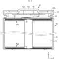
- FIGS. 1 to 3 are diagrams showing a process of manufacturing a tab-less cylindrical battery.
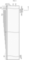
- FIG. 1 shows the structure of an electrode
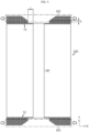
- FIG. 2 shows a process of winding the electrode
- FIG. 3 shows a process of welding a current collector to a bent surface of an uncoated portion.
- FIG. 4 is a sectional view showing the tab-less cylindrical battery, taken along a longitudinal direction (Y).
- a positive electrode 10 and a negative electrode 11 have a structure in which a sheet-shaped current collector 20 is coated with an active material 21, and include an uncoated portion 22 at one long side along the winding direction X.
- An electrode assembly A is manufactured by sequentially stacking the positive electrode 10 and the negative electrode 11 together with two sheets of separators 12 as shown in FIG. 2 and then winding them in one direction X. At this time, the uncoated portions of the positive electrode 10 and the negative electrode 11 are arranged in opposite directions.
- the uncoated portion 10a of the positive electrode 10 and the uncoated portion 11a of the negative electrode 11 are bent toward the core. After that, current collectors 30, 31 are welded and coupled to the uncoated portions 10a, 11a, respectively.
- An electrode tab is not separately coupled to the positive electrode uncoated portion 10a and the negative electrode uncoated portion 11a, the current collectors 30, 31 are connected to external electrode terminals, and a current path is formed with a large cross-sectional area along the winding axis direction of electrode assembly A (see an arrow in Fig. 3 ), which has an advantage of lowering the resistance of the battery. This is because resistance is inversely proportional to the cross-sectional area of the path through which the current flows.
- the conventional tab-less cylindrical battery 40 includes a battery housing 41 and a sealing body 42 as shown in FIG. 4 .
- the battery housing 41 is also called a battery can.
- the sealing body 42 includes a cap 42a, a sealing gasket 42b and a connection plate 42c.
- the sealing gasket 42b surrounds the edge of the cap 42a and is fixed by a crimping portion 43.
- the electrode assembly A is fixed in the battery housing 41 by a beading portion 44 to prevent vertical movement.
- the positive electrode terminal is the cap 42a of the sealing body 42
- the negative electrode terminal is the battery housing 41.
- the current collector 30 coupled to the uncoated portion 10a of the positive electrode 10 is electrically connected to the connection plate 42c attached to the cap 42a through a lead 45 in the form of a strip.
- the current collector 31 coupled to the uncoated portion 11a of the negative electrode 11 is electrically connected to the bottom of the battery housing 41.
- An insulator 46 covers the current collector 30 to prevent the battery housing 41 and the uncoated portion 10a of the positive electrode 10 having different polarities from contacting each other and causing a short circuit.
- the lead 45 in the form of a strip is used.
- the lead 45 is separately attached to the current collector 30 or is manufactured integrally with the current collector 30.
- the lead 45 is in the form of a thin strip, its cross-sectional area is small, and thus a lot of heat is generated when the rapid charging current flows.
- the excessive heat generated from the lead 45 is transferred to the electrode assembly A to shrink the separator 12, which may cause an inner short circuit that is a main cause of thermal runaway.
- the lead 45 also occupies a significant installation space within the battery housing 41. Therefore, the cylindrical battery 40 including the lead 45 has low space efficiency, so there is a limit in increasing the energy density.
- the top of the crimping portion 43 has a negative polarity but has a small area.
- the crimping portion 43 is illustrated large, but in fact, the top of the crimping portion 43 has a very smaller area than the sealing body 42.
- the present disclosure is designed to solve the problems of the related art, and therefore the present disclosure is directed to lowering the inner resistance of a cylindrical battery and increasing the energy density by improving an electrode terminal structure of the cylindrical battery to increase the space efficiency in a battery housing.
- the present disclosure is also directed to improving the electrode terminal structure of a cylindrical battery to solve the internal heating problem caused during rapid charging by expanding the cross-sectional area of a current path.
- the present disclosure is also directed to providing a cylindrical battery having an improved structure that allows electrical wiring for serial and/or parallel connection of the cylindrical batteries to be performed at one side of the cylindrical batteries.
- the present disclosure is also directed to providing a battery pack manufactured using the cylindrical battery with an improved structure and a vehicle including the battery pack.
- a fixing structure of an electrode terminal comprising: a battery housing configured to be opened at one side and have a bottom at the other side in which a perforation hole is formed; an electrode terminal installed through the perforation hole not to contact an inner wall of the perforation hole; and a terminal gasket interposed between the electrode terminal and the perforation hole, wherein the electrode terminal includes: a body portion inserted into the perforation hole; an outer flange portion configured to extend along an outer surface of the bottom of the battery housing from a first side of the body portion; an inner flange portion configured to extend toward an inner surface of the bottom of the battery housing from a second side of the body portion; and a flat portion provided to an inner side of the inner flange portion.
- the flat portion may be parallel with the inner surface of the bottom of the battery housing.
- the electrode terminal may be made of metal, and the inner flange portion is formed by plastically processing the second side of the body portion.
- the electrode terminal may be a rivet terminal riveted through the perforation hole by the inner flange portion.
- an angle between a surface of the inner flange portion facing the bottom of the battery housing and the inner surface of the bottom of the battery housing may be 0° to 60°.
- the inner flange portion may include a first region gradually spaced away from the bottom of the battery housing and a second region connected to the first region and extending toward the bottom of the battery housing, and an angle between a surface of the second region facing the bottom and the inner surface of the bottom may be 0° to 30°.
- a recess may be provided between the inner flange portion and the flat portion.
- the recess may be a groove having a closed loop shape recessed toward a central axis of the body portion.
- the recess may have an asymmetric cross section.
- the asymmetric cross section may include a sidewall of the flat portion and an inclined surface of the inner flange portion connected to an end of the sidewall of the flat portion.
- the sidewall may be perpendicular to the inner surface of the bottom of the battery housing.
- the sidewall may be inclined toward the flat portion.
- the inner flange portion may have a thickness gradually decreasing as being farther away from the body portion.
- the terminal gasket may include an outer gasket interposed between the outer flange portion and a first plane where the outer surface of the bottom of the battery housing is located; an inner gasket interposed between the inner flange portion and a second plane where the inner surface of the bottom of the battery housing is located; and an intermediate gasket interposed between the body portion and the perforation hole to connect the outer gasket and the inner gasket.
- the intermediate gasket may have different thicknesses depending on locations thereof.
- the terminal gasket may have a minimum thickness in the intermediate gasket.
- a region of the intermediate gasket adjacent to the first plane may have a thickness increasing as being closer to the first plane.
- a region of the intermediate gasket adjacent to the second plane may have a thickness increasing as being closer to the second plane.
- a central region located between the first plane and the second plane of the intermediate gasket may have a uniform thickness.
- a region of the intermediate gasket interposed between an inner edge of the perforation hole connected to the inner surface of the bottom and the inner flange portion may have a relatively smaller thickness than the other region of the intermediate gasket.
- the intermediate gasket may have a thickness gradually decreasing as being farther away from the outer flange portion.
- a region of the inner gasket interposed between the inner surface of the bottom and a region near an end of the inner flange portion may have a smallest thickness.
- the inner edge of the perforation hole may include a facing surface that faces the inner flange portion.
- the inner gasket may be configured to extend longer than the inner flange portion so that an end thereof is exposed.
- a height of the flat portion may be equal to or larger than a height of an end of the inner gasket based on the inner surface of the bottom of the battery housing.
- a height of the flat portion may be equal to or larger than a height of the inner flange portion based on the inner surface of the bottom of the battery housing.
- a height of the inner flange portion may be larger than a height of an end of the inner gasket based on the inner surface of the bottom of the battery housing.
- a height of the inner flange portion may be 0.5 mm to 3.0 mm based on the inner surface of the bottom of the battery housing.
- a height of the electrode terminal extending from a lower surface of the outer flange portion to a surface of the flat portion may be 4 mm to 7 mm.
- a height of the outer flange portion may be 0.8 mm or more based on the outer surface of the bottom of the battery housing.
- At least a portion of the outer gasket may be exposed to the outside of the outer flange portion, and the exposed portion of the outer gasket, when measured in a direction parallel to the outer surface of the bottom of the battery housing, may have a width of 0.1 mm to 1 mm.
- a radius from a center of the body portion to an edge of the outer flange portion may be 10% to 70% of a radius of the bottom of the battery housing.
- a radius from a center of the body portion to an edge of the flat portion may be 4% to 30% of a radius of the bottom of the battery housing.
- the compression ratio of the terminal gasket may be 30% to 90%.
- the terminal gasket may include polybutylene terephthalate, polyethylene fluoride, or polypropylene, and the compression ratio of the terminal gasket may be 50% to 90%.
- the intermediate gasket and the inner gasket of the terminal gasket may have substantially the same thickness before compression, and the compression ratio of the intermediate gasket and the inner gasket may be 50% to 90%.
- a battery comprising: an electrode assembly in which a first electrode and a second electrode are wound with a separator interposed therebetween, the electrode assembly having a first portion of the first electrode and a second portion of the second electrode configured to extend from both ends thereof and exposed to the outside of the separator; a battery housing configured to accommodate the electrode assembly and electrically connected to the first electrode; an electrode terminal installed through a perforation hole formed in a bottom of the battery housing not to contact an inner wall of the perforation hole and electrically connected to the second electrode; the electrode terminal including: a body portion inserted into the perforation hole; an outer flange portion configured to extend along an outer surface of the bottom of the battery housing from a first side of the body portion; an inner flange portion configured to extend toward an inner surface of the bottom of the battery housing from a second side of the body portion; and a flat portion provided to an inner side of the inner flange portion, a terminal gasket interposed between the electrode terminal and the perforation
- the battery housing may include a beading portion formed in a region adjacent to the open end and pressed-in into the battery housing, and the sealing body may include a cap having no polarity and a sealing gasket interposed between an edge of the cap and the open end of the battery housing.
- the battery housing may further include a crimping portion extended and bent into the inside of the battery housing and configured to surround and fix the edge of the cap together with the sealing gasket.
- the cap may include a vent notch that ruptures when a pressure inside the battery housing exceeds a threshold.
- the vent notch may be ruptured when the pressure inside the battery housing is in the range of 15 kgf/cm 2 to 35 kgf/cm 2 .
- the battery according to the present disclosure may further comprise a first current collector coupled to the first portion of the first electrode, and at least a part of an edge of the first current collector not in contact with the first portion of the first electrode may be interposed between the beading portion and the sealing gasket and fixed by the crimping portion.
- At least a part of the edge of the first current collector may be fixed to an inner circumference of the beading portion adjacent to the crimping portion by welding.
- the battery according to the present disclosure may further comprise a second current collector coupled to the second portion of the second electrode, and at least a part of the second current collector may be coupled to the flat portion of the electrode terminal.
- the second current collector and the flat portion of the electrode terminal may be coupled through welding, and a tensile force of the welding portion between the second current collector and the flat portion of the electrode terminal may be 2 kgf or above.
- a converted diameter of the welding pattern exposed on a surface of the second current collector may be 2 mm or more.
- a diameter of the flat portion of the electrode terminal may be 3 mm to 14 mm.
- a ratio of an area of the welding pattern exposed on a surface of the second current collector to an area of the flat portion of the electrode terminal may be 2.04% to 44.4%.
- the battery according to the present disclosure may further comprise an insulator interposed between the second current collector and an inner circumference of the bottom of the battery housing and between an inner circumference of a sidewall of the battery housing and the electrode assembly.
- the insulator may have a welding hole formed to expose the flat portion of the electrode terminal toward the second current collector and cover a surface of the second current collector and an edge of one side of the electrode assembly.
- a height from the inner surface of the bottom of the battery housing to the flat portion of the electrode terminal may be equal to or smaller than a thickness of the insulator.
- the terminal gasket may include an outer gasket interposed between the outer flange portion and a first plane where the outer surface of the bottom of the battery housing is located; an inner gasket interposed between the inner flange portion and a second plane where the inner surface of the bottom of the battery housing is located; and an intermediate gasket interposed between the body portion and the perforation hole to connect the outer gasket and the inner gasket.
- an end of the inner gasket may be exposed to the outside of the inner flange portion.
- the welding hole may expose the flat portion of the electrode terminal and the inner flange portion.
- the welding hole may expose the flat portion of the electrode terminal, the inner flange portion and the inner gasket.
- a first bus bar terminal may be electrically coupled to a surface of the electrode terminal, and a second bus bar terminal may be electrically coupled to the outer surface of the bottom of the battery housing.
- the first bus bar terminal may overlap with the electrode terminal on a plane to form a first overlapping region
- the second bus bar terminal may overlap with the outer surface of the bottom of the battery housing to form a second overlapping region
- a diameter of the electrode terminal and a width of the outer surface of the bottom of the battery housing may satisfy the following relational expression, W 1 ⁇ E 1 ⁇ D ⁇ 2 R d ⁇ 2 G ⁇ 2
- W 2 E 2 0.5 ⁇ D ⁇ 2 R d ⁇ 2 G ⁇ E 1
- E 1 diameter of the electrode terminal
- E 2 width of an exposed surface parallel to a surface of the electrode terminal in the outer surface of the bottom of the battery housing
- D outer diameter of the battery housing
- R d width of a round region at an edge of the battery housing measured on a plane
- G exposure width of the outer gasket through an edge of the electrode terminal
- W 1 maximum value among distances between any two points selected in an edge of the first overlapping region
- W 2 maximum value among distances between two points where a plurality of linear lines passing through the center of the electrode terminal meet an edge of the second overlapping region).
- a form factor ratio obtained by dividing a diameter of the battery by height may be greater than 0.4.
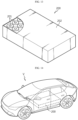
- a battery pack comprising a plurality of batteries described above.
- the plurality of batteries may be arranged in a predetermined number of columns, and the electrode terminal and the outer surface of the bottom of the battery housing of each of the plurality of batteries may be disposed to face upward.
- the battery pack according to the present disclosure may comprise a plurality of bus bars configured to connect the plurality of batteries in series and in parallel, the plurality of bus bars may be disposed above the plurality of batteries, and each bus bar may include a body portion configured to extend between electrode terminals of adjacent batteries; a plurality of first bus bar terminals respectively configured to extend in one side direction from the body portion and electrically coupled to the electrode terminal of the battery located in the one side direction; and a plurality of second bus bar terminals respectively configured to extend in the other side direction from the body portion and electrically coupled to the outer surface of the bottom of the battery housing of the battery located in the other side direction.
- an AC resistance of the battery measured between the electrode terminal and the outer surface of the bottom of the battery housing may be 4 milliohms (mohm) or less.
- a vehicle comprising the battery pack described above.
- electrical wiring for serial and/or parallel connection of the batteries may be performed at one side of the batteries.
- the substantially identical objects may include deviations considered low in the art, for example, deviations within 5%. Also, when it is explained that certain parameters are uniform in a predetermined region, this may mean that the parameters are uniform in terms of an average.
- first, second or the like are used to describe different elements, these elements are not limited by the terms. These terms are used to distinguish one element from another, and unless stated to the contrary, a first element may be a second element.
- the element When an element is “above (or under)” or “on (or below)” another element, the element can be on an upper surface (or a lower surface) of the other element, and intervening elements may be present between the element and the other element on (or below) the element.
- an element when referred to as being "connected”, “coupled” or “linked” to another element, the element can be directly connected or coupled to the other element, but it should be understood that intervening elements may be present between each element, or each element may be “connected”, “coupled” or “linked” to each other through another element.
- a and/or B refers to either A or B or both A and B unless expressly stated otherwise
- C to D refers to C or greater and D or smaller unless expressly stated otherwise.
- a direction that goes along a lengthwise direction of a winding axis of an electrode assembly wound in a roll shape is herein referred to as an axis direction Y.
- a direction around the winding axis is herein referred to as a circumferential or peripheral direction X.
- a direction that gets closer to or faces away from the winding axis is referred to as a radial direction.
- the direction that gets closer to the winding axis is referred to as a centripetal direction
- the direction that faces away from the winding axis is referred to as a centrifugal direction.
- a cylindrical battery according to an embodiment of the present disclosure may include an electrode terminal installed in a perforation hole formed in a bottom of a battery housing.
- FIG. 5 is a sectional view showing a fixing structure of an electrode terminal 50 according to an embodiment of the present disclosure
- FIG. 6a is an enlarged sectional view showing a portion indicated by a dotted circle in FIG. 5 .
- the electrode terminal 50 may include a body portion 50a having an upper surface, a lower surface and an outer surface, an outer flange portion 50b extending from an outer surface of the body portion 50a along an outer surface 52a of the bottom 52 of the battery housing 51, and an inner flange portion 50c extending from the outer surface of the body portion 50a toward an inner surface 52b of the bottom 52 of the battery housing 51.
- the upper surface of the body portion 50a is flat and may be connected to a current collector, and is located above the inner flange portion 50c.
- the fixing structure of the electrode terminal 50 may be applied to a structure of a cylindrical battery housing 51.
- the fixing structure of the electrode terminal 50 may include a battery housing 51 having one open side, an electrode terminal 50 fixed through a perforation hole 53 formed in the bottom 52 of the battery housing 51, and a terminal gasket 54 interposed between the electrode terminal 50 and the perforation hole 53.
- the battery housing 51 may include a cylindrical sidewall and a bottom 52 connected to an end of the sidewall. Since the perforation hole 53 is formed in the bottom 52, the battery housing 51 has a structure in which one side is opened and the other side is partially closed by the bottom 52.
- the battery housing 51 may have shapes other than the cylindrical shape, for example, a rectangular shape with a rectangular cross section.
- the battery housing 51 is made of a conductive metal material.
- the battery housing 51 may be made of a steel, an aluminum, stainless steel or the like, but the present disclosure is not limited thereto.
- the inner and outer surfaces of the battery housing 51 may be coated with a Ni plating layer.
- the electrode terminal 50 is made of a conductive metal material.
- the electrode terminal 50 may be made of a steel, an aluminum, stainless steel or the like, but the present disclosure is not limited thereto.
- the electrode terminal 50 may be made of 10 series aluminum alloy, which is easy for plastic processing and has low resistance.
- the plastic processing is a method of deforming a metal into a desired shape by applying a physical force thereto, and may include riveting, caulking, and the like.
- the terminal gasket 54 may be made of a polymer resin having insulation and elasticity.
- the terminal gasket 54 may be made of polypropylene, polybutylene terephthalate, polyethylene fluoride, or the like, but the present disclosure is not limited thereto.
- the electrode terminal 50 is installed in the perforation hole 53 not to contact an inner wall of the perforation hole 53.
- the electrode terminal 50 may include a body portion 50a inserted into the perforation hole 53.
- the body portion 50a may include an upper surface, a lower surface, and an outer surface connecting the upper and lower surfaces.
- the body portion 50a may include an outer flange portion 50b extending along an outer surface 52a from the circumference of a first side of the body portion 50a exposed through the outer surface 52a of the bottom 52 of the battery housing 51, an inner flange portion 50c extending toward an inner surface 52b from the circumference of a second side of the body portion 50a exposed through the inner surface 52b of the bottom 52 of the battery housing 51, and a flat portion 50d provided to an inner side of the inner flange portion 50c and surrounded by the inner flange portion 50c.
- the flat portion 50d corresponds to the upper surface of the body portion 50a.
- the flat portion 50d and the inner surface 52b of the bottom 52 of the battery housing 51 may be parallel to each other.
- the term ⁇ parallel' means substantially parallel when observed with the naked eye.
- the flat portion 50d may be a surface that is formed in advance before the electrode terminal 50 is plastically processed. That is, the flat portion 50d may be a region that is not deformed by plastic processing.
- the electrode terminal 50 is made of metal, and the inner flange portion 50c may be formed by plastically processing an upper periphery of the body portion 50a.
- the plastic processing may be caulking.
- the present disclosure is not limited thereto.
- the electrode terminal 50 may be a rivet terminal riveted through the perforation hole 53 by the inner flange portion 50c.
- the inner flange portion 50c extends in a direction gradually away from the bottom 52 of the battery housing 51.
- the angle ( ⁇ ) between the surface of the inner flange portion 50c facing the bottom 52 of the battery housing 51 and the inner surface 52b of the bottom 52 of the battery housing 51 may be 0° to 60°.
- the size of the angle ( ⁇ ) is determined by the caulking strength when the electrode terminal 50 is installed in the perforation hole 53 of the battery housing 51 by a caulking method. In one example, as the caulking strength increases, the angle ( ⁇ ) may decrease to 0°. If the angle ( ⁇ ) exceeds 60°, the sealing effect of the terminal gasket 54 may be deteriorated.
- the angle between the inner flange portion 50c and the outer flange portion 50b may also be 0° to 60°.
- a recess 55 may be provided between the inner flange portion 50c and the flat portion 50d.
- the recess 55 is a groove recessed toward a central axis of the body portion 50a.
- the groove may have a closed loop shape when viewed from the central axis of the body portion 50a.
- the recess 55 may have an asymmetric cross section.
- the asymmetric cross section may have an approximately V or U shape.
- the asymmetric cross section may include a sidewall 55a of the flat portion 50d and an inclined surface 55b connected to an end of the sidewall 55a and formed by the upper surface of the inner flange portion 50c.
- the outer surface of the body portion 50a exposed through the sidewall 55a may be called a first surface, and the inclined surface 55b may be called a second surface.
- the first surface and the second surface are asymmetric to each other.
- the sidewall 55a may be substantially perpendicular to the inner surface 52b of the bottom 52 of the battery housing 51.
- the term 'vertical' means substantially vertical when observed with the naked eye.
- the sidewall 55a may be inclined toward the flat portion 50d.
- the recess 55 is formed by the shape of a caulking jig when the electrode terminal 50 is installed in the perforation hole 53 of the battery housing 51 in a caulking method.
- the thickness of the inner flange portion 50c may gradually decrease as being farther away from the body portion 50a of the electrode terminal 50.
- the terminal gasket 54 may include an outer gasket 54a interposed between the outer flange portion 50b and a first plane P1 where the outer surface 52a of the bottom 52 of the battery housing 51 is located, an inner gasket 54b interposed between the inner flange portion 50c and a second plane P2 where the inner surface 52b of the bottom 52 of the battery housing 51 is located, and an intermediate gasket 54c interposed between the body portion 50a and the perforation hole 53 and connecting the outer gasket 54a and the inner gasket 54b.
- the outer gasket 54a and/or the inner gasket 54b and/or the intermediate gasket 54c may have different thicknesses depending on their locations.
- the intermediate gasket 54c may have different thicknesses depending on its location, and the terminal gasket 54 may have a minimum thickness in the intermediate gasket 54c.
- the region of the intermediate gasket 54c adjacent to the first plane P1 may have a thickness increasing as being closer to the first plane P1.
- the region of the intermediate gasket 54c adjacent to the second plane P2 may have a thickness increasing as being closer to the second plane P2.
- the central region of the intermediate gasket 54c positioned between the first plane P1 and the second plane P2 may have a uniform thickness.
- a region of the intermediate gasket 54c interposed between the inner flange portion 50c and an inner edge 56 of the perforation hole 53 connected to the inner surface 52b of the bottom 52 of the battery housing 51 may have a relatively smaller thickness.
- a minimum thickness point may be present in the region of the intermediate gasket 54c interposed between the inner edge 56 of the perforation hole 53 and the inner flange portion 50c.
- the inner edge 56 of the perforation hole 53 may include a facing surface 57 that faces the inner flange portion 50c.
- top and bottom of the inner wall of the perforation hole 53 perpendicular to the bottom 52 of the battery housing 51 are chamfered (corner-cut) to form a tapered surface toward the electrode terminal 50.
- the top and/or bottom of the inner wall of the perforation hole 53 may be transformed into a smooth curved surface with curvature. In this case, the stress applied to the gasket 54 near the top and/or bottom of the inner wall of the perforation hole 53 may be more relaxed.
- the inner gasket 54b may extend longer than the inner flange portion 50c while forming an angle ( ⁇ ) of 0° to 60° with the inner surface 52b of the bottom 52 of the battery housing 51.
- the height (H1) of the flat portion 50d based on the inner surface 52b of the bottom 52 of the battery housing 51 may be equal to or greater than the height (H2) of the end of the inner gasket 54b.
- the height (H1) of the flat portion 50d based on the inner surface 52b of the bottom 52 of the battery housing 51 may be equal to or greater than the height (H3) of the end of the inner flange portion 50c.
- the height H2 is the maximum height of the end of the inner gasket 54b measured based on the inner surface 52b.
- the height H3 is the maximum height of the upper surface of the inner flange portion 50c measured based on the inner surface 52b.
- the height (H3) of the inner flange portion 50c may be 0.5 mm to 3.0 mm. If the height (H3) of the inner flange portion 50c is less than 0.5 mm, sufficient sealing properties are not ensured. In addition, if the height (H3) of the inner flange portion 50c exceeds 3 mm, the inner space of the battery housing 51 that can be occupied by the electrode assembly is reduced.
- the height (H4) of the electrode terminal 50 may be 1.5 mm to 7 mm.
- the height (H4) of the electrode terminal 50 corresponds to a distance from the lower surface of the outer flange portion 50b to the flat portion 50d. If the height (H4) of the electrode terminal 50 is less than 1.5 mm, it is difficult to increase the height of the inner flange portion 50c to the extent that sealing properties can be secured due to the thickness of the bottom 52 of the battery housing 51.
- the thickness of the battery housing 51 bottom 52 is about 0.5 mm to 1 mm.
- the height (H4) of the electrode terminal 50 exceeds 7 mm, the inner space of the battery housing 51 that can be occupied by the electrode assembly decreases and the height of the battery increases, and thus the energy density per unit volume decreases as much.
- H3 and H4 satisfy the above numerical ranges, it is possible to sufficiently secure the sealing properties of the electrode terminal 50 without reducing the space inside the battery housing 51.
- the height (H5) of the outer flange portion 50b may be 0.8 mm or more based on the outer surface 52a of the bottom 54 of the battery housing 51. If the height (H5) of the outer flange portion 50b is less than 0.8 mm, the outer flange portion 50b may be deformed when the electrode terminal 50 is riveted.
- the thickness of the outer gasket 54a is 0.3 mm or more in consideration of insulation and sealing properties. Considering the thickness of the outer gasket 54a, if the height of the outer flange portion 50b is less than 0.8mm, the outer flange portion 50b becomes thin to a level that is difficult to secure sufficient mechanical rigidity. In particular, it is more serious when the electrode terminal 50 is made of aluminum.
- the height of the outer flange portion 50b may be appropriately set in consideration of the space margin of the upper part of the battery.
- the height of the outer flange portion 50b may be set to 2 mm or less, or 3 mm or less, or 4 mm or less, or 5 mm or less, but the present disclosure is not limited thereto.
- the outer gasket 54a may be exposed to the outside of the outer flange portion 50b of the electrode terminal 50.
- the outer gasket 54a is in order to insulate the electrode terminal 50 and the outer surface 52a having the opposite polarity to the electrode terminal 50 from each other.
- the exposure width (G) of the outer gasket 54a may be 0.1 mm to 1 mm. If the exposure width (G) is smaller than 0.1 mm, the electrical insulation of the electrode terminal 50 and the outer surface 52a on a plane may be broken when high c-rate charge/discharge of 300A or more is performed.
- the exposure width (G) exceeds 1 mm, the electrical insulation effect is not further increased, but rather the area of the outer surface 52a used as an area of the negative electrode is reduced, so the contact area of a component (e.g., a bus bar) used for electrical connection is reduced.
- a component e.g., a bus bar
- the diameter of the flat portion 50d of the electrode terminal 50 may be determined in consideration of welding strength between the current collector and the flat portion 50d.
- the tensile force of the welding portion between the flat portion 50d and the current collector may be at least 2 kgf or more, or 5 kgf or more, or 6 kgf or more, or 7 kgf or more, or 8 kgf or more, or 9 kgf or more, or 10 kgf or more. It is desirable to increase the tensile force of the welding portion as much as possible within an allowable range by selecting the welding method in a best way.
- the diameter of the welding pattern Wp formed on the flat portion 50d may be at least 2 mm.
- the diameter of the welding pattern Wp may be defined as a converted diameter (2 ⁇ (S/ ⁇ ) 0.5 ) of the corresponding circle.
- the welding pattern Wp may be continuous or discontinuous.
- the welding pattern Wp may not be a circle.
- the converted diameter (maximum value*2) may be determined from the maximum value of the distance from the center of the flat portion 50d to the edge of the welding pattern Wp.
- the flat portion 50d of the electrode terminal 50 corresponds to a weldable region.
- the diameter of the weldable region may be 3 mm and 14 mm. If the diameter of the weldable region is less than 3 mm, it is difficult to secure a welding pattern with a diameter of 2 mm or more. In particular, when forming the welding pattern using laser welding, it is difficult to secure a welding pattern having a diameter of 2 mm or more due to laser beam interference. If the diameter of the weldable region exceeds 14 mm, the diameter of the outer flange portion 50b of the electrode terminal 50 becomes too large, and thus it is difficult to sufficiently secure the area of the outer surface 52a of the battery housing bottom 52 to be used as the negative electrode region.
- the ratio of the area of the welding pattern to the area of the weldable region required to secure a tensile force of the welding portion of at least 2 kgf or more is preferably 2.04% ( ⁇ 1 2 / ⁇ 7 2 ) to 44.4% ( ⁇ 1 2 / ⁇ 1.5 2 ).
- the radius (R1) from the center of the body portion 50a to the edge of the outer flange portion 50b may be 10 to 70% of the radius (R2) of the bottom 52 of the battery housing 51.
- R1 is small, when wiring a component (a bus bar) used for electric connection of the electrode terminal 50, the welding space is insufficient. In addition, if R1 is large, the welding space decreases when welding a component (a bus bar) for electric connection to the outer surface 52a of the bottom 52 of the battery housing 51 except for the electrode terminal 50.
- ratio R1/R2 is adjusted between 10 and 70%, it is possible to properly secure the welding space for the electrode terminal 50 and the outer surface 52a of the bottom 52 of the battery housing 51.
- the radius (R3) from the center of the body portion 50a of the electrode terminal 50 to the edge of the flat portion 50d may be 4% to 30% of the radius (R2) of the bottom 52 of the battery housing 51.
- R3 is small, the welding space becomes insufficient when welding a current collector to the flat portion 50d of the electrode terminal 50, and the welding area of the electrode terminal 50 decreases, thereby increasing the contact resistance.
- R3 must be smaller than R1, and if R3 becomes larger, the thickness of the inner flange portion 50c becomes thinner, and the strength of the inner flange portion 50c compressing the terminal gasket 54 becomes weak, which may deteriorating the sealing ability of the terminal gasket 54.
- the welding process may be easily performed by sufficiently securing the welding area between the flat portion 50d of the electrode terminal 50 and the current collector, and also it is possible to reduce the contact resistance of the welding region the and prevent the sealing ability of the terminal gasket 54 from deteriorating.
- the fixing structure of the electrode terminal 50 may be formed using a caulking jig that moves up and down.
- a preform (not shown) of the electrode terminal 50 is inserted into the perforation hole 53 formed in the bottom 52 of the battery housing 51 by interposing the terminal gasket 54.
- the preform refers to an electrode terminal before the caulking process is performed.
- the caulking jig is inserted into the inner space of battery housing 51.
- the caulking jig has a groove and a protrusion corresponding to the final shape of the electrode terminal 50 on the surface opposite the preform in order to form the electrode terminal 50 by press-forming the preform.
- the caulking jig is moved downward to perform press-forming to the upper portion of the preform, so that the preform is transformed into an electrode terminal 50 riveted to the perforation hole 53 of the battery housing 51.
- the press-in depth of the caulking jig may be regulated by the flat portion 50d.
- the flat portion 50d is formed in advance in the body portion 50a, and the caulking jig has a groove into which the flat portion 50d is inserted. Therefore, while the preform is being press-formed, if the flat portion 50d comes into contact with the bottom of the groove, the press-forming is stopped. Accordingly, the inner flange portion 50c and the recess 55 formed through plastic deformation may have the uniform shape even in the mass production process.
- the flat portion 50d is not deformed or hardly deformed while the preform is being pressed by the caulking jig. Accordingly, the flat portion 50d may also maintain a uniform shape during mass production. This makes it easier to weld the flat portion 50d and the current collector, as explained later, and accordingly, the manufacturing deviation may be significantly reduced.
- the outer gasket 54a interposed between the outer flange portion 50b and the outer surface 52a of the bottom 52 of the battery housing 51 is elastically compressed so that its thickness decreases.
- the region of the intermediate gasket 54c interposed between the inner edge 56 of the perforation hole 53 and the preform is elastically compressed by the inner flange portion 50c, the thickness of the region is further reduced than other regions.
- the region where the thickness of the intermediate gasket 54c is intensively reduced is indicated by a dotted circle in FIG. 6a . Accordingly, the sealing and airtightness between the riveted electrode terminal 50 and the battery housing 51 are significantly improved.
- the terminal gasket 54 is compressed sufficiently to secure a desired sealing strength without being physically damaged in the process of riveting the preform through plastic processing, called caulking.
- the compression ratio of the terminal gasket 54 may be 30% to 90%.
- the minimum compression ratio (30%) corresponds to a compression ratio of a minimum level to ensure the sealing property of the electrode terminal 50.
- the maximum compression ratio (90%) corresponds to a compression ratio of a maximum level that can be achieved without physically damaging the terminal gasket 54.
- the terminal gasket 54 when the terminal gasket 54 is made of polybutylene terephthalate, it is preferable that the terminal gasket 54 has a compression ratio of 50% or more at the point where the terminal gasket 54 is compressed to a minimum thickness.
- the compression ratio may be defined as a ratio of the thickness change at a maximum compression point compared to the thickness before compression of the terminal gasket 54.
- the thickness of the inner gasket 54b and the intermediate gasket 54c before compression may be uniform, and a maximum compression point may exist near the inner edge 56.
- the compression ratio may be calculated based on the uniform thickness of the inner gasket 54b and the intermediate gasket 54c.
- the terminal gasket 54 when the terminal gasket 54 is made of polyfluoroethylene, it is preferable that the terminal gasket 54 has a compression ratio of 60% or more at the point where the terminal gasket 54 is compressed to a minimum thickness.
- the compression ratio may be calculated based on the uniform thickness of the inner gasket 54b and the intermediate gasket 54c.
- the terminal gasket 54 when the terminal gasket 54 is made of polypropylene, it is preferable that the terminal gasket 54 has a compression ratio of 60% or more at the point where the terminal gasket 54 is compressed to a minimum thickness.
- the compression ratio may be calculated based on the uniform thickness of the inner gasket 54b and the intermediate gasket 54c.
- press-forming may be performed in multiple stages to the upper portion of the preform by vertically moving the caulking jig at least two times. That is, the preform may be deformed several times by performing press-forming in multiple stages. At this time, the pressure applied to the caulking jig may be increased step by step. In this way, the stress applied to the preform is dispersed several times, thereby preventing the terminal gasket 54 from being damaged during the caulking process. In particular, when the region of the intermediate gasket 54c interposed between the inner edge 56 of the perforation hole 53 and the preform is intensively compressed by the inner flange portion 50c, the damage to the gasket is minimized by performing press-forming in multiple stages.
- the fixing structure of the electrode terminal 50 may be obtained as shown in FIG. 6a .
- the caulking jig performs press-forming to the upper portion of the preform by vertical moving inside the battery housing 51.
- a rotary jig used in the prior art may be used for performing press-forming to the preform.
- the rotary jig rotates in a state of being inclined at a predetermined angle with respect to the central axis of the battery housing 51. Therefore, the rotary jig with a large rotation radius may interfere with the inner wall of the battery housing 51. In addition, if the battery housing 51 has a large depth, the length of the rotary jig is also increased. In this case, as the rotation radius of the end of the rotary jig increases, press-forming may not be performed properly to the preform. Therefore, it is more effective to perform press-forming using a caulking jig rather than using a rotary jig.
- the electrode terminal 50 may have various structures depending on the design of the preform and/or the caulking jig and/or the terminal gasket 54 and the magnitude of the pressure applied to the preform during the caulking process.
- FIG. 6b is a partially enlarged sectional view showing the structure of an electrode terminals 50' according to another embodiment of the present disclosure.
- the electrode terminal 50' has a structure in which the inner flange portion 50c is riveted toward the inner surface 52b of the bottom 52 of the battery housing 51.
- the inner flange portion 50c includes a first region 50c1 extending in a direction gradually away from the bottom 52 of the battery housing 51, and a second region 50c2 connected to the first region 50c1 and extending toward the bottom 52 of the battery housing 51.
- the angle ( ⁇ ) between the surface of the second region 50c2 facing the bottom 52 of the battery housing 51 and the inner surface 52b of the bottom 52 may be 0° to 30°.
- the angle ( ⁇ ) may be substantially close to 0 (zero) in order to increase the sealing properties of the terminal gasket 54 to the maximum. Since the second region 50c2 strongly compresses the inner gasket 54b, it is possible to increase the sealing properties of the terminal gasket 54. This effect increases as the angle ( ⁇ ) is closer to 0.
- the height (H3) of the inner flange portion 50c is greater than the height (H2) of the inner gasket 54b.
- the inner edge of the perforation hole 53 has an arc shape with a predetermined curvature.
- the sidewall 55a of the edge portion of the flat portion 50d has a structure inclined toward the flat portion 50d.
- the terminal gasket 54 includes an outer gasket 54a interposed between the outer flange portion 50b and the first plane P1 where the outer surface 52a of the bottom 52 of the battery housing 51 is located; an inner gasket 54b interposed between the inner flange portion 50c and the second plane P2 where the inner surface 52b of the bottom 52 of the battery housing 51 is located; and an intermediate gasket 54c interposed between the body portion 50a and the perforation hole 53 to connect the outer gasket 54a and the inner gasket 54b.
- the thickness of the intermediate gasket 54c may gradually decrease as being farther away from the outer gasket 54a.
- the thickness of the inner gasket 54b may decrease to the minimum thickness near the end of the inner flange portion 50c, and then slightly increase toward the uppermost end.
- the compression structure of this inner gasket 54b may further improve the sealing properties of the electrode terminal 50'.
- the compression ratio of the inner gasket 54b can be calculated at the minimum thickness point near the end of the inner flange portion 50c.
- the fixing structure of the electrode terminal 50, 50' may be applied to a cylindrical battery having a form factor greater than 2170.
- the form factor of the cylindrical battery is increasing compared to the conventional form factor of 1865, 2170, and the like.
- An increase in the form factor leads to an increase in energy density, an increase in safety against thermal runaway, and an improvement in cooling efficiency.
- electrical wiring may be performed at one side of the cylindrical battery to which the fixing structure of the electrode terminal 50, 50' is applied.
- the electrode terminal 50, 50' has a large sectional area and low resistance, so it is very suitable for rapid charging.
- the cylindrical battery to which the structure of the electrode terminal 50, 50' of the present disclosure is applied may have a form factor ratio (defined as a value obtained by dividing the diameter of the cylindrical battery by height, namely a ratio of diameter ( ⁇ ) to height (H)) is greater than about 0.4.
- the form factor means a value indicating the diameter and height of a cylindrical battery.
- the form factor of the cylindrical battery according to an embodiment of the present disclosure may be, for example, 4611, 4875, 48110, 4880, or 4680.
- first two digits indicate the diameter of the battery, the other digits indicate the height of the battery.
- a battery according to an embodiment of the present disclosure may be a cylindrical battery, whose diameter is approximately 46 mm, height is approximately 110 mm, and form factor ratio is 0.418.
- a battery according to another embodiment may be a cylindrical battery, whose diameter is about 48 mm, height is about 75 mm, and form factor ratio is 0.640.
- a battery according to still another embodiment may be a cylindrical battery, whose diameter is approximately 48 mm, height is approximately 110 mm, and form factor ratio is 0.436.
- a battery according to still another embodiment may be a cylindrical battery, whose diameter is approximately 48 mm, height is approximately 80 mm, and form factor ratio is 0.600.
- a battery according to still another embodiment may be a cylindrical battery, whose diameter is approximately 46 mm, height is approximately 80 mm, and form factor ratio is 0.575.
- batteries having a form factor ratio of about 0.4 or less have been used. That is, conventionally, for example, an 1865 battery, a 2170 battery, etc. were used.
- the 1865 battery has a diameter of approximately 18 mm, height of approximately 65 mm, and a form factor ratio of 0.277.
- the 2170 battery has a diameter of approximately 21 mm, a height of approximately 70 mm, and a form factor ratio of 0.300.
- FIG. 7a is a sectional view showing a cylindrical battery 70 according to an embodiment of the present disclosure, taken along a longitudinal direction (Y).
- the cylindrical battery 70 includes a jelly-roll type electrode assembly 71 in which a first electrode and a second electrode having a sheet shape are wound with a separator interposed therebetween so that an uncoated portion 72 serving as a first portion of the first electrode is exposed at a lower portion and an uncoated portion 73 serving as a second portion of the second electrode is exposed at an upper portion.
- the first portion and the second portion may be other portions of the electrode than the uncoated portion.
- the other portion may be a metal tab electrically coupled to the uncoated portion of the electrode.
- the electrode assembly 71 has a shape other than the j elly-roll shape.
- the battery may have not only a cylindrical shape but also other shapes such as a prismatic shape as well as a cylindrical shape.
- the first electrode may be a negative electrode and the second electrode may be a positive electrode, or vice versa.
- the method of winding the electrode assembly 71 is substantially the same as the method of winding the electrode assembly used in manufacturing the conventional tab-less cylindrical battery described with reference to FIG. 2 .
- the cylindrical battery 70 also includes a cylindrical battery housing 51 that accommodates the electrode assembly 71 and is electrically connected to the uncoated portion 72 of the first electrode.
- one side (lower portion) of the battery housing 51 is open.
- the bottom 52 of the battery housing 51 has a structure in which the electrode terminal 50 is riveted to the perforation hole 53 through a plastic process (for example, caulking).
- the electrode terminal 50 may include a body portion 50a inserted into the perforation hole 53, an outer flange portion 50b extending along the outer surface 52a from the circumference of the first side of the body portion 50a exposed through the outer surface 52a of the bottom 52 of the battery housing 51, an inner flange portion 50c extending toward the inner surface 52b from the circumference of the second side of the body portion 50a exposed through the inner surface 52b of the bottom 52 of the battery housing 51, and a flat portion 50d provided at an inner side of the inner flange portion 50c and surrounded by the inner flange portion 50c.
- the electrode terminal 50 may be replaced with the electrode terminal 50' shown in FIG. 6b .
- the cylindrical battery 70 may also include a terminal gasket 54 interposed between the electrode terminal 50 and the perforation hole 53.
- the cylindrical battery 70 may also include a sealing body 74 that seals the open end of the battery housing 51 to be insulated from the battery housing 51.
- the sealing body 74 may include a cap 74a having no polarity and having a plate shape, and a sealing gasket 74b interposed between an edge of the cap 74a and the open end of the battery housing 51.
- the cap 74a may be made of a conductive metal material such as aluminum, steel, nickel or the like.
- the sealing gasket 74b may be made of polypropylene, polybutylene terephthalate, polyethylene fluoride, or the like having insulation and elasticity.
- the present disclosure is not limited by the materials of the cap 74a and the sealing gasket 74b.
- the cap 74a may include a vent notch 77 that ruptures when the pressure inside the battery housing 51 exceeds a threshold.
- the vent notch 77 may be formed at both sides of the cap 74a.
- the vent notch 77 may form a continuous or discontinuous circular pattern, a straight pattern or any other pattern on the surface of the cap 74a.
- the depth and width of the vent notch 77 may be set such that the vent notch 77 is ruptured when the pressure inside the battery housing 51 is in the range of 15 kgf/cm 2 to 35 kgf/cm 2 .
- the battery housing 51 may include a crimping portion 75 that is extended and bent into the inside of the battery housing 51 to surround and fix the edge of the cap 74a together with the sealing gasket 74b in order to fix the sealing body 74 to the battery housing 51.
- the lower surface of the cap 74a may be located above the lower end of the crimping portion 75. Then, a vent space is formed below the cap 74a, so that when the vent notch 77 is ruptured, the gas can be smoothly discharged.
- the battery housing 51 may also include a beading portion 76 pressed-in into the battery housing 51 in a region adjacent the open end thereof.
- the beading portion 76 supports the edge of the sealing body 74, particularly the outer circumferential surface of the sealing gasket 74b, when the sealing body 74 is fixed by the crimping portion 75.
- the cylindrical battery 70 may further include a first current collector 78 welded to the uncoated portion 72 of the first electrode.
- the first current collector 78 is made of a conductive metal material such as aluminum, steel, nickel or the like.
- at least a portion 78a of the edge of the first current collector 78 not in contact with the uncoated portion 72 of the first electrode may be interposed between the beading portion 76 and the sealing gasket 74b and fixed by the crimping portion 75.
- at least a portion 78a of the edge of the first current collector 78 may be fixed to the inner circumference 76a of the beading portion 76 adjacent to the crimping portion 75 by a laser welding, a spot welding, an ultrasonic welding or the like.
- the cylindrical battery 70 may also include a second current collector 79 that is welded to the uncoated portion 73 of the second electrode.
- a second current collector 79 that is welded to the uncoated portion 73 of the second electrode.
- at least a portion of the second current collector 79, for example a central portion 79a thereof, may be welded to the flat portion 50d of the electrode terminal 50.
- a welding tool may be inserted through the cavity 80 in the core of the electrode assembly 71 to reach a welding point of the second current collector 79.
- a welding tool may be inserted through the cavity 80 in the core of the electrode assembly 71 to reach a welding point of the second current collector 79.
- the second current collector 79 is welded to the flat portion 50d of the electrode terminal 50, since the electrode terminal 50 supports the welding region of the second current collector 79, it is possible to improve the welding quality by applying a strong pressure to the welding region.
- the flat portion 50d of the electrode terminal 50 has a large area, a wide welding region may also be secured. Accordingly, the contact resistance of the welding region is lowered, thereby lowering the inner resistance of the cylindrical battery 70.
- the face-to-face welding structure of the riveted electrode terminal 50 and the second current collector 79 is very useful for rapid charging using high C-rate current. This is because the current density per unit area may be lowered in the cross section in a direction in which the current flows and thus the amount of heat generated in the current path may be lowered than that of the prior art.
- any one of laser welding, ultrasonic welding, spot welding, and resistance welding may be used.
- the diameter of the arc welding pattern is 2 mm or more, preferably 4 mm or more.
- the diameter of the arc welding pattern satisfies the corresponding conditions, it is possible to increase the tensile force of the welding portion to 2 kgf or above, thereby securing sufficient welding strength.
- the diameter of the circular welding pattern is preferably 2 mm or more.
- the diameter of the circular welding pattern satisfies the corresponding conditions, it is possible to increase the tensile force of the welding portion to 2 kgf or above, thereby securing sufficient welding strength.
- the diameter of the flat portion 50d corresponding to the weldable region may be adjusted in the range of 3 mm to 14 mm. If the radius of the flat portion 50d is less than 3 mm, it is difficult to form a welding pattern with a diameter of 2 mm or more using a laser welding tool, an ultrasonic welding tool, or the like. In addition, if the radius of the flat portion 50d exceeds 14 mm, the size of the electrode terminal 50 becomes excessively large, and the area occupied by the outer surface 52a of the bottom 52 of the battery housing 51 is reduced, so that it is difficult to connect an electrical connection component (a bus bar) through the outer surface 52a.
- an electrical connection component a bus bar
- the area ratio of the welding pattern to the area of the weldable region may be 2.04(100 ⁇ ⁇ 1 2 / ⁇ 7 2 )% to 44.4(100 ⁇ 1 2 ⁇ 1 2 / ⁇ 1.5 2 )%.
- the cylindrical battery 70 may further include an insulator 80.
- the insulator 80 may be interposed between the second current collector 79 and the inner surface 52b of the bottom 52 of the battery housing 51, and between the inner circumference 51a of the sidewall of the battery housing 51 and the electrode assembly 71.
- the insulator 80 may have a welding hole 80a that exposes the flat portion 50d of the electrode terminal 50 toward the second current collector 79.
- the welding hole 80a may expose the inner flange portion 50c and the inner gasket 54b together with the flat portion 50d of the electrode terminal.
- the insulator 80 may cover the surface of the second current collector 79 and one (upper) edge of the electrode assembly 71. By doing so, it is possible to prevent the second current collector 79 having a polarity different from that of the battery housing 51 from contacting the uncoated portion 73 of the second electrode.
- the insulator 80 is made of an insulating resin, and may include an upper plate 80b and a side sleeve 80c.
- the upper plate 80b and the side sleeve 80c may be integrally formed by injection molding.
- the side sleeve 80c may be replaced with an insulation tape or the like. The insulation tape may cover the outer edge of the second current collector 79 together with the uncoated portion 73 of the second electrode exposed through the outer circumference of the electrode assembly 71.
- the inner surface 52b of the insulator 80 and the bottom 52 of the battery housing 51 may be in close contact with each other as shown in FIG. 7b .
- ⁇ close contact' means that there is no space (gap) that is visually confirmed.
- the distance from the inner surface 52b of the bottom 52 of the battery housing 51 to the flat portion 50d of the electrode terminal 50 may be equal to or slightly smaller than the thickness of the insulator 80.
- the uncoated portions 72, 73 of the first electrode and/or the second electrode may be bent in a radial direction, for example from the outer circumference of the electrode assembly 71 to the core, to form bent surfaces at the upper and lower portions of the electrode assembly 71.
- the first current collector 78 may be welded to the bent surface formed by bending the uncoated portion 72 of the first electrode
- the second current collector 79 may be welded to the bent surface formed by bending the uncoated portion 73 of the second electrode.
- the first electrode and/or the second electrode may have an improved structure different from that of the conventional electrode (see FIG. 1 ).
- FIG. 8 is a plan view exemplarily showing a structure of an electrode 90 according to a preferred embodiment of the present disclosure.
- the electrode 90 has a sheet-shaped current collector 91 made of a conductive material foil, an active material layer 92 formed on at least one surface of the current collector 91, and an uncoated portion 93 formed at a long side end of the current collector 91 and not coated with an active material.
- the uncoated portion 93 may include a plurality of notched segments 93a.
- the plurality of segments 93a constitute a plurality of groups, and the segments 93a included in each group may have the same height (length in the Y direction) and/or the same width (length in the X direction) and/or the same separation pitch.
- the number of segments 93a belonging to each group may be increased or decreased than shown.
- the segment 93a has a shape of a geometric figure in which at least one linear line and/or at least one curve are combined.
- the segment 93a may have a trapezoidal shape, which may be changed into a rectangular, parallelogram, semicircular, semi-elliptical shape, or the like as desired.
- the height of the segment 93a may be increased stepwise along one direction parallel to the winding direction of the electrode assembly, for example from the core to the outer circumference.
- a core-side uncoated portion 93' adjacent to the core may not include the segment 93a, and the height of the core-side uncoated portion 93' may be smaller than that of other uncoated portion regions.
- an outer circumferential uncoated portion 93" adjacent to the outer circumferential may not include the segment 93a, and the height of the outer circumferential uncoated portion 93" may be smaller than that of other uncoated portion regions.
- the electrode 90 may include an insulating coating layer 94 for covering the boundary between the active material layer 92 and the uncoated portion 93.
- the insulating coating layer 94 includes an insulating polymer resin, and may optionally include an inorganic filler further.
- the insulating coating layer 94 prevents the end of the active material layer 92 from coming into contact with the opposite-polarity active material layer opposite thereto through the separator, and serves to structurally support the bending of the segment 93a.
- the insulating coating layer 94 is at least partially exposed from the separator to the outside.
- FIG. 9 is a sectional view showing an electrode assembly 100 in which a segment structure of an uncoated portion of the electrode 90 according to an embodiment of the present disclosure is applied to the first electrode and the second electrode, taken along the longitudinal direction (Y).
- the electrode assembly 100 may be manufactured by the winding method described with reference to FIG. 2 .
- the protruding structure of the uncoated portions 72, 73 extending out of the separator is illustrated in detail, and the winding structure of the first electrode, the second electrode and the separator is not illustrated in detail.
- the uncoated portion 72 protruding downward extends from the first electrode, and the uncoated portion 73 protruding upward extends from the second electrode.
- the pattern in which the heights of the uncoated portions 72, 73 change is schematically shown. That is, the heights of the uncoated portions 72, 73 may vary irregularly depending on the position at which the cross-section is cut. For example, when the side portion of the trapezoidal segment 93a is cut, the height of the uncoated portion at the cross section is lower than the height of the segment 93a. Accordingly, it should be understood that the heights of the uncoated portions 72, 73 depicted in the drawing showing the cross-section of the electrode assembly 100 correspond to the average of the heights of the uncoated portions included in each winding turn.
- the uncoated portions 72, 73 may be bent along the radial direction of the electrode assembly 100, for example from the outer circumference to the core, as shown in FIGS. 10a and 10b .
- the bent portion 101 is indicated by a dotted line box.
- bent surfaces 102 are formed at the upper and lower portions of the electrode assembly 100 as the segments adjacent to each other in a radius direction overlap each other in multiple layers.
- the core-side uncoated portion 93' see FIG.
- the cavity 80 in the core of the electrode assembly 100 is not closed by the bent segments. If the cavity 80 is not closed, there is no difficulty in the electrolyte injection process, and the electrolyte injection efficiency is improved.
- the electrode terminal 50 and the second current collector 79 may be easily welded by inserting a welding tool through the cavity 80.
- the cap 74a of the sealing body 74 has no polarity.
- the first current collector 78 is connected to the sidewall of the battery housing 51, so that the outer surface 52a of the bottom 52 of the battery housing 51 has polarity opposite to the electrode terminal 50. Therefore, when a plurality of batteries are to be connected in series and/or in parallel, wiring such as bus bar connection may be performed at the upper portion of the cylindrical battery 70 using the electrode terminal 50 and the outer surface 52a of the bottom 52 of the battery housing 51. Through this, the energy density may be improved by increasing the number of batteries that can be mounted in the same space, and the electric wiring work may be performed easily.
- FIG. 11 is a diagram showing a state in which the cylindrical batteries 70 according to an embodiment of the present disclosure are electrically connected using a bus bar 150.
- the plurality of cylindrical batteries 70 may be connected in series and in parallel at an upper portion using the bus bar 150.
- the number of cylindrical batteries 70 may be increased or decreased in consideration of the capacity of the battery pack.
- the electrode terminal 50 may have a positive polarity, and the outer surface 52a of the bottom 52 of the battery housing 51 may have a negative polarity, and vice versa.
- the plurality of cylindrical batteries 70 may be arranged in a plurality of columns and rows. Columns are provided in an upper and lower direction with respect to the ground, and rows are provided in a left and right direction with respect to the drawings. Also, in order to maximize space efficiency, the cylindrical batteries 70 may be arranged in a closest packing structure. The closest packing structure is formed when the centers of the electrode terminals 50 form an equilateral triangle when being connected to each other.
- the bus bar 150 may be disposed above the plurality of batteries, more preferably between adjacent columns. Alternatively, the bus bar 150 may be disposed between adjacent rows.
- the bus bar 150 connects cells arranged in the same column in parallel to each other, and serially connects cells arranged in two adjacent columns to each other.
- the bus bar 150 may include a body portion 151, a plurality of first bus bar terminals 152 and a plurality of second bus bar terminals 153.
- the body portion 151 may extend between electrode terminals (50) of adjacent cylindrical batteries 70, preferably between columns of the cylindrical batteries 70. Alternatively, the body portion 151 may extend along a column of cylindrical batteries 70, and the body portion 151 may be regularly bent like a zigzag shape.
- the plurality of first bus bar terminals 152 may protrude from one side of the body portion 151 toward the electrode terminal 50 of each cylindrical battery 70 and may be electrically coupled to the electrode terminal 50. Electrical coupling with the electrode terminal 50 may be achieved through laser welding, ultrasonic welding, or the like.
- the plurality of second bus bar terminals 153 may protrude from the other side of the body portion 151 toward the outer surface 52a of the bottom 52 of the battery housing 51 of each cylindrical battery 70, and may be electrically coupled to the outer surface 52a. Electrical coupling with the outer surface 52a may be performed by laser welding, ultrasonic welding, or the like.
- the body portion 151, the plurality of first bus bar terminals 152 and the plurality of second bus bar terminals 153 may be made of one conductive metal plate.
- the metal plate may be an aluminum plate or a copper plate, but the present disclosure is not limited thereto.
- the body portion 151, the plurality of first bus bar terminals 152 and the plurality of second bus bar terminals 153 may be manufactured as separate pieces and then coupled to each other through welding or the like.
- the electrode terminal 50 having a positive polarity and the outer surface 52a of the bottom 52 of the battery housing 51 having a negative polarity are located in the same direction, and thus the cylindrical batteries 70 may be electrically connected easily using the bus bar 150.
- the coupling area of the bus bar 150 may be sufficiently secured to sufficiently reduce the resistance of the battery pack including the cylindrical battery 70.
- FIG. 12a is a partially enlarged view showing an electrical connection portion between the bus bar 150 and the cylindrical battery 70
- FIGS. 12b and 12c are diagrams showing the definition of various parameters to design upper and lower limits of the diameter of the electrode terminal 50 and the exposure width of the outer surface 52a in consideration of the sizes of the bus bar terminals 152, 153.
- the diameter (E 1 ) of the electrode terminal 50 and the width (E 2 ) of the ring-shaped outer surface 52a may be adaptively adjusted in consideration of the dimensions of the contact areas of the bus bar terminals 152, 153.
- the width E2 of the outer surface 52a is the width of the exposed surface parallel to the surface of the electrode terminal 50.
- the width E2 of the outer surface 52a is defined as the width of a line segment connecting two points where a linear line (L 1 ) drawn in a radial direction from the center C of the electrode terminal 50 intersects inner and outer boundaries of the outer surface 52a.
- the width E2 of the outer surface 52a is the width of the flat exposed surface excluding the round region existing at the edge of the bottom 52 and the exposed area 54a' of the outer gasket 54a.
- the outer surface of the bottom 52 of the battery housing 51 may be divided into the electrode terminal 50, the exposed area 54a' of the terminal gasket 54, and the round region R at the edge of the outer surface 52a when viewed from the top.
- the round region R is a processing region (see FIGS. 7a and 7b ) for smoothly connecting the bottom 52 of the battery housing 51 and the sidewall of the battery housing 51, and has a width (R d ) on a plane.
- the first bus bar terminal 152 of the bus bar 150 is branched to one side different from the traveling direction of the body portion 151, and is electrically coupled to the electrode terminal 50.
- the electrode terminal 50 and the first bus bar terminal 152 form a first overlapping region (hatched in the drawing) on a plane, and the first overlapping region has a first width (W 1 ).
- the first overlapping region is a region where the electrode terminal 50 and the first bus bar terminal 152 overlap on a plane.
- the first width (W 1 ) is defined as a maximum value among distances between any two points selected in the edge of the first overlapping region.
- the definition of the first width (W 1 ) is applied identically when the first overlapping region includes the center of the electrode terminal 50 ( FIG. 12b ) and when the first overlapping region does not include the center of the electrode terminal 50 ( FIG. 12c ).
- the distance represented by W 1 corresponds to a maximum value among distances between any two points selected in the edge of the first overlapping region.
- the second bus bar terminal 153 of the bus bar 150 extends in a direction opposite to the first bus bar terminal 152 based on the traveling direction of the body portion 151, and is electrically coupled to the outer surface 52a of the bottom 52 of the battery housing 51.
- the second bus bar terminal 153 and the outer surface 52a form a second overlapping region (hatched on the figure) on a plane, and the second overlapping region has a second width (W 2 ).
- the second overlapping region is a region where the outer surface 52a and the second bus bar terminal 153 overlap on a plane.
- the second width (W 2 ) is defined as a maximum value among widths between two points where each linear line and the edge of the second overlapping region meet when a plurality of linear lines (L 3 ) are drawn from the center C of the electrode terminal 50 to pass through the second overlapping region.
- the diameter (E 1 ) of the electrode terminal 50 must be at least equal to or greater than the first width (W 1 ) of the first bus bar terminal 152. This is because the first overlapping region of the first bus bar terminal 152 and the electrode terminal 50 must not deviate out of the electrode terminal 50 on the plane. Also, the diameter (E 1 ) of the electrode terminal 50 may be increased to the maximum until the distance between the boundary of the electrode terminal 50 and the second bus bar terminal 153 corresponds to the width (G) of the exposed area 54a' of the outer gasket 54a. Therefore, the maximum value of the diameter (E 1 ) of the electrode terminal 50 is 'D-2 ⁇ R d -2 ⁇ G-2 ⁇ W 2 '.
- the width (E 2 ) of the outer surface 52a is a factor dependent on the diameter (E 1 ) of the electrode terminal 50, and must be at least equal to or greater than the second width (W 2 ) of the second bus bar terminal 153. Only in this case, an overlapping region of the second bus bar terminal 153 and the outer surface 52a may be formed.
- the width (E 2 ) of the outer surface 52a may be increased to the maximum up to 50% of 'D-2 ⁇ R d -2 ⁇ G-E 1 ', which is a value obtained by subtracting the diameter (E 1 ) of the electrode terminal 50, the width (2*G) of the exposed area of the outer gasket 54a, and the width (2 ⁇ R d ) of the round region from the outer diameter (D) of the battery housing 51.
- the diameter (E 1 ) of the electrode terminal 50 and the width (E 2 ) of the outer surface 52a are designed to satisfy the following relational expression.
- W 2 E 2 0.5 ⁇ D ⁇ 2 R d ⁇ 2 G ⁇ E 1 (E 1 : diameter of the electrode terminal 50, E 2 : width of the outer surface 52a, D: outer diameter of the battery housing 51, R d : width of the round region R measured on a plane, G: width of the exposed area 54a' of the outer gasket 54a, W 1 : width of the first bus bar terminal 152, W 2 : width of the second bus bar terminal 153)
- D is 46 mm
- W 1 and W 2 are 6 mm
- G is 0.5 mm and R d is 1.5 mm
- the diameter (E 1 ) of the electrode terminal 50 is 6 mm to 30 mm
- the width (E 2 ) of the outer surface 52a is 6 mm to 18 mm.
- the cylindrical battery 70 of the present disclosure has a structure in which resistance is minimized by expanding a welding area through a bent surface of the uncoated portion, multiplexing a current path by using a first current collector, minimizing a current path length, and the like.
- the AC resistance of the cylindrical battery 70 measured using a resistance measuring instrument between the electrode terminal 50 (positive-polarity terminal) and the outer surface 52a (negative-polarity terminal) near the electrode terminal 50 may be about 0.5 milliohms (mohm) to 4 milliohms (mohm), preferably 1 milliohms (mohm) to 4 milliohms (mohm), which is appropriate to quick charging.
- a positive electrode active material coated on the positive electrode and a negative electrode active material coated on the negative electrode may employ any active material known in the art without limitation.
- the positive electrode active material may include an alkali metal compound expressed by a general formula A[A x M y ]O 2+z (A includes at least one element among Li, Na and K; M includes at least one element selected from is Ni, Co, Mn, Ca, Mg, Al, Ti, Si, Fe, Mo, V, Zr, Zn, Cu, Al, Mo, Sc, Zr, Ru, and Cr; x ⁇ 0, 1 ⁇ x+y ⁇ 2, -0.1 ⁇ z ⁇ 2; and the stoichiometric coefficients x, y and z are selected so that the compound maintains electrical neutrality).
- A includes at least one element among Li, Na and K
- M includes at least one element selected from is Ni, Co, Mn, Ca, Mg, Al, Ti, Si, Fe, Mo, V, Zr, Zn, Cu, Al, Mo, Sc, Zr, Ru, and Cr
- the positive electrode active material may be an alkali metal compound xLiM 1 O 2 -(1-x)Li 2 M 2 O 3 disclosed in US6,677,082 , US6,680,143 , et al., wherein M 1 includes at least one element having an average oxidation state 3; M 2 includes at least one element having an average oxidation state 4; and 0 ⁇ x ⁇ 1).
- the positive electrode active material may be lithium metal phosphate expressed by a general formula Li a M 1 x Fe 1-x M 2 y P 1-y M 3 z O 4-z
- M 1 includes at least one element selected from the Ti, Si, Mn, Co, Fe, V, Cr, Mo, Ni, Nd, Mg and Al
- M 2 includes at least one element selected from Ti, Si, Mn, Co, Fe, Cr, Mo, Ni, Nd, Al, Mg, Al, As, Sb, Si, Ge, V and S
- M 3 includes a halogen element optionally including F; 0 ⁇ a ⁇ 2, 0 ⁇ x ⁇ 1, 0 ⁇ y ⁇ 1, 0 ⁇ z ⁇ 1; the stoichiometric coefficients a, x, y and z are selected so that the compound maintains electrical neutrality), or Li 3 M 2 (PO 4 ) 3 (M includes at least one element selected from Ti, Si, Mn, Fe, Co, V, Cr, Mo,
- the positive electrode active material may include primary particles and/or secondary particles in which the primary particles are aggregated.
- the negative electrode active material may employ carbon material, lithium metal or lithium metal compound, silicon or silicon compound, tin or tin compound, or the like.
- Metal oxides such as TiOz and SnOz with a potential of less than 2V may also be used as the negative electrode active material.
- the carbon material low-crystalline carbon and/or high-crystalline carbon may be used.
- the separator may employ a porous polymer film, for example, a porous polymer film made of a polyolefin-based polymer such as ethylene homopolymer, propylene homopolymer, ethylene/butene copolymer, ethylene/hexene copolymer, ethylene/methacrylate copolymer, or the like, or laminates thereof.
- a porous polymer film for example, a porous polymer film made of a polyolefin-based polymer such as ethylene homopolymer, propylene homopolymer, ethylene/butene copolymer, ethylene/hexene copolymer, ethylene/methacrylate copolymer, or the like, or laminates thereof.
- the separator may employ a common porous nonwoven fabric, for example, a nonwoven fabric made of high melting point glass fiber, polyethylene terephthalate fiber, or the like.
- a coating layer of inorganic particles may be included in at least one surface of the separator. It is also possible that the separator itself is made of a coating layer of inorganic particles. Particles in the coating layer may be coupled with a binder so that an interstitial volume exists between adjacent particles.
- the inorganic particles may be made of an inorganic material having a dielectric constant of 5 or more.
- the inorganic particles may include at least one material selected from the group consisting of Pb(Zr,Ti)O 3 (PZT), Pb 1-x La x Zr 1-y Ti y O 3 (PLZT), PB(Mg 3 Nb 2/3 )O 3 -PbTiO 3 (PMN-PT), BaTiO 3 , hafnia (HfO 2 ), SrTiO 3 , TiOz, Al 2 O 3 , ZrOz, SnOz, CeOz, MgO, CaO, ZnO and Y 2 O 3 .
- the electrolyte may be a salt having a structure like A + B - .
- a + includes an alkali metal cation such as Li + , Na + , or K + , or a combination thereof
- B - includes at least one anion selected from the group consisting of F - , Cl - , Br - , I - , NO 3 - , N(CN) 2 - , BF 4 - , ClO 4 - , AlO 4 - , AlCl 4 - , PF 6 - , SbF 6 - , AsF 6 - , BF 2 C 2 O 4 - , BC 4 O 8 - , (CF 3 ) 2 PF 4 - , (CF 3 ) 3 PF 3 - , (CF 3 ) 4 PF 2 - , (CF 3 ) 5 PF - , (CF 3 ) 6 P - , CF 3 SO 3 - , C 4 F 9 SO
- the electrolyte may also be dissolved in an organic solvent.
- the organic solvent may employ propylene carbonate (PC), ethylene carbonate (EC), diethyl carbonate (DEC), dimethyl carbonate (DMC), dipropyl carbonate (DPC), dimethyl sulfoxide, acetonitrile, dimethoxyethane, diethoxyethane, tetrahydrofuran, N-methyl-2-pyrrolidone (NMP), ethyl methyl carbonate (EMC), ⁇ -butyrolactone, or a mixture thereof.
- PC propylene carbonate
- EC ethylene carbonate
- DEC diethyl carbonate
- DMC dimethyl carbonate
- DPC dipropyl carbonate
- dimethyl sulfoxide acetonitrile, dimethoxyethane, diethoxyethane, tetrahydrofuran, N-methyl-2-pyrrolidone (NMP), ethyl methyl carbonate (
- the cylindrical battery 70 according to the above embodiment may be used to manufacture a battery pack.
- FIG. 13 is a diagram schematically showing a battery pack according to an embodiment of the present disclosure.
- a battery pack 200 includes an aggregate in which cylindrical batteries 201 are electrically connected, and a pack housing 202 for accommodating the aggregate.
- the cylindrical battery 201 is the battery according to the above embodiment.
- components such as a bus bar, a cooling unit, and an external terminal for electrical connection of the cylindrical batteries 201 are not depicted for convenience of illustration.
- the battery pack 200 may be mounted to a vehicle.
- the vehicle may be, for example, an electric vehicle, a hybrid electric vehicle, or a plug-in hybrid vehicle.
- the vehicle includes a four-wheeled vehicle or a two-wheeled vehicle.
- FIG. 14 is a diagram for illustrating a vehicle including the battery pack 200 of FIG. 13 .
- a vehicle V includes the battery pack 200 according to an embodiment of the present disclosure.
- the vehicle V operates by receiving power from the battery pack 200 according to an embodiment of the present disclosure.
Landscapes
- Chemical & Material Sciences (AREA)
- Chemical Kinetics & Catalysis (AREA)
- Electrochemistry (AREA)
- General Chemical & Material Sciences (AREA)
- Engineering & Computer Science (AREA)
- Manufacturing & Machinery (AREA)
- Inorganic Chemistry (AREA)
- Physics & Mathematics (AREA)
- Materials Engineering (AREA)
- Mechanical Engineering (AREA)
- Optics & Photonics (AREA)
- Aviation & Aerospace Engineering (AREA)
- General Physics & Mathematics (AREA)
- Condensed Matter Physics & Semiconductors (AREA)
- Plasma & Fusion (AREA)
- Connection Of Batteries Or Terminals (AREA)
- Secondary Cells (AREA)
- Sealing Battery Cases Or Jackets (AREA)
- Battery Mounting, Suspending (AREA)
- Battery Electrode And Active Subsutance (AREA)
- Gas Exhaust Devices For Batteries (AREA)
- Passenger Equipment (AREA)
- Cell Electrode Carriers And Collectors (AREA)
- Life Sciences & Earth Sciences (AREA)
- Sustainable Development (AREA)
- Sustainable Energy (AREA)
- Power Engineering (AREA)
- Transportation (AREA)
- Cell Separators (AREA)
- Spectroscopy & Molecular Physics (AREA)
- Primary Cells (AREA)
Applications Claiming Priority (33)
| Application Number | Priority Date | Filing Date | Title |
|---|---|---|---|
| KR20210007278 | 2021-01-19 | ||
| KR20210022894 | 2021-02-19 | ||
| KR20210022891 | 2021-02-19 | ||
| KR20210022897 | 2021-02-19 | ||
| KR20210022881 | 2021-02-19 | ||
| KR20210024424 | 2021-02-23 | ||
| KR20210030300 | 2021-03-08 | ||
| KR20210030291 | 2021-03-08 | ||
| KR20210046798 | 2021-04-09 | ||
| KR20210058183 | 2021-05-04 | ||
| KR20210077046 | 2021-06-14 | ||
| KR20210084326 | 2021-06-28 | ||
| KR20210131225 | 2021-10-01 | ||
| KR20210131207 | 2021-10-01 | ||
| KR20210131215 | 2021-10-01 | ||
| KR20210131205 | 2021-10-01 | ||
| KR20210131208 | 2021-10-01 | ||
| KR20210137001 | 2021-10-14 | ||
| KR1020210137856A KR20220105112A (ko) | 2021-01-19 | 2021-10-15 | 원통형 이차전지, 그리고 이를 포함하는 배터리 팩 및 자동차 |
| KR20210142196 | 2021-10-22 | ||
| KR20210153472 | 2021-11-09 | ||
| KR20210160823 | 2021-11-19 | ||
| KR20210163809 | 2021-11-24 | ||
| KR20210165866 | 2021-11-26 | ||
| KR20210172446 | 2021-12-03 | ||
| KR20210177091 | 2021-12-10 | ||
| KR20210194612 | 2021-12-31 | ||
| KR20210194610 | 2021-12-31 | ||
| KR20210194611 | 2021-12-31 | ||
| KR1020210194593A KR20220105118A (ko) | 2021-01-19 | 2021-12-31 | 원통형 배터리 셀, 그리고 이를 포함하는 배터리 팩 및 자동차 |
| KR20210194572 | 2021-12-31 | ||
| KR20220001802 | 2022-01-05 | ||
| PCT/KR2022/001012 WO2022158864A2 (ko) | 2021-01-19 | 2022-01-19 | 전극 단자의 고정 구조 및 이를 포함하는 배터리, 배터리 팩 및 자동차 |
Publications (2)
| Publication Number | Publication Date |
|---|---|
| EP4239784A2 true EP4239784A2 (de) | 2023-09-06 |
| EP4239784A4 EP4239784A4 (de) | 2024-12-25 |
Family
ID=79730080
Family Applications (17)
| Application Number | Title | Priority Date | Filing Date |
|---|---|---|---|
| EP22152207.1A Active EP4047702B1 (de) | 2021-01-19 | 2022-01-19 | Elektrodenanordnung, batterie und batteriepack und fahrzeug damit |
| EP22152237.8A Active EP4044358B1 (de) | 2021-01-19 | 2022-01-19 | Batterie, stromabnehmer für eine batterie, batteriepack und fahrzeug mit einem batteriepack |
| EP24168384.6A Pending EP4376211A1 (de) | 2021-01-19 | 2022-01-19 | Elektrodenanordnung, batterie und batteriepack und fahrzeug damit |
| EP23215163.9A Pending EP4318699A3 (de) | 2021-01-19 | 2022-01-19 | Elektrodenanordnung, batterie, batteriepack und fahrzeug |
| EP22152223.8A Active EP4047725B1 (de) | 2021-01-19 | 2022-01-19 | Batterie, batteriepack und fahrzeug damit |
| EP22742840.6A Pending EP4239784A4 (de) | 2021-01-19 | 2022-01-19 | Elektrodenanschlussbefestigungsstruktur und batterie, batteriepack und fahrzeug damit |
| EP23214922.9A Active EP4312301B1 (de) | 2021-01-19 | 2022-01-19 | Batterie und batteriepack sowie fahrzeug damit |
| EP23218081.0A Pending EP4325652A3 (de) | 2021-01-19 | 2022-01-19 | Batterie, stromabnehmer für eine batterie, batteriepack und fahrzeug mit einem batteriepack |
| EP22152250.1A Active EP4047703B1 (de) | 2021-01-19 | 2022-01-19 | Elektrodenanschluss, zylindrische batteriezelle, batteriepack und fahrzeug |
| EP23215214.0A Pending EP4311013A3 (de) | 2021-01-19 | 2022-01-19 | Elektrodenanschluss, zylindrische batteriezelle, batteriepack und fahrzeug |
| EP22152262.6A Pending EP4044332A3 (de) | 2021-01-19 | 2022-01-19 | Batterie mit stromabnehmer, batteriepack und fahrzeug mit einer solchen batterie |
| EP22742834.9A Pending EP4228082A4 (de) | 2021-01-19 | 2022-01-19 | Batterie und batteriepack sowie automobil damit |
| EP22152245.1A Active EP4044336B1 (de) | 2021-01-19 | 2022-01-19 | Elektrodenanordnung, batterie, batteriepack und fahrzeug |
| EP22152256.8A Pending EP4044334A3 (de) | 2021-01-19 | 2022-01-19 | Batterie mit stromabnehmer, batteriepack und fahrzeug mit einer solchen batterie |
| EP22742833.1A Pending EP4250469A4 (de) | 2021-01-19 | 2022-01-19 | Elektrodenanordnung und batterie sowie batteriepack und fahrzeug damit |
| EP25167190.5A Pending EP4553974A3 (de) | 2021-01-19 | 2022-01-19 | Batterie und batteriepack sowie fahrzeug damit |
| EP22742838.0A Pending EP4243195A4 (de) | 2021-01-19 | 2022-01-19 | Elektrodenanordnung, batterie und batteriepack sowie fahrzeug damit |
Family Applications Before (5)
| Application Number | Title | Priority Date | Filing Date |
|---|---|---|---|
| EP22152207.1A Active EP4047702B1 (de) | 2021-01-19 | 2022-01-19 | Elektrodenanordnung, batterie und batteriepack und fahrzeug damit |
| EP22152237.8A Active EP4044358B1 (de) | 2021-01-19 | 2022-01-19 | Batterie, stromabnehmer für eine batterie, batteriepack und fahrzeug mit einem batteriepack |
| EP24168384.6A Pending EP4376211A1 (de) | 2021-01-19 | 2022-01-19 | Elektrodenanordnung, batterie und batteriepack und fahrzeug damit |
| EP23215163.9A Pending EP4318699A3 (de) | 2021-01-19 | 2022-01-19 | Elektrodenanordnung, batterie, batteriepack und fahrzeug |
| EP22152223.8A Active EP4047725B1 (de) | 2021-01-19 | 2022-01-19 | Batterie, batteriepack und fahrzeug damit |
Family Applications After (11)
| Application Number | Title | Priority Date | Filing Date |
|---|---|---|---|
| EP23214922.9A Active EP4312301B1 (de) | 2021-01-19 | 2022-01-19 | Batterie und batteriepack sowie fahrzeug damit |
| EP23218081.0A Pending EP4325652A3 (de) | 2021-01-19 | 2022-01-19 | Batterie, stromabnehmer für eine batterie, batteriepack und fahrzeug mit einem batteriepack |
| EP22152250.1A Active EP4047703B1 (de) | 2021-01-19 | 2022-01-19 | Elektrodenanschluss, zylindrische batteriezelle, batteriepack und fahrzeug |
| EP23215214.0A Pending EP4311013A3 (de) | 2021-01-19 | 2022-01-19 | Elektrodenanschluss, zylindrische batteriezelle, batteriepack und fahrzeug |
| EP22152262.6A Pending EP4044332A3 (de) | 2021-01-19 | 2022-01-19 | Batterie mit stromabnehmer, batteriepack und fahrzeug mit einer solchen batterie |
| EP22742834.9A Pending EP4228082A4 (de) | 2021-01-19 | 2022-01-19 | Batterie und batteriepack sowie automobil damit |
| EP22152245.1A Active EP4044336B1 (de) | 2021-01-19 | 2022-01-19 | Elektrodenanordnung, batterie, batteriepack und fahrzeug |
| EP22152256.8A Pending EP4044334A3 (de) | 2021-01-19 | 2022-01-19 | Batterie mit stromabnehmer, batteriepack und fahrzeug mit einer solchen batterie |
| EP22742833.1A Pending EP4250469A4 (de) | 2021-01-19 | 2022-01-19 | Elektrodenanordnung und batterie sowie batteriepack und fahrzeug damit |
| EP25167190.5A Pending EP4553974A3 (de) | 2021-01-19 | 2022-01-19 | Batterie und batteriepack sowie fahrzeug damit |
| EP22742838.0A Pending EP4243195A4 (de) | 2021-01-19 | 2022-01-19 | Elektrodenanordnung, batterie und batteriepack sowie fahrzeug damit |
Country Status (11)
| Country | Link |
|---|---|
| US (9) | US20240128517A1 (de) |
| EP (17) | EP4047702B1 (de) |
| JP (11) | JP7642807B2 (de) |
| KR (20) | KR102448987B1 (de) |
| CN (17) | CN114864857A (de) |
| CA (8) | CA3202317A1 (de) |
| DE (31) | DE202022003181U1 (de) |
| ES (6) | ES2974169T3 (de) |
| HU (5) | HUE067411T2 (de) |
| PL (6) | PL4044358T3 (de) |
| WO (8) | WO2022158859A2 (de) |
Cited By (1)
| Publication number | Priority date | Publication date | Assignee | Title |
|---|---|---|---|---|
| EP4325654A4 (de) * | 2021-11-26 | 2024-12-25 | LG Energy Solution, Ltd. | Nietstruktur für elektrodenanschluss sowie batteriezelle, batteriepack und fahrzeug damit |
Families Citing this family (163)
| Publication number | Priority date | Publication date | Assignee | Title |
|---|---|---|---|---|
| CA3202317A1 (en) * | 2021-01-19 | 2022-07-28 | Lg Energy Solution, Ltd. | Battery and current collector applied thereto, and battery pack and vehicle including the same |
| US12132227B2 (en) | 2021-01-19 | 2024-10-29 | Lg Energy Solution, Ltd. | Battery, and battery pack and vehicle comprising the same |
| US12407028B2 (en) | 2021-02-19 | 2025-09-02 | Lg Energy Solution, Ltd. | Electrode assembly, battery, and battery pack and vehicle including the same |
| CA3207443A1 (en) * | 2021-02-19 | 2022-08-25 | Min-Woo Kim | Electrode assembly, battery, and battery pack and vehicle including the same |
| KR102663271B1 (ko) * | 2021-03-24 | 2024-05-03 | 삼성에스디아이 주식회사 | 이차 전지 |
| SE544360C2 (en) * | 2021-04-22 | 2022-04-19 | Northvolt Ab | Cylindrical secondary cell |
| SE547559C2 (en) * | 2021-04-22 | 2025-10-21 | Northvolt Ab | A cylindrical secondary cell and a method of its manufacture |
| SE2150506A1 (en) * | 2021-04-22 | 2022-10-23 | Northvolt Ab | A cylindrical secondary cell |
| KR102525388B1 (ko) * | 2021-06-30 | 2023-04-26 | 삼성에스디아이 주식회사 | 이차전지 |
| JP7610018B2 (ja) * | 2021-07-06 | 2025-01-07 | ジアンス・コンテンポラリー・アンプレックス・テクノロジー・リミテッド | 電池セル、電池、電力消費機器及び電池セルの製造方法と機器 |
| PT4170781T (pt) * | 2021-08-23 | 2024-12-09 | Contemporary Amperex Technology Hong Kong Ltd | Célula de bateria, método e sistema para fabricar uma célula de bateria, bateria e dispositivo elétrico |
| JP7744502B2 (ja) | 2021-10-15 | 2025-09-25 | エルジー エナジー ソリューション リミテッド | 電極組立体、円筒形バッテリーセル、それを含むバッテリーパック及び自動車 |
| CA3235893A1 (en) | 2021-10-22 | 2023-04-27 | Hae-Jin Lim | Electrode assembly, battery, and battery pack and vehicle including the same |
| CN116014262B (zh) * | 2021-10-22 | 2026-02-10 | 株式会社Lg新能源 | 圆筒形电池、包括该圆筒形电池的电池组及汽车 |
| CN219497932U (zh) * | 2021-10-22 | 2023-08-08 | 株式会社Lg新能源 | 圆筒形电池、包括其的电池组及汽车 |
| CN219350421U (zh) * | 2021-10-22 | 2023-07-14 | 株式会社Lg新能源 | 圆筒形电池、应用于其的集电板、包括其的电池组及汽车 |
| EP4366073A4 (de) * | 2021-10-29 | 2025-08-13 | Lg Energy Solution Ltd | Zylindrische batteriezelle und batteriepack damit sowie fahrzeug damit und stromabnehmerplatte |
| CN116169440B (zh) * | 2021-11-24 | 2026-03-13 | 株式会社Lg新能源 | 电极端子的固定结构及包括其的电池、电池组及汽车 |
| CA3232315A1 (en) * | 2021-12-01 | 2023-06-08 | Jae-Won Lim | Cylindrical battery, current collector applied thereto, and battery pack and vehicle including the cylindrical battery |
| KR102577169B1 (ko) * | 2021-12-02 | 2023-09-11 | 삼성에스디아이 주식회사 | 원통형 이차 전지 |
| KR102794895B1 (ko) * | 2022-01-19 | 2025-04-14 | 삼성에스디아이 주식회사 | 이차 전지 |
| KR102797992B1 (ko) * | 2022-01-25 | 2025-04-22 | 주식회사 엘지에너지솔루션 | 집전판 및 이를 포함하는 원통형 이차전지 |
| IT202200003536A1 (it) * | 2022-02-25 | 2023-08-25 | Gd Spa | Metodo di assemblaggio di una batteria elettrica |
| IT202200003533A1 (it) * | 2022-02-25 | 2023-08-25 | Gd Spa | Batteria elettrica |
| DE102022115671A1 (de) | 2022-06-23 | 2023-12-28 | Bayerische Motoren Werke Aktiengesellschaft | Speicherzelle für einen elektrischen Energiespeicher, insbesondere eines Kraftfahrzeugs, elektrischer Energiespeicher sowie Verfahren zum Herstellen einer Speicherzelle |
| DE212022000368U1 (de) * | 2022-07-04 | 2024-10-11 | Eve Power Co., Ltd. | Stromsammelscheibe und Batterie |
| CN118555992A (zh) * | 2022-08-16 | 2024-08-27 | 株式会社Lg新能源 | 超声波焊接装置和超声波焊接系统 |
| EP4564586A1 (de) * | 2022-08-26 | 2025-06-04 | LG Energy Solution, Ltd. | Zylindrische batterie mit drucksensor, vorrichtung zur überwachung des schwelldrucks und batterieverwaltungssystem damit |
| CN118414733A (zh) * | 2022-08-31 | 2024-07-30 | 宁德时代新能源科技股份有限公司 | 电池单体、电池及用电设备 |
| CN118556338A (zh) * | 2022-09-06 | 2024-08-27 | 宁德时代新能源科技股份有限公司 | 电极组件、电池单体、电池、用电设备和极耳整形装置 |
| EP4336632A1 (de) * | 2022-09-07 | 2024-03-13 | VARTA Microbattery GmbH | Energiespeicherelement und verfahren zum herstellen eines solchen energiespeicherelements |
| EP4589759A4 (de) * | 2022-09-14 | 2026-01-21 | Panasonic Energy Co Ltd | Batterie |
| KR102586883B1 (ko) * | 2022-09-15 | 2023-10-10 | 삼성에스디아이 주식회사 | 원통형 이차전지 |
| SE546430C2 (en) * | 2022-09-16 | 2024-10-29 | Northvolt Ab | A method of manufacturing a secondary cell |
| CN219180726U (zh) * | 2022-09-20 | 2023-06-13 | 江苏正力新能电池技术有限公司 | 一种集流构件及圆柱电池 |
| KR102559655B1 (ko) * | 2022-09-21 | 2023-07-24 | 삼성에스디아이 주식회사 | 이차전지 |
| CN115275529B (zh) * | 2022-09-27 | 2022-12-09 | 楚能新能源股份有限公司 | 圆柱型锂离子电池及其制备工艺 |
| US20260058328A1 (en) * | 2022-09-30 | 2026-02-26 | Panasonic Energy Co., Ltd. | Cylindrical battery |
| KR102619896B1 (ko) * | 2022-10-04 | 2024-01-02 | 삼성에스디아이 주식회사 | 원통형 이차 전지 |
| WO2024076106A1 (ko) * | 2022-10-04 | 2024-04-11 | 주식회사 엘지에너지솔루션 | 원통형 이차전지, 그리고 이를 포함하는 배터리 팩 및 자동차 |
| KR102670692B1 (ko) * | 2022-10-04 | 2024-05-30 | 삼성에스디아이 주식회사 | 원통형 이차 전지 |
| EP4597651A4 (de) * | 2022-10-05 | 2026-02-25 | Lg Electronics Inc | Vorrichtung zum wickeln von elektrodenmaterial |
| KR102559656B1 (ko) * | 2022-10-06 | 2023-07-24 | 삼성에스디아이 주식회사 | 이차전지 |
| CN115295860B (zh) * | 2022-10-09 | 2022-12-20 | 深圳海润新能源科技有限公司 | 二次电池的制备方法、二次电池及电池模组 |
| US20240120584A1 (en) * | 2022-10-11 | 2024-04-11 | Samsung Sdi Co., Ltd. | Secondary battery and method of manufacturing same |
| CN115483488A (zh) * | 2022-10-13 | 2022-12-16 | 中创新航科技股份有限公司 | 圆柱电池 |
| DE212022000300U1 (de) * | 2022-10-13 | 2024-06-19 | Eve Power Co., Ltd. | Spulenstruktur und Batterie |
| CN115621629B (zh) * | 2022-10-13 | 2026-01-09 | 中创新航科技集团股份有限公司 | 圆柱电池 |
| CN115395146A (zh) * | 2022-10-13 | 2022-11-25 | 中创新航科技股份有限公司 | 圆柱电池 |
| US20240128606A1 (en) * | 2022-10-13 | 2024-04-18 | CALB Group Co., Ltd. | Cylindrical battery |
| KR102586886B1 (ko) * | 2022-10-26 | 2023-10-10 | 삼성에스디아이 주식회사 | 원통형 이차 전지 |
| CN218448361U (zh) * | 2022-10-26 | 2023-02-03 | 宁德时代新能源科技股份有限公司 | 卷绕式电芯、电池、电池组件及用电装置 |
| KR102570308B1 (ko) * | 2022-10-27 | 2023-08-24 | 삼성에스디아이 주식회사 | 원통형 이차 전지 |
| KR102736954B1 (ko) * | 2022-10-27 | 2024-12-02 | 주식회사 엘지에너지솔루션 | 전지 캔과 캡의 용접 구조 및 이를 적용한 배터리 셀 |
| US20260011831A1 (en) * | 2022-10-27 | 2026-01-08 | Lg Energy Solution, Ltd. | Welding Structure of Battery Can and Cap, and Battery Cell Having the Same Applied Thereto |
| KR20240061226A (ko) | 2022-10-31 | 2024-05-08 | 주식회사 엘지에너지솔루션 | 이차 전지 |
| CN115911256A (zh) * | 2022-11-04 | 2023-04-04 | 厦门新能达科技有限公司 | 柱状电池及包含其的用电装置 |
| EP4572000A4 (de) * | 2022-11-08 | 2025-12-31 | Lg Energy Solution Ltd | Batterie und batteriepack sowie fahrzeug damit |
| WO2024098425A1 (zh) * | 2022-11-11 | 2024-05-16 | 深圳海润新能源科技有限公司 | 储能装置、用电设备以及卷绕方法 |
| WO2024101898A1 (ko) * | 2022-11-11 | 2024-05-16 | 주식회사 엘지에너지솔루션 | 배터리 셀, 배터리 팩 및 이를 포함하는 자동차 |
| KR20240072732A (ko) * | 2022-11-17 | 2024-05-24 | 주식회사 엘지에너지솔루션 | 젤리롤, 이차 전지, 배터리 팩 및 자동차 |
| KR20240076744A (ko) * | 2022-11-22 | 2024-05-30 | 주식회사 엘지에너지솔루션 | 배터리 셀, 배터리 팩 및 이를 포함하는 자동차 |
| KR102614640B1 (ko) * | 2022-12-06 | 2023-12-15 | 삼성에스디아이 주식회사 | 원통형 이차 전지 |
| CN115566373B (zh) * | 2022-12-07 | 2023-03-03 | 楚能新能源股份有限公司 | 一种错位型的全极耳极片、卷绕电芯和圆柱电池 |
| KR102914836B1 (ko) * | 2022-12-13 | 2026-01-19 | 주식회사 엘지에너지솔루션 | 캐리어 |
| CN119013827A (zh) * | 2022-12-13 | 2024-11-22 | 株式会社Lg新能源 | 电池以及包括该电池的电池组和车辆 |
| CN218827495U (zh) * | 2022-12-14 | 2023-04-07 | 中创新航科技股份有限公司 | 电池包 |
| WO2024136465A1 (ko) * | 2022-12-20 | 2024-06-27 | 주식회사 엘지에너지솔루션 | 양극 및 이를 포함하는 리튬 이차 전지 |
| KR20240100285A (ko) | 2022-12-22 | 2024-07-01 | 주식회사 엘지에너지솔루션 | 원통형 리튬 이차전지 |
| EP4614653A4 (de) * | 2022-12-22 | 2026-03-11 | Lg Energy Solution Ltd | Zylindrische lithiumsekundärbatterie |
| SE547682C2 (en) * | 2022-12-23 | 2025-11-11 | Northvolt Ab | Secondary cell |
| WO2024133557A1 (en) * | 2022-12-23 | 2024-06-27 | Northvolt Ab | Secondary cell |
| CA3246327A1 (en) * | 2022-12-23 | 2025-06-13 | Lg Energy Solution, Ltd. | BATTERY CELL, BATTERY BLOCK, AND VEHICLE CONTAINING IT |
| WO2024133482A1 (en) * | 2022-12-23 | 2024-06-27 | Northvolt Ab | Cylindrical battery cell comprising a lid closure |
| WO2024133544A1 (en) * | 2022-12-23 | 2024-06-27 | Northvolt Ab | Secondary cell |
| WO2024136609A1 (ko) * | 2022-12-23 | 2024-06-27 | 주식회사 엘지에너지솔루션 | 전해액 주입 오링 및 이를 이용한 원통형 배터리 제조 방법 |
| KR20240101501A (ko) * | 2022-12-23 | 2024-07-02 | 주식회사 엘지에너지솔루션 | 전극 조립체, 원통형 배터리 셀 및 이를 포함하는 배터리 팩 |
| WO2024136617A1 (ko) * | 2022-12-23 | 2024-06-27 | 주식회사 엘지에너지솔루션 | 원통형 이차전지 및 이의 제조 방법 |
| WO2024144194A1 (ko) * | 2022-12-26 | 2024-07-04 | 주식회사 엘지에너지솔루션 | 전극조립체, 및 이를 포함하는 이차 전지, 배터리 팩 및 운송 수단 |
| KR20240103101A (ko) * | 2022-12-26 | 2024-07-04 | 주식회사 엘지에너지솔루션 | 젤리-롤형 전극조립체, 이차전지, 배터리 팩 및 자동차 |
| CN119366053A (zh) * | 2022-12-28 | 2025-01-24 | 株式会社Lg新能源 | 电池单元、电池模块、电池组及包括其的车辆 |
| CN115799653A (zh) * | 2022-12-29 | 2023-03-14 | 蜂巢能源科技股份有限公司 | 电芯、模组及电池包 |
| KR102637571B1 (ko) * | 2023-01-02 | 2024-02-16 | 삼성에스디아이 주식회사 | 이차전지 |
| WO2024162118A1 (ja) * | 2023-01-31 | 2024-08-08 | パナソニックIpマネジメント株式会社 | 蓄電装置 |
| CN119404372A (zh) | 2023-02-07 | 2025-02-07 | 宁德时代新能源科技股份有限公司 | 电池单体、电池及用电装置 |
| AU2023205673A1 (en) | 2023-03-01 | 2024-09-19 | Ola Electric Mobility Limited | Current collector plates for batteries |
| CN219717200U (zh) * | 2023-03-02 | 2023-09-19 | 惠州亿纬锂能股份有限公司 | 全极耳负极片及圆柱电池 |
| EP4597678A4 (de) * | 2023-03-03 | 2026-01-07 | Contemporary Amperex Technology Hong Kong Ltd | Batteriezelle, batterie und elektrische vorrichtung |
| DE102023105811A1 (de) * | 2023-03-09 | 2024-09-12 | Bayerische Motoren Werke Aktiengesellschaft | Elektrochemische Speicherzelle, Fortbewegungsmittel und Verfahren zur Herstellung einer Komponente einer elektrochemischen Speicherzelle |
| DE102023105812A1 (de) * | 2023-03-09 | 2024-09-12 | Bayerische Motoren Werke Aktiengesellschaft | Fortbewegungsmittel, elektrochemische Zelle und Verfahren zur Herstellung der elektrochemischen Zelle |
| KR20240137784A (ko) * | 2023-03-09 | 2024-09-20 | 삼성에스디아이 주식회사 | 원통형 이차 전지 |
| CN219498134U (zh) * | 2023-03-10 | 2023-08-08 | 远景动力技术(江苏)有限公司 | 一种电芯和包含该电芯的用电装置 |
| KR20250078530A (ko) * | 2023-03-24 | 2025-06-02 | 컨템포러리 엠퍼렉스 테크놀로지 (홍콩) 리미티드 | 전지 셀, 전지 및 전기 기기 |
| US20240322400A1 (en) * | 2023-03-26 | 2024-09-26 | Samsung Sdi Co., Ltd. | Battery |
| EP4439809A1 (de) * | 2023-03-29 | 2024-10-02 | Bayerische Motoren Werke Aktiengesellschaft | Elektrode für eine zylindrische elektrochemische energiespeicherzelle |
| WO2024205269A1 (ko) * | 2023-03-30 | 2024-10-03 | 에스케이온 주식회사 | 배터리 셀 및 배터리 장치 |
| EP4614635A4 (de) * | 2023-04-07 | 2026-02-25 | Lg Energy Solution Ltd | Elektrodenanordnung, zylindrische batteriezelle und batteriepack und fahrzeug damit |
| CN220021522U (zh) * | 2023-04-14 | 2023-11-14 | 比亚迪股份有限公司 | 极芯组件、电池单体、电池包及用电装置 |
| KR102941648B1 (ko) * | 2023-07-18 | 2026-03-18 | 삼성에스디아이 주식회사 | 전극 조립체 및 이를 포함하는 이차 전지 |
| KR20240156286A (ko) * | 2023-04-21 | 2024-10-29 | 주식회사 엘지에너지솔루션 | 이차 전지 |
| WO2024227203A2 (en) * | 2023-04-22 | 2024-10-31 | South 8 Technologies, Inc. | Conductive power rod for electrochemical cell |
| US12586873B2 (en) | 2023-04-22 | 2026-03-24 | South 8 Technologies, Inc. | Conductive power rod for electrochemical cell |
| KR102902712B1 (ko) * | 2023-04-24 | 2025-12-22 | 삼성에스디아이 주식회사 | 원통형 이차 전지 |
| DE202024102979U1 (de) * | 2023-05-08 | 2024-07-25 | Lg Energy Solution, Ltd. | (Rollen-)Nahtschweißstruktur einer Batteriedose, einer Stromabnehmerplatte und einer Kappe und Batteriezelle mit derselben |
| JP2024165157A (ja) * | 2023-05-16 | 2024-11-28 | 大豊工業株式会社 | 端子の接合構造及び端子の接合方法 |
| CN219801068U (zh) * | 2023-05-22 | 2023-10-03 | 远景动力技术(江苏)有限公司 | 圆柱电池、电池集成和用电设备 |
| KR20240170325A (ko) * | 2023-05-26 | 2024-12-03 | 주식회사 엘지에너지솔루션 | 원통형 배터리, 그리고 이를 포함하는 배터리 팩 및 자동차 |
| DE102023205324A1 (de) * | 2023-06-07 | 2024-12-12 | Robert Bosch Gesellschaft mit beschränkter Haftung | Wechselakkupack für einen Verbraucher |
| KR102885914B1 (ko) * | 2023-06-09 | 2025-11-13 | 주식회사 엘지에너지솔루션 | 전지 캔과 집전판과 캡의 용접 구조 및 이를 적용한 배터리 셀 |
| KR102853427B1 (ko) * | 2023-06-09 | 2025-09-02 | 삼성에스디아이 주식회사 | 이차전지 |
| US12597683B2 (en) | 2023-06-16 | 2026-04-07 | Lg Energy Solution, Ltd. | Current collector, battery cell, battery pack, and vehicle including the same |
| KR102895012B1 (ko) * | 2023-06-16 | 2025-12-04 | 주식회사 엘지에너지솔루션 | 집전체, 배터리 셀, 배터리 팩 및 이를 포함하는 자동차 |
| CN116632159A (zh) * | 2023-06-20 | 2023-08-22 | 浙江极氪智能科技有限公司 | 电池的极片、电极组件以及电池 |
| JP7782520B2 (ja) * | 2023-06-20 | 2025-12-09 | トヨタ自動車株式会社 | 蓄電セル |
| CN119998988B (zh) * | 2023-06-27 | 2026-01-02 | 株式会社Lg新能源 | 电池电芯 |
| CN116666776B (zh) * | 2023-08-01 | 2023-11-21 | 宁德时代新能源科技股份有限公司 | 电池单体、电池及用电装置 |
| EP4576408A4 (de) * | 2023-08-03 | 2026-03-18 | Lg Energy Solution Ltd | Stromabnehmerplatte, zylindrische batteriezelle damit und batteriepack und fahrzeug mit der zylindrischen batteriezelle |
| KR102604971B1 (ko) * | 2023-08-04 | 2023-11-23 | (주)금양 | 애노드 집전체 |
| WO2025034023A1 (ko) * | 2023-08-08 | 2025-02-13 | 주식회사 엘지에너지솔루션 | 집전체, 배터리 셀, 배터리 팩 및 이를 포함하는 자동차 |
| KR102597478B1 (ko) * | 2023-08-08 | 2023-11-02 | (주)금양 | 캐소드 집전체 |
| EP4625681A1 (de) * | 2023-08-09 | 2025-10-01 | LG Energy Solution, Ltd. | Batterie und batteriepack sowie fahrzeug damit |
| CN116722321A (zh) * | 2023-08-10 | 2023-09-08 | 宁德时代新能源科技股份有限公司 | 电极组件、电池单体及其装配方法、电池包、用电装置 |
| JP2026511467A (ja) * | 2023-08-11 | 2026-04-14 | エルジー エナジー ソリューション リミテッド | バッテリーセル、バッテリーパックおよびこれを含む自動車 |
| KR102803726B1 (ko) * | 2023-08-18 | 2025-05-13 | 주식회사 엘지에너지솔루션 | 전극 조립체, 원통형 배터리 및 이를 포함하는 배터리 팩 및 자동차 |
| KR20250028882A (ko) * | 2023-08-22 | 2025-03-04 | 주식회사 엘지에너지솔루션 | 배터리 및 이를 포함하는 배터리 팩, 그리고 배터리 팩을 포함하는 자동차 |
| KR20250031921A (ko) * | 2023-08-29 | 2025-03-07 | 주식회사 엘지에너지솔루션 | 배터리, 그리고 이를 포함하는 배터리 팩 및 자동차, 그리고 배터리의 제조 방법 |
| EP4712254A1 (de) * | 2023-08-29 | 2026-03-18 | LG Energy Solution, Ltd. | Batterie, batteriepack mit der batterie und fahrzeug mit dem batteriepack |
| CN116864909B (zh) * | 2023-09-01 | 2024-01-26 | 宁德时代新能源科技股份有限公司 | 电池单体、电池及用电设备 |
| WO2025070820A1 (ja) * | 2023-09-29 | 2025-04-03 | ダイキン工業株式会社 | 電気化学デバイス用ガスケット、及び、電気化学デバイス |
| KR102893641B1 (ko) * | 2023-10-04 | 2025-12-08 | (주)한국 모니터링 시스템 | 전극조립체 및 이를 구비하는 이차전지 |
| KR20250052771A (ko) * | 2023-10-12 | 2025-04-21 | 주식회사 엘지에너지솔루션 | 배터리 셀 그리고 이러한 배터리 셀을 포함하는 배터리 팩 및 자동차 |
| SE2351181A1 (en) * | 2023-10-13 | 2025-04-14 | Northvolt Ab | Down-holder for use in manufacturing of a battery cell, and a method for manufacturing a battery cell |
| WO2025095764A1 (ko) * | 2023-11-02 | 2025-05-08 | 주식회사 엘지에너지솔루션 | 전지 캔과 집전판과 캡의 용접 구조 및 이를 적용한 배터리 셀 |
| WO2025100878A1 (ko) * | 2023-11-07 | 2025-05-15 | 주식회사 엘지에너지솔루션 | 이차전지의 전극집전판 및 이를 적용한 원통형 이차전지 |
| KR102789133B1 (ko) * | 2023-11-13 | 2025-04-01 | 주식회사 엘지에너지솔루션 | 배터리, 그리고 이를 포함하는 배터리 팩 및 자동차 |
| KR20250070884A (ko) * | 2023-11-14 | 2025-05-21 | 주식회사 엘지에너지솔루션 | 전극 조립체 및 이를 포함하는 이차 전지 |
| EP4571908A1 (de) * | 2023-12-11 | 2025-06-18 | CUSTOMCELLS Holding GmbH | Batteriezelle und verfahren zur herstellung einer batteriezelle |
| KR102833974B1 (ko) * | 2023-12-14 | 2025-07-14 | 주식회사 엘지에너지솔루션 | 캔의 측벽부재 파손 방지 구조를 구비하는 배터리 셀 |
| US20250201986A1 (en) * | 2023-12-14 | 2025-06-19 | Sk On Co., Ltd. | Battery Cell and Manufacturing Method of the Same |
| EP4571909A1 (de) | 2023-12-14 | 2025-06-18 | Customcells Holding GmbH | Verfahren zur herstellung eines energiespeichers |
| WO2025143591A1 (ko) * | 2023-12-26 | 2025-07-03 | 주식회사 엘지에너지솔루션 | 집전체, 배터리 셀, 배터리 모듈, 배터리 팩 및 이를 포함하는 자동차 |
| SE2430136A1 (en) * | 2024-03-20 | 2025-09-21 | Northvolt Ab | An annular current collecting part for a cylindrical secondary cell |
| WO2025220831A1 (ko) * | 2024-04-18 | 2025-10-23 | 주식회사 엘지에너지솔루션 | 진동 적응 집전판 및 이를 적용한 원통형 배터리 셀 |
| CN222380700U (zh) * | 2024-04-22 | 2025-01-21 | 株式会社Aesc日本 | 二次电池、电池组及电子装置 |
| KR20250158206A (ko) * | 2024-04-30 | 2025-11-06 | 삼성에스디아이 주식회사 | 이차전지 |
| WO2025244396A1 (ko) * | 2024-05-20 | 2025-11-27 | 주식회사 엘지에너지솔루션 | 음극, 음극 시트, 및 전극 조립체 |
| EP4664498A1 (de) * | 2024-06-11 | 2025-12-17 | Skeleton Technologies GmbH | Verfahren zum schweissen von mindestens einer zellkomponente an eine elektrodenanordnung einer energiespeicherzelle |
| KR20250178092A (ko) * | 2024-06-18 | 2025-12-26 | 삼성에스디아이 주식회사 | 이차 전지 및 이를 포함하는 전지 팩 |
| WO2025263849A1 (ko) | 2024-06-21 | 2025-12-26 | 주식회사 엘지에너지솔루션 | 배터리 셀 및 그 제조방법 |
| US20250392011A1 (en) * | 2024-06-21 | 2025-12-25 | GM Global Technology Operations LLC | Battery cells and methods for making the same |
| WO2026005181A1 (ko) * | 2024-06-26 | 2026-01-02 | 주식회사 엘지에너지솔루션 | 집전체 및 이를 포함하는 배터리 셀, 배터리 팩 및 자동차 |
| WO2026004971A1 (ja) * | 2024-06-28 | 2026-01-02 | パナソニックIpマネジメント株式会社 | 蓄電装置および蓄電装置の製造方法 |
| WO2026010362A1 (ko) * | 2024-07-05 | 2026-01-08 | 주식회사 엘지에너지솔루션 | 배터리, 배터리 팩 및 이를 포함하는 자동차 |
| KR20260007759A (ko) * | 2024-07-08 | 2026-01-15 | 주식회사 엘지에너지솔루션 | 배터리 셀 및 그 제조방법 |
| KR20260011419A (ko) * | 2024-07-16 | 2026-01-23 | 주식회사 엘지에너지솔루션 | 전류 차단 기능을 구비하는 원통형 배터리 셀, 이를 포함하는 배터리 팩 및 상기 배터리 팩을 탑재한 자동차 |
| KR20260017248A (ko) * | 2024-07-29 | 2026-02-05 | 주식회사 엘지에너지솔루션 | 이차 전지, 이를 구비하는 전지 모듈 및 이의 제조방법 |
| WO2026029030A1 (ja) * | 2024-07-31 | 2026-02-05 | パナソニックIpマネジメント株式会社 | 蓄電装置 |
| KR20260024114A (ko) * | 2024-08-13 | 2026-02-20 | 삼성에스디아이 주식회사 | 전극 조립체, 전극 조립체의 제조 방법 및 전극 조립체를 포함하는 이차 전지 |
| KR20260028427A (ko) * | 2024-08-22 | 2026-03-04 | 삼성에스디아이 주식회사 | 전극 단자 고정 구조, 이를 포함하는 이차 전지 및 이차 전지의 제조방법 |
| KR20260037209A (ko) * | 2024-09-10 | 2026-03-17 | 삼성에스디아이 주식회사 | 리벳 고정 구조 및 이를 포함하는 이차 전지 |
| KR20260045429A (ko) * | 2024-09-27 | 2026-04-03 | 삼성에스디아이 주식회사 | 전지 팩 |
| KR20260050699A (ko) * | 2024-10-08 | 2026-04-15 | 주식회사 엘지에너지솔루션 | 전극단자가 절연 설치된 배터리 하우징, 이를 적용한 배터리 셀, 및 배터리 팩 |
| WO2026079574A1 (ko) * | 2024-10-11 | 2026-04-16 | 주식회사 엘지에너지솔루션 | 서브어셈블리 및 이를 포함하는 배터리, 배터리 팩 및 자동차 |
Family Cites Families (459)
| Publication number | Priority date | Publication date | Assignee | Title |
|---|---|---|---|---|
| NL133825C (de) | 1966-07-25 | |||
| US3503806A (en) | 1967-09-01 | 1970-03-31 | Gen Electric | Rechargeable battery of the spiral wound plate type |
| JPS4834834Y1 (de) | 1968-09-30 | 1973-10-20 | ||
| FR2094491A5 (de) | 1970-06-23 | 1972-02-04 | Accumulateurs Fixes | |
| DE2542459A1 (de) | 1975-09-24 | 1977-04-07 | Varta Batterie | Gas- und fluessigkeitsdichter akkumulator |
| CH600584A5 (de) | 1975-10-17 | 1978-06-30 | Accumulateurs Fixes | |
| US4322484A (en) | 1978-09-05 | 1982-03-30 | General Electric Company | Spiral wound electrochemical cell having high capacity |
| US4563551A (en) | 1985-01-09 | 1986-01-07 | Indak Manufacturing Corp. | Electrical switch having assured low-resistance electrical contact between terminal rivets and contact plates |
| JPS627157U (de) * | 1985-06-27 | 1987-01-16 | ||
| US4794773A (en) | 1987-07-29 | 1989-01-03 | Monarch Machine Tool Company | Method of measuring camber |
| JPH06124696A (ja) | 1992-08-24 | 1994-05-06 | Sony Corp | 円筒型電池 |
| JP2955135B2 (ja) | 1992-10-01 | 1999-10-04 | 旭化成工業株式会社 | 正極ピンおよびそれを有するリチウムイオン電池 |
| US5576113A (en) * | 1993-06-04 | 1996-11-19 | Katayama Special Industries, Ltd. | Battery can, sheet for forming battery can, and method for manufacturing sheet |
| JPH07201309A (ja) | 1993-12-28 | 1995-08-04 | Fuji Elelctrochem Co Ltd | 防爆形電池の封口構造 |
| JP2897104B2 (ja) * | 1994-06-03 | 1999-05-31 | 古河電池株式会社 | 密閉型アルカリ蓄電池の製造方法 |
| JPH0822818A (ja) * | 1994-07-05 | 1996-01-23 | Matsushita Electric Ind Co Ltd | アルカリ蓄電池 |
| JPH08102313A (ja) | 1994-09-30 | 1996-04-16 | Sony Corp | 非水電解液二次電池 |
| JP3718872B2 (ja) | 1994-11-25 | 2005-11-24 | ソニー株式会社 | 乾電池 |
| JPH08180849A (ja) | 1994-12-22 | 1996-07-12 | Fuji Elelctrochem Co Ltd | 電気化学素子の防爆構造 |
| JP3316338B2 (ja) | 1995-05-30 | 2002-08-19 | 三洋電機株式会社 | 角型電池 |
| US5849431A (en) | 1995-09-27 | 1998-12-15 | Sony Corporation | High capacity secondary battery of jelly roll type |
| JPH09306439A (ja) | 1996-05-21 | 1997-11-28 | Katayama Tokushu Kogyo Kk | 電池缶形成材料、電池缶形成方法および電池缶 |
| JPH1083833A (ja) | 1996-09-06 | 1998-03-31 | Japan Storage Battery Co Ltd | 二次電池 |
| JP3876934B2 (ja) | 1996-09-17 | 2007-02-07 | 株式会社ジーエス・ユアサコーポレーション | 非水電解質二次電池 |
| JPH10106532A (ja) | 1996-09-30 | 1998-04-24 | Sanyo Electric Co Ltd | 密閉型蓄電池 |
| JPH10108532A (ja) | 1996-10-03 | 1998-04-28 | Mitsubishi Agricult Mach Co Ltd | ノッターにおける紐バスケット保護装置 |
| US6132900A (en) | 1996-12-25 | 2000-10-17 | Matsushita Electric Industrial Co., Ltd. | Method of production of non-aqueous electrolyte battery and seal plate thereof |
| JPH10214609A (ja) | 1997-01-30 | 1998-08-11 | Mitsubishi Cable Ind Ltd | 密閉型電池の安全構造 |
| JP3173405B2 (ja) | 1997-01-31 | 2001-06-04 | 日本電気株式会社 | 半導体装置の製造方法 |
| JP3424482B2 (ja) | 1997-02-17 | 2003-07-07 | 松下電器産業株式会社 | アルカリ蓄電池 |
| JP3906519B2 (ja) | 1997-04-30 | 2007-04-18 | 宇部興産株式会社 | 電池用電極とこれを用いた電池 |
| US6875540B2 (en) | 1997-07-29 | 2005-04-05 | Ngk Insulators, Ltd. | Lithium secondary battery |
| JP3386698B2 (ja) | 1997-08-25 | 2003-03-17 | 株式会社デンソー | 電 池 |
| JP3857818B2 (ja) | 1997-09-08 | 2006-12-13 | 松下電器産業株式会社 | リチウムイオン二次電池 |
| JP3260675B2 (ja) * | 1997-10-14 | 2002-02-25 | 日本碍子株式会社 | リチウム二次電池 |
| JPH11135161A (ja) | 1997-10-29 | 1999-05-21 | Yazaki Corp | 電気コネクタ |
| JPH11135151A (ja) * | 1997-10-30 | 1999-05-21 | Sanyo Electric Co Ltd | 複数の出力電圧を取り出しできる電池 |
| JPH11176447A (ja) | 1997-12-10 | 1999-07-02 | Denso Corp | 電池およびその製造方法 |
| JPH11178447A (ja) | 1997-12-19 | 1999-07-06 | Mitsubishi Agricult Mach Co Ltd | 育苗箱の積み重ね装置 |
| JPH11219720A (ja) | 1998-02-03 | 1999-08-10 | Shin Kobe Electric Mach Co Ltd | 電池及びリチウムイオン電池 |
| JP4479013B2 (ja) * | 1998-02-13 | 2010-06-09 | 株式会社ジーエス・ユアサコーポレーション | 円筒形電池 |
| US5972532A (en) | 1998-05-04 | 1999-10-26 | Saft America, Inc. | Current collection through the ends of a spirally wound electrochemical cell |
| JPH11329398A (ja) | 1998-05-18 | 1999-11-30 | Denso Corp | 巻回電極電池 |
| JP4538857B2 (ja) | 1998-08-07 | 2010-09-08 | 株式会社Gsユアサ | 筒形電池及びその製造方法並びに電池用集電体のスポット溶接電極 |
| KR100490526B1 (ko) | 1998-10-23 | 2005-08-02 | 삼성에스디아이 주식회사 | 2차 전지 조립체 |
| JP3751782B2 (ja) | 1998-12-25 | 2006-03-01 | 松下電器産業株式会社 | 円筒型アルカリ蓄電池とその製造方法 |
| KR100522676B1 (ko) | 1999-01-22 | 2005-10-19 | 삼성에스디아이 주식회사 | 이차전지의 가스켓 |
| JP3588264B2 (ja) | 1999-02-22 | 2004-11-10 | 三洋電機株式会社 | 二次電池 |
| JP2001028274A (ja) * | 1999-02-24 | 2001-01-30 | Sanyo Electric Co Ltd | 電気エネルギー蓄積素子 |
| JP3628899B2 (ja) | 1999-03-11 | 2005-03-16 | トヨタ自動車株式会社 | 積層型電池 |
| JP3252846B2 (ja) | 1999-06-01 | 2002-02-04 | 日本電気株式会社 | 非水電解液二次電池およびその製造方法 |
| CN1159780C (zh) | 1999-06-01 | 2004-07-28 | Nec东金株式会社 | 非水电解液二次电池及其制备方法 |
| JP3802282B2 (ja) | 1999-06-29 | 2006-07-26 | 三洋電機株式会社 | 筒型二次電池 |
| FR2796205B1 (fr) * | 1999-07-08 | 2001-10-05 | Cit Alcatel | Accumulateur electrochimique etanche comportant un dispositif de reprise de courant en aluminium |
| JP2001043844A (ja) | 1999-07-30 | 2001-02-16 | Furukawa Battery Co Ltd:The | 円筒型蓄電池用長尺状極板 |
| KR20010017098A (ko) | 1999-08-07 | 2001-03-05 | 김순택 | 각형 밀폐전지 |
| CN1277330C (zh) | 1999-08-10 | 2006-09-27 | 三洋电机株式会社 | 非水电解液二次蓄电池及其制造方法 |
| EP1223592B1 (de) * | 1999-09-30 | 2007-02-28 | Asahi Glass Company Ltd. | Kondensatorelement |
| KR100325861B1 (ko) * | 1999-10-27 | 2002-03-07 | 김순택 | 밀폐전지 |
| JP2001148238A (ja) | 1999-11-19 | 2001-05-29 | Sony Corp | 2次電池 |
| KR100349908B1 (ko) | 1999-12-15 | 2002-08-22 | 삼성에스디아이 주식회사 | 각형 밀폐전지 |
| JP4020555B2 (ja) * | 1999-12-27 | 2007-12-12 | 三洋電機株式会社 | 円筒型電池 |
| WO2001059856A1 (fr) | 2000-02-09 | 2001-08-16 | Ngk Insulators, Ltd. | Accumulateur au lithium et son procede de production |
| JP2001256954A (ja) | 2000-03-10 | 2001-09-21 | Sony Corp | 蓄電装置 |
| DE60138577D1 (de) | 2000-03-14 | 2009-06-10 | Sanyo Electric Co | Geschweißte Stromsammlerplatten in Sekundärzellen mit nichtwässrigem Elektrolyten |
| WO2001084647A1 (en) | 2000-04-28 | 2001-11-08 | Matsushita Electric Industrial Co., Ltd. | Cell tube and method of manufacturing the cell tube |
| US6677082B2 (en) | 2000-06-22 | 2004-01-13 | The University Of Chicago | Lithium metal oxide electrodes for lithium cells and batteries |
| US6680143B2 (en) | 2000-06-22 | 2004-01-20 | The University Of Chicago | Lithium metal oxide electrodes for lithium cells and batteries |
| JP3632586B2 (ja) | 2000-10-25 | 2005-03-23 | トヨタ自動車株式会社 | 電池およびその製造方法 |
| JP2002141099A (ja) | 2000-10-31 | 2002-05-17 | Sanyo Electric Co Ltd | 密閉電池 |
| JP2002151022A (ja) | 2000-11-14 | 2002-05-24 | Wako Denshi Kk | 二次電池の蓋 |
| JP4797236B2 (ja) | 2000-11-17 | 2011-10-19 | 株式会社Gsユアサ | 電池 |
| JP2002289170A (ja) | 2001-03-27 | 2002-10-04 | Toshiba Battery Co Ltd | アルカリ二次電池 |
| JP4955865B2 (ja) | 2001-06-05 | 2012-06-20 | ミヤマツール株式会社 | 密閉型電池の封口板及びその製造方法 |
| DE10144281A1 (de) | 2001-09-08 | 2003-03-27 | Nbt Gmbh | Galvanisches Element mit Wickelektrodensatz |
| JP4433650B2 (ja) | 2001-10-03 | 2010-03-17 | 日本碍子株式会社 | リチウム二次単電池及びリチウム二次単電池の接続構造体 |
| CN101979413A (zh) | 2001-11-12 | 2011-02-23 | 诺沃挪第克公司 | 通过金属离子亲和层析法的肽纯化 |
| JP3753052B2 (ja) | 2001-11-14 | 2006-03-08 | 松下電器産業株式会社 | 円筒型リチウムイオン二次電池 |
| JP2003173767A (ja) | 2001-12-04 | 2003-06-20 | Nec Tokin Tochigi Ltd | 密閉型電池 |
| JP2003203621A (ja) | 2001-12-28 | 2003-07-18 | Toyota Motor Corp | 蓄電装置の端子接合構造 |
| CN1320682C (zh) | 2002-03-08 | 2007-06-06 | 居永明 | 可反复充放电的锂离子动力电池及其制造方法 |
| JP4289820B2 (ja) | 2002-03-13 | 2009-07-01 | 三洋電機株式会社 | 二次電池 |
| JP3935749B2 (ja) | 2002-03-13 | 2007-06-27 | 三洋電機株式会社 | 二次電池 |
| JP4127618B2 (ja) | 2002-03-19 | 2008-07-30 | 日立マクセル株式会社 | 密閉型の電池 |
| JP4304919B2 (ja) | 2002-06-04 | 2009-07-29 | 株式会社ジーエス・ユアサコーポレーション | 電池 |
| JP2004071265A (ja) | 2002-08-05 | 2004-03-04 | Sanyo Electric Co Ltd | 電池 |
| JP4401634B2 (ja) * | 2002-09-04 | 2010-01-20 | パナソニック株式会社 | 蓄電池およびその製造方法 |
| KR100477750B1 (ko) | 2002-09-23 | 2005-03-18 | 삼성에스디아이 주식회사 | 리튬 이온 전지의 전극조립체 및 이를 이용한 리튬이온 전지 |
| JP4524982B2 (ja) * | 2002-10-16 | 2010-08-18 | パナソニック株式会社 | 円筒型二次電池 |
| JP2004247192A (ja) | 2003-02-14 | 2004-09-02 | Ngk Insulators Ltd | リチウム二次電池 |
| JP4326818B2 (ja) | 2003-02-20 | 2009-09-09 | 日本碍子株式会社 | リチウム二次電池とその製造方法 |
| FR2853764B1 (fr) | 2003-04-11 | 2009-06-05 | Cit Alcatel | Raccordement electrique d'une connexion a un faisceau electrochimique |
| JP4501361B2 (ja) | 2003-06-05 | 2010-07-14 | パナソニック株式会社 | 二次電池 |
| JP2004111362A (ja) | 2003-07-18 | 2004-04-08 | Ngk Insulators Ltd | リチウム二次電池 |
| DE10334064B3 (de) | 2003-07-25 | 2005-04-14 | Infineon Technologies Ag | Verfahren und Schaltungsanordnung zum Kalibrieren eines den Abtastzeitpunkt eines Empfangssignals beeinflussenden Abtastungssteuersignales eines Abtastphasenauswahlelements |
| KR100669270B1 (ko) | 2003-08-25 | 2007-01-16 | 도시바 마쯔시따 디스플레이 테크놀로지 컴퍼니, 리미티드 | 표시 장치 및 광전 변환 소자 |
| JP4567374B2 (ja) | 2003-08-28 | 2010-10-20 | パナソニック株式会社 | 電池およびその製造方法 |
| KR100551885B1 (ko) | 2003-10-20 | 2006-02-10 | 삼성에스디아이 주식회사 | 리튬 이온 2차 전지 |
| JP4654575B2 (ja) * | 2003-10-27 | 2011-03-23 | パナソニック株式会社 | 円筒形電池とそれを用いた電池間接続構造 |
| JP4530333B2 (ja) | 2003-11-14 | 2010-08-25 | 日立マクセル株式会社 | 密閉型電池 |
| KR100599641B1 (ko) | 2003-11-29 | 2006-07-12 | 삼성에스디아이 주식회사 | 이차 전지 |
| JP5030379B2 (ja) | 2003-12-24 | 2012-09-19 | パナソニック株式会社 | 電極群からなる捲回形電気化学素子および電池 |
| CN1309105C (zh) | 2003-12-24 | 2007-04-04 | 松下电器产业株式会社 | 卷式电化学元件用极板组和电池 |
| KR100658614B1 (ko) | 2004-01-16 | 2006-12-15 | 삼성에스디아이 주식회사 | 이차 전지 |
| CN2681364Y (zh) | 2004-02-27 | 2005-02-23 | 何策衡 | 具有极组负极封装的充电电池 |
| KR100536253B1 (ko) | 2004-03-24 | 2005-12-12 | 삼성에스디아이 주식회사 | 이차 전지 |
| KR100589347B1 (ko) | 2004-04-27 | 2006-06-14 | 삼성에스디아이 주식회사 | 이차 전지 |
| KR100599792B1 (ko) * | 2004-05-19 | 2006-07-13 | 삼성에스디아이 주식회사 | 이차 전지와 이에 사용되는 전극 조립체 및 집전판 |
| KR100599793B1 (ko) | 2004-05-19 | 2006-07-13 | 삼성에스디아이 주식회사 | 이차 전지와 이에 사용되는 전극 조립체 |
| KR100601500B1 (ko) | 2004-06-22 | 2006-07-14 | 삼성에스디아이 주식회사 | 온도와 압력 감응형 안전 벤트를 갖는 리튬 이온 이차 전지 |
| KR20050121914A (ko) * | 2004-06-23 | 2005-12-28 | 삼성에스디아이 주식회사 | 이차 전지와 이에 사용되는 전극 조립체 |
| KR100599749B1 (ko) | 2004-06-23 | 2006-07-12 | 삼성에스디아이 주식회사 | 이차 전지와 이에 사용되는 전극 조립체 |
| WO2006011645A1 (ja) | 2004-07-28 | 2006-02-02 | Gs Yuasa Corporation | 密閉形電池及びその製造方法並びに密閉形電池の複数個で構成した組電池及びその製造方法 |
| CN1308105C (zh) | 2004-08-27 | 2007-04-04 | 湖南一派数控设备有限公司 | 活塞环内外圆数控仿形立式车床 |
| KR20060022128A (ko) | 2004-09-06 | 2006-03-09 | 삼성에스디아이 주식회사 | 원통형 리튬 이온 이차 전지 및 이에 사용되는 권취형전극 조립체 |
| KR100612236B1 (ko) | 2004-09-07 | 2006-08-11 | 삼성에스디아이 주식회사 | 이차 전지와 이에 사용되는 전극 조립체 |
| JP4563264B2 (ja) * | 2004-09-22 | 2010-10-13 | 日本碍子株式会社 | リチウム二次電池 |
| WO2006035980A1 (ja) | 2004-09-29 | 2006-04-06 | Gs Yuasa Corporation | 密閉形電池、密閉形電池用リ-ド、及び密閉形電池の複数個で構成した組電池 |
| JP4951207B2 (ja) | 2005-02-09 | 2012-06-13 | Fdkエナジー株式会社 | 筒形密閉電池 |
| KR20060097603A (ko) | 2005-03-09 | 2006-09-14 | 산요덴키가부시키가이샤 | 전지 및 그 제조 방법 |
| JP2006252890A (ja) * | 2005-03-09 | 2006-09-21 | Sanyo Electric Co Ltd | 筒型二次電池及びその製造方法 |
| JP2006278016A (ja) | 2005-03-28 | 2006-10-12 | Gs Yuasa Corporation:Kk | 密閉形電池とその製造方法およびその密閉形電池複数個で構成した組電池 |
| KR100659878B1 (ko) | 2005-04-25 | 2006-12-20 | 삼성에스디아이 주식회사 | 리튬 이차 전지 |
| KR100709870B1 (ko) | 2005-04-27 | 2007-04-20 | 삼성에스디아이 주식회사 | 이차 전지 및 그 형성 방법 |
| JP5051410B2 (ja) | 2005-05-30 | 2012-10-17 | 株式会社Gsユアサ | 密閉形電池用リード、そのリードを用いた密閉形電池及びその電池の製造方法 |
| CN1709495A (zh) | 2005-06-20 | 2005-12-21 | 余内逊 | 一种微米糖参银耳养颜润肺降糖口服液制备方法 |
| JP5011664B2 (ja) | 2005-07-11 | 2012-08-29 | パナソニック株式会社 | 密閉型二次電池 |
| JP4701947B2 (ja) | 2005-09-21 | 2011-06-15 | トヨタ自動車株式会社 | 操舵輪用ストラット式サスペンション |
| KR100719740B1 (ko) * | 2005-09-22 | 2007-05-17 | 삼성에스디아이 주식회사 | 이차전지 및 그 제조방법 |
| CN100468827C (zh) | 2005-12-20 | 2009-03-11 | 深圳华粤宝电池有限公司 | 电池圆柱外壳及圆柱防爆电池及其加工方法和设备 |
| CN100573978C (zh) | 2005-12-30 | 2009-12-23 | 比亚迪股份有限公司 | 二次电池 |
| JP5019557B2 (ja) | 2006-02-03 | 2012-09-05 | 日立マクセルエナジー株式会社 | 筒形非水電解液一次電池 |
| JP5082256B2 (ja) | 2006-02-23 | 2012-11-28 | パナソニック株式会社 | 密閉型蓄電池 |
| JP5016236B2 (ja) | 2006-03-03 | 2012-09-05 | 株式会社Gsユアサ | 電池 |
| CN101083317A (zh) | 2006-05-31 | 2007-12-05 | 比亚迪股份有限公司 | 一种二次电池 |
| US20090280406A1 (en) | 2006-06-02 | 2009-11-12 | Kiyomi Kozuki | Secondary battery |
| JP2007335156A (ja) | 2006-06-13 | 2007-12-27 | Honda Motor Co Ltd | 蓄電素子 |
| US20080026293A1 (en) | 2006-07-26 | 2008-01-31 | Eveready Battery Company, Inc. | Lithium-iron disulfide cylindrical cell with modified positive electrode |
| JP2008041527A (ja) | 2006-08-09 | 2008-02-21 | Matsushita Electric Ind Co Ltd | 電池缶及びそれを用いた電池 |
| US8568915B2 (en) | 2006-08-11 | 2013-10-29 | Johnson Controls—SAFT Power Solutions LLC | Battery with integrally formed terminal |
| CN200990393Y (zh) | 2006-09-04 | 2007-12-12 | 中银(宁波)电池有限公司 | 电池壳体以及由该电池壳体制成的电池 |
| FR2905525B1 (fr) | 2006-09-05 | 2008-10-31 | Accumulateurs Fixes | Dispositif de raccordement electrique pour borne de sortie d'un accumulateur de courant |
| JP5082397B2 (ja) * | 2006-11-13 | 2012-11-28 | 株式会社Gsユアサ | 電池 |
| KR20080047165A (ko) | 2006-11-24 | 2008-05-28 | 주식회사 엘지화학 | 전극 조립체 및 이를 구비하는 이차전지 |
| JP4346637B2 (ja) | 2006-11-24 | 2009-10-21 | 日立ビークルエナジー株式会社 | 円筒型二次電池 |
| JP5172138B2 (ja) | 2006-12-19 | 2013-03-27 | パナソニック株式会社 | アルカリ蓄電池 |
| KR101320581B1 (ko) | 2007-01-30 | 2013-10-22 | 삼성에스디아이 주식회사 | 이차 전지 |
| JP2008192552A (ja) | 2007-02-07 | 2008-08-21 | Toyota Motor Corp | 電極 |
| EP2220986B1 (de) | 2007-02-12 | 2014-03-26 | Black & Decker Inc. | Motor, Ventilator und Filteranordnung für einen Staubsauger |
| JP2008243811A (ja) * | 2007-02-28 | 2008-10-09 | Matsushita Electric Ind Co Ltd | 電池 |
| JP5127271B2 (ja) | 2007-03-12 | 2013-01-23 | 株式会社東芝 | 捲回型電極電池およびその製造方法 |
| US20080254354A1 (en) | 2007-04-11 | 2008-10-16 | Saft | Connection system for an electrochemical cell |
| JP2008262825A (ja) | 2007-04-12 | 2008-10-30 | Hitachi Maxell Ltd | コイン形非水電解液二次電池 |
| JP2008288079A (ja) * | 2007-05-18 | 2008-11-27 | Panasonic Corp | 無水銀アルカリ乾電池 |
| US8119280B2 (en) | 2007-06-07 | 2012-02-21 | A123 Systems, Inc. | Cap assembly for a high current capacity energy delivery device |
| CN101772850B (zh) | 2007-06-07 | 2013-03-20 | A123系统公司 | 用于大电流容量的能量提供装置的盖组件 |
| KR100882915B1 (ko) | 2007-07-03 | 2009-02-10 | 삼성에스디아이 주식회사 | 이차 전지 |
| CN201066701Y (zh) | 2007-07-13 | 2008-05-28 | 深圳市比克电池有限公司 | 锂离子电池 |
| JP4355356B2 (ja) * | 2007-07-20 | 2009-10-28 | パナソニック株式会社 | 電池用電極板、電池用極板群、リチウム二次電池、及び電池用電極板の製造方法 |
| CN101188311B (zh) | 2007-09-30 | 2010-09-22 | 广州市鹏辉电池有限公司 | 一种锂铁电池及其制作工艺 |
| KR100922352B1 (ko) | 2007-10-02 | 2009-10-21 | 삼성에스디아이 주식회사 | 이차 전지 |
| EP2223362B1 (de) | 2007-10-19 | 2024-02-07 | Energizer Brands, LLC | Entwurf für eine lithium-eisen-disulfidzelle |
| CN201117731Y (zh) | 2007-10-24 | 2008-09-17 | 中国电子科技集团公司第十八研究所 | 一种高倍率充放电二次电池结构 |
| JP2009104925A (ja) | 2007-10-24 | 2009-05-14 | Toyota Motor Corp | 電池および電池の製造方法 |
| JP2009110751A (ja) | 2007-10-29 | 2009-05-21 | Panasonic Corp | 二次電池 |
| JP2009110885A (ja) | 2007-10-31 | 2009-05-21 | Sanyo Electric Co Ltd | 密閉電池及びその製造方法 |
| JP5132269B2 (ja) | 2007-11-13 | 2013-01-30 | 日立ビークルエナジー株式会社 | リチウムイオン二次電池 |
| JP4307503B2 (ja) | 2007-12-21 | 2009-08-05 | パナソニック株式会社 | 電池缶およびその製造方法、ならびに電池 |
| JP5300274B2 (ja) | 2008-01-22 | 2013-09-25 | 日立ビークルエナジー株式会社 | リチウム二次電池 |
| JP5241287B2 (ja) * | 2008-03-31 | 2013-07-17 | 三洋電機株式会社 | 二次電池 |
| JP4446205B2 (ja) | 2008-04-14 | 2010-04-07 | トヨタ自動車株式会社 | 電池およびその製造方法 |
| JP5198134B2 (ja) | 2008-04-28 | 2013-05-15 | パナソニック株式会社 | 円筒形電池の製造方法 |
| US8527194B2 (en) | 2008-05-29 | 2013-09-03 | Theo Kamalski | Portable navigation device, portable electronic communications apparatus, and method of generating radio data system information therefor |
| JP2009289672A (ja) | 2008-05-30 | 2009-12-10 | Hitachi Vehicle Energy Ltd | 捲回型蓄電デバイス |
| JP2010010117A (ja) | 2008-05-30 | 2010-01-14 | Hitachi Vehicle Energy Ltd | リチウム二次電池およびその製造方法 |
| JP2009295356A (ja) | 2008-06-04 | 2009-12-17 | Toyota Motor Corp | 円筒電池およびその製造方法 |
| US8147999B2 (en) | 2008-06-11 | 2012-04-03 | Eveready Battery Company, Inc. | Closure assembly with low vapor transmission for electrochemical cell |
| JP2010033940A (ja) | 2008-07-30 | 2010-02-12 | Toshiba Corp | 電池 |
| KR100995417B1 (ko) | 2008-08-14 | 2010-11-18 | 삼성에스디아이 주식회사 | 이차전지 |
| JP2010061892A (ja) | 2008-09-02 | 2010-03-18 | M & G Eco Battery:Kk | 渦巻き電極群を有する二次電池 |
| US8334071B2 (en) | 2008-09-29 | 2012-12-18 | Kabushiki Kaisha Toshiba | Non-aqueous electrolyte secondary battery, electrode used for secondary battery, and method of manufacturing electrode |
| JP2010080392A (ja) * | 2008-09-29 | 2010-04-08 | Toshiba Corp | 電池用電極及びその製造方法 |
| JP5449959B2 (ja) | 2008-10-31 | 2014-03-19 | 三洋電機株式会社 | 円筒型二次電池 |
| EP2347461B1 (de) * | 2008-11-21 | 2016-04-06 | Johnson Controls Saft Advanced Power Solutions LLC | Stromsammler für eine elektrochemische zelle |
| US8632907B2 (en) | 2008-11-25 | 2014-01-21 | A123 Systems Llc | Method and design for externally applied laser welding of internal connections in a high power electrochemical cell |
| KR101574082B1 (ko) | 2008-12-12 | 2015-12-04 | 삼성에스디아이 주식회사 | 이차 전지 |
| KR101056425B1 (ko) | 2008-12-24 | 2011-08-11 | 에스비리모티브 주식회사 | 이차 전지 |
| KR101023865B1 (ko) | 2009-02-25 | 2011-03-22 | 에스비리모티브 주식회사 | 이차 전지 |
| CN201400087Y (zh) | 2009-04-28 | 2010-02-10 | 王亚生 | 汽车风能源动力助力装置 |
| CN201466087U (zh) | 2009-06-11 | 2010-05-12 | 天津力神电池股份有限公司 | 一种锂离子电池负极柱铆接密封结构 |
| DE102009060800A1 (de) | 2009-06-18 | 2011-06-09 | Varta Microbattery Gmbh | Knopfzelle mit Wickelelektrode und Verfahren zu ihrer Herstellung |
| JP2011030487A (ja) | 2009-07-31 | 2011-02-17 | Nisshin Pharma Inc | キノン類の製造方法 |
| KR101137372B1 (ko) | 2009-09-18 | 2012-04-20 | 삼성에스디아이 주식회사 | 이차 전지용 전극 조립체 제조 방법 |
| US8958770B2 (en) | 2009-10-12 | 2015-02-17 | At&T Mobility Ii Llc | Dynamic usage inequity detection and/or remedy |
| KR101839158B1 (ko) | 2009-10-13 | 2018-03-15 | 파워지닉스 시스템즈, 인코포레이티드 | 양성 캔을 포함하는 원통형 니켈-아연 전지 |
| JP5535597B2 (ja) | 2009-11-27 | 2014-07-02 | 有限会社スガイ総業 | 単電池の接続装置、この接続装置を具備する組電池およびその製造方法 |
| JP5500970B2 (ja) | 2009-12-17 | 2014-05-21 | パナソニック株式会社 | 金属箔と金属板との接合方法 |
| KR101093957B1 (ko) * | 2010-01-11 | 2011-12-15 | 삼성에스디아이 주식회사 | 이차전지 |
| JP5418261B2 (ja) | 2010-02-03 | 2014-02-19 | トヨタ自動車株式会社 | 電池及びその製造方法 |
| CN201638890U (zh) | 2010-03-30 | 2010-11-17 | 江苏伊思达电池有限公司 | 用于卷绕式锂离子电池的无外加极耳式极片 |
| JP2011216297A (ja) | 2010-03-31 | 2011-10-27 | Panasonic Corp | 捲回型電極群、それを備えた電池、および電池の製造方法 |
| JP2011238375A (ja) | 2010-05-06 | 2011-11-24 | Hitachi Vehicle Energy Ltd | 二次電池およびその製造方法 |
| JP5790987B2 (ja) | 2010-05-17 | 2015-10-07 | 株式会社Gsユアサ | 電池及び電池の製造方法 |
| JP5510084B2 (ja) | 2010-06-03 | 2014-06-04 | ソニー株式会社 | リチウムイオン二次電池用負極、リチウムイオン二次電池、電動工具、電気自動車および電力貯蔵システム |
| CN201781028U (zh) | 2010-07-30 | 2011-03-30 | 比亚迪股份有限公司 | 一种二次电池 |
| CN201725845U (zh) | 2010-08-03 | 2011-01-26 | 唐菊香 | 卷绕式锂电池的电芯及卷绕式锂电池 |
| JP5858325B2 (ja) | 2010-09-03 | 2016-02-10 | 株式会社Gsユアサ | 電池 |
| KR101240717B1 (ko) | 2010-10-13 | 2013-03-11 | 삼성에스디아이 주식회사 | 이차 전지 |
| US8945759B2 (en) | 2010-10-22 | 2015-02-03 | Samsung Sdi Co., Ltd. | Rechargeable battery |
| JP5917407B2 (ja) | 2010-10-29 | 2016-05-11 | 三洋電機株式会社 | 角形二次電池 |
| JP5527176B2 (ja) | 2010-11-25 | 2014-06-18 | ソニー株式会社 | 非水電解質電池 |
| KR101446151B1 (ko) | 2010-12-20 | 2014-10-01 | 주식회사 엘지화학 | 이차 전지 |
| JP2012134108A (ja) | 2010-12-24 | 2012-07-12 | Fdk Twicell Co Ltd | 電池 |
| JP2014053071A (ja) * | 2010-12-29 | 2014-03-20 | Sanyo Electric Co Ltd | 円筒形電池及びその製造方法 |
| US20120171535A1 (en) * | 2010-12-31 | 2012-07-05 | Fuyuan Ma | Nickel-zinc battery and manufacturing method thereof |
| JP2012160658A (ja) | 2011-02-02 | 2012-08-23 | Nippon Chemicon Corp | コンデンサの製造方法 |
| CN103392257B (zh) | 2011-02-16 | 2016-01-20 | 新神户电机株式会社 | 锂离子电池 |
| US10658633B2 (en) * | 2011-02-16 | 2020-05-19 | Panasonic Intellectual Property Management Co., Ltd. | Battery and manufacturing method of the battery |
| JP2012190739A (ja) | 2011-03-14 | 2012-10-04 | Hitachi Vehicle Energy Ltd | 二次電池 |
| JP5651536B2 (ja) | 2011-05-30 | 2015-01-14 | 日立オートモティブシステムズ株式会社 | 円筒形二次電池 |
| KR101265214B1 (ko) | 2011-06-22 | 2013-05-27 | 로베르트 보쉬 게엠베하 | 이차 전지 및 그 제조방법 |
| WO2013001821A1 (ja) | 2011-06-28 | 2013-01-03 | 日本ケミコン株式会社 | 蓄電デバイスおよび蓄電デバイスの製造方法 |
| JP5767407B2 (ja) | 2011-07-13 | 2015-08-19 | エルジー・ケム・リミテッド | 円筒型二次電池 |
| KR101265199B1 (ko) | 2011-08-08 | 2013-05-23 | 삼성에스디아이 주식회사 | 이차 전지 |
| US9496539B2 (en) | 2011-08-12 | 2016-11-15 | Johnson Controls Technology Llc | Current collector for an electromechanical cell |
| WO2013024542A1 (ja) | 2011-08-18 | 2013-02-21 | 日立ビークルエナジー株式会社 | 円筒形二次電池 |
| KR101483700B1 (ko) | 2011-11-11 | 2015-01-19 | 주식회사 엘지화학 | 이차 전지 및 이를 포함하는 배터리 팩 |
| JP6175758B2 (ja) * | 2011-11-29 | 2017-08-09 | 株式会社Gsユアサ | 蓄電素子 |
| CN202423400U (zh) | 2011-12-16 | 2012-09-05 | 日本碍子株式会社 | 阳极容器、钠硫电池及模块电池 |
| KR101893954B1 (ko) | 2012-01-16 | 2018-08-31 | 삼성에스디아이 주식회사 | 이차 전지 |
| JP5877724B2 (ja) | 2012-01-19 | 2016-03-08 | Fdk鳥取株式会社 | 密閉型電池用封口体、密閉型電池及びその製造方法 |
| US9324976B2 (en) | 2012-02-21 | 2016-04-26 | Johnson Controls Technology Company | Electrochemical cell having a fixed cell element |
| JP5935878B2 (ja) * | 2012-04-17 | 2016-06-15 | 株式会社豊田自動織機 | 蓄電装置 |
| JP6214629B2 (ja) | 2012-05-04 | 2017-10-18 | トライコピアン・エルエルシー | 電池を識別するシステムおよび方法 |
| JP5868265B2 (ja) | 2012-05-25 | 2016-02-24 | 日立オートモティブシステムズ株式会社 | 単電池および組電池 |
| JP5668729B2 (ja) | 2012-06-25 | 2015-02-12 | トヨタ自動車株式会社 | 電池 |
| JP5837468B2 (ja) | 2012-08-23 | 2015-12-24 | トヨタ自動車株式会社 | 密閉型電池 |
| TW201414046A (zh) | 2012-09-19 | 2014-04-01 | Dijiya Energy Saving Technology Inc | 鋰電池結構 |
| JP6112338B2 (ja) | 2012-10-24 | 2017-04-12 | トヨタ自動車株式会社 | 二次電池 |
| KR102007702B1 (ko) | 2013-01-03 | 2019-10-21 | 삼성에스디아이 주식회사 | 이차 전지 |
| US20140212695A1 (en) * | 2013-01-30 | 2014-07-31 | Tesla Motors, Inc. | Flexible printed circuit as high voltage interconnect in battery modules |
| WO2014119308A1 (ja) | 2013-01-31 | 2014-08-07 | 三洋電機株式会社 | 密閉型電池 |
| KR101514827B1 (ko) | 2013-02-26 | 2015-04-23 | 주식회사 엘지화학 | 이차 전지 및 그 제조 방법 |
| US9966584B2 (en) | 2013-03-11 | 2018-05-08 | Atieva, Inc. | Bus bar for battery packs |
| CN105190952A (zh) | 2013-04-01 | 2015-12-23 | 日立汽车系统株式会社 | 锂离子二次电池及其制造方法 |
| WO2014168885A1 (en) | 2013-04-10 | 2014-10-16 | Maxwell Technologies, Inc | Collector plate for energy storage device and methods of manufacturing |
| CN103280543A (zh) | 2013-05-21 | 2013-09-04 | 深圳市力可兴电池有限公司 | 圆柱形二次电池的结构和制作方法 |
| JP6037171B2 (ja) | 2013-06-24 | 2016-11-30 | トヨタ自動車株式会社 | 非水電解質二次電池とその製造方法 |
| EP2821128B1 (de) | 2013-07-04 | 2016-09-14 | F.LLI Sacchi di Sacchi Angelo E C. S.N.C. | System zur Herstellung von Rezepten mit Komponenten aus geschlossenen Behältern |
| JP6117927B2 (ja) | 2013-08-22 | 2017-04-19 | 日立オートモティブシステムズ株式会社 | 二次電池 |
| FR3011128B1 (fr) * | 2013-09-25 | 2015-10-30 | Commissariat Energie Atomique | Procede de realisation d'un faisceau electrochimique d'un accumulateur au lithium |
| US10347894B2 (en) | 2017-01-20 | 2019-07-09 | Tesla, Inc. | Energy storage system |
| US20150140378A1 (en) | 2013-11-15 | 2015-05-21 | Sumitomo Electric Industries, Ltd. | Molten salt battery and power supply system |
| EP2876338B1 (de) * | 2013-11-21 | 2016-03-30 | Western Global Holdings Limited | Rückschlagventil mit rückseitiger Druckentlastung |
| CN203553261U (zh) | 2013-11-27 | 2014-04-16 | 杭州山合江新能源技术有限公司 | 一种用于极盖和集流体间的平面式连接结构 |
| JP6364757B2 (ja) * | 2013-11-29 | 2018-08-01 | 日本ケミコン株式会社 | 蓄電デバイスおよびその製造方法 |
| JP5796623B2 (ja) | 2013-12-13 | 2015-10-21 | 株式会社Gsユアサ | 電池 |
| KR20150070928A (ko) | 2013-12-17 | 2015-06-25 | 에스에프씨 주식회사 | 유기발광 화합물 및 이를 포함하는 유기전계발광소자 |
| JP6406836B2 (ja) | 2014-03-13 | 2018-10-17 | Fdk株式会社 | 円筒形電池の製造方法、および円筒形電池 |
| JP2015185517A (ja) | 2014-03-26 | 2015-10-22 | Fdk株式会社 | 電池用セパレータ、電池用セパレータの製造方法、円筒形電池、円筒形電池の製造方法 |
| US9490079B2 (en) | 2014-03-28 | 2016-11-08 | Cooper Technologies Company | Electrochemical energy storage device with flexible metal contact current collector and methods of manufacture |
| WO2015146078A1 (ja) | 2014-03-28 | 2015-10-01 | 三洋電機株式会社 | 円筒形密閉電池及び電池パック |
| KR102234292B1 (ko) | 2014-04-09 | 2021-03-31 | 삼성에스디아이 주식회사 | 전극 조립체 및 이를 구비한 이차 전지 |
| KR20150134566A (ko) | 2014-05-22 | 2015-12-02 | 주식회사 엘지화학 | 원통형 이차 전지 |
| JP2015222685A (ja) | 2014-05-23 | 2015-12-10 | トヨタ自動車株式会社 | 二次電池用の電極 |
| JP6735445B2 (ja) | 2014-06-26 | 2020-08-05 | パナソニックIpマネジメント株式会社 | 捲回型電池 |
| CN203967145U (zh) | 2014-06-27 | 2014-11-26 | 惠州市豪鹏科技有限公司 | 圆柱电池 |
| KR101679413B1 (ko) | 2015-04-03 | 2016-11-25 | (주)오렌지파워 | 중공형 이차전지 |
| EP2996189A4 (de) | 2014-07-14 | 2016-11-30 | Orange Power Ltd | Hohle sekundärbatterie |
| KR101743136B1 (ko) | 2014-07-16 | 2017-06-02 | 주식회사 엘지화학 | 내부 저항이 감소된 이차전지 및 그의 제조방법 |
| US10147967B2 (en) | 2014-07-24 | 2018-12-04 | Panasonic Intellectual Property Management Co., Ltd. | Cylindrical battery |
| KR20160024685A (ko) | 2014-08-26 | 2016-03-07 | 주식회사 엘지화학 | 사이드 비드를 구비한 리튬 이차전지 |
| CN204230370U (zh) | 2014-09-03 | 2015-03-25 | 郴州格兰博科技有限公司 | 一种镍氢电池结构 |
| JP6144658B2 (ja) | 2014-10-01 | 2017-06-07 | トヨタ自動車株式会社 | 車載用電源装置 |
| KR20160043725A (ko) | 2014-10-14 | 2016-04-22 | 주식회사 엘지화학 | 노치를 포함하는 원형 이차전지 |
| KR20160059748A (ko) | 2014-11-19 | 2016-05-27 | 삼성에스디아이 주식회사 | 전극 조립체 및 이를 포함하는 배터리 팩 |
| JP6398655B2 (ja) | 2014-11-26 | 2018-10-03 | トヨタ自動車株式会社 | 電池及びその製造方法 |
| US10079370B2 (en) | 2014-11-28 | 2018-09-18 | Sanyo Electric Co., Ltd. | Secondary battery |
| CN104398044B (zh) | 2014-12-01 | 2017-12-08 | 河南科技大学第一附属医院 | 一种带暖脚及脚踝按摩功能的椅子 |
| JP2018018575A (ja) | 2014-12-03 | 2018-02-01 | パナソニックIpマネジメント株式会社 | 密閉型電池の製造方法及び密閉型電池 |
| JP6415959B2 (ja) | 2014-12-11 | 2018-10-31 | 株式会社東芝 | 電極群、電池、及び電池の製造方法 |
| CN107112597A (zh) | 2014-12-25 | 2017-08-29 | 三洋电机株式会社 | 圆筒形非水电解质二次电池 |
| KR102177485B1 (ko) | 2015-01-14 | 2020-11-11 | 엘에스엠트론 주식회사 | 내부 터미널의 결합 구조가 개선된 전기에너지 저장장치 |
| KR102143576B1 (ko) * | 2015-01-19 | 2020-09-09 | 엘에스엠트론 주식회사 | 내부 터미널의 설치 구조가 개선된 전기에너지 저장장치 |
| KR102324345B1 (ko) | 2015-01-28 | 2021-11-10 | 삼성에스디아이 주식회사 | 이차 전지 |
| CN107431215B (zh) | 2015-03-26 | 2020-10-16 | 森村索福克科技股份有限公司 | 电化学反应单元和燃料电池堆 |
| JP2016195025A (ja) | 2015-03-31 | 2016-11-17 | 株式会社Gsユアサ | 蓄電素子 |
| JP2016195014A (ja) | 2015-03-31 | 2016-11-17 | 株式会社Gsユアサ | 蓄電素子 |
| JP6550863B2 (ja) | 2015-03-31 | 2019-07-31 | 株式会社Gsユアサ | 蓄電素子及び蓄電素子の製造方法 |
| CN105449291B (zh) | 2015-04-16 | 2017-12-01 | 东莞市创明电池技术有限公司 | 一种圆柱型电池无极耳焊接的制备方法 |
| JP6577998B2 (ja) | 2015-04-21 | 2019-09-18 | 日立オートモティブシステムズ株式会社 | 角形二次電池 |
| CN204596910U (zh) * | 2015-04-27 | 2015-08-26 | 深圳金山电池有限公司 | 一种纽扣型锂离子二次电池 |
| CN106159350B (zh) | 2015-04-27 | 2019-04-26 | 深圳金山电池有限公司 | 一种纽扣型锂离子二次电池及其制备方法 |
| US9917291B2 (en) | 2015-05-05 | 2018-03-13 | Johnson Controls Technology Company | Welding process for a battery module |
| KR101807353B1 (ko) | 2015-05-11 | 2017-12-08 | 주식회사 엘지화학 | 원통형 이차전지 및 이의 제조 방법 |
| JP2016225014A (ja) * | 2015-05-27 | 2016-12-28 | 日立オートモティブシステムズ株式会社 | 円筒形二次電池 |
| US20180175333A1 (en) | 2015-06-16 | 2018-06-21 | Sony Corporation | Battery, battery can, battery pack, electronic device, electric vehicle, power storage device, and power system |
| US9793530B2 (en) | 2015-07-17 | 2017-10-17 | Atieva, Inc. | Battery assembly with linear bus bar configuration |
| CN204885267U (zh) | 2015-07-22 | 2015-12-16 | 朝阳立塬新能源有限公司 | 双端引出低内阻储能器件 |
| FR3039709B1 (fr) | 2015-07-28 | 2017-08-18 | Commissariat Energie Atomique | Accumulateur au lithium a surete de fonctionnement amelioree par un dispositif coupe-circuit integre |
| KR102397218B1 (ko) | 2015-08-27 | 2022-05-12 | 삼성에스디아이 주식회사 | 배터리 팩 |
| JP6861368B2 (ja) | 2015-08-31 | 2021-04-21 | パナソニックIpマネジメント株式会社 | 非水電解質二次電池 |
| KR20170033543A (ko) | 2015-09-17 | 2017-03-27 | 삼성에스디아이 주식회사 | 전극 조립체 및 이를 이용한 이차 전지 |
| KR102470495B1 (ko) | 2015-11-24 | 2022-11-24 | 삼성에스디아이 주식회사 | 이차전지 및 그 제조방법 |
| JP2017120765A (ja) | 2015-12-25 | 2017-07-06 | パナソニック株式会社 | 非水電解質二次電池 |
| DE112016006086T5 (de) | 2015-12-28 | 2018-09-13 | Gs Yuasa International Ltd. | Energiespeichervorrichtung und Verfahren zur Herstellung der Energiespeichervorrichtung |
| CN106935746A (zh) | 2015-12-31 | 2017-07-07 | 深圳市沃特玛电池有限公司 | 电动汽车的电池模组 |
| KR102042999B1 (ko) | 2016-02-05 | 2019-11-11 | 주식회사 엘지화학 | 다양한 크기의 전극 탭들을 포함하는 스택 및 폴딩형 전극조립체의 제조방법 |
| JP6834139B2 (ja) * | 2016-02-10 | 2021-02-24 | 株式会社Gsユアサ | 蓄電素子 |
| KR102145525B1 (ko) | 2016-02-29 | 2020-08-18 | 주식회사 엘지화학 | 개선된 고정성으로 젤리롤 전극조립체를 포함하는 이차전지 |
| US10193123B2 (en) | 2016-03-01 | 2019-01-29 | Atieva, Inc. | Battery pack bus bar assembly with enlarged interconnect mounting platforms |
| DE102016205160A1 (de) | 2016-03-30 | 2017-10-05 | Robert Bosch Gmbh | Batteriezelle |
| CN205862351U (zh) | 2016-04-15 | 2017-01-04 | 江苏马上游科技股份有限公司 | 一种用于电商结算的分离式指纹卡 |
| DE102016208589A1 (de) | 2016-05-19 | 2017-11-23 | Robert Bosch Gmbh | Elektrodenanordnung einer Batteriezelle, Elektrodenschicht und Batteriezelle sowie Verfahren zu deren Herstellung |
| FR3052917B1 (fr) | 2016-06-15 | 2022-03-25 | Commissariat Energie Atomique | Electrode pour faisceau electrochimique d'un accumulateur metal-ion ou d'un supercondensateur, procede de realisation du faisceau et de l'accumulateur associes |
| JP7018903B2 (ja) | 2016-06-23 | 2022-02-14 | テスラ,インコーポレイテッド | 溶接電池キャップを有する電池セル |
| KR102663722B1 (ko) | 2016-09-05 | 2024-05-07 | 삼성에스디아이 주식회사 | 이차 전지 |
| CN109891640B (zh) | 2016-10-26 | 2022-12-06 | 三洋电机株式会社 | 非水电解质二次电池用电极以及非水电解质二次电池 |
| KR102103900B1 (ko) | 2016-11-02 | 2020-04-24 | 주식회사 엘지화학 | 전극조립체 및 그 전극조립체의 제조 방법 |
| JP6601684B2 (ja) | 2016-11-09 | 2019-11-06 | トヨタ自動車株式会社 | 密閉型電池および密閉型電池の製造方法 |
| JP2018092776A (ja) | 2016-12-01 | 2018-06-14 | 株式会社豊田自動織機 | 電池製造方法及び電池 |
| CN206250283U (zh) | 2016-12-02 | 2017-06-13 | 东莞新能源科技有限公司 | 一种阴极极片及电芯 |
| KR102063462B1 (ko) | 2016-12-22 | 2020-01-08 | 주식회사 엘지화학 | 2차 크림핑 금형을 포함하는 원통형 전지셀 제조장치 |
| CN206471426U (zh) | 2016-12-30 | 2017-09-05 | 江西佳沃新能源有限公司 | 一种锂电池结构 |
| JP6868400B2 (ja) | 2017-01-17 | 2021-05-12 | Fdk株式会社 | 筒型電池の封口体、筒型電池 |
| KR102252347B1 (ko) | 2017-01-25 | 2021-05-14 | 주식회사 엘지화학 | 고분자 발포체를 포함하는 완충부재로 감싸여 있는 원통형 전지셀 |
| CN206461044U (zh) | 2017-02-13 | 2017-09-01 | 山东巨维新能源股份有限公司 | 端面引流结构的钢壳圆柱电池 |
| CN206461019U (zh) * | 2017-02-13 | 2017-09-01 | 山东巨维新能源股份有限公司 | 端面引流结构的铝壳圆柱电池 |
| JP2020071898A (ja) * | 2017-03-03 | 2020-05-07 | 株式会社Gsユアサ | 蓄電素子 |
| KR102291131B1 (ko) | 2017-03-20 | 2021-08-18 | 주식회사 엘지화학 | 이차전지의 전극 탭 구조 |
| JP6986672B2 (ja) | 2017-03-24 | 2021-12-22 | パナソニックIpマネジメント株式会社 | 密閉型電池の製造方法 |
| CN206619636U (zh) | 2017-03-30 | 2017-11-07 | 陕西沃特玛新能源有限公司 | 一种电池 |
| CN108695451B (zh) | 2017-04-07 | 2021-02-09 | 宁德时代新能源科技股份有限公司 | 二次电池的顶盖组件以及二次电池 |
| CN108428847B (zh) * | 2017-04-07 | 2023-08-29 | 宁德时代新能源科技股份有限公司 | 二次电池 |
| KR102316338B1 (ko) | 2017-04-14 | 2021-10-22 | 주식회사 엘지에너지솔루션 | 전극조립체 |
| DE202018006912U1 (de) * | 2017-04-14 | 2024-05-16 | Lg Energy Solution, Ltd. | Sekundärbatterie und Herstellung |
| JP2018183785A (ja) | 2017-04-24 | 2018-11-22 | テクノコート株式会社 | レーザ溶接システム及びレーザゴーグル |
| US10431853B2 (en) * | 2017-05-02 | 2019-10-01 | Apple Inc. | Rechargeable battery features and components |
| KR102316488B1 (ko) * | 2017-05-25 | 2021-10-22 | 주식회사 엘지화학 | 원통형 셀 연결 분리형 버스바와 이를 이용한 배터리 모듈 및 제조 방법 |
| JP6972703B2 (ja) | 2017-06-26 | 2021-11-24 | 三洋電機株式会社 | 角形二次電池 |
| GB2564670B (en) | 2017-07-18 | 2020-08-19 | Dyson Technology Ltd | Electrochemical energy storage device |
| CN107482156B (zh) | 2017-08-29 | 2020-11-06 | 江苏英能新能源科技有限公司 | 一种大单体锂离子电池 |
| CN111033807B (zh) | 2017-08-31 | 2023-07-11 | 松下知识产权经营株式会社 | 电池块以及具备该电池块的电池模块 |
| JP6667965B2 (ja) | 2017-08-31 | 2020-03-18 | 矢崎総業株式会社 | コネクタ |
| JP7205050B2 (ja) | 2017-09-01 | 2023-01-17 | 株式会社村田製作所 | 密閉型蓄電装置 |
| JP7229928B2 (ja) | 2017-09-06 | 2023-02-28 | 三洋電機株式会社 | 非水電解質二次電池 |
| US10938003B2 (en) | 2017-09-12 | 2021-03-02 | Chongqing Jinkang New Energy Vehicle Co., Ltd. | Battery packs to power electric vehicles |
| KR102263435B1 (ko) | 2017-09-13 | 2021-06-11 | 주식회사 엘지에너지솔루션 | 비딩부가 생략된 원통형 전지셀 |
| CN207217654U (zh) | 2017-09-14 | 2018-04-10 | 合肥国轩高科动力能源有限公司 | 一种绝缘连接片及使用此连接片的全极耳锂离子电池 |
| KR102535745B1 (ko) | 2017-10-11 | 2023-05-23 | 삼성에스디아이 주식회사 | 이차 전지 |
| JP6920956B2 (ja) | 2017-10-11 | 2021-08-18 | 信越化学工業株式会社 | 洗浄料用組成物 |
| CN111194503A (zh) | 2017-10-17 | 2020-05-22 | 日本碍子株式会社 | 锂二次电池和电池内置器件的制造方法 |
| CN207381468U (zh) | 2017-11-13 | 2018-05-18 | 济南圣泉集团股份有限公司 | 电极引出结构及储能器件 |
| CN108063182B (zh) | 2017-11-27 | 2019-08-09 | 大连理工大学 | 一种压电复合元件电极制备方法 |
| KR102288405B1 (ko) * | 2017-12-26 | 2021-08-09 | 주식회사 엘지에너지솔루션 | 공간 활용성과 안전성이 향상된 원통형 전지셀 조립체 및 이를 포함하는 배터리 모듈 |
| KR102659830B1 (ko) | 2018-01-09 | 2024-04-23 | 삼성에스디아이 주식회사 | 이차 전지 및 그 제조 방법 |
| JP6996308B2 (ja) | 2018-01-17 | 2022-01-17 | 三洋電機株式会社 | 二次電池及びその製造方法 |
| CN208481044U (zh) | 2018-01-23 | 2019-02-12 | 茅迎松 | 一种晾衣架 |
| KR102570969B1 (ko) | 2018-02-01 | 2023-08-25 | 삼성에스디아이 주식회사 | 원통형 리튬 이온 이차 전지 |
| KR102596537B1 (ko) | 2018-03-07 | 2023-10-30 | 삼성에스디아이 주식회사 | 이차전지 |
| US20190296283A1 (en) * | 2018-03-23 | 2019-09-26 | Sf Motors, Inc. | Integrated battery cell modules with plug-in battery cells for electric vehicles |
| FR3079765B1 (fr) | 2018-04-04 | 2021-11-26 | Commissariat Energie Atomique | Procede et dispositif de soudage laser d'une premiere piece sur une seconde piece |
| JP7320162B2 (ja) | 2018-04-06 | 2023-08-03 | パナソニックエナジー株式会社 | 円筒形電池 |
| KR102920709B1 (ko) | 2018-05-25 | 2026-01-30 | 아메리칸 나노, 엘엘씨 | 실리카 섬유를 통합한 배터리 |
| CN208400966U (zh) | 2018-05-29 | 2019-01-18 | 江西中汽瑞华新能源科技有限公司 | 一种大容量圆柱形二次锂电池 |
| JP7128666B2 (ja) | 2018-06-11 | 2022-08-31 | Fdk株式会社 | 二次電池 |
| KR102665556B1 (ko) | 2018-07-13 | 2024-05-10 | 주식회사 엘지에너지솔루션 | 절연 가스켓 및 이를 포함하는 이차전지 |
| CN208619636U (zh) | 2018-07-18 | 2019-03-19 | 常州铸越机械有限公司 | 一种开卷机用减速箱机构 |
| TWI679311B (zh) | 2018-08-10 | 2019-12-11 | 南韓商Kcf科技有限公司 | 最小化隆起、皺紋或撕裂的銅箔、包含其的電極、包含其的二次電池、及製造其的方法 |
| KR102622370B1 (ko) | 2018-08-16 | 2024-01-09 | 주식회사 엘지에너지솔루션 | 이차전지 |
| JP7278731B2 (ja) | 2018-08-30 | 2023-05-22 | 株式会社東芝 | 磁石材料、永久磁石、回転電機、及び車両 |
| US11450909B2 (en) | 2018-09-12 | 2022-09-20 | Cardiac Pacemakers, Inc. | Open tube battery housing |
| KR102340419B1 (ko) | 2018-09-21 | 2021-12-15 | 주식회사 엘지에너지솔루션 | 모듈 버스바를 포함하는 배터리 모듈 |
| KR102616467B1 (ko) | 2018-09-27 | 2023-12-21 | 삼성에스디아이 주식회사 | 이차 전지 |
| KR102667745B1 (ko) * | 2018-10-01 | 2024-05-21 | 삼성에스디아이 주식회사 | 이차전지 |
| KR102480958B1 (ko) | 2018-10-05 | 2022-12-23 | 주식회사 엘지에너지솔루션 | 이차전지 |
| KR102712362B1 (ko) | 2018-10-12 | 2024-10-04 | 삼성에스디아이 주식회사 | 이차전지 |
| EP3640519A1 (de) | 2018-10-15 | 2020-04-22 | E.ON Sverige AB | Verfahren zum füllen eines grabens mit einem leitungspaar und ein derartiger gefüllter graben |
| CN109119674B (zh) | 2018-10-16 | 2024-07-05 | 苏州创能新能源实业有限公司 | 一种动力锂电池 |
| CN208819970U (zh) | 2018-10-26 | 2019-05-03 | 宁德时代新能源科技股份有限公司 | 二次电池 |
| JP7649736B2 (ja) | 2018-11-05 | 2025-03-21 | テスラ,インコーポレイテッド | タブレス構造電極を有するセル |
| CN209133626U (zh) | 2018-11-06 | 2019-07-19 | 苏州安靠电源有限公司 | 高倍率电池 |
| DE102018130173A1 (de) | 2018-11-28 | 2020-05-28 | Carl Freudenberg Kg | Elektrochemische Energiespeicherzelle |
| CN113169347B (zh) | 2018-11-30 | 2023-10-20 | 松下知识产权经营株式会社 | 电池 |
| CN209328958U (zh) | 2018-12-24 | 2019-08-30 | 苏州安靠电源有限公司 | 一种电池盖帽和圆柱形电池 |
| KR102352296B1 (ko) | 2019-01-10 | 2022-01-14 | 주식회사 엘지에너지솔루션 | 내부 플레이트를 포함한 배터리 모듈 |
| CN113302786B (zh) | 2019-01-18 | 2023-05-09 | 三洋电机株式会社 | 密闭电池 |
| CN209487560U (zh) | 2019-01-23 | 2019-10-11 | 深圳新恒业电池科技有限公司 | 电池 |
| KR102765440B1 (ko) | 2019-01-30 | 2025-02-12 | 삼성에스디아이 주식회사 | 이차 전지 |
| KR102409422B1 (ko) | 2019-02-22 | 2022-06-15 | 주식회사 엘지에너지솔루션 | 배터리 셀 연결용 버스 바, 배터리 팩 및 이의 제조 방법 |
| WO2020174954A1 (ja) | 2019-02-27 | 2020-09-03 | 株式会社Gsユアサ | 蓄電装置 |
| TWI834823B (zh) | 2019-03-12 | 2024-03-11 | 日商索尼股份有限公司 | 無線通訊裝置及方法 |
| CN209822778U (zh) | 2019-03-20 | 2019-12-20 | 东莞天予天正新能源科技有限公司 | 一种锂离子电池极片结构 |
| CN209766578U (zh) | 2019-05-13 | 2019-12-10 | 宁德时代新能源科技股份有限公司 | 二次电池 |
| CN110061182B (zh) * | 2019-05-21 | 2020-12-01 | 宁德新能源科技有限公司 | 电池极片及电芯 |
| JP7169524B2 (ja) * | 2019-06-06 | 2022-11-11 | トヨタ自動車株式会社 | 非水電解質二次電池 |
| CN209912959U (zh) | 2019-06-24 | 2020-01-07 | 福建卫东新能源股份有限公司 | 一种碱性蓄电池电极结构 |
| KR102358157B1 (ko) | 2019-06-27 | 2022-02-04 | 코리아크레딧뷰로 (주) | 보이스 피싱 예방 방법 |
| KR20210001802A (ko) | 2019-06-29 | 2021-01-06 | 박인솔 | 교체가 용이한 아이섀도 케이스 |
| KR20210006203A (ko) | 2019-07-08 | 2021-01-18 | 삼성에스디아이 주식회사 | 이차 전지 |
| KR20210007278A (ko) | 2019-07-10 | 2021-01-20 | 주식회사 이음파트너스 | 골목길 위급 상황 신고 장치 |
| KR102804868B1 (ko) | 2019-07-26 | 2025-05-09 | 삼성에스디아이 주식회사 | 이차 전지 |
| JP7363900B2 (ja) | 2019-07-30 | 2023-10-18 | 株式会社村田製作所 | 二次電池、電池パック、電子機器、電動工具、電動式航空機及び電動車両 |
| WO2021020139A1 (ja) | 2019-07-30 | 2021-02-04 | 株式会社村田製作所 | 二次電池、電池パック、電子機器、電動工具、電動式航空機及び電動車両 |
| WO2021020119A1 (ja) | 2019-07-30 | 2021-02-04 | 株式会社村田製作所 | 二次電池、電池パック、電子機器、電動工具、電動式航空機及び電動車両 |
| WO2021020237A1 (ja) | 2019-07-30 | 2021-02-04 | 株式会社村田製作所 | 二次電池、電池パック、電子機器、電動工具、電動式航空機及び電動車両 |
| CN111326699B (zh) * | 2019-08-14 | 2021-11-09 | 宁德时代新能源科技股份有限公司 | 二次电池 |
| KR102246418B1 (ko) | 2019-08-21 | 2021-04-29 | 한양대학교 산학협력단 | 차선 유지 제어 방법 및 그 장치 |
| KR102227640B1 (ko) | 2019-08-21 | 2021-03-16 | 한국항공우주산업 주식회사 | 회전익 항공기 자동착륙 시스템 |
| KR102325814B1 (ko) | 2019-08-21 | 2021-11-11 | 씨에스케이(주) | 스크러버용 버너 |
| KR102226072B1 (ko) | 2019-08-21 | 2021-03-11 | 에이엠티 주식회사 | 챔버 내 모듈 ic 그립핑장치 |
| ES2917823T3 (es) | 2019-08-23 | 2022-07-11 | Asustek Comp Inc | Procedimiento y aparato para la configuración de la compresión de cabecera para el portador de radio de enlace lateral en un sistema de comunicación inalámbrica |
| CN110459705A (zh) | 2019-09-05 | 2019-11-15 | 重庆市紫建电子有限公司 | 一种提升径向空间利用率的纽扣电池 |
| KR102368265B1 (ko) | 2019-11-13 | 2022-03-02 | 건국대학교 산학협력단 | E형 간염바이러스에 대한 나노겔 백신용 조성물 |
| KR102149886B1 (ko) | 2019-11-19 | 2020-09-03 | (주)벡셀 | 재활용이 가능한 리튬이차전지 |
| CN211208547U (zh) | 2019-12-06 | 2020-08-07 | 苏州市齐凡电子科技有限公司 | 一种公母连接片组件 |
| KR20210077046A (ko) | 2019-12-16 | 2021-06-25 | 현대자동차주식회사 | 자율주행 차량의 운행 제어 시스템 및 방법 |
| KR102304141B1 (ko) | 2019-12-27 | 2021-09-24 | (주)글루가 | 네일 아트의 제조 방법 |
| EP3872891A1 (de) | 2020-02-27 | 2021-09-01 | Mersen France Angers SAS | Laminierte stromschiene für energiespeichervorrichtung |
| CN211907486U (zh) | 2020-03-03 | 2020-11-10 | 珠海冠宇电池股份有限公司 | 扣式电池的外壳组件、扣式电池以及电子产品 |
| WO2021186947A1 (ja) | 2020-03-17 | 2021-09-23 | 三洋電機株式会社 | 非水電解質二次電池 |
| US12475024B2 (en) | 2020-04-21 | 2025-11-18 | UiPath, Inc. | Test automation for robotic process automation |
| CN111524166B (zh) | 2020-04-22 | 2023-06-30 | 北京百度网讯科技有限公司 | 视频帧的处理方法和装置 |
| KR102149949B1 (ko) | 2020-04-23 | 2020-08-31 | 최재연 | 고성능 선루프 |
| KR102161824B1 (ko) | 2020-04-23 | 2020-10-05 | 안병로 | 위생 마스크 |
| CN211879534U (zh) | 2020-04-30 | 2020-11-06 | 宁德时代新能源科技股份有限公司 | 电极组件、二次电池、电池组及装置 |
| KR20210137856A (ko) | 2020-05-11 | 2021-11-18 | 삼성전자주식회사 | 디스플레이 및 카메라를 포함하는 전자 장치 |
| CN111668534A (zh) | 2020-05-26 | 2020-09-15 | 大连中比能源科技有限公司 | 锂电池及锂电池的制备方法 |
| CN212303743U (zh) | 2020-05-26 | 2021-01-05 | 大连中比能源科技有限公司 | 锂电池 |
| KR102371072B1 (ko) | 2020-06-10 | 2022-03-10 | 주식회사 이엠피이모션캡쳐 | 모션 및 얼굴 캡쳐를 이용한 실시간 방송플랫폼 제공 방법, 장치 및 그 시스템 |
| CN212182379U (zh) | 2020-06-23 | 2020-12-18 | 江西远东电池有限公司 | 一种底部定向泄压的铝壳圆柱电池 |
| KR20220001802A (ko) | 2020-06-30 | 2022-01-06 | 주식회사 쓰리스타 | 흡배기 체크밸브가 부착된 필터교체형 마스크 |
| CN111952525B (zh) | 2020-08-20 | 2023-06-20 | 华霆(合肥)动力技术有限公司 | 同侧集流装置、电池模组和电动车 |
| CN212907981U (zh) | 2020-08-20 | 2021-04-06 | 华霆(合肥)动力技术有限公司 | 单体电芯、电池模组和电动车 |
| MX2023002977A (es) | 2020-09-21 | 2023-04-10 | Tesla Inc | Dispositivos de almacenamiento de energia sin lenguetas y metodos para fabricarlos. |
| CN118738778A (zh) | 2020-09-30 | 2024-10-01 | 宁德时代新能源科技股份有限公司 | 圆柱型电池单体、电池、用电装置、制造方法及制造系统 |
| KR20210030298A (ko) | 2020-10-23 | 2021-03-17 | (주)쓰리엠탑 | 살균수모듈을 갖는 3 몹 로봇 걸레청소기 |
| CN115136394B (zh) | 2021-01-14 | 2024-12-27 | 株式会社Lg新能源 | 制造柱形二次电池电芯的设备和方法 |
| CA3202317A1 (en) | 2021-01-19 | 2022-07-28 | Lg Energy Solution, Ltd. | Battery and current collector applied thereto, and battery pack and vehicle including the same |
| CN112909445A (zh) | 2021-01-26 | 2021-06-04 | 苏州宇量电池有限公司 | 一种单头双极的多极耳圆柱锂离子电池 |
| CN116349066A (zh) * | 2021-02-19 | 2023-06-27 | 株式会社Lg新能源 | 电池、以及电池组和包括该电池组的车辆 |
| CN121863017A (zh) * | 2021-02-19 | 2026-04-14 | 株式会社Lg新能源 | 电极端子的铆接结构及包括其的二次电池、电池组及汽车 |
| US12407028B2 (en) | 2021-02-19 | 2025-09-02 | Lg Energy Solution, Ltd. | Electrode assembly, battery, and battery pack and vehicle including the same |
| CN214378637U (zh) | 2021-03-31 | 2021-10-08 | 蜂巢能源科技(无锡)有限公司 | 圆柱电池及其盖帽结构 |
| CN113346201A (zh) | 2021-05-21 | 2021-09-03 | 湖北亿纬动力有限公司 | 圆柱型电池、电池模组和电池包 |
| CN113193165B (zh) | 2021-05-28 | 2023-06-06 | 微宏动力系统(湖州)有限公司 | 极耳极片及卷绕电池 |
| CN215342666U (zh) | 2021-06-01 | 2021-12-28 | 宁波久鼎新能源科技有限公司 | 一种防焊穿锂电池端部封口结构 |
| CN113659290B (zh) | 2021-08-04 | 2025-10-31 | 湖南时代联合新能源有限公司 | 一种具有抗震耐冲击效果的圆柱电池 |
| EP4258462A4 (de) * | 2021-09-30 | 2024-10-09 | LG Energy Solution, Ltd. | Zylindrische batteriezelle, batteriepack und fahrzeug damit sowie verfahren zur herstellung einer zylindrischen batteriezelle |
| EP4184669B1 (de) | 2021-09-30 | 2025-11-12 | Contemporary Amperex Technology (Hong Kong) Limited | Bodenzelle und herstellungsverfahren und herstellungssystem dafür, batterie und stromverbrauchende vorrichtung |
| EP4224618A4 (de) | 2021-10-20 | 2023-10-04 | Contemporary Amperex Technology Co., Limited | Batteriezelle, batterie, elektrische vorrichtung sowie herstellungsverfahren und -vorrichtung für batteriezelle |
| CA3235893A1 (en) * | 2021-10-22 | 2023-04-27 | Hae-Jin Lim | Electrode assembly, battery, and battery pack and vehicle including the same |
| CN219123348U (zh) | 2021-10-22 | 2023-06-02 | 株式会社Lg新能源 | 圆筒形电池、包括该圆筒形电池的电池组及汽车 |
| EP4307461A4 (de) * | 2021-11-19 | 2025-10-29 | Lg Energy Solution Ltd | Elektrodenanordnung, batterie und batteriepack sowie fahrzeug damit |
| US12249681B2 (en) * | 2021-11-19 | 2025-03-11 | Lg Energy Solution, Ltd. | Electrode assembly, battery, and battery pack and vehicle including the same |
| CN116169440B (zh) | 2021-11-24 | 2026-03-13 | 株式会社Lg新能源 | 电极端子的固定结构及包括其的电池、电池组及汽车 |
| CN114446386B (zh) * | 2022-01-17 | 2024-02-02 | 中国人民解放军国防科技大学 | 一种血液ctDNA的检测方法 |
| CN114614101B (zh) | 2022-03-17 | 2023-06-06 | 远景动力技术(江苏)有限公司 | 圆柱电池的制造方法 |
| KR20240156061A (ko) | 2023-04-21 | 2024-10-29 | 삼성에스디아이 주식회사 | 원통형 이차전지 |
-
2022
- 2022-01-19 CA CA3202317A patent/CA3202317A1/en active Pending
- 2022-01-19 DE DE202022003181.5U patent/DE202022003181U1/de active Active
- 2022-01-19 US US18/273,010 patent/US20240128517A1/en active Pending
- 2022-01-19 CA CA3205236A patent/CA3205236A1/en active Pending
- 2022-01-19 CN CN202210062377.4A patent/CN114864857A/zh active Pending
- 2022-01-19 EP EP22152207.1A patent/EP4047702B1/de active Active
- 2022-01-19 HU HUE22152207A patent/HUE067411T2/hu unknown
- 2022-01-19 ES ES22152223T patent/ES2974169T3/es active Active
- 2022-01-19 PL PL22152237.8T patent/PL4044358T3/pl unknown
- 2022-01-19 PL PL22152223.8T patent/PL4047725T3/pl unknown
- 2022-01-19 DE DE202022003254.4U patent/DE202022003254U1/de active Active
- 2022-01-19 PL PL23214922.9T patent/PL4312301T3/pl unknown
- 2022-01-19 CA CA3204067A patent/CA3204067A1/en active Pending
- 2022-01-19 WO PCT/KR2022/001007 patent/WO2022158859A2/ko not_active Ceased
- 2022-01-19 ES ES22152250T patent/ES2973526T3/es active Active
- 2022-01-19 CN CN202210061735.XA patent/CN114865242B/zh active Active
- 2022-01-19 CN CN202510009631.8A patent/CN119812692A/zh active Pending
- 2022-01-19 CA CA3204064A patent/CA3204064A1/en active Pending
- 2022-01-19 DE DE202022002770.2U patent/DE202022002770U1/de active Active
- 2022-01-19 DE DE202022003226.9U patent/DE202022003226U1/de active Active
- 2022-01-19 EP EP22152237.8A patent/EP4044358B1/de active Active
- 2022-01-19 JP JP2023527697A patent/JP7642807B2/ja active Active
- 2022-01-19 EP EP24168384.6A patent/EP4376211A1/de active Pending
- 2022-01-19 ES ES22152207T patent/ES2987039T3/es active Active
- 2022-01-19 DE DE202022003255.2U patent/DE202022003255U1/de active Active
- 2022-01-19 CN CN202210061964.1A patent/CN114865054A/zh active Pending
- 2022-01-19 EP EP23215163.9A patent/EP4318699A3/de active Pending
- 2022-01-19 DE DE202022003280.3U patent/DE202022003280U1/de active Active
- 2022-01-19 US US18/272,537 patent/US20240322399A1/en active Pending
- 2022-01-19 DE DE202022003262.5U patent/DE202022003262U1/de active Active
- 2022-01-19 CN CN202210062683.8A patent/CN114864956A/zh active Pending
- 2022-01-19 EP EP22152223.8A patent/EP4047725B1/de active Active
- 2022-01-19 DE DE202022003223.4U patent/DE202022003223U1/de active Active
- 2022-01-19 DE DE202022003263.3U patent/DE202022003263U1/de active Active
- 2022-01-19 EP EP22742840.6A patent/EP4239784A4/de active Pending
- 2022-01-19 DE DE202022003374.5U patent/DE202022003374U1/de active Active
- 2022-01-19 WO PCT/KR2022/001005 patent/WO2022158857A2/ko not_active Ceased
- 2022-01-19 WO PCT/KR2022/001008 patent/WO2022158860A2/ko not_active Ceased
- 2022-01-19 DE DE202022003257.9U patent/DE202022003257U1/de active Active
- 2022-01-19 DE DE202022003228.5U patent/DE202022003228U1/de active Active
- 2022-01-19 CN CN202210062750.6A patent/CN115000339A/zh active Pending
- 2022-01-19 WO PCT/KR2022/001012 patent/WO2022158864A2/ko not_active Ceased
- 2022-01-19 DE DE202022003221.8U patent/DE202022003221U1/de active Active
- 2022-01-19 WO PCT/KR2022/001011 patent/WO2022158863A2/ko not_active Ceased
- 2022-01-19 DE DE202022002773.7U patent/DE202022002773U1/de active Active
- 2022-01-19 CN CN202220147223.0U patent/CN217655927U/zh active Active
- 2022-01-19 CN CN202220148636.0U patent/CN217239587U/zh active Active
- 2022-01-19 ES ES23214922T patent/ES3054431T3/es active Active
- 2022-01-19 US US17/579,380 patent/US12136706B2/en active Active
- 2022-01-19 CN CN202220148424.2U patent/CN217239510U/zh active Active
- 2022-01-19 JP JP2023537229A patent/JP7670830B2/ja active Active
- 2022-01-19 CN CN202210062772.2A patent/CN114824413A/zh active Pending
- 2022-01-19 EP EP23214922.9A patent/EP4312301B1/de active Active
- 2022-01-19 DE DE202022003225.0U patent/DE202022003225U1/de active Active
- 2022-01-19 DE DE202022003222.6U patent/DE202022003222U1/de active Active
- 2022-01-19 PL PL22152245.1T patent/PL4044336T3/pl unknown
- 2022-01-19 PL PL22152207.1T patent/PL4047702T3/pl unknown
- 2022-01-19 DE DE202022003324.9U patent/DE202022003324U1/de active Active
- 2022-01-19 HU HUE22152250A patent/HUE065665T2/hu unknown
- 2022-01-19 KR KR1020220008150A patent/KR102448987B1/ko active Active
- 2022-01-19 KR KR1020220008145A patent/KR102438158B1/ko active Active
- 2022-01-19 DE DE202022003375.3U patent/DE202022003375U1/de active Active
- 2022-01-19 DE DE202022003261.7U patent/DE202022003261U1/de active Active
- 2022-01-19 DE DE202022003256.0U patent/DE202022003256U1/de active Active
- 2022-01-19 ES ES22152245T patent/ES2982765T3/es active Active
- 2022-01-19 KR KR1020220008149A patent/KR102448988B1/ko active Active
- 2022-01-19 EP EP23218081.0A patent/EP4325652A3/de active Pending
- 2022-01-19 CN CN202220147338.XU patent/CN218182246U/zh active Active
- 2022-01-19 DE DE202022002774.5U patent/DE202022002774U1/de active Active
- 2022-01-19 EP EP22152250.1A patent/EP4047703B1/de active Active
- 2022-01-19 HU HUE22152245A patent/HUE066138T2/hu unknown
- 2022-01-19 HU HUE22152223A patent/HUE065419T2/hu unknown
- 2022-01-19 CN CN202220148548.0U patent/CN217239523U/zh active Active
- 2022-01-19 JP JP2023528037A patent/JP7645373B2/ja active Active
- 2022-01-19 EP EP23215214.0A patent/EP4311013A3/de active Pending
- 2022-01-19 JP JP2023528402A patent/JP7729886B2/ja active Active
- 2022-01-19 EP EP22152262.6A patent/EP4044332A3/de active Pending
- 2022-01-19 CA CA3202172A patent/CA3202172A1/en active Pending
- 2022-01-19 EP EP22742834.9A patent/EP4228082A4/de active Pending
- 2022-01-19 JP JP2023535625A patent/JP7768991B2/ja active Active
- 2022-01-19 EP EP22152245.1A patent/EP4044336B1/de active Active
- 2022-01-19 US US18/030,442 patent/US12609362B2/en active Active
- 2022-01-19 DE DE202022002771.0U patent/DE202022002771U1/de active Active
- 2022-01-19 WO PCT/KR2022/001009 patent/WO2022158861A2/ko not_active Ceased
- 2022-01-19 KR KR1020220008147A patent/KR102444337B1/ko active Active
- 2022-01-19 EP EP22152256.8A patent/EP4044334A3/de active Pending
- 2022-01-19 DE DE202022002769.9U patent/DE202022002769U1/de active Active
- 2022-01-19 DE DE202022003327.3U patent/DE202022003327U1/de active Active
- 2022-01-19 DE DE202022003253.6U patent/DE202022003253U1/de active Active
- 2022-01-19 CN CN202210061531.6A patent/CN114865053A/zh active Pending
- 2022-01-19 HU HUE22152237A patent/HUE066661T2/hu unknown
- 2022-01-19 CN CN202220148499.0U patent/CN217740748U/zh active Active
- 2022-01-19 CA CA3203640A patent/CA3203640A1/en active Pending
- 2022-01-19 DE DE202022003318.4U patent/DE202022003318U1/de active Active
- 2022-01-19 EP EP22742833.1A patent/EP4250469A4/de active Pending
- 2022-01-19 JP JP2023528158A patent/JP7662782B2/ja active Active
- 2022-01-19 KR KR1020220008152A patent/KR102446351B1/ko active Active
- 2022-01-19 DE DE202022002772.9U patent/DE202022002772U1/de active Active
- 2022-01-19 US US18/273,016 patent/US20240136674A1/en active Pending
- 2022-01-19 KR KR1020220008148A patent/KR102448822B1/ko active Active
- 2022-01-19 CN CN202220147074.8U patent/CN217239536U/zh active Active
- 2022-01-19 WO PCT/KR2022/001010 patent/WO2022158862A2/ko not_active Ceased
- 2022-01-19 KR KR1020220008151A patent/KR102437061B1/ko active Active
- 2022-01-19 ES ES22152237T patent/ES2978042T3/es active Active
- 2022-01-19 CN CN202220147398.1U patent/CN217655909U/zh active Active
- 2022-01-19 DE DE202022003260.9U patent/DE202022003260U1/de active Active
- 2022-01-19 CA CA3204066A patent/CA3204066A1/en active Pending
- 2022-01-19 DE DE202022002775.3U patent/DE202022002775U1/de active Active
- 2022-01-19 CN CN202210062748.9A patent/CN114865174A/zh active Pending
- 2022-01-19 JP JP2023528505A patent/JP7826310B2/ja active Active
- 2022-01-19 EP EP25167190.5A patent/EP4553974A3/de active Pending
- 2022-01-19 WO PCT/KR2022/001006 patent/WO2022158858A2/ko not_active Ceased
- 2022-01-19 DE DE202022003224.2U patent/DE202022003224U1/de active Active
- 2022-01-19 DE DE202022002791.5U patent/DE202022002791U1/de active Active
- 2022-01-19 KR KR1020220008146A patent/KR102446797B1/ko active Active
- 2022-01-19 CA CA3203047A patent/CA3203047A1/en active Pending
- 2022-01-19 JP JP2023528469A patent/JP7739426B2/ja active Active
- 2022-01-19 EP EP22742838.0A patent/EP4243195A4/de active Pending
- 2022-01-19 PL PL22152250.1T patent/PL4047703T3/pl unknown
- 2022-07-20 KR KR1020220089936A patent/KR20220108012A/ko active Pending
- 2022-07-20 KR KR1020220089935A patent/KR20220107133A/ko active Pending
- 2022-07-20 KR KR1020220089934A patent/KR102798643B1/ko active Active
- 2022-07-20 KR KR1020220089933A patent/KR20220108011A/ko active Pending
- 2022-07-20 KR KR1020220089932A patent/KR20220107131A/ko active Pending
- 2022-08-02 KR KR1020220096292A patent/KR20220113329A/ko active Pending
- 2022-08-02 KR KR1020220096293A patent/KR20220113654A/ko active Pending
- 2022-08-22 KR KR1020220104894A patent/KR20220123354A/ko active Pending
-
2023
- 2023-04-06 US US18/131,751 patent/US12142734B2/en active Active
-
2024
- 2024-03-26 US US18/617,202 patent/US20240266611A1/en active Pending
- 2024-05-14 US US18/664,152 patent/US20240304870A1/en active Pending
- 2024-06-19 KR KR1020240079880A patent/KR102796805B1/ko active Active
-
2025
- 2025-04-15 KR KR1020250048949A patent/KR20250058722A/ko active Pending
- 2025-04-17 JP JP2025068251A patent/JP2025118678A/ja active Pending
- 2025-10-23 JP JP2025178662A patent/JP2026021372A/ja active Pending
- 2025-10-30 JP JP2025183815A patent/JP2026020179A/ja active Pending
- 2025-11-03 US US19/378,142 patent/US20260066360A1/en active Pending
- 2025-11-12 KR KR1020250170421A patent/KR20250167530A/ko active Pending
- 2025-11-12 KR KR1020250170672A patent/KR20250167532A/ko active Pending
Cited By (1)
| Publication number | Priority date | Publication date | Assignee | Title |
|---|---|---|---|---|
| EP4325654A4 (de) * | 2021-11-26 | 2024-12-25 | LG Energy Solution, Ltd. | Nietstruktur für elektrodenanschluss sowie batteriezelle, batteriepack und fahrzeug damit |
Also Published As
Similar Documents
| Publication | Publication Date | Title |
|---|---|---|
| EP4239784A2 (de) | Elektrodenanschlussbefestigungsstruktur und batterie, batteriepack und fahrzeug damit | |
| US12451523B2 (en) | Riveting structure of electrode terminal, and cylindrical battery cell, battery pack and vehicle including the same | |
| EP4336649A1 (de) | Befestigungsstruktur eines elektrodenanschlusses und batterie, batteriepack und fahrzeug damit | |
| EP4290630B1 (de) | Elektrodeneinheit, batterie und batteriepaket sowie fahrzeug diese enthaltend | |
| EP4383414A1 (de) | Befestigungsstruktur eines elektrodenanschlusses und batterie, batteriepack und fahrzeug damit | |
| EP4325654B1 (de) | Nietstruktur für elektrodenanschluss sowie batteriezelle, batteriepack und fahrzeug damit | |
| EP4528916A1 (de) | Zylindrische batteriezelle und batteriepack und fahrzeug damit | |
| CN116711149A (zh) | 电极端子的固定结构及包括其的电池、电池组和车辆 | |
| KR20260052351A (ko) | 배터리 하우징 및 이를 포함하는 배터리, 배터리 팩 및 자동차 |
Legal Events
| Date | Code | Title | Description |
|---|---|---|---|
| STAA | Information on the status of an ep patent application or granted ep patent |
Free format text: STATUS: THE INTERNATIONAL PUBLICATION HAS BEEN MADE |
|
| PUAI | Public reference made under article 153(3) epc to a published international application that has entered the european phase |
Free format text: ORIGINAL CODE: 0009012 |
|
| STAA | Information on the status of an ep patent application or granted ep patent |
Free format text: STATUS: REQUEST FOR EXAMINATION WAS MADE |
|
| 17P | Request for examination filed |
Effective date: 20230602 |
|
| AK | Designated contracting states |
Kind code of ref document: A2 Designated state(s): AL AT BE BG CH CY CZ DE DK EE ES FI FR GB GR HR HU IE IS IT LI LT LU LV MC MK MT NL NO PL PT RO RS SE SI SK SM TR |
|
| TPAC | Observations filed by third parties |
Free format text: ORIGINAL CODE: EPIDOSNTIPA |
|
| TPAC | Observations filed by third parties |
Free format text: ORIGINAL CODE: EPIDOSNTIPA |
|
| DAV | Request for validation of the european patent (deleted) | ||
| DAX | Request for extension of the european patent (deleted) | ||
| REG | Reference to a national code |
Ref country code: DE Ref legal event code: R079 Free format text: PREVIOUS MAIN CLASS: H01M0050583000 Ipc: H01M0050119000 |
|
| RIC1 | Information provided on ipc code assigned before grant |
Ipc: H01M 50/249 20210101ALI20240710BHEP Ipc: H01M 50/213 20210101ALI20240710BHEP Ipc: H01M 50/186 20210101ALI20240710BHEP Ipc: H01M 50/179 20210101ALI20240710BHEP Ipc: H01M 50/167 20210101ALI20240710BHEP Ipc: H01M 50/152 20210101ALI20240710BHEP Ipc: H01M 50/107 20210101ALI20240710BHEP Ipc: H01M 10/04 20060101ALI20240710BHEP Ipc: H01M 50/593 20210101ALI20240710BHEP Ipc: H01M 50/586 20210101ALI20240710BHEP Ipc: H01M 50/559 20210101ALI20240710BHEP Ipc: H01M 50/545 20210101ALI20240710BHEP Ipc: H01M 50/538 20210101ALI20240710BHEP Ipc: H01M 50/536 20210101ALI20240710BHEP Ipc: H01M 50/533 20210101ALI20240710BHEP Ipc: H01M 50/55 20210101ALI20240710BHEP Ipc: H01M 50/188 20210101ALI20240710BHEP Ipc: H01M 50/133 20210101ALI20240710BHEP Ipc: H01M 50/124 20210101ALI20240710BHEP Ipc: H01M 50/119 20210101AFI20240710BHEP |
|
| A4 | Supplementary search report drawn up and despatched |
Effective date: 20241122 |
|
| TPAC | Observations filed by third parties |
Free format text: ORIGINAL CODE: EPIDOSNTIPA |
|
| STAA | Information on the status of an ep patent application or granted ep patent |
Free format text: STATUS: EXAMINATION IS IN PROGRESS |
|
| 17Q | First examination report despatched |
Effective date: 20250829 |