EP3792602B1 - Baugruppe bestehend aus einem füllstandsmessgerät und mindestens einem abstandshalter - Google Patents
Baugruppe bestehend aus einem füllstandsmessgerät und mindestens einem abstandshalter Download PDFInfo
- Publication number
- EP3792602B1 EP3792602B1 EP20206361.6A EP20206361A EP3792602B1 EP 3792602 B1 EP3792602 B1 EP 3792602B1 EP 20206361 A EP20206361 A EP 20206361A EP 3792602 B1 EP3792602 B1 EP 3792602B1
- Authority
- EP
- European Patent Office
- Prior art keywords
- container
- measuring device
- level
- spacer
- level measuring
- Prior art date
- Legal status (The legal status is an assumption and is not a legal conclusion. Google has not performed a legal analysis and makes no representation as to the accuracy of the status listed.)
- Active
Links
Images

Classifications
-
- G—PHYSICS
- G01—MEASURING; TESTING
- G01F—MEASURING VOLUME, VOLUME FLOW, MASS FLOW OR LIQUID LEVEL; METERING BY VOLUME
- G01F23/00—Indicating or measuring liquid level or level of fluent solid material, e.g. indicating in terms of volume or indicating by means of an alarm
- G01F23/22—Indicating or measuring liquid level or level of fluent solid material, e.g. indicating in terms of volume or indicating by means of an alarm by measuring physical variables, other than linear dimensions, pressure or weight, dependent on the level to be measured, e.g. by difference of heat transfer of steam or water
- G01F23/28—Indicating or measuring liquid level or level of fluent solid material, e.g. indicating in terms of volume or indicating by means of an alarm by measuring physical variables, other than linear dimensions, pressure or weight, dependent on the level to be measured, e.g. by difference of heat transfer of steam or water by measuring the variations of parameters of electromagnetic or acoustic waves applied directly to the liquid or fluent solid material
- G01F23/296—Acoustic waves
- G01F23/2968—Transducers specially adapted for acoustic level indicators
-
- G—PHYSICS
- G01—MEASURING; TESTING
- G01F—MEASURING VOLUME, VOLUME FLOW, MASS FLOW OR LIQUID LEVEL; METERING BY VOLUME
- G01F23/00—Indicating or measuring liquid level or level of fluent solid material, e.g. indicating in terms of volume or indicating by means of an alarm
- G01F23/22—Indicating or measuring liquid level or level of fluent solid material, e.g. indicating in terms of volume or indicating by means of an alarm by measuring physical variables, other than linear dimensions, pressure or weight, dependent on the level to be measured, e.g. by difference of heat transfer of steam or water
- G01F23/28—Indicating or measuring liquid level or level of fluent solid material, e.g. indicating in terms of volume or indicating by means of an alarm by measuring physical variables, other than linear dimensions, pressure or weight, dependent on the level to be measured, e.g. by difference of heat transfer of steam or water by measuring the variations of parameters of electromagnetic or acoustic waves applied directly to the liquid or fluent solid material
- G01F23/296—Acoustic waves
-
- F—MECHANICAL ENGINEERING; LIGHTING; HEATING; WEAPONS; BLASTING
- F17—STORING OR DISTRIBUTING GASES OR LIQUIDS
- F17C—VESSELS FOR CONTAINING OR STORING COMPRESSED, LIQUEFIED OR SOLIDIFIED GASES; FIXED-CAPACITY GAS-HOLDERS; FILLING VESSELS WITH, OR DISCHARGING FROM VESSELS, COMPRESSED, LIQUEFIED, OR SOLIDIFIED GASES
- F17C13/00—Details of vessels or of the filling or discharging of vessels
- F17C13/02—Special adaptations of indicating, measuring, or monitoring equipment
- F17C13/021—Special adaptations of indicating, measuring, or monitoring equipment having the height as the parameter
-
- F—MECHANICAL ENGINEERING; LIGHTING; HEATING; WEAPONS; BLASTING
- F17—STORING OR DISTRIBUTING GASES OR LIQUIDS
- F17C—VESSELS FOR CONTAINING OR STORING COMPRESSED, LIQUEFIED OR SOLIDIFIED GASES; FIXED-CAPACITY GAS-HOLDERS; FILLING VESSELS WITH, OR DISCHARGING FROM VESSELS, COMPRESSED, LIQUEFIED, OR SOLIDIFIED GASES
- F17C13/00—Details of vessels or of the filling or discharging of vessels
- F17C13/02—Special adaptations of indicating, measuring, or monitoring equipment
- F17C13/026—Special adaptations of indicating, measuring, or monitoring equipment having the temperature as the parameter
-
- G—PHYSICS
- G01—MEASURING; TESTING
- G01F—MEASURING VOLUME, VOLUME FLOW, MASS FLOW OR LIQUID LEVEL; METERING BY VOLUME
- G01F23/00—Indicating or measuring liquid level or level of fluent solid material, e.g. indicating in terms of volume or indicating by means of an alarm
- G01F23/22—Indicating or measuring liquid level or level of fluent solid material, e.g. indicating in terms of volume or indicating by means of an alarm by measuring physical variables, other than linear dimensions, pressure or weight, dependent on the level to be measured, e.g. by difference of heat transfer of steam or water
- G01F23/28—Indicating or measuring liquid level or level of fluent solid material, e.g. indicating in terms of volume or indicating by means of an alarm by measuring physical variables, other than linear dimensions, pressure or weight, dependent on the level to be measured, e.g. by difference of heat transfer of steam or water by measuring the variations of parameters of electromagnetic or acoustic waves applied directly to the liquid or fluent solid material
- G01F23/296—Acoustic waves
- G01F23/2962—Measuring transit time of reflected waves
-
- G—PHYSICS
- G01—MEASURING; TESTING
- G01S—RADIO DIRECTION-FINDING; RADIO NAVIGATION; DETERMINING DISTANCE OR VELOCITY BY USE OF RADIO WAVES; LOCATING OR PRESENCE-DETECTING BY USE OF THE REFLECTION OR RERADIATION OF RADIO WAVES; ANALOGOUS ARRANGEMENTS USING OTHER WAVES
- G01S15/00—Systems using the reflection or reradiation of acoustic waves, e.g. sonar systems
- G01S15/88—Sonar systems specially adapted for specific applications
-
- G—PHYSICS
- G01—MEASURING; TESTING
- G01S—RADIO DIRECTION-FINDING; RADIO NAVIGATION; DETERMINING DISTANCE OR VELOCITY BY USE OF RADIO WAVES; LOCATING OR PRESENCE-DETECTING BY USE OF THE REFLECTION OR RERADIATION OF RADIO WAVES; ANALOGOUS ARRANGEMENTS USING OTHER WAVES
- G01S7/00—Details of systems according to groups G01S13/00, G01S15/00, G01S17/00
- G01S7/003—Transmission of data between radar, sonar or lidar systems and remote stations
-
- G—PHYSICS
- G01—MEASURING; TESTING
- G01S—RADIO DIRECTION-FINDING; RADIO NAVIGATION; DETERMINING DISTANCE OR VELOCITY BY USE OF RADIO WAVES; LOCATING OR PRESENCE-DETECTING BY USE OF THE REFLECTION OR RERADIATION OF RADIO WAVES; ANALOGOUS ARRANGEMENTS USING OTHER WAVES
- G01S7/00—Details of systems according to groups G01S13/00, G01S15/00, G01S17/00
- G01S7/52—Details of systems according to groups G01S13/00, G01S15/00, G01S17/00 of systems according to group G01S15/00
- G01S7/521—Constructional features
-
- G—PHYSICS
- G08—SIGNALLING
- G08C—TRANSMISSION SYSTEMS FOR MEASURED VALUES, CONTROL OR SIMILAR SIGNALS
- G08C17/00—Arrangements for transmitting signals characterised by the use of a wireless electrical link
- G08C17/02—Arrangements for transmitting signals characterised by the use of a wireless electrical link using a radio link
-
- G—PHYSICS
- G10—MUSICAL INSTRUMENTS; ACOUSTICS
- G10K—SOUND-PRODUCING DEVICES; METHODS OR DEVICES FOR PROTECTING AGAINST, OR FOR DAMPING, NOISE OR OTHER ACOUSTIC WAVES IN GENERAL; ACOUSTICS NOT OTHERWISE PROVIDED FOR
- G10K11/00—Methods or devices for transmitting, conducting or directing sound in general; Methods or devices for protecting against, or for damping, noise or other acoustic waves in general
- G10K11/004—Mounting transducers, e.g. provided with mechanical moving or orienting device
-
- F—MECHANICAL ENGINEERING; LIGHTING; HEATING; WEAPONS; BLASTING
- F17—STORING OR DISTRIBUTING GASES OR LIQUIDS
- F17B—GAS-HOLDERS OF VARIABLE CAPACITY
- F17B1/00—Gas-holders of variable capacity
-
- F—MECHANICAL ENGINEERING; LIGHTING; HEATING; WEAPONS; BLASTING
- F17—STORING OR DISTRIBUTING GASES OR LIQUIDS
- F17C—VESSELS FOR CONTAINING OR STORING COMPRESSED, LIQUEFIED OR SOLIDIFIED GASES; FIXED-CAPACITY GAS-HOLDERS; FILLING VESSELS WITH, OR DISCHARGING FROM VESSELS, COMPRESSED, LIQUEFIED, OR SOLIDIFIED GASES
- F17C2201/00—Vessel construction, in particular geometry, arrangement or size
- F17C2201/01—Shape
- F17C2201/0104—Shape cylindrical
-
- F—MECHANICAL ENGINEERING; LIGHTING; HEATING; WEAPONS; BLASTING
- F17—STORING OR DISTRIBUTING GASES OR LIQUIDS
- F17C—VESSELS FOR CONTAINING OR STORING COMPRESSED, LIQUEFIED OR SOLIDIFIED GASES; FIXED-CAPACITY GAS-HOLDERS; FILLING VESSELS WITH, OR DISCHARGING FROM VESSELS, COMPRESSED, LIQUEFIED, OR SOLIDIFIED GASES
- F17C2201/00—Vessel construction, in particular geometry, arrangement or size
- F17C2201/03—Orientation
- F17C2201/032—Orientation with substantially vertical main axis
-
- F—MECHANICAL ENGINEERING; LIGHTING; HEATING; WEAPONS; BLASTING
- F17—STORING OR DISTRIBUTING GASES OR LIQUIDS
- F17C—VESSELS FOR CONTAINING OR STORING COMPRESSED, LIQUEFIED OR SOLIDIFIED GASES; FIXED-CAPACITY GAS-HOLDERS; FILLING VESSELS WITH, OR DISCHARGING FROM VESSELS, COMPRESSED, LIQUEFIED, OR SOLIDIFIED GASES
- F17C2201/00—Vessel construction, in particular geometry, arrangement or size
- F17C2201/05—Size
- F17C2201/058—Size portable (<30 l)
-
- F—MECHANICAL ENGINEERING; LIGHTING; HEATING; WEAPONS; BLASTING
- F17—STORING OR DISTRIBUTING GASES OR LIQUIDS
- F17C—VESSELS FOR CONTAINING OR STORING COMPRESSED, LIQUEFIED OR SOLIDIFIED GASES; FIXED-CAPACITY GAS-HOLDERS; FILLING VESSELS WITH, OR DISCHARGING FROM VESSELS, COMPRESSED, LIQUEFIED, OR SOLIDIFIED GASES
- F17C2205/00—Vessel construction, in particular mounting arrangements, attachments or identifications means
- F17C2205/01—Mounting arrangements
- F17C2205/0153—Details of mounting arrangements
- F17C2205/018—Supporting feet
-
- F—MECHANICAL ENGINEERING; LIGHTING; HEATING; WEAPONS; BLASTING
- F17—STORING OR DISTRIBUTING GASES OR LIQUIDS
- F17C—VESSELS FOR CONTAINING OR STORING COMPRESSED, LIQUEFIED OR SOLIDIFIED GASES; FIXED-CAPACITY GAS-HOLDERS; FILLING VESSELS WITH, OR DISCHARGING FROM VESSELS, COMPRESSED, LIQUEFIED, OR SOLIDIFIED GASES
- F17C2223/00—Handled fluid before transfer, i.e. state of fluid when stored in the vessel or before transfer from the vessel
- F17C2223/01—Handled fluid before transfer, i.e. state of fluid when stored in the vessel or before transfer from the vessel characterised by the phase
- F17C2223/0146—Two-phase
- F17C2223/0153—Liquefied gas, e.g. LPG, GPL
- F17C2223/0161—Liquefied gas, e.g. LPG, GPL cryogenic, e.g. LNG, GNL, PLNG
-
- F—MECHANICAL ENGINEERING; LIGHTING; HEATING; WEAPONS; BLASTING
- F17—STORING OR DISTRIBUTING GASES OR LIQUIDS
- F17C—VESSELS FOR CONTAINING OR STORING COMPRESSED, LIQUEFIED OR SOLIDIFIED GASES; FIXED-CAPACITY GAS-HOLDERS; FILLING VESSELS WITH, OR DISCHARGING FROM VESSELS, COMPRESSED, LIQUEFIED, OR SOLIDIFIED GASES
- F17C2223/00—Handled fluid before transfer, i.e. state of fluid when stored in the vessel or before transfer from the vessel
- F17C2223/03—Handled fluid before transfer, i.e. state of fluid when stored in the vessel or before transfer from the vessel characterised by the pressure level
- F17C2223/033—Small pressure, e.g. for liquefied gas
-
- F—MECHANICAL ENGINEERING; LIGHTING; HEATING; WEAPONS; BLASTING
- F17—STORING OR DISTRIBUTING GASES OR LIQUIDS
- F17C—VESSELS FOR CONTAINING OR STORING COMPRESSED, LIQUEFIED OR SOLIDIFIED GASES; FIXED-CAPACITY GAS-HOLDERS; FILLING VESSELS WITH, OR DISCHARGING FROM VESSELS, COMPRESSED, LIQUEFIED, OR SOLIDIFIED GASES
- F17C2250/00—Accessories; Control means; Indicating, measuring or monitoring of parameters
- F17C2250/04—Indicating or measuring of parameters as input values
- F17C2250/0404—Parameters indicated or measured
- F17C2250/0408—Level of content in the vessel
- F17C2250/0417—Level of content in the vessel with electrical means
-
- F—MECHANICAL ENGINEERING; LIGHTING; HEATING; WEAPONS; BLASTING
- F17—STORING OR DISTRIBUTING GASES OR LIQUIDS
- F17C—VESSELS FOR CONTAINING OR STORING COMPRESSED, LIQUEFIED OR SOLIDIFIED GASES; FIXED-CAPACITY GAS-HOLDERS; FILLING VESSELS WITH, OR DISCHARGING FROM VESSELS, COMPRESSED, LIQUEFIED, OR SOLIDIFIED GASES
- F17C2250/00—Accessories; Control means; Indicating, measuring or monitoring of parameters
- F17C2250/04—Indicating or measuring of parameters as input values
- F17C2250/0404—Parameters indicated or measured
- F17C2250/0439—Temperature
-
- F—MECHANICAL ENGINEERING; LIGHTING; HEATING; WEAPONS; BLASTING
- F17—STORING OR DISTRIBUTING GASES OR LIQUIDS
- F17C—VESSELS FOR CONTAINING OR STORING COMPRESSED, LIQUEFIED OR SOLIDIFIED GASES; FIXED-CAPACITY GAS-HOLDERS; FILLING VESSELS WITH, OR DISCHARGING FROM VESSELS, COMPRESSED, LIQUEFIED, OR SOLIDIFIED GASES
- F17C2250/00—Accessories; Control means; Indicating, measuring or monitoring of parameters
- F17C2250/04—Indicating or measuring of parameters as input values
- F17C2250/0486—Indicating or measuring characterised by the location
- F17C2250/0491—Parameters measured at or inside the vessel
-
- F—MECHANICAL ENGINEERING; LIGHTING; HEATING; WEAPONS; BLASTING
- F17—STORING OR DISTRIBUTING GASES OR LIQUIDS
- F17C—VESSELS FOR CONTAINING OR STORING COMPRESSED, LIQUEFIED OR SOLIDIFIED GASES; FIXED-CAPACITY GAS-HOLDERS; FILLING VESSELS WITH, OR DISCHARGING FROM VESSELS, COMPRESSED, LIQUEFIED, OR SOLIDIFIED GASES
- F17C2260/00—Purposes of gas storage and gas handling
- F17C2260/02—Improving properties related to fluid or fluid transfer
- F17C2260/024—Improving metering
-
- F—MECHANICAL ENGINEERING; LIGHTING; HEATING; WEAPONS; BLASTING
- F17—STORING OR DISTRIBUTING GASES OR LIQUIDS
- F17C—VESSELS FOR CONTAINING OR STORING COMPRESSED, LIQUEFIED OR SOLIDIFIED GASES; FIXED-CAPACITY GAS-HOLDERS; FILLING VESSELS WITH, OR DISCHARGING FROM VESSELS, COMPRESSED, LIQUEFIED, OR SOLIDIFIED GASES
- F17C2270/00—Applications
- F17C2270/07—Applications for household use
- F17C2270/0745—Gas bottles
Definitions
- the invention relates to an assembly consisting of a level measuring device for measuring the level in a container through its wall by means of ultrasound, and at least one spacer.
- the fill level in the container can be determined without having to insert a fill level gauge into the interior of the container or opening the container for measurement. This is particularly advantageous for containers that are under high pressure, such as liquid gas bottles, or that cannot be opened for other reasons.
- a mobile level gauge for measuring the level using ultrasound is available from the EN 20 2011 110 687 It is designed as a hand-held measuring device that an operator presses against the wall of the container when necessary to carry out a measurement. The level gauge then indicates whether or not there is liquid inside the container at the height at which the gauge was placed.
- a stationary level gauge is known that is integrated into a base on which a gas cylinder can be placed.
- WO 2010/111450 A2 From the WO 2010/111450 A2 is a liquid gas tank of the type used to supply a building.
- the tank rests on feet that stand on the ground.
- a tensioning belt is attached around the cylindrical wall of the tank, which holds a level gauge against the wall of the tank.
- the level gauge can be used to measure the level and send it to a receiver located separately from the gauge.
- the object of the invention is to protect the level measuring device from damage.
- the invention provides an assembly with a level gauge for measuring the level in a container through its wall by means of ultrasound and at least one spacer, wherein the level gauge is provided with an ultrasonic measuring head, a controller and a fastening device by means of which the level gauge can be fastened to the container in such a way that the ultrasonic measuring head is pressed against the wall of the container, wherein a communication interface for wireless communication is provided which contains a transmitting/receiving unit, and wherein the spacer can be attached to the lower edge of a container to be provided with the level gauge in order to increase the distance between the bottom of the container and the ground, wherein the spacer is a base with a closed bottom and the base is provided with at least two positioning designs for two types of containers.
- the spacer can be used to increase the distance between the bottom of the container and the ground so that the level gauge can be reliably attached there even if the container is placed on uneven ground (for example gravel).
- the spacers reduce the risk of the container fitted with the level gauge resting on the ground via the level gauge, which could potentially damage the level gauge.
- Such a base with a closed bottom is particularly preferred when the container is to be placed on a loose surface.
- the positioning designs can be, for example, rings or clamps with which the base can be reliably attached to a foot ring of the container. With different positioning designs, it is possible to use one and the same base for different containers.
- the invention is based on the basic idea of integrating a fastening device into the level measuring device so that it is permanently held on the container.
- the level measuring device can be used for long-term measurements of the level.
- it can be used for a variety of different containers, since it can be flexibly attached to the wall of the container regardless of its specific geometry.
- the wireless communication interface allows Level measurement values are transmitted externally so that they can be displayed to a user. This eliminates the need for wiring the level measuring device.
- an assembly comprising a level measuring device for measuring the level in a container through its wall by means of ultrasound, with an ultrasonic measuring head, a controller and a fastening device by means of which the level measuring device can be fastened to the container in such a way that the ultrasonic measuring head is pressed against the wall of the container, wherein a wireless communication interface is provided which contains a transmitting/receiving unit, and at least one spacer which can be attached to the lower edge of a container to be provided with the level measuring device in order to increase the distance between the bottom of the container and the ground, wherein the spacer consists of three or more spacer elements which can be clipped onto the lower edge of the container, wherein each spacer element has a slot of a first type and at least one second slot of a further type.
- spacer elements can be flexibly mounted by a user if this is advantageous in the individual case. Due to the different slots, it is possible to use the same spacer elements in different containers, for example by clipping the spacer elements to the bottom of the container in different orientations.
- the spacer elements are made of an elastic plastic so that the deformation of the slots allows other types of containers to be used by flexibly adapting the slots to the container edge.
- the fastening device contains magnets. This embodiment makes it possible to attach the level measuring device with minimal effort to all containers made of a ferromagnetic material, in particular to all steel bottles. The holding magnets hold the level measuring device in the desired position until it is removed again.
- the fastening device contains an adhesive.
- the level gauge can be stuck to the wall of the container at the desired location, similar to a plaster, where it then remains permanently.
- the "old" adhesive layer can be reused, depending on the adhesive, or a new adhesive layer can be applied.
- the fastening device contains a spring clip.
- the spring clip is particularly suitable for attaching the level measuring device to protruding parts of the container, for example a base ring or a handle.
- the fastening device can also include a tensioning belt. This extends around the circumference of the container and presses the level measuring device and in particular the ultrasonic measuring head against its wall.
- a container 2 is shown, in the interior of which a liquid 3 is located.
- the liquid 3 fills the interior of the container 2 up to a level F; above the liquid level there is a gaseous medium 4.
- This can be evaporated liquid 3 or air which has absorbed a certain proportion of evaporated liquid 3.
- the container 2 is a liquid gas bottle which is provided with a gas connection 5, a base 6 and a foot ring 7.
- the foot ring 7 allows the liquid gas bottle to stand on a base 8, for example the base of a gas box in a motorhome.
- the wall 9 of the liquid gas bottle is made of a ferromagnetic steel alloy.
- a level gauge 10 is attached to the bottom 6 of the LPG cylinder, with which the level F within the LPG cylinder and thus the amount of LPG in the LPG cylinder can be determined.
- level measuring device 10 Even if the level measuring device 10 is described below in connection with a liquid gas cylinder, it is basically suitable and intended to be used with other types of containers 2. It is also not absolutely necessary to attach the level measuring device 10 to the bottom 6 of a container.
- the level measuring device 10 could also be arranged, for example, on the side wall or on the top of the container.
- the level measuring device 10 uses ultrasound to determine the level F in the container 2. Generally speaking, ultrasonic waves are generated which penetrate the wall 9 of the container (in the embodiment shown specifically into the bottom 6). From there, the ultrasonic waves run through the liquid as a signal S and are reflected at the interface between the liquid medium and the gaseous medium, so that they run back as an echo E. This echo can be detected by the level measuring device 10.
- the fill level can be determined from the travel time of the sound waves, and this fill level can be converted into a fill quantity (either liters or kilograms) if the geometry of the container 2 is known.
- the level measuring device 10 has an ultrasonic measuring head 12, which is in particular a piezoceramic.
- the ultrasonic measuring head 12 is provided with a coupling pad 14, which consists of an elastomer, for example silicone.
- the coupling pad 14 serves to couple the vibrations of the piezoceramic into the wall of the container 2 and, conversely, to transmit the vibrations of the wall of the container 2 resulting from the echo E back to the piezoceramic.
- the ultrasonic measuring head 12 is arranged in a housing 16, which is designed in two parts here. It consists of a housing part 16A and a housing part 16B, which are connected to one another. In the embodiment shown, a hinge 18 is shown schematically.
- the level measuring device 10 is further provided with a control 20 with which the level can be measured. Details of the control will be explained later with reference to Figure 5 explained.
- a power supply in the form of two replaceable batteries 22 is provided, which provide the electrical energy required to operate the controller 20.
- the batteries can be commercially available AA batteries.
- the batteries 22 are arranged as far out as possible in the housing parts 16A, 16B, i.e. at a large distance from the hinge 18.
- a fastening device 24 is provided, which here consists of two magnets.
- a magnet 24 is arranged in each housing part 16A, 16B, specifically on the side facing away from the hinge 18.
- the ultrasonic measuring head 12 is arranged elastically spring-loaded in the housing 16 in such a way that it is acted upon from the housing 16 towards the side on which the magnets 24 are arranged.
- Two springs 26 are provided here for the spring-loaded attachment of the ultrasonic measuring head.
- the springs 26 can be separate springs that are mounted in the housing parts 16A, 16B. Preferably, however, the springs 26 are manufactured integrally with the housing parts 16A, 16B, namely as injection-molded elements of the housing parts 16A, 16B.
- the housing 16 is provided with a spring clip 28 which is effective between the two housing parts 16A, 16B.
- the spring clip 28 acts on the two housing parts relative to each other in the direction of the Figure 2 shown arrows P, i.e. the magnets 24 away from an "upper side" which is defined by the side on which the coupling pad 14 is located.
- the ultrasonic measuring head 12 In order to attach the level measuring device 10 to the container 2, it is placed on the base 6 in such a way that the ultrasonic measuring head 12 is located approximately at the lowest point of the base.
- the two housing parts 16A, 16B are then pressed against the base 6 against the effect of the spring clip 28 so that the magnets 24 adhere magnetically to the base 6. Due to the effect of the spring clip 28, the housing 16 is pressed against the curved base 6 of the container 2 in the area of the hinge 18, whereby the ultrasonic measuring head 12 with its coupling pad 14 is pressed against the base 6 of the container 2.
- the springs 26 ensure the desired contact force (necessary with regard to the transmission of ultrasonic waves) and also tolerance compensation.
- the difference between the first and the second embodiment is that in the second embodiment the two housing parts 16A, 16B are not attached to each other, but to opposite sides of a central Housing part 16C.
- the ultrasonic measuring head 12 is mounted in the housing part 16C. Springs can be used for this as in the first embodiment.
- no fixed hinge is used as the hinge 18 between the first housing part 16A and the third housing part 16C or the third housing part 16C and the second housing part 16B, but rather an elastomer joint which enables the desired mobility between the housing parts.
- a spring clip 28 is also integrated into the housing parts 16A, 16B, 16C, which pushes the housing parts 16A, 16B, 16C into a starting position.
- the undersides of the three housing parts can extend in one plane (see Figure 3 ).
- the power supply (batteries 22 are also used here) is not divided between two housing parts, but rather two batteries 22 are arranged next to each other in one housing part (here the second housing part 16B). In the same way as in the first embodiment, however, the batteries 22 are arranged far outwards.
- the level measuring device 10 according to the second embodiment is mounted on the container in the same way as was explained for the first embodiment.
- the two housing parts 16A, 16B are brought close to the wall of the container 2 so that the magnets 24 adhere to the wall 9 of the container, the desired pre-tension is automatically generated between the ultrasonic measuring head 12 and the wall of the container.
- FIG. 5 a level measuring device according to a third embodiment is shown.
- the same reference numerals are used for the components known from the previous embodiments and reference is made to the above explanations.
- a rigid housing 16 which consists of an upper part 16A and a lower part 16B.
- the two parts 16A, 16B can be clipped together so that a user can change the batteries 22 accommodated therein with little effort.
- the difference between the third and the first two embodiments is that in the third embodiment the ultrasonic measuring head 12 is rigidly mounted in the housing.
- the necessary prestress between the wall of the container 2 and the ultrasonic measuring head 12 is achieved here solely by the dimensioning of the coupling cushion 14 and its material.
- the coupling cushion 14 projects slightly beyond the side of the housing 16 facing the container 2.
- the projection s can be in the order of 1 to 2 mm.
- the level gauge 10 When the level gauge 10 is attached to a container (see the Figure 5 When the container is pushed into the bottom wall 6 of a container (indicated by dashed lines), the wall of the container compresses the coupling cushion 14 under the effect of the attractive force of the fastening device 24, so that the desired preload is achieved.
- the coupling cushion 14 can thereby move laterally, since an annular free space 50 is provided between the housing 16 and the coupling cushion.
- the projection s of the coupling cushion defines the maximum extent to which the coupling cushion 14 can be compressed (for a wall of a container with the smallest radius of curvature).
- a load transfer section 52 is provided in the housing. This serves to transfer loads that act on the side of the housing 16 facing away from the container 2 directly to the side of the housing 16 facing the container 2 and from there to the wall of the container 2.
- the load transfer section is designed here as a continuous material section from the top to the bottom of the housing 16. It is ring-shaped and surrounds the ultrasonic measuring head 12 and the coupling cushion 14 so that the free space 50 is present. Alternatively, several separate load transfer sections, for example in the form of posts, could be used.
- the level gauge 10 If excessive loads are applied to the level gauge 10 (for example, if the container 2 provided with the level gauge 10 is placed on a gravel floor and a stone presses against the housing 16), these loads are transmitted through the housing and introduced into the wall of the container 2.
- the housing cannot be damaged in the process because the load transfer section extends directly from the floor (here: from the lower part 16B) to the top of the housing 16 (here: to the upper part 16A).
- the coupling cushion is protected from excessively high loads, since at a certain load the upper side of the housing 16 rests on the container and the coupling cushion 14 can no longer be compressed.
- a ring-shaped magnet 24 can be used as a fastening device, which is arranged in a ring-shaped receptacle 60.
- the bottom of the receptacle 60 (in the case of Figure 5 shown orientation of the housing: the top of the receptacle) is formed by a wall of the housing.
- the radially inner side of the receptacle is formed here by the load-bearing section 52.
- the magnet pulls the housing 16 against the container so that the level gauge 10 is fixed to the wall of the container.
- the adhesive forces pull the magnet 24 against the wall that delimits the holder 60. It is therefore sufficient to simply secure the magnet 24 so that it does not fall out of the holder 60.
- the radially outer side of the receptacle extends here to the lower part 16B of the housing 16 and thus acts as part of the load transmission section 52.
- a ring-shaped magnet 24 As an alternative to a ring-shaped magnet 24, several individual magnets can also be used. These are then arranged around the ultrasonic measuring head 12 For example, three magnets can be used, which are arranged concentrically in separate receptacles at a distance of 120° around the ultrasonic measuring head 12.
- a load transfer section 52 and a receptacle for the magnets which is closed on the side of the container by a wall of the housing 16, can also be used individually or in combination in the first or second embodiment.
- control 20 suitably control the ultrasonic measuring head 12 in order to generate and detect ultrasonic waves when an ultrasonic echo strikes the ultrasonic measuring head 12.
- a temperature sensor 30 is preferably provided, which enables the controller 20 to take into account the (approximate) temperature of the liquid 3 in the container 2 when evaluating the transit time signal.
- the temperature sensor 30 can, for example, be cast into the coupling cushion 14, so that the temperature measured by it depends at least to a certain extent on the temperature of the wall 9 against which the coupling cushion 14 is pressed during a measurement. Alternatively, it is possible to arrange the temperature sensor 30 inside the housing 16.
- the controller 20 also has a forecast module with which the controller 20 can calculate, depending on the current fill level and consumption values from the past, how long the supply of liquid 3 in the bottle 2 will last (assuming that the consumption values do not change significantly).
- a characteristic curve module 34 is provided in which the amount (or volume) of liquid 3 in the container 2 is stored as a function of the fill level F.
- the characteristic curve module 34 can also store the type of liquid 3 in the container 2. This is relevant if the level measuring device 10 is to be used universally for level measurement in very different containers, since different Liquids have different sound speeds, which must be taken into account when measuring the level.
- the controller 20 is assigned a communication interface 36, via which the result of the level measurement is made available to a user.
- the communication interface 36 is a wireless communication interface that operates according to the Bluetooth standard. This makes it possible to send a receiver 38 (see Figure 1 ) to send the measurement result.
- the receiver 38 can be, for example, a user's smartphone. This can couple with the level measuring device 10 and either trigger a measuring process or retrieve a level measurement value that is stored in a measurement value memory 40 of the controller 20.
- the receiver 38 can also be a higher-level device control, for example in a mobile home. This is used to centrally control and monitor various devices such as a refrigerator, an air conditioner or a water supply.
- the control 20 of the level measuring device 10 can transmit a level measurement value to this device control so that it can be displayed to a user on a central control panel.
- the measured value memory 40 also ensures that there is no loss of data if communication with a receiver 38 is temporarily lost; nevertheless, forecast data, for example, is available again at any time.
- measured values can easily be made available to several receivers 38, even if some of them have only recently been connected to the communication interface 36.
- a high sampling rate can be used initially (see area I in Figure 7 ). For example, fill level measurements can be carried out at intervals of one second. The measured values are averaged so that the current fill level can be determined quite reliably after a relatively short time (for example, a maximum of one minute). Then (either time-controlled or when the control system detects that the determined fill levels sufficiently stable around a mean value) the sampling rate is reduced (see area 2 in Figure 7 ). For example, the sampling rate is reduced to one measurement per minute. This sampling rate is sufficient to detect a change in the fill level F of container 2 and also to provide a forecast of the range of the remaining fill level.
- the controller 20 detects that the fill level F does not change over a certain period of time (which may be specified by the user), the sampling rate can be further reduced (see area III in Figure 7 ). For example, only one measurement is taken per hour.
- the sampling rate can also be reduced to zero.
- the sampling rate is increased again (see area IV of Figure 7 ).
- measurements can be made with a high sampling rate, as shown here (this is particularly recommended if a sampling rate of zero has been used in the meantime), in order to be able to reliably determine a starting fill level for a container that may have been replaced.
- a medium sampling rate (corresponding to the range V of Figure 7 ) in order to be able to reliably continue recording the consumption and the correspondingly changing fill level.
- a spacer 50 between the container 2 and the base 8.
- a spacer 50 if it is made of plastic, a gap can be created between the foot ring 7 and the possibly metallic base of a gas box, thereby improving the wireless communication between the communication interface 36 and the receiver 38.
- a spacer 50 can also be advantageous if the container 2 with the level measuring device 10 attached to it is to be placed on a loose surface, for example gravel. In this case, there is a risk that the base ring 7 digs into the surface 8 and the level measuring device 10 is pressed against protruding areas of the surface 8 under the weight of the container 2.
- the spacer 50 can, for example, be a circumferential ring (see Figure 1 ) which is adapted to the diameter of the foot ring 7 and can be provided with several smaller magnets so that it adheres to the foot ring 7. This facilitates handling.
- the spacer 50 can also be formed by several spacer elements 50A, 50B, 50C, as shown in the Figures 8 and 9
- the spacer elements 50A, 50B, 50C are here clip-like plastic parts which are provided with a slot 52 of a first type and a slot 54 of a second type.
- the slots 52, 54 are adapted to different foot rings 7 so that the spacer elements can be used with different containers 2.
- the spacer elements are clipped onto the foot ring 7 in one orientation or the other.
- the level measuring device 10 can also be attached to containers 2 using other designs of fastening devices 24.
- a spring clip can be used to attach the level measuring device 10 within a base ring 7. This spring clip can then be supported on a flanged edge section of the base ring 7.
- the level gauge 10 can also be glued to the wall 9 of the container.
- the level measuring device 10 is provided with current limiting diodes, which ensure that the energy provided to the control 20 remains below certain limits. This makes it unnecessary to encapsulate the components of the control in an explosion-proof manner in order to the level measuring device can be used without any problems in potentially explosive areas.
Landscapes
- Physics & Mathematics (AREA)
- Engineering & Computer Science (AREA)
- General Physics & Mathematics (AREA)
- Acoustics & Sound (AREA)
- Electromagnetism (AREA)
- Thermal Sciences (AREA)
- Fluid Mechanics (AREA)
- Remote Sensing (AREA)
- Radar, Positioning & Navigation (AREA)
- Computer Networks & Wireless Communication (AREA)
- General Engineering & Computer Science (AREA)
- Mechanical Engineering (AREA)
- Multimedia (AREA)
- Measurement Of Levels Of Liquids Or Fluent Solid Materials (AREA)
- Filling Or Discharging Of Gas Storage Vessels (AREA)
- Arrangements For Transmission Of Measured Signals (AREA)
- Pharmaceuticals Containing Other Organic And Inorganic Compounds (AREA)
Description
- Die Erfindung betrifft eine Baugruppe bestehend asu einem Füllstandsmessgerät zum Messen des Füllstandes in einem Behälter durch dessen Wand hindurch mittels Ultraschall, und mindestens einem Abstandshalter.
- Durch eine Füllstandsmessung mittels Ultraschall kann der Füllstand im Behälter bestimmt werden, ohne dass ein Füllstandsmesser in das Innere des Behälters eingebracht oder der Behälter zum Messen geöffnet werden muss. Dies ist insbesondere bei Behältern von Vorteil, die unter einem hohen Druck stehen, beispielsweise Flüssiggasflaschen, oder aus anderen Gründen nicht zu öffnen sind.
- Ein mobiles Füllstandsmessgerät zum Messen des Füllstandes mittels Ultraschall ist aus der
DE 20 2011 110 687 bekannt. Es ist als Handmessgerät ausgeführt, das von einem Bediener bei Bedarf gegen die Wand des Behälters gedrückt wird, um einen Messvorgang auszuführen. Das Füllstandsmessgerät zeigt dann an, ob sich auf der Höhe, auf der das Messgerät angesetzt wurde, im Inneren des Behälters eine Flüssigkeit befindet oder nicht. - Aus der
DE 198 20 482 C1 ist ein stationäres Füllstandsmessgerät bekannt, das in einen Sockel integriert ist, auf den eine Gasflasche gesetzt werden kann. - Aus der
WO 2010/111450 A2 ist ein Flüssiggastank der Typs bekannt, der zur Versorgung eines Gebäudes dient. Der Tank ruht auf Standfüßen, die wiederum auf dem Untergrund stehen. Um die zylindrische Wand des Tanks herum ist ein Spanngurt angebracht, der ein Füllstandsmessgerät gegen die Wand des Tanks hält. Mit dem Füllstandsmessgerät kann der Füllstand erfasst und an einen separat vom Messgerät angeordneten Empfänger gesendet werden. - Die Aufgabe der Erfindung besteht darin, das Füllstandsmessgerät vor Beschädigungen zu schützen.
- Zur Lösung dieser Aufgabe ist erfindungsgemäß eine Baugruppe mit einem Füllstandsmessgerät zum Messen des Füllstandes in einem Behälter durch dessen Wand hindurch mittels Ultraschall und mindestens einem Abstandhalter vorgesehen, wobei das Füllstandsmessgerät mit einem Ultraschall-Messkopf, einer Steuerung und einer Befestigungsvorrichtung versehen ist, mittels der das Füllstandsmessgerät so am Behälter befestigt werden kann, dass der Ultraschall-Messkopf gegen die Wand des Behälters gedrückt wird, wobei eine Kommunikationsschnittstelle zur drahtlosen Kommunikation vorgesehen ist, die eine Sende-/ Empfangseinheit enthält, und wobei der Abstandshalter am unteren Rand eines mit dem Füllstandsmessgerät zu versehenden Behälters angebracht werden kann, um den Abstand zwischen dem Boden des Behälters und dem Untergrund zu erhöhen, wobei der Abstandshalter ein Sockel mit geschlossenem Boden ist und der Sockel mit mindestens zwei Positioniergestaltungen für zwei Arten von Behältern versehen ist.. Mit dem Abstandshalter kann der Abstand zwischen dem Boden des Behälters und dem Untergrund erhöht werden, sodass dort das Füllstandsmessgerät auch dann zuverlässig angebracht werden kann, wenn der Behälter auf einem unebenen Boden (beispielsweise Kies) abgestellt wird. Mit den Abstandshaltern wird das Risiko verringert, dass der mit dem Füllstandsmessgerät versehene Behälter sich über das Füllstandsmessgerät am Untergrund abstützt, was eventuell zu einer Beschädigung des Füllstandsmessgeräts führen könnte. Ein solcher Sockel mit geschlossenem Boden ist besonders dann bevorzugt, wenn der Behälter auf einem losen Untergrund abgestellt werden soll. Die Positioniergestaltungen können beispielsweise Ringe oder Klammern sein, mit denen der Sockel zuverlässig an einem Fußring des Behälters angebracht werden kann. Mit unterschiedlichen Positioniergestaltungen ist es möglich, ein und denselben Sockel für unterschiedliche Behälter zu verwenden.
- Die Erfindung beruht auf dem Grundgedanken, in das Füllstandsmessgerät eine Befestigungsvorrichtung zu integrieren, sodass es dauerhaft am Behälter gehalten ist. Auf diese Weise kann das Füllstandsmessgerät für langfristige Messungen des Füllstandes verwendet werden. Weiterhin kann es für eine Vielzahl von unterschiedlichen Behältern eingesetzt werden, da es unabhängig von der speziellen Geometrie des Behälters flexibel an dessen Wand befestigt werden kann. Durch die drahtlose Kommunikationsschnittstelle können Füllstands-Messwerte nach außen übertragen werden, sodass sie einem Benutzer angezeigt werden können. Dabei entfällt der Aufwand für eine Verkabelung des Füllstandsmessgerätes.
- Gemäß einer alternativen Ausgestaltung ist eine Baugruppe vorgesehen aus einem Füllstandsmessgerät zum Messen des Füllstandes in einem Behälter durch dessen Wand hindurch mittels Ultraschall, mit einem Ultraschall-Messkopf, einer Steuerung und einer Befestigungsvorrichtung, mittels der das Füllstandsmessgerät so am Behälter befestigt werden kann, dass der Ultraschall-Messkopf gegen die Wand des Behälters gedrückt wird, wobei eine drahtlose Kommunikationsschnittstelle vorgesehen ist, die eine Sende-/ Empfangseinheit enthält, und mindestens einem Abstandshalter, der am unteren Rand eines mit dem Füllstandsmessgerät zu versehenden Behälters angebracht werden kann, um den Abstand zwischen dem Boden des Behälters und dem Untergrund zu erhöhen, wobei der Abstandshalter aus drei oder mehr Abstandshalterelementen besteht, die am unteren Rand des Behälters angeklipst werden können, wobei jedes Abstandshalterelement einen Schlitz eines ersten Typs und mindestens einen zweiten Schlitz eines weiteren Typs aufweist. Diese Abstandshalterelemente können von einem Benutzer flexibel dann montiert werden, wenn dies im Einzelfall vorteilhaft ist. Aufgrund der unterschiedlichen Schlitze ist es ermöglich, dieselben Abstandshalterelemente bei unterschiedlichen Behältern zu verwenden, beispielsweise indem die Abstandshalterelemente in unterschiedlichen Ausrichtungen am Boden des Behälters angeclipst werden.
- Vorzugsweise werden die Abstandshalterelemente aus einem elastischen Kunststoff aufgebaut, so dass durch die Verformung die Schlitze weitere Behältertypen verwendet werden können, indem sich die Schlitze dem Behälterrand flexibel anpassen.
- Gemäß einer bevorzugten Ausführungsform der Erfindung ist vorgesehen, dass die Befestigungsvorrichtung Magnete enthält. Diese Ausführungsform ermöglicht es, das Füllstandsmessgerät mit minimalstem Aufwand an allen Behältern anzubringen, die aus einem ferromagnetischen Material bestehen, also insbesondere an allen Stahlflaschen. Die Haftmagnete halten das Füllstandsmessgerät so lange in der gewünschten Position, bis es wieder abgezogen wird.
- Gemäß einer alternativen Ausführungsform der Erfindung ist vorgesehen, dass die Befestigungsvorrichtung einen Klebstoff enthält. Bei dieser Ausführungsform kann das Füllstandsmessgerät ähnlich wie ein Pflaster an der gewünschten Stelle an die Wand des Behälters geklebt werden, wo es dann dauerhaft verbleibt. Um das Füllstandsmessgerät, nachdem es von einem Behälter abgenommen wurde, am nächsten Behälter anzubringen, kann je nach Klebstoff die "alte" Klebstoffschicht weiterverwendet werden, oder es wird eine neue Klebstoffschicht aufgebracht.
- Gemäß einer wiederum weiteren Ausführungsform der Erfindung ist vorgesehen, dass die Befestigungsvorrichtung eine Federklammer enthält. Die Federklammer ist besonders geeignet, das Füllstandsmessgerät an abstehenden Teilen des Behälters anzubringen, beispielsweise einem Standring oder einem Griff.
- Die Befestigungsvorrichtung kann auch einen Spanngurt enthalten. Dieser erstreckt sich um den Umfang des Behälters und drückt das Füllstandsmessgerät und insbesondere den Ultraschall-Messkopf gegen dessen Wand.
- Die Erfindung wird nachfolgend anhand verschiedener Ausführungsformen beschrieben, die in den beigefügten Zeichnungen dargestellt sind. In diesen zeigen:
-
Figur 1 in einer schematischen Schnittansicht eine erfindungsgemäße Baugruppe mit einem Füllstandsmessgerät angebracht an einem Behälter und einen Abstandshalter; -
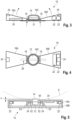
Figur 2 in einer schematischen Schnittansicht das Füllstandsmessgerät vonFigur 1 ; -
Figur 3 in einer schematischen Schnittansicht ein Füllstandsmessgerät gemäß einer zweiten Ausführungsform; -
Figur 4 das Füllstandsmessgerät vonFigur 3 in einer Draufsicht; -
Figur 5 in einer schematischen Schnittansicht ein Füllstandsmessgerät gemäß einer dritten Ausführungsform; -
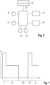
Figur 6 schematisch die elektronischen Komponenten eines erfindungsgemäßen Füllstandsmessgeräts; -
Figur 7 in einem Diagramm die vom Füllstandsmessgerät verwendete Abtastrate über der Zeit; -
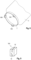
Figur 8 in einer perspektivischen, abgebrochenen Ansicht drei Abstandshalterelemente, die an einem Behälter angebracht sind; und -
Figur 9 in einer vergrößerten, perspektivischen Ansicht eines der inFigur 8 gezeigten Abstandshalterelemente. - In
Figur 1 ist ein Behälter 2 gezeigt, in dessen Innenraum sich eine Flüssigkeit 3 befindet Die Flüssigkeit 3 füllt den Innenraum des Behälters 2 bis zu einem Füllstand F; oberhalb des Flüssigkeitsspiegels befindet sich ein gasförmiges Medium 4. Bei diesem kann es sich um verdampfte Flüssigkeit 3 handeln oder um Luft, die einen gewissen Anteil an verdampfter Flüssigkeit 3 aufgenommen hat. - Im gezeigten Ausführungsbeispiel handelt es sich beim Behälter 2 um eine Flüssiggasflasche, die mit einem Gasanschluss 5, einem Boden 6 und einem Fußring 7 versehen ist. Mit dem Fußring 7 steht die Flüssiggasflasche auf einem Untergrund 8, beispielsweise dem Boden eines Gaskastens eines Reisemobils. Die Wand 9 der Flüssiggasflasche besteht aus einer ferromagnetischen Stahllegierung.
- Am Boden 6 der Flüssiggasflasche ist ein Füllstandsmessgerät 10 angebracht, mit dem der Füllstand F innerhalb der Flüssiggasflasche und damit die Menge des sich in der Flüssiggasflasche befindenden Flüssiggases bestimmt werden kann.
- Auch wenn das Füllstandsmessgerät 10 nachfolgend im Zusammenhang mit einer Flüssiggasflasche beschrieben wird, ist es grundsätzlich dafür geeignet und vorgesehen, bei anderen Arten von Behältern 2 verwendet zu werden. Es ist auch nicht zwingend notwendig, das Füllstandsmessgerät 10 am Boden 6 eines Behälters anzubringen. Das Füllstandsmessgerät 10 könnte beispielsweise auch an der Seitenwand oder auf der Oberseite des Behälters angeordnet sein.
- Das Füllstandsmessgerät 10 arbeitet zur Bestimmung des Füllstandes F im Behälter 2 mit Ultraschall. Allgemein ausgedrückt werden Ultraschallwellen erzeugt, die in die Wand 9 des Behälters (beim gezeigten Ausführungsbeispiel konkret in den Boden 6) eingekoppelt werden. Von dort laufen die Ultraschallwellen als Signal S durch die Flüssigkeit und werden an der Grenzfläche zwischen flüssigem Medium und gasförmigem Medium reflektiert, sodass sie als Echo E zurücklaufen. Dieses Echo kann vom Füllstandsmessgerät 10 erfasst werden. Aus der Laufzeit der Schallwellen kann auf den Füllstand geschlossen werden, und dieser Füllstand kann, wenn die Geometrie des Behälters 2 bekannt ist, in eine Füllmenge (entweder Liter oder Kilogramm) umgerechnet werden.
- Das Füllstandsmessgerät 10 weist einen Ultraschall-Messkopf 12 auf, der insbesondere eine Piezokeramik ist. Auf der dem Behälter 2 zugewandten Seite ist der Ultraschall-Messkopf 12 mit einem Koppelkissen 14 versehen, das aus einem Elastomer besteht, beispielsweise Silikon. Das Koppelkissen 14 dient dazu, die Schwingungen der Piezokeramik in die Wand des Behälters 2 einzukoppeln und umgekehrt die aus dem Echo E resultierenden Schwingungen der Wand des Behälters 2 wieder zur Piezokeramik zu übertragen.
- Der Ultraschall-Messkopf 12 ist in einem Gehäuse 16 angeordnet, das hier zweiteilig ausgeführt ist. Es besteht aus einem Gehäuseteil 16A und einem Gehäuseteil 16B, die miteinander verbunden sind. Beim gezeigten Ausführungsbeispiel ist hier ein schematisch dargestelltes Scharnier 18 vorhanden.
- Das Füllstandsmessgerät 10 ist weiterhin mit einer Steuerung 20 versehen, mit der die Messung des Füllstandes vorgenommen werden kann. Einzelheiten der Steuerung werden später mit Bezug auf
Figur 5 erläutert. - Es ist eine Energieversorgung in der Form von zwei austauschbaren Batterien 22 vorgesehen, die die zum Betrieb der Steuerung 20 notwendige elektrische Energie bereitstellt. Bei den Batterien kann es sich um handelsübliche Batterien der Größe AA handeln.
- Die Batterien 22 sind dabei möglichst weit außen in den Gehäuseteilen 16A, 16B angeordnet, also mit großem Abstand vom Scharnier 18.
- Um das Füllstandsmessgerät 10 am Behälter 2 befestigen zu können, ist eine Befestigungsvorrichtung 24 vorgesehen, die hier aus zwei Magneten besteht. Dabei ist in jedem Gehäuseteil 16A, 16B ein Magnet 24 angeordnet, und zwar auf der vom Scharnier 18 abgewandten Seite.
- Der Ultraschall-Messkopf 12 ist im Gehäuse 16 elastisch federnd angeordnet, und zwar so, dass er aus dem Gehäuse 16 heraus zu der Seite hin beaufschlagt wird, auf der die Magnete 24 angeordnet sind.
- Für die federnde Anbringung des Ultraschall-Messkopfes sind hier zwei Federn 26 vorgesehen.
- Die Federn 26 können separate Federn sein, die in den Gehäuseteilen 16A, 16B montiert sind. Bevorzugt werden die Federn 26 jedoch einstückig mit den Gehäuseteilen 16A, 16B hergestellt, nämlich als Spritzgusselemente der Gehäuseteile 16A, 16B.
- Das Gehäuse 16 ist mit einem Federbügel 28 versehen, der zwischen den beiden Gehäuseteilen 16A, 16B wirksam ist. Der Federbügel 28 beaufschlagt die beiden Gehäuseteile relativ zueinander in der Richtung der in
Figur 2 gezeigten Pfeile P, also die Magnete 24 weg von einer "Oberseite", die definiert ist durch die Seite, auf der sich das Koppelkissen 14 befindet. - Um das Füllstandsmessgerät 10 am Behälter 2 anzubringen, wird es so am Boden 6 angesetzt, dass der Ultraschall-Messkopf 12 sich etwa am tiefsten Punkt des Bodens befindet. Dann werden die beiden Gehäuseteile 16A, 16B entgegen der Wirkung des Federbügels 28 so gegen den Boden 6 gedrückt, dass die Magnete 24 magnetisch am Boden 6 haften. Aufgrund der Wirkung des Federbügels 28 wird dabei das Gehäuse 16 im Bereich des Scharniers 18 gegen den gekrümmten Boden 6 des Behälters 2 gedrückt, wodurch der Ultraschall-Messkopf 12 mit seinem Koppelkissen 14 gegen den Boden 6 des Behälters 2 gedrückt wird. Die Federn 26 sorgen dabei für die gewünschte (im Hinblick auf das Übertragen von Ultraschallwellen nötige) Anpresskraft und auch für einen Toleranzausgleich.
- In den
Figuren 3 und 4 ist eine zweite Ausführungsform des Füllstandsmessgeräts 10 gezeigt. Für die von der ersten Ausführungsform bekannten Bauteile werden dieselben Bezugszeichen verwendet, und es wird insoweit auf die obigen Erläuterungen verwiesen. - Der Unterschied zwischen der ersten und der zweiten Ausführungsform besteht darin, dass bei der zweiten Ausführungsform die beiden Gehäuseteile 16A, 16B nicht aneinander, sondern an entgegengesetzten Seiten eines mittigen Gehäuseteils 16C angebracht sind. Im Gehäuseteil 16C ist der Ultraschall-Messkopf 12 angebracht. Hierfür können wie bei der ersten Ausführungsform Federn verwendet werden.
- Als Scharnier 18 zwischen dem ersten Gehäuseteil 16A und dem dritten Gehäuseteil 16C bzw. dem dritten Gehäuseteil 16C und dem zweiten Gehäuseteil 16B wird anders als bei der ersten Ausführungsform kein festes Scharnier verwendet, sondern ein Elastomergelenk, welches die gewünschte Beweglichkeit zwischen den Gehäuseteilen ermöglicht.
- In die Gehäuseteile 16A, 16B, 16C ist auch bei der zweiten Ausführungsform ein Federbügel 28 integriert, der die Gehäuseteile 16A, 16B, 16C in eine Ausgangsstellung beaufschlagt. In der Ausgangsstellung können sich die Unterseiten der drei Gehäuseteile in einer Ebene erstrecken (siehe
Figur 3 ). - Ein weiterer Unterschied zwischen der ersten und der zweiten Ausführungsform besteht darin, dass bei der zweiten Ausführungsform die Energieversorgung (auch hier werden Batterien 22 verwendet) nicht aufgeteilt ist auf zwei Gehäuseteile, sondern dass zwei Batterien 22 nebeneinanderliegend in einem Gehäuseteil angeordnet sind (hier dem zweiten Gehäuseteil 16B). In der gleichen Weise wie bei der ersten Ausführungsform sind die Batterien 22 jedoch weit außen angeordnet.
- Das Füllstandsmessgerät 10 gemäß der zweiten Ausführungsform wird in derselben Weise am Behälter montiert, wie dies für die erste Ausführungsform erläutert wurde. Wenn die beiden Gehäuseteile 16A, 16B so an die Wand des Behälters 2 angenähert werden, dass die Magnete 24 an der Wand 9 des Behälters haften, wird automatisch die gewünschte Vorspannung zwischen dem Ultraschall-Messkopf 12 und der Wand des Behälters erzeugt.
- In
Figur 5 ist ein Füllstandsmessgerät gemäß einer dritten Ausführungsform gezeigt. Für die von den vorhergehenden Ausführungsformen bekannten Bauteile werden dieselben Bezugszeichen verwendet, und es wird insoweit auf die obigen Erläuterungen verwiesen. - Bei der dritten Ausführungsform wird ein starres Gehäuse 16 verwendet, das aus einem Oberteil 16A und einem Unterteil 16B besteht. Die beiden Teile 16A, 16B können miteinander verclipst sein, so dass ein Benutzer die darin aufgenommenen Batterien 22 mit geringem Aufwand wechseln kann.
- Alternativ ist auch möglich, auf der Unterseite zwei kleine Deckel zu jeweils einem Batteriefach vorzusehen, so dass ein Benutzer die Batterien wechseln kann, ohne die beiden Teile 16A, 16B voneinander zu trennen.
- Der Unterschied zwischen der dritten und den ersten beiden Ausführungsformen besteht darin, dass bei der dritten Ausführungsform der Ultraschall-Messkopf 12 starr im Gehäuse angebracht ist.
- Die nötige Vorspannung zwischen der Wand des Behälters 2 und dem Ultraschall-Messkopf 12 wird hier allein durch die Dimensionierung des Koppelkissens 14 und dessen Material erzielt.
- Das Koppelkissen 14 steht geringfügig über die dem Behälter 2 zugewandte Seite des Gehäuses 16 über. Der Überstand s kann in der Größenordnung von 1 bis 2 mm betragen.
- Wenn das Füllstandsmessgerät 10 an einen Behälter angesetzt wird (siehe die in
Figur 5 gestrichelt angedeutete Bodenwand 6 eines Behälters), komprimiert dessen Wand das Koppelkissen 14 unter der Wirkung der Anziehungskraft der Befestigungsvorrichtung 24, so dass sich die gewünschte Vorspannung ergibt. Das Koppelkissen 14 kann dabei seitlich ausweichen, da zwischen dem Gehäuses 16 und dem Koppelkissen ein ringförmiger Freiraum 50 vorgesehen ist. - Der Überstand s des Koppelkissens definiert, wie weit das Koppelkissen 14 (bei einer Wand eines Behälters mit dem geringsten Krümmungsradius) maximal zusammengedrückt werden kann.
- Ein weiterer Unterschied zwischen der dritten und den ersten beiden Ausführungsformen besteht darin, dass bei der dritten Ausführungsform im Gehäuse ein Lastübertragungsabschnitt 52 vorgesehen ist. Dieser dient dazu, Belastungen, die auf die vom Behälter 2 abgewandte Seite des Gehäuses 16 wirken, direkt auf die dem Behälter 2 zugewandten Seite des Gehäuses 16 und von dort auf die Wand des Behälters 2 zu übertragen.
- Der Lastübertragungsabschnitt ist hier als von der Oberseite zur Unterseite des Gehäuses 16 durchgehender Materialabschnitt ausgeführt. Er ist ringförmig und umgibt den Ultraschall-Messkopf 12 und das Koppelkissen 14, so dass der Freiraum 50 vorhanden ist. Alternativ könnten auch mehrere getrennte, beispielsweise pfostenartig ausgeführte Lastübertragungsabschnitte verwendet werden.
- Wenn auf das Füllstandsmessgerät 10 übermäßig hohe Belastungen wirken (beispielsweise wenn der mit dem Füllstandsmessgerät 10 versehene Behälter 2 auf einem Kiesboden abgesetzt wird und ein Stein gegen das Gehäuse 16 drückt), werden diese Belastungen durch das Gehäuse übertragen und in die Wand des Behälters 2 eingeleitet. Das Gehäuse kann dabei nicht beschädigt werden, da der Lastübertragungsabschnitt sich direkt vom Boden (hier: vom Unterteil 16B) zur Oberseite des Gehäuses 16 (hier: zum Oberteil 16A) erstreckt.
- Gleichzeitig wird das Koppelkissen vor übermäßig hohen Belastungen geschützt, da sich an einer bestimmten Belastung die Oberseite des Gehäuses 16 am Behälter abstützt und das Koppelkissen 14 nicht weiter komprimiert werden kann.
- Als Befestigungsvorrichtung kann ein ringförmiger Magnet 24 verwendet werden, der in einer ringförmigen Aufnahme 60 angeordnet ist. Der Boden der Aufnahme 60 (bei der in
Figur 5 gezeigten Ausrichtung des Gehäuses: die Oberseite der Aufnahme) ist von einer Wand des Gehäuses gebildet. Die radial innenliegende Seite der Aufnahme ist hier vom Lastaufnahmeabschnitt 52 gebildet. - Wenn das Füllstandsmessgerät 10 an einem Behälter angebracht ist, zieht der Magnet das Gehäuse 16 gegen den Behälter, so dass das Füllstandmessgerät 10 an der Wand des Behälters fixiert ist. Gleichzeitig ziehen die Haftkräfte den Magneten 24 gegen die Wand, die die Aufnahme 60 begrenzt. Es ist also ausreichend, den Magneten 24 lediglich so zu sichern, dass er nicht aus der Aufnahme 60 herausfällt.
- Die radial außenliegende Seite der Aufnahme (Materialabschnitt 53) erstreckt sich hier bis zum Unterteil 16B des Gehäuses 16 und wirkt somit als Teil des Lastübertragungsabschnitts 52.
- Alternativ zu einem ringförmigen Magneten 24 können auch mehrere einzelne Magnete verwendet werden. Diese werden dann um den Ultraschall-Messkopf 12 herum angeordnet. Beispielsweise können drei Magnete verwendet werden, die in separaten Aufnahmen konzentrisch im Abstand von 120° um den Ultraschall-Messkopf 12 herum angeordnet sind.
- Die Merkmale eines Lastübertragungsabschnittes 52 und einer Aufnahme für die Magnete, die auf der Seite des Behälters von einer Wand des Gehäuses 16 geschlossen ist, können einzeln oder in Kombination auch bei der ersten oder der zweiten Ausführungsform verwendet werden.
- Bei allen Ausführungsformen des Gehäuses kann die Steuerung 20 (siehe
Figur 6 ) den Ultraschall-Messkopf 12 geeignet ansteuern, um dort Ultraschallwellen zu erzeugen und zu erfassen, wenn ein Ultraschall-Echo auf den Ultraschall-Messkopf 12 trifft. - Um die Genauigkeit der Füllstandsmessung zu erhöhen, ist vorzugsweise ein Temperatursensor 30 vorgesehen, der es der Steuerung 20 ermöglicht, bei der Auswertung des Laufzeitsignals die (angenäherte) Temperatur der Flüssigkeit 3 im Behälter 2 zu berücksichtigen. Der Temperatursensor 30 kann beispielsweise in das Koppelkissen 14 eingegossen sein, sodass die von ihm gemessene Temperatur wenigstens zu einem gewissen Teil von der Temperatur der Wand 9 abhängt, gegen die das Koppelkissen 14 bei einer Messung gedrückt wird. Alternativ ist es möglich, den Temperatursensor 30 innerhalb des Gehäuses 16 anzuordnen.
- Die Steuerung 20 verfügt weiterhin über ein Prognosemodul, mit dem die Steuerung 20 in Abhängigkeit vom aktuell vorhandenen Füllstand und abhängig von Verbrauchswerten aus der Vergangenheit hochrechnen kann, wie lange der Vorrat an Flüssigkeit 3 in der Flasche 2 noch hält (unter der Annahme, dass sich die Verbrauchswerte nicht erheblich ändern).
- Weiterhin ist ein Kennlinienmodul 34 vorgesehen, in dem die Menge (oder das Volumen) von sich im Behälter 2 befindender Flüssigkeit 3 in Abhängigkeit vom Füllstand F niedergelegt ist. Im Kennlinienmodul 34 kann auch niedergelegt sein, um welche Art von Flüssigkeit 3 es sich im Behälter 2 handelt. Dies ist dann relevant, wenn das Füllstandsmessgerät 10 universell zur Füllstandsmessung in ganz unterschiedlichen Behältern verwendet werden soll, da unterschiedliche Flüssigkeiten unterschiedliche Schallgeschwindigkeiten haben, die bei der Füllstandsmessung berücksichtigt werden müssen.
- Der Steuerung 20 ist eine Kommunikationsschnittstelle 36 zugeordnet, über die einem Benutzer das Ergebnis der Füllstandsmessung zur Verfügung gestellt wird.
- Im gezeigten Ausführungsbeispiel handelt es sich bei der Kommunikationsschnittstelle 36 um eine drahtlose Kommunikationsschnittstelle, die nach dem Bluetooth-Standard arbeitet. Über diese ist es möglich, einem Empfänger 38 (siehe
Figur 1 ) das Messergebnis zu senden. - Beim Empfänger 38 kann es sich beispielsweise um ein Smartphone eines Benutzers handeln. Dieses kann sich mit dem Füllstandsmessgerät 10 koppeln und entweder einen Messvorgang auslösen oder einen Füllstands-Messwert abrufen, der in einem Messwertespeicher 40 der Steuerung 20 hinterlegt ist.
- Beim Empfänger 38 kann es sich auch um eine übergeordnete Gerätesteuerung handeln, beispielsweise in einem Reisemobil. Mit dieser werden zentral verschiedene Geräte wie ein Kühlschrank, eine Klimaanlage oder eine Wasserversorgung angesteuert und überwacht. Dieser Gerätesteuerung kann die Steuerung 20 des Füllstandsmessgeräts 10 einen Füllstands-Messwert übermitteln, sodass er einem Benutzer auf einem zentralen Bedienfeld angezeigt werden kann.
- Der Messwertspeicher 40 gewährleistet auch, dass es keinerlei Datenverlust gibt, wenn die Kommunikation mit einem Empfänger 38 zwischenzeitlich verloren geht; dennoch sind beispielsweise Prognosedaten jederzeit wieder verfügbar. Außerdem können Messwerte problemlos mehreren Empfängern 38 zur Verfügung gestellt werden, auch wenn einige von ihnen erst kürzlich mit der Kommunikationsschnittstelle 36 verbunden wurden.
- Wenn das Füllstandsmessgerät 10 neu an einem Behälter 2 angebracht wird, kann anfänglich mit einer hohen Abtastrate gearbeitet werden (siehe den Bereich I in
Figur 7 ). Beispielsweise können Messungen des Füllstands in Intervallen von einer Sekunde durchgeführt werden. Die dabei ermittelten Messwerte werden gemittelt, sodass nach relativ kurzer Zeit (beispielsweise maximal einer Minute) recht zuverlässig der aktuelle Füllstand ermittelt ist. Anschließend (entweder zeitgesteuert oder wenn die Steuerung erkennt, dass die ermittelten Füllstände ausreichend stabil um einen Mittelwert schwanken) wird die Abtastrate verringert (siehe den Bereich 2 inFigur 7 ). Beispielsweise wird die Abtastrate auf eine Messung je Minute verringert. Diese Abtastrate ist ausreichend, um eine Änderung des Füllstandes F des Behälters 2 zu erfassen und auch eine Prognose über die Reichweite des verbleibenden Füllstandes abzugeben. - Wenn die Steuerung 20 über einen gewissen (u. U. vom Benutzer vorgebbaren) Zeitraum erkennt, dass sich der Füllstand F nicht ändert, kann die Abtastrate weiter verringert werden (siehe den Bereich III in
Figur 7 ). Beispielsweise erfolgt nur noch eine Messung je Stunde. - Erkennt die Steuerung 20, dass mit der Kommunikationsschnittstelle 36 kein Empfänger 38 mehr gekoppelt ist, kann die Abtastrate auch auf Null herabgesetzt werden.
- Auf ein äußeres Signal hin (entweder eine Änderung des Füllstandes hin oder auf ein Koppeln eines Empfängers 38 mit der Kommunikationsschnittstelle 36) wird die Abtastrate wieder erhöht (siehe den Bereich IV von
Figur 7 ). Dabei können entweder, wie dies hier dargestellt ist, Messungen mit einer hohen Abtastrate vorgenommen werden (dies empfiehlt sich insbesondere, wenn in der Zwischenzeit eine Abtastrate von Null verwendet wurde), um zuverlässig einen Start-Füllstand bei einem u. U. ausgetauschten Behälter ermitteln zu können. Alternativ kann mit einer mittleren Abtastrate (entsprechend dem Bereich V vonFigur 7 ) fortgefahren werden, um den Verbrauch und den sich dementsprechend ändernden Füllstand wieder zuverlässig weiterschreiben zu können. - Aufgrund der variablen Abtastrate und insbesondere aufgrund der Tatsache, dass die Abtastrate weitestgehend gesenkt wird, wenn dies ohne Einbußen hinsichtlich der Messgenauigkeit möglich ist, kann mit einem Satz von Batterien 22 eine Betriebsdauer von bis zu einen Jahr erhalten werden.
- Bei verschiedenen Anwendungen kann es vorteilhaft sein, einen Abstandshalter 50 zwischen dem Behälter 2 und dem Untergrund 8 vorzusehen. Mit einem Abstandshalter 50 kann, wenn dieser aus Kunststoff besteht, ein Zwischenraum zwischen dem Fußring 7 und dem u. U. metallischen Boden eines Gaskastens erzeugt werden, wodurch die drahtlose Kommunikation zwischen der Kommunikationsschnittstelle 36 und dem Empfänger 38 verbessert wird.
- Ein Abstandshalter 50 kann auch dann vorteilhaft sein, wenn der Behälter 2 mit dem daran angebrachten Füllstandsmessgerät 10 auf einem losen Untergrund abgesetzt werden soll, beispielsweise Kies. Hierbei besteht die Gefahr, dass sich der Fußring 7 in den Untergrund 8 eingräbt und das Füllstandsmessgerät 10 unter dem Gewicht des Behälters 2 gegen hervorstehende Bereiche des Untergrundes 8 gedrückt wird.
- Der Abstandshalter 50 kann beispielsweise ein umlaufender Ring (siehe
Figur 1 ) sein, der an den Durchmesser des Fußrings 7 angepasst ist und mit mehreren kleineren Magneten versehen sein kann, sodass er am Fußring 7 haftet. Dies erleichtert die Handhabung. - Der Abstandshalter 50 kann auch durch mehrere Abstandshalterelemente 50A, 50B, 50C gebildet sein, wie sie in den
Figuren 8 und 9 dargestellt sind. Die Abstandshalterelemente 50A, 50B, 50C sind hier klipsartige Kunststoffteile, die mit einem Schlitz 52 eines ersten Typs und einem Schlitz 54 eines zweiten Typs versehen sind. Die Schlitze 52, 54 sind an unterschiedliche Fußringe 7 angepasst, sodass die Abstandshalterelemente bei unterschiedlichen Behältern 2 verwendet werden können. Je nach Behältertyp werden die Abstandshalterelemente in der einen oder anderen Ausrichtung am Fußring 7 angeklipst. - Das Füllstandsmessgerät 10 lässt sich auch mit anderen Ausführungen von Befestigungsvorrichtungen 24 an Behältern 2 anbringen. Beispielsweise kann eine Federklammer verwendet werden, mit der das Füllstandsmessgerät 10 innerhalb eines Fußrings 7 angebracht wird. Diese Federklammer kann sich dann an einem umgebördelten Randabschnitt des Fußrings 7 abstützen.
- Es ist auch möglich, einen Spanngurt zu verwenden, um das Füllstandsmessgerät 10 am Umfang der Wand 9 anzubringen.
- Das Füllstandsmessgerät 10 kann auch auf die Wand 9 des Behälters aufgeklebt werden.
- Gemäß einer Ausführungsvariante ist das Füllstandsmessgerät 10 mit Strombegrenzungsdioden versehen, die gewährleisten, dass die der Steuerung 20 zur Verfügung gestellte Energie unterhalb gewisser Grenzen bleibt. Hierdurch ist es nicht notwendig, die Bauteile der Steuerung explosionssicher zu vergießen um das Füllstandsmessgerät problemlos in explosionsgefährdeten Bereichen einsetzen zu können.
Claims (8)
- Baugruppe aus einem Füllstandsmessgerät (10) zum Messen des Füllstandes in einem Behälter (2) durch dessen Wand (9) hindurch mittels Ultraschall, mit einem Ultraschall-Messkopf (12), einer Steuerung (20) und einer Befestigungsvorrichtung (24), mittels der das Füllstandsmessgerät (10) so am Behälter (2) befestigt werden kann, dass der Ultraschall-Messkopf (12) gegen die Wand (9) des Behälters (2) gedrückt wird, wobei eine drahtlose Kommunikationsschnittstelle (36) vorgesehen ist, die eine Sende-/ Empfangseinheit enthält, und mindestens einem Abstandshalter (50), der am unteren Rand eines mit dem Füllstandsmessgerät (10) zu versehenden Behälters (2) angebracht werden kann, um den Abstand zwischen dem Boden des Behälters und dem Untergrund zu erhöhen, dadurch gekennzeichnet, dass der Abstandshalter ein Sockel (50) mit geschlossenem Boden ist und der Sockel (50) mit mindestens zwei Positioniergestaltungen für zwei Arten von Behältern versehen ist.
- Baugruppe aus einem Füllstandsmessgerät (10) zum Messen des Füllstandes in einem Behälter (2) durch dessen Wand (9) hindurch mittels Ultraschall, mit einem Ultraschall-Messkopf (12), einer Steuerung (20) und einer Befestigungsvorrichtung (24), mittels der das Füllstandsmessgerät (10) so am Behälter (2) befestigt werden kann, dass der Ultraschall-Messkopf (12) gegen die Wand (9) des Behälters (2) gedrückt wird, wobei eine drahtlose Kommunikationsschnittstelle (36) vorgesehen ist, die eine Sende-/ Empfangseinheit enthält, und mindestens einem Abstandshalter (50), der am unteren Rand eines mit dem Füllstandsmessgerät (10) zu versehenden Behälters (2) angebracht werden kann, um den Abstand zwischen dem Boden des Behälters und dem Untergrund zu erhöhen, dadurch gekennzeichnet, dass der Abstandshalter aus drei oder mehr Abstandshalterelementen (50A, 50B, 50C) besteht, die am unteren Rand des Behälters (2) angeclipst werden können und dass jedes Abstandshalterelement (50A, 50B, 50C) mit einem Schlitz (52) eines ersten Typs und mindestens einem zweiten Schlitz (52) eines weiteren Typs versehen ist.
- Baugruppe nach Anspruch 2, dadurch gekennzeichnet, dass die Abstandshalterelemente (50A, 50B, 50C) in der einen oder anderen Ausrichtung am unteren Rand des Behälters (2) anklipsbar sind.
- Baugruppe nach einem der Ansprüche 2 und 3, dadurch gekennzeichnet, dass die Abstandshalterelemente (50A, 50B, 50C) aus einem elastischen Kunststoff bestehen.
- Baugruppe nach einem der vorhergehenden Ansprüche, dadurch gekennzeichnet, dass die Befestigungsvorrichtung mindestens einen Magnet (24) enthält.
- Baugruppe nach einem der Ansprüche 2 und 3, dadurch gekennzeichnet, dass die Befestigungsvorrichtung (24) einen Klebstoff enthält.
- Baugruppe nach einem der vorhergehenden Ansprüche, dadurch gekennzeichnet, dass die Befestigungsvorrichtung (24) eine Federklammer enthält.
- Baugruppe nach einem der vorhergehenden Ansprüche, dadurch gekennzeichnet, dass die Befestigungsvorrichtung (24) einen Spanngurt enthält.
Applications Claiming Priority (4)
| Application Number | Priority Date | Filing Date | Title |
|---|---|---|---|
| DE102015113908.1A DE102015113908B4 (de) | 2015-08-21 | 2015-08-21 | Füllstandsmessgerät |
| US15/042,890 US10180343B2 (en) | 2015-08-21 | 2016-02-12 | Device and method for measuring the level of liquid in a container |
| EP16757208.0A EP3338067B1 (de) | 2015-08-21 | 2016-08-19 | Füllstandsmessgerät sowie baugruppe bestehend aus einem füllstandsmessgerät und mindestens einem abstandshalter |
| PCT/EP2016/069670 WO2017032698A1 (de) | 2015-08-21 | 2016-08-19 | Füllstandsmessgerät, verfahren zum betreiben eines füllstandsmessgeräts sowie baugruppe bestehend aus einem füllstandsmessgerät und mindestens einem abstandshalter |
Related Parent Applications (2)
| Application Number | Title | Priority Date | Filing Date |
|---|---|---|---|
| EP16757208.0A Division-Into EP3338067B1 (de) | 2015-08-21 | 2016-08-19 | Füllstandsmessgerät sowie baugruppe bestehend aus einem füllstandsmessgerät und mindestens einem abstandshalter |
| EP16757208.0A Division EP3338067B1 (de) | 2015-08-21 | 2016-08-19 | Füllstandsmessgerät sowie baugruppe bestehend aus einem füllstandsmessgerät und mindestens einem abstandshalter |
Publications (3)
| Publication Number | Publication Date |
|---|---|
| EP3792602A1 EP3792602A1 (de) | 2021-03-17 |
| EP3792602C0 EP3792602C0 (de) | 2024-08-07 |
| EP3792602B1 true EP3792602B1 (de) | 2024-08-07 |
Family
ID=57961311
Family Applications (6)
| Application Number | Title | Priority Date | Filing Date |
|---|---|---|---|
| EP21174709.2A Active EP3885718B1 (de) | 2015-08-21 | 2016-08-19 | Verfahren zum betreiben eines füllstandsmessgeräts |
| EP20182604.7A Active EP3734240B1 (de) | 2015-08-21 | 2016-08-19 | Verfahren zum betreiben eines füllstandsmessgeräts |
| EP20206361.6A Active EP3792602B1 (de) | 2015-08-21 | 2016-08-19 | Baugruppe bestehend aus einem füllstandsmessgerät und mindestens einem abstandshalter |
| EP21174705.0A Active EP3896406B1 (de) | 2015-08-21 | 2016-08-19 | Verfahren zum betreiben eines füllstandsmessgeräts |
| EP16757208.0A Active EP3338067B1 (de) | 2015-08-21 | 2016-08-19 | Füllstandsmessgerät sowie baugruppe bestehend aus einem füllstandsmessgerät und mindestens einem abstandshalter |
| EP21174700.1A Active EP3889557B1 (de) | 2015-08-21 | 2016-08-19 | Füllstandsmessgerät |
Family Applications Before (2)
| Application Number | Title | Priority Date | Filing Date |
|---|---|---|---|
| EP21174709.2A Active EP3885718B1 (de) | 2015-08-21 | 2016-08-19 | Verfahren zum betreiben eines füllstandsmessgeräts |
| EP20182604.7A Active EP3734240B1 (de) | 2015-08-21 | 2016-08-19 | Verfahren zum betreiben eines füllstandsmessgeräts |
Family Applications After (3)
| Application Number | Title | Priority Date | Filing Date |
|---|---|---|---|
| EP21174705.0A Active EP3896406B1 (de) | 2015-08-21 | 2016-08-19 | Verfahren zum betreiben eines füllstandsmessgeräts |
| EP16757208.0A Active EP3338067B1 (de) | 2015-08-21 | 2016-08-19 | Füllstandsmessgerät sowie baugruppe bestehend aus einem füllstandsmessgerät und mindestens einem abstandshalter |
| EP21174700.1A Active EP3889557B1 (de) | 2015-08-21 | 2016-08-19 | Füllstandsmessgerät |
Country Status (14)
| Country | Link |
|---|---|
| US (4) | US10180343B2 (de) |
| EP (6) | EP3885718B1 (de) |
| JP (2) | JP6839657B2 (de) |
| CN (2) | CN112212944A (de) |
| AU (3) | AU2016311193B2 (de) |
| BR (1) | BR112017020455B1 (de) |
| CA (1) | CA2979834A1 (de) |
| CL (2) | CL2018000404A1 (de) |
| DE (1) | DE102015113908B4 (de) |
| MA (1) | MA41525B1 (de) |
| MX (3) | MX2018002250A (de) |
| NZ (1) | NZ735612A (de) |
| RU (1) | RU2722058C2 (de) |
| WO (1) | WO2017032698A1 (de) |
Families Citing this family (29)
| Publication number | Priority date | Publication date | Assignee | Title |
|---|---|---|---|---|
| DE102015113908B4 (de) * | 2015-08-21 | 2023-05-04 | Truma Gerätetechnik GmbH & Co. KG | Füllstandsmessgerät |
| AU201712794S (en) | 2016-11-23 | 2017-05-23 | Dometic Sweden Ab | Ventilation and air conditioning apparatus |
| US10725160B2 (en) | 2017-04-07 | 2020-07-28 | Rosemount Tank Radar Ab | Non-invasive radar level gauge |
| US11261075B2 (en) * | 2017-04-27 | 2022-03-01 | DC Devices LLC | System and method for determining a liquid level in a vessel |
| US10718654B2 (en) * | 2017-04-27 | 2020-07-21 | DC Devices LLC | System and method for determining a liquid level in a vessel |
| AU2018366469B2 (en) | 2017-11-16 | 2024-09-12 | Dometic Sweden Ab | Air conditioning apparatus for recreational vehicles |
| EP3605032B1 (de) * | 2018-08-02 | 2021-06-02 | VEGA Grieshaber KG | Radarsensor zur füllstand- oder grenzstandmessung |
| USD905217S1 (en) | 2018-09-05 | 2020-12-15 | Dometic Sweden Ab | Air conditioning apparatus |
| US10889484B2 (en) * | 2019-01-15 | 2021-01-12 | Haier Us Appliance Solutions, Inc. | System and method for sensing a liquid level in an autofill pitcher using vibrations |
| JP2022529882A (ja) * | 2019-03-12 | 2022-06-27 | サノフイ | 薬剤レベルを測定するための装置 |
| CN109764927B (zh) * | 2019-03-14 | 2023-12-19 | 长沙学院 | 浮子式智能溶液深度测量装置及测量方法 |
| TWI708045B (zh) * | 2019-06-28 | 2020-10-21 | 黃智淵 | 桶裝物料的配送系統及其操作方法 |
| CN112141647A (zh) * | 2019-06-28 | 2020-12-29 | 黄智渊 | 桶装物料的配送系统及其操作方法 |
| GB2585228B (en) * | 2019-07-04 | 2023-06-14 | The Smart Container Company Ltd | Monitoring device |
| IT201900019193A1 (it) | 2019-10-17 | 2021-04-17 | Dometic Sweden Ab | Apparato di condizionamento dell'aria per veicoli ricreativi |
| WO2021081142A1 (en) * | 2019-10-22 | 2021-04-29 | Amtrol Licensing Inc. | Tank level sensor and management system |
| CN110793601B (zh) * | 2019-11-29 | 2021-07-30 | 三一汽车制造有限公司 | 料位计的校准方法、料位计与沥青站 |
| WO2021197613A1 (de) * | 2020-04-03 | 2021-10-07 | Vega Grieshaber Kg | Sensor mit befestigungsmittel, behälter und verwendung |
| DE102020114777A1 (de) | 2020-06-03 | 2021-12-09 | Tdk Electronics Ag | Ultraschallwandler und Verfahren zum Betrieb eines Ultraschallwandlers |
| TWI775685B (zh) * | 2021-11-25 | 2022-08-21 | 凌波股份有限公司 | 非金屬容器的液態燃料容量偵測裝置 |
| CN114136397B (zh) * | 2021-12-31 | 2025-02-25 | 成都星科圣非低温设备有限公司 | 磁扭压力转化装置 |
| KR20240017698A (ko) * | 2022-08-01 | 2024-02-08 | 주식회사 엘지에너지솔루션 | 액체보관용기 내 액체의 잔량 측정방법 및 측정장치 |
| US12529621B2 (en) | 2022-08-04 | 2026-01-20 | Air Products And Chemicals, Inc. | Compressed fluid vessel monitoring apparatus and method |
| DE102022122949A1 (de) | 2022-09-09 | 2024-03-14 | SCHäFER WERKE GMBH | Verfahren zur indirekten Messung des Füllstandes in einem Gefäß |
| GB2625585A (en) * | 2022-12-21 | 2024-06-26 | Manholemetrics Ltd | Water level sensor |
| US20240245000A1 (en) * | 2023-01-24 | 2024-07-25 | Bin Slide, Llc | Sensor, sensor housing, and attachment for monitoring bin product level |
| CN122003583A (zh) * | 2023-06-05 | 2026-05-08 | 天道科技股份有限公司 | 用于流体质量确定的装置、系统和方法 |
| DE102023134620A1 (de) * | 2023-12-11 | 2025-06-12 | Vega Grieshaber Kg | Sensor, Halterung und Sensorsystem |
| US20250362166A1 (en) * | 2024-04-05 | 2025-11-27 | Rochester Sensors, Llc | Method and system for detecting fill in fluid storage systems |
Family Cites Families (89)
| Publication number | Priority date | Publication date | Assignee | Title |
|---|---|---|---|---|
| CH162704A (de) | 1932-06-18 | 1933-07-15 | Schneggenburger Johann | Untersatz für Abraumbehälter etc. |
| DE860700C (de) | 1951-08-17 | 1952-12-22 | Franz Bergs | Schutzeinfassung fuer den Bodenrand von Gefaessen, wie Eimer u. dgl. |
| FR1052525A (fr) | 1952-03-17 | 1954-01-25 | Dispositif protecteur pour seaux et autres récipients | |
| US4398424A (en) * | 1980-12-16 | 1983-08-16 | Micro Pure Systems, Inc. | Ultrasonic sensing |
| US4448207A (en) | 1981-11-03 | 1984-05-15 | Vital Metrics, Inc. | Medical fluid measuring system |
| JPS6392900A (ja) | 1986-10-03 | 1988-04-23 | Toyo Sanso Kk | ガスボンベバルブの自動開閉方法 |
| JPH0663810B2 (ja) * | 1988-12-27 | 1994-08-22 | 株式会社タツノ・メカトロニクス | 無線式液位信号送信装置 |
| US5335545A (en) * | 1990-09-04 | 1994-08-09 | Magnetrol International, Inc. | Ultrasonic detector with frequency matching |
| DE4120186A1 (de) | 1991-06-19 | 1992-12-24 | Cramer Gmbh & Co Kg | Fuellstand-messvorrichtung fuer behaelter, insbesondere fuer gasflaschen |
| US6529451B2 (en) | 1992-10-05 | 2003-03-04 | Mitsubishi Denki Kabushiki Kaisha | Optical disk and optical disk drive device |
| US5463905A (en) * | 1993-02-23 | 1995-11-07 | Baird; James D. | Portable non-invasive flowmeter for partially filled pipe |
| JPH06347019A (ja) * | 1993-06-04 | 1994-12-20 | Iwatani Internatl Corp | 液化ガスボンベの残量検出方法 |
| US5558430A (en) * | 1994-12-09 | 1996-09-24 | Phorm Concept And Design, Inc. | Dual beam flashlight |
| JP3516776B2 (ja) * | 1995-07-11 | 2004-04-05 | 株式会社富永製作所 | 無線式液位測定送信装置 |
| DE19641339A1 (de) * | 1996-10-08 | 1998-04-09 | Klaus Reinhold Dipl In Doehrer | Meß- und Anzeigevorrichtung für einen Flüssigkeitsbehälter |
| JP3457845B2 (ja) * | 1997-06-10 | 2003-10-20 | 三菱重工業株式会社 | 高温用超音波探触子及びその取り付け方法 |
| EP0989998A1 (de) | 1997-06-27 | 2000-04-05 | Aventis CropScience N.V. | Verbessertes bacillus thuringiensis-toxins |
| FR2766256B1 (fr) | 1997-07-15 | 1999-10-08 | Totalgaz Snc | Socle d'ancrage pour reservoir enfoui de gaz propane liquefie destine a l'alimentation en energie domestique |
| JPH1142133A (ja) | 1997-07-28 | 1999-02-16 | Fujitsu Kiden Ltd | パイプスタンド及び滑り止め |
| JP3751719B2 (ja) * | 1997-08-06 | 2006-03-01 | 矢崎総業株式会社 | ガス供給制御システムに用いられるガス使用可能残時間換算表示方法、及びガス供給制御システム |
| DE19820482C1 (de) | 1998-05-07 | 1999-07-01 | Truma Geraetetechnik Gmbh & Co | Füllstandsmeßgerät |
| US6227053B1 (en) | 1998-07-14 | 2001-05-08 | Bayer Corporation | Dynamic noninvasive detection of analytical container feature using ultrasound |
| KR20000053591A (ko) | 1999-01-25 | 2000-08-25 | 사토 요시하루 | 초음파센서를 사용하여 검출대상으로서의 용기내의 액체를검출하는 시스템 및 방법 |
| JP2001082998A (ja) * | 1999-09-14 | 2001-03-30 | Yamatake Corp | 超音波液面検出装置の探触子ケース固定構造 |
| JP2000228796A (ja) * | 1999-02-05 | 2000-08-15 | Ricoh Microelectronics Co Ltd | 超音波装置及び液面測定装置 |
| JP2000338115A (ja) * | 1999-05-24 | 2000-12-08 | Toshiba Corp | 液体残量検出装置 |
| JP2001091335A (ja) * | 1999-09-17 | 2001-04-06 | Sunx Ltd | 超音波センサ |
| JP3869997B2 (ja) * | 2000-03-17 | 2007-01-17 | シャープ株式会社 | 貯液タンク |
| DE10061531B4 (de) | 2000-12-11 | 2007-04-05 | Robert Seuffer Gmbh & Co. Kg | Verfahren und Vorrichtung zum Messen eines durch Betriebsverbrauch sich ändernden Füllstandes einer Flüssigkeit in einem Behälter |
| JP2002013965A (ja) * | 2000-06-29 | 2002-01-18 | Yamatake Corp | 機器の取付方法および機器の保持機構 |
| JP2002071124A (ja) * | 2000-08-31 | 2002-03-08 | Diamond Electric Mfg Co Ltd | 液体燃料の残量検知方法とこれに伴う燃焼可能時間算出方法 |
| JP2002148093A (ja) * | 2000-11-10 | 2002-05-22 | Miyairi Valve Seisakusho:Kk | 液面計およびバルク貯槽 |
| US6621763B2 (en) * | 2001-07-23 | 2003-09-16 | Siemens Milltronics Process Instruments Inc. | Power saving technique for pulse-echo acoustic ranging systems |
| JP2003156379A (ja) | 2001-11-20 | 2003-05-30 | Ricoh Elemex Corp | 貯槽の残量検出装置およびその取付方法 |
| US7626508B2 (en) | 2002-03-05 | 2009-12-01 | Aeromesh Corporation | Monitoring system and method |
| US20040035873A1 (en) * | 2002-08-26 | 2004-02-26 | Willard Worden | LP gas tank with a spark preventer |
| JP4188107B2 (ja) * | 2003-02-27 | 2008-11-26 | 本田技研工業株式会社 | 車両の可能走行距離の表示装置及び方法 |
| DE10312100A1 (de) | 2003-03-19 | 2004-09-30 | Robert Bosch Gmbh | Vorrichtung zur Messung eines Füllstandes einer Flüssigkeit in einem Behälter |
| JP4265753B2 (ja) * | 2003-05-08 | 2009-05-20 | リコーエレメックス株式会社 | 超音波レベル計の液面検出方法及び超音波レベル計 |
| US7100462B2 (en) * | 2004-03-05 | 2006-09-05 | Buglab Llc | Self adjusting sensor mounting device |
| US20060033631A1 (en) * | 2004-08-10 | 2006-02-16 | Ranco Incorporated Of Delaware | Pressure based battery powered wireless cellular liquid level tank monitor and level reporting system |
| US20080036615A1 (en) * | 2004-08-13 | 2008-02-14 | Lyall Lucian H Iii | Automated level indicator for liquids container |
| US20070084283A1 (en) * | 2005-10-18 | 2007-04-19 | Bj Services Company | Safety tank level gauging system |
| JP2007218740A (ja) * | 2006-02-16 | 2007-08-30 | Taiheiyo Cement Corp | 液面センサ装置、コンクリート製品、及び、浸水状況検知システム |
| DE102006032250B4 (de) * | 2006-07-12 | 2008-08-14 | Vega Grieshaber Kg | Sensoren mit integrierter Solarenergieerzeugung |
| GB2441737B (en) | 2006-09-12 | 2009-04-22 | Oue Owt | Furniture leg support |
| JP2008202849A (ja) * | 2007-02-20 | 2008-09-04 | Sharp Corp | 蒸気調理器 |
| JP2008203207A (ja) * | 2007-02-22 | 2008-09-04 | Ricoh Elemex Corp | 液体検知装置 |
| CA2644410C (en) * | 2007-08-30 | 2009-07-21 | Sensotech Inc. | Level sensor system for propane tanks or the likes |
| CN101842672A (zh) * | 2007-08-30 | 2010-09-22 | 感测技术股份有限公司 | 用于丙烷储罐等的液位传感器系统 |
| DE102007050968B4 (de) | 2007-10-25 | 2025-02-13 | Purem GmbH | Blechbauteil, insbesondere einer Abgasanlage |
| US8091494B2 (en) | 2007-12-03 | 2012-01-10 | Nli Innovation As | Liquefied gas tank with a central hub in the bottom structure |
| NO332554B1 (no) | 2007-12-03 | 2012-10-22 | Nli Innovation As | En tank for likvidisert gass med et sentralt nav i bunnstrukturen. |
| JP2009139212A (ja) * | 2007-12-06 | 2009-06-25 | Ricoh Elemex Corp | 超音波式液面計 |
| CN101464179A (zh) * | 2007-12-18 | 2009-06-24 | 丹东东方测控技术有限公司 | 超声波物位计 |
| JP2009168554A (ja) * | 2008-01-15 | 2009-07-30 | Ricoh Elemex Corp | 超音波式液面検出装置 |
| IES20080466A2 (en) * | 2008-06-06 | 2009-09-30 | Tekelek Patents Ltd | A method for determining level of material in a container |
| EP2146190B1 (de) * | 2008-07-15 | 2014-11-19 | Krohne AG | Ultraschallwandler |
| US8104341B2 (en) * | 2009-03-25 | 2012-01-31 | Schmitt Measurement Systems, Inc. | Ultrasonic liquid level monitoring system |
| JP2011003975A (ja) | 2009-06-16 | 2011-01-06 | Sharp Corp | 誤り訂正符号化装置および誤り訂正復号装置 |
| JP2011002326A (ja) | 2009-06-18 | 2011-01-06 | Ricoh Elemex Corp | 超音波液面計 |
| JP2011007764A (ja) * | 2009-06-29 | 2011-01-13 | Kazumasa Onishi | 超音波レベル計 |
| US20110029262A1 (en) | 2009-07-29 | 2011-02-03 | Wolfedale Engineering Limited | Container level sensor assembly |
| JP5317888B2 (ja) * | 2009-08-17 | 2013-10-16 | 菱電湘南エレクトロニクス株式会社 | 超音波液体検知装置 |
| MX2012003742A (es) * | 2009-09-28 | 2012-10-10 | Illuminare Holdings Ltd | Dispositivo de verificacion intravaginal y red. |
| US20110264012A1 (en) * | 2009-10-23 | 2011-10-27 | Frans Lautzenhiser | Compliant couplant with liquid reservoir for transducer |
| WO2011051949A1 (en) * | 2009-11-01 | 2011-05-05 | M.S.E Monitoring System Engineering Ltd | Fuel tank monitoring system and method |
| US9404891B2 (en) * | 2010-03-09 | 2016-08-02 | California Institute Of Technology | Apparatus for and method of monitoring condensed water in steam pipes at high temperature |
| EP2625455B1 (de) | 2010-10-04 | 2021-12-08 | AMTROL Licensing Inc. | Ständer für druckbehälter |
| ITLT20110001U1 (it) * | 2011-03-21 | 2012-09-22 | Rcs Srl | Serbatoio fisso(cilindrico o sferico) di acciaio saldato, per gas di petrolio liquefatti (gpl) con capacita' di riempimento inferiore a lt 300 (<0.3mc).uso esterno o interrato |
| JP2012251836A (ja) * | 2011-06-01 | 2012-12-20 | Toshiba Plant Systems & Services Corp | 残液検知装置及び方法並びに超音波探触子取付治具 |
| DE102011051494A1 (de) * | 2011-07-01 | 2013-01-03 | Bernd Fromm | Schutzring für eine Gasflasche |
| DE202011110687U1 (de) | 2011-08-19 | 2015-07-27 | Truma Gerätetechnik GmbH & Co. KG | Mobiles Messgerät zur Füllbestandsbestimmung bei Behältern aller Art |
| CN102322920A (zh) * | 2011-08-24 | 2012-01-18 | 四川大学 | 测定容器特定料位有无粉体物料的方法及其实施料位开关 |
| JP5779107B2 (ja) * | 2012-01-04 | 2015-09-16 | 日立Geニュークリア・エナジー株式会社 | 液位計測方法および液位計測装置 |
| GB2498952A (en) * | 2012-01-31 | 2013-08-07 | Coltraco Ltd | Monitoring liquid levels within a vessel using ultrasonic echo |
| AU2012100960B4 (en) | 2012-06-22 | 2013-02-21 | Castle Farms Ltd | Gas Bottle Support Kit |
| WO2014036170A1 (en) * | 2012-08-29 | 2014-03-06 | Thync, Inc. | Systems and devices for coupling ultrasound energy to a body |
| JP2014071065A (ja) * | 2012-10-01 | 2014-04-21 | Osakasokkikisyokijigyo Co Ltd | 水防情報配信システム及びその配信方法 |
| US20140209773A1 (en) * | 2013-01-27 | 2014-07-31 | Brian Lawrence Dorr | Tank holder |
| DE102013201412A1 (de) * | 2013-01-29 | 2014-07-31 | Hilti Aktiengesellschaft | Gerätegehäuse für ein Messgerät |
| US9395228B2 (en) * | 2013-02-15 | 2016-07-19 | Truma Geraetetechnik Gmbh & Co. Kg | Device and method for measuring the level of a liquid within a container |
| CN203202582U (zh) | 2013-04-24 | 2013-09-18 | 大连卓尔高科技有限公司 | 二氧化碳储罐 |
| CA2929131C (en) * | 2013-11-03 | 2023-11-07 | SteadyServ Technologies, LLC | Draft beer supply chain systems and methods |
| CN204901339U (zh) | 2015-05-14 | 2015-12-23 | 天津东轩燃气有限公司 | 一种天然气储罐安全固定装置 |
| DE102015113908B4 (de) * | 2015-08-21 | 2023-05-04 | Truma Gerätetechnik GmbH & Co. KG | Füllstandsmessgerät |
| US10571328B2 (en) | 2015-08-29 | 2020-02-25 | Mopeka Products Llc | Sensor arrangements, sensor systems, and methods for determining height of liquids in tanks |
| CL2017001410A1 (es) | 2017-06-02 | 2017-12-15 | Tarco Trazabilidad Spa | Medición de fluidos de estanques y sistema de monitoreo remoto |
| CN207378495U (zh) | 2017-10-30 | 2018-05-18 | 南京汇涛节能科技有限公司 | 一种液氮储罐及其阀门保护装置 |
-
2015
- 2015-08-21 DE DE102015113908.1A patent/DE102015113908B4/de not_active Expired - Fee Related
-
2016
- 2016-02-12 US US15/042,890 patent/US10180343B2/en active Active
- 2016-08-19 MA MA41525A patent/MA41525B1/fr unknown
- 2016-08-19 WO PCT/EP2016/069670 patent/WO2017032698A1/de not_active Ceased
- 2016-08-19 EP EP21174709.2A patent/EP3885718B1/de active Active
- 2016-08-19 EP EP20182604.7A patent/EP3734240B1/de active Active
- 2016-08-19 NZ NZ735612A patent/NZ735612A/en not_active IP Right Cessation
- 2016-08-19 BR BR112017020455-0A patent/BR112017020455B1/pt not_active IP Right Cessation
- 2016-08-19 RU RU2017145387A patent/RU2722058C2/ru active
- 2016-08-19 MX MX2018002250A patent/MX2018002250A/es unknown
- 2016-08-19 EP EP20206361.6A patent/EP3792602B1/de active Active
- 2016-08-19 EP EP21174705.0A patent/EP3896406B1/de active Active
- 2016-08-19 CN CN202010993815.XA patent/CN112212944A/zh active Pending
- 2016-08-19 CN CN201680031877.4A patent/CN107735654B/zh active Active
- 2016-08-19 EP EP16757208.0A patent/EP3338067B1/de active Active
- 2016-08-19 CA CA2979834A patent/CA2979834A1/en active Pending
- 2016-08-19 JP JP2017556810A patent/JP6839657B2/ja not_active Expired - Fee Related
- 2016-08-19 EP EP21174700.1A patent/EP3889557B1/de active Active
- 2016-08-19 AU AU2016311193A patent/AU2016311193B2/en not_active Ceased
-
2018
- 2018-02-14 CL CL2018000404A patent/CL2018000404A1/es unknown
- 2018-02-21 MX MX2021010697A patent/MX2021010697A/es unknown
- 2018-02-21 MX MX2021010698A patent/MX2021010698A/es unknown
- 2018-10-23 US US16/168,063 patent/US10830631B2/en active Active
-
2019
- 2019-04-12 CL CL2019000995A patent/CL2019000995A1/es unknown
-
2020
- 2020-07-02 US US16/919,257 patent/US11060901B2/en active Active
- 2020-09-18 AU AU2020233782A patent/AU2020233782B2/en not_active Ceased
-
2021
- 2021-02-15 JP JP2021021539A patent/JP7041292B2/ja not_active Expired - Fee Related
- 2021-04-13 US US17/229,294 patent/US11530942B2/en active Active
- 2021-11-18 AU AU2021269406A patent/AU2021269406B2/en not_active Ceased
Non-Patent Citations (1)
| Title |
|---|
| WIKIPEDIA: "Baugruppe", 13 June 2016 (2016-06-13), XP055827686, Retrieved from the Internet <URL:https://de.wikipedia.org/w/index.php?title=Baugruppe&oldid=155243668> [retrieved on 20210726] * |
Also Published As
Similar Documents
| Publication | Publication Date | Title |
|---|---|---|
| EP3338067B1 (de) | Füllstandsmessgerät sowie baugruppe bestehend aus einem füllstandsmessgerät und mindestens einem abstandshalter | |
| DE112009003688B4 (de) | Linearpositionssensor mit Drehblockiervorrichtung | |
| DE102004051032B4 (de) | Manometer | |
| WO1991005226A1 (de) | Aus bauelementen zusammensetzbares füllstandsmessgerät | |
| DE19538677C2 (de) | Anordnung zur Überwachung eines vorbestimmten Füllstands einer Flüssigkeit in einem Behälter | |
| EP3713782A1 (de) | Sensorvorrichtung für eine zugfahrzeugkupplung | |
| EP3153830A1 (de) | Lastaufnehmer mit einrastvorrichtung | |
| EP3188594B1 (de) | Vorrichtung zur halterung eines köders, insbesondere eines köders für nagetiere | |
| DE102004052489A1 (de) | Vorrichtung zum Befestigen eines Messsensors auf einer Rohrleitung | |
| EP0955529A1 (de) | Füllstandsmessgerät | |
| DE102016015047B4 (de) | Teleskopbalken zum Sichern von Ladegut | |
| DE102009060458A1 (de) | Einrichtung zum elastischen schwingungsfähigen Befestigen einer Tilgermasse an ein Schwingungen und/oder Vibrationen ausgesetztes Kraftfahrzeugbauteil | |
| EP3885717B1 (de) | Messanordnung zur befestigung an einem behältnis | |
| CA2380147A1 (en) | Lockdown and support structure for agricultural particulate tank | |
| DE102018112723A1 (de) | Modulare Messvorrichtung für eine Arbeitsmaschine und System zur Bereitstellung von Messdaten für eine Arbeitsmaschine | |
| DE102010015510A1 (de) | System aus einer mobilen Einheit und einer Vorrichtung zum berührungslosen Laden der mobilen Einheit mit elektrischer Energie | |
| DE202014004098U1 (de) | Montagevorrichtung zum Befestigen eines Reifenmoduls an einem Fahrzeugreifen | |
| EP3918297A1 (de) | Vorrichtung zur erfassung einer schienenbelastung und verfahren zur montage einer solchen vorrichtung in einer schiene | |
| DE10240936B3 (de) | Abstützverbindung, insbesondere Verspannungsverbindung, mit einem im Kraftfluss liegenden Übertragungsglied | |
| EP3657147A1 (de) | Kalibriervorrichtung zum kalibrieren einer druckmesseinrichtung und entsprechende verwendung dieser kalibriervorrichtung | |
| DE19600888A1 (de) | Behälter mit einer Einrichtung zum Bestimmen der Füllmenge des Behälters | |
| DE102021117286A1 (de) | Drehmomentmessenrichtung | |
| EP2185067A1 (de) | Druckmessgerät, insbesondere blutdruckmessgerät | |
| DE102018221034A1 (de) | Vorrichtung und verfahren zum verschliessen einer flasche mit drehmomentmessung | |
| DE202018101057U1 (de) | Funkrufeinheit sowie Funkrufsystem, sowie Arbeitsstation und Ladestation für ein Funkrufsystem |
Legal Events
| Date | Code | Title | Description |
|---|---|---|---|
| PUAI | Public reference made under article 153(3) epc to a published international application that has entered the european phase |
Free format text: ORIGINAL CODE: 0009012 |
|
| STAA | Information on the status of an ep patent application or granted ep patent |
Free format text: STATUS: THE APPLICATION HAS BEEN PUBLISHED |
|
| AC | Divisional application: reference to earlier application |
Ref document number: 3338067 Country of ref document: EP Kind code of ref document: P |
|
| AK | Designated contracting states |
Kind code of ref document: A1 Designated state(s): AL AT BE BG CH CY CZ DE DK EE ES FI FR GB GR HR HU IE IS IT LI LT LU LV MC MK MT NL NO PL PT RO RS SE SI SK SM TR |
|
| RIC1 | Information provided on ipc code assigned before grant |
Ipc: G01S 7/00 20060101ALI20210217BHEP Ipc: G01F 23/296 20060101AFI20210217BHEP Ipc: F17C 13/02 20060101ALI20210217BHEP Ipc: G01S 7/521 20060101ALI20210217BHEP Ipc: G01S 15/88 20060101ALI20210217BHEP |
|
| STAA | Information on the status of an ep patent application or granted ep patent |
Free format text: STATUS: REQUEST FOR EXAMINATION WAS MADE |
|
| 17P | Request for examination filed |
Effective date: 20210510 |
|
| RBV | Designated contracting states (corrected) |
Designated state(s): AL AT BE BG CH CY CZ DE DK EE ES FI FR GB GR HR HU IE IS IT LI LT LU LV MC MK MT NL NO PL PT RO RS SE SI SK SM TR |
|
| STAA | Information on the status of an ep patent application or granted ep patent |
Free format text: STATUS: EXAMINATION IS IN PROGRESS |
|
| 17Q | First examination report despatched |
Effective date: 20210730 |
|
| APBK | Appeal reference recorded |
Free format text: ORIGINAL CODE: EPIDOSNREFNE |
|
| APBN | Date of receipt of notice of appeal recorded |
Free format text: ORIGINAL CODE: EPIDOSNNOA2E |
|
| APBR | Date of receipt of statement of grounds of appeal recorded |
Free format text: ORIGINAL CODE: EPIDOSNNOA3E |
|
| APAF | Appeal reference modified |
Free format text: ORIGINAL CODE: EPIDOSCREFNE |
|
| P01 | Opt-out of the competence of the unified patent court (upc) registered |
Effective date: 20230514 |
|
| APBX | Invitation to file observations in appeal sent |
Free format text: ORIGINAL CODE: EPIDOSNOBA2E |
|
| APBZ | Receipt of observations in appeal recorded |
Free format text: ORIGINAL CODE: EPIDOSNOBA4E |
|
| APBT | Appeal procedure closed |
Free format text: ORIGINAL CODE: EPIDOSNNOA9E |
|
| GRAP | Despatch of communication of intention to grant a patent |
Free format text: ORIGINAL CODE: EPIDOSNIGR1 |
|
| STAA | Information on the status of an ep patent application or granted ep patent |
Free format text: STATUS: GRANT OF PATENT IS INTENDED |
|
| RIC1 | Information provided on ipc code assigned before grant |
Ipc: F17C 13/02 20060101ALI20240304BHEP Ipc: G01S 15/88 20060101ALI20240304BHEP Ipc: G01S 7/521 20060101ALI20240304BHEP Ipc: G01S 7/00 20060101ALI20240304BHEP Ipc: G01F 23/2962 20220101ALI20240304BHEP Ipc: G01F 23/296 20060101AFI20240304BHEP |
|
| INTG | Intention to grant announced |
Effective date: 20240320 |
|
| GRAS | Grant fee paid |
Free format text: ORIGINAL CODE: EPIDOSNIGR3 |
|
| GRAA | (expected) grant |
Free format text: ORIGINAL CODE: 0009210 |
|
| STAA | Information on the status of an ep patent application or granted ep patent |
Free format text: STATUS: THE PATENT HAS BEEN GRANTED |
|
| AC | Divisional application: reference to earlier application |
Ref document number: 3338067 Country of ref document: EP Kind code of ref document: P |
|
| AK | Designated contracting states |
Kind code of ref document: B1 Designated state(s): AL AT BE BG CH CY CZ DE DK EE ES FI FR GB GR HR HU IE IS IT LI LT LU LV MC MK MT NL NO PL PT RO RS SE SI SK SM TR |
|
| REG | Reference to a national code |
Ref country code: GB Ref legal event code: FG4D Free format text: NOT ENGLISH |
|
| REG | Reference to a national code |
Ref country code: CH Ref legal event code: EP |
|
| REG | Reference to a national code |
Ref country code: IE Ref legal event code: FG4D Free format text: LANGUAGE OF EP DOCUMENT: GERMAN |
|
| REG | Reference to a national code |
Ref country code: DE Ref legal event code: R096 Ref document number: 502016016664 Country of ref document: DE |
|
| U01 | Request for unitary effect filed |
Effective date: 20240821 |
|
| P04 | Withdrawal of opt-out of the competence of the unified patent court (upc) registered |
Free format text: CASE NUMBER: APP_48969/2024 Effective date: 20240827 |
|
| U07 | Unitary effect registered |
Designated state(s): AT BE BG DE DK EE FI FR IT LT LU LV MT NL PT RO SE SI Effective date: 20240902 |
|
| U20 | Renewal fee for the european patent with unitary effect paid |
Year of fee payment: 9 Effective date: 20240827 |
|
| PGFP | Annual fee paid to national office [announced via postgrant information from national office to epo] |
Ref country code: GB Payment date: 20240827 Year of fee payment: 9 |
|
| P05 | Withdrawal of opt-out of the competence of the unified patent court (upc) changed |
Free format text: CASE NUMBER: APP_48969/2024 Effective date: 20240902 |
|
| PG25 | Lapsed in a contracting state [announced via postgrant information from national office to epo] |
Ref country code: NO Free format text: LAPSE BECAUSE OF FAILURE TO SUBMIT A TRANSLATION OF THE DESCRIPTION OR TO PAY THE FEE WITHIN THE PRESCRIBED TIME-LIMIT Effective date: 20241107 |
|
| PG25 | Lapsed in a contracting state [announced via postgrant information from national office to epo] |
Ref country code: PL Free format text: LAPSE BECAUSE OF FAILURE TO SUBMIT A TRANSLATION OF THE DESCRIPTION OR TO PAY THE FEE WITHIN THE PRESCRIBED TIME-LIMIT Effective date: 20240807 Ref country code: GR Free format text: LAPSE BECAUSE OF FAILURE TO SUBMIT A TRANSLATION OF THE DESCRIPTION OR TO PAY THE FEE WITHIN THE PRESCRIBED TIME-LIMIT Effective date: 20241108 |
|
| PG25 | Lapsed in a contracting state [announced via postgrant information from national office to epo] |
Ref country code: IS Free format text: LAPSE BECAUSE OF FAILURE TO SUBMIT A TRANSLATION OF THE DESCRIPTION OR TO PAY THE FEE WITHIN THE PRESCRIBED TIME-LIMIT Effective date: 20241207 |
|
| PG25 | Lapsed in a contracting state [announced via postgrant information from national office to epo] |
Ref country code: HR Free format text: LAPSE BECAUSE OF FAILURE TO SUBMIT A TRANSLATION OF THE DESCRIPTION OR TO PAY THE FEE WITHIN THE PRESCRIBED TIME-LIMIT Effective date: 20240807 |
|
| PG25 | Lapsed in a contracting state [announced via postgrant information from national office to epo] |
Ref country code: RS Free format text: LAPSE BECAUSE OF FAILURE TO SUBMIT A TRANSLATION OF THE DESCRIPTION OR TO PAY THE FEE WITHIN THE PRESCRIBED TIME-LIMIT Effective date: 20241107 Ref country code: ES Free format text: LAPSE BECAUSE OF FAILURE TO SUBMIT A TRANSLATION OF THE DESCRIPTION OR TO PAY THE FEE WITHIN THE PRESCRIBED TIME-LIMIT Effective date: 20240807 |
|
| PG25 | Lapsed in a contracting state [announced via postgrant information from national office to epo] |
Ref country code: RS Free format text: LAPSE BECAUSE OF FAILURE TO SUBMIT A TRANSLATION OF THE DESCRIPTION OR TO PAY THE FEE WITHIN THE PRESCRIBED TIME-LIMIT Effective date: 20241107 Ref country code: PL Free format text: LAPSE BECAUSE OF FAILURE TO SUBMIT A TRANSLATION OF THE DESCRIPTION OR TO PAY THE FEE WITHIN THE PRESCRIBED TIME-LIMIT Effective date: 20240807 Ref country code: NO Free format text: LAPSE BECAUSE OF FAILURE TO SUBMIT A TRANSLATION OF THE DESCRIPTION OR TO PAY THE FEE WITHIN THE PRESCRIBED TIME-LIMIT Effective date: 20241107 Ref country code: IS Free format text: LAPSE BECAUSE OF FAILURE TO SUBMIT A TRANSLATION OF THE DESCRIPTION OR TO PAY THE FEE WITHIN THE PRESCRIBED TIME-LIMIT Effective date: 20241207 Ref country code: HR Free format text: LAPSE BECAUSE OF FAILURE TO SUBMIT A TRANSLATION OF THE DESCRIPTION OR TO PAY THE FEE WITHIN THE PRESCRIBED TIME-LIMIT Effective date: 20240807 Ref country code: GR Free format text: LAPSE BECAUSE OF FAILURE TO SUBMIT A TRANSLATION OF THE DESCRIPTION OR TO PAY THE FEE WITHIN THE PRESCRIBED TIME-LIMIT Effective date: 20241108 Ref country code: ES Free format text: LAPSE BECAUSE OF FAILURE TO SUBMIT A TRANSLATION OF THE DESCRIPTION OR TO PAY THE FEE WITHIN THE PRESCRIBED TIME-LIMIT Effective date: 20240807 |
|
| REG | Reference to a national code |
Ref country code: CH Ref legal event code: PL |
|
| PG25 | Lapsed in a contracting state [announced via postgrant information from national office to epo] |
Ref country code: SM Free format text: LAPSE BECAUSE OF FAILURE TO SUBMIT A TRANSLATION OF THE DESCRIPTION OR TO PAY THE FEE WITHIN THE PRESCRIBED TIME-LIMIT Effective date: 20240807 |
|
| PG25 | Lapsed in a contracting state [announced via postgrant information from national office to epo] |
Ref country code: CH Free format text: LAPSE BECAUSE OF NON-PAYMENT OF DUE FEES Effective date: 20240831 |
|
| PG25 | Lapsed in a contracting state [announced via postgrant information from national office to epo] |
Ref country code: CZ Free format text: LAPSE BECAUSE OF FAILURE TO SUBMIT A TRANSLATION OF THE DESCRIPTION OR TO PAY THE FEE WITHIN THE PRESCRIBED TIME-LIMIT Effective date: 20240807 |
|
| PG25 | Lapsed in a contracting state [announced via postgrant information from national office to epo] |
Ref country code: SK Free format text: LAPSE BECAUSE OF FAILURE TO SUBMIT A TRANSLATION OF THE DESCRIPTION OR TO PAY THE FEE WITHIN THE PRESCRIBED TIME-LIMIT Effective date: 20240807 |
|
| PLBE | No opposition filed within time limit |
Free format text: ORIGINAL CODE: 0009261 |
|
| STAA | Information on the status of an ep patent application or granted ep patent |
Free format text: STATUS: NO OPPOSITION FILED WITHIN TIME LIMIT |
|
| PG25 | Lapsed in a contracting state [announced via postgrant information from national office to epo] |
Ref country code: MC Free format text: LAPSE BECAUSE OF FAILURE TO SUBMIT A TRANSLATION OF THE DESCRIPTION OR TO PAY THE FEE WITHIN THE PRESCRIBED TIME-LIMIT Effective date: 20240807 |
|
| 26N | No opposition filed |
Effective date: 20250508 |
|
| PG25 | Lapsed in a contracting state [announced via postgrant information from national office to epo] |
Ref country code: IE Free format text: LAPSE BECAUSE OF NON-PAYMENT OF DUE FEES Effective date: 20240819 |
|
| PG25 | Lapsed in a contracting state [announced via postgrant information from national office to epo] |
Ref country code: CY Free format text: LAPSE BECAUSE OF FAILURE TO SUBMIT A TRANSLATION OF THE DESCRIPTION OR TO PAY THE FEE WITHIN THE PRESCRIBED TIME-LIMIT; INVALID AB INITIO Effective date: 20160819 |
|
| PG25 | Lapsed in a contracting state [announced via postgrant information from national office to epo] |
Ref country code: HU Free format text: LAPSE BECAUSE OF FAILURE TO SUBMIT A TRANSLATION OF THE DESCRIPTION OR TO PAY THE FEE WITHIN THE PRESCRIBED TIME-LIMIT; INVALID AB INITIO Effective date: 20160819 |
|
| U90 | Renewal fees not paid: noting of loss of rights |
Free format text: RENEWAL FEE NOT PAID FOR YEAR 10 Effective date: 20260323 |
|
| GBPC | Gb: european patent ceased through non-payment of renewal fee |
Effective date: 20250819 |