EP3651136A1 - Détecteur de dangers de maison intelligente fournissant des signaux d'état hors alarme aux moments opportuns - Google Patents
Détecteur de dangers de maison intelligente fournissant des signaux d'état hors alarme aux moments opportuns Download PDFInfo
- Publication number
- EP3651136A1 EP3651136A1 EP19216551.2A EP19216551A EP3651136A1 EP 3651136 A1 EP3651136 A1 EP 3651136A1 EP 19216551 A EP19216551 A EP 19216551A EP 3651136 A1 EP3651136 A1 EP 3651136A1
- Authority
- EP
- European Patent Office
- Prior art keywords
- hazard detector
- status
- hazard
- light
- user
- Prior art date
- Legal status (The legal status is an assumption and is not a legal conclusion. Google has not performed a legal analysis and makes no representation as to the accuracy of the status listed.)
- Granted
Links
- 238000005286 illumination Methods 0.000 claims abstract description 160
- 238000012545 processing Methods 0.000 claims abstract description 156
- 238000000034 method Methods 0.000 claims abstract description 130
- 238000001514 detection method Methods 0.000 claims abstract description 93
- 230000033001 locomotion Effects 0.000 claims abstract description 92
- 230000004044 response Effects 0.000 claims abstract description 70
- 230000006854 communication Effects 0.000 claims abstract description 49
- 238000004891 communication Methods 0.000 claims abstract description 49
- 239000000779 smoke Substances 0.000 claims description 45
- UGFAIRIUMAVXCW-UHFFFAOYSA-N Carbon monoxide Chemical compound [O+]#[C-] UGFAIRIUMAVXCW-UHFFFAOYSA-N 0.000 claims description 35
- 229910002091 carbon monoxide Inorganic materials 0.000 claims description 34
- 238000012544 monitoring process Methods 0.000 claims description 21
- 230000003247 decreasing effect Effects 0.000 claims description 11
- 230000004913 activation Effects 0.000 claims description 6
- 230000003213 activating effect Effects 0.000 claims description 4
- 230000006870 function Effects 0.000 description 49
- 230000000007 visual effect Effects 0.000 description 38
- 230000000694 effects Effects 0.000 description 27
- 238000012360 testing method Methods 0.000 description 26
- 238000003860 storage Methods 0.000 description 23
- 239000003086 colorant Substances 0.000 description 20
- 238000004590 computer program Methods 0.000 description 13
- 238000010586 diagram Methods 0.000 description 10
- 238000004458 analytical method Methods 0.000 description 9
- 230000000875 corresponding effect Effects 0.000 description 9
- 230000007613 environmental effect Effects 0.000 description 9
- 230000015654 memory Effects 0.000 description 8
- 230000009471 action Effects 0.000 description 6
- 230000002262 irrigation Effects 0.000 description 6
- 238000003973 irrigation Methods 0.000 description 6
- 230000001960 triggered effect Effects 0.000 description 6
- 238000003032 molecular docking Methods 0.000 description 5
- 230000008569 process Effects 0.000 description 5
- 230000008901 benefit Effects 0.000 description 4
- 230000007423 decrease Effects 0.000 description 4
- 125000001475 halogen functional group Chemical group 0.000 description 4
- 230000001965 increasing effect Effects 0.000 description 4
- 230000003287 optical effect Effects 0.000 description 4
- CURLTUGMZLYLDI-UHFFFAOYSA-N Carbon dioxide Chemical compound O=C=O CURLTUGMZLYLDI-UHFFFAOYSA-N 0.000 description 3
- 230000007175 bidirectional communication Effects 0.000 description 3
- 230000033228 biological regulation Effects 0.000 description 3
- 230000008859 change Effects 0.000 description 3
- 230000001276 controlling effect Effects 0.000 description 3
- 230000007246 mechanism Effects 0.000 description 3
- 230000011664 signaling Effects 0.000 description 3
- 230000005236 sound signal Effects 0.000 description 3
- 239000000126 substance Substances 0.000 description 3
- 206010041349 Somnolence Diseases 0.000 description 2
- 238000013459 approach Methods 0.000 description 2
- 238000003491 array Methods 0.000 description 2
- 238000013473 artificial intelligence Methods 0.000 description 2
- 229910002092 carbon dioxide Inorganic materials 0.000 description 2
- 238000010411 cooking Methods 0.000 description 2
- 230000001419 dependent effect Effects 0.000 description 2
- 230000000994 depressogenic effect Effects 0.000 description 2
- 238000005516 engineering process Methods 0.000 description 2
- 231100001261 hazardous Toxicity 0.000 description 2
- 239000000383 hazardous chemical Substances 0.000 description 2
- 230000036541 health Effects 0.000 description 2
- 230000000737 periodic effect Effects 0.000 description 2
- 230000002093 peripheral effect Effects 0.000 description 2
- 238000003825 pressing Methods 0.000 description 2
- 238000010408 sweeping Methods 0.000 description 2
- 230000008685 targeting Effects 0.000 description 2
- 230000007704 transition Effects 0.000 description 2
- 239000012855 volatile organic compound Substances 0.000 description 2
- 238000005406 washing Methods 0.000 description 2
- QGZKDVFQNNGYKY-UHFFFAOYSA-O Ammonium Chemical compound [NH4+] QGZKDVFQNNGYKY-UHFFFAOYSA-O 0.000 description 1
- WHXSMMKQMYFTQS-UHFFFAOYSA-N Lithium Chemical compound [Li] WHXSMMKQMYFTQS-UHFFFAOYSA-N 0.000 description 1
- 230000009286 beneficial effect Effects 0.000 description 1
- 230000005540 biological transmission Effects 0.000 description 1
- 239000001569 carbon dioxide Substances 0.000 description 1
- 231100000357 carcinogen Toxicity 0.000 description 1
- 239000003183 carcinogenic agent Substances 0.000 description 1
- 230000001413 cellular effect Effects 0.000 description 1
- 230000008131 children development Effects 0.000 description 1
- 230000019771 cognition Effects 0.000 description 1
- 238000012790 confirmation Methods 0.000 description 1
- 238000010276 construction Methods 0.000 description 1
- 230000002596 correlated effect Effects 0.000 description 1
- 238000013480 data collection Methods 0.000 description 1
- 230000000881 depressing effect Effects 0.000 description 1
- 238000013461 design Methods 0.000 description 1
- 239000003814 drug Substances 0.000 description 1
- 229940079593 drug Drugs 0.000 description 1
- 230000009977 dual effect Effects 0.000 description 1
- 230000002708 enhancing effect Effects 0.000 description 1
- 231100000573 exposure to toxins Toxicity 0.000 description 1
- 230000001815 facial effect Effects 0.000 description 1
- 230000002779 inactivation Effects 0.000 description 1
- 230000010354 integration Effects 0.000 description 1
- 230000002452 interceptive effect Effects 0.000 description 1
- 229910052744 lithium Inorganic materials 0.000 description 1
- 238000012423 maintenance Methods 0.000 description 1
- 238000005259 measurement Methods 0.000 description 1
- 238000002156 mixing Methods 0.000 description 1
- 239000000203 mixture Substances 0.000 description 1
- 238000012986 modification Methods 0.000 description 1
- 230000004048 modification Effects 0.000 description 1
- 238000012806 monitoring device Methods 0.000 description 1
- 230000036651 mood Effects 0.000 description 1
- 230000035764 nutrition Effects 0.000 description 1
- 235000016709 nutrition Nutrition 0.000 description 1
- 230000037361 pathway Effects 0.000 description 1
- 230000002085 persistent effect Effects 0.000 description 1
- 238000002360 preparation method Methods 0.000 description 1
- 230000005855 radiation Effects 0.000 description 1
- 238000011160 research Methods 0.000 description 1
- 238000012552 review Methods 0.000 description 1
- 230000000630 rising effect Effects 0.000 description 1
- 239000004065 semiconductor Substances 0.000 description 1
- 239000002689 soil Substances 0.000 description 1
- 239000007787 solid Substances 0.000 description 1
- 238000009987 spinning Methods 0.000 description 1
- 230000001360 synchronised effect Effects 0.000 description 1
- 230000002618 waking effect Effects 0.000 description 1
- 230000036642 wellbeing Effects 0.000 description 1
Images


Classifications
-
- G—PHYSICS
- G01—MEASURING; TESTING
- G01N—INVESTIGATING OR ANALYSING MATERIALS BY DETERMINING THEIR CHEMICAL OR PHYSICAL PROPERTIES
- G01N33/00—Investigating or analysing materials by specific methods not covered by groups G01N1/00 - G01N31/00
- G01N33/0004—Gaseous mixtures, e.g. polluted air
- G01N33/0009—General constructional details of gas analysers, e.g. portable test equipment
- G01N33/0027—General constructional details of gas analysers, e.g. portable test equipment concerning the detector
- G01N33/0031—General constructional details of gas analysers, e.g. portable test equipment concerning the detector comprising two or more sensors, e.g. a sensor array
-
- F—MECHANICAL ENGINEERING; LIGHTING; HEATING; WEAPONS; BLASTING
- F24—HEATING; RANGES; VENTILATING
- F24F—AIR-CONDITIONING; AIR-HUMIDIFICATION; VENTILATION; USE OF AIR CURRENTS FOR SCREENING
- F24F11/00—Control or safety arrangements
- F24F11/30—Control or safety arrangements for purposes related to the operation of the system, e.g. for safety or monitoring
- F24F11/32—Responding to malfunctions or emergencies
- F24F11/33—Responding to malfunctions or emergencies to fire, excessive heat or smoke
- F24F11/34—Responding to malfunctions or emergencies to fire, excessive heat or smoke by opening air passages
-
- F—MECHANICAL ENGINEERING; LIGHTING; HEATING; WEAPONS; BLASTING
- F24—HEATING; RANGES; VENTILATING
- F24F—AIR-CONDITIONING; AIR-HUMIDIFICATION; VENTILATION; USE OF AIR CURRENTS FOR SCREENING
- F24F11/00—Control or safety arrangements
- F24F11/50—Control or safety arrangements characterised by user interfaces or communication
- F24F11/56—Remote control
- F24F11/58—Remote control using Internet communication
-
- G—PHYSICS
- G01—MEASURING; TESTING
- G01J—MEASUREMENT OF INTENSITY, VELOCITY, SPECTRAL CONTENT, POLARISATION, PHASE OR PULSE CHARACTERISTICS OF INFRARED, VISIBLE OR ULTRAVIOLET LIGHT; COLORIMETRY; RADIATION PYROMETRY
- G01J1/00—Photometry, e.g. photographic exposure meter
- G01J1/42—Photometry, e.g. photographic exposure meter using electric radiation detectors
- G01J1/4204—Photometry, e.g. photographic exposure meter using electric radiation detectors with determination of ambient light
-
- G—PHYSICS
- G01—MEASURING; TESTING
- G01N—INVESTIGATING OR ANALYSING MATERIALS BY DETERMINING THEIR CHEMICAL OR PHYSICAL PROPERTIES
- G01N27/00—Investigating or analysing materials by the use of electric, electrochemical, or magnetic means
- G01N27/02—Investigating or analysing materials by the use of electric, electrochemical, or magnetic means by investigating impedance
- G01N27/04—Investigating or analysing materials by the use of electric, electrochemical, or magnetic means by investigating impedance by investigating resistance
- G01N27/12—Investigating or analysing materials by the use of electric, electrochemical, or magnetic means by investigating impedance by investigating resistance of a solid body in dependence upon absorption of a fluid; of a solid body in dependence upon reaction with a fluid, for detecting components in the fluid
- G01N27/121—Investigating or analysing materials by the use of electric, electrochemical, or magnetic means by investigating impedance by investigating resistance of a solid body in dependence upon absorption of a fluid; of a solid body in dependence upon reaction with a fluid, for detecting components in the fluid for determining moisture content, e.g. humidity, of the fluid
-
- G—PHYSICS
- G01—MEASURING; TESTING
- G01N—INVESTIGATING OR ANALYSING MATERIALS BY DETERMINING THEIR CHEMICAL OR PHYSICAL PROPERTIES
- G01N33/00—Investigating or analysing materials by specific methods not covered by groups G01N1/00 - G01N31/00
- G01N33/0004—Gaseous mixtures, e.g. polluted air
- G01N33/0009—General constructional details of gas analysers, e.g. portable test equipment
- G01N33/0027—General constructional details of gas analysers, e.g. portable test equipment concerning the detector
- G01N33/0036—Specially adapted to detect a particular component
- G01N33/004—Specially adapted to detect a particular component for CO, CO2
-
- G—PHYSICS
- G01—MEASURING; TESTING
- G01V—GEOPHYSICS; GRAVITATIONAL MEASUREMENTS; DETECTING MASSES OR OBJECTS; TAGS
- G01V8/00—Prospecting or detecting by optical means
- G01V8/10—Detecting, e.g. by using light barriers
-
- G—PHYSICS
- G06—COMPUTING; CALCULATING OR COUNTING
- G06T—IMAGE DATA PROCESSING OR GENERATION, IN GENERAL
- G06T7/00—Image analysis
- G06T7/70—Determining position or orientation of objects or cameras
-
- G—PHYSICS
- G06—COMPUTING; CALCULATING OR COUNTING
- G06V—IMAGE OR VIDEO RECOGNITION OR UNDERSTANDING
- G06V20/00—Scenes; Scene-specific elements
- G06V20/40—Scenes; Scene-specific elements in video content
- G06V20/46—Extracting features or characteristics from the video content, e.g. video fingerprints, representative shots or key frames
-
- G—PHYSICS
- G08—SIGNALLING
- G08B—SIGNALLING OR CALLING SYSTEMS; ORDER TELEGRAPHS; ALARM SYSTEMS
- G08B17/00—Fire alarms; Alarms responsive to explosion
- G08B17/10—Actuation by presence of smoke or gases, e.g. automatic alarm devices for analysing flowing fluid materials by the use of optical means
- G08B17/117—Actuation by presence of smoke or gases, e.g. automatic alarm devices for analysing flowing fluid materials by the use of optical means by using a detection device for specific gases, e.g. combustion products, produced by the fire
-
- G—PHYSICS
- G08—SIGNALLING
- G08B—SIGNALLING OR CALLING SYSTEMS; ORDER TELEGRAPHS; ALARM SYSTEMS
- G08B21/00—Alarms responsive to a single specified undesired or abnormal condition and not otherwise provided for
- G08B21/02—Alarms for ensuring the safety of persons
- G08B21/12—Alarms for ensuring the safety of persons responsive to undesired emission of substances, e.g. pollution alarms
- G08B21/14—Toxic gas alarms
-
- G—PHYSICS
- G08—SIGNALLING
- G08B—SIGNALLING OR CALLING SYSTEMS; ORDER TELEGRAPHS; ALARM SYSTEMS
- G08B21/00—Alarms responsive to a single specified undesired or abnormal condition and not otherwise provided for
- G08B21/18—Status alarms
-
- G—PHYSICS
- G08—SIGNALLING
- G08B—SIGNALLING OR CALLING SYSTEMS; ORDER TELEGRAPHS; ALARM SYSTEMS
- G08B21/00—Alarms responsive to a single specified undesired or abnormal condition and not otherwise provided for
- G08B21/18—Status alarms
- G08B21/182—Level alarms, e.g. alarms responsive to variables exceeding a threshold
-
- G—PHYSICS
- G08—SIGNALLING
- G08B—SIGNALLING OR CALLING SYSTEMS; ORDER TELEGRAPHS; ALARM SYSTEMS
- G08B25/00—Alarm systems in which the location of the alarm condition is signalled to a central station, e.g. fire or police telegraphic systems
- G08B25/002—Generating a prealarm to the central station
-
- G—PHYSICS
- G08—SIGNALLING
- G08B—SIGNALLING OR CALLING SYSTEMS; ORDER TELEGRAPHS; ALARM SYSTEMS
- G08B25/00—Alarm systems in which the location of the alarm condition is signalled to a central station, e.g. fire or police telegraphic systems
- G08B25/008—Alarm setting and unsetting, i.e. arming or disarming of the security system
-
- G—PHYSICS
- G08—SIGNALLING
- G08B—SIGNALLING OR CALLING SYSTEMS; ORDER TELEGRAPHS; ALARM SYSTEMS
- G08B25/00—Alarm systems in which the location of the alarm condition is signalled to a central station, e.g. fire or police telegraphic systems
- G08B25/01—Alarm systems in which the location of the alarm condition is signalled to a central station, e.g. fire or police telegraphic systems characterised by the transmission medium
- G08B25/012—Alarm systems in which the location of the alarm condition is signalled to a central station, e.g. fire or police telegraphic systems characterised by the transmission medium using recorded signals, e.g. speech
-
- G—PHYSICS
- G08—SIGNALLING
- G08B—SIGNALLING OR CALLING SYSTEMS; ORDER TELEGRAPHS; ALARM SYSTEMS
- G08B29/00—Checking or monitoring of signalling or alarm systems; Prevention or correction of operating errors, e.g. preventing unauthorised operation
- G08B29/02—Monitoring continuously signalling or alarm systems
- G08B29/04—Monitoring of the detection circuits
-
- G—PHYSICS
- G08—SIGNALLING
- G08B—SIGNALLING OR CALLING SYSTEMS; ORDER TELEGRAPHS; ALARM SYSTEMS
- G08B29/00—Checking or monitoring of signalling or alarm systems; Prevention or correction of operating errors, e.g. preventing unauthorised operation
- G08B29/12—Checking intermittently signalling or alarm systems
- G08B29/14—Checking intermittently signalling or alarm systems checking the detection circuits
- G08B29/145—Checking intermittently signalling or alarm systems checking the detection circuits of fire detection circuits
-
- G—PHYSICS
- G08—SIGNALLING
- G08B—SIGNALLING OR CALLING SYSTEMS; ORDER TELEGRAPHS; ALARM SYSTEMS
- G08B29/00—Checking or monitoring of signalling or alarm systems; Prevention or correction of operating errors, e.g. preventing unauthorised operation
- G08B29/18—Prevention or correction of operating errors
- G08B29/185—Signal analysis techniques for reducing or preventing false alarms or for enhancing the reliability of the system
-
- G—PHYSICS
- G08—SIGNALLING
- G08B—SIGNALLING OR CALLING SYSTEMS; ORDER TELEGRAPHS; ALARM SYSTEMS
- G08B29/00—Checking or monitoring of signalling or alarm systems; Prevention or correction of operating errors, e.g. preventing unauthorised operation
- G08B29/18—Prevention or correction of operating errors
- G08B29/20—Calibration, including self-calibrating arrangements
- G08B29/22—Provisions facilitating manual calibration, e.g. input or output provisions for testing; Holding of intermittent values to permit measurement
-
- G—PHYSICS
- G08—SIGNALLING
- G08B—SIGNALLING OR CALLING SYSTEMS; ORDER TELEGRAPHS; ALARM SYSTEMS
- G08B29/00—Checking or monitoring of signalling or alarm systems; Prevention or correction of operating errors, e.g. preventing unauthorised operation
- G08B29/18—Prevention or correction of operating errors
- G08B29/20—Calibration, including self-calibrating arrangements
- G08B29/24—Self-calibration, e.g. compensating for environmental drift or ageing of components
- G08B29/26—Self-calibration, e.g. compensating for environmental drift or ageing of components by updating and storing reference thresholds
-
- G—PHYSICS
- G08—SIGNALLING
- G08B—SIGNALLING OR CALLING SYSTEMS; ORDER TELEGRAPHS; ALARM SYSTEMS
- G08B3/00—Audible signalling systems; Audible personal calling systems
- G08B3/10—Audible signalling systems; Audible personal calling systems using electric transmission; using electromagnetic transmission
-
- G—PHYSICS
- G08—SIGNALLING
- G08B—SIGNALLING OR CALLING SYSTEMS; ORDER TELEGRAPHS; ALARM SYSTEMS
- G08B5/00—Visible signalling systems, e.g. personal calling systems, remote indication of seats occupied
- G08B5/22—Visible signalling systems, e.g. personal calling systems, remote indication of seats occupied using electric transmission; using electromagnetic transmission
- G08B5/36—Visible signalling systems, e.g. personal calling systems, remote indication of seats occupied using electric transmission; using electromagnetic transmission using visible light sources
-
- H—ELECTRICITY
- H04—ELECTRIC COMMUNICATION TECHNIQUE
- H04L—TRANSMISSION OF DIGITAL INFORMATION, e.g. TELEGRAPHIC COMMUNICATION
- H04L12/00—Data switching networks
- H04L12/28—Data switching networks characterised by path configuration, e.g. LAN [Local Area Networks] or WAN [Wide Area Networks]
- H04L12/2803—Home automation networks
- H04L12/2807—Exchanging configuration information on appliance services in a home automation network
- H04L12/2809—Exchanging configuration information on appliance services in a home automation network indicating that an appliance service is present in a home automation network
-
- H—ELECTRICITY
- H04—ELECTRIC COMMUNICATION TECHNIQUE
- H04L—TRANSMISSION OF DIGITAL INFORMATION, e.g. TELEGRAPHIC COMMUNICATION
- H04L12/00—Data switching networks
- H04L12/28—Data switching networks characterised by path configuration, e.g. LAN [Local Area Networks] or WAN [Wide Area Networks]
- H04L12/2803—Home automation networks
- H04L12/2816—Controlling appliance services of a home automation network by calling their functionalities
- H04L12/2818—Controlling appliance services of a home automation network by calling their functionalities from a device located outside both the home and the home network
-
- H—ELECTRICITY
- H04—ELECTRIC COMMUNICATION TECHNIQUE
- H04L—TRANSMISSION OF DIGITAL INFORMATION, e.g. TELEGRAPHIC COMMUNICATION
- H04L12/00—Data switching networks
- H04L12/28—Data switching networks characterised by path configuration, e.g. LAN [Local Area Networks] or WAN [Wide Area Networks]
- H04L12/2803—Home automation networks
- H04L12/2816—Controlling appliance services of a home automation network by calling their functionalities
- H04L12/282—Controlling appliance services of a home automation network by calling their functionalities based on user interaction within the home
-
- H—ELECTRICITY
- H04—ELECTRIC COMMUNICATION TECHNIQUE
- H04L—TRANSMISSION OF DIGITAL INFORMATION, e.g. TELEGRAPHIC COMMUNICATION
- H04L67/00—Network arrangements or protocols for supporting network services or applications
- H04L67/01—Protocols
- H04L67/10—Protocols in which an application is distributed across nodes in the network
-
- H—ELECTRICITY
- H04—ELECTRIC COMMUNICATION TECHNIQUE
- H04L—TRANSMISSION OF DIGITAL INFORMATION, e.g. TELEGRAPHIC COMMUNICATION
- H04L67/00—Network arrangements or protocols for supporting network services or applications
- H04L67/50—Network services
- H04L67/54—Presence management, e.g. monitoring or registration for receipt of user log-on information, or the connection status of the users
-
- H—ELECTRICITY
- H04—ELECTRIC COMMUNICATION TECHNIQUE
- H04M—TELEPHONIC COMMUNICATION
- H04M1/00—Substation equipment, e.g. for use by subscribers
- H04M1/72—Mobile telephones; Cordless telephones, i.e. devices for establishing wireless links to base stations without route selection
- H04M1/724—User interfaces specially adapted for cordless or mobile telephones
- H04M1/72403—User interfaces specially adapted for cordless or mobile telephones with means for local support of applications that increase the functionality
- H04M1/72445—User interfaces specially adapted for cordless or mobile telephones with means for local support of applications that increase the functionality for supporting Internet browser applications
-
- H—ELECTRICITY
- H04—ELECTRIC COMMUNICATION TECHNIQUE
- H04N—PICTORIAL COMMUNICATION, e.g. TELEVISION
- H04N7/00—Television systems
- H04N7/18—Closed-circuit television [CCTV] systems, i.e. systems in which the video signal is not broadcast
- H04N7/183—Closed-circuit television [CCTV] systems, i.e. systems in which the video signal is not broadcast for receiving images from a single remote source
-
- H—ELECTRICITY
- H05—ELECTRIC TECHNIQUES NOT OTHERWISE PROVIDED FOR
- H05B—ELECTRIC HEATING; ELECTRIC LIGHT SOURCES NOT OTHERWISE PROVIDED FOR; CIRCUIT ARRANGEMENTS FOR ELECTRIC LIGHT SOURCES, IN GENERAL
- H05B45/00—Circuit arrangements for operating light-emitting diodes [LED]
- H05B45/10—Controlling the intensity of the light
-
- H—ELECTRICITY
- H05—ELECTRIC TECHNIQUES NOT OTHERWISE PROVIDED FOR
- H05B—ELECTRIC HEATING; ELECTRIC LIGHT SOURCES NOT OTHERWISE PROVIDED FOR; CIRCUIT ARRANGEMENTS FOR ELECTRIC LIGHT SOURCES, IN GENERAL
- H05B45/00—Circuit arrangements for operating light-emitting diodes [LED]
- H05B45/20—Controlling the colour of the light
-
- H—ELECTRICITY
- H05—ELECTRIC TECHNIQUES NOT OTHERWISE PROVIDED FOR
- H05B—ELECTRIC HEATING; ELECTRIC LIGHT SOURCES NOT OTHERWISE PROVIDED FOR; CIRCUIT ARRANGEMENTS FOR ELECTRIC LIGHT SOURCES, IN GENERAL
- H05B47/00—Circuit arrangements for operating light sources in general, i.e. where the type of light source is not relevant
- H05B47/10—Controlling the light source
- H05B47/105—Controlling the light source in response to determined parameters
- H05B47/11—Controlling the light source in response to determined parameters by determining the brightness or colour temperature of ambient light
-
- H—ELECTRICITY
- H05—ELECTRIC TECHNIQUES NOT OTHERWISE PROVIDED FOR
- H05B—ELECTRIC HEATING; ELECTRIC LIGHT SOURCES NOT OTHERWISE PROVIDED FOR; CIRCUIT ARRANGEMENTS FOR ELECTRIC LIGHT SOURCES, IN GENERAL
- H05B47/00—Circuit arrangements for operating light sources in general, i.e. where the type of light source is not relevant
- H05B47/10—Controlling the light source
- H05B47/175—Controlling the light source by remote control
- H05B47/19—Controlling the light source by remote control via wireless transmission
-
- F—MECHANICAL ENGINEERING; LIGHTING; HEATING; WEAPONS; BLASTING
- F24—HEATING; RANGES; VENTILATING
- F24F—AIR-CONDITIONING; AIR-HUMIDIFICATION; VENTILATION; USE OF AIR CURRENTS FOR SCREENING
- F24F11/00—Control or safety arrangements
- F24F11/30—Control or safety arrangements for purposes related to the operation of the system, e.g. for safety or monitoring
- F24F11/46—Improving electric energy efficiency or saving
-
- F—MECHANICAL ENGINEERING; LIGHTING; HEATING; WEAPONS; BLASTING
- F24—HEATING; RANGES; VENTILATING
- F24F—AIR-CONDITIONING; AIR-HUMIDIFICATION; VENTILATION; USE OF AIR CURRENTS FOR SCREENING
- F24F11/00—Control or safety arrangements
- F24F11/70—Control systems characterised by their outputs; Constructional details thereof
- F24F11/72—Control systems characterised by their outputs; Constructional details thereof for controlling the supply of treated air, e.g. its pressure
- F24F11/74—Control systems characterised by their outputs; Constructional details thereof for controlling the supply of treated air, e.g. its pressure for controlling air flow rate or air velocity
- F24F11/75—Control systems characterised by their outputs; Constructional details thereof for controlling the supply of treated air, e.g. its pressure for controlling air flow rate or air velocity for maintaining constant air flow rate or air velocity
-
- F—MECHANICAL ENGINEERING; LIGHTING; HEATING; WEAPONS; BLASTING
- F24—HEATING; RANGES; VENTILATING
- F24F—AIR-CONDITIONING; AIR-HUMIDIFICATION; VENTILATION; USE OF AIR CURRENTS FOR SCREENING
- F24F11/00—Control or safety arrangements
- F24F11/89—Arrangement or mounting of control or safety devices
-
- F—MECHANICAL ENGINEERING; LIGHTING; HEATING; WEAPONS; BLASTING
- F24—HEATING; RANGES; VENTILATING
- F24F—AIR-CONDITIONING; AIR-HUMIDIFICATION; VENTILATION; USE OF AIR CURRENTS FOR SCREENING
- F24F2120/00—Control inputs relating to users or occupants
- F24F2120/10—Occupancy
-
- G—PHYSICS
- G08—SIGNALLING
- G08B—SIGNALLING OR CALLING SYSTEMS; ORDER TELEGRAPHS; ALARM SYSTEMS
- G08B19/00—Alarms responsive to two or more different undesired or abnormal conditions, e.g. burglary and fire, abnormal temperature and abnormal rate of flow
- G08B19/005—Alarms responsive to two or more different undesired or abnormal conditions, e.g. burglary and fire, abnormal temperature and abnormal rate of flow combined burglary and fire alarm systems
-
- G—PHYSICS
- G08—SIGNALLING
- G08B—SIGNALLING OR CALLING SYSTEMS; ORDER TELEGRAPHS; ALARM SYSTEMS
- G08B25/00—Alarm systems in which the location of the alarm condition is signalled to a central station, e.g. fire or police telegraphic systems
- G08B25/01—Alarm systems in which the location of the alarm condition is signalled to a central station, e.g. fire or police telegraphic systems characterised by the transmission medium
- G08B25/08—Alarm systems in which the location of the alarm condition is signalled to a central station, e.g. fire or police telegraphic systems characterised by the transmission medium using communication transmission lines
-
- H—ELECTRICITY
- H04—ELECTRIC COMMUNICATION TECHNIQUE
- H04L—TRANSMISSION OF DIGITAL INFORMATION, e.g. TELEGRAPHIC COMMUNICATION
- H04L67/00—Network arrangements or protocols for supporting network services or applications
- H04L67/01—Protocols
- H04L67/02—Protocols based on web technology, e.g. hypertext transfer protocol [HTTP]
- H04L67/025—Protocols based on web technology, e.g. hypertext transfer protocol [HTTP] for remote control or remote monitoring of applications
-
- Y—GENERAL TAGGING OF NEW TECHNOLOGICAL DEVELOPMENTS; GENERAL TAGGING OF CROSS-SECTIONAL TECHNOLOGIES SPANNING OVER SEVERAL SECTIONS OF THE IPC; TECHNICAL SUBJECTS COVERED BY FORMER USPC CROSS-REFERENCE ART COLLECTIONS [XRACs] AND DIGESTS
- Y02—TECHNOLOGIES OR APPLICATIONS FOR MITIGATION OR ADAPTATION AGAINST CLIMATE CHANGE
- Y02A—TECHNOLOGIES FOR ADAPTATION TO CLIMATE CHANGE
- Y02A50/00—TECHNOLOGIES FOR ADAPTATION TO CLIMATE CHANGE in human health protection, e.g. against extreme weather
- Y02A50/20—Air quality improvement or preservation, e.g. vehicle emission control or emission reduction by using catalytic converters
Definitions
- Hazard detection devices such as smoke alarms and carbon monoxide alarms, help alert home or building occupants to the presence of danger but typically leave much to be desired in the realm of usability.
- the hazard detection device when an installed battery's charge is low, the hazard detection device will periodically emit a chirp or other sound to alert nearby persons to the low battery charge condition. Frequently, this sound will initiate being produced by the hazard detection device during the night, waking nearby persons from sleep and potentially sending them on a hunt through their dwelling for the offending hazard detection device.
- it is typically required to press a button located on the hazard detection device. Such an arrangement may be inefficient, such as if the hazard detection device is located in an inconvenient place.
- This patent specification relates to systems, devices, methods, and related computer program products for smart buildings including the smart home. More particularly, this patent specification relates to detection units, such as hazard detection units (e.g., smoke detectors. carbon monoxide sensors, etc.) or other monitoring devices, that are useful in smart building and smart home environments.
- detection units such as hazard detection units (e.g., smoke detectors. carbon monoxide sensors, etc.) or other monitoring devices, that are useful in smart building and smart home environments.
- Various systems, devices, apparatuses, methods, computer readable mediums are presented that allow for the presentation of statuses of a hazard detector.
- a status may be presented in the form of an illuminated light using one or more colors and animations.
- Such a status may be presented when the brightness level in an environment drops below a threshold level.
- a hazard detector that include at least one hazard detection sensor that detects a presence of at least one type of hazard.
- the hazard detector may include a light sensor that senses a brightness level in an ambient environment of the hazard detector.
- the hazard detector may include a light.
- the hazard detector may include a processing system provided in operative communication with the at least one hazard detection sensor, the light sensor, and the light.
- the processing system may be configured to receive an indication of the brightness level in the ambient environment of the hazard detector from the light sensor.
- the processing system may be configured to determine the brightness level in the ambient environment of the hazard detector has reached a threshold value.
- the processing system may be configured to perform a status check of one or more components of the hazard detector.
- the processing system may be configured to select an illumination state from a plurality of illumination states based on the status check wherein each illumination state of the plurality of illumination states is assigned to a status associated with the hazard detector.
- the processing system may be configured to cause the light to illuminate using the selected illumination state of the plurality of illumination states in response to the determining the brightness level in the ambient environment of the hazard detector has reached the threshold value.
- Embodiments of such a hazard detector may include one or more of the following features:
- the at least one hazard detection sensor may include a smoke detection sensor and a carbon monoxide detection sensor.
- the processing system being configured to perform the status check of the one or more components of the hazard detector may include the processing system being configured to determine that a battery charge of a battery of the hazard detector is below a threshold charge level, wherein the illumination state is indicative of a low battery condition.
- Each illumination state of the plurality of illumination states may include at least a color and an animation pattern.
- the processing system may be configured to gradually increase a brightness level of the light for at least 0.5 seconds; maintain the brightness level of the light for at least 0.5 seconds; and gradually decrease the brightness level of the light for at least 0.5 seconds.
- the hazard detector may include wireless transceiver configured to communicate with a wireless network, wherein the processing system is further configured to transmit a request to a remote server system accessible via the wireless transceiver and the Internet.
- the processing system may be configured to receive a notification from the remote server system via the wireless transceiver, wherein the illumination state is selected by the processing system based on the status check of the one or more components of the hazard detector and the notification from the remote server system received via the wireless transceiver.
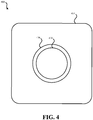
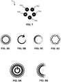
- the hazard detector may include a plurality of light emitting diodes (LEDs) that output light from the hazard detector in a circular pattern.
- the hazard detector may include a button configured to be actuated by a user to initiate a function of the hazard detector, wherein the plurality of LEDs are arranged to output light from the hazard detector in the circular pattern encircling the button.
- the processing system may be configured to determine whether at least a threshold time period has elapsed since previously causing the light to illuminate in response to determining the lighting condition is indicative of the brightness level in the ambient environment of the hazard detector reaching the threshold value.
- the processing system may be configured to cause the light to illuminate based on the illumination state and further based on at least the threshold time period having been determined to have elapsed.
- the hazard detector may include a motion detection sensor that senses motion in the ambient environment of the hazard detector, wherein the processing system is further configured to cause the light to illuminate based on the motion detector indicating motion is present in the ambient environment of the hazard detector and the lighting condition indicative of the brightness level in the ambient environment of the hazard detector reaching the threshold value.
- the processing system may be configured to cause the light to illuminate based on the motion detector indicating motion is present in the ambient environment of the hazard detector, the lighting condition indicative of the brightness level in the ambient environment of the hazard detector reaching the threshold value, and a user-defined setting stored by the processing system indicative of the hazard detector being not inside a bedroom.
- a hazard detector apparatus may include means for measuring a brightness level in the ambient environment of the hazard detector.
- the apparatus may include means for determining the brightness level in the ambient environment of the hazard detector has reached a stored threshold value.
- the apparatus may include means for performing a status check of one or more components of the hazard detector.
- the apparatus may include means for selecting an illumination state from a plurality of illumination states based on the status check wherein each illumination state of the plurality of illumination states is assigned to a status associated with the hazard detector.
- the apparatus may include means for illuminating using the selected illumination state of the plurality of illumination states in response to determining the brightness level in the ambient environment of the hazard detector has reached the threshold value.
- the apparatus may include means for wirelessly communicating with a wireless network, to transmit a request to a remote server system accessible via the wireless network and the Internet.
- the apparatus may include means for receiving, via the wireless network, a notification from the remote server system.
- the illumination state is selected may be based on the status check and the notification from the remote server system received via the wireless network.
- Various systems, devices, apparatuses, methods, computer readable mediums are presented that allow for the presentation of statuses of a hazard detector.
- a status may be presented in the form of an illuminated light using one or more colors and animations.
- a user may provide input to learn further details of the status.
- further detail may be output via a different mode than the status. For instance, if the status was output using light, the details may be output using sound.
- a hazard detector may include at least one hazard detection sensor that detects a presence of at least one type of hazard.
- the hazard detector may include a motion detection sensor that detects motion in an ambient environment of the hazard detector.
- the hazard detector may include a speaker.
- the hazard detector may include a light that comprises multiple lighting elements.
- the hazard detector may include a processing system provided in operative communication with the at least one hazard detection sensor, the motion detection sensor, and the light. The processing system may be configured to select an illumination state from a plurality of illumination states, wherein each illumination state of the plurality of illumination states is assigned to a status associated with the hazard detector.
- the processing system may be configured to cause the light to illuminate based on the selected illumination state of the plurality of illumination states.
- the processing system may be configured to determine a gesture has been performed based on analyzing motion detected by the motion detection sensor in the ambient environment of the hazard detector following the light being illuminated based on the selected illumination state.
- the processing system may be configured to output a detail of the status via the speaker corresponding to the illumination state in response to determining the gesture has been performed.
- the hazard detector may include a light sensor that senses a brightness level in the ambient environment of the hazard detector.
- the processing system may be configured to receive an indication of the brightness level in the ambient environment of the hazard detector from the light sensor.
- the processing system may be configured to determine the brightness level in the ambient environment of the hazard detector has decreased to a threshold value.
- the processing system may be configured to activate the motion detection sensor in response to the brightness level in the ambient environment of the hazard detector reaching the threshold value.
- the processing system may be configured to monitor, using the motion detection sensor, for the gesture for up to a predefined period of time following activation.
- the hazard detector may include an on-board battery module that powers the hazard detector, wherein the motion detection sensor is powered exclusively by the on-board battery module.
- the illumination state may be indicative of a low-battery status of the on-board battery module of the hazard detector.
- the detail of the status output by the speaker may be a spoken auditory message.
- the processing system being configured to determine the gesture has been performed may include the processing system being configured to determine a plurality of waves have been performed as the gesture by a user in the ambient environment of the hazard detector.
- the at least one hazard detection sensor may include a smoke detection sensor and a carbon monoxide detection sensor.
- a method for a hazard detector to output a status detail may include selecting, by the hazard detector, an illumination state from a plurality of illumination states, wherein each illumination state of the plurality of illumination states is assigned to a status associated with the hazard detector.
- the method may include causing, by the hazard detector, a light of the hazard detector to illuminate based on the selected illumination state of the plurality of illumination states.
- the method may include determining, by the hazard detector, a gesture has been performed based on analyzing motion detected in the ambient environment of the hazard detector following the light being illuminated based on the selected illumination state.
- the method may include outputting, by the hazard detector, a detail of the status via a speaker corresponding to the illumination state in response to determining the gesture has been performed.
- a hazard detector apparatus may include means for selecting an illumination state from a plurality of illumination states, wherein each illumination state of the plurality of illumination states is assigned to a status associated with the hazard detector apparatus.
- the apparatus may include means for causing an illumination means of the hazard detector apparatus to illuminate based on the selected illumination state of the plurality of illumination states.
- the apparatus may include means for determining a gesture has been performed based on analyzing motion detected in the ambient environment of the hazard detector apparatus following the lighting means being illuminated based on the selected illumination state.
- the apparatus may include means for outputting a detail of the status via an auditory means corresponding to the illumination state in response to determining the gesture has been performed.
- Hazard detectors may include smoke detectors, carbon monoxide detectors, and/or other forms of detectors that can detect the presence of a hazard.
- a hazard detector may be a combined smoke and carbon monoxide detector configured to be installed on a wall or ceiling in a room, such as a room of a home (e.g., bedroom, office, kitchen, hallway, etc.) or other type of structure. It may be beneficial for such a hazard detector to provide a user with information regarding the functioning of the hazard detector.
- a user refers to a person who is in the vicinity of the hazard detector and/or is interacting with the hazard detector.
- the hazard detector may provide a user with status information, such as the result of a battery test that determines if the battery has sufficient charge, has a low charge, or needs to be replaced immediately.
- status information such as the result of a battery test that determines if the battery has sufficient charge, has a low charge, or needs to be replaced immediately.
- the hazard detector may commence emitting a periodic noise, such as a loud chirp, to alert nearby users to the low battery condition.
- information regarding a status of the hazard detector may be presented by embodiments of a hazard detector detailed herein in response to environmental conditions.
- Such environmental conditions may be indicative of a user leaving a room, potentially for the last time on a given day (or going to bed).
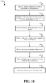
- the hazard detector may monitor the lighting conditions of its ambient environment and determine when the amount of ambient light has dropped below a threshold level. Such a drop in ambient light may be indicative of a user shutting one or more lights off in the vicinity of the hazard detector. Further, the ambient light dropping below the threshold level may be indicative of evening and a dearth of natural light being present in the ambient environment of the hazard detector. In response to the hazard detector detecting that the amount of light present in its vicinity has dropped below the threshold level, either performance of a status check may be triggered or presentation of the results of a status check may be triggered to be presented.
- the status check may check various conditions of the hazard detector, such as the battery charge level, connectivity to a remote server, whether any messages are pending for a user of the hazard detector (e.g., at the remote server), whether the smoke sensor and/or carbon monoxide sensor is functioning properly, whether the effective life of the hazard detector has expired, whether a full test of the hazard detector should be performed, whether wired power is being received by the hazard detector, whether connectivity to a wireless network is present, and/or other conditions of the hazard detector.
- various conditions of the hazard detector such as the battery charge level, connectivity to a remote server, whether any messages are pending for a user of the hazard detector (e.g., at the remote server), whether the smoke sensor and/or carbon monoxide sensor is functioning properly, whether the effective life of the hazard detector has expired, whether a full test of the hazard detector should be performed, whether wired power is being received by the hazard detector, whether connectivity to a wireless network is present,
- the drop in ambient lighting may trigger the hazard detector to visually present a result of the status check.
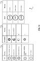
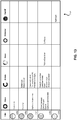
- Color, animation patterns, and/or a speed of presentation may be used to convey information to a user. For instance, green light may be presented to the user for a brief time following the lighting condition reaching the threshold brightness level. Such green light may be indicative of the status check identifying no issues that need action from a user. If yellow light is displayed instead, this may be indicative of the status check determining one or more issues, such as a low battery condition, require action from the user. Yellow light may be indicative of actions that are not needed immediately.
- Red light may be indicative of the status check determining one or more issues need to be dealt with by the user immediately, such as a missing battery or a damaged sensor.
- the use of light to provide the status may be especially useful to avoid being overly intrusive to users in the vicinity of the hazard detector. For instance, the status check of the hazard detector could be ignored by an uninterested user simply by not looking at the hazard detector.
- an optical signal such as the light signal described above, while particularly avoiding the provision of an accompanying alerting sound signal, for non-alarm status notifications.
- the provision of a brief, silent green light can provide a pleasing sense of reassurance for the user, without being irritated or interfering.
- the brief, silent, pleasant green glow can provide a satisfying sense of well-being and reassurance.
- the light on the hazard detector may shut off or may fade to off.
- the hazard detector may be configured to not present the status again until at least a predefined period of time has elapsed (e.g., 1 hour, 4 hours, 20 hours, 1 day, etc.).
- the hazard detector may be configured to provide ambient lighting if motion is detected in the vicinity of the hazard detector, the ambient lighting is below the threshold, and the hazard detector is configured to provide such light (e.g., the hazard detector has received input indicating it is not present in a bedroom).
- the same light which output the status may be used to provide ambient lighting, possibility using a different color, such as white light.
- the user may perform no other action, may simply leave the room, may go to bed, or otherwise may continue about his or her day.
- the user may desire more information about the status. For instance, if the hazard detector presents a yellow status, the user may desire to learn one or more details about the status.
- the hazard detector may activate a motion detector that can determine if the user has performed any gestures in the vicinity of the hazard detector.
- the hazard detector may output an auditory message.
- the auditory message may be a spoken message that indicates further detail about the status of the hazard detector.
- the hazard detector may state "The battery is low. Please replace the battery at your earliest convenience.” The ability to use a gesture to trigger the detail about the status to be spoken to the user may be useful especially if the hazard detector is out of reach, such as mounted to a ceiling.
- FIG. 1 illustrates a block diagram of an embodiment of a hazard detector 100.
- Hazard detector 100 may include: processing system 110, hazard sensor 120, light sensor 130, and light 140. It should be understood that this block diagram is a simplification of hazard detector 100; other components may be present. For instance, hazard detector 100 requires some form of power source. As another example, hazard detector 100 likely includes some form of sound creator configured to make a loud noise when the presence of the hazard is detected by hazard sensor 120.
- Hazard sensor 120 may be configured to detect a particular type of hazard in the vicinity of hazard detector 100.
- hazard sensor 120 may be configured to detect the presence of smoke or the presence of carbon monoxide in the vicinity of hazard detector 100.
- hazard detector 100 is illustrated as having a single hazard sensor 120, it should be understood that multiple hazard sensors may be present.
- hazard detector 100 may include both a smoke sensor and a carbon monoxide sensor.
- multiple forms of smoke sensors may be present.
- an ionization-based smoke sensor may be present and also a photoelectric smoke sensor may be present.
- hazard sensor 120 may be configured to detect the presence of ammonium, volatile organic compounds, humidity, temperature, or any other environmental condition which may pose a threat to users or equipment in the vicinity. Whether one or more hazard sensors are present, data may be transferred to processing system 110. For example, if hazard sensor 120 detects the presence of smoke, data indicating the presence of smoke may be transferred to processing system 110 by hazard sensor 120.
- Hazard sensor 120 may also be able to provide processing system 110 with additional information, such as data indicating whether hazard sensor 120 is functioning properly. In some embodiments, it may be possible for processing system 110 to transmit a signal to hazard sensor 120 that causes hazard sensor 120 to perform a self-test.
- Light sensor 130 may be configured to detect a brightness level of light in the ambient environment of hazard detector 100. Light sensor 130 may provide data to processing system 110 that indicates a brightness of the ambient environment of hazard detector 100. In some embodiments, rather than providing a brightness level to processing system 110, light sensor 130 may indicate to processing system 110 when a threshold brightness level has been reached by the brightness of the ambient environment of hazard detector 100. In some embodiments, the threshold brightness value may be monitored for when the brightness drops below the threshold brightness value to trigger the status check of hazard detector 100.
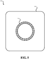
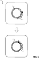
- Light 140 may include one or more lighting elements, such as light emitting diodes (LEDs), that are configured to output multiple colors of light. Further, light 140 may be configured to output various patterns of light. For example, light 140 may be configured to output green, yellow, red, blue, and white light. Further, light 140 may be configured to flash, produce a circulation effect (as will be further described in this document, also referred to as a halo-sweep effect), and/or fade on and off.
- LEDs light emitting diodes
- Processing system 110 may be in communication with hazard sensor 120, light sensor 130, and the light 140.
- Processing system 110 may include one or more processors configured to receive data from hazard sensor 120 and light sensor 130, and configured to control illumination of light 140.
- Processing system 110 may receive data from light sensor 130.
- Processing system 110 may be configured to use the data received from light sensor 130 to determine when the brightness in the ambient environment of hazard detector 100 has dropped below a threshold brightness level. Therefore, processing system 110 may store the threshold brightness level used for the comparison with brightness information received in the data from light sensor 130.
- Processing system 110 may also be configured to monitor when the last time a status check was performed and/or when was the last time the brightness level in the ambient environment of hazard detector 100 dropped below the threshold brightness level.
- processing system 110 periodically performs a status check of one or more components of hazard detector 100 (and, possibly, checks an account of the user of hazard detector 100 stored by a remote server). In some embodiments, rather than periodically performing the status check, processing system 110 may perform the status check in response to the ambient brightness detected by light sensor 130 dropping below the threshold brightness level.
- Processing system 110 may be configured to check the status of hazard sensor 120. For instance, processing system 110 may be configured to query hazard sensor 120 to determine if hazard sensor 120 is functioning properly. In some embodiments, processing system 110 is configured to determine if hazard sensor 120 has expired (for example, smoke detectors may be considered only functional for a predetermined amount of time, such as seven years).
- Processing system 110 may be configured to check the status of one or more components of hazard detector 100 in addition to or alternatively to hazard sensor 120. For instance, processing system 110 may be configured to check a battery level of an onboard battery of hazard detector 100. In response to the status check performed by processing system 110, processing system 110 may be configured to determine a light color animation pattern, and/or speed that corresponds to the determined status. Processing system 110 may cause light 140 to illuminate according to the determined light color, pattern, and/or speed. Light 140 may be lit according to the light color, pattern, and/or speed for a predetermined amount of time, such as two or three seconds in order to convey the result of the status check to a user in the vicinity of hazard detector 100. In some embodiments, the status is presented as part of a one second fade in, one second at full brightness, and one second fade out animation of the light. Such a quick presentation may help preserve battery life.
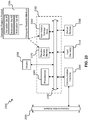
- FIG. 2 illustrates another block diagram of an embodiment of a hazard detector 200.
- Hazard detector 200 may represent a more detailed embodiment of hazard detector 100.
- Hazard detector 200 may include: processing system 110, carbon monoxide sensor 121, smoke sensor 122, light sensor 130, light 140, battery-based power source 210, user input module 222, structure power source 220, motion sensor 225, wireless communication module 230, and audio output module 240.
- hazard detector 100 was illustrated as having a single hazard sensor 120, hazard detector 200 has two hazard detectors: carbon monoxide sensor 121 and smoke sensor 122.
- carbon monoxide sensor 121 may be configured to detect carbon monoxide
- smoke sensor 122 may be configured to detect smoke.
- multiple forms of smoke sensors are present, including an ionization sensor and a photoelectric sensor. Both carbon monoxide sensor 121 and smoke sensor 122 may provide an indication of a presence of the hazard to processing system 110.
- Light sensor 130 and light 140 may function as detailed in relation to hazard detector 100.
- Hazard detector 200 is illustrated as including battery-based power source 210 and structure power source 220. In some embodiments of hazard detector 200, such a configuration may be present. Structure power source 220 may be used to power hazard detector 200 when such power is present. Structure power source 220 may represent a hard-wired connector within a structure (e.g., house, building, office, etc.) configured to provide an AC or DC voltage source to one or more hazard detectors located throughout the structure. While the AC or DC power may be available a significant percentage of time (e.g., 99.5% of the time), it may be desirable for hazard detector 200 to continue functioning if power in the structure in which hazard detector 200 is installed is unavailable (e.g., during a power failure).
- a structure e.g., house, building, office, etc.
- battery-based power source 210 may also be present.
- Battery-based power source 210 may include one or more batteries which are configured to power the various components of hazard detector 200 when structure power source 220 is not available. In some embodiments of hazard detector 200, structure power source 220 is not present. As such, hazard detector 200 may permanently rely on battery-based power source 210 to power components of hazard detector 200.
- Structure power source 220 and battery-based power source 210 are illustrated in FIG. 2 as connected with processing system 110. Processing system 110 may be configured to determine if structure power source 220 is available and/or check a charge level of battery-based power source 210.
- structure power source 220 and battery-based power source 210 are illustrated as only connected with processing system 110, this is for simplicity only; structure power source 220 and battery-based power source 210 may be connected to the various components of hazard detector 200 as necessary to power such components.
- Motion sensor 225 may be configured to detect motion in the vicinity of hazard detector 200. Motion sensor 225 may be configured to detect one or more gestures that may be performed by user in the vicinity of hazard detector 200. In some embodiments, motion sensor 225 may be a passive infrared (PIR) sensor that detects received infrared radiation. For instance, motion sensor 225 may be configured to detect a wave gesture performed by user. In some embodiments, multiple waves may be required to be performed by the user in order for a wave gesture to be detected. In some embodiments, motion sensor 225 may only be enabled at certain times, such as to conserve power.
- PIR passive infrared
- motion sensor 225 may only be enabled for a predefined period of time after a status is output via light 140 to a user. As such, motion sensor 225 may be used to detect if a gesture is performed by the user within a predefined amount of time after the status has been output via light 140. If structure power source 220 is available, motion sensor 225 may be enabled a greater amount of time. For instance, motion sensor 225 may be used to monitor for whenever a user is within the vicinity of hazard detector 200. Such motion detection may be used to enable lighting to allow a user to see in the vicinity of hazard detector 200 and/or may be used to control and/or provide data to HVAC systems within the structure. If structure power source 220 is available, motion sensor 225 may, in some embodiments, only be enabled for a predefined period of time after status has been presented via light 140 in order to monitor for a gesture performed by a user in the vicinity of hazard detector 200.
- User input module 222 may represent an alternate form of input component through which a user can provide input to processing system 110 in addition or in alternate to a gesture.
- User input module 222 may take the form of a button or switch on hazard detector 200. By depressing the button or actuating the switch, a user can provide input via user input module 222 to processing system 110. For instance, user input module 222 may be used to disable the alarm currently sounding by hazard detector 200.
- Wireless communication module 230 may be configured to allow processing system 110 to communicate with a wireless network present within the structure in which hazard detector 200 is installed.
- wireless communication module 230 may be configured to communicate with a wireless network that uses the 802.11a/b/g network protocol for communication.
- Wireless communication module 230 may permit processing system 110 to communicate with a remote server.
- the remote server may be configured to provide information to processing system 110 about an account of the user associated with hazard detector 200. For instance, if an account of the user maintained at the remote server requires attention from a user, such indication may be provided to processing system 110 via wireless communication module 230. Such indication may be provided by the remote server in response to inquiry from processing system 110 made to the remote server. Further, processing system 110 may transmit status information to a remote server. Such an arrangement may permit a user to view status information by logging in to the remote server via a computing device.
- Audio output module 240 may be configured to output various forms of audio in response to data provided to audio output module 240 by processing system 110.
- Audio output module 240 may be a speaker that can output recorded or synthesized spoken messages.
- voice-based messages which may indicate the presence of a hazard or may provide detail on the status of the hazard detector 200, may be output by audio output module 240 in order to be heard by a user in the vicinity of hazard detector 200.
- Audio output module 240 may be configured to output an alarm sound, such as a shrill beep or tone that is intended to alert users to the presence of a hazard. Different patterns and/or tones of sound may be used to alert users to different types of hazards.
- spoken messages may be interspersed with patterns and/or tones of sound to alert users to the presence of a hazard.
- Processing system 110 which may be configured to communicate with the various components presented in FIG. 2 , is part of hazard detector 200. For instance, processing system 110 may receive data from motion sensor 225, user input module 222, wireless communication module 230, carbon monoxide sensor 121, smoke sensor 122, battery-based power source 210, structure power source 220, and/or light sensor 130. Processing system 110 may also output data to various components of hazard detector 200, including wireless communication module 230, light 140, and/or audio output module 240. Processing system 110 may be configured to periodically perform, or, in response to environmental condition, perform a status check of one or more components of hazard detector 200.
- processing system 110 may be configured to check a charge level of battery-based power source 210, check whether structure power source 220 is available, determine account status maintained at a remote server via wireless communication module 230, and/or test whether sensors, such as carbon monoxide sensor 121 and/or smoke sensor 122, are functional. Processing system 110 may then output information regarding the status to a user via light 140 and/or audio output module 240. It should be understood that processing system 110 may be configured to perform various blocks of the methods detailed in relation to FIGS. 17-21 .
- Processing system 110 may contain multiple engines that are implemented using software (running on hardware), firmware, and/or hardware. Such engines may include status check engine 251, definition lookup engine 252, output trigger engine 253, motion analysis engine 254, and presentation monitor engine 255. It should be understood that such engines may be split into a greater number of engines or may be combined into fewer engines. Status check engine 251 may be configured to perform a status check periodically, such as once per day or once per hour. In some embodiments, status check engine 251 may be configured to perform a status check based on an indication from output trigger engine 253 that indicates that a status indication is to be output. Status check engine 251 may check the status of one or more components of the hazard detector.
- status check engine 251 may be configured to perform a status check periodically, such as once per day or once per hour. In some embodiments, status check engine 251 may be configured to perform a status check based on an indication from output trigger engine 253 that indicates that a status indication is to be output. Status check engine 251 may check the status of one or more
- Status check engine 251 may check the status of: a battery level of battery-based power source 210 as compared to one or more thresholds, carbon monoxide sensor 121 (e.g., functional, nonfunctional expired, etc.), smoke sensor 122 (e.g., functional, nonfunctional expired, etc.), motion sensor 225 (e.g., functional, nonfunctional), structure power source 220 (e.g., available, unavailable), light sensor 130 (e.g., functional, nonfunctional), etc. Status check engine 251 may check the status of a user account associated with the hazard detector by querying a remote server. Status check engine 251 may check battery-based power source 210 against multiple thresholds.
- carbon monoxide sensor 121 e.g., functional, nonfunctional expired, etc.
- smoke sensor 122 e.g., functional, nonfunctional expired, etc.
- motion sensor 225 e.g., functional, nonfunctional
- structure power source 220 e.g., available, unavailable
- light sensor 130 e.g.,
- a first threshold which may be greater than the second threshold, may be used to determine that a battery is approaching a low voltage and the user should consider replacing it.
- the second threshold may be used to determine the battery's voltage is low and should be replaced immediately. More than two thresholds are also possible for assessing battery voltage.
- Definition lookup engine 252 may determine a color, animation, and/or speed at which light 140 should be illuminated to provide an indication of the status to one or more users. Definition lookup engine 252 may access one or more lookup tables to determine an appropriate combination of color, animation, and/or speed for representing the determined status.
- Output trigger engine 253 may cause the appropriate combination of color, animation, and/or speed selected by definition lookup engine 252 to be used to illuminate light 140 in response to a determination that data from light sensor 130 is indication of the light in the ambient environment of hazard detector 200 being at or below a stored threshold brightness level and/or that at least an amount of time has elapsed since the previous time that an indication of the status was output.
- Presentation monitor engine 255 may determine whether at least a stored threshold period of time has elapsed since the last time an indication of the status of the hazard detector was output. If the threshold period of time has not elapsed, presentation monitor engine 255 may provide an indication to output trigger engine 253 that prevents light 140 from being illuminated based on the status.
- Motion analysis engine 254 may be active during and/or following presentation of the status via light 140 (for up to a stored threshold period of time). If a particular gesture, such as a wave gesture is identified by motion analysis engine based on data from motion sensor 225, detail about the status may be output via audio output module 240 or some other component of hazard detector 200.
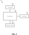
- FIG. 3 illustrates a block diagram of a system 300 that may perform a function in response to an unrelated event.
- System 300 may be configured to detect one or more forms of events. Such event may or may not qualify as a hazard.
- System 300 may represent embodiments of hazard detector 100 and/or hazard detector 200 of FIGS. 1 and 2 , respectively.
- system 300 may include: processing system 310, function module 320, event detection module 330, and output module 340.
- Function module 320 may be configured to perform some function, such as monitoring an environment in the vicinity of system 300 for one or more conditions. For example, these conditions may be hazards. However, it should be understood that one or more conditions being monitored for by function module 320 may be other than hazards. As an example, function module 320 may monitor for motion, temperature, humidity, and/or the presence or absence of some other condition or object. Function module 320 may perform some function other than a monitoring function. For instance, function module 320 may perform a status check of some other system or may serve to activate some other component or system. Function module 320 may perform any number of various functions such as control of a motor, a pump, a medical system, a computing device, etc. Function module 320 may provide input to processing system 310. Further, processing system 310 may be configured to check a status of function module 320.
- some function such as monitoring an environment in the vicinity of system 300 for one or more conditions. For example, these conditions may be hazards. However, it should be understood that one or more conditions being monitored for by function module 320
- Event detection module 330 may be configured to monitor the vicinity of system 300 for one or more types of event. This event may trigger one or more actions to be performed by processing system 310. For example, a triggering event detected by event detection module 330 may cause processing system 310 to initiate function module 320 and/or perform a status check of one or more components of system 300, such as function module 320. The event detected by event detection module 330 may be unrelated to the functioning of function module 320. While event detection module 330 may be configured to detect an event that coincides with the time at which the user is likely to desire information about system 300, this event may be unrelated to performance of any other function of system 300.
- event detection module 330 may be configured to trigger based on brightness in the environment of system 300 or some other condition, such as temperature, the presence of a chemical or other substance in the air, motion, or some other type of event or condition.
- event detection module 330 is configured to monitor for brightness in the vicinity of system 300, when the brightness level in the vicinity of system 300 reaches a predefined value, processing system 310 may perform a self-test or status check on one or more components of system 300, such as function module 320 and/or an onboard power source, such as a battery.
- Output module 340 may be used to provide an output that indicates the result of the self-test or status check.
- the self-test or status check may be performed based on some other schedule, but an indication of the results of the self-test or status check may be output via output module 340 in response to the events being detected by event detection module 330.
- Event detection module 330 may be configured to detect an event that coincides with the time at which the user is likely to desire information about system 300.
- One possible example is based on brightness of light in the ambient environment of system 300. For instance, when the light within the vicinity of system 300 increases, it may correspond to a light being turned on and the user entering a room in which system 300 is present. Similarly, when brightness within the vicinity of system 300 decreases, it may correspond to a light being turned off and the user leaving a room in which system 300 is present. Both of these events may represent an opportune time for either a status check to be performed or results of a status check to be output to a user.
- function module 320 is monitoring a condition in a room of a structure, upon entering the room and turning on a light, a user may find it useful to learn the status of system 300. Similarly, in certain circumstances, the user may find it useful to learn the status of system 300 upon leaving the room of the structure in which system 300 is installed.
- Output module 340 may be configured to provide an indication of the self-test or status check performed by processing system 310.
- Output module 340 may include components configured to visually output an indication of the status or self-test and/or may include components configured to output audio such that an auditory indication of the status or self-test is output.
- output module 340 may include one or more speakers and/or one or more lights, such as LEDs, such as detailed in relation to hazard detectors 100 and 200.
- Output module 340 may receive data from processing system 310 which triggers sound and/or visual output.
- processing system 310 may output spoken messages to be output by output module 340. It should be understood that embodiments of system 300 may be further configured to include components such as those detailed in relation to hazard detector 200 of FIG. 2 .
- FIG. 4 illustrates an external view of an embodiment of a hazard detector 400.
- Hazard detector 400 may represent hazard detector 100, hazard detector 200, or system 300 of FIGS. 1-3 , respectively.
- Hazard detector 400 may include case 410, light 420, and/or center region 430.
- Case 410 may represent a shell of hazard detector 400 which is configured to be mounted to a wall or ceiling. Case 410 may be configured to allow airflow through hazard detector 400 to permit one or more sensors within hazard detector 400 to be exposed to the air of the ambient environment of hazard detector 400.
- light 420 may be present.
- Light 420 may include one or more light sources, such as LEDs.
- Light 420 may be configured to present various colors and/or various lighting patterns, possibly with such patterns presented at various speeds. For instance light 420 may be configured to present lighting patterns that appear to produce a circulation effect, flash, and/or fade. While light 420 may be used to confer information about a status of hazard detector 400, light 420 may also be used to provide ambient lighting. For instance, a color unassociated with a status may be output by light 420 when motion is detected by hazard detector 400 and the ambient lighting is determined to be less than a threshold value.
- hazard detector 400 may determine whether such a feature has been enabled or disabled by user and/or if hazard detector 400 is installed in a bedroom (e.g., by determining whether a user has classified hazard detector 400 as installed within a bedroom).
- light 420 is illustrated as a circle (or halo), it should be understood that, in other embodiments of hazard detector 400, other shapes may be used for light 420.
- light 420 may be elliptical, square, triangular, some other geometric shape, some other abstract shape, or a line.
- case 410 is square or rectangular, with rounded edges. While such a design may be pleasing to the eye, other shapes, both geometric or abstract, may be used to house the functional components of hazard detector 400.
- light 420 represents a depressed portion of case 410 which reflects light generated within hazard detector 400.
- one or more LEDs may be located within case 410, such as behind center region 430 and may be output light that reflects off a depressed portion of case 410 in the shape of light 420.
- Center region 430 may include a lens that is used in conjunction with a motion sensor to determine if a user is present and/or detect whether a gesture has been performed by user. Center region 430 may serve a dual function: functioning as a lens and as a button which can be pushed by user to provide input to hazard detector 400. In some embodiments, center region 430 is only a button. When center region 430 is a button, by having center region 430 encircled by light 420, it may be easy for a user to locate the button in a darkened environment when light 420 is illuminated. In such a situation, the user would only need to push within the circle of light or other region defined by light 420 in order to actuate the button.
- FIG. 5 illustrates an external view of an embodiment of a hazard detector 500 that uses multiple lighting elements as part of a light.
- hazard detector 500 multiple LEDs are used as the lighting elements as part of light 520.
- Hazard detector 500 may represent an embodiment of hazard detector 400 of FIG. 4 .
- Hazard detector 500 may include hazard detector 100, hazard detector 200, or system 300 of FIGS. 1-3 , respectively.
- Light 520 may include multiple LEDs. In FIG. 5 , light 520 is made up of 26 LEDs. It should be understood that the number of LEDs illustrated in FIG. 5 is merely exemplary. For instance, a fewer or a greater number of LEDs may be used to create light 520.
- five LEDs may be used as part of light 520.
- various lighting effects may be created in which only portions of light 520 are illuminated at a given time and/or various portions of light 520 are illuminated with different colors and/or different brightness levels at a given time.
- the LEDs of light 520 may fade from not producing light to a defined brightness level, then, either immediately or after a defined time period, fade back to not producing light.
- LEDs may be used as part of light 520, which is present on case 510.
- other forms of components that create visible light may be used in place of LEDs, such as light sources that use fluorescent or incandescent technologies.
- light 520 is illustrated in FIG. 5 as being arranged in a circle. It should be understood that in other embodiments, light 520 may be arranged in other shapes, such as an oval, square, rectangle, line, or some abstract shape.
- FIG. 6 illustrates an external view of an embodiment of a hazard detector that outputs a circular pattern of light.
- Hazard detector 600 which is illustrated in FIG. 6 in two states, may represent hazard detector 500 of FIG. 5 and/or hazard detector 400 of FIG. 4 .
- Hazard detector 600 may include hazard detector 100, hazard detector 200, or system 300 of FIGS. 1-3 , respectively.
- FIG. 6 illustrates hazard detector 600 outputting a lighting effect. This lighting effect is output in a (roughly) circular pattern and can be referred to as a circulation effect or halo effect.
- the circulation effect also referred to as a halo-sweep effect
- various lighting elements such as LEDs
- Lighting elements of light 520 are illuminated consecutively, then faded to off. This effect results in the appearance of a point of light spinning around light 520 with a tail.
- a user viewing hazard detector 600 may view the circulation or halo effect and understand the status of the hazard detector based on the lighting effect and/or the color of light being output by light 520.
- each lighting element of light 520 may output the same color, or multiple colors may be output by different lighting elements.
- Imaginary arrow 601 illustrates the circulation effect, the opposite direction is also possible.
- the darker a lighting element is shaded in FIG. 6 the brighter the lighting element may be illuminated. Therefore, in some embodiments, a first lighting element may be bright, while the lighting element immediately behind it may be slightly less bright, and so on.
- Imaginary arrow 602 shows the circulation effect of hazard detector 600 at a later time at which a different lighting element is now the brightest lighting element with subsequent lighting elements being illuminated progressively less bright.
- FIG. 7 illustrates an embodiment of lighting elements 700 arranged in a circle.
- a pattern of lighting elements e.g., LED lights
- Such a pattern can include five lighting elements: lighting elements 702, 704, 706, 708 and 710.
- Lighting elements 700 may be turned on and off according to a number of patterns and each may cycle through different hue ranges. The color of each of the lighting elements may also vary in order to provide an additional variety of visual effects. While five lighting elements are illustrated, it should be understood that a fewer or a greater number of lighting elements may be incorporated as a light of a hazard detector or some other form of device.
- FIGS. 8A-8D illustrate an embodiment of four visual effects (also referred to as animations) that may be generated using a light of a hazard detector.
- FIG. 8A illustrates a representation of a pulsing effect that may be created when all of lighting elements 702, 704, 706, 708 and 710 (shown in FIG. 7 ) are turned on and off simultaneously. Alternatively, all of lighting elements 702, 704, 706, 708 and 710 may increase and decrease the brightness of the light they each produce in a synchronized fashion to create a pulsing effect.
- FIG. 8B illustrates a representation of a rotating effect (also referred to as a circulation effect or halo sweep effect) that may be created when all of lighting elements 702, 704, 706, 708 and 710 are turned on and off sequentially in a clockwise direction to create a rotating effect. Furthermore, turning on and off the lights may be done in a gradual fashion. For example, lighting element 704 may gradually turn off and lighting element 702 gradually turns on while lighting elements 706, 708 and 710 are turned on at an equal brightness.
- FIG. 10 provides a further illustration of the rotating visual effect of FIG. 8B (and FIG. 6 ), according to an embodiment. Viewed from left to right, FIG.
- FIG. 10 shows new lights turning on at one end of the rotating visual effect and other lights gradually turning off at the other end of the rotation visual effect.
- the hatch patterns of each of the sequential representations illustrate how the rotating light may change color during the rotation sequence.
- lighting elements 702, 704, 706, 708 and 710 may each be a different color individually, the colored light mixing causes the color of the rotating visual effect to constantly change through the course of the visual effect.
- FIG. 8C illustrates a representation of a wave visual effect that may be created when lighting elements 700 (shown in FIG. 7 ) turn on and off in a side-to-side direction.
- lighting element 710 may be most bright
- lighting elements 708 and 702 may be the next brightest
- lighting elements 706 and 704 may be the least bright.
- the lights may gradually change brightness in a linear manner such that lighting elements 704 and 706 are the brightest, lighting elements 708 and 702 are the next brightest, and lighting element 710 is the least bright.
- FIG. 8D illustrates a representation of a shimmer visual effect that may be created when each of the lighting elements 700 cycle through a hue range pattern with each lighting element's hue range pattern being out of sync with all of the lights.
- FIG. 11 illustrates the different hue range patterns associated with each of the lighting elements 700 for the shimmering visual effect, according to an embodiment. The extent to which the lighting elements 702, 704, 706, 708 and 710 are out of sync may be varied in order to produce variations of the shimmer visual effect.
- FIGS. 9A and 9B illustrate an embodiment of a pulse visual effect that may be generated using a light of a hazard detector.
- FIG. 9A represents an on and off pattern for power off or no power available situations wherein the pulse animations will transition smoothly through pulses in order to provide an alert in a non-distracting manner.
- FIG. 9B represents left-to-right pulse patterns that could be used when presenting a user with selectable options via visual effects.
- a button (such as center region 430 of FIG. 4 ) may be used to select a language preference for the operation of hazard detector 400 during an initial setup procedure. A user could be asked to press such a button when the left side is pulsing for English and when the right side is pulsing for Chinese. Therefore, a user may wait until the side of light is pulsing or otherwise illuminated that is associated with the user's desired selection.
- the user may perform a gesture, such as one or multiple waves of a hand.
- each effect may be animated faster or slower, brighter or dimmer, for a specific number of animation cycles, with only some of the light participating, and using different colors, e.g., white, blue, green, yellow and red. and/or a mixture of multiple colors.
- FIGS. 12 and 13 illustrate an exemplary "visual vocabulary" for visual effects and colors that may be used by embodiments of hazard detectors.
- FIG. 11 illustrates various hue range patterns associated with each of the lighting elements 700 for the shimmering visual effect, according to an embodiment.
- the extent to which lighting elements (abbreviated LE in FIG. 11 ) 702, 704, 706, 708 and 710 are out of sync may be varied in order to produce variations of the shimmer visual effect.
- each lighting element is increased and decreased in brightness between two hues as time progresses.
- Some or all of the lighting elements are "out of sync" in that the lighting elements, while illuminating according to the same pattern, do so at different times.
- the pattern illustrated in FIG. 11 could be adapted for fewer or greater numbers of lighting elements.
- the waveforms could be altered to produce a different visual effect.
- FIG. 12 illustrates an embodiment 1200 of definitions for visual effects that may be used by a hazard detector, such as the hazard detectors of FIGS. 1-6 .
- Color definitions 1210, animation definitions 1220, and speed definitions 1230 may be stored by a hazard detector or may be accessible by the hazard detector from some remote location, such as a cloud-based server (e.g., cloud-computing system 1564).
- cloud-based server e.g., cloud-computing system 1564
- Such definitions of colors, animations, and/or speeds may be provided to a user, such as in the form of a quick reference sheet or manual provided with a hazard detector when purchased. As such, a user can learn or look-up the meaning of a particular visual effect.
- Each color, animation, and speed may have an individualized meaning.
- the speed of an animation may be used to indicate a level of urgency.
- Animation may be used to provide an acknowledgment ("OK"), an indication that attention is needed, and/or some other status.
- Such an animation used in conjunction with a speed may alert the user as to how urgent the status associated with the animation is.
- various colors may be incorporated to provide more information to a user, such as green for "OK”, yellow for "something may be wrong” or a warning, and red for "something is definitely wrong.” Other colors may be used for other forms of messages.
- a separate color, such as white may be used by the light for ambient lighting provided by the hazard detector in certain situations as previously detailed.
- the color may be yellow ("something may be wrong")
- the animation may be "here's my status", and the speed may be slow. If the battery is not replaced, the speed may transition to fast after a time. Once the battery must be replaced, the color may be red ("something is definitely wrong"), the animation may be a circulation ("I need your attention") and the speed may be fast (or alarm).
- a battery may be checked against multiple voltage thresholds - the lower the voltage, the more urgent the presented status.
- color definitions 1210, animation definitions 1220, and speed definitions 1230 may be used independently to select a color, animation, and speed by the hazard detector based on a status check of the hazard detector.
- a look-up may be performed using color definitions 1210, animation definitions 1220, and speed definitions 1230 to select a color, animation, and speed that corresponds to the status determined by the hazard detector.
- the color, animation, and/or speed selected from color definitions 1210, animation definitions 1220, and/or speed definitions 1230 may be used by the hazard detector to output a status via a light of the hazard detector.
- FIG. 13 illustrates an embodiment 1300 various combinations of visual effects (also referred to as animations) and color that may be used by a hazard detector, such as the hazard detectors of FIGS. 1-6 .
- a hazard detector such as the hazard detectors of FIGS. 1-6 .
- Such combinations may be stored in the form of a look-up table by a hazard detector or may be accessible via a network from a remote computerized device, such as a cloud-based server system (e.g., cloud-computing system 1564).
- a table such as presented in embodiment 1300 may be used to determine an animation, color, and/or speed to use for outputting an indication of the status.
- Color 1301 may be red, color 1302 may be yellow, color 1303 may be green, color 1304 may be blue, and color 1305 may be white. Other color assignments are also possible. Definitions of colors, visual effects, and/or speeds may be stored by a hazard detector. In response to a condition determined by the hazard detector during a status check, the processing system of the hazard detector may look up or otherwise determine the appropriate combination of colors, visual effect, and/or speed to use to illuminate the light. The light may then be illuminated according to the determined combination to convey information to one or more users. Again here, definitions of colors and animations may be provided to a user, such as in the form of a quick reference sheet or manual provided with a hazard detector when purchased.
- FIG. 14 illustrates an embodiment 1400 of a user performing a gesture that is detected by a hazard detector.
- User 1420 is performing a gesture of waving his hand in order to provide input to hazard detector 1410.
- Hazard detector 1410 may represent one of the previously detailed hazard detectors, such as those detailed in relation to FIGS. 1 through 6 .
- the wave gesture being performed by user 1420 may consist of a single wave or multiple waves of the user's hand. While illustrated embodiment 1400 focuses on a wave gesture, it should be understood that other forms of gestures may be performed by user 1420 and detected by hazard detector 1410.
- Hazard detector 1410 may monitor for a gesture being performed by user 1420 for a predefined amount of time after information has been presented by a light of hazard detector 1410.
- hazard detector 1410 may monitor for a gesture being performed by user 1420. If a gesture is detected within this predefined period of time, detail about the status presented by the light of hazard detector 1410 may be provided. While the status was initially presented using the light, the further detail about the status may be presented using auditory information. For instance, a spoken message may be played aloud by hazard detector 1410.
- a spoken message may be output by hazard detector 1410 saying "All components are functioning normally.”
- a spoken message may be output by hazard detector 1410 saying "The battery is low. Please replace the battery at your earliest convenience.”
- a gesture may be preferable to allow a user to provide input without having to physically contact hazard detector 1410.
- Hazard detector 1410 may have a lens that targets motion detection to a conical region beneath hazard detector 1410. Such targeting of gesture and motion detection may be preferable to avoid stray motions being interpreted as a gesture.
- FIG. 15 illustrates an example of a smart-home environment 1500 within which one or more of the devices, methods, systems, services, and/or computer program products described further herein can be applicable, such as the hazard detectors detailed in relation to FIGS. 1-6 .
- the depicted smart-home environment 1500 includes a structure 1550, which can include, e.g., a house, office building, garage, or mobile home. It will be appreciated that devices can also be integrated into a smart-home environment 1500 that does not include an entire structure 1550, such as an apartment, condominium, or office space. Further, the smart home environment can control and/or be coupled to devices outside of the actual structure 1550. Indeed, several devices in the smart home environment need not physically be within the structure 1550 at all. For example, a device controlling a pool heater or irrigation system can be located outside of the structure 1550.
- the depicted structure 1550 includes a plurality of rooms 1552, separated at least partly from each other via walls 1554.
- the walls 1554 can include interior walls or exterior walls.
- Each room can further include a floor 1556 and a ceiling 1558.
- Devices can be mounted on, integrated with and/or supported by a wall 1554, floor 1556 or ceiling 1558.
- the smart-home environment 1500 of FIG. 15 includes a plurality of devices, including intelligent, multi-sensing, network-connected devices, that can integrate seamlessly with each other and/or with a central server or a cloud-computing system to provide any of a variety of useful smart-home objectives.
- the smart-home environment 1500 may include one or more intelligent, multi-sensing, network-connected thermostats 1502 (hereinafter referred to as "smart thermostats 1502”), one or more intelligent, network-connected, hazard detectors 1504, and one or more intelligent, multi-sensing, network-connected entry way interface devices 1506 (hereinafter referred to as "smart doorbells 1506").
- the smart thermostat 1502 detects ambient climate characteristics (e.g., temperature and/or humidity) and controls a HVAC system 1503 accordingly.
- the hazard detector 1504 may detect the presence of a hazardous substance or a substance indicative of a hazardous substance (e.g., smoke, fire, or carbon monoxide).
- the smart doorbell 1506 may detect a person's approach to or departure from a location (e.g., an outer door), control doorbell functionality, announce a person's approach or departure via audio or visual means, or control settings on a security system (e.g., to activate or deactivate the security system when occupants go and come).
- the smart-home environment 1500 of FIG. 15 further includes one or more intelligent, multi-sensing, network-connected wall switches 1508 (hereinafter referred to as “smart wall switches 1508"), along with one or more intelligent, multi-sensing, network-connected wall plug interfaces 1510 (hereinafter referred to as “smart wall plugs 1510").
- the smart wall switches 1508 may detect ambient lighting conditions, detect room-occupancy states, and control a power and/or dim state of one or more lights. In some instances, smart wall switches 1508 may also control a power state or speed of a fan, such as a ceiling fan.
- the smart wall plugs 1510 may detect occupancy of a room or enclosure and control supply of power to one or more wall plugs (e.g., such that power is not supplied to the plug if nobody is at home).
- the smart-home environment 1500 of FIG. 15 includes a plurality of intelligent, multi-sensing, network-connected appliances 1512 (hereinafter referred to as "smart appliances 1512"), such as refrigerators, stoves and/or ovens, televisions, washers, dryers, lights, stereos, intercom systems, garage-door openers, floor fans, ceiling fans, wall air conditioners, pool heaters, irrigation systems, security systems, and so forth.
- the network-connected appliances 1512 are made compatible with the smart-home environment by cooperating with the respective manufacturers of the appliances.
- the appliances can be space heaters, window AC units, motorized duct vents, etc.
- an appliance When plugged in, an appliance can announce itself to the smart-home network, such as by indicating what type of appliance it is, and it can automatically integrate with the controls of the smart-home. Such communication by the appliance to the smart home can be facilitated by any wired or wireless communication protocols known by those having ordinary skill in the art.
- the smart home also can include a variety of non-communicating legacy appliances 1540, such as old conventional washer/dryers, refrigerators, and the like which can be controlled, albeit coarsely (ON/OFF), by virtue of the smart wall plugs 1510.
- the smart-home environment 1500 can further include a variety of partially communicating legacy appliances 1542, such as infrared ("IR”) controlled wall air conditioners or other IR-controlled devices, which can be controlled by IR signals provided by the hazard detectors 1504 or the smart wall switches 1508.
- legacy appliances 1542 such as infrared ("IR") controlled wall air conditioners or other IR-controlled devices, which can be controlled by IR signals provided by the hazard detectors 1504 or the smart wall switches 1508.
- the smart thermostats 1502, the hazard detectors 1504, the smart doorbells 1506, the smart wall switches 1508, the smart wall plugs 1510, and other devices of the smart-home environment 1500 are modular and can be incorporated into older and new houses.
- the devices are designed around a modular platform consisting of two basic components: a head unit and a back plate, which is also referred to as a docking station. Multiple configurations of the docking station are provided so as to be compatible with any home, such as older and newer homes.
- all of the docking stations include a standard head-connection arrangement, such that any head unit can be removably attached to any docking station.
- the docking stations are interfaces that serve as physical connections to the structure and the voltage wiring of the homes, and the interchangeable head units contain all of the sensors, processors, user interfaces, the batteries, and other functional components of the devices.
- the smart-home environment 1500 may also include communication with devices outside of the physical home but within a proximate geographical range of the home.
- the smart-home environment 1500 may include a pool heater monitor 1514 that communicates a current pool temperature to other devices within the smart-home environment 1500 or receives commands for controlling the pool temperature.
- the smart-home environment 1500 may include an irrigation monitor 1516 that communicates information regarding irrigation systems within the smart-home environment 1500 and/or receives control information for controlling such irrigation systems.
- an algorithm is provided for considering the geographic location of the smart-home environment 1500, such as based on the zip code or geographic coordinates of the home. The geographic information is then used to obtain data helpful for determining optimal times for watering; such data may include sun location information, temperature, due point, soil type of the land on which the home is located, etc.
- one or more of the smart-home devices of FIG. 15 can further allow a user to interact with the device even if the user is not proximate to the device.
- a user can communicate with a device using a computer (e.g., a desktop computer, laptop computer, or tablet) or other portable electronic device (e.g., a smartphone) 1566.
- a webpage or app can be configured to receive communications from the user and control the device based on the communications and/or to present information about the device's operation to the user.
- the user can view a current setpoint temperature for a device and adjust it, using a computer.
- the user can be in the structure during this remote communication or outside the structure.
- users can control and interact with the smart thermostat, hazard detectors 1504, and other smart devices in the smart-home environment 1500 using a network-connected computer or portable electronic device 1566.
- some or all of the occupants e.g., individuals who live in the home
- Such registration can be made at a central server to authenticate the occupant and/or the device as being associated with the home and to give permission to the occupant to use the device to control the smart devices in the home.
- An occupant can use their registered electronic device 1566 to remotely control the smart devices of the home, such as when the occupant is at work or on vacation.
- the occupant may also use their registered device to control the smart devices when the occupant is actually located inside the home, such as when the occupant is sitting on a couch inside the home.
- the smart-home environment 1500 makes inferences about which individuals live in the home and are therefore occupants and which electronic devices 1566 are associated with those individuals. As such, the smart-home environment "learns" who is an occupant and permits the electronic devices 1566 associated with those individuals to control the smart devices of the home.
- each of the devices 1502, 1504, 1506, 1508, 1510, 1512, 1514, and 1516 is capable of data communications and information sharing with any other of the smart devices, as well as to any central server or cloud-computing system or any other device that is network-connected anywhere in the world.
- the required data communications can be carried out using one or more of a variety of custom or standard wireless protocols (e.g., cellular, 3G/4G, Wi-Fi, ZigBee, 6LoWPAN, BLE, etc.) and/or any of a variety of custom or standard wired protocols (CAT6 Ethernet, HomePlug, etc.).
- Thread protocol which is promulgated by the Thread Group and based on 802.15.4, IETF IPv6, and 6LoWPAN.
- devices that are powered by the household mains current can be provided with a combination of Wi-Fi, which can be relatively power-intensive, along with one or more lower-power protocols such as Thread and/or BLE.
- devices that are power-constrained in that they are not powered by the household mains current and do not have access to a high-capacity battery source are provided only with one or more low-power protocols such as Thread and/or BLE.
- devices that are not powered by the household mains current, but do have access to a reasonably high-capacity battery source, can be provided with a combination of Wi-Fi and one or more lower-power protocols such as Thread and/or BLE, with the Wi-Fi communications being controlled to be temporally restricted, such as being turned on only during brief periodic time intervals (e.g., once per day to upload logs and receive updates from the cloud), during particular device-sensed events, or when the user has physically actuated the device such as by pressing a button on the device.
- a combination of Wi-Fi and one or more lower-power protocols such as Thread and/or BLE
- the hazard detectors described herein can be provided in two different SKUs, one SKU being mains-powered with battery backup and the other SKU being battery only, albeit with a relatively large battery source (e.g., six lithium AA cells).
- the hazard detector is preferably provided with a combination of the temporally restricted Wi-Fi and one or more lower-power protocols such as Thread and/or BLE.
- all or some of the smart devices can serve as wireless or wired repeaters.
- a first one of the smart devices can communicate with a second one of the smart devices via a wireless router 1560.
- the smart devices can further communicate with each other via a connection to a network, such as the Internet 1599.
- the smart devices can communicate with a cloud-computing system 1564, which can include one or more centralized or distributed server systems.
- the cloud-computing system 1564 can be associated with a manufacturer, support entity, or service provider associated with the device.
- a user may be able to contact customer support using a device itself rather than needing to use other communication means such as a telephone or Internet-connected computer.
- software updates can be automatically sent from cloud-computing system 1564 to devices (e.g., when available, when purchased, or at routine intervals).
- the smart devices combine to create a mesh network of spokesman and low-power nodes in the smart-home environment 1500, where some of the smart devices are “spokesman” nodes and others are “low-powered” nodes.
- Some of the smart devices in the smart-home environment 1500 are battery powered, while others have a regular and reliable power source, such as by connecting to wiring (e.g., to 120V line voltage wires) behind the walls 1554 of the smart-home environment.
- the smart devices that have a regular and reliable power source are referred to as "spokesman" nodes.
- These nodes are equipped with the capability of using any wireless protocol or manner to facilitate bidirectional communication with any of a variety of other devices in the smart-home environment 1500 as well as with the cloud-computing system 1564.
- low-power nodes the devices that are battery powered are referred to as "low-power" nodes. These nodes tend to be smaller than spokesman nodes and can only communicate using wireless protocols that require very little power, such as Zigbee, 6LoWPAN, etc. Further, some, but not all, low-power nodes are incapable of bidirectional communication. These low-power nodes send messages, but they are unable to "listen”. Thus, other devices in the smart-home environment 1500, such as the spokesman nodes, cannot send information to these low-power nodes.
- the smart devices serve as low-power and spokesman nodes to create a mesh network in the smart-home environment 1500.
- Individual low-power nodes in the smart-home environment regularly send out messages regarding what they are sensing, and the other low-powered nodes in the smart-home environment - in addition to sending out their own messages - repeat the messages, thereby causing the messages to travel from node to node (i.e., device to device) throughout the smart-home environment 1500.
- the spokesman nodes in the smart-home environment 1500 are able to "drop down" to low-powered communication protocols to receive these messages, translate the messages to other communication protocols, and send the translated messages to other spokesman nodes and/or cloud-computing system 1564.
- the low-powered nodes using low-power communication protocols are able to send messages across the entire smart-home environment 1500 as well as over the Internet 1563 to cloud-computing system 1564.
- the mesh network enables cloud-computing system 1564 to regularly receive data from all of the smart devices in the home, make inferences based on the data, and send commands back to one of the smart devices to accomplish some of the smart-home objectives described herein.
- the spokesman nodes and some of the low-powered nodes are capable of "listening.” Accordingly, users, other devices, and cloud-computing system 1564 can communicate controls to the low-powered nodes.
- a user can use the portable electronic device (e.g., a smartphone) 1566 to send commands over the Internet to cloud-computing system 1564, which then relays the commands to the spokesman nodes in the smart-home environment 1500.
- the spokesman nodes drop down to a low-power protocol to communicate the commands to the low-power nodes throughout the smart-home environment, as well as to other spokesman nodes that did not receive the commands directly from the cloud-computing system 1564.
- a low-power node is a smart nightlight 1570.
- the smart nightlight 1570 houses an occupancy sensor, such as an ultrasonic or passive IR sensor, and an ambient light sensor, such as a photoresistor or a single-pixel sensor that measures light in the room.
- the smart nightlight 1570 is configured to activate the light source when its ambient light sensor detects that the room is dark and when its occupancy sensor detects that someone is in the room. In other embodiments, the smart nightlight 1570 is simply configured to activate the light source when its ambient light sensor detects that the room is dark.
- the smart nightlight 1570 includes a low-power wireless communication chip (e.g., ZigBee chip) that regularly sends out messages regarding the occupancy of the room and the amount of light in the room, including instantaneous messages coincident with the occupancy sensor detecting the presence of a person in the room.
- these messages may be sent wirelessly, using the mesh network, from node to node (i.e., smart device to smart device) within the smart-home environment 1500 as well as over the Internet 1599 to cloud-computing system 1564.
- low-powered nodes include battery-operated versions of the hazard detectors 1504.
- These hazard detectors 1504 are often located in an area without access to constant and reliable (e.g., structural) power and, as discussed in detail below, may include any number and type of sensors, such as smoke/fire/heat sensors, carbon monoxide/dioxide sensors, occupancy/motion sensors, ambient light sensors, temperature sensors, humidity sensors, and the like.
- hazard detectors 1504 can send messages that correspond to each of the respective sensors to the other devices and cloud-computing system 1564, such as by using the mesh network as described above.
- spokesman nodes include smart doorbells 1506, smart thermostats 1502, smart wall switches 1508, and smart wall plugs 1510. These devices 1502, 1506, 1508, and 1510 are often located near and connected to a reliable power source, and therefore can include more power-consuming components, such as one or more communication chips capable of bidirectional communication in any variety of protocols.
- the mesh network of low-powered and spokesman nodes can be used to provide exit lighting in the event of an emergency.
- users provide pre-configuration information that indicates exit routes in the smart-home environment 1500. For example, for each room in the house, the user provides a map of the best exit route.
- cloud-computing system 1564 or some other device could automatically determine the routes using uploaded maps, diagrams, architectural drawings of the smart-home house, as well as using a map generated based on positional information obtained from the nodes of the mesh network (e.g., positional information from the devices is used to construct a map of the house).
- cloud-computing system 1564 uses occupancy information obtained from the low-powered and spokesman nodes to determine which rooms are occupied and then turns on lights (e.g., smart nightlights 1570, wall switches 1508, smart wall plugs 1510 that power lamps, etc.) along the exit routes from the occupied rooms so as to provide emergency exit lighting.
- lights e.g., smart nightlights 1570, wall switches 1508, smart wall plugs 1510 that power lamps, etc.
- service robots 1562 each configured to carry out, in an autonomous manner, any of a variety of household tasks.
- the service robots 1562 can be respectively configured to perform floor sweeping, floor washing, etc. in a manner similar to that of known commercially available devices such as the RoombaTM and ScoobaTM products sold by iRobot, Inc. of Bedford, Massachusetts.
- Tasks such as floor sweeping and floor washing can be considered as "away” or “while-away” tasks for purposes of the instant description, as it is generally more desirable for these tasks to be performed when the occupants are not present.
- one or more of the service robots 1562 are configured to perform tasks such as playing music for an occupant, serving as a localized thermostat for an occupant, serving as a localized air monitor/purifier for an occupant, serving as a localized baby monitor, serving as a localized hazard detector for an occupant, and so forth, it being generally more desirable for such tasks to be carried out in the immediate presence of the human occupant.
- tasks can be considered as "human-facing" or "human-centric" tasks.
- a particular service robot 1562 can be considered to be facilitating what can be called a "personal health-area network" for the occupant, with the objective being to keep the air quality in the occupant's immediate space at healthy levels.
- other health-related functions can be provided, such as monitoring the temperature or heart rate of the occupant (e.g., using finely remote sensors, near-field communication with on-person monitors, etc.).
- a particular service robot 1562 When serving as a localized hazard detector for an occupant, a particular service robot 1562 can be considered to be facilitating what can be called a "personal safety-area network" for the occupant, with the objective being to ensure there is no excessive carbon monoxide, smoke, fire, etc., in the immediate space of the occupant.
- Methods analogous to those described above for personal comfort-area networks in terms of occupant identifying and tracking are likewise applicable for personal health-area network and personal safety-area network embodiments.
- the above-referenced facilitation of personal comfort-area networks, personal health-area networks, personal safety-area networks, and/or other such human-facing functionalities of the service robots 1562 are further enhanced by logical integration with other smart sensors in the home according to rules-based inferencing techniques or artificial intelligence techniques for achieving better performance of those human-facing functionalities and/or for achieving those goals in energy-conserving or other resource-conserving ways.
- the air monitor/purifier service robot 1562 can be configured to detect whether a household pet is moving toward the currently settled location of the occupant (e.g., using on-board sensors and/or by data communications with other smart-home sensors along with rules-based inferencing/artificial intelligence techniques), and if so, the air purifying rate is immediately increased in preparation for the arrival of more airborne pet dander.
- the hazard detector service robot 1562 can be advised by other smart-home sensors that the temperature and humidity levels are rising in the kitchen, which is nearby the occupant's current dining room location, and responsive to this advisory, the hazard detector service robot 1562 will temporarily raise a hazard detection threshold, such as a smoke detection threshold, under an inference that any small increases in ambient smoke levels will most likely be due to cooking activity and not due to a genuinely hazardous condition.
- a hazard detection threshold such as a smoke detection threshold
- the user can be provided with a suite of related smart-home devices, such as may be provided by a common manufacturer or group or badged to work with a common "ecosystem" of that manufacturer or group, wherein each of the devices, where practicable, provides a same or similarly triggered illumination-based notification scheme and theme, such that the user can be readily familiar with the status signals emitted by the variety of different devices without needing to learn a different scheme for each device.
- a suite of devices including a security/automation hub, multiple door/window sensors, and multiple hazard detectors, wherein each such device has a circular illumination ring that conveys triggered visual information according to the themes and schemes described herein.
- FIG. 16A illustrates a network-level view of an extensible devices and services platform 1600A with which a plurality of smart-home environments, such as the smart-home environment 1500 of FIG. 15 , can be integrated.
- the extensible devices and services platform 1600A includes cloud-computing system 1564.
- Each of the intelligent, network-connected devices 1502, 1504, 1506, 1508, 1510, 1512, 1514, and 1516 from FIG. 15 may communicate with cloud-computing system 1564.
- a connection to the Internet 1599 can be established either directly (for example, using 3G/4G connectivity to a wireless carrier), through a hubbed network 1612 (which can be a scheme ranging from a simple wireless router, for example, up to and including an intelligent, dedicated whole-home control node), or through any combination thereof.
- a hubbed network 1612 which can be a scheme ranging from a simple wireless router, for example, up to and including an intelligent, dedicated whole-home control node
- the devices and services platform 1600A communicates with and collects data from the smart devices of smart-home environment 1500 of FIG. 15
- the devices and services platform 1600A communicates with and collects data from a plurality of smart-home environments across the world.
- cloud-computing system 1564 can collect home data 1602 from the devices of one or more smart-home environments, where the devices can routinely transmit home data or can transmit home data in specific instances (e.g., when a device queries the home data 1602).
- the devices and services platform 1600A routinely collects data from homes across the world.
- the collected home data 1602 includes, for example, power consumption data, occupancy data, HVAC settings and usage data, carbon monoxide levels data, carbon dioxide levels data, volatile organic compounds levels data, sleeping schedule data, cooking schedule data, inside and outside temperature humidity data, television viewership data, inside and outside noise level data, etc.
- Cloud-computing system 1564 can further provide one or more services 1604.
- the services 1604 can include, e.g., software updates, customer support, sensor data collection/logging, remote access, remote or distributed control, or use suggestions (e.g., based on collected home data 1602 to improve performance, reduce utility cost, etc.).
- Data associated with the services 1604 can be stored at cloud-computing system 1564 and cloud-computing system 1564 can retrieve and transmit the data at an appropriate time (e.g., at regular intervals, upon receiving a request from a user, etc.).
- user accounts may be maintained by the cloud-computing system 1564.
- the user account may store subscription information, billing information, registration information, user preferences, and/or other data associated with various smart-home devices, such as one or more hazard detectors, installed within a structure that is linked with a user account. Occasionally, attention of a user to his or her user account may be requested.
- hazard detector 1650 or other smart-home device
- a message may be transmitted by the cloud-computing system 1564 to hazard detector 1650 (which may represent any of the previously described hazard detectors) indicating that a status output by hazard detector 1650 should indicate that a user is requested to log in to his or her user account.
- the requested log may be transmitted by service 1604 to hazard detector 1650.
- the reason for the requested login may be expired payment information (such as an expired credit card).
- the user can request detail on a status output by hazard detector 1650, which may be presented to the user as a color and animation output via a light of hazard detector 1650.
- the request for detail may be by performing a gesture within the vicinity of hazard detector 1650.
- a spoken message may then be output by hazard detector 1650 indicating that the user is requested to log in to his account and may also indicate the reason of the payment information needing to be updated.
- a status check performed by hazard detector 1650 may not only check the status of hazard detector 1650 itself, but also the state of a remotely-maintained user account.
- an embodiment of the extensible devices and services platform 1600A includes a processing engine 1606, which can be concentrated at a single server or distributed among several different computing entities without limitation.
- the processing engine 1606 can include computerized engines (e.g., software executed by hardware) configured to receive data from devices of smart-home environments (e.g., via the Internet 1599 or a hubbed network), to index the data, to analyze the data and/or to generate statistics based on the analysis or as part of the analysis.
- the analyzed data can be stored as derived home data 1608.
- Results of the analysis or statistics can thereafter be transmitted back to the device that provided home data used to derive the results, to other devices, to a server providing a webpage to a user of the device, or to other non-device entities.
- use statistics, use statistics relative to use of other devices, use patterns, and/or statistics summarizing sensor readings can be generated by the processing engine 1606 and transmitted.
- the results or statistics can be provided via the Internet 1599.
- the processing engine 1606 can be configured and programmed to derive a variety of useful information from the home data 1602.
- a single server can include one or more engines.
- the devices and services platform 1600A exposes a range of application programming interfaces (APIs) 1610 to third parties, such as charities, governmental entities (e.g., the Food and Drug Administration or the Environmental Protection Agency), academic institutions (e.g., university researchers), businesses (e.g., providing device warranties or service to related equipment, targeting advertisements based on home data), utility companies, and other third parties.
- the APIs 1610 may be coupled to and permit third-party systems to communicate with cloud-computing system 1564, including the services 1604, the processing engine 1606, the home data 1602, and the derived home data 1608.
- the APIs 1610 allow applications executed by the third parties to initiate specific data processing tasks that are executed by cloud-computing system 1564, as well as to receive dynamic updates to the home data 1602 and the derived home data 1608.
- Account alert engine may serve to determine whether a hazard detector should provide an indication that the user's account requires attention. For instance, account alert engine 1605 may periodically assess the state of a user's account, such as whether settings need updating, whether payment information is up-to-date, whether one or more messages are pending, whether payment is due, etc. If user attention is required, upon a request being received from a hazard detector and a look-up of the user's account being performed, account alert engine may respond with an indication that the user account requires attention. Additional detail may also be provided such that if the user performs a gesture or otherwise requests additional detail, such detail can be provided, such as via an auditory message.
- account alert engine may respond with an indication that the user account does not require attention.
- FIG. 16B illustrates an abstracted functional view 1600B of the extensible devices and services platform 1600A of FIG. 16A , with particular reference to the processing engine 1606 as well as devices, such as those of the smart-home environment 1500 of FIG. 15 .
- devices situated in smart-home environments will have an endless variety of different individual capabilities and limitations, they can all be thought of as sharing common characteristics in that each of them is a data consumer 1665 (DC), a data source 1666 (DS), a services consumer 1667 (SC), and a services source 1668 (SS).
- DC data consumer 1665
- DS data source 1666
- SC services consumer 1667
- SS services source 1668
- the extensible devices and services platform 1600A can also be configured to harness the large amount of data that is flowing out of these devices.
- the extensible devices and services platform 1600A can be directed to "repurposing" that data in a variety of automated, extensible, flexible, and/or scalable ways to achieve a variety of useful objectives. These objectives may be predefined or adaptively identified based on, e.g., usage patterns, device efficiency, and/or user input (e.g., requesting specific functionality).
- FIG. 16B shows processing engine 1606 as including a number of paradigms 1671.
- Processing engine 1606 can include a managed services paradigm 1671a that monitors and manages primary or secondary device functions.
- the device functions can include ensuring proper operation of a device given user inputs, estimating that (e.g., and responding to an instance in which) an intruder is or is attempting to be in a dwelling, detecting a failure of equipment coupled to the device (e.g., a light bulb having burned out), implementing or otherwise responding to energy demand response events, or alerting a user of a current or predicted future event or characteristic.
- Processing engine 1606 can further include an advertising/communication paradigm 1671b that estimates characteristics (e.g., demographic information), desires and/or products of interest of a user based on device usage. Services, promotions, products or upgrades can then be offered or automatically provided to the user.
- Processing engine 1606 can further include a social paradigm 1671c that uses information from a social network, provides information to a social network (for example, based on device usage), and/or processes data associated with user and/or device interactions with the social network platform. For example, a user's status as reported to their trusted contacts on the social network could be updated to indicate when they are home based on light detection, security system inactivation or device usage detectors. As another example, a user may be able to share device-usage statistics with other users. In yet another example, a user may share HVAC settings that result in low power bills and other users may download the HVAC settings to their smart thermostat 1502 to reduce their power bills.
- characteristics e.g., demographic information
- Services, promotions, products or upgrades can then be offered or automatically provided
- the processing engine 1606 can include a challenges/rules/compliance/rewards paradigm 1671d that informs a user of challenges, competitions, rules, compliance regulations and/or rewards and/or that uses operation data to determine whether a challenge has been met, a rule or regulation has been complied with and/or a reward has been earned.
- the challenges, rules or regulations can relate to efforts to conserve energy, to live safely (e.g., reducing exposure to toxins or carcinogens), to conserve money and/or equipment life, to improve health, etc.
- one challenge may involve participants turning down their thermostat by one degree for one week. Those that successfully complete the challenge are rewarded, such as by coupons, virtual currency, status, etc.
- compliance an example involves a rental-property owner making a rule that no renters are permitted to access certain owner's rooms. The devices in the room having occupancy sensors could send updates to the owner when the room is accessed.
- the processing engine 1606 can integrate or otherwise utilize extrinsic information 1673 from extrinsic sources to improve the functioning of one or more processing paradigms.
- Extrinsic information 1673 can be used to interpret data received from a device, to determine a characteristic of the environment near the device (e.g., outside a structure that the device is enclosed in), to determine services or products available to the user, to identify a social network or social-network information, to determine contact information of entities (e.g., public-service entities such as an emergency-response team, the police or a hospital) near the device, etc., to identify statistical or environmental conditions, trends or other information associated with a home or neighborhood, and so forth.
- entities e.g., public-service entities such as an emergency-response team, the police or a hospital
- each bedroom of the smart-home environment 1500 can be provided with a smart wall switch 1508, a smart wall plug 1510, and/or smart hazard detectors 1504, all or some of which include an occupancy sensor, wherein the occupancy sensor is also capable of inferring (e.g., by virtue of motion detection, facial recognition, audible sound patterns, etc.) whether the occupant is asleep or awake.
- the remote security/monitoring service or fire department is advised of how many occupants there are in each bedroom, and whether those occupants are still asleep (or immobile) or whether they have properly evacuated the bedroom. While this is, of course, a very advantageous capability accommodated by the described extensible devices and services platform, there can be substantially more "profound” examples that can truly illustrate the potential of a larger "intelligence” that can be made available. By way of perhaps a more "profound” example, the same bedroom occupancy data that is being used for fire safety can also be "repurposed" by the processing engine 1606 in the context of a social paradigm of neighborhood child development and education.
- the same bedroom occupancy and motion data discussed in the "ordinary" example can be collected and made available (properly anonymized) for processing in which the sleep patterns of schoolchildren in a particular ZIP code can be identified and tracked.
- Localized variations in the sleeping patterns of the schoolchildren may be identified and correlated, for example, to different nutrition programs in local schools.
- FIG. 17 illustrates an embodiment of a method 1700 for outputting a status of a hazard detector.
- Method 1700 represents various blocks which may be performed by a hazard detector, such as the hazard detector and/or other devices detailed in relation to FIGS. 1 through 6 .
- a lighting condition in the ambient environment of a hazard detector may be analyzed. Such analysis may include the collection of one or more measurements of a brightness level in the ambient environment of the hazard detector.
- a hazard detector may have one or more onboard light sensors that detect a level of brightness in the ambient environment of the hazard detector.
- the lighting condition in the ambient environment of the hazard detector may be affected by artificial lighting and/or natural lighting.
- An indication of the lighting condition may be provided by the one or more light sensors of the hazard detector to a processing system, which may include one or more processors, of the hazard detector.
- the lighting condition in the ambient environment of the hazard detector may be analyzed directly by the lighting sensor, such as via an integrated processor.
- Means for performing block 1710 may generally include a hazard detector. More specifically, means for performing block 1710 may include one or more processing devices, such as processors, and one or more light sensors.
- the lighting condition analyzed at block 1710 may be compared with a threshold brightness level value stored by the hazard detector. This comparison may be used to determine that the lighting condition is indicative of a brightness level in the ambient environment that has reached the threshold brightness level.
- the determination of block 1720 may involve determining that the brightness level in the ambient environment of the hazard detector has decreased to, or fallen below, the threshold brightness level.
- block 1720 can be understood as determining that a falling edge of brightness within the ambient environment of the hazard detector has met the threshold brightness level.
- Means for performing block 1720 may generally include a hazard detector. More specifically, means for performing block 1720 may include one or more processing devices, such as processors, and a storage medium, such as to store the threshold brightness level.
- a status check of one or more components of the hazard detector may be performed.
- the status check performed as part of block 1730 is performed in response to block 1720; that is, the status check can be performed in response to determining that the lighting condition is indicative of the brightness level in the ambient environment of the hazard detector falling to the threshold brightness level.
- the status check is performed independent of block 1720; that is, the status check is not dependent on determining that the lighting condition in the ambient environment of the hazard detector has reached the threshold brightness level.
- the status check performed at block 1730 may involving checking a status one or more components of the hazard detector. For instance, the status check may check a battery charge level of the hazard detector.
- the battery charge level may be compared to multiple threshold voltage levels. Such multiple levels may be used to assess whether: the battery has a sufficient charge level, the battery charge level is low (but does not need replacement yet), or the battery needs replacement immediately.
- the status check may check the functionality of one or more sensors of the hazard detector, such as a smoke sensor and/or a carbon monoxide sensor. In some embodiments, the status check involves checking an expiration date of one or more sensors of the hazard detector and/or of the hazard detector itself. For instance, smoke detectors and/or carbon monoxide detectors may be required by law to expire after a predefined amount of time, such as seven years.
- the status check of block 1730 may involve determining whether a structure power source, if installed and connected, is providing power.
- the status check of block 1730 may involve checking the status of a user account maintained remotely from the hazard detector. This may involve transmitting a request to a remote server, such as detailed in relation to FIGS. 15 , 16A , and 16B , to determine the status of the user account. If the user account requires attention, the hazard detector may receive a message indicating as such, possibly with one or more details about the nature of the status, in response to the transmitted request. The status check performed at block 1730 may check whether a test of the hazard detector has been performed within a predefined amount of time.
- Means for performing block 1730 may generally include a hazard detector. More specifically, means for performing block 1720 may include one or more processing devices, such as processors, and one or more components to be tested, such as one or more instances of the various components detailed in relation to hazard detector 200. Means for performing block 1730 may further include a remote server and one or more networks to communicate with the remote server.
- an illumination state that is based on the status check may be selected.
- the illumination state may include one or more colors, an animation, and/or speed to illuminate a light of the hazard detector.
- the light may include one or more lighting elements, such as LEDs. Such an arrangement may permit animations and multiple colors to be presented by the light simultaneously.
- a lookup table or other storage arrangement of definitions of illumination states associated with results of status checks may be stored by the hazard detector. For example, lookup tables corresponding to FIGS. 12 and 13 may be used to determine the appropriate illumination state to be presented by the hazard detector in response to a status check.
- Means for performing block 1740 may generally include a hazard detector. More specifically, means for performing block 1740 may include one or more processing devices, such as processors, and a storage medium, such as to store the definitions of various illumination states.
- the light of the hazard detector may be illuminated based on the illumination state selected at block 1740.
- the performance of block 1750 is contingent on block 1720. That is, while the status check performed at block 1730 may not be contingent on determining that the lighting condition in the ambient environment of the hazard detector has reached the threshold brightness level, illumination of the light using the illumination state indicative of the results of the status check may be based on the lighting condition in the ambient environment of the hazard detector reaching the threshold brightness level. Stated another way, the brightness level in the ambient environment of the hazard detector may be used to determine when to present the results of the status check but not when to perform the status check. In other embodiments, such as embodiments in which the status check of block 1730 is performed in response to block 1720, the illumination of block 1750 may occur in response to blocks 1730 and 1740 being performed.
- the illumination of block 1750 may occur for a predefined period of time.
- the light may be illuminated for periods of time ranging from 1 to 5 seconds, or some other period of time.
- the light fades on for one second, presents an illumination state for one second, then fades off for one second. It should be understood that by waiting for the lighting condition in the ambient environment of the hazard detector to decrease to the threshold brightness level, a user may be more likely to view the illumination state at block 1750 because the ambient environment of the hazard detector is darkened (as compared to a previous lighting condition of the ambient environment).
- Means for performing block 1750 may generally include a hazard detector. More specifically, means for performing block 1750 may include one or more processing devices, such as processors, and one or more lights, which may each include one or more lighting elements.
- FIG. 18 illustrates an embodiment of a method 1800 for outputting a status of a hazard detector.
- Method 1800 may represent an alternate or more detailed embodiment of method 1700.
- Method 1800 represents various blocks which may be performed by a hazard detector, such as the hazard detector and/or other devices detailed in relation to FIGS. 1 through 6 .
- Blocks 1810 and 1820 may be performed similarly to blocks 1710 and 1720 of method 1700, respectively.
- Means for performing such blocks may generally include a hazard detector. More specifically, means for performing such blocks may include one or more processing devices, such as processors, one or more light sensors, and one or more storage mediums.
- a determination may be made as to whether at least a threshold period of time has elapsed since: a previous status check, a previous illumination of a light of the hazard detector indicative of the status, and/or a previous determination that the lighting condition is indicative of a brightness level in the ambient environment of the hazard detector dropping below a threshold brightness level.
- Block 1830 may be used to ensure that status checks or the output of illumination states indicative of the result of status checks do not occur overly frequently. For example, it may be desired that the threshold period of time be one month, one week, one day, ten hours, five hours, an hour, ten minutes, one minute, or some other period of time between the listed periods of time.
- Means for performing block 1830 may generally include a hazard detector. More specifically, means for performing block 1830 may include one or more processing devices, such as a processor and one or more storage mediums.
- the status check may be performed.
- the status check of block 1840 may be performed similarly to block 1730 of method 1700. If performance of the status check is contingent on the lighting condition indicative of the brightness level in the ambient environment falling to a threshold brightness level, the performance of the status check may be additionally contingent on block 1830 determining that at least the threshold period of time has elapsed since the previous status check.
- Means for performing block 1840 may generally include a hazard detector. More specifically, means for performing block 1840 may include one or more processing devices, such as processors, and one or more components to be tested, such as one or more instances of the various components detailed in relation to hazard detector 200 of FIG. 2 .
- the hazard detector may transmit a message to a remote server to check a status of an account held by a user, the hazard detector having previously been added to and linked with a user account.
- the user account may be used to manage multiple smart home devices, including the hazard detector, that are installed within a particular home or other form of structure.
- the message may be sent to the remote server roughly periodically (e.g., once per day, once per week), or may occur in response to a condition occurring, such as block 1840 being performed, block 1830 being performed, and/or block 1820 being performed.
- the remote server (which may be part of cloud-computing system 1564 of FIG.
- Means for performing block 1850 may generally include a hazard detector. More specifically, means for performing block 1850 may include one or more processing devices, such as processors, a wireless communication module, one or more networks, and/or a remote server.
- an illumination state may be selected based on the status check of block 1840 and the account status retrieved at block 1850.
- the illumination state may include one or more colors, an animation, and/or speed to illuminate a light of the hazard detector.
- the light may include one or more lighting elements, such as LEDs. Such an arrangement may permit animations and multiple colors to be presented by the light simultaneously.
- a lookup table or other storage arrangement of definitions of illumination states associated with results of status checks may be stored by the hazard detector. For example, lookup tables corresponding to FIGS. 12 and 13 may be used to determine the appropriate illumination state to be presented by the hazard detector in response to a status check.
- Means for performing block 1860 may generally include a hazard detector. More specifically, means for performing block 1860 may include one or more processing devices, such as processors, and a storage medium, such as to store the definitions of various illumination states.
- the light may be illuminated according to the illumination state selected at block 1860.
- the performance of block 1870 is contingent on the determinations of blocks 1820 and 1830. That is, while the status check performed at block 1840 may not be contingent on determining that the lighting condition in the ambient environment of the hazard detector has reached the threshold brightness level (or that the predefined period of time has elapsed), illumination of the light using the illumination state indicative of the results of the status check (and/or account status) may be based on the lighting condition in the ambient environment of the hazard detector reaching the threshold brightness level and the threshold period of time having elapsed.
- the brightness level in the ambient environment of the hazard detector and the predefined period of time having elapsed may be used to determine when to present the results of the status check (which may include the account status check) but not when to perform the status check.
- block 1870 may be performed in response to blocks 1840, 1850, and/or 1860 being completed.
- Means for performing block 1860 may generally include a hazard detector. More specifically, means for performing block 1860 may include one or more processing devices, such as processors, and one or more lights, which may each include one or more lighting elements.
- FIG. 19 illustrates an embodiment of a method 1900 for performing a function in response to an unrelated environmental characteristic.
- Method 1900 represents various blocks which may be performed by a system or device, which may or may not be a hazard detector.
- the device or system may be a device configured to sense or monitor a situation, such as temperature, humidity, motion, etc. Each block of method 1900 may be performed by such a device.
- an environment may be monitored for the presence of a trigger event.
- the environment may be monitored in the vicinity of the device performing method 1900.
- the device may have one or more sensors installed that are configured to measure a characteristic present in the environment. This collected data may be monitored for the stored, predefined trigger event. Examples include: monitoring for a temperature, monitoring for a humidity, monitoring for a brightness, monitoring for motion, etc.
- the trigger event may be received from a remote device or system, such as via a wireless network connection.
- Means for performing block 1910 may generally include a device or system such as in FIG. 3 . More specifically, means for performing block 1910 may include one or more processing devices, such as processors, and an event detection module, which may include one or more types of sensors.
- a predefined trigger event may be determined to have occurred in the environment.
- Monitoring the environment at block 1910 may have resulted in data being gathered that indicates the predefined trigger event, of which a definition is stored by the system, is determined to have occurred. Examples include: the monitored temperature having reached a threshold temperature, the monitored humidity having reached a humidity threshold, the monitored brightness having reached a brightness threshold, motion being determined to have occurred, etc.
- Means for performing block 1920 may generally include a device or system such as in FIG. 3 . More specifically, means for performing block 1920 may include one or more processing devices, such as processors, an event detection module, which may include one or more types of sensors, and a processor-readable medium, to store a definition of the predefined trigger event.
- a function may be performed.
- the function performed at block 1930 may be performed in response to the predefined trigger event determining to occurred. In other embodiments, the function performed at block 1930 may occur according to a predefined schedule or contingent on the occurrence of some event other than the trigger event of block 1920.
- Means for performing block 1930 may generally include a device or system such as in FIG. 3 . More specifically, means for performing block 1930 may include one or more processing devices, such as processors, and a function component (which, in some embodiments, may be the one or more processing devices).
- the function of block 1930 may be wholly unrelated to the trigger event of block 1920.
- the trigger event of block 1920 may be selected based on an event that will likely correspond to a time when a user desires to view a status of a function.
- the function of block 1930 may be a self-test, status check of the device performing method 1900, or some other form of function.
- the predefined trigger event for which the environment is monitored at block 1910 and which is determined to have occurred at block 1920 may be wholly unrelated to this self-test and/or status check.
- the trigger event may be selected based on its likely correlation to a time at which a user would desire information about the results of a function, regardless of whether the function is performed in response to the trigger event or not.
- an indication may be output based on the performed function.
- Output at block 1940 may be contingent on the predefined trigger event having occurred as determined at block 1920. Accordingly, an output that is based on the performed function may be output in response to the predefined trigger event having occurred, which may be wholly unrelated to the function itself. An example of this may be seen in various embodiments of methods 1700 and 1800.
- a status of a hazard detector is output in response to a lighting condition present in the environment of the hazard detector. Such a lighting condition may be wholly unrelated to the status of the hazard detector (that is, brightness may have no effect on the status).
- block 1940 may be performed in response to block 1930 having been performed.
- the indication output at block 1940 may be indicative of a result of the function of block 1930.
- the output of block 1940 may include light and/or sound.
- the output may be a combination of a color of the light, animation, and/or speed.
- Sound output may include a ring, tone, or spoken message.
- Means for performing block 1940 may generally include a device or system such as in FIG. 3 .
- means for performing block 1940 may include one or more processing devices, such as processors, and an output module (which, in some embodiments, may include a speaker and/or a light, which can have one or more lighting elements, a vibration device, a printer, etc.).
- processing devices such as processors
- output module which, in some embodiments, may include a speaker and/or a light, which can have one or more lighting elements, a vibration device, a printer, etc.
- FIG. 20 illustrates an embodiment of method 2000 for providing detail about a status in response to user input.
- Method 2000 may be performed by a hazard detector following performing one of methods 1700 through 1900 or some other method for outputting a condition or status of the hazard detector.
- Each block of method 2000 may be performed by a hazard detector.
- Block 2010 may represent the conclusion of methods 1700 through 1900. For instance block 2010 may represent block 1750 of method 1700, block 1870 of method 1800, and/or block 1940 of method 1900. Block 2010 may also represent some other indication of a status being output. For instance, in some embodiments, block 2010 may be performed without at least one of methods 1700 through 1900 being performed.
- the hazard detector or other device may monitor for user input following the indication of the status being output at block 2010.
- block 2020 may be triggered by some other condition occurring. For instance, the lighting condition reaching a brightness level in the ambient environment of the hazard detector that matches or is below the threshold brightness level may serve as a trigger for block 2020 or block 2010 may trigger block 2020.
- Monitoring for user input may include activating one or more sensors that are configured to monitor for user input. For example, a motion sensor or similar component may be activated for block 2020 to monitor for a gesture being performed by user. Such a gesture may be one or multiple waves by a user.
- Means for performing block 2020 may generally include a hazard detector (or other form of device). More specifically, means for performing block 2020 may include one or more processing devices, such as processors, and one or more sensors, such as a motion sensor.
- Method 2000 may proceed to block 2040 if no user input is received at block 2020. If user input is received at block 2020, method 2000 may proceed to block 2030. For instance, method 2000 may proceed to block 2030 if a user performs a wave gesture at block 2020 that is detected by the hazard detector.
- method 2000 may proceed to block 2030 if a user performs a wave gesture at block 2020 that is detected by the hazard detector.
- one or more details regarding the status previously output at block 2010 may be provided; the one or more details provided at block 2030 may be provided via a different mode than the status of block 2010.
- the status output at block 2010 may have been in the form of light, such as the previously described colors, animations, and/or speeds of lighting elements.
- the output of one or more status details of block 2030 may be via a different mode, such as an audio-based message.
- the one or more status details of block 2030 are output in the form of the spoken message. This may involve the hazard detector retrieving, either from a local storage medium or from a remote server, a recorded message to be played via a speaker to the user. While the detail is being output, the status output at block 2020 may also be output, such that the status is in the form of light and the detail is in the form of audio.
- Means for performing block 2030 may generally include a hazard detector (or other form of device). More specifically, means for performing block 2030 may include one or more processing devices, such as processors, and one or more audio output devices, such as a speaker. It should be understood, that the one or more status details output at block 2030 may be output in some format other than audio. For instance, if the hazard detector has a screen, a written message or graphical indicator may be presented in addition to or alternatively to an auditory message.
- a yellow illuminated status may be output to the user.
- the user may see the status in the form of a color and animation output by a light of a hazard detector and may understand that the hazard detector requires some form of attention; however the user may be unsure exactly what aspect of the hazard detector requires attention. If the user does not wish to deal with the situation presently, the user may simply not provide any input, such as a gesture. However, if the user is interested in learning one or more details as to what aspect of the hazard detector requires attention, the user may provide input, such as by pushing a button on the hazard detector or performing a gesture, such as one or more wave gestures during the predefined period of time for which the hazard detector is monitoring for user input.
- an auditory message containing one or more details about the status may be output by the hazard detector.
- the message may state: "My battery is low. Please replace at your earliest convenience.”
- the user may understand the detailed aspect of the hazard detector that requires attention: the battery needs to be replaced. It should be understood that the same indication of the status may be output for various conditions of the hazard detector. In some embodiments, only by the user providing input in response to the status can the user learn precisely the aspect of the hazard detector that requires attention.
- the hazard detector may continue to monitor for one or more hazards. Such hazards may include the monitoring for smoke and/or carbon monoxide. Further, monitoring for such hazards may occur throughout method 2000. Regardless of the portion of method 2000 being performed, a primary function of the hazard detector may be to continue to monitor for such hazards. As such, if a hazard is detected at any point during method 2000, method 2000 may be interrupted and an appropriate alarm may sound.
- Means for performing block 2040 may generally include a hazard detector (or other form of device). More specifically, means for performing block 2040 may include one or more processing devices, such as processors, and one or more sensors, such as smoke and/or carbon monoxide sensors.
- FIG. 21 illustrates an embodiment of a method 2100 for providing detail about a status in response to user input.
- Method 2000 may be performed by a hazard detector following performing one of methods 1700 through 1900 or some other method for presenting a condition or status of the hazard detector. Each block of method 2000 may be performed by a hazard detector. Method 2000 may represent a more detailed embodiment of method 2000 of FIG. 20 .
- Block 2110 may represent the conclusion of methods 1700 through 1900.
- Block 2110 may require that a light of the hazard detector be illuminated according to an illumination state, the illumination state may be indicative of a status of the hazard detector.
- block 2110 may represent block 1750 of method 1700, block 1870 of method 1800, and/or block 1940 of method 1900.
- Block 2110 may also represent some other indication of a status being output.
- block 2110 may be performed without at least one of methods 1700 through 1900 being performed.
- one or more motion detector sensors may be activated for up to a predefined period of time.
- the one or more motion detector sensors are continuously or at least already activated. Whether a motion detector needs to be activated at block 2120 may be dependent on whether the hazard detector is powered by a battery or via a structure power source. For instance, if powered by a battery, it may be desirable to conserve power such as to increase the longevity of the battery's life.
- the hazard detector or other device may monitor for a gesture being performed by a user following the indication of the status being output at block 2110.
- block 2130 may be triggered by some other condition occurring. For instance, the lighting condition reaching (e.g., decreasing to) a brightness level in the ambient environment of the hazard detector that matches or is below the threshold brightness level may serve as a trigger for block 2130.
- Monitoring for a gesture may include monitoring the output of the motion detection sensor for a specific gesture, such as a wave gesture, being performed once or more than once (for instance, multiple waves may be required). If the gesture is detected, the sensor may be disabled because no immediate future user input needs to be monitored for.
- Means for performing block 2130 may generally include a hazard detector (or other form of device). More specifically, means for performing block 2130 may include one or more processing devices, such as processors, and one or more sensors, such as a motion sensor.
- Means for performing block 2130 may generally include a hazard detector (or other form of device). More specifically, means for performing block 2140 may include one or more processing devices, such as processors.
- Blocks 2150 and 2160 may be performed similarly to blocks 2030 and 2040 of method 2000. As such, if the gesture is detected, the user is provided one or more details regarding the status of the hazard detector. If the gesture is not detected, the hazard detector continues monitoring for hazards without outputting one or more status details.
- FIG. 22 illustrates an embodiment of a method 2200 for outputting a status based on user input and the criticality of the status.
- Method 2200 may represent an alternate or more detailed embodiment of methods 1700, 1800, 2000, or 2100.
- Method 2200 represents various blocks which may be performed by a hazard detector, such as the hazard detector and/or other devices detailed in relation to FIGS. 1 through 6 . It should be understood that blocks of method 2200 may be performed as part of other methods detailed in relation to FIGS. 17-20 .
- a status check of one or more components of the hazard detector may be performed.
- the status check performed as part of block 2205 is performed in response to other blocks being performed, such as block 1720 (and, thus block 1710) of method 1700.
- Block 2205 may result in a similar analysis as is discussed in relation to block 1730.
- the status check of block 2205 may be divided up into an analysis of critical and non-critical status checks.
- Non-critical status checks may include determining if the battery is below a first threshold charge level, a message being present at a remote server in association with a user account linked with the hazard detector, the hazard detector is disconnected from the Internet (and was previously connected), the hazard detector is disconnected from a structure's power supply (and was previously connected), and/or some other problem occurred (an alphanumeric code may be assigned to such other problems).
- Critical status checks may include determining if the hazard detector has expired, determining if a hazard sensor has failed, and/or determining if the battery charge level is below a second threshold (which is representative of a lower charge level than the first threshold associated with the non-critical battery charge level).
- method 2200 may proceed to block 2215.
- a visual indication of there being no critical or non-critical status may be output, such as a green illumination of the light of the hazard detector using a calm animation, such as a pulse animation.
- the hazard detector may not monitor for user input, such as a button press or gesture relevant to the status, and may proceed to block 2220 to continue to monitor for hazards.
- a status check results in a critical or non-critical status having a negative result (e.g., a sensor fails, the battery is low, Internet connectivity is lost, etc.)
- method 2200 may proceed to block 2225.
- a status check resulted in a critical status
- method 2200 may proceed to block 2235.
- an auditory warning status indicative of the critical status may be output.
- the auditory warning status may include a synthesized or recorded spoken message.
- the warning message may be accompanied by illumination of the hazard detector's light using a color indicative of a warning, such as yellow.
- An animation such as a fast pulsing of the yellow light may be used to alert the user to the dangerous situation.
- method 2200 may proceed to block 2230.
- a purely visual warning status indicative of the non-critical status may be output.
- the warning status may be illumination of the hazard detector's light using a color indicative of a warning, such as yellow.
- An animation, such as a slow pulsing of the yellow light may be used to alert the user to the quasi-dangerous situation.
- the user may be required to provide user input.
- user input such as in the form of a button press of the hazard detector (or actuation of some other physical device on the hazard detector) or by a gesture being performed, may be monitored for by the hazard detector for up to a predefined period of time.
- the hazard detector may monitor for input in response to the output status at blocks 2230 or 2235 for thirty seconds. If the user's presence is detected, the light of the hazard detector may be lit to indicate such presence, such as by illuminated or pulsing blue.
- it may be determined if input has been received. If no, method 2200 may proceed to block 2220. If yes, block 2250 may be performed.
- the critical and/or non-critical statuses may be output via an auditory message.
- a message may include recorded or synthesized speech being output by the hazard detector. If the status was non-critical, block 2250 may be the first time the status is output via audio. If the status is critical, block 2250 may represent at least the second time the status is output via audio (due to block 2235).
- the auditory output may be accompanied by illumination of the hazard detector's light using a color indicative of a warning, such as yellow.
- An animation such as a slow (for non-critical statuses) or fast (for critical statues) pulsing of the yellow light may be used to alert the user to the statues.
- method 2200 may return to block 2245 to see if any additional user input is received, such as if the user wants the statuses to be repeated. Whether a gesture or a button push was performed by the user while block 2240 was being performed may alter how the hazard detector's light is lit at block 2250. For instance, if a button press was received at block 2240, the light may be lit blue and pulsed at a fast speed; if a gesture was detected at block 2240, the light may output a yellow wave animation (which may serve as an acknowledgement that the gesture was detected).
- a special-purpose computer system 2300 For example, one or more intelligent components, processing engine 206 and components thereof may be a special-purpose computer system 2300.
- a special-purpose computer system 2300 may be incorporated as part of a hazard detector and/or any of the other computerized devices discussed herein, such as a remote server, smart thermostat, or network.
- the above methods may be implemented by computer-program products that direct a computer system to perform the actions of the above-described methods and components.
- Each such computer-program product may comprise sets of instructions (codes) embodied on a computer-readable medium that direct the processor of a computer system to perform corresponding actions.
- the instructions may be configured to run in sequential order, or in parallel (such as under different processing threads), or in a combination thereof. After loading the computer-program products on a general purpose computer system 2326, it is transformed into the special-purpose computer system 2300.
- Special-purpose computer system 2300 comprises a computer 2302, a monitor 2306 coupled to computer 2302, one or more additional user output devices 2330 (optional) coupled to computer 2302, one or more user input devices 2340 (e.g., keyboard, mouse, track ball, touch screen) coupled to computer 2302, an optional communications interface 2350 coupled to computer 2302, a computer-program product 2305 stored in a tangible computer-readable memory in computer 2302.
- Computer-program product 2305 directs computer system 2300 to perform the above-described methods.
- Computer 2302 may include one or more processors 2360 that communicate with a number of peripheral devices via a bus subsystem 2390.
- peripheral devices may include user output device(s) 2330, user input device(s) 2340, communications interface 2350, and a storage subsystem, such as random access memory (RAM) 2370 and non-volatile storage drive 2380 (e.g., disk drive, optical drive, solid state drive), which are forms of tangible computer-readable memory.
- RAM random access memory
- non-volatile storage drive 2380 e.g., disk drive, optical drive, solid state drive
- Computer-program product 2305 may be stored in non-volatile storage drive 2380 or another computer-readable medium accessible to computer 2302 and loaded into random access memory (RAM) 2370.
- Each processor 2360 may comprise a microprocessor, such as a microprocessor from Intel® or Advanced Micro Devices, Inc.®, or the like.
- the computer 2302 runs an operating system that handles the communications of computer-program product 2305 with the above-noted components, as well as the communications between the above-noted components in support of the computer-program product 2305.
- Exemplary operating systems include Windows® or the like from Microsoft Corporation, Solaris® from Sun Microsystems, LINUX, UNIX, and the like.
- User input devices 2340 include all possible types of devices and mechanisms to input information to computer 2302. These may include a keyboard, a keypad, a mouse, a scanner, a digital drawing pad, a touch screen incorporated into the display, audio input devices such as voice recognition systems, microphones, and other types of input devices.
- user input devices 2340 are typically embodied as a computer mouse, a trackball, a track pad, a joystick, wireless remote, a drawing tablet, a voice command system.
- User input devices 2340 typically allow a user to select objects, icons, text and the like that appear on the monitor 2306 via a command such as a click of a button or the like.
- User output devices 2330 include all possible types of devices and mechanisms to output information from computer 2302. These may include a display (e.g., monitor 2306), printers, non-visual displays such as audio output devices, etc.
- Communications interface 2350 provides an interface to other communication networks, such as communication network 2395, and devices and may serve as an interface to receive data from and transmit data to other systems, WANs and/or the Internet.
- Embodiments of communications interface 2350 typically include an Ethernet card, a modem (telephone, satellite, cable, ISDN), a (asynchronous) digital subscriber line (DSL) unit, a FireWire® interface, a USB® interface, a wireless network adapter, and the like.
- communications interface 2350 may be coupled to a computer network, to a FireWire® bus, or the like.
- communications interface 2350 may be physically integrated on the motherboard of computer 2302, and/or may be a software program, or the like.
- RAM 2370 and non-volatile storage drive 2380 are examples of tangible computer-readable media configured to store data such as computer-program product embodiments of the present invention, including executable computer code, human-readable code, or the like.
- Other types of tangible computer-readable media include floppy disks, removable hard disks, optical storage media such as CD-ROMs, DVDs, bar codes, semiconductor memories such as flash memories, read-only-memories (ROMs), battery-backed volatile memories, networked storage devices, and the like.
- RAM 2370 and non-volatile storage drive 2380 may be configured to store the basic programming and data constructs that provide the functionality of various embodiments of the present invention, as described above.
- RAM 2370 and non-volatile storage drive 2380 may be stored in RAM 2370 and non-volatile storage drive 2380. These instruction sets or code may be executed by the processor(s) 2360.
- RAM 2370 and non-volatile storage drive 2380 may also provide a repository to store data and data structures used in accordance with the present invention.
- RAM 2370 and non-volatile storage drive 2380 may include a number of memories including a main random access memory (RAM) to store instructions and data during program execution and a read-only memory (ROM) in which fixed instructions are stored.
- RAM 2370 and non-volatile storage drive 2380 may include a file storage subsystem providing persistent (non-volatile) storage of program and/or data files.
- RAM 2370 and non-volatile storage drive 2380 may also include removable storage systems, such as removable flash memory.
- Bus subsystem 2390 provides a mechanism to allow the various components and subsystems of computer 2302 to communicate with each other as intended. Although bus subsystem 2390 is shown schematically as a single bus, alternative embodiments of the bus subsystem may utilize multiple busses or communication paths within the computer 2302.
- hazard detectors represent important life safety devices, in that hazard detectors are likely to be placed in many rooms around the house, in that hazard detectors are likely to be well-positioned for viewing from many places in these rooms, including from near light switches, and in that hazard detectors will usually not have full on-device graphical user interfaces but can be outfitted quite readily with non-graphical but simple, visually appealing on-device user interface elements (e.g., a simple pressable button with shaped on-device lighting), and in further view of power limitations for the case of battery-only hazard detectors making it desirable for status communications using minimal amounts of electrical power, the scope of the present disclosure is not so limited.
- the described methods and systems for intuitive status signaling at opportune times are widely applicable to any of a variety of smart-home devices such as those described in relation to FIG. 15 supra and including, but not limited to, thermostats, environmental sensors, motion sensors, occupancy sensors, baby monitors, remote controllers, key fob remote controllers, smart-home hubs, security keypads, biometric access controllers, other security devices, cameras, microphones, speakers, time-of-flight based LED position/motion sensing arrays, doorbells, intercom devices, smart light switches, smart door locks, door sensors, window sensors, generic programmable wireless control buttons, lighting equipment including night lights and mood lighting, smart appliances, entertainment devices, home service robots, garage door openers, door openers, window shade controllers, other mechanical actuation devices, solar power arrays, outdoor pathway lighting, irrigation equipment, lawn care equipment, or other smart home devices.
- the described methods and systems for intuitive status signaling at opportune times for a hazard detector are particularly advantageous for hazard detectors that are network-connected, in that the status communications can relate to both intrinsic hazard detector status as well as any non-hazard-detector related status information that the hazard detector might be able to receive from other home devices, from the cloud service, or from any other network-connected or internet-connected data source.
- the hazard detector could provide an alertive-color status if a certain notable security condition in the home (e.g ., there is a downstairs window open, the back garage door is not locked, etc.), or there is a certain notable maintenance condition in the home (e.g., the HVAC filter needs replacing, a front porch lamp bulb needs replacing, etc.), or there is some other notable status, condition, pattern of activity, or concurrent activity in the home (e.g., the living room television is on but there has not been any person in the living room for 20 minutes, the family dog has been standing at the back door for 15 minutes, etc.).
- a certain notable security condition in the home e.g ., there is a downstairs window open, the back garage door is not locked, etc.
- a certain notable maintenance condition in the home e.g., the HVAC filter needs replacing, a front porch lamp bulb needs replacing, etc.
- there is some other notable status, condition, pattern of activity, or concurrent activity in the home e.g., the living room television is on but
Applications Claiming Priority (4)
| Application Number | Priority Date | Filing Date | Title |
|---|---|---|---|
| US201361887963P | 2013-10-07 | 2013-10-07 | |
| US201361887969P | 2013-10-07 | 2013-10-07 | |
| PCT/US2014/059460 WO2015054225A1 (fr) | 2013-10-07 | 2014-10-07 | Détecteur de risques de maison intelligente émettant des signaux de statut hors alarme à des moments opportuns |
| EP14851785.7A EP3055842B1 (fr) | 2013-10-07 | 2014-10-07 | Détecteur de risques de maison intelligente émettant des signaux de statut hors alarme à des moments opportuns |
Related Parent Applications (2)
| Application Number | Title | Priority Date | Filing Date |
|---|---|---|---|
| EP14851785.7A Division EP3055842B1 (fr) | 2013-10-07 | 2014-10-07 | Détecteur de risques de maison intelligente émettant des signaux de statut hors alarme à des moments opportuns |
| EP14851785.7A Division-Into EP3055842B1 (fr) | 2013-10-07 | 2014-10-07 | Détecteur de risques de maison intelligente émettant des signaux de statut hors alarme à des moments opportuns |
Publications (2)
| Publication Number | Publication Date |
|---|---|
| EP3651136A1 true EP3651136A1 (fr) | 2020-05-13 |
| EP3651136B1 EP3651136B1 (fr) | 2022-12-07 |
Family
ID=52683311
Family Applications (5)
| Application Number | Title | Priority Date | Filing Date |
|---|---|---|---|
| EP14852527.2A Active EP3055851B1 (fr) | 2013-10-07 | 2014-10-07 | Détecteur de risque pour maison intelligente, permettant d'obtenir des caractéristiques spécifiques à un contexte et/ou des configurations de pré-alarme |
| EP14852792.2A Active EP3055846B1 (fr) | 2013-10-07 | 2014-10-07 | Procédés d'avertissement visuel et auditif d'un utilisateur destinés à un détecteur de danger domestique intelligent |
| EP14852672.6A Active EP3055844B1 (fr) | 2013-10-07 | 2014-10-07 | Détecteur de danger domestique intelligent fournissant des communications de suivi utiles à des événements de détection |
| EP19216551.2A Active EP3651136B1 (fr) | 2013-10-07 | 2014-10-07 | Détecteur de dangers de maison intelligente fournissant des signaux d'état hors alarme aux moments opportuns |
| EP14851785.7A Active EP3055842B1 (fr) | 2013-10-07 | 2014-10-07 | Détecteur de risques de maison intelligente émettant des signaux de statut hors alarme à des moments opportuns |
Family Applications Before (3)
| Application Number | Title | Priority Date | Filing Date |
|---|---|---|---|
| EP14852527.2A Active EP3055851B1 (fr) | 2013-10-07 | 2014-10-07 | Détecteur de risque pour maison intelligente, permettant d'obtenir des caractéristiques spécifiques à un contexte et/ou des configurations de pré-alarme |
| EP14852792.2A Active EP3055846B1 (fr) | 2013-10-07 | 2014-10-07 | Procédés d'avertissement visuel et auditif d'un utilisateur destinés à un détecteur de danger domestique intelligent |
| EP14852672.6A Active EP3055844B1 (fr) | 2013-10-07 | 2014-10-07 | Détecteur de danger domestique intelligent fournissant des communications de suivi utiles à des événements de détection |
Family Applications After (1)
| Application Number | Title | Priority Date | Filing Date |
|---|---|---|---|
| EP14851785.7A Active EP3055842B1 (fr) | 2013-10-07 | 2014-10-07 | Détecteur de risques de maison intelligente émettant des signaux de statut hors alarme à des moments opportuns |
Country Status (6)
| Country | Link |
|---|---|
| US (41) | US9646480B2 (fr) |
| EP (5) | EP3055851B1 (fr) |
| JP (5) | JP6515093B2 (fr) |
| CN (4) | CN105981082B (fr) |
| CA (11) | CA3148411A1 (fr) |
| WO (4) | WO2015054278A1 (fr) |
Cited By (1)
| Publication number | Priority date | Publication date | Assignee | Title |
|---|---|---|---|---|
| CN113110080A (zh) * | 2021-04-14 | 2021-07-13 | 武汉奥果果网络科技有限公司 | 基于物联网和云计算的家居环境智能监测调控管理云系统 |
Families Citing this family (921)
| Publication number | Priority date | Publication date | Assignee | Title |
|---|---|---|---|---|
| USD822716S1 (en) | 2016-05-13 | 2018-07-10 | Google Llc | Voice interface device |
| US10142392B2 (en) | 2007-01-24 | 2018-11-27 | Icontrol Networks, Inc. | Methods and systems for improved system performance |
| US11113950B2 (en) | 2005-03-16 | 2021-09-07 | Icontrol Networks, Inc. | Gateway integrated with premises security system |
| US10156959B2 (en) | 2005-03-16 | 2018-12-18 | Icontrol Networks, Inc. | Cross-client sensor user interface in an integrated security network |
| US7711796B2 (en) | 2006-06-12 | 2010-05-04 | Icontrol Networks, Inc. | Gateway registry methods and systems |
| US11582065B2 (en) | 2007-06-12 | 2023-02-14 | Icontrol Networks, Inc. | Systems and methods for device communication |
| US9141276B2 (en) | 2005-03-16 | 2015-09-22 | Icontrol Networks, Inc. | Integrated interface for mobile device |
| US11368429B2 (en) | 2004-03-16 | 2022-06-21 | Icontrol Networks, Inc. | Premises management configuration and control |
| US10339791B2 (en) | 2007-06-12 | 2019-07-02 | Icontrol Networks, Inc. | Security network integrated with premise security system |
| US11343380B2 (en) | 2004-03-16 | 2022-05-24 | Icontrol Networks, Inc. | Premises system automation |
| US11201755B2 (en) | 2004-03-16 | 2021-12-14 | Icontrol Networks, Inc. | Premises system management using status signal |
| US9729342B2 (en) | 2010-12-20 | 2017-08-08 | Icontrol Networks, Inc. | Defining and implementing sensor triggered response rules |
| AU2005223267B2 (en) | 2004-03-16 | 2010-12-09 | Icontrol Networks, Inc. | Premises management system |
| US11811845B2 (en) | 2004-03-16 | 2023-11-07 | Icontrol Networks, Inc. | Communication protocols over internet protocol (IP) networks |
| US11244545B2 (en) | 2004-03-16 | 2022-02-08 | Icontrol Networks, Inc. | Cross-client sensor user interface in an integrated security network |
| US11277465B2 (en) | 2004-03-16 | 2022-03-15 | Icontrol Networks, Inc. | Generating risk profile using data of home monitoring and security system |
| US20160065414A1 (en) | 2013-06-27 | 2016-03-03 | Ken Sundermeyer | Control system user interface |
| US20090077623A1 (en) | 2005-03-16 | 2009-03-19 | Marc Baum | Security Network Integrating Security System and Network Devices |
| US11677577B2 (en) | 2004-03-16 | 2023-06-13 | Icontrol Networks, Inc. | Premises system management using status signal |
| US10237237B2 (en) | 2007-06-12 | 2019-03-19 | Icontrol Networks, Inc. | Communication protocols in integrated systems |
| US20170118037A1 (en) | 2008-08-11 | 2017-04-27 | Icontrol Networks, Inc. | Integrated cloud system for premises automation |
| US10522026B2 (en) * | 2008-08-11 | 2019-12-31 | Icontrol Networks, Inc. | Automation system user interface with three-dimensional display |
| US11916870B2 (en) | 2004-03-16 | 2024-02-27 | Icontrol Networks, Inc. | Gateway registry methods and systems |
| US11489812B2 (en) | 2004-03-16 | 2022-11-01 | Icontrol Networks, Inc. | Forming a security network including integrated security system components and network devices |
| US11316958B2 (en) | 2008-08-11 | 2022-04-26 | Icontrol Networks, Inc. | Virtual device systems and methods |
| US10721087B2 (en) | 2005-03-16 | 2020-07-21 | Icontrol Networks, Inc. | Method for networked touchscreen with integrated interfaces |
| US7623028B2 (en) * | 2004-05-27 | 2009-11-24 | Lawrence Kates | System and method for high-sensitivity sensor |
| US11496568B2 (en) | 2005-03-16 | 2022-11-08 | Icontrol Networks, Inc. | Security system with networked touchscreen |
| US11700142B2 (en) | 2005-03-16 | 2023-07-11 | Icontrol Networks, Inc. | Security network integrating security system and network devices |
| US11615697B2 (en) | 2005-03-16 | 2023-03-28 | Icontrol Networks, Inc. | Premise management systems and methods |
| US20120324566A1 (en) | 2005-03-16 | 2012-12-20 | Marc Baum | Takeover Processes In Security Network Integrated With Premise Security System |
| US10999254B2 (en) | 2005-03-16 | 2021-05-04 | Icontrol Networks, Inc. | System for data routing in networks |
| US20110128378A1 (en) | 2005-03-16 | 2011-06-02 | Reza Raji | Modular Electronic Display Platform |
| US20170180198A1 (en) | 2008-08-11 | 2017-06-22 | Marc Baum | Forming a security network including integrated security system components |
| US10079839B1 (en) | 2007-06-12 | 2018-09-18 | Icontrol Networks, Inc. | Activation of gateway device |
| JP5393471B2 (ja) * | 2006-11-08 | 2014-01-22 | イーパルズ インコーポレイテッド | 意味ネットワークにおけるノードの動的特性化 |
| US11706279B2 (en) | 2007-01-24 | 2023-07-18 | Icontrol Networks, Inc. | Methods and systems for data communication |
| US7633385B2 (en) | 2007-02-28 | 2009-12-15 | Ucontrol, Inc. | Method and system for communicating with and controlling an alarm system from a remote server |
| US8451986B2 (en) | 2007-04-23 | 2013-05-28 | Icontrol Networks, Inc. | Method and system for automatically providing alternate network access for telecommunications |
| US10469556B2 (en) | 2007-05-31 | 2019-11-05 | Ooma, Inc. | System and method for providing audio cues in operation of a VoIP service |
| US11646907B2 (en) | 2007-06-12 | 2023-05-09 | Icontrol Networks, Inc. | Communication protocols in integrated systems |
| US11601810B2 (en) | 2007-06-12 | 2023-03-07 | Icontrol Networks, Inc. | Communication protocols in integrated systems |
| US11423756B2 (en) | 2007-06-12 | 2022-08-23 | Icontrol Networks, Inc. | Communication protocols in integrated systems |
| US11237714B2 (en) | 2007-06-12 | 2022-02-01 | Control Networks, Inc. | Control system user interface |
| US10523689B2 (en) | 2007-06-12 | 2019-12-31 | Icontrol Networks, Inc. | Communication protocols over internet protocol (IP) networks |
| US11212192B2 (en) | 2007-06-12 | 2021-12-28 | Icontrol Networks, Inc. | Communication protocols in integrated systems |
| US11316753B2 (en) | 2007-06-12 | 2022-04-26 | Icontrol Networks, Inc. | Communication protocols in integrated systems |
| US11218878B2 (en) | 2007-06-12 | 2022-01-04 | Icontrol Networks, Inc. | Communication protocols in integrated systems |
| US10223903B2 (en) | 2010-09-28 | 2019-03-05 | Icontrol Networks, Inc. | Integrated security system with parallel processing architecture |
| US11831462B2 (en) | 2007-08-24 | 2023-11-28 | Icontrol Networks, Inc. | Controlling data routing in premises management systems |
| US11916928B2 (en) | 2008-01-24 | 2024-02-27 | Icontrol Networks, Inc. | Communication protocols over internet protocol (IP) networks |
| RU2470681C2 (ru) | 2008-06-20 | 2012-12-27 | Маннкайнд Корпорейшн | Интерактивное устройство и способ профилирования усилий при ингаляции в реальном масштабе времени |
| US20170185278A1 (en) | 2008-08-11 | 2017-06-29 | Icontrol Networks, Inc. | Automation system user interface |
| US11758026B2 (en) | 2008-08-11 | 2023-09-12 | Icontrol Networks, Inc. | Virtual device systems and methods |
| US11729255B2 (en) | 2008-08-11 | 2023-08-15 | Icontrol Networks, Inc. | Integrated cloud system with lightweight gateway for premises automation |
| US10530839B2 (en) | 2008-08-11 | 2020-01-07 | Icontrol Networks, Inc. | Integrated cloud system with lightweight gateway for premises automation |
| US11258625B2 (en) | 2008-08-11 | 2022-02-22 | Icontrol Networks, Inc. | Mobile premises automation platform |
| US11792036B2 (en) | 2008-08-11 | 2023-10-17 | Icontrol Networks, Inc. | Mobile premises automation platform |
| US9722813B2 (en) | 2008-09-08 | 2017-08-01 | Tendril Networks, Inc. | Consumer directed energy management systems and methods |
| US8638211B2 (en) | 2009-04-30 | 2014-01-28 | Icontrol Networks, Inc. | Configurable controller and interface for home SMA, phone and multimedia |
| US8937658B2 (en) | 2009-10-15 | 2015-01-20 | At&T Intellectual Property I, L.P. | Methods, systems, and products for security services |
| WO2011056889A1 (fr) | 2009-11-03 | 2011-05-12 | Mannkind Corporation | Appareil et méthode de simulation d'efforts d'inhalation |
| US9599981B2 (en) | 2010-02-04 | 2017-03-21 | Echostar Uk Holdings Limited | Electronic appliance status notification via a home entertainment system |
| US8836467B1 (en) | 2010-09-28 | 2014-09-16 | Icontrol Networks, Inc. | Method, system and apparatus for automated reporting of account and sensor zone information to a central station |
| US11750414B2 (en) | 2010-12-16 | 2023-09-05 | Icontrol Networks, Inc. | Bidirectional security sensor communication for a premises security system |
| US9147337B2 (en) | 2010-12-17 | 2015-09-29 | Icontrol Networks, Inc. | Method and system for logging security event data |
| US20120251963A1 (en) * | 2011-03-31 | 2012-10-04 | Siemens Industry, Inc. | Thermostat with integrated carbon monoxide (co) sensor |
| FR2973545B1 (fr) * | 2011-03-31 | 2013-04-12 | Finsecur | Dispositif de declenchement d'alarme pour un systeme de securite et procede d'installation d'un dispositif de declenchement d'alarme |
| WO2013003804A2 (fr) | 2011-06-30 | 2013-01-03 | Lutron Electronics Co., Inc. | Procédé de programmation de dispositif de régulation de charge à l'aide de téléphone intelligent |
| WO2013012547A1 (fr) | 2011-06-30 | 2013-01-24 | Lutron Electronics Co., Inc. | Dispositif de commande de charge ayant une connectivité internet, et procédé de programmation de celui-ci à l'aide d'un téléphone intelligent |
| WO2013003813A1 (fr) | 2011-06-30 | 2013-01-03 | Lutron Electronics Co., Inc. | Dispositif et procédé permettant de transmettre de façon optique des informations numériques à partir d'un smart phone vers un dispositif de commande de charge |
| US9718371B2 (en) | 2011-06-30 | 2017-08-01 | International Business Machines Corporation | Recharging of battery electric vehicles on a smart electrical grid system |
| WO2013033257A1 (fr) | 2011-08-29 | 2013-03-07 | Lutron Electronics Co., Inc. | Système de régulation de charge en deux parties pouvant être monté sur un coffret électrique mural unique |
| US9396634B2 (en) | 2011-11-10 | 2016-07-19 | At&T Intellectual Property I, L.P. | Methods, systems, and products for security services |
| US9379915B2 (en) | 2011-11-10 | 2016-06-28 | At&T Intellectual Property I, L.P. | Methods, systems, and products for security services |
| US8692665B2 (en) | 2011-11-10 | 2014-04-08 | At&T Intellectual Property I, L.P. | Methods, systems, and products for security services |
| US8902740B2 (en) | 2011-11-10 | 2014-12-02 | At&T Intellectual Property I, L.P. | Methods, systems, and products for security services |
| US10992187B2 (en) | 2012-07-06 | 2021-04-27 | Energous Corporation | System and methods of using electromagnetic waves to wirelessly deliver power to electronic devices |
| US10992185B2 (en) | 2012-07-06 | 2021-04-27 | Energous Corporation | Systems and methods of using electromagnetic waves to wirelessly deliver power to game controllers |
| US10128699B2 (en) | 2014-07-14 | 2018-11-13 | Energous Corporation | Systems and methods of providing wireless power using receiver device sensor inputs |
| US9923386B1 (en) | 2012-07-06 | 2018-03-20 | Energous Corporation | Systems and methods for wireless power transmission by modifying a number of antenna elements used to transmit power waves to a receiver |
| US10148097B1 (en) | 2013-11-08 | 2018-12-04 | Energous Corporation | Systems and methods for using a predetermined number of communication channels of a wireless power transmitter to communicate with different wireless power receivers |
| US10050462B1 (en) | 2013-08-06 | 2018-08-14 | Energous Corporation | Social power sharing for mobile devices based on pocket-forming |
| US9941707B1 (en) | 2013-07-19 | 2018-04-10 | Energous Corporation | Home base station for multiple room coverage with multiple transmitters |
| US9887739B2 (en) | 2012-07-06 | 2018-02-06 | Energous Corporation | Systems and methods for wireless power transmission by comparing voltage levels associated with power waves transmitted by antennas of a plurality of antennas of a transmitter to determine appropriate phase adjustments for the power waves |
| US9893555B1 (en) | 2013-10-10 | 2018-02-13 | Energous Corporation | Wireless charging of tools using a toolbox transmitter |
| US9859756B2 (en) | 2012-07-06 | 2018-01-02 | Energous Corporation | Transmittersand methods for adjusting wireless power transmission based on information from receivers |
| US10965164B2 (en) | 2012-07-06 | 2021-03-30 | Energous Corporation | Systems and methods of wirelessly delivering power to a receiver device |
| US9882427B2 (en) | 2013-05-10 | 2018-01-30 | Energous Corporation | Wireless power delivery using a base station to control operations of a plurality of wireless power transmitters |
| US9124125B2 (en) | 2013-05-10 | 2015-09-01 | Energous Corporation | Wireless power transmission with selective range |
| US9824815B2 (en) | 2013-05-10 | 2017-11-21 | Energous Corporation | Wireless charging and powering of healthcare gadgets and sensors |
| US10090699B1 (en) | 2013-11-01 | 2018-10-02 | Energous Corporation | Wireless powered house |
| US9876648B2 (en) | 2014-08-21 | 2018-01-23 | Energous Corporation | System and method to control a wireless power transmission system by configuration of wireless power transmission control parameters |
| US10224758B2 (en) | 2013-05-10 | 2019-03-05 | Energous Corporation | Wireless powering of electronic devices with selective delivery range |
| US10141791B2 (en) | 2014-05-07 | 2018-11-27 | Energous Corporation | Systems and methods for controlling communications during wireless transmission of power using application programming interfaces |
| US9939864B1 (en) | 2014-08-21 | 2018-04-10 | Energous Corporation | System and method to control a wireless power transmission system by configuration of wireless power transmission control parameters |
| US9876379B1 (en) | 2013-07-11 | 2018-01-23 | Energous Corporation | Wireless charging and powering of electronic devices in a vehicle |
| US9954374B1 (en) | 2014-05-23 | 2018-04-24 | Energous Corporation | System and method for self-system analysis for detecting a fault in a wireless power transmission Network |
| US10186913B2 (en) | 2012-07-06 | 2019-01-22 | Energous Corporation | System and methods for pocket-forming based on constructive and destructive interferences to power one or more wireless power receivers using a wireless power transmitter including a plurality of antennas |
| US9893554B2 (en) | 2014-07-14 | 2018-02-13 | Energous Corporation | System and method for providing health safety in a wireless power transmission system |
| US9843213B2 (en) | 2013-08-06 | 2017-12-12 | Energous Corporation | Social power sharing for mobile devices based on pocket-forming |
| US10063106B2 (en) | 2014-05-23 | 2018-08-28 | Energous Corporation | System and method for a self-system analysis in a wireless power transmission network |
| US9806564B2 (en) | 2014-05-07 | 2017-10-31 | Energous Corporation | Integrated rectifier and boost converter for wireless power transmission |
| US10199849B1 (en) | 2014-08-21 | 2019-02-05 | Energous Corporation | Method for automatically testing the operational status of a wireless power receiver in a wireless power transmission system |
| US10193396B1 (en) | 2014-05-07 | 2019-01-29 | Energous Corporation | Cluster management of transmitters in a wireless power transmission system |
| US9859757B1 (en) | 2013-07-25 | 2018-01-02 | Energous Corporation | Antenna tile arrangements in electronic device enclosures |
| US9793758B2 (en) | 2014-05-23 | 2017-10-17 | Energous Corporation | Enhanced transmitter using frequency control for wireless power transmission |
| US11502551B2 (en) | 2012-07-06 | 2022-11-15 | Energous Corporation | Wirelessly charging multiple wireless-power receivers using different subsets of an antenna array to focus energy at different locations |
| US9948135B2 (en) | 2015-09-22 | 2018-04-17 | Energous Corporation | Systems and methods for identifying sensitive objects in a wireless charging transmission field |
| US10128693B2 (en) | 2014-07-14 | 2018-11-13 | Energous Corporation | System and method for providing health safety in a wireless power transmission system |
| US10263432B1 (en) | 2013-06-25 | 2019-04-16 | Energous Corporation | Multi-mode transmitter with an antenna array for delivering wireless power and providing Wi-Fi access |
| US9438045B1 (en) | 2013-05-10 | 2016-09-06 | Energous Corporation | Methods and systems for maximum power point transfer in receivers |
| US9252628B2 (en) | 2013-05-10 | 2016-02-02 | Energous Corporation | Laptop computer as a transmitter for wireless charging |
| US10270261B2 (en) | 2015-09-16 | 2019-04-23 | Energous Corporation | Systems and methods of object detection in wireless power charging systems |
| US9941754B2 (en) | 2012-07-06 | 2018-04-10 | Energous Corporation | Wireless power transmission with selective range |
| US10206185B2 (en) | 2013-05-10 | 2019-02-12 | Energous Corporation | System and methods for wireless power transmission to an electronic device in accordance with user-defined restrictions |
| US9887584B1 (en) | 2014-08-21 | 2018-02-06 | Energous Corporation | Systems and methods for a configuration web service to provide configuration of a wireless power transmitter within a wireless power transmission system |
| US10223717B1 (en) | 2014-05-23 | 2019-03-05 | Energous Corporation | Systems and methods for payment-based authorization of wireless power transmission service |
| US10075008B1 (en) | 2014-07-14 | 2018-09-11 | Energous Corporation | Systems and methods for manually adjusting when receiving electronic devices are scheduled to receive wirelessly delivered power from a wireless power transmitter in a wireless power network |
| US9847679B2 (en) | 2014-05-07 | 2017-12-19 | Energous Corporation | System and method for controlling communication between wireless power transmitter managers |
| US9843201B1 (en) | 2012-07-06 | 2017-12-12 | Energous Corporation | Wireless power transmitter that selects antenna sets for transmitting wireless power to a receiver based on location of the receiver, and methods of use thereof |
| US10211674B1 (en) | 2013-06-12 | 2019-02-19 | Energous Corporation | Wireless charging using selected reflectors |
| US10291066B1 (en) | 2014-05-07 | 2019-05-14 | Energous Corporation | Power transmission control systems and methods |
| US10381880B2 (en) | 2014-07-21 | 2019-08-13 | Energous Corporation | Integrated antenna structure arrays for wireless power transmission |
| US10218227B2 (en) | 2014-05-07 | 2019-02-26 | Energous Corporation | Compact PIFA antenna |
| US10038337B1 (en) | 2013-09-16 | 2018-07-31 | Energous Corporation | Wireless power supply for rescue devices |
| US9893768B2 (en) | 2012-07-06 | 2018-02-13 | Energous Corporation | Methodology for multiple pocket-forming |
| US10256657B2 (en) | 2015-12-24 | 2019-04-09 | Energous Corporation | Antenna having coaxial structure for near field wireless power charging |
| US20140008993A1 (en) | 2012-07-06 | 2014-01-09 | DvineWave Inc. | Methodology for pocket-forming |
| US10090886B1 (en) | 2014-07-14 | 2018-10-02 | Energous Corporation | System and method for enabling automatic charging schedules in a wireless power network to one or more devices |
| US9906065B2 (en) | 2012-07-06 | 2018-02-27 | Energous Corporation | Systems and methods of transmitting power transmission waves based on signals received at first and second subsets of a transmitter's antenna array |
| US10224982B1 (en) | 2013-07-11 | 2019-03-05 | Energous Corporation | Wireless power transmitters for transmitting wireless power and tracking whether wireless power receivers are within authorized locations |
| US10230266B1 (en) | 2014-02-06 | 2019-03-12 | Energous Corporation | Wireless power receivers that communicate status data indicating wireless power transmission effectiveness with a transmitter using a built-in communications component of a mobile device, and methods of use thereof |
| US10211680B2 (en) | 2013-07-19 | 2019-02-19 | Energous Corporation | Method for 3 dimensional pocket-forming |
| US10205239B1 (en) | 2014-05-07 | 2019-02-12 | Energous Corporation | Compact PIFA antenna |
| US10063064B1 (en) | 2014-05-23 | 2018-08-28 | Energous Corporation | System and method for generating a power receiver identifier in a wireless power network |
| US10243414B1 (en) | 2014-05-07 | 2019-03-26 | Energous Corporation | Wearable device with wireless power and payload receiver |
| US10141768B2 (en) | 2013-06-03 | 2018-11-27 | Energous Corporation | Systems and methods for maximizing wireless power transfer efficiency by instructing a user to change a receiver device's position |
| US9143000B2 (en) | 2012-07-06 | 2015-09-22 | Energous Corporation | Portable wireless charging pad |
| US10124754B1 (en) | 2013-07-19 | 2018-11-13 | Energous Corporation | Wireless charging and powering of electronic sensors in a vehicle |
| US9882430B1 (en) | 2014-05-07 | 2018-01-30 | Energous Corporation | Cluster management of transmitters in a wireless power transmission system |
| US9899861B1 (en) | 2013-10-10 | 2018-02-20 | Energous Corporation | Wireless charging methods and systems for game controllers, based on pocket-forming |
| US9787103B1 (en) | 2013-08-06 | 2017-10-10 | Energous Corporation | Systems and methods for wirelessly delivering power to electronic devices that are unable to communicate with a transmitter |
| US9966765B1 (en) | 2013-06-25 | 2018-05-08 | Energous Corporation | Multi-mode transmitter |
| US9973021B2 (en) | 2012-07-06 | 2018-05-15 | Energous Corporation | Receivers for wireless power transmission |
| US9368020B1 (en) | 2013-05-10 | 2016-06-14 | Energous Corporation | Off-premises alert system and method for wireless power receivers in a wireless power network |
| US10063105B2 (en) | 2013-07-11 | 2018-08-28 | Energous Corporation | Proximity transmitters for wireless power charging systems |
| US9991741B1 (en) | 2014-07-14 | 2018-06-05 | Energous Corporation | System for tracking and reporting status and usage information in a wireless power management system |
| US9867062B1 (en) | 2014-07-21 | 2018-01-09 | Energous Corporation | System and methods for using a remote server to authorize a receiving device that has requested wireless power and to determine whether another receiving device should request wireless power in a wireless power transmission system |
| US20150326070A1 (en) | 2014-05-07 | 2015-11-12 | Energous Corporation | Methods and Systems for Maximum Power Point Transfer in Receivers |
| US9876394B1 (en) | 2014-05-07 | 2018-01-23 | Energous Corporation | Boost-charger-boost system for enhanced power delivery |
| US9941747B2 (en) | 2014-07-14 | 2018-04-10 | Energous Corporation | System and method for manually selecting and deselecting devices to charge in a wireless power network |
| US10291055B1 (en) | 2014-12-29 | 2019-05-14 | Energous Corporation | Systems and methods for controlling far-field wireless power transmission based on battery power levels of a receiving device |
| US9831718B2 (en) | 2013-07-25 | 2017-11-28 | Energous Corporation | TV with integrated wireless power transmitter |
| US9899873B2 (en) | 2014-05-23 | 2018-02-20 | Energous Corporation | System and method for generating a power receiver identifier in a wireless power network |
| US10312715B2 (en) | 2015-09-16 | 2019-06-04 | Energous Corporation | Systems and methods for wireless power charging |
| US9825674B1 (en) | 2014-05-23 | 2017-11-21 | Energous Corporation | Enhanced transmitter that selects configurations of antenna elements for performing wireless power transmission and receiving functions |
| US9912199B2 (en) | 2012-07-06 | 2018-03-06 | Energous Corporation | Receivers for wireless power transmission |
| US9891669B2 (en) | 2014-08-21 | 2018-02-13 | Energous Corporation | Systems and methods for a configuration web service to provide configuration of a wireless power transmitter within a wireless power transmission system |
| US9812890B1 (en) | 2013-07-11 | 2017-11-07 | Energous Corporation | Portable wireless charging pad |
| US9900057B2 (en) | 2012-07-06 | 2018-02-20 | Energous Corporation | Systems and methods for assigning groups of antenas of a wireless power transmitter to different wireless power receivers, and determining effective phases to use for wirelessly transmitting power using the assigned groups of antennas |
| US10211682B2 (en) | 2014-05-07 | 2019-02-19 | Energous Corporation | Systems and methods for controlling operation of a transmitter of a wireless power network based on user instructions received from an authenticated computing device powered or charged by a receiver of the wireless power network |
| US10199835B2 (en) | 2015-12-29 | 2019-02-05 | Energous Corporation | Radar motion detection using stepped frequency in wireless power transmission system |
| US9871398B1 (en) | 2013-07-01 | 2018-01-16 | Energous Corporation | Hybrid charging method for wireless power transmission based on pocket-forming |
| US10103582B2 (en) | 2012-07-06 | 2018-10-16 | Energous Corporation | Transmitters for wireless power transmission |
| US9847677B1 (en) | 2013-10-10 | 2017-12-19 | Energous Corporation | Wireless charging and powering of healthcare gadgets and sensors |
| US10439448B2 (en) | 2014-08-21 | 2019-10-08 | Energous Corporation | Systems and methods for automatically testing the communication between wireless power transmitter and wireless power receiver |
| US9838083B2 (en) | 2014-07-21 | 2017-12-05 | Energous Corporation | Systems and methods for communication with remote management systems |
| US9853692B1 (en) | 2014-05-23 | 2017-12-26 | Energous Corporation | Systems and methods for wireless power transmission |
| US9859797B1 (en) | 2014-05-07 | 2018-01-02 | Energous Corporation | Synchronous rectifier design for wireless power receiver |
| US10008889B2 (en) | 2014-08-21 | 2018-06-26 | Energous Corporation | Method for automatically testing the operational status of a wireless power receiver in a wireless power transmission system |
| US9853458B1 (en) | 2014-05-07 | 2017-12-26 | Energous Corporation | Systems and methods for device and power receiver pairing |
| US10678279B2 (en) | 2012-08-01 | 2020-06-09 | Tendril Oe, Llc | Optimization of energy use through model-based simulations |
| US9468162B2 (en) * | 2012-08-01 | 2016-10-18 | Rain Bird Corporation | Irrigation controller wireless network adapter and networked remote service |
| ES2734348T3 (es) | 2012-11-07 | 2019-12-05 | Rain Bird Corp | Sistema de control de riego |
| US10244086B2 (en) | 2012-12-21 | 2019-03-26 | Lutron Electronics Co., Inc. | Multiple network access load control devices |
| US9413171B2 (en) | 2012-12-21 | 2016-08-09 | Lutron Electronics Co., Inc. | Network access coordination of load control devices |
| US10019047B2 (en) | 2012-12-21 | 2018-07-10 | Lutron Electronics Co., Inc. | Operational coordination of load control devices for control of electrical loads |
| US9423779B2 (en) | 2013-02-06 | 2016-08-23 | Tendril Networks, Inc. | Dynamically adaptive personalized smart energy profiles |
| US9310815B2 (en) | 2013-02-12 | 2016-04-12 | Tendril Networks, Inc. | Setpoint adjustment-based duty cycling |
| WO2014163715A1 (fr) * | 2013-03-13 | 2014-10-09 | Eddins Scott | Commande dynamique d'éclairage changeant de couleur |
| US10135629B2 (en) | 2013-03-15 | 2018-11-20 | Lutron Electronics Co., Inc. | Load control device user interface and database management using near field communication (NFC) |
| US9509676B1 (en) * | 2013-04-30 | 2016-11-29 | United Services Automobile Association (Usaa) | Efficient startup and logon |
| US9430624B1 (en) * | 2013-04-30 | 2016-08-30 | United Services Automobile Association (Usaa) | Efficient logon |
| US9419443B2 (en) | 2013-05-10 | 2016-08-16 | Energous Corporation | Transducer sound arrangement for pocket-forming |
| US9819230B2 (en) | 2014-05-07 | 2017-11-14 | Energous Corporation | Enhanced receiver for wireless power transmission |
| US9866279B2 (en) | 2013-05-10 | 2018-01-09 | Energous Corporation | Systems and methods for selecting which power transmitter should deliver wireless power to a receiving device in a wireless power delivery network |
| US9537357B2 (en) | 2013-05-10 | 2017-01-03 | Energous Corporation | Wireless sound charging methods and systems for game controllers, based on pocket-forming |
| US9538382B2 (en) | 2013-05-10 | 2017-01-03 | Energous Corporation | System and method for smart registration of wireless power receivers in a wireless power network |
| US20140358592A1 (en) * | 2013-05-31 | 2014-12-04 | OneEvent Technologies, LLC | Sensors for usage-based property insurance |
| US10103552B1 (en) | 2013-06-03 | 2018-10-16 | Energous Corporation | Protocols for authenticated wireless power transmission |
| US10003211B1 (en) | 2013-06-17 | 2018-06-19 | Energous Corporation | Battery life of portable electronic devices |
| US10021523B2 (en) | 2013-07-11 | 2018-07-10 | Energous Corporation | Proximity transmitters for wireless power charging systems |
| US9300484B1 (en) | 2013-07-12 | 2016-03-29 | Smartlabs, Inc. | Acknowledgement as a propagation of messages in a simulcast mesh network |
| US9514631B2 (en) * | 2013-07-18 | 2016-12-06 | Google Inc. | Multiple procesor hazard detection system |
| US9979440B1 (en) | 2013-07-25 | 2018-05-22 | Energous Corporation | Antenna tile arrangements configured to operate as one functional unit |
| PT3036976T (pt) * | 2013-08-19 | 2020-01-20 | Signify Holding Bv | Dispositivo de iluminação programável e método e sistema para programação de dispositivo de iluminação |
| US9600989B2 (en) * | 2013-09-12 | 2017-03-21 | Google Inc. | Detector unit with multiple integrated sensing systems and visually pleasing housing |
| US9560198B2 (en) | 2013-09-23 | 2017-01-31 | Ooma, Inc. | Identifying and filtering incoming telephone calls to enhance privacy |
| US9386148B2 (en) | 2013-09-23 | 2016-07-05 | Ooma, Inc. | Identifying and filtering incoming telephone calls to enhance privacy |
| EP3055851B1 (fr) | 2013-10-07 | 2020-02-26 | Google LLC | Détecteur de risque pour maison intelligente, permettant d'obtenir des caractéristiques spécifiques à un contexte et/ou des configurations de pré-alarme |
| US10276026B2 (en) * | 2013-12-06 | 2019-04-30 | Vivint, Inc. | Voice annunciated reminders and alerts |
| US9554958B2 (en) * | 2013-12-11 | 2017-01-31 | General Electric Company | System and method for detection of infant presence |
| US9900177B2 (en) | 2013-12-11 | 2018-02-20 | Echostar Technologies International Corporation | Maintaining up-to-date home automation models |
| US9495860B2 (en) | 2013-12-11 | 2016-11-15 | Echostar Technologies L.L.C. | False alarm identification |
| US20150159904A1 (en) | 2013-12-11 | 2015-06-11 | Honeywell International Inc. | Rotary dial mechanism for a building automation controller |
| US20150161452A1 (en) | 2013-12-11 | 2015-06-11 | Echostar Technologies, Llc | Home Monitoring and Control |
| US9769522B2 (en) | 2013-12-16 | 2017-09-19 | Echostar Technologies L.L.C. | Methods and systems for location specific operations |
| US9373243B2 (en) | 2014-01-03 | 2016-06-21 | Intwine Connect, Llc | Connected gateway for an abatement device processing raw data |
| JP6292440B2 (ja) * | 2014-01-31 | 2018-03-14 | 株式会社パトライト | 信号表示灯 |
| US10075017B2 (en) | 2014-02-06 | 2018-09-11 | Energous Corporation | External or internal wireless power receiver with spaced-apart antenna elements for charging or powering mobile devices using wirelessly delivered power |
| US9935482B1 (en) | 2014-02-06 | 2018-04-03 | Energous Corporation | Wireless power transmitters that transmit at determined times based on power availability and consumption at a receiving mobile device |
| EP3105676B1 (fr) * | 2014-02-12 | 2022-10-19 | Nokia Technologies Oy | Procédé et appareil pour mettre à jour un micrologiciel d'un appareil |
| US11405463B2 (en) | 2014-03-03 | 2022-08-02 | Icontrol Networks, Inc. | Media content management |
| US11146637B2 (en) | 2014-03-03 | 2021-10-12 | Icontrol Networks, Inc. | Media content management |
| US10932103B1 (en) * | 2014-03-21 | 2021-02-23 | Amazon Technologies, Inc. | Determining position of a user relative to a tote |
| TWI561091B (en) * | 2014-03-24 | 2016-12-01 | Univ Nat Taiwan | Method of group cooperation for automatic network configuration |
| US9723393B2 (en) | 2014-03-28 | 2017-08-01 | Echostar Technologies L.L.C. | Methods to conserve remote batteries |
| KR102214660B1 (ko) * | 2014-04-17 | 2021-02-09 | 엘지전자 주식회사 | 의류처리기기 및 그 제어방법 |
| US10282787B1 (en) | 2014-04-25 | 2019-05-07 | State Farm Mutual Automobile Insurance Company | Systems and methods for determining cause of loss to a property |
| US10158257B2 (en) | 2014-05-01 | 2018-12-18 | Energous Corporation | System and methods for using sound waves to wirelessly deliver power to electronic devices |
| US9966784B2 (en) | 2014-06-03 | 2018-05-08 | Energous Corporation | Systems and methods for extending battery life of portable electronic devices charged by sound |
| US10153653B1 (en) | 2014-05-07 | 2018-12-11 | Energous Corporation | Systems and methods for using application programming interfaces to control communications between a transmitter and a receiver |
| US9973008B1 (en) | 2014-05-07 | 2018-05-15 | Energous Corporation | Wireless power receiver with boost converters directly coupled to a storage element |
| US10170917B1 (en) | 2014-05-07 | 2019-01-01 | Energous Corporation | Systems and methods for managing and controlling a wireless power network by establishing time intervals during which receivers communicate with a transmitter |
| US9800172B1 (en) | 2014-05-07 | 2017-10-24 | Energous Corporation | Integrated rectifier and boost converter for boosting voltage received from wireless power transmission waves |
| US10153645B1 (en) | 2014-05-07 | 2018-12-11 | Energous Corporation | Systems and methods for designating a master power transmitter in a cluster of wireless power transmitters |
| TWI533731B (zh) * | 2014-05-20 | 2016-05-11 | 啟碁科技股份有限公司 | 標燈裝置及其控制方法 |
| US9633547B2 (en) | 2014-05-20 | 2017-04-25 | Ooma, Inc. | Security monitoring and control |
| US10553098B2 (en) | 2014-05-20 | 2020-02-04 | Ooma, Inc. | Appliance device integration with alarm systems |
| US10769931B2 (en) | 2014-05-20 | 2020-09-08 | Ooma, Inc. | Network jamming detection and remediation |
| US9876536B1 (en) | 2014-05-23 | 2018-01-23 | Energous Corporation | Systems and methods for assigning groups of antennas to transmit wireless power to different wireless power receivers |
| US9990842B2 (en) * | 2014-06-03 | 2018-06-05 | Carrier Corporation | Learning alarms for nuisance and false alarm reduction |
| US9503623B2 (en) | 2014-06-03 | 2016-11-22 | Applied Minds, Llc | Color night vision cameras, systems, and methods thereof |
| USD755205S1 (en) * | 2014-06-03 | 2016-05-03 | Microsoft Corporation | Display screen with animated graphical user interface |
| WO2015187775A1 (fr) * | 2014-06-03 | 2015-12-10 | Otis Elevator Company | Système d'évacuation de bâtiment intégré |
| US10154401B2 (en) * | 2014-06-23 | 2018-12-11 | BeaconWatch, LLC | Safety device utilizing a beacon |
| US9513898B2 (en) * | 2014-06-30 | 2016-12-06 | Google Inc. | Systems and methods for updating software in a hazard detection system |
| US9779613B2 (en) | 2014-07-01 | 2017-10-03 | Sonos, Inc. | Display and control of pre-determined audio content playback |
| JP6396463B2 (ja) * | 2014-07-01 | 2018-09-26 | シャープ株式会社 | 姿勢制御装置、ロボット、プログラム、および姿勢制御方法 |
| US20160004521A1 (en) * | 2014-07-02 | 2016-01-07 | Honeywell International Inc. | System and method of providing context sensitive help for alarm system installation |
| AU2015287352B2 (en) * | 2014-07-06 | 2019-09-19 | Usm Holdings Limited | Personal hazard detection system with redundant position registration and communication |
| KR101532174B1 (ko) * | 2014-07-08 | 2015-06-26 | 김영웅 | 공기질측정장치와 무선단말기를 연동한 공기질 알림장치 및 그 공기질 알림방법 |
| US20160012711A1 (en) * | 2014-07-08 | 2016-01-14 | Honeywell International Inc. | System and Method Identifying Unevacuated Facility Residents During An Emergency Condition |
| US11330100B2 (en) | 2014-07-09 | 2022-05-10 | Ooma, Inc. | Server based intelligent personal assistant services |
| US9552711B2 (en) * | 2014-07-18 | 2017-01-24 | Google Inc. | Systems and methods for intelligent alarming |
| US9871301B2 (en) | 2014-07-21 | 2018-01-16 | Energous Corporation | Integrated miniature PIFA with artificial magnetic conductor metamaterials |
| US10068703B1 (en) | 2014-07-21 | 2018-09-04 | Energous Corporation | Integrated miniature PIFA with artificial magnetic conductor metamaterials |
| US10116143B1 (en) | 2014-07-21 | 2018-10-30 | Energous Corporation | Integrated antenna arrays for wireless power transmission |
| JP2016035343A (ja) * | 2014-08-01 | 2016-03-17 | 三菱電機株式会社 | 空気調和機の遠隔操作装置 |
| US11190400B2 (en) | 2014-08-06 | 2021-11-30 | Belkin International, Inc. | Identifying and automating a device type using image data |
| US9111221B1 (en) * | 2014-08-06 | 2015-08-18 | Belkin International, Inc. | Detector devices for presenting notifications and supporting context inferences |
| WO2016025149A1 (fr) * | 2014-08-13 | 2016-02-18 | Thomson Licensing | Alarmes atsc pour système d'alerte d'urgence (eas) |
| US10019889B2 (en) | 2014-08-13 | 2018-07-10 | Thomson Licensing | Enhanced detection devices using consumer communication devices for additional notifications |
| US9917477B1 (en) * | 2014-08-21 | 2018-03-13 | Energous Corporation | Systems and methods for automatically testing the communication between power transmitter and wireless receiver |
| US9965009B1 (en) | 2014-08-21 | 2018-05-08 | Energous Corporation | Systems and methods for assigning a power receiver to individual power transmitters based on location of the power receiver |
| US9621959B2 (en) | 2014-08-27 | 2017-04-11 | Echostar Uk Holdings Limited | In-residence track and alert |
| US20160061795A1 (en) * | 2014-09-03 | 2016-03-03 | Oberon, Inc. | Environmental Sensor Device with Calibration |
| US20160061794A1 (en) * | 2014-09-03 | 2016-03-03 | Oberon, Inc. | Environmental Sensor Device with Thresholding |
| US9824578B2 (en) | 2014-09-03 | 2017-11-21 | Echostar Technologies International Corporation | Home automation control using context sensitive menus |
| US10304123B2 (en) | 2014-09-08 | 2019-05-28 | Leeo, Inc. | Environmental monitoring device with event-driven service |
| US9989507B2 (en) | 2014-09-25 | 2018-06-05 | Echostar Technologies International Corporation | Detection and prevention of toxic gas |
| US10346811B1 (en) | 2014-10-07 | 2019-07-09 | State Farm Mutual Automobile Insurance Company | Systems and methods for responding to a broken circuit |
| US9472079B2 (en) * | 2014-10-12 | 2016-10-18 | The Boeing Company | Method and system to enable selective smoke detection sensitivity |
| US9748708B2 (en) | 2014-10-14 | 2017-08-29 | Honeywell International Inc. | Poke-in electrical connector |
| US10034622B1 (en) * | 2014-10-15 | 2018-07-31 | Fadi A. Mahmoud | In-shoe foot monitoring utilizing an insert |
| MX2015014860A (es) | 2014-10-22 | 2017-03-13 | Braeburn Systems Llc | Sistema de entrada del codigo de termostato y metodo para el mismo que utiliza el identificador del conjunto de servicios. |
| US10206264B2 (en) | 2014-10-23 | 2019-02-12 | Vivint, Inc. | Smart lighting system |
| US10262359B2 (en) * | 2014-10-23 | 2019-04-16 | Capital One Services, Llc | Financial status display |
| US9983011B2 (en) | 2014-10-30 | 2018-05-29 | Echostar Technologies International Corporation | Mapping and facilitating evacuation routes in emergency situations |
| US9511259B2 (en) | 2014-10-30 | 2016-12-06 | Echostar Uk Holdings Limited | Fitness overlay and incorporation for home automation system |
| CA2910884C (fr) | 2014-10-30 | 2023-05-23 | Braeburn Systems Llc | Systeme de modification rapide pour la programmation d'un thermostat |
| US10254724B2 (en) * | 2014-10-31 | 2019-04-09 | Samsung Electronics Co., Ltd. | Method and system for personalized, secure, and intuitive smart home control using a smart hand |
| US10234163B1 (en) * | 2014-11-03 | 2019-03-19 | Alarm.Com Incorporated | Thermostat technology |
| US10027501B1 (en) * | 2014-11-06 | 2018-07-17 | United Services Automobile Association (Usaa) | Systems and methods for pre-configuring a payment vehicle |
| PL3018978T3 (pl) * | 2014-11-10 | 2021-09-27 | Schreder | Sposób konfigurowania i wysterowywania sieci opraw oświetleniowych |
| US9438573B2 (en) | 2014-11-12 | 2016-09-06 | Smartlabs, Inc. | Systems and methods to securely install network devices using physical confirmation |
| US9425979B2 (en) * | 2014-11-12 | 2016-08-23 | Smartlabs, Inc. | Installation of network devices using secure broadcasting systems and methods from remote intelligent devices |
| US9531587B2 (en) | 2014-11-12 | 2016-12-27 | Smartlabs, Inc. | Systems and methods to link network controllers using installed network devices |
| US10147305B2 (en) | 2014-11-12 | 2018-12-04 | Jwin Electronics Corp. | Alarm and monitoring system and method of operation thereof |
| US9922538B2 (en) * | 2014-11-12 | 2018-03-20 | Justin Chiwon Kim | Alarm and monitoring system and method of operation thereof |
| US10417899B2 (en) | 2014-11-12 | 2019-09-17 | Jwin Electronics Corp. | Alarm and monitoring system and method of operation thereof |
| US10089168B2 (en) * | 2014-11-14 | 2018-10-02 | T-Mobile Usa, Inc. | Self-healing charging device |
| US10031826B2 (en) | 2014-11-14 | 2018-07-24 | T-Mobile Usa, Inc. | Self-healing charging device |
| US10643458B2 (en) * | 2014-11-18 | 2020-05-05 | William Michael Smith | Emergency service provision with destination-specific information |
| US20160146769A1 (en) * | 2014-11-21 | 2016-05-26 | Xiaomi Inc. | Methods and devices for acquiring air quality |
| FR3029336A1 (fr) * | 2014-11-28 | 2016-06-03 | Orange | Procede de qualification d’alerte parmi des alertes issues d’un systeme de supervision d’activite |
| US10707685B2 (en) * | 2014-12-08 | 2020-07-07 | Disney Enterprises, Inc. | Resonant cavity mode enabled wireless power transfer |
| CN104483865B (zh) * | 2014-12-26 | 2017-11-10 | 小米科技有限责任公司 | 智能硬件设备的安装实现方法及装置 |
| US10114615B1 (en) * | 2014-12-16 | 2018-10-30 | United Technologies Corporation | Feature based control system for multi-user CAx |
| US20160182246A1 (en) * | 2014-12-19 | 2016-06-23 | Smartlabs, Inc. | Smart home device adaptive configuration systems and methods using network data |
| US11489690B2 (en) | 2014-12-19 | 2022-11-01 | Smartlabs, Inc. | System communication utilizing path between neighboring networks |
| US9985796B2 (en) | 2014-12-19 | 2018-05-29 | Smartlabs, Inc. | Smart sensor adaptive configuration systems and methods using cloud data |
| JP6677463B2 (ja) * | 2015-08-24 | 2020-04-08 | 新コスモス電機株式会社 | 警報器 |
| US10122415B2 (en) | 2014-12-27 | 2018-11-06 | Energous Corporation | Systems and methods for assigning a set of antennas of a wireless power transmitter to a wireless power receiver based on a location of the wireless power receiver |
| GB201423300D0 (en) | 2014-12-29 | 2015-02-11 | Sprue Safety Products Ltd | Multi alarm remote monitoring system |
| US9967614B2 (en) | 2014-12-29 | 2018-05-08 | Echostar Technologies International Corporation | Alert suspension for home automation system |
| US9870696B2 (en) * | 2015-01-05 | 2018-01-16 | Ford Global Technologies, Llc | Smart device vehicle integration |
| CN107408809B (zh) | 2015-01-13 | 2019-12-10 | 特灵国际有限公司 | 改进的无线hvac组件 |
| US10222360B1 (en) * | 2015-01-16 | 2019-03-05 | Airviz Inc. | Home air quality analysis and reporting |
| US10055946B2 (en) * | 2015-01-28 | 2018-08-21 | Embertec Pty Ltd | Energy informatics display device and method |
| US10204505B2 (en) | 2015-02-06 | 2019-02-12 | Google Llc | Systems and methods for processing coexisting signals for rapid response to user input |
| US9958948B2 (en) | 2015-02-06 | 2018-05-01 | Google Llc | Systems and methods for altering a state of a system using a remote device that processes gestures |
| US9893535B2 (en) | 2015-02-13 | 2018-02-13 | Energous Corporation | Systems and methods for determining optimal charging positions to maximize efficiency of power received from wirelessly delivered sound wave energy |
| DE112016000745B4 (de) * | 2015-02-13 | 2024-01-25 | Swan Solutions Inc. | System und Verfahren zum Steuern einer Endgeräteeinrichtung |
| US9834975B2 (en) * | 2015-02-27 | 2017-12-05 | Wildeck, Inc. | Hazard alert device for elevated barrier |
| US10114351B2 (en) | 2015-03-05 | 2018-10-30 | Google Llc | Smart-home automation system that suggests or autmatically implements selected household policies based on sensed observations |
| US9998803B2 (en) | 2015-03-05 | 2018-06-12 | Google Llc | Generation and implementation of household policies for the smart home |
| US10530608B2 (en) * | 2015-03-10 | 2020-01-07 | Elemental Machines, Inc. | Method and apparatus for environmental sensing |
| US9984686B1 (en) * | 2015-03-17 | 2018-05-29 | Amazon Technologies, Inc. | Mapping device capabilities to a predefined set |
| US9911318B2 (en) * | 2015-03-27 | 2018-03-06 | Google Llc | Configuring a smart home controller |
| US9729989B2 (en) | 2015-03-27 | 2017-08-08 | Echostar Technologies L.L.C. | Home automation sound detection and positioning |
| JP5975135B1 (ja) | 2015-03-31 | 2016-08-23 | ダイキン工業株式会社 | 制御システム |
| US9836069B1 (en) | 2015-03-31 | 2017-12-05 | Google Inc. | Devices and methods for protecting unattended children in the home |
| FR3034607A1 (fr) * | 2015-03-31 | 2016-10-07 | Orange | Procede de gestion d'alertes relatives a la detection d'un phenomene local |
| US10650626B2 (en) * | 2015-04-01 | 2020-05-12 | Urban SKY, LLC | Smart building system for integrating and automating property management and resident services in multi-dwelling unit buildings |
| US9652959B2 (en) * | 2015-04-07 | 2017-05-16 | Vivint, Inc. | Smart wake |
| JP6688008B2 (ja) * | 2015-04-07 | 2020-04-28 | 株式会社小糸製作所 | 車両用灯具 |
| US9692380B2 (en) * | 2015-04-08 | 2017-06-27 | Google Inc. | Dynamic volume adjustment |
| US11226856B2 (en) | 2015-04-24 | 2022-01-18 | Senslytics Corporation | Methods and systems correlating hypotheses outcomes using relevance scoring for intuition based forewarning |
| US10073724B2 (en) * | 2015-04-24 | 2018-09-11 | Senslytics Corporation | Method of intuition generation |
| US10802459B2 (en) * | 2015-04-27 | 2020-10-13 | Ademco Inc. | Geo-fencing with advanced intelligent recovery |
| EP3292456B1 (fr) | 2015-05-04 | 2020-12-16 | Johnson Controls Technology Company | Thermostat tactile montable utilisant une technologie d'écran transparent |
| US10677484B2 (en) | 2015-05-04 | 2020-06-09 | Johnson Controls Technology Company | User control device and multi-function home control system |
| US20160327301A1 (en) | 2015-05-04 | 2016-11-10 | Johnson Controls Technology Company | User control device with housing containing angled circuit boards |
| US10009286B2 (en) | 2015-05-08 | 2018-06-26 | Ooma, Inc. | Communications hub |
| US10911368B2 (en) | 2015-05-08 | 2021-02-02 | Ooma, Inc. | Gateway address spoofing for alternate network utilization |
| US9521069B2 (en) | 2015-05-08 | 2016-12-13 | Ooma, Inc. | Managing alternative networks for high quality of service communications |
| US10771396B2 (en) | 2015-05-08 | 2020-09-08 | Ooma, Inc. | Communications network failure detection and remediation |
| US11171875B2 (en) | 2015-05-08 | 2021-11-09 | Ooma, Inc. | Systems and methods of communications network failure detection and remediation utilizing link probes |
| US10489055B2 (en) | 2015-05-08 | 2019-11-26 | Trane International Inc. | Z-wave controller shift in thermostats |
| US9946857B2 (en) | 2015-05-12 | 2018-04-17 | Echostar Technologies International Corporation | Restricted access for home automation system |
| US9948477B2 (en) | 2015-05-12 | 2018-04-17 | Echostar Technologies International Corporation | Home automation weather detection |
| WO2016183167A1 (fr) * | 2015-05-13 | 2016-11-17 | Rajmy Sayavong | Détection de présence identifiée à l'intérieur et autour de locaux |
| US9746154B2 (en) | 2015-05-15 | 2017-08-29 | Google Inc. | Optical signaling system for a smart-home device |
| US9632746B2 (en) | 2015-05-18 | 2017-04-25 | Echostar Technologies L.L.C. | Automatic muting |
| US9454893B1 (en) | 2015-05-20 | 2016-09-27 | Google Inc. | Systems and methods for coordinating and administering self tests of smart home devices having audible outputs |
| US10078959B2 (en) | 2015-05-20 | 2018-09-18 | Google Llc | Systems and methods for testing hazard detectors in a smart home |
| US9685061B2 (en) * | 2015-05-20 | 2017-06-20 | Google Inc. | Event prioritization and user interfacing for hazard detection in multi-room smart-home environment |
| US9953516B2 (en) | 2015-05-20 | 2018-04-24 | Google Llc | Systems and methods for self-administering a sound test |
| CN105100190B (zh) * | 2015-05-21 | 2019-05-10 | 小米科技有限责任公司 | 对账户与设备的控制关系进行管理的方法、装置和系统 |
| CN104991457A (zh) * | 2015-06-02 | 2015-10-21 | 广东海洋大学 | 一种基于安防机器人的远程智能家居安防监控系统及方法 |
| US9922549B2 (en) * | 2015-06-10 | 2018-03-20 | Vivint, Inc. | Vehicle integration with security and/or automation systems |
| US10133443B2 (en) | 2015-06-14 | 2018-11-20 | Google Llc | Systems and methods for smart home automation using a multifunction status and entry point icon |
| USD803241S1 (en) | 2015-06-14 | 2017-11-21 | Google Inc. | Display screen with animated graphical user interface for an alert screen |
| US9361011B1 (en) | 2015-06-14 | 2016-06-07 | Google Inc. | Methods and systems for presenting multiple live video feeds in a user interface |
| USD812076S1 (en) | 2015-06-14 | 2018-03-06 | Google Llc | Display screen with graphical user interface for monitoring remote video camera |
| US10365619B2 (en) * | 2015-06-16 | 2019-07-30 | Abb Schweiz Ag | Technologies for optimally individualized building automation |
| US9854425B2 (en) | 2015-06-16 | 2017-12-26 | Google Inc. | Remote alarm hushing |
| WO2016205402A1 (fr) * | 2015-06-16 | 2016-12-22 | Google, Inc. | Mise en silencieux d'alarme à distance |
| US10655951B1 (en) | 2015-06-25 | 2020-05-19 | Amazon Technologies, Inc. | Determining relative positions of user devices |
| US9736219B2 (en) | 2015-06-26 | 2017-08-15 | Bank Of America Corporation | Managing open shares in an enterprise computing environment |
| DE202015004618U1 (de) * | 2015-06-30 | 2016-10-04 | Rudolf King | Methode zur gemeinschaftlich-sozialen Anwendung mit Nutzung technischer Komponenten, bei der nach Gebäuden getrennt ein Feuerwarnsystem unter Nutzung des mobilen Internets und/oder einfacher Telefonverbindungen aufgesetzt werden kann |
| US20170004726A1 (en) * | 2015-06-30 | 2017-01-05 | The Boeing Company | Scenario response simulation |
| US10365620B1 (en) | 2015-06-30 | 2019-07-30 | Amazon Technologies, Inc. | Interoperability of secondary-device hubs |
| CN107851347A (zh) * | 2015-07-13 | 2018-03-27 | 开利公司 | 安全自动化系统 |
| WO2017011497A1 (fr) | 2015-07-13 | 2017-01-19 | Carrier Corporation | Système d'automatisation de sécurité et procédé de fonctionnement |
| US20180211512A1 (en) * | 2015-07-13 | 2018-07-26 | Carrier Corporation | Safety automation system |
| US10623162B2 (en) | 2015-07-23 | 2020-04-14 | Centurylink Intellectual Property Llc | Customer based internet of things (IoT) |
| US10375172B2 (en) | 2015-07-23 | 2019-08-06 | Centurylink Intellectual Property Llc | Customer based internet of things (IOT)—transparent privacy functionality |
| US11138721B2 (en) * | 2015-07-31 | 2021-10-05 | Paul Atkinson | Symbol verification for an intelligent label device |
| US10705679B1 (en) * | 2015-08-10 | 2020-07-07 | Mitel Networks, Inc. | Automatic configuration of interactive virtual objects implemented on auxiliary devices |
| US9858803B2 (en) | 2015-08-12 | 2018-01-02 | Honeywell International Inc. | Gas detectors safety compliance advertisement via low-power wireless radio |
| US9960980B2 (en) | 2015-08-21 | 2018-05-01 | Echostar Technologies International Corporation | Location monitor and device cloning |
| US10028225B2 (en) * | 2015-08-26 | 2018-07-17 | International Business Machines Corporation | Efficient usage of internet services on mobile devices |
| US10553096B2 (en) | 2015-09-08 | 2020-02-04 | Nuro Technologies, Inc. | Health application for residential electrical switch sensor device platform |
| US10274947B2 (en) | 2015-09-08 | 2019-04-30 | Nuro Technologies, Inc. | Residential sensor device platform |
| CN105225412B (zh) * | 2015-09-10 | 2017-11-03 | 上海宇芯科技有限公司 | 一种道路的安全监控系统及方法 |
| US10769735B2 (en) | 2015-09-11 | 2020-09-08 | Johnson Controls Technology Company | Thermostat with user interface features |
| US9451060B1 (en) | 2015-10-15 | 2016-09-20 | Civiq Smartscapes, Llc | Techniques and apparatus for controlling access to components of a personal communication structure (PCS) |
| US10760809B2 (en) | 2015-09-11 | 2020-09-01 | Johnson Controls Technology Company | Thermostat with mode settings for multiple zones |
| USD770316S1 (en) * | 2015-09-14 | 2016-11-01 | Philip M. Wilkinson | Gas safety shut-off device |
| US10523033B2 (en) | 2015-09-15 | 2019-12-31 | Energous Corporation | Receiver devices configured to determine location within a transmission field |
| US9906275B2 (en) | 2015-09-15 | 2018-02-27 | Energous Corporation | Identifying receivers in a wireless charging transmission field |
| US10373453B2 (en) | 2015-09-15 | 2019-08-06 | At&T Intellectual Property I, L.P. | Methods, systems, and products for security services |
| US10186893B2 (en) | 2015-09-16 | 2019-01-22 | Energous Corporation | Systems and methods for real time or near real time wireless communications between a wireless power transmitter and a wireless power receiver |
| US9941752B2 (en) | 2015-09-16 | 2018-04-10 | Energous Corporation | Systems and methods of object detection in wireless power charging systems |
| US10008875B1 (en) | 2015-09-16 | 2018-06-26 | Energous Corporation | Wireless power transmitter configured to transmit power waves to a predicted location of a moving wireless power receiver |
| US10158259B1 (en) | 2015-09-16 | 2018-12-18 | Energous Corporation | Systems and methods for identifying receivers in a transmission field by transmitting exploratory power waves towards different segments of a transmission field |
| US10211685B2 (en) | 2015-09-16 | 2019-02-19 | Energous Corporation | Systems and methods for real or near real time wireless communications between a wireless power transmitter and a wireless power receiver |
| US9871387B1 (en) | 2015-09-16 | 2018-01-16 | Energous Corporation | Systems and methods of object detection using one or more video cameras in wireless power charging systems |
| US11710321B2 (en) | 2015-09-16 | 2023-07-25 | Energous Corporation | Systems and methods of object detection in wireless power charging systems |
| US9893538B1 (en) | 2015-09-16 | 2018-02-13 | Energous Corporation | Systems and methods of object detection in wireless power charging systems |
| US10778041B2 (en) | 2015-09-16 | 2020-09-15 | Energous Corporation | Systems and methods for generating power waves in a wireless power transmission system |
| US10199850B2 (en) | 2015-09-16 | 2019-02-05 | Energous Corporation | Systems and methods for wirelessly transmitting power from a transmitter to a receiver by determining refined locations of the receiver in a segmented transmission field associated with the transmitter |
| FI126189B (fi) | 2015-09-21 | 2016-08-15 | Innohome Oy | Valvonta- ja ohjausmenetelmä huonon ilmanlaadun ja tulipalon ehkäisemiseksi sekä vaarallisen tilan hälyttämiseksi |
| US10153660B1 (en) | 2015-09-22 | 2018-12-11 | Energous Corporation | Systems and methods for preconfiguring sensor data for wireless charging systems |
| US10135295B2 (en) | 2015-09-22 | 2018-11-20 | Energous Corporation | Systems and methods for nullifying energy levels for wireless power transmission waves |
| US10033222B1 (en) | 2015-09-22 | 2018-07-24 | Energous Corporation | Systems and methods for determining and generating a waveform for wireless power transmission waves |
| US10027168B2 (en) | 2015-09-22 | 2018-07-17 | Energous Corporation | Systems and methods for generating and transmitting wireless power transmission waves using antennas having a spacing that is selected by the transmitter |
| US10128686B1 (en) | 2015-09-22 | 2018-11-13 | Energous Corporation | Systems and methods for identifying receiver locations using sensor technologies |
| US10050470B1 (en) | 2015-09-22 | 2018-08-14 | Energous Corporation | Wireless power transmission device having antennas oriented in three dimensions |
| US10135294B1 (en) | 2015-09-22 | 2018-11-20 | Energous Corporation | Systems and methods for preconfiguring transmission devices for power wave transmissions based on location data of one or more receivers |
| US10020678B1 (en) | 2015-09-22 | 2018-07-10 | Energous Corporation | Systems and methods for selecting antennas to generate and transmit power transmission waves |
| US9934672B2 (en) * | 2015-09-24 | 2018-04-03 | Honeywell International Inc. | Systems and methods of conserving battery life in ambient condition detectors |
| JP6278280B2 (ja) * | 2015-09-30 | 2018-02-14 | パナソニックIpマネジメント株式会社 | センサネットワークシステム |
| US10002504B2 (en) * | 2015-10-01 | 2018-06-19 | Honeywell International Inc. | System and method of providing intelligent system trouble notifications using localization |
| US10461951B2 (en) | 2015-10-07 | 2019-10-29 | Trane International Inc. | HVAC thermostat with fuel control |
| US10116796B2 (en) | 2015-10-09 | 2018-10-30 | Ooma, Inc. | Real-time communications-based internet advertising |
| US9981385B2 (en) * | 2015-10-12 | 2018-05-29 | The Boeing Company | Dynamic automation work zone safety system |
| US10734717B2 (en) | 2015-10-13 | 2020-08-04 | Energous Corporation | 3D ceramic mold antenna |
| US10333332B1 (en) | 2015-10-13 | 2019-06-25 | Energous Corporation | Cross-polarized dipole antenna |
| US10270918B2 (en) | 2015-10-15 | 2019-04-23 | Civiq Smartscapes, Llc | Method and apparatus for power and temperature control of compartments within a personal communication structure (PCS) |
| US10353360B2 (en) * | 2015-10-19 | 2019-07-16 | Ademco Inc. | Method of smart scene management using big data pattern analysis |
| CN108353477B (zh) * | 2015-10-22 | 2020-05-19 | 飞利浦照明控股有限公司 | 通知照明控制 |
| US10546472B2 (en) | 2015-10-28 | 2020-01-28 | Johnson Controls Technology Company | Thermostat with direction handoff features |
| US11277893B2 (en) | 2015-10-28 | 2022-03-15 | Johnson Controls Technology Company | Thermostat with area light system and occupancy sensor |
| US10655881B2 (en) | 2015-10-28 | 2020-05-19 | Johnson Controls Technology Company | Thermostat with halo light system and emergency directions |
| US9853485B2 (en) | 2015-10-28 | 2017-12-26 | Energous Corporation | Antenna for wireless charging systems |
| US9899744B1 (en) | 2015-10-28 | 2018-02-20 | Energous Corporation | Antenna for wireless charging systems |
| US10180673B2 (en) | 2015-10-28 | 2019-01-15 | Johnson Controls Technology Company | Multi-function thermostat with emergency direction features |
| US10515308B2 (en) | 2015-10-30 | 2019-12-24 | Global Design Corporation Ltd. | System, method and cloud-based platform for predicting energy consumption |
| US10600307B2 (en) | 2015-10-30 | 2020-03-24 | Global Design Corporation Ltd. | Energy consumption alerting method, energy consumption alerting system and platform |
| US10510126B2 (en) * | 2015-10-30 | 2019-12-17 | Global Design Corporation Ltd. | Energy consumption alerting system, platform and method |
| US10063108B1 (en) | 2015-11-02 | 2018-08-28 | Energous Corporation | Stamped three-dimensional antenna |
| US10027180B1 (en) | 2015-11-02 | 2018-07-17 | Energous Corporation | 3D triple linear antenna that acts as heat sink |
| US10135112B1 (en) | 2015-11-02 | 2018-11-20 | Energous Corporation | 3D antenna mount |
| US10805775B2 (en) | 2015-11-06 | 2020-10-13 | Jon Castor | Electronic-device detection and activity association |
| US9826352B2 (en) * | 2015-11-06 | 2017-11-21 | Google Llc | Adjusting security in response to alert communications |
| US10565840B2 (en) | 2015-11-12 | 2020-02-18 | At&T Intellectual Property I, L.P. | Alarm reporting |
| US10127781B2 (en) * | 2015-11-16 | 2018-11-13 | Civiq Smartscapes, Llc | Systems and techniques for vandalism detection in a personal communication structure (PCS) |
| DE102015120055A1 (de) * | 2015-11-19 | 2017-05-24 | Pikkerton Gmbh | Vorrichtung und Verfahren zum Bestimmen eines Sturzes einer Person |
| CN106781239B (zh) * | 2015-11-20 | 2019-04-02 | 上海点艺信息技术有限公司 | 一种智能看护的监测方法及系统 |
| US10318266B2 (en) | 2015-11-25 | 2019-06-11 | Johnson Controls Technology Company | Modular multi-function thermostat |
| US9996066B2 (en) | 2015-11-25 | 2018-06-12 | Echostar Technologies International Corporation | System and method for HVAC health monitoring using a television receiver |
| US10061552B2 (en) | 2015-11-25 | 2018-08-28 | International Business Machines Corporation | Identifying the positioning in a multiple display grid |
| CN105404162A (zh) * | 2015-11-30 | 2016-03-16 | 重庆金鑫智慧科技有限公司 | 一种家居智能物联网控制器 |
| US10055965B2 (en) | 2015-11-30 | 2018-08-21 | Fluke Corporation | Detector-to-detector alerts |
| EP3173755B1 (fr) * | 2015-11-30 | 2018-09-26 | Fluke Corporation | Alertes de température de condition de travail dangereuse dans des détecteurs de gaz portables |
| US9973032B2 (en) * | 2015-12-04 | 2018-05-15 | Google Llc | Two-tier battery solution for data center backup |
| US10013337B2 (en) * | 2015-12-14 | 2018-07-03 | Sap Se | Feature switches for private cloud and on-premise application components |
| US10101717B2 (en) | 2015-12-15 | 2018-10-16 | Echostar Technologies International Corporation | Home automation data storage system and methods |
| US20170170979A1 (en) * | 2015-12-15 | 2017-06-15 | Pentair Flow Technologies, Llc | Systems and Methods for Wireless Control and Monitoring of Residential Devices |
| US9798309B2 (en) | 2015-12-18 | 2017-10-24 | Echostar Technologies International Corporation | Home automation control based on individual profiling using audio sensor data |
| US9705695B1 (en) | 2015-12-21 | 2017-07-11 | Hartford Fire Insurance Company | Sensors and system for accessing and validating sensor data |
| US10038332B1 (en) | 2015-12-24 | 2018-07-31 | Energous Corporation | Systems and methods of wireless power charging through multiple receiving devices |
| US10079515B2 (en) | 2016-12-12 | 2018-09-18 | Energous Corporation | Near-field RF charging pad with multi-band antenna element with adaptive loading to efficiently charge an electronic device at any position on the pad |
| US11863001B2 (en) | 2015-12-24 | 2024-01-02 | Energous Corporation | Near-field antenna for wireless power transmission with antenna elements that follow meandering patterns |
| US10256677B2 (en) | 2016-12-12 | 2019-04-09 | Energous Corporation | Near-field RF charging pad with adaptive loading to efficiently charge an electronic device at any position on the pad |
| US10027159B2 (en) | 2015-12-24 | 2018-07-17 | Energous Corporation | Antenna for transmitting wireless power signals |
| US10277054B2 (en) | 2015-12-24 | 2019-04-30 | Energous Corporation | Near-field charging pad for wireless power charging of a receiver device that is temporarily unable to communicate |
| US10320446B2 (en) | 2015-12-24 | 2019-06-11 | Energous Corporation | Miniaturized highly-efficient designs for near-field power transfer system |
| US10008886B2 (en) | 2015-12-29 | 2018-06-26 | Energous Corporation | Modular antennas with heat sinks in wireless power transmission systems |
| US10091017B2 (en) | 2015-12-30 | 2018-10-02 | Echostar Technologies International Corporation | Personalized home automation control based on individualized profiling |
| US9640061B1 (en) | 2015-12-31 | 2017-05-02 | Google Inc. | Remote alarm hushing with acoustic presence verification |
| US10073428B2 (en) | 2015-12-31 | 2018-09-11 | Echostar Technologies International Corporation | Methods and systems for control of home automation activity based on user characteristics |
| US10672252B2 (en) | 2015-12-31 | 2020-06-02 | Delta Faucet Company | Water sensor |
| US10060644B2 (en) | 2015-12-31 | 2018-08-28 | Echostar Technologies International Corporation | Methods and systems for control of home automation activity based on user preferences |
| CN105554391B (zh) * | 2015-12-31 | 2019-05-14 | 广州广电运通金融电子股份有限公司 | 摄像头的控制方法及装置、金融设备终端 |
| US10726700B2 (en) | 2016-01-04 | 2020-07-28 | Theodore F. Economy | Modular carbon monoxide poisoning prevention system |
| US10057664B1 (en) | 2016-01-06 | 2018-08-21 | State Farm Mutual Automobile Insurance Company | Sensor data to identify catastrophe areas |
| US10412064B2 (en) | 2016-01-11 | 2019-09-10 | Centurylink Intellectual Property Llc | System and method for implementing secure communications for internet of things (IOT) devices |
| USD855676S1 (en) * | 2016-01-16 | 2019-08-06 | Hella Aglaia Mobile Vision Gmbh | Stereo camera |
| US9858789B2 (en) | 2016-01-19 | 2018-01-02 | Vivint, Inc. | Occupancy-targeted baby monitoring |
| US20170221337A1 (en) * | 2016-02-02 | 2017-08-03 | Wipro Limited | System and Method for Handling Emergency Warning Alerts |
| USD794478S1 (en) | 2016-02-12 | 2017-08-15 | Honeywell International Inc. | Wall mountable connector |
| US10054326B2 (en) | 2016-02-12 | 2018-08-21 | Honeywell International Inc. | Wall mountable connector for an HVAC controller |
| US9686880B1 (en) | 2016-02-12 | 2017-06-20 | Honeywell International Inc. | Thermostat housing with pc board locating apertures |
| US9735518B1 (en) | 2016-02-12 | 2017-08-15 | Honeywell International Inc. | Wall mountable connector terminal configuration |
| US9735482B1 (en) | 2016-02-12 | 2017-08-15 | Honeywell International Inc. | Wall mountable connector with commonly used field wire terminals spaced from one another |
| US10359790B2 (en) | 2016-02-12 | 2019-07-23 | Ademco Inc. | Multi piece HVAC controller housing with latches and guiding features |
| US9774158B2 (en) | 2016-02-12 | 2017-09-26 | Honeywell International Inc. | Wall mountable connector with built in jumper functionality |
| US9897339B2 (en) | 2016-02-12 | 2018-02-20 | Honeywell International Inc. | HVAC wall mountable connector with memory |
| US9768564B2 (en) | 2016-02-12 | 2017-09-19 | Honeywell International Inc. | HVAC wall mountable connector with mounting features |
| US10208972B2 (en) | 2016-02-12 | 2019-02-19 | Ademco Inc. | Automatic detection of jumper switch position of a wall mount connector |
| US9780511B2 (en) | 2016-02-12 | 2017-10-03 | Honeywell International Inc. | Jumper switch for an HVAC wall mountable connector |
| US9667009B1 (en) | 2016-02-12 | 2017-05-30 | Honeywell International Inc. | HVAC wall mountable connector with movable door |
| US9941183B2 (en) | 2016-02-12 | 2018-04-10 | Honeywell International Inc. | Wall mountable connector with wall covering plate |
| US9989273B2 (en) | 2016-02-12 | 2018-06-05 | Honeywell International Inc. | Wall covering plate for use with an HVAC controller |
| USD843324S1 (en) | 2016-02-12 | 2019-03-19 | Ademco Inc. | Wall mountable connector with terminal labels |
| US9960581B2 (en) | 2016-02-12 | 2018-05-01 | Honeywell International Inc. | Adapter plate with mounting features for a wall mountable connector |
| US9628286B1 (en) | 2016-02-23 | 2017-04-18 | Echostar Technologies L.L.C. | Television receiver and home automation system and methods to associate data with nearby people |
| KR102516111B1 (ko) * | 2016-02-24 | 2023-03-30 | 삼성전자주식회사 | 전자 장치, 적어도 하나의 스마트 장치를 이용한 서버의 사용자 환경 제어 방법 및 서버 |
| DE102016202881B4 (de) * | 2016-02-24 | 2018-01-18 | Kuka Roboter Gmbh | Bediengerät für Manipulator |
| US20170264383A1 (en) | 2016-03-09 | 2017-09-14 | Google Inc. | Detection of anomaly related to information about location of mobile computing device |
| US9924021B2 (en) * | 2016-03-11 | 2018-03-20 | Distech Controls Inc. | Environment controllers capable of controlling a plurality of smart light fixtures |
| US10811904B2 (en) * | 2016-03-21 | 2020-10-20 | Google Llc | Modular lighting control system |
| DE102016105340A1 (de) * | 2016-03-22 | 2017-09-28 | Webasto SE | Verfahren und System zur Überwachung einer Basiseinrichtung durch ein mobiles Endgerät |
| US10368037B2 (en) * | 2016-03-23 | 2019-07-30 | Purdue Research Foundation | Public safety camera monitoring system and method |
| US10506201B2 (en) * | 2016-03-23 | 2019-12-10 | Purdue Research Foundation | Public safety camera identification and monitoring system and method |
| US10341617B2 (en) * | 2016-03-23 | 2019-07-02 | Purdue Research Foundation | Public safety camera identification and monitoring system and method |
| EP3436749A4 (fr) | 2016-04-01 | 2019-12-11 | Tendril Networks, Inc. | Énergie orchestrée |
| US20170284690A1 (en) * | 2016-04-01 | 2017-10-05 | Softarex Technologies, Inc. | Mobile environment monitoring system |
| CN109068987B (zh) * | 2016-04-01 | 2022-03-22 | 心脏起搏器股份公司 | 用于生理事件检测的警报管理 |
| USD869500S1 (en) * | 2016-04-06 | 2019-12-10 | Inventio Ag | Display screen with icon |
| USD869502S1 (en) * | 2016-04-06 | 2019-12-10 | Invento Ag | Display screen with icon |
| WO2017176582A1 (fr) * | 2016-04-07 | 2017-10-12 | Wal-Mart Stores, Inc. | Systèmes et procédés de localisation de caisses ayant un stock bas |
| CN105701952B (zh) * | 2016-04-19 | 2019-02-12 | 北京小米移动软件有限公司 | 空气异常告警的方法及装置 |
| US10218780B2 (en) * | 2016-04-20 | 2019-02-26 | Wyse Technology L.L.C. | Cloud based peer assisted updates in a device management environment |
| EP3455719A1 (fr) | 2016-05-10 | 2019-03-20 | Google LLC | Mises en oeuvre d'assistant vocal sur des dispositifs |
| EP3455721B1 (fr) | 2016-05-13 | 2020-09-16 | Google LLC | Transfert multimédia parmi des dispositifs de sortie multimédia |
| US20170337425A1 (en) * | 2016-05-19 | 2017-11-23 | Scenera, Inc. | Scene marking |
| US10832665B2 (en) | 2016-05-27 | 2020-11-10 | Centurylink Intellectual Property Llc | Internet of things (IoT) human interface apparatus, system, and method |
| DK3466068T3 (da) * | 2016-06-03 | 2021-02-15 | Utku Buyuksahin | Et system og en metode til at tage og generere 3d-billeder |
| GB2551172B (en) * | 2016-06-08 | 2019-02-20 | Sts Defence Ltd | Predicting temperature rise event |
| US9882736B2 (en) | 2016-06-09 | 2018-01-30 | Echostar Technologies International Corporation | Remote sound generation for a home automation system |
| US10757790B2 (en) * | 2016-06-10 | 2020-08-25 | Intel Corporation | Sensor hub apparatus and method for sensing ambient light and audio conditions |
| US20170357411A1 (en) | 2016-06-11 | 2017-12-14 | Apple Inc. | User interface for initiating a telephone call |
| US10317919B2 (en) * | 2016-06-15 | 2019-06-11 | Braeburn Systems Llc | Tamper resistant thermostat having hidden limit adjustment capabilities |
| CN107517238A (zh) * | 2016-06-17 | 2017-12-26 | 阿里巴巴集团控股有限公司 | 一种用于物联网的智能设备控制方法、装置和设备 |
| CN107517236B (zh) | 2016-06-17 | 2021-06-15 | 斑马智行网络(香港)有限公司 | 一种用于物联网的事件处理方法、装置和设备 |
| US10291742B2 (en) | 2016-07-01 | 2019-05-14 | Google Llc | Damage sensors for a mobile computing device |
| FR3053815B1 (fr) * | 2016-07-05 | 2018-07-27 | Novia Search | Systeme de surveillance d'une personne au sein d'un logement |
| KR101939756B1 (ko) * | 2016-07-05 | 2019-01-18 | 현대자동차주식회사 | 사물인터넷 시스템 및 그 제어 방법 |
| US10531167B2 (en) * | 2016-07-06 | 2020-01-07 | RPH Engineering, LLC | Electronic monitoring, security, and communication device assembly |
| WO2018009851A1 (fr) * | 2016-07-08 | 2018-01-11 | Charlton Erik Allen | Appareils, systèmes et procédés de système de commande d'éclairage intelligent |
| US10263802B2 (en) | 2016-07-12 | 2019-04-16 | Google Llc | Methods and devices for establishing connections with remote cameras |
| USD882583S1 (en) * | 2016-07-12 | 2020-04-28 | Google Llc | Display screen with graphical user interface |
| US9942960B2 (en) * | 2016-07-13 | 2018-04-10 | HealthCo LLC | Ambient flame style flicker lighting system and methods |
| US10609878B2 (en) | 2016-07-15 | 2020-04-07 | Rain Bird Corporation | Wireless remote irrigation control |
| TWI607153B (zh) * | 2016-07-15 | 2017-12-01 | 台達電子工業股份有限公司 | 智慧型換氣扇系統與智慧型換氣扇裝置 |
| US11113828B2 (en) * | 2016-07-22 | 2021-09-07 | Google Llc | Determining sensor installation characteristics from camera image |
| US10488062B2 (en) | 2016-07-22 | 2019-11-26 | Ademco Inc. | Geofence plus schedule for a building controller |
| US10062258B2 (en) * | 2016-07-26 | 2018-08-28 | Amazon Technologies, Inc. | Floodlight controllers with wireless audio/video recording and communication features |
| US10941951B2 (en) | 2016-07-27 | 2021-03-09 | Johnson Controls Technology Company | Systems and methods for temperature and humidity control |
| US10294600B2 (en) | 2016-08-05 | 2019-05-21 | Echostar Technologies International Corporation | Remote detection of washer/dryer operation/fault condition |
| US20180182218A1 (en) * | 2016-08-17 | 2018-06-28 | Marc Toland | Fire detection system |
| US10110272B2 (en) | 2016-08-24 | 2018-10-23 | Centurylink Intellectual Property Llc | Wearable gesture control device and method |
| US10049515B2 (en) | 2016-08-24 | 2018-08-14 | Echostar Technologies International Corporation | Trusted user identification and management for home automation systems |
| US10895883B2 (en) | 2016-08-26 | 2021-01-19 | Ademco Inc. | HVAC controller with a temperature sensor mounted on a flex circuit |
| JP6693354B2 (ja) * | 2016-09-08 | 2020-05-13 | トヨタ自動車株式会社 | 車両用情報提示装置 |
| DE202016008374U1 (de) | 2016-09-09 | 2017-10-26 | Mario Güth | System zum Notfallmanagement, Client |
| US11048226B2 (en) * | 2016-09-09 | 2021-06-29 | Fanuc America Corporation | Program and variable change analysis |
| US11668480B2 (en) | 2016-09-09 | 2023-06-06 | Trane International Inc. | Sleep enhancement in an HVAC system |
| US10982869B2 (en) * | 2016-09-13 | 2021-04-20 | Board Of Trustees Of Michigan State University | Intelligent sensing system for indoor air quality analytics |
| MX2017011987A (es) | 2016-09-19 | 2018-09-26 | Braeburn Systems Llc | Sistema de gestion de control que tiene calendario perpetuo con excepciones. |
| US10341178B1 (en) | 2016-09-19 | 2019-07-02 | Amazon Technologies, Inc. | Configuring client devices |
| US10574618B1 (en) * | 2016-09-19 | 2020-02-25 | Amazon Technologies, Inc. | Processing client devices |
| CN106288229B (zh) * | 2016-09-20 | 2018-09-07 | 珠海格力电器股份有限公司 | 一种空调控制方法、装置、集中控制节点及系统 |
| KR102053988B1 (ko) * | 2016-09-21 | 2019-12-09 | 주식회사 엘지화학 | 에너지 저장 장치 및 에너지 저장 장치의 화재 관리 방법 |
| US10806177B2 (en) | 2016-09-26 | 2020-10-20 | Erich Linus Birchler | Apparatus and method for monitoring airing events in humidors |
| CN109790991B (zh) * | 2016-09-30 | 2021-05-25 | 大金工业株式会社 | 机器设备管理系统、空调机管理系统、通信条件调整方法 |
| US10104549B2 (en) | 2016-09-30 | 2018-10-16 | Mitsubishi Electric Corporation | Network provisioning system and method for collection of endpoints |
| US10448520B2 (en) | 2016-10-03 | 2019-10-15 | Google Llc | Voice-activated electronic device assembly with separable base |
| US10535966B2 (en) | 2016-10-03 | 2020-01-14 | Google Llc | Planar electrical connector for an electronic device |
| GB2554815B (en) * | 2016-10-03 | 2021-03-31 | Google Llc | Voice-activated electronic device assembly with separable base |
| DE102017123139A1 (de) * | 2016-10-05 | 2018-04-05 | Cognex Corporation | Optisches Zubehörteil zur Befestigung an einem Mobilgerät |
| US9838843B1 (en) * | 2016-10-13 | 2017-12-05 | Adobe Systems Incorporated | Generating data-driven geo-fences |
| WO2018079400A1 (fr) * | 2016-10-24 | 2018-05-03 | ホーチキ株式会社 | Système de surveillance d'incendie |
| US11238290B2 (en) | 2016-10-26 | 2022-02-01 | Google Llc | Timeline-video relationship processing for alert events |
| CN107995014B (zh) * | 2016-10-26 | 2021-03-09 | 北京亿阳信通科技有限公司 | 基于告警信息发现功能拓扑的方法及装置 |
| USD843398S1 (en) | 2016-10-26 | 2019-03-19 | Google Llc | Display screen with graphical user interface for a timeline-video relationship presentation for alert events |
| US10386999B2 (en) | 2016-10-26 | 2019-08-20 | Google Llc | Timeline-video relationship presentation for alert events |
| AU2016428807B2 (en) * | 2016-11-01 | 2020-04-16 | Mitsubishi Electric Corporation | Information processing device, informing system, information processing method, and program |
| US10923954B2 (en) | 2016-11-03 | 2021-02-16 | Energous Corporation | Wireless power receiver with a synchronous rectifier |
| WO2018089127A1 (fr) * | 2016-11-09 | 2018-05-17 | W.C. Bradley Co. | Système activé par géo-repérage, appareil et procédé de cuisson et de fumaison en plein air |
| US11586166B2 (en) * | 2016-11-11 | 2023-02-21 | Recon Pillar, Llc | Systems and methods for providing monitoring and response measures in connection with remote sites |
| US10348405B2 (en) * | 2016-11-21 | 2019-07-09 | Corning Incorporated | Multi-functional units incorporating lighting capabilities in converged networks |
| TW201821888A (zh) * | 2016-12-01 | 2018-06-16 | 盾心科技股份有限公司 | 具環狀結構呼吸燈之攝影裝置 |
| US10008128B1 (en) * | 2016-12-02 | 2018-06-26 | Imam Abdulrahman Bin Faisal University | Systems and methodologies for assisting communications |
| JP6851888B2 (ja) * | 2016-12-02 | 2021-03-31 | 矢崎エナジーシステム株式会社 | 警報器 |
| TWM539085U (zh) * | 2016-12-08 | 2017-04-01 | Thermaltake Technology Co Ltd | 環狀發光之散熱風扇 |
| KR102442058B1 (ko) * | 2016-12-09 | 2022-09-13 | 삼성전자주식회사 | 전자 장치 및 그의 제어방법 |
| KR102349607B1 (ko) | 2016-12-12 | 2022-01-12 | 에너저스 코포레이션 | 전달되는 무선 전력을 최대화하기 위한 근접장 충전 패드의 안테나 존들을 선택적으로 활성화시키는 방법 |
| JP7134994B2 (ja) * | 2016-12-12 | 2022-09-12 | セイフガード イクウィップメント インコーポレイテッド | エネルギー検出警告装置 |
| CN106781216A (zh) * | 2016-12-14 | 2017-05-31 | 天津市优创科技企业孵化器有限公司 | 一种无线安防主机功能开关及安防报警系统 |
| US10429817B2 (en) * | 2016-12-19 | 2019-10-01 | Honeywell International Inc. | Voice control of components of a facility |
| EP3456154A4 (fr) * | 2016-12-20 | 2019-03-20 | Wizconnected Company Limited | Dispositif, système et procédé de commande de fonctionnement d'unités d'éclairage |
| US10426358B2 (en) | 2016-12-20 | 2019-10-01 | Centurylink Intellectual Property Llc | Internet of things (IoT) personal tracking apparatus, system, and method |
| US20180181094A1 (en) * | 2016-12-23 | 2018-06-28 | Centurylink Intellectual Property Llc | Smart Home, Building, or Customer Premises Apparatus, System, and Method |
| US10637683B2 (en) | 2016-12-23 | 2020-04-28 | Centurylink Intellectual Property Llc | Smart city apparatus, system, and method |
| US10150471B2 (en) | 2016-12-23 | 2018-12-11 | Centurylink Intellectual Property Llc | Smart vehicle apparatus, system, and method |
| US10735220B2 (en) | 2016-12-23 | 2020-08-04 | Centurylink Intellectual Property Llc | Shared devices with private and public instances |
| US10439442B2 (en) | 2017-01-24 | 2019-10-08 | Energous Corporation | Microstrip antennas for wireless power transmitters |
| US10389161B2 (en) | 2017-03-15 | 2019-08-20 | Energous Corporation | Surface mount dielectric antennas for wireless power transmitters |
| US10680319B2 (en) | 2017-01-06 | 2020-06-09 | Energous Corporation | Devices and methods for reducing mutual coupling effects in wireless power transmission systems |
| US11297470B2 (en) * | 2017-01-17 | 2022-04-05 | Qualcomm Incorporated | User location aware smart event handling |
| JP6939817B2 (ja) * | 2017-01-19 | 2021-09-22 | Tdk株式会社 | ガスセンサ |
| US20180211339A1 (en) * | 2017-01-25 | 2018-07-26 | Microsoft Technology Licensing, Llc | Systems, methods, and computer-readable media for generating property and tenant insights based on sensor devices |
| US20180219676A1 (en) * | 2017-01-27 | 2018-08-02 | Walmart Apollo, Llc | Managing smart appliances using blockchain technology |
| US10319207B1 (en) * | 2017-02-02 | 2019-06-11 | Briggs & Stratton Corporation | Portable generator including carbon monoxide detector |
| US10140821B2 (en) * | 2017-02-03 | 2018-11-27 | Vivint, Inc. | Thermostat with downcast light |
| CA3155440A1 (fr) | 2017-02-07 | 2018-08-16 | Lutron Technology Company Llc | Systeme de commande de charge a base audio |
| US10366587B2 (en) * | 2017-02-07 | 2019-07-30 | Mobel Fadeyi | Audible sensor chip |
| NL2018404B1 (en) * | 2017-02-22 | 2018-09-17 | Marusys Europe B V | System and method of data an environmental status in a room |
| WO2018158103A1 (fr) * | 2017-03-02 | 2018-09-07 | Philips Lighting Holding B.V. | Système de sécurité |
| US10412346B1 (en) * | 2017-03-09 | 2019-09-10 | Chengfu Yu | Dual video signal monitoring and management of a personal internet protocol surveillance camera |
| US10255787B1 (en) * | 2017-03-10 | 2019-04-09 | Alarm.Com Incorporated | Magnetic sensor batteries |
| EP3596905B1 (fr) * | 2017-03-15 | 2023-07-12 | Financial & Risk Organisation Limited | Systèmes et procédés de détection et de localisation de capteurs non sécurisés dans un réseau |
| WO2018183506A1 (fr) | 2017-03-28 | 2018-10-04 | Briggs & Stratton Corporation | Générateur portatif comprenant un détecteur de monoxyde de carbone |
| US10458669B2 (en) | 2017-03-29 | 2019-10-29 | Johnson Controls Technology Company | Thermostat with interactive installation features |
| WO2018183892A1 (fr) | 2017-03-30 | 2018-10-04 | Energous Corporation | Antennes plates ayant deux fréquences de résonance ou plus destinées à être utilisées dans des systèmes de transmission de puissance sans fil |
| CN111295504A (zh) | 2017-03-31 | 2020-06-16 | 杰耐瑞克动力系统公司 | 用于基于内燃发动机的机器的一氧化碳检测系统 |
| CN107147698B (zh) * | 2017-04-10 | 2020-12-15 | 北京德威特电气科技股份有限公司 | 智能开关的远程控制系统、方法和装置 |
| US20180302403A1 (en) * | 2017-04-13 | 2018-10-18 | Plas.md, Inc. | System and method for location-based biometric data collection and processing |
| WO2018191510A1 (fr) | 2017-04-14 | 2018-10-18 | Johnson Controls Technology Company | Thermostat multifonction avec affichage de la qualité de l'air |
| WO2018191688A2 (fr) | 2017-04-14 | 2018-10-18 | Johnson Controls Techology Company | Thermostat avec commande de ventilateur d'échappement pour commande de la qualité de l'air et de l'humidité |
| US10057125B1 (en) * | 2017-04-17 | 2018-08-21 | Essential Products, Inc. | Voice-enabled home setup |
| US10984640B2 (en) * | 2017-04-20 | 2021-04-20 | Amazon Technologies, Inc. | Automatic adjusting of day-night sensitivity for motion detection in audio/video recording and communication devices |
| US10395493B1 (en) | 2017-04-25 | 2019-08-27 | John Christopher Simmons | Smart tray and method of use |
| WO2018200544A1 (fr) * | 2017-04-27 | 2018-11-01 | Facilasystems, LLC | Indication visuelle d'une source d'alimentation faiblissant d'un capteur de sécurité |
| US10754673B2 (en) * | 2017-05-08 | 2020-08-25 | Google Llc | Smart device configuration guidance via automated assistant interface of separate client device |
| USD810805S1 (en) | 2017-05-08 | 2018-02-20 | Ring Inc. | Security camera |
| US11502869B2 (en) | 2017-05-09 | 2022-11-15 | Vivint, Inc. | Smart doorbell |
| US10511097B2 (en) | 2017-05-12 | 2019-12-17 | Energous Corporation | Near-field antennas for accumulating energy at a near-field distance with minimal far-field gain |
| US10895971B2 (en) | 2017-05-12 | 2021-01-19 | Irobot Corporation | Methods, systems, and devices for mapping, controlling, and displaying device status |
| US11462949B2 (en) | 2017-05-16 | 2022-10-04 | Wireless electrical Grid LAN, WiGL Inc | Wireless charging method and system |
| US11765114B2 (en) | 2017-05-16 | 2023-09-19 | Apple Inc. | Voice communication method |
| JP2020521366A (ja) * | 2017-05-23 | 2020-07-16 | ブレイノフティー インコーポレイテッド | マルチモーダル対話型ホームオートメーションシステム |
| US10352496B2 (en) | 2017-05-25 | 2019-07-16 | Google Llc | Stand assembly for an electronic device providing multiple degrees of freedom and built-in cables |
| US10972685B2 (en) | 2017-05-25 | 2021-04-06 | Google Llc | Video camera assembly having an IR reflector |
| US10819921B2 (en) | 2017-05-25 | 2020-10-27 | Google Llc | Camera assembly having a single-piece cover element |
| US11067556B1 (en) | 2017-05-30 | 2021-07-20 | Briggs & Stratton, Llc | Carbon monoxide sensor for portable generator |
| CN108986388A (zh) * | 2017-05-31 | 2018-12-11 | 尚茂智能科技股份有限公司 | 闸道装置及其保全监控方法 |
| JP2018206101A (ja) * | 2017-06-06 | 2018-12-27 | ホーチキ株式会社 | 警報システム及び警報器 |
| US9906375B1 (en) * | 2017-06-09 | 2018-02-27 | Abl Ip Holding Llc | Secondary radio for diagnostic/debug |
| USD817208S1 (en) | 2017-06-12 | 2018-05-08 | Amcrest Global Holdings Limited | Doorbell |
| US10102728B1 (en) * | 2017-06-14 | 2018-10-16 | Google Llc | Smoke detector for event classification and methods of making and using same |
| CN107248266A (zh) * | 2017-06-15 | 2017-10-13 | 中国科学院电工研究所 | 一种分布式有害气体监控报警系统 |
| US10589057B2 (en) * | 2017-06-16 | 2020-03-17 | Comcast Cable Communications, Llc | Enhancing user sleep cycle |
| US10848853B2 (en) | 2017-06-23 | 2020-11-24 | Energous Corporation | Systems, methods, and devices for utilizing a wire of a sound-producing device as an antenna for receipt of wirelessly delivered power |
| CN107402532A (zh) * | 2017-06-23 | 2017-11-28 | 深圳市盛路物联通讯技术有限公司 | 一种基于物联网车间环境监测方法和系统 |
| US10452046B2 (en) | 2017-06-29 | 2019-10-22 | Midea Group Co., Ltd. | Cooking appliance control of residential heating, ventilation and/or air conditioning (HVAC) system |
| US10540871B2 (en) | 2017-07-05 | 2020-01-21 | Oneevent Technologies, Inc. | Evacuation system |
| US11354995B2 (en) * | 2017-07-10 | 2022-06-07 | Carrier Corporation | Hazard detector with optical status indicator |
| JP6840046B2 (ja) * | 2017-07-11 | 2021-03-10 | 新コスモス電機株式会社 | 携帯型測定器 |
| US10846387B2 (en) | 2017-07-12 | 2020-11-24 | At&T Intellectual Property I, L.P. | Managing access based on activities of entities |
| USD839336S1 (en) | 2017-07-17 | 2019-01-29 | Amazon Technologies, Inc. | Security camera |
| US11567726B2 (en) * | 2017-07-21 | 2023-01-31 | Google Llc | Methods, systems, and media for providing information relating to detected events |
| TWI642929B (zh) | 2017-07-27 | 2018-12-01 | 研能科技股份有限公司 | 致動傳感模組之驅動系統 |
| CN109307730A (zh) * | 2017-07-27 | 2019-02-05 | 研能科技股份有限公司 | 致动传感模块的驱动系统 |
| TWI684160B (zh) * | 2017-07-31 | 2020-02-01 | 陳兆煒 | 分析提示系統及方法 |
| US10619807B1 (en) | 2017-08-02 | 2020-04-14 | Regalo International, Llc | Gate light apparatus |
| EP3664057B1 (fr) * | 2017-08-02 | 2023-05-10 | Omron Corporation | Unité de gestion de capteur, système de distribution de données de détection, procédé d'évaluation de données de détection et programme d'évaluation de données de détection |
| ES2790737T3 (es) * | 2017-08-08 | 2020-10-29 | Carrier Corp | Cerradura de puerta con unidad de pantalla |
| US20200246084A1 (en) * | 2017-08-08 | 2020-08-06 | Intuitive Surgical Operations, Inc. | Systems and methods for rendering alerts in a display of a teleoperational system |
| AU2018316677B2 (en) * | 2017-08-15 | 2021-08-26 | Soter Technologies, Llc | System and method for identifying vaping and bullying |
| GB2579927B (en) * | 2017-08-16 | 2022-06-15 | Caroma Industries Ltd | Passive care control method and associated systems |
| US10757787B2 (en) * | 2017-08-17 | 2020-08-25 | Vaxcel International Co., Ltd. | LED security light with integrated motion sensor and motion sensing lighting system |
| CN107393252A (zh) * | 2017-08-23 | 2017-11-24 | 深圳企管加企业服务有限公司 | 基于物联网的机房烟雾报警系统 |
| CN107393251A (zh) * | 2017-08-23 | 2017-11-24 | 深圳企管加企业服务有限公司 | 基于物联网的机房烟雾报警方法、装置及存储介质 |
| TWI685227B (zh) * | 2017-08-28 | 2020-02-11 | 大同股份有限公司 | 閘道器、物聯網裝置控制系統與其方法 |
| EP3451306B1 (fr) * | 2017-08-28 | 2020-12-30 | Honeywell International Inc. | Diagnostic à distance pour détecteurs de flamme utilisant une technique de réplication d'incendie |
| TWI632371B (zh) * | 2017-08-31 | 2018-08-11 | 研能科技股份有限公司 | 致動傳感模組 |
| US11042540B2 (en) | 2017-09-12 | 2021-06-22 | International Business Machines Corporation | Determining whether to take an action by applying a metric calculated using natural language processing tokens |
| US20190080589A1 (en) * | 2017-09-13 | 2019-03-14 | 4Morr Enterprises IP, LLC | System for Effecting Smoke Detector Data using an Emergency Personnel Router |
| US10024568B1 (en) | 2017-09-14 | 2018-07-17 | Honeywell International Inc. | Lock box for a building controller |
| US10598553B2 (en) * | 2017-09-19 | 2020-03-24 | Lennox Industries Inc. | Method and apparatus for identifying erroneous discharge air temperature (DAT) sensor installation |
| US20220103889A1 (en) * | 2017-09-22 | 2022-03-31 | Enseo, Llc | Thermostat with interactive features and system and method for use of same |
| JP7357213B2 (ja) * | 2017-09-27 | 2023-10-06 | パナソニックIpマネジメント株式会社 | 水素供給装置 |
| US20190108738A1 (en) * | 2017-10-02 | 2019-04-11 | Micro Automation Industries | Method and apparatus for providing early warning of hazardous conditions that may cause fires |
| WO2019068184A1 (fr) * | 2017-10-02 | 2019-04-11 | 2Klic Inc. | Systèmes et procédés permettant d'accéder à des dispositifs et des services et de les commander |
| US10122219B1 (en) | 2017-10-10 | 2018-11-06 | Energous Corporation | Systems, methods, and devices for using a battery as a antenna for receiving wirelessly delivered power from radio frequency power waves |
| WO2019074836A1 (fr) | 2017-10-13 | 2019-04-18 | Carrier Corporation | Dispositif d'arrêt électrique automatique |
| CN107505011A (zh) * | 2017-10-23 | 2017-12-22 | 北京海洁海斯健康科技有限公司 | 空间卫生智能识别系统 |
| CN107682772B (zh) * | 2017-10-25 | 2019-05-24 | 倬韵科技(深圳)有限公司 | 一种识别危险以控制音频输出的方法、装置和耳机 |
| US11243006B2 (en) | 2017-10-26 | 2022-02-08 | Savant Systems, Inc. | Intelligent lighting control system vibration detecting floor puck |
| US11342798B2 (en) | 2017-10-30 | 2022-05-24 | Energous Corporation | Systems and methods for managing coexistence of wireless-power signals and data signals operating in a same frequency band |
| US10909979B1 (en) * | 2017-11-21 | 2021-02-02 | Ewig Industries Macao Commercial Offshore Limited | Voice controlled remote thermometer |
| US10026275B1 (en) * | 2017-11-21 | 2018-07-17 | Hugh Riley | Presentation moderator assembly |
| US10760803B2 (en) | 2017-11-21 | 2020-09-01 | Emerson Climate Technologies, Inc. | Humidifier control systems and methods |
| CN107993420A (zh) * | 2017-11-27 | 2018-05-04 | 成都力鑫科技有限公司 | 防干扰的多路一键在线报警设备 |
| US20190169916A1 (en) * | 2017-12-01 | 2019-06-06 | Tyler W. Morgan | Carbon Defense |
| US11301985B2 (en) * | 2017-12-06 | 2022-04-12 | Advancetrex Sensor Technologies Corp | Sensing and alert system for electrical switchgear |
| EP4191412A1 (fr) | 2017-12-08 | 2023-06-07 | Google LLC | Coordination de traitement de signal entre des dispositifs informatiques d'assistant vocal numérique |
| US10971173B2 (en) | 2017-12-08 | 2021-04-06 | Google Llc | Signal processing coordination among digital voice assistant computing devices |
| US10838375B2 (en) | 2017-12-12 | 2020-11-17 | Distech Controls Inc. | Inference server and environment controller for inferring via a neural network one or more commands for controlling an appliance |
| US10845768B2 (en) | 2017-12-12 | 2020-11-24 | Distech Controls Inc. | Environment controller and method for inferring via a neural network one or more commands for controlling an appliance |
| US10895853B2 (en) | 2017-12-12 | 2021-01-19 | Distech Controls Inc. | Inference server and environment controller for inferring one or more commands for controlling an appliance taking into account room characteristics |
| US10908561B2 (en) * | 2017-12-12 | 2021-02-02 | Distech Controls Inc. | Environment controller and method for inferring one or more commands for controlling an appliance taking into account room characteristics |
| DE102017011683A1 (de) * | 2017-12-18 | 2019-06-19 | Dräger Safety AG & Co. KGaA | Gasmessvorrichtung |
| US10627794B2 (en) | 2017-12-19 | 2020-04-21 | Centurylink Intellectual Property Llc | Controlling IOT devices via public safety answering point |
| KR101906434B1 (ko) * | 2017-12-22 | 2018-10-10 | 김기봉 | 다기능 비상등 |
| US20190199585A1 (en) * | 2017-12-22 | 2019-06-27 | Comptel Oy | System and method to configure a user device |
| CN107948837A (zh) * | 2017-12-24 | 2018-04-20 | 广州市尊浪电器有限公司 | 用于家庭防盗的智能音响 |
| US10914430B2 (en) * | 2017-12-31 | 2021-02-09 | Google Llc | Smart-home device light rings with lens spacing for uniform output |
| US20190212759A1 (en) * | 2018-01-09 | 2019-07-11 | Osram Gmbh | System and Method of Networked Local Heating |
| DE102018200720A1 (de) * | 2018-01-17 | 2019-07-18 | BSH Hausgeräte GmbH | Steuerung eines Hausgeräts |
| CN108302703B (zh) * | 2018-01-18 | 2020-04-21 | 广东美的制冷设备有限公司 | 空气质量管理方法、系统及计算机可读存储介质 |
| EP3542231A4 (fr) | 2018-01-19 | 2020-10-07 | Schneider Electric Buildings, LLC | Mise en service intelligente de dispositifs de commande d'automatisation de bâtiment |
| KR20200112844A (ko) * | 2018-01-22 | 2020-10-05 | 아싸 아브로이 에이비 | 센서 디바이스의 이벤트 저장 |
| CN108397648B (zh) * | 2018-01-29 | 2019-10-11 | 中高(泰州)知识产权管理咨询有限公司 | 一种智能家居用的红外指引装置 |
| CN108386955A (zh) * | 2018-01-31 | 2018-08-10 | 青岛海尔空调器有限总公司 | 一种利用空调进行火灾报警的方法及空调 |
| US10615647B2 (en) | 2018-02-02 | 2020-04-07 | Energous Corporation | Systems and methods for detecting wireless power receivers and other objects at a near-field charging pad |
| US11651675B2 (en) * | 2018-02-02 | 2023-05-16 | Siemens Schweiz Ag | Safety device inspection |
| US10038611B1 (en) * | 2018-02-08 | 2018-07-31 | Extrahop Networks, Inc. | Personalization of alerts based on network monitoring |
| CN108965654B (zh) * | 2018-02-11 | 2020-12-25 | 浙江宇视科技有限公司 | 基于单传感器的双光谱摄像机系统和图像处理方法 |
| EP3528468B1 (fr) | 2018-02-20 | 2021-04-07 | Nokia Technologies Oy | Partage d'informations de profil |
| KR102600482B1 (ko) * | 2018-02-23 | 2023-11-10 | 삼성전자주식회사 | 경보를 출력하는 전자 장치 및 방법, 및 상기 전자 장치와 연결되는 잠금 장치를 포함하는 시스템 |
| CA3092676A1 (fr) * | 2018-02-26 | 2019-08-29 | Safer Alarms, Inc. | Systeme de detection d'incendie |
| JP2019153883A (ja) * | 2018-03-01 | 2019-09-12 | パナソニックIpマネジメント株式会社 | 表示方法およびプログラム |
| DE102018105407B4 (de) * | 2018-03-08 | 2019-10-31 | Thyssenkrupp Ag | Verfahren zur Sicherung von durch eine Person durchzuführenden feuergefährlichen Arbeiten |
| US11131474B2 (en) | 2018-03-09 | 2021-09-28 | Johnson Controls Tyco IP Holdings LLP | Thermostat with user interface features |
| US10098204B1 (en) * | 2018-03-13 | 2018-10-09 | Cisco Technology, Inc. | System to determine the placement of smart light emitters |
| US11159057B2 (en) | 2018-03-14 | 2021-10-26 | Energous Corporation | Loop antennas with selectively-activated feeds to control propagation patterns of wireless power signals |
| JP7309761B2 (ja) | 2018-03-14 | 2023-07-18 | クロノライフ | 複数の信号を処理するためのシステムおよび方法 |
| CN108282641A (zh) * | 2018-03-22 | 2018-07-13 | 深圳市邻友通科技发展有限公司 | 监控设备、监控基站和监控系统 |
| CN108469765A (zh) * | 2018-03-27 | 2018-08-31 | 熙家智能系统(深圳)有限公司 | 一种本质安全型厨房综合监测报警和应急处理系统 |
| JP2019175397A (ja) * | 2018-03-29 | 2019-10-10 | パナソニックIpマネジメント株式会社 | 音響装置、制御方法、及びプログラム |
| US10825313B2 (en) * | 2018-03-30 | 2020-11-03 | Carrier Corporation | Hazard detector with optical status indicator |
| US10935268B2 (en) * | 2018-04-03 | 2021-03-02 | Carrier Corporation | HVAC system controller and method for obtaining environmental data for HVAC system |
| EP3762911A4 (fr) * | 2018-04-06 | 2021-04-21 | Lacy, Terry | Détecteur de conditions dangereuses avec interface de communication sans fil |
| WO2019199575A1 (fr) * | 2018-04-09 | 2019-10-17 | Carrier Corporation | Extraction et déploiement de profils dans des bâtiments intelligents |
| US11094180B1 (en) | 2018-04-09 | 2021-08-17 | State Farm Mutual Automobile Insurance Company | Sensing peripheral heuristic evidence, reinforcement, and engagement system |
| US10985935B2 (en) * | 2018-04-09 | 2021-04-20 | Ayla Networks, Inc. | Device control application with changeable workflow |
| EP3777254A1 (fr) * | 2018-04-09 | 2021-02-17 | Carrier Corporation | Mesure de satisfaction pour bâtiments intelligents |
| EP3740840A4 (fr) * | 2018-04-13 | 2021-08-18 | Hewlett-Packard Development Company, L.P. | Politiques thermiques pour commande de ventilateur |
| US11847241B1 (en) * | 2018-04-20 | 2023-12-19 | Amazon Technologies, Inc. | Management of service permissions |
| US11371726B2 (en) | 2018-04-20 | 2022-06-28 | Emerson Climate Technologies, Inc. | Particulate-matter-size-based fan control system |
| US11421901B2 (en) | 2018-04-20 | 2022-08-23 | Emerson Climate Technologies, Inc. | Coordinated control of standalone and building indoor air quality devices and systems |
| US11226128B2 (en) | 2018-04-20 | 2022-01-18 | Emerson Climate Technologies, Inc. | Indoor air quality and occupant monitoring systems and methods |
| EP3781879A4 (fr) | 2018-04-20 | 2022-01-19 | Emerson Climate Technologies, Inc. | Systèmes et procédés avec seuils d'atténuation variable |
| US11486593B2 (en) | 2018-04-20 | 2022-11-01 | Emerson Climate Technologies, Inc. | Systems and methods with variable mitigation thresholds |
| CN108490798B (zh) * | 2018-04-22 | 2021-04-13 | 苏州西格诺智能科技有限公司 | 智能家居系统的访问交互方法及装置 |
| US11175270B2 (en) * | 2018-04-23 | 2021-11-16 | Sensesafe, Llc | Home and business monitoring system and methods |
| US10792813B1 (en) * | 2018-04-26 | 2020-10-06 | X Development Llc | Managing robot resources |
| CN108986380A (zh) * | 2018-05-28 | 2018-12-11 | 上海工程技术大学 | 一种多功能报警器 |
| CN112703535B (zh) | 2018-05-29 | 2023-05-23 | 奥创尼卡消防和保安有限公司 | 危害探测器插座 |
| US10904076B2 (en) * | 2018-05-30 | 2021-01-26 | International Business Machines Corporation | Directing functioning of an object based on its association to another object in an environment |
| CN108944964A (zh) * | 2018-05-31 | 2018-12-07 | 安徽安为科技有限公司 | 机车状态远程实时监测系统 |
| CN108765843A (zh) * | 2018-06-01 | 2018-11-06 | 浙江鑫飞智能工程有限公司 | 用于智能建筑的防火警报系统 |
| US10921008B1 (en) | 2018-06-11 | 2021-02-16 | Braeburn Systems Llc | Indoor comfort control system and method with multi-party access |
| CN108923942A (zh) * | 2018-06-13 | 2018-11-30 | 上海快鱼电子有限公司 | 用于保障校园安全的ip广播对讲系统 |
| CN108648396A (zh) * | 2018-06-13 | 2018-10-12 | 浙江极智通信科技股份有限公司 | 一种智能烟感装置及系统 |
| CN110580016A (zh) * | 2018-06-13 | 2019-12-17 | 佛山市易于嘉农业科技有限公司 | 一种多功能智能家居系统 |
| US10510239B1 (en) * | 2018-06-14 | 2019-12-17 | Honeywell International Inc. | Systems and methods for managing alert notifications from a secured area |
| US10725629B2 (en) * | 2018-06-25 | 2020-07-28 | Google Llc | Identifying and controlling smart devices |
| US11515732B2 (en) | 2018-06-25 | 2022-11-29 | Energous Corporation | Power wave transmission techniques to focus wirelessly delivered power at a receiving device |
| US20190393699A1 (en) * | 2018-06-26 | 2019-12-26 | Ganesh Shastri | Smart Utility Hub |
| US10319213B1 (en) | 2018-06-27 | 2019-06-11 | Google Llc | Thermal management in smart doorbells |
| GB2601986B (en) | 2018-06-29 | 2023-04-12 | Halo Smart Solutions Inc | Sensor device and system |
| ES2737880A1 (es) * | 2018-07-16 | 2020-01-16 | Verisure Sarl | Unidad de control para un sistema de alarma para un edificio y sistema de alarma |
| US11037416B2 (en) | 2018-07-20 | 2021-06-15 | Comcast Cable Communications, Llc | Methods and systems for path lighting |
| US10803715B2 (en) * | 2018-07-23 | 2020-10-13 | Abb Schweiz Ag | Intelligent emergency evacuation system |
| WO2020028445A1 (fr) * | 2018-07-30 | 2020-02-06 | Prophet Productions, Llc | Système et procédé de traitement de signal numérique de câble intelligent |
| US11526873B1 (en) | 2018-08-10 | 2022-12-13 | Wells Fargo Bank, N.A | Retailer card instant approval and provisioning |
| CN112543954A (zh) * | 2018-08-10 | 2021-03-23 | 索尼半导体解决方案公司 | 信息处理装置、终端装置、信息处理方法和信息处理程序 |
| US11327453B2 (en) * | 2018-09-01 | 2022-05-10 | Honeywell International Inc. | Status indicator for a building controller |
| CN110895862B (zh) | 2018-09-13 | 2023-07-04 | 开利公司 | 火灾探测系统-用于火灾探测设计框架的端对端解决方案 |
| CN110895864B (zh) * | 2018-09-13 | 2024-02-09 | 开利公司 | 用于火灾设备的与约束一致的放置的火灾探测系统工具 |
| US10380862B1 (en) * | 2018-09-17 | 2019-08-13 | Massoud M Heidary | Fire protection system with fan shut off, including a camera and a display unit |
| JP2020046866A (ja) * | 2018-09-18 | 2020-03-26 | 株式会社レスキューナウ | 災害報知システム |
| US11408116B2 (en) * | 2018-09-19 | 2022-08-09 | Haier Us Appliance Solutions, Inc. | Dryer appliances and venting methods for dryer appliances |
| US10755537B1 (en) * | 2018-10-04 | 2020-08-25 | Amazon Technologies, Inc. | Implementing deterrent protocols in response to detected security events |
| USD875568S1 (en) | 2018-10-10 | 2020-02-18 | Ademco Inc. | Room sensor housing |
| US11960261B2 (en) | 2019-07-12 | 2024-04-16 | Johnson Controls Tyco IP Holdings LLP | HVAC system with sustainability and emissions controls |
| US11131473B2 (en) | 2019-07-12 | 2021-09-28 | Johnson Controls Tyco IP Holdings LLP | HVAC system design and operational tool for building infection control |
| US10852154B1 (en) * | 2018-10-24 | 2020-12-01 | Massachusetts Mutual Life Insurance Company | Wearable electronic navigation system |
| EP3871205A1 (fr) * | 2018-10-25 | 2021-09-01 | Carrier Corporation | Détection de mouvement basée sur une intelligence artificielle |
| US10900687B2 (en) | 2018-10-31 | 2021-01-26 | Trane International Inc. | Flexible scheduling HVAC graphical user interface and methods of use thereof |
| US10957132B2 (en) | 2018-11-13 | 2021-03-23 | International Business Machines Corporation | Authenticating access to a physical space |
| US11694139B2 (en) | 2018-11-13 | 2023-07-04 | International Business Machines Corporation | Dynamic assignment of tasks to internet connected devices |
| US11437735B2 (en) | 2018-11-14 | 2022-09-06 | Energous Corporation | Systems for receiving electromagnetic energy using antennas that are minimally affected by the presence of the human body |
| CN109191772A (zh) * | 2018-11-17 | 2019-01-11 | 大连高马文化产业发展有限公司 | 一种高校宿舍安全智能监控系统 |
| ES2939368T3 (es) * | 2018-11-20 | 2023-04-21 | Signify Holding Bv | Selección de un destino para una señal de sensor en función de una configuración de iluminación activa |
| CN109781643A (zh) * | 2018-11-29 | 2019-05-21 | 陕西理工大学 | 一种分布式无线臭氧检测系统 |
| JP7241313B2 (ja) * | 2018-11-30 | 2023-03-17 | パナソニックIpマネジメント株式会社 | 検知器、検知システム、検知器管理システム、制御方法、及びプログラム |
| WO2020109963A1 (fr) * | 2018-11-30 | 2020-06-04 | 3M Innovative Properties Company | Système de surveillance de la qualité de l'air |
| US11602655B2 (en) * | 2018-12-06 | 2023-03-14 | Carrier Corporation | Networked hazard detectors which monitor for readiness and availability |
| DE202018005800U1 (de) | 2018-12-14 | 2019-01-24 | Martina Klotz | Multifunktionssensor |
| DE102018221775A1 (de) | 2018-12-14 | 2020-06-18 | Martina Klotz | Multifunktionssensor |
| CN109818838A (zh) * | 2018-12-20 | 2019-05-28 | 深圳市奋达科技股份有限公司 | 一种基于4g/5g智能音箱以及基于智能音箱的监控方法和监控系统 |
| US11107390B2 (en) | 2018-12-21 | 2021-08-31 | Johnson Controls Technology Company | Display device with halo |
| US10965484B2 (en) * | 2018-12-21 | 2021-03-30 | Opendoor Labs Inc. | Fleet of home electronic systems |
| US20200210804A1 (en) * | 2018-12-31 | 2020-07-02 | Qi Lu | Intelligent enclosure systems and computing methods |
| US20220154954A1 (en) * | 2019-01-07 | 2022-05-19 | Broan-Nutone Llc | System and method for controlling indoor air quality |
| USD968436S1 (en) | 2019-01-08 | 2022-11-01 | Sleep Number Corporation | Display screen or portion thereof with graphical user interface |
| CN113597723A (zh) | 2019-01-28 | 2021-11-02 | 艾诺格思公司 | 用于无线电力传输的小型化天线的系统和方法 |
| CN111489531B (zh) * | 2019-01-29 | 2021-12-24 | 杭州海康威视数字技术股份有限公司 | 一种适配报警主机的线尾阻的方法、电子设备和存储介质 |
| US11761660B2 (en) | 2019-01-30 | 2023-09-19 | Johnson Controls Tyco IP Holdings LLP | Building control system with feedback and feedforward total energy flow compensation |
| JP2022519749A (ja) | 2019-02-06 | 2022-03-24 | エナージャス コーポレイション | アンテナアレイ内の個々のアンテナに使用するための最適位相を推定するシステム及び方法 |
| WO2020168190A1 (fr) * | 2019-02-15 | 2020-08-20 | Aveva Software, Llc | Processus de cartographie et de surveillance à l'aide d'intelligence artificielle |
| US10870348B2 (en) * | 2019-02-26 | 2020-12-22 | Capital One Services, Llc | Detecting and disabling a vehicle left running while parked |
| CN113614516A (zh) * | 2019-02-27 | 2021-11-05 | 金泰克斯公司 | 战术性化学检测器 |
| US11626010B2 (en) * | 2019-02-28 | 2023-04-11 | Nortek Security & Control Llc | Dynamic partition of a security system |
| US10869005B2 (en) | 2019-02-28 | 2020-12-15 | Arlo Technologies, Inc. | Electronic doorbell system with reduced latency |
| US11074797B2 (en) * | 2019-03-06 | 2021-07-27 | Ademco Inc. | Building health analysis and management system |
| KR20200115696A (ko) * | 2019-03-07 | 2020-10-08 | 삼성전자주식회사 | 전자 장치 및 그 제어 방법 |
| JP6944482B2 (ja) * | 2019-03-28 | 2021-10-06 | 株式会社ファルテック | 一酸化炭素濃度監視制御装置 |
| CN111752443A (zh) * | 2019-03-28 | 2020-10-09 | 华为技术有限公司 | 显示设备控制页面的方法、相关装置及系统 |
| JP7234742B2 (ja) * | 2019-03-28 | 2023-03-08 | 富士通株式会社 | 特徴量抽出方法、特徴量抽出プログラムおよび特徴量抽出装置 |
| KR102049457B1 (ko) * | 2019-04-04 | 2019-11-27 | 김종운 | 스피커 방송신호 조절 장치 |
| CN110057024A (zh) * | 2019-04-12 | 2019-07-26 | 青岛海尔空调器有限总公司 | 空气处理系统、用于空气处理系统的控制方法及空调器 |
| CN110017573A (zh) * | 2019-04-22 | 2019-07-16 | 西安航空学院 | 一种自动化暖通系统 |
| CN111862557B (zh) * | 2019-04-24 | 2022-08-16 | 广州煜煊信息科技有限公司 | 一种基于物联网监测方式的家庭事故处理方法 |
| CN110671792A (zh) * | 2019-05-08 | 2020-01-10 | 青岛海尔空调器有限总公司 | 用于控制出风风量和出音音量的方法、装置和空调室内机 |
| USD916745S1 (en) | 2019-05-08 | 2021-04-20 | Sleep Number Corporation | Display screen or portion thereof with graphical user interface |
| DE102019112019B4 (de) * | 2019-05-08 | 2021-01-14 | Danfoss Power Electronics A/S | Motorantrieb und Verfahren zur Überwachung von Betriebsmessdaten eines Elektromotors mit mindestens einem Arbeitspunkt |
| US10802513B1 (en) | 2019-05-09 | 2020-10-13 | Braeburn Systems Llc | Comfort control system with hierarchical switching mechanisms |
| US11455881B2 (en) * | 2019-05-10 | 2022-09-27 | David G. Tyson | Alarm and first responder systems, methods, and devices |
| US11366437B2 (en) * | 2019-05-17 | 2022-06-21 | Samarth Mahapatra | System and method for optimal food cooking or heating operations |
| US11109213B2 (en) * | 2019-05-17 | 2021-08-31 | EaseAlert, LLC | Pre-alert system for first responders |
| CN110136390A (zh) * | 2019-05-28 | 2019-08-16 | 赛特威尔电子股份有限公司 | 一种烟雾检测方法、装置、烟雾报警器及存储介质 |
| CN112013506B (zh) * | 2019-05-31 | 2022-02-25 | 青岛海尔空调电子有限公司 | 用于通讯检测的方法及装置、空调 |
| WO2020251733A1 (fr) * | 2019-06-14 | 2020-12-17 | Carrier Corporation | Détecteur de fumée et de vapeur |
| US11615682B2 (en) | 2019-06-27 | 2023-03-28 | Carrier Corporation | Smoke detection and localization based on cloud platform |
| CN110475206B (zh) * | 2019-06-28 | 2020-11-13 | 安徽四创电子股份有限公司 | 一种基于wifi日志的监控预警方法 |
| FR3098335A1 (fr) * | 2019-07-04 | 2021-01-08 | Finsécur | Dispositif d’avertissement sonore autonome a commande radio longue portée |
| EP3997391A1 (fr) * | 2019-07-12 | 2022-05-18 | Johnson Controls Tyco IP Holdings LLP | Système de gestion de bâtiment, dispositif de commande et procédé de filtration de fluide |
| US11714393B2 (en) | 2019-07-12 | 2023-08-01 | Johnson Controls Tyco IP Holdings LLP | Building control system with load curtailment optimization |
| US11274842B2 (en) | 2019-07-12 | 2022-03-15 | Johnson Controls Tyco IP Holdings LLP | Systems and methods for optimizing ventilation, filtration, and conditioning schemes for buildings |
| CN110401584B (zh) * | 2019-07-16 | 2021-11-02 | 北京智网时代科技有限公司 | 低功耗人数检测装置及方法、低功耗开关电器系统及方法 |
| WO2021016243A1 (fr) * | 2019-07-22 | 2021-01-28 | Gentex Corporation | Communication de données sur une ligne tandem de réseau d'alarme |
| US11149975B2 (en) | 2019-07-24 | 2021-10-19 | Uplight, Inc. | Adaptive thermal comfort learning for optimized HVAC control |
| US11570792B2 (en) | 2019-07-31 | 2023-01-31 | Carrier Corporation | System and method for configuring communication interval for sensing device/s |
| CN110376912B (zh) * | 2019-08-02 | 2021-03-30 | 黄小芬 | 一种家居智能环境控制系统 |
| CN110488692B (zh) * | 2019-08-08 | 2022-05-20 | 深圳绿米联创科技有限公司 | 设备控制方法、装置、系统、电子设备及存储介质 |
| JP7391429B2 (ja) * | 2019-08-23 | 2023-12-05 | 長沙天儀空間科技研究院有限公司 | 衛星編隊ベースの遠隔検知システム及びコンステレーションシステム |
| US11328564B2 (en) * | 2019-08-31 | 2022-05-10 | Appleton Grp Llc | Event indications of hazardous environment luminaires using visual sequences |
| CN112466094A (zh) * | 2019-09-09 | 2021-03-09 | 黄一轩 | 一种智能区域声光报警控制系统 |
| US11232684B2 (en) * | 2019-09-09 | 2022-01-25 | Appleton Grp Llc | Smart luminaire group control using intragroup communication |
| WO2021050294A1 (fr) | 2019-09-10 | 2021-03-18 | Integrated Energy Services Corporation | Système et procédé pour assurer la qualité de l'air d'un bâtiment |
| EP4038541A4 (fr) * | 2019-09-19 | 2023-06-28 | Arctan Analytics Pte. Ltd. | Système et procédé pour évaluer la satisfaction d'un client à partir d'un geste physique d'un client |
| US11381118B2 (en) | 2019-09-20 | 2022-07-05 | Energous Corporation | Systems and methods for machine learning based foreign object detection for wireless power transmission |
| WO2021055899A1 (fr) | 2019-09-20 | 2021-03-25 | Energous Corporation | Systèmes et procédés de protection de récepteurs de puissance sans fil à l'aide de multiples redresseurs et établissement de communications en bande à l'aide de multiples redresseurs |
| WO2021055898A1 (fr) | 2019-09-20 | 2021-03-25 | Energous Corporation | Systèmes et procédés de détection d'objet étranger basée sur l'apprentissage automatique pour transmission de puissance sans fil |
| CN114731061A (zh) | 2019-09-20 | 2022-07-08 | 艾诺格思公司 | 使用无线功率发射系统中的功率放大器控制器集成电路来分类和检测异物 |
| CN114341551A (zh) * | 2019-09-26 | 2022-04-12 | 谷歌有限责任公司 | 集成到网状网络设备中的环形光导 |
| CN110634217B (zh) * | 2019-09-29 | 2022-04-01 | 深圳市新系区块链技术有限公司 | 房屋租赁管理方法及服务器 |
| KR102266698B1 (ko) * | 2019-10-29 | 2021-06-21 | 린나이코리아 주식회사 | Co 농도 기반의 보일러 경보 장치 |
| WO2021084473A1 (fr) * | 2019-10-29 | 2021-05-06 | Gentex Corporation | Système de surveillance connecté |
| US11170623B2 (en) * | 2019-10-29 | 2021-11-09 | Cheryl Spencer | Portable hazard communicator device |
| US11193918B2 (en) * | 2019-11-05 | 2021-12-07 | Michelle Brown | Vehicular carbon monoxide alarm |
| CN111007113B (zh) * | 2019-11-22 | 2020-09-01 | 湖南城市学院 | 一种金属氧化物半导体气体传感器结构优化设计方法 |
| EP3825553B1 (fr) * | 2019-11-25 | 2024-01-10 | Grundfos Holding A/S | Procédé de contrôle d'une installation utilitaire d'eau utilisant une perception de bruit par un utilisateur |
| CN110853285A (zh) * | 2019-11-26 | 2020-02-28 | 徐州龙安电子科技有限公司 | 一种自动报警系统 |
| US11487458B2 (en) | 2019-11-26 | 2022-11-01 | International Business Machines Corporation | Risk detection of data loss for 5G enabled devices |
| KR102307931B1 (ko) * | 2019-11-29 | 2021-10-06 | 린나이코리아 주식회사 | Co 탐지 거리 기반의 연소기기 자동 연소 정지 장치 |
| CN110867061B (zh) * | 2019-11-29 | 2022-03-18 | 中国联合网络通信集团有限公司 | 一种遥控器、遥控终端及其控制方法 |
| CN111210599A (zh) * | 2019-12-11 | 2020-05-29 | 南京连易智能科技有限公司 | 一种化工指标预警方法、系统、电子设备及存储介质 |
| WO2021119483A1 (fr) | 2019-12-13 | 2021-06-17 | Energous Corporation | Station de charge présentant des contours de guidage permettant d'aligner un dispositif électronique sur la station de charge et de transférer efficacement de l'énergie radiofréquence en champ proche au dispositif électronique |
| US11145187B2 (en) * | 2019-12-30 | 2021-10-12 | Climax Technology Co., Ltd. | Integrated fire alarm method and system |
| CA3166437A1 (fr) * | 2019-12-31 | 2021-07-08 | Daikin Manufacturing Company, L.P. | Systeme et procede de commande de systemes cvc |
| US10985617B1 (en) | 2019-12-31 | 2021-04-20 | Energous Corporation | System for wirelessly transmitting energy at a near-field distance without using beam-forming control |
| US11682094B2 (en) | 2020-01-13 | 2023-06-20 | Florida Power & Light Company | Public reporting of power line-down conditions |
| CN114846276A (zh) * | 2020-01-17 | 2022-08-02 | 布罗恩-努托恩有限责任公司 | 用于室内空气质量系统的装置 |
| US11288935B2 (en) | 2020-01-21 | 2022-03-29 | Arris Enterprises Llc | Relaying device status information using light indicator patterns |
| US11024154B1 (en) | 2020-01-28 | 2021-06-01 | Honeywell International Inc. | Self-testing fire sensing device |
| JPWO2021171578A1 (fr) * | 2020-02-28 | 2021-09-02 | ||
| USD969964S1 (en) | 2020-03-06 | 2022-11-15 | Pentair Residential Filtration, Llc | Filtration system |
| US11320312B2 (en) | 2020-03-06 | 2022-05-03 | Butlr Technologies, Inc. | User interface for determining location, trajectory and behavior |
| US11022495B1 (en) | 2020-03-06 | 2021-06-01 | Butlr Technologies, Inc. | Monitoring human location, trajectory and behavior using thermal data |
| CN111322719B (zh) * | 2020-03-17 | 2021-12-07 | 思拟环保科技(上海)有限公司 | 楼宇暖通空调控制系统、方法及无线Mesh通信设备 |
| WO2021194849A1 (fr) * | 2020-03-23 | 2021-09-30 | Portland State University | Détection de feu incontrôlé en temps réel |
| US11809151B1 (en) | 2020-03-27 | 2023-11-07 | Amazon Technologies, Inc. | Activity-based device recommendations |
| CN111432087A (zh) * | 2020-03-30 | 2020-07-17 | 海信集团有限公司 | 一种告警方法以及相关设备 |
| CN111417102A (zh) * | 2020-03-31 | 2020-07-14 | 倪航标 | 用于实时传输智能家居安防报警信息的方法及系统 |
| CN111429707A (zh) * | 2020-04-01 | 2020-07-17 | 南通市第一老年病医院 | 一种临床病房空气检测用可进行远程报警系统 |
| EP4125549A1 (fr) | 2020-04-01 | 2023-02-08 | UDP Labs, Inc. | Systèmes et procédés de surveillance de santé à commande vocale |
| US11855446B2 (en) | 2020-04-03 | 2023-12-26 | FireAvert, LLC | Remote device management |
| US11799324B2 (en) | 2020-04-13 | 2023-10-24 | Energous Corporation | Wireless-power transmitting device for creating a uniform near-field charging area |
| US11810595B2 (en) | 2020-04-16 | 2023-11-07 | At&T Intellectual Property I, L.P. | Identification of life events for virtual reality data and content collection |
| US11217029B2 (en) * | 2020-04-16 | 2022-01-04 | At&T Intellectual Property I, L.P. | Facilitation of augmented reality-based space assessment |
| WO2021216493A1 (fr) | 2020-04-21 | 2021-10-28 | Soter Technologies, Llc | Systèmes et procédés permettant d'améliorer la précision de détection d'une altercation ou d'un harcèlement ou l'identification d'un bruit de machine excessif |
| CN111578457A (zh) * | 2020-05-13 | 2020-08-25 | 西安交通大学 | 一种声音控风空调系统 |
| US11810349B2 (en) * | 2020-05-28 | 2023-11-07 | Wayne Fueling Systems Llc | Ensuring security on the fueling forecourt |
| CN113465251B (zh) * | 2020-05-28 | 2022-10-18 | 海信集团有限公司 | 智能冰箱及食材识别方法 |
| CN111765522B (zh) * | 2020-06-02 | 2021-11-05 | 海信(山东)空调有限公司 | 空调器的布防控制方法以及空调器 |
| USD951780S1 (en) | 2020-06-15 | 2022-05-17 | Honeywell International Inc. | Building controller |
| AU2020204132A1 (en) * | 2020-06-19 | 2022-01-20 | Peter Smithson | System and method for monitoring buildings including facades |
| CN111698409A (zh) * | 2020-06-23 | 2020-09-22 | 韶关市启之信息技术有限公司 | 一种室内拍照灯光调光方法 |
| US11609008B2 (en) | 2020-06-26 | 2023-03-21 | Hamilton Sundstrand Corporation | Detection and automatic response to biological hazards in critical infrastructure |
| US11228879B1 (en) | 2020-06-30 | 2022-01-18 | Soter Technologies, Llc | Systems and methods for location-based electronic fingerprint detection |
| CN111780339A (zh) * | 2020-07-20 | 2020-10-16 | 宁波奥克斯电气股份有限公司 | 一种断电控制装置、方法及空调器 |
| US11335176B2 (en) * | 2020-07-31 | 2022-05-17 | Honeywell International Inc. | Generating a model for a control panel of a fire control system |
| NL2026209B1 (en) * | 2020-08-04 | 2022-04-08 | Schreder Sa | Touchless command method for a lighting system |
| RU208620U1 (ru) * | 2020-08-12 | 2021-12-28 | Ольга Викторовна Калашникова | Многофункциональное устройство зональной автоматизации помещения "МУЗА" |
| US11813926B2 (en) | 2020-08-20 | 2023-11-14 | Denso International America, Inc. | Binding agent and olfaction sensor |
| US11636870B2 (en) | 2020-08-20 | 2023-04-25 | Denso International America, Inc. | Smoking cessation systems and methods |
| US11760170B2 (en) | 2020-08-20 | 2023-09-19 | Denso International America, Inc. | Olfaction sensor preservation systems and methods |
| US11932080B2 (en) | 2020-08-20 | 2024-03-19 | Denso International America, Inc. | Diagnostic and recirculation control systems and methods |
| US11760169B2 (en) | 2020-08-20 | 2023-09-19 | Denso International America, Inc. | Particulate control systems and methods for olfaction sensors |
| US11828210B2 (en) | 2020-08-20 | 2023-11-28 | Denso International America, Inc. | Diagnostic systems and methods of vehicles using olfaction |
| US11881093B2 (en) | 2020-08-20 | 2024-01-23 | Denso International America, Inc. | Systems and methods for identifying smoking in vehicles |
| US11553618B2 (en) | 2020-08-26 | 2023-01-10 | PassiveLogic, Inc. | Methods and systems of building automation state load and user preference via network systems activity |
| US20220067547A1 (en) * | 2020-09-01 | 2022-03-03 | International Business Machines Corporation | Smart environment mitigation of identified risk |
| US20220067313A1 (en) * | 2020-09-03 | 2022-03-03 | Taoglas Group Holdings Limited | System, apparatus and methods for determination of trigger events using radio-frequency identification devices |
| US11580843B2 (en) | 2020-09-08 | 2023-02-14 | Alarm.Com Incorporated | Intelligent emergency response for multi-tenant dwelling units |
| CN112146160B (zh) * | 2020-09-22 | 2022-05-27 | 海信(山东)空调有限公司 | 空调及其控制方法 |
| DE102020127714A1 (de) * | 2020-10-21 | 2022-04-21 | Ebm-Papst Mulfingen Gmbh & Co. Kg | Warnmelder zur Warnung vor einer zu hohen Luftbelastung der Luft mit Partikeln und insbesondere Viren einer bestimmten Größe |
| US11523483B2 (en) * | 2020-10-26 | 2022-12-06 | Amazon Technologies, Inc. | Maintaining sensing state of a sensor and controlling related light emission |
| CN112386854B (zh) * | 2020-10-27 | 2021-11-02 | 中消恒安(北京)科技有限公司 | 一种建筑防排烟监测控制系统 |
| CN112288056B (zh) * | 2020-10-28 | 2022-04-29 | 河北时代电子有限公司 | 一种关于人员健康管理系统的二维码应用方法 |
| CN112349058A (zh) * | 2020-11-07 | 2021-02-09 | 杭州集联科技有限公司 | 一种基于物联网的区域安全报警系统 |
| US11302170B1 (en) | 2020-11-19 | 2022-04-12 | General Electric Company | Systems and methods for mapping hazards using wearable sensors |
| EP4006858B1 (fr) * | 2020-11-30 | 2023-12-27 | Carrier Corporation | Détection d'incendie dans un compartiment occupé |
| US20220180725A1 (en) * | 2020-12-04 | 2022-06-09 | Wearable Technologies Inc. | Smart wearable personal safety devices and related systems and methods |
| CN112542029A (zh) * | 2020-12-07 | 2021-03-23 | 广州市耀安实业发展有限公司 | 风机噪声检测监控方法、系统、计算机设备及存储介质 |
| USD977996S1 (en) | 2020-12-18 | 2023-02-14 | Research Products Corporation | Heating ventilation and air conditioning controller |
| US20220205962A1 (en) * | 2020-12-31 | 2022-06-30 | Trane International Inc. | Battery life extender for indoor air quality sensor |
| US11202130B1 (en) | 2021-01-07 | 2021-12-14 | International Business Machines Corporation | Offline video presentation |
| US11776270B2 (en) | 2021-01-14 | 2023-10-03 | International Business Machines Corporation | Telecommunication network monitoring |
| KR20220111672A (ko) | 2021-02-02 | 2022-08-09 | 트루 매뉴팩쳐링 코., 인크. | 냉장 가전기기들의 지역적 제어를 가능하게 하는 시스템들, 방법들 및 가전기기들 |
| BE1029088B1 (nl) * | 2021-02-08 | 2022-09-05 | Talenco B V | Verbinden van een machine |
| AU2021245122A1 (en) * | 2021-02-18 | 2022-01-13 | Emerald Planet Environmental Pty Ltd | Smoke alarm |
| CN114968424A (zh) * | 2021-02-18 | 2022-08-30 | Oppo广东移动通信有限公司 | 智能家居设备的触发条件设置方法、装置及终端 |
| US20220268523A1 (en) * | 2021-02-19 | 2022-08-25 | Inirv Labs, Inc. | Camera-enabled machine learning for device control in a kitchen environment |
| CN112634593B (zh) * | 2021-03-09 | 2021-11-05 | 深圳佳兆业科技集团有限公司 | 设备预警方法、装置、计算机设备和存储介质 |
| USD977343S1 (en) | 2021-03-09 | 2023-02-07 | Research Products Corporation | Heating ventilation and air conditioning controller |
| US11804121B2 (en) * | 2021-04-01 | 2023-10-31 | Lenovo (Singapore) Pte. Ltd. | Human presence detector device |
| CN113313903A (zh) * | 2021-04-06 | 2021-08-27 | 中国船舶重工集团公司第七0三研究所 | 一种多参数数据融合火灾判定方法 |
| WO2022232662A1 (fr) * | 2021-04-29 | 2022-11-03 | Trackonomy Systems, Inc. | Surveillance de matières dangeureuses et détection de violations de règles pour des actifs groupés à l'aide de dispositifs de suivi sans fil |
| US20220391805A1 (en) * | 2021-06-04 | 2022-12-08 | International Business Machines Corporation | Enterprise asset management (eam) system that integrates internet of things (iot) data |
| US11785012B2 (en) | 2021-06-07 | 2023-10-10 | Bank Of America Corporation | Data processing for internet of things (IoT) devices based on recorded user behavior |
| CN113256931B (zh) * | 2021-06-22 | 2022-05-17 | 杭州火眼猴信息科技有限公司 | 一种火灾报警及火灾喷水装置 |
| US20220417119A1 (en) * | 2021-06-29 | 2022-12-29 | International Business Machines Corporation | Correlative risk management for mesh network devices |
| US20230039101A1 (en) * | 2021-07-16 | 2023-02-09 | Lawrence Garcia | System and methodology that facilitates an alarm with a dynamic alert and mitigation response |
| CN113303665B (zh) * | 2021-07-20 | 2022-08-12 | 深圳市发掘科技有限公司 | 一种儿童友好型的料理机控制方法及系统 |
| US11688267B2 (en) * | 2021-07-23 | 2023-06-27 | Renan Pereira | Beverage temperature monitoring and communication device and method |
| US20230031655A1 (en) * | 2021-07-29 | 2023-02-02 | Carrier Corporation | Intelligent environmental air management system |
| US20230068136A1 (en) * | 2021-08-27 | 2023-03-02 | Arlo Technologies, Inc. | Electronic Monitoring System Implementing Coordinated Waking of Wireless Battery-Powered Monitoring Devices |
| US11893203B2 (en) * | 2021-08-31 | 2024-02-06 | Apple Inc. | Methods and interfaces for initiating communications |
| CN113505758B (zh) * | 2021-09-07 | 2021-11-30 | 广州汇图计算机信息技术有限公司 | 一种基于视觉检测的烟雾预警系统 |
| US11610472B1 (en) | 2021-09-07 | 2023-03-21 | Honeywell International Inc. | Aspirating smoke detector device operational analysis |
| US20230071312A1 (en) * | 2021-09-08 | 2023-03-09 | PassiveLogic, Inc. | External Activation of Quiescent Device |
| US11830383B2 (en) | 2021-09-08 | 2023-11-28 | PassiveLogic, Inc. | External activating of quiescent device |
| US11449084B1 (en) * | 2021-09-22 | 2022-09-20 | Building4Health Inc. | Device for assessing and managing a health impact of an indoor environment at a site location |
| US11302174B1 (en) | 2021-09-22 | 2022-04-12 | Halo Smart Solutions, Inc. | Heat-not-burn activity detection device, system and method |
| EP4156136A1 (fr) | 2021-09-24 | 2023-03-29 | Carrier Corporation | Algorithmes de personnalisation basés sur l'orientation de montage de dispositif |
| CN113932389A (zh) * | 2021-09-30 | 2022-01-14 | 青岛海尔空调器有限总公司 | 用于空调控制的方法、装置、空调及存储介质 |
| US11925260B1 (en) | 2021-10-19 | 2024-03-12 | Braeburn Systems Llc | Thermostat housing assembly and methods |
| US20240060948A1 (en) * | 2021-10-28 | 2024-02-22 | Noiseaware Inc. | System and method for monitoring and classifying smoking events in monitored spaces |
| US20230194654A1 (en) * | 2021-12-17 | 2023-06-22 | Lenovo (Singapore) Pte. Ltd. | Detection of device providing audible notification and presentation of id/location of device in response |
| US11916398B2 (en) | 2021-12-29 | 2024-02-27 | Energous Corporation | Small form-factor devices with integrated and modular harvesting receivers, and shelving-mounted wireless-power transmitters for use therewith |
| US11710388B1 (en) * | 2022-01-20 | 2023-07-25 | Prime Dragon Limited | LED status indicating unit for an electrical appliance |
| WO2023150048A1 (fr) * | 2022-02-02 | 2023-08-10 | Broan-Nutone Llc | Appareil et procédé de gestion de la qualité de l'air intérieur |
| US20230260387A1 (en) * | 2022-02-15 | 2023-08-17 | Johnson Controls Tyco IP Holdings LLP | Systems and methods for detecting security events in an environment |
| CN114777281B (zh) * | 2022-03-14 | 2024-02-20 | 青岛海尔空调器有限总公司 | 一种预警控制方法、装置、计算机可读存储介质及空调 |
| US20230294561A1 (en) * | 2022-03-17 | 2023-09-21 | Celeste Crenshaw | Vehicle Occupancy Alarm Assembly |
| WO2023208353A1 (fr) | 2022-04-28 | 2023-11-02 | Siemens Schweiz Ag | Transmission distribuée temporellement d'enregistrements de données d'incident, consignés par une alarme incendie et comprenant des valeurs de mesure relatives à des variables caractéristiques d'incendie significatives, à un système d'alarme incendie central |
| US11816056B1 (en) | 2022-06-29 | 2023-11-14 | Amazon Technologies, Inc. | Maintaining sensing state of a sensor and interfacing with device components |
Citations (2)
| Publication number | Priority date | Publication date | Assignee | Title |
|---|---|---|---|---|
| WO2011143273A1 (fr) * | 2010-05-10 | 2011-11-17 | Icontrol Networks, Inc | Interface utilisateur d'un système de commande |
| WO2012092627A1 (fr) * | 2010-12-31 | 2012-07-05 | Nest Labs, Inc. | Configuration de l'heure du jour pour une unité de commande de bâtiment |
Family Cites Families (262)
| Publication number | Priority date | Publication date | Assignee | Title |
|---|---|---|---|---|
| CH547532A (de) | 1972-07-17 | 1974-03-29 | Cerberus Ag | Ionisationsfeuermelder. |
| CH629905A5 (de) | 1978-07-17 | 1982-05-14 | Cerberus Ag | Gas- und/oder brandmeldeanlage. |
| US4254414A (en) | 1979-03-22 | 1981-03-03 | The United States Of America As Represented By The Secretary Of The Navy | Processor-aided fire detector |
| DE2923142C2 (de) * | 1979-06-07 | 1983-08-18 | Jakov Fokič Anikejev | Ultraschallgeber zur Werkstoffprüfung in Tauchtechnik |
| US4308911A (en) | 1979-11-13 | 1982-01-05 | Mandl William J | Residential monitoring and control system |
| US4313110A (en) | 1980-02-19 | 1982-01-26 | Thomas Subulak | Smoke alarm having temporary disabling features |
| US4511886A (en) * | 1983-06-01 | 1985-04-16 | Micron International, Ltd. | Electronic security and surveillance system |
| US4651020A (en) * | 1985-09-10 | 1987-03-17 | Westinghouse Electric Corp. | Redundant power supply system |
| US4737770A (en) * | 1986-03-10 | 1988-04-12 | Interactive Technologies, Inc. | Security system with programmable sensor and user data input transmitters |
| US4818970A (en) | 1987-08-13 | 1989-04-04 | Gpac, Inc. | Fire condition detection and control system for air moving and filtering units |
| US4977818A (en) | 1988-07-22 | 1990-12-18 | Taylor Harry L | Air flow control system |
| US5155468A (en) * | 1990-05-17 | 1992-10-13 | Sinmplex Time Recorder Co. | Alarm condition detecting method and apparatus |
| JPH04257674A (ja) | 1991-02-06 | 1992-09-11 | Sanyo Electric Co Ltd | 冷凍機の制御装置 |
| US5173683A (en) * | 1991-04-22 | 1992-12-22 | Simplex Time Recorder Co. | Apparatus and method for multiplexing multiple data and analog values in a peripheral device |
| US5382943A (en) * | 1991-07-31 | 1995-01-17 | Tanaka; Mutuo | Remote monitoring unit |
| US5307051A (en) * | 1991-09-24 | 1994-04-26 | Sedlmayr Steven R | Night light apparatus and method for altering the environment of a room |
| US5376924A (en) * | 1991-09-26 | 1994-12-27 | Hochiki Corporation | Fire sensor |
| US5519878A (en) * | 1992-03-18 | 1996-05-21 | Echelon Corporation | System for installing and configuring (grouping and node address assignment) household devices in an automated environment |
| US5309145A (en) | 1992-05-01 | 1994-05-03 | Samsonite Corporation | Travel convenience and security device |
| CH685410A5 (de) * | 1993-02-15 | 1995-06-30 | Cerberus Ag | Vorrichtung zur Funktionsprüfung von Rauchmeldern. |
| DE4329847C1 (de) * | 1993-09-03 | 1995-01-05 | Wagner Alarm Sicherung | Verfahren zum Erzeugen von Rauchaerosolen und Pyrolysegerät zur Durchführung des Verfahrens |
| US5552763A (en) * | 1993-11-10 | 1996-09-03 | Simplex Time Recorder Company | Fire alarm system with sensitivity adjustment |
| CA2119194A1 (fr) | 1994-03-16 | 1995-09-17 | Robert W. Smith | Detecteur de fumee pour four |
| DE69531898T2 (de) | 1994-08-26 | 2004-05-19 | Interlogix, Inc., North Saint Paul | Autonomer, selbsteinstellender rauchmelder und verfahren zu seinem betrieb |
| US5461365A (en) * | 1994-10-27 | 1995-10-24 | Schlager; Dan | Multi-hazard alarm system using selectable power-level transmission and localization |
| US5572438A (en) | 1995-01-05 | 1996-11-05 | Teco Energy Management Services | Engery management and building automation system |
| US5608375A (en) | 1995-03-20 | 1997-03-04 | Wheelock Inc. | Synchronized visual/audible alarm system |
| US5686896A (en) * | 1995-09-28 | 1997-11-11 | Interactive Technologies, Inc. | Low battery report inhibitor for a sensor |
| US5898369A (en) * | 1996-01-18 | 1999-04-27 | Godwin; Paul K. | Communicating hazardous condition detector |
| US5945924A (en) * | 1996-01-29 | 1999-08-31 | Marman; Douglas H. | Fire and smoke detection and control system |
| WO1997030313A1 (fr) | 1996-02-20 | 1997-08-21 | Polk Steven A | Desactiveur d'un dispositif de chauffage |
| US6100792A (en) * | 1996-05-20 | 2000-08-08 | Alpine Electronics, Inc. | Car security apparatus and car security system |
| US5969600A (en) * | 1997-02-19 | 1999-10-19 | Ranco Inc. Of Delware | Dangerous condition warning device incorporating a time-limited hush mode of operation to defeat an audible low battery warning signal |
| JP3789201B2 (ja) * | 1997-05-23 | 2006-06-21 | セコム株式会社 | 警備システム及びセンサーテスト方法 |
| US6426703B1 (en) * | 1997-08-07 | 2002-07-30 | Brk Brands, Inc. | Carbon monoxide and smoke detection apparatus |
| US6215405B1 (en) * | 1998-04-23 | 2001-04-10 | Digital Security Controls Ltd. | Programmable temperature sensor for security system |
| US6115709A (en) * | 1998-09-18 | 2000-09-05 | Tacit Knowledge Systems, Inc. | Method and system for constructing a knowledge profile of a user having unrestricted and restricted access portions according to respective levels of confidence of content of the portions |
| AU1443400A (en) * | 1998-10-06 | 2000-04-26 | Slc Technologies, Inc. | Wireless home fire and security alarm system |
| US6144310A (en) * | 1999-01-26 | 2000-11-07 | Morris; Gary Jay | Environmental condition detector with audible alarm and voice identifier |
| WO2000022591A1 (fr) * | 1998-10-14 | 2000-04-20 | Morris Gary J | Systeme d'alarme se declenchant en cas de perturbation des conditions ambiantes, avec mise en garde vocale |
| US6154555A (en) * | 1999-01-07 | 2000-11-28 | Mitek Corporation | Recessed audio speaker system |
| US6643566B1 (en) | 1999-01-12 | 2003-11-04 | Powerdsine Ltd. | System for power delivery over data communication cabling infrastructure |
| US6130412A (en) | 1999-01-14 | 2000-10-10 | Ssm Technologies | Method and apparatus for remotely controlling devices in response to a detected environmental condition |
| US6344799B1 (en) * | 1999-02-08 | 2002-02-05 | Calvin Walker | Location specific alarm relay (L.S.A.R) |
| US6166633A (en) * | 1999-05-21 | 2000-12-26 | Wang; Randall | Process for reducing motion-type false alarm of security alarm system with self-analyzing and self-adjusting control |
| US6119469A (en) | 1999-06-14 | 2000-09-19 | Spx Corporation | Programmable electronic start-up delay for refrigeration units |
| US6552647B1 (en) * | 1999-07-01 | 2003-04-22 | Ricky H. Thiessen | Building environment monitor and control system |
| US6166627A (en) * | 1999-07-20 | 2000-12-26 | Reeley; Ronald B. | Mobile detection and alert system |
| BR0015584A (pt) | 1999-11-15 | 2002-07-09 | Interlogix Inc | Sistema de comunicações de linha de energia altamente confiável |
| US6876305B2 (en) * | 1999-12-08 | 2005-04-05 | Gentex Corporation | Compact particle sensor |
| US20020011923A1 (en) * | 2000-01-13 | 2002-01-31 | Thalia Products, Inc. | Appliance Communication And Control System And Appliance For Use In Same |
| US7218938B1 (en) * | 2002-04-24 | 2007-05-15 | Chung Lau | Methods and apparatus to analyze and present location information |
| US6518878B1 (en) * | 2000-03-30 | 2003-02-11 | Roger E. Skoff | Warning system |
| US6445292B1 (en) | 2000-04-12 | 2002-09-03 | Pittway Corporation | Processor based wireless detector |
| EP1174838B1 (fr) * | 2000-07-21 | 2003-11-26 | Siemens Building Technologies AG | Procédé et dispositif pour installer des appareils périphériques |
| US6725402B1 (en) * | 2000-07-31 | 2004-04-20 | Advanced Micro Devices, Inc. | Method and apparatus for fault detection of a processing tool and control thereof using an advanced process control (APC) framework |
| US6392536B1 (en) * | 2000-08-25 | 2002-05-21 | Pittway Corporation | Multi-sensor detector |
| US6553241B2 (en) * | 2000-08-31 | 2003-04-22 | Mallinckrodt Inc. | Oximeter sensor with digital memory encoding sensor expiration data |
| US6912429B1 (en) | 2000-10-19 | 2005-06-28 | Destiny Networks, Inc. | Home automation system and method |
| CN1355483A (zh) * | 2000-12-01 | 2002-06-26 | 英业达股份有限公司 | 一种检测与安装外围设备的方法 |
| US6920085B2 (en) | 2001-02-14 | 2005-07-19 | Halliburton Energy Services, Inc. | Downlink telemetry system |
| US7113090B1 (en) * | 2001-04-24 | 2006-09-26 | Alarm.Com Incorporated | System and method for connecting security systems to a wireless device |
| US20020170595A1 (en) | 2001-05-17 | 2002-11-21 | Oliver Jason A. | Earthquake and/or emission detector with utility shut off |
| US6509833B2 (en) * | 2001-05-18 | 2003-01-21 | Siemens Information And Communication Networks, Inc. | Method and system for providing a warning alert |
| JP4644992B2 (ja) * | 2001-08-10 | 2011-03-09 | パナソニック電工株式会社 | 距離画像を用いた人体検知方法 |
| EP1288880B1 (fr) | 2001-08-22 | 2014-07-16 | Nohmi Bosai Ltd. | Récepteur centrale d'alarme d'incendie |
| US6993417B2 (en) * | 2001-09-10 | 2006-01-31 | Osann Jr Robert | System for energy sensing analysis and feedback |
| US6642849B1 (en) * | 2001-12-11 | 2003-11-04 | Maple Chase Company | Hush disable feature for photoelectric smoke alarm |
| JP2003242041A (ja) * | 2002-02-14 | 2003-08-29 | Matsushita Electric Ind Co Ltd | 機密保持機能付き端末装置 |
| US20030179096A1 (en) * | 2002-03-22 | 2003-09-25 | Eytan Hanan | Smoke detector and door bell kit with wireless remote audio alarm |
| US7696891B2 (en) * | 2002-06-14 | 2010-04-13 | FireKiller Technologies, LLP | System and method for suppressing the spread of fire and various contaminants |
| US7102529B2 (en) | 2002-06-14 | 2006-09-05 | Firekiller Technologies | System and method for suppressing the spread of fire and various contaminants |
| US6873256B2 (en) * | 2002-06-21 | 2005-03-29 | Dorothy Lemelson | Intelligent building alarm |
| US6930596B2 (en) * | 2002-07-19 | 2005-08-16 | Ut-Battelle | System for detection of hazardous events |
| JP4107902B2 (ja) * | 2002-07-26 | 2008-06-25 | 富士通テン株式会社 | 防犯装置 |
| JP2004086566A (ja) * | 2002-08-27 | 2004-03-18 | Matsushita Electric Works Ltd | 住宅用火災警報器 |
| US20040186739A1 (en) * | 2002-11-01 | 2004-09-23 | David Bolles | Customer configurable system and method for alarm system and monitoring service |
| US6980091B2 (en) | 2002-12-10 | 2005-12-27 | Current Technologies, Llc | Power line communication system and method of operating the same |
| GB2396943A (en) | 2003-01-03 | 2004-07-07 | Apollo Fire Detectors Ltd | Hazard detector |
| US6956473B2 (en) * | 2003-01-06 | 2005-10-18 | Jbs Technologies, Llc | Self-adjusting alarm system |
| US6975237B2 (en) * | 2003-01-10 | 2005-12-13 | The Boeing Company | System, controller and method of detecting a hazardous condition within an enclosure having a ventilation system |
| US20110010041A1 (en) * | 2003-01-30 | 2011-01-13 | Smr Patents S.A.R.L. | Software for an automotive hazardous detection and information system |
| US7113086B2 (en) * | 2003-04-07 | 2006-09-26 | Altec Energy Systems | Systems and methods for monitoring room conditions to improve occupant performance |
| JP3817542B2 (ja) * | 2003-05-09 | 2006-09-06 | 東京瓦斯株式会社 | 火災警報器及びバッテリー寿命設定方法 |
| US7057153B2 (en) * | 2003-05-12 | 2006-06-06 | T.J. Feetures Inc. | Multiple sensing automatic lighting system for personal safety |
| JP4112425B2 (ja) * | 2003-05-14 | 2008-07-02 | 東京瓦斯株式会社 | 火災警報器及び火災判定方法 |
| US6967565B2 (en) * | 2003-06-27 | 2005-11-22 | Hx Lifespace, Inc. | Building automation system |
| US20050011997A1 (en) * | 2003-07-15 | 2005-01-20 | Kalal J. David | Lawn debris bag |
| US20050270151A1 (en) * | 2003-08-22 | 2005-12-08 | Honeywell International, Inc. | RF interconnected HVAC system and security system |
| US20080129497A1 (en) * | 2003-09-11 | 2008-06-05 | Jon Woodard | Reconfigurable alarm apparatus |
| US7091855B2 (en) * | 2003-09-12 | 2006-08-15 | Simplexgrinnell Lp | Fire alarm with distinct alarm reset threshold |
| US7649472B1 (en) | 2003-10-14 | 2010-01-19 | David Joseph August Paterno | Integrated lighting and detector units |
| JP2005136890A (ja) * | 2003-10-31 | 2005-05-26 | Omron Corp | 遠隔操作システムの本体装置、遠隔操作装置、制御方法 |
| US7363028B2 (en) * | 2003-11-04 | 2008-04-22 | Universal Electronics, Inc. | System and method for controlling device location determination |
| US7953228B2 (en) * | 2003-11-18 | 2011-05-31 | Honeywell International Inc. | Automatic audio systems for fire detection and diagnosis, and crew and person locating during fires |
| US7265678B2 (en) * | 2004-01-08 | 2007-09-04 | Maple Chase Company | System and method for remotely controlling low battery warnings for smoke detectors and the like |
| US7360370B2 (en) | 2004-01-20 | 2008-04-22 | Carrier Corporation | Method of verifying proper installation of a zoned HVAC system |
| US7142105B2 (en) * | 2004-02-11 | 2006-11-28 | Southwest Sciences Incorporated | Fire alarm algorithm using smoke and gas sensors |
| US7140551B2 (en) | 2004-03-01 | 2006-11-28 | Honeywell International Inc. | HVAC controller |
| US6920874B1 (en) * | 2004-03-01 | 2005-07-26 | Robert Paul Siegel | Intelligent ventilating safety range hood |
| US9729342B2 (en) * | 2010-12-20 | 2017-08-08 | Icontrol Networks, Inc. | Defining and implementing sensor triggered response rules |
| US10156959B2 (en) * | 2005-03-16 | 2018-12-18 | Icontrol Networks, Inc. | Cross-client sensor user interface in an integrated security network |
| US20090077623A1 (en) * | 2005-03-16 | 2009-03-19 | Marc Baum | Security Network Integrating Security System and Network Devices |
| US10444964B2 (en) * | 2007-06-12 | 2019-10-15 | Icontrol Networks, Inc. | Control system user interface |
| WO2005114611A1 (fr) * | 2004-05-14 | 2005-12-01 | Ranco Incorporated Of Delaware | Detecteur de situation dangereuse comprenant un dispositif a infrastructure de connectivite sans fil integrale |
| US7623028B2 (en) * | 2004-05-27 | 2009-11-24 | Lawrence Kates | System and method for high-sensitivity sensor |
| US7102504B2 (en) * | 2004-05-27 | 2006-09-05 | Lawrence Kates | Wireless sensor monitoring unit |
| US7429936B2 (en) * | 2004-08-26 | 2008-09-30 | Massachusetts Institute Of Technology | Parasitic mobility in dynamically distributed sensor networks |
| GB0421435D0 (en) * | 2004-09-27 | 2004-10-27 | Sata Ltd | Testing detectors |
| AU2005288454B2 (en) * | 2004-09-28 | 2009-02-12 | Daikin Industries, Ltd. | Environmental control apparatus, environmental control system, environmental control method, and environmental control program |
| US7242288B2 (en) * | 2004-10-15 | 2007-07-10 | Ranco Incorporated Of Delaware | Method for initiating a remote hazardous condition detector self test and for testing the interconnection of remote hazardous condition detectors |
| US7126487B2 (en) * | 2004-10-15 | 2006-10-24 | Ranco Incorporated Of Delaware | Circuit and method for prioritization of hazardous condition messages for interconnected hazardous condition detectors |
| US7246514B2 (en) | 2004-10-29 | 2007-07-24 | Honeywell International, Inc. | Method for verifying sensors installation and determining the location of the sensors after installation in a structural health management system |
| US7327247B2 (en) * | 2004-11-23 | 2008-02-05 | Honeywell International, Inc. | Fire detection system and method using multiple sensors |
| US7642909B2 (en) * | 2005-01-04 | 2010-01-05 | Mustafa Acar | System for remotely monitoring a premise |
| US7378976B1 (en) | 2005-01-07 | 2008-05-27 | David Joseph August Paterno | Night light and alarm detector |
| US20060250578A1 (en) * | 2005-05-06 | 2006-11-09 | Pohl Garrick G | Systems and methods for controlling, monitoring, and using remote applications |
| US7768414B2 (en) * | 2005-05-25 | 2010-08-03 | Beacon Medical Products Llc | Medical gas alarm system |
| EP1732049A1 (fr) * | 2005-06-10 | 2006-12-13 | Siemens S.A.S. | Détecteur de feux ou de fumée à haute rejection de fausses alarmes |
| US7455240B2 (en) | 2005-08-31 | 2008-11-25 | Ranco Incorporated Of Delaware | Thermostat display system providing animated icons |
| US20070076095A1 (en) * | 2005-10-03 | 2007-04-05 | Tomaszewski Olga D | Video Monitoring System Incorporating Cellular Phone Technology |
| EP1949339A2 (fr) * | 2005-11-04 | 2008-07-30 | Clean Earth Technologies, Llc | Suivi au moyen d'un groupe elastique de suiveurs |
| US7688203B2 (en) | 2006-01-12 | 2010-03-30 | Alfred Gerhold Rockefeller | Surveillance device by use of digital cameras linked to a cellular or wireless telephone |
| US20080133190A1 (en) * | 2006-02-13 | 2008-06-05 | Shay Peretz | method and a system for planning a security array of sensor units |
| US8264344B2 (en) | 2006-03-06 | 2012-09-11 | Cisco Technology, Inc. | Remote surveillance and intervention using wireless phone |
| US7800511B1 (en) * | 2006-03-07 | 2010-09-21 | Living Space International, Inc. | Emergency lighting system |
| US8320932B2 (en) * | 2006-04-11 | 2012-11-27 | Motorola Solutions, Inc. | Method and system of utilizing a context vector and method and system of utilizing a context vector and database for location applications |
| US20070241866A1 (en) * | 2006-04-13 | 2007-10-18 | Troy Cool | Wireless service tool for automated protection systems |
| US7671728B2 (en) * | 2006-06-02 | 2010-03-02 | Sensormatic Electronics, LLC | Systems and methods for distributed monitoring of remote sites |
| US7592923B2 (en) * | 2006-06-07 | 2009-09-22 | L.I.F.E. Support Technologies, Llc | Smoke detection and laser escape indication system utilizing a control master with base and satellite stations |
| US7576659B2 (en) * | 2006-06-07 | 2009-08-18 | L.I.F.E. Support Technologies, Llc | Smoke detection and laser escape indication system utilizing base and satellite |
| US20080016440A1 (en) * | 2006-07-14 | 2008-01-17 | Microsoft Corporation | Programming And Managing Sensor Networks |
| US20080071395A1 (en) * | 2006-08-18 | 2008-03-20 | Honeywell International Inc. | Model predictive control with stochastic output limit handling |
| US7746222B2 (en) | 2006-10-23 | 2010-06-29 | Robert Bosch Gmbh | Method and apparatus for installing a wireless security system |
| US20080101789A1 (en) | 2006-10-30 | 2008-05-01 | Tyco Safety Products Canada Ltd. | Method and apparatus for setting camera viewpoint based on alarm event or condition |
| US7916018B2 (en) * | 2006-12-29 | 2011-03-29 | Honeywell International Inc. | Wireless door contact sensor with motion sensor disable |
| US20100283608A1 (en) * | 2007-01-04 | 2010-11-11 | Honeywell International Inc. | Intrusion Warning and Reporting Network |
| US8172154B1 (en) * | 2007-02-22 | 2012-05-08 | Figley Donald A | Humidity monitoring and alarm system for unattended detection of building moisture management problems |
| US7987110B2 (en) | 2007-07-25 | 2011-07-26 | International Business Machines Corporation | Managing organizational resources |
| US8674842B2 (en) * | 2007-07-26 | 2014-03-18 | Faiz Zishaan | Responsive units |
| JP5084020B2 (ja) * | 2007-08-23 | 2012-11-28 | ニッタン株式会社 | 火災警報器 |
| JP2009070118A (ja) * | 2007-09-13 | 2009-04-02 | Nec Access Technica Ltd | セキュリティ装置および監視モード切替制御方法 |
| EP2204787B1 (fr) * | 2007-10-16 | 2013-03-20 | Hochiki Corporation | Système de communication et alarme |
| US8154398B2 (en) * | 2007-10-23 | 2012-04-10 | La Crosse Technology | Remote location monitoring |
| US8032254B2 (en) * | 2007-11-30 | 2011-10-04 | Honeywell International Inc. | Method and apparatus for configuring an HVAC controller |
| US20140085070A1 (en) * | 2007-12-14 | 2014-03-27 | Cars-N-Kids Llc | Systems and Methods for Monitoring the Orientation, Tensioning, and Installation of a Child Safety Restraint |
| KR101466426B1 (ko) * | 2007-12-17 | 2014-11-28 | 호치키 가부시키가이샤 | 화재 판정 장치 |
| JP4862831B2 (ja) * | 2008-01-28 | 2012-01-25 | パナソニック電工株式会社 | 警報器 |
| EP2096610A1 (fr) | 2008-02-26 | 2009-09-02 | British Telecommunications Public Limited Company | Seuil de surveillance à distance |
| US8548422B2 (en) * | 2008-03-05 | 2013-10-01 | Nevin C. Jenkins | Versatile personal medical emergency communication system |
| US20090273470A1 (en) * | 2008-03-21 | 2009-11-05 | Vytas Sinkevicius | Environmental monitoring and control system |
| US8515937B1 (en) * | 2008-06-30 | 2013-08-20 | Alexa Internet | Automated identification and assessment of keywords capable of driving traffic to particular sites |
| JP5230001B2 (ja) * | 2008-07-28 | 2013-07-10 | パナソニック株式会社 | 火災警報器 |
| JP5156519B2 (ja) * | 2008-07-28 | 2013-03-06 | パナソニック株式会社 | 火災警報器 |
| US8228184B2 (en) * | 2008-09-03 | 2012-07-24 | Lutron Electronics Co., Inc. | Battery-powered occupancy sensor |
| US8332075B2 (en) | 2008-09-15 | 2012-12-11 | Johnson Controls Technology Company | Transition temperature adjustment user interfaces |
| JP2010073042A (ja) * | 2008-09-19 | 2010-04-02 | Panasonic Electric Works Co Ltd | 火災警報器 |
| US8766807B2 (en) * | 2008-10-03 | 2014-07-01 | Universal Security Instruments, Inc. | Dynamic alarm sensitivity adjustment and auto-calibrating smoke detection |
| US8442693B2 (en) | 2008-10-27 | 2013-05-14 | Lennox Industries, Inc. | System and method of use for a user interface dashboard of a heating, ventilation and air conditioning network |
| CN201282503Y (zh) * | 2008-11-07 | 2009-07-29 | 西安科技大学 | 自动报警网络通信控制系统 |
| US8970365B2 (en) * | 2008-12-30 | 2015-03-03 | Oneevent Technologies, Inc. | Evacuation system |
| US8643467B2 (en) * | 2009-01-02 | 2014-02-04 | Johnson Controls Technology Company | System and method for causing garage door opener to open garage door using sensor input |
| CA2691774C (fr) | 2009-02-02 | 2014-11-18 | Alarmforce Industries Inc. | Systeme de securite avec dispositif de communication bidirectionnel et video |
| JP2010182173A (ja) * | 2009-02-06 | 2010-08-19 | Nohmi Bosai Ltd | 警報器 |
| WO2010097963A1 (fr) * | 2009-02-27 | 2010-09-02 | Panasonic Electric Works Co., Ltd. | Système de surveillance de sécurité de domicile |
| US8669878B1 (en) * | 2009-03-09 | 2014-03-11 | Thomas L. Vantilburg | Carbon monoxide activated garage door opening system and associated method |
| JP2010236759A (ja) * | 2009-03-31 | 2010-10-21 | Panasonic Corp | 空気調和機 |
| US8098166B2 (en) * | 2009-04-23 | 2012-01-17 | Honeywell International Inc. | Variable air speed aspirating smoke detector |
| US8232884B2 (en) * | 2009-04-24 | 2012-07-31 | Gentex Corporation | Carbon monoxide and smoke detectors having distinct alarm indications and a test button that indicates improper operation |
| US8638211B2 (en) * | 2009-04-30 | 2014-01-28 | Icontrol Networks, Inc. | Configurable controller and interface for home SMA, phone and multimedia |
| US8350694B1 (en) * | 2009-05-18 | 2013-01-08 | Alarm.Com Incorporated | Monitoring system to monitor a property with a mobile device with a monitoring application |
| US9441846B2 (en) | 2009-05-21 | 2016-09-13 | Lennox Industries Inc. | HVAC unit, a method of generating a network address for a HVAC unit and a HVAC controller therefor |
| US8108075B2 (en) * | 2009-05-22 | 2012-01-31 | R.W. Beckett Corporation | Failsafe HVAC control upgrades |
| US11893871B2 (en) * | 2009-08-31 | 2024-02-06 | Honeywell International Inc. | Gas detector with visual compliance verification |
| US20110057806A1 (en) * | 2009-09-09 | 2011-03-10 | Universal Security Instruments, Inc | Hazardous Condition Detector with Hardware Hush |
| JP5548415B2 (ja) * | 2009-09-25 | 2014-07-16 | パナソニック株式会社 | 火災警報器 |
| US9978251B2 (en) * | 2009-12-28 | 2018-05-22 | Honeywell International Inc. | Wireless location-based system and method for detecting hazardous and non-hazardous conditions |
| WO2011089879A1 (fr) * | 2010-01-21 | 2011-07-28 | ホーチキ株式会社 | Détecteur |
| JP5136703B2 (ja) * | 2010-02-02 | 2013-02-06 | 富士通株式会社 | カメラ設置位置評価プログラム、カメラ設置位置評価方法およびカメラ設置位置評価装置 |
| JP5339632B2 (ja) * | 2010-03-29 | 2013-11-13 | 能美防災株式会社 | 火災検知器の試験器 |
| GB201006683D0 (en) * | 2010-04-21 | 2010-06-09 | Fireangel Ltd | Smoke alarm |
| JP2012018468A (ja) * | 2010-07-06 | 2012-01-26 | Aisin Aw Co Ltd | 表示装置、および、プログラム |
| CN101923767B (zh) * | 2010-07-30 | 2012-09-19 | 蚌埠依爱消防电子有限责任公司 | 一种感烟型火灾探测器自动校准装置 |
| JP5620742B2 (ja) * | 2010-08-10 | 2014-11-05 | ホーチキ株式会社 | 無線式感知器の試験方法及び試験用治具 |
| EP2423895B1 (fr) * | 2010-08-26 | 2017-03-08 | Siemens Schweiz AG | Alarme incendie à lumière diffusée dotée de moyens de suppression d'une alerte acoustique en cas de faible tension d'alimentation |
| US8918219B2 (en) | 2010-11-19 | 2014-12-23 | Google Inc. | User friendly interface for control unit |
| US9104211B2 (en) | 2010-11-19 | 2015-08-11 | Google Inc. | Temperature controller with model-based time to target calculation and display |
| US8510255B2 (en) | 2010-09-14 | 2013-08-13 | Nest Labs, Inc. | Occupancy pattern detection, estimation and prediction |
| US8727611B2 (en) | 2010-11-19 | 2014-05-20 | Nest Labs, Inc. | System and method for integrating sensors in thermostats |
| US8606374B2 (en) | 2010-09-14 | 2013-12-10 | Nest Labs, Inc. | Thermodynamic modeling for enclosures |
| USD660732S1 (en) | 2011-02-23 | 2012-05-29 | Nest Labs, Inc. | HVAC control device |
| US8789175B2 (en) * | 2010-09-30 | 2014-07-22 | Verizon Patent And Licensing Inc. | Device security system |
| US10381869B2 (en) | 2010-10-29 | 2019-08-13 | Verizon Patent And Licensing Inc. | Remote power outage and restoration notification |
| US20120112920A1 (en) * | 2010-11-04 | 2012-05-10 | Pradeep Ramdeo | Carbon monoxide and smoke alarm device |
| US8375118B2 (en) * | 2010-11-18 | 2013-02-12 | Verizon Patent And Licensing Inc. | Smart home device management |
| US8395501B2 (en) * | 2010-11-23 | 2013-03-12 | Universal Security Instruments, Inc. | Dynamic alarm sensitivity adjustment and auto-calibrating smoke detection for reduced resource microprocessors |
| US8170722B1 (en) * | 2010-12-09 | 2012-05-01 | Elbex Video Ltd. | Method and apparatus for coding and linking electrical appliances for control and status report |
| JP2012121267A (ja) * | 2010-12-09 | 2012-06-28 | Funai Electric Co Ltd | 電子書籍再生装置および読了位置同期システム |
| US11750414B2 (en) * | 2010-12-16 | 2023-09-05 | Icontrol Networks, Inc. | Bidirectional security sensor communication for a premises security system |
| EP3764191A1 (fr) * | 2010-12-31 | 2021-01-13 | Google LLC | Système de contrôle du climat |
| WO2012115649A1 (fr) * | 2011-02-24 | 2012-08-30 | Research In Motion Limited | Appareil à utiliser dans un véhicule pour avertir un utilisateur qu'il a oublié un dispositif mobile |
| US8847773B2 (en) | 2011-03-10 | 2014-09-30 | Honeywell International Inc. | Combination CO/smoke detector with reverse compatible initiating circuit |
| US8354935B2 (en) * | 2011-03-10 | 2013-01-15 | Honeywell International Inc. | Method for hushing a CO detector through power-on reset |
| US8340696B2 (en) | 2011-03-25 | 2012-12-25 | Sony Mobile Communications Japan, Inc. | Mobile terminal device |
| CN102122166B (zh) * | 2011-03-29 | 2013-07-03 | 江洪 | 智能家居系统及其工作方法 |
| US8489065B2 (en) | 2011-05-03 | 2013-07-16 | Robert M Green | Mobile device controller application for any security system |
| US20130024123A1 (en) * | 2011-07-21 | 2013-01-24 | Nellcor Puritan Bennett Ireland | Methods and systems for determining physiological parameters using template matching |
| JP5878707B2 (ja) * | 2011-08-04 | 2016-03-08 | ホーチキ株式会社 | 監視システム及び警報器 |
| US20130046710A1 (en) * | 2011-08-16 | 2013-02-21 | Stockato Llc | Methods and system for financial instrument classification |
| US8618927B2 (en) * | 2011-08-24 | 2013-12-31 | At&T Intellectual Property I, L.P. | Methods, systems, and products for notifications in security systems |
| JP5744685B2 (ja) * | 2011-09-14 | 2015-07-08 | 東京瓦斯株式会社 | 水取器内水位監視装置及び水取器内水位監視通信システム |
| JP5862143B2 (ja) * | 2011-09-15 | 2016-02-16 | オムロン株式会社 | ジェスチャ認識装置、電子機器、ジェスチャ認識装置の制御方法、制御プログラムおよび記録媒体 |
| JP5872247B2 (ja) * | 2011-10-28 | 2016-03-01 | セコム株式会社 | 監視システム |
| CN202257884U (zh) * | 2011-10-31 | 2012-05-30 | 郑州康联安防科技有限公司 | 一种报警系统 |
| KR101337340B1 (ko) * | 2011-12-05 | 2013-12-06 | 삼성전자주식회사 | 검사장치 및 그 제어방법 |
| CA2762869C (fr) | 2011-12-20 | 2021-09-14 | Premier Lighting Ltd. | Eclairage sans fil et systeme de commande de dispositif electrique |
| US20130154823A1 (en) | 2011-12-20 | 2013-06-20 | L&O Wireless, Inc. | Alarm Detection and Notification System |
| CN104364803B (zh) * | 2011-12-21 | 2017-11-24 | 慧与发展有限责任合伙企业 | 一种基于rfid的正确安装确定 |
| JP2013134539A (ja) * | 2011-12-26 | 2013-07-08 | Tokyo Parts Ind Co Ltd | 火炎監視装置 |
| US20130169430A1 (en) * | 2011-12-28 | 2013-07-04 | Joe Shook | Apparatus and method for smoke detection & alarm |
| US20130170323A1 (en) * | 2012-01-03 | 2013-07-04 | Richard Alan Smith | Method and System for Audio Detector Mode Activation |
| US20130194585A1 (en) * | 2012-01-27 | 2013-08-01 | David R. Cowles | Proper installation determination based on arbitrary pattern identification |
| JP2013191195A (ja) * | 2012-02-14 | 2013-09-26 | Panasonic Corp | 無線通信システム |
| US20130229276A1 (en) * | 2012-03-02 | 2013-09-05 | Desiree Hunter | Systems and Methods for Providing Hand Washing and Sanitizing Alerts |
| US20130231077A1 (en) * | 2012-03-02 | 2013-09-05 | Clandestine Development LLC | Personal security system |
| JP2013185388A (ja) * | 2012-03-09 | 2013-09-19 | Panasonic Corp | 便座装置 |
| US9351094B2 (en) * | 2012-03-14 | 2016-05-24 | Digi International Inc. | Spatially aware smart device provisioning |
| CN202632460U (zh) * | 2012-03-23 | 2012-12-26 | 中国科学技术大学 | 一种无线节能复合型火灾探测器 |
| US9488994B2 (en) * | 2012-03-29 | 2016-11-08 | Honeywell International Inc. | Method and system for configuring wireless sensors in an HVAC system |
| US20130271286A1 (en) * | 2012-04-14 | 2013-10-17 | Zhi Quan | Methods and Systems for Monitoring Environmental Conditions Using Wireless Sensor Devices and Actuator Networks |
| US9140646B2 (en) * | 2012-04-29 | 2015-09-22 | Valor Fire Safety, Llc | Smoke detector with external sampling volume using two different wavelengths and ambient light detection for measurement correction |
| US8947243B2 (en) * | 2012-04-29 | 2015-02-03 | Valor Fire Safety, Llc | Smoke detector with external sampling volume and utilizing internally reflected light |
| US8941752B2 (en) | 2012-04-30 | 2015-01-27 | Hewlett-Packard Development Company, L.P. | Determining a location using an image |
| WO2013186640A2 (fr) * | 2012-05-24 | 2013-12-19 | Lundy Douglas H | Système et procédé de détection de menace |
| US8754763B2 (en) * | 2012-07-31 | 2014-06-17 | Livewatch Security, Llc | Security alarm systems and methods |
| US8620841B1 (en) | 2012-08-31 | 2013-12-31 | Nest Labs, Inc. | Dynamic distributed-sensor thermostat network for forecasting external events |
| CN102881108B (zh) * | 2012-09-17 | 2014-05-07 | 公安部沈阳消防研究所 | 一种火灾探测器粉尘试验装置与试验方法 |
| US8888002B2 (en) * | 2012-09-18 | 2014-11-18 | Sensormatic Electronics, LLC | Access control reader enabling remote applications |
| US9007222B2 (en) * | 2012-09-21 | 2015-04-14 | Google Inc. | Detector unit and sensing chamber therefor |
| US9208676B2 (en) | 2013-03-14 | 2015-12-08 | Google Inc. | Devices, methods, and associated information processing for security in a smart-sensored home |
| US8539567B1 (en) | 2012-09-22 | 2013-09-17 | Nest Labs, Inc. | Multi-tiered authentication methods for facilitating communications amongst smart home devices and cloud-based servers |
| US8594850B1 (en) * | 2012-09-30 | 2013-11-26 | Nest Labs, Inc. | Updating control software on a network-connected HVAC controller |
| US10192411B2 (en) * | 2012-12-13 | 2019-01-29 | Oneevent Technologies, Inc. | Sensor-based monitoring system |
| US9261602B2 (en) * | 2012-12-19 | 2016-02-16 | Intel Corporation | Location change detection based on ambient sensor data |
| FR3000271B1 (fr) * | 2012-12-21 | 2016-03-11 | Finsecur | Dispositif de detection d'incendie |
| US8890680B2 (en) * | 2013-01-11 | 2014-11-18 | State Farm Mutual Automobile Insurance Company | Alternative billing modes for security and automation applications |
| US9342930B1 (en) | 2013-01-25 | 2016-05-17 | A9.Com, Inc. | Information aggregation for recognized locations |
| US9176491B2 (en) * | 2013-03-15 | 2015-11-03 | Gridpoint, Inc. | Remote terminal thermostat |
| US9251687B2 (en) * | 2013-04-19 | 2016-02-02 | Jonathan Thompson | Global positioning system equipped hazard detector and a system for providing hazard alerts thereby |
| US20150015401A1 (en) * | 2013-07-15 | 2015-01-15 | Oneevent Technologies, Inc. | Owner controlled evacuation system |
| US20150015390A1 (en) | 2013-07-15 | 2015-01-15 | Continental Automotive Systems, Inc. | Method and devices for writing an identifier to a tire pressure monitoring sensor |
| WO2015021428A1 (fr) * | 2013-08-09 | 2015-02-12 | Cnry Inc. | Système et procédés de surveillance d'un environnement |
| US9189930B2 (en) * | 2013-08-20 | 2015-11-17 | Verizon Patent And Licensing Inc. | Customizing alerts on an alerting device |
| US20150077248A1 (en) | 2013-09-17 | 2015-03-19 | Microchip Technology Incorporated | Smoke Detectors with Wireless Local Area Network Capabilities |
| US9159218B2 (en) * | 2013-09-17 | 2015-10-13 | Microchip Technology Incorporated | Initiation of carbon monoxide and/or smoke detector alarm test using image recognition and/or facial gesturing |
| EP3447744B1 (fr) * | 2013-10-07 | 2020-04-15 | Google LLC | Unité de détection de danger facilitant l'expérience de configuration conviviale |
| EP3055851B1 (fr) | 2013-10-07 | 2020-02-26 | Google LLC | Détecteur de risque pour maison intelligente, permettant d'obtenir des caractéristiques spécifiques à un contexte et/ou des configurations de pré-alarme |
| US20150187194A1 (en) * | 2013-12-29 | 2015-07-02 | Keanu Hypolite | Device, system, and method of smoke and hazard detection |
| US20150288857A1 (en) * | 2014-04-07 | 2015-10-08 | Microsoft Corporation | Mount that facilitates positioning and orienting a mobile computing device |
| US9958948B2 (en) * | 2015-02-06 | 2018-05-01 | Google Llc | Systems and methods for altering a state of a system using a remote device that processes gestures |
| US9454893B1 (en) * | 2015-05-20 | 2016-09-27 | Google Inc. | Systems and methods for coordinating and administering self tests of smart home devices having audible outputs |
| US9801234B2 (en) * | 2015-08-25 | 2017-10-24 | Logitech Europe S.A. | Power efficient mesh network |
-
2014
- 2014-10-07 EP EP14852527.2A patent/EP3055851B1/fr active Active
- 2014-10-07 US US14/508,302 patent/US9646480B2/en active Active
- 2014-10-07 CA CA3148411A patent/CA3148411A1/fr active Pending
- 2014-10-07 CA CA3148424A patent/CA3148424A1/fr active Pending
- 2014-10-07 CA CA3122468A patent/CA3122468C/fr active Active
- 2014-10-07 WO PCT/US2014/059526 patent/WO2015054278A1/fr active Application Filing
- 2014-10-07 CN CN201480065556.7A patent/CN105981082B/zh active Active
- 2014-10-07 CA CA3148692A patent/CA3148692C/fr active Active
- 2014-10-07 JP JP2016520649A patent/JP6515093B2/ja active Active
- 2014-10-07 US US14/508,485 patent/US10262507B2/en active Active
- 2014-10-07 US US14/508,502 patent/US9235976B2/en active Active
- 2014-10-07 US US14/508,555 patent/US9626858B2/en active Active
- 2014-10-07 CA CA3148688A patent/CA3148688A1/fr active Pending
- 2014-10-07 EP EP14852792.2A patent/EP3055846B1/fr active Active
- 2014-10-07 US US14/508,752 patent/US9905122B2/en active Active
- 2014-10-07 CN CN201480065558.6A patent/CN105874520B/zh active Active
- 2014-10-07 CA CA2926463A patent/CA2926463A1/fr active Pending
- 2014-10-07 CA CA3148378A patent/CA3148378A1/fr active Pending
- 2014-10-07 CN CN201480065576.4A patent/CN106030673B/zh active Active
- 2014-10-07 US US14/508,146 patent/US8988232B1/en active Active
- 2014-10-07 US US14/508,182 patent/US9613525B2/en active Active
- 2014-10-07 US US14/508,047 patent/US9007224B1/en active Active
- 2014-10-07 US US14/508,067 patent/US10140849B2/en active Active
- 2014-10-07 JP JP2016520665A patent/JP6490675B2/ja active Active
- 2014-10-07 EP EP14852672.6A patent/EP3055844B1/fr active Active
- 2014-10-07 CA CA2926453A patent/CA2926453C/fr active Active
- 2014-10-07 US US14/508,614 patent/US9652976B2/en active Active
- 2014-10-07 WO PCT/US2014/059538 patent/WO2015054288A1/fr active Application Filing
- 2014-10-07 EP EP19216551.2A patent/EP3651136B1/fr active Active
- 2014-10-07 US US14/508,409 patent/US9430933B2/en active Active
- 2014-10-07 CA CA2926811A patent/CA2926811C/fr active Active
- 2014-10-07 CA CA3182299A patent/CA3182299A1/fr active Pending
- 2014-10-07 CN CN201811258155.XA patent/CN109345799B/zh active Active
- 2014-10-07 US US14/508,521 patent/US9251696B2/en active Active
- 2014-10-07 JP JP2016520646A patent/JP6507155B2/ja active Active
- 2014-10-07 CA CA2926442A patent/CA2926442C/fr active Active
- 2014-10-07 WO PCT/US2014/059460 patent/WO2015054225A1/fr active Application Filing
- 2014-10-07 US US14/508,430 patent/US9520054B2/en active Active
- 2014-10-07 WO PCT/US2014/059482 patent/WO2015054241A2/fr active Application Filing
- 2014-10-07 US US14/508,536 patent/US9019111B1/en active Active
- 2014-10-07 EP EP14851785.7A patent/EP3055842B1/fr active Active
- 2014-10-07 US US14/508,777 patent/US10546469B2/en active Active
-
2015
- 2015-02-09 US US14/617,619 patent/US9189946B2/en active Active
- 2015-03-10 US US14/643,912 patent/US9552718B2/en active Active
- 2015-03-11 US US14/645,216 patent/US9183736B2/en active Active
- 2015-10-05 US US14/875,503 patent/US9691258B2/en active Active
- 2015-10-08 US US14/878,884 patent/US9489829B2/en active Active
- 2015-12-01 US US14/955,847 patent/US9997058B2/en active Active
- 2015-12-22 US US14/979,174 patent/US20160125730A1/en not_active Abandoned
-
2016
- 2016-07-25 US US15/218,899 patent/US9836953B2/en active Active
- 2016-08-30 US US15/251,273 patent/US20160371969A1/en not_active Abandoned
- 2016-12-12 US US15/376,054 patent/US20170092115A1/en not_active Abandoned
-
2017
- 2017-02-21 US US15/438,076 patent/US10032343B2/en active Active
- 2017-03-03 US US15/448,733 patent/US9900958B2/en active Active
- 2017-03-07 US US15/451,930 patent/US10049280B2/en active Active
- 2017-04-11 US US15/484,733 patent/US10032363B2/en active Active
- 2017-05-26 US US15/606,610 patent/US10121364B2/en active Active
- 2017-10-31 US US15/799,252 patent/US10002523B2/en active Active
- 2017-12-18 US US15/845,019 patent/US10262508B2/en active Active
-
2018
- 2018-01-18 US US15/874,012 patent/US10540864B2/en active Active
- 2018-06-19 US US16/012,070 patent/US10438460B2/en active Active
- 2018-06-26 US US16/019,231 patent/US10163333B2/en active Active
- 2018-06-29 US US16/023,450 patent/US10529195B2/en active Active
- 2018-09-17 US US16/133,277 patent/US10403127B2/en active Active
- 2018-10-01 US US16/148,404 patent/US10529196B2/en active Active
- 2018-11-21 US US16/197,848 patent/US10546470B2/en active Active
-
2019
- 2019-02-08 JP JP2019021542A patent/JP6803417B2/ja active Active
- 2019-02-27 JP JP2019034475A patent/JP6731506B2/ja active Active
- 2019-08-20 US US16/545,237 patent/US10943444B2/en active Active
- 2019-11-26 US US16/695,492 patent/US10991213B2/en active Active
Patent Citations (3)
| Publication number | Priority date | Publication date | Assignee | Title |
|---|---|---|---|---|
| WO2011143273A1 (fr) * | 2010-05-10 | 2011-11-17 | Icontrol Networks, Inc | Interface utilisateur d'un système de commande |
| WO2012092627A1 (fr) * | 2010-12-31 | 2012-07-05 | Nest Labs, Inc. | Configuration de l'heure du jour pour une unité de commande de bâtiment |
| WO2012092622A2 (fr) * | 2010-12-31 | 2012-07-05 | Nest Labs, Inc. | Inhibition de couplage de commande nuisible dans une enceinte dotée de multiples zones de chauffage, de ventilation et de climatisation |
Cited By (1)
| Publication number | Priority date | Publication date | Assignee | Title |
|---|---|---|---|---|
| CN113110080A (zh) * | 2021-04-14 | 2021-07-13 | 武汉奥果果网络科技有限公司 | 基于物联网和云计算的家居环境智能监测调控管理云系统 |
Also Published As
Similar Documents
| Publication | Publication Date | Title |
|---|---|---|
| US10529196B2 (en) | Status indication triggering and user interfacing in a smart-home device |
Legal Events
| Date | Code | Title | Description |
|---|---|---|---|
| PUAI | Public reference made under article 153(3) epc to a published international application that has entered the european phase |
Free format text: ORIGINAL CODE: 0009012 |
|
| STAA | Information on the status of an ep patent application or granted ep patent |
Free format text: STATUS: THE APPLICATION HAS BEEN PUBLISHED |
|
| AC | Divisional application: reference to earlier application |
Ref document number: 3055842 Country of ref document: EP Kind code of ref document: P |
|
| AK | Designated contracting states |
Kind code of ref document: A1 Designated state(s): AL AT BE BG CH CY CZ DE DK EE ES FI FR GB GR HR HU IE IS IT LI LT LU LV MC MK MT NL NO PL PT RO RS SE SI SK SM TR |
|
| STAA | Information on the status of an ep patent application or granted ep patent |
Free format text: STATUS: REQUEST FOR EXAMINATION WAS MADE |
|
| 17P | Request for examination filed |
Effective date: 20201023 |
|
| RBV | Designated contracting states (corrected) |
Designated state(s): AL AT BE BG CH CY CZ DE DK EE ES FI FR GB GR HR HU IE IS IT LI LT LU LV MC MK MT NL NO PL PT RO RS SE SI SK SM TR |
|
| RIC1 | Information provided on ipc code assigned before grant |
Ipc: G08B 29/20 20060101AFI20220405BHEP |
|
| GRAP | Despatch of communication of intention to grant a patent |
Free format text: ORIGINAL CODE: EPIDOSNIGR1 |
|
| STAA | Information on the status of an ep patent application or granted ep patent |
Free format text: STATUS: GRANT OF PATENT IS INTENDED |
|
| INTG | Intention to grant announced |
Effective date: 20220603 |
|
| GRAS | Grant fee paid |
Free format text: ORIGINAL CODE: EPIDOSNIGR3 |
|
| GRAA | (expected) grant |
Free format text: ORIGINAL CODE: 0009210 |
|
| STAA | Information on the status of an ep patent application or granted ep patent |
Free format text: STATUS: THE PATENT HAS BEEN GRANTED |
|
| AC | Divisional application: reference to earlier application |
Ref document number: 3055842 Country of ref document: EP Kind code of ref document: P |
|
| AK | Designated contracting states |
Kind code of ref document: B1 Designated state(s): AL AT BE BG CH CY CZ DE DK EE ES FI FR GB GR HR HU IE IS IT LI LT LU LV MC MK MT NL NO PL PT RO RS SE SI SK SM TR |
|
| REG | Reference to a national code |
Ref country code: GB Ref legal event code: FG4D |
|
| REG | Reference to a national code |
Ref country code: CH Ref legal event code: EP Ref country code: AT Ref legal event code: REF Ref document number: 1536768 Country of ref document: AT Kind code of ref document: T Effective date: 20221215 |
|
| REG | Reference to a national code |
Ref country code: DE Ref legal event code: R096 Ref document number: 602014085774 Country of ref document: DE |
|
| REG | Reference to a national code |
Ref country code: IE Ref legal event code: FG4D |
|
| REG | Reference to a national code |
Ref country code: NL Ref legal event code: FP |
|
| REG | Reference to a national code |
Ref country code: LT Ref legal event code: MG9D |
|
| PG25 | Lapsed in a contracting state [announced via postgrant information from national office to epo] |
Ref country code: SE Free format text: LAPSE BECAUSE OF FAILURE TO SUBMIT A TRANSLATION OF THE DESCRIPTION OR TO PAY THE FEE WITHIN THE PRESCRIBED TIME-LIMIT Effective date: 20221207 Ref country code: NO Free format text: LAPSE BECAUSE OF FAILURE TO SUBMIT A TRANSLATION OF THE DESCRIPTION OR TO PAY THE FEE WITHIN THE PRESCRIBED TIME-LIMIT Effective date: 20230307 Ref country code: LT Free format text: LAPSE BECAUSE OF FAILURE TO SUBMIT A TRANSLATION OF THE DESCRIPTION OR TO PAY THE FEE WITHIN THE PRESCRIBED TIME-LIMIT Effective date: 20221207 Ref country code: FI Free format text: LAPSE BECAUSE OF FAILURE TO SUBMIT A TRANSLATION OF THE DESCRIPTION OR TO PAY THE FEE WITHIN THE PRESCRIBED TIME-LIMIT Effective date: 20221207 Ref country code: ES Free format text: LAPSE BECAUSE OF FAILURE TO SUBMIT A TRANSLATION OF THE DESCRIPTION OR TO PAY THE FEE WITHIN THE PRESCRIBED TIME-LIMIT Effective date: 20221207 |
|
| REG | Reference to a national code |
Ref country code: AT Ref legal event code: MK05 Ref document number: 1536768 Country of ref document: AT Kind code of ref document: T Effective date: 20221207 |
|
| PG25 | Lapsed in a contracting state [announced via postgrant information from national office to epo] |
Ref country code: RS Free format text: LAPSE BECAUSE OF FAILURE TO SUBMIT A TRANSLATION OF THE DESCRIPTION OR TO PAY THE FEE WITHIN THE PRESCRIBED TIME-LIMIT Effective date: 20221207 Ref country code: PL Free format text: LAPSE BECAUSE OF FAILURE TO SUBMIT A TRANSLATION OF THE DESCRIPTION OR TO PAY THE FEE WITHIN THE PRESCRIBED TIME-LIMIT Effective date: 20221207 Ref country code: LV Free format text: LAPSE BECAUSE OF FAILURE TO SUBMIT A TRANSLATION OF THE DESCRIPTION OR TO PAY THE FEE WITHIN THE PRESCRIBED TIME-LIMIT Effective date: 20221207 Ref country code: HR Free format text: LAPSE BECAUSE OF FAILURE TO SUBMIT A TRANSLATION OF THE DESCRIPTION OR TO PAY THE FEE WITHIN THE PRESCRIBED TIME-LIMIT Effective date: 20221207 Ref country code: GR Free format text: LAPSE BECAUSE OF FAILURE TO SUBMIT A TRANSLATION OF THE DESCRIPTION OR TO PAY THE FEE WITHIN THE PRESCRIBED TIME-LIMIT Effective date: 20230308 |
|
| P01 | Opt-out of the competence of the unified patent court (upc) registered |
Effective date: 20230509 |
|
| PG25 | Lapsed in a contracting state [announced via postgrant information from national office to epo] |
Ref country code: SM Free format text: LAPSE BECAUSE OF FAILURE TO SUBMIT A TRANSLATION OF THE DESCRIPTION OR TO PAY THE FEE WITHIN THE PRESCRIBED TIME-LIMIT Effective date: 20221207 Ref country code: RO Free format text: LAPSE BECAUSE OF FAILURE TO SUBMIT A TRANSLATION OF THE DESCRIPTION OR TO PAY THE FEE WITHIN THE PRESCRIBED TIME-LIMIT Effective date: 20221207 Ref country code: PT Free format text: LAPSE BECAUSE OF FAILURE TO SUBMIT A TRANSLATION OF THE DESCRIPTION OR TO PAY THE FEE WITHIN THE PRESCRIBED TIME-LIMIT Effective date: 20230410 Ref country code: EE Free format text: LAPSE BECAUSE OF FAILURE TO SUBMIT A TRANSLATION OF THE DESCRIPTION OR TO PAY THE FEE WITHIN THE PRESCRIBED TIME-LIMIT Effective date: 20221207 Ref country code: CZ Free format text: LAPSE BECAUSE OF FAILURE TO SUBMIT A TRANSLATION OF THE DESCRIPTION OR TO PAY THE FEE WITHIN THE PRESCRIBED TIME-LIMIT Effective date: 20221207 Ref country code: AT Free format text: LAPSE BECAUSE OF FAILURE TO SUBMIT A TRANSLATION OF THE DESCRIPTION OR TO PAY THE FEE WITHIN THE PRESCRIBED TIME-LIMIT Effective date: 20221207 |
|
| PG25 | Lapsed in a contracting state [announced via postgrant information from national office to epo] |
Ref country code: SK Free format text: LAPSE BECAUSE OF FAILURE TO SUBMIT A TRANSLATION OF THE DESCRIPTION OR TO PAY THE FEE WITHIN THE PRESCRIBED TIME-LIMIT Effective date: 20221207 Ref country code: IS Free format text: LAPSE BECAUSE OF FAILURE TO SUBMIT A TRANSLATION OF THE DESCRIPTION OR TO PAY THE FEE WITHIN THE PRESCRIBED TIME-LIMIT Effective date: 20230407 Ref country code: AL Free format text: LAPSE BECAUSE OF FAILURE TO SUBMIT A TRANSLATION OF THE DESCRIPTION OR TO PAY THE FEE WITHIN THE PRESCRIBED TIME-LIMIT Effective date: 20221207 |
|
| REG | Reference to a national code |
Ref country code: DE Ref legal event code: R097 Ref document number: 602014085774 Country of ref document: DE |
|
| PLBE | No opposition filed within time limit |
Free format text: ORIGINAL CODE: 0009261 |
|
| STAA | Information on the status of an ep patent application or granted ep patent |
Free format text: STATUS: NO OPPOSITION FILED WITHIN TIME LIMIT |
|
| PG25 | Lapsed in a contracting state [announced via postgrant information from national office to epo] |
Ref country code: DK Free format text: LAPSE BECAUSE OF FAILURE TO SUBMIT A TRANSLATION OF THE DESCRIPTION OR TO PAY THE FEE WITHIN THE PRESCRIBED TIME-LIMIT Effective date: 20221207 |
|
| 26N | No opposition filed |
Effective date: 20230908 |
|
| PG25 | Lapsed in a contracting state [announced via postgrant information from national office to epo] |
Ref country code: SI Free format text: LAPSE BECAUSE OF FAILURE TO SUBMIT A TRANSLATION OF THE DESCRIPTION OR TO PAY THE FEE WITHIN THE PRESCRIBED TIME-LIMIT Effective date: 20221207 |
|
| PGFP | Annual fee paid to national office [announced via postgrant information from national office to epo] |
Ref country code: NL Payment date: 20231026 Year of fee payment: 10 |
|
| PGFP | Annual fee paid to national office [announced via postgrant information from national office to epo] |
Ref country code: GB Payment date: 20231027 Year of fee payment: 10 |
|
| PGFP | Annual fee paid to national office [announced via postgrant information from national office to epo] |
Ref country code: FR Payment date: 20231025 Year of fee payment: 10 Ref country code: DE Payment date: 20231027 Year of fee payment: 10 |