US10444964B2 - Control system user interface - Google Patents
Control system user interface Download PDFInfo
- Publication number
- US10444964B2 US10444964B2 US13/929,568 US201313929568A US10444964B2 US 10444964 B2 US10444964 B2 US 10444964B2 US 201313929568 A US201313929568 A US 201313929568A US 10444964 B2 US10444964 B2 US 10444964B2
- Authority
- US
- United States
- Prior art keywords
- premises
- structural component
- devices
- security
- gateway
- Prior art date
- Legal status (The legal status is an assumption and is not a legal conclusion. Google has not performed a legal analysis and makes no representation as to the accuracy of the status listed.)
- Active
Links
Images


Classifications
-
- G—PHYSICS
- G06—COMPUTING; CALCULATING OR COUNTING
- G06F—ELECTRIC DIGITAL DATA PROCESSING
- G06F3/00—Input arrangements for transferring data to be processed into a form capable of being handled by the computer; Output arrangements for transferring data from processing unit to output unit, e.g. interface arrangements
- G06F3/01—Input arrangements or combined input and output arrangements for interaction between user and computer
- G06F3/048—Interaction techniques based on graphical user interfaces [GUI]
- G06F3/0484—Interaction techniques based on graphical user interfaces [GUI] for the control of specific functions or operations, e.g. selecting or manipulating an object, an image or a displayed text element, setting a parameter value or selecting a range
- G06F3/04847—Interaction techniques to control parameter settings, e.g. interaction with sliders or dials
-
- G—PHYSICS
- G06—COMPUTING; CALCULATING OR COUNTING
- G06F—ELECTRIC DIGITAL DATA PROCESSING
- G06F3/00—Input arrangements for transferring data to be processed into a form capable of being handled by the computer; Output arrangements for transferring data from processing unit to output unit, e.g. interface arrangements
- G06F3/01—Input arrangements or combined input and output arrangements for interaction between user and computer
- G06F3/048—Interaction techniques based on graphical user interfaces [GUI]
- G06F3/0481—Interaction techniques based on graphical user interfaces [GUI] based on specific properties of the displayed interaction object or a metaphor-based environment, e.g. interaction with desktop elements like windows or icons, or assisted by a cursor's changing behaviour or appearance
- G06F3/04817—Interaction techniques based on graphical user interfaces [GUI] based on specific properties of the displayed interaction object or a metaphor-based environment, e.g. interaction with desktop elements like windows or icons, or assisted by a cursor's changing behaviour or appearance using icons
-
- G—PHYSICS
- G06—COMPUTING; CALCULATING OR COUNTING
- G06F—ELECTRIC DIGITAL DATA PROCESSING
- G06F3/00—Input arrangements for transferring data to be processed into a form capable of being handled by the computer; Output arrangements for transferring data from processing unit to output unit, e.g. interface arrangements
- G06F3/01—Input arrangements or combined input and output arrangements for interaction between user and computer
- G06F3/048—Interaction techniques based on graphical user interfaces [GUI]
- G06F3/0484—Interaction techniques based on graphical user interfaces [GUI] for the control of specific functions or operations, e.g. selecting or manipulating an object, an image or a displayed text element, setting a parameter value or selecting a range
- G06F3/04842—Selection of displayed objects or displayed text elements
-
- G—PHYSICS
- G08—SIGNALLING
- G08B—SIGNALLING OR CALLING SYSTEMS; ORDER TELEGRAPHS; ALARM SYSTEMS
- G08B13/00—Burglar, theft or intruder alarms
-
- G—PHYSICS
- G08—SIGNALLING
- G08B—SIGNALLING OR CALLING SYSTEMS; ORDER TELEGRAPHS; ALARM SYSTEMS
- G08B13/00—Burglar, theft or intruder alarms
- G08B13/18—Actuation by interference with heat, light, or radiation of shorter wavelength; Actuation by intruding sources of heat, light, or radiation of shorter wavelength
- G08B13/189—Actuation by interference with heat, light, or radiation of shorter wavelength; Actuation by intruding sources of heat, light, or radiation of shorter wavelength using passive radiation detection systems
- G08B13/194—Actuation by interference with heat, light, or radiation of shorter wavelength; Actuation by intruding sources of heat, light, or radiation of shorter wavelength using passive radiation detection systems using image scanning and comparing systems
- G08B13/196—Actuation by interference with heat, light, or radiation of shorter wavelength; Actuation by intruding sources of heat, light, or radiation of shorter wavelength using passive radiation detection systems using image scanning and comparing systems using television cameras
- G08B13/19678—User interface
- G08B13/1968—Interfaces for setting up or customising the system
-
- G—PHYSICS
- G08—SIGNALLING
- G08B—SIGNALLING OR CALLING SYSTEMS; ORDER TELEGRAPHS; ALARM SYSTEMS
- G08B25/00—Alarm systems in which the location of the alarm condition is signalled to a central station, e.g. fire or police telegraphic systems
- G08B25/003—Address allocation methods and details
-
- G—PHYSICS
- G08—SIGNALLING
- G08B—SIGNALLING OR CALLING SYSTEMS; ORDER TELEGRAPHS; ALARM SYSTEMS
- G08B25/00—Alarm systems in which the location of the alarm condition is signalled to a central station, e.g. fire or police telegraphic systems
- G08B25/008—Alarm setting and unsetting, i.e. arming or disarming of the security system
-
- G—PHYSICS
- G08—SIGNALLING
- G08B—SIGNALLING OR CALLING SYSTEMS; ORDER TELEGRAPHS; ALARM SYSTEMS
- G08B25/00—Alarm systems in which the location of the alarm condition is signalled to a central station, e.g. fire or police telegraphic systems
- G08B25/14—Central alarm receiver or annunciator arrangements
-
- H—ELECTRICITY
- H04—ELECTRIC COMMUNICATION TECHNIQUE
- H04L—TRANSMISSION OF DIGITAL INFORMATION, e.g. TELEGRAPHIC COMMUNICATION
- H04L12/00—Data switching networks
- H04L12/28—Data switching networks characterised by path configuration, e.g. LAN [Local Area Networks] or WAN [Wide Area Networks]
- H04L12/2803—Home automation networks
- H04L12/2807—Exchanging configuration information on appliance services in a home automation network
- H04L12/2809—Exchanging configuration information on appliance services in a home automation network indicating that an appliance service is present in a home automation network
-
- H—ELECTRICITY
- H04—ELECTRIC COMMUNICATION TECHNIQUE
- H04L—TRANSMISSION OF DIGITAL INFORMATION, e.g. TELEGRAPHIC COMMUNICATION
- H04L12/00—Data switching networks
- H04L12/28—Data switching networks characterised by path configuration, e.g. LAN [Local Area Networks] or WAN [Wide Area Networks]
- H04L12/2803—Home automation networks
- H04L12/2816—Controlling appliance services of a home automation network by calling their functionalities
- H04L12/2818—Controlling appliance services of a home automation network by calling their functionalities from a device located outside both the home and the home network
-
- H—ELECTRICITY
- H04—ELECTRIC COMMUNICATION TECHNIQUE
- H04L—TRANSMISSION OF DIGITAL INFORMATION, e.g. TELEGRAPHIC COMMUNICATION
- H04L12/00—Data switching networks
- H04L12/28—Data switching networks characterised by path configuration, e.g. LAN [Local Area Networks] or WAN [Wide Area Networks]
- H04L12/2803—Home automation networks
- H04L12/2823—Reporting information sensed by appliance or service execution status of appliance services in a home automation network
-
- H—ELECTRICITY
- H04—ELECTRIC COMMUNICATION TECHNIQUE
- H04L—TRANSMISSION OF DIGITAL INFORMATION, e.g. TELEGRAPHIC COMMUNICATION
- H04L12/00—Data switching networks
- H04L12/28—Data switching networks characterised by path configuration, e.g. LAN [Local Area Networks] or WAN [Wide Area Networks]
- H04L12/2803—Home automation networks
- H04L12/283—Processing of data at an internetworking point of a home automation network
-
- H—ELECTRICITY
- H04—ELECTRIC COMMUNICATION TECHNIQUE
- H04L—TRANSMISSION OF DIGITAL INFORMATION, e.g. TELEGRAPHIC COMMUNICATION
- H04L41/00—Arrangements for maintenance, administration or management of data switching networks, e.g. of packet switching networks
- H04L41/22—Arrangements for maintenance, administration or management of data switching networks, e.g. of packet switching networks comprising specially adapted graphical user interfaces [GUI]
-
- H—ELECTRICITY
- H04—ELECTRIC COMMUNICATION TECHNIQUE
- H04L—TRANSMISSION OF DIGITAL INFORMATION, e.g. TELEGRAPHIC COMMUNICATION
- H04L43/00—Arrangements for monitoring or testing data switching networks
- H04L43/04—Processing captured monitoring data, e.g. for logfile generation
-
- H—ELECTRICITY
- H04—ELECTRIC COMMUNICATION TECHNIQUE
- H04L—TRANSMISSION OF DIGITAL INFORMATION, e.g. TELEGRAPHIC COMMUNICATION
- H04L43/00—Arrangements for monitoring or testing data switching networks
- H04L43/04—Processing captured monitoring data, e.g. for logfile generation
- H04L43/045—Processing captured monitoring data, e.g. for logfile generation for graphical visualisation of monitoring data
-
- H—ELECTRICITY
- H04—ELECTRIC COMMUNICATION TECHNIQUE
- H04L—TRANSMISSION OF DIGITAL INFORMATION, e.g. TELEGRAPHIC COMMUNICATION
- H04L67/00—Network arrangements or protocols for supporting network services or applications
- H04L67/01—Protocols
- H04L67/02—Protocols based on web technology, e.g. hypertext transfer protocol [HTTP]
- H04L67/025—Protocols based on web technology, e.g. hypertext transfer protocol [HTTP] for remote control or remote monitoring of applications
-
- H—ELECTRICITY
- H04—ELECTRIC COMMUNICATION TECHNIQUE
- H04L—TRANSMISSION OF DIGITAL INFORMATION, e.g. TELEGRAPHIC COMMUNICATION
- H04L67/00—Network arrangements or protocols for supporting network services or applications
- H04L67/50—Network services
- H04L67/75—Indicating network or usage conditions on the user display
-
- H—ELECTRICITY
- H04—ELECTRIC COMMUNICATION TECHNIQUE
- H04L—TRANSMISSION OF DIGITAL INFORMATION, e.g. TELEGRAPHIC COMMUNICATION
- H04L12/00—Data switching networks
- H04L12/28—Data switching networks characterised by path configuration, e.g. LAN [Local Area Networks] or WAN [Wide Area Networks]
- H04L12/2803—Home automation networks
- H04L2012/284—Home automation networks characterised by the type of medium used
- H04L2012/2841—Wireless
-
- H—ELECTRICITY
- H04—ELECTRIC COMMUNICATION TECHNIQUE
- H04L—TRANSMISSION OF DIGITAL INFORMATION, e.g. TELEGRAPHIC COMMUNICATION
- H04L12/00—Data switching networks
- H04L12/28—Data switching networks characterised by path configuration, e.g. LAN [Local Area Networks] or WAN [Wide Area Networks]
- H04L12/2803—Home automation networks
- H04L2012/284—Home automation networks characterised by the type of medium used
- H04L2012/2843—Mains power line
-
- H—ELECTRICITY
- H04—ELECTRIC COMMUNICATION TECHNIQUE
- H04L—TRANSMISSION OF DIGITAL INFORMATION, e.g. TELEGRAPHIC COMMUNICATION
- H04L41/00—Arrangements for maintenance, administration or management of data switching networks, e.g. of packet switching networks
- H04L41/08—Configuration management of networks or network elements
- H04L41/0803—Configuration setting
- H04L41/0806—Configuration setting for initial configuration or provisioning, e.g. plug-and-play
-
- H—ELECTRICITY
- H04—ELECTRIC COMMUNICATION TECHNIQUE
- H04L—TRANSMISSION OF DIGITAL INFORMATION, e.g. TELEGRAPHIC COMMUNICATION
- H04L41/00—Arrangements for maintenance, administration or management of data switching networks, e.g. of packet switching networks
- H04L41/08—Configuration management of networks or network elements
- H04L41/0803—Configuration setting
- H04L41/0813—Configuration setting characterised by the conditions triggering a change of settings
-
- H—ELECTRICITY
- H04—ELECTRIC COMMUNICATION TECHNIQUE
- H04L—TRANSMISSION OF DIGITAL INFORMATION, e.g. TELEGRAPHIC COMMUNICATION
- H04L41/00—Arrangements for maintenance, administration or management of data switching networks, e.g. of packet switching networks
- H04L41/08—Configuration management of networks or network elements
- H04L41/0876—Aspects of the degree of configuration automation
- H04L41/0883—Semiautomatic configuration, e.g. proposals from system
Definitions
- the embodiments described herein relate generally to a method and apparatus for improving the capabilities of security systems in premise applications.
- a disadvantage of the prior art technologies of the traditional proprietary hardware providers arises due to the continued proprietary approach of these vendors. As they develop technology in this area it once again operates only with the hardware from that specific vendor, ignoring the need for a heterogeneous, cross-vendor solution. Yet another disadvantage of the prior art technologies of the traditional proprietary hardware providers arises due to the lack of experience and capability of these companies in creating open internet and web based solutions, and consumer friendly interfaces.
- a disadvantage of the prior art technologies of the third party hard-wired module providers arises due to the installation and operational complexities and functional limitations associated with hardwiring a new component into existing security systems. Moreover, a disadvantage of the prior art technologies of the new proprietary systems providers arises due to the need to discard all prior technologies, and implement an entirely new form of security system to access the new functionalities associated with broadband and wireless data networks. There remains, therefore, a need for systems, devices, and methods that easily interface to and control the existing proprietary security technologies utilizing a variety of wireless technologies.
- FIG. 1 is a block diagram of the integrated security system, under an embodiment.
- FIG. 2 is a block diagram of components of the integrated security system, under an embodiment.
- FIG. 3 is a block diagram of the gateway software or applications, under an embodiment.
- FIG. 4 is a block diagram of the gateway components, under an embodiment.
- FIG. 5 (collectively FIGS. 5A and 5B ) shows the orb icon and corresponding text summary display elements, under an embodiment.
- FIG. 6 is a table of security state and the corresponding sensor status displayed on the SUI, under an embodiment.
- FIG. 7 is a table of system state and the corresponding warning text displayed as system warnings on the SUI, under an embodiment.
- FIG. 8 is a table of sensor state/sort order and the corresponding sensor name and status text of the SUI, under an embodiment.
- FIG. 9 shows icons of the interesting sensors, under an embodiment.
- FIG. 10 shows the quiet sensor icon, under an embodiment.
- FIG. 11 is an example Home Management Mode (HMM) screen presented via the web portal SUI, under an embodiment.
- HMM Home Management Mode
- FIG. 12 is an example Home Management Mode (HMM) screen presented via the mobile portal SUI, under an embodiment.
- HMM Home Management Mode
- FIG. 13 is a block diagram of an iPhone® client device SUI, under an embodiment.
- FIG. 14 is a first example iPhone® client device SUI, under an embodiment.
- FIG. 15 is a second example iPhone® client device SUI, under an embodiment.
- FIG. 16 is a block diagram of a mobile portal client device SUI, under an embodiment.
- FIG. 17 is an example summary page or screen presented via the mobile portal SUI, under an embodiment.
- FIG. 18 is an example security panel page or screen presented via the mobile portal SUI, under an embodiment.
- FIG. 19 is an example sensor status page or screen presented via the mobile portal SUI, under an embodiment.
- FIG. 20 is an example interface page or screen presented via the web portal SUI, under an embodiment.
- FIG. 21 is an example summary page or screen presented via the touchscreen SUI, under an embodiment.
- FIG. 22 is an example sensor status page or screen presented via the touchscreen SUI, under an embodiment.
- FIG. 23 is an example Home View display, under an embodiment.
- FIG. 24 shows a table of sensor icons displayed on the Home View floor plan, under an embodiment.
- FIG. 25 shows example device icons of Home View, under an embodiment.
- FIG. 26 shows a Home View display that includes indicators for multiple floors, under an embodiment.
- FIG. 27 shows the system states along with the corresponding Home View display and system or orb icon, under an embodiment.
- FIG. 28 shows a Home View floor display (disarmed) that includes a warning indicator, under an embodiment.
- FIG. 29 shows an example of the Home View using the iPhone security tab, under an embodiment.
- FIG. 30 shows an example screen for site Settings, under an embodiment.
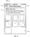
- FIG. 31 shows an example screen for Security Tab Options, under an embodiment.
- FIG. 32 shows an example “Add Floor” screen for use in selecting a floor plan, under an embodiment.
- FIG. 33 shows an “Edit Home View” screen of the editor, under an embodiment.
- FIG. 34 shows an example of dragging a device icon during which a name of the device (“Front Door”) is displayed, under an embodiment.
- FIG. 35 is an example of a U-shaped floor plan customized by changing interior tiles to define walls, under an embodiment.
- FIG. 36 shows an example in which the zoom level is increased and dragging has been used to focus on a sensor location, under an embodiment.
- FIG. 37 is an example “Add Floor” page, under an embodiment.
- FIG. 38 is an example Edit Home View screen showing the floor thumbnails for use in selecting a floor, under an embodiment.
- FIG. 39 shows the Edit Home View screen with a delete floor selector, under an embodiment.
- FIG. 40 is an example Edit Home View screen displaying options to “Save” and “Don't Save” changes following selection of the Done button, under an embodiment.
- FIG. 41 is an example of the floor grid data, under an embodiment.
- FIG. 42 is an example sensor hash table for a single-floor site, under an embodiment.
- FIG. 43 shows an example hash table mapping, under an embodiment.
- FIG. 44 shows the twelve shapes of a tile set, under an embodiment.
- FIG. 45 shows the tile shapes and corresponding fill options for rendered tiles, under an embodiment.
- FIG. 46 is an example tile rendering for a room of a premise, under an embodiment.
- FIG. 47 is an example popup display in response to hovering near/adjacent a sensor icon (e.g., “Garage” sensor), under an embodiment.
- a sensor icon e.g., “Garage” sensor
- FIG. 48 shows a Home View display that includes a floor plan display 4800 of a selected floor along with indicators 4801 / 4802 for multiple floors, under an embodiment.
- FIG. 49 shows an example of the Home View user interface displayed via a mobile device (e.g., iPhone), under an embodiment.
- a mobile device e.g., iPhone
- Home View is configured via site settings as described in detail herein. Each application retains or remembers the user's preferred mode across sessions.
- FIG. 50 shows an example of a Settings page of Home View, under an embodiment.
- FIG. 51 shows an example “Home View Setup” editor page 5100 for use in selecting a floor plan, under an embodiment.
- FIG. 52 shows a “Home View Setup” editor screen 5200 with a selected floor plan 5201 , under an embodiment.
- FIG. 59 shows a Home View Setup page 5900 with options displayed, under an embodiment.
- FIG. 53 shows an example editor screen 5300 for which a label 5301 with a name of the device (“Front Door”) is displayed, under an embodiment.
- FIG. 54 shows a Home View Setup page 5400 with a selected floor plan 5201 that has been edited to add numerous interior walls 5401 , under an embodiment.
- FIG. 55 shows a Home View Setup page with a label editing prompt 5501 , under an embodiment.
- FIG. 56 shows a Home View Setup page 5600 in a zoomed editing mode to zoom on one room 5601 in a building, under an embodiment.
- FIG. 57 shows a Home View Setup page for adding at least one floor to a floor plan, under an embodiment.
- FIG. 58 shows a Home View Setup page 5800 with editing for multiple floors, under an embodiment.
- FIG. 60 shows a Home View Setup page 6000 with editor exit option prompts 6001 displayed, under an embodiment.
- FIG. 61 is an example floor plan, under an embodiment.
- FIG. 62 is an example Home View one-story floor plan, under an embodiment.
- FIG. 63 is an example Home View floor plan that includes two devices, under an embodiment.
- FIG. 64 is an example Home View floor plan that includes two labels, under an embodiment.
- FIG. 65 is a block diagram of IP device integration with a premise network, under an embodiment.
- FIG. 66 is a block diagram of IP device integration with a premise network, under an alternative embodiment.
- FIG. 67 is a block diagram of a touchscreen, under an embodiment.
- FIG. 68 is an example screenshot of a networked security touchscreen, under an embodiment.
- FIG. 69 is a block diagram of network or premise device integration with a premise network, under an embodiment.
- FIG. 70 is a block diagram of network or premise device integration with a premise network, under an alternative embodiment.
- FIG. 71 is a flow diagram for a method of forming a security network including integrated security system components, under an embodiment.
- FIG. 72 is a flow diagram for a method of forming a security network including integrated security system components and network devices, under an embodiment.
- FIG. 73 is a flow diagram for installation of an IP device into a private network environment, under an embodiment.
- FIG. 74 is a block diagram showing communications among IP devices of the private network environment, under an embodiment.
- FIG. 75 is a flow diagram of a method of integrating an external control and management application system with an existing security system, under an embodiment.
- FIG. 76 is a block diagram of an integrated security system wirelessly interfacing to proprietary security systems, under an embodiment.
- FIG. 77 is a flow diagram for wirelessly ‘learning’ the gateway into an existing security system and discovering extant sensors, under an embodiment.
- FIG. 78 is a block diagram of a security system in which the legacy panel is replaced with a wireless security panel wirelessly coupled to a gateway, under an embodiment.
- FIG. 79 is a block diagram of a security system in which the legacy panel is replaced with a wireless security panel wirelessly coupled to a gateway, and a touchscreen, under an alternative embodiment.
- FIG. 80 is a block diagram of a security system in which the legacy panel is replaced with a wireless security panel connected to a gateway via an Ethernet coupling, under another alternative embodiment.
- FIG. 81 is a flow diagram for automatic takeover of a security system, under an embodiment.
- FIG. 82 is a flow diagram for automatic takeover of a security system, under an alternative embodiment.
- An integrated security system that integrates broadband and mobile access and control with conventional security systems and premise devices to provide a tri-mode security network (broadband, cellular/GSM, POTS access) that enables users to remotely stay connected to their premises.
- the integrated security system while delivering remote premise monitoring and control functionality to conventional monitored premise protection, complements existing premise protection equipment.
- the integrated security system integrates into the premise network and couples wirelessly with the conventional security panel, enabling broadband access to premise security systems.
- Automation devices (cameras, lamp modules, thermostats, etc.) can be added, enabling users to remotely see live video and/or pictures and control home devices via their personal web portal or webpage, mobile phone, and/or other remote client device. Users can also receive notifications via email or text message when happenings occur, or do not occur, in their home.
- a wireless system e.g., radio frequency (RF)
- RF radio frequency
- the system includes an RF-capable Gateway device (physically located within RF range of the RF-capable security system) and associated software operating on the Gateway device.
- the system also includes a web server, application server, and remote database providing a persistent store for information related to the system.
- the security systems of an embodiment extend the value of traditional home security by adding broadband access and the advantages of remote home monitoring and home control through the formation of a security network including components of the integrated security system integrated with a conventional premise security system and a premise local area network (LAN).
- LAN local area network
- conventional home security sensors, cameras, touchscreen keypads, lighting controls, and/or Internet Protocol (IP) devices in the home (or business) become connected devices that are accessible anywhere in the world from a web browser, mobile phone or through content-enabled touchscreens.
- IP Internet Protocol
- the integrated security system experience allows security operators to both extend the value proposition of their monitored security systems and reach new consumers that include broadband users interested in staying connected to their family, home and property when they are away from home.
- the integrated security system of an embodiment includes security servers (also referred to herein as iConnect servers or security network servers) and an iHub gateway (also referred to herein as the gateway, the iHub, or the iHub client) that couples or integrates into a home network (e.g., LAN) and communicates directly with the home security panel, in both wired and wireless installations.
- the security system of an embodiment automatically discovers the security system components (e.g., sensors, etc.) belonging to the security system and connected to a control panel of the security system and provides consumers with full two-way access via web and mobile portals.
- the gateway supports various wireless protocols and can interconnect with a wide range of control panels offered by security system providers.
- IP cameras IP cameras
- security devices such as interactive touchscreen keypads.
- the integrated security system adds an enhanced value to these security systems by enabling consumers to stay connected through email and SMS alerts, photo push, event-based video capture and rule-based monitoring and notifications. This solution extends the reach of home security to households with broadband access.
- the integrated security system builds upon the foundation afforded by traditional security systems by layering broadband and mobile access, IP cameras, interactive touchscreens, and an open approach to home automation on top of traditional security system configurations.
- the integrated security system is easily installed and managed by the security operator, and simplifies the traditional security installation process, as described below.
- the integrated security system provides an open systems solution to the home security market.
- CPE customer premises equipment
- the integrated security system DeviceConnect technology that enables this capability supports protocols, devices, and panels from GE Security and Honeywell, as well as consumer devices using Z-Wave, IP cameras (e.g., Ethernet, wifi, and Homeplug), and IP touchscreens.
- the DeviceConnect is a device abstraction layer that enables any device or protocol layer to interoperate with integrated security system components. This architecture enables the addition of new devices supporting any of these interfaces, as well as add entirely new protocols.
- DeviceConnect provides supplier flexibility.
- the same consistent touchscreen, web, and mobile user experience operate unchanged on whatever security equipment selected by a security system provider, with the system provider's choice of IP cameras, backend data center and central station software.
- the integrated security system provides a complete system that integrates or layers on top of a conventional host security system available from a security system provider.
- the security system provider therefore can select different components or configurations to offer (e.g., CDMA, GPRS, no cellular, etc.) as well as have iControl modify the integrated security system configuration for the system provider's specific needs (e.g., change the functionality of the web or mobile portal, add a GE or Honeywell-compatible TouchScreen, etc.).
- the integrated security system integrates with the security system provider infrastructure for central station reporting directly via Broadband and GPRS alarm transmissions. Traditional dial-up reporting is supported via the standard panel connectivity. Additionally, the integrated security system provides interfaces for advanced functionality to the CMS, including enhanced alarm events, system installation optimizations, system test verification, video verification, 2-way voice over IP and GSM.
- the integrated security system is an IP centric system that includes broadband connectivity so that the gateway augments the existing security system with broadband and GPRS connectivity. If broadband is down or unavailable GPRS may be used, for example.
- the integrated security system supports GPRS connectivity using an optional wireless package that includes a GPRS modem in the gateway.
- the integrated security system treats the GPRS connection as a higher cost though flexible option for data transfers. In an embodiment the GPRS connection is only used to route alarm events (e.g., for cost), however the gateway can be configured (e.g., through the iConnect server interface) to act as a primary channel and pass any or all events over GPRS. Consequently, the integrated security system does not interfere with the current plain old telephone service (POTS) security panel interface.
- POTS plain old telephone service
- the integrated security system provides a web application interface to the CSR tool suite as well as XML web services interfaces for programmatic integration between the security system provider's existing call center products.
- the integrated security system includes, for example, APIs that allow the security system provider to integrate components of the integrated security system into a custom call center interface.
- the APIs include XML web service APIs for integration of existing security system provider call center applications with the integrated security system service. All functionality available in the CSR Web application is provided with these API sets.
- the Java and XML-based APIs of the integrated security system support provisioning, billing, system administration, CSR, central station, portal user interfaces, and content management functions, to name a few.
- the integrated security system can provide a customized interface to the security system provider's billing system, or alternatively can provide security system developers with APIs and support in the integration effort.
- the integrated security system provides or includes business component interfaces for provisioning, administration, and customer care to name a few. Standard templates and examples are provided with a defined customer professional services engagement to help integrate OSS/BSS systems of a Service Provider with the integrated security system.
- the integrated security system components support and allow for the integration of customer account creation and deletion with a security system.
- the iConnect APIs provides access to the provisioning and account management system in iConnect and provide full support for account creation, provisioning, and deletion. Depending on the requirements of the security system provider, the iConnect APIs can be used to completely customize any aspect of the integrated security system backend operational system.
- the integrated security system includes a gateway that supports the following standards-based interfaces, to name a few: Ethernet IP communications via Ethernet ports on the gateway, and standard XML/TCP/IP protocols and ports are employed over secured SSL sessions; USB 2.0 via ports on the gateway; 802.11b/g/n IP communications; GSM/GPRS RF WAN communications; CDMA 1 ⁇ RTT RF WAN communications (optional, can also support EVDO and 3G technologies).
- the gateway supports the following proprietary interfaces, to name a few: interfaces including Dialog RF network (319.5 MHz) and RS485 Superbus 2000 wired interface; RF mesh network (908 MHz); and interfaces including RF network (345 MHz) and RS485/RS232bus wired interfaces.
- the integrated security system uses SSL to encrypt all IP traffic, using server and client-certificates for authentication, as well as authentication in the data sent over the SSL-encrypted channel.
- SSL Secure Sockets Layer
- integrated security system issues public/private key pairs at the time/place of manufacture, and certificates are not stored in any online storage in an embodiment.
- the integrated security system does not need any special rules at the customer premise and/or at the security system provider central station because the integrated security system makes outgoing connections using TCP over the standard HTTP and HTTPS ports. Provided outbound TCP connections are allowed then no special requirements on the firewalls are necessary.
- FIG. 1 is a block diagram of the integrated security system 100 , under an embodiment.
- the integrated security system 100 of an embodiment includes the gateway 102 and the security servers 104 coupled to the conventional home security system 110 .
- the gateway 102 connects and manages the diverse variety of home security and self-monitoring devices.
- the gateway 102 communicates with the iConnect Servers 104 located in the service provider's data center 106 (or hosted in integrated security system data center), with the communication taking place via a communication network 108 or other network (e.g., cellular network, internet, etc.).
- These servers 104 manage the system integrations necessary to deliver the integrated system service described herein.
- the combination of the gateway 102 and the iConnect servers 104 enable a wide variety of remote client devices 120 (e.g., PCs, mobile phones and PDAs) allowing users to remotely stay in touch with their home, business and family.
- remote client devices 120 e.g., PCs, mobile phones and PDAs
- the technology allows home security and self-monitoring information, as well as relevant third party content such as traffic and weather, to be presented in intuitive ways within the home, such as on advanced touchscreen keypads.
- the integrated security system service (also referred to as iControl service) can be managed by a service provider via browser-based Maintenance and Service Management applications that are provided with the iConnect Servers. Or, if desired, the service can be more tightly integrated with existing OSS/BSS and service delivery systems via the iConnect web services-based XML APIs.
- the integrated security system service can also coordinate the sending of alarms to the home security Central Monitoring Station (CMS) 199 .
- Alarms are passed to the CMS 199 using standard protocols such as Contact ID or SIA and can be generated from the home security panel location as well as by iConnect server 104 conditions (such as lack of communications with the integrated security system).
- the link between the security servers 104 and CMS 199 provides tighter integration between home security and self-monitoring devices and the gateway 102 . Such integration enables advanced security capabilities such as the ability for CMS personnel to view photos taken at the time a burglary alarm was triggered.
- the gateway 102 and iConnect servers 104 support the use of a mobile network (both GPRS and CDMA options are available) as a backup to the primary broadband connection.
- FIG. 2 is a block diagram of components of the integrated security system 100 , under an embodiment. Following is a more detailed description of the components.
- the iConnect servers 104 support a diverse collection of clients 120 ranging from mobile devices, to PCs, to in-home security devices, to a service provider's internal systems. Most clients 120 are used by end-users, but there are also a number of clients 120 that are used to operate the service.
- Clients 120 used by end-users of the integrated security system 100 include, but are not limited to, the following:
- the iConnect servers 104 support PC browser-based Service Management clients that manage the ongoing operation of the overall service. These clients run applications that handle tasks such as provisioning, service monitoring, customer support and reporting.
- server components of the iConnect servers 104 of an embodiment including, but not limited to, the following: Business Components which manage information about all of the home security and self-monitoring devices; End-User Application Components which display that information for users and access the Business Components via published XML APIs; and Service Management Application Components which enable operators to administer the service (these components also access the Business Components via the XML APIs, and also via published SNMP MIBs).
- the server components provide access to, and management of, the objects associated with an integrated security system installation.
- the top-level object is the “network.” It is a location where a gateway 102 is located, and is also commonly referred to as a site or premises; the premises can include any type of structure (e.g., home, office, warehouse, etc.) at which a gateway 102 is located. Users can only access the networks to which they have been granted permission.
- Every object monitored by the gateway 102 is called a device. Devices include the sensors, cameras, home security panels and automation devices, as well as the controller or processor-based device running the gateway applications.
- Automations define actions that occur as a result of a change in state of a device. For example, take a picture with the front entry camera when the front door sensor changes to “open”. Notifications are messages sent to users to indicate that something has occurred, such as the front door going to “open” state, or has not occurred (referred to as an iWatch notification). Schedules define changes in device states that are to take place at predefined days and times. For example, set the security panel to “Armed” mode every weeknight at 11:00 pm.
- the iConnect Business Components are responsible for orchestrating all of the low-level service management activities for the integrated security system service. They define all of the users and devices associated with a network (site), analyze how the devices interact, and trigger associated actions (such as sending notifications to users). All changes in device states are monitored and logged. The Business Components also manage all interactions with external systems as required, including sending alarms and other related self-monitoring data to the home security Central Monitoring System (CMS) 199 .
- CMS Central Monitoring System
- the Business Components are implemented as portable Java J2EE Servlets, but are not so limited.
- Additional iConnect Business Components handle direct communications with certain clients and other systems, for example:
- the iConnect Business Components store information about the objects that they manage in the iControl Service Database 240 and in the iControl Content Store 242 .
- the iControl Content Store is used to store media objects like video, photos and widget content, while the Service Database stores information about users, networks, and devices. Database interaction is performed via a JDBC interface.
- the Business Components manage all data storage and retrieval.
- the iControl Business Components provide web services-based APIs that application components use to access the Business Components' capabilities. Functions of application components include presenting integrated security system service data to end-users, performing administrative duties, and integrating with external systems and back-office applications.
- the primary published APIs for the iConnect Business Components include, but are not limited to, the following:
- Each API of an embodiment includes two modes of access: Java API or XML API.
- the XML APIs are published as web services so that they can be easily accessed by applications or servers over a network.
- the Java APIs are a programmer-friendly wrapper for the XML APIs.
- Application components and integrations written in Java should generally use the Java APIs rather than the XML APIs directly.
- the iConnect Business Components also have an XML-based interface 260 for quickly adding support for new devices to the integrated security system.
- This interface 260 referred to as DeviceConnect 260 , is a flexible, standards-based mechanism for defining the properties of new devices and how they can be managed. Although the format is flexible enough to allow the addition of any type of future device, pre-defined XML profiles are currently available for adding common types of devices such as sensors (SensorConnect), home security panels (PanelConnect) and IP cameras (CameraConnect).
- the iConnect End-User Application Components deliver the user interfaces that run on the different types of clients supported by the integrated security system service.
- the components are written in portable Java J2EE technology (e.g., as Java Servlets, as JavaServer Pages (JSPs), etc.) and they all interact with the iControl Business Components via the published APIs.
- JSPs JavaServer Pages
- End-User Application Components generate CSS-based HTML/JavaScript that is displayed on the target client. These applications can be dynamically branded with partner-specific logos and URL links (such as Customer Support, etc.).
- End-User Application Components of an embodiment include, but are not limited to, the following:
- Service Management Application Components are responsible for overall management of the service. These pre-defined applications, referred to as Service Management Application Components, are configured to offer off-the-shelf solutions for production management of the integrated security system service including provisioning, overall service monitoring, customer support, and reporting, for example.
- the Service Management Application Components of an embodiment include, but are not limited to, the following:
- the iConnect servers 104 also support custom-built integrations with a service provider's existing OSS/BSS, CSR and service delivery systems 290 . Such systems can access the iConnect web services XML API to transfer data to and from the iConnect servers 104 . These types of integrations can compliment or replace the PC browser-based Service Management applications, depending on service provider needs.
- the integrated security system of an embodiment includes a gateway, or iHub.
- the gateway of an embodiment includes a device that is deployed in the home or business and couples or connects the various third-party cameras, home security panels, sensors and devices to the iConnect server over a WAN connection as described in detail herein.
- the gateway couples to the home network and communicates directly with the home security panel in both wired and wireless sensor installations.
- the gateway is configured to be low-cost, reliable and thin so that it complements the integrated security system network-based architecture.
- the gateway supports various wireless protocols and can interconnect with a wide range of home security control panels. Service providers and users can then extend the system's capabilities by adding IP cameras, lighting modules and additional security devices.
- the gateway is configurable to be integrated into many consumer appliances, including set-top boxes, routers and security panels. The small and efficient footprint of the gateway enables this portability and versatility, thereby simplifying and reducing the overall cost of the deployment.
- FIG. 3 is a block diagram of the gateway 102 including gateway software or applications, under an embodiment.
- the gateway software architecture is relatively thin and efficient, thereby simplifying its integration into other consumer appliances such as set-top boxes, routers, touch screens and security panels.
- the software architecture also provides a high degree of security against unauthorized access. This section describes the various key components of the gateway software architecture.
- the gateway application layer 302 is the main program that orchestrates the operations performed by the gateway.
- the Security Engine 304 provides robust protection against intentional and unintentional intrusion into the integrated security system network from the outside world (both from inside the premises as well as from the WAN).
- the Security Engine 304 of an embodiment comprises one or more sub-modules or components that perform functions including, but not limited to, the following:
- the security manager can be upgraded “over the air” to provide new and better security for communications between the iConnect server and the gateway application, and locally at the premises to remove any risk of eavesdropping on camera communications.
- a Remote Firmware Download module 306 allows for seamless and secure updates to the gateway firmware through the iControl Maintenance Application on the server 104 , providing a transparent, hassle-free mechanism for the service provider to deploy new features and bug fixes to the installed user base.
- the firmware download mechanism is tolerant of connection loss, power interruption and user interventions (both intentional and unintentional). Such robustness reduces down time and customer support issues.
- Gateway firmware can be remotely download either for one gateway at a time, a group of gateways, or in batches.
- the Automations engine 308 manages the user-defined rules of interaction between the different devices (e.g. when door opens turn on the light). Though the automation rules are programmed and reside at the portal/server level, they are cached at the gateway level in order to provide short latency between device triggers and actions.
- DeviceConnect 310 includes definitions of all supported devices (e.g., cameras, security panels, sensors, etc.) using a standardized plug-in architecture.
- the DeviceConnect module 310 offers an interface that can be used to quickly add support for any new device as well as enabling interoperability between devices that use different technologies/protocols. For common device types, pre-defined sub-modules have been defined, making supporting new devices of these types even easier.
- SensorConnect 312 is provided for adding new sensors, CameraConnect 316 for adding IP cameras, and PanelConnect 314 for adding home security panels.
- the Schedules engine 318 is responsible for executing the user defined schedules (e.g., take a picture every five minutes; every day at 8 am set temperature to 65 degrees Fahrenheit, etc.). Though the schedules are programmed and reside at the iConnect server level they are sent to the scheduler within the gateway application. The Schedules Engine 318 then interfaces with SensorConnect 312 to ensure that scheduled events occur at precisely the desired time.
- the Schedules Engine 318 then interfaces with SensorConnect 312 to ensure that scheduled events occur at precisely the desired time.
- the Device Management module 320 is in charge of all discovery, installation and configuration of both wired and wireless IP devices (e.g., cameras, etc.) coupled or connected to the system.
- Networked IP devices such as those used in the integrated security system, require user configuration of many IP and security parameters—to simplify the user experience and reduce the customer support burden, the device management module of an embodiment handles the details of this configuration.
- the device management module also manages the video routing module described below.
- the video routing engine 322 is responsible for delivering seamless video streams to the user with zero-configuration. Through a multi-step, staged approach the video routing engine uses a combination of UPnP port-forwarding, relay server routing and STUN/TURN peer-to-peer routing.
- FIG. 4 is a block diagram of components of the gateway 102 , under an embodiment.
- the gateway 102 can use any of a number of processors 402 , due to the small footprint of the gateway application firmware.
- the gateway could include the Broadcom BCM5354 as the processor for example.
- the gateway 102 includes memory (e.g., FLASH 404 , RAM 406 , etc.) and any number of input/output (I/O) ports 408 .
- the gateway 102 of an embodiment can communicate with the iConnect server using a number of communication types and/or protocols, for example Broadband 412 , GPRS 414 and/or Public Switched Telephone Network (PTSN) 416 to name a few.
- broadband communication 412 is the primary means of connection between the gateway 102 and the iConnect server 104 and the GPRS/CDMA 414 and/or PSTN 416 interfaces acts as back-up for fault tolerance in case the user's broadband connection fails for whatever reason, but the embodiment is not so limited.
- the gateway 102 is protocol-agnostic and technology-agnostic and as such can easily support almost any device networking protocol.
- the gateway 102 can, for example, support GE and Honeywell security RF protocols 422 , Z-Wave 424 , serial (RS232 and RS485) 426 for direct connection to security panels as well as WiFi 428 (802.11b/g) for communication to WiFi cameras.
- the system of an embodiment uses or includes a system user interface (SUI) that provides an iconic, at-a-glance representation of security system status.
- the SUI is for use across all client types as described above with reference to FIG. 1 .
- the SUI includes a number of display elements that are presented across all types of client devices used to monitor status of the security system.
- the clients of an embodiment include, but are not limited to, the iPhone®, the iPad®, a mobile portal, a web portal, and a touchscreen.
- the display elements of the SUI of an embodiment include, but are not limited to, an orb icon, text summary, security button, device and system warnings, interesting sensors, and quiet sensors, as described in detail below.
- the SUI thus provides system status summary information (e.g., security and sensors) uniformly across all clients. Additionally, the SUI provides consistent iconography, terminology, and display rules across all clients as well as consistent sensor and system detail across clients.
- FIG. 5 shows the orb icon and corresponding text summary display elements, under an embodiment. Across all clients, when sensor detail is shown in a list or timeline, state is indicated using the proper icon, text summary and grouping.
- the orb icons and text summary elements of an embodiment generally represent system state 4001 to include the following states: “Disarmed” or “Subdisarmed; “Armed (Doors and Windows, Stay, Away, All, Night Stay, Instant, Motion, Maximum)”; “Disarmed”, or “Subdisarmed” (sensor absent; sensor tripped; sensor tampered; low battery; uncleared alarm); “Armed (Doors and Windows, Stay, Away, All, Night Stay, Instant, Motion, Maximum)” (sensor absent; sensor tripped; sensor tampered; low battery); “Alarm”; and “No iHub Connection” (broadband offline, etc.) (no security panel connection).
- system status 4002 to include the following status: “All Quiet”; “Motion”; “Open”; “Open & Motion”.
- the orb icons of an embodiment indicate or represent numerous system states.
- the orb icons of an embodiment indicate or represent status 4002 as follows: Disarmed (status: all quiet) 4010 (e.g., icon color is green); Disarmed (status: motion) 4011 (e.g., icon color is green); Disarmed, (number of sensors open) Sensor(s) Open (status: open) 4012 (e.g., icon color is green, bottom region for sensor number is yellow); Disarmed, (number of sensors open) Sensor(s) Open (status: open and motion) 4013 (e.g., icon color is green, bottom region for sensor number is yellow).
- the orb icons of an embodiment indicate or represent status 4002 as follows: Armed Doors & Windows (status: all quiet) 4014 (e.g., icon color is red); Armed Doors & Windows (status: motion) 4015 (e.g., icon color is red); Armed Doors & Windows, (number of sensors open) Sensor(s) Open (status: open) 4016 (e.g., icon color is red, bottom region for sensor number is yellow); Armed Doors & Windows, (number of sensors open) Sensor(s) Open (status: open and motion) 4017 (e.g., icon color is red, bottom region for sensor number is yellow).
- the orb icons of an embodiment indicate or represent status 4002 as follows: Disarmed, sensor problem (status: all quiet) 4018 (e.g., icon color is green, badge in top region with “!” symbol is red); Disarmed, sensor problem (status: motion) 4019 (e.g., icon color is green, badge in top region with “!” symbol is red); Disarmed, sensor problem (status: open) 4020 (e.g., icon color is green, badge in top region with “!” symbol is red, bottom region for sensor number is yellow); Disarmed, sensor problem (status: open and motion) 4021 (e.g., icon color is green, badge in top region with “!” symbol is red, bottom region for sensor number is yellow).
- Disarmed, sensor problem (status: all quiet) 4018 e.g., icon color is green, badge in top region with “!” symbol is red
- Disarmed, sensor problem (status: motion) 4019 e.g., icon color is green, badge in top region with “!” symbol is red
- the orb icons of an embodiment indicate or represent status 4002 as follows: Armed Doors & Windows, sensor problem (status: all quiet) 4022 (e.g., icon color is red, badge in top region with “!” symbol is red); Armed Doors & Windows, sensor problem (status: motion) 4023 (e.g., icon color is red, badge in top region with “!” symbol is red); Armed Doors & Windows, sensor problem (status: open) 4024 (e.g., icon color is red, badge in top region with “!” symbol is red, bottom region for sensor number is yellow); Armed Doors & Windows, sensor problem (status: open & motion) 4025 (e.g., icon color is red, badge in top region with “!” symbol is red, bottom region for sensor number is yellow).
- Armed Doors & Windows sensor problem (status: open & motion) 4025 (e.g., icon color is red, badge in top region with “!” symbol is red, bottom region for sensor number is yellow).
- the orb icons of an embodiment indicate or represent status 4002 as follows: Armed Away/Stay, (alarm type) ALARM 4026 (e.g., icon color is red).
- the orb icons of an embodiment indicate or represent status 4002 as follows: Status Unavailable 4027 (e.g., icon color is grey).
- a mini orb is presented at the bottom of the touch screen in all widgets and settings screens.
- the mini orb is green when the security panel is disarmed, and it is red when the security panel is armed, but is not so limited.
- the form factor of the mini orb, and the text corresponding to the mini orb, is the same or similar to that described above as corresponding to the orb icon on the home screen.
- the orb icons of an embodiment include motion indicators that animate to indicate motion detected by a corresponding sensor or detector. Furthermore, the orb icons of an embodiment show an animation during the exit delay when arming the security system and, additionally, indicate a countdown time showing the time remaining before the security system is fully armed. Moreover, selection of the orb of an embodiment causes additional information (e.g., list of sensors, etc.) of the security system and/or premise to be displayed.
- the text summary display element of the SUI includes or displays information including a direct description of the current state of the security system to support the visual appearance of the orb icon.
- two phrases are shown, including a first phrase for security state and a second phrase for sensor status (e.g., “Armed Stay. All Quiet”), as described herein.
- FIG. 6 is a table of security state and the corresponding sensor status displayed on the SUI, under an embodiment.
- the possible values for the text summary are (in priority order): Status Unavailable; if the security panel and control box are online and there are no current alarms, the text summary section is a combination of one phrase from each of the security state 4030 and the sensor status 4032 .
- the security state 4030 of an embodiment is selected from among the following, but is not so limited: Armed Doors & Windows; Armed All; Armed Stay; Armed Away; Disarmed; Armed Maximum; Armed Night Stay; Armed Stay Instant; Armed Away Instant; Armed Motion; Subdisarmed.
- the sensor status 4032 of an embodiment is selected from among the following, but is not so limited: Uncleared Alarm; Sensor Tripped; Sensor Problem; Sensor(s) Bypassed; Motion; All Quiet; (number of sensors open) Sensor(s) Open.
- the display elements of the SUI also include security buttons.
- the security buttons are used to control or arm/disarm the security panel.
- a single arm button e.g., button labeled “Arm” can be used on the SUI of a first client device type (e.g., Touchscreen, iPhone®, etc.).
- Two different buttons e.g., buttons labeled “Arm Away/Arm Stay” or “Arm All/Doors and Windows” can be used on the SUI of a second client device type (e.g., web portal, mobile portal, etc.).
- the arm button e.g., “Arm”, “Arm Stay” and “Arm Away” label will change to a “Disarm” label. If the system is in the process of arming, the button is disabled.
- the display elements of the SUI include system and device warnings, as described above.
- the system and device warning are informational warnings that are not associated with specific sensors, and involve more detail than can be displayed in the text summary display element.
- FIG. 7 is a table of system state and the corresponding icons and warning text displayed as system warnings on the SUI, under an embodiment. Where an icon is displayed, an embodiment uses a red color for the icon, but it is not so limited.
- the system states/warnings of an embodiment include, but are not limited to, the following: primary connection is broadband, broadband is down, cellular is being used/using cellular connection; primary connection is broadband, broadband and cellular are down/no cellular connection; primary connection is broadband, broadband is down, no cellular backup installed/broadband connection unknown; primary connection is cellular, cellular is down/no cellular connection; security panel not connected to AC power/security panel AC power loss; security panel low battery/security panel low battery; security panel tampered/security panel tampered; sensor(s) bypassed/sensor bypassed.
- the device warnings of an embodiment include, but are not limited to, the following: camera(s) offline; light(s) offline; thermostat(s) offline.
- the device and system warnings may be combined into one box, or indicated separately in respective regions or portions of the SUI, depending on a type of the client device (e.g., combined into one box on a web portal or a mobile portal, but indicated in separate boxes on a Touchscreen or iPhone® device).
- the device and system warnings display element is cumulative (e.g., built up in a list), but is not so limited.
- the system and device warnings of an embodiment are combined into one area, but are not so limited.
- the touchscreen device and mobile phone e.g., iPhone®
- device warnings are indicated separately so that, in an embodiment, the iPhone® tab bar and the touchscreen home screen indicate device warnings with icon badges, and system warnings are placed on the sensors screen.
- the list of all sensors includes, but is not limited to, door/window sensors, motion detectors, smoke, flood, fire, glass break, etc.
- the list of all sensors of an embodiment does not include cameras or locks, or non-security related devices such as lights, thermostats, energy, water etc.
- the list of sensors is split into groups that, in an embodiment, include interesting sensors as a first group, and quiet sensors as a second group.
- the interesting sensor group is positioned above or sorted to the top portion of the sensor list and the quiet sensors are sorted to the bottom portion of the sensor list.
- Any sensor that is triggered e.g. open, motion, etc.
- other sensor states such as tampered, tripped, absent, installing, low battery, or bypassed make a sensor “interesting” regardless of their state.
- FIG. 8 is a table of sensor state/sort order and the corresponding icon, sensor name and status text of the SUI, under an embodiment.
- the list of interesting sensors is sorted according to the following categories: motion; open/tripped; tampered; low battery; offline; installing; bypassed.
- Sensors are sorted alphabetically by sensor name within each category or interest type when multiple interesting sensors have the same state.
- the sensor state/sort order of an embodiment includes, but is not limited to, the following: breached & any sensor state (e.g., red icon) (interesting sensor); tripped (smoke, water, gas, freeze, etc.) (e.g., red icon) (interesting sensor); tampered (e.g., red icon) (interesting sensor); low battery (e.g., red icon) (interesting sensor); offline/AWOL (e.g., red icon) (interesting sensor); unknown (if the iHub or Security Panel is offline, all sensors have a grey diamond icon and “Unknown” for the status text) (e.g., grey icon) (interesting sensor); installing (e.g., grey icon) (interesting sensor); open (e.g., yellow icon) (interesting sensor); motion (e.g., yellow icon) (interesting sensor); bypassed (e.g., yellow or green icon) (interesting sensor); okay, closed, no motion (e.g., green icon) (quiet
- FIG. 9 shows icons of the interesting sensors, under an embodiment.
- a red diamond bang icon represents tamper, offline, bypassed, installing, and/or battery.
- a yellow triangle icon represents open or triggered.
- a wavy lines icon represents motion. It is possible for an interesting sensor to have a green/closed icon (e.g., any quiet sensor that has been bypassed).
- an embodiment displays status text.
- the status of an embodiment includes, but is not limited to, the following: ALARM, (sensor state); tripped; tampered, (sensor state); low battery, (sensor state); offline; unknown; installing; bypassed, (sensor state). If a sensor is offline or tampered, it will show that text; otherwise the status text will show the tripped state: open, motion, tripped, etc.
- a sensor is bypassed its state is “Bypassed, (sensor state)”. For example, a bypassed motion sensor that has recently detected motion would have the status: “Motion, bypassed”. If a sensor has a low battery its state does not change, but it still joins the interesting sensors group.
- the quiet sensors include the remaining sensors that are not currently active, and so are not categorized as interesting sensors.
- Quiet sensor states of an embodiment include closed, no motion or otherwise not tripped or faulted.
- FIG. 10 shows the quiet sensor icon, under an embodiment.
- a green circle icon is a quiet sensor icon in an embodiment, and represents closed/no motion/okay/quiet.
- each quiet sensor shows status text as follows: if a door/window sensor is closed its state is “closed”; if a motion sensor has not recently detected motion then its state is “no motion”; other sensors, such as a smoke detector, indicate “quiet” or “okay”.
- Quiet sensors are listed alphabetically.
- the SUI of an embodiment includes control icons for a Home Management Mode (HMM). If the user deselects the “Set home management modes automatically” setting via the web portal, then the Home Management Mode (HMM) screen will appear in the web and mobile Portals.
- FIG. 11 is an example Home Management Mode (HMM) screen presented via the web portal SUI, under an embodiment.
- the HMM screen includes an orb icon and corresponding text summary display elements, along with security buttons that control or arm/disarm the security panel.
- the HMM screen includes sensor status information (e.g., “Door”, status is “open”, icon is yellow; “Basement Motion”, status is “motion”, icon is yellow; “Family Room North Motion”, status is “motion”, icon is yellow; “Water”, status is “okay”, icon is green).
- FIG. 12 is an example Home Management Mode (HMM) screen presented via the mobile portal SUI, under an embodiment.
- the HMM screen of the mobile portal includes an orb icon and corresponding text summary display elements, along with security buttons that control or arm/disarm the security panel.
- the SUI of an embodiment is supported on numerous client types, for example, mobile telephones (e.g., iPhone®, etc.), client access via mobile portal, client access via web portal, and touchscreen to name a few. All clients types supported in an embodiment have the same status related sections, but their locations change slightly depending on the client.
- the status related sections of an embodiment include the following: orb; arm state/sensor summary; change mode; device summary and system warnings; interesting sensors; and quiet sensors.
- FIG. 13 is a block diagram of an iPhone® client device SUI, under an embodiment.
- the client interface of the iPhone® as one example client, has the orb on the security page.
- the text summary is below the orb.
- the security button (e.g., arm, disarm, etc.) is below the text summary.
- a tab bar is presented at the bottom of the screen.
- the SUI of an embodiment represents device warnings by the icons in the bottom horizontal tab bar. If a camera, light, lock, or thermostat is offline then a red circle will badge the corresponding icon in the tab bar. The number of offline devices is shown in the badge.
- FIG. 14 is a first example iPhone® client device SUI, under an embodiment. In this first example screenshot, the security page indicates one camera is offline, as indicated by the “1” in a “circle” badge displayed corresponding to the “camera” icon in the tab bar.
- System warnings appear as a group in an area (e.g., yellow area) at the top of the sensor status screen. This area at the top of the sensor status screen appears only when there is a device or system warning; otherwise, it is not presented. Multiple messages appear as a vertical list with one message on each line. The yellow bar will grow in length to fit additional messages. If there are no system warnings then the interesting sensors group is at the top of the sensor status screen. Interesting sensors are presented below system warnings. Quiet sensors are presented below interesting sensors.
- FIG. 15 is a second example iPhone® client device SUI, under an embodiment. In this second example screenshot, the sensor status page indicates at least one sensor is bypassed, as indicated by the “Sensor(s) bypassed” message displayed at the top of the sensor status screen.
- FIG. 16 is a block diagram of a mobile portal client device SUI, under an embodiment.
- the mobile portal of an embodiment comprises three (3) pages or screens presented to the client, including a summary page (“summary”), a security panel page (“security panel”), and a sensor status page (“sensors status”), but the embodiment is not so limited.
- the client interface of the mobile portal as one example client, has the orb at the top of the summary page below the site name.
- the text summary is below the orb.
- the security buttons e.g., arm, disarm, etc.
- Device and system warnings are presented in an area (e.g., yellow area) below the text summary; in an embodiment this area is presented only when device or system warnings are present.
- interesting sensors presented are at the top of the sensor status page.
- Quiet sensors are presented below interesting sensors on the sensor status page.
- FIG. 17 is an example summary page or screen presented via the mobile portal SUI, under an embodiment.
- FIG. 18 is an example security panel page or screen presented via the mobile portal SUI, under an embodiment.
- FIG. 19 is an example sensor status page or screen presented via the mobile portal SUI, under an embodiment.
- FIG. 20 is an example interface page or screen presented via the web portal SUI, under an embodiment.
- the client interface of the web portal as one example client, has the orb in the center of the security widget.
- the text summary is below the orb.
- the security button (plurality in the web portal) is adjacent to the orb's right side.
- System warnings are presented in an area (e.g., yellow area) below the text summary; in an embodiment this area is presented only when device or system warnings are present.
- Multiple system warning messages are presented as a vertical list with one message on each line, and the area dedicated to the system warnings grows in length to accommodate additional messages.
- Interesting sensors span across the entire security widget below the text summary.
- Quiet sensors span across the entire security widget below interesting sensors.
- FIG. 21 is an example summary page or screen presented via the touchscreen SUI, under an embodiment.
- the summary page of the touchscreen as one example, has the orb in the center of the security bar.
- the text summary is split into sections or parts on each side of the orb.
- the security button is presented on the right side of the security bar.
- the summary page also includes one or more icons that enable a transfer of content to and from the remote network, as described in detail herein.
- the touchscreen integrates the content with access and control of the security system.
- the content includes interactive content in the form of internet widgets.
- the summary page of an embodiment also comprises at least one icon enabling communication and control of the premise devices coupled to the subnetwork.
- the summary page also comprises one or more icons enabling access to live video from a camera, wherein the camera is an Internet Protocol (IP) camera.
- IP Internet Protocol
- FIG. 22 is an example sensor status page or screen presented via the touchscreen SUI, under an embodiment.
- the sensor status page of the touchscreen displays widget badges or icons representing device warnings.
- System warnings are at the top of the sensor status screen; in an embodiment this area is presented only when system warnings are present.
- Multiple system warning messages are presented as a vertical list with one message on each line, and the area dedicated to the system warnings grows in length to accommodate additional messages.
- Interesting sensors are below system warnings.
- Quiet sensors are below interesting sensors.
- the sensors screen also includes the mini-orb which indicates the arm state with text and color.
- the integrated security system of an embodiment includes a component referred to herein as “Home View” that provides end users an at-a-glance representation of their home security status using the layout of their home.
- Home View is intended to complement a set of common elements including, but not limited to, the security text summary, arm/disarm button, system warnings, and sensor status list.
- These UI elements are in the primary display of every iControl client application, and Home View adds to that set of UI elements.
- Home View can be an alternative to the System Icon, adding sensor location and information about other devices like lights, thermostats, cameras, locks, and energy devices, to name a few.
- Home View is an optional view, and users who set up Home View are able to switch between the System Icon view and Home View.
- Home View provides the user or installer a way to express the floor plans of their home, where the layout of Home View is representational and, as such, is not meant to be a precise rendering of a home.
- the rendering of Home View can vary on each device depending on screen size and display capabilities.
- FIG. 23 is an example Home View display 4000 , under an embodiment.
- Home View 4000 expresses or represents with a display the floor plan 4002 of a relatively large premise (e.g., home) or structure (e.g., 5 rooms wide and 5 rooms tall).
- Home View accommodates multi-story homes or structures (e.g., 4 stories).
- This mechanism can also be used to express other parts of a property, such as outbuildings.
- Home View allows the user to see all devices 4010 present on a selected floor, and indications if other floors have interesting/active devices (such as an open door, or a light that is on).
- Home View information defined on one client affects all clients. In other words, if a change is made to the floor plans on one client, all clients display that change if they are using Home View. Home View is provided on the iPhone, and is also supported on one or more clients common to all users (web portal and/or touch screen).
- Home View of an embodiment includes an editing tool that supports basic sensors and common devices. Using the sensor state display of Home View, and while editing, the user can position each sensor device on each floor, and the sensor icon is displayed over each floor plan.
- FIG. 24 shows a table of sensor state icons displayed on the Home View floor plan, under an embodiment.
- the sensor states displayed in an embodiment include, but are not limited to, the following: breached or alarmed, tripped, or tampered (e.g., red icon) (interesting sensor); low battery (e.g., red icon) (interesting sensor); offline/AWOL (e.g., red icon) (interesting sensor); unknown (if the iHub or Security Panel is offline, all sensors have a grey diamond icon and “Unknown” for the status text) (e.g., grey icon) (interesting sensor); installing (e.g., grey icon) (interesting sensor); open door/window (e.g., yellow icon) (interesting sensor); motion sensor active (e.g., yellow icon) (interesting sensor); okay, closed, no motion (e.g., green icon) (quiet sensor).
- a touch sensed anywhere in Home View navigates the UI to the sensor list available in System Icon view.
- the user can also touch any sensor icon in Home View and see a popup display showing the sensor name.
- the popup box is presented above the sensor with a connector pointing to and indicating the sensor selected. If the sensor is at the top of the screen, the popup box may appear below the sensor with a connector pointing up to and indicating the selected sensor.
- the popup box also includes a “more” button for navigating to detailed information about that sensor (in this case, sensor history).
- An embodiment presents sensor icon, name, and status text, and the last event for that sensor, plus a navigation arrow e.g., (a blue circle on some UIs) the selection of which switches screens to the sensor detail or history (same as clicking sensor name in each client).
- a navigation arrow e.g., (a blue circle on some UIs) the selection of which switches screens to the sensor detail or history (same as clicking sensor name in each client).
- FIG. 25 shows example sensor status and device icons of Home View, under an embodiment.
- the device icons include, but are not limited to, icons representing lights, thermostats, cameras, locks, and energy devices, to name a few.
- Each of the device icons change states in the same way they change in their device list. These states include offline, installing, quiet, and active states but are not so limited. In an embodiment, cameras do no indicate an active state with an icon change. When the user touches a device icon, the device name pops up or is displayed.
- the popup box includes a “more” button for navigating to more information about that device as follows: camera icon (the popup box “more” button jumps to live video for that camera; exiting live video returns to Home View); lights, thermostats, energy, locks icon (“more” button jumps to the detail screen for controlling each device; the back buttons from those screens behave as they always do).
- Home View visually indicates changes in device state under an embodiment.
- device icons represent an underlying device component and its current state by modeling the device itself.
- an iconic image of a lock represents an actual lock device.
- an iconic image of a lamp represents an actual lamp device monitored/controlled by the integrated security system.
- Home View may then use the device icon itself to indicate change in state.
- Home View may express an unlocked or open status of a lock device by replacing the symbol of a closed or engaged lock with a symbol clearly depicting a lock that is unlocked or disengaged.
- Home View may indicate an inactive lamp device by replacing an iconic lamp representation in an “on” state (i.e., indicating emanation of light) with a darkened lamp representation (using a darkened lamp shade) indicating an “off” status.
- change in appearance of the device icon expresses a change in state of the underlying device.
- a generic sensor icon may be used to represent a device and its operational status.
- a user may use an edit feature of Home View (described in greater detail below) to place a generic sensor icon on the Home View floor plan.
- Home View may use one of the status icons described in FIG. 24 as appropriate to the operational status of the represented device but is not so limited.
- Home View may indicate a change in state of the device by simply replacing the device icon with a status icon.
- a lock device may be offline at which time the Home View would replace the lock icon representation with a status icon representation that indicates an offline status.
- the offline status icon may correspond to the offline status symbol set forth in FIG. 24 but is not so limited.
- Home View may visually superimpose or visually annotate a device icon with status representations.
- Home View may visually annotate a lock device icon with a status icon to indicate its current operational status.
- the Home View may use the status icons described in FIG. 24 to visually append status information to device representations but is not so limited.
- the Home View may use smaller representations of such icons to serve as status badges on a portion of the device icons.
- the Home View may also superimpose a partially transparent status icon as a palimpsest layer over the device icon or alternatively integrate a partially transparent status icon into the device icon as a watermark representation.
- Home View may use one of the status icons described in FIG. 24 as appropriate to the operational status of the represented device but is not so limited.
- Home View may use any combination and/or manipulation of status/device icons to represent operational status of system components.
- FIG. 26 shows a Home View display 4100 that includes indicators 4101 / 4102 for multiple floors, under an embodiment.
- two icons are presented to indicate a first (lower) floor 4101 and a second (upper) floor 4102 .
- the currently-displayed floor 4101 e.g., first (lower) floor
- the last-viewed floor will be remembered across sessions.
- the display of indicators for multiple floors through a mobile portal includes numbered links on a portion of the display (e.g., right), starting from “1”.
- the currently-displayed floor is shown as bold, and not a link, as in:
- FIG. 27 shows the system states along with the corresponding Home View display and system or orb icon, under an embodiment. Across all clients, system state is indicated using a representative color. The disarmed or subdisarmed system state is displayed in Home View using a green background or green border 4202 on the floor plan. The armed (any type) system state is displayed in Home View using a red background or red border 4204 on the floor plan. The alarm system state is displayed in Home View using a red background (with or without black diagonal stripes) 4206 on the floor plan. The offline (iHub or panel) system state is displayed in Home View using a grey background 4208 on the floor plan.
- the System Icon of some client device UIs also includes a warning badge to indicate that there are warnings to see in the sensor list.
- a general warning indicator 4302 is shown in a region (e.g., on one side) of the Home View floor display.
- FIG. 28 shows a Home View floor display (disarmed 4202 ) that includes a warning indicator 4302 , under an embodiment.
- the Home View display and warning indicator correspond to the system icon or “orb” set forth in the upper left corner of FIG. 28 .
- FIG. 29 shows an example of the Home View 4402 using the iPhone security tab, under an embodiment.
- System state information 4404 is displayed (“Disarmed. 1 Sensor Open”), and an “Arm” button 4406 is displayed by which a user arms the system.
- FIG. 30 shows an example screen for site Settings 4500 , under an embodiment.
- the Settings screen 4500 includes a list of sites 4502 that can be selected, along with a Sign Out button 4504 .
- the Settings screen 4500 also includes a Security Tab Options button 4506 . Selection of the Security Tab Options button 4506 displays the Security Tab Options screen 4600 .
- FIG. 31 shows an example screen for Security Tab Options 4600 , under an embodiment.
- the Security Tab Options screen 4600 displays a list of options 4602 to select what the security tab displays (i.e., the System Icon display or the Home View display), along with an Edit Home View button 4604 .
- the following modal dialog is displayed: “Home View must be set up before use.” This dialog includes but is not limited to the following two buttons: “Set Up Now” and “Cancel”.
- the user wants to alter their Home View floor plans or device positions, they can choose Settings 4500 , then select the Security Tab Options button 4506 , then the Edit Home View button 4604 . If a device has been deleted, then the Home View display code removes it from the device settings table. If a device has been installed or added to the system, it does not automatically appear in Home View, but it will be available in Edit Home View mode, ready to be placed on a floor.
- the Home View mode of an embodiment includes an editor or Edit Mode.
- the user can select Security Tab Options 4506 , then Edit Home View 4604 , as described above. This puts the user in Edit mode, where they can make changes to device positions, floor plans, and add/remove floors, for example.
- selection of a “Done” button on the screen returns a user to the Security Tab Options screen 4600 . If the user has made changes, then a dialog slides up that includes buttons for “Save Changes”, “Don't Save”, and “Cancel”.
- Home View data is saved on the iHub/iServer with other site settings, and can appear in any client that has Home View enabled for display.
- FIG. 32 shows an example “Add Floor” screen for use in selecting a floor plan, under an embodiment.
- Numerous floor plan selections are presented in a region of the screen labeled “Select a floor plan” 4702 , and the floor plan selections 4702 of an embodiment comprise, but are not limited to, the following: square; horizontal; vertical; four different L-shapes; four different U-shapes; four different zigzag shapes.
- the title bar of the “Add Floor” screen 4700 includes a Cancel button 4704 . At the point when there are no floors, there are no other buttons.
- FIG. 33 shows an “Edit Home View” screen 4800 of the editor, under an embodiment.
- the title bar includes an add floor button [+] 4802 . In this example only one floor is defined, so there is no delete button (cannot delete the last floor).
- the editor of an embodiment displays selection buttons 4810 - 4814 for three editing modes: Devices mode 4810 (used for placing devices on each floor); Walls mode 4812 (used for adding or changing walls); Erase mode 4814 (used for deleting walls). If the default floor plan matches the user's home, then the user has only to position devices on that floor. However, if the user wishes to modify a floor plan or define interiors then the Walls Mode and Erase mode are used to make changes.
- Devices are represented by icons in the editor, and the icons can be positioned by dragging to the appropriate location on the floor plan 4804 .
- a dock area 4806 that includes all devices displayed in rows. The user can drag a device to any tile on the floor 4804 that does not already contain a device icon. Devices can also be dragged back off the floor 4804 and onto the dock 4806 . To identify a device the user can tap a device icon or start dragging and the name will appear above the device icon.
- FIG. 34 shows an example of dragging a device icon during which a name of the device 4900 (“Front Door”) is displayed, under an embodiment. Devices are not required to be placed on floors, and any devices left in the dock 4806 are ignored when Home View is displayed. These can be added to any floor at a subsequent time. Newly installed devices are also left on the dock 4806 , ready to be placed when editing.
- the dock 4806 has a grid of tiles, similar to the floor plans. The user can move devices around on that grid. Upon exiting the editor and then returning, the dock is drawn in ordered rows. Devices of an embodiment are placed every-other-tile, up to 11 devices per row and up to 3 rows for a total of up to 33 devices on screen, but are not so limited. If the site has more than 33 devices in the dock, they are not shown until some devices are moved onto the floor, so that the dock condenses after each device is placed on a floor.
- the selected floor plan provides a basic perimeter for the floor. If the user wishes to change the default perimeter walls or define interior walls, the user can switch to Walls mode.
- the user can tap any tile to customize that tile, and tapping a tile cycles the tile through twelve different tile shapes. Tile cycles start with the best-fit tile based on context, then cycle through all possible tile shapes in best-fit order. For example, if the user taps a blank tile with a horizontal line to the right and a vertical line below it, then the first tile drawn will be a corner tile that connects those lines, then a tile that connects one line, then the other line, etc.
- FIG. 35 is an example of a U-shaped floor plan 5000 customized by changing interior tiles to define walls 5002 , under an embodiment.
- the editor of an embodiment includes a Walls mode and an Erase mode, as described above.
- the device icons are hidden.
- Erase mode is used to change wall tiles into blank tiles, to remove mistakes, and/or begin to move a wall. For example, a user wanting to narrow a rectangular floor plan by moving an entire wall inward first switches to Erase mode and taps every tile of the vertical wall they wish to move, and then switches to Walls mode and taps every tile where they wish a wall to be placed.
- An embodiment may adopt an alternative floor plan editing scheme in the form of a commercial diagramming tool.
- the alternative approach replaces the tile based diagramming described above with a vector based graphics approach.
- a user may choose design primitives to establish and subsequently manipulate (via touch/drag interactions or keyboard/mouse operations) basic floor plan shapes and representations.
- Such approach may incorporate a “free hand” ability to trace lines or other floor plan elements (via touch/drag interactions or keyboard/mouse operations).
- zoom to 300% for example, the user taps the + magnifying glass 5004 , and to return to 100% zoom, the user taps the ⁇ magnifying glass 5102 . If there are multiple floors, tapping a floor thumbnail returns to 100% zoom.
- FIG. 36 shows an example in which the zoom level is increased and dragging has been used to focus on a sensor location 5100 , under an embodiment.
- zoomed in if the user touches and drags a device, the device moves and not the floor. If the user taps and drags a tile, the floor scrolls around and the tile is not altered.
- FIG. 37 is an example “Add Floor” page 5200 , under an embodiment. If at least one floor has previously been defined, a new control appears to help add this new floor above (“Add Above” 5202 ) or below (“Add Below” 5204 ) the current floor. The default option adds the new floor above (“Add Above”) the current floor. By selecting a floor in Edit mode, touching +, and changing this control in the Add Floor page, the user can add basements, insert floors etc.
- FIG. 38 is an example Edit Home View screen 5300 showing the floor thumbnails 5302 / 5304 for use in selecting a floor, under an embodiment.
- An additional change displayed on the Edit Home View screen includes the display of a delete floor button [ ⁇ ] in the title bar of the editor, to the right of the add floor button [+]. If more than one floor is defined, the user selects the [ ⁇ ] button to delete the current floor. The user is prompted with a warning with the options to Delete Floor or Cancel 5404 .
- FIG. 39 shows the Edit Home View screen 5400 with a delete floor selector 5402 , under an embodiment.
- FIG. 40 is an example Edit Home View screen 5500 displaying options to “Save” 5502 and “Don't Save” 5504 changes following selection of the Done button, under an embodiment.
- Home View allows users to define the floors of their home and the locations of all devices on those floors using the Edit Home View layout editor described above.
- the output of the layout editor includes two strings that are stored in site preferences on the server. All client applications share this static definition of the site layout, and locally combine it with the current state of the sensors and panel to produce a graphical view.
- FIG. 41 is an example of the floor grid data, under an embodiment.
- a second layer, or top layer is a set of sensor/device icons (states changing) placed or overlaid over the grid (first layer).
- FIG. 42 is an example sensor hash table for a single-floor site, under an embodiment.
- the server e.g., iServer of an embodiment stores the two structures in two variables in site preferences, but the embodiment is not so limited.
- a first variable comprises a series of floor layouts corresponding to the number of floors.
- Each floor layout is a floor grid represented by a single string of characters (e.g., 19 ⁇ 19 or 361 ASCII characters), with one character corresponding to each tile as described above.
- the homeViewLayouts preference strings represents between 1 and 4 tile grids. Each tile grid is 19 tiles by 19 tiles for a total of 361 tiles. The grids comprise odd numbers to support centering of walls. The first 361 tiles represent the first floor of the premise. If there are multiple floors, the next 361 tiles represent the second floor of the premise. Therefore, homeViewLayouts length is 361 characters (premise having one floor), 722 characters (premise having two floors), 1083 characters (premise having three floors), or 1444 characters (premise having four floors).
- FIG. 43 shows an example homeViewLayouts string, under an embodiment.
- a second variable comprises a hash table mapping specific tiles to sensors, separated by commas, and every sensor is represented.
- a homeViewDevice preference string represents such information and comprises key,value pairs separated by commas.
- homeViewDevices character string is as follows:
- homeViewDevices ”3,zone2,74,zone5,88,zone1,129,zone2,166, cameraFront Door Cam,200,lightUpstairs Light 2,226,thermoUpstairs”.
- the key of the key,value pair is an integer representing the absolute offset into the homeViewLayouts array.
- the value of the key,value pair represents a way to precisely identify the device. For sensors, this value is “zone” followed by the zone ID. For example, if the front door (zone id 7) is on the third tile over, then the key value pair is 2,zone7 (e.g., zero-based offset).
- Each tile set includes twelve basic shapes.
- the shapes of an embodiment include, but are not limited to the following: empty; horizontal wall; vertical wall; top left corner; top right corner; bottom left corner; bottom right corner; T-shape down; T-shape right; T-shape up; T-shape left; 4 corner shape.
- FIG. 44 shows the twelve shapes of a tile set, under an embodiment. Wall lines are centered within each tile to ensure alignment. The user draws the floor(s) of their premise using the shapes, and the set of tile shapes is used while editing (generally blue, like blueprints), and for two of the rendered states of the security system: when alarmed (red and black striped) and when offline (gray tiles).
- the user defines the walls of each floor of their home using twelve basic tile shapes.
- the building exteriors should be readily distinguished from the interiors.
- algorithms determine the interior of the home and compute which tiles are transparent and which tiles are filled.
- perimeter walls the algorithm clears the exterior side but not the interior side.
- a larger set of tiles is used to handle all possible transparent/filled tile renderings.
- FIG. 45 shows the tile shapes and corresponding fill options for rendered tiles, under an embodiment.
- the user defines the walls of each floor of their home using twelve basic tile shapes.
- the building exteriors should be readily distinguished from the interiors. This achieved when the editor is exited and tiles exterior to each building are replaced with transparent tiles. Similarly, tiles with walls facing the exterior are replaced with tiles where the exterior portions are transparent.
- FIG. 46 is an example tile rendering for a room of a premise, under an embodiment.
- the algorithm then examines the four tiles on each side (top, right, bottom, left) of the current tile and, if they are non-empty, replaces them with tiles where the side facing the current tile is transparent.
- the algorithm then examines the four tiles diagonal to this exterior tile and, if they are non-empty and have a corner (T shapes, plus shape, corners), replaces them with tiles where the corner facing the current tile is transparent.
- a list is generated comprising any of the four tiles on each side (top, right, bottom, left) of the current tile that are empty. With each empty tile, a recursive function is called and the process repeats as described above.
- the algorithm does not call the recursive function in response to empty tiles if there are wall edges touching the current tile. For example, the process only recurses down to an empty tile if the tiles to the right and left are not horizontal tiles (or similar) touching the current tile. This works for doors one and two tiles wide; wider openings get filled.
- the fully computed floor definition is stored in the gateway (e.g., iHub) and/or server (e.g., iServer) but is not so limited. If the Home View editor is used, these computed tiles can be converted back to the twelve-tile set while editing.
- the Home View data output from Edit mode is checked to ensure integrity of parameters, for example: the number of tiles (and number of floors) is correct; the tile data only includes valid tile characters; all sensors and devices still exist.
- the same checks are again performed to verify data integrity. If any checks fail, the user is presented a dialog, and the preference returns to the System Icon (the “orb”). Essentially the feature is turned off for display, but the data is still there until edited. If the user tries to edit home view and the data is corrupted, they are given the option to reset the data and start over.
- An alternative embodiment of Home View also provides methods for generating and presenting floor plans and icons representing sensors overlaid on a floor plan for a home, thereby enabling users to quickly see the state of each sensor (such as open doors, status of lights and thermostats, etc.), and click on any sensor to get more information about that sensor.
- FIG. 24 shows a table of sensor state icons displayed on the Home View floor plan
- FIG. 25 shows example sensor status and device icons of Home View, under an embodiment.
- the device icons include, but are not limited to, icons representing lights, thermostats, cameras, locks, and energy devices, to name a few.
- Each of the device icons change states in the same way they change in their device list. These states include offline, installing, quiet, and active states but are not so limited.
- the sensor states displayed in an embodiment include, but are not limited to, the following: breached or alarmed, tripped, or tampered (e.g., red icon) (interesting sensor); low battery (e.g., red icon) (interesting sensor); offline/AWOL (e.g., red icon) (interesting sensor); unknown (if the iHub or Security Panel is offline, all sensors have a grey diamond icon and “Unknown” for the status text) (e.g., grey icon) (interesting sensor); installing (e.g., grey icon) (interesting sensor); open door/window (e.g., yellow icon) (interesting sensor); motion sensor active (e.g., yellow icon) (interesting sensor); okay, closed, no motion (e.g., green icon) (quiet sensor).
- the states of each sensor icon of an embodiment are updated periodically (typically 15-30 seconds) to reflect their status.
- a touch sensed anywhere in Home View navigates the user interface to the sensor list available in the System Icon view.
- the sensor icons of an embodiment update periodically (e.g., frequently) to reflect their current status (e.g., an open window).
- the sensor icon also represents the “health” of that sensor (offline, low battery etc.).
- a user can hover over (in desktop web browser) or tap (tablet/touch device) any sensor icon and see a popup display showing the name, state, and the last event for that sensor.
- FIG. 47 is an example popup display in response to hovering near/adjacent a sensor icon (e.g., “Garage” sensor), under an embodiment. If the device is at the very top of the screen, the popup box may appear below the sensor.
- the popup box may be pushed inward or displayed in another portion of the interface. Clicking (desktop) or double-tapping (tablets) in regions of the display causes the system to navigate to sensor history.
- the popup box may also have a blue “more” button for that same navigation.
- FIG. 48 shows a Home View display that includes a floor plan display 4800 of a selected floor along with indicators 4801 / 4802 for multiple floors, under an embodiment.
- a floor plan display 4800 of a selected floor along with indicators 4801 / 4802 for multiple floors, under an embodiment.
- two icons are presented to indicate a first (lower) floor 4801 and a second (upper) floor 4802 .
- other notations e.g., dots, etc.
- the currently-displayed floor 4801 e.g., first (lower) floor
- the last-viewed floor will be remembered across sessions.
- the display of indicators for multiple floors through the mobile portal includes numbered links on a portion of the display (e.g., right), starting from “1”.
- the currently-displayed floor is shown as bold, and not a link, for example:
- FIG. 49 shows an example of the Home View user interface displayed via a mobile device (e.g., iPhone), under an embodiment.
- the user interface 4900 includes a floor plan display 4901 of a selected floor along with indicators 4902 for selecting among corresponding multiple floors of a building.
- System state information is displayed 4903 (“Disarmed. All Quiet.”), and an “Arm” button 4904 is displayed by which a user controls arming of the system.
- a toolbar 4905 is included by which a user selects a device type (e.g., security, cameras, lights, thermostats, etc.) for which status and control information is available via Home View.
- a device type e.g., security, cameras, lights, thermostats, etc.
- FIG. 50 shows an example of a Settings page of Home View, under an embodiment.
- the Settings page includes a Sites list, a “Home View” button 5001 , and a corresponding On/Off switch 5002 .
- a “Set Up Home View” button (not shown), the selection of which directs the system to the editor.
- the interface presents the “Set Up Home View” button as an “Edit Home View” button 5003 .
- Home View can be enabled and edited using a Customize link on the Summary tab. Users can check the box to show Home View, and site owners will have an Edit button.
- the Home View mode of an embodiment includes an editor or Edit Mode, as described in detail herein.
- the user can select the Edit Home View button, as described above. This puts the user in Edit mode, where they can make changes to device positions, floor plans, labels, and add/remove floors, for example.
- selection of a “Done” button on the screen returns a user to the Security Tab Options screen. If the user has made changes, then a dialog slides up that includes buttons for “Save Changes”, “Don't Save”, and “Cancel”.
- Home View data is saved on the iHub/iServer with other site settings, and can appear in any client that has Home View enabled for display.
- FIG. 51 shows an example “Home View Setup” editor page 5100 for use in selecting a floor plan, under an embodiment.
- Numerous floor plan selections 5102 are presented in a region of the screen labeled “Select a floor plan” 5102 , and the floor plan selections of an embodiment comprise, but are not limited to, the following: square; horizontal; vertical; numerous different L-shapes; numerous different U-shapes; numerous different zigzag shapes.
- the title bar 5103 is labeled “Home View Setup” and includes a Back button 5104 .
- FIG. 52 shows a “Home View Setup” editor screen 5200 with a selected floor plan 5201 , under an embodiment.
- the editor screen 5200 displays a selected floor plan 5201 , and includes a device dock 5202 , or dock 5202 , that includes devices 5203 as represented by icons.
- the editor 5200 includes an “Options” 5204 icon, the selection of which presents editing options.
- FIG. 59 shows a Home View Setup page 5900 with options displayed, under an embodiment.
- the editor 5200 includes numerous editing operations including, but not limited to, positioning devices (dragging device icons from the dock and placing devices on the floor), editing walls (adding new horizontal or vertical walls, or deleting existing walls), and adding or editing labels (changing or deleting room labels). If the default floor plan matches the user's home, then the user has only to position devices on that floor plan. Optionally, the user can add labels. If the user wishes to modify a floor plan or define interiors, however, then walls can be drawn or erased.
- Devices are represented by icons that are presented in a device icon dock 5202 of the interface.
- the interface includes a dock area that includes device icons displayed in rows.
- Device icons are positioned on the floor plan by dragging them from the dock to the appropriate location on the floor plan. To identify a device the user can tap a device icon or start dragging the device and the name will appear above the device icon. Devices can also be dragged back off the floor and into the dock.
- labels can be added to devices of the home (e.g., front door 5301 ).
- FIG. 53 shows an example editor screen 5300 for which a label 5301 with a name of the device (“Front Door”) is displayed, under an embodiment.
- any device left in the dock is ignored when Home View is displayed.
- the devices remaining in the dock can be added to any floor of a floor plan at a subsequent time. Newly installed devices are also left on the dock, ready to be placed when editing.
- the dock of an embodiment is rendered in ordered rows, and the dock can be scrolled vertically to access all devices in the dock.
- the selected floor plan of Home View provides a basic perimeter for the floor, but is not so limited.
- a user wishing to draw new perimeter walls or define interior walls drags across the grid lines to create new walls.
- the user deletes walls in much the same way by dragging along the gridline over an existing wall.
- the process of erasing old walls then drawing new ones can be used to “move” a wall but the embodiment is not so limited.
- the process of narrowing a rectangular floor plan by moving an entire wall inward includes dragging over the vertical wall that is to be moved and then dragging on the new gridline where the wall is to be placed.
- FIG. 54 shows a Home View Setup page 5400 with a selected floor plan 5201 that has been edited to add numerous interior walls 5401 , under an embodiment.
- FIG. 55 shows a Home View Setup page with a label editing prompt 5501 , under an embodiment.
- a label editing prompt 5501 For add a new label, the user selects the option to add a room label and then touches a location for that label.
- the interface presents a label editing prompt 5501 for the label text.
- the user taps that location and the same label editing prompt 5501 is presented for use in editing the label.
- To delete a label the user clears the text.
- FIG. 56 shows a Home View Setup page 5600 in a zoomed editing mode to zoom on one room 5601 in a building, under an embodiment.
- the user edits in a zoomed mode by tapping a magnifying glass icon 5206 displayed on Home View Setup.
- the magnifying glass icon 5206 of the Home View Setup page is replaced with a floor plan icon 5602 displaying the entire floor plan with an overlay 5603 showing the region of the floor plan on which the user has zoomed.
- the user scrolls around the floor by dragging the view rectangle in the zoom thumbnail area. Tapping the zoom thumbnail area returns the display to full zoom.
- zoom editing the touching and dragging of a device results in the device being moved instead of the floor.
- the editor scrolls the floor automatically.
- FIG. 57 shows a Home View Setup page for adding at least one floor to a floor plan, under an embodiment.
- the user touches the Options button 5204 at the top of the Home View Setup page and chooses Add Floor Above (e.g., FIG. 59 , element 5902 ).
- Add Floor page 5700 appears.
- the current user floor is also available for copying to a new floor.
- the Add Floor page 5702 presents a prompt 5703 to select a floor plan along with numerous floor plans 5704 available for selection.
- FIG. 58 shows a Home View Setup page 5800 with editing for multiple floors, under an embodiment.
- the editor has a few changes. For example, a column of floor thumbnails 5802 appears in a portion of the interface, and the currently selected floor thumbnail 5801 is highlighted. At any time, the user can tap any floor to switch to that floor.
- a Remove Floor option is available in the Options menu (see FIG. 59 , element 5902 ).
- the Home View editor enables the setting of a default floor when multiple floors are included. Generally, the first floor is drawn first on any client. However, if multiple floors are included and the bottom floor is not the default (e.g., a basement is included), Home View enables changing of this default. The default floor is changed, for example, by tapping the icon for the second floor and then choosing the option “Set As Default Floor” (see FIG. 59 , element 5902 ).
- the Home View editor supports the moving of devices between floors when multiple floors are included. At any time, the user can move a device to the dock, switch floors by touching the floor thumbnail corresponding to the desired floor, then drag the device onto the new floor.
- the Home View editor of an embodiment includes auto-fill interiors.
- the interiors of each floor of an embodiment are “filled” to look different from the exteriors, and the interior walls are less prominent than the exterior walls.
- the auto-fill interiors can be selectively enabled.
- FIG. 60 shows a Home View Setup page 6000 with editor exit option prompts 6001 displayed, under an embodiment.
- FIG. 61 is an example floor plan, under an embodiment.
- the output of the layout editor of an embodiment is represented using compact ASCII strings stored in site preferences on the server, but is not so limited. This storage scheme uses a virtual grid, and stores simple vector and x,y locations on that grid.
- the data describes the visual components as follows: the lighter-shade interior tile areas are described as two large rectangles; the stronger, exterior walls are described as four horizontal and three vertical vectors; the lighter interior walls are described as one horizontal and one vertical vector; the two device icons are each described with an x,y coordinate plus device identifier; the two room labels are each described with an x,y coordinate plus the text.
- This static ASCII data model of the home is stored by the editor so that client applications can fetch this static data model and combine it locally with the current state of their devices to render a graphical view.
- client applications can fetch this static data model and combine it locally with the current state of their devices to render a graphical view.
- the only thing that subsequently changes are the device icons as users take actions that affect the status of devices (e.g., open doors, turn on lights, etc.).
- the data model strings are stored in three variables in site preferences on the server.
- the three variables include homeview/floors, homeview/devices, and homeview/labels.
- the variable homeview/floors specifies where the walls should be drawn for each floor, and whether interior floor space should be filled.
- the variable homeview/floors includes a single floor, or multiple floors (separated in the data by semicolons). If multiple floors are included, a default floor can be indicated so apps will display the default floor first.
- variable homeview/devices includes a list of floor locations and device IDs to draw on those locations.
- per-floor data is separated by semicolons, but is not so limited.
- the list of floor locations and device IDs may be a subset of devices (the data model does not include information about devices that have not been placed on a floor).
- variable homeview/labels includes a list of locations, and text labels to draw centered on those locations.
- the data per floor is separated by semicolons.
- Home View of an embodiment includes a compact method for storing numbers wherein, throughout this model, numbers such as x,y coordinates and vector lengths are compactly represented using an ASCII-offset model starting with the lowercase alphabet (plus a few characters that follow z in ASCII for >26), as follows:
- the homeview/floors variable includes specific data elements, but the embodiments are not so limited.
- the data elements of an embodiment include the following: [max # of tiles across] [optional flag: don't autofill interiors]; [floorplan data for 1st floor] [; floorplan data for 2nd floor] [; 3rd floor] [; 4th floor] [; 5th floor].
- the data element “max # of tiles across” is saved as 28 by default. The result is that the user can draw a floor plan using up to 28 walls horizontally (29 walls vertically), containing 28 “tiles,” which supports a house with up to five rooms across.
- the data element optional flag to prevent autofill interiors, when included, instructs the Home View editor to never fill any floor interiors when exporting the floor data. While the data may not include any interior tiles, depending on how the walls were drawn, but this flag prevents any interior tiles from being computed by the editor.
- the data element “semicolon” separates the general settings from the first floor data.
- the data element “floorplan data for a single floor” includes an optional flag plus a number of blocks of text representing vectors to draw, each block separated by spaces.
- the first character of each block indicates the type of vector to draw, and the characters that follow represent the vectors.
- the flag “default” is added before the vector data for that floor.
- the first floor is the default, so in that case (or in a single-floor house) this flag is not needed.
- the blocks of text representing the vectors include but are not limited to an H block, V block, h block, v block, and t block.
- the H block when there are horizontal exterior walls to draw, starts with a capital H, followed by three characters for each horizontal wall to draw (startX, startY, length). For example, a 15-tile wall drawn from the top corner is represented as H(0,0,15), which is compactly represented as Haap. A second horizontal wall drawn elsewhere appends another block of three coordinates. So Haap might become Haappph if there are two horizontal exterior walls. In the full example there are four exterior walls to draw so the data block is H followed by 4 triples: Haappphxpfa ⁇ .
- V block when there are vertical exterior walls to draw, starts with a capital V, followed by three characters for each vertical wall to draw (startX, startY, length).
- startX, startY, length A vertical exterior wall drawn down the left side is represented as V(0,0,28) as Vaa ⁇ . Again, another three characters are added for each additional vertical exterior wall to draw.
- the h block is similar to the H block except these are rendered as horizontal interior walls.
- This block starts with the letter h, followed by three characters for each horizontal line to draw (startX, startY, length). For example, a 15-tile line drawn in the middle is represented as h(0,15,15), which is compactly represented as happ.
- Another wall drawn in another area appends another block of three coordinates for each additional wall.
- the v block is similar to the V block except these are rendered as vertical interior walls. This block starts with the letter v, followed by three characters for each vertical wall to draw (startX, startY, length).
- the t block when there are interior tiles to draw, starts with the letter t, followed by four characters for each rectangle to draw (x, y, width, height). For example, a 15-tile square is drawn in the corner is represented as t(0,0,15,15), which is compactly represented as taapp. Another rectangle of tiles drawn in another area appends another block of four coordinates. So taapp might become taappap ⁇ n.
- a semicolon is added and then another block of floor plan data can be added.
- a three-story house with nothing defined for the middle floor is represented as follows: 28; Haapppgxpfa Vaa ⁇ pap ⁇ pn; ; Haapppgxpfa Vaa ⁇ pap ⁇ pn.
- FIG. 62 is an example Home View one-story floor plan, under an embodiment.
- This floor plan is represented in an embodiment as follows: 28 (draw on a grid 28 tiles wide by 28 tiles tall); taappap ⁇ n (draw interior tiles as two large rectangles (x,y,w,h): (0,0,15,15) and (0,15,28,13)); happ (draw an interior horizontal wall (x,y,w): (0,15,15)); vhui (draw an interior vertical wall (x,y,h): (7,20,8)); Haappphxpfa ⁇ (draw 4 exterior horizontal walls); Vaa ⁇ pap ⁇ pn (draw 3 vertical exterior walls).
- the complete homeview/floors data for this single-story home would be: 28;taappap ⁇ n happ vhui Haappphxpfa ⁇ Vaa ⁇ pap ⁇ pn.
- the homeview/devices variable includes specific data elements, but the embodiments are not so limited.
- the data elements of an embodiment include the following: [device location+id on 1st floor] [another device location+id on 1st floor] [ . . . ] [; device data for 2nd floor] [; 3rd floor] [; 4th floor] [; 5th floor].
- each device location starts with a letter indicating location type: t (center the device over the middle of a tile); h (center the device over the middle of a horizontal segment); v (center the device over the middle of a vertical segment).
- the device location is followed by two characters that specify the (x,y) location of that tile or wall segment. For example, to place a device in the center of the first tile an embodiment uses t(0,0), represented as taa.
- the device identifier data element is the unique identifier for the device. Note that some IDs can be long, so an embodiment only stores the last six characters of the device ID. For example, if the identifier is “ZONE12VER1”, an embodiment stores “12VER1”, and if the identifier is “ZONE5VER1” the embodiment stores “E5VER1”.
- a complete device location+id element is a minimum of four characters (type, x, y, id) and can be up to nine characters.
- An example of a complete device location and identification is as follows: Draw camera “SC0FEBED” centered on the third horizontal wall segment across the top: t+(2, 0)+SC0FEBED, stored compactly as tca0FEBED.
- Another example of a complete device location and identification is as follows: Draw z-wave light with ID “7” centered over vertical wall segment 11 across and 5 down: vke7.
- FIG. 63 is an example Home View floor plan that includes two devices, under an embodiment.
- This floor plan is represented in an embodiment as follows: t ⁇ qE5VER1: draw a motion sensor “ZONE5VER1” centered over tile at x,y location (26, 16); h ⁇ w0FEBED: draw camera “SC0FEBED” centered over horizontal wall at x,y location (26, 22).
- the complete homeview/devices data for this single-story home are: t ⁇ qE5VER1 h ⁇ w0FEBED.
- the homeview/labels variable includes specific data elements, but the embodiments are not so limited.
- the data elements of an embodiment include the following: [label location+label text on 1st floor] [another location+label on 1st floor] [ . . . ] [; label data for 2nd floor] [; 3rd floor] [; 4th floor] [; 5th floor].
- Each label location data element starts with a letter indicating location type: t (center the label over the middle of a tile; h (center the label over the middle of a horizontal segment; v (center the label over the middle of a vertical segment).
- the label location data element is followed by two characters that specify the (x,y) location of that tile or wall segment. For example, to place a label in the center of the first tile of an embodiment uses t(0,0), represented as taa.
- the label text data element can be almost any string, enclosed in brackets [ ].
- the text encoding of an embodiment follows the W3C definition for encodeURLComponent( ) method in javascript, which encodes everything except ⁇ !*( )′.. The only characters not allowed in labels are brackets themselves ([ ]). These should be stripped out when labels are defined in the editor.
- a complete label location+text element includes a minimum of six characters (type, x, y, [text]), as in vhg[Bedroom].
- FIG. 64 is an example Home View floor plan that includes two labels, under an embodiment.
- This floor plan is represented in an embodiment as follows: vhg[Bedroom]: draw label “Bedroom” centered over vertical wall at x,y location (7, 6); tsv[Living % 20Room]: draw label “Living Room” centered over tile at x,y location (26, 22).
- the complete homeview/labels data for this single-story home are: vhg[Bedroom] tsv[Living % 20Room].
- the user defines the walls of each floor of a home by drawing basic vectors.
- the building exteriors should be readily distinguished from the interiors.
- an embodiment includes algorithms that determine the interior of the home and compute which tiles should be transparent and which are filled. Perimeter walls are rendered to be more vivid than interior walls. The user may draw openings in the external walls.
- the algorithm of an embodiment for determining interior and exterior walls begins by marking all tiles as interior tile. A list is generated of tiles on the edge of each floor that are empty (top row, bottom row, left column, right column), and a function is called to clear each tile having no outside wall. Any edge tiles having no walls outside of them are marked as exterior tiles. For each exterior tile, the algorithm recursively searches the surrounding tiles. If there are no walls separating that tile from the next, then the next one is also marked as exterior.
- Home View recursively crawls into the house from the edges, marking tiles as “exterior” as operation proceeds. Once all exterior tiles are determined, walls adjacent to them are also considered “exterior”, and any walls bounded by interior tiles are considered “interior”.
- the algorithm identifies small openings, before recursing from one exterior tile to an adjacent tile, by examining the walls nearby to ensure the opening is wide enough before proceeding. This interior/exterior computation is computed by the Home View editor, and stored with the floor data on the server. Client renderers have an easier job since the data indicates interior/exterior information as defined above in homeview/floors.
- the Home View data output from Edit mode is checked to ensure integrity through performance of the following: the home vectors fit without bounds of each floor; all sensors and devices still exist. At the time of rendering of the home view, the same checks are repeated to verify data integrity. If any checks fail, a dialog is presented to the user, and the preference returns to the System Icon (the “orb”). The feature therefore is turned off for display, but the data is still there until subsequently edited; if a user attempts to edit home view and the data is corrupted, the user is given the option to reset the data and start over.
- the integrated security system includes couplings or connections among a variety of IP devices or components, and the device management module is in charge of the discovery, installation and configuration of the IP devices coupled or connected to the system, as described above.
- the integrated security system of an embodiment uses a “sandbox” network to discover and manage all IP devices coupled or connected as components of the system.
- the IP devices of an embodiment include wired devices, wireless devices, cameras, interactive touchscreens, and security panels to name a few. These devices can be wired via ethernet cable or Wifi devices, all of which are secured within the sandbox network, as described below.
- the “sandbox” network is described in detail below.
- FIG. 65 is a block diagram 500 of network or premise device integration with a premise network 250 , under an embodiment.
- network devices 255 - 257 are coupled to the gateway 102 using a secure network coupling or connection such as SSL over an encrypted 802.11 link (utilizing for example WPA-2 security for the wireless encryption).
- the network coupling or connection between the gateway 102 and the network devices 255 - 257 is a private coupling or connection in that it is segregated from any other network couplings or connections.
- the gateway 102 is coupled to the premise router/firewall 252 via a coupling with a premise LAN 250 .
- the premise router/firewall 252 is coupled to a broadband modem 251 , and the broadband modem 251 is coupled to a WAN 200 or other network outside the premise.
- the gateway 102 thus enables or forms a separate wireless network, or sub-network, that includes some number of devices and is coupled or connected to the LAN 250 of the host premises.
- the gateway sub-network can include, but is not limited to, any number of other devices like WiFi IP cameras, security panels (e.g., IP-enabled), and security touchscreens, to name a few.
- the gateway 102 manages or controls the sub-network separately from the LAN 250 and transfers data and information between components of the sub-network and the LAN 250 /WAN 200 , but is not so limited. Additionally, other network devices 254 can be coupled to the LAN 250 without being coupled to the gateway 102 .
- FIG. 66 is a block diagram 600 of network or premise device integration with a premise network 250 , under an alternative embodiment.
- the network or premise devices 255 - 257 are coupled to the gateway 102 .
- the network coupling or connection between the gateway 102 and the network devices 255 - 257 is a private coupling or connection in that it is segregated from any other network couplings or connections.
- the gateway 102 is coupled or connected between the premise router/firewall 252 and the broadband modem 251 .
- the broadband modem 251 is coupled to a WAN 200 or other network outside the premise, while the premise router/firewall 252 is coupled to a premise LAN 250 .
- the gateway 102 can be configured or function as the premise router routing specified data between the outside network (e.g., WAN 200 ) and the premise router/firewall 252 of the LAN 250 .
- the gateway 102 in this configuration enables or forms a separate wireless network, or sub-network, that includes the network or premise devices 255 - 257 and is coupled or connected between the LAN 250 of the host premises and the WAN 200 .
- the gateway sub-network can include, but is not limited to, any number of network or premise devices 255 - 257 like WiFi IP cameras, security panels (e.g., IP-enabled), and security touchscreens, to name a few.
- the gateway 102 manages or controls the sub-network separately from the LAN 250 and transfers data and information between components of the sub-network and the LAN 250 /WAN 200 , but is not so limited. Additionally, other network devices 254 can be coupled to the LAN 250 without being coupled to the gateway 102 .
- IP device integration The integrated security system is not limited to the type, number and/or combination of IP devices shown and described in these examples, and any type, number and/or combination of IP devices is contemplated within the scope of this disclosure as capable of being integrated with the premise network.
- the integrated security system of an embodiment includes a touchscreen (also referred to as the iControl touchscreen or integrated security system touchscreen), as described above, which provides core security keypad functionality, content management and presentation, and embedded systems design.
- the networked security touchscreen system of an embodiment enables a consumer or security provider to easily and automatically install, configure and manage the security system and touchscreen located at a customer premise. Using this system the customer may access and control the local security system, local IP devices such as cameras, local sensors and control devices (such as lighting controls or pipe freeze sensors), as well as the local security system panel and associated security sensors (such as door/window, motion, and smoke detectors).
- the customer premise may be a home, business, and/or other location equipped with a wired or wireless broadband IP connection.
- the system of an embodiment includes a touchscreen with a configurable software user interface and/or a gateway device (e.g., iHub) that couples or connects to a premise security panel through a wired or wireless connection, and a remote server that provides access to content and information from the premises devices to a user when they are remote from the home.
- the touchscreen supports broadband and/or WAN wireless connectivity.
- the touchscreen incorporates an IP broadband connection (e.g., Wifi radio, Ethernet port, etc.), and/or a cellular radio (e.g., GPRS/GSM, CDMA, WiMax, etc.).
- the touchscreen described herein can be used as one or more of a security system interface panel and a network user interface (UI) that provides an interface to interact with a network (e.g., LAN, WAN, internet, etc.).
- a network e.g., LAN, WAN, internet, etc.
- the touchscreen of an embodiment provides an integrated touchscreen and security panel as an all-in-one device. Once integrated using the touchscreen, the touchscreen and a security panel of a premise security system become physically co-located in one device, and the functionality of both may even be co-resident on the same CPU and memory (though this is not required).
- the touchscreen of an embodiment also provides an integrated IP video and touchscreen UI.
- the touchscreen supports one or more standard video CODECs/players (e.g., H.264, Flash Video, MOV, MPEG4, M-JPEG, etc.).
- the touchscreen UI then provides a mechanism (such as a camera or video widget) to play video.
- the video is streamed live from an IP video camera.
- the video comprises video clips or photos sent from an IP camera or from a remote location.
- the touchscreen of an embodiment provides a configurable user interface system that includes a configuration supporting use as a security touchscreen.
- the touchscreen utilizes a modular user interface that allows components to be modified easily by a service provider, an installer, or even the end user. Examples of such a modular approach include using Flash widgets, HTML-based widgets, or other downloadable code modules such that the user interface of the touchscreen can be updated and modified while the application is running.
- the touchscreen user interface modules can be downloaded over the internet. For example, a new security configuration widget can be downloaded from a standard web server, and the touchscreen then loads such configuration app into memory, and inserts it in place of the old security configuration widget.
- the touchscreen of an embodiment is configured to provide a self-install user interface.
- Embodiments of the networked security touchscreen system described herein include a touchscreen device with a user interface that includes a security toolbar providing one or more functions including arm, disarm, panic, medic, and alert.
- the touchscreen therefore includes at least one screen having a separate region of the screen dedicated to a security toolbar.
- the security toolbar of an embodiment is present in the dedicated region at all times that the screen is active.
- the touchscreen of an embodiment includes a home screen having a separate region of the screen allocated to managing home-based functions.
- the home-based functions of an embodiment include managing, viewing, and/or controlling IP video cameras.
- regions of the home screen are allocated in the form of widget icons; these widget icons (e.g. for cameras, thermostats, lighting, etc) provide functionality for managing home systems. So, for example, a displayed camera icon, when selected, launches a Camera Widget, and the Camera widget in turn provides access to video from one or more cameras, as well as providing the user with relevant camera controls (take a picture, focus the camera, etc.)
- the touchscreen of an embodiment includes a home screen having a separate region of the screen allocated to managing, viewing, and/or controlling internet-based content or applications.
- the Widget Manager UI presents a region of the home screen (up to and including the entire home screen) where internet widgets icons such as weather, sports, etc. may be accessed). Each of these icons may be selected to launch their respective content services.
- the touchscreen of an embodiment is integrated into a premise network using the gateway, as described above.
- the gateway as described herein functions to enable a separate wireless network, or sub-network, that is coupled, connected, or integrated with another network (e.g., WAN, LAN of the host premises, etc.).
- the sub-network enabled by the gateway optimizes the installation process for IP devices, like the touchscreen, that couple or connect to the sub-network by segregating these IP devices from other such devices on the network.
- This segregation of the IP devices of the sub-network further enables separate security and privacy policies to be implemented for these IP devices so that, where the IP devices are dedicated to specific functions (e.g., security), the security and privacy policies can be tailored specifically for the specific functions.
- the gateway and the sub-network it forms enables the segregation of data traffic, resulting in faster and more efficient data flow between components of the host network, components of the sub-network, and between components of the sub-network and components of the network.
- the touchscreen of an embodiment includes a core functional embedded system that includes an embedded operating system, required hardware drivers, and an open system interface to name a few.
- the core functional embedded system can be provided by or as a component of a conventional security system (e.g., security system available from GE Security). These core functional units are used with components of the integrated security system as described herein. Note that portions of the touchscreen description below may include reference to a host premise security system (e.g., GE security system), but these references are included only as an example and do not limit the touchscreen to integration with any particular security system.
- a reduced memory footprint version of embedded Linux forms the core operating system in an embodiment, and provides basic TCP/IP stack and memory management functions, along with a basic set of low-level graphics primitives.
- a set of device drivers is also provided or included that offer low-level hardware and network interfaces.
- an interface to the RS 485 bus is included that couples or connects to the security system panel (e.g., GE Concord panel).
- the interface may, for example, implement the Superbus 2000 protocol, which can then be utilized by the more comprehensive transaction-level security functions implemented in PanelConnect technology (e.g SetAlarmLevel (int level, int partition, char *accessCode)).
- Power control drivers are also provided.
- FIG. 67 is a block diagram of a touchscreen 700 of the integrated security system, under an embodiment.
- the touchscreen 700 generally includes an application/presentation layer 702 with a resident application 704 , and a core engine 706 .
- the touchscreen 700 also includes one or more of the following, but is not so limited: applications of premium services 710 , widgets 712 , a caching proxy 714 , network security 716 , network interface 718 , security object 720 , applications supporting devices 722 , PanelConnect API 724 , a gateway interface 726 , and one or more ports 728 .
- the touchscreen when configured as a home security device, includes but is not limited to the following application or software modules: RS 485 and/or RS-232 bus security protocols to conventional home security system panel (e.g., GE Concord panel); functional home security classes and interfaces (e.g. Panel ARM state, Sensor status, etc.); Application/Presentation layer or engine; Resident Application; Consumer Home Security Application; installer home security application; core engine; and System bootloader/Software Updater.
- the core Application engine and system bootloader can also be used to support other advanced content and applications. This provides a seamless interaction between the premise security application and other optional services such as weather widgets or IP cameras.
- An alternative configuration of the touchscreen includes a first Application engine for premise security and a second Application engine for all other applications.
- the integrated security system application engine supports content standards such as HTML, XML, Flash, etc. and enables a rich consumer experience for all ‘widgets’, whether security-based or not.
- the touchscreen thus provides service providers the ability to use web content creation and management tools to build and download any ‘widgets’ regardless of their functionality.
- Security Applications have specific low-level functional requirements in order to interface with the premise security system, these applications make use of the same fundamental application facilities as any other ‘widget’, application facilities that include graphical layout, interactivity, application handoff, screen management, and network interfaces, to name a few.
- widgets are created by web developers and hosted on the integrated security system Content Manager (and stored in the Content Store database).
- the server component caches the widgets and offers them to consumers through the web-based integrated security system provisioning system.
- the servers interact with the advanced touchscreen using HTTPS interfaces controlled by the core engine and dynamically download widgets and updates as needed to be cached on the touchscreen.
- widgets can be accessed directly over a network such as the Internet without needing to go through the iControl Content Manager
- the touchscreen system is built on a tiered architecture, with defined interfaces between the Application/Presentation Layer (the Application Engine) on the top, the Core Engine in the middle, and the security panel and gateway APIs at the lower level.
- the architecture is configured to provide maximum flexibility and ease of maintenance.
- FIG. 68 is an example screenshot 800 of a networked security touchscreen, under an embodiment.
- This example screenshot 800 includes three interfaces or user interface (UI) components 802 - 806 , but is not so limited.
- UI user interface
- a first UI 802 of the touchscreen includes icons by which a user controls or accesses functions and/or components of the security system (e.g., “Main”, “Panic”, “Medic”, “Fire”, state of the premise alarm system (e.g., disarmed, armed, etc.), etc.); the first UI 802 , which is also referred to herein as a security interface, is always presented on the touchscreen.
- a second UI 804 of the touchscreen includes icons by which a user selects or interacts with services and other network content (e.g., clock, calendar, weather, stocks, news, sports, photos, maps, music, etc.) that is accessible via the touchscreen.
- the second UI 804 is also referred to herein as a network interface or content interface.
- a third UI 806 of the touchscreen includes icons by which a user selects or interacts with additional services or components (e.g., intercom control, security, cameras coupled to the system in particular regions (e.g., front door, baby, etc.) available via the touchscreen.
- additional services or components e.g., intercom control, security, cameras coupled to the system in particular regions (e.g., front door, baby, etc.) available via the touchscreen.
- a component of the application engine is the Presentation Engine, which includes a set of libraries that implement the standards-based widget content (e.g., XML, HTML, JavaScript, Flash) layout and interactivity.
- This engine provides the widget with interfaces to dynamically load both graphics and application logic from third parties, support high level data description language as well as standard graphic formats.
- the set of web content-based functionality available to a widget developer is extended by specific touchscreen functions implemented as local web services by the Core Engine.
- the resident application of the touchscreen is the master service that controls the interaction of all widgets in the system, and enforces the business and security rules required by the service provider. For example, the resident application determines the priority of widgets, thereby enabling a home security widget to override resource requests from a less critical widget (e.g. a weather widget). The resident application also monitors widget behavior, and responds to client or server requests for cache updates.
- a less critical widget e.g. a weather widget
- the core engine of the touchscreen manages interaction with other components of the integrated security system, and provides an interface through which the resident application and authorized widgets can get information about the home security system, set alarms, install sensors, etc.
- the Core Engine's main interactions are through the PanelConnect API, which handles all communication with the security panel, and the gateway Interface, which handles communication with the gateway.
- both the iHub Interface and PanelConnect API are resident and operating on the touchscreen.
- the PanelConnect API runs on the gateway or other device that provides security system interaction and is accessed by the touchscreen through a web services interface.
- the Core Engine also handles application and service level persistent and cached memory functions, as well as the dynamic provisioning of content and widgets, including but not limited to: flash memory management, local widget and content caching, widget version management (download, cache flush new/old content versions), as well as the caching and synchronization of user preferences.
- the Core engine incorporates the bootloader functionality that is responsible for maintaining a consistent software image on the touchscreen, and acts as the client agent for all software updates.
- the bootloader is configured to ensure full update redundancy so that unsuccessful downloads cannot corrupt the integrated security system.
- Video management is provided as a set of web services by the Core Engine. Video management includes the retrieval and playback of local video feeds as well as remote control and management of cameras (all through iControl CameraConnect technology).
- Both the high level application layer and the mid-level core engine of the touchscreen can make calls to the network. Any call to the network made by the application layer is automatically handed off to a local caching proxy, which determines whether the request should be handled locally. Many of the requests from the application layer are web services API requests; although such requests could be satisfied by the iControl servers, they are handled directly by the touchscreen and the gateway. Requests that get through the caching proxy are checked against a white list of acceptable sites, and, if they match, are sent off through the network interface to the gateway. Included in the Network Subsystem is a set of network services including HTTP, HTTPS, and server-level authentication functions to manage the secure client-server interface. Storage and management of certificates is incorporated as a part of the network services layer.
- Server components of the integrated security system servers support interactive content services on the touchscreen. These server components include, but are not limited to the content manager, registry manager, network manager, and global registry, each of which is described herein.
- the Content Manager oversees aspects of handling widget data and raw content on the touchscreen. Once created and validated by the service provider, widgets are ‘ingested’ to the Content Manager, and then become available as downloadable services through the integrated security system Content Management APIs.
- the Content manager maintains versions and timestamp information, and connects to the raw data contained in the backend Content Store database. When a widget is updated (or new content becomes available) all clients registering interest in a widget are systematically updated as needed (a process that can be configured at an account, locale, or system-wide level).
- the Registry Manager handles user data, and provisioning accounts, including information about widgets the user has decided to install, and the user preferences for these widgets.
- the Network Manager handles getting and setting state for all devices on the integrated security system network (e.g., sensors, panels, cameras, etc.).
- the Network manager synchronizes with the gateway, the advanced touchscreen, and the subscriber database.
- the Global Registry is a primary starting point server for all client services, and is a logical referral service that abstracts specific server locations/addresses from clients (touchscreen, gateway 102 , desktop widgets, etc.). This approach enables easy scaling/migration of server farms.
- the touchscreen of an embodiment operates wirelessly with a premise security system.
- the touchscreen of an embodiment incorporates an RF transceiver component that either communicates directly with the sensors and/or security panel over the panel's proprietary RF frequency, or the touchscreen communicates wirelessly to the gateway over 802.11, Ethernet, or other IP-based communications channel, as described in detail herein.
- the gateway implements the PanelConnect interface and communicates directly to the security panel and/or sensors over wireless or wired networks as described in detail above.
- the touchscreen of an embodiment is configured to operate with multiple security systems through the use of an abstracted security system interface.
- the PanelConnect API can be configured to support a plurality of proprietary security system interfaces, either simultaneously or individually as described herein.
- the touchscreen incorporates multiple physical interfaces to security panels (e.g. GE Security RS-485, Honeywell RF, etc.) in addition to the PanelConnect API implemented to support multiple security interfaces.
- security panels e.g. GE Security RS-485, Honeywell RF, etc.
- the change needed to support this in PanelConnect is a configuration parameter specifying the panel type connection that is being utilized.
- the ‘panelType’ parameter is used by the setARMState function (and in practice by all of the PanelConnect functions) to select an algorithm appropriate to the specific panel out of a plurality of algorithms.
- the touchscreen of an embodiment is self-installable. Consequently, the touchscreen provides a ‘wizard’ approach similar to that used in traditional computer installations (e.g. InstallShield).
- the wizard can be resident on the touchscreen, accessible through a web interface, or both.
- the service provider can associate devices (sensors, touchscreens, security panels, lighting controls, etc.) remotely using a web-based administrator interface.
- the touchscreen of an embodiment includes a battery backup system for a security touchscreen.
- the touchscreen incorporates a standard Li-ion or other battery and charging circuitry to allow continued operation in the event of a power outage.
- the battery is physically located and connected within the touchscreen enclosure.
- the battery is located as a part of the power transformer, or in between the power transformer and the touchscreen.
- the example configurations of the integrated security system described above with reference to FIGS. 47 and 48 include a gateway that is a separate device, and the touchscreen couples to the gateway.
- the gateway device and its functionality can be incorporated into the touchscreen so that the device management module, which is now a component of or included in the touchscreen, is in charge of the discovery, installation and configuration of the IP devices coupled or connected to the system, as described above.
- the integrated security system with the integrated touchscreen/gateway uses the same “sandbox” network to discover and manage all IP devices coupled or connected as components of the system.
- the touchscreen of this alternative embodiment integrates the components of the gateway with the components of the touchscreen as described herein. More specifically, the touchscreen of this alternative embodiment includes software or applications described above with reference to FIG. 3 . In this alternative embodiment, the touchscreen includes the gateway application layer 302 as the main program that orchestrates the operations performed by the gateway.
- a Security Engine 304 of the touchscreen provides robust protection against intentional and unintentional intrusion into the integrated security system network from the outside world (both from inside the premises as well as from the WAN).
- the Security Engine 304 of an embodiment comprises one or more sub-modules or components that perform functions including, but not limited to, the following:
- the security manager can be upgraded “over the air” to provide new and better security for communications between the iConnect server and the gateway application, and locally at the premises to remove any risk of eavesdropping on camera communications.
- a Remote Firmware Download module 306 of the touchscreen allows for seamless and secure updates to the gateway firmware through the iControl Maintenance Application on the server 104 , providing a transparent, hassle-free mechanism for the service provider to deploy new features and bug fixes to the installed user base.
- the firmware download mechanism is tolerant of connection loss, power interruption and user interventions (both intentional and unintentional). Such robustness reduces down time and customer support issues.
- Touchscreen firmware can be remotely download either for one touchscreen at a time, a group of touchscreen, or in batches.
- the Automations engine 308 of the touchscreen manages the user-defined rules of interaction between the different devices (e.g. when door opens turn on the light). Though the automation rules are programmed and reside at the portal/server level, they are cached at the gateway level in order to provide short latency between device triggers and actions.
- DeviceConnect 310 of the touchscreen touchscreen includes definitions of all supported devices (e.g., cameras, security panels, sensors, etc.) using a standardized plug-in architecture.
- the DeviceConnect module 310 offers an interface that can be used to quickly add support for any new device as well as enabling interoperability between devices that use different technologies/protocols. For common device types, pre-defined sub-modules have been defined, making supporting new devices of these types even easier.
- SensorConnect 312 is provided for adding new sensors, CameraConnect 316 for adding IP cameras, and PanelConnect 314 for adding home security panels.
- the Schedules engine 318 of the touchscreen is responsible for executing the user defined schedules (e.g., take a picture every five minutes; every day at 8 am set temperature to 65 degrees Fahrenheit, etc.). Though the schedules are programmed and reside at the iConnect server level they are sent to the scheduler within the gateway application of the touchscreen. The Schedules Engine 318 then interfaces with SensorConnect 312 to ensure that scheduled events occur at precisely the desired time.
- the Schedules Engine 318 then interfaces with SensorConnect 312 to ensure that scheduled events occur at precisely the desired time.
- the Device Management module 320 of the touchscreen is in charge of all discovery, installation and configuration of both wired and wireless IP devices (e.g., cameras, etc.) coupled or connected to the system.
- Networked IP devices such as those used in the integrated security system, require user configuration of many IP and security parameters, and the device management module of an embodiment handles the details of this configuration.
- the device management module also manages the video routing module described below.
- the video routing engine 322 of the touchscreen is responsible for delivering seamless video streams to the user with zero-configuration.
- the video routing engine uses a combination of UPnP port-forwarding, relay server routing and STUN/TURN peer-to-peer routing.
- the video routing engine is described in detail in the Related Applications.
- FIG. 69 is a block diagram 900 of network or premise device integration with a premise network 250 , under an embodiment.
- network devices 255 , 256 , 957 are coupled to the touchscreen 902 using a secure network connection such as SSL over an encrypted 802.11 link (utilizing for example WPA-2 security for the wireless encryption), and the touchscreen 902 coupled to the premise router/firewall 252 via a coupling with a premise LAN 250 .
- the premise router/firewall 252 is coupled to a broadband modem 251
- the broadband modem 251 is coupled to a WAN 200 or other network outside the premise.
- the touchscreen 902 thus enables or forms a separate wireless network, or sub-network, that includes some number of devices and is coupled or connected to the LAN 250 of the host premises.
- the touchscreen sub-network can include, but is not limited to, any number of other devices like WiFi IP cameras, security panels (e.g., IP-enabled), and IP devices, to name a few.
- the touchscreen 902 manages or controls the sub-network separately from the LAN 250 and transfers data and information between components of the sub-network and the LAN 250 /WAN 200 , but is not so limited. Additionally, other network devices 254 can be coupled to the LAN 250 without being coupled to the touchscreen 902 .
- FIG. 70 is a block diagram 1000 of network or premise device integration with a premise network 250 , under an alternative embodiment.
- the network or premise devices 255 , 256 , 1057 are coupled to the touchscreen 1002 , and the touchscreen 1002 is coupled or connected between the premise router/firewall 252 and the broadband modem 251 .
- the broadband modem 251 is coupled to a WAN 200 or other network outside the premise, while the premise router/firewall 252 is coupled to a premise LAN 250 .
- the touchscreen 1002 can be configured or function as the premise router routing specified data between the outside network (e.g., WAN 200 ) and the premise router/firewall 252 of the LAN 250 .
- the touchscreen 1002 in this configuration enables or forms a separate wireless network, or sub-network, that includes the network or premise devices 255 , 156 , 1057 and is coupled or connected between the LAN 250 of the host premises and the WAN 200 .
- the touchscreen sub-network can include, but is not limited to, any number of network or premise devices 255 , 256 , 1057 like WiFi IP cameras, security panels (e.g., IP-enabled), and security touchscreens, to name a few.
- the touchscreen 1002 manages or controls the sub-network separately from the LAN 250 and transfers data and information between components of the sub-network and the LAN 250 /WAN 200 , but is not so limited. Additionally, other network devices 254 can be coupled to the LAN 250 without being coupled to the touchscreen 1002 .
- the gateway of an embodiment whether a stand-along component or integrated with a touchscreen, enables couplings or connections and thus the flow or integration of information between various components of the host premises and various types and/or combinations of IP devices, where the components of the host premises include a network (e.g., LAN) and/or a security system or subsystem to name a few. Consequently, the gateway controls the association between and the flow of information or data between the components of the host premises.
- the gateway of an embodiment forms a sub-network coupled to another network (e.g., WAN, LAN, etc.), with the sub-network including IP devices.
- the gateway further enables the association of the IP devices of the sub-network with appropriate systems on the premises (e.g., security system, etc.). Therefore, for example, the gateway can form a sub-network of IP devices configured for security functions, and associate the sub-network only with the premises security system, thereby segregating the IP devices dedicated to security from other IP devices that may be coupled to another network on the premises.
- appropriate systems on the premises e.g., security system, etc.
- the gateway of an embodiment enables couplings or connections and thus the flow of information between various components of the host premises and various types and/or combinations of IP devices, where the components of the host premises include a network, a security system or subsystem to name a few. Consequently, the gateway controls the association between and the flow of information or data between the components of the host premises.
- the gateway of an embodiment forms a sub-network coupled to another network (e.g., WAN, LAN, etc.), with the sub-network including IP devices.
- the gateway further enables the association of the IP devices of the sub-network with appropriate systems on the premises (e.g., security system, etc.). Therefore, for example, the gateway can form a sub-network of IP devices configured for security functions, and associate the sub-network only with the premises security system, thereby segregating the IP devices dedicated to security from other IP devices that may be coupled to another network on the premises.
- FIG. 71 is a flow diagram for a method 1100 of forming a security network including integrated security system components, under an embodiment.
- the method comprises coupling 1102 a gateway comprising a connection management component to a local area network in a first location and a security server in a second location.
- the method comprises forming 1104 a security network by automatically establishing a wireless coupling between the gateway and a security system using the connection management component.
- the security system of an embodiment comprises security system components located at the first location.
- the method comprises integrating 1106 communications and functions of the security system components into the security network via the wireless coupling.
- FIG. 72 is a flow diagram for a method 1200 of forming a security network including integrated security system components and network devices, under an embodiment.
- the method comprises coupling 1202 a gateway to a local area network located in a first location and a security server in a second location.
- the method comprises automatically establishing 1204 communications between the gateway and security system components at the first location, the security system including the security system components.
- the method comprises automatically establishing 1206 communications between the gateway and premise devices at the first location.
- the method comprises forming 1208 a security network by electronically integrating, via the gateway, communications and functions of the premise devices and the security system components.
- FIG. 73 is a flow diagram 1300 for integration or installation of an IP device into a private network environment, under an embodiment.
- the IP device includes any IP-capable device that, for example, includes the touchscreen of an embodiment.
- the variables of an embodiment set at time of installation include, but are not limited to, one or more of a private SSID/Password, a gateway identifier, a security panel identifier, a user account TS, and a Central Monitoring Station account identification.
- An embodiment of the IP device discovery and management begins with a user or installer activating 1302 the gateway and initiating 1304 the install mode of the system. This places the gateway in an install mode. Once in install mode, the gateway shifts to a default (Install) Wifi configuration. This setting will match the default setting for other integrated security system-enabled devices that have been pre-configured to work with the integrated security system. The gateway will then begin to provide 1306 DHCP addresses for these IP devices. Once the devices have acquired a new DHCP address from the gateway, those devices are available for configuration into a new secured Wifi network setting.
- the user or installer of the system selects 1308 all devices that have been identified as available for inclusion into the integrated security system.
- the user may select these devices by their unique IDs via a web page, Touchscreen, or other client interface.
- the gateway provides 1310 data as appropriate to the devices. Once selected, the devices are configured 1312 with appropriate secured Wifi settings, including SSID and WPA/WPA-2 keys that are used once the gateway switches back to the secured sandbox configuration from the “Install” settings. Other settings are also configured as appropriate for that type of device. Once all devices have been configured, the user is notified and the user can exit install mode. At this point all devices will have been registered 1314 with the integrated security system servers.
- the installer switches 1316 the gateway to an operational mode, and the gateway instructs or directs 1318 all newly configured devices to switch to the “secured” Wifi sandbox settings.
- the gateway then switches 1320 to the “secured” Wifi settings.
- the gateway can create or generate a dynamic network security configuration based on the unique ID and private key in the gateway, coupled with a randomizing factor that can be based on online time or other inputs. This guarantees the uniqueness of the gateway secured network configuration.
- the gateway analyzes the RF spectrum of the 802.11x network and determines which frequency band/channel it should select to run.
- An alternative embodiment of the camera/IP device management process leverages the local ethernet connection of the sandbox network on the gateway. This alternative process is similar to the Wifi discovery embodiment described above, except the user connects the targeted device to the ethernet port of the sandbox network to begin the process. This alternative embodiment accommodates devices that have not been pre-configured with the default “Install” configuration for the integrated security system.
- This alternative embodiment of the IP device discovery and management begins with the user/installer placing the system into install mode.
- the user is instructed to attach an IP device to be installed to the sandbox Ethernet port of the gateway.
- the IP device requests a DHCP address from the gateway which, in response to the request, provides the address.
- the user is presented the device and is asked if he/she wants to install the device. If yes, the system configures the device with the secured Wifi settings and other device-specific settings (e.g., camera settings for video length, image quality etc.).
- the user is next instructed to disconnect the device from the ethernet port.
- the device is now available for use on the secured sandbox network.
- FIG. 74 is a block diagram showing communications among integrated IP devices of the private network environment, under an embodiment.
- the IP devices of this example include a security touchscreen 1403 , gateway 1402 (e.g., “iHub”), and security panel (e.g., “Security Panel 1”, “Security Panel 2”, “Security Panel n”), but the embodiment is not so limited. In alternative embodiments any number and/or combination of these three primary component types may be combined with other components including IP devices and/or security system components.
- a single device which comprises an integrated gateway, touchscreen, and security panel is merely another embodiment of the integrated security system described herein.
- the description that follows includes an example configuration that includes a touchscreen hosting particular applications. However, the embodiment is not limited to the touchscreen hosting these applications, and the touchscreen should be thought of as representing any IP device.
- the touchscreen 1403 incorporates an application 1410 that is implemented as computer code resident on the touchscreen operating system, or as a web-based application running in a browser, or as another type of scripted application (e.g., Flash, Java, Visual Basic, etc.).
- the touchscreen core application 1410 represents this application, providing user interface and logic for the end user to manage their security system or to gain access to networked information or content (Widgets).
- the touchscreen core application 1410 accesses a library or libraries of functions to control the local hardware (e.g. screen display, sound, LEDs, memory, etc.) as well as specialized librarie(s) to couple or connect to the security system.
- the touchscreen 1403 communicates to the gateway 1402 , and has no direct communication with the security panel.
- the touchscreen core application 1410 accesses the remote service APIs 1412 which provide security system functionality (e.g. ARM/DISARM panel, sensor state, get/set panel configuration parameters, initiate or get alarm events, etc.).
- security system functionality e.g. ARM/DISARM panel, sensor state, get/set panel configuration parameters, initiate or get alarm events, etc.
- Functions of the remote service APIs 1412 of an embodiment use a remote PanelConnect API 1424 which resides in memory on the gateway 1402 .
- the touchscreen 1403 communicates with the gateway 1402 through a suitable network interface such as an Ethernet or 802.11 RF connection, for example.
- the remote PanelConnect API 1424 provides the underlying Security System Interfaces 1426 used to communicate with and control one or more types of security panel via wired link 1430 and/or RF link 3.
- the PanelConnect API 1224 provides responses and input to the remote services APIs 1426 , and in turn translates function calls and data to and from the specific protocols and functions supported by a specific implementation of a Security Panel (e.g. a GE Security Simon XT or Honeywell Vista 20P).
- a Security Panel e.g. a GE Security Simon XT or Honeywell Vista 20P.
- the PanelConnect API 1224 uses a 345 MHz RF transceiver or receiver hardware/firmware module to communicate wirelessly to the security panel and directly to a set of 345 MHz RF-enabled sensors and devices, but the embodiment is not so limited.
- the gateway of an alternative embodiment communicates over a wired physical coupling or connection to the security panel using the panel's specific wired hardware (bus) interface and the panel's bus-level protocol.
- the Touchscreen 1403 implements the same PanelConnect API 1414 locally on the Touchscreen 1403 , communicating directly with the Security Panel 2 and/or Sensors 2 over the proprietary RF link or over a wired link for that system.
- the Touchscreen 1403 instead of the gateway 1402 , incorporates the 345 MHz RF transceiver to communicate directly with Security Panel 2 or Sensors 2 over the RF link 2.
- the Touchscreen 1403 incorporates the real-time hardware (e.g. a PIC chip and RS232-variant serial link) to physically connect to and satisfy the specific bus-level timing requirements of the SecurityPanel2.
- either the gateway 1402 or the Touchscreen 1403 implements the remote service APIs.
- This embodiment includes a Cricket device (“Cricket”) which comprises but is not limited to the following components: a processor (suitable for handling 802.11 protocols and processing, as well as the bus timing requirements of SecurityPanel1); an 802.11 (WiFi) client IP interface chip; and, a serial bus interface chip that implements variants of RS232 or RS485, depending on the specific Security Panel.
- a Cricket device which comprises but is not limited to the following components: a processor (suitable for handling 802.11 protocols and processing, as well as the bus timing requirements of SecurityPanel1); an 802.11 (WiFi) client IP interface chip; and, a serial bus interface chip that implements variants of RS232 or RS485, depending on the specific Security Panel.
- the Cricket also implements the full PanelConnect APIs such that it can perform the same functions as the case where the gateway implements the PanelConnect APIs.
- the touchscreen core application 1410 calls functions in the remote service APIs 1412 (such as setArmState( )). These functions in turn couple or connect to the remote Cricket through a standard IP connection (“Cricket IP Link”) (e.g., Ethernet, Homeplug, the gateway's proprietary Wifi network, etc.).
- the Cricket in turn implements the PanelConnect API, which responds to the request from the touchscreen core application, and performs the appropriate function using the proprietary panel interface. This interface uses either the wireless or wired proprietary protocol for the specific security panel and/or sensors.
- FIG. 75 is a flow diagram of a method of integrating an external control and management application system with an existing security system, under an embodiment.
- Operations begin when the system is powered on 1510 , involving at a minimum the power-on of the gateway device, and optionally the power-on of the connection between the gateway device and the remote servers.
- the gateway device initiates 1520 a software and RF sequence to locate the extant security system.
- the gateway and installer initiate and complete 1530 a sequence to ‘learn’ the gateway into the security system as a valid and authorized control device.
- the gateway initiates 1540 another software and RF sequence of instructions to discover and learn the existence and capabilities of existing RF devices within the extant security system, and store this information in the system.
- the system of an embodiment operates utilizing the proprietary wireless protocols of the security system manufacturer.
- the gateway is an embedded computer with an IP LAN and WAN connection and a plurality of RF transceivers and software protocol modules capable of communicating with a plurality of security systems each with a potentially different RF and software protocol interface.
- the gateway After the gateway has completed the discovery and learning 1540 of sensors and has been integrated 1550 as a virtual control device in the extant security system, the system becomes operational.
- the security system and associated sensors are presented 1550 as accessible devices to a potential plurality of user interface subsystems.
- the system of an embodiment integrates 1560 the functionality of the extant security system with other non-security devices including but not limited to IP cameras, touchscreens, lighting controls, door locking mechanisms, which may be controlled via RF, wired, or powerline-based networking mechanisms supported by the gateway or servers.
- the system of an embodiment provides a user interface subsystem 1570 enabling a user to monitor, manage, and control the system and associated sensors and security systems.
- a user interface subsystem is an HTML/XML/Javascript/Java/AJAX/Flash presentation of a monitoring and control application, enabling users to view the state of all sensors and controllers in the extant security system from a web browser or equivalent operating on a computer, PDA, mobile phone, or other consumer device.
- a user interface subsystem is an HTML/XML/Javascript/Java/AJAX presentation of a monitoring and control application, enabling users to combine the monitoring and control of the extant security system and sensors with the monitoring and control of non-security devices including but not limited to IP cameras, touchscreens, lighting controls, door locking mechanisms.
- a user interface subsystem is a mobile phone application enabling users to monitor and control the extant security system as well as other non-security devices.
- a user interface subsystem is an application running on a keypad or touchscreen device enabling users to monitor and control the extant security system as well as other non-security devices.
- a user interface subsystem is an application operating on a TV or set-top box connected to a TV enabling users to monitor and control the extant security system as well as other non-security devices.
- FIG. 76 is a block diagram of an integrated security system 1600 wirelessly interfacing to proprietary security systems, under an embodiment.
- a security system 1610 is coupled or connected to a Gateway 1620 , and from Gateway 1620 coupled or connected to a plurality of information and content sources across a network 1630 including one or more web servers 1640 , system databases 1650 , and applications servers 1660 .
- network 1630 is the Internet, including the World Wide Web, those of skill in the art will appreciate that network 1630 may be any type of network, such as an intranet, an extranet, a virtual private network (VPN), a mobile network, or a non-TCP/IP based network.
- VPN virtual private network
- security system 1610 could be any type home or business security system, such devices including but not limited to a standalone RF home security system or a non-RF-capable wired home security system with an add-on RF interface module.
- security system 1610 includes an RF-capable wireless security panel (WSP) 1611 that acts as the master controller for security system 1610 .
- WSP RF-capable wireless security panel
- WSP RF-capable wireless security panel
- a wireless module 1614 includes the RF hardware and protocol software necessary to enable communication with and control of a plurality of wireless devices 1613 .
- WSP 1611 may also manage wired devices 1614 physically connected to WSP 1611 with an RS232 or RS485 or Ethernet connection or similar such wired interface.
- Gateway 1620 provides the interface between security system 1610 and LAN and/or WAN for purposes of remote control, monitoring, and management.
- Gateway 1620 communicates with an external web server 1640 , database 1650 , and application server 1660 over network 1630 (which may comprise WAN, LAN, or a combination thereof).
- application logic, remote user interface functionality, as well as user state and account are managed by the combination of these remote servers.
- Gateway 1620 includes server connection manager 1621 , a software interface module responsible for all server communication over network 1630 .
- Event manager 1622 implements the main event loop for Gateway 1620 , processing events received from device manager 1624 (communicating with non-security system devices including but not limited to IP cameras, wireless thermostats, or remote door locks). Event manager 1622 further processes events and control messages from and to security system 1610 by utilizing WSP manager 1623 .
- WSP manager 1623 and device manager 1624 both rely upon wireless protocol manager 1626 which receives and stores the proprietary or standards-based protocols required to support security system 1610 as well as any other devices interfacing with gateway 1620 .
- WSP manager 1623 further utilizes the comprehensive protocols and interface algorithms for a plurality of security systems 1610 stored in the WSP DB client database associated with wireless protocol manager 1626 . These various components implement the software logic and protocols necessary to communicate with and manager devices and security systems 1610 .
- Wireless Transceiver hardware modules 1625 are then used to implement the physical RF communications link to such devices and security systems 1610 .
- An illustrative wireless transceiver 1625 is the GE Security Dialog circuit board, implementing a 319.5 MHz two-way RF transceiver module.
- RF Link 1670 represents the 319.5 MHz RF communication link, enabling gateway 1620 to monitor and control WSP 1611 and associated wireless and wired devices 1613 and 1614 , respectively.
- server connection manager 1621 requests and receives a set of wireless protocols for a specific security system 1610 (an illustrative example being that of the GE Security Concord panel and sensors) and stores them in the WSP DB portion of the wireless protocol manager 1626 .
- WSP manager 1623 then utilizes such protocols from wireless protocol manager 1626 to initiate the sequence of processes detailed in FIG. 57 and FIG. 58 for learning gateway 1620 into security system 1610 as an authorized control device.
- event manager 1622 processes all events and messages detected by the combination of WSP manager 1623 and the GE Security wireless transceiver module 1625 .
- gateway 1620 incorporates a plurality of wireless transceivers 1625 and associated protocols managed by wireless protocol manager 1626 .
- events and control of multiple heterogeneous devices may be coordinated with WSP 1611 , wireless devices 1613 , and wired devices 1614 .
- a wireless sensor from one manufacturer may be utilized to control a device using a different protocol from a different manufacturer.
- gateway 1620 incorporates a wired interface to security system 1610 , and incorporates a plurality of wireless transceivers 1625 and associated protocols managed by wireless protocol manager 1626 .
- events and control of multiple heterogeneous devices may be coordinated with WSP 1611 , wireless devices 1613 , and wired devices 1614 .
- FIG. 77 is a flow diagram for wirelessly ‘learning’ the Gateway into an existing security system and discovering extant sensors, under an embodiment.
- the learning interfaces gateway 1620 with security system 1610 .
- Gateway 1620 powers up 1710 and initiates software sequences 1720 and 1725 to identify accessible WSPs 1611 and wireless devices 1613 , respectively (e.g., one or more WSPs and/or devices within range of gateway 1620 ).
- WSP 1611 is manually or automatically set into ‘learn mode’ 1730
- gateway 1620 utilizes available protocols to add 1740 itself as an authorized control device in security system 1610 .
- WSP 1611 is manually or automatically removed from ‘learn mode’ 1750 .
- Gateway 1620 utilizes the appropriate protocols to mimic 1760 the first identified device 1614 .
- gateway 1620 identifies itself using the unique or pseudo-unique identifier of the first found device 1614 , and sends an appropriate change of state message over RF Link 1670 .
- WSP 1611 responds to this change of state message
- the device 1614 is then added 1770 to the system in database 1650 .
- Gateway 1620 associates 1780 any other information (such as zone name or token-based identifier) with this device 1614 in database 1650 , enabling gateway 1620 , user interface modules, or any application to retrieve this associated information.
- the device 1614 is not added 1770 to the system in database 1650 , and this device 1614 is identified as not being a part of security system 1610 with a flag, and is either ignored or added as an independent device, at the discretion of the system provisioning rules. Operations hereunder repeat 1785 operations 1760 , 1770 , 1780 for all devices 1614 if applicable. Once all devices 1614 have been tested in this way, the system begins operation 1790 .
- gateway 1620 utilizes a wired connection to WSP 1611 , but also incorporates a wireless transceiver 1625 to communicate directly with devices 1614 .
- operations under 1720 above are removed, and operations under 1740 above are modified so the system of this embodiment utilizes wireline protocols to add itself as an authorized control device in security system 1610 .
- FIG. 58 , element 1620 is the iHub available from iControl Networks, Palo Alto, Calif., and described in detail herein.
- the gateway is “automatically” installed with a security system.
- the automatic security system installation begins with the assignment of an authorization key to components of the security system (e.g., gateway, kit including the gateway, etc.).
- the assignment of an authorization key is done in lieu of creating a user account.
- An installer later places the gateway in a user's premises along with the premises security system.
- the installer uses a computer to navigate to a web portal (e.g., integrated security system web interface), logs in to the portal, and enters the authorization key of the installed gateway into the web portal for authentication.
- a web portal e.g., integrated security system web interface
- the gateway automatically discovers devices at the premises (e.g., sensors, cameras, light controls, etc.) and adds the discovered devices to the system or “network”.
- the installer assigns names to the devices, and tests operation of the devices back to the server (e.g., did the door open, did the camera take a picture, etc.).
- the security device information is optionally pushed or otherwise propagated to a security panel and/or to the server network database.
- the installer finishes the installation, and instructs the end user on how to create an account, username, and password.
- the user enters the authorization key which validates the account creation (uses a valid authorization key to associate the network with the user's account).
- New devices may subsequently be added to the security network in a variety of ways (e.g., user first enters a unique ID for each device/sensor and names it in the server, after which the gateway can automatically discover and configure the device).
- FIG. 58 , element 1610 is a Dialog system and the WSP ( FIG. 58 , element 1611 ) is a SimonXT available from General Electric Security, and the Gateway ( FIG. 58 , element 1620 ) is the iHub available from iControl Networks, Palo Alto, Calif., and described in detail herein. Descriptions of the install process for the SimonXT and iHub are also provided below.
- GE Security's Dialog network is one of the most widely deployed and tested wireless security systems in the world.
- the physical RF network is based on a 319.5 MHz unlicensed spectrum, with a bandwidth supporting up to 19 Kbps communications. Typical use of this bandwidth—even in conjunction with the integrated security system—is far less than that.
- Devices on this network can support either one-way communication (either a transmitter or a receiver) or two-way communication (a transceiver).
- Certain GE Simon, Simon XT, and Concord security control panels incorporate a two-way transceiver as a standard component.
- the gateway also incorporates the same two-way transceiver card.
- the physical link layer of the network is managed by the transceiver module hardware and firmware, while the coded payload bitstreams are made available to the application layer for processing.
- Sensors in the Dialog network typically use a 60-bit protocol for communicating with the security panel transceiver, while security system keypads and the gateway use the encrypted 80-bit protocol.
- the Dialog network is configured for reliability, as well as low-power usage. Many devices are supervised, i.e. they are regularly monitored by the system ‘master’ (typically a GE security panel), while still maintaining excellent power usage characteristics.
- a typical door window sensor has a battery life in excess of 5-7 years.
- the gateway has two modes of operation in the Dialog network: a first mode of operation is when the gateway is configured or operates as a ‘slave’ to the GE security panel; a second mode of operation is when the gateway is configured or operates as a ‘master’ to the system in the event a security panel is not present.
- a first mode of operation is when the gateway is configured or operates as a ‘slave’ to the GE security panel; a second mode of operation is when the gateway is configured or operates as a ‘master’ to the system in the event a security panel is not present.
- the gateway has the ability to ‘listen’ to network traffic, enabling the gateway to continually keep track of the status of all devices in the system.
- the gateway can address and control devices that support setting adjustments (such as the GE wireless thermostat).
- the gateway In the configuration in which the gateway acts as a ‘slave’ to the security panel, the gateway is ‘learned into’ the system as a GE wireless keypad. In this mode of operation, the gateway emulates a security system keypad when managing the security panel, and can query the security panel for status and ‘listen’ to security panel events (such as alarm events).
- the gateway incorporates an RF Transceiver manufactured by GE Security, but is not so limited.
- This transceiver implements the Dialog protocols and handles all network message transmissions, receptions, and timing. As such, the physical, link, and protocol layers of the communications between the gateway and any GE device in the Dialog network are totally compliant with GE Security specifications.
- the gateway emulates the behavior of a GE wireless keypad utilizing the GE Security 80-bit encrypted protocol, and only supported protocols and network traffic are generated by the gateway.
- Extensions to the Dialog RF protocol of an embodiment enable full control and configuration of the panel, and iControl can both automate installation and sensor enrollment as well as direct configuration downloads for the panel under these protocol extensions.
- the gateway participates in the GE Security network at the customer premises. Because the gateway has intelligence and a two-way transceiver, it can ‘hear’ all of the traffic on that network.
- the gateway makes use of the periodic sensor updates, state changes, and supervisory signals of the network to maintain a current state of the premises. This data is relayed to the integrated security system server (e.g., FIG. 2 , element 260 ) and stored in the event repository for use by other server components.
- This usage of the GE Security RF network is completely non-invasive; there is no new data traffic created to support this activity.
- the gateway can directly (or indirectly through the Simon XT panel) control two-way devices on the network.
- the gateway can direct a GE Security Thermostat to change its setting to ‘Cool’ from ‘Off’, as well as request an update on the current temperature of the room.
- the gateway performs these functions using the existing GE Dialog protocols, with little to no impact on the network; a gateway device control or data request takes only a few dozen bytes of data in a network that can support 19 Kbps.
- the gateway By enrolling with the Simon XT as a wireless keypad, as described herein, the gateway includes data or information of all alarm events, as well as state changes relevant to the security panel. This information is transferred to the gateway as encrypted packets in the same way that the information is transferred to all other wireless keypads on the network.
- the gateway can also initiate the same panel commands that a keypad can initiate. For example, the gateway can arm or disarm the panel using the standard Dialog protocol for this activity.
- the gateway can arm or disarm the panel using the standard Dialog protocol for this activity.
- the only incremental data traffic on the network as a result of the gateway is the infrequent remote arm/disarm events that the gateway initiates, or infrequent queries on the state of the panel.
- the gateway is enrolled into the Simon XT panel as a ‘slave’ device which, in an embodiment, is a wireless keypad. This enables the gateway for all necessary functionality for operating the Simon XT system remotely, as well as combining the actions and information of non-security devices such as lighting or door locks with GE Security devices.
- the only resource taken up by the gateway in this scenario is one wireless zone (sensor ID).
- the gateway of an embodiment supports three forms of sensor and panel enrollment/installation into the integrated security system, but is not limited to this number of enrollment/installation options.
- the enrollment/installation options of an embodiment include installer installation, kitting, and panel, each of which is described below.
- the installer enters the sensor IDs at time of installation into the integrated security system web portal or iScreen. This technique is supported in all configurations and installations.
- Kits can be pre-provisioned using integrated security system provisioning applications when using the kitting option. At kitting time, multiple sensors are automatically associated with an account, and at install time there is no additional work required.
- the gateway has the capability to automatically extract the sensor information from the system and incorporate it into the user account on the integrated security system server.
- the gateway and integrated security system of an embodiment uses an auto-learn process for sensor and panel enrollment in an embodiment.
- the deployment approach of an embodiment can use additional interfaces that GE Security is adding to the Simon XT panel. With these interfaces, the gateway has the capability to remotely enroll sensors in the panel automatically.
- the interfaces include, but are not limited to, the following: EnrollDevice(ID, type, name, zone, group); SetDeviceParameters(ID, type, Name, zone, group), GetDeviceParameters(zone); and RemoveDevice(zone).
- the integrated security system incorporates these new interfaces into the system, providing the following install process.
- the install process can include integrated security system logistics to handle kitting and pre-provisioning.
- Pre-kitting and logistics can include a pre-provisioning kitting tool provided by integrated security system that enables a security system vendor or provider (“provider”) to offer pre-packaged initial ‘kits’. This is not required but is recommended for simplifying the install process.
- a ‘Basic’ kit is preassembled and includes one (1) Simon XT, three (3) Door/window sensors, one (1) motion sensor, one (1) gateway, one (1) keyfob, two (2) cameras, and ethernet cables.
- the kit also includes a sticker page with all Zones (1-24) and Names (full name list).
- the provider uses the integrated security system kitting tool to assemble ‘Basic’ kit packages.
- the contents of different types of starter kits may be defined by the provider.
- a worker uses a bar code scanner to scan each sensor and the gateway as it is packed into the box.
- An ID label is created that is attached to the box.
- the scanning process automatically associates all the devices with one kit, and the new ID label is the unique identifier of the kit.
- These boxes are then sent to the provider for distribution to installer warehouses. Individual sensors, cameras, etc. are also sent to the provider installer warehouse. Each is labeled with its own barcode/ID.
- An installation and enrollment procedure of a security system including a gateway is described below as one example of the installation process.
- An installation and enrollment procedure of a security system including a gateway is described below as an alternative example of the installation process.
- This installation process is for use for enrolling sensors into the SimonXT and integrated security system and is compatible with all existing GE Simon panels.
- the integrated security system supports all pre-kitting functionality described in the installation process above. However, for the purpose of the following example, no kitting is used.
- the panel of an embodiment can be programmed remotely.
- the CMS pushes new programming to SimonXT over a telephone or GPRS link.
- iControl and GE provide a broadband link or coupling to the gateway and then a link from the gateway to the Simon XT over GE RF.
- the gateway of an embodiment supports takeover configurations in which it is introduced or added into a legacy security system.
- a description of example takeover configurations follow in which the security system ( FIG. 2 , element 210 ) is a Dialog system and the WSP ( FIG. 2 , element 211 ) is a GE Concord panel (e.g., equipped with POTS, GE RE, and Superbus 2000 RS485 interface (in the case of a Lynx takeover the Simon XT is used) available from General Electric Security.
- the gateway ( FIG. 1 ) is a Dialog system and the WSP ( FIG. 2 , element 211 ) is a GE Concord panel (e.g., equipped with POTS, GE RE, and Superbus 2000 RS485 interface (in the case of a Lynx takeover the Simon XT is used) available from General Electric Security.
- the gateway FIG.
- element 220 in the takeover configurations is an iHub (e.g., equipped with built-in 802.11b/g router, Ethernet Hub, GSM/GPRS card, RS485 interface, and iControl Honeywell-compatible RF card) available from iControl Networks, Palo Alto, Calif. While components of particular manufacturers are used in this example, the embodiments are not limited to these components or to components from these vendors.
- iHub e.g., equipped with built-in 802.11b/g router, Ethernet Hub, GSM/GPRS card, RS485 interface, and iControl Honeywell-compatible RF card
- the security system can optionally include RF wireless sensors (e.g., GE wireless sensors utilizing the GE Dialog RF technology), IP cameras, a GE-iControl Touchscreen (the touchscreen is assumed to be an optional component in the configurations described herein, and is thus treated separately from the iHub; in systems in which the touchscreen is a component of the base security package, the integrated iScreen (available from iControl Networks, Palo Alto, Calif.) can be used to combine iHub technology with the touchscreen in a single unit), and Z-Wave devices to name a few.
- RF wireless sensors e.g., GE wireless sensors utilizing the GE Dialog RF technology
- IP cameras e.g., IP cameras
- a GE-iControl Touchscreen the touchscreen is assumed to be an optional component in the configurations described herein, and is thus treated separately from the iHub; in systems in which the touchscreen is a component of the base security package, the integrated iScreen (available from iControl Networks,
- the takeover configurations described below assume takeover by a “new” system of an embodiment of a security system provided by another third party vendor, referred to herein as an “original” or “legacy” system.
- the takeover begins with removal of the control panel and keypad of the legacy system.
- a GE Concord panel is installed to replace the control panel of the legacy system along with an iHub with GPRS Modem.
- the legacy system sensors are then connected or wired to the Concord panel, and a GE keypad or touchscreen is installed to replace the control panel of the legacy system.
- the iHub includes the iControl RF card, which is compatible with the legacy system.
- the iHub finds and manages the wireless sensors of the legacy system, and learns the sensors into the Concord by emulating the corresponding GE sensors.
- the iHub effectively acts as a relay for legacy wireless sensors.
- the new security system provides a homogeneous system that removes the compromises inherent in taking over or replacing a legacy system.
- the new system provides a modern touchscreen that may include additional functionality, new services, and supports integration of sensors from various manufacturers.
- lower support costs can be realized because call centers, installers, etc. are only required to support one architecture.
- there is minimal install cost because only the panel is required to be replaced as a result of the configuration flexibility offered by the iHub.
- the system takeover configurations described below include but are not limited to a dedicated wireless configuration, a dedicated wireless configuration that includes a touchscreen, and a fished Ethernet configuration. Each of these configurations is described in detail below.
- FIG. 78 is a block diagram of a security system in which the legacy panel is replaced with a GE Concord panel wirelessly coupled to an iHub, under an embodiment. All existing wired and RF sensors remain in place.
- the iHub is located near the Concord panel, and communicates with the panel via the 802.11 link, but is not so limited.
- the iHub manages cameras through a built-in 802.11 router.
- the iHub listens to the existing RF HW sensors, and relays sensor information to the Concord panel (emulating the equivalent GE sensor).
- the wired sensors of the legacy system are connected to the wired zones on the control panel.
- FIG. 79 is a block diagram of a security system in which the legacy panel is replaced with a GE Concord panel wirelessly coupled to an iHub, and a GE-iControl Touchscreen, under an embodiment. All existing wired and RF sensors remain in place.
- the iHub is located near the Concord panel, and communicates with the panel via the 802.11 link, but is not so limited.
- the iHub manages cameras through a built-in 802.11 router.
- the iHub listens to the existing RF HW sensors, and relays sensor information to the Concord panel (emulating the equivalent GE sensor).
- the wired sensors of the legacy system are connected to the wired zones on the control panel.
- the GE-iControl Touchscreen can be used with either of an 802.11 connection or Ethernet connection with the iHub. Because the takeover involves a GE Concord panel (or Simon XT), the touchscreen is always an option. No extra wiring is required for the touchscreen as it can use the 4-wire set from the replaced keypad of the legacy system. This provides power, battery backup (through Concord), and data link (RS485 Superbus 2000) between Concord and touchscreen. The touchscreen receives its broadband connectivity through the dedicated 802.11 link to the iHub.
- FIG. 80 is a block diagram of a security system in which the legacy panel is replaced with a GE Concord panel connected to an iHub via an Ethernet coupling, under an embodiment. All existing wired and RF sensors remain in place.
- the iHub is located near the Concord panel, and wired to the panel using a 4-wire Superbus 2000 (RS485) interface, but is not so limited.
- the iHub manages cameras through a built-in 802.11 router.
- the iHub listens to the existing RF HW sensors, and relays sensor information to the Concord panel (emulating the equivalent GE sensor).
- the wired sensors of the legacy system are connected to the wired zones on the control panel.
- the takeover installation process is similar to the installation process described above, except the control panel of the legacy system is replaced; therefore, only the differences with the installation described above are provided here.
- the takeover approach of an embodiment uses the existing RS485 control interfaces that GE Security and iControl support with the iHub, touchscreen, and Concord panel. With these interfaces, the iHub is capable of automatically enrolling sensors in the panel. The exception is the leverage of an iControl RF card compatible with legacy systems to ‘takeover’ existing RF sensors. A description of the takeover installation process follows.
- the iHub uses an RF Takeover Card to automatically extract all sensor IDs, zones, and names from the legacy panel.
- the installer removes connections at the legacy panel from hardwired wired sensors and labels each with the zone.
- the installer pulls the legacy panel and replaces it with the GE Concord panel.
- the installer also pulls the existing legacy keypad and replaces it with either a GE keypad or a GE-iControl touchscreen.
- the installer connects legacy hardwired sensors to appropriate wired zone (from labels) on the Concord.
- the installer connects the iHub to the local network and connects the iHub RS485 interface to the Concord panel.
- the iHub automatically ‘enrolls’ legacy RF sensors into the Concord panel as GE sensors (maps IDs), and pushes or otherwise propagates other information gathered from HW panel (zone, name, group).
- the installer performs a test of all sensors back to CMS.
- the iHub relays legacy sensor data to the Concord panel, emulating equivalent GE sensor behavior and protocols.
- the areas of the installation process particular to the legacy takeover include how the iHub extracts sensor info from the legacy panel and how the iHub automatically enrolls legacy RF sensors and populates Concord with wired zone information. Each of these areas is described below.
- the installer ‘enrolls’ iHub into the legacy panel as a wireless keypad (use install code and house ID—available from panel).
- the iHub legacy RF Takeover Card is a compatible legacy RF transceiver.
- the installer uses the web portal to place iHub into ‘Takeover Mode’, and the web portal the automatically instructs the iHub to begin extraction.
- the iHub queries the panel over the RF link (to get all zone information for all sensors, wired and RF).
- the iHub then stores the legacy sensor information received during the queries on the iConnect server.
- the iHub also automatically enrolls legacy RF sensors and populates Concord with wired zone information. In so doing, the installer selects ‘Enroll legacy Sensors into Concord’ (next step in ‘Takeover’ process on web portal).
- the iHub automatically queries the iConnect server, and downloads legacy sensor information previously extracted.
- the downloaded information includes an ID mapping from legacy ID to ‘spoofed’ GE ID. This mapping is stored on the server as part of the sensor information (e.g., the iConnect server knows that the sensor is a legacy sensor acting in GE mode).
- the iHub instructs Concord to go into install mode, and sends appropriate Superbus 2000 commands for sensor learning to the panel.
- the ‘spoofed’ GE ID is loaded, and zone, name, and group are set based on information extracted from legacy panel.
- the iHub notifies the server, and the web portal is updated to reflect next phase of Takeover (e.g., ‘Test Sensors’).
- CMS pushes new programming to Concord over a phone line, or to the iConnect CMS/Alarm Server API, which in turn pushes the programming to the iHub.
- the iHub uses the Concord Superbus 2000 RS485 link to push the programming to the Concord panel.
- FIG. 81 is a flow diagram for automatic takeover 2100 of a security system, under an embodiment.
- Automatic takeover includes establishing 2102 a wireless coupling between a takeover component running under a processor and a first controller of a security system installed at a first location.
- the security system includes some number of security system components coupled to the first controller.
- the automatic takeover includes automatically extracting 2104 security data of the security system from the first controller via the takeover component.
- the automatic takeover includes automatically transferring 2106 the security data to a second controller and controlling loading of the security data into the second controller.
- the second controller is coupled to the security system components and replaces the first controller.
- FIG. 82 is a flow diagram for automatic takeover 2200 of a security system, under an alternative embodiment.
- Automatic takeover includes automatically forming 2202 a security network at a first location by establishing a wireless coupling between a security system and a gateway.
- the gateway of an embodiment includes a takeover component.
- the security system of an embodiment includes security system components.
- the automatic takeover includes automatically extracting 2204 security data of the security system from a first controller of the security system.
- the automatic takeover includes automatically transferring 2206 the security data to a second controller.
- the second controller of an embodiment is coupled to the security system components and replaces the first controller.
- Embodiments described herein include a system comprising a gateway located at a premise and forming at least one network on the premise that includes a plurality of premise devices.
- the system includes a sensor user interface (SUI) coupled to the gateway and presented to a user via a remote device.
- the SUI comprises at least one display element that includes a floor plan display representing at least one floor of the premise.
- the floor plan display includes a plurality of system icons that represent location and state of the plurality of premise devices. Control of the plurality of premises devices is accessed via the plurality of system icons.
- the SUI includes an edit mode for generating the floor plan display to represent the premise and placing the plurality of system icons on the floor plan display.
- Embodiments described herein include a system comprising: a gateway located at a premise and forming at least one network on the premise that includes a plurality of premise devices; and a sensor user interface (SUI) coupled to the gateway and presented to a user via a remote device, wherein the SUI comprises at least one display element that includes a floor plan display representing at least one floor of the premise, wherein the floor plan display includes a plurality of system icons that represent location and state of the plurality of premise devices, wherein control of the plurality of premises devices is accessed via the plurality of system icons, wherein the SUI includes an edit mode for generating the floor plan display to represent the premise and placing the plurality of system icons on the floor plan display.
- the SUI comprises at least one display element that includes a floor plan display representing at least one floor of the premise, wherein the floor plan display includes a plurality of system icons that represent location and state of the plurality of premise devices, wherein control of the plurality of premises devices is accessed via the
- Embodiments described herein include a system comprising a security network comprising a gateway at a premise coupled to a security system that includes security system components located at the premise.
- the gateway is coupled to a remote network.
- the system includes a subnetwork coupled to the gateway.
- the subnetwork comprises a plurality of premise devices located at the premise.
- the system includes a sensor user interface (SUI) coupled to the gateway and presented to a user via a plurality of remote client devices.
- the SUI comprises at least one display element that includes a floor plan display that represents at least one floor of the premise.
- the at least one display element includes a plurality of system icons displayed on the floor plan display and representing location and status of the security system components and the plurality of premise devices.
- the SUI includes an edit mode for generating the floor plan display to represent the premise and placing the plurality of system icons on the floor plan display.
- Embodiments described herein include a system comprising: a security network comprising a gateway at a premise coupled to a security system that includes security system components located at the premise, wherein the gateway is coupled to a remote network; a subnetwork coupled to the gateway, wherein the subnetwork comprises a plurality of premise devices located at the premise; and a sensor user interface (SUI) coupled to the gateway and presented to a user via a plurality of remote client devices, wherein the SUI comprises at least one display element that includes a floor plan display that represents at least one floor of the premise, wherein the at least one display element includes a plurality of system icons displayed on the floor plan display and representing location and status of the security system components and the plurality of premise devices, wherein the SUI includes an edit mode for generating the floor plan display to represent the premise and placing the plurality of system icons on the floor plan display.
- a security network comprising a gateway at a premise coupled to a security system that includes security system components located at the
- the SUI of an embodiment includes a security button that enables control of the security system.
- the security button of an embodiment enables arming of the security system.
- the security button of an embodiment enables disarming of the security system.
- the at least one floor of an embodiment comprises a plurality of floors.
- the SUI of an embodiment comprises a plurality of floor icons, wherein each floor icon corresponds to one of the plurality of floors.
- the plurality of system icons of an embodiment includes a plurality of sensor icons, wherein each sensor icon represents a location and a state of a security system component corresponding to the sensor icon.
- the plurality of system icons of an embodiment includes a plurality of device icons, wherein each device icon represents a location and a state of a premise device corresponding to the device icon.
- the system comprises a popup display that is displayed in response to a touch of a system icon of the plurality of system icons.
- the popup display of an embodiment includes a name of the security system component corresponding to the sensor icon that was touched and information of the security system component.
- the popup display of an embodiment includes a name of the premise device corresponding to the device icon that was touched.
- the popup display of an embodiment includes a link to information of the premise device.
- the edit mode of an embodiment comprises a plurality of floor plans, wherein each floor plan of the plurality of floor plans defines a perimeter shape of a floor and corresponds to a floor plan icon that is selectable by a user for the floor plan display.
- the edit mode of an embodiment comprises at least one of adding walls and deleting walls.
- the edit mode of an embodiment comprises adding a wall on the floor plan display, wherein the adding of the wall comprises forming the wall to have a length and placing the wall at a location on the floor plan display.
- the edit mode of an embodiment comprises deleting at least a portion of a wall from the floor plan display.
- the edit mode of an embodiment comprises placing the plurality of system icons on the floor plan display.
- the edit mode of an embodiment comprises a dock region that includes the plurality of system icons.
- Each system icon of an embodiment is dragged from the dock region to a tile of the floor plan display representative of a location in the premise of the security system components and the plurality of premise devices.
- the edit mode of an embodiment comprises at least one control that controls addition and deletion of floors.
- the at least one control of an embodiment comprises an add selector that controls addition of a floor.
- the at least one control of an embodiment comprises a delete selector that controls deletion of a floor.
- the at least one control of an embodiment comprises an add above selector that controls adding a new floor above an existing floor.
- the at least one control of an embodiment comprises an add below selector that controls adding a new floor below an existing floor.
- the subnetwork of an embodiment is formed by the gateway and is external to the gateway.
- the gateway of an embodiment electronically integrates communications and functions of the plurality of premise devices and the security system components into the security network and controls communications between the security system, the subnetwork and the remote network.
- the SUI of an embodiment includes at least one display element for managing and receiving data of the premise devices agnostically across the plurality of remote client devices.
- the plurality of remote client devices of an embodiment include at least one of a touchscreen device, a mobile telephone, a cellular telephone, a client device coupled to the gateway via a mobile portal, and a client device coupled to the gateway via a web portal.
- Embodiments described herein include a system comprising a touchscreen located at a premise and forming at least one network on the premise that includes a plurality of premise devices.
- the system includes a sensor user interface (SUI) coupled to the touchscreen and presented to a user via a remote device.
- the SUI comprises at least one display element that includes a floor plan display representing at least one floor of the premise.
- the floor plan display includes a plurality of system icons that represent location and state of the plurality of premise devices. Control of the plurality of premises devices is accessed via the plurality of system icons.
- the SUI includes an edit mode for generating the floor plan display to represent the premise and placing the plurality of system icons on the floor plan display.
- Embodiments described herein include a system comprising: a touchscreen located at a premise and forming at least one network on the premise that includes a plurality of premise devices; and a sensor user interface (SUI) coupled to the touchscreen and presented to a user via a remote device, wherein the SUI comprises at least one display element that includes a floor plan display representing at least one floor of the premise, wherein the floor plan display includes a plurality of system icons that represent location and state of the plurality of premise devices, wherein control of the plurality of premises devices is accessed via the plurality of system icons, wherein the SUI includes an edit mode for generating the floor plan display to represent the premise and placing the plurality of system icons on the floor plan display.
- the SUI comprises at least one display element that includes a floor plan display representing at least one floor of the premise, wherein the floor plan display includes a plurality of system icons that represent location and state of the plurality of premise devices, wherein control of the plurality of premises devices is accessed via the
- Embodiments described herein include a system comprising a security network comprising a touchscreen at a premise coupled to a security system that includes security system components located at the premise.
- the touchscreen is coupled to a remote network.
- the system includes a subnetwork coupled to the touchscreen.
- the subnetwork comprises a plurality of premise devices located at the premise.
- the system includes a sensor user interface (SUI) coupled to the touchscreen and presented to a user via a plurality of remote client devices.
- the SUI comprises at least one display element that includes a floor plan display that represents at least one floor of the premise.
- the at least one display element includes a plurality of system icons displayed on the floor plan display and representing location and status of the security system components and the plurality of premise devices.
- the SUI includes an edit mode for generating the floor plan display to represent the premise and placing the plurality of system icons on the floor plan display.
- Embodiments described herein include a system comprising: a security network comprising a touchscreen at a premise coupled to a security system that includes security system components located at the premise, wherein the touchscreen is coupled to a remote network; a subnetwork coupled to the touchscreen, wherein the subnetwork comprises a plurality of premise devices located at the premise; and a sensor user interface (SUI) coupled to the touchscreen and presented to a user via a plurality of remote client devices, wherein the SUI comprises at least one display element that includes a floor plan display that represents at least one floor of the premise, wherein the at least one display element includes a plurality of system icons displayed on the floor plan display and representing location and status of the security system components and the plurality of premise devices, wherein the SUI includes an edit mode for generating the floor plan display to represent the premise and placing the plurality of system icons on the floor plan display.
- a security network comprising a touchscreen at a premise coupled to a security system that includes security system components located at the
- Embodiments described herein include a system comprising a gateway located at a premise and forming at least one network on the premise that includes a plurality of premise devices.
- the system includes a sensor user interface (SUI) coupled to the gateway and presented to a user via a remote device.
- the SUI includes at least one display element.
- the at least one display element includes a floor plan display that represents at least one floor of the premise.
- the floor plan display visually and separately indicates a location and a current state of each premise device of the plurality of premise devices.
- Embodiments described herein include a system comprising: a gateway located at a premise and forming at least one network on the premise that includes a plurality of premise devices; and a sensor user interface (SUI) coupled to the gateway and presented to a user via a remote device, wherein the SUI includes at least one display element, wherein the at least one display element includes a floor plan display that represents at least one floor of the premise, wherein the floor plan display visually and separately indicates a location and a current state of each premise device of the plurality of premise devices.
- a gateway located at a premise and forming at least one network on the premise that includes a plurality of premise devices
- a sensor user interface SUVI
- Embodiments described herein include a system comprising a security network comprising a gateway at a premise coupled to a security system that includes security system components located at the premise.
- the gateway is coupled to a remote network.
- the system includes a subnetwork coupled to the gateway.
- the subnetwork comprises a plurality of premise devices located at the premise.
- the system includes a sensor user interface (SUI) coupled to the gateway and presented to a user via a plurality of remote client devices.
- the SUI includes at least one display element.
- the at least one display element includes a floor plan display that represents at least one floor of the premise.
- the at least one display element includes a plurality of system icons displayed on the floor plan display and representing location and current status of the security system components and the plurality of premise devices.
- Embodiments described herein include a system comprising: a security network comprising a gateway at a premise coupled to a security system that includes security system components located at the premise, wherein the gateway is coupled to a remote network; a subnetwork coupled to the gateway, wherein the subnetwork comprises a plurality of premise devices located at the premise; and a sensor user interface (SUI) coupled to the gateway and presented to a user via a plurality of remote client devices, wherein the SUI includes at least one display element, wherein the at least one display element includes a floor plan display that represents at least one floor of the premise, wherein the at least one display element includes a plurality of system icons displayed on the floor plan display and representing location and current status of the security system components and the plurality of premise devices.
- a security network comprising a gateway at a premise coupled to a security system that includes security system components located at the premise, wherein the gateway is coupled to a remote network
- a subnetwork coupled to the gateway, where
- Embodiments described herein include a system comprising a gateway at a premise.
- the gateway forms a security network with a security system that includes security system components located at a premise and forms a subnetwork that includes a plurality of premise devices located at the premise.
- the system includes a sensor user interface (SUI) coupled to the gateway and presented to a user via a remote device.
- the SUI includes at least one display element.
- the at least one display element includes a floor plan display that represents at least one floor of the premise.
- the floor plan display visually indicates a state of the security system and location and current status of the security system components and the plurality of premise devices.
- Embodiments described herein include a system comprising: a gateway at a premise, the gateway forming a security network with a security system that includes security system components located at a premise and forming a subnetwork that includes a plurality of premise devices located at the premise; and a sensor user interface (SUI) coupled to the gateway and presented to a user via a remote device, wherein the SUI includes at least one display element, wherein the at least one display element includes a floor plan display that represents at least one floor of the premise, wherein the floor plan display visually indicates a state of the security system and location and current status of the security system components and the plurality of premise devices.
- a sensor user interface SUVI
- Embodiments described herein include a system comprising a gateway at a premise.
- the gateway forms a security network with a security system that includes security system components located at a premise and forms a subnetwork that includes a plurality of premise devices located at the premise.
- the system includes a sensor user interface (SUI) coupled to the gateway and presented to a user via a remote device.
- the SUI includes at least one display element.
- the at least one display element includes a floor plan display that represents at least one floor of the premise.
- the at least one display element includes a plurality of system icons displayed on the floor plan display.
- the plurality of system icons includes a plurality of sensor icons that each represents a location and a state of a security system component corresponding to the sensor icon.
- the plurality of system icons includes a plurality of device icons that each represent a location and a state of a premise device corresponding to the device icon.
- Embodiments described herein include a system comprising: a gateway at a premise, the gateway forming a security network with a security system that includes security system components located at a premise and forming a subnetwork that includes a plurality of premise devices located at the premise; and a sensor user interface (SUI) coupled to the gateway and presented to a user via a remote device, wherein the SUI includes at least one display element, wherein the at least one display element includes a floor plan display that represents at least one floor of the premise, wherein the at least one display element includes a plurality of system icons displayed on the floor plan display, wherein the plurality of system icons includes a plurality of sensor icons that each represent a location and a state of a security system component corresponding to the sensor icon, wherein the plurality of system icons includes a plurality of device icons that each represent a location and a state of a premise device corresponding to the device icon.
- the SUI sensor user interface
- Embodiments described herein include a system comprising a gateway at a premise.
- the gateway foams a security network with a security system that includes security system components located at a premise and forms a subnetwork that includes a plurality of premise devices located at the premise.
- the system includes a sensor user interface (SUI) coupled to the gateway and presented to a user via a remote device.
- the SUI includes at least one display element.
- the at least one display element includes at least one of an orb icon and a floor plan display that represents at least one floor of the premise.
- the at least one display element visually indicates a state of the security system and location and current status of the security system components and the plurality of premise devices.
- Embodiments described herein include a system comprising: a gateway at a premise, the gateway forming a security network with a security system that includes security system components located at a premise and forming a subnetwork that includes a plurality of premise devices located at the premise; and a sensor user interface (SUI) coupled to the gateway and presented to a user via a remote device, wherein the SUI includes at least one display element, wherein the at least one display element includes at least one of an orb icon and a floor plan display that represents at least one floor of the premise, wherein the at least one display element visually indicates a state of the security system and location and current status of the security system components and the plurality of premise devices.
- SUI sensor user interface
- Embodiments described herein include method comprising forming at least one network on a premise using a gateway located at the premise.
- the at least one network includes a plurality of premise devices.
- the method comprises generating and presenting a sensor user interface (SUI) to a user via a remote device.
- the SUI is coupled to the gateway.
- the SUI includes at least one display element.
- the at least one display element includes a floor plan display that represents at least one floor of the premise.
- the floor plan display visually and separately indicates a location and a current state of each premise device of the plurality of premise devices.
- Embodiments described herein include method comprising: forming at least one network on a premise using a gateway located at the premise, wherein the at least one network includes a plurality of premise devices; and generating and presenting a sensor user interface (SUI) to a user via a remote device, wherein the SUI is coupled to the gateway, wherein the SUI includes at least one display element, wherein the at least one display element includes a floor plan display that represents at least one floor of the premise, wherein the floor plan display visually and separately indicates a location and a current state of each premise device of the plurality of premise devices.
- SAI sensor user interface
- Embodiments described herein include method comprising forming a security network comprising a gateway at a premise coupled to a security system that includes security system components located at the premise.
- the gateway is coupled to a remote network.
- the method comprises forming a subnetwork with the gateway.
- the subnetwork comprises a plurality of premise devices located at the premise.
- the method comprises generating and presenting a sensor user interface (SUI) to a user via a plurality of remote client devices.
- the SUI is coupled to the gateway and includes at least one display element.
- the at least one display element includes a floor plan display that represents at least one floor of the premise.
- the at least one display element includes a plurality of system icons displayed on the floor plan display and representing location and current status of the security system components and the plurality of premise devices.
- Embodiments described herein include method comprising: forming a security network comprising a gateway at a premise coupled to a security system that includes security system components located at the premise, wherein the gateway is coupled to a remote network; forming a subnetwork with the gateway, wherein the subnetwork comprises a plurality of premise devices located at the premise; and generating and presenting a sensor user interface (SUI) to a user via a plurality of remote client devices, wherein the SUI is coupled to the gateway and includes at least one display element, wherein the at least one display element includes a floor plan display that represents at least one floor of the premise, wherein the at least one display element includes a plurality of system icons displayed on the floor plan display and representing location and current status of the security system components and the plurality of premise devices.
- a sensor user interface SUVI
- Embodiments described herein include method comprising forming a security network between a gateway and a security system that includes security system components located at a premise and forming with the gateway a subnetwork that includes a plurality of premise devices located at the premise.
- the method comprises generating and presenting a sensor user interface (SUI) to a user via a remote device.
- the SUI is coupled to the gateway and includes at least one display element.
- the at least one display element includes a floor plan display that represents at least one floor of the premise.
- the floor plan display visually indicates a state of the security system and location and current status of the security system components and the plurality of premise devices.
- Embodiments described herein include method comprising: forming a security network between a gateway and a security system that includes security system components located at a premise and forming with the gateway a subnetwork that includes a plurality of premise devices located at the premise; and generating and presenting a sensor user interface (SUI) to a user via a remote device, wherein the SUI is coupled to the gateway and includes at least one display element, wherein the at least one display element includes a floor plan display that represents at least one floor of the premise, wherein the floor plan display visually indicates a state of the security system and location and current status of the security system components and the plurality of premise devices.
- SUI sensor user interface
- Embodiments described herein include method comprising forming a security network with a gateway and a security system that includes security system components located at a premise and forming a subnetwork that includes a plurality of premise devices located at the premise.
- the method comprises generating and presenting a sensor user interface (SUI) to a user via a remote device.
- the SUI is coupled to the gateway and includes at least one display element.
- the at least one display element includes a floor plan display that represents at least one floor of the premise.
- the at least one display element includes a plurality of system icons displayed on the floor plan display.
- the plurality of system icons includes a plurality of sensor icons that each represents a location and a state of a security system component corresponding to the sensor icon.
- the plurality of system icons includes a plurality of device icons that each represents a location and a state of a premise device corresponding to the device icon.
- Embodiments described herein include method comprising: forming a security network with a gateway and a security system that includes security system components located at a premise and forming a subnetwork that includes a plurality of premise devices located at the premise; and generating and presenting a sensor user interface (SUI) to a user via a remote device, wherein the SUI is coupled to the gateway and includes at least one display element, wherein the at least one display element includes a floor plan display that represents at least one floor of the premise, wherein the at least one display element includes a plurality of system icons displayed on the floor plan display, wherein the plurality of system icons includes a plurality of sensor icons that each represent a location and a state of a security system component corresponding to the sensor icon, wherein the plurality of system icons includes a plurality of device icons that each represent a location and a state of a premise device corresponding to the device icon.
- SUI sensor user interface
- Embodiments described herein include method comprising forming a security network with a gateway and a security system that includes security system components located at a premise and forming a subnetwork that includes a plurality of premise devices located at the premise.
- the method comprises generating and presenting a sensor user interface (SUI) to a user via a remote device.
- the SUI is coupled to the gateway.
- the SUI includes at least one display element.
- the at least one display element includes at least one of an orb icon and a floor plan display that represents at least one floor of the premise.
- the at least one display element visually indicates a state of the security system and location and current status of the security system components and the plurality of premise devices.
- Embodiments described herein include method comprising: forming a security network with a gateway and a security system that includes security system components located at a premise and forming a subnetwork that includes a plurality of premise devices located at the premise; and generating and presenting a sensor user interface (SUI) to a user via a remote device, wherein the SUI is coupled to the gateway, wherein the SUI includes at least one display element, wherein the at least one display element includes at least one of an orb icon and a floor plan display that represents at least one floor of the premise, wherein the at least one display element visually indicates a state of the security system and location and current status of the security system components and the plurality of premise devices.
- a sensor user interface SUVI
- the floor plan display of an embodiment comprises a color that visually indicates a state of the security system.
- the color of an embodiment is a background color.
- the color of an embodiment is a color of a border of the at least one floor displayed on the floor plan display.
- Each color of a plurality of colors of an embodiment represents each state of a plurality of states of the security system.
- the SUI of an embodiment comprises text presented with floor plan display.
- the text of an embodiment comprises a text description of the state of the security system.
- the text of an embodiment comprises a plurality of phrases.
- the text of an embodiment comprises a first phrase describing an arm state of the security system.
- the text of an embodiment comprises a second phrase describing a sensor status of at least one sensor of the security system components.
- the SUI of an embodiment includes a security button that enables control of the security system.
- the security button of an embodiment enables arming of the security system.
- the security button of an embodiment enables disarming of the security system.
- the floor plan display of an embodiment comprises a plurality of tiles.
- At least one rendered state of the security system components and the plurality of premise devices of an embodiment comprises the plurality of tiles.
- the at least one rendered state of an embodiment comprises an alarmed state.
- the at least one rendered state of an embodiment comprises an offline state.
- the at least one floor of an embodiment comprises a plurality of floors.
- the SUI of an embodiment comprises a plurality of floor icons, wherein each floor icon corresponds to one of the plurality of floors.
- the plurality of floors of an embodiment corresponds to a number of floors of the premise.
- the plurality of floors of an embodiment corresponds to at least one floor of the premise and at least one floor of an outbuilding corresponding to the premise.
- the plurality of system icons of an embodiment includes a plurality of sensor icons, wherein each sensor icon represents a location and a state of a security system component corresponding to the sensor icon.
- the security system component of an embodiment is a door sensor.
- the security system component of an embodiment is a window sensor.
- the security system component of an embodiment is a motion sensor.
- the security system component of an embodiment is a fire sensor.
- the security system component of an embodiment is a smoke sensor.
- the security system component of an embodiment is a glass-break sensor.
- the security system component of an embodiment is a flood sensor.
- the state of an embodiment comprises an alarmed state.
- the state of an embodiment comprises a tripped state.
- the state of an embodiment comprises a tampered state.
- the state of an embodiment comprises a low-battery state.
- the state of an embodiment comprises an offline state.
- the state of an embodiment comprises an unknown state.
- the state of an embodiment comprises an installing state.
- the state of an embodiment comprises an open door state.
- the state of an embodiment comprises an open window state.
- the state of an embodiment comprises a motion sensor active state.
- the state of an embodiment comprises a quiet state.
- the quiet state of an embodiment comprises an inactive state.
- the quiet state of an embodiment comprises a closed state.
- the quiet state of an embodiment comprises an untriggered state.
- the quiet state of an embodiment comprises an untripped state.
- the plurality of system icons of an embodiment includes a plurality of device icons, wherein each device icon represents a location and a state of a premise device corresponding to the device icon.
- the premise device of an embodiment is a light.
- the premise device of an embodiment is a thermostat.
- the premise device of an embodiment is a camera.
- the premise device of an embodiment is a lock.
- the premise device of an embodiment is an energy device.
- the state of an embodiment comprises an installing state.
- the state of an embodiment comprises an active state.
- the state of an embodiment comprises a quiet state.
- the system and method of an embodiment comprise a popup display that is displayed in response to a touch of a system icon of the plurality of system icons.
- the popup display of an embodiment includes a name of the security system component corresponding to the sensor icon that was touched.
- the popup display of an embodiment includes detailed information of the security system component.
- the detailed information of an embodiment comprises text describing a status of the security system component.
- the detailed information of an embodiment comprises data of a last event of the security system component.
- the popup display of an embodiment includes a name of the premise device corresponding to the device icon that was touched.
- the popup display of an embodiment includes a link to information of the premise device.
- the link of an embodiment activates presentation of live video of the premise device when the premise device is a camera.
- the link of an embodiment activates presentation of a control screen comprising controls for the premise device.
- the system and method of an embodiment comprise an edit mode, wherein the SUI presents the edit mode for use in generating the floor plan display and placing the plurality of system icons on the floor plan display.
- the edit mode of an embodiment comprises a plurality of floor plans, wherein each floor plan of the plurality of floor plans defines a perimeter shape of a floor and corresponds to a floor plan icon that is selectable by a user for the floor plan display.
- the edit mode of an embodiment presents a grid comprising a plurality of tiles on the floor plan display.
- the edit mode of an embodiment comprises at least one of adding walls and deleting walls.
- the edit mode of an embodiment comprises adding a wall on the floor plan display, wherein the adding of the wall comprises forming the wall to have a length and placing the wall at a location on the floor plan display.
- the edit mode of an embodiment comprises deleting at least a portion of a wall from the floor plan display.
- the edit mode of an embodiment comprises placing the plurality of system icons on the floor plan display.
- the edit mode of an embodiment comprises a dock region that includes the plurality of system icons.
- Each system icon of an embodiment is dragged from the dock region to a tile of the floor plan display representative of a location in the premise of the security system components and the plurality of premise devices.
- the edit mode of an embodiment differentiates premise exteriors from premise interiors based on a location of a tile.
- the edit mode of an embodiment automatically identifies interior tiles as tiles on a first side of a perimeter wall of the floor plan display and exterior tiles as tiles on a second side of the perimeter wall.
- the edit mode of an embodiment comprises a fill option that renders tiles on the first side of the perimeter wall as filled and renders tiles on the second side of the perimeter wall as transparent.
- the at least one floor of an embodiment comprises a plurality of floors, wherein the edit mode comprises at least one control that controls addition and deletion of floors.
- the at least one control of an embodiment comprises an add selector that controls addition of a floor.
- the at least one control of an embodiment comprises a delete selector that controls deletion of a floor.
- the at least one control of an embodiment comprises an add above selector that controls adding a new floor above an existing floor.
- the at least one control of an embodiment comprises an add below selector that controls adding a new floor below an existing floor.
- the at least one display element of an embodiment includes an orb icon that visually indicates an arm state of the security system.
- the orb icon of an embodiment visually indicates a sensor status of at least one sensor of a plurality of sensors, wherein the security system components comprise the plurality of sensors.
- the at least one display element of an embodiment includes orb text presented with the orb icon, wherein the orb text comprises a text description of the arm state, wherein the orb text comprises a first phrase describing the arm state and a second phrase describing a sensor status of at least one sensor of a plurality of sensors, wherein the security system components comprise the plurality of sensors.
- the at least one display element of an embodiment includes at least one system warning that is an informational warning of the security system.
- the at least one display element of an embodiment includes at least one device warning that is an information warning of at least one of a security system component and a premise device.
- the at least one device warning of an embodiment corresponds to at least one of a camera device, a lighting device, and a thermostat device.
- the at least one system warning and the at least one device warning of an embodiment is disassociated with at least one sensor of a plurality of sensors, wherein the security system components comprise the plurality of sensors.
- a plurality of system warnings of an embodiment comprises the at least one system warning and the at least one device warning, wherein the plurality of system warnings are cumulative.
- the at least one display element of an embodiment includes a list of interesting sensors that identifies at least one security system component corresponding to an interesting state.
- the at least one display element of an embodiment comprises a plurality of interesting state icons corresponding to a plurality of interesting states, wherein the interesting state comprises at least one of a triggered state, a tampered state, a tripped state, an offline state, an installing state, a low-battery state, and a bypassed state.
- the at least one display element of an embodiment includes a list of quiet sensors that identifies at least one security system component corresponding to a quiet state, wherein the quiet state comprises at least one of an inactive state, a closed state, an untriggered state, and an untripped state.
- the SUI of an embodiment comprises a summary page, the summary page including an orb icon that visually indicates an arm state of the security system and a security button that enables control of the security system.
- the summary page of an embodiment includes orb text presented with the orb icon, wherein the orb text comprises a text description of an arm state of the security system and a sensor status of at least one sensor of a plurality of sensors, wherein the security system components comprise the plurality of sensors.
- the security button of an embodiment enables arming and disarming of the security system.
- the summary page of an embodiment includes at least one icon representing at least one device warning, wherein the device warning is an information warning of at least one of a premise device.
- the summary page of an embodiment comprises at least one icon enabling a transfer of content to and from the remote network, wherein the content includes interactive content in the form of internet widgets.
- the summary page of an embodiment comprises at least one icon enabling communication and control of the premise devices coupled to the subnetwork, and access to live video from a camera, wherein the camera is an Internet Protocol (IP) camera.
- IP Internet Protocol
- the SUI of an embodiment comprises a sensor status page, wherein the sensor status page includes a set of display elements of the at least one display element, wherein the set of display elements includes a list of interesting sensors that identifies at least one security system component corresponding to an interesting state.
- the set of display elements of an embodiment comprises a plurality of interesting state icons corresponding to a plurality of interesting states.
- the set of display elements of an embodiment includes a list of quiet sensors that identifies at least one security system component corresponding to a quiet state.
- the sensor status page of an embodiment includes at least one system warning that is an informational warning of the security system.
- the subnetwork of an embodiment is formed by the gateway and is external to the gateway.
- the gateway of an embodiment electronically integrates communications and functions of the plurality of premise devices and the security system components into the security network and controls communications between the security system, the subnetwork and the remote network.
- the SUI of an embodiment includes at least one display element for managing and receiving data of the premise devices agnostically across the plurality of remote client devices.
- the plurality of remote client devices of an embodiment include at least one of a touchscreen device, a mobile telephone, a cellular telephone, a client device coupled to the gateway via a mobile portal, and a client device coupled to the gateway via a web portal.
- computer networks suitable for use with the embodiments described herein include local area networks (LAN), wide area networks (WAN), Internet, or other connection services and network variations such as the world wide web, the public internet, a private internet, a private computer network, a public network, a mobile network, a cellular network, a value-added network, and the like.
- Computing devices coupled or connected to the network may be any microprocessor controlled device that permits access to the network, including terminal devices, such as personal computers, workstations, servers, mini computers, main-frame computers, laptop computers, mobile computers, palm top computers, hand held computers, mobile phones, TV set-top boxes, or combinations thereof.
- the computer network may include one of more LANs, WANs, Internets, and computers.
- the computers may serve as servers, clients, or a combination thereof.
- the integrated security system can be a component of a single system, multiple systems, and/or geographically separate systems.
- the integrated security system can also be a subcomponent or subsystem of a single system, multiple systems, and/or geographically separate systems.
- the integrated security system can be coupled to one or more other components (not shown) of a host system or a system coupled to the host system.
- One or more components of the integrated security system and/or a corresponding system or application to which the integrated security system is coupled or connected includes and/or runs under and/or in association with a processing system.
- the processing system includes any collection of processor-based devices or computing devices operating together, or components of processing systems or devices, as is known in the art.
- the processing system can include one or more of a portable computer, portable communication device operating in a communication network, and/or a network server.
- the portable computer can be any of a number and/or combination of devices selected from among personal computers, personal digital assistants, portable computing devices, and portable communication devices, but is not so limited.
- the processing system can include components within a larger computer system.
- the processing system of an embodiment includes at least one processor and at least one memory device or subsystem.
- the processing system can also include or be coupled to at least one database.
- the term “processor” as generally used herein refers to any logic processing unit, such as one or more central processing units (CPUs), digital signal processors (DSPs), application-specific integrated circuits (ASIC), etc.
- the processor and memory can be monolithically integrated onto a single chip, distributed among a number of chips or components, and/or provided by some combination of algorithms.
- the methods described herein can be implemented in one or more of software algorithm(s), programs, firmware, hardware, components, circuitry, in any combination.
- Communication paths couple the components and include any medium for communicating or transferring files among the components.
- the communication paths include wireless connections, wired connections, and hybrid wireless/wired connections.
- the communication paths also include couplings or connections to networks including local area networks (LANs), metropolitan area networks (MANs), wide area networks (WANs), proprietary networks, interoffice or backend networks, and the Internet.
- LANs local area networks
- MANs metropolitan area networks
- WANs wide area networks
- proprietary networks interoffice or backend networks
- the Internet and the Internet.
- the communication paths include removable fixed mediums like floppy disks, hard disk drives, and CD-ROM disks, as well as flash RAM, Universal Serial Bus (USB) connections, RS-232 connections, telephone lines, buses, and electronic mail messages.
- USB Universal Serial Bus
- aspects of the integrated security system and corresponding systems and methods described herein may be implemented as functionality programmed into any of a variety of circuitry, including programmable logic devices (PLDs), such as field programmable gate arrays (FPGAs), programmable array logic (PAL) devices, electrically programmable logic and memory devices and standard cell-based devices, as well as application specific integrated circuits (ASICs).
- PLDs programmable logic devices
- FPGAs field programmable gate arrays
- PAL programmable array logic
- ASICs application specific integrated circuits
- microcontrollers with memory such as electronically erasable programmable read only memory (EEPROM)
- embedded microprocessors firmware, software, etc.
- aspects of the integrated security system and corresponding systems and methods may be embodied in microprocessors having software-based circuit emulation, discrete logic (sequential and combinatorial), custom devices, fuzzy (neural) logic, quantum devices, and hybrids of any of the above device types.
- the underlying device technologies may be provided in a variety of component types, e.g., metal-oxide semiconductor field-effect transistor (MOSFET) technologies like complementary metal-oxide semiconductor (CMOS), bipolar technologies like emitter-coupled logic (ECL), polymer technologies (e.g., silicon-conjugated polymer and metal-conjugated polymer-metal structures), mixed analog and digital, etc.
- MOSFET metal-oxide semiconductor field-effect transistor
- CMOS complementary metal-oxide semiconductor
- bipolar technologies like emitter-coupled logic (ECL)
- polymer technologies e.g., silicon-conjugated polymer and metal-conjugated polymer-metal structures
- mixed analog and digital etc.
- any system, method, and/or other components disclosed herein may be described using computer aided design tools and expressed (or represented), as data and/or instructions embodied in various computer-readable media, in terms of their behavioral, register transfer, logic component, transistor, layout geometries, and/or other characteristics.
- Computer-readable media in which such formatted data and/or instructions may be embodied include, but are not limited to, non-volatile storage media in various forms (e.g., optical, magnetic or semiconductor storage media) and carrier waves that may be used to transfer such formatted data and/or instructions through wireless, optical, or wired signaling media or any combination thereof.
- Examples of transfers of such formatted data and/or instructions by carrier waves include, but are not limited to, transfers (uploads, downloads, e-mail, etc.) over the Internet and/or other computer networks via one or more data transfer protocols (e.g., HTTP, FTP, SMTP, etc.).
- data transfer protocols e.g., HTTP, FTP, SMTP, etc.
- a processing entity e.g., one or more processors
- processors within the computer system in conjunction with execution of one or more other computer programs.
- the words “comprise,” “comprising,” and the like are to be construed in an inclusive sense as opposed to an exclusive or exhaustive sense; that is to say, in a sense of “including, but not limited to.” Words using the singular or plural number also include the plural or singular number respectively. Additionally, the words “herein,” “hereunder,” “above,” “below,” and words of similar import, when used in this application, refer to this application as a whole and not to any particular portions of this application. When the word “or” is used in reference to a list of two or more items, that word covers all of the following interpretations of the word: any of the items in the list, all of the items in the list and any combination of the items in the list.
Abstract
Description
-
- Clients based on gateway client applications 202 (e.g., a processor-based device running the gateway technology that manages home security and automation devices).
- A
web browser 204 accessing a Web Portal application, performing end-user configuration and customization of the integrated security system service as well as monitoring of in-home device status, viewing photos and video, etc. Device and user management can also be performed by this portal application. - A mobile device 206 (e.g., PDA, mobile phone, etc.) accessing the integrated security system Mobile Portal. This type of
client 206 is used by end-users to view system status and perform operations on devices (e.g., turning on a lamp, arming a security panel, etc.) rather than for system configuration tasks such as adding a new device or user. - PC or browser-based “widget”
containers 208 that present integrated security system service content, as well as other third-party content, in simple, targeted ways (e.g. a widget that resides on a PC desktop and shows live video from a single in-home camera). “Widget” as used herein means applications or programs in the system. - Touchscreen
home security keypads 208 and advanced in-home devices that present a variety of content widgets via an intuitive touchscreen user interface. - Notification recipients 210 (e.g., cell phones that receive SMS-based notifications when certain events occur (or don't occur), email clients that receive an email message with similar information, etc.).
- Custom-built clients (not shown) that access the iConnect web services XML API to interact with users' home security and self-monitoring information in new and unique ways. Such clients could include new types of mobile devices, or complex applications where integrated security system content is integrated into a broader set of application features.
-
- A
Registry Manager 220 defines and manages users and networks. This component is responsible for the creation, modification and termination of users and networks. It is also where a user's access to networks is defined. - A
Network Manager 222 defines and manages security and self-monitoring devices that are deployed on a network (site). This component handles the creation, modification, deletion and configuration of the devices, as well as the creation of automations, schedules and notification rules associated with those devices. - A
Data Manager 224 manages access to current and logged state data for an existing network and its devices. This component specifically does not provide any access to network management capabilities, such as adding new devices to a network, which are handled exclusively by theNetwork Manager 222. - To achieve optimal performance for all types of queries, data for current device states is stored separately from historical state data (a.k.a. “logs”) in the database. A Log Data Manager 226 performs ongoing transfers of current device state data to the historical data log tables.
- A
-
- An
iHub Manager 228 directly manages all communications with gateway clients, including receiving information about device state changes, changing the configuration of devices, and pushing new versions of the gateway client to the hardware it is running on. - A
Notification Manager 230 is responsible for sending all notifications to clients via SMS (mobile phone messages), email (via a relay server like an SMTP email server), etc. - An Alarm and CMS Manager 232 sends critical server-generated alarm events to the home security Central Monitoring Station (CMS) and manages all other communications of integrated security system service data to and from the CMS.
- The Element Management System (EMS) 234 is an iControl Business Component that manages all activities associated with service installation, scaling and monitoring, and filters and packages service operations data for use by service management applications. The SNMP MIBs published by the EMS can also be incorporated into any third party monitoring system if desired.
- An
-
- A
Registry Manager API 252 provides access to the Registry Manager Business Component's functionality, allowing management of networks and users. - A
Network Manager API 254 provides access to the Network Manager Business Component's functionality, allowing management of devices on a network. - A
Data Manager API 256 provides access to the Data Manager Business Component's functionality, such as setting and retrieving (current and historical) data about device states. - A
Provisioning API 258 provides a simple way to create new networks and configure initial default properties.
- A
-
- An
iControl Activation Application 270 that delivers the first application that a user sees when they set up the integrated security system service. This wizard-based web browser application securely associates a new user with a purchased gateway and the other devices included with it as a kit (if any). It primarily uses functionality published by the Provisioning API. - An iControl
Web Portal Application 272 runs on PC browsers and delivers the web-based interface to the integrated security system service. This application allows users to manage their networks (e.g. add devices and create automations) as well as to view/change device states, and manage pictures and videos. Because of the wide scope of capabilities of this application, it uses three different Business Component APIs that include the Registry Manager API, Network Manager API, and Data Manager API, but the embodiment is not so limited. - An
iControl Mobile Portal 274 is a small-footprint web-based interface that runs on mobile phones and PDAs. This interface is optimized for remote viewing of device states and pictures/videos rather than network management. As such, its interaction with the Business Components is primarily via the Data Manager API. - Custom portals and targeted client applications can be provided that leverage the same Business Component APIs used by the above applications.
- A Content
Manager Application Component 276 delivers content to a variety of clients. It sends multimedia-rich user interface components to widget container clients (both PC and browser-based), as well as to advanced touchscreen keypad clients. In addition to providing content directly to end-user devices, theContent Manager 276 provides widget-based user interface components to satisfy requests from other Application Components such as theiControl Web 272 andMobile 274 portals.
- An
-
- A
Service Management Application 280 allows service administrators to perform activities associated with service installation, scaling and monitoring/alerting. This application interacts heavily with the Element Management System (EMS) Business Component to execute its functionality, and also retrieves its monitoring data from that component via protocols such as SNMP MIBs. - A
Kitting Application 282 is used by employees performing service provisioning tasks. This application allows home security and self-monitoring devices to be associated with gateways during the warehouse kitting process. - A CSR Application and
Report Generator 284 is used by personnel supporting the integrated security system service, such as CSRs resolving end-user issues and employees enquiring about overall service usage. Pushes of new gateway firmware to deployed gateways is also managed by this application.
- A
-
- Encryption including 128-bit SSL encryption for gateway and iConnect server communication to protect user data privacy and provide secure communication.
- Bi-directional authentication between the gateway and iConnect server in order to prevent unauthorized spoofing and attacks. Data sent from the iConnect server to the gateway application (or vice versa) is digitally signed as an additional layer of security. Digital signing provides both authentication and validation that the data has not been altered in transit.
- Camera SSL encapsulation because picture and video traffic offered by off-the-shelf networked IP cameras is not secure when traveling over the Internet. The gateway provides for 128-bit SSL encapsulation of the user picture and video data sent over the internet for complete user security and privacy.
- 802.11b/g/n with WPA-2 security to ensure that wireless camera communications always takes place using the strongest available protection.
- A gateway-enabled device is assigned a unique activation key for activation with an iConnect server. This ensures that only valid gateway-enabled devices can be activated for use with the specific instance of iConnect server in use. Attempts to activate gateway-enabled devices by brute force are detected by the Security Engine. Partners deploying gateway-enabled devices have the knowledge that only a gateway with the correct serial number and activation key can be activated for use with an iConnect server. Stolen devices, devices attempting to masquerade as gateway-enabled devices, and malicious outsiders (or insiders as knowledgeable but nefarious customers) cannot effect other customers' gateway-enabled devices.
-
- Floor: 1 2 3
| homeViewDevices=”3,zone2,74,zone5,88,zone1,129,zone2,166, |
| cameraFront Door Cam,200,lightUpstairs Light 2,226,thermoUpstairs”. |
-
- Floor: 1 2 3
-
- a=0, b=1, c=2, . . . , x=23, y=24, z=25, {=26, |=27,}=28
The use of this model enables specification of any (x,y) coordinate using two characters. For example, a horizontal line drawn from x,y position
- a=0, b=1, c=2, . . . , x=23, y=24, z=25, {=26, |=27,}=28
-
- Encryption including 128-bit SSL encryption for gateway and iConnect server communication to protect user data privacy and provide secure communication.
- Bi-directional authentication between the touchscreen and iConnect server in order to prevent unauthorized spoofing and attacks. Data sent from the iConnect server to the gateway application (or vice versa) is digitally signed as an additional layer of security. Digital signing provides both authentication and validation that the data has not been altered in transit.
- Camera SSL encapsulation because picture and video traffic offered by off-the-shelf networked IP cameras is not secure when traveling over the Internet. The touchscreen provides for 128-bit SSL encapsulation of the user picture and video data sent over the internet for complete user security and privacy.
- 802.11b/g/n with WPA-2 security to ensure that wireless camera communications always takes place using the strongest available protection.
- A touchscreen-enabled device is assigned a unique activation key for activation with an iConnect server. This ensures that only valid gateway-enabled devices can be activated for use with the specific instance of iConnect server in use. Attempts to activate gateway-enabled devices by brute force are detected by the Security Engine. Partners deploying touchscreen-enabled devices have the knowledge that only a gateway with the correct serial number and activation key can be activated for use with an iConnect server. Stolen devices, devices attempting to masquerade as gateway-enabled devices, and malicious outsiders (or insiders as knowledgeable but nefarious customers) cannot effect other customers' gateway-enabled devices.
- 1. Order and Physical Install Process
- a. Once an order is generated in the iControl system, an account is created and an install ticket is created and sent electronically to the provider for assignment to an installer.
- b. The assigned installer picks up his/her ticket(s) and fills his/her truck with Basic and/or Advanced starter kits. He/she also keeps a stock of individual sensors, cameras, iHubs, Simon XTs, etc. Optionally, the installer can also stock homeplug adapters for problematic installations.
- c. The installer arrives at the address on the ticket, and pulls out the Basic kit. The installer determines sensor locations from a tour of the premises and discussion with the homeowner. At this point assume the homeowner requests additional equipment including an extra camera, two (2) additional door/window sensors, one (1) glass break detector, and one (1) smoke detector.
- d. Installer mounts SimonXT in the kitchen or other location in the home as directed by the homeowner, and routes the phone line to Simon XT if available. GPRS and Phone numbers pre-programmed in SimonXT to point to the provider Central Monitoring Station (CMS).
- e. Installer places gateway in the home in the vicinity of a router and cable modem. Installer installs an ethernet line from gateway to router and plugs gateway into an electrical outlet.
- 2. Associate and Enroll gateway into SimonXT
- a. Installer uses either his/her own laptop plugged into router, or homeowners computer to go to the integrated security system web interface and log in with installer ID/pass.
- b. Installer enters ticket number into admin interface, and clicks ‘New Install’ button. Screen prompts installer for kit ID (on box's barcode label).
- c. Installer clicks ‘Add SimonXT’. Instructions prompt installer to put Simon XT into install mode, and add gateway as a wireless keypad. It is noted that this step is for security only and can be automated in an embodiment.
- d. Installer enters the installer code into the Simon XT. Installer Learns ‘gateway’ into the panel as a wireless keypad as a
group 1 device. - e. Installer goes back to Web portal, and clicks the ‘Finished Adding SimonXT’ button.
- 3. Enroll Sensors into SimonXT via iControl
- a. All devices in the Basic kit are already associated with the user's account.
- b. For additional devices, Installer clicks ‘Add Device’ and adds the additional camera to the user's account (by typing in the camera ID/Serial #).
- c. Installer clicks ‘Add Device’ and adds other sensors (two (2) door/window sensors, one (1) glass break sensor, and one (1) smoke sensor) to the account (e.g., by typing in IDs).
- d. As part of Add Device, Installer assigns zone, name, and group to the sensor. Installer puts appropriate Zone and Name sticker on the sensor temporarily.
- e. All sensor information for the account is pushed or otherwise propagated to the iConnect server, and is available to propagate to CMS automation software through the CMS application programming interface (API).
- f. Web interface displays ‘Installing Sensors in System . . . ’ and automatically adds all of the sensors to the Simon XT panel through the GE RF link.
- g. Web interface displays ‘Done Installing’→all sensors show green.
- 4. Place and Tests Sensors in Home
- a. Installer physically mounts each sensor in its desired location, and removes the stickers.
- b. Installer physically mounts WiFi cameras in their location and plugs into AC power. Optional fishing of low voltage wire through wall to remove dangling wires. Camera transformer is still plugged into outlet but wire is now inside the wall.
- c. Installer goes to Web interface and is prompted for automatic camera install. Each camera is provisioned as a private, encrypted Wifi device on the gateway secured sandbox network, and firewall NAT traversal is initiated. Upon completion the customer is prompted to test the security system.
- d. Installer selects the ‘Test System’ button on the web portal—the SimonXT is put into Test mode by the gateway over GE RF.
- e. Installer manually tests the operation of each sensor, receiving an audible confirmation from SimonXT.
- f. gateway sends test data directly to CMS over broadband link, as well as storing the test data in the user's account for subsequent report generation.
- g. Installer exits test mode from the Web portal.
- 5. Installer instructs customer on use of the Simon XT, and shows customer how to log into the iControl web and mobile portals. Customer creates a username/password at this time.
- 6. Installer instructs customer how to change Simon XT user code from the Web interface. Customer changes user code which is pushed to SimonXT automatically over GE RF.
-
- 1. Order and Physical Install Process
- a. Once an order is generated in the iControl system, an account is created and an install ticket is created and sent electronically to the security system provider for assignment to an installer.
- b. The assigned installer picks up his/her ticket(s) and fills his/her truck with individual sensors, cameras, iHubs, Simon XTs, etc. Optionally, the installer can also stock homeplug adapters for problematic installations.
- c. The installer arrives at the address on the ticket, and analyzes the house and talks with the homeowner to determine sensor locations. At this point assume the homeowner requests three (3) cameras, five (5) door/window sensors, one (1) glass break detector, one (1) smoke detector, and one (1) keyfob.
- d. Installer mounts SimonXT in the kitchen or other location in the home. The installer routes a phone line to Simon XT if available. GPRS and Phone numbers are pre-programmed in SimonXT to point to the provider CMS.
- e. Installer places gateway in home in the vicinity of a router and cable modem, and installs an ethernet line from gateway to the router, and plugs gateway into an electrical outlet.
- 2. Associate and Enroll gateway into SimonXT
- a. Installer uses either his/her own laptop plugged into router, or homeowners computer to go to the integrated security system web interface and log in with an installer ID/pass.
- b. Installer enters ticket number into admin interface, and clicks ‘New Install’ button. Screen prompts installer to add devices.
- c. Installer types in ID of gateway, and it is associated with the user's account.
- d. Installer clicks ‘Add Device’ and adds the cameras to the user's account (by typing in the camera ID/Serial #).
- e. Installer clicks ‘Add SimonXT’. Instructions prompt installer to put Simon XT into install mode, and add gateway as a wireless keypad.
- f. Installer goes to Simon XT and enters the installer code into the Simon XT. Learns ‘gateway’ into the panel as a wireless keypad as
group 1 type sensor. - g. Installer returns to Web portal, and clicks the ‘Finished Adding SimonXT’ button.
- h. Gateway now is alerted to all subsequent installs over the security system RF.
- 3. Enroll Sensors into SimonXT via iControl
- a. Installer clicks ‘Add Simon XT Sensors’—Displays instructions for adding sensors to Simon XT.
- b. Installer goes to Simon XT and uses Simon XT install process to add each sensor, assigning zone, name, group. These assignments are recorded for later use.
- c. The gateway automatically detects each sensor addition and adds the new sensor to the integrated security system.
- d. Installer exits install mode on the Simon XT, and returns to the Web portal.
- e. Installer clicks ‘Done Adding Devices’.
- f. Installer enters zone/sensor naming from recorded notes into integrated security system to associate sensors to friendly names.
- g. All sensor information for the account is pushed to the iConnect server, and is available to propagate to CMS automation software through the CMS API.
- 4. Place and Tests Sensors in Home
- a. Installer physically mounts each sensor in its desired location.
- b. Installer physically mounts Wifi cameras in their location and plugs into AC power. Optional fishing of low voltage wire through wall to remove dangling wires. Camera transformer is still plugged into outlet but wire is now inside the wall.
- c. Installer puts SimonXT into Test mode from the keypad.
- d. Installer manually tests the operation of each sensor, receiving an audible confirmation from SimonXT.
- e. Installer exits test mode from the Simon XT keypad.
- f. Installer returns to web interface and is prompted to automatically set up cameras. After waiting for completion cameras are now provisioned and operational.
- 5. Installer instructs customer on use of the Simon XT, and shows customer how to log into the integrated security system web and mobile portals. Customer creates a username/password at this time.
- 6. Customer and Installer observe that all sensors/cameras are green.
- 7. Installer instructs customer how to change Simon XT user code from the keypad. Customer changes user code and stores in SimonXT.
- 8. The first time the customer uses the web portal to Arm/Disarm system the web interface prompts the customer for the user code, which is then stored securely on the server. In the event the user code is changed on the panel the web interface once again prompts the customer.
- 1. Order and Physical Install Process
Claims (43)
Priority Applications (42)
| Application Number | Priority Date | Filing Date | Title |
|---|---|---|---|
| US13/929,568 US10444964B2 (en) | 2007-06-12 | 2013-06-27 | Control system user interface |
| US13/954,553 US11582065B2 (en) | 2007-06-12 | 2013-07-30 | Systems and methods for device communication |
| US13/954,663 US10051078B2 (en) | 2007-06-12 | 2013-07-30 | WiFi-to-serial encapsulation in systems |
| US14/704,045 US10365810B2 (en) | 2007-06-12 | 2015-05-05 | Control system user interface |
| US14/704,098 US10348575B2 (en) | 2013-06-27 | 2015-05-05 | Control system user interface |
| US14/704,127 US20160065414A1 (en) | 2013-06-27 | 2015-05-05 | Control system user interface |
| US15/177,448 US20170070563A1 (en) | 2008-08-11 | 2016-06-09 | Data model for home automation |
| US15/177,915 US11316958B2 (en) | 2008-08-11 | 2016-06-09 | Virtual device systems and methods |
| US15/177,441 US20170070361A1 (en) | 2008-08-11 | 2016-06-09 | Data model for home automation |
| US15/196,646 US20170118037A1 (en) | 2008-08-11 | 2016-06-29 | Integrated cloud system for premises automation |
| US15/196,281 US11368327B2 (en) | 2008-08-11 | 2016-06-29 | Integrated cloud system for premises automation |
| US15/198,531 US11190578B2 (en) | 2008-08-11 | 2016-06-30 | Integrated cloud system with lightweight gateway for premises automation |
| US15/198,855 US10530839B2 (en) | 2008-08-11 | 2016-06-30 | Integrated cloud system with lightweight gateway for premises automation |
| US15/204,662 US10522026B2 (en) | 2008-08-11 | 2016-07-07 | Automation system user interface with three-dimensional display |
| US15/237,873 US20170185277A1 (en) | 2008-08-11 | 2016-08-16 | Automation system user interface |
| US15/238,864 US20170185278A1 (en) | 2008-08-11 | 2016-08-17 | Automation system user interface |
| US15/292,866 US20170257257A1 (en) | 2008-08-11 | 2016-10-13 | Coordinated control of connected devices in a premise |
| US15/354,380 US11258625B2 (en) | 2008-08-11 | 2016-11-17 | Mobile premises automation platform |
| US16/026,703 US10498830B2 (en) | 2007-06-12 | 2018-07-03 | Wi-Fi-to-serial encapsulation in systems |
| US16/258,858 US10796557B2 (en) | 2004-03-16 | 2019-01-28 | Automation system user interface with three-dimensional display |
| US16/391,625 US11296950B2 (en) | 2013-06-27 | 2019-04-23 | Control system user interface |
| US16/427,999 US20200142574A1 (en) | 2013-06-27 | 2019-05-31 | Control system user interface |
| US16/585,481 US11237714B2 (en) | 2007-06-12 | 2019-09-27 | Control system user interface |
| US16/656,874 US20200162558A1 (en) | 2011-12-22 | 2019-10-18 | Wifi-to-serial encapsulation in systems |
| US16/688,717 US11641391B2 (en) | 2008-08-11 | 2019-11-19 | Integrated cloud system with lightweight gateway for premises automation |
| US16/807,028 US20200204430A1 (en) | 2008-08-11 | 2020-03-02 | Coordinated control of connected devices in a premise |
| US17/003,550 US11410531B2 (en) | 2004-03-16 | 2020-08-26 | Automation system user interface with three-dimensional display |
| US17/094,120 US11616659B2 (en) | 2008-08-11 | 2020-11-10 | Integrated cloud system for premises automation |
| US17/202,279 US11816323B2 (en) | 2008-06-25 | 2021-03-15 | Automation system user interface |
| US17/403,526 US20220075514A1 (en) | 2007-06-12 | 2021-08-16 | Control system user interface |
| US17/455,005 US11729255B2 (en) | 2008-08-11 | 2021-11-15 | Integrated cloud system with lightweight gateway for premises automation |
| US17/457,463 US11625161B2 (en) | 2007-06-12 | 2021-12-03 | Control system user interface |
| US17/576,336 US11792036B2 (en) | 2008-08-11 | 2022-01-14 | Mobile premises automation platform |
| US17/691,774 US11758026B2 (en) | 2008-08-11 | 2022-03-10 | Virtual device systems and methods |
| US17/712,911 US20220376990A1 (en) | 2012-06-27 | 2022-04-04 | Control system user interface |
| US17/804,941 US11711234B2 (en) | 2008-08-11 | 2022-06-01 | Integrated cloud system for premises automation |
| US18/150,316 US20230291608A1 (en) | 2007-06-12 | 2023-01-05 | Systems and methods for device communication |
| US18/307,985 US20230291789A1 (en) | 2008-08-11 | 2023-04-27 | Integrated cloud system with lightweight gateway for premises automation |
| US18/313,728 US20230275957A1 (en) | 2008-08-11 | 2023-05-08 | Integrated cloud system with lightweight gateway for premises automation |
| US18/316,580 US11962672B2 (en) | 2023-05-12 | Virtual device systems and methods | |
| US18/450,878 US20240089140A1 (en) | 2008-08-11 | 2023-08-16 | Mobile premises automation platform |
| US18/474,039 US20240031247A1 (en) | 2007-06-12 | 2023-09-25 | Control system user interface |
Applications Claiming Priority (14)
| Application Number | Priority Date | Filing Date | Title |
|---|---|---|---|
| US11/761,745 US8635350B2 (en) | 2006-06-12 | 2007-06-12 | IP device discovery systems and methods |
| US12/019,568 US10142392B2 (en) | 2007-01-24 | 2008-01-24 | Methods and systems for improved system performance |
| US12/189,757 US8473619B2 (en) | 2005-03-16 | 2008-08-11 | Security network integrated with premise security system |
| US12/539,537 US10156959B2 (en) | 2005-03-16 | 2009-08-11 | Cross-client sensor user interface in an integrated security network |
| US12/637,671 US8478871B2 (en) | 2006-06-12 | 2009-12-14 | Gateway registry methods and systems |
| US12/750,470 US9191228B2 (en) | 2005-03-16 | 2010-03-30 | Cross-client sensor user interface in an integrated security network |
| US13/104,936 US10380871B2 (en) | 2005-03-16 | 2011-05-10 | Control system user interface |
| US13/104,932 US20120066608A1 (en) | 2005-03-16 | 2011-05-10 | Control system user interface |
| US13/311,365 US9141276B2 (en) | 2005-03-16 | 2011-12-05 | Integrated interface for mobile device |
| US13/335,279 US11113950B2 (en) | 2005-03-16 | 2011-12-22 | Gateway integrated with premises security system |
| US13/531,757 US20120331109A1 (en) | 2005-03-16 | 2012-06-25 | System for data routing in networks |
| US201261665078P | 2012-06-27 | 2012-06-27 | |
| US13/718,851 US10156831B2 (en) | 2004-03-16 | 2012-12-18 | Automation system with mobile interface |
| US13/929,568 US10444964B2 (en) | 2007-06-12 | 2013-06-27 | Control system user interface |
Related Parent Applications (9)
| Application Number | Title | Priority Date | Filing Date |
|---|---|---|---|
| US12/637,671 Continuation-In-Part US8478871B2 (en) | 2004-03-16 | 2009-12-14 | Gateway registry methods and systems |
| US13/104,932 Continuation-In-Part US20120066608A1 (en) | 2004-03-16 | 2011-05-10 | Control system user interface |
| US13/244,008 Continuation-In-Part US8963713B2 (en) | 2004-03-16 | 2011-09-23 | Integrated security network with security alarm signaling system |
| US13/311,365 Continuation-In-Part US9141276B2 (en) | 2004-03-16 | 2011-12-05 | Integrated interface for mobile device |
| US13/718,851 Continuation-In-Part US10156831B2 (en) | 2004-03-16 | 2012-12-18 | Automation system with mobile interface |
| US13/925,181 Continuation-In-Part US10339791B2 (en) | 2004-03-16 | 2013-06-24 | Security network integrated with premise security system |
| US14/628,651 Continuation-In-Part US10091014B2 (en) | 2004-03-16 | 2015-02-23 | Integrated security network with security alarm signaling system |
| US14/704,045 Continuation-In-Part US10365810B2 (en) | 2004-03-16 | 2015-05-05 | Control system user interface |
| US16/585,481 Continuation-In-Part US11237714B2 (en) | 2007-06-12 | 2019-09-27 | Control system user interface |
Related Child Applications (12)
| Application Number | Title | Priority Date | Filing Date |
|---|---|---|---|
| US13/104,969 Continuation-In-Part US8646720B2 (en) | 2008-06-25 | 2011-05-10 | Modular flight vehicle with wings |
| US13/104,936 Continuation-In-Part US10380871B2 (en) | 2004-03-16 | 2011-05-10 | Control system user interface |
| US13/104,932 Continuation-In-Part US20120066608A1 (en) | 2004-03-16 | 2011-05-10 | Control system user interface |
| US13/335,279 Continuation US11113950B2 (en) | 2004-03-16 | 2011-12-22 | Gateway integrated with premises security system |
| US13/932,837 Continuation-In-Part US9621408B2 (en) | 2004-03-16 | 2013-07-01 | Gateway registry methods and systems |
| US13/954,663 Continuation-In-Part US10051078B2 (en) | 2007-06-12 | 2013-07-30 | WiFi-to-serial encapsulation in systems |
| US13/954,553 Continuation-In-Part US11582065B2 (en) | 2004-03-16 | 2013-07-30 | Systems and methods for device communication |
| US14/704,127 Continuation US20160065414A1 (en) | 2004-03-16 | 2015-05-05 | Control system user interface |
| US14/704,098 Continuation US10348575B2 (en) | 2004-03-16 | 2015-05-05 | Control system user interface |
| US14/704,045 Continuation US10365810B2 (en) | 2004-03-16 | 2015-05-05 | Control system user interface |
| US16/585,481 Continuation US11237714B2 (en) | 2007-06-12 | 2019-09-27 | Control system user interface |
| US16/688,717 Continuation-In-Part US11641391B2 (en) | 2008-08-11 | 2019-11-19 | Integrated cloud system with lightweight gateway for premises automation |
Publications (2)
| Publication Number | Publication Date |
|---|---|
| US20140143695A1 US20140143695A1 (en) | 2014-05-22 |
| US10444964B2 true US10444964B2 (en) | 2019-10-15 |
Family
ID=50729178
Family Applications (2)
| Application Number | Title | Priority Date | Filing Date |
|---|---|---|---|
| US13/929,568 Active US10444964B2 (en) | 2004-03-16 | 2013-06-27 | Control system user interface |
| US14/704,045 Active 2034-07-30 US10365810B2 (en) | 2004-03-16 | 2015-05-05 | Control system user interface |
Family Applications After (1)
| Application Number | Title | Priority Date | Filing Date |
|---|---|---|---|
| US14/704,045 Active 2034-07-30 US10365810B2 (en) | 2004-03-16 | 2015-05-05 | Control system user interface |
Country Status (1)
| Country | Link |
|---|---|
| US (2) | US10444964B2 (en) |
Families Citing this family (165)
| Publication number | Priority date | Publication date | Assignee | Title |
|---|---|---|---|---|
| US6658091B1 (en) | 2002-02-01 | 2003-12-02 | @Security Broadband Corp. | LIfestyle multimedia security system |
| US11113950B2 (en) | 2005-03-16 | 2021-09-07 | Icontrol Networks, Inc. | Gateway integrated with premises security system |
| US10721087B2 (en) * | 2005-03-16 | 2020-07-21 | Icontrol Networks, Inc. | Method for networked touchscreen with integrated interfaces |
| US11343380B2 (en) | 2004-03-16 | 2022-05-24 | Icontrol Networks, Inc. | Premises system automation |
| US8988221B2 (en) | 2005-03-16 | 2015-03-24 | Icontrol Networks, Inc. | Integrated security system with parallel processing architecture |
| US11190578B2 (en) | 2008-08-11 | 2021-11-30 | Icontrol Networks, Inc. | Integrated cloud system with lightweight gateway for premises automation |
| US11316958B2 (en) | 2008-08-11 | 2022-04-26 | Icontrol Networks, Inc. | Virtual device systems and methods |
| US11811845B2 (en) | 2004-03-16 | 2023-11-07 | Icontrol Networks, Inc. | Communication protocols over internet protocol (IP) networks |
| US20090077623A1 (en) | 2005-03-16 | 2009-03-19 | Marc Baum | Security Network Integrating Security System and Network Devices |
| US10375253B2 (en) | 2008-08-25 | 2019-08-06 | Icontrol Networks, Inc. | Security system with networked touchscreen and gateway |
| US10156959B2 (en) | 2005-03-16 | 2018-12-18 | Icontrol Networks, Inc. | Cross-client sensor user interface in an integrated security network |
| US10313303B2 (en) * | 2007-06-12 | 2019-06-04 | Icontrol Networks, Inc. | Forming a security network including integrated security system components and network devices |
| US20120066608A1 (en) | 2005-03-16 | 2012-03-15 | Ken Sundermeyer | Control system user interface |
| US10200504B2 (en) | 2007-06-12 | 2019-02-05 | Icontrol Networks, Inc. | Communication protocols over internet protocol (IP) networks |
| US11677577B2 (en) | 2004-03-16 | 2023-06-13 | Icontrol Networks, Inc. | Premises system management using status signal |
| US9141276B2 (en) | 2005-03-16 | 2015-09-22 | Icontrol Networks, Inc. | Integrated interface for mobile device |
| US11277465B2 (en) | 2004-03-16 | 2022-03-15 | Icontrol Networks, Inc. | Generating risk profile using data of home monitoring and security system |
| US10142392B2 (en) | 2007-01-24 | 2018-11-27 | Icontrol Networks, Inc. | Methods and systems for improved system performance |
| US11368429B2 (en) | 2004-03-16 | 2022-06-21 | Icontrol Networks, Inc. | Premises management configuration and control |
| US10382452B1 (en) | 2007-06-12 | 2019-08-13 | Icontrol Networks, Inc. | Communication protocols in integrated systems |
| US10339791B2 (en) | 2007-06-12 | 2019-07-02 | Icontrol Networks, Inc. | Security network integrated with premise security system |
| US8635350B2 (en) | 2006-06-12 | 2014-01-21 | Icontrol Networks, Inc. | IP device discovery systems and methods |
| US11582065B2 (en) | 2007-06-12 | 2023-02-14 | Icontrol Networks, Inc. | Systems and methods for device communication |
| US10062273B2 (en) | 2010-09-28 | 2018-08-28 | Icontrol Networks, Inc. | Integrated security system with parallel processing architecture |
| US10522026B2 (en) | 2008-08-11 | 2019-12-31 | Icontrol Networks, Inc. | Automation system user interface with three-dimensional display |
| AU2005223267B2 (en) | 2004-03-16 | 2010-12-09 | Icontrol Networks, Inc. | Premises management system |
| US11244545B2 (en) | 2004-03-16 | 2022-02-08 | Icontrol Networks, Inc. | Cross-client sensor user interface in an integrated security network |
| US10237237B2 (en) | 2007-06-12 | 2019-03-19 | Icontrol Networks, Inc. | Communication protocols in integrated systems |
| US11916870B2 (en) | 2004-03-16 | 2024-02-27 | Icontrol Networks, Inc. | Gateway registry methods and systems |
| US7711796B2 (en) | 2006-06-12 | 2010-05-04 | Icontrol Networks, Inc. | Gateway registry methods and systems |
| US11201755B2 (en) | 2004-03-16 | 2021-12-14 | Icontrol Networks, Inc. | Premises system management using status signal |
| US9729342B2 (en) | 2010-12-20 | 2017-08-08 | Icontrol Networks, Inc. | Defining and implementing sensor triggered response rules |
| US20170118037A1 (en) | 2008-08-11 | 2017-04-27 | Icontrol Networks, Inc. | Integrated cloud system for premises automation |
| US10444964B2 (en) | 2007-06-12 | 2019-10-15 | Icontrol Networks, Inc. | Control system user interface |
| US9531593B2 (en) | 2007-06-12 | 2016-12-27 | Icontrol Networks, Inc. | Takeover processes in security network integrated with premise security system |
| US20160065414A1 (en) | 2013-06-27 | 2016-03-03 | Ken Sundermeyer | Control system user interface |
| US8963713B2 (en) | 2005-03-16 | 2015-02-24 | Icontrol Networks, Inc. | Integrated security network with security alarm signaling system |
| US9609003B1 (en) | 2007-06-12 | 2017-03-28 | Icontrol Networks, Inc. | Generating risk profile using data of home monitoring and security system |
| US11159484B2 (en) | 2004-03-16 | 2021-10-26 | Icontrol Networks, Inc. | Forming a security network including integrated security system components and network devices |
| US9191228B2 (en) | 2005-03-16 | 2015-11-17 | Icontrol Networks, Inc. | Cross-client sensor user interface in an integrated security network |
| US11489812B2 (en) | 2004-03-16 | 2022-11-01 | Icontrol Networks, Inc. | Forming a security network including integrated security system components and network devices |
| US20110128378A1 (en) | 2005-03-16 | 2011-06-02 | Reza Raji | Modular Electronic Display Platform |
| US9450776B2 (en) | 2005-03-16 | 2016-09-20 | Icontrol Networks, Inc. | Forming a security network including integrated security system components |
| US11496568B2 (en) | 2005-03-16 | 2022-11-08 | Icontrol Networks, Inc. | Security system with networked touchscreen |
| US11615697B2 (en) | 2005-03-16 | 2023-03-28 | Icontrol Networks, Inc. | Premise management systems and methods |
| US20120324566A1 (en) | 2005-03-16 | 2012-12-20 | Marc Baum | Takeover Processes In Security Network Integrated With Premise Security System |
| US11700142B2 (en) | 2005-03-16 | 2023-07-11 | Icontrol Networks, Inc. | Security network integrating security system and network devices |
| US9306809B2 (en) | 2007-06-12 | 2016-04-05 | Icontrol Networks, Inc. | Security system with networked touchscreen |
| US10999254B2 (en) | 2005-03-16 | 2021-05-04 | Icontrol Networks, Inc. | System for data routing in networks |
| US20170180198A1 (en) | 2008-08-11 | 2017-06-22 | Marc Baum | Forming a security network including integrated security system components |
| US10079839B1 (en) | 2007-06-12 | 2018-09-18 | Icontrol Networks, Inc. | Activation of gateway device |
| US11706279B2 (en) | 2007-01-24 | 2023-07-18 | Icontrol Networks, Inc. | Methods and systems for data communication |
| US7633385B2 (en) | 2007-02-28 | 2009-12-15 | Ucontrol, Inc. | Method and system for communicating with and controlling an alarm system from a remote server |
| US8451986B2 (en) | 2007-04-23 | 2013-05-28 | Icontrol Networks, Inc. | Method and system for automatically providing alternate network access for telecommunications |
| US10389736B2 (en) | 2007-06-12 | 2019-08-20 | Icontrol Networks, Inc. | Communication protocols in integrated systems |
| US11218878B2 (en) | 2007-06-12 | 2022-01-04 | Icontrol Networks, Inc. | Communication protocols in integrated systems |
| US11212192B2 (en) | 2007-06-12 | 2021-12-28 | Icontrol Networks, Inc. | Communication protocols in integrated systems |
| US11601810B2 (en) | 2007-06-12 | 2023-03-07 | Icontrol Networks, Inc. | Communication protocols in integrated systems |
| US10523689B2 (en) | 2007-06-12 | 2019-12-31 | Icontrol Networks, Inc. | Communication protocols over internet protocol (IP) networks |
| US10051078B2 (en) | 2007-06-12 | 2018-08-14 | Icontrol Networks, Inc. | WiFi-to-serial encapsulation in systems |
| US10498830B2 (en) | 2007-06-12 | 2019-12-03 | Icontrol Networks, Inc. | Wi-Fi-to-serial encapsulation in systems |
| US11646907B2 (en) | 2007-06-12 | 2023-05-09 | Icontrol Networks, Inc. | Communication protocols in integrated systems |
| US10666523B2 (en) | 2007-06-12 | 2020-05-26 | Icontrol Networks, Inc. | Communication protocols in integrated systems |
| US11423756B2 (en) | 2007-06-12 | 2022-08-23 | Icontrol Networks, Inc. | Communication protocols in integrated systems |
| US11089122B2 (en) | 2007-06-12 | 2021-08-10 | Icontrol Networks, Inc. | Controlling data routing among networks |
| US11316753B2 (en) | 2007-06-12 | 2022-04-26 | Icontrol Networks, Inc. | Communication protocols in integrated systems |
| US10616075B2 (en) * | 2007-06-12 | 2020-04-07 | Icontrol Networks, Inc. | Communication protocols in integrated systems |
| US10423309B2 (en) | 2007-06-12 | 2019-09-24 | Icontrol Networks, Inc. | Device integration framework |
| US11237714B2 (en) | 2007-06-12 | 2022-02-01 | Control Networks, Inc. | Control system user interface |
| US11831462B2 (en) | 2007-08-24 | 2023-11-28 | Icontrol Networks, Inc. | Controlling data routing in premises management systems |
| US9154379B2 (en) * | 2007-10-25 | 2015-10-06 | Sercomm Corporation | Remote configuration of a hardware device module of a security system |
| US11916928B2 (en) | 2008-01-24 | 2024-02-27 | Icontrol Networks, Inc. | Communication protocols over internet protocol (IP) networks |
| US20170185278A1 (en) | 2008-08-11 | 2017-06-29 | Icontrol Networks, Inc. | Automation system user interface |
| US11792036B2 (en) | 2008-08-11 | 2023-10-17 | Icontrol Networks, Inc. | Mobile premises automation platform |
| US11258625B2 (en) | 2008-08-11 | 2022-02-22 | Icontrol Networks, Inc. | Mobile premises automation platform |
| US11758026B2 (en) | 2008-08-11 | 2023-09-12 | Icontrol Networks, Inc. | Virtual device systems and methods |
| US11729255B2 (en) | 2008-08-11 | 2023-08-15 | Icontrol Networks, Inc. | Integrated cloud system with lightweight gateway for premises automation |
| US9628440B2 (en) | 2008-11-12 | 2017-04-18 | Icontrol Networks, Inc. | Takeover processes in security network integrated with premise security system |
| US8638211B2 (en) | 2009-04-30 | 2014-01-28 | Icontrol Networks, Inc. | Configurable controller and interface for home SMA, phone and multimedia |
| US10079892B2 (en) * | 2010-04-16 | 2018-09-18 | Avaya Inc. | System and method for suggesting automated assistants based on a similarity vector in a graphical user interface for managing communication sessions |
| US8836467B1 (en) | 2010-09-28 | 2014-09-16 | Icontrol Networks, Inc. | Method, system and apparatus for automated reporting of account and sensor zone information to a central station |
| US11750414B2 (en) | 2010-12-16 | 2023-09-05 | Icontrol Networks, Inc. | Bidirectional security sensor communication for a premises security system |
| US9147337B2 (en) | 2010-12-17 | 2015-09-29 | Icontrol Networks, Inc. | Method and system for logging security event data |
| CA3044757C (en) | 2011-10-21 | 2021-11-09 | Google Llc | User-friendly, network connected learning thermostat and related systems and methods |
| US9311427B2 (en) | 2012-01-03 | 2016-04-12 | Cimpress Schweiz Gmbh | Automated generation of mobile optimized website based on an existing conventional web page description |
| US9258206B2 (en) | 2012-03-14 | 2016-02-09 | Panorama9, Inc. | System administration |
| USD759062S1 (en) | 2012-10-24 | 2016-06-14 | Square, Inc. | Display screen with a graphical user interface for merchant transactions |
| WO2014122552A1 (en) * | 2013-02-07 | 2014-08-14 | Koninklijke Philips N.V. | Configuring interaction control in multi-controller network |
| US9928975B1 (en) | 2013-03-14 | 2018-03-27 | Icontrol Networks, Inc. | Three-way switch |
| US9118952B2 (en) * | 2013-03-15 | 2015-08-25 | Time Warner Cable Enterprises Llc | Methods and apparatus that facilitate controlling multiple devices |
| US9867143B1 (en) | 2013-03-15 | 2018-01-09 | Icontrol Networks, Inc. | Adaptive Power Modulation |
| US9287727B1 (en) | 2013-03-15 | 2016-03-15 | Icontrol Networks, Inc. | Temporal voltage adaptive lithium battery charger |
| EP2981093B1 (en) * | 2013-03-29 | 2018-02-14 | Panasonic Intellectual Property Corporation of America | Mobile information terminal control method and program |
| KR102163684B1 (en) * | 2013-07-19 | 2020-10-12 | 삼성전자주식회사 | Method and apparatus for constructing a home screen of the device |
| WO2015021469A2 (en) | 2013-08-09 | 2015-02-12 | Icontrol Networks Canada Ulc | System, method and apparatus for remote monitoring |
| USD768142S1 (en) * | 2013-08-29 | 2016-10-04 | Samsung Electronics Co., Ltd. | Electronic device with graphical user interface |
| US9917911B2 (en) * | 2013-09-18 | 2018-03-13 | Mivalife Mobile Technology, Inc. | Security system communications management |
| CA2926463A1 (en) | 2013-10-07 | 2015-04-16 | Google Inc. | Smart-home hazard detector providing useful follow up communications to detection events |
| US10177933B2 (en) | 2014-02-05 | 2019-01-08 | Apple Inc. | Controller networks for an accessory management system |
| USD742413S1 (en) * | 2013-11-21 | 2015-11-03 | Microsoft Corporation | Display screen with icon |
| USD738919S1 (en) * | 2013-11-21 | 2015-09-15 | Microsoft Corporation | Display screen with icon |
| US20150160935A1 (en) * | 2013-12-06 | 2015-06-11 | Vivint, Inc. | Managing device configuration information |
| US9519398B2 (en) | 2013-12-16 | 2016-12-13 | Sap Se | Search in a nature inspired user interface |
| US9501205B2 (en) * | 2013-12-16 | 2016-11-22 | Sap Se | Nature inspired interaction paradigm |
| USD754682S1 (en) * | 2014-01-03 | 2016-04-26 | Samsung Electronics Co., Ltd. | Display screen or portion thereof with graphical user interface |
| JP6166484B2 (en) | 2014-02-05 | 2017-07-19 | アップル インコーポレイテッド | Unified communication protocol for communication between controller and accessories |
| US11405463B2 (en) | 2014-03-03 | 2022-08-02 | Icontrol Networks, Inc. | Media content management |
| US11146637B2 (en) | 2014-03-03 | 2021-10-12 | Icontrol Networks, Inc. | Media content management |
| TWI576755B (en) * | 2014-05-30 | 2017-04-01 | 蘋果公司 | Method executable in a first controller device, controller device, and computer-readable storage medium |
| WO2015184387A1 (en) * | 2014-05-30 | 2015-12-03 | Apple Inc. | Accessory management system using environment model |
| US10140827B2 (en) | 2014-07-07 | 2018-11-27 | Google Llc | Method and system for processing motion event notifications |
| US9082018B1 (en) * | 2014-09-30 | 2015-07-14 | Google Inc. | Method and system for retroactively changing a display characteristic of event indicators on an event timeline |
| KR20160014242A (en) * | 2014-07-29 | 2016-02-11 | 삼성전자주식회사 | Method and device for mapping location of sensor and event operation with monitoring device |
| USD759057S1 (en) * | 2014-09-11 | 2016-06-14 | Korean Airlines Co., Ltd. | Display screen with graphical user interface |
| US9728021B2 (en) * | 2014-09-16 | 2017-08-08 | Honeywell International Inc. | System and method for auto-configuration of devices in BIM using bluetooth low energy devices |
| USD770469S1 (en) * | 2014-10-06 | 2016-11-01 | National Comprehensive Cancer Network | Display screen or portion thereof with icon |
| USD780768S1 (en) * | 2014-10-06 | 2017-03-07 | National Comprehensive Cancer Network | Display screen or portion thereof with icon |
| USD770468S1 (en) | 2014-10-06 | 2016-11-01 | National Comprehensive Cancer Network | Display screen or portion thereof with graphical user interface for clinical practice guidelines |
| USD772889S1 (en) | 2014-10-06 | 2016-11-29 | National Comprehensive Cancer Network | Display screen or portion thereof with graphical user interface for clinical practice guidelines |
| USD778316S1 (en) * | 2014-11-27 | 2017-02-07 | Abb Schweiz Ag | Display screen with graphic user interface |
| US10206170B2 (en) | 2015-02-05 | 2019-02-12 | Apple Inc. | Dynamic connection path detection and selection for wireless controllers and accessories |
| US10635411B2 (en) * | 2015-03-12 | 2020-04-28 | Honeywell International Inc. | System and method of locating installed devices |
| CN107660300B (en) * | 2015-03-24 | 2021-01-29 | 开利公司 | System and method for providing a graphical user interface indicating intruder threat levels for a building |
| WO2016154306A1 (en) | 2015-03-24 | 2016-09-29 | Carrier Corporation | System and method for capturing and analyzing multidimensional building information |
| EP3274932A1 (en) * | 2015-03-24 | 2018-01-31 | Carrier Corporation | Integrated system for sales, installation, and maintenance of building systems |
| US10230326B2 (en) | 2015-03-24 | 2019-03-12 | Carrier Corporation | System and method for energy harvesting system planning and performance |
| CN107660299B (en) * | 2015-03-24 | 2021-02-26 | 开利公司 | Floor plan based planning for building systems |
| US10944837B2 (en) | 2015-03-24 | 2021-03-09 | Carrier Corporation | Floor-plan based learning and registration of distributed devices |
| CN107646118B (en) | 2015-03-24 | 2022-04-15 | 开利公司 | System and method for determining RF sensor performance in relation to floor plans |
| WO2016154326A1 (en) | 2015-03-24 | 2016-09-29 | Carrier Corporation | Floor plan coverage based auto pairing and parameter setting |
| US20160370775A1 (en) * | 2015-06-19 | 2016-12-22 | Dan Daugherty | Methods and systems for remote multi-tenant facility management |
| CN105159523A (en) * | 2015-07-31 | 2015-12-16 | 小米科技有限责任公司 | Target function enabling method, apparatus and system |
| US11546231B2 (en) | 2016-01-27 | 2023-01-03 | Starry, Inc. | Network management system and method for access network |
| US10180779B2 (en) * | 2016-03-03 | 2019-01-15 | Vmware, Inc. | Method for dynamically presenting status information of a monitored system within a graphical user interface |
| US10157366B2 (en) * | 2016-03-25 | 2018-12-18 | Ricoh Company, Ltd. | System, application and method for generating proposed state floormap |
| AU2017280957A1 (en) * | 2016-06-19 | 2019-01-03 | iDevices, LLC | Application icon customization |
| WO2018005815A1 (en) * | 2016-06-30 | 2018-01-04 | Carrier Corporation | Collaborative alarm monitoring system and method |
| USD819075S1 (en) * | 2016-09-29 | 2018-05-29 | Intuit Inc. | Display screen or portion thereof with an animated graphical user interface |
| US10409305B2 (en) | 2017-01-29 | 2019-09-10 | Trane International Inc. | HVAC system configuration and zone management |
| USD839292S1 (en) * | 2017-03-28 | 2019-01-29 | Intuit Inc. | Display device with a graphical user interface presenting a call queue confirmation |
| USD849768S1 (en) * | 2017-03-28 | 2019-05-28 | Intuit Inc. | Display device with a graphical user interface presenting a decline option |
| USD826256S1 (en) | 2017-03-28 | 2018-08-21 | Intuit Inc. | Display device with a graphical user interface presenting call options |
| US10496508B2 (en) | 2017-06-02 | 2019-12-03 | Apple Inc. | Accessory communication control |
| US10619882B2 (en) | 2017-07-27 | 2020-04-14 | Johnson Controls Technology Company | Building management system with scorecard for building energy and equipment performance |
| GB2566295B (en) | 2017-09-07 | 2022-06-22 | Spherica Systems Ltd | System and methods utilizing dataset management user interface |
| USD859459S1 (en) * | 2017-11-30 | 2019-09-10 | WARP Lab, Inc. | Display screen or portion thereof with graphical user interface for video and time recording |
| USD920992S1 (en) * | 2018-03-16 | 2021-06-01 | Magic Leap, Inc. | Display panel or portion thereof with a graphical user interface |
| USD886860S1 (en) | 2018-05-21 | 2020-06-09 | Spherica Systems Limited | Display screen with computer graphical user interface |
| USD886858S1 (en) | 2018-05-21 | 2020-06-09 | Spherica Systems Limited | Display screen with computer graphical user interface |
| US11805009B2 (en) | 2018-06-03 | 2023-10-31 | Apple Inc. | Configuring accessory network connections |
| US10595073B2 (en) | 2018-06-03 | 2020-03-17 | Apple Inc. | Techniques for authorizing controller devices |
| US10900687B2 (en) | 2018-10-31 | 2021-01-26 | Trane International Inc. | Flexible scheduling HVAC graphical user interface and methods of use thereof |
| US10990261B2 (en) | 2018-10-31 | 2021-04-27 | Trane International Inc. | HVAC graphical user interface with visual obscurity and methods of use thereof |
| US11626010B2 (en) * | 2019-02-28 | 2023-04-11 | Nortek Security & Control Llc | Dynamic partition of a security system |
| JP7426619B2 (en) * | 2019-11-05 | 2024-02-02 | パナソニックIpマネジメント株式会社 | Control system and control method |
| US11356851B2 (en) | 2019-12-03 | 2022-06-07 | Harris Global Communications, Inc. | Communications system having multiple carriers with selectively transmitted real information and fake information and associated methods |
| USD940197S1 (en) * | 2020-08-13 | 2022-01-04 | Pnc Financial Services Group, Inc. | Display screen portion with icon |
| US11828210B2 (en) | 2020-08-20 | 2023-11-28 | Denso International America, Inc. | Diagnostic systems and methods of vehicles using olfaction |
| US11881093B2 (en) | 2020-08-20 | 2024-01-23 | Denso International America, Inc. | Systems and methods for identifying smoking in vehicles |
| US11813926B2 (en) | 2020-08-20 | 2023-11-14 | Denso International America, Inc. | Binding agent and olfaction sensor |
| US11932080B2 (en) | 2020-08-20 | 2024-03-19 | Denso International America, Inc. | Diagnostic and recirculation control systems and methods |
| US11760169B2 (en) | 2020-08-20 | 2023-09-19 | Denso International America, Inc. | Particulate control systems and methods for olfaction sensors |
| US11760170B2 (en) | 2020-08-20 | 2023-09-19 | Denso International America, Inc. | Olfaction sensor preservation systems and methods |
| US11636870B2 (en) | 2020-08-20 | 2023-04-25 | Denso International America, Inc. | Smoking cessation systems and methods |
| USD941333S1 (en) * | 2020-08-26 | 2022-01-18 | Intel Corporation | Display screen with animated graphical user interface |
Citations (1590)
| Publication number | Priority date | Publication date | Assignee | Title |
|---|---|---|---|---|
| US686838A (en) | 1901-07-02 | 1901-11-19 | Richard Appel | Flaying-knife. |
| US1738540A (en) | 1919-05-19 | 1929-12-10 | Delcolight Company | System of generating and storing electricity |
| US3803576A (en) | 1972-07-12 | 1974-04-09 | Emhart Corp | Residential alarm system |
| US3852541A (en) | 1973-08-10 | 1974-12-03 | E Altenberger | Burglar alarm actuated by cut telephone wire |
| US4006460A (en) | 1974-12-10 | 1977-02-01 | Westinghouse Electric Corporation | Computer controlled security system |
| US4141006A (en) | 1976-07-14 | 1979-02-20 | Braxton Kenneth J | Security system for centralized monitoring and selective reporting of remote alarm conditions |
| US4257038A (en) | 1979-02-28 | 1981-03-17 | Notifier Company | Coded security system |
| US4286331A (en) | 1979-11-14 | 1981-08-25 | Gte Products Corp. | Monitoring and signalling system including apparatus for processing and analyzing signals produced by activity monitoring sensors |
| US4304970A (en) | 1979-11-14 | 1981-12-08 | Gte Products Corp. | Telephone status monitor apparatus |
| US4363031A (en) | 1980-07-07 | 1982-12-07 | Jack Reinowitz | Wireless alarm system |
| US4520503A (en) | 1983-10-14 | 1985-05-28 | University Of New Mexico | Tone discrimination circuit |
| US4559527A (en) | 1982-09-29 | 1985-12-17 | Kirby Brian T | Dual mode electronic intrusion or burglar alarm system |
| US4559526A (en) | 1982-06-29 | 1985-12-17 | Secom Co., Ltd. | Security alarm system |
| US4574305A (en) | 1983-08-11 | 1986-03-04 | Tocum, Incorporated | Remote hub television and security systems |
| US4581606A (en) | 1982-08-30 | 1986-04-08 | Isotec Industries Limited | Central monitor for home security system |
| US4591834A (en) | 1983-11-25 | 1986-05-27 | Argus Systems, Inc. | Intrusion detecting apparatus with zone identification and with noise interference discrimination |
| USD284084S (en) | 1983-03-21 | 1986-06-03 | Summagraphics Corporation | Digitizer |
| FR2584217A1 (en) | 1985-06-27 | 1987-01-02 | Fayette Claude | Discreet and high-security remote surveillance and alarm installation |
| US4641127A (en) | 1985-01-30 | 1987-02-03 | Hogan Dennis R | Security and fire protection system |
| US4652859A (en) | 1985-04-22 | 1987-03-24 | Ntc Electronics, Inc. | Alarm reporting system |
| US4670739A (en) | 1984-12-14 | 1987-06-02 | Kelly Jr Lawrence R | Communication system especially useful as an incident location reporting security system |
| US4683460A (en) | 1984-05-25 | 1987-07-28 | Kabushiki Kaisha Toshiba | Intrusion alarm system with automatic exit control and misset indicator |
| US4694282A (en) | 1985-01-31 | 1987-09-15 | Kabushiki Kaisha Toshiba | Security monitoring system |
| US4716973A (en) | 1985-06-14 | 1988-01-05 | Teleco Oilfield Services Inc. | Method for evaluation of formation invasion and formation permeability |
| JPS6333088A (en) | 1986-07-28 | 1988-02-12 | Matsushita Electric Works Ltd | Television camera system with privacy protecting function |
| US4730184A (en) | 1985-11-25 | 1988-03-08 | Arthur Bach | Neighborhood audio-visual alarm system |
| US4754261A (en) | 1987-03-30 | 1988-06-28 | Pittway Corporation | Security system |
| US4779007A (en) | 1987-02-13 | 1988-10-18 | Unison Technologies, Inc. | Uninterrupted power supply system |
| EP0295146A2 (en) | 1987-06-12 | 1988-12-14 | Versus Technology, Inc. | Supervised, interactive alarm reporting system |
| US4801924A (en) | 1987-11-09 | 1989-01-31 | Dicon Systems Limited | Transmitter programmer connect system |
| US4812820A (en) | 1985-07-23 | 1989-03-14 | Chatwin Ian Malcolm | Electronic surveillance system and transceiver unit therefor |
| EP0308046A2 (en) | 1987-09-14 | 1989-03-22 | Disys Corporation | Voice interactive security system |
| US4818970A (en) | 1987-08-13 | 1989-04-04 | Gpac, Inc. | Fire condition detection and control system for air moving and filtering units |
| US4833339A (en) | 1983-10-13 | 1989-05-23 | Lutron Electronics Co., Inc. | Load control system |
| US4833449A (en) | 1988-07-05 | 1989-05-23 | Gaffigan Robert J | Home security system |
| US4855713A (en) | 1988-10-07 | 1989-08-08 | Interactive Technologies, Inc. | Learn mode transmitter |
| US4860185A (en) | 1987-08-21 | 1989-08-22 | Electronic Research Group, Inc. | Integrated uninterruptible power supply for personal computers |
| WO1989007855A1 (en) | 1988-02-22 | 1989-08-24 | Bavco Manufacturing Company | Backup electrical system for lamps |
| WO1989011187A1 (en) | 1986-05-14 | 1989-11-16 | Secure Networks, Ltd. | Reconfigurable local area network |
| US4887064A (en) | 1987-12-28 | 1989-12-12 | Clifford Electronics, Inc. | Multi-featured security system with self-diagnostic capability |
| US4897630A (en) | 1987-01-21 | 1990-01-30 | Electronic Security Products Of California, Inc. | Programmable alarm system having proximity detection with vocal alarm and reporting features |
| GB2222288A (en) | 1988-08-26 | 1990-02-28 | Pico Electronics Ltd | Remote control systems |
| US4918717A (en) | 1988-08-23 | 1990-04-17 | Knight Protective Industries | Alarm system having bidirectional communication with secured area |
| US4918623A (en) | 1985-10-04 | 1990-04-17 | Codex Corporation | Testing the performance of a communication line between two modems using modem processor |
| US4951029A (en) | 1988-02-16 | 1990-08-21 | Interactive Technologies, Inc. | Micro-programmable security system |
| US4959713A (en) | 1989-10-10 | 1990-09-25 | Matsushita Electric Industrial Co., Ltd. | Home automation system |
| US4962473A (en) | 1988-12-09 | 1990-10-09 | Itt Corporation | Emergency action systems including console and security monitoring apparatus |
| US4980666A (en) | 1985-07-26 | 1990-12-25 | Hwang Shih Ming | Two-step alarm disarming device with automatic rearming feature |
| US4993059A (en) | 1989-02-08 | 1991-02-12 | Cableguard, Inc. | Alarm system utilizing wireless communication path |
| US4994787A (en) | 1989-05-25 | 1991-02-19 | Robert W. Kratt | Remote intrusion alarm condition advisory system |
| US4996646A (en) | 1988-03-31 | 1991-02-26 | Square D Company | Microprocessor-controlled circuit breaker and system |
| US5023901A (en) | 1988-08-22 | 1991-06-11 | Vorec Corporation | Surveillance system having a voice verification unit |
| FR2661023A1 (en) | 1990-04-11 | 1991-10-18 | Lamarque Guy | System for remote monitoring of unoccupied premises |
| US5083106A (en) | 1991-02-11 | 1992-01-21 | Detection Systems, Inc. | Intruder detection system with programmable countdown timer for self-supervision |
| US5086385A (en) | 1989-01-31 | 1992-02-04 | Custom Command Systems | Expandable home automation system |
| US5091780A (en) | 1990-05-09 | 1992-02-25 | Carnegie-Mellon University | A trainable security system emthod for the same |
| US5109278A (en) | 1990-07-06 | 1992-04-28 | Commonwealth Edison Company | Auto freeze frame display for intrusion monitoring system |
| US5132968A (en) | 1991-01-14 | 1992-07-21 | Robotic Guard Systems, Inc. | Environmental sensor data acquisition system |
| US5134644A (en) | 1990-08-17 | 1992-07-28 | Senses International | Data communication device |
| US5159315A (en) | 1990-12-11 | 1992-10-27 | Motorola, Inc. | Communication system with environmental condition detection capability |
| US5160879A (en) | 1991-10-08 | 1992-11-03 | Curtis Manufacturing Company, Inc. | Safe, rechargeable, battery-containing power pack and method |
| US5164703A (en) | 1991-05-02 | 1992-11-17 | C & K Systems, Inc. | Audio intrusion detection system |
| US5164979A (en) | 1989-11-21 | 1992-11-17 | Goldstar Co., Ltd. | Security system using telephone lines to transmit video images to remote supervisory location |
| JPH05167712A (en) | 1991-12-16 | 1993-07-02 | Casio Comput Co Ltd | Visual telephone set |
| US5227776A (en) | 1987-03-18 | 1993-07-13 | Starefoss Carl E | Combined alarm, security and rescue system |
| USD337569S (en) | 1991-03-05 | 1993-07-20 | Canon Kabushiki Kaisha | Electronic notebook for data entry |
| US5237305A (en) | 1990-11-30 | 1993-08-17 | Mitsubishi Denki Kabushiki Kaisha | Home bus system |
| US5245694A (en) | 1990-11-19 | 1993-09-14 | Zwern Arthur L | User-programmable voice notification device for security alarm systems |
| US5280527A (en) | 1992-04-14 | 1994-01-18 | Kamahira Safe Co., Inc. | Biometric token for authorizing access to a host system |
| US5283816A (en) | 1991-01-15 | 1994-02-01 | Dip Technologies, Inc. | Smoke detector using telephone link |
| WO1994003881A1 (en) | 1992-08-06 | 1994-02-17 | Menvier (Electronic Engineers) Ltd. | Fire detection system |
| US5299971A (en) | 1988-11-29 | 1994-04-05 | Hart Frank J | Interactive tracking device |
| EP0591585A1 (en) | 1991-07-31 | 1994-04-13 | Mutuo Tanaka | Remote monitoring unit |
| US5319394A (en) | 1991-02-11 | 1994-06-07 | Dukek Randy R | System for recording and modifying behavior of passenger in passenger vehicles |
| US5319698A (en) | 1992-02-11 | 1994-06-07 | Boat Buddy Sentry, Ltd. | Security system |
| GB2273593A (en) | 1992-12-18 | 1994-06-22 | Dynamic Signal Processing Ltd | Monitoring landfill sites |
| US5334974A (en) | 1992-02-06 | 1994-08-02 | Simms James R | Personal security system |
| JPH06339183A (en) | 1993-05-26 | 1994-12-06 | Tokyo Gas Co Ltd | Remote installation supervisory equipment using telephone line |
| US5400246A (en) | 1989-05-09 | 1995-03-21 | Ansan Industries, Ltd. | Peripheral data acquisition, monitor, and adaptive control system via personal computer |
| US5400011A (en) | 1994-01-18 | 1995-03-21 | Knight Protective Industries, Inc. | Method and apparatus for enhancing remote audio monitoring in security systems |
| US5406260A (en) | 1992-12-18 | 1995-04-11 | Chrimar Systems, Inc. | Network security system for detecting removal of electronic equipment |
| US5410343A (en) | 1991-09-27 | 1995-04-25 | Bell Atlantic Network Services, Inc. | Video-on-demand services using public switched telephone network |
| US5412708A (en) | 1993-03-12 | 1995-05-02 | Katz; Ronald A. | Videophone system for scrutiny monitoring with computer control |
| US5414409A (en) | 1992-07-23 | 1995-05-09 | International Electronics, Inc. | Alarm system for detecting an audio signal when glass breakage occurs |
| US5414833A (en) | 1993-10-27 | 1995-05-09 | International Business Machines Corporation | Network security system and method using a parallel finite state machine adaptive active monitor and responder |
| WO1995013944A1 (en) | 1993-11-16 | 1995-05-26 | Mobile Security Communications, Inc. | Programmable multi-access verification vehicle monitoring system |
| US5428293A (en) | 1991-10-22 | 1995-06-27 | Halliburton Logging Services, Inc. | Logging while drilling apparatus with multiple depth of resistivity investigation |
| US5438607A (en) | 1992-11-25 | 1995-08-01 | U.S. Monitors, Ltd. | Programmable monitoring system and method |
| GB2286423A (en) | 1994-02-09 | 1995-08-16 | James Mccracken | Security system |
| US5446445A (en) | 1991-07-10 | 1995-08-29 | Samsung Electronics Co., Ltd. | Mobile detection system |
| US5448290A (en) | 1991-08-23 | 1995-09-05 | Go-Video Inc. | Video security system with motion sensor override, wireless interconnection, and mobile cameras |
| US5452344A (en) | 1992-05-29 | 1995-09-19 | Datran Systems Corporation | Communication over power lines |
| US5465081A (en) | 1990-03-03 | 1995-11-07 | Cedar-Dell Limited | Multicomponent wireless system with periodic shutdown of transmitting and receiving modes |
| US5471194A (en) | 1993-03-23 | 1995-11-28 | Aritech Corporation | Event detection system with centralized signal processing and dynamically adjustable detection threshold |
| US5483224A (en) | 1994-09-22 | 1996-01-09 | Kitty Rankin, Inc. | Security system and method for monitoring security in the vicinity of a location perimeter |
| US5486812A (en) | 1990-03-03 | 1996-01-23 | Cedardell Limited | Security arrangement |
| GB2291554A (en) | 1994-07-18 | 1996-01-24 | Parvaiz Akhtar | Mobile video security system |
| US5499196A (en) | 1993-08-18 | 1996-03-12 | P.C. Sentry, Inc. | Sensor interface for computer-based notification system |
| US5499014A (en) | 1994-07-01 | 1996-03-12 | Greenwaldt; Gordon E. | Security alarm system |
| US5510975A (en) | 1994-07-01 | 1996-04-23 | Atlantic Software, Inc. | Method of logical operations in home automation |
| US5519878A (en) | 1992-03-18 | 1996-05-21 | Echelon Corporation | System for installing and configuring (grouping and node address assignment) household devices in an automated environment |
| US5526428A (en) | 1993-12-29 | 1996-06-11 | International Business Machines Corporation | Access control apparatus and method |
| USRE35268E (en) | 1990-11-19 | 1996-06-11 | Harrow Products, Inc. | Door security system |
| US5525966A (en) | 1995-08-22 | 1996-06-11 | Eagle Electronics Inc. | Electronic security system for weapons |
| CA2203813A1 (en) | 1994-12-22 | 1996-06-27 | James Powers Redden | Specialized call routing method and apparatus for a cellular communication system |
| US5534845A (en) | 1992-09-16 | 1996-07-09 | Issa; Darrell E. | Advanced automotive automation and security system |
| US5541585A (en) | 1994-10-11 | 1996-07-30 | Stanley Home Automation | Security system for controlling building access |
| US5543778A (en) | 1993-04-19 | 1996-08-06 | Code-Alarm, Inc. | Security system |
| US5546072A (en) | 1994-07-22 | 1996-08-13 | Irw Inc. | Alert locator |
| US5546447A (en) | 1994-06-29 | 1996-08-13 | Intel Corporation | Displaying caller identification information in a computer system |
| US5546074A (en) | 1993-08-19 | 1996-08-13 | Sentrol, Inc. | Smoke detector system with self-diagnostic capabilities and replaceable smoke intake canopy |
| US5548646A (en) | 1994-09-15 | 1996-08-20 | Sun Microsystems, Inc. | System for signatureless transmission and reception of data packets between computer networks |
| US5550984A (en) | 1994-12-07 | 1996-08-27 | Matsushita Electric Corporation Of America | Security system for preventing unauthorized communications between networks by translating communications received in ip protocol to non-ip protocol to remove address and routing services information |
| BE1008939A6 (en) | 1994-12-19 | 1996-10-01 | Henriet Yves Gilbert Fernand | Security alarm system with bi-directional modem transmission - has alarm centre including detector, alarm transmitter and interface connected to network for communication with central computer for monitoring purposes |
| US5570079A (en) | 1995-04-24 | 1996-10-29 | Dockery; Devan | Home security system for detecting an intrusion into a monitored area by an infrared detector |
| US5572438A (en) | 1995-01-05 | 1996-11-05 | Teco Energy Management Services | Engery management and building automation system |
| WO1996036301A1 (en) | 1994-03-02 | 1996-11-21 | Ab Transistor | A portable modular alarm system |
| US5579197A (en) | 1995-01-24 | 1996-11-26 | Best Power Technology, Incorporated | Backup power system and method |
| US5578989A (en) | 1992-12-18 | 1996-11-26 | Detection Systems, Inc. | Personal security system with system wide testing |
| US5579221A (en) | 1993-12-31 | 1996-11-26 | Samsung Electronics Co., Ltd. | Home automation system having user controlled definition function |
| US5587705A (en) | 1994-08-29 | 1996-12-24 | Morris; Gary J. | Multiple alert smoke detector |
| USD377034S (en) | 1995-07-18 | 1996-12-31 | Asahi Kogaku Kogyo Kabushiki Kaisha | Digital camera |
| US5598086A (en) | 1995-08-03 | 1997-01-28 | Motorola, Inc. | Peak voltage and peak slope detector for a battery charger circuit |
| US5602918A (en) | 1995-12-22 | 1997-02-11 | Virtual Open Network Environment Corp. | Application level security system and method |
| US5604493A (en) | 1995-12-19 | 1997-02-18 | Detection Systems, Inc. | Security system transmitter with opposed concave actuators |
| US5606615A (en) | 1995-05-16 | 1997-02-25 | Lapointe; Brian K. | Computer security system |
| WO1997013230A2 (en) | 1995-09-21 | 1997-04-10 | Patrick Joseph Farragher | A security system |
| US5621662A (en) | 1994-02-15 | 1997-04-15 | Intellinet, Inc. | Home automation system |
| US5623601A (en) | 1994-11-18 | 1997-04-22 | Milkway Networks Corporation | Apparatus and method for providing a secure gateway for communication and data exchanges between networks |
| US5625410A (en) | 1993-04-21 | 1997-04-29 | Kinywa Washino | Video monitoring and conferencing system |
| US5625338A (en) | 1993-12-16 | 1997-04-29 | Digital Security Controls Ltd. | Wireless alarm system |
| US5629687A (en) | 1994-08-29 | 1997-05-13 | Emergency Technologies, Inc. | Universal interface for remotely-monitored security systems |
| US5630216A (en) | 1994-09-06 | 1997-05-13 | The Regents Of The University Of California | Micropower RF transponder with superregenerative receiver and RF receiver with sampling mixer |
| US5631630A (en) | 1995-09-18 | 1997-05-20 | Mcsweeney; Terrance J. | Low voltage pool security system |
| US5638046A (en) | 1995-02-13 | 1997-06-10 | Malinowski; Robert | Security system |
| US5651070A (en) | 1995-04-12 | 1997-07-22 | Blunt; Thomas O. | Warning device programmable to be sensitive to preselected sound frequencies |
| US5652567A (en) | 1995-08-22 | 1997-07-29 | C.O.P. Corp. | Adjustable zone security system |
| US5675321A (en) | 1995-11-29 | 1997-10-07 | Mcbride; Randall C. | Personal computer security system |
| CA2174482A1 (en) | 1996-04-18 | 1997-10-19 | Boris A. Velman | Remote starter, control and security system for vehicles with internal combustion engines |
| US5680131A (en) | 1993-10-29 | 1997-10-21 | National Semiconductor Corporation | Security system having randomized synchronization code after power up |
| US5686896A (en) | 1995-09-28 | 1997-11-11 | Interactive Technologies, Inc. | Low battery report inhibitor for a sensor |
| US5686885A (en) | 1995-09-28 | 1997-11-11 | Interactive Technologies, Inc. | Sensor test method and apparatus |
| US5689235A (en) | 1996-04-02 | 1997-11-18 | Optex Co., Ltd. | Electronic security system |
| US5689708A (en) | 1995-03-31 | 1997-11-18 | Showcase Corporation | Client/server computer systems having control of client-based application programs, and application-program control means therefor |
| US5691697A (en) | 1995-09-22 | 1997-11-25 | Kidde Technologies, Inc. | Security system |
| US5694595A (en) | 1993-12-23 | 1997-12-02 | International Business Machines, Corporation | Remote user profile management administration in a computer network |
| US5694335A (en) | 1996-03-12 | 1997-12-02 | Hollenberg; Dennis D. | Secure personal applications network |
| US5696898A (en) | 1995-06-06 | 1997-12-09 | Lucent Technologies Inc. | System and method for database access control |
| US5696486A (en) | 1995-03-29 | 1997-12-09 | Cabletron Systems, Inc. | Method and apparatus for policy-based alarm notification in a distributed network management environment |
| JPH104451A (en) | 1996-06-14 | 1998-01-06 | Sony Corp | Telephone information display device and its method |
| US5706191A (en) | 1995-01-19 | 1998-01-06 | Gas Research Institute | Appliance interface apparatus and automated residence management system |
| USD389501S (en) | 1997-02-24 | 1998-01-20 | Intel Corporation | Digital camera |
| US5712679A (en) | 1989-01-16 | 1998-01-27 | Coles; Christopher Francis | Security system with method for locatable portable electronic camera image transmission to a remote receiver |
| US5714933A (en) | 1995-01-10 | 1998-02-03 | Sgs-Thomson Microelectronics S.A. | System for protection of goods against theft |
| US5715394A (en) | 1993-06-29 | 1998-02-03 | Alcatel N.V. | Method of supporting the management of a communications network, and network management facility therefor |
| US5717379A (en) | 1995-04-10 | 1998-02-10 | Alcatel N.V. | Remote monitoring system |
| US5717378A (en) | 1995-12-22 | 1998-02-10 | Detection Systems, Inc. | Security system with fall back to local control |
| US5717578A (en) | 1996-02-07 | 1998-02-10 | Emerging Technologies Corporation | Constant current source employing power conversion circuitry |
| US5719551A (en) | 1996-08-22 | 1998-02-17 | Flick; Kenneth E. | Vehicle security system for a vehicle having a data communications bus and related methods |
| US5726912A (en) | 1996-09-06 | 1998-03-10 | Honeywell Iac | Control system monitor |
| US5731756A (en) | 1996-10-10 | 1998-03-24 | United Technologies Automotive, Inc. | Universal encrypted radio transmitter for multiple functions |
| US5736927A (en) | 1993-09-29 | 1998-04-07 | Interactive Technologies, Inc. | Audio listen and voice security system |
| US5737391A (en) | 1995-09-06 | 1998-04-07 | Richard J. Dame | Alarm system backup with cut line detector |
| US5748084A (en) | 1996-11-18 | 1998-05-05 | Isikoff; Jeremy M. | Device security system |
| US5748089A (en) | 1996-08-13 | 1998-05-05 | Sizemore; Edric | Portable personal security system |
| GB2319373A (en) | 1996-11-15 | 1998-05-20 | Menvier | Allocating addresses to addressable devices |
| US5757616A (en) | 1996-10-31 | 1998-05-26 | Hewlett-Packard Company | Physical security system for portable computer |
| US5761206A (en) | 1996-02-09 | 1998-06-02 | Interactive Technologies, Inc. | Message packet protocol for communication of remote sensor information in a wireless security system |
| WO1998025243A1 (en) | 1996-11-30 | 1998-06-11 | Watkins, Daryl, Joclyn | Improvements relating to security systems |
| GB2320644A (en) | 1996-12-23 | 1998-06-24 | Detection Systems Inc | Security system using caller ID |
| US5774051A (en) | 1995-11-27 | 1998-06-30 | Detection Systems, Inc. | Security system with multi-function transmitter |
| US5777551A (en) | 1994-09-09 | 1998-07-07 | Hess; Brian K. | Portable alarm system |
| US5777837A (en) | 1995-02-02 | 1998-07-07 | Hubbell Incorporated | Three wire air gap off power supply circuit for operating switch and regulating current when switch or load is open |
| US5784463A (en) | 1996-12-04 | 1998-07-21 | V-One Corporation | Token distribution, registration, and dynamic configuration of user entitlement for an application level security system and method |
| US5784461A (en) | 1996-05-23 | 1998-07-21 | Eastman Kodak Company | Security system for controlling access to images and image related services |
| US5793763A (en) | 1995-11-03 | 1998-08-11 | Cisco Technology, Inc. | Security system for network address translation systems |
| US5794128A (en) | 1995-09-20 | 1998-08-11 | The United States Of America As Represented By The Secretary Of The Army | Apparatus and processes for realistic simulation of wireless information transport systems |
| US5793028A (en) | 1996-06-24 | 1998-08-11 | Fred N. Gratzon | Electronic transaction security system |
| US5796401A (en) | 1996-08-09 | 1998-08-18 | Winer; Peter W. | System for designing dynamic layouts adaptable to various display screen sizes and resolutions |
| US5798701A (en) | 1994-08-26 | 1998-08-25 | Slc Technologies, Inc. | Self-adjusting smoke detector with self-diagnostic capabilities |
| US5801618A (en) | 1996-02-08 | 1998-09-01 | Jenkins; Mark | Vehicle alarm and lot monitoring system |
| US5805064A (en) | 1995-08-04 | 1998-09-08 | Yorkey; David | Security system |
| US5805056A (en) | 1993-05-28 | 1998-09-08 | Code-Alarm, Inc. | Vehicle security system |
| US5809013A (en) | 1996-02-09 | 1998-09-15 | Interactive Technologies, Inc. | Message packet management in a wireless security system |
| TW340934B (en) | 1997-06-17 | 1998-09-21 | Chinq-Hwa Her | The cable TV security system |
| US5812054A (en) | 1994-05-09 | 1998-09-22 | Audiogard International Ltd. | Device for the verification of an alarm |
| US5819124A (en) | 1994-09-13 | 1998-10-06 | Timothy Laurie Somner | Security system |
| US5821937A (en) | 1996-02-23 | 1998-10-13 | Netsuite Development, L.P. | Computer method for updating a network design |
| GB2324630A (en) | 1997-04-22 | 1998-10-28 | Daewoo Telecom Ltd | Managing facilities and workers within a closed passage |
| WO1998049663A1 (en) | 1997-04-24 | 1998-11-05 | Digital Security Controls Ltd. | Home automation and security system controller |
| WO1998052343A1 (en) | 1997-05-14 | 1998-11-19 | Bellsouth Intellectual Property Corporation | Switch-based line continuity verification method and system |
| GB2325548A (en) | 1997-05-21 | 1998-11-25 | Richard Parviz Nabavi | Security alarm systems |
| US5845070A (en) | 1996-12-18 | 1998-12-01 | Auric Web Systems, Inc. | Security system for internet provider transaction |
| US5844599A (en) | 1994-06-20 | 1998-12-01 | Lucent Technologies Inc. | Voice-following video system |
| WO1998059256A2 (en) | 1997-06-25 | 1998-12-30 | Navox Corporation | Vehicle tracking and security system incorporating simultaneous voice and data communication |
| US5859966A (en) | 1995-10-10 | 1999-01-12 | Data General Corporation | Security system for computer systems |
| US5861804A (en) | 1997-07-10 | 1999-01-19 | Bakson, Inc. | Computer controlled security and surveillance system |
| US5867484A (en) | 1997-01-31 | 1999-02-02 | Intellect Network Technologies | Switchable multi-drop video distribution system |
| US5874952A (en) | 1995-04-07 | 1999-02-23 | Sony Corporation | Method and apparatus for improved graphical user interface with function icons |
| US5877696A (en) | 1996-04-09 | 1999-03-02 | Powell; Roger A. | Security system for warheads |
| US5881226A (en) | 1996-10-28 | 1999-03-09 | Veneklase; Brian J. | Computer security system |
| US5880775A (en) | 1993-08-16 | 1999-03-09 | Videofaxx, Inc. | Method and apparatus for detecting changes in a video display |
| US5886894A (en) | 1995-03-28 | 1999-03-23 | Chubb Security Canada, Inc. | Control system for automated security and control systems |
| US5892442A (en) | 1997-01-29 | 1999-04-06 | Ozery; Nissim | Two-way pager alarm system |
| US5898831A (en) | 1996-12-16 | 1999-04-27 | Motorola, Inc. | Interactive appliance security system and method |
| US5905438A (en) | 1997-01-10 | 1999-05-18 | Micro Weiss Electronics | Remote detecting system and method |
| US5907279A (en) | 1996-02-08 | 1999-05-25 | U.S. Philips Corporation | Initialization of a wireless security system |
| US5909183A (en) | 1996-12-26 | 1999-06-01 | Motorola, Inc. | Interactive appliance remote controller, system and method |
| US5914655A (en) | 1996-10-17 | 1999-06-22 | Senstar-Stellar Corporation | Self-compensating intruder detector system |
| WO1999034339A2 (en) | 1997-12-29 | 1999-07-08 | Ameritech Corporation | System and method for home automation and security |
| US5924069A (en) | 1997-01-30 | 1999-07-13 | Lucent Technologies Inc. | Voice-control integrated field support data communications system for maintenance, repair and emergency services |
| US5926209A (en) | 1995-07-14 | 1999-07-20 | Sensormatic Electronics Corporation | Video camera apparatus with compression system responsive to video camera adjustment |
| US5933098A (en) | 1997-03-21 | 1999-08-03 | Haxton; Phil | Aircraft security system and method |
| US5940387A (en) | 1995-11-22 | 1999-08-17 | Samsung Information Systems America | Home multimedia network architecture |
| US5943394A (en) | 1998-03-19 | 1999-08-24 | Detection Systems, Inc. | Event detection system with dialer intercept |
| US5952815A (en) | 1997-07-25 | 1999-09-14 | Minnesota Mining & Manufacturing Co. | Equalizer system and method for series connected energy storing devices |
| US5955946A (en) | 1998-02-06 | 1999-09-21 | Beheshti; Ali | Alarm/facility management unit |
| GB2335523A (en) | 1998-03-17 | 1999-09-22 | Ascot Management Solutions Ltd | Remote monitoring system using the GSM network |
| US5959529A (en) | 1997-03-07 | 1999-09-28 | Kail, Iv; Karl A. | Reprogrammable remote sensor monitoring system |
| US5959528A (en) | 1998-07-01 | 1999-09-28 | General Signal Corporation | Auto synchronous output module and system |
| US5958053A (en) | 1997-01-30 | 1999-09-28 | At&T Corp. | Communications protocol with improved security |
| US5963916A (en) | 1990-09-13 | 1999-10-05 | Intouch Group, Inc. | Network apparatus and method for preview of music products and compilation of market data |
| US5967975A (en) | 1997-11-13 | 1999-10-19 | Ridgeway; Donald G. | Home health parameter monitoring system |
| US5982418A (en) | 1996-04-22 | 1999-11-09 | Sensormatic Electronics Corporation | Distributed video data storage in video surveillance system |
| USD416910S (en) | 1998-06-24 | 1999-11-23 | Amx Corporation | Remote control |
| US5991795A (en) | 1997-04-18 | 1999-11-23 | Emware, Inc. | Communication system and methods using dynamic expansion for computer networks |
| US6002430A (en) | 1994-01-31 | 1999-12-14 | Interactive Pictures Corporation | Method and apparatus for simultaneous capture of a spherical image |
| US6009320A (en) | 1997-08-07 | 1999-12-28 | Dudley; Sandra L. | Vehicle alarm system triggerable cell phone activation circuit |
| US6011921A (en) | 1996-03-19 | 2000-01-04 | Fujitsu Limited | Intermediate communication controller that sends transmission data in a predetermined order to a corresponding slave unit upon request from a master controller |
| JP2000006343A (en) | 1998-06-29 | 2000-01-11 | Mitsubishi Plastics Ind Ltd | Composite film for packaging liquid beverage |
| JP2000023146A (en) | 1998-07-02 | 2000-01-21 | Hitachi Ltd | Monitoring system |
| US6032036A (en) | 1997-06-18 | 2000-02-29 | Telectronics, S.A. | Alarm and emergency call system |
| US6038289A (en) | 1996-09-12 | 2000-03-14 | Simplex Time Recorder Co. | Redundant video alarm monitoring system |
| US6037991A (en) | 1996-11-26 | 2000-03-14 | Motorola, Inc. | Method and apparatus for communicating video information in a communication system |
| US6040770A (en) | 1997-09-05 | 2000-03-21 | Britton; Rick A. | Communication path integrity supervision in a network system for automatic alarm data communication |
| US6049598A (en) | 1996-04-03 | 2000-04-11 | Alcatel | Facility for tying a door intercommunication system with a video camera to an integrated services digital network |
| US6049273A (en) | 1994-09-09 | 2000-04-11 | Tattletale Portable Alarm, Inc. | Cordless remote alarm transmission apparatus |
| US6049272A (en) | 1997-01-22 | 2000-04-11 | Boyd B. Moore et al. | Automated data transmission link to law enforcement and security personnel |
| WO2000021053A1 (en) | 1998-10-06 | 2000-04-13 | Slc Technologies, Inc. | Wireless home fire and security alarm system |
| US6052052A (en) | 1997-08-29 | 2000-04-18 | Navarro Group Limited, Inc. | Portable alarm system |
| US6060994A (en) | 1999-01-20 | 2000-05-09 | Tempa Communication Inc. | Method for controlling united home security system |
| US6067440A (en) | 1997-06-12 | 2000-05-23 | Diefes; Gunther | Cable services security system |
| US6067346A (en) | 1998-12-18 | 2000-05-23 | Lucent Technologies Inc. | Method and system for providing redundancy in security systems served by a public switched telephone network |
| US6069655A (en) | 1997-08-01 | 2000-05-30 | Wells Fargo Alarm Services, Inc. | Advanced video security system |
| US6078649A (en) | 1998-12-30 | 2000-06-20 | Bell Atlantic Network Services, Inc. | Remote subscriber loop terminal alarm monitoring |
| US6078257A (en) | 1995-06-15 | 2000-06-20 | Ferraro; Joseph C. | Current detector flood light lamp removal alarm |
| US6078253A (en) | 1997-02-04 | 2000-06-20 | Mytech Corporation | Occupancy sensor and method of operating same |
| WO2000036812A1 (en) | 1998-12-17 | 2000-06-22 | Portus Pty Limited | Local and remote monitoring using a standard web browser |
| US6085030A (en) | 1997-05-02 | 2000-07-04 | Novell, Inc. | Network component server |
| US6091771A (en) | 1997-08-01 | 2000-07-18 | Wells Fargo Alarm Services, Inc. | Workstation for video security system |
| US6094134A (en) | 1994-05-09 | 2000-07-25 | Audiogard International | Device for the verification of an alarm |
| US6097429A (en) | 1997-08-01 | 2000-08-01 | Esco Electronics Corporation | Site control unit for video security system |
| US6104785A (en) | 1999-01-20 | 2000-08-15 | Tempa Communication Inc. | Subscriber control unit for united home security system |
| US6108034A (en) | 1997-06-18 | 2000-08-22 | Samsung Electronics Co., Ltd | Remote image information monitor |
| US6107918A (en) | 1997-11-25 | 2000-08-22 | Micron Electronics, Inc. | Method for personal computer-based home surveillance |
| US6107930A (en) | 1997-10-29 | 2000-08-22 | Behlke; George Eric | Security system keypad illuminated by proximate motion |
| US6117182A (en) | 1998-06-12 | 2000-09-12 | International Business Machines Corporation | Optimum buffer placement for noise avoidance |
| US6124882A (en) | 1992-02-19 | 2000-09-26 | 8×8, Inc. | Videocommunicating apparatus and method therefor |
| JP2000278671A (en) | 1999-03-20 | 2000-10-06 | Ritaa Sekyuritarii Engineering:Kk | Remote monitor terminal having provision for video telephone set |
| US6134591A (en) | 1997-06-18 | 2000-10-17 | Client/Server Technologies, Inc. | Network security and integration method and system |
| US6134303A (en) | 1999-01-20 | 2000-10-17 | Tempa Communication Inc. | United home security system |
| US6138249A (en) | 1997-12-11 | 2000-10-24 | Emc Corporation | Method and apparatus for monitoring computer systems during manufacturing, testing and in the field |
| GB2349293A (en) | 1999-03-02 | 2000-10-25 | Visionpower Limited | Alarm sensor |
| US6139177A (en) | 1996-12-03 | 2000-10-31 | Hewlett Packard Company | Device access and control using embedded web access functionality |
| US6140987A (en) | 1996-09-18 | 2000-10-31 | Intellinet, Inc. | User interface for home automation system |
| FR2793334A1 (en) | 1999-05-06 | 2000-11-10 | Bernard Dias | Household intruder protection system having internet site connected detector/micro camera signal generator with internet storing recorded information and passing back intruders loudspeaker information. |
| US6154133A (en) | 1998-01-22 | 2000-11-28 | Ross & Baruzzini, Inc. | Exit guard system |
| WO2000072598A1 (en) | 1999-05-20 | 2000-11-30 | Securityvillage.Com, Inc. | Video surveillance system |
| US6157943A (en) | 1998-11-12 | 2000-12-05 | Johnson Controls Technology Company | Internet access to a facility management system |
| US6161182A (en) | 1998-03-06 | 2000-12-12 | Lucent Technologies Inc. | Method and apparatus for restricting outbound access to remote equipment |
| US6167186A (en) | 1996-11-07 | 2000-12-26 | Mitsubishi Denki Kabushiki Kaisha | Video recording device for retroactively reproducing a video image of an event, while also recording images in real time |
| JP2001006088A (en) | 1999-06-17 | 2001-01-12 | Matsushita Electric Ind Co Ltd | Monitor camera apparatus |
| JP2001006343A (en) | 1999-06-18 | 2001-01-12 | Hitachi Ltd | Picture recording and reproducing device |
| US6181341B1 (en) | 1996-12-17 | 2001-01-30 | Canon Kabushiki Kaisha | Position information setting method for apparatus connected to network |
| WO2001011586A1 (en) | 1999-08-05 | 2001-02-15 | Princeton Protech Llc | Alarm reporting system using the internet and instant messaging |
| US6192418B1 (en) | 1997-06-25 | 2001-02-20 | Unisys Corp. | System and method for performing external procedure calls from a client program to a server program while both are operating in a heterogenous computer |
| US6198475B1 (en) | 1997-06-26 | 2001-03-06 | Kabushiki Kaisha Tokai-Rika-Denki-Seisakusho | Touch operation information output device |
| US6198479B1 (en) | 1997-06-25 | 2001-03-06 | Samsung Electronics Co., Ltd | Home network, browser based, command and control |
| JP2001069209A (en) | 1999-08-26 | 2001-03-16 | Denso Corp | Mobile radio telephone set |
| US6208247B1 (en) | 1998-08-18 | 2001-03-27 | Rockwell Science Center, Llc | Wireless integrated sensor network using multiple relayed communications |
| US6209011B1 (en) | 1997-05-08 | 2001-03-27 | Microsoft Corporation | Handheld computing device with external notification system |
| US6211783B1 (en) | 2000-05-04 | 2001-04-03 | Randall Wang | Action control process of security alarm system |
| US6215404B1 (en) | 1999-03-24 | 2001-04-10 | Fernando Morales | Network audio-link fire alarm monitoring system and method |
| US6219677B1 (en) | 1998-05-01 | 2001-04-17 | Emware, Inc. | Split file system |
| US6218938B1 (en) | 2000-06-09 | 2001-04-17 | Wen-Hsien Lin | Anti-burglar alarming door bell |
| US6226031B1 (en) | 1992-02-19 | 2001-05-01 | Netergy Networks, Inc. | Video communication/monitoring apparatus and method therefor |
| US6229429B1 (en) | 1998-05-15 | 2001-05-08 | Daniel J. Horon | Fire protection and security monitoring system |
| US6239892B1 (en) | 1998-05-31 | 2001-05-29 | Sun Microsystems, Inc. | Method and apparatus for bit synchronization in optical communication and networking systems |
| US6243683B1 (en) | 1998-12-29 | 2001-06-05 | Intel Corporation | Video control of speech recognition |
| US6246320B1 (en) | 1999-02-25 | 2001-06-12 | David A. Monroe | Ground link with on-board security surveillance system for aircraft and other commercial vehicles |
| EP1117214A2 (en) | 2000-01-14 | 2001-07-18 | Terayon Communication Systems, Inc. | Home network gateway |
| WO2001052478A2 (en) | 2000-01-07 | 2001-07-19 | Invensys Controls Plc | Building control |
| US6271752B1 (en) | 1998-10-02 | 2001-08-07 | Lucent Technologies, Inc. | Intelligent multi-access system |
| US6275227B1 (en) | 1998-02-09 | 2001-08-14 | International Business Machines Corporation | Computer system and method for controlling the same utilizing a user interface control integrated with multiple sets of instructional material therefor |
| US20010016501A1 (en) | 1998-06-16 | 2001-08-23 | Joseph D. King | Integrated cellular telephone with programmable transmitter |
| US6282569B1 (en) | 1993-09-11 | 2001-08-28 | International Business Machines Corp. | Name server computer having a load levelling facility to spread the load from client computers across a plurality of server computers |
| US6281790B1 (en) | 1999-09-01 | 2001-08-28 | Net Talon Security Systems, Inc. | Method and apparatus for remotely monitoring a site |
| US6286038B1 (en) | 1998-08-03 | 2001-09-04 | Nortel Networks Limited | Method and apparatus for remotely configuring a network device |
| US6289382B1 (en) | 1999-08-31 | 2001-09-11 | Andersen Consulting, Llp | System, method and article of manufacture for a globally addressable interface in a communication services patterns environment |
| US6292827B1 (en) | 1997-06-20 | 2001-09-18 | Shore Technologies (1999) Inc. | Information transfer systems and method with dynamic distribution of data, control and management of information |
| US6292766B1 (en) | 1998-12-18 | 2001-09-18 | Vlsi Technology, Inc. | Simulation tool input file generator for interface circuitry |
| US6295346B1 (en) | 1998-07-13 | 2001-09-25 | At&T Corp. | Automated emergency notification system |
| US20010025349A1 (en) | 2000-01-07 | 2001-09-27 | Sharood John N. | Retrofit monitoring device |
| WO2001071489A1 (en) | 2000-03-17 | 2001-09-27 | Sharegate, Inc. | Device, system and method for providing web browser access and control of devices on customer premise gateways |
| US20010029585A1 (en) | 2000-03-13 | 2001-10-11 | Theodore Simon | Integrated security and communications system with secure communications link |
| US20010030597A1 (en) | 2000-04-18 | 2001-10-18 | Mitsubushi Denki Kabushiki Kaisha | Home electronics system enabling display of state of controlled devices in various manners |
| US20010034209A1 (en) | 2000-01-20 | 2001-10-25 | Wen Tong | Hybrid ARQ schemes with soft combining in variable rate packet data applications |
| US20010034759A1 (en) | 2000-03-17 | 2001-10-25 | Chiles David Clyde | Home-networking |
| US6314425B1 (en) | 1999-04-07 | 2001-11-06 | Critical Path, Inc. | Apparatus and methods for use of access tokens in an internet document management system |
| US6320506B1 (en) | 1999-10-02 | 2001-11-20 | Joseph C. Ferraro | Current detector flood light lamp removal alarm |
| US6323897B1 (en) | 1998-09-04 | 2001-11-27 | Matsushita Electric Industrial Co., Ltd. | Network surveillance video camera system |
| US20010046366A1 (en) | 2000-04-11 | 2001-11-29 | Susskind Robert Aaron | System for controlling a remotely located video recording device |
| US20010047474A1 (en) | 2000-05-23 | 2001-11-29 | Kabushiki Kaisha Toshiba | Communication control scheme using proxy device and security protocol in combination |
| USD451529S1 (en) | 2001-02-27 | 2001-12-04 | Amx Corporation | Remote camera controller |
| US6331122B1 (en) | 2001-07-16 | 2001-12-18 | Hon Hai Precision Ind. Co., Ltd. | Electrical connector having a reduced longitudinal dimension |
| US6332193B1 (en) | 1999-01-18 | 2001-12-18 | Sensar, Inc. | Method and apparatus for securely transmitting and authenticating biometric data over a network |
| US20010054115A1 (en) | 1998-05-29 | 2001-12-20 | Tabitha Ferguson | System and method for bundling information |
| US20010053207A1 (en) | 2000-06-16 | 2001-12-20 | Paul Jeon | Network infrastructure integrated system |
| WO2001099078A2 (en) | 2000-06-20 | 2001-12-27 | Eutech Cybernetics, Inc. | Remote real-time data monitoring and control system |
| US20020003575A1 (en) | 2000-03-14 | 2002-01-10 | Marchese Joseph Robert | Digital video system using networked cameras |
| US20020004828A1 (en) | 1999-02-23 | 2002-01-10 | Davis Kenton T. | Element management system for heterogeneous telecommunications network |
| US20020005894A1 (en) | 2000-04-10 | 2002-01-17 | Foodman Bruce A. | Internet based emergency communication system |
| US20020016639A1 (en) | 1996-10-01 | 2002-02-07 | Intelihome, Inc., Texas Corporation | Method and apparatus for improved building automation |
| WO2002011444A1 (en) | 2000-08-01 | 2002-02-07 | Vodafone Ag | Method for controlling and administering subscriber-related services which are provided through the multimedia infrastructure of a catv network |
| US6347393B1 (en) | 1999-05-24 | 2002-02-12 | International Business Machines Corporation | Method and apparatus for performing buffer insertion with accurate gate and interconnect delay computation |
| US20020018057A1 (en) | 2000-07-25 | 2002-02-14 | Eiichi Sano | Display terminal |
| US20020019751A1 (en) | 2000-06-22 | 2002-02-14 | Radvault, Inc. | Medical image management system and method |
| JP2002055895A (en) | 2000-08-14 | 2002-02-20 | Tokyo Electric Power Co Inc:The | Communication system of computer network |
| US6351829B1 (en) | 1998-10-28 | 2002-02-26 | Honeywell Inc | System and method for distinguishing a device failure from an inter-device communication failure |
| US6351213B1 (en) | 1998-01-19 | 2002-02-26 | Siemens Aktiengesellschaft | Method and communication system for processing alarms using a management network involving several layers of management |
| US6351595B1 (en) | 1997-04-25 | 2002-02-26 | Lg Electronics Inc. | Method for fine recording of video frames |
| US20020026476A1 (en) | 2000-08-31 | 2002-02-28 | Takao Miyazaki | Informing system and method |
| US20020026531A1 (en) | 2000-04-12 | 2002-02-28 | John Keane | Methods and systems for enabling communication between a processor and a network operations center |
| US6353853B1 (en) | 1998-10-26 | 2002-03-05 | Triatek, Inc. | System for management of building automation systems through an HTML client program |
| US6353891B1 (en) | 2000-03-20 | 2002-03-05 | 3Com Corporation | Control channel security for realm specific internet protocol |
| US20020029276A1 (en) | 2000-04-12 | 2002-03-07 | Samuel Bendinelli | Methods and systems for an extranet |
| US20020028696A1 (en) | 2000-07-03 | 2002-03-07 | Naofumi Hirayama | Portable telephone, remote monitoring system, portable information terminal, and method for using the same |
| US20020027504A1 (en) | 1999-03-18 | 2002-03-07 | James Davis | System and method for controlling communication between a host computer and communication devices associated with remote devices in an automated monitoring system |
| US20020031120A1 (en) | 2000-01-14 | 2002-03-14 | Rakib Selim Shlomo | Remote control for wireless control of system including home gateway and headend, either or both of which have digital video recording functionality |
| WO2002021300A1 (en) | 2000-09-06 | 2002-03-14 | Xanboo, Inc. | Method and system for adaptively setting a data refresh interval |
| US6359560B1 (en) | 1998-11-12 | 2002-03-19 | Smith Micro Software | Computer system with motion-triggered alarm procedure |
| US6363422B1 (en) | 1998-06-24 | 2002-03-26 | Robert R. Hunter | Multi-capability facilities monitoring and control intranet for facilities management system |
| US6363417B1 (en) | 2000-03-31 | 2002-03-26 | Emware, Inc. | Device interfaces for networking a computer and an embedded device |
| US20020038380A1 (en) | 2000-05-15 | 2002-03-28 | Brawn John Melvin | System and method of aggregating discontiguous address ranges into addresses and masks using a plurality of repeating address blocks |
| US20020037004A1 (en) | 1998-03-13 | 2002-03-28 | Ameritech Corporation | Home gateway system and method |
| US6369705B1 (en) | 1997-12-04 | 2002-04-09 | Thom Kennedy | Alarm monitoring and reporting system |
| US6370436B1 (en) | 1999-03-26 | 2002-04-09 | Emware, Inc. | Distributed objects for a computer system |
| US6374079B1 (en) | 2000-01-04 | 2002-04-16 | Pni Corporation | Modular RF communication module for automated home and vehicle systems |
| US6377861B1 (en) | 1996-04-05 | 2002-04-23 | X10 Wireless Technology, Inc. | Integrated remote controlled computer and television system |
| US6378109B1 (en) | 1999-07-15 | 2002-04-23 | Texas Instruments Incorporated | Method of simulation for gate oxide integrity check on an entire IC |
| US20020052719A1 (en) | 2000-09-28 | 2002-05-02 | Bruce Alexander | Method and process for configuring a premises for monitoring |
| US20020052913A1 (en) | 2000-09-06 | 2002-05-02 | Teruhiro Yamada | User support apparatus and system using agents |
| US6385772B1 (en) | 1998-04-30 | 2002-05-07 | Texas Instruments Incorporated | Monitoring system having wireless remote viewing and control |
| US20020055977A1 (en) | 2000-11-09 | 2002-05-09 | Yamatake Corporation | Remote control system |
| US20020059078A1 (en) | 2000-09-01 | 2002-05-16 | Valdes Alfonso De Jesus | Probabilistic alert correlation |
| US20020059148A1 (en) | 2000-10-23 | 2002-05-16 | Matthew Rosenhaft | Telecommunications initiated data fulfillment system |
| US20020059637A1 (en) | 2000-01-14 | 2002-05-16 | Rakib Selim Shlomo | Home gateway for video and data distribution from various types of headend facilities and including digital video recording functions |
| US6392538B1 (en) | 1995-11-13 | 2002-05-21 | Charles J. Shere | Advanced services interactive security system |
| US6400265B1 (en) | 2001-04-24 | 2002-06-04 | Microstrategy, Inc. | System and method for monitoring security systems by using video images |
| US20020068984A1 (en) | 2000-12-06 | 2002-06-06 | Bruce Alexander | System and method for implementing open-protocol remote device control |
| US6405348B1 (en) | 1999-10-27 | 2002-06-11 | Synopsys, Inc. | Deep sub-micron static timing analysis in the presence of crosstalk |
| US20020077077A1 (en) | 2000-11-28 | 2002-06-20 | Babak Rezvani | Method and system for communicating with a wireless device |
| GB2370400A (en) | 2000-08-25 | 2002-06-26 | Pittway Corp | Multi-sensor detector having communication means used to control functions associated with detected conditions |
| US20020083342A1 (en) | 2000-12-21 | 2002-06-27 | Webb Brian T. | Systems, methods and computer program products for accessing devices on private networks via clients on a public network |
| JP2002185629A (en) | 2000-12-11 | 2002-06-28 | Canon Inc | Facsimile equipment and method for controlling the same and computer readable storage medium where its control program is stored |
| US20020085488A1 (en) | 2000-12-28 | 2002-07-04 | Nec Corporation | Communication system and packet switching method thereof |
| US6418037B1 (en) | 2000-08-16 | 2002-07-09 | Intel Corporation | Computer system with hybrid power distribution |
| US20020091815A1 (en) | 2001-01-10 | 2002-07-11 | Center 7, Inc. | Methods for enterprise management from a central location using intermediate systems |
| US6421080B1 (en) | 1999-11-05 | 2002-07-16 | Image Vault Llc | Digital surveillance system with pre-event recording |
| USD460472S1 (en) | 2001-06-20 | 2002-07-16 | Navitek Technology Inc. | Multifunctional digital camera |
| US20020095490A1 (en) | 2000-09-28 | 2002-07-18 | Barker Geoffrey T. | System and method for providing configurable security monitoring utilizing an integrated information portal |
| US20020099809A1 (en) | 2000-05-17 | 2002-07-25 | Lycos Korea, Inc. | Method for providing integrated user management environment to multi-internet service and system for the same |
| US20020099829A1 (en) | 2000-11-27 | 2002-07-25 | Richards Kenneth W. | Filter proxy system and method |
| US20020103898A1 (en) | 2001-01-31 | 2002-08-01 | Moyer Stanley L. | System and method for using session initiation protocol (SIP) to communicate with networked appliances |
| US20020103927A1 (en) | 2000-11-30 | 2002-08-01 | Emware, Inc. | Architecture for communicating with one or more electronic devices through a gateway computer |
| US6430629B1 (en) | 1999-06-10 | 2002-08-06 | Sony Corporation | Methods and apparatus for monitoring a 1394 home network |
| US20020107910A1 (en) | 2001-02-02 | 2002-08-08 | Yan Zhao | Client/server two-way communication system framework under HTTP protocol |
| US6434700B1 (en) | 1998-12-22 | 2002-08-13 | Cisco Technology, Inc. | Authentication and authorization mechanisms for Fortezza passwords |
| US6433683B1 (en) | 2000-02-28 | 2002-08-13 | Carl Robinson | Multipurpose wireless video alarm device and system |
| US20020112182A1 (en) | 2000-12-15 | 2002-08-15 | Ching-Jye Chang | Method and system for network management with adaptive monitoring and discovery of computer systems based on user login |
| US20020112051A1 (en) | 2000-12-15 | 2002-08-15 | International Business Machines Corporation | Method and system for network management with redundant monitoring and categorization of endpoints |
| US20020111698A1 (en) | 2001-02-09 | 2002-08-15 | Marco Graziano | Web-based system for monitoring and/or controlling home devices |
| US20020109580A1 (en) | 2001-02-15 | 2002-08-15 | Shreve Gregory A. | Wireless universal personal access system |
| US6437692B1 (en) | 1998-06-22 | 2002-08-20 | Statsignal Systems, Inc. | System and method for monitoring and controlling remote devices |
| US20020116117A1 (en) | 1999-11-22 | 2002-08-22 | Daniel Martens | Method and apparatus for remotely controlling motor vehicles |
| US20020114439A1 (en) | 2001-01-19 | 2002-08-22 | Dunlap John H. | User transparent internet telephony device and method |
| US6442241B1 (en) | 1999-07-15 | 2002-08-27 | William J. Tsumpes | Automated parallel and redundant subscriber contact and event notification system |
| US20020120696A1 (en) | 1998-05-29 | 2002-08-29 | Mousseau Gary P. | System and method for pushing information from a host system to a mobile data communication device |
| US20020118796A1 (en) | 2001-02-26 | 2002-08-29 | Menard Raymond J. | Emergency response information distribution |
| US20020120790A1 (en) | 2001-02-28 | 2002-08-29 | Schwalb Eddie M. | Content proxy method and apparatus for digital television environment |
| US20020118107A1 (en) | 2000-11-30 | 2002-08-29 | Kenji Yamamoto | Home security video system using internet technique |
| US6446192B1 (en) | 1999-06-04 | 2002-09-03 | Embrace Networks, Inc. | Remote monitoring and control of equipment over computer networks using a single web interfacing chip |
| US20020128728A1 (en) | 2001-03-09 | 2002-09-12 | Takashi Murakami | Remote maintenance system |
| US6452923B1 (en) | 1998-12-31 | 2002-09-17 | At&T Corp | Cable connected wan interconnectivity services for corporate telecommuters |
| US6452490B1 (en) | 1999-08-24 | 2002-09-17 | Lucent Technologies Inc. | Home/commercial security monitoring system |
| US20020133539A1 (en) | 2001-03-14 | 2002-09-19 | Imation Corp. | Dynamic logical storage volumes |
| US20020131404A1 (en) | 2000-11-28 | 2002-09-19 | 4Thpass Inc. | Method and system for maintaining and distributing wireless applications |
| US20020133578A1 (en) | 2001-01-18 | 2002-09-19 | Wu C. T. | Novel method in serving residential broadband subscribers |
| US6453687B2 (en) | 2000-01-07 | 2002-09-24 | Robertshaw Controls Company | Refrigeration monitor unit |
| US20020143805A1 (en) | 2001-01-29 | 2002-10-03 | Hayes Patrick H. | Hand held device having a browser application |
| US20020143923A1 (en) | 2001-04-03 | 2002-10-03 | Vigilos, Inc. | System and method for managing a device network |
| US6462507B2 (en) | 1998-08-07 | 2002-10-08 | Okc Products, Inc. | Apparatus and method for initial charging, self-starting, and operation of a power supply with an intermittent and/or variable energy source and a rechargeable energy storage device |
| US6462663B1 (en) | 1998-11-26 | 2002-10-08 | Infrared Integrated Systems, Ltd. | Use of detector arrays to detect cessation of motion |
| US20020147982A1 (en) * | 1999-07-20 | 2002-10-10 | @Security Broadband Corp | Video security system |
| USD464328S1 (en) | 2001-05-30 | 2002-10-15 | Amx Corporation | Wall-mount remote controller |
| US6467084B1 (en) | 1999-12-16 | 2002-10-15 | Emware, Inc. | Systems and methods for reprogramming an embedded device with program code using relocatable program code |
| US20020152298A1 (en) | 2001-01-12 | 2002-10-17 | Christopher Kikta | Small building automation control system |
| US20020156564A1 (en) | 2001-04-24 | 2002-10-24 | Medius, Inc. | Open communication system for real-time multiprocessor applications |
| USD464948S1 (en) | 2001-05-30 | 2002-10-29 | Amx Corporation | Desktop remote controller |
| US6476858B1 (en) | 1999-08-12 | 2002-11-05 | Innovation Institute | Video monitoring and security system |
| US20020163534A1 (en) | 2001-04-13 | 2002-11-07 | Samsung Electronics Co., Ltd. | System and method for controlling devices in home network environment |
| US20020165006A1 (en) | 2001-05-07 | 2002-11-07 | Amit Haller | Wireless device having a single processor in a short-range radio network |
| US20020163997A1 (en) | 2001-05-01 | 2002-11-07 | Bergman John Todd | Wireless phone-interface device |
| US6480901B1 (en) | 1999-07-09 | 2002-11-12 | Lsi Logic Corporation | System for monitoring and managing devices on a network from a management station via a proxy server that provides protocol converter |
| US20020174367A1 (en) * | 1999-09-01 | 2002-11-21 | Kimmel David E. | Method and apparatus for remotely monitoring a site |
| US20020174434A1 (en) | 2001-05-18 | 2002-11-21 | Tsu-Chang Lee | Virtual broadband communication through bundling of a group of circuit switching and packet switching channels |
| US20020178211A1 (en) | 2001-05-03 | 2002-11-28 | Reefedge, Inc. A Delaware Corporation | Technique for enabling remote data access and manipulation from a pervasive device |
| US20020177482A1 (en) | 2000-09-26 | 2002-11-28 | Richard Cheong | Remote control receiver |
| US20020177428A1 (en) | 2001-03-28 | 2002-11-28 | Menard Raymond J. | Remote notification of monitored condition |
| US20020184301A1 (en) | 2001-01-05 | 2002-12-05 | Emware, Inc., | Web server for communicating with one or more electronic devices through a gateway computer |
| US20020180579A1 (en) | 2000-09-27 | 2002-12-05 | Tatsuji Nagaoka | Electronic device remote control method and electronic device management facility |
| WO2002097584A2 (en) | 2001-05-31 | 2002-12-05 | Hyperspace Communications, Inc. | Adaptive video server |
| US20020184527A1 (en) | 2001-06-01 | 2002-12-05 | Chun Jon Andre | Intelligent secure data manipulation apparatus and method |
| US6493020B1 (en) | 2000-06-01 | 2002-12-10 | X10 Wireless Technology, Inc. | Television video phone |
| WO2002100083A1 (en) | 2001-06-04 | 2002-12-12 | Sharp Kabushiki Kaisha | Internet telephone apparatus and internet telephone system |
| US6496927B1 (en) | 1999-06-09 | 2002-12-17 | Amx Corporation | Method and configuring a user interface for controlling a controlled device based upon a device class |
| US20020191636A1 (en) | 2001-06-14 | 2002-12-19 | Hallenbeck Peter D. | Timekeeping apparatus providing premises-automation-related function through a network |
| US6499131B1 (en) | 1999-07-15 | 2002-12-24 | Texas Instruments Incorporated | Method for verification of crosstalk noise in a CMOS design |
| US20030005030A1 (en) | 2001-06-01 | 2003-01-02 | Sutton Jeffrey P. | Reconfigurable autonomous device networks |
| US6504479B1 (en) | 2000-09-07 | 2003-01-07 | Comtrak Technologies Llc | Integrated security system |
| US20030009553A1 (en) | 2001-06-29 | 2003-01-09 | International Business Machines Corporation | Method and system for network management with adaptive queue management |
| US20030009552A1 (en) | 2001-06-29 | 2003-01-09 | International Business Machines Corporation | Method and system for network management with topology system providing historical topological views |
| US20030010243A1 (en) | 2001-07-13 | 2003-01-16 | Snpe | Ignition device for pyrotechnic microcharges |
| US20030023839A1 (en) | 2001-07-24 | 2003-01-30 | Ryan Burkhardt | Method and system for creating and employing an operating system having selected functionality |
| US20030025599A1 (en) | 2001-05-11 | 2003-02-06 | Monroe David A. | Method and apparatus for collecting, sending, archiving and retrieving motion video and still images and notification of detected events |
| US20030028398A1 (en) | 2001-07-31 | 2003-02-06 | International Business Machines Corporation | Method for transmitting jobs between computer systems, and computer system and program therefor |
| US20030030548A1 (en) | 2001-06-15 | 2003-02-13 | Alex Kovacs | Vehicle alarm system |
| US20030031165A1 (en) | 2001-08-10 | 2003-02-13 | O'brien James D. | Providing voice over internet protocol networks |
| US6526581B1 (en) | 1999-08-03 | 2003-02-25 | Ucentric Holdings, Llc | Multi-service in-home network with an open interface |
| US20030041137A1 (en) | 2001-08-24 | 2003-02-27 | Fujitsu Limited | Home gateway apparatus |
| US20030038730A1 (en) | 2001-08-08 | 2003-02-27 | Kazuo Imafuku | Apparatus and system for controlling appliances |
| US20030041167A1 (en) | 2001-08-15 | 2003-02-27 | International Business Machines Corporation | Method and system for managing secure geographic boundary resources within a network management framework |
| US20030039242A1 (en) | 2001-07-06 | 2003-02-27 | General Instrument Corporation | Methods, apparatus,and systems for accessing mobile and voice over IP telephone networks with a mobile handset |
| US20030038849A1 (en) | 2001-07-10 | 2003-02-27 | Nortel Networks Limited | System and method for remotely interfacing with a plurality of electronic devices |
| US6529723B1 (en) | 1999-07-06 | 2003-03-04 | Televoke, Inc. | Automated user notification system |
| US6529230B1 (en) | 1999-08-30 | 2003-03-04 | Safe-T-Net Systems Pte Ltd | Security and fire control system |
| US20030051026A1 (en) | 2001-01-19 | 2003-03-13 | Carter Ernst B. | Network surveillance and security system |
| US20030051009A1 (en) | 2001-09-10 | 2003-03-13 | Shah Neelay N. | Discovery and control of devices on an area network from the internet |
| CA2389958A1 (en) | 2001-09-18 | 2003-03-18 | @Security Broadband Corp. | Video security system |
| US20030052923A1 (en) | 1999-06-24 | 2003-03-20 | Swain W. Porter | Exclusive use display surface areas and persistently visible display of contents including advertisements |
| US20030052905A1 (en) | 1997-12-03 | 2003-03-20 | Donald F. Gordon | Method and apparatus for providing a menu structure for an interactive information distribution system |
| US20030056014A1 (en) | 2001-07-10 | 2003-03-20 | Verberkt Mark Henricus | Gateway for interconnecting networks |
| JP2003085258A (en) | 2001-09-13 | 2003-03-20 | Yamatake Building Systems Co Ltd | Facility management supporting device |
| US20030056012A1 (en) | 2001-05-10 | 2003-03-20 | Philbert Modeste | System for providing continuous cyber link between embedded controllers and web servers |
| US20030061615A1 (en) | 2001-09-27 | 2003-03-27 | Koninklijke Philips Electronics N.V. | Method and system and article of manufacture for IP radio stream interception for notification of events using synthesized audio |
| US20030061344A1 (en) | 2001-09-21 | 2003-03-27 | Monroe David A | Multimedia network appliances for security and surveillance applications |
| US20030061621A1 (en) | 2001-09-26 | 2003-03-27 | Micro Technology Services, Inc. | Transportable LAN-based surveillance system |
| US6542992B1 (en) | 1999-01-26 | 2003-04-01 | 3Com Corporation | Control and coordination of encryption and compression between network entities |
| US20030065791A1 (en) | 2001-09-28 | 2003-04-03 | Ajay Garg | System and method for remotely accessing a home server while preserving end-to-end security |
| US20030065407A1 (en) | 2000-04-28 | 2003-04-03 | Echelon Corporation | Internet based home communications system |
| US20030065757A1 (en) | 2001-10-01 | 2003-04-03 | Duane Mentze | Automatic networking device configuration method for home networking environments |
| US20030067923A1 (en) | 2001-09-11 | 2003-04-10 | Samsung Electronics Co., Ltd. | Method for providing packet data service in a wireless communication system |
| US20030071724A1 (en) | 1999-11-30 | 2003-04-17 | D'amico Joseph N. | Security system linked to the internet |
| US6553336B1 (en) | 1999-06-25 | 2003-04-22 | Telemonitor, Inc. | Smart remote monitoring system and method |
| US20030081768A1 (en) | 2001-10-31 | 2003-05-01 | Andrew Caminschi | System and method for secure download of waveforms to signal generators |
| US6559769B2 (en) | 2001-10-01 | 2003-05-06 | Eric Anthony | Early warning real-time security system |
| US6563800B1 (en) | 1999-11-10 | 2003-05-13 | Qualcomm, Inc. | Data center for providing subscriber access to data maintained on an enterprise network |
| US20030090473A1 (en) | 2000-03-24 | 2003-05-15 | Joshi Vikas B. | Multiple screen automatic programming interface |
| WO2003040839A1 (en) | 2001-10-22 | 2003-05-15 | Smart Systems Technologies, Inc. | Programmable and expandable building automation and control system |
| JP2003141659A (en) | 2001-10-31 | 2003-05-16 | Yamatake Building Systems Co Ltd | Facility managing device |
| US6567122B1 (en) | 1998-03-18 | 2003-05-20 | Ipac Acquisition Subsidiary I | Method and system for hosting an internet web site on a digital camera |
| US6567502B2 (en) | 2000-12-19 | 2003-05-20 | Bellsouth Intellectual Property Corporation | Multimedia emergency services |
| US20030096590A1 (en) | 2001-11-21 | 2003-05-22 | Kazuhiko Satoh | Interconnecting device |
| US6574234B1 (en) | 1997-09-05 | 2003-06-03 | Amx Corporation | Method and apparatus for controlling network devices |
| US20030103088A1 (en) | 2001-11-20 | 2003-06-05 | Universal Electronics Inc. | User interface for a remote control application |
| US20030110302A1 (en) | 2001-10-22 | 2003-06-12 | Telemetric Corporation | Apparatus and method for bridging network messages over wireless networks |
| US20030115345A1 (en) | 1999-06-23 | 2003-06-19 | Herman Chien | Methods and apparatus for masking destination addresses to reduce traffic over a communication link |
| US20030112866A1 (en) | 2001-12-18 | 2003-06-19 | Shan Yu | Method and apparatus for motion detection from compressed video sequence |
| US20030113100A1 (en) | 2001-12-17 | 2003-06-19 | Greg Hecht | Interface and method for managing multimedia content and related information |
| US6587046B2 (en) | 1996-03-27 | 2003-07-01 | Raymond Anthony Joao | Monitoring apparatus and method |
| US6587739B1 (en) | 2000-09-29 | 2003-07-01 | Sunbeam Products, Inc. | Appliance communication and control system and appliances for use in same |
| US6587455B1 (en) | 1999-05-27 | 2003-07-01 | Telefonaktiebolaget Lm Ericsson (Publ) | Automatic discovery of nodes associated with a virtual subnet |
| US20030123634A1 (en) | 2000-12-22 | 2003-07-03 | Wei-Meng Chee | Method and system for facilitating mediated communication |
| US6591094B1 (en) | 1999-07-06 | 2003-07-08 | Televoke, Inc. | Automated user notification system |
| US20030128115A1 (en) | 2002-01-10 | 2003-07-10 | Daniel Giacopelli | Method and apparatus for improving premises-line call availability in an alarm system |
| US20030128114A1 (en) | 1999-02-22 | 2003-07-10 | Early Warning Corporation | Command console for home monitoring system |
| US20030132018A1 (en) | 2002-01-11 | 2003-07-17 | Hon Hai Precision Ind, Co., Ltd. | ZIF socket |
| US6597703B1 (en) | 1999-11-29 | 2003-07-22 | Nortel Networks Limited | System, device, and method for reducing multicast forwarding states in a multicast communication system |
| US20030137426A1 (en) | 2001-12-07 | 2003-07-24 | Eric Anthony | Early warning near-real-time security system |
| US6601086B1 (en) | 2000-06-06 | 2003-07-29 | Emware, Inc. | Service provider for providing data, applications and services to embedded devices and for facilitating control and monitoring of embedded devices |
| US20030147534A1 (en) | 2002-02-06 | 2003-08-07 | Ablay Sewim F. | Method and apparatus for in-vehicle device authentication and secure data delivery in a distributed vehicle network |
| US20030149671A1 (en) | 2002-02-01 | 2003-08-07 | Masaya Yamamoto | License information exchange system |
| US20030153325A1 (en) | 2002-02-14 | 2003-08-14 | Sivaramakrishna Veerepalli | Method and apparatus for conserving home agent resources in mobile IP deployment |
| US6609127B1 (en) | 1999-06-09 | 2003-08-19 | Amx Corporation | Method for dynamically updating master controllers in a control system |
| US20030158635A1 (en) | 1999-07-30 | 2003-08-21 | Oshkosh Truck Corporation | Firefighting vehicle with network-assisted scene management |
| US20030155757A1 (en) | 2002-02-20 | 2003-08-21 | Larsen Alan R. | Flexible airbag inflator |
| US20030159135A1 (en) | 1999-12-16 | 2003-08-21 | Dean Hiller | Compatible version module loading |
| US6611206B2 (en) | 2001-03-15 | 2003-08-26 | Koninklijke Philips Electronics N.V. | Automatic system for monitoring independent person requiring occasional assistance |
| US6615088B1 (en) | 1999-06-09 | 2003-09-02 | Amx Corporation | System and method of device interface configuration for a control system |
| US6621827B1 (en) | 2000-09-06 | 2003-09-16 | Xanboo, Inc. | Adaptive method for polling |
| US20030174648A1 (en) | 2001-10-17 | 2003-09-18 | Mea Wang | Content delivery network by-pass system |
| US20030174717A1 (en) | 2002-03-15 | 2003-09-18 | Boris Zabarski | System and method for longest prefix match for internet protocol lookup |
| US20030177236A1 (en) | 2002-03-18 | 2003-09-18 | Hironori Goto | DDNS server, a DDNS client terminal and a DDNS system, and a web server terminal, its network system and an access control method |
| US20030174154A1 (en) | 2000-04-04 | 2003-09-18 | Satoru Yukie | User interface for interfacing with plural real-time data sources |
| US20030182640A1 (en) | 2002-03-20 | 2003-09-25 | Alani Alaa F. | Signal integrity analysis system |
| US20030182396A1 (en) | 2002-03-22 | 2003-09-25 | Daniel Reich | Internet based distributed control system |
| US20030184436A1 (en) | 2002-04-02 | 2003-10-02 | Seales Todd Z. | Security system |
| US20030187920A1 (en) | 2002-04-01 | 2003-10-02 | Tejaswi Redkar | Communication management system |
| US20030187938A1 (en) | 1998-05-29 | 2003-10-02 | Mousseau Gary P. | System and method for pushing information from a host system to a mobile data communication device |
| US20030189509A1 (en) | 1998-07-23 | 2003-10-09 | Universal Electronics Inc. | System and method for automatically setting up a universal remote control |
| US6636893B1 (en) | 1998-09-24 | 2003-10-21 | Itron, Inc. | Web bridged energy management system and method |
| US20030200325A1 (en) | 1998-03-27 | 2003-10-23 | Srivatsa Krishnaswamy | Multi-protocol communication subsystem controller |
| US20030197847A1 (en) | 2002-04-23 | 2003-10-23 | Kenichiro Shinoda | Illumination optical system, exposure apparatus having the same, and device fabricating method |
| US20030200285A1 (en) | 2002-04-19 | 2003-10-23 | Hansen James R. | Configuring a network gateway |
| US20030201889A1 (en) | 2002-03-27 | 2003-10-30 | Terry Zulkowski | Remote security condition detection and notifcation system |
| US6643795B1 (en) | 2000-03-30 | 2003-11-04 | Hewlett-Packard Development Company, L.P. | Controller-based bi-directional remote copy system with storage site failover capability |
| US6643652B2 (en) | 2000-01-14 | 2003-11-04 | Saba Software, Inc. | Method and apparatus for managing data exchange among systems in a network |
| US6643669B1 (en) | 2000-03-14 | 2003-11-04 | Telefonaktiebolaget Lm Ericsson (Publ) | Method for optimization of synchronization between a client's database and a server database |
| US20030208610A1 (en) | 2002-05-01 | 2003-11-06 | Rochetti Robert J. | Method and apparatus for facilitating content distribution across a network |
| US20030210126A1 (en) | 2002-04-18 | 2003-11-13 | Ritsuko Kanazawa | Control system and method for controlling system |
| US6648682B1 (en) | 2002-07-24 | 2003-11-18 | Hon Hai Precision Ind. Co., Ltd. | Electrical connector having board locks |
| US20030217136A1 (en) | 2002-05-16 | 2003-11-20 | Chunglae Cho | Apparatus and method for managing and controlling UPnP devices in home network over external internet network |
| US6658091B1 (en) | 2002-02-01 | 2003-12-02 | @Security Broadband Corp. | LIfestyle multimedia security system |
| US20030225883A1 (en) | 2002-06-03 | 2003-12-04 | Sevenspace, Inc. | System and method for reliable delivery of event information |
| US6662340B2 (en) | 2000-04-28 | 2003-12-09 | America Online, Incorporated | Client-side form filler that populates form fields based on analyzing visible field labels and visible display format hints without previous examination or mapping of the form |
| US6661340B1 (en) | 2001-04-24 | 2003-12-09 | Microstrategy Incorporated | System and method for connecting security systems to a wireless device |
| US20030230934A1 (en) | 2002-06-17 | 2003-12-18 | Cordelli Gary Gerard | Modular power supply with multiple and interchangeable output units for AC- and DC-powered equipment |
| US20030233332A1 (en) | 2002-05-29 | 2003-12-18 | Keeler James D. | System and method for user access to a distributed network communication system using persistent identification of subscribers |
| US20030233155A1 (en) | 2002-06-18 | 2003-12-18 | Bellsouth Intellectual Property Corporation | Learning device interaction rules |
| US6667688B1 (en) | 1998-08-28 | 2003-12-23 | Royal Thoughts, L.L.C. | Detection system using personal communication device with response |
| US20030236841A1 (en) | 2002-06-21 | 2003-12-25 | Intel Corporation | Method and apparatus for increasing TCP/IP server responsiveness |
| US20030234725A1 (en) | 2002-06-21 | 2003-12-25 | Lemelson Jerome H. | Intelligent bulding alarm |
| US20040003241A1 (en) | 2002-06-27 | 2004-01-01 | Nokia, Inc. | Authentication of remotely originating network messages |
| US20040003051A1 (en) | 2002-06-27 | 2004-01-01 | Openpeak Inc. | Method, system, and computer program product for managing controlled residential or non-residential environments |
| US6675365B2 (en) | 2001-12-14 | 2004-01-06 | Intel Corporation | Method and system for predicting worst-case capacitive and inductive switching vector |
| WO2004004222A1 (en) | 2002-06-26 | 2004-01-08 | Thomson Licensing S.A. | Module for integration in a home network |
| US20040008724A1 (en) | 2002-05-03 | 2004-01-15 | Geoffrey Devine | Communications switching architecture |
| US6680730B1 (en) | 1999-01-25 | 2004-01-20 | Robert Shields | Remote control of apparatus using computer networks |
| US20040015572A1 (en) | 2002-06-18 | 2004-01-22 | Samsung Electronics Co., Ltd. | Gateway and remote server for automatically configuring a device, and method therefor |
| US6686838B1 (en) | 2000-09-06 | 2004-02-03 | Xanboo Inc. | Systems and methods for the automatic registration of devices |
| US6690411B2 (en) | 1999-07-20 | 2004-02-10 | @Security Broadband Corp. | Security system |
| US6693545B2 (en) | 2002-01-31 | 2004-02-17 | International Business Machines Corporation | Personal alarm device transmitting telephone number for alarm confirmation and inquiry |
| US6693530B1 (en) | 2001-10-16 | 2004-02-17 | At&T Corp. | Home security administration platform |
| US20040034798A1 (en) | 2002-06-26 | 2004-02-19 | Yuka Yamada | Network system |
| US6697103B1 (en) | 1998-03-19 | 2004-02-24 | Dennis Sunga Fernandez | Integrated network for monitoring remote objects |
| US20040037295A1 (en) | 2002-03-28 | 2004-02-26 | Hiroki Tanaka | Creating virtual local area network (VLAN) |
| US20040036615A1 (en) | 2002-08-12 | 2004-02-26 | Candela Paul Joseph | Water leak mitigation system |
| US6704786B1 (en) | 1997-12-15 | 2004-03-09 | Sun Microsystems, Inc. | Network and end-host efficiency for web communication |
| US20040054789A1 (en) | 2002-09-12 | 2004-03-18 | International Business Machines Corporation | Pervasive home network portal |
| US20040068657A1 (en) | 2002-05-20 | 2004-04-08 | Vigilos, Inc. | System and method for providing data communication in a device network |
| US6721689B2 (en) | 2000-11-29 | 2004-04-13 | Icanon Associates, Inc. | System and method for hosted facilities management |
| US6721747B2 (en) | 2000-01-14 | 2004-04-13 | Saba Software, Inc. | Method and apparatus for an information server |
| US6720990B1 (en) | 1998-12-28 | 2004-04-13 | Walker Digital, Llc | Internet surveillance system and method |
| US6721740B1 (en) | 1998-05-29 | 2004-04-13 | Sun Microsystems, Inc. | Method and apparatus of performing active update notification |
| US6728233B1 (en) | 1998-07-16 | 2004-04-27 | Samsung Electronics Co., Ltd | Processing packet data in mobile communication system |
| US6727811B1 (en) | 1999-06-25 | 2004-04-27 | Gregory Fendis | Monitoring system |
| US6728688B1 (en) | 1997-11-27 | 2004-04-27 | Siemens Aktiengesellschaft | Method and communication system for handling alarms using a management network having a number of management levels |
| US20040086093A1 (en) | 2002-10-29 | 2004-05-06 | Schranz Paul Steven | VoIP security monitoring & alarm system |
| US20040093492A1 (en) | 2002-11-13 | 2004-05-13 | Olivier Daude | Virtual private network management with certificates |
| US6738824B1 (en) | 1999-03-30 | 2004-05-18 | Cisco Technology, Inc. | Dial-out link selection via static route redistribution |
| US6741171B2 (en) | 2000-12-07 | 2004-05-25 | Phasys Limited | System for transmitting and verifying alarm signals |
| US20040103308A1 (en) | 2002-11-25 | 2004-05-27 | Gabor Paller | Self-configuring protocol gateway |
| US20040107299A1 (en) | 2002-12-03 | 2004-06-03 | Sang-Jae Lee | Home gateway apparatus having in-home phone line switching function and embodiment method thereof |
| US20040107027A1 (en) | 2002-10-11 | 2004-06-03 | Boudrieau Gary Jon | Safety Aircraft Flight System |
| US20040117068A1 (en) | 2002-02-28 | 2004-06-17 | Lee Koon Seok | Home network system and method for exchanging standards in the same |
| US20040113778A1 (en) | 1996-05-30 | 2004-06-17 | Script Michael H. | Portable motion detector and alarm system and method |
| US20040113937A1 (en) * | 2002-12-13 | 2004-06-17 | Sawdey David M | Method and apparatus for improved computer-aided facilities management |
| US20040117462A1 (en) | 2002-12-12 | 2004-06-17 | International Business Machines Corporation | Client device configuration with user entry of configuration parameters |
| US20040117465A1 (en) | 2002-12-12 | 2004-06-17 | International Business Machines Corporation | Client device configuration with vendor association of configuration parameters |
| US20040117330A1 (en) | 2002-03-28 | 2004-06-17 | Ehlers Gregory A. | System and method for controlling usage of a commodity |
| US20040113770A1 (en) | 2002-07-11 | 2004-06-17 | Dietrich Falk | Monitoring system and monitoring method |
| US6754717B1 (en) | 2000-10-23 | 2004-06-22 | International Business Machines Corporation | Establishing compatibility of messages for communicating between processing entities with continuous availability |
| US20040123149A1 (en) | 2002-12-18 | 2004-06-24 | Dan Tyroler | Universal gateway module for interfacing a security system control to external peripheral devices |
| US6756896B2 (en) | 2002-04-11 | 2004-06-29 | Michael Brent Ford | Distributed residental alarm system and method therefor |
| US6756998B1 (en) * | 2000-10-19 | 2004-06-29 | Destiny Networks, Inc. | User interface and method for home automation system |
| US20040125146A1 (en) | 2002-09-16 | 2004-07-01 | Siemens Aktiengesellschaft | System for detection and indication of a secure status of appliances |
| US20040125782A1 (en) | 2002-12-12 | 2004-07-01 | Chang William Ho | Method for wireless communication between computing devices |
| US6759956B2 (en) | 1998-10-23 | 2004-07-06 | Royal Thoughts, L.L.C. | Bi-directional wireless detection system |
| JP2004192659A (en) | 2004-02-27 | 2004-07-08 | Sony Corp | Data processing method, and data processor |
| US20040133689A1 (en) | 2002-12-24 | 2004-07-08 | Samrat Vasisht | Method, system and device for automatically configuring a communications network |
| US6762686B1 (en) | 1999-05-21 | 2004-07-13 | Joseph A. Tabe | Interactive wireless home security detectors |
| US20040137915A1 (en) | 2002-11-27 | 2004-07-15 | Diener Neil R. | Server and multiple sensor system for monitoring activity in a shared radio frequency band |
| US20040139227A1 (en) | 2003-01-15 | 2004-07-15 | Yutaka Takeda | Relayed network address translator (NAT) traversal |
| US20040143749A1 (en) | 2003-01-16 | 2004-07-22 | Platformlogic, Inc. | Behavior-based host-based intrusion prevention system |
| US20040155757A1 (en) | 2003-02-11 | 2004-08-12 | Litwin Louis Robert | Apparatus and method for monitoring security camera operation over a powerline network |
| US6778085B2 (en) | 2002-07-08 | 2004-08-17 | James Otis Faulkner | Security system and method with realtime imagery |
| US6779019B1 (en) | 1998-05-29 | 2004-08-17 | Research In Motion Limited | System and method for pushing information from a host system to a mobile data communication device |
| US20040163073A1 (en) | 2002-06-27 | 2004-08-19 | Openpeak Inc. | Method, system, and computer program product for automatically managing components within a controlled environment |
| US20040162902A1 (en) | 2003-02-18 | 2004-08-19 | Davis James S. | User interface for monitoring remote devices |
| US20040163118A1 (en) | 2000-07-26 | 2004-08-19 | Mottur Peter A. | Systems and methods for controlling devices over a network |
| US20040160309A1 (en) | 2003-02-03 | 2004-08-19 | Stilp Louis A. | Communications control in a security system |
| US6781509B1 (en) | 1999-11-12 | 2004-08-24 | Oppedahl & Larson Llp | Alarm reporting system |
| US6785542B1 (en) | 2001-02-28 | 2004-08-31 | Palm Source, Inc. | Resource proxy for mobile wireless electronic devices |
| US20040170120A1 (en) | 2003-01-13 | 2004-09-02 | Jukka Reunamaki | Method for modulation |
| US20040170155A1 (en) | 2001-07-12 | 2004-09-02 | Omar Salim H. | System and method for providing remote data access for a mobile communication device |
| US20040172396A1 (en) | 2001-05-17 | 2004-09-02 | Marko Vanska | Remotely granting access to a smart environment |
| US20040169288A1 (en) | 2003-02-28 | 2004-09-02 | Han-Kun Hsieh | Padless high density circuit board and manufacturing method thereof |
| US6789147B1 (en) | 2001-07-24 | 2004-09-07 | Cavium Networks | Interface for a security coprocessor |
| US20040177163A1 (en) | 2003-01-31 | 2004-09-09 | Qwest Communications International Inc. | Systems and methods for integrating microservers with a network interface device |
| US20040181693A1 (en) | 2003-03-11 | 2004-09-16 | Alcatel | Remote monitoring method and system |
| US6795863B1 (en) | 1999-08-10 | 2004-09-21 | Intline.Com, Inc. | System, device and method for combining streaming video with e-mail |
| US6795322B2 (en) | 1998-12-25 | 2004-09-21 | Hitachi, Ltd. | Power supply with uninterruptible function |
| US20040183756A1 (en) | 2003-03-17 | 2004-09-23 | Pedro Freitas | Methods and apparatus for rendering user interfaces and display information on remote client devices |
| US6798344B2 (en) | 2002-07-08 | 2004-09-28 | James Otis Faulkner | Security alarm system and method with realtime streaming video |
| US20040189460A1 (en) | 2001-01-30 | 2004-09-30 | Michael Heaton | Method and system for monitoring events |
| US20040189871A1 (en) | 2003-03-31 | 2004-09-30 | Canon Kabushiki Kaisha | Method of generating moving picture information |
| US20040198386A1 (en) | 2002-01-16 | 2004-10-07 | Dupray Dennis J. | Applications for a wireless location gateway |
| US20040196844A1 (en) | 2000-02-21 | 2004-10-07 | Hitachi, Ltd. | Control system including controller and field devices |
| US20040199645A1 (en) | 2002-11-22 | 2004-10-07 | Arash Rouhi | Multimedia network |
| US6804638B2 (en) | 1999-04-30 | 2004-10-12 | Recent Memory Incorporated | Device and method for selective recall and preservation of events prior to decision to record the events |
| US20040201472A1 (en) | 2001-10-18 | 2004-10-14 | Mcgunn Edward J. | Method and apparatus for monitoring a safe |
| US20040202351A1 (en) | 2003-01-11 | 2004-10-14 | Samsung Electronics Co., Ltd. | Mobile robot, and system and method for autnomous navigation of the same |
| US6810409B1 (en) | 1998-06-02 | 2004-10-26 | British Telecommunications Public Limited Company | Communications network |
| US20040215694A1 (en) | 2003-03-26 | 2004-10-28 | Leon Podolsky | Automated system and method for integrating and controlling home and office subsystems |
| US20040215750A1 (en) | 2003-04-28 | 2004-10-28 | Stilp Louis A. | Configuration program for a security system |
| US20040215700A1 (en) * | 2002-12-26 | 2004-10-28 | Michael Shenfield | System and method for building and execution of platform-neutral generic services' client applications |
| US20040213150A1 (en) | 2003-03-13 | 2004-10-28 | Krause Joel M | Method and apparatus for providing integrated voice and data services over a common interface device |
| US20040212503A1 (en) | 2003-02-03 | 2004-10-28 | Stilp Louis A. | Communications architecture for a security network |
| US20040212494A1 (en) | 2003-02-03 | 2004-10-28 | Stilp Louis A. | Cordless telephone system |
| US20040223605A1 (en) | 2001-08-10 | 2004-11-11 | Repoint Pty Ltd | System and method for customising call alerts |
| US20040225719A1 (en) | 2003-05-07 | 2004-11-11 | International Business Machines Corporation | Distributed file serving architecture system with metadata storage virtualization and data access at the data server connection speed |
| WO2004098127A1 (en) | 2003-04-25 | 2004-11-11 | Matsushita Electric Industrial Co., Ltd. | Control unit, electrical equipment, control system, control method and control program |
| US20040229569A1 (en) | 2003-05-13 | 2004-11-18 | Hewlett-Packard Development Company, L.P. | Door answering systems and methods |
| US6826233B1 (en) | 1999-12-28 | 2004-11-30 | Kabushiki Kaisha Toshiba | Apparatus and method for data transmission |
| US6826173B1 (en) | 1999-12-30 | 2004-11-30 | At&T Corp. | Enhanced subscriber IP alerting |
| US20040243835A1 (en) | 2003-05-28 | 2004-12-02 | Andreas Terzis | Multilayer access control security system |
| US20040243996A1 (en) | 2003-05-29 | 2004-12-02 | Sheehy Justin J. | Method of scheduling hosts for software updates in a distributed computer network |
| US6829478B1 (en) | 1999-11-19 | 2004-12-07 | Pamela G. Layton | Information management network for automated delivery of alarm notifications and other information |
| US20040249922A1 (en) | 2003-03-31 | 2004-12-09 | Hackman Thomas J. | Home automation system security |
| US20040246339A1 (en) | 2003-03-31 | 2004-12-09 | Isao Ooshima | Network-connected camera and image display method |
| WO2004107710A1 (en) | 2003-05-30 | 2004-12-09 | Lg Electronics, Inc. | Home network system |
| US20040249613A1 (en) | 2002-12-20 | 2004-12-09 | Sprogis David H. | System and method for remotely monitoring, diagnosing, intervening with and reporting problems with cinematic equipment |
| US6834208B2 (en) | 1999-12-30 | 2004-12-21 | Microsoft Corporation | Method and apparatus for providing distributed control of a home automation and control system |
| US20040260527A1 (en) | 2003-06-19 | 2004-12-23 | Stanculescu Alexandru G. | Compact and effective representation of simulation results |
| US20040260427A1 (en) | 2003-04-08 | 2004-12-23 | William Wimsatt | Home automation contextual user interface |
| US20040260407A1 (en) | 2003-04-08 | 2004-12-23 | William Wimsatt | Home automation control architecture |
| US20040257433A1 (en) | 2003-06-20 | 2004-12-23 | Lia Tom Erik | Method and apparatus for video conferencing having dynamic picture layout |
| US20040267937A1 (en) | 2003-06-30 | 2004-12-30 | Klemets Anders E. | Client to server streaming of multimedia content using HTTP |
| US20040266493A1 (en) | 2003-06-30 | 2004-12-30 | Microsoft Corporation | Energy-aware communications for a multi-radio system |
| US20040267385A1 (en) | 2003-06-27 | 2004-12-30 | Hx Lifespace, Inc. | Building automation system |
| US20040263314A1 (en) | 2003-06-27 | 2004-12-30 | International Business Machines Corporation | System and method for enhancing security applications |
| US20050015805A1 (en) | 2003-07-17 | 2005-01-20 | Sony Corporation | Power line home network |
| US20050022210A1 (en) | 1999-06-11 | 2005-01-27 | Microsoft Corporation | Synchronization of controlled device state using state table and eventing in data-driven remote device control model |
| US6850252B1 (en) | 1999-10-05 | 2005-02-01 | Steven M. Hoffberg | Intelligent electronic appliance system and method |
| US20050024203A1 (en) | 2000-09-06 | 2005-02-03 | Wolfe Daniel G. | Personal property security device |
| US20050023858A1 (en) | 1999-03-24 | 2005-02-03 | Donnelly Corporation, A Corporation Of The State Of Michigan | Safety system for a closed compartment of a vehicle |
| US20050030928A1 (en) | 2003-06-30 | 2005-02-10 | Nokia Corporation | Provision of a data transmission connection |
| US20050033513A1 (en) | 2003-08-05 | 2005-02-10 | Gasbarro Henry Frank | Dismount tablet computer assembly for wireless communication applications |
| US6856236B2 (en) | 2000-04-10 | 2005-02-15 | Ensys A/S | RF home automation system comprising nodes with dual functionality |
| US6857026B1 (en) | 1999-12-14 | 2005-02-15 | Nortel Networks Limited | Using alternate routes for fail-over in a communication network |
| US20050038326A1 (en) | 2003-05-30 | 2005-02-17 | Michael Mathur | System, device, and method for remote monitoring and servicing |
| US20050038325A1 (en) | 2003-08-13 | 2005-02-17 | Bradley Jon Moll, Rodney L. Moll And Anne E. Moll Family Trust | Method and device for monitoring loss of body fluid and dislodgment of medical instrument from body |
| US20050044061A1 (en) | 2003-08-22 | 2005-02-24 | Klemow Jason L. | Method and system for providing interactive business directory services |
| US6865690B2 (en) | 2001-06-21 | 2005-03-08 | Northrop Grumman Corporation | Voltage conditioner with embedded battery backup |
| US20050052831A1 (en) | 2003-09-08 | 2005-03-10 | Inventec Corporation | Lift-back tablet computer background of the invention |
| US20050055716A1 (en) | 2002-04-15 | 2005-03-10 | Universal Electronics Inc. | System and method for adaptively controlling the recording of program material using a program guide |
| US20050060163A1 (en) | 2003-09-11 | 2005-03-17 | International Business Machines Corporation | Power on demand tiered response time pricing |
| US20050060411A1 (en) | 2003-09-16 | 2005-03-17 | Stephane Coulombe | System and method for adaptation of peer-to-peer multimedia sessions |
| US20050057361A1 (en) | 2003-07-10 | 2005-03-17 | University Of Florida Research Foundation, Inc. | Remote surveillance and assisted care using a mobile communication device |
| US6871193B1 (en) | 2000-11-29 | 2005-03-22 | Verizon Corporate Services Group | Method and system for partitioned service-enablement gateway with utility and consumer services |
| US20050066045A1 (en) | 2003-09-03 | 2005-03-24 | Johnson Neil James | Integrated network interface supporting multiple data transfer protocols |
| US20050069098A1 (en) | 2001-12-21 | 2005-03-31 | Matti Kalervo | Unified user interface to a communication network |
| US20050066912A1 (en) | 2003-06-10 | 2005-03-31 | Nat Korbitz | Method and appartus for training and for constraining a subject to a specific area |
| US20050071483A1 (en) | 2003-09-26 | 2005-03-31 | Tetsuro Motoyama | Method and system for supporting multiple protocols used to monitor networked devices in a remote monitoring system |
| US20050075764A1 (en) | 2003-09-22 | 2005-04-07 | Canac Inc. | Remote control system for a locomotive having user authentication capabilities |
| US20050079855A1 (en) | 2003-08-20 | 2005-04-14 | Jethi Rashesh J. | Architecture that enables a mobile virtual network operator (MVNO) to create a branded wireless offering |
| US20050081161A1 (en) | 2003-10-10 | 2005-04-14 | Macinnes Cathryn | Three-dimensional interior design system |
| US20050086366A1 (en) | 2003-10-15 | 2005-04-21 | Luebke Charles J. | Home system including a portable fob having a display |
| US20050086211A1 (en) | 2000-06-22 | 2005-04-21 | Yaron Mayer | System and method for searching, finding and contacting dates on the Internet in instant messaging networks and/or in other methods that enable immediate finding and creating immediate contact |
| US20050086126A1 (en) | 2003-10-20 | 2005-04-21 | Patterson Russell D. | Network account linking |
| US6885362B2 (en) | 2001-07-12 | 2005-04-26 | Nokia Corporation | System and method for accessing ubiquitous resources in an intelligent environment |
| US20050088983A1 (en) | 2003-10-10 | 2005-04-28 | Anders Wesslen | Method of and system for scalable mobile-terminal platform |
| US20050091435A1 (en) | 2003-10-23 | 2005-04-28 | Microsoft Corporation | Architecture for an extensible real-time collaboration system |
| US20050089023A1 (en) | 2003-10-23 | 2005-04-28 | Microsoft Corporation | Architecture for an extensible real-time collaboration system |
| US20050090915A1 (en) | 2002-10-22 | 2005-04-28 | Smart Systems Technologies, Inc. | Programmable and expandable building automation and control system |
| US20050091696A1 (en) | 2003-09-15 | 2005-04-28 | Digital Networks North America, Inc. | Method and system for adaptive transcoding and transrating in a video network |
| US20050096753A1 (en) | 2003-11-04 | 2005-05-05 | Universal Electronics Inc. | Home appliance control system and methods in a networked environment |
| US20050097478A1 (en) | 2003-11-03 | 2005-05-05 | Openpeak Inc. | User interface for multi-device control |
| USD504889S1 (en) | 2004-03-17 | 2005-05-10 | Apple Computer, Inc. | Electronic device |
| US6891838B1 (en) | 1998-06-22 | 2005-05-10 | Statsignal Ipc, Llc | System and method for monitoring and controlling residential devices |
| US20050102152A1 (en) | 2003-11-07 | 2005-05-12 | Kevin Hodges | Commercial real estate property management system |
| US20050101314A1 (en) | 2003-11-10 | 2005-05-12 | Uri Levi | Method and system for wireless group communications |
| US20050108369A1 (en) | 2003-10-27 | 2005-05-19 | Sather Dale A. | Simple and dynamic configuration of network devices |
| US20050108091A1 (en) | 2003-11-14 | 2005-05-19 | John Sotak | Methods, systems and computer program products for providing resident aware home management |
| US20050114900A1 (en) | 2003-11-24 | 2005-05-26 | Patrick Ladd | Methods and apparatus for hardware registration in a network device |
| US20050119913A1 (en) | 2003-12-01 | 2005-06-02 | International Business Machines Corporation | Subscription-based dynamic content update |
| US20050120082A1 (en) | 1999-12-02 | 2005-06-02 | Lambertus Hesselink | Managed peer-to-peer applications, systems and methods for distributed data access and storage |
| US20050125083A1 (en) | 2003-11-10 | 2005-06-09 | Kiko Frederick J. | Automation apparatus and methods |
| US20050128068A1 (en) | 2003-12-10 | 2005-06-16 | Honeywell International, Inc. | Home security system with vehicle interface, and remote vehicle monitor |
| US20050128093A1 (en) | 2003-12-16 | 2005-06-16 | Genova James J. | Self-protected fire-sensing alarm apparatus and method |
| US20050128083A1 (en) | 2003-11-24 | 2005-06-16 | Daniel Puzio | Wireless asset monitoring and security system |
| US6912429B1 (en) | 2000-10-19 | 2005-06-28 | Destiny Networks, Inc. | Home automation system and method |
| US20050144312A1 (en) | 2001-01-24 | 2005-06-30 | Microsoft Corporation | Accounting for update notifications in synchronizing data that may be represented by different data structures |
| US6914533B2 (en) | 1998-06-22 | 2005-07-05 | Statsignal Ipc Llc | System and method for accessing residential monitoring devices |
| US20050148356A1 (en) | 1998-05-29 | 2005-07-07 | Research In Motion Limited | System and method for bundling information |
| US20050149746A1 (en) | 2003-12-30 | 2005-07-07 | Chih-Chung Lu | System for actively updating a cryptography module in a security gateway and related method |
| US20050149639A1 (en) | 2002-02-22 | 2005-07-07 | Koninklijke Philips Electronics N.V. | Method, device and system for providing a single user interface to a pluralty of devices |
| US6918112B2 (en) | 2000-11-29 | 2005-07-12 | Microsoft Corporation | System and method to facilitate installation of components across one or more computers |
| US20050154494A1 (en) | 2003-09-26 | 2005-07-14 | Osman Ahmed | Integrated building environment data system |
| US20050154774A1 (en) | 2002-03-28 | 2005-07-14 | Raffaele Giaffreda | Method of data transfer in mobile and fixed telecommunications systems |
| US6920615B1 (en) | 2000-11-29 | 2005-07-19 | Verizon Corporate Services Group Inc. | Method and system for service-enablement gateway and its service portal |
| US6920502B2 (en) | 2000-04-13 | 2005-07-19 | Netilla Networks, Inc. | Apparatus and accompanying methods for providing, through a centralized server site, an integrated virtual office environment, remotely accessible via a network-connected web browser, with remote network monitoring and management capabilities |
| US20050155757A1 (en) | 2002-11-22 | 2005-07-21 | Paton Alan S. | Fluid collecting device |
| US20050159911A1 (en) | 2002-07-03 | 2005-07-21 | Tokyo Electron Limited | Method and apparatus for automatic sensor installation |
| US20050159823A1 (en) | 2003-11-04 | 2005-07-21 | Universal Electronics Inc. | System and methods for home appliance identification and control in a networked environment |
| US20050156568A1 (en) | 2003-12-30 | 2005-07-21 | Yueh Wen H. | Power supply with AC and DC back-up power |
| US20050169288A1 (en) | 2003-05-22 | 2005-08-04 | Fujitsu Limited | Secure virtual private network |
| US20050174229A1 (en) | 2004-02-06 | 2005-08-11 | Feldkamp Gregory E. | Security system configured to provide video and/or audio information to public or private safety personnel at a call center or other fixed or mobile emergency assistance unit |
| US6930730B2 (en) | 2001-05-03 | 2005-08-16 | Mitsubishi Digital Electronics America, Inc. | Control system and user interface for network of input devices |
| US20050184865A1 (en) | 2004-02-25 | 2005-08-25 | Lg Electronics Inc. | Wireless terminal-interoperable home network system and method controlling the same |
| TWI239176B (en) | 2003-12-30 | 2005-09-01 | Chunghwa Telecom Co Ltd | Wireless control gate channel system |
| US6941258B2 (en) | 2000-03-17 | 2005-09-06 | Interuniversitair Microelektronica Centrum | Method, apparatus and computer program product for determination of noise in mixed signal systems |
| US20050197847A1 (en) | 2004-03-08 | 2005-09-08 | Smith Renato L. | Facility management computer system operable for receiving data over a network generated by users and sensors |
| US20050204076A1 (en) | 2002-05-14 | 2005-09-15 | Cumpson Stephen R. | Method of processing data of at least one data stream, data storage system and method of use thereof |
| US20050200474A1 (en) | 2004-03-15 | 2005-09-15 | Behnke Walter C. | Remotely monitored and controlled building automation system |
| US20050207429A1 (en) | 2004-03-17 | 2005-09-22 | Kenichi Akita | Home agent duplication method and home agent duplication apparatus |
| US20050210532A1 (en) | 2004-03-22 | 2005-09-22 | Honeywell International, Inc. | Supervision of high value assets |
| CA2559842A1 (en) | 2004-03-16 | 2005-09-29 | Icontrol Networks, Inc. | Premises management system |
| US20050222933A1 (en) | 2002-05-21 | 2005-10-06 | Wesby Philip B | System and method for monitoring and control of wireless modules linked to assets |
| US20050222820A1 (en) | 2003-02-26 | 2005-10-06 | Intexact Technologies Limited | Security system and a method of operating |
| US20050220123A1 (en) | 2004-04-02 | 2005-10-06 | Samsung Electronics Co., Ltd. | Apparatus and method for multi-protocol route redistribution in a massively parallel router |
| US20050229016A1 (en) | 2004-04-05 | 2005-10-13 | Honeywell International, Inc. | Power over Ethernet-prioritized active splitter |
| US6956477B2 (en) | 2001-07-14 | 2005-10-18 | Samsung Electronics Co., Ltd. | Multichannel image processor and security system employing the same |
| US6957186B1 (en) | 1999-05-27 | 2005-10-18 | Accenture Llp | System method and article of manufacture for building, managing, and supporting various components of a system |
| US6957275B1 (en) | 1999-06-03 | 2005-10-18 | Panasonic Communications Co., Ltd. | Gateway apparatus for controlling apparatuses on home network |
| US20050234568A1 (en) | 2004-04-19 | 2005-10-20 | Lg Electronics Inc. | Home network system and method for operating the same |
| US20050231349A1 (en) | 2004-03-30 | 2005-10-20 | Honeywell International Inc. | Evacuation systems providing enhanced operational control |
| US6959341B1 (en) | 2000-12-20 | 2005-10-25 | Cisco Technology, Inc. | Dynamic network allocation for mobile router |
| US6959393B2 (en) | 2002-04-30 | 2005-10-25 | Threat Guard, Inc. | System and method for secure message-oriented network communications |
| US20050237182A1 (en) | 2002-12-20 | 2005-10-27 | Randall Wang | Wireless alarm system for contributing security network |
| US6963981B1 (en) | 2001-01-29 | 2005-11-08 | Akamai Technologies, Inc. | Method and apparatus for remote installation of an operating system over a network connection |
| US6963908B1 (en) | 2000-03-29 | 2005-11-08 | Symantec Corporation | System for transferring customized hardware and software settings from one computer to another computer to provide personalized operating environments |
| US20050249199A1 (en) | 1999-07-02 | 2005-11-10 | Cisco Technology, Inc., A California Corporation | Load balancing using distributed forwarding agents with application based feedback for different virtual machines |
| US6965294B1 (en) | 2002-02-28 | 2005-11-15 | Kimball International, Inc. | Workspace security system |
| US20050253706A1 (en) | 2004-05-12 | 2005-11-17 | Honeywell International Inc. | Method and apparatus for interfacing security systems |
| US20050257260A1 (en) | 2002-06-17 | 2005-11-17 | Koninklijke Philips Electronics N.V. | System for authentication between devices using group certificates |
| US20050256608A1 (en) | 2004-05-14 | 2005-11-17 | King Henry S | Method and apparatus for making status reporting devices for container handlers |
| US20050262241A1 (en) | 1998-09-11 | 2005-11-24 | Cirrus Logic, Inc. | Method and apparatus for accessing a computer network communication channel |
| US20050260973A1 (en) | 2004-05-24 | 2005-11-24 | Van De Groenendaal Joannes G | Wireless manager and method for managing wireless devices |
| US20050259673A1 (en) | 2004-05-18 | 2005-11-24 | Axalto Inc. | Method and system for end-to-end communication between a universal integrated circuit card and a remote entity over an IP-based wireless wide area network and the internet |
| US6970183B1 (en) | 2000-06-14 | 2005-11-29 | E-Watch, Inc. | Multimedia surveillance and monitoring system including network configuration |
| US6971076B2 (en) | 2001-12-18 | 2005-11-29 | Cadence Design Systems, Inc. | Method for estimating peak crosstalk noise based on separate crosstalk model |
| US20050267605A1 (en) | 2004-01-07 | 2005-12-01 | Lee Paul K | Home entertainment, security, surveillance, and automation control system |
| US6972676B1 (en) | 1999-09-01 | 2005-12-06 | Nettalon Security Systems, Inc. | Method and apparatus for remotely monitoring a site |
| US20050273831A1 (en) | 2004-06-03 | 2005-12-08 | Juda Slomovich | Video monitoring system |
| US20050270151A1 (en) | 2003-08-22 | 2005-12-08 | Honeywell International, Inc. | RF interconnected HVAC system and security system |
| US6975220B1 (en) | 2000-04-10 | 2005-12-13 | Radia Technologies Corporation | Internet based security, fire and emergency identification and communication system |
| US20050276389A1 (en) | 2004-06-14 | 2005-12-15 | Honeywell International, Inc. | Automated configuration of security system control panels using calling number information |
| US6977485B1 (en) | 2004-09-03 | 2005-12-20 | Mobiletron Electronics Co., Ltd. | Battery charging and/or DC power supply circuitry |
| US20050283823A1 (en) | 2004-06-21 | 2005-12-22 | Nec Corporation | Method and apparatus for security policy management |
| US20050280964A1 (en) | 2004-06-18 | 2005-12-22 | Richmond Rebecca M | Parallel power supply system for low voltage devices |
| US20050285941A1 (en) | 2004-06-28 | 2005-12-29 | Haigh Karen Z | Monitoring devices |
| US6983432B2 (en) | 2001-05-04 | 2006-01-03 | International Business Machines Corporation | Circuit and method for modeling I/O |
| US6990591B1 (en) | 1999-11-18 | 2006-01-24 | Secureworks, Inc. | Method and system for remotely configuring and monitoring a communication device |
| US20060018479A1 (en) | 2004-06-29 | 2006-01-26 | Ying-Nan Chen | Update method for wireless system of vehicle security system |
| US20060018328A1 (en) * | 2004-07-23 | 2006-01-26 | Comcast Cable Holdings, Llc | Method and system for powerline networking |
| US6993658B1 (en) | 2000-03-06 | 2006-01-31 | April System Design Ab | Use of personal communication devices for user authentication |
| US20060022816A1 (en) | 2004-07-30 | 2006-02-02 | Mitsuhiko Yukawa | Home security system |
| US20060025132A1 (en) | 2004-04-16 | 2006-02-02 | Jeyhan Karaoguz | Remote configuration and control of local devices via a broadband access gateway |
| US20060023847A1 (en) | 2004-07-27 | 2006-02-02 | Honeywell International, Inc. | Remote control of a speaker phone device as a standalone device or as part of a security system |
| US20060031852A1 (en) | 2004-04-30 | 2006-02-09 | Wenjing Chu | Virtualization of control software for communication devices |
| US6999992B1 (en) | 2000-10-04 | 2006-02-14 | Microsoft Corporation | Efficiently sending event notifications over a computer network |
| US20060041655A1 (en) | 2004-05-06 | 2006-02-23 | Marty Holloway | Bi-directional remote control for remotely controllable apparatus |
| US20060045074A1 (en) | 2004-09-02 | 2006-03-02 | Dae-Hyun Lee | Guaranteeing quality of service (QoS) using bandwidth reservation in switch |
| KR20060021605A (en) | 2004-09-03 | 2006-03-08 | 주식회사 대우일렉트로닉스 | System and method for bridging a protocol in a multi home network |
| US20060051122A1 (en) | 2003-01-21 | 2006-03-09 | Canon Kabushiki Kaisha | Image forming apparatus |
| US20060053447A1 (en) | 2002-06-27 | 2006-03-09 | Openpeak Inc. | Method, system, and computer program product for managing controlled residential or non-residential environments |
| US20060053491A1 (en) | 2004-03-01 | 2006-03-09 | Invensys Systems, Inc. | Process control methods and apparatus for intrusion detection, protection and network hardening |
| US20060050862A1 (en) | 2001-05-22 | 2006-03-09 | Shen Fong F | Automation of customer premises equipment provisioning in a telecommunications network |
| US20060050692A1 (en) | 2002-10-09 | 2006-03-09 | Alexandru Petrescu | Routing in a data communication network |
| US20060052884A1 (en) | 2004-09-08 | 2006-03-09 | Staples Mathew L | User interface builder application for building automation |
| US7016970B2 (en) | 2000-07-06 | 2006-03-21 | Matsushita Electric Industrial Co., Ltd. | System for transmitting stream data from server to client based on buffer and transmission capacities and delay time of the client |
| US20060064305A1 (en) | 2002-04-30 | 2006-03-23 | Alonso Jose M | Security and property management system |
| US20060064478A1 (en) | 2004-05-03 | 2006-03-23 | Level 3 Communications, Inc. | Geo-locating load balancing |
| US20060063534A1 (en) | 2002-06-28 | 2006-03-23 | Petri Kokkonen | Communicating information associated with provisioning of a service, over a user plane connection |
| US7020701B1 (en) | 1999-10-06 | 2006-03-28 | Sensoria Corporation | Method for collecting and processing data using internetworked wireless integrated network sensors (WINS) |
| US7019639B2 (en) | 2003-02-03 | 2006-03-28 | Ingrid, Inc. | RFID based security network |
| US7020697B1 (en) | 1999-10-01 | 2006-03-28 | Accenture Llp | Architectures for netcentric computing systems |
| US20060067344A1 (en) | 2004-09-30 | 2006-03-30 | Icom Incorporated | Network system, gateway, radio terminal, and recording medium |
| US20060067484A1 (en) | 2003-06-17 | 2006-03-30 | Elliot Harvey A | Private VoIP network for security system monitoring |
| US20060067356A1 (en) | 2004-08-23 | 2006-03-30 | Han-Gyoo Kim | Method and apparatus for network direct attached storage |
| US7023913B1 (en) | 2000-06-14 | 2006-04-04 | Monroe David A | Digital security multimedia sensor |
| US7023975B2 (en) | 2001-08-14 | 2006-04-04 | Sharp Laboratories Of America, Inc. | Privacy mode system and method for home network telephone |
| US7023914B2 (en) | 2000-02-29 | 2006-04-04 | Kabushiki Kaisha Toshiba | Video encoding apparatus and method |
| US7024676B1 (en) | 1999-05-25 | 2006-04-04 | Thomson Licensing | System for acquiring and processing broadcast programs, program guide and channel identification data |
| US20060075235A1 (en) | 2004-09-30 | 2006-04-06 | Martin Renkis | Wireless video surveillance system and method with security key |
| US20060077254A1 (en) | 2004-10-12 | 2006-04-13 | International Business Machines Corporation | Apparatus and methods for establishing and managing a distributed, modular and extensible video surveillance system |
| US20060080465A1 (en) | 2004-10-12 | 2006-04-13 | Conzola Vincent C | Apparatus, system, and method for presenting a mapping between a namespace and a set of computing resources |
| US7032002B1 (en) | 2000-09-06 | 2006-04-18 | Xanboo, Inc. | Service broker for processing data from a data network |
| US7035907B1 (en) | 2000-09-13 | 2006-04-25 | Jibe Networks, Inc. | Manipulating content objects to control their display |
| US20060088092A1 (en) | 2004-10-21 | 2006-04-27 | Wen-Hsiung Chen | Method and apparatus of controlling a plurality of video surveillance cameras |
| US20060092011A1 (en) | 2004-10-20 | 2006-05-04 | Honeywell International, Inc. | Central station monitoring with real-time status and control |
| US20060093365A1 (en) | 2004-10-29 | 2006-05-04 | Dybsetter Gerald L | Selectable host-transceiver interface protocol |
| US7043537B1 (en) | 1997-09-05 | 2006-05-09 | Cisco Technology, Inc | System and method for remote device management |
| US20060101062A1 (en) | 2004-10-29 | 2006-05-11 | Godman Peter J | Distributed system with asynchronous execution systems and methods |
| US7047088B2 (en) | 2000-03-27 | 2006-05-16 | Seiko Epson Corporation | Management system for devices connecting with network |
| US20060104312A1 (en) | 2004-11-16 | 2006-05-18 | SONITROL CORPORATION, Corporation of the State of Delaware | System and method for monitoring security at a premises |
| US20060103520A1 (en) | 2004-11-02 | 2006-05-18 | Provider Services, Inc. | Active security system |
| US20060105713A1 (en) | 2004-11-12 | 2006-05-18 | Zheng Jianyu R | System and method for managing wireless connections in computer |
| US20060103510A1 (en) | 2004-10-29 | 2006-05-18 | Sin Etke Technology Co., Ltd. | Vehicle burglar alarm system with GPS recognition |
| US7050388B2 (en) | 2003-08-07 | 2006-05-23 | Quellan, Inc. | Method and system for crosstalk cancellation |
| US20060111095A1 (en) | 2003-09-26 | 2006-05-25 | Weigand David L | Dynamically distributed, portal-based application services network topology for cellular systems |
| US20060109860A1 (en) | 2004-11-05 | 2006-05-25 | Sony Corporation | Asynchronous network system, information processing apparatus, data-transmission managing method, data-reception managing method, and program |
| US20060109113A1 (en) | 2004-09-17 | 2006-05-25 | Reyes Tommy D | Computer-enabled, networked, facility emergency notification, management and alarm system |
| US7053764B2 (en) | 2003-02-03 | 2006-05-30 | Ingrid, Inc. | Controller for a security system |
| US20060123212A1 (en) | 2004-12-08 | 2006-06-08 | Hitachi, Ltd. | Remote copy system having multiple data centers |
| US20060129837A1 (en) | 2004-12-09 | 2006-06-15 | Samsung Electronics Co., Ltd. | Security device for home network and security configuration method thereof |
| US20060132302A1 (en) | 2003-02-03 | 2006-06-22 | Stilp Louis A | Power management of transponders and sensors in an RFID security network |
| US20060136558A1 (en) | 2004-12-17 | 2006-06-22 | Modius, Inc. | Event manager for use in a facilities monitoring system having network-level and protocol-neutral communication with a physical device |
| US7068164B1 (en) | 2002-11-21 | 2006-06-27 | Global Networks Security, Inc. | Facilities management system with server-independent enclosures |
| US20060143268A1 (en) | 2001-01-29 | 2006-06-29 | Sony Computer Entertainment America Inc. | Methods and systems for providing auxiliary content during user interactivity with digital data over a network |
| US20060142880A1 (en) | 2004-12-16 | 2006-06-29 | Deen Damon M | Messaging system based building control |
| US20060142968A1 (en) | 2004-12-29 | 2006-06-29 | Samsung Electronics Co., Ltd. | Home control system using galvanic skin response and heart rate and method thereof |
| US7073140B1 (en) | 2002-08-30 | 2006-07-04 | Cadence Design Systems, Inc. | Method and system for performing crosstalk analysis |
| US7072934B2 (en) | 2000-01-14 | 2006-07-04 | Saba Software, Inc. | Method and apparatus for a business applications server management system platform |
| US20060145842A1 (en) | 2003-02-03 | 2006-07-06 | Stilp Louis A | Multi-level meshed security network |
| US7075429B2 (en) | 2004-10-14 | 2006-07-11 | Cranbrook Marshall | Alarm with remote monitor and delay timer |
| US20060154642A1 (en) | 2004-02-20 | 2006-07-13 | Scannell Robert F Jr | Medication & health, environmental, and security monitoring, alert, intervention, information and network system with associated and supporting apparatuses |
| US20060155851A1 (en) | 2003-11-25 | 2006-07-13 | Matsushita Electric Industrial Co., Ltd. | Networked home surveillance architecture for a portable or remote monitoring device |
| US7080046B1 (en) | 2000-09-06 | 2006-07-18 | Xanboo, Inc. | Method for amortizing authentication overhead |
| US20060161960A1 (en) | 2005-01-20 | 2006-07-20 | Benoit Brian V | Network security system appliance and systems based thereon |
| US20060161662A1 (en) | 2005-01-19 | 2006-07-20 | Microsoft Corporation | Remote command framework for devices |
| US20060159032A1 (en) | 2005-01-19 | 2006-07-20 | Emulex Design & Manufacturing Corporation | Discovery and configuration of devices across an ethernet interface |
| US20060161270A1 (en) | 2004-10-14 | 2006-07-20 | Lagotek Corporation | Distributed wireless home and commercial electrical automation systems |
| US20060167919A1 (en) | 2004-07-19 | 2006-07-27 | Aten International Co., Ltd. | Intelligent platform management interface validating system and method |
| US20060168178A1 (en) | 2004-12-21 | 2006-07-27 | Electronics And Telecommunications Research Institute | Platform-independent system for remotely controlling home devices and method thereof |
| US20060167784A1 (en) | 2004-09-10 | 2006-07-27 | Hoffberg Steven M | Game theoretic prioritization scheme for mobile ad hoc networks permitting hierarchal deference |
| US7086018B2 (en) | 2002-06-19 | 2006-08-01 | Fujitsu Limited | Electronic circuit design method, simulation apparatus and computer-readable storage medium |
| US7085814B1 (en) | 1999-06-11 | 2006-08-01 | Microsoft Corporation | Data driven remote device control model with general programming interface-to-network messaging adapter |
| US7085937B1 (en) | 2000-09-06 | 2006-08-01 | Xanboo, Inc. | Adaptive method for amortizing authentication overhead |
| US20060176167A1 (en) | 2005-01-25 | 2006-08-10 | Laser Shield Systems, Inc. | Apparatus, system, and method for alarm systems |
| US20060176146A1 (en) | 2005-02-09 | 2006-08-10 | Baldev Krishan | Wireless universal serial bus memory key with fingerprint authentication |
| US20060183460A1 (en) | 2005-02-17 | 2006-08-17 | Sudharshan Srinivasan | Instant help security system for emergency help using 2G, 2.5G and 3G cellular wirelesses half duplex call |
| US20060182100A1 (en) | 2005-02-11 | 2006-08-17 | Microsoft Corporation | Automated NAT traversal for peer-to-peer networks |
| US20060190529A1 (en) | 2003-07-01 | 2006-08-24 | T & D Corporation | Multipurpose semiconductor integrated circuit device |
| US20060190458A1 (en) | 2005-02-22 | 2006-08-24 | Hitachi, Ltd. | Sensor network management system |
| US20060187900A1 (en) | 2005-02-22 | 2006-08-24 | Akbar Imran M | Method and system for providing private virtual secure Voice over Internet Protocol communications |
| US7099994B2 (en) | 2003-09-29 | 2006-08-29 | Hewlett-Packard Development Company, L.P. | RAID memory system |
| US7099944B1 (en) | 2001-07-13 | 2006-08-29 | Bellsouth Intellectual Property Corporation | System and method for providing network and service access independent of an internet service provider |
| US20060197660A1 (en) | 2005-02-22 | 2006-09-07 | Eaton Corporation | Home system, method and wireless node employing non-physical configuration of embedded device or sensor of a household object |
| US20060200845A1 (en) | 2005-03-04 | 2006-09-07 | Foster Sloan B | Wireless integrated security controller |
| US7106176B2 (en) | 2003-01-15 | 2006-09-12 | Lg Electronics Inc. | Portable device-interoperable home network system |
| US7107322B1 (en) | 1998-10-01 | 2006-09-12 | Automated Business Companies | Master operating software system |
| US20060206220A1 (en) | 2003-12-02 | 2006-09-14 | Honeywell International Inc. | Natural language installer setup for controller |
| US7110774B1 (en) | 2000-10-27 | 2006-09-19 | Intel Corporation | Dual mode uplink/downlink location measurement and multi-protocol location measurement |
| US20060209857A1 (en) | 2005-03-15 | 2006-09-21 | Bellsouth Intellectual Property Corporation | Broadband home applications gateway/residential gateway systems, methods and computer program products |
| US20060208880A1 (en) | 2005-03-10 | 2006-09-21 | Karsten Funk | Secure method and apparatus for retrieving network node identifier in wireless networks |
| US20060208872A1 (en) | 2005-03-02 | 2006-09-21 | Matsushita Electric Industrial Co., Ltd. | Rule based intelligent alarm management system for digital surveillance system |
| US7113090B1 (en) | 2001-04-24 | 2006-09-26 | Alarm.Com Incorporated | System and method for connecting security systems to a wireless device |
| US7113099B2 (en) | 2003-11-06 | 2006-09-26 | Honeywell Internationakl, Inc. | Tracking, presence verification and locating features as part of a security system |
| US20060215650A1 (en) | 2005-03-22 | 2006-09-28 | Sbc Knowledge Ventures, L.P. | System and method for allocating processing bandwith in a residential gateway utilizing transmission rules and data mapping |
| US20060218593A1 (en) | 1998-09-30 | 2006-09-28 | Afshary Amir S | Digital coaxial cable LAN |
| US7114554B2 (en) | 2003-12-01 | 2006-10-03 | Honeywell International Inc. | Controller interface with multiple day programming |
| US20060222153A1 (en) | 2005-03-30 | 2006-10-05 | On-Q/Legrand | Distributed intercom system |
| US7119674B2 (en) | 2003-05-22 | 2006-10-10 | Pips Technology, Inc. | Automated site security, monitoring and access control system |
| US20060229746A1 (en) | 2005-04-07 | 2006-10-12 | Ollis Jeffrey D | Modular controller for an environmental management system |
| US20060230270A1 (en) * | 2005-04-07 | 2006-10-12 | Goffin Glen P | Method and apparatus for providing status information from a security and automation system to an emergency responder |
| US20060233372A1 (en) | 2004-12-16 | 2006-10-19 | Shaheen Amal A | System and method for enforcing network cluster proximity requirements using a proxy |
| US20060235963A1 (en) | 2005-04-18 | 2006-10-19 | Research In Motion Limited | System and method for exposing a synchronous web service as a notification web service |
| US7126473B1 (en) | 2004-02-18 | 2006-10-24 | Roger Andrew Powell | Intrusion detection and secure remote alarm communication system for a security system for the inactive storage of the active ingredients of weapons of mass destruction |
| US20060242395A1 (en) | 2005-03-09 | 2006-10-26 | Wyse Technology Inc. | Operating system boot from network location |
| US20060238372A1 (en) | 2005-04-18 | 2006-10-26 | Lg Electrpnics Inc. | Apparatus and method for controlling electric appliances using broadcast wave, and apparatus and method for controlling home network |
| US7130585B1 (en) | 2005-12-16 | 2006-10-31 | Microsoft Corporation | Unified object transfer for multiple wireless transfer mechanisms |
| US20060245369A1 (en) | 2005-04-19 | 2006-11-02 | Joern Schimmelpfeng | Quality of service in IT infrastructures |
| US20060246919A1 (en) | 2005-04-29 | 2006-11-02 | Lg Electronics Inc. | Method for transmitting location information |
| US7134138B2 (en) | 2001-02-15 | 2006-11-07 | Emc Corporation | Methods and apparatus for providing security for a data storage system |
| US20060250235A1 (en) | 2005-05-04 | 2006-11-09 | Astrin Arthur W | Locking mechanism, systems and methods for cargo container transport security |
| US7136711B1 (en) | 2002-11-21 | 2006-11-14 | Global Network Security, Inc. | Facilities management system |
| US20060258342A1 (en) | 2005-04-21 | 2006-11-16 | Kenny Fok | Methods and apparatus for providing wireless device-centric control of an external computing device |
| US20060265489A1 (en) | 2005-02-01 | 2006-11-23 | Moore James F | Disaster management using an enhanced syndication platform |
| US7142503B1 (en) | 2000-02-11 | 2006-11-28 | Nortel Networks Limited | Communication system architecture and operating methodology providing a virtual neighborhood network |
| US20060271695A1 (en) | 2005-05-16 | 2006-11-30 | Electronics Line 3000 Ltd. | System for remote secured operation, monitoring and control of security and other types of events |
| US20060274764A1 (en) | 2005-06-02 | 2006-12-07 | Mah Donald T | Power saving methods in gateway |
| US7149814B2 (en) | 2002-01-04 | 2006-12-12 | Hewlett-Packard Development Company, L.P. | Method and apparatus to provide sound on a remote console |
| US20060282886A1 (en) | 2005-06-09 | 2006-12-14 | Lockheed Martin Corporation | Service oriented security device management network |
| US20060288288A1 (en) | 2005-06-17 | 2006-12-21 | Fuji Xerox Co., Ltd. | Methods and interfaces for event timeline and logs of video streams |
| US20060291507A1 (en) | 2005-06-10 | 2006-12-28 | Sarosi George W | Methods and apparatus for controlling display in a networked device |
| US20060294565A1 (en) | 2005-06-24 | 2006-12-28 | Sbc Knowledge Ventures, L.P. | Television-based security monitoring system |
| US7158920B2 (en) | 2004-06-17 | 2007-01-02 | Fujitsu Limited | Noise checking method and apparatus and computer-readable recording medium which records a noise checking program |
| US7158776B1 (en) | 2001-09-18 | 2007-01-02 | Cisco Technology, Inc. | Techniques for voice-based user authentication for mobile access to network services |
| US20070005957A1 (en) | 2005-06-30 | 2007-01-04 | Ravi Sahita | Agent presence monitor configured to execute in a secure environment |
| US20070002833A1 (en) | 2005-06-30 | 2007-01-04 | Symbol Technologies, Inc. | Method, system and apparatus for assigning and managing IP addresses for wireless clients in wireless local area networks (WLANs) |
| US20070006177A1 (en) | 2005-05-10 | 2007-01-04 | International Business Machines Corporation | Automatic generation of hybrid performance models |
| US20070001818A1 (en) | 2005-06-30 | 2007-01-04 | Small David B | Network to alarm panel simulator for VoIp |
| US20070008099A1 (en) | 1999-09-01 | 2007-01-11 | Nettalon Security Systems, Inc. | Method and apparatus for remotely monitoring a site |
| US7164907B2 (en) | 2004-01-13 | 2007-01-16 | Qualcomm Inc. | Automated over the air plug-in device recognition and software driver download |
| US7166987B2 (en) | 2003-10-10 | 2007-01-23 | R. F. Tech Co., Ltd | Portable charger for mobile phone |
| US7171686B1 (en) | 1998-12-28 | 2007-01-30 | Nortel Networks Corporation | Operating system extension to provide security for web-based public access services |
| US7174564B1 (en) | 1999-09-03 | 2007-02-06 | Intel Corporation | Secure wireless local area network |
| US7181716B1 (en) | 2004-05-28 | 2007-02-20 | Sun Microsystems, Inc. | Method and apparatus for generating circuit model for static noise analysis |
| US7180889B1 (en) | 1999-12-30 | 2007-02-20 | At&T Corp. | Personal control of address assignment and greeting options for multiple BRG ports |
| US7181207B1 (en) | 1998-12-30 | 2007-02-20 | At&T Corp. | Method and apparatus for over-the-air activation of neighborhood cordless-type services |
| US20070043478A1 (en) | 2003-07-28 | 2007-02-22 | Ehlers Gregory A | System and method of controlling an HVAC system |
| US20070043954A1 (en) | 2005-08-17 | 2007-02-22 | Fox Christopher W | Legacy access control security system modernization apparatus |
| US7184848B2 (en) | 2002-06-27 | 2007-02-27 | Openpeak Inc. | Method, system, and computer program product for managing controlled residential or non-residential environments |
| US20070047585A1 (en) | 2005-06-23 | 2007-03-01 | Xds Inc. | Methods and apparatus for network address change for mobile devices |
| US20070055770A1 (en) | 2005-04-18 | 2007-03-08 | Research In Motion Limited | Method and system for centralized user notification and application execution control |
| US20070052675A1 (en) | 2005-09-02 | 2007-03-08 | Hon Hai Precision Industry Co., Ltd. | Remote controller and digital information control system employing the same |
| US20070061430A1 (en) | 2005-08-09 | 2007-03-15 | Hee-Gu Kim | Environment setup apparatus and method for home gateway system |
| US20070061266A1 (en) | 2005-02-01 | 2007-03-15 | Moore James F | Security systems and methods for use with structured and unstructured data |
| US20070058627A1 (en) | 2005-08-30 | 2007-03-15 | Sbc Knowledge Ventures, L.P. | Dynamic source selection within an IP multicast network |
| US20070061018A1 (en) | 2005-09-12 | 2007-03-15 | Rockwell Automation Technologies, Inc. | Network communications in an industrial automation environment |
| US20070061878A1 (en) | 2005-09-12 | 2007-03-15 | Microsoft Corporation | Creating secure interactive connections with remote resources |
| US20070063866A1 (en) | 2005-06-02 | 2007-03-22 | Andisa Technologies, Inc. | Remote meter monitoring and control system |
| US20070064714A1 (en) | 2005-09-16 | 2007-03-22 | Sbc Knowledge Ventures, L.P. | Wireless based troubleshooting of customer premise equipment installation |
| US20070063836A1 (en) | 2005-09-20 | 2007-03-22 | Hayden Craig A | Method and apparatus for adding wireless devices to a security system |
| US20070079151A1 (en) | 2005-09-30 | 2007-04-05 | Patrick Connor | System powered from a local area network cable |
| US20070079385A1 (en) | 2005-09-22 | 2007-04-05 | Software 2000 Limited | Managing user permissions in a computer system |
| US7203486B2 (en) | 2003-05-19 | 2007-04-10 | France Telecom | Wireless system having a dynamically configured multimodal user interface based on user preferences |
| WO2007038872A1 (en) | 2005-10-05 | 2007-04-12 | Byres Security Inc. | Network security appliance |
| US7209945B2 (en) | 2002-09-11 | 2007-04-24 | Bellsouth Intellectual Property Corporation | Application services gateway |
| US20070090944A1 (en) | 2005-10-25 | 2007-04-26 | Du Breuil Thomas L | Home-monitoring system |
| US7213061B1 (en) | 1999-04-29 | 2007-05-01 | Amx Llc | Internet control system and method |
| US7212570B2 (en) | 2002-10-21 | 2007-05-01 | Hitachi, Ltd. | Video converter and computer program for executing said video converter |
| US20070101345A1 (en) | 2005-11-02 | 2007-05-03 | Canon Kabushiki Kaisha | Information processing apparatus, information processing method, and program thereof |
| US20070096981A1 (en) | 2005-10-28 | 2007-05-03 | Charles Abraham | Method and apparatus for providing a global secure user plane location (SUPL) service |
| US20070103433A1 (en) | 2005-11-09 | 2007-05-10 | Honeywell International Inc | Touchscreen device for controlling a security system |
| US20070106124A1 (en) | 2005-09-20 | 2007-05-10 | Hiroyuki Kuriyama | Safety check system, method, and program, and memory medium for memorizing program therefor |
| US7218217B2 (en) | 2004-08-05 | 2007-05-15 | Honeywell International, Inc. | False alarm reduction in security systems using weather sensor and control panel logic |
| US7222359B2 (en) | 2001-07-27 | 2007-05-22 | Check Point Software Technologies, Inc. | System methodology for automatic local network discovery and firewall reconfiguration for mobile computing devices |
| US20070117464A1 (en) | 2003-10-07 | 2007-05-24 | Koninklijke Philips Electronics N.V. | Apparatus and method for return notification for stand-alone equipment |
| US20070118609A1 (en) | 2005-11-23 | 2007-05-24 | France Telecom | Distributed computing architecture and associated method of providing a portable user environment |
| US20070116020A1 (en) | 2005-11-23 | 2007-05-24 | Greg Cheever | Method for providing home agent geographic redundancy via a service redundancy protocol |
| US20070130286A1 (en) | 2004-12-07 | 2007-06-07 | Pure Networks, Inc. | Network device management |
| US20070142022A1 (en) | 2005-12-20 | 2007-06-21 | Madonna Robert P | Programmable multimedia controller with programmable services |
| US20070143440A1 (en) | 2005-11-04 | 2007-06-21 | Reckamp Steven R | Application updating in a home automation data transfer system |
| US20070142044A1 (en) | 2005-12-15 | 2007-06-21 | Michael Fitzgerald | Communications system and method |
| US20070140267A1 (en) | 2003-07-25 | 2007-06-21 | Zte Corporation | System and method for implementing multimedia calls across a private network boundary |
| US7237267B2 (en) | 2003-10-16 | 2007-06-26 | Cisco Technology, Inc. | Policy-based network security management |
| US20070147419A1 (en) | 2004-04-20 | 2007-06-28 | Takahiro Tsujimoto | Communication network system and communication apparatus |
| US20070146484A1 (en) | 2005-11-16 | 2007-06-28 | Joshua Horton | Automated video system for context-appropriate object tracking |
| US20070150616A1 (en) | 2003-05-30 | 2007-06-28 | Seung-Myun Baek | Home network system |
| US7240327B2 (en) | 2003-06-04 | 2007-07-03 | Sap Ag | Cross-platform development for devices with heterogeneous capabilities |
| US20070155325A1 (en) | 2005-10-11 | 2007-07-05 | Bambic Britt B | Modular communications apparatus and method |
| US20070154010A1 (en) | 2005-12-29 | 2007-07-05 | Jack Wong | Direct access arrangement device |
| US20070162228A1 (en) | 2006-01-02 | 2007-07-12 | Don Mitchell | Location aware content using presence information data formation with location object (PIDF-LO) |
| US20070161372A1 (en) | 2006-01-04 | 2007-07-12 | Gary Rogalski | Cordless phone system with integrated alarm & remote monitoring capability |
| US20070160017A1 (en) | 2006-01-09 | 2007-07-12 | Cisco Technology, Inc. | Seamless roaming for dual-mode WiMax/WiFi stations |
| US20070162680A1 (en) | 2006-01-09 | 2007-07-12 | Mitchell Donald L R | Virtual location aware content using presence information data formation with location object (PIDF-LO) |
| US7246044B2 (en) | 2000-09-13 | 2007-07-17 | Matsushita Electric Works, Ltd. | Method for aiding space design using network, system therefor, and server computer of the system |
| US20070168860A1 (en) | 2006-01-18 | 2007-07-19 | Nintendo Co., Ltd. | Communication system, storage medium having stored thereon communication program usable for the same, and connection control apparatus |
| US7249317B1 (en) | 1999-09-27 | 2007-07-24 | Canon Kabushiki Kaisha | Information processing apparatus, its control method, and storage medium |
| US7248150B2 (en) | 1997-01-29 | 2007-07-24 | Directed Electronics, Inc. | Menu-driven remote control transmitter |
| US7249177B1 (en) | 2002-11-27 | 2007-07-24 | Sprint Communications Company L.P. | Biometric authentication of a client network connection |
| US7250859B2 (en) | 2004-08-02 | 2007-07-31 | Honeywell International, Inc. | Automatic panel configuration upload to a central station automation system |
| US7254779B1 (en) | 2000-09-06 | 2007-08-07 | Xanboo Inc. | Customizable presentation environment |
| US20070185989A1 (en) | 2006-02-07 | 2007-08-09 | Thomas Grant Corbett | Integrated video surveillance system and associated method of use |
| US20070182543A1 (en) | 2006-02-04 | 2007-08-09 | Hongyue Luo | Intelligent Home Security System |
| US20070183345A1 (en) | 2006-02-06 | 2007-08-09 | Sereniti, Inc. | Managing a home or a small office network |
| US20070192486A1 (en) | 2006-02-14 | 2007-08-16 | Sbc Knowledge Ventures L.P. | Home automation system and method |
| US20070198698A1 (en) | 2006-02-23 | 2007-08-23 | Boyd John D | System and method for scheduling content updates in a content-based application |
| US20070208521A1 (en) | 2001-08-09 | 2007-09-06 | Hunt Technologies, Llc | System for controlling electrically-powered devices in an electrical network |
| US20070214262A1 (en) | 2000-02-25 | 2007-09-13 | Anywheremobile, Inc. | Personal server technology with firewall detection and penetration |
| US20070214264A1 (en) | 2006-03-09 | 2007-09-13 | Jari Koister | Device social-control system |
| US20070216783A1 (en) | 2000-10-26 | 2007-09-20 | Ortiz Luis M | Providing video of a venue activity to a hand held device through a cellular communications network |
| US20070218895A1 (en) | 2006-03-20 | 2007-09-20 | Rave Wireless, Inc. | Personal security system |
| US20070216764A1 (en) | 2006-01-09 | 2007-09-20 | Samsung Electronics Co., Ltd. | Access authentication system and method using smart communicator |
| US20070223465A1 (en) | 2006-03-21 | 2007-09-27 | Lee Wang | System, method and article for VOIP and PSTN communication |
| US20070226182A1 (en) | 2006-03-21 | 2007-09-27 | Sobotka David C | Matching engine for comparing data feeds with user profile criteria |
| US7277010B2 (en) | 1996-03-27 | 2007-10-02 | Raymond Anthony Joao | Monitoring apparatus and method |
| US20070230415A1 (en) | 2006-03-31 | 2007-10-04 | Symbol Technologies, Inc. | Methods and apparatus for cluster management using a common configuration file |
| US20070245223A1 (en) | 2006-04-17 | 2007-10-18 | Microsoft Corporation | Synchronizing multimedia mobile notes |
| US20070256105A1 (en) | 2005-12-08 | 2007-11-01 | Tabe Joseph A | Entertainment device configured for interactive detection and security vigilant monitoring in communication with a control server |
| US20070255856A1 (en) | 2005-11-04 | 2007-11-01 | Reckamp Steven R | Proxy commands and devices for a home automation data transfer system |
| WO2007124453A2 (en) | 2006-04-20 | 2007-11-01 | Exceptional Innovation Llc | Touch screen for convergence and automation system |
| US7292142B2 (en) | 2004-10-20 | 2007-11-06 | Honeywell International, Inc. | Method and apparatus for interfacing security systems by periodic check in with remote facility |
| US20070260713A1 (en) | 2006-03-16 | 2007-11-08 | Seale Moorer | Automation control system having a configuration tool |
| US20070257986A1 (en) | 2006-05-05 | 2007-11-08 | Ivanov Yuri A | Method for processing queries for surveillance tasks |
| US20070262857A1 (en) | 2006-05-15 | 2007-11-15 | Visual Protection, Inc. | Automated, remotely-verified alarm system with intrusion and video surveillance and digital video recording |
| US20070263782A1 (en) | 2006-02-10 | 2007-11-15 | Stock John A | Apparatus and method of managing POTS lines in a PON network |
| US20070265866A1 (en) | 2006-05-12 | 2007-11-15 | Oracle International Corporation | Method of and system for managing data in a sensor network |
| US7298253B2 (en) | 2005-04-11 | 2007-11-20 | Robert Bosch Gmbh | Method and apparatus for deciding whether to issue an alarm signal in a security system |
| US20070271398A1 (en) | 2006-05-22 | 2007-11-22 | Microsoft Corporation | Configuring network settings for a power line networking device |
| US20070275703A1 (en) | 2006-05-03 | 2007-11-29 | Lg Electronics Inc. | Mobile communication terminal and method of processing key signal |
| US7305461B2 (en) | 2000-12-15 | 2007-12-04 | International Business Machines Corporation | Method and system for network management with backup status gathering |
| US20070283001A1 (en) | 2006-05-31 | 2007-12-06 | Patrik Spiess | System monitor for networks of nodes |
| US20070282665A1 (en) | 2006-06-02 | 2007-12-06 | Buehler Christopher J | Systems and methods for providing video surveillance data |
| US20070288858A1 (en) | 2006-06-09 | 2007-12-13 | Mindy Pereira | Engine for rendering widgets using platform-specific attributes |
| US20070286369A1 (en) | 2006-06-12 | 2007-12-13 | Gerald Gutt | Gateway Registry Methods and Systems |
| US20070287405A1 (en) | 2006-06-09 | 2007-12-13 | Radtke William O | Method and Device for Providing Broadband Over Power Line Communications |
| US20070286210A1 (en) | 2006-06-12 | 2007-12-13 | Gerald Gutt | IP Device Discovery Systems and Methods |
| US7310115B2 (en) | 2002-03-29 | 2007-12-18 | Sanyo Electric Co., Ltd. | Imaging device with boosting circuit |
| US20070290830A1 (en) | 2006-06-15 | 2007-12-20 | Phase Iv Partners, Inc. | Remotely monitored security system |
| US7313102B2 (en) | 2003-03-17 | 2007-12-25 | Hewlett-Packard Development Company, L.P. | System and method for subnet configuration and selection |
| US20070298772A1 (en) | 2004-08-27 | 2007-12-27 | Owens Steve B | System and method for an interactive security system for a home |
| US20070296814A1 (en) | 2005-08-12 | 2007-12-27 | Cooper Benjamin J | System and process for capturing, processing, compressing, and displaying image information |
| USD558756S1 (en) | 2007-01-05 | 2008-01-01 | Apple Inc. | Electronic device |
| USD558460S1 (en) | 2006-12-08 | 2008-01-01 | Shenzhen Futaihong Precision Industry Co., Ltd. | Digital photo frame |
| US20080001734A1 (en) | 2003-02-03 | 2008-01-03 | Stilp Louis A | Portable telephone in a security network |
| US20080013957A1 (en) | 2006-07-14 | 2008-01-17 | Tenvera, Inc. | Service Aggregation Gateway |
| EP1881716A1 (en) | 2003-11-13 | 2008-01-23 | Research In Motion Limited | Network selection methods and apparatus with home network prioritization after network signal recovery or power-on |
| US20080027587A1 (en) | 2003-12-23 | 2008-01-31 | Rain Bird Corporation | Code replacement for irrigation controllers |
| US20080042826A1 (en) | 2006-08-17 | 2008-02-21 | Napco Security Systems, Inc. | Security system interface module |
| US7337217B2 (en) | 2000-07-21 | 2008-02-26 | Samsung Electronics Co., Ltd. | Architecture for home network on world wide web |
| US20080048975A1 (en) | 2005-04-12 | 2008-02-28 | Michael Leibow | Apparatus and System for Managing Multiple Computers |
| US20080052348A1 (en) | 2006-08-24 | 2008-02-28 | Adler Steven M | Configurable personal audiovisual device for use in networked application-sharing system |
| US7340314B1 (en) | 2002-11-21 | 2008-03-04 | Global Network Security, Inc. | Facilities management system with local display and user interface |
| US20080056261A1 (en) | 2006-08-31 | 2008-03-06 | Sony Ericsson Mobile Communications Ab | Zigbee/IP Gateway |
| US20080059533A1 (en) | 2005-06-07 | 2008-03-06 | Sling Media, Inc. | Personal video recorder functionality for placeshifting systems |
| US7343619B2 (en) | 2002-03-16 | 2008-03-11 | Trustedflow Systems, Inc. | Trusted flow and operation control method |
| US20080065681A1 (en) | 2004-10-21 | 2008-03-13 | Koninklijke Philips Electronics, N.V. | Method of Annotating Timeline Files |
| US7346338B1 (en) | 2003-04-04 | 2008-03-18 | Airespace, Inc. | Wireless network system including integrated rogue access point detection |
| US20080072244A1 (en) | 2006-09-15 | 2008-03-20 | Telefonaktiebolaget L M Ericsson (Publ) | Injecting Proxy Components Using Blueprints |
| US7349761B1 (en) | 2002-02-07 | 2008-03-25 | Cruse Mike B | System and method for distributed facility management and operational control |
| US7349682B1 (en) | 1998-06-12 | 2008-03-25 | Sbc Properties, L.P. | Home gateway system for automation and security |
| US20080082186A1 (en) | 2006-09-29 | 2008-04-03 | Rockwell Automation Technologies, Inc. | Module and controller operation for industrial control systems |
| US7356372B1 (en) | 2002-11-21 | 2008-04-08 | Global Network Security, Inc. | Facilities management system with programmable logic control |
| GB2442628A (en) | 2004-03-16 | 2008-04-09 | Icontrol Networks Inc | A system and method for providing a summary of premises management information |
| GB2442640A (en) | 2004-03-16 | 2008-04-09 | Icontrol Networks Inc | A system and method for communication between devices of a premises management system. |
| GB2442633A (en) | 2004-03-16 | 2008-04-09 | Icontrol Networks Inc | A system and method for converting device data formats to a common format in a premises management system |
| US20080084294A1 (en) | 2006-10-05 | 2008-04-10 | Electronics And Telecommunications Research Institute | Wireless sensor network and adaptive method for monitoring the security thereof |
| US20080084296A1 (en) | 2000-11-09 | 2008-04-10 | David Kutzik | System for Maximizing the Effectiveness of Care Giving |
| US20080086564A1 (en) | 2002-01-15 | 2008-04-10 | Janis Rae Putman | Communication application server for converged communication services |
| US7359843B1 (en) | 2003-09-19 | 2008-04-15 | Cadence Design Systems, Inc. | Robust calculation of crosstalk delay change in integrated circuit design |
| US20080091793A1 (en) | 2006-10-16 | 2008-04-17 | Yolius Diroo | Methods and apparatus to provide service information and activate communication services at a network demarcation point |
| US20080104516A1 (en) | 2006-10-25 | 2008-05-01 | Ulead Systems, Inc. | System and method for editing slideshow |
| US20080102845A1 (en) | 2006-10-26 | 2008-05-01 | Hitachi, Ltd. | System and method for dynamic channel selection in IEEE 802.11 WLANs |
| US20080104215A1 (en) | 2006-10-25 | 2008-05-01 | Sun Microsystems, Inc. | Method and system for managing server configuration data |
| US20080103608A1 (en) | 2006-11-01 | 2008-05-01 | Chris Gough | Transducer access point |
| US7370115B2 (en) | 2001-12-28 | 2008-05-06 | Samsung Electronics Co., Ltd. | Method of controlling terminal of MPEG-4 system using caching mechanism |
| US20080109302A1 (en) | 2006-11-08 | 2008-05-08 | Nokia Corporation | Connectionless information transfer from advertising device |
| US20080109650A1 (en) | 2005-01-17 | 2008-05-08 | Dong-Hee Shim | Tls Session Management Method In Supl-Based Positioning System |
| US20080112405A1 (en) | 2006-11-01 | 2008-05-15 | Chris Cholas | Methods and apparatus for premises content distribution |
| US20080112340A1 (en) | 2006-11-09 | 2008-05-15 | Luebke Charles J | Wireless communication network and method of dynamic channel selection of a wireless communication network |
| WO2008056320A1 (en) | 2006-11-07 | 2008-05-15 | David Miles Winson | A security system |
| US20080120405A1 (en) | 2006-11-21 | 2008-05-22 | Young-Sung Son | Apparatus and method for searching/managing home network service based on home network condition |
| US20080117201A1 (en) | 2006-11-22 | 2008-05-22 | Ronald Martinez | Methods, Systems and Apparatus for Delivery of Media |
| US20080126535A1 (en) | 2006-11-28 | 2008-05-29 | Yinjun Zhu | User plane location services over session initiation protocol (SIP) |
| US7383339B1 (en) | 2002-07-31 | 2008-06-03 | Aol Llc, A Delaware Limited Liability Company | Local proxy server for establishing device controls |
| US7383522B2 (en) | 2004-10-08 | 2008-06-03 | Fujitsu Limited | Crosstalk-aware timing analysis |
| US20080134343A1 (en) | 2006-11-30 | 2008-06-05 | Havoc Pennington | Internet service login using preexisting services |
| US20080133725A1 (en) | 2006-11-30 | 2008-06-05 | International Business Machines Corporation | Method, system and program product for audio tonal monitoring of web events |
| US20080130949A1 (en) | 2006-11-30 | 2008-06-05 | Ivanov Yuri A | Surveillance System and Method for Tracking and Identifying Objects in Environments |
| US20080129821A1 (en) | 2006-12-01 | 2008-06-05 | Embarq Holdings Company, Llc | System and method for home monitoring using a set top box |
| US20080129484A1 (en) | 2006-10-30 | 2008-06-05 | Dahl Andrew A | Access station for building monitoring systems |
| US20080141303A1 (en) | 2005-12-29 | 2008-06-12 | United Video Properties, Inc. | Interactive media guidance system having multiple devices |
| US20080141341A1 (en) | 2006-12-07 | 2008-06-12 | Ilja Vinogradov | Security proxying for end-user applications |
| US20080137572A1 (en) | 2006-12-08 | 2008-06-12 | Wan-Ki Park | Apparatus and method for controlling home appliances using zigbee wireless communication |
| US20080140868A1 (en) | 2006-12-12 | 2008-06-12 | Nicholas Kalayjian | Methods and systems for automatic configuration of peripherals |
| US20080147834A1 (en) | 2006-12-19 | 2008-06-19 | Quinn William M | System and method for achieving highly scalable real-time collaboration applications using http |
| US20080144884A1 (en) | 2006-07-20 | 2008-06-19 | Babak Habibi | System and method of aerial surveillance |
| US20080155080A1 (en) | 2006-12-22 | 2008-06-26 | Yahoo! Inc. | Provisioning my status information to others in my social network |
| US20080155470A1 (en) | 2003-10-01 | 2008-06-26 | Musicgremlin, Inc. | Portable media device with list management tools |
| US20080163355A1 (en) | 2006-12-27 | 2008-07-03 | Mci Communications Services | Method and apparatus for participating in a virtual community for viewing a remote event over a wireless network |
| US20080168404A1 (en) | 2007-01-07 | 2008-07-10 | Apple Inc. | List Scrolling and Document Translation, Scaling, and Rotation on a Touch-Screen Display |
| US20080170511A1 (en) | 2006-01-31 | 2008-07-17 | Peter Shorty | Home electrical device control within a wireless mesh network |
| US20080183483A1 (en) * | 2007-01-17 | 2008-07-31 | Hart Marcia A | Office management solution |
| US20080181239A1 (en) | 2007-01-31 | 2008-07-31 | Anthony Wood | Methods and apparatus to control network access from a user device |
| US20080183842A1 (en) | 2007-01-24 | 2008-07-31 | Icontrol Networks | Methods and Systems for Improved System Performance |
| US20080180240A1 (en) | 2007-01-24 | 2008-07-31 | Icontrol Networks | Method for Defining and Implementing Alarm/Notification by Exception |
| US7409451B1 (en) | 2003-05-30 | 2008-08-05 | Aol Llc, A Delaware Limited Liability Company | Switching between connectivity types to maintain connectivity |
| US20080189609A1 (en) | 2007-01-23 | 2008-08-07 | Timothy Mark Larson | Method and system for creating customized output |
| US7412447B2 (en) | 2004-03-01 | 2008-08-12 | Fuji Xerox Co., Ltd. | Remote file management using shared credentials for remote clients outside firewall |
| US20080201468A1 (en) | 2006-11-16 | 2008-08-21 | Titus Timothy G | Apparatus and method for measuring and using response to SNMP requests to provide real-time network parameter estimates in a network management zone |
| US20080209505A1 (en) | 2006-08-14 | 2008-08-28 | Quantum Secure, Inc. | Policy-based physical security system for restricting access to computer resources and data flow through network equipment |
| US20080204190A1 (en) | 2007-02-28 | 2008-08-28 | Ucontrol, Inc. | Method and system for communicating with and controlling an alarm system from a remote server |
| US20080208399A1 (en) | 2007-02-27 | 2008-08-28 | Pham Tuan A | Electronic flight bag system and method |
| US20080209506A1 (en) | 2006-08-14 | 2008-08-28 | Quantum Secure, Inc. | Physical access control and security monitoring system utilizing a normalized data format |
| US20080204219A1 (en) | 2007-02-28 | 2008-08-28 | Alan Wade Cohn | Method and system for coupling an alarm system to an external network |
| US20080215450A1 (en) | 2006-09-28 | 2008-09-04 | Microsoft Corporation | Remote provisioning of information technology |
| US20080219239A1 (en) | 2007-03-05 | 2008-09-11 | Grid Net, Inc. | Policy-based utility networking |
| US7425101B2 (en) | 2006-05-26 | 2008-09-16 | Yi-Jen Cheng | Image adjusting assembly for a monitoring camera |
| US7428585B1 (en) | 2002-07-31 | 2008-09-23 | Aol Llc, A Delaware Limited Liability Company | Local device access controls |
| US20080235326A1 (en) | 2007-03-21 | 2008-09-25 | Certeon, Inc. | Methods and Apparatus for Accelerating Web Browser Caching |
| US20080235600A1 (en) | 2007-03-23 | 2008-09-25 | Microsoft Corporation | Interaction with a Display System |
| US7430614B2 (en) | 2003-10-31 | 2008-09-30 | Redback Networks, Inc. | Use of IP address blocks with default interfaces in a router |
| US20080240696A1 (en) | 2007-03-28 | 2008-10-02 | Honeywell International Inc. | Mesh communication wireless camera system and method |
| US20080240372A1 (en) | 2007-03-26 | 2008-10-02 | Tyco Safety Products Canada Ltd. | Alarm system providing multiple network routing, interface module and method |
| US20080239075A1 (en) | 2007-03-26 | 2008-10-02 | Pelco, Inc. | Method and apparatus for improving video performance in a wireless surveillance system |
| US7437753B2 (en) | 2001-03-01 | 2008-10-14 | Lsi Technologies Israel Ltd. | Storage area network (SAN) security |
| US20080253391A1 (en) | 2007-04-10 | 2008-10-16 | Alexander Krits | Protocol Negotiation for a Group Communication System |
| US7440767B2 (en) | 2003-10-15 | 2008-10-21 | Eaton Corporation | Home system including a portable fob having a rotary menu and a display |
| US7440434B2 (en) | 2004-02-11 | 2008-10-21 | Airtight Networks, Inc. | Method and system for detecting wireless access devices operably coupled to computer local area networks and related methods |
| US20080261540A1 (en) | 2007-04-19 | 2008-10-23 | Nader Rohani | Universal front end module for networking device |
| US20080271150A1 (en) | 2007-04-30 | 2008-10-30 | Paul Boerger | Security based on network environment |
| US20080266257A1 (en) | 2007-04-24 | 2008-10-30 | Kuo-Ching Chiang | User motion detection mouse for electronic device |
| US20080266080A1 (en) | 2007-04-30 | 2008-10-30 | Wing Fai Leung | Wireless communication system |
| US7454731B2 (en) | 2006-09-22 | 2008-11-18 | Synopsys, Inc. | Generation of engineering change order (ECO) constraints for use in selecting ECO repair techniques |
| US20080284592A1 (en) | 2007-05-16 | 2008-11-20 | Collins Jr Donald A | Home health monitoring system |
| US20080284587A1 (en) | 2007-05-14 | 2008-11-20 | Michael Saigh | Personal safety mobile notification system, method and apparatus |
| US7457869B2 (en) | 2004-04-06 | 2008-11-25 | Sitewatch Technologies, Llc | System and method for monitoring management |
| US20080297599A1 (en) | 2007-05-28 | 2008-12-04 | Donovan John J | Video data storage, search, and retrieval using meta-data and attribute data in a video surveillance system |
| US20080303903A1 (en) | 2003-12-02 | 2008-12-11 | Connexed Technologies Inc. | Networked video surveillance system |
| US7466223B2 (en) | 2004-05-21 | 2008-12-16 | Pips Technology, Inc. | Automated site security, monitoring and access control system |
| US7469294B1 (en) | 2002-01-15 | 2008-12-23 | Cisco Technology, Inc. | Method and system for providing authorization, authentication, and accounting for a virtual private network |
| US7469391B2 (en) | 2004-11-30 | 2008-12-23 | Infineon Technologies Ag | Method and device of analyzing crosstalk effects in an electronic device |
| US20080316024A1 (en) | 2007-06-11 | 2008-12-25 | Honeywell International Inc. | Security system control module |
| US20090007596A1 (en) | 2007-04-27 | 2009-01-08 | Personics Holdings Inc. | Designer control devices |
| US7477629B2 (en) | 2001-06-14 | 2009-01-13 | Qualcomm Incorporated | Methods and apparatus for supporting session registration messaging |
| USD584738S1 (en) | 2007-04-12 | 2009-01-13 | Lg Electronics Inc. | MP3 player |
| WO2009006670A1 (en) | 2007-07-06 | 2009-01-15 | Parphips Pty Ltd | Secure communications device |
| US20090019141A1 (en) | 2004-12-07 | 2009-01-15 | Bush Steven M | Network management |
| US7479949B2 (en) | 2006-09-06 | 2009-01-20 | Apple Inc. | Touch screen device, method, and graphical user interface for determining commands by applying heuristics |
| US7480724B2 (en) | 2002-09-25 | 2009-01-20 | At&T Intellectual Property I, L.P. | API tool-set for providing services through a residential communication gateway |
| USD585399S1 (en) | 2008-04-16 | 2009-01-27 | Openpeak Inc. | Multi-media phone system monitor |
| US7483958B1 (en) | 2001-03-26 | 2009-01-27 | Microsoft Corporation | Methods and apparatuses for sharing media content, libraries and playlists |
| US20090036142A1 (en) | 2006-03-20 | 2009-02-05 | Huawei Technologies Co., Ltd. | Extended triggered position method and device |
| US20090041467A1 (en) | 2007-08-09 | 2009-02-12 | General Instrument Corporation | Field-Configurable Optical Network Terminal Device |
| US20090042649A1 (en) | 2007-08-10 | 2009-02-12 | Industrial Technology Research Institute | input control apparatus and an interactive system using the same |
| US20090046664A1 (en) | 2006-03-17 | 2009-02-19 | Matsushita Electric Industrial Co., Ltd. | Packet transfer control device and mobile node |
| WO2009023647A1 (en) | 2007-08-10 | 2009-02-19 | Icontrol Networks, Inc. | Security network integrated with premise security system |
| US20090049488A1 (en) | 2004-09-30 | 2009-02-19 | Philippe Stransky | Method for updating a table of correspondence between a logical address and an identification number |
| US20090055760A1 (en) | 2006-08-17 | 2009-02-26 | Vantage Controls, Inc. | System and method for creating a user interface |
| US7498695B2 (en) | 2004-02-18 | 2009-03-03 | Diversified Technologies, Inc. | More compact and higher reliability power source system |
| WO2009029590A1 (en) | 2007-08-24 | 2009-03-05 | Icontrol Networks, Inc. | Networked touchscreen with integrated interfaces |
| US20090063582A1 (en) | 2007-08-28 | 2009-03-05 | International Business Machines Corporation | Maintaining message versions at nodes in a network |
| US20090067395A1 (en) | 2007-06-13 | 2009-03-12 | Curtis Richard R | Routing Network Requests Based on a Mobile Network Signature |
| US20090070436A1 (en) | 2005-03-16 | 2009-03-12 | Dawes Paul J | Networked Touchscreen With Integrated Interfaces |
| US20090067441A1 (en) | 2007-09-11 | 2009-03-12 | Amir Ansari | Multi-interface wireless adapter and network bridge |
| US20090070477A1 (en) | 2005-03-16 | 2009-03-12 | Marc Baum | Controlling Data Routing Among Networks |
| US20090070682A1 (en) | 2005-03-16 | 2009-03-12 | Dawes Paul J | Security System With Networked Touchscreen |
| US20090070681A1 (en) | 2005-03-16 | 2009-03-12 | Dawes Paul J | Security System With Networked Touchscreen and Gateway |
| US20090066788A1 (en) | 2005-03-16 | 2009-03-12 | Marc Baum | System for Data Routing in Networks |
| US20090066534A1 (en) | 2007-09-07 | 2009-03-12 | Verizon Data Services Inc. | Network-based access and control of home automation systems |
| US20090066789A1 (en) | 2005-03-16 | 2009-03-12 | Marc Baum | Device for Data Routing in Networks |
| US20090070692A1 (en) | 2005-03-16 | 2009-03-12 | Dawes Paul J | Method For Networked Touchscreen With Integrated Interfaces |
| US20090070473A1 (en) | 2005-03-16 | 2009-03-12 | Marc Baum | Method for Data Routing in Networks |
| US7506052B2 (en) | 2005-04-11 | 2009-03-17 | Microsoft Corporation | Network experience rating system and method |
| US20090077623A1 (en) | 2005-03-16 | 2009-03-19 | Marc Baum | Security Network Integrating Security System and Network Devices |
| US20090076211A1 (en) | 2003-08-18 | 2009-03-19 | Yong Yang | Copolymer surfactants |
| US20090074184A1 (en) | 2005-03-16 | 2009-03-19 | Marc Baum | Controlling Data Routing in Integrated Security Systems |
| US20090077167A1 (en) | 2005-03-16 | 2009-03-19 | Marc Baum | Forming A Security Network Including Integrated Security System Components |
| US7509687B2 (en) | 2002-03-16 | 2009-03-24 | Trustedflow Systems, Inc. | Remotely authenticated operation method |
| US20090079547A1 (en) | 2007-09-25 | 2009-03-26 | Nokia Corporation | Method, Apparatus and Computer Program Product for Providing a Determination of Implicit Recommendations |
| US7512965B1 (en) | 2000-04-19 | 2009-03-31 | Hewlett-Packard Development Company, L.P. | Computer system security service |
| US20090086660A1 (en) | 2007-09-28 | 2009-04-02 | Kapil Sood | Power saving operation of always-connected wireless roaming |
| US20090100329A1 (en) | 2007-10-04 | 2009-04-16 | Danny Javier Espinoza | Method of Deploying a Web Widget In a Desktop Widget Platform |
| US20090100492A1 (en) | 2007-10-12 | 2009-04-16 | Hicks Iii John A | Systems, Methods, and Products for Multimedia Applications Gateways |
| US7526539B1 (en) | 2000-01-04 | 2009-04-28 | Pni Corporation | Method and apparatus for a distributed home-automation-control (HAC) window |
| US7526762B1 (en) | 2000-06-30 | 2009-04-28 | Nokia Corporation | Network with mobile terminals as browsers having wireless access to the internet and method for using same |
| US20090113344A1 (en) | 2007-10-25 | 2009-04-30 | Sequel Technologies, Llc | Remote configuration of a hardware device module of a security system |
| US7528723B2 (en) | 2004-02-04 | 2009-05-05 | Contigo Systems, Inc. | System for, and method of, monitoring the movement of mobile items |
| US20090119397A1 (en) | 2001-01-16 | 2009-05-07 | Akamai Technologies, Inc. | Using virtual domain name service (DNS) zones for enterprise content delivery |
| US20090125708A1 (en) | 2007-11-09 | 2009-05-14 | Relation Systems, Inc. | Internet appliance |
| US20090128365A1 (en) | 2007-11-19 | 2009-05-21 | Laskin Bruce Steven | Methods and systems for delivering real-time traffic video to a handheld device |
| WO2009064795A1 (en) | 2007-11-12 | 2009-05-22 | Icontrol Networks, Inc. | Takeover processes in security network integrated with premise security system |
| US20090138958A1 (en) | 2005-03-16 | 2009-05-28 | Marc Baum | Takeover Processes in Security Network Integrated with Premise Security System |
| US20090138600A1 (en) | 2005-03-16 | 2009-05-28 | Marc Baum | Takeover Processes in Security Network Integrated with Premise Security System |
| US20090134998A1 (en) | 2005-03-16 | 2009-05-28 | Marc Baum | Takeover Processes in Security Network Integrated with Premise Security System |
| US20090146846A1 (en) | 2007-12-10 | 2009-06-11 | Grossman Victor A | System and method for setting functions according to location |
| US20090158292A1 (en) | 2007-12-18 | 2009-06-18 | Sun Microsystems, Inc. | Use of external services with clusters |
| US20090158189A1 (en) | 2007-12-18 | 2009-06-18 | Verizon Data Services Inc. | Predictive monitoring dashboard |
| US20090161609A1 (en) | 2007-12-19 | 2009-06-25 | Bergstrom Dean W | Automatic busy status notifications in wireless packet services sessions |
| US20090165114A1 (en) | 2005-03-16 | 2009-06-25 | Marc Baum | Takeover Processes in Security Network Integrated with Premise Security System |
| US7554934B2 (en) | 2004-09-01 | 2009-06-30 | Broadcom Corporation | Method and apparatus for processing location service messages in a satellite position location system |
| US20090172443A1 (en) | 2007-12-31 | 2009-07-02 | Rothman Michael A | Methods and apparatuses for processing wake events of communication networks |
| US7558903B2 (en) | 2003-04-11 | 2009-07-07 | The Boeing Company | Interfacing a legacy data bus with a wideband wireless data resource utilizing an embedded bus controller |
| US20090177906A1 (en) | 2006-08-30 | 2009-07-09 | Paniagua Jr Frank | Powering An Electrical Device Through a Legacy Adapter Capable of Digital Communication |
| US7562323B1 (en) | 2003-09-19 | 2009-07-14 | Cadence Design Systems, Inc. | System, method and computer program product for handling small aggressors in signal integrity analysis |
| US7564855B1 (en) | 2004-04-13 | 2009-07-21 | Sprint Communications Company L.P. | Comprehensive signaling node and method, including a plurality of signaling routines |
| US20090187297A1 (en) | 2008-01-17 | 2009-07-23 | Loretta Kish | Integrated Vessel Monitoring and Control System |
| US7568018B1 (en) | 2004-03-19 | 2009-07-28 | New Boundary Technologies Inc. | Dynamic identification and administration of networked clients |
| US20090193373A1 (en) | 2008-01-29 | 2009-07-30 | Soroush Abbaspour | Multiple voltage threshold timing analysis for a digital integrated circuit |
| US7571459B2 (en) | 2004-04-30 | 2009-08-04 | Microsoft Corporation | System and method for zone transition mitigation with relation to a network browser |
| US20090204693A1 (en) | 2004-12-14 | 2009-08-13 | Dmitry Andreev | Optimization of aspects of information technology structures |
| US20090202250A1 (en) | 2008-02-12 | 2009-08-13 | Smk Manufacturing | Universal remote controller having home automation function |
| US7583191B2 (en) | 2006-11-14 | 2009-09-01 | Zinser Duke W | Security system and method for use of same |
| US20090221368A1 (en) | 2007-11-28 | 2009-09-03 | Ailive Inc., | Method and system for creating a shared game space for a networked game |
| US7587464B2 (en) | 2006-03-16 | 2009-09-08 | Exceptional Innovation, Llc | Device automation using networked device control having a web services for devices stack |
| US20090228445A1 (en) | 2008-03-04 | 2009-09-10 | Systems Biology (1) Pvt. Ltd. | Automated molecular mining and activity prediction using xml schema, xml queries, rule inference and rule engines |
| US20090224875A1 (en) | 2008-03-06 | 2009-09-10 | Vira Manufacturing, Inc. | System for preventing theft of articles from an enclosure |
| US7590953B2 (en) | 2005-02-03 | 2009-09-15 | Sage Software, Inc. | Static timing analysis and dynamic simulation for custom and ASIC designs |
| US20090240814A1 (en) | 2008-03-18 | 2009-09-24 | Microsoft Corporation | Unified pairing for wireless devices |
| US20090240730A1 (en) * | 2008-03-24 | 2009-09-24 | Andrew Wood | Selective quantity takeoff from computer aided design drawings |
| US20090240946A1 (en) | 2007-12-20 | 2009-09-24 | Tet Hin Yeap | Dynamic identifier for use in identification of a device |
| US20090240787A1 (en) | 2002-06-14 | 2009-09-24 | At&T Intellectual Property I, L.P. | Method and System for Redirecting an Electronic Content Request to an Alternate Content Transport Mechanism or Storage Site |
| US7596622B2 (en) | 2004-02-26 | 2009-09-29 | Research In Motion Limited | Apparatus and method for processing web service descriptions |
| USD602014S1 (en) | 2007-08-31 | 2009-10-13 | Apple Inc. | Electronic device |
| USD602017S1 (en) | 2008-09-05 | 2009-10-13 | Apple Inc. | Electronic device |
| USD602015S1 (en) | 2008-04-07 | 2009-10-13 | Apple Inc. | Electronic device |
| US20090259515A1 (en) | 2008-04-11 | 2009-10-15 | Petros Belimpasakis | Use of network composition descriptors for determining product compatibility |
| US20090256708A1 (en) | 2008-04-14 | 2009-10-15 | Jue-Hsuan Hsiao | System and method of rfid wireless control |
| US20090260052A1 (en) | 2008-04-11 | 2009-10-15 | Microsoft Corporation | Inter-Process Message Security |
| USD602487S1 (en) | 2007-12-11 | 2009-10-20 | Acer Incorporated | Mobile internet device |
| US7606767B1 (en) | 1996-11-27 | 2009-10-20 | Diebold, Incorporated | Cash dispensing automated banking machine system and communication method |
| USD602486S1 (en) | 2007-08-31 | 2009-10-20 | Apple Inc. | Electronic device |
| US20090260430A1 (en) | 2007-11-21 | 2009-10-22 | Konstandinos Zamfes | Method and Apparatus for Measurement of Formation Fluid Loss |
| US20090265193A1 (en) | 2008-04-17 | 2009-10-22 | Collins Dean | Methods and systems for automated property insurance inspection |
| US20090265042A1 (en) | 2008-04-17 | 2009-10-22 | Mollenkopf James D | System and Method for Providing Voltage Regulation in a Power Distribution System |
| US7610555B2 (en) | 2001-11-20 | 2009-10-27 | Universal Electronics, Inc. | Hand held remote control device having an improved user interface |
| EP2112784A1 (en) | 2008-04-22 | 2009-10-28 | Honeywell International Inc. | System for determining real time network up time |
| US7619512B2 (en) | 2006-10-02 | 2009-11-17 | Alarm.Com | System and method for alarm signaling during alarm system destruction |
| US7620427B2 (en) | 1999-12-06 | 2009-11-17 | Twenty Year Innovations, Inc. | Methods and apparatuses for programming user-defined information into electronic devices |
| US20090289787A1 (en) | 2008-05-21 | 2009-11-26 | International Business Machines Corporation | Residential security cluster with associated alarm interconnects |
| US7627665B2 (en) | 2000-09-28 | 2009-12-01 | Barker Geoffrey T | System and method for providing configurable security monitoring utilizing an integrated information system |
| WO2009145747A1 (en) | 2007-05-24 | 2009-12-03 | Face Bradbury R | Lighting fixture with low voltage transformer & self-powered switching system |
| US20090303100A1 (en) | 2005-10-14 | 2009-12-10 | Bae Systems Information And Electronic Systems Int | Motion Detection Systems Using CW Radar in Combination With Additional Sensors |
| US20090307255A1 (en) | 2008-06-06 | 2009-12-10 | Johnson Controls Technology Company | Graphical management of building devices |
| US7634519B2 (en) | 2004-12-17 | 2009-12-15 | International Business Machines Corporation | Bypassing an intermediate synchronization server of a three tiered synchronization system |
| US20090313693A1 (en) | 2008-06-16 | 2009-12-17 | Rogers Sean Scott | Method and system for graphical passcode security |
| US20090322510A1 (en) | 2008-05-16 | 2009-12-31 | Terahop Networks, Inc. | Securing, monitoring and tracking shipping containers |
| US20090324010A1 (en) | 2008-06-26 | 2009-12-31 | Billy Hou | Neural network-controlled automatic tracking and recognizing system and method |
| US20100000791A1 (en) | 2008-07-07 | 2010-01-07 | Bp Corporation North America, Inc. | Method to detect formation pore pressure from resistivity measurements ahead of the bit during drilling of a well |
| US20100001812A1 (en) | 2008-07-02 | 2010-01-07 | Atmel Corporation | Mode Switching RC Network |
| US20100004949A1 (en) | 2008-07-03 | 2010-01-07 | Impulse Monitoring, Inc. | Method, system, and computer program product for receiving, extracting, and translating intraoperative neurophysiologic monitoring (ionm) data from multiple device types |
| US20100008274A1 (en) | 2008-07-14 | 2010-01-14 | Nokia Corporation | Power save enhancements for wireless communication devices |
| US7653911B2 (en) | 2003-09-05 | 2010-01-26 | Alcatel-Lucent Usa Inc. | Implicit interprocess communications (IPC) versioning support |
| US20100023865A1 (en) | 2005-03-16 | 2010-01-28 | Jim Fulker | Cross-Client Sensor User Interface in an Integrated Security Network |
| US20100030578A1 (en) | 2008-03-21 | 2010-02-04 | Siddique M A Sami | System and method for collaborative shopping, business and entertainment |
| US20100030810A1 (en) | 2008-08-04 | 2010-02-04 | Paul Marr | Real-time interactive system and method for making and updating changes to infrastructure data |
| US20100026487A1 (en) | 2006-05-04 | 2010-02-04 | Shmuel Hershkovitz | Security system control panel |
| US20100039958A1 (en) | 2007-04-23 | 2010-02-18 | Huawei Technologies Co., Ltd. | Device, system, and method for automatically configuring application terminals in home network |
| WO2010019624A1 (en) | 2008-08-11 | 2010-02-18 | Icontrol Networks, Inc. | Cross-client sensor user interface in an integrated security network |
| US7671729B2 (en) | 2006-11-14 | 2010-03-02 | Shmuel Hershkovitz | System and a method for remote monitoring customer security systems |
| WO2010025468A1 (en) | 2008-08-29 | 2010-03-04 | Icontrol Networks, Inc. | Battery-backed power interface transformer for low-power devices |
| US7681201B2 (en) | 2006-08-04 | 2010-03-16 | Lectronix | Method and system for integrating and controlling components and subsystems |
| US7679503B2 (en) | 2007-02-13 | 2010-03-16 | Honeywell International Inc. | Auto connect virtual keypad |
| US20100067371A1 (en) | 2008-09-18 | 2010-03-18 | Qualcomm Incorporated | Using identifier mapping to resolve access point identifier ambiguity |
| US20100077111A1 (en) | 2008-09-23 | 2010-03-25 | David Holmes | Apparatus and methods to communicatively couple field devices to controllers in a process control system |
| US20100074112A1 (en) | 2008-09-25 | 2010-03-25 | Battelle Energy Alliance, Llc | Network traffic monitoring devices and monitoring systems, and associated methods |
| US7697028B1 (en) | 2004-06-24 | 2010-04-13 | Johnson Douglas M | Vehicle mounted surveillance system |
| US20100100269A1 (en) | 2008-10-20 | 2010-04-22 | Honeywell International Inc. | Systems and Methods for Unmanned Aerial Vehicle Navigation |
| US20100102951A1 (en) | 2008-10-29 | 2010-04-29 | Dei Holdings, Inc. | Sharing of a Neighboring Wireless Network |
| USD615083S1 (en) | 2008-04-07 | 2010-05-04 | Apple Inc. | Electronic device |
| US20100122091A1 (en) | 2008-11-07 | 2010-05-13 | Yi-Hsiung Huang | Access Control System And Method Based On Hierarchical Key, And Authentication Key Exchange Method Thereof |
| US20100121521A1 (en) | 2008-11-11 | 2010-05-13 | Denso Corporation | Electronic safing system |
| US7720654B2 (en) | 2005-10-15 | 2010-05-18 | Micron Technology, Inc. | Generation and manipulation of realistic signals for circuit and system verification |
| US20100138764A1 (en) | 2004-09-08 | 2010-06-03 | Universal Electronics, Inc. | System and method for flexible configuration of a controlling device |
| US20100138758A1 (en) * | 2007-05-21 | 2010-06-03 | Hitachi Construction Machinery Co., Ltd. | On-site system building support tool |
| US7734906B2 (en) | 2002-03-13 | 2010-06-08 | Honeywell International Inc. | System and method for panel linking in a security system |
| US7734286B2 (en) | 2005-09-16 | 2010-06-08 | Conpact, Inc. | Remote control system |
| US7734020B2 (en) | 2002-06-20 | 2010-06-08 | Nextalarm International, Inc. | Two-way voice and voice over IP receivers for alarm systems |
| US20100145485A1 (en) | 2008-12-10 | 2010-06-10 | Isabelle Duchene | Method of operating a home automation system |
| US7739596B2 (en) | 2007-04-06 | 2010-06-15 | Yahoo! Inc. | Method and system for displaying contextual advertisements with media |
| US20100153853A1 (en) | 2008-08-25 | 2010-06-17 | Dawes Paul J | Networked Touchscreen With Integrated Interfaces |
| US20100150170A1 (en) | 2008-12-16 | 2010-06-17 | At&T Intellectual Property 1, L.P. | Scalable and Robust Mechanism for Remote IP Device Monitoring With Changing IP Address Assignment |
| US20100159898A1 (en) | 2008-12-19 | 2010-06-24 | Openpeak, Inc. | Services platform for networked devices that provide telephony and digital media services |
| US20100159967A1 (en) | 2004-07-02 | 2010-06-24 | Pounds Gregory E | Method and apparatus for a family center |
| US7747975B2 (en) | 2005-08-31 | 2010-06-29 | Lsi Corporation | Timing violation debugging inside place and route tool |
| US20100164736A1 (en) | 2008-12-31 | 2010-07-01 | Cisco Technology, Inc. | Energy-saving status indicator |
| US7751409B1 (en) | 2002-03-20 | 2010-07-06 | Oracle America, Inc. | Logical service domains for enabling network mobility |
| US7755506B1 (en) | 2003-09-03 | 2010-07-13 | Legrand Home Systems, Inc. | Automation and theater control system |
| US20100177749A1 (en) | 2009-01-13 | 2010-07-15 | Metrologic Instruments, Inc. | Methods of and apparatus for programming and managing diverse network components, including electronic-ink based display devices, in a mesh-type wireless communication network |
| US20100177750A1 (en) | 2009-01-13 | 2010-07-15 | Metrologic Instruments, Inc. | Wireless Diplay sensor communication network |
| US7761275B2 (en) | 2005-12-19 | 2010-07-20 | International Business Machines Corporation | Synthesizing current source driver model for analysis of cell characteristics |
| US20100185857A1 (en) | 2009-01-21 | 2010-07-22 | Lee Allen Neitzel | Removable security modules and related methods |
| US20100197219A1 (en) | 2009-02-02 | 2010-08-05 | Kota Enterprises, Llc | System and method for automated location-based widgets |
| US20100204839A1 (en) | 2009-02-09 | 2010-08-12 | International Business Machines Corporation | Method and apparatus for the monitoring of water usage with pattern recognition |
| US20100212012A1 (en) | 2008-11-19 | 2010-08-19 | Yoggie Security Systems Ltd. | Systems and Methods for Providing Real Time Access Monitoring of a Removable Media Device |
| US20100210240A1 (en) | 2009-02-17 | 2010-08-19 | Flexilis, Inc. | System and method for remotely securing or recovering a mobile device |
| US20100218104A1 (en) | 1999-05-24 | 2010-08-26 | Computer Associates Think, Inc. | System and method for reactive and deliberative service level management (slm) |
| US20100238286A1 (en) | 2007-05-15 | 2010-09-23 | Ip-Sotek Ltd | Data processing apparatus |
| US20100241711A1 (en) | 2006-12-29 | 2010-09-23 | Prodea Systems, Inc. | File sharing through multi-services gateway device at user premises |
| US7804760B2 (en) | 2003-08-07 | 2010-09-28 | Quellan, Inc. | Method and system for signal emulation |
| US20100245107A1 (en) | 2005-03-16 | 2010-09-30 | Jim Fulker | Cross-Client Sensor User Interface in an Integrated Security Network |
| US20100248681A1 (en) | 2009-03-27 | 2010-09-30 | Anthony Phills | Method and system for producing emergency notifications |
| USD624896S1 (en) | 2009-08-12 | 2010-10-05 | Lg Electronics Inc. | Cellular phone |
| US20100267390A1 (en) | 2008-09-04 | 2010-10-21 | Gao Lin | Fault-tolerant, multi-network detour router system for text messages, data, and voice |
| US20100274366A1 (en) | 2009-04-15 | 2010-10-28 | DiMi, Inc. | Monitoring and control systems and methods |
| USD626437S1 (en) | 2010-02-17 | 2010-11-02 | Garmain Switzerland GmbH | Navigation device |
| US7825793B1 (en) | 2006-06-21 | 2010-11-02 | Sunrise Technologies, Inc. | Remote monitoring and control system |
| US20100277302A1 (en) | 2009-04-30 | 2010-11-04 | Alan Wade Cohn | Method, system and apparatus for activation of a home security, monitoring and automation controller |
| US20100298024A1 (en) | 2009-05-19 | 2010-11-25 | Lg Electronics Inc. | Mobile terminal and process control method thereof |
| US7847675B1 (en) | 2002-02-28 | 2010-12-07 | Kimball International, Inc. | Security system |
| US20100321151A1 (en) | 2007-04-04 | 2010-12-23 | Control4 Corporation | Home automation security system and method |
| US20100325107A1 (en) | 2008-02-22 | 2010-12-23 | Christopher Kenton | Systems and methods for measuring and managing distributed online conversations |
| US7859404B2 (en) | 2008-03-25 | 2010-12-28 | Tyco Safety Products Canada Ltd. | Method and apparatus for proximity activated RFID system |
| US20100332164A1 (en) | 2008-02-05 | 2010-12-30 | Indesit Company S.P.A. | Communication device for household electric appliances and monitoring system using said device |
| US20110000521A1 (en) | 2008-02-27 | 2011-01-06 | Shinsuke Tachibana | Thin film solar cell and method for manufacturing the same |
| US7882466B2 (en) | 2005-12-22 | 2011-02-01 | Fujitsu Limited | Noise checking method and apparatus, and computer-readable recording medium in which noise checking program is stored |
| US20110029875A1 (en) | 2009-07-28 | 2011-02-03 | Verizon Patent And Licensing, Inc. | Vehicle alarm customization systems and methods |
| US20110030056A1 (en) | 2009-07-29 | 2011-02-03 | Shingo Tokunaga | Information processing apparatus |
| US7884855B2 (en) | 2000-10-26 | 2011-02-08 | Front Row Technologies, Llc | Displaying broadcasts of multiple camera perspective recordings from live activities at entertainment venues on remote video monitors |
| US7890612B2 (en) | 2006-05-08 | 2011-02-15 | Electro Guard Corp. | Method and apparatus for regulating data flow between a communications device and a network |
| US7890915B2 (en) | 2005-03-18 | 2011-02-15 | Mustafa Celik | Statistical delay and noise calculation considering cell and interconnect variations |
| US20110040877A1 (en) | 2009-08-11 | 2011-02-17 | Tyco Safety Products Canada Ltd. | Load balancing for packet switched alarm monitoring |
| US7899732B2 (en) | 2002-03-04 | 2011-03-01 | First Data Corporation | Rules management systems and methods |
| US20110051638A1 (en) | 2006-10-13 | 2011-03-03 | Beom Jin Jeon | Method for managing the power in the wireless network |
| US7904187B2 (en) | 1999-02-01 | 2011-03-08 | Hoffberg Steven M | Internet appliance system and method |
| US20110068921A1 (en) | 2009-09-21 | 2011-03-24 | Checkpoint Systems, Inc. | configurable monitoring device |
| WO2011038409A1 (en) | 2009-09-28 | 2011-03-31 | Icontrol Networks, Inc. | Integrated security system with parallel processing architecture |
| US20110080267A1 (en) | 2009-10-02 | 2011-04-07 | Checkpoint Systems, Inc. | Calibration of Beamforming Nodes in a Configurable Monitoring Device System |
| US7921686B2 (en) | 2007-08-28 | 2011-04-12 | Cisco Technology, Inc. | Highly scalable architecture for application network appliances |
| US20110093799A1 (en) | 2004-09-08 | 2011-04-21 | Universal Electronics Inc. | System and method for configuration of controlling device functionality |
| USD636769S1 (en) | 2010-08-11 | 2011-04-26 | Research In Motion Limited | Portable electronic device |
| US20110096678A1 (en) | 2007-08-10 | 2011-04-28 | 7Signal Oy | End-to-end service quality monitoring method and system in a radio network |
| US20110102588A1 (en) | 2009-10-02 | 2011-05-05 | Alarm.Com | Image surveillance and reporting technology |
| USD637596S1 (en) | 2010-01-06 | 2011-05-10 | Apple Inc. | Portable display device |
| US7949960B2 (en) | 2003-09-30 | 2011-05-24 | Sap Ag | Predictive rendering of user interfaces |
| US20110125333A1 (en) | 2005-07-01 | 2011-05-26 | Board Of Regents, The University Of Texas System | System, Program Products, and Methods For Controlling Drilling Fluid Parameters |
| US20110125846A1 (en) | 2009-11-20 | 2011-05-26 | Ustream, Inc. | Broadcast notifications using social networking systems |
| WO2011063354A1 (en) | 2009-11-20 | 2011-05-26 | Icontrol Networks, Inc. | Modular electronic display platform |
| US20110128378A1 (en) | 2005-03-16 | 2011-06-02 | Reza Raji | Modular Electronic Display Platform |
| USD639805S1 (en) | 2010-08-27 | 2011-06-14 | Samsung Electronics Co., Ltd. | Mobile terminal |
| US7970863B1 (en) | 2003-12-29 | 2011-06-28 | AOL, Inc. | Using a home-networking gateway to manage communications |
| USD640663S1 (en) | 2010-10-20 | 2011-06-28 | Motorola Mobility, Inc. | Communication device |
| US20110156914A1 (en) | 2008-05-02 | 2011-06-30 | Sheharri Nache D | Systems And Methods For Detecting Use Of An Electronic Control Device |
| USD641018S1 (en) | 2010-10-15 | 2011-07-05 | Samsung Electronics Co., Ltd. | Tablet computer |
| US7974235B2 (en) | 2006-11-13 | 2011-07-05 | Telecommunication Systems, Inc. | Secure location session manager |
| US20110169637A1 (en) | 2010-01-08 | 2011-07-14 | Siegler Ii Michael J | Control System, Security System, and Method of Monitoring a Location |
| USD642563S1 (en) | 2010-08-16 | 2011-08-02 | Apple Inc. | Electronic device |
| US8001219B2 (en) | 2006-03-16 | 2011-08-16 | Exceptional Innovation, Llc | User control interface for convergence and automation system |
| US20110197327A1 (en) | 2008-10-06 | 2011-08-18 | Bae Systems Land & Armaments | Customizable military helmet system |
| US20110200052A1 (en) | 2010-02-15 | 2011-08-18 | Fabio Mungo | Machine to machine architecture |
| US20110208359A1 (en) | 2010-02-25 | 2011-08-25 | Somfy Sas | Assigning Scenarios to Command Buttons |
| US20110212706A1 (en) | 2009-09-02 | 2011-09-01 | Nokia Corporation | Method and Apparatus for Providing a Regional Theft Guard |
| US20110218777A1 (en) * | 2010-03-03 | 2011-09-08 | Honeywell International Inc. | System and method for generating a building information model |
| USD645015S1 (en) | 2010-09-03 | 2011-09-13 | Samsung Electronics Co., Ltd. | Mobile phone |
| USD645435S1 (en) | 2010-08-17 | 2011-09-20 | Samsung Electronics Co., Ltd. | Mobile phone |
| US8022833B2 (en) | 2007-12-07 | 2011-09-20 | Samsung Electronics Co., Ltd. | Method operating wireless device according to power state |
| US20110230160A1 (en) | 2010-03-20 | 2011-09-22 | Arthur Everett Felgate | Environmental Monitoring System Which Leverages A Social Networking Service To Deliver Alerts To Mobile Phones Or Devices |
| USD645833S1 (en) | 2010-11-19 | 2011-09-27 | Motorola Mobility, Inc. | Communication device |
| US8028041B2 (en) | 2006-04-07 | 2011-09-27 | Ebay Inc. | Dynamic content for online transactions |
| US8032881B2 (en) | 2006-03-01 | 2011-10-04 | Axis Ab | Method and system for upgrading a plurality of devices |
| US20110257953A1 (en) | 2010-04-19 | 2011-10-20 | Peng Li | Simulation tool for high-speed communications links |
| US8046411B2 (en) | 2006-04-28 | 2011-10-25 | Yahoo! Inc. | Multimedia sharing in social networks for mobile devices |
| WO2011143273A1 (en) | 2010-05-10 | 2011-11-17 | Icontrol Networks, Inc | Control system user interface |
| US20110283006A1 (en) | 2007-05-31 | 2011-11-17 | American Megatrends, Inc. | Communicating with an in-band management application through an out-of-band communications channel |
| US20110286437A1 (en) | 2010-05-20 | 2011-11-24 | At&T Mobility Ii Llc | Wi-Fi Intelligent Selection Engine |
| US8069194B1 (en) | 2004-03-04 | 2011-11-29 | Ophivain Applications NY L.L.C. | Automated annotation of a resource on a computer network using a network address of the resource |
| US20110302497A1 (en) | 2010-06-04 | 2011-12-08 | David Garrett | Method and System for Supporting a User-Specified and Customized Interface for a Broadband Gateway |
| USD650381S1 (en) | 2010-06-30 | 2011-12-13 | Samsung Electronics Co., Ltd. | Smart book |
| US20110309929A1 (en) | 2009-02-25 | 2011-12-22 | Timothy Myers | Security system with keyfob alert notification |
| US20120016607A1 (en) | 2007-06-15 | 2012-01-19 | Michael Edward Cottrell | Remote monitoring systems and methods |
| USD654497S1 (en) | 2010-12-21 | 2012-02-21 | Coby Electronics Coporation | Mobile media device |
| USD654460S1 (en) | 2011-01-03 | 2012-02-21 | Samsung Electronics Co., Ltd. | Mobile phone |
| US20120062370A1 (en) | 2010-09-14 | 2012-03-15 | Crestron Electronics, Inc. | Control System for Augmenting a Portable Touch Screen Device |
| US20120062026A1 (en) | 2010-04-30 | 2012-03-15 | Reza Raji | Power and Data Solution for Remote Low-Power Devices |
| USD656137S1 (en) | 2011-01-13 | 2012-03-20 | Micro-Star Int'l Co., Ltd. | Tablet computer |
| US8140658B1 (en) | 1999-10-06 | 2012-03-20 | Borgia/Cummins, Llc | Apparatus for internetworked wireless integrated network sensors (WINS) |
| WO2012040653A1 (en) | 2010-09-23 | 2012-03-29 | Icontrol Networks, Inc. | Integrated security network with security alarm signaling system |
| US20120081842A1 (en) | 2006-01-11 | 2012-04-05 | Server Technology, Inc. | Power distribution unit and methods of making and use including modular construction and assemblies |
| US8159945B2 (en) | 2006-08-04 | 2012-04-17 | Hitachi, Ltd. | Sensor network system and data processing method for sensor network |
| US8160425B2 (en) | 2005-06-29 | 2012-04-17 | Canon Kabushiki Kaisha | Storing video data in a video file |
| US8159519B2 (en) | 2007-05-31 | 2012-04-17 | Eastman Kodak Company | Personal controls for personal video communications |
| US20120143383A1 (en) | 2007-02-02 | 2012-06-07 | Inovus Solar, Inc. | Energy-efficient utility system utilizing solar-power |
| US8200827B1 (en) | 2004-10-25 | 2012-06-12 | Juniper Networks, Inc. | Routing VoIP calls through multiple security zones |
| US8205181B1 (en) | 2010-03-05 | 2012-06-19 | Applied Micro Circuits Corporation | Victim net crosstalk reduction |
| US20120154138A1 (en) | 2010-12-17 | 2012-06-21 | Alan Wade Cohn | Method and System For Logging Security Event Data |
| US20120154126A1 (en) | 2010-12-16 | 2012-06-21 | Alan Wade Cohn | Bidirectional security sensor communication for a premises security system |
| US8214494B1 (en) | 2009-05-18 | 2012-07-03 | Alarm.Com Incorporated | Network device management technology |
| US20120172027A1 (en) | 2011-01-03 | 2012-07-05 | Mani Partheesh | Use of geofences for location-based activation and control of services |
| USD663298S1 (en) | 2010-12-16 | 2012-07-10 | Samsung Electronics Co., Ltd. | Terminal for portable mobile communication |
| US20120182245A1 (en) | 2009-10-16 | 2012-07-19 | Golden Hour Data Systems, Inc | System And Method Of Using A Portable Touch Screen Device |
| USD664540S1 (en) | 2011-01-13 | 2012-07-31 | Samsung Electronics Co., Ltd. | Tablet computer |
| US8239477B2 (en) | 2005-07-08 | 2012-08-07 | Cisco Technology, Inc. | Apparatus and methods for controlling a data tapping session in a storage area network |
| USD664954S1 (en) | 2011-01-18 | 2012-08-07 | Samsung Electronics Co., Ltd. | Tablet computer |
| US20120209951A1 (en) | 2011-02-10 | 2012-08-16 | Trilliant Incorporated | Device and Method for Facilitating Secure Communications Over a Cellular Network |
| US20120214502A1 (en) | 2011-02-21 | 2012-08-23 | Telefonaktiebolaget L M Ericsson (Publ) | Offline device paging |
| USD666198S1 (en) | 2011-02-07 | 2012-08-28 | Hewlett-Packard Development Company, L.P. | Housing for a mobile computing device |
| US20120232788A1 (en) | 2011-03-09 | 2012-09-13 | Telenav, Inc. | Navigation system with single pass clustering based template generation mechanism and method of operation thereof |
| US8269376B1 (en) | 2011-09-06 | 2012-09-18 | Elbex Video Ltd. | Method and apparatus for switching on-off a group or all lights or appliances of premises |
| USD667398S1 (en) | 2010-12-16 | 2012-09-18 | Samsung Electronics Co., Ltd. | Terminal for portable mobile communication |
| USD667399S1 (en) | 2010-12-27 | 2012-09-18 | Samsung Electronics Co., Ltd. | Terminal for portable mobile communication |
| USD667395S1 (en) | 2010-12-21 | 2012-09-18 | Coby Electronics Corporation | Mobile media device |
| US8269623B2 (en) | 2009-03-25 | 2012-09-18 | Honeywell International Inc. | Method and apparatus for interrogation of a security system |
| USD667396S1 (en) | 2010-12-16 | 2012-09-18 | Samsung Electronics Co., Ltd. | Terminal for portable mobile communication |
| US8271629B1 (en) | 2008-12-02 | 2012-09-18 | ioBridge, Inc. | Module-based device interaction system |
| USD667397S1 (en) | 2010-12-16 | 2012-09-18 | Samsung Electronics Co., Ltd. | Terminal for portable mobile communication |
| US8272053B2 (en) | 2003-12-18 | 2012-09-18 | Honeywell International Inc. | Physical security management system |
| US20120242788A1 (en) | 2010-12-16 | 2012-09-27 | The Massachusetts Institute Of Technology | Imaging system for immersive surveillance |
| USD668650S1 (en) | 2011-02-18 | 2012-10-09 | Samsung Electronics Co., Ltd. | Mobile terminal |
| USD668651S1 (en) | 2011-03-09 | 2012-10-09 | Samsung Electronics Co., Ltd. | Mobile terminal |
| USD668652S1 (en) | 2011-01-14 | 2012-10-09 | Samsung Electronics Co., Ltd. | Terminal for portable mobile communication |
| US20120260184A1 (en) | 2005-03-16 | 2012-10-11 | Dawes Paul J | Networked touchscreen with integrated interfaces |
| US20120257061A1 (en) | 2011-04-05 | 2012-10-11 | Honeywell International Inc. | Neighborhood Camera Linking System |
| US20120265892A1 (en) | 2009-12-01 | 2012-10-18 | Azuki Systems, Inc. | Method and system for secure and reliable video streaming with rate adaptation |
| USD669469S1 (en) | 2010-10-29 | 2012-10-23 | Lg Electronics Inc. | Tablet computer |
| US20120278877A1 (en) | 2005-03-16 | 2012-11-01 | Marc Baum | Takeover Processes In Security Network Integrated With Premise Security System |
| US8311526B2 (en) | 2007-06-28 | 2012-11-13 | Apple Inc. | Location-based categorical information services |
| USD670692S1 (en) | 2011-01-07 | 2012-11-13 | Apple Inc. | Portable display device |
| US20120296486A1 (en) | 2011-05-16 | 2012-11-22 | Robert Bosch Gmbh | Energy monitoring and management security system |
| USD671514S1 (en) | 2011-06-10 | 2012-11-27 | Samsung Electronics Co., Ltd. | Mobile terminal |
| USD671938S1 (en) | 2011-04-07 | 2012-12-04 | Compal Electronics, Inc. | Portable display device |
| US20120307646A1 (en) | 2011-06-03 | 2012-12-06 | Xia Mingyao | Sensor having an integrated Zigbee® device for communication with Zigbee® enabled appliances to control and monitor Zigbee® enabled appliances |
| US20120309354A1 (en) | 2011-06-06 | 2012-12-06 | Syracuse University | Situation aware security system and method for mobile devices |
| USD672344S1 (en) | 2011-06-22 | 2012-12-11 | Fih (Hong Kong) Limited | Tablet computer |
| USD672345S1 (en) | 2011-06-22 | 2012-12-11 | Fih (Hong Kong) Limited | Tablet computer |
| US20120315848A1 (en) | 2011-06-10 | 2012-12-13 | Darin William Smith | Processing near field communications between active/passive devices and a control system |
| US8335854B2 (en) | 2009-07-21 | 2012-12-18 | Empire Technology Development Llc | Performing services on behalf of low-power devices |
| US8336010B1 (en) | 2009-12-04 | 2012-12-18 | Cadence Design Systems, Inc. | Design-specific on chip variation de-rating factors for static timing analysis of integrated circuits |
| USD672739S1 (en) | 2012-02-15 | 2012-12-18 | Samsung Electronics Co., Ltd. | Portable electronic device |
| USD672768S1 (en) | 2011-06-21 | 2012-12-18 | Chi Mei Communication Systems, Inc. | Electronic book |
| US20120324566A1 (en) | 2005-03-16 | 2012-12-20 | Marc Baum | Takeover Processes In Security Network Integrated With Premise Security System |
| US20120327242A1 (en) | 2011-06-27 | 2012-12-27 | Barley Christopher B | Surveillance camera with rapid shutter activation |
| USD673561S1 (en) | 2010-12-31 | 2013-01-01 | Lg Electronics Inc. | Tablet computer |
| US20130007871A1 (en) | 2002-10-31 | 2013-01-03 | Aol Inc. | Migrating configuration information based on user identity information |
| USD673950S1 (en) | 2011-07-07 | 2013-01-08 | Fih (Hong Kong) Limited | Tablet computer |
| US8350694B1 (en) | 2009-05-18 | 2013-01-08 | Alarm.Com Incorporated | Monitoring system to monitor a property with a mobile device with a monitoring application |
| USD674369S1 (en) | 2011-11-30 | 2013-01-15 | Samsung Electronics Co., Ltd. | Mobile phone |
| USD675203S1 (en) | 2011-09-22 | 2013-01-29 | Hannspree, Inc. | Tablet PC |
| USD675612S1 (en) | 2008-04-07 | 2013-02-05 | Apple Inc. | Electronic device |
| USD675588S1 (en) | 2011-08-29 | 2013-02-05 | Samsung Electronics Co., Ltd. | Terminal for mobile communication |
| US8373313B2 (en) | 2009-06-15 | 2013-02-12 | Homerun Holdings Corporation | Three-way switch for home automation apparatus and method |
| US20130038800A1 (en) | 2010-10-04 | 2013-02-14 | Ben Yoo | Universal User Interface App and Server |
| US20130038730A1 (en) | 2011-08-09 | 2013-02-14 | Continental Automotive Systems, Inc. | Transparent video screen and alternate reverse camera monitor |
| USD676443S1 (en) | 2011-09-27 | 2013-02-19 | Amazon Technologies, Inc. | Electronic device |
| USD676819S1 (en) | 2011-11-14 | 2013-02-26 | Samsung Electronics Co., Ltd. | Mobile communication terminal |
| USD677255S1 (en) | 2011-07-28 | 2013-03-05 | VIZIO Inc. | Electronic tablet |
| USD677640S1 (en) | 2011-01-11 | 2013-03-12 | Lg Electronics Inc. | Mobile phone |
| USD677660S1 (en) | 2012-05-16 | 2013-03-12 | Microsoft Corporation | Electronic tablet |
| USD678271S1 (en) | 2011-09-23 | 2013-03-19 | Hannspree, Inc. | Tablet PC |
| USD678272S1 (en) | 2012-05-16 | 2013-03-19 | Microsoft Corporation | Electronic tablet with input device |
| US8400767B2 (en) | 2010-01-06 | 2013-03-19 | Samsung Electronics Co., Ltd. | Electronic apparatus with stable support member system |
| US20130073746A1 (en) | 2011-09-21 | 2013-03-21 | Industrial Technology Research Institute | Apparatus And Method For Operating M2M Devices |
| USD678877S1 (en) | 2012-05-16 | 2013-03-26 | Microsoft Corporation | Electronic tablet |
| US8413204B2 (en) | 2008-03-31 | 2013-04-02 | At&T Intellectual Property I, Lp | System and method of interacting with home automation systems via a set-top box device |
| US20130082835A1 (en) | 2011-07-29 | 2013-04-04 | Adt Us Holding, Inc. | Security system and method |
| US20130085620A1 (en) | 2011-10-04 | 2013-04-04 | Advanergy, Inc. | Power Control System and Method |
| USD679706S1 (en) | 2011-03-24 | 2013-04-09 | Hon Hai Precision Industry Co., Ltd. | Electronic book |
| USD680151S1 (en) | 2012-01-26 | 2013-04-16 | Panasonic Corporation | Network camera |
| USD680524S1 (en) | 2010-12-31 | 2013-04-23 | Byd Company Limited | Tablet computer |
| US20130103207A1 (en) | 2010-11-19 | 2013-04-25 | Nest Labs, Inc. | Adjusting proximity thresholds for activating a device user interface |
| USD681032S1 (en) | 2012-09-11 | 2013-04-30 | Apple Inc. | Electronic device |
| USD681632S1 (en) | 2012-08-11 | 2013-05-07 | Apple Inc. | Electronic device |
| USD681591S1 (en) | 2011-12-20 | 2013-05-07 | Samsung Electronics Co., Ltd. | Mobile communication terminal |
| USD681583S1 (en) | 2011-10-14 | 2013-05-07 | Samsung Electronics Co., Ltd. | Mobile terminal |
| US20130115972A1 (en) | 2007-10-04 | 2013-05-09 | Zos Communications, Llc | Method for Managing a Geo-Targeted Campaign |
| USD682239S1 (en) | 2012-04-27 | 2013-05-14 | Chi Mei Communication Systems, Inc. | Mobile phone |
| US20130120134A1 (en) | 2011-11-10 | 2013-05-16 | At&T Intellectual Property I, L.P. | Methods, Systems, and Products for Security Services |
| US8451986B2 (en) | 2007-04-23 | 2013-05-28 | Icontrol Networks, Inc. | Method and system for automatically providing alternate network access for telecommunications |
| US20130136102A1 (en) | 2011-11-28 | 2013-05-30 | At&T Intellectual Property I, Lp | Internet protocol session persistence for mobile communications |
| US8456293B1 (en) | 2007-10-22 | 2013-06-04 | Alarm.Com Incorporated | Providing electronic content based on sensor data |
| USD684553S1 (en) | 2011-11-03 | 2013-06-18 | Samsung Electronics Co., Ltd. | Mobile terminal |
| US20130154822A1 (en) | 2011-12-20 | 2013-06-20 | Rogers Communications Inc. | Method and system for cross media alarm event notification |
| US20130155229A1 (en) | 2011-11-14 | 2013-06-20 | Massachusetts Institute Of Technology | Assisted video surveillance of persons-of-interest |
| USD684968S1 (en) | 2012-02-14 | 2013-06-25 | Research In Motion Limited | Portable electronic device |
| US20130163491A1 (en) | 2011-12-27 | 2013-06-27 | Industrial Technology Research Institute | Operation method in heterogeneous networks and gateway and wireless communication device using the same |
| US20130174239A1 (en) | 2011-12-29 | 2013-07-04 | Korea Internet & Security Agency | Reinforced authentication system and method using context information at the time of access to mobile cloud service |
| USD685778S1 (en) | 2011-07-26 | 2013-07-09 | Research In Motion Limited | Electronic device shell |
| USD685783S1 (en) | 2011-02-07 | 2013-07-09 | Palm, Inc. | Housing for a mobile computing device |
| US8483853B1 (en) | 2006-09-12 | 2013-07-09 | Sonos, Inc. | Controlling and manipulating groupings in a multi-zone media system |
| US20130183924A1 (en) | 2008-01-28 | 2013-07-18 | Michael Martin Saigh | Personal safety mobile notification system |
| US20130184874A1 (en) | 2011-12-08 | 2013-07-18 | Energyhub, Inc. | Enhanced premises monitoring and/or control |
| US8493202B1 (en) | 2010-03-22 | 2013-07-23 | Alarm.Com | Alarm signaling technology |
| US20130191755A1 (en) | 2012-01-23 | 2013-07-25 | Zonoff, Inc. | Commissioning devices for automation systems |
| US8499038B1 (en) | 2010-05-07 | 2013-07-30 | Enconcert, Inc. | Method and mechanism for performing cloud image display and capture with mobile devices |
| US20130218959A1 (en) | 2012-02-17 | 2013-08-22 | Brian Paihan Sa | Social Distribution of Emergency Status |
| US8520072B1 (en) | 2009-10-02 | 2013-08-27 | Alarm.Com Incorporated | Video monitoring and alarm verification technology |
| US20130222133A1 (en) | 2012-02-29 | 2013-08-29 | Verizon Patent And Licensing Inc. | Method and system for generating emergency notifications based on aggregate event data |
| US20130223279A1 (en) | 2012-02-24 | 2013-08-29 | Peerapol Tinnakornsrisuphap | Sensor based configuration and control of network devices |
| US8525664B2 (en) | 2009-08-03 | 2013-09-03 | Tyco Safety Products Canada Ltd | System and method for minimizing the amount of data being sent on a network for supervised security systems |
| US20130261821A1 (en) | 2011-10-04 | 2013-10-03 | Advanergy, Inc. | Power distribution system and method |
| US8554478B2 (en) | 2007-02-23 | 2013-10-08 | Honeywell International Inc. | Correlation position determination |
| US20130266193A1 (en) | 2012-04-09 | 2013-10-10 | Accenture Global Services Limited | Biometric matching technology |
| USD692042S1 (en) | 2012-04-30 | 2013-10-22 | Icontrol Networks, Inc. | Remote camera |
| US8584199B1 (en) | 2006-10-17 | 2013-11-12 | A10 Networks, Inc. | System and method to apply a packet routing policy to an application session |
| US20130318443A1 (en) | 2010-08-24 | 2013-11-28 | Apple Inc. | Visual presentation composition |
| US8599018B2 (en) | 2010-11-18 | 2013-12-03 | Yael Debra Kellen | Alarm system having an indicator light that is external to an enclosed space for indicating the time elapsed since an intrusion into the enclosed space and method for installing the alarm system |
| US20130331109A1 (en) | 2012-06-08 | 2013-12-12 | T-Mobile Usa, Inc. | Cell Cluster Network Performance Optimizations |
| USD695735S1 (en) | 2012-05-08 | 2013-12-17 | Icontrol Networks, Inc. | System touchscreen |
| US20130344875A1 (en) | 2012-06-22 | 2013-12-26 | Alcatel-Lucent Usa Inc. | Energy-management in a user-premises area network |
| WO2014004911A2 (en) | 2012-06-27 | 2014-01-03 | Icontrol Networks, Inc. | Control system user interface |
| US8634533B2 (en) | 2010-11-11 | 2014-01-21 | At&T Intellectual Property I, L.P. | Directed notifications |
| US20140032034A1 (en) | 2012-05-09 | 2014-01-30 | Singularity University | Transportation using network of unmanned aerial vehicles |
| US20140035726A1 (en) | 2012-05-22 | 2014-02-06 | Trimble Navigation Limited | Entity tracking |
| US20140053246A1 (en) | 2012-08-16 | 2014-02-20 | Longgang Huang | Self-configuring wireless network |
| US20140068486A1 (en) | 2012-08-31 | 2014-03-06 | Verizon Patent And Licensing Inc. | Connected home user interface systems and methods |
| US20140075464A1 (en) | 2012-09-07 | 2014-03-13 | Comcast Cable Communications, Llc | Data usage monitoring |
| US8675071B1 (en) | 2009-10-02 | 2014-03-18 | Alarm.Com Incorporated | Video monitoring and alarm verification technology |
| US20140098247A1 (en) | 1999-06-04 | 2014-04-10 | Ip Holdings, Inc. | Home Automation And Smart Home Control Using Mobile Devices And Wireless Enabled Electrical Switches |
| US20140112405A1 (en) | 2012-10-23 | 2014-04-24 | Qualcomm Incorporated | Methods and apparatus for managing wireless medium utilization |
| US20140126425A1 (en) | 2007-06-12 | 2014-05-08 | Dana Burd | Wifi-to-serial encapsulation in systems |
| US8723671B2 (en) | 2009-01-23 | 2014-05-13 | Tyco Safety Products Canada Ltd. | Alarm monitoring telecommunications line condition detection and automatic calibration |
| US20140136936A1 (en) | 2012-11-09 | 2014-05-15 | Microsoft Corporation | Spreadsheet functions to call rest api sources |
| US8730834B2 (en) | 2005-12-23 | 2014-05-20 | General Electric Company | Intelligent electronic device with embedded multi-port data packet controller |
| US20140143854A1 (en) | 2011-02-16 | 2014-05-22 | Fortinet, Inc. | Load balancing among a cluster of firewall security devices |
| US20140143851A1 (en) | 2007-06-12 | 2014-05-22 | Marc Baum | Forming a security network including integrated security system components and network devices |
| US20140140575A1 (en) | 2012-11-19 | 2014-05-22 | Mace Wolf | Image capture with privacy protection |
| US20140143695A1 (en) | 2007-06-12 | 2014-05-22 | Ken Sundermeyer | Control system user interface |
| US8738765B2 (en) | 2011-06-14 | 2014-05-27 | Lookout, Inc. | Mobile device DNS optimization |
| US20140146171A1 (en) | 2012-11-26 | 2014-05-29 | Microsoft Corporation | Surveillance and Security Communications Platform |
| US20140153695A1 (en) | 2011-08-05 | 2014-06-05 | Canon Kabushiki Kaisha | Radiation generating apparatus and radiation imaging apparatus |
| US20140167928A1 (en) | 2007-06-12 | 2014-06-19 | Icontrol Networks, Inc. | Wifi-to-serial encapsulation in systems |
| US20140172957A1 (en) | 2007-06-12 | 2014-06-19 | Marc Baum | Security network integrated with premise security system |
| US20140176797A1 (en) | 2006-09-12 | 2014-06-26 | Savant Systems, Llc | Telephony services for programmable multimedia controller |
| US20140180968A1 (en) | 2012-12-18 | 2014-06-26 | Samsung Electronics Co. Ltd. | Method and apparatus for managing energy consumption in a home network system |
| US20140201291A1 (en) | 2013-01-16 | 2014-07-17 | Long Russell | System and Method for Creating a Geographically-Defined Social Network |
| US20140218517A1 (en) | 2012-12-14 | 2014-08-07 | Samsung Electronics Co., Ltd. | Home monitoring method and apparatus |
| US20140236325A1 (en) | 2013-02-20 | 2014-08-21 | Panasonic Corporation | Control method for information apparatus and computer-readable recording medium |
| US8836467B1 (en) | 2010-09-28 | 2014-09-16 | Icontrol Networks, Inc. | Method, system and apparatus for automated reporting of account and sensor zone information to a central station |
| US20140282934A1 (en) | 2013-03-15 | 2014-09-18 | Athoc, Inc. | Personnel crisis communication management system |
| US20140266678A1 (en) | 2013-03-15 | 2014-09-18 | Adt Us Holdings, Inc. | Security system health monitoring |
| US20140278281A1 (en) | 2013-03-15 | 2014-09-18 | Adt Us Holdings, Inc. | Security system using visual floor plan |
| US20140289384A1 (en) | 2013-03-15 | 2014-09-25 | Wayne Kao | Filtering notifications from a third party application to a user of a social networking system based on an action of the user |
| US20140293046A1 (en) | 2013-03-26 | 2014-10-02 | Verizon Patent And Licensing Inc. | Web based security system |
| US20140316616A1 (en) | 2013-03-11 | 2014-10-23 | Airphrame, Inc. | Unmanned aerial vehicle and methods for controlling same |
| US8885552B2 (en) | 2009-12-11 | 2014-11-11 | At&T Intellectual Property I, L.P. | Remote control via local area network |
| US20140340216A1 (en) | 2013-05-20 | 2014-11-20 | Apple Inc. | Wireless Device Networks With Smoke Detection Capabilities |
| US20140359101A1 (en) | 2007-06-12 | 2014-12-04 | Paul J. Dawes | Security system with networked touchscreen |
| US20140359524A1 (en) | 2013-02-20 | 2014-12-04 | Panasonic Intellectual Property Corporation America | Method for controlling information apparatus and computer-readable recording medium |
| US20140355588A1 (en) | 2013-05-30 | 2014-12-04 | Samsung Electronics Co., Ltd. | Home appliance and home network system using the same |
| US20140369584A1 (en) | 2012-02-03 | 2014-12-18 | The Trustees Of Dartmouth College | Method And Apparatus For Determining Tumor Shift During Surgery Using A Stereo-Optical Three-Dimensional Surface-Mapping System |
| US20150009325A1 (en) | 2013-07-05 | 2015-01-08 | Flir Systems, Inc. | Modular camera monitoring systems and methods |
| US8935236B2 (en) | 2003-01-28 | 2015-01-13 | Sony Corporation | Information processing apparatus and method, and computer program |
| US20150019714A1 (en) | 2013-07-11 | 2015-01-15 | Neura, Inc. | Physical environment profiling through internet of things integration platform |
| US8937658B2 (en) | 2009-10-15 | 2015-01-20 | At&T Intellectual Property I, L.P. | Methods, systems, and products for security services |
| US8953479B2 (en) | 2012-08-07 | 2015-02-10 | Ca, Inc. | System and method for license enforcement for data center monitoring applications |
| WO2015021469A2 (en) | 2013-08-09 | 2015-02-12 | Icontrol Networks Canada Ulc | System, method and apparatus for remote monitoring |
| US8963713B2 (en) | 2005-03-16 | 2015-02-24 | Icontrol Networks, Inc. | Integrated security network with security alarm signaling system |
| US20150054947A1 (en) | 2005-03-16 | 2015-02-26 | Paul J. Dawes | Device for data routing in networks |
| US8976763B2 (en) | 2009-12-21 | 2015-03-10 | Telecommunications Research Laboratories | Method and system for allocation guaranteed time slots for efficient transmission of time-critical data in IEEE 802.15.4 wireless personal area networks |
| US20150074206A1 (en) | 2013-09-12 | 2015-03-12 | At&T Intellectual Property I, L.P. | Method and apparatus for providing participant based image and video sharing |
| US20150082414A1 (en) | 2007-06-12 | 2015-03-19 | Paul J. Dawes | Controlling data routing among networks |
| US8988217B2 (en) | 2010-12-17 | 2015-03-24 | Tyco Fire & Security Gmbh | Method and system for wireless configuration, control, and status reporting of devices in a fire alarm system |
| US8988221B2 (en) | 2005-03-16 | 2015-03-24 | Icontrol Networks, Inc. | Integrated security system with parallel processing architecture |
| US20150088982A1 (en) | 2006-09-25 | 2015-03-26 | Weaved, Inc. | Load balanced inter-device messaging |
| US20150106721A1 (en) | 2013-10-14 | 2015-04-16 | Samsung Techwin Co., Ltd. | Monitoring method |
| US20150116108A1 (en) | 2012-09-21 | 2015-04-30 | Google Inc. | Visitor options at an entryway to a smart-home |
| US20150142991A1 (en) | 2011-04-21 | 2015-05-21 | Efficiency3 Corp. | Electronic hub appliances used for collecting, storing, and processing potentially massive periodic data streams indicative of real-time or other measuring parameters |
| US20150205465A1 (en) | 2014-01-22 | 2015-07-23 | Google Inc. | Adaptive alert duration |
| US9094407B1 (en) | 2014-11-21 | 2015-07-28 | Citrix Systems, Inc. | Security and rights management in a machine-to-machine messaging system |
| US20150222517A1 (en) | 2014-02-05 | 2015-08-06 | Apple Inc. | Uniform communication protocols for communication between controllers and accessories |
| WO2015134520A1 (en) | 2014-03-03 | 2015-09-11 | Icontrol Networks, Inc. | Media content management |
| US20150261427A1 (en) | 2013-07-19 | 2015-09-17 | Panasonic Intellectual Property Corporation Of America | Method for controlling information apparatus and computer-readable recording medium |
| US9160784B2 (en) | 2010-10-15 | 2015-10-13 | Hanwha Techwin Co., Ltd. | Remote management system, remote management method, and monitoring server |
| US9170707B1 (en) | 2014-09-30 | 2015-10-27 | Google Inc. | Method and system for generating a smart time-lapse video clip |
| US9172605B2 (en) | 2014-03-07 | 2015-10-27 | Ubiquiti Networks, Inc. | Cloud device identification and authentication |
| US9172532B1 (en) | 2013-11-19 | 2015-10-27 | Amazon Technologies, Inc. | Multi-tiered encryption system for efficiently regulating use of encryption keys |
| US9189934B2 (en) | 2005-09-22 | 2015-11-17 | Rsi Video Technologies, Inc. | Security monitoring with programmable mapping |
| US20150334087A1 (en) | 2008-11-12 | 2015-11-19 | Paul J. Dawes | Takeover processes in security network integrated with premise security system |
| US9202362B2 (en) | 2008-10-27 | 2015-12-01 | Mueller International, Llc | Infrastructure monitoring system and method |
| US20150350031A1 (en) | 2014-02-05 | 2015-12-03 | Apple Inc. | Accessory management system using environment model |
| US20150348554A1 (en) | 2014-05-30 | 2015-12-03 | Apple Inc. | Intelligent assistant for home automation |
| US20150365217A1 (en) | 2014-06-13 | 2015-12-17 | Unifythings, Inc. | Virtual Gateway for a Connected Device |
| US20150373149A1 (en) | 2014-06-23 | 2015-12-24 | Google Inc. | Methods and apparatus for using smart environment devices via application program interfaces |
| US20160019763A1 (en) | 2010-09-28 | 2016-01-21 | Reza Raji | Integrated security system with parallel processing architecture |
| US9246921B1 (en) | 2014-01-20 | 2016-01-26 | SmartThings, Inc. | Secure external access to device automation system |
| US20160023475A1 (en) | 2013-12-03 | 2016-01-28 | Nike, Inc. | Method Of Printing Onto Apparel And Apparatus |
| US20160036944A1 (en) | 2014-03-03 | 2016-02-04 | Jim KITCHEN | Media content management |
| US20160042637A1 (en) | 2014-08-11 | 2016-02-11 | Clandestine Development, Llc | Drone Safety Alert Monitoring System and Method |
| US20160065414A1 (en) | 2013-06-27 | 2016-03-03 | Ken Sundermeyer | Control system user interface |
| US9287727B1 (en) | 2013-03-15 | 2016-03-15 | Icontrol Networks, Inc. | Temporal voltage adaptive lithium battery charger |
| US9300921B2 (en) | 1999-07-20 | 2016-03-29 | Comcast Cable Communications, Llc | Video security systems and methods |
| US9310864B1 (en) | 2012-09-19 | 2016-04-12 | Amazon Technologies, Inc. | Monitoring and real-time adjustment of power consumption settings |
| US20160107749A1 (en) | 2014-10-17 | 2016-04-21 | Tyco Fire & Security Gmbh | Fixed Drone Visualization In Security Systems |
| US20160116914A1 (en) | 2014-10-17 | 2016-04-28 | Tyco Fire & Security Gmbh | Drone Tours In Security Systems |
| US20160127641A1 (en) | 2014-11-03 | 2016-05-05 | Robert John Gove | Autonomous media capturing |
| US20160164923A1 (en) | 2008-08-25 | 2016-06-09 | Paul J. Dawes | Method for data routing in networks |
| US20160161277A1 (en) | 2014-12-08 | 2016-06-09 | Lg Electronics Inc. | Mobile terminal and control method for the mobile terminal |
| US20160180719A1 (en) | 2014-12-23 | 2016-06-23 | Intel Corporation | Community drone monitoring and information exchange |
| US20160191621A1 (en) | 2014-12-24 | 2016-06-30 | Samsung Electronics Co., Ltd. | Method of sharing data and electronic device thereof |
| US20160189549A1 (en) | 2014-12-31 | 2016-06-30 | AirMap, Inc. | System and method for controlling autonomous flying vehicle flight paths |
| US20160189527A1 (en) | 2014-12-30 | 2016-06-30 | Google Inc. | Intelligent Object-Based Alarm System |
| US20160189509A1 (en) | 2014-12-30 | 2016-06-30 | Google Inc. | Learned overrides for home security |
| US20160226732A1 (en) | 2014-05-01 | 2016-08-04 | Belkin International, Inc. | Systems and methods for interaction with an iot device |
| US20160234075A1 (en) | 2015-02-06 | 2016-08-11 | Jamdeo Canada Ltd. | System and methods for settings cards |
| US20160260135A1 (en) | 2015-03-04 | 2016-09-08 | Google Inc. | Privacy-aware personalized content for the smart home |
| US20160261932A1 (en) | 2015-03-05 | 2016-09-08 | Google Inc. | Monitoring and reporting household activities in the smart home according to a household policy |
| US20160269191A1 (en) | 2014-06-04 | 2016-09-15 | Grandios Technologies, Llc | Transmitting appliance-specific content to a user device |
| US20160266579A1 (en) | 2015-03-12 | 2016-09-15 | Nightingale Intelligent Systems | Automated drone systems |
| US20160274759A1 (en) | 2008-08-25 | 2016-09-22 | Paul J. Dawes | Security system with networked touchscreen and gateway |
| US9462041B1 (en) | 2013-03-15 | 2016-10-04 | SmartThings, Inc. | Distributed control scheme for remote control and monitoring of devices through a data network |
| US20160364089A1 (en) | 2015-06-10 | 2016-12-15 | Citibank, N.A. | Methods and Systems for Managing a Graphical Interface |
| WO2016201033A1 (en) | 2015-06-09 | 2016-12-15 | Icontrol Networks, Inc. | Data model for home automation |
| US20160373453A1 (en) | 2013-03-15 | 2016-12-22 | Google Inc. | Streamlined utility portals for managing demand-response events |
| US9529344B1 (en) | 2013-03-15 | 2016-12-27 | SmartThings, Inc. | Device-type handlers for remote control and monitoring of devices through a data network |
| US9531593B2 (en) | 2007-06-12 | 2016-12-27 | Icontrol Networks, Inc. | Takeover processes in security network integrated with premise security system |
| US20170004714A1 (en) | 2015-06-30 | 2017-01-05 | DreamSpaceWorld Co., LTD. | Systems and methods for monitoring unmanned aerial vehicles |
| US20170005818A1 (en) | 2015-06-30 | 2017-01-05 | K4Connect Inc. | Home automation (ha) system including desired scene implementation based upon user-selectable list of addressable ha devices and related methods |
| US20170019644A1 (en) | 2015-07-13 | 2017-01-19 | Honeywell International Inc. | Home, office security, surveillance system using micro mobile drones and ip cameras |
| US20170039413A1 (en) | 2015-08-03 | 2017-02-09 | Disney Enterprises, Inc. | Commercial drone detection |
| US20170054571A1 (en) | 2008-08-11 | 2017-02-23 | Jim KITCHEN | Integrated cloud system for premises automation |
| US20170054594A1 (en) | 2008-08-11 | 2017-02-23 | Chris DeCenzo | Virtual device systems and methods |
| US20170063968A1 (en) | 2008-08-11 | 2017-03-02 | Jim KITCHEN | Integrated cloud system with lightweight gateway for premises automation |
| US20170070563A1 (en) | 2008-08-11 | 2017-03-09 | Ken Sundermeyer | Data model for home automation |
| US20170070361A1 (en) | 2008-08-11 | 2017-03-09 | Ken Sundermeyer | Data model for home automation |
| US20170068419A1 (en) | 2008-08-11 | 2017-03-09 | Ken Sundermeyer | Automation system user interface with three-dimensional display |
| US20170078298A1 (en) | 2013-03-15 | 2017-03-16 | SmartThings, Inc. | Secured device access in a device automation system |
| US9609003B1 (en) | 2007-06-12 | 2017-03-28 | Icontrol Networks, Inc. | Generating risk profile using data of home monitoring and security system |
| US9613524B1 (en) | 2016-04-27 | 2017-04-04 | Ecolink Intelligent Technologies, Inc. | Reduced false alarm security system |
| US20170180198A1 (en) | 2008-08-11 | 2017-06-22 | Marc Baum | Forming a security network including integrated security system components |
| US20170185277A1 (en) | 2008-08-11 | 2017-06-29 | Icontrol Networks, Inc. | Automation system user interface |
| US20170185278A1 (en) | 2008-08-11 | 2017-06-29 | Icontrol Networks, Inc. | Automation system user interface |
| US9729342B2 (en) | 2010-12-20 | 2017-08-08 | Icontrol Networks, Inc. | Defining and implementing sensor triggered response rules |
| US20170227965A1 (en) | 2008-08-11 | 2017-08-10 | Chris DeCenzo | Mobile premises automation platform |
| US20170255452A1 (en) | 2016-03-04 | 2017-09-07 | Google Inc. | Device Common Model Interface |
| US20170257257A1 (en) | 2008-08-11 | 2017-09-07 | Paul DAWES | Coordinated control of connected devices in a premise |
| US9779595B2 (en) | 2011-10-25 | 2017-10-03 | Ecolink Intellegent Technology, Inc. | Security apparatus and method |
| US20170310500A1 (en) | 2005-03-16 | 2017-10-26 | Icontrol Networks, Inc. | Controlling Data Routing in Premises Management Systems |
| US20170353324A1 (en) | 2005-03-16 | 2017-12-07 | Icontrol Networks, Inc. | System For Data Routing In Networks |
| US20180004377A1 (en) | 2007-06-12 | 2018-01-04 | Icontrol Networks, Inc. | Device Integration Framework |
| US20180019890A1 (en) | 2007-06-12 | 2018-01-18 | Icontrol Networks, Inc. | Communication Protocols In Integrated Systems |
| US9882985B1 (en) | 2015-09-14 | 2018-01-30 | EMC IP Holding Company LLC | Data storage path optimization for internet of things computing system |
| CA2976682A1 (en) | 2016-08-16 | 2018-02-16 | Icontrol Networks, Inc. | Automation system user interface |
| CA2976802A1 (en) | 2016-08-17 | 2018-02-17 | Icontrol Networks, Inc. | Automation system user interface |
| US20180092046A1 (en) | 2013-03-15 | 2018-03-29 | Icontrol Networks, Inc. | Adaptive Power Modulation |
| US10002507B2 (en) | 2015-08-05 | 2018-06-19 | Securenet Technologies | Integrated security network |
| US20180191807A1 (en) | 2007-06-12 | 2018-07-05 | Icontrol Networks, Inc. | Communication protocols in integrated systems |
| US20180191720A1 (en) | 2007-06-12 | 2018-07-05 | Icontrol Networks, Inc. | Communication protocols in integrated systems |
| US20180191741A1 (en) | 2007-06-12 | 2018-07-05 | Icontrol Networks, Inc. | Communication protocols in integrated systems |
| US20180191742A1 (en) | 2007-06-12 | 2018-07-05 | Icontrol Networks, Inc. | Communication protocols in integrated systems |
| US20180191740A1 (en) | 2007-06-12 | 2018-07-05 | Icontrol Networks, Inc. | Communication protocols over internet protocol (ip) networks |
| US20180197387A1 (en) | 2007-06-12 | 2018-07-12 | Icontrol Networks, Inc. | Communication protocols in integrated systems |
| US20180198788A1 (en) | 2007-06-12 | 2018-07-12 | Icontrol Networks, Inc. | Security system integrated with social media platform |
| US20180198688A1 (en) | 2007-06-12 | 2018-07-12 | Icontrol Networks, Inc. | Communication protocols in integrated systems |
| US20180198802A1 (en) | 2007-06-12 | 2018-07-12 | Icontrol Networks, Inc. | Communication protocols in integrated systems |
| US20180198755A1 (en) | 2007-06-12 | 2018-07-12 | Icontrol Networks, Inc. | Integrated security and control system with geofencing |
| US20180198756A1 (en) | 2007-06-12 | 2018-07-12 | Icontrol Networks, Inc. | Communication protocols in integrated systems |
| US10025473B2 (en) | 2014-12-18 | 2018-07-17 | Aditazz, Inc. | Room plan generation user interface for room plan selection |
Family Cites Families (1)
| Publication number | Priority date | Publication date | Assignee | Title |
|---|---|---|---|---|
| JP3464302B2 (en) | 1995-02-21 | 2003-11-10 | 三菱電機株式会社 | Building management equipment |
-
2013
- 2013-06-27 US US13/929,568 patent/US10444964B2/en active Active
-
2015
- 2015-05-05 US US14/704,045 patent/US10365810B2/en active Active
Patent Citations (1842)
| Publication number | Priority date | Publication date | Assignee | Title |
|---|---|---|---|---|
| US686838A (en) | 1901-07-02 | 1901-11-19 | Richard Appel | Flaying-knife. |
| US1738540A (en) | 1919-05-19 | 1929-12-10 | Delcolight Company | System of generating and storing electricity |
| US3803576A (en) | 1972-07-12 | 1974-04-09 | Emhart Corp | Residential alarm system |
| US3852541A (en) | 1973-08-10 | 1974-12-03 | E Altenberger | Burglar alarm actuated by cut telephone wire |
| US4006460A (en) | 1974-12-10 | 1977-02-01 | Westinghouse Electric Corporation | Computer controlled security system |
| US4141006A (en) | 1976-07-14 | 1979-02-20 | Braxton Kenneth J | Security system for centralized monitoring and selective reporting of remote alarm conditions |
| US4257038A (en) | 1979-02-28 | 1981-03-17 | Notifier Company | Coded security system |
| US4304970A (en) | 1979-11-14 | 1981-12-08 | Gte Products Corp. | Telephone status monitor apparatus |
| US4286331A (en) | 1979-11-14 | 1981-08-25 | Gte Products Corp. | Monitoring and signalling system including apparatus for processing and analyzing signals produced by activity monitoring sensors |
| US4363031A (en) | 1980-07-07 | 1982-12-07 | Jack Reinowitz | Wireless alarm system |
| US4559526A (en) | 1982-06-29 | 1985-12-17 | Secom Co., Ltd. | Security alarm system |
| US4581606A (en) | 1982-08-30 | 1986-04-08 | Isotec Industries Limited | Central monitor for home security system |
| US4559527A (en) | 1982-09-29 | 1985-12-17 | Kirby Brian T | Dual mode electronic intrusion or burglar alarm system |
| USD284084S (en) | 1983-03-21 | 1986-06-03 | Summagraphics Corporation | Digitizer |
| US4574305A (en) | 1983-08-11 | 1986-03-04 | Tocum, Incorporated | Remote hub television and security systems |
| US4833339A (en) | 1983-10-13 | 1989-05-23 | Lutron Electronics Co., Inc. | Load control system |
| US4520503A (en) | 1983-10-14 | 1985-05-28 | University Of New Mexico | Tone discrimination circuit |
| US4591834A (en) | 1983-11-25 | 1986-05-27 | Argus Systems, Inc. | Intrusion detecting apparatus with zone identification and with noise interference discrimination |
| US4683460A (en) | 1984-05-25 | 1987-07-28 | Kabushiki Kaisha Toshiba | Intrusion alarm system with automatic exit control and misset indicator |
| US4670739A (en) | 1984-12-14 | 1987-06-02 | Kelly Jr Lawrence R | Communication system especially useful as an incident location reporting security system |
| US4641127A (en) | 1985-01-30 | 1987-02-03 | Hogan Dennis R | Security and fire protection system |
| US4694282A (en) | 1985-01-31 | 1987-09-15 | Kabushiki Kaisha Toshiba | Security monitoring system |
| US4652859A (en) | 1985-04-22 | 1987-03-24 | Ntc Electronics, Inc. | Alarm reporting system |
| US4716973A (en) | 1985-06-14 | 1988-01-05 | Teleco Oilfield Services Inc. | Method for evaluation of formation invasion and formation permeability |
| FR2584217A1 (en) | 1985-06-27 | 1987-01-02 | Fayette Claude | Discreet and high-security remote surveillance and alarm installation |
| US4812820A (en) | 1985-07-23 | 1989-03-14 | Chatwin Ian Malcolm | Electronic surveillance system and transceiver unit therefor |
| US4980666A (en) | 1985-07-26 | 1990-12-25 | Hwang Shih Ming | Two-step alarm disarming device with automatic rearming feature |
| US4918623A (en) | 1985-10-04 | 1990-04-17 | Codex Corporation | Testing the performance of a communication line between two modems using modem processor |
| US4730184A (en) | 1985-11-25 | 1988-03-08 | Arthur Bach | Neighborhood audio-visual alarm system |
| WO1989011187A1 (en) | 1986-05-14 | 1989-11-16 | Secure Networks, Ltd. | Reconfigurable local area network |
| JPS6333088A (en) | 1986-07-28 | 1988-02-12 | Matsushita Electric Works Ltd | Television camera system with privacy protecting function |
| US4897630A (en) | 1987-01-21 | 1990-01-30 | Electronic Security Products Of California, Inc. | Programmable alarm system having proximity detection with vocal alarm and reporting features |
| US4779007A (en) | 1987-02-13 | 1988-10-18 | Unison Technologies, Inc. | Uninterrupted power supply system |
| US5227776A (en) | 1987-03-18 | 1993-07-13 | Starefoss Carl E | Combined alarm, security and rescue system |
| US4754261A (en) | 1987-03-30 | 1988-06-28 | Pittway Corporation | Security system |
| EP0295146A2 (en) | 1987-06-12 | 1988-12-14 | Versus Technology, Inc. | Supervised, interactive alarm reporting system |
| US4818970A (en) | 1987-08-13 | 1989-04-04 | Gpac, Inc. | Fire condition detection and control system for air moving and filtering units |
| US4860185A (en) | 1987-08-21 | 1989-08-22 | Electronic Research Group, Inc. | Integrated uninterruptible power supply for personal computers |
| EP0308046A2 (en) | 1987-09-14 | 1989-03-22 | Disys Corporation | Voice interactive security system |
| US4801924A (en) | 1987-11-09 | 1989-01-31 | Dicon Systems Limited | Transmitter programmer connect system |
| US4887064A (en) | 1987-12-28 | 1989-12-12 | Clifford Electronics, Inc. | Multi-featured security system with self-diagnostic capability |
| US4951029A (en) | 1988-02-16 | 1990-08-21 | Interactive Technologies, Inc. | Micro-programmable security system |
| WO1989007855A1 (en) | 1988-02-22 | 1989-08-24 | Bavco Manufacturing Company | Backup electrical system for lamps |
| US4996646A (en) | 1988-03-31 | 1991-02-26 | Square D Company | Microprocessor-controlled circuit breaker and system |
| US4833449A (en) | 1988-07-05 | 1989-05-23 | Gaffigan Robert J | Home security system |
| US5023901A (en) | 1988-08-22 | 1991-06-11 | Vorec Corporation | Surveillance system having a voice verification unit |
| US4918717A (en) | 1988-08-23 | 1990-04-17 | Knight Protective Industries | Alarm system having bidirectional communication with secured area |
| GB2222288A (en) | 1988-08-26 | 1990-02-28 | Pico Electronics Ltd | Remote control systems |
| US4855713A (en) | 1988-10-07 | 1989-08-08 | Interactive Technologies, Inc. | Learn mode transmitter |
| US5299971A (en) | 1988-11-29 | 1994-04-05 | Hart Frank J | Interactive tracking device |
| US4962473A (en) | 1988-12-09 | 1990-10-09 | Itt Corporation | Emergency action systems including console and security monitoring apparatus |
| US5712679A (en) | 1989-01-16 | 1998-01-27 | Coles; Christopher Francis | Security system with method for locatable portable electronic camera image transmission to a remote receiver |
| US5086385A (en) | 1989-01-31 | 1992-02-04 | Custom Command Systems | Expandable home automation system |
| US4993059A (en) | 1989-02-08 | 1991-02-12 | Cableguard, Inc. | Alarm system utilizing wireless communication path |
| US5400246A (en) | 1989-05-09 | 1995-03-21 | Ansan Industries, Ltd. | Peripheral data acquisition, monitor, and adaptive control system via personal computer |
| US4994787A (en) | 1989-05-25 | 1991-02-19 | Robert W. Kratt | Remote intrusion alarm condition advisory system |
| US4959713A (en) | 1989-10-10 | 1990-09-25 | Matsushita Electric Industrial Co., Ltd. | Home automation system |
| US5164979A (en) | 1989-11-21 | 1992-11-17 | Goldstar Co., Ltd. | Security system using telephone lines to transmit video images to remote supervisory location |
| US5486812A (en) | 1990-03-03 | 1996-01-23 | Cedardell Limited | Security arrangement |
| US5465081A (en) | 1990-03-03 | 1995-11-07 | Cedar-Dell Limited | Multicomponent wireless system with periodic shutdown of transmitting and receiving modes |
| FR2661023A1 (en) | 1990-04-11 | 1991-10-18 | Lamarque Guy | System for remote monitoring of unoccupied premises |
| US5091780A (en) | 1990-05-09 | 1992-02-25 | Carnegie-Mellon University | A trainable security system emthod for the same |
| US5109278A (en) | 1990-07-06 | 1992-04-28 | Commonwealth Edison Company | Auto freeze frame display for intrusion monitoring system |
| US5134644A (en) | 1990-08-17 | 1992-07-28 | Senses International | Data communication device |
| US5963916A (en) | 1990-09-13 | 1999-10-05 | Intouch Group, Inc. | Network apparatus and method for preview of music products and compilation of market data |
| US5245694A (en) | 1990-11-19 | 1993-09-14 | Zwern Arthur L | User-programmable voice notification device for security alarm systems |
| USRE35268E (en) | 1990-11-19 | 1996-06-11 | Harrow Products, Inc. | Door security system |
| US5237305A (en) | 1990-11-30 | 1993-08-17 | Mitsubishi Denki Kabushiki Kaisha | Home bus system |
| US5159315A (en) | 1990-12-11 | 1992-10-27 | Motorola, Inc. | Communication system with environmental condition detection capability |
| US5132968A (en) | 1991-01-14 | 1992-07-21 | Robotic Guard Systems, Inc. | Environmental sensor data acquisition system |
| US5283816A (en) | 1991-01-15 | 1994-02-01 | Dip Technologies, Inc. | Smoke detector using telephone link |
| US5319394A (en) | 1991-02-11 | 1994-06-07 | Dukek Randy R | System for recording and modifying behavior of passenger in passenger vehicles |
| US5083106A (en) | 1991-02-11 | 1992-01-21 | Detection Systems, Inc. | Intruder detection system with programmable countdown timer for self-supervision |
| USD337569S (en) | 1991-03-05 | 1993-07-20 | Canon Kabushiki Kaisha | Electronic notebook for data entry |
| US5164703A (en) | 1991-05-02 | 1992-11-17 | C & K Systems, Inc. | Audio intrusion detection system |
| US5446445A (en) | 1991-07-10 | 1995-08-29 | Samsung Electronics Co., Ltd. | Mobile detection system |
| EP0591585A1 (en) | 1991-07-31 | 1994-04-13 | Mutuo Tanaka | Remote monitoring unit |
| US5448290A (en) | 1991-08-23 | 1995-09-05 | Go-Video Inc. | Video security system with motion sensor override, wireless interconnection, and mobile cameras |
| US5410343A (en) | 1991-09-27 | 1995-04-25 | Bell Atlantic Network Services, Inc. | Video-on-demand services using public switched telephone network |
| US5160879A (en) | 1991-10-08 | 1992-11-03 | Curtis Manufacturing Company, Inc. | Safe, rechargeable, battery-containing power pack and method |
| US5428293A (en) | 1991-10-22 | 1995-06-27 | Halliburton Logging Services, Inc. | Logging while drilling apparatus with multiple depth of resistivity investigation |
| JPH05167712A (en) | 1991-12-16 | 1993-07-02 | Casio Comput Co Ltd | Visual telephone set |
| US5334974A (en) | 1992-02-06 | 1994-08-02 | Simms James R | Personal security system |
| US5319698A (en) | 1992-02-11 | 1994-06-07 | Boat Buddy Sentry, Ltd. | Security system |
| US6124882A (en) | 1992-02-19 | 2000-09-26 | 8×8, Inc. | Videocommunicating apparatus and method therefor |
| US6226031B1 (en) | 1992-02-19 | 2001-05-01 | Netergy Networks, Inc. | Video communication/monitoring apparatus and method therefor |
| US5519878A (en) | 1992-03-18 | 1996-05-21 | Echelon Corporation | System for installing and configuring (grouping and node address assignment) household devices in an automated environment |
| US5280527A (en) | 1992-04-14 | 1994-01-18 | Kamahira Safe Co., Inc. | Biometric token for authorizing access to a host system |
| US5452344A (en) | 1992-05-29 | 1995-09-19 | Datran Systems Corporation | Communication over power lines |
| US5414409A (en) | 1992-07-23 | 1995-05-09 | International Electronics, Inc. | Alarm system for detecting an audio signal when glass breakage occurs |
| WO1994003881A1 (en) | 1992-08-06 | 1994-02-17 | Menvier (Electronic Engineers) Ltd. | Fire detection system |
| US5534845A (en) | 1992-09-16 | 1996-07-09 | Issa; Darrell E. | Advanced automotive automation and security system |
| US5438607A (en) | 1992-11-25 | 1995-08-01 | U.S. Monitors, Ltd. | Programmable monitoring system and method |
| GB2273593A (en) | 1992-12-18 | 1994-06-22 | Dynamic Signal Processing Ltd | Monitoring landfill sites |
| US5578989A (en) | 1992-12-18 | 1996-11-26 | Detection Systems, Inc. | Personal security system with system wide testing |
| US5406260A (en) | 1992-12-18 | 1995-04-11 | Chrimar Systems, Inc. | Network security system for detecting removal of electronic equipment |
| US5412708A (en) | 1993-03-12 | 1995-05-02 | Katz; Ronald A. | Videophone system for scrutiny monitoring with computer control |
| US5471194A (en) | 1993-03-23 | 1995-11-28 | Aritech Corporation | Event detection system with centralized signal processing and dynamically adjustable detection threshold |
| US5543778A (en) | 1993-04-19 | 1996-08-06 | Code-Alarm, Inc. | Security system |
| US5625410A (en) | 1993-04-21 | 1997-04-29 | Kinywa Washino | Video monitoring and conferencing system |
| JPH06339183A (en) | 1993-05-26 | 1994-12-06 | Tokyo Gas Co Ltd | Remote installation supervisory equipment using telephone line |
| US5805056A (en) | 1993-05-28 | 1998-09-08 | Code-Alarm, Inc. | Vehicle security system |
| US5715394A (en) | 1993-06-29 | 1998-02-03 | Alcatel N.V. | Method of supporting the management of a communications network, and network management facility therefor |
| US5880775A (en) | 1993-08-16 | 1999-03-09 | Videofaxx, Inc. | Method and apparatus for detecting changes in a video display |
| US5499196A (en) | 1993-08-18 | 1996-03-12 | P.C. Sentry, Inc. | Sensor interface for computer-based notification system |
| US5546074A (en) | 1993-08-19 | 1996-08-13 | Sentrol, Inc. | Smoke detector system with self-diagnostic capabilities and replaceable smoke intake canopy |
| US6282569B1 (en) | 1993-09-11 | 2001-08-28 | International Business Machines Corp. | Name server computer having a load levelling facility to spread the load from client computers across a plurality of server computers |
| US5736927A (en) | 1993-09-29 | 1998-04-07 | Interactive Technologies, Inc. | Audio listen and voice security system |
| US5414833A (en) | 1993-10-27 | 1995-05-09 | International Business Machines Corporation | Network security system and method using a parallel finite state machine adaptive active monitor and responder |
| US5680131A (en) | 1993-10-29 | 1997-10-21 | National Semiconductor Corporation | Security system having randomized synchronization code after power up |
| WO1995013944A1 (en) | 1993-11-16 | 1995-05-26 | Mobile Security Communications, Inc. | Programmable multi-access verification vehicle monitoring system |
| US5682133A (en) | 1993-11-16 | 1997-10-28 | Mobile Security Communications, Inc. | Programmable vehicle monitoring and security system having multiple access verification devices |
| US5557254A (en) | 1993-11-16 | 1996-09-17 | Mobile Security Communications, Inc. | Programmable vehicle monitoring and security system having multiple access verification devices |
| US5625338A (en) | 1993-12-16 | 1997-04-29 | Digital Security Controls Ltd. | Wireless alarm system |
| US5694595A (en) | 1993-12-23 | 1997-12-02 | International Business Machines, Corporation | Remote user profile management administration in a computer network |
| US5526428A (en) | 1993-12-29 | 1996-06-11 | International Business Machines Corporation | Access control apparatus and method |
| US5579221A (en) | 1993-12-31 | 1996-11-26 | Samsung Electronics Co., Ltd. | Home automation system having user controlled definition function |
| US5400011A (en) | 1994-01-18 | 1995-03-21 | Knight Protective Industries, Inc. | Method and apparatus for enhancing remote audio monitoring in security systems |
| US6002430A (en) | 1994-01-31 | 1999-12-14 | Interactive Pictures Corporation | Method and apparatus for simultaneous capture of a spherical image |
| GB2286423A (en) | 1994-02-09 | 1995-08-16 | James Mccracken | Security system |
| US5621662A (en) | 1994-02-15 | 1997-04-15 | Intellinet, Inc. | Home automation system |
| WO1996036301A1 (en) | 1994-03-02 | 1996-11-21 | Ab Transistor | A portable modular alarm system |
| US6094134A (en) | 1994-05-09 | 2000-07-25 | Audiogard International | Device for the verification of an alarm |
| US5812054A (en) | 1994-05-09 | 1998-09-22 | Audiogard International Ltd. | Device for the verification of an alarm |
| US5844599A (en) | 1994-06-20 | 1998-12-01 | Lucent Technologies Inc. | Voice-following video system |
| US5546447A (en) | 1994-06-29 | 1996-08-13 | Intel Corporation | Displaying caller identification information in a computer system |
| US5510975A (en) | 1994-07-01 | 1996-04-23 | Atlantic Software, Inc. | Method of logical operations in home automation |
| US5499014A (en) | 1994-07-01 | 1996-03-12 | Greenwaldt; Gordon E. | Security alarm system |
| GB2291554A (en) | 1994-07-18 | 1996-01-24 | Parvaiz Akhtar | Mobile video security system |
| US5546072A (en) | 1994-07-22 | 1996-08-13 | Irw Inc. | Alert locator |
| US5798701A (en) | 1994-08-26 | 1998-08-25 | Slc Technologies, Inc. | Self-adjusting smoke detector with self-diagnostic capabilities |
| US5629687A (en) | 1994-08-29 | 1997-05-13 | Emergency Technologies, Inc. | Universal interface for remotely-monitored security systems |
| US5587705A (en) | 1994-08-29 | 1996-12-24 | Morris; Gary J. | Multiple alert smoke detector |
| US5630216A (en) | 1994-09-06 | 1997-05-13 | The Regents Of The University Of California | Micropower RF transponder with superregenerative receiver and RF receiver with sampling mixer |
| US5777551A (en) | 1994-09-09 | 1998-07-07 | Hess; Brian K. | Portable alarm system |
| US6049273A (en) | 1994-09-09 | 2000-04-11 | Tattletale Portable Alarm, Inc. | Cordless remote alarm transmission apparatus |
| US5819124A (en) | 1994-09-13 | 1998-10-06 | Timothy Laurie Somner | Security system |
| US5548646A (en) | 1994-09-15 | 1996-08-20 | Sun Microsystems, Inc. | System for signatureless transmission and reception of data packets between computer networks |
| US5483224A (en) | 1994-09-22 | 1996-01-09 | Kitty Rankin, Inc. | Security system and method for monitoring security in the vicinity of a location perimeter |
| US5541585A (en) | 1994-10-11 | 1996-07-30 | Stanley Home Automation | Security system for controlling building access |
| US5623601A (en) | 1994-11-18 | 1997-04-22 | Milkway Networks Corporation | Apparatus and method for providing a secure gateway for communication and data exchanges between networks |
| US5550984A (en) | 1994-12-07 | 1996-08-27 | Matsushita Electric Corporation Of America | Security system for preventing unauthorized communications between networks by translating communications received in ip protocol to non-ip protocol to remove address and routing services information |
| BE1008939A6 (en) | 1994-12-19 | 1996-10-01 | Henriet Yves Gilbert Fernand | Security alarm system with bi-directional modem transmission - has alarm centre including detector, alarm transmitter and interface connected to network for communication with central computer for monitoring purposes |
| CA2203813A1 (en) | 1994-12-22 | 1996-06-27 | James Powers Redden | Specialized call routing method and apparatus for a cellular communication system |
| US5572438A (en) | 1995-01-05 | 1996-11-05 | Teco Energy Management Services | Engery management and building automation system |
| US5714933A (en) | 1995-01-10 | 1998-02-03 | Sgs-Thomson Microelectronics S.A. | System for protection of goods against theft |
| US5706191A (en) | 1995-01-19 | 1998-01-06 | Gas Research Institute | Appliance interface apparatus and automated residence management system |
| US5579197A (en) | 1995-01-24 | 1996-11-26 | Best Power Technology, Incorporated | Backup power system and method |
| US5777837A (en) | 1995-02-02 | 1998-07-07 | Hubbell Incorporated | Three wire air gap off power supply circuit for operating switch and regulating current when switch or load is open |
| US5638046A (en) | 1995-02-13 | 1997-06-10 | Malinowski; Robert | Security system |
| US5886894A (en) | 1995-03-28 | 1999-03-23 | Chubb Security Canada, Inc. | Control system for automated security and control systems |
| US5696486A (en) | 1995-03-29 | 1997-12-09 | Cabletron Systems, Inc. | Method and apparatus for policy-based alarm notification in a distributed network management environment |
| US5689708A (en) | 1995-03-31 | 1997-11-18 | Showcase Corporation | Client/server computer systems having control of client-based application programs, and application-program control means therefor |
| US5874952A (en) | 1995-04-07 | 1999-02-23 | Sony Corporation | Method and apparatus for improved graphical user interface with function icons |
| US5717379A (en) | 1995-04-10 | 1998-02-10 | Alcatel N.V. | Remote monitoring system |
| US5651070A (en) | 1995-04-12 | 1997-07-22 | Blunt; Thomas O. | Warning device programmable to be sensitive to preselected sound frequencies |
| US5854588A (en) | 1995-04-24 | 1998-12-29 | Dockery; Devan | Home security system for detecting an intrusion into a monitored area by an infrared detector |
| US5570079A (en) | 1995-04-24 | 1996-10-29 | Dockery; Devan | Home security system for detecting an intrusion into a monitored area by an infrared detector |
| US5606615A (en) | 1995-05-16 | 1997-02-25 | Lapointe; Brian K. | Computer security system |
| US5696898A (en) | 1995-06-06 | 1997-12-09 | Lucent Technologies Inc. | System and method for database access control |
| US6078257A (en) | 1995-06-15 | 2000-06-20 | Ferraro; Joseph C. | Current detector flood light lamp removal alarm |
| US5926209A (en) | 1995-07-14 | 1999-07-20 | Sensormatic Electronics Corporation | Video camera apparatus with compression system responsive to video camera adjustment |
| USD377034S (en) | 1995-07-18 | 1996-12-31 | Asahi Kogaku Kogyo Kabushiki Kaisha | Digital camera |
| US5598086A (en) | 1995-08-03 | 1997-01-28 | Motorola, Inc. | Peak voltage and peak slope detector for a battery charger circuit |
| US5805064A (en) | 1995-08-04 | 1998-09-08 | Yorkey; David | Security system |
| US5652567A (en) | 1995-08-22 | 1997-07-29 | C.O.P. Corp. | Adjustable zone security system |
| US5525966A (en) | 1995-08-22 | 1996-06-11 | Eagle Electronics Inc. | Electronic security system for weapons |
| US5737391A (en) | 1995-09-06 | 1998-04-07 | Richard J. Dame | Alarm system backup with cut line detector |
| US5631630A (en) | 1995-09-18 | 1997-05-20 | Mcsweeney; Terrance J. | Low voltage pool security system |
| US5794128A (en) | 1995-09-20 | 1998-08-11 | The United States Of America As Represented By The Secretary Of The Army | Apparatus and processes for realistic simulation of wireless information transport systems |
| WO1997013230A2 (en) | 1995-09-21 | 1997-04-10 | Patrick Joseph Farragher | A security system |
| US5691697A (en) | 1995-09-22 | 1997-11-25 | Kidde Technologies, Inc. | Security system |
| US5686885A (en) | 1995-09-28 | 1997-11-11 | Interactive Technologies, Inc. | Sensor test method and apparatus |
| US5686896A (en) | 1995-09-28 | 1997-11-11 | Interactive Technologies, Inc. | Low battery report inhibitor for a sensor |
| US5859966A (en) | 1995-10-10 | 1999-01-12 | Data General Corporation | Security system for computer systems |
| US5793763A (en) | 1995-11-03 | 1998-08-11 | Cisco Technology, Inc. | Security system for network address translation systems |
| US6392538B1 (en) | 1995-11-13 | 2002-05-21 | Charles J. Shere | Advanced services interactive security system |
| US5940387A (en) | 1995-11-22 | 1999-08-17 | Samsung Information Systems America | Home multimedia network architecture |
| US5774051A (en) | 1995-11-27 | 1998-06-30 | Detection Systems, Inc. | Security system with multi-function transmitter |
| US5675321A (en) | 1995-11-29 | 1997-10-07 | Mcbride; Randall C. | Personal computer security system |
| US5604493A (en) | 1995-12-19 | 1997-02-18 | Detection Systems, Inc. | Security system transmitter with opposed concave actuators |
| US5602918A (en) | 1995-12-22 | 1997-02-11 | Virtual Open Network Environment Corp. | Application level security system and method |
| US5717378A (en) | 1995-12-22 | 1998-02-10 | Detection Systems, Inc. | Security system with fall back to local control |
| US5717578A (en) | 1996-02-07 | 1998-02-10 | Emerging Technologies Corporation | Constant current source employing power conversion circuitry |
| US5907279A (en) | 1996-02-08 | 1999-05-25 | U.S. Philips Corporation | Initialization of a wireless security system |
| US5801618A (en) | 1996-02-08 | 1998-09-01 | Jenkins; Mark | Vehicle alarm and lot monitoring system |
| US5761206A (en) | 1996-02-09 | 1998-06-02 | Interactive Technologies, Inc. | Message packet protocol for communication of remote sensor information in a wireless security system |
| US5809013A (en) | 1996-02-09 | 1998-09-15 | Interactive Technologies, Inc. | Message packet management in a wireless security system |
| US5821937A (en) | 1996-02-23 | 1998-10-13 | Netsuite Development, L.P. | Computer method for updating a network design |
| US5694335A (en) | 1996-03-12 | 1997-12-02 | Hollenberg; Dennis D. | Secure personal applications network |
| US6011921A (en) | 1996-03-19 | 2000-01-04 | Fujitsu Limited | Intermediate communication controller that sends transmission data in a predetermined order to a corresponding slave unit upon request from a master controller |
| US7277010B2 (en) | 1996-03-27 | 2007-10-02 | Raymond Anthony Joao | Monitoring apparatus and method |
| US6587046B2 (en) | 1996-03-27 | 2003-07-01 | Raymond Anthony Joao | Monitoring apparatus and method |
| US5689235A (en) | 1996-04-02 | 1997-11-18 | Optex Co., Ltd. | Electronic security system |
| US6049598A (en) | 1996-04-03 | 2000-04-11 | Alcatel | Facility for tying a door intercommunication system with a video camera to an integrated services digital network |
| US6377861B1 (en) | 1996-04-05 | 2002-04-23 | X10 Wireless Technology, Inc. | Integrated remote controlled computer and television system |
| US5877696A (en) | 1996-04-09 | 1999-03-02 | Powell; Roger A. | Security system for warheads |
| CA2174482A1 (en) | 1996-04-18 | 1997-10-19 | Boris A. Velman | Remote starter, control and security system for vehicles with internal combustion engines |
| US5982418A (en) | 1996-04-22 | 1999-11-09 | Sensormatic Electronics Corporation | Distributed video data storage in video surveillance system |
| US5784461A (en) | 1996-05-23 | 1998-07-21 | Eastman Kodak Company | Security system for controlling access to images and image related services |
| US20040113778A1 (en) | 1996-05-30 | 2004-06-17 | Script Michael H. | Portable motion detector and alarm system and method |
| JPH104451A (en) | 1996-06-14 | 1998-01-06 | Sony Corp | Telephone information display device and its method |
| US5793028A (en) | 1996-06-24 | 1998-08-11 | Fred N. Gratzon | Electronic transaction security system |
| US5796401A (en) | 1996-08-09 | 1998-08-18 | Winer; Peter W. | System for designing dynamic layouts adaptable to various display screen sizes and resolutions |
| US5748089A (en) | 1996-08-13 | 1998-05-05 | Sizemore; Edric | Portable personal security system |
| US5719551A (en) | 1996-08-22 | 1998-02-17 | Flick; Kenneth E. | Vehicle security system for a vehicle having a data communications bus and related methods |
| US5726912A (en) | 1996-09-06 | 1998-03-10 | Honeywell Iac | Control system monitor |
| US6038289A (en) | 1996-09-12 | 2000-03-14 | Simplex Time Recorder Co. | Redundant video alarm monitoring system |
| US6140987A (en) | 1996-09-18 | 2000-10-31 | Intellinet, Inc. | User interface for home automation system |
| US20020016639A1 (en) | 1996-10-01 | 2002-02-07 | Intelihome, Inc., Texas Corporation | Method and apparatus for improved building automation |
| US5731756A (en) | 1996-10-10 | 1998-03-24 | United Technologies Automotive, Inc. | Universal encrypted radio transmitter for multiple functions |
| US5914655A (en) | 1996-10-17 | 1999-06-22 | Senstar-Stellar Corporation | Self-compensating intruder detector system |
| US5881226A (en) | 1996-10-28 | 1999-03-09 | Veneklase; Brian J. | Computer security system |
| US5757616A (en) | 1996-10-31 | 1998-05-26 | Hewlett-Packard Company | Physical security system for portable computer |
| US6167186A (en) | 1996-11-07 | 2000-12-26 | Mitsubishi Denki Kabushiki Kaisha | Video recording device for retroactively reproducing a video image of an event, while also recording images in real time |
| GB2319373A (en) | 1996-11-15 | 1998-05-20 | Menvier | Allocating addresses to addressable devices |
| US5748084A (en) | 1996-11-18 | 1998-05-05 | Isikoff; Jeremy M. | Device security system |
| US6037991A (en) | 1996-11-26 | 2000-03-14 | Motorola, Inc. | Method and apparatus for communicating video information in a communication system |
| US7606767B1 (en) | 1996-11-27 | 2009-10-20 | Diebold, Incorporated | Cash dispensing automated banking machine system and communication method |
| WO1998025243A1 (en) | 1996-11-30 | 1998-06-11 | Watkins, Daryl, Joclyn | Improvements relating to security systems |
| US6139177A (en) | 1996-12-03 | 2000-10-31 | Hewlett Packard Company | Device access and control using embedded web access functionality |
| US5784463A (en) | 1996-12-04 | 1998-07-21 | V-One Corporation | Token distribution, registration, and dynamic configuration of user entitlement for an application level security system and method |
| US5898831A (en) | 1996-12-16 | 1999-04-27 | Motorola, Inc. | Interactive appliance security system and method |
| US6181341B1 (en) | 1996-12-17 | 2001-01-30 | Canon Kabushiki Kaisha | Position information setting method for apparatus connected to network |
| US5845070A (en) | 1996-12-18 | 1998-12-01 | Auric Web Systems, Inc. | Security system for internet provider transaction |
| GB2320644A (en) | 1996-12-23 | 1998-06-24 | Detection Systems Inc | Security system using caller ID |
| US5909183A (en) | 1996-12-26 | 1999-06-01 | Motorola, Inc. | Interactive appliance remote controller, system and method |
| US5905438A (en) | 1997-01-10 | 1999-05-18 | Micro Weiss Electronics | Remote detecting system and method |
| US6049272A (en) | 1997-01-22 | 2000-04-11 | Boyd B. Moore et al. | Automated data transmission link to law enforcement and security personnel |
| US7248150B2 (en) | 1997-01-29 | 2007-07-24 | Directed Electronics, Inc. | Menu-driven remote control transmitter |
| US5892442A (en) | 1997-01-29 | 1999-04-06 | Ozery; Nissim | Two-way pager alarm system |
| US5958053A (en) | 1997-01-30 | 1999-09-28 | At&T Corp. | Communications protocol with improved security |
| US5924069A (en) | 1997-01-30 | 1999-07-13 | Lucent Technologies Inc. | Voice-control integrated field support data communications system for maintenance, repair and emergency services |
| US5867484A (en) | 1997-01-31 | 1999-02-02 | Intellect Network Technologies | Switchable multi-drop video distribution system |
| US6078253A (en) | 1997-02-04 | 2000-06-20 | Mytech Corporation | Occupancy sensor and method of operating same |
| USD389501S (en) | 1997-02-24 | 1998-01-20 | Intel Corporation | Digital camera |
| US5959529A (en) | 1997-03-07 | 1999-09-28 | Kail, Iv; Karl A. | Reprogrammable remote sensor monitoring system |
| US5933098A (en) | 1997-03-21 | 1999-08-03 | Haxton; Phil | Aircraft security system and method |
| US5991795A (en) | 1997-04-18 | 1999-11-23 | Emware, Inc. | Communication system and methods using dynamic expansion for computer networks |
| GB2324630A (en) | 1997-04-22 | 1998-10-28 | Daewoo Telecom Ltd | Managing facilities and workers within a closed passage |
| EP0978111A1 (en) | 1997-04-24 | 2000-02-09 | Digital Security Controls Ltd. | Home automation and security system controller |
| WO1998049663A1 (en) | 1997-04-24 | 1998-11-05 | Digital Security Controls Ltd. | Home automation and security system controller |
| US6351595B1 (en) | 1997-04-25 | 2002-02-26 | Lg Electronics Inc. | Method for fine recording of video frames |
| US6085030A (en) | 1997-05-02 | 2000-07-04 | Novell, Inc. | Network component server |
| US6209011B1 (en) | 1997-05-08 | 2001-03-27 | Microsoft Corporation | Handheld computing device with external notification system |
| WO1998052343A1 (en) | 1997-05-14 | 1998-11-19 | Bellsouth Intellectual Property Corporation | Switch-based line continuity verification method and system |
| GB2325548A (en) | 1997-05-21 | 1998-11-25 | Richard Parviz Nabavi | Security alarm systems |
| US6067440A (en) | 1997-06-12 | 2000-05-23 | Diefes; Gunther | Cable services security system |
| TW340934B (en) | 1997-06-17 | 1998-09-21 | Chinq-Hwa Her | The cable TV security system |
| US6134591A (en) | 1997-06-18 | 2000-10-17 | Client/Server Technologies, Inc. | Network security and integration method and system |
| US6032036A (en) | 1997-06-18 | 2000-02-29 | Telectronics, S.A. | Alarm and emergency call system |
| US6108034A (en) | 1997-06-18 | 2000-08-22 | Samsung Electronics Co., Ltd | Remote image information monitor |
| US6292827B1 (en) | 1997-06-20 | 2001-09-18 | Shore Technologies (1999) Inc. | Information transfer systems and method with dynamic distribution of data, control and management of information |
| US6192418B1 (en) | 1997-06-25 | 2001-02-20 | Unisys Corp. | System and method for performing external procedure calls from a client program to a server program while both are operating in a heterogenous computer |
| US6603488B2 (en) | 1997-06-25 | 2003-08-05 | Samsung Electronics Co., Ltd. | Browser based command and control home network |
| WO1998059256A2 (en) | 1997-06-25 | 1998-12-30 | Navox Corporation | Vehicle tracking and security system incorporating simultaneous voice and data communication |
| US20050010866A1 (en) | 1997-06-25 | 2005-01-13 | Samsung Electronics Co., Ltd. | Method and apparatus for a home network auto-tree builder |
| US6198479B1 (en) | 1997-06-25 | 2001-03-06 | Samsung Electronics Co., Ltd | Home network, browser based, command and control |
| US6288716B1 (en) | 1997-06-25 | 2001-09-11 | Samsung Electronics, Co., Ltd | Browser based command and control home network |
| US6198475B1 (en) | 1997-06-26 | 2001-03-06 | Kabushiki Kaisha Tokai-Rika-Denki-Seisakusho | Touch operation information output device |
| US5861804A (en) | 1997-07-10 | 1999-01-19 | Bakson, Inc. | Computer controlled security and surveillance system |
| US5952815A (en) | 1997-07-25 | 1999-09-14 | Minnesota Mining & Manufacturing Co. | Equalizer system and method for series connected energy storing devices |
| US6097429A (en) | 1997-08-01 | 2000-08-01 | Esco Electronics Corporation | Site control unit for video security system |
| US6069655A (en) | 1997-08-01 | 2000-05-30 | Wells Fargo Alarm Services, Inc. | Advanced video security system |
| US6091771A (en) | 1997-08-01 | 2000-07-18 | Wells Fargo Alarm Services, Inc. | Workstation for video security system |
| US6009320A (en) | 1997-08-07 | 1999-12-28 | Dudley; Sandra L. | Vehicle alarm system triggerable cell phone activation circuit |
| US6052052A (en) | 1997-08-29 | 2000-04-18 | Navarro Group Limited, Inc. | Portable alarm system |
| US7043537B1 (en) | 1997-09-05 | 2006-05-09 | Cisco Technology, Inc | System and method for remote device management |
| US6040770A (en) | 1997-09-05 | 2000-03-21 | Britton; Rick A. | Communication path integrity supervision in a network system for automatic alarm data communication |
| US6574234B1 (en) | 1997-09-05 | 2003-06-03 | Amx Corporation | Method and apparatus for controlling network devices |
| US6107930A (en) | 1997-10-29 | 2000-08-22 | Behlke; George Eric | Security system keypad illuminated by proximate motion |
| US5967975A (en) | 1997-11-13 | 1999-10-19 | Ridgeway; Donald G. | Home health parameter monitoring system |
| US6107918A (en) | 1997-11-25 | 2000-08-22 | Micron Electronics, Inc. | Method for personal computer-based home surveillance |
| US6728688B1 (en) | 1997-11-27 | 2004-04-27 | Siemens Aktiengesellschaft | Method and communication system for handling alarms using a management network having a number of management levels |
| US20030052905A1 (en) | 1997-12-03 | 2003-03-20 | Donald F. Gordon | Method and apparatus for providing a menu structure for an interactive information distribution system |
| US6369705B1 (en) | 1997-12-04 | 2002-04-09 | Thom Kennedy | Alarm monitoring and reporting system |
| US6138249A (en) | 1997-12-11 | 2000-10-24 | Emc Corporation | Method and apparatus for monitoring computer systems during manufacturing, testing and in the field |
| US6704786B1 (en) | 1997-12-15 | 2004-03-09 | Sun Microsystems, Inc. | Network and end-host efficiency for web communication |
| WO1999034339A2 (en) | 1997-12-29 | 1999-07-08 | Ameritech Corporation | System and method for home automation and security |
| US20060220830A1 (en) | 1997-12-29 | 2006-10-05 | Bennett Raymond Walden Iii | System and method for home automation and security |
| US7551071B2 (en) | 1997-12-29 | 2009-06-23 | At&T Intellectual Property I, L.P. | System and method for home automation and security |
| US20120023151A1 (en) | 1997-12-29 | 2012-01-26 | Bennett Raymond Walden Iii | System and method for home automation and security |
| US6351213B1 (en) | 1998-01-19 | 2002-02-26 | Siemens Aktiengesellschaft | Method and communication system for processing alarms using a management network involving several layers of management |
| US6154133A (en) | 1998-01-22 | 2000-11-28 | Ross & Baruzzini, Inc. | Exit guard system |
| US5955946A (en) | 1998-02-06 | 1999-09-21 | Beheshti; Ali | Alarm/facility management unit |
| US6275227B1 (en) | 1998-02-09 | 2001-08-14 | International Business Machines Corporation | Computer system and method for controlling the same utilizing a user interface control integrated with multiple sets of instructional material therefor |
| US6161182A (en) | 1998-03-06 | 2000-12-12 | Lucent Technologies Inc. | Method and apparatus for restricting outbound access to remote equipment |
| US20020037004A1 (en) | 1998-03-13 | 2002-03-28 | Ameritech Corporation | Home gateway system and method |
| GB2335523A (en) | 1998-03-17 | 1999-09-22 | Ascot Management Solutions Ltd | Remote monitoring system using the GSM network |
| US6567122B1 (en) | 1998-03-18 | 2003-05-20 | Ipac Acquisition Subsidiary I | Method and system for hosting an internet web site on a digital camera |
| US5943394A (en) | 1998-03-19 | 1999-08-24 | Detection Systems, Inc. | Event detection system with dialer intercept |
| US6697103B1 (en) | 1998-03-19 | 2004-02-24 | Dennis Sunga Fernandez | Integrated network for monitoring remote objects |
| US20030200325A1 (en) | 1998-03-27 | 2003-10-23 | Srivatsa Krishnaswamy | Multi-protocol communication subsystem controller |
| US6385772B1 (en) | 1998-04-30 | 2002-05-07 | Texas Instruments Incorporated | Monitoring system having wireless remote viewing and control |
| US6219677B1 (en) | 1998-05-01 | 2001-04-17 | Emware, Inc. | Split file system |
| US6229429B1 (en) | 1998-05-15 | 2001-05-08 | Daniel J. Horon | Fire protection and security monitoring system |
| US6369695B2 (en) | 1998-05-15 | 2002-04-09 | Daniel J. Horon | Fire protection and security monitoring system |
| US20050148356A1 (en) | 1998-05-29 | 2005-07-07 | Research In Motion Limited | System and method for bundling information |
| US20030187938A1 (en) | 1998-05-29 | 2003-10-02 | Mousseau Gary P. | System and method for pushing information from a host system to a mobile data communication device |
| US20010054115A1 (en) | 1998-05-29 | 2001-12-20 | Tabitha Ferguson | System and method for bundling information |
| US6779019B1 (en) | 1998-05-29 | 2004-08-17 | Research In Motion Limited | System and method for pushing information from a host system to a mobile data communication device |
| US6721740B1 (en) | 1998-05-29 | 2004-04-13 | Sun Microsystems, Inc. | Method and apparatus of performing active update notification |
| US20020120696A1 (en) | 1998-05-29 | 2002-08-29 | Mousseau Gary P. | System and method for pushing information from a host system to a mobile data communication device |
| US6239892B1 (en) | 1998-05-31 | 2001-05-29 | Sun Microsystems, Inc. | Method and apparatus for bit synchronization in optical communication and networking systems |
| US6810409B1 (en) | 1998-06-02 | 2004-10-26 | British Telecommunications Public Limited Company | Communications network |
| US6117182A (en) | 1998-06-12 | 2000-09-12 | International Business Machines Corporation | Optimum buffer placement for noise avoidance |
| US20080074258A1 (en) | 1998-06-12 | 2008-03-27 | Bennett Raymond W Iii | Home gateway system for home automation and security |
| US7349682B1 (en) | 1998-06-12 | 2008-03-25 | Sbc Properties, L.P. | Home gateway system for automation and security |
| US20010016501A1 (en) | 1998-06-16 | 2001-08-23 | Joseph D. King | Integrated cellular telephone with programmable transmitter |
| US6914533B2 (en) | 1998-06-22 | 2005-07-05 | Statsignal Ipc Llc | System and method for accessing residential monitoring devices |
| US20060181406A1 (en) | 1998-06-22 | 2006-08-17 | Statsignal Systems, Inc. | System and method for monitoring and controlling remote devices |
| US6891838B1 (en) | 1998-06-22 | 2005-05-10 | Statsignal Ipc, Llc | System and method for monitoring and controlling residential devices |
| US6437692B1 (en) | 1998-06-22 | 2002-08-20 | Statsignal Systems, Inc. | System and method for monitoring and controlling remote devices |
| US6363422B1 (en) | 1998-06-24 | 2002-03-26 | Robert R. Hunter | Multi-capability facilities monitoring and control intranet for facilities management system |
| USD416910S (en) | 1998-06-24 | 1999-11-23 | Amx Corporation | Remote control |
| JP2000006343A (en) | 1998-06-29 | 2000-01-11 | Mitsubishi Plastics Ind Ltd | Composite film for packaging liquid beverage |
| US5959528A (en) | 1998-07-01 | 1999-09-28 | General Signal Corporation | Auto synchronous output module and system |
| JP2000023146A (en) | 1998-07-02 | 2000-01-21 | Hitachi Ltd | Monitoring system |
| US6295346B1 (en) | 1998-07-13 | 2001-09-25 | At&T Corp. | Automated emergency notification system |
| US6728233B1 (en) | 1998-07-16 | 2004-04-27 | Samsung Electronics Co., Ltd | Processing packet data in mobile communication system |
| US20030189509A1 (en) | 1998-07-23 | 2003-10-09 | Universal Electronics Inc. | System and method for automatically setting up a universal remote control |
| US6286038B1 (en) | 1998-08-03 | 2001-09-04 | Nortel Networks Limited | Method and apparatus for remotely configuring a network device |
| US6462507B2 (en) | 1998-08-07 | 2002-10-08 | Okc Products, Inc. | Apparatus and method for initial charging, self-starting, and operation of a power supply with an intermittent and/or variable energy source and a rechargeable energy storage device |
| US6208247B1 (en) | 1998-08-18 | 2001-03-27 | Rockwell Science Center, Llc | Wireless integrated sensor network using multiple relayed communications |
| US6667688B1 (en) | 1998-08-28 | 2003-12-23 | Royal Thoughts, L.L.C. | Detection system using personal communication device with response |
| US6323897B1 (en) | 1998-09-04 | 2001-11-27 | Matsushita Electric Industrial Co., Ltd. | Network surveillance video camera system |
| US7028328B2 (en) | 1998-09-04 | 2006-04-11 | Matsushita Electric Industrial Co., Ltd. | Network surveillance video camera system |
| US20050262241A1 (en) | 1998-09-11 | 2005-11-24 | Cirrus Logic, Inc. | Method and apparatus for accessing a computer network communication channel |
| US6636893B1 (en) | 1998-09-24 | 2003-10-21 | Itron, Inc. | Web bridged energy management system and method |
| US20060218593A1 (en) | 1998-09-30 | 2006-09-28 | Afshary Amir S | Digital coaxial cable LAN |
| US7107322B1 (en) | 1998-10-01 | 2006-09-12 | Automated Business Companies | Master operating software system |
| US6271752B1 (en) | 1998-10-02 | 2001-08-07 | Lucent Technologies, Inc. | Intelligent multi-access system |
| WO2000021053A1 (en) | 1998-10-06 | 2000-04-13 | Slc Technologies, Inc. | Wireless home fire and security alarm system |
| US6624750B1 (en) | 1998-10-06 | 2003-09-23 | Interlogix, Inc. | Wireless home fire and security alarm system |
| EP1119837A1 (en) | 1998-10-06 | 2001-08-01 | SLC Technologies, Inc | Wireless home fire and security alarm system |
| CA2346638A1 (en) | 1998-10-06 | 2000-04-13 | Interlogix, Inc. | Wireless home fire and security alarm system |
| US6759956B2 (en) | 1998-10-23 | 2004-07-06 | Royal Thoughts, L.L.C. | Bi-directional wireless detection system |
| US6353853B1 (en) | 1998-10-26 | 2002-03-05 | Triatek, Inc. | System for management of building automation systems through an HTML client program |
| US6351829B1 (en) | 1998-10-28 | 2002-02-26 | Honeywell Inc | System and method for distinguishing a device failure from an inter-device communication failure |
| US6359560B1 (en) | 1998-11-12 | 2002-03-19 | Smith Micro Software | Computer system with motion-triggered alarm procedure |
| US6157943A (en) | 1998-11-12 | 2000-12-05 | Johnson Controls Technology Company | Internet access to a facility management system |
| US6462663B1 (en) | 1998-11-26 | 2002-10-08 | Infrared Integrated Systems, Ltd. | Use of detector arrays to detect cessation of motion |
| US8914526B1 (en) | 1998-12-17 | 2014-12-16 | Portus Singapore Pte Ltd | Local and remote monitoring using a standard web browser |
| WO2000036812A1 (en) | 1998-12-17 | 2000-06-22 | Portus Pty Limited | Local and remote monitoring using a standard web browser |
| US6067346A (en) | 1998-12-18 | 2000-05-23 | Lucent Technologies Inc. | Method and system for providing redundancy in security systems served by a public switched telephone network |
| US6292766B1 (en) | 1998-12-18 | 2001-09-18 | Vlsi Technology, Inc. | Simulation tool input file generator for interface circuitry |
| US6434700B1 (en) | 1998-12-22 | 2002-08-13 | Cisco Technology, Inc. | Authentication and authorization mechanisms for Fortezza passwords |
| US6795322B2 (en) | 1998-12-25 | 2004-09-21 | Hitachi, Ltd. | Power supply with uninterruptible function |
| US6720990B1 (en) | 1998-12-28 | 2004-04-13 | Walker Digital, Llc | Internet surveillance system and method |
| US7171686B1 (en) | 1998-12-28 | 2007-01-30 | Nortel Networks Corporation | Operating system extension to provide security for web-based public access services |
| US6243683B1 (en) | 1998-12-29 | 2001-06-05 | Intel Corporation | Video control of speech recognition |
| US7181207B1 (en) | 1998-12-30 | 2007-02-20 | At&T Corp. | Method and apparatus for over-the-air activation of neighborhood cordless-type services |
| US6078649A (en) | 1998-12-30 | 2000-06-20 | Bell Atlantic Network Services, Inc. | Remote subscriber loop terminal alarm monitoring |
| US6452923B1 (en) | 1998-12-31 | 2002-09-17 | At&T Corp | Cable connected wan interconnectivity services for corporate telecommuters |
| US6332193B1 (en) | 1999-01-18 | 2001-12-18 | Sensar, Inc. | Method and apparatus for securely transmitting and authenticating biometric data over a network |
| US6060994A (en) | 1999-01-20 | 2000-05-09 | Tempa Communication Inc. | Method for controlling united home security system |
| US6104785A (en) | 1999-01-20 | 2000-08-15 | Tempa Communication Inc. | Subscriber control unit for united home security system |
| US6134303A (en) | 1999-01-20 | 2000-10-17 | Tempa Communication Inc. | United home security system |
| US6680730B1 (en) | 1999-01-25 | 2004-01-20 | Robert Shields | Remote control of apparatus using computer networks |
| US6542992B1 (en) | 1999-01-26 | 2003-04-01 | 3Com Corporation | Control and coordination of encryption and compression between network entities |
| US7904187B2 (en) | 1999-02-01 | 2011-03-08 | Hoffberg Steven M | Internet appliance system and method |
| US20030128114A1 (en) | 1999-02-22 | 2003-07-10 | Early Warning Corporation | Command console for home monitoring system |
| US20020004828A1 (en) | 1999-02-23 | 2002-01-10 | Davis Kenton T. | Element management system for heterogeneous telecommunications network |
| US6246320B1 (en) | 1999-02-25 | 2001-06-12 | David A. Monroe | Ground link with on-board security surveillance system for aircraft and other commercial vehicles |
| GB2349293A (en) | 1999-03-02 | 2000-10-25 | Visionpower Limited | Alarm sensor |
| US20020027504A1 (en) | 1999-03-18 | 2002-03-07 | James Davis | System and method for controlling communication between a host computer and communication devices associated with remote devices in an automated monitoring system |
| JP2000278671A (en) | 1999-03-20 | 2000-10-06 | Ritaa Sekyuritarii Engineering:Kk | Remote monitor terminal having provision for video telephone set |
| US6215404B1 (en) | 1999-03-24 | 2001-04-10 | Fernando Morales | Network audio-link fire alarm monitoring system and method |
| US20050023858A1 (en) | 1999-03-24 | 2005-02-03 | Donnelly Corporation, A Corporation Of The State Of Michigan | Safety system for a closed compartment of a vehicle |
| US6370436B1 (en) | 1999-03-26 | 2002-04-09 | Emware, Inc. | Distributed objects for a computer system |
| US6587736B2 (en) | 1999-03-26 | 2003-07-01 | Emware, Inc. | Distributed objects for a computer system |
| US6738824B1 (en) | 1999-03-30 | 2004-05-18 | Cisco Technology, Inc. | Dial-out link selection via static route redistribution |
| US6314425B1 (en) | 1999-04-07 | 2001-11-06 | Critical Path, Inc. | Apparatus and methods for use of access tokens in an internet document management system |
| US7213061B1 (en) | 1999-04-29 | 2007-05-01 | Amx Llc | Internet control system and method |
| US20080313316A1 (en) | 1999-04-29 | 2008-12-18 | Amx Llc | Internet control system communication protocol, method and computer program |
| US20080059622A1 (en) | 1999-04-29 | 2008-03-06 | Amx Llc | Internet control system communication protocol, method and computer program |
| US6804638B2 (en) | 1999-04-30 | 2004-10-12 | Recent Memory Incorporated | Device and method for selective recall and preservation of events prior to decision to record the events |
| FR2793334A1 (en) | 1999-05-06 | 2000-11-10 | Bernard Dias | Household intruder protection system having internet site connected detector/micro camera signal generator with internet storing recorded information and passing back intruders loudspeaker information. |
| WO2000072598A1 (en) | 1999-05-20 | 2000-11-30 | Securityvillage.Com, Inc. | Video surveillance system |
| US6762686B1 (en) | 1999-05-21 | 2004-07-13 | Joseph A. Tabe | Interactive wireless home security detectors |
| US20100218104A1 (en) | 1999-05-24 | 2010-08-26 | Computer Associates Think, Inc. | System and method for reactive and deliberative service level management (slm) |
| US6347393B1 (en) | 1999-05-24 | 2002-02-12 | International Business Machines Corporation | Method and apparatus for performing buffer insertion with accurate gate and interconnect delay computation |
| US7024676B1 (en) | 1999-05-25 | 2006-04-04 | Thomson Licensing | System for acquiring and processing broadcast programs, program guide and channel identification data |
| US6957186B1 (en) | 1999-05-27 | 2005-10-18 | Accenture Llp | System method and article of manufacture for building, managing, and supporting various components of a system |
| US6587455B1 (en) | 1999-05-27 | 2003-07-01 | Telefonaktiebolaget Lm Ericsson (Publ) | Automatic discovery of nodes associated with a virtual subnet |
| US6957275B1 (en) | 1999-06-03 | 2005-10-18 | Panasonic Communications Co., Ltd. | Gateway apparatus for controlling apparatuses on home network |
| US6446192B1 (en) | 1999-06-04 | 2002-09-03 | Embrace Networks, Inc. | Remote monitoring and control of equipment over computer networks using a single web interfacing chip |
| US20140098247A1 (en) | 1999-06-04 | 2014-04-10 | Ip Holdings, Inc. | Home Automation And Smart Home Control Using Mobile Devices And Wireless Enabled Electrical Switches |
| US6496927B1 (en) | 1999-06-09 | 2002-12-17 | Amx Corporation | Method and configuring a user interface for controlling a controlled device based upon a device class |
| US6609127B1 (en) | 1999-06-09 | 2003-08-19 | Amx Corporation | Method for dynamically updating master controllers in a control system |
| US6615088B1 (en) | 1999-06-09 | 2003-09-02 | Amx Corporation | System and method of device interface configuration for a control system |
| US6430629B1 (en) | 1999-06-10 | 2002-08-06 | Sony Corporation | Methods and apparatus for monitoring a 1394 home network |
| US7085814B1 (en) | 1999-06-11 | 2006-08-01 | Microsoft Corporation | Data driven remote device control model with general programming interface-to-network messaging adapter |
| US20050022210A1 (en) | 1999-06-11 | 2005-01-27 | Microsoft Corporation | Synchronization of controlled device state using state table and eventing in data-driven remote device control model |
| JP2001006088A (en) | 1999-06-17 | 2001-01-12 | Matsushita Electric Ind Co Ltd | Monitor camera apparatus |
| JP2001006343A (en) | 1999-06-18 | 2001-01-12 | Hitachi Ltd | Picture recording and reproducing device |
| US20030115345A1 (en) | 1999-06-23 | 2003-06-19 | Herman Chien | Methods and apparatus for masking destination addresses to reduce traffic over a communication link |
| US20030052923A1 (en) | 1999-06-24 | 2003-03-20 | Swain W. Porter | Exclusive use display surface areas and persistently visible display of contents including advertisements |
| US6727811B1 (en) | 1999-06-25 | 2004-04-27 | Gregory Fendis | Monitoring system |
| US6553336B1 (en) | 1999-06-25 | 2003-04-22 | Telemonitor, Inc. | Smart remote monitoring system and method |
| US20050249199A1 (en) | 1999-07-02 | 2005-11-10 | Cisco Technology, Inc., A California Corporation | Load balancing using distributed forwarding agents with application based feedback for different virtual machines |
| US6529723B1 (en) | 1999-07-06 | 2003-03-04 | Televoke, Inc. | Automated user notification system |
| US6591094B1 (en) | 1999-07-06 | 2003-07-08 | Televoke, Inc. | Automated user notification system |
| US6480901B1 (en) | 1999-07-09 | 2002-11-12 | Lsi Logic Corporation | System for monitoring and managing devices on a network from a management station via a proxy server that provides protocol converter |
| US6378109B1 (en) | 1999-07-15 | 2002-04-23 | Texas Instruments Incorporated | Method of simulation for gate oxide integrity check on an entire IC |
| US6499131B1 (en) | 1999-07-15 | 2002-12-24 | Texas Instruments Incorporated | Method for verification of crosstalk noise in a CMOS design |
| US6442241B1 (en) | 1999-07-15 | 2002-08-27 | William J. Tsumpes | Automated parallel and redundant subscriber contact and event notification system |
| US8520068B2 (en) | 1999-07-20 | 2013-08-27 | Comcast Cable Communications, Llc | Video security system |
| US6930599B2 (en) | 1999-07-20 | 2005-08-16 | @ Security Broadband Corp. | Security system |
| US20030062997A1 (en) | 1999-07-20 | 2003-04-03 | Naidoo Surendra N. | Distributed monitoring for a video security system |
| US9300921B2 (en) | 1999-07-20 | 2016-03-29 | Comcast Cable Communications, Llc | Video security systems and methods |
| US20020147982A1 (en) * | 1999-07-20 | 2002-10-10 | @Security Broadband Corp | Video security system |
| US6690411B2 (en) | 1999-07-20 | 2004-02-10 | @Security Broadband Corp. | Security system |
| US7015806B2 (en) | 1999-07-20 | 2006-03-21 | @Security Broadband Corporation | Distributed monitoring for a video security system |
| US20160171853A1 (en) | 1999-07-20 | 2016-06-16 | Comcast Cable Communications, Llc | Video security systems and methods |
| US20030158635A1 (en) | 1999-07-30 | 2003-08-21 | Oshkosh Truck Corporation | Firefighting vehicle with network-assisted scene management |
| US20030101459A1 (en) | 1999-08-03 | 2003-05-29 | Ucentric Holdings, Llc | Multi-service in-home network with an open interface |
| US6526581B1 (en) | 1999-08-03 | 2003-02-25 | Ucentric Holdings, Llc | Multi-service in-home network with an open interface |
| WO2001011586A1 (en) | 1999-08-05 | 2001-02-15 | Princeton Protech Llc | Alarm reporting system using the internet and instant messaging |
| US6795863B1 (en) | 1999-08-10 | 2004-09-21 | Intline.Com, Inc. | System, device and method for combining streaming video with e-mail |
| US6476858B1 (en) | 1999-08-12 | 2002-11-05 | Innovation Institute | Video monitoring and security system |
| US6452490B1 (en) | 1999-08-24 | 2002-09-17 | Lucent Technologies Inc. | Home/commercial security monitoring system |
| JP2001069209A (en) | 1999-08-26 | 2001-03-16 | Denso Corp | Mobile radio telephone set |
| US6529230B1 (en) | 1999-08-30 | 2003-03-04 | Safe-T-Net Systems Pte Ltd | Security and fire control system |
| US6289382B1 (en) | 1999-08-31 | 2001-09-11 | Andersen Consulting, Llp | System, method and article of manufacture for a globally addressable interface in a communication services patterns environment |
| US20020174367A1 (en) * | 1999-09-01 | 2002-11-21 | Kimmel David E. | Method and apparatus for remotely monitoring a site |
| US20070008099A1 (en) | 1999-09-01 | 2007-01-11 | Nettalon Security Systems, Inc. | Method and apparatus for remotely monitoring a site |
| US6972676B1 (en) | 1999-09-01 | 2005-12-06 | Nettalon Security Systems, Inc. | Method and apparatus for remotely monitoring a site |
| US6281790B1 (en) | 1999-09-01 | 2001-08-28 | Net Talon Security Systems, Inc. | Method and apparatus for remotely monitoring a site |
| US7174564B1 (en) | 1999-09-03 | 2007-02-06 | Intel Corporation | Secure wireless local area network |
| US7249317B1 (en) | 1999-09-27 | 2007-07-24 | Canon Kabushiki Kaisha | Information processing apparatus, its control method, and storage medium |
| US7020697B1 (en) | 1999-10-01 | 2006-03-28 | Accenture Llp | Architectures for netcentric computing systems |
| US6320506B1 (en) | 1999-10-02 | 2001-11-20 | Joseph C. Ferraro | Current detector flood light lamp removal alarm |
| US6850252B1 (en) | 1999-10-05 | 2005-02-01 | Steven M. Hoffberg | Intelligent electronic appliance system and method |
| US7020701B1 (en) | 1999-10-06 | 2006-03-28 | Sensoria Corporation | Method for collecting and processing data using internetworked wireless integrated network sensors (WINS) |
| US8140658B1 (en) | 1999-10-06 | 2012-03-20 | Borgia/Cummins, Llc | Apparatus for internetworked wireless integrated network sensors (WINS) |
| US8812654B2 (en) | 1999-10-06 | 2014-08-19 | Borgia/Cummins, Llc | Method for internetworked hybrid wireless integrated network sensors (WINS) |
| US6405348B1 (en) | 1999-10-27 | 2002-06-11 | Synopsys, Inc. | Deep sub-micron static timing analysis in the presence of crosstalk |
| US6421080B1 (en) | 1999-11-05 | 2002-07-16 | Image Vault Llc | Digital surveillance system with pre-event recording |
| US6563800B1 (en) | 1999-11-10 | 2003-05-13 | Qualcomm, Inc. | Data center for providing subscriber access to data maintained on an enterprise network |
| US6781509B1 (en) | 1999-11-12 | 2004-08-24 | Oppedahl & Larson Llp | Alarm reporting system |
| US6990591B1 (en) | 1999-11-18 | 2006-01-24 | Secureworks, Inc. | Method and system for remotely configuring and monitoring a communication device |
| US6829478B1 (en) | 1999-11-19 | 2004-12-07 | Pamela G. Layton | Information management network for automated delivery of alarm notifications and other information |
| US20020116117A1 (en) | 1999-11-22 | 2002-08-22 | Daniel Martens | Method and apparatus for remotely controlling motor vehicles |
| US6597703B1 (en) | 1999-11-29 | 2003-07-22 | Nortel Networks Limited | System, device, and method for reducing multicast forwarding states in a multicast communication system |
| US20030071724A1 (en) | 1999-11-30 | 2003-04-17 | D'amico Joseph N. | Security system linked to the internet |
| US20050120082A1 (en) | 1999-12-02 | 2005-06-02 | Lambertus Hesselink | Managed peer-to-peer applications, systems and methods for distributed data access and storage |
| US7620427B2 (en) | 1999-12-06 | 2009-11-17 | Twenty Year Innovations, Inc. | Methods and apparatuses for programming user-defined information into electronic devices |
| US6857026B1 (en) | 1999-12-14 | 2005-02-15 | Nortel Networks Limited | Using alternate routes for fail-over in a communication network |
| US20030159135A1 (en) | 1999-12-16 | 2003-08-21 | Dean Hiller | Compatible version module loading |
| US6467084B1 (en) | 1999-12-16 | 2002-10-15 | Emware, Inc. | Systems and methods for reprogramming an embedded device with program code using relocatable program code |
| US6826233B1 (en) | 1999-12-28 | 2004-11-30 | Kabushiki Kaisha Toshiba | Apparatus and method for data transmission |
| US7180889B1 (en) | 1999-12-30 | 2007-02-20 | At&T Corp. | Personal control of address assignment and greeting options for multiple BRG ports |
| US6834208B2 (en) | 1999-12-30 | 2004-12-21 | Microsoft Corporation | Method and apparatus for providing distributed control of a home automation and control system |
| US6826173B1 (en) | 1999-12-30 | 2004-11-30 | At&T Corp. | Enhanced subscriber IP alerting |
| US6374079B1 (en) | 2000-01-04 | 2002-04-16 | Pni Corporation | Modular RF communication module for automated home and vehicle systems |
| US7526539B1 (en) | 2000-01-04 | 2009-04-28 | Pni Corporation | Method and apparatus for a distributed home-automation-control (HAC) window |
| US20010025349A1 (en) | 2000-01-07 | 2001-09-27 | Sharood John N. | Retrofit monitoring device |
| US6453687B2 (en) | 2000-01-07 | 2002-09-24 | Robertshaw Controls Company | Refrigeration monitor unit |
| WO2001052478A2 (en) | 2000-01-07 | 2001-07-19 | Invensys Controls Plc | Building control |
| US7072934B2 (en) | 2000-01-14 | 2006-07-04 | Saba Software, Inc. | Method and apparatus for a business applications server management system platform |
| US20020031120A1 (en) | 2000-01-14 | 2002-03-14 | Rakib Selim Shlomo | Remote control for wireless control of system including home gateway and headend, either or both of which have digital video recording functionality |
| US6643652B2 (en) | 2000-01-14 | 2003-11-04 | Saba Software, Inc. | Method and apparatus for managing data exchange among systems in a network |
| US20020059637A1 (en) | 2000-01-14 | 2002-05-16 | Rakib Selim Shlomo | Home gateway for video and data distribution from various types of headend facilities and including digital video recording functions |
| US6721747B2 (en) | 2000-01-14 | 2004-04-13 | Saba Software, Inc. | Method and apparatus for an information server |
| EP1117214A2 (en) | 2000-01-14 | 2001-07-18 | Terayon Communication Systems, Inc. | Home network gateway |
| US20010034209A1 (en) | 2000-01-20 | 2001-10-25 | Wen Tong | Hybrid ARQ schemes with soft combining in variable rate packet data applications |
| US7142503B1 (en) | 2000-02-11 | 2006-11-28 | Nortel Networks Limited | Communication system architecture and operating methodology providing a virtual neighborhood network |
| US20040196844A1 (en) | 2000-02-21 | 2004-10-07 | Hitachi, Ltd. | Control system including controller and field devices |
| US20070214262A1 (en) | 2000-02-25 | 2007-09-13 | Anywheremobile, Inc. | Personal server technology with firewall detection and penetration |
| US6433683B1 (en) | 2000-02-28 | 2002-08-13 | Carl Robinson | Multipurpose wireless video alarm device and system |
| US7023914B2 (en) | 2000-02-29 | 2006-04-04 | Kabushiki Kaisha Toshiba | Video encoding apparatus and method |
| US6993658B1 (en) | 2000-03-06 | 2006-01-31 | April System Design Ab | Use of personal communication devices for user authentication |
| US7558379B2 (en) | 2000-03-13 | 2009-07-07 | Steven Winick | Integrated security and communications system with secure communications link |
| US20010029585A1 (en) | 2000-03-13 | 2001-10-11 | Theodore Simon | Integrated security and communications system with secure communications link |
| US6928148B2 (en) | 2000-03-13 | 2005-08-09 | Pittway Corporation | Integrated security and communications system with secure communications link |
| US6643669B1 (en) | 2000-03-14 | 2003-11-04 | Telefonaktiebolaget Lm Ericsson (Publ) | Method for optimization of synchronization between a client's database and a server database |
| US20020003575A1 (en) | 2000-03-14 | 2002-01-10 | Marchese Joseph Robert | Digital video system using networked cameras |
| US20010034759A1 (en) | 2000-03-17 | 2001-10-25 | Chiles David Clyde | Home-networking |
| US20010034754A1 (en) | 2000-03-17 | 2001-10-25 | Elwahab Amgad Mazen | Device, system and method for providing web browser access and control of devices on customer premise gateways |
| WO2001071489A1 (en) | 2000-03-17 | 2001-09-27 | Sharegate, Inc. | Device, system and method for providing web browser access and control of devices on customer premise gateways |
| US20010036192A1 (en) | 2000-03-17 | 2001-11-01 | Chiles David Clyde | Home-networking |
| US6941258B2 (en) | 2000-03-17 | 2005-09-06 | Interuniversitair Microelektronica Centrum | Method, apparatus and computer program product for determination of noise in mixed signal systems |
| US6353891B1 (en) | 2000-03-20 | 2002-03-05 | 3Com Corporation | Control channel security for realm specific internet protocol |
| US20030090473A1 (en) | 2000-03-24 | 2003-05-15 | Joshi Vikas B. | Multiple screen automatic programming interface |
| US7047088B2 (en) | 2000-03-27 | 2006-05-16 | Seiko Epson Corporation | Management system for devices connecting with network |
| US6963908B1 (en) | 2000-03-29 | 2005-11-08 | Symantec Corporation | System for transferring customized hardware and software settings from one computer to another computer to provide personalized operating environments |
| US6643795B1 (en) | 2000-03-30 | 2003-11-04 | Hewlett-Packard Development Company, L.P. | Controller-based bi-directional remote copy system with storage site failover capability |
| US6363417B1 (en) | 2000-03-31 | 2002-03-26 | Emware, Inc. | Device interfaces for networking a computer and an embedded device |
| US20030174154A1 (en) | 2000-04-04 | 2003-09-18 | Satoru Yukie | User interface for interfacing with plural real-time data sources |
| US20020005894A1 (en) | 2000-04-10 | 2002-01-17 | Foodman Bruce A. | Internet based emergency communication system |
| US6975220B1 (en) | 2000-04-10 | 2005-12-13 | Radia Technologies Corporation | Internet based security, fire and emergency identification and communication system |
| US6856236B2 (en) | 2000-04-10 | 2005-02-15 | Ensys A/S | RF home automation system comprising nodes with dual functionality |
| US20010046366A1 (en) | 2000-04-11 | 2001-11-29 | Susskind Robert Aaron | System for controlling a remotely located video recording device |
| US20020026531A1 (en) | 2000-04-12 | 2002-02-28 | John Keane | Methods and systems for enabling communication between a processor and a network operations center |
| US6631416B2 (en) | 2000-04-12 | 2003-10-07 | Openreach Inc. | Methods and systems for enabling a tunnel between two computers on a network |
| US20020029276A1 (en) | 2000-04-12 | 2002-03-07 | Samuel Bendinelli | Methods and systems for an extranet |
| US6920502B2 (en) | 2000-04-13 | 2005-07-19 | Netilla Networks, Inc. | Apparatus and accompanying methods for providing, through a centralized server site, an integrated virtual office environment, remotely accessible via a network-connected web browser, with remote network monitoring and management capabilities |
| US20010030597A1 (en) | 2000-04-18 | 2001-10-18 | Mitsubushi Denki Kabushiki Kaisha | Home electronics system enabling display of state of controlled devices in various manners |
| US7512965B1 (en) | 2000-04-19 | 2009-03-31 | Hewlett-Packard Development Company, L.P. | Computer system security service |
| US6580950B1 (en) | 2000-04-28 | 2003-06-17 | Echelon Corporation | Internet based home communications system |
| US6662340B2 (en) | 2000-04-28 | 2003-12-09 | America Online, Incorporated | Client-side form filler that populates form fields based on analyzing visible field labels and visible display format hints without previous examination or mapping of the form |
| US7187986B2 (en) | 2000-04-28 | 2007-03-06 | Echelon Corporation | Internet based home communications system |
| US20030065407A1 (en) | 2000-04-28 | 2003-04-03 | Echelon Corporation | Internet based home communications system |
| US6211783B1 (en) | 2000-05-04 | 2001-04-03 | Randall Wang | Action control process of security alarm system |
| US20020038380A1 (en) | 2000-05-15 | 2002-03-28 | Brawn John Melvin | System and method of aggregating discontiguous address ranges into addresses and masks using a plurality of repeating address blocks |
| US20020099809A1 (en) | 2000-05-17 | 2002-07-25 | Lycos Korea, Inc. | Method for providing integrated user management environment to multi-internet service and system for the same |
| US20010047474A1 (en) | 2000-05-23 | 2001-11-29 | Kabushiki Kaisha Toshiba | Communication control scheme using proxy device and security protocol in combination |
| US6493020B1 (en) | 2000-06-01 | 2002-12-10 | X10 Wireless Technology, Inc. | Television video phone |
| US6601086B1 (en) | 2000-06-06 | 2003-07-29 | Emware, Inc. | Service provider for providing data, applications and services to embedded devices and for facilitating control and monitoring of embedded devices |
| US6218938B1 (en) | 2000-06-09 | 2001-04-17 | Wen-Hsien Lin | Anti-burglar alarming door bell |
| US7023913B1 (en) | 2000-06-14 | 2006-04-04 | Monroe David A | Digital security multimedia sensor |
| US6970183B1 (en) | 2000-06-14 | 2005-11-29 | E-Watch, Inc. | Multimedia surveillance and monitoring system including network configuration |
| US20010053207A1 (en) | 2000-06-16 | 2001-12-20 | Paul Jeon | Network infrastructure integrated system |
| WO2001099078A2 (en) | 2000-06-20 | 2001-12-27 | Eutech Cybernetics, Inc. | Remote real-time data monitoring and control system |
| US20020019751A1 (en) | 2000-06-22 | 2002-02-14 | Radvault, Inc. | Medical image management system and method |
| US20050086211A1 (en) | 2000-06-22 | 2005-04-21 | Yaron Mayer | System and method for searching, finding and contacting dates on the Internet in instant messaging networks and/or in other methods that enable immediate finding and creating immediate contact |
| US7526762B1 (en) | 2000-06-30 | 2009-04-28 | Nokia Corporation | Network with mobile terminals as browsers having wireless access to the internet and method for using same |
| US20020028696A1 (en) | 2000-07-03 | 2002-03-07 | Naofumi Hirayama | Portable telephone, remote monitoring system, portable information terminal, and method for using the same |
| US7016970B2 (en) | 2000-07-06 | 2006-03-21 | Matsushita Electric Industrial Co., Ltd. | System for transmitting stream data from server to client based on buffer and transmission capacities and delay time of the client |
| US7349967B2 (en) | 2000-07-21 | 2008-03-25 | Samsung Electronics Co., Ltd. | Architecture for home network on world wide web with private-public IP address/URL mapping |
| US7337217B2 (en) | 2000-07-21 | 2008-02-26 | Samsung Electronics Co., Ltd. | Architecture for home network on world wide web |
| US20020018057A1 (en) | 2000-07-25 | 2002-02-14 | Eiichi Sano | Display terminal |
| US20040163118A1 (en) | 2000-07-26 | 2004-08-19 | Mottur Peter A. | Systems and methods for controlling devices over a network |
| WO2002011444A1 (en) | 2000-08-01 | 2002-02-07 | Vodafone Ag | Method for controlling and administering subscriber-related services which are provided through the multimedia infrastructure of a catv network |
| JP2002055895A (en) | 2000-08-14 | 2002-02-20 | Tokyo Electric Power Co Inc:The | Communication system of computer network |
| US6418037B1 (en) | 2000-08-16 | 2002-07-09 | Intel Corporation | Computer system with hybrid power distribution |
| GB2370400A (en) | 2000-08-25 | 2002-06-26 | Pittway Corp | Multi-sensor detector having communication means used to control functions associated with detected conditions |
| US20020026476A1 (en) | 2000-08-31 | 2002-02-28 | Takao Miyazaki | Informing system and method |
| US20020059078A1 (en) | 2000-09-01 | 2002-05-16 | Valdes Alfonso De Jesus | Probabilistic alert correlation |
| US7080046B1 (en) | 2000-09-06 | 2006-07-18 | Xanboo, Inc. | Method for amortizing authentication overhead |
| US7085937B1 (en) | 2000-09-06 | 2006-08-01 | Xanboo, Inc. | Adaptive method for amortizing authentication overhead |
| US20060010078A1 (en) | 2000-09-06 | 2006-01-12 | Xanboo, Inc. | Systems and methods for the automatic registration of devices |
| US7032002B1 (en) | 2000-09-06 | 2006-04-18 | Xanboo, Inc. | Service broker for processing data from a data network |
| US20020052913A1 (en) | 2000-09-06 | 2002-05-02 | Teruhiro Yamada | User support apparatus and system using agents |
| US6686838B1 (en) | 2000-09-06 | 2004-02-03 | Xanboo Inc. | Systems and methods for the automatic registration of devices |
| WO2002021300A1 (en) | 2000-09-06 | 2002-03-14 | Xanboo, Inc. | Method and system for adaptively setting a data refresh interval |
| US7149798B2 (en) | 2000-09-06 | 2006-12-12 | Xanboo, Inc. | Method and system for adaptively setting a data refresh interval |
| US6621827B1 (en) | 2000-09-06 | 2003-09-16 | Xanboo, Inc. | Adaptive method for polling |
| US6943681B2 (en) | 2000-09-06 | 2005-09-13 | Xanboo, Inc. | Systems and methods for the automatic registration of devices |
| US7250854B2 (en) | 2000-09-06 | 2007-07-31 | Xanboo, Inc. | Systems and methods for the automatic registration of devices |
| US20050024203A1 (en) | 2000-09-06 | 2005-02-03 | Wolfe Daniel G. | Personal property security device |
| US7254779B1 (en) | 2000-09-06 | 2007-08-07 | Xanboo Inc. | Customizable presentation environment |
| US6504479B1 (en) | 2000-09-07 | 2003-01-07 | Comtrak Technologies Llc | Integrated security system |
| US7246044B2 (en) | 2000-09-13 | 2007-07-17 | Matsushita Electric Works, Ltd. | Method for aiding space design using network, system therefor, and server computer of the system |
| US7035907B1 (en) | 2000-09-13 | 2006-04-25 | Jibe Networks, Inc. | Manipulating content objects to control their display |
| US20020177482A1 (en) | 2000-09-26 | 2002-11-28 | Richard Cheong | Remote control receiver |
| US20020180579A1 (en) | 2000-09-27 | 2002-12-05 | Tatsuji Nagaoka | Electronic device remote control method and electronic device management facility |
| US20020052719A1 (en) | 2000-09-28 | 2002-05-02 | Bruce Alexander | Method and process for configuring a premises for monitoring |
| US6542075B2 (en) | 2000-09-28 | 2003-04-01 | Vigilos, Inc. | System and method for providing configurable security monitoring utilizing an integrated information portal |
| US20020095490A1 (en) | 2000-09-28 | 2002-07-18 | Barker Geoffrey T. | System and method for providing configurable security monitoring utilizing an integrated information portal |
| US20050021309A1 (en) | 2000-09-28 | 2005-01-27 | Vigilos, Inc. | Method and process for configuring a premises for monitoring |
| US7627665B2 (en) | 2000-09-28 | 2009-12-01 | Barker Geoffrey T | System and method for providing configurable security monitoring utilizing an integrated information system |
| US6587739B1 (en) | 2000-09-29 | 2003-07-01 | Sunbeam Products, Inc. | Appliance communication and control system and appliances for use in same |
| US6999992B1 (en) | 2000-10-04 | 2006-02-14 | Microsoft Corporation | Efficiently sending event notifications over a computer network |
| US6912429B1 (en) | 2000-10-19 | 2005-06-28 | Destiny Networks, Inc. | Home automation system and method |
| US6756998B1 (en) * | 2000-10-19 | 2004-06-29 | Destiny Networks, Inc. | User interface and method for home automation system |
| US20020059148A1 (en) | 2000-10-23 | 2002-05-16 | Matthew Rosenhaft | Telecommunications initiated data fulfillment system |
| US6754717B1 (en) | 2000-10-23 | 2004-06-22 | International Business Machines Corporation | Establishing compatibility of messages for communicating between processing entities with continuous availability |
| US20070216783A1 (en) | 2000-10-26 | 2007-09-20 | Ortiz Luis M | Providing video of a venue activity to a hand held device through a cellular communications network |
| US7884855B2 (en) | 2000-10-26 | 2011-02-08 | Front Row Technologies, Llc | Displaying broadcasts of multiple camera perspective recordings from live activities at entertainment venues on remote video monitors |
| US7110774B1 (en) | 2000-10-27 | 2006-09-19 | Intel Corporation | Dual mode uplink/downlink location measurement and multi-protocol location measurement |
| US20080084296A1 (en) | 2000-11-09 | 2008-04-10 | David Kutzik | System for Maximizing the Effectiveness of Care Giving |
| US20020055977A1 (en) | 2000-11-09 | 2002-05-09 | Yamatake Corporation | Remote control system |
| US20020099829A1 (en) | 2000-11-27 | 2002-07-25 | Richards Kenneth W. | Filter proxy system and method |
| US20020131404A1 (en) | 2000-11-28 | 2002-09-19 | 4Thpass Inc. | Method and system for maintaining and distributing wireless applications |
| US7039391B2 (en) | 2000-11-28 | 2006-05-02 | Xanboo, Inc. | Method and system for communicating with a wireless device |
| US20020077077A1 (en) | 2000-11-28 | 2002-06-20 | Babak Rezvani | Method and system for communicating with a wireless device |
| US6871193B1 (en) | 2000-11-29 | 2005-03-22 | Verizon Corporate Services Group | Method and system for partitioned service-enablement gateway with utility and consumer services |
| US6918112B2 (en) | 2000-11-29 | 2005-07-12 | Microsoft Corporation | System and method to facilitate installation of components across one or more computers |
| US20050188315A1 (en) | 2000-11-29 | 2005-08-25 | Verizon Corporate Services Group Inc. | Method and system for service-enablement gateway and its service portal |
| US6721689B2 (en) | 2000-11-29 | 2004-04-13 | Icanon Associates, Inc. | System and method for hosted facilities management |
| US6920615B1 (en) | 2000-11-29 | 2005-07-19 | Verizon Corporate Services Group Inc. | Method and system for service-enablement gateway and its service portal |
| US7034681B2 (en) | 2000-11-30 | 2006-04-25 | Agilent Technologies, Inc. | Home security video system using internet technique |
| US20020103927A1 (en) | 2000-11-30 | 2002-08-01 | Emware, Inc. | Architecture for communicating with one or more electronic devices through a gateway computer |
| US20020118107A1 (en) | 2000-11-30 | 2002-08-29 | Kenji Yamamoto | Home security video system using internet technique |
| US20020068984A1 (en) | 2000-12-06 | 2002-06-06 | Bruce Alexander | System and method for implementing open-protocol remote device control |
| US6741171B2 (en) | 2000-12-07 | 2004-05-25 | Phasys Limited | System for transmitting and verifying alarm signals |
| JP2002185629A (en) | 2000-12-11 | 2002-06-28 | Canon Inc | Facsimile equipment and method for controlling the same and computer readable storage medium where its control program is stored |
| US7305461B2 (en) | 2000-12-15 | 2007-12-04 | International Business Machines Corporation | Method and system for network management with backup status gathering |
| US20020112182A1 (en) | 2000-12-15 | 2002-08-15 | Ching-Jye Chang | Method and system for network management with adaptive monitoring and discovery of computer systems based on user login |
| US20020112051A1 (en) | 2000-12-15 | 2002-08-15 | International Business Machines Corporation | Method and system for network management with redundant monitoring and categorization of endpoints |
| US7337473B2 (en) | 2000-12-15 | 2008-02-26 | International Business Machines Corporation | Method and system for network management with adaptive monitoring and discovery of computer systems based on user login |
| US7480713B2 (en) | 2000-12-15 | 2009-01-20 | International Business Machines Corporation | Method and system for network management with redundant monitoring and categorization of endpoints |
| US6567502B2 (en) | 2000-12-19 | 2003-05-20 | Bellsouth Intellectual Property Corporation | Multimedia emergency services |
| US6959341B1 (en) | 2000-12-20 | 2005-10-25 | Cisco Technology, Inc. | Dynamic network allocation for mobile router |
| US20020083342A1 (en) | 2000-12-21 | 2002-06-27 | Webb Brian T. | Systems, methods and computer program products for accessing devices on private networks via clients on a public network |
| US20030123634A1 (en) | 2000-12-22 | 2003-07-03 | Wei-Meng Chee | Method and system for facilitating mediated communication |
| US20020085488A1 (en) | 2000-12-28 | 2002-07-04 | Nec Corporation | Communication system and packet switching method thereof |
| US20020184301A1 (en) | 2001-01-05 | 2002-12-05 | Emware, Inc., | Web server for communicating with one or more electronic devices through a gateway computer |
| US20020091815A1 (en) | 2001-01-10 | 2002-07-11 | Center 7, Inc. | Methods for enterprise management from a central location using intermediate systems |
| US20020152298A1 (en) | 2001-01-12 | 2002-10-17 | Christopher Kikta | Small building automation control system |
| US20090119397A1 (en) | 2001-01-16 | 2009-05-07 | Akamai Technologies, Inc. | Using virtual domain name service (DNS) zones for enterprise content delivery |
| US20020133578A1 (en) | 2001-01-18 | 2002-09-19 | Wu C. T. | Novel method in serving residential broadband subscribers |
| US20020114439A1 (en) | 2001-01-19 | 2002-08-22 | Dunlap John H. | User transparent internet telephony device and method |
| US20030051026A1 (en) | 2001-01-19 | 2003-03-13 | Carter Ernst B. | Network surveillance and security system |
| US20050144312A1 (en) | 2001-01-24 | 2005-06-30 | Microsoft Corporation | Accounting for update notifications in synchronizing data that may be represented by different data structures |
| US20020143805A1 (en) | 2001-01-29 | 2002-10-03 | Hayes Patrick H. | Hand held device having a browser application |
| US20060143268A1 (en) | 2001-01-29 | 2006-06-29 | Sony Computer Entertainment America Inc. | Methods and systems for providing auxiliary content during user interactivity with digital data over a network |
| US6963981B1 (en) | 2001-01-29 | 2005-11-08 | Akamai Technologies, Inc. | Method and apparatus for remote installation of an operating system over a network connection |
| US20040189460A1 (en) | 2001-01-30 | 2004-09-30 | Michael Heaton | Method and system for monitoring events |
| US7262690B2 (en) | 2001-01-30 | 2007-08-28 | Mygard Plc | Method and system for monitoring events |
| US20020103898A1 (en) | 2001-01-31 | 2002-08-01 | Moyer Stanley L. | System and method for using session initiation protocol (SIP) to communicate with networked appliances |
| US20020107910A1 (en) | 2001-02-02 | 2002-08-08 | Yan Zhao | Client/server two-way communication system framework under HTTP protocol |
| US20020111698A1 (en) | 2001-02-09 | 2002-08-15 | Marco Graziano | Web-based system for monitoring and/or controlling home devices |
| US7134138B2 (en) | 2001-02-15 | 2006-11-07 | Emc Corporation | Methods and apparatus for providing security for a data storage system |
| US20020109580A1 (en) | 2001-02-15 | 2002-08-15 | Shreve Gregory A. | Wireless universal personal access system |
| US20020118796A1 (en) | 2001-02-26 | 2002-08-29 | Menard Raymond J. | Emergency response information distribution |
| US6563910B2 (en) | 2001-02-26 | 2003-05-13 | Royal Thoughts, Llc | Emergency response information distribution |
| USD451529S1 (en) | 2001-02-27 | 2001-12-04 | Amx Corporation | Remote camera controller |
| US6785542B1 (en) | 2001-02-28 | 2004-08-31 | Palm Source, Inc. | Resource proxy for mobile wireless electronic devices |
| US20020120790A1 (en) | 2001-02-28 | 2002-08-29 | Schwalb Eddie M. | Content proxy method and apparatus for digital television environment |
| US7437753B2 (en) | 2001-03-01 | 2008-10-14 | Lsi Technologies Israel Ltd. | Storage area network (SAN) security |
| US20020128728A1 (en) | 2001-03-09 | 2002-09-12 | Takashi Murakami | Remote maintenance system |
| US20020133539A1 (en) | 2001-03-14 | 2002-09-19 | Imation Corp. | Dynamic logical storage volumes |
| US6611206B2 (en) | 2001-03-15 | 2003-08-26 | Koninklijke Philips Electronics N.V. | Automatic system for monitoring independent person requiring occasional assistance |
| US7483958B1 (en) | 2001-03-26 | 2009-01-27 | Microsoft Corporation | Methods and apparatuses for sharing media content, libraries and playlists |
| US20020177428A1 (en) | 2001-03-28 | 2002-11-28 | Menard Raymond J. | Remote notification of monitored condition |
| US20020143923A1 (en) | 2001-04-03 | 2002-10-03 | Vigilos, Inc. | System and method for managing a device network |
| US20020163534A1 (en) | 2001-04-13 | 2002-11-07 | Samsung Electronics Co., Ltd. | System and method for controlling devices in home network environment |
| US6965313B1 (en) | 2001-04-24 | 2005-11-15 | Alarm.Com Inc. | System and method for connecting security systems to a wireless device |
| US20020156564A1 (en) | 2001-04-24 | 2002-10-24 | Medius, Inc. | Open communication system for real-time multiprocessor applications |
| US6661340B1 (en) | 2001-04-24 | 2003-12-09 | Microstrategy Incorporated | System and method for connecting security systems to a wireless device |
| US6400265B1 (en) | 2001-04-24 | 2002-06-04 | Microstrategy, Inc. | System and method for monitoring security systems by using video images |
| US7113090B1 (en) | 2001-04-24 | 2006-09-26 | Alarm.Com Incorporated | System and method for connecting security systems to a wireless device |
| US20020163997A1 (en) | 2001-05-01 | 2002-11-07 | Bergman John Todd | Wireless phone-interface device |
| US6930730B2 (en) | 2001-05-03 | 2005-08-16 | Mitsubishi Digital Electronics America, Inc. | Control system and user interface for network of input devices |
| US20020178211A1 (en) | 2001-05-03 | 2002-11-28 | Reefedge, Inc. A Delaware Corporation | Technique for enabling remote data access and manipulation from a pervasive device |
| US6983432B2 (en) | 2001-05-04 | 2006-01-03 | International Business Machines Corporation | Circuit and method for modeling I/O |
| US20020165006A1 (en) | 2001-05-07 | 2002-11-07 | Amit Haller | Wireless device having a single processor in a short-range radio network |
| US20030056012A1 (en) | 2001-05-10 | 2003-03-20 | Philbert Modeste | System for providing continuous cyber link between embedded controllers and web servers |
| US20030025599A1 (en) | 2001-05-11 | 2003-02-06 | Monroe David A. | Method and apparatus for collecting, sending, archiving and retrieving motion video and still images and notification of detected events |
| US20040172396A1 (en) | 2001-05-17 | 2004-09-02 | Marko Vanska | Remotely granting access to a smart environment |
| US7493651B2 (en) | 2001-05-17 | 2009-02-17 | Nokia Corporation | Remotely granting access to a smart environment |
| US20020174434A1 (en) | 2001-05-18 | 2002-11-21 | Tsu-Chang Lee | Virtual broadband communication through bundling of a group of circuit switching and packet switching channels |
| US20060050862A1 (en) | 2001-05-22 | 2006-03-09 | Shen Fong F | Automation of customer premises equipment provisioning in a telecommunications network |
| USD464328S1 (en) | 2001-05-30 | 2002-10-15 | Amx Corporation | Wall-mount remote controller |
| USD464948S1 (en) | 2001-05-30 | 2002-10-29 | Amx Corporation | Desktop remote controller |
| WO2002097584A2 (en) | 2001-05-31 | 2002-12-05 | Hyperspace Communications, Inc. | Adaptive video server |
| US20030005030A1 (en) | 2001-06-01 | 2003-01-02 | Sutton Jeffrey P. | Reconfigurable autonomous device networks |
| US20020184527A1 (en) | 2001-06-01 | 2002-12-05 | Chun Jon Andre | Intelligent secure data manipulation apparatus and method |
| WO2002100083A1 (en) | 2001-06-04 | 2002-12-12 | Sharp Kabushiki Kaisha | Internet telephone apparatus and internet telephone system |
| US20020191636A1 (en) | 2001-06-14 | 2002-12-19 | Hallenbeck Peter D. | Timekeeping apparatus providing premises-automation-related function through a network |
| US7477629B2 (en) | 2001-06-14 | 2009-01-13 | Qualcomm Incorporated | Methods and apparatus for supporting session registration messaging |
| US20030030548A1 (en) | 2001-06-15 | 2003-02-13 | Alex Kovacs | Vehicle alarm system |
| USD460472S1 (en) | 2001-06-20 | 2002-07-16 | Navitek Technology Inc. | Multifunctional digital camera |
| US6865690B2 (en) | 2001-06-21 | 2005-03-08 | Northrop Grumman Corporation | Voltage conditioner with embedded battery backup |
| US20030009552A1 (en) | 2001-06-29 | 2003-01-09 | International Business Machines Corporation | Method and system for network management with topology system providing historical topological views |
| US20030009553A1 (en) | 2001-06-29 | 2003-01-09 | International Business Machines Corporation | Method and system for network management with adaptive queue management |
| US20030039242A1 (en) | 2001-07-06 | 2003-02-27 | General Instrument Corporation | Methods, apparatus,and systems for accessing mobile and voice over IP telephone networks with a mobile handset |
| US20030056014A1 (en) | 2001-07-10 | 2003-03-20 | Verberkt Mark Henricus | Gateway for interconnecting networks |
| US20030038849A1 (en) | 2001-07-10 | 2003-02-27 | Nortel Networks Limited | System and method for remotely interfacing with a plurality of electronic devices |
| US20040170155A1 (en) | 2001-07-12 | 2004-09-02 | Omar Salim H. | System and method for providing remote data access for a mobile communication device |
| US6885362B2 (en) | 2001-07-12 | 2005-04-26 | Nokia Corporation | System and method for accessing ubiquitous resources in an intelligent environment |
| US7099944B1 (en) | 2001-07-13 | 2006-08-29 | Bellsouth Intellectual Property Corporation | System and method for providing network and service access independent of an internet service provider |
| US20030010243A1 (en) | 2001-07-13 | 2003-01-16 | Snpe | Ignition device for pyrotechnic microcharges |
| US6956477B2 (en) | 2001-07-14 | 2005-10-18 | Samsung Electronics Co., Ltd. | Multichannel image processor and security system employing the same |
| US6331122B1 (en) | 2001-07-16 | 2001-12-18 | Hon Hai Precision Ind. Co., Ltd. | Electrical connector having a reduced longitudinal dimension |
| US20030023839A1 (en) | 2001-07-24 | 2003-01-30 | Ryan Burkhardt | Method and system for creating and employing an operating system having selected functionality |
| US6789147B1 (en) | 2001-07-24 | 2004-09-07 | Cavium Networks | Interface for a security coprocessor |
| US7222359B2 (en) | 2001-07-27 | 2007-05-22 | Check Point Software Technologies, Inc. | System methodology for automatic local network discovery and firewall reconfiguration for mobile computing devices |
| US20030028398A1 (en) | 2001-07-31 | 2003-02-06 | International Business Machines Corporation | Method for transmitting jobs between computer systems, and computer system and program therefor |
| US20030038730A1 (en) | 2001-08-08 | 2003-02-27 | Kazuo Imafuku | Apparatus and system for controlling appliances |
| US20070208521A1 (en) | 2001-08-09 | 2007-09-06 | Hunt Technologies, Llc | System for controlling electrically-powered devices in an electrical network |
| US20030031165A1 (en) | 2001-08-10 | 2003-02-13 | O'brien James D. | Providing voice over internet protocol networks |
| US20040223605A1 (en) | 2001-08-10 | 2004-11-11 | Repoint Pty Ltd | System and method for customising call alerts |
| US7023975B2 (en) | 2001-08-14 | 2006-04-04 | Sharp Laboratories Of America, Inc. | Privacy mode system and method for home network telephone |
| US20030041167A1 (en) | 2001-08-15 | 2003-02-27 | International Business Machines Corporation | Method and system for managing secure geographic boundary resources within a network management framework |
| US20030041137A1 (en) | 2001-08-24 | 2003-02-27 | Fujitsu Limited | Home gateway apparatus |
| US20030051009A1 (en) | 2001-09-10 | 2003-03-13 | Shah Neelay N. | Discovery and control of devices on an area network from the internet |
| US20030067923A1 (en) | 2001-09-11 | 2003-04-10 | Samsung Electronics Co., Ltd. | Method for providing packet data service in a wireless communication system |
| JP2003085258A (en) | 2001-09-13 | 2003-03-20 | Yamatake Building Systems Co Ltd | Facility management supporting device |
| US7158776B1 (en) | 2001-09-18 | 2007-01-02 | Cisco Technology, Inc. | Techniques for voice-based user authentication for mobile access to network services |
| CA2389958A1 (en) | 2001-09-18 | 2003-03-18 | @Security Broadband Corp. | Video security system |
| WO2003026305A1 (en) | 2001-09-18 | 2003-03-27 | @Security Broadband Corp. | Video security system |
| US20030061344A1 (en) | 2001-09-21 | 2003-03-27 | Monroe David A | Multimedia network appliances for security and surveillance applications |
| US20030061621A1 (en) | 2001-09-26 | 2003-03-27 | Micro Technology Services, Inc. | Transportable LAN-based surveillance system |
| US7171466B2 (en) | 2001-09-27 | 2007-01-30 | Koninklijke Philips Electronics N. V. | Method and system and article of manufacture for IP radio stream interception for notification of events using synthesized audio |
| US20030061615A1 (en) | 2001-09-27 | 2003-03-27 | Koninklijke Philips Electronics N.V. | Method and system and article of manufacture for IP radio stream interception for notification of events using synthesized audio |
| US20030065791A1 (en) | 2001-09-28 | 2003-04-03 | Ajay Garg | System and method for remotely accessing a home server while preserving end-to-end security |
| US20030065757A1 (en) | 2001-10-01 | 2003-04-03 | Duane Mentze | Automatic networking device configuration method for home networking environments |
| US6559769B2 (en) | 2001-10-01 | 2003-05-06 | Eric Anthony | Early warning real-time security system |
| US6693530B1 (en) | 2001-10-16 | 2004-02-17 | At&T Corp. | Home security administration platform |
| US20030174648A1 (en) | 2001-10-17 | 2003-09-18 | Mea Wang | Content delivery network by-pass system |
| US20040201472A1 (en) | 2001-10-18 | 2004-10-14 | Mcgunn Edward J. | Method and apparatus for monitoring a safe |
| US20030110302A1 (en) | 2001-10-22 | 2003-06-12 | Telemetric Corporation | Apparatus and method for bridging network messages over wireless networks |
| WO2003040839A1 (en) | 2001-10-22 | 2003-05-15 | Smart Systems Technologies, Inc. | Programmable and expandable building automation and control system |
| JP2003141659A (en) | 2001-10-31 | 2003-05-16 | Yamatake Building Systems Co Ltd | Facility managing device |
| US20030081768A1 (en) | 2001-10-31 | 2003-05-01 | Andrew Caminschi | System and method for secure download of waveforms to signal generators |
| US20030103088A1 (en) | 2001-11-20 | 2003-06-05 | Universal Electronics Inc. | User interface for a remote control application |
| US7610555B2 (en) | 2001-11-20 | 2009-10-27 | Universal Electronics, Inc. | Hand held remote control device having an improved user interface |
| US20030096590A1 (en) | 2001-11-21 | 2003-05-22 | Kazuhiko Satoh | Interconnecting device |
| US20030137426A1 (en) | 2001-12-07 | 2003-07-24 | Eric Anthony | Early warning near-real-time security system |
| US6675365B2 (en) | 2001-12-14 | 2004-01-06 | Intel Corporation | Method and system for predicting worst-case capacitive and inductive switching vector |
| US20030113100A1 (en) | 2001-12-17 | 2003-06-19 | Greg Hecht | Interface and method for managing multimedia content and related information |
| US6971076B2 (en) | 2001-12-18 | 2005-11-29 | Cadence Design Systems, Inc. | Method for estimating peak crosstalk noise based on separate crosstalk model |
| US20030112866A1 (en) | 2001-12-18 | 2003-06-19 | Shan Yu | Method and apparatus for motion detection from compressed video sequence |
| US20050069098A1 (en) | 2001-12-21 | 2005-03-31 | Matti Kalervo | Unified user interface to a communication network |
| US7370115B2 (en) | 2001-12-28 | 2008-05-06 | Samsung Electronics Co., Ltd. | Method of controlling terminal of MPEG-4 system using caching mechanism |
| US7149814B2 (en) | 2002-01-04 | 2006-12-12 | Hewlett-Packard Development Company, L.P. | Method and apparatus to provide sound on a remote console |
| US20030128115A1 (en) | 2002-01-10 | 2003-07-10 | Daniel Giacopelli | Method and apparatus for improving premises-line call availability in an alarm system |
| US20030132018A1 (en) | 2002-01-11 | 2003-07-17 | Hon Hai Precision Ind, Co., Ltd. | ZIF socket |
| US20080086564A1 (en) | 2002-01-15 | 2008-04-10 | Janis Rae Putman | Communication application server for converged communication services |
| US7469294B1 (en) | 2002-01-15 | 2008-12-23 | Cisco Technology, Inc. | Method and system for providing authorization, authentication, and accounting for a virtual private network |
| US20040198386A1 (en) | 2002-01-16 | 2004-10-07 | Dupray Dennis J. | Applications for a wireless location gateway |
| US6693545B2 (en) | 2002-01-31 | 2004-02-17 | International Business Machines Corporation | Personal alarm device transmitting telephone number for alarm confirmation and inquiry |
| US20170103646A1 (en) | 2002-02-01 | 2017-04-13 | Comcast Cable Communications, Inc. | Premises Management Systems |
| US7409045B2 (en) | 2002-02-01 | 2008-08-05 | @Security Broadband Corp. | Lifestyle multimedia security system |
| US20040024851A1 (en) | 2002-02-01 | 2004-02-05 | Naidoo Surendra N. | Lifestyle multimedia security system |
| US7120232B2 (en) | 2002-02-01 | 2006-10-10 | @Security Broadband Corp. | Lifestyle multimedia security system |
| US20040086088A1 (en) | 2002-02-01 | 2004-05-06 | Naidoo Surendra N. | Lifestyle multimedia security system |
| US7120233B2 (en) | 2002-02-01 | 2006-10-10 | @Security Broadband Corp. | Lifestyle multimedia security system |
| US7103152B2 (en) | 2002-02-01 | 2006-09-05 | @Security Broadband Corp. | Lifestyle multimedia security system |
| US7119609B2 (en) | 2002-02-01 | 2006-10-10 | @Seurity Broadband Corp. | Lifestyle multimedia security system |
| US7130383B2 (en) | 2002-02-01 | 2006-10-31 | @ Security Broadband | Lifestyle multimedia security system |
| US9600945B2 (en) | 2002-02-01 | 2017-03-21 | Comcast Cable Communications, Llc | Lifestyle multimedia security system |
| US6658091B1 (en) | 2002-02-01 | 2003-12-02 | @Security Broadband Corp. | LIfestyle multimedia security system |
| US20040086090A1 (en) | 2002-02-01 | 2004-05-06 | Naidoo Surendra N. | Lifestyle multimedia security system |
| US20080048861A1 (en) | 2002-02-01 | 2008-02-28 | Security Broadband Corp. | Lifestyle multimedia security system |
| US8144836B2 (en) | 2002-02-01 | 2012-03-27 | @Security Broadband Corp. | Lifestyle multimedia security system |
| US20040041910A1 (en) | 2002-02-01 | 2004-03-04 | Naidoo Surendra N. | Lifestyle multimedia security system |
| US20030149671A1 (en) | 2002-02-01 | 2003-08-07 | Masaya Yamamoto | License information exchange system |
| US8953749B2 (en) | 2002-02-01 | 2015-02-10 | Comcast Cable Communications, Llc | Lifestyle multimedia security system |
| US20030147534A1 (en) | 2002-02-06 | 2003-08-07 | Ablay Sewim F. | Method and apparatus for in-vehicle device authentication and secure data delivery in a distributed vehicle network |
| US7349761B1 (en) | 2002-02-07 | 2008-03-25 | Cruse Mike B | System and method for distributed facility management and operational control |
| US20030153325A1 (en) | 2002-02-14 | 2003-08-14 | Sivaramakrishna Veerepalli | Method and apparatus for conserving home agent resources in mobile IP deployment |
| US20030155757A1 (en) | 2002-02-20 | 2003-08-21 | Larsen Alan R. | Flexible airbag inflator |
| US20050149639A1 (en) | 2002-02-22 | 2005-07-07 | Koninklijke Philips Electronics N.V. | Method, device and system for providing a single user interface to a pluralty of devices |
| US7847675B1 (en) | 2002-02-28 | 2010-12-07 | Kimball International, Inc. | Security system |
| US6965294B1 (en) | 2002-02-28 | 2005-11-15 | Kimball International, Inc. | Workspace security system |
| US20040117068A1 (en) | 2002-02-28 | 2004-06-17 | Lee Koon Seok | Home network system and method for exchanging standards in the same |
| US7899732B2 (en) | 2002-03-04 | 2011-03-01 | First Data Corporation | Rules management systems and methods |
| US7734906B2 (en) | 2002-03-13 | 2010-06-08 | Honeywell International Inc. | System and method for panel linking in a security system |
| US20030174717A1 (en) | 2002-03-15 | 2003-09-18 | Boris Zabarski | System and method for longest prefix match for internet protocol lookup |
| US7343619B2 (en) | 2002-03-16 | 2008-03-11 | Trustedflow Systems, Inc. | Trusted flow and operation control method |
| US7367045B2 (en) | 2002-03-16 | 2008-04-29 | Trustedflow Systems, Inc. | Trusted communications system |
| US7509687B2 (en) | 2002-03-16 | 2009-03-24 | Trustedflow Systems, Inc. | Remotely authenticated operation method |
| US20030177236A1 (en) | 2002-03-18 | 2003-09-18 | Hironori Goto | DDNS server, a DDNS client terminal and a DDNS system, and a web server terminal, its network system and an access control method |
| US20030182640A1 (en) | 2002-03-20 | 2003-09-25 | Alani Alaa F. | Signal integrity analysis system |
| US7751409B1 (en) | 2002-03-20 | 2010-07-06 | Oracle America, Inc. | Logical service domains for enabling network mobility |
| US20030182396A1 (en) | 2002-03-22 | 2003-09-25 | Daniel Reich | Internet based distributed control system |
| US20030201889A1 (en) | 2002-03-27 | 2003-10-30 | Terry Zulkowski | Remote security condition detection and notifcation system |
| US20040037295A1 (en) | 2002-03-28 | 2004-02-26 | Hiroki Tanaka | Creating virtual local area network (VLAN) |
| US20040117330A1 (en) | 2002-03-28 | 2004-06-17 | Ehlers Gregory A. | System and method for controlling usage of a commodity |
| US20050154774A1 (en) | 2002-03-28 | 2005-07-14 | Raffaele Giaffreda | Method of data transfer in mobile and fixed telecommunications systems |
| US7310115B2 (en) | 2002-03-29 | 2007-12-18 | Sanyo Electric Co., Ltd. | Imaging device with boosting circuit |
| US20030187920A1 (en) | 2002-04-01 | 2003-10-02 | Tejaswi Redkar | Communication management system |
| US20030184436A1 (en) | 2002-04-02 | 2003-10-02 | Seales Todd Z. | Security system |
| US6756896B2 (en) | 2002-04-11 | 2004-06-29 | Michael Brent Ford | Distributed residental alarm system and method therefor |
| US20050055716A1 (en) | 2002-04-15 | 2005-03-10 | Universal Electronics Inc. | System and method for adaptively controlling the recording of program material using a program guide |
| US20030210126A1 (en) | 2002-04-18 | 2003-11-13 | Ritsuko Kanazawa | Control system and method for controlling system |
| US20070005736A1 (en) | 2002-04-19 | 2007-01-04 | Axeda Corporation, A Massachusetts Corporation | Configuring a network gateway |
| US20030200285A1 (en) | 2002-04-19 | 2003-10-23 | Hansen James R. | Configuring a network gateway |
| US7082460B2 (en) | 2002-04-19 | 2006-07-25 | Axeda Corporation | Configuring a network gateway |
| US20030197847A1 (en) | 2002-04-23 | 2003-10-23 | Kenichiro Shinoda | Illumination optical system, exposure apparatus having the same, and device fabricating method |
| US6959393B2 (en) | 2002-04-30 | 2005-10-25 | Threat Guard, Inc. | System and method for secure message-oriented network communications |
| US20060064305A1 (en) | 2002-04-30 | 2006-03-23 | Alonso Jose M | Security and property management system |
| US20030208610A1 (en) | 2002-05-01 | 2003-11-06 | Rochetti Robert J. | Method and apparatus for facilitating content distribution across a network |
| US20040008724A1 (en) | 2002-05-03 | 2004-01-15 | Geoffrey Devine | Communications switching architecture |
| US20050204076A1 (en) | 2002-05-14 | 2005-09-15 | Cumpson Stephen R. | Method of processing data of at least one data stream, data storage system and method of use thereof |
| US20030217136A1 (en) | 2002-05-16 | 2003-11-20 | Chunglae Cho | Apparatus and method for managing and controlling UPnP devices in home network over external internet network |
| US20040068657A1 (en) | 2002-05-20 | 2004-04-08 | Vigilos, Inc. | System and method for providing data communication in a device network |
| US20050222933A1 (en) | 2002-05-21 | 2005-10-06 | Wesby Philip B | System and method for monitoring and control of wireless modules linked to assets |
| US20030233332A1 (en) | 2002-05-29 | 2003-12-18 | Keeler James D. | System and method for user access to a distributed network communication system using persistent identification of subscribers |
| US20030225883A1 (en) | 2002-06-03 | 2003-12-04 | Sevenspace, Inc. | System and method for reliable delivery of event information |
| US20090240787A1 (en) | 2002-06-14 | 2009-09-24 | At&T Intellectual Property I, L.P. | Method and System for Redirecting an Electronic Content Request to an Alternate Content Transport Mechanism or Storage Site |
| US20030230934A1 (en) | 2002-06-17 | 2003-12-18 | Cordelli Gary Gerard | Modular power supply with multiple and interchangeable output units for AC- and DC-powered equipment |
| US20050257260A1 (en) | 2002-06-17 | 2005-11-17 | Koninklijke Philips Electronics N.V. | System for authentication between devices using group certificates |
| US20040015572A1 (en) | 2002-06-18 | 2004-01-22 | Samsung Electronics Co., Ltd. | Gateway and remote server for automatically configuring a device, and method therefor |
| US20030233155A1 (en) | 2002-06-18 | 2003-12-18 | Bellsouth Intellectual Property Corporation | Learning device interaction rules |
| US7086018B2 (en) | 2002-06-19 | 2006-08-01 | Fujitsu Limited | Electronic circuit design method, simulation apparatus and computer-readable storage medium |
| US7734020B2 (en) | 2002-06-20 | 2010-06-08 | Nextalarm International, Inc. | Two-way voice and voice over IP receivers for alarm systems |
| US6873256B2 (en) | 2002-06-21 | 2005-03-29 | Dorothy Lemelson | Intelligent building alarm |
| US20030234725A1 (en) | 2002-06-21 | 2003-12-25 | Lemelson Jerome H. | Intelligent bulding alarm |
| US20030236841A1 (en) | 2002-06-21 | 2003-12-25 | Intel Corporation | Method and apparatus for increasing TCP/IP server responsiveness |
| US20040034798A1 (en) | 2002-06-26 | 2004-02-19 | Yuka Yamada | Network system |
| WO2004004222A1 (en) | 2002-06-26 | 2004-01-08 | Thomson Licensing S.A. | Module for integration in a home network |
| US8196064B2 (en) | 2002-06-27 | 2012-06-05 | Id8 Group R2 Studios, Inc. | Method, system, and computer program product for managing controlled residential or non-residential environments |
| US20040163073A1 (en) | 2002-06-27 | 2004-08-19 | Openpeak Inc. | Method, system, and computer program product for automatically managing components within a controlled environment |
| US20060053447A1 (en) | 2002-06-27 | 2006-03-09 | Openpeak Inc. | Method, system, and computer program product for managing controlled residential or non-residential environments |
| US20040003051A1 (en) | 2002-06-27 | 2004-01-01 | Openpeak Inc. | Method, system, and computer program product for managing controlled residential or non-residential environments |
| US20040003241A1 (en) | 2002-06-27 | 2004-01-01 | Nokia, Inc. | Authentication of remotely originating network messages |
| US7184848B2 (en) | 2002-06-27 | 2007-02-27 | Openpeak Inc. | Method, system, and computer program product for managing controlled residential or non-residential environments |
| US20080221715A1 (en) | 2002-06-27 | 2008-09-11 | Openpeak Inc. | Method, system, and computer program product for managing controlled residential or non-residential environments |
| US20060063534A1 (en) | 2002-06-28 | 2006-03-23 | Petri Kokkonen | Communicating information associated with provisioning of a service, over a user plane connection |
| US20050159911A1 (en) | 2002-07-03 | 2005-07-21 | Tokyo Electron Limited | Method and apparatus for automatic sensor installation |
| US6778085B2 (en) | 2002-07-08 | 2004-08-17 | James Otis Faulkner | Security system and method with realtime imagery |
| US6798344B2 (en) | 2002-07-08 | 2004-09-28 | James Otis Faulkner | Security alarm system and method with realtime streaming video |
| US20040113770A1 (en) | 2002-07-11 | 2004-06-17 | Dietrich Falk | Monitoring system and monitoring method |
| US6648682B1 (en) | 2002-07-24 | 2003-11-18 | Hon Hai Precision Ind. Co., Ltd. | Electrical connector having board locks |
| US7428585B1 (en) | 2002-07-31 | 2008-09-23 | Aol Llc, A Delaware Limited Liability Company | Local device access controls |
| US7383339B1 (en) | 2002-07-31 | 2008-06-03 | Aol Llc, A Delaware Limited Liability Company | Local proxy server for establishing device controls |
| US20040036615A1 (en) | 2002-08-12 | 2004-02-26 | Candela Paul Joseph | Water leak mitigation system |
| US7073140B1 (en) | 2002-08-30 | 2006-07-04 | Cadence Design Systems, Inc. | Method and system for performing crosstalk analysis |
| US7549134B1 (en) | 2002-08-30 | 2009-06-16 | Cadence Design Systems, Inc. | Method and system for performing crosstalk analysis |
| US7209945B2 (en) | 2002-09-11 | 2007-04-24 | Bellsouth Intellectual Property Corporation | Application services gateway |
| US20040054789A1 (en) | 2002-09-12 | 2004-03-18 | International Business Machines Corporation | Pervasive home network portal |
| US20040125146A1 (en) | 2002-09-16 | 2004-07-01 | Siemens Aktiengesellschaft | System for detection and indication of a secure status of appliances |
| US7480724B2 (en) | 2002-09-25 | 2009-01-20 | At&T Intellectual Property I, L.P. | API tool-set for providing services through a residential communication gateway |
| US20060050692A1 (en) | 2002-10-09 | 2006-03-09 | Alexandru Petrescu | Routing in a data communication network |
| US20040107027A1 (en) | 2002-10-11 | 2004-06-03 | Boudrieau Gary Jon | Safety Aircraft Flight System |
| US7212570B2 (en) | 2002-10-21 | 2007-05-01 | Hitachi, Ltd. | Video converter and computer program for executing said video converter |
| US20050090915A1 (en) | 2002-10-22 | 2005-04-28 | Smart Systems Technologies, Inc. | Programmable and expandable building automation and control system |
| US20040086093A1 (en) | 2002-10-29 | 2004-05-06 | Schranz Paul Steven | VoIP security monitoring & alarm system |
| US20130007871A1 (en) | 2002-10-31 | 2013-01-03 | Aol Inc. | Migrating configuration information based on user identity information |
| US20040093492A1 (en) | 2002-11-13 | 2004-05-13 | Olivier Daude | Virtual private network management with certificates |
| US7356372B1 (en) | 2002-11-21 | 2008-04-08 | Global Network Security, Inc. | Facilities management system with programmable logic control |
| US7068164B1 (en) | 2002-11-21 | 2006-06-27 | Global Networks Security, Inc. | Facilities management system with server-independent enclosures |
| US7340314B1 (en) | 2002-11-21 | 2008-03-04 | Global Network Security, Inc. | Facilities management system with local display and user interface |
| US7136711B1 (en) | 2002-11-21 | 2006-11-14 | Global Network Security, Inc. | Facilities management system |
| US20050155757A1 (en) | 2002-11-22 | 2005-07-21 | Paton Alan S. | Fluid collecting device |
| US20040199645A1 (en) | 2002-11-22 | 2004-10-07 | Arash Rouhi | Multimedia network |
| US20040103308A1 (en) | 2002-11-25 | 2004-05-27 | Gabor Paller | Self-configuring protocol gateway |
| US7249177B1 (en) | 2002-11-27 | 2007-07-24 | Sprint Communications Company L.P. | Biometric authentication of a client network connection |
| US20040137915A1 (en) | 2002-11-27 | 2004-07-15 | Diener Neil R. | Server and multiple sensor system for monitoring activity in a shared radio frequency band |
| US20040107299A1 (en) | 2002-12-03 | 2004-06-03 | Sang-Jae Lee | Home gateway apparatus having in-home phone line switching function and embodiment method thereof |
| US20040125782A1 (en) | 2002-12-12 | 2004-07-01 | Chang William Ho | Method for wireless communication between computing devices |
| US20040117465A1 (en) | 2002-12-12 | 2004-06-17 | International Business Machines Corporation | Client device configuration with vendor association of configuration parameters |
| US20040117462A1 (en) | 2002-12-12 | 2004-06-17 | International Business Machines Corporation | Client device configuration with user entry of configuration parameters |
| US20040113937A1 (en) * | 2002-12-13 | 2004-06-17 | Sawdey David M | Method and apparatus for improved computer-aided facilities management |
| US7030752B2 (en) | 2002-12-18 | 2006-04-18 | Honeywell International, Inc. | Universal gateway module for interfacing a security system control to external peripheral devices |
| US20040123149A1 (en) | 2002-12-18 | 2004-06-24 | Dan Tyroler | Universal gateway module for interfacing a security system control to external peripheral devices |
| US20050237182A1 (en) | 2002-12-20 | 2005-10-27 | Randall Wang | Wireless alarm system for contributing security network |
| US20040249613A1 (en) | 2002-12-20 | 2004-12-09 | Sprogis David H. | System and method for remotely monitoring, diagnosing, intervening with and reporting problems with cinematic equipment |
| US20040133689A1 (en) | 2002-12-24 | 2004-07-08 | Samrat Vasisht | Method, system and device for automatically configuring a communications network |
| US20040215700A1 (en) * | 2002-12-26 | 2004-10-28 | Michael Shenfield | System and method for building and execution of platform-neutral generic services' client applications |
| US20040202351A1 (en) | 2003-01-11 | 2004-10-14 | Samsung Electronics Co., Ltd. | Mobile robot, and system and method for autnomous navigation of the same |
| US20040170120A1 (en) | 2003-01-13 | 2004-09-02 | Jukka Reunamaki | Method for modulation |
| US7106176B2 (en) | 2003-01-15 | 2006-09-12 | Lg Electronics Inc. | Portable device-interoperable home network system |
| US20040139227A1 (en) | 2003-01-15 | 2004-07-15 | Yutaka Takeda | Relayed network address translator (NAT) traversal |
| US20040143749A1 (en) | 2003-01-16 | 2004-07-22 | Platformlogic, Inc. | Behavior-based host-based intrusion prevention system |
| US20060078344A1 (en) | 2003-01-21 | 2006-04-13 | Canon Kabushiki Kaisha | Image forming apparatus |
| US20060051122A1 (en) | 2003-01-21 | 2006-03-09 | Canon Kabushiki Kaisha | Image forming apparatus |
| US8935236B2 (en) | 2003-01-28 | 2015-01-13 | Sony Corporation | Information processing apparatus and method, and computer program |
| US20040177163A1 (en) | 2003-01-31 | 2004-09-09 | Qwest Communications International Inc. | Systems and methods for integrating microservers with a network interface device |
| US20040212494A1 (en) | 2003-02-03 | 2004-10-28 | Stilp Louis A. | Cordless telephone system |
| US20040160309A1 (en) | 2003-02-03 | 2004-08-19 | Stilp Louis A. | Communications control in a security system |
| US20080001734A1 (en) | 2003-02-03 | 2008-01-03 | Stilp Louis A | Portable telephone in a security network |
| US20060132302A1 (en) | 2003-02-03 | 2006-06-22 | Stilp Louis A | Power management of transponders and sensors in an RFID security network |
| US20040212503A1 (en) | 2003-02-03 | 2004-10-28 | Stilp Louis A. | Communications architecture for a security network |
| US7053764B2 (en) | 2003-02-03 | 2006-05-30 | Ingrid, Inc. | Controller for a security system |
| US7511614B2 (en) | 2003-02-03 | 2009-03-31 | Ingrid, Inc. | Portable telephone in a security network |
| US20040212497A1 (en) | 2003-02-03 | 2004-10-28 | Stilp Louis A. | Multi-controller security network |
| US20060145842A1 (en) | 2003-02-03 | 2006-07-06 | Stilp Louis A | Multi-level meshed security network |
| US7079020B2 (en) | 2003-02-03 | 2006-07-18 | Ingrid, Inc. | Multi-controller security network |
| US7019639B2 (en) | 2003-02-03 | 2006-03-28 | Ingrid, Inc. | RFID based security network |
| US20040155757A1 (en) | 2003-02-11 | 2004-08-12 | Litwin Louis Robert | Apparatus and method for monitoring security camera operation over a powerline network |
| US6931445B2 (en) | 2003-02-18 | 2005-08-16 | Statsignal Systems, Inc. | User interface for monitoring remote devices |
| US20040162902A1 (en) | 2003-02-18 | 2004-08-19 | Davis James S. | User interface for monitoring remote devices |
| US20050222820A1 (en) | 2003-02-26 | 2005-10-06 | Intexact Technologies Limited | Security system and a method of operating |
| US20040169288A1 (en) | 2003-02-28 | 2004-09-02 | Han-Kun Hsieh | Padless high density circuit board and manufacturing method thereof |
| US20040181693A1 (en) | 2003-03-11 | 2004-09-16 | Alcatel | Remote monitoring method and system |
| US20040213150A1 (en) | 2003-03-13 | 2004-10-28 | Krause Joel M | Method and apparatus for providing integrated voice and data services over a common interface device |
| US20040183756A1 (en) | 2003-03-17 | 2004-09-23 | Pedro Freitas | Methods and apparatus for rendering user interfaces and display information on remote client devices |
| US7313102B2 (en) | 2003-03-17 | 2007-12-25 | Hewlett-Packard Development Company, L.P. | System and method for subnet configuration and selection |
| US20040215694A1 (en) | 2003-03-26 | 2004-10-28 | Leon Podolsky | Automated system and method for integrating and controlling home and office subsystems |
| US20040189871A1 (en) | 2003-03-31 | 2004-09-30 | Canon Kabushiki Kaisha | Method of generating moving picture information |
| US20040246339A1 (en) | 2003-03-31 | 2004-12-09 | Isao Ooshima | Network-connected camera and image display method |
| US20040249922A1 (en) | 2003-03-31 | 2004-12-09 | Hackman Thomas J. | Home automation system security |
| US7346338B1 (en) | 2003-04-04 | 2008-03-18 | Airespace, Inc. | Wireless network system including integrated rogue access point detection |
| US20040260427A1 (en) | 2003-04-08 | 2004-12-23 | William Wimsatt | Home automation contextual user interface |
| US7047092B2 (en) | 2003-04-08 | 2006-05-16 | Coraccess Systems | Home automation contextual user interface |
| US20040260407A1 (en) | 2003-04-08 | 2004-12-23 | William Wimsatt | Home automation control architecture |
| US7558903B2 (en) | 2003-04-11 | 2009-07-07 | The Boeing Company | Interfacing a legacy data bus with a wideband wireless data resource utilizing an embedded bus controller |
| WO2004098127A1 (en) | 2003-04-25 | 2004-11-11 | Matsushita Electric Industrial Co., Ltd. | Control unit, electrical equipment, control system, control method and control program |
| US20040215750A1 (en) | 2003-04-28 | 2004-10-28 | Stilp Louis A. | Configuration program for a security system |
| US20040225719A1 (en) | 2003-05-07 | 2004-11-11 | International Business Machines Corporation | Distributed file serving architecture system with metadata storage virtualization and data access at the data server connection speed |
| US20040229569A1 (en) | 2003-05-13 | 2004-11-18 | Hewlett-Packard Development Company, L.P. | Door answering systems and methods |
| US7203486B2 (en) | 2003-05-19 | 2007-04-10 | France Telecom | Wireless system having a dynamically configured multimodal user interface based on user preferences |
| US20050169288A1 (en) | 2003-05-22 | 2005-08-04 | Fujitsu Limited | Secure virtual private network |
| US7119674B2 (en) | 2003-05-22 | 2006-10-10 | Pips Technology, Inc. | Automated site security, monitoring and access control system |
| US20040243835A1 (en) | 2003-05-28 | 2004-12-02 | Andreas Terzis | Multilayer access control security system |
| US20040243996A1 (en) | 2003-05-29 | 2004-12-02 | Sheehy Justin J. | Method of scheduling hosts for software updates in a distributed computer network |
| US7409451B1 (en) | 2003-05-30 | 2008-08-05 | Aol Llc, A Delaware Limited Liability Company | Switching between connectivity types to maintain connectivity |
| WO2004107710A1 (en) | 2003-05-30 | 2004-12-09 | Lg Electronics, Inc. | Home network system |
| US20050038326A1 (en) | 2003-05-30 | 2005-02-17 | Michael Mathur | System, device, and method for remote monitoring and servicing |
| US20070150616A1 (en) | 2003-05-30 | 2007-06-28 | Seung-Myun Baek | Home network system |
| US7240327B2 (en) | 2003-06-04 | 2007-07-03 | Sap Ag | Cross-platform development for devices with heterogeneous capabilities |
| US20050066912A1 (en) | 2003-06-10 | 2005-03-31 | Nat Korbitz | Method and appartus for training and for constraining a subject to a specific area |
| US20060067484A1 (en) | 2003-06-17 | 2006-03-30 | Elliot Harvey A | Private VoIP network for security system monitoring |
| US20040260527A1 (en) | 2003-06-19 | 2004-12-23 | Stanculescu Alexandru G. | Compact and effective representation of simulation results |
| US20040257433A1 (en) | 2003-06-20 | 2004-12-23 | Lia Tom Erik | Method and apparatus for video conferencing having dynamic picture layout |
| US20060009863A1 (en) | 2003-06-27 | 2006-01-12 | Hx Lifespace Incorporated | Building automation system |
| US20040263314A1 (en) | 2003-06-27 | 2004-12-30 | International Business Machines Corporation | System and method for enhancing security applications |
| US20040267385A1 (en) | 2003-06-27 | 2004-12-30 | Hx Lifespace, Inc. | Building automation system |
| US20050030928A1 (en) | 2003-06-30 | 2005-02-10 | Nokia Corporation | Provision of a data transmission connection |
| US20040266493A1 (en) | 2003-06-30 | 2004-12-30 | Microsoft Corporation | Energy-aware communications for a multi-radio system |
| US20040267937A1 (en) | 2003-06-30 | 2004-12-30 | Klemets Anders E. | Client to server streaming of multimedia content using HTTP |
| US20060190529A1 (en) | 2003-07-01 | 2006-08-24 | T & D Corporation | Multipurpose semiconductor integrated circuit device |
| US20050057361A1 (en) | 2003-07-10 | 2005-03-17 | University Of Florida Research Foundation, Inc. | Remote surveillance and assisted care using a mobile communication device |
| US20050015805A1 (en) | 2003-07-17 | 2005-01-20 | Sony Corporation | Power line home network |
| US20070140267A1 (en) | 2003-07-25 | 2007-06-21 | Zte Corporation | System and method for implementing multimedia calls across a private network boundary |
| US20070043478A1 (en) | 2003-07-28 | 2007-02-22 | Ehlers Gregory A | System and method of controlling an HVAC system |
| US20050033513A1 (en) | 2003-08-05 | 2005-02-10 | Gasbarro Henry Frank | Dismount tablet computer assembly for wireless communication applications |
| US7050388B2 (en) | 2003-08-07 | 2006-05-23 | Quellan, Inc. | Method and system for crosstalk cancellation |
| US7804760B2 (en) | 2003-08-07 | 2010-09-28 | Quellan, Inc. | Method and system for signal emulation |
| US20050038325A1 (en) | 2003-08-13 | 2005-02-17 | Bradley Jon Moll, Rodney L. Moll And Anne E. Moll Family Trust | Method and device for monitoring loss of body fluid and dislodgment of medical instrument from body |
| US20090076211A1 (en) | 2003-08-18 | 2009-03-19 | Yong Yang | Copolymer surfactants |
| US20050079855A1 (en) | 2003-08-20 | 2005-04-14 | Jethi Rashesh J. | Architecture that enables a mobile virtual network operator (MVNO) to create a branded wireless offering |
| US20050044061A1 (en) | 2003-08-22 | 2005-02-24 | Klemow Jason L. | Method and system for providing interactive business directory services |
| US20050270151A1 (en) | 2003-08-22 | 2005-12-08 | Honeywell International, Inc. | RF interconnected HVAC system and security system |
| US7755506B1 (en) | 2003-09-03 | 2010-07-13 | Legrand Home Systems, Inc. | Automation and theater control system |
| US20050066045A1 (en) | 2003-09-03 | 2005-03-24 | Johnson Neil James | Integrated network interface supporting multiple data transfer protocols |
| US7653911B2 (en) | 2003-09-05 | 2010-01-26 | Alcatel-Lucent Usa Inc. | Implicit interprocess communications (IPC) versioning support |
| US20050052831A1 (en) | 2003-09-08 | 2005-03-10 | Inventec Corporation | Lift-back tablet computer background of the invention |
| US20050060163A1 (en) | 2003-09-11 | 2005-03-17 | International Business Machines Corporation | Power on demand tiered response time pricing |
| US20050091696A1 (en) | 2003-09-15 | 2005-04-28 | Digital Networks North America, Inc. | Method and system for adaptive transcoding and transrating in a video network |
| US20050060411A1 (en) | 2003-09-16 | 2005-03-17 | Stephane Coulombe | System and method for adaptation of peer-to-peer multimedia sessions |
| US7359843B1 (en) | 2003-09-19 | 2008-04-15 | Cadence Design Systems, Inc. | Robust calculation of crosstalk delay change in integrated circuit design |
| US7562323B1 (en) | 2003-09-19 | 2009-07-14 | Cadence Design Systems, Inc. | System, method and computer program product for handling small aggressors in signal integrity analysis |
| US20050075764A1 (en) | 2003-09-22 | 2005-04-07 | Canac Inc. | Remote control system for a locomotive having user authentication capabilities |
| US20050071483A1 (en) | 2003-09-26 | 2005-03-31 | Tetsuro Motoyama | Method and system for supporting multiple protocols used to monitor networked devices in a remote monitoring system |
| US20050154494A1 (en) | 2003-09-26 | 2005-07-14 | Osman Ahmed | Integrated building environment data system |
| US20060111095A1 (en) | 2003-09-26 | 2006-05-25 | Weigand David L | Dynamically distributed, portal-based application services network topology for cellular systems |
| US7099994B2 (en) | 2003-09-29 | 2006-08-29 | Hewlett-Packard Development Company, L.P. | RAID memory system |
| US7949960B2 (en) | 2003-09-30 | 2011-05-24 | Sap Ag | Predictive rendering of user interfaces |
| US20080155470A1 (en) | 2003-10-01 | 2008-06-26 | Musicgremlin, Inc. | Portable media device with list management tools |
| US20070117464A1 (en) | 2003-10-07 | 2007-05-24 | Koninklijke Philips Electronics N.V. | Apparatus and method for return notification for stand-alone equipment |
| US20050081161A1 (en) | 2003-10-10 | 2005-04-14 | Macinnes Cathryn | Three-dimensional interior design system |
| US7166987B2 (en) | 2003-10-10 | 2007-01-23 | R. F. Tech Co., Ltd | Portable charger for mobile phone |
| US20050088983A1 (en) | 2003-10-10 | 2005-04-28 | Anders Wesslen | Method of and system for scalable mobile-terminal platform |
| US20050086366A1 (en) | 2003-10-15 | 2005-04-21 | Luebke Charles J. | Home system including a portable fob having a display |
| US7440767B2 (en) | 2003-10-15 | 2008-10-21 | Eaton Corporation | Home system including a portable fob having a rotary menu and a display |
| US7237267B2 (en) | 2003-10-16 | 2007-06-26 | Cisco Technology, Inc. | Policy-based network security management |
| US20050086126A1 (en) | 2003-10-20 | 2005-04-21 | Patterson Russell D. | Network account linking |
| US20050091435A1 (en) | 2003-10-23 | 2005-04-28 | Microsoft Corporation | Architecture for an extensible real-time collaboration system |
| US20050089023A1 (en) | 2003-10-23 | 2005-04-28 | Microsoft Corporation | Architecture for an extensible real-time collaboration system |
| US20050108369A1 (en) | 2003-10-27 | 2005-05-19 | Sather Dale A. | Simple and dynamic configuration of network devices |
| US7430614B2 (en) | 2003-10-31 | 2008-09-30 | Redback Networks, Inc. | Use of IP address blocks with default interfaces in a router |
| US20050097478A1 (en) | 2003-11-03 | 2005-05-05 | Openpeak Inc. | User interface for multi-device control |
| US8042049B2 (en) | 2003-11-03 | 2011-10-18 | Openpeak Inc. | User interface for multi-device control |
| US20050096753A1 (en) | 2003-11-04 | 2005-05-05 | Universal Electronics Inc. | Home appliance control system and methods in a networked environment |
| US20050159823A1 (en) | 2003-11-04 | 2005-07-21 | Universal Electronics Inc. | System and methods for home appliance identification and control in a networked environment |
| US7113099B2 (en) | 2003-11-06 | 2006-09-26 | Honeywell Internationakl, Inc. | Tracking, presence verification and locating features as part of a security system |
| US20050102152A1 (en) | 2003-11-07 | 2005-05-12 | Kevin Hodges | Commercial real estate property management system |
| US20050101314A1 (en) | 2003-11-10 | 2005-05-12 | Uri Levi | Method and system for wireless group communications |
| US20050125083A1 (en) | 2003-11-10 | 2005-06-09 | Kiko Frederick J. | Automation apparatus and methods |
| EP1881716A1 (en) | 2003-11-13 | 2008-01-23 | Research In Motion Limited | Network selection methods and apparatus with home network prioritization after network signal recovery or power-on |
| US20050108091A1 (en) | 2003-11-14 | 2005-05-19 | John Sotak | Methods, systems and computer program products for providing resident aware home management |
| US20050114900A1 (en) | 2003-11-24 | 2005-05-26 | Patrick Ladd | Methods and apparatus for hardware registration in a network device |
| US20050128083A1 (en) | 2003-11-24 | 2005-06-16 | Daniel Puzio | Wireless asset monitoring and security system |
| US20060155851A1 (en) | 2003-11-25 | 2006-07-13 | Matsushita Electric Industrial Co., Ltd. | Networked home surveillance architecture for a portable or remote monitoring device |
| US7114554B2 (en) | 2003-12-01 | 2006-10-03 | Honeywell International Inc. | Controller interface with multiple day programming |
| US20050119913A1 (en) | 2003-12-01 | 2005-06-02 | International Business Machines Corporation | Subscription-based dynamic content update |
| US20080303903A1 (en) | 2003-12-02 | 2008-12-11 | Connexed Technologies Inc. | Networked video surveillance system |
| US20060206220A1 (en) | 2003-12-02 | 2006-09-14 | Honeywell International Inc. | Natural language installer setup for controller |
| US7081813B2 (en) | 2003-12-10 | 2006-07-25 | Honeywell International, Inc. | Home security system with vehicle interface, and remote vehicle monitor |
| US20050128068A1 (en) | 2003-12-10 | 2005-06-16 | Honeywell International, Inc. | Home security system with vehicle interface, and remote vehicle monitor |
| US20050128093A1 (en) | 2003-12-16 | 2005-06-16 | Genova James J. | Self-protected fire-sensing alarm apparatus and method |
| US8272053B2 (en) | 2003-12-18 | 2012-09-18 | Honeywell International Inc. | Physical security management system |
| US20080027587A1 (en) | 2003-12-23 | 2008-01-31 | Rain Bird Corporation | Code replacement for irrigation controllers |
| US20110040415A1 (en) | 2003-12-23 | 2011-02-17 | Rain Bird Corporation | Code replacement for irrigation controllers |
| US7970863B1 (en) | 2003-12-29 | 2011-06-28 | AOL, Inc. | Using a home-networking gateway to manage communications |
| TWI239176B (en) | 2003-12-30 | 2005-09-01 | Chunghwa Telecom Co Ltd | Wireless control gate channel system |
| US20050156568A1 (en) | 2003-12-30 | 2005-07-21 | Yueh Wen H. | Power supply with AC and DC back-up power |
| US20050149746A1 (en) | 2003-12-30 | 2005-07-07 | Chih-Chung Lu | System for actively updating a cryptography module in a security gateway and related method |
| US20050267605A1 (en) | 2004-01-07 | 2005-12-01 | Lee Paul K | Home entertainment, security, surveillance, and automation control system |
| US7164907B2 (en) | 2004-01-13 | 2007-01-16 | Qualcomm Inc. | Automated over the air plug-in device recognition and software driver download |
| US7528723B2 (en) | 2004-02-04 | 2009-05-05 | Contigo Systems, Inc. | System for, and method of, monitoring the movement of mobile items |
| US7158026B2 (en) | 2004-02-06 | 2007-01-02 | @Security Broadband Corp. | Security system configured to provide video and/or audio information to public or private safety personnel at a call center or other fixed or mobile emergency assistance unit |
| US20050174229A1 (en) | 2004-02-06 | 2005-08-11 | Feldkamp Gregory E. | Security system configured to provide video and/or audio information to public or private safety personnel at a call center or other fixed or mobile emergency assistance unit |
| US7440434B2 (en) | 2004-02-11 | 2008-10-21 | Airtight Networks, Inc. | Method and system for detecting wireless access devices operably coupled to computer local area networks and related methods |
| US7498695B2 (en) | 2004-02-18 | 2009-03-03 | Diversified Technologies, Inc. | More compact and higher reliability power source system |
| US7126473B1 (en) | 2004-02-18 | 2006-10-24 | Roger Andrew Powell | Intrusion detection and secure remote alarm communication system for a security system for the inactive storage of the active ingredients of weapons of mass destruction |
| US20060154642A1 (en) | 2004-02-20 | 2006-07-13 | Scannell Robert F Jr | Medication & health, environmental, and security monitoring, alert, intervention, information and network system with associated and supporting apparatuses |
| US20050184865A1 (en) | 2004-02-25 | 2005-08-25 | Lg Electronics Inc. | Wireless terminal-interoperable home network system and method controlling the same |
| US7596622B2 (en) | 2004-02-26 | 2009-09-29 | Research In Motion Limited | Apparatus and method for processing web service descriptions |
| JP2004192659A (en) | 2004-02-27 | 2004-07-08 | Sony Corp | Data processing method, and data processor |
| US7412447B2 (en) | 2004-03-01 | 2008-08-12 | Fuji Xerox Co., Ltd. | Remote file management using shared credentials for remote clients outside firewall |
| US20060053491A1 (en) | 2004-03-01 | 2006-03-09 | Invensys Systems, Inc. | Process control methods and apparatus for intrusion detection, protection and network hardening |
| US8069194B1 (en) | 2004-03-04 | 2011-11-29 | Ophivain Applications NY L.L.C. | Automated annotation of a resource on a computer network using a network address of the resource |
| US20050197847A1 (en) | 2004-03-08 | 2005-09-08 | Smith Renato L. | Facility management computer system operable for receiving data over a network generated by users and sensors |
| US20050200474A1 (en) | 2004-03-15 | 2005-09-15 | Behnke Walter C. | Remotely monitored and controlled building automation system |
| US20170052513A1 (en) | 2004-03-16 | 2017-02-23 | Reza Raji | Automation system with mobile interface |
| CA2559842A1 (en) | 2004-03-16 | 2005-09-29 | Icontrol Networks, Inc. | Premises management system |
| GB2442633A (en) | 2004-03-16 | 2008-04-09 | Icontrol Networks Inc | A system and method for converting device data formats to a common format in a premises management system |
| AU2005223267B2 (en) | 2004-03-16 | 2010-12-09 | Icontrol Networks, Inc. | Premises management system |
| US20130318231A1 (en) | 2004-03-16 | 2013-11-28 | Reza Raji | Premises management networking |
| GB2442640A (en) | 2004-03-16 | 2008-04-09 | Icontrol Networks Inc | A system and method for communication between devices of a premises management system. |
| GB2428821A (en) | 2004-03-16 | 2007-02-07 | Icontrol Networks Inc | Premises management system |
| US20170331781A1 (en) | 2004-03-16 | 2017-11-16 | Icontrol Networks, Inc. | Gateway registry methods and systems |
| US20050216302A1 (en) | 2004-03-16 | 2005-09-29 | Icontrol Networks, Inc. | Business method for premises management |
| EP1738540B1 (en) | 2004-03-16 | 2017-10-04 | Icontrol Networks, Inc. | Premises management system |
| US8335842B2 (en) | 2004-03-16 | 2012-12-18 | Icontrol Networks, Inc. | Premises management networking |
| GB2442628A (en) | 2004-03-16 | 2008-04-09 | Icontrol Networks Inc | A system and method for providing a summary of premises management information |
| JP2007529826A (en) | 2004-03-16 | 2007-10-25 | アイコントロール ネットワークス, インコーポレイテッド | Object management network |
| WO2005091218A2 (en) | 2004-03-16 | 2005-09-29 | Icontrol Networks, Inc | Premises management system |
| US20050216580A1 (en) | 2004-03-16 | 2005-09-29 | Icontrol Networks, Inc. | Premises management networking |
| US20050207429A1 (en) | 2004-03-17 | 2005-09-22 | Kenichi Akita | Home agent duplication method and home agent duplication apparatus |
| USD504889S1 (en) | 2004-03-17 | 2005-05-10 | Apple Computer, Inc. | Electronic device |
| US7568018B1 (en) | 2004-03-19 | 2009-07-28 | New Boundary Technologies Inc. | Dynamic identification and administration of networked clients |
| US7651530B2 (en) | 2004-03-22 | 2010-01-26 | Honeywell International Inc. | Supervision of high value assets |
| US20050210532A1 (en) | 2004-03-22 | 2005-09-22 | Honeywell International, Inc. | Supervision of high value assets |
| US7148810B2 (en) | 2004-03-30 | 2006-12-12 | Honeywell International, Inc. | Evacuation systems providing enhanced operational control |
| US20050231349A1 (en) | 2004-03-30 | 2005-10-20 | Honeywell International Inc. | Evacuation systems providing enhanced operational control |
| US20050220123A1 (en) | 2004-04-02 | 2005-10-06 | Samsung Electronics Co., Ltd. | Apparatus and method for multi-protocol route redistribution in a massively parallel router |
| US20050229016A1 (en) | 2004-04-05 | 2005-10-13 | Honeywell International, Inc. | Power over Ethernet-prioritized active splitter |
| US7457869B2 (en) | 2004-04-06 | 2008-11-25 | Sitewatch Technologies, Llc | System and method for monitoring management |
| US7564855B1 (en) | 2004-04-13 | 2009-07-21 | Sprint Communications Company L.P. | Comprehensive signaling node and method, including a plurality of signaling routines |
| US20060025132A1 (en) | 2004-04-16 | 2006-02-02 | Jeyhan Karaoguz | Remote configuration and control of local devices via a broadband access gateway |
| US7904074B2 (en) | 2004-04-16 | 2011-03-08 | Broadcom Corporation | Remote configuration and control of local devices via a broadband access gateway |
| US20050234568A1 (en) | 2004-04-19 | 2005-10-20 | Lg Electronics Inc. | Home network system and method for operating the same |
| US20070147419A1 (en) | 2004-04-20 | 2007-06-28 | Takahiro Tsujimoto | Communication network system and communication apparatus |
| US20060031852A1 (en) | 2004-04-30 | 2006-02-09 | Wenjing Chu | Virtualization of control software for communication devices |
| US7571459B2 (en) | 2004-04-30 | 2009-08-04 | Microsoft Corporation | System and method for zone transition mitigation with relation to a network browser |
| US20060064478A1 (en) | 2004-05-03 | 2006-03-23 | Level 3 Communications, Inc. | Geo-locating load balancing |
| US20060041655A1 (en) | 2004-05-06 | 2006-02-23 | Marty Holloway | Bi-directional remote control for remotely controllable apparatus |
| US7248161B2 (en) | 2004-05-12 | 2007-07-24 | Honeywell International, Inc. | Method and apparatus for interfacing security systems |
| US20050253706A1 (en) | 2004-05-12 | 2005-11-17 | Honeywell International Inc. | Method and apparatus for interfacing security systems |
| US20050256608A1 (en) | 2004-05-14 | 2005-11-17 | King Henry S | Method and apparatus for making status reporting devices for container handlers |
| US20050259673A1 (en) | 2004-05-18 | 2005-11-24 | Axalto Inc. | Method and system for end-to-end communication between a universal integrated circuit card and a remote entity over an IP-based wireless wide area network and the internet |
| US7466223B2 (en) | 2004-05-21 | 2008-12-16 | Pips Technology, Inc. | Automated site security, monitoring and access control system |
| US20050260973A1 (en) | 2004-05-24 | 2005-11-24 | Van De Groenendaal Joannes G | Wireless manager and method for managing wireless devices |
| US7469139B2 (en) | 2004-05-24 | 2008-12-23 | Computer Associates Think, Inc. | Wireless manager and method for configuring and securing wireless access to a network |
| US7787863B2 (en) | 2004-05-24 | 2010-08-31 | Computer Associates Think, Inc. | System and method for automatically configuring a mobile device |
| US7181716B1 (en) | 2004-05-28 | 2007-02-20 | Sun Microsystems, Inc. | Method and apparatus for generating circuit model for static noise analysis |
| US20050273831A1 (en) | 2004-06-03 | 2005-12-08 | Juda Slomovich | Video monitoring system |
| US20050276389A1 (en) | 2004-06-14 | 2005-12-15 | Honeywell International, Inc. | Automated configuration of security system control panels using calling number information |
| US7158920B2 (en) | 2004-06-17 | 2007-01-02 | Fujitsu Limited | Noise checking method and apparatus and computer-readable recording medium which records a noise checking program |
| US20050280964A1 (en) | 2004-06-18 | 2005-12-22 | Richmond Rebecca M | Parallel power supply system for low voltage devices |
| US7882537B2 (en) | 2004-06-21 | 2011-02-01 | Nec Corporation | Method and apparatus for security policy management |
| US20050283823A1 (en) | 2004-06-21 | 2005-12-22 | Nec Corporation | Method and apparatus for security policy management |
| US7697028B1 (en) | 2004-06-24 | 2010-04-13 | Johnson Douglas M | Vehicle mounted surveillance system |
| US20050285941A1 (en) | 2004-06-28 | 2005-12-29 | Haigh Karen Z | Monitoring devices |
| US20060018479A1 (en) | 2004-06-29 | 2006-01-26 | Ying-Nan Chen | Update method for wireless system of vehicle security system |
| US20100159967A1 (en) | 2004-07-02 | 2010-06-24 | Pounds Gregory E | Method and apparatus for a family center |
| US20060167919A1 (en) | 2004-07-19 | 2006-07-27 | Aten International Co., Ltd. | Intelligent platform management interface validating system and method |
| US20060018328A1 (en) * | 2004-07-23 | 2006-01-26 | Comcast Cable Holdings, Llc | Method and system for powerline networking |
| US20060023847A1 (en) | 2004-07-27 | 2006-02-02 | Honeywell International, Inc. | Remote control of a speaker phone device as a standalone device or as part of a security system |
| US20060022816A1 (en) | 2004-07-30 | 2006-02-02 | Mitsuhiko Yukawa | Home security system |
| US7250859B2 (en) | 2004-08-02 | 2007-07-31 | Honeywell International, Inc. | Automatic panel configuration upload to a central station automation system |
| US7218217B2 (en) | 2004-08-05 | 2007-05-15 | Honeywell International, Inc. | False alarm reduction in security systems using weather sensor and control panel logic |
| US20060067356A1 (en) | 2004-08-23 | 2006-03-30 | Han-Gyoo Kim | Method and apparatus for network direct attached storage |
| US20070298772A1 (en) | 2004-08-27 | 2007-12-27 | Owens Steve B | System and method for an interactive security system for a home |
| US7554934B2 (en) | 2004-09-01 | 2009-06-30 | Broadcom Corporation | Method and apparatus for processing location service messages in a satellite position location system |
| US20060045074A1 (en) | 2004-09-02 | 2006-03-02 | Dae-Hyun Lee | Guaranteeing quality of service (QoS) using bandwidth reservation in switch |
| KR20060021605A (en) | 2004-09-03 | 2006-03-08 | 주식회사 대우일렉트로닉스 | System and method for bridging a protocol in a multi home network |
| US6977485B1 (en) | 2004-09-03 | 2005-12-20 | Mobiletron Electronics Co., Ltd. | Battery charging and/or DC power supply circuitry |
| US20060052884A1 (en) | 2004-09-08 | 2006-03-09 | Staples Mathew L | User interface builder application for building automation |
| US20100138764A1 (en) | 2004-09-08 | 2010-06-03 | Universal Electronics, Inc. | System and method for flexible configuration of a controlling device |
| US20110093799A1 (en) | 2004-09-08 | 2011-04-21 | Universal Electronics Inc. | System and method for configuration of controlling device functionality |
| US20060167784A1 (en) | 2004-09-10 | 2006-07-27 | Hoffberg Steven M | Game theoretic prioritization scheme for mobile ad hoc networks permitting hierarchal deference |
| US20060109113A1 (en) | 2004-09-17 | 2006-05-25 | Reyes Tommy D | Computer-enabled, networked, facility emergency notification, management and alarm system |
| US20090049488A1 (en) | 2004-09-30 | 2009-02-19 | Philippe Stransky | Method for updating a table of correspondence between a logical address and an identification number |
| US20060075235A1 (en) | 2004-09-30 | 2006-04-06 | Martin Renkis | Wireless video surveillance system and method with security key |
| US20060067344A1 (en) | 2004-09-30 | 2006-03-30 | Icom Incorporated | Network system, gateway, radio terminal, and recording medium |
| US7383522B2 (en) | 2004-10-08 | 2008-06-03 | Fujitsu Limited | Crosstalk-aware timing analysis |
| US20060080465A1 (en) | 2004-10-12 | 2006-04-13 | Conzola Vincent C | Apparatus, system, and method for presenting a mapping between a namespace and a set of computing resources |
| US20060077254A1 (en) | 2004-10-12 | 2006-04-13 | International Business Machines Corporation | Apparatus and methods for establishing and managing a distributed, modular and extensible video surveillance system |
| US7075429B2 (en) | 2004-10-14 | 2006-07-11 | Cranbrook Marshall | Alarm with remote monitor and delay timer |
| US20060161270A1 (en) | 2004-10-14 | 2006-07-20 | Lagotek Corporation | Distributed wireless home and commercial electrical automation systems |
| US7292142B2 (en) | 2004-10-20 | 2007-11-06 | Honeywell International, Inc. | Method and apparatus for interfacing security systems by periodic check in with remote facility |
| US7183907B2 (en) | 2004-10-20 | 2007-02-27 | Honeywell International, Inc. | Central station monitoring with real-time status and control |
| US20060092011A1 (en) | 2004-10-20 | 2006-05-04 | Honeywell International, Inc. | Central station monitoring with real-time status and control |
| US20060088092A1 (en) | 2004-10-21 | 2006-04-27 | Wen-Hsiung Chen | Method and apparatus of controlling a plurality of video surveillance cameras |
| US20080065681A1 (en) | 2004-10-21 | 2008-03-13 | Koninklijke Philips Electronics, N.V. | Method of Annotating Timeline Files |
| US8200827B1 (en) | 2004-10-25 | 2012-06-12 | Juniper Networks, Inc. | Routing VoIP calls through multiple security zones |
| US20060093365A1 (en) | 2004-10-29 | 2006-05-04 | Dybsetter Gerald L | Selectable host-transceiver interface protocol |
| US20060103510A1 (en) | 2004-10-29 | 2006-05-18 | Sin Etke Technology Co., Ltd. | Vehicle burglar alarm system with GPS recognition |
| US20060101062A1 (en) | 2004-10-29 | 2006-05-11 | Godman Peter J | Distributed system with asynchronous execution systems and methods |
| US7053765B1 (en) | 2004-11-02 | 2006-05-30 | Provider Services, Inc. | Active security system |
| US20060103520A1 (en) | 2004-11-02 | 2006-05-18 | Provider Services, Inc. | Active security system |
| US20060109860A1 (en) | 2004-11-05 | 2006-05-25 | Sony Corporation | Asynchronous network system, information processing apparatus, data-transmission managing method, data-reception managing method, and program |
| US20060105713A1 (en) | 2004-11-12 | 2006-05-18 | Zheng Jianyu R | System and method for managing wireless connections in computer |
| US20060104312A1 (en) | 2004-11-16 | 2006-05-18 | SONITROL CORPORATION, Corporation of the State of Delaware | System and method for monitoring security at a premises |
| US7469391B2 (en) | 2004-11-30 | 2008-12-23 | Infineon Technologies Ag | Method and device of analyzing crosstalk effects in an electronic device |
| US7827252B2 (en) | 2004-12-07 | 2010-11-02 | Cisco Technology, Inc. | Network device management |
| US20090019141A1 (en) | 2004-12-07 | 2009-01-15 | Bush Steven M | Network management |
| US20070130286A1 (en) | 2004-12-07 | 2007-06-07 | Pure Networks, Inc. | Network device management |
| US20060123212A1 (en) | 2004-12-08 | 2006-06-08 | Hitachi, Ltd. | Remote copy system having multiple data centers |
| US20060129837A1 (en) | 2004-12-09 | 2006-06-15 | Samsung Electronics Co., Ltd. | Security device for home network and security configuration method thereof |
| US20090204693A1 (en) | 2004-12-14 | 2009-08-13 | Dmitry Andreev | Optimization of aspects of information technology structures |
| US20060142880A1 (en) | 2004-12-16 | 2006-06-29 | Deen Damon M | Messaging system based building control |
| US7403838B2 (en) | 2004-12-16 | 2008-07-22 | General Instrument Corporation | Messaging system based building control |
| US20060233372A1 (en) | 2004-12-16 | 2006-10-19 | Shaheen Amal A | System and method for enforcing network cluster proximity requirements using a proxy |
| US7634519B2 (en) | 2004-12-17 | 2009-12-15 | International Business Machines Corporation | Bypassing an intermediate synchronization server of a three tiered synchronization system |
| US20060136558A1 (en) | 2004-12-17 | 2006-06-22 | Modius, Inc. | Event manager for use in a facilities monitoring system having network-level and protocol-neutral communication with a physical device |
| US20060168178A1 (en) | 2004-12-21 | 2006-07-27 | Electronics And Telecommunications Research Institute | Platform-independent system for remotely controlling home devices and method thereof |
| US20060142968A1 (en) | 2004-12-29 | 2006-06-29 | Samsung Electronics Co., Ltd. | Home control system using galvanic skin response and heart rate and method thereof |
| US20080109650A1 (en) | 2005-01-17 | 2008-05-08 | Dong-Hee Shim | Tls Session Management Method In Supl-Based Positioning System |
| US20060159032A1 (en) | 2005-01-19 | 2006-07-20 | Emulex Design & Manufacturing Corporation | Discovery and configuration of devices across an ethernet interface |
| US20060161662A1 (en) | 2005-01-19 | 2006-07-20 | Microsoft Corporation | Remote command framework for devices |
| US20060161960A1 (en) | 2005-01-20 | 2006-07-20 | Benoit Brian V | Network security system appliance and systems based thereon |
| US20080117029A1 (en) | 2005-01-25 | 2008-05-22 | Lasershield Systems, Inc. | System and method for reliable communications in a one-way communication system |
| US20060176167A1 (en) | 2005-01-25 | 2006-08-10 | Laser Shield Systems, Inc. | Apparatus, system, and method for alarm systems |
| US20070061266A1 (en) | 2005-02-01 | 2007-03-15 | Moore James F | Security systems and methods for use with structured and unstructured data |
| US20060265489A1 (en) | 2005-02-01 | 2006-11-23 | Moore James F | Disaster management using an enhanced syndication platform |
| US7590953B2 (en) | 2005-02-03 | 2009-09-15 | Sage Software, Inc. | Static timing analysis and dynamic simulation for custom and ASIC designs |
| US20060176146A1 (en) | 2005-02-09 | 2006-08-10 | Baldev Krishan | Wireless universal serial bus memory key with fingerprint authentication |
| US20060182100A1 (en) | 2005-02-11 | 2006-08-17 | Microsoft Corporation | Automated NAT traversal for peer-to-peer networks |
| US7577420B2 (en) | 2005-02-17 | 2009-08-18 | Sudharshan Srinivasan | Instant help security system for emergency help using 2G, 2.5G and 3G cellular wirelesses half duplex call |
| US20060183460A1 (en) | 2005-02-17 | 2006-08-17 | Sudharshan Srinivasan | Instant help security system for emergency help using 2G, 2.5G and 3G cellular wirelesses half duplex call |
| US20060197660A1 (en) | 2005-02-22 | 2006-09-07 | Eaton Corporation | Home system, method and wireless node employing non-physical configuration of embedded device or sensor of a household object |
| US20060190458A1 (en) | 2005-02-22 | 2006-08-24 | Hitachi, Ltd. | Sensor network management system |
| US20060187900A1 (en) | 2005-02-22 | 2006-08-24 | Akbar Imran M | Method and system for providing private virtual secure Voice over Internet Protocol communications |
| US20060208872A1 (en) | 2005-03-02 | 2006-09-21 | Matsushita Electric Industrial Co., Ltd. | Rule based intelligent alarm management system for digital surveillance system |
| US20060200845A1 (en) | 2005-03-04 | 2006-09-07 | Foster Sloan B | Wireless integrated security controller |
| US20060242395A1 (en) | 2005-03-09 | 2006-10-26 | Wyse Technology Inc. | Operating system boot from network location |
| US20060208880A1 (en) | 2005-03-10 | 2006-09-21 | Karsten Funk | Secure method and apparatus for retrieving network node identifier in wireless networks |
| US20060209857A1 (en) | 2005-03-15 | 2006-09-21 | Bellsouth Intellectual Property Corporation | Broadband home applications gateway/residential gateway systems, methods and computer program products |
| US20090134998A1 (en) | 2005-03-16 | 2009-05-28 | Marc Baum | Takeover Processes in Security Network Integrated with Premise Security System |
| US20160267751A1 (en) | 2005-03-16 | 2016-09-15 | Jim Fulker | Cross-client sensor user interface in an integrated security network |
| US10156959B2 (en) | 2005-03-16 | 2018-12-18 | Icontrol Networks, Inc. | Cross-client sensor user interface in an integrated security network |
| US20180083831A1 (en) | 2005-03-16 | 2018-03-22 | Icontrol Networks, Inc. | Forming A Security Network Including Integrated Security System Components |
| US20180063248A1 (en) | 2005-03-16 | 2018-03-01 | Icontrol Networks, Inc. | Security system with networked touchscreen |
| US20150054947A1 (en) | 2005-03-16 | 2015-02-26 | Paul J. Dawes | Device for data routing in networks |
| US8963713B2 (en) | 2005-03-16 | 2015-02-24 | Icontrol Networks, Inc. | Integrated security network with security alarm signaling system |
| US8988221B2 (en) | 2005-03-16 | 2015-03-24 | Icontrol Networks, Inc. | Integrated security system with parallel processing architecture |
| US8996665B2 (en) | 2005-03-16 | 2015-03-31 | Icontrol Networks, Inc. | Takeover processes in security network integrated with premise security system |
| US20100245107A1 (en) | 2005-03-16 | 2010-09-30 | Jim Fulker | Cross-Client Sensor User Interface in an Integrated Security Network |
| US20170353324A1 (en) | 2005-03-16 | 2017-12-07 | Icontrol Networks, Inc. | System For Data Routing In Networks |
| US9059863B2 (en) | 2005-03-16 | 2015-06-16 | Icontrol Networks, Inc. | Method for data routing in networks |
| US20170310500A1 (en) | 2005-03-16 | 2017-10-26 | Icontrol Networks, Inc. | Controlling Data Routing in Premises Management Systems |
| US8825871B2 (en) | 2005-03-16 | 2014-09-02 | Icontrol Networks, Inc. | Controlling data routing among networks |
| US20090165114A1 (en) | 2005-03-16 | 2009-06-25 | Marc Baum | Takeover Processes in Security Network Integrated with Premise Security System |
| US20110128378A1 (en) | 2005-03-16 | 2011-06-02 | Reza Raji | Modular Electronic Display Platform |
| US20170289360A1 (en) | 2005-03-16 | 2017-10-05 | Icontrol Networks, Inc. | Communication and automation in a premises management system |
| US20170279629A1 (en) | 2005-03-16 | 2017-09-28 | Icontrol Networks, Inc. | Modular electronic display platform |
| US20150077553A1 (en) | 2005-03-16 | 2015-03-19 | Paul J. Dawes | Controlling data routing in integrated security systems |
| US20090138600A1 (en) | 2005-03-16 | 2009-05-28 | Marc Baum | Takeover Processes in Security Network Integrated with Premise Security System |
| US20090138958A1 (en) | 2005-03-16 | 2009-05-28 | Marc Baum | Takeover Processes in Security Network Integrated with Premise Security System |
| US8073931B2 (en) | 2005-03-16 | 2011-12-06 | Icontrol Networks, Inc. | Networked touchscreen with integrated interfaces |
| US8086703B2 (en) | 2005-03-16 | 2011-12-27 | Icontrol Networks, Inc. | Takeover processes in security network integrated with premise security system |
| US8086702B2 (en) | 2005-03-16 | 2011-12-27 | Icontrol Networks, Inc. | Takeover processes in security network integrated with premise security system |
| US8122131B2 (en) | 2005-03-16 | 2012-02-21 | Icontrol Networks, Inc. | Takeover processes in security network integrated with premise security system |
| US20120066632A1 (en) | 2005-03-16 | 2012-03-15 | Ken Sundermeyer | Control system user interface |
| US20120066608A1 (en) | 2005-03-16 | 2012-03-15 | Ken Sundermeyer | Control system user interface |
| US20170244573A1 (en) | 2005-03-16 | 2017-08-24 | Icontrol Networks, Inc. | Security network integrating security system and network devices |
| US9450776B2 (en) | 2005-03-16 | 2016-09-20 | Icontrol Networks, Inc. | Forming a security network including integrated security system components |
| US8209400B2 (en) | 2005-03-16 | 2012-06-26 | Icontrol Networks, Inc. | System for data routing in networks |
| US20120260184A1 (en) | 2005-03-16 | 2012-10-11 | Dawes Paul J | Networked touchscreen with integrated interfaces |
| US20120278877A1 (en) | 2005-03-16 | 2012-11-01 | Marc Baum | Takeover Processes In Security Network Integrated With Premise Security System |
| US20090077167A1 (en) | 2005-03-16 | 2009-03-19 | Marc Baum | Forming A Security Network Including Integrated Security System Components |
| US20090077624A1 (en) | 2005-03-16 | 2009-03-19 | Marc Baum | Forming A Security Network Including Integrated Security System Components and Network Devices |
| US20090074184A1 (en) | 2005-03-16 | 2009-03-19 | Marc Baum | Controlling Data Routing in Integrated Security Systems |
| US20100023865A1 (en) | 2005-03-16 | 2010-01-28 | Jim Fulker | Cross-Client Sensor User Interface in an Integrated Security Network |
| US20090077623A1 (en) | 2005-03-16 | 2009-03-19 | Marc Baum | Security Network Integrating Security System and Network Devices |
| US20090077622A1 (en) | 2005-03-16 | 2009-03-19 | Marc Baum | Security Network Integrated With Premise Security System |
| US20120324566A1 (en) | 2005-03-16 | 2012-12-20 | Marc Baum | Takeover Processes In Security Network Integrated With Premise Security System |
| US8819178B2 (en) | 2005-03-16 | 2014-08-26 | Icontrol Networks, Inc. | Controlling data routing in integrated security systems |
| US20160231916A1 (en) | 2005-03-16 | 2016-08-11 | Paul J. Dawes | Networked touchscreen with integrated interfaces |
| US20090070473A1 (en) | 2005-03-16 | 2009-03-12 | Marc Baum | Method for Data Routing in Networks |
| US20090070692A1 (en) | 2005-03-16 | 2009-03-12 | Dawes Paul J | Method For Networked Touchscreen With Integrated Interfaces |
| US20120331109A1 (en) | 2005-03-16 | 2012-12-27 | Marc Baum | System for data routing in networks |
| US20090066789A1 (en) | 2005-03-16 | 2009-03-12 | Marc Baum | Device for Data Routing in Networks |
| US20090066788A1 (en) | 2005-03-16 | 2009-03-12 | Marc Baum | System for Data Routing in Networks |
| US20090070681A1 (en) | 2005-03-16 | 2009-03-12 | Dawes Paul J | Security System With Networked Touchscreen and Gateway |
| US8473619B2 (en) | 2005-03-16 | 2013-06-25 | Icontrol Networks, Inc. | Security network integrated with premise security system |
| US20090070682A1 (en) | 2005-03-16 | 2009-03-12 | Dawes Paul J | Security System With Networked Touchscreen |
| US8478844B2 (en) | 2005-03-16 | 2013-07-02 | Icontrol Networks, Inc. | Forming a security network including integrated security system components and network devices |
| US9141276B2 (en) | 2005-03-16 | 2015-09-22 | Icontrol Networks, Inc. | Integrated interface for mobile device |
| US8713132B2 (en) | 2005-03-16 | 2014-04-29 | Icontrol Networks, Inc. | Device for data routing in networks |
| US9172553B2 (en) | 2005-03-16 | 2015-10-27 | Icontrol Networks, Inc. | Security system with networked touchscreen and gateway |
| US20150325106A1 (en) | 2005-03-16 | 2015-11-12 | Paul J. Dawes | Integrated security network with security alarm signaling system |
| US20090070477A1 (en) | 2005-03-16 | 2009-03-12 | Marc Baum | Controlling Data Routing Among Networks |
| US20090070436A1 (en) | 2005-03-16 | 2009-03-12 | Dawes Paul J | Networked Touchscreen With Integrated Interfaces |
| US20160012715A1 (en) | 2005-03-16 | 2016-01-14 | Reza Raji | Integrated security system with parallel processing architecture |
| US8612591B2 (en) | 2005-03-16 | 2013-12-17 | Icontrol Networks, Inc. | Security system with networked touchscreen |
| US9191228B2 (en) | 2005-03-16 | 2015-11-17 | Icontrol Networks, Inc. | Cross-client sensor user interface in an integrated security network |
| US7890915B2 (en) | 2005-03-18 | 2011-02-15 | Mustafa Celik | Statistical delay and noise calculation considering cell and interconnect variations |
| US20060215650A1 (en) | 2005-03-22 | 2006-09-28 | Sbc Knowledge Ventures, L.P. | System and method for allocating processing bandwith in a residential gateway utilizing transmission rules and data mapping |
| US20060222153A1 (en) | 2005-03-30 | 2006-10-05 | On-Q/Legrand | Distributed intercom system |
| US20060230270A1 (en) * | 2005-04-07 | 2006-10-12 | Goffin Glen P | Method and apparatus for providing status information from a security and automation system to an emergency responder |
| US20060229746A1 (en) | 2005-04-07 | 2006-10-12 | Ollis Jeffrey D | Modular controller for an environmental management system |
| US7506052B2 (en) | 2005-04-11 | 2009-03-17 | Microsoft Corporation | Network experience rating system and method |
| US7298253B2 (en) | 2005-04-11 | 2007-11-20 | Robert Bosch Gmbh | Method and apparatus for deciding whether to issue an alarm signal in a security system |
| US20080048975A1 (en) | 2005-04-12 | 2008-02-28 | Michael Leibow | Apparatus and System for Managing Multiple Computers |
| US20070055770A1 (en) | 2005-04-18 | 2007-03-08 | Research In Motion Limited | Method and system for centralized user notification and application execution control |
| US20060238372A1 (en) | 2005-04-18 | 2006-10-26 | Lg Electrpnics Inc. | Apparatus and method for controlling electric appliances using broadcast wave, and apparatus and method for controlling home network |
| US20060235963A1 (en) | 2005-04-18 | 2006-10-19 | Research In Motion Limited | System and method for exposing a synchronous web service as a notification web service |
| US20060245369A1 (en) | 2005-04-19 | 2006-11-02 | Joern Schimmelpfeng | Quality of service in IT infrastructures |
| US20060258342A1 (en) | 2005-04-21 | 2006-11-16 | Kenny Fok | Methods and apparatus for providing wireless device-centric control of an external computing device |
| US20060246919A1 (en) | 2005-04-29 | 2006-11-02 | Lg Electronics Inc. | Method for transmitting location information |
| US20060250235A1 (en) | 2005-05-04 | 2006-11-09 | Astrin Arthur W | Locking mechanism, systems and methods for cargo container transport security |
| US20070006177A1 (en) | 2005-05-10 | 2007-01-04 | International Business Machines Corporation | Automatic generation of hybrid performance models |
| US20060271695A1 (en) | 2005-05-16 | 2006-11-30 | Electronics Line 3000 Ltd. | System for remote secured operation, monitoring and control of security and other types of events |
| US20060274764A1 (en) | 2005-06-02 | 2006-12-07 | Mah Donald T | Power saving methods in gateway |
| US20070063866A1 (en) | 2005-06-02 | 2007-03-22 | Andisa Technologies, Inc. | Remote meter monitoring and control system |
| US20080059533A1 (en) | 2005-06-07 | 2008-03-06 | Sling Media, Inc. | Personal video recorder functionality for placeshifting systems |
| US20060282886A1 (en) | 2005-06-09 | 2006-12-14 | Lockheed Martin Corporation | Service oriented security device management network |
| US20060291507A1 (en) | 2005-06-10 | 2006-12-28 | Sarosi George W | Methods and apparatus for controlling display in a networked device |
| US20060288288A1 (en) | 2005-06-17 | 2006-12-21 | Fuji Xerox Co., Ltd. | Methods and interfaces for event timeline and logs of video streams |
| US20070047585A1 (en) | 2005-06-23 | 2007-03-01 | Xds Inc. | Methods and apparatus for network address change for mobile devices |
| US20060294565A1 (en) | 2005-06-24 | 2006-12-28 | Sbc Knowledge Ventures, L.P. | Television-based security monitoring system |
| US8160425B2 (en) | 2005-06-29 | 2012-04-17 | Canon Kabushiki Kaisha | Storing video data in a video file |
| US20070005957A1 (en) | 2005-06-30 | 2007-01-04 | Ravi Sahita | Agent presence monitor configured to execute in a secure environment |
| US20070001818A1 (en) | 2005-06-30 | 2007-01-04 | Small David B | Network to alarm panel simulator for VoIp |
| US20070002833A1 (en) | 2005-06-30 | 2007-01-04 | Symbol Technologies, Inc. | Method, system and apparatus for assigning and managing IP addresses for wireless clients in wireless local area networks (WLANs) |
| US20110125333A1 (en) | 2005-07-01 | 2011-05-26 | Board Of Regents, The University Of Texas System | System, Program Products, and Methods For Controlling Drilling Fluid Parameters |
| US8239477B2 (en) | 2005-07-08 | 2012-08-07 | Cisco Technology, Inc. | Apparatus and methods for controlling a data tapping session in a storage area network |
| US20070061430A1 (en) | 2005-08-09 | 2007-03-15 | Hee-Gu Kim | Environment setup apparatus and method for home gateway system |
| US20070296814A1 (en) | 2005-08-12 | 2007-12-27 | Cooper Benjamin J | System and process for capturing, processing, compressing, and displaying image information |
| US20070043954A1 (en) | 2005-08-17 | 2007-02-22 | Fox Christopher W | Legacy access control security system modernization apparatus |
| US20070058627A1 (en) | 2005-08-30 | 2007-03-15 | Sbc Knowledge Ventures, L.P. | Dynamic source selection within an IP multicast network |
| US7747975B2 (en) | 2005-08-31 | 2010-06-29 | Lsi Corporation | Timing violation debugging inside place and route tool |
| US20070052675A1 (en) | 2005-09-02 | 2007-03-08 | Hon Hai Precision Industry Co., Ltd. | Remote controller and digital information control system employing the same |
| US20070061018A1 (en) | 2005-09-12 | 2007-03-15 | Rockwell Automation Technologies, Inc. | Network communications in an industrial automation environment |
| US20070061878A1 (en) | 2005-09-12 | 2007-03-15 | Microsoft Corporation | Creating secure interactive connections with remote resources |
| US20070064714A1 (en) | 2005-09-16 | 2007-03-22 | Sbc Knowledge Ventures, L.P. | Wireless based troubleshooting of customer premise equipment installation |
| US7734286B2 (en) | 2005-09-16 | 2010-06-08 | Conpact, Inc. | Remote control system |
| US20070063836A1 (en) | 2005-09-20 | 2007-03-22 | Hayden Craig A | Method and apparatus for adding wireless devices to a security system |
| US20070106124A1 (en) | 2005-09-20 | 2007-05-10 | Hiroyuki Kuriyama | Safety check system, method, and program, and memory medium for memorizing program therefor |
| US9189934B2 (en) | 2005-09-22 | 2015-11-17 | Rsi Video Technologies, Inc. | Security monitoring with programmable mapping |
| US20070079385A1 (en) | 2005-09-22 | 2007-04-05 | Software 2000 Limited | Managing user permissions in a computer system |
| US20070079151A1 (en) | 2005-09-30 | 2007-04-05 | Patrick Connor | System powered from a local area network cable |
| WO2007038872A1 (en) | 2005-10-05 | 2007-04-12 | Byres Security Inc. | Network security appliance |
| US20070155325A1 (en) | 2005-10-11 | 2007-07-05 | Bambic Britt B | Modular communications apparatus and method |
| US20090303100A1 (en) | 2005-10-14 | 2009-12-10 | Bae Systems Information And Electronic Systems Int | Motion Detection Systems Using CW Radar in Combination With Additional Sensors |
| US7720654B2 (en) | 2005-10-15 | 2010-05-18 | Micron Technology, Inc. | Generation and manipulation of realistic signals for circuit and system verification |
| US20070090944A1 (en) | 2005-10-25 | 2007-04-26 | Du Breuil Thomas L | Home-monitoring system |
| US20070096981A1 (en) | 2005-10-28 | 2007-05-03 | Charles Abraham | Method and apparatus for providing a global secure user plane location (SUPL) service |
| US20070101345A1 (en) | 2005-11-02 | 2007-05-03 | Canon Kabushiki Kaisha | Information processing apparatus, information processing method, and program thereof |
| US20070143440A1 (en) | 2005-11-04 | 2007-06-21 | Reckamp Steven R | Application updating in a home automation data transfer system |
| US20070255856A1 (en) | 2005-11-04 | 2007-11-01 | Reckamp Steven R | Proxy commands and devices for a home automation data transfer system |
| US20070103433A1 (en) | 2005-11-09 | 2007-05-10 | Honeywell International Inc | Touchscreen device for controlling a security system |
| US7362221B2 (en) | 2005-11-09 | 2008-04-22 | Honeywell International Inc. | Touchscreen device for controlling a security system |
| US20070146484A1 (en) | 2005-11-16 | 2007-06-28 | Joshua Horton | Automated video system for context-appropriate object tracking |
| US20070118609A1 (en) | 2005-11-23 | 2007-05-24 | France Telecom | Distributed computing architecture and associated method of providing a portable user environment |
| US20070116020A1 (en) | 2005-11-23 | 2007-05-24 | Greg Cheever | Method for providing home agent geographic redundancy via a service redundancy protocol |
| US20070256105A1 (en) | 2005-12-08 | 2007-11-01 | Tabe Joseph A | Entertainment device configured for interactive detection and security vigilant monitoring in communication with a control server |
| US20070142044A1 (en) | 2005-12-15 | 2007-06-21 | Michael Fitzgerald | Communications system and method |
| US7130585B1 (en) | 2005-12-16 | 2006-10-31 | Microsoft Corporation | Unified object transfer for multiple wireless transfer mechanisms |
| US7761275B2 (en) | 2005-12-19 | 2010-07-20 | International Business Machines Corporation | Synthesizing current source driver model for analysis of cell characteristics |
| US20070142022A1 (en) | 2005-12-20 | 2007-06-21 | Madonna Robert P | Programmable multimedia controller with programmable services |
| US7882466B2 (en) | 2005-12-22 | 2011-02-01 | Fujitsu Limited | Noise checking method and apparatus, and computer-readable recording medium in which noise checking program is stored |
| US8730834B2 (en) | 2005-12-23 | 2014-05-20 | General Electric Company | Intelligent electronic device with embedded multi-port data packet controller |
| US20080141303A1 (en) | 2005-12-29 | 2008-06-12 | United Video Properties, Inc. | Interactive media guidance system having multiple devices |
| US20070154010A1 (en) | 2005-12-29 | 2007-07-05 | Jack Wong | Direct access arrangement device |
| US20070162228A1 (en) | 2006-01-02 | 2007-07-12 | Don Mitchell | Location aware content using presence information data formation with location object (PIDF-LO) |
| US20070161372A1 (en) | 2006-01-04 | 2007-07-12 | Gary Rogalski | Cordless phone system with integrated alarm & remote monitoring capability |
| US20070216764A1 (en) | 2006-01-09 | 2007-09-20 | Samsung Electronics Co., Ltd. | Access authentication system and method using smart communicator |
| US20070160017A1 (en) | 2006-01-09 | 2007-07-12 | Cisco Technology, Inc. | Seamless roaming for dual-mode WiMax/WiFi stations |
| US20070162680A1 (en) | 2006-01-09 | 2007-07-12 | Mitchell Donald L R | Virtual location aware content using presence information data formation with location object (PIDF-LO) |
| US20120081842A1 (en) | 2006-01-11 | 2012-04-05 | Server Technology, Inc. | Power distribution unit and methods of making and use including modular construction and assemblies |
| US20070168860A1 (en) | 2006-01-18 | 2007-07-19 | Nintendo Co., Ltd. | Communication system, storage medium having stored thereon communication program usable for the same, and connection control apparatus |
| US20080170511A1 (en) | 2006-01-31 | 2008-07-17 | Peter Shorty | Home electrical device control within a wireless mesh network |
| US20070182543A1 (en) | 2006-02-04 | 2007-08-09 | Hongyue Luo | Intelligent Home Security System |
| US20070183345A1 (en) | 2006-02-06 | 2007-08-09 | Sereniti, Inc. | Managing a home or a small office network |
| US20070185989A1 (en) | 2006-02-07 | 2007-08-09 | Thomas Grant Corbett | Integrated video surveillance system and associated method of use |
| US20070263782A1 (en) | 2006-02-10 | 2007-11-15 | Stock John A | Apparatus and method of managing POTS lines in a PON network |
| US20070192486A1 (en) | 2006-02-14 | 2007-08-16 | Sbc Knowledge Ventures L.P. | Home automation system and method |
| US20070198698A1 (en) | 2006-02-23 | 2007-08-23 | Boyd John D | System and method for scheduling content updates in a content-based application |
| US8032881B2 (en) | 2006-03-01 | 2011-10-04 | Axis Ab | Method and system for upgrading a plurality of devices |
| US20070214264A1 (en) | 2006-03-09 | 2007-09-13 | Jari Koister | Device social-control system |
| US8001219B2 (en) | 2006-03-16 | 2011-08-16 | Exceptional Innovation, Llc | User control interface for convergence and automation system |
| US20070260713A1 (en) | 2006-03-16 | 2007-11-08 | Seale Moorer | Automation control system having a configuration tool |
| US7587464B2 (en) | 2006-03-16 | 2009-09-08 | Exceptional Innovation, Llc | Device automation using networked device control having a web services for devices stack |
| US20090046664A1 (en) | 2006-03-17 | 2009-02-19 | Matsushita Electric Industrial Co., Ltd. | Packet transfer control device and mobile node |
| US20070218895A1 (en) | 2006-03-20 | 2007-09-20 | Rave Wireless, Inc. | Personal security system |
| US20160183073A1 (en) | 2006-03-20 | 2016-06-23 | Rave Wireless, Inc. | Personal security system |
| US20090036142A1 (en) | 2006-03-20 | 2009-02-05 | Huawei Technologies Co., Ltd. | Extended triggered position method and device |
| US20070223465A1 (en) | 2006-03-21 | 2007-09-27 | Lee Wang | System, method and article for VOIP and PSTN communication |
| US20070226182A1 (en) | 2006-03-21 | 2007-09-27 | Sobotka David C | Matching engine for comparing data feeds with user profile criteria |
| US20070230415A1 (en) | 2006-03-31 | 2007-10-04 | Symbol Technologies, Inc. | Methods and apparatus for cluster management using a common configuration file |
| US8028041B2 (en) | 2006-04-07 | 2011-09-27 | Ebay Inc. | Dynamic content for online transactions |
| US20070245223A1 (en) | 2006-04-17 | 2007-10-18 | Microsoft Corporation | Synchronizing multimedia mobile notes |
| WO2007124453A2 (en) | 2006-04-20 | 2007-11-01 | Exceptional Innovation Llc | Touch screen for convergence and automation system |
| US20070288849A1 (en) | 2006-04-20 | 2007-12-13 | Seale Moorer | Touch screen for convergence and automation system |
| US8271881B2 (en) | 2006-04-20 | 2012-09-18 | Exceptional Innovation, Llc | Touch screen for convergence and automation system |
| US8046411B2 (en) | 2006-04-28 | 2011-10-25 | Yahoo! Inc. | Multimedia sharing in social networks for mobile devices |
| US20070275703A1 (en) | 2006-05-03 | 2007-11-29 | Lg Electronics Inc. | Mobile communication terminal and method of processing key signal |
| US20100026487A1 (en) | 2006-05-04 | 2010-02-04 | Shmuel Hershkovitz | Security system control panel |
| US20070257986A1 (en) | 2006-05-05 | 2007-11-08 | Ivanov Yuri A | Method for processing queries for surveillance tasks |
| US7890612B2 (en) | 2006-05-08 | 2011-02-15 | Electro Guard Corp. | Method and apparatus for regulating data flow between a communications device and a network |
| US20070265866A1 (en) | 2006-05-12 | 2007-11-15 | Oracle International Corporation | Method of and system for managing data in a sensor network |
| US20070262857A1 (en) | 2006-05-15 | 2007-11-15 | Visual Protection, Inc. | Automated, remotely-verified alarm system with intrusion and video surveillance and digital video recording |
| US20130314542A1 (en) | 2006-05-15 | 2013-11-28 | Cernium Corporation | Automated, remotely-verified alarm system with intrusion and video surveillance and digital video recording |
| US20070271398A1 (en) | 2006-05-22 | 2007-11-22 | Microsoft Corporation | Configuring network settings for a power line networking device |
| US7425101B2 (en) | 2006-05-26 | 2008-09-16 | Yi-Jen Cheng | Image adjusting assembly for a monitoring camera |
| US20070283001A1 (en) | 2006-05-31 | 2007-12-06 | Patrik Spiess | System monitor for networks of nodes |
| US20070282665A1 (en) | 2006-06-02 | 2007-12-06 | Buehler Christopher J | Systems and methods for providing video surveillance data |
| US20070287405A1 (en) | 2006-06-09 | 2007-12-13 | Radtke William O | Method and Device for Providing Broadband Over Power Line Communications |
| US20070288858A1 (en) | 2006-06-09 | 2007-12-13 | Mindy Pereira | Engine for rendering widgets using platform-specific attributes |
| US20170180306A1 (en) | 2006-06-12 | 2017-06-22 | Gerald Gutt | Gateway registry methods and systems |
| US8635350B2 (en) | 2006-06-12 | 2014-01-21 | Icontrol Networks, Inc. | IP device discovery systems and methods |
| US20100095111A1 (en) | 2006-06-12 | 2010-04-15 | Icontrol | Gateway Registry Methods and Systems |
| US7711796B2 (en) | 2006-06-12 | 2010-05-04 | Icontrol Networks, Inc. | Gateway registry methods and systems |
| US20070286210A1 (en) | 2006-06-12 | 2007-12-13 | Gerald Gutt | IP Device Discovery Systems and Methods |
| US20100095369A1 (en) | 2006-06-12 | 2010-04-15 | Icontrol | Gateway Registry Methods and Systems |
| US20070286369A1 (en) | 2006-06-12 | 2007-12-13 | Gerald Gutt | Gateway Registry Methods and Systems |
| US9621408B2 (en) | 2006-06-12 | 2017-04-11 | Icontrol Networks, Inc. | Gateway registry methods and systems |
| US20140372599A1 (en) | 2006-06-12 | 2014-12-18 | Gerald Gutt | Ip device discovery systems and methods |
| US8478871B2 (en) | 2006-06-12 | 2013-07-02 | Icontrol Networks, Inc. | Gateway registry methods and systems |
| US8214496B2 (en) | 2006-06-12 | 2012-07-03 | Icontrol Networks, Inc. | Gateway registry methods and systems |
| US20070290830A1 (en) | 2006-06-15 | 2007-12-20 | Phase Iv Partners, Inc. | Remotely monitored security system |
| US7825793B1 (en) | 2006-06-21 | 2010-11-02 | Sunrise Technologies, Inc. | Remote monitoring and control system |
| US20080013957A1 (en) | 2006-07-14 | 2008-01-17 | Tenvera, Inc. | Service Aggregation Gateway |
| US20080144884A1 (en) | 2006-07-20 | 2008-06-19 | Babak Habibi | System and method of aerial surveillance |
| US7681201B2 (en) | 2006-08-04 | 2010-03-16 | Lectronix | Method and system for integrating and controlling components and subsystems |
| US8159945B2 (en) | 2006-08-04 | 2012-04-17 | Hitachi, Ltd. | Sensor network system and data processing method for sensor network |
| US20080209506A1 (en) | 2006-08-14 | 2008-08-28 | Quantum Secure, Inc. | Physical access control and security monitoring system utilizing a normalized data format |
| US20080209505A1 (en) | 2006-08-14 | 2008-08-28 | Quantum Secure, Inc. | Policy-based physical security system for restricting access to computer resources and data flow through network equipment |
| US20080042826A1 (en) | 2006-08-17 | 2008-02-21 | Napco Security Systems, Inc. | Security system interface module |
| US20090055760A1 (en) | 2006-08-17 | 2009-02-26 | Vantage Controls, Inc. | System and method for creating a user interface |
| US20080052348A1 (en) | 2006-08-24 | 2008-02-28 | Adler Steven M | Configurable personal audiovisual device for use in networked application-sharing system |
| US20090177906A1 (en) | 2006-08-30 | 2009-07-09 | Paniagua Jr Frank | Powering An Electrical Device Through a Legacy Adapter Capable of Digital Communication |
| US20080056261A1 (en) | 2006-08-31 | 2008-03-06 | Sony Ericsson Mobile Communications Ab | Zigbee/IP Gateway |
| US8149849B2 (en) | 2006-08-31 | 2012-04-03 | Sony Ericsson Mobile Communications Ab | Zigbee/IP gateway |
| US7479949B2 (en) | 2006-09-06 | 2009-01-20 | Apple Inc. | Touch screen device, method, and graphical user interface for determining commands by applying heuristics |
| US8483853B1 (en) | 2006-09-12 | 2013-07-09 | Sonos, Inc. | Controlling and manipulating groupings in a multi-zone media system |
| US20140176797A1 (en) | 2006-09-12 | 2014-06-26 | Savant Systems, Llc | Telephony services for programmable multimedia controller |
| US20150331662A1 (en) | 2006-09-12 | 2015-11-19 | Sonos, Inc. | "Updating Zone Configuration in a Multi-Zone Media System" |
| US20080072244A1 (en) | 2006-09-15 | 2008-03-20 | Telefonaktiebolaget L M Ericsson (Publ) | Injecting Proxy Components Using Blueprints |
| US7454731B2 (en) | 2006-09-22 | 2008-11-18 | Synopsys, Inc. | Generation of engineering change order (ECO) constraints for use in selecting ECO repair techniques |
| US20150088982A1 (en) | 2006-09-25 | 2015-03-26 | Weaved, Inc. | Load balanced inter-device messaging |
| US20080215450A1 (en) | 2006-09-28 | 2008-09-04 | Microsoft Corporation | Remote provisioning of information technology |
| US20080082186A1 (en) | 2006-09-29 | 2008-04-03 | Rockwell Automation Technologies, Inc. | Module and controller operation for industrial control systems |
| US7619512B2 (en) | 2006-10-02 | 2009-11-17 | Alarm.Com | System and method for alarm signaling during alarm system destruction |
| US20080084294A1 (en) | 2006-10-05 | 2008-04-10 | Electronics And Telecommunications Research Institute | Wireless sensor network and adaptive method for monitoring the security thereof |
| US20110051638A1 (en) | 2006-10-13 | 2011-03-03 | Beom Jin Jeon | Method for managing the power in the wireless network |
| US20080091793A1 (en) | 2006-10-16 | 2008-04-17 | Yolius Diroo | Methods and apparatus to provide service information and activate communication services at a network demarcation point |
| US8584199B1 (en) | 2006-10-17 | 2013-11-12 | A10 Networks, Inc. | System and method to apply a packet routing policy to an application session |
| US20080104516A1 (en) | 2006-10-25 | 2008-05-01 | Ulead Systems, Inc. | System and method for editing slideshow |
| US20080104215A1 (en) | 2006-10-25 | 2008-05-01 | Sun Microsystems, Inc. | Method and system for managing server configuration data |
| US20080102845A1 (en) | 2006-10-26 | 2008-05-01 | Hitachi, Ltd. | System and method for dynamic channel selection in IEEE 802.11 WLANs |
| US20080129484A1 (en) | 2006-10-30 | 2008-06-05 | Dahl Andrew A | Access station for building monitoring systems |
| US20080112405A1 (en) | 2006-11-01 | 2008-05-15 | Chris Cholas | Methods and apparatus for premises content distribution |
| US20080103608A1 (en) | 2006-11-01 | 2008-05-01 | Chris Gough | Transducer access point |
| WO2008056320A1 (en) | 2006-11-07 | 2008-05-15 | David Miles Winson | A security system |
| US20080109302A1 (en) | 2006-11-08 | 2008-05-08 | Nokia Corporation | Connectionless information transfer from advertising device |
| US20080112340A1 (en) | 2006-11-09 | 2008-05-15 | Luebke Charles J | Wireless communication network and method of dynamic channel selection of a wireless communication network |
| US7974235B2 (en) | 2006-11-13 | 2011-07-05 | Telecommunication Systems, Inc. | Secure location session manager |
| US7583191B2 (en) | 2006-11-14 | 2009-09-01 | Zinser Duke W | Security system and method for use of same |
| US7671729B2 (en) | 2006-11-14 | 2010-03-02 | Shmuel Hershkovitz | System and a method for remote monitoring customer security systems |
| US20080201468A1 (en) | 2006-11-16 | 2008-08-21 | Titus Timothy G | Apparatus and method for measuring and using response to SNMP requests to provide real-time network parameter estimates in a network management zone |
| US20080120405A1 (en) | 2006-11-21 | 2008-05-22 | Young-Sung Son | Apparatus and method for searching/managing home network service based on home network condition |
| US20080117201A1 (en) | 2006-11-22 | 2008-05-22 | Ronald Martinez | Methods, Systems and Apparatus for Delivery of Media |
| US20080126535A1 (en) | 2006-11-28 | 2008-05-29 | Yinjun Zhu | User plane location services over session initiation protocol (SIP) |
| US20080134343A1 (en) | 2006-11-30 | 2008-06-05 | Havoc Pennington | Internet service login using preexisting services |
| US20080133725A1 (en) | 2006-11-30 | 2008-06-05 | International Business Machines Corporation | Method, system and program product for audio tonal monitoring of web events |
| US20080130949A1 (en) | 2006-11-30 | 2008-06-05 | Ivanov Yuri A | Surveillance System and Method for Tracking and Identifying Objects in Environments |
| US20080129821A1 (en) | 2006-12-01 | 2008-06-05 | Embarq Holdings Company, Llc | System and method for home monitoring using a set top box |
| US20080141341A1 (en) | 2006-12-07 | 2008-06-12 | Ilja Vinogradov | Security proxying for end-user applications |
| US20080137572A1 (en) | 2006-12-08 | 2008-06-12 | Wan-Ki Park | Apparatus and method for controlling home appliances using zigbee wireless communication |
| USD558460S1 (en) | 2006-12-08 | 2008-01-01 | Shenzhen Futaihong Precision Industry Co., Ltd. | Digital photo frame |
| US20080140868A1 (en) | 2006-12-12 | 2008-06-12 | Nicholas Kalayjian | Methods and systems for automatic configuration of peripherals |
| US20080147834A1 (en) | 2006-12-19 | 2008-06-19 | Quinn William M | System and method for achieving highly scalable real-time collaboration applications using http |
| US20080155080A1 (en) | 2006-12-22 | 2008-06-26 | Yahoo! Inc. | Provisioning my status information to others in my social network |
| US20080163355A1 (en) | 2006-12-27 | 2008-07-03 | Mci Communications Services | Method and apparatus for participating in a virtual community for viewing a remote event over a wireless network |
| US20100241711A1 (en) | 2006-12-29 | 2010-09-23 | Prodea Systems, Inc. | File sharing through multi-services gateway device at user premises |
| US8543665B2 (en) | 2006-12-29 | 2013-09-24 | Prodea Systems, Inc. | Multi-services application gateway and system employing the same |
| USD558756S1 (en) | 2007-01-05 | 2008-01-01 | Apple Inc. | Electronic device |
| US7469381B2 (en) | 2007-01-07 | 2008-12-23 | Apple Inc. | List scrolling and document translation, scaling, and rotation on a touch-screen display |
| US20080168404A1 (en) | 2007-01-07 | 2008-07-10 | Apple Inc. | List Scrolling and Document Translation, Scaling, and Rotation on a Touch-Screen Display |
| US20080183483A1 (en) * | 2007-01-17 | 2008-07-31 | Hart Marcia A | Office management solution |
| US20080189609A1 (en) | 2007-01-23 | 2008-08-07 | Timothy Mark Larson | Method and system for creating customized output |
| US20100082744A1 (en) | 2007-01-24 | 2010-04-01 | Icontrol Networks | Methods and Systems for Improved System Performance |
| US20080180240A1 (en) | 2007-01-24 | 2008-07-31 | Icontrol Networks | Method for Defining and Implementing Alarm/Notification by Exception |
| US7911341B2 (en) | 2007-01-24 | 2011-03-22 | Icontrol Networks Inc. | Method for defining and implementing alarm/notification by exception |
| US20080183842A1 (en) | 2007-01-24 | 2008-07-31 | Icontrol Networks | Methods and Systems for Improved System Performance |
| US20080181239A1 (en) | 2007-01-31 | 2008-07-31 | Anthony Wood | Methods and apparatus to control network access from a user device |
| US20120143383A1 (en) | 2007-02-02 | 2012-06-07 | Inovus Solar, Inc. | Energy-efficient utility system utilizing solar-power |
| US7679503B2 (en) | 2007-02-13 | 2010-03-16 | Honeywell International Inc. | Auto connect virtual keypad |
| US8554478B2 (en) | 2007-02-23 | 2013-10-08 | Honeywell International Inc. | Correlation position determination |
| US20080208399A1 (en) | 2007-02-27 | 2008-08-28 | Pham Tuan A | Electronic flight bag system and method |
| US7855635B2 (en) | 2007-02-28 | 2010-12-21 | Ucontrol, Inc. | Method and system for coupling an alarm system to an external network |
| US7956736B2 (en) | 2007-02-28 | 2011-06-07 | Ucontrol, Inc. | Method and system for communicating with and controlling an alarm system from a remote server |
| US20080204190A1 (en) | 2007-02-28 | 2008-08-28 | Ucontrol, Inc. | Method and system for communicating with and controlling an alarm system from a remote server |
| US20110234392A1 (en) | 2007-02-28 | 2011-09-29 | Alan Wade Cohn | Method and System for Communicating with and Controlling an Alarm System from a Remote Server |
| US9412248B1 (en) | 2007-02-28 | 2016-08-09 | Icontrol Networks, Inc. | Security, monitoring and automation controller access and use of legacy security control panel information |
| US20080204219A1 (en) | 2007-02-28 | 2008-08-28 | Alan Wade Cohn | Method and system for coupling an alarm system to an external network |
| US20100066530A1 (en) | 2007-02-28 | 2010-03-18 | Alan Wade Cohn | Method and system for communicating with and controlling an alarm system from a remote server |
| US7633385B2 (en) | 2007-02-28 | 2009-12-15 | Ucontrol, Inc. | Method and system for communicating with and controlling an alarm system from a remote server |
| US20080219239A1 (en) | 2007-03-05 | 2008-09-11 | Grid Net, Inc. | Policy-based utility networking |
| US20080235326A1 (en) | 2007-03-21 | 2008-09-25 | Certeon, Inc. | Methods and Apparatus for Accelerating Web Browser Caching |
| US20080235600A1 (en) | 2007-03-23 | 2008-09-25 | Microsoft Corporation | Interaction with a Display System |
| US20080239075A1 (en) | 2007-03-26 | 2008-10-02 | Pelco, Inc. | Method and apparatus for improving video performance in a wireless surveillance system |
| US20080240372A1 (en) | 2007-03-26 | 2008-10-02 | Tyco Safety Products Canada Ltd. | Alarm system providing multiple network routing, interface module and method |
| US20080240696A1 (en) | 2007-03-28 | 2008-10-02 | Honeywell International Inc. | Mesh communication wireless camera system and method |
| US20100321151A1 (en) | 2007-04-04 | 2010-12-23 | Control4 Corporation | Home automation security system and method |
| US7739596B2 (en) | 2007-04-06 | 2010-06-15 | Yahoo! Inc. | Method and system for displaying contextual advertisements with media |
| US20080253391A1 (en) | 2007-04-10 | 2008-10-16 | Alexander Krits | Protocol Negotiation for a Group Communication System |
| US7701970B2 (en) | 2007-04-10 | 2010-04-20 | International Business Machines Corporation | Protocol negotiation for a group communication system |
| USD584738S1 (en) | 2007-04-12 | 2009-01-13 | Lg Electronics Inc. | MP3 player |
| US20080261540A1 (en) | 2007-04-19 | 2008-10-23 | Nader Rohani | Universal front end module for networking device |
| US20100039958A1 (en) | 2007-04-23 | 2010-02-18 | Huawei Technologies Co., Ltd. | Device, system, and method for automatically configuring application terminals in home network |
| US9510065B2 (en) | 2007-04-23 | 2016-11-29 | Icontrol Networks, Inc. | Method and system for automatically providing alternate network access for telecommunications |
| US20170301216A1 (en) | 2007-04-23 | 2017-10-19 | Icontrol Networks, Inc. | Method and system for automatically providing alternate network access for telecommunications |
| US8451986B2 (en) | 2007-04-23 | 2013-05-28 | Icontrol Networks, Inc. | Method and system for automatically providing alternate network access for telecommunications |
| US20080266257A1 (en) | 2007-04-24 | 2008-10-30 | Kuo-Ching Chiang | User motion detection mouse for electronic device |
| US20090007596A1 (en) | 2007-04-27 | 2009-01-08 | Personics Holdings Inc. | Designer control devices |
| US20080271150A1 (en) | 2007-04-30 | 2008-10-30 | Paul Boerger | Security based on network environment |
| US20080266080A1 (en) | 2007-04-30 | 2008-10-30 | Wing Fai Leung | Wireless communication system |
| US20080284587A1 (en) | 2007-05-14 | 2008-11-20 | Michael Saigh | Personal safety mobile notification system, method and apparatus |
| US20100238286A1 (en) | 2007-05-15 | 2010-09-23 | Ip-Sotek Ltd | Data processing apparatus |
| US20080284592A1 (en) | 2007-05-16 | 2008-11-20 | Collins Jr Donald A | Home health monitoring system |
| US20100138758A1 (en) * | 2007-05-21 | 2010-06-03 | Hitachi Construction Machinery Co., Ltd. | On-site system building support tool |
| WO2009145747A1 (en) | 2007-05-24 | 2009-12-03 | Face Bradbury R | Lighting fixture with low voltage transformer & self-powered switching system |
| US20080297599A1 (en) | 2007-05-28 | 2008-12-04 | Donovan John J | Video data storage, search, and retrieval using meta-data and attribute data in a video surveillance system |
| US8159519B2 (en) | 2007-05-31 | 2012-04-17 | Eastman Kodak Company | Personal controls for personal video communications |
| US20110283006A1 (en) | 2007-05-31 | 2011-11-17 | American Megatrends, Inc. | Communicating with an in-band management application through an out-of-band communications channel |
| US20080316024A1 (en) | 2007-06-11 | 2008-12-25 | Honeywell International Inc. | Security system control module |
| US20180198688A1 (en) | 2007-06-12 | 2018-07-12 | Icontrol Networks, Inc. | Communication protocols in integrated systems |
| US20140143695A1 (en) | 2007-06-12 | 2014-05-22 | Ken Sundermeyer | Control system user interface |
| US20160062624A1 (en) | 2007-06-12 | 2016-03-03 | Ken Sundermeyer | Control system user interface |
| US20150082414A1 (en) | 2007-06-12 | 2015-03-19 | Paul J. Dawes | Controlling data routing among networks |
| US20140359101A1 (en) | 2007-06-12 | 2014-12-04 | Paul J. Dawes | Security system with networked touchscreen |
| US20140172957A1 (en) | 2007-06-12 | 2014-06-19 | Marc Baum | Security network integrated with premise security system |
| US20140167928A1 (en) | 2007-06-12 | 2014-06-19 | Icontrol Networks, Inc. | Wifi-to-serial encapsulation in systems |
| US9306809B2 (en) | 2007-06-12 | 2016-04-05 | Icontrol Networks, Inc. | Security system with networked touchscreen |
| US20140143851A1 (en) | 2007-06-12 | 2014-05-22 | Marc Baum | Forming a security network including integrated security system components and network devices |
| US9531593B2 (en) | 2007-06-12 | 2016-12-27 | Icontrol Networks, Inc. | Takeover processes in security network integrated with premise security system |
| US20180198756A1 (en) | 2007-06-12 | 2018-07-12 | Icontrol Networks, Inc. | Communication protocols in integrated systems |
| US20170006107A1 (en) | 2007-06-12 | 2017-01-05 | Paul J. Dawes | Security system with networked touchscreen |
| US20180004377A1 (en) | 2007-06-12 | 2018-01-04 | Icontrol Networks, Inc. | Device Integration Framework |
| US20180019890A1 (en) | 2007-06-12 | 2018-01-18 | Icontrol Networks, Inc. | Communication Protocols In Integrated Systems |
| US20140126425A1 (en) | 2007-06-12 | 2014-05-08 | Dana Burd | Wifi-to-serial encapsulation in systems |
| US20180191807A1 (en) | 2007-06-12 | 2018-07-05 | Icontrol Networks, Inc. | Communication protocols in integrated systems |
| US20170155545A1 (en) | 2007-06-12 | 2017-06-01 | Marc Baum | Takeover processes in security network integrated with premise security system |
| US20180198755A1 (en) | 2007-06-12 | 2018-07-12 | Icontrol Networks, Inc. | Integrated security and control system with geofencing |
| US20180198802A1 (en) | 2007-06-12 | 2018-07-12 | Icontrol Networks, Inc. | Communication protocols in integrated systems |
| US20180191720A1 (en) | 2007-06-12 | 2018-07-05 | Icontrol Networks, Inc. | Communication protocols in integrated systems |
| US20180191741A1 (en) | 2007-06-12 | 2018-07-05 | Icontrol Networks, Inc. | Communication protocols in integrated systems |
| US20180191742A1 (en) | 2007-06-12 | 2018-07-05 | Icontrol Networks, Inc. | Communication protocols in integrated systems |
| US20180191740A1 (en) | 2007-06-12 | 2018-07-05 | Icontrol Networks, Inc. | Communication protocols over internet protocol (ip) networks |
| US20180198841A1 (en) | 2007-06-12 | 2018-07-12 | Icontrol Networks, Inc. | Generating risk profile using data of home monitoring and security system |
| US9609003B1 (en) | 2007-06-12 | 2017-03-28 | Icontrol Networks, Inc. | Generating risk profile using data of home monitoring and security system |
| US20180197387A1 (en) | 2007-06-12 | 2018-07-12 | Icontrol Networks, Inc. | Communication protocols in integrated systems |
| US20180198788A1 (en) | 2007-06-12 | 2018-07-12 | Icontrol Networks, Inc. | Security system integrated with social media platform |
| US20090067395A1 (en) | 2007-06-13 | 2009-03-12 | Curtis Richard R | Routing Network Requests Based on a Mobile Network Signature |
| US20120016607A1 (en) | 2007-06-15 | 2012-01-19 | Michael Edward Cottrell | Remote monitoring systems and methods |
| US8311526B2 (en) | 2007-06-28 | 2012-11-13 | Apple Inc. | Location-based categorical information services |
| WO2009006670A1 (en) | 2007-07-06 | 2009-01-15 | Parphips Pty Ltd | Secure communications device |
| US20090041467A1 (en) | 2007-08-09 | 2009-02-12 | General Instrument Corporation | Field-Configurable Optical Network Terminal Device |
| US20090042649A1 (en) | 2007-08-10 | 2009-02-12 | Industrial Technology Research Institute | input control apparatus and an interactive system using the same |
| US20110096678A1 (en) | 2007-08-10 | 2011-04-28 | 7Signal Oy | End-to-end service quality monitoring method and system in a radio network |
| WO2009023647A1 (en) | 2007-08-10 | 2009-02-19 | Icontrol Networks, Inc. | Security network integrated with premise security system |
| WO2009029590A1 (en) | 2007-08-24 | 2009-03-05 | Icontrol Networks, Inc. | Networked touchscreen with integrated interfaces |
| WO2009029597A1 (en) | 2007-08-24 | 2009-03-05 | Icontrol Networks, Inc. | System for data routing in networks |
| US7921686B2 (en) | 2007-08-28 | 2011-04-12 | Cisco Technology, Inc. | Highly scalable architecture for application network appliances |
| US20090063582A1 (en) | 2007-08-28 | 2009-03-05 | International Business Machines Corporation | Maintaining message versions at nodes in a network |
| USD602014S1 (en) | 2007-08-31 | 2009-10-13 | Apple Inc. | Electronic device |
| USD602486S1 (en) | 2007-08-31 | 2009-10-20 | Apple Inc. | Electronic device |
| US20090066534A1 (en) | 2007-09-07 | 2009-03-12 | Verizon Data Services Inc. | Network-based access and control of home automation systems |
| US20090067441A1 (en) | 2007-09-11 | 2009-03-12 | Amir Ansari | Multi-interface wireless adapter and network bridge |
| US8649386B2 (en) | 2007-09-11 | 2014-02-11 | Prodea Systems, Inc | Multi-interface wireless adapter and network bridge |
| US20090079547A1 (en) | 2007-09-25 | 2009-03-26 | Nokia Corporation | Method, Apparatus and Computer Program Product for Providing a Determination of Implicit Recommendations |
| US20090086660A1 (en) | 2007-09-28 | 2009-04-02 | Kapil Sood | Power saving operation of always-connected wireless roaming |
| US20090100329A1 (en) | 2007-10-04 | 2009-04-16 | Danny Javier Espinoza | Method of Deploying a Web Widget In a Desktop Widget Platform |
| US20130115972A1 (en) | 2007-10-04 | 2013-05-09 | Zos Communications, Llc | Method for Managing a Geo-Targeted Campaign |
| US20090100492A1 (en) | 2007-10-12 | 2009-04-16 | Hicks Iii John A | Systems, Methods, and Products for Multimedia Applications Gateways |
| US8456293B1 (en) | 2007-10-22 | 2013-06-04 | Alarm.Com Incorporated | Providing electronic content based on sensor data |
| US20090113344A1 (en) | 2007-10-25 | 2009-04-30 | Sequel Technologies, Llc | Remote configuration of a hardware device module of a security system |
| US20090125708A1 (en) | 2007-11-09 | 2009-05-14 | Relation Systems, Inc. | Internet appliance |
| WO2009064795A1 (en) | 2007-11-12 | 2009-05-22 | Icontrol Networks, Inc. | Takeover processes in security network integrated with premise security system |
| US20090128365A1 (en) | 2007-11-19 | 2009-05-21 | Laskin Bruce Steven | Methods and systems for delivering real-time traffic video to a handheld device |
| US20090260430A1 (en) | 2007-11-21 | 2009-10-22 | Konstandinos Zamfes | Method and Apparatus for Measurement of Formation Fluid Loss |
| US20090221368A1 (en) | 2007-11-28 | 2009-09-03 | Ailive Inc., | Method and system for creating a shared game space for a networked game |
| US8022833B2 (en) | 2007-12-07 | 2011-09-20 | Samsung Electronics Co., Ltd. | Method operating wireless device according to power state |
| US20090146846A1 (en) | 2007-12-10 | 2009-06-11 | Grossman Victor A | System and method for setting functions according to location |
| USD602487S1 (en) | 2007-12-11 | 2009-10-20 | Acer Incorporated | Mobile internet device |
| US20090158189A1 (en) | 2007-12-18 | 2009-06-18 | Verizon Data Services Inc. | Predictive monitoring dashboard |
| US20090158292A1 (en) | 2007-12-18 | 2009-06-18 | Sun Microsystems, Inc. | Use of external services with clusters |
| US20090161609A1 (en) | 2007-12-19 | 2009-06-25 | Bergstrom Dean W | Automatic busy status notifications in wireless packet services sessions |
| US20090240946A1 (en) | 2007-12-20 | 2009-09-24 | Tet Hin Yeap | Dynamic identifier for use in identification of a device |
| US20090172443A1 (en) | 2007-12-31 | 2009-07-02 | Rothman Michael A | Methods and apparatuses for processing wake events of communication networks |
| US20090187297A1 (en) | 2008-01-17 | 2009-07-23 | Loretta Kish | Integrated Vessel Monitoring and Control System |
| US20130183924A1 (en) | 2008-01-28 | 2013-07-18 | Michael Martin Saigh | Personal safety mobile notification system |
| US20090193373A1 (en) | 2008-01-29 | 2009-07-30 | Soroush Abbaspour | Multiple voltage threshold timing analysis for a digital integrated circuit |
| US20100332164A1 (en) | 2008-02-05 | 2010-12-30 | Indesit Company S.P.A. | Communication device for household electric appliances and monitoring system using said device |
| US20090202250A1 (en) | 2008-02-12 | 2009-08-13 | Smk Manufacturing | Universal remote controller having home automation function |
| US20100325107A1 (en) | 2008-02-22 | 2010-12-23 | Christopher Kenton | Systems and methods for measuring and managing distributed online conversations |
| US20110000521A1 (en) | 2008-02-27 | 2011-01-06 | Shinsuke Tachibana | Thin film solar cell and method for manufacturing the same |
| US20090228445A1 (en) | 2008-03-04 | 2009-09-10 | Systems Biology (1) Pvt. Ltd. | Automated molecular mining and activity prediction using xml schema, xml queries, rule inference and rule engines |
| US20090224875A1 (en) | 2008-03-06 | 2009-09-10 | Vira Manufacturing, Inc. | System for preventing theft of articles from an enclosure |
| US20090240814A1 (en) | 2008-03-18 | 2009-09-24 | Microsoft Corporation | Unified pairing for wireless devices |
| US20100030578A1 (en) | 2008-03-21 | 2010-02-04 | Siddique M A Sami | System and method for collaborative shopping, business and entertainment |
| US20090240730A1 (en) * | 2008-03-24 | 2009-09-24 | Andrew Wood | Selective quantity takeoff from computer aided design drawings |
| US7859404B2 (en) | 2008-03-25 | 2010-12-28 | Tyco Safety Products Canada Ltd. | Method and apparatus for proximity activated RFID system |
| US8413204B2 (en) | 2008-03-31 | 2013-04-02 | At&T Intellectual Property I, Lp | System and method of interacting with home automation systems via a set-top box device |
| USD615083S1 (en) | 2008-04-07 | 2010-05-04 | Apple Inc. | Electronic device |
| USD673948S1 (en) | 2008-04-07 | 2013-01-08 | Apple Inc. | Electronic device |
| USD602015S1 (en) | 2008-04-07 | 2009-10-13 | Apple Inc. | Electronic device |
| USD675612S1 (en) | 2008-04-07 | 2013-02-05 | Apple Inc. | Electronic device |
| US20090260052A1 (en) | 2008-04-11 | 2009-10-15 | Microsoft Corporation | Inter-Process Message Security |
| US20090259515A1 (en) | 2008-04-11 | 2009-10-15 | Petros Belimpasakis | Use of network composition descriptors for determining product compatibility |
| US20090256708A1 (en) | 2008-04-14 | 2009-10-15 | Jue-Hsuan Hsiao | System and method of rfid wireless control |
| USD585399S1 (en) | 2008-04-16 | 2009-01-27 | Openpeak Inc. | Multi-media phone system monitor |
| US20090265193A1 (en) | 2008-04-17 | 2009-10-22 | Collins Dean | Methods and systems for automated property insurance inspection |
| US20090265042A1 (en) | 2008-04-17 | 2009-10-22 | Mollenkopf James D | System and Method for Providing Voltage Regulation in a Power Distribution System |
| EP2112784A1 (en) | 2008-04-22 | 2009-10-28 | Honeywell International Inc. | System for determining real time network up time |
| US20110156914A1 (en) | 2008-05-02 | 2011-06-30 | Sheharri Nache D | Systems And Methods For Detecting Use Of An Electronic Control Device |
| US20090322510A1 (en) | 2008-05-16 | 2009-12-31 | Terahop Networks, Inc. | Securing, monitoring and tracking shipping containers |
| US20090289787A1 (en) | 2008-05-21 | 2009-11-26 | International Business Machines Corporation | Residential security cluster with associated alarm interconnects |
| US20090307255A1 (en) | 2008-06-06 | 2009-12-10 | Johnson Controls Technology Company | Graphical management of building devices |
| US20090313693A1 (en) | 2008-06-16 | 2009-12-17 | Rogers Sean Scott | Method and system for graphical passcode security |
| US20090324010A1 (en) | 2008-06-26 | 2009-12-31 | Billy Hou | Neural network-controlled automatic tracking and recognizing system and method |
| US20100001812A1 (en) | 2008-07-02 | 2010-01-07 | Atmel Corporation | Mode Switching RC Network |
| US20100004949A1 (en) | 2008-07-03 | 2010-01-07 | Impulse Monitoring, Inc. | Method, system, and computer program product for receiving, extracting, and translating intraoperative neurophysiologic monitoring (ionm) data from multiple device types |
| US20100000791A1 (en) | 2008-07-07 | 2010-01-07 | Bp Corporation North America, Inc. | Method to detect formation pore pressure from resistivity measurements ahead of the bit during drilling of a well |
| US20100008274A1 (en) | 2008-07-14 | 2010-01-14 | Nokia Corporation | Power save enhancements for wireless communication devices |
| US20100030810A1 (en) | 2008-08-04 | 2010-02-04 | Paul Marr | Real-time interactive system and method for making and updating changes to infrastructure data |
| US20170054571A1 (en) | 2008-08-11 | 2017-02-23 | Jim KITCHEN | Integrated cloud system for premises automation |
| US20170180198A1 (en) | 2008-08-11 | 2017-06-22 | Marc Baum | Forming a security network including integrated security system components |
| US20170118037A1 (en) | 2008-08-11 | 2017-04-27 | Icontrol Networks, Inc. | Integrated cloud system for premises automation |
| US20170227965A1 (en) | 2008-08-11 | 2017-08-10 | Chris DeCenzo | Mobile premises automation platform |
| US20170068419A1 (en) | 2008-08-11 | 2017-03-09 | Ken Sundermeyer | Automation system user interface with three-dimensional display |
| US20170070361A1 (en) | 2008-08-11 | 2017-03-09 | Ken Sundermeyer | Data model for home automation |
| US20170257257A1 (en) | 2008-08-11 | 2017-09-07 | Paul DAWES | Coordinated control of connected devices in a premise |
| US20170070563A1 (en) | 2008-08-11 | 2017-03-09 | Ken Sundermeyer | Data model for home automation |
| US20170185277A1 (en) | 2008-08-11 | 2017-06-29 | Icontrol Networks, Inc. | Automation system user interface |
| US20170063967A1 (en) | 2008-08-11 | 2017-03-02 | Jim KITCHEN | Integrated cloud system with lightweight gateway for premises automation |
| US20170063968A1 (en) | 2008-08-11 | 2017-03-02 | Jim KITCHEN | Integrated cloud system with lightweight gateway for premises automation |
| WO2010019624A1 (en) | 2008-08-11 | 2010-02-18 | Icontrol Networks, Inc. | Cross-client sensor user interface in an integrated security network |
| US20170054594A1 (en) | 2008-08-11 | 2017-02-23 | Chris DeCenzo | Virtual device systems and methods |
| US20170185278A1 (en) | 2008-08-11 | 2017-06-29 | Icontrol Networks, Inc. | Automation system user interface |
| US20160164923A1 (en) | 2008-08-25 | 2016-06-09 | Paul J. Dawes | Method for data routing in networks |
| US20160274759A1 (en) | 2008-08-25 | 2016-09-22 | Paul J. Dawes | Security system with networked touchscreen and gateway |
| US20170154507A1 (en) | 2008-08-25 | 2017-06-01 | Paul J. Dawes | Device for data routing in networks |
| US9047753B2 (en) | 2008-08-25 | 2015-06-02 | Icontrol Networks, Inc. | Networked touchscreen with integrated interfaces |
| US20100153853A1 (en) | 2008-08-25 | 2010-06-17 | Dawes Paul J | Networked Touchscreen With Integrated Interfaces |
| US20100052612A1 (en) | 2008-08-29 | 2010-03-04 | Reza Raji | Battery-Backed Power Interface Transformer for Low-Power Devices |
| WO2010025468A1 (en) | 2008-08-29 | 2010-03-04 | Icontrol Networks, Inc. | Battery-backed power interface transformer for low-power devices |
| US20130062951A1 (en) | 2008-08-29 | 2013-03-14 | Reza Raji | Battery-backed power interface transformer for low-power devices |
| US8125184B2 (en) | 2008-08-29 | 2012-02-28 | Icontrol Networks, Inc. | Battery-backed power interface transformer for low-power devices |
| US20100267390A1 (en) | 2008-09-04 | 2010-10-21 | Gao Lin | Fault-tolerant, multi-network detour router system for text messages, data, and voice |
| USD602017S1 (en) | 2008-09-05 | 2009-10-13 | Apple Inc. | Electronic device |
| US20100067371A1 (en) | 2008-09-18 | 2010-03-18 | Qualcomm Incorporated | Using identifier mapping to resolve access point identifier ambiguity |
| US20100077111A1 (en) | 2008-09-23 | 2010-03-25 | David Holmes | Apparatus and methods to communicatively couple field devices to controllers in a process control system |
| US20100074112A1 (en) | 2008-09-25 | 2010-03-25 | Battelle Energy Alliance, Llc | Network traffic monitoring devices and monitoring systems, and associated methods |
| US20110197327A1 (en) | 2008-10-06 | 2011-08-18 | Bae Systems Land & Armaments | Customizable military helmet system |
| US20100100269A1 (en) | 2008-10-20 | 2010-04-22 | Honeywell International Inc. | Systems and Methods for Unmanned Aerial Vehicle Navigation |
| US9202362B2 (en) | 2008-10-27 | 2015-12-01 | Mueller International, Llc | Infrastructure monitoring system and method |
| US20100102951A1 (en) | 2008-10-29 | 2010-04-29 | Dei Holdings, Inc. | Sharing of a Neighboring Wireless Network |
| US20100122091A1 (en) | 2008-11-07 | 2010-05-13 | Yi-Hsiung Huang | Access Control System And Method Based On Hierarchical Key, And Authentication Key Exchange Method Thereof |
| US20100121521A1 (en) | 2008-11-11 | 2010-05-13 | Denso Corporation | Electronic safing system |
| US20150334087A1 (en) | 2008-11-12 | 2015-11-19 | Paul J. Dawes | Takeover processes in security network integrated with premise security system |
| US20100212012A1 (en) | 2008-11-19 | 2010-08-19 | Yoggie Security Systems Ltd. | Systems and Methods for Providing Real Time Access Monitoring of a Removable Media Device |
| US8271629B1 (en) | 2008-12-02 | 2012-09-18 | ioBridge, Inc. | Module-based device interaction system |
| US20100145485A1 (en) | 2008-12-10 | 2010-06-10 | Isabelle Duchene | Method of operating a home automation system |
| US20100150170A1 (en) | 2008-12-16 | 2010-06-17 | At&T Intellectual Property 1, L.P. | Scalable and Robust Mechanism for Remote IP Device Monitoring With Changing IP Address Assignment |
| US20100159898A1 (en) | 2008-12-19 | 2010-06-24 | Openpeak, Inc. | Services platform for networked devices that provide telephony and digital media services |
| US20100164736A1 (en) | 2008-12-31 | 2010-07-01 | Cisco Technology, Inc. | Energy-saving status indicator |
| US20100177750A1 (en) | 2009-01-13 | 2010-07-15 | Metrologic Instruments, Inc. | Wireless Diplay sensor communication network |
| US20100177749A1 (en) | 2009-01-13 | 2010-07-15 | Metrologic Instruments, Inc. | Methods of and apparatus for programming and managing diverse network components, including electronic-ink based display devices, in a mesh-type wireless communication network |
| US20100185857A1 (en) | 2009-01-21 | 2010-07-22 | Lee Allen Neitzel | Removable security modules and related methods |
| US8723671B2 (en) | 2009-01-23 | 2014-05-13 | Tyco Safety Products Canada Ltd. | Alarm monitoring telecommunications line condition detection and automatic calibration |
| US20100197219A1 (en) | 2009-02-02 | 2010-08-05 | Kota Enterprises, Llc | System and method for automated location-based widgets |
| US20100204839A1 (en) | 2009-02-09 | 2010-08-12 | International Business Machines Corporation | Method and apparatus for the monitoring of water usage with pattern recognition |
| US20100210240A1 (en) | 2009-02-17 | 2010-08-19 | Flexilis, Inc. | System and method for remotely securing or recovering a mobile device |
| US20110309929A1 (en) | 2009-02-25 | 2011-12-22 | Timothy Myers | Security system with keyfob alert notification |
| US8269623B2 (en) | 2009-03-25 | 2012-09-18 | Honeywell International Inc. | Method and apparatus for interrogation of a security system |
| US20100248681A1 (en) | 2009-03-27 | 2010-09-30 | Anthony Phills | Method and system for producing emergency notifications |
| US20100274366A1 (en) | 2009-04-15 | 2010-10-28 | DiMi, Inc. | Monitoring and control systems and methods |
| US20100280637A1 (en) | 2009-04-30 | 2010-11-04 | Alan Wade Cohn | Hardware configurable security, monitoring and automation controller having modular communication protocol interfaces |
| US20140368331A1 (en) | 2009-04-30 | 2014-12-18 | Alan Wade Cohn | Server-based notification of alarm event subsequent to communication failure with armed security system |
| US20180054774A1 (en) | 2009-04-30 | 2018-02-22 | Icontrol Networks, Inc. | Notification of event subsequent to communication failure with security system |
| US8635499B2 (en) | 2009-04-30 | 2014-01-21 | Icontrol Networks, Inc. | Server-based notification of alarm event subsequent to communication failure with armed security system |
| US20100280635A1 (en) | 2009-04-30 | 2010-11-04 | Alan Wade Cohn | Method, system and apparatus for activation of a home security, monitoring and automation controller using remotely stored configuration data |
| US20160191265A1 (en) | 2009-04-30 | 2016-06-30 | Alan Wade Cohn | Method, system and apparatus for activation of a home security, monitoring and automation controller using remotely stored configuration data |
| TWI517106B (en) | 2009-04-30 | 2016-01-11 | U控制股份有限公司 | Method, system and apparatus for activation of a home security, monitoring and automation controller |
| US9100446B2 (en) | 2009-04-30 | 2015-08-04 | Icontrol Networks, Inc. | Method, system and apparatus for activation of a home security, monitoring and automation controller using remotely stored configuration data |
| US20100277300A1 (en) | 2009-04-30 | 2010-11-04 | Alan Wade Cohn | Configurable controller and interface for home sma, phone and multimedia |
| US20180096568A1 (en) | 2009-04-30 | 2018-04-05 | Icontrol Networks, Inc. | Controller and Interface for Home Security, Monitoring and Automation Having Customizable Audio Alerts for SMA Events |
| US20100277315A1 (en) | 2009-04-30 | 2010-11-04 | Alan Wade Cohn | Controller and interface for home security, monitoring and automation having customizable audio alerts for sma events |
| US20100281161A1 (en) | 2009-04-30 | 2010-11-04 | Ucontrol, Inc. | Method, system and apparatus for automated inventory reporting of security, monitoring and automation hardware and software at customer premises |
| US20100281135A1 (en) | 2009-04-30 | 2010-11-04 | Ucontrol, Inc. | Method, system and apparatus for management of applications for an sma controller |
| WO2010127203A1 (en) | 2009-04-30 | 2010-11-04 | Ucontrol, Inc. | Method, system and apparatus for activation of a home security, monitoring and automation controller using remotely stored configuration data |
| WO2010127009A1 (en) | 2009-04-30 | 2010-11-04 | Ucontrol, Inc. | Configurable controller and interface for home sma, phone and multimedia |
| WO2010127200A1 (en) | 2009-04-30 | 2010-11-04 | Ucontrol, Inc. | Server-based notification of alarm event subsequent to communication failure with armed security system |
| TWI480839B (en) | 2009-04-30 | 2015-04-11 | U控制股份有限公司 | Method, system and apparatus for activation of a home security, monitoring and automation controller using remotely stored configuration data |
| TWI480840B (en) | 2009-04-30 | 2015-04-11 | U控制股份有限公司 | Device for controlling security, monitoring and automation (sma), and method performed by an sma controller |
| TWI509579B (en) | 2009-04-30 | 2015-11-21 | U控制股份有限公司 | Server-based notification of alarm event subsequent to communication failure with armed security system |
| US20140372811A1 (en) | 2009-04-30 | 2014-12-18 | Alan Wade Cohn | Server-based notification of alarm event subsequent to communication failure with armed security system |
| US20160100348A1 (en) | 2009-04-30 | 2016-04-07 | Alan Wade Cohn | Server-based notification of alarm event subsequent to communication failure with armed security system |
| US20100281312A1 (en) | 2009-04-30 | 2010-11-04 | Alan Wade Cohn | Server-based notification of alarm event subsequent to communication failure with armed security system |
| US20100277302A1 (en) | 2009-04-30 | 2010-11-04 | Alan Wade Cohn | Method, system and apparatus for activation of a home security, monitoring and automation controller |
| US9426720B2 (en) | 2009-04-30 | 2016-08-23 | Icontrol Networks, Inc. | Controller and interface for home security, monitoring and automation having customizable audio alerts for SMA events |
| US8638211B2 (en) | 2009-04-30 | 2014-01-28 | Icontrol Networks, Inc. | Configurable controller and interface for home SMA, phone and multimedia |
| WO2010127194A2 (en) | 2009-04-30 | 2010-11-04 | Ucontrol, Inc. | Method, system and apparatus for activation of a home security, monitoring and automation controller |
| US8350694B1 (en) | 2009-05-18 | 2013-01-08 | Alarm.Com Incorporated | Monitoring system to monitor a property with a mobile device with a monitoring application |
| US8214494B1 (en) | 2009-05-18 | 2012-07-03 | Alarm.Com Incorporated | Network device management technology |
| US20100298024A1 (en) | 2009-05-19 | 2010-11-25 | Lg Electronics Inc. | Mobile terminal and process control method thereof |
| US8373313B2 (en) | 2009-06-15 | 2013-02-12 | Homerun Holdings Corporation | Three-way switch for home automation apparatus and method |
| US8335854B2 (en) | 2009-07-21 | 2012-12-18 | Empire Technology Development Llc | Performing services on behalf of low-power devices |
| US20110029875A1 (en) | 2009-07-28 | 2011-02-03 | Verizon Patent And Licensing, Inc. | Vehicle alarm customization systems and methods |
| US20110030056A1 (en) | 2009-07-29 | 2011-02-03 | Shingo Tokunaga | Information processing apparatus |
| US8525664B2 (en) | 2009-08-03 | 2013-09-03 | Tyco Safety Products Canada Ltd | System and method for minimizing the amount of data being sent on a network for supervised security systems |
| US20110040877A1 (en) | 2009-08-11 | 2011-02-17 | Tyco Safety Products Canada Ltd. | Load balancing for packet switched alarm monitoring |
| USD624896S1 (en) | 2009-08-12 | 2010-10-05 | Lg Electronics Inc. | Cellular phone |
| US20110212706A1 (en) | 2009-09-02 | 2011-09-01 | Nokia Corporation | Method and Apparatus for Providing a Regional Theft Guard |
| US20110068921A1 (en) | 2009-09-21 | 2011-03-24 | Checkpoint Systems, Inc. | configurable monitoring device |
| AU2010297957A1 (en) | 2009-09-28 | 2012-05-24 | Icontrol Networks, Inc. | Integrated security system with parallel processing architecture |
| WO2011038409A1 (en) | 2009-09-28 | 2011-03-31 | Icontrol Networks, Inc. | Integrated security system with parallel processing architecture |
| CN102834818A (en) | 2009-09-28 | 2012-12-19 | 网际网路控制架构网络有限公司 | Integrated security system with parallel processing architecture |
| US20110102588A1 (en) | 2009-10-02 | 2011-05-05 | Alarm.Com | Image surveillance and reporting technology |
| US20110080267A1 (en) | 2009-10-02 | 2011-04-07 | Checkpoint Systems, Inc. | Calibration of Beamforming Nodes in a Configurable Monitoring Device System |
| US8520072B1 (en) | 2009-10-02 | 2013-08-27 | Alarm.Com Incorporated | Video monitoring and alarm verification technology |
| US8675071B1 (en) | 2009-10-02 | 2014-03-18 | Alarm.Com Incorporated | Video monitoring and alarm verification technology |
| US8937658B2 (en) | 2009-10-15 | 2015-01-20 | At&T Intellectual Property I, L.P. | Methods, systems, and products for security services |
| US20120182245A1 (en) | 2009-10-16 | 2012-07-19 | Golden Hour Data Systems, Inc | System And Method Of Using A Portable Touch Screen Device |
| WO2011063354A1 (en) | 2009-11-20 | 2011-05-26 | Icontrol Networks, Inc. | Modular electronic display platform |
| US20110125846A1 (en) | 2009-11-20 | 2011-05-26 | Ustream, Inc. | Broadcast notifications using social networking systems |
| US20120265892A1 (en) | 2009-12-01 | 2012-10-18 | Azuki Systems, Inc. | Method and system for secure and reliable video streaming with rate adaptation |
| US8336010B1 (en) | 2009-12-04 | 2012-12-18 | Cadence Design Systems, Inc. | Design-specific on chip variation de-rating factors for static timing analysis of integrated circuits |
| US8885552B2 (en) | 2009-12-11 | 2014-11-11 | At&T Intellectual Property I, L.P. | Remote control via local area network |
| US8976763B2 (en) | 2009-12-21 | 2015-03-10 | Telecommunications Research Laboratories | Method and system for allocation guaranteed time slots for efficient transmission of time-critical data in IEEE 802.15.4 wireless personal area networks |
| USD637596S1 (en) | 2010-01-06 | 2011-05-10 | Apple Inc. | Portable display device |
| USD677659S1 (en) | 2010-01-06 | 2013-03-12 | Apple Inc. | Portable display device |
| US8400767B2 (en) | 2010-01-06 | 2013-03-19 | Samsung Electronics Co., Ltd. | Electronic apparatus with stable support member system |
| US20110169637A1 (en) | 2010-01-08 | 2011-07-14 | Siegler Ii Michael J | Control System, Security System, and Method of Monitoring a Location |
| US20110200052A1 (en) | 2010-02-15 | 2011-08-18 | Fabio Mungo | Machine to machine architecture |
| USD626437S1 (en) | 2010-02-17 | 2010-11-02 | Garmain Switzerland GmbH | Navigation device |
| US20110208359A1 (en) | 2010-02-25 | 2011-08-25 | Somfy Sas | Assigning Scenarios to Command Buttons |
| US20110218777A1 (en) * | 2010-03-03 | 2011-09-08 | Honeywell International Inc. | System and method for generating a building information model |
| US8205181B1 (en) | 2010-03-05 | 2012-06-19 | Applied Micro Circuits Corporation | Victim net crosstalk reduction |
| US20110230160A1 (en) | 2010-03-20 | 2011-09-22 | Arthur Everett Felgate | Environmental Monitoring System Which Leverages A Social Networking Service To Deliver Alerts To Mobile Phones Or Devices |
| US8493202B1 (en) | 2010-03-22 | 2013-07-23 | Alarm.Com | Alarm signaling technology |
| US20110257953A1 (en) | 2010-04-19 | 2011-10-20 | Peng Li | Simulation tool for high-speed communications links |
| US20120062026A1 (en) | 2010-04-30 | 2012-03-15 | Reza Raji | Power and Data Solution for Remote Low-Power Devices |
| US9144143B2 (en) | 2010-04-30 | 2015-09-22 | Icontrol Networks, Inc. | Power and data solution for remote low-power devices |
| US8499038B1 (en) | 2010-05-07 | 2013-07-30 | Enconcert, Inc. | Method and mechanism for performing cloud image display and capture with mobile devices |
| WO2011143273A1 (en) | 2010-05-10 | 2011-11-17 | Icontrol Networks, Inc | Control system user interface |
| AU2017201365A1 (en) | 2010-05-10 | 2017-03-16 | Icontrol Networks, Inc. | Control system user interface |
| CN102985915A (en) | 2010-05-10 | 2013-03-20 | 网际网路控制架构网络有限公司 | Control system user interface |
| AU2011250886A1 (en) | 2010-05-10 | 2013-01-10 | Icontrol Networks, Inc | Control system user interface |
| US20110286437A1 (en) | 2010-05-20 | 2011-11-24 | At&T Mobility Ii Llc | Wi-Fi Intelligent Selection Engine |
| US8570993B2 (en) | 2010-05-20 | 2013-10-29 | At&T Mobility Ii Llc | Wi-Fi intelligent selection engine |
| US20110302497A1 (en) | 2010-06-04 | 2011-12-08 | David Garrett | Method and System for Supporting a User-Specified and Customized Interface for a Broadband Gateway |
| USD650381S1 (en) | 2010-06-30 | 2011-12-13 | Samsung Electronics Co., Ltd. | Smart book |
| USD636769S1 (en) | 2010-08-11 | 2011-04-26 | Research In Motion Limited | Portable electronic device |
| USD642563S1 (en) | 2010-08-16 | 2011-08-02 | Apple Inc. | Electronic device |
| USD645435S1 (en) | 2010-08-17 | 2011-09-20 | Samsung Electronics Co., Ltd. | Mobile phone |
| US20130318443A1 (en) | 2010-08-24 | 2013-11-28 | Apple Inc. | Visual presentation composition |
| USD639805S1 (en) | 2010-08-27 | 2011-06-14 | Samsung Electronics Co., Ltd. | Mobile terminal |
| USD645015S1 (en) | 2010-09-03 | 2011-09-13 | Samsung Electronics Co., Ltd. | Mobile phone |
| US20120062370A1 (en) | 2010-09-14 | 2012-03-15 | Crestron Electronics, Inc. | Control System for Augmenting a Portable Touch Screen Device |
| ZA201302668B (en) | 2010-09-23 | 2014-06-25 | Icontrol Networks Inc | Integrated security network with security alarm signaling system |
| AU2017201585A1 (en) | 2010-09-23 | 2017-03-30 | Icontrol Networks, Inc. | Integrated security network with security alarm signaling system |
| WO2012040653A1 (en) | 2010-09-23 | 2012-03-29 | Icontrol Networks, Inc. | Integrated security network with security alarm signaling system |
| AU2011305163A1 (en) | 2010-09-23 | 2013-05-23 | Icontrol Networks, Inc. | Integrated security network with security alarm signaling system |
| US20150161875A1 (en) | 2010-09-28 | 2015-06-11 | Alan Wade Cohn | Method, system and apparatus for automated reporting of account and sensor zone information to a central station |
| US20160019778A1 (en) | 2010-09-28 | 2016-01-21 | Reza Raji | Integrated security system with parallel processing architecture |
| US20160019763A1 (en) | 2010-09-28 | 2016-01-21 | Reza Raji | Integrated security system with parallel processing architecture |
| US20170109999A1 (en) | 2010-09-28 | 2017-04-20 | Icontrol Networks, Inc. | Method, system and apparatus for automated reporting of account and sensor zone information to a central station |
| US20170337806A1 (en) | 2010-09-28 | 2017-11-23 | Icontrol Networks, Inc. | Method, system and apparatus for automated reporting of account and sensor zone information to a central station |
| US20160027295A1 (en) | 2010-09-28 | 2016-01-28 | Reza Raji | Integrated security system with parallel processing architecture |
| US8836467B1 (en) | 2010-09-28 | 2014-09-16 | Icontrol Networks, Inc. | Method, system and apparatus for automated reporting of account and sensor zone information to a central station |
| US10062273B2 (en) | 2010-09-28 | 2018-08-28 | Icontrol Networks, Inc. | Integrated security system with parallel processing architecture |
| US20130038800A1 (en) | 2010-10-04 | 2013-02-14 | Ben Yoo | Universal User Interface App and Server |
| US9160784B2 (en) | 2010-10-15 | 2015-10-13 | Hanwha Techwin Co., Ltd. | Remote management system, remote management method, and monitoring server |
| USD641018S1 (en) | 2010-10-15 | 2011-07-05 | Samsung Electronics Co., Ltd. | Tablet computer |
| USD640663S1 (en) | 2010-10-20 | 2011-06-28 | Motorola Mobility, Inc. | Communication device |
| USD669469S1 (en) | 2010-10-29 | 2012-10-23 | Lg Electronics Inc. | Tablet computer |
| US8634533B2 (en) | 2010-11-11 | 2014-01-21 | At&T Intellectual Property I, L.P. | Directed notifications |
| US8599018B2 (en) | 2010-11-18 | 2013-12-03 | Yael Debra Kellen | Alarm system having an indicator light that is external to an enclosed space for indicating the time elapsed since an intrusion into the enclosed space and method for installing the alarm system |
| USD645833S1 (en) | 2010-11-19 | 2011-09-27 | Motorola Mobility, Inc. | Communication device |
| US20130103207A1 (en) | 2010-11-19 | 2013-04-25 | Nest Labs, Inc. | Adjusting proximity thresholds for activating a device user interface |
| US20120242788A1 (en) | 2010-12-16 | 2012-09-27 | The Massachusetts Institute Of Technology | Imaging system for immersive surveillance |
| USD663298S1 (en) | 2010-12-16 | 2012-07-10 | Samsung Electronics Co., Ltd. | Terminal for portable mobile communication |
| USD667397S1 (en) | 2010-12-16 | 2012-09-18 | Samsung Electronics Co., Ltd. | Terminal for portable mobile communication |
| USD667398S1 (en) | 2010-12-16 | 2012-09-18 | Samsung Electronics Co., Ltd. | Terminal for portable mobile communication |
| USD667396S1 (en) | 2010-12-16 | 2012-09-18 | Samsung Electronics Co., Ltd. | Terminal for portable mobile communication |
| US20120154126A1 (en) | 2010-12-16 | 2012-06-21 | Alan Wade Cohn | Bidirectional security sensor communication for a premises security system |
| US8988217B2 (en) | 2010-12-17 | 2015-03-24 | Tyco Fire & Security Gmbh | Method and system for wireless configuration, control, and status reporting of devices in a fire alarm system |
| US20120154138A1 (en) | 2010-12-17 | 2012-06-21 | Alan Wade Cohn | Method and System For Logging Security Event Data |
| US20160232780A1 (en) | 2010-12-17 | 2016-08-11 | Alan Wade Cohn | Method and system for logging security event data |
| US9147337B2 (en) | 2010-12-17 | 2015-09-29 | Icontrol Networks, Inc. | Method and system for logging security event data |
| US9729342B2 (en) | 2010-12-20 | 2017-08-08 | Icontrol Networks, Inc. | Defining and implementing sensor triggered response rules |
| US20170302469A1 (en) | 2010-12-20 | 2017-10-19 | Icontrol Networks, Inc. | Defining and implementing sensor triggered response rules |
| USD654497S1 (en) | 2010-12-21 | 2012-02-21 | Coby Electronics Coporation | Mobile media device |
| USD667395S1 (en) | 2010-12-21 | 2012-09-18 | Coby Electronics Corporation | Mobile media device |
| USD667399S1 (en) | 2010-12-27 | 2012-09-18 | Samsung Electronics Co., Ltd. | Terminal for portable mobile communication |
| USD680524S1 (en) | 2010-12-31 | 2013-04-23 | Byd Company Limited | Tablet computer |
| USD673561S1 (en) | 2010-12-31 | 2013-01-01 | Lg Electronics Inc. | Tablet computer |
| USD654460S1 (en) | 2011-01-03 | 2012-02-21 | Samsung Electronics Co., Ltd. | Mobile phone |
| US20120172027A1 (en) | 2011-01-03 | 2012-07-05 | Mani Partheesh | Use of geofences for location-based activation and control of services |
| USD670692S1 (en) | 2011-01-07 | 2012-11-13 | Apple Inc. | Portable display device |
| USD677640S1 (en) | 2011-01-11 | 2013-03-12 | Lg Electronics Inc. | Mobile phone |
| USD664540S1 (en) | 2011-01-13 | 2012-07-31 | Samsung Electronics Co., Ltd. | Tablet computer |
| USD656137S1 (en) | 2011-01-13 | 2012-03-20 | Micro-Star Int'l Co., Ltd. | Tablet computer |
| USD668652S1 (en) | 2011-01-14 | 2012-10-09 | Samsung Electronics Co., Ltd. | Terminal for portable mobile communication |
| USD664954S1 (en) | 2011-01-18 | 2012-08-07 | Samsung Electronics Co., Ltd. | Tablet computer |
| USD666198S1 (en) | 2011-02-07 | 2012-08-28 | Hewlett-Packard Development Company, L.P. | Housing for a mobile computing device |
| USD685783S1 (en) | 2011-02-07 | 2013-07-09 | Palm, Inc. | Housing for a mobile computing device |
| US20120209951A1 (en) | 2011-02-10 | 2012-08-16 | Trilliant Incorporated | Device and Method for Facilitating Secure Communications Over a Cellular Network |
| US20140143854A1 (en) | 2011-02-16 | 2014-05-22 | Fortinet, Inc. | Load balancing among a cluster of firewall security devices |
| USD668650S1 (en) | 2011-02-18 | 2012-10-09 | Samsung Electronics Co., Ltd. | Mobile terminal |
| US20120214502A1 (en) | 2011-02-21 | 2012-08-23 | Telefonaktiebolaget L M Ericsson (Publ) | Offline device paging |
| USD668651S1 (en) | 2011-03-09 | 2012-10-09 | Samsung Electronics Co., Ltd. | Mobile terminal |
| US20120232788A1 (en) | 2011-03-09 | 2012-09-13 | Telenav, Inc. | Navigation system with single pass clustering based template generation mechanism and method of operation thereof |
| USD679706S1 (en) | 2011-03-24 | 2013-04-09 | Hon Hai Precision Industry Co., Ltd. | Electronic book |
| US20120257061A1 (en) | 2011-04-05 | 2012-10-11 | Honeywell International Inc. | Neighborhood Camera Linking System |
| USD671938S1 (en) | 2011-04-07 | 2012-12-04 | Compal Electronics, Inc. | Portable display device |
| US20150142991A1 (en) | 2011-04-21 | 2015-05-21 | Efficiency3 Corp. | Electronic hub appliances used for collecting, storing, and processing potentially massive periodic data streams indicative of real-time or other measuring parameters |
| US20120296486A1 (en) | 2011-05-16 | 2012-11-22 | Robert Bosch Gmbh | Energy monitoring and management security system |
| US20120307646A1 (en) | 2011-06-03 | 2012-12-06 | Xia Mingyao | Sensor having an integrated Zigbee® device for communication with Zigbee® enabled appliances to control and monitor Zigbee® enabled appliances |
| US20120309354A1 (en) | 2011-06-06 | 2012-12-06 | Syracuse University | Situation aware security system and method for mobile devices |
| US20120315848A1 (en) | 2011-06-10 | 2012-12-13 | Darin William Smith | Processing near field communications between active/passive devices and a control system |
| USD671514S1 (en) | 2011-06-10 | 2012-11-27 | Samsung Electronics Co., Ltd. | Mobile terminal |
| US8738765B2 (en) | 2011-06-14 | 2014-05-27 | Lookout, Inc. | Mobile device DNS optimization |
| USD672768S1 (en) | 2011-06-21 | 2012-12-18 | Chi Mei Communication Systems, Inc. | Electronic book |
| USD672345S1 (en) | 2011-06-22 | 2012-12-11 | Fih (Hong Kong) Limited | Tablet computer |
| USD672344S1 (en) | 2011-06-22 | 2012-12-11 | Fih (Hong Kong) Limited | Tablet computer |
| US20120327242A1 (en) | 2011-06-27 | 2012-12-27 | Barley Christopher B | Surveillance camera with rapid shutter activation |
| USD673950S1 (en) | 2011-07-07 | 2013-01-08 | Fih (Hong Kong) Limited | Tablet computer |
| USD685778S1 (en) | 2011-07-26 | 2013-07-09 | Research In Motion Limited | Electronic device shell |
| USD677255S1 (en) | 2011-07-28 | 2013-03-05 | VIZIO Inc. | Electronic tablet |
| US9286772B2 (en) | 2011-07-29 | 2016-03-15 | Adt Us Holdings, Inc. | Security system and method |
| US20130082835A1 (en) | 2011-07-29 | 2013-04-04 | Adt Us Holding, Inc. | Security system and method |
| US20140153695A1 (en) | 2011-08-05 | 2014-06-05 | Canon Kabushiki Kaisha | Radiation generating apparatus and radiation imaging apparatus |
| US20130038730A1 (en) | 2011-08-09 | 2013-02-14 | Continental Automotive Systems, Inc. | Transparent video screen and alternate reverse camera monitor |
| USD675588S1 (en) | 2011-08-29 | 2013-02-05 | Samsung Electronics Co., Ltd. | Terminal for mobile communication |
| US8269376B1 (en) | 2011-09-06 | 2012-09-18 | Elbex Video Ltd. | Method and apparatus for switching on-off a group or all lights or appliances of premises |
| US20130073746A1 (en) | 2011-09-21 | 2013-03-21 | Industrial Technology Research Institute | Apparatus And Method For Operating M2M Devices |
| USD675203S1 (en) | 2011-09-22 | 2013-01-29 | Hannspree, Inc. | Tablet PC |
| USD678271S1 (en) | 2011-09-23 | 2013-03-19 | Hannspree, Inc. | Tablet PC |
| USD676443S1 (en) | 2011-09-27 | 2013-02-19 | Amazon Technologies, Inc. | Electronic device |
| US8478450B2 (en) | 2011-10-04 | 2013-07-02 | Advanergy, Inc. | Power control system and method |
| US8666560B2 (en) | 2011-10-04 | 2014-03-04 | Advanergy, Inc. | Power control system and method |
| US20130261821A1 (en) | 2011-10-04 | 2013-10-03 | Advanergy, Inc. | Power distribution system and method |
| US20130085620A1 (en) | 2011-10-04 | 2013-04-04 | Advanergy, Inc. | Power Control System and Method |
| USD681583S1 (en) | 2011-10-14 | 2013-05-07 | Samsung Electronics Co., Ltd. | Mobile terminal |
| US9779595B2 (en) | 2011-10-25 | 2017-10-03 | Ecolink Intellegent Technology, Inc. | Security apparatus and method |
| USD684553S1 (en) | 2011-11-03 | 2013-06-18 | Samsung Electronics Co., Ltd. | Mobile terminal |
| US20130120134A1 (en) | 2011-11-10 | 2013-05-16 | At&T Intellectual Property I, L.P. | Methods, Systems, and Products for Security Services |
| US8902740B2 (en) | 2011-11-10 | 2014-12-02 | At&T Intellectual Property I, L.P. | Methods, systems, and products for security services |
| US20130155229A1 (en) | 2011-11-14 | 2013-06-20 | Massachusetts Institute Of Technology | Assisted video surveillance of persons-of-interest |
| USD676819S1 (en) | 2011-11-14 | 2013-02-26 | Samsung Electronics Co., Ltd. | Mobile communication terminal |
| US20130136102A1 (en) | 2011-11-28 | 2013-05-30 | At&T Intellectual Property I, Lp | Internet protocol session persistence for mobile communications |
| USD674369S1 (en) | 2011-11-30 | 2013-01-15 | Samsung Electronics Co., Ltd. | Mobile phone |
| US20130184874A1 (en) | 2011-12-08 | 2013-07-18 | Energyhub, Inc. | Enhanced premises monitoring and/or control |
| US20130154822A1 (en) | 2011-12-20 | 2013-06-20 | Rogers Communications Inc. | Method and system for cross media alarm event notification |
| USD681591S1 (en) | 2011-12-20 | 2013-05-07 | Samsung Electronics Co., Ltd. | Mobile communication terminal |
| US20130163491A1 (en) | 2011-12-27 | 2013-06-27 | Industrial Technology Research Institute | Operation method in heterogeneous networks and gateway and wireless communication device using the same |
| US20130174239A1 (en) | 2011-12-29 | 2013-07-04 | Korea Internet & Security Agency | Reinforced authentication system and method using context information at the time of access to mobile cloud service |
| US20130191755A1 (en) | 2012-01-23 | 2013-07-25 | Zonoff, Inc. | Commissioning devices for automation systems |
| USD680151S1 (en) | 2012-01-26 | 2013-04-16 | Panasonic Corporation | Network camera |
| US20140369584A1 (en) | 2012-02-03 | 2014-12-18 | The Trustees Of Dartmouth College | Method And Apparatus For Determining Tumor Shift During Surgery Using A Stereo-Optical Three-Dimensional Surface-Mapping System |
| USD684968S1 (en) | 2012-02-14 | 2013-06-25 | Research In Motion Limited | Portable electronic device |
| USD672739S1 (en) | 2012-02-15 | 2012-12-18 | Samsung Electronics Co., Ltd. | Portable electronic device |
| US20130218959A1 (en) | 2012-02-17 | 2013-08-22 | Brian Paihan Sa | Social Distribution of Emergency Status |
| US20130223279A1 (en) | 2012-02-24 | 2013-08-29 | Peerapol Tinnakornsrisuphap | Sensor based configuration and control of network devices |
| US20130222133A1 (en) | 2012-02-29 | 2013-08-29 | Verizon Patent And Licensing Inc. | Method and system for generating emergency notifications based on aggregate event data |
| US20130266193A1 (en) | 2012-04-09 | 2013-10-10 | Accenture Global Services Limited | Biometric matching technology |
| USD682239S1 (en) | 2012-04-27 | 2013-05-14 | Chi Mei Communication Systems, Inc. | Mobile phone |
| USD692042S1 (en) | 2012-04-30 | 2013-10-22 | Icontrol Networks, Inc. | Remote camera |
| USD695735S1 (en) | 2012-05-08 | 2013-12-17 | Icontrol Networks, Inc. | System touchscreen |
| US20140032034A1 (en) | 2012-05-09 | 2014-01-30 | Singularity University | Transportation using network of unmanned aerial vehicles |
| USD677660S1 (en) | 2012-05-16 | 2013-03-12 | Microsoft Corporation | Electronic tablet |
| USD678272S1 (en) | 2012-05-16 | 2013-03-19 | Microsoft Corporation | Electronic tablet with input device |
| USD678877S1 (en) | 2012-05-16 | 2013-03-26 | Microsoft Corporation | Electronic tablet |
| US20140035726A1 (en) | 2012-05-22 | 2014-02-06 | Trimble Navigation Limited | Entity tracking |
| US20130331109A1 (en) | 2012-06-08 | 2013-12-12 | T-Mobile Usa, Inc. | Cell Cluster Network Performance Optimizations |
| US20130344875A1 (en) | 2012-06-22 | 2013-12-26 | Alcatel-Lucent Usa Inc. | Energy-management in a user-premises area network |
| AU2013284428A1 (en) | 2012-06-27 | 2015-02-19 | Icontrol Networks, Inc. | Control system user interface |
| CA2878117A1 (en) | 2012-06-27 | 2014-01-03 | Icontrol Networks, Inc. | Control system user interface |
| WO2014004911A2 (en) | 2012-06-27 | 2014-01-03 | Icontrol Networks, Inc. | Control system user interface |
| EP2868039A2 (en) | 2012-06-27 | 2015-05-06 | Icontrol Networks, Inc. | Control system user interface |
| US8953479B2 (en) | 2012-08-07 | 2015-02-10 | Ca, Inc. | System and method for license enforcement for data center monitoring applications |
| USD681632S1 (en) | 2012-08-11 | 2013-05-07 | Apple Inc. | Electronic device |
| US20140053246A1 (en) | 2012-08-16 | 2014-02-20 | Longgang Huang | Self-configuring wireless network |
| US20140068486A1 (en) | 2012-08-31 | 2014-03-06 | Verizon Patent And Licensing Inc. | Connected home user interface systems and methods |
| US20140075464A1 (en) | 2012-09-07 | 2014-03-13 | Comcast Cable Communications, Llc | Data usage monitoring |
| USD681032S1 (en) | 2012-09-11 | 2013-04-30 | Apple Inc. | Electronic device |
| US9310864B1 (en) | 2012-09-19 | 2016-04-12 | Amazon Technologies, Inc. | Monitoring and real-time adjustment of power consumption settings |
| US20150116108A1 (en) | 2012-09-21 | 2015-04-30 | Google Inc. | Visitor options at an entryway to a smart-home |
| US9978238B2 (en) | 2012-09-21 | 2018-05-22 | Google Llc | Visitor options at an entryway to a smart-home |
| US20140112405A1 (en) | 2012-10-23 | 2014-04-24 | Qualcomm Incorporated | Methods and apparatus for managing wireless medium utilization |
| US20140136936A1 (en) | 2012-11-09 | 2014-05-15 | Microsoft Corporation | Spreadsheet functions to call rest api sources |
| US20140140575A1 (en) | 2012-11-19 | 2014-05-22 | Mace Wolf | Image capture with privacy protection |
| US20140146171A1 (en) | 2012-11-26 | 2014-05-29 | Microsoft Corporation | Surveillance and Security Communications Platform |
| US20140218517A1 (en) | 2012-12-14 | 2014-08-07 | Samsung Electronics Co., Ltd. | Home monitoring method and apparatus |
| US20140180968A1 (en) | 2012-12-18 | 2014-06-26 | Samsung Electronics Co. Ltd. | Method and apparatus for managing energy consumption in a home network system |
| US20140201291A1 (en) | 2013-01-16 | 2014-07-17 | Long Russell | System and Method for Creating a Geographically-Defined Social Network |
| US20140359524A1 (en) | 2013-02-20 | 2014-12-04 | Panasonic Intellectual Property Corporation America | Method for controlling information apparatus and computer-readable recording medium |
| US20140236325A1 (en) | 2013-02-20 | 2014-08-21 | Panasonic Corporation | Control method for information apparatus and computer-readable recording medium |
| US20140316616A1 (en) | 2013-03-11 | 2014-10-23 | Airphrame, Inc. | Unmanned aerial vehicle and methods for controlling same |
| US9287727B1 (en) | 2013-03-15 | 2016-03-15 | Icontrol Networks, Inc. | Temporal voltage adaptive lithium battery charger |
| US20160373453A1 (en) | 2013-03-15 | 2016-12-22 | Google Inc. | Streamlined utility portals for managing demand-response events |
| US20140278281A1 (en) | 2013-03-15 | 2014-09-18 | Adt Us Holdings, Inc. | Security system using visual floor plan |
| US20140289384A1 (en) | 2013-03-15 | 2014-09-25 | Wayne Kao | Filtering notifications from a third party application to a user of a social networking system based on an action of the user |
| US20140282934A1 (en) | 2013-03-15 | 2014-09-18 | Athoc, Inc. | Personnel crisis communication management system |
| US20140266678A1 (en) | 2013-03-15 | 2014-09-18 | Adt Us Holdings, Inc. | Security system health monitoring |
| US9462041B1 (en) | 2013-03-15 | 2016-10-04 | SmartThings, Inc. | Distributed control scheme for remote control and monitoring of devices through a data network |
| US9529344B1 (en) | 2013-03-15 | 2016-12-27 | SmartThings, Inc. | Device-type handlers for remote control and monitoring of devices through a data network |
| US20180092046A1 (en) | 2013-03-15 | 2018-03-29 | Icontrol Networks, Inc. | Adaptive Power Modulation |
| US20170078298A1 (en) | 2013-03-15 | 2017-03-16 | SmartThings, Inc. | Secured device access in a device automation system |
| US20140293046A1 (en) | 2013-03-26 | 2014-10-02 | Verizon Patent And Licensing Inc. | Web based security system |
| US20140340216A1 (en) | 2013-05-20 | 2014-11-20 | Apple Inc. | Wireless Device Networks With Smoke Detection Capabilities |
| US9876651B2 (en) | 2013-05-30 | 2018-01-23 | Samsung Electronics Co., Ltd. | Home appliance and home network system using the same |
| US20140355588A1 (en) | 2013-05-30 | 2014-12-04 | Samsung Electronics Co., Ltd. | Home appliance and home network system using the same |
| US20160065413A1 (en) | 2013-06-27 | 2016-03-03 | Ken Sundermeyer | Control system user interface |
| US20160065414A1 (en) | 2013-06-27 | 2016-03-03 | Ken Sundermeyer | Control system user interface |
| US20150009325A1 (en) | 2013-07-05 | 2015-01-08 | Flir Systems, Inc. | Modular camera monitoring systems and methods |
| US20150019714A1 (en) | 2013-07-11 | 2015-01-15 | Neura, Inc. | Physical environment profiling through internet of things integration platform |
| US20150261427A1 (en) | 2013-07-19 | 2015-09-17 | Panasonic Intellectual Property Corporation Of America | Method for controlling information apparatus and computer-readable recording medium |
| US20150097949A1 (en) | 2013-08-09 | 2015-04-09 | Icontrol Networks, Inc. | System, Method and Apparatus for Remote Monitoring |
| US20150097961A1 (en) | 2013-08-09 | 2015-04-09 | Russell URE | System, Method and Apparatus for Remote Monitoring |
| WO2015021469A2 (en) | 2013-08-09 | 2015-02-12 | Icontrol Networks Canada Ulc | System, method and apparatus for remote monitoring |
| EP3031206A2 (en) | 2013-08-09 | 2016-06-15 | Icontrol Networks Canada ULC | System, method and apparatus for remote monitoring |
| US20150074206A1 (en) | 2013-09-12 | 2015-03-12 | At&T Intellectual Property I, L.P. | Method and apparatus for providing participant based image and video sharing |
| US20150106721A1 (en) | 2013-10-14 | 2015-04-16 | Samsung Techwin Co., Ltd. | Monitoring method |
| US9172532B1 (en) | 2013-11-19 | 2015-10-27 | Amazon Technologies, Inc. | Multi-tiered encryption system for efficiently regulating use of encryption keys |
| US20160023475A1 (en) | 2013-12-03 | 2016-01-28 | Nike, Inc. | Method Of Printing Onto Apparel And Apparatus |
| US9246921B1 (en) | 2014-01-20 | 2016-01-26 | SmartThings, Inc. | Secure external access to device automation system |
| US20150205465A1 (en) | 2014-01-22 | 2015-07-23 | Google Inc. | Adaptive alert duration |
| US20150350031A1 (en) | 2014-02-05 | 2015-12-03 | Apple Inc. | Accessory management system using environment model |
| US20150222517A1 (en) | 2014-02-05 | 2015-08-06 | Apple Inc. | Uniform communication protocols for communication between controllers and accessories |
| US9979625B2 (en) | 2014-02-05 | 2018-05-22 | Apple Inc. | Uniform communication protocols for communication between controllers and accessories |
| WO2015134520A1 (en) | 2014-03-03 | 2015-09-11 | Icontrol Networks, Inc. | Media content management |
| US20160036944A1 (en) | 2014-03-03 | 2016-02-04 | Jim KITCHEN | Media content management |
| US9172605B2 (en) | 2014-03-07 | 2015-10-27 | Ubiquiti Networks, Inc. | Cloud device identification and authentication |
| US20160226732A1 (en) | 2014-05-01 | 2016-08-04 | Belkin International, Inc. | Systems and methods for interaction with an iot device |
| US20150348554A1 (en) | 2014-05-30 | 2015-12-03 | Apple Inc. | Intelligent assistant for home automation |
| US20160269191A1 (en) | 2014-06-04 | 2016-09-15 | Grandios Technologies, Llc | Transmitting appliance-specific content to a user device |
| US9843458B2 (en) | 2014-06-04 | 2017-12-12 | Grandios Technologies, Llc | Transmitting appliance-specific content to a user device |
| US20150365217A1 (en) | 2014-06-13 | 2015-12-17 | Unifythings, Inc. | Virtual Gateway for a Connected Device |
| US20170192402A1 (en) | 2014-06-23 | 2017-07-06 | Google, Inc. | Methods and apparatus for using smart environment devices via application program interfaces |
| US20150373149A1 (en) | 2014-06-23 | 2015-12-24 | Google Inc. | Methods and apparatus for using smart environment devices via application program interfaces |
| US20160042637A1 (en) | 2014-08-11 | 2016-02-11 | Clandestine Development, Llc | Drone Safety Alert Monitoring System and Method |
| US9170707B1 (en) | 2014-09-30 | 2015-10-27 | Google Inc. | Method and system for generating a smart time-lapse video clip |
| US20160116914A1 (en) | 2014-10-17 | 2016-04-28 | Tyco Fire & Security Gmbh | Drone Tours In Security Systems |
| US20160107749A1 (en) | 2014-10-17 | 2016-04-21 | Tyco Fire & Security Gmbh | Fixed Drone Visualization In Security Systems |
| US20160127641A1 (en) | 2014-11-03 | 2016-05-05 | Robert John Gove | Autonomous media capturing |
| US9094407B1 (en) | 2014-11-21 | 2015-07-28 | Citrix Systems, Inc. | Security and rights management in a machine-to-machine messaging system |
| US20160161277A1 (en) | 2014-12-08 | 2016-06-09 | Lg Electronics Inc. | Mobile terminal and control method for the mobile terminal |
| US10025473B2 (en) | 2014-12-18 | 2018-07-17 | Aditazz, Inc. | Room plan generation user interface for room plan selection |
| US20160180719A1 (en) | 2014-12-23 | 2016-06-23 | Intel Corporation | Community drone monitoring and information exchange |
| US20160191621A1 (en) | 2014-12-24 | 2016-06-30 | Samsung Electronics Co., Ltd. | Method of sharing data and electronic device thereof |
| US20160189509A1 (en) | 2014-12-30 | 2016-06-30 | Google Inc. | Learned overrides for home security |
| US20160189527A1 (en) | 2014-12-30 | 2016-06-30 | Google Inc. | Intelligent Object-Based Alarm System |
| US20160189549A1 (en) | 2014-12-31 | 2016-06-30 | AirMap, Inc. | System and method for controlling autonomous flying vehicle flight paths |
| US20160234075A1 (en) | 2015-02-06 | 2016-08-11 | Jamdeo Canada Ltd. | System and methods for settings cards |
| US20160260135A1 (en) | 2015-03-04 | 2016-09-08 | Google Inc. | Privacy-aware personalized content for the smart home |
| US20160261932A1 (en) | 2015-03-05 | 2016-09-08 | Google Inc. | Monitoring and reporting household activities in the smart home according to a household policy |
| US20160266579A1 (en) | 2015-03-12 | 2016-09-15 | Nightingale Intelligent Systems | Automated drone systems |
| CA2992429A1 (en) | 2015-06-09 | 2016-12-15 | Icontrol Networks, Inc. | Data model for home automation |
| EP3308222A1 (en) | 2015-06-09 | 2018-04-18 | iControl Networks, Inc. | Data model for home automation |
| WO2016201033A1 (en) | 2015-06-09 | 2016-12-15 | Icontrol Networks, Inc. | Data model for home automation |
| US20160364089A1 (en) | 2015-06-10 | 2016-12-15 | Citibank, N.A. | Methods and Systems for Managing a Graphical Interface |
| US20170005818A1 (en) | 2015-06-30 | 2017-01-05 | K4Connect Inc. | Home automation (ha) system including desired scene implementation based upon user-selectable list of addressable ha devices and related methods |
| US20170004714A1 (en) | 2015-06-30 | 2017-01-05 | DreamSpaceWorld Co., LTD. | Systems and methods for monitoring unmanned aerial vehicles |
| US20170019644A1 (en) | 2015-07-13 | 2017-01-19 | Honeywell International Inc. | Home, office security, surveillance system using micro mobile drones and ip cameras |
| US20170039413A1 (en) | 2015-08-03 | 2017-02-09 | Disney Enterprises, Inc. | Commercial drone detection |
| US10002507B2 (en) | 2015-08-05 | 2018-06-19 | Securenet Technologies | Integrated security network |
| US9882985B1 (en) | 2015-09-14 | 2018-01-30 | EMC IP Holding Company LLC | Data storage path optimization for internet of things computing system |
| US20170255452A1 (en) | 2016-03-04 | 2017-09-07 | Google Inc. | Device Common Model Interface |
| US9613524B1 (en) | 2016-04-27 | 2017-04-04 | Ecolink Intelligent Technologies, Inc. | Reduced false alarm security system |
| CA2976682A1 (en) | 2016-08-16 | 2018-02-16 | Icontrol Networks, Inc. | Automation system user interface |
| EP3285238A2 (en) | 2016-08-16 | 2018-02-21 | iControl Networks, Inc. | Automation system user interface |
| CA2976802A1 (en) | 2016-08-17 | 2018-02-17 | Icontrol Networks, Inc. | Automation system user interface |
Non-Patent Citations (271)
| Title |
|---|
| "Application" The Authoritative Dictionary of IEEE Standard Terms. 7th ed. 2000. * |
| "Modular programming", The Authoritative Dictionary of IEEE Standard Terms. 7th ed. 2000. * |
| "Windows". Newton's Telecom Dictionary, 21st ed., Mar. 2005. |
| 6270 Touch Screen Keypad Notes, Honeywell, Sep. 2006. |
| Alarm.com—Interactive Security Systems, Elders [retrieved on Nov. 4, 2003], 1 page. |
| Alarm.com—Interactive Security Systems, Frequently Asked Questions [retrieved on Nov. 4, 2003], 3 pages. |
| Alarm.com—Interactive Security Systems, Overview [retrieved on Nov. 4, 2003], 2 pages. |
| Alarm.com—Interactive Security Systems, Product Advantages [retrieved on Nov. 4, 2003], 3 pages. |
| AU application filed on Feb. 28, 2017, entitled "Control System User Interface", 2017201365. |
| AU application filed on Mar. 8, 2017, entitled "Integrated Security Network with Security Alarm Signaling System", 2017201585. |
| CA application filed on Aug. 15, 2017, entitled "Automation System User Interface", 2976682. |
| CA application filed on Aug. 16, 2017, entitled "Automation System User Interface", 2976802. |
| Condry M et al., Open Service Gateway architecture overview, Industrial Electronics Society, 1999, IECON '99 Proceedings, The 25th Annual Conference of the IEEE, San Jose, CA, USA, Nov. 29-Dec. 3, 1999, Piscataway, NJ, USA, IEEE, US, vol. 2, Nov. 29, 1999 (Nov. 29, 1999), pp. 735-742, XP010366642. |
| CONDRY M., GALL U., DELISLE P.: "Open Service Gateway architecture overview", INDUSTRIAL ELECTRONICS SOCIETY, 1999. IECON '99 PROCEEDINGS. THE 25TH ANNUAL CONFERENCE OF THE IEEE SAN JOSE, CA, USA 29 NOV.-3 DEC. 1999, PISCATAWAY, NJ, USA,IEEE, US, vol. 2, 29 November 1999 (1999-11-29) - 3 December 1999 (1999-12-03), US, pages 735 - 742, XP010366642, ISBN: 978-0-7803-5735-8, DOI: 10.1109/IECON.1999.816492 |
| Control Panel Standard—Features for False Alarm Reduction, The Security Industry Association, SIA 2009, pp. 1-48. |
| CorAccess Systems, Companion 6 User Guide, Jun. 17, 2002. |
| Diaz, Redondo R P et al., Enhancing Residential Gateways: OSGI Service Composition, IEEE Transactions on Consumer Electronics, IEEE Service Center, New York, NY, US, vol. 53, No. 1, Feb. 1, 2007 (Feb. 1, 2007), pp. 87-95, XP011381790. |
| Elwahab et al.; Device, System and . . . Customer Premises Gateways; Sep. 27, 2001; WO 01/71489. |
| EP application filed on Aug. 16, 2017, entitled, "Automation System User Interface", 17186497.8. |
| EP application filed on Jun. 9, 2016, entitled, "Data Model for Home Automation", 16808247.7. |
| EP examination report issued in EP08797646.0, dated May 17, 2017, 11 pages. |
| Examination Report under Section 18(3) re for UK Patent Application No. GB0620362.4, dated Aug. 13, 2007. |
| Examination Report under Section 18(3) re for UK Patent Application No. GB0724248.0, dated Jan. 30, 2008. |
| Examination Report under Section 18(3) re for UK Patent Application No. GB0724248.0, dated Jun. 4, 2008. |
| Examination Report under Section 18(3) re for UK Patent Application No. GB0724760.4, dated Jan. 30, 2008. |
| Examination Report under Section 18(3) re for UK Patent Application No. GB0800040.8, dated Jan. 30, 2008. |
| Faultline, "AT&T Targets Video Home Security as Next Broadband Market," The Register, Nov. 2, 2006, 2 pages. |
| Final Office Action dated Aug. 1, 2011 for U.S. Appl. No. 12/630,092, filed Dec. 3, 2009. |
| Final Office Action dated Dec. 31, 2012 for U.S. Appl. No. 12/770,365, filed Apr. 29, 2010. |
| Final Office Action dated Feb. 16, 2011 for U.S. Appl. No. 12/019,568, filed Jan. 24, 2008. |
| Final Office Action dated Feb. 26, 2013 for U.S. Appl. No. 12/771,471, filed Apr. 30, 2010. |
| Final Office Action dated Jan. 10, 2011 for U.S. Appl. No. 12/189,785, filed Aug. 11, 2008. |
| Final Office Action dated Jan. 13, 2011 for U.S. Appl. No. 12/189,780, filed Aug. 11, 2008. |
| Final Office Action dated Jul. 12, 2010 for U.S. Appl. No. 12/019,554, filed Jan. 24, 2008. |
| Final Office Action dated Jul. 23, 2013 for U.S. Appl. No. 13/531,757, filed Jun. 25, 2012. |
| Final Office Action dated Jun. 1, 2009 for U.S. Appl. No. 11/084,232, filed Mar. 16, 2005. |
| Final Office Action dated Jun. 10, 2011 for U.S. Appl. No. 11/084,232, filed Mar. 16, 2005. |
| Final Office Action dated Jun. 29, 2012 for U.S. Appl. No. 12/539,537, filed 11 Aug. 11, 2009. |
| Final Office Action dated Jun. 5, 2012 for U.S. Appl. No. 12/771,071, filed Apr. 30, 2010. |
| Final Office Action dated Mar. 21, 2013 for U.S. Appl. No. 12/691,992, filed Jan. 22, 2010. |
| Final Office Action dated May 9, 2013 for U.S. Appl. No. 12/189,780, filed Aug. 11, 2008. |
| Final Office Action dated May 9, 2013 for U.S. Appl. No. 12/952,080, filed Nov. 22, 2010. |
| Final Office Action dated Oct. 17, 2012 for U.S. Appl. No. 12/637,671, filed Dec. 14, 2009. |
| Final Office Action dated Oct. 31, 2012 for U.S. Appl. No. 12/771,624, filed Apr. 30, 2010. |
| Final Office Action dated Sep. 14, 2011 for U.S. Appl. No. 12/197,931, filed Aug. 25, 2008. |
| Final Office Action dated Sep. 17, 2012 for U.S. Appl. No. 12/197,958, filed Aug. 25, 2008. |
| Foreign communication from a related counterpart application—International Preliminary Examination Report, App No. PCT/US02/14450, dated Mar. 2, 2004, 4 pgs. |
| Foreign communication from a related counterpart application—International Search Report, App No. PCT/US02/14450, dated Dec. 17, 2002, 6 pgs. |
| Form PCT/ISA/210, "PCT International Search Report for the Application No. PCT/US05/08766," dated May 23, 2006, 2 pages. |
| Form PCT/ISA/210, "PCT International Search Report for the Application No. PCT/US08/72831," dated Nov. 4, 2008, 2 pages. |
| Form PCT/ISA/210, "PCT International Search Report for the Application No. PCT/US08/74246," dated Nov. 14, 2008, 2 pages. |
| Form PCT/ISA/210, "PCT International Search Report for the Application No. PCT/US08/74260," dated Nov. 13, 2008, 2 pages. |
| Form PCT/ISA/210, "PCT International Search Report for the Application No. PCT/US09/53485," dated Oct. 22, 2009, 2 pages. |
| Form PCT/ISA/210, "PCT International Search Report for the Application No. PCT/US09/55559," dated Nov. 12, 2009, 2 pages. |
| Form PCT/ISA/210, "PCT International Search Report for the Application No. PCT/US10/50585," dated Dec. 30, 2010, 2 pages. |
| Form PCT/ISA/210, "PCT International Search Report for the Application No. PCT/US10/57674," dated Mar. 2, 2011, 2 pages. |
| Form PCT/ISA/210, "PCT International Search Report for the Application No. PCT/US11/34858," dated Oct. 3, 2011, 2 pages. |
| Form PCT/ISA/210, "PCT International Search Report for the Application No. PCT/US11/35994," dated Sep. 28, 2011, 2 pages. |
| Form PCT/ISA/210, "PCT International Search Report for the Application No. PCT/US11/53136," dated Jan. 5, 2012, 2 pages. |
| Form PCT/ISA/210, "PCT International Search Report of the Application No. PCT/US08/83254," dated Jan. 14, 2009, 2 pages. |
| Form PCT/ISA/220, "PCT Notification of Transmittal of the International Search Report and the Written Opinion of the International Searching Authority, or the Declaration for the Application No. PCT/US05/08766," dated May 23, 2006, 1 page. |
| Form PCT/ISA/220, "PCT Notification of Transmittal of the International Search Report and the Written Opinion of the International Searching Authority, or the Declaration for the Application No. PCT/US08/72831," dated Nov. 4, 2008, 1 page. |
| Form PCT/ISA/220, "PCT Notification of Transmittal of the International Search Report and the Written Opinion of the International Searching Authority, or the Declaration for the Application No. PCT/US08/74246" dated Nov. 14, 2008, 1 page. |
| Form PCT/ISA/220, "PCT Notification of Transmittal of the International Search Report and the Written Opinion of the International Searching Authority, or the Declaration for the Application No. PCT/US08/74260," dated Nov. 13, 2008, 1 page. |
| Form PCT/ISA/220, "PCT Notification of Transmittal of the International Search Report and the Written Opinion of the International Searching Authority, or the Declaration for the Application No. PCT/US08172831," dated Nov. 4, 2008, 1 page. |
| Form PCT/ISA/220, "PCT Notification of Transmittal of the International Search Report and the Written Opinion of the International Searching Authority, or the Declaration for the Application No. PCT/US09/53485," dated Oct. 22, 2009, 1 page. |
| Form PCT/ISA/220, "PCT Notification of Transmittal of the International Search Report and the Written Opinion of the International Searching Authority, or the Declaration for the Application No. PCT/US09/55559," dated Nov. 12, 2009, 1 page. |
| Form PCT/ISA/220, "PCT Notification of Transmittal of the International Search Report and the Written Opinion of the International Searching Authority, or the Declaration for the Application No. PCT/US10/50585," dated Dec. 30, 2010, 1 page. |
| Form PCT/ISA/220, "PCT Notification of Transmittal of the International Search Report and the Written Opinion of the International Searching Authority, or the Declaration for the Application No. PCT/US10/57674," dated Mar. 2, 2011, 1 page. |
| Form PCT/ISA/220, "PCT Notification of Transmittal of the International Search Report and the Written Opinion of the International Searching Authority, or the Declaration for the Application No. PCT/US11/35994," dated Sep. 28, 2011, 1 page. |
| Form PCT/ISA/220, "PCT Notification of Transmittal of the International Search Report and the Written Opinion of the International Searching Authority, or the Declaration of the Application No. PCT/US08/83254," dated dated Jan. 14, 2009, 1 page. |
| Form PCT/ISA/220, "PCT Notification of Transmittal of the International Search Report and the Written Opinion of the International Searching Authority, or the Declaration," 1 pg. |
| Form PCT/ISA/237, "PCT Written Opinion of the International Searching Authority for the Application No. PCT/US08/72831," dated Nov. 4, 2008, 6 pages. |
| Form PCT/ISA/237, "PCT Written Opinion of the International Searching Authority for the Application No. PCT/US08/74246," dated Nov. 14, 2008, 6 pages. |
| Form PCT/ISA/237, "PCT Written Opinion of the International Searching Authority for the Application No. PCT/US08/74260," dated Nov. 13, 2008, 6 pages. |
| Form PCT/ISA/237, "PCT Written Opinion of the International Searching Authority for the Application No. PCT/US09/53485," dated Oct. 22, 2009, 8 pages. |
| Form PCT/ISA/237, "PCT Written Opinion of the International Searching Authority for the Application No. PCT/US09/55559," dated Nov. 12, 2009, 6 pages. |
| Form PCT/ISA/237, "PCT Written Opinion of the International Searching Authority for the Application No. PCT/US10/50585," dated Dec. 30, 2010, 7 pages. |
| Form PCT/ISA/237, "PCT Written Opinion of the International Searching Authority for the Application No. PCT/US10/57674," dated Mar. 2, 2011, 6 pages. |
| Form PCT/ISA/237, "PCT Written Opinion of the International Searching Authority for the Application No. PCT/US11/34858," dated Oct. 3, 2011, 8 pages. |
| Form PCT/ISA/237, "PCT Written Opinion of the International Searching Authority for the Application No. PCT/US11/35994," dated Sep. 28, 2011, 11 pages. |
| Form PCT/ISA/237, "PCT Written Opinion of the International Searching Authority for the Application No. PCT/US11/53136," Jan. 5, 2012. |
| Form PCT/ISA/237, "PCT Written Opinion of the International Searching Authority," 6 pgs. |
| Form PCT/ISA/237, "PCT Written Opinion ofthe International Searching Authority for the Application No. PCT/US05/08766," dated dated May 23, 2006, 5 pages. |
| Form PCT/ISA/237, "PCT Written Opinion ofthe International Searching Authority of the Application No. PCT/US08/83254," Jan. 14, 2009, 7 pages. |
| Genex OmniEye, http://www.genextech.com/prod01_htm. |
| Genex Technologies, Genex OmniEye, www.av-iq.com/avcat/images/documents/pdfs/omnieye%20nightwatch_brochure.pdf; webpage accessed Jan. 10, 2018. |
| Gong, Li, A Software architecture for open service gateways, Internet Computing, IEEE 5.1, Jan.-Feb. 2001, 64-70. |
| GrayElectronics, "Digitizing TV cameras on TCP/IP Computer Networks," http://www.grayelectronics.com/default.htm, printed on Oct. 12, 1999 (2 pages). |
| GrayElectronics, http://www.grayelectronics.com/default.htm. |
| GrayElectronics, http://www.grayelectronics.com; webpage accessed on Jan. 10, 2018. |
| GTI Genex Technologies, Inc. OmniEye.(Trademark). Product Brochure, Sep. 14, 1999 (5 pages). |
| Gutierrez J.A., "On the Use of IEEE 802.15.4 to Enable Wireless Sensor Networks in Building Automation," Personal, Indoor and Mobile Radio Communications (PIMRC), 15th IEEE International Symposium, 2004, vol. 3, pp. 1865-1869. |
| Indian Patent App. No. 10698/DELNP/2012, corresponds to W02011/143273. |
| Indian Patent App. No. 3687/DELNP/2012, corresponds to W02011/038409. |
| International Search Report for Application No. PCT/US13/48324, dated Jan 14, 2014, 2 pages. |
| International Search Report for Application No. PCT/US2014/050548, dated Mar. 18, 2015, 4 pages. |
| J. David Eisenberg, SVG Essentials: Producing Scalable Vector Graphics with XML. O'Reilly & Associates, Inc., Sebastopol, CA 2002. * |
| Lagotek Wireless Home Automation System, May 2006 [retrieved on Aug. 22, 2012]. |
| Network Working Group, Request for Comments H.Schulzrinne Apr. 1998. |
| Non-Final Office Action dated Apr. 12, 2012 for U.S. Appl. No. 12/770,365, filed Apr. 29, 2010. |
| Non-Final Office Action dated Apr. 13, 2010 for U.S. Appl. No. 11/761,745, filed Jun. 12, 2007. |
| Non-Final Office Action dated Apr. 4, 2013 for U.S. Appl. No. 12/197,931, filed Aug. 25, 2008. |
| Non-Final Office Action dated Apr. 9, 2012 for U.S. Appl. No. 12/771,624, filed Apr. 30, 2010. |
| Non-Final Office Action dated Aug. 10, 2012 for U.S. Appl. No. 12/771,471, filed Apr. 30, 2010. |
| Non-Final Office Action dated Aug. 18, 2011 for U.S. Appl. No. 12/197,958, filed Aug. 25, 2008. |
| Non-Final Office Action dated Dec. 22, 2010 for U.S. Appl. No. 12/197,931, filed Aug. 25, 2008. |
| Non-Final Office Action dated Dec. 30, 2009 for U.S. Appl. No. 11/084,232, filed Mar. 16, 2005. |
| Non-Final Office Action dated Dec. 9, 2008 for U.S. Appl. No. 11/084,232, filed Mar. 16, 2005. |
| Non-Final Office Action dated Feb. 18, 2011 for U.S. Appl. No. 12/630,092, filed Dec. 3, 2009. |
| Non-Final Office Action dated Feb. 21, 2013 for U.S. Appl. No. 12/771,372, filed Apr. 30, 2010. |
| Non-Final Office Action dated Feb. 7, 2012 for U.S. Appl. No. 12/637,671, filed Dec. 14, 2009. |
| Non-Final Office Action dated Feb. 7, 2013 for U.S. Appl. No. 12/970,313, filed Dec. 16, 2010. |
| Non-Final Office Action dated Feb. 8, 2012 for U.S. Appl. No. 12/630,092, filed Dec. 3, 2009. |
| Non-Final Office Action dated Jan. 18, 2012 for U.S. Appl. No. 12/771,071, filed Apr. 30, 2010. |
| Non-Final Office Action dated Jan. 26, 2012 for U.S. Appl. No. 12/019,568, filed Jan. 24, 2008. |
| Non-Final Office Action dated Jan. 5, 2010 for U.S. Appl. No. 12/019,554, filed Jan. 24, 2008. |
| Non-Final Office Action dated Jul. 12, 2012 for U.S. Appl. No. 12/691,992, filed Jan. 22, 2010. |
| Non-Final Office Action dated Jul. 13, 2010 for U.S. Appl. No. 12/019,568, filed Jan. 24, 2008. |
| Non-Final Office Action dated Jul. 21, 2010 for U.S. Appl. No. 12/630,092, filed Dec. 3, 2009. |
| Non-Final Office Action dated Jul. 22, 2013 for U.S. Appl. No. 12/630,092, filed Dec. 3, 2009. |
| Non-Final Office Action dated Jun. 27, 2013 for U.S. Appl. No. 12/019,568, filed Jan. 24, 2008. |
| Non-Final Office Action dated Mar. 4, 2013 for U.S. Appl. No. 13/400,477, filed Feb. 20, 2012. |
| Non-Final Office Action dated May 23, 2013 for U.S. Appl. No. 13/104,932, filed May 10, 2011. |
| Non-Final Office Action dated May 23, 2013 for U.S. Appl. No. 13/104,936, filed May 10, 2011. |
| Non-Final Office Action dated May 30, 2008 for U.S. Appl. No. 11/084,232, filed Mar. 16, 2005. |
| Non-Final Office Action dated May 5, 2010 for U.S. Appl. No. 12/189,780, filed Aug. 11, 2008. |
| Non-Final Office Action dated May 5, 2010 for U.S. Appl. No. 12/189,785, filed Aug. 11, 2008. |
| Non-Final Office Action dated Nov. 14, 2012 for U.S. Appl. No. 13/531,757, filed Jun. 25, 2012. |
| Non-Final Office Action dated Nov. 26, 2010 for U.S. Appl. No. 12/197,958, filed Aug. 25, 2008. |
| Non-Final Office Action dated Oct. 11, 2012 for U.S. Appl. No. 12/019,568, filed Jan. 24, 2008. |
| Non-Final Office Action dated Oct. 12, 2012 for U.S. Appl. No. 12/630,092, filed Dec. 3, 2009. |
| Non-Final Office Action dated Sep. 12, 2012 for U.S. Appl. No. 12/952,080, filed Nov. 22, 2010. |
| Non-Final Office Action dated Sep. 14, 2010 for U.S. Appl. No. 11/084,232, filed Mar. 16, 2005. |
| Non-Final Office Action dated Sep. 16, 2011 for U.S. Appl. No. 12/539,537, filed Aug. 11, 2009. |
| Non-Final Office Action dated Sep. 17, 2012 for U.S. Appl. No. 12/189,780, filed Aug. 11, 2008. |
| Notice of Allowance dated May 14, 2013 for U.S. Appl. No. 12/637,671, filed Dec. 14, 2009. |
| Notice of Allowance dated Oct. 25, 2012 for U.S. Appl. No. 11/084,232, filed Mar. 16, 2005. |
| PCT Application filed on Aug. 16, 2016, entitled "Automation System User Interface", PCT/US2016/047172. |
| PCT Application filed on Aug. 17, 2016, entitled "Automation System User Interface", PCT/US2016/047262. |
| PCT Application filed on Jul. 7, 2016, entitled "Automation System User Interface with Three-Dimensional Display", PCT/US2016/041353. |
| PCT Application filed on Jun. 29, 2016, entitled "Integrated Cloud System for Premises Automation", PCT/US2016/040046. |
| PCT Application filed on Jun. 30, 2016, entitled "Integrated Cloud System with Lightweight Gateway for Premises Automation", PCT/US2016/040451. |
| PCT Application filed on Jun. 9, 2016, entitled "Virtual Device Systems and Methods", PCT/US2016/036674. |
| PCT Application filed on Nov. 17, 2016, entitled "Mobile Premises Automation Platform", PCT/US2016/062519. |
| PCT Application filed on Oct. 13, 2016, entitled "Coordinated Control of Connected Devices in a Premise", PCT/US2016/056842. |
| R.P. DIAZ REDONDO ; A.F. VILAS ; M.R. CABRER ; J.J. PAZOS ARIAS: "Enhancing Residential Gateways: OSGi Service Composition", IEEE TRANSACTIONS ON CONSUMER ELECTRONICS, IEEE SERVICE CENTER, NEW YORK, NY, US, vol. 53, no. 1, 1 February 2007 (2007-02-01), NEW YORK, NY, US, pages 87 - 95, XP011381790, ISSN: 0098-3063, DOI: 10.1109/TCE.2007.339507 |
| Requirement for Restriction/Election dated Jan. 22, 2013 for U.S. Appl. No. 13/104,932, filed May 10, 2011. |
| Requirement for Restriction/Election dated Jan. 22, 2013 for U.S. Appl. No. 13/104,936, filed May 10, 2011. |
| Requirement for Restriction/Election dated Oct. 24, 2012 for U.S. Appl. No. 12/750,470, filed Mar. 30, 2010. |
| Security for the Future, Introducing 5804BD—Advanced two-way wireless remote technology, Advertisement, ADEMCO Group, Syosset, NY, circa 1997. |
| Shang, Wei-lai, Study on Application of Embedded Intelligent Area System, Journal of Anyang Institute of Technology, vol. 9, No. 6, pp. 56-57 and 65. |
| Supplemental European Search Report for Application No. EP05725743.8 dated Sep. 14, 2010, 2 pages. |
| Supplementary European Search Report for Application No. EP10819658, dated Mar. 10, 2015, 2 pages. |
| Supplementary European Search Report for Application No. EP11827671, dated Mar. 10, 2015, 2 pages. |
| Supplementary European Search Report for Application No. EP2191351, dated Jun. 23, 2014, 2 pages. |
| Supplementary Non-Final Office Action dated Oct. 28, 2010 for U.S. Appl. No. 12/630,092, filed Dec. 3, 2009. |
| Supplementary Partial European Search Report for Application No. EP09807196, dated Nov. 17, 2014, 5 pages. |
| Topalis E., et al., "A Generic Network Management Architecture Targeted to Support Home Automation Networks and Home Internet Connectivity, Consumer Electronics, IEEE Transactions," 2000, vol. 46 (1), pp. 44-51. |
| U.S. Appl. No. 11/761,745, filed Jun. 12, 2007. |
| U.S. Appl. No. 12/019 568, filed Jan. 24, 2008. |
| U.S. Appl. No. 12/189,780, filed Aug. 11, 2008. |
| U.S. Appl. No. 12/189,785, filed Aug. 11, 2008. |
| U.S. Appl. No. 12/197,931, filed Aug. 25, 2008. |
| U.S. Appl. No. 12/197,946, filed Aug. 25, 2008. |
| U.S. Appl. No. 12/197,958, filed Aug. 25, 2008. |
| U.S. Appl. No. 12/198,039, filed Aug. 25, 2008. |
| U.S. Appl. No. 12/198,051, filed Aug. 25, 2008. |
| U.S. Appl. No. 12/198,060, filed Aug. 25, 2008. |
| U.S. Appl. No. 12/198,066, filed Aug. 25, 2008. |
| U.S. Appl. No. 12/269,735, filed Nov. 12, 2008. |
| U.S. Appl. No. 12/539,537, filed Aug. 11, 2009. |
| U.S. Appl. No. 12/568,718, filed Sep. 9, 2009. |
| U.S. Appl. No. 12/630,092, filed Dec. 3, 2009. |
| U.S. Appl. No. 12/691,992, filed Jan. 22, 2010. |
| U.S. Appl. No. 12/718,385, filed Mar. 5, 2010. |
| U.S. Appl. No. 12/732,879, filed Mar. 26, 2010. |
| U.S. Appl. No. 12/750,470, filed Mar. 30, 2010. |
| U.S. Appl. No. 12/770,253, filed Apr. 29, 2010. |
| U.S. Appl. No. 12/770,365, filed Apr. 29, 2010. |
| U.S. Appl. No. 12/771,071, filed Apr. 30, 2010. |
| U.S. Appl. No. 12/771,372, filed Apr. 30, 2010. |
| U.S. Appl. No. 12/771,471, filed Apr. 30, 2010. |
| U.S. Appl. No. 12/771,624, filed Apr. 30, 2010. |
| U.S. Appl. No. 12/892,303, filed Sep. 28, 2010. |
| U.S. Appl. No. 12/892,801, filed Sep. 28, 2010. |
| U.S. Appl. No. 12/952,080, filed Nov. 22, 2010. |
| U.S. Appl. No. 12/970,313, filed Dec. 16, 2010. |
| U.S. Appl. No. 12/971,282, filed Dec. 17, 2010. |
| U.S. Appl. No. 12/972,740, filed Dec. 20, 2010. |
| U.S. Appl. No. 13/099,293, filed May 2, 2011. |
| U.S. Appl. No. 13/104,932, filed May 10, 2011. |
| U.S. Appl. No. 13/104,936, filed May 10, 2011. |
| U.S. Appl. No. 13/153,807, filed Jun. 6, 2011. |
| U.S. Appl. No. 13/244,008, filed Sep. 23, 2011. |
| U.S. Appl. No. 13/311,365, filed Dec. 5, 2011. |
| U.S. Appl. No. 13/334,998, filed Dec. 22, 2011. |
| U.S. Appl. No. 13/335,279, filed Dec. 22, 2011. |
| U.S. Appl. No. 13/400,477, filed Feb. 20, 2012. |
| U.S. Appl. No. 13/406,264, filed Feb. 27, 2012. |
| U.S. Appl. No. 13/486,276, filed Jun. 1, 2012. |
| U.S. Appl. No. 13/531,757, filed Jun. 25, 2012. |
| U.S. Appl. No. 13/718,851, filed Dec. 18, 2012. |
| U.S. Appl. No. 13/725,607, filed Dec. 21, 2012. |
| U.S. Appl. No. 13/925,181, filed Jun. 24, 2013. |
| U.S. Appl. No. 13/929,568, filed Jun. 27, 2013. |
| U.S. Appl. No. 13/932,816, filed Jul. 1, 2013. |
| U.S. Appl. No. 13/932,837, filed Jul. 1, 2013. |
| U.S. Appl. No. 29/419,628, filed Apr. 30, 2012. |
| U.S. Appl. No. 29/420,377, filed May 8, 2012. |
| United States Patent and Trademark Office—Before the Patent Trial and Appeal Board, Alarm.com (U.S. Pat. No. 8,350,694B1) (inventors Stephen Scott Trundle & Alison Jane Slavin) V iControl Networks, Inc. (U.S. Appl. No. 13/311,365) (Inventors. Poul j. Dawes, Jim Fulker, Carolyn Wales, Reza Raji, and Gerald Guff), Patent Interference 106,001 (HHB) (Technology Center 24000), Mar. 31, 2015. |
| US Patent Application filed Aug. 21, 2018, entitled "Premises System Management Using Status Signal", U.S. Appl. No. 16/107,568. |
| US Patent Application filed Aug. 8, 2016, entitled "Security, Monitoring and Automation Controller Access and Use of Legacy Security Control Panel Information", U.S. Appl. No. 15/231,273. |
| US Patent Application filed Aug. 9, 2016, entitled "Controller and Interface for Home Security, Monitoring and Automation Having Customizable Audio Alerts for SMA Events", U.S. Appl. No. 15/232,135. |
| US Patent Application filed Aug. 9, 2018, entitled "Method and System for Processing Security Event Data", U.S. Appl. No. 16/059,833. |
| US Patent Application filed Dec. 14, 2018, entitled "Communication Protocols Over Internet Protocol (IP) Networks", U.S. Appl. No. 16/221,299. |
| US Patent Application filed Dec. 27, 2018, entitled "Communication Protocols in Integrated Systems", U.S. Appl. No. 16/233,913. |
| US Patent Application filed Jan. 22, 2019, entitled "Data Model for Home Automation", U.S. Appl. No. 16/254,535. |
| US Patent Application filed Jan. 22, 2019, entitled "Premises System Automation", U.S. Appl. No. 16/254,480. |
| US Patent Application filed Jan. 25, 2019, entitled Communication Protocols in Integrated Systems, U.S. Appl. No. 16/257,706. |
| US Patent Application filed Jan. 28, 2019, entitled "Automation System User Interface With Three-Dimensional Display", U.S. Appl. No. 16/258,858. |
| US Patent Application filed Jan. 3, 2019, entitled "Methods and Systems for Data Communication", U.S. Appl. No. 16/239,114. |
| US Patent Application filed Jul. 12, 2018, entitled "Integrated Security System with Parallel Processing Architecture", U.S. Appl. No. 16/034,132. |
| US Patent Application filed Jul. 20, 2018, entitled "Cross-Client Sensor User Interface in an Integrated Security Network", U.S. Appl. No. 16/041,291. |
| US Patent Application filed Jul. 28, 2016, entitled "Method and System for Automatically Providing Alternate Network Access for Telecommunications", U.S. Appl. No. 15/222,416. |
| US Patent Application filed Jul. 3, 2018, entitled "WIFI-To-Serial Encapsulation in Systems", U.S. Appl. No. 16/026,703. |
| US Patent Application filed Jun. 27, 2018, entitled "Activation of Gateway Device", U.S. Appl. No. 16/020,499. |
| US Patent Application filed Mar. 10, 2014, entitled "Communication Protocols in Integrated Systems", U.S. Appl. No. 14/202,573. |
| US Patent Application filed Mar. 10, 2014, entitled "Communication Protocols in Integrated Systems", U.S. Appl. No. 14/202,592. |
| US Patent Application filed Mar. 10, 2014, entitled "Communication Protocols in Integrated Systems", U.S. Appl. No. 14/202,627. |
| US Patent Application filed Mar. 10, 2014, entitled "Communication Protocols in Integrated Systems", U.S. Appl. No. 14/202,685. |
| US Patent Application filed Mar. 10, 2014, entitled "Communication Protocols in Integrated Systems", U.S. Appl. No. 14/203,077. |
| US Patent Application filed Mar. 10, 2014, entitled "Communication Protocols in Integrated Systems", U.S. Appl. No. 14/203,084. |
| US Patent Application filed Mar. 10, 2014, entitled "Communication Protocols in Integrated Systems", U.S. Appl. No. 14/203,128. |
| US Patent Application filed Mar. 10, 2014, entitled "Communication Protocols in Integrated Systems", U.S. Appl. No. 14/203,141. |
| US Patent Application filed Mar. 10, 2014, entitled "Communication Protocols in Integrated Systems", U.S. Appl. No. 14/203,219. |
| US Patent Application filed Mar. 10, 2014, entitled "Communication Protocols Over Internet Protocol (IP) Networks", U.S. Appl. No. 14/202,505. |
| US Patent Application filed Mar. 10, 2014, entitled "Communication Protocols Over Internet Protocol (IP) Networks", U.S. Appl. No. 14/202,579. |
| US Patent Application filed Mar. 2, 2017, entitled "Generating Risk Profile Using Data of Home Monitoring and Security System", U.S. Appl. No. 15/447,982. |
| US Patent Application filed Mar. 7, 2014, entitled "Activation of Gateway Device", U.S. Appl. No. 14/201,162. |
| US Patent Application filed Mar. 7, 2014, entitled "Communication Protocols in Integrated Systems", U.S. Appl. No. 14/200,921. |
| US Patent Application filed Mar. 7, 2014, entitled "Device Integration Framework", U.S. Appl. No. 14/201,227. |
| US Patent Application filed Mar. 7, 2014, entitled "Integrated Security and Control System With Geofencing", U.S. Appl. No. 14/201,189. |
| US Patent Application filed Mar. 7, 2014, entitled "Security System Integrated With Social Media Platform", U.S. Appl. No. 14/201,133. |
| US patent application filed May 2, 2018, entitled "Automation System With Mobile Interface", U.S. Appl. No. 15/969,514. |
| US Patent Application filed May 23, 2018, entitled "Networked Touchscreen With Integrated Interfaces", U.S. Appl. No. 15/987,638. |
| US Patent Application filed Nov. 28, 2017, entitled "Forming a Security Network Including Integrated Security System Components", U.S. Appl. No. 15/824,503. |
| US Patent Application filed Nov. 29, 2018, entitled "Premise Management Systems and Methods", U.S. Appl. No. 16/204,442. |
| US Patent Application filed Nov. 30, 2017, entitled "Controller and Interface for Home Security, Monitoring and Automation Having Customizable Audio Alerts for SMA Events", U.S. Appl. No. 15/828,030. |
| US Patent Application filed Oct. 1, 2018, entitled "Integrated Security System With Parallel Processing Architecture", U.S. Appl. No. 16/148,387. |
| US Patent Application filed Oct. 1, 2018, entitled "Integrated Security System with Parallel Processing Architecture", U.S. Appl. No. 16/148,411. |
| US Patent Application filed Oct. 1, 2018, entitled "User Interface in a Premises Network", U.S. Appl. No. 16/148,572. |
| US Patent Application filed Oct. 10, 2018, entitled "Method and System for Providing Alternate Network Access", U.S. Appl. No. 16/156,448. |
| US Patent Application filed Oct. 13, 2017, entitled "Notification of Event Subsequent to Communication Failure With Security System", U.S. Appl. 15/783,858. |
| US Patent Application filed Oct. 18, 2018, entitled "Generating Risk Profile Using Data of Home Monitoring and Security System", U.S. Appl. No. 16/164,114. |
| US Patent Application filed Oct. 27, 2017, entitled "Security System With Networked Touchscreen", U.S. Appl. No. 15/796,421. |
| US Patent Application filed Oct. 3, 2018, entitled "Activation of a Home Automation Controller", U.S. Appl. No. U.S. Appl. No. 16/150,973. |
| US Patent Application filed Sep. 11, 2018, entitled "Premises Management Networking", U.S. Appl. No. 16/128,089. |
| US Patent Application filed Sep. 17, 2018, entitled "Integrated Security System With Parallel Processing Architecture", U.S. Appl. No. 16/133,135. |
| US Patent Application filed Sep. 28, 2018, entitled "Control System User Interface", U.S. Appl. No. 16/146,715. |
| US Patent Application filed Sep. 28, 2018, entitled "Forming a Security Network Including Integrated Security System Components and Network Devices", U.S. Appl. No. 16/147,044. |
| US Patent Application filed Sep. 6, 2018, entitled "Takeover of Security Network", U.S. Appl. No. 16/123,695. |
| Valtchev, D., and I. Frankov. "Service gateway architecture for a smart home." Communications Magazine, IEEE 40.4 (2002): 126-132. |
| Visitalk, Communication with Vision, http://www.visitalk.jimbo.com; website accessed Jan. 10, 2018. |
| visitalk.com—communication with vision, http://www.visitalk.com. |
| Wilkinson, S: "Logitech Harmony One Universal Remote" Ultimate AV magazine May 2008 (May 2008), XP002597782 Retrieved from the Internet : Original URL: http://www.ultimateavmag.com/remotecontrols/508logi) [retrieved on Aug. 23, 2010] the whole document; Updated URL: https://www.soundandvision.com/content/logitech-harmony-one-universal-remote, Retrieved from Internet on Jan. 11, 2018. |
| Windows, Newton's Telecom Dictionary, 21st Edition, Mar. 2005, 937-938. |
| Wireless, Battery-Powered Smoke Detectors, Brochure, SafeNight Technology, Inc. Roanoke, VA, 1995. |
| WLS906 Photoelectric Smoke Alarm, Data Sheet, DSC Security Products, Ontario, Canada, Jan. 1998. |
| X10—ActiveHome, Home Automation Made Easy [retrieved on Nov. 4, 2003], 3 pages. |
| Yanni Zhai et al., Design of Smart Home Remote Monitoring System Based on Embedded System, 2011 IEEE 2nd International Conference on Computing, Control and Industrial Engineering, vol. 2, pp. 41-44. |
Also Published As
| Publication number | Publication date |
|---|---|
| US10365810B2 (en) | 2019-07-30 |
| US20140143695A1 (en) | 2014-05-22 |
| US20160062624A1 (en) | 2016-03-03 |
Similar Documents
| Publication | Publication Date | Title |
|---|---|---|
| US11625161B2 (en) | Control system user interface | |
| US11296950B2 (en) | Control system user interface | |
| US10692356B2 (en) | Control system user interface | |
| US11410531B2 (en) | Automation system user interface with three-dimensional display | |
| US11816323B2 (en) | Automation system user interface | |
| US10365810B2 (en) | Control system user interface | |
| CA2878117C (en) | Control system user interface | |
| US10691295B2 (en) | User interface in a premises network | |
| US20170185277A1 (en) | Automation system user interface | |
| EP3285238A2 (en) | Automation system user interface | |
| CA2976802A1 (en) | Automation system user interface | |
| US20220376990A1 (en) | Control system user interface |
Legal Events
| Date | Code | Title | Description |
|---|---|---|---|
| AS | Assignment |
Owner name: ICONTROL NETWORKS, INC., CALIFORNIA Free format text: ASSIGNMENT OF ASSIGNORS INTEREST;ASSIGNORS:SUNDERMEYER, KEN;DAWES, PAUL;FULKER, JIM;SIGNING DATES FROM 20130702 TO 20130711;REEL/FRAME:031103/0656 |
|
| FEPP | Fee payment procedure |
Free format text: ENTITY STATUS SET TO UNDISCOUNTED (ORIGINAL EVENT CODE: BIG.); ENTITY STATUS OF PATENT OWNER: LARGE ENTITY |
|
| STPP | Information on status: patent application and granting procedure in general |
Free format text: ADVISORY ACTION MAILED |
|
| STPP | Information on status: patent application and granting procedure in general |
Free format text: DOCKETED NEW CASE - READY FOR EXAMINATION |
|
| STPP | Information on status: patent application and granting procedure in general |
Free format text: NOTICE OF ALLOWANCE MAILED -- APPLICATION RECEIVED IN OFFICE OF PUBLICATIONS |
|
| STPP | Information on status: patent application and granting procedure in general |
Free format text: AWAITING TC RESP., ISSUE FEE NOT PAID |
|
| STPP | Information on status: patent application and granting procedure in general |
Free format text: NOTICE OF ALLOWANCE MAILED -- APPLICATION RECEIVED IN OFFICE OF PUBLICATIONS |
|
| STPP | Information on status: patent application and granting procedure in general |
Free format text: AWAITING TC RESP, ISSUE FEE PAYMENT VERIFIED |
|
| STCF | Information on status: patent grant |
Free format text: PATENTED CASE |
|
| MAFP | Maintenance fee payment |
Free format text: PAYMENT OF MAINTENANCE FEE, 4TH YEAR, LARGE ENTITY (ORIGINAL EVENT CODE: M1551); ENTITY STATUS OF PATENT OWNER: LARGE ENTITY Year of fee payment: 4 |